Embed Size (px)
Citation preview
Robotics and Autonomous Systems 62 (2014) 401–413
Contents lists available at ScienceDirect
Robotics and Autonomous Systems
journal homepage: www.elsevier.com/locate/robot
C2TAM: A Cloud framework for cooperative tracking and mappingL. Riazuelo ∗, Javier Civera, J.M.M. MontielRobotics, Perception and Real-Time Group, Aragón Institute of Engineering Research (I3A), Universidad de Zaragoza, 50018 Zaragoza, Spain
h i g h l i g h t s
• Allocate the expensive map optimization process out of the robot platform.• Interoperability between different visual sensors.• The raw keyframe images are stored in the Cloud along with the point-based map.• The proposed framework naturally adapts to the cooperative SLAM problem.
a r t i c l e i n f o
Article history:Received 19 December 2012Received in revised form12 November 2013Accepted 22 November 2013Available online 4 December 2013
Keywords:SLAMVisual SLAMCloud SLAMCloud RoboticsCloud Computing
a b s t r a c t
The Simultaneous Localization And Mapping by an autonomous mobile robot – known by its acronymSLAM – is a computationally demanding process for medium and large-scale scenarios, in spite of theprogress both in the algorithmic and hardware sides. As a consequence, a robot with SLAM capabilitieshas to be equipped with the latest computers whose weight and power consumption might limit itsautonomy.
This paper describes a visual SLAM system based on a distributed framework where the expensivemap optimization and storage is allocated as a service in the Cloud, while a light camera tracking clientruns on a local computer. The robot onboard computers are freed frommost of the computation, the onlyextra requirement being an internet connection. The data flow from and to the Cloud is low enough to besupported by a standard wireless connection.
The experimental section is focused on showing real-time performance for single-robot andcooperative SLAM using an RGBD camera. The system provides the interface to a map database where:(1) a map can be built and stored, (2) stored maps can be reused by other robots, (3) a robot can fuse itsmap online with a map already in the database, and (4) several robots can estimate individual maps andfuse them together if an overlap is detected.
© 2013 Elsevier B.V. All rights reserved.
1. Introduction
The acronym SLAM, standing for Simultaneous Localization andMapping, refers to the problem of simultaneously estimating amodel of the surroundings of a mobile robot – the ‘‘map’’ – andthe robot’s location into it from a stream of sensor data [1]. SLAMis a problem of key importance in robotics; as an accurate modelof the environment is a prerequisite of most of the mobile robots’tasks (e.g., navigation, exploration or manipulation). In a practi-cal robotic setting, the computation and memory requirements ofthe SLAM algorithms are two aspects of prime interest: SLAM al-gorithms tend to be computationally demanding and the onboardresources of amobile robot are limited. Also, SLAM has strong real-time constraints as it is integrated in the control loop of the robot.
∗ Corresponding author. Tel.: +34 876554559.E-mail address: [email protected] (L. Riazuelo).
0921-8890/$ – see front matter© 2013 Elsevier B.V. All rights reserved.http://dx.doi.org/10.1016/j.robot.2013.11.007
In recent years the possibility of massive storage and computa-tion in Internet servers – knownasCloud Computing andCloud Stor-age – has become a reality. The availability of such technology andits possible use in robotics have opened the door to a whole newline of research called Cloud Robotics [2]. Regarding SLAM, robotscould benefit from the use of the Cloud bymoving part of the SLAMestimation from their limited computers to external servers; sav-ing computational and power resources. This paper tries to answerthe following question How should a SLAM system be partitionedin order to leverage the storage and computational resources in theCloud? Notice that the answer to this question is not trivial. Due tothe real-time constraints of SLAM algorithms and the network de-lays the naïve solution of moving all the computation to the Cloudwould be unfeasible. In order to guarantee the real-time, part ofthe computation must be performed on the robot’s computers.
The contribution of this paper is the partition of a real-timeSLAM algorithm that allows part of the computation to be movedto the Cloudwithout loss of performance. Our experimental resultsshow that the bandwidth required in all cases does not exceed
402 L. Riazuelo et al. / Robotics and Autonomous Systems 62 (2014) 401–413
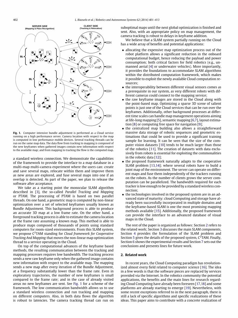
Fig. 1. Computer intensive bundle adjustment is performed as a Cloud servicerunning on a high performance server. Camera location with respect to the mapis computed in low performance mobile devices. Several tracking threads can berun on the same map data. The data flow from tracking to mapping is composed ofthe new keyframes when gathered images contain new information with respectto the available map; and frommapping to tracking the flow is the computed map.
a standard wireless connection. We demonstrate the capabilitiesof the framework to provide the interface to a map database in amulti-map multi-camera experiment where the users can: createand save several maps, relocate within them and improve themas new areas are explored, and fuse several maps into one if anoverlap is detected. As part of the paper, we plan to release thesoftware after acceptance.
We take as a starting point the monocular SLAM algorithmdescribed in [3], the so-called Parallel Tracking and Mappingor PTAM. The processing of PTAM is based on two parallelthreads. On one hand, a geometric map is computed by non-linearoptimization over a set of selected keyframes usually known asBundle Adjustment. This background process is able to producean accurate 3D map at a low frame rate. On the other hand, aforeground tracking process is able to estimate the camera locationat the frame rate assuming a known map. This method is able toproduce maps composed of thousands of points using standardcomputers for room-sized environments. From this SLAM system,we propose C2TAM standing for Cloud framework for CooperativeTracking AndMapping thatmoves the non-linearmap optimizationthread to a service operating in the Cloud.
On top of the computational advances of the keyframe basedmethods, the resulting communication between the tracking andmapping processes requires low bandwidth. The tracking processsends a new raw keyframe only when the gathered image containsnew information with respect to the available map. The mappingsends a new map after every iteration of the Bundle Adjustment,at a frequency substantially lower than the frame rate. Even inexploratory trajectories, the number of new keyframes is smallcompared to the frame rate; and in the case of already visitedareas no new keyframes are sent. See Fig. 1 for a scheme of theframework. The low communication bandwidth allows us to usea standard wireless connection and run tracking and mappingon different computers. Also, in both data flows the algorithmis robust to latencies. The camera tracking thread can run on
suboptimal maps until the next global optimization is finished andsent. Also, with an appropriate policy on map management, thecamera tracking is robust to delays in keyframe addition.
We believe that a SLAM system partially running on the Cloudhas a wide array of benefits and potential applications:
• allocating the expensive map optimization process out of therobot platform allows a significant reduction in the onboardcomputational budget, hence reducing the payload and powerconsumption; both critical factors for field robotics (e.g., un-manned aerial [4] or underwater vehicles). More importantly,it provides the foundations to accommodate SLAM algorithmswithin the distributed computation framework, which makesit possible to exploit the newly available Cloud computation re-sources;
• the interoperability between different visual sensors comes asa prerequisite in our system, as very different robots with dif-ferent cameras could connect to the mapping service;
• the raw keyframe images are stored in the Cloud along withthe point-based map. Optimizing a sparse 3D scene of salientpoints is just one of the Cloud services that can be run over thekeyframes. Additionally, other background processes at differ-ent time scales can handlemapmanagement operations aimingat life-longmapping [5], semanticmapping [6,7], layout estima-tion [8] or computing free space for navigation [9];
• the centralized map building also allows a straightforwardmassive data storage of robotic sequences and geometric es-timations that could be used to provide a significant trainingsample for learning. It can be seen that the size of the com-puter vision datasets [10] tends to be much larger than thoseof the robotics [11]. The creation of datasets with data exclu-sively from robots is essential for exploiting the commonalitiesin the robotic data [12];
• the proposed framework naturally adapts to the cooperativeSLAM problem [13,14]; where several robots have to build ajoint map of the environment. The server can operate on differ-ent maps and fuse them independently of the trackers runningon the robots. As the number of clients grows the server com-putation can be parallelized. The bandwidth required for eachtracker is lowenough to be provided by a standardwireless con-nection;
• the technologies involved in the proposed system are in an ad-vanced state of maturity: cloud Computing and storage have al-ready been successfully incorporated in multiple domains andthe keyframe-based SLAM is one the most promising mappingmethods available [15]. Additionally, the proposed frameworkcan provide the interface to an advanced database of visualmaps in the Cloud.
The rest of the paper is organized as follows: Section 2 refers tothe related work; Section 3 discusses the main SLAM components,Section 4 provides the formulation of the SLAM problem andSection 5 gives the details of the proposed system, C2TAM. Finally,Section 6 shows the experimental results and Section 7 sets out theconclusions and presents lines for future work.
2. Related work
In recent years, the Cloud Computing paradigm has revolution-ized almost every field related to computer science [16]. The ideain a few words is that the software pieces are replaced by servicesprovided via the Internet. In the robotics community the potentialapplications, the benefits and the main lines for research regard-ing Cloud Computing have already been foreseen [17,18] and someplatforms are already starting to emerge [19]. Nevertheless, withsome recent exceptions referred to in the next paragraph, there isstill a lack of specific algorithms and specific realizations of theseideas. This paper aims to contribute with a concrete realization of
L. Riazuelo et al. / Robotics and Autonomous Systems 62 (2014) 401–413 403
a SLAM algorithm operating in the Cloud and a thorough experi-mental testing.
In [20], Bistry et al. analyse how SIFT extraction and matchingcan be moved from a robot to several servers in the Cloud. [21]queries the Cloud service Google Goggles to read text in signsand uses this for loop closing detection. More closely related toour concerns, [22] implements a laser-based FastSLAM algorithmrunning on the Cloud by distributing the particles among severalcomputing nodes.
Recently [23] presented a real-time dense 3D reconstructionthat shares some similarities with our approach. Specifically,this work also builds on PTAM and uses a distributed architec-ture very similar to the one presented in this paper. Our con-tribution is to address the multi-user multi-map case ([23] is asingle-user–single-map system). The contributions that allow oursystem to support multiple users and multiple maps are (1) a two-step map relocation robust to communications delays, and (2) amap fusion algorithm that operates in the Cloud server. It is quiterelevant the very recent [24], published during the review processof the current paper, because it describes a system very similar toours for collaborative SLAM with micro aerial vehicles.
In [25,26], Castle et al. introduce in PTAM the relocationcapability in a set of multiple maps. Our relocation algorithm isbuilt on top of this work, ourmain contribution being the two-steprelocation that is able to cope with the standard network delays ofCloud Computing.
3. A discussion on the SLAM components
The aim of this paper is to provide a splitting of the SLAMproblem such that its strong real-time constraints are not affectedby the network delays when Cloud Computing is used. For the sakeof clarity in later sections, we will start with a high-level definitionof the main components of a modern visual SLAM system.1. Mapping. The mapping component estimates a model of the
scene – a map – from sensor data. We will denote the mapmodel as M; and will assume that our mapping system canhave several independentmaps. The initial approaches to SLAMused to update the camera pose and map estimation jointlyand sequentially for every sensor data arriving [1]. Nevertheless,recent research [3,15] has proposed a clever partition ofthe problem into a one frame-rate thread for camera poseestimation and a second one at a lower rate for map estimation,and has shown that it has computational advantages without aloss of performance or accuracy. This is hence the approach wewill take in this paper.
2. Tracking. The tracking component estimates the camera poseT t for every time step t given an estimation of the map M.A multiple-user–multiple-map SLAM system has one trackingcomponent per user. As this pose estimation is based on thetracking of visual features in an image sequence, it should bedone at a high frequency and with strong real-time constraints.If real-time is lost, the image tracking is likely to fail and hencethe pose tracking will also fail.
3. Relocation. Once the tracking component has failed, therelocation component tries to relocate the camera and re-startthe tracking. The tracking failure can be caused by severalreasons: occlusions, high-acceleration motion, blur or lackof visual features. This component also has strong real-timeconstraints. If the relocation takes too much time the cameramight havemoved from the relocation position and the trackingcomponent might not be able to start.
4. Place recognition. We understand by place recognition thecapability of a SLAM system to relocate in a large number ofmaps. This problem is also known in the robotics communityas the kidnapped robot problem; where a robot perceives anunknown environment and has to recognize the place it is infrom a number of possibilities. Notice that the difference withrelocation is the a priori knowledge on the location. Relocation
comes just after a tracking failure, so we can assume a smallcameramotion and check nearby places to re-start the tracking.Place recognition does not assume any particular location, soevery possible location is equally likely and every map in thedatabase should be checked.
5. Map fusion.Map fusionmerges two independent maps into onewhen an overlapping area is detected by place recognition. First,we search for correspondences between local features in thetwo independent maps. After that, using the geometric con-straints of the corresponding points, the rigid transformationbetween the twomaps is computed. One of themaps is then putin the reference frame of the second one and duplicated pointsare deleted.
4. The SLAM formulation as tracking and mapping
4.1. Mapping
The mapping component contains l local maps {M1, . . . , Mk,. . . , Ml}. Each local map M is composed of a set of n 3D points{P1, . . . , Pi, . . . , Pn} and m keyframes
C1, . . . , Cj, . . . , Cm
M =
P1, . . . , Pi, . . . , Pn, C1, . . . , Cj, . . . , Cm
. (1)
Eachmap entity is modelledwith a set of geometric parametersand, for most of them, an appearance descriptor. The model fora 3D point P =
P, dp
contains its Euclidean 3D position P =
XWYWZW⊤ and a normal n =
nWx nW
y nWz
⊤ in a world referenceframe W ; and its descriptor dp = {w1, . . . , wr} is composed of rdifferent patches extracted at different scales from a source image.For efficiency reasons, at the implementation level we save thepyramid at r different scales of the source image. Hence, each pointP contains a pointer (u v r)⊤ to a pixel and a scale of the pyramidwhere the descriptor can be extracted.
A keyframe C = {C, dc} is modelled quite similarly. First the3D camera pose C =
XWYWZWαWβWγ W
⊤ using its Euclideancoordinates
XWYWZW
and roll–pitch–yaw angles
αWβWγ W
all of them in a world reference frame W . As the keyframedescriptor dc we use – as [27] – the frame Ic ; subsampled to size40 × 30, filtered with a Gaussian mask g(σ ) and normalized bysubtracting the mean.
dc = I40×30c ∗ g(σ ) − I40×30
c ∗ g(σ ). (2)
For each point Pi we have several image measurements indifferent keyframes Cj that we will denote as zji. Each image mea-surement zji puts a geometric constraint between the geometric pa-rameters of the pointPi and the keyframeCj given by the projectionmodel f
zji = f(Pi, Cj,Kj); (3)
where Kj is the internal calibration of the jth keyframe.The mapping component computes the Maximum Likelihood
Estimation (MLE) of the geometric map parametersPi, Cj
⊤
by
minimizing a robust cost function of the error ∆zji; following whatit is usually known as the Bundle Adjustment [28].Pi, Cj
⊤
= arg minPi,Cj
ni=1
mj=1
ρ(∆zji/σ). (4)
The error ∆zji = zji − f(Pi, Cj,Kj) is the difference between theactual image measurements zji and the projected ones f(Pi, Cj,Kj).σ is a median-based estimation of the standard deviation of themeasurement’s noise. As in [3], in order to avoid the influence of
404 L. Riazuelo et al. / Robotics and Autonomous Systems 62 (2014) 401–413
outlier correspondences, we do not minimize the error directlybut use a robust function of the error. We use Tukey’s biweightfunction that is defined as
ρ(ξ) =
1 − (1 − ξ 2)3, |ξ | <= 10, else. (5)
The initialization of amap is one of the key aspects in any visualSLAM system [29,30]. In the first frames of a sequence the SLAMestimation is degenerate or quasi-degenerate and hence it mightfail quite often. As the PTAM system [3] is oriented to AugmentedReality applications, it initializes the map by asking the user toperform a careful translation of the camera in a scene with adominant plane.We believe that this initialization procedure is notsuited to a general robotic application; aswe cannot guarantee thatthe initial motion is a translation – it will be constrained by thescene – or that the scene has a dominant plane.
For the initialization of the proposed C2TAMmap, we have usedan initial multiple model filtering scheme similar to [29]. Filteringschemes are less sensitive to initialization problems in imagesequences than approaches based on pairwise correspondences.This initialization process is as follows: an interacting multiplemodel scheme (see [29] for details) is run on the robot client forthe first frames of the sequence. Once enough parallax has beendetected and the estimation is not degenerate, the first frame of thesequence is set as the first keyframeC1 and the current frame as thesecond oneC2. Both keyframes are sent to themapping componentand the optimization described above is started.
All the experiments in Section 6 were run using this initializa-tion. While the initialization process will have an extra computa-tion cost on the client side; it will not be high as the map is juststarted and its size is small. See the details in Section 6.1.
4.2. Tracking
The tracking component models each frame It from the imagesequence as a set of geometric and appearance parameters T t
=
{T, dt}. The geometric parameters are those of the camera posethat acquired the frame T =
XWYWZWαWβWγ W
⊤. The framedescriptor is composed of a global descriptor dGt and a set of b
local descriptors dLt : dt =
dGt , d
L1t , . . . , dLbt
. The global descriptor
dGt is a subsampled, filtered and normalized version of the frame.The local descriptors dLt are the image patches surrounding a set ofsalient FAST features [31] extracted at 4 scales. Again, for efficiencyreasons, only the image pyramid and the FAST feature positions arestored instead of the image patches.
The tracking component estimates the camera pose parametersTt
=XWYWZWαWβWγ W
⊤ at every time step k from theinformation of previous camera poses, the current frame It andthe current map Mk. This estimation is done in three steps. First,the camera pose Tt|t−1 at time t is predicted from the informationup to theprevious frameat t−1 applying a constant velocitymodel.
In the second step, the points in map Mk extracted at thecoarsest scale – that we will name as P ∗
k – are projected intothe current image It . For each point P ∗
k,i we search for itscorrespondence among the closest salient points in It . The camerapose is roughly estimated from this first set of correspondences bya robust minimization.
Tt∗= arg min
Tt
i
ρ(∆z∗
i /σ∗); (6)
where ρ(ξ) is again Tukey’s biweight function (Eq. (5)), σ∗ is amedian-based estimation of the standard deviation of ∆z∗
i , and∆z∗
i is the reprojection error of each pointP ∗
k,i in the current frame
T t at time step t
∆z∗
i = z∗
i − f(P∗
k,i, Tt ,Kt). (7)
Using this first estimation Tt∗ as a seed, a fine grain estimationfor the pose Tt is finally obtained by projecting every map point –at every scale and not just the coarsest one – into the current frameT t and minimizing the reprojection error.
Tt= arg min
Tt
i
ρ(∆zi/σ). (8)
Againρ(ξ) is Tukey’s biweight function,σ themedian-based es-timation of the standard deviation of ∆zi, and ∆zi the reprojectionerror of each point Pk,i in the current frame T t .
A multiple-user PTAM-like systemwill have a pose tracking peruser; hence the tracking component will be {T1, . . . , Te, . . . , Tr}.
4.3. Relocation
Relocation, or the ability to quickly compute the pose of thecamera when the tracking thread is lost, is done as a two step pro-cess. First, for each new image It , its global descriptor dt is ex-tracted as shown in Eq. (2). We extract the closest keyframe Cjin the current map Mk by computing the Euclidean distance be-tween dt and the global descriptors for each keyframe dc1, . . . ,dcj, . . . , dcm. Assuming that the 3D space is densely populatedwithkeyframes, the nearest-neighbour of dt will be a keyframe veryclose in the 3D space.
Using a simple global descriptor, like the reduced versionof the image that we use, might seem at first sight to offer apoor representation of the image content. Nevertheless, severalworks have proved the good performance of such descriptors. [32]shows the most relevant work on the use of downsampled andfiltered images as descriptors for scene recognition as a veryefficient alternative to more elaborate models with no noticeabledegradation in performance. Such a descriptor is called hereTiny Image. The key here is the dense population of the imagespace by growing the training set size to 80 million images.Recently, [33] has reached the same conclusion for the problem ofplace recognition in mobile robots. The good performance of thisdescriptor for place recognition in SLAM is also reported in [27].In these two latest references, the key aspect is again the densesampling of the image space. In [33] the experiments are donewith an autonomous car that shows limited viewpoint differences.In [27] the amount of keyframes in the optimization is kept high toguarantee that a close match will always exist.
After that, the camera location of It is set as that of thekeyframe Cj and the rotation is compensated by minimizing theerror between the global descriptorsXW
T t YWT t ZW
T t
⊤=
XW
CjYW
CjZW
Cj
⊤
(9)αW
T t βWT t γ
WT t
⊤= arg min
αWT t β
WT t γ
WT t
dt − w(dcj, αW
T t βWT t γ
WT t )
; (10)
where w(d, α, β, γ ) is the warping of the image descriptor d bya rotation given by the angles (α, β, γ ). After this initial pose hasbeen assigned, the tracking thread of Section 4.2 is re-started. If thetracking is successful the camera is relocated, if not the relocationalgorithm of this section is repeated again with the next imageIt+1.
4.4. Place recognition and ego-location
By place recognition, we understand the ability to recognize apart of a map Mk from the visual information in a frame It . Thesubtle difference with the relocation described in Section 4.3 is
L. Riazuelo et al. / Robotics and Autonomous Systems 62 (2014) 401–413 405
the scale of the problem. The relocation component starts whenthe camera tracking is lost; hence we can assume that the camerahas not moved much and we are in the surroundings of the latestcamera pose. Only the closest keyframes in the current map Mkwill be analyzed for similarities. The place recognition component,from the information in the frame It , tries to recognize amap fromall the maps in the SLAM database {M1, . . . , Mk, . . . , Ml}.
For the place recognition and ego-location we will use thesame algorithm as in the previous section; but the fact that thecomputation is larger will introduce differences in our C2TAMalgorithm, as is detailed in Section 5.5. For very large mapdatabases, an interesting line for future work would be to usemore efficient search algorithms, such as the Approximate NearestNeighbour [34] or the recent [35].
4.5. Map fusion
Suppose that, from the l local maps in the Cloud server {M1,. . . , Mk, . . . , Mq, . . . , Ml}, the place recognition component fromSection 4.4 has detected that maps Mk and Mq overlap in somespecific region. The map fusion component merges the two mapsin a common reference frame.
Our map fusion algorithm works as follows. When the map op-timization over Mk receives a new keyframe Ck
j from the trackingnode; the latest is compared with every keyframe in the rest of themaps in the server. Similarly to the relocation component of Sec-tion 4.3, we will use the global descriptor dt as defined in Eq. (2)to quickly extract a set of potential keyframe candidates that areimaging the same area.
In a second step, once we have two potentially overlappingkeyframes Ck
j and Cqh from the maps Mk and Mq we search
for point correspondences between the two maps. We projectthe 3D points from the two maps P k and P q in the commonkeyframe Ck
j , resulting in two sets of image points zj,k = (zj,k1 , . . . ,
zj,kik , . . . , zj,knk )⊤ and zj,q =
zj,q1 , . . . , zj,qiq , . . . , zj,qnq
⊤
.
zj,kik = fPkik , Cj,k,Kj
(11)
zj,qiq = fPqiq , Cj,k,Kj
. (12)
As the two keyframes are assumed to be very similar,correspondences between zj,kik and zj,qiq are computed based on their
distance in the image plane ∥zj,kik − zj,qiq ∥: If this distance is lowerthan a threshold (2 pixels in our experiments) the image points areconsidered to match. Using the correspondences between Pq andzj,k – 3D points in map Mq and image projections from map Mk –we can compute the relative transformation between the keyframeCk
j and the map Mq using the Perspective-n-Point (PnP) [36]. Therelative transformation between themapsMk andMq is calculatedfrom the composition.
Finally, the duplicated points (correspondences between zj,kand zj,q) are deleted and the rest of the points and cameras in mapMq are transformed according to the relative motion between thetwo maps and merged into Mk.
It should be noticed that the formulation of the proposedmapping and tracking components in Sections 4.1 and 4.2 usesonly the RGB information; and hence the maps in the database areestimated up to a scale factor. This fact becomes relevant for mapfusion, as two maps of different scales cannot be fused directly.There are two possible solutions. The first one is to estimate thetransformation and the scale when two maps are fused; as forexample in [37]. The second one is, if a RGB-D sensor is used, toextract an estimation of the real scale of the map from the depthchannel of the camera.
We chose the second option for this paper. For all the points{P1, . . . , Pi, . . . , Pn} in a map M we extracted their real depthmeasurement DRGB-D
=DRGB-D1 , . . . ,DRGB-D
i , . . . ,DRGB-Dn
from the
RGB-D keyframe where they were initialized. We then extractedtheir depth values at the map scale as the distances DM
=DM1 , . . . ,DM
i , . . . ,DMn
between each point position Pi and the
position of the keyframe Cj where it was initialized. Finally, weestimated the scale ratio as the median value of DRGB-D
− DM .With this value, eachmap can be transformed into a real-scalemapand it can be fused with any other map in the database using thealgorithm described in this section.
Notice that the relocation in Section 4.3 and the map fusion inthis section allow several working modes:• single-user–multiple-maps, where a single user is estimating
a map that can be fused with other map instances in thedatabase—previously estimated by other users. As a result, thefinalmap comes from the fusion of two ormoremaps estimatedat different times possibly by different users;
• multiple-user–multiple-maps, where several users are estimat-ing independent maps at the same time that might be fused ifthey belong to the same environment. As a result, we obtaina global map from several individual maps that are being esti-mated at the same time. After the maps are fused, the differentusers can keep tracking and improving the global map cooper-atively.
5. C2TAM: a SLAM in the Cloud
5.1. Mapping as a Cloud Service
The estimationof themapdatabase of our system {M1, . . . , Mk,. . . , Ml} is the most demanding computation in our frameworkand does not have strong real-time constraint. The map optimiza-tion in Eq. (4) can take several frames of the sequence and thetracking can still operate in a non-optimal map from a previousoptimization. The mapping component might be a perfect candi-date for Cloud Computing as it can tolerate the network delays;but it is also necessary that the data flow with the onboard robotcomputers is low enough.Wewill analyse this in the next sections.
5.2. Tracking as a client in the robot
The camera pose tracking is a process with strong real-timeconstraints that has to operate at the frame rate and might fail ifa few frames are skipped. This component is hence not resilient tonetwork delays and should be allocated in the robot.
The mapping service in the Cloud receives as input newkeyframes from the tracking client. This produces a low-bandwidthtraffic, as typically the ratio of keyframes to total frames in thesequence is quite low (in our experiments, this ratio is around10−2). The mapping serves to the client the current map Mk everytime the map is optimized. This produces quite high traffic.
5.3. Relocation as a client in the robot
Relocation refers to the ability of a SLAM system to relocate ina map previously estimated and stored in the Cloud. A trackingnode may need to relocate in two cases: (i) the tracking node,operating successfully over a map, is lost because of a suddenmotion or large occlusion. In this case, the camera is likely to bein the previous map, and relocation should only check the currentmap. This relocation is performed on the tracking node; (ii) thetracking thread has been lost for a long time, or just started. Inthis case, the camera could possibly be in a large number of maps.In this case, relocation should look for correspondences against apossibly very large number of stored maps. As this case will bemore demanding, it should run partially on the mapping node.
406 L. Riazuelo et al. / Robotics and Autonomous Systems 62 (2014) 401–413
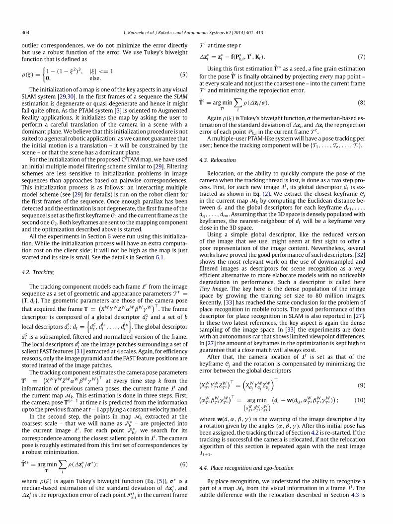
Fig. 2. Coarse-grained place recognition in the Cloud server. The robot client R1sends a frame from the sequence to the server; which tries to relocalize the camerawith respect to every keyframe in every map in the database using the algorithm inSection 4.3. If there is a match, a set of close keyframes is downloaded to the clientfor fine-grained place recognition.
Fig. 3. Fine-grained place recognition on the robot client. The robot client tries torelocate with respect to the set of candidates coming from the first stage, using thealgorithm from Section 4.3.
5.4. Place recognition and ego-location in two steps
Place recognition and ego-location in a large number of mapscan be computationally demanding, and hence it should beallocated in principle as a Cloud service. On the other hand, it is alsoa critical process sensitive to network delays: if the ego-locationestimation takes too much time, the robot might have movedand already be in another place. In our experiments, Tiny Imagecomparisons take around 0.03 ms. With maps of several hundredsof keyframes and databases of possibly hundreds of maps, the costof this place recognition might easily be a second. This is why wepropose a two-stage relocation algorithm, the first part being runon the Cloud and the second in the robot client.
In the first stage, the mapping server in the Cloud coarsely re-locates the camera in a possibly large number of maps. This firstcoarse relocation can take a significant amount of time, and thecamera may have moved when the relocation data arrives at theclient. The server sends to the client a small number of filtered relo-cation candidates consisting of the closest keyframe from the firststage and several close keyframes from the same map; assumingthat the camera may have moved during the relocation search inthe server. Fig. 2 illustrates this process.
In the second stage, the client runs a fine-grained relocationamong the filtered candidate keyframes sent by the server. Delaysare not influential in this second stage, as relocation has avery small number of candidates and it is entirely done by theclient without data transmission. A scheme of this fine-grainedrelocation can be seen in Fig. 3.
a
b
c
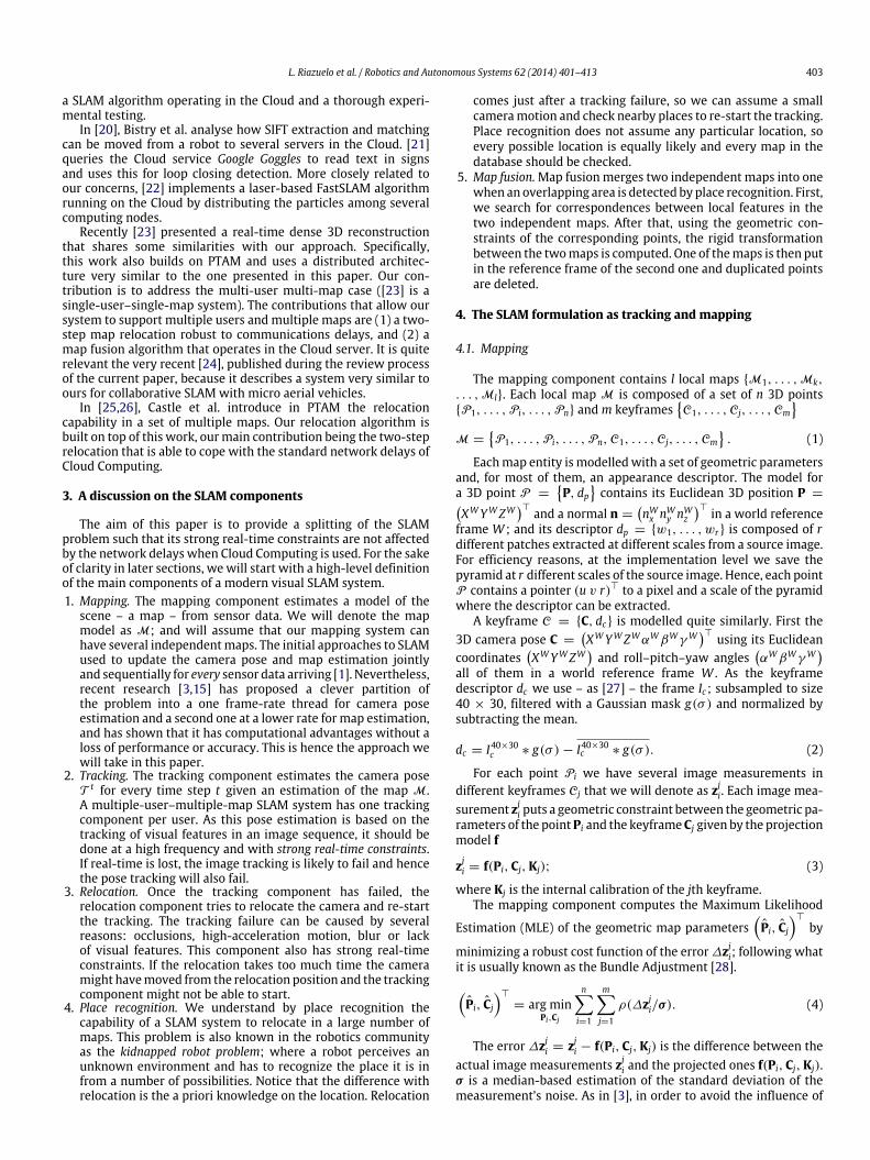
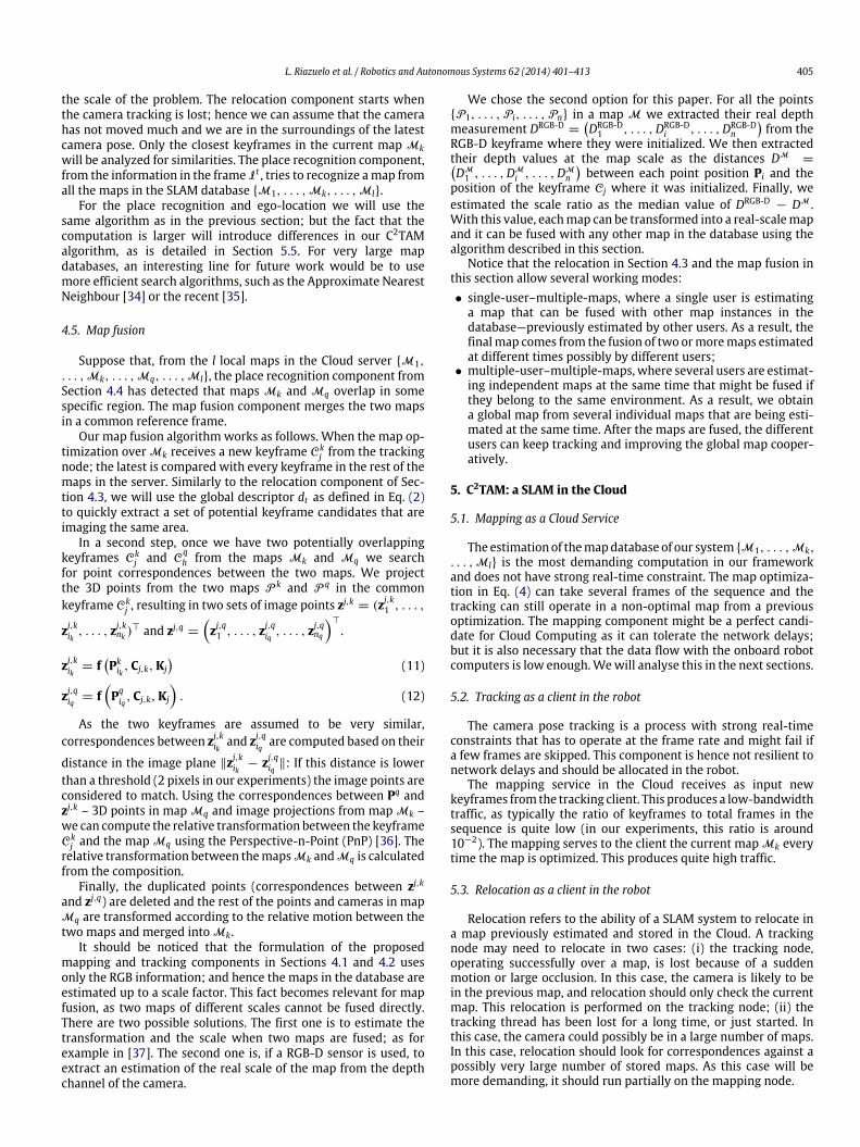
Fig. 4. Map fusion in the Cloud. (a) The robot clientR1 uploads a new keyframeC13
to the map M1 . (b) The keyframe C13 in M1 presents an overlap with the keyframe
C22 in M2 . (c) M1 and M2 are fused into M1,2 and the fused map is downloaded by
the robot client R1 .
5.5. Map fusion as a Cloud service
The map fusion is entirely done in the Cloud server in ourC2TAM framework; as it is a process that does not have real-timeconstraints. An illustrative example of the map fusion algorithmin the Cloud and the associated data traffic is shown in Fig. 4. InFig. 4(a) a robot client R1 is tracking the camera pose and upload-ing a new keyframe C1
3 to the map M1. Every new keyframe thatis uploaded to the Cloud server is compared with every map inthe database. In this case the server detects an overlap of this newkeyframeC1
3 inM1 with the keyframeC22 inM2. This is graphically
shown in Fig. 4(b).The map fusion algorithm from Section 4.5 is then applied;
map M1 and M2 being fused into a single map M1,2 as is shownin Fig. 4(c). Notice that this fusion might produce high trafficbetween the Cloud server and the robot client as the keyframesand points that did not have a local copy in the robot client – inthis case, the keyframes and points in map M2 – have to be sent.But notice also that this process does not have strong real-timeconstraints. The robot can track its pose with a suboptimal mapwhile new keyframes are arriving, as is shown in the experimentin Section 6.3.
In the case that M2 is a large map and its download requires alarge amount of time, some heuristics can still be applied in orderto guarantee the robustness against latencies.
• When a map Mk is sent from the server to a client, the key-frames
C1, . . . , Cj, . . . , Cm
should be downloaded according
L. Riazuelo et al. / Robotics and Autonomous Systems 62 (2014) 401–413 407
to their distance from the current camera frame Tt . In thismanner the client always has the best possible estimation forthe areas that are currently being visited; while far areas mightbe outdated.We implemented this heuristic in our code and didnot observe a big difference in our experiments, but it might bean important technical detail in the case of large maps.
• While a large map Mk is being downloaded, the client can beexploring new areas and hence uploading new keyframes to theserver. The estimated pose of these new keyframes might takea long time to be downloaded by the client, as the largemapMkhas to be downloaded first. The solution for this problem is toperform a local Bundle Adjustment in the server any time a newkeyframe arrives, and send it to the client with high priority.In this manner, we are sure that a first initial seed for newkeyframes will be sent very quickly to the client and trackingis not lost. Again, we did not encounter this problem in ourexperiments but it might be a relevant issue for large mappingin the Cloud.
6. Experimental results
In this section, we detail four experiments that show differentmodes of use of the proposed C2TAM framework. All theexperiments were recorded using RGBD cameras at 640 × 480.Nevertheless, it should be noted that only the RGB channels areeffectively used for the visual SLAM and the depth from the Dchannel is only used for visualization. All the experiments wererun in real-time and using the standard wireless of our University,demonstrating that the proposed system is resilient to its networkdelays.
The experimental results are organized as follows. In Section 6.1a single-user–single-map experiment is performed to evaluate thecost and bandwidth required for the operation of the tracking,mapping and relocation components. Section 6.2 shows a single-user–multiple-maps experiment to demonstrate the real-timeplace recognition capabilities. Once the real-time relocation in astored map is shown, Section 6.3 shows how an online estimationof a map can be fused with a previously stored map. Finally,Section 6.4 presents a multiple-user–multiple-map experimentwhere two independentmaps of the same roomare first estimated,fused when a significant overlap is detected, and the two userskeep enlarging the joint map cooperatively after the fusion.
6.1. Cost and bandwidth analysis
In this experiment, a single user is estimating a single map.Our aim is to illustrate the computational advantages of theproposed architecture with a simple example before going intomore elaborate examples. The camera tracking client was run ona laptop (Intel Core i7 M 620 at 2.67 GHz, 4 GB RAM) and themapping service was run on a desktop PC (Intel Core i7-2600 at3.4 GHz, 8 GB RAM). Both processes, tracking and mapping, havebeen implemented using ROS (Robot Operating System) [38] andthe open source libraries of PTAM [3]. The tracking client and themapping server were connected through the standard wirelessconnection in our institution.
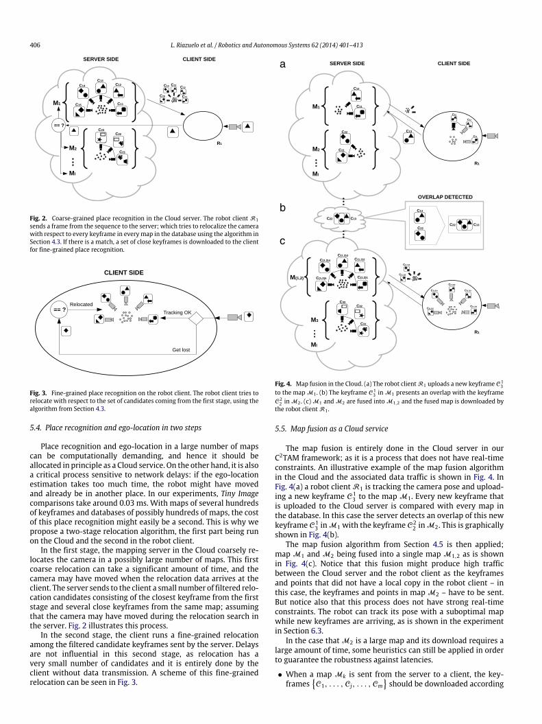
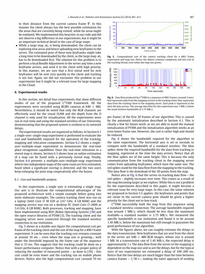
Fig. 5 shows in a double-axis figure the computational cost perframe of the tracking client and the size of themap for a 4961 frameexperiment. It can be seen that the tracking cost remains constantat around 10 ms – even when the map size is growing–, wellunder the threshold imposed by the frame rate of the sequencethat is 33 ms. This suggests that the tracking could be done on alower-performance computer. Notice that with a proper policy ofreducing the number of measured points – as done in [39] – thiscost could be even lower and the tracking run on mobile phonedevices. Notice also the high computational cost (around 70 ms
Fig. 5. Computational cost of the camera tracking client for a 4961 frameexperiment and map size. Notice the almost constant complexity and low cost ofthe tracking thread, even when the map size grows.
Fig. 6. Data flow produced by C2TAM in a sequence of 4961 frames (around 3min).Red represents data from themapping service to the tracking client, blue representsdata from the tracking client to the mapping server. Each peak is registered at thetime the data arrives. The average data flow for this experiment was 1 MB/s, belowthe usual wireless bandwidth of 3.75 MB/s.
per frame) of the first 20 frames of our algorithm. This is causedby the automatic initialization described in Section 4.1. This isclearly a line for future work, as we are able to avoid the manualinitialization of PTAM and the initialization algorithm works at aneven lower frame rate. However, the cost is rather high and shouldbe reduced.
Fig. 6 shows the bandwidth required for the algorithm inthe same experiment. The horizontal axis is set in seconds tocompare with the bandwidth of a standard wireless. The bluespikes show the required bandwidth for the data from tracking tomapping, registered at the time the data arrives. Notice that allthe blue spikes are of the same height. This is because the onlycommunication from the tracking client to the mapping servercomes from uploading keyframes, which have the same size. Thered spikes stand for the data flow from themapping to the tracking.This data flow is the download of the 3D points from the map.
Notice also in Fig. 6 that the server-to-tracking data flow – thered spikes – slightly increases over time. This comes as a result ofthemap becoming larger aswe explore.While this is not a problemfor the experiments described in this paper, it might become arelevant issue for very large maps. In this case, the same solutionwe proposed in Section 5.5 applies: the keyframes and points thatare closer to the current camera pose should be given a higherpriority for the client not to lose track.
C2TAM successfully built the map from this sequence usinga standard wireless connection. The average bandwidth requiredwas around 1 MB/s; which should be less than the maximumavailable—a standard number is 3.75 MB/s. We measured thespecific bandwidth in our institution and found it to be around1.45 MB/s; below the maximum but still enough to guarantee thegood performance of our algorithm.
With the figures above, we can roughly estimate the delays inthe data transmission. New keyframes that are sent from the clientto the server are 640 × 480 RGB images, whose size is around1 MB. At a transmission rate of 1.45 MB/s, the expected delay isapproximately 1 s. The data flow from the server to the mapping isdependent on themap size and so are the delays, but for the typicalsizes of our experiments we estimated a delay of 100–200 ms.Notice that the two delays are much bigger than the time betweencamera frames – 1/30 s–; making the naïve approach of sending
408 L. Riazuelo et al. / Robotics and Autonomous Systems 62 (2014) 401–413
(a) Sample keyframes from the desktop sequence.
(b) Map estimated from the desktop sequence.
(c) Estimated map for the desktop after the laboratory sequence.
Fig. 7. Keyframes and map for the desktop scene.
every frame to the server infeasible and justifying our approach.Notice also that neither themapping service nor the tracking clientwas influenced by this network latency in the communicationswith the proposed C2TAM.
6.2. Relocation in multiple maps
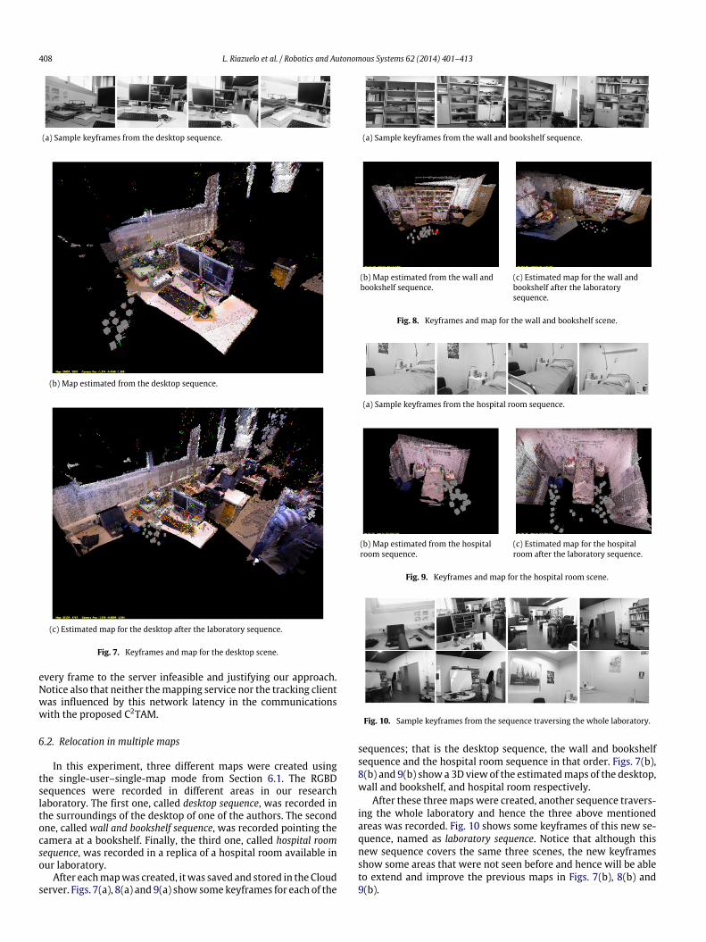
In this experiment, three different maps were created usingthe single-user–single-map mode from Section 6.1. The RGBDsequences were recorded in different areas in our researchlaboratory. The first one, called desktop sequence, was recorded inthe surroundings of the desktop of one of the authors. The secondone, called wall and bookshelf sequence, was recorded pointing thecamera at a bookshelf. Finally, the third one, called hospital roomsequence, was recorded in a replica of a hospital room available inour laboratory.
After eachmapwas created, itwas saved and stored in the Cloudserver. Figs. 7(a), 8(a) and 9(a) show somekeyframes for each of the
(a) Sample keyframes from the wall and bookshelf sequence.
(b) Map estimated from the wall andbookshelf sequence.
(c) Estimated map for the wall andbookshelf after the laboratorysequence.
Fig. 8. Keyframes and map for the wall and bookshelf scene.
(a) Sample keyframes from the hospital room sequence.
(b) Map estimated from the hospitalroom sequence.
(c) Estimated map for the hospitalroom after the laboratory sequence.
Fig. 9. Keyframes and map for the hospital room scene.
Fig. 10. Sample keyframes from the sequence traversing the whole laboratory.
sequences; that is the desktop sequence, the wall and bookshelfsequence and the hospital room sequence in that order. Figs. 7(b),8(b) and 9(b) show a 3D view of the estimatedmaps of the desktop,wall and bookshelf, and hospital room respectively.
After these threemapswere created, another sequence travers-ing the whole laboratory and hence the three above mentionedareas was recorded. Fig. 10 shows some keyframes of this new se-quence, named as laboratory sequence. Notice that although thisnew sequence covers the same three scenes, the new keyframesshow some areas that were not seen before and hence will be ableto extend and improve the previous maps in Figs. 7(b), 8(b) and9(b).
L. Riazuelo et al. / Robotics and Autonomous Systems 62 (2014) 401–413 409
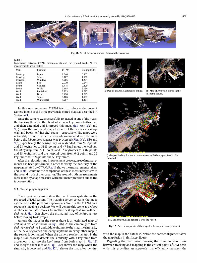
Fig. 11. Set of the measurements taken on the scenarios.
Table 1Comparison between C2TAM measurements and the ground truth. All themeasurements are in metres.
Map Element C2TAM Ground truth
Desktop Laptop 0.340 0.337Desktop Table 1.107 1.102Desktop Window 1.205 1.201Room Bed 2.039 2.044Room Cabinet 0.418 0.420Room Walls 3.105 3.096Wall Bookshelf 2.723 2.727Wall Door 1.790 1.795Wall Table 1.106 1.107Wall Whiteboard 1.267 1.264
In this new sequence, C2TAM tried to relocate the currentcamera in one of the three previously stored maps as described inSection 4.3.
Once the camera was successfully relocated in one of the maps,the tracking thread in the client added new keyframes to this mapand then extended and improved this map. Figs. 7(c), 8(c) and9(c) show the improved maps for each of the scenes –desktop,wall and bookshelf, hospital room– respectively. The maps werenoticeably extended, as can be seenwhen comparedwith themapsbefore the laboratory sequence was processed (Figs. 7(b), 8(b) and9(b)). Specifically, the desktop mapwas extended from 2662 pointsand 28 keyframes to 3313 points and 47 keyframes, the wall andbookshelf map from 2711 points and 32 keyframes to 3987 pointsand 58 keyframes, and the hospital room from 642 points and 29keyframes to 1624 points and 58 keyframes.
After the relocation and improvement process, a set ofmeasure-ments has been performed in order to verify the accuracy of themaps generated by C2TAM. Fig. 11 shows themeasurements taken,and Table 1 contains the comparison of these measurements withthe ground truth of the scenarios. The ground truthmeasurementsweremade by a tapemeasure withmillimeter precision due to thetape resolution.
6.3. Overlapping map fusion
This experiment aims to show themap fusion capabilities of theproposed C2TAM system. The mapping server contains the mapsestimated for the previous experiments. We run the C2TAM on asequence imaging a desktop. We will denote this scene as desktopA. The camera later moves to another desktop that we will calldesktop B. Fig. 12(a) shows the estimated map of desktop A, justbefore moving to desktop B.
Among the maps in the server there is an estimated map ofdesktop B, which is shown in Fig. 12(b). As the camera goes fromdesktop A to desktop B and adds keyframes to themap, the similarityof the new keyframes and every keyframe in every other map inthe server is computed. When the camera reaches desktop B, themap fusion process detects the similarity with a keyframe froma previous map (see the keyframes from both maps in Fig. 13)and merges them into one. Fig. 12(c) shows the map when thesimilarity is detected, and Fig. 12(d) shows the map after merging
(a) Map of desktop A, estimated online. (b) Map of desktop B, stored in themapping server.
(c) Map of desktop Awhen a common area with the map of desktop B isdetected.
(d) Maps desktop A and desktop B after the fusion.
Fig. 12. Several snapshots of the maps for the map fusion experiment.
with the map in the database. Notice the correct alignment afterthe map fusion in this latest figure.
Regarding the map fusion process, the communication flowbetween tracking and mapping is the critical point. C2TAM dealswith this providing an approach that efficiently manages the
410 L. Riazuelo et al. / Robotics and Autonomous Systems 62 (2014) 401–413
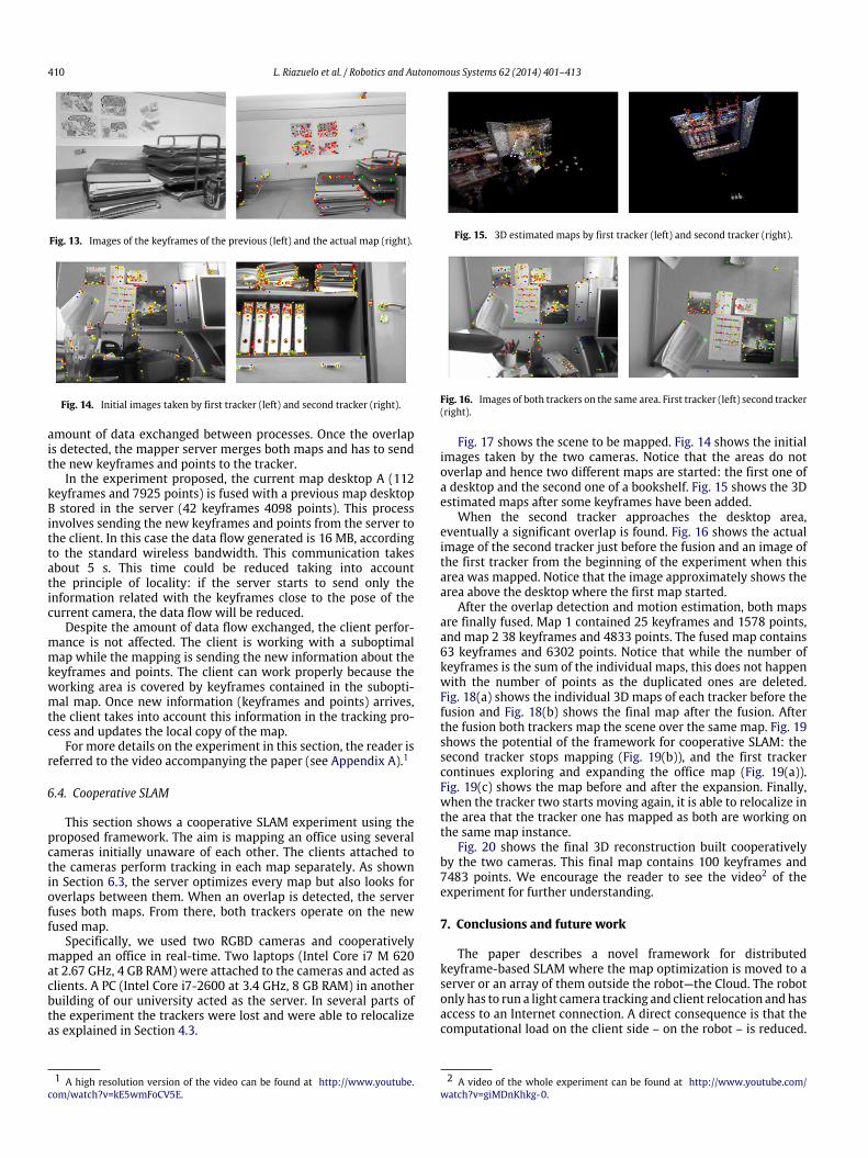
Fig. 13. Images of the keyframes of the previous (left) and the actual map (right).
Fig. 14. Initial images taken by first tracker (left) and second tracker (right).
amount of data exchanged between processes. Once the overlapis detected, the mapper server merges both maps and has to sendthe new keyframes and points to the tracker.
In the experiment proposed, the current map desktop A (112keyframes and 7925 points) is fused with a previous map desktopB stored in the server (42 keyframes 4098 points). This processinvolves sending the new keyframes and points from the server tothe client. In this case the data flow generated is 16 MB, accordingto the standard wireless bandwidth. This communication takesabout 5 s. This time could be reduced taking into accountthe principle of locality: if the server starts to send only theinformation related with the keyframes close to the pose of thecurrent camera, the data flow will be reduced.
Despite the amount of data flow exchanged, the client perfor-mance is not affected. The client is working with a suboptimalmap while the mapping is sending the new information about thekeyframes and points. The client can work properly because theworking area is covered by keyframes contained in the subopti-mal map. Once new information (keyframes and points) arrives,the client takes into account this information in the tracking pro-cess and updates the local copy of the map.
For more details on the experiment in this section, the reader isreferred to the video accompanying the paper (see Appendix A).1
6.4. Cooperative SLAM
This section shows a cooperative SLAM experiment using theproposed framework. The aim is mapping an office using severalcameras initially unaware of each other. The clients attached tothe cameras perform tracking in each map separately. As shownin Section 6.3, the server optimizes every map but also looks foroverlaps between them. When an overlap is detected, the serverfuses both maps. From there, both trackers operate on the newfused map.
Specifically, we used two RGBD cameras and cooperativelymapped an office in real-time. Two laptops (Intel Core i7 M 620at 2.67 GHz, 4 GB RAM) were attached to the cameras and acted asclients. A PC (Intel Core i7-2600 at 3.4 GHz, 8 GB RAM) in anotherbuilding of our university acted as the server. In several parts ofthe experiment the trackers were lost and were able to relocalizeas explained in Section 4.3.
1 A high resolution version of the video can be found at http://www.youtube.com/watch?v=kE5wmFoCV5E.
Fig. 15. 3D estimated maps by first tracker (left) and second tracker (right).
Fig. 16. Images of both trackers on the same area. First tracker (left) second tracker(right).
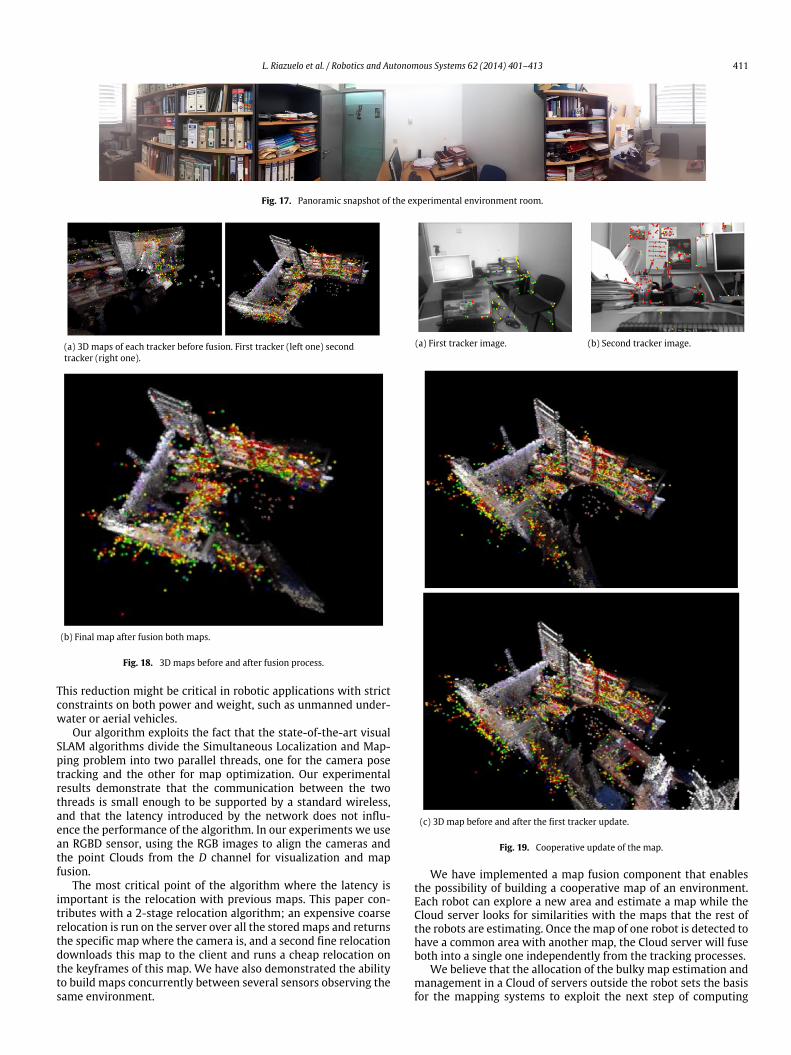
Fig. 17 shows the scene to be mapped. Fig. 14 shows the initialimages taken by the two cameras. Notice that the areas do notoverlap and hence two different maps are started: the first one ofa desktop and the second one of a bookshelf. Fig. 15 shows the 3Destimated maps after some keyframes have been added.
When the second tracker approaches the desktop area,eventually a significant overlap is found. Fig. 16 shows the actualimage of the second tracker just before the fusion and an image ofthe first tracker from the beginning of the experiment when thisarea was mapped. Notice that the image approximately shows thearea above the desktop where the first map started.
After the overlap detection and motion estimation, both mapsare finally fused. Map 1 contained 25 keyframes and 1578 points,and map 2 38 keyframes and 4833 points. The fused map contains63 keyframes and 6302 points. Notice that while the number ofkeyframes is the sum of the individual maps, this does not happenwith the number of points as the duplicated ones are deleted.Fig. 18(a) shows the individual 3D maps of each tracker before thefusion and Fig. 18(b) shows the final map after the fusion. Afterthe fusion both trackers map the scene over the same map. Fig. 19shows the potential of the framework for cooperative SLAM: thesecond tracker stops mapping (Fig. 19(b)), and the first trackercontinues exploring and expanding the office map (Fig. 19(a)).Fig. 19(c) shows the map before and after the expansion. Finally,when the tracker two starts moving again, it is able to relocalize inthe area that the tracker one has mapped as both are working onthe same map instance.
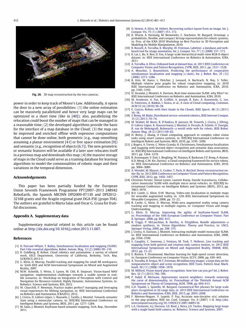
Fig. 20 shows the final 3D reconstruction built cooperativelyby the two cameras. This final map contains 100 keyframes and7483 points. We encourage the reader to see the video2 of theexperiment for further understanding.
7. Conclusions and future work
The paper describes a novel framework for distributedkeyframe-based SLAM where the map optimization is moved to aserver or an array of them outside the robot—the Cloud. The robotonly has to run a light camera tracking and client relocation andhasaccess to an Internet connection. A direct consequence is that thecomputational load on the client side – on the robot – is reduced.
2 A video of the whole experiment can be found at http://www.youtube.com/watch?v=giMDnKhkg-0.
L. Riazuelo et al. / Robotics and Autonomous Systems 62 (2014) 401–413 411
Fig. 17. Panoramic snapshot of the experimental environment room.
(a) 3D maps of each tracker before fusion. First tracker (left one) secondtracker (right one).
(b) Final map after fusion both maps.
Fig. 18. 3D maps before and after fusion process.
This reduction might be critical in robotic applications with strictconstraints on both power and weight, such as unmanned under-water or aerial vehicles.
Our algorithm exploits the fact that the state-of-the-art visualSLAM algorithms divide the Simultaneous Localization and Map-ping problem into two parallel threads, one for the camera posetracking and the other for map optimization. Our experimentalresults demonstrate that the communication between the twothreads is small enough to be supported by a standard wireless,and that the latency introduced by the network does not influ-ence the performance of the algorithm. In our experiments we usean RGBD sensor, using the RGB images to align the cameras andthe point Clouds from the D channel for visualization and mapfusion.
The most critical point of the algorithm where the latency isimportant is the relocation with previous maps. This paper con-tributes with a 2-stage relocation algorithm; an expensive coarserelocation is run on the server over all the storedmaps and returnsthe specific map where the camera is, and a second fine relocationdownloads this map to the client and runs a cheap relocation onthe keyframes of this map. We have also demonstrated the abilityto build maps concurrently between several sensors observing thesame environment.
(a) First tracker image. (b) Second tracker image.
(c) 3D map before and after the first tracker update.
Fig. 19. Cooperative update of the map.
We have implemented a map fusion component that enablesthe possibility of building a cooperative map of an environment.Each robot can explore a new area and estimate a map while theCloud server looks for similarities with the maps that the rest ofthe robots are estimating. Once themap of one robot is detected tohave a common area with another map, the Cloud server will fuseboth into a single one independently from the tracking processes.
We believe that the allocation of the bulky map estimation andmanagement in a Cloud of servers outside the robot sets the basisfor the mapping systems to exploit the next step of computing
412 L. Riazuelo et al. / Robotics and Autonomous Systems 62 (2014) 401–413
Fig. 20. 3D map reconstruction by the two cameras.
power in order to keep track of Moore’s Law. Additionally, it opensthe door to a new array of possibilities: (1) the online estimationcan be massively parallelized and hence very large maps can beoptimized in a short time (like in [40]); also, parallelizing therelocation could boost the number of maps that can bemanaged ina reasonable time; (2) the developed algorithms provide the basisfor the interface of a map database in the Cloud; (3) the map canbe improved and enriched offline with expensive computationsthat cannot be done online, both geometric (e.g., map smoothingassuming a planar environment [41] or free space estimation [9])and semantic (e.g., recognition of objects [6,7]). The new geometricor semantic features will be available if a later user relocates itselfin a previousmap and downloads thismap; (4) themassive storageof maps in the Cloud could serve as a training database for learningalgorithms to model the commonalities of robotic maps and theirvariations in the temporal dimension.
Acknowledgements
This paper has been partially funded by the EuropeanUnion Seventh Framework Programme FP7/2007–2013 248942RoboEarth, the Spanish MICINN DPI2009-07130 and DPI2012-32168 grants and the Aragón regional grant DGA-FSE (grupo T04).The authors are grateful toMarta Salas and Oscar G. Grasa for fruit-ful discussions.
Appendix A. Supplementary data
Supplementary material related to this article can be foundonline at http://dx.doi.org/10.1016/j.robot.2013.11.007.
References
[1] H. Durrant-Whyte, T. Bailey, Simultaneous localisation and mapping (SLAM):Part I the essential algorithms, Robot. Autom. Mag. 13 (2) (2006) 99–110.
[2] K. Goldberg, B. Kehoe, Cloud robotics and automation: a survey of relatedwork, EECS Department, University of California, Berkeley, Tech. Rep.UCB/EECS-2013-5.
[3] G. Klein, D. Murray, Parallel tracking and mapping for small AR workspaces,in: Sixth IEEE and ACM International Symposium on Mixed and AugmentedReality, 2007.
[4] M.W. Achtelik, S. Weiss, S. Lynen, M. Chli, R. Siegwart, Vision-based MAVnavigation: implementation challenges towards a usable system in real-life scenarios, in: Workshop on Integration of Perception with Control andNavigation for Resource-Limited, Highly Dynamic, Autonomous Systems, in:Robotics: Science and Systems, RSS, 2012.
[5] W. Churchill, P. Newman, Practice makes perfect? managing and leveragingvisual experiences for lifelong navigation, in: IEEE International Conferenceon Robotics and Automation, ICRA2012, 2012.
[6] J. Civera, D. Gálvez-López, L. Riazuelo, J. Tardós, J. Montiel, Towards semanticslam using a monocular camera, in: IEEE/RSJ International Conference onIntelligent Robots and Systems, IROS, 2011, pp. 1277–1284.
[7] M. Salas, J. Montiel, Keyframe based semantic mapping, Tech. Rep., December2011.
[8] D. Hoiem, A. Efros, M. Hebert, Recovering surface layout from an image, Int. J.Comput. Vis. 75 (1) (2007) 151–172.
[9] K. Wurm, A. Hornung, M. Bennewitz, C. Stachniss, W. Burgard, Octomap: aprobabilistic, flexible, and compact 3dmap representation for robotic systems,in: Proc. of the ICRA 2010 Workshop on Best Practice in 3D Perception andModeling for Mobile Manipulation, 2010.
[10] B. Russell, A. Torralba, K. Murphy, W. Freeman, Labelme: a database and web-based tool for image annotation, Int. J. Comput. Vis. 77 (1) (2008) 157–173.
[11] K. Lai, L. Bo, X. Ren, D. Fox, A large-scale hierarchical multi-view RGB-D objectdataset, in: IEEE International Conference on Robotics & Automation, ICRA,2011.
[12] A. Torralba, A. Efros, Unbiased look at dataset bias, in: 2011 IEEE Conference onComputer Vision and Pattern Recognition, CVPR, IEEE, 2011, pp. 1521–1528.
[13] A. Mourikis, S. Roumeliotis, Predicting the performance of cooperativesimultaneous localization and mapping (c-slam), Int. J. Robot. Res. 25 (12)(2006) 1273–1286.
[14] B. Kim, M. Kaess, L. Fletcher, J. Leonard, A. Bachrach, N. Roy, S. Teller,Multiple relative pose graphs for robust cooperative mapping, in: 2010IEEE International Conference on Robotics and Automation, ICRA, 2010,pp. 3185–3192.
[15] H. Strasdat, J. Montiel, A. Davison, Real-time monocular SLAM: why filter? in:IEEE International Conference on Robotics and Automation, ICRA, 2010.
[16] M. Armbrust, A. Fox, R. Griffith, A. Joseph, R. Katz, A. Konwinski, G. Lee,D. Patterson, A. Rabkin, I. Stoica, et al., A view of Cloud computing, Commun.ACM 53 (4) (2010) 50–58.
[17] E. Guizzo, Robots with their heads in the Clouds, IEEE Spectr. 48 (3) (2011)16–18.
[18] S. Remy,M. Blake, Distributed service-oriented robotics, IEEE Internet Comput.15 (2) (2011) 70–74.
[19] M. Waibel, M. Beetz, R. D’Andrea, R. Janssen, M. Tenorth, J. Civera, J. Elfring,D. Gálvez-López, K. Haussermann, J. Montiel, A. Perzylo, B. Schiele, O. Zweigle,R. van de Molengraft, Roboearth—a world wide web for robots, IEEE Robot.Autom. Mag. 18 (2) (2011) 69–82.
[20] H. Bistry, J. Zhang, A Cloud computing approach to complex robot visiontasks using smart camera systems, in: IEEE/RSJ International Conference onIntelligent Robots and Systems, IROS, 2010, pp. 3195–3200.
[21] J. Rogers, A. Trevor, C. Nieto-Granda, H. Christensen, Simultaneous localizationand mapping with learned object recognition and semantic data association,in: IEEE/RSJ International Conference on Intelligent Robots and Systems, IROS,2011, pp. 1264–1270.
[22] R. Arumugam, V. Enti, L. Bingbing,W. Xiaojun, K. Baskaran, F.F. Kong, A. Kumar,K.D. Meng, G.W. Kit, Davinci: a Cloud computing framework for service robots,in: IEEE International Conference on Robotics and Automation, ICRA, 2010,pp. 3084–3089.
[23] A. Wendel, M. Maurer, G. Graber, T. Pock, H. Bischof, Dense reconstruction on-the-fly, in: 2012 IEEE Conference on Computer Vision and Pattern Recognition,CVPR, IEEE, 2012, pp. 1450–1457.
[24] Christian Forster, Simon Lynen, Laurent Kneip, Davide Scaramuzza, Collabo-rative monocular SLAM with multiple micro aerial vehicles, in: IEEE/RSJ In-ternational Conference on Intelligent Robots and Systems (IROS), 2013, pp.3963–3970.
[25] R.O. Castle, G. Klein, D.W. Murray, Video-rate localization in multiple mapsfor wearable augmented reality, in: 12th IEEE International Symposium onWearable Computers, 2008, pp. 15–22.
[26] R. Castle, G. Klein, D. Murray, Wide-area augmented reality using cameratracking and mapping in multiple regions, in: Computer Vision and ImageUnderstanding.
[27] G. Klein, D. Murray, Improving the agility of keyframe-based SLAM,in: Proceedings of the 10th European Conference on Computer Vision: PartII, Springer, 2008, pp. 802–815.
[28] B. Triggs, P. McLauchlan, R. Hartley, A. Fitzgibbon, Bundle adjustment—amodern synthesis, in: Vision Algorithms: Theory and Practice, in: LNCS,Springer Verlag, 2000, pp. 298–375.
[29] J. Civera, A. Davison, J. Montiel, Interacting multiple model monocular SLAM,in: IEEE International Conference on Robotics and Automation, ICRA, 2008,pp. 3704–3709.
[30] S. Gauglitz, C. Sweeney, J. Ventura, M. Turk, T. Hollerer, Live tracking andmapping from both general and rotation-only camera motion, in: 2012 IEEEInternational Symposium on Mixed and Augmented Reality, ISMAR, IEEE,2012, pp. 13–22.
[31] E. Rosten, T. Drummond, Machine learning for high-speed corner detection,in: European Conference on Computer Vision, ECCV, 2006, pp. 430–443.
[32] A. Torralba, R. Fergus,W.T. Freeman, 80million tiny images: a large data set fornonparametric object and scene recognition, IEEE Trans. Pattern Anal. Mach.Intell. 30 (11) (2008) 1958–1970.
[33] M. Milford, Vision-based place recognition: how low can you go? Int. J. Robot.Res. 32 (7) (2013) 766–789.
[34] P. Indyk, R. Motwani, Approximate nearest neighbors: towards removingthe curse of dimensionality, in: Proceedings of the Thirtieth Annual ACMSymposium on Theory of Computing, ACM, 1998, pp. 604–613.
[35] G.D. Tipaldi, L. Spinello, W. Burgard, Geometrical flirt phrases for large scaleplace recognition in 2d range data, in: 2013 IEEE International Conference onRobotics and Automation, ICRA, IEEE, 2013, pp. 2693–2698.
[36] F. Moreno-Noguer, V. Lepetit, P. Fua, Accurate non-iterative o(n) solutionto the pnp problem, IEEE Int. Conf. Comput. Vis. 0 (2007) 1–8. http://doi.ieeecomputersociety.org/10.1109/ICCV.2007.4409116.
[37] L.A. Clemente, A.J. Davison, I.D. Reid, J. Neira, J.D. Tardos, Mapping large loopswith a single hand-held camera, in: Robotics: Science and Systems, 2007.
L. Riazuelo et al. / Robotics and Autonomous Systems 62 (2014) 401–413 413
[38] M. Quigley, K. Conley, B.P. Gerkey, J. Faust, T. Foote, J. Leibs, R. Wheeler,A.Y. Ng, Ros: an open-source robot operating system, in: ICRA Workshop onOpen Source Software, 2009.
[39] G. Klein, D. Murray, Parallel tracking and mapping on a camera phone, in:8th IEEE International Symposium on Mixed and Augmented Reality, 2009,pp. 83–86.
[40] Y. Furukawa, B. Curless, S. Seitz, R. Szeliski, Towards internet-scale multi-viewstereo, in: IEEE Conference on Computer Vision and Pattern Recognition, 2010,pp. 1434–1441.
[41] D. Gallup, J. Frahm, M. Pollefeys, Piecewise planar and non-planar stereofor urban scene reconstruction, in: IEEE Conference on Computer Vision andPattern Recognition, CVPR, IEEE, 2010, pp. 1418–1425.
L. Riazuelo received the M.S. degree in computer sciencefrom the University of Zaragoza, Spain, in 2006, andreceived the Master’s degree in biomedical engineeringfrom the University of Zaragoza, Spain in 2008. He iscurrently a researcher at the Robotics, Perception andReal TimeGroup, Aragón Institute of Engineering Research(I3A), University of Zaragoza.Hehas participated in severalEU-funded and national funded projects. His currentresearch interests include computer vision and mobilerobot navigation.
Javier Civera received his Ph.D. from the University ofZaragoza, Spain, in 2009. He is currently an associateprofessor at the University of Zaragoza, where he teachescourses in control theory and computer vision. Hehas participated in several EU-funded and nationalfunded projects, all of them on 3D vision from imagesequences. He has coauthored around 20 publications intop conferences and journals on this topic. His currentresearch interests are focused on computer vision andmachine learning.
J.M.M. Montiel received the M.S. and Ph.D. degrees inelectrical engineering from the Universidad de Zaragoza,Spain, in 1991 and 1996, respectively. He is currently a FullProfessor with the Departamento de Informatica, Univer-sidad de Zaragoza, where he is in charge of Perception andComputer Vision research grants and courses. His currentinterests include, real-time vision localization and seman-tic mapping for rigid and non rigid environments, and thetransference of this technology to robotic and nonroboticapplication domains. Prof. Martínez Montiel is a memberof the I3A Robotics, Perception, and Real-Time Group. He
has been awarded several Spanish MEC grants to fund research at the University ofOxford, UK, and at Imperial College London, UK.