Embed Size (px)
DESCRIPTION
manual
Citation preview
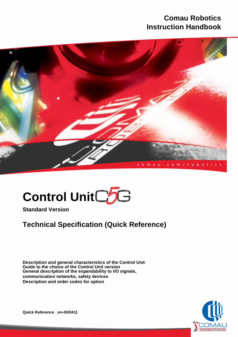
Comau RoboticsInstruction Handbook
Control UnitStandard Version
Technical Specification (Quick Reference)
Description and general characteristics of the Control UnitGuide to the choice of the Control Unit versionGeneral description of the expandability to I/O signals, communication networks, safety devicesDescription and order codes for option
Quick Reference _en-00/0411

The information contained in this manual is the property of COMAU S.p.A.
Reproduction of text and illustrations is not permitted without prior written approval by COMAU S.p.A.
COMAU S.p.A. reserves the right to alter product specifications at any time without notice or obligation.
Copyright © 2008-2011 by COMAU - Date of publication 04/2011
Summary
SUMMARY
PREFACE . . . . . . . . . . . . . . . . . . . . . . . . . . . . . . . . . . . . . . . . . . . . . . . . . . . . . . . . . . . .5
Reference documents . . . . . . . . . . . . . . . . . . . . . . . . . . . . . . . . . . . . . . . . . . . . . . . . . . . . . . . . . 5
Content of the C5G Control Unit manuals . . . . . . . . . . . . . . . . . . . . . . . . . . . . . . . . . . . . . . . . . . 6
Document preservation . . . . . . . . . . . . . . . . . . . . . . . . . . . . . . . . . . . . . . . . . . . . . . . . . . . . . . . . 6
Manual content limits . . . . . . . . . . . . . . . . . . . . . . . . . . . . . . . . . . . . . . . . . . . . . . . . . . . . . . . . . . 6
Symbols in the manual. . . . . . . . . . . . . . . . . . . . . . . . . . . . . . . . . . . . . . . . . . . . . . . . . . . . . . . . . 7
1. GENERAL SAFETY PRECAUTIONS . . . . . . . . . . . . . . . . . . . . . . . . . . . . . . . . . . . . . ...8
Responsibilities . . . . . . . . . . . . . . . . . . . . . . . . . . . . . . . . . . . . . . . . . . . . . . . . . . . . . . . . . . . . . . 8
Safety Precautions. . . . . . . . . . . . . . . . . . . . . . . . . . . . . . . . . . . . . . . . . . . . . . . . . . . . . . . . . . . . 9Purpose . . . . . . . . . . . . . . . . . . . . . . . . . . . . . . . . . . . . . . . . . . . . . . . . . . . . . . . . . . . . . . . . . . 9Definitions . . . . . . . . . . . . . . . . . . . . . . . . . . . . . . . . . . . . . . . . . . . . . . . . . . . . . . . . . . . . . . . . 9Applicability . . . . . . . . . . . . . . . . . . . . . . . . . . . . . . . . . . . . . . . . . . . . . . . . . . . . . . . . . . . . . . 10Operating Modes . . . . . . . . . . . . . . . . . . . . . . . . . . . . . . . . . . . . . . . . . . . . . . . . . . . . . . . . . . 11Performance. . . . . . . . . . . . . . . . . . . . . . . . . . . . . . . . . . . . . . . . . . . . . . . . . . . . . . . . . . . . . . 17
2. INTRODUCTION TO THE CONTROL UNIT: RELIABILITY AND SAFETY . . . . . . . ...18
Reliability and serviceability . . . . . . . . . . . . . . . . . . . . . . . . . . . . . . . . . . . . . . . . . . . . . . . . . . . . 19
Calculation power . . . . . . . . . . . . . . . . . . . . . . . . . . . . . . . . . . . . . . . . . . . . . . . . . . . . . . . . . . . 20
Expandability . . . . . . . . . . . . . . . . . . . . . . . . . . . . . . . . . . . . . . . . . . . . . . . . . . . . . . . . . . . . . . . 21
Programming . . . . . . . . . . . . . . . . . . . . . . . . . . . . . . . . . . . . . . . . . . . . . . . . . . . . . . . . . . . . . . . 21
Safety . . . . . . . . . . . . . . . . . . . . . . . . . . . . . . . . . . . . . . . . . . . . . . . . . . . . . . . . . . . . . . . . . . . 22Compliance with the norms in force . . . . . . . . . . . . . . . . . . . . . . . . . . . . . . . . . . . . . . . . . . . . 22Directives and norms . . . . . . . . . . . . . . . . . . . . . . . . . . . . . . . . . . . . . . . . . . . . . . . . . . . . . . . 23Statement of incorporation of partly completed machinery . . . . . . . . . . . . . . . . . . . . . . . . . . 24Manufacturer’s details . . . . . . . . . . . . . . . . . . . . . . . . . . . . . . . . . . . . . . . . . . . . . . . . . . . . . . 24Safety devices control procedures . . . . . . . . . . . . . . . . . . . . . . . . . . . . . . . . . . . . . . . . . . . . . 25Safety solutions installed . . . . . . . . . . . . . . . . . . . . . . . . . . . . . . . . . . . . . . . . . . . . . . . . . . . . 25
Control modes . . . . . . . . . . . . . . . . . . . . . . . . . . . . . . . . . . . . . . . . . . . . . . . . . . . . . . . . . . . . . . 26
3. VERSIONS AND TECHNICAL FEATURES . . . . . . . . . . . . . . . . . . . . . . . . . . . . . . . ...27
Selecting the Control Unit version . . . . . . . . . . . . . . . . . . . . . . . . . . . . . . . . . . . . . . . . . . . . . . . 27
C5G Control Unit . . . . . . . . . . . . . . . . . . . . . . . . . . . . . . . . . . . . . . . . . . . . . . . . . . . . . . . . . . . . 28Control Unit technical features . . . . . . . . . . . . . . . . . . . . . . . . . . . . . . . . . . . . . . . . . . . . . . . . 30
Teach Pendant. . . . . . . . . . . . . . . . . . . . . . . . . . . . . . . . . . . . . . . . . . . . . . . . . . . . . . . . . . . . . . 32Teach Pendant operating principle . . . . . . . . . . . . . . . . . . . . . . . . . . . . . . . . . . . . . . . . . . . . 32Teach Pendant overview . . . . . . . . . . . . . . . . . . . . . . . . . . . . . . . . . . . . . . . . . . . . . . . . . . . . 33Teach Pendant technical features . . . . . . . . . . . . . . . . . . . . . . . . . . . . . . . . . . . . . . . . . . . . . 34
3LB-RC-C5E-SPTTOC.fm
00/0309
Summary
Teach Pendant with cable connection (C5G-iTP), selecting mode T1, AUTO and REMOTE 35Teach Pendant with cable connection (C5G-iTP2), selecting mode T1 and REMOTE . . . . . 36Teach Pendant with wireless connection (C5G-WiTP) . . . . . . . . . . . . . . . . . . . . . . . . . . . . . 37
Connection cables between C5G and Robot. . . . . . . . . . . . . . . . . . . . . . . . . . . . . . . . . . . . . . . 38
4. OVERVIEW OF THE CONNECTIONS TO THE C5G CONTROL UNIT. . . . . . . . . . . ..39
Overview of the C5G Control Unit connections . . . . . . . . . . . . . . . . . . . . . . . . . . . . . . . . . . . . . 40
Robot, positioning devices and auxiliary axes . . . . . . . . . . . . . . . . . . . . . . . . . . . . . . . . . . . . . . 41X10 connector (Robot signals) . . . . . . . . . . . . . . . . . . . . . . . . . . . . . . . . . . . . . . . . . . . . . . . . 42X60 connector (Robot Power) . . . . . . . . . . . . . . . . . . . . . . . . . . . . . . . . . . . . . . . . . . . . . . . . 43X10-EXT connector (Extension, Positioning device signals) . . . . . . . . . . . . . . . . . . . . . . . . . 44X60-EXT connector (Extension, motors and brakes of the positioning device) . . . . . . . . . . . 45X61..X64 connectors (Signals and power for auxiliary Axes). . . . . . . . . . . . . . . . . . . . . . . . . 46
Line . . . . . . . . . . . . . . . . . . . . . . . . . . . . . . . . . . . . . . . . . . . . . . . . . . . . . . . . . . . . . . . . . . . 48X30 connector (Safety items) . . . . . . . . . . . . . . . . . . . . . . . . . . . . . . . . . . . . . . . . . . . . . . . . . 49ETH2 connector on AMS-APC820 (Ethernet) . . . . . . . . . . . . . . . . . . . . . . . . . . . . . . . . . . . . 50COM2 connector on AMS-APC820 (RS422 serial) . . . . . . . . . . . . . . . . . . . . . . . . . . . . . . . . 50X90 cable gland connector. . . . . . . . . . . . . . . . . . . . . . . . . . . . . . . . . . . . . . . . . . . . . . . . . . . 51
Application . . . . . . . . . . . . . . . . . . . . . . . . . . . . . . . . . . . . . . . . . . . . . . . . . . . . . . . . . . . . . . . . . 52X31..X32 connectors (Applications) . . . . . . . . . . . . . . . . . . . . . . . . . . . . . . . . . . . . . . . . . . . . 54X93..X94 connector (Master Field Bus) . . . . . . . . . . . . . . . . . . . . . . . . . . . . . . . . . . . . . . . . . 55COM2 connector on AMS-APC820 (RS232 serial) . . . . . . . . . . . . . . . . . . . . . . . . . . . . . . . . 56
Programming and user’s interface on PC . . . . . . . . . . . . . . . . . . . . . . . . . . . . . . . . . . . . . . . . . 57
Summary of connectors and corresponding function. . . . . . . . . . . . . . . . . . . . . . . . . . . . . . . . . 59
5. OPTIONS . . . . . . . . . . . . . . . . . . . . . . . . . . . . . . . . . . . . . . . . . . . . . . . . . . . . . . . . . . ..61
Information about the options installation . . . . . . . . . . . . . . . . . . . . . . . . . . . . . . . . . . . . . . . . . 61
Options Circuit diagram . . . . . . . . . . . . . . . . . . . . . . . . . . . . . . . . . . . . . . . . . . . . . . . . . . . . . . . 61
Opzions for the C5G Control Unit . . . . . . . . . . . . . . . . . . . . . . . . . . . . . . . . . . . . . . . . . . . . . . . 62
4LB-RC-C5E-SPTTOC.fm
00/0309
Preface
PREFACE
This chapter deals with the following topics:
– Reference documents
– Content of the C5G Control Unit manuals
– Document preservation
– Manual content limits
– Symbols in the manual.
Reference documents
This document refers to the C5G Control Unit.
The complete set of manuals concerning the C5G control units consists of:
Those manuals are to be supplemented by the following documents:
Comau C5G Control Unit – Technical Specification– Transport and installation– Maintenance– Control Unit use
Circuit Diagram – Circuit Diagram (ver. ACC1 and ACC3)
– Circuit Diagram (ver. ACC5)– Circuit Diagram (ver. PAL)
Comau Robot – Technical Specifications *¹– Transport and installation *¹– Maintenance *¹
Programming – PDL2 Programming Language Manual – VP2 - Visual PDL2 – Motion programming
Applications – According to the required application type.
*¹ specific for the installed Robot type
The above mentioned manuals shall be preserved in good repair for the entire Robot System operating life and shall always be available for the staff members carrying out activities on the Robot System.
5HS-RC-C5E-0_01.fm
00/0211
Preface
Content of the C5G Control Unit manuals
Document preservation
All documents forwarded shall be preserved nearby the Robot System and be at the disposal of all staff members, who carry out activities on the Robot System. Moreover the documents shall be preserved in good repair for the entire Robot System operating life.
Manual content limits
The images in the instruction manuals are aimed at representing the product and may differ from the items actually installed on the Robot System.
Device Manuals Contents
C5G Control Unit
– Technical Specification
– Description and main features of the Control Unit– Guide to Control Unit model selection– General description about the expanding possibilities in
relation to I/O signals, communication networks and safety devices
– Description and purchase codes for the Control Unit and its optionals.
– Transport and installation
– Information about the preparing activities and prearrangements required to install the C5G
– Dimensions and weights, transport and lifting methods– Procedures to adapt the internal components and options for
the powering network– Procedure to perform the connection to the mains– Preliminary procedure to set the Control Unit at work
– Maintenance – Help to problem-solving– Preventive maintenance plan to guarantee the C5G
efficiency over time– Preventive and special maintenance procedures– Spare part list
– Wiring diagram
6HS-RC-C5E-0_01.fm
00/0211
Symbols in the manual
Find below the symbols highlighting WARNING, CAUTION and NOTES together with their meaning
This symbol applies to operating procedures, technical information and precautions that are to be complied with and/or properly performed to prevent possible injuries.
This symbol applies to operating procedures, technical information and precautions that are to be complied with and/or properly performed to prevent possible equipment damages.
This symbol applies to operating procedures, technical information and precautions that need necessarily to be highlighted.
This symbol concerns the material disposal procedures ruled by the RAEE Directive.
This symbol reminds the user to avoid polluting the environment and stimulate a sustainable attitude, i.e. disposing of the materials in the suitable waste collection sites.
7HS-RC-C5E-0_01.fm
00/0211
General Safety Precautions
1. GENERAL SAFETY PRECAUTIONS
This specification deals with the following topics:
– Responsibilities
– Safety Precautions.
1.1 Responsibilities
– The system integrator is responsible for ensuring that the Robot System (Robot and Control System) are installed and handled in accordance with the Safety Standards in force in the country where the installation takes place. The application and use of the protection and safety devices necessary, the issuing of declarations of conformity and any CE markings of the system are the responsibility of the Integrator.
– COMAU Robotics & Service shall in no way be held liable for any accidents caused by incorrect or improper use of the Robot System (Robot and Control System), by tampering with circuits, components or software, or the use of spare parts that are not included in the spare parts list.
– The application of these Safety Precautions is the responsibility of the persons assigned to direct / supervise the activities indicated in the Applicability sectionally are to make sure that the Authorised Personnel is aware of and scrupulously follow the precautions contained in this document as well as the Safety Standards in addition to the Safety Standards in force in the country in which it is installed.
– The non-observance of the Safety Standards could cause injuries to the operators and damage the Robot System (Robot and Control System).
It deals with a general specification that apply to the whole Robot System. Due to ist significance, this document is referred to unreservedly in any system instruction manual.
The installation shall be made by qualified installation Personnel and should conform to all national and local codes.
8ge-0-0-0_01.FM
00/0710
General Safety Precautions
1.2 Safety Precautions
1.2.1 Purpose
These safety precautions are aimed to define the behaviour and rules to be observed when performing the activities listed in the Applicability section.
1.2.2 Definitions
Robot System (Robot and Control System)The Robot System is a functional unit consisting of Robot, Control Unit, Programming terminal and possible options.
Protected AreaThe protected area is the zone confined by the safety barriers and to be used for the installation and operation of the robot
Authorised PersonnelAuthorised personnel defines the group of persons who have been trained and assigned to carry out the activities listed in the Applicability section.
Assigned Personnel The persons assigned to direct or supervise the activities of the workers referred to in the paragraph above.
Installation and Putting into ServiceThe installation is intended as the mechanical, electrical and software integration of the Robot and Control System in any environment that requires controlled movement of robot axes, in compliance with the safety requirements of the country where the system is installed.
Programming ModeOperating mode under the control of the operator, that excludes automatic operation and allows the following activities: manual handling of robot axes and programming of work cycles at low speed, programmed cycle testing at low speed and, when allowed, at the working speed.
Auto / Remote Automatic ModeOperating mode in which the robot autonomously executes the programmed cycle at the work speed, with the operators outside the protected area, with the safety barriers closed and the safety circuit activated, with local (located outside the protected area) or remote start/stop.
Maintenance and RepairsMaintenance and repairs are activities that involve periodical checking and / or replacement (mechanical, electrical, software) of Robot and Control System parts or components, and trouble shooting, that terminates when the Robot and Control System has been reset to its original project functional condition.
9ge-0-0-0_01.FM
00/0710
General Safety Precautions
Putting Out of Service and DismantlingPutting out of service defines the activities involved in the mechanical and electrical removal of the Robot and Control System from a production unit or from an environment in which it was under study.Dismantling consists of the demolition and dismantling of the components that make up the Robot and Control System.
IntegratorThe integrator is the professional expert responsible for the installation and putting into service of the Robot and Control System.
Incorrect UseIncorrect use is when the system is used in a manner other than that specified in the Technical Documentation.
Range of Action The robot range of action is the enveloping volume of the area occupied by the robot and its fixtures during movement in space.
1.2.3 Applicability
These Specifications are to be applied when executing the following activities:
– Installation and Putting into Service;
– Programming Mode;
– Auto / Remote Automatic Mode;
– Robot axes release;
– Maintenance and Repairs;
– Putting Out of Service and Dismantling
10ge-0-0-0_01.FM
00/0710
General Safety Precautions
1.2.4 Operating Modes
Installation and Putting into Service
– Putting into service is only possible when the Robot and Control System has been correctly and completely installed.
– The system installation and putting into service is exclusively the task of the authorised personnel.
– The system installation and putting into service is only permitted inside a protected area of an adequate size to house the robot and the fixtures it is outfitted with, without passing beyond the safety barriers. It is also necessary to check that under normal robot movement conditions there is no collision with parts inside the protected area (structural columns, power supply lines, etc.) or with the barriers. If necessary, limit the robot working areas with mechanical hard stop (see optional assemblies).
– Any fixed robot control protections are to be located outside the protected area and in a point where there is a full view of the robot movements.
– The robot installation area is to be as free as possible from materials that could impede or limit visibility.
– During installation the robot and the Control Unit are to be handled as described in the product Technical Documentation; if lifting is necessary, check that the eye-bolts are fixed securely and use only adequate slings and equipment.
– Secure the robot to the support, with all the bolts and pins foreseen, tightened to the torque indicated in the product Technical Documentation.
– If present, remove the fastening brackets from the axes and check that the fixing of the robot fixture is secured correctly.
– Check that the robot guards are correctly secured and that there are no moving or loose parts. Check that the Control Unit components are intact.
– If applicable, connect the robot pneumatic system to the air distribution line paying attention to set the system to the specified pressure value: a wrong setting of the pressure system influences correct robot movement.
– Install filters on the pneumatic system to collect any condensation.
– Install the Control Unit outside the protected area: the Control Unit is not to be used to form part of the fencing.
– Check that the voltage value of the mains is consistent with that indicated on the plate of the Control Unit.
– Before electrically connecting the Control Unit, check that the circuit breaker on the mains is locked in open position.
– Connection between the Control Unit and the three-phase supply mains at the works, is to be with a four-pole (3 phases + earth) armoured cable dimensioned appropriately for the power installed on the Control Unit. See the product Technical Documentation.
– The power supply cable is to enter the Control Unit through the specific fairlead and be properly clamped.
– Connect the earth conductor (PE) then connect the power conductors to the main switch.
11ge-0-0-0_01.FM
00/0710
General Safety Precautions
– Connect the power supply cable, first connecting the earth conductor to the circuit breaker on the mains line, after checking with a tester that the circuit breaker terminals are not powered. Connect the cable armouring to the earth.
– Connect the signals and power cables between the Control Unit and the robot.
– Connect the robot to earth or to the Control Unit or to a nearby earth socket.
– Check that the Control Unit door (or doors) is/are locked with the key.
– A wrong connection of the connectors could cause permanent damage to the Control Unit components.
– The C5G Control Unit manages internally the main safety interlocks (gates, enabling pushbuttons, etc.). Connect the C5G Control Unit safety interlocks to the line safety circuits, taking care to connect them as required by the Safety standards. The safety of the interlock signals coming from the transfer line (emrgency stop, gates safey devices etc) i.e. the realisation of correct and safe circuits, is the responsibility of the Robot and Control System integrator.
– The safety of the system cannot be guaranteed if these interlocks are wrongly executed, incomplete or missing.
– The safety circuit executes a controlled stop (IEC 60204-1 , class 1 stop) for the safety inputs Auto Stop/ General Stop and Emergency Stop. The controlled stop is only active in Automatic states; in Programming the power is cut out (power contactors open) immediately. The procedure for the selection of the controlled stop time (that can be set on SDM board) is contained in the Installation manual .
– When preparing protection barriers, especially light barriers and access doors, bear in mind that the robot stop times and distances are according to the stop category (0 or 1) and the weight of the robot.
– Check that the environment and working conditions are within the range specified in the specific product Technical Documentation.
– The calibration operations are to be carried out with great care, as indicated in the Technical Documentation of the specific product, and are to be concluded checking the correct position of the machine.
– To load or update the system software (for example after replacing boards), use only the original software handed over by COMAU Robotics & Service. Scrupulously follow the system software uploading procedure described in the Technical Documentation supplied with the specific product. After uploading, always make some tests moving the robot at slow speed and remaining outside the protected area.
– Check that the barriers of the protected area are correctly positioned.
In the cell/line emergency stop circuit the contacts must be included of the control unit emergency stop buttons, which are on X30. The push buttons are not interlocked in the emergency stop circuit of the Control Unit.
Check that the controlled stop time is consistent with the type of Robot connected to the Control Unit. The stop time is selected using selector switches SW1 and SW2 on the SDM board.
12ge-0-0-0_01.FM
00/0710
General Safety Precautions
Programming Mode
– The robot is only to be programmed by the authorised personnel.
– Before starting to program, the operator must check the Robot System (Robot and Control System) to make sure that there are no potentially hazardous irregular conditions, and that there is nobody inside the protected area.
– When possible the programming should be controlled from outside the protected area.
– Before operating inside the Protected Area, the operator must make sure from outside that all the necessary protections and safety devices are present and in working order, and especially that the hand-held programming unit functions correctly (slow speed, emergency stop, enabling device, etc.).
– During the programming session, only the operator with the hand-held terminal is allowed inside the Protected Area.
– If the presence of a second operator in the working area is necessary when checking the program, this person must have an enabling device interlocked with the safety devices.
– Activation of the motors (Drive On) is always to be controlled from a position outside the range of the robot, after checking that there is nobody in the area involved. The Drive On operation is concluded when the relevant machine status indication is shown.
– When programming, the operator is to keep at a distance from the robot to be able to avoid any irregular machine movements, and in any case in a position to avoid the risk of being trapped between the robot and structural parts (columns, barriers, etc.), or between movable parts of the actual robot.
– When programming, the operator is to avoid remaining in a position where parts of the robot, pulled by gravity, could execute downward movements, or move upwards or sideways (when installed on a sloped plane).
– Testing a programmed cycle at working speed with the operator inside the protected area, in some situations where a close visual check is necessary, is only to be carried out after a complete test cycle at slow speed has been executed. The test is to be controlled from a safe distance.
– Special attention is to be paid when programming using the hand-held terminal: in this situation, although all the hardware and software safety devices are active, the robot movement depends on the operator.
– During the first running of a new program, the robot may move along a path that is not the one expected.
– The modification of program steps (such as moving by a step from one point to another of the flow, wrong recording of a step, modification of the robot position out of the path that links two steps of the program), could give rise to movements not envisaged by the operator when testing the program.
– In both cases operate cautiously, always remaining out of the robot’s range of action and test the cycle at slow speed.
13ge-0-0-0_01.FM
00/0710
General Safety Precautions
Auto / Remote Automatic Mode
– The activation of the automatic operation (AUTO and REMOTE states) is only to be executed with the Robot System (Robot and Control System) integrated inside an area with safety barriers properly interlocked, as specified by Safety Standards currently in force in the Country where the installation takes place.
– Before starting the automatic mode the operator is to check the Robot and Control System and the protected area to make sure there are no potentially hazardous irregular conditions.
– The operator can only activate automatic operation after having checked:• that the Robot and Control System is not in maintenance or being repaired;• the safety barriers are correctly positioned;• that there is nobody inside the protected area;• that the Control Unit doors are closed and locked;• that the safety devices (emergency stop, safety barrier devices) are
functioning;
– Special attention is to be paid when selecting the automatic-remote mode, where the line PLC can perform automatic operations to switch on motors and start the program.
Robot axes release
– In the absence of motive power, the robot axes movement is possible by means of optional release devices and suitable lifting devices. Such devices only enable the brake deactivation of each axis. In this case, all the system safety devices (including the emergency stop and the enable button) are cut out; also the robot axes can move upwards or downwards because of the force generated by the balancing system, or the force of gravity.
– Enabling the brake releasing device may cause the axes falling due to gravity as well as possible impacts due to an incorrect restoration, after applying the brake releasing module. The procedure for the correct usage of the brake releasing device (both for the integrated one and module one) is to be found in the maintenance manuals.
– When the motion is enabled again following the interruption of an unfinished MOVE, the track recovery typical function may generate unpredictable paths that may imply the risk of impact. This same condition arises at the next automatic cycle restarting. Avoid moving the Robot to positions that are far away from the ones provided for the motion restart; alternatively disable the outstanding MOVE programmes and/or instructions.
Maintenance and Repairs
– When assembled in COMAU Robotics & Service, the robot is supplied with lubricant that does not contain substances harmful to health, however, in some cases, repeated and prolonged exposure to the product could cause skin irritation, or if swallowed, indisposition. First Aid. Contact with the eyes or the skin: wash the contaminated zones with abundant water; if the irritation persists, consult a doctor. If swallowed, do not provoke vomiting or take anything by mouth, see a doctor as soon as possible.
Before using the manual release devices, it is strongly recommended to sling the robot, or hook to an overhead travelling crane.
14ge-0-0-0_01.FM
00/0710
General Safety Precautions
– Maintenance, trouble-shooting and repairs are only to be carried out by authorised personnel.
– When carrying out maintenance and repairs, the specific warning sign is to be placed on the control panel of the Control Unit, stating that maintenance is in progress and it is only to be removed after the operation has been completely finished - even if it should be temporarily suspended.
– Maintenance operations and replacement of components or the Control Unit are to be carried out with the main switch in open position and locked with a padlock.
– Even if the Control Unit is not powered (main switch open), there may be interconnected voltages coming from connections to peripheral units or external power sources (e.g. 24 Vdc inputs/outputs). Cut out external sources when operating on parts of the system that are involved.
– Removal of panels, protection shields, grids, etc. is only allowed with the main switch open and padlocked.
– Faulty components are to be replaced with others having the same code, or equivalent components defined by COMAU Robotics & Service.
– Trouble-shooting and maintenance activities are to be executed, when possible, outside the protected area.
– Trouble-shooting executed on the control is to be carried out, when possible without power supply.
– Should it be necessary, during trouble-shooting, to intervene with the Control Unit powered, all the precautions specified by Safety Standards are to be observed when operating with hazardous voltages present.
– Trouble-shooting on the robot is to be carried out with the power supply cut out (Drive off).
– At the end of the maintenance and trouble-shooting operations, all deactivated safety devices are to be reset (panels, protection shields, interlocks, etc.).
– Maintenance, repairs and trouble-shooting operations are to be concluded checking the correct operation of the Robot System (Robot and Control System)and all the safety devices, executed from outside the protected area.
– When loading the software (for example after replacing electronic boards) the original software handed over by COMAU Robotics & Service is to be used. Scrupulously follow the system software loading procedure described in the specific product Technical Documentation; after loading always run a test cycle to make sure, remaining outside the protected area
– Disassembly of robot components (motors, balancing cylinders, etc.) may cause uncontrolled movements of the axes in any direction: before starting a disassembly procedure, consult the warning plates applied to the robot and the Technical Documentation supplied.
– It is strictly forbidden to remove the protective covering of the robot springs.
After replacement of the SDM module, check on the new module that the setting of the stop time on selector switches SW1 and SW2 is consistent with the type of Robot connected to the Control Unit.
15ge-0-0-0_01.FM
00/0710
General Safety Precautions
Putting Out of Service and Dismantling
– Putting out of service and dismantling the Robot and Control System is only to be carried out by Authorised Personnel.
– Bring the robot to transport position and fit the axis clamping brackets (where applicable) consulting the plate applied on the robot and the robot Technical Documentation.
– Before stating to put out of service, the mains voltage to the Control Unit must be cut out (switch off the circuit breaker on the mains distribution line and lock it in open position).
– After using the specific instrument to check there is no voltage on the terminals, disconnect the power supply cable from the circuit breaker on the distribution line, first disconnecting the power conductors, then the earth. Disconnect the power supply cable from the Control Unit and remove it.
– First disconnect the connection cables between the robot and the Control Unit, then the earth cable.
– If present, disconnect the robot pneumatic system from the air distribution line.
– Check that the robot is properly balanced and if necessary sling it correctly, then remove the robot securing bolts from the support.
– Remove the robot and the Control Unit from the work area, applying the rules indicated in the products Technical Documentation; if lifting is necessary, check the correct fastening of the eye-bolts and use appropriate slings and equipment only.
– Before starting dismantling operations (disassembly, demolition and disposal) of the Robot and Control System components, contact COMAU Robotics & Service, or one of its branches, who will indicate, according to the type of robot and Control Unit, the operating methods in accordance with safety principles and safeguarding the environment.
– The waste disposal operations are to be carried out complying with the legislation of the country where the Robot and Control System is installed.
16ge-0-0-0_01.FM
00/0710
General Safety Precautions
1.2.5 Performance
The performances below shall be considered before installing the robot system:
– Stop distances
– Mission time (typ. case).
Stop distances
– With Robot in programming modality (T1), if you press the sttop pushbutton (red mushroom-shaped one on WiTP) in category 0 (secondo norma EN60204-1), you will obtain:
– Considering the Robot in automatico modality, under full extension, full load and maximmum speed conditions, if you press the stop pushbutton (red mushroom-shaped one on WiTP) in category 1 (according to norm EN60204-1) you will trigger the Robot complete stop with controlled deleration ramp. Example: for Robot NJ 370-2.7 you will obtain the complete stop in about 85 ° motion, that correspond to about 3000 mm movement measured on TCP flange. Under the said conditions, the stopping time for Robot NJ 370-2.7 is equal to 1,5 seconds.
Mission time (typ. case)
– We remind you that the safety system efficiency covering is equal to 20 years (mission time of safety-related parts of control systems (SRP/CS), according to EN ISO 13849-1).
Tab. 1.1 - Stop spaces in programming modality (T1)
ModeExpected
speedCase
Stopping time
Stopping space
T1 250 mm/sNominal 120 ms 30 mm
Limit 500 ms 125 mm
Tab. 1.2 - Safety electronics reaction time in programming modality (T1)
ModeExpected
speedCase
Stopping time
T1 250 mm/s
For the safety inputs of the SDM module (e.g. stop pushbutton of TP in wired version)
150 msFor the stop stop and enabling device inputs from the TP in wireless version, when the safety wire trasmission is active.
For the time-out of stop input and enabling device from TP in wireless version, when the safety wire transmission is lost or interrupted.
350 ms
17ge-0-0-0_01.FM
00/0710
Introduction to the control unit: reliability and safety
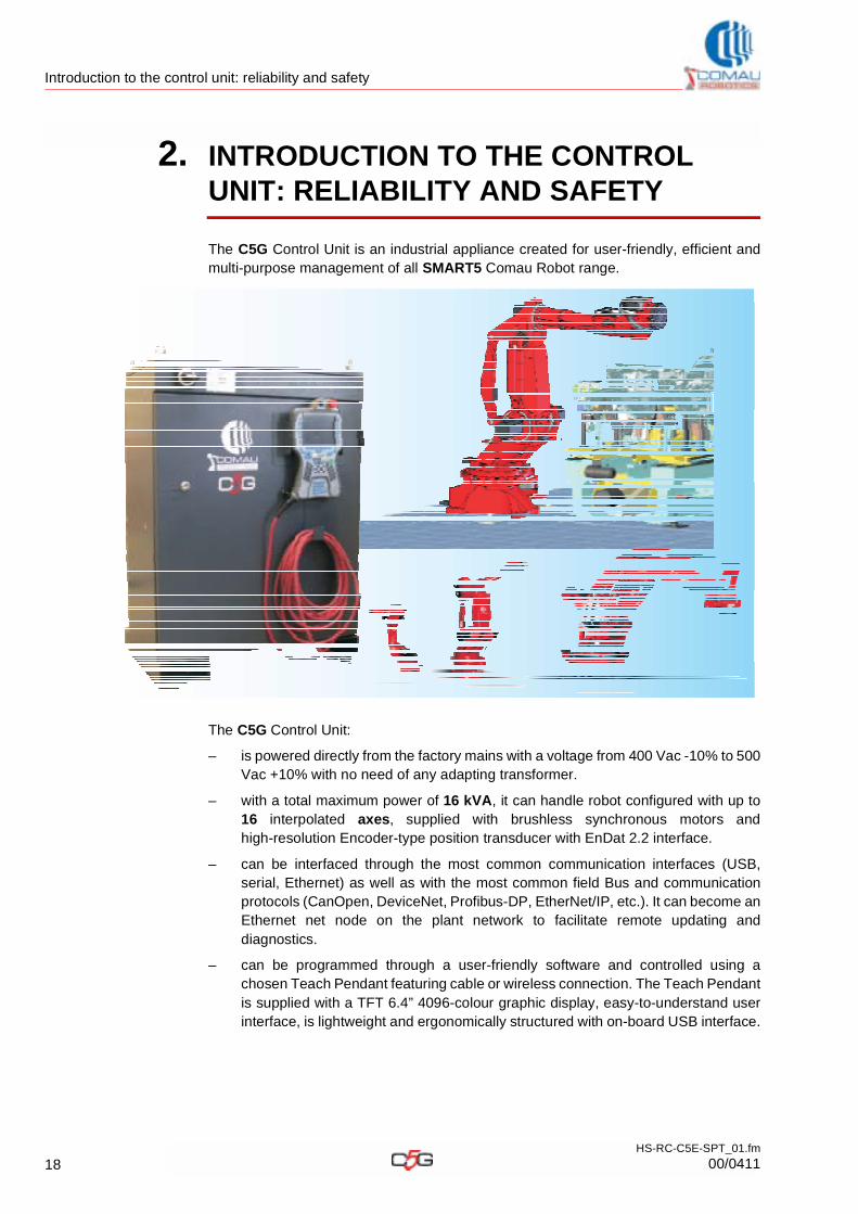
2. INTRODUCTION TO THE CONTROL UNIT: RELIABILITY AND SAFETY
The C5G Control Unit is an industrial appliance created for user-friendly, efficient and multi-purpose management of all SMART5 Comau Robot range.
The C5G Control Unit:
– is powered directly from the factory mains with a voltage from 400 Vac -10% to 500 Vac +10% with no need of any adapting transformer.
– with a total maximum power of 16 kVA, it can handle robot configured with up to 16 interpolated axes, supplied with brushless synchronous motors and high-resolution Encoder-type position transducer with EnDat 2.2 interface.
– can be interfaced through the most common communication interfaces (USB, serial, Ethernet) as well as with the most common field Bus and communication protocols (CanOpen, DeviceNet, Profibus-DP, EtherNet/IP, etc.). It can become an Ethernet net node on the plant network to facilitate remote updating and diagnostics.
– can be programmed through a user-friendly software and controlled using a chosen Teach Pendant featuring cable or wireless connection. The Teach Pendant is supplied with a TFT 6.4” 4096-colour graphic display, easy-to-understand user interface, is lightweight and ergonomically structured with on-board USB interface.
18HS-RC-C5E-SPT_01.fm
00/0411
Introduction to the control unit: reliability and safety
– It is easily expandable through optional modules, to better adapt to the user’s applications and make them easier.
The C5G Control Unit has been conceived to guarantee:
– Reliability and serviceability
– Calculation power
– Expandability
– Programming
– Safety
– Control modes.
The results obtained has enabled us to develop a Control Unit suitable to fulfil the requirements of multiple applications featuring high-level sophisticated performances.
2.1 Reliability and serviceabilityThe C5G Control Unit has been conceived and developed applying care and precision principles and using high-quality components, according to the following concepts:
– minimum functional divisions, with specific high-potential modules
– limited interconnections among modules, accomplished mainly through communication networks
– high MTBF: the system main items have been developed to guarantee a high MTBF. The control unit internal wiring and interconnections have been carried out such as not to impact on the main item MTBF.
– reduced MTTR: the Control Unit main items assembly is such as to guarantee a quick replacement of all control unit internal items.
– sophisticated diagnostics in order to facilitate maintenance, with the possibility of remote diagnostics as well as SMS and e-mail sending.
This Control Unit shall be matched to a SMART5 series Comau robot only.
19HS-RC-C5E-SPT_01.fm
00/0411
Introduction to the control unit: reliability and safety
2.2 Calculation powerThe C5G Control Unit features state-of-the-art processors to control the trajectory and the periphery, the application software and the user’s interface, in order to ensure the highest level of performance of both areas. The processors work through a real time VxWorks operating system.
The processor controlling the movements carries out the following functions reliably and accurately:
– Servo-adaptive algorithms, with dynamic pattern calculated in real time based on the load, position speed (Smart Move) and inertia conditions. The dynamic model is applied to all 6 axes.
– Acceleration/deceleration modulation for joint-like movements, to optimize the robot motor performances in terms of speed.
– Linear interpolation featuring fly-path total programmability and constant speed.
– Circular interpolation featuring different orientation evolution possibilities (even 2 angles in relation to the trajectory).
– Possibility to control up to 16 axes:• Synchronized movements - Sync Move (function provided for)• Integrated Arms the control arm chains (1 arm carries a second one that
performs the process) (function provided for)• is open to Cooperative Motion, to control two cooperating arms (1 arm
position the item, 1 arm carries out the process).
– Conveyor tracking, to carry out the process of items moving on conveyor lines or rotating plates that are not controlled by the robot.
– Weaving, for more sophisticated arc welding processes (Cartesian weaving and high frequency joints).
– Sensor Tracking, guaranteeing the highest tracking precision and the possibility to interfacing with different sensor typologies: 3D laser telecameras, arc parameter sensors, power sensors, others (function provided for).
– Reference systems: base, tool, users, to reuse programmes on different cells.
– Collision detection: it allows to detect collision situation between the robot and the surrounding environment.
– Load self-determination: a software tool is available that allows to correctly define the load parameters that will influence the robot movements, to optimize the performances and protect the components.
20HS-RC-C5E-SPT_01.fm
00/0411
Introduction to the control unit: reliability and safety
2.3 ExpandabilityThe expandability is based on the usage of standard protocols and connections, usually available in industrial environments.
The C5G Control Unit is supplied with 6 base axes that can be expanded up to 11 inside the same cabinet.
Modules are available on the Ethernet POWERLINK network for the interfacing with field and application control Bus and parallel I/O signals.
The safety circuit basic prearrangement, that can be easily integrated on the line, can be expanded using modules for the safe control on Safety Bus and axes safe shutting.
Moreover, several options allow to adapt and customize the C5G Control Unit such as to fulfil the different installation requirements.
2.4 ProgrammingThe programming features:
– on-line and off-line programming facilities through a graphic Teach Pendant, Personal computer and dedicated CAD (e.g. RobCad)
– PDL2 easy language combined with the potential to guarantee the robot integration in the most demanding applications
– possibility to run simultaneously more PDL2 programmes
– possibility to customize application programmes through Java graphics and language.
21HS-RC-C5E-SPT_01.fm
00/0411
Introduction to the control unit: reliability and safety
2.5 Safety– Compliance with the norms in force
– Directives and norms
– Statement of incorporation of partly completed machinery
– Manufacturer’s details
– Safety devices control procedures
– Safety solutions installed.
2.5.1 Compliance with the norms in force
The C5G Control Unit consists of a functional area specifically designed to fulfil the safety requirements provided for by the norms in force:
– Compliance with norm EN ISO 10218-1: the Robot Control Unit to be used with the Comau robots has been developed to fulfil the norm requirements and facilitate the controller integration
– Safe stopping circuits: the emergency stop control, that is available also as connection outside the Control Unit, ensures a safe stop of the corresponding Comau robot, also under the most demanding conditions that are to be expected (full load at high speed)
– Safe movement control circuits: the motion is triggered and controlled by the Control Unit, which ensures the correct motion accomplishing. All trajectories are constantly checked and monitored and any possible deviation due to external causes is immediately detected and corrected. If the trajectory is compromised, the immediate stop will be triggered in good time.
– Safety circuit category: all safety circuits inside on Robot Control Unit standard models are in compliance with category 3 according to standard EN ISO 13849-1 (PL = d, DCawg = 95%, MTTFd > 100, CCF = 75). Also all internal circuits, external interconnection circuits and expansion modules, which allow to increase the number of contacts for the application interfacing, comply with the same category.
– Compliance with the European Directives: Machine Directive, Electromagnetic Compatibility Directive (EMC), Low Voltage Directive and Directives pertaning the environmental protection. The Control Unit matched to a Comau robot is an “partly completed machinery” (according to the definition in the Machinery Directive 2006/42/CE, item 2 paragraph g). The terms of compliance with the directives are described in details in par. 2.5.3 Statement of incorporation of partly completed machinery on page 24.
22HS-RC-C5E-SPT_01.fm
00/0411
Introduction to the control unit: reliability and safety
2.5.2 Directives and norms
The C5G Control Unit has been designed and manufactured in compliance with the directives and norms listed in Tab. 2.1.
Tab. 2.1 - Applicable Directives and norms
Directive / Norm Description and applicability
2006/42/CE DIRECTIVE 2006/42/EC OF THE EUROPEAN PARLIAMENT AND OF THE COUNCIL of 17 May 2006 on machinery, and amending Directive 95/16/EC (recast) (for the sake of brevity referred to as Machine directive)
2006/95/CE DIRECTIVE 2006/95/EC OF THE EUROPEAN PARLIAMENT AND OF THE COUNCIL of 12 December 2006 on the harmonisation of the laws of Member States relating to electrical equipment designed for use within certain voltage limits (for the sake of brevity referred to as Low voltage directive)
2004/108/CE DIRECTIVE 2004/108/EC OF THE EUROPEAN PARLIAMENT AND OF THE COUNCIL of 15 December 2004 on the approximation of the laws of the Member States relating to electromagnetic compatibility and repealing Directive 89/336/EEC (for the sake of brevity referred to as EMC Directive)
2002/95/CE DIRECTIVE 2002/95/EC OF THE EUROPEAN PARLIAMENT AND OF THE COUNCIL of 27 January 2003 on the restriction of the use of certain hazardous substances in electrical and electronic equipment (for the sake of brevity referred to as RoHS Directive) and later amendments (2008/385/EC)
EN ISO 13850 Safety of machinery - Emergency stop - Principles for design
EN ISO 13732-1 Ergonomics of the thermal environment - Methods for the assessment of human responses to contact with surfaces - Part 1: Hot surfaces
EN ISO 10218-1 Robots for industrial environments - Safety requirements - Part 1: Robot
EN ISO 13849-1 Safety of machinery - Safety related parts of control systems - General principles for design
EN 60068-2-6 Basic environmental testing procedures - part 2: Vibration (sinusoidal)
EN 60068-2-31 Basic environmental testing procedures - part 2: Drop and topple, primarily for equipment type specimens
EN 60068-2-64 Environmental testing - Test methods - Test FH: vibration, broad band random (Digital Control) and guidance
EN 60204-1 Safety of Machinery - Electrical equipment of machines - Part 1: General requirements
EN 60529 Degrees of protection provided by enclosures (IP code)
EN 61000-6-2 Electromagnetic Compatibility - Generic immunity standard - Part 6-2: Industrial environment
EN 61000-6-4 Electromagnetic Compatibility - Generic emission standard - Part 6-4: Industrial environment
23HS-RC-C5E-SPT_01.fm
00/0411
Introduction to the control unit: reliability and safety
2.5.3 Statement of incorporation of partly completed machinery
The group consisting of the C5G Control Unit and the SMART5 series robot is supplied with statement of incorporation of partly completed machinery, as provided for in the Annex II b. of directive 2006/42/EC.
The Statement of incorporation of partly completed machinery is supplied in original together with the group consisting of the C5G Control Unit and SMART5 serie Robot.
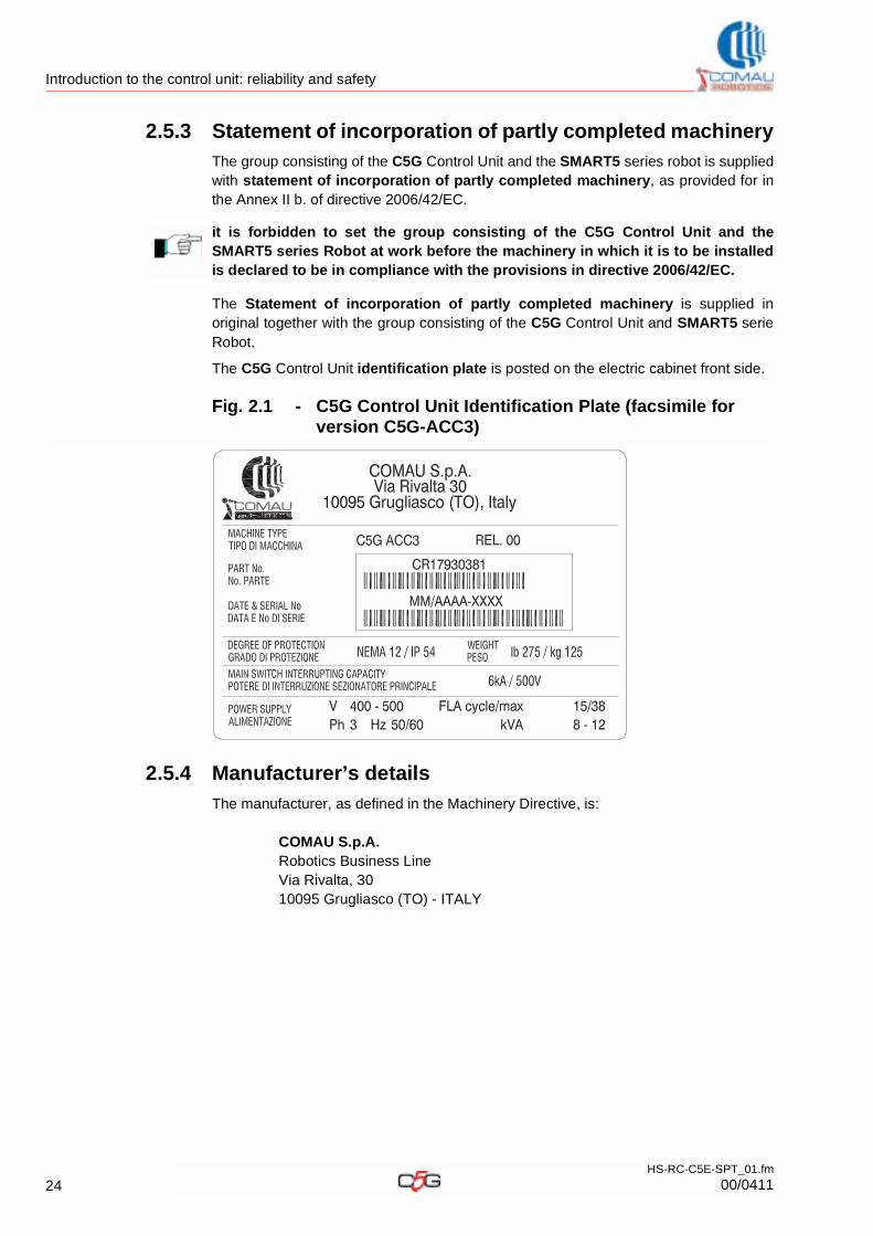
The C5G Control Unit identification plate is posted on the electric cabinet front side.
Fig. 2.1 - C5G Control Unit Identification Plate (facsimile for version C5G-ACC3)
2.5.4 Manufacturer’s details
The manufacturer, as defined in the Machinery Directive, is:
COMAU S.p.A. Robotics Business LineVia Rivalta, 3010095 Grugliasco (TO) - ITALY
it is forbidden to set the group consisting of the C5G Control Unit and the SMART5 series Robot at work before the machinery in which it is to be installed is declared to be in compliance with the provisions in directive 2006/42/EC.
24HS-RC-C5E-SPT_01.fm
00/0411
Introduction to the control unit: reliability and safety
2.5.5 Safety devices control procedures
To facilitate the safety devices control procedures, the controlling circuits and basic interlocks, that are necessary to control a cell, have been integrated inside the C5GRobot Control Unit.This solution represents a noticeable advantage for the installation, as it will no longer be necessary to provide for the outside interlocks controlling the safety gates or other operator protecting devices and it will simply be sufficient to connect to the dedicated connector located by the cabinet base to make use of all available safety functions.This flexibility do not damage the reverse situation, i.e. the safety signals controlling by the external circuits. In that case all C5G Robot Control Unit safety and status signals are available on the same dedicated connector.If the number of contacts related to the safety and status signals available in the Control Unit are not sufficient to control one or more applications, it is possible to use the available expansion cards to increase the contact number without altering the safety circuit category.
(In compliance with norm EN 60204-1) the stopping procedure is accomplished according to category 0 (zero) in Programming (T1) mode and to category 1 in Local automatic (AUTO) and Remote automatic (REMOTE) mode
2.5.6 Safety solutions installed
The safety circuit and the connections for the external devices allow the compliance in according to norm EN ISO 13849-1.
Find below the solutions installed to guarantee the operators’ safety:
– Emergency stop push button The red mushroom-shaped push button triggering the emergency stop is installed on the Teach Pendant.The potential-free push button contacts are available on the interface connector and are not connected to the internal emergency stop circuit.
– Emergency stop control The cell emergency contacts (mushroom-shaped push buttons) can be connected to the internal safety circuit to trigger the robot stopping. In automatic mode, the robot stopping is accomplished through controlled decelation ramp, in compliance with category 1, according to norm EN 60204-1.
– Enabling Device pushbuttonThe Teach Pendant hosts the three-position Enabling Device with hardware control. By pressing the enabling device power is delivered to the actuating devices and the robot movements are enabled in programming operating mode. The enabling device is active in programming mode only and disabled in the other machine modes.
– Cell access gates controlThe contacts of the limit switches installed on the cell access gates can be connected to the safety circuit to control the robot stopping in automatic mode. In programming mode, those contacts are cut off to allow the robot motion with open gates.
– Safe power cut-off The 24V I/O power supply to the dedicated interface connectors depends on the following items:• emergency stop• safety gate opening in automatic mode• enabling device releasing in programming mode
25HS-RC-C5E-SPT_01.fm
00/0411
Introduction to the control unit: reliability and safety
• motor-off command (Drive Off).
2.6 Control modesThe group consisting of the C5G Control Unit and SMART5 series Robot features 3 control modes. The control modes can be selected using the key selector switch located on the Teach Pendant.
– Programming (T1) Used for low speed motion, to programme the robot operating trajectory.The operator may remain inside the cell. The robot movements are accomplished at reduced speed, reaching maximum 250 mm/s by the flange centre. The robot is directly controlled by the operator. Movements and program running at reduced speed are allowed.
– Local automatic (AUTO) Used to run working programmes, in automatic mode with gates closed and at set speed, that are triggered from the Teach Pendant.This mode may be unavailable for some Teach Pendant versions.
– Remote automatic (REMOTE) Used to run programmes, in automatic mode with gates closed and at set speed, that are triggered from external devices (PLC, others).
26HS-RC-C5E-SPT_01.fm
00/0411
Versions and Technical features
3. VERSIONS AND TECHNICAL FEATURES
This chapter deals with the following topics:
– Selecting the Control Unit version:
– C5G Control Unit
– Teach Pendant
– Connection cables between C5G and Robot
3.1 Selecting the Control Unit versionTo choose the most suitable C5G Control Unit version it is necessary to take into account first of all the Robot family and the related required electric power. This manual does not deal with the selection of the Robot version, please refer to the Robot specific “Technical Specifications” manuals.
The C5G Control Unit configuration has to be chosen accomplishing the following steps:
– C5G Control Unit, depending on the Robot family it will be matched to
– Teach Pendant, depending on the type of connection required between Control Unit and Teach Pendant
– Connection cables between C5G and Robot, depending on the Robot family and the installation distance.
– Customizing adding optional functions (refer to Chap.5. - Options on page 61).
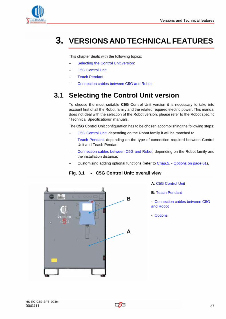
Fig. 3.1 - C5G Control Unit: overall view
A: C5G Control Unit
B: Teach Pendant
-: Connection cables between C5G and Robot
-: Options
B
A
27HS-RC-C5E-SPT_02.fm
00/0411
Versions and Technical features
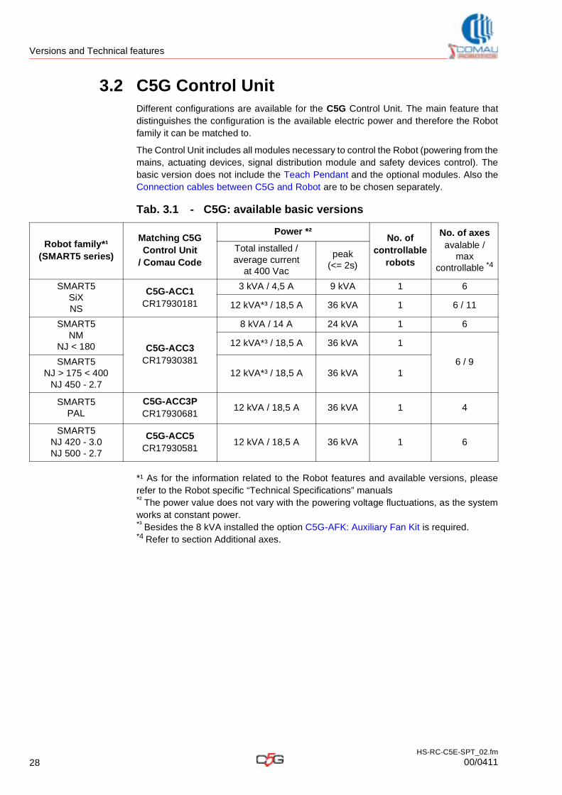
3.2 C5G Control UnitDifferent configurations are available for the C5G Control Unit. The main feature that distinguishes the configuration is the available electric power and therefore the Robot family it can be matched to.
The Control Unit includes all modules necessary to control the Robot (powering from the mains, actuating devices, signal distribution module and safety devices control). The basic version does not include the Teach Pendant and the optional modules. Also the Connection cables between C5G and Robot are to be chosen separately.
*¹ As for the information related to the Robot features and available versions, please refer to the Robot specific “Technical Specifications” manuals*² The power value does not vary with the powering voltage fluctuations, as the system works at constant power.*³ Besides the 8 kVA installed the option C5G-AFK: Auxiliary Fan Kit is required.*4 Refer to section Additional axes.
Tab. 3.1 - C5G: available basic versions
Robot family*¹(SMART5 series)
Matching C5GControl Unit
/ Comau Code
Power *²No. of
controllable robots
No. of axesavalable /
max controllable *4
Total installed / average current
at 400 Vac
peak(<= 2s)
SMART5SiXNS
C5G-ACC1CR17930181
3 kVA / 4,5 A 9 kVA 1 6
12 kVA*³ / 18,5 A 36 kVA 1 6 / 11
SMART5NM
NJ < 180 C5G-ACC3CR17930381
8 kVA / 14 A 24 kVA 1 6
12 kVA*³ / 18,5 A 36 kVA 1
6 / 9SMART5NJ > 175 < 400
NJ 450 - 2.712 kVA*³ / 18,5 A 36 kVA 1
SMART5PAL
C5G-ACC3PCR17930681
12 kVA / 18,5 A 36 kVA 1 4
SMART5 NJ 420 - 3.0NJ 500 - 2.7
C5G-ACC5CR17930581
12 kVA / 18,5 A 36 kVA 1 6
28HS-RC-C5E-SPT_02.fm
00/0411
Versions and Technical features
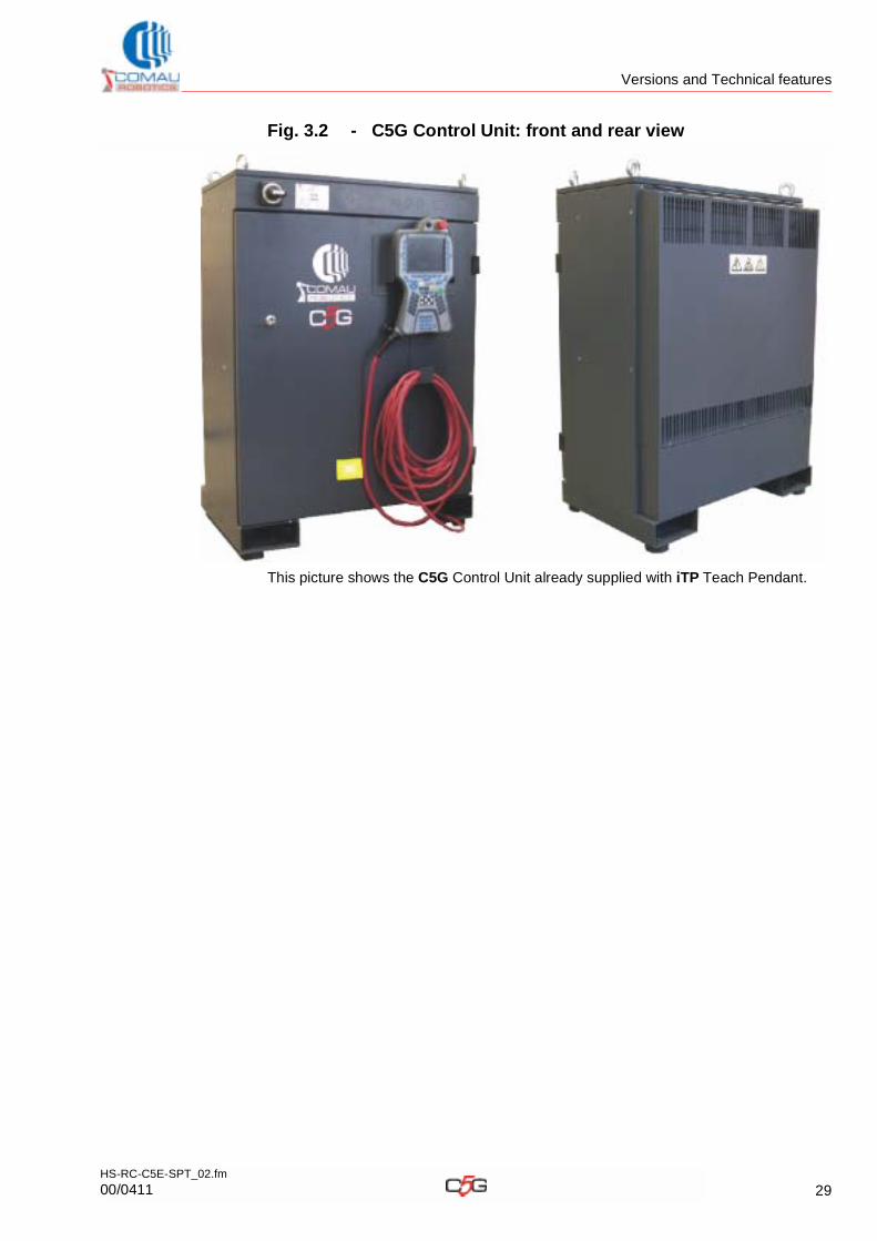
Fig. 3.2 - C5G Control Unit: front and rear view
This picture shows the C5G Control Unit already supplied with iTP Teach Pendant.
29HS-RC-C5E-SPT_02.fm
00/0411
Versions and Technical features
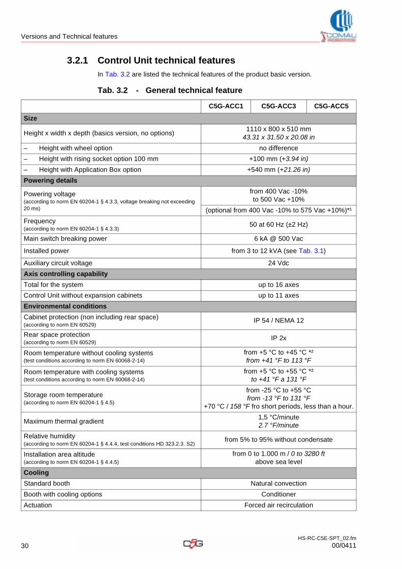
3.2.1 Control Unit technical features
In Tab. 3.2 are listed the technical features of the product basic version.
Tab. 3.2 - General technical feature
C5G-ACC1 C5G-ACC3 C5G-ACC5
Size
Height x width x depth (basics version, no options) 1110 x 800 x 510 mm
43.31 x 31.50 x 20.08 in
– Height with wheel option no difference
– Height with rising socket option 100 mm +100 mm (+3.94 in)
– Height with Application Box option +540 mm (+21.26 in)
Powering details
Powering voltage(according to norm EN 60204-1 § 4.3.3, voltage breaking not exceeding 20 ms)
from 400 Vac -10% to 500 Vac +10%
(optional from 400 Vac -10% to 575 Vac +10%)*¹
Frequency(according to norm EN 60204-1 § 4.3.3)
50 at 60 Hz (±2 Hz)
Main switch breaking power 6 kA @ 500 Vac
Installed power from 3 to 12 kVA (see Tab. 3.1)
Auxiliary circuit voltage 24 Vdc
Axis controlling capability
Total for the system up to 16 axes
Control Unit without expansion cabinets up to 11 axes
Environmental conditions
Cabinet protection (non including rear space)(according to norm EN 60529)
IP 54 / NEMA 12
Rear space protection (according to norm EN 60529)
IP 2x
Room temperature without cooling systems(test conditions according to norm EN 60068-2-14)
from +5 °C to +45 °C *²from +41 °F to 113 °F
Room temperature with cooling systems(test conditions according to norm EN 60068-2-14)
from +5 °C to +55 °C *²to +41 °F a 131 °F
Storage room temperature(according to norm EN 60204-1 § 4.5)
from -25 °C to +55 °Cfrom -13 °F to 131 °F
+70 °C / 158 °F fro short periods, less than a hour.
Maximum thermal gradient1,5 °C/minute2.7 °F/minute
Relative humidity(according to norm EN 60204-1 § 4.4.4, test conditions HD 323.2.3. S2)
from 5% to 95% without condensate
Installation area altitude(according to norm EN 60204-1 § 4.4.5)
from 0 to 1.000 m / 0 to 3280 ftabove sea level
Cooling
Standard booth Natural convection
Booth with cooling options Conditioner
Actuation Forced air recirculation
30HS-RC-C5E-SPT_02.fm
00/0411
Versions and Technical features
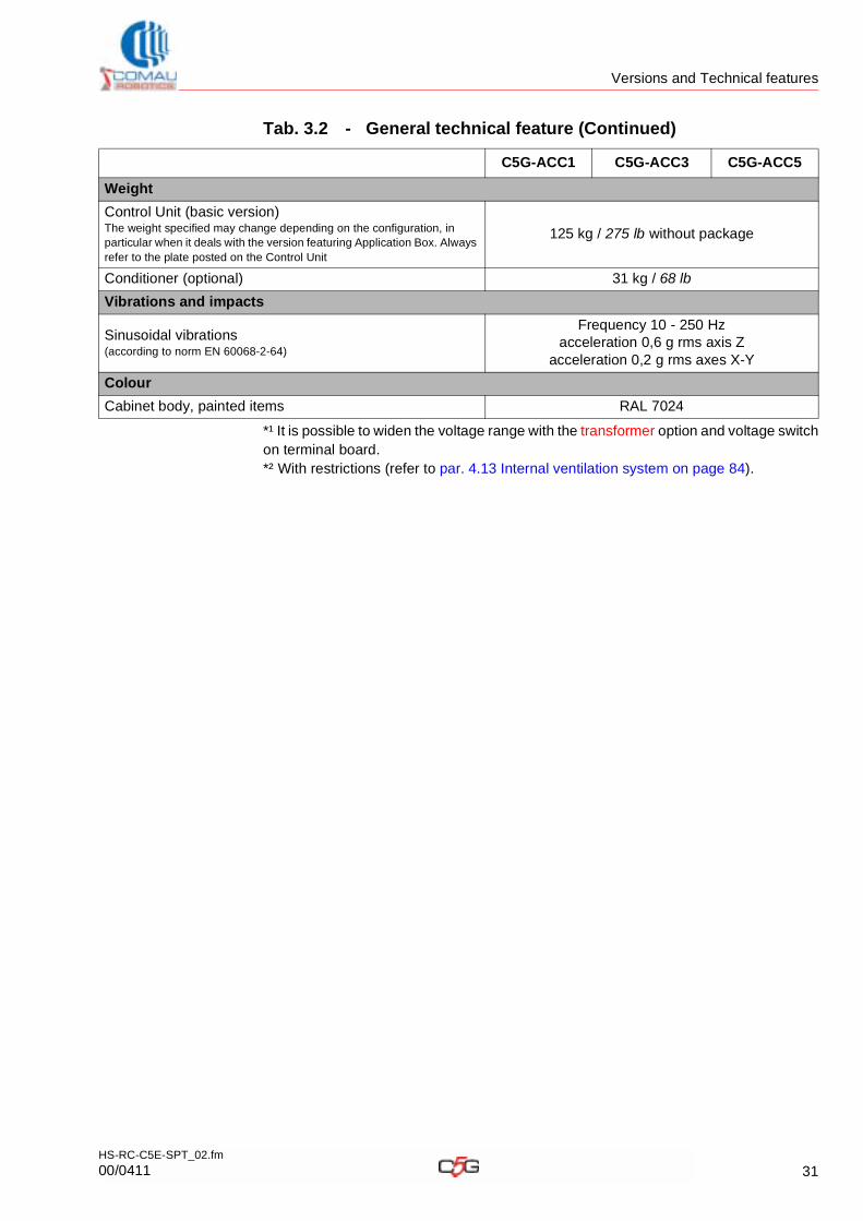
*¹ It is possible to widen the voltage range with the transformer option and voltage switch on terminal board.*² With restrictions (refer to par. 4.13 Internal ventilation system on page 84).
Weight
Control Unit (basic version) The weight specified may change depending on the configuration, in particular when it deals with the version featuring Application Box. Always refer to the plate posted on the Control Unit
125 kg / 275 lb without package
Conditioner (optional) 31 kg / 68 lb
Vibrations and impacts
Sinusoidal vibrations(according to norm EN 60068-2-64)
Frequency 10 - 250 Hzacceleration 0,6 g rms axis Z
acceleration 0,2 g rms axes X-Y
Colour
Cabinet body, painted items RAL 7024
Tab. 3.2 - General technical feature (Continued)
C5G-ACC1 C5G-ACC3 C5G-ACC5
31HS-RC-C5E-SPT_02.fm
00/0411
Versions and Technical features
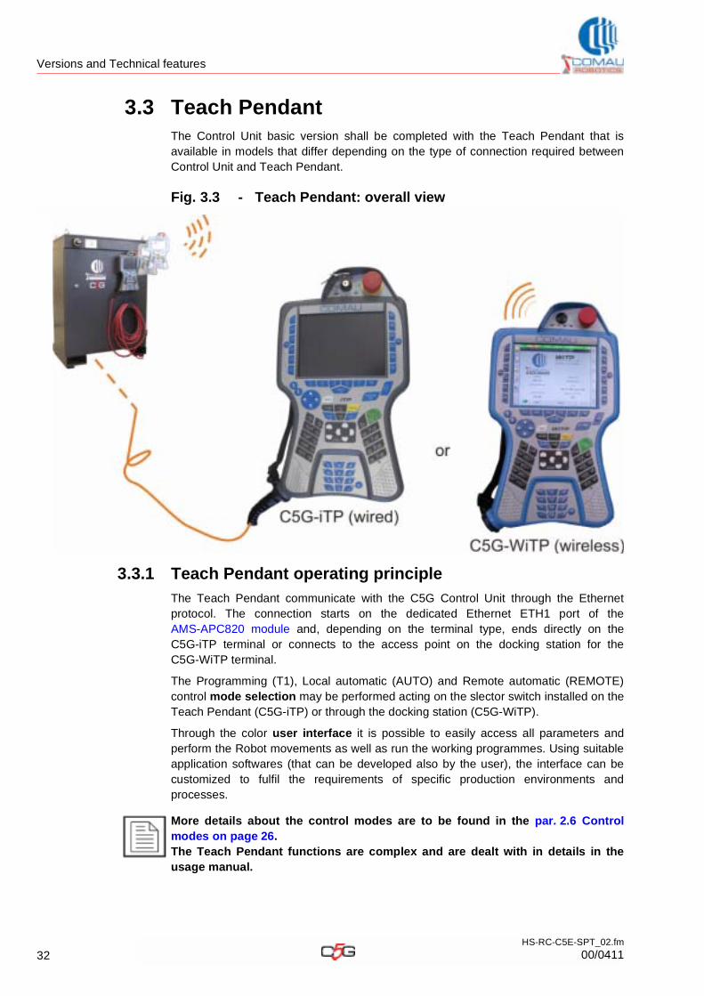
3.3 Teach PendantThe Control Unit basic version shall be completed with the Teach Pendant that is available in models that differ depending on the type of connection required between Control Unit and Teach Pendant.
Fig. 3.3 - Teach Pendant: overall view
3.3.1 Teach Pendant operating principle
The Teach Pendant communicate with the C5G Control Unit through the Ethernet protocol. The connection starts on the dedicated Ethernet ETH1 port of the AMS-APC820 module and, depending on the terminal type, ends directly on the C5G-iTP terminal or connects to the access point on the docking station for the C5G-WiTP terminal.
The Programming (T1), Local automatic (AUTO) and Remote automatic (REMOTE) control mode selection may be performed acting on the slector switch installed on the Teach Pendant (C5G-iTP) or through the docking station (C5G-WiTP).
Through the color user interface it is possible to easily access all parameters and perform the Robot movements as well as run the working programmes. Using suitable application softwares (that can be developed also by the user), the interface can be customized to fulfil the requirements of specific production environments and processes.
More details about the control modes are to be found in the par. 2.6 Control modes on page 26.The Teach Pendant functions are complex and are dealt with in details in the usage manual.
32HS-RC-C5E-SPT_02.fm
00/0411
Versions and Technical features
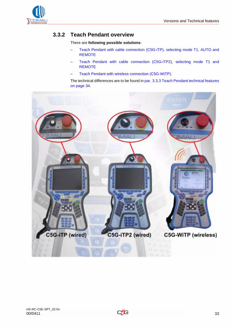
3.3.2 Teach Pendant overview
There are following possible solutions:
– Teach Pendant with cable connection (C5G-iTP), selecting mode T1, AUTO and REMOTE
– Teach Pendant with cable connection (C5G-iTP2), selecting mode T1 and REMOTE
– Teach Pendant with wireless connection (C5G-WiTP).
The technical differences are to be found in par. 3.3.3 Teach Pendant technical featureson page 34.
33HS-RC-C5E-SPT_02.fm
00/0411
Versions and Technical features
3.3.3 Teach Pendant technical features
*¹ Modality unavailable for model C5G-iTP2*² Each independent communication channel can be used to send and receive data from different Wi-Fi sources at the same time.*³ Implementing the Pairing / Un-Pairing procedure (Comau Patented) it is possible to use an only one terminal for 2 or more Control UnitsNA: Not Applicable
Tab. 3.3 - Teach Pendant: versions available
FeatureC5G-iTP / C5G-iTP2
TerminalC5G-WiTP Terminal
Modal selector switch (Mode T1, AUTO *¹, REMOTE)
Installed on terminalInstalled on the docking
station
Display lit-up LCD
4096-colour TFT 6.4” resolution 640 x 480
Sizes 360 x 210 x 80 mm
Weight 1090 g 1470 g
Port USB 1.1 available on terminal 1
Connection typology Cable Wireless
Reachable distance between Control Unit and Teach Pendant
up to 60 m guaranteed up to 40 m
Need to combine the terminal with one only Control Unit
Yes No*²
Colour Grey Blue
Processor Intel® PXA 270 Intel® PXA 270
Operating system Microsoft® Windows® CE Microsoft® Windows® CE
Internal memory 128 Mbyte 128 Mbyte
Communication protocol / method TCP-IP
through cableTCP-IP
IEEE802.11a
Independent communication channels *² (as per standard 802.11 a)
NA 19 EU / 24 USA
Connection safety wiredPairing / Un-Pairing *³ -
Comau Patented
Safety according to standar EN ISO 13849-1 PL = dPL = d, DCawg = 95%,
MTTFd > 100, CCF = 75
Usage endurance illimited 5 hours (typical)
Battery charging time NA 2 hours (typical)
34HS-RC-C5E-SPT_02.fm
00/0411
Versions and Technical features
3.3.4 Teach Pendant with cable connection (C5G-iTP), selecting mode T1, AUTO and REMOTE
At the time of purchase it is necessary to choose a Station, including Teach Pendant and medium.
The medium can be installed on the door or be delivered separately to allow the customized installation by the line/cell control station (installation to be carried out by the user). At the time of purchase the user shall specify if it shall be pre assembled on the Unit Control door.
The Programming (T1), Local automatic (AUTO) and Remote automatic (REMOTE) control mode selection may beperformed acting on the key selector switch available on the terminal.
When only the Teach Pendant with cable is needed, it is possible to choose among the versions listed below.
Moreover it is possible to install an additional extension, to be chosen among the models specified below.
Tab. 3.4 - Teach Pendant with cable, selector switch for 3 modes, supplied with medium: available station versions
Description Cable length Abbreviation Comau Code
Station C5G-iRT10 10 m (33 ft) C5G-iRT10 CR17431980
Station C5G-iRT20 20 m (66 ft) C5G-iRT20 CR17431981
Station C5G-iRT30 30 m (98 ft) C5G-iRT30 CR17431982
It includes: C5G-iTP Teach Pendant with inside-cabinet cable and connectors, C5G-iBK2 medium.
Tab. 3.5 - Teach Pendant with cable (no medium): available versions
Description Cable length Abbreviation Comau Code
C5G-iTP Teach Pendant with cable
10 m (33 ft) C5G-iTP10 CR17910381
20 m (66 ft) C5G-iTP20 CR17910382
30 m (98 ft) C5G-iTP30 CR17910383
It includes: C5G-iTP Teach Pendant with cable.
Tab. 3.6 - Extension cable for Teach Pendant with cable: available models
Description Cable length Abbreviation Comau Code
C5G-iTP cable extension iTP 10 m 10 m (33 ft) -- CR17241260
C5G-iTP cable extension iTP 20 m 20 m (66 ft) -- CR17241261
C5G-iTP cable extension iTP 30 m 30 m (98 ft) -- CR17241262
It includes: Cable extension with end male and female connectors
35HS-RC-C5E-SPT_02.fm
00/0411
Versions and Technical features
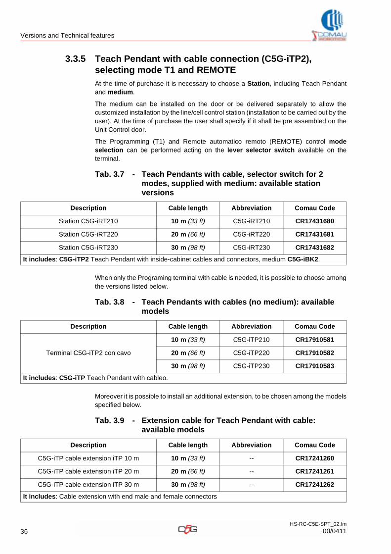
3.3.5 Teach Pendant with cable connection (C5G-iTP2), selecting mode T1 and REMOTE
At the time of purchase it is necessary to choose a Station, including Teach Pendant and medium.
The medium can be installed on the door or be delivered separately to allow the customized installation by the line/cell control station (installation to be carried out by the user). At the time of purchase the user shall specify if it shall be pre assembled on the Unit Control door.
The Programming (T1) and Remote automatico remoto (REMOTE) control mode selection can be performed acting on the lever selector switch available on the terminal.
When only the Programing terminal with cable is needed, it is possible to choose among the versions listed below.
Moreover it is possible to install an additional extension, to be chosen among the models specified below.
Tab. 3.7 - Teach Pendants with cable, selector switch for 2 modes, supplied with medium: available station versions
Description Cable length Abbreviation Comau Code
Station C5G-iRT210 10 m (33 ft) C5G-iRT210 CR17431680
Station C5G-iRT220 20 m (66 ft) C5G-iRT220 CR17431681
Station C5G-iRT230 30 m (98 ft) C5G-iRT230 CR17431682
It includes: C5G-iTP2 Teach Pendant with inside-cabinet cables and connectors, medium C5G-iBK2.
Tab. 3.8 - Teach Pendants with cables (no medium): available models
Description Cable length Abbreviation Comau Code
Terminal C5G-iTP2 con cavo
10 m (33 ft) C5G-iTP210 CR17910581
20 m (66 ft) C5G-iTP220 CR17910582
30 m (98 ft) C5G-iTP230 CR17910583
It includes: C5G-iTP Teach Pendant with cableo.
Tab. 3.9 - Extension cable for Teach Pendant with cable: available models
Description Cable length Abbreviation Comau Code
C5G-iTP cable extension iTP 10 m 10 m (33 ft) -- CR17241260
C5G-iTP cable extension iTP 20 m 20 m (66 ft) -- CR17241261
C5G-iTP cable extension iTP 30 m 30 m (98 ft) -- CR17241262
It includes: Cable extension with end male and female connectors
36HS-RC-C5E-SPT_02.fm
00/0411
Versions and Technical features
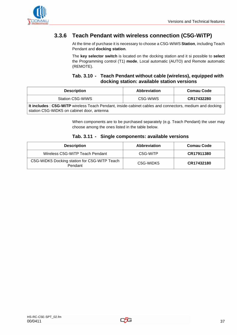
3.3.6 Teach Pendant with wireless connection (C5G-WiTP)
At the time of purchase it is necessary to choose a C5G-WiWS Station, including Teach Pendant and docking station.
The key selector switch is located on the docking station and it si possible to selectthe Programming control (T1) mode, Local automatic (AUTO) and Remote automatic (REMOTE).
When components are to be purchased separately (e.g. Teach Pendant) the user may choose among the ones listed in the table below.
Tab. 3.10 - Teach Pendant without cable (wireless), equipped with docking station: available station versions
Description Abbreviation Comau Code
Station C5G-WiWS C5G-WiWS CR17432280
It includes : C5G-WiTP wireless Teach Pendant, inside-cabinet cables and connectors, medium and docking station C5G-WiDK5 on cabinet door, antenna
Tab. 3.11 - Single components: available versions
Description Abbreviation Comau Code
Wireless C5G-WiTP Teach Pendant C5G-WiTP CR17911380
C5G-WiDK5 Docking station for C5G-WiTP Teach Pendant
C5G-WiDK5 CR17432180
37HS-RC-C5E-SPT_02.fm
00/0411
Versions and Technical features
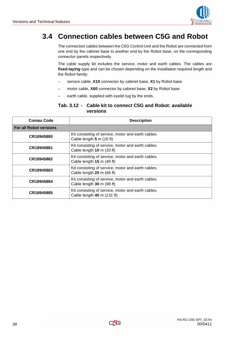
3.4 Connection cables between C5G and RobotThe connection cables between the C5G Control Unit and the Robot are connected from one end by the cabinet base to another end by the Robot base, on the corresponding connector panels respectively.
The cable supply kit includes the service, motor and earth cables. The cables are fixed-laying-type and can be chosen depending on the installation required length and the Robot family:
– service cable, X10 connector by cabinet base, X1 by Robot base
– motor cable, X60 connector by cabinet base, X2 by Robot base
– earth cable, supplied with eyelet lug by the ends.
Tab. 3.12 - Cable kit to connect C5G and Robot: available versions
Comau Code Description
For all Robot versions
CR18945880Kit consisting of service, motor and earth cables.Cable length 5 m (16 ft)
CR18945881Kit consisting of service, motor and earth cables.Cable length 10 m (33 ft)
CR18945882Kit consisting of service, motor and earth cables.Cable length 15 m (49 ft)
CR18945883Kit consisting of service, motor and earth cables.Cable length 20 m (66 ft)
CR18945884Kit consisting of service, motor and earth cables.Cable length 30 m (98 ft)
CR18945885Kit consisting of service, motor and earth cables.Cable length 40 m (131 ft)
38HS-RC-C5E-SPT_02.fm
00/0411
Overview of the connections to the C5G Control Unit
4. OVERVIEW OF THE CONNECTIONS TO THE C5G CONTROL UNIT
This chapter deals with the following topics:
– Overview of the C5G Control Unit connections
– Summary of the Robot, positioning devices and auxiliary axes connections
– Summary of the Line connections
– Summary of the Application connections
– Summary of the Programming and user’s interface on PC connections
To help the user to identify the functions of the main connectors:
– Summary of connectors and corresponding function.
39HS-RC-C5E-SPT_05.fm
00/0211
Overview of the connections to the C5G Control Unit
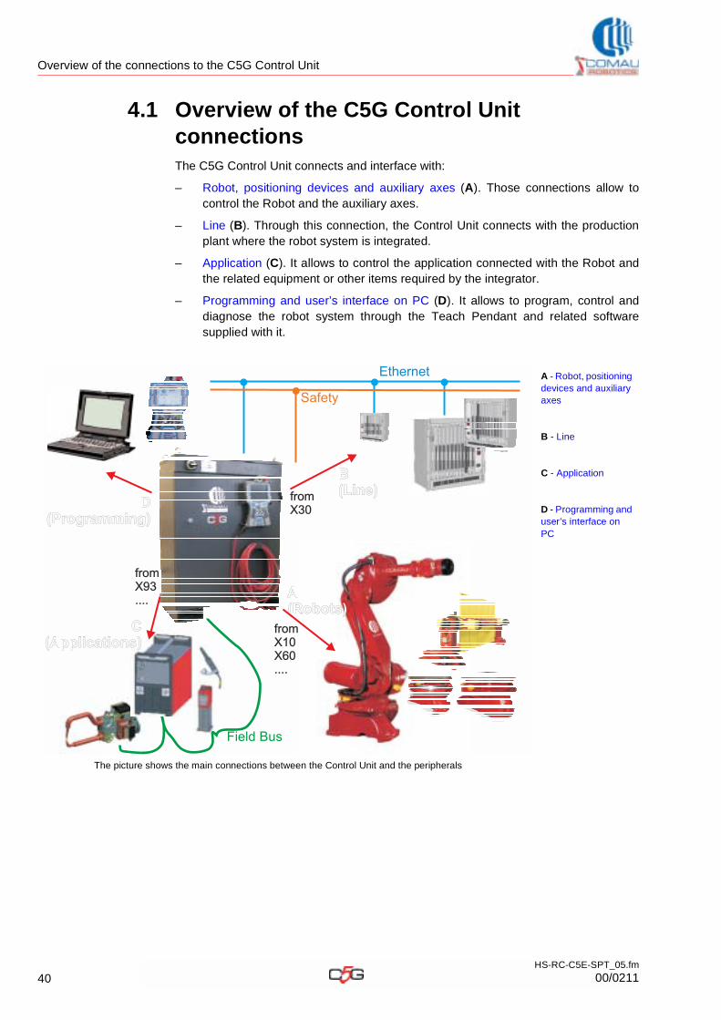
4.1 Overview of the C5G Control Unit connectionsThe C5G Control Unit connects and interface with:
– Robot, positioning devices and auxiliary axes (A). Those connections allow to control the Robot and the auxiliary axes.
– Line (B). Through this connection, the Control Unit connects with the production plant where the robot system is integrated.
– Application (C). It allows to control the application connected with the Robot and the related equipment or other items required by the integrator.
– Programming and user’s interface on PC (D). It allows to program, control and diagnose the robot system through the Teach Pendant and related software supplied with it.
A - Robot, positioning devices and auxiliary axes
B - Line
C - Application
D - Programming and user’s interface on PC
The picture shows the main connections between the Control Unit and the peripherals
A(Robots)A(Robots)
D(Programming)
D(Programming)
B(Line)B(Line)
Ethernet
Field Bus
fromX30fromX30
fromX10X60....
fromX10X60....
fromX93....
fromX93....
C(Applications)
C(Applications)
Safety
40HS-RC-C5E-SPT_05.fm
00/0211
Overview of the connections to the C5G Control Unit
4.2 Robot, positioning devices and auxiliary axesThe connection with the Robot, positioning devices and auxiliary axes is accomplished through suitable connectors installed on the Connector Interface Panel (CIP) by the C5G Control Unit base.
The typical configurations feature the following solutions:
C5G peripheralInvolved
connectorDescription
RobotX10X60
the main Robot is connected through the Connection cables between C5G and Robot with the X10 connector (Robot signals) and the X60 connector (Robot Power)
Positioning device X10-EXTX60-EXT
the positioning device (e.g. series SMART5 PTDV, PTDORB, other ones) is connected through the Connection cables between C5G and Robot (uses the same Robot cables exploiting only the necessary wires, depending on the no. of available axes) with the X10-EXT connector (Extension, Positioning device signals) and the X60-EXT connector (Extension, motors and brakes of the positioning device)
Auxiliary axes
X61X62X63X64
the single auxiliary axes (e.g. saddle on axis 7, electric gripper for spot welding on axis 8, other ones) are connected through the Connection cables between C5G and Robot, each one with only one connector that includes both the power and the control signal, with the X61..X64 connectors (Signals and power for auxiliary Axes)
The X10, X60, X10-EXT, X60-EXT, X61..X63 connector pin structure is available in the wiring diagram of the C5G Control Unit.
41HS-RC-C5E-SPT_05.fm
00/0211
Overview of the connections to the C5G Control Unit
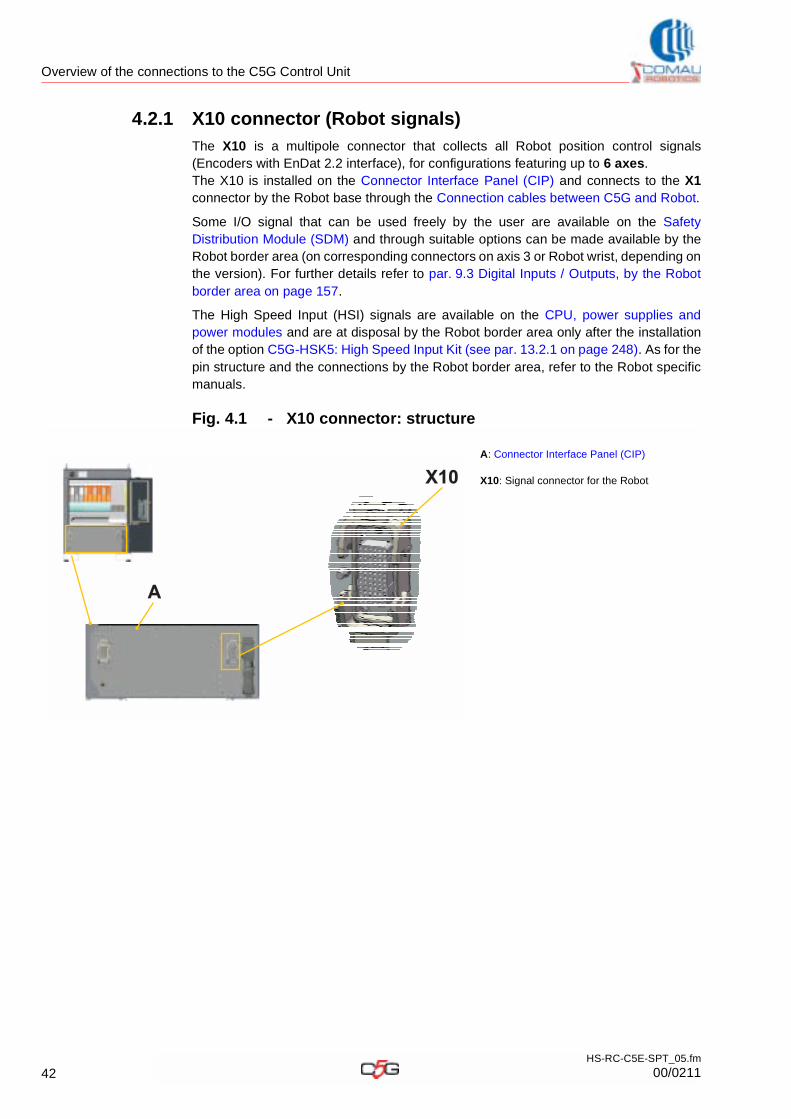
4.2.1 X10 connector (Robot signals)
The X10 is a multipole connector that collects all Robot position control signals (Encoders with EnDat 2.2 interface), for configurations featuring up to 6 axes.The X10 is installed on the Connector Interface Panel (CIP) and connects to the X1connector by the Robot base through the Connection cables between C5G and Robot.
Some I/O signal that can be used freely by the user are available on the Safety Distribution Module (SDM) and through suitable options can be made available by the Robot border area (on corresponding connectors on axis 3 or Robot wrist, depending on the version). For further details refer to par. 9.3 Digital Inputs / Outputs, by the Robot border area on page 157.
The High Speed Input (HSI) signals are available on the CPU, power supplies and power modules and are at disposal by the Robot border area only after the installation of the option C5G-HSK5: High Speed Input Kit (see par. 13.2.1 on page 248). As for the pin structure and the connections by the Robot border area, refer to the Robot specific manuals.
Fig. 4.1 - X10 connector: structure
A: Connector Interface Panel (CIP)
X10: Signal connector for the Robot
A
X10
42HS-RC-C5E-SPT_05.fm
00/0211
Overview of the connections to the C5G Control Unit
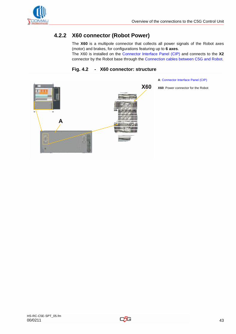
4.2.2 X60 connector (Robot Power)
The X60 is a multipole connector that collects all power signals of the Robot axes (motor) and brakes, for configurations featuring up to 6 axes. The X60 is installed on the Connector Interface Panel (CIP) and connects to the X2connector by the Robot base through the Connection cables between C5G and Robot.
Fig. 4.2 - X60 connector: structure
A: Connector Interface Panel (CIP)
X60: Power connector for the Robot
A
X60
43HS-RC-C5E-SPT_05.fm
00/0211
Overview of the connections to the C5G Control Unit
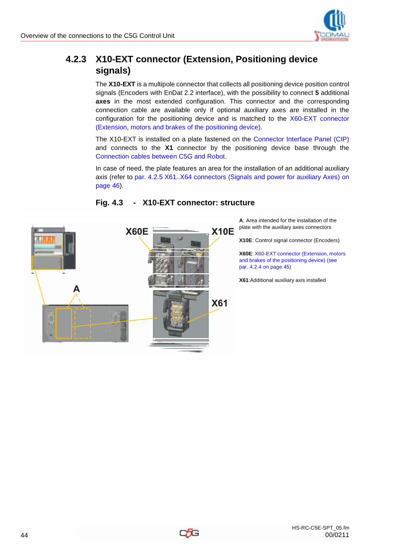
4.2.3 X10-EXT connector (Extension, Positioning device signals)
The X10-EXT is a multipole connector that collects all positioning device position control signals (Encoders with EnDat 2.2 interface), with the possibility to connect 5 additional axes in the most extended configuration. This connector and the corresponding connection cable are available only if optional auxiliary axes are installed in the configuration for the positioning device and is matched to the X60-EXT connector (Extension, motors and brakes of the positioning device).
The X10-EXT is installed on a plate fastened on the Connector Interface Panel (CIP)and connects to the X1 connector by the positioning device base through the Connection cables between C5G and Robot.
In case of need, the plate features an area for the installation of an additional auxiliary axis (refer to par. 4.2.5 X61..X64 connectors (Signals and power for auxiliary Axes) on page 46).
Fig. 4.3 - X10-EXT connector: structure
A: Area intended for the installation of the plate with the auxiliary axes connectors
X10E: Control signal connector (Encoders)
X60E: X60-EXT connector (Extension, motors and brakes of the positioning device) (see par. 4.2.4 on page 45)
X61:Additional auxiliary axis installed
A
X60E X10E
X61
44HS-RC-C5E-SPT_05.fm
00/0211
Overview of the connections to the C5G Control Unit
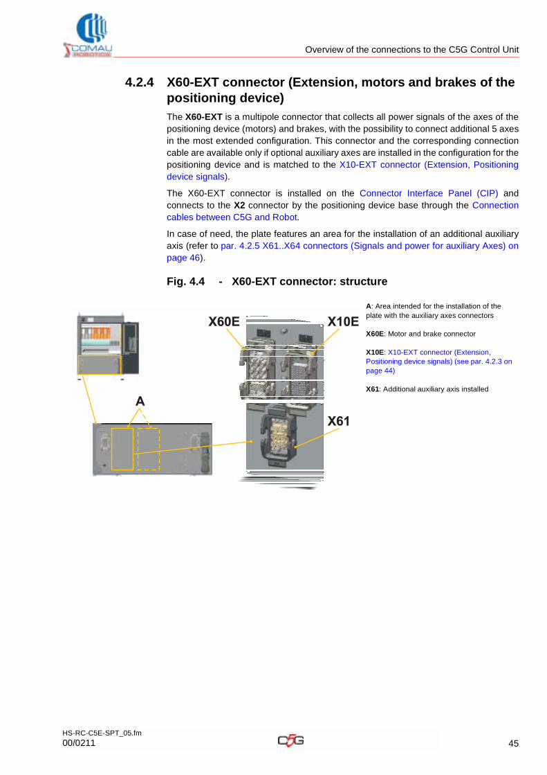
4.2.4 X60-EXT connector (Extension, motors and brakes of the positioning device)
The X60-EXT is a multipole connector that collects all power signals of the axes of the positioning device (motors) and brakes, with the possibility to connect additional 5 axes in the most extended configuration. This connector and the corresponding connection cable are available only if optional auxiliary axes are installed in the configuration for the positioning device and is matched to the X10-EXT connector (Extension, Positioning device signals).
The X60-EXT connector is installed on the Connector Interface Panel (CIP) and connects to the X2 connector by the positioning device base through the Connection cables between C5G and Robot.
In case of need, the plate features an area for the installation of an additional auxiliary axis (refer to par. 4.2.5 X61..X64 connectors (Signals and power for auxiliary Axes) on page 46).
Fig. 4.4 - X60-EXT connector: structure
A: Area intended for the installation of the plate with the auxiliary axes connectors
X60E: Motor and brake connector
X10E: X10-EXT connector (Extension, Positioning device signals) (see par. 4.2.3 on page 44)
X61: Additional auxiliary axis installed
A
X60E X10E
X61
45HS-RC-C5E-SPT_05.fm
00/0211
Overview of the connections to the C5G Control Unit
4.2.5 X61..X64 connectors (Signals and power for auxiliary Axes)
The X61, X62, X63 or X64 are multipole connectors that collect the power, brake and the position control signals (Encoders with EnDat 2.2 interface) of the auxiliary axes. Those connectors and the corresponding cable are available only if optional auxiliary axes are installed.
Each auxiliary axis is matched to a specific connector and the latter is polarized such as to prevent connection errors; the axes and matching connectors are listed in the table below:
The X61, X62, X63 or X64 connectors are installed on one or more plates fastened on the Connector Interface Panel (CIP) and connect to the connector on the motor switching case through the corresponding cables. Each plate can take up to 3 connectors.
Fin below some typical match examples:
– X61..X63 connector in a solution featuring up to 3 axes: structure
– X61 connector in a solution featuring 1 axis matched to X60-EXT and X10-EXT already available: structure
Fig. 4.5 - X61..X63 connector in a solution featuring up to 3 axes: structure
Tab. 4.1 - Axis-connector match
Auxiliary axis Matching connector
Axis 7(usually saddle)
X61
Axis 8 (usually electric gripper)
X62
Axis 9 X63
Axis 10 X64
A: Area intended for the installation of the plate hosting the auxiliary axes connectors
X61:First auxiliary axis installed
X62: Second auxiliary axis installed
X63:Third auxiliary axis installed
Note: the picture shows an example featuring 3 connectors with consecutive abbreviation.A
X61 X62
X63
46HS-RC-C5E-SPT_05.fm
00/0211
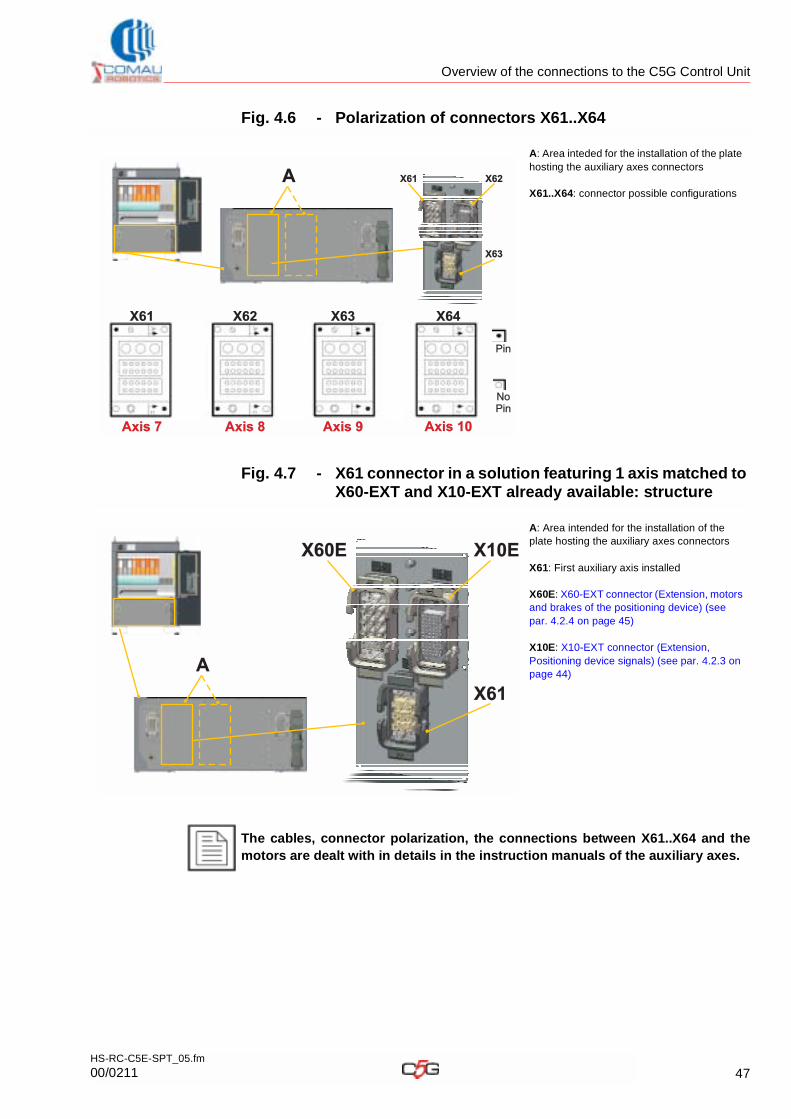
Overview of the connections to the C5G Control Unit
Fig. 4.6 - Polarization of connectors X61..X64
Fig. 4.7 - X61 connector in a solution featuring 1 axis matched to X60-EXT and X10-EXT already available: structure
A: Area inteded for the installation of the plate hosting the auxiliary axes connectors
X61..X64: connector possible configurations
A: Area intended for the installation of the plate hosting the auxiliary axes connectors
X61: First auxiliary axis installed
X60E: X60-EXT connector (Extension, motors and brakes of the positioning device) (see par. 4.2.4 on page 45)
X10E: X10-EXT connector (Extension, Positioning device signals) (see par. 4.2.3 on page 44)
The cables, connector polarization, the connections between X61..X64 and the motors are dealt with in details in the instruction manuals of the auxiliary axes.
A X61 X62
X63
X61 X62 X63 X64
Axis 7Axis 7 Axis 8Axis 8 Axis 9Axis 9 Axis 10Axis 10
Pin
NoPinNoPin
A
X60E X10E
X61
47HS-RC-C5E-SPT_05.fm
00/0211
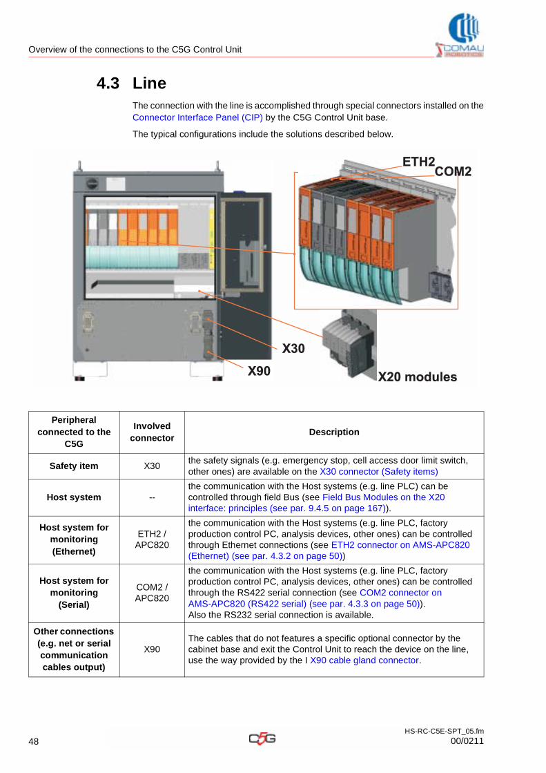
Overview of the connections to the C5G Control Unit
4.3 LineThe connection with the line is accomplished through special connectors installed on the Connector Interface Panel (CIP) by the C5G Control Unit base.
The typical configurations include the solutions described below.
Peripheral connected to the
C5G
Involved connector
Description
Safety item X30the safety signals (e.g. emergency stop, cell access door limit switch, other ones) are available on the X30 connector (Safety items)
Host system --the communication with the Host systems (e.g. line PLC) can be controlled through field Bus (see Field Bus Modules on the X20 interface: principles (see par. 9.4.5 on page 167)).
Host system for monitoring (Ethernet)
ETH2 / APC820
the communication with the Host systems (e.g. line PLC, factory production control PC, analysis devices, other ones) can be controlled through Ethernet connections (see ETH2 connector on AMS-APC820 (Ethernet) (see par. 4.3.2 on page 50))
Host system for monitoring
(Serial)
COM2 / APC820
the communication with the Host systems (e.g. line PLC, factory production control PC, analysis devices, other ones) can be controlled through the RS422 serial connection (see COM2 connector on AMS-APC820 (RS422 serial) (see par. 4.3.3 on page 50)). Also the RS232 serial connection is available.
Other connections (e.g. net or serial communication cables output)
X90The cables that do not features a specific optional connector by the cabinet base and exit the Control Unit to reach the device on the line, use the way provided by the I X90 cable gland connector.
X30
ETH2COM2
X90 X20 modulesX20 modules
48HS-RC-C5E-SPT_05.fm
00/0211
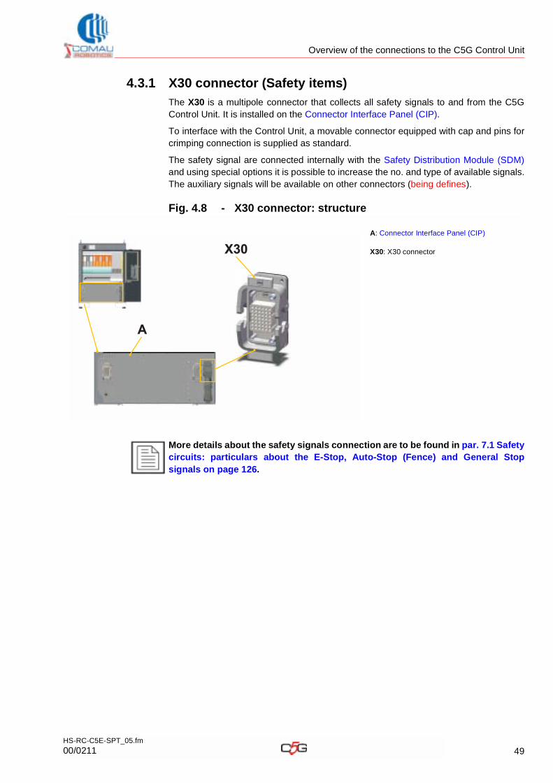
Overview of the connections to the C5G Control Unit
4.3.1 X30 connector (Safety items)
The X30 is a multipole connector that collects all safety signals to and from the C5GControl Unit. It is installed on the Connector Interface Panel (CIP).
To interface with the Control Unit, a movable connector equipped with cap and pins for crimping connection is supplied as standard.
The safety signal are connected internally with the Safety Distribution Module (SDM)and using special options it is possible to increase the no. and type of available signals. The auxiliary signals will be available on other connectors (being defines).
Fig. 4.8 - X30 connector: structure
A: Connector Interface Panel (CIP)
X30: X30 connector
More details about the safety signals connection are to be found in par. 7.1 Safety circuits: particulars about the E-Stop, Auto-Stop (Fence) and General Stop signals on page 126.
A
X30
49HS-RC-C5E-SPT_05.fm
00/0211
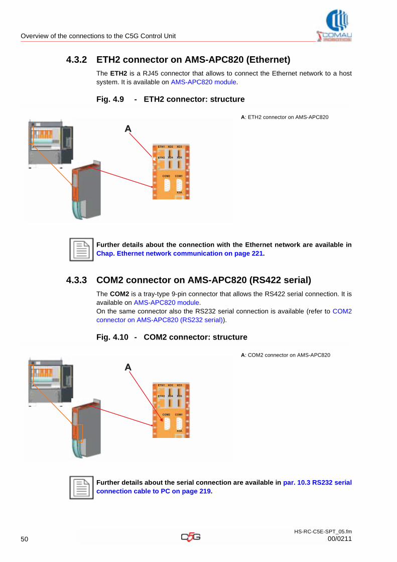
Overview of the connections to the C5G Control Unit
4.3.2 ETH2 connector on AMS-APC820 (Ethernet)
The ETH2 is a RJ45 connector that allows to connect the Ethernet network to a host system. It is available on AMS-APC820 module.
Fig. 4.9 - ETH2 connector: structure
4.3.3 COM2 connector on AMS-APC820 (RS422 serial)
The COM2 is a tray-type 9-pin connector that allows the RS422 serial connection. It is available on AMS-APC820 module. On the same connector also the RS232 serial connection is available (refer to COM2 connector on AMS-APC820 (RS232 serial)).
Fig. 4.10 - COM2 connector: structure
A: ETH2 connector on AMS-APC820
Further details about the connection with the Ethernet network are available in Chap. Ethernet network communication on page 221.
A: COM2 connector on AMS-APC820
Further details about the serial connection are available in par. 10.3 RS232 serial connection cable to PC on page 219.
XD2
COM2 COM1
XD3
XD4
X3A
ETH1
ETH2 XD5
A
XD2
COM2 COM1
XD3
XD4
X3A
ETH1
ETH2 XD5
A
50HS-RC-C5E-SPT_05.fm
00/0211
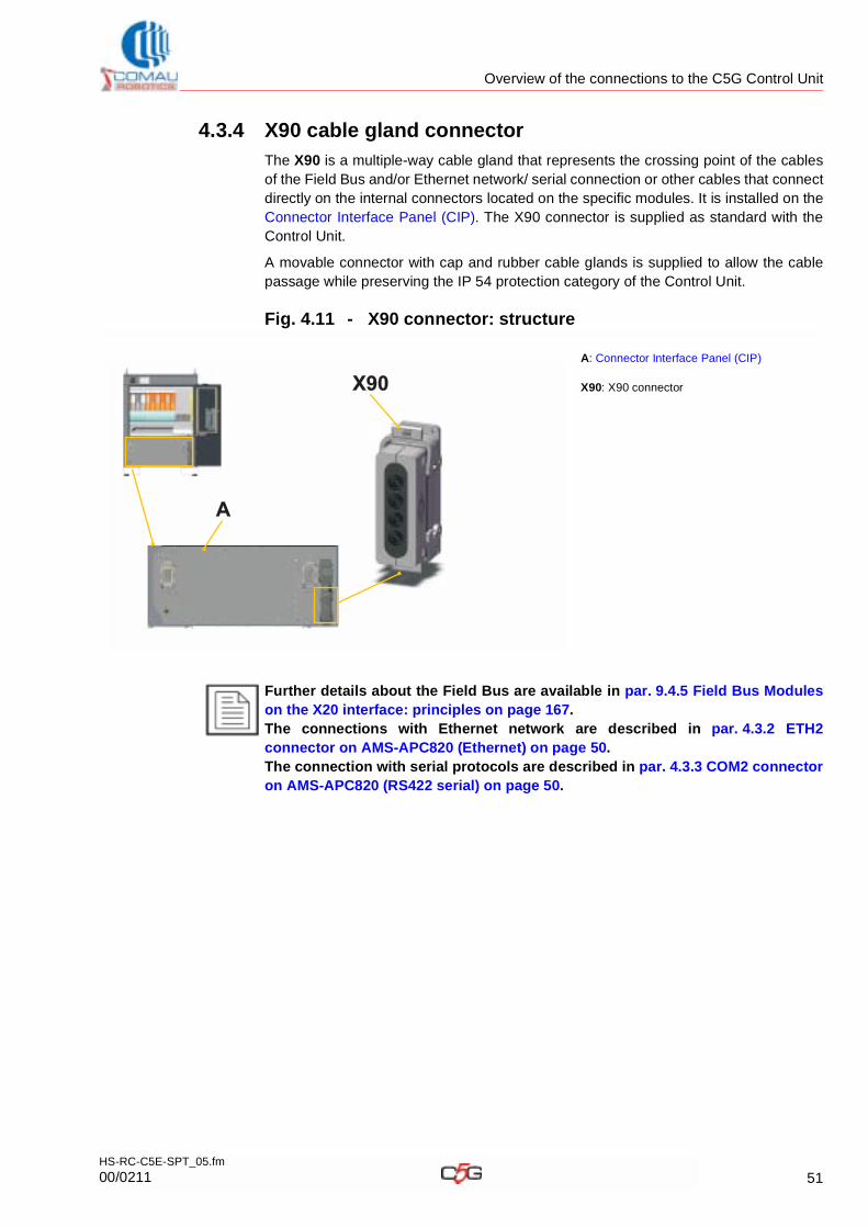
Overview of the connections to the C5G Control Unit
4.3.4 X90 cable gland connector
The X90 is a multiple-way cable gland that represents the crossing point of the cables of the Field Bus and/or Ethernet network/ serial connection or other cables that connect directly on the internal connectors located on the specific modules. It is installed on the Connector Interface Panel (CIP). The X90 connector is supplied as standard with the Control Unit.
A movable connector with cap and rubber cable glands is supplied to allow the cable passage while preserving the IP 54 protection category of the Control Unit.
Fig. 4.11 - X90 connector: structure
A: Connector Interface Panel (CIP)
X90: X90 connector
Further details about the Field Bus are available in par. 9.4.5 Field Bus Modules on the X20 interface: principles on page 167.The connections with Ethernet network are described in par. 4.3.2 ETH2 connector on AMS-APC820 (Ethernet) on page 50.The connection with serial protocols are described in par. 4.3.3 COM2 connector on AMS-APC820 (RS422 serial) on page 50.
A
X90
51HS-RC-C5E-SPT_05.fm
00/0211
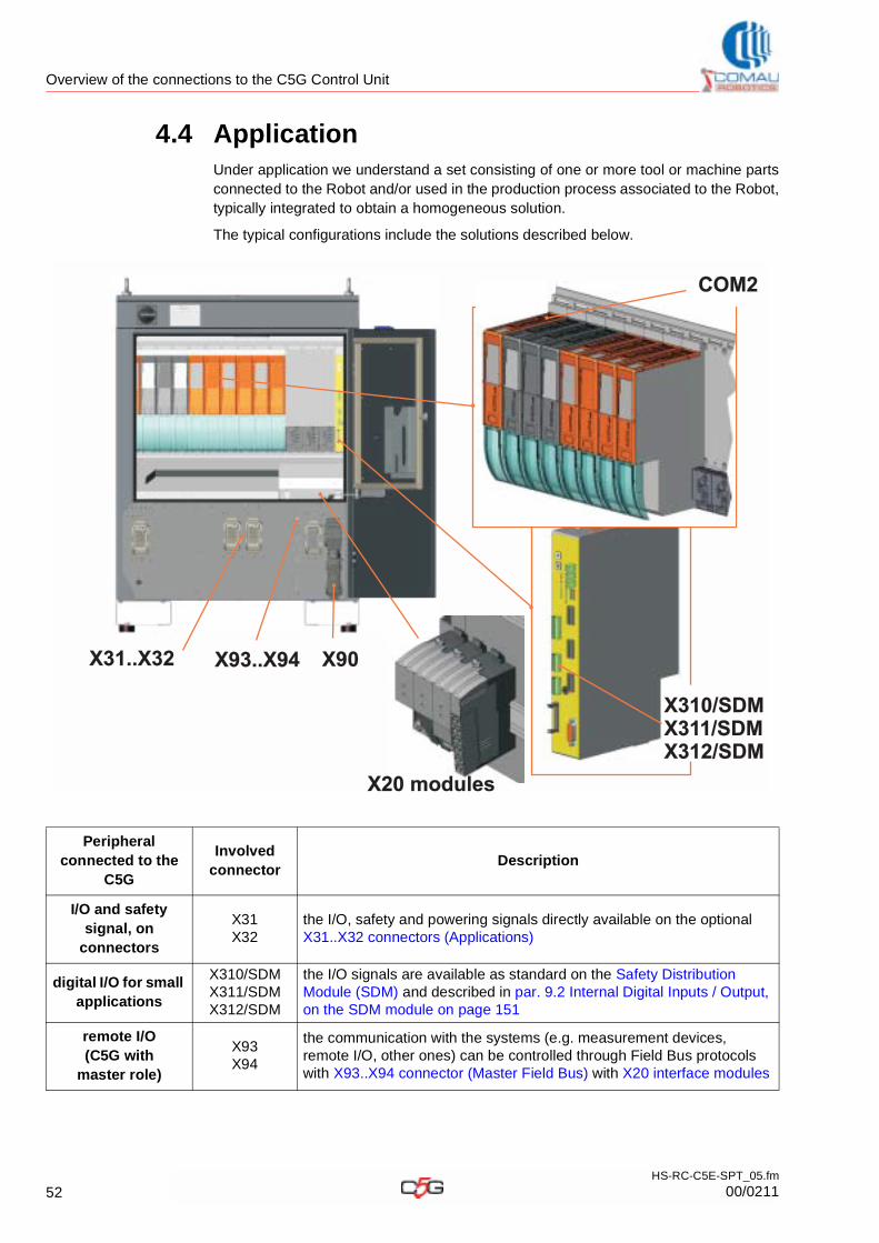
Overview of the connections to the C5G Control Unit
4.4 ApplicationUnder application we understand a set consisting of one or more tool or machine parts connected to the Robot and/or used in the production process associated to the Robot, typically integrated to obtain a homogeneous solution.
The typical configurations include the solutions described below.
Peripheral connected to the
C5G
Involved connector
Description
I/O and safety signal, on
connectors
X31X32
the I/O, safety and powering signals directly available on the optional X31..X32 connectors (Applications)
digital I/O for small applications
X310/SDMX311/SDMX312/SDM
the I/O signals are available as standard on the Safety Distribution Module (SDM) and described in par. 9.2 Internal Digital Inputs / Output, on the SDM module on page 151
remote I/O (C5G with
master role)
X93X94
the communication with the systems (e.g. measurement devices, remote I/O, other ones) can be controlled through Field Bus protocols with X93..X94 connector (Master Field Bus) with X20 interface modules
COM2
X31..X32 X93..X94 X90
X20 modulesX20 modules
X310/SDMX311/SDMX312/SDM
X310/SDMX311/SDMX312/SDM
52HS-RC-C5E-SPT_05.fm
00/0211
Overview of the connections to the C5G Control Unit
Analysis, measurement
systems (serial)
COM2 / APC820
the communication with the systems (e.g. measurement systems, other ones) can be controlled through the serial RS232 on COM2 connector on AMS-APC820 (RS232 serial). The serial connection RS422 is also available.
Other connections (e.g. net or serial communication cables output)
X90The cables that do not features a specific optional connector by the cabinet base and exit the Control Unit to reach the device on the line, use the way provided by the I X90 cable gland connector.
Other connections (e.g. output for
electrode dresser powering cables)
--
The powering cables can exit from the box base through the cable glands (that are not part of the supply volume), which are to be fastened to the 25,5 mm dinking holes (M25 cable glands) located on the central panel.
Peripheral connected to the
C5G
Involved connector
Description
53HS-RC-C5E-SPT_05.fm
00/0211
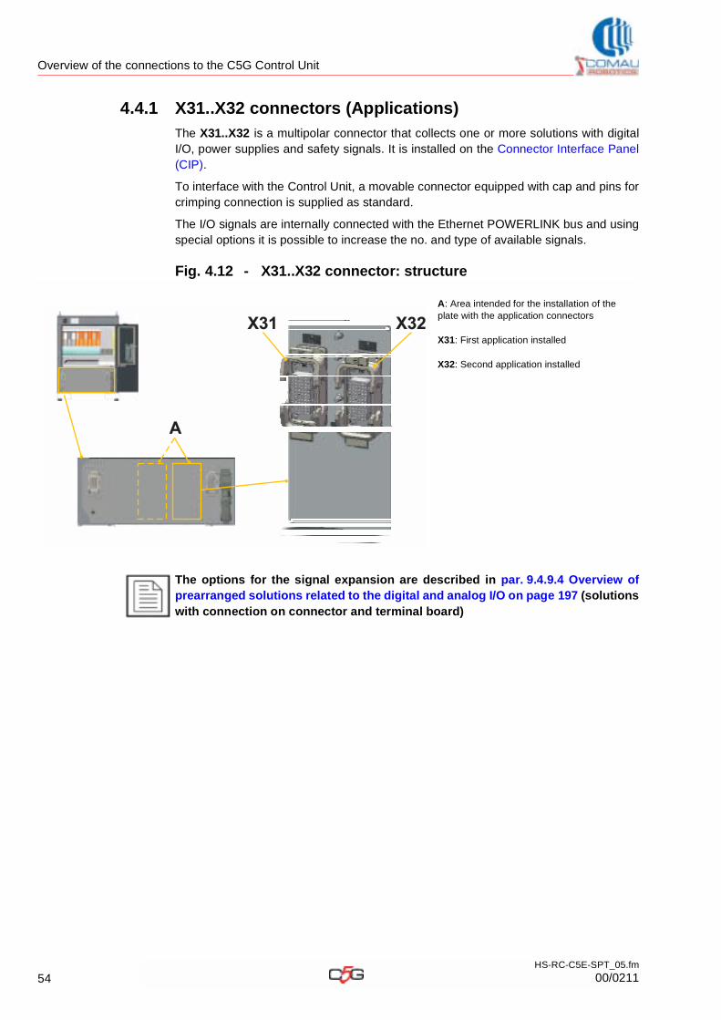
Overview of the connections to the C5G Control Unit
4.4.1 X31..X32 connectors (Applications)
The X31..X32 is a multipolar connector that collects one or more solutions with digital I/O, power supplies and safety signals. It is installed on the Connector Interface Panel (CIP).
To interface with the Control Unit, a movable connector equipped with cap and pins for crimping connection is supplied as standard.
The I/O signals are internally connected with the Ethernet POWERLINK bus and using special options it is possible to increase the no. and type of available signals.
Fig. 4.12 - X31..X32 connector: structure
A: Area intended for the installation of the plate with the application connectors
X31: First application installed
X32: Second application installed
The options for the signal expansion are described in par. 9.4.9.4 Overview of prearranged solutions related to the digital and analog I/O on page 197 (solutions with connection on connector and terminal board)
A
X31 X32
54HS-RC-C5E-SPT_05.fm
00/0211
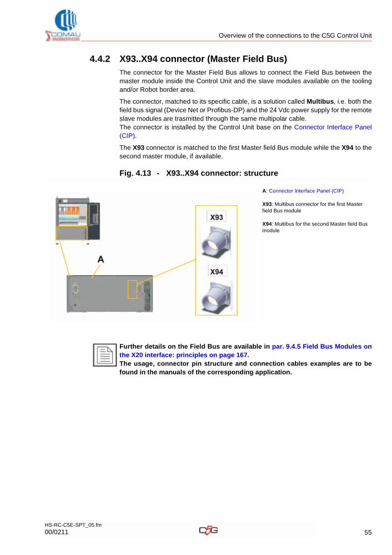
Overview of the connections to the C5G Control Unit
4.4.2 X93..X94 connector (Master Field Bus)
The connector for the Master Field Bus allows to connect the Field Bus between the master module inside the Control Unit and the slave modules available on the tooling and/or Robot border area.
The connector, matched to its specific cable, is a solution called Multibus, i.e. both the field bus signal (Device Net or Profibus-DP) and the 24 Vdc power supply for the remote slave modules are trasmitted through the same multipolar cable.The connector is installed by the Control Unit base on the Connector Interface Panel (CIP).
The X93 connector is matched to the first Master field Bus module while the X94 to the second master module, if available.
Fig. 4.13 - X93..X94 connector: structure
A: Connector Interface Panel (CIP)
X93: Multibus connector for the first Master field Bus module
X94: Multibus for the second Master field Bus module
Further details on the Field Bus are available in par. 9.4.5 Field Bus Modules on the X20 interface: principles on page 167.The usage, connector pin structure and connection cables examples are to be found in the manuals of the corresponding application.
A
X93
X94
55HS-RC-C5E-SPT_05.fm
00/0211
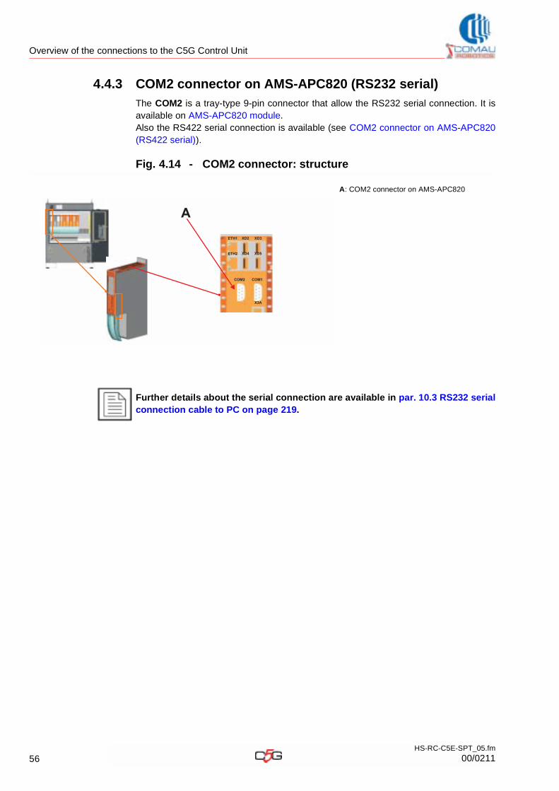
Overview of the connections to the C5G Control Unit
4.4.3 COM2 connector on AMS-APC820 (RS232 serial)
The COM2 is a tray-type 9-pin connector that allow the RS232 serial connection. It is available on AMS-APC820 module. Also the RS422 serial connection is available (see COM2 connector on AMS-APC820 (RS422 serial)).
Fig. 4.14 - COM2 connector: structure
A: COM2 connector on AMS-APC820
Further details about the serial connection are available in par. 10.3 RS232 serial connection cable to PC on page 219.
XD2
COM2 COM1
XD3
XD4
X3A
ETH1
ETH2 XD5
A
56HS-RC-C5E-SPT_05.fm
00/0211
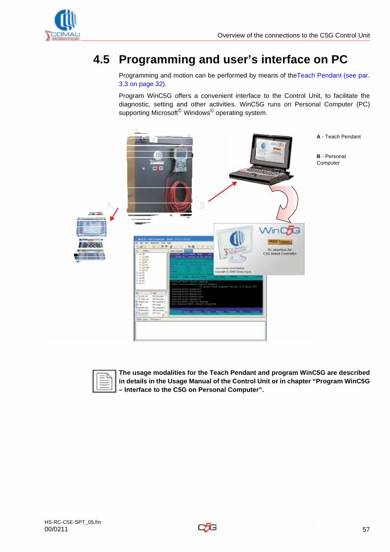
Overview of the connections to the C5G Control Unit
4.5 Programming and user’s interface on PCProgramming and motion can be performed by means of theTeach Pendant (see par. 3.3 on page 32).
Program WinC5G offers a convenient interface to the Control Unit, to facilitate the diagnostic, setting and other activities. WinC5G runs on Personal Computer (PC) supporting Microsoft© Windows© operating system.
A - Teach Pendant
B - Personal Computer
The usage modalities for the Teach Pendant and program WinC5G are described in details in the Usage Manual of the Control Unit or in chapter “Program WinC5G – Interface to the C5G on Personal Computer”.
A B
57HS-RC-C5E-SPT_05.fm
00/0211
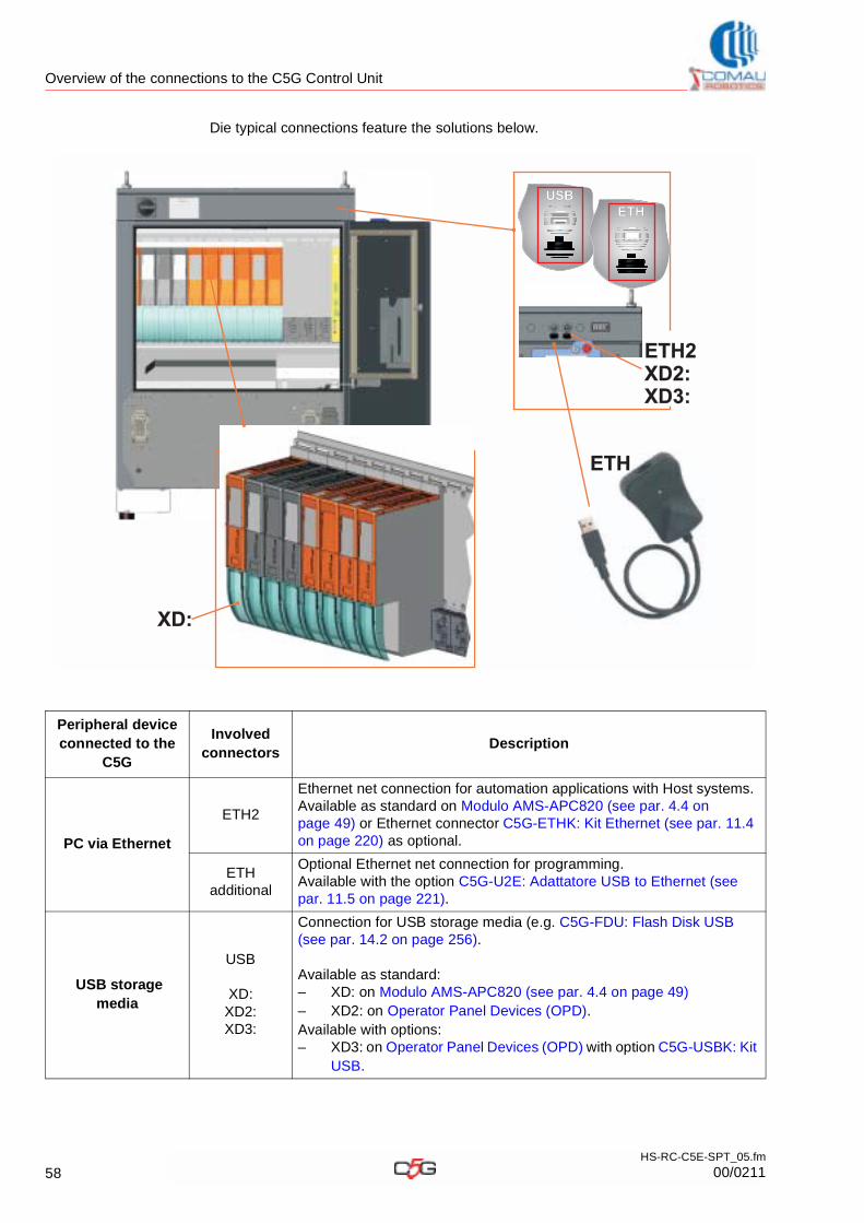
Overview of the connections to the C5G Control Unit
Die typical connections feature the solutions below.
Peripheral device connected to the
C5G
Involved connectors
Description
PC via Ethernet
ETH2
Ethernet net connection for automation applications with Host systems.Available as standard on Modulo AMS-APC820 (see par. 4.4 on page 49) or Ethernet connector C5G-ETHK: Kit Ethernet (see par. 11.4 on page 220) as optional.
ETH additional
Optional Ethernet net connection for programming.Available with the option C5G-U2E: Adattatore USB to Ethernet (see par. 11.5 on page 221).
USB storage media
USB
XD:XD2:XD3:
Connection for USB storage media (e.g. C5G-FDU: Flash Disk USB (see par. 14.2 on page 256).
Available as standard:– XD: on Modulo AMS-APC820 (see par. 4.4 on page 49) – XD2: on Operator Panel Devices (OPD).Available with options:– XD3: on Operator Panel Devices (OPD) with option C5G-USBK: Kit
USB.
XD:
USB
ETH
ETH2XD2:XD3:
ETH2XD2:XD3:
ETH
58HS-RC-C5E-SPT_05.fm
00/0211
Overview of the connections to the C5G Control Unit
4.6 Summary of connectors and corresponding functionTo facilitate the identification of the functions of the main Control Unit connectors, find below the list in alphabetical order and the corresponding paragraph.
Tab. 4.2 - Summary of connectors
Connector / Position
Typical function Description
COM2 / APC820
Analysis, measurement
systems (via RS232 serial)
The communication with the systems (e.g. measurement systems, other ones) can be controlled through the RS232 serial connection on COM2 connector on AMS-APC820 (RS232 serial).
COM2 / APC820
Host systems for monitoring
(via RS422 serial)
The communication with the Host systems (e.g. line PLC, factory production controlling PC, analysis devices, other ones) can be controlled through the RS422 serial connection (see COM2 connector on AMS-APC820 (RS422 serial) (see par. 4.3.3 on page 50)).
ETH2 / APC820
Host systems for monitoring
(via Ethernet)
The communication with the Host systems (e.g. line PLC, factory production controlling PC, analysis devices, other ones) can be controlled through Ethernet connections (see ETH2 connector on AMS-APC820 (Ethernet) (see par. 4.3.2 on page 50))
X10/CIP RobotThe main Robot is connected through the Connection cables between C5G and Robot con I X10 connector (Robot signals)
X10-EXT/CIP Positioning device
The positioning device (e.g. series SMART5 PTDV, PTDORB, other ones) is connected through the Connection cables between C5G and Robot (it uses the same Robot cables, exploiting only the necessary wires depending on the no. of axes available) with the X10-EXT connector (Extension, Positioning device signals)
X30/CIP Safety itemsThe safety signals (e.g. emergency stop, cell access door limit switches, other ones) are available on the X30 connector (Safety items)
X31/CIPX32/CIP
wired I/O, on connector
The I/O, safety and power supply signals are directly available on the optional X31..X32 connectors (Applications)
wired I/O, on module and terminal
board
The I/O signals are directly available on the optional X31..X32 connectors (Applications)
X60/CIP RobotThe main Robot is connected through the Connection cables between C5G and Robot with the X60 connector (Robot Power)
X60-EXT/CIP Positioning device
The positioning device (e.g. series SMART5 PTDV, PTDORB, other ones) is connected through the Connection cables between C5G and Robot (it uses the same Robot cables, exploiting only the necessary wires depending on the no. of axes available) with the X60-EXT connector (Extension, motors and brakes of the positioning device)
X61/CIPX62/CIPX63/CIPX64/CIP
Auxiliary axes
The single auxiliary axis (e.g. saddle on axis 7, electric gripper for spot welding, other ones) are connected through the Connection cables between C5G and Robot, each one with an only one connector that includes both the power and the control signals, with the X61..X64 connectors (Signals and power for auxiliary Axes)
X90/CIPMultiple cable input/output
The cables can be connected inside the Control Unit through the X90 cable gland connector with no interruption
59HS-RC-C5E-SPT_05.fm
00/0211
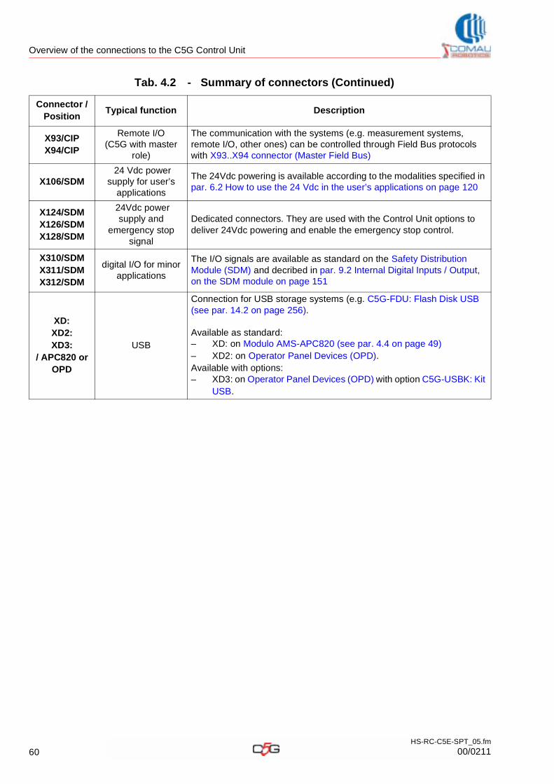
Overview of the connections to the C5G Control Unit
X93/CIPX94/CIP
Remote I/O (C5G with master
role)
The communication with the systems (e.g. measurement systems, remote I/O, other ones) can be controlled through Field Bus protocols with X93..X94 connector (Master Field Bus)
X106/SDM 24 Vdc power
supply for user’s applications
The 24Vdc powering is available according to the modalities specified in par. 6.2 How to use the 24 Vdc in the user’s applications on page 120
X124/SDMX126/SDMX128/SDM
24Vdc power supply and
emergency stop signal
Dedicated connectors. They are used with the Control Unit options to deliver 24Vdc powering and enable the emergency stop control.
X310/SDMX311/SDMX312/SDM
digital I/O for minor applications
The I/O signals are available as standard on the Safety Distribution Module (SDM) and decribed in par. 9.2 Internal Digital Inputs / Output, on the SDM module on page 151
XD:XD2:XD3:
/ APC820 or OPD
USB
Connection for USB storage systems (e.g. C5G-FDU: Flash Disk USB (see par. 14.2 on page 256).
Available as standard:– XD: on Modulo AMS-APC820 (see par. 4.4 on page 49) – XD2: on Operator Panel Devices (OPD).Available with options:– XD3: on Operator Panel Devices (OPD) with option C5G-USBK: Kit
USB.
Tab. 4.2 - Summary of connectors (Continued)
Connector / Position
Typical function Description
60HS-RC-C5E-SPT_05.fm
00/0211
Options
5. OPTIONS
This chapter deals with the following topics:
– Information about the options installation
– Options Circuit diagram
– Opzions for the C5G Control Unit
5.1 Information about the options installationThe options purchased together with the C5G Control Unit are supplied already installed. If the options are purchased later, the installation instruction are to be found in the single option installation manual.
5.2 Options Circuit diagramThe options circuit diagrams (available only for those ones where electric connections are to be performed) are to be found in the Control Unit complete circuit diagram. Due to the complexity of some options, some circuit diagrams may be supplied in a separate document.
The option listed here can be installed and used solely for the C5G Contrl Unit.
All circuit diagrams are available in the CD-ROM supplied together with the C5GControl Unit. Refere also to par. Reference documents a pag. 5.
61HS-RC-C5E-SPT_04.fm
00/0411
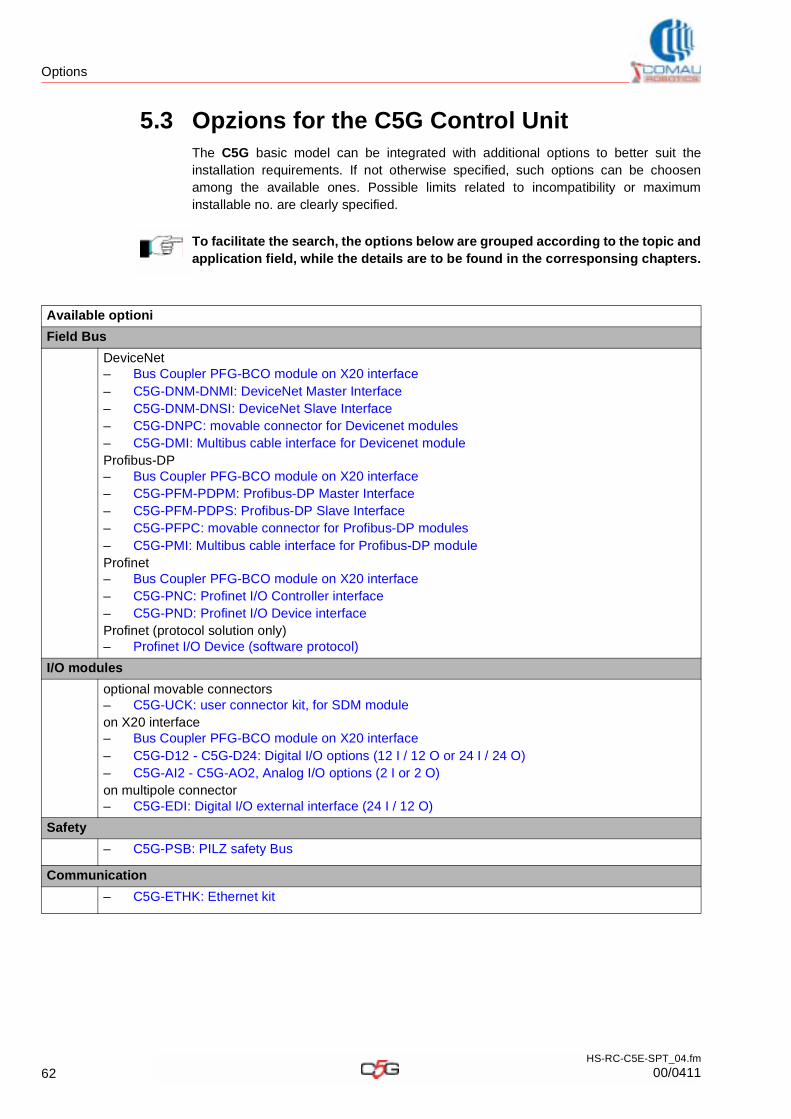
Options
5.3 Opzions for the C5G Control UnitThe C5G basic model can be integrated with additional options to better suit the installation requirements. If not otherwise specified, such options can be choosen among the available ones. Possible limits related to incompatibility or maximum installable no. are clearly specified.
To facilitate the search, the options below are grouped according to the topic and application field, while the details are to be found in the corresponsing chapters.
Available optioni
Field Bus
DeviceNet– Bus Coupler PFG-BCO module on X20 interface– C5G-DNM-DNMI: DeviceNet Master Interface– C5G-DNM-DNSI: DeviceNet Slave Interface– C5G-DNPC: movable connector for Devicenet modules– C5G-DMI: Multibus cable interface for Devicenet moduleProfibus-DP– Bus Coupler PFG-BCO module on X20 interface– C5G-PFM-PDPM: Profibus-DP Master Interface– C5G-PFM-PDPS: Profibus-DP Slave Interface– C5G-PFPC: movable connector for Profibus-DP modules– C5G-PMI: Multibus cable interface for Profibus-DP moduleProfinet– Bus Coupler PFG-BCO module on X20 interface– C5G-PNC: Profinet I/O Controller interface– C5G-PND: Profinet I/O Device interfaceProfinet (protocol solution only)– Profinet I/O Device (software protocol)
I/O modules
optional movable connectors– C5G-UCK: user connector kit, for SDM moduleon X20 interface– Bus Coupler PFG-BCO module on X20 interface– C5G-D12 - C5G-D24: Digital I/O options (12 I / 12 O or 24 I / 24 O)– C5G-AI2 - C5G-AO2, Analog I/O options (2 I or 2 O)on multipole connector– C5G-EDI: Digital I/O external interface (24 I / 12 O)
Safety
– C5G-PSB: PILZ safety Bus
Communication
– C5G-ETHK: Ethernet kit
62HS-RC-C5E-SPT_04.fm
00/0411
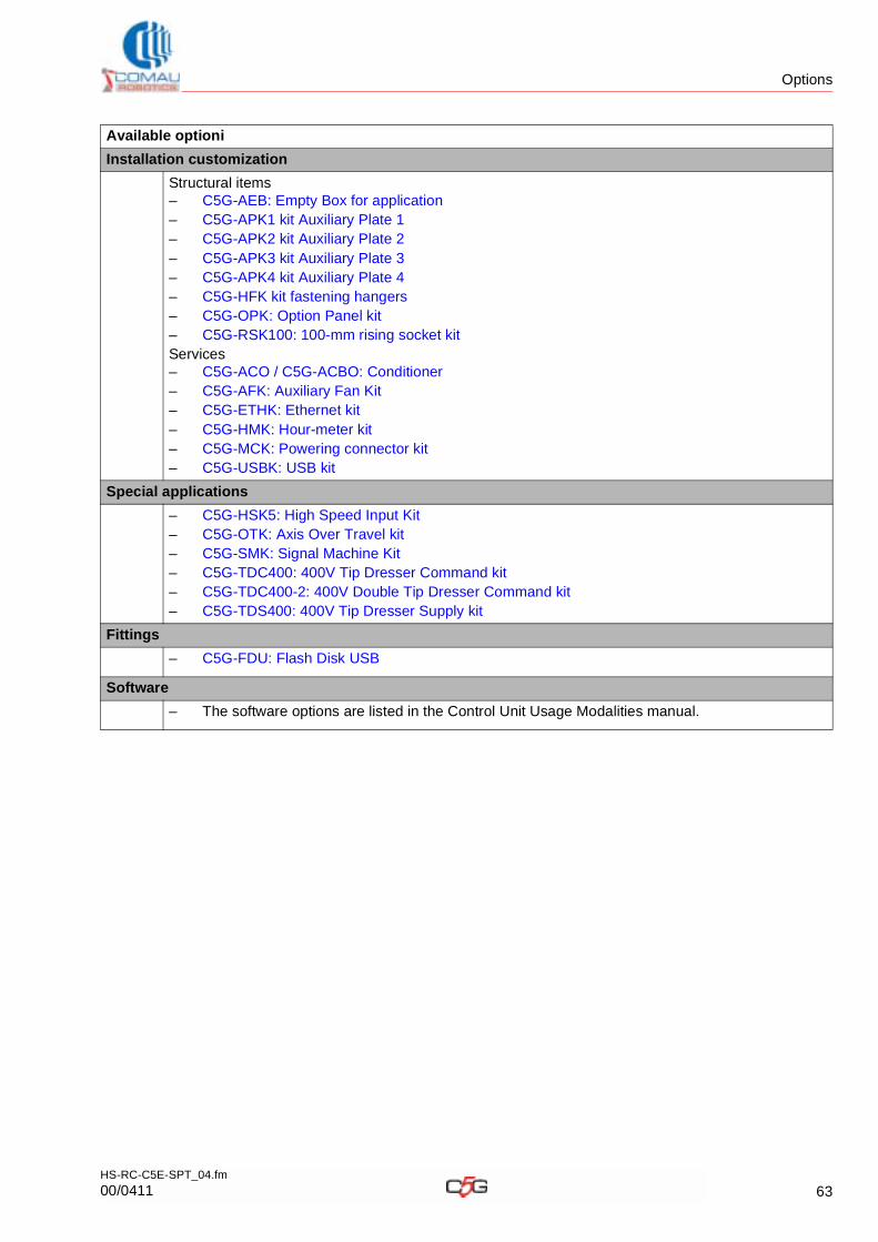
Options
Installation customization
Structural items– C5G-AEB: Empty Box for application– C5G-APK1 kit Auxiliary Plate 1– C5G-APK2 kit Auxiliary Plate 2– C5G-APK3 kit Auxiliary Plate 3– C5G-APK4 kit Auxiliary Plate 4– C5G-HFK kit fastening hangers– C5G-OPK: Option Panel kit– C5G-RSK100: 100-mm rising socket kitServices– C5G-ACO / C5G-ACBO: Conditioner– C5G-AFK: Auxiliary Fan Kit– C5G-ETHK: Ethernet kit– C5G-HMK: Hour-meter kit– C5G-MCK: Powering connector kit– C5G-USBK: USB kit
Special applications
– C5G-HSK5: High Speed Input Kit– C5G-OTK: Axis Over Travel kit– C5G-SMK: Signal Machine Kit– C5G-TDC400: 400V Tip Dresser Command kit– C5G-TDC400-2: 400V Double Tip Dresser Command kit– C5G-TDS400: 400V Tip Dresser Supply kit
Fittings
– C5G-FDU: Flash Disk USB
Software
– The software options are listed in the Control Unit Usage Modalities manual.
Available optioni
63HS-RC-C5E-SPT_04.fm
00/0411

Original instructions
COMAU Robotics servicesRepair: [email protected]: [email protected] parts: [email protected] service: [email protected]/robotics