Embed Size (px)
Citation preview
COSENG-LOGO TIRE CHANGER C901
Installation, Operations and Maintenance Manual (Watch the enclosed operations video)

1. General The Coseng C901 Logo Tire Changer is a hands free system to mount and demount passenger and light truck tires. The system supports a rim diameter from 14 to 30 and a maximum wheel diameter up to 1200mm (47�”). Please read this manual carefully before use. Coseng is not responsible for any personal injury or machine damage resulted from any incorrect use of this machine. PLEASE KEEP THIS MANUAL NEAR THE C901 FOR EASY REFERENCE
2. Specifications
Electric motor 110V 1PH / 220V 1PH / 380V 3PH .75 or 1.1 KW
Rim diameter range 14�” to 30
Maximum tire diameter 1200mm (47�”)
Total lifting height for upper bead breaker disc 450mm (17/7�”)
Total lifting height for lower bead breaker disc 350mm (13.7�”)
Maximum wheel width 380mm (15�”)
Cylinder pressure for upper/lower bead breaker disc
at 8bar (110psi) 790kg (1,800lb)
Working pressure 8bar/110psi
Net Weight 450 kg (1,100lb)
Noise level (during working) <70db
3. Safety Rules This equipment should be operated by professionally trained personnel. Manufacturer is not responsible for any alteration, especially the electrical components, made to this machine without prior authorization. Work on the electrical system, even if minor, must be completed exclusively by an electrical technician.
4. Transport
This machine is available to ship in three possible packaging
options. All packing includes a plastic protective sheet and other
packing materials according to customer requirements.
1- Cardboard box on pallet
2- Reseal able wood box on pallet Fig. 1
-1-
3- No packing on pallet. All packing methods permit the use of a fork lift or pallet jack for transportation as shown on figure 1.
This equipment is 550kg (1,200lb) for shipment
5. Unpacking Unpack carefully �– do not use hammers or sharp objects. Check for damage. Dispose of packing
materials in a proper manner as dictated by local regulations.
IMPORTANT: some dust may be visible as exposes metal parts are coated with an anti corrosion
oil to limit rust. Prior to use clean surfaces thoroughly.
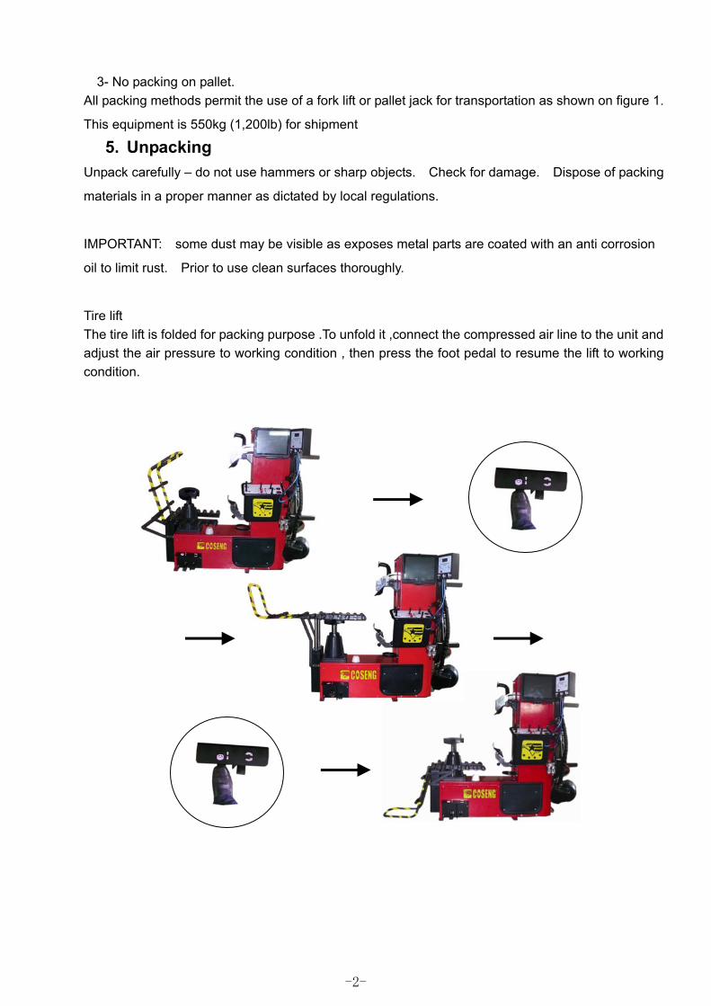
Tire lift The tire lift is folded for packing purpose .To unfold it ,connect the compressed air line to the unit and adjust the air pressure to working condition , then press the foot pedal to resume the lift to working condition.
-2-
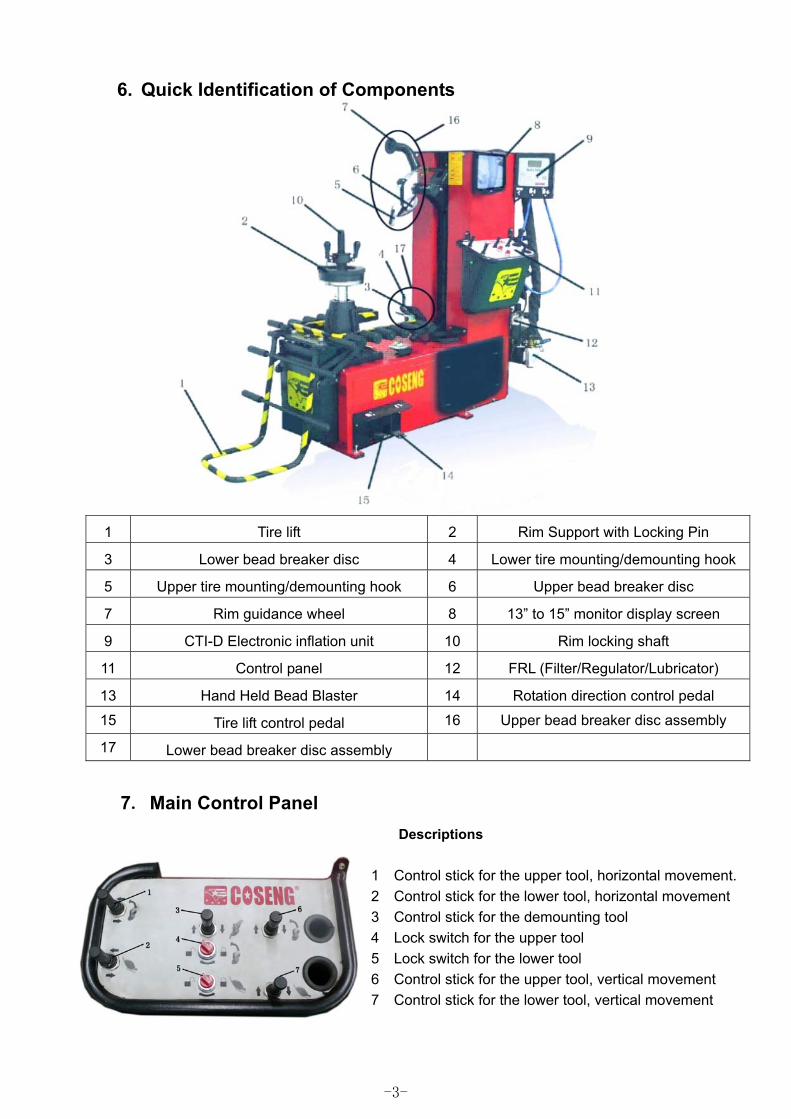
6. Quick Identification of Components
1 Tire lift 2 Rim Support with Locking Pin
3 Lower bead breaker disc 4 Lower tire mounting/demounting hook
5 Upper tire mounting/demounting hook 6 Upper bead breaker disc
7 Rim guidance wheel 8 13�” to 15�” monitor display screen
9 CTI-D Electronic inflation unit 10 Rim locking shaft
11 Control panel 12 FRL (Filter/Regulator/Lubricator)
13 Hand Held Bead Blaster 14 Rotation direction control pedal
15 Tire lift control pedal 16 Upper bead breaker disc assembly
17 Lower bead breaker disc assembly
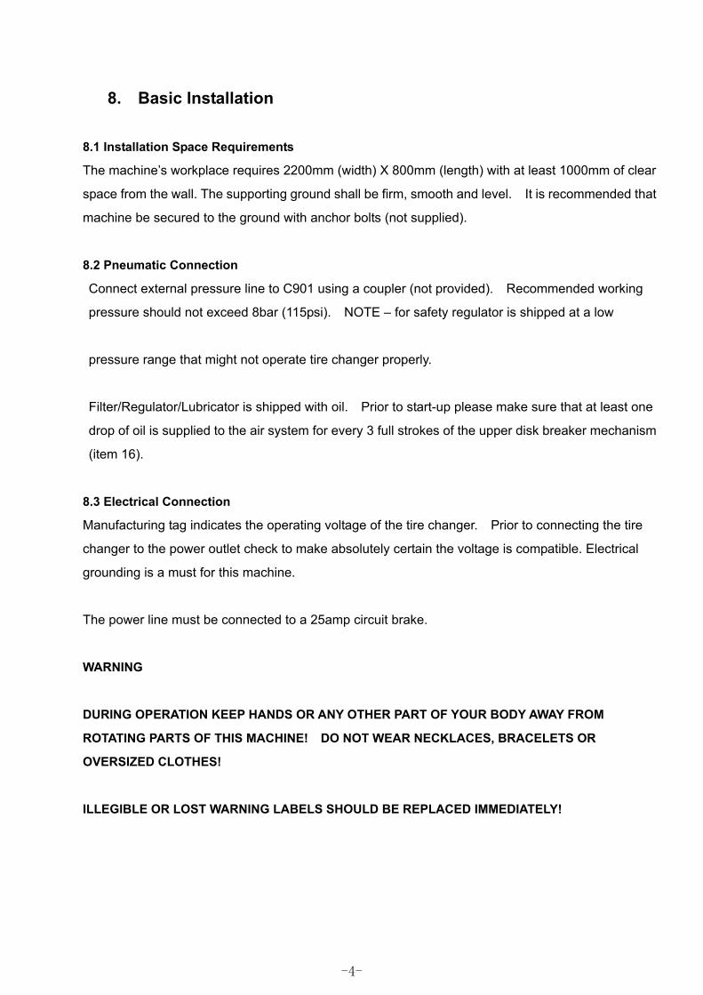
7ĕMain Control Panel Descriptions
1 Control stick for the upper tool, horizontal movement. 2 Control stick for the lower tool, horizontal movement 3 Control stick for the demounting tool 4 Lock switch for the upper tool 5 Lock switch for the lower tool 6 Control stick for the upper tool, vertical movement 7 Control stick for the lower tool, vertical movement
-3-
8. Basic Installation
8.1 Installation Space Requirements
The machine�’s workplace requires 2200mm (width) X 800mm (length) with at least 1000mm of clear
space from the wall. The supporting ground shall be firm, smooth and level. It is recommended that
machine be secured to the ground with anchor bolts (not supplied).
8.2 Pneumatic Connection
Connect external pressure line to C901 using a coupler (not provided). Recommended working
pressure should not exceed 8bar (115psi). NOTE �– for safety regulator is shipped at a low
pressure range that might not operate tire changer properly.
Filter/Regulator/Lubricator is shipped with oil. Prior to start-up please make sure that at least one
drop of oil is supplied to the air system for every 3 full strokes of the upper disk breaker mechanism
(item 16).
8.3 Electrical Connection
Manufacturing tag indicates the operating voltage of the tire changer. Prior to connecting the tire
changer to the power outlet check to make absolutely certain the voltage is compatible. Electrical
grounding is a must for this machine.
The power line must be connected to a 25amp circuit brake.
WARNING
DURING OPERATION KEEP HANDS OR ANY OTHER PART OF YOUR BODY AWAY FROM
ROTATING PARTS OF THIS MACHINE! DO NOT WEAR NECKLACES, BRACELETS OR
OVERSIZED CLOTHES!
ILLEGIBLE OR LOST WARNING LABELS SHOULD BE REPLACED IMMEDIATELY!
-4-
Operating Instructions
A Normal mount application
1. Connect to the electric power grid. Connect the external power supply terminal (optional) to power switch with corresponding voltage.
2. Connect the external air supply.
ATTENTION: POINT THE BEAD BLASTER NOZZLE AWAY FROM FACE AS RELEASE OF
AIR MAY CAUSE PERSONAL INJURY TO OPERATING PERSONNEL.
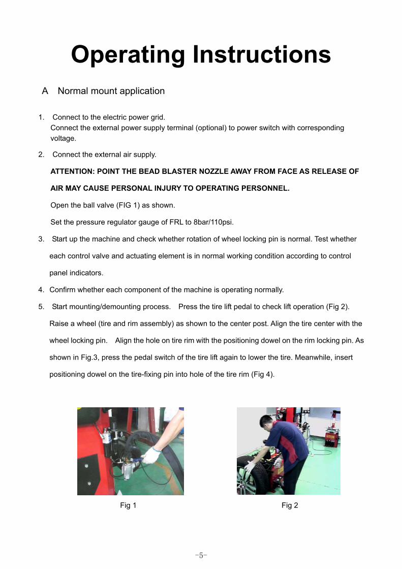
Open the ball valve (FIG 1) as shown.
Set the pressure regulator gauge of FRL to 8bar/110psi.
3. Start up the machine and check whether rotation of wheel locking pin is normal. Test whether
each control valve and actuating element is in normal working condition according to control
panel indicators.
4. Confirm whether each component of the machine is operating normally.
5. Start mounting/demounting process. Press the tire lift pedal to check lift operation (Fig 2).
Raise a wheel (tire and rim assembly) as shown to the center post. Align the tire center with the
wheel locking pin. Align the hole on tire rim with the positioning dowel on the rim locking pin. As
shown in Fig.3, press the pedal switch of the tire lift again to lower the tire. Meanwhile, insert
positioning dowel on the tire-fixing pin into hole of the tire rim (Fig 4).
Fig 1 Fig 2
-5-
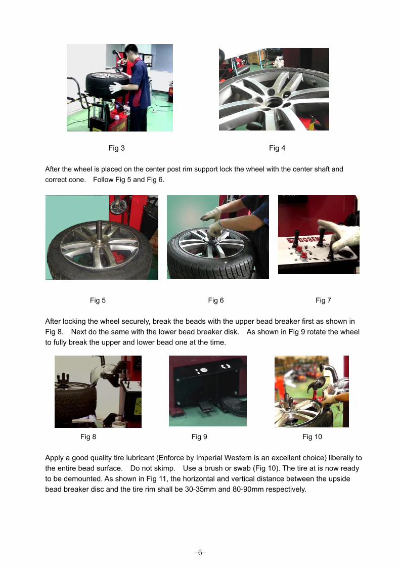
Fig 3 Fig 4 After the wheel is placed on the center post rim support lock the wheel with the center shaft and correct cone. Follow Fig 5 and Fig 6.
Fig 5 Fig 6 Fig 7
After locking the wheel securely, break the beads with the upper bead breaker first as shown in Fig 8. Next do the same with the lower bead breaker disk. As shown in Fig 9 rotate the wheel to fully break the upper and lower bead one at the time.
Fig 8 Fig 9 Fig 10
Apply a good quality tire lubricant (Enforce by Imperial Western is an excellent choice) liberally to the entire bead surface. Do not skimp. Use a brush or swab (Fig 10). The tire at is now ready to be demounted. As shown in Fig 11, the horizontal and vertical distance between the upside bead breaker disc and the tire rim shall be 30-35mm and 80-90mm respectively.
-6-
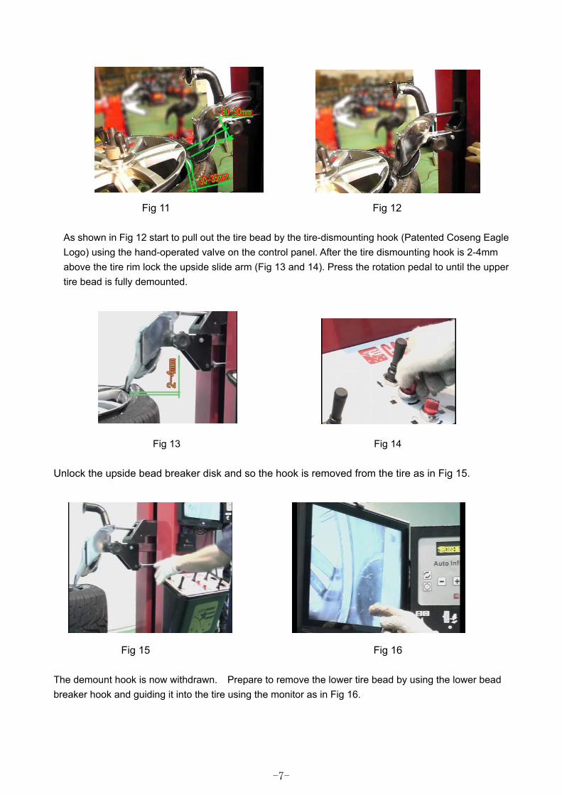
Fig 11 Fig 12
As shown in Fig 12 start to pull out the tire bead by the tire-dismounting hook (Patented Coseng Eagle Logo) using the hand-operated valve on the control panel. After the tire dismounting hook is 2-4mm above the tire rim lock the upside slide arm (Fig 13 and 14). Press the rotation pedal to until the upper tire bead is fully demounted.
Fig 13 Fig 14
Unlock the upside bead breaker disk and so the hook is removed from the tire as in Fig 15.
Fig 15 Fig 16 The demount hook is now withdrawn. Prepare to remove the lower tire bead by using the lower bead breaker hook and guiding it into the tire using the monitor as in Fig 16.
-7-
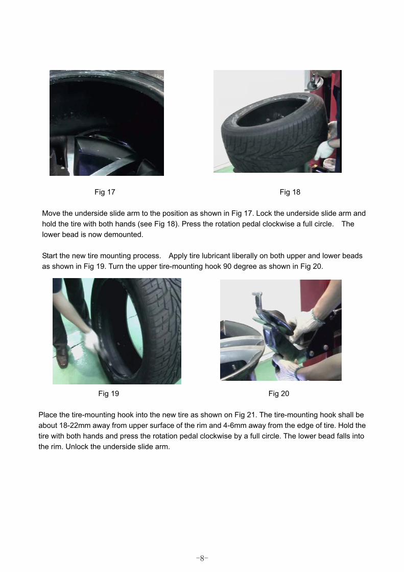
Fig 17 Fig 18
Move the underside slide arm to the position as shown in Fig 17. Lock the underside slide arm and hold the tire with both hands (see Fig 18). Press the rotation pedal clockwise a full circle. The lower bead is now demounted. Start the new tire mounting process. Apply tire lubricant liberally on both upper and lower beads as shown in Fig 19. Turn the upper tire-mounting hook 90 degree as shown in Fig 20.
Fig 19 Fig 20 Place the tire-mounting hook into the new tire as shown on Fig 21. The tire-mounting hook shall be about 18-22mm away from upper surface of the rim and 4-6mm away from the edge of tire. Hold the tire with both hands and press the rotation pedal clockwise by a full circle. The lower bead falls into the rim. Unlock the underside slide arm.
-8-
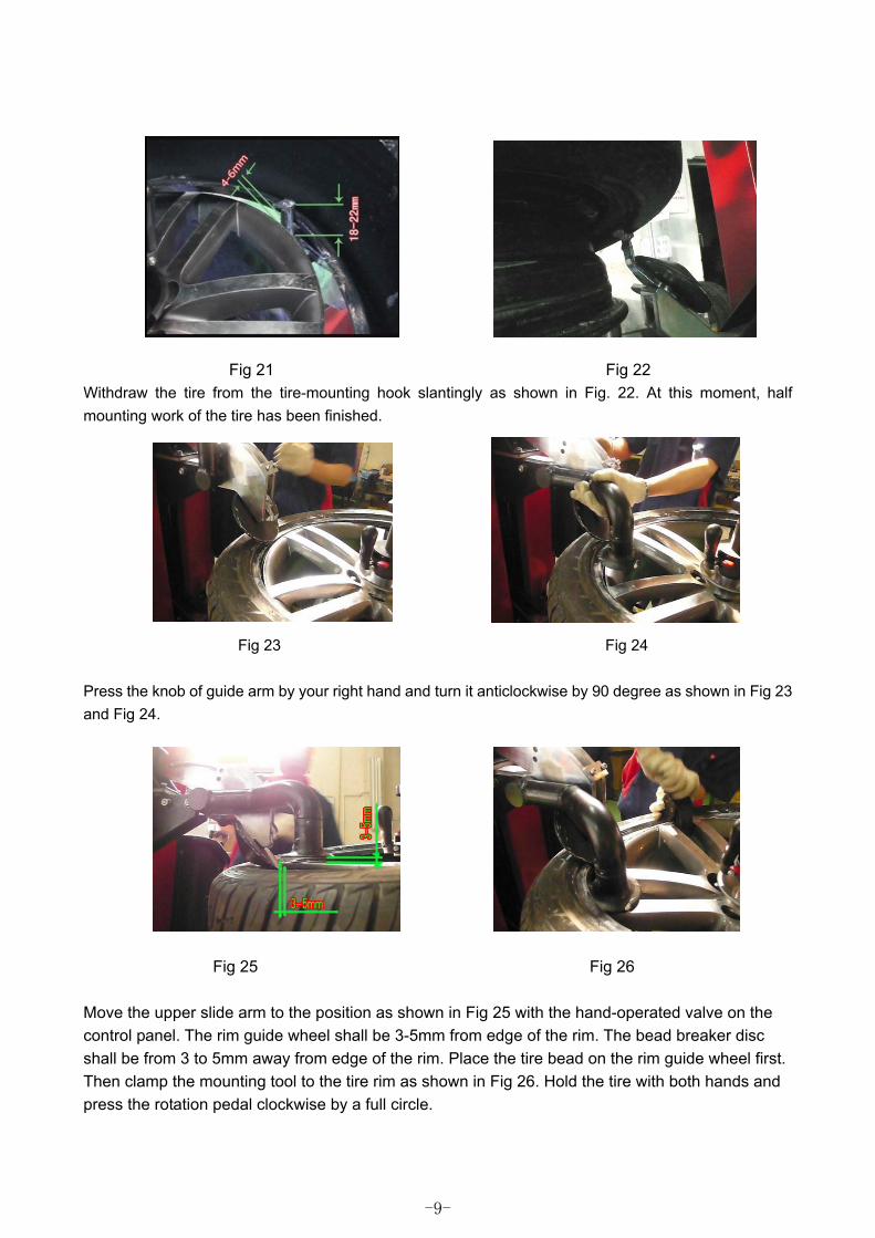
Fig 21 Fig 22 Withdraw the tire from the tire-mounting hook slantingly as shown in Fig. 22. At this moment, half mounting work of the tire has been finished.
Fig 23 Fig 24 Press the knob of guide arm by your right hand and turn it anticlockwise by 90 degree as shown in Fig 23 and Fig 24.
Fig 25 Fig 26
Move the upper slide arm to the position as shown in Fig 25 with the hand-operated valve on the control panel. The rim guide wheel shall be 3-5mm from edge of the rim. The bead breaker disc shall be from 3 to 5mm away from edge of the rim. Place the tire bead on the rim guide wheel first. Then clamp the mounting tool to the tire rim as shown in Fig 26. Hold the tire with both hands and press the rotation pedal clockwise by a full circle.
-9-
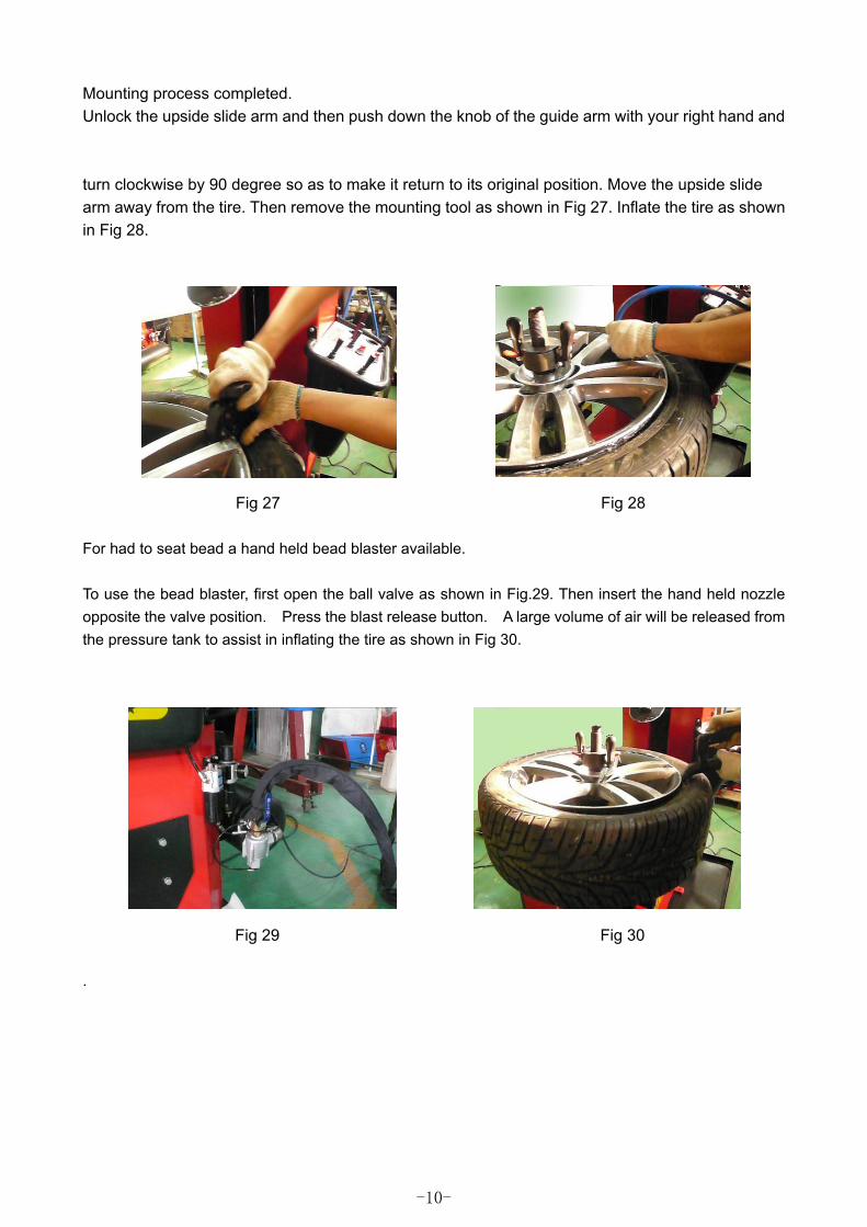
Mounting process completed. Unlock the upside slide arm and then push down the knob of the guide arm with your right hand and turn clockwise by 90 degree so as to make it return to its original position. Move the upside slide arm away from the tire. Then remove the mounting tool as shown in Fig 27. Inflate the tire as shown in Fig 28.
Fig 27 Fig 28
For had to seat bead a hand held bead blaster available. To use the bead blaster, first open the ball valve as shown in Fig.29. Then insert the hand held nozzle opposite the valve position. Press the blast release button. A large volume of air will be released from the pressure tank to assist in inflating the tire as shown in Fig 30.
Fig 29 Fig 30
.
-10-
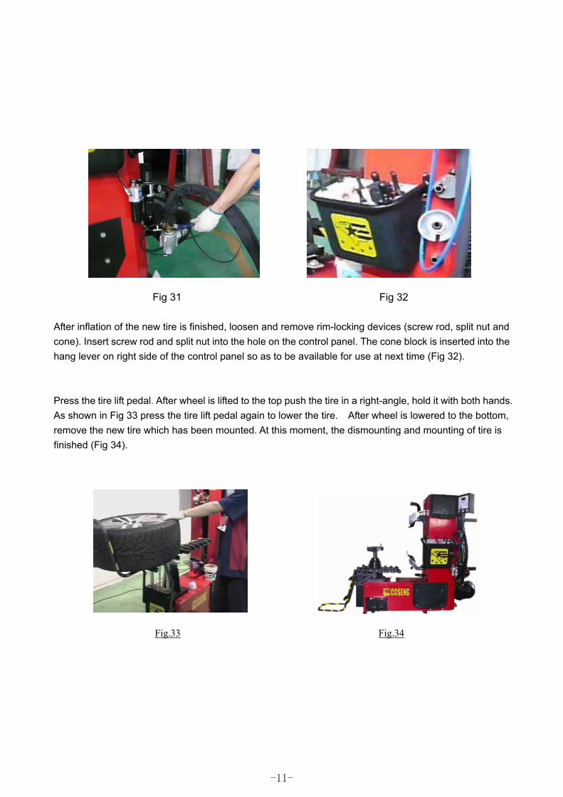
Fig 31 Fig 32
After inflation of the new tire is finished, loosen and remove rim-locking devices (screw rod, split nut and cone). Insert screw rod and split nut into the hole on the control panel. The cone block is inserted into the hang lever on right side of the control panel so as to be available for use at next time (Fig 32).
Press the tire lift pedal. After wheel is lifted to the top push the tire in a right-angle, hold it with both hands. As shown in Fig 33 press the tire lift pedal again to lower the tire. After wheel is lowered to the bottom, remove the new tire which has been mounted. At this moment, the dismounting and mounting of tire is finished (Fig 34).
Fig.33 Fig.34
-11-
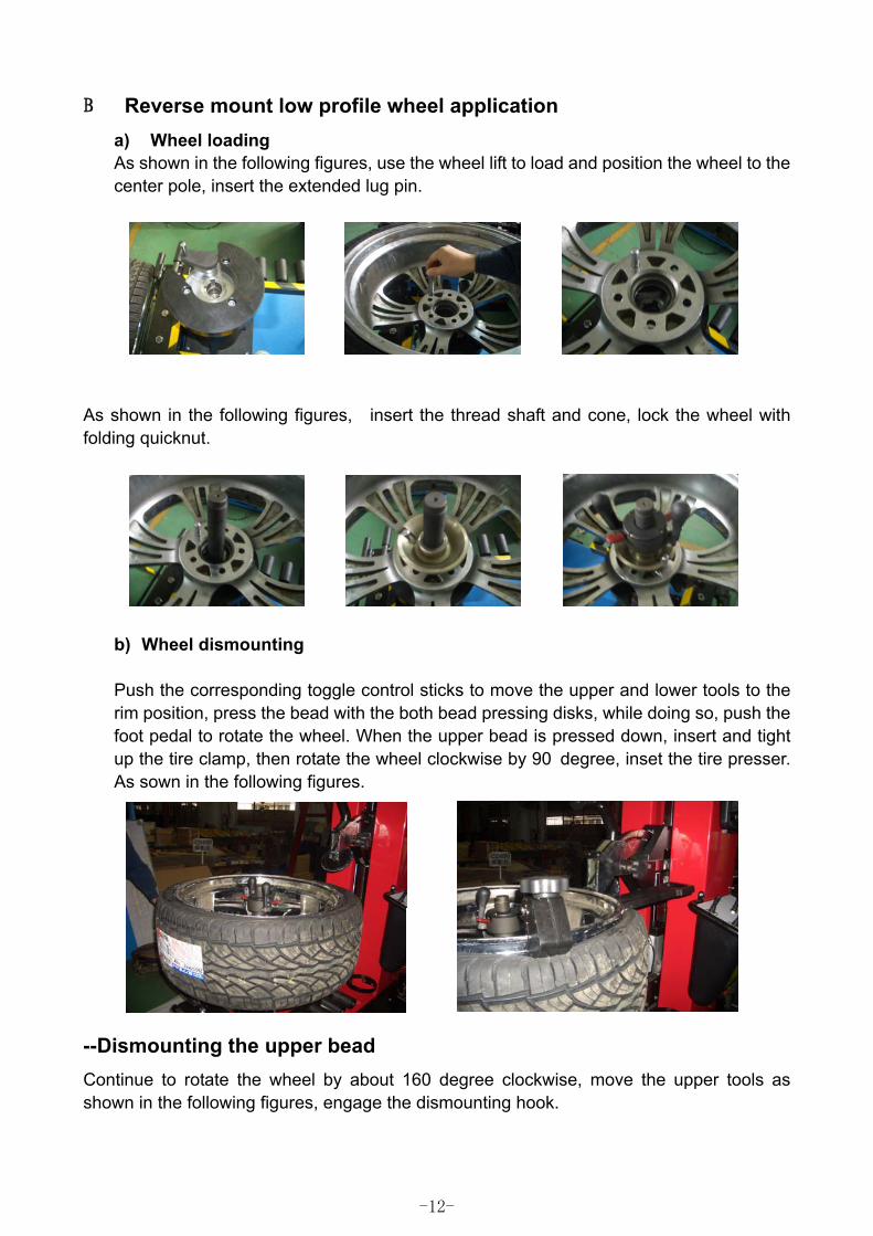
%� Reverse mount low profile wheel application a) Wheel loading As shown in the following figures, use the wheel lift to load and position the wheel to the center pole, insert the extended lug pin.
�
As shown in the following figures, insert the thread shaft and cone, lock the wheel with folding quicknut.
b) Wheel dismounting Push the corresponding toggle control sticks to move the upper and lower tools to the rim position, press the bead with the both bead pressing disks, while doing so, push the foot pedal to rotate the wheel. When the upper bead is pressed down, insert and tight up the tire clamp, then rotate the wheel clockwise by 90�degree, inset the tire presser. As sown in the following figures.
--Dismounting the upper bead Continue to rotate the wheel by about 160 degree clockwise, move the upper tools as shown in the following figures, engage the dismounting hook.
-12-
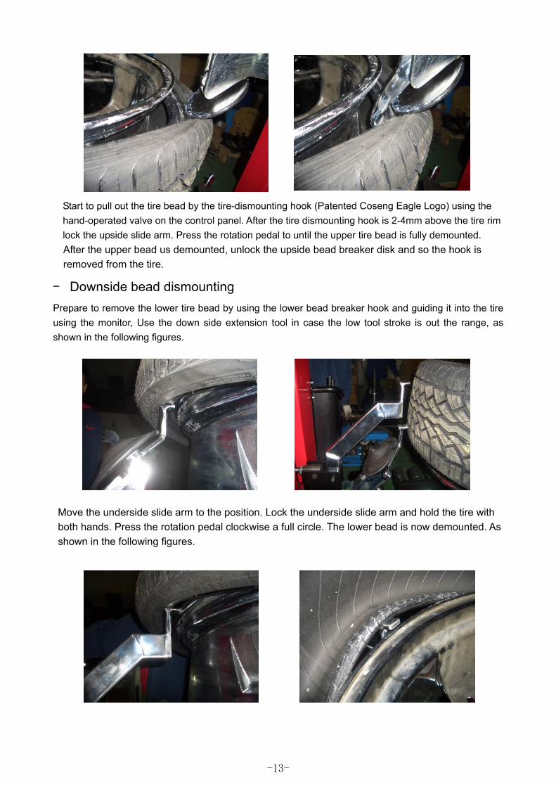
Start to pull out the tire bead by the tire-dismounting hook (Patented Coseng Eagle Logo) using the hand-operated valve on the control panel. After the tire dismounting hook is 2-4mm above the tire rim lock the upside slide arm. Press the rotation pedal to until the upper tire bead is fully demounted. After the upper bead us demounted, unlock the upside bead breaker disk and so the hook is removed from the tire.
� Downside bead dismounting Prepare to remove the lower tire bead by using the lower bead breaker hook and guiding it into the tire using the monitor, Use the down side extension tool in case the low tool stroke is out the range, as shown in the following figures. �
Move the underside slide arm to the position. Lock the underside slide arm and hold the tire with both hands. Press the rotation pedal clockwise a full circle. The lower bead is now demounted. As shown in the following figures.
�
�
�
�
-13-
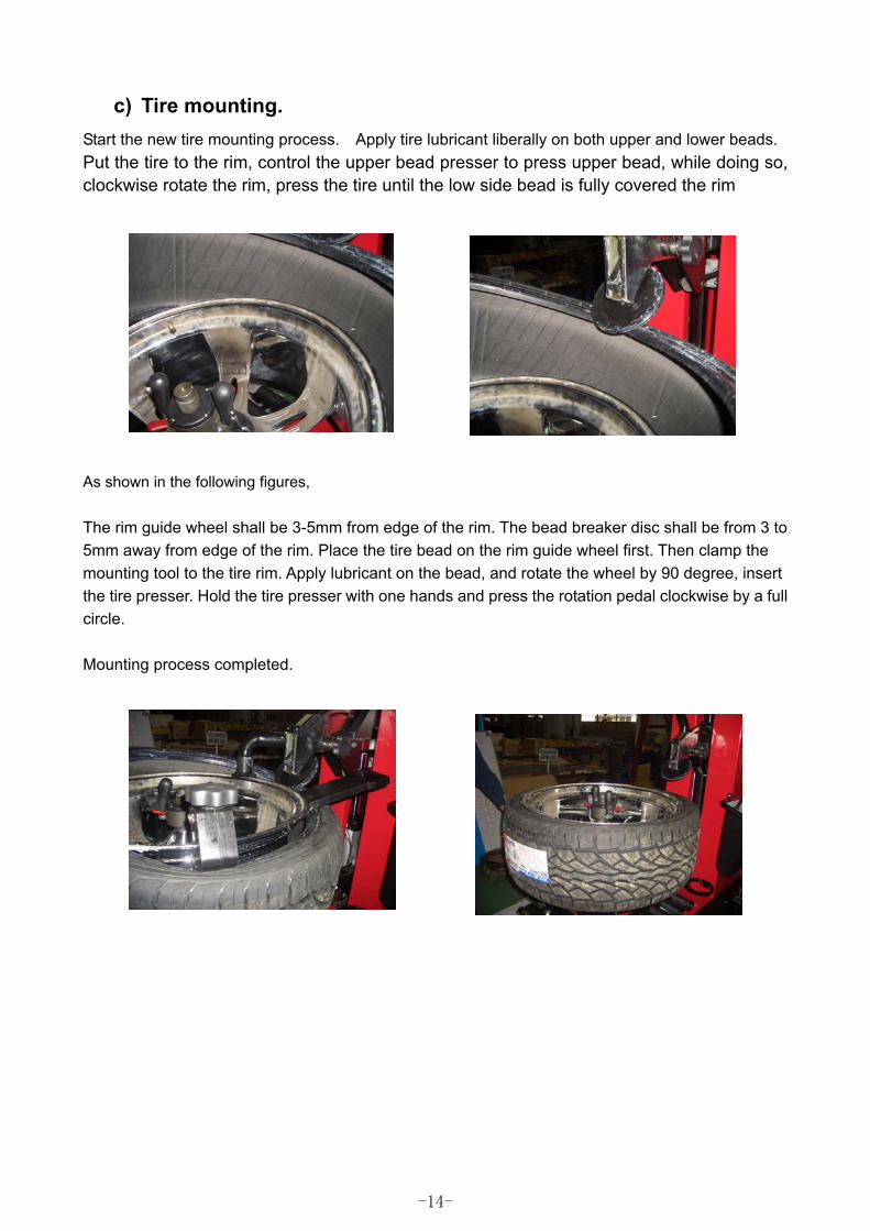
c) Tire mounting. Start the new tire mounting process. Apply tire lubricant liberally on both upper and lower beads. Put the tire to the rim, control the upper bead presser to press upper bead, while doing so, clockwise rotate the rim, press the tire until the low side bead is fully covered the rim
�
As shown in the following figures, The rim guide wheel shall be 3-5mm from edge of the rim. The bead breaker disc shall be from 3 to 5mm away from edge of the rim. Place the tire bead on the rim guide wheel first. Then clamp the mounting tool to the tire rim. Apply lubricant on the bead, and rotate the wheel by 90 degree, insert the tire presser. Hold the tire presser with one hands and press the rotation pedal clockwise by a full circle. Mounting process completed.
�
-14-
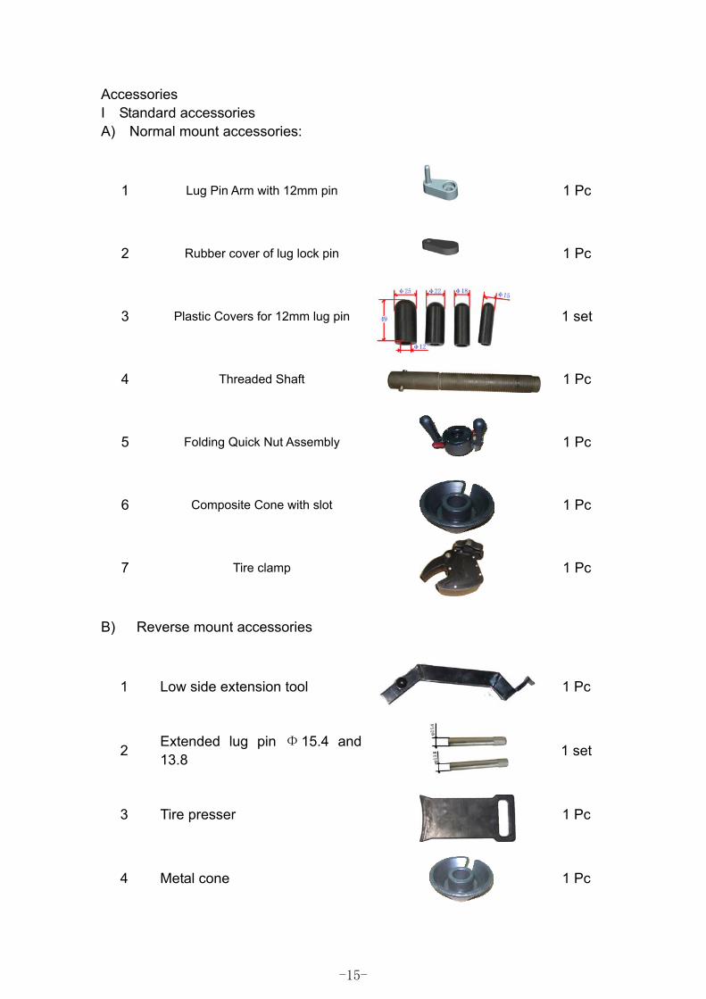
Accessories I Standard accessories A) Normal mount accessories:
1 Lug Pin Arm with 12mm pin
1 Pc
2 Rubber cover of lug lock pin
1 Pc
3 Plastic Covers for 12mm lug pin
1 set
4 Threaded Shaft
1 Pc
5 Folding Quick Nut Assembly
1 Pc
6 Composite Cone with slot
1 Pc
7 Tire clamp
1 Pc
B) Reverse mount accessories
1 Low side extension tool
1 Pc
2 Extended lug pin Φ15.4 and 13.8
1 set
3 Tire presser
1 Pc
4 Metal cone
1 Pc
-15-
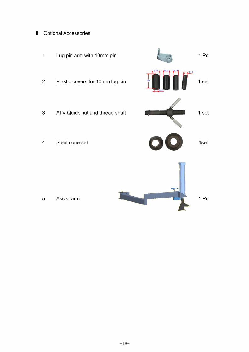
II Optional Accessories
1 Lug pin arm with 10mm pin
1 Pc
2 Plastic covers for 10mm lug pin
1 set
3 ATV Quick nut and thread shaft
1 set
4 Steel cone set
1set
5 Assist arm
1 Pc
-16-
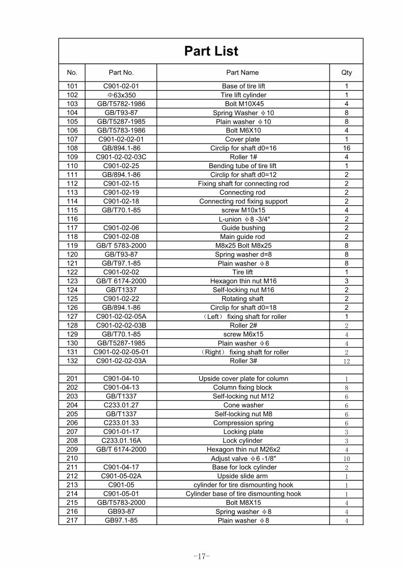
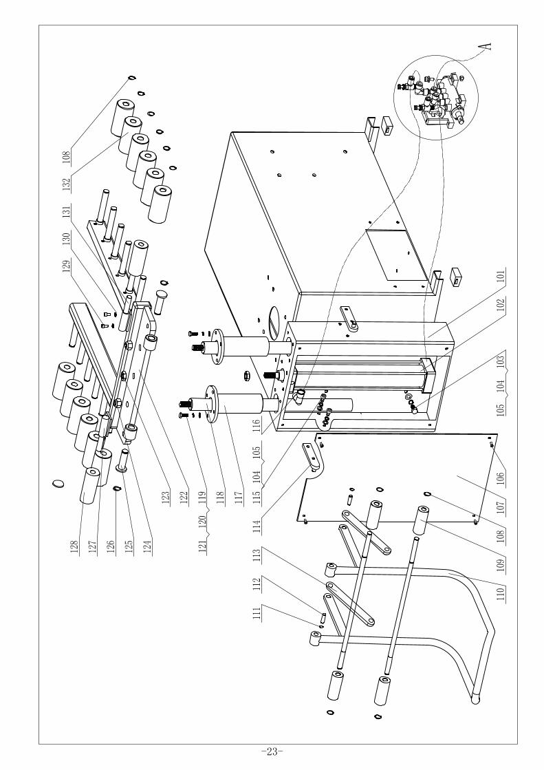
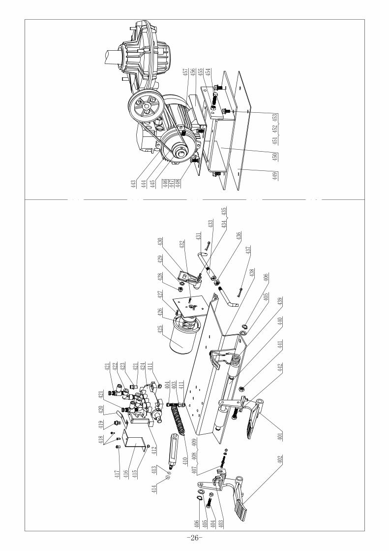
101 C901-02-01 Base of tire lift 1102 Φ63x350 Tire lift cylinder 1103 GB/T5782-1986 Bolt M10X45 4104 GB/T93-87 Spring Washer φ10 8105 GB/T5287-1985 Plain washer φ10 8106 GB/T5783-1986 Bolt M6X10 4107 C901-02-02-01 Cover plate 1108 GB/894.1-86 Circlip for shaft d0=16 16109 C901-02-02-03C Roller 1# 4110 C901-02-25 Bending tube of tire lift 1111 GB/894.1-86 Circlip for shaft d0=12 2112 C901-02-15 Fixing shaft for connecting rod 2113 C901-02-19 Connecting rod 2114 C901-02-18 Connecting rod fixing support 2115 GB/T70.1-85 screw M10x15 4116 L-union φ8 -3/4" 2117 C901-02-06 Guide bushing 2118 C901-02-08 Main guide rod 2119 GB/T 5783-2000 M8x25 Bolt M8x25 8120 GB/T93-87 Spring washer d=8 8121 GB/T97.1-85 Plain washer φ8 8122 C901-02-02 Tire lift 1123 GB/T 6174-2000 Hexagon thin nut M16 3124 GB/T1337 Self-locking nut M16 2125 C901-02-22 Rotating shaft 2126 GB/894.1-86 Circlip for shaft d0=18 2127 C901-02-02-05A (Left) fixing shaft for roller 1128 C901-02-02-03B Roller 2# 2129 GB/T70.1-85 screw M6x15 4130 GB/T5287-1985 Plain washer φ6 4131 C901-02-02-05-01 (Right) fixing shaft for roller 2132 C901-02-02-03A Roller 3# 12
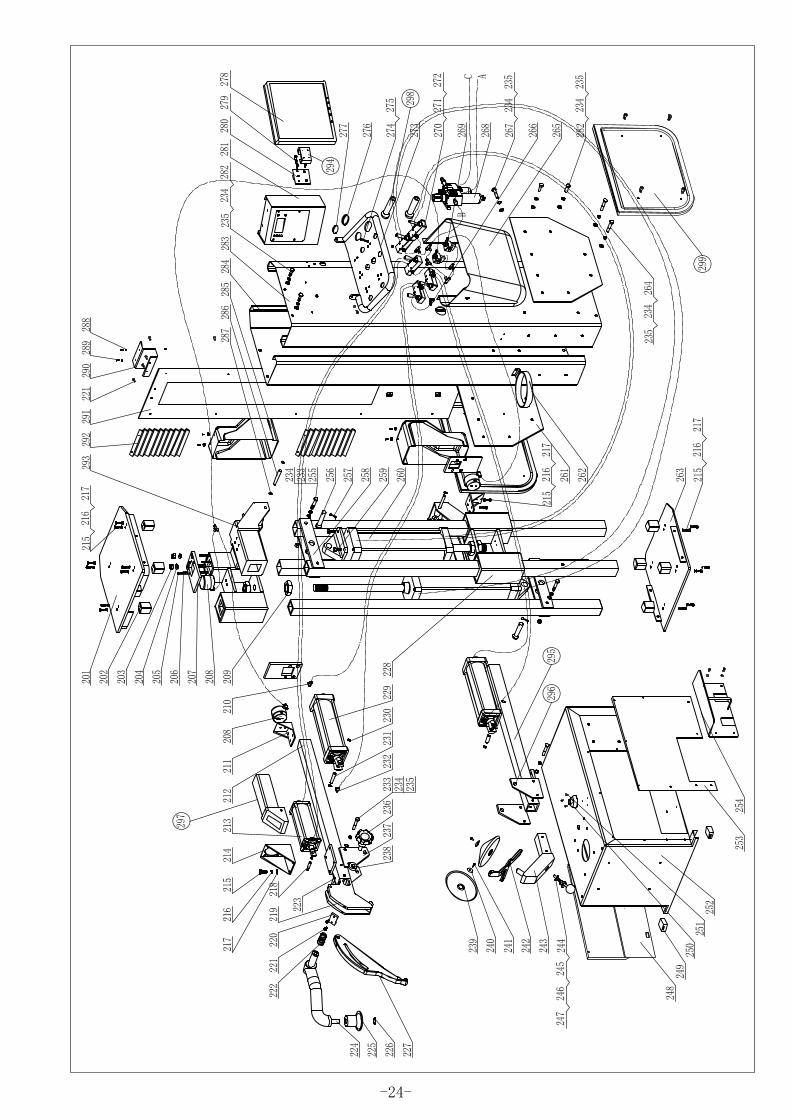
201 C901-04-10 Upside cover plate for column 1202 C901-04-13 Column fixing block 8203 GB/T1337 Self-locking nut M12 6204 C233.01.27 Cone washer 6205 GB/T1337 Self-locking nut M8 6206 C233.01.33 Compression spring 6207 C901-01-17 Locking plate 3208 C233.01.16A Lock cylinder 3209 GB/T 6174-2000 Hexagon thin nut M26x2 4210 Adjust valve φ6 -1/8" 10211 C901-04-17 Base for lock cylinder 2212 C901-05-02A Upside slide arm 1213 C901-05 cylinder for tire dismounting hook 1214 C901-05-01 Cylinder base of tire dismounting hook 1215 GB/T5783-2000 Bolt M8X15 4216 GB93-87 Spring washer φ8 4217 GB97.1-85 Plain washer φ8 4
Part ListNo. Part No. Part Name Qty
-17-
Part ListNo. Part No. Part Name Qty
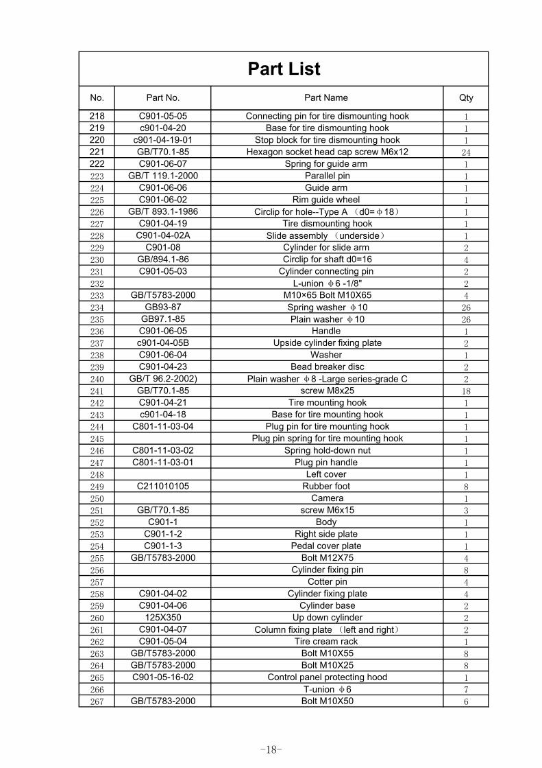
218 C901-05-05 Connecting pin for tire dismounting hook 1219 c901-04-20 Base for tire dismounting hook 1220 c901-04-19-01 Stop block for tire dismounting hook 1221 GB/T70.1-85 Hexagon socket head cap screw M6x12 24222 C901-06-07 Spring for guide arm 1
223 GB/T 119.1-2000 Parallel pin 1
224 C901-06-06 Guide arm 1
225 C901-06-02 Rim guide wheel 1
226 GB/T 893.1-1986 Circlip for hole--Type A (d0=φ18) 1
227 C901-04-19 Tire dismounting hook 1
228 C901-04-02A Slide assembly (underside) 1
229 C901-08 Cylinder for slide arm 2
230 GB/894.1-86 Circlip for shaft d0=16 4
231 C901-05-03 Cylinder connecting pin 2
232 L-union φ6 -1/8" 2
233 GB/T5783-2000 M10×65 Bolt M10X65 4
234 GB93-87 Spring washer φ10 26
235 GB97.1-85 Plain washer φ10 26
236 C901-06-05 Handle 1
237 c901-04-05B Upside cylinder fixing plate 2
238 C901-06-04 Washer 1
239 C901-04-23 Bead breaker disc 2
240 GB/T 96.2-2002) Plain washer φ8 -Large series-grade C 2
241 GB/T70.1-85 screw M8x25 18
242 C901-04-21 Tire mounting hook 1
243 c901-04-18 Base for tire mounting hook 1
244 C801-11-03-04 Plug pin for tire mounting hook 1
245 Plug pin spring for tire mounting hook 1
246 C801-11-03-02 Spring hold-down nut 1
247 C801-11-03-01 Plug pin handle 1
248 Left cover 1
249 C211010105 Rubber foot 8
250 Camera 1
251 GB/T70.1-85 screw M6x15 3
252 C901-1 Body 1
253 C901-1-2 Right side plate 1
254 C901-1-3 Pedal cover plate 1
255 GB/T5783-2000 Bolt M12X75 4
256 Cylinder fixing pin 8
257 Cotter pin 4
258 C901-04-02 Cylinder fixing plate 4
259 C901-04-06 Cylinder base 2
260 125X350 Up down cylinder 2
261 C901-04-07 Column fixing plate (left and right) 2
262 C901-05-04 Tire cream rack 1
263 GB/T5783-2000 Bolt M10X55 8
264 GB/T5783-2000 Bolt M10X25 8
265 C901-05-16-02 Control panel protecting hood 1
266 T-union φ6 7
267 GB/T5783-2000 Bolt M10X50 6
-18-
Part ListNo. Part No. Part Name Qty
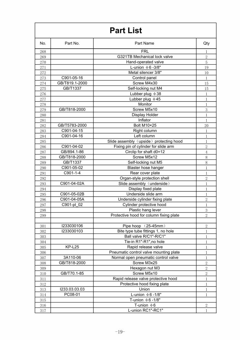
268 FRL 1
269 G321TB Mechanical lock valve 2
270 Hand-operated valve 5
271 L-union φ6 -3/8" 19
272 Metal silencer 3/8" 10
273 C901-05-16 Control panel 1
274 GB/T819.1-2000 Screw M4x30 15
275 GB/T1337 Self-locking nut M4 15
276 Lubber plug φ38 1
277 Lubber plug φ45 1
278 Monitor 1
279 GB/T818-2000 Screw M5x10 3
280 Display Holder 1
281 Inflator 1
282 GB/T5783-2000 Bolt M10×25 20
283 C901-04-15 Right column 1
284 C901-04-16 Left column 1
285 Slide assembly(upside)protecting hood 1
286 C901-04-02 Fixing pin of cylinder for slide arm 2
287 GB/894.1-86 Circlip for shaft d0=12 4
288 GB/T818-2000 Screw M5x12 8
289 GB/T1337 Self-locking nut M5 8
290 C901-05-02 Blaster hose hanger 1
291 C901-1-4 Rear cover plate 1
292 Organ-style protection shell 2
293 C901-04-02A Slide assembly(underside) 1
294 Display fixed plate 1
295 C901-05-02B Underside slide arm 1
296 C901-04-05A Underside cylinder fixing plate 2
297 C901-pl_02 Cylinder protective hood 1
298 Plastic hang lever 3
299 Protective hood for column fixing plate 2
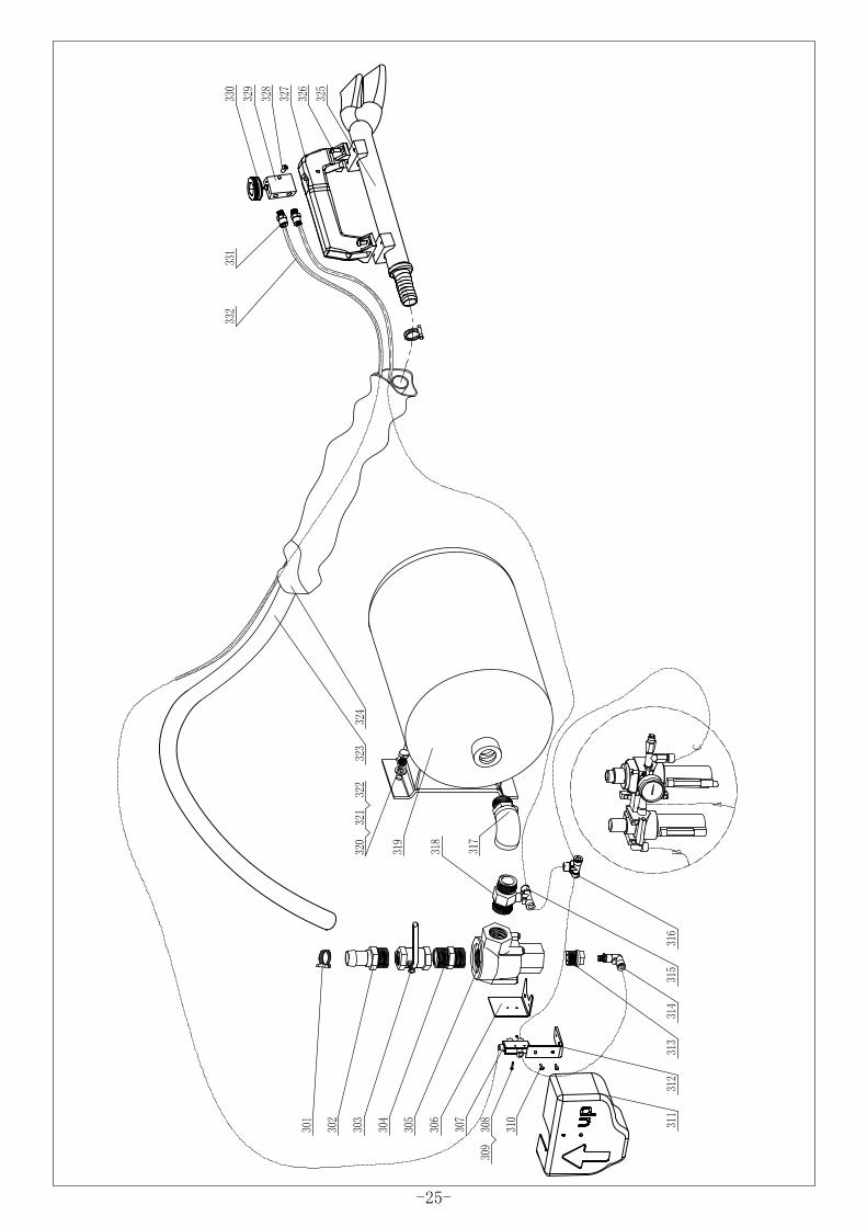
301 I233030106 Pipe hoop (25-45mm) 2
302 I233030103 Bite type tube fittings 1, no hole 1
303 Ball valve R/C1"-R/C1" 1
304 Tie-in R1"-R1",no hole 1
305 KP-L25 Rapid release valve 1
306 Pneumatic control valve mounting plate 1
307 3A110-06 Normal open pneumatic control valve 1
308 GB/T818-2000 Screw M3x25 2
309 Hexagon nut M3 2
310 GB/T70.1-85 Screw M5x10 2
311 Rapid release valve protective hood 1
312 Protective hood fixing plate 1
313 I233.03.03.03 Union 1
314 PC08-01 L-union φ6 -1/8" 1
315 T-union φ6 -1/8"316 T-union φ6 2
317 L-union RC1"-RC1" 1
-19-
Part ListNo. Part No. Part Name Qty
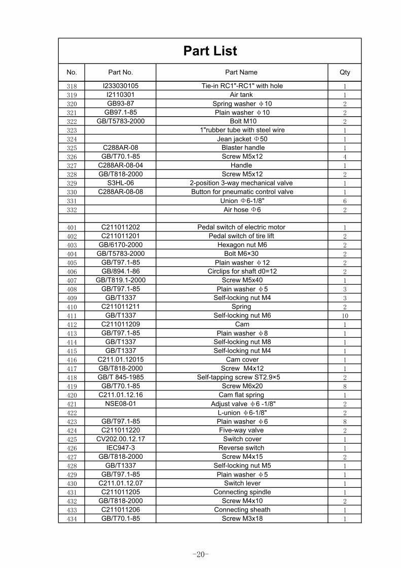
318 I233030105 Tie-in RC1"-RC1" with hole 1
319 I2110301 Air tank 1
320 GB93-87 Spring washer φ10 2
321 GB97.1-85 Plain washer φ10 2
322 GB/T5783-2000 Bolt M10 2
323 1"rubber tube with steel wire 1
324 Jean jacket Φ50 1
325 C288AR-08 Blaster handle 1
326 GB/T70.1-85 Screw M5x12 4
327 C288AR-08-04 Handle 1
328 GB/T818-2000 Screw M5x12 2
329 S3HL-06 2-position 3-way mechanical valve 1
330 C288AR-08-08 Button for pneumatic control valve 1
331 Union Φ6-1/8" 6
332 Air hose Φ6 2
401 C211011202 Pedal switch of electric motor 1
402 C211011201 Pedal switch of tire lift 2
403 GB/6170-2000 Hexagon nut M6 2
404 GB/T5783-2000 Bolt M6×30 2
405 GB/T97.1-85 Plain washer φ12 2
406 GB/894.1-86 Circlips for shaft d0=12 2
407 GB/T819.1-2000 Screw M5x40 1
408 GB/T97.1-85 Plain washer φ5 3
409 GB/T1337 Self-locking nut M4 3
410 C211011211 Spring 2
411 GB/T1337 Self-locking nut M6 10
412 C211011209 Cam 1
413 GB/T97.1-85 Plain washer φ8 1
414 GB/T1337 Self-locking nut M8 1
415 GB/T1337 Self-locking nut M4 1
416 C211.01.12015 Cam cover 1
417 GB/T818-2000 Screw M4x12 1
418 GB/T 845-1985 Self-tapping screw ST2.9×5 2
419 GB/T70.1-85 Screw M6x20 8
420 C211.01.12.16 Cam flat spring 1
421 NSE08-01 Adjust valve φ6 -1/8" 2
422 L-union φ6-1/8" 2
423 GB/T97.1-85 Plain washer φ6 8
424 C211011220 Five-way valve 2
425 CV202.00.12.17 Switch cover 1
426 IEC947-3 Reverse switch 1
427 GB/T818-2000 Screw M4x15 2
428 GB/T1337 Self-locking nut M5 1
429 GB/T97.1-85 Plain washer φ5 1
430 C211.01.12.07 Switch lever 1
431 C211011205 Connecting spindle 1
432 GB/T818-2000 Screw M4x10 2
433 C211011206 Connecting sheath 1
434 GB/T70.1-85 Screw M3x18 1
-20-
Part ListNo. Part No. Part Name Qty
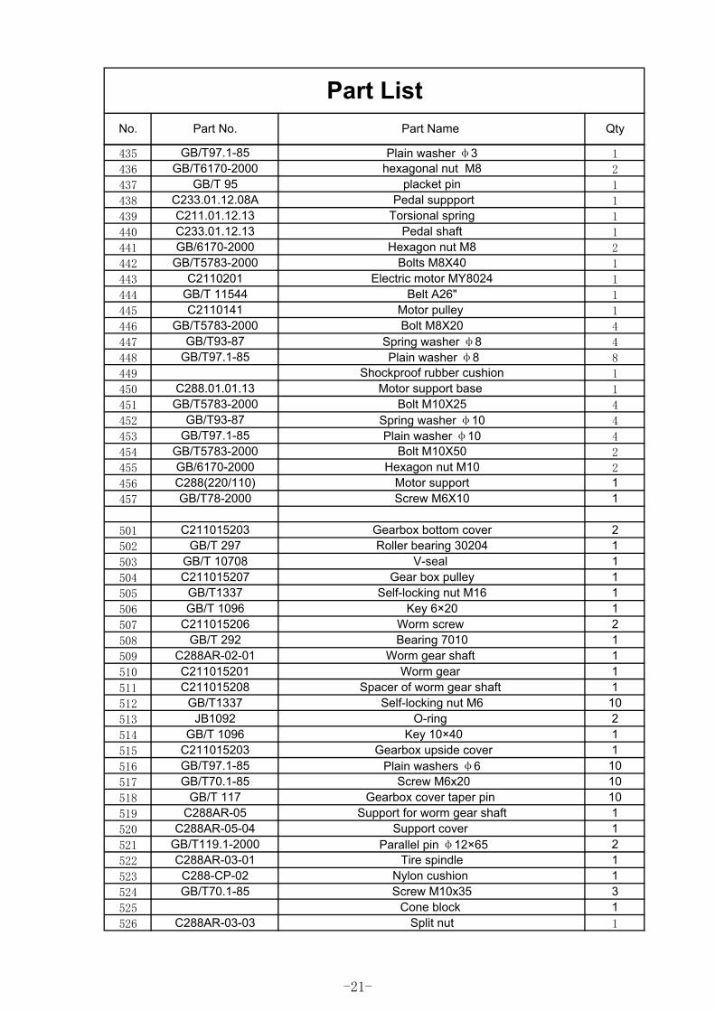
435 GB/T97.1-85 Plain washer φ3 1
436 GB/T6170-2000 hexagonal nut M8 2
437 GB/T 95 placket pin 1
438 C233.01.12.08A Pedal suppport 1
439 C211.01.12.13 Torsional spring 1
440 C233.01.12.13 Pedal shaft 1
441 GB/6170-2000 Hexagon nut M8 2
442 GB/T5783-2000 Bolts M8X40 1
443 C2110201 Electric motor MY8024 1
444 GB/T 11544 Belt A26" 1
445 C2110141 Motor pulley 1
446 GB/T5783-2000 Bolt M8X20 4
447 GB/T93-87 Spring washer φ8 4
448 GB/T97.1-85 Plain washer φ8 8
449 Shockproof rubber cushion 1
450 C288.01.01.13 Motor support base 1
451 GB/T5783-2000 Bolt M10X25 4
452 GB/T93-87 Spring washer φ10 4
453 GB/T97.1-85 Plain washer φ10 4
454 GB/T5783-2000 Bolt M10X50 2
455 GB/6170-2000 Hexagon nut M10 2
456 C288(220/110) Motor support 1457 GB/T78-2000 Screw M6X10 1
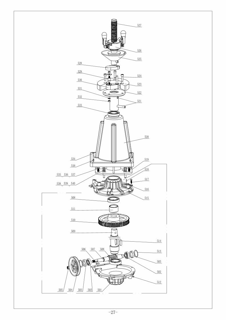
501 C211015203 Gearbox bottom cover 2502 GB/T 297 Roller bearing 30204 1503 GB/T 10708 V-seal 1504 C211015207 Gear box pulley 1505 GB/T1337 Self-locking nut M16 1506 GB/T 1096 Key 6×20 1507 C211015206 Worm screw 2508 GB/T 292 Bearing 7010 1509 C288AR-02-01 Worm gear shaft 1510 C211015201 Worm gear 1511 C211015208 Spacer of worm gear shaft 1512 GB/T1337 Self-locking nut M6 10513 JB1092 O-ring 2514 GB/T 1096 Key 10×40 1515 C211015203 Gearbox upside cover 1516 GB/T97.1-85 Plain washers φ6 10517 GB/T70.1-85 Screw M6x20 10518 GB/T 117 Gearbox cover taper pin 10519 C288AR-05 Support for worm gear shaft 1520 C288AR-05-04 Support cover 1521 GB/T119.1-2000 Parallel pin φ12×65 2522 C288AR-03-01 Tire spindle 1523 C288-CP-02 Nylon cushion 1524 GB/T70.1-85 Screw M10x35 3525 Cone block 1526 C288AR-03-03 Split nut 1
-21-
Part ListNo. Part No. Part Name Qty
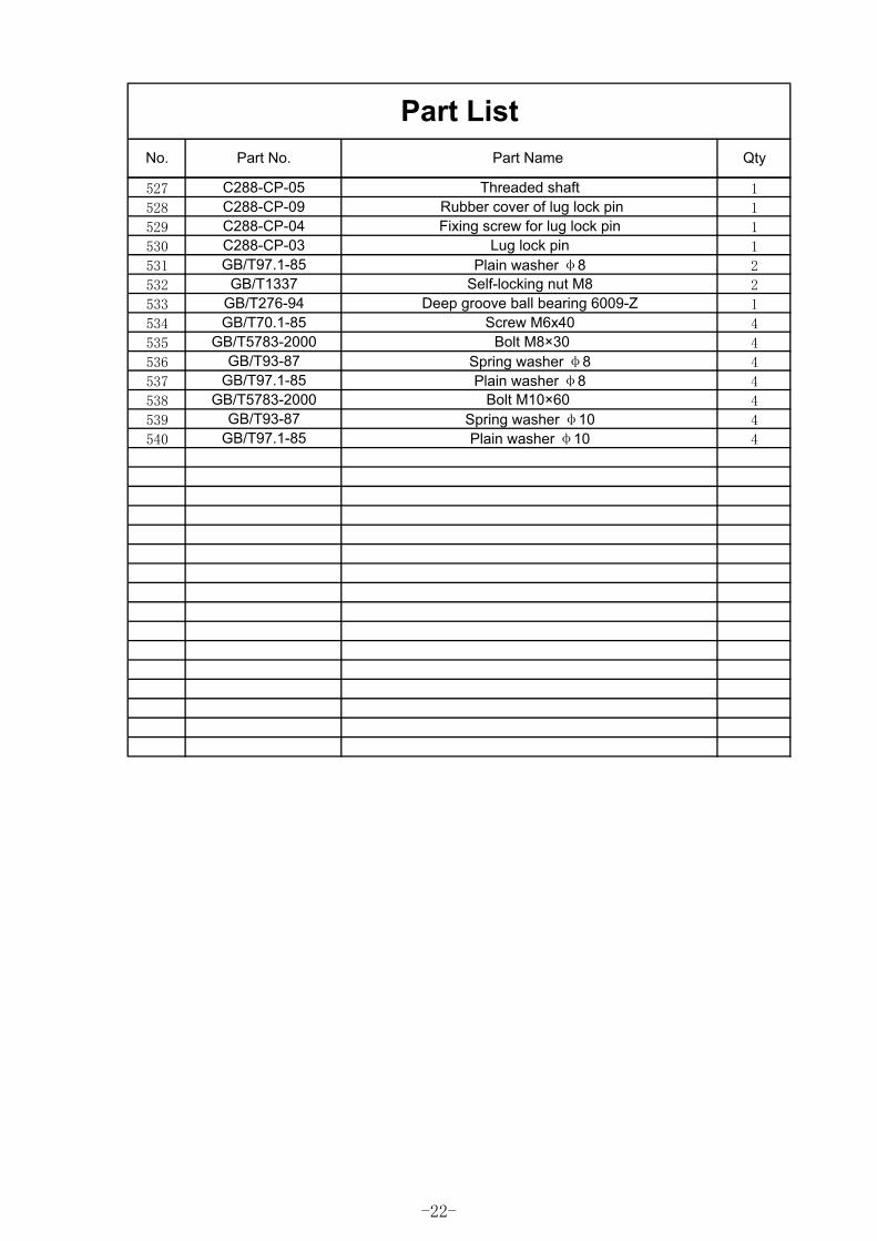
527 C288-CP-05 Threaded shaft 1
528 C288-CP-09 Rubber cover of lug lock pin 1
529 C288-CP-04 Fixing screw for lug lock pin 1
530 C288-CP-03 Lug lock pin 1
531 GB/T97.1-85 Plain washer φ8 2
532 GB/T1337 Self-locking nut M8 2
533 GB/T276-94 Deep groove ball bearing 6009-Z 1
534 GB/T70.1-85 Screw M6x40 4
535 GB/T5783-2000 Bolt M8×30 4
536 GB/T93-87 Spring washer φ8 4
537 GB/T97.1-85 Plain washer φ8 4
538 GB/T5783-2000 Bolt M10×60 4
539 GB/T93-87 Spring washer φ10 4
540 GB/T97.1-85 Plain washer φ10 4
-22-
-23-
-24-
-25-
-26-
-27-
12
34
ABCD
43
21
D C B A
13
24
L N PE
1 2
35 6
4
7 8
9 10
WV
U L1L2
L3
10
2 10
2
910
78
56 4
3 12
3 2 1
NL
PE
LCD
Aut
o In
flato
r
Vid
icon
NL
PEIN OUTDC12V 5A
NL
PE
AV
IN0V
12V
AV
OU
T0V
12V
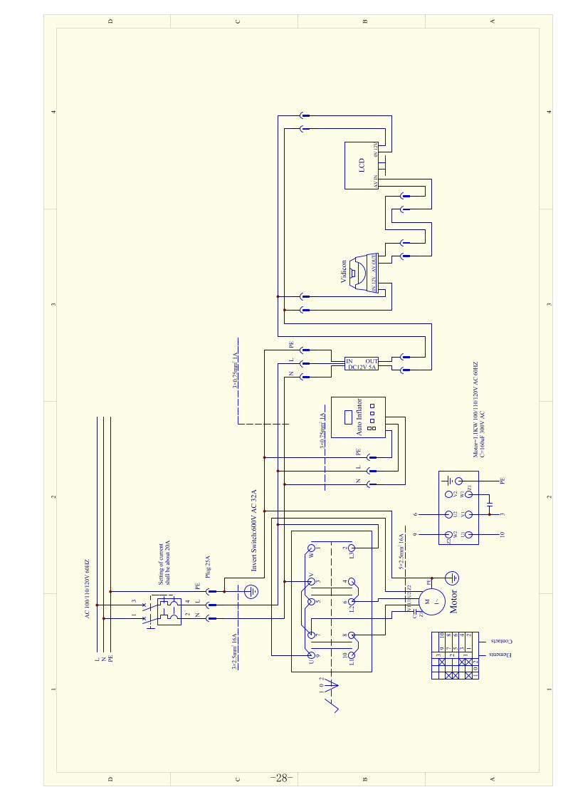
Mot
or
AC
100/
110/
120V
60H
Z
Inve
rt Sw
itch:
600V
AC
32A
Setti
ng o
f cur
rent
shal
l be
abou
t 20A
Plug
25A
3×2.
5mm
16A
2
Elements
Contacts
W2
U2
V2
U1
V1
W1
Z2
Z1
96
103
PE
5×2.
5mm
16A
2
M 1~
V1
U1
U2
Z2
Z1C
PE
Mot
or=1
.1K
W 1
00/1
10/1
20V
AC
60H
ZC=
160u
F 30
0V A
C
3×0.
75m
m 1
A2
3×0.
75m
m 1
A2
-28-

ABCDD C B A
13
24
L N PE
1 2
35 6
4
7 8
9 10
WV
U L1L2
L3
10
2 10
2
910
78
56 4
3 12
3 2 1
NL
PE
LCD
Aut
o In
flato
r
Vid
icon
NL
PEIN OUTDC12V 5A
NL
PE
AV
IN0V
12V
AV
OU
T0V
12V
Mot
or
AC
220/
230/
240V
50/
60H
Z
Inve
rt Sw
itch:
600V
AC
32A
Setti
ng o
f cur
rent
shal
l be
abou
t 10A
Plug
16A
3×2.
5mm
7.6
A2
Elements
Contacts
W2
U2
V2
U1
V1
W1
Z2
Z1
96
103
PE
5×2.
5mm
7.6
A2
M 1~
V1
U1
U2
Z2
Z1C
PE
Mot
or=0
.75K
W 2
20/2
30/2
40V
AC
50/6
0HZ
C=60
uF 4
50V
AC
3×0.
75m
m 1
A2
3×0.
75m
m 1
A
2
2
-29-
12
34
ABCD
43
21
D C B A
L1 L3 PE
10
2
910
78
56 4
3 12
3 2 1
LCD
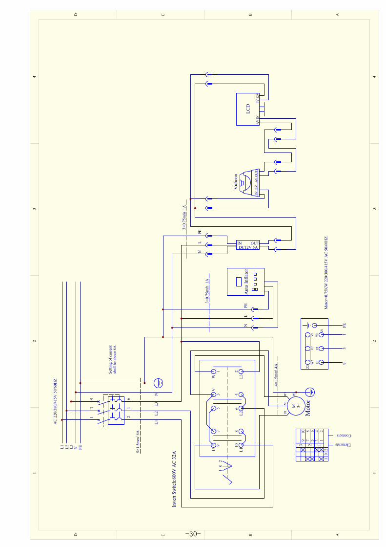
Aut
o In
flato
r
Vid
icon
NL
PEIN OUTDC12V 5A
NL
PE
AV
IN0V
12V
AV
OU
T0V
12V
Mot
or
AC
220/
380/
415V
50/
60H
Z
Inve
rt Sw
itch:
600V
AC
32A
Setti
ng o
f cur
rent
shal
l be
abou
t 6A
5×1.
5mm
6A
2
Elements
Contacts
W2
U2
V2
U1
V1
W1
Z2
Z1
93
PE
4×1.
5mm
4A
2
Mot
or=0
.75K
W 2
20/3
80/4
15V
AC
50/6
0HZ
L2
1 2
35 6
4
7 8
9 10
WV
U L1L2
L3
10
2
13
5
24
6
N
M 3~
U1
V1
W1
PE
1
L2L3
NL1
3×0.
75m
m 1
A2
3×0.
75m
m 1
A2
-30-