Embed Size (px)
Citation preview

Cable Glands & Accessories This catalog features ITC’s extensive range of liquid-tight, strain relief cord connectors (cable glands) and accessories, including locknuts, sealing washers, plugs, etc. These cable glands suit the majority of industrial applications such as switchgear manufacturing, automation and control panels, machine tools, instrumentation, and anywhere else a reliable, liquid-tight and pull-resistant seal is required when running cables and wires from an enclosure to the external environment. ITC’s cable glands are available in an array of styles and colours, and in the most popular threads including NPT, PG, Metric and BSP (PF or Gas). These glands are designed to accommodate a wide variety of cable diameters, from approximately 2mm-63mm / 0.08-2.50”, and most models are IP68 rated, meaning that they can be immersed in matter and still maintain a liquid-tight seal. The majority of models carry UL, CSA and VDE certifications. ITC’s plastic glands are made of polyamide 6 (or PA6). Plastic locknuts are made of PA6 reinforced with 33% fiberglass. Standard colours are Black (RAL9005) or light grey (RAL7035). Other colours: Dark grey (RAL7001) available upon request for all polyamide glands, blue (RAL5015) standard for Ex-i glands, and red (RAL3020) or white (RAL9003) available for select models only. Metal glands and locknuts are made of brass, nickel plated for optimal resistance to corrosion (some models available upon request in stainless steel – please consult ITC). Internal seals are made of neoprene (synthetic rubber). See page 29 for more detailed characteristics of these materials. New items to be found in this catalogue include metal glands for extra-large diameters of wires, long-thread glands, multi-hole seals, 90-degrees elbow connectors (male-female), and brass fittings for liquid-tight conduits. INDEX
Plastic Glands with Standard & Reducing Seals ........................................................................ 3 Plastic Glands with Long Thread- Metric & Pg ......................................................................... 6 Conus Glands - Polystyrene (Pg) & Metal (Pg & BSP) .................................................................. 7 Flex Protect Spiral Plastic Glands with Standard & Reducing Seals ................................................ 8 Elbow Plastic Glands & Elbow Plastic Connectors ................................................................... 10 Metal Glands with Standard & Reducing Seals - NPT ................................................................ 11 Metal Glands with Standard & Reducing Seals – Metric & Pg ...................................................... 12 Metal Glands with Long Thread – Metric & Pg ........................................................................ 13 Large Head Metal Glands with Long Thread – Metric ................................................................ 14 Double Seal Metal Glands - Metric & Pg .............................................................................. 15 EMC Metal Glands .......................................................................................................... 16 Large Metal Glands with Standard & Long Thread ................................................................... 17 Ventilation Plugs & Ventilation Glands – Metric & Pg ............................................................... 18 Accessories – Plastic Locknuts ........................................................................................... 20 Accessories – Metal Locknuts ............................................................................................ 22 Accessories – Threaded Stopping Plugs ................................................................................ 23 Accessories – Sealing Washers & O-Rings .............................................................................. 25 Accessories – Multi-Hole Seals ........................................................................................... 26 Accessories – Custom Cable Seals & Special Seals ................................................................... 27 Accessories - Hole Plugs & Temporary Sealing Plugs ................................................................ 27 Snap Bushings & Plugs .................................................................................................... 28 Ingress Protection (IP) .................................................................................................... 28 Characteristics of Plastic Materials .................................................................................... 29 Thread Tables with recommended cut-out sizes .................................................................... 29 Thread Adapters ........................................................................................................... 30
-2-
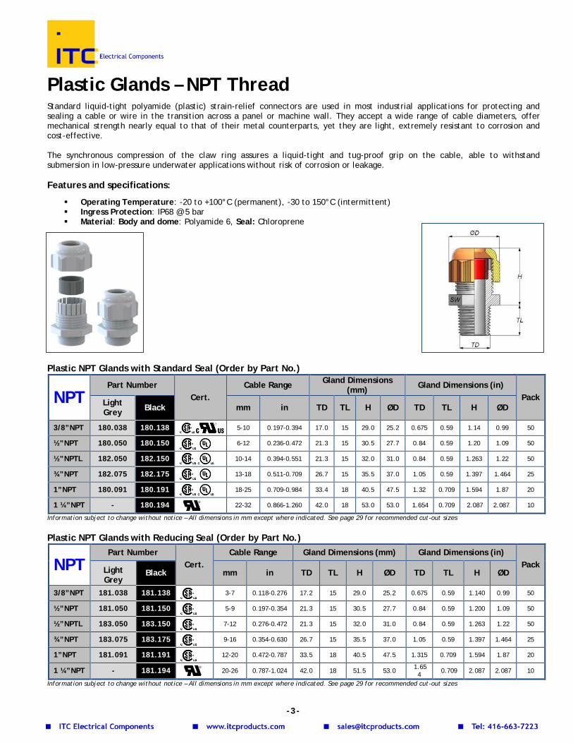
Plastic Glands – NPT Thread Standard liquid-tight polyamide (plastic) strain-relief connectors are used in most industrial applications for protecting and sealing a cable or wire in the transition across a panel or machine wall. They accept a wide range of cable diameters, offer mechanical strength nearly equal to that of their metal counterparts, yet they are light, extremely resistant to corrosion and cost-effective. The synchronous compression of the claw ring assures a liquid-tight and tug-proof grip on the cable, able to withstand submersion in low-pressure underwater applications without risk of corrosion or leakage. Features and specifications:
Operating Temperature: -20 to +100°C (permanent), -30 to 150°C (intermittent) Ingress Protection: IP68 @ 5 bar Material: Body and dome: Polyamide 6, Seal: Chloroprene
Plastic NPT Glands with Standard Seal (Order by Part No.)
NPT Part Number
Cert. Cable Range Gland Dimensions
(mm) Gland Dimensions (in) Pack Light
Grey Black mm in TD TL H ØD TD TL H ØD
3/8”NPT 180.038 180.138 5-10 0.197-0.394 17.0 15 29.0 25.2 0.675 0.59 1.14 0.99 50
½”NPT 180.050 180.150 6-12 0.236-0.472 21.3 15 30.5 27.7 0.84 0.59 1.20 1.09 50
½”NPTL 182.050 182.150 10-14 0.394-0.551 21.3 15 32.0 31.0 0.84 0.59 1.263 1.22 50
¾”NPT 182.075 182.175 13-18 0.511-0.709 26.7 15 35.5 37.0 1.05 0.59 1.397 1.464 25
1”NPT 180.091 180.191 18-25 0.709-0.984 33.4 18 40.5 47.5 1.32 0.709 1.594 1.87 20
1 ¼”NPT - 180.194 22-32 0.866-1.260 42.0 18 53.0 53.0 1.654 0.709 2.087 2.087 10
Information subject to change without notice – All dimensions in mm except where indicated. See page 29 for recommended cut-out sizes
Plastic NPT Glands with Reducing Seal (Order by Part No.)
NPT Part Number
Cert. Cable Range Gland Dimensions (mm) Gland Dimensions (in)
Pack Light Grey
Black mm in TD TL H ØD TD TL H ØD
3/8”NPT 181.038 181.138
3-7 0.118-0.276 17.2 15 29.0 25.2 0.675 0.59 1.140 0.99 50
½”NPT 181.050 181.150
5-9 0.197-0.354 21.3 15 30.5 27.7 0.84 0.59 1.200 1.09 50
½”NPTL 183.050 183.150
7-12 0.276-0.472 21.3 15 32.0 31.0 0.84 0.59 1.263 1.22 50
¾”NPT 183.075 183.175
9-16 0.354-0.630 26.7 15 35.5 37.0 1.05 0.59 1.397 1.464 25
1”NPT 181.091 181.191
12-20 0.472-0.787 33.5 18 40.5 47.5 1.315 0.709 1.594 1.87 20
1 ¼”NPT - 181.194
20-26 0.787-1.024 42.0 18 51.5 53.0 1.654 0.709 2.087 2.087 10
Information subject to change without notice – All dimensions in mm except where indicated. See page 29 for recommended cut-out sizes
-3-
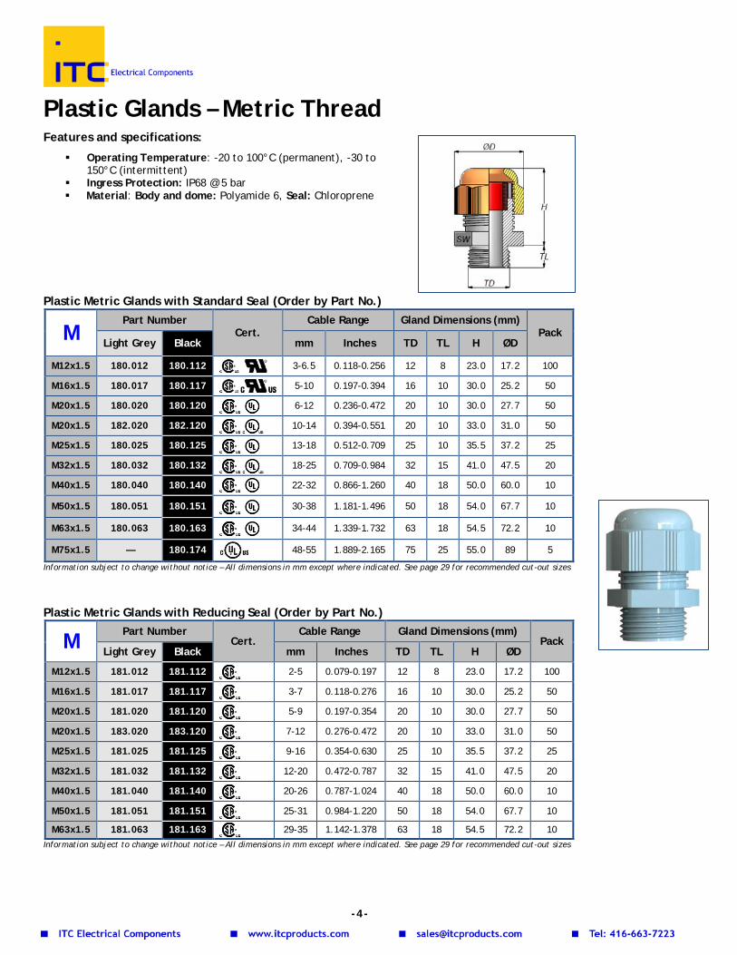
Plastic Glands – Metric Thread Features and specifications:
Operating Temperature: -20 to 100°C (permanent), -30 to 150°C (intermittent)
Ingress Protection: IP68 @ 5 bar Material: Body and dome: Polyamide 6, Seal: Chloroprene
Plastic Metric Glands with Standard Seal (Order by Part No.)
M Part Number
Cert. Cable Range Gland Dimensions (mm)
Pack Light Grey Black mm Inches TD TL H ØD
M12x1.5 180.012 180.112 3-6.5 0.118-0.256 12 8 23.0 17.2 100
M16x1.5 180.017 180.117 5-10 0.197-0.394 16 10 30.0 25.2 50
M20x1.5 180.020 180.120 6-12 0.236-0.472 20 10 30.0 27.7 50
M20x1.5 182.020 182.120 10-14 0.394-0.551 20 10 33.0 31.0 50
M25x1.5 180.025 180.125 13-18 0.512-0.709 25 10 35.5 37.2 25
M32x1.5 180.032 180.132 18-25 0.709-0.984 32 15 41.0 47.5 20
M40x1.5 180.040 180.140 22-32 0.866-1.260 40 18 50.0 60.0 10
M50x1.5 180.051 180.151 30-38 1.181-1.496 50 18 54.0 67.7 10
M63x1.5 180.063 180.163 34-44 1.339-1.732 63 18 54.5 72.2 10
M75x1.5 — 180.174
48-55 1.889-2.165 75 25 55.0 89 5
Information subject to change without notice – All dimensions in mm except where indicated. See page 29 for recommended cut-out sizes
Plastic Metric Glands with Reducing Seal (Order by Part No.)
M Part Number Cert.
Cable Range Gland Dimensions (mm) Pack
Light Grey Black mm Inches TD TL H ØD
M12x1.5 181.012 181.112
2-5 0.079-0.197 12 8 23.0 17.2 100
M16x1.5 181.017 181.117
3-7 0.118-0.276 16 10 30.0 25.2 50
M20x1.5 181.020 181.120
5-9 0.197-0.354 20 10 30.0 27.7 50
M20x1.5 183.020 183.120
7-12 0.276-0.472 20 10 33.0 31.0 50
M25x1.5 181.025 181.125
9-16 0.354-0.630 25 10 35.5 37.2 25
M32x1.5 181.032 181.132
12-20 0.472-0.787 32 15 41.0 47.5 20
M40x1.5 181.040 181.140
20-26 0.787-1.024 40 18 50.0 60.0 10
M50x1.5 181.051 181.151
25-31 0.984-1.220 50 18 54.0 67.7 10
M63x1.5 181.063 181.163
29-35 1.142-1.378 63 18 54.5 72.2 10 Information subject to change without notice – All dimensions in mm except where indicated. See page 29 for recommended cut-out sizes
-4-
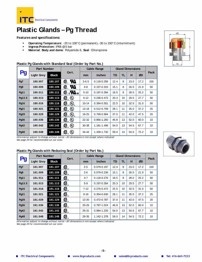
Plastic Glands – Pg Thread Features and specifications:
Operating Temperature: -20 to 100°C (permanent),-30 to 150°C (intermittent) Ingress Protection: IP68 @ 5 bar Material: Body and dome: Polyamide 6, Seal: Chloroprene
Plastic Pg Glands with Standard Seal (Order by Part No.)
Pg Part Number
Cert. Cable Range Gland Dimensions
Pack Light Grey Black mm Inches TD TL H ØD
Pg7 180.007 180.107 3-6.5 0.118-0.256 12.4 8 23.0 17.2 100
Pg9 180.009 180.109 4-8 0.157-0.315 15.1 8 26.5 21.9 50
Pg11 180.011 180.111 5-10 0.197-0.394 18.5 8 28.0 25.2 50
Pg13.5 180.013 180.113 6-12 0.236-0.472 20.3 10 29.5 27.7 50
Pg16 180.016 180.116 10-14 0.394-0.551 22.5 10 32.5 31.0 50
Pg21 180.021 180.121 13-18 0.512-0.709 28.1 11 35.0 37.2 25
Pg29 180.029 180.129 18-25 0.709-0.984 37.0 11 42.0 47.5 20
Pg36 180.036 180.136 22-32 0.866-1.260 46.8 13 52.0 60.0 10
Pg42 180.042 180.142 30-38 1.181-1.496 54.0 13 54.5 67.7 10
Pg48 180.048 180.148 34-44 1.339-1.732 59.0 14 54.5 72.2 10
Information subject to change without notice – All dimensions in mm except where indicated See page 29 for recommended cut-out sizes
Plastic Pg Glands with Reducing Seal (Order by Part No.)
Pg Part Number Cert.
Cable Range Gland Dimensions Pack
Light Grey Black mm Inches TD TL H ØD
Pg7 181.007 181.107
2-5 0.079-0.197 12.4 8 23.0 17.2 100
Pg9 181.009 181.109
2-6 0.079-0.236 15.1 8 26.5 21.9 50
Pg11 181.011 181.111
3-7 0.118-0.276 18.5 8 28.0 25.2 50
Pg13.5 181.013 181.113
5-9 0.197-0.354 20.3 10 29.5 27.7 50
Pg16 181.016 181.116
7-12 0.276-0.472 22.5 10 32.5 31.0 50
Pg21 181.021 181.121
9-16 0.354-0.630 28.1 11 35.0 37.2 25
Pg29 181.029 181.129
12-20 0.472-0.787 37.0 11 42.0 47.5 20
Pg36 181.036 181.136
20-26 0.787-1.024 46.8 13 52.0 60.0 10
Pg42 181.042 181.142
25-31 0.984-1.220 54.0 13 54.5 67.7 10
Pg48 181.048 181.148
29-35 1.142-1.378 59.0 14 54.5 72.2 10
Information subject to change without notice – All dimensions in mm except where indicated See page 29 for recommended cut-out sizes
-5-
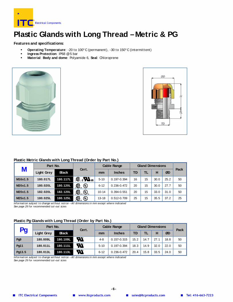
Plastic Glands with Long Thread – Metric & PG Features and specifications:
Operating Temperature: -20 to 100°C (permanent), -30 to 150°C (intermittent) Ingress Protection: IP68 @ 5 bar Material: Body and dome: Polyamide 6, Seal: Chloroprene
Plastic Metric Glands with Long Thread (Order by Part No.)
M Part No.
Cert. Cable Range Gland Dimensions
Pack Light Grey Black mm Inches TD TL H ØD
M16x1.5 180.017L 180.117L 5-10 0.197-0.394 16 15 30.0 25.2 50
M20x1.5 180.020L 180.120L 6-12 0.236-0.472 20 15 30.0 27.7 50
M20x1.5 182.020L 182.120L 10-14 0.394-0.551 20 15 33.0 31.0 50
M25x1.5 180.025L 180.125L 13-18 0.512-0.709 25 15 35.5 37.2 25
Information subject to change without notice – All dimensions in mm except where indicated See page 29 for recommended cut-out sizes
Plastic Pg Glands with Long Thread (Order by Part No.)
Pg Part No. Cert.
Cable Range Gland Dimensions Pack
Light Grey Black mm Inches TD TL H ØD
Pg9 180.009L 180.109L
4-8 0.157-0.315 15.2 14.7 27.1 18.8 50
Pg11 180.011L 180.111L
5-10 0.197-0.394 18.3 14.9 32.0 22.0 50
Pg13.5 180.013L 180.113L
6-12 0.236-0.472 20.4 15.8 33.5 24.0 50
Information subject to change without notice – All dimensions in mm except where indicated See page 29 for recommended cut-out sizes
-6-
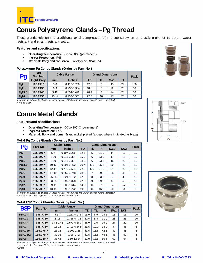
Conus Polystyrene Glands – Pg Thread These glands rely on the traditional axial compression of the top screw on an elastic grommet to obtain water resistant and strain-resistant seals. Features and specifications:
Operating Temperature: -30 to 80°C (permanent) Ingress Protection: IP65 Material: Body and top screw: Polystyrene, Seal: PVC
Polystyrene Pg Conus Glands (Order by Part No.)
Information subject to change without notice – All dimensions in mm except where indicated ^ end of stock
Conus Metal Glands Features and specifications:
Operating Temperature: -20 to 100°C (permanent) Ingress Protection: IP55 Material: Body and dome: Brass, nickel plated (except where indicated as brass)
Metal Pg Conus Glands (Order by Part No.)
Pg Part No. Cable Range Gland Dimensions
Pack mm inches TD TL H SW1 SW2
Pg7 185.691^ 5-7 0.197-0.276 12.5 5 21.0 14 13 10 Pg9 185.692^ 8-10 0.315-0.394 15.2 6 23.0 17 15 10 Pg11 185.693^ 8-10 0.315-0.394 18.6 6 23.5 18 20 10 Pg13.5 185.694^ 10-12 0.394-0.472 20.4 6.5 25.5 20 22 10 Pg16 185.695^ 12-14 0.472-0.551 22.5 6.5 27.0 24 22 10 Pg21 185.696^ 17-19 0.669-0.748 28.3 7 29.5 28 30 10 Pg29 185.697^ 26-28 1.024-1.102 37.0 8 33.0 37 40 10 Pg36 185.698^ 33-35 1.299-1.378 47.0 9 39.0 47 50 10 Pg42 185.699^ 39-41 1.535-1.614 54.0 10 57.0 54 57 10 Pg48 185.700^ 43-45 1.693-1.772 59.3 10 46.0 60 64 5
Information subject to change without notice – All dimensions in mm except where indicated ^ end of stock. See page 29 for recommended cut-out sizes Metal BSP Conus Glands (Order by Part No.)
BSP Part No. Cable Range Gland Dimensions
Pack mm inches TD TL H SW1 SW2
BSP 1/4” 185.771^ 5.5-7 0.217-0.276 13.0 6.5 23.5 13 15 10 BSP 1/2” 185.773^ 8-11 0.315-0.433 20.5 8.4 31.0 21 23 10 BSP 3/4" 185.775^ 14.5-17.5 0.571-0.689 26.0 9.0 35.0 27 29 10 BSP 1” 185.776^ 18-22 0.709-0.866 33.5 10.0 38.0 34 36 5 BSP 1 1/4" 185.778^ª 28-32 1.102-1.26 41.5 11.5 42.5 42 45 5 BSP 1 1/2" 185.779^ª 32-36 1.26-1.42 47.5 11.5 46.5 48 50 5 BSP 2” 185.780^ª 38-42 1.50-1.654 59.0 13.5 50.5 60 64 5
Information subject to change without notice – All dimensions in mm except where indicated ^ end of stock. See page 29 for recommended cut-out sizes ª Brass
Pg Part
Number Cable Range Gland Dimensions Pack
Light Grey mm Inches TD TL SW1 H Pg7 185.241^ 3-6 0.118-0.236 12.5 8 15 22 100 Pg11 185.243^ 6-9 0.236-0.354 18.6 8 22 25 50 Pg13.5 185.244^ 9-12 0.354-0.472 20.4 9 24 26 50 Pg16 185.245^ 11-14 0.433-0.551 22.5 10 27 28 50
-7-
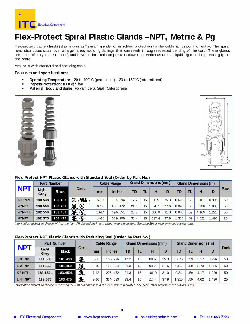
Flex-Protect Spiral Plastic Glands – NPT, Metric & Pg Flex-protect cable glands (also known as “spiral” glands) offer added protection to the cable at its point of entry. The spiral head distributes strain over a larger area, avoiding damage that can result through repeated bending of the cord. These glands are made of polyamide (plastic) and have an internal compression claw ring, which assures a liquid-tight and tug-proof grip on the cable.
Available with standard and reducing seals.
Features and specifications:
Operating Temperature: -20 to 100°C (permanent), -30 to 150°C (intermittent) Ingress Protection: IP68 @ 5 bar Material: Body and dome: Polyamide 6, Seal: Chloroprene
Flex-Protect NPT Plastic Glands with Standard Seal (Order by Part No.)
NPT Part Number
Cert. Cable Range Gland Dimensions (mm) Gland Dimensions (in)
Pack Light Grey Black mm Inches TD TL H D TD TL H D
3/8”NPT 180.538 180.438 5-10 .197-.394 17.2 15 80.5 25.3 0.675 .59 3.167 0.996 50
½”NPT 180.550 180.450 6-12 .236-.472 21.3 15 94.7 27.6 0.840 .59 3.730 1.086 50
½”NPT L 182.550 182.450 10-14 .394-.551 26.7 15 106.0 31.0 0.840 .59 4.169 1.220 50
¾”NPT 182.575 182.475 14-18 .551-.709 33.4 15 117.4 37.9 1.315 .59 4.622 1.490 25 Information subject to change without notice – All dimensions in mm except where indicated. See page 29 for recommended cut-out sizes
Flex-Protect NPT Plastic Glands with Reducing Seal (Order by Part No.)
NPT Part Number
Cert. Cable Range Gland Dimensions (mm) Gland Dimensions (in)
Pack Light Grey Black mm Inches TD TL H D TD TL H D
3/8” NPT 181.538 181.438
3-7 .118-.276 17.2 15 80.5 25.3 0.675 .59 3.17 0.996 50
1/2” NPT 181.550 181.450
5-10 .197-.354 21.3 15 94.7 27.6 0.84 .59 3.73 1.086 50
½” NPT L 183.550L 183.450L
7-12 .276-.472 21.3 15 106.0 31.0 0.84 .59 4.17 1.220 50
3/4” NPT 183.575 183.475
9-16 .354-.630 33.4 15 117.4 37.9 1.315 .59 4.62 1.490 25
Information subject to change without notice – All dimensions in mm except where indicated. See page 29 for recommended cut-out sizes
-8-
Flex-Protect Metric Plastic Glands with Standard Seal (Order by Part No.)
M Part Number
Cert. Cable Range Gland Dimensions
Pack Light Grey Black mm Inches TD TL H D
M12x1.5 180.512 180.412 3-6.5 0.118-0.256 12 8 56.0 17.1 100
M16x1.5 180.517 180.417 5-10 0.197-0.394 16 10 81.5 25.2 50
M20x1.5 180.520 180.420 6-12 0.236-0.472 20 10 94.5 27.6 50
M25x1.5 180.525 180.425 13-18 0.512-0.709 25 10 117.0 38.0 25 Information subject to change without notice – All dimensions in mm except where indicated. See page 29 for recommended cut-out sizes Flex-Protect Metric Plastic Glands with Reducing Seal (Order by Part No.)
M Part Number
Cert. Cable Range Gland Dimensions
Pack Light Grey Black mm Inches TD TL H D
M12x1.5 181.512 181.412
2-5 0.079-0.197 12 8 56.0 15 100
M16x1.5 181.517 181.417
3-7 0.118-0.276 16 10 81.5 22 50
M20x1.5 181.520 181.420
5-9 0.197-0.354 20 10 94.5 24 50
M25x1.5 181.525 181.425
9-16 0.354-0.630 25 10 117.0 33 25
Information subject to change without notice – All dimensions in mm except where indicated. See page 29 for recommended cut-out sizes Flex-Protect Pg Plastic Glands with Standard Seal (Order by Part No.)
Pg Part Number Cert.
Cable Range Gland Dimensions Pack
Light Grey Black mm Inches TD TL H D
Pg7 180.507 180.407 3-6.5 0.118-0.256 12.4 8 56.0 17.2 100
Pg9 180.509 180.409 4-8 0.157-0.315 15.1 8 69.0 21.8 50
Pg11 180.511 180.411 5-10 0.197-0.394 18.5 8 82.5 25.3 50
Pg13.5 180.513 180.413 6-12 0.236-0.472 20.3 9 94.0 27.6 50
Pg16 180.516 180.416 10-14 0.394-0.551 22.5 10 106 31.1 50
Pg21 180.521 180.421 13-18 0.512-0.709 28.1 11 117 38.0 25 Information subject to change without notice – All dimensions in mm except where indicated. See page 29 for recommended cut-out sizes Flex-Protect Pg Plastic Glands with Reducing Seal (Order by Part No.)
Pg Part Number Cert.
Cable Range Gland Dimensions Pack
Light Grey Black mm Inches TD TL H D
Pg7 181.507 181.407
2-5 0.079-0.197 12.4 8 56 17.2 100
Pg9 181.509 181.409
2-6 0.079-0.236 15.1 8 69 21.8 50
Pg11 181.511 181.411
3-7 0.118-0.276 18.5 8 82.5 25.3 50
Pg13.5 181.513 181.413
5-9 0.197-0.354 20.3 9 94 27.6 50
Pg16 181.516 181.416
7-12 0.276-0.472 22.5 10 106 31.1 50
Pg21 181.521 181.421
9-16 0.354-0.630 28.1 11 117 38.0 25
Information subject to change without notice – All dimensions in mm except where indicated. See page 29 for recommended cut-out sizes
-9-
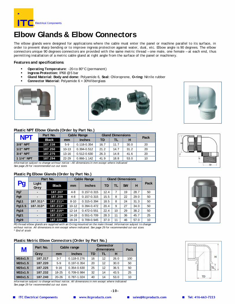
Elbow Glands & Elbow Connectors The elbow glands were designed for applications where the cable must enter the panel or machine parallel to its surface, in order to prevent sharp bending or to improve ingress protection against water, dust, etc. Elbow angle is 90 degrees. The elbow connectors unique 90 degrees connectors are provided with the same metric thread – one male, one female – at each end, thus permitting installation of a metric cable gland at right angle from the surface of the panel or machinery.
Features and specifications:
Operating Temperature: -20-to 80°C (permanent) Ingress Protection: IP68 @ 5 bar Gland Material: Body and dome: Polyamide 6, Seal: Chloroprene, O-ring: Nitrile rubber Connector Material: Polyamide 6 + 30% fiberglass
Plastic NPT Elbow Glands (Order by Part No.)
NPT Part No. Cable Range Gland Dimensions Pack
Black mm Inches TD TL H 3/8” NPT 187.238 5-9 0.118-0.354 16.7 11.7 30.0 20 1/2” NPT 187.250 10-13 0.394-0.512 21.2 14.7 31.2 20 3/4” NPT 187.275 13-16 0.512-0.630 26.3 14.8 41.6 20 1 1/4” NPT 187.294 22-29 0.866-1.142 41.9 18.8 53.0 10
Information subject to change without notice – All dimensions in mm except where indicated See page 29 for recommended cut-out sizes Plastic Pg Elbow Glands (Order by Part No.)
PG thread elbow glands are supplied with an O-ring mounted on the male thread. Information subject to change without notice. All dimensions in mm except where indicated. See page 29 for recommended cut-out sizes ^ End of stock Plastic Metric Elbow Connectors (Order by Part No.)
Information subject to change without notice. All dimensions in mm except where indicated See page 29 for recommended cut-out sizes
Pg Part No. Cable Range Gland Dimensions
Pack Light Grey Black mm Inches TD TL SW H
Pg7 - 187.207 4-8 0.157-0.315 12.4 7 19 28.7 50 Pg9 - 187.209 4-8 0.157-0.315 15.5 8 22 29.0 50 Pg11 187.311^ 187.211^ 8-10 0.315-0.394 18.5 8 24 31.3 50 Pg13.5 187.313^ 187.213^ 10-12 0.394-0.472 20.4 9 27 34.0 50 Pg16 - 187.216^ 12-14 0.472-0.551 22.4 10 29 38.2 50 Pg21 - 187.221^ 14-18 0.551-0.709 28.3 11 36 45.7 25 Pg29 - 187.229^ 18-24 0.709-0.945 37.0 11 46 57.0 10
M Part No. Cable range Connector dimensions Pack
Grey mm Inches TD TL H M16x1.5 187.217 3-7 0.118-0.276 16 12 26.0 100 M20x1.5 187.220 5-9 0.197-0.354 20 12 30.0 50 M25x1.5 187.225 9-16 0.354-0.630 25 12 36.5 50 M32x1.5 187.232 18-25 0.709-0.984 32 14 43.5 25 M40x1.5 187.240 20-26 0.787-1.024 40 14 53.0 10
-10-
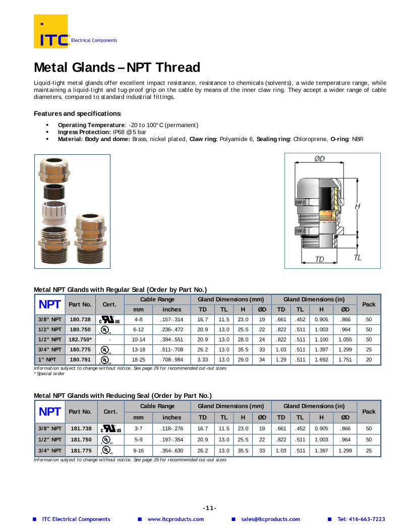
Metal Glands – NPT Thread Liquid-tight metal glands offer excellent impact resistance, resistance to chemicals (solvents), a wide temperature range, while maintaining a liquid-tight and tug-proof grip on the cable by means of the inner claw ring. They accept a wider range of cable diameters, compared to standard industrial fittings. Features and specifications:
Operating Temperature: -20 to 100°C (permanent) Ingress Protection: IP68 @ 5 bar Material: Body and dome: Brass, nickel plated, Claw ring: Polyamide 6, Sealing ring: Chloroprene, O-ring: NBR
Metal NPT Glands with Regular Seal (Order by Part No.)
NPT Part No. Cert. Cable Range Gland Dimensions (mm) Gland Dimensions (in)
Pack mm inches TD TL H ØD TD TL H ØD
3/8” NPT 180.738 4-8 .157-.314 16.7 11.5 23.0 19 .661 .452 0.905 .866 50
1/2” NPT 180.750 6-12 .236-.472 20.9 13.0 25.5 22 .822 .511 1.003 .964 50
1/2” NPT 182.750* - 10-14 .394-.551 20.9 13.0 28.0 24 .822 .511 1.100 1.055 50
3/4” NPT 180.775 13-18 .511-.708 26.2 13.0 35.5 33 1.03 .511 1.397 1.299 25
1” NPT 180.791 18-25 .708-.984 3.33 13.0 29.0 34 1.29 .511 1.692 1.751 20 Information subject to change without notice. See page 29 for recommended cut-out sizes * Special order Metal NPT Glands with Reducing Seal (Order by Part No.)
NPT Part No. Cert. Cable Range Gland Dimensions (mm) Gland Dimensions (in)
Pack mm inches TD TL H ØD TD TL H ØD
3/8” NPT 181.738 3-7 .118-.276 16.7 11.5 23.0 19 .661 .452 0.905 .866 50
1/2” NPT 181.750 5-9 .197-.354 20.9 13.0 25.5 22 .822 .511 1.003 .964 50
3/4” NPT 181.775 9-16 .354-.630 26.2 13.0 35.5 33 1.03 .511 1.397 1.299 25
Information subject to change without notice. See page 29 for recommended cut-out sizes
-11-
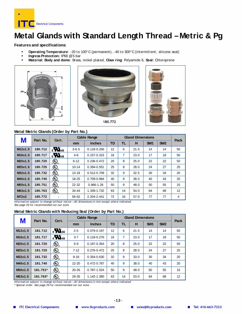
Metal Glands with Standard Length Thread – Metric & Pg Features and specifications:
Operating Temperature: -20 to 100°C (permanent), -40 to 300°C (intermittent, silicone seal) Ingress Protection: IP68 @ 5 bar Material: Body and dome: Brass, nickel plated, Claw ring: Polyamide 6, Seal: Chloroprene
Metal Metric Glands (Order by Part No.)
M Part No. Cert. Cable Range Gland Dimensions
Pack mm Inches TD TL H SW1 SW2
M12x1.5 180.712 3-6.5 0.118-0.256 12 6 21.5 14 14 50
M16x1.5 180.717 4-8 0.157-0.315 16 7 23.0 17 18 50
M20x1.5 180.720 6-12 0.236-0.472 20 8 25.0 22 22 50
M25x1.5 180.725 10-14 0.394-0.551 25 8 28.0 24 27 25
M32x1.5 180.732 13-18 0.512-0.709 32 9 32.5 30 34 20
M40x1.5 180.740 18-25 0.709-0.984 40 9 38.0 40 43 20
M50x1.5 180.751 22-32 0.866-1.26 50 9 48.0 50 55 15
M63x1.5 180.763 34-44 1.339-1.732 63 14 54.0 64 68 12
M72x2 180.772 - 56-62 2.204-2.441 72 16 57.0 77 77 4 Information subject to change without notice – All dimensions in mm except where indicated. See page 29 for recommended cut-out sizes
Metal Metric Glands with Reducing Seal (Order by Part No.)
M Part No. Cert. Cable Range Gland Dimensions
Pack mm Inches TD TL H SW1 SW2
M12x1.5 181.712 2-5 0.079-0.197 12 6 21.5 14 14 50
M16x1.5 181.717 3-7 0.118-0.276 16 7 23.0 17 18 50
M20x1.5 181.720 5-9 0.197-0.354 20 8 25.0 22 22 50
M25x1.5 181.725 7-12 0.276-0.472 25 8 28.0 24 27 25
M32x1.5 181.732 9-16 0.354-0.630 32 9 33.0 30 34 20
M40x1.5 181.740 12-20 0.472-0.787 40 9 38.0 40 43 20
M50x1.5 181.751* 20-26 0.787-1.024 50 9 48.0 50 55 15
M63x1.5 181.763* 29-35 1.142-1.380 63 14 53.0 64 68 12
Information subject to change without notice – All dimensions in mm except where indicated * Special order. See page 29 for recommended cut-out sizes
-12-
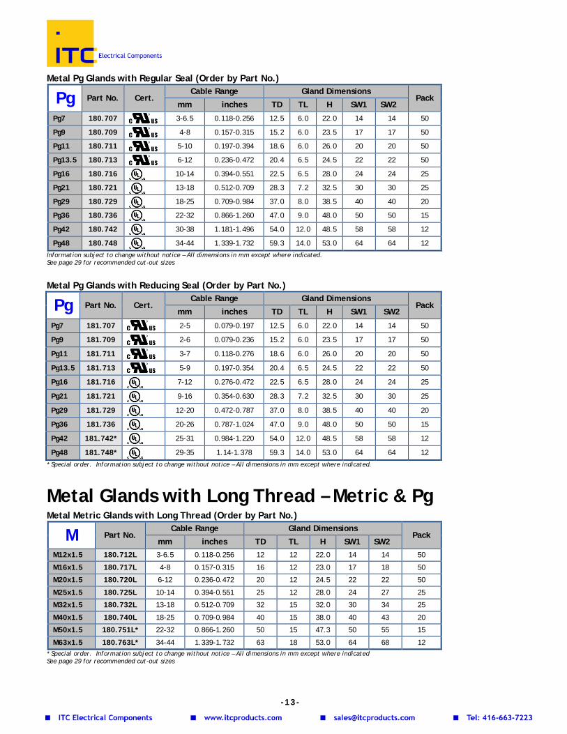
Metal Pg Glands with Regular Seal (Order by Part No.)
Pg Part No. Cert. Cable Range Gland Dimensions
Pack mm inches TD TL H SW1 SW2
Pg7 180.707 3-6.5 0.118-0.256 12.5 6.0 22.0 14 14 50
Pg9 180.709 4-8 0.157-0.315 15.2 6.0 23.5 17 17 50
Pg11 180.711 5-10 0.197-0.394 18.6 6.0 26.0 20 20 50
Pg13.5 180.713 6-12 0.236-0.472 20.4 6.5 24.5 22 22 50
Pg16 180.716 10-14 0.394-0.551 22.5 6.5 28.0 24 24 25
Pg21 180.721 13-18 0.512-0.709 28.3 7.2 32.5 30 30 25
Pg29 180.729 18-25 0.709-0.984 37.0 8.0 38.5 40 40 20
Pg36 180.736 22-32 0.866-1.260 47.0 9.0 48.0 50 50 15
Pg42 180.742 30-38 1.181-1.496 54.0 12.0 48.5 58 58 12
Pg48 180.748 34-44 1.339-1.732 59.3 14.0 53.0 64 64 12 Information subject to change without notice – All dimensions in mm except where indicated. See page 29 for recommended cut-out sizes
Metal Pg Glands with Reducing Seal (Order by Part No.)
Pg Part No. Cert. Cable Range Gland Dimensions
Pack mm inches TD TL H SW1 SW2
Pg7 181.707 2-5 0.079-0.197 12.5 6.0 22.0 14 14 50
Pg9 181.709 2-6 0.079-0.236 15.2 6.0 23.5 17 17 50
Pg11 181.711 3-7 0.118-0.276 18.6 6.0 26.0 20 20 50
Pg13.5 181.713 5-9 0.197-0.354 20.4 6.5 24.5 22 22 50
Pg16 181.716 7-12 0.276-0.472 22.5 6.5 28.0 24 24 25
Pg21 181.721 9-16 0.354-0.630 28.3 7.2 32.5 30 30 25
Pg29 181.729 12-20 0.472-0.787 37.0 8.0 38.5 40 40 20
Pg36 181.736 20-26 0.787-1.024 47.0 9.0 48.0 50 50 15
Pg42 181.742* 25-31 0.984-1.220 54.0 12.0 48.5 58 58 12
Pg48 181.748* 29-35 1.14-1.378 59.3 14.0 53.0 64 64 12 * Special order. Information subject to change without notice – All dimensions in mm except where indicated.
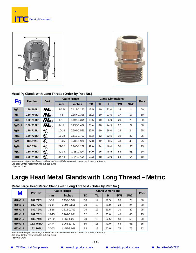
Metal Glands with Long Thread – Metric & Pg
Metal Metric Glands with Long Thread (Order by Part No.)
M Part No. Cable Range Gland Dimensions
Pack mm inches TD TL H SW1 SW2
M12x1.5 180.712L 3-6.5 0.118-0.256 12 12 22.0 14 14 50
M16x1.5 180.717L 4-8 0.157-0.315 16 12 23.0 17 18 50
M20x1.5 180.720L 6-12 0.236-0.472 20 12 24.5 22 22 50
M25x1.5 180.725L 10-14 0.394-0.551 25 12 28.0 24 27 25
M32x1.5 180.732L 13-18 0.512-0.709 32 15 32.0 30 34 25
M40x1.5 180.740L 18-25 0.709-0.984 40 15 38.0 40 43 20
M50x1.5 180.751L* 22-32 0.866-1.260 50 15 47.3 50 55 15
M63x1.5 180.763L* 34-44 1.339-1.732 63 18 53.0 64 68 12 * Special order. Information subject to change without notice – All dimensions in mm except where indicated See page 29 for recommended cut-out sizes
-13-
Metal Pg Glands with Long Thread (Order by Part No.)
Pg Part No. Cert. Cable Range Gland Dimensions
Pack mm inches TD TL H SW1 SW2
Pg7 180.707L*
3-6.5 0.118-0.256 12.5 10 22.0 14 14 50
Pg9 180.709L*
4-8 0.157-0.315 15.2 10 23.5 17 17 50
Pg11 180.711L*
5-10 0.197-0.394 18.6 10 26.0 20 20 50
Pg13.5 180.713L*
6-12 0.236-0.472 20.4 10 24.5 22 22 50
Pg16 180.716L*
10-14 0.394-0.551 22.5 10 28.0 24 24 25
Pg21 180.721L*
13-18 0.512-0.709 28.3 12 32.5 30 30 25
Pg29 180.729L 18-25 0.709-0.984 37.0 12 38.5 40 40 25
Pg36 180.736L 22-32 0.866-1.259 47.0 14 48.0 50 50 25
Pg42 180.742L* 30-38 1.18-1.496 54.0 16 48.5 58 58 10
Pg48 180.748L* 34-44 1.34-1.732 59.3 18 53.0 64 64 10
Information subject to change without notice – All dimensions in mm except where indicated See page 29 for recommended cut-out sizes * Special order
Large Head Metal Glands with Long Thread – Metric Metal Large Head Metric Glands with Long Thread & (Order by Part No.)
M Part No. Cable Range Gland Dimensions
Pack mm inches TD TL H SW1 SW2
M16x1.5 182.717L 5-10 0.197-0.394 16 12 29.5 20 20 50
M20x1.5 182.720L 10-14 0.394-0.551 20 12 28.0 24 24 50
M25x1.5 182.725L 13-18 0.512-0.709 25 12 29.5 30 30 25
M32x1.5 182.732L 18-25 0.709-0.984 32 15 35.0 40 40 25
M40x1.5 182.740L 22-32 0.866-1.260 40 15 52.5 50 50 20
M50x1.5 182.751L* 27-44 1.063-1.732 50 15 49.0 64 68 15
M63x1.5 182.763L* 37-53 1.457-2.087 63 18 50.0 75 75 12 Information subject to change without notice – All dimensions in mm except where indicated See page 29 for recommended cut-out sizes * Special order
-14-
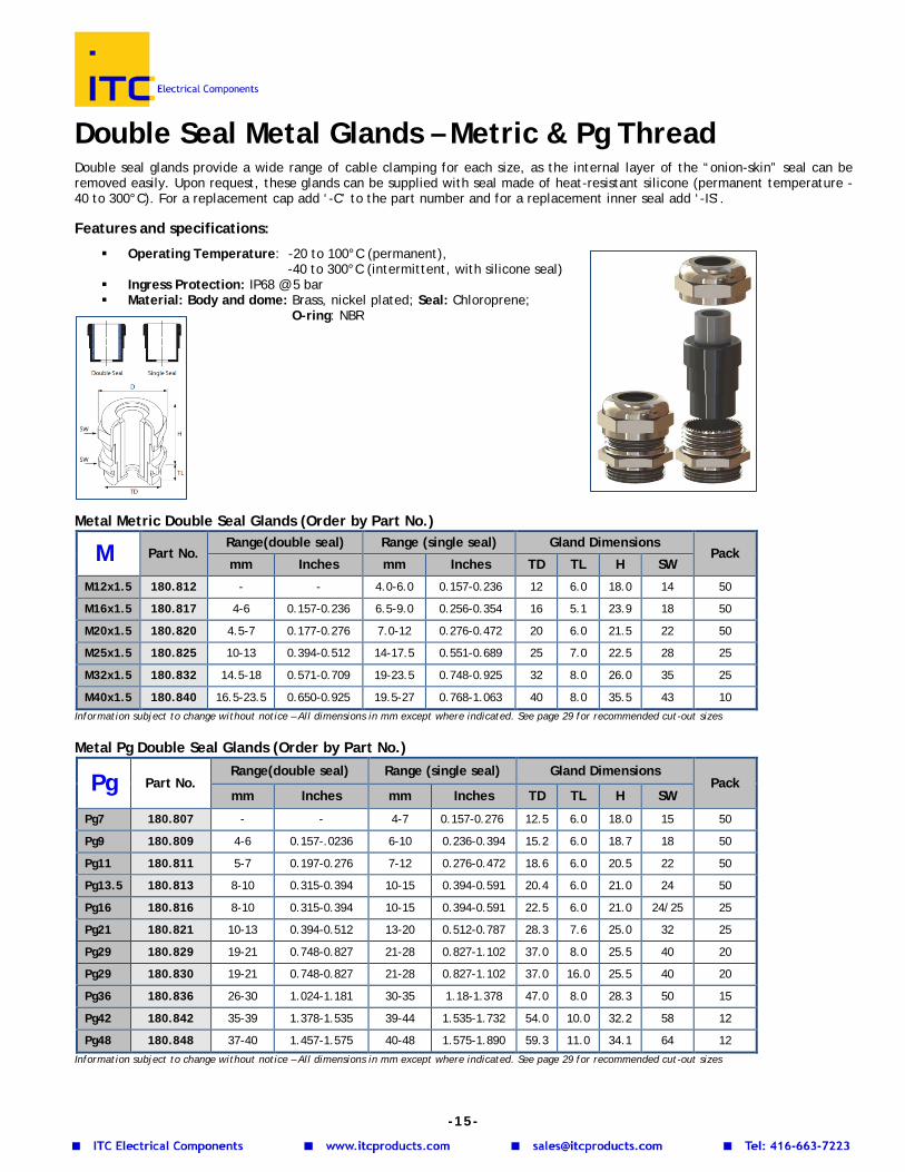
Double Seal Metal Glands – Metric & Pg Thread Double seal glands provide a wide range of cable clamping for each size, as the internal layer of the “onion-skin” seal can be removed easily. Upon request, these glands can be supplied with seal made of heat-resistant silicone (permanent temperature -40 to 300°C). For a replacement cap add ‘-C’ to the part number and for a replacement inner seal add ‘-IS’. Features and specifications:
Operating Temperature: -20 to 100°C (permanent), -40 to 300°C (intermittent, with silicone seal)
Ingress Protection: IP68 @ 5 bar Material: Body and dome: Brass, nickel plated; Seal: Chloroprene;
O-ring: NBR Metal Metric Double Seal Glands (Order by Part No.)
M Part No. Range(double seal) Range (single seal) Gland Dimensions
Pack mm Inches mm Inches TD TL H SW
M12x1.5 180.812 - - 4.0-6.0 0.157-0.236 12 6.0 18.0 14 50
M16x1.5 180.817 4-6 0.157-0.236 6.5-9.0 0.256-0.354 16 5.1 23.9 18 50
M20x1.5 180.820 4.5-7 0.177-0.276 7.0-12 0.276-0.472 20 6.0 21.5 22 50
M25x1.5 180.825 10-13 0.394-0.512 14-17.5 0.551-0.689 25 7.0 22.5 28 25
M32x1.5 180.832 14.5-18 0.571-0.709 19-23.5 0.748-0.925 32 8.0 26.0 35 25
M40x1.5 180.840 16.5-23.5 0.650-0.925 19.5-27 0.768-1.063 40 8.0 35.5 43 10 Information subject to change without notice – All dimensions in mm except where indicated. See page 29 for recommended cut-out sizes
Metal Pg Double Seal Glands (Order by Part No.)
Pg Part No. Range(double seal) Range (single seal) Gland Dimensions
Pack mm Inches mm Inches TD TL H SW
Pg7 180.807 - - 4-7 0.157-0.276 12.5 6.0 18.0 15 50
Pg9 180.809 4-6 0.157-.0236 6-10 0.236-0.394 15.2 6.0 18.7 18 50
Pg11 180.811 5-7 0.197-0.276 7-12 0.276-0.472 18.6 6.0 20.5 22 50
Pg13.5 180.813 8-10 0.315-0.394 10-15 0.394-0.591 20.4 6.0 21.0 24 50
Pg16 180.816 8-10 0.315-0.394 10-15 0.394-0.591 22.5 6.0 21.0 24/25 25
Pg21 180.821 10-13 0.394-0.512 13-20 0.512-0.787 28.3 7.6 25.0 32 25
Pg29 180.829 19-21 0.748-0.827 21-28 0.827-1.102 37.0 8.0 25.5 40 20
Pg29 180.830 19-21 0.748-0.827 21-28 0.827-1.102 37.0 16.0 25.5 40 20
Pg36 180.836 26-30 1.024-1.181 30-35 1.18-1.378 47.0 8.0 28.3 50 15
Pg42 180.842 35-39 1.378-1.535 39-44 1.535-1.732 54.0 10.0 32.2 58 12
Pg48 180.848 37-40 1.457-1.575 40-48 1.575-1.890 59.3 11.0 34.1 64 12 Information subject to change without notice – All dimensions in mm except where indicated. See page 29 for recommended cut-out sizes
-15-
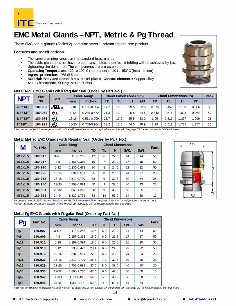
EMC Metal Glands – NPT, Metric & Pg Thread These EMC cable glands (Series 2) combine several advantages in one product. Features and specifications:
The same clamping ranges as the standard brass glands The cable gland does not have to be disassembled; a perfect shielding will be achieved by just
tightening the dome nut. The components are pre-assembled Operating Temperature: -20 to 100°C (permanent), -40 to 150°C (intermittent) Ingress protection: IP68 @ 5 bar Material: Body and dome: Brass, nickel plated, Contact elements: Copper alloy,
Seal: Chloroprene, O-ring: Nitrile Rubber Metal NPT EMC Glands with Regular Seal (Order by Part No.)
NPT Part No. Cert.
Cable Range Gland Dimensions (mm) Gland Dimensions (in) Pack mm Inches TD TL H ØD TD TL H ØD
3/8” NPT 180.938 5-10 0.196-0.394 17.2 11.5 29.5 22.0 0.675 0.452 1.160 0.866 50
1/2” NPT 180.950 6-12 0.236-0.472 21.3 13.0 25.5 24.5 0.840 0.511 1.003 0.964 50
3/4” NPT 180.975 13-18 0.511-0.709 26.7 13.0 35.5 33.0 1.05 0.511 1.397 1.299 25
1” NPT 180.991 18-25 0.708-0.984 33.2 13.0 44.5 48.9 1.29 0.511 1.735 1.757 10 Information subject to change without notice – Dimensions in mm except where indicated. See page 29 for recommended cut-out sizes
Metal Metric EMC Glands with Regular Seal (Order by Part No.)
M Part No. Cable Range Gland Dimensions
Pack mm Inches TD TL H SW1 SW2
M12x1.5 180.912 3-6.5 0.118-0.256 12 6 22.0 14 14 50
M16x1.5 180.917 4-8 0.157-0.315 16 7 23.0 17 18 50
M20x1.5 180.920 6-12 0.236-0.472 20 8 24.5 22 22 50
M25x1.5 180.925 10-14 0.394-0.551 25 8 28.0 24 27 25
M32x1.5 180.932 13-18 0.512-0.709 32 9 32.5 30 34 25
M40x1.5 180.940 18-25 0.709-0.984 40 9 38.0 40 43 20
M50x1.5 180.951 22-32 0.866-1.260 50 9 48.0 50 55 15
M63x1.5 180.963 34-44 1.339-1.732 63 14 53.0 64 68 12 Large head metric EMC domed glands up to M110x2 are available on request. Information subject to change without notice – Dimensions in mm except where indicated. See page 29 for recommended cut-out sizes
Metal Pg EMC Glands with Regular Seal (Order by Part No.)
Pg Part No. Cable Range Gland Dimensions
Pack mm inches TD TL H SW1 SW2
Pg7 180.907 3-6.5 0.118-0.256 12.5 6.0 22.0 14 14 50
Pg9 180.909 4-8 0.157-0.315 15.2 6.0 23.2 17 17 50
Pg11 180.911 5-10 0.197-0.394 18.6 6.0 26.0 20 20 50
Pg13.5 180.913 6-12 0.236-0.472 20.4 6.5 24.5 22 22 50
Pg16 180.916 10-14 0.394-.0551 22.5 6.5 28.0 24 24 25
Pg21 180.921 13-18 0.512-.0709 28.3 7.2 32.3 30 30 25
Pg29 180.929 18-25 0.709-0.984 37.0 8.0 38.0 40 40 20
Pg36 180.936 22-32 0.866-1.260 47.0 9.0 47.8 50 50 15
Pg42 180.942 30-38 1.18-1.496 54.0 12.0 48.9 58 58 12
Pg48 180.948 34-44 1.339-1.73 59.3 14.0 52.4 64 64 12 Information subject to change without notice – Dimensions in mm except where indicated. See page 29 for recommended cut-out sizes
-16-
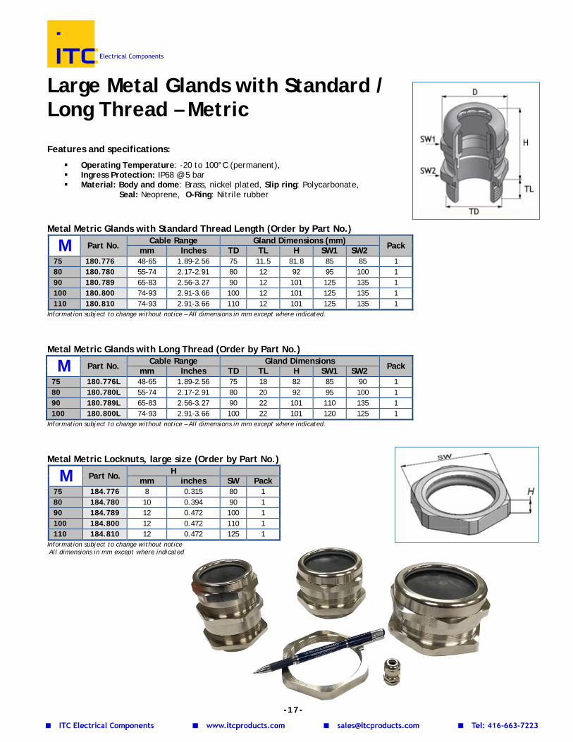
Large Metal Glands with Standard / Long Thread – Metric
Features and specifications:
Operating Temperature: -20 to 100°C (permanent), Ingress Protection: IP68 @ 5 bar Material: Body and dome: Brass, nickel plated, Slip ring: Polycarbonate,
Seal: Neoprene, O-Ring: Nitrile rubber Metal Metric Glands with Standard Thread Length (Order by Part No.)
M Part No. Cable Range Gland Dimensions (mm) Pack mm Inches TD TL H SW1 SW2 75 180.776 48-65 1.89-2.56 75 11.5 81.8 85 85 1 80 180.780 55-74 2.17-2.91 80 12 92 95 100 1 90 180.789 65-83 2.56-3.27 90 12 101 125 135 1 100 180.800 74-93 2.91-3.66 100 12 101 125 135 1 110 180.810 74-93 2.91-3.66 110 12 101 125 135 1
Information subject to change without notice – All dimensions in mm except where indicated.
Metal Metric Glands with Long Thread (Order by Part No.)
M Part No. Cable Range Gland Dimensions Pack mm Inches TD TL H SW1 SW2 75 180.776L 48-65 1.89-2.56 75 18 82 85 90 1 80 180.780L 55-74 2.17-2.91 80 20 92 95 100 1 90 180.789L 65-83 2.56-3.27 90 22 101 110 135 1 100 180.800L 74-93 2.91-3.66 100 22 101 120 125 1
Information subject to change without notice – All dimensions in mm except where indicated.
Metal Metric Locknuts, large size (Order by Part No.)
M Part No. H mm inches SW Pack
75 184.776 8 0.315 80 1 80 184.780 10 0.394 90 1 90 184.789 12 0.472 100 1 100 184.800 12 0.472 110 1 110 184.810 12 0.472 125 1
Information subject to change without notice All dimensions in mm except where indicated
-17-
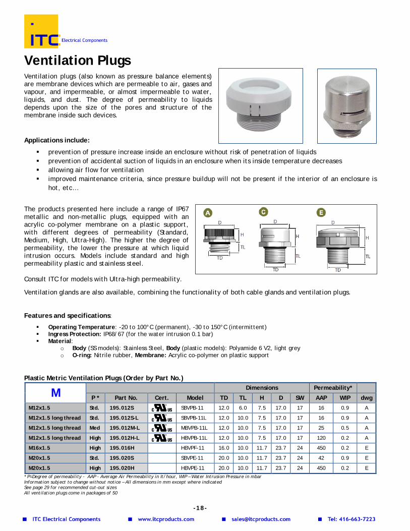
Ventilation Plugs Ventilation plugs (also known as pressure balance elements) are membrane devices which are permeable to air, gases and vapour, and impermeable, or almost impermeable to water, liquids, and dust. The degree of permeability to liquids depends upon the size of the pores and structure of the membrane inside such devices.
Applications include:
prevention of pressure increase inside an enclosure without risk of penetration of liquids prevention of accidental suction of liquids in an enclosure when its inside temperature decreases allowing air flow for ventilation improved maintenance criteria, since pressure buildup will not be present if the interior of an enclosure is
hot, etc…
The products presented here include a range of IP67 metallic and non-metallic plugs, equipped with an acrylic co-polymer membrane on a plastic support, with different degrees of permeability (Standard, Medium, High, Ultra-High). The higher the degree of permeability, the lower the pressure at which liquid intrusion occurs. Models include standard and high permeability plastic and stainless steel. Consult ITC for models with Ultra-high permeability. Ventilation glands are also available, combining the functionality of both cable glands and ventilation plugs. Features and specifications:
Operating Temperature: -20 to 100°C (permanent), -30 to 150°C (intermittent) Ingress Protection: IP68/67 (for the water intrusion 0.1 bar) Material:
o Body (SS models): Stainless Steel, Body (plastic models): Polyamide 6 V2, light grey o O-ring: Nitrile rubber, Membrane: Acrylic co-polymer on plastic support
Plastic Metric Ventilation Plugs (Order by Part No.)
M Dimensions Permeability*
P * Part No. Cert. Model TD TL H D SW AAP WIP dwg
M12x1.5 Std. 195.012S SBVPB-11 12.0 6.0 7.5 17.0 17 16 0.9 A
M12x1.5 long thread Std. 195.012S-L SBVPB-11L 12.0 10.0 7.5 17.0 17 16 0.9 A
M12x1.5 long thread Med 195.012M-L MBVPB-11L 12.0 10.0 7.5 17.0 17 25 0.5 A
M12x1.5 long thread High 195.012H-L HBVPB-11L 12.0 10.0 7.5 17.0 17 120 0.2 A
M16x1.5 High 195.016H HBVPF-11 16.0 10.0 11.7 23.7 24 450 0.2 E
M20x1.5 Std. 195.020S SBVPE-11 20.0 10.0 11.7 23.7 24 42 0.9 E
M20x1.5 High 195.020H HBVPE-11 20.0 10.0 11.7 23.7 24 450 0.2 E * P=Degree of permeability - AAP - Average Air Permeability in It/hour, WIP – Water Intrusion Pressure in mbar Information subject to change without notice – All dimensions in mm except where indicated See page 29 for recommended cut-out sizes All ventilation plugs come in packages of 50
-18-
Stainless Steel Metric Ventilation Plugs Short & Long Thread (Order by Part No.)
M/Pg Dimensions Permeability*
P * Part No. Cert. Model TD TL H D SW AAP WIP dwg
M12x1.5 Std. 195.712S SBBVP-01L 12.0 10.0 11.0 17.0 17 16 0.9 C
M12x1.5 High 195.712H HBBVP-01L 12.0 10.0 11.0 17.0 17 120 0.2 C
Pg7 Std. 195.707S SBBVP-0S 16.0 10.0 11.7 23.7 24 42 0.9 E
Pg7 High 195.707H HBBVP-0S 16.0 10.0 11.7 23.7 24 42 0.9 E
M16x1.5 Std. 195.716S SBBVP-02 16.5 6.0 12.4 17.0 18 120 0.2 C
M16x1.5 High 195.716H HBBVP-02 16.5 6.0 17.0 17.0 18 16 0.9 C
M20x1.5 Std. 195.720S SBBVP-03L 20.0 6.0 17.0 17.0 22 16 0.9 C
M20x1.5 High 195.720H HBBVP-03L 20.0 6.0 17.0 17.0 22 120 0.2 C * P=Degree of permeability - AAP - Average Air Permeability in It/hour, WIP – Water Intrusion Pressure in mbar Information subject to change without notice – All dimensions in mm except where indicated See page 29 for recommended cut-out sizes All ventilation plugs come in packages of 50
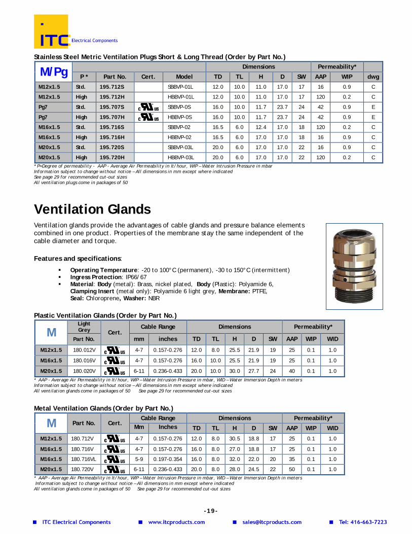
Ventilation Glands Ventilation glands provide the advantages of cable glands and pressure balance elements combined in one product. Properties of the membrane stay the same independent of the cable diameter and torque. Features and specifications:
Operating Temperature: -20 to 100°C (permanent), -30 to 150°C (intermittent) Ingress Protection: IP66/67 Material: Body (metal): Brass, nickel plated, Body (Plastic): Polyamide 6,
Clamping Insert (metal only): Polyamide 6 light grey, Membrane: PTFE, Seal: Chloroprene, Washer: NBR
Plastic Ventilation Glands (Order by Part No.)
M Light Grey Cert.
Cable Range Dimensions Permeability*
Part No. mm inches TD TL H D SW AAP WIP WID
M12x1.5 180.012V 4-7 0.157-0.276 12.0 8.0 25.5 21.9 19 25 0.1 1.0
M16x1.5 180.016V 4-7 0.157-0.276 16.0 10.0 25.5 21.9 19 25 0.1 1.0
M20x1.5 180.020V 6-11 0.236-0.433 20.0 10.0 30.0 27.7 24 40 0.1 1.0
* AAP - Average Air Permeability in It/hour, WIP – Water Intrusion Pressure in mbar, WID – Water Immersion Depth in meters Information subject to change without notice – All dimensions in mm except where indicated All ventilation glands come in packages of 50 See page 29 for recommended cut-out sizes
Metal Ventilation Glands (Order by Part No.)
M Part No. Cert. Cable Range Dimensions Permeability*
Mm Inches TD TL H D SW AAP WIP WID
M12x1.5 180.712V 4-7 0.157-0.276 12.0 8.0 30.5 18.8 17 25 0.1 1.0
M16x1.5 180.716V 4-7 0.157-0.276 16.0 8.0 27.0 18.8 17 25 0.1 1.0
M16x1.5 180.716VL 5-9 0.197-0.354 16.0 8.0 32.0 22.0 20 35 0.1 1.0
M20x1.5 180.720V 6-11 0.236-0.433 20.0 8.0 28.0 24.5 22 50 0.1 1.0 * AAP - Average Air Permeability in It/hour, WIP – Water Intrusion Pressure in mbar, WID – Water Immersion Depth in meters Information subject to change without notice – All dimensions in mm except where indicated All ventilation glands come in packages of 50 See page 29 for recommended cut-out sizes
-19-
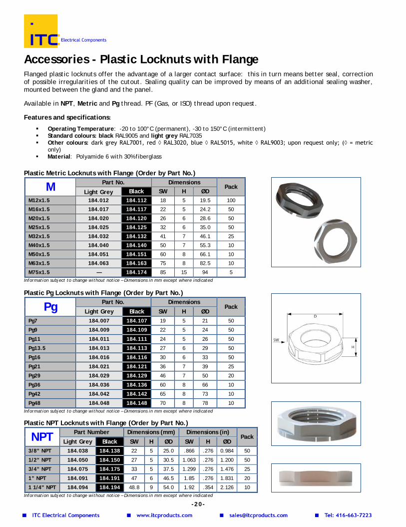
Accessories - Plastic Locknuts with Flange
Flanged plastic locknuts offer the advantage of a larger contact surface: this in turn means better seal, correction of possible irregularities of the cutout. Sealing quality can be improved by means of an additional sealing washer, mounted between the gland and the panel. Available in NPT, Metric and Pg thread. PF (Gas, or ISO) thread upon request. Features and specifications:
Operating Temperature: -20 to 100°C (permanent), -30 to 150°C (intermittent) Standard colours: black RAL9005 and light grey RAL7035 Other colours: dark grey RAL7001, red ◊ RAL3020, blue ◊ RAL5015, white ◊ RAL9003; upon request only; (◊ = metric
only) Material: Polyamide 6 with 30% fiberglass
Plastic Metric Locknuts with Flange (Order by Part No.)
Information subject to change without notice – Dimensions in mm except where indicated Plastic Pg Locknuts with Flange (Order by Part No.)
Information subject to change without notice – Dimensions in mm except where indicated Plastic NPT Locknuts with Flange (Order by Part No.)
Information subject to change without notice – Dimensions in mm except where indicated
M Part No. Dimensions Pack
Light Grey Black SW H ØD M12x1.5 184.012 184.112 18 5 19.5 100
M16x1.5 184.017 184.117 22 5 24.2 50
M20x1.5 184.020 184.120 26 6 28.6 50
M25x1.5 184.025 184.125 32 6 35.0 50
M32x1.5 184.032 184.132 41 7 46.1 25
M40x1.5 184.040 184.140 50 7 55.3 10
M50x1.5 184.051 184.151 60 8 66.1 10
M63x1.5 184.063 184.163 75 8 82.5 10
M75x1.5 — 184.174 85 15 94 5
Pg Part No. Dimensions Pack
Light Grey Black SW H ØD Pg7 184.007 184.107 19 5 21 50
Pg9 184.009 184.109 22 5 24 50
Pg11 184.011 184.111 24 5 26 50
Pg13.5 184.013 184.113 27 6 29 50
Pg16 184.016 184.116 30 6 33 50
Pg21 184.021 184.121 36 7 39 25
Pg29 184.029 184.129 46 7 50 20
Pg36 184.036 184.136 60 8 66 10
Pg42 184.042 184.142 65 8 73 10
Pg48 184.048 184.148 70 8 78 10
NPT Part Number Dimensions (mm) Dimensions (in) Pack
Light Grey Black SW H ØD SW H ØD 3/8” NPT 184.038 184.138 22 5 25.0 .866 .276 0.984 50
1/2” NPT 184.050 184.150 27 5 30.5 1.063 .276 1.200 50
3/4” NPT 184.075 184.175 33 5 37.5 1.299 .276 1.476 25
1” NPT 184.091 184.191 47 6 46.5 1.85 .276 1.831 20
1 1/4” NPT 184.094 184.194 48.8 9 54.0 1.92 .354 2.126 10
-20-
Plastic BSP Locknuts (Order by Part No.)
Information subject to change without notice – Dimensions in mm except where indicated
Accessories - Plastic Locknuts without Flange
Non-flanged plastic locknuts (Metric and Pg thread) are mostly used when there is limited space for the application of the locknut. Sealing quality can be improved by means of an additional sealing washer, mounted between the gland and the panel.
Features and specifications:
Operating Temperature: -20 to 80°C (permanent) Colours: Black RAL9005 and light grey RAL7035. Dark grey RAL7001 available upon request Material: Polyamide 6 with 30% fiberglass
Plastic Metric Locknuts without Flange (Order by Part No.)
M Part Number Dimensions Pack
Light Grey Black SW H ØD
M12x1.5 184.512 184.412 18 5 19.5 100
M16x1.5 184.517 184.417 22 5 24.2 50
M20x1.5 184.520 184.420 26 6 28.6 50
M25x1.5 184.525 184.425 32 6 35.0 50
M32x1.5 184.532 184.432 41 7 46.1 25
M40x1.5 184.540 184.440 50 7 55.3 10 Information subject to change without notice – Dimensions in mm except where indicated
Plastic Pg Locknuts without Flange (Order by Part No.)
Pg Part Number Dimensions Pack
Light Grey Black SW H ØD
Pg7 184.507 184.407 19 5 21 100
Pg9 184.509 184.409 22 5 24 100
Pg11 184.511 184.411 24 5 26 50
Pg13.5 184.513 184.413 27 6 29 50
Pg16 184.516 184.416 30 6 33 50
Pg21 184.521 184.421 36 7 39 25
Pg29 184.529 184.429 46 7 50 25
Pg36 184.536 184.436 60 8 66 25
Pg42 184.542 184.442 65 8 72 10
Pg48 184.548 184.448 70 8 78 10 Information subject to change without notice – Dimensions in mm except where indicated
BSP Part No. with Flange Part No. without Flange Pack
Light Grey Black Light Grey Black BSP 1/4” 184.027 184.127 184.527 184.427 100
BSP 3/8” 184.037 184.137 184.537 184.437 100
BSP 1/2" 184.049 184.149 184.549 184.449 50
BSP 3/4" 184.074 184.174 184.574 184.474 25
BSP 1” 184.090 184.190 184.590 184.490 10
-21-
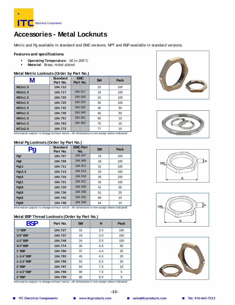
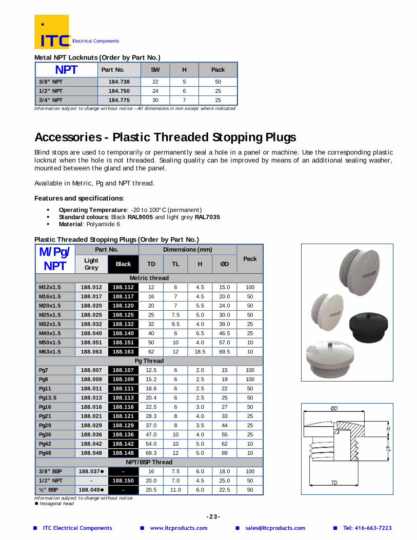
Accessories - Metal Locknuts Metric and Pg available in standard and EMC versions; NPT and BSP available in standard versions. Features and specifications:
Operating Temperature: -60 to 200°C Material: Brass, nickel plated
Metal Metric Locknuts (Order by Part No.)
Information subject to change without notice – All dimensions in mm except where indicated
Metal Pg Locknuts (Order by Part No.)
Information subject to change without notice – All dimensions in mm except where indicated Metal BSP Thread Locknuts (Order by Part No.)
Information subject to change without notice – All dimensions in mm except where indicated
M Standard Part No.
EMC Part No. SW Pack
M12x1.5 184.712 - 15 100
M16x1.5 184.717 184.917 19 100
M20x1.5 184.720 184.920 24 100
M25x1.5 184.725 184.925 30 100
M32x1.5 184.732 184.932 36 50
M40x1.5 184.740 184.940 46 50
M50x1.5 184.751 184.951 60 10
M63x1.5 184.763 184.963 70 10
M72x2.0 184.772 - 77 10
Pg Standard Part No.
EMC Part No. SW Pack
Pg7 184.707 184.907 15 100
Pg9 184.709 184.909 18 100
Pg11 184.711 184.911 21 100
Pg13.5 184.713 184.913 23 100
Pg16 184.716 184.916 26 100
Pg21 184.721 184.921 32 100
Pg29 184.729 184.929 41 50
Pg36 184.736 184.936 51 25
Pg42 184.742 184.942 60 10
Pg48 184.748 184.948 64 10
BSP Part No. SW H Pack
¼”BSP 184.727 15 3.0 100
3/8”BSP 184.737 19 3.0 100
1/2”BSP 184.749 24 3.5 100
3/4”BSP 184.774 30 4.0 50
1”BSP 184.790 37 4.0 25
1-1/4”BSP 184.793 45 4.5 20
1-1/2”BSP 184.796 52 5.5 20
2”BSP 184.797 64 7.0 10
2-1/2”BSP 184.798 80 7.0 5
3”BSP 184.799 95 8.0 5
-22-
Metal NPT Locknuts (Order by Part No.)
Information subject to change without notice – All dimensions in mm except where indicated
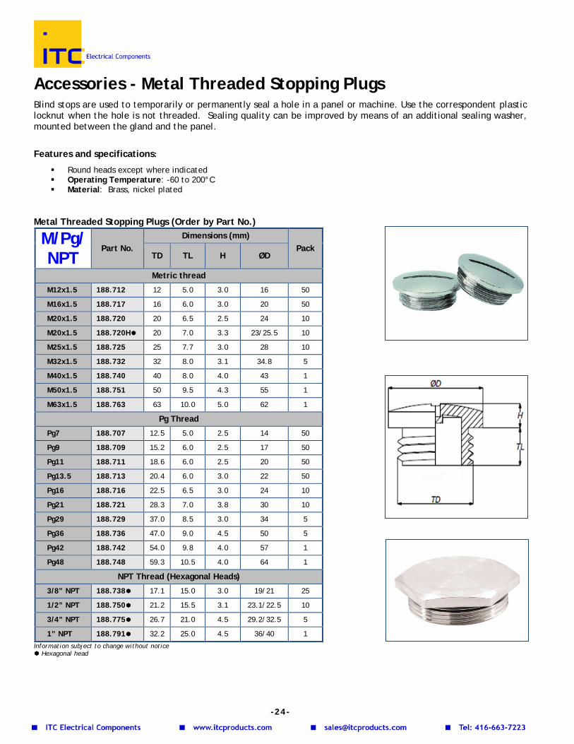
Accessories - Plastic Threaded Stopping Plugs Blind stops are used to temporarily or permanently seal a hole in a panel or machine. Use the corresponding plastic locknut when the hole is not threaded. Sealing quality can be improved by means of an additional sealing washer, mounted between the gland and the panel. Available in Metric, Pg and NPT thread. Features and specifications:
Operating Temperature: -20 to 100°C (permanent) Standard colours: Black RAL9005 and light grey RAL7035 Material: Polyamide 6
Plastic Threaded Stopping Plugs (Order by Part No.)
Information subject to change without notice hexagonal head
NPT Part No. SW H Pack
3/8” NPT 184.738 22 5 50
1/2” NPT 184.750 24 6 25
3/4” NPT 184.775 30 7 25
M/Pg/ NPT
Part No. Dimensions (mm) Pack Light
Grey Black TD TL H ØD
Metric thread M12x1.5 188.012 188.112 12 6 4.5 15.0 100
M16x1.5 188.017 188.117 16 7 4.5 20.0 50
M20x1.5 188.020 188.120 20 7 5.5 24.0 50
M25x1.5 188.025 188.125 25 7.5 5.0 30.0 50
M32x1.5 188.032 188.132 32 9.5 4.0 39.0 25
M40x1.5 188.040 188.140 40 6 6.5 46.5 25
M50x1.5 188.051 188.151 50 10 4.0 57.0 10
M63x1.5 188.063 188.163 62 12 18.5 69.5 10
Pg Thread Pg7 188.007 188.107 12.5 6 2.0 15 100
Pg9 188.009 188.109 15.2 6 2.5 19 100
Pg11 188.011 188.111 18.6 6 2.5 22 50
Pg13.5 188.013 188.113 20.4 6 2.5 25 50
Pg16 188.016 188.116 22.5 6 3.0 27 50
Pg21 188.021 188.121 28.3 8 4.0 33 25
Pg29 188.029 188.129 37.0 8 3.5 44 25
Pg36 188.036 188.136 47.0 10 4.0 55 25
Pg42 188.042 188.142 54.0 10 5.0 62 10
Pg48 188.048 188.148 69.3 12 5.0 69 10
NPT/BSP Thread 3/8” BSP 188.037 - 16 7.5 6.0 18.0 100
1/2” NPT - 188.150 20.0 7.0 4.5 25.0 50
½” BSP 188.049 - 20.5 11.0 6.0 22.5 50
-23-
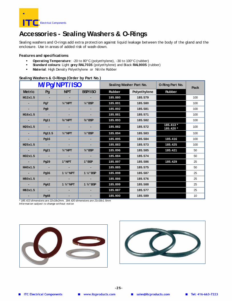
Accessories - Metal Threaded Stopping Plugs Blind stops are used to temporarily or permanently seal a hole in a panel or machine. Use the correspondent plastic locknut when the hole is not threaded. Sealing quality can be improved by means of an additional sealing washer, mounted between the gland and the panel.
Features and specifications:
Round heads except where indicated Operating Temperature: -60 to 200°C Material: Brass, nickel plated
Metal Threaded Stopping Plugs (Order by Part No.)
Information subject to change without notice Hexagonal head
M/Pg/ NPT
Part No. Dimensions (mm)
Pack TD TL H ØD
Metric thread
M12x1.5 188.712 12 5.0 3.0 16 50
M16x1.5 188.717 16 6.0 3.0 20 50
M20x1.5 188.720 20 6.5 2.5 24 10
M20x1.5 188.720H 20 7.0 3.3 23/25.5 10
M25x1.5 188.725 25 7.7 3.0 28 10
M32x1.5 188.732 32 8.0 3.1 34.8 5
M40x1.5 188.740 40 8.0 4.0 43 1
M50x1.5 188.751 50 9.5 4.3 55 1
M63x1.5 188.763 63 10.0 5.0 62 1
Pg Thread
Pg7 188.707 12.5 5.0 2.5 14 50
Pg9 188.709 15.2 6.0 2.5 17 50
Pg11 188.711 18.6 6.0 2.5 20 50
Pg13.5 188.713 20.4 6.0 3.0 22 50
Pg16 188.716 22.5 6.5 3.0 24 10
Pg21 188.721 28.3 7.0 3.8 30 10
Pg29 188.729 37.0 8.5 3.0 34 5
Pg36 188.736 47.0 9.0 4.5 50 5
Pg42 188.742 54.0 9.8 4.0 57 1
Pg48 188.748 59.3 10.5 4.0 64 1
NPT Thread (Hexagonal Heads)
3/8” NPT 188.738 17.1 15.0 3.0 19/21 25
1/2” NPT 188.750 21.2 15.5 3.1 23.1/22.5 10
3/4” NPT 188.775 26.7 21.0 4.5 29.2/32.5 5
1” NPT 188.791 32.2 25.0 4.5 36/40 1
-24-
Accessories - Sealing Washers & O-Rings Sealing washers and O-rings add extra protection against liquid leakage between the body of the gland and the enclosure. Use in areas of added risk of wash-down. Features and specifications:
Operating Temperature: -20 to 80°C (polyethylene), -30 to 100°C (rubber) Standard colours: Light grey RAL7035 (polyethylene) and Black RAL9005 (rubber) Material: High Density Polyethylene or Nitrile Rubber
Sealing Washers & O-Rings (Order by Part No.)
M/Pg/NPT/ISO Sealing Washer Part No. O-Ring Part No. Pack
Metric Pg NPT BSP/ISO Rubber Polyethylene Rubber
M12x1.5 - - - 185.880 185.579 100
- Pg7 ¼”NPT ¼”BSP 185.891 185.580 100
- Pg9 - - 185.892 185.581 100
M16x1.5 - - - 185.881 185.571 100
- Pg11 ⅜”NPT ⅜”BSP 185.893 185.582 100
M20x1.5 - - - 185.882 185.572 185.413 * 185.420 * 100
- Pg13.5 ½”NPT ½”BSP 185.894 185.583 100
- Pg16 - - 185.895 185.584 185.416 100
M25x1.5 - - - 185.883 185.573 185.425 100
- Pg21 ¾”NPT ¾”BSP 185.896 185.585 185.421 50
M32x1.5 - - - 185.884 185.574 50
- Pg29 1”NPT 1”BSP 185.897 185.586 185.429 25
M40x1.5 - - - 185.885 185.575 50
- Pg36 1 ½”NPT 1 ½”BSP 185.898 185.587 25
M50x1.5 - - - 185.886 185.576 25
- Pg42 1 ¾”NPT 1 ¾”BSP 185.899 185.588 25
M63x1.5 - - - 185.887 185.577 25
- Pg48 - - 185.900 185.589 10 * 185.413 dimensions are 22x18x2mm, 184.420 dimensions are 21x18x1.5mm Information subject to change without notice
-25-
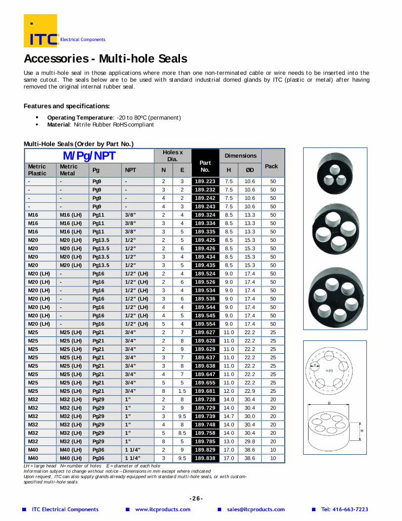
Accessories - Multi-hole Seals Use a multi-hole seal in those applications where more than one non-terminated cable or wire needs to be inserted into the same cutout. The seals below are to be used with standard industrial domed glands by ITC (plastic or metal) after having removed the original internal rubber seal. Features and specifications:
Operating Temperature: -20 to 80ºC (permanent) Material: Nitrile Rubber RoHS compliant
Multi-Hole Seals (Order by Part No.)
M/Pg/NPT Holes x
Dia. Part No.
Dimensions
Pack Metric Plastic
Metric Metal Pg NPT N E H ØD
- - Pg9 - 2 3 189.223 7.5 10.6 50
- - Pg9 - 3 2 189.232 7.5 10.6 50
- - Pg9 - 4 2 189.242 7.5 10.6 50
- - Pg9 - 4 3 189.243 7.5 10.6 50
M16 M16 (LH) Pg11 3/8” 2 4 189.324 8.5 13.3 50
M16 M16 (LH) Pg11 3/8” 3 4 189.334 8.5 13.3 50
M16 M16 (LH) Pg11 3/8” 3 5 189.335 8.5 13.3 50
M20 M20 (LH) Pg13.5 1/2” 2 5 189.425 8.5 15.3 50
M20 M20 (LH) Pg13.5 1/2” 2 6 189.426 8.5 15.3 50
M20 M20 (LH) Pg13.5 1/2” 3 4 189.434 8.5 15.3 50
M20 M20 (LH) Pg13.5 1/2” 3 5 189.435 8.5 15.3 50
M20 (LH) - Pg16 1/2” (LH) 2 4 189.524 9.0 17.4 50
M20 (LH) - Pg16 1/2” (LH) 2 6 189.526 9.0 17.4 50
M20 (LH) - Pg16 1/2” (LH) 3 4 189.534 9.0 17.4 50
M20 (LH) - Pg16 1/2” (LH) 3 6 189.536 9.0 17.4 50
M20 (LH) - Pg16 1/2” (LH) 4 4 189.544 9.0 17.4 50
M20 (LH) - Pg16 1/2” (LH) 4 5 189.545 9.0 17.4 50
M20 (LH) - Pg16 1/2” (LH) 5 4 189.554 9.0 17.4 50
M25 M25 (LH) Pg21 3/4” 2 7 189.627 11.0 22.2 25
M25 M25 (LH) Pg21 3/4” 2 8 189.628 11.0 22.2 25
M25 M25 (LH) Pg21 3/4” 2 9 189.629 11.0 22.2 25
M25 M25 (LH) Pg21 3/4” 3 7 189.637 11.0 22.2 25
M25 M25 (LH) Pg21 3/4” 3 8 189.638 11.0 22.2 25
M25 M25 (LH) Pg21 3/4” 4 7 189.647 11.0 22.2 25
M25 M25 (LH) Pg21 3/4” 5 5 189.655 11.0 22.2 25
M25 M25 (LH) Pg21 3/4” 8 1.5 189.681 12.0 22.9 25
M32 M32 (LH) Pg29 1” 2 8 189.728 14.0 30.4 20
M32 M32 (LH) Pg29 1” 2 9 189.729 14.0 30.4 20
M32 M32 (LH) Pg29 1” 3 9.5 189.739 14.7 30.0 20
M32 M32 (LH) Pg29 1” 4 8 189.748 14.0 30.4 20
M32 M32 (LH) Pg29 1” 5 8.5 189.758 14.0 30.4 20
M32 M32 (LH) Pg29 1” 8 5 189.785 13.0 29.8 20
M40 M40 (LH) Pg36 1 1/4" 2 9 189.829 17.0 38.6 10
M40 M40 (LH) Pg36 1 1/4" 3 9.5 189.838 17.0 38.6 10 LH = large head N= number of holes E = diameter of each hole Information subject to change without notice – Dimensions in mm except where indicated Upon request, ITC can also supply glands already equipped with standard multi-hole seals, or with custom- specified multi-hole seals
-26-
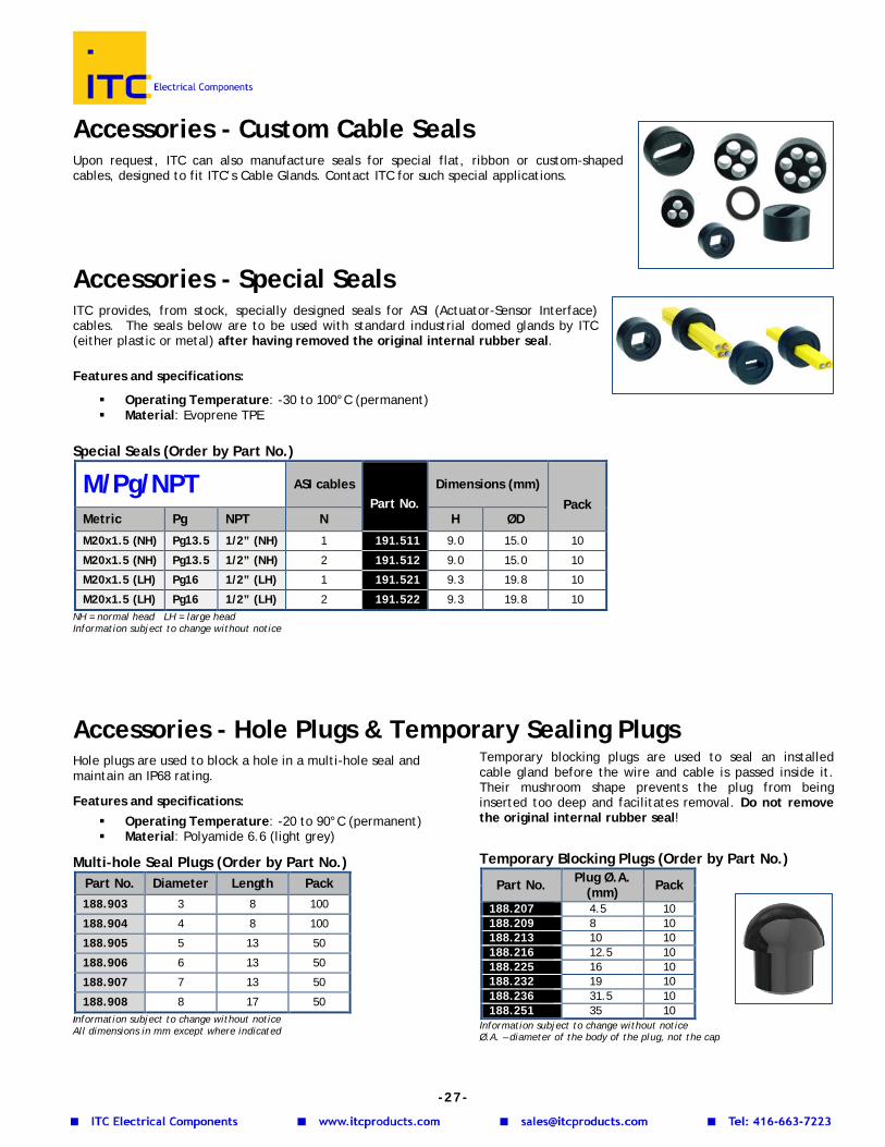
Accessories - Custom Cable Seals Upon request, ITC can also manufacture seals for special flat, ribbon or custom-shaped cables, designed to fit ITC’s Cable Glands. Contact ITC for such special applications.
Accessories - Special Seals ITC provides, from stock, specially designed seals for ASI (Actuator-Sensor Interface) cables. The seals below are to be used with standard industrial domed glands by ITC (either plastic or metal) after having removed the original internal rubber seal.
Features and specifications:
Operating Temperature: -30 to 100°C (permanent) Material: Evoprene TPE
Special Seals (Order by Part No.)
M/Pg/NPT ASI cables Part No.
Dimensions (mm) Pack
Metric Pg NPT N H ØD
M20x1.5 (NH) Pg13.5 1/2” (NH) 1 191.511 9.0 15.0 10
M20x1.5 (NH) Pg13.5 1/2” (NH) 2 191.512 9.0 15.0 10
M20x1.5 (LH) Pg16 1/2” (LH) 1 191.521 9.3 19.8 10
M20x1.5 (LH) Pg16 1/2” (LH) 2 191.522 9.3 19.8 10 NH = normal head LH = large head Information subject to change without notice
Accessories - Hole Plugs & Temporary Sealing PlugsHole plugs are used to block a hole in a multi-hole seal and maintain an IP68 rating.
Features and specifications:
Operating Temperature: -20 to 90°C (permanent) Material: Polyamide 6.6 (light grey)
Multi-hole Seal Plugs (Order by Part No.) Part No. Diameter Length Pack 188.903 3 8 100
188.904 4 8 100
188.905 5 13 50
188.906 6 13 50
188.907 7 13 50
188.908 8 17 50 Information subject to change without notice All dimensions in mm except where indicated
Temporary blocking plugs are used to seal an installed cable gland before the wire and cable is passed inside it. Their mushroom shape prevents the plug from being inserted too deep and facilitates removal. Do not remove the original internal rubber seal!
Temporary Blocking Plugs (Order by Part No.)
Part No. Plug Ø.A. (mm) Pack
188.207 4.5 10 188.209 8 10 188.213 10 10 188.216 12.5 10 188.225 16 10 188.232 19 10 188.236 31.5 10 188.251 35 10
Information subject to change without notice Ø.A. – diameter of the body of the plug, not the cap
-27-
Snap Bushings & Plugs Snap bushings are used to protect wires and cables passing through panel openings. Hole-plugs are used for temporary closing round holes in a panel. Features and specifications:
Lock into hole firmly with fingertip pressure Colour: Black Material: Polyamide
Grommets & Plugs (Order by Part No.)
Part No. Description Cutout (mm)
Inside Ø (mm)
Head outside Ø (mm)
Pack Qty Approvals
111.148 Snap bushing, black polyamide 7.8mm dia. 7.8 6.8 9.8 100 111.149 Snap bushing, black polyamide 9.5mm dia. 9.5 6.4 12.0 100 111.150 Snap bushing, black polyamide 12.7mm dia. 12.7 8.0 15.0 100 111.152 Snap bushing, black polyamide 15.9mm dia. 15.9 12.7 18.6 100 111.153 Snap bushing, black polyamide 19 mm dia. 19.0 14.3 21.7 100 111.154 Snap bushing, black polyamide 22.2 mm dia. 22.2 17.5 24.2 100 111.155 Snap bushing, black polyamide 25.5mm dia. 25.5 19.1 28.5 100 111.156 Snap bushing, black polyamide 30mm dia. 30.0 24.1 33.3 100 111.157 Snap bushing, black polyamide 31.5mm dia. 31.5 23.8 34.6 100 111.158 Snap bushing, black polyamide 38.1mm dia. 38.1 29.0 42.1 100 111.159 Snap bushing, black polyamide 44.5mm dia. 44.5 35.4 47.8 10 111.160 Snap bushing, black polyamide, 50.1mm dia. 50.1 41.6 54.6 10 111.162 Hole-plug, black polyamide, 16mm dia. 15.9 - 19.5 10 - 111.163 Hole-plug, black polyamide, 19mm dia. 19.0 - 22.9 10 - 111.164 Hole-plug, black polyamide, 22.5mm dia. 22.2 - 25.8 10 - 111.165 Hole-plug, black polyamide, 25mm dia. 25.3 - 29.0 10 - 111.166 Hole-plug, black polyamide, 30mm dia. 30.0 - 34.2 10 - 111.167 Hole-plug, black polyamide, 38mm dia. 38.1 - 42.1 10 -
111.174 Cable guiding snap bushing, black polyamide 22.5mm dia. 22.5 - 25.6 100
Information subject to change without notice – All dimensions in mm
Ingress Protection (IP) Ingress protection for Low Voltage Enclosures is defined by the European Standard IEC 60529 as a code comprising 2 letters (IP) and 2 digits.
The first digit (between 0 and 6) indicates the degree of protection provided with respect to the equipment contained in the enclosure. The second digit (between 0 and 8) indicates the degree of protection with respect to the harmful effects of liquid penetration. The ratings for water ingress are not cumulative beyond IPX6. Since the definitions are different, there is no exact equivalence between European IP Ingress Protection ratings, and North American NEMA ratings.
1st digit IP Description 0 No protection
1 Protection against solid objects greater than 50mm
2 Protection against solid objects greater than 12.5mm
3 Protection against solid objects greater than 2.5mm
4 Protection against solid objects greater than 1.0mm
5 Protection against penetration of dust 6 Dust-tight
2nd digit IP Description 0 No protection 1 Protection against dripping water
2 Protection against dripping water when tilted up to 15º
3 Protection against spraying water 4 Protection against splashing water 5 Protection against water jets 6 Protection against heavy seas 7 Protection against the effects of immersion 8 Protection against submersion
9K Protection against high pressure, high temperature liquid (80°C) or steam
Example: an enclosure rated IP54 is protected against penetration of dust, and against splashing water.
- 2 8 -
Characteristics of Plastic Materials
Resistance to chemicals and solvents, UL 94 rating and temperature
Wea
k ac
ids
Stro
ng
acid
s
Wea
k al
kali
Stro
ng
alka
li
Alc
ohol
Gas
olin
e
Min
eral
oil
Am
mon
ia
Veg
etab
le
fats
/oils
Ani
mal
fa
ts
UL9
4 ra
ting
Tem
p °C
ra
ting
Polystyrene HB -20/+70 Polycarbonate V2 -40/+135 Polyamide 6 V2 -30/+100 Polyamide 6 w/fiberglass HB -30/+110 Chloroprene - -25/+100 NBR - -25/+120 Silicon rubber - - -50/+230 Polyoxymethylene - - HB -30/+100 PVC V0 -20/+130
= Very Good, = Fair, = Poor, - = test results not available The information above is given for average applications and for general use only
Thread Tables
METRIC ISO Thread According to EN 60423
PG Thread According to DIN 40430
NPT Thread
M Pitch (mm)
D1 (mm)
Core D2 (mm)
Cut-out (mm)*
Recommended Cut-out (mm)
Recommended Cut-out (in)
M10 x 1.0 1.0 10 9.0 10.2 10.5 0.41 M12 x 1.5 1.5 12 10.5 12.2 12.5 0.5 M16 x 1.5 1.5 16 14.5 16.2 16.5 0.65 M20 x 1.5 1.5 20 18.5 20.2 20.5 0.81 M25 x 1.5 1.5 25 23.5 25.2 25.5 1.0 M32 x 1.5 1.5 32 30.5 32.2 32.5 1.3 M40 x 1.5 1.5 40 38.5 40.2 40.5 1.6 M50 x 1.5 1.5 50 48.5 50.2 50.5 1.99 M63 x 1.5 1.5 63 61.5 63.2 63.5 2.5
Pg Pitch (mm)
D1 (mm)
Core D2 (mm)
Cut-out (mm)*
Recommended Cut-out (mm)
Recommended Cut-out (in)
Pg 7 1.270 12.5 11.28 12.7 13 0.51 Pg 9 1.410 15.2 13.86 15.4 16 0.63 Pg 11 1.410 18.6 17.26 18.8 19 0.75 Pg 13.5 1.410 20.4 19.06 20.7 21 0.83 Pg 16 1.410 22.5 21.16 22.8 23 0.91 Pg 21 1.588 28.3 26.78 28.6 29 1.14 Pg 29 1.588 37.0 35.48 37.4 37 1.46 Pg 36 1.588 47.0 45.48 47.5 42 1.65 Pg 42 1.588 54.0 52.48 54.5 47 1.85 Pg 48 1.588 59.3 57.78 59.8 54 2.13
NPT Pitch (mm)
D1 (mm)
Threads/inch
Cut-out (mm)*
Recommended Cut-out (mm)
Recommended Cut-out (in)
3/8” 1.411 17.055 18 17.2 17.5 0.69 1/2” 1.814 21.223 14 21.4 21.5 0.85 3/4” 1.814 26.568 14 26.9 27.0 1.07 1” 2.208 33.227 11 ½” 33.7 34.5 1.36 1 ¼” 2.208 41.984 11 ½” 42.4 43.0 1.69 1 ½” 2.208 48.053 11 ½” 48.5 49.2 1.93 2” 2.208 60.091 11 ½” 60.2 61.0 2.40
- 2 9 -
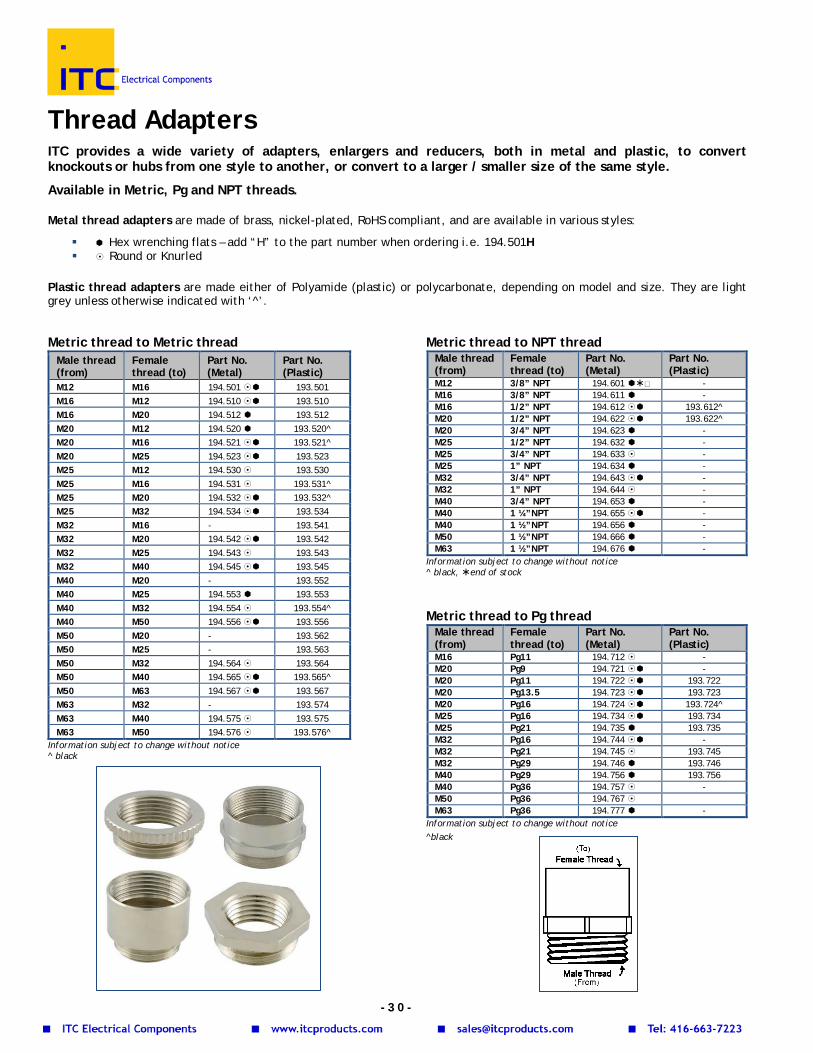
Thread Adapters ITC provides a wide variety of adapters, enlargers and reducers, both in metal and plastic, to convert knockouts or hubs from one style to another, or convert to a larger / smaller size of the same style.
Available in Metric, Pg and NPT threads. Metal thread adapters are made of brass, nickel-plated, RoHS compliant, and are available in various styles:
Hex wrenching flats – add “H” to the part number when ordering i.e. 194.501H Round or Knurled
Plastic thread adapters are made either of Polyamide (plastic) or polycarbonate, depending on model and size. They are light grey unless otherwise indicated with ‘^’.
Metric thread to Metric thread Male thread (from)
Female thread (to)
Part No. (Metal)
Part No. (Plastic)
M12 M16 194.501 193.501 M16 M12 194.510 193.510 M16 M20 194.512 193.512 M20 M12 194.520 193.520^ M20 M16 194.521 193.521^ M20 M25 194.523 193.523 M25 M12 194.530 193.530 M25 M16 194.531 193.531^ M25 M20 194.532 193.532^ M25 M32 194.534 193.534 M32 M16 - 193.541 M32 M20 194.542 193.542 M32 M25 194.543 193.543 M32 M40 194.545 193.545 M40 M20 - 193.552 M40 M25 194.553 193.553 M40 M32 194.554 193.554^ M40 M50 194.556 193.556 M50 M20 - 193.562 M50 M25 - 193.563 M50 M32 194.564 193.564 M50 M40 194.565 193.565^ M50 M63 194.567 193.567 M63 M32 - 193.574 M63 M40 194.575 193.575 M63 M50 194.576 193.576^
Information subject to change without notice ^ black
Metric thread to NPT thread Male thread (from)
Female thread (to)
Part No. (Metal)
Part No. (Plastic)
M12 3/8” NPT 194.601 - M16 3/8” NPT 194.611 - M16 1/2” NPT 194.612 193.612^ M20 1/2” NPT 194.622 193.622^ M20 3/4” NPT 194.623 - M25 1/2” NPT 194.632 - M25 3/4” NPT 194.633 - M25 1” NPT 194.634 - M32 3/4” NPT 194.643 - M32 1” NPT 194.644 - M40 3/4” NPT 194.653 - M40 1 ¼”NPT 194.655 - M40 1 ½”NPT 194.656 - M50 1 ½”NPT 194.666 - M63 1 ½”NPT 194.676 -
Information subject to change without notice ^ black, end of stock Metric thread to Pg thread
Male thread (from)
Female thread (to)
Part No. (Metal)
Part No. (Plastic)
M16 Pg11 194.712 - M20 Pg9 194.721 - M20 Pg11 194.722 193.722 M20 Pg13.5 194.723 193.723 M20 Pg16 194.724 193.724^ M25 Pg16 194.734 193.734 M25 Pg21 194.735 193.735 M32 Pg16 194.744 - M32 Pg21 194.745 193.745 M32 Pg29 194.746 193.746 M40 Pg29 194.756 193.756 M40 Pg36 194.757 - M50 Pg36 194.767 M63 Pg36 194.777 -
Information subject to change without notice ^black
- 3 0 -
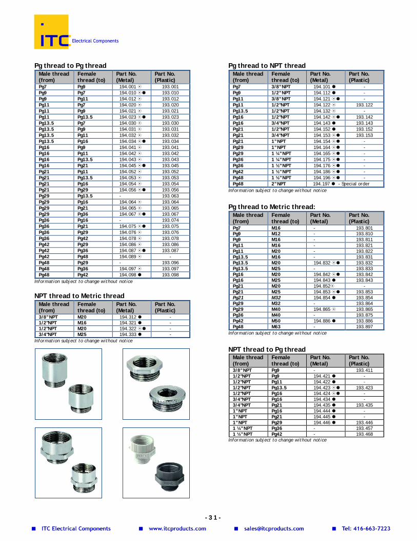
Pg thread to Pg thread
Male thread (from)
Female thread (to)
Part No. (Metal)
Part No. (Plastic)
Pg7 Pg9 194.001 193.001 Pg9 Pg7 194.010 193.010 Pg9 Pg11 194.012 193.012 Pg11 Pg7 194.020 193.020 Pg11 Pg9 194.021 193.021 Pg11 Pg13.5 194.023 193.023 Pg13.5 Pg7 194.030 193.030 Pg13.5 Pg9 194.031 193.031 Pg13.5 Pg11 194.032 193.032 Pg13.5 Pg16 194.034 193.034 Pg16 Pg9 194.041 193.041 Pg16 Pg11 194.042 193.042 Pg16 Pg13.5 194.043 193.043 Pg16 Pg21 194.045 193.045 Pg21 Pg11 194.052 193.052 Pg21 Pg13.5 194.053 193.053 Pg21 Pg16 194.054 193.054 Pg21 Pg29 194.056 193.056 Pg29 Pg13.5 - 193.063 Pg29 Pg16 194.064 193.064 Pg29 Pg21 194.065 193.065 Pg29 Pg36 194.067 193.067 Pg36 Pg16 - 193.074 Pg36 Pg21 194.075 193.075 Pg36 Pg29 194.076 193.076 Pg36 Pg42 194.078 193.078 Pg42 Pg29 194.086 193.086 Pg42 Pg36 194.087 193.087 Pg42 Pg48 194.089 - Pg48 Pg29 - 193.096 Pg48 Pg36 194.097 193.097 Pg48 Pg42 194.098 193.098
Information subject to change without notice NPT thread to Metric thread
Male thread (from)
Female thread (to)
Part No. (Metal)
Part No. (Plastic)
3/8”NPT M20 194.312 - 1/2"NPT M16 194.321 - 1/2"NPT M20 194.322 - 3/4"NPT M25 194.333 -
Information subject to change without notice
Pg thread to NPT thread Male thread (from)
Female thread (to)
Part No. (Metal)
Part No. (Plastic)
Pg7 3/8”NPT 194.101 - Pg9 1/2”NPT 194.112 - Pg11 3/8”NPT 194.121 - Pg11 1/2"NPT 194.122 193.122 Pg13.5 1/2"NPT 194.132 - Pg16 1/2"NPT 194.142 193.142 Pg16 3/4"NPT 194.143 193.143 Pg21 1/2"NPT 194.152 193.152 Pg21 3/4"NPT 194.153 193.153 Pg21 1”NPT 194.154 - Pg29 1”NPT 194.164 - Pg29 1 ¼”NPT 194.165 - Pg36 1 ¼”NPT 194.175 - Pg36 1 ½”NPT 194.176 - Pg42 1 ½”NPT 194.186 - Pg48 1 ½”NPT 194.196 - Pg48 2”NPT 194.197 - Special order
Information subject to change without notice Pg thread to Metric thread:
Male thread (from)
Female thread (to)
Part No. (Metal)
Part No. (Plastic)
Pg7 M16 - 193.801 Pg9 M12 - 193.810 Pg9 M16 - 193.811 Pg11 M16 - 193.821 Pg11 M20 - 193.822 Pg13.5 M16 - 193.831 Pg13.5 M20 194.832 193.832 Pg13.5 M25 - 193.833 Pg16 M20 194.842 193.842 Pg16 M25 194.843 193.843 Pg21 M20 194.852 - Pg21 M25 194.853 193.853 Pg21 M32 194.854 193.854 Pg29 M32 - 193.864 Pg29 M40 194.865 193.865 Pg36 M40 - 193.875 Pg42 M50 194.886 193.886 Pg48 M63 - 193.897
Information subject to change without notice NPT thread to Pg thread
Male thread (from)
Female thread (to)
Part No. (Metal)
Part No. (Plastic)
3/8”NPT Pg9 - 193.411 1/2"NPT Pg9 194.421 - 1/2"NPT Pg11 194.422 - 1/2"NPT Pg13.5 194.423 193.423 1/2"NPT Pg16 194.424 - 3/4"NPT Pg16 194.434 - 3/4"NPT Pg21 194.435 193.435 1”NPT Pg16 194.444 - 1”NPT Pg21 194.445 - 1”NPT Pg29 194.446 193.446 1 ¼”NPT Pg36 - 193.457 1 ½”NPT Pg42 - 193.468
Information subject to change without notice
- 3 1 -


![ADDIMAX CABLE GLANDS FOR INDUSTRIAL USE CABLE GLANDS Glands/Cable Glands.pdf · [ 2 ] CABLE GLANDS FOR INDUSTRIAL USE Single Compression A2 Type Weatherproof & Waterproof (IP66) Cable](https://img.pdfslide.net/doc/110x75/5abe4c4f7f8b9ac0598ceed5/addimax-cable-glands-for-industrial-use-cable-glandscable-glandspdf-2-cable.jpg)