Embed Size (px)
DESCRIPTION
Manual de CADtools 7 for Adobe Illustrator
Citation preview
1
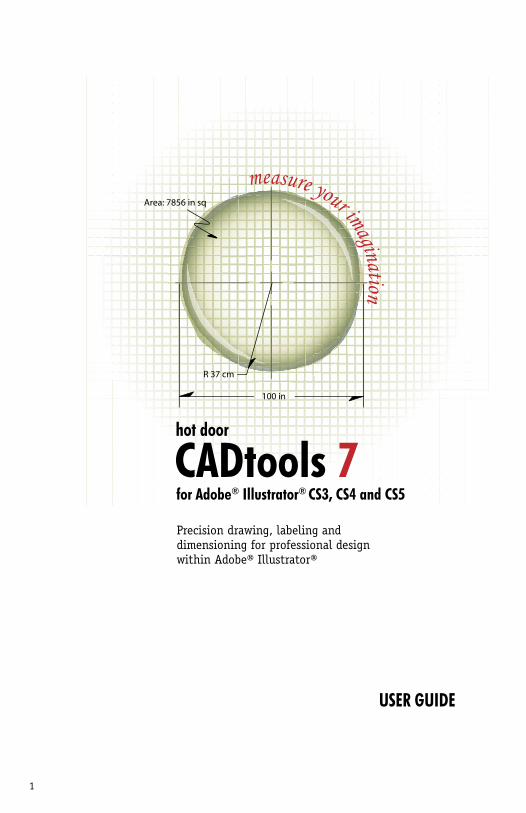
measure your imagination
R 37 cm
Area: 7856 in sq
100 in
for Adobe® Illustrator® CS3, CS4 and CS5
hot door
USER GUIDE
Precision drawing, labeling and dimensioning for professional design within Adobe® Illustrator®
CADtools 7

2
3
Table of contents
Table of ContentsThis user guide is designed for use as a product tutorial or reference guide, with topics organized to follow the process of a typical project. When printing this user guide, please save paper by printing 2 pages per sheet. Also visithotdoor.com for in-depth tutorials with tool animations.
About CADtools 7 ............................................................5Core features of CADtools 7 .............................................6About Hot Door ..............................................................7Updating or installing ....................................................8Personalizing .................................................................9Registration & technical support .....................................9Working with older versions of Illustrator ..................... 10Overview of the interface ........................................ 11-12Setting up the document
CADdocument panel with scale ......................... 13-16CADguides panel ................................................... 17Numeric input ...................................................... 18
2D CAD drawing tools .............................................. 19-24CAD wall tools ......................................................... 25-31Dimensioning control
CADtext panel .................................................. 32-34CADstyle panel ...................................................... 35
Automation: CADshortcutsPresets ............................................................ 36-37Global interface control ......................................... 37Automatic dimensioning ....................................... 37
2D dimensioning tools ............................................. 38-48Labeling
CADlabels panel .................................................... 49Label tools ....................................................... 50-56
Construction tools - title blocks and tables ............... 57-592D CAD editing
Precision measuring with CADtrackerGeometry ..................................................... 60Transform .................................................... 61Area Transform ............................................. 62Move ............................................................ 62Repeat.......................................................... 63
2D CAD editing tools ........................................ 64-69Isometric drawing
CADisometric panel .......................................... 70-72Isometric drawing tools ................................... 73-76
Isometric dimensioning tools ................................. 77-83Quick reference ...................................................... 84-86Advanced topics ..................................................... 87-89Index .................................................................... 90-91
4
hot door
HOT DOOR LICENSE AGREEMENT©2010 Hot Door, Inc. This manual, as well as the software described in it, is provided under license and may not be copied by any means without written consent of Hot Door except in accordance with the terms of the license. The existing artwork may be protected under copyright law and unauthorized use of this artwork could violate the rights of the original author. Hot Door, the Hot Door logo, CADtools, the CADtools logo are trademarks of Hot Door, Inc. Adobe and Adobe Illustrator are registered trademarks of Adobe Systems, Inc. Windows is a registered trademark of Microsoft Corporation. Apple, Macintosh, and Power Macintosh are registered trademarks of Apple Computer, Inc. All other trademarks are the property of their respective owners.
HOT DOOR DOES NOT AND CANNOT WARRANT THAT THE SOFTWARE IS FREE FROM ALL BUGS, ERRORS AND OMISSIONS. HOT DOOR MAKES NO WARRANTIES, EXPRESSED OR IMPLIED, INCLUDING WARRANTIES OF MERCHANTABILITY AND FITNESS FOR A PARTICULAR PURPOSE. THE ENTIRE RISK AS TO THE RESULTS AND PERFORMANCE OF THE SOFTWARE IS ASSUMED BY YOU. HOT DOOR OR ITS SUPPLIERS WILL IN NO EVENT BE LIABLE TO YOU FOR ANY CONSEQUENTIAL OR INDIRECT DAMAGES, INCLUDING ANY LOST PROFITS OR LOST SAVINGS, ARISING OUT OF THE USE OR INABILITY TO USE THE SOFTWARE, EVEN IF HOT DOOR HAS BEEN ADVISED OF THE POSSIBILITY OF SUCH DAMAGES, OR FOR ANY CLAIM BY ANY THIRD PARTY. Because some jurisdictions do not allow the exclusion or limitation of liability for consequential or incidental damages, the above limitations may not apply to you.
http://www.hotdoor.com/phone: 949-464-0300fax: 949-464-0301email: [email protected]
© 2010 Hot Door, Inc.PO Box 5220Laguna Beach, CA 92652
5
About CADtools 7Welcome to Hot Door CADtools, a full-featured CAD plug-in for Adobe Illustrator CS3, CS4 and CS5. CADtools offers an easy and elegant solution for designers who need the precision of CAD within the flexible, creative environment of Adobe Illustrator.
What’s new in CADtools 7• CS5 compatibility - Not available in previous versions• Table tool - Located in the new construction tool group, create tables with specified sizes and cell info• Title block tool - Create title blocks with specified drawing notes and revision blocks• Door and Window Insertion tools - Located inside the new CADwall tool group, choose these tools to insert doors and windows into CADwalls with adjustable size, angle, and style• 3-point circle tool - Create circles with three defined points• Constrained line option - Double-click the CAD-line tool for options to connect lines or set an angle of constraint. Use the control key after dragging with the CADline tool to constrain it to that angle.• Offset - The Offset tool now works with linear paths as well as curved paths and closed objects to create offsets in scale• Auto-expand option for CADisometric drawing - Prevent surprise updates by drawing isometric objects with Auto-expand selected • Key object feature with Proportion tool - Use the Proportion tool to resize objects with new 'key object' control. Ungrouped selected objects follow the clicked key object, and grouped selected objects resize together.• Resize objects to specified area - Use CADtracker's new Area Transform to resize a selected object by defining an area• Reference dimension option - Select the parentheses ( ) option in the CADtext panel to show reference dimensions within parentheses (as approximations)• New units - Select from new unit options for mils, simple decimal feet with symbol (X.X'), and simple deci-mal feet with units (X.X ft)• CADrulers accommodate artboards - CADrulers are updated individually for each artboard on update
6
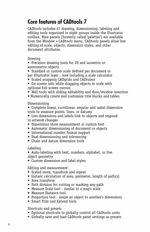
Core features of CADtools 7CADtools includes 67 drawing, dimensioning, labeling and editing tools organized in eight groups inside the Illustrator toolbox. Nine panels (formerly called 'palettes') are available from the Window > CADtools menu. CADtools panels allow live editing of scale, objects, dimension styles, and other document attributes.
Drawing• Precision drawing tools for 2D and isometric or axonometric objects• Standard or custom scale defined per document or per Illustrator layer - now including a scale calculator• Scaled snapping CADgrids and CADrulers• On-screen info while dragging objects in scale with optional full screen cursors• Wall tools with sliding editability and door/window insertion• Numerically create and customize title blocks and tables
Dimensioning• Complete linear, curvilinear, angular and radial dimension tools to measure points, lines, or datums• Live dimensions and labels link to objects and respond to artwork changes• Dimensions show measurement or custom text• Automatic dimensioning of document or objects• International number format support• Dual dimensioning and tolerancing• Chain and datum dimension tools
Labeling• Auto-labeling with text, numbers, alphabet, or live object geometry• Custom dimension and label styles
Editing and measurement• Scaled move, transform and repeat• Instant calculation of area, perimeter, length of path(s)• Area transform• Path division for cutting or marking any path• Measure Scale tool - similar to a map's scale• Measure Distance tool• Proportion tool - resize an object to another's dimensions• Smart Trim and Extend tools
Shortcuts and presets• Optional shortcuts to globally control all CADtools units• Globally save and load CADtools panel settings as presets
7
Behind the conceptHot Door, Inc. was formed in 1996 around a product concept that blended CAD with vector illustration. Lead developer Brendon Cheves conceived the idea while teaching students how to use Adobe Illustrator to present their CAD files in a university classroom. After much research in the technical design field, CADtools 1 was developed and released in 1997. With the support of Adobe Solutions Network and thousands of happy customers, CADtools evolved into a more complete set of features. Over thirteen years, we have added live precision drawing and dimensioning, customizable labels, isometric drawing and dimensioning, automated shortcuts and refined measuring tools. Between upgrades to CADtools, we developed additional Illustrator plug-ins for designers like MultiPage and Perspective, bringing more power into Illustrator for publishing and technical illustration. New pattern and symbol libraries were added to our online store, helping designers save time and stay creative within Adobe Illustrator.
This latest version focuses on all-important details – much-needed door and window insertion, an innovative set of construction tools for tables and title blocks, and area transform. Even little steps save so much time - like constraining with the improved CADline tool to keep your lines at any angle!
We promise complete satisfaction with a 90-day money-back guarantee on every product. Please call us anytime with questions or comments – we always love to hear from you.
Shari Cheves, President
Brendon ChevesLead Software Engineer
Garrett Walbridge & Jeff WintersSupport Engineers
8
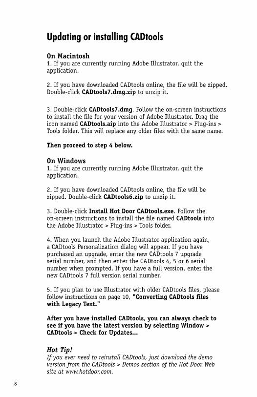
Updating or installing CADtools
On Macintosh1. If you are currently running Adobe Illustrator, quit the application.
2. If you have downloaded CADtools online, the file will be zipped. Double-click CADtools7.dmg.zip to unzip it.
3. Double-click CADtools7.dmg. Follow the on-screen instructions to install the file for your version of Adobe Illustrator. Drag the icon named CADtools.aip into the Adobe Illustrator > Plug-ins > Tools folder. This will replace any older files with the same name.
Then proceed to step 4 below.
On Windows1. If you are currently running Adobe Illustrator, quit the application.
2. If you have downloaded CADtools online, the file will be zipped. Double-click CADtools6.zip to unzip it.
3. Double-click Install Hot Door CADtools.exe. Follow the on-screen instructions to install the file named CADtools into the Adobe Illustrator > Plug-ins > Tools folder.
4. When you launch the Adobe Illustrator application again, a CADtools Personalization dialog will appear. If you have purchased an upgrade, enter the new CADtools 7 upgradeserial number, and then enter the CADtools 4, 5 or 6 serial number when prompted. If you have a full version, enter the new CADtools 7 full version serial number.
5. If you plan to use Illustrator with older CADtools files, please follow instructions on page 10, "Converting CADtools files with Legacy Text."
After you have installed CADtools, you can always check to see if you have the latest version by selecting Window > CADtools > Check for Updates...
Hot Tip!If you ever need to reinstall CADtools, just download the demo version from the CADtools > Demos section of the Hot Door Web site at www.hotdoor.com.
9
Personalizing, registration and support
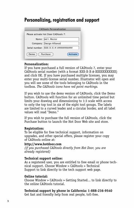
Personalization:If you have purchased a full version of CADtools 7, enter your CADtools serial number (with a format XXX-X-X-#-XXXXXXXXXXX) and click OK. If you have purchased multiple licenses, you may enter your multi-license serial number. Illustrator will open and you will see some of the tools belonging to CADtools in the toolbox. The CADtools icons have red point markings.
If you wish to use the demo version of CADtools, click the Demo button. CADtools will function for an unlimited time period but limits your drawing and dimensioning to 1:3 scale with access to only the top tool in six of the eight tool groups. The labels are limited to a curved leader and a circular border, and all label values will read "Demo."
If you wish to purchase the full version of CADtools, click the Purchase button to launch the Hot Door Web site and store.
Registration:To be eligible for free technical support, information on upgrades, and other special offers, please register your copy of CADtools online at:http://www.hotdoor.com(if you purchased CADtools directly from Hot Door, you are already registered)
Technical support online:As a registered user, you are entitled to free email or phone tech-nical support. Choose Window > CADtools > Technical Support to link directly to the tech support web page.
Online tutorial:Choose Window > CADtools > Getting Started... to link directly to the online CADtools tutorial.
Technical support by phone in California: 1-888-236-9540 Get fast and friendly help from real people, toll-free.
10
Working with older versions of Illustrator
Converting CADtools files created with Legacy Text
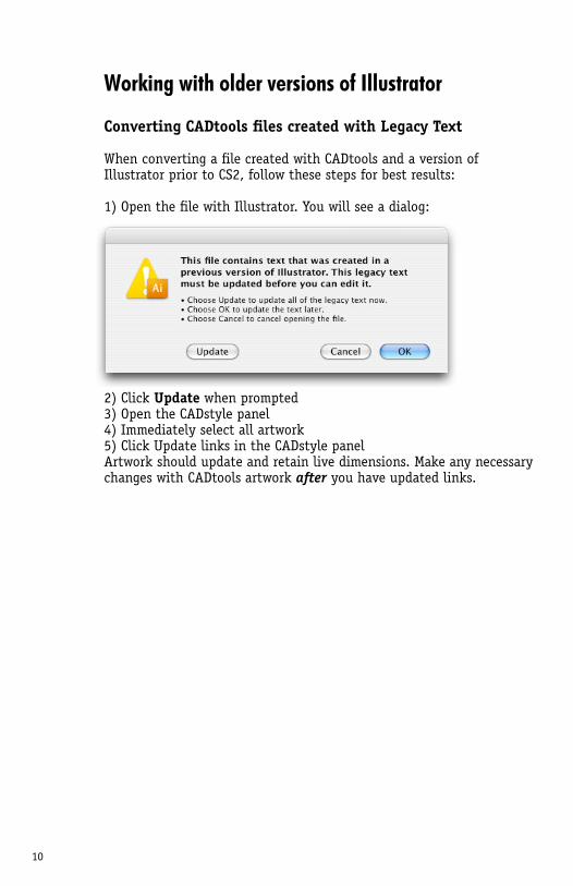
When converting a file created with CADtools and a version of Illustrator prior to CS2, follow these steps for best results:
1) Open the file with Illustrator. You will see a dialog:
2) Click Update when prompted3) Open the CADstyle panel4) Immediately select all artwork5) Click Update links in the CADstyle panelArtwork should update and retain live dimensions. Make any necessary changes with CADtools artwork after you have updated links.
11
Overview of the CADtools interface
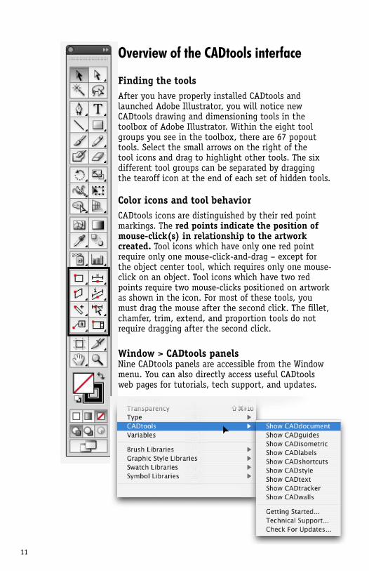
Finding the toolsAfter you have properly installed CADtools and launched Adobe Illustrator, you will notice new CADtools drawing and dimensioning tools in the toolbox of Adobe Illustrator. Within the eight tool groups you see in the toolbox, there are 67 popout tools. Select the small arrows on the right of the tool icons and drag to highlight other tools. The six different tool groups can be separated by dragging the tearoff icon at the end of each set of hidden tools.
Color icons and tool behaviorCADtools icons are distinguished by their red point markings. The red points indicate the position of mouse-click(s) in relationship to the artwork created. Tool icons which have only one red point require only one mouse-click-and-drag – except for the object center tool, which requires only one mouse-click on an object. Tool icons which have two red points require two mouse-clicks positioned on artwork as shown in the icon. For most of these tools, you must drag the mouse after the second click. The fillet, chamfer, trim, extend, and proportion tools do not require dragging after the second click.
Window > CADtools panelsNine CADtools panels are accessible from the Window menu. You can also directly access useful CADtools web pages for tutorials, tech support, and updates.
12
Overview of the CADtools interface (cont.)
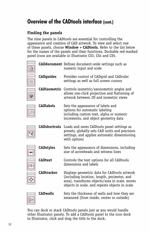
Finding the panelsThe nine panels in CADtools are essential for controlling the appearance and creation of CAD artwork. To view and select one of these panels, choose Window > CADtools. Refer to the list below for the names of the panels and their functions. Dockable red-marked panel icons are available in Illustrator CS3, CS4 and CS5.
CADdocument Defines document-wide settings such as numeric input and scale
CADguides Provides control of CADgrid and CADruler settings as well as full screen cursors
CADisometric Controls isometric/axonometric angles and allows one-click projection and flattening of artwork between 2D and isometric views
CADlabels Sets the appearance of labels and options for automatic labeling including custom text, alpha or numeric increments, and object geometry data
CADshortcuts Loads and saves CADtools panel settings as presets, globally sets CAD units and precision settings, and applies automatic dimensioning with options
CADstyles Sets the appearance of dimensions, including size of arrowheads and witness lines
CADtext Controls the text options for all CADtools dimensions and labels CADtracker Displays geometric data for CADtools artwork (including location, length, perimeter, and area), transforms objects/area in scale, moves objects in scale, and repeats objects in scale
CADwalls Sets the thickness of walls and how they are measured (from inside, center or outside)
You can dock or stack CADtools panels just as you would handle other Illustrator panels. To add a CADtools panel to the icon dock in Illustrator, click and drag the title to the dock.
13
Setting up the document: CADdocument
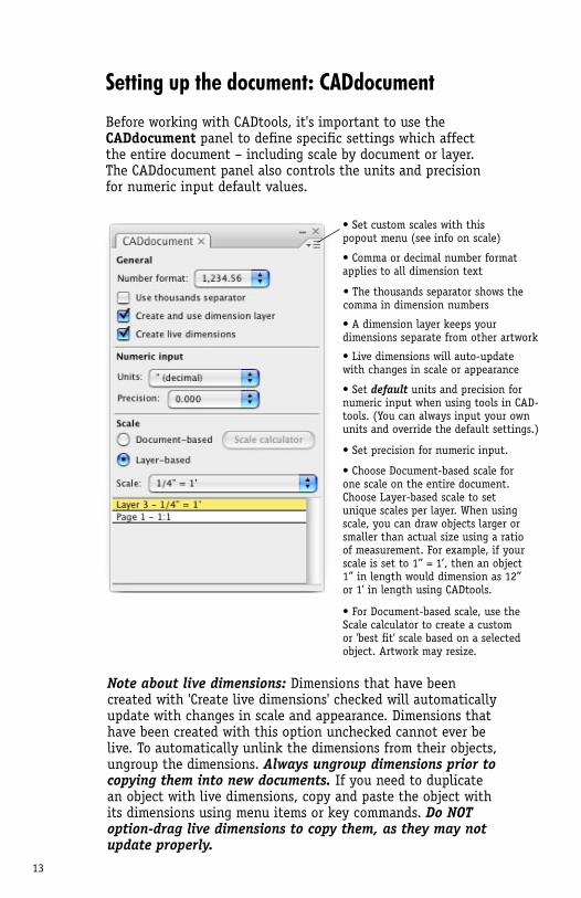
Before working with CADtools, it's important to use the CADdocument panel to define specific settings which affect the entire document – including scale by document or layer. The CADdocument panel also controls the units and precision for numeric input default values.
Note about live dimensions: Dimensions that have been created with 'Create live dimensions' checked will automatically update with changes in scale and appearance. Dimensions that have been created with this option unchecked cannot ever be live. To automatically unlink the dimensions from their objects, ungroup the dimensions. Always ungroup dimensions prior to copying them into new documents. If you need to duplicate an object with live dimensions, copy and paste the object with its dimensions using menu items or key commands. Do NOT option-drag live dimensions to copy them, as they may not update properly.
• Comma or decimal number format applies to all dimension text
• A dimension layer keeps your dimensions separate from other artwork
• Live dimensions will auto-update with changes in scale or appearance
• Set default units and precision for numeric input when using tools in CAD-tools. (You can always input your own units and override the default settings.)
• The thousands separator shows the comma in dimension numbers
• Choose Document-based scale for one scale on the entire document. Choose Layer-based scale to set unique scales per layer. When using scale, you can draw objects larger or smaller than actual size using a ratio of measurement. For example, if your scale is set to 1” = 1’, then an object 1” in length would dimension as 12” or 1’ in length using CADtools.
• Set precision for numeric input.
• Set custom scales with this popout menu (see info on scale)
• For Document-based scale, use the Scale calculator to create a custom or 'best fit' scale based on a selected object. Artwork may resize.
14
Setting up the document: ScaleUsing CADdocument and scaleTo change a layer or document scale, use the Scale popup menu in the CADdocument panel. Choose a scale from the three sections of presets: custom, engineering, and architectural scales.
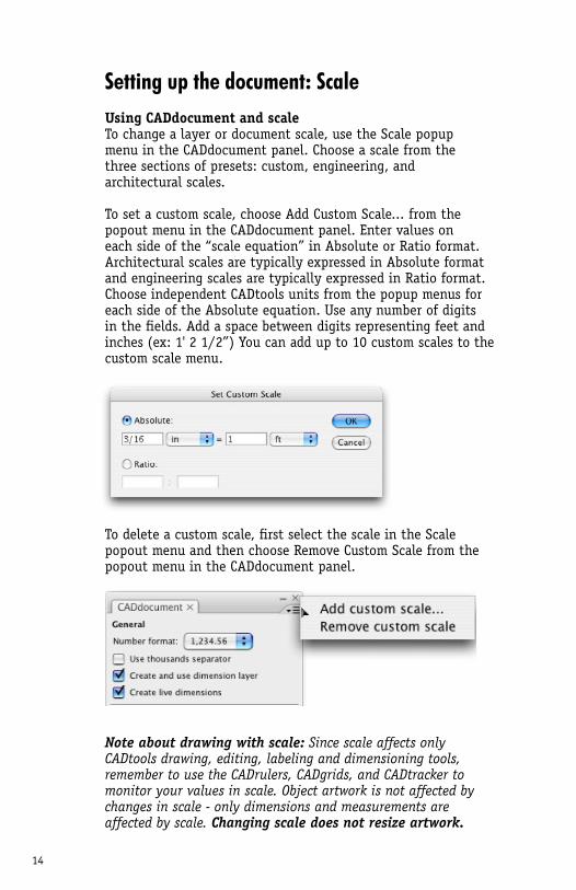
To set a custom scale, choose Add Custom Scale... from the popout menu in the CADdocument panel. Enter values on each side of the “scale equation” in Absolute or Ratio format. Architectural scales are typically expressed in Absolute format and engineering scales are typically expressed in Ratio format. Choose independent CADtools units from the popup menus for each side of the Absolute equation. Use any number of digits in the fields. Add a space between digits representing feet and inches (ex: 1' 2 1/2”) You can add up to 10 custom scales to the custom scale menu.
To delete a custom scale, first select the scale in the Scale popout menu and then choose Remove Custom Scale from the popout menu in the CADdocument panel.
Note about drawing with scale: Since scale affects only CADtools drawing, editing, labeling and dimensioning tools, remember to use the CADrulers, CADgrids, and CADtracker to monitor your values in scale. Object artwork is not affected by changes in scale - only dimensions and measurements are affected by scale. Changing scale does not resize artwork.

15
Setting up the document: Scale (cont.)
Using the Scale calculatorWhen using Document-based scale, you can use the Scale calculator to create a custom or 'best fit' scale and resize artwork based on a selected object's dimensions.
Before using the Scale calculator, make sure you have Document-based scale selected in the CADdocument palette. Select the object that you are using as a reference for your scale calculation. Click the Scale calculator button.
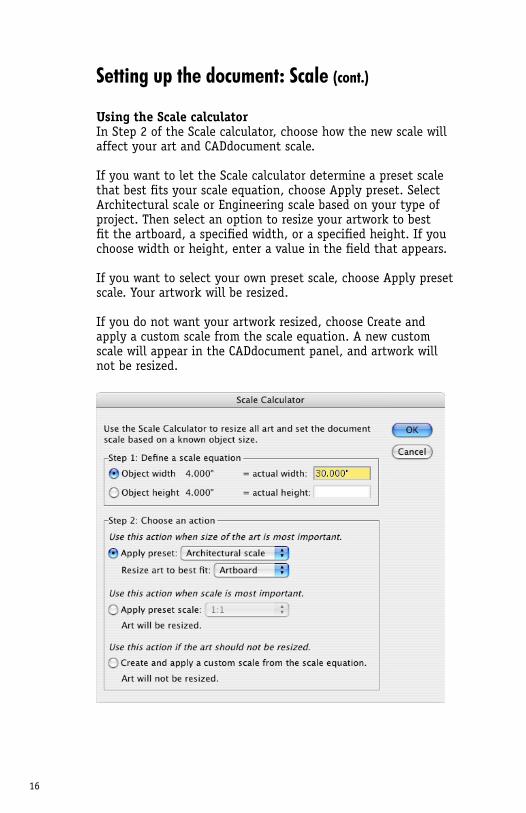
In Step 1 of the Scale Calculator dialog, the selected object's real dimensions are displayed in terms of width and height. Choose the object width or height as the reference value, then enter a desired actual value on the right.
16
Setting up the document: Scale (cont.)
Using the Scale calculatorIn Step 2 of the Scale calculator, choose how the new scale will affect your art and CADdocument scale.
If you want to let the Scale calculator determine a preset scale that best fits your scale equation, choose Apply preset. Select Architectural scale or Engineering scale based on your type of project. Then select an option to resize your artwork to best fit the artboard, a specified width, or a specified height. If you choose width or height, enter a value in the field that appears.
If you want to select your own preset scale, choose Apply preset scale. Your artwork will be resized.
If you do not want your artwork resized, choose Create and apply a custom scale from the scale equation. A new custom scale will appear in the CADdocument panel, and artwork will not be resized.
17
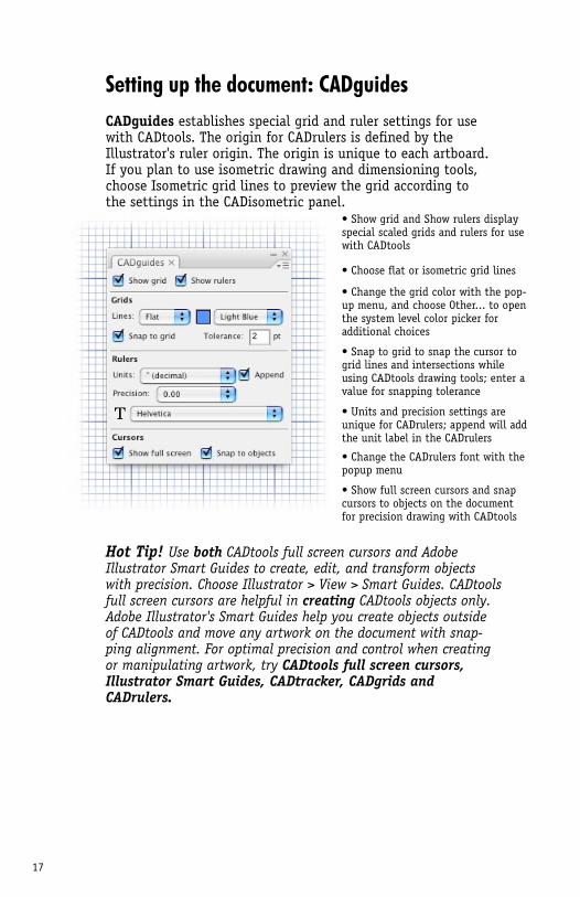
Setting up the document: CADguidesCADguides establishes special grid and ruler settings for use with CADtools. The origin for CADrulers is defined by the Illustrator's ruler origin. The origin is unique to each artboard. If you plan to use isometric drawing and dimensioning tools, choose Isometric grid lines to preview the grid according to the settings in the CADisometric panel.
• Show grid and Show rulers display special scaled grids and rulers for use with CADtools
• Change the grid color with the pop-up menu, and choose Other... to open the system level color picker for additional choices
• Choose flat or isometric grid lines
• Snap to grid to snap the cursor to grid lines and intersections while using CADtools drawing tools; enter a value for snapping tolerance
• Units and precision settings are unique for CADrulers; append will add the unit label in the CADrulers
• Change the CADrulers font with the popup menu
Hot Tip! Use both CADtools full screen cursors and Adobe Illustrator Smart Guides to create, edit, and transform objects with precision. Choose Illustrator > View > Smart Guides. CADtools full screen cursors are helpful in creating CADtools objects only. Adobe Illustrator's Smart Guides help you create objects outside of CADtools and move any artwork on the document with snap-ping alignment. For optimal precision and control when creating or manipulating artwork, try CADtools full screen cursors, Illustrator Smart Guides, CADtracker, CADgrids and CADrulers.
• Show full screen cursors and snap cursors to objects on the documentfor precision drawing with CADtools
18
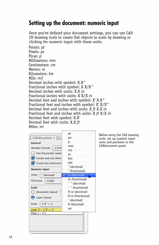
Setting up the document: numeric inputOnce you've defined your document settings, you can use CAD 2D drawing tools to create flat objects in scale by drawing or clicking for numeric input with these units:
Points: pt Pixels: px Picas: p Millimeters: mm Centimeters: cm Meters: m Kilometers: km Mils: mil Decimal inches with symbol: X.X“ Fractional inches with symbol: X X/X“ Decimal inches with units: X.X in Fractional inches with units: X X/X in Decimal feet and inches with symbol: X' X.X“ Fractional feet and inches with symbol: X' X/X“ Decimal feet and inches with units: X ft X.X in Fractional feet and inches with units: X ft X/X in Decimal feet with symbol: X.X' Decimal feet with units: X.X ft Miles: mi
Before using the CAD drawing tools, set up numeric input units and precision in the CADdocument panel.
19
2D CAD drawing tools
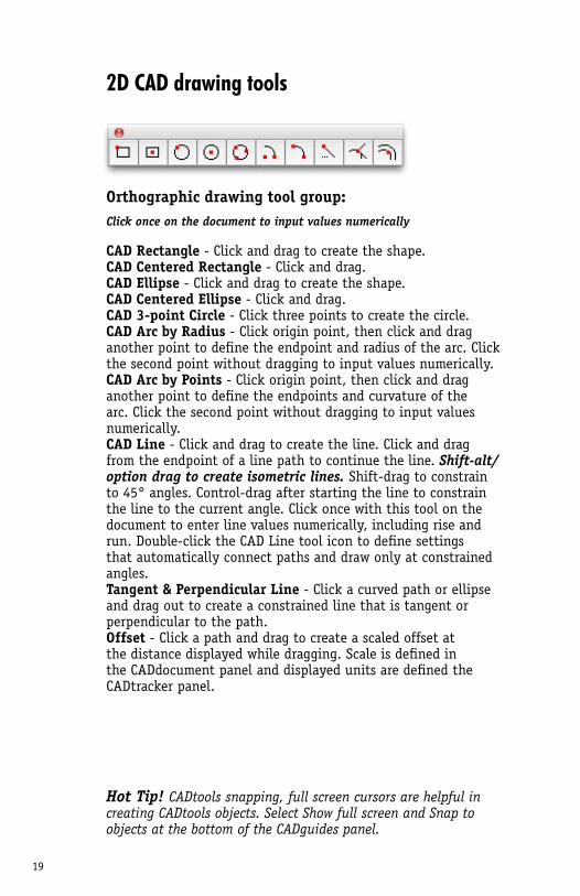
Orthographic drawing tool group:Click once on the document to input values numerically
CAD Rectangle - Click and drag to create the shape.CAD Centered Rectangle - Click and drag.CAD Ellipse - Click and drag to create the shape.CAD Centered Ellipse - Click and drag.CAD 3-point Circle - Click three points to create the circle.CAD Arc by Radius - Click origin point, then click and drag another point to define the endpoint and radius of the arc. Click the second point without dragging to input values numerically.CAD Arc by Points - Click origin point, then click and drag another point to define the endpoints and curvature of the arc. Click the second point without dragging to input values numerically.CAD Line - Click and drag to create the line. Click and drag from the endpoint of a line path to continue the line. Shift-alt/option drag to create isometric lines. Shift-drag to constrain to 45° angles. Control-drag after starting the line to constrain the line to the current angle. Click once with this tool on the document to enter line values numerically, including rise and run. Double-click the CAD Line tool icon to define settings that automatically connect paths and draw only at constrained angles. Tangent & Perpendicular Line - Click a curved path or ellipse and drag out to create a constrained line that is tangent or perpendicular to the path.Offset - Click a path and drag to create a scaled offset at the distance displayed while dragging. Scale is defined in the CADdocument panel and displayed units are defined the CADtracker panel.
Hot Tip! CADtools snapping, full screen cursors are helpful in creating CADtools objects. Select Show full screen and Snap to objects at the bottom of the CADguides panel.
20
2D CAD drawing tools (cont.)
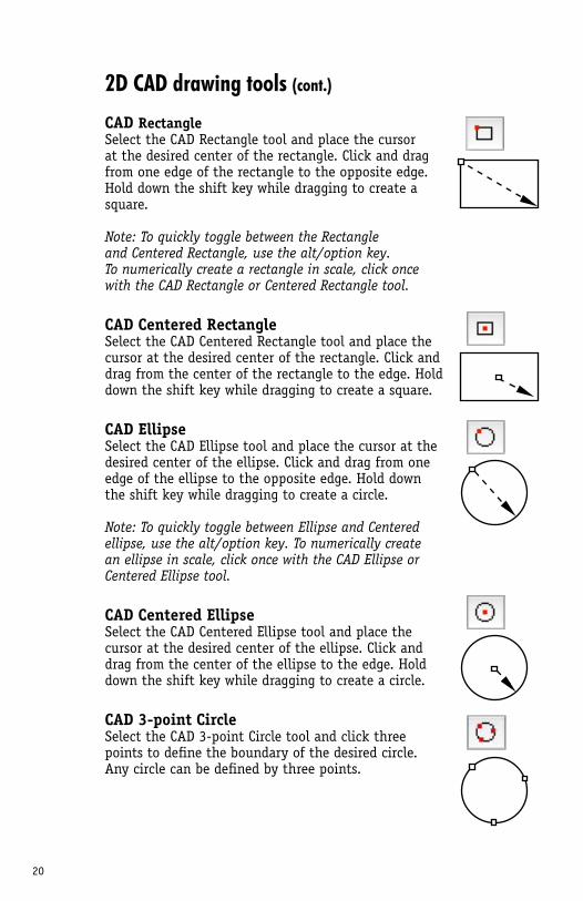
CAD Rectangle Select the CAD Rectangle tool and place the cursor at the desired center of the rectangle. Click and drag from one edge of the rectangle to the opposite edge. Hold down the shift key while dragging to create a square.
Note: To quickly toggle between the Rectangle and Centered Rectangle, use the alt/option key. To numerically create a rectangle in scale, click once with the CAD Rectangle or Centered Rectangle tool.
CAD Centered RectangleSelect the CAD Centered Rectangle tool and place the cursor at the desired center of the rectangle. Click and drag from the center of the rectangle to the edge. Hold down the shift key while dragging to create a square.
CAD Ellipse Select the CAD Ellipse tool and place the cursor at the desired center of the ellipse. Click and drag from one edge of the ellipse to the opposite edge. Hold down the shift key while dragging to create a circle.
Note: To quickly toggle between Ellipse and Centered ellipse, use the alt/option key. To numerically create an ellipse in scale, click once with the CAD Ellipse or Centered Ellipse tool.
CAD Centered Ellipse Select the CAD Centered Ellipse tool and place the cursor at the desired center of the ellipse. Click and drag from the center of the ellipse to the edge. Hold down the shift key while dragging to create a circle.
CAD 3-point Circle Select the CAD 3-point Circle tool and click three points to define the boundary of the desired circle. Any circle can be defined by three points.
21
2D CAD drawing tools (cont.)
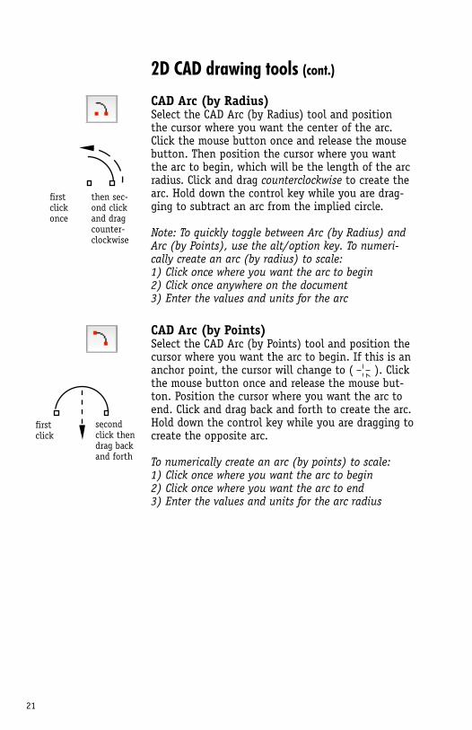
CAD Arc (by Radius)Select the CAD Arc (by Radius) tool and position the cursor where you want the center of the arc. Click the mouse button once and release the mouse button. Then position the cursor where you want the arc to begin, which will be the length of the arc radius. Click and drag counterclockwise to create the arc. Hold down the control key while you are drag-ging to subtract an arc from the implied circle.
Note: To quickly toggle between Arc (by Radius) and Arc (by Points), use the alt/option key. To numeri-cally create an arc (by radius) to scale:1) Click once where you want the arc to begin2) Click once anywhere on the document3) Enter the values and units for the arc
CAD Arc (by Points)Select the CAD Arc (by Points) tool and position the cursor where you want the arc to begin. If this is an anchor point, the cursor will change to ( ). Click the mouse button once and release the mouse but-ton. Position the cursor where you want the arc to end. Click and drag back and forth to create the arc. Hold down the control key while you are dragging to create the opposite arc.
To numerically create an arc (by points) to scale:1) Click once where you want the arc to begin2) Click once where you want the arc to end3) Enter the values and units for the arc radius
first clickonce
then sec-ond click and dragcounter-clockwise
first click
second click then drag back and forth
22
2D CAD drawing tools (cont.)
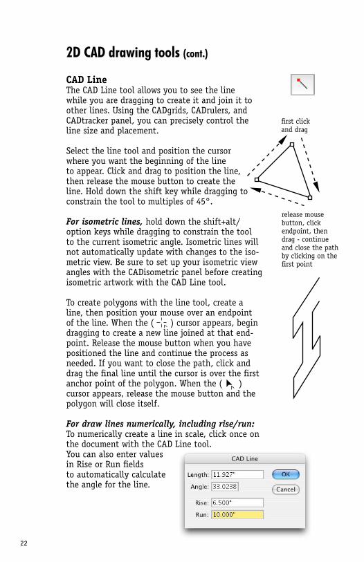
CAD LineThe CAD Line tool allows you to see the line while you are dragging to create it and join it to other lines. Using the CADgrids, CADrulers, and CADtracker panel, you can precisely control the line size and placement.
Select the line tool and position the cursor where you want the beginning of the line to appear. Click and drag to position the line, then release the mouse button to create the line. Hold down the shift key while dragging to constrain the tool to multiples of 45°.
For isometric lines, hold down the shift+alt/option keys while dragging to constrain the tool to the current isometric angle. Isometric lines will not automatically update with changes to the iso-metric view. Be sure to set up your isometric view angles with the CADisometric panel before creating isometric artwork with the CAD Line tool.
To create polygons with the line tool, create a line, then position your mouse over an endpoint of the line. When the ( ) cursor appears, begin dragging to create a new line joined at that end-point. Release the mouse button when you have positioned the line and continue the process as needed. If you want to close the path, click and drag the final line until the cursor is over the first anchor point of the polygon. When the ( ) cursor appears, release the mouse button and the polygon will close itself.
For draw lines numerically, including rise/run: To numerically create a line in scale, click once on the document with the CAD Line tool. You can also enter valuesin Rise or Run fieldsto automatically calculatethe angle for the line.
first click and drag
release mouse button, click endpoint, then drag - continue and close the path by clicking on the first point
23
2D CAD drawing tools (cont.)
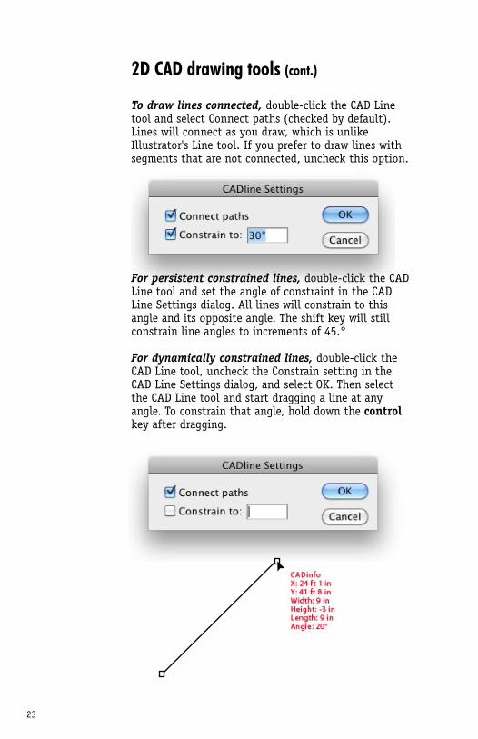
To draw lines connected, double-click the CAD Line tool and select Connect paths (checked by default). Lines will connect as you draw, which is unlike Illustrator's Line tool. If you prefer to draw lines with segments that are not connected, uncheck this option.
For persistent constrained lines, double-click the CAD Line tool and set the angle of constraint in the CAD Line Settings dialog. All lines will constrain to this angle and its opposite angle. The shift key will still constrain line angles to increments of 45.°
For dynamically constrained lines, double-click the CAD Line tool, uncheck the Constrain setting in the CAD Line Settings dialog, and select OK. Then select the CAD Line tool and start dragging a line at any angle. To constrain that angle, hold down the control key after dragging.
24
2D CAD drawing tools (cont.)
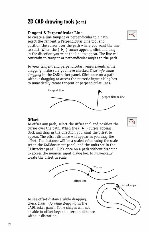
Tangent & Perpendicular Line To create a line tangent or perpendicular to a path, select the Tangent & Perpendicular Line tool and position the cursor over the path where you want the line to start. When the ( ) cursor appears, click and drag in the direction you want the line to appear. The line will constrain to tangent or perpendicular angles to the path.
To view tangent and perpendicular measurements while dragging, make sure you have checked Show info while dragging in the CADtracker panel. Click once on a path without dragging to access the numeric input dialog box to numerically create tangent or perpendicular lines.
OffsetTo offset any path, select the Offset tool and position the cursor over the path. When the ( ) cursor appears, click and drag in the direction you want the offset to appear. The offset distance will appear as you drag the offset. The distance will be a scaled value using the scale set in the CADdocument panel, and the units set in the CADtracker panel. Click once on a path without dragging to access the numeric input dialog box to numerically create the offset in scale.
To see offset distance while dragging,check Show info while dragging in the CADtracker panel. Some shapes will not be able to offset beyond a certain distance without distortion.
tangent line
perpendicular line
offset lineoffset object
.25 cm
25
CAD wall tools
CADwalls tool group:
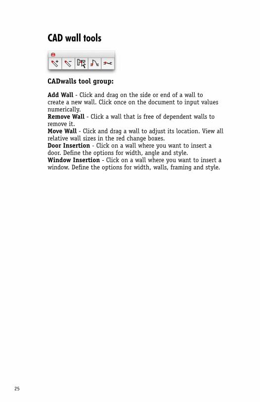
Add Wall - Click and drag on the side or end of a wall to create a new wall. Click once on the document to input values numerically.Remove Wall - Click a wall that is free of dependent walls to remove it.Move Wall - Click and drag a wall to adjust its location. View all relative wall sizes in the red change boxes.Door Insertion - Click on a wall where you want to insert a door. Define the options for width, angle and style.Window Insertion - Click on a wall where you want to insert a window. Define the options for width, walls, framing and style.
26
CAD wall tools
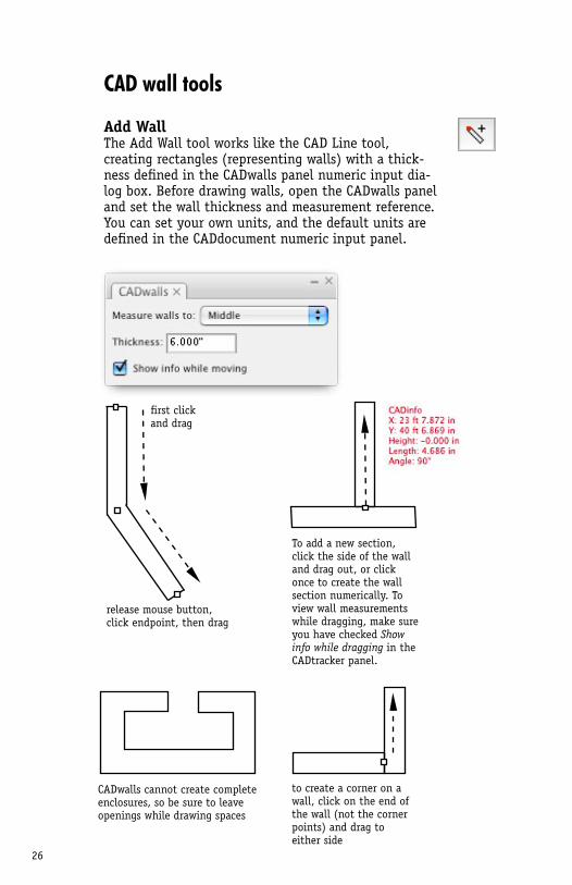
Add WallThe Add Wall tool works like the CAD Line tool, creating rectangles (representing walls) with a thick-ness defined in the CADwalls panel numeric input dia-log box. Before drawing walls, open the CADwalls panel and set the wall thickness and measurement reference. You can set your own units, and the default units are defined in the CADdocument numeric input panel.
release mouse button, click endpoint, then drag
first click and drag
To add a new section,click the side of the walland drag out, or clickonce to create the wallsection numerically. To view wall measurements while dragging, make sure you have checked Show info while dragging in the CADtracker panel.
CADwalls cannot create complete enclosures, so be sure to leave openings while drawing spaces
to create a corner on a wall, click on the end of the wall (not the corner points) and drag to either side
27
CAD wall tools (cont.)
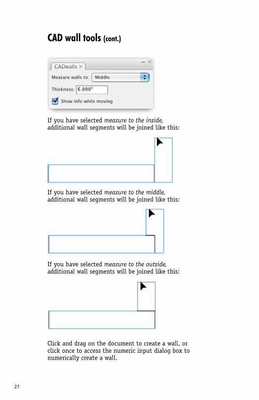
If you have selected measure to the inside, additional wall segments will be joined like this:
If you have selected measure to the middle, additional wall segments will be joined like this:
If you have selected measure to the outside, additional wall segments will be joined like this:
Click and drag on the document to create a wall, or click once to access the numeric input dialog box to numerically create a wall.
28
CAD wall tools (cont.)
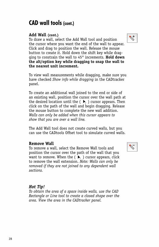
Add Wall (cont.)To draw a wall, select the Add Wall tool and position the cursor where you want the end of the wall to appear. Click and drag to position the wall. Release the mouse button to create it. Hold down the shift key while drag-ging to constrain the wall to 45° increments. Hold down the alt/option key while dragging to snap the wall to the nearest unit increment.
To view wall measurements while dragging, make sure you have checked Show info while dragging in the CADtracker panel.
To create an additional wall joined to the end or side of an existing wall, position the cursor over the wall path at the desired location until the ( ) cursor appears. Then click on the path of the wall and begin dragging. Release the mouse button to complete the new wall addition. Walls can only be added when this cursor appears to show that you are over a wall line.
The Add Wall tool does not create curved walls, but you can use the CADtools Offset tool to simulate curved walls.
Remove WallTo remove a wall, select the Remove Wall tools and position the cursor over the path of the wall that you want to remove. When the ( ) cursor appears, click to remove the wall extension. Note: Walls can only be removed if they are not joined to any dependent wall sections.
Hot Tip!To obtain the area of a space inside walls, use the CAD Rectangle or Line tool to create a closed shape over the area. View the area in the CADtracker panel.
29
CAD wall tools (cont.)
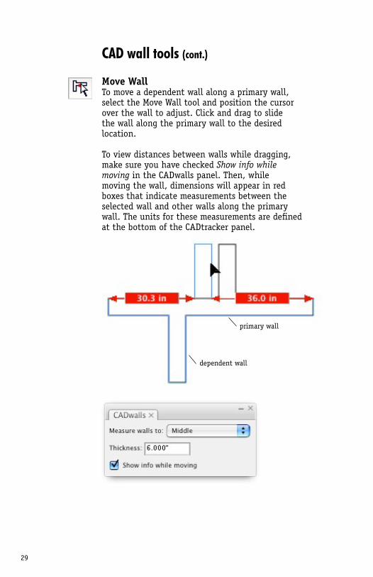
Move WallTo move a dependent wall along a primary wall, select the Move Wall tool and position the cursor over the wall to adjust. Click and drag to slide the wall along the primary wall to the desired location.
To view distances between walls while dragging, make sure you have checked Show info while moving in the CADwalls panel. Then, while moving the wall, dimensions will appear in red boxes that indicate measurements between the selected wall and other walls along the primary wall. The units for these measurements are defined at the bottom of the CADtracker panel.
primary wall
dependent wall
30
CAD wall tools (cont.)
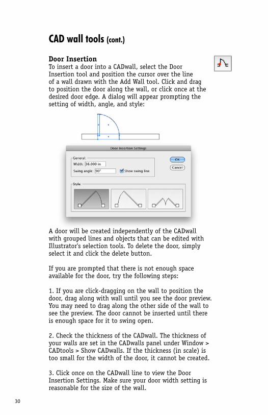
Door InsertionTo insert a door into a CADwall, select the Door Insertion tool and position the cursor over the line of a wall drawn with the Add Wall tool. Click and drag to position the door along the wall, or click once at the desired door edge. A dialog will appear prompting the setting of width, angle, and style:
A door will be created independently of the CADwall with grouped lines and objects that can be edited with Illustrator's selection tools. To delete the door, simply select it and click the delete button.
If you are prompted that there is not enough space available for the door, try the following steps:
1. If you are click-dragging on the wall to position the door, drag along with wall until you see the door preview. You may need to drag along the other side of the wall to see the preview. The door cannot be inserted until there is enough space for it to swing open.
2. Check the thickness of the CADwall. The thickness of your walls are set in the CADwalls panel under Window > CADtools > Show CADwalls. If the thickness (in scale) is too small for the width of the door, it cannot be created.
3. Click once on the CADwall line to view the Door Insertion Settings. Make sure your door width setting is reasonable for the size of the wall.
31
CAD wall tools (cont.)
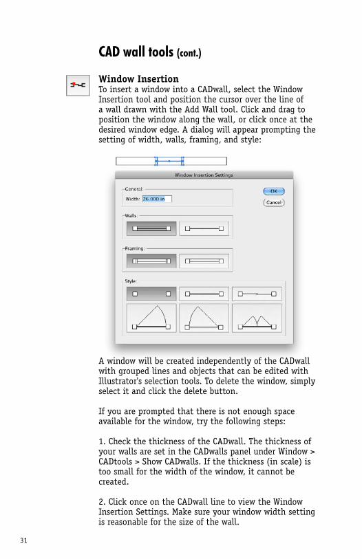
Window InsertionTo insert a window into a CADwall, select the Window Insertion tool and position the cursor over the line of a wall drawn with the Add Wall tool. Click and drag to position the window along the wall, or click once at the desired window edge. A dialog will appear prompting the setting of width, walls, framing, and style:
A window will be created independently of the CADwall with grouped lines and objects that can be edited with Illustrator's selection tools. To delete the window, simply select it and click the delete button.
If you are prompted that there is not enough space available for the window, try the following steps:
1. Check the thickness of the CADwall. The thickness of your walls are set in the CADwalls panel under Window > CADtools > Show CADwalls. If the thickness (in scale) is too small for the width of the window, it cannot be created.
2. Click once on the CADwall line to view the Window Insertion Settings. Make sure your window width setting is reasonable for the size of the wall.
32
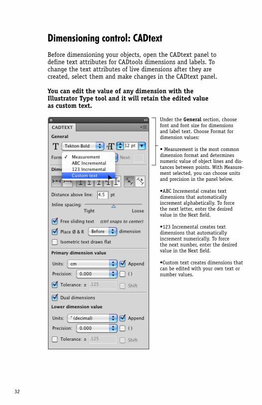
Dimensioning control: CADtextBefore dimensioning your objects, open the CADtext panel to define text attributes for CADtools dimensions and labels. To change the text attributes of live dimensions after they are created, select them and make changes in the CADtext panel.
You can edit the value of any dimension with the Illustrator Type tool and it will retain the edited value as custom text.
Under the General section, choose font and font size for dimensions and label text. Choose Format for dimension values:
• Measurement is the most common dimension format and determines numeric value of object lines and dis-tances between points. With Measure-ment selected, you can choose units and precision in the panel below.
•ABC Incremental creates text dimensions that automatically increment alphabetically. To force the next letter, enter the desired value in the Next field.
•123 Incremental creates text dimensions that automatically increment numerically. To force the next number, enter the desired value in the Next field.
•Custom text creates dimensions that can be edited with your own text or number values.
33
Dimensioning control: CADtext (cont.)
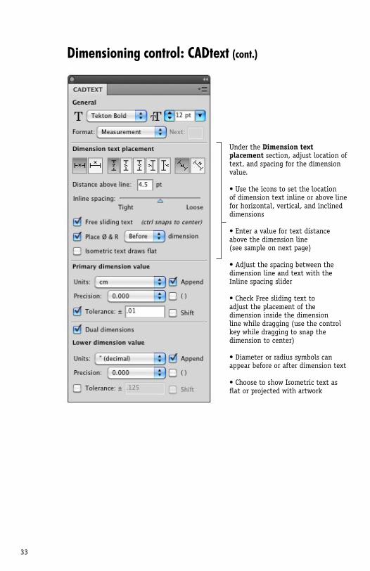
Under the Dimension text placement section, adjust location of text, and spacing for the dimension value.
• Use the icons to set the location of dimension text inline or above line for horizontal, vertical, and inclined dimensions
• Enter a value for text distance above the dimension line (see sample on next page)
• Adjust the spacing between the dimension line and text with the Inline spacing slider
• Check Free sliding text to adjust the placement of the dimension inside the dimension line while dragging (use the control key while dragging to snap the dimension to center)
• Diameter or radius symbols can appear before or after dimension text
• Choose to show Isometric text as flat or projected with artwork
34
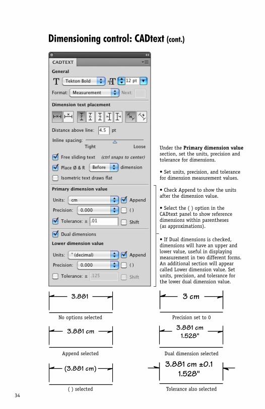
Under the Primary dimension value section, set the units, precision and tolerance for dimensions.
• Set units, precision, and tolerance for dimension measurement values.
• Check Append to show the units after the dimension value.
• Select the ( ) option in the CADtext panel to show reference dimensions within parentheses (as approximations).
• If Dual dimensions is checked, dimensions will have an upper and lower value, useful in displaying measurement in two different forms. An additional section will appear called Lower dimension value. Set units, precision, and tolerance for the lower dual dimension value.
Dimensioning control: CADtext (cont.)
No options selected Precision set to 0
Dual dimension selected
Tolerance also selected
Append selected
( ) selected
3.881
3.881 cm
(3.881 cm)
3.881 cm1.528"
3 cm
3.881 cm ±0.11.528"
35
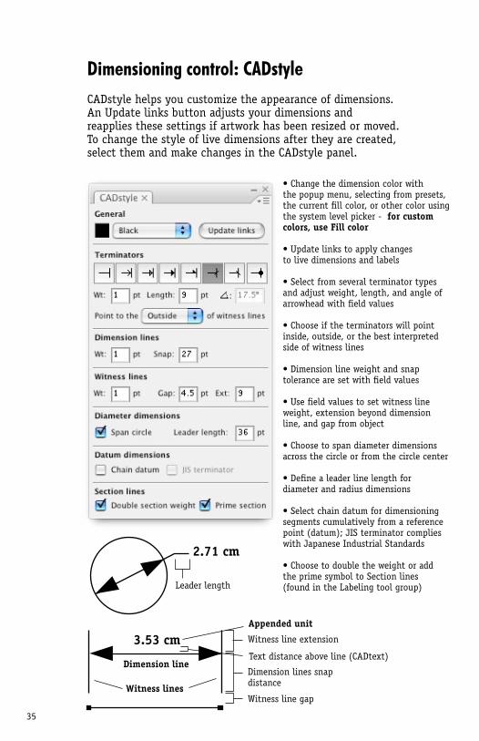
Dimensioning control: CADstyleCADstyle helps you customize the appearance of dimensions. An Update links button adjusts your dimensions and reapplies these settings if artwork has been resized or moved. To change the style of live dimensions after they are created, select them and make changes in the CADstyle panel.
3.53 cmAppended unit
Text distance above line (CADtext)
Witness line gap
Witness line extension
Dimension lines snapdistance
Dimension line
Witness lines
• Change the dimension color with the popup menu, selecting from presets, the current fill color, or other color using the system level picker - for custom colors, use Fill color
• Update links to apply changesto live dimensions and labels
• Select from several terminator types and adjust weight, length, and angle of arrowhead with field values
• Choose if the terminators will point inside, outside, or the best interpreted side of witness lines
• Dimension line weight and snap tolerance are set with field values
• Use field values to set witness line weight, extension beyond dimension line, and gap from object
• Choose to span diameter dimensions across the circle or from the circle center
• Define a leader line length for diameter and radius dimensions
• Select chain datum for dimensioning segments cumulatively from a reference point (datum); JIS terminator complies with Japanese Industrial Standards
• Choose to double the weight or add the prime symbol to Section lines (found in the Labeling tool group)
2.71 cm
Leader length
36
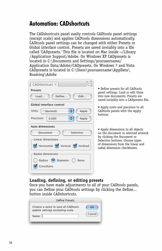
Automation: CADshortcutsThe CADshortcuts panel easily controls CADtools panel settings (except scale) and applies CADtools dimensions automatically. CADtools panel settings can be changed with either Presets or Global interface control. Presets are saved invisibly into a file called 'CADpresets.' This file is located on Mac inside ~/Library /Application Support/Adobe. On Windows XP CADpresets is located in C:\Documents and Settings/yourusername/Application Data/Adobe/CADpresets. On Windows 7 and Vista CADpresets is located in C:\Users\yourusername\AppData\Roaming\Adobe
Loading, defining, or editing presetsOnce you have made adjustments to all of your CADtools panels, you can Define your CADtools settings by clicking the Define... button inside CADshortcuts.
• Define presets for all CADtools panel settings. Load or edit them into new documents. Presets are saved invisibly into a CADpresets file.
• Apply units and precision to all CADtools panels with the Apply buttons
• Apply dimensions to all objects on the document or selected artwork by clicking the Document or Selection buttons. Choose types of dimensions from the linear and radial dimension checkboxes.
37
Automation: CADshortcuts (cont.)
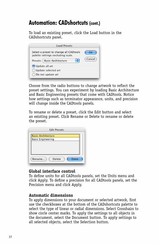
To load an existing preset, click the Load button in the CADshortcuts panel.
Choose from the radio buttons to change artwork to reflect the preset settings. You can experiment by loading Basic Architecture and Basic Engineering presets that come with CADtools. Notice how settings such as terminator appearance, units, and precision will change inside the CADtools panels.
To rename or delete a preset, click the Edit button and select an existing preset. Click Rename or Delete to rename or delete the preset.
Global interface controlTo define units for all CADtools panels, set the Units menu and click Apply. To define a precision for all CADtools panels, set the Precision menu and click Apply.
Automatic dimensionsTo apply dimensions to your document or selected artwork, first use the checkboxes at the bottom of the CADshortcuts palette to select the type of linear or radial dimensions. Select Crosshairs to show circle center marks. To apply the settings to all objects in the document, select the Document button. To apply settings to all selected objects, select the Selection button.
38
2D dimensioning tools
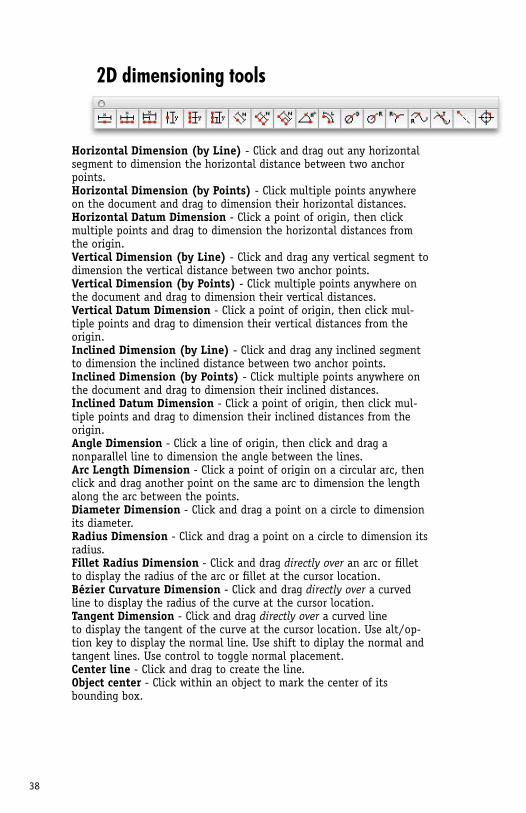
Horizontal Dimension (by Line) - Click and drag out any horizontal segment to dimension the horizontal distance between two anchor points.Horizontal Dimension (by Points) - Click multiple points anywhere on the document and drag to dimension their horizontal distances.Horizontal Datum Dimension - Click a point of origin, then click multiple points and drag to dimension the horizontal distances from the origin.Vertical Dimension (by Line) - Click and drag any vertical segment to dimension the vertical distance between two anchor points. Vertical Dimension (by Points) - Click multiple points anywhere on the document and drag to dimension their vertical distances.Vertical Datum Dimension - Click a point of origin, then click mul-tiple points and drag to dimension their vertical distances from the origin.Inclined Dimension (by Line) - Click and drag any inclined segment to dimension the inclined distance between two anchor points.Inclined Dimension (by Points) - Click multiple points anywhere on the document and drag to dimension their inclined distances.Inclined Datum Dimension - Click a point of origin, then click mul-tiple points and drag to dimension their inclined distances from the origin.Angle Dimension - Click a line of origin, then click and drag a nonparallel line to dimension the angle between the lines.Arc Length Dimension - Click a point of origin on a circular arc, then click and drag another point on the same arc to dimension the length along the arc between the points.Diameter Dimension - Click and drag a point on a circle to dimension its diameter.Radius Dimension - Click and drag a point on a circle to dimension its radius.Fillet Radius Dimension - Click and drag directly over an arc or fillet to display the radius of the arc or fillet at the cursor location.Bézier Curvature Dimension - Click and drag directly over a curved line to display the radius of the curve at the cursor location.Tangent Dimension - Click and drag directly over a curved line to display the tangent of the curve at the cursor location. Use alt/op-tion key to display the normal line. Use shift to diplay the normal and tangent lines. Use control to toggle normal placement.Center line - Click and drag to create the line.Object center - Click within an object to mark the center of its bounding box.
39
2D dimensioning tools (cont.)
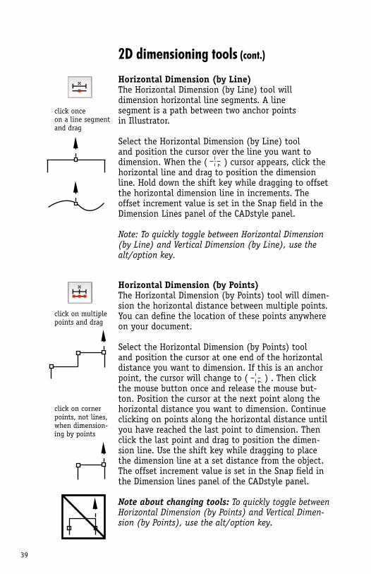
Horizontal Dimension (by Line)The Horizontal Dimension (by Line) tool will dimension horizontal line segments. A line segment is a path between two anchor points in Illustrator.
Select the Horizontal Dimension (by Line) tool and position the cursor over the line you want to dimension. When the ( ) cursor appears, click the horizontal line and drag to position the dimension line. Hold down the shift key while dragging to offset the horizontal dimension line in increments. The offset increment value is set in the Snap field in the Dimension Lines panel of the CADstyle panel.
Note: To quickly toggle between Horizontal Dimension (by Line) and Vertical Dimension (by Line), use the alt/option key.
Horizontal Dimension (by Points)The Horizontal Dimension (by Points) tool will dimen-sion the horizontal distance between multiple points. You can define the location of these points anywhere on your document.
Select the Horizontal Dimension (by Points) tool and position the cursor at one end of the horizontal distance you want to dimension. If this is an anchor point, the cursor will change to ( ) . Then click the mouse button once and release the mouse but-ton. Position the cursor at the next point along the horizontal distance you want to dimension. Continue clicking on points along the horizontal distance until you have reached the last point to dimension. Then click the last point and drag to position the dimen-sion line. Use the shift key while dragging to place the dimension line at a set distance from the object. The offset increment value is set in the Snap field in the Dimension lines panel of the CADstyle panel.
Note about changing tools: To quickly toggle between Horizontal Dimension (by Points) and Vertical Dimen-sion (by Points), use the alt/option key.
click onceon a line segmentand drag
click on multiplepoints and drag
click on corner points, not lines, when dimension-ing by points
40
2D dimensioning tools (cont.)
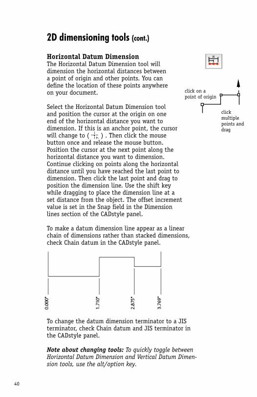
Horizontal Datum DimensionThe Horizontal Datum Dimension tool will dimension the horizontal distances between a point of origin and other points. You can define the location of these points anywhere on your document.
Select the Horizontal Datum Dimension tool and position the cursor at the origin on one end of the horizontal distance you want to dimension. If this is an anchor point, the cursor will change to ( ) . Then click the mouse button once and release the mouse button. Position the cursor at the next point along the horizontal distance you want to dimension. Continue clicking on points along the horizontal distance until you have reached the last point todimension. Then click the last point and drag to position the dimension line. Use the shift key while dragging to place the dimension line at a set distance from the object. The offset increment value is set in the Snap field in the Dimension lines section of the CADstyle panel.
To make a datum dimension line appear as a linear chain of dimensions rather than stacked dimensions, check Chain datum in the CADstyle panel.
To change the datum dimension terminator to a JIS terminator, check Chain datum and JIS terminator in the CADstyle panel.
Note about changing tools: To quickly toggle between Horizontal Datum Dimension and Vertical Datum Dimen-sion tools, use the alt/option key.
click on a point of origin
clickmultiplepoints and drag
41
2D dimensioning tools (cont.)
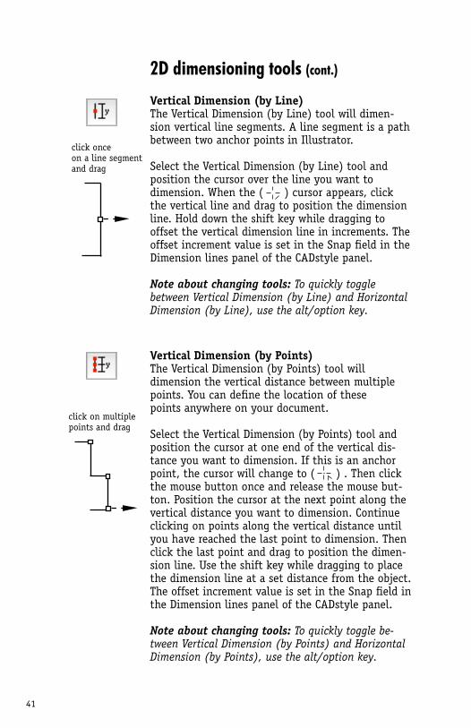
Vertical Dimension (by Line)The Vertical Dimension (by Line) tool will dimen-sion vertical line segments. A line segment is a path between two anchor points in Illustrator.
Select the Vertical Dimension (by Line) tool and position the cursor over the line you want to dimension. When the ( ) cursor appears, click the vertical line and drag to position the dimension line. Hold down the shift key while dragging to offset the vertical dimension line in increments. The offset increment value is set in the Snap field in the Dimension lines panel of the CADstyle panel.
Note about changing tools: To quickly toggle between Vertical Dimension (by Line) and Horizontal Dimension (by Line), use the alt/option key.
Vertical Dimension (by Points)The Vertical Dimension (by Points) tool will dimension the vertical distance between multiple points. You can define the location of these points anywhere on your document.
Select the Vertical Dimension (by Points) tool and position the cursor at one end of the vertical dis-tance you want to dimension. If this is an anchor point, the cursor will change to ( ) . Then click the mouse button once and release the mouse but-ton. Position the cursor at the next point along the vertical distance you want to dimension. Continue clicking on points along the vertical distance until you have reached the last point to dimension. Then click the last point and drag to position the dimen-sion line. Use the shift key while dragging to place the dimension line at a set distance from the object. The offset increment value is set in the Snap field in the Dimension lines panel of the CADstyle panel.
Note about changing tools: To quickly toggle be-tween Vertical Dimension (by Points) and Horizontal Dimension (by Points), use the alt/option key.
click onceon a line segmentand drag
click on multiplepoints and drag
42
2D dimensioning tools (cont.)
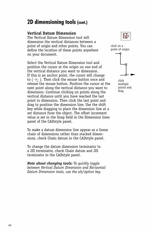
Vertical Datum DimensionThe Vertical Datum Dimension tool will dimension the vertical distances between a point of origin and other points. You can define the location of these points anywhere on your document.
Select the Vertical Datum Dimension tool and position the cursor at the origin on one end of the vertical distance you want to dimension. If this is an anchor point, the cursor will change to ( ). Then click the mouse button once and release the mouse button. Position the cursor at the next point along the vertical distance you want to dimension. Continue clicking on points along the vertical distance until you have reached the last point to dimension. Then click the last point and drag to position the dimension line. Use the shift key while dragging to place the dimension line at a set distance from the object. The offset increment value is set in the Snap field in the Dimension lines panel of the CADstyle panel.
To make a datum dimension line appear as a linear chain of dimensions rather than stacked dimen-sions, check Chain datum in the CADstyle panel.
To change the datum dimension terminator to a JIS terminator, check Chain datum and JIS terminator in the CADstyle panel.
Note about changing tools: To quickly toggle between Vertical Datum Dimension and Horizontal Datum Dimension tools, use the alt/option key.
click on a point of origin
clickmultiplepoints and drag
43
2D dimensioning tools (cont.)
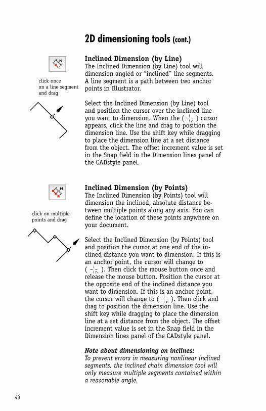
Inclined Dimension (by Line)The Inclined Dimension (by Line) tool will dimension angled or “inclined” line segments. A line segment is a path between two anchor points in Illustrator. Select the Inclined Dimension (by Line) tool and position the cursor over the inclined line you want to dimension. When the ( ) cursor appears, click the line and drag to position the dimension line. Use the shift key while dragging to place the dimension line at a set distance from the object. The offset increment value is set in the Snap field in the Dimension lines panel of the CADstyle panel.
Inclined Dimension (by Points)The Inclined Dimension (by Points) tool will dimension the inclined, absolute distance be-tween multiple points along any axis. You can define the location of these points anywhere on your document.
Select the Inclined Dimension (by Points) tool and position the cursor at one end of the in-clined distance you want to dimension. If this is an anchor point, the cursor will change to ( ). Then click the mouse button once and release the mouse button. Position the cursor at the opposite end of the inclined distance you want to dimension. If this is an anchor point, the cursor will change to ( ). Then click and drag to position the dimension line. Use the shift key while dragging to place the dimension line at a set distance from the object. The offset increment value is set in the Snap field in the Dimension lines panel of the CADstyle panel.
Note about dimensioning on inclines: To prevent errors in measuring nonlinear inclined segments, the inclined chain dimension tool will only measure multiple segments contained within a reasonable angle.
click onceon a line segmentand drag
click on multiplepoints and drag
44
2D dimensioning tools (cont.)
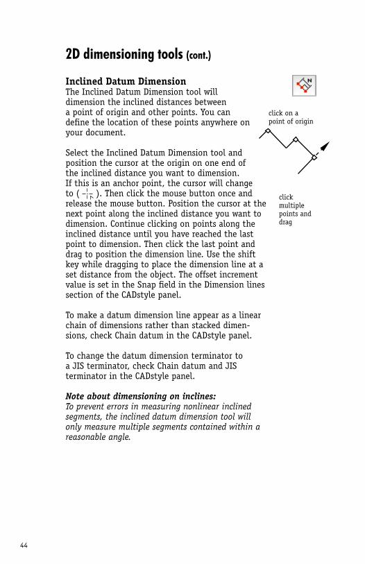
Inclined Datum DimensionThe Inclined Datum Dimension tool will dimension the inclined distances between a point of origin and other points. You can define the location of these points anywhere on your document.
Select the Inclined Datum Dimension tool and position the cursor at the origin on one end of the inclined distance you want to dimension. If this is an anchor point, the cursor will change to ( ). Then click the mouse button once and release the mouse button. Position the cursor at the next point along the inclined distance you want to dimension. Continue clicking on points along the inclined distance until you have reached the last point to dimension. Then click the last point and drag to position the dimension line. Use the shift key while dragging to place the dimension line at a set distance from the object. The offset increment value is set in the Snap field in the Dimension lines section of the CADstyle panel.
To make a datum dimension line appear as a linear chain of dimensions rather than stacked dimen-sions, check Chain datum in the CADstyle panel.
To change the datum dimension terminator to a JIS terminator, check Chain datum and JIS terminator in the CADstyle panel.
Note about dimensioning on inclines: To prevent errors in measuring nonlinear inclined segments, the inclined datum dimension tool will only measure multiple segments contained within a reasonable angle.
click on a point of origin
clickmultiplepoints and drag
45
2D dimensioning tools (cont.)
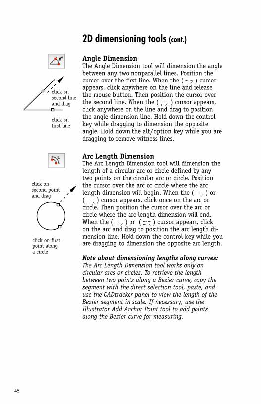
Angle DimensionThe Angle Dimension tool will dimension the angle between any two nonparallel lines. Position the cursor over the first line. When the ( ) cursor appears, click anywhere on the line and release the mouse button. Then position the cursor over the second line. When the ( ) cursor appears, click anywhere on the line and drag to position the angle dimension line. Hold down the control key while dragging to dimension the opposite angle. Hold down the alt/option key while you are dragging to remove witness lines.
Arc Length DimensionThe Arc Length Dimension tool will dimension the length of a circular arc or circle defined by any two points on the circular arc or circle. Position the cursor over the arc or circle where the arc length dimension will begin. When the ( ) or ( ) cursor appears, click once on the arc or circle. Then position the cursor over the arc or circle where the arc length dimension will end. When the ( ) or ( ) cursor appears, click on the arc and drag to position the arc length di-mension line. Hold down the control key while you are dragging to dimension the opposite arc length.
Note about dimensioning lengths along curves: The Arc Length Dimension tool works only on circular arcs or circles. To retrieve the length between two points along a Bezier curve, copy the segment with the direct selection tool, paste, and use the CADtracker panel to view the length of the Bezier segment in scale. If necessary, use the Illustrator Add Anchor Point tool to add points along the Bezier curve for measuring.
click on second lineand drag
click on first line
click on first point along a circle
click on second pointand drag
46
2D dimensioning tools (cont.)
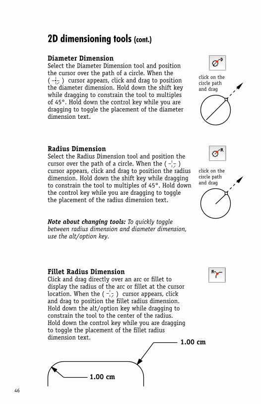
Diameter DimensionSelect the Diameter Dimension tool and position the cursor over the path of a circle. When the ( ) cursor appears, click and drag to position the diameter dimension. Hold down the shift key while dragging to constrain the tool to multiples of 45°. Hold down the control key while you are dragging to toggle the placement of the diameter dimension text.
Radius DimensionSelect the Radius Dimension tool and position the cursor over the path of a circle. When the ( ) cursor appears, click and drag to position the radius dimension. Hold down the shift key while dragging to constrain the tool to multiples of 45°. Hold down the control key while you are dragging to toggle the placement of the radius dimension text.
Note about changing tools: To quickly toggle between radius dimension and diameter dimension, use the alt/option key.
Fillet Radius DimensionClick and drag directly over an arc or fillet to display the radius of the arc or fillet at the cursor location. When the ( ) cursor appears, click and drag to position the fillet radius dimension. Hold down the alt/option key while dragging to constrain the tool to the center of the radius. Hold down the control key while you are dragging to toggle the placement of the fillet radius dimension text.
click on the circle pathand drag
click on the circle pathand drag
1.00 cm
1.00 cm
47
Hot Tip!To dimension type, convert type to outlines with the Create Outlines command in Adobe Illustrator. Or use the dimension by points tools to measure between any points on the document.
click and drag directly over the curved path
click and drag directly over the curved path
2D dimensioning tools (cont.)
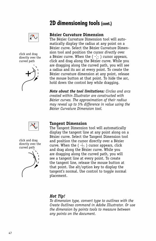
Bézier Curvature DimensionThe Bézier Curvature Dimension tool will auto-matically display the radius at any point on a Bézier curve. Select the Bézier Curvature Dimen-sion tool and position the cursor directly over a Bézier curve. When the ( ) cursor appears, click and drag along the Bézier curve. While you are dragging along the curved path, you will see a radius and its arc at every point. To create the Bézier curvature dimension at any point, release the mouse button at that point. To hide the arc, hold down the control key while dragging.
Note about the tool limitations: Circles and arcs created within Illustrator are constructed with Bézier curves. The approximation of their radius may reveal up to 5% difference in value using the Bézier Curvature Dimension tool.
Tangent DimensionThe Tangent Dimension tool will automatically display the tangent line at any point along on a Bézier curve. Select the Tangent Dimension tool and position the cursor directly over a Bézier curve. When the ( ) cursor appears, click and drag along the Bézier curve. While you are dragging along the curved path, you will see a tangent line at every point. To create the tangent line, release the mouse button at that point. Use alt/option key to display the tangent's normal. Use control to toggle normal placement.
48
2D dimensioning tools (cont.)
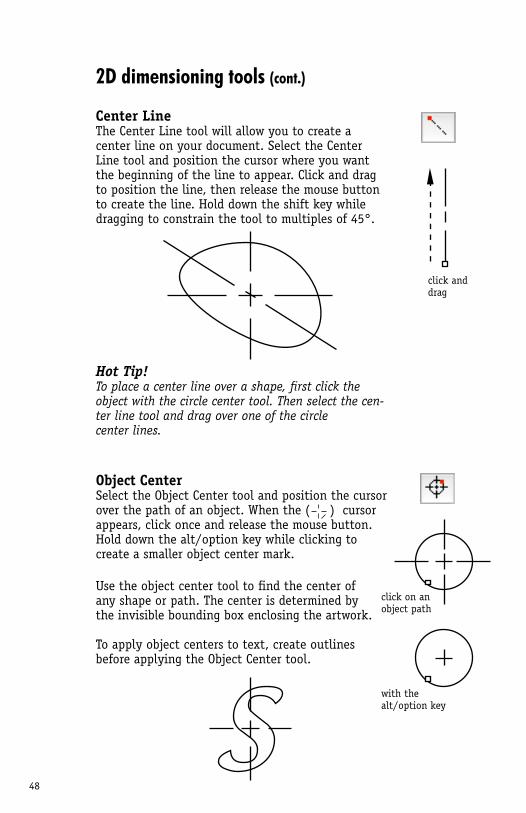
Center LineThe Center Line tool will allow you to create a center line on your document. Select the Center Line tool and position the cursor where you want the beginning of the line to appear. Click and drag to position the line, then release the mouse button to create the line. Hold down the shift key while dragging to constrain the tool to multiples of 45°.
Hot Tip!To place a center line over a shape, first click the object with the circle center tool. Then select the cen-ter line tool and drag over one of the circle center lines.
Object CenterSelect the Object Center tool and position the cursor over the path of an object. When the ( ) cursor appears, click once and release the mouse button. Hold down the alt/option key while clicking to create a smaller object center mark.
Use the object center tool to find the center of any shape or path. The center is determined by the invisible bounding box enclosing the artwork.
To apply object centers to text, create outlines before applying the Object Center tool.
click anddrag
click on an object path
with the alt/option key
49
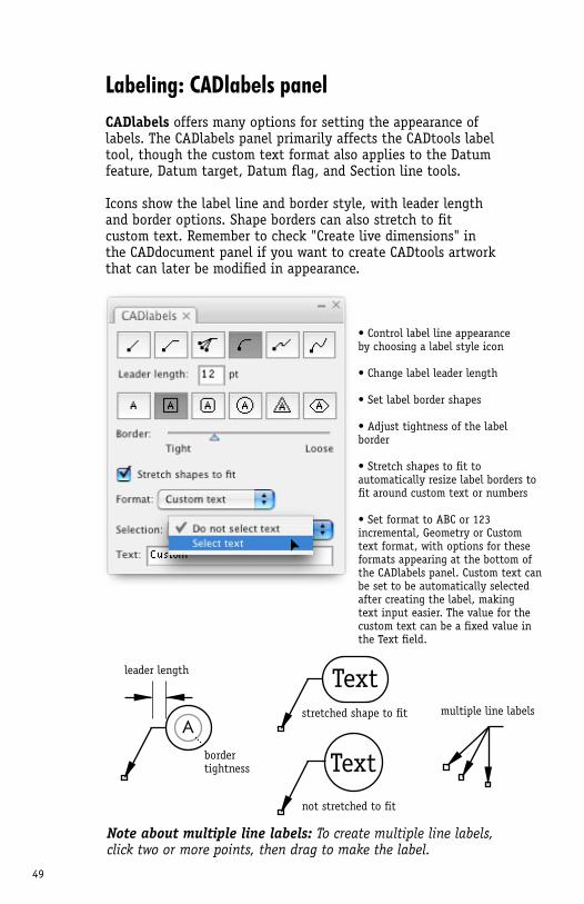
Labeling: CADlabels panelCADlabels offers many options for setting the appearance of labels. The CADlabels panel primarily affects the CADtools label tool, though the custom text format also applies to the Datum feature, Datum target, Datum flag, and Section line tools.
Icons show the label line and border style, with leader length and border options. Shape borders can also stretch to fit custom text. Remember to check "Create live dimensions" in the CADdocument panel if you want to create CADtools artwork that can later be modified in appearance.
• Control label line appearance by choosing a label style icon
• Change label leader length
• Set label border shapes
• Adjust tightness of the label border
• Stretch shapes to fit to automatically resize label borders to fit around custom text or numbers
• Set format to ABC or 123 incremental, Geometry or Custom text format, with options for these formats appearing at the bottom of the CADlabels panel. Custom text can be set to be automatically selected after creating the label, making text input easier. The value for the custom text can be a fixed value in the Text field.
A
leader length
border tightness
Textstretched shape to fit multiple line labels
Note about multiple line labels: To create multiple line labels, click two or more points, then drag to make the label.
Textnot stretched to fit
50
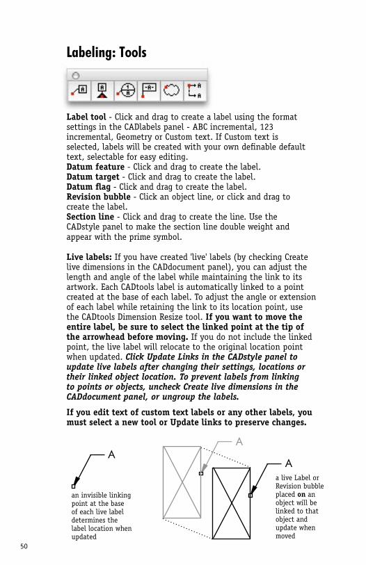
an invisible linking point at the base of each live label determines the label location when updated
A
Labeling: Tools
Label tool - Click and drag to create a label using the format settings in the CADlabels panel - ABC incremental, 123 incremental, Geometry or Custom text. If Custom text is selected, labels will be created with your own definable default text, selectable for easy editing. Datum feature - Click and drag to create the label.Datum target - Click and drag to create the label.Datum flag - Click and drag to create the label.Revision bubble - Click an object line, or click and drag to create the label. Section line - Click and drag to create the line. Use the CADstyle panel to make the section line double weight and appear with the prime symbol.
Live labels: If you have created 'live' labels (by checking Create live dimensions in the CADdocument panel), you can adjust the length and angle of the label while maintaining the link to its artwork. Each CADtools label is automatically linked to a point created at the base of each label. To adjust the angle or extension of each label while retaining the link to its location point, use the CADtools Dimension Resize tool. If you want to move the entire label, be sure to select the linked point at the tip of the arrowhead before moving. If you do not include the linked point, the live label will relocate to the original location point when updated. Click Update Links in the CADstyle panel to update live labels after changing their settings, locations or their linked object location. To prevent labels from linking to points or objects, uncheck Create live dimensions in the CADdocument panel, or ungroup the labels.
If you edit text of custom text labels or any other labels, you must select a new tool or Update links to preserve changes.
a live Label or Revision bubble placed on an object will be linked to that object and update when moved
A
A
51
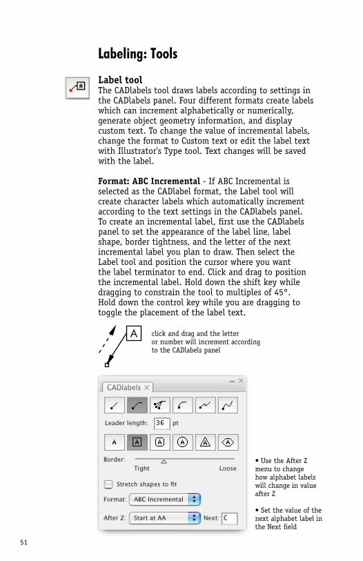
Labeling: Tools
Label toolThe CADlabels tool draws labels according to settings in the CADlabels panel. Four different formats create labels which can increment alphabetically or numerically, generate object geometry information, and display custom text. To change the value of incremental labels, change the format to Custom text or edit the label text with Illustrator's Type tool. Text changes will be saved with the label. Format: ABC Incremental - If ABC Incremental is selected as the CADlabel format, the Label tool will create character labels which automatically increment according to the text settings in the CADlabels panel. To create an incremental label, first use the CADlabels panel to set the appearance of the label line, label shape, border tightness, and the letter of the next incremental label you plan to draw. Then select the Label tool and position the cursor where you want the label terminator to end. Click and drag to position the incremental label. Hold down the shift key while dragging to constrain the tool to multiples of 45°. Hold down the control key while you are dragging to toggle the placement of the label text.
A click and drag and the letter or number will increment according to the CADlabels panel
• Use the After Z menu to change how alphabet labels will change in value after Z
• Set the value of the next alphabet label in the Next field
52
Labeling: Tools (cont.)
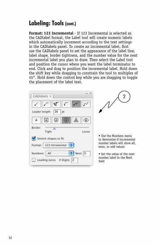
Format: 123 Incremental - If 123 Incremental is selected as the CADlabel format, the Label tool will create numeric labels which automatically increment according to the text settings in the CADlabels panel. To create an incremental label, first use the CADlabels panel to set the appearance of the label line, label shape, border tightness, and the number value for the next incremental label you plan to draw. Then select the Label tool and position the cursor where you want the label terminator to end. Click and drag to position the incremental label. Hold down the shift key while dragging to constrain the tool to multiples of 45°. Hold down the control key while you are dragging to toggle the placement of the label text.
• Use the Numbers menu to determine if incremental number labels will show all, even, or odd values
• Set the value of the next number label in the Next field
2
53
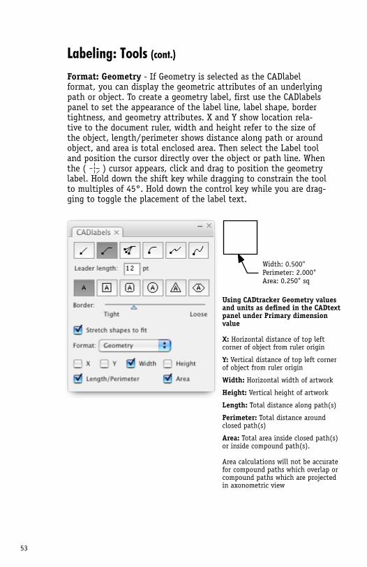
Width: 0.500"Perimeter: 2.000"Area: 0.250" sq
Using CADtracker Geometry valuesand units as defined in the CADtext panel under Primary dimension value
X: Horizontal distance of top left corner of object from ruler origin
Y: Vertical distance of top left corner of object from ruler origin
Width: Horizontal width of artwork
Height: Vertical height of artwork
Length: Total distance along path(s)
Perimeter: Total distance around closed path(s)
Area: Total area inside closed path(s) or inside compound path(s).
Area calculations will not be accurate for compound paths which overlap or compound paths which are projected in axonometric view
Labeling: Tools (cont.)
Format: Geometry - If Geometry is selected as the CADlabel format, you can display the geometric attributes of an underlying path or object. To create a geometry label, first use the CADlabels panel to set the appearance of the label line, label shape, border tightness, and geometry attributes. X and Y show location rela-tive to the document ruler, width and height refer to the size of the object, length/perimeter shows distance along path or around object, and area is total enclosed area. Then select the Label tool and position the cursor directly over the object or path line. When the ( ) cursor appears, click and drag to position the geometry label. Hold down the shift key while dragging to constrain the tool to multiples of 45°. Hold down the control key while you are drag-ging to toggle the placement of the label text.
54
Labeling: Tools (cont.)
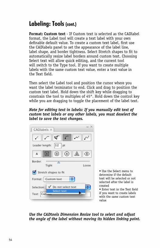
Format: Custom text - If Custom text is selected as the CADlabel format, the Label tool will create a text label with your own definable default value. To create a custom text label, first use the CADlabels panel to set the appearance of the label line, label shape, and border tightness. Select Stretch shapes to fit to automatically resize label borders around custom text. Choosing Select text will allow quick editing, and the current tool will switch to the Type tool. If you want to create multiple labels with the same custom text value, enter a text value in the Text field. Then select the Label tool and position the cursor where you want the label terminator to end. Click and drag to position the custom text label. Hold down the shift key while dragging to constrain the tool to multiples of 45°. Hold down the control key while you are dragging to toggle the placement of the label text.
Note for editing text in labels: If you manually edit text of custom text labels or any other labels, you must deselect the label to save the text changes.
Use the CADtools Dimension Resize tool to select and adjust the angle of the label without moving its hidden linking point.
• Use the Select menu to determine if the default text will be selected or not selected after the label is created• Enter text in the Text field if you want to create labels with the same custom text value
55
Labeling: Tools (cont.)
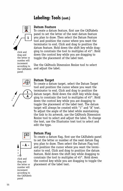
Datum FeatureTo create a datum feature, first use the CADlabels panel to set the letter of the next datum feature you plan to draw. Then select the Datum Feature tool and position the cursor where you want the terminator to end. Click and drag to position the datum feature. Hold down the shift key while drag-ging to constrain the tool to multiples of 45°. Hold down the control key while you are dragging to toggle the placement of the label text.
Use the CADtools Dimension Resize tool to select and adjust the label.
Datum TargetTo create a datum target, select the Datum Target tool and position the cursor where you want the terminator to end. Click and drag to position the datum target. Hold down the shift key while drag-ging to constrain the tool to multiples of 45°. Hold down the control key while you are dragging to toggle the placement of the label text. The datum target will always be created with “1” and “A” text. To adjust the angle of the label while maintaining the link to its artwork, use the CADtools Dimension Resize tool to select and adjust the label. To change the text, use the Illustrator text tool to select and edit the type.
Datum FlagTo create a datum flag, first use the CADlabels panel to set the letter or number of the next datum flag you plan to draw. Then select the Datum Flag tool and position the cursor where you want the termi-nator to end. Click and drag to position the datum feature. Hold down the shift key while dragging to constrain the tool to multiples of 45°. Hold down the control key while you are dragging to toggle the placement of the label text.
1
1A
click and drag and the letter or number will incrementaccording to the CADlabels panel
- A -
click and drag andthe letter or number will incrementaccording to the CADlabels panel
56
Labeling: Tools (cont.)
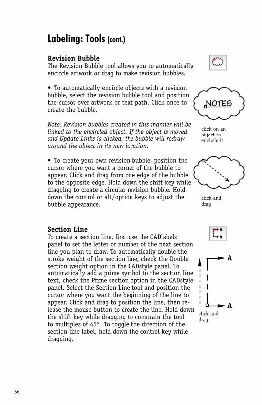
Revision BubbleThe Revision Bubble tool allows you to automatically encircle artwork or drag to make revision bubbles.
• To automatically encircle objects with a revision bubble, select the revision bubble tool and position the cursor over artwork or text path. Click once to create the bubble.
Note: Revision bubbles created in this manner will be linked to the encircled object. If the object is moved and Update Links is clicked, the bubble will redraw around the object in its new location.
• To create your own revision bubble, position the cursor where you want a corner of the bubble to appear. Click and drag from one edge of the bubble to the opposite edge. Hold down the shift key while dragging to create a circular revision bubble. Hold down the control or alt/option keys to adjust the bubble appearance.
Section LineTo create a section line, first use the CADlabels panel to set the letter or number of the next section line you plan to draw. To automatically double the stroke weight of the section line, check the Double section weight option in the CADstyle panel. To automatically add a prime symbol to the section line text, check the Prime section option in the CADstyle panel. Select the Section Line tool and position the cursor where you want the beginning of the line to appear. Click and drag to position the line, then re-lease the mouse button to create the line. Hold down the shift key while dragging to constrain the tool to multiples of 45°. To toggle the direction of the section line label, hold down the control key while dragging.
click anddrag
click on an object to encircle it
A
Aclick anddrag
57
Construction tools
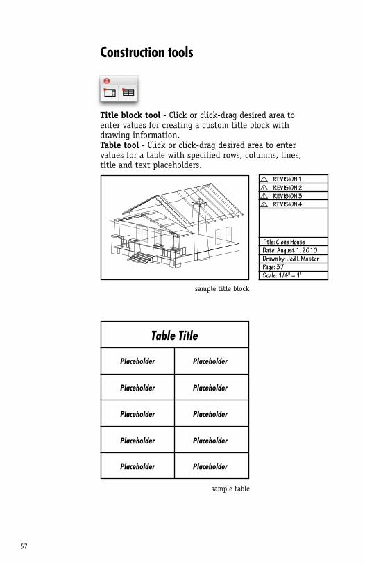
Title block tool - Click or click-drag desired area to enter values for creating a custom title block with drawing information. Table tool - Click or click-drag desired area to enter values for a table with specified rows, columns, lines, title and text placeholders.
sample title block
sample table
REVISION 11
2
3
4
REVISION 2REVISION 3REVISION 4
Title: Clone HouseDate: August 1, 2010Drawn by: Jed I. MasterPage: 37Scale: 1/4" = 1'
Table Title
Placeholder
Placeholder
Placeholder
Placeholder
Placeholder
Placeholder
Placeholder
Placeholder
Placeholder
Placeholder
58
Construction tools (cont.)
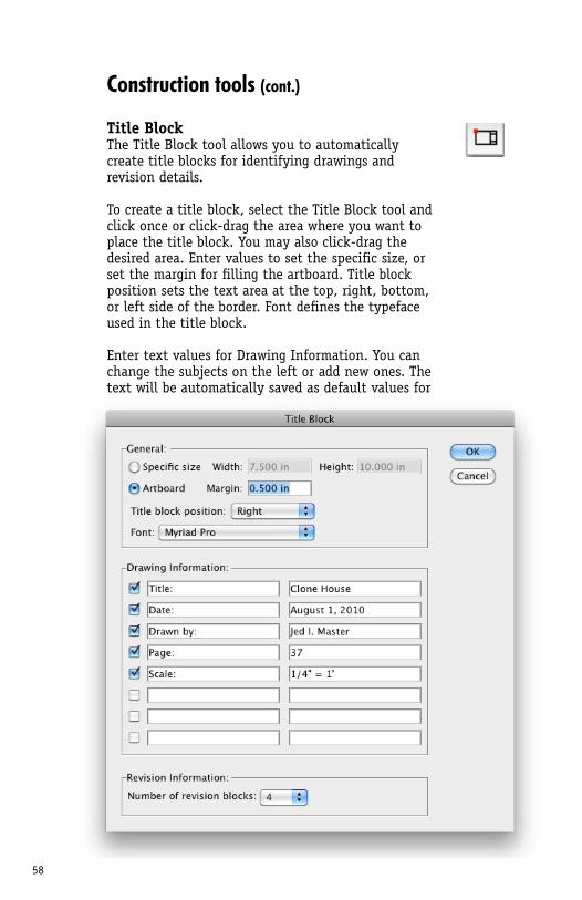
Title BlockThe Title Block tool allows you to automatically create title blocks for identifying drawings and revision details.
To create a title block, select the Title Block tool and click once or click-drag the area where you want to place the title block. You may also click-drag the desired area. Enter values to set the specific size, or set the margin for filling the artboard. Title block position sets the text area at the top, right, bottom, or left side of the border. Font defines the typeface used in the title block.
Enter text values for Drawing Information. You can change the subjects on the left or add new ones. The text will be automatically saved as default values for the next title block that you make.
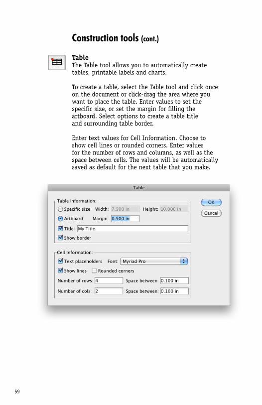
59
Construction tools (cont.)
TableThe Table tool allows you to automatically create tables, printable labels and charts.
To create a table, select the Table tool and click once on the document or click-drag the area where you want to place the table. Enter values to set the specific size, or set the margin for filling the artboard. Select options to create a table title and surrounding table border.
Enter text values for Cell Information. Choose to show cell lines or rounded corners. Enter values for the number of rows and columns, as well as the space between cells. The values will be automatically saved as default for the next table that you make.
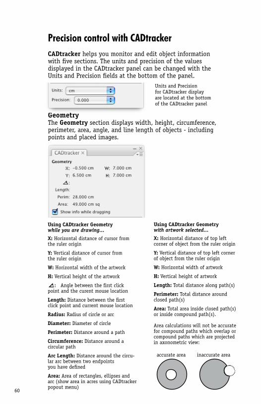
60
Precision control with CADtrackerCADtracker helps you monitor and edit object information with five sections. The units and precision of the values displayed in the CADtracker panel can be changed with the Units and Precision fields at the bottom of the panel.
GeometryThe Geometry section displays width, height, circumference, perimeter, area, angle, and line length of objects - including points and placed images.
Using CADtracker Geometry while you are drawing...
X: Horizontal distance of cursor from the ruler origin
Y: Vertical distance of cursor from the ruler origin
W: Horizontal width of the artwork
H: Vertical height of the artwork
Angle between the first click point and the curent mouse location
Length: Distance between the first click point and current mouse location
Radius: Radius of circle or arc
Diameter: Diameter of circle
Perimeter: Distance around a path
Circumference: Distance around a circular path
Arc Length: Distance around the circu-lar arc between two endpoints you have defined
Area: Area of rectangles, ellipses and arc (show area in acres using CADtracker popout menu)
Using CADtracker Geometry with artwork selected...
X: Horizontal distance of top left corner of object from the ruler origin
Y: Vertical distance of top left corner of object from the ruler origin
W: Horizontal width of artwork
H: Vertical height of artwork
Length: Total distance along path(s)
Perimeter: Total distance around closed path(s)
Area: Total area inside closed path(s) or inside compound path(s).
Area calculations will not be accurate for compound paths which overlap or compound paths which are projected in axonometric view:
Units and Precisionfor CADtracker displayare located at the bottomof the CADtracker panel
accurate area inaccurate area
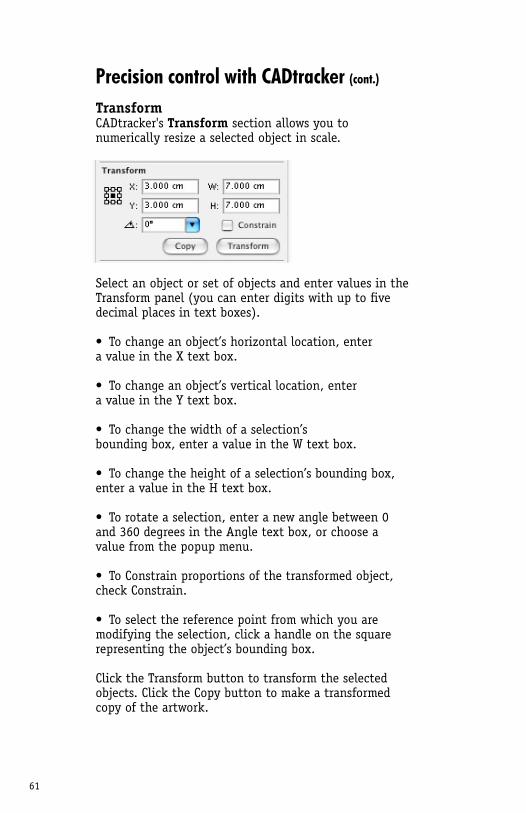
61
Precision control with CADtracker (cont.)
TransformCADtracker's Transform section allows you to numerically resize a selected object in scale.
Select an object or set of objects and enter values in the Transform panel (you can enter digits with up to five decimal places in text boxes).
• To change an object’s horizontal location, enter a value in the X text box.
• To change an object’s vertical location, enter a value in the Y text box.
• To change the width of a selection’s bounding box, enter a value in the W text box.
• To change the height of a selection’s bounding box, enter a value in the H text box.
• To rotate a selection, enter a new angle between 0 and 360 degrees in the Angle text box, or choose a value from the popup menu.
• To Constrain proportions of the transformed object, check Constrain.
• To select the reference point from which you are modifying the selection, click a handle on the square representing the object’s bounding box.
Click the Transform button to transform the selected objects. Click the Copy button to make a transformed copy of the artwork.
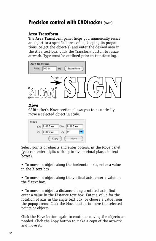
62
Precision control with CADtracker (cont.)
Area TransformThe Area Transform panel helps you numerically resize an object to a specified area value, keeping its propor-tions. Select the object(s) and enter the desired area in the Area text box. Click the Transform button to resize artwork. Type must be outlined prior to transforming.
MoveCADtracker's Move section allows you to numerically move a selected object in scale.
Select points or objects and enter options in the Move panel (you can enter digits with up to five decimal places in text boxes).
• To move an object along the horizontal axis, enter a value in the X text box.
• To move an object along the vertical axis, enter a value in the Y text box.
• To move an object a distance along a rotated axis, first enter a value in the Distance text box. Enter a value for the rotation of axis in the angle text box, or choose a value from the popup menu. Click the Move button to move the selected points or objects.
Click the Move button again to continue moving the objects as needed. Click the Copy button to make a copy of the artwork and move it.
Tranform
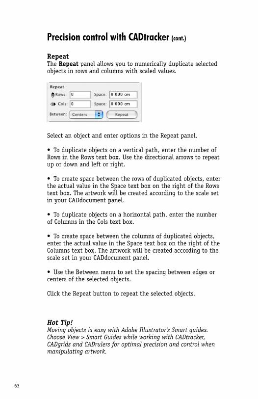
63
Hot Tip!Moving objects is easy with Adobe Illustrator's Smart guides. Choose View > Smart Guides while working with CADtracker, CADgrids and CADrulers for optimal precision and control when manipulating artwork.
Precision control with CADtracker (cont.)
RepeatThe Repeat panel allows you to numerically duplicate selected objects in rows and columns with scaled values.
Select an object and enter options in the Repeat panel.
• To duplicate objects on a vertical path, enter the number of Rows in the Rows text box. Use the directional arrows to repeat up or down and left or right.
• To create space between the rows of duplicated objects, enter the actual value in the Space text box on the right of the Rows text box. The artwork will be created according to the scale set in your CADdocument panel.
• To duplicate objects on a horizontal path, enter the number of Columns in the Cols text box.
• To create space between the columns of duplicated objects, enter the actual value in the Space text box on the right of the Columns text box. The artwork will be created according to the scale set in your CADdocument panel.
• Use the Between menu to set the spacing between edges or centers of the selected objects.
Click the Repeat button to repeat the selected objects.
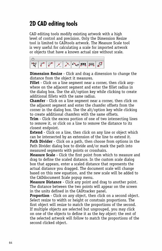
64
2D CAD editing toolsCAD editing tools modify existing artwork with a high level of control and precision. Only the Dimension Resize tool is limited to CADtools artwork. The Measure Scale tool is very useful for calculating a scale for imported artwork or objects that have a known actual size without scale.
Dimension Resize - Click and drag a dimension to change the distance from the object it measures.Fillet - Click on a line segment near a corner, then click any-where on the adjacent segment and enter the fillet radius in the dialog box. Use the alt/option key while clicking to create additional fillets with the same radius.Chamfer - Click on a line segment near a corner, then click on the adjacent segment and enter the chamfer offsets from the corner in the dialog box. Use the alt/option key while clicking to create additional chamfers with the same offsets.Trim - Click the excess portion of one of two intersecting lines to remove it, or click on a line to remove the distance to its closest endpoint.Extend - Click on a line, then click on any line or object which can be intersected by an extension of the line to extend it. Path Divider - Click on a path, then choose from options in the Path Divider dialog box to divide and/or mark the path into measured segments with points or crosshairs. Measure Scale - Click the first point from which to measure and drag to define the scaled distance. In the custom scale dialog box that appears, enter a scaled distance that represents the actual distance you dragged. The document scale will change based on this new equation, and the new scale will be added to the CADdocument Scale popup menu.Measure Distance - Click any point and drag to another point. The distance between the two points will appear on the screen in the units defined in the CADtracker panel. Proportion - Click on any object, then click on a second object. Select resize to width or height or constrain proportions. The first object will resize to match the proportions of the second. If multiple objects are selected but ungrouped, you may click on one of the objects to define it as the key object; the rest of the selected artwork will follow to match the proportions of the second clicked object.
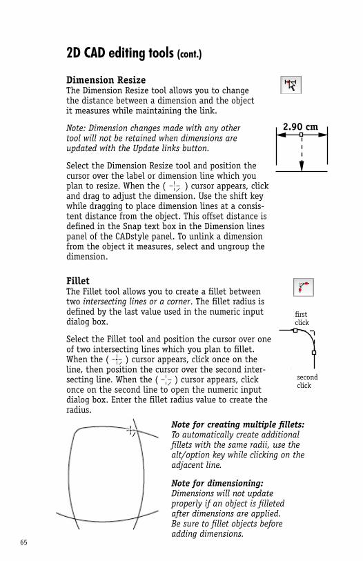
65
2.90 cm
first click
second click
2D CAD editing tools (cont.)
Dimension ResizeThe Dimension Resize tool allows you to change the distance between a dimension and the object it measures while maintaining the link.
Note: Dimension changes made with any other tool will not be retained when dimensions are updated with the Update links button.
Select the Dimension Resize tool and position the cursor over the label or dimension line which you plan to resize. When the ( ) cursor appears, click and drag to adjust the dimension. Use the shift key while dragging to place dimension lines at a consis-tent distance from the object. This offset distance is defined in the Snap text box in the Dimension lines panel of the CADstyle panel. To unlink a dimension from the object it measures, select and ungroup the dimension.
FilletThe Fillet tool allows you to create a fillet between two intersecting lines or a corner. The fillet radius is defined by the last value used in the numeric input dialog box.
Select the Fillet tool and position the cursor over one of two intersecting lines which you plan to fillet. When the ( ) cursor appears, click once on the line, then position the cursor over the second inter-secting line. When the ( ) cursor appears, click once on the second line to open the numeric input dialog box. Enter the fillet radius value to create the radius.
Note for creating multiple fillets: To automatically create additional fillets with the same radii, use the alt/option key while clicking on the adjacent line.
Note for dimensioning: Dimensions will not update properly if an object is filleted after dimensions are applied. Be sure to fillet objects before adding dimensions.
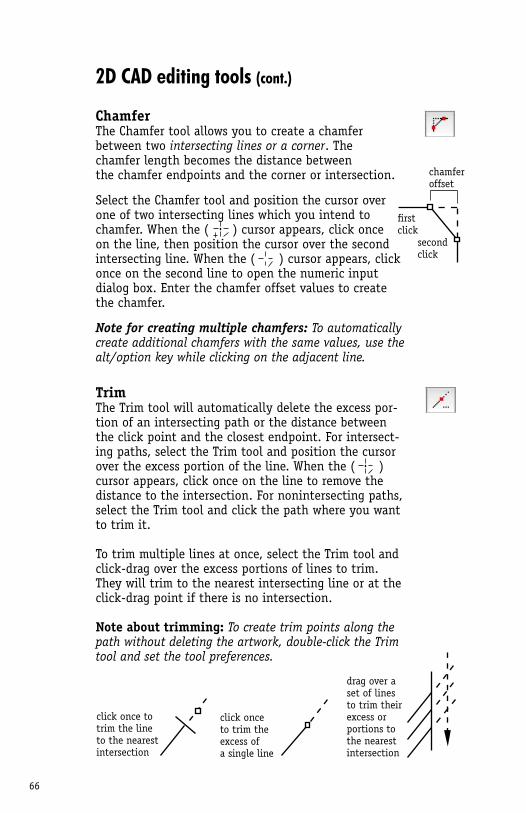
66
second click
chamfer offset
first click
2D CAD editing tools (cont.)
ChamferThe Chamfer tool allows you to create a chamfer between two intersecting lines or a corner. The chamfer length becomes the distance between the chamfer endpoints and the corner or intersection.
Select the Chamfer tool and position the cursor over one of two intersecting lines which you intend to chamfer. When the ( ) cursor appears, click once on the line, then position the cursor over the second intersecting line. When the ( ) cursor appears, click once on the second line to open the numeric input dialog box. Enter the chamfer offset values to create the chamfer.
Note for creating multiple chamfers: To automatically create additional chamfers with the same values, use the alt/option key while clicking on the adjacent line.
TrimThe Trim tool will automatically delete the excess por-tion of an intersecting path or the distance between the click point and the closest endpoint. For intersect-ing paths, select the Trim tool and position the cursor over the excess portion of the line. When the ( ) cursor appears, click once on the line to remove the distance to the intersection. For nonintersecting paths, select the Trim tool and click the path where you want to trim it.
To trim multiple lines at once, select the Trim tool and click-drag over the excess portions of lines to trim. They will trim to the nearest intersecting line or at the click-drag point if there is no intersection.
Note about trimming: To create trim points along the path without deleting the artwork, double-click the Trim tool and set the tool preferences.
click once to trim the line to the nearest intersection
click onceto trim theexcess ofa single line
drag over aset of lines to trim theirexcess orportions tothe nearestintersection
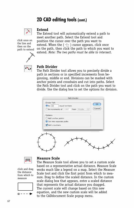
67
click once on the line and then on the path to extend
click and dragthe distance from which to measure
2D CAD editing tools (cont.)
ExtendThe Extend tool will automatically extend a path to meet another path. Select the Extend tool and position the cursor over the path you want to extend. When the ( ) cursor appears, click once on the path, then click the path to which you want to extend. Note: The two paths must be able to intersect.
Path DividerThe Path Divider tool allows you to precisely divide a path in sections or in specified increments from be-ginning, middle or end. Divisions can be marked with anchor points and crosshairs and cut into paths. Select the Path Divider tool and click on the path you want to divide. Use the dialog box to set the options for division.
Measure ScaleThe Measure Scale tool allows you to set a custom scale based on a representative actual distance. Measure Scale works much like a legend on a map. Select the Measure Scale tool and click the first point from which to mea-sure. Drag to define the scaled distance. In the custom scale dialog box that appears, enter a scaled distance that represents the actual distance you dragged. The current scale will change based on this new equation, and the new custom scale will be added to the CADdocument Scale popup menu.
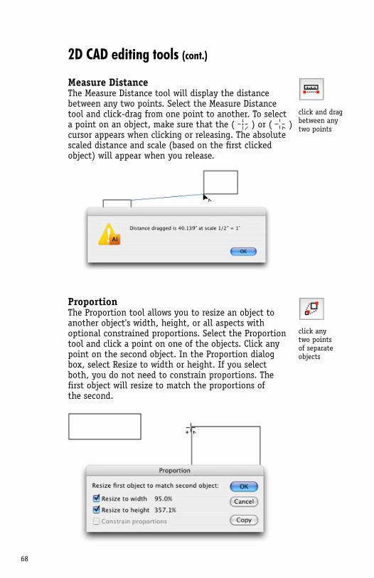
68
2D CAD editing tools (cont.)
Measure DistanceThe Measure Distance tool will display the distance between any two points. Select the Measure Distance tool and click-drag from one point to another. To select a point on an object, make sure that the ( ) or ( ) cursor appears when clicking or releasing. The absolute scaled distance and scale (based on the first clicked object) will appear when you release.
ProportionThe Proportion tool allows you to resize an object to another object's width, height, or all aspects with optional constrained proportions. Select the Proportion tool and click a point on one of the objects. Click any point on the second object. In the Proportion dialog box, select Resize to width or height. If you select both, you do not need to constrain proportions. The first object will resize to match the proportions of the second.
click and dragbetween anytwo points
click anytwo pointsof separateobjects
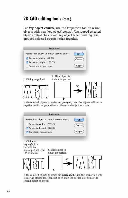
69
2D CAD editing tools (cont.)
For key object control, use the Proportion tool to resize objects with new 'key object' control. Ungrouped selected objects follow the clicked key object when resizing, and grouped selected objects resize together.
If the selected objects to resize are grouped, then the objects will resize together to fit the proportions of the second object as shown.
1. Click grouped set
1. Click one key object in the selected, ungrouped set - the "A" as shown
2. Click object to match proportion
2. Click object to match proportion
If the selected objects to resize are ungrouped, then the proportion will resize the objects together, but to fit only the clicked object into the second object as shown.
OK
OK
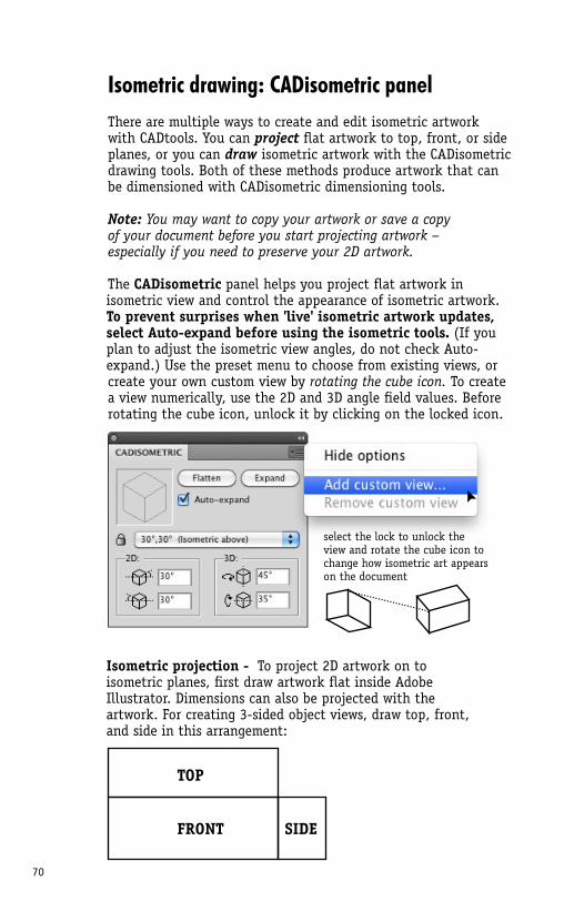
70
Isometric drawing: CADisometric panelThere are multiple ways to create and edit isometric artwork with CADtools. You can project flat artwork to top, front, or side planes, or you can draw isometric artwork with the CADisometric drawing tools. Both of these methods produce artwork that can be dimensioned with CADisometric dimensioning tools.
Note: You may want to copy your artwork or save a copy of your document before you start projecting artwork – especially if you need to preserve your 2D artwork.
The CADisometric panel helps you project flat artwork in isometric view and control the appearance of isometric artwork. To prevent surprises when 'live' isometric artwork updates, select Auto-expand before using the isometric tools. (If you plan to adjust the isometric view angles, do not check Auto-expand.) Use the preset menu to choose from existing views, or create your own custom view by rotating the cube icon. To create a view numerically, use the 2D and 3D angle field values. Before rotating the cube icon, unlock it by clicking on the locked icon.
Isometric projection - To project 2D artwork on to isometric planes, first draw artwork flat inside Adobe Illustrator. Dimensions can also be projected with the artwork. For creating 3-sided object views, draw top, front, and side in this arrangement:
select the lock to unlock the view and rotate the cube icon to change how isometric art appears on the document
TOP
FRONT SIDE
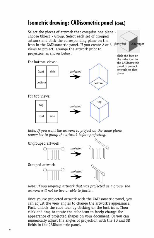
71
projected
projected
bottom
front side
top
front side
projected
projected
top
bottom
click the face on the cube icon in the CADisometric panel to project artwork on that plane
Isometric drawing: CADisometric panel (cont.)
Select the pieces of artwork that comprise one plane - choose Object > Group. Select each set of grouped artwork and click the corresponding plane on the icon in the CADisometric panel. If you create 2 or 3 views to project, arrange the artwork prior to projection as shown below:
For bottom views:
For top views:
Note: If you want the artwork to project on the same plane, remember to group the artwork before projecting.
Ungrouped artwork
Grouped artwork
Note: If you ungroup artwork that was projected as a group, the artwork will not be live or able to flatten.
Once you've projected artwork with the CADisometric panel, you can adjust the view angles to change the artwork's appearance. First, unlock the cube icon by clicking on the lock icon. Then click and drag to rotate the cube icon to freely change the appearance of projected shapes on your document. Or you can numerically adjust the angles of projection with the 2D and 3D fields in the CADisometric panel.
front/left side/right
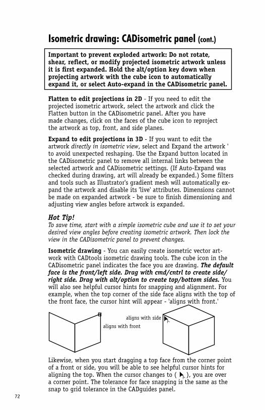
72
Isometric drawing: CADisometric panel (cont.)
Important to prevent exploded artwork: Do not rotate, shear, reflect, or modify projected isometric artwork unless it is first expanded. Hold the alt/option key down when projecting artwork with the cube icon to automatically expand it, or select Auto-expand in the CADisometric panel.
Flatten to edit projections in 2D - If you need to edit the projected isometric artwork, select the artwork and click the Flatten button in the CADisometric panel. After you have made changes, click on the faces of the cube icon to reproject the artwork as top, front, and side planes.
Expand to edit projections in 3D - If you want to edit the artwork directly in isometric view, select and Expand the artwork 'to avoid unexpected reshaping. Use the Expand button located in the CADisometric panel to remove all internal links between the selected artwork and CADisometric settings. (If Auto-Expand was checked during drawing, art will already be expanded.) Some filters and tools such as Illustrator's gradient mesh will automatically ex-pand the artwork and disable its 'live' attributes. Dimensions cannot be made on expanded artwork - be sure to finish dimensioning and adjusting view angles before artwork is expanded.
Hot Tip!To save time, start with a simple isometric cube and use it to set your desired view angles before creating isometric artwork. Then lock the view in the CADisometric panel to prevent changes.
Isometric drawing - You can easily create isometric vector art-work with CADtools isometric drawing tools. The cube icon in the CADisometric panel indicates the face you are drawing. The default face is the front/left side. Drag with cmd/cntrl to create side/right side. Drag with alt/option to create top/bottom sides. You will also see helpful cursor hints for snapping and alignment. For example, when the top corner of the side face aligns with the top of the front face, the cursor hint will appear - 'aligns with front.'
Likewise, when you start dragging a top face from the corner point of a front or side, you will be able to see helpful cursor hints for aligning the top. When the cursor changes to ( ), you are over a corner point. The tolerance for face snapping is the same as the snap to grid tolerance in the CADguides panel.
aligns with side
aligns with front
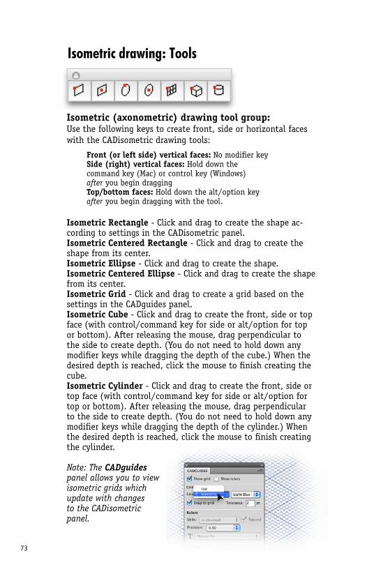
73
Isometric drawing: Tools
Isometric (axonometric) drawing tool group:Use the following keys to create front, side or horizontal faces with the CADisometric drawing tools:
Isometric Rectangle - Click and drag to create the shape ac-cording to settings in the CADisometric panel.Isometric Centered Rectangle - Click and drag to create the shape from its center.Isometric Ellipse - Click and drag to create the shape.Isometric Centered Ellipse - Click and drag to create the shape from its center.Isometric Grid - Click and drag to create a grid based on the settings in the CADguides panel.Isometric Cube - Click and drag to create the front, side or top face (with control/command key for side or alt/option for top or bottom). After releasing the mouse, drag perpendicular to the side to create depth. (You do not need to hold down any modifier keys while dragging the depth of the cube.) When the desired depth is reached, click the mouse to finish creating the cube.Isometric Cylinder - Click and drag to create the front, side or top face (with control/command key for side or alt/option for top or bottom). After releasing the mouse, drag perpendicular to the side to create depth. (You do not need to hold down any modifier keys while dragging the depth of the cylinder.) When the desired depth is reached, click the mouse to finish creating the cylinder.
Note: The CADguides panel allows you to view isometric grids whichupdate with changesto the CADisometricpanel.
Front (or left side) vertical faces: No modifier keySide (right) vertical faces: Hold down the command key (Mac) or control key (Windows) after you begin draggingTop/bottom faces: Hold down the alt/option key after you begin dragging with the tool.
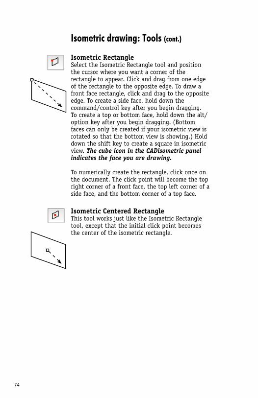
74
Isometric drawing: Tools (cont.)
Isometric Rectangle Select the Isometric Rectangle tool and position the cursor where you want a corner of the rectangle to appear. Click and drag from one edge of the rectangle to the opposite edge. To draw a front face rectangle, click and drag to the opposite edge. To create a side face, hold down the command/control key after you begin dragging. To create a top or bottom face, hold down the alt/option key after you begin dragging. (Bottom faces can only be created if your isometric view is rotated so that the bottom view is showing.) Hold down the shift key to create a square in isometric view. The cube icon in the CADisometric panel indicates the face you are drawing.
To numerically create the rectangle, click once on the document. The click point will become the top right corner of a front face, the top left corner of a side face, and the bottom corner of a top face.
Isometric Centered RectangleThis tool works just like the Isometric Rectangle tool, except that the initial click point becomes the center of the isometric rectangle.
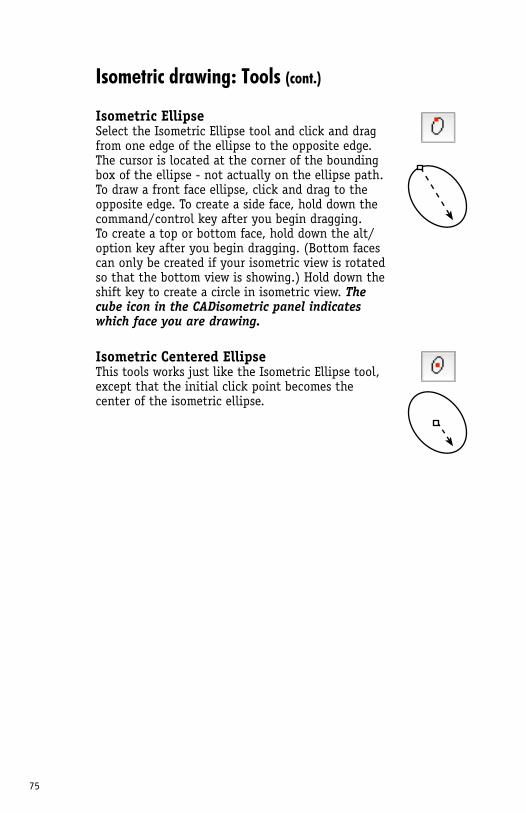
75
Isometric drawing: Tools (cont.)
Isometric Ellipse Select the Isometric Ellipse tool and click and drag from one edge of the ellipse to the opposite edge. The cursor is located at the corner of the bounding box of the ellipse - not actually on the ellipse path. To draw a front face ellipse, click and drag to the opposite edge. To create a side face, hold down the command/control key after you begin dragging. To create a top or bottom face, hold down the alt/option key after you begin dragging. (Bottom faces can only be created if your isometric view is rotated so that the bottom view is showing.) Hold down the shift key to create a circle in isometric view. The cube icon in the CADisometric panel indicates which face you are drawing.
Isometric Centered Ellipse This tools works just like the Isometric Ellipse tool, except that the initial click point becomes the center of the isometric ellipse.
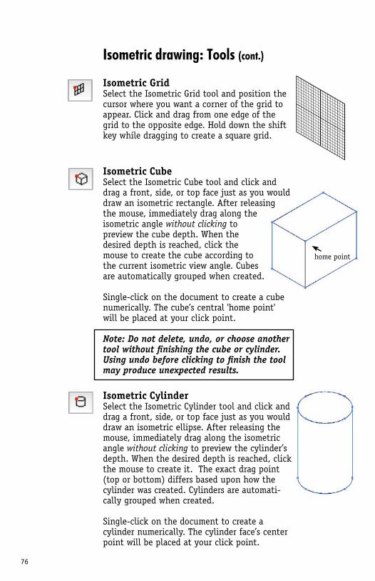
76
Isometric drawing: Tools (cont.)
Isometric Grid Select the Isometric Grid tool and position the cursor where you want a corner of the grid to appear. Click and drag from one edge of the grid to the opposite edge. Hold down the shift key while dragging to create a square grid.
Isometric Cube Select the Isometric Cube tool and click and drag a front, side, or top face just as you would draw an isometric rectangle. After releasing the mouse, immediately drag along the isometric angle without clicking to preview the cube depth. When the desired depth is reached, click the mouse to create the cube according to the current isometric view angle. Cubes are automatically grouped when created.
Single-click on the document to create a cube numerically. The cube’s central 'home point' will be placed at your click point.
Note: Do not delete, undo, or choose another tool without finishing the cube or cylinder. Using undo before clicking to finish the tool may produce unexpected results.
Isometric Cylinder Select the Isometric Cylinder tool and click and drag a front, side, or top face just as you would draw an isometric ellipse. After releasing the mouse, immediately drag along the isometric angle without clicking to preview the cylinder’s depth. When the desired depth is reached, click the mouse to create it. The exact drag point (top or bottom) differs based upon how the cylinder was created. Cylinders are automati-cally grouped when created.
Single-click on the document to create a cylinder numerically. The cylinder face’s center point will be placed at your click point.
home point
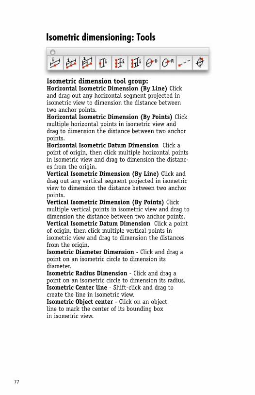
77
Isometric dimensioning: Tools
Isometric dimension tool group:Horizontal Isometric Dimension (By Line) Click and drag out any horizontal segment projected in isometric view to dimension the distance between two anchor points.Horizontal Isometric Dimension (By Points) Click multiple horizontal points in isometric view and drag to dimension the distance between two anchor points.Horizontal Isometric Datum Dimension Click a point of origin, then click multiple horizontal points in isometric view and drag to dimension the distanc-es from the origin.Vertical Isometric Dimension (By Line) Click and drag out any vertical segment projected in isometric view to dimension the distance between two anchor points.Vertical Isometric Dimension (By Points) Click multiple vertical points in isometric view and drag to dimension the distance between two anchor points.Vertical Isometric Datum Dimension Click a point of origin, then click multiple vertical points in isometric view and drag to dimension the distances from the origin.Isometric Diameter Dimension - Click and drag a point on an isometric circle to dimension its diameter.Isometric Radius Dimension - Click and drag a point on an isometric circle to dimension its radius.Isometric Center line - Shift-click and drag to create the line in isometric view.Isometric Object center - Click on an object line to mark the center of its bounding box in isometric view.
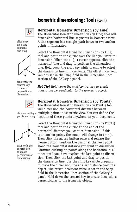
78
click onceon a line segmentand drag
click on multiplepoints and drag
drag with the control key to create perpendicular dimensions
drag with the control key to create perpendicular dimensions
Isometric dimensioning: Tools (cont.)
Horizontal Isometric Dimension (by Line)The Horizontal Isometric Dimension (by Line) tool will dimension horizontal line segments in isometric view. A line segment is a straight path between two anchor points in Illustrator.
Select the Horizontal Isometric Dimension (by Line) tool and position the cursor over the line you want to dimension. When the ( ) cursor appears, click the horizontal line and drag to position the dimension line. Hold down the shift key while dragging to offset the dimension line in increments. The offset increment value is set in the Snap field in the Dimension lines section of the CADstyle panel.
Hot Tip! Hold down the cmd/control key to create dimensions perpendicular to the isometric object.
Horizontal Isometric Dimension (by Points)The Horizontal Isometric Dimension (by Points) tool will dimension the horizontal distance between multiple points in isometric view. You can define the location of these points anywhere on your document.
Select the Horizontal Isometric Dimension (by Points) tool and position the cursor at one end of the horizontal distance you want to dimension. If this is an anchor point, the cursor will change to ( ). Then click the mouse button once and release the mouse button. Position the cursor at the next point along the horizontal distance you want to dimension. Continue clicking on points along the horizontal dis-tance until you have reached the last point to dimen-sion. Then click the last point and drag to position the dimension line. Use the shift key while dragging to place the dimension line at a set distance from the object. The offset increment value is set in the Snap field in the Dimension lines section of the CADstyle panel. Hold down the control key to create dimensions perpendicular to the isometric object.
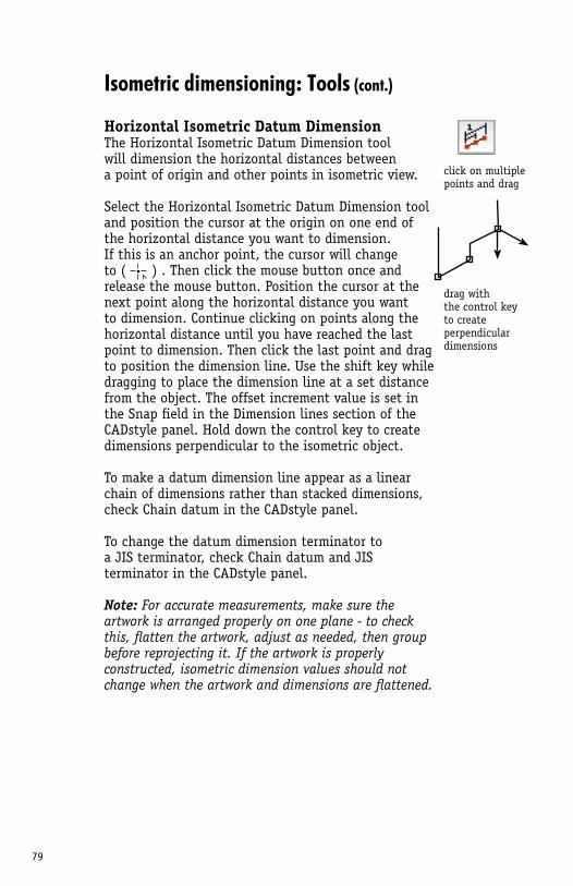
79
Isometric dimensioning: Tools (cont.)
Horizontal Isometric Datum DimensionThe Horizontal Isometric Datum Dimension tool will dimension the horizontal distances between a point of origin and other points in isometric view.
Select the Horizontal Isometric Datum Dimension tool and position the cursor at the origin on one end of the horizontal distance you want to dimension. If this is an anchor point, the cursor will change to ( ) . Then click the mouse button once and release the mouse button. Position the cursor at the next point along the horizontal distance you want to dimension. Continue clicking on points along the horizontal distance until you have reached the last point to dimension. Then click the last point and drag to position the dimension line. Use the shift key while dragging to place the dimension line at a set distance from the object. The offset increment value is set in the Snap field in the Dimension lines section of the CADstyle panel. Hold down the control key to create dimensions perpendicular to the isometric object.
To make a datum dimension line appear as a linear chain of dimensions rather than stacked dimensions, check Chain datum in the CADstyle panel.
To change the datum dimension terminator to a JIS terminator, check Chain datum and JIS terminator in the CADstyle panel.
Note: For accurate measurements, make sure the artwork is arranged properly on one plane - to check this, flatten the artwork, adjust as needed, then group before reprojecting it. If the artwork is properly constructed, isometric dimension values should not change when the artwork and dimensions are flattened.
click on multiplepoints and drag
drag with the control key to create perpendicular dimensions
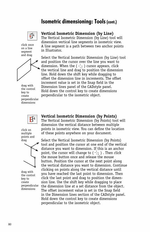
80
click onceon a line segmentand drag
click on multiplepoints and drag
drag with the control key to create perpendicular dimensions
drag with the control key to create perpendicular dimensions
Isometric dimensioning: Tools (cont.)
Vertical Isometric Dimension (by Line)The Vertical Isometric Dimension (by Line) tool will dimension vertical line segments in isometric view. A line segment is a path between two anchor points in Illustrator.
Select the Vertical Isometric Dimension (by Line) tool and position the cursor over the line you want to dimension. When the ( ) cursor appears, click the vertical line and drag to position the dimension line. Hold down the shift key while dragging to offset the dimension line in increments. The offset increment value is set in the Snap field in the Dimension lines panel of the CADstyle panel. Hold down the control key to create dimensions perpendicular to the isometric object.
Vertical Isometric Dimension (by Points)The Vertical Isometric Dimension (by Points) tool will dimension the vertical distance between multiple points in isometric view. You can define the location of these points anywhere on your document.
Select the Vertical Isometric Dimension (by Points) tool and position the cursor at one end of the vertical distance you want to dimension. If this is an anchor point, the cursor will change to ( ) . Then click the mouse button once and release the mouse button. Position the cursor at the next point along the vertical distance you want to dimension. Continue clicking on points along the vertical distance until you have reached the last point to dimension. Then click the last point and drag to position the dimen-sion line. Use the shift key while dragging to place the dimension line at a set distance from the object. The offset increment value is set in the Snap field in the Dimension lines section of the CADstyle panel. Hold down the control key to create dimensions perpendicular to the isometric object.
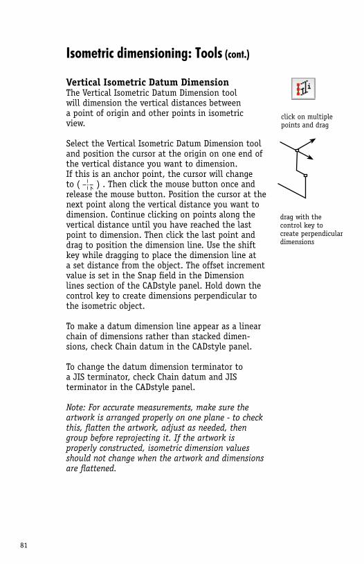
81
Isometric dimensioning: Tools (cont.)
Vertical Isometric Datum DimensionThe Vertical Isometric Datum Dimension tool will dimension the vertical distances between a point of origin and other points in isometric view.
Select the Vertical Isometric Datum Dimension tool and position the cursor at the origin on one end of the vertical distance you want to dimension. If this is an anchor point, the cursor will change to ( ) . Then click the mouse button once and release the mouse button. Position the cursor at the next point along the vertical distance you want to dimension. Continue clicking on points along the vertical distance until you have reached the last point to dimension. Then click the last point and drag to position the dimension line. Use the shift key while dragging to place the dimension line at a set distance from the object. The offset increment value is set in the Snap field in the Dimension lines section of the CADstyle panel. Hold down the control key to create dimensions perpendicular to the isometric object.
To make a datum dimension line appear as a linear chain of dimensions rather than stacked dimen-sions, check Chain datum in the CADstyle panel.
To change the datum dimension terminator to a JIS terminator, check Chain datum and JIS terminator in the CADstyle panel.
Note: For accurate measurements, make sure the artwork is arranged properly on one plane - to check this, flatten the artwork, adjust as needed, then group before reprojecting it. If the artwork is properly constructed, isometric dimension values should not change when the artwork and dimensions are flattened.
click on multiplepoints and drag
drag with the control key to create perpendicular dimensions
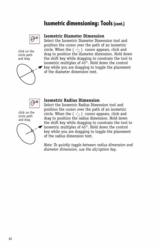
82
click on the circle pathand drag
click on the circle pathand drag
Isometric dimensioning: Tools (cont.)
Isometric Diameter DimensionSelect the Isometric Diameter Dimension tool and position the cursor over the path of an isometric circle. When the ( ) cursor appears, click and drag to position the diameter dimension. Hold down the shift key while dragging to constrain the tool to isometric multiples of 45°. Hold down the control key while you are dragging to toggle the placement of the diameter dimension text.
Isometric Radius DimensionSelect the Isometric Radius Dimension tool and position the cursor over the path of an isometric circle. When the ( ) cursor appears, click and drag to position the radius dimension. Hold down the shift key while dragging to constrain the tool to isometric multiples of 45°. Hold down the control key while you are dragging to toggle the placement of the radius dimension text.
Note: To quickly toggle between radius dimension and diameter dimension, use the alt/option key.
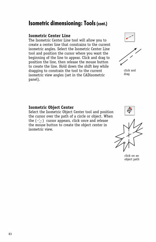
83
Isometric dimensioning: Tools (cont.)
Isometric Center LineThe Isometric Center Line tool will allow you to create a center line that constrains to the current isometric angles. Select the Isometric Center Line tool and position the cursor where you want the beginning of the line to appear. Click and drag to position the line, then release the mouse button to create the line. Hold down the shift key while dragging to constrain the tool to the current isometric view angles (set in the CADisometric panel).
Isometric Object CenterSelect the Isometric Object Center tool and position the cursor over the path of a circle or object. When the ( ) cursor appears, click once and release the mouse button to create the object center in isometric view.
click anddrag
click on an object path
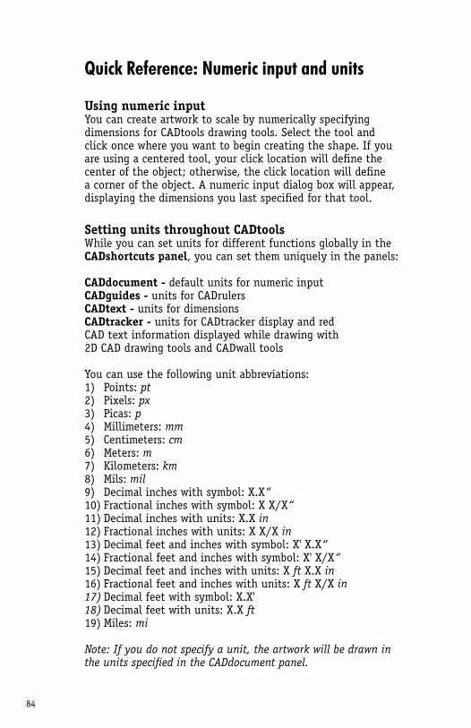
84
Using numeric inputYou can create artwork to scale by numerically specifying dimensions for CADtools drawing tools. Select the tool and click once where you want to begin creating the shape. If you are using a centered tool, your click location will define the center of the object; otherwise, the click location will define a corner of the object. A numeric input dialog box will appear, displaying the dimensions you last specified for that tool.
Setting units throughout CADtoolsWhile you can set units for different functions globally in the CADshortcuts panel, you can set them uniquely in the panels:
CADdocument - default units for numeric inputCADguides - units for CADrulersCADtext - units for dimensionsCADtracker - units for CADtracker display and red CAD text information displayed while drawing with 2D CAD drawing tools and CADwall tools
You can use the following unit abbreviations:1) Points: pt2) Pixels: px3) Picas: p4) Millimeters: mm5) Centimeters: cm6) Meters: m7) Kilometers: km8) Mils: mil9) Decimal inches with symbol: X.X“10) Fractional inches with symbol: X X/X“11) Decimal inches with units: X.X in12) Fractional inches with units: X X/X in13) Decimal feet and inches with symbol: X' X.X“14) Fractional feet and inches with symbol: X' X/X“15) Decimal feet and inches with units: X ft X.X in16) Fractional feet and inches with units: X ft X/X in17) Decimal feet with symbol: X.X'18) Decimal feet with units: X.X ft19) Miles: mi
Note: If you do not specify a unit, the artwork will be drawn in the units specified in the CADdocument panel.
Quick Reference: Numeric input and units
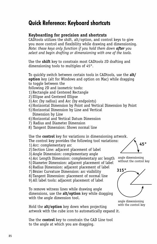
85
angle dimensioning without the control key
45°
Quick Reference: Keyboard shortcuts
angle dimensioning with the control key
Keyboarding for precision and shortcutsCADtools utilizes the shift, alt/option, and control keys to give you more control and flexibility while drawing and dimensioning. Note: these keys only function if you hold them down after you select and begin drafting or dimensioning with one of the tools.
Use the shift key to constrain most CADtools 2D drafting and dimensioning tools to multiples of 45°.
To quickly switch between certain tools in CADtools, use the alt/option key (alt for Windows and option on Mac) while dragging to toggle between the following 2D and isometric tools: 1) Rectangle and Centered Rectangle2) Ellipse and Centered Ellipse3) Arc (by radius) and Arc (by endpoints)4) Horizontal Dimension by Point and Vertical Dimension by Point5) Horizontal Dimension by Line and Vertical Dimension by Line6) Horizontal and Vertical Datum Dimension7) Radius and Diameter Dimension8) Tangent Dimension: Shows normal line
Use the control key for variations in dimensioning artwork. The control key provides the following tool variations:1) Arc: complementary arc2) Section Line: adjacent placement of label3) Angle Dimension: complementary angle4) Arc Length Dimension: complementary arc length5) Diameter Dimension: adjacent placement of label6) Radius Dimension: adjacent placement of label7) Bézier Curvature Dimension: arc visibility8) Tangent Dimension: placement of normal line9) All label tools: adjacent placement of label
To remove witness lines while drawing angle dimensions, use the alt/option key while dragging with the angle dimension tool.
Hold the alt/option key down when projecting artwork with the cube icon to automatically expand it.
Use the control key to constrain the CAD Line tool to the angle at which you are dragging.
315°
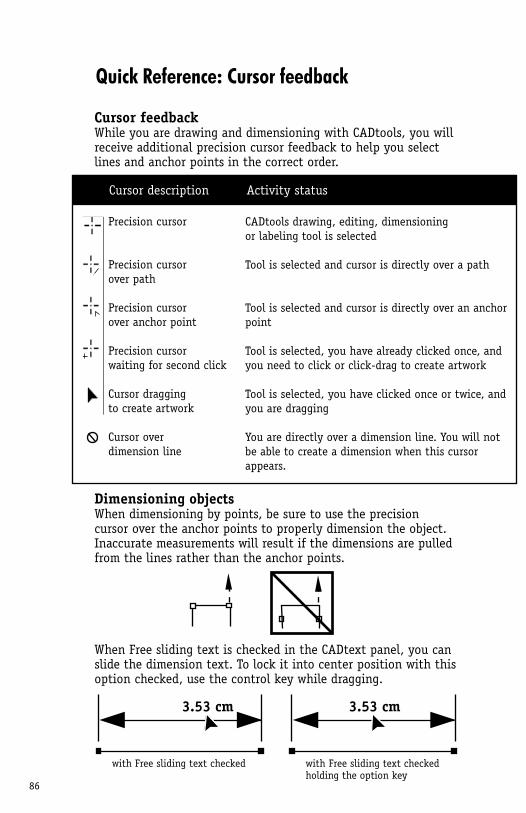
86
Cursor feedbackWhile you are drawing and dimensioning with CADtools, you will receive additional precision cursor feedback to help you select lines and anchor points in the correct order.
Precision cursor
Precision cursor over path
Precision cursor over anchor point
Precision cursor waiting for second click
Cursor dragging to create artwork
Cursor over dimension line
CADtools drawing, editing, dimensioning or labeling tool is selected
Tool is selected and cursor is directly over a path
Tool is selected and cursor is directly over an anchor point
Tool is selected, you have already clicked once, and you need to click or click-drag to create artwork
Tool is selected, you have clicked once or twice, and you are dragging
You are directly over a dimension line. You will not be able to create a dimension when this cursor appears.
Activity statusCursor description
Quick Reference: Cursor feedback
Dimensioning objectsWhen dimensioning by points, be sure to use the precision cursor over the anchor points to properly dimension the object. Inaccurate measurements will result if the dimensions are pulled from the lines rather than the anchor points.
When Free sliding text is checked in the CADtext panel, you can slide the dimension text. To lock it into center position with this option checked, use the control key while dragging.
3.53 cm
with Free sliding text checked
3.53 cm
with Free sliding text checkedholding the option key
87
Advanced topics
Saving artworkYou must save artwork in Illustrator CS or higher format or the dimension information may not display properly.
Importing or exporting artworkAdobe Illustrator CS3, CS4 and CS5 include DXF and DWG import and export in R13, R14, 2000, and 2004/2005/2006 formats. Once a file is imported as vector artwork inside Adobe Illustra-tor, CADtools can be used to dimension or edit the artwork. In some cases, an imported file may contain artwork comprised of small line segments. Dimensioning tools by line, as well as radius, diameter, arc length, and Bézier curvature dimensioning tools will not work for such segmented artwork. To connect these DXF line segments, use the Concatenate filter available at (http://rj-graffix.com/) For more information on opening or placing files within Illustrator, please refer to the DXF/DWG conversion link on the Hot Door Web site as well as the Adobe Illustrator User Guide, technical notes, and Adobe web site at (www.adobe.com).
Symbol and pattern librariesHot Door CADpatterns offers 134 patterns for technical drawing. DGI makes SignSymbols for creative use of road sign graphics. Code Zebra makes a comprehensive set of TechSymbols in seven categories: Architecture, Building Services, Landscaping, Electrical, Mechanical, Fasteners and General. Purchase the entire set or separate libraries at (www.hotdoor.com). Check the Hot Door Web site for updates on these and other design resouces as they become available.
Keyboard shortcutsAdobe Illustrator includes Keyboard Shortcuts for making your own sets of shortcuts. The tools in CADtools can be accessed with keyboard shortcuts that you define. Choose Edit > Keyboard Shortcuts to edit or create Illustrator keyboard shortcuts. You can also create separate sets for different workspaces chosen from the Window > Workspace menu.
Conflicts with MultiPageWhen using CADtools with MultiPage, uncheck Create and use dimension layer and Create live dimensions in the CADdocument panel. Use of MultiPage layers will conflict with the CADtools Dimension layer.
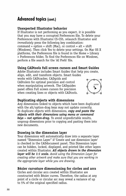
88
Advanced topics (cont.)
Unexpected Illustrator behaviorIf Illustrator is not performing as you expect, it is possible that you may have a corrupted Preferences file. To delete your Preferences with Illustrator CS-CS5, relaunch Illustrator and immediately press the following key combination: command + option + shift (Mac), or control + alt + shift (Windows). Then click Yes to delete your settings. On Mac OS X platforms, the Preferences file is found in the Home > Library > Preferences folder. To find the Preferences file on Windows, perform a file search for the 'AI Prefs' file.
Using CADtools full screen cursors and Smart GuidesAdobe Illustrator includes Smart Guides that help you create, align, edit, and transform objects. Smart Guides works with CADtracker, CADgrids and CADrulers for optimal precision and control when manipulating artwork. The CADguides panel offers Full screen cursors for precision when creating lines or objects with CADtools.
Duplicating objects with dimensionsAny dimensions linked to objects which have been duplicated with the alt/option-drag keys may not update correctly. To duplicate objects with dimensions, copy and paste the objects with their dimensions using menu or command keys – not option-drag. To avoid unpredictable results, ungroup dimensions prior to copying and pasting them into new documents.
Drawing in the dimension layerYour dimensions will automatically draw into a separate layer named “Dimension Layer” if 'Create and use dimension layer' is checked in the CADdocument panel. This Dimension layer can be hidden, locked, displayed, and printed like other layers created within Illustrator. All objects drawn in the dimension layer will be 1:1 scale. Avoid using the Dimension Layer for creating other artwork and make sure that you are working in the appropriate layer while you are drawing.
Bézier curvature dimensioning for circles and arcsCircles and circular arcs created within Illustrator are constructed with Bézier curves. Therefore, the radius at any point of a circle or circular arc may reveal a variance of up to 5% of the original specified radius.
centerx
89
Advanced topics (cont.)
Using CADgridsCADgrids and CADrulers are created as artwork in separate locked layers. CADgrids increments are logical divisions of the units defined in the CADguides panel. Only CADtools drawing tools can snap to CADgrids if Snap to grid is checked in the CADguides panel. You cannot use CADtools to snap to Illustrator grids and guides, and you cannot use Illustrator tools to snap to CADgrids.
Drawing isometric objectsFor best results, create a simple isometric cube before creating artwork and adjust the view angles. Then lock the cube icon in the CADisometric panel to prevent accidental view changes. For separate isometric shapes that share the same plane, first create them as flat artwork and group them. Then project them to the front, side, or top plane with the cube in the CADisometric panel.
Area values for intersecting or compound pathsThe area of a path that intersects itself cannot be calculated correctly by the CADtracker panel. Area can be calculated for single or multiple shapes as long as they are closed and do not include overlapping compound paths.
Using patterns in isometric viewPatterns are not automatically transformed with CADtools objects, but you can force a transformation of pattern artwork by expanding and projecting it with your flat artwork using the CADisometric panel.
Smoothing sharp isometric artworkThe geometry of isometric objects may naturally show many sharp angles in the artwork. If you plan to stroke the artwork, use Round Join for a cleaner appearance. You can choose Round Join in the Options panel of the Illustrator Stroke panel.
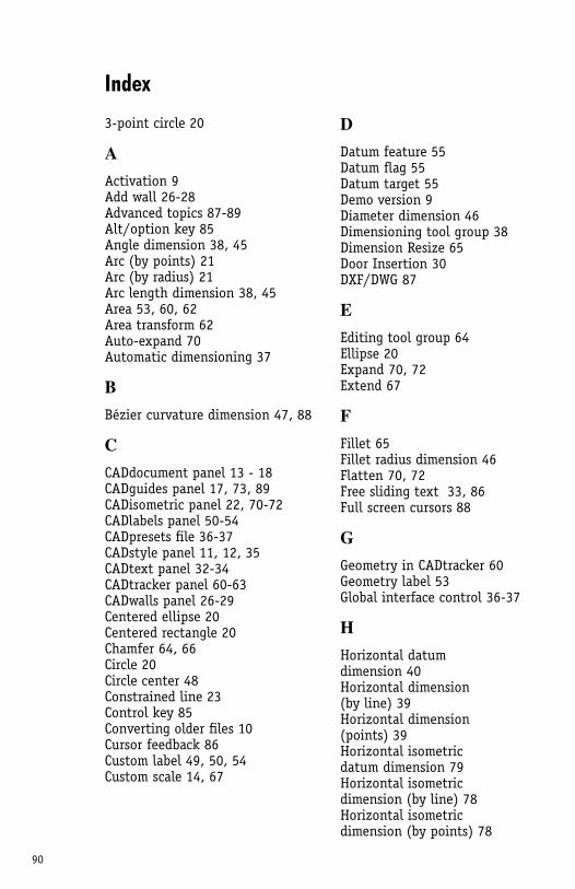
90
Index
DDatum feature 55Datum flag 55Datum target 55Demo version 9Diameter dimension 46Dimensioning tool group 38Dimension Resize 65Door Insertion 30 DXF/DWG 87
EEditing tool group 64Ellipse 20Expand 70, 72Extend 67
FFillet 65Fillet radius dimension 46Flatten 70, 72Free sliding text 33, 86Full screen cursors 88
GGeometry in CADtracker 60Geometry label 53Global interface control 36-37
HHorizontal datum dimension 40Horizontal dimension (by line) 39Horizontal dimension (points) 39Horizontal isometric datum dimension 79Horizontal isometricdimension (by line) 78Horizontal isometricdimension (by points) 78
3-point circle 20
AActivation 9Add wall 26-28Advanced topics 87-89Alt/option key 85Angle dimension 38, 45Arc (by points) 21Arc (by radius) 21Arc length dimension 38, 45Area 53, 60, 62Area transform 62Auto-expand 70Automatic dimensioning 37
BBézier curvature dimension 47, 88
CCADdocument panel 13 - 18CADguides panel 17, 73, 89CADisometric panel 22, 70-72CADlabels panel 50-54CADpresets file 36-37CADstyle panel 11, 12, 35CADtext panel 32-34CADtracker panel 60-63CADwalls panel 26-29 Centered ellipse 20Centered rectangle 20Chamfer 64, 66Circle 20Circle center 48Constrained line 23Control key 85Converting older files 10Cursor feedback 86Custom label 49, 50, 54Custom scale 14, 67
91
IIcons 11Importing older files 10, 87Inclined datum dimension 44Inclined dimension (by line) 43Inclined dimension (points) 43Incremental labeling 51-52Interface 11-12Isometric center line 83Isometric cube 76Isometric cylinder 76Isometric diameter dimension 82Isometric ellipse 75Isometric grid 76Isometric object center 83Isometric radius dimension 82Isometric rectangle 74
KKeyboard shortcuts 85, 87Key object (proportion) 69
LLabeling tools 50-56Layer scales 13Legacy text 10License Agreement 4Line 22-23
MMeasure Distance 68Measure Scale 67Move 62Move wall 29MultiPage 87
OOffset 24
PPath Divider 67Patterns 87Perpendicular 24Personalization 9Polygons 22
Presets 36-37Projection 70-72Proportion 64, 68-69
RRadius dimension 46Rectangle 20Reference dimensions 32Repeat 63Revision bubble 56Rise, run 22Rulers 17
SScale 13-16Section line 56Serial number 8-9, 88Shift key 85Shortcut keys 86 Sliding text 86Sliding walls 29Span circle 35
TTable 57, 59Table of Contents 3Tangent 24Title block 57-58Transform 61Trim 66
UUnit abbreviations 18, 84
VVertical datum dimension 42Vertical dimension (by line) 41Vertical dimension (points) 41
WWall 25-31Window Insertion 31