Embed Size (px)
DESCRIPTION
Caltech 40m Lab Update LSC meeting at LSU Aug 16, 2006 Robert Ward, Caltech and the 40m team: - PowerPoint PPT Presentation
Citation preview
LSC meeting at LSU, August 2006 1LIGO- G060402-00-R
Caltech 40m Lab Update
LSC meeting at LSUAug 16, 2006
Robert Ward, Caltech
and the 40m team:Rana Adhikari, Benjamin Abbott, Rolf Bork, Daniel Busby, Matthew
Evans, Keisuke Goda, Jay Heefner, Alexander Ivanov, Seiji Kawamura, Osamu Miyakawa, Shally Saraf, Michael Smith, Robert
Taylor, Monica Varvella, Stephen Vass, Sam Waldman, and Alan Weinstein

LSC meeting at LSU, August 2006 2LIGO- G060402-00-R
Caltech 40 meter prototype interferometer
Objectives Develop lock acquisition procedure of detuned Resonant Sideband
Extraction (RSE) interferometer, as close as possible to AdLIGO optical design
BSPRM SRM
X arm
Darkport
Brightport
Y arm
Test/Characterize LSC scheme Develop DC readout scheme Characterize noise mechanisms Test QND techniques Develop/Test ASC scheme Extrapolate to AdLIGO via
simulation
Prototyping will yield crucial information about how to build and run AdLIGO (and eLIGO).
LSC meeting at LSU, August 2006 3LIGO- G060402-00-R
101
102
103
104
370
380
390
400
410
420
430
440
dB
mag (
arb
units
)
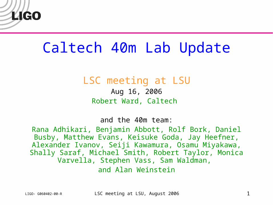
40m DARM Optical Response
101
102
103
104
-200
-100
0
100
200
f (Hz)
Phase
(deg)
B&CData
DARM Optical response
Optical spring and optical resonance of detuned RSE were
measured and fitted to theoretical prediction from A. Buonanno and
Y. Chen, PRD64, 042006.
Detuning

LSC meeting at LSU, August 2006 4LIGO- G060402-00-R
Optical Response paper
“Measurement of Optical Response of a Detuned Resonant Sideband Extraction Interferometer” Miyakawa et al, Published in Phys. Rev. D74, 022001 (2006) LIGO-P060007-00-R
LSC meeting at LSU, August 2006 5LIGO- G060402-00-R
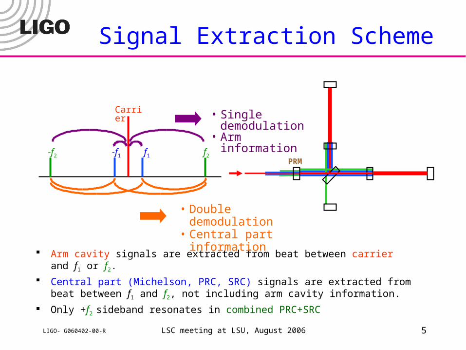
Signal Extraction Scheme
Arm cavity signals are extracted from beat between carrier and f1 or f2.
Central part (Michelson, PRC, SRC) signals are extracted from beat between f1 and f2, not including arm cavity information.
Only +f2 sideband resonates in combined PRC+SRC
• Double demodulation• Central part information
f1-f1 f2-f2
Carrier • Single demodulation• Arm information
PRM
LSC meeting at LSU, August 2006 6LIGO- G060402-00-R
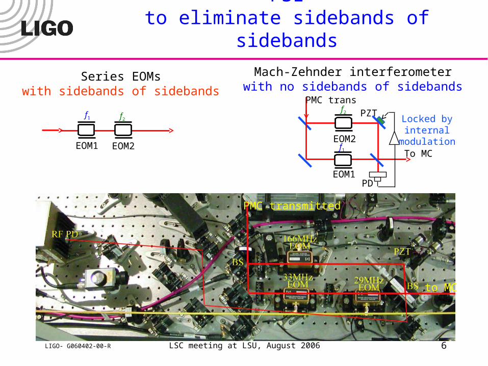
Mach-Zehnder interferometer on 40m PSLto eliminate sidebands of sidebands
Series EOMswith sidebands of sidebands
EOM2EOM1
Mach-Zehnder interferometerwith no sidebands of sidebands
PD
EOM2
EOM1
PZTPMC trans
To MC
Locked byinternal
modulation
f1 f2
f1
f2
PMC transmitted
to MC
LSC meeting at LSU, August 2006 7LIGO- G060402-00-R
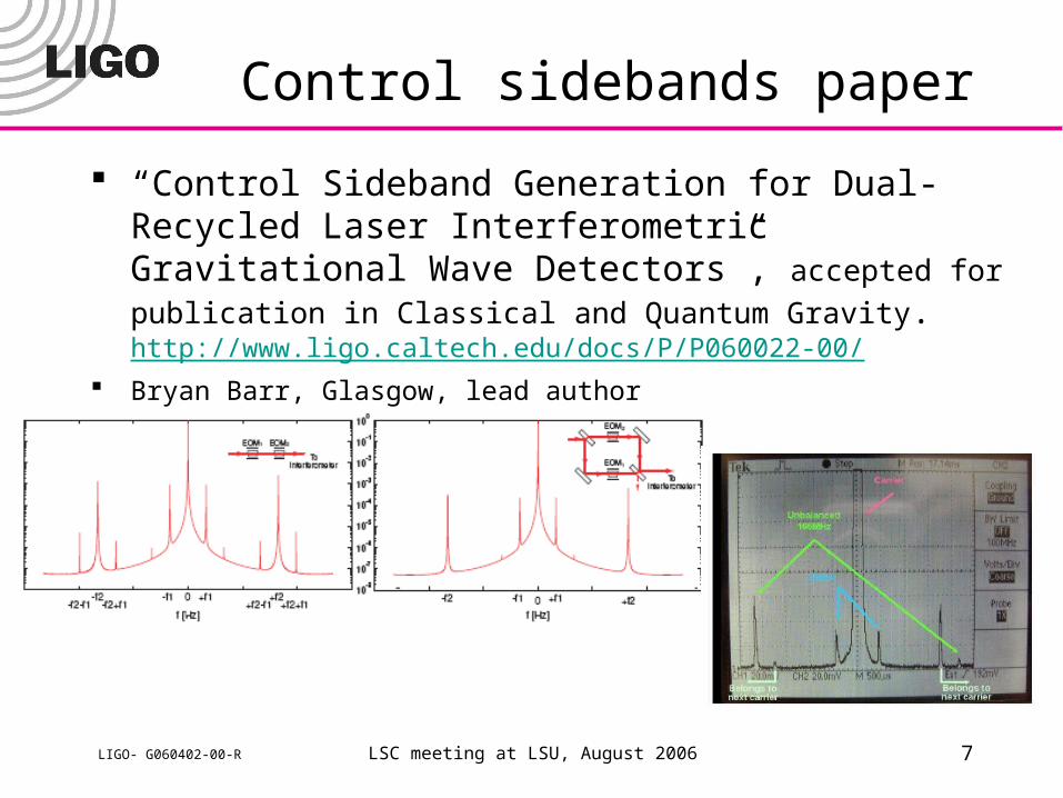
Control sidebands paper
“Control Sideband Generation for Dual-Recycled Laser Interferometric Gravitational Wave Detectors”, accepted for
publication in Classical and Quantum Gravity.http://www.ligo.caltech.edu/docs/P/P060022-00/
Bryan Barr, Glasgow, lead author
LSC meeting at LSU, August 2006 8LIGO- G060402-00-R
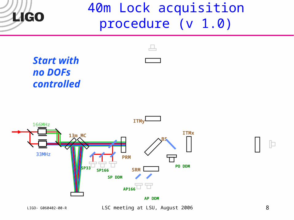
40m Lock acquisition procedure (v 1.0)
Start withno DOFscontrolled
ITMy
ITMxBS
PRM
SRM
SP DDM
13m MC
33MHz
166MHz
SP33SP166
AP DDM
AP166
PO DDM
LSC meeting at LSU, August 2006 9LIGO- G060402-00-R
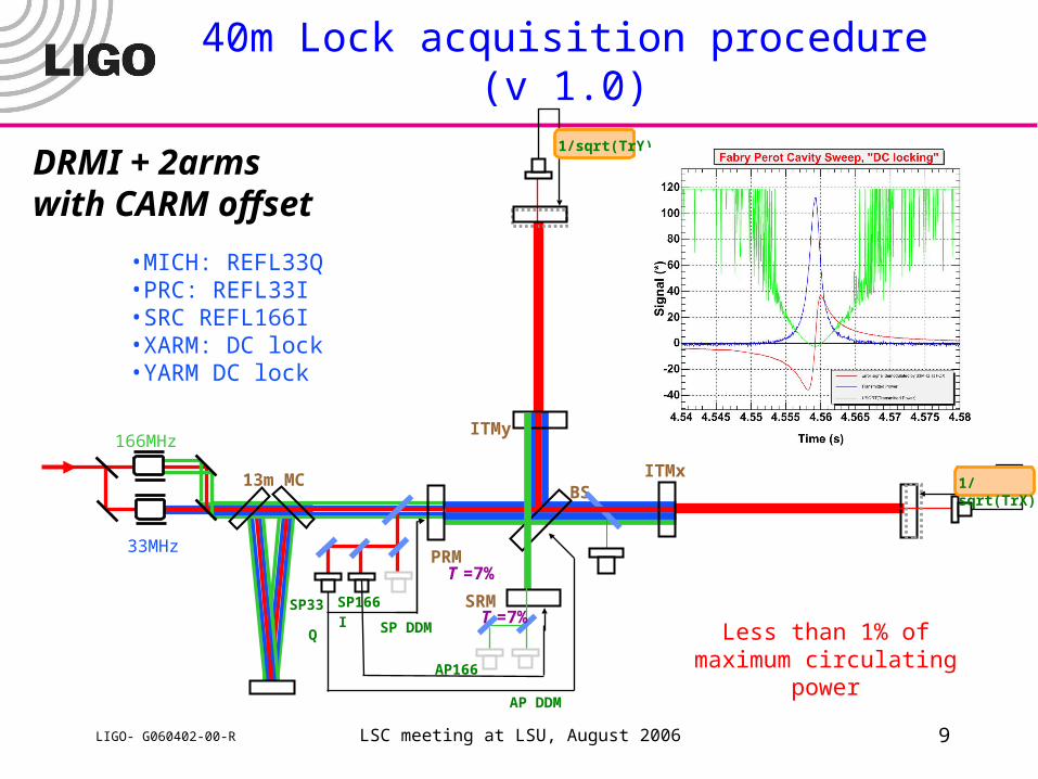
40m Lock acquisition procedure (v 1.0)
DRMI + 2armswith CARM offset
ITMy
ITMxBS
PRM
SRM
SP DDM
13m MC
33MHz
166MHz
SP33 SP166
AP DDM
AP166
T =7%
T =7%IQ
1/sqrt(TrY)
1/sqrt(TrX)
•MICH: REFL33Q•PRC: REFL33I•SRC REFL166I•XARM: DC lock•YARM DC lock
Less than 1% of maximum circulating power
LSC meeting at LSU, August 2006 10LIGO- G060402-00-R
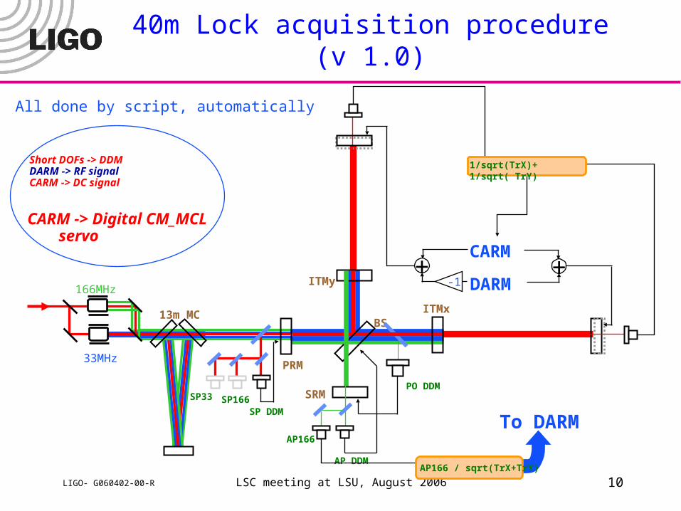
40m Lock acquisition procedure (v 1.0)
ITMy
ITMxBS
PRM
SRM
SP DDM
13m MC
33MHz
166MHz
SP33 SP166
AP DDM
AP166
To DARM
PO DDM
AP166 / sqrt(TrX+TrY)
CARM
DARM+
-1+
Short DOFs -> DDMDARM -> RF signalCARM -> DC signal
1/sqrt(TrX)+ 1/sqrt( TrY)
CARM -> Digital CM_MCL servo
All done by script, automatically
LSC meeting at LSU, August 2006 11LIGO- G060402-00-R
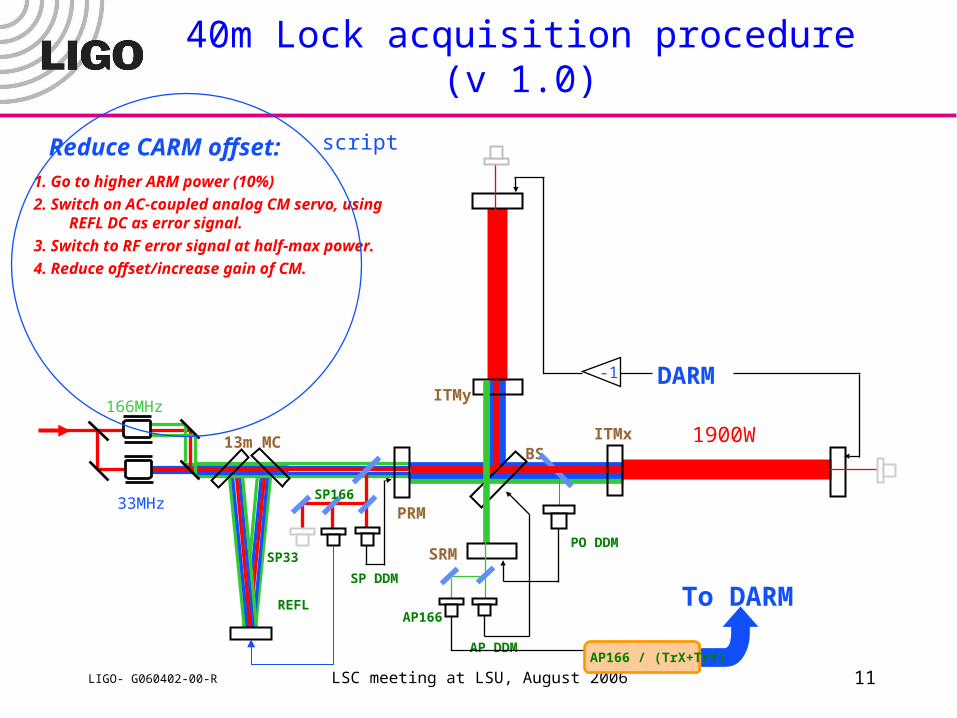
40m Lock acquisition procedure (v 1.0)
Reduce CARM offset:1. Go to higher ARM power (10%)
2. Switch on AC-coupled analog CM servo, using REFL DC as error signal.
3. Switch to RF error signal at half-max power.
4. Reduce offset/increase gain of CM.
ITMy
ITMxBS
PRM
SRM
SP DDM
13m MC
33MHz
166MHz
SP33
SP166
AP DDM
AP166To DARMREFL
DARM-1
PO DDM
AP166 / (TrX+TrY)
script
1900W
LSC meeting at LSU, August 2006 12LIGO- G060402-00-R
Lock acquisition development, automation
Initial, scripted, auto-alignment works now for all DOFs All loops use single-demod signals (carrier+one sideband) for
initial lock acquisition, to aid in tuning double-demod signals (offsets, demod phases).
In initial stage, all loops now have useful power level triggers. Fast input matrix ramping: all signal handoffs are automated
and smooth. With improved LO levels, now using real double-demod at 133
and 199 MHz. Work continues on Deterministic Locking.
» PRFPMI, DRMI, no DRFPMI
E2E modeling of lock acquisition under development
LSC meeting at LSU, August 2006 13LIGO- G060402-00-R
DC Readout
Motivations» DC Readout (AdvLIGO baseline) has technical noise benefits:
– RF Oscillator phase noise (significant at ~few kHz)– Laser frequency noise (close to limiting)– Perfect spatial overlap of LO and GW signal at PD.
» Limited by photodetector saturations; Output Mode Cleaner removes most of the junk light
» Removing the junk light reduces shot noise.
» Homodyne detection has lower potential shot noise
LSC meeting at LSU, August 2006 14LIGO- G060402-00-R
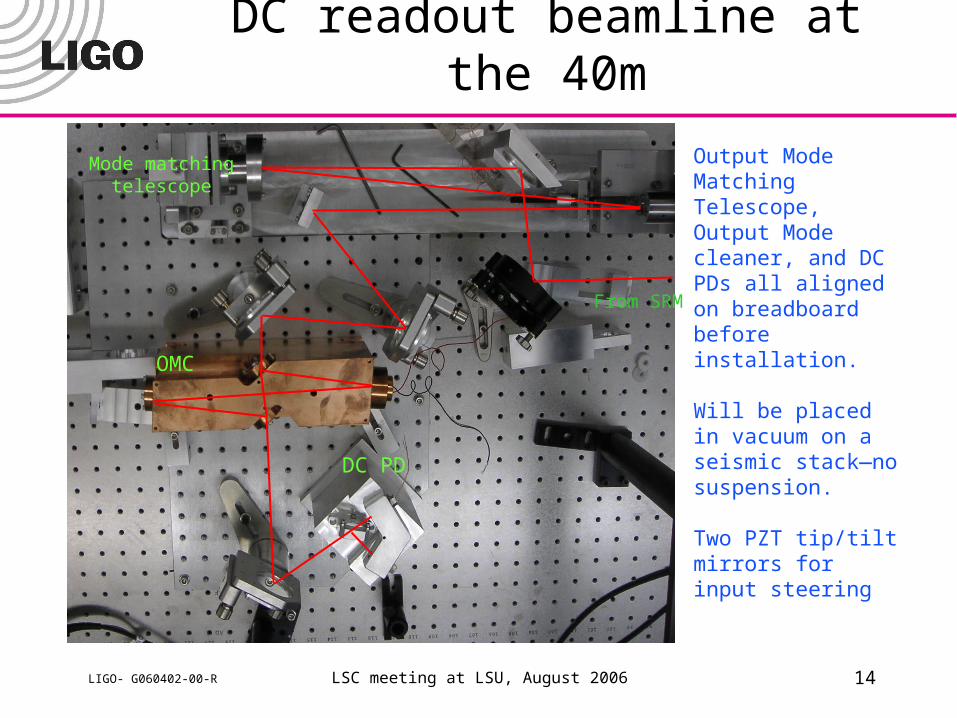
DC readout beamline at the 40m
OMC
DC PD
Mode matchingtelescope
From SRM
Output Mode Matching Telescope, Output Mode cleaner, and DC PDs all aligned on breadboard before installation.
Will be placed in vacuum on a seismic stack—no suspension.
Two PZT tip/tilt mirrors for input steering
LSC meeting at LSU, August 2006 15LIGO- G060402-00-R
DC readout beamline status
All components pre-aligned on breadboard(s) to be installed in-vac
OMMT aligned and coarsely focused with picomotor OMC dither-locked at 20 kHz using length PZT and
PD at reflected and transmitted port Dither-align to OMC using tip/tilt PZTs (one of 4
DOFs tested) In-vac alignment procedure developed, using fiber-
fed beam from DC PD mount back through all components to SRM. Tested in air.
All components disassembled, catalogued, and baked. » Ready to be re-assembled in clean room (next week)
LSC meeting at LSU, August 2006 16LIGO- G060402-00-R
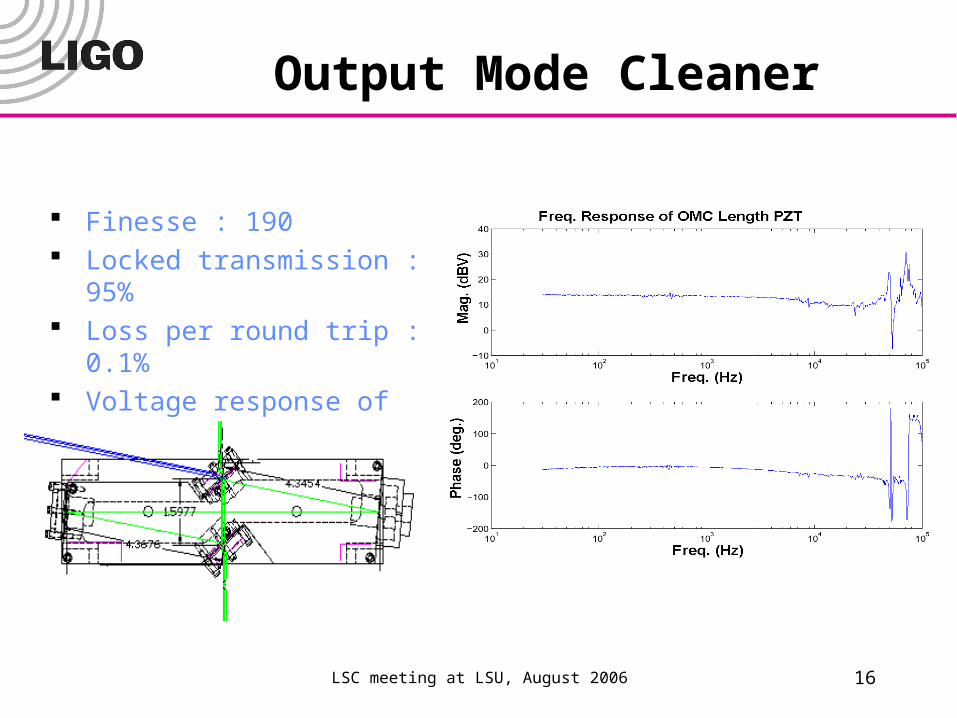
Output Mode Cleaner
Finesse : 190 Locked transmission : 95% Loss per round trip : 0.1% Voltage response of length
PZT: 8 nm/V L = 48 cm
LSC meeting at LSU, August 2006 17LIGO- G060402-00-R
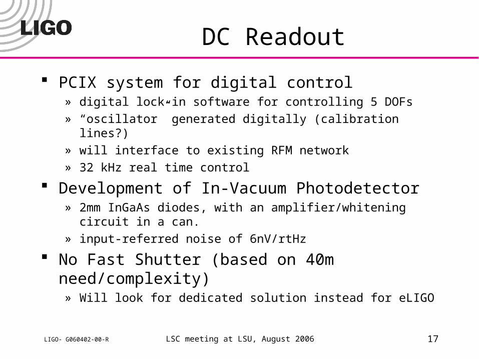
DC Readout
PCIX system for digital control» digital lock-in software for controlling 5 DOFs
» “oscillator” generated digitally (calibration lines?)
» will interface to existing RFM network
» 32 kHz real time control
Development of In-Vacuum Photodetector» 2mm InGaAs diodes, with an amplifier/whitening circuit in a can.
» input-referred noise of 6nV/rtHz
No Fast Shutter (based on 40m need/complexity)» Will look for dedicated solution instead for eLIGO
LSC meeting at LSU, August 2006 18LIGO- G060402-00-R
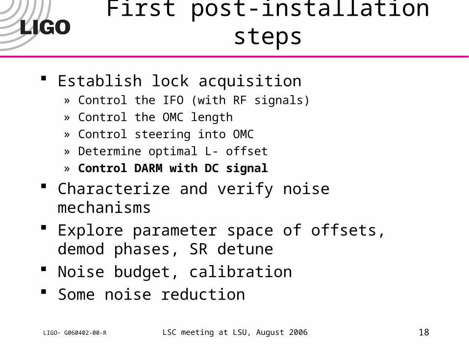
First post-installation steps
Establish lock acquisition» Control the IFO (with RF signals)
» Control the OMC length
» Control steering into OMC
» Determine optimal L- offset
» Control DARM with DC signal
Characterize and verify noise mechanisms Explore parameter space of offsets, demod phases,
SR detune Noise budget, calibration Some noise reduction
LSC meeting at LSU, August 2006 19LIGO- G060402-00-R
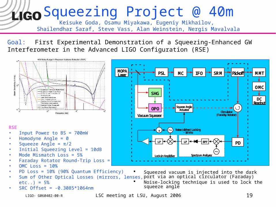
Goal: First Experimental Demonstration of a Squeezing-Enhanced GW Interferometer in the Advanced LIGO Configuration (RSE)
Squeezing Project @ 40mKeisuke Goda, Osamu Miyakawa, Eugeniy Mikhailov,
Shailendhar Saraf, Steve Vass, Alan Weinstein, Nergis Mavalvala
RSE• Input Power to BS = 700mW• Homodyne Angle = 0• Squeeze Angle = π/2• Initial Squeezing Level = 10dB• Mode Mismatch Loss = 5%• Faraday Rotator Round-Trip Loss = 10%• OMC Loss = 10%• PD Loss = 10% (90% Quantum Efficiency)• Sum of Other Optical Losses (mirrors, lenses, etc..) =
5%• SRC Offset = -0.3085*1064nm
Lock-in Amplifier Spectrum Analyzer
Vacuum Squeezer
MOPALaser MC IFO
Squeeze AngleActuatorOPO
SHG
BPFLPLP
+
Circulator(Faraday Rotator)
Noise (dither) Locking~ 10 kHz
PickoffSRM
OMC
MMT
DCReadout
PSL
PD
Squeezed vacuum is injected into the dark port via an optical circulator (Faraday)
Noise-locking technique is used to lock the squeeze angle
LSC meeting at LSU, August 2006 20LIGO- G060402-00-R
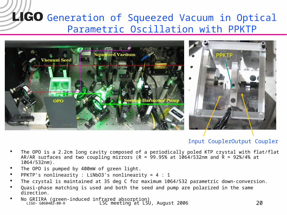
Generation of Squeezed Vacuum in Optical Parametric Oscillation with PPKTP
The OPO is a 2.2cm long cavity composed of a periodically poled KTP crystal with flat/flat AR/AR surfaces and two coupling mirrors (R = 99.95% at 1064/532nm and R = 92%/4% at 1064/532nm).
The OPO is pumped by 400mW of green light. PPKTP’s nonlinearity : LiNbO3’s nonlinearity = 4 : 1 The crystal is maintained at 35 deg C for maximum 1064/532 parametric down-conversion. Quasi-phase matching is used and both the seed and pump are polarized in the same direction. No GRIIRA (green-induced infrared absorption)
Input Coupler Output Coupler
PPKTP
LSC meeting at LSU, August 2006 21LIGO- G060402-00-R
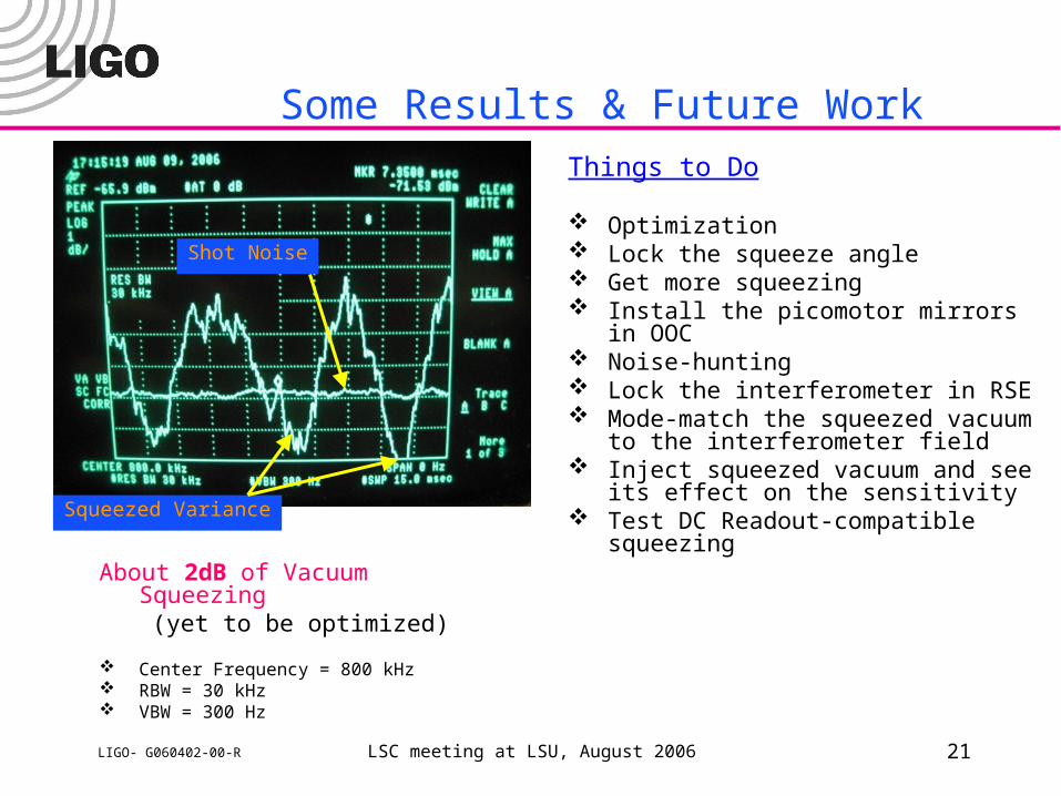
Some Results & Future Work
About 2dB of Vacuum Squeezing(yet to be optimized)
Center Frequency = 800 kHz RBW = 30 kHz VBW = 300 Hz
Squeezed Variance
Shot Noise
Things to Do
Optimization Lock the squeeze angle Get more squeezing Install the picomotor mirrors in OOC Noise-hunting Lock the interferometer in RSE Mode-match the squeezed vacuum to the
interferometer field Inject squeezed vacuum and see its effect
on the sensitivity Test DC Readout-compatible squeezing
LSC meeting at LSU, August 2006 22LIGO- G060402-00-R
What’s NEXT?
We have a clear set of objectives for the next ~6 months or so.» lock acquisition
» DC readout
» squeezing
What should come next?» new signal matrix (lower RF sideband frequencies)
» new modulation scheme (non-Mach-Zehnder)» ASC system Output Mode Cleaner» Suspension Point Interferometer