Embed Size (px)
Citation preview

This document consists of 26 printed pages and 2 blank pages.
DC (LK/CGW) 90046© UCLES 2014 [Turn over
Cambridge International ExaminationsCambridge International Advanced Level
*1551101250*
PHYSICS 9702/43
Paper 4 A2 Structured Questions May/June 2014
2 hours
Candidates answer on the Question Paper.
No Additional Materials are required.
READ THESE INSTRUCTIONS FIRST
Write your Centre number, candidate number and name on all the work you hand in.Write in dark blue or black pen.You may use an HB pencil for any diagrams or graphs.Do not use staples, paper clips, glue or correction fluid.DO NOT WRITE IN ANY BARCODES.
Answer all questions.
Electronic calculators may be used.You may lose marks if you do not show your working or if you do not use appropriate units.
At the end of the examination, fasten all your work securely together.The number of marks is given in brackets [ ] at the end of each question or part question.
For Examiner’s Use
1
2
3
4
5
6
7
8
9
10
11
12
13
14
Total
2
9702/43/M/J/14© UCLES 2014
Data
speed of light in free space, c = 3.00 × 10⁸ m s–1
permeability of free space, μ0 = 4π × 10–7 H m–1
permittivity of free space, ε0 = 8.85 × 10⁻¹² F m–1
(1
4πε0 = 8.99 × 10⁹ m F–1)
elementary charge, e = 1.60 × 10⁻¹⁹ C
the Planck constant, h = 6.63 × 10⁻³⁴ J s
unified atomic mass constant, u = 1.66 × 10⁻²⁷ kg
rest mass of electron, me = 9.11 × 10⁻³¹ kg
rest mass of proton, mp = 1.67 × 10⁻²⁷ kg
molar gas constant, R = 8.31 J K–1 mol–1
the Avogadro constant, NA = 6.02 × 10²³ mol–1
the Boltzmann constant, k = 1.38 × 10⁻²³ J K–1
gravitational constant, G = 6.67 × 10⁻¹¹ N m2 kg–2
acceleration of free fall, g = 9.81 m s–2
3
9702/43/M/J/14© UCLES 2014 [Turn over
Formulae
uniformly accelerated motion, s = ut + �� at 2
v2 = u2 + 2as
work done on/by a gas, W = pΔV
gravitational potential, φ = – Gm
r
hydrostatic pressure, p = ρgh
pressure of an ideal gas, p = �� NmV
<c2>
simple harmonic motion, a = – ω 2x
velocity of particle in s.h.m., v = v0 cos ωt
v = ± ω √⎯ ⎯ ⎯ ⎯ ⎯ ⎯ ⎯ ⎯ ⎯ (x02 – x2)
electric potential, V = Q4πε0r
capacitors in series, 1/C = 1/C1 + 1/C2 + . . .
capacitors in parallel, C = C1 + C2 + . . .
energy of charged capacitor, W = �� QV
resistors in series, R = R1 + R2 + . . .
resistors in parallel, 1/R = 1/R1 + 1/R2 + . . .
alternating current/voltage, x = x0 sin ω t
radioactive decay, x = x0 exp(–λt )
decay constant, λ = 0.693
t ��
4
9702/43/M/J/14© UCLES 2014
Section A
Answer all the questions in the spaces provided.
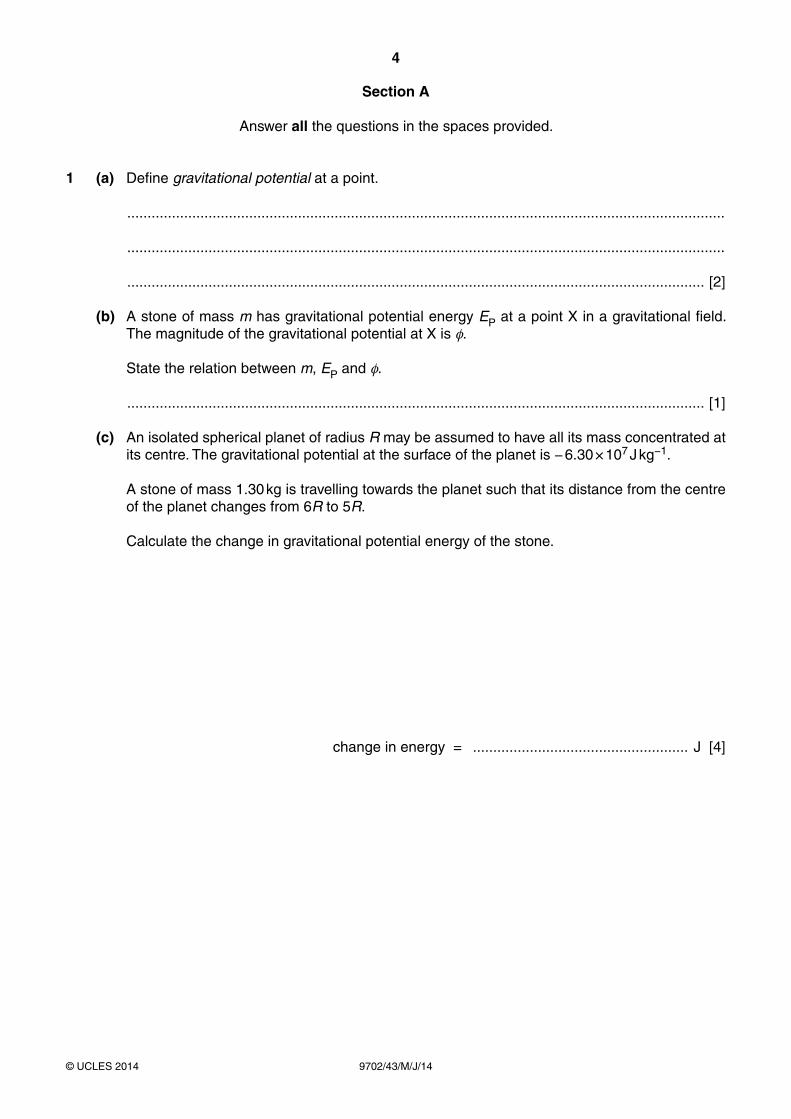
1 (a) Define gravitational potential at a point.
...................................................................................................................................................
...................................................................................................................................................
.............................................................................................................................................. [2]
(b) A stone of mass m has gravitational potential energy EP at a point X in a gravitational field. The magnitude of the gravitational potential at X is φ.
State the relation between m, EP and φ.
.............................................................................................................................................. [1]
(c) An isolated spherical planet of radius R may be assumed to have all its mass concentrated at its centre. The gravitational potential at the surface of the planet is − 6.30 × 10⁷ J kg−1.
A stone of mass 1.30 kg is travelling towards the planet such that its distance from the centre of the planet changes from 6R to 5R.
Calculate the change in gravitational potential energy of the stone.
change in energy = ..................................................... J [4]
5
9702/43/M/J/14© UCLES 2014 [Turn over
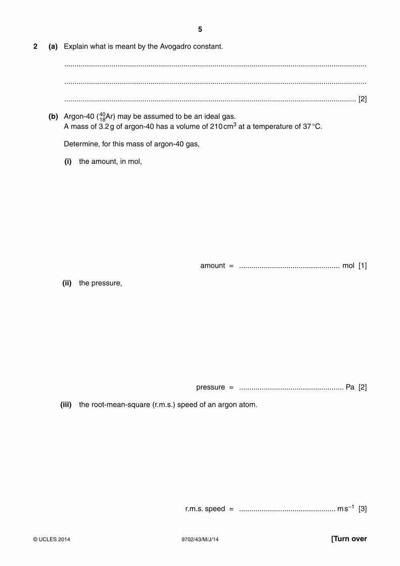
2 (a) Explain what is meant by the Avogadro constant.
...................................................................................................................................................
...................................................................................................................................................
.............................................................................................................................................. [2]
(b) Argon-40 (4018Ar) may be assumed to be an ideal gas.
A mass of 3.2 g of argon-40 has a volume of 210 cm3 at a temperature of 37 °C.
Determine, for this mass of argon-40 gas,
(i) the amount, in mol,
amount = ................................................. mol [1]
(ii) the pressure,
pressure = ................................................... Pa [2]
(iii) the root-mean-square (r.m.s.) speed of an argon atom.
r.m.s. speed = ............................................... m s−1 [3]

6
9702/43/M/J/14© UCLES 2014
BLANK PAGE
7
9702/43/M/J/14© UCLES 2014 [Turn over
3 The volume of 1.00 kg of water in the liquid state at 100 °C is 1.00 × 10⁻³ m3. The volume of 1.00 kg of water vapour at 100 °C and atmospheric pressure 1.01 × 10⁵ Pa is 1.69 m3.
(a) Show that the work done against the atmosphere when 1.00 kg of liquid water becomes water vapour is 1.71 × 10⁵ J.
[2]
(b) (i) The first law of thermodynamics may be given by the expression
ΔU = + q + w
where ΔU is the increase in internal energy of the system.
State what is meant by
1. + q,
...................................................................................................................................... [1]
2. + w.
...................................................................................................................................... [1]
(ii) The specific latent heat of vaporisation of water at 100 °C is 2.26 × 10⁶ J kg−1.
A mass of 1.00 kg of liquid water becomes water vapour at 100 °C.
Determine, using your answer in (a), the increase in internal energy of this mass of water during vaporisation.
increase in internal energy = ..................................................... J [2]
8
9702/43/M/J/14© UCLES 2014
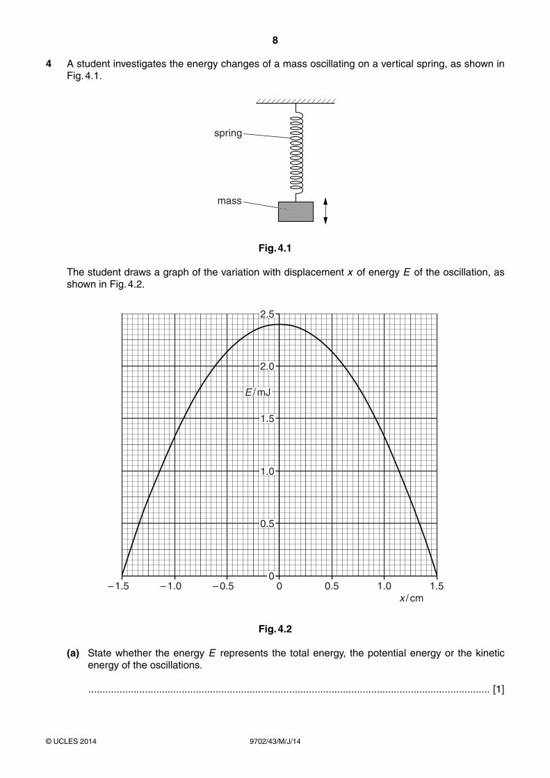
4 A student investigates the energy changes of a mass oscillating on a vertical spring, as shown in Fig. 4.1.
spring
mass
Fig. 4.1
The student draws a graph of the variation with displacement x of energy E of the oscillation, as shown in Fig. 4.2.
– 1.5 – 1.0 – 0.5x / cm
0 0.5 1.0 1.5
2.0
2.5
1.5
1.0
0.5
0
E / mJ
Fig. 4.2
(a) State whether the energy E represents the total energy, the potential energy or the kinetic energy of the oscillations.
.............................................................................................................................................. [1]

9
9702/43/M/J/14© UCLES 2014 [Turn over
(b) The student repeats the investigation but with a smaller amplitude. The maximum value of E is now found to be 1.8 mJ.
Use Fig. 4.2 to determine the change in the amplitude. Explain your working.
change in amplitude = .................................................. cm [3]
10
9702/43/M/J/14© UCLES 2014
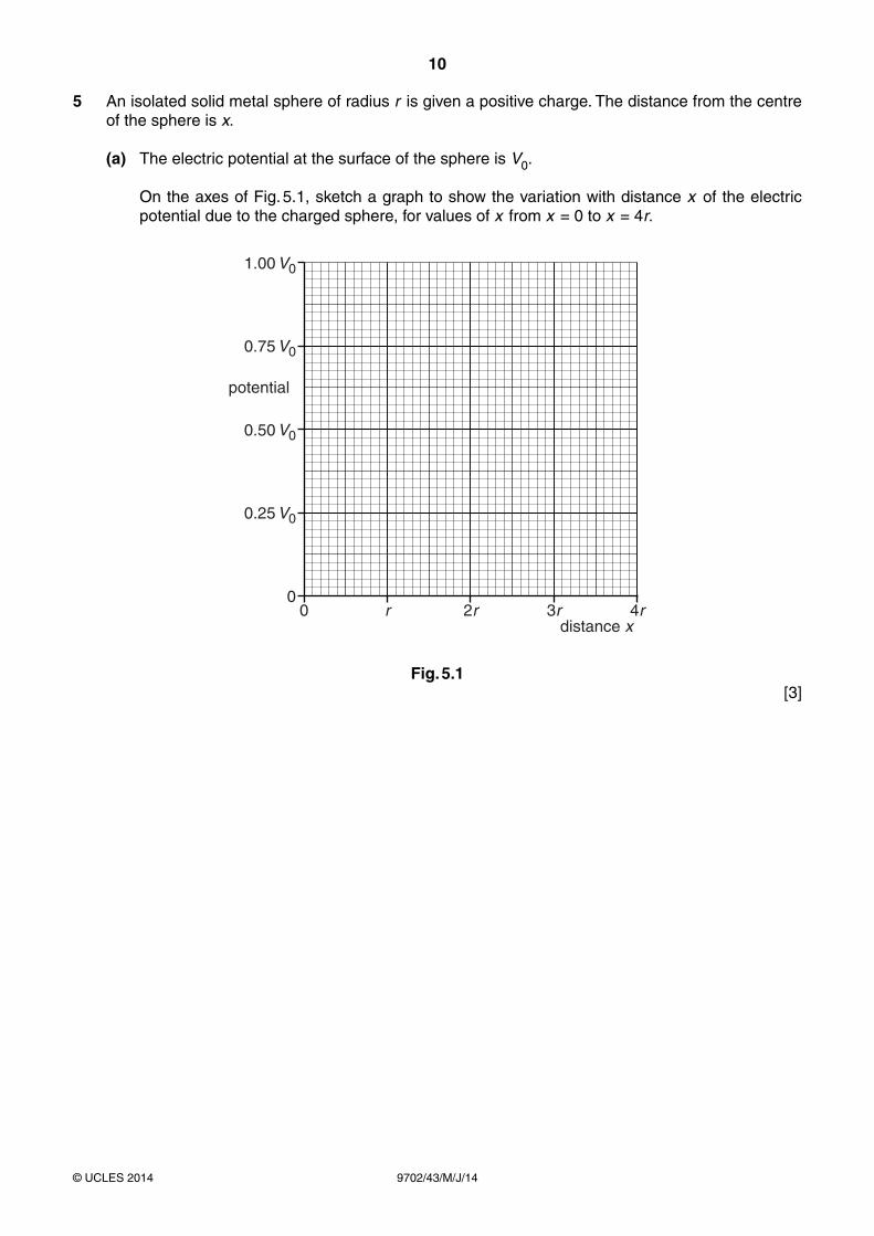
5 An isolated solid metal sphere of radius r is given a positive charge. The distance from the centre of the sphere is x.
(a) The electric potential at the surface of the sphere is V0.
On the axes of Fig. 5.1, sketch a graph to show the variation with distance x of the electric potential due to the charged sphere, for values of x from x = 0 to x = 4r.
0 r0
0.25 V0
0.50 V0
0.75 V0
1.00 V0
2r
potential
distance x3r 4r
Fig. 5.1 [3]
11
9702/43/M/J/14© UCLES 2014 [Turn over
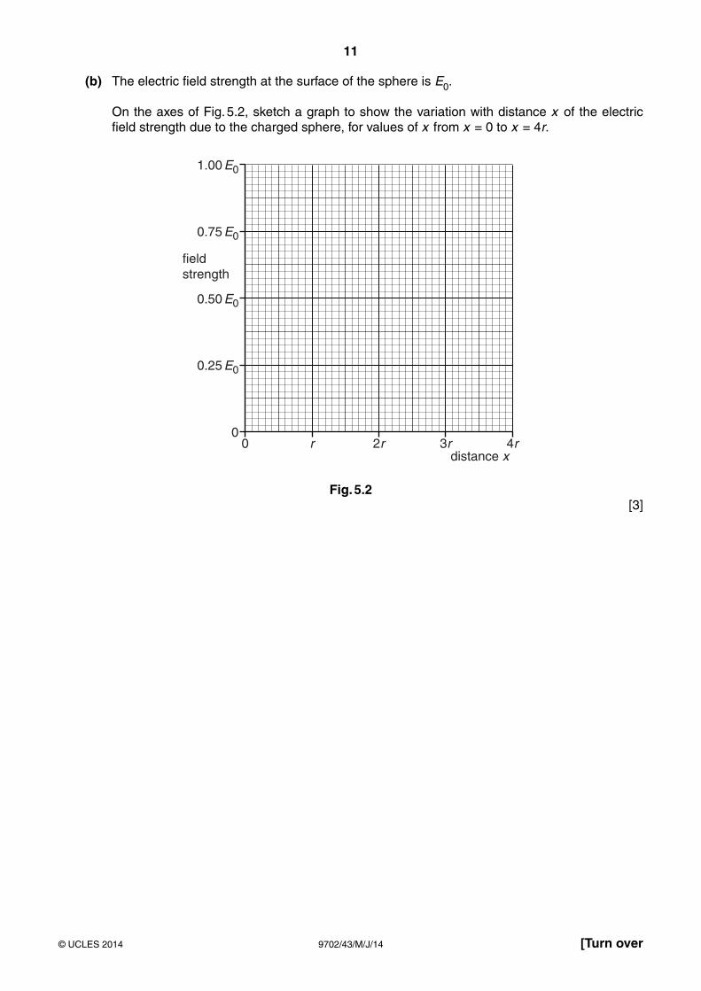
(b) The electric field strength at the surface of the sphere is E0.
On the axes of Fig. 5.2, sketch a graph to show the variation with distance x of the electric field strength due to the charged sphere, for values of x from x = 0 to x = 4r.
0 r0
0.25 E0
0.50 E0
0.75 E0
1.00 E0
2r
fieldstrength
distance x3r 4r
Fig. 5.2 [3]
12
9702/43/M/J/14© UCLES 2014
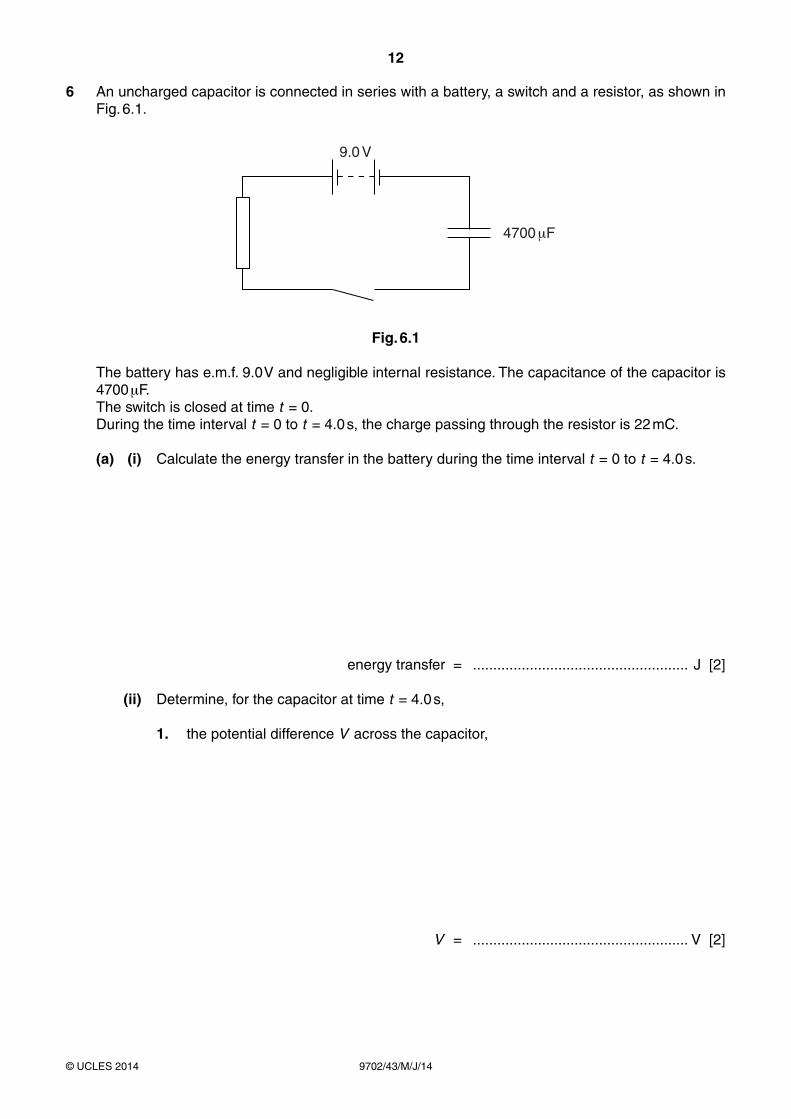
6 An uncharged capacitor is connected in series with a battery, a switch and a resistor, as shown in Fig. 6.1.
9.0 V
4700 F
Fig. 6.1
The battery has e.m.f. 9.0 V and negligible internal resistance. The capacitance of the capacitor is 4700 μF.
The switch is closed at time t = 0. During the time interval t = 0 to t = 4.0 s, the charge passing through the resistor is 22 mC.
(a) (i) Calculate the energy transfer in the battery during the time interval t = 0 to t = 4.0 s.
energy transfer = ..................................................... J [2]
(ii) Determine, for the capacitor at time t = 4.0 s,
1. the potential difference V across the capacitor,
V = ..................................................... V [2]

13
9702/43/M/J/14© UCLES 2014 [Turn over
2. the energy stored in the capacitor.
energy = ..................................................... J [2]
(b) Suggest why your answers in (a)(i) and (a)(ii) part 2 are different.
...................................................................................................................................................
.............................................................................................................................................. [1]
14
9702/43/M/J/14© UCLES 2014
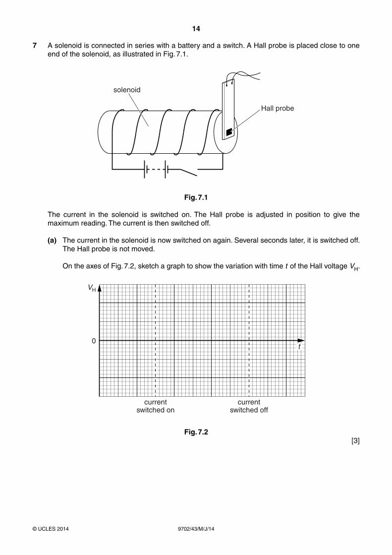
7 A solenoid is connected in series with a battery and a switch. A Hall probe is placed close to one end of the solenoid, as illustrated in Fig. 7.1.
solenoid
Hall probe
Fig. 7.1
The current in the solenoid is switched on. The Hall probe is adjusted in position to give the maximum reading. The current is then switched off.
(a) The current in the solenoid is now switched on again. Several seconds later, it is switched off. The Hall probe is not moved.
On the axes of Fig. 7.2, sketch a graph to show the variation with time t of the Hall voltage VH.
0
VH
currentswitched on
currentswitched off
t
Fig. 7.2 [3]
15
9702/43/M/J/14© UCLES 2014 [Turn over
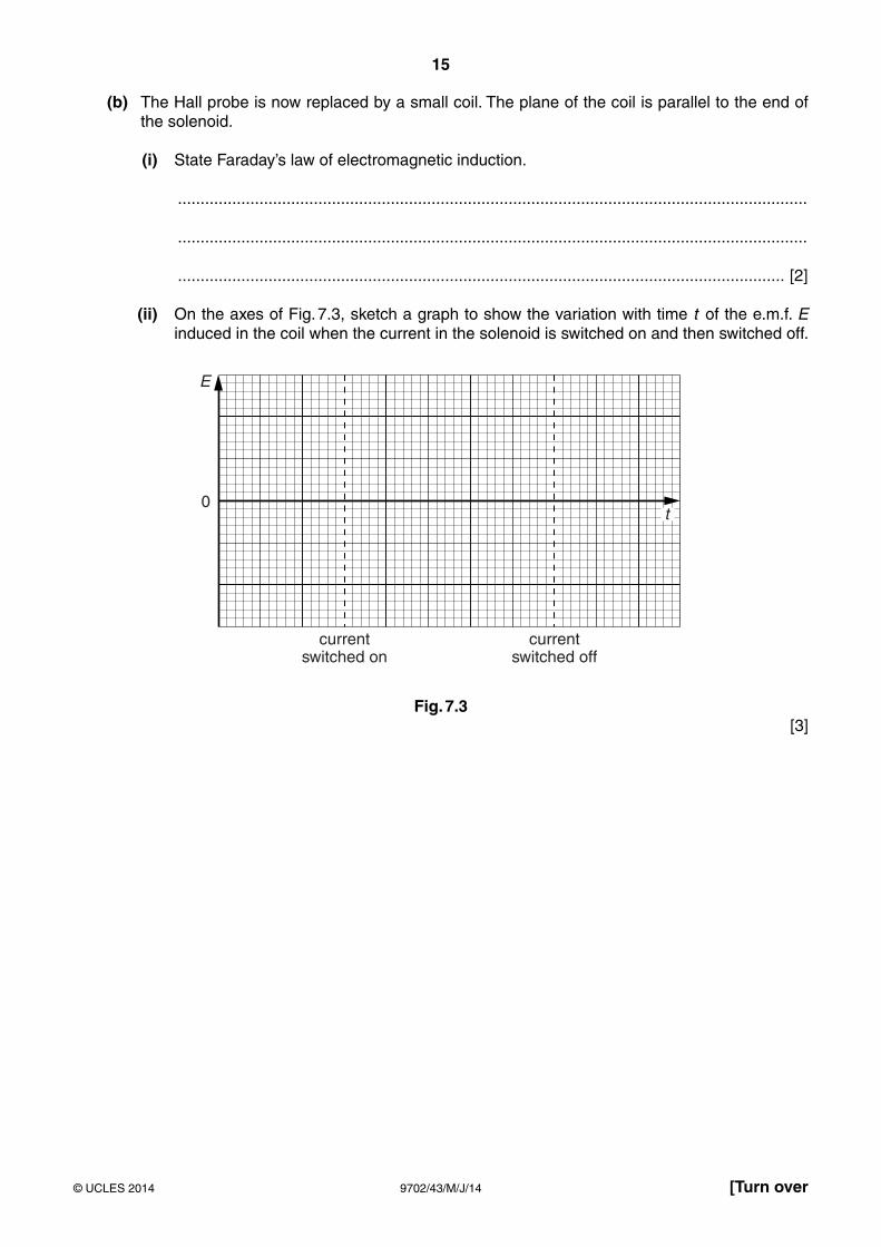
(b) The Hall probe is now replaced by a small coil. The plane of the coil is parallel to the end of the solenoid.
(i) State Faraday’s law of electromagnetic induction.
...........................................................................................................................................
...........................................................................................................................................
...................................................................................................................................... [2]
(ii) On the axes of Fig. 7.3, sketch a graph to show the variation with time t of the e.m.f. E induced in the coil when the current in the solenoid is switched on and then switched off.
0
E
currentswitched on
currentswitched off
t
Fig. 7.3 [3]
16
9702/43/M/J/14© UCLES 2014
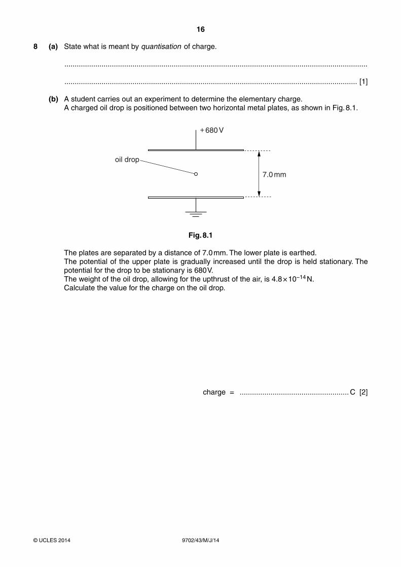
8 (a) State what is meant by quantisation of charge.
...................................................................................................................................................
.............................................................................................................................................. [1]
(b) A student carries out an experiment to determine the elementary charge. A charged oil drop is positioned between two horizontal metal plates, as shown in Fig. 8.1.
7.0 mm
oil drop
+ 680 V
Fig. 8.1
The plates are separated by a distance of 7.0 mm. The lower plate is earthed. The potential of the upper plate is gradually increased until the drop is held stationary. The
potential for the drop to be stationary is 680 V. The weight of the oil drop, allowing for the upthrust of the air, is 4.8 × 10⁻¹⁴ N. Calculate the value for the charge on the oil drop.
charge = ..................................................... C [2]

17
9702/43/M/J/14© UCLES 2014 [Turn over
(c) The student repeats the experiment and determines the following values for the charge on oil drops.
3.3 × 10⁻¹⁹ C 4.9 × 10⁻¹⁹ C 9.7 × 10⁻¹⁹ C 3.4 × 10⁻¹⁹ C
Use these values to suggest a value for the elementary charge. Explain your working.
elementary charge = ..................................................... C [2]
18
9702/43/M/J/14© UCLES 2014
9 For a particular metal surface, it is observed that there is a minimum frequency of light below which photoelectric emission does not occur. This observation provides evidence for a particulate nature of electromagnetic radiation.
(a) State three further observations from photoelectric emission that provide evidence for a particulate nature of electromagnetic radiation.
1. ...............................................................................................................................................
...................................................................................................................................................
2. ...............................................................................................................................................
...................................................................................................................................................
3. ...............................................................................................................................................
................................................................................................................................................... [3]
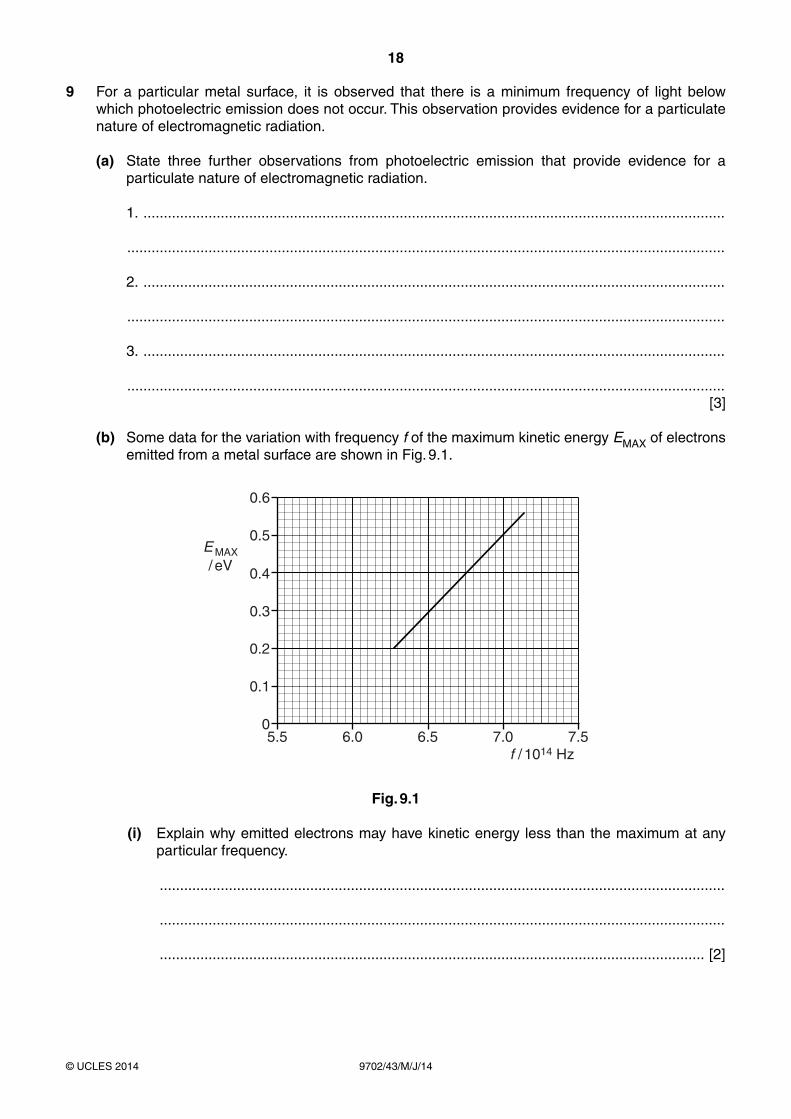
(b) Some data for the variation with frequency f of the maximum kinetic energy EMAX of electrons emitted from a metal surface are shown in Fig. 9.1.
5.5 6.0 6.5 7.0 7.50
0.2
0.4
0.6
0.1
0.3
0.5E MAX/ eV
f / 1014 Hz
Fig. 9.1
(i) Explain why emitted electrons may have kinetic energy less than the maximum at any particular frequency.
...........................................................................................................................................
...........................................................................................................................................
...................................................................................................................................... [2]

19
9702/43/M/J/14© UCLES 2014 [Turn over
(ii) Use Fig. 9.1 to determine
1. the threshold frequency,
threshold frequency = ................................................... Hz [1]
2. the work function energy, in eV, of the metal surface.
work function energy = ................................................... eV [3]
20
9702/43/M/J/14© UCLES 2014
10 (a) Explain what is meant by the binding energy of a nucleus.
...................................................................................................................................................
...................................................................................................................................................
.............................................................................................................................................. [2]
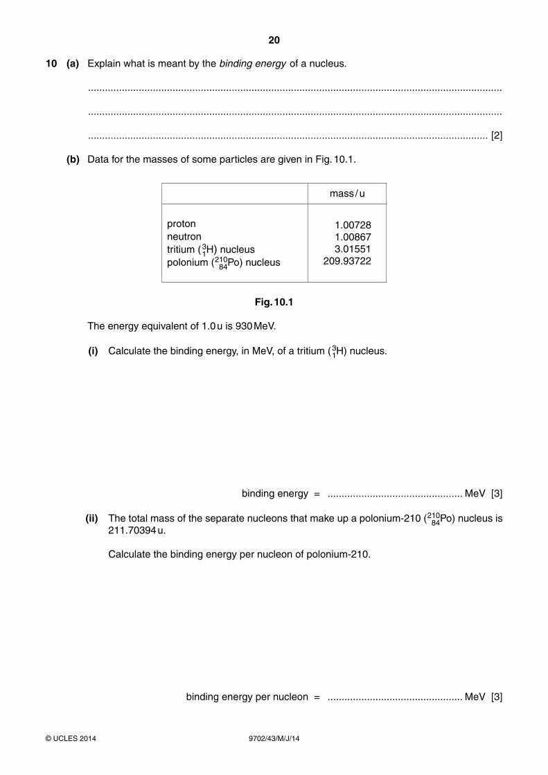
(b) Data for the masses of some particles are given in Fig. 10.1.
mass / u
protonneutrontritium (3
1H) nucleuspolonium (210
84Po) nucleus
1.00728 1.00867 3.01551209.93722
Fig. 10.1
The energy equivalent of 1.0 u is 930 MeV.
(i) Calculate the binding energy, in MeV, of a tritium (31H) nucleus.
binding energy = ................................................ MeV [3]
(ii) The total mass of the separate nucleons that make up a polonium-210 (21084Po) nucleus is
211.70394 u.
Calculate the binding energy per nucleon of polonium-210.
binding energy per nucleon = ................................................ MeV [3]

21
9702/43/M/J/14© UCLES 2014 [Turn over
(c) One possible fission reaction is
23592U + 1
0n 14156Ba + 92
36Kr + 310n .
By reference to binding energy, explain, without any calculation, why this fission reaction is energetically possible.
...................................................................................................................................................
...................................................................................................................................................
.............................................................................................................................................. [2]
22
9702/43/M/J/14© UCLES 2014
Section B
Answer all the questions in the spaces provided.
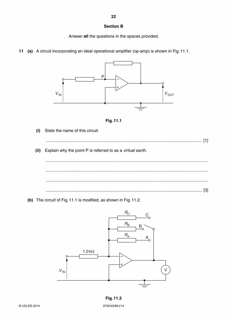
11 (a) A circuit incorporating an ideal operational amplifier (op-amp) is shown in Fig. 11.1.
P
V IN V OUT
+
–
Fig. 11.1
(i) State the name of this circuit.
...................................................................................................................................... [1]
(ii) Explain why the point P is referred to as a virtual earth.
...........................................................................................................................................
...........................................................................................................................................
...........................................................................................................................................
...................................................................................................................................... [3]
(b) The circuit of Fig. 11.1 is modified, as shown in Fig. 11.2.
V IN
1.0 k
CRC
RB
RA
+
–
B
A
V
Fig. 11.2
23
9702/43/M/J/14© UCLES 2014 [Turn over
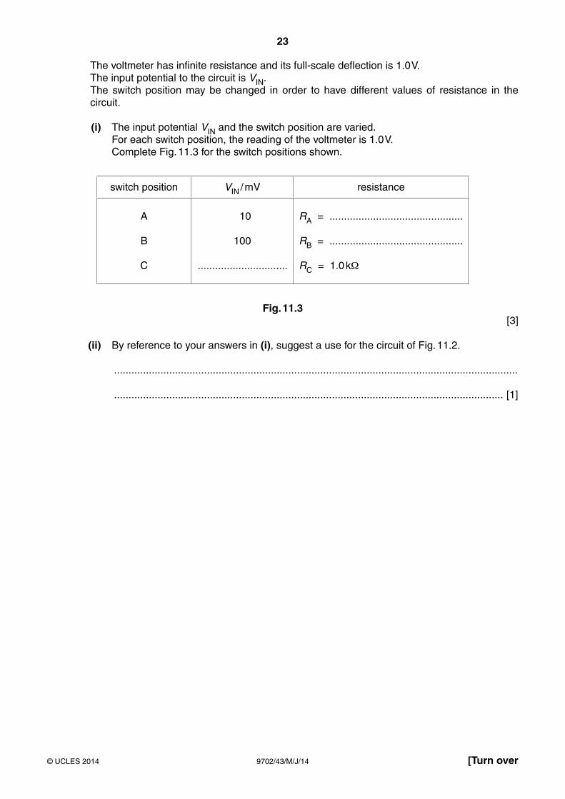
The voltmeter has infinite resistance and its full-scale deflection is 1.0 V. The input potential to the circuit is VIN. The switch position may be changed in order to have different values of resistance in the
circuit.
(i) The input potential VIN and the switch position are varied. For each switch position, the reading of the voltmeter is 1.0 V. Complete Fig. 11.3 for the switch positions shown.
switch position VIN / mV resistance
A
B
C
10
100
...............................
RA = ..............................................
RB = ..............................................
RC = 1.0 kΩ
Fig. 11.3 [3]
(ii) By reference to your answers in (i), suggest a use for the circuit of Fig. 11.2.
...........................................................................................................................................
...................................................................................................................................... [1]

24
9702/43/M/J/14© UCLES 2014
12 (a) Outline briefly the principles of CT scanning.
...................................................................................................................................................
...................................................................................................................................................
...................................................................................................................................................
...................................................................................................................................................
...................................................................................................................................................
...................................................................................................................................................
...................................................................................................................................................
...................................................................................................................................................
...................................................................................................................................................
.............................................................................................................................................. [5]
25
9702/43/M/J/14© UCLES 2014 [Turn over
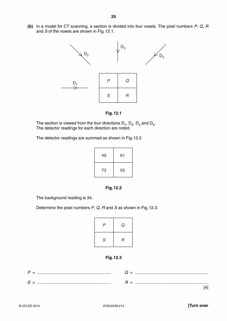
(b) In a model for CT scanning, a section is divided into four voxels. The pixel numbers P, Q, R and S of the voxels are shown in Fig. 12.1.
P
D2 D4
D1
D3
S
Q
R
Fig. 12.1
The section is viewed from the four directions D1, D2, D3 and D4. The detector readings for each direction are noted.
The detector readings are summed as shown in Fig. 12.2.
49
73
61
55
Fig. 12.2
The background reading is 34.
Determine the pixel numbers P, Q, R and S as shown in Fig. 12.3.
P
S
Q
R
Fig. 12.3
P = ............................................................... Q = ...............................................................
S = ............................................................... R = ............................................................... [4]
26
9702/43/M/J/14© UCLES 2014
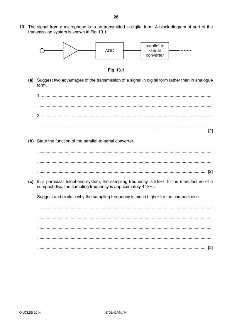
13 The signal from a microphone is to be transmitted in digital form. A block diagram of part of the transmission system is shown in Fig. 13.1.
ADCparallel-to
-serialconverter
Fig. 13.1
(a) Suggest two advantages of the transmission of a signal in digital form rather than in analogue form.
1. ...............................................................................................................................................
...................................................................................................................................................
2. ...............................................................................................................................................
................................................................................................................................................... [2]
(b) State the function of the parallel-to-serial converter.
...................................................................................................................................................
...................................................................................................................................................
.............................................................................................................................................. [2]
(c) In a particular telephone system, the sampling frequency is 8 kHz. In the manufacture of a compact disc, the sampling frequency is approximately 44 kHz.
Suggest and explain why the sampling frequency is much higher for the compact disc.
...................................................................................................................................................
...................................................................................................................................................
...................................................................................................................................................
...................................................................................................................................................
.............................................................................................................................................. [3]
27
9702/43/M/J/14© UCLES 2014
14 (a) State what is meant by the attenuation of a signal.
...................................................................................................................................................
.............................................................................................................................................. [1]
(b) A transmission cable has a length of 30 km. The attenuation per unit length of the cable is 2.4 dB km−1.
Calculate, for a signal being transmitted along the cable,
(i) the total attenuation, in dB,
attenuation = ................................................... dB [1]
(ii) the ratio
input power of signaloutput power of signal .
ratio = ......................................................... [3]
(c) By reference to your answers in (b), suggest why the attenuation of transmitted signals is usually expressed in dB.
...................................................................................................................................................
.............................................................................................................................................. [1]

28
9702/43/M/J/14© UCLES 2014
Permission to reproduce items where third-party owned material protected by copyright is included has been sought and cleared where possible. Every reasonable effort has been made by the publisher (UCLES) to trace copyright holders, but if any items requiring clearance have unwittingly been included, the publisher will be pleased to make amends at the earliest possible opportunity.
Cambridge International Examinations is part of the Cambridge Assessment Group. Cambridge Assessment is the brand name of University of Cambridge Local Examinations Syndicate (UCLES), which is itself a department of the University of Cambridge.
BLANK PAGE