Embed Size (px)
DESCRIPTION
Camp2 Operation
Citation preview
INSTRUCTION MANUAL
E84511-K00070-002008/1
Ver.3-1.01
HK S E L E C T R ONIC S T E C HNOL OG Y

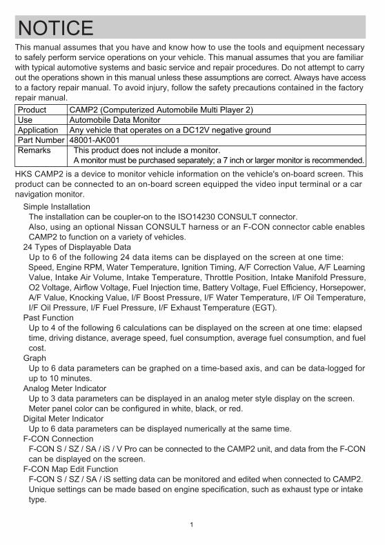
ProductUseApplicationPart NumberRemarks
CAMP2 (Computerized Automobile Multi Player 2)Automobile Data MonitorAny vehicle that operates on a DC12V negative ground48001-AK001・This product does not include a monitor.・A monitor must be purchased separately; a 7 inch or larger monitor is recommended.
NOTICE
-1-
This manual assumes that you have and know how to use the tools and equipment necessaryto safely perform service operations on your vehicle. This manual assumes that you are familiarwith typical automotive systems and basic service and repair procedures. Do not attempt to carryout the operations shown in this manual unless these assumptions are correct. Always have accessto a factory repair manual. To avoid injury, follow the safety precautions contained in the factoryrepair manual.
HKS CAMP2 is a device to monitor vehicle information on the vehicle's on-board screen. This product can be connected to an on-board screen equipped the video input terminal or a car navigation monitor.●Simple Installation The installation can be coupler-on to the ISO14230 CONSULT connector. Also, using an optional Nissan CONSULT harness or an F-CON connector cable enables CAMP2 to function on a variety of vehicles.●24 Types of Displayable Data Up to 6 of the following 24 data items can be displayed on the screen at one time: Speed, Engine RPM, Water Temperature, Ignition Timing, A/F Correction Value, A/F Learning Value, Intake Air Volume, Intake Temperature, Throttle Position, Intake Manifold Pressure, O2 Voltage, Airflow Voltage, Fuel Injection time, Battery Voltage, Fuel Efficiency, Horsepower, A/F Value, Knocking Value, I/F Boost Pressure, I/F Water Temperature, I/F Oil Temperature, I/F Oil Pressure, I/F Fuel Pressure, I/F Exhaust Temperature (EGT).●Past Function Up to 4 of the following 6 calculations can be displayed on the screen at one time: elapsed time, driving distance, average speed, fuel consumption, average fuel consumption, and fuel cost.●Graph Up to 6 data parameters can be graphed on a time-based axis, and can be data-logged for up to 10 minutes. ●Analog Meter Indicator Up to 3 data parameters can be displayed in an analog meter style display on the screen. Meter panel color can be configured in white, black, or red.●Digital Meter Indicator Up to 6 data parameters can be displayed numerically at the same time. ●F-CON Connection F-CON S / SZ / SA / iS / V Pro can be connected to the CAMP2 unit, and data from the F-CON can be displayed on the screen. ●F-CON Map Edit Function F-CON S / SZ / SA / iS setting data can be monitored and edited when connected to CAMP2. Unique settings can be made based on engine specification, such as exhaust type or intake type.
-2-
Notice ……………………………………………
Index ……………………………………………
Safety Instructions ……………………………
Parts List ………………………………………
Names & Functions ………………………… 1.Names …………………………………… 2.Items on the screen ……………………
Installation …………………………………… 1.Disconnecting the Battery Terminal …… 2.Wiring …………………………………… 3.Mounting ………………………………… 4.After Installation …………………………
Confirmation after Installation ………………
Operation ……………………………………… 1.Operation Outline ……………………… 2.SET UP Mode …………………………… 3.PAST Mode ……………………………… 4.GRAPH Mode …………………………… 5.ANALOG Mode ………………………… 6.DIGITAL Mode ………………………… 7.F-CON Mode ……………………………
INDEX1
2
3
4
556
777
1011
11
1212141819212426
・This manual indicates items you need to pay attention in order to install this product safely and lists precautions to avoid any possible damage and/or accidents.・For any lost, defective and/or damaged parts, contact the dealer to order.・HKS will not be responsible for any damage caused by incorrect installation and/or use or use after modification and/or dismantling of this product.・HKS will not be responsible for any damage caused by removing vehicle's in/exterior, electric parts or modification for installation.・This product was designed based on installing it onto a factory vehicle or a vehicle using other HKS products. The performance and/or safety cannot be guaranteed if this product was installed onto other inapplicable vehicles.・This product works only with a vehicle with DC12V negative ground.・The specifications of this product are subject to be changed without notice.・This manual is subject to be revised without notice. ・The user must keep this manual.
●I/F Unit Connection Connecting an HKS I/F Unit (P/N 44008-AK011) to the CAMP2 will allow for connected sensor data to be displayed on the screen.●Warning Function When actual data exceeds or falls short of set value, the driver is notified with audible and visual alerts. ●Peak Hold Function The data peak values can be displayed on the screen.
Optional Parts List ……………………………
Maintenance …………………………………
Troubleshooting ………………………………
Product Specifications ………………………
28
28
29
29
-3-
SAFETY INSTRUCTIONSWARNING
・Make sure to work on the vehicle in a well-ventilated area to prevent possible explosion or a fire.・Do not mount the unit where distracts driving to avoid possible accident.・Do not install this product to a vehicle with DC24V negative ground. It may cause a fire.・Make sure to remove the cable from the negative terminal of the battery to avoid possible damage to other electronics parts and/or a fire caused by a short circuit.・Make sure to hold the connectors' lock when removing them to avoid possible damage to other electronics parts and/or a fire caused by disconnection or a short circuit.・Stop using the product if any unusual situation is noticed. Consult the dealer immediately.・Do not stare at the monitor while driving; this may cause car accidents. Please park the car in a safe area when operating the product.・Make sure to work on the vehicle without children to prevent them from swallowing small parts.
CAUTIONS・Do not install this product by yourself unless you have and know how to use the tools and equipment necessary to safely perform service operations on your vehicle.・Do not modify, disassemble, and/or remodel the product and attached parts to avoid any damage to the unit and/or harness. ・Handle the parts with caution at all times.・To avoid possible malfunction and damage to the engine, install the unit away from excessive heat, water/moisture, and/or dust.・Make sure all connections and wiring are not disconnected, short circuited, or incorrect. If so, it may cause an electric shock, burn out, or damage to the vehicle.・Use the supplied splice as instructed in the manual to avoid any damage to the vehicle by misconnection. ・If the product or the vehicle with the product does not perform properly, consult the dealer immediately.・Do not try to repair the product by yourself. Consult the dealer.・When unusual noise, smell, and/or vibration are noticed while driving, deal with them as instructed in the user's manual.・Do not test the product on a public road.・If this product is connected using an external input, the vehicle's factory navigation and/or audio may not function while this product is in use.
-4-
◆Daily maintenance on the vehicle is the responsibility of the owner.◆This manual shows a typical installation. Actual installation may vary depending on the vehicle application.◆When removing factory parts, refer to the factory manual. ◆Do not lose and/or damage any removed parts.◆Make sure all connections and wiring are correct.◆Make sure to use appropriate tools to tighten bolts and nuts. Do not over-tighten bolts and nuts.◆Make sure not to disconnect the vehicle's wiring while installing this product. It may cause damage to the vehicle and/or this product.◆If this product is operated around the passenger seat or rear seat area while driving, use an adaptor to display the audio and video properly on the vehicle monitor. (The adaptor is not included in this product.)
・If the TV's video on the screen becomes distorted, or the picture from this product does not appear clearly, this does not necessarily mean that the product is damaged. To solve these symptoms, disconnect and reconnect the AV cable or turn off/on this product. ・Since CAMP2 uses an infrared remote controller, keep the controller and receiver away from exposure to the direct rays of the sun. If the controller and/or the receiver are exposed directly to the sun, the controller may not function properly.
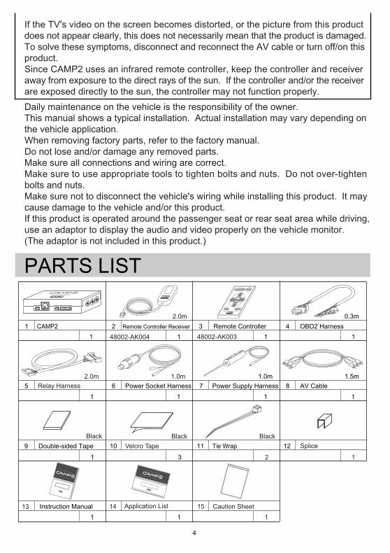
PARTS LIST
Instruction Manual
Double-sided Tape
Remote Controller ReceiverCAMP211 1 1 1
1 1
3
2 3 4
5 8
9 10 11 12
1.5mPower Socket Harness
1
OBD2 Harness0.3m
Power Supply Harness AV Cable
1 1
1.0m6 7
1
Remote Controller
Velcro TapeBlack
2.0m
Tie Wrap
2
Black
13
Splice
14
1
1.0m
2.0m
車種別適合表本書はHKS CAMP2を取付けるための適合表です。
製品の取付けは取扱説明書をお読みください。
取付ける車両の車種・年式・型式・エンジン型式・通信タイプ
コネクタ位置をよく確認して取付けを行ってください。
E84511-K00040-002008年2月発行Ver.3-1.01
HK S E L E C T R ONIC S T E C HNOL OG Y
Application List
115
1Caution Sheet
Black
取扱説明書取付けは、必ず専門業者に依頼してください。
取付前及びご使用前に必ずお読みになってください。
本書はお読みになった後も、本製品の側に置いてご活用ください。
ご使用中にわからないことや、不具合が生じた際に便利です。
E84511-K00030-002008年2月発行Ver.3-1.01
HK S E L E C T R ONIC S T E C HNOL OG Y
製品使用上の注意
●本製品は車載モニターに車両情報を表示する装置です。
カーナビゲーションユニットの外部入力機能を使用して本製品
を接続した場合、本製品の映像を表示している間、カーナビ
ゲーション機能およびオーディオ機能などが使用できなくなる
場合があります。 これはカーナビゲーションユニットの仕様となりますので、
あらかじめご了承ください。●本製品を車載モニターに接続した状態で、まれにTV映像が
ちらつく・TV映像に本製品の映像が薄く表示されるなどの症
状が発生する場合がございますが、本製品の異常ではあり
ません。 上記のような症状が発生した場合、本製品を使用しない時
はAVケーブルを外すか電源を切って頂けますよう、お願い
致します。●本製品は操作用に赤外線リモコンを使用しております。
このためリモコンおよびリモコン受光部に直射日光などの
強い光が当たっていると、リモコン操作ができない場合が
あります。 直射日光などを避け設置して頂けますよう、お願い致します。
●運転中、ドライバは本製品の操作および画面の注視をしない
でください。 ドライバが操作する場合は、 安全な場所に車を停止して
から行ってください。 わき見運転は事故の原因となります。
48002-AK004 48002-AK003
Relay Harness
-5-
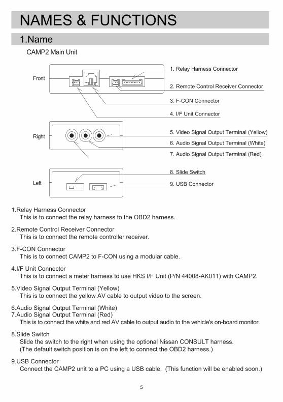
NAMES & FUNCTIONS1.Name
1. Relay Harness Connector
Front 2. Remote Control Receiver Connector
3. F-CON Connector
4. I/F Unit Connector
Right5. Video Signal Output Terminal (Yellow)
6. Audio Signal Output Terminal (White)
7. Audio Signal Output Terminal (Red)
8. Slide Switch
9. USB ConnectorLeft
●CAMP2 Main Unit
1.Relay Harness Connector This is to connect the relay harness to the OBD2 harness.
2.Remote Control Receiver Connector This is to connect the remote controller receiver.
3.F-CON Connector This is to connect CAMP2 to F-CON using a modular cable.
4.I/F Unit Connector This is to connect a meter harness to use HKS I/F Unit (P/N 44008-AK011) with CAMP2.
5.Video Signal Output Terminal (Yellow) This is to connect the yellow AV cable to output video to the screen.
6.Audio Signal Output Terminal (White)7.Audio Signal Output Terminal (Red) This is to connect the white and red AV cable to output audio to the vehicle's on-board monitor.
8.Slide Switch Slide the switch to the right when using the optional Nissan CONSULT harness. (The default switch position is on the left to connect the OBD2 harness.)
9.USB Connector Connect the CAMP2 unit to a PC using a USB cable. (This function will be enabled soon.)
-6-
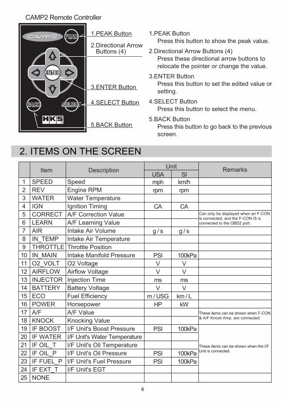
●CAMP2 Remote Controller
1.PEAK Button
2.Directional Arrow Buttons (4)
3.ENTER Button
4.SELECT Button
5.BACK Button
2. ITEMS ON THE SCREEN
Item
SPEEDREVWATERIGNCORRECTLEARNAIRIN_TEMPTHROTTLEIN_MAINO2_VOLTAIRFLOWINJECTORBATTERYECOPOWERA/FKNOCKIF BOOSTIF WATERIF OIL_TIF OIL_PIF FUEL_PIF EXT_TNONE
Description
SpeedEngine RPMWater TemperatureIgnition TimingA/F Correction ValueA/F Learning ValueIntake Air VolumeIntake Air TemperatureThrottle PositionIntake Manifold PressureO2 VoltageAirflow VoltageInjection TimeBattery VoltageFuel EfficiencyHorsepowerA/F ValueKnocking ValueI/F Unit's Boost PressureI/F Unit's Water TemperatureI/F Unit's Oil TemperatureI/F Unit's Oil PressureI/F Unit's Fuel PressureI/F Unit's EGT -
№
12345678910111213141516171819202122232425
UnitSI
km/hrpm℃
CA%
%
g / s℃
%
×100kPaVV
msV
km / LkW-
-
×100kPa℃
℃
×100kPa×100kPa℃
-
USAmphrpm゜F
CA%
%
g / s゜F
%
PSIVV
msV
m / USGHP-
-
PSI゜F
゜F
PSIPSI゜F
-
1.PEAK Button Press this button to show the peak value.
2.Directional Arrow Buttons (4) Press these directional arrow buttons to relocate the pointer or change the value.
3.ENTER Button Press this button to set the edited value or setting.
4.SELECT Button Press this button to select the menu.
5.BACK Button Press this button to go back to the previous screen.
Can only be displayed when an F-CONis connected, and the F-CON iS isconnected to the OBD2 port.
These items can be shown when F-CON& A/F Knock Amp. are connected.
Remarks
These items can be shown when the I/FUnit is connected.
-7-
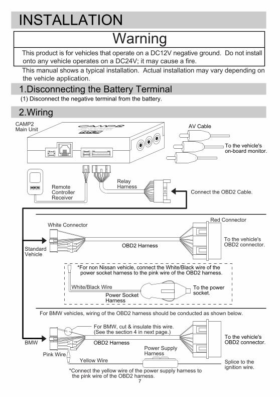
INSTALLATION
(1) Disconnect the negative terminal from the battery.1.Disconnecting the Battery Terminal
2.Wiring
Warning
To the vehicle'son-board monitor.
AV Cable
OBD2 Harness
Power SocketHarness
*For non Nissan vehicle, connect the White/Black wire of the power socket harness to the pink wire of the OBD2 harness.
To the powersocket.
CAMP2Main Unit
White ConnectorRed Connector
White/Black Wire
To the vehicle'sOBD2 connector.
Splice to theignition wire.
Yellow WirePink Wire
Power SupplyHarness
OBD2 HarnessBMW
StandardVehicle
●This manual shows a typical installation. Actual installation may vary depending on the vehicle application.
●This product is for vehicles that operate on a DC12V negative ground. Do not install onto any vehicle operates on a DC24V; it may cause a fire.
Connect the OBD2 Cable.RemoteControllerReceiver
RelayHarness
To the vehicle'sOBD2 connector.
・For BMW vehicles, wiring of the OBD2 harness should be conducted as shown below.
For BMW, cut & insulate this wire.(See the section 4 in next page.)
*Connect the yellow wire of the power supply harness to the pink wire of the OBD2 harness.
-8-
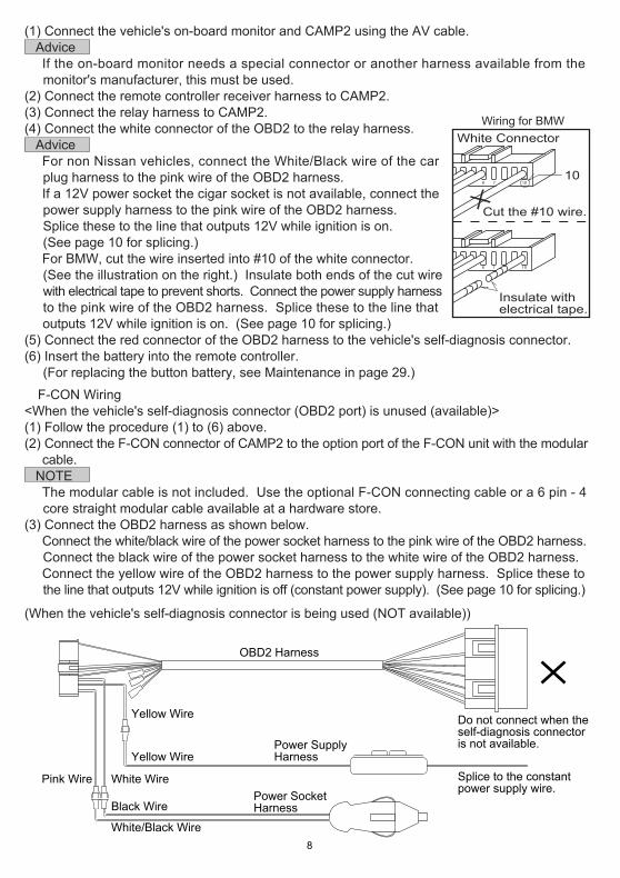
OBD2 Harness
Power SocketHarness
Power SupplyHarness
Splice to the constantpower supply wire.
Do not connect when theself-diagnosis connectoris not available.
Yellow Wire
Yellow Wire
Black Wire
White Wire
White/Black Wire
Pink Wire
Wiring for BMW White Connector
6 7 1010
Cut the #10 wire.
Insulate withelectrical tape.
6 7 10
(1) Connect the vehicle's on-board monitor and CAMP2 using the AV cable. Advice ・If the on-board monitor needs a special connector or another harness available from the monitor's manufacturer, this must be used.(2) Connect the remote controller receiver harness to CAMP2.(3) Connect the relay harness to CAMP2.(4) Connect the white connector of the OBD2 to the relay harness. Advice ・For non Nissan vehicles, connect the White/Black wire of the car plug harness to the pink wire of the OBD2 harness. ・If a 12V power socket the cigar socket is not available, connect the power supply harness to the pink wire of the OBD2 harness. Splice these to the line that outputs 12V while ignition is on. (See page 10 for splicing.) ・For BMW, cut the wire inserted into #10 of the white connector. (See the illustration on the right.) Insulate both ends of the cut wire with electrical tape to prevent shorts. Connect the power supply harness to the pink wire of the OBD2 harness. Splice these to the line that outputs 12V while ignition is on. (See page 10 for splicing.)(5) Connect the red connector of the OBD2 harness to the vehicle's self-diagnosis connector.(6) Insert the battery into the remote controller. (For replacing the button battery, see Maintenance in page 29.)
●F-CON Wiring<When the vehicle's self-diagnosis connector (OBD2 port) is unused (available)>(1) Follow the procedure (1) to (6) above.(2) Connect the F-CON connector of CAMP2 to the option port of the F-CON unit with the modular cable. NOTE ・The modular cable is not included. Use the optional F-CON connecting cable or a 6 pin - 4 core straight modular cable available at a hardware store. (3) Connect the OBD2 harness as shown below. ・Connect the white/black wire of the power socket harness to the pink wire of the OBD2 harness. Connect the black wire of the power socket harness to the white wire of the OBD2 harness. ・Connect the yellow wire of the OBD2 harness to the power supply harness. Splice these to the line that outputs 12V while ignition is off (constant power supply). (See page 10 for splicing.)
(When the vehicle's self-diagnosis connector is being used (NOT available))
-9-
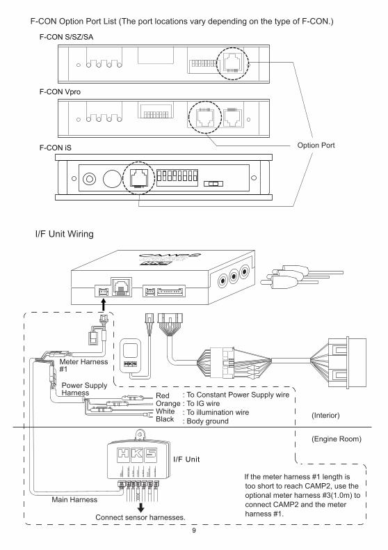
Option Port
・F-CON S/SZ/SA
・F-CON Vpro
・F-CON iS
・F-CON Option Port List (The port locations vary depending on the type of F-CON.)
●I/F Unit Wiring
MA
INH
ARN
ESS
WAT
ER T
EMP
OIL
TEM
P
EXT.
TEM
P
OIL
PRE
SS
BO
OST
& V
AC
UU
M
FUEL
PRE
SS
I/F Unit
Main Harness
Power SupplyHarness
Meter Harness#1
WhiteOrange Red
Black
Connect sensor harnesses.
(Engine Room)
(Interior)
※If the meter harness #1 length is too short to reach CAMP2, use the optional meter harness #3(1.0m) to connect CAMP2 and the meter harness #1.
: To Constant Power Supply wire: To IG wire: To illumination wire: Body ground
-10-
3.Mounting
Strip the cover 5mm.
Twist wires together.
Insulate with plastictape.
Stake the wiresusing a splice.
One Side of Velcro Tape
Another Side of Velcro Tape
To interior To interior
(Mounting CAMP2)
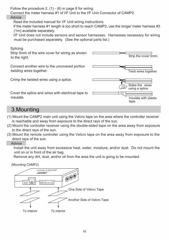
・Follow the procedure 2. (1) - (6) in page 8 for wiring.・Connect the meter harness #1 of I/F Unit to the I/F Unit Connector of CAMP2. Advice ・Read the included manual for I/F Unit wiring instructions. ・If the meter harness #1 length is too short to reach CAMP2, use the longer meter harness #3 (1m) available separately. ・I/F Unit does not include sensors and sensor harnesses. Harnesses necessary for wiring must be purchased separately. (See the optional parts list.)
●Splicing ①Strip 5mm of the wire cover for wiring as shown to the right.
②Connect another wire to the uncovered portion twisting wires together.
③Crimp the twisted wires using a splice.
④Cover the splice and wires with electrical tape to insulate.
(1) Mount the CAMP2 main unit using the Velcro tape on the area where the controller receiver is reachable and away from exposure to the direct rays of the sun.(2) Mount the controller receiver using the double-sided tape on the area away from exposure to the direct rays of the sun.(3) Mount the remote controller using the Velcro tape on the area away from exposure to the direct rays of the sun. Advice ・Install the unit away from excessive heat, water, moisture, and/or dust. Do not mount the unit on or in front of the air bag. ・Remove any dirt, dust, and/or oil from the area the unit is going to be mounted.
-11-
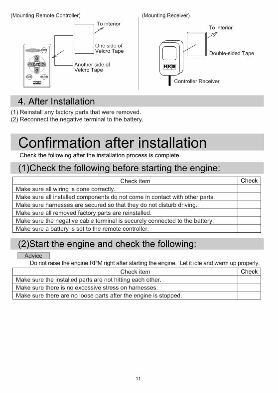
4. After Installation(1) Reinstall any factory parts that were removed.(2) Reconnect the negative terminal to the battery.
Another side ofVelcro Tape
One side ofVelcro Tape
To interior
Double-sided Tape
Controller Receiver
To interior
(Mounting Remote Controller) (Mounting Receiver)
Confirmation after installation
Check
Check
・Check the following after the installation process is complete.
(1)Check the following before starting the engine:
(2)Start the engine and check the following:
Check item Make sure all wiring is done correctly. Make sure all installed components do not come in contact with other parts. Make sure harnesses are secured so that they do not disturb driving. Make sure all removed factory parts are reinstalled. Make sure the negative cable terminal is securely connected to the battery. Make sure a battery is set to the remote controller.
Advice ・Do not raise the engine RPM right after starting the engine. Let it idle and warm up properly.
Check item Make sure the installed parts are not hitting each other. Make sure there is no excessive stress on harnesses. Make sure there are no loose parts after the engine is stopped.
-12-
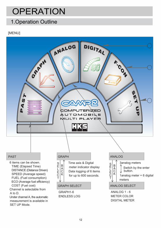
1.Operation Outline
OPERATION
GRAPH
・Time axis & Digital meter indicator display. ・Data logging of 6 items for up to 600 seconds.
GRAPH SELECT
・GRAPH1-6・ENDLESS LOG
SELECT
BACK
ANALOG
・3analog meters Switch by the enter button. ・1analog meter + 6 digital meters
ANALOG SELECT
・ANALOG 1 - 6・METER COLOR・DIGITAL METER
SELECT
BACK
S
D
F
PAST
・6 items can be shown. TIME (Elapsed Time) DISTANCE (Distance Driven) SPEED (Average speed) FUEL (Fuel consumption) ECO (Average fuel efficiency) COST (Fuel cost)・Channel is selectable from A to D.・Under channel A, the automatic measurement is available in SET UP Mode.
[MENU]
-13-
SET UP
(Setting menu1) TYPE
ECO CORRECT SPEED CORRECT POWER CORRECT CAR WEIGHT GAS COST AUTO PAST WARNING ALL REST ▼
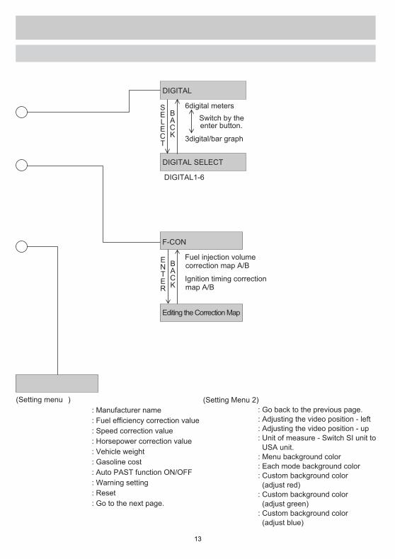
DIGITAL
・6digital meters Switch by the enter button.
・3digital/bar graph
DIGITAL SELECT
・DIGITAL1-6
SELECT
BACK
F-CON
・Fuel injection volume correction map A/B
・Ignition timing correction map A/B
Editing the Correction Map
ENTER
BACK
(Setting Menu 2) ▲
X OFFSET Y OFFSET UNIT
TITLE BACK MENU BACK
EDIT RED
EDIT GREEN
EDIT BLUE
S
D
F
: Manufacturer name: Fuel efficiency correction value: Speed correction value: Horsepower correction value: Vehicle weight: Gasoline cost: Auto PAST function ON/OFF: Warning setting: Reset: Go to the next page.
: Go back to the previous page.: Adjusting the video position - left: Adjusting the video position - up: Unit of measure - Switch SI unit to USA unit.: Menu background color: Each mode background color: Custom background color (adjust red) : Custom background color (adjust green): Custom background color (adjust blue)
-14-
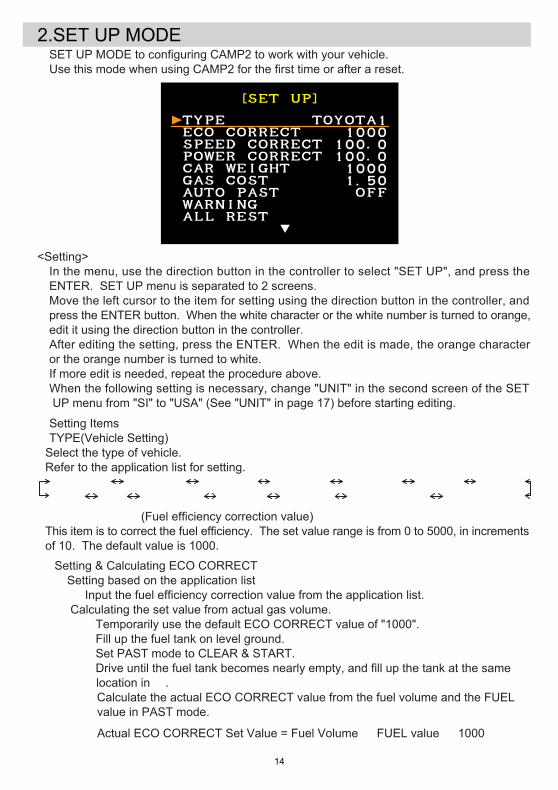
2.SET UP MODE・SET UP MODE to configuring CAMP2 to work with your vehicle. ・Use this mode when using CAMP2 for the first time or after a reset.
<Setting Items>●TYPE(Vehicle Setting) Select the type of vehicle. Refer to the application list for setting. TOYOTA1 TOYOTA2 NISSAN1 NISSAN2 NISSAN3 MAZDA HONDA BMW CAN DAIHATSU SUZUKI SUBARU MITSUBISHI2 MITSUBISHI1
●ECO CORRECT(Fuel efficiency correction value) This item is to correct the fuel efficiency. The set value range is from 0 to 5000, in increments of 10. The default value is 1000.
・ Setting & Calculating ECO CORRECT ・Setting based on the application list Input the fuel efficiency correction value from the application list. ・ Calculating the set value from actual gas volume. ①Temporarily use the default ECO CORRECT value of "1000". ②Fill up the fuel tank on level ground. ③Set PAST mode to CLEAR & START. ④Drive until the fuel tank becomes nearly empty, and fill up the tank at the same location in ②. ⑤Calculate the actual ECO CORRECT value from the fuel volume and the FUEL value in PAST mode.
Actual ECO CORRECT Set Value = Fuel Volume ÷ FUEL value × 1000
<Setting>・In the menu, use the direction button in the controller to select "SET UP", and press the ENTER. SET UP menu is separated to 2 screens.・Move the left cursor to the item for setting using the direction button in the controller, and press the ENTER button. When the white character or the white number is turned to orange, edit it using the direction button in the controller. ・After editing the setting, press the ENTER. When the edit is made, the orange character or the orange number is turned to white.・If more edit is needed, repeat the procedure above.※When the following setting is necessary, change "UNIT" in the second screen of the SET UP menu from "SI" to "USA" (See "UNIT" in page 17) before starting editing.
-15-
●SPEED CORRECT (Speed correction value) This item is to correct the speed value when the vehicle is equipped with tires of different size from factory spec, or when there is a variance between the actual driving distance and the value of DISTANCE in PAST mode. The set value range is from 0.1 to 199.9(%) in increments of 0.1. The default value is 100.0. ・Setting & Calculating SPEED CORRECT Change the default value "100.0" to the value calculated in (a) or (b) below. (a) Calculating the set value for the vehicle equipped with tires of different size from factory spec:
SPEED CORRECT (Speed correction value) = Outer diameter of the upgraded tire / Outer diameter of the factory tire × 100 (Example) Size of the upgraded tire : 235/45-17 Outer diameter of the upgraded tire : (235 x 45 ÷ 100 x 2 + 17 x 25.4) x 3.14 = 2019.962mm Size of the factory tire : 205/55-16 Outer diameter of the factory tire : (205 x 55 ÷ 100 x 2 + 16 x 25.4) x 3.14 = 1984.166mm
SPEED CORRECT (Speed correction value) = 2019.962 ÷ 1984.166 x 100 = 101.804 = 101.8 *Round to the second decimal point.
(b) When there is a variance between the actual driving distance and the value of DISTANCE in PAST mode: Calculate the speed correction value by measuring the actual driving distance as follows: ・Do not measure on a public road. ・Do not burn out or otherwise spin tires without contact with pavement while measuring. ・Measure while the vehicle is driven in a straight line. Measurement needs a certain distance to figure out the actual driving distance.
SPEED CORRECT (Speed correction value) = Actual driving distance ÷ the indicated DISTANCE value × 100 (Example) Actual driving distance : 1.0 mile Indicated DISTANCE value : 1.1 mile
SPEED CORRECT (Speed correction value) = 1.0 ÷ 1.1 x 100 = 90.909 = 90.9 *Round to the second decimal point.
●POWER CORRECT (Horsepower correction value) This item is to correct the value when there is a variance between the actual horsepower on the chassis dynamometer and the values of POWER in each mode. The set value range is from 1.0 to 199.9(%) in increments of 1. The default value is 100.0. ・Setting & Calculating POWER CORRECT(HP correction value) Change the default value "100.0" to the value calculated below.
POWER CORRECT (HP correction value) = Actual HP ÷ Indicated HP x 100 (Example)
Actual HP : 268HP Indicated HP : 276HP
POWER CORRECT (HP correction value) = 268 ÷ 276 x 100 = 97.101 = 97 *Round to the first digit.
(Example) Fuel volume : 12.0 USG FUEL value : 8.2USG ECO CORRECT Set Value = 12.0 ÷ 8.2 x 1000 = 1463.4 = 1460 *Round to the first digit. ⑥ Change ECO CORRECT value from "1000" to "1460
-16-
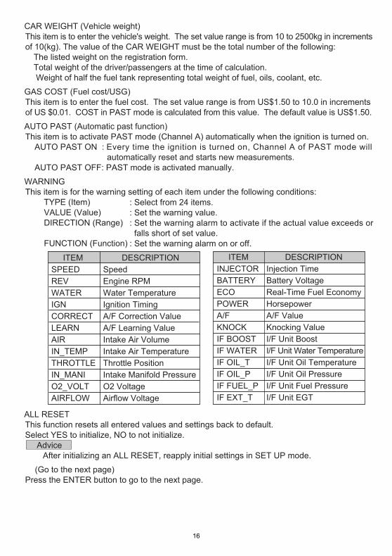
ITEMINJECTORBATTERYECOPOWERA/FKNOCKIF BOOSTIF WATERIF OIL_TIF OIL_PIF FUEL_PIF EXT_T
DESCRIPTIONInjection TimeBattery VoltageReal-Time Fuel EconomyHorsepowerA/F ValueKnocking ValueI/F Unit BoostI/F Unit Water TemperatureI/F Unit Oil TemperatureI/F Unit Oil PressureI/F Unit Fuel PressureI/F Unit EGT
ITEMSPEEDREVWATERIGNCORRECTLEARNAIRIN_TEMPTHROTTLEIN_MANIO2_VOLTAIRFLOW
DESCRIPTIONSpeedEngine RPMWater TemperatureIgnition TimingA/F Correction ValueA/F Learning ValueIntake Air VolumeIntake Air TemperatureThrottle PositionIntake Manifold PressureO2 VoltageAirflow Voltage
●CAR WEIGHT (Vehicle weight) This item is to enter the vehicle's weight. The set value range is from 10 to 2500kg in increments of 10(kg). The value of the CAR WEIGHT must be the total number of the following: ①The listed weight on the registration form. ②Total weight of the driver/passengers at the time of calculation. ③ Weight of half the fuel tank representing total weight of fuel, oils, coolant, etc.
●GAS COST (Fuel cost/USG) This item is to enter the fuel cost. The set value range is from US$1.50 to 10.0 in increments of US $0.01. COST in PAST mode is calculated from this value. The default value is US$1.50.
●AUTO PAST (Automatic past function) This item is to activate PAST mode (Channel A) automatically when the ignition is turned on. AUTO PAST ON : Every time the ignition is turned on, Channel A of PAST mode will automatically reset and starts new measurements. AUTO PAST OFF: PAST mode is activated manually.
●WARNING This item is for the warning setting of each item under the following conditions: TYPE (Item) VALUE (Value) DIRECTION (Range) FUNCTION (Function)
: Select from 24 items.: Set the warning value.: Set the warning alarm to activate if the actual value exceeds or falls short of set value.: Set the warning alarm on or off.
●ALL RESET This function resets all entered values and settings back to default. Select YES to initialize, NO to not initialize. Advice ・After initializing an ALL RESET, reapply initial settings in SET UP mode.
● ▼(Go to the next page) Press the ENTER button to go to the next page.
-17-
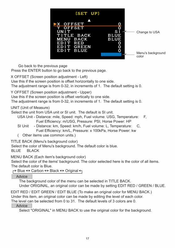
Menu's backgroundcolor
Change to USA
●▲(Go back to the previous page) Press the ENTER button to go back to the previous page.
●X OFFSET (Screen position adjustment - Left) Use this if the screen position is offset horizontally to one side. The adjustment range is from 0-32, in increments of 1. The default setting is 0.
●Y OFFSET (Screen position adjustment - Upper) Use this if the screen position is offset vertically to one side. The adjustment range is from 0-32, in increments of 1. The default setting is 0.
●UNIT (Unit of Measure) Select the unit from USA unit or SI unit. The default is SI unit. USA Unit - Distance: mile, Speed: mph, Fuel volume: USG, Temperature: °F, Fuel Efficiency: m/USG, Pressure: PSI, Horse Power: HP SI Unit - Distance: km, Speed: km/h, Fuel volume: L, Temperature: °C, Fuel Efficiency: km/L, Pressure: x 100kPa, Horse Power: kw (※Other items use common units.)
●TITLE BACK (Menu's background color) Select the color of Menu's background. The default color is blue. BLUE ⇔ BLACK
●MENU BACK (Each item's background color) Select the color of the items' background. The color selected here is the color of all items. The default color is Blue. Blue Carbon Black Original Advice ・The background color of the menu can be selected in TITLE BACK. ・Under ORIGINAL, an original color can be made by setting EDIT RED / GREEN / BLUE.
●EDIT RED / EDIT GREEN / EDIT BLUE (To make an original color for MENU BACK.) Under this item, an original color can be made by editing the level of each color. The level can be selected from 0 to 31. The default levels of 3 colors are 0. Advice ・Select "ORIGINAL" in MENU BACK to use the original color for the background.
-18-
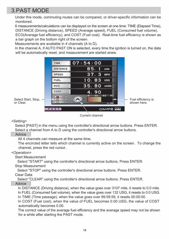
3.PAST MODE・Under this mode, commuting routes can be compared, or driver-specific information can be monitored.・6 measurements/calculations can be displayed on the screen at one time: TIME (Elapsed Time), DISTANCE (Driving distance), SPEED (Average speed), FUEL (Consumed fuel volume), ECO(Average fuel efficiency), and COST (Fuel cost). Real-time fuel efficiency is shown as a bar graph on the bottom right of the screen.・Measurements are available in 4 channels (A to D).・In the channel A, if AUTO PAST ON is selected, every time the ignition is turned on, the data will be automatically reset, and measurement are started anew.
Current channel
Select Start, Stop,or Clear.
Fuel efficiency isshown here.
<Setting>・Select [PAST] in the menu using the controller's directional arrow buttons. Press ENTER.・Select a channel from A to D using the controller's directional arrow buttons. Advice ・All 4 channels can measure at the same time. ・The encircled letter tells which channel is currently active on the screen. To change the channel, press the red cursor.<Operation>・Start Measurement Select "START" using the controller's directional arrow buttons. Press ENTER.・Stop Measurement Select "STOP" using the controller's directional arrow buttons. Press ENTER.・Clear Data Select "CLEAR" using the controller's directional arrow buttons. Press ENTER. Advice ・In DISTANCE (Driving distance), when the value goes over 3107 mile, it resets to 0.0 mile. ・In FUEL (Consumed fuel volume), when the value goes over 132 USG, it resets to 0.0 USG. ・In TIME (Time passage), when the value goes over 99:59:59, it resets 00:00:00. ・In COST (Fuel cost), when the value of FUEL becomes 0.00 USG, the value of COST automatically becomes 0.00. ・The correct value of the average fuel efficiency and the average speed may not be shown for a while after starting the PAST mode.
-19-
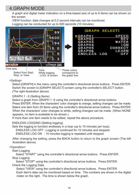
4.GRAPH MODE
TimeWhile logging, -LOG- is shown.
Select from Start,Stop, or View.
These colorscorrespond tothe graph line.
Time axis
・A graph and digital meter indication on a time-based axis of up to 6 items can be shown on the screen. ・VIEW function: data changes at 0.2 second intervals can be monitored. ・Logging can be conducted for up to 600 seconds (10 minutes).
<Setting>・Select [GRAPH] in the menu using the controller's directional arrow buttons. Press ENTER.・Switch the screen to [GRAPH SELECT] screen using the controller's SELECT button. (The right illustration above)
●GRAPH 1 - 6 (Setting Items)・Select a graph from GRAPH 1 -6 using the controller's directional arrow buttons. Press ENTER. When the characters' color changes to orange, setting changes can be made.・Select one item from 25 items using the controller's directional arrow buttons. Press ENTER. When the characters' color changes to white, setting changes can be made. (When NONE appears, no item is available to be shown.)・If more than one item needs to be edited, repeat the above procedure.
●ENDLESS LOGGING (Setting logging)・Sets the logging to function endlessly in a loop (up to 10 minutes per loop). ENDLESS LOG OFF ENDLESS LOG ON
After changing the setting, press the BACK button to return to the graph screen (The left illustration above).<Operation>・Start Logging Select "START" using the controller's directional arrow buttons. Press ENTER.・Stop Logging Select "STOP" using the controller's directional arrow buttons. Press ENTER.・Check the Logging Data ・Select "VIEW" using the controller's directional arrow buttons. Press ENTER. ・Each item's data can be monitored based on time. The numbers are shown in the digital meter on the right. The time is shown below the graph.
: Logging is continued for 10 minutes and stopped.: 10 minutes logging is repeated until stopped.
-20-
<Display Contents>●LOGGING・Up to 6 logged items can be displayed in a graph and digital meter indicator. ●PEAK・PEAK Indication When the PEAK button is pressed on the remote controller, the color of the digital meter will change from white to green; then the peak value appears.・Reset PEAK Value To reset the peak value, press the ENTER button of the controller.・Exit PEAK Value indication To exit the PEAK value indication, press the BACK button of the controller.
●WARNING・When the warning function is activated, the color of the value is changed from white to red, and the buzzer sounds.・For setting of this function, see the warning setting under the SET UP mode. Advice ・WARNING functions only for the item on the screen. To see other items' warning setting, first select the desired item to be shown on the screen. ・If selecting the same item, the same data is shown on each screen. ・When the ignition is turned off, the logging data will be automatically deleted.
・The time axis can be set using the controller's directional arrow buttons as follows: Up Down Right Right (Press and hold) Left Left (Press and hold)
: Move every -20 sec.: Move every +0.2 sec.: Move every -0.2 sec.
: Move every +20 sec.: Move every +2 sec.: Move every -2 sec.
-21-
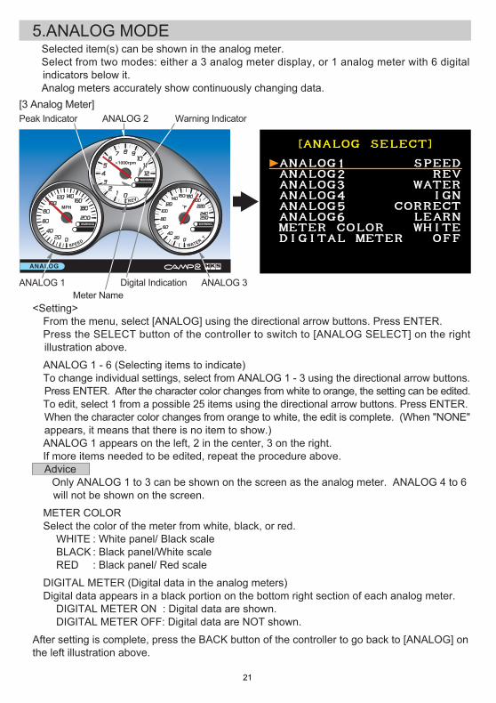
5.ANALOG MODE ・Selected item(s) can be shown in the analog meter. ・Select from two modes: either a 3 analog meter display, or 1 analog meter with 6 digital indicators below it. ・Analog meters accurately show continuously changing data.[3 Analog Meter]
ANALOG 3
Peak Indicator ANALOG 2 Warning Indicator
ANALOG 1Meter Name
Digital Indication
<Setting>・From the menu, select [ANALOG] using the directional arrow buttons. Press ENTER.・Press the SELECT button of the controller to switch to [ANALOG SELECT] on the right illustration above.
●ANALOG 1 - 6 (Selecting items to indicate)・To change individual settings, select from ANALOG 1 - 3 using the directional arrow buttons. Press ENTER. After the character color changes from white to orange, the setting can be edited.・To edit, select 1 from a possible 25 items using the directional arrow buttons. Press ENTER. When the character color changes from orange to white, the edit is complete. (When "NONE" appears, it means that there is no item to show.) ・ANALOG 1 appears on the left, 2 in the center, 3 on the right.・If more items needed to be edited, repeat the procedure above. Advice ・Only ANALOG 1 to 3 can be shown on the screen as the analog meter. ANALOG 4 to 6 will not be shown on the screen.
●METER COLOR・Select the color of the meter from white, black, or red. WHITE BLACK RED
●DIGITAL METER (Digital data in the analog meters)・Digital data appears in a black portion on the bottom right section of each analog meter. DIGITAL METER ON : Digital data are shown. DIGITAL METER OFF: Digital data are NOT shown.
After setting is complete, press the BACK button of the controller to go back to [ANALOG] onthe left illustration above.
: White panel/ Black scale: Black panel/White scale: Black panel/ Red scale
-22-
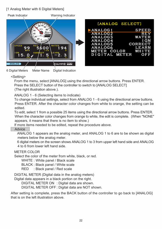
[1 Analog Meter with 6 Digital Meters]
Digital Indication
Peak Indicator Warning Indicator
6 Digital Meters Meter Name
<Setting>・From the menu, select [ANALOG] using the directional arrow buttons. Press ENTER.・Press the SELECT button of the controller to switch to [ANALOG SELECT] (The right illustration above.).
●ANALOG 1 - 6 (Selecting items to indicate)・To change individual settings, select from ANALOG 1 - 6 using the directional arrow buttons. Press ENTER. After the character color changes from white to orange, the setting can be edited.・To edit, select 1 from a possible 25 items using the directional arrow buttons. Press ENTER. When the character color changes from orange to white, the edit is complete. (When "NONE" appears, it means that there is no item to show.)・If more items needed to be edited, repeat the procedure above. Advice ・ANALOG 1 appears as the analog meter, and ANALOG 1 to 6 are to be shown as digital meters below the analog meter. ・6 digital meters on the screen shows ANALOG 1 to 3 from upper left hand side and ANALOG 4 to 6 from lower left hand side.
●METER COLOR・Select the color of the meter from white, black, or red. WHITE BLACK RED
●DIGITAL METER (Digital data in the analog meters)・Digital data appears in a black portion on the right. DIGITAL METER ON DIGITAL METER OFF
After setting is complete, press the BACK button of the controller to go back to [ANALOG] that is on the left illustration above.
: White panel / Black scale: Black panel / White scale: Black panel / Red scale
: Digital data are shown.: Digital data are NOT shown.
-23-
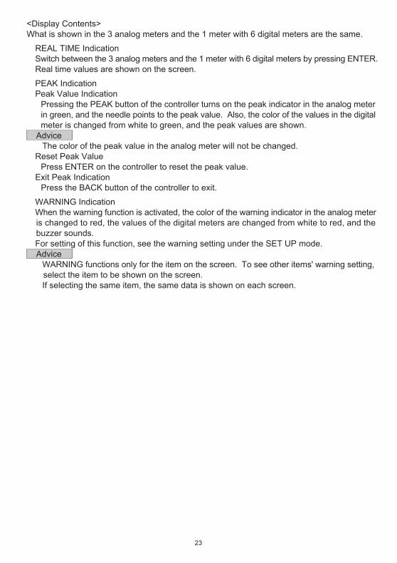
<Display Contents>What is shown in the 3 analog meters and the 1 meter with 6 digital meters are the same.
●REAL TIME Indication・Switch between the 3 analog meters and the 1 meter with 6 digital meters by pressing ENTER.・Real time values are shown on the screen.
●PEAK Indication・Peak Value Indication Pressing the PEAK button of the controller turns on the peak indicator in the analog meter in green, and the needle points to the peak value. Also, the color of the values in the digital meter is changed from white to green, and the peak values are shown. Advice ・The color of the peak value in the analog meter will not be changed.・Reset Peak Value Press ENTER on the controller to reset the peak value.・Exit Peak Indication Press the BACK button of the controller to exit.
●WARNING Indication・When the warning function is activated, the color of the warning indicator in the analog meter is changed to red, the values of the digital meters are changed from white to red, and the buzzer sounds.・For setting of this function, see the warning setting under the SET UP mode. Advice ・WARNING functions only for the item on the screen. To see other items' warning setting, select the item to be shown on the screen. ・If selecting the same item, the same data is shown on each screen.
-24-
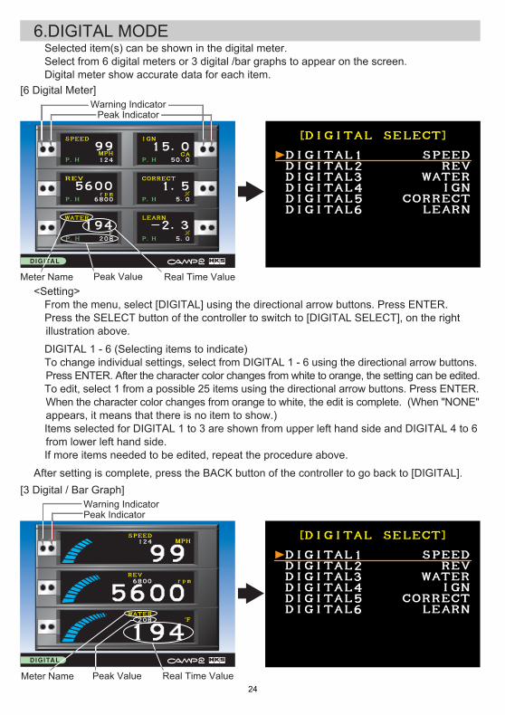
6.DIGITAL MODE
[6 Digital Meter]Warning Indicator
Real Time ValuePeak ValueMeter Name
Peak IndicatorWarning Indicator
[3 Digital / Bar Graph]
Real Time ValuePeak ValueMeter Name
・Selected item(s) can be shown in the digital meter.・Select from 6 digital meters or 3 digital /bar graphs to appear on the screen.・Digital meter show accurate data for each item.
Peak Indicator
<Setting>・From the menu, select [DIGITAL] using the directional arrow buttons. Press ENTER.・Press the SELECT button of the controller to switch to [DIGITAL SELECT], on the right illustration above.
●DIGITAL 1 - 6 (Selecting items to indicate)・To change individual settings, select from DIGITAL 1 - 6 using the directional arrow buttons. Press ENTER. After the character color changes from white to orange, the setting can be edited.・To edit, select 1 from a possible 25 items using the directional arrow buttons. Press ENTER. When the character color changes from orange to white, the edit is complete. (When "NONE" appears, it means that there is no item to show.) ・Items selected for DIGITAL 1 to 3 are shown from upper left hand side and DIGITAL 4 to 6 from lower left hand side.・If more items needed to be edited, repeat the procedure above.
After setting is complete, press the BACK button of the controller to go back to [DIGITAL].
-25-
<Setting>・From the menu, select [DIGITAL] using the direction button of the controller. Press the ENTER.・Press the SELECT button of the controller to switch to [DIGITAL SELECT].
●DIGITAL 1 - 3 (Selecting items to indicate)・To change individual settings, select from DIGITAL 1 - 3 using the directional arrow buttons. Press ENTER. After the character color changes from white to orange, the setting can be edited.・To edit, select 1 from a possible 25 items using the directional arrow buttons. Press ENTER. When the character color changes from orange to white, the edit is complete. (When "NONE" appears, it means that there is no item to show.)・If more items needed to be edited, repeat the procedure above. Advice ・Only DIGITAL 1 - 3 from DIGITAL 1 - 6 are shown in the 3 digital / bar graph. DIGITAL 4-6 are not shown.
After setting is complete, press the BACK button of the controller to go back to [DIGITAL].
<Indicated Contents>The same data is shown regardless of whether 6 digital meters or the 3 digital/bar graphs are used.
●REAL TIME Indication・Switch between the 6 digital meters and the 3 digital/bar graphs by pressing ENTER.・The bar graph consists of 20 bars.・Real time values and Peak values are shown on the screen.
●PEAK Indication・Peak Value Indication Pressing the Peak button of the controller turns on the peak indicator in the digital meter, in green. Also, the color of the values in the digital meter changes from white to green, and the peak values are shown.・Reset Peak Value Press the ENTER of the controller to reset the peak value.・Exit Peak Indication Press the BACK button of the controller to exit. Advice ・The values on the 3 digital/bar graph are always Real Time values. ・The range of the 3 digital/bar graph is the same as the range of the values for the WARNING setting in the SET UP mode. E.g.: The bar graph for SPEED is shown in the range of 0-186 MPH by 20 bars.
●WARNING Indicator・When the warning function is activated, the color of the warning indicator changes to red; the values of the digital meters changes from white to red, and the warning buzzer sounds.・For setting of this function, see the warning setting under the SET UP mode. Advice ・WARNING functions only for the item on the screen. To see other items' warning setting, select the desired item to be shown on the screen. ・If selecting the same item, the same data is shown on each screen.
-26-
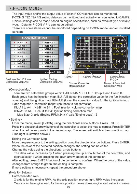
7.F-CON MODE
Name of SelectedCorrection Map
Cursor PositionCursor 6 items fromF-CON
Current CorrectionMap's position
Fuel Injection VolumeCorrection Map A/B
Ignition TimingCorrection Map A/B
・The input value and/or the output value of each F-CON sensor can be monitored.・F-CON S / SZ / SA / iS setting data can be monitored and edited when connected to CAMP2. Unique settings can be made based on engine specification, such as exhaust type or intake type. (Data for F-CON V Pro cannot be edited.)※There are some items cannot be monitored depending on F-CON model and/or installed sensors.
(Correction Map)・There are two selectable groups within F-CON MAP SELECT: Group A and Group B.・Each group has the injection map, INJ- A/B (to set the correction value for the fuel injection volume) and the ignition map, IGN-A/B (to set the correction value for the ignition timing). Each map has 4 correction maps; use these to set correction. INJ-A1 to A4・INJ-B1 to B4 IGN-A1 to A4・IGN-B1 to B4 Map Size: X-axis (Engine RPM) 24 x Y-axis (Engine Load) 16
<Setting>・From the menu, select [F-CON] using the directional arrow buttons. Press ENTER.・Press the directional arrow buttons of the controller to select the map to correct. Press ENTER when the red cursor points to the desired map. The screen will switch to the correction map. (The right illustration above.)
●Editing the Correction Map・Move the green cursor to the setting position using the directional arrow buttons. Press ENTER.・When the color of the selected position changes, the setting can be edited.・Change the value using the directional arrow buttons. The data value increases by 1 when pressing the up arrow button of the controller, and decreases by 1 when pressing the down arrow button of the controller.・After editing, press ENTER button of the controller to confirm. When the color of the value changes from orange to green, the editing is complete.・If more editing is necessary, repeat the procedure above.
(Note for Setting)・Correction Map Axis X-axis is for the engine RPM. As the axis position moves right, RPM value increases. Y-axis is for the engine load. As the axis position moves down, engine load value increases.
: Fuel injection volume correction map: Ignition timing correction map
-27-
・Color of the Cursor Blue: The position F-CON is currently reading. Green: Current position of the cursor Orange: Under editing・Cursor Position The X value shown in lower left of the correction map is the engine RPM value on the axis indicated by the green cursor. The Y value shown in lower left of the correction map is the engine load value on the axis. X=The engine RPM axis value, Y=The engine load axis value When the load axis is set to airflow, the airflow value is shown. When the load axis is set to boost, the boost value is shown. When the load axis is set to throttle, the throttle position is shown.・Correction Map on the Screen The maximum size of the map that can be shown on the screen is 8(X-axis) x 16(Y-axis). To view other hidden correction maps, press the directional arrow buttons. The position of the correction map on the screen is shown in the bar graph below the correction map. The 6 digital meter items on the right are monitoring values from the F-CON sensors' current input values. These items cannot be edited since they are taken from the output signal from F-CON. Advice ・Turn off the ignition when connecting the F-CON, otherwise the CAMP2 unit may become damaged. ・Editable correction maps may vary depending on the dip switch settings on the F-CON and/or the HKS POWER WRITER settings. ・Editable correction maps are affected by the dip switch settings on the F-CON S / SZ / SA / iS. Make sure corrections are enabled on all desired correction maps. ・Refer to the F-CON manual regarding the relationship between the dip switch position and the correction map. ・INJ-A/B (Fuel injection volume correction map) Data unit of measure is a percentage (%). The injector duration rate is increased or decreased depending on the correction set value. ・IGN-A/B (Ignition timing correction map) Data unit of measure is degrees (°). The ignition timing is advanced or retarded depending on the correction set value. ※「°」is the crank's angle (BTDC). Set to + for advancing and - for retarding.
-28-
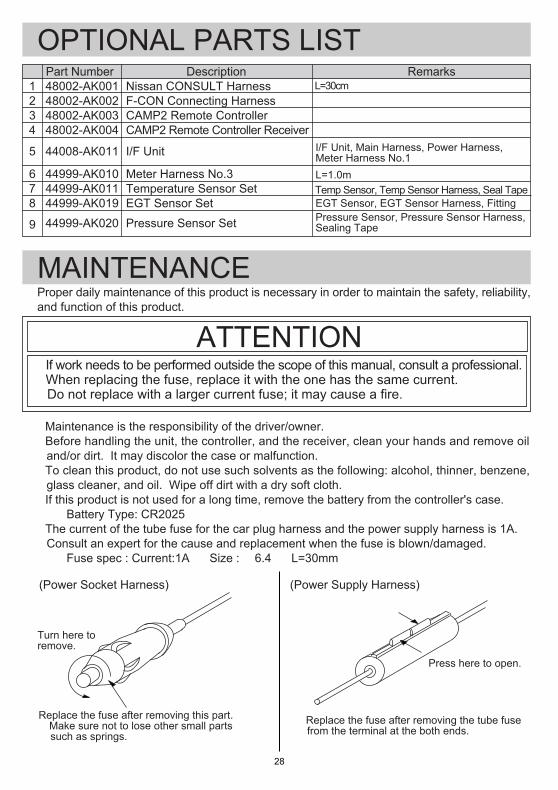
№ Part NumberNissan CONSULT HarnessF-CON Connecting HarnessCAMP2 Remote ControllerCAMP2 Remote Controller Receiver
I/F Unit
Meter Harness No.3Temperature Sensor SetEGT Sensor Set
Pressure Sensor Set
Remarks
・If work needs to be performed outside the scope of this manual, consult a professional.・When replacing the fuse, replace it with the one has the same current. Do not replace with a larger current fuse; it may cause a fire.
Description
(Power Socket Harness) (Power Supply Harness)
Turn here toremove.
Press here to open.
※Replace the fuse after removing the tube fuse from the terminal at the both ends.
OPTIONAL PARTS LIST
MAINTENANCE
48002-AK00148002-AK00248002-AK00348002-AK004
44008-AK011
44999-AK01044999-AK01144999-AK019
44999-AK020
1234
5
678
9
L=1.0m Temp Sensor, Temp Sensor Harness, Seal Tape
Pressure Sensor, Pressure Sensor Harness, Sealing Tape
EGT Sensor, EGT Sensor Harness, Fitting
I/F Unit, Main Harness, Power Harness, Meter Harness No.1
L=30cm
Proper daily maintenance of this product is necessary in order to maintain the safety, reliability,and function of this product.
ATTENTION
・Maintenance is the responsibility of the driver/owner. ・Before handling the unit, the controller, and the receiver, clean your hands and remove oil and/or dirt. It may discolor the case or malfunction.・To clean this product, do not use such solvents as the following: alcohol, thinner, benzene, glass cleaner, and oil. Wipe off dirt with a dry soft cloth.・If this product is not used for a long time, remove the battery from the controller's case. Battery Type: CR2025・The current of the tube fuse for the car plug harness and the power supply harness is 1A. Consult an expert for the cause and replacement when the fuse is blown/damaged. Fuse spec : Current:1A Size : φ6.4 L=30mm
Replace the fuse after removing this part.※Make sure not to lose other small parts such as springs.
-29-
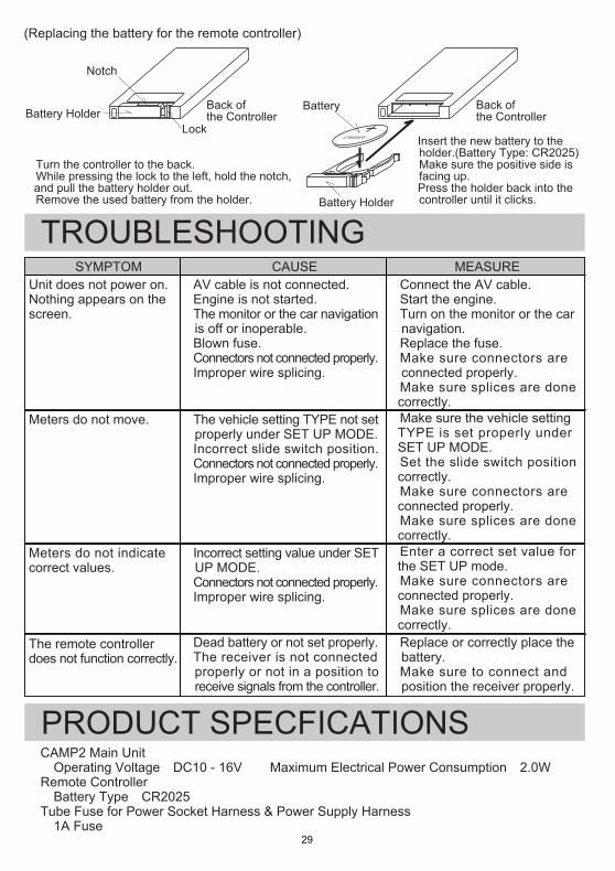
SYMPTOM CAUSE MEASUREUnit does not power on.Nothing appears on thescreen.
Meters do not move.
Meters do not indicatecorrect values.
The remote controllerdoes not function correctly.
TROUBLESHOOTING
(Replacing the battery for the remote controller)
CR2025Lock
Notch
Battery HolderBack ofthe Controller
Back ofthe Controller
Battery Holder
① ②
Battery
・Turn the controller to the back.・While pressing the lock to the left, hold the notch, and pull the battery holder out.・Remove the used battery from the holder.
・Insert the new battery to the holder.(Battery Type: CR2025) Make sure the positive side is facing up.・Press the holder back into the controller until it clicks.
・AV cable is not connected.・Engine is not started.・The monitor or the car navigation is off or inoperable. ・Blown fuse. ・Connectors not connected properly. ・Improper wire splicing.
・The vehicle setting TYPE not set properly under SET UP MODE. ・Incorrect slide switch position.・Connectors not connected properly. ・Improper wire splicing.
・Incorrect setting value under SET UP MODE. ・Connectors not connected properly. ・Improper wire splicing.
・Dead battery or not set properly.・The receiver is not connected properly or not in a position to receive signals from the controller.
・Connect the AV cable.・Start the engine.・Turn on the monitor or the car navigation.・Replace the fuse.・Make sure connectors are connected properly.・Make sure splices are done correctly.・Make sure the vehicle setting TYPE is set properly under SET UP MODE.・Set the slide switch position correctly.・Make sure connectors are connected properly.・Make sure splices are done correctly.・Enter a correct set value for the SET UP mode.・Make sure connectors are connected properly.・Make sure splices are done correctly.・Replace or correctly place the battery.・Make sure to connect and position the receiver properly.
PRODUCT SPECFICATIONSCAMP2 Main Unit・Operating Voltage…DC10 - 16V ・Maximum Electrical Power Consumption…2.0WRemote Controller・Battery Type…CR2025Tube Fuse for Power Socket Harness & Power Supply Harness・1A Fuse

Pursuing the Ultimate in Engine Performance and Efficiency.H.K.S Company Limited.