Embed Size (px)
Citation preview
Journal of Theoretical and Applied Information Technology
© 2005 - 2010 JATIT. All rights reserved.
www.jatit.org
11
CAPACITY AND V-BLAST TECHNIQUES FOR MIMO WIRELESS CHANNEL
1 NIRMALENDU BIKAS SINHA, 2R. BERA, 3 M. MITRA.
1Assistant Prof., Department of Electronics and Communication Engineering and Electronics and
Instrumentation Engineering, C.E.M.K, K.T.P.P.Township, W.B, India-721171. 2 Prof., Department of E.C.E, SMIT, Sikkim,Majitar India - 737132. 3Assistant Prof., Department of E.T.E,BESU, Howrah, W.B, India.
ABSTRACT
In wireless communications, spectrum is a scarce resource and hence imposes a high cost on the high data rate transmission. Fortunately, the emergence of multiple antenna system has opened another very resourceful dimension – space, for information transmission in the air. It has been demonstrated that multiple antenna system provides very promising gain in capacity without increasing the use of spectrum, reliability, throughput, power consumption and less sensitivity to fading, hence leading to a breakthrough in the data rate of wireless communication systems. Since then, multiple-input multiple-output (MIMO) system has become one of the major focuses in the research community of wireless communications and information theory. The study of the performance limits of MIMO system becomes very important since it gives a lot of insights in understanding and designing the practical MIMO systems. There are many schemes that can be applied to MIMO systems such as space time block codes, space time trellis codes, and the Vertical Bell Labs Space-Time Architecture (V-BLAST). In this paper, we study the performance of general MIMO system, the general V-BLAST architecture with Maximum Likelihood (ML), the Successive Interference Cancellation (SIC), Zero-Forcing (ZF), Minimum Mean- Square Error (MMSE) and Maximal Ratio Combining (MRC) detectors in fading channels. Based on bit error rate, we show the performance of these receiver schemes indicates that the ordered SIC detector with Maximum-Likelihood (ML) detection most effectively balances the accuracy of symbol detection. SIC receiver based on ZF or MMSE combined with symbol cancellation and optimal ordering to improve the performance with lower complexity and compare the computational complexity of these schemes with other existence model. Finally, the paper addresses the current questions regarding the integration of MIMO system in practical wireless systems and standards.
Keywords: MIMO, CCI, ITS, SIC, V-BLAST, ML, STBC, MRC, ZF.
1. INTRODUCTION During the past decades, wireless communication has benefitted from substantial advances and it is considered as the key enabling technique of innovative future consumer products. For the sake of satisfying the requirements of various applications, significant technological achievements are required to ensure that wireless devices have appropriate architectures suitable for supporting a wide range of services delivered to the users. In the foreseeable future, the large-scale
deployment of wireless devices and the requirements of high bandwidth and high data rate applications are expected to lead to tremendous new challenges in terms of the efficient exploitation of the achievable spectral resources and constitute a substantial research challenge in the context of the emerging WLANs and other indoor multimedia networks.Due to the physical limits imposed by the mobile radio channel which cause performance degradation and make it very difficult to achieve
Journal of Theoretical and Applied Information Technology
© 2005 - 2010 JATIT. All rights reserved.
www.jatit.org
12
high bit rates at low error rates over the time dispersive wireless channels. Other detrimental characteristics are co-channel interference (CCI), Doppler effect, intentional jamming in military communications and Intersymbol interference (ISI) induced by multipath fading; however, there is an irreducible error floor that imposes a limit on the maximum attainable transmission rate. Specifically, the employment of multiple antennas at both the transmitter and the receiver, which is widely referred to as the MIMO technique, constitutes a cost-effective approach to high-throughput wireless communications and remote sensing.The concept MIMO for both wired and wireless systems was first introduced by Jack Winters [1]-[3] in 1987 for two basic communication systems. The first was for communication between multiple mobiles and a base station with multiple antennas and the second for communication between two mobiles each with multiple antennas. Where, he introduced a technique of transmitting data from multiple users over the same frequency/time channel using multiple antennas at both the transmitter and receiver ends. Sparked off by winters’ pioneering work [1], Salz [4] investigated joint transmitter/receiver optimization using the minimum mean square error (MMSE) criterion. Since then, winters and others [5]–[8] have made further significant advances in the field of MIMOs. In 1996, Raleigh and Cioffi [9] and Foschini [2] [10] proposed new approaches for improving the efficiency of MIMO systems, which inspired numerous further contributions [11]–[13] for two suitable architectures for its realisation known as Vertical Bell-Labs Layered Space-Time(V-BLAST), and Diagonal Bell-Labs Layered Space-Time BLAST (D-BLAST) algorithm has been proposed by Foschini, which is capable of achieving a substantial part of the MIMO capacity. It is capable of achieving high spectral efficiency while being relatively simple to implement. This structure offers highly better error performance than other existence detection method and still has low complexity.The basic motive was to increase the data rate in a constrained spectrum. The promises of information theoretic MIMO analysis for the channel capacity were the main trigger for this enthusiasm and also ignited the study of related areas such as MIMO channel modelling, Space-
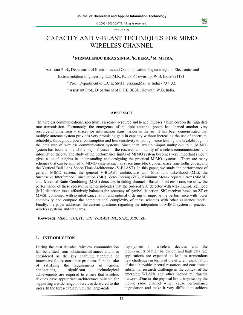
Time signal processing, Space-Time coding, etc. The objective of such multi-channel diagonalization is to partition or distribute multi-user signals into disjoint space and resultant channel gains are maximized to optimize the overall system capacity under the constraint of a fixed transmit power . Also improve the quality (BER) or potential of achieving extraordinary data rates [2,7,19-25] by transferring the signals in time domain and space domain separately, without consuming more frequency resources , frequency diversity due to delay spread, higher spectral efficiency and without increasing the total transmission power or bandwidth[2][10][14]-[18] of the communication system by means of the deployment of multiple spatial ports, improved link reliability, beam forming, and adequate signal processing techniques at both ends of the system by using interference cancellation techniques for the communication as well as remote sensing. 2. MIMO CHANNEL MODELS MIMO systems are an extension of smart antennas systems. Traditional smart antenna systems employ multiple antennas at the receiver, whereas in a general MIMO system multiple antennas are employed both at the transmitter and the receiver. The addition of multiple antennas at the transmitter combined with advanced signal processing algorithms at the transmitter and the receiver yields significant advantage over traditional smart antenna systems - both in terms of capacity and diversity advantage. A MIMO channel is a wireless link between M transmits and N receive antennas. It consists of MN elements that represent the MIMO channel coefficients. The multiple transmit and receive antennas could belong to a single user modem or it could be distributed among different users. The later configuration is called distributed MIMO and cooperative communications. Statistical MIMO channel models offer flexibility in selecting the channel parameters, temporal and spatial correlations. Fig.1 (a), (b), (c) and (d) shows conceptual diagram of existing technology, smart antenna system and MIMO channels respectively.
Journal of Theoretical and Applied Information Technology
© 2005 - 2010 JATIT. All rights reserved.
www.jatit.org
13
(a) (b) (c)
Figure 1 (a) Existing technology, (b) & (c) Smart antenna system
Figure 1(d) A MIMO wireless channel
3. MIMO SYSTEM CHANNEL CAPACITY Multipath propagation has long been regarded as “impairment” because it causes signal fading. To mitigate this problem, diversity techniques were developed. Antenna diversity is a widespread form of diversity. Information theory has shown that with multipath propagation, multiple antennas at both transmitter and receiver can establish essentially multiple parallel channels that operate simultaneously, on the same frequency band at the same total radiated power. Antenna correlation varies drastically as a function of the scattering environment, the distance between transmitter and
receiver, the antenna configurations, and the Doppler spread. Recent research has shown that multipath propagation can in fact “contribute” to capacity. Channel capacity is the maximum information rate that can be transmitted and received with arbitrarily low probability of error at the receiver. A common representation of the channel capacity is within a unit bandwidth of the channel and can be expressed in bps/Hz. This representation is also known as spectral (bandwidth) efficiency. MIMO channel capacity depends heavily on the statistical properties and antenna element correlations of the channel. Representing the input and output of a
SISO SIMO
NR
MISO
MT
M
Scatterer
TX
1
2
N
RX
1
2
Y HX n
Journal of Theoretical and Applied Information Technology
© 2005 - 2010 JATIT. All rights reserved.
www.jatit.org
14
memory less channel with the random variables X and Y respectively, the channel capacity is defined as the maximum of the mutual information between X and Y :
C max I X; Y …… 1 A channel is said to memory less if the probability distribution of the output depends only on the input at that time and is conditionally independent of previous channel inputs or outputs. p x is the probability distribution function (pdf) of the input symbols X. 3.1. Capacity of Single-Input-Single-Output (SISO) System According to Shannon capacity of wireless channels, given a single channel corrupted by an additive white Gaussian noise at a level of SNR, the capacity is: C B. log 1 SNR BPS H⁄ …… 2
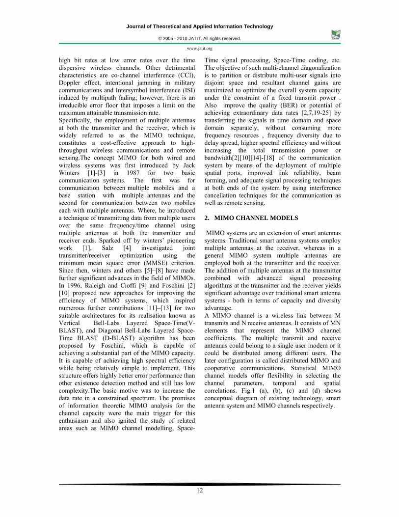
Where: C is the Shannon limits on channel capacity, SNR is signal-to-noise ratio, B is bandwidth of channel. In the practical case of time-varying and randomly fading wireless channel, the capacity can be written as: C B. log 1 SNR. |H| BPS H⁄ … . 3
Where: H is the 1x1 unit-power complex matrix Gaussian amplitude of the channel. Moreover, it has been noticed that the capacity is very small due to fading events.
Figure 2 Shanons capacity for SISO system
From the above expression it is clear that theoretically capacity increase as the bandwidth is increased which shown in Fig.2. C increases 1 bits/sec/Hz for every 3dB of SNR.
3.2. Capacity of Single-Input-Multiple-Output (SIMO) System For the SIMO system, we have N antennas at receiver and only one at transmitter. If the signals received on these antennas have on average the same amplitude, then they can be added coherently to produce an N increase in the signal power. On the other hand, there are N sets of noise that are added incoherently and result in an N-fold increase in the noise power. Hence, there is an overall increase in the SNR:
SNR N . signal power
N. noise N. SNR
So the capacity of SIMO channel is: C B. log 1 N. SNR BPS H⁄ … . . 4
The capacity of SIMO system in the practical case of time-varying and randomly fading wireless channel is: C B. log 1 SNR.HH BPS H⁄ … . 5 Where H is 1xN channel vector and ( )* is the transpose conjugate. 3.3 Capacity of Multiple-Input-Single-Output (MISO) System For the SIMO system, we have M antennas at transmitter and only one at receiver. As same as the case of the SIMO system, we have capacity of MISO system C B. log 1 M. SNR BPS H⁄ … 6
In the practical case of time-varying and randomly fading wireless channel, it shown that the capacity of M x 1 MIMO system is : C B. log 1 SNR.HH BPS H⁄ … 7
Compared with SISO system, the capacity of SIMO and MISO system shows improvement. The increase in capacity is due to the spatial diversity which reduces fading and SNR improvement. However, the SNR improvement is limited, since the SNR is increasing inside the log function .
0 5 10 15 20 25 300
50
100
150
200
250
300
350
400
SNR in dB
Cap
acity
(Mbp
s)
SHANONS Capacity
B = 20 MHzB = 40MHzB = 80MHz
Journal of Theoretical and Applied Information Technology
© 2005 - 2010 JATIT. All rights reserved.
www.jatit.org
15
3.4 Capacity of MIMO System For the MIMO system, we have M antennas at transmitter and N antennas at receiver. We analyze the capacity of MIMO channel in two cases: 3.4.1 Same signal transmitted by each antenna In this case, the MIMO system can be view in effect as a combination of the SIMO and MISO channels. As same as the case in 3.2 and 3.3, we have:
SNR N M . signal power
N.M. noise M. N. SNR
So the capacity of MIMO channels in this case is: C B. log 1 M.N. SNR BPS H⁄ … 8
Thus, we can see that the channel capacity for the MIMO systems is higher than that of SIMO and MIMO system. But in this case, the capacity is increasing inside the log function. This means that trying to increase the data rate by simply transmitting more power is extremely costly. 3.4.2 Different signal transmitted by each antenna The big idea in MIMO is that we can send different signals using the same bandwidth and still be able to decode correctly at the receiver. Thus, it is like we are creating a channel for each one of the transmitters. The capacity of each one of these channels is roughly equal to: C B. log 1 . SNR BPS H⁄ … . 9 But we have M of these channels, so the total capacity of the system is: C M. B. log 1
NM . SNR BPS H⁄ … 10
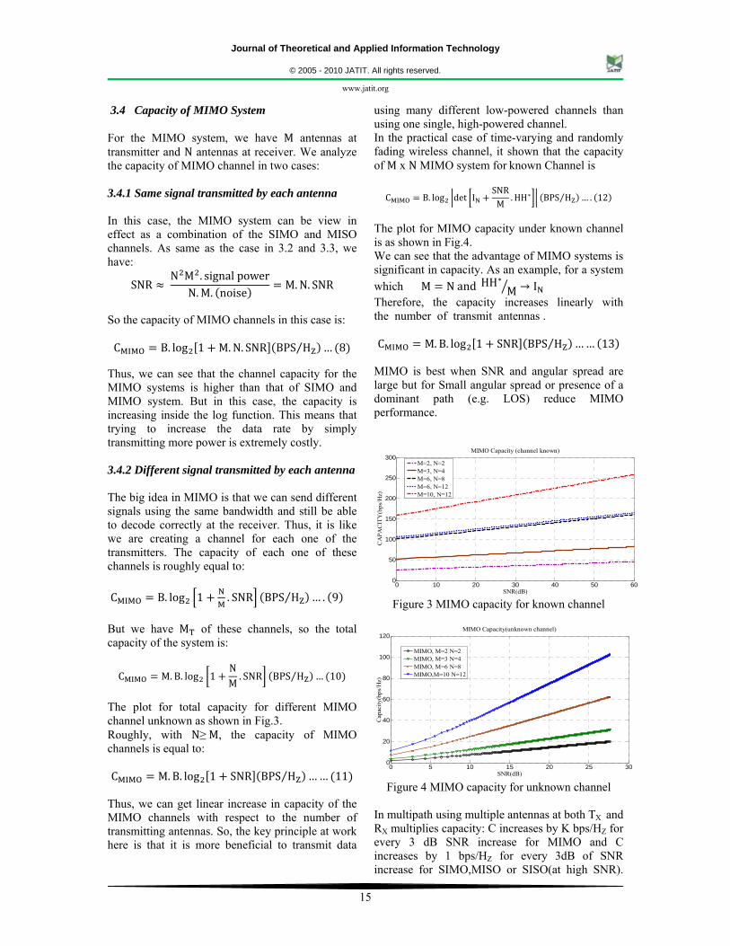
The plot for total capacity for different MIMO channel unknown as shown in Fig.3. Roughly, with N≥ M, the capacity of MIMO channels is equal to: C M. B. log 1 SNR BPS H⁄ …… 11
Thus, we can get linear increase in capacity of the MIMO channels with respect to the number of transmitting antennas. So, the key principle at work here is that it is more beneficial to transmit data
using many different low-powered channels than using one single, high-powered channel. In the practical case of time-varying and randomly fading wireless channel, it shown that the capacity of M x N MIMO system for known Channel is C B. log det I
SNRM
.HH BPS H⁄ … . 12
The plot for MIMO capacity under known channel is as shown in Fig.4. We can see that the advantage of MIMO systems is significant in capacity. As an example, for a system which M N and HH M I Therefore, the capacity increases linearly with the number of transmit antennas . C M. B. log 1 SNR BPS H⁄ …… 13
MIMO is best when SNR and angular spread are large but for Small angular spread or presence of a dominant path (e.g. LOS) reduce MIMO performance.
Figure 3 MIMO capacity for known channel
Figure 4 MIMO capacity for unknown channel
In multipath using multiple antennas at both TX and RX multiplies capacity: C increases by K bps/HZ for every 3 dB SNR increase for MIMO and C increases by 1 bps/HZ for every 3dB of SNR increase for SIMO,MISO or SISO(at high SNR).
0 10 20 30 40 50 600
50
100
150
200
250
300
SNR(dB)
CA
PAC
ITY
(bps
/Hz)
MIMO Capacity (channel known)
M=2, N=2M=3, N=4M=6, N=8M=6, N=12M=10, N=12
0 5 10 15 20 25 300
20
40
60
80
100
120
SNR(dB)
Cap
acity
(bps
/Hz)
MIMO Capacity(unknown channel)
MIMO, M=2 N=2MIMO, M=3 N=4MIMO, M=6 N=8MIMO,M=10 N=12
Journal of Theoretical and Applied Information Technology
© 2005 - 2010 JATIT. All rights reserved.
www.jatit.org
16
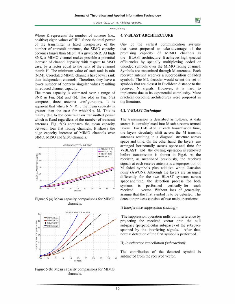
Where K represents the number of nonzero (i.e., positive) eigen values of HH . Since the total power of the transmitter is fixed irrespective of the number of transmit antennas, the SIMO capacity becomes larger than MISO at a given SNR. At high SNR, a MIMO channel makes possible a potential increase of channel capacity with respect to SISO case, by a factor equal to the rank of the channel matrix H. The minimum value of such rank is min (N,M). Correlated MIMO channels have lower rank than independent channels. Therefore, they have a lower number of nonzero singular values resulting in reduced channel capacity. The mean capacity is estimated over a range of SNR in Fig. 5(a) and (b). The plot in Fig. 5(a) compares three antenna configurations. It is apparent that when N M , the mean capacity is greater than the case for whichN M. This is mainly due to the constraint on transmitted power which is fixed regardless of the number of transmit antennas. Fig. 5(b) compares the mean capacity between four flat fading channels. It shows the huge capacity increase of MIMO channels over SIMO, MISO and SISO channels.
Figure 5 (a) Mean capacity comparisons for MIMO
channels.
Figure 5 (b) Mean capacity comparisons for MIMO
channels.
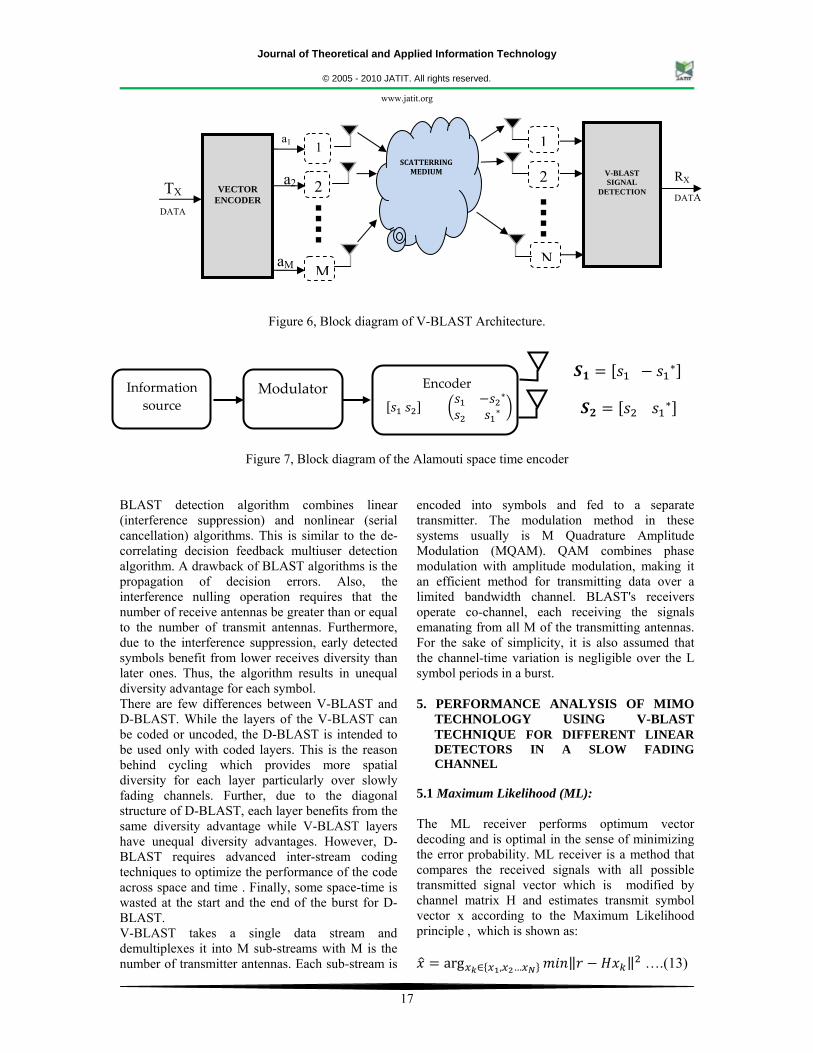
4. V-BLAST ARCHITECTURE One of the earliest communication systems that were proposed to take advantage of the promising capacity of MIMO channels is the BLAST architecture. It achieves high spectral efficiencies by spatially multiplexing coded or uncoded symbols over the MIMO fading channel. Symbols are transmitted through M antennas. Each receiver antenna receives a superposition of faded symbols. The ML decoder would select the set of symbols that are closest in Euclidean distance to the received N signals. However, it is hard to implement due to its exponential complexity. More practical decoding architectures were proposed in the literature. 4.1. V-BLAST Technique The transmission is described as follows. A data stream is demultiplexed into M sub-streams termed layers. For D-BLAST at each transmission time, the layers circularly shift across the M transmit antennas resulting in a diagonal structure across space and time. On the other hand, the layers are arranged horizontally across space and time for V-BLAST and the cycling operation is removed before transmission is shown in Fig.6. At the receiver, as mentioned previously, the received signals at each receive antenna is a superposition of M faded symbols plus additive white Gaussian noise (AWGN). Although the layers are arranged differently for the two BLAST systems across space and time, the detection process for both systems is performed vertically for each received vector. Without loss of generality, assume that the first symbol is to be detected. The detection process consists of two main operations: I) Interference suppression (nulling): The suppression operation nulls out interference by projecting the received vector onto the null subspace (perpendicular subspace) of the subspace spanned by the interfering signals. After that, normal detection of the first symbol is performed. II) Interference cancellation (subtraction): The contribution of the detected symbol is subtracted from the received vector.
-10 -5 0 5 10 15 20 25 30 35 400
5
10
15
20
25
30
SNR(dB)
MEA
N C
APA
CIT
Y (b
its/s
ec/H
z)
MEAN CAPACITY Vs. SNR PLOT
MIMO(5 X 5)MISO(6 X 1)SIMO(1 X 6)SISO(1 X 1)
-10 -5 0 5 10 15 20 25 30 35 400
5
10
15
20
25
30
SNR(dB)
MEA
N C
APA
CIT
Y (b
its/s
ec/H
z)
MEAN CAPACITY Vs. SNR
MIMO(2 X 2)MIMO(4 X 4)MIMO(3 X 3)MIMO(6 X 6)
Journal of Theoretical and Applied Information Technology
© 2005 - 2010 JATIT. All rights reserved.
www.jatit.org
17
Figure 6, Block diagram of V-BLAST Architecture.
Figure 7, Block diagram of the Alamouti space time encoder
BLAST detection algorithm combines linear (interference suppression) and nonlinear (serial cancellation) algorithms. This is similar to the de-correlating decision feedback multiuser detection algorithm. A drawback of BLAST algorithms is the propagation of decision errors. Also, the interference nulling operation requires that the number of receive antennas be greater than or equal to the number of transmit antennas. Furthermore, due to the interference suppression, early detected symbols benefit from lower receives diversity than later ones. Thus, the algorithm results in unequal diversity advantage for each symbol. There are few differences between V-BLAST and D-BLAST. While the layers of the V-BLAST can be coded or uncoded, the D-BLAST is intended to be used only with coded layers. This is the reason behind cycling which provides more spatial diversity for each layer particularly over slowly fading channels. Further, due to the diagonal structure of D-BLAST, each layer benefits from the same diversity advantage while V-BLAST layers have unequal diversity advantages. However, D-BLAST requires advanced inter-stream coding techniques to optimize the performance of the code across space and time . Finally, some space-time is wasted at the start and the end of the burst for D-BLAST. V-BLAST takes a single data stream and demultiplexes it into M sub-streams with M is the number of transmitter antennas. Each sub-stream is
encoded into symbols and fed to a separate transmitter. The modulation method in these systems usually is M Quadrature Amplitude Modulation (MQAM). QAM combines phase modulation with amplitude modulation, making it an efficient method for transmitting data over a limited bandwidth channel. BLAST's receivers operate co-channel, each receiving the signals emanating from all M of the transmitting antennas. For the sake of simplicity, it is also assumed that the channel-time variation is negligible over the L symbol periods in a burst. 5. PERFORMANCE ANALYSIS OF MIMO
TECHNOLOGY USING V-BLAST TECHNIQUE FOR DIFFERENT LINEAR DETECTORS IN A SLOW FADING CHANNEL
5.1 Maximum Likelihood (ML): The ML receiver performs optimum vector decoding and is optimal in the sense of minimizing the error probability. ML receiver is a method that compares the received signals with all possible transmitted signal vector which is modified by channel matrix H and estimates transmit symbol vector x according to the Maximum Likelihood principle , which is shown as:
arg , … ….(13)
aM
a2
SCATTERRING MEDIUM
1
2
V-BLAST SIGNAL
DETECTION
a1
N
2
M
1
VECTOR ENCODER
TX DATA
RX DATA
Encoder
Information
source Modulator
Journal of Theoretical and Applied Information Technology
© 2005 - 2010 JATIT. All rights reserved.
www.jatit.org
18
Where the minimization is performed over all possible transmit estimated vector symbols . Although ML detection offers optimal error performance, it suffers from complexity issues. It has exponential complexity in the sense that the receiver has to consider |A|M possible symbols for an M transmitter antenna system with A is the modulation constellation. 5.2 V-BLAST Zero Forcing (ZF) characteristic: We can reduce the decoding complexity of the ML receiver significantly by employing linear receiver front-ends to separate the transmitted data streams, and then independently decode each of the streams. Simple linear receiver with low computational complexity and suffers from noise enhancement. It works best with high SNR. The solution of the ZF is given by:
… 14 Where, represents the pseudo-inverse. The ZF receiver converts the joint decoding problem into M single stream decoding problems thereby significantly reducing receiver complexity. This complexity reduction comes, however, at the expense of noise enhancement which in general results in a significant performance degradation (compared to the ML decoder). The diversity order achieved by each of the individual data streams equals N - M + 1. 5.3 .V-BLAST with Minimum Mean Square Error (MMSE): The MMSE receiver suppresses both the interference and noise components, whereas the ZF receiver removes only the interference components. This implies that the mean square error between the transmitted symbols and the estimate of the receiver is minimized. Hence, MMSE is superior to ZF in the presence of noise. Some of the important characteristics of MMSE detector are simple linear receiver, superior performance to ZF and at Low SNR, MMSE becomes matched filter. Also at high SNR, MMSE becomes Zero-Forcing. MMSE receiver gives a solution of:
·1
· . . 15 At low SNR, MMSE becomes ZF:
1 1… 16
At high SNR, MMSE becomes ZF:
·1
… 17 i.e., the MMSE receiver approaches the ZF receiver and therefore realizes (N-M + 1)th order diversity for each data stream. 5.4 .V-BLAST with Maximal Ratio Combining (MRC): MRC combines the information from all the received branches in order to maximize the ratio of signal to noise power, which gives it its name. MRC works by weighting each branch with a complex factor and then adding up the branches, MRC is intuitively appealing: the total SNR is achieved by simply adding up the branch SNRs when the appropriate weighting coefficients are used. BER for MRC in Rayleigh fading channel (1x2) with BPSK modulation,
1 2 1 … 18
12 1
1⁄
… 19
5.4. STBC (space-time block codes): STBC is a class of linear coding for MIMO systems that aims to maximize the system diversity gain rather than the data rate. A very popular STBC for a two transmit antennas setup was developed by Alamouti, which is illustrated in Fig.7. It is designed for 2x2 MIMO systems and its simplicity and high frequency have led to its wide adoption in MIMO systems. In this scheme orthogonal signals are transmitted from each antenna, which greatly simplifies receiver design. This particular scheme is restricted to using M = 2 antennas at the transmitter but can any number of receive antennas N .Two QAM symbols S1 and S2 for transmission by the Alamouti scheme are encoded in both the space and time domain at the two transmitter antennas over the consecutive symbol periods as shown in equation( 20). The information
Journal of Theoretical and Applied Information Technology
© 2005 - 2010 JATIT. All rights reserved.
www.jatit.org
19
bits are first modulated using a modulation scheme (for example QPSK). The encoder then takes a block of two modulated symbols s1 and s2 in each encoding operation and gives to the transmit antennas according to the code matrix,
…… 20
The code matrix has the following property
S. S |x | |x | 0
0 |x | |x | |x | |x | I . . 21 Where I is the 2x2 identity matrix. In the above matrix the first column represents the first transmission periods and the second column, the second transmission period. The first row corresponds to the symbols transmitted from the first antenna and second row corresponds to the symbols transmitted from the second antenna. It means that during the symbol period, the first antenna transmits s1 and second antenna s2. During the second symbol period, the first antenna transmits –s2
* and the second antenna transmits s1*
being the complex conjugate of s1. This implies that we are transmitting both in space (across two antennas) and time (two transmission intervals). This is space time coding. Hence, S1= [s1 -s2
*] and S2= [s2 s1*]
Moreover a close look reveals that sequences are orthogonal over a frame interval, since the inner product of the sequences S1 and S2 is zero, i.e.
S1 .S2 = s1s2
* - s2*s1 =0 ……….. (22)
1 2 1 … 23
12 1
2⁄
…… . 24
In a fast fading channel, the BER is of primary interest since the channel varies every symbol time; while in a slow fading situation, the FER (Frequency error rate) is more important because channel stays the same for a frame.
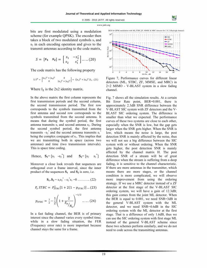
Figure 7, Performance curves for different linear detectors (ML, STBC, ZF, MMSE, and MRC) in 2×2 MIMO - V-BLAST system in a slow fading channel. Fig. 7 shows all the simulation results. At a certain Bit Error Rate point, BER=0.001, there is approximately 2.3dB SNR difference between the V-BLAST SIC system with ZF detectors and the V-BLAST SIC ordering system. The difference is smaller than what we expected. The performance curves of these two systems are close to each other, especially when the SNR is low, but the gap gets larger when the SNR gets higher. When the SNR is low, which means the noise is large, the post detection SNR is mainly affected by the noise, thus we will not see a big difference between the SIC system with or without ordering. When the SNR gets higher, the post detection SNR is mainly affected by the channel matrix H. The post detection SNR of a stream will be of great difference when the stream is suffering from a deep fading, it is sensitive to the channel characteristic. If there are more antennas in the transmitter, which means there are more stages, or the channel condition is more complicated, we will observe more improvement from using the ordering strategy. If we use a MRC detector instead of a ZF detector at the first stage of the V-BLAST SIC ordering system, we will have a gain of 12.3dB; this gain comes from the joint ML detector. When the BER is equal to 0.001, we need SNR=3dB in the general V-BLAST system with the ML detector, and we need SNR=4.6dB in the SIC ordering system with the ML detector at the first stage. That is a difference of only 1.6dB, thus we can use the SIC ordering system with first stage ML instead of the general V-BLAST scheme since these two schemes perform similarly, and we do not need to code across the transmitting antennas.
0 2 4 6 8 10 12 14 16 18
10-4
10-3
10-2
10-1
100
Eb/No , dB
Bit
Erro
r Rat
e
BER for QPSK modulation with ML,STBC,ZF, MMSE & MRC detector for 2 X 2 (Rayleigh channel)
MLSTBCZFMMSEMRC
Journal of Theoretical and Applied Information Technology
© 2005 - 2010 JATIT. All rights reserved.
www.jatit.org
20
6. CONCLUSION In this paper, we provide a general multiple antenna system, the general V- BLAST system and analyzed the performance of V-BLAST with several detectors (ML, ZF, MMSE, STBC, and MRC) in slow fading channels. We first provide a comprehensive summary of capacity results for single-user MIMO channels. These results indicate that the capacity gain obtained from multiple antennas heavily depends on the amount of channel knowledge at either the receiver or transmitter, the channel SNR, and the correlation between the channel gains on each antenna element. We then focus attention on the capacity regions for MIMO broadcast and multiple accesses under known channels or unknown channels. In contrast to single-user MIMO channels, capacity results for these multiuser MIMO channels are quite difficult to obtain, even for constant channels. We summarize capacity results for the MIMO broadcast and multiple access channels for channels that are either constant or fading with perfect instantaneous knowledge of the antenna gains at both transmitter(s) and receiver(s). We also show that the MIMO multiple access and broadcast capacity regions are intimately related via a duality transformation. This transformation is not only useful for proving capacity theorems; it also facilitates finding the optimal transmission strategy of the nonconvex MIMO broadcast channel using convex optimization techniques applied to the dual MIMO multiple access channel. Furthermore, we introduced SIC schemes to improve the independent coded V-BLAST system. We showed that in V-BLAST systems, performance is limited by error propagation. Therefore, we proposed ordering schemes to combat error propagation. The results of these schemes are compared in the Fig 7. We showed the benefits of ordering strategy over Successive Interference Cancellation and proposed an ordering strategy with ML detection at the first stage. We applied this strategy to the general V-BLAST system and got a higher performance gain. In this way, MIMO is an important key for enabling the wireless industry to deliver on the vast potential and promise of wireless broadband. REFERENCES: [1] J. H. Winters , “Optimum combining in digital
mobile radio with cochannel interference”, IEEE J. Sel. Areas Commun., Vol. SAC-2, no. 4, pp. 528–539, (Jul. 1984).
[2] G. J. Foschini, “Layered space-time architecture for wireless communication in a fading environment when using multi-element antennas”, Bell Labs. Technology. Journal, Vol. 1, No.2, PP. 41-59(1996).
[3] J. H. Winters,“Optimum combining for indoor radio systems with multiple users”, IEEE Trans. Commun., vol. COM-35, no. 11, pp. 1222–1230, Nov. 1987.
[4] J. Salz, “Digital transmission over cross-coupled linear channels”, AT&T Tech. J., vol. 64, pp. 1147–1159,(Jul.–Aug. 1985).
[5] S. Cheng and S. Verdu,“Gaussian multi-access channels with ISI: Capacity region and multiuser water-filling”, IEEE Trans. Inf. Theory, vol. 39, no. 3, pp. 773–785,(May 1993).
[6] J. H. Winters, J. Salz, and R. D. Gitlin ,“The impact of antenna diversity on the capacity of wireless communication systems”, IEEE Trans. commun., vol. 5, no. 234, pp. 1740–1751, (Feb./Mar./Apr. 1994).
[7] J. Yang and S. Roy, “On joint transmitter and receiver optimization for multiple-input multiple-output (MIMO) transmission systems”, IEEE Trans. Commun., vol. 42,no. 12, pp. 3221–3231, (Dec. 1994).
[8] J. H. Winters, “The diversity gain of transmit diversity in wireless systems with Rayleigh fading”, IEEE Trans. Veh. Technol., vol. 47, no. 1, pp. 119–123, (Feb. 1998).
[9] G. G. Raleigh and J. M. Cioffi, “Spatio-temporal coding for wireless communications”, in Proc. 1996 IEEE Global Telecommunications Conf. (GLOBECOM ’96), Nov. 18–22, vol. 3, pp. 1809–1814, (1996).
[10] G. J. Foschini, “Layered space-time architecture for wireless communication”, Bell Labs. Technology. Journal, Vol. 6, No.3, PP. 311-335(1998).
[11] B. Lu and X. Wang, “Iterative receivers for multiuser space-time coding systems”, IEEE J. Sel. Areas Commun., vol. 18, no. 11, pp. 2322–2335, (Nov. 2000).
[12] X. Zhu and R. D. Murch, “Layered space-frequency equalization in a single-carrier MIMO system for frequency-selective channels, IEEE Trans. Wireless Commun., vol. 3, no. 3, pp. 701–708, (May 2004).
[13] M. R. McKay and I. B. Collings,“Capacity and performance of MIMO-BICM with zero-forcing receivers”, IEEE Trans. Commun., vol. 53, no. 1, pp. 74–83, (Jan. 2005).
[14] J.H.Kotecha and A.M.Sayeed,“Transmit signal design for optimal estimation of Correlated
Journal of Theoretical and Applied Information Technology
© 2005 - 2010 JATIT. All rights reserved.
www.jatit.org
21
MIMO channels Kotecha”, IEEE transaction on signal processing, Vol.52, PP.546-577(Feb 2004).
[15] A. J. Paulraj, D. A. Gore, R. U. Nabar, and H. Bölcskei“An overview of MIMO communication-A Key to Gigabit Wireless”, Proceedings of the IEEE, Vol. 92, No. 2, PP. 198-218(Feb. 2004).
[16] Kyung Won Park and Yong Soo Cho,"An MIMO-OFDM technique for high-speed mobile channels," IEEE Communications Letters, Volume 9, No. 7, PP. 604 – 606(July 2005).
[17] H. B¨olcskei,“MIMO-OFDM wireless systems: Basics, perspectives, and challenges”, IEEE Journal on Wireless Communications, Vol. 13, No. 4, PP. 31-37 ( Aug. 2006).
[18] M.Cicerone,O.Simeone and U.Spagnolini, “Channel Estimation for MIMO-OFDM Systems by Modal Analysis/Filtering”, IEEE transaction on communication, Vol.54, No.11, PP..2062-2074(Nov.2006).
[19] Y. Li and N. R. Sollenberger, “Adaptive Antenna Arrays for OFDM systems with Co-Channel Interference”, IEEE Trans. Communications, vol. 47, no. 2, pp. 217-229, February 1999.
[20] G. J. Foschini and M. J. Gans, “On limits of wireless communications in a fading environment when using multiple antennas”, Wireless Personal Communications, Vol. 6, No. 3, March 1998, pp 311-335.
[21] M. Jankiraman, Space time Codes and MIMO systems, published by Artech House, 2004.
[22] B. Vucetic & J. Yuan, ‘Space Time Coding’, published by John Wiley &Sons Inc., 2003.
[23] A. J. Paulraj and T. Kailath, “Increasing capacity in wireless broadcast systems using distributed transmission/directional reception," U. S. Patent, no. 5,345,599, 1994
[24] H. Blolcskei, D. Gesbert, and A. J. Paulraj, “On the capacity of OFDM-based spatial multiplexing systems," IEEE Trans. Commun., vol. 50, no. 2, pp. 225-234, Feb. 2002.
[25] I.E. Telatar, “Capacity of multi-antenna Gaussian channels,” Eur. Trans.Telecomm, vol. 10, no. 6, pp. 585–595, 1999.
Journal of Theoretical and Applied Information Technology
© 2005 - 2010 JATIT. All rights reserved.
www.jatit.org
22
BIOGRAPHY:
Prof. Nirmalendu Bikas Sinha received the B.Sc (Honours in Physics), B. Tech, M. Tech degrees in Radio-Physics and Electronics from Calcutta University, Calcutta, India,in1996, 1999 and 2001, respectively. He is currently
working towards the Ph.D degree in Electronics and Telecommunication Engineering at BESU. Since 2003, he has been associated with the College of Engineering and Management, Kolaghat. W.B, India where he is currently an Asst.Professor is with the department of Electronics & Communication Engineering & Electronics & Instrumentation Engineering. His current research Interests are in the area of signal processing for high-speed digital communications, signal detection, MIMO, multiuser communications,Microwave /Millimeter wave based Broadband Wireless Mobile Communication ,semiconductor Devices, Remote Sensing, Digital Radar, RCS Imaging, and Wireless 4G communication. He has published large number of papers in different international Conference, proceedings and journals.He is currently serving as a member in international journal editorial board and reviewer for Wireless communication and radar system in different international journals.
Dr. Rabindranath Bera is a professor and Dean (R&D), HOD in Sikkim Manipal University and Ex-reader of Calcutta University, India. B.Tech, M.Tech and Ph.D.degrees from Institute of
Radio-Physicsand Electronics, Calcutta University. Field of Interests are in the area of Digital Radar, RCS Imaging, Wireless 4G Communication, Radiometric remote sensing. He has published large number of papers in different national and international Conference and journals.
Dr. Monojit Mitra is an Assistant Professor in the Department of Electronics & Telecommunication Engineering of Bengal Engineering & Science University, Shibpur. He obtained his B.Tech, M.Tech & Ph. D .degrees from
Calcutta University. His research areas are in the field of Microwave & Microelectronics, especially in the fabrication of high frequency solid state
devices like IMPATT. He has published large number of papers in different national and international journals. He has handled sponsored research projects of DOE and DRDO. He is a member of IETE (I) and Institution of Engineers (I).


![Performance Evaluation of V-BLAST MIMO System Using ...Innovative Systems Design and Engineering 2012, 3(10): 11-25. [7] G.Singh, R. Vij, and P.Mishra, “Performance Evaluation for](https://img.pdfslide.net/doc/110x75/604fe4a1791def7df66d0708/performance-evaluation-of-v-blast-mimo-system-using-innovative-systems-design.jpg)