Embed Size (px)
Citation preview
1
Caprivi Link
Interconnector
Presentation to SAPP Management Committee
17 February 2010
03 May 2010 NamPower 203 May 2010 NamPower 2
Contents
Caprivi Link Interconnector Overview
Project Progress
Effect of HVDC Link on AC Networks
03 May 2010 NamPower 3
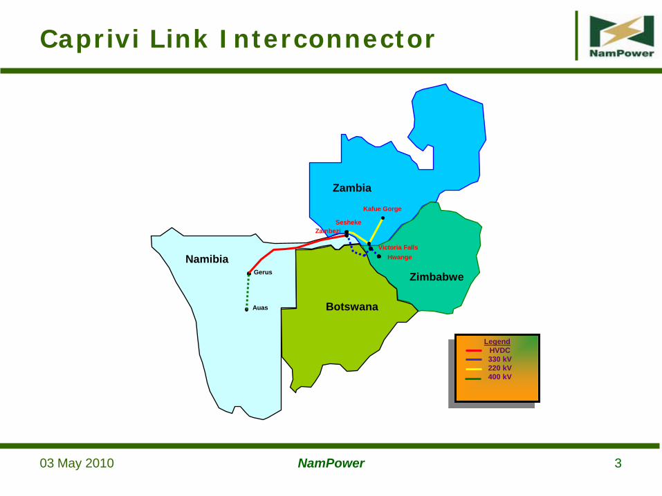
Caprivi Link Interconnector
Gerus
HwangeVictoria Falls
Sesheke
Kafue Gorge
Zambezi
Auas
LegendHVDC330 kV220 kV400 kV
Namibia
Zambia
Zimbabwe
Botswana
03 May 2010 NamPower 4
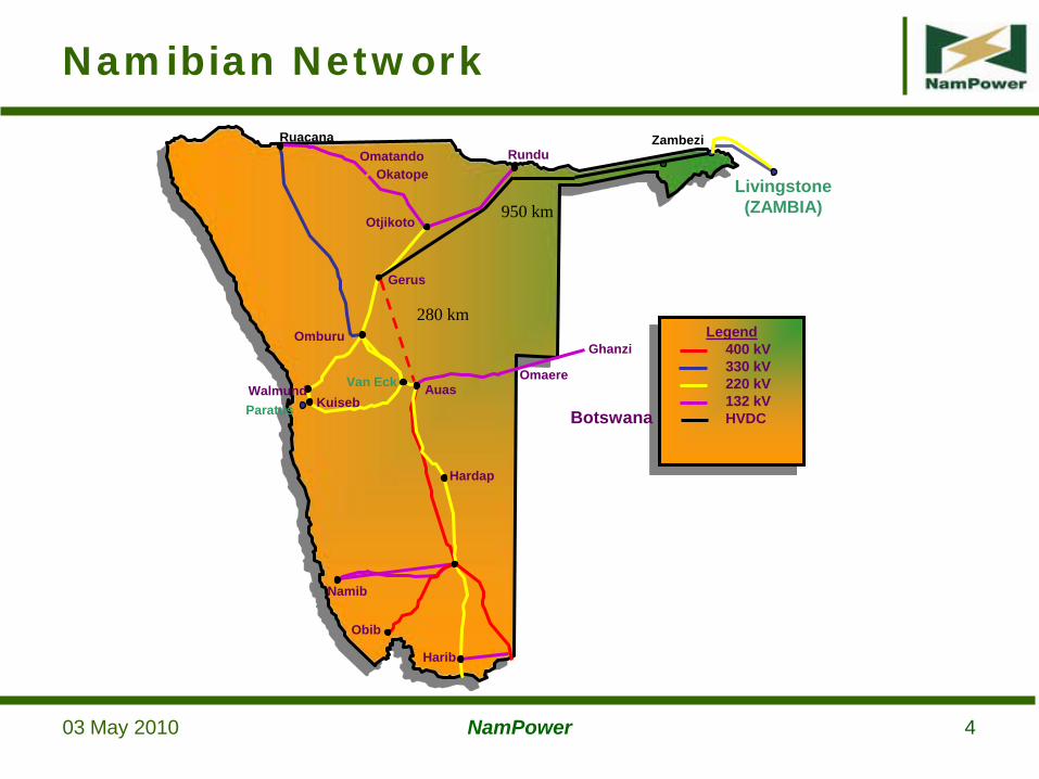
Namibian Network
Gerus
Otjikoto
Auas
Hardap
Omatando Rundu
Omburu
Namib
Obib
Walmund Van Eck Omaere
Ruacana
Paratus
Harib
OkatopeLivingstone(ZAMBIA)
Ghanzi
280 km
950 km
Zambezi
Legend400 kV330 kV220 kV132 kVHVDC
KuisebBotswana
03 May 2010 NamPower 5
The objective of the Caprivi Link Interconnector is to provide an asynchronous link between the Namibian and Zambian/Zimbabwean electricity networks in order to ensure a reliable power transfer capability between the east and west of the South African Power Pool (SAPP)
Purpose of Scheme
03 May 2010 NamPower 6
Connection of Zambezi substation to the rest of the NamPower grid
Better utilisation of the Livingstone – Zambezi 220 kV line that was constructed by ZESCO & NamPower
Provide and alternative wheeling path for SAPP electricity trade
Benefits of Scheme
03 May 2010 NamPower 7
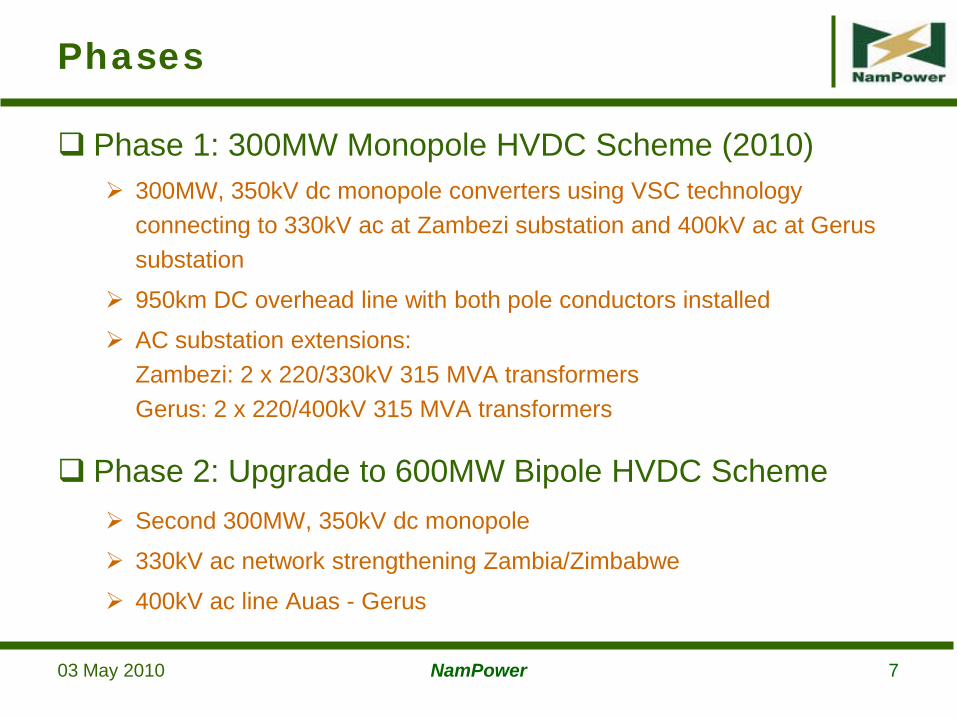
Phase 1: 300MW Monopole HVDC Scheme (2010) 300MW, 350kV dc monopole converters using VSC technology
connecting to 330kV ac at Zambezi substation and 400kV ac at Gerus substation
950km DC overhead line with both pole conductors installed
AC substation extensions:Zambezi: 2 x 220/330kV 315 MVA transformersGerus: 2 x 220/400kV 315 MVA transformers
Phase 2: Upgrade to 600MW Bipole HVDC Scheme Second 300MW, 350kV dc monopole
330kV ac network strengthening Zambia/Zimbabwe
400kV ac line Auas - Gerus
Phases
03 May 2010 NamPower 8
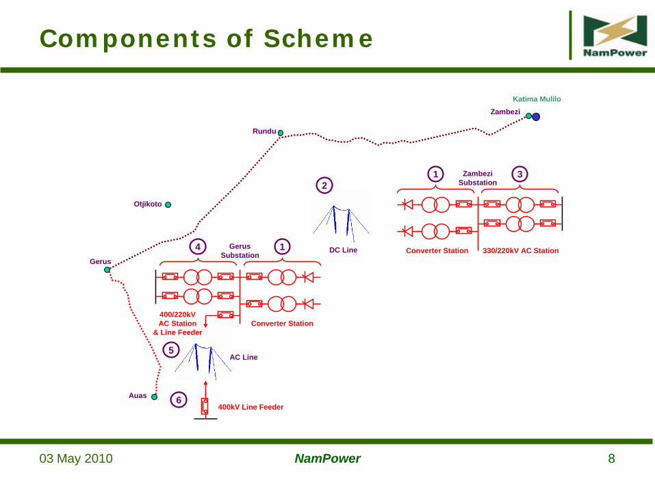
Components of Scheme
6
5
21 3Zambezi
Substation
AC Line
DC Line Converter Station 330/220kV AC Station4 1GerusSubstation
Converter Station400/220kVAC Station
& Line Feeder
400kV Line FeederAuas
Rundu
Katima Mulilo
Otjikoto
Gerus
Zambezi
03 May 2010 NamPower 9
Active power control
AC voltage control at both ends (SVC operation)
Power oscillation damping (not used)
Subsynchronous resonance (SSR) damping
Operation with reduced DC voltage
Overload capability to 350 MW
Control Features
03 May 2010 NamPower 10
Normal power transfer in both directions
Passive/Islanded network at Gerus or Zambezi – HVDC scheme does frequency control of separated network
Energisation of a black network from remote station
Metallic return and earth return
Modes of Operation
03 May 2010 NamPower 1103 May 2010 NamPower 11
350kV HVDC Line Completed November 2009
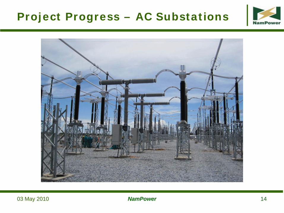
AC Substation Extensions: Gerus and Zambezi Equipment installation 98% complete
Busbars and stringing is complete
2 x 315MVA coupling transformers installed
Busy with commissioning
Energisation of first 315MVA transformers planned for early March 2010
Project Progress
03 May 2010 NamPower 12
Project Progress
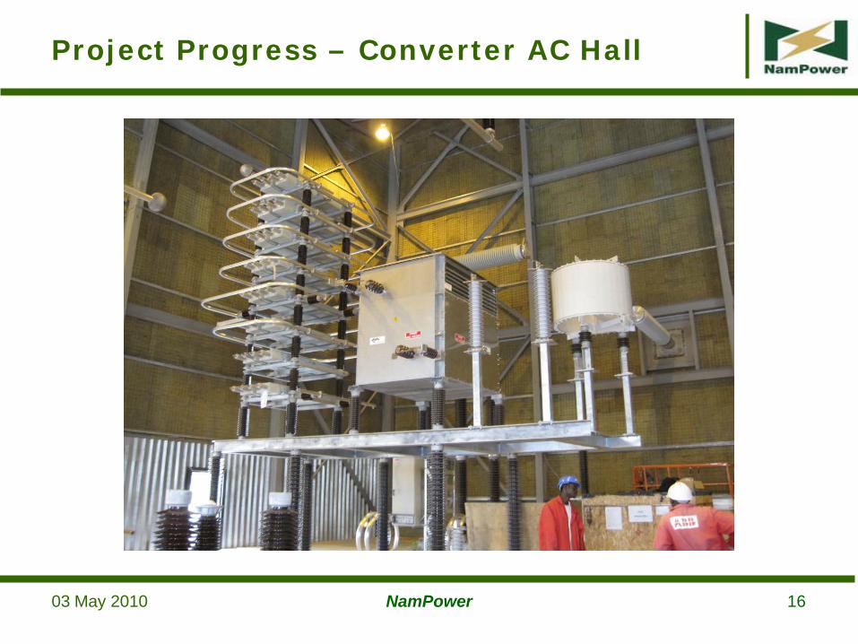
HVDC Converter Stations Civil works 98% complete
Installation 65% complete
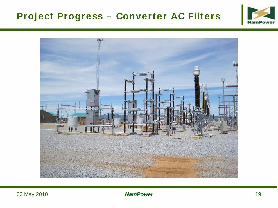
AC yard equipment and AC filters installed
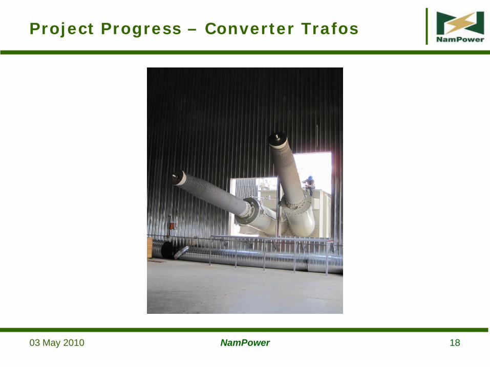
3 x single phase converter transformers installed
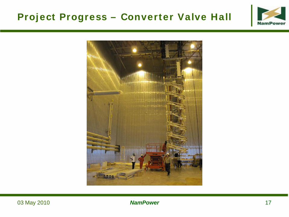
Busy with installation of valves, converter reactors, AC hall, DC hall and DC yard equipment and cabling
Energised testing & transmission tests from end-March to end-May 2010
Earth electrodes installation planned for Sept./Oct. 2010 (scheme will be operated in metallic return initially)
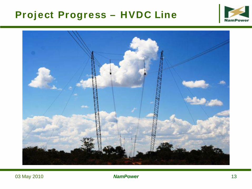
03 May 2010 NamPower 13
Project Progress – HVDC Line
03 May 2010 NamPower 14
Project Progress – AC Substations
03 May 2010 NamPower 15
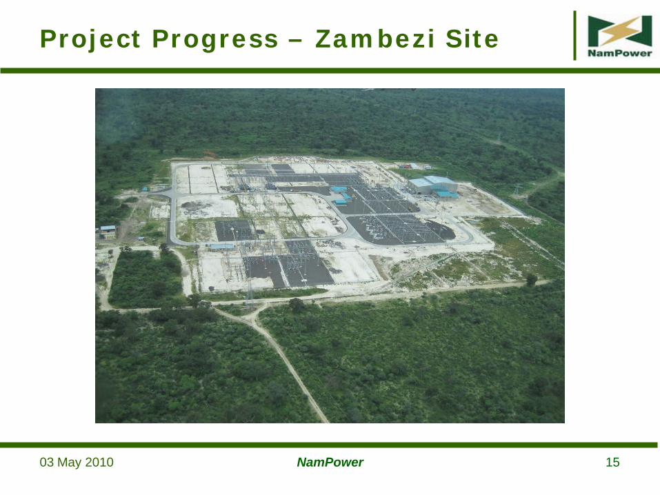
Project Progress – Zambezi Site
03 May 2010 NamPower 16
Project Progress – Converter AC Hall
03 May 2010 NamPower 17
Project Progress – Converter Valve Hall
03 May 2010 NamPower 18
Project Progress – Converter Trafos
03 May 2010 NamPower 19
Project Progress – Converter AC Filters
03 May 2010 NamPower 20
Extensive studies done to optimise HVDC controls and check for AC network stability
Effect of AC network faults
Effect of DC line faults
Power oscillations
Subsynchronous torsional interaction (SSTI)
Frequency control in islanded networks
Extensive verification of actual control & protection systems done with RTDS model in factory
Effect of HVDC on AC Networks
03 May 2010 NamPower 2103 May 2010 NamPower 21
Effect of HVDC on AC Networks
Power Control The power can be precisely controlled in the HVDC link from 0 –
300MW (Phase 1).
Initially a maximum power transfer of 150MW is expected due to limitations in the connected AC networks
Balance of power will flow in AC networks according to impedances and phase angle differences
AC Voltage Control at Terminals (SVC Operation) AC voltage control available in conjunction with active power transfer
Provides voltage stability to connected AC networks
±100 MVAr available at terminals throughout 0 – 300 MW range
03 May 2010 NamPower 22
Effect of HVDC on AC Networks
03 May 2010 NamPower 23
Harmonics Harmonics generated by converter stations may not exceed 50% of
allowable maximum levels (NRS)
All envisaged AC network configurations and realistic contingencies included in AC network harmonic impedance representation
Use of PWM in a voltage sourced converter allows “selected” harmonics to be suppressed.
For Caprivi OPWM is used which cancels harmonics of order 5, 7, 11, 13, 15, 17, 19, 23, 25, 29
Filters tuned to 3rd, 32nd and 60th harmonics are installed
Effect of HVDC on AC Networks
03 May 2010 NamPower 24
Frequency Control of Islanded Networks E.g. Northern Namibian network separated from southern network
(connected to Eskom)
HVDC can control frequency in northern network by control of active power into the network
Black Start Capability A VSC HVDC converter can be energised from the other converter
station
The newly energised converter can then feed into a previously blacked-out network
Effect of HVDC on AC Networks
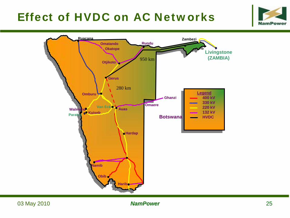
03 May 2010 NamPower 25
Gerus
Otjikoto
Auas
Hardap
Omatando Rundu
Omburu
Namib
Obib
Walmund Van Eck Omaere
Ruacana
Paratus
Harib
OkatopeLivingstone(ZAMBIA)
Ghanzi
280 km
950 km
Zambezi
Legend400 kV330 kV220 kV132 kVHVDC
KuisebBotswana
Effect of HVDC on AC Networks
03 May 2010 NamPower 26
Single phase to earth fault with successful ARC on Zambezi - Sesheke 220kV line: Present network (2010)
100MW transfer from Zambezi to Gerus through HVDC link
Single phase to earth fault on Zambezi – Shesheke 220kV line
Cleared by zone 1 protection, ARC in 1.2s
AC Line Fault, successful ARC
03 May 2010 NamPower 27
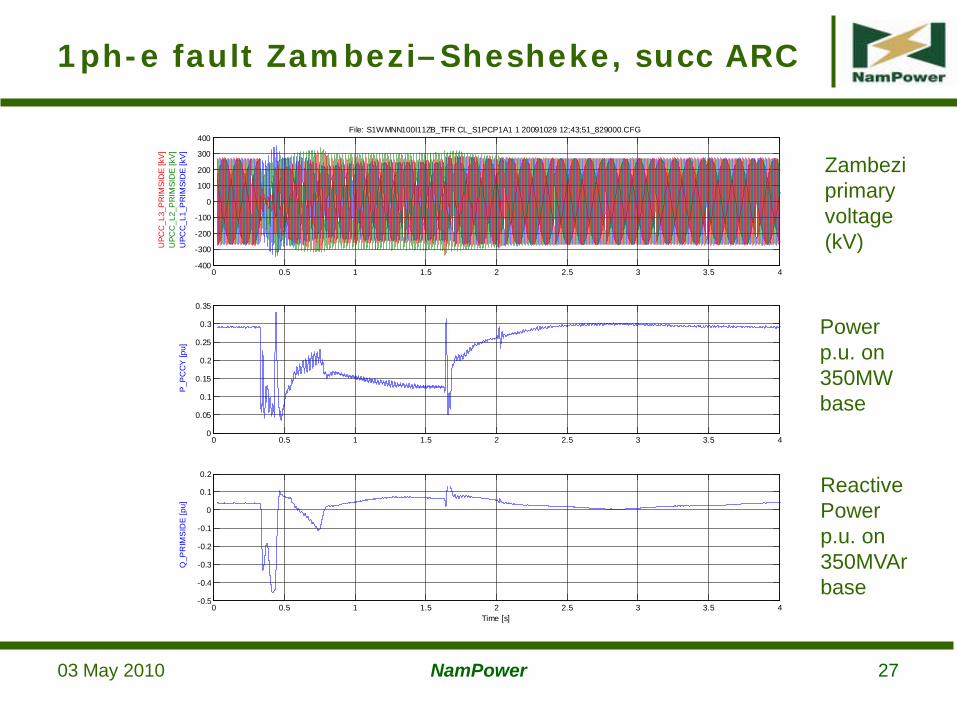
1ph-e fault Zambezi–Shesheke, succ ARC
0 0.5 1 1.5 2 2.5 3 3.5 4-400
-300
-200
-100
0
100
200
300
400
UPC
C_L
1_P
RIM
SID
E [k
V]
UPC
C_L
2_P
RIM
SID
E [k
V]
UPC
C_L
3_P
RIM
SID
E [k
V]
File: S1WMNN100I11ZB_TFR CL_S1PCP1A1 1 20091029 12;43;51_829000.CFG
0 0.5 1 1.5 2 2.5 3 3.5 40
0.05
0.1
0.15
0.2
0.25
0.3
0.35
P_P
CC
Y [p
u]
0 0.5 1 1.5 2 2.5 3 3.5 4-0.5
-0.4
-0.3
-0.2
-0.1
0
0.1
0.2
Q_P
RIM
SID
E [p
u]
Time [s]
Power p.u. on 350MW base
Reactive Power p.u. on 350MVAr base
Zambezi primary voltage (kV)
03 May 2010 NamPower 28
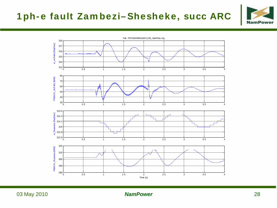
1ph-e fault Zambezi–Shesheke, succ ARC
0 0.5 1 1.5 2 2.5 3 3.5 4313.6
313.8
314
314.2
314.4
314.6
w_R
uaca
na [R
ad/s
ec]
0 0.5 1 1.5 2 2.5 3 3.5 4313
314
315
316
317
318
w_v
icFa
lls [R
ad/s
ec]
File: RTDSWMNN100I11ZB_rtdsPlots.cfg
0 0.5 1 1.5 2 2.5 3 3.5 430
40
50
60
70
80
PM
AC
H_V
icFa
lls [M
W]
0 0.5 1 1.5 2 2.5 3 3.5 4280
290
300
310
320
PM
AC
H_R
uaca
na [M
W]
Time [s]
03 May 2010 NamPower 29
DC Line Fault, successful clearing
DC line fault (pole to earth) at midpoint of DC line with successful fault clearing: Present network
100MW transfer from Zambezi to Gerus
DC line fault clearing sequence
Converter AC breakers opened
DC pole breakers and high speed switches opened
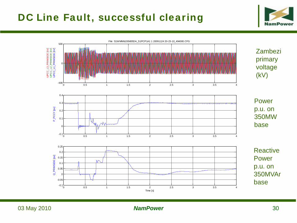
Active power transmission resumed ~900ms after fault
03 May 2010 NamPower 30
DC Line Fault, successful clearing
0 0.5 1 1.5 2 2.5 3 3.5 4-0.1
0
0.1
0.2
0.3
0.4
P_P
CC
Y [p
u]
0 0.5 1 1.5 2 2.5 3 3.5 4-500
0
500
UPC
C_L
1_P
RIM
SID
E [k
V]
UPC
C_L
2_P
RIM
SID
E [k
V]
UPC
C_L
3_P
RIM
SID
E [k
V]
File: S1WMNN100M35DA_S1PCP1A1 1 20091124 20-23-10_494000.CFG
0 0.5 1 1.5 2 2.5 3 3.5 4-0.1
-0.05
0
0.05
0.1
0.15
0.2
0.25
Q_P
RIM
SID
E [p
u]
Time [s]
Power p.u. on 350MW base
Reactive Powerp.u. on 350MVAr base
Zambezi primary voltage (kV)
03 May 2010 NamPower 31
DC Line Fault, successful clearing
0 0.5 1 1.5 2 2.5 3 3.5 4312
313
314
315
w_R
uaca
na [R
ad/s
ec]
0 0.5 1 1.5 2 2.5 3 3.5 4310
312
314
316
318
w_v
icFa
lls [R
ad/s
ec]
File: RTDSWMNN100M35DA_rtdsPlots.cfg
0 0.5 1 1.5 2 2.5 3 3.5 40
20
40
60
80
PM
AC
H_V
icFa
lls [M
W]
0 0.5 1 1.5 2 2.5 3 3.5 4240
260
280
300
320
PM
AC
H_R
uaca
na [M
W]
Time [s]
03 May 2010 NamPower 32
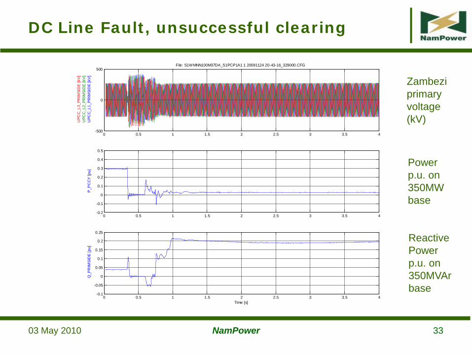
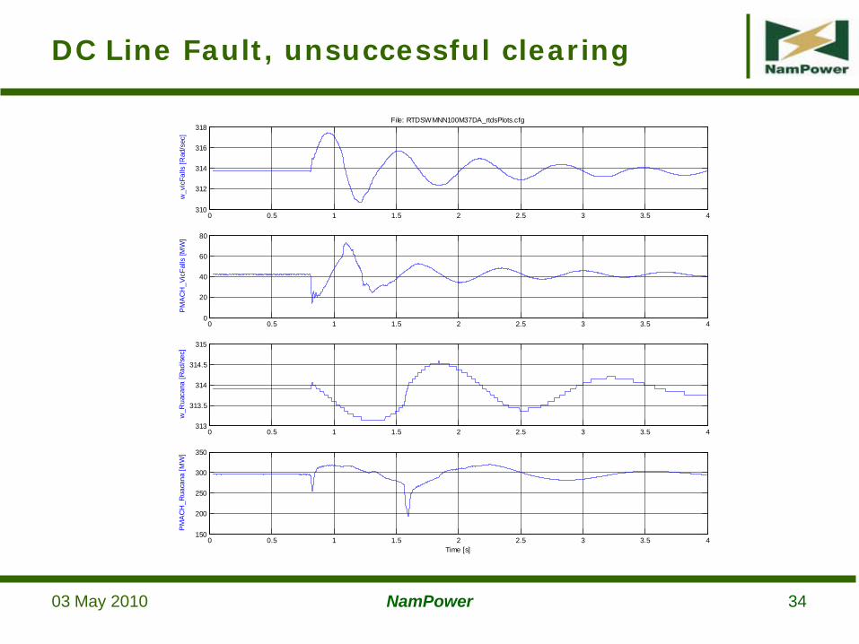
DC line fault (pole to earth) at midpoint of DC line with unsuccessful fault clearing: Present network
100MW transfer from Zambezi to Gerus
DC line fault clearing sequence
Converter AC breakers opened
DC pole breakers and high speed switches opened
Reclose attempt, second clearing sequence
DC line isolated but converter AC breakers closed
SVC functionality available after fault
DC Line Fault, unsuccessful clearing
03 May 2010 NamPower 33
DC Line Fault, unsuccessful clearing
0 0.5 1 1.5 2 2.5 3 3.5 4-0.2
-0.1
0
0.1
0.2
0.3
0.4
0.5
P_P
CC
Y [p
u]
0 0.5 1 1.5 2 2.5 3 3.5 4-500
0
500
UPC
C_L
1_P
RIM
SID
E [k
V]
UPC
C_L
2_P
RIM
SID
E [k
V]
UPC
C_L
3_P
RIM
SID
E [k
V]
File: S1WMNN100M37DA_S1PCP1A1 1 20091124 20-43-16_329000.CFG
0 0.5 1 1.5 2 2.5 3 3.5 4-0.1
-0.05
0
0.05
0.1
0.15
0.2
0.25
Q_P
RIM
SID
E [p
u]
Time [s]
Power p.u. on 350MW base
Reactive Powerp.u. on 350MVAr base
Zambezi primary voltage (kV)
03 May 2010 NamPower 34
DC Line Fault, unsuccessful clearing
0 0.5 1 1.5 2 2.5 3 3.5 4313
313.5
314
314.5
315
w_R
uaca
na [R
ad/s
ec]
0 0.5 1 1.5 2 2.5 3 3.5 4310
312
314
316
318
w_v
icFa
lls [R
ad/s
ec]
File: RTDSWMNN100M37DA_rtdsPlots.cfg
0 0.5 1 1.5 2 2.5 3 3.5 40
20
40
60
80
PM
AC
H_V
icFa
lls [M
W]
0 0.5 1 1.5 2 2.5 3 3.5 4150
200
250
300
350
PM
AC
H_R
uaca
na [M
W]
Time [s]
03 May 2010 NamPower 35
Power Oscillations Studies done to check power oscillations between HVDC controls and
nearby generation after network disturbances
It was found that oscillations are sufficiently damped
POD function available in HVDC controls but not activated
SSTI Hydro generators not at risk
Possible interaction with thermal generators
Screening study done to check for risk of SSTI using Unit Interaction Factor (UIF) method
Hwange not at risk, Van Eck may be at risk for 600 MW scheme, further studies being done
Power Oscillations and SSTI
03 May 2010 NamPower 36
Caprivi Link Interconnector
Thank you for your attention!