Embed Size (px)
Citation preview
Hydro Instruments 600 Emlen Way Telford, PA 18969
Phone: 215.799.0980 Fax: 215.799.0984 Email: [email protected] Web Address: www.hydroinstruments.com
Specifications subject to change without notice. 2013 Hydro Instruments
Carbon Dioxide Handling Manual
Carbon Dioxide Handling Manual
The information contained in this manual was accurate at the time of printing. The most current versions of all Hydro Instruments’
manuals can be found on our website www.hydroinstruments.com
CO2-001 Rev. 03/14/13
Hydro Instruments 600 Emlen Way Telford, PA 18969
Phone: 215.799.0980 Fax: 215.799.0984 Email: [email protected] Web Address: www.hydroinstruments.com
Specifications subject to change without notice. 2013 Hydro Instruments
Carbon Dioxide Handling Manual
Carbon Dioxide Handling Manual
Table of Contents
Warnings……………………………………………………………………………………….............2
I. Introduction.............................................................................................................................................3
II. Carbon Dioxide Uses and Properties.......................................................................................................3
III. Safety Information ................................................................................................................................5
1. General Health Hazards, Emergency Equipment & Emergency Action Plans.............. ..5
2. Carbon Dioxide Storage Facilities........................................................................................6
IV. Carbon Dioxide Containers.....................................................................................................................7
1. High Pressure Cylinders.......................................................................................................7
2. Pressure Regulated Containers............................................................................................8
3. Withdrawal Rates..................................................................................................................9
V. Storage and Use of Containers..............................................................................................................9
VI. Pressure Manifolding, Piping and Other Carbon Dioxide Line Accessories..................................10
1. Pressure Reducing Valves....................................................................................................10
2. Flexible Connectors................................................................................................................11
3. Manifold/Pressurized Piping.................................................................................................11
4. Pressure Relief Valves...........................................................................................................11
5. Pressure Gauges....................................................................................................................11
6. Valves....................................................................................................................................11
7. Heaters..................................................................................................................................11
VII. Vacuum Piping and Other Carbon Dioxide Line Accessories..........................................................11
1
Hydro Instruments 600 Emlen Way Telford, PA 18969
Phone: 215.799.0980 Fax: 215.799.0984 Email: [email protected] Web Address: www.hydroinstruments.com
Specifications subject to change without notice. 2013 Hydro Instruments
Carbon Dioxide Handling Manual
Warning
Carbon dioxide is a hazardous chemical that can cause injury and death if not handled properly. This
manual contains only general information on the physical properties, storage, and handling of carbon
dioxide containers and relevant equipment. It is not intended to replace or limit safety procedures in your
facility.
Safety procedures in an industrial setting must be designed in accordance with all governmental
regulations and national safety codes, after giving full consideration to the specific needs of the industrial
facility involved. Under no circumstances should the information in this manual be construed as
substituting or superseding any local, state, or federal laws and regulations.
Hydro Instruments cannot anticipate the specific safety procedures required at every industrial facility.
Accordingly, Hydro Instruments does not guarantee that safety procedures designed in accordance with
this manual will completely eliminate hazards and thus assumes no liability for accidents that may occur
in your facility.
Read this entire manual and be fully familiar with your equipment and your entire industrial system so
that the safety procedures you establish will meet the needs of the employees in you facility. Reading
only part of the manual will not help you analyze the needs of your facility. Contact your carbon dioxide
suppliers, and other similar organizations to obtain any MSDS and/or more information.
All information in this manual was current at time of printing. Please note the date of printing and
possible obsolescence of material as a result of scientific and medical developments after the date of
publication. This applies to all materials you review in the course of developing safety procedures for
use at you facility.
When working with Carbon Dioxide
Ensure that approved, self-contained breathing apparatuses are always available and personnel are
properly trained for its use.
Safety equipment should be inspected and maintained in accordance with the manufacturer’s instructions.
Ensure that all warning signs and placards are in their appropriate place and can clearly be displayed.
In the event of a leak, use proper safety equipment and trained personnel to respond to the leak
immediately. Evacuate all personnel in a dangerous area to a safe space. If breathing has stopped
perform respiration immediately. If heart has stopped perform CPR.
Knowledgeable design personnel should oversee and approve equipment installation and suitability of the
system for which it is intended. Qualified personnel should also perform routine equipment checks and
maintenance in accordance with manufactures recommendations and instructions.
2
Hydro Instruments 600 Emlen Way Telford, PA 18969
Phone: 215.799.0980 Fax: 215.799.0984 Email: [email protected] Web Address: www.hydroinstruments.com
Specifications subject to change without notice. 2013 Hydro Instruments
Carbon Dioxide Handling Manual
I. INTRODUCTION
Warning: Carbon dioxide is a hazardous and dangerous chemical. Take extreme care when handling and
follow all pertinent safety rules and regulations.
This manual was designed for the reader to understand the proper handling, storage, service and delivery of
carbon dioxide. This manual should be read fully and understood before handling any containers or
equipment. It is also suggested that the reader read all relevant material safety data sheets and contact your
chemical supplier and/or compressed gas association for more information.
II. CARBON DIOXIDE USES AND PROPERTIES
Carbon dioxide is used primarily in the water and wastewater industry for pH control as upon dissolution
into water will form carbonic acid . The carbonic acid is then used to react with any alkalis in the water, thus
lowering the pH without affecting the alkalinity. Carbon dioxide is also used in the beverage industry for the
carbonation of soda and beer and is also used in many types of fire extinguishers as carbon dioxide is non-
flammable and is able to displace oxygen from the fire source. Carbon dioxide can also be produced
naturally in humans as a by-product of respiration and is used in the pH control of our blood. It is a crucial
component in the carbon cycle making life on earth as we know it inhabitable. Solid and liquid carbon
dioxide also have practical industrial uses but their applications are outside the scope of this manual.
Carbon dioxide is a linear molecule that is formed by the reaction of carbon and oxygen. In commerce,
carbon dioxide is stored as a liquefied gas under pressure. It is colorless in both the gas and liquid phases,
and is relatively non-detectable until much higher concentrations are reached in which carbon dioxide is said
to have a sharp, acidic odor. Due to the nature of carbon dioxide, no liquid phase can be reached until
pressures go above 75 psi. Vapor pressure from carbon dioxide is very high, as container temperatures above
85 ˚F will reach pressures above 1000 psi. Thus, in some applications storage vessels will be equipped with
insulation and pressure regulating devices (see section IV). Carbon dioxide is non-flammable and generally
considered non-toxic, although if exposed to high enough concentrations can result in serious injury or death
(see section III). Care should be taken when dealing with carbon dioxide. A list of important properties can
be found on page 4.
3
Hydro Instruments 600 Emlen Way Telford, PA 18969
Phone: 215.799.0980 Fax: 215.799.0984 Email: [email protected] Web Address: www.hydroinstruments.com
Specifications subject to change without notice. 2013 Hydro Instruments
Carbon Dioxide Handling Manual
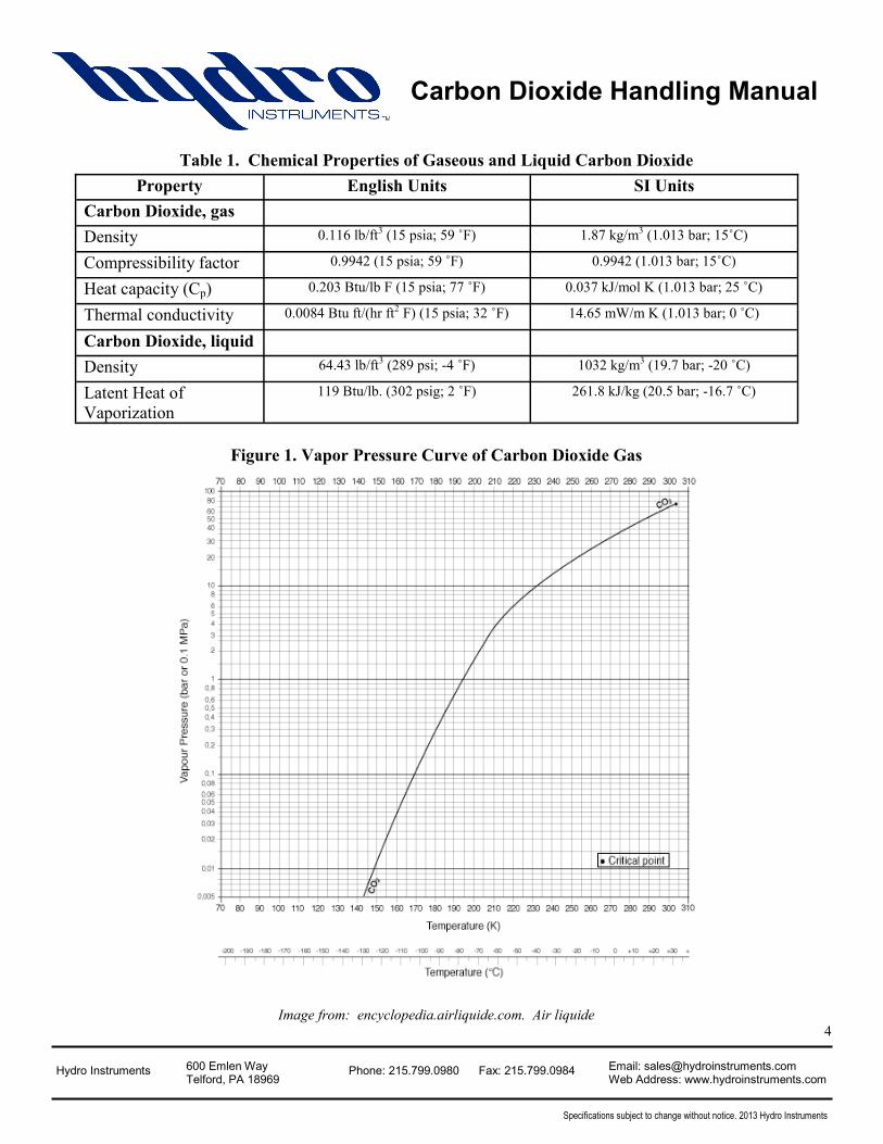
Table 1. Chemical Properties of Gaseous and Liquid Carbon Dioxide
Figure 1. Vapor Pressure Curve of Carbon Dioxide Gas
Image from: encyclopedia.airliquide.com. Air liquide
Property English Units SI Units
Carbon Dioxide, gas
Density 0.116 lb/ft3 (15 psia; 59 ˚F) 1.87 kg/m3 (1.013 bar; 15˚C)
Compressibility factor 0.9942 (15 psia; 59 ˚F) 0.9942 (1.013 bar; 15˚C)
Heat capacity (Cp) 0.203 Btu/lb F (15 psia; 77 ˚F) 0.037 kJ/mol K (1.013 bar; 25 ˚C)
Thermal conductivity 0.0084 Btu ft/(hr ft2 F) (15 psia; 32 ˚F) 14.65 mW/m K (1.013 bar; 0 ˚C)
Carbon Dioxide, liquid
Density 64.43 lb/ft3 (289 psi; -4 ˚F) 1032 kg/m3 (19.7 bar; -20 ˚C)
Latent Heat of
Vaporization
119 Btu/lb. (302 psig; 2 ˚F) 261.8 kJ/kg (20.5 bar; -16.7 ˚C)
4
Hydro Instruments 600 Emlen Way Telford, PA 18969
Phone: 215.799.0980 Fax: 215.799.0984 Email: [email protected] Web Address: www.hydroinstruments.com
Specifications subject to change without notice. 2013 Hydro Instruments
Carbon Dioxide Handling Manual
III. SAFETY INFORMATION
1. General Health Hazards, Emergency Equipment & Emergency Action Plans:
Carbon Dioxide is a relatively harmless gas and is not subjected to as many regulations as chemicals like
chlorine, ammonia or sulfur dioxide. However, if not handled properly it can lead to some serious health
defects. The most harmful effects from carbon dioxide are due to inhalation. If concentrations of CO2 are
allowed to rise above 10 % in air, suffocation and serious health effects can ensue. Symptoms of carbon
dioxide gas inhalation include: rapid breathing, rapid heart rate, clumsiness, nausea, vomiting and
unconsciousness. Contact with liquid carbon dioxide can also cause burns, irritation and frostbite. If any of
these symptoms exist leave the area immediately. Carbon dioxide gas sensors should be installed
everywhere appropriate. If conditions exist, notify the appropriate personnel. If breathing has stopped then
qualified personnel should perform respiratory measures until a medical team arrives. If heart stops, perform
CPR.
The Occupational Safety and Health Administration (OSHA) has set a maximum exposure limit of 0.5 % in
air for an 8 hr. exposure (the threshold limit will change based on the amount of time spent in the
environment). Once carbon dioxide levels reach 10 %, the concentration is considered immediately
dangerous to life and health and the room should be vacated immediately and not be entered unless wearing
proper respiratory and other personal protective equipment (PPE), and should only be entered by
appropriately trained personnel using the buddy system (a system in which two people are accountable for
the welfare of each other). The best respirators for dealing with leaks can depend on the size of the leak, but
they should meet the NIOSH safety requirements for dealing with carbon dioxide. Air tank type pressure
demand masks with a self contained air supply are a good choice as they can be used regardless of the size of
the leak. Escape type respirators should also be available for any personnel in rooms where leaks may occur.
It is also recommended to wear gloves and eye protection appropriate for carbon dioxide use as contact with
liquid/solid carbon dioxide can result in injury. All safety equipment should be located outside of the carbon
dioxide feed room and be easily accessed by all personnel. Do not lock up equipment.
Emergency action plans should be determined before setting up the carbon dioxide system and reviewed by
the chemical supplier and the agency in your area responsible for handling chemical disposal. For assistance
developing an emergency action plan, providing respiratory and personal protective equipment, or
determining who to contact in the event of a leak contact your chemical supplier, or OSHA.
It is always good to practice emergency action plans and provide proper and routine maintenance to the
equipment in order to prevent and quickly respond to leaks. Be sure to always replace gaskets and check
piping. Carbon dioxide leaks never get better, they should be responded to immediately.
5
Hydro Instruments 600 Emlen Way Telford, PA 18969
Phone: 215.799.0980 Fax: 215.799.0984 Email: [email protected] Web Address: www.hydroinstruments.com
Specifications subject to change without notice. 2013 Hydro Instruments
Carbon Dioxide Handling Manual
If the container is stored in the area of a fire, it should be removed to a safe area; if this is not possible then
water should be sprayed on the container to keep it cool. Carbon dioxide is not flammable, but a pressure
can build up in the container resulting in an explosion if left in the area.
Warning: Never use water on a leaking carbon dioxide container; this can cause rapid corrosion of the
metals making the leak worse or increase the leak rate if the water temperature is hotter than the gas.
If carbon dioxide is in contact with skin or clothes move to the nearest, safe emergency shower and use
immediately. Clothing should be removed while showering and skin should be washed with large amounts
of water for at least 15 minutes. Do not attempt chemical neutralization on skin unless recommended by an
appropriate physician.
If carbon dioxide contact causes irritation of the eyes, move to the nearest, safe eye wash or sink (if no eye
wash is available) flush eyes with large amounts of warm, low flow water. Do not attempt chemical
neutralization on the eyes unless recommended by an appropriate physician.
Material safety data sheets, as well as other important carbon dioxide documentation should be on site for
operator and emergency personnel reference.
2. Carbon Dioxide Storage Facilities:
Buildings used to hold carbon dioxide containers and equipment should comply with all local building and
fire codes. If the storage facility is to have any flammable materials inside then a fire wall must be built to
segregate the two areas. Non-combustible building material is recommended and carbon dioxide gas
monitors should be installed in the facility. Carbon dioxide gas is heavier than air so gas monitors should be
mounted approximately two feet above the floor for quick and accurate detection. All facilities should be
designed with at least two outward opening exits. Ventilation should be installed in accordance with local
building codes. The facility should not have any heavy objects placed above the containers, nor should the
containers be placed near elevators or other quick leak paths. Carbon dioxide storage facilities should be
maintained at 60-70 ˚F (15-20 ˚C) to facilitate safe and consistent discharge rates of carbon dioxide. Never
apply heat directly to a carbon dioxide container as most storage cylinders contain copper bursts disks
which are set at a range of 2200 to 2800 psi. Thus, a malfunction with the heater could result in a large
pressure build up leading to an explosion/leak. Also avoid placing containers next to radiators or any heat
generating equipment as radiant heat can lead to a pressure build up and possibly a leak. Take special care to
avoid restrictive spaces in working areas.
6
Hydro Instruments 600 Emlen Way Telford, PA 18969
Phone: 215.799.0980 Fax: 215.799.0984 Email: [email protected] Web Address: www.hydroinstruments.com
Specifications subject to change without notice. 2013 Hydro Instruments
Carbon Dioxide Handling Manual
IV. CARBON DIOXIDE CONTAINERS
There are two common types of containers for carbon dioxide use.. The most common being the high
pressure cylinder and the other being a low pressure/pressure regulated container. Both types of carbon
dioxide containers will be described in this section.
1. High Pressure Cylinders
High pressure cylinders can come in a variety of sizes from 5 pounds up to the most common 50 pound
cylinders. These cylinders can be designed for both gas and liquid service through the use of a drop (siphon)
tube connected to the cylinder valve. Contact your gas supplier to ensure the correct cylinder is selected.
Common cylinder sizes can be found in table 2.
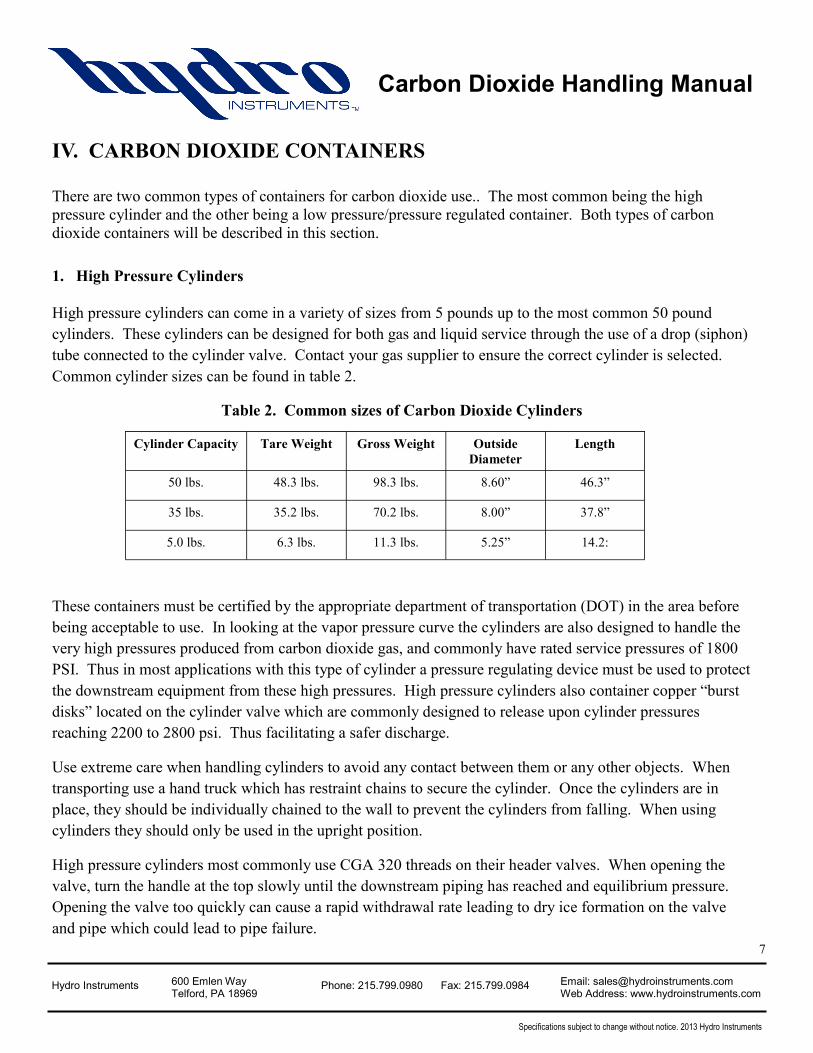
Table 2. Common sizes of Carbon Dioxide Cylinders
These containers must be certified by the appropriate department of transportation (DOT) in the area before
being acceptable to use. In looking at the vapor pressure curve the cylinders are also designed to handle the
very high pressures produced from carbon dioxide gas, and commonly have rated service pressures of 1800
PSI. Thus in most applications with this type of cylinder a pressure regulating device must be used to protect
the downstream equipment from these high pressures. High pressure cylinders also container copper “burst
disks” located on the cylinder valve which are commonly designed to release upon cylinder pressures
reaching 2200 to 2800 psi. Thus facilitating a safer discharge.
Use extreme care when handling cylinders to avoid any contact between them or any other objects. When
transporting use a hand truck which has restraint chains to secure the cylinder. Once the cylinders are in
place, they should be individually chained to the wall to prevent the cylinders from falling. When using
cylinders they should only be used in the upright position.
High pressure cylinders most commonly use CGA 320 threads on their header valves. When opening the
valve, turn the handle at the top slowly until the downstream piping has reached and equilibrium pressure.
Opening the valve too quickly can cause a rapid withdrawal rate leading to dry ice formation on the valve
and pipe which could lead to pipe failure.
7
Cylinder Capacity Tare Weight Gross Weight Outside
Diameter
Length
50 lbs. 48.3 lbs. 98.3 lbs. 8.60” 46.3”
35 lbs. 35.2 lbs. 70.2 lbs. 8.00” 37.8”
5.0 lbs. 6.3 lbs. 11.3 lbs. 5.25” 14.2:
Hydro Instruments 600 Emlen Way Telford, PA 18969
Phone: 215.799.0980 Fax: 215.799.0984 Email: [email protected] Web Address: www.hydroinstruments.com
Specifications subject to change without notice. 2013 Hydro Instruments
Carbon Dioxide Handling Manual
2. Pressure Regulated Containers
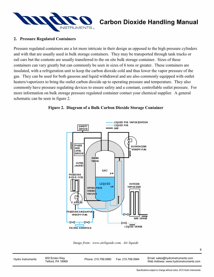
Pressure regulated containers are a lot more intricate in their design as opposed to the high pressure cylinders
and with that are usually used in bulk storage containers. They may be transported through tank trucks or
rail cars but the contents are usually transferred to the on site bulk storage container. Sizes of these
containers can vary greatly but can commonly be seen in sizes of 6 tons or greater. These containers are
insulated, with a refrigeration unit to keep the carbon dioxide cold and thus lower the vapor pressure of the
gas. They can be used for both gaseous and liquid withdrawal and are also commonly equipped with outlet
heaters/vaporizers to bring the outlet carbon dioxide up to operating pressure and temperature. They also
commonly have pressure regulating devices to ensure safety and a constant, controllable outlet pressure. For
more information on bulk storage pressure regulated container contact your chemical supplier. A general
schematic can be seen in figure 2.
Figure 2. Diagram of a Bulk Carbon Dioxide Storage Container
Image from: www.airliquide.com. Air liquide
8
Hydro Instruments 600 Emlen Way Telford, PA 18969
Phone: 215.799.0980 Fax: 215.799.0984 Email: [email protected] Web Address: www.hydroinstruments.com
Specifications subject to change without notice. 2013 Hydro Instruments
Carbon Dioxide Handling Manual
3. Withdrawal Rates
In general, a dependable withdrawal rate from a 50 pound cylinder is around 25 scfh (2.9 lbs/hr) , assuming a
minimum liquid carbon dioxide temperature of 70 ˚F. The maximum rate from any high pressure cylinder is
stated to be 10 % of the total contents per hour. Withdrawal rates from larger containers will vary based on
size. Contact your chemical supplier for more information. Gas withdrawal rates can be increased for brief
periods of time (usually at the start of feed) if necessary, but if prolonged will lead to pipe sweating and frost
formation on the pipes. If a larger feed rate is required the best practice is to manifold cylinders together.
Never apply heat directly to a container, in this case the gas temperature could get too hot and result in an
explosion due to pressure build-up and/or a leak.
Liquid withdrawal from storage containers can reach feed rates considerably higher. Contact your chemical
supply for liquid withdrawal rate information.
The withdrawal rates are primarily based on the temperature of the liquid in the cylinder, and thus the
pressure of the gas. For low withdrawal rates, heat will be able to be transferred from the surrounding air to
the container in time so that there is no drop in temperature or pressure, resulting in a constant withdrawal
rate. If the feed rates are large enough, the air will not be able to transfer the heat quickly enough and the
temperature (and pressure) of the carbon dioxide will drop, thus resulting in a lower feed rate. If high
enough and prolonged enough, this can even result in ice formation around the outside of the container,
further decreasing the withdrawal rate. The most effective way to increase withdrawal rate from a single
container is to circulate the surrounding air with a fan. Again, never apply heat to the containers.
If the gas withdrawal rate from one container is not enough, then multiple containers can be manifolded
together.
V. STORAGE AND USE OF CONTAINERS
Any type of carbon dioxide container should be kept in a cool, dry, temperature stable environment generally
around 60-70 ˚F (15-50 ˚C). They should also be kept out of direct sunlight and securely chained to a wall
(cylinders). Operators, especially in earthquake prone areas, may want to secure cylinders to the ground by
strapping them to the floor. The storage area should be well ventilated and free of flammable materials (see
section III.2). If stored outdoors, the containers should be fenced off so that only proper personnel can reach
them. Containers should not be stored below ground or in heavily trafficked areas. Anywhere carbon
dioxide is being stored or there is a possible chance for a leak. A carbon dioxide gas monitor must always
be installed. Measures should be taken to control the temperature of the chemical storage room to prevent
abnormally high temperatures leading to dangerous pressure build-ups in the storage containers. Be sure to
avoid placing next to radiators or other heat producing objects. 9
Hydro Instruments 600 Emlen Way Telford, PA 18969
Phone: 215.799.0980 Fax: 215.799.0984 Email: [email protected] Web Address: www.hydroinstruments.com
Specifications subject to change without notice. 2013 Hydro Instruments
Carbon Dioxide Handling Manual
Full and empty containers should be stored separately. Cylinders should always be stored in an upright
position and properly secured using chains. Avoid contact between cylinders or any situations where objects
will contact cylinders. Any cylinder that has been dropped or contacted by another object must be set aside
immediately and marked for evaluation.
In most cases, state and/or local regulations will limit the amount of carbon dioxide that can be stored on
site, be sure to check with all the regulations before purchasing.
Do not remove the protective cap from cylinders unless they are ready to be used. It is good practice to use
the containers that have been in storage the longest before using newer ones.
When in use, it is ideal to have a separate scale for each cylinder tared to its specific weight so that you can
monitor chemical supply. There are many different types of scales for cylinders. Scales should be kept as
flat with the floor as possible to minimize lifting of the containers. Some bulk storage containers have a
scale built into the unit. Contact your chemical supplier for more information.
If moving the containers from a storage area to a feed area, an adequate amount of time should be allowed to
let the temperature and pressure of the cylinder stabilize before beginning to feed. All containers that are
manifolded together should be at the same elevation, temperature and pressure before feeding.
VI. PRESSURE MANIFOLDING, PIPING AND OTHER CARBON
DIOXIDE LINE ACCESSORIES
Due to the high pressure of the cylinders and the large size of the bulk storage containers, carbon dioxide
regulators can not be directly mounted to the container in any situation. Thus, some sort of pressure
manifold is required. There is special equipment that goes along with the procedure and it will be described
in the remainder of this section.
1. Pressure Reducing Valves:
Pressure reducing valves for carbon dioxide use are either directly mounted onto the cylinder, or if using
multiple cylinders can be placed downstream on the manifold. Bulk storage containers generally come with
pressure regulating equipment, but check with the chemical supplier as to whether this is included. Pressure
reducing valves should be rated for the high pressures of carbon dioxide and be made of equipment
compatible with carbon dioxide. Most regulating devices for direct mounting to cylinders come with two
pressure gauges, CGA 320 inlet, and an NPT outlet. Damage to vacuum regulators can occur at pressures
above 150 psi. Therefore, the pressure reducing valve needs to ensure that the outlet pressure will remain
below 150 psi.. 10
Hydro Instruments 600 Emlen Way Telford, PA 18969
Phone: 215.799.0980 Fax: 215.799.0984 Email: [email protected] Web Address: www.hydroinstruments.com
Specifications subject to change without notice. 2013 Hydro Instruments
Carbon Dioxide Handling Manual
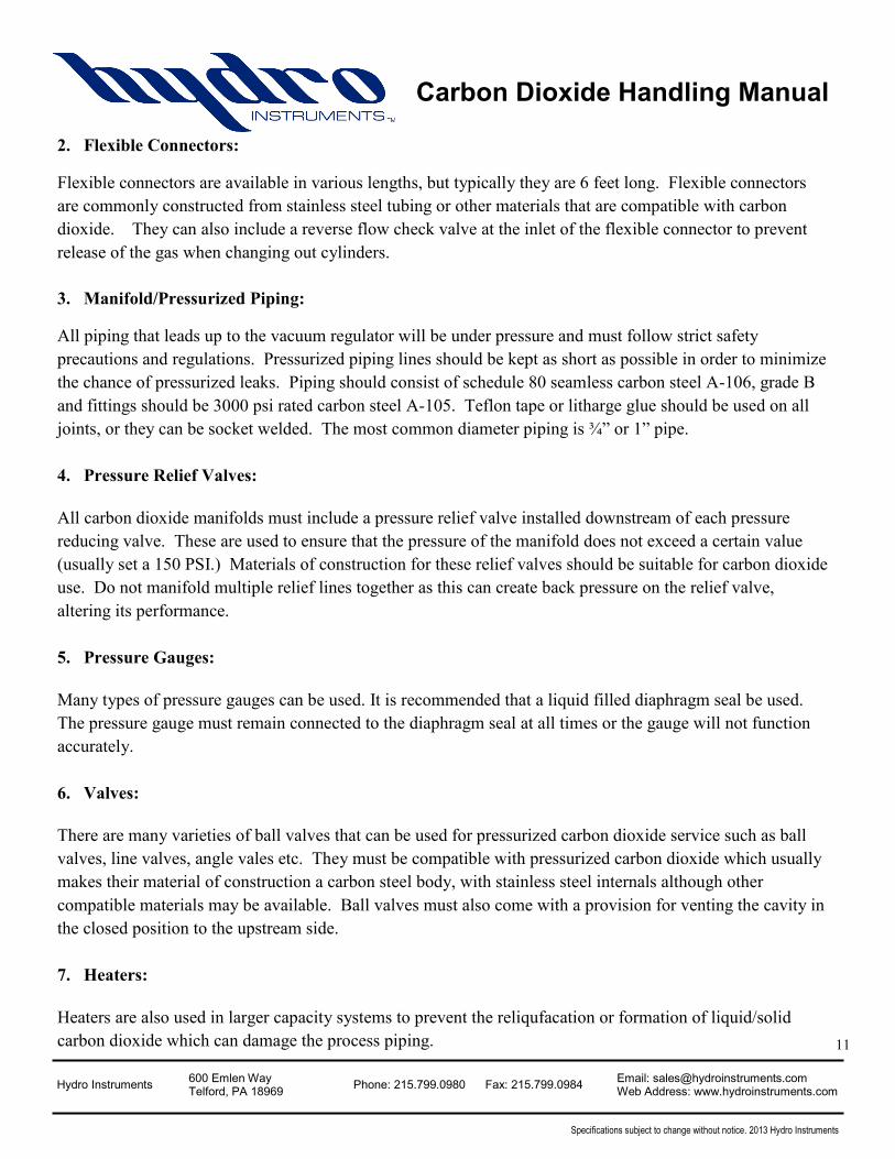
2. Flexible Connectors:
Flexible connectors are available in various lengths, but typically they are 6 feet long. Flexible connectors
are commonly constructed from stainless steel tubing or other materials that are compatible with carbon
dioxide. They can also include a reverse flow check valve at the inlet of the flexible connector to prevent
release of the gas when changing out cylinders.
3. Manifold/Pressurized Piping:
All piping that leads up to the vacuum regulator will be under pressure and must follow strict safety
precautions and regulations. Pressurized piping lines should be kept as short as possible in order to minimize
the chance of pressurized leaks. Piping should consist of schedule 80 seamless carbon steel A-106, grade B
and fittings should be 3000 psi rated carbon steel A-105. Teflon tape or litharge glue should be used on all
joints, or they can be socket welded. The most common diameter piping is ¾” or 1” pipe.
4. Pressure Relief Valves:
All carbon dioxide manifolds must include a pressure relief valve installed downstream of each pressure
reducing valve. These are used to ensure that the pressure of the manifold does not exceed a certain value
(usually set a 150 PSI.) Materials of construction for these relief valves should be suitable for carbon dioxide
use. Do not manifold multiple relief lines together as this can create back pressure on the relief valve,
altering its performance.
5. Pressure Gauges:
Many types of pressure gauges can be used. It is recommended that a liquid filled diaphragm seal be used.
The pressure gauge must remain connected to the diaphragm seal at all times or the gauge will not function
accurately.
6. Valves:
There are many varieties of ball valves that can be used for pressurized carbon dioxide service such as ball
valves, line valves, angle vales etc. They must be compatible with pressurized carbon dioxide which usually
makes their material of construction a carbon steel body, with stainless steel internals although other
compatible materials may be available. Ball valves must also come with a provision for venting the cavity in
the closed position to the upstream side.
7. Heaters:
Heaters are also used in larger capacity systems to prevent the reliqufacation or formation of liquid/solid
carbon dioxide which can damage the process piping.
11
Hydro Instruments 600 Emlen Way Telford, PA 18969
Phone: 215.799.0980 Fax: 215.799.0984 Email: [email protected] Web Address: www.hydroinstruments.com
Specifications subject to change without notice. 2013 Hydro Instruments
Carbon Dioxide Handling Manual
VII. VACUUM PIPING AND OTHER CARBON DIOXIDE LINE
ACCESSORIES
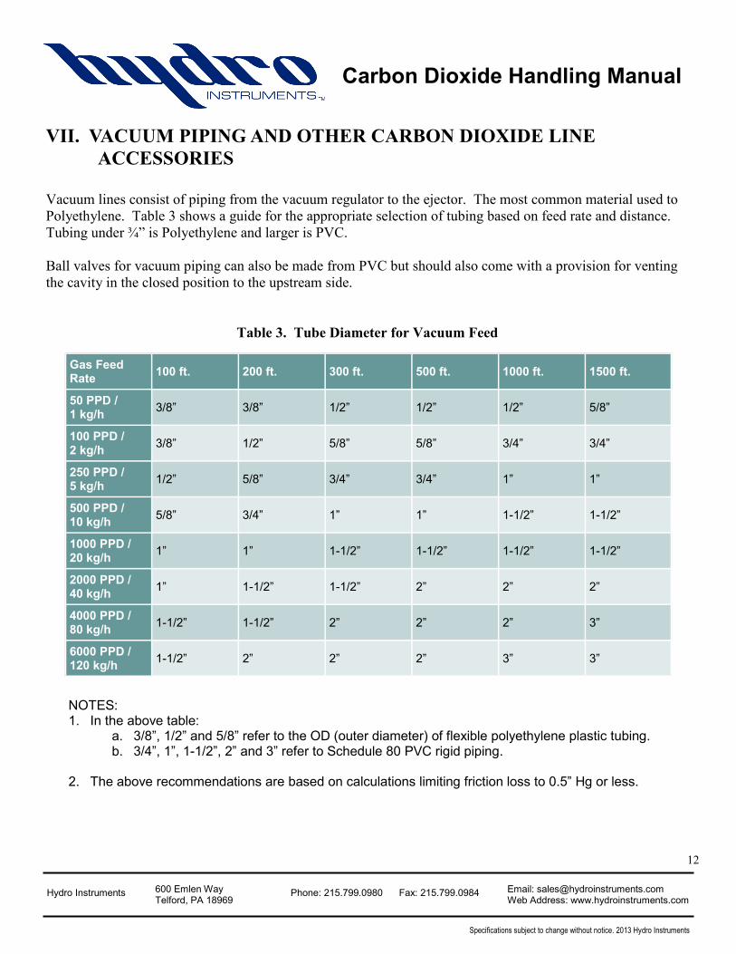
Vacuum lines consist of piping from the vacuum regulator to the ejector. The most common material used to
Polyethylene. Table 3 shows a guide for the appropriate selection of tubing based on feed rate and distance.
Tubing under ¾” is Polyethylene and larger is PVC.
Ball valves for vacuum piping can also be made from PVC but should also come with a provision for venting
the cavity in the closed position to the upstream side.
Table 3. Tube Diameter for Vacuum Feed
12
Gas Feed Rate
100 ft. 200 ft. 300 ft. 500 ft. 1000 ft. 1500 ft.
50 PPD / 1 kg/h
3/8” 3/8” 1/2” 1/2” 1/2” 5/8”
100 PPD / 2 kg/h
3/8” 1/2” 5/8” 5/8” 3/4” 3/4”
250 PPD / 5 kg/h
1/2” 5/8” 3/4” 3/4” 1” 1”
500 PPD / 10 kg/h
5/8” 3/4” 1” 1” 1-1/2” 1-1/2”
1000 PPD / 20 kg/h
1” 1” 1-1/2” 1-1/2” 1-1/2” 1-1/2”
2000 PPD / 40 kg/h
1” 1-1/2” 1-1/2” 2” 2” 2”
4000 PPD / 80 kg/h
1-1/2” 1-1/2” 2” 2” 2” 3”
6000 PPD / 120 kg/h
1-1/2” 2” 2” 2” 3” 3”
NOTES: 1. In the above table:
a. 3/8”, 1/2” and 5/8” refer to the OD (outer diameter) of flexible polyethylene plastic tubing. b. 3/4”, 1”, 1-1/2”, 2” and 3” refer to Schedule 80 PVC rigid piping.
2. The above recommendations are based on calculations limiting friction loss to 0.5” Hg or less.