Embed Size (px)
Citation preview
419D.C. Sigg et al. (eds.), Cardiac Electrophysiology Methods and Models, DOI 10.1007/978-1-4419-6658-2_21, © Springer Science + Business Media, LLC 2010
Abstract Emergence of new management strategies in cardiac electrophysiology, including catheter ablation and device implantation, has lead to the development of better imaging modalities that provide accurate anatomic characterization. Standard fluoroscopy still remains the standard imaging modality during catheter ablation procedures and device implantation. However, fluoroscopy is insufficient for detailed imaging of important anatomical structures, and its desirability is also limited by the inherent patient and staff radiation exposure. Intracardiac echocardiography (ICE), computed tomography (CT), and magnetic resonance imaging (MRI) provide more detailed anatomic visualization. Currently, image integration with either CT or MRI is being used to enhance the acquisition of 3D electroanatomic mapping and to guide radiofrequency ablation. This involves imaging of the patient before the procedure and registration of the anatomy at the time of the procedure. In the future, real-time MRI would allow true real-time 3D imaging, displaying the exact catheter position in regard to the accurate cardiac anatomy without any ionizing radiation. Real-time MRI would allow direct monitoring of surrounding structures such as the esophagus and pericardial space, thus providing real-time feedback to reduce the chance of complications. Finally, fusion imaging with two different imaging modalities such as MRI and positron emission tomography (PET) may allow anatomic and metabolic characterization of a left ventricular scar that may provide improved guidance for ventricular tachycardia ablations. This chapter provides an overview of different imaging modalities in cardiac electrophysiology with an emphasis on CT and MRI.
21.1 Introduction
The field of cardiac electrophysiology has developed rapidly over the past decade with new exciting treatment strategies. Radiofrequency (RF) catheter ablation tech-niques have had a dramatic impact on the treatment of various forms of arrhythmias.
M.N. Jameel (*) Department of Medicine, University of Minnesota, Minneapolis, MN, USA e-mail: [email protected]
Chapter 21Cardiac CT/MRI Imaging for Electrophysiology
Mohammad Nurulqadr Jameel and Abdul Mansoor
420 M.N. Jameel and A. Mansoor
Similarly, transvenous device implantation has emerged as an important modality to prevent sudden cardiac death, and cardiac resynchronization therapy (CRT) has played a major role in management of heart failure patients.
Defining a patient’s cardiac anatomy accurately has become essential for successful electrophysiologic procedures. Until recently, fluoroscopy provided the most important guidance while advancing and positioning catheters. However, fluoroscopy is often insufficient for the detailed imaging of important anatomical structures and its desirability is also limited by inherent patient and staff radiation exposure. Likewise, echocardiography also allows for real-time imaging of cardiac anatomy, e.g., intracardiac echocardiography (ICE) can be used for direct visualiza-tion of anatomic structures within the heart and real-time imaging during catheter placement. However, current systems for obtaining ICE windows may not be able to accurately delineate anatomic structures in the left atrium from the right atrium. Therefore, neither of these techniques employed alone allow for electrical mapping of the heart.
In the late 1990s, new nonfluoroscopic mapping techniques were developed in which the electrical and anatomic data were combined into 3D electroanatomic models. These systems continuously record the locations of roving mapping cath-eters and create maps of electrical activities in 3D space. However, these mapping systems are quite expensive and are also limited by the anatomic information collected by the roving catheters at certain points with a rough geometric approxi-mation of the endocardial cavity. Of interest here, newer imaging modalities such as computed tomography (CT) and magnetic resonance imaging (MRI) have allowed detailed anatomical examination of the heart. Furthermore, this informa-tion can be integrated into electroanatomic maps. Currently, much research is being performed to assess the utility of real-time MRI for electrophysiologic procedures. In this chapter, we will briefly review the different imaging modalities used in cardiac electrophysiology. There will be a brief discussion of ICE followed by in-depth review of the roles of both CT and MRI in the evolving field of cardiac electrophysiology.
21.2 Intracardiac Echocardiography
Intracardiac echocardiography is currently a useful imaging modality in both the clinical and experimental electrophysiology laboratories. There are two types of ICE transducers – mechanical and phased array. Today, the only commercially available mechanical ICE catheter for clinical use is a 9 Fr and 4-cm radial imaging field.1 Utilizing radial imaging, it only allows for views within the horizontal plane. Furthermore, this catheter does not have a deflectable tip or Doppler capabilities. On the other hand, phased array ICE catheters have Doppler capabilities, deflect-able tips, and image capabilities in a longitudinal fashion with a 90° window that extends to 2–12 cm deep (8–10 Fr).2,3 To date, ICE has several common clinical applications. It has been used to guide transseptal punctures for ultimate catheter
42121 Cardiac CT/MRI Imaging for Electrophysiology
access to the left atrium.4,5 In other words, it can be employed to provide reasonable images of the fossa ovalis, and thus can be used for confirming needle placement prior to transseptal puncture to reduce the risk of atrial or aortic perforation. It can also aid in the identification of unusual anatomy in the atria that may ultimately impact ablation strategies.
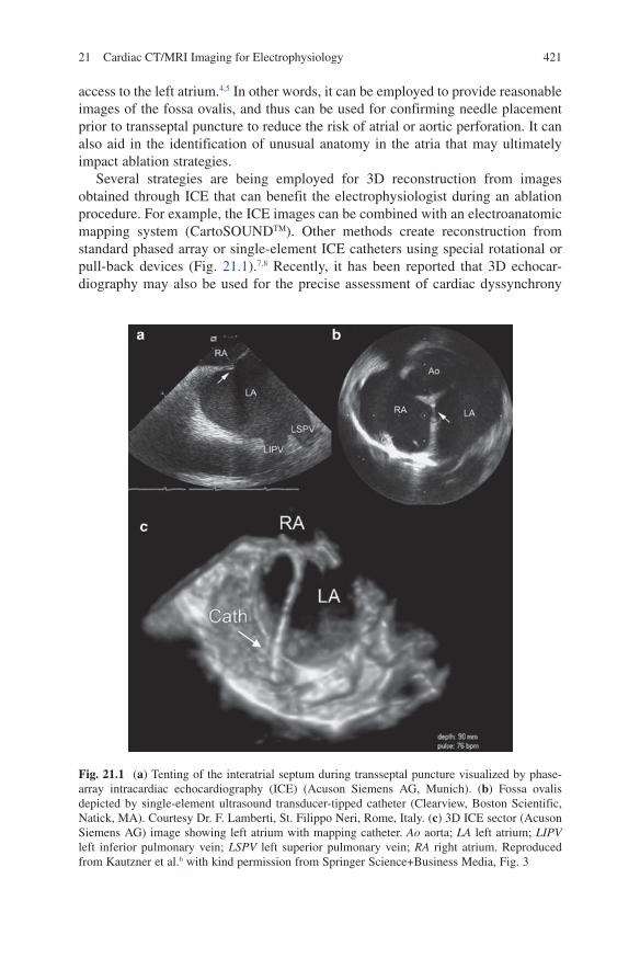
Several strategies are being employed for 3D reconstruction from images obtained through ICE that can benefit the electrophysiologist during an ablation procedure. For example, the ICE images can be combined with an electroanatomic mapping system (CartoSOUNDTM). Other methods create reconstruction from standard phased array or single-element ICE catheters using special rotational or pull-back devices (Fig. 21.1).7,8 Recently, it has been reported that 3D echocar-diography may also be used for the precise assessment of cardiac dyssynchrony
Fig. 21.1 (a) Tenting of the interatrial septum during transseptal puncture visualized by phase-array intracardiac echocardiography (ICE) (Acuson Siemens AG, Munich). (b) Fossa ovalis depicted by single-element ultrasound transducer-tipped catheter (Clearview, Boston Scientific, Natick, MA). Courtesy Dr. F. Lamberti, St. Filippo Neri, Rome, Italy. (c) 3D ICE sector (Acuson Siemens AG) image showing left atrium with mapping catheter. Ao aorta; LA left atrium; LIPV left inferior pulmonary vein; LSPV left superior pulmonary vein; RA right atrium. Reproduced from Kautzner et al.6 with kind permission from Springer Science+Business Media, Fig. 3
422 M.N. Jameel and A. Mansoor
before CRT in order to minimize the number of nonresponders to this treatment and optimize the left ventricular lead positioning for maximum hemodynamic benefits.9
21.3 Computed Tomography
In this section, we briefly summarize several key areas in clinical cardiac electrophysiology where cardiac CT has made an impact or is considered to have a strong future role. The ability of CT to image the cardiac structures with excellent temporal and spatial resolution has improved tremendously over the past two decades. Typically, cardiac CT utilizes either a moving electron beam or revolving X-ray source array to generate images of cardiac structures. The procedure is rapid and noninvasive with scanning times on the order of seconds and temporal resolu-tion as low as 100 ms. Yet, quality image production of the functioning heart requires acquisition gating to ECG trigger points in order to overcome cardiac motion as well as time intravenous injection of iodinated contrast material. Common applications of CT relative to clinical cardiac electrophysiology include (1) atrial fibrillation ablation procedures; (2) atrial flutter ablation procedures; (3) biventricular lead insertions for CRT; and/or (4) evaluations of arrhythmogenic substrate. However, it should be realized that cardiac CT is not a zero-risk proce-dure. Radiation exposure is a necessary consequence of these procedures, and this exposure is actually increased with newer generation 64-slice scanners. The typical radiation dose for a cardiac structural evaluation is on the order of 10 mSv.10 Nevertheless, this exposure can be reduced by as much as 50% by employing ECG-gated attenuation techniques that limit scanning during less informative parts of the cardiac cycle.11 Yet, an increased heart rate is a known factor that can be associated with degraded image quality through motion artifact; this can often be minimized by the use of beta-blockers and optimal selection of reconstruction windows.12,13 When employed, cardiac CT may also expose a patient to iodinated contrast materi-als that can be nephrotoxic.
21.3.1 Ablation of Atrial Fibrillation
It has been shown that pulmonary veins are an important source of ectopic beats initiating paroxysms of atrial fibrillation (AF) and that catheter ablation may successfully eliminate these triggers.14 Ostial segmental isolation of the pulmonary vein and anatomically-based circumferential ablation are two commonly used abla-tion strategies.14–17 Yet, it is the operator’s understanding of intracardiac anatomy that is necessary for a successful and safe ablation procedure. More specifically, knowledge of the pulmonary vein anatomy and exact location of the junction of the pulmonary vein and left atrium, in particular, are required for ablation. Furthermore,
42321 Cardiac CT/MRI Imaging for Electrophysiology
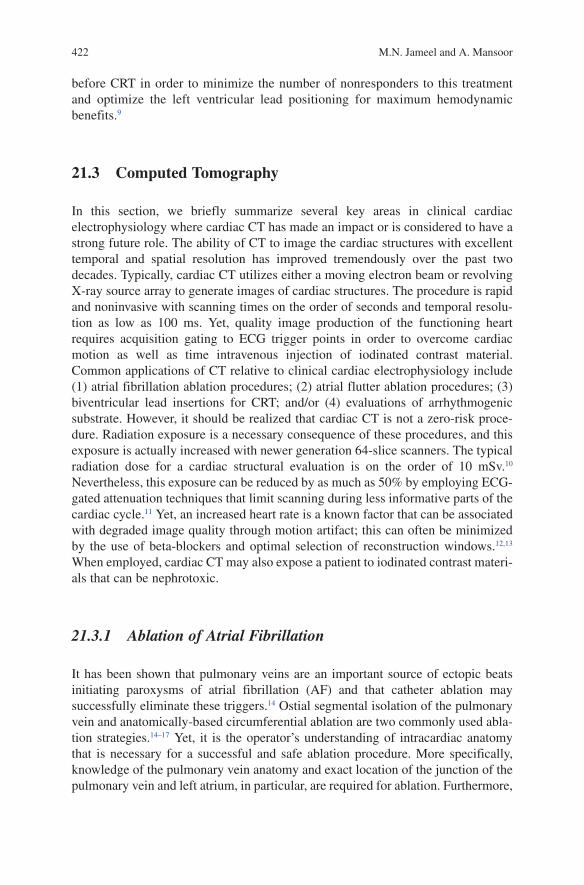
only 70% of patients undergoing AF ablation have traditional anatomy with four pulmonary veins (each having an individual ostium), while the other 30% have various anatomic variants.18–20 Nevertheless, multidimensional computed tomography (MDCT) can provide an accurate 3D reconstruction of the left atrium and associated pulmonary veins (Fig. 21.2).22,23 Results of such imaging have also been compared to other modalities24–26; for instance, in a blinded head-to-head comparison, cardiac CT was considered superior to ICE, transesophageal echocardiography, and/or reflux venography in detecting the four typical pulmonary vein ostia.26 In another study of 42 patients, MDCT was again reported as more sensitive than ICE in detecting variations in pulmonary vein anatomy.24
Most of the information regarding pulmonary vein location and ostia can be obtained from axial and multiplanar reformatted images. Yet, 3D and endoluminal views of the left atrium and pulmonary veins are also helpful in guiding electro-physiologists in procedure planning prior to AF ablation. At present, catheter abla-tion of AF is by far the most common electrophysiologic indication for cardiac multidetector CT. Knowledge of the location, length, and number of pulmonary vein ostia and branches, prior to an ablation procedure, help guide curative proce-dures. More specifically, MDCT can accurately define the pulmonary vein ostium at the junction with the left atrium, pulmonary venous branch points, and the saddle of left atrial tissue in between the ipsilateral pulmonary venous ostia.20 It should be noted that the pulmonary venous trunk is typically defined as the distance from the
Fig. 21.2 Posterior 3D image of the left atrium and pulmonary veins demonstrates circumferential pulmonary vein ablation. Circumferential ablation lines (red) around two pulmonary vein lesions are connected by a roof ablation line (green). A mitral isthmus ablati on line (blue) was created between the left inferior pulmonary vein and the lateral mitral annulus (arrows). AAo ascending aorta; IVC inferior vena cava; LA left atrium; LAA left atrial appendage; LCx left circumflex artery; LIPV left inferior pulmonary vein; LSPV left superior pulmonary vein; RIPV right inferior pulmonary vein; RSPV right superior pulmonary vein. Reproduced from Saremi et al.21
424 M.N. Jameel and A. Mansoor
ostium to the first-order branch. It is important to gain insight about the trunk length and ostial diameters of each vein which will, in turn, influence the selection of catheter diameters. It should also be recognized that the pulmonary veins and their ostia are usually oval. As such, with use of multiplanar reformations, two orthogo-nal pulmonary vein measurements can be obtained in a plane perpendicular to the long axis of a given vessel, to better define their shapes.
From a clinical imaging standpoint, the most common anomalies found include ipsilateral single pulmonary vein ostium, accessory pulmonary veins, and early branching (£5 mm from the ostium of the main pulmonary vein). Additionally, single pulmonary vein drainage into the left atrium often occurs on the left side, and this is similar to that in the swine heart. Such common ostia are generally larger than the individual pulmonary venous ostia, and the myocardial sleeve around the common ostia is circumferential. As such, segmental PZ isolation is rarely feasible in these patients.27 Accessory pulmonary veins in humans are more commonly found on the right side. Accessory veins usually drain a pulmonary lobe directly into the left atrium with the right middle and right lower lobes most commonly having accessory drainage. Thus, as would be expected, the ostia of these accessory veins are often smaller than those of the true pulmonary veins, thus they are at a higher risk for developing stenosis following an ablation procedure.23 When an accessory vein is located between the upper and lower pulmonary veins, it may be difficult to deliver RF lesions between the upper and lower pulmonary veins due to the small amount of atrial tissue between the three ostia.27 Unstable catheter position on a small isthmus of atrial tissue can lead to delivering lesions in the pulmonary vein, thus increasing the risk for pulmonary vein stenosis. Accessory veins may also drain into different locations in the left atrium. If this is not known prior to the ablation procedure, the accessory vein may be missed and not isolated with the lesions delivered. Early branching of the pulmonary vein may place the branch close to the left atrial wall. Ablation of the atrial wall at these sites can lead to damage to the pulmonary vein branch and stenosis or occlusion of the branch.27
In addition to the detailed pulmonary venous anatomy example above, MDCT can also be used to evaluate the presence of a left atrial thrombus prior to under-going catheter ablation. To date, the transesophageal echocardiogram (TEE) is considered the gold standard for visualizing a thrombus, however, in a small study, MDCT reconstruction of the left atrium and left atrial appendage identified all patients with a left atrium and left atrial appendage thrombus as observed on TEE, with no false positive results.28
Multidetector CT is valuable for defining the relationship of the esophagus to the posterior left atrial wall prior to arrhythmia ablation.29 Due to the proximity of the esophagus to the left atrium, RF lesions delivered in the left atrium over the esopha-gus can lead to atrioesophageal fistula formation.30–32 However, the esophagus can migrate to different positions during ablation procedures and real-time imaging would be extremely useful to avoid creating lesions in high-risk areas.
Recently, image integration systems for catheter ablation procedures have been introduced.33–35 With this new technology, 3D multidetector CT scans acquired
42521 Cardiac CT/MRI Imaging for Electrophysiology
prior to ablation can be fused with electroanatomic mapping data at the time of the procedure, with an accuracy of 2-mm distance between corresponding points on the two images.35 This fusion approach allows for enhanced positioning of the catheter in the anatomic area of interest, thereby facilitating ablation procedures for AF.
The MDCT can also be useful in diagnosing the complications of ablation procedures such as pulmonary vein stenosis, dissection, and/or perforation. For example, when segmental pulmonary vein ostial ablations are performed, the ostial diameters can narrow by an average of 1.5 mm, and a 28–61% focal stenosis has been reported to occur within 7.6 mm from the ostium in 3% of cases.36 In a recent prospective study using CT, it was shown that symptomatic pulmonary vein stenosis can even develop several months after a pulmonary vein isolation procedure, and this complication is more common when RF is applied inside the distal pulmonary veins.37 Nevertheless, this delayed presentation of acquired pulmonary vein stenosis and the simplicity of outpatient cardiac CT make it a useful tool for potentially identifying this condition and for serial follow-ups.
It should be noted that the recurrence of atrial arrhythmias is not uncommon, particularly in the left atrial isthmus (the area between the orifice of the left inferior pulmonary vein and the posteroinferior mitral annulus).38,39 For example, the length of the left atrial isthmus is highly variable, reported by Becker as ranging from 17 to 51 mm.40 Of interest, it has been shown that the isthmus is longer in patients with AF.41 Importantly, the use of multidetector CT can accurately demonstrate the boundaries of this area, including the exact location of the mitral valve ring, coro-nary sinus, and great cardiac veins (GCVs), as well as their anatomic variants.41 It should be noted that a serious complication of left atrial isthmus ablation is potential injury to the adjacent vessels, including the LCx artery.42 Again, the use of multide-tector CT can demonstrate the relationships between the coronary sinus, LCx artery, and left atrial wall, thereby providing a safer approach in this type of ablation.
21.3.2 Atrial Flutter Ablation
The most common type of atrial flutter is isthmus-dependent atrial flutter, in which the reentrant circuit is confined to the tricuspid annulus with the wavefront progressing in either a counterclockwise or clockwise direction across the cavotri-cuspid isthmus between the inferior vena cava and the tricuspid annulus.43 From an anatomical standpoint, this is a relatively narrow target but can easily be reached with ablation catheters introduced from the inferior vena cava. With new catheter techniques, the success rate for ablation of this form of atrial flutter is generally over 95%.44 Most consider that cardiac CT is helpful in characterizing the cavotri-cuspid isthmus, including its size, depth, and anatomic relationship with the inferior vena cava, eustachian ridge, and coronary sinus ostium. Furthermore, cardiac CT imaging helps to depict the pouches and recesses that are commonly present along the cavotricuspid isthmus and that sometimes make it clinically difficult to create a complete ablation line of block in the isthmus.
426 M.N. Jameel and A. Mansoor
21.3.3 Biventricular Lead Insertion for Cardiac Resynchronization Therapy
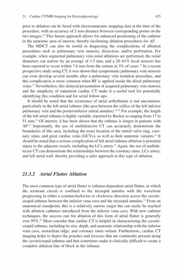
CRT with biventricular pacing can improve the synchrony of contractions of the two ventricles, leading to improved hemodynamics and left ventricular ejection fraction. Pacing of the left ventricle by placing transvenous leads is accomplished via access to the coronary sinus. However, the presence and identification of a suitable branch for placement from the coronary sinus is crucial for positioning the left ventricular lead with a transvenous approach. Recently, multidetector CT has been used to evaluate the coronary sinus and coronary veins prior to lead place-ment (Fig. 21.3).45–48 This allows for visualization of the major components of the cardiac venous system, including the coronary sinus, GCV, and/or anterior and posterior interventricular veins. The GCV typically courses alongside the LCx artery and subsequently drains into the coronary sinus48; it receives two main branches, namely the left marginal vein (LMV) (which courses along the lateral border of the left ventricle) and the posterior vein or posterolateral vein (PLV). The LMV and PLV are often the target veins for left-sided pacemaker lead placement for CRT. Ideally, the anatomy of the cardiac venous system would be assessed
Fig. 21.3 Three-dimensional image depicts the cardiac venous anatomy. The great cardiac vein (GCV) receives two main branches: the left marginal vein (LMV), along the lateral border of the left ventricle, and the posterior vein or posterolateral vein (PLV). Implantation of the coronary sinus (CS) lead usually involves the lateral and posterior branches, which are quite variable in number, tortuosity, dimension, and angulation with the GCV. PIV posterior interventricular vein. Reproduced from Saremi et al.21
42721 Cardiac CT/MRI Imaging for Electrophysiology
noninvasively on an outpatient basis, before referring the patient for CRT implantation. It should be noted that both electron-beam computed tomography and MDCT provide excellent images of the coronary venous system.45,49–51 These structures are better identified during systole, but lead to greater motion artifact.51 Furthermore, the 3D reconstruction of CT images has been instrumental in revealing the anatomic variability of the coronary venous system. Of course, such knowledge has implications for lead implantation because preprocedure identification of coronary venous anatomy would likely decrease overall procedure times. For example, common anatomic variants seen on CT include a small cardiac vein that drains into the right atrium by a separate ostium from the coronary sinus and a posterior interventricular vein that fails to connect to the coronary sinus.45 Imaging with CT also shows variability in coronary vein branch angles and segment lengths.47
Several variations in coronary venous anatomy can, in some individuals, make the coronary sinus approach difficult and/or can lead to suboptimal resynchronization. Specific examples, all of which are well seen on cardiac CT, include (1) small or absent lateral branches; (2) veins with acute branch angles; (3) compression of the coronary sinus against the spine because of cardiomegaly; (4) prominent Thebesian valves blocking the coronary sinus ostium; (5) coronary sinus atresia; and (6) persistent left superior vena cava.52–
56 It should also be noted that left phrenic nerve stimulation after CRT is a well-recognized complication.57 The left phrenic nerve passes at a distance of less than 3 mm from the LMV in 43% of cadaveric hearts.58 Given the ana-tomic variability of the target coronary veins for CRT and the proximity of the left phrenic nerve to these structures, it is important to understand their rela-tionship in order to avoid the phrenic nerve during left ventricular lead place-ment. As such, coronary multidetector CT angiography has the potential to help detect the left phrenic nerve in its neurovascular bundle as it passes over the left ventricular pericardium.59 Finally, it should be noted that, to date, no controlled trial data exist to suggest that procedural success or complications are affected by the specific use of cardiac CT in CRT.
21.3.4 Evaluation of Arrhythmogenic Substrate
It has been recently reported that cardiac CT may be useful in identifying arrhythmogenic substrates within the myocardium. More specifically, it can be used to visualize the dysplastic changes of arrhythmogenic right ventricular dysplasia.60 Similarly, in Brugada syndrome which is an inheritable cardiac membrane channel disorder, cardiac CT can be helpful to identify focal cardiac abnormalities.61 Additionally, it should be mentioned that age-related fatty infiltration of the right ventricle can be seen on cardiac CT in asymptomatic patients, and it may lead to unnecessary workup if CT is used as the primary screening modality without adequate pretest suspicion.62,63
428 M.N. Jameel and A. Mansoor
21.4 Magnetic Resonance Imaging
Magnetic resonance imaging is based upon the principles of nuclear magnetic resonance. The human body is primarily fat and water, both which contain hydrogen atoms. More specifically, the hydrogen nuclei have an inherent nuclear magnetic resonance signal which is imaged by MRI. Importantly, cardiac motion compensation is performed by synchronization of the image acquisition to the simultaneously recorded ECG signal. In addition to cardiac cycle motion, another potential source of image distortion is respiratory activity. Yet, due to the development of faster MR imaging techniques such as echo-planar imaging and turbo field echo imaging, it is possible to acquire images during short breath hold of around 15 s. To date, MRI has been commonly employed for the assessment of cardiac anatomy, congenital heart disease, blood flow, valvular pathology, myocardial infarction, and/or human heart viability. Both prospective and retrospective cardiac imaging studies can be performed.
One advantage of MRI over CT is that it has no associated radiation exposure and does not involve administration of a nephrotoxic contrast dye, although gadolinium exposure has been linked to development of nephrogenic systemic fibrosis in patients with renal insufficiency.64 Recently, MRI has been increas-ingly used for electrophysiological applications and may have a very important role in the future. The relative role of MRI in specific fields in electrophysiology is discussed below.
21.4.1 Atrial Fibrillation Ablation
Imaging studies using MRI can be done prior to atrial fibrillation ablation to obtain the same important anatomic information as provided by CT. For example, abnormal pulmonary vein anatomy can be identified in up to 38% of patients by MRI65–67; this includes a common left or inferior truncus, addi-tional right middle cardiac vein, or pulmonary roof veins. In many clinical electrophysiology centers, pre-ablation imaging of the left atrium has become part of the standard evaluation for atrial fibrillation ablation. In many cases, high-resolution MRI is able to visualize left atrial ganglionated plexi and could potentially be used to facilitate the newer ablation techniques targeting these plexi for atrial fibrillation treatment.68 In addition, MRI along with CT also has a role in identifying procedural complications postablation. Specifically, MRI has been well validated in the diagnosis of symptomatic and asymptomatic pulmonary vein narrowing and long-term follow-up.69–73 Furthermore, the use of MRI has the potential to delineate the course of the esophagus and potentially diagnose atrioesophageal fistulas which have a mortality of up to 50%.31,32,74
42921 Cardiac CT/MRI Imaging for Electrophysiology
21.4.2 Ventricular Tachycardia Ablation
It is critical to identify that ventricular tachycardia ablation and other complex ablation procedures require detailed 3D information of the myocardial scar, its transmural extent, and border zones.75–77 Specifically, contrast-enhanced MRI can be used to determine relative myocardial viability, and also allows for accurate localization and extent of nonviable scar tissue. The technique of delayed hyperen-hancement is characterized by enhancement of myocardium more than 10 min after contrast injection, and the visualization is then suggestive of myocardial necrosis or scar tissue. Thus, in some cases, MRI can be useful to evaluate the myocardium for scar tissue that may be arrhythmogenic and act as a road map to guide ablation procedures. Yet, it should also be noted that channels of surviving myocardium within the scar can participate in the tachycardia circuit and may represent potential ablation targets. It is foreseen that newer mapping systems will utilize volume imaging and integration to display this information during the ablation procedure and provide additional anatomic guidance for ablations. Finally, MRI can also visualize the involved myocardial regions in diseases such as sarcoidosis and arrhythmogenic right ventricular dysplasia, and may provide new anatomically guided ablation approaches.78,79
21.4.3 Subsequent Imaging of Ablation Lesions with Magnetic Resonance Imaging
Myocardial scar tissue after myocardial infarction can be seen as delayed enhancement, and this same concept can be utilized to subsequently study formed ablation lesions. For example, in one recent study, RF ablation within the right ventricular apex could be visualized in six mongrel dogs after about 2 min, with an increase in signal intensity over the first 12 ± 2.1 min.80 In another study, multiple RV lesions showed a characteristic enhancement pattern that differed significantly from the typical appearance seen in myocardial infarction.81 In this study, four distinct phases of contrast enhancement were noted: (1) during the first phase, directly after injection of gadolinium contrast, RF lesions were clearly seen as contrast-free areas of low intensity; (2) a second phase demonstrated an increasing diffusion of the contrast material slowly diffusing from the lesion periphery to the lesion center; (3) complete delayed enhancement depended on the lesion size and was only reached after 98 ± 21 min; and (4) the lesions remained visible during a wash out period of >12 h, with slowly decreasing size, signal-to-noise ratio, and contrast-to-noise ratio. These different kinetics, compared to myocardial infarction, are likely due to a complete loss of the cellular architecture and total disruption of the vascular system. Thus, in the case of an ablation, enhancement relies mostly on a diffusion process starting from the lesion periphery. It should be noted that lesion size measured during the first three phases of contrast enhancement correlated well
430 M.N. Jameel and A. Mansoor
with the histopathological lesion size measured during necropsy.81 Furthermore, knowledge about differential enhancement kinetics can be used to determine the relative age of an ablation lesion. Given the recent reports of nephrogenic systemic fibrosis associated with gadolinium, the noncontrast-enhanced visualization of ablation lesions is of increasing interest. Specifically, in a recent study, it was reported that noncontrast-enhanced MRI allowed for accurate assessment of RF ablation and its intralesional pathology during a 12-h follow-up.82 It was shown that lesions were successfully visualized with T2- and T1-weighted images 30 min to 12 h after RF ablation. It was noted that T2 images were more consistent and displayed a characteristic elliptical, high-signal core with a surrounding 0.5-mm low-intensity rim that, on histopathology, corresponded to the central tissue necrosis and the transition zone, respectively; T1 images showed a less remarkable increase in signal intensity without a surrounding rim. Nevertheless, lesion sizes and appearances were well defined and unchanged during the 12-h follow-up, i.e., contrast-to-noise ratio was independent of applied RF energy and allowed accurate assessment of RF ablation at all time points. Importantly, transmural lesions, interlesional gaps, and intralesional pathology could be reliably predicted in >90% of cases.82
21.4.4 Real-Time Magnetic Resonance Imaging
Real-time MRI is an exciting tool that will likely have a tremendous impact on the field of electrophysiology. It is expected to allow true real-time 3D imaging that displays the exact catheter position in regard to accurate cardiac anatomy. Further, real-time MRI would allow direct monitoring of surrounding structures such as the esophagus and pericardial space, thus providing necessary feedback to reduce the chance of complications. It will also enable monitoring of the catheter–tissue contact and visualize ablation lesions and/or potential lesion gaps. Importantly, even lengthy electrophysiologic procedures would not require ionizing radiation. Finally, to date, while initial unit acquisition costs are high, they are in the same range as a current state-of-the-art biplane fluoroscopy system.
Despite the clinical potential for applying real-time MRI, to date, its use and assessment of utility has been limited to developmental work in only a few academic centers83–85; in its present form, real-time MRI has many technical challenges. For example, catheter guidance by real-time MRI may be limited by catheter heating,86 yet this can be partially prevented by not allowing parts of the catheter to potentially function as a RF antenna, thus protecting the patient from hazardous heating effects.87 Secondly, real-time MRI has the disadvantage of elec-tromagnetic signal interference.88 To avoid potentially hazardous magnetic forces, new electrophysiological equipment without ferro-magnetic properties or long fiberoptic connections is rapidly being developed. A third potential limitation is that image distortion may occur89; as such, new catheter designs have been devel-oped to minimize any artifacts distorting the image quality. In a final example,
43121 Cardiac CT/MRI Imaging for Electrophysiology
during scanning protocols with high signal absorption rates, it is challenging to measure intracardiac signals in the millivolt range. Yet, faster imaging sequences continue to evolve to provide sufficient spatial and temporal resolution.
Recently, the first real-time MRI-guided electrophysiological studies in humans were performed at Johns Hopkins Hospital.83 These investigators employed a real-time fast gradient-recalled-echo sequence to minimize metal susceptibility artifacts and specific absorption rate. In these studies, the imaging speed was approximately 5 frames/s and was considered adequate for catheter guidance. The investigators performed both passive (visualize catheter components based on magnetic properties) and active catheter tracking (utilize a signal received by the catheter to provide a local region of high signal through incorporation of RF coils). They noted that active catheters were easier to localize and also did not have any associated catheter trauma. Importantly, they noted that the catheters were success-fully positioned at the right atrial, His bundle, and right ventricular target sites, and adequate target catheter localization was confirmed with recording of intracardiac electrograms.
Given the complication of gastroesophageal fistulas during ablation procedures, real-time MRI also offers the potential for thermometry, i.e., one could acquire temperature measurements in the adjacent esophagus. This is currently being performed during ablation of metastatic liver cancer90 and could potentially be used to assess intracardiac energy delivery and prevent unnecessary complications.
In another recent study, an MRI-based electroanatomic system was designed to navigate catheters to the left ventricle, in vivo, in swine using MR tracking of micro-coils incorporated into the catheters91; both retrograde aortic and transseptal approaches were used. More specifically, the catheters were manipulated to all desired endocardial locations to project electrophysiological electrogram information to the ventricular shell. Finally, to allow ventricular substrate mapping, these investi-gators were able to integrate this information with both 3D MR angiography and myocardial delayed enhancement images. Importantly, in all animals, the chronically infarcted myocardium was correctly identified. Thus, it appears that these findings support the potential to clinically use active MR tracking techniques to perform electrophysiology procedures completely in an MR imaging environment.
21.5 Fusion Imaging/Multimodal Imaging
In this investigative strategy, multiple imaging modalities are combined to allow supplemental and synergistic evaluation and guidance for ablation procedures. For example, MRI and positron emission tomography (PET) are simultaneously performed to allow the anatomic and metabolic characterization of a left ventricular scar to optimize guidance in ventricular tachycardia ablative procedures. In other words, this strategy can identify surviving myocardial channels or nontransmural infarcts that were not detected by the current gold standard of voltage mapping. Furthermore, in patients with structural heart disease, combined PET and CT has
432 M.N. Jameel and A. Mansoor
the potential to provide supplementary scar characterization by displaying additional metabolic (PET) and morphologic (CT) tissue-specific information.92 Importantly, 3D scar maps can be created from the imaging datasets and uploaded into clinical mapping systems, and then employed to facilitate substrate-guided ablation proce-dures. This approach, although currently equipment heavy (i.e., a large facility investment), has the potential to shorten procedure times, decrease complications, and improve procedural success.
21.6 Conclusion
Enhanced cardiac imaging has become extremely important as a vital component of cardiac electrophysiology, as newer techniques provide for accurate anatomic char-acterization. To date, standard fluoroscopy remains the widespread standard imaging modality during catheter ablation procedures and device implantation. However, in centers of excellence, ICE, CT, and MRI techniques will have increasing roles in the future. Currently, image integration with either CT or MRI is being used to enhance the acquisition of 3D electroanatomic mapping and guide RF ablation; as such, this involves imaging of the patient before the procedure and registration of the anatomy at the time of the procedure. In the future, real-time MRI will likely allow for cath-eter navigation and enable the user to conduct procedures in an MR imaging environment.
References
1. Chu E, Fitzpatrick AP, Chin MC, et al. Radiofrequency catheter ablation guided by intracardiac echocardiography. Circulation 1994; 89:1301–5.
2. Bruce CJ, Nishimura RA, Rihal CS, et al. Intracardiac echocardiography in the interventional catheterization laboratory: preliminary experience with a novel, phased-array transducer. Am J Cardiol 2002; 89:635–40.
3. Bruce CJ, Packer DL, Seward JB. Intracardiac Doppler hemodynamics and flow: new vector, phased-array ultrasound-tipped catheter. Am J Cardiol 1999; 83:1509–12.
4. Daoud EG, Kalbfleisch SJ, Hummel JD. Intracardiac echocardiography to guide transseptal left heart catheterization for radiofrequency catheter ablation. J Cardiovasc Electrophysiol 1999; 10:358–63.
5. Epstein LM, Smith T, TenHoff H. Nonfluoroscopic transseptal catheterization: safety and effi-cacy of intracardiac echocardiographic guidance. J Cardiovasc Electrophysiol 1998; 9:625–30.
6. Kautzner J, Peichl P. 3D and 4D echo – applications in EP laboratory procedures. J Interv Card Electrophysiol 2008; 22:139–44.
7. Knackstedt C, Franke A, Mischke K, et al. Semi-automated 3-dimensional intracardiac echocardiography: development and initial clinical experience of a new system to guide abla-tion procedures. Heart Rhythm 2006; 3:1453–9.
8. Szili-Torok T, McFadden EP, Jordaens LJ, et al. Visualization of elusive structures using intrac-ardiac echocardiography: insights from electrophysiology. Cardiovasc Ultrasound 2004; 2:6.
43321 Cardiac CT/MRI Imaging for Electrophysiology
9. Kapetanakis S, Kearney MT, Siva A, et al. Real-time three-dimensional echocardiography: a novel technique to quantify global left ventricular mechanical dyssynchrony. Circulation 2005; 112:992–1000.
10. Morin RL, Gerber TC, McCollough CH. Radiation dose in computed tomography of the heart. Circulation 2003; 107:917–22.
11. Kuettner A, Beck T, Drosch T, et al. Diagnostic accuracy of noninvasive coronary imaging using 16-detector slice spiral computed tomography with 188 ms temporal resolution. J Am Coll Cardiol 2005; 45:123–7.
12. Choi HS, Choi BW, Choe KO, et al. Pitfalls, artifacts, and remedies in multi-detector row CT coronary angiography. Radiographics 2004; 24:787–800.
13. Leschka S, Scheffel H, Desbiolles L, et al. Image quality and reconstruction intervals of dual-source CT coronary angiography: recommendations for ECG-pulsing windowing. Invest Radiol 2007; 42:543–9.
14. Haissaguerre M, Jais P, Shah DC, et al. Spontaneous initiation of atrial fibrillation by ectopic beats originating in the pulmonary veins. N Engl J Med 1998; 339:659–66.
15. Morady F. Mechanisms and catheter ablation therapy of atrial fibrillation. Tex Heart Inst J 2005; 32:199–201.
16. Ouyang F, Bansch D, Ernst S, et al. Complete isolation of left atrium surrounding the pulmo-nary veins: new insights from the double-Lasso technique in paroxysmal atrial fibrillation. Circulation 2004; 110:2090–6.
17. Pappone C, Rosanio S, Oreto G, et al. Circumferential radiofrequency ablation of pulmonary vein ostia: a new anatomic approach for curing atrial fibrillation. Circulation 2000; 102:2619–28.
18. Cronin P, Sneider MB, Kazerooni EA, et al. MDCT of the left atrium and pulmonary veins in planning radiofrequency ablation for atrial fibrillation: a how-to guide. Am J Roentgenol 2004; 183:767–78.
19. Ghaye B, Szapiro D, Dacher JN, et al. Percutaneous ablation for atrial fibrillation: the role of cross-sectional imaging. Radiographics 2003; 23:S19–33; discussion S48–50.
20. Lacomis JM, Wigginton W, Fuhrman C, et al. Multi-detector row CT of the left atrium and pulmonary veins before radio-frequency catheter ablation for atrial fibrillation. Radiographics 2003; 23:S35–48; discussion S48–50.
21. Saremi F, Krishnan S. Cardiac conduction system: anatomic landmarks relevant to interven-tional electrophysiologic techniques demonstrated with 64-detector CT. Radiographics 2007; 27:1539–65; discussion 1566–7.
22. Jongbloed MR, Dirksen MS, Bax JJ, et al. Atrial fibrillation: multi-detector row CT of pul-monary vein anatomy prior to radiofrequency catheter ablation – initial experience. Radiology 2005; 234:702–9.
23. Stanford W, Breen JF. CT evaluation of left atrial pulmonary venous anatomy. Int J Cardiovasc Imaging 2005; 21:133–9.
24. Jongbloed MR, Bax JJ, Lamb HJ, et al. Multislice computed tomography versus intracardiac echocardiography to evaluate the pulmonary veins before radiofrequency catheter ablation of atrial fibrillation: a head-to-head comparison. J Am Coll Cardiol 2005; 45:343–50.
25. Schwartzman D, Lacomis J, Wigginton WG. Characterization of left atrium and distal pulmo-nary vein morphology using multidimensional computed tomography. J Am Coll Cardiol 2003; 41:1349–57.
26. Wood MA, Wittkamp M, Henry D, et al. A comparison of pulmonary vein ostial anatomy by computerized tomography, echocardiography, and venography in patients with atrial fibrilla-tion having radiofrequency catheter ablation. Am J Cardiol 2004; 93:49–53.
27. Mansour M, Holmvang G, Ruskin J. Role of imaging techniques in preparation for catheter ablation of atrial fibrillation. J Cardiovasc Electrophysiol 2004; 15:1107–8.
28. Jaber WA, White RD, Kuzmiak SA, et al. Comparison of ability to identify left atrial thrombus by three-dimensional tomography versus transesophageal echocardiography in patients with atrial fibrillation. Am J Cardiol 2004; 93:486–9.
434 M.N. Jameel and A. Mansoor
29. Lemola K, Sneider M, Desjardins B, et al. Computed tomographic analysis of the anatomy of the left atrium and the esophagus: implications for left atrial catheter ablation. Circulation 2004; 110:3655–60.
30. Cummings JE, Schweikert RA, Saliba WI, et al. Assessment of temperature, proximity, and course of the esophagus during radiofrequency ablation within the left atrium. Circulation 2005; 112:459–64.
31. Pappone C, Oral H, Santinelli V, et al. Atrio-esophageal fistula as a complication of percutane-ous transcatheter ablation of atrial fibrillation. Circulation 2004; 109:2724–6.
32. Scanavacca MI, D’Avila A, Parga J, et al. Left atrial-esophageal fistula following radiofre-quency catheter ablation of atrial fibrillation. J Cardiovasc Electrophysiol 2004; 15:960–2.
33. Dong J, Calkins H, Solomon SB, et al. Integrated electroanatomic mapping with three-dimensional computed tomographic images for real-time guided ablations. Circulation 2006; 113:186–94.
34. Sra J, Krum D, Hare J, et al. Feasibility and validation of registration of three-dimensional left atrial models derived from computed tomography with a noncontact cardiac mapping system. Heart Rhythm 2005; 2:55–63.
35. Tops LF, Bax JJ, Zeppenfeld K, et al. Fusion of multislice computed tomography imaging with three-dimensional electroanatomic mapping to guide radiofrequency catheter ablation procedures. Heart Rhythm 2005; 2:1076–81.
36. Scharf C, Sneider M, Case I, et al. Anatomy of the pulmonary veins in patients with atrial fibrillation and effects of segmental ostial ablation analyzed by computed tomography. J Cardiovasc Electrophysiol 2003; 14:150–5.
37. Saad EB, Rossillo A, Saad CP, et al. Pulmonary vein stenosis after radiofrequency ablation of atrial fibrillation: functional characterization, evolution, and influence of the ablation strategy. Circulation 2003; 108:3102–7.
38. Fassini G, Riva S, Chiodelli R, et al. Left mitral isthmus ablation associated with PV Isolation: long-term results of a prospective randomized study. J Cardiovasc Electrophysiol 2005; 16:1150–6.
39. Jais P, Hocini M, Hsu LF, et al. Technique and results of linear ablation at the mitral isthmus. Circulation 2004; 110:2996–3002.
40. Becker AE. Left atrial isthmus: anatomic aspects relevant for linear catheter ablation proce-dures in humans. J Cardiovasc Electrophysiol 2004; 15:809–12.
41. Chiang SJ, Tsao HM, Wu MH, et al. Anatomic characteristics of the left atrial isthmus in patients with atrial fibrillation: lessons from computed tomographic images. J Cardiovasc Electrophysiol 2006; 17:1274–8.
42. Takahashi Y, Jais P, Hocini M, et al. Acute occlusion of the left circumflex coronary artery during mitral isthmus linear ablation. J Cardiovasc Electrophysiol 2005; 16:1104–7.
43. Kalman JM, Olgin JE, Saxon LA, et al. Electrocardiographic and electrophysiologic charac-terization of atypical atrial flutter in man: use of activation and entrainment mapping and implications for catheter ablation. J Cardiovasc Electrophysiol 1997; 8:121–44.
44. Schreieck J, Zrenner B, Kumpmann J, et al. Prospective randomized comparison of closed cooled-tip versus 8-mm-tip catheters for radiofrequency ablation of typical atrial flutter. J Cardiovasc Electrophysiol 2002; 13:980–5.
45. Jongbloed MR, Lamb HJ, Bax JJ, et al. Noninvasive visualization of the cardiac venous system using multislice computed tomography. J Am Coll Cardiol 2005; 45:749–53.
46. Lemola K, Mueller G, Desjardins B, et al. Topographic analysis of the coronary sinus and major cardiac veins by computed tomography. Heart Rhythm 2005; 2:694–9.
47. Mao S, Shinbane JS, Girsky MJ, et al. Coronary venous imaging with electron beam computed tomographic angiography: three-dimensional mapping and relationship with coronary arteries. Am Heart J 2005; 150:315–22.
48. Meisel E, Pfeiffer D, Engelmann L, et al. Investigation of coronary venous anatomy by retrograde venography in patients with malignant ventricular tachycardia. Circulation 2001; 104:442–7.
43521 Cardiac CT/MRI Imaging for Electrophysiology
49. Gerber TC, Sheedy PF, Bell MR, et al. Evaluation of the coronary venous system using electron beam computed tomography. Int J Cardiovasc Imaging 2001; 17:65–75.
50. Schaffler GJ, Groell R, Peichel KH, et al. Imaging the coronary venous drainage system using electron-beam CT. Surg Radiol Anat 2000; 22:35–9.
51. Tada H, Kurosaki K, Naito S, et al. Three-dimensional visualization of the coronary venous system using multidetector row computed tomography. Circ J 2005; 69:165–70.
52. Lane RE, Chow AW, Mayet J, et al. Biventricular pacing exclusively via a persistent left-sided superior vena cava: case report. Pacing Clin Electrophysiol 2003; 26:640–2.
53. Luik A, Deisenhofer I, Estner H, et al. Atresia of the coronary sinus in patients with supraven-tricular tachycardia. Pacing Clin Electrophysiol 2006; 29:171–4.
54. Shinbane JS, Girsky MJ, Mao S, et al. Thebesian valve imaging with electron beam CT angiography: implications for resynchronization therapy. Pacing Clin Electrophysiol 2004; 27:1331–2.
55. Singh JP, Houser S, Heist EK, et al. The coronary venous anatomy: a segmental approach to aid cardiac resynchronization therapy. J Am Coll Cardiol 2005; 46:68–74.
56. Yamada T, Plumb VJ, McElderry HT, et al. Left ventricular lead implantation in an unusual anatomy of the proximal coronary sinus. J Interv Card Electrophysiol 2007; 18:191–3.
57. Alonso C, Leclercq C, d’Allonnes FR, et al. Six year experience of transvenous left ventricu-lar lead implantation for permanent biventricular pacing in patients with advanced heart failure: technical aspects. Heart 2001; 86:405–10.
58. Sanchez-Quintana D, Cabrera JA, Climent V, et al. How close are the phrenic nerves to cardiac structures? Implications for cardiac interventionalists. J Cardiovasc Electrophysiol 2005; 16:309–13.
59. Matsumoto Y, Krishnan S, Fowler SJ, et al. Detection of phrenic nerves and their relation to cardiac anatomy using 64-slice multidetector computed tomography. Am J Cardiol 2007; 100:133–7.
60. Wu YW, Tadamura E, Kanao S, et al. Structural and functional assessment of arrhythmogenic right ventricular dysplasia/cardiomyopathy by multi-slice computed tomography: comparison with cardiovascular magnetic resonance. Int J Cardiol 2007; 115:e118–21.
61. Takagi M, Aihara N, Kuribayashi S, et al. Localized right ventricular morphological abnor-malities detected by electron-beam computed tomography represent arrhythmogenic substrates in patients with the Brugada syndrome. Eur Heart J 2001; 22:1032–41.
62. Jacobi AH, Gohari A, Zalta B, et al. Ventricular myocardial fat: CT findings and clinical correlates. J Thorac Imaging 2007; 22:130–5.
63. Kim E, Choe YH, Han BK, et al. Right ventricular fat infiltration in asymptomatic subjects: observations from ECG-gated 16-slice multidetector CT. J Comput Assist Tomogr 2007; 31:22–8.
64. Swaminathan S, Shah SV. New insights into nephrogenic systemic fibrosis. J Am Soc Nephrol 2007; 18:2636–43.
65. Kato R, Lickfett L, Meininger G, et al. Pulmonary vein anatomy in patients undergoing cath-eter ablation of atrial fibrillation: lessons learned by use of magnetic resonance imaging. Circulation 2003; 107:2004–10.
66. Lickfett L, Kato R, Tandri H, et al. Characterization of a new pulmonary vein variant using magnetic resonance angiography: incidence, imaging, and interventional implications of the “right top pulmonary vein.” J Cardiovasc Electrophysiol 2004; 15:538–43.
67. Sra J, Malloy A, Shah H, et al. Common ostium of the inferior pulmonary veins in a patient undergoing left atrial ablation for atrial fibrillation. J Interv Card Electrophysiol 2006; 15:203.
68. Scherlag BJ, Nakagawa H, Jackman WM, et al. Electrical stimulation to identify neural elements on the heart: their role in atrial fibrillation. J Interv Card Electrophysiol 2005; 13(Suppl 1):37–42.
69. Arentz T, Jander N, von Rosenthal J, et al. Incidence of pulmonary vein stenosis 2 years after radiofrequency catheter ablation of refractory atrial fibrillation. Eur Heart J 2003; 24:963–9.
436 M.N. Jameel and A. Mansoor
70. Dill T, Neumann T, Ekinci O, et al. Pulmonary vein diameter reduction after radiofrequency catheter ablation for paroxysmal atrial fibrillation evaluated by contrast-enhanced three-dimensional magnetic resonance imaging. Circulation 2003; 107:845–50.
71. Dong J, Vasamreddy CR, Jayam V, et al. Incidence and predictors of pulmonary vein stenosis following catheter ablation of atrial fibrillation using the anatomic pulmonary vein ablation approach: results from paired magnetic resonance imaging. J Cardiovasc Electrophysiol 2005; 16:845–52.
72. Kluge A, Dill T, Ekinci O, et al. Decreased pulmonary perfusion in pulmonary vein stenosis after radiofrequency ablation: assessment with dynamic magnetic resonance perfusion imaging. Chest 2004; 126:428–37.
73. Tsao HM, Chen SA. Evaluation of pulmonary vein stenosis after catheter ablation of atrial fibrillation. Card Electrophysiol Rev 2002; 6:397–400.
74. Kenigsberg DN, Lee BP, Grizzard JD, et al. Accuracy of intracardiac echocardiography for assessing the esophageal course along the posterior left atrium: a comparison to magnetic resonance imaging. J Cardiovasc Electrophysiol 2007; 18:169–73.
75. Marchlinski FE, Callans DJ, Gottlieb CD, et al. Linear ablation lesions for control of unmap-pable ventricular tachycardia in patients with ischemic and nonischemic cardiomyopathy. Circulation 2000; 101:1288–96.
76. Stevenson WG, Khan H, Sager P, et al. Identification of reentry circuit sites during catheter mapping and radiofrequency ablation of ventricular tachycardia late after myocardial infarc-tion. Circulation 1993; 88:1647–70.
77. Verma A, Marrouche NF, Schweikert RA, et al. Relationship between successful ablation sites and the scar border zone defined by substrate mapping for ventricular tachycardia post-myo-cardial infarction. J Cardiovasc Electrophysiol 2005; 16:465–71.
78. Koplan BA, Soejima K, Baughman K, et al. Refractory ventricular tachycardia secondary to cardiac sarcoid: electrophysiologic characteristics, mapping, and ablation. Heart Rhythm 2006; 3:924–9.
79. Tandri H, Saranathan M, Rodriguez ER, et al. Noninvasive detection of myocardial fibrosis in arrhythmogenic right ventricular cardiomyopathy using delayed-enhancement magnetic reso-nance imaging. J Am Coll Cardiol 2005; 45:98–103.
80. Lardo AC, McVeigh ER, Jumrussirikul P, et al. Visualization and temporal/spatial character-ization of cardiac radiofrequency ablation lesions using magnetic resonance imaging. Circulation 2000; 102:698–705.
81. Dickfeld T, Kato R, Zviman M, et al. Characterization of radiofrequency ablation lesions with gadolinium-enhanced cardiovascular magnetic resonance imaging. J Am Coll Cardiol 2006; 47:370–8.
82. Dickfeld T, Kato R, Zviman M, et al. Characterization of acute and subacute radiofrequency abla-tion lesions with nonenhanced magnetic resonance imaging. Heart Rhythm 2007; 4:208–14.
83. Nazarian S, Kolandaivelu A, Zviman MM, et al. Feasibility of real-time magnetic resonance imaging for catheter guidance in electrophysiology studies. Circulation 2008; 118:223–9.
84. Raval AN, Karmarkar PV, Guttman MA, et al. Real-time magnetic resonance imaging-guided endovascular recanalization of chronic total arterial occlusion in a swine model. Circulation 2006; 113:1101–7.
85. Razavi R, Hill DL, Keevil SF, et al. Cardiac catheterisation guided by MRI in children and adults with congenital heart disease. Lancet 2003; 362:1877–82.
86. Nitz WR, Oppelt A, Renz W, et al. On the heating of linear conductive structures as guide wires and catheters in interventional MRI. J Magn Reson Imaging 2001; 13:105–14.
87. Susil RC, Yeung CJ, Halperin HR, et al. Multifunctional interventional devices for MRI: a combined electrophysiology/MRI catheter. Magn Reson Med 2002; 47:594–600.
88. Laudon MK, Webster JG, Frayne R, et al. Minimizing interference from magnetic resonance imagers during electrocardiography. IEEE Trans Biomed Eng 1998; 45:160–4.
89. Wacker FK, Hillenbrand CM, Duerk JL, et al. MR-guided endovascular interventions: device visualization, tracking, navigation, clinical applications, and safety aspects. Magn Reson Imaging Clin N Am 2005; 13:431–9.

43721 Cardiac CT/MRI Imaging for Electrophysiology
90. Melodelima D, Salomir R, Chapelon JY, et al. Intraluminal high intensity ultrasound treatment in the esophagus under fast MR temperature mapping: in vivo studies. Magn Reson Med 2005; 54:975–82.
91. Dukkipati SR, Mallozzi R, Schmidt EJ, et al. Electroanatomic mapping of the left ventricle in a porcine model of chronic myocardial infarction with magnetic resonance-based catheter tracking. Circulation 2008; 118:853–62.
92. Dickfeld T, Kocher C. The role of integrated PET-CT scar maps for guiding ventricular tachy-cardia ablations. Curr Cardiol Rep 2008; 10:149–57.