Embed Size (px)
Citation preview
Case Studies of the Bending Vibration and Whirling Motion of Drill Collars .... Kim V.ndlv.r, SPE, Massachusetts Inst. of Technology; .... m •• W. Nlchol.on, SPE, Shell Development Co.; and Rong ..... uln Shyu, * Massachusetts Inst. of Technology
Summa". This paper describes two principal sources of bottomhole-assembly (BHA) bending vibration: (1) drill-collar whirling and (2) linear coupling between weight-on-bit (WOB) fluctuations and bending vibration of an initially curved BHA. It also evaluates the consequences of bending vibration in terms of drill-collar wear and connection fatigue. Equations are given for forward and backward whirl rate and for tangential velocity at the borehole wall. Downhole measurements of bending moment are used to detect and to identify bending-vibration events, and data taken with a downhole vibration-measurement system are used to illustrate cases oflinearly coupled bending vibration, forward and backward whirl, and bit bounce.
Introduction Because of the lack of adequate downhole-vibration data, very little has been known about the actual bending dynamics experienced by the drillstring during rotary drilling and about the contributions of bending vibration to drillstring deterioration and failure. Recent use of downhole-vibration recorders and systems with hard wires to the surface has provided much needed data and insight into events downhole. At first glance, the data appear to be extremely complex, even to the experienced vibration analyst. Many different vibration phenomena occur simultaneously, making it difficult to isolate, evaluate, and explain anyone of them. To varying degrees, axial, torsional, and bending vibrations are all present and at times intimately coupled. Bit bounce, stick slip, forward and backward whirl, and linear and parametric coupling between axial and bending vibrations all occur.
Several authors l-S have made recent contributions particularly relevant to the measurement of bending vibration ofBHA's. Wolf et al. I present downhole-vibration data acquired in the same well as the data presented here. Included in the paper are several suspected cases of whirling. Besaisow and Payne2 also show suspected examples of bending vibration and whirling. Burgess et al. 3
conclude specifically that transverse vibration is a source of downhole measurement-while-drilling (MWD) tool failure and cite a method for reducing downhole failures. Dunayevsky et al. 4 make an important contribution in identifying a mechanism for parametric excitation of drillstring bending vibration by means of coupling between axial and lateral vibrations. Close et al. 5 present downhole recordings of large-amplitude bending vibrations.
This paper discusses two sources of transverse or bending vibration of the BHA: (1) linear coupling of axial and transverse vibrations owing to initial curvature of the BHA and (2) drill-collar whirling. This paper goes beyond earlier works; it presents a detailed analysis of these two phenomena verified by downhole measurements. The mechanisms are first described; then means of identifying each event in downhole data are developed. Case studies based on downhole measurements are presented that illustrate several important types of vibration, including forward and backward whirl, linear coupling between WOB and lateral vibration, and bit bounce.
Coupling of Axial and Transverse Vibrations Two types of bending vibration result from coupling with axial forces: "linear" and "parametric" coupling. Dunayevsky et al. 4
describe parametric coupling between axial forces in the drillstring and bending vibrations. Although this mechanism is likely to be important in some circumstances, it is not covered here because of space restrictions and lack of a good example from field measurements.
Linear coupling between the axial forces on the bit and bending vibration occurs frequently in real drilling assemblies and is often superposed on other bending-vibration phenomena. The source of
'Now at Taiwan Nail. Ocean U.
Copyright 1990 Society of Petroleum Engineers
282
linear coupling is initial curvature of the BHA (see Fig, 1). Linear coupling is easy to visualize by taking a thin ruler or a piece of paper, giving it a slight curve, and then pressing axially on the ends. The object responds by additional bending in the plane of the initial curvature. The frequency of the bending and axial vibrations is the same.
Linear coupling will not occur on a perfectly straight beam excited by an axial load that is less than the critical buckling load. If any initial curvature exists, however, an axial load will cause a lateral deflection. For small amounts of curvature, the greater the initial curvature, the greater the lateral deflection. Curvature is of course very common in BHA' s because of the combined effects of gravity and axial force in inclined holes. Whirling also results in curvature of the BHA and therefore leads to coupling. Dynamic variations in the WOB then cause bending vibration to occur about the mean statically deflected shape.
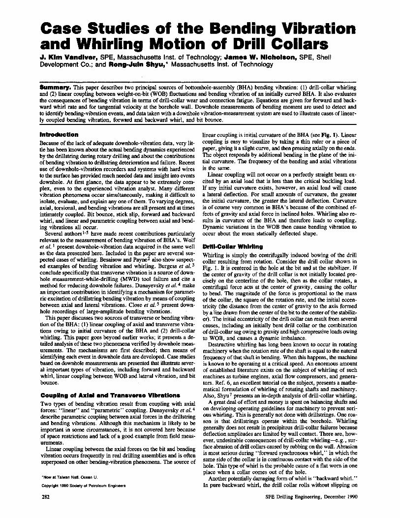
DrllI·Coliar Whirling Whirling is simply the centrifugally induced bowing of the drill collar resulting from rotation. Consider the drill collar shown in Fig. 1. It is centered in the hole at the bit and at the stabilizer. If the center of gravity of the drill collar is not initially located precisely on the centerline of the hole, then as the collar rotates, a centrifugal force acts at the center of gravity, causing the collar to bend. The magnitude of the force is proportional to the mass of the collar, the square of the rotation rate, and the initial eccentricity (the distance from the center of gravity to the axis formed by a line drawn from the center of the bit to the center of the stabilizer). The initial eccentricity of the drill collar can result from several causes, including an initially bent drill collar or the combination of drill-collar sag owing to gravity and high compressive loads owing to WOB, and causes a dynamic imbalance.
Destructive whirling has long been known to occur in rotating machinery when the rotation rate of the shaft is equal to the natural frequency of that shaft in bending. When this happens, the machine is known to be operating at a critical speed. An enormous amount of established literature exists on the subject of whirling of such machines as turbine engines, axial flow compressors, and generators. Ref. 6, an excellent tutorial on the subject, presents a mathematical formulation of whirling of rotating shafts and machinery. Also, Shyu 7 presents an in-depth analysis of drill-collar whirling.
A great deal of effort and money is spent on balancing shafts and on developing operating guidelines for machinery to prevent serious whirling. This is generally not done with drillstrings. One reason is that drillstrings operate within the borehole. Whirling generally does not result in precipitous drill-collar failures because deflection amplitudes are limited by wall contact. There are, however, undesirable consequences of drill-collar whirling-e.g., surface abrasion of drill collars caused by rubbing on the wall. Abrasion is most serious during "forward synchronous whirl," in which the same side of the collar is in continuous contact with the side of the hole. This type of whirl is the probable cause of a flat worn in one place when a collar comes out of the hole.
Another potentially damaging form of whirl is "backward whirl. " In pure backward whirl, the drill collar rolls without slipping on
SPE Drilling Engineering. December 1990
"U •• IHQ
.,T
Fig. 1-Whlrllng drill collar.
the inside of the hole in a direction opposite to the imposed rotation rate. If your eye could follow backward whirl, it would s~ the center of the drill colliu moving around the hole at a frequency much higher than the rotation rate of the drill collar. This phenomenon does not cause substantial surface abrasion becau~e little, if any, relative velocity exists between the drill collar and the wall. High-frequency stress cycles caused by drill-collar bending occur at rates many times higher than the rate of rotation and may lead to connection fatigue failure. Brett et al. 8 discuss damage associated with backward whirl of PDC bits.
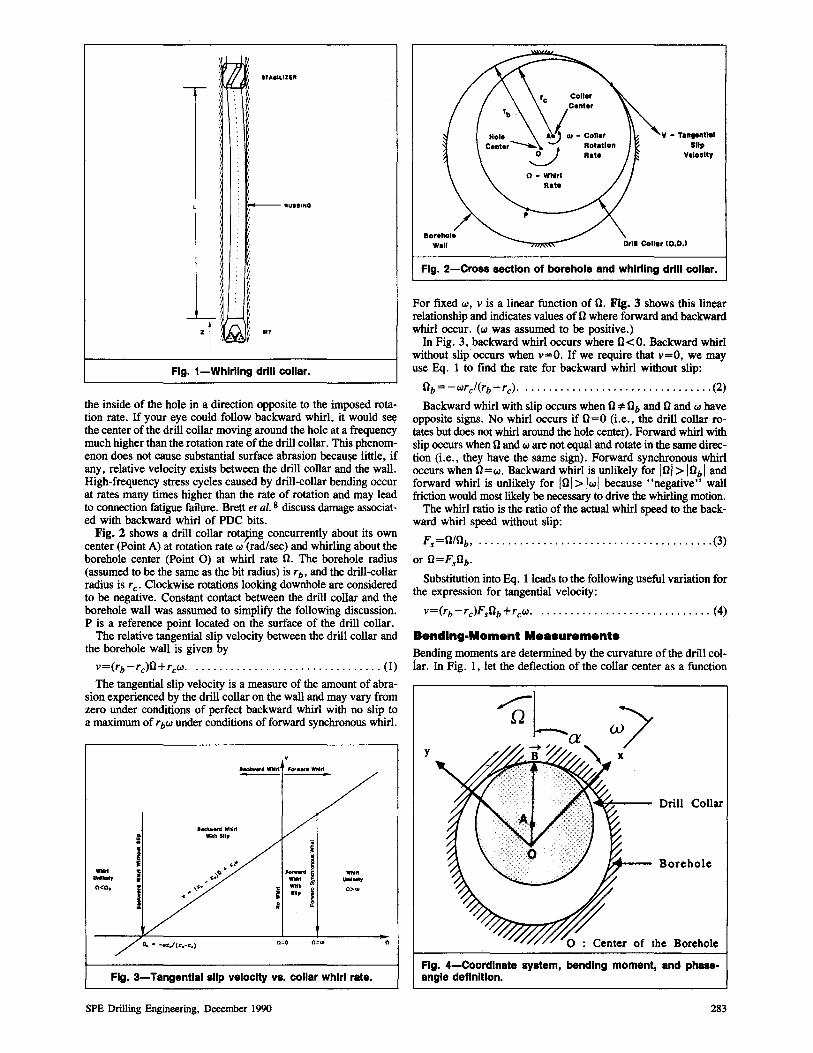
Fig. 2 shows a drill collar rota?ng concurrently about its own center (Point A) at rotation rate w (rad/sec) and whirling about the borehole center (Point 0) at whirl rate 0. The borehole radius (assumed to be the same as the bit radius) is rb, and the drill-collar radius is rc' Clockwise rotations looking downhole are considered to be negative. Constant contact between the drill collar and the borehole wall was assumed to simplify the following discussion. P is a reference point located on the surface of the drill'collar.
The relative tangential slip velocity between the drill collar and the borehole wall is given by
v=(rb-rc)O+rcw . ................................ (1)
The tangential slip velocity is a measure of the amount of abrasion experienced by the drill collar on the wall and may vary from zero under conditions of perfect backward whirl with no slip to a maximum of rbw under conditions of forward synchronous whirl.
a.".1Nd WlIirt ~ Witll Slip li
~ ~ !
~ i .1 ..... " 1-~~ .
'::::d i _. .... ..., " ....... , • With ib 0<0,
I ," " 0> .. ~ .. , I . z
0=0 O=w o
Fig. 3-Tangential slip velocity vs. collar whirl rate.
SPE Drilling Engineering, December 1990
v - Tangential Slip
Veloolty
D,.I Collar (O.D.)
Fig. 2-Cross section of borehole and whirling drill collar.
For fixed w, v is a linear function of 0. Fig. 3 shows this linear relationship and indicates values of ° where forward and backward whirl occur. (w was assumed to be positive.)
In Fig. 3, backward whirl occurs where 0<0. Backward whirl without slip occurs when v=O. If we require that v=O, we may use Eq. 1 to find the rate for backward whirl without slip:
0b=-wrArb-rc)' ................................ (2)
Backward whirl with slip occurs when O:;!:Ob and 0 and w have opposite signs. No whirl occurs if 0=0 (Le., the drill collar rotates but does not whirl around the hole center). Forward whirl with slip occurs when 0 and w are not equal and rotate in the same direction (Le., they have the same sign). Forward synchronous whirl occurs when O=w. Backward whirl is unlikely for 101> lObi and forward whirl is unlikely for 101> Iwl because "negative" wall friction would most likely be necessary to drive the whirling motion.
The whirl ratio is the ratio of the actual whirl speed to the backward whirl speed without slip:
Fs=O/Ob, ........................................ (3)
or O=FsOb.
Substitution into Eq. 1 leads to the following useful variation for the expression for tangential velocity:
v=(rb -rc)FsOb +rcw. . ............................ (4)
Bending-Moment Me.surements Bending moments are determined by the curvature of the drill collar. In Fig. 1, let the deflection ofthe collar center as a function
y
Drill Collar
Borehole
Fig. 4-Coordlnate system, bending moment, and phaseangle definition.
283
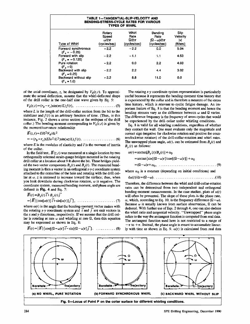
TABLE 1-TANGENTIAL·SLIP·VELOCITY AND BENDING·STRESS·CYCLE RATES FOR VARIOUS
TYPES OF WHIRL
Rotary Speed w/27r
Type of Whirl (cycles/sec)
Forward synchronous -2.2 (F. = -0.25)
Forward with slip -2.2 (F. = -0.125)
Pure rotation -2.2 (F. =0)
Backward with slip -2.2 (F. =0.25)
Backward without slip -2.2 (F. = 1.0)
of the axial coordinate, z, be designated by Vo(z,t). To approxi· mate the actual deflection, assume that the whirl·deflected shape of the drill collar is the one-half sine wave given by Eq. 5:
Vo(z,t)=(rb -rc)sin(1I"z/L)f(t), ...................... (5)
where L is the length of the drill-collar section from the bit to the stabilizer andf(t) is an arbitrary function of time. (Thus, in this instance, Fig. 2 shows a cross section at the midspan of the drill collar.) The bending moment corresponding to Vo(z,t) is given by the moment/curvature relationship
B(z,t)=Eld2 Voldz 2
= -(rb -rc)(Eh2/LZ)sin(1I"zIL)f(t), .................. (6)
where E is the modulus of elasticity and I is the moment of inertia of the collar.
In the field test, B(z,t) was measured at a single location by two orthogonally oriented strain-gauge bridges mounted in the rotating drill collar at a location about 9 ft above the bit. These bridges yielded the two vector components Bx(t) and ByCt). The measured bending moment is then a vector in an orthogonal x-y-z coordinate system attached to the centerline ofthe hole and rotating with the drill collar at w. Z is assumed to increase toward the surface; thus, when you look downhole during clockwise rotation, w is negative. The coordinate system, measured bending moment, and phase angle are defined in Fig. 4 and Eq. 7:
B(t)=Bx(t) TtBy(t)[
=IBI{cos[a(t)] Ttsin[a(t)][} , ..................... (7)
where aCt) is the angle that the bending-moment vector makes with the rotating x-y coordinate system and land [are unit vectors in the x andy directions, respectively. If we assume that the drill collar is rotating at rate w and whirling at rate n, then this equation may be expressed as shown in Eq. 8:
B(t) = I BI {cos[(n-w)t] Ttsin[(n-w)t][}. . .......... (8)
Whirl Bending Slip Rate Rate Velocity O/27r (O-w)/27r Ivl
(cycles/sec) (cycles/sec) (fUsec) -2.2 0.0 5.04
-1.1 1.1 4.53
0.0 2.2 4.03
2.2 4.4 3.02
B.B 11.0 0.0
The rotating x-y coordinate system representation is particularly useful because it represents the bending-moment time history that is experienced by the collar and is therefore a measure of the stress time history, which is relevant to cyclic fatigue damage. An important feature of Eq. 8 is that the bending moment and hence the bending stresses vary as the difference between w and n varies. The difference frequency is the frequency of stress cycles that would be experienced by the drill collar under whirling conditions.
Eq. 8 is valid for all whirling conditions, regardless of whether they contact the wall. One must evaluate only the magnitude and correct sign (negative for clockwise rotation and positive for counterclockwise rotation) of the drill-collar-rotation and whirl rates. The unwrapped phase angle, aCt), can be estimated from Bx(t) and By (t) as follows:
a(t)=arctan[By (t)IBx(t)] +ao
=arctan{sin[(n-w)t]/cos[(n-w)t]} +ao
=(n-w)t+ao, ................................ (9)
where ao is a constant (depending on initial conditions) and
da(t)/dt=(n-w) . ................................. (10)
Therefore, the difference between the whirl and drill-collar-rotation rates can be determined from two independent and orthogonal bending-moment measurements. In the case studies, plots of aCt) will often be presented. The slope of these plots is the phase rate, a, which, according to Eq. 10, is the frequency difference (n-w). Because w is usually known from surface observation, n can be deduced. With further use ofEqs. 2 through 4, one can also deduce the whirl ratio and tangential velocity. "Unwrapped" phase angle refers to the way the arctangent function is computed from real data. The arctangent function used here is not restricted to a range of -11" to +11". Instead, the phase angle is meant to accumulate linear~ ly with time as shown in Eq. 9. aCt) is calculated from real data
(a) NO WHIRL, PURE·ROTATION (b) FORWARD SYNCHRONOUS WHIRL (c) BACKWARD WHIRL WITHOUT SLIP
Fig. 5-Locus of Point P on the collar surface for different whirling conditions.
284 SPE Drilling Engineering, December 1990
�0000,--------,,---____ -, ________ -, ________ ~
5000
B,(Ibf-ft) o
·5000
-10000 0~----------='0_5:-----------.l1---------:1c'::.s--------....J SECONDS
10000,-----____ ,-______ -, ________ -, ________ -,
-10000 0~---------::-0_L5 ----------'1---------:-':1.5:---------,J SECONDS
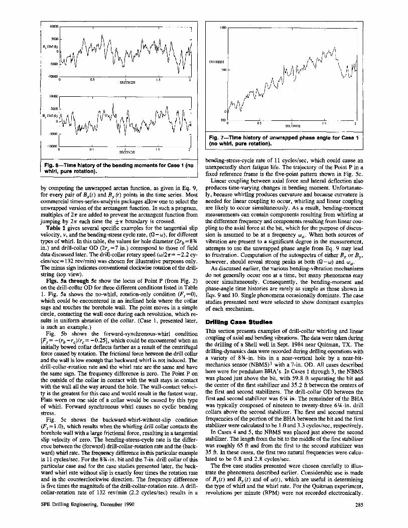
Fig. 6-Time history of the bending moments for Case 1 (no whirl, pure rotation).
by computing the unwrapped arctan function, as given in Eq. 9, for every pair of Bx(t) and By (t) points in the time series. Most commercial times-series-analysis packages allow one to select the unwrapped version of the arctangent function. In such a program, multiples of 211" are added to prevent the arctangent function from jumping by 211" each time the ±11" boundary is crossed.
Table 1 gives several specific examples for the tangential slip velocity, v, and the bending-stress cycle rate, (O-w), for different types of whirl. In this table, the values for hole diameter (2rb =8* in.) and drill-collar OD (2rc=7 in.) correspond to those of field data discussed later. The drill-collar rotary speed (w/211"= - 2.2 cycles/sec=132 rev/min) was chosen for illustrative purposes only. The minus sign indicates conventional clockwise rotation of the drillstring (top view).
Figs. 5a through 5c show the locus of Point P (from Fig. 2) on the drill-collar OD for three different conditions listed in Table 1. Fig. 5a shows the no-whirl, rotation-only condition (Fs=O), which could be encountered in an inclined hole where the collar sags and touches the borehole wall. The point moves in a-simple circle, contacting the wall once during each revolution, which results in uniform abrasion of the collar. (Case 1, presented later, is such an example.)
Fig. 5b shows the forward-synchronous-whirl condition [Fs= -(rb-rc)/rc= -0.25], which could be encountered when an initially bowed collar deflects farther as a result of the centrifugal force caused by rotation. The frictional force between the drill collar and the wall is low enough that backward whirl is not induced. The drill-collar-rotation rate and the whirl rate are the same and have the same sign. The frequency difference is zero. The Point P on the outside of the collar in contact with the wall stays in contact with the wall all the way around the hole. The wall-contact velocity is the greatest for this case and would result in the fastest wear. Flats worn on one side of a collar would be caused by this type of whirl. Forward synchronous whirl causes no cyclic bending stress.
Fig. 5c shows the backward-whirl-without-slip condition (Fs = 1.0), which results when the whirling drill collar contacts the borehole wall with a large frictional force, resulting in a tangential slip velocity of zero. The bending-stress-cycle rate is the difference between the (forward) drill-collar-rotation rate and the (backward) whirl rate. The frequency difference in this particular example is 11 cycles/sec. For the 8*-in. bit and the 7-in. drill collar of this particular case and for the case studies presented later, the backward whirl rate without slip is exactly four times the rotation rate and in the counterclockwise direction. The frequency difference is five times the magnitude of the drill-collar-rotation rate. A drillcollar-rotation rate of 132 rev/min (2.2 cycles/sec) results in a
SPE Drilling Engineering, December 1990
1000,--------,---------.--------.---------.
DEGREES
-100 0c--------0:C::.s---------'-1 --------c"l.5:-----------' SECONDS
Fig. 7-Tlme history of unwrapped phase angle for Case 1 (no whirl, pure rotation).
bending-stress-cycle rate of 11 cycles/sec, which could cause an unexpectedly short fatigue life. The trajectory of the Point P in a fixed reference frame is the five-point pattern shown in Fig. 5c.
Linear coupling between axial force and lateral deflection also produces time-varying changes in bending moment. Unfortunately, because whirling produces curvature and because curvature is needed for linear coupling to occur, whirling and linear coupling are likely to occur simultaneously. As a result, bending-moment measurements can contain components resulting from whirling at the difference frequency and components resulting from linear coupling to the axial force at the bit, which for the purpose of discussion is assumed to be at a frequency Wa. When both sources of vibration are present to a significant degree in the measurement, attempts to use the unwrapped phase angle from Eq. 9 may lead to frustration. Computation of the autospectra of either Bx or By, however, should reveal strong peaks at both (O-w) and Wa.
As discussed earlier, the various bending-vibration mechanisms do not generally occur one at a time, but many phenomena may occur simultaneously. Consequently, the bending-moment and phase-angle time histories are rarely as simple as those shown in Eqs. 9 and 10. Single phenomena occasionally dominate. The case studies presented next were selected to show dominant examples of each mechanism.
Drilling Case Studies This section presents examples of drill-collar whirling and linear coupling of axial and bending vibrations. The data were taken during the drilling of a Shell well in Sept. 1984 near Quitman, TX. The drilling-dynamics data were recorded during drilling operations with a variety of 8*-in. bits in a near-vertical hole by a near-bitmechanics sensor (NBMS)! with a 7-in. OD. All cases described here were for pendulum BRA's. In Cases 1 through 3, the NBMS was placed just above the bit, with 59.8 ft separating the bit and the center of the first stabilizer and 35.2 ft between the centers of the first and second stabilizers. The drill-collar OD between the first and second stabilizer was 6'A in. The remainder of the BRA was typically composed of nineteen to twenty-three 6 IA-in. drill collars above the second stabilizer. The first and second natural frequencies of the portion of the BRA between the bit and the first stabilizer were calculated to be 1. 0 and 3.3 cycles/sec, respectively.
In Cases 4 and 5, the NBMS was placed just above the second stabilizer. The length from the bit to the middle of the first stabilizer was roughly 65 ft and from the first to the second stabilizer was 35 ft. In these cases, the first two natural frequencies were calculated to be 0.8 and 2.8 cycles/sec.
The five case studies presented were chosen carefully to illustrate the phenomena described earlier. Considerable use is made of Bx(t) and By(t) and of a(t), which are useful in determining the type of whirl and the whirl rate. For the Quitman experiment, revolutions per minute (RPM) were not recorded electronically.
285
i ~ ~ ~ <=
~ e 2
~ V)
=
¥ } <= <o!.
~ e 2
5e+Ob
4<.06
k.06
2<.06
1 • .06
0
5<.06
4<.06
k.06
2e+06
A
J "- -- ~
0 10 15 cycles/sec
~ , • .061/
V)~ 0 ~~ = 0 5 It) 15
cycles/sec
20 25 JO
:!O JO
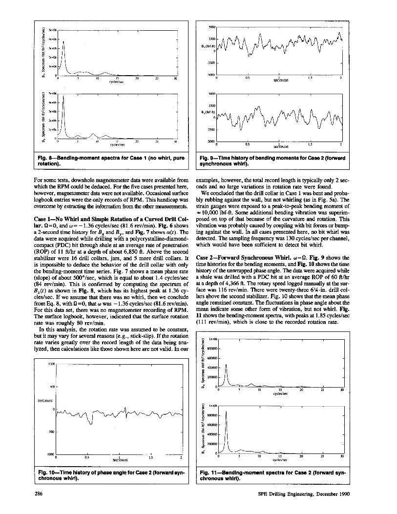
Fig. 8-Bendlng-moment spectra for Case 1 (no whirl, pure rotation).
For some tests, downhole magnetometer data were available from which the RPM could be deduced. For the five cases presented here, however, magnetometer data were not available. Occasional surface logbook entries were the only records of RPM. This handicap was overcome by extracting the information from the other measurements.
Case I-No Whirl and Simple Rotation of a Curved Drill Collar. 0=0, and w= -1.36 cycles/sec (81.6 rev/min). Fig. 6 shows a 2-second time history for Bx and By, and Fig. 7 shows aCt). The data were acquired while drilling with a polycrystalline-diamondcompact (PDC) bit through shale at an average rate of penetration (ROP) of 11 ftlhr at a depth of about 6,850 ft. Above the second stabilizer were 16 drill collars, jars, and 5 more drill collars. It is impossible to deduce the behavior of the drill collar with only the bending-moment time series. Fig. 7 shows a mean phase rate (slope) of about 500o /sec, which is equal to about 1.4 cycles/sec (84 rev/min). This is confirmed by computing the spectrum of Bx(t) as shown in Fig. 8, which has its highest peak at 1.36 cycles/sec. If we assume that there was no whirl, then we conclude from Eq. 8, with 0=0, that w was -1.36 cycles/sec (81.6 rev/min). For this data set, there was no magnetometer recording of RPM. The surface logbook, however, indicated that the surface rotation rate was roughly 80 rev/min.
In this analysis, the rotation rate was assumed to be constant, but it may vary for several reasons (e.g., stick-slip). If the rotation rate varies greatly over the record length of the data being analyzed, then calculations like those shown here are not valid. In our
IIXX',------, ____ ---, ____ -, ____ --,
500
DEGREES
-500
-1000 O~----:Oc':-.5----LI -----:-1.'=-5 -------,J SECONDS
Fig. 10-Time history of phase angle for Case 2 (forward synchronous whirl).
286
-2500
-5000 0~----0:-':.5,------7-, ------:"I.S:------7
SECONDS
sooo,-----,-----,----,------,
-2S00
-50000L----~0.5------'-,----~I.~S---~
SECONDS
Fig. 9-Time history of bending moments for Case 2 (forward synchronous whirl).
examples, however, the total record length is typically only 2 seconds and no large variations in rotation rate were found.
We concluded that the drill collar in Case 1 was bent and probably rubbing against the wall, but not whirling (as in Fig. 5a). The strain gauges were exposed to a peak-to-peak bending moment of "" 10,000 Ibf-ft. Some additional bending vibration was superimposed on top of that because of the curvature and rotation. This vibration was probably caused by coupling with bit forces or bumping against the wall. In all cases presented here, no bit whirl was detected. The sampling frequency was 130 cycles/sec per channel, which would have been sufficient to detect bit whirl.
Case 2-Forward Synchronous Whirl. w=O. Fig. 9 shows the time histories for the bending moments, and Fig. 10 shows the time history of the unwrapped phase angle. The data were acquired while a shale was drilled with a poe bit at an average ROP of 60 ft/hr at a depth of 4,366 ft. The rotary speed logged manually at the surface was 116 rev/min. There were twenty-three 6'A-in. drill collars a,bove the second stabilizer. Fig. 10 shows that the mean phase angle remained constant. The fluctuations in phase angle about the mean indicate some other form of vibration, but not whirl. Fig. 11 shows the bending-moment spectra, with peaks at 1.85 cycles/sec (111 rev/min), which is close to the recorded rotation rate.
~ le+()6
-,; .!! 800000
£wxro '" t--A J.2OOOOl
~ = 0 0 10 IS 20 25 JO cycles/sec
~ le+()6
~8OO<XX) g 2 6CXXKX) <o!. a E 400000 2
~ 200000
~ 0) "--~ 0 S 10 IS 20 lS 30
cycles/sec
Fig. 11-Bendlng-moment spectra for Case 2 (forward synchronous whirl).
SPE Drilling Engineering. December 1990
2()()()()
I()()()()
0.5 I 1.5 SECONDS
2()()()()
• 2()()()() 0~----'0;:';.5:------:-1 ----:-':1.5:-----....,.J SECONDS
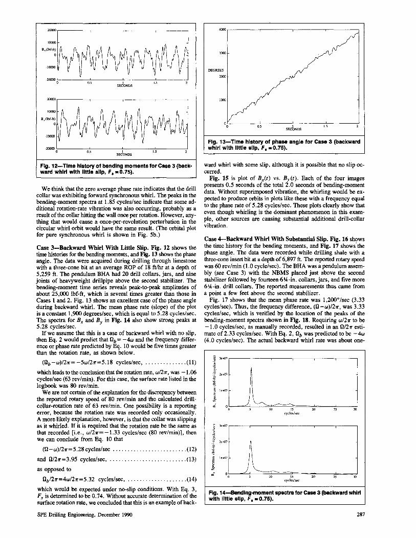
Fig. 12-Time history of bending moments for Case 3 (backward whirl with little slip, F. =0.75).
We think that the zero average phase rate indicates that the drill collar was exhibiting forward synchronous whirl. The peaks in the bending-moment spectra at 1.85 cycles/sec indicate that some additional rotation-rate vibration was also occurring, probably as a result of the collar hitting the wall once per rotation. However, anything that would cause a once-per-revolution perturbation in the circular whirl orbit would have the same result. (The orbital plot for pure synchronous whirl is shown in Fig. 5b.)
Case 3-Backward Whirl With Little Slip. Fig. 12 shows the time histories for the bending moments, and Fig. 13 shows the phase angle. The data were acquired during drilling through limestone with a three-cone bit at an average ROP of 18 ft/hr at a depth of 5,259 ft. The pendulum BHA had 20 drill collars, jars, and nine joints of heavyweight drillpipe above the second stabilizer. The bending-moment time series reveals peak-to-peak amplitudes of about 25,000 lbf-ft, which is several times greater than those in Cases 1 and 2. Fig. 13 shows an excellent case of the phase angle during backward whirl. The mean phase rate (slope) of the plot is a constant 1,900 degrees/sec, which is equal to 5.28 cycles/sec. The spectra for Bx and By in Fig. 14 also show strong peaks at 5.28 cycles/sec.
If we assume that this is a case of backward whirl with no slip, then Eq. 2 would predict that 0b= -4w and the frequency difference or phase rate predicted by Eq. 10 would be five times greater than the rotation rate, as shown below.
(Ob-w)/21r=-5w/211"=5.18 cycles/sec, .............. (11)
which leads to the conclusion that the rotation rate, w/211", was -1.06 cycles/sec (63 rev/min). For this case, the surface rate listed in the logbook was 80 rev/min.
We are not certain of the explanation for the discrepancy between the reported rotary speed of 80 rev/min and the calculated drillcollar-rotation rate of 63 rev/min. One possibility is a reporting error, because the rotation rate was recorded only occasionally. A more likely explanation, however, is that the collar was slipping as it whirled. If it is required that the rotation rate be the same as that recorded [Le., w/211" = -1.33 cycles/sec (80 rev/min)], then we can conclude from Eq. 10 that
(0-w)/211"=5.28 cycles/sec ......................... (12)
and 0/211"=3.95 cycles/sec, .......................... (13)
as opposed to
Ob/211"=4w/211"=5.32 cycles/sec, .................... (14)
which would be expected under no-slip conditions. With Eq. 3, Fs is determined to be 0.74. Without accurate determination of the surface rotation rate, we concluded that this is an example of back-
SPE Drilling Engineering, December 1990
4000
3000
DEGREES
2000
1000
0.5 I SECONDS
1.5
Fig. 13-Time history of phase angle for Case 3 (backward whirl with little slip, F. =0.75) •
ward whirl with some slip, although it is possible that no slip occurred.
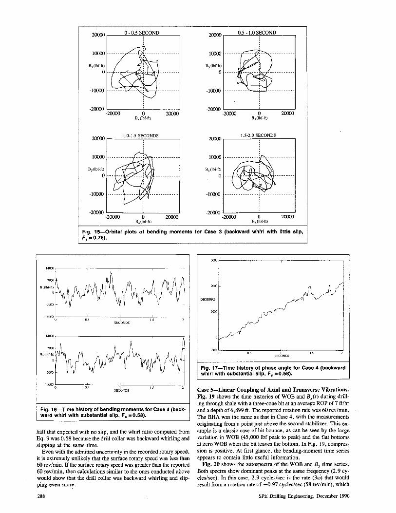
Fig. 15 is plot of Bx(t) vs. By (t). Each of the four images presents 0.5 seconds of the total 2.0 seconds of bending-moment data. Without superimposed vibration, the whirling would be expected to produce orbits in plots like these with a frequency equal to the phase rate of 5.28 cycles/sec. These plots clearly show that even though whirling is the dominant phenomenon in this example, other sources are causing substantial additional drill-collar vibration.
Case 4-Backward Whirl With Substantial Slip. Fig. 16 shows the time history for the bending moments, and Fig. 17 shows· the phase angle. The data were recorded while drilling shale with a three-cone insert bit at a depth of 6,897 ft. The reported rotary speed was 60 rev/min (1.0 cycle/sec). The BHA was a pendulum assembly (see Case 3) with the NBMS placed just above the second stabilizer followed by fourteen 6IA-in. collars, jars, and five more 6'A-in. drill collars. The reported measurements thus came from a point a few feet above the second stabilizer.
Fig. 17 shows that the mean phase rate was 1,2OOo/sec (3.33 cycles/sec). Thus, the frequency difference, (0-w)/211", was 3.33 cycles/sec, which is verified by the location of the peaks of the bending-moment spectra shown in Fig. 18. Requiring wl21r to be -1.0 cycles/sec, as manually recorded, resulted in an 0/211" estimate of 2.33 cycles/sec. With Eq. 2, 0b was predicted to be -4w (4.0 cycles/sec). The actual backward whirl rate was about one-
¥ k~7r---r---.---'----r---r---' ]
f 2e+07
'" @ E le+07 2
i '" '" 0
~ 3e+07
U
f 2e+07
~ E le ... {)7 2
i '" ",' 0
) 0
) 0
10
10
15 cycles/sec
15 cycles/sec
20 25 30
20 25 30
Fig. 14-Bendlng-moment spectra for case 3 (backward whirl with little slip, F. = 0.75).
287
2~r-__ ~0~-~0~.5~S~E~CO~ND~ ____ ~
I~
By(lbf-ft)
o
-2~ L-____ ~ ___ ___.J
-2~ o B,(lbf-ft)
2~
2~ r-__ I._O_-I_.5~S~E7C~O=N~D_S __ -----,
I~
By(lbf-ft)
o
-2~ L-____ -'--___ .--J
-2~ o B,(Ibf-ft)
2~
2~.-__ ~0.~5~-~1.~0~SE~C~O~N~D~ __ -,
I~
By (lbf-ft)
o
-10000 ........ ---- ..
-20000 L-____ ~ ___ ____l
-20000 o B,(Ibf-ft)
20000
2OOOO~_~I~.5~-2~.O~SE~C~O_N_D_S~_-,
10000
By (lbf-ft)
o
-10000 -- --. --.... -.. ---- -•... ---- -- --. --- --.-
-20000 L-____ --l ____ ---l
-20000 o B,(Ibf-ft)
2~
Fig. 15-0rbital plots of bending moments for Case 3 (backward whirl with little slip, F. =0.75).
14000 ,---------,--------,-------,-----,
7000
B~(Ibf-ft)
o
-7000
-14000 O'------::-'O.;::----------'I---------'I.;,--------------.J
SECONDS
-140000':-------:c
0.""S-----IL-----I.L; ---
SECONDS
Fig. 16-Time history of bending moments for Case 4 (backward whirl with substantial slip, F. = 0.58).
half that expected with no slip, and the whirl ratio computed from Eq. 3 was 0.58 because the drill collar was backward whirling and slipping at the same time.
Even with the admitted uncert?lnty in the recorded rotary speed, it is extremely unlikely that the surface rotary speed was less than 60 rev/min. If the surface rotary speed was greater than the reported 60 rev/min, then calculations similar to the ones conducted above would show that the drill collar was backward whirling and slipping even more.
288
3000 ,--------,-------,------,---------,
2000
DEGREES
1000
-500 0:----------'0.;:---------"--1 -----:--'15:-----...J
SECONDS
Fig. 17-Time history of phase angle for Case 4 (backward whirl with substantial slip, F. = 0.58).
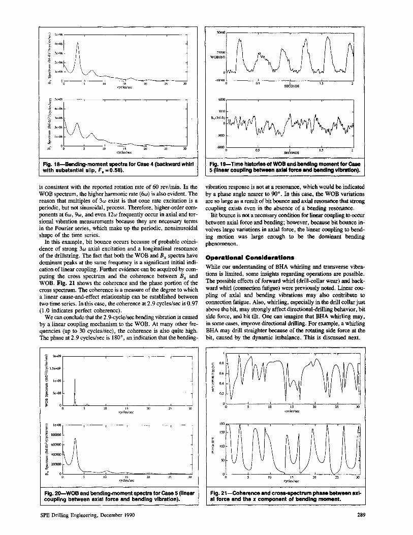
Case 5-Linear Coupling of Axial and Transverse Vibrations. Fig. 19 shows the time histories of WOB and Bx(t) during drilling through shale with a three-cone bit at an average ROP of 7 ft/hr and a depth of 6,899 ft. The reported rotation rate was 60 rev/min. The BHA was the same as that in Case 4, with the measurements originating from a point just above the second stabilizer. This example is a classic case of bit bounce, as can be seen by the large variation in WOB (45,000 lbf peak to peak) and the flat bottoms at zero WOB when the bit leaves the bottom. In Fig. 19, compression is positive. At first glance, the bending-moment time series appears to contain little useful information.
Fig. 20 shows the autospectra of the WOB and Bx time series. Both spectra show dominant peaks at the same frequency (2.9 cycles/sec). In this case, 2.9 cycles/sec is the rate (3~) that would result from a rotation rate of -0.97 cycles/sec (58 rev/min), which
SPE Drilling Engineering, December 1990
0 5c+ft6
~ ~ .tc+06
g 3e+06 ."
~ 2e+{)6 E 2
I le+()6
ri () 0
E 2 1,<{J6
~ '" ",,-
0 0
10
10
15 cycles/sec
15 cycles/sec
20 25 J()
20 25 J()
Fig. 18-Bendlng-moment spectra for Case 4 (backward whirl with substantial slip, F. = 0.58).
is consistent with the reported rotation rate of 60 rev/min. In the WOB spectrum, the higher harmonic rate (6w) is also evident. The reason that multiples of 3w exist is that cone rate excitation is a periodic, but not sinusoidal, process. Therefore, higher-order components at 6w, 9w, and even 12w frequently occur in axial and torsional vibration measurements because they are necessary terms in the Fourier series, which make up the periodic, nonsinusoidal shape of the time series.
In this example, bit bounce occurs because of probable coincidence of strong 3w axial excitation and a longitudinal resonance of the drillstring. The fact that both the WOB and B x spectra have dominant peaks at the same frequency is a significant initial indication oflinear coupling. Further evidence can be acquired by computing the cross spectrum and the coherence between B x and WOB. Fig. 21 shows the coherence and the phase portion of the cross spectrum. The coherence is a measure of the degree to which a linear cause-and-effect relationship can be established between two time series. In this case, the coherence at 2.9 cycles/sec is 0.97 (1.0 indicates perfect coherence).
We can conclude that the 2. 9-cycle/sec bending vibration is caused by a linear coupling mechanism to the WOB. At many other frequencies (up to 30 cycles/sec), the coherence is also quite high. The phase at 2.9 cycles/sec is 1800
, an indication that the bending-
°0~~~~----~IO------15L-----2~0----~25----~M)
cycles/sec
°0L---~L=~~~1O~~~15~~==2±0=---~25~--~~) cycles/sec
Fig. 20-WOB and bending-moment spectra for Case 5 (linear coupling between axial force and bending vibration).
SPE Drilling Engineering, December 1990
5<X1OO
25('00
WOB(lbO
·I(X1OO 0 05 I
SECONOS 1.5
6(100
3(100
.6(JOO0L-------~0~.5--------~1---------1~L--------J SECONOS
Fig. 19-Time histories of WOB and bending moment for Case 5 (linear coupling between axial force and bendl", vibration).
vibration response is not at a resonance, which would be indicated by a phase angle nearer to 90 0
• In this case, the WOB variations are so large as a result of bit bounce and axial resonance that strong coupling exists even in the absence of a bending resonance.
Bit bounce is not a necessary condition for linear coupling to occur between axial force and bending; however, because bit bounce involves large variations in axial force, the linear coupling to bending motion was large enough to be the dominant bending phenomenon.
Operational Considerations While our understanding of BHA whirling and transverse vibrations is limited, some insights regarding operations are possible. The possible effects of forward whirl (drill-collar wear) and backward whirl (connection fatigue) were previously noted. Linear coupling of axial and bending vibrations may also con 'tribute to connection fatigue. Also, whirling, especially in the drill collar just above the bit, may strongly affect directional-drilling behavior, bit side force, and bit tilt. One can imagine that BHA whirling may, in some cases, improve directional drilling. For example, a whirling BHA may drill straighter because of the rotating side force at the bit, caused by the dynamic imbalance. This is discussed next.
C 0.8 0 H E 0.6 R E N 0.4 C E
0.2
10 15 cycles/sec
20 J()
180 ""--,---,------------,.--------,-----,-----;-....--:---:1
P H
150
~ 100 E
50
Fig. 21-Coherence and cross-spectrum phase between axial force and the x component of bending moment.
289
Authors
Nicholson Vandiver
... Kim Vandiver Is a professor of ocean engineering at the Massachusetts Inst. of Technology. His technical interests Include the dynamics of offshor6 structures, flow-Induced vibration of cables and risers, and drlllstring dynamics . .. ames W. Nicholson Is a senior research engineer for Shell Development Co. In Houston, where he Is responsible for drillIng mechanics research. He previously was professor of theoretical and applied mechanics at the U. of illinois, Champaign-Urbana. Nicholson holds as, MS, and PhD degrees In applied mathematics from the U. of Virginia. Rong"uln Shyu Is an associate professor of naval architecture at the Natl. Taiwan Ocean U. His research Interests are vibration, signal processing, and wave propagation. He holds a PhD degree from the Massachusetts Inst. of Technology.
An eccentrically weighted drill collar was shown to drill straighter holes in some applications. 9 If this mass-unbalanced drill collar is placed in the BHA just above the bit and the right WOB and rotary-speed conditions are present, it will whirl, producing a considerable rotating side force on the bit. If the bit and formation characteristics are such that the ROP to the side is nonlinearly proportional (with a power greater than one) to the side force, then it can be shown that a rotating side force will increase the dropping tendency of the BHA.
Reliable predictive models for whirling are not yet available. It is known that prediction of whirling will require knowledge of the WOB, the wall friction coefficient, and the damping coefficient of the mud resisting the whirling. It is also known that once a collar contacts the wall during whirling, it may continue to do so through a broad range of rotary speeds. 10
Unlike axial and torsional vibrations, bending vibrations are not transmitted to the surface by the drillstring. Although it may be possible to see evidence of downhole bending vibration in the surface axial and torsional vibration signals, the relationships are not yet understood well enough to be used diagnostically. Thus, for the near future, predictive models for whirling and surface measurements will be limited in their abilities to provide operational guidance regarding downhole bending vibrations. Downhole measurement-while-drilling systems that provide simple measures of the bending motions of the BHA, however, hold great promise for providing real-time operational information on drill-collar whirling and coupling of axial and bending vibrations.
Conclusions
1. Simple equations for the tangential slip velocity between the drill-collar OD and the borehole wall and for the forward and backward whirl rate were developed.
2. Bending-moment phase angle and bending-moment spectra can be used to determine the type of whirling or vibration behavior of the BHA.
3. Forward whirl can cause abrasive wear of the drill-collar OD and is the probable cause of flat spots.
4. Backward whirl can shorten the fatigue life of drill-collar connections when bending-stress cycles accumulate at a rate several times greater than the drill-collar rotary speed.
5. Case studies showed that forward and backward whirling of the BHA in the borehole can occur during normal drilling operations.
6. Case studies also demonstrated linear coupling of axial and bending vibrations of the BHA.
290
7. Drill-collar whirling is likely to affect directional drilling. This possibility requires further research.
8. The use of downhole measurement systems in conjunction with simple downhole processing and mud-pulse telemetry may be a practical way to provide real-time operational guidance on BHA whirling and vibration.
Nomenclature
B x = bending-moment x component _By = bending-moment y component B (z) = bending-moment vector
E = Young's modulus of drill collar Fs = stick ratio
I = area moment of inertia of drill collar L = length of drill-collar section from bit to stabilizer rb = borehole radius r c = drill-collar radius
t = time v = tangential slip velocity
Vo(z) = drill-collar deflection z = drill-collar axial coordinate
a(t) = phase angle w = drill-collar-rotation rate o = whirl rate
0b = backward whirl rate (without slip)
Acknowledgments
We thank Shell Oil Co., Shell Development Co., Shell Western E&P Inc., and NL Industries for conducting the field test. We also thank Shell Development Co. for the opportunity to publish this paper.
References I. Wolf, S.F., Zacksenhouse, M., and Arian, A.: "Field Measurement
of Downhole Drillstring Vibrations," paper SPE 14330 presented at the 1985 SPE Annual Technical Conference and Exhibition, Las Vegas, Sept. 22-25.
2. Besaisow, A.A. and Payne, M.L.: "A Study of Excitation Mechanisms and Resonances Inducing Bottornhole-Assembly Vibrations," SPEDE (March 1988) 93-10 I.
3. Burgess, T.M., McDaniel, G.L., and Das, P.K.: "Improving BHA Tool Reliability With Drillstring Vibration Models: Field Experience and Limitations," paper SPE 16109 presented at the 1987 SPE/IADC Drilling Conference, New Orleans, March 15-19.
4. Dunayevsky, V.A. et af.: "Dynamic Stability of Drillstrings Under Fluctuating Weights-on-Bit," paper SPE 14329 presented at the 1985 SPE Annual Technical Conference and Exhibition, Las Vegas, Sept. 22-25.
5. Close, D.A., Owens, S.C., and MacPherson, J.D.: "Measurement of BHA Vibration Using MWD," paper SPE 17273 presented at the 1988 IADC/SPE Drilling Conference, Dallas, Feb. 28-March 2.
6. Lalanne, M. and Ferraris, G.: Rotordynamics Prediction in Engineering, John Wiley & Sons, New York City (1990).
7. Shyu, RJ.: "Bending Vibration of Rotating Drill Strings," PhD dissertation, Massachusetts Inst. of Technology, Cambridge (Aug. 1989).
8. Brett, J.F., Warren, T.M., and Behr, S.M.: "Bit Whirl-A New Theory of PDC Bit Failure," SPEDE (Dec. 1990) 275-81.
9. "Unbalanced Drill Collar Increases Penetration Rates," World Oil (Jan. 1978).
10. Joglekar, N.: "Experimental Evaluation of Rotor Motion With Radial Rub," MS thesis, Massachusetts Inst. of Technology, Cambridge (June 1987).
51 Metric Conversion Factors
cycles/sec x 1.0* E+OO ft x 3.048* E-Ol
in. x 2.54* E+OO lbf x 4.448 222 E+OO
·Conversion factor is exact.
Hz m cm N
SPEDE
Original SPE manuscript received for review Feb. 28, 1989. Paper accepted for publication Sept. 20, 1990. Revised manuscript received Sept. 12, 1990. Paper (SPE 18652) first presented at the 1989 SPE/IADC Drilling Conference held in New Orleans, Feb. 28-March 3.
SPE Drilling Engineering, December 1990