Embed Size (px)
Citation preview
Cassette unitsModel Comfort Circle
- heating- cooling- ventilation
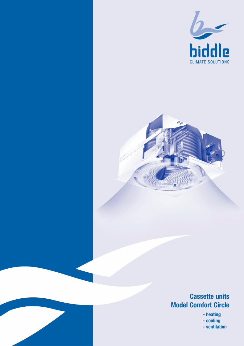
Cassette unit: Comfort Circle A comfortable room and climate are pleasant to work in and may also entice visitorsto lengthen their stay. Whoever is looking for an attractive and space-saving solutionfor heating and/or cooling from the ceiling will find a friend in Biddle's Comfort Circle.The Comfort Circle provides for comfortable heat during cold winter months andoffers comfortable cooling during hot summer days. Its stylish appearance and lownoise level make this cassette unit highly suitable for use in rooms such as shops,showrooms, offices, reception areas and computer rooms.
Biddle’s compact cassette unit has been especially designed to be built into suspendedceilings. The very small overall height of only 30 cm allows the unit to be mountedabove the ceiling, with only the plastic grille remaining visible.
Circular discharge technology
The Comfort Circle has been designed using circular discharge technology. Both thedischarge and extraction of air takes place through the same grille. Return air is viathe round holes in the middle of the grille. Having been heated or cooled, the air isevenly discharged into the room through the discharge openings in the grille's sides.Compared with a square discharge grille, the round discharge pattern provides forbetter air distribution, ensuring good downward penetration and air circulation atlow air velocity.
When used for both heating and cooling Comfort Circle has an automatically adjustableand patented ‘ring’ as part of the discharge grille. The ring itself selects the correctdischarge angle when heating or cooling, thus ensuring proper downward penetrationand dispersion of air in either mode. The discharge pattern of the Comfort Circle canbe geared to the room by applying blanking plates.
Units that can only heat or cool do not feature the adjustable and patented ‘ring’,having a fixed discharge angle.
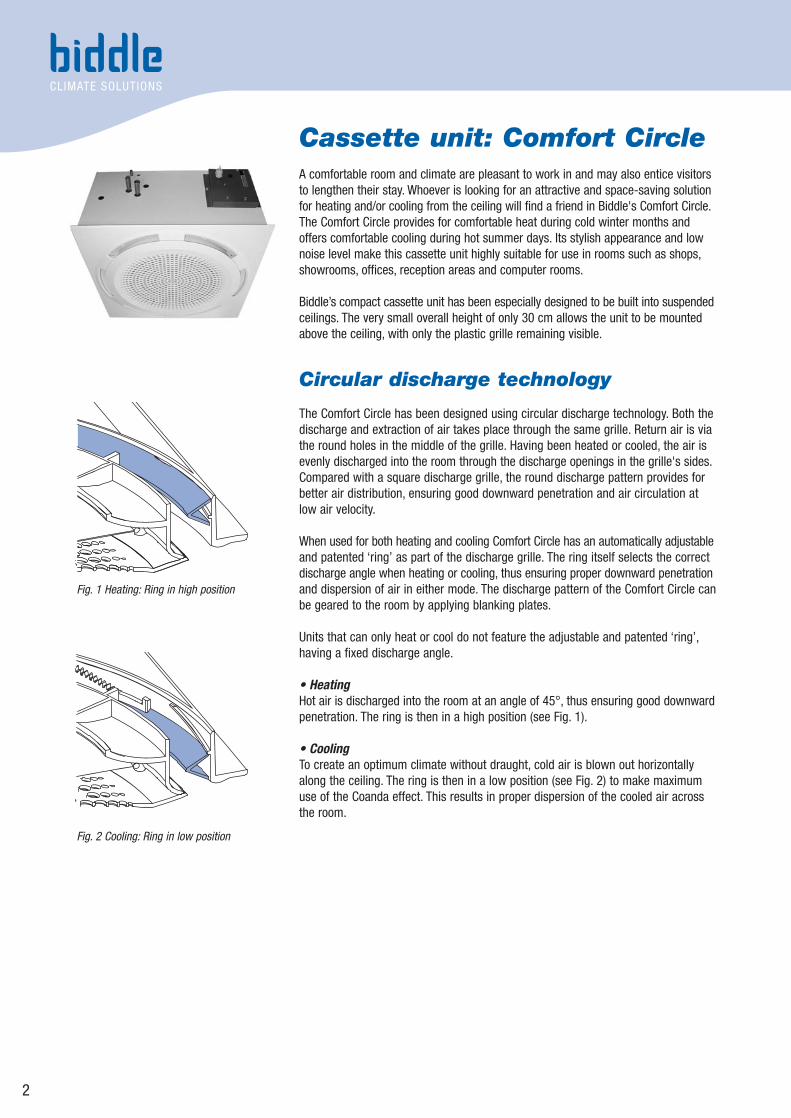
• HeatingHot air is discharged into the room at an angle of 45°, thus ensuring good downwardpenetration. The ring is then in a high position (see Fig. 1).
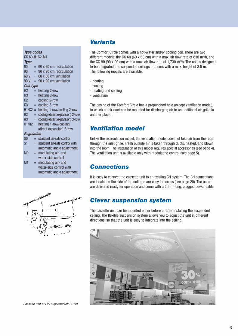
• CoolingTo create an optimum climate without draught, cold air is blown out horizontallyalong the ceiling. The ring is then in a low position (see Fig. 2) to make maximumuse of the Coanda effect. This results in proper dispersion of the cooled air acrossthe room.
2
Fig. 1 Heating: Ring in high position
Fig. 2 Cooling: Ring in low position
Variants
The Comfort Circle comes with a hot-water and/or cooling coil. There are two different models: the CC 60 (60 x 60 cm) with a max. air flow rate of 830 m3/h, andthe CC 90 (90 x 90 cm) with a max. air flow rate of 1,730 m3/h. The unit is designed to be integrated into suspended ceilings in rooms with a max. height of 3.5 m.The following models are available:
- heating- cooling- heating and cooling- ventilation
The casing of the Comfort Circle has a prepunched hole (except ventilation model),to which an air duct can be mounted for discharging air to an additional air grille inanother place.
Ventilation model
Unlike the recirculation model, the ventilation model does not take air from the roomthrough the inlet grille. Fresh outside air is taken through ducts, heated, and blowninto the room. The installation of this model requires special accessories (see page 4).The ventilation unit is available only with modulating control (see page 5).
Connections
It is easy to connect the cassette unit to an existing CH system. The CH connectionsare located in the side of the unit and are easy to access (see page 20). The unitsare delivered ready for operation and come with a 2.5 m-long, plugged power cable.
Clever suspension system
The cassette unit can be mounted either before or after installing the suspendedceiling. The flexible suspension system allows you to adjust the unit in differentdirections, so that the unit is easy to integrate into the ceiling.
3
Cassette unit at Lidl supermarket: CC 90
Type codesCC 60-H1C2-M1Type60 = 60 x 60 cm recirculation90 = 90 x 90 cm recirculation60 V = 60 x 60 cm ventilation90 V = 90 x 90 cm ventilationCoil typeH2 = heating 2-rowH3 = heating 3-rowC2 = cooling 2-rowC3 = cooling 3-rowH1/C2 = heating 1-row/cooling 2-rowR2 = cooling (direct expansion) 2-rowR3 = cooling (direct expansion) 3-rowH1/R2 = heating 1-row/cooling
(direct expansion) 2-rowRegulationS0 = standard air-side controlS1 = standard air-side control with
automatic angle adjustmentM0 = modulating air- and
water-side controlM1 = modulating air- and
water-side control withautomatic angle adjustment
4
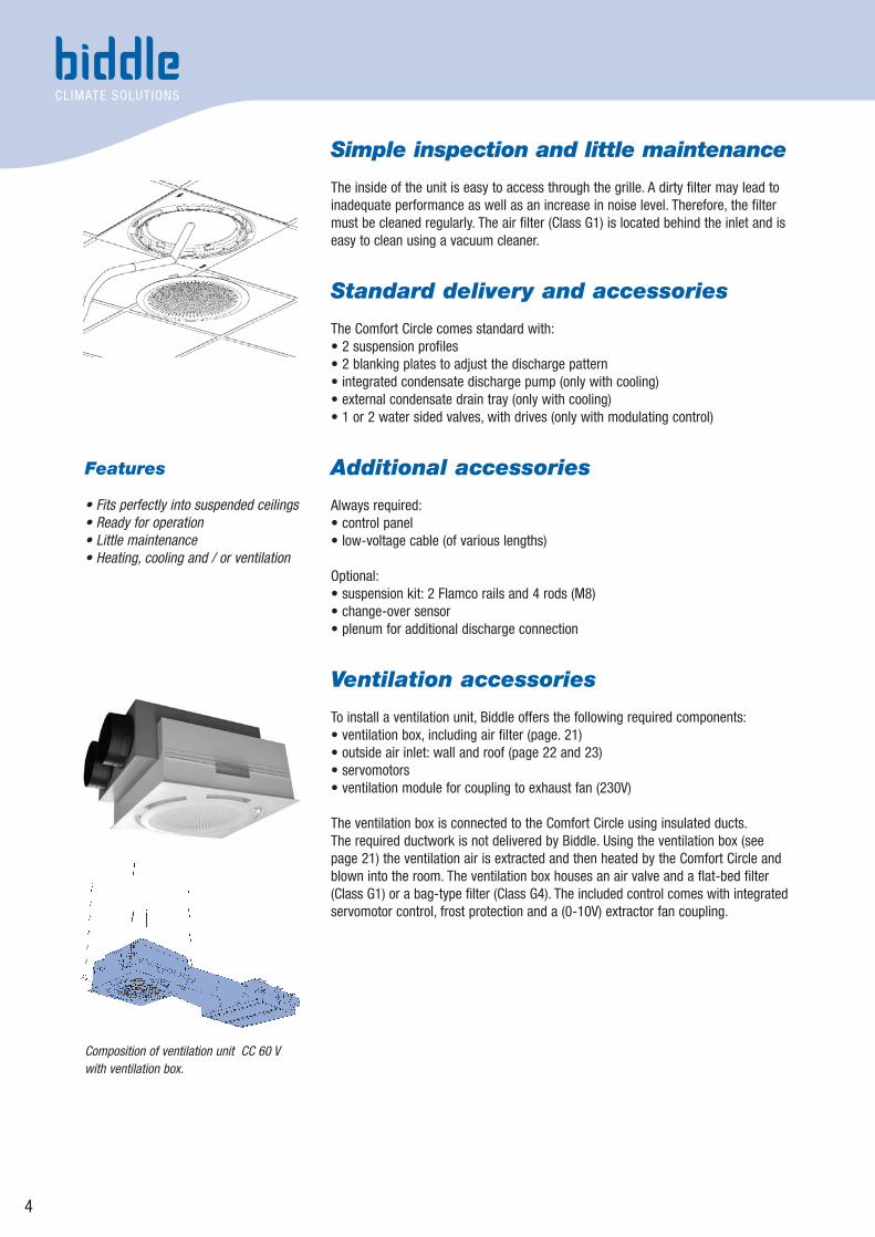
Simple inspection and little maintenance
The inside of the unit is easy to access through the grille. A dirty filter may lead toinadequate performance as well as an increase in noise level. Therefore, the filtermust be cleaned regularly. The air filter (Class G1) is located behind the inlet and iseasy to clean using a vacuum cleaner.
Standard delivery and accessories
The Comfort Circle comes standard with:• 2 suspension profiles• 2 blanking plates to adjust the discharge pattern• integrated condensate discharge pump (only with cooling)• external condensate drain tray (only with cooling)• 1 or 2 water sided valves, with drives (only with modulating control)
Additional accessories
Always required:• control panel• low-voltage cable (of various lengths)
Optional:• suspension kit: 2 Flamco rails and 4 rods (M8)• change-over sensor• plenum for additional discharge connection
Ventilation accessories
To install a ventilation unit, Biddle offers the following required components:• ventilation box, including air filter (page. 21)• outside air inlet: wall and roof (page 22 and 23)• servomotors• ventilation module for coupling to exhaust fan (230V)
The ventilation box is connected to the Comfort Circle using insulated ducts.The required ductwork is not delivered by Biddle. Using the ventilation box (seepage 21) the ventilation air is extracted and then heated by the Comfort Circle andblown into the room. The ventilation box houses an air valve and a flat-bed filter(Class G1) or a bag-type filter (Class G4). The included control comes with integratedservomotor control, frost protection and a (0-10V) extractor fan coupling.
Features
• Fits perfectly into suspended ceilings• Ready for operation• Little maintenance• Heating, cooling and / or ventilation
Composition of ventilation unit CC 60 Vwith ventilation box.
Control options
The Comfort Circle is available with two control types: a standard (air-side) controland a modulating (air- and water-side) control. The control panel allows the user toeasily set the indoor climate to a comfortable level.
1. Standard air-side control (S)This control regulates the fan speed (in 3 speed) to reach the desired room temperature.
2. Modulating air- and water-side control (M) This control regulates both the fan speed and the discharge air temperature toreach the desired room temperature. The ventilation unit is available only with thismodulating control.
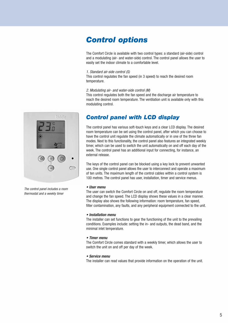
Control panel with LCD display
The control panel has various soft-touch keys and a clear LCD display. The desiredroom temperature can be set using the control panel, after which you can choose tohave the control unit regulate the climate automatically or in one of the three fanmodes. Next to this functionality, the control panel also features an integrated weeklytimer, which can be used to switch the unit automatically on and off each day of theweek. The control panel has an additional input for connecting, for instance, anexternal release.
The keys of the control panel can be blocked using a key lock to prevent unwanteduse. One single control panel allows the user to interconnect and operate a maximumof ten units. The maximum length of the control cables within a control system is100 metres. The control panel has user, installation, timer and service menus.
• User menu The user can switch the Comfort Circle on and off, regulate the room temperatureand change the fan speed. The LCD display shows these values in a clear manner.The display also shows the following information: room temperature, fan speed,filter contamination, any faults, and any peripheral equipment connected to the unit.
• Installation menuThe installer can set functions to gear the functioning of the unit to the prevailingconditions. Examples include: setting the in- and outputs, the dead band, and theminimal inlet temperature.
• Timer menuThe Comfort Circle comes standard with a weekly timer, which allows the user toswitch the unit on and off per day of the week.
• Service menuThe installer can read values that provide information on the operation of the unit.
5
The control panel includes a room thermostat and a weekly timer
6
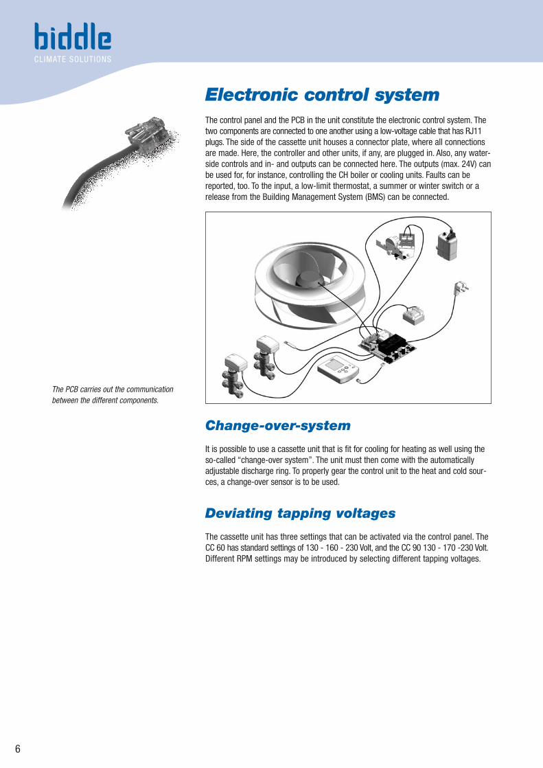
Electronic control systemThe control panel and the PCB in the unit constitute the electronic control system. Thetwo components are connected to one another using a low-voltage cable that has RJ11plugs. The side of the cassette unit houses a connector plate, where all connectionsare made. Here, the controller and other units, if any, are plugged in. Also, any water-side controls and in- and outputs can be connected here. The outputs (max. 24V) canbe used for, for instance, controlling the CH boiler or cooling units. Faults can bereported, too. To the input, a low-limit thermostat, a summer or winter switch or arelease from the Building Management System (BMS) can be connected.
Change-over-system
It is possible to use a cassette unit that is fit for cooling for heating as well using theso-called “change-over system”. The unit must then come with the automaticallyadjustable discharge ring. To properly gear the control unit to the heat and cold sour-ces, a change-over sensor is to be used.
Deviating tapping voltages
The cassette unit has three settings that can be activated via the control panel. TheCC 60 has standard settings of 130 - 160 - 230 Volt, and the CC 90 130 - 170 -230 Volt.Different RPM settings may be introduced by selecting different tapping voltages.
The PCB carries out the communicationbetween the different components.
7
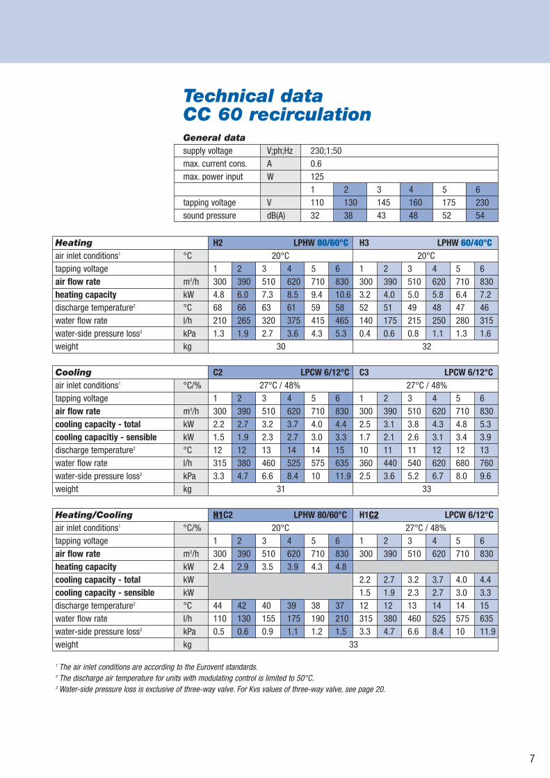
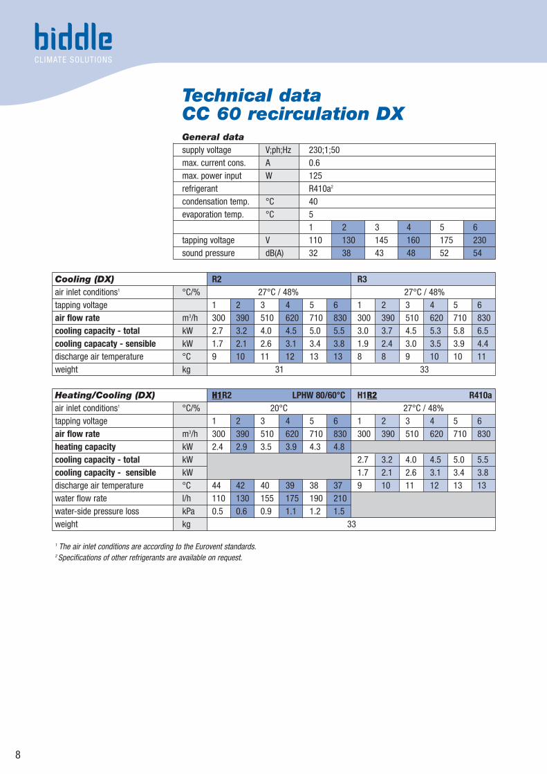
Technical dataCC 60 recirculationGeneral datasupply voltage V;ph;Hz 230;1;50max. current cons. A 0.6max. power input W 125
1 2 3 4 5 6tapping voltage V 110 130 145 160 175 230sound pressure dB(A) 32 38 43 48 52 54
Heating H2 LPHW 80/60°C H3 LPHW 60/40°Cair inlet conditions1 °C 20°C 20°Ctapping voltage 1 2 3 4 5 6 1 2 3 4 5 6air flow rate m3/h 300 390 510 620 710 830 300 390 510 620 710 830heating capacity kW 4.8 6.0 7.3 8.5 9.4 10.6 3.2 4.0 5.0 5.8 6.4 7.2discharge temperature2 °C 68 66 63 61 59 58 52 51 49 48 47 46water flow rate l/h 210 265 320 375 415 465 140 175 215 250 280 315water-side pressure loss3 kPa 1.3 1.9 2.7 3.6 4.3 5.3 0.4 0.6 0.8 1.1 1.3 1.6weight kg 30 32
Cooling C2 LPCW 6/12°C C3 LPCW 6/12°Cair inlet conditions1 °C/% 27°C / 48% 27°C / 48%tapping voltage 1 2 3 4 5 6 1 2 3 4 5 6air flow rate m3/h 300 390 510 620 710 830 300 390 510 620 710 830cooling capacity - total kW 2.2 2.7 3.2 3.7 4.0 4.4 2.5 3.1 3.8 4.3 4.8 5.3cooling capacitiy - sensible kW 1.5 1.9 2.3 2.7 3.0 3.3 1.7 2.1 2.6 3.1 3.4 3.9discharge temperature2 °C 12 12 13 14 14 15 10 11 11 12 12 13water flow rate l/h 315 380 460 525 575 635 360 440 540 620 680 760water-side pressure loss3 kPa 3.3 4.7 6.6 8.4 10 11.9 2.5 3.6 5.2 6.7 8.0 9.6weight kg 31 33
Heating/Cooling H1C2 LPHW 80/60°C H1C2 LPCW 6/12°Cair inlet conditions1 °C/% 20°C 27°C / 48%tapping voltage 1 2 3 4 5 6 1 2 3 4 5 6air flow rate m3/h 300 390 510 620 710 830 300 390 510 620 710 830heating capacity kW 2.4 2.9 3.5 3.9 4.3 4.8cooling capacity - total kW 2.2 2.7 3.2 3.7 4.0 4.4cooling capacity - sensible kW 1.5 1.9 2.3 2.7 3.0 3.3discharge temperature2 °C 44 42 40 39 38 37 12 12 13 14 14 15water flow rate l/h 110 130 155 175 190 210 315 380 460 525 575 635water-side pressure loss3 kPa 0.5 0.6 0.9 1.1 1.2 1.5 3.3 4.7 6.6 8.4 10 11.9weight kg 33
1 The air inlet conditions are according to the Eurovent standards.2 The discharge air temperature for units with modulating control is limited to 50°C.3 Water-side pressure loss is exclusive of three-way valve. For Kvs values of three-way valve, see page 20.
8
Technical dataCC 60 recirculation DXGeneral datasupply voltage V;ph;Hz 230;1;50max. current cons. A 0.6max. power input W 125refrigerant R410a2
condensation temp. °C 40evaporation temp. °C 5
1 2 3 4 5 6tapping voltage V 110 130 145 160 175 230sound pressure dB(A) 32 38 43 48 52 54
Cooling (DX) R2 R3air inlet conditions1 °C/% 27°C / 48% 27°C / 48%tapping voltage 1 2 3 4 5 6 1 2 3 4 5 6air flow rate m3/h 300 390 510 620 710 830 300 390 510 620 710 830cooling capacity - total kW 2.7 3.2 4.0 4.5 5.0 5.5 3.0 3.7 4.5 5.3 5.8 6.5cooling capacaty - sensible kW 1.7 2.1 2.6 3.1 3.4 3.8 1.9 2.4 3.0 3.5 3.9 4.4discharge air temperature °C 9 10 11 12 13 13 8 8 9 10 10 11weight kg 31 33
Heating/Cooling (DX) H1R2 LPHW 80/60°C H1R2 R410aair inlet conditions1 °C/% 20°C 27°C / 48%tapping voltage 1 2 3 4 5 6 1 2 3 4 5 6air flow rate m3/h 300 390 510 620 710 830 300 390 510 620 710 830heating capacity kW 2.4 2.9 3.5 3.9 4.3 4.8cooling capacity - total kW 2.7 3.2 4.0 4.5 5.0 5.5cooling capacity - sensible kW 1.7 2.1 2.6 3.1 3.4 3.8discharge air temperature °C 44 42 40 39 38 37 9 10 11 12 13 13water flow rate l/h 110 130 155 175 190 210water-side pressure loss kPa 0.5 0.6 0.9 1.1 1.2 1.5weight kg 33
1 The air inlet conditions are according to the Eurovent standards.2 Specifications of other refrigerants are available on request.
9
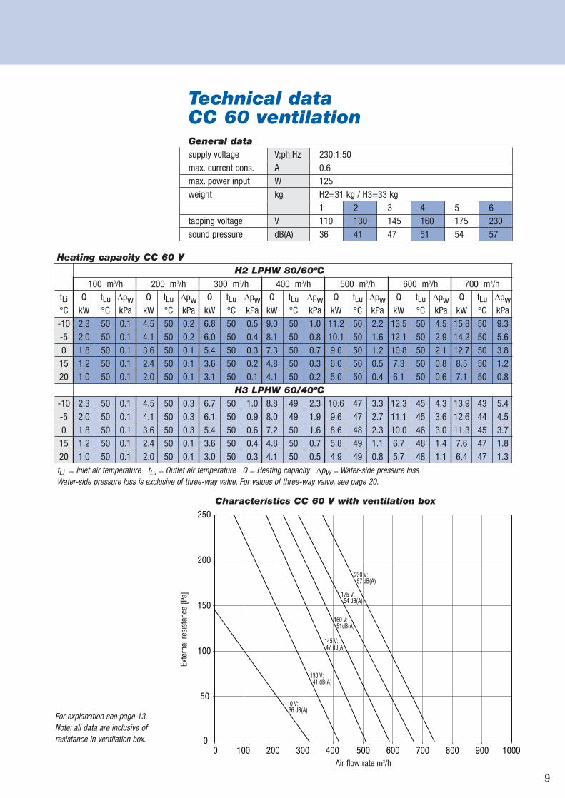
Technical dataCC 60 ventilationGeneral datasupply voltage V;ph;Hz 230;1;50max. current cons. A 0.6max. power input W 125weight kg H2=31 kg / H3=33 kg
1 2 3 4 5 6tapping voltage V 110 130 145 160 175 230sound pressure dB(A) 36 41 47 51 54 57
Heating capacity CC 60 VH2 LPHW 80/60ºC
100 m3/h 200 m3/h 300 m3/h 400 m3/h 500 m3/h 600 m3/h 700 m3/htLi Q tLu Δpw Q tLu Δpw Q tLu Δpw Q tLu Δpw Q tLu Δpw Q tLu Δpw Q tLu Δpw°C kW °C kPa kW °C kPa kW °C kPa kW °C kPa kW °C kPa kW °C kPa kW °C kPa-10 2.3 50 0.1 4.5 50 0.2 6.8 50 0.5 9.0 50 1.0 11.2 50 2.2 13.5 50 4.5 15.8 50 9.3-5 2.0 50 0.1 4.1 50 0.2 6.0 50 0.4 8.1 50 0.8 10.1 50 1.6 12.1 50 2.9 14.2 50 5.60 1.8 50 0.1 3.6 50 0.1 5.4 50 0.3 7.3 50 0.7 9.0 50 1.2 10.8 50 2.1 12.7 50 3.8
15 1.2 50 0.1 2.4 50 0.1 3.6 50 0.2 4.8 50 0.3 6.0 50 0.5 7.3 50 0.8 8.5 50 1.220 1.0 50 0.1 2.0 50 0.1 3.1 50 0.1 4.1 50 0.2 5.0 50 0.4 6.1 50 0.6 7.1 50 0.8
H3 LPHW 60/40ºC-10 2.3 50 0.1 4.5 50 0.3 6.7 50 1.0 8.8 49 2.3 10.6 47 3.3 12.3 45 4.3 13.9 43 5.4-5 2.0 50 0.1 4.1 50 0.3 6.1 50 0.9 8.0 49 1.9 9.6 47 2.7 11.1 45 3.6 12.6 44 4.50 1.8 50 0.1 3.6 50 0.3 5.4 50 0.6 7.2 50 1.6 8.6 48 2.3 10.0 46 3.0 11.3 45 3.7
15 1.2 50 0.1 2.4 50 0.1 3.6 50 0.4 4.8 50 0.7 5.8 49 1.1 6.7 48 1.4 7.6 47 1.820 1.0 50 0.1 2.0 50 0.1 3.0 50 0.3 4.1 50 0.5 4.9 49 0.8 5.7 48 1.1 6.4 47 1.3
tLi = Inlet air temperature tLu = Outlet air temperature Q = Heating capacity Δpw = Water-side pressure lossWater-side pressure loss is exclusive of three-way valve. For values of three-way valve, see page 20.
110 V: 36 dB(A)
130 V: 41 dB(A)
145 V: 47 dB(A)
160 V: 51 dB(A)
175 V: 54 dB(A)
230 V: 57 dB(A)
0
50
100
150
200
250
0 100 200 300 400 500 600 700 800 900 1000
For explanation see page 13.Note: all data are inclusive of resistance in ventilation box.
Characteristics CC 60 V with ventilation box
Exte
rnal
resi
stan
ce [P
a]
Air flow rate m3/h
10
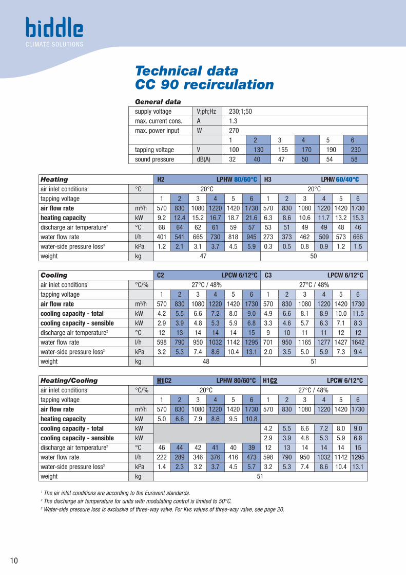
Technical dataCC 90 recirculationGeneral datasupply voltage V;ph;Hz 230;1;50max. current cons. A 1.3max. power input W 270
1 2 3 4 5 6tapping voltage V 100 130 155 170 190 230sound pressure dB(A) 32 40 47 50 54 58
Heating H2 LPHW 80/60°C H3 LPHW 60/40°Cair inlet conditions1 °C 20°C 20°Ctapping voltage 1 2 3 4 5 6 1 2 3 4 5 6air flow rate m3/h 570 830 1080 1220 1420 1730 570 830 1080 1220 1420 1730heating capacity kW 9.2 12.4 15.2 16.7 18.7 21.6 6.3 8.6 10.6 11.7 13.2 15.3discharge air temperature2 °C 68 64 62 61 59 57 53 51 49 49 48 46water flow rate l/h 401 541 665 730 818 945 273 373 462 509 573 666water-side pressure loss3 kPa 1.2 2.1 3.1 3.7 4.5 5.9 0.3 0.5 0.8 0.9 1.2 1.5weight kg 47 50
Cooling C2 LPCW 6/12°C C3 LPCW 6/12°Cair inlet conditions1 °C/% 27°C / 48% 27°C / 48%tapping voltage 1 2 3 4 5 6 1 2 3 4 5 6air flow rate m3/h 570 830 1080 1220 1420 1730 570 830 1080 1220 1420 1730cooling capacity - total kW 4.2 5.5 6.6 7.2 8.0 9.0 4.9 6.6 8.1 8.9 10.0 11.5cooling capacity - sensible kW 2.9 3.9 4.8 5.3 5.9 6.8 3.3 4.6 5.7 6.3 7.1 8.3discharge air temperature2 °C 12 13 14 14 14 15 9 10 11 11 12 12water flow rate l/h 598 790 950 1032 1142 1295 701 950 1165 1277 1427 1642water-side pressure loss3 kPa 3.2 5.3 7.4 8.6 10.4 13.1 2.0 3.5 5.0 5.9 7.3 9.4weight kg 48 51
Heating/Cooling H1C2 LPHW 80/60°C H1C2 LPCW 6/12°Cair inlet conditions1 °C/% 20°C 27°C / 48%tapping voltage 1 2 3 4 5 6 1 2 3 4 5 6air flow rate m3/h 570 830 1080 1220 1420 1730 570 830 1080 1220 1420 1730heating capacity kW 5.0 6.6 7.9 8.6 9.5 10.8cooling capacity - total kW 4.2 5.5 6.6 7.2 8.0 9.0cooling capacity - sensible kW 2.9 3.9 4.8 5.3 5.9 6.8discharge air temperature2 °C 46 44 42 41 40 39 12 13 14 14 14 15water flow rate l/h 222 289 346 376 416 473 598 790 950 1032 1142 1295water-side pressure loss3 kPa 1.4 2.3 3.2 3.7 4.5 5.7 3.2 5.3 7.4 8.6 10.4 13.1weight kg 51
1 The air inlet conditions are according to the Eurovent standards.2 The discharge air temperature for units with modulating control is limited to 50°C.3 Water-side pressure loss is exclusive of three-way valve. For Kvs values of three-way valve, see page 20.
11
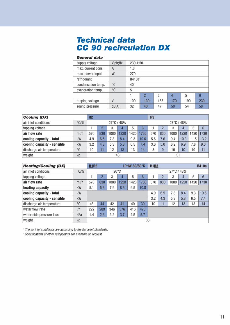
Technical dataCC 90 recirculation DXGeneral datasupply voltage V;ph;Hz 230;1;50max. current cons. A 1.3max. power input W 270refrigerant R410a2
condensation temp. °C 40evaporation temp. °C 5
1 2 3 4 5 6tapping voltage V 100 130 155 170 190 230sound pressure dB(A) 32 40 47 50 54 58
Cooling (DX) R2 R3air inlet conditions1 °C/% 27°C / 48% 27°C / 48%tapping voltage 1 2 3 4 5 6 1 2 3 4 5 6air flow rate m3/h 570 830 1080 1220 1420 1730 570 830 1080 1220 1420 1730cooling capacity - total kW 4.9 6.5 7.8 8.4 9.3 10.6 5.6 7.6 9.4 10.3 11.5 13.2cooling capacity - sensible kW 3.2 4.3 5.3 5.8 6.5 7.4 3.6 5.0 6.2 6.9 7.8 9.0discharge air temperature °C 10 11 12 13 13 14 8 9 10 10 10 11weight kg 48 51
Heating/Cooling (DX) H1R2 LPHW 80/60°C H1R2 R410aair inlet conditions1 °C/% 20°C 27°C / 48%tapping voltage 1 2 3 4 5 6 1 2 3 4 5 6air flow rate m3/h 570 830 1080 1220 1420 1730 570 830 1080 1220 1420 1730heating capacity kW 5.1 6.6 7.9 8.6 9.5 10.8cooling capacity - total kW 4.9 6.5 7.8 8.4 9.3 10.6cooling capacity - sensible kW 3.2 4.3 5.3 5.8 6.5 7.4discharge air temperature °C 46 44 42 41 40 39 10 11 12 13 13 14water flow rate l/h 222 289 346 376 416 473water-side pressure loss kPa 1.4 2.3 3.2 3.7 4.5 5.7weight kg 33
1 The air inlet conditions are according to the Eurovent standards.2 Specifications of other refrigerants are available on request.
12
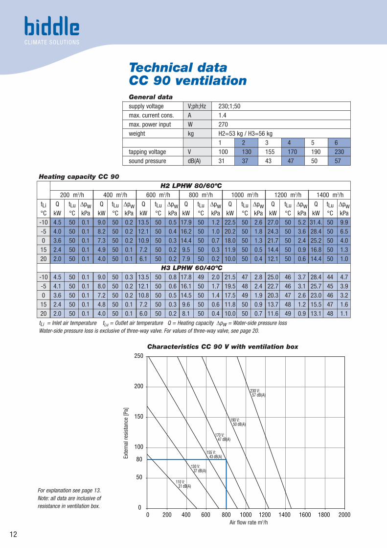
Technical dataCC 90 ventilationGeneral datasupply voltage V;ph;Hz 230;1;50max. current cons. A 1.4max. power input W 270weight kg H2=53 kg / H3=56 kg
1 2 3 4 5 6tapping voltage V 100 130 155 170 190 230sound pressure dB(A) 31 37 43 47 50 57
Heating capacity CC 90H2 LPHW 80/60ºC
200 m3/h 400 m3/h 600 m3/h 800 m3/h 1000 m3/h 1200 m3/h 1400 m3/htLi Q tLu Δpw Q tLu Δpw Q tLu Δpw Q tLu Δpw Q tLu Δpw Q tLu Δpw Q tLu Δpw°C kW °C kPa kW °C kPa kW °C kPa kW °C kPa kW °C kPa kW °C kPa kW °C kPa-10 4.5 50 0.1 9.0 50 0.2 13.5 50 0.5 17.9 50 1.2 22.5 50 2.6 27.0 50 5.2 31.4. 50 9.9-5 4.0 50 0.1 8.2 50 0.2 12.1 50 0.4 16.2 50 1.0 20.2 50 1.8 24.3 50 3.6 28.4 50 6.50 3.6 50 0.1 7.3 50 0.2 10.9 50 0.3 14.4 50 0.7 18.0 50 1.3 21.7 50 2.4 25.2 50 4.0
15 2.4 50 0.1 4.9 50 0.1 7.2 50 0.2 9.5 50 0.3 11.9 50 0.5 14.4 50 0.9 16.8 50 1.320 2.0 50 0.1 4.0 50 0.1 6.1 50 0.2 7.9 50 0.2 10.0 50 0.4 12.1 50 0.6 14.4 50 1.0
H3 LPHW 60/40ºC-10 4.5 50 0.1 9.0 50 0.3 13.5 50 0.8 17.8 49 2.0 21.5 47 2.8 25.0 46 3.7 28.4 44 4.7-5 4.1 50 0.1 8.0 50 0.2 12.1 50 0.6 16.1 50 1.7 19.5 48 2.4 22.7 46 3.1 25.7 45 3.90 3.6 50 0.1 7.2 50 0.2 10.8 50 0.5 14.5 50 1.4 17.5 49 1.9 20.3 47 2.6 23.0 46 3.2
15 2.4 50 0.1 4.8 50 0.1 7.2 50 0.3 9.6 50 0.6 11.8 50 0.9 13.7 48 1.2 15.5 47 1.620 2.0 50 0.1 4.0 50 0.1 6.0 50 0.2 8.1 50 0.4 10.0 50 0.7 11.6 49 0.9 13.1 48 1.1
tLi = Inlet air temperature tLu = Outlet air temperature Q = Heating capacity Δpw = Water-side pressure lossWater-side pressure loss is exclusive of three-way valve. For values of three-way valve, see page 20.
0
50
80
100
150
200
250
0 200 400 600 800 1000 1200 1400 1600 1800 2000
110 V: 31 dB(A)
130 V: 37 dB(A)
155 V: 43 dB(A)
170 V: 47 dB(A)
190 V: 50 dB(A)
230 V: 57 dB(A)
For explanation see page 13.Note: all data are inclusive of resistance in ventilation box.
Characteristics CC 90 V with ventilation box
Exte
rnal
resi
stan
ce [P
a]
Air flow rate m3/h
Explanation of Technical Data
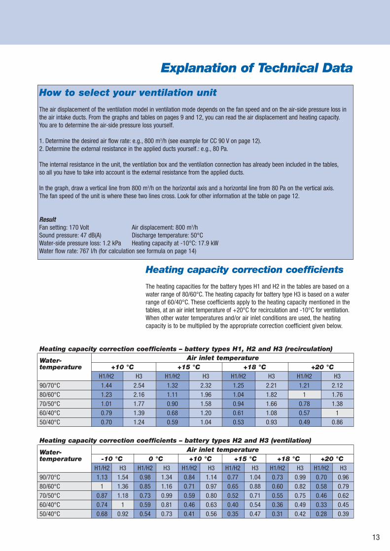
How to select your ventilation unit
The air displacement of the ventilation model in ventilation mode depends on the fan speed and on the air-side pressure loss inthe air intake ducts. From the graphs and tables on pages 9 and 12, you can read the air displacement and heating capacity.You are to determine the air-side pressure loss yourself.
1. Determine the desired air flow rate: e.g., 800 m3/h (see example for CC 90 V on page 12).2. Determine the external resistance in the applied ducts yourself.: e.g., 80 Pa.
The internal resistance in the unit, the ventilation box and the ventilation connection has already been included in the tables,so all you have to take into account is the external resistance from the applied ducts.
In the graph, draw a vertical line from 800 m3/h on the horizontal axis and a horizontal line from 80 Pa on the vertical axis.The fan speed of the unit is where these two lines cross. Look for other information at the table on page 12.
ResultFan setting: 170 Volt Air displacement: 800 m3/hSound pressure: 47 dB(A) Discharge temperature: 50°CWater-side pressure loss: 1.2 kPa Heating capacity at -10°C: 17.9 kWWater flow rate: 767 l/h (for calculation see formula on page 14)
13
Heating capacity correction coefficients – battery types H1, H2 and H3 (recirculation)
Heating capacity correction coefficients
The heating capacities for the battery types H1 and H2 in the tables are based on awater range of 80/60°C. The heating capacity for battery type H3 is based on a waterrange of 60/40°C. These coefficients apply to the heating capacity mentioned in thetables, at an air inlet temperature of +20°C for recirculation and -10°C for ventilation.When other water temperatures and/or air inlet conditions are used, the heatingcapacity is to be multiplied by the appropriate correction coefficient given below.
Water- Air inlet temperaturetemperature +10 °C +15 °C +18 °C +20 °C
H1/H2 H3 H1/H2 H3 H1/H2 H3 H1/H2 H390/70°C 1.44 2.54 1.32 2.32 1.25 2.21 1.21 2.1280/60°C 1.23 2.16 1.11 1.96 1.04 1.82 1 1.7670/50°C 1.01 1.77 0.90 1.58 0.94 1.66 0.78 1.3860/40°C 0.79 1.39 0.68 1.20 0.61 1.08 0.57 150/40°C 0.70 1.24 0.59 1.04 0.53 0.93 0.49 0.86
Heating capacity correction coefficients – battery types H2 and H3 (ventilation)
Water- Air inlet temperaturetemperature -10 °C 0 °C +10 °C +15 °C +18 °C +20 °C
H1/H2 H3 H1/H2 H3 H1/H2 H3 H1/H2 H3 H1/H2 H3 H1/H2 H390/70°C 1.13 1.54 0.98 1.34 0.84 1.14 0.77 1.04 0.73 0.99 0.70 0.9680/60°C 1 1.36 0.85 1.16 0.71 0.97 0.65 0.88 0.60 0.82 0.58 0.7970/50°C 0.87 1.18 0.73 0.99 0.59 0.80 0.52 0.71 0.55 0.75 0.46 0.6260/40°C 0.74 1 0.59 0.81 0.46 0.63 0.40 0.54 0.36 0.49 0.33 0.4550/40°C 0.68 0.92 0.54 0.73 0.41 0.56 0.35 0.47 0.31 0.42 0.28 0.39
14
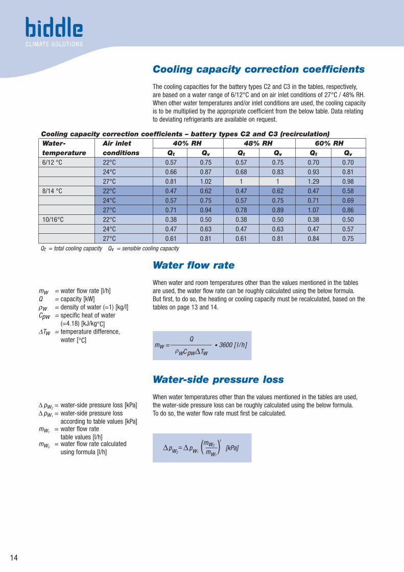
Cooling capacity correction coefficients
The cooling capacities for the battery types C2 and C3 in the tables, respectively,are based on a water range of 6/12°C and on air inlet conditions of 27°C / 48% RH.When other water temperatures and/or inlet conditions are used, the cooling capacityis to be multiplied by the appropriate coefficient from the below table. Data relatingto deviating refrigerants are available on request.
Water flow rate
When water and room temperatures other than the values mentioned in the tablesare used, the water flow rate can be roughly calculated using the below formula.But first, to do so, the heating or cooling capacity must be recalculated, based on thetables on page 13 and 14.
Water-side pressure loss
When water temperatures other than the values mentioned in the tables are used,the water-side pressure loss can be roughly calculated using the below formula.To do so, the water flow rate must first be calculated.
Water- Air inlet 40% RH 48% RH 60% RHtemperature conditions Qt Qv Qt Qv Qt Qv
6/12 °C 22°C 0.57 0.75 0.57 0.75 0.70 0.7024°C 0.66 0.87 0.68 0.83 0.93 0.8127°C 0.81 1.02 1 1 1.29 0.98
8/14 °C 22°C 0.47 0.62 0.47 0.62 0.47 0.5824°C 0.57 0.75 0.57 0.75 0.71 0.6927°C 0.71 0.94 0.78 0.89 1.07 0.86
10/16°C 22°C 0.38 0.50 0.38 0.50 0.38 0.5024°C 0.47 0.63 0.47 0.63 0.47 0.5727°C 0.61 0.81 0.61 0.81 0.84 0.75
Qt = total cooling capacity Qv = sensible cooling capacity
Cooling capacity correction coefficients – battery types C2 and C3 (recirculation)
mw = • 3600 [ l /h ] Q
ρwCpwΔTw
Δpw2= Δpw1
[kPa]mw1
(mw2 )2
mw = water flow rate [l/h]Q = capacity [kW]ρw = density of water (=1) [kg/l]Cpw = specific heat of water
(=4.18) [kJ/kg°C]ΔTw = temperature difference,
water [°C]
Δ pw2= water-side pressure loss [kPa]
Δ pw1= water-side pressure loss
according to table values [kPa]mw1
= water flow ratetable values [l/h]
mw2= water flow rate calculated
using formula [l/h]
15
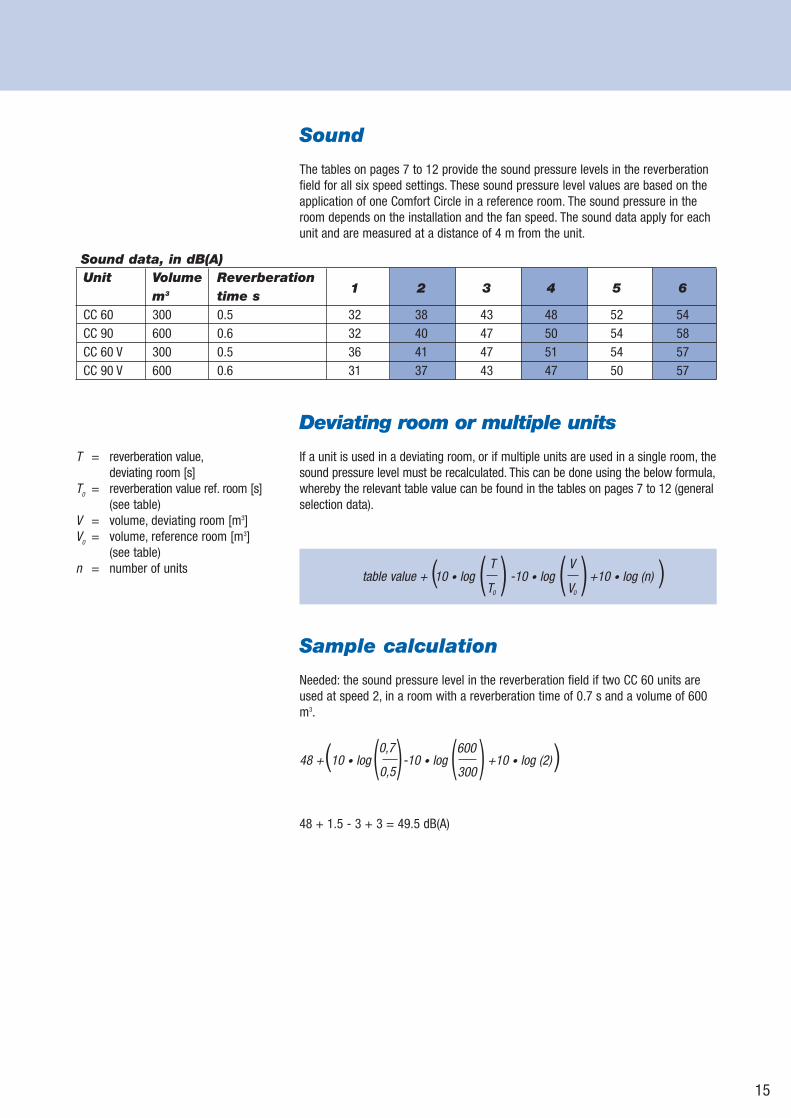
Sound
The tables on pages 7 to 12 provide the sound pressure levels in the reverberationfield for all six speed settings. These sound pressure level values are based on theapplication of one Comfort Circle in a reference room. The sound pressure in theroom depends on the installation and the fan speed. The sound data apply for eachunit and are measured at a distance of 4 m from the unit.
Deviating room or multiple units
If a unit is used in a deviating room, or if multiple units are used in a single room, thesound pressure level must be recalculated. This can be done using the below formula,whereby the relevant table value can be found in the tables on pages 7 to 12 (generalselection data).
Sample calculation
Needed: the sound pressure level in the reverberation field if two CC 60 units areused at speed 2, in a room with a reverberation time of 0.7 s and a volume of 600m3.
48 + 1.5 - 3 + 3 = 49.5 dB(A)
Unit Volume Reverberationm3 time s
1 2 3 4 5 6
CC 60 300 0.5 32 38 43 48 52 54CC 90 600 0.6 32 40 47 50 54 58CC 60 V 300 0.5 36 41 47 51 54 57CC 90 V 600 0.6 31 37 43 47 50 57
Sound data, in dB(A)
T = reverberation value,deviating room [s]
T0 = reverberation value ref. room [s](see table)
V = volume, deviating room [m3]V0 = volume, reference room [m3]
(see table)n = number of units
table value + 10 • log -10 • log +10 • log (n) V
V0
( ( ) ) T
T0( )
0,7
0,548 + 10 • log -10 • log +10 • log (2) ( ( ) ( ) ) 600
300
16
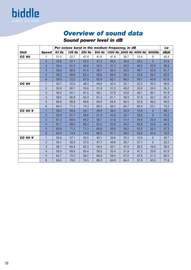
Overview of sound data Sound power level in dB
Per octave band in the medium frequency, in dB LwUnit Speed 63 Hz 125 Hz 250 Hz 500 Hz 1000 Hz 2000 Hz 4000 Hz 8000Hz dB(A)CC 60 1 51.5 52.7 47.4 41.8 41.4 36.7 15.4 0 45.4
2 53.6 57.1 52.5 47.3 45.8 45.0 29.3 0 51.63 54.4 61.5 56.6 52.2 51.5 50.5 40.2 22.9 56.84 56.8 66.6 61.5 56.7 56.4 55.0 48.7 32.6 61.75 58.3 69.6 65.3 60.6 60.4 58.3 53.9 39.3 65.56 59.9 72.2 67.9 62.9 62.7 60.2 56.7 43.6 67.8
CC 90 1 43.7 52.6 48.3 44.0 42.4 32.1 22.2 20.2 46.62 52.9 60.1 55.6 51.9 51.2 46.2 35.0 24.5 55.33 58.4 64.7 61.5 58.1 57.9 53.6 46.1 36.1 61.94 59.5 66.9 65.3 61.3 61.1 56.9 51.0 42.1 65.25 60.8 68.8 69.6 64.9 64.8 60.5 55.6 48.2 69.06 64.4 71.3 74.3 69.5 69.3 64.7 60.4 55.1 73.5
CC 60 V 1 56.4 59.8 53.1 45.9 38.0 34.4 14.9 0 49.12 56.9 61.7 58.6 51.9 43.9 43.1 28.9 0 54.23 61.2 64.6 64.2 58.1 51.6 51.4 44.9 25.9 60.54 61.7 69.3 68.3 62.2 55.8 54.2 50.8 33.6 64.55 62.6 71.3 71.3 65.0 58.8 56.5 53.5 38.3 67.36 63.9 73.4 74.9 68.5 61.7 59.0 55.6 42.6 70.5
CC 90 V 1 50.6 57.1 50.5 40.1 35.6 25.3 15.0 0 45.72 54.1 58.9 57.5 47.7 44.6 39.7 27.7 0 52.23 58.1 65.9 62.3 54.4 52.1 47.0 38.3 16.0 58.54 58.0 69.6 65.4 56.8 55.4 51.9 41.3 25.6 61.85 62.7 72.2 68.2 60.9 59.4 57.2 47.6 31.3 65.56 64.0 79.0 74.5 66.3 64.9 64.4 57.6 42.0 71.9
17
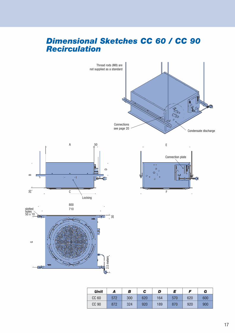
Dimensional Sketches CC 60 / CC 90Recirculation
Unit A B C D E F G
CC 60 572 300 620 164 570 620 600
CC 90 872 324 920 189 870 920 900
A 50
C20B
D
E
F
800710
G
2.5
met
ers
30
Thread rods (M8) are not supplied as a standard
Condensate discharge
Connectionssee page 20
Connection plate
Locking
slotted holes50 x 10
18
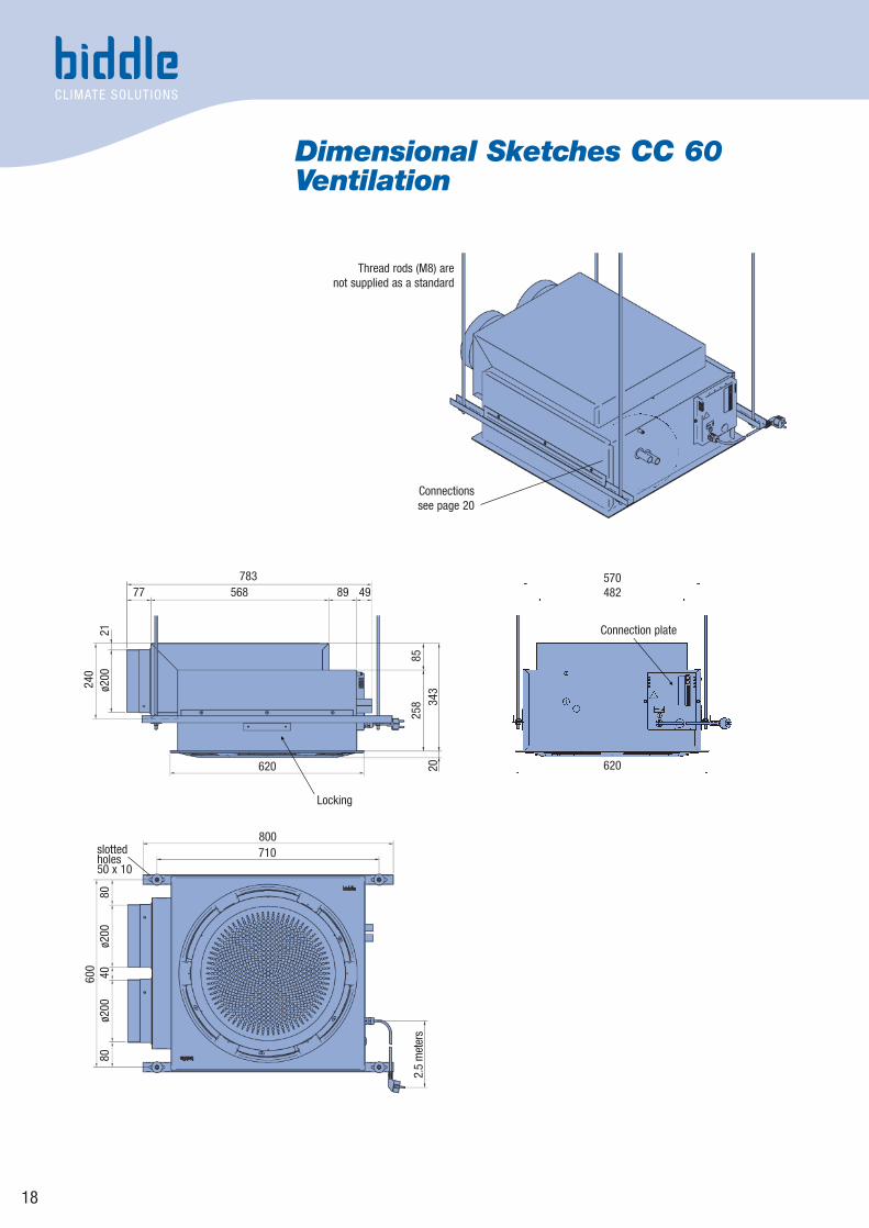
Dimensional Sketches CC 60Ventilation
783568
620
570
800710
482
620
77
240
2.5
met
ers
600
40ø2
00ø2
0080
80ø2
0021
2034
325
885
89 49
Thread rods (M8) are not supplied as a standard
Locking
Connection plate
Connectionssee page 20
slotted holes50 x 10
19
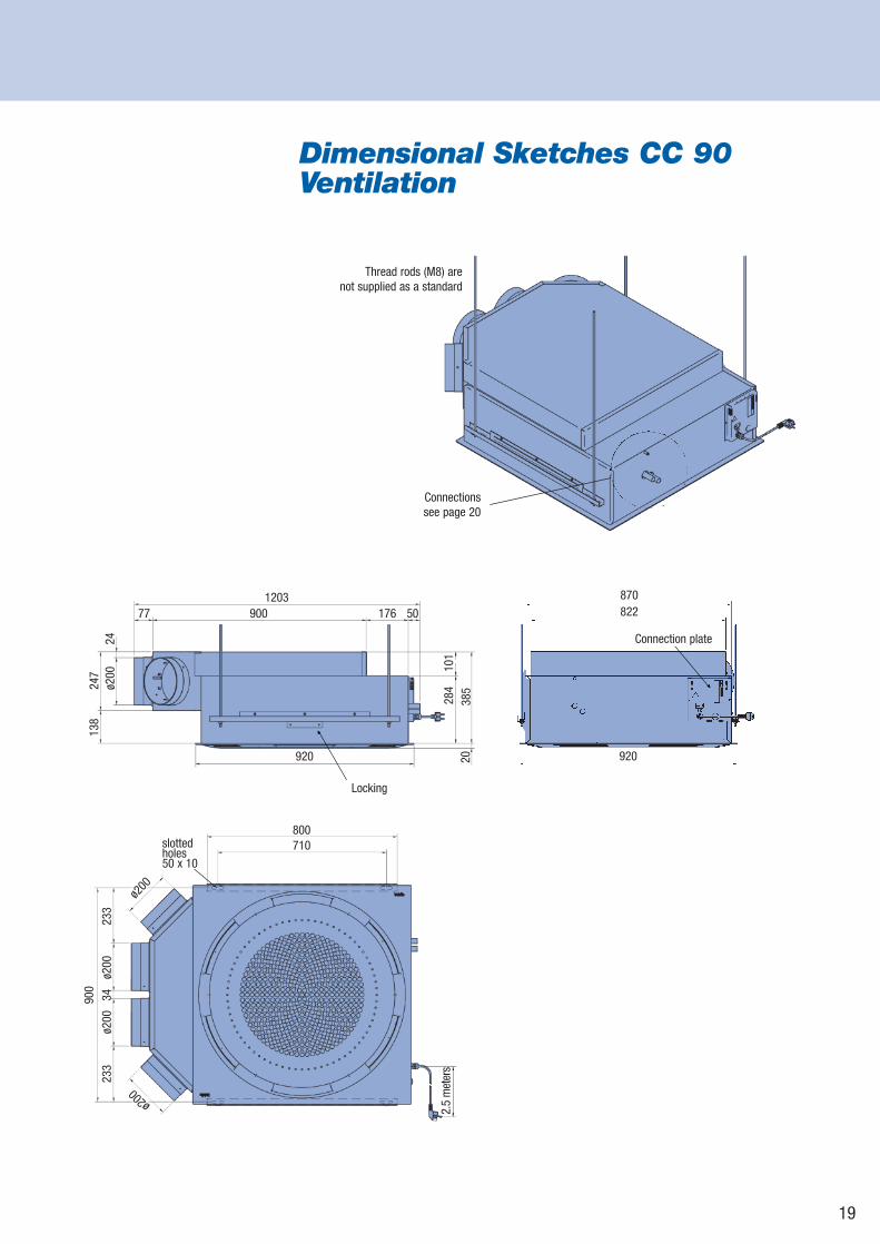
Dimensional Sketches CC 90Ventilation
176 50
ø200
2413
824
7
385
2010
128
4
900
920
870822
920
120377
800710
900
3423
323
3ø2
00ø2
00
2.5
met
ers
ø200
ø200
Thread rods (M8) are not supplied as a standard
Locking
Connection plate
Connectionssee page 20
slotted holes50 x 10
20
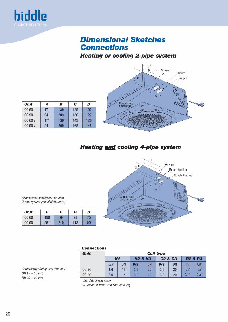
Dimensional SketchesConnectionsHeating or cooling 2-pipe system
Unit Coil typeH1 H2 & H3 C2 & C3 R2 & R3
Kvs1 DN Kvs1 DN Kvs1 DN In2 Uit2
CC 60 1.6 15 2.5 20 2.5 20 3/8” 5/8”CC 90 3.0 15 3.0 20 3.0 20 3/8” 3/4”
1 Kvs data 3-way valve2 R -model is fitted with flare coupling
Compression fitting pipe diameter DN 15 = 15 mmDN 20 = 22 mm
Connections cooling are equal to 2-pipe system (see sketch above)
Connections
Condensate discharge
Air vent
Return heating
Supply heating
FE
Condensate discharge
Air ventReturn
Supply
AB
DC
HG
Heating and cooling 4-pipe system
Unit A B C DCC 60 171 139 125 102CC 90 241 209 150 127CC 60 V 171 139 143 120CC 90 V 241 209 168 145
Unit E F G HCC 60 196 164 98 75CC 90 251 219 113 90
21
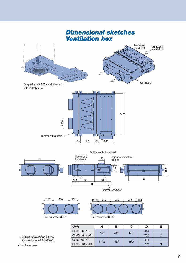
Composition of CC 60-V ventilation unit with ventilation box.
Unit A B C D ECC 60-HS / VS
748 788 607444 -
CC 60-HG4 / VG4 782 2CC 90-HS / VS
1123 1163 982444 -
CC 90-HG4 / VG4 782 3
Dimensional sketches Ventilation box
G4-module1
Connection wall duct
Connection roof duct
Module only for G4-unit
Optional servomotor
Vertical ventilation air inlet
Horizontal ventilation air inlet
106 338 338 C
127
230
D
ø 20
0
Number of bag filters E
A B
76 262 76 262
141,5 280 280 280 141,5197 354 197
Duct connection CC 60 Duct connection CC 90
1) When a standard filter is used,the G4-module will be left out.
= filter remove
C 127
22
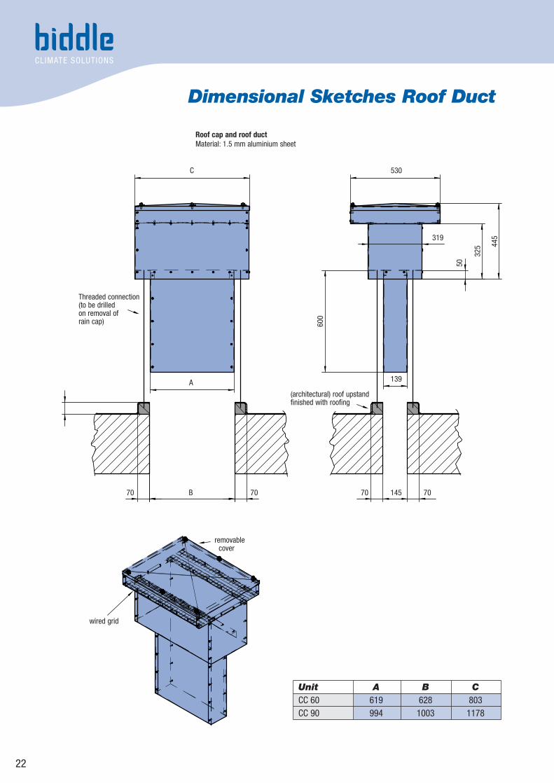
Dimensional Sketches Roof Duct
Unit A B CCC 60 619 628 803CC 90 994 1003 1178
Roof cap and roof ductMaterial: 1.5 mm aluminium sheet
C 530
319
139A
70 70145
50
325 44
5
600
7070 B
(architectural) roof upstandfinished with roofing
Threaded connection (to be drilled on removal of rain cap)
removablecover
wired grid
23
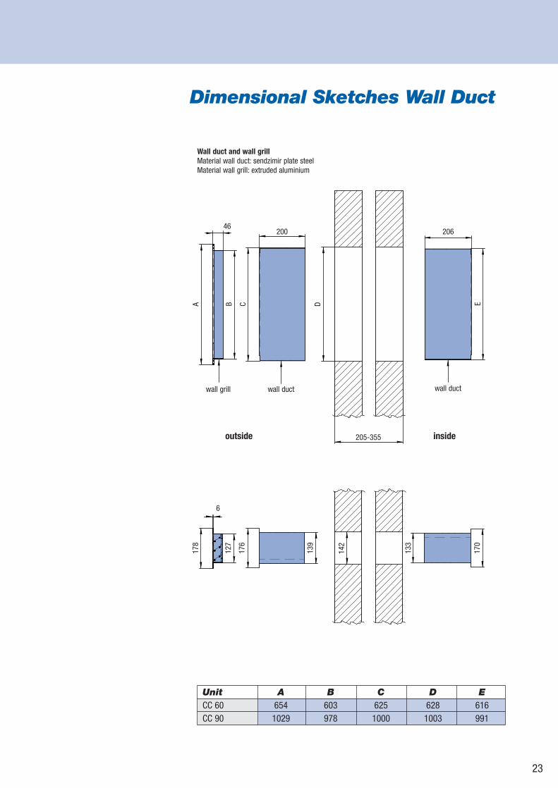
Dimensional Sketches Wall Duct
Unit A B C D ECC 60 654 603 625 628 616CC 90 1029 978 1000 1003 991
Wall duct and wall grillMaterial wall duct: sendzimir plate steelMaterial wall grill: extruded aluminium
outside inside
46200 206
205-355
A B C D E
wall grill wall duct wall duct
178
127
176
139
142
133
170
6
24
SpecificationsCasing
The casing is made of zinc-plated sheet steel, extra strengthened to minimisedeformation and vibration, and it has an adjustable plastic air inlet grille in the bottom.The casing is fitted with soundproofing heat-insulation material. Units that arecapable of both heating and cooling have an inlet grille with an automatic angleadjustment. The casing and the inlet grille come standard in the colour white (RAL 9010) but other RAL colours are available at an extra charge.
Motor / fan assembly
The centrifugal fan has backward bent blades and has been mounted in the casingsuch that it causes no vibrations. The fan is driven by a rotor motor on ball bearings.The fan casing and the impeller are made of zinc coated sheet steel. The EBMmotor is manufactured according to DIN 40050, Protection Class IP44 and InsulationClass F, and comes standard with thermal contacts. These thermal contacts willbreak the circuit of the motor when the maximum permissible motor temperature isexceeded (auto-reset).
Heating- (LPHW) / Cooling Coil (LPCW or DX)
The coils are made up of 3/8” copper tubes and aluminium fins. The coils are availablewith 2 or 4 rows of tubes. The maximum operating pressure is 8 bar at maximum90°C. With the direct expansion coil (exclusive of expansion valve) the refrigerantR410a is used as standard, but other refrigerants may also be used. The maximumoperating pressure is 41 bar.
Frost protection thermostat
Ventilation units have a frost protection thermostat, which is integrated into the controlunit, and reduces the risk of the coil freezing (preset at 5°C).
ConnectionsThe units come with a 2.5 m-longpower cable with a moulded-on, earthedplug. The CH connections and the connector plate are located in the sideof the unit.
Control and operationThe control panel is connected to the cassette unit using a low-voltage cablethat has RJ11 plugs. This type of cableis also used to interconnect multipleunits. The control unit in the deviceregulates the room temperature andthe fan speed.
CC-E
NG-2
006-
06-1
000•
3674
03
Subject to change. Biddle bvP.O. Box 15NL-9288 ZG KootstertilleThe Netherlandstel. +31 512 33 55 55fax +31 512 33 55 54 e-mail [email protected] www.biddle.info