Embed Size (px)
Citation preview
IEEE 802.3az May 2008 Interim Meeting1
Cat5 Twisted Pair Model for “Green” 10BASE-T
PresenterMandeep Chadha
Vitesse Semiconductor Corp.
ContributorsJim McElweeDan Stiurca
IEEE 802.3az May 2008 Interim Meeting2
Supporters
• Mandeep Chadha (Vitesse)• Joseph Chou (Real)• Geoff Thompson (Nortel)• Hugh Barrass (Cisco)
IEEE 802.3az May 2008 Interim Meeting3
Background• Goal is to reduce transmit amplitude for 10BASE-T operating mode
– Lower power consumption– Allow scaling with I/O voltages and newer technologies
• Sacrifice:– 100-180 meter reach over Cat5– 65-100 meter reach over Cat3 and DIW
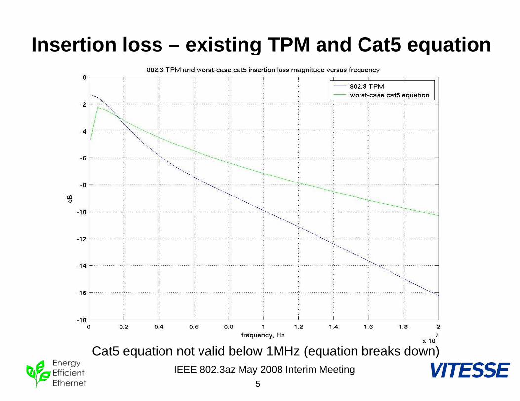
• New TPM should be created that provides a better approximation to the worst case Cat5 channel, as defined in the worst-case insertion loss equation from 802.3: – 2.1*f0.529 + 0.4/f ( 1MHz < f < 100MHz)
• As with the previous TPM, we are only concerned with 10BASE-T data frequencies (~2MHz to 15MHz)
• Try to keep same structure as 802.3 TPM. PCBs already fabricated can be “stuffed” with new components
• See backup slides for more background information
IEEE 802.3az May 2008 Interim Meeting4
Cat5 TPM, target specifications• Good approximation to worst case insertion loss magnitude from
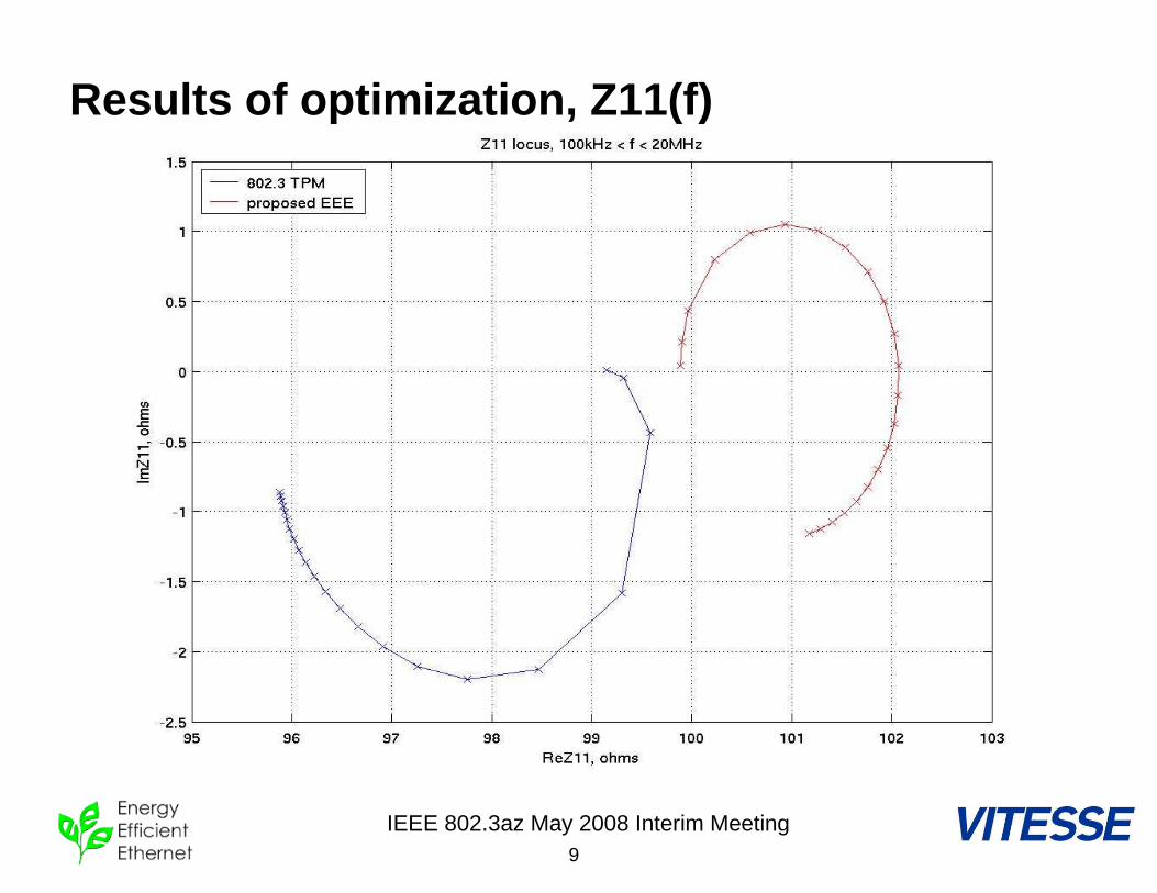
1MHz to ~15MHz. Very good approximation at 5MHz and 10MHz.• Z11 of approximately 100ohms (when TPM is loaded with 100ohms)
from 1MHz to 15MHz – this results in realistic loading of line-driver during testing.
• Phase response not important. Linear phase and group delay matching of actual Cat5 cable is not possible with lumped TPM structure (and current 10BASE-T TPM does not exhibit linear phase).
• Use LMS directed optimization to accomplish both insertion loss magnitude and Z11 goals.
• “Quantization” of resultant ideal values results in some deviation from ideal fit. Standard available component values chosen to minimize this error (not just rounded to nearest standard component size)
IEEE 802.3az May 2008 Interim Meeting5
Insertion loss – existing TPM and Cat5 equation
Cat5 equation not valid below 1MHz (equation breaks down)
IEEE 802.3az May 2008 Interim Meeting6
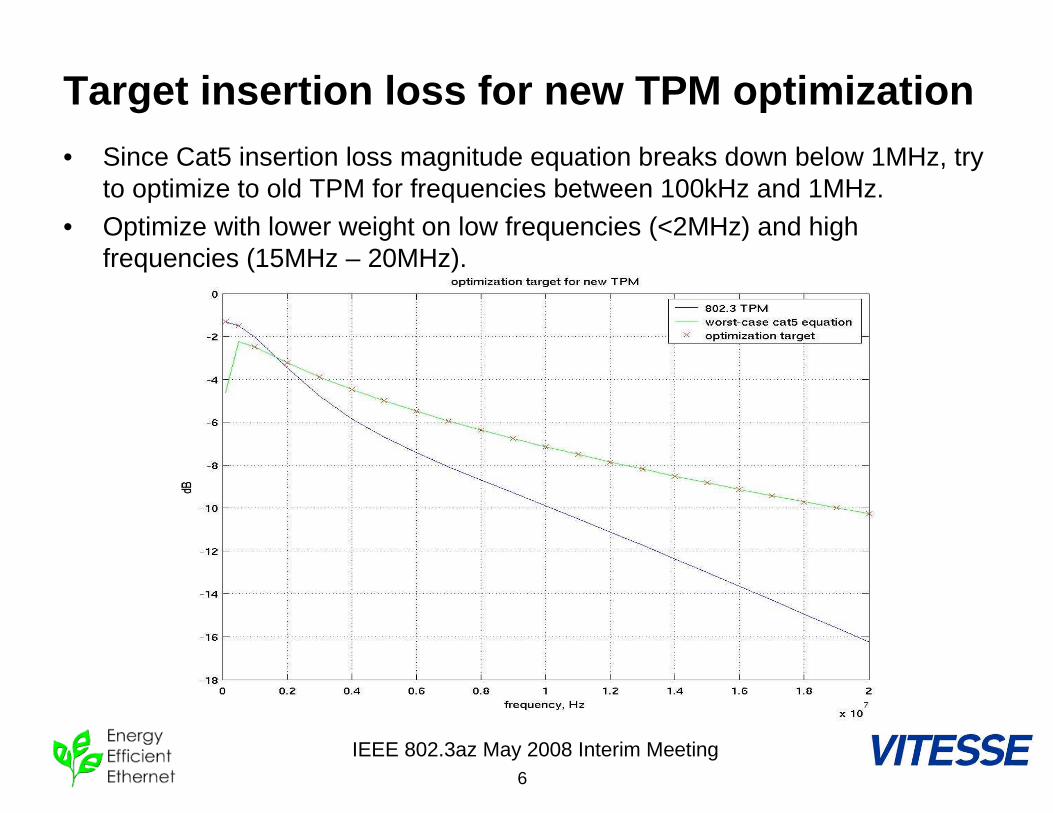
Target insertion loss for new TPM optimization
• Since Cat5 insertion loss magnitude equation breaks down below 1MHz, try to optimize to old TPM for frequencies between 100kHz and 1MHz.
• Optimize with lower weight on low frequencies (<2MHz) and high frequencies (15MHz – 20MHz).

IEEE 802.3az May 2008 Interim Meeting7
Results of optimization, component values
• Some components (2 C, 1 L, 2R) are zero valued
IEEE 802.3az May 2008 Interim Meeting8
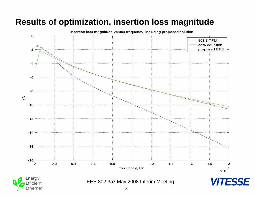
Results of optimization, insertion loss magnitude
IEEE 802.3az May 2008 Interim Meeting9
Results of optimization, Z11(f)
IEEE 802.3az May 2008 Interim Meeting10
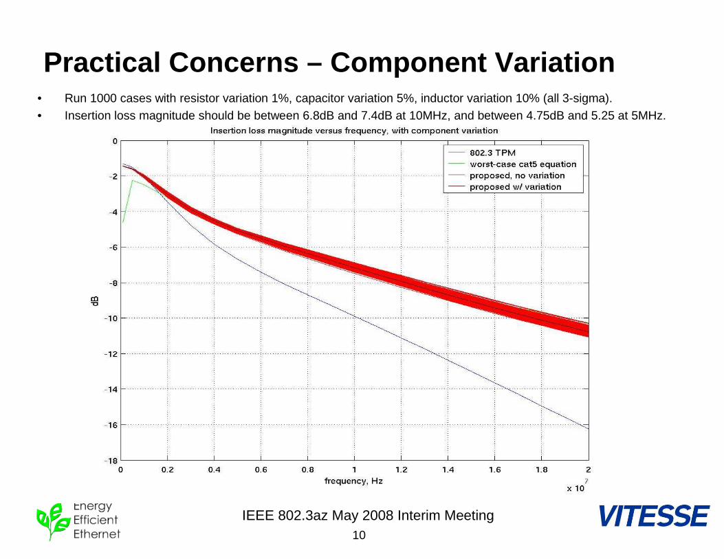
Practical Concerns – Component Variation• Run 1000 cases with resistor variation 1%, capacitor variation 5%, inductor variation 10% (all 3-sigma).• Insertion loss magnitude should be between 6.8dB and 7.4dB at 10MHz, and between 4.75dB and 5.25 at 5MHz.
IEEE 802.3az May 2008 Interim Meeting11
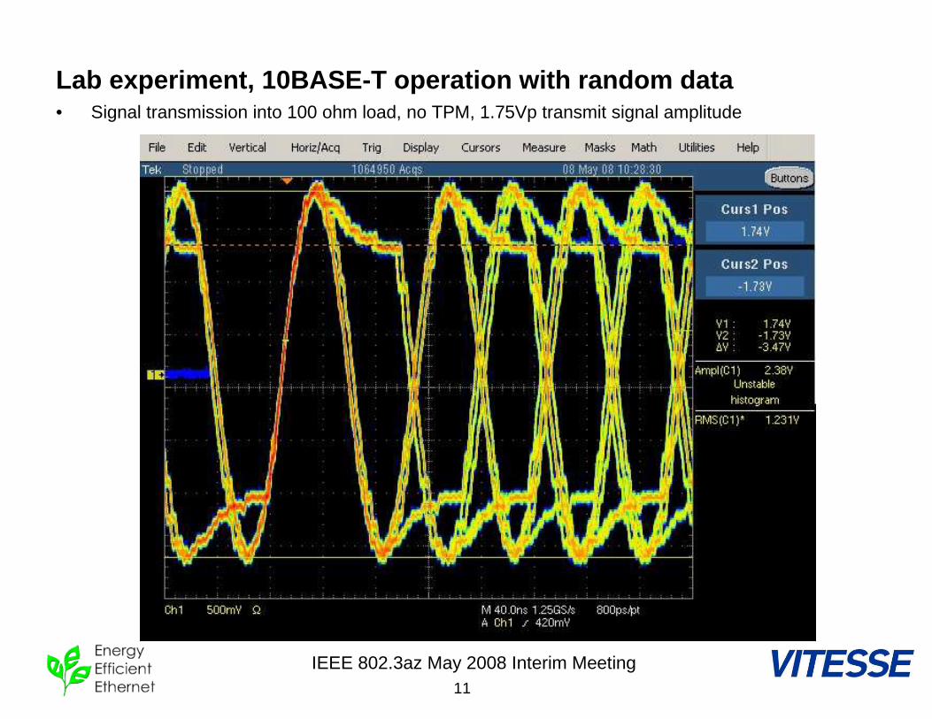
Lab experiment, 10BASE-T operation with random data• Signal transmission into 100 ohm load, no TPM, 1.75Vp transmit signal amplitude
IEEE 802.3az May 2008 Interim Meeting12
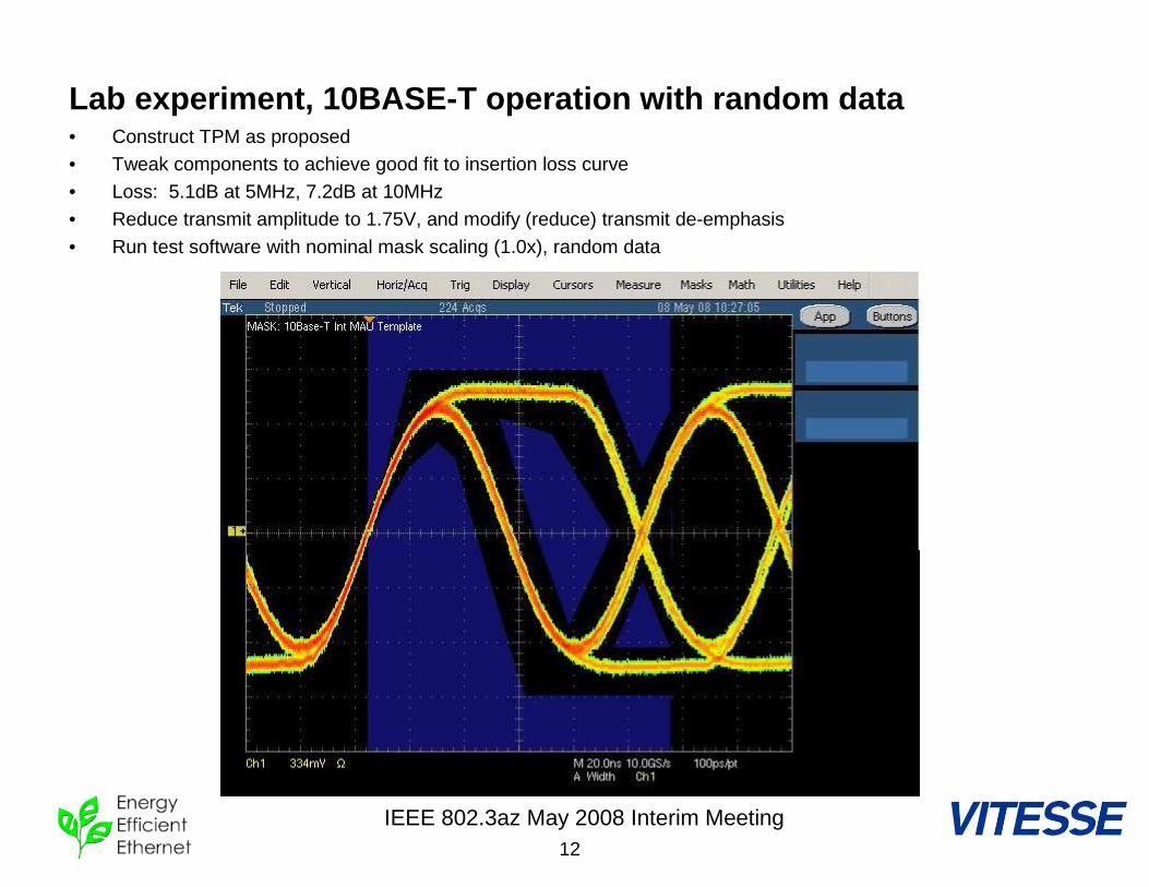
Lab experiment, 10BASE-T operation with random data• Construct TPM as proposed• Tweak components to achieve good fit to insertion loss curve• Loss: 5.1dB at 5MHz, 7.2dB at 10MHz• Reduce transmit amplitude to 1.75V, and modify (reduce) transmit de-emphasis
• Run test software with nominal mask scaling (1.0x), random data
IEEE 802.3az May 2008 Interim Meeting13
Conclusions, TBDs
• Conclusions– New TPM can model Cat5 channel insertion loss.– Lower amplitude transmit waveforms (1.75Vp) can be
easily modified to fit the existing MAU template.
• TBD– Run other waveform tests (TP_IDL, link pulse) with
802.3 “load 1” and “load 2”– Consider reducing number of segments in TPM?
This would simplify the TPM, and could still be compatible with PCBs and test jigs for the existing TPM (just re-stuff)
IEEE 802.3az May 2008 Interim Meeting14
Backup
IEEE 802.3az May 2008 Interim Meeting15
Motivation and Goals• 10BASE-T is not the lowest power Ethernet technology, largely
because it is constrained by legacy requirements for transmit voltage.
• Goal is to modernize 10BASE-T to:– Align with modern on-chip voltages (eliminate barriers to new
implementations, such as additional power supplies or on-chip converters)
– Specifically, use of lower analog and I/O voltages to track process improvements.
– Get 10Base-T power consumption more appropriately in line with its speed.
– Be able to take more advantage of 10BASE-T very low duty cycle in IDL for “Green” requirements.
• While:– Maintaining compatibility with legacy 10BASE-T receivers.– Maintaining 100 meter reach over Cat5 or better
• But sacrificing:– 100-180 meter reach over Cat5 (beyond scope of 802.3)– 65-100 meter reach on Cat3 and DIW.
IEEE 802.3az May 2008 Interim Meeting16
Background: Existing 10BT specifications
• Existing 10BT amplitude spec: 2.2Vp to 2.8Vp with random data sequence into 100ohm load.
• 2.5Vp specification resulted from factors that are no longer significant concerns in modern LANs– e.g. telephone pulse, switch-hook and mechanical ringer interference to data pairs in a shared sheath cable with poor cross-talk specs.
• Twisted pair model is based on DIW/Cat3 model that is no longer common. (DIW was “D-inside-wire”, i.e.AT&T voice grade UTP)
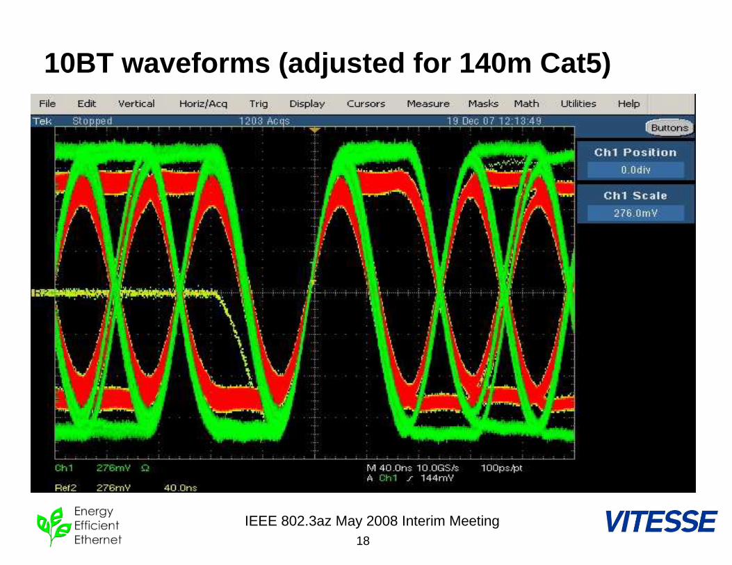
• Loop reach with existing 10BT implementation is >180m Cat5.• The following plots on pages 5,6 show performance of
existing amplitude requirements applied to the 802.3 twisted-pair-model as well as 140m typical Cat5 cable. (Note vertical scale difference between plots on next two pages).
IEEE 802.3az May 2008 Interim Meeting17
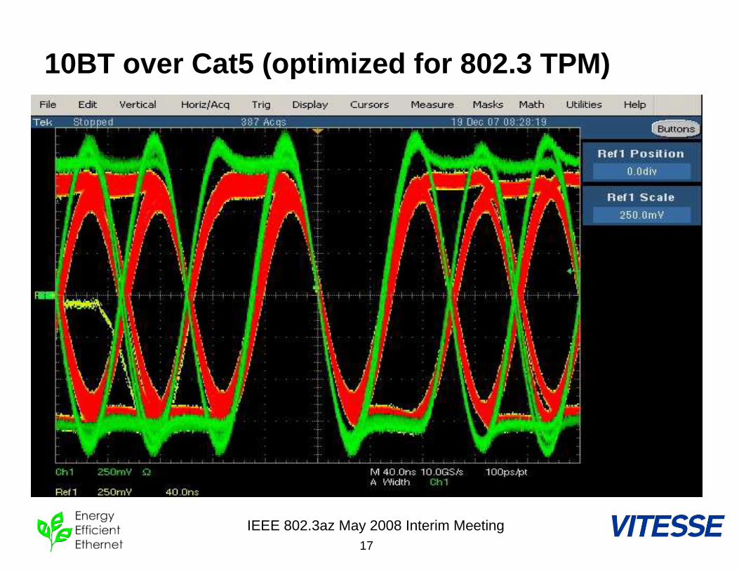
10BT over Cat5 (optimized for 802.3 TPM)
IEEE 802.3az May 2008 Interim Meeting18
10BT waveforms (adjusted for 140m Cat5)
IEEE 802.3az May 2008 Interim Meeting19
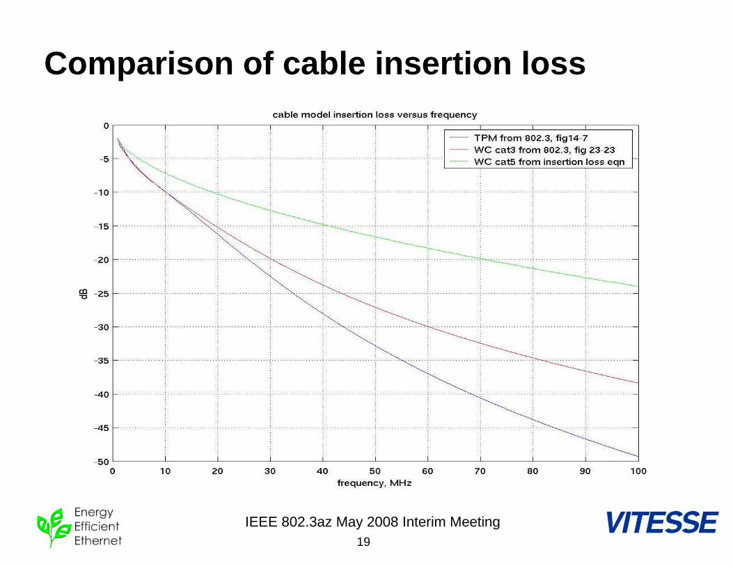
Comparison of cable insertion loss
IEEE 802.3az May 2008 Interim Meeting20
Proposal: Amplitude reduction
• Scope plots indicate Cat5 amplitude is 1.25-1.3x greater than the resulting TPM output waveform.
• Frequency domain insertion loss plots indicate similar difference between TPM/Cat3 and Cat5– ~2 dB delta at 5MHz– ~3 dB delta at 10MHz
• Propose amplitude reduction of ~30% based on previous plots -> ~1.75V
IEEE 802.3az May 2008 Interim Meeting21
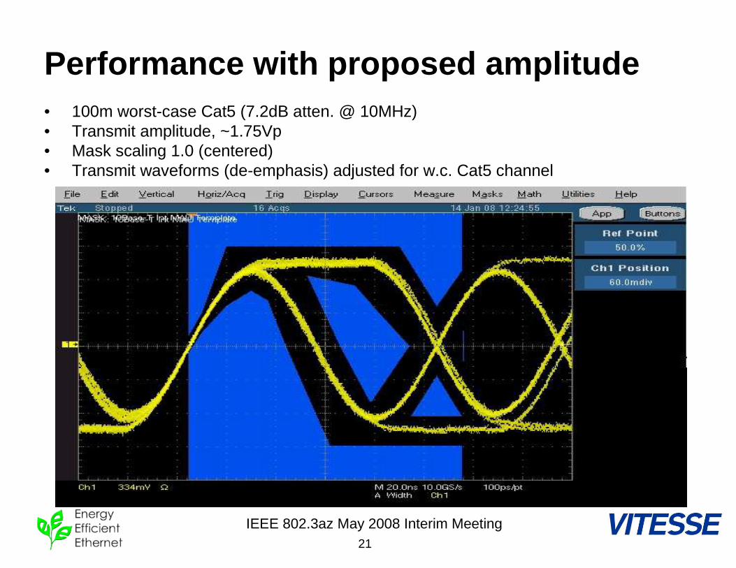
Performance with proposed amplitude• 100m worst-case Cat5 (7.2dB atten. @ 10MHz)• Transmit amplitude, ~1.75Vp• Mask scaling 1.0 (centered)• Transmit waveforms (de-emphasis) adjusted for w.c. Cat5 channel
IEEE 802.3az May 2008 Interim Meeting22
Proposal: System considerations• Autoneg functionality would remain the same. No new
autoneg states are implied.• Link pulses would be reduced in amplitude, which would
not cause problems on modern cabling with compliant PHY link partners.
• MAU voltage template (figure 14-9) implications:– One solution is to derive a TPM that better approximates a
worst-case Cat5/5e channel. Modified de-emphasis could then be used, in conjunction with lowered amplitude, on the transmit waveform to remain compliant with figure 14-9 (preferred).
– Or, keep existing TPM, but modify MAU template, using figure 14-9 as a starting point.
• A part may contain both “Green 10BT” and traditional 10BT capability, and be configured (by pin or register settings) to either mode.
IEEE 802.3az May 2008 Interim Meeting23
Expected Impact/Benefit
• + Power savings are realized by line-driver circuitry, as well as all other analog functionality on the PHY sharing the line driver’s supply. This addresses the 10BT PHY blocks that generally consume the most power.
• + Ability to scale with process and IO voltages. As systems support lower IO voltages, fewer special power supplies are required.
• + It becomes more attractive to include 10Mb/s in modern multi-speed implementations because of reduced requirements for specialized power.