Embed Size (px)
Citation preview
Low voltageIE4 synchronous reluctance motors
Catalog | August 2016
2 9AKK105828 EN 08-2016 | ABB Motors and Generators
With expertise, and a comprehensive portfolio of products andlife-cycle services, we help value-minded industrial customersimprove their energy efficiency and productivity.
IE4 synchronous reluctance motorsSizes 132 to 315
General information 4
Package benefits 4
ACS880 drive highlights 6
ACS850 drive highlights 7
IE4 synchronous reluctance motors 9
Synchronous reluctance motor technology 10
Ordering information 11
Mounting arrangements 12
Rating plates 13
Technical data 14
Variant codes 16
Mechanical design 21
Motor frame and drain holes 21
Heating elements 21
Bearings 22
Terminal box 27
Dimension drawings 33
Accessories 39
Separate cooling 39
Protective roof and tachometer 40
Silencer 41
Slide rails 42
Motor construction 44
Motors in brief 45
Total product offering 46
Life cycle services and support 47
ABB Motors and Generators | 9AKK105828 EN 08-2016 3
4 9AKK105828 EN 08-2016 | ABB Motors and Generators
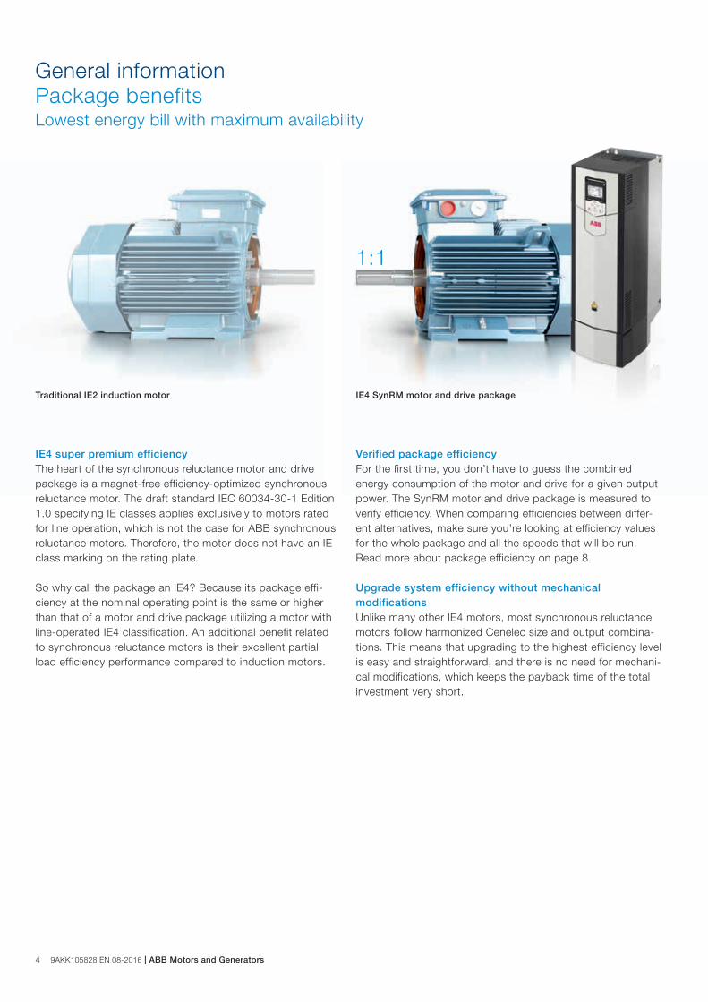
General informationPackage benefitsLowest energy bill with maximum availability
IE4 super premium efficiencyThe heart of the synchronous reluctance motor and drive package is a magnet-free efficiency-optimized synchronous reluctance motor. The draft standard IEC 60034-30-1 Edition 1.0 specifying IE classes applies exclusively to motors rated for line operation, which is not the case for ABB synchronous reluctance motors. Therefore, the motor does not have an IE class marking on the rating plate.
So why call the package an IE4? Because its package effi-ciency at the nominal operating point is the same or higher than that of a motor and drive package utilizing a motor with line-operated IE4 classification. An additional benefit related to synchronous reluctance motors is their excellent partial load efficiency performance compared to induction motors.
Traditional IE2 induction motor IE4 SynRM motor and drive package
1:1
Verified package efficiencyFor the first time, you don’t have to guess the combined energy consumption of the motor and drive for a given output power. The SynRM motor and drive package is measured to verify efficiency. When comparing efficiencies between differ-ent alternatives, make sure you’re looking at efficiency values for the whole package and all the speeds that will be run. Read more about package efficiency on page 8.
Upgrade system efficiency without mechanical modificationsUnlike many other IE4 motors, most synchronous reluctance motors follow harmonized Cenelec size and output combina-tions. This means that upgrading to the highest efficiency level is easy and straightforward, and there is no need for mechani-cal modifications, which keeps the payback time of the total investment very short.
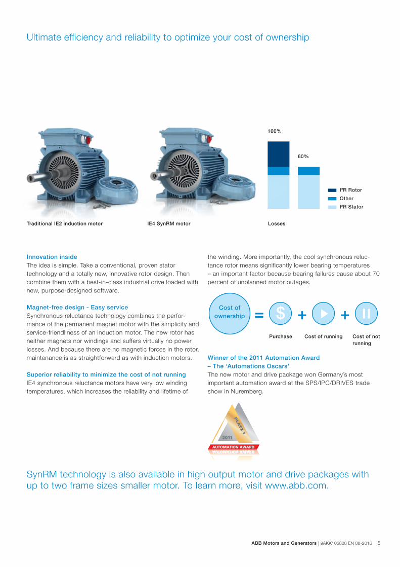
100%
60%
Ultimate efficiency and reliability to optimize your cost of ownership
Innovation insideThe idea is simple. Take a conventional, proven stator technology and a totally new, innovative rotor design. Then combine them with a best-in-class industrial drive loaded with new, purpose-designed software.
Magnet-free design - Easy serviceSynchronous reluctance technology combines the perfor-mance of the permanent magnet motor with the simplicity and service-friendliness of an induction motor. The new rotor has neither magnets nor windings and suffers virtually no power losses. And because there are no magnetic forces in the rotor, maintenance is as straightforward as with induction motors.
Superior reliability to minimize the cost of not runningIE4 synchronous reluctance motors have very low winding temperatures, which increases the reliability and lifetime of
SynRM technology is also available in high output motor and drive packages with up to two frame sizes smaller motor. To learn more, visit www.abb.com.
IE4 SynRM motor
the winding. More importantly, the cool synchronous reluc-tance rotor means significantly lower bearing temperatures– an important factor because bearing failures cause about 70 percent of unplanned motor outages.
Winner of the 2011 Automation Award – The ‘Automations Oscars’The new motor and drive package won Germany’s most important automation award at the SPS/IPC/DRIVES tradeshow in Nuremberg.
Losses
I2R Stator
I2R Rotor
Other
Traditional IE2 induction motor
= $ + +Purchase Cost of running Cost of not
running
Cost of ownership
ABB Motors and Generators | 9AKK105828 EN 08-2016 5
6 9AKK105828 EN 08-2016 | ABB Motors and Generators
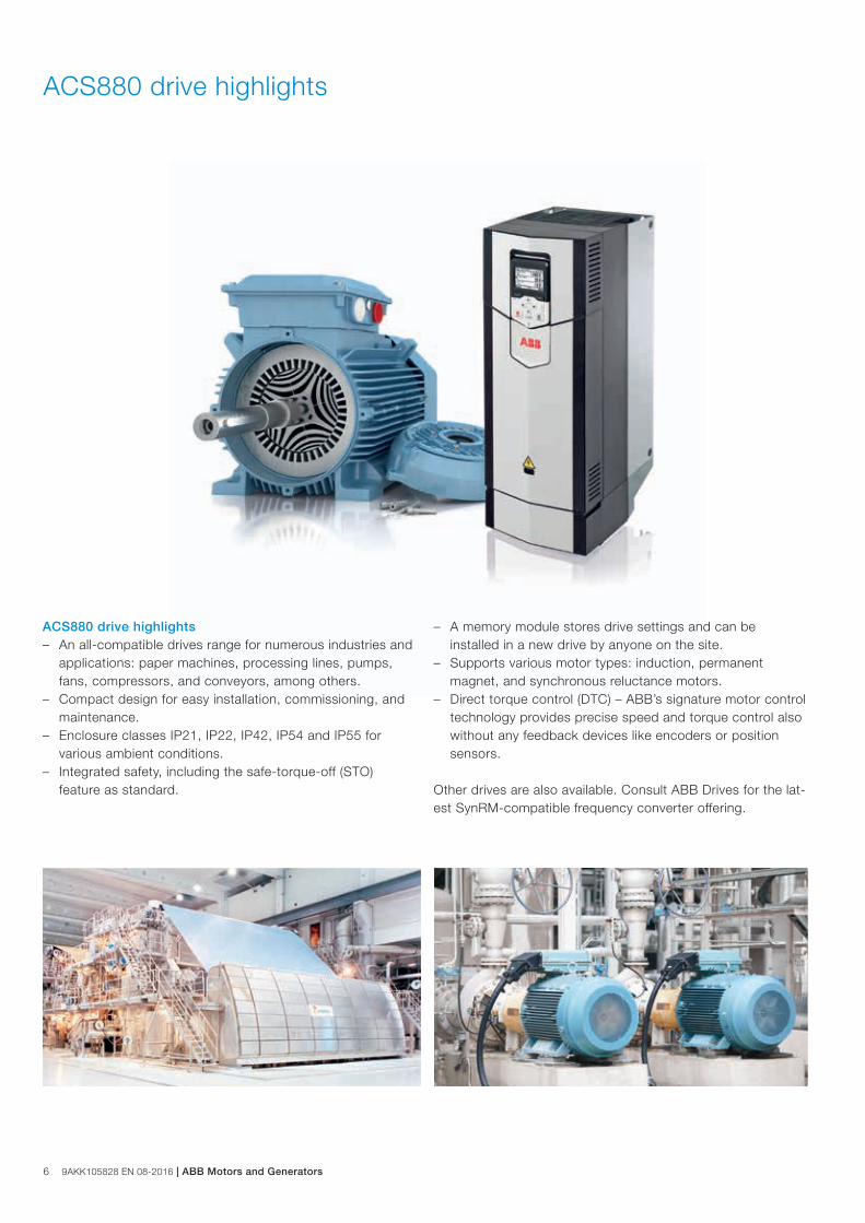
ACS880 drive highlights – An all-compatible drives range for numerous industries and
applications: paper machines, processing lines, pumps, fans, compressors, and conveyors, among others.
– Compact design for easy installation, commissioning, and maintenance.
– Enclosure classes IP21, IP22, IP42, IP54 and IP55 for various ambient conditions.
– Integrated safety, including the safe-torque-off (STO) feature as standard.
– A memory module stores drive settings and can be installed in a new drive by anyone on the site.
– Supports various motor types: induction, permanent magnet, and synchronous reluctance motors.
– Direct torque control (DTC) – ABB’s signature motor control technology provides precise speed and torque control also without any feedback devices like encoders or position sensors.
Other drives are also available. Consult ABB Drives for the lat-est SynRM-compatible frequency converter offering.
ACS880 drive highlights
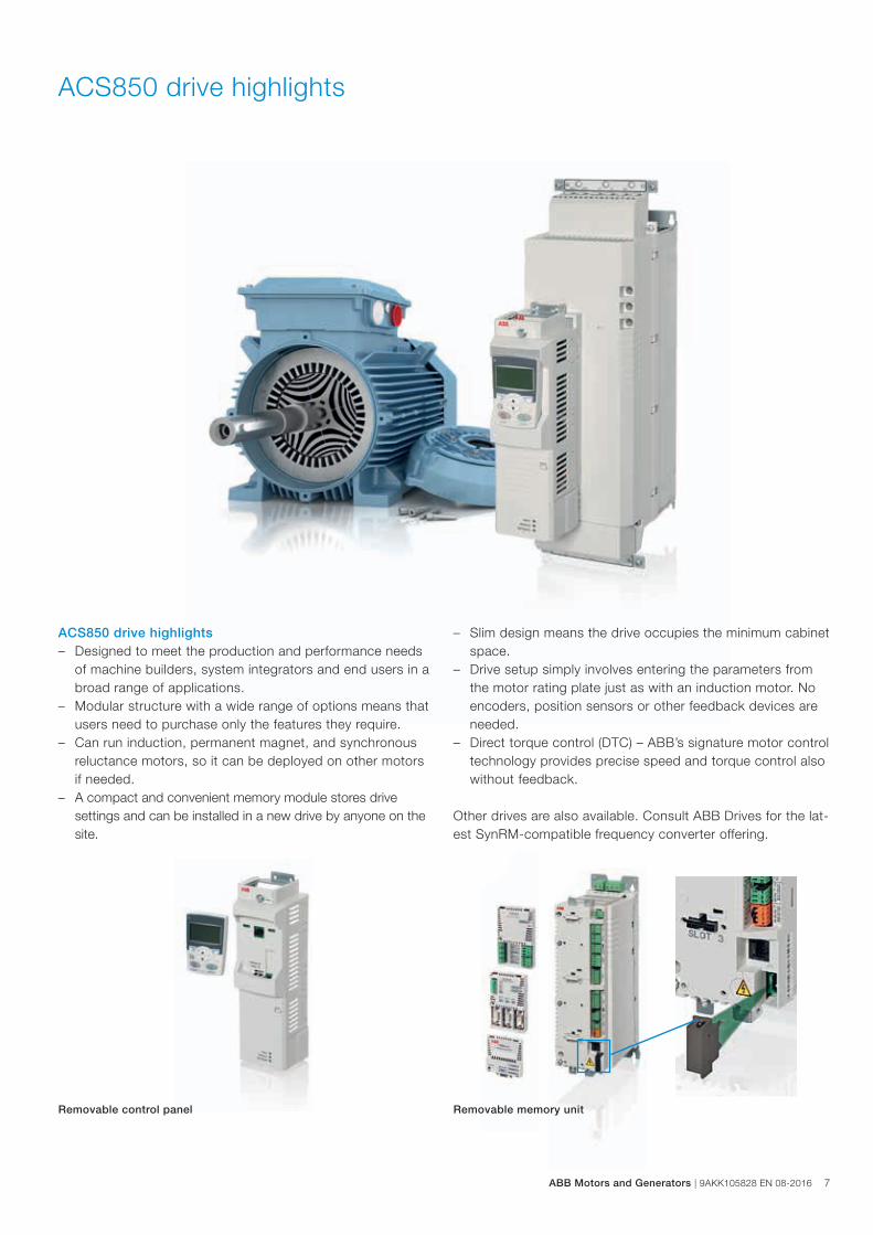
ACS850 drive highlights – Designed to meet the production and performance needs
of machine builders, system integrators and end users in a broad range of applications.
– Modular structure with a wide range of options means that users need to purchase only the features they require.
– Can run induction, permanent magnet, and synchronous reluctance motors, so it can be deployed on other motors if needed.
– A compact and convenient memory module stores drive settings and can be installed in a new drive by anyone on the site.
ACS850 drive highlights
– Slim design means the drive occupies the minimum cabinet space.
– Drive setup simply involves entering the parameters from the motor rating plate just as with an induction motor. No encoders, position sensors or other feedback devices are needed.
– Direct torque control (DTC) – ABB’s signature motor control technology provides precise speed and torque control also without feedback.
Other drives are also available. Consult ABB Drives for the lat-est SynRM-compatible frequency converter offering.
Removable control panel Removable memory unit
ABB Motors and Generators | 9AKK105828 EN 08-2016 7
8 9AKK105828 EN 08-2016 | ABB Motors and Generators
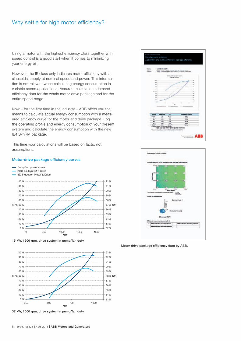
Pump/fan power curveABB IE4 SynRM & DriveIE2 Induction Motor & Drive
Why settle for high motor efficiency?
Using a motor with the highest efficiency class together with speed control is a good start when it comes to minimizing your energy bill.
However, the IE class only indicates motor efficiency with a sinusoidal supply at nominal speed and power. This informa-tion is not relevant when calculating energy consumption in variable speed applications. Accurate calculations demand efficiency data for the whole motor-drive package and for the entire speed range.
Now – for the first time in the industry – ABB offers you the means to calculate actual energy consumption with a meas-ured efficiency curve for the motor and drive package. Log the operating profile and energy consumption of your present system and calculate the energy consumption with the new IE4 SynRM package.
This time your calculations will be based on facts, not assumptions.
Motor-drive package efficiency curves
15 kW, 1500 rpm, drive system in pump/fan duty
37 kW, 1000 rpm, drive system in pump/fan duty
Motor-drive package efficiency data by ABB.
IE4 synchronous reluctance motors
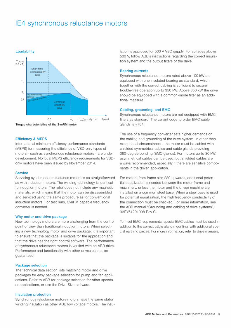
Loadability
Torque characteristics of the SynRM motor
nN
Tn
0.7
Torque 2.5 x Tn
Tol
Speed0.5
Short time overloadability
area
Separate cooling,optional
Self cooling, standard
nmax(typically 1.4)
Continousloadability
area
Efficiency & MEPS International minimum efficiency performance standards (MEPS) for measuring the efficiency of VSD-only types of motors - such as synchronous reluctance motors - are under development. No local MEPS efficiency requirements for VSD-only motors have been issued by November 2014.
Service Servicing synchronous reluctance motors is as straightforward as with induction motors. The winding technology is identical to induction motors. The rotor does not include any magnetic materials, which means that the motor can be disassembled and serviced using the same procedure as for conventional induction motors. For test runs, SynRM capable frequency converter is needed.
Why motor and drive packageNew technology motors are more challenging from the control point of view than traditional induction motors. When select-ing a new technology motor and drive package, it is important to ensure that the package is suitable for the application and that the drive has the right control software. The performance of synhronous reluctance motors is verified with an ABB drive. Performance and functionality with other drives cannot be guaranteed.
Package selection The technical data section lists matching motor and drive packages for easy package selection for pump and fan appli-cations. Refer to ABB for package selection for other speeds or applications, or use the Drive-Size software.
Insulation protection Synchronous reluctance motors motors have the same stator winding insulation as other ABB low voltage motors. The insu-
lation is approved for 500 V VSD supply. For voltages above 500 V, follow ABB’s instructions regarding the correct insula-tion system and the output filters of the drive.
Bearing currents Synchronous reluctance motors rated above 100 kW are equipped with one insulated bearing as standard, which together with the correct cabling is sufficient to secure trouble-free operation up to 350 kW. Above 350 kW the drive should be equipped with a common-mode filter as an addi-tional measure.
Cabling, grounding, and EMCSynchronous reluctance motors are not equipped with EMC filters as standard. The variant code to order EMC cable glands is +704.
The use of a frequency converter sets higher demands on the cabling and grounding of the drive system. In other than exceptional circumstances, the motor must be cabled with shielded symmetrical cables and cable glands providing 360-degree bonding (EMC glands). For motors up to 30 kW, asymmetrical cables can be used, but shielded cables are always recommended, especially if there are sensitive compo-nents in the driven application.
For motors from frame size 280 upwards, additional poten-tial equalization is needed between the motor frame and machinery, unless the motor and the driven machine are installed on a common steel base. When a steel base is used for potential equalization, the high frequency conductivity of the connection must be checked. For more information, see the ABB manual “Grounding and cabling of drive systems”, 3AFY61201998 Rev C.
To meet EMC requirements, special EMC cables must be used in addition to the correct cable gland mounting, with additional spe-cial earthing pieces. For more information, refer to drive manuals.
ABB Motors and Generators | 9AKK105828 EN 08-2016 9
10 9AKK105828 EN 08-2016 | ABB Motors and Generators
Synchronous reluctance motor technology
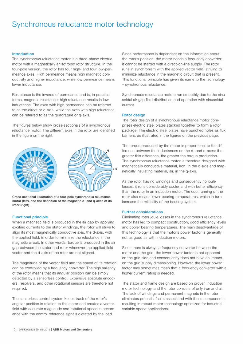
IntroductionThe synchronous reluctance motor is a three-phase electric motor with a magnetically anisotropic rotor structure. In the four-pole version, the rotor has four high- and four low-per-meance axes. High permeance means high magnetic con-ductivity and higher inductance, while low permeance means lower inductance.
Reluctance is the inverse of permeance and is, in practical terms, magnetic resistance; high reluctance results in low inductance. The axes with high permeance can be referred to as the direct or d-axis, while the axes with high reluctance can be referred to as the quadrature or q-axis.
The figures below show cross-sectionals of a synchronous reluctance motor. The different axes in the rotor are identified in the figure on the right.
Cross-sectional illustration of a four-pole synchronous reluctance motor (left), and the definition of the magnetic d- and q-axes of its rotor (right).
Functional principleWhen a magnetic field is produced in the air gap by applying exciting currents to the stator windings, the rotor will strive to align its most magnetically conductive axis, the d-axis, with the applied field, in order to minimize the reluctance in the magnetic circuit. In other words, torque is produced in the air gap between the stator and rotor whenever the applied field vector and the d-axis of the rotor are not aligned.
The magnitude of the vector field and the speed of its rotation can be controlled by a frequency converter. The high saliency of the rotor means that its angular position can be simply detected by a sensorless control. Expensive absolute encod-ers, resolvers, and other rotational sensors are therefore not required.
The sensorless control system keeps track of the rotor’s angular position in relation to the stator and creates a vector field with accurate magnitude and rotational speed in accord-ance with the control reference signals dictated by the load.
q
d
q
d
Since performance is dependent on the information about the rotor’s position, the motor needs a frequency converter; it cannot be started with a direct-on-line supply. The rotor runs in synchronism with the applied vector field, striving to minimize reluctance in the magnetic circuit that is present. This functional principle has given its name to the technology – synchronous reluctance.
Synchronous reluctance motors run smoothly due to the sinu-soidal air gap field distribution and operation with sinusoidal current.
Rotor designThe rotor design of a synchronous reluctance motor com-prises electric steel plates stacked together to form a rotor package. The electric steel plates have punched holes as flux barriers, as illustrated in the figures on the previous page.
The torque produced by the motor is proportional to the dif-ference between the inductances on the d- and q-axes: the greater this difference, the greater the torque production. The synchronous reluctance motor is therefore designed with magnetically conductive material, iron, in the d-axis and mag-netically insulating material, air, in the q-axis.
As the rotor has no windings and consequently no joule losses, it runs considerably cooler and with better efficiency than the rotor in an induction motor. The cool running of the rotor also means lower bearing temperatures, which in turn increase the reliability of the bearing system. Further considerationsEliminating rotor joule losses in the synchronous reluctance motor has led to compact construction, good efficiency levels and cooler bearing temperatures. The main disadvantage of this technology is that the motor’s power factor is generally not as good as with induction motors.
Since there is always a frequency converter between the motor and the grid, the lower power factor is not apparent on the grid side and consequently does not have an impact on the grid supply dimensioning. However, the lower power factor may sometimes mean that a frequency converter with a higher current rating is needed.
The stator and frame design are based on proven induction motor technology, and the rotor consists of only iron and air. The lack of windings and permanent magnets in the rotor eliminates potential faults associated with these components, resulting in robust motor technology optimized for industrial variable speed applications.
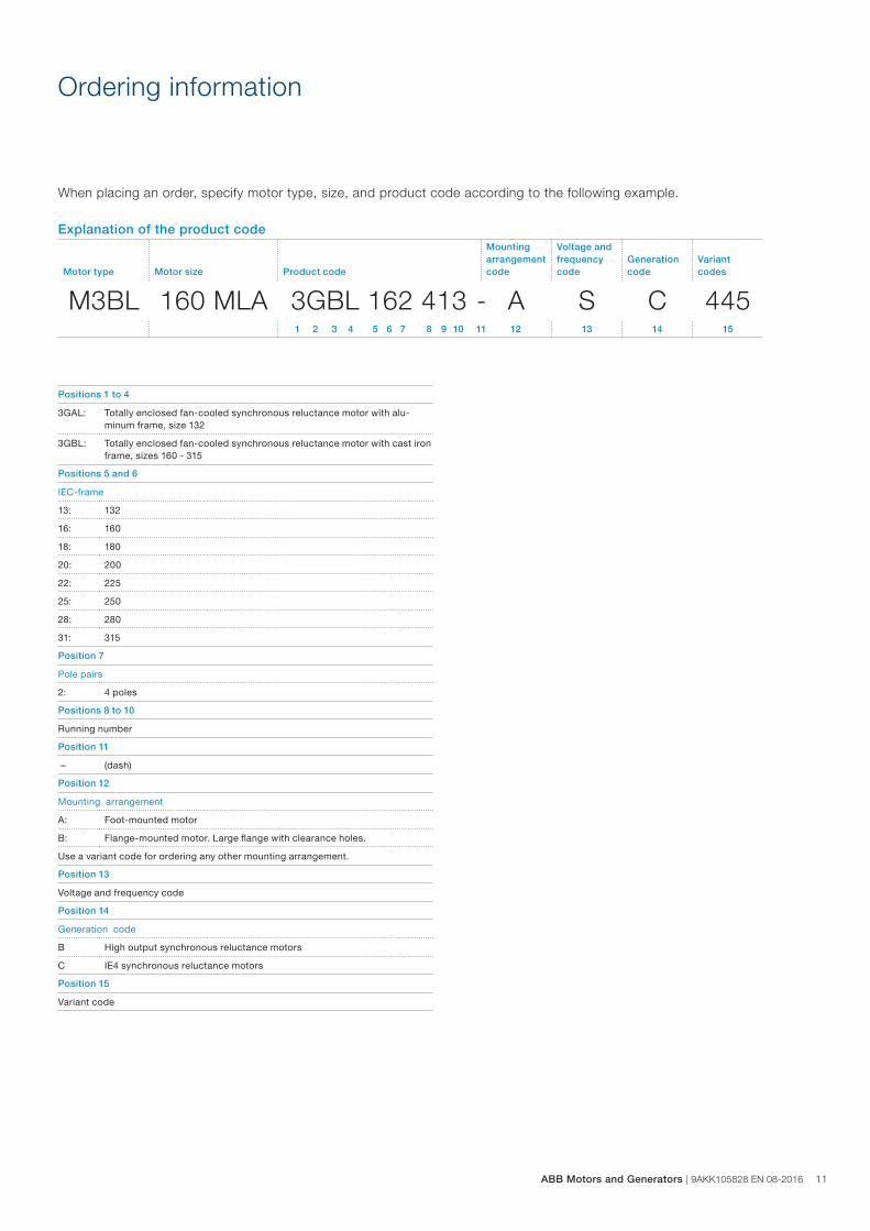
Explanation of the product code
Motor type Motor size Product code
Mounting arrangement code
Voltage and frequency code
Generation code
Variant codes
M3BL 160 MLA 3GBL 162 413 - A S C 445 1 2 3 4 5 6 7 8 9 10 11 12 13 14 15
Ordering information
When placing an order, specify motor type, size, and product code according to the following example.
Positions 1 to 4
3GAL: Totally enclosed fan-cooled synchronous reluctance motor with alu-minum frame, size 132
3GBL: Totally enclosed fan-cooled synchronous reluctance motor with cast iron frame, sizes 160 - 315
Positions 5 and 6
IEC-frame
13: 132
16: 160
18: 180
20: 200
22: 225
25: 250
28: 280
31: 315
Position 7
Pole pairs
2: 4 poles
Positions 8 to 10
Running number
Position 11
– (dash)
Position 12
Mounting arrangement
A: Foot-mounted motor
B: Flange-mounted motor. Large flange with clearance holes.
Use a variant code for ordering any other mounting arrangement.
Position 13
Voltage and frequency code
Position 14
Generation code
B High output synchronous reluctance motors
C IE4 synchronous reluctance motors
Position 15
Variant code
ABB Motors and Generators | 9AKK105828 EN 08-2016 11
12 9AKK105828 EN 08-2016 | ABB Motors and Generators
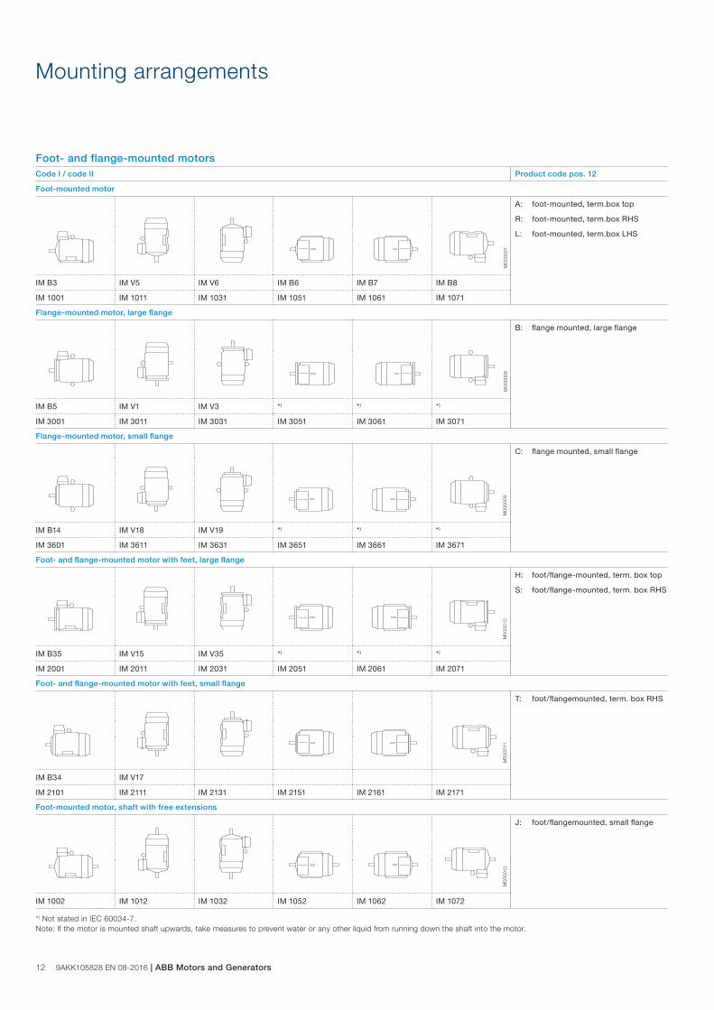
Mounting arrangements
Foot- and flange-mounted motorsCode I / code II Product code pos. 12
Foot-mounted motor
A: foot-mounted, term.box top
R: foot-mounted, term.box RHS
L: foot-mounted, term.box LHS
IM B3 IM V5 IM V6 IM B6 IM B7 IM B8
IM 1001 IM 1011 IM 1031 IM 1051 IM 1061 IM 1071
Flange-mounted motor, large flange
B: flange mounted, large flange
IM B5 IM V1 IM V3 *) *) *)
IM 3001 IM 3011 IM 3031 IM 3051 IM 3061 IM 3071
Flange-mounted motor, small flange
C: flange mounted, small flange
IM B14 IM V18 IM V19 *) *) *)
IM 3601 IM 3611 IM 3631 IM 3651 IM 3661 IM 3671
Foot- and flange-mounted motor with feet, large flange
H: foot/flange-mounted, term. box top
S: foot/flange-mounted, term. box RHS
IM B35 IM V15 IM V35 *) *) *)
IM 2001 IM 2011 IM 2031 IM 2051 IM 2061 IM 2071
Foot- and flange-mounted motor with feet, small flange
T: foot/flangemounted, term. box RHS
IM B34 IM V17
IM 2101 IM 2111 IM 2131 IM 2151 IM 2161 IM 2171
Foot-mounted motor, shaft with free extensions
J: foot/flangemounted, small flange
IM 1002 IM 1012 IM 1032 IM 1052 IM 1062 IM 1072
*) Not stated in IEC 60034-7. Note: If the motor is mounted shaft upwards, take measures to prevent water or any other liquid from running down the shaft into the motor.
M00
0007
M00
0008
M00
0009
M00
0010
M00
0011
M00
0012
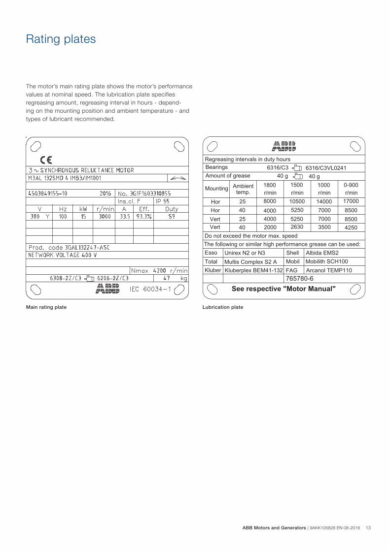
Rating plates
The motor’s main rating plate shows the motor’s performance values at nominal speed. The lubrication plate specifies regreasing amount, regreasing interval in hours - depend-ing on the mounting position and ambient temperature - and types of lubricant recommended.
Main rating plate Lubrication plate
ABB Motors and Generators | 9AKK105828 EN 08-2016 13
14 9AKK105828 EN 08-2016 | ABB Motors and Generators
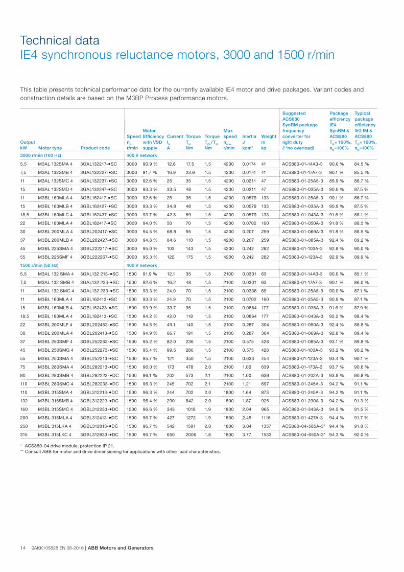
This table presents technical performance data for the currently available IE4 motor and drive packages. Variant codes and construction details are based on the M3BP Process performance motors.
Technical dataIE4 synchronous reluctance motors, 3000 and 1500 r/min
Output kW Motor type Product code
SpeednN r/min
Motor Efficiencywith VSD supply
CurrentIN A
TorqueTN
Nm
TorqueTOL/TN Nm
Max speednmax r/min
Inertia J kgm2
Weight m kg
Suggested ACS880 SynRM package frequency converter for light duty (**no overload)
Package efficiency IE4 SynRM & ACS880 TN= 100%, nN=100%
Typical package efficiency IE2 IM & ACS880 TN= 100%, nN=100%
3000 r/min (100 Hz) 400 V network
5,5 M3AL 132SMA 4 3GAL132217-●SC 3000 90.9 % 12.6 17.5 1.5 4200 0.0174 41 ACS880-01-14A3-3 90.0 % 84.5 %
7,5 M3AL 132SMB 4 3GAL132227-●SC 3000 91.7 % 16.9 23.9 1.5 4200 0.0174 41 ACS880-01-17A7-3 90.1 % 85.5 %
11 M3AL 132SMC 4 3GAL132237-●SC 3000 92.6 % 25 35 1.5 4200 0.0211 47 ACS880-01-25A5-3 89.9 % 86.7 %
15 M3AL 132SMD 4 3GAL132247-●SC 3000 93.3 % 33.5 48 1.5 4200 0.0211 47 ACS880-01-035A-3 90.0 % 87.5 %
11 M3BL 160MLA 4 3GBL162417-●SC 3000 92.6 % 25 35 1.5 4200 0.0579 133 ACS880-01-25A5-3 90.1 % 86.7 %
15 M3BL 160MLB 4 3GBL162427-●SC 3000 93.3 % 34.8 48 1.5 4200 0.0579 133 ACS880-01-035A-3 90.9 % 87.5 %
18,5 M3BL 160MLC 4 3GBL162437-●SC 3000 93.7 % 42.8 59 1.5 4200 0.0579 133 ACS880-01-043A-3 91.6 % 88.1 %
22 M3BL 180MLA 4 3GBL182417-●SC 3000 94.0 % 50 70 1.5 4200 0.0702 160 ACS880-01-050A-3 91.8 % 88.5 %
30 M3BL 200MLA 4 3GBL202417-●SC 3000 94.5 % 68.8 95 1.5 4200 0.207 259 ACS880-01-069A-3 91.8 % 88.5 %
37 M3BL 200MLB 4 3GBL202427-●SC 3000 94.8 % 84.6 118 1.5 4200 0.207 259 ACS880-01-085A-3 92.4 % 89.2 %
45 M3BL 225SMA 4 3GBL222217-●SC 3000 95.0 % 103 143 1.5 4200 0.242 282 ACS880-01-103A-3 92.8 % 90.0 %
55 M3BL 225SMF 4 3GBL222267-●SC 3000 95.3 % 122 175 1.5 4200 0.242 282 ACS880-01-123A-3 92.9 % 89.9 %
1500 r/min (50 Hz) 400 V network
5,5 M3AL 132 SMA 4 3GAL132 213-●SC 1500 91.9 % 12.1 35 1.5 2100 0.0301 63 ACS880-01-14A3-3 90.0 % 85.1 %
7,5 M3AL 132 SMB 4 3GAL132 223-●SC 1500 92.6 % 16.2 48 1.5 2100 0.0301 63 ACS880-01-17A7-3 90.1 % 86.0 %
11 M3AL 132 SMC 4 3GAL132 233-●SC 1500 93.3 % 24.0 70 1.5 2100 0.0336 69 ACS880-01-25A5-3 90.0 % 87.1 %
11 M3BL 160MLA 4 3GBL162413-●SC 1500 93.3 % 24.9 70 1.5 2100 0.0702 160 ACS880-01-25A5-3 90.9 % 87.1 %
15 M3BL 160MLB 4 3GBL162423-●SC 1500 93.9 % 33.7 95 1.5 2100 0.0864 177 ACS880-01-035A-3 91.6 % 87.9 %
18,5 M3BL 180MLA 4 3GBL182413-●SC 1500 94.2 % 42.0 118 1.5 2100 0.0864 177 ACS880-01-043A-3 92.2 % 88.4 %
22 M3BL 200MLF 4 3GBL202463-●SC 1500 94.5 % 49.1 140 1.5 2100 0.287 304 ACS880-01-050A-3 92.4 % 88.8 %
30 M3BL 200MLA 4 3GBL202413-●SC 1500 94.9 % 66.7 191 1.5 2100 0.287 304 ACS880-01-069A-3 92.8 % 89.4 %
37 M3BL 250SMF 4 3GBL252263-●SC 1500 95.2 % 82.0 236 1.5 2100 0.575 428 ACS880-01-085A-3 93.1 % 89.8 %
45 M3BL 250SMG 4 3GBL252273-●SC 1500 95.4 % 99.5 286 1.5 2100 0.575 428 ACS880-01-103A-3 93.2 % 90.2 %
55 M3BL 250SMA 4 3GBL252213-●SC 1500 95.7 % 121 350 1.5 2100 0.633 454 ACS880-01-123A-3 93.4 % 90.1 %
75 M3BL 280SMA 4 3GBL282213-●DC 1500 96.0 % 173 478 2.0 2100 1.00 639 ACS880-01-173A-3 93.7 % 90.6 %
90 M3BL 280SMB 4 3GBL282223-●DC 1500 96.1 % 202 573 2.1 2100 1.00 639 ACS880-01-202A-3 93.9 % 90.8 %
110 M3BL 280SMC 4 3GBL282233-●DC 1500 96.3 % 245 702 2.1 2100 1.21 697 ACS880-01-245A-3 94.2 % 91.1 %
110 M3BL 315SMA 4 3GBL312213-●DC 1500 96.3 % 244 702 2.0 1800 1.64 873 ACS880-01-245A-3 94.2 % 91.1 %
132 M3BL 315SMB 4 3GBL312223-●DC 1500 96.4 % 290 842 2.0 1800 1.87 925 ACS880-01-290A-3 94.2 % 91.3 %
160 M3BL 315SMC 4 3GBL312233-●DC 1500 96.6 % 343 1018 1.9 1800 2.04 965 ASC880-01-343A-3 94.5 % 91.5 %
200 M3BL 315MLA 4 3GBL312413-●DC 1500 96.7 % 427 1272 1.9 1800 2.45 1116 ACS880-01-427A-3 94.4 % 91.7 %
250 M3BL 315LKA 4 3GBL312813-●DC 1500 96.7 % 542 1591 2.0 1800 3.04 1357 ACS880-04-585A-3* 94.4 % 91.8 %
315 M3BL 315LKC 4 3GBL312833-●DC 1500 96.7 % 650 2006 1.8 1800 3.77 1533 ACS880-04-650A-3* 94.3 % 92.0 %
* ACS880-04 drive module, protection IP 21.** Consult ABB for motor and drive dimensioning for applications with other load characteristics.
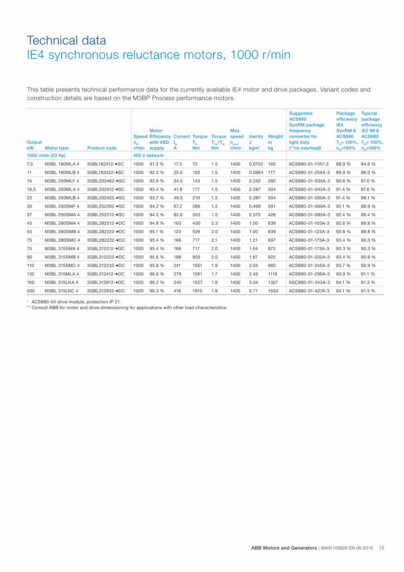
This table presents technical performance data for the currently available IE4 motor and drive packages. Variant codes and construction details are based on the M3BP Process performance motors.
Technical dataIE4 synchronous reluctance motors, 1000 r/min
Output kW Motor type Product code
SpeednN r/min
Motor Efficiencywith VSD supply
CurrentIN A
TorqueTN
Nm
TorqueTOL/TN Nm
Max speednmax r/min
Inertia J kgm2
Weight m kg
Suggested ACS880 SynRM package frequency converter for light duty (**no overload)
Package efficiency IE4 SynRM & ACS880 TN= 100%, nN=100%
Typical package efficiency IE2 IM & ACS880 TN= 100%, nN=100%
1000 r/min (33 Hz) 400 V network
7,5 M3BL 160MLA 4 3GBL162412-●SC 1000 91.3 % 17.3 72 1.5 1400 0.0702 160 ACS880-01-17A7-3 88.9 % 84.6 %
11 M3BL 160MLB 4 3GBL162422-●SC 1000 92.3 % 25.0 105 1.5 1400 0.0864 177 ACS880-01-25A5-3 89.9 % 86.0 %
15 M3BL 200MLF 4 3GBL202462-●SC 1000 92.9 % 34.0 143 1.5 1400 0.242 282 ACS880-01-035A-3 90.6 % 87.0 %
18,5 M3BL 200MLA 4 3GBL202412-●SC 1000 93.4 % 41.8 177 1.5 1400 0.287 304 ACS880-01-043A-3 91.4 % 87.6 %
22 M3BL 200MLB 4 3GBL202422-●SC 1000 93.7 % 49.5 210 1.5 1400 0.287 304 ACS880-01-050A-3 91.4 % 88.1 %
30 M3BL 250SMF 4 3GBL252262-●SC 1000 94.2 % 67.2 286 1.5 1400 0.499 391 ACS880-01-069A-3 92.1 % 88.9 %
37 M3BL 250SMA 4 3GBL252212-●SC 1000 94.5 % 82.6 353 1.5 1400 0.575 428 ACS880-01-085A-3 92.4 % 89.4 %
45 M3BL 280SMA 4 3GBL282212-●DC 1000 94.8 % 103 430 2.3 1400 1.00 639 ACS880-01-103A-3 92.6 % 89.8 %
55 M3BL 280SMB 4 3GBL282222-●DC 1000 95.1 % 123 526 2.0 1400 1.00 639 ACS880-01-123A-3 92.8 % 89.8 %
75 M3BL 280SMC 4 3GBL282232-●DC 1000 95.4 % 166 717 2.1 1400 1.21 697 ACS880-01-173A-3 93.4 % 90.3 %
75 M3BL 315SMA 4 3GBL312212-●DC 1000 95.4 % 166 717 2.0 1400 1.64 873 ACS880-01-173A-3 93.3 % 90.3 %
90 M3BL 315SMB 4 3GBL312222-●DC 1000 95.6 % 198 859 2.0 1400 1.87 925 ACS880-01-202A-3 93.4 % 90.6 %
110 M3BL 315SMC 4 3GBL312232-●DC 1000 95.8 % 241 1051 1.9 1400 2.04 965 ACS880-01-245A-3 93.7 % 90.9 %
132 M3BL 315MLA 4 3GBL312412-●DC 1000 96.0 % 279 1261 1.7 1400 2.45 1116 ACS880-01-290A-3 93.9 % 91.1 %
160 M3BL 315LKA 4 3GBL312812-●DC 1000 96.2 % 340 1527 1.9 1400 3.04 1357 ASC880-01-343A-3 94.1 % 91.3 %
200 M3BL 315LKC 4 3GBL312832-●DC 1000 96.3 % 418 1910 1.8 1400 3.77 1533 ACS880-01-427A-3 94.1 % 91.5 %
* ACS880-04 drive module, protection IP 21.** Consult ABB for motor and drive dimensioning for applications with other load characteristics.
ABB Motors and Generators | 9AKK105828 EN 08-2016 15
16 9AKK105828 EN 08-2016 | ABB Motors and Generators
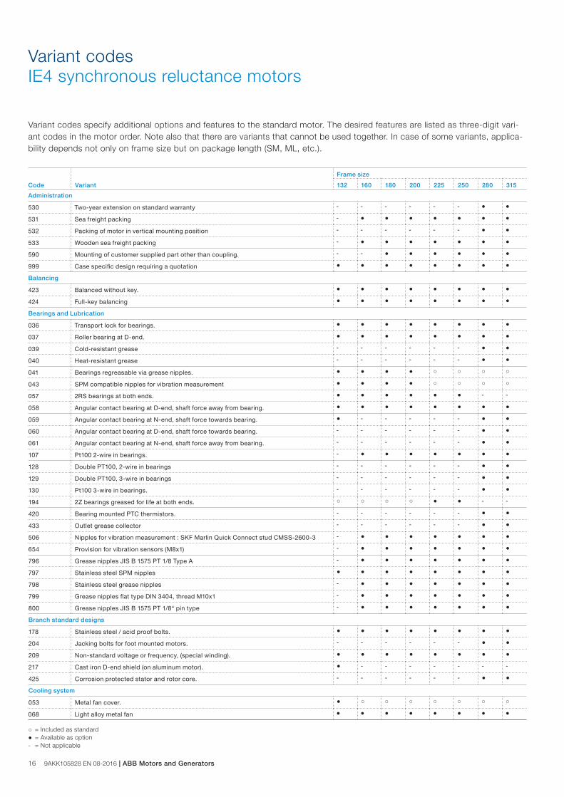
Variant codesIE4 synchronous reluctance motors
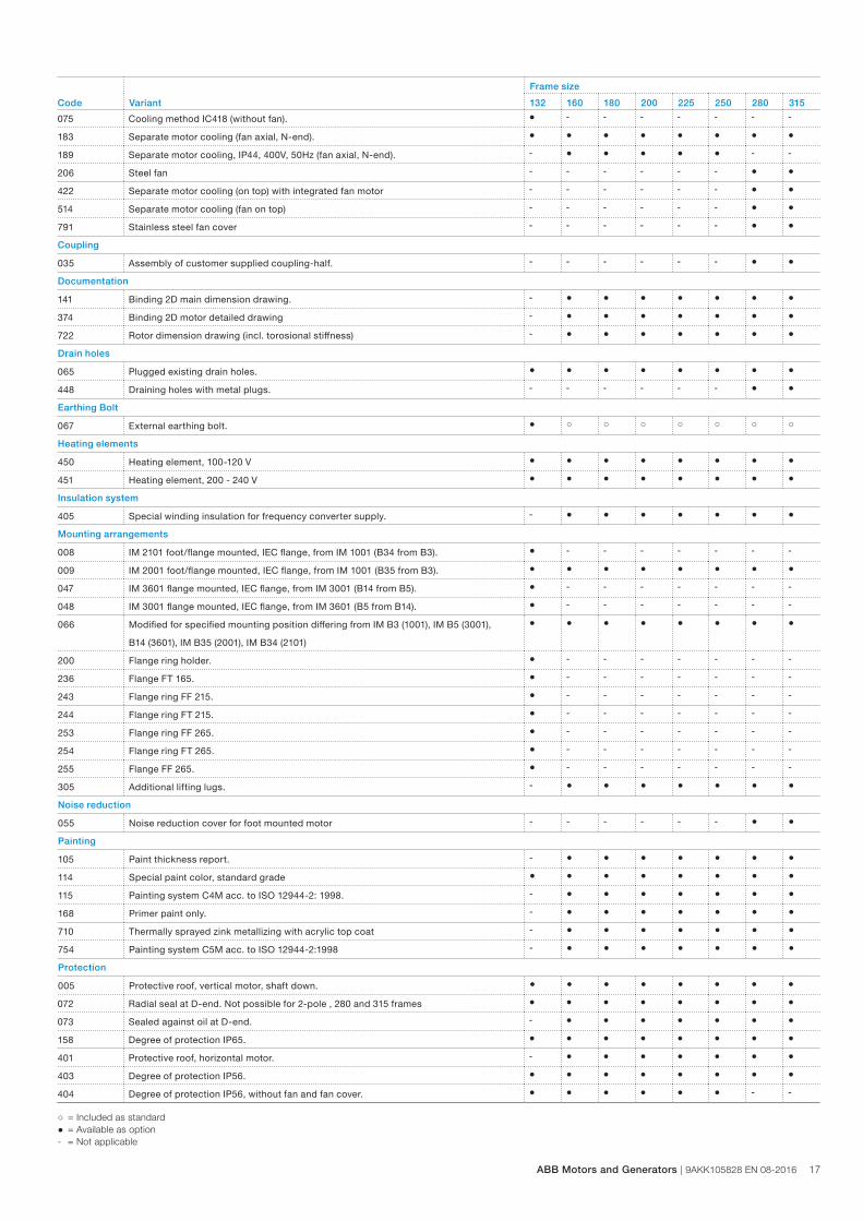
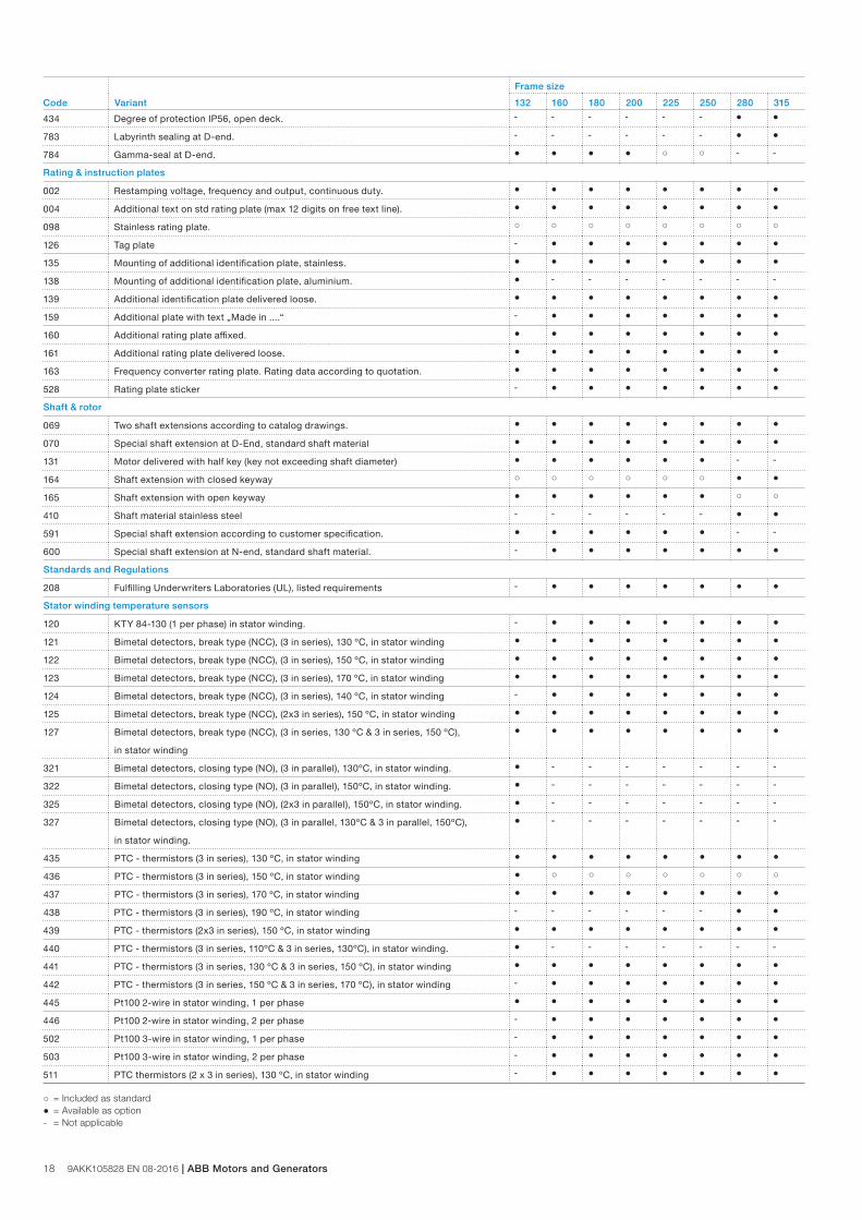
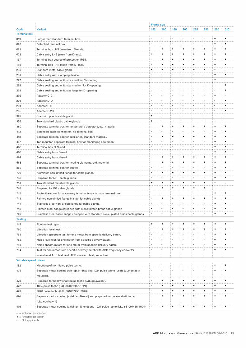
Variant codes specify additional options and features to the standard motor. The desired features are listed as three-digit vari-ant codes in the motor order. Note also that there are variants that cannot be used together. In case of some variants, applica-bility depends not only on frame size but on package length (SM, ML, etc.).
Code Variant
Frame size
132 160 180 200 225 250 280 315
Administration
530 Two-year extension on standard warranty - - - - - - ● ●
531 Sea freight packing - ● ● ● ● ● ● ●
532 Packing of motor in vertical mounting position - - - - - - ● ●
533 Wooden sea freight packing - ● ● ● ● ● ● ●
590 Mounting of customer supplied part other than coupling. - - ● ● ● ● ● ●
999 Case specific design requiring a quotation ● ● ● ● ● ● ● ●
Balancing
423 Balanced without key. ● ● ● ● ● ● ● ●
424 Full-key balancing ● ● ● ● ● ● ● ●
Bearings and Lubrication
036 Transport lock for bearings. ● ● ● ● ● ● ● ●
037 Roller bearing at D-end. ● ● ● ● ● ● ● ●
039 Cold-resistant grease - - - - - - ● ●
040 Heat-resistant grease - - - - - - ● ●
041 Bearings regreasable via grease nipples. ● ● ● ● ○ ○ ○ ○
043 SPM compatible nipples for vibration measurement ● ● ● ● ○ ○ ○ ○
057 2RS bearings at both ends. ● ● ● ● ● ● - -
058 Angular contact bearing at D-end, shaft force away from bearing. ● ● ● ● ● ● ● ●
059 Angular contact bearing at N-end, shaft force towards bearing. ● - - - - - ● ●
060 Angular contact bearing at D-end, shaft force towards bearing. - - - - - - ● ●
061 Angular contact bearing at N-end, shaft force away from bearing. - - - - - - ● ●
107 Pt100 2-wire in bearings. - ● ● ● ● ● ● ●
128 Double PT100, 2-wire in bearings - - - - - - ● ●
129 Double PT100, 3-wire in bearings - - - - - - ● ●
130 Pt100 3-wire in bearings. - - - - - - ● ●
194 2Z bearings greased for life at both ends. ○ ○ ○ ○ ● ● - -
420 Bearing mounted PTC thermistors. - - - - - - ● ●
433 Outlet grease collector - - - - - - ● ●
506 Nipples for vibration measurement : SKF Marlin Quick Connect stud CMSS-2600-3 - ● ● ● ● ● ● ●
654 Provision for vibration sensors (M8x1) - ● ● ● ● ● ● ●
796 Grease nipples JIS B 1575 PT 1/8 Type A - ● ● ● ● ● ● ●
797 Stainless steel SPM nipples ● ● ● ● ● ● ● ●
798 Stainless steel grease nipples - ● ● ● ● ● ● ●
799 Grease nipples flat type DIN 3404, thread M10x1 - ● ● ● ● ● ● ●
800 Grease nipples JIS B 1575 PT 1/8“ pin type - ● ● ● ● ● ● ●
Branch standard designs
178 Stainless steel / acid proof bolts. ● ● ● ● ● ● ● ●
204 Jacking bolts for foot mounted motors. - - - - - - ● ●
209 Non-standard voltage or frequency, (special winding). ● ● ● ● ● ● ● ●
217 Cast iron D-end shield (on aluminum motor). ● - - - - - - -
425 Corrosion protected stator and rotor core. - - - - - - ● ●
Cooling system
053 Metal fan cover. ● ○ ○ ○ ○ ○ ○ ○
068 Light alloy metal fan ● ● ● ● ● ● ● ●
○ = Included as standard● = Available as option- = Not applicable
Code Variant
Frame size
132 160 180 200 225 250 280 315
075 Cooling method IC418 (without fan). ● - - - - - - -
183 Separate motor cooling (fan axial, N-end). ● ● ● ● ● ● ● ●
189 Separate motor cooling, IP44, 400V, 50Hz (fan axial, N-end). - ● ● ● ● ● - -
206 Steel fan - - - - - - ● ●
422 Separate motor cooling (on top) with integrated fan motor - - - - - - ● ●
514 Separate motor cooling (fan on top) - - - - - - ● ●
791 Stainless steel fan cover - - - - - - ● ●
Coupling
035 Assembly of customer supplied coupling-half. - - - - - - ● ●
Documentation
141 Binding 2D main dimension drawing. - ● ● ● ● ● ● ●
374 Binding 2D motor detailed drawing - ● ● ● ● ● ● ●
722 Rotor dimension drawing (incl. torosional stiffness) - ● ● ● ● ● ● ●
Drain holes
065 Plugged existing drain holes. ● ● ● ● ● ● ● ●
448 Draining holes with metal plugs. - - - - - - ● ●
Earthing Bolt
067 External earthing bolt. ● ○ ○ ○ ○ ○ ○ ○
Heating elements
450 Heating element, 100-120 V ● ● ● ● ● ● ● ●
451 Heating element, 200 - 240 V ● ● ● ● ● ● ● ●
Insulation system
405 Special winding insulation for frequency converter supply. - ● ● ● ● ● ● ●
Mounting arrangements
008 IM 2101 foot/flange mounted, IEC flange, from IM 1001 (B34 from B3). ● - - - - - - -
009 IM 2001 foot/flange mounted, IEC flange, from IM 1001 (B35 from B3). ● ● ● ● ● ● ● ●
047 IM 3601 flange mounted, IEC flange, from IM 3001 (B14 from B5). ● - - - - - - -
048 IM 3001 flange mounted, IEC flange, from IM 3601 (B5 from B14). ● - - - - - - -
066 Modified for specified mounting position differing from IM B3 (1001), IM B5 (3001),
B14 (3601), IM B35 (2001), IM B34 (2101)
● ● ● ● ● ● ● ●
200 Flange ring holder. ● - - - - - - -
236 Flange FT 165. ● - - - - - - -
243 Flange ring FF 215. ● - - - - - - -
244 Flange ring FT 215. ● - - - - - - -
253 Flange ring FF 265. ● - - - - - - -
254 Flange ring FT 265. ● - - - - - - -
255 Flange FF 265. ● - - - - - - -
305 Additional lifting lugs. - ● ● ● ● ● ● ●
Noise reduction
055 Noise reduction cover for foot mounted motor - - - - - - ● ●
Painting
105 Paint thickness report. - ● ● ● ● ● ● ●
114 Special paint color, standard grade ● ● ● ● ● ● ● ●
115 Painting system C4M acc. to ISO 12944-2: 1998. - ● ● ● ● ● ● ●
168 Primer paint only. - ● ● ● ● ● ● ●
710 Thermally sprayed zink metallizing with acrylic top coat - ● ● ● ● ● ● ●
754 Painting system C5M acc. to ISO 12944-2:1998 - ● ● ● ● ● ● ●
Protection
005 Protective roof, vertical motor, shaft down. ● ● ● ● ● ● ● ●
072 Radial seal at D-end. Not possible for 2-pole , 280 and 315 frames ● ● ● ● ● ● ● ●
073 Sealed against oil at D-end. - ● ● ● ● ● ● ●
158 Degree of protection IP65. ● ● ● ● ● ● ● ●
401 Protective roof, horizontal motor. - ● ● ● ● ● ● ●
403 Degree of protection IP56. ● ● ● ● ● ● ● ●
404 Degree of protection IP56, without fan and fan cover. ● ● ● ● ● ● - -
○ = Included as standard● = Available as option- = Not applicable
ABB Motors and Generators | 9AKK105828 EN 08-2016 17
18 9AKK105828 EN 08-2016 | ABB Motors and Generators
Code Variant
Frame size
132 160 180 200 225 250 280 315
434 Degree of protection IP56, open deck. - - - - - - ● ●
783 Labyrinth sealing at D-end. - - - - - - ● ●
784 Gamma-seal at D-end. ● ● ● ● ○ ○ - -
Rating & instruction plates
002 Restamping voltage, frequency and output, continuous duty. ● ● ● ● ● ● ● ●
004 Additional text on std rating plate (max 12 digits on free text line). ● ● ● ● ● ● ● ●
098 Stainless rating plate. ○ ○ ○ ○ ○ ○ ○ ○
126 Tag plate - ● ● ● ● ● ● ●
135 Mounting of additional identification plate, stainless. ● ● ● ● ● ● ● ●
138 Mounting of additional identification plate, aluminium. ● - - - - - - -
139 Additional identification plate delivered loose. ● ● ● ● ● ● ● ●
159 Additional plate with text „Made in ....“ - ● ● ● ● ● ● ●
160 Additional rating plate affixed. ● ● ● ● ● ● ● ●
161 Additional rating plate delivered loose. ● ● ● ● ● ● ● ●
163 Frequency converter rating plate. Rating data according to quotation. ● ● ● ● ● ● ● ●
528 Rating plate sticker - ● ● ● ● ● ● ●
Shaft & rotor
069 Two shaft extensions according to catalog drawings. ● ● ● ● ● ● ● ●
070 Special shaft extension at D-End, standard shaft material ● ● ● ● ● ● ● ●
131 Motor delivered with half key (key not exceeding shaft diameter) ● ● ● ● ● ● - -
164 Shaft extension with closed keyway ○ ○ ○ ○ ○ ○ ● ●
165 Shaft extension with open keyway ● ● ● ● ● ● ○ ○
410 Shaft material stainless steel - - - - - - ● ●
591 Special shaft extension according to customer specification. ● ● ● ● ● ● - -
600 Special shaft extension at N-end, standard shaft material. - ● ● ● ● ● ● ●
Standards and Regulations
208 Fulfilling Underwriters Laboratories (UL), listed requirements - ● ● ● ● ● ● ●
Stator winding temperature sensors
120 KTY 84-130 (1 per phase) in stator winding. - ● ● ● ● ● ● ●
121 Bimetal detectors, break type (NCC), (3 in series), 130 ºC, in stator winding ● ● ● ● ● ● ● ●
122 Bimetal detectors, break type (NCC), (3 in series), 150 ºC, in stator winding ● ● ● ● ● ● ● ●
123 Bimetal detectors, break type (NCC), (3 in series), 170 ºC, in stator winding ● ● ● ● ● ● ● ●
124 Bimetal detectors, break type (NCC), (3 in series), 140 ºC, in stator winding - ● ● ● ● ● ● ●
125 Bimetal detectors, break type (NCC), (2x3 in series), 150 ºC, in stator winding ● ● ● ● ● ● ● ●
127 Bimetal detectors, break type (NCC), (3 in series, 130 ºC & 3 in series, 150 ºC),
in stator winding
● ● ● ● ● ● ● ●
321 Bimetal detectors, closing type (NO), (3 in parallel), 130ºC, in stator winding. ● - - - - - - -
322 Bimetal detectors, closing type (NO), (3 in parallel), 150ºC, in stator winding. ● - - - - - - -
325 Bimetal detectors, closing type (NO), (2x3 in parallel), 150ºC, in stator winding. ● - - - - - - -
327 Bimetal detectors, closing type (NO), (3 in parallel, 130ºC & 3 in parallel, 150ºC),
in stator winding.
● - - - - - - -
435 PTC - thermistors (3 in series), 130 ºC, in stator winding ● ● ● ● ● ● ● ●
436 PTC - thermistors (3 in series), 150 ºC, in stator winding ● ○ ○ ○ ○ ○ ○ ○
437 PTC - thermistors (3 in series), 170 ºC, in stator winding ● ● ● ● ● ● ● ●
438 PTC - thermistors (3 in series), 190 ºC, in stator winding - - - - - - ● ●
439 PTC - thermistors (2x3 in series), 150 ºC, in stator winding ● ● ● ● ● ● ● ●
440 PTC - thermistors (3 in series, 110ºC & 3 in series, 130ºC), in stator winding. ● - - - - - - -
441 PTC - thermistors (3 in series, 130 ºC & 3 in series, 150 ºC), in stator winding ● ● ● ● ● ● ● ●
442 PTC - thermistors (3 in series, 150 ºC & 3 in series, 170 ºC), in stator winding - ● ● ● ● ● ● ●
445 Pt100 2-wire in stator winding, 1 per phase ● ● ● ● ● ● ● ●
446 Pt100 2-wire in stator winding, 2 per phase - ● ● ● ● ● ● ●
502 Pt100 3-wire in stator winding, 1 per phase - ● ● ● ● ● ● ●
503 Pt100 3-wire in stator winding, 2 per phase - ● ● ● ● ● ● ●
511 PTC thermistors (2 x 3 in series), 130 ºC, in stator winding - ● ● ● ● ● ● ●
○ = Included as standard● = Available as option- = Not applicable
Code Variant
Frame size
132 160 180 200 225 250 280 315
Terminal box
019 Larger than standard terminal box. - - - - - - ● ●
020 Detached terminal box. - - - - - - ● ●
021 Terminal box LHS (seen from D-end). - ● ● ● ● ● ● ●
022 Cable entry LHS (seen from D-end). ○ ● ● ● ● ● ● ●
157 Terminal box degree of protection IP65. - ● ● ● ● ● ● ●
180 Terminal box RHS (seen from D-end). - ● ● ● ● ● ● ●
230 Standard metal cable gland. ● ● ● ● ● ● ○ ○
231 Cable entry with clamping device. - - - - - - ● ●
277 Cable sealing end unit, size small for C-opening - - - - - - ● -
278 Cable sealing end unit, size medium for D-opening - - - - - - - ●
279 Cable sealing end unit, size large for D-opening - - - - - - - ●
292 Adapter C-C - - - - - - ● -
293 Adapter D-D - - - - - - - ●
294 Adapter E-D - - - - - - - ●
295 Adapter E-2D - - - - - - - ●
375 Standard plastic cable gland ● - - - - - - -
376 Two standard plastic cable glands ● - - - - - - -
380 Separate terminal box for temperature detectors, std. material - ● ● ● ● ● ● ●
413 Extended cable connection, no terminal box. - - - - - - ● ●
418 Separate terminal box for auxiliaries, standard material. - ● ● ● ● ● ● ●
447 Top mounted separate terminal box for monitoring equipment. - - - - - - ● ●
466 Terminal box at N-end. - - - - - - ● ●
468 Cable entry from D-end. - - - - - - ● ●
469 Cable entry from N-end. - ● ● ● ● ● ● ●
568 Separate terminal box for heating elements, std. material - ● ● ● ● ● ● ●
569 Separate terminal box for brakes - - - - - - ● ●
729 Aluminum non-drilled flange for cable glands - ● ● ● ● ● ● ●
730 Prepared for NPT cable glands. - - - - - - ● ●
731 Two standard metal cable glands. ● ● ● ● ● ● ○ ○
740 Prepared for PG cable glands. - ● ● ● ● ● - -
742 Protective cover for accessory terminal block in main terminal box. - - - - - - ● ●
743 Painted non-drilled flange in steel for cable glands - ● ● ● ● ● ● ●
744 Stainless steel non-drilled flange for cable glands. - - - - - - ● ●
745 Painted steel flange equipped with nickel plated brass cable glands - - - - - - ● ●
746 Stainless steel cable flange equipped with standard nickel plated brass cable glands - - - - - - ● ●
Testing
148 Routine test report. ● ● ● ● ● ● ● ●
760 Vibration level test - ● ● ● ● ● ● ●
761 Vibration spectrum test for one motor from specific delivery batch. - - - - - - ● ●
762 Noise level test for one motor from specific delivery batch. - - - - - - ● ●
763 Noise spectrum test for one motor from specific delivery batch. - - - - - - ● ●
764 Test for one motor from specific delivery batch with ABB frequency converter
available at ABB test field. ABB standard test procedure.
- - - - - - ● ●
Variable speed drives
182 Mounting of non-listed pulse tacho. - - - - - - ● ●
429 Separate motor cooling (fan top, N-end) and 1024 pulse tacho (Leine & Linde 861)
mounted.
- - - - - - ● ●
470 Prepared for hollow shaft pulse tacho (L&L equivalent). - ● ● ● ● ● ● ●
472 1024 pulse tacho (L&L 861007455-1024). - ● ● ● ● ● ● ●
473 2048 pulse tacho (L&L 861007455-2048). - ● ● ● ● ● ● ●
474 Separate motor cooling (axial fan, N-end) and prepared for hollow shaft tacho
(L&L equivalent)
- ● ● ● ● ● ● ●
476 Separate motor cooling (axial fan, N-end) and 1024 pulse tacho (L&L 861007455-1024) - ● ● ● ● ● ● ●
○ = Included as standard● = Available as option- = Not applicable
ABB Motors and Generators | 9AKK105828 EN 08-2016 19
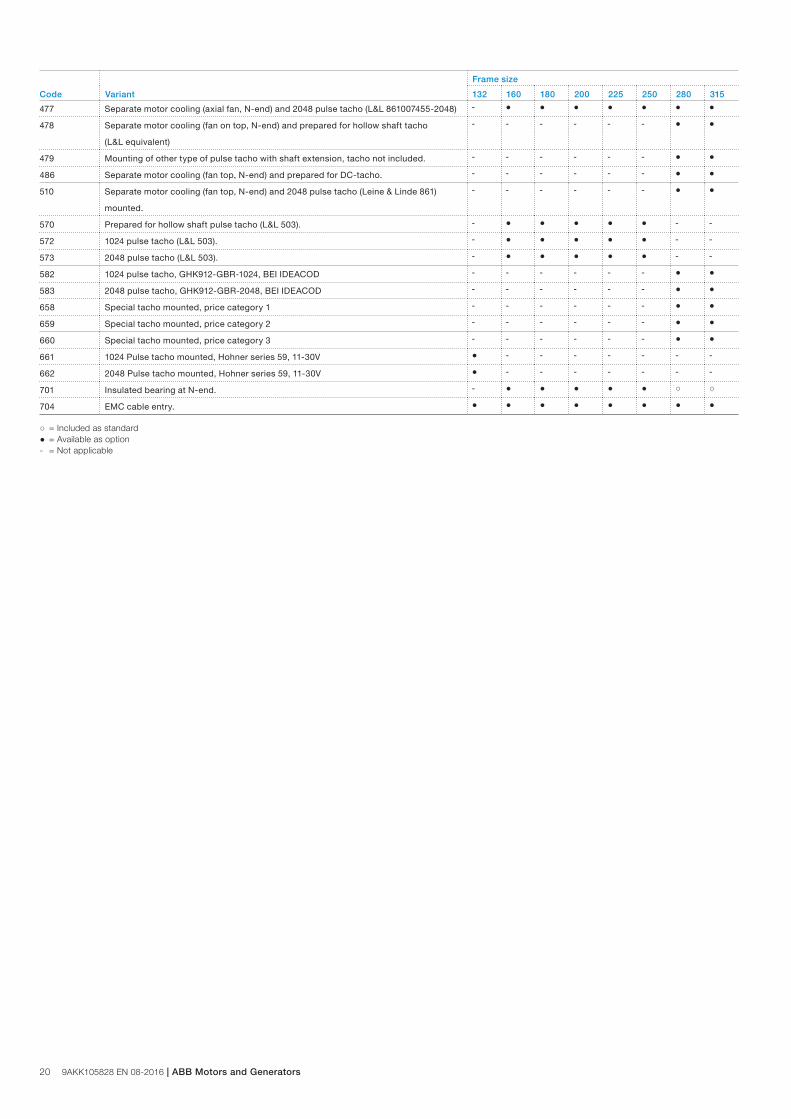
20 9AKK105828 EN 08-2016 | ABB Motors and Generators
Code Variant
Frame size
132 160 180 200 225 250 280 315
477 Separate motor cooling (axial fan, N-end) and 2048 pulse tacho (L&L 861007455-2048) - ● ● ● ● ● ● ●
478 Separate motor cooling (fan on top, N-end) and prepared for hollow shaft tacho
(L&L equivalent)
- - - - - - ● ●
479 Mounting of other type of pulse tacho with shaft extension, tacho not included. - - - - - - ● ●
486 Separate motor cooling (fan top, N-end) and prepared for DC-tacho. - - - - - - ● ●
510 Separate motor cooling (fan top, N-end) and 2048 pulse tacho (Leine & Linde 861)
mounted.
- - - - - - ● ●
570 Prepared for hollow shaft pulse tacho (L&L 503). - ● ● ● ● ● - -
572 1024 pulse tacho (L&L 503). - ● ● ● ● ● - -
573 2048 pulse tacho (L&L 503). - ● ● ● ● ● - -
582 1024 pulse tacho, GHK912-GBR-1024, BEI IDEACOD - - - - - - ● ●
583 2048 pulse tacho, GHK912-GBR-2048, BEI IDEACOD - - - - - - ● ●
658 Special tacho mounted, price category 1 - - - - - - ● ●
659 Special tacho mounted, price category 2 - - - - - - ● ●
660 Special tacho mounted, price category 3 - - - - - - ● ●
661 1024 Pulse tacho mounted, Hohner series 59, 11-30V ● - - - - - - -
662 2048 Pulse tacho mounted, Hohner series 59, 11-30V ● - - - - - - -
701 Insulated bearing at N-end. - ● ● ● ● ● ○ ○
704 EMC cable entry. ● ● ● ● ● ● ● ●
○ = Included as standard● = Available as option- = Not applicable
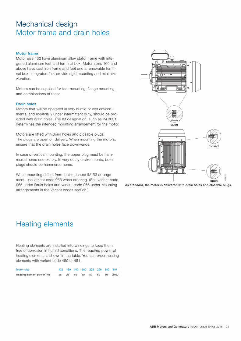
Mechanical designMotor frame and drain holes
M00
0178
Motor frameMotor size 132 have aluminum alloy stator frame with inte-grated aluminum feet and terminal box. Motor sizes 160 and above have cast iron frame and feet and a removable termi-nal box. Integrated feet provide rigid mounting and minimize vibration.
Motors can be supplied for foot mounting, flange mounting, and combinations of these.
Drain holesMotors that will be operated in very humid or wet environ-ments, and especially under intermittent duty, should be pro-vided with drain holes. The IM designation, such as IM 3031, determines the intended mounting arrangement for the motor.
Motors are fitted with drain holes and closable plugs. The plugs are open on delivery. When mounting the motors, ensure that the drain holes face downwards.
In case of vertical mounting, the upper plug must be ham-mered home completely. In very dusty environments, both plugs should be hammered home.
When mounting differs from foot-mounted IM B3 arrange-ment, use variant code 066 when ordering. (See variant code 065 under Drain holes and variant code 066 under Mounting arrangements in the Variant codes section.)
As standard, the motor is delivered with drain holes and closable plugs.
open
closed
open
Heating elements are installed into windings to keep them free of corrosion in humid conditions. The required power of heating elements is shown in the table. You can order heating elements with variant code 450 or 451.
Motor size 132 160 180 200 225 250 280 315
Heating element power (W) 25 25 50 50 50 50 60 2x60
Heating elements
ABB Motors and Generators | 9AKK105828 EN 08-2016 21
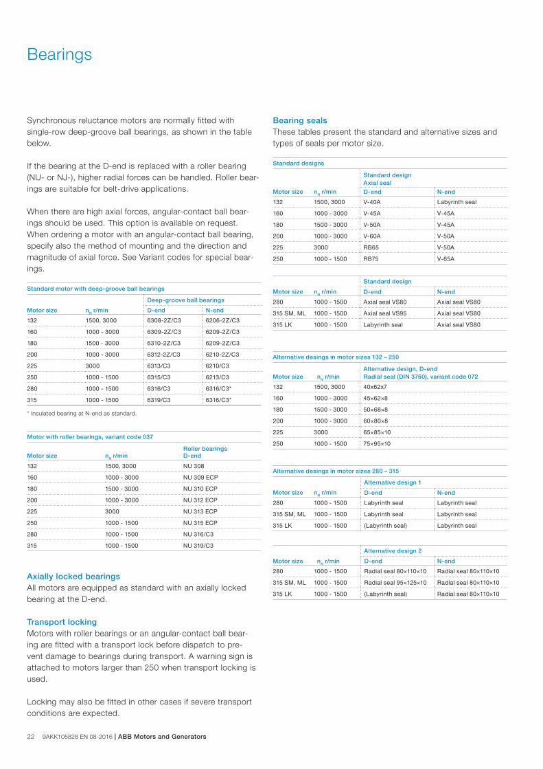
22 9AKK105828 EN 08-2016 | ABB Motors and Generators
Synchronous reluctance motors are normally fitted with single-row deep-groove ball bearings, as shown in the table below.
If the bearing at the D-end is replaced with a roller bearing (NU- or NJ-), higher radial forces can be handled. Roller bear-ings are suitable for belt-drive applications.
When there are high axial forces, angular-contact ball bear-ings should be used. This option is available on request. When ordering a motor with an angular-contact ball bearing, specify also the method of mounting and the direction and magnitude of axial force. See Variant codes for special bear-ings.
Standard motor with deep-groove ball bearings
Deep-groove ball bearings
Motor size nN r/min D-end N-end
132 1500, 3000 6308-2Z/C3 6206-2Z/C3
160 1000 - 3000 6309-2Z/C3 6209-2Z/C3
180 1500 - 3000 6310-2Z/C3 6209-2Z/C3
200 1000 - 3000 6312-2Z/C3 6210-2Z/C3
225 3000 6313/C3 6210/C3
250 1000 - 1500 6315/C3 6213/C3
280 1000 - 1500 6316/C3 6316/C3*
315 1000 - 1500 6319/C3 6316/C3*
* Insulated bearing at N-end as standard.
Motor with roller bearings, variant code 037
Roller bearingsMotor size nN r/min D-end
132 1500, 3000 NU 308
160 1000 - 3000 NU 309 ECP
180 1500 - 3000 NU 310 ECP
200 1000 - 3000 NU 312 ECP
225 3000 NU 313 ECP
250 1000 - 1500 NU 315 ECP
280 1000 - 1500 NU 316/C3
315 1000 - 1500 NU 319/C3
Axially locked bearingsAll motors are equipped as standard with an axially locked bearing at the D-end.
Transport lockingMotors with roller bearings or an angular-contact ball bear-ing are fitted with a transport lock before dispatch to pre-vent damage to bearings during transport. A warning sign is attached to motors larger than 250 when transport locking is used.
Locking may also be fitted in other cases if severe transport conditions are expected.
Bearing sealsThese tables present the standard and alternative sizes and types of seals per motor size.
Standard designs
Standard design Axial seal
Motor size nN r/min D-end N-end
132 1500, 3000 V-40A Labyrinth seal
160 1000 - 3000 V-45A V-45A
180 1500 - 3000 V-50A V-45A
200 1000 - 3000 V-60A V-50A
225 3000 RB65 V-50A
250 1000 - 1500 RB75 V-65A
Standard design
Motor size nN r/min D-end N-end
280 1000 - 1500 Axial seal VS80 Axial seal VS80
315 SM, ML 1000 - 1500 Axial seal VS95 Axial seal VS80
315 LK 1000 - 1500 Labyrinth seal Axial seal VS80
Alternative desings in motor sizes 132 – 250
Motor size nN r/minAlternative design, D-end Radial seal (DIN 3760), variant code 072
132 1500, 3000 40x62x7
160 1000 - 3000 45×62×8
180 1500 - 3000 50×68×8
200 1000 - 3000 60×80×8
225 3000 65×85×10
250 1000 - 1500 75×95×10
Alternative desings in motor sizes 280 – 315
Alternative design 1
Motor size nN r/min D-end N-end
280 1000 - 1500 Labyrinth seal Labyrinth seal
315 SM, ML 1000 - 1500 Labyrinth seal Labyrinth seal
315 LK 1000 - 1500 (Labyrinth seal) Labyrinth seal
Alternative design 2
Motor size nN r/min D-end N-end
280 1000 - 1500 Radial seal 80×110×10 Radial seal 80×110×10
315 SM, ML 1000 - 1500 Radial seal 95×125×10 Radial seal 80×110×10
315 LK 1000 - 1500 (Labyrinth seal) Radial seal 80×110×10
Bearings
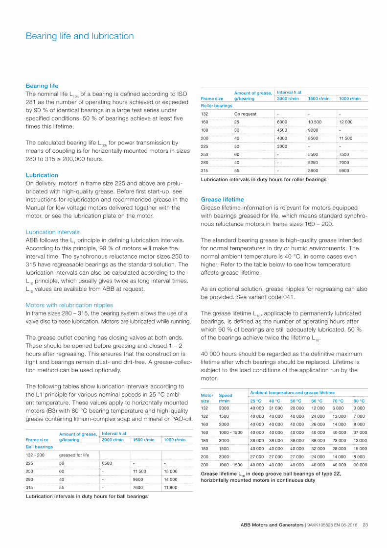
Bearing lifeThe nominal life L10h of a bearing is defined according to ISO 281 as the number of operating hours achieved or exceeded by 90 % of identical bearings in a large test series under specified conditions. 50 % of bearings achieve at least five times this lifetime.
The calculated bearing life L10h for power transmission by means of coupling is for horizontally mounted motors in sizes 280 to 315 ≥ 200,000 hours.
LubricationOn delivery, motors in frame size 225 and above are prelu-bricated with high-quality grease. Before first start-up, see instructions for relubricaton and recommended grease in the Manual for low voltage motors delivered together with the motor, or see the lubrication plate on the motor.
Lubrication intervalsABB follows the L1 principle in defining lubrication intervals. According to this principle, 99 % of motors will make the interval time. The synchronous reluctance motor sizes 250 to 315 have regreasable bearings as the standard solution. The lubrication intervals can also be calculated according to the L10 principle, which usually gives twice as long interval times. L10 values are available from ABB at request.
Motors with relubrication nipplesIn frame sizes 280 – 315, the bearing system allows the use of a valve disc to ease lubrication. Motors are lubricated while running.
The grease outlet opening has closing valves at both ends. These should be opened before greasing and closed 1 – 2 hours after regreasing. This ensures that the construction is tight and bearings remain dust- and dirt-free. A grease-collec-tion method can be used optionally.
The following tables show lubrication intervals according to the L1 principle for various nominal speeds in 25 °C ambi-ent temperature. These values apply to horizontally mounted motors (B3) with 80 °C bearing temperature and high-quality grease containing lithium-complex soap and mineral or PAO-oil.
Amount of grease,g/bearing
Interval h at
Frame size 3000 r/min 1500 r/min 1000 r/min
Ball bearings
132 - 200 greased for life
225 50 6500 - -
250 60 - 11 500 15 000
280 40 - 9600 14 000
315 55 - 7600 11 800
Lubrication intervals in duty hours for ball bearings
Amount of grease,g/bearing
Interval h at
Frame size 3000 r/min 1500 r/min 1000 r/min
Roller bearings
132 On request - - -
160 25 6000 10 500 12 000
180 30 4500 9000 -
200 40 4000 8500 11 500
225 50 3000 - -
250 60 - 5500 7500
280 40 - 5250 7000
315 55 - 3800 5900
Lubrication intervals in duty hours for roller bearings
Grease lifetimeGrease lifetime information is relevant for motors equipped with bearings greased for life, which means standard synchro-nous reluctance motors in frame sizes 160 – 200.
The standard bearing grease is high-quality grease intended for normal temperatures in dry or humid environments. The normal ambient temperature is 40 °C, in some cases even higher. Refer to the table below to see how temperature affects grease lifetime.
As an optional solution, grease nipples for regreasing can also be provided. See variant code 041.
The grease lifetime L10, applicable to permanently lubricated bearings, is defined as the number of operating hours after which 90 % of bearings are still adequately lubricated. 50 % of the bearings achieve twice the lifetime L10.
40 000 hours should be regarded as the definitive maximum lifetime after which bearings should be replaced. Lifetime is subject to the load conditions of the application run by the motor.
Motorsize
Speedr/min
Ambient temperature and grease lifetime
25 °C 40 °C 50 °C 60 °C 70 °C 80 °C
132 3000 40 000 31 000 20 000 12 000 6 000 3 000
132 1500 40 000 40 000 40 000 24 000 13 000 7 000
160 3000 40 000 40 000 40 000 26 000 14 000 8 000
160 1000 - 1500 40 000 40 000 40 000 40 000 40 000 37 000
180 3000 38 000 38 000 38 000 38 000 23 000 13 000
180 1500 40 000 40 000 40 000 32 000 28 000 15 000
200 3000 27 000 27 000 27 000 24 000 14 000 8 000
200 1000 - 1500 40 000 40 000 40 000 40 000 40 000 30 000
Grease lifetime L10 in deep groove ball bearings of type 2Z, horizontally mounted motors in continuous duty
Bearing life and lubrication
ABB Motors and Generators | 9AKK105828 EN 08-2016 23
24 9AKK105828 EN 08-2016 | ABB Motors and Generators
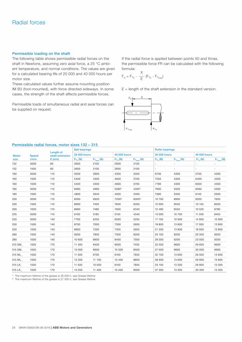
Permissible loading on the shaftThe following table shows permissible radial forces on the shaft in Newtons, assuming zero axial force, a 25 °C ambi-ent temperature, and normal conditions. The values are given for a calculated bearing life of 20 000 and 40 000 hours per motor size. These calculated values further assume mounting position IM B3 (foot-mounted), with force directed sideways. In some cases, the strength of the shaft affects permissible forces.
Permissible loads of simultaneous radial and axial forces can be supplied on request.
If the radial force is applied between points X0 and Xmax, the permissible force FR can be calculated with the following formula:
FR = FX0 -X
(FX0 - FXmax)E
E = length of the shaft extension in the standard version.
Permissible radial forces, motor sizes 132 – 315
Motor size
Speedr/min
Length ofshaft extensionE (mm)
Ball bearings Roller bearings
20 000 hours 40 000 hours 20 000 hours 40 000 hours
FX0 (N) FXmax (N) FX0 (N) FXmax (N) FX0 (N) FXmax (N) FX0 (N) FXmax (N)
132 3000 80 2600 2100 2600 2100 - - - -
132 1500 80 2600 2100 2600 2100 - - - -
160 3000 110 5050 3900 4350 3350 6700 4300 5700 4300
160 1500 110 5400 4300 4600 3700 7550 4300 6400 4300
160 1000 110 5400 4300 4600 3700 7780 4300 6500 4300
180 3000 110 6060 4960 52801) 43051) 7600 5500 6560 5500
180 1500 110 4800 3940 4020 3300 7280 5500 6140 5500
200 3000 110 8300 6900 72002) 60002) 10 700 8900 9200 7650
200 1500 110 8900 7400 7600 6350 12 000 9550 10 150 8500
200 1000 110 8960 7480 7600 6340 12 480 9550 10 520 8780
225 3000 110 6100 5185 5155 4340 13 000 10 700 11 200 9455
250 3000 140 7700 6250 6500 5250 17 100 10 900 14 900 10 900
250 1500 140 8700 7000 7300 5900 19 800 13 800 17 000 13 800
250 1000 140 8900 7200 7355 5955 21 200 13 800 18 000 13 800
280 1500 140 9200 7800 7300 6200 25 100 9200 20 300 9200
280 1000 140 10 600 8900 8400 7000 28 300 9200 23 000 9200
315 SM_ 1500 170 11 400 9400 9000 7450 32 500 9600 26 600 9600
315 SM_ 1000 170 13 000 9600 10 300 8500 37 000 9600 30 000 9600
315 ML_ 1500 170 11 500 9700 9100 7650 32 700 13 600 26 500 13 600
315 ML_ 1000 170 13 200 11 100 10 400 8800 36 900 13 600 29 900 13 600
315 LK_ 1500 170 11 500 10 000 9100 7850 33 100 13 300 26 800 13 300
315 LK_ 1000 170 13 200 11 400 10 400 9000 37 300 13 300 30 300 13 300
1) The maximum lifetime of the grease is 38 000 h, see Grease lifetime 2) The maximum lifetime of the grease is 27 000 h, see Grease lifetime
Radial forces
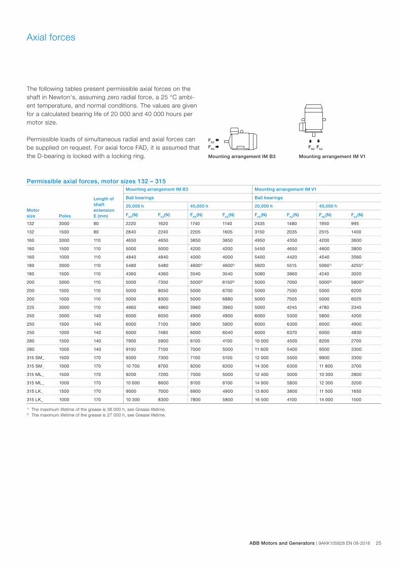
The following tables present permissible axial forces on the shaft in Newton‘s, assuming zero radial force, a 25 °C ambi-ent temperature, and normal conditions. The values are given for a calculated bearing life of 20 000 and 40 000 hours per motor size.
Permissible loads of simultaneous radial and axial forces can be supplied on request. For axial force FAD, it is assumed that the D-bearing is locked with a locking ring.
FAZ Å
FAD Æ
Ç È FAD FAZ
Mounting arrangement IM B3 Mounting arrangement IM V1
Axial forces
Permissible axial forces, motor sizes 132 – 315
Motorsize Poles
Length ofshaftextensionE (mm)
Mounting arrangement IM B3 Mounting arrangement IM V1
Ball bearings Ball bearings
20,000 h 40,000 h 20,000 h 40,000 h
FAD(N) FAZ(N) FAD(N) FAZ(N) FAD(N) FAZ(N) FAD(N) FAZ(N)
132 3000 80 2220 1620 1740 1140 2435 1480 1950 995
132 1500 80 2840 2240 2205 1605 3150 2035 2515 1400
160 3000 110 4650 4650 3850 3850 4950 4350 4200 3600
160 1500 110 5000 5000 4200 4200 5450 4650 4600 3800
160 1000 110 4840 4840 4000 4000 5400 4420 4540 3560
180 3000 110 5480 5480 46001) 46001) 5920 5515 50601) 42551)
180 1500 110 4360 4360 3540 3540 5080 3860 4240 3020
200 3000 110 5000 7350 50002) 61502) 5000 7050 50002) 58002)
200 1500 110 5000 8050 5000 6700 5000 7550 5000 6200
200 1000 110 5000 8300 5000 6880 5000 7505 5000 6025
225 3000 110 4860 4860 3960 3960 5000 4245 4780 3345
250 3000 140 6000 6050 4900 4900 6000 5300 5800 4200
250 1500 140 6000 7100 5800 5800 6000 6300 6000 4900
250 1000 140 6000 7480 6000 6040 6000 6370 6000 4830
280 1500 140 7900 5900 6100 4100 10 000 4500 8200 2700
280 1000 140 9100 7100 7000 5000 11 600 5400 9500 3300
315 SM_ 1500 170 9300 7300 7100 5100 12 000 5500 9900 3300
315 SM_ 1000 170 10 700 8700 8200 6200 14 300 6300 11 800 3700
315 ML_ 1500 170 9200 7200 7000 5000 12 400 5000 10 300 2800
315 ML_ 1000 170 10 600 8600 8100 6100 14 900 5800 12 300 3200
315 LK_ 1500 170 9000 7000 6900 4900 13 600 3800 11 500 1650
315 LK_ 1000 170 10 300 8300 7800 5800 16 500 4100 14 000 1500
1) The maximum lifetime of the grease is 38 000 h, see Grease lifetime. 2) The maximum lifetime of the grease is 27 000 h, see Grease lifetime.
ABB Motors and Generators | 9AKK105828 EN 08-2016 25
26 9AKK105828 EN 08-2016 | ABB Motors and Generators
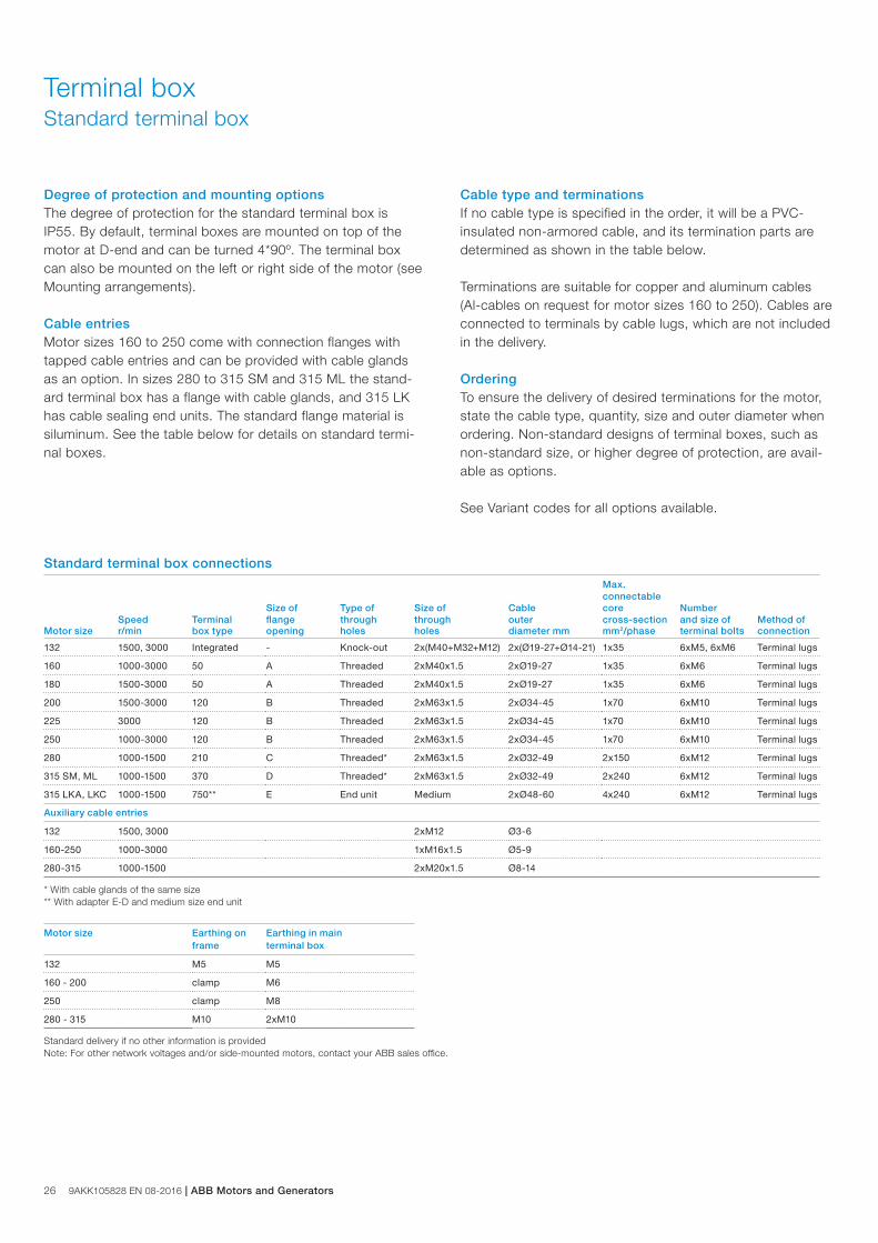
Degree of protection and mounting optionsThe degree of protection for the standard terminal box is IP55. By default, terminal boxes are mounted on top of the motor at D-end and can be turned 4*90º. The terminal box can also be mounted on the left or right side of the motor (see Mounting arrangements).
Cable entriesMotor sizes 160 to 250 come with connection flanges with tapped cable entries and can be provided with cable glands as an option. In sizes 280 to 315 SM and 315 ML the stand-ard terminal box has a flange with cable glands, and 315 LK has cable sealing end units. The standard flange material is siluminum. See the table below for details on standard termi-nal boxes.
Terminal boxStandard terminal box
Cable type and terminationsIf no cable type is specified in the order, it will be a PVC-insulated non-armored cable, and its termination parts are determined as shown in the table below.
Terminations are suitable for copper and aluminum cables (Al-cables on request for motor sizes 160 to 250). Cables are connected to terminals by cable lugs, which are not included in the delivery.
OrderingTo ensure the delivery of desired terminations for the motor, state the cable type, quantity, size and outer diameter when ordering. Non-standard designs of terminal boxes, such as non-standard size, or higher degree of protection, are avail-able as options.
See Variant codes for all options available.
Max.connectable
Size of Type of Size of Cable core NumberSpeed Terminal flange through through outer cross-section and size of Method of
Motor size r/min box type opening holes holes diameter mm mm2/phase terminal bolts connection
132 1500, 3000 Integrated - Knock-out 2x(M40+M32+M12) 2x(Ø19-27+Ø14-21) 1x35 6xM5, 6xM6 Terminal lugs
160 1000-3000 50 A Threaded 2xM40x1.5 2xØ19-27 1x35 6xM6 Terminal lugs
180 1500-3000 50 A Threaded 2xM40x1.5 2xØ19-27 1x35 6xM6 Terminal lugs
200 1500-3000 120 B Threaded 2xM63x1.5 2xØ34-45 1x70 6xM10 Terminal lugs
225 3000 120 B Threaded 2xM63x1.5 2xØ34-45 1x70 6xM10 Terminal lugs
250 1000-3000 120 B Threaded 2xM63x1.5 2xØ34-45 1x70 6xM10 Terminal lugs
280 1000-1500 210 C Threaded* 2xM63x1.5 2xØ32-49 2x150 6xM12 Terminal lugs
315 SM, ML 1000-1500 370 D Threaded* 2xM63x1.5 2xØ32-49 2x240 6xM12 Terminal lugs
315 LKA, LKC 1000-1500 750** E End unit Medium 2xØ48-60 4x240 6xM12 Terminal lugs
Auxiliary cable entries
132 1500, 3000 2xM12 Ø3-6
160-250 1000-3000 1xM16x1.5 Ø5-9
280-315 1000-1500 2xM20x1.5 Ø8-14
* With cable glands of the same size** With adapter E-D and medium size end unit
Motor size Earthing on frame
Earthing in main terminal box
132 M5 M5
160 - 200 clamp M6
250 clamp M8
280 - 315 M10 2xM10
Standard delivery if no other information is providedNote: For other network voltages and/or side-mounted motors, contact your ABB sales office.
Standard terminal box connections
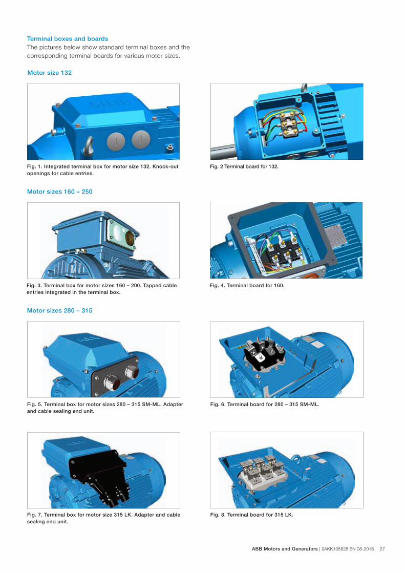
Terminal boxes and boardsThe pictures below show standard terminal boxes and the corresponding terminal boards for various motor sizes.
Motor sizes 160 – 250
Fig. 3. Terminal box for motor sizes 160 – 200. Tapped cable entries integrated in the terminal box.
Fig. 4. Terminal board for 160.
Motor size 132
Fig. 1. Integrated terminal box for motor size 132. Knock-out openings for cable entries.
Fig. 2 Terminal board for 132.
Fig. 5. Terminal box for motor sizes 280 – 315 SM-ML. Adapter and cable sealing end unit.
Fig. 6. Terminal board for 280 – 315 SM-ML.
Fig. 7. Terminal box for motor size 315 LK. Adapter and cable sealing end unit.
Fig. 8. Terminal board for 315 LK.
Motor sizes 280 – 315
ABB Motors and Generators | 9AKK105828 EN 08-2016 27
28 9AKK105828 EN 08-2016 | ABB Motors and Generators
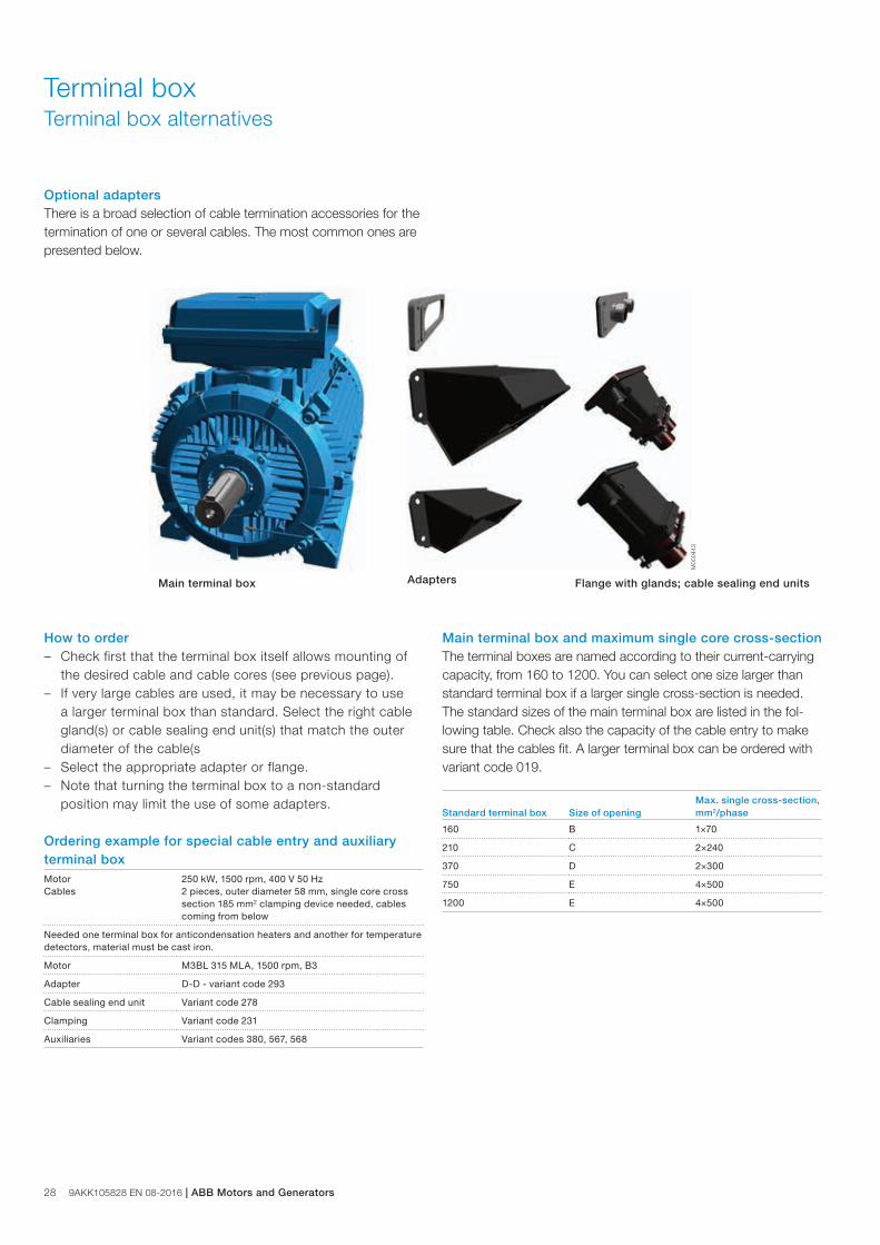
Main terminal box
Optional adapters There is a broad selection of cable termination accessories for the termination of one or several cables. The most common ones are presented below.
Main terminal box and maximum single core cross-sectionThe terminal boxes are named according to their current-carrying capacity, from 160 to 1200. You can select one size larger than standard terminal box if a larger single cross-section is needed. The standard sizes of the main terminal box are listed in the fol-lowing table. Check also the capacity of the cable entry to make sure that the cables fit. A larger terminal box can be ordered with variant code 019.
Standard terminal box Size of openingMax. single cross-section, mm2/phase
160 B 1×70
210 C 2×240
370 D 2×300
750 E 4×500
1200 E 4×500
How to order – Check first that the terminal box itself allows mounting of
the desired cable and cable cores (see previous page). – If very large cables are used, it may be necessary to use
a larger terminal box than standard. Select the right cable gland(s) or cable sealing end unit(s) that match the outer diameter of the cable(s
– Select the appropriate adapter or flange. – Note that turning the terminal box to a non-standard
position may limit the use of some adapters.
Ordering example for special cable entry and auxiliary terminal boxMotor Cables
250 kW, 1500 rpm, 400 V 50 Hz 2 pieces, outer diameter 58 mm, single core cross section 185 mm2 clamping device needed, cables coming from below
Needed one terminal box for anticondensation heaters and another for temperature detectors, material must be cast iron.
Motor M3BL 315 MLA, 1500 rpm, B3
Adapter D-D - variant code 293
Cable sealing end unit Variant code 278
Clamping Variant code 231
Auxiliaries Variant codes 380, 567, 568
Terminal boxTerminal box alternatives
Flange with glands; cable sealing end units
Adapters
M00
0443
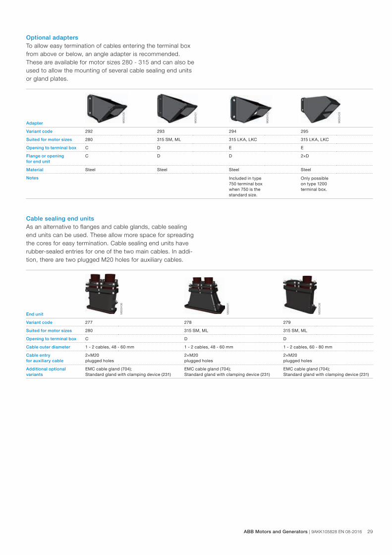
Optional adaptersTo allow easy termination of cables entering the terminal box from above or below, an angle adapter is recommended. These are available for motor sizes 280 - 315 and can also be used to allow the mounting of several cable sealing end units or gland plates.
Cable sealing end unitsAs an alternative to flanges and cable glands, cable sealing end units can be used. These allow more space for spreading the cores for easy termination. Cable sealing end units have rubber-sealed entries for one of the two main cables. In addi-tion, there are two plugged M20 holes for auxiliary cables.
Adapter M00
0430
M00
0431
M00
0432
M00
0433
Variant code 292 293 294 295
Suited for motor sizes 280 315 SM, ML 315 LKA, LKC 315 LKA, LKC
Opening to terminal box C D E E
Flange or opening for end unit
C D D 2×D
Material Steel Steel Steel Steel
Notes Included in type 750 terminal box when 750 is the standard size.
Only possible on type 1200 terminal box.
End unit M00
0436
M00
0437
M00
0438
Variant code 277 278 279
Suited for motor sizes 280 315 SM, ML 315 SM, ML
Opening to terminal box C D D
Cable outer diameter 1 - 2 cables, 48 - 60 mm 1 - 2 cables, 48 - 60 mm 1 - 2 cables, 60 - 80 mm
Cable entry for auxiliary cable
2×M20 plugged holes
2×M20 plugged holes
2×M20 plugged holes
Additional optional variants
EMC cable gland (704);Standard gland with clamping device (231)
EMC cable gland (704);Standard gland with clamping device (231)
EMC cable gland (704);Standard gland with clamping device (231)
ABB Motors and Generators | 9AKK105828 EN 08-2016 29
30 9AKK105828 EN 08-2016 | ABB Motors and Generators
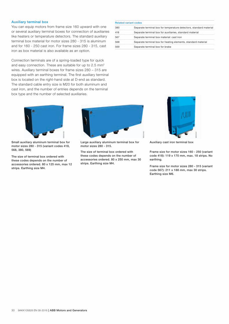
Auxiliary terminal box You can equip motors from frame size 160 upward with one or several auxiliary terminal boxes for connection of auxiliaries like heaters or temperature detectors. The standard auxiliary terminal box material for motor sizes 280 - 315 is aluminum and for 160 - 250 cast iron. For frame sizes 280 - 315, cast iron as box material is also available as an option.
Connection terminals are of a spring-loaded type for quick and easy connection. These are suitable for up to 2.5 mm2 wires. Auxiliary terminal boxes for frame sizes 280 – 315 are equipped with an earthing terminal. The first auxiliary terminal box is located on the right-hand side at D-end as standard. The standard cable entry size is M20 for both aluminum and cast iron, and the number of entries depends on the terminal box type and the number of selected auxiliaries.
M00
0439
M00
0440
M00
0441
Related variant codes
380 Separate terminal box for temperature detectors, standard material
418 Separate terminal box for auxiliaries, standard material
567 Separate terminal box material: cast iron
568 Separate terminal box for heating elements, standard material
569 Separate terminal box for brake
Small auxiliary aluminum terminal box for motor sizes 280 - 315 (variant codes 418, 568, 380, 569)
The size of terminal box ordered with these codes depends on the number of accessories ordered. 80 x 125 mm, max 12 strips. Earthing size M4.
Large auxiliary aluminum terminal box for motor sizes 280 - 315.
The size of terminal box ordered with these codes depends on the number of accessories ordered. 80 x 250 mm, max 30 strips. Earthing size M4.
Auxiliary cast iron terminal box
Frame size for motor sizes 160 - 250 (variant code 418): 119 x 170 mm, max. 18 strips. No earthing.
Frame size for motor sizes 280 - 315 (variant code 567): 211 x 188 mm, max 30 strips. Earthing size M6.
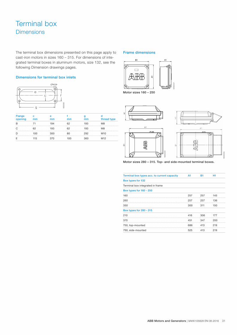
Flange c e f g dopening mm mm mm mm thread type
B 71 194 62 193 M8
C 62 193 62 193 M8
D 100 300 80 292 M10
E 115 370 100 360 M12
Terminal box types acc. to current capacity A1 B1 H1
Box types for 132
Terminal box integrated in frame
Box types for 160 - 250
160 257 257 145
260 257 257 136
350 300 311 150
Box types for 280 - 315
210 416 306 177
370 451 347 200
750, top-mounted 686 413 219
750, side-mounted 525 413 219
Frame dimensions
Dimensions for terminal box inlets
Terminal boxDimensions
M00
0407
M00
088
M00
0205
M00
0206
Motor sizes 160 – 250
Motor sizes 280 – 315. Top- and side-mounted terminal boxes.
The terminal box dimensions presented on this page apply to cast-iron motors in sizes 160 – 315. For dimensions of inte-grated terminal boxes in aluminum motors, size 132, see the following Dimension drawings pages.
ABB Motors and Generators | 9AKK105828 EN 08-2016 31
32 9AKK105828 EN 08-2016 | ABB Motors and Generators
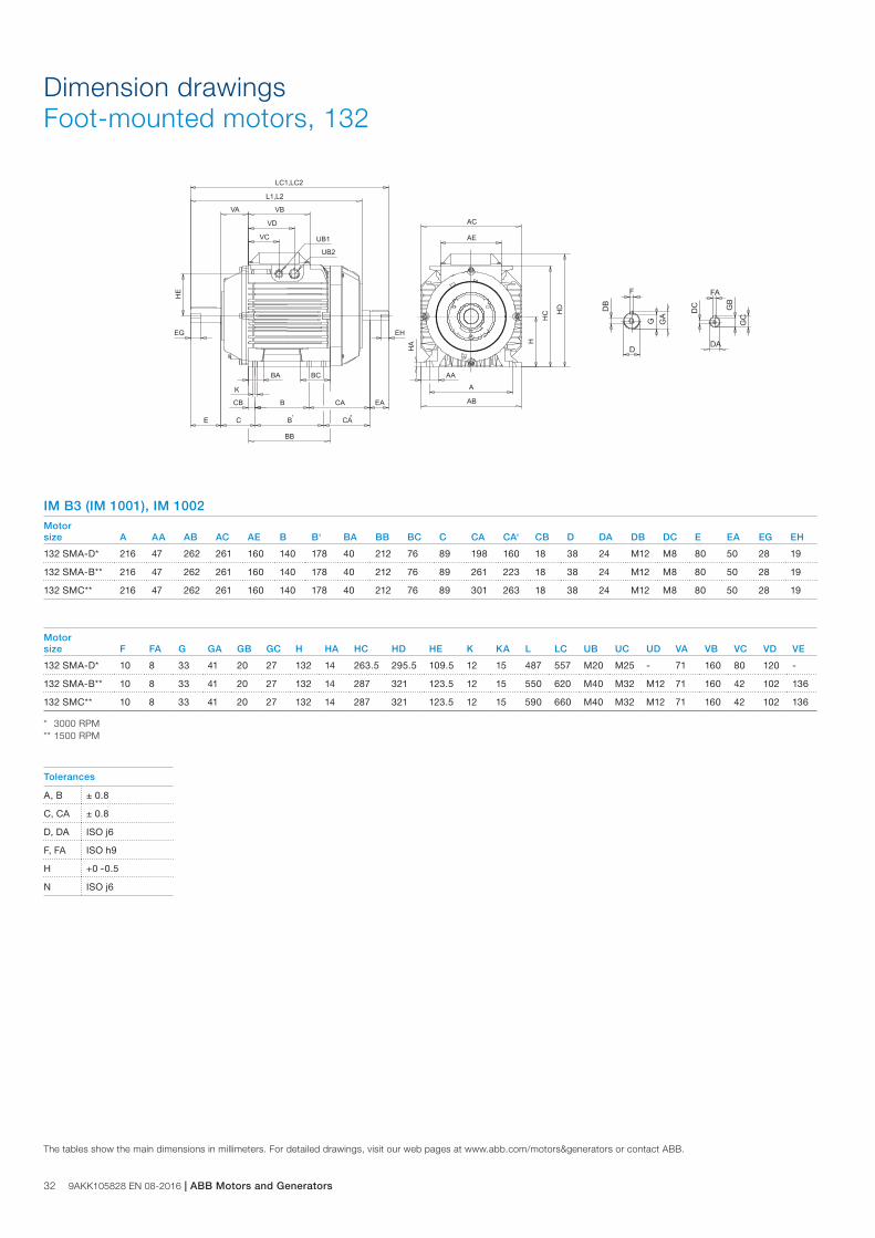
Dimension drawings Foot-mounted motors, 132
IM B3 (IM 1001), IM 1002Motorsize A AA AB AC AE B B‘ BA BB BC C CA CA‘ CB D DA DB DC E EA EG EH
132 SMA-D* 216 47 262 261 160 140 178 40 212 76 89 198 160 18 38 24 M12 M8 80 50 28 19
132 SMA-B** 216 47 262 261 160 140 178 40 212 76 89 261 223 18 38 24 M12 M8 80 50 28 19
132 SMC** 216 47 262 261 160 140 178 40 212 76 89 301 263 18 38 24 M12 M8 80 50 28 19
Motorsize F FA G GA GB GC H HA HC HD HE K KA L LC UB UC UD VA VB VC VD VE
132 SMA-D* 10 8 33 41 20 27 132 14 263.5 295.5 109.5 12 15 487 557 M20 M25 - 71 160 80 120 -
132 SMA-B** 10 8 33 41 20 27 132 14 287 321 123.5 12 15 550 620 M40 M32 M12 71 160 42 102 136
132 SMC** 10 8 33 41 20 27 132 14 287 321 123.5 12 15 590 660 M40 M32 M12 71 160 42 102 136
* 3000 RPM** 1500 RPM
The tables show the main dimensions in millimeters. For detailed drawings, visit our web pages at www.abb.com/motors&generators or contact ABB.
Tolerances
A, B ± 0.8
C, CA ± 0.8
D, DA ISO j6
F, FA ISO h9
H +0 -0.5
N ISO j6
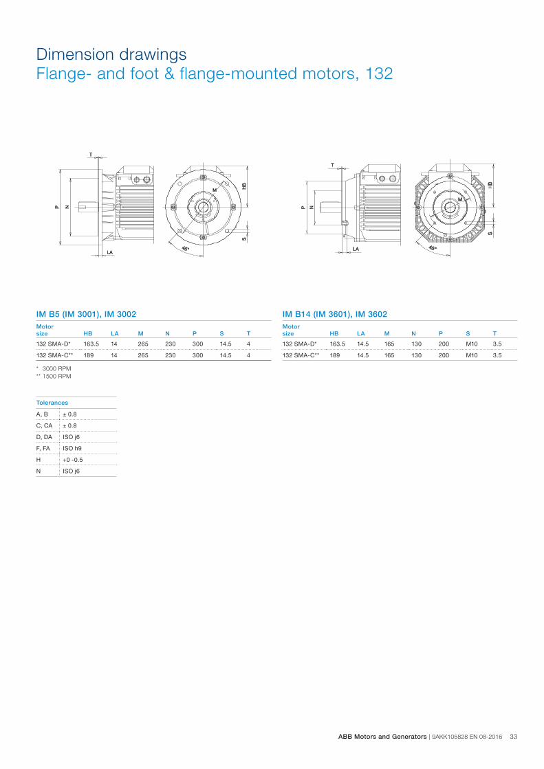
Dimension drawings Flange- and foot & flange-mounted motors, 132
IM B5 (IM 3001), IM 3002Motorsize HB LA M N P S T
132 SMA-D* 163.5 14 265 230 300 14.5 4
132 SMA-C** 189 14 265 230 300 14.5 4
* 3000 RPM** 1500 RPM
IM B14 (IM 3601), IM 3602Motorsize HB LA M N P S T
132 SMA-D* 163.5 14.5 165 130 200 M10 3.5
132 SMA-C** 189 14.5 165 130 200 M10 3.5
Tolerances
A, B ± 0.8
C, CA ± 0.8
D, DA ISO j6
F, FA ISO h9
H +0 -0.5
N ISO j6
ABB Motors and Generators | 9AKK105828 EN 08-2016 33
34 9AKK105828 EN 08-2016 | ABB Motors and Generators
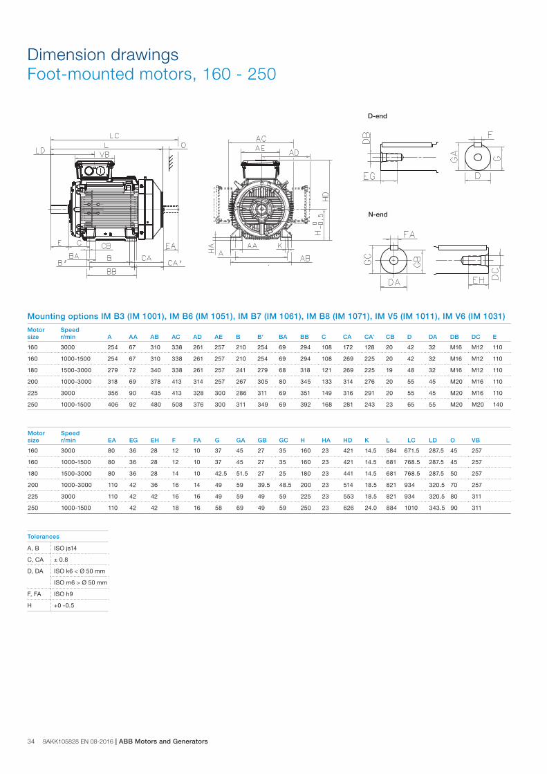
Dimension drawings Foot-mounted motors, 160 - 250
Mounting options IM B3 (IM 1001), IM B6 (IM 1051), IM B7 (IM 1061), IM B8 (IM 1071), IM V5 (IM 1011), IM V6 (IM 1031)
Motor Speedsize r/min A AA AB AC AD AE B B’ BA BB C CA CA’ CB D DA DB DC E
160 3000 254 67 310 338 261 257 210 254 69 294 108 172 128 20 42 32 M16 M12 110
160 1000-1500 254 67 310 338 261 257 210 254 69 294 108 269 225 20 42 32 M16 M12 110
180 1500-3000 279 72 340 338 261 257 241 279 68 318 121 269 225 19 48 32 M16 M12 110
200 1000-3000 318 69 378 413 314 257 267 305 80 345 133 314 276 20 55 45 M20 M16 110
225 3000 356 90 435 413 328 300 286 311 69 351 149 316 291 20 55 45 M20 M16 110
250 1000-1500 406 92 480 508 376 300 311 349 69 392 168 281 243 23 65 55 M20 M20 140
Motor Speedsize r/min EA EG EH F FA G GA GB GC H HA HD K L LC LD O VB
160 3000 80 36 28 12 10 37 45 27 35 160 23 421 14.5 584 671.5 287.5 45 257
160 1000-1500 80 36 28 12 10 37 45 27 35 160 23 421 14.5 681 768.5 287.5 45 257
180 1500-3000 80 36 28 14 10 42.5 51.5 27 25 180 23 441 14.5 681 768.5 287.5 50 257
200 1000-3000 110 42 36 16 14 49 59 39.5 48.5 200 23 514 18.5 821 934 320.5 70 257
225 3000 110 42 42 16 16 49 59 49 59 225 23 553 18.5 821 934 320.5 80 311
250 1000-1500 110 42 42 18 16 58 69 49 59 250 23 626 24.0 884 1010 343.5 90 311
Tolerances
A, B ISO js14
C, CA ± 0.8
D, DA ISO k6 < Ø 50 mm
ISO m6 > Ø 50 mm
F, FA ISO h9
H +0 -0.5
N-end
D-end
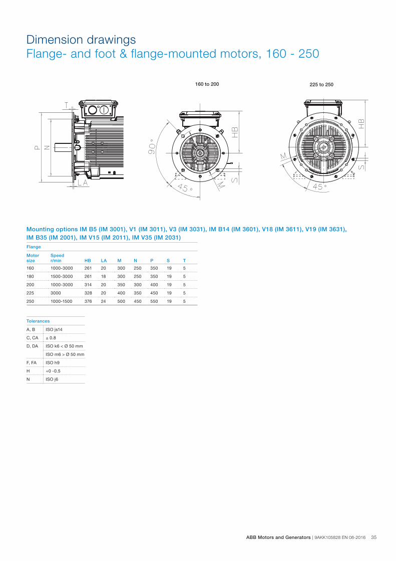
Dimension drawings Flange- and foot & flange-mounted motors, 160 - 250
Mounting options IM B5 (IM 3001), V1 (IM 3011), V3 (IM 3031), IM B14 (IM 3601), V18 (IM 3611), V19 (IM 3631), IM B35 (IM 2001), IM V15 (IM 2011), IM V35 (IM 2031)
225 to 250160 to 200
Flange
Motor Speedsize r/min HB LA M N P S T
160 1000-3000 261 20 300 250 350 19 5
180 1500-3000 261 18 300 250 350 19 5
200 1000-3000 314 20 350 300 400 19 5
225 3000 328 20 400 350 450 19 5
250 1000-1500 376 24 500 450 550 19 5
Tolerances
A, B ISO js14
C, CA ± 0.8
D, DA ISO k6 < Ø 50 mm
ISO m6 > Ø 50 mm
F, FA ISO h9
H +0 -0.5
N ISO j6
ABB Motors and Generators | 9AKK105828 EN 08-2016 35
36 9AKK105828 EN 08-2016 | ABB Motors and Generators
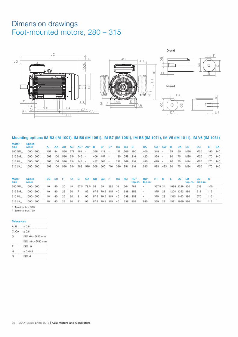
Dimension drawings Foot-mounted motors, 280 – 315
N-end
D-end
Motor Speedsize r/min A AA AB AC AD1) AD2) B B ‘ B’’ BA BB C CA CA ‘ CA’’ D DA DB DC E EA
280 SM_ 1000-1500 457 84 530 577 481 - 368 419 - 147 506 190 400 349 - 75 65 M20 M20 140 140
315 SM_ 1000-1500 508 100 590 654 545 - 406 457 - 180 558 216 420 369 - 80 75 M20 M20 170 140
315 ML_ 1000-1500 508 100 590 654 545 - 457 508 - 212 669 216 480 429 - 90 75 M24 M20 170 140
315 LK_ 1000-1500 508 100 590 654 562 576 508 560 710 336 851 216 635 583 433 90 75 M24 M20 170 140
Motor Speed EG EH F FA G GA GB GC H HA HC HD1) HD2) HT K L LC LD LD Osize r/min top-m. top-m. top-m. side-m.
280 SM_ 1000-1500 40 40 20 18 67.5 79.5 58 69 280 31 564 762 - 337.5 24 1088 1238 336 539 100
315 SM_ 1000-1500 40 40 22 20 71 85 67.5 79.5 315 40 638 852 - 375 28 1204 1352 386 615 115
315 ML_ 1000-1500 48 40 25 20 81 95 67.5 79.5 315 40 638 852 - 375 28 1315 1463 386 670 115
315 LK_ 1000-1500 48 40 25 20 81 95 67.5 79.5 315 40 638 852 880 359 28 1521 1669 386 751 115
1) Terminal box 3702) Terminal box 750
Mounting options IM B3 (IM 1001), IM B6 (IM 1051), IM B7 (IM 1061), IM B8 (IM 1071), IM V5 (IM 1011), IM V6 (IM 1031)
Tolerances
A, B ± 0.8
C, CA ± 0.8
D ISO k6 < Ø 50 mm
ISO m6 > Ø 50 mm
F ISO h9
H + 0 -0.5
N ISO j6
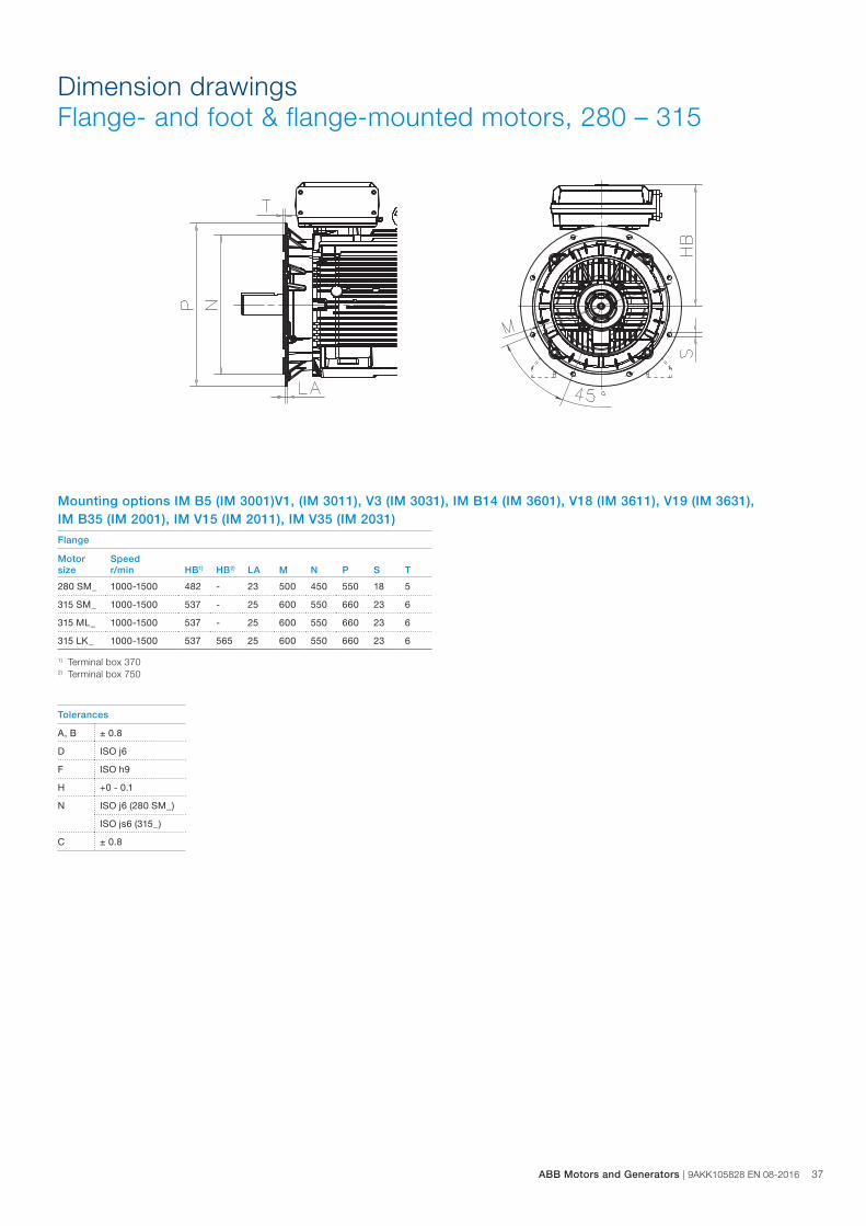
Dimension drawings Flange- and foot & flange-mounted motors, 280 – 315
Flange
Motor Speedsize r/min HB1) HB2) LA M N P S T
280 SM_ 1000-1500 482 - 23 500 450 550 18 5
315 SM_ 1000-1500 537 - 25 600 550 660 23 6
315 ML_ 1000-1500 537 - 25 600 550 660 23 6
315 LK_ 1000-1500 537 565 25 600 550 660 23 6
1) Terminal box 3702) Terminal box 750
Mounting options IM B5 (IM 3001)V1, (IM 3011), V3 (IM 3031), IM B14 (IM 3601), V18 (IM 3611), V19 (IM 3631), IM B35 (IM 2001), IM V15 (IM 2011), IM V35 (IM 2031)
Tolerances
A, B ± 0.8
D ISO j6
F ISO h9
H +0 - 0.1
N ISO j6 (280 SM_)
ISO js6 (315_)
C ± 0.8
ABB Motors and Generators | 9AKK105828 EN 08-2016 37
38 9AKK105828 EN 08-2016 | ABB Motors and Generators
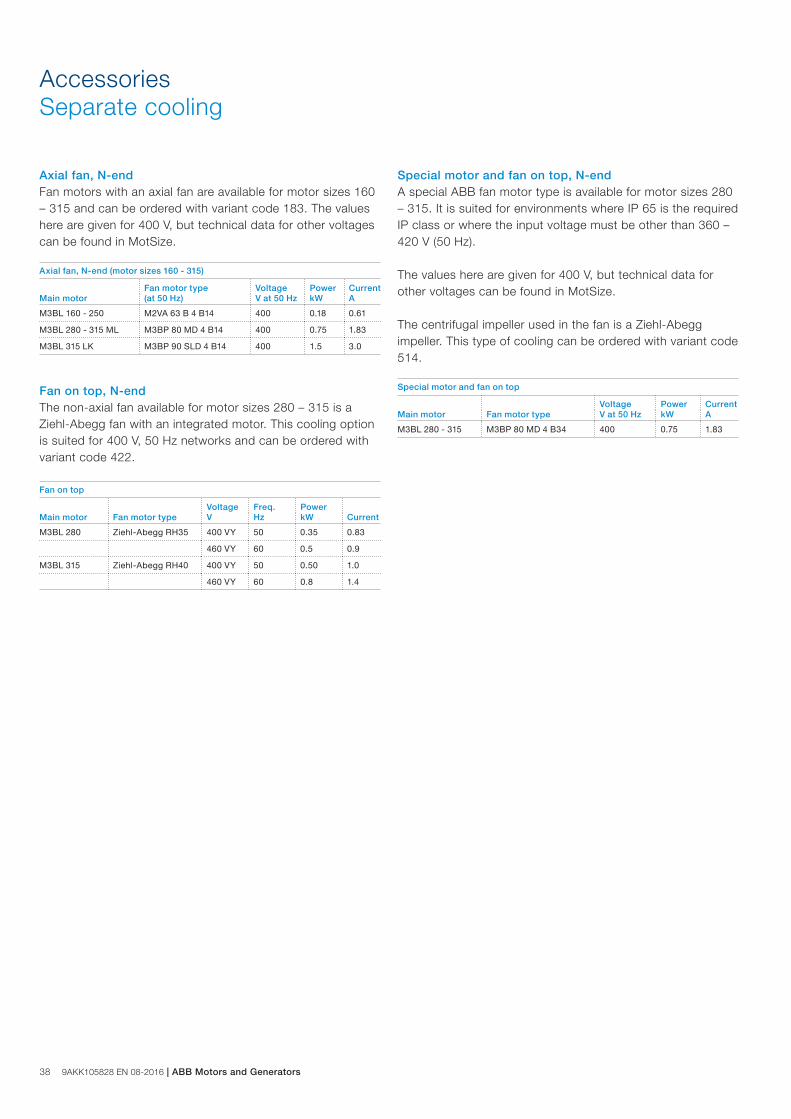
AccessoriesSeparate cooling
Axial fan, N-endFan motors with an axial fan are available for motor sizes 160 – 315 and can be ordered with variant code 183. The values here are given for 400 V, but technical data for other voltages can be found in MotSize.
Fan on top, N-endThe non-axial fan available for motor sizes 280 – 315 is a Ziehl-Abegg fan with an integrated motor. This cooling option is suited for 400 V, 50 Hz networks and can be ordered with variant code 422.
Special motor and fan on top, N-end A special ABB fan motor type is available for motor sizes 280 – 315. It is suited for environments where IP 65 is the required IP class or where the input voltage must be other than 360 – 420 V (50 Hz).
The values here are given for 400 V, but technical data for other voltages can be found in MotSize.
The centrifugal impeller used in the fan is a Ziehl-Abegg impeller. This type of cooling can be ordered with variant code 514.
Axial fan, N-end (motor sizes 160 - 315)
Fan motor type Voltage Power CurrentMain motor (at 50 Hz) V at 50 Hz kW A
M3BL 160 - 250 M2VA 63 B 4 B14 400 0.18 0.61
M3BL 280 - 315 ML M3BP 80 MD 4 B14 400 0.75 1.83
M3BL 315 LK M3BP 90 SLD 4 B14 400 1.5 3.0
Fan on top
Voltage Freq. PowerMain motor Fan motor type V Hz kW Current
M3BL 280 Ziehl-Abegg RH35 400 VY 50 0.35 0.83
460 VY 60 0.5 0.9
M3BL 315 Ziehl-Abegg RH40 400 VY 50 0.50 1.0
460 VY 60 0.8 1.4
Special motor and fan on top
Voltage Power CurrentMain motor Fan motor type V at 50 Hz kW A
M3BL 280 - 315 M3BP 80 MD 4 B34 400 0.75 1.83
M00
0057
M00
0058
M00
0059
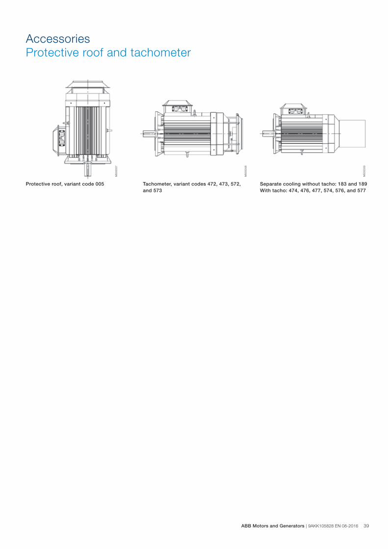
AccessoriesProtective roof and tachometer
Protective roof, variant code 005 Tachometer, variant codes 472, 473, 572, and 573
Separate cooling without tacho: 183 and 189 With tacho: 474, 476, 477, 574, 576, and 577
ABB Motors and Generators | 9AKK105828 EN 08-2016 39
40 9AKK105828 EN 08-2016 | ABB Motors and Generators
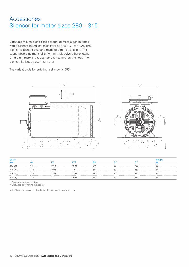
AccessoriesSilencer for motor sizes 280 - 315
Both foot-mounted and flange-mounted motors can be fitted with a silencer to reduce noise level by about 5 – 6 dB(A). The silencer is painted blue and made of 2 mm steel sheet. The sound absorbing material is 40 mm thick polyurethane foam. On the rim there is a rubber strip for sealing on the floor. The silencer fits loosely over the motor.
The variant code for ordering a silencer is 055.
M00
0309
Motor Weightsize AV LV LVT DV O 1) S 2) kg
280 SM_ 681 1010 1090 616 50 762 38
315 SM_ 760 1094 1191 697 60 852 47
315 ML_ 760 1205 1302 697 60 852 51
315 LK_ 760 1411 1508 697 60 852 58
1) Clearance for motor cooling2) Clearance for removing the silencer
Note: The dimensions are only valid for standard foot-mounted motors.
M
O
E
G
AB
N
D
C
L
F
H
1
2 4
3 5Xmax.
Ymax.
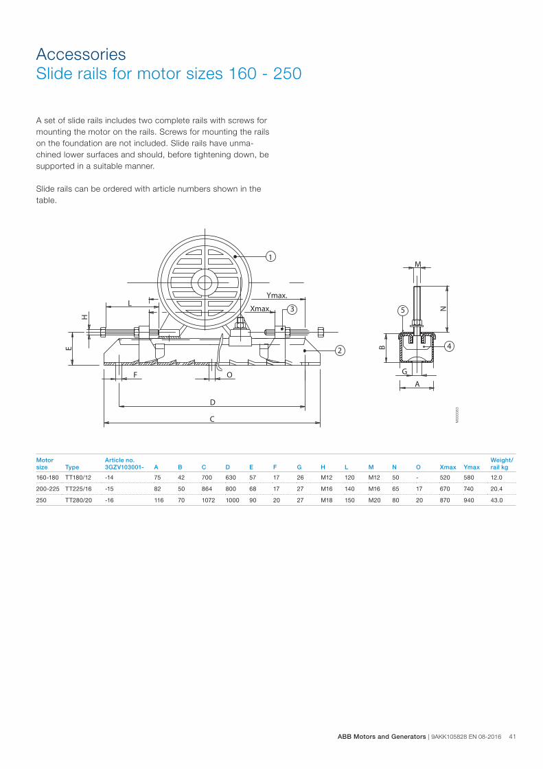
AccessoriesSlide rails for motor sizes 160 - 250
A set of slide rails includes two complete rails with screws for mounting the motor on the rails. Screws for mounting the rails on the foundation are not included. Slide rails have unma-chined lower surfaces and should, before tightening down, be supported in a suitable manner.
Slide rails can be ordered with article numbers shown in the table.
M00
0063
Motor Article no. Weight/ size Type 3GZV103001- A B C D E F G H L M N O Xmax Ymax rail kg
160-180 TT180/12 -14 75 42 700 630 57 17 26 M12 120 M12 50 - 520 580 12.0
200-225 TT225/16 -15 82 50 864 800 68 17 27 M16 140 M16 65 17 670 740 20.4
250 TT280/20 -16 116 70 1072 1000 90 20 27 M18 150 M20 80 20 870 940 43.0
ABB Motors and Generators | 9AKK105828 EN 08-2016 41
42 9AKK105828 EN 08-2016 | ABB Motors and Generators
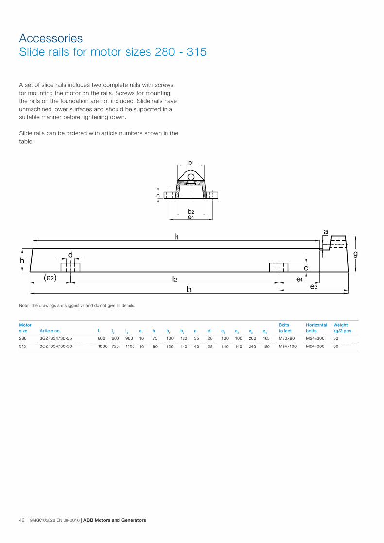
AccessoriesSlide rails for motor sizes 280 - 315
A set of slide rails includes two complete rails with screws for mounting the motor on the rails. Screws for mounting the rails on the foundation are not included. Slide rails have unmachined lower surfaces and should be supported in a suitable manner before tightening down.
Slide rails can be ordered with article numbers shown in the table.
b2
b1
e4
c
l1
l3l2(e2)
hgd
c
e3e1
a
Note: The drawings are suggestive and do not give all details.
Motor Bolts Horizontal Weightsize Article no. l1 l2 l3 a h b1 b2 c d e1 e2 e3 e4 to feet bolts kg/2 pcs
280 3GZF334730-55 800 600 900 16 75 100 120 35 28 100 100 200 165 M20×90 M24×300 50
315 3GZF334730-56 1000 720 1100 16 80 120 140 40 28 140 140 240 190 M24×100 M24×300 80
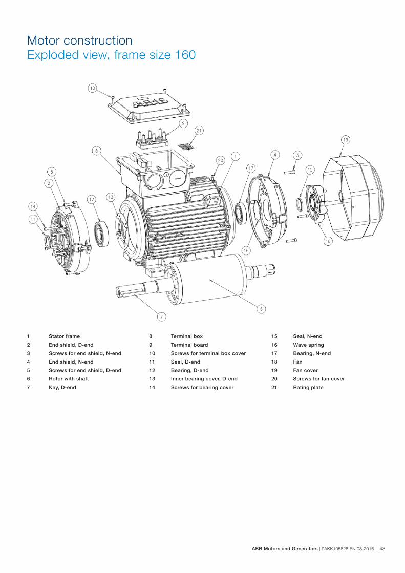
Motor constructionExploded view, frame size 160
1 Stator frame
2 End shield, D-end
3 Screws for end shield, N-end
4 End shield, N-end
5 Screws for end shield, D-end
6 Rotor with shaft
7 Key, D-end
8 Terminal box
9 Terminal board
10 Screws for terminal box cover
11 Seal, D-end
12 Bearing, D-end
13 Inner bearing cover, D-end
14 Screws for bearing cover
15 Seal, N-end
16 Wave spring
17 Bearing, N-end
18 Fan
19 Fan cover
20 Screws for fan cover
21 Rating plate
ABB Motors and Generators | 9AKK105828 EN 08-2016 43
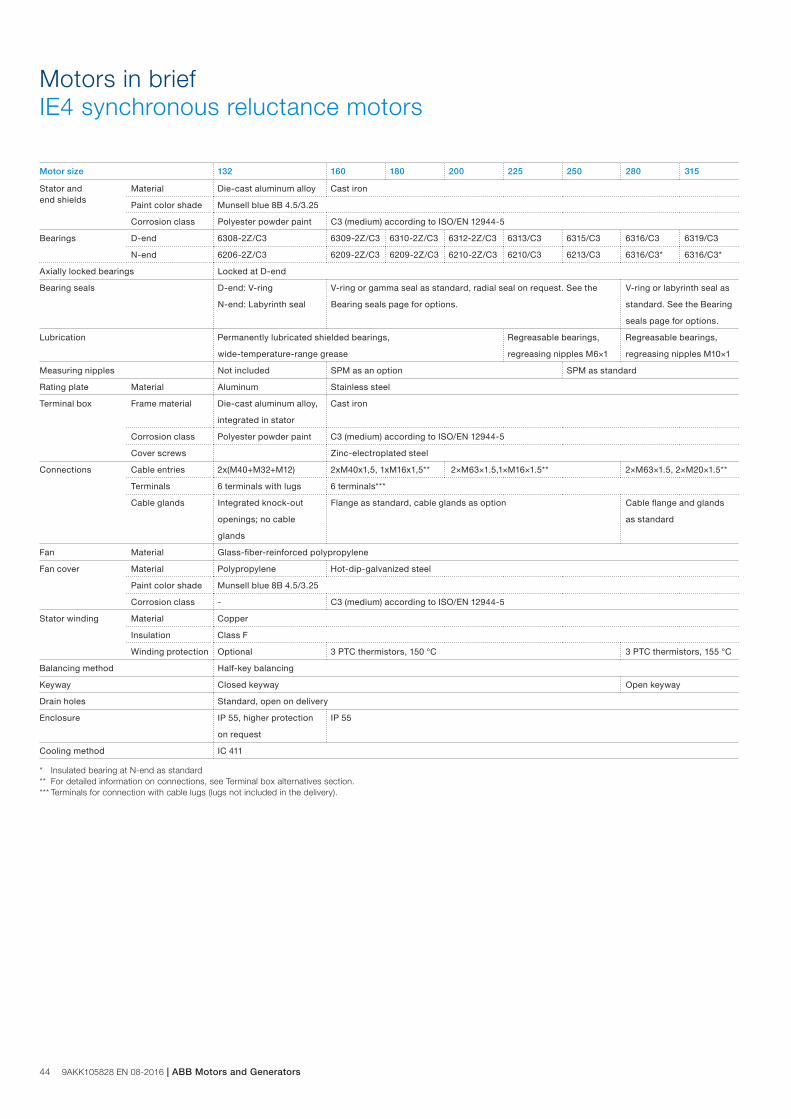
44 9AKK105828 EN 08-2016 | ABB Motors and Generators
Motors in brief IE4 synchronous reluctance motors
Motor size 132 160 180 200 225 250 280 315
Stator and end shields
Material Die-cast aluminum alloy Cast iron
Paint color shade Munsell blue 8B 4.5/3.25
Corrosion class Polyester powder paint C3 (medium) according to ISO/EN 12944-5
Bearings D-end 6308-2Z/C3 6309-2Z/C3 6310-2Z/C3 6312-2Z/C3 6313/C3 6315/C3 6316/C3 6319/C3
N-end 6206-2Z/C3 6209-2Z/C3 6209-2Z/C3 6210-2Z/C3 6210/C3 6213/C3 6316/C3* 6316/C3*
Axially locked bearings Locked at D-end
Bearing seals D-end: V-ring
N-end: Labyrinth seal
V-ring or gamma seal as standard, radial seal on request. See the
Bearing seals page for options.
V-ring or labyrinth seal as
standard. See the Bearing
seals page for options.
Lubrication Permanently lubricated shielded bearings, Regreasable bearings, Regreasable bearings,
wide-temperature-range grease regreasing nipples M6×1 regreasing nipples M10×1
Measuring nipples Not included SPM as an option SPM as standard
Rating plate Material Aluminum Stainless steel
Terminal box Frame material Die-cast aluminum alloy,
integrated in stator
Cast iron
Corrosion class Polyester powder paint C3 (medium) according to ISO/EN 12944-5
Cover screws Zinc-electroplated steel
Connections Cable entries 2x(M40+M32+M12) 2xM40x1,5, 1xM16x1,5** 2×M63×1.5,1×M16×1.5** 2×M63×1.5, 2×M20×1.5**
Terminals 6 terminals with lugs 6 terminals***
Cable glands Integrated knock-out
openings; no cable
glands
Flange as standard, cable glands as option Cable flange and glands
as standard
Fan Material Glass-fiber-reinforced polypropylene
Fan cover Material Polypropylene Hot-dip-galvanized steel
Paint color shade Munsell blue 8B 4.5/3.25
Corrosion class - C3 (medium) according to ISO/EN 12944-5
Stator winding Material Copper
Insulation Class F
Winding protection Optional 3 PTC thermistors, 150 °C 3 PTC thermistors, 155 °C
Balancing method Half-key balancing
Keyway Closed keyway Open keyway
Drain holes Standard, open on delivery
Enclosure IP 55, higher protection
on request
IP 55
Cooling method IC 411
* Insulated bearing at N-end as standard** For detailed information on connections, see Terminal box alternatives section.*** Terminals for connection with cable lugs (lugs not included in the delivery).
For your notes
ABB Motors and Generators | 9AKK105828 EN 08-2016 45
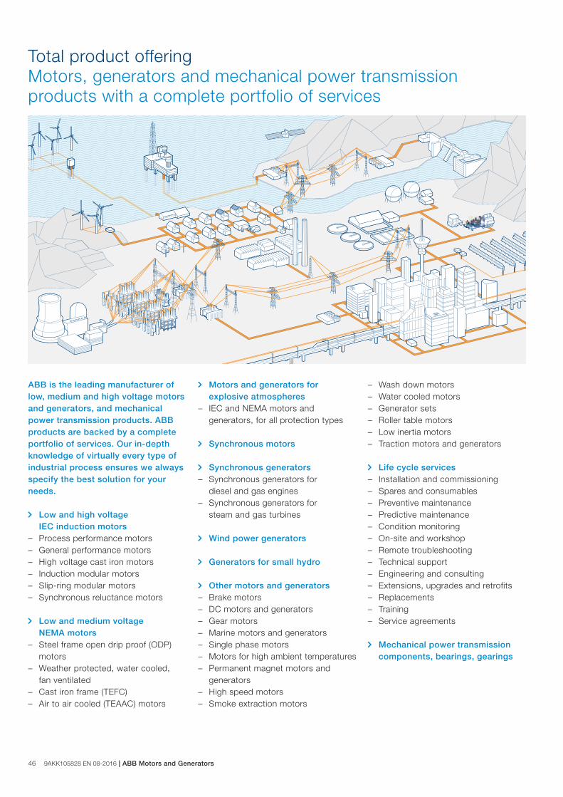
46 9AKK105828 EN 08-2016 | ABB Motors and Generators
Total product offeringMotors, generators and mechanical power transmission products with a complete portfolio of services
ABB is the leading manufacturer of low, medium and high voltage motors and generators, and mechanical power transmission products. ABB products are backed by a complete portfolio of services. Our in-depth knowledge of virtually every type of industrial process ensures we always specify the best solution for your needs.
Low and high voltage IEC induction motors – Process performance motors – General performance motors – High voltage cast iron motors – Induction modular motors – Slip-ring modular motors – Synchronous reluctance motors
Low and medium voltage
NEMA motors – Steel frame open drip proof (ODP)
motors – Weather protected, water cooled,
fan ventilated – Cast iron frame (TEFC) – Air to air cooled (TEAAC) motors
Motors and generators for explosive atmospheres – IEC and NEMA motors and
generators, for all protection types Synchronous motors
Synchronous generators – Synchronous generators for
diesel and gas engines – Synchronous generators for
steam and gas turbines Wind power generators
Generators for small hydro
Other motors and generators – Brake motors – DC motors and generators – Gear motors – Marine motors and generators – Single phase motors – Motors for high ambient temperatures – Permanent magnet motors and
generators – High speed motors – Smoke extraction motors
– Wash down motors – Water cooled motors – Generator sets – Roller table motors – Low inertia motors – Traction motors and generators
Life cycle services – Installation and commissioning – Spares and consumables – Preventive maintenance – Predictive maintenance – Condition monitoring – On-site and workshop – Remote troubleshooting – Technical support – Engineering and consulting – Extensions, upgrades and retrofits – Replacements – Training – Service agreements
Mechanical power transmission components, bearings, gearings
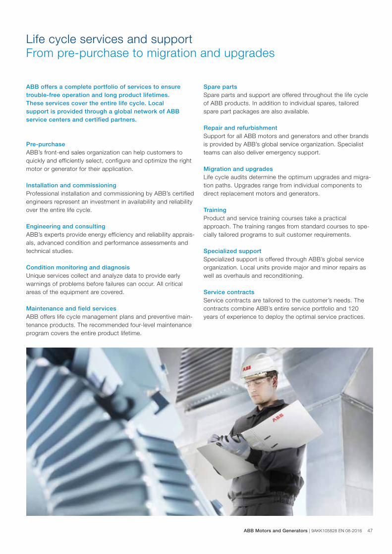
ABB Motors and Generators | 9AKK105828 EN 08-2016 47
Life cycle services and supportFrom pre-purchase to migration and upgrades
Pre-purchaseABB’s front-end sales organization can help customers to quickly and efficiently select, configure and optimize the right motor or generator for their application.
Installation and commissioningProfessional installation and commissioning by ABB’s certified engineers represent an investment in availability and reliability over the entire life cycle.
Engineering and consulting ABB’s experts provide energy efficiency and reliability apprais-als, advanced condition and performance assessments and technical studies.
Condition monitoring and diagnosisUnique services collect and analyze data to provide early warnings of problems before failures can occur. All critical areas of the equipment are covered. Maintenance and field servicesABB offers life cycle management plans and preventive main-tenance products. The recommended four-level maintenance program covers the entire product lifetime.
Spare partsSpare parts and support are offered throughout the life cycle of ABB products. In addition to individual spares, tailored spare part packages are also available.
Repair and refurbishmentSupport for all ABB motors and generators and other brands is provided by ABB’s global service organization. Specialist teams can also deliver emergency support.
Migration and upgradesLife cycle audits determine the optimum upgrades and migra-tion paths. Upgrades range from individual components to direct replacement motors and generators.
TrainingProduct and service training courses take a practical approach. The training ranges from standard courses to spe-cially tailored programs to suit customer requirements.
Specialized support Specialized support is offered through ABB’s global service organization. Local units provide major and minor repairs as well as overhauls and reconditioning.
Service contractsService contracts are tailored to the customer’s needs. The contracts combine ABB’s entire service portfolio and 120 years of experience to deploy the optimal service practices.
ABB offers a complete portfolio of services to ensure trouble-free operation and long product lifetimes. These services cover the entire life cycle. Local support is provided through a global network of ABB service centers and certified partners.
9A
KK
1058
28 E
N 0
8-20
16
Contact us
www.abb.com/motors&generators We reserve the right to make technical changes or modify
the contents of this document without prior notice. With
regard to purchase orders, the agreed particulars shall
prevail. ABB does not accept any responsibil ity what so ever
for potential errors or possible lack of information in this
document.
We reserve all rights in this document and in the subject
matter and il lustrations contained herein. Any reproduction,
disclosure to third parties or uti l ization of its contents – in
whole or in parts – is forbidden without prior written consent
of ABB.
© Copyright 2016 ABB.
All rights reserved.