Embed Size (px)
Citation preview
The Quality Connection
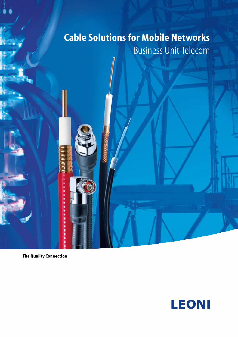
Cable Solutions for Mobile NetworksBusiness Unit Telecom
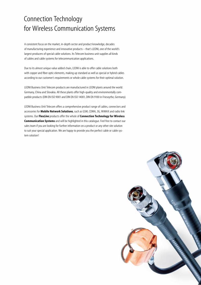
Connection Technology for Wireless Communication Systems
A consistent focus on the market, in-depth sector and product knowledge, decades
of manufacturing experience and innovative products – that‘s LEONI, one of the world‘s
largest producers of special cable solutions. Its Telecom business unit supplies all kinds
of cables and cable systems for telecommunication applications.
Due to its almost unique value added chain, LEONI is able to offer cable solutions both
with copper and fiber optic elements, making up standard as well as special or hybrid cables
according to our customer‘s requirements or whole cable systems for their optimal solution.
LEONI Business Unit Telecom products are manufactured in LEONI plants around the world:
Germany, China and Slovakia. All these plants offer high-quality and environmentally com -
patible products (DIN EN ISO 9001 and DIN EN ISO 14001, DIN EN 9100 in Friesoythe, Germany).
LEONI Business Unit Telecom offers a comprehensive product range of cables, connectors and
accessories for Mobile Network Solutions, such as GSM, CDMA, 3G, WiMAX and radio link
systems. Our FlexLine products offer the whole of Connection Technology for Wireless
Communication Systems and will be highlighted in this catalogue. Feel free to contact our
sales team if you are looking for further information on a product or any other site solution
to suit your special application. We are happy to provide you the perfect cable or cable sys-
tem solution !
LEONI 3
APAC Issue 5/2008
All FlexLine products are permanently enhanced
for our customers. Therefore this brochure is subject
to change and error. You will find the updated status
in our datasheets at www.leoni-telecom.com
Fields of Application 4
FlexLine® Coaxial Cables 6
FlexLine® Coaxial Cables
with corrugated outer conductor 7
FlexLine® Coaxial Cables
with braided outer conductor 25
FlexLine® Coaxial Stripping Tools 36
FlexLine® Coaxial Connectors, Adaptors,
Attenuators and Terminations 38
FlexLine® Coaxial Jumper Cables 42
FlexLine® Coaxial Lightning Protection 50
FlexLine® Coaxial Power Splitters 52
FlexLine® Coaxial Couplers 53
FlexLine® Coaxial Antennas 54
FlexLine® Coaxial Grounding Kits 55
FlexLine® Symmetric Cables 58
Accessories for FlexLine®
Installation Material for FlexLine® 68
Insulation and Weatherproofing for FlexLine® 70
Hoisting Grips for FlexLine® 72
Technical Data 73
Quality and Environment 78
Sales Network 79
Contents
4 LEONI
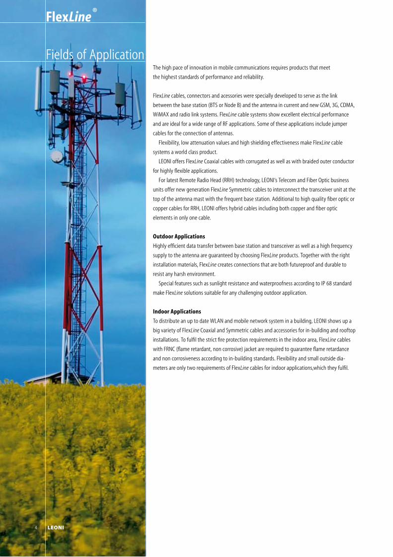
The high pace of innovation in mobile communications requires products that meet
the highest standards of performance and reliability.
FlexLine cables, connectors and acessories were specially developed to serve as the link
between the base station (BTS or Node B) and the antenna in current and new GSM, 3G, CDMA,
WiMAX and radio link systems. FlexLine cable systems show excellent electrical performance
and are ideal for a wide range of RF applications. Some of these applications include jumper
cables for the connection of antennas.
Flexibility, low attenuation values and high shielding effectiveness make FlexLine cable
systems a world class product.
LEONI offers FlexLine Coaxial cables with corrugated as well as with braided outer conductor
for highly flexible applications.
For latest Remote Radio Head (RRH) technology, LEONI‘s Telecom and Fiber Optic business
units offer new generation FlexLine Symmetric cables to interconnect the transceiver unit at the
top of the antenna mast with the frequent base station. Additional to high quality fiber optic or
copper cables for RRH, LEONI offers hybrid cables including both copper and fiber optic
elements in only one cable.
Outdoor Applications
Highly efficient data transfer between base station and transceiver as well as a high frequency
supply to the antenna are guaranteed by choosing FlexLine products. Together with the right
installation materials, FlexLine creates connections that are both futureproof and durable to
resist any harsh environment.
Special features such as sunlight resistance and waterproofness according to IP 68 standard
make FlexLine solutions suitable for any challenging outdoor application.
Indoor Applications
To distribute an up to date WLAN and mobile network system in a building, LEONI shows up a
big variety of FlexLine Coaxial and Symmetric cables and accessories for in-building and rooftop
installations. To fulfil the strict fire protection requirements in the indoor area, FlexLine cables
with FRNC (flame retardant, non corrosive) jacket are required to guarantee flame retardance
and non corrosiveness according to in-building standards. Flexibility and small outside dia-
meters are only two requirements of FlexLine cables for indoor applications,which they fulfil.
Fields of Application
FlexLine ®
4 LEONI
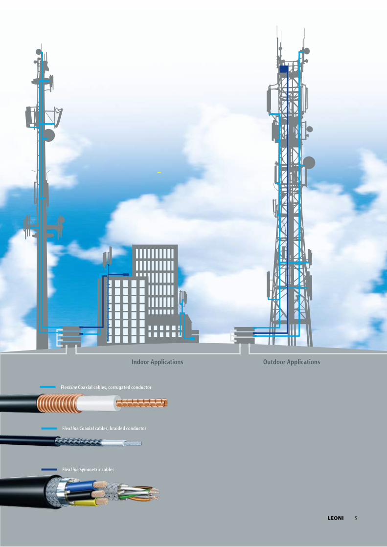
Outdoor ApplicationsIndoor Applications
FlexLine Coaxial cables, corrugated conductor
FlexLine Coaxial cables, braided conductor
FlexLine Symmetric cables
LEONI 5
6 LEONI
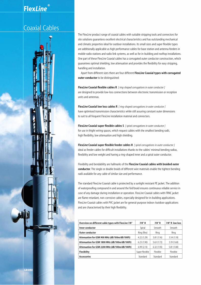
The FlexLine product range of coaxial cables with suitable stripping tools and connectors for
site solutions guarantees excellent electrical characteristics and has outstanding mechanical
and climatic properties ideal for outdoor installations. Its small sizes and super flexible types
are additionally applicable as high performance cables for base station and antenna feeders in
mobile radio stations and radio link systems, as well as for in-building and rooftop installations.
One part of these FlexLine Coaxial cables has a corrugated outer conductor construction, which
guarantees optimal shielding, low attenuation and provides the flexibility for easy stripping,
handling and installation.
Apart from different sizes there are four different FlexLine Coaxial types with corrugated
outer conductor to be distinguished:
FlexLine Coaxial flexible cables R [ ring-shaped corrugations in outer conductor ]
are designed to provide low-loss connections between electronic transmission or reception
units and antennas.
FlexLine Coaxial low loss cables R [ ring-shaped corrugations in outer conductor ]
have optimised transmission characteristics while still assuring constant outer dimensions
to suit to all frequent FlexLine installation material and connectors.
FlexLine Coaxial super flexible cables S [ spiral corrugations in outer conductor ]
for use in thight wiring spaces, which request cables with the smallest bending radii,
high flexibility, low attenuation and high shielding.
FlexLine Coaxial super flexible feeder cables H [ spiral corrugations in outer conductor ]
ideal as feeder cables for difficult installations thanks to the cables‘ minimal bending radius,
flexibility and low weight and having a ring-shaped inner and a spiral outer conductor.
Flexibility and bendability are hallmarks of the FlexLine Coaxial cables with braided outer
conductor. The single or double braids of different wire materials enable the tightest bending
radii available for any cable of similar size and performance.
The standard FlexLine Coaxial cable is protected by a sunlight resistant PE jacket. The addition
of waterproofing compound in and around the foil/braid ensures continuous reliable service in
case of any damage during installation or operation. FlexLine Coaxial cables with FRNC jacket
are flame retardant, non-corrosive cables, especially designed for in-building applications.
FlexLine Coaxial cables with PVC jacket are for general-purpose indoor-/outdoor-applications
and are characterised by their high flexibility.
Overview on different cable types with FlexLine 7/8” 7/8" H 7/8" R 7/8" R low loss
Inner conductor Spiral Smooth Smooth
Outer conductor Ring (flex) Ring Ring
Attenuation for GSM 900 MHz (dB/100m/dB/100ft) 4.22 (1.29) 3.81 (1.16) 3.54 (1.10)
Attenuation for GSM 1800 MHz (dB/100m/dB/100ft) 6.23 (1.90) 5.63 (1.72) 5.19 (1.60)
Attenuation for GSM 2200 MHz (dB/100m/dB/100ft) 6.99 (2.13) 6.32 (1.93) 5.81 (1.80)
Flexibility Super flexible Flexible Flexible
Accessories Standard Standard Standard
Coaxial Cables
FlexLine ®
6 LEONI
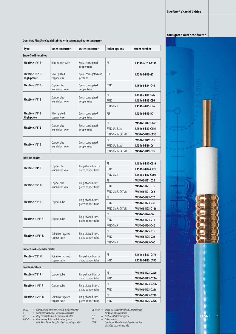
Type Inner conductor Outer conductor Jacket options Order number
Superflexible cables
FlexLine 1/6“ S Bare copper wire Spiral corrugated copper tube
PE L45466- B13-C116
FlexLine 1/6“ S High power
Silver platedcopper wire
Spiral corrugated cop-per tube
FEP L45466-B13-G7
FlexLine 1/5“ S Copper cladaluminium wire
Spiral corrugated copper tube
FRNC L45466-B14-C46
FlexLine 1/4“ SCopper cladaluminium wire
Spiral corrugated copper tube
PE L45466-B15-C76
FRNC L45466-B15-C36
FRNC-CMR L45466-B15-C96
FlexLine 1/4“ S High power
Silver platedcopper wire
Spiral corrugated copper tube
FEP L45466-B15-N7
FlexLine 3/8“ SCopper cladaluminium wire
Spiral corrugated copper tube
PE V45466-B17-C146
FRNC-UL listed L45466-B17-C116
FRNC-CMR / CATVR V45466-B17-C156
FlexLine 1/2“ SCopper cladaluminium wire
Spiral corrugated copper tube
PE V45466-B19-C56
FRNC-UL listed L45466-B20-C6
FRNC-CMR / CATVR V45466-B19-C76
Flexible cables
FlexLine 1/4“ RCopper cladaluminium wire
Ring-shaped corru-gated copper tube
PE L45466-B17-C216
FRNC L45466-B17-C226
FRNC-CMR L45466-B17-C206
FlexLine 1/2“ RCopper cladaluminium wire
Ring-shaped corru-gated copper tube
PE V45466-B21-C26
FRNC V45466-B21-C36
FRNC-CMR / CATVR V45466-B21-C66
FlexLine 7/8“ R Copper tubeRing-shaped corru-gated copper tube
PE V45466-B23-C26
FRNC V45466-B23-C36
FRNC-CMR / CATVR V45466-B23-C126
FlexLine 1 1/4“ R Copper tubeRing-shaped corru-gated copper tube
PE V45466-B24-C6
FRNC V45466-B24-C16
FRNC-CMR V45466-B24-C46
FlexLine 1 5/8“ RSpiral corrugated copper tube
Ring-shaped corru-gated copper tube
PE V45466-B25-C16
FRNC V45466-B25-C26
FRNC-CMR V45466-B25-C66
Superflexible feeder cables
FlexLine 7/8“ H Spiral corrugated copper tube
Ring-shaped corru-gated copper tube
PE L45466-B23-C176
FRNC L45466-B23-C186
Low loss cables
FlexLine 7/8“ R Copper tube Ring-shaped corru-gated copper tube
PE V45466-B23-C226
FRNC V45466-B23-C236
FlexLine 1 1/4“ R Copper tube Ring-shaped corru-gated copper tube
PE V45466-B23-C206
FRNC V45466-B23-C216
FlexLine 1 5/8“ R Spiral corrugated copper tube
Ring-shaped corru-gated copper tube
PE V45466-B25-C216
FRNC V45466-B25-C226
FRNC = Flame Retardant Non Corosive (halogene free) S = Spiral corrugation of the outer conductor R = Ring corrugation of the outer conductorCATVR = Community Antenna Television System with Riser Flame Test,classified according to NEC
UL listed = Listed by UL (Underwriters Laboratories) for Wires, MiscellaneousFEP = PerfluorethylenepropylenePE = Polyethylene CMR = Conductor Metallic with Riser Flame Test, classified according to NEC
Overview FlexLine Coaxial cables with corrugated outer conductor
FlexLine® Coaxial Cables
corrugated outer conductor
LEONI 7
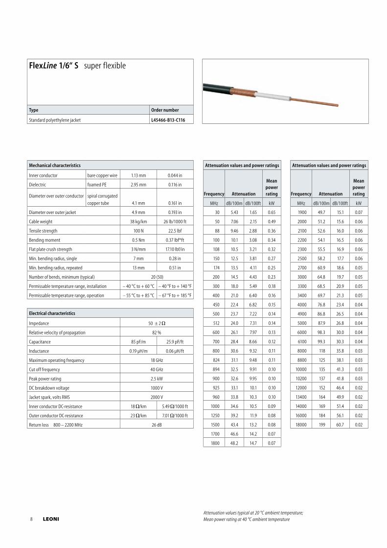
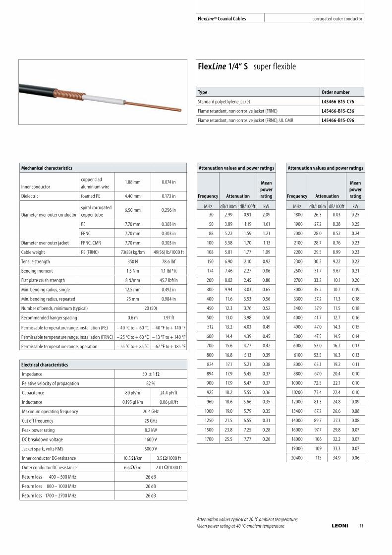
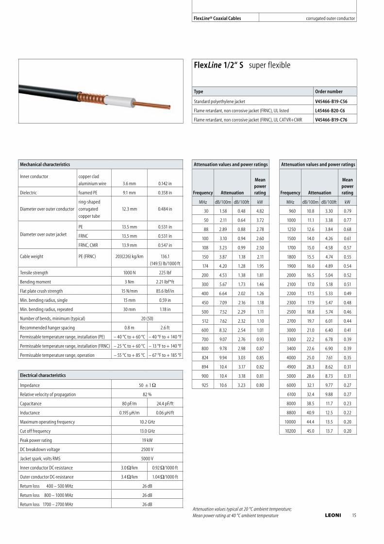
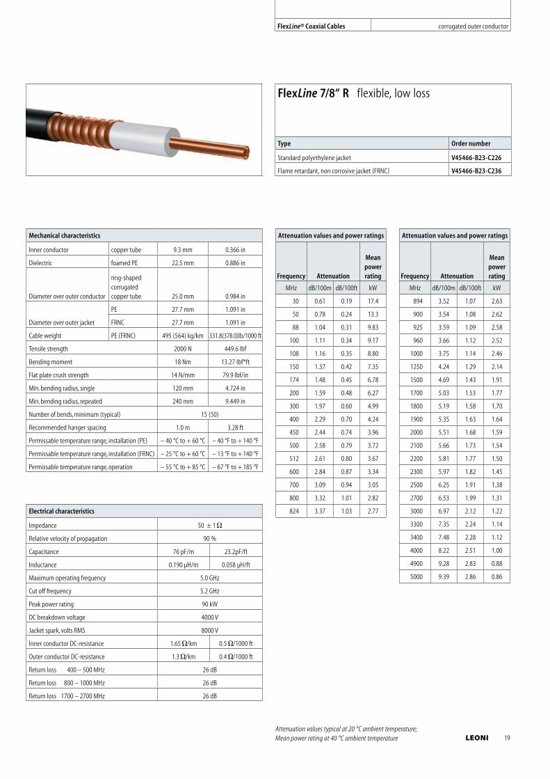
Mechanical characteristics
Inner conductor bare copper wire 1.13 mm 0.044 in
Dielectric foamed PE 2.95 mm 0.116 in
Diameter over outer conductor spiral corrugated
copper tube 4.1 mm 0.161 in
Diameter over outer jacket 4.9 mm 0.193 in
Cable weight 38 kg/km 26 lb/1000 ft
Tensile strength 100 N 22.5 lbf
Bending moment 0.5 Nm 0.37 lbf*ft
Flat plate crush strength 3 N/mm 17.10 lbf/in
Min. bending radius, single 7 mm 0.28 in
Min. bending radius, repeated 13 mm 0.51 in
Number of bends, minimum (typical) 20 (50)
Permissable temperature range, installation – 40 °C to + 60 °C – 40 °F to + 140 °F
Permissable temperature range, operation – 55 °C to + 85 °C – 67 °F to + 185 °F
Electrical characteristics
Impedance 50 ± 2
Relative velocity of propagation 82 %
Capacitance 85 pF/m 25.9 pF/ft
Inductance 0.19 μH/m 0.06 μH/ft
Maximum operating frequency 18 GHz
Cut off frequency 40 GHz
Peak power rating 2.5 kW
DC breakdown voltage 1000 V
Jacket spark, volts RMS 2000 V
Inner conductor DC-resistance 18 /km 5.49 /1000 ft
Outer conductor DC-resistance 23 /km 7.01 /1000 ft
Return loss 800 – 2200 MHz 26 dB
Attenuation values and power ratings
Frequency Attenuation
Meanpowerrating
MHz dB/100m dB/100ft kW
30 5.43 1.65 0.65
50 7.06 2.15 0.49
88 9.46 2.88 0.36
100 10.1 3.08 0.34
108 10.5 3.21 0.32
150 12.5 3.81 0.27
174 13.5 4.11 0.25
200 14.5 4.43 0.23
300 18.0 5.49 0.18
400 21.0 6.40 0.16
450 22.4 6.82 0.15
500 23.7 7.22 0.14
512 24.0 7.31 0.14
600 26.1 7.97 0.13
700 28.4 8.66 0.12
800 30.6 9.32 0.11
824 31.1 9.48 0.11
894 32.5 9.91 0.10
900 32.6 9.95 0.10
925 33.1 10.1 0.10
960 33.8 10.3 0.10
1000 34.6 10.5 0.09
1250 39.2 11.9 0.08
1500 43.4 13.2 0.08
1700 46.6 14.2 0.07
1800 48.2 14.7 0.07
Attenuation values and power ratings
Frequency Attenuation
Meanpowerrating
MHz dB/100m dB/100ft kW
1900 49.7 15.1 0.07
2000 51.2 15.6 0.06
2100 52.6 16.0 0.06
2200 54.1 16.5 0.06
2300 55.5 16.9 0.06
2500 58.2 17.7 0.06
2700 60.9 18.6 0.05
3000 64.8 19.7 0.05
3300 68.5 20.9 0.05
3400 69.7 21.3 0.05
4000 76.8 23.4 0.04
4900 86.8 26.5 0.04
5000 87.9 26.8 0.04
6000 98.3 30.0 0.04
6100 99.3 30.3 0.04
8000 118 35.8 0.03
8800 125 38.1 0.03
10000 135 41.3 0.03
10200 137 41.8 0.03
12000 152 46.4 0.02
13400 164 49.9 0.02
14000 169 51.4 0.02
16000 184 56.1 0.02
18000 199 60.7 0.02
Attenuation values typical at 20 °C ambient temperature; Mean power rating at 40 °C ambient temperature
FlexLine 1/6“ S super flexible
Type Order number
Standard polyethylene jacket L45466-B13-C116
8 LEONI
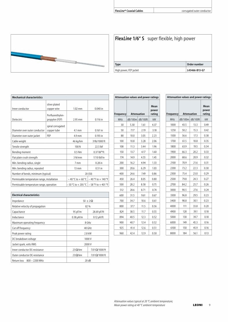
Mechanical characteristics
Inner conductor
silver plated
copper wire 1.02 mm 0.040 in
Dielectric
Perfluorethylen-
propylen (FEP) 2.95 mm 0.116 in
Diameter over outer conductor
spiral corrugated
copper tube 4.1 mm 0.161 in
Diameter over outer jacket FEP 4.9 mm 0.193 in
Cable weight 46 kg/km 31lb/1000 ft
Tensile strength 100 N 22.5 lbf
Bending moment 0.5 Nm 0.37 lbf*ft
Flat plate crush strength 3 N/mm 17.10 lbf/in
Min. bending radius, single 7 mm 0.28 in
Min. bending radius, repeated 13 mm 0.51 in
Number of bends, minimum (typical) 20 (50)
Permissable temperature range, installation – 40 °C to + 60 °C – 40 °F to + 140 °F
Permissable temperature range, operation – 50 °C to + 205 °C – 58 °F to + 401 °F
Electrical characteristics
Impedance 50 ± 2
Relative velocity of propagation 82 %
Capacitance 95 pF/m 28.69 pF/ft
Inductance 0.38 μH/m 0.12 μH/ft
Maximum operating frequency 8 GHz
Cut off frequency 40 GHz
Peak power rating 2.8 kW
DC breakdown voltage 1000 V
Jacket spark, volts RMS 2000 V
Inner conductor DC-resistance 23 /km 7.01 /1000 ft
Outer conductor DC-resistance 23 /km 7.01 /1000 ft
Return loss 800 – 2200 MHz 20 dB
Attenuation values and power ratings
Frequency Attenuation
Meanpowerrating
MHz dB/100m dB/100ft kW
30 5.30 1.61 4.37
50 7.17 2.19 3.18
88 10.0 3.05 2.23
100 10.8 3.28 2.06
108 11.3 3.44 1.96
150 13.7 4.17 1.60
174 14.9 4.55 1.45
200 16.2 4.94 1.33
300 20.6 6.29 1.03
400 24.6 7.49 0.86
450 26.4 8.05 0.80
500 28.2 8.58 0.75
512 28.6 8.71 0.74
600 31.5 9.61 0.67
700 34.7 10.6 0.61
800 37.7 11.5 0.56
824 38.5 11.7 0.55
894 40.5 12.3 0.52
900 40.7 12.4 0.52
925 41.4 12.6 0.51
960 42.4 12.9 0.50
Attenuation values and power ratings
Frequency Attenuation
Meanpowerrating
MHz dB/100m dB/100ft kW
1000 43.5 13.3 0.49
1250 50.2 15.3 0.42
1500 56.6 17.3 0.38
1700 61.5 18.8 0.35
1800 63.9 19.5 0.34
1900 66.3 20.2 0.33
2000 68.6 20.9 0.32
2100 70.9 21.6 0.31
2200 73.2 22.3 0.30
2300 75.4 23.0 0.29
2500 79.8 24.3 0.27
2700 84.2 25.7 0.26
3000 90.5 27.6 0.24
3300 96.8 29.5 0.23
3400 98.8 30.1 0.23
4000 111 33.8 0.20
4900 128 39.1 0.18
5000 130 39.7 0.18
6000 149 45.3 0.16
6100 150 45.9 0.16
8000 184 56.1 0.13
Attenuation values typical at 20 °C ambient temperature; Mean power rating at 40 °C ambient temperature
FlexLine 1/6“ S super flexible, high power
Type Order number
High power, FEP jacket L45466-B13-G7
FlexLine® Coaxial Cables corrugated outer conductor
LEONI 9
Mechanical characteristics
Inner conductor
copper clad
aluminium wire 1.57 mm 0.062 in
Dielectric foamed PE 3.9 mm 0.154 in
Diameter over outer conductor
spiral corrugated
copper tube5.7 mm 0.224 in
Diameter over outer jacket FRNC 6.9 mm 0.272 in
Cable weight FRNC 54.6 kg/km 36.6 lb/1000 ft
Tensile strength 250 N 56.2 lbf
Bending moment 1 Nm 0.73 lbf*ft
Flat plate crush strength 6 N/mm 34.3 lbf/in
Min. bending radius, single 8 mm 0.31 in
Min. bending radius, repeated 15 mm 0.412 in
Number of bends, minimum (typical) 15 (50)
Permissable temperature range, installation (FRNC) – 25 °C to + 60 °C – 13 °F to + 140 °F
Permissable temperature range, operation – 40 °C to + 85 °C – 40 °F to + 185 °F
Electrical characteristics
Impedance 50 ± 1
Relative velocity of propagation 82 %
Capacitance 80 pF/m 24.4 pF/ft
Inductance 0.19 μH/m 0.06 μH/ft
Maximum operating frequency 8 GHz
Cut off frequency 25 GHz
Peak power rating 4.2 kW
DC breakdown voltage 1300 V
Jacket spark, volts RMS 1500 V
Inner conductor DC-resistance 14 /km 4.27 /1000 ft
Outer conductor DC-resistance 10 /km 3.05 /1000 ft
Return loss 400 – 500 MHz 26 dB
Return loss 800 – 1000 MHz 26 dB
Return loss 1700 – 2700 MHz 26 dB
Attenuation values typical at 20 °C ambient temperature; Mean power rating at 40 °C ambient temperature
Attenuation values and power ratings
Frequency Attenuation
Meanpowerrating
MHz dB/100m dB/100ft kW
30 3.97 1.21 1.31
50 5.16 1.57 1.00
88 6.89 2.10 0.75
100 7.35 2.24 0.70
108 7.65 2.33 0.67
150 9.06 2.76 0.57
174 9.79 2.98 0.53
200 10.5 3.21 0.49
300 13.0 3.96 0.40
400 15.1 4.61 0.34
450 16.1 4.90 0.32
500 17.0 5.19 0.30
512 17.2 5.25 0.30
600 18.7 5.71 0.28
700 20.4 6.20 0.26
800 21.9 6.66 0.24
824 22.2 6.77 0.24
894 23.2 7.07 0.23
900 23.3 7.10 0.22
925 23.6 7.21 0.22
Attenuation values and power ratings
Frequency Attenuation
Meanpowerrating
MHz dB/100m dB/100ft kW
960 24.1 7.35 0.22
1000 24.7 7.52 0.21
1250 27.8 8.49 0.19
1500 30.8 9.38 0.17
1700 33.0 10.0 0.16
1800 34.0 10.4 0.16
1900 35.1 10.7 0.15
2000 36.1 11.0 0.15
2100 37.1 11.3 0.14
2200 38.0 11.6 0.14
2300 39.0 11.9 0.14
2500 40.9 12.5 0.13
2700 42.7 13.0 0.13
3000 45.3 13.8 0.12
3300 47.8 14.6 0.11
3400 48.7 14.8 0.11
4000 53.4 16.3 0.10
4900 60.1 18.3 0.09
5000 60.8 18.5 0.09
6000 67.7 20.6 0.08
6100 68.3 20.8 0.08
8000 80.3 24.5 0.07
FlexLine 1/5“ S super flexible
Type Order number
Flame retardant, non corrosive jacket (FRNC) L45466-B14-C46
10 LEONI
Mechanical characteristics
Inner conductor
copper clad
aluminium wire1.88 mm 0.074 in
Dielectric foamed PE 4.40 mm 0.173 in
Diameter over outer conductor
spiral corrugated
copper tube6.50 mm 0.256 in
Diameter over outer jacket
PE 7.70 mm 0.303 in
FRNC 7.70 mm 0.303 in
FRNC, CMR 7.70 mm 0.303 in
Cable weight PE (FRNC) 73(83) kg/km 49(56) lb/1000 ft
Tensile strength 350 N 78.6 lbf
Bending moment 1.5 Nm 1.1 lbf*ft
Flat plate crush strength 8 N/mm 45.7 lbf/in
Min. bending radius, single 12.5 mm 0.492 in
Min. bending radius, repeated 25 mm 0.984 in
Number of bends, minimum (typical) 20 (50)
Recommended hanger spacing 0.6 m 1.97 ft
Permissable temperature range, installation (PE) – 40 °C to + 60 °C – 40 °F to + 140 °F
Permissable temperature range, installation (FRNC) – 25 °C to + 60 °C – 13 °F to + 140 °F
Permissable temperature range, operation – 55 °C to + 85 °C – 67 °F to + 185 °F
Electrical characteristics
Impedance 50 ± 1
Relative velocity of propagation 82 %
Capacitance 80 pF/m 24.4 pF/ft
Inductance 0.195 μH/m 0.06 μH/ft
Maximum operating frequency 20.4 GHz
Cut off frequency 25 GHz
Peak power rating 8.2 kW
DC breakdown voltage 1600 V
Jacket spark, volts RMS 5000 V
Inner conductor DC-resistance 10.5 /km 3.5 /1000 ft
Outer conductor DC-resistance 6.6 /km 2.01 /1000 ft
Return loss 400 – 500 MHz 26 dB
Return loss 800 – 1000 MHz 26 dB
Return loss 1700 – 2700 MHz 26 dB
Attenuation values and power ratings
Frequency Attenuation
Meanpowerrating
MHz dB/100m dB/100ft kW
30 2.99 0.91 2.09
50 3.89 1.19 1.61
88 5.22 1.59 1.21
100 5.58 1.70 1.13
108 5.81 1.77 1.09
150 6.90 2.10 0.92
174 7.46 2.27 0.86
200 8.02 2.45 0.80
300 9.94 3.03 0.65
400 11.6 3.53 0.56
450 12.3 3.76 0.52
500 13.0 3.98 0.50
512 13.2 4.03 0.49
600 14.4 4.39 0.45
700 15.6 4.77 0.42
800 16.8 5.13 0.39
824 17.1 5.21 0.38
894 17.9 5.45 0.37
900 17.9 5.47 0.37
925 18.2 5.55 0.36
960 18.6 5.66 0.35
1000 19.0 5.79 0.35
1250 21.5 6.55 0.31
1500 23.8 7.25 0.28
1700 25.5 7.77 0.26
Attenuation values and power ratings
Frequency Attenuation
Meanpowerrating
MHz dB/100m dB/100ft kW
1800 26.3 8.03 0.25
1900 27.2 8.28 0.25
2000 28.0 8.52 0.24
2100 28.7 8.76 0.23
2200 29.5 8.99 0.23
2300 30.3 9.22 0.22
2500 31.7 9.67 0.21
2700 33.2 10.1 0.20
3000 35.2 10.7 0.19
3300 37.2 11.3 0.18
3400 37.9 11.5 0.18
4000 41.7 12.7 0.16
4900 47.0 14.3 0.15
5000 47.5 14.5 0.14
6000 53.0 16.2 0.13
6100 53.5 16.3 0.13
8000 63.1 19.2 0.11
8800 67.0 20.4 0.10
10000 72.5 22.1 0.10
10200 73.4 22.4 0.10
12000 81.3 24.8 0.09
13400 87.2 26.6 0.08
14000 89.7 27.3 0.08
16000 97.7 29.8 0.07
18000 106 32.2 0.07
19000 109 33.3 0.07
20400 115 34.9 0.06
Attenuation values typical at 20 °C ambient temperature; Mean power rating at 40 °C ambient temperature
FlexLine 1/4“ S super flexible
Type Order number
Standard polyethylene jacket L45466-B15-C76
Flame retardant, non corrosive jacket (FRNC) L45466-B15-C36
Flame retardant, non corrosive jacket (FRNC), UL CMR L45466-B15-C96
FlexLine® Coaxial Cables corrugated outer conductor
LEONI 11
Mechanical characteristics
Inner conductor silver plated
copper wire 1.8 mm 0.071 in
Dielectric foamed
Fluorethylen 4.4 mm 0.173 in
Diameter over outer conductor spiral corrugated
copper tube 6.4 mm 0.252 in
Diameter over outer jacket Perfluoethylen-
propylen (FEP) 7.4 mm 0.291 in
Cable weight 102 kg/km 68.4 lb/1000 ft
Tensile strength 100 N 22.5 lbf
Bending moment 1.5 Nm 1.10 lbf*ft
Flat plate crush strength 8 N/mm 45.60 lbf/in
Min. bending radius, single 12.5 mm 0.492 in
Min. bending radius, repeated 25 mm 0.984 in
Number of bends, minimum (typical) 20 (50)
Permissable temperature range, installation – 40 °C to + 60 °C – 40 °F to + 140 °F
Permissable temperature range, operation – 200 °C to + 205 °C – 328 °F to + 401 °F
Electrical characteristics
Impedance 50 ± 2
Relative velocity of propagation 82 %
Capacitance 78 pF/m 23.8 pF/ft
Inductance 0.3 μH/m 0.09 μH/ft
Maximum operating frequency 8 GHz
Cut off frequency 25.4 GHz
Peak power rating 6.4 kW
DC breakdown voltage 1600 V
Jacket spark, volts RMS 2000 V
Inner conductor DC-resistance 6.9 /km 2.10 /1000 ft
Outer conductor DC-resistance 5.0 /km 1.52 /1000 ft
Return loss 800 – 2200 MHz 20 dB
Attenuation values and power ratings
Frequency Attenuation
Meanpowerrating
MHz dB/100m dB/100ft kW
0.5 0.06 0.02 6.40
1 0.24 0.07 6.40
1.5 0.38 0.12 6.40
2 0.50 0.15 6.40
10 1.62 0.49 6.40
20 2.47 0.75 5.49
30 3.14 0.96 4.59
50 4.23 1.29 3.67
88 5.85 1.78 2.87
100 6.30 1.92 2.71
108 6.58 2.01 2.62
150 7.94 2.42 2.27
174 8.65 2.64 2.13
200 9.37 2.86 2.00
300 11.9 3.61 1.67
400 14.0 4.28 1.48
450 15.1 4.59 1.40
500 16.0 4.88 1.34
512 16.3 4.95 1.32
600 17.9 5.45 1.24
700 19.6 5.98 1.15
800 21.3 6.48 1.09
824 21.7 6.60 1.08
Attenuation values and power ratings
Frequency Attenuation
Meanpowerrating
MHz dB/100m dB/100ft kW
894 22.8 6.94 1.04
900 22.9 6.97 1.03
925 23.2 7.08 1.02
960 23.8 7.25 1.01
1000 24.4 7.43 0.99
1250 28.0 8.54 0.90
1500 31.4 9.58 0.83
1700 34.0 10.4 0.78
1800 35.3 10.8 0.76
1900 36.6 11.1 0.75
2000 37.8 11.5 0.73
2100 39.0 11.9 0.71
2200 40.2 12.3 0.70
2300 41.4 12.6 0.69
2500 43.7 13.3 0.66
2700 46.0 14.0 0.64
3000 49.3 15.0 0.61
3300 52.6 16.0 0.59
3400 53.6 16.3 0.58
4000 59.9 18.2 0.54
4900 68.8 21.0 0.49
5000 69.8 21.3 0.49
6000 79.3 24.2 0.45
6100 80.2 24.5 0.45
8000 97.4 29.7 0.40
Attenuation values typical at 20 °C ambient temperature; Mean power rating at 40 °C ambient temperature
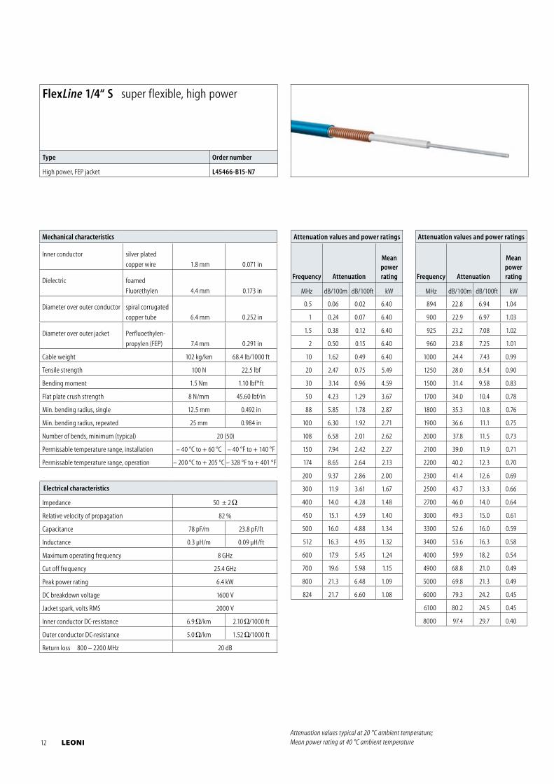
FlexLine 1/4“ S super flexible, high power
Type Order number
High power, FEP jacket L45466-B15-N7
12 LEONI
Electrical characteristics
Impedance 50 ± 1
Relative velocity of propagation 82 %
Capacitance 80 pF/m 24.4 pF/ft
Inductance 0.195 μH/m 0.06 μH/ft
Maximum operating frequency 15.8 GHz
Cut off frequency 19 GHz
Peak power rating 13 kW
DC breakdown voltage 2200 V
Jacket spark, volts RMS 5000 V
Inner conductor DC-resistance 5.95 /km 1.82 /1000 ft
Outer conductor DC-resistance 3.5 /km 1.07 /1000 ft
Return loss 400 – 500 MHz 26 dB
Return loss 800 – 1000 MHz 26 dB
Return loss 1700 – 2700 MHz 26 dB
Mechanical characteristics
Inner conductor copper wire 2.38 mm 0.094 in
Dielectric foamed PE 6.4 mm 0.252 in
Diameter over outer conductor ring-shaped corrugated copper tube 7.5 mm 0.295 in
Diameter over outer jacket
PE 8.8 mm 0.346 in
FRNC 8.7 mm 0.343 in
FRNC, CMR 8.7 mm 0.343 in
Cable weight PE (FRNC) 102 (110) kg/km 69(74.4) lb/1000 ft
Tensile strength 600 N 135 lbf
Bending moment 2 Nm 1.47 lbf*ft
Flat plate crush strength 10 N/mm 57 lbf/in
Min. bending radius, single 40 mm 1.57 in
Min. bending radius, repeated 120 mm 4.72 in
Number of bends, minimum (typical) 15 (50)
Recommended hanger spacing 0.6 m 1.97 ft
Permissable temperature range, installation (PE) – 40 °C to + 60 °C – 40 °F to + 140 °F
Permissable temperature range, installation (FRNC) – 25 °C to + 60 °C – 13 °F to + 140 °F
Permissable temperature range, operation – 55 °C to + 85 °C – 67 °F to + 185 °F
Attenuation values and power ratings
Frequency Attenuation
Meanpowerrating
MHz dB/100m dB/100ft kW
30 2.29 0.70 3.30
50 2.97 0.91 2.54
88 3.98 1.21 1.91
100 4.25 1.30 1.79
108 4.43 1.35 1.72
150 5.25 1.60 1.45
174 5.68 1.73 1.34
200 6.11 1.86 1.25
300 7.57 2.31 1.01
400 8.82 2.69 0.87
450 9.39 2.86 0.82
500 9.94 3.03 0.77
512 10.1 3.07 0.77
600 11.0 3.34 0.71
700 11.9 3.63 0.65
800 12.8 3.91 0.61
824 13.0 3.97 0.60
894 13.6 4.15 0.57
900 13.7 4.17 0.57
925 13.9 4.23 0.56
960 14.2 4.32 0.55
1000 14.5 4.42 0.54
1250 16.4 5.00 0.48
1500 18.2 5.54 0.43
1700 19.5 5.94 0.40
Attenuation values and power ratings
Frequency Attenuation
Meanpowerrating
MHz dB/100m dB/100ft kW
1800 20.1 6.14 0.39
1900 20.8 6.33 0.38
2000 21.4 6.51 0.37
2100 22.0 6.70 0.36
2200 22.6 6.88 0.35
2300 23.1 7.05 0.34
2500 24.3 7.40 0.33
2700 25.4 7.74 0.31
3000 27.0 8.23 0.30
3300 28.5 8.70 0.79
3400 29.0 8.85 0.28
4000 32.0 9.74 0.25
4900 36.1 11.0 0.22
5000 36.5 11.1 0.22
6000 40.8 12.4 0.20
6100 41.2 12.5 0.20
8000 48.6 14.8 0.17
8800 51.6 15.7 0.16
10000 55.9 17.1 0.15
10200 56.7 17.3 0.15
12000 62.8 19.2 0.13
13400 67.5 20.6 0.12
14000 69.4 21.2 0.12
16000 75.7 23.1 0.11
18000 81.8 24.9 0.10
19000 84.8 25.9 0.10
Attenuation values typical at 20 °C ambient temperature; Mean power rating at 40 °C ambient temperature
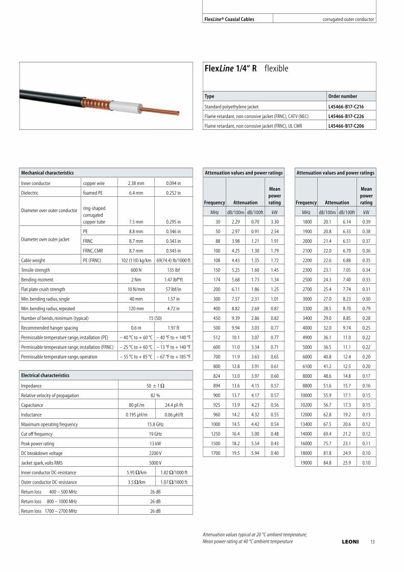
FlexLine 1/4“ R flexible
Type Order number
Standard polyethylene jacket L45466-B17-C216
Flame retardant, non corrosive jacket (FRNC), CATV (NEC) L45466-B17-C226
Flame retardant, non corrosive jacket (FRNC), UL CMR L45466-B17-C206
FlexLine® Coaxial Cables corrugated outer conductor
LEONI 13
Mechanical characteristics
Inner conductor
copper clad
aluminium wire 2.6 mm 0.102 in
Dielectric foamed PE 6.5 mm 0.256 in
Diameter over outer conductor
spiral corrugated
copper tube 9.1 mm 0.358 in
Diameter over outer jacket
PE 10.3 mm 0.406 in
FRNC 10.3 mm 0.406 in
FRNC, CMR 10.7 mm 0.421 in
Cable weight PE (FRNC) 125(130) kg/km 84.5(87.9) lb/1000 ft
Tensile strength 600 N 134.9 lbf
Bending moment 2.5 Nm 1.84 lbf*ft
Flat plate crush strength 15 N/mm 85.6 lbf/in
Min. bending radius, single 12.5 mm 0.492 in
Min. bending radius, repeated 25 mm 0.984 in
Number of bends, minimum (typical) 20 (50)
Recommended hanger spacing 0.6 m 1.97 ft
Permissable temperature range, installation (PE) – 40 °C to + 60 °C – 40 °F to + 140 °F
Permissable temperature range, installation (FRNC) – 25 °C to + 60 °C – 13 °F to + 140 °F
Permissable temperature range, operation – 55 °C to + 85 °C – 67 °F to + 185 °F
Electrical characteristics
Impedance 50 ± 1
Relative velocity of propagation 82 %
Capacitance 80 pF/m 24.4 pF/ft
Inductance 0.195 μH/m 0.06 μH/ft
Maximum operating frequency 13.4 GHz
Cut off frequency 17.0 GHz
Peak power rating 13.5 kW
DC breakdown voltage 2300 V
Jacket spark, volts RMS 5000 V
Inner conductor DC-resistance 5.4 /km 1.65 /1000 ft
Outer conductor DC-resistance 5.6 /km 1.71 /1000 ft
Return loss 400 – 500 MHz 26 dB
Return loss 800 – 1000 MHz 26 dB
Return loss 1700 – 2700 MHz 26 dB
Attenuation values and power ratings
Frequency Attenuation
Meanpowerrating
MHz dB/100m dB/100ft kW
30 2.12 0.65 3.43
50 2.74 0.84 2.65
88 3.66 1.12 1.98
100 3.91 1.19 1.86
108 4.06 1.24 1.79
150 4.82 1.47 1.51
174 5.20 1.59 1.40
200 5.59 1.71 1.30
300 6.93 2.11 1.05
400 8.08 2.46 0.91
450 8.61 2.62 0.85
500 9.11 2.78 0.81
512 9.23 2.81 0.80
600 10.1 3.07 0.73
700 10.9 3.34 0.68
800 11.8 3.59 0.63
824 12.0 3.65 0.62
894 12.5 3.82 0.59
900 12.6 3.83 0.59
925 12.8 3.89 0.58
960 13.0 3.97 0.57
1000 13.3 4.06 0.56
1250 15.1 4.61 0.49
Attenuation values and power ratings
Frequency Attenuation
Meanpowerrating
MHz dB/100m dB/100ft kW
1500 16.8 5.11 0.45
1700 18.0 5.49 0.42
1800 18.6 5.67 0.41
1900 19.2 5.85 0.39
2000 19.8 6.03 0.38
2100 20.3 6.20 0.37
2200 20.9 6.37 0.36
2300 21.5 6.54 0.35
2500 22.5 6.87 0.34
2700 23.6 7.19 0.32
3000 25.1 7.65 0.31
3300 26.6 8.10 0.29
3400 27.0 8.25 0.28
4000 29.8 9.10 0.26
4900 33.8 10.3 0.23
5000 34.2 10.4 0.23
6000 38.3 11.7 0.21
6100 38.7 11.8 0.20
8000 45.9 14.0 0.17
8800 48.8 14.9 0.16
10000 53.1 16.2 0.15
10200 53.8 16.4 0.15
12000 59.8 18.2 0.14
13400 64.4 19.6 0.13
Attenuation values typical at 20 °C ambient temperature; Mean power rating at 40 °C ambient temperature
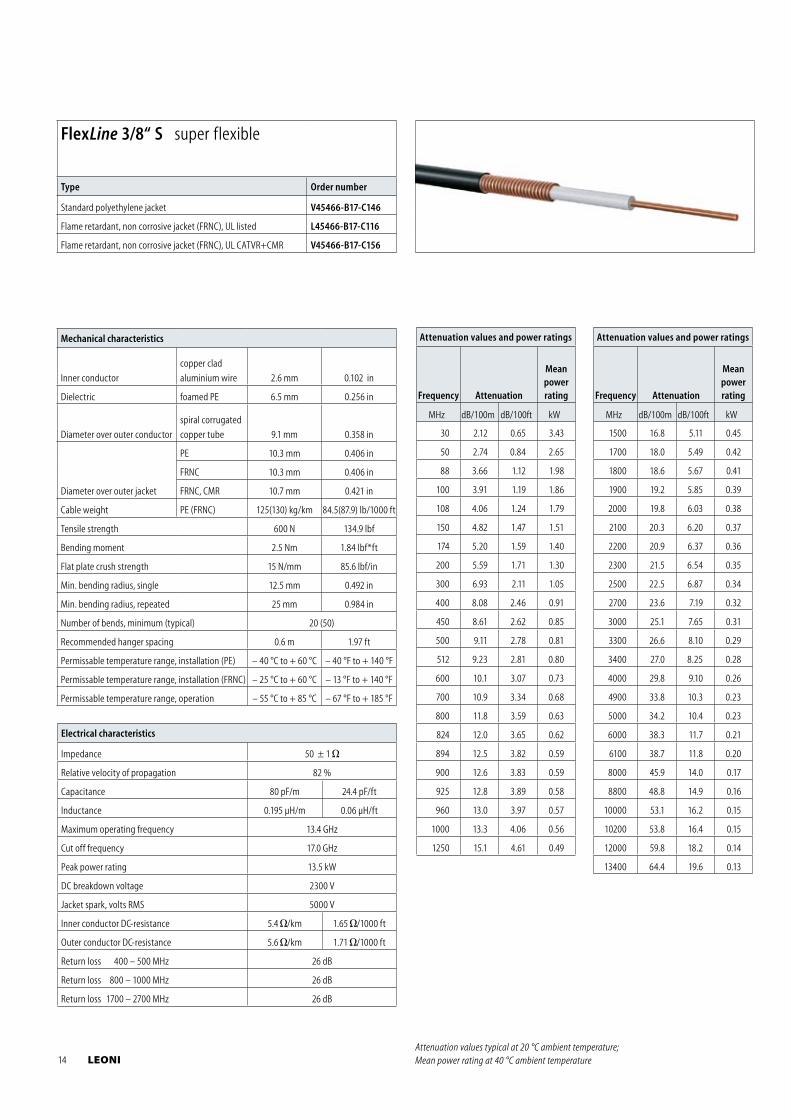
FlexLine 3/8“ S super flexible
Type Order number
Standard polyethylene jacket V45466-B17-C146
Flame retardant, non corrosive jacket (FRNC), UL listed L45466-B17-C116
Flame retardant, non corrosive jacket (FRNC), UL CATVR+CMR V45466-B17-C156
14 LEONI
Electrical characteristics
Impedance 50 ± 1
Relative velocity of propagation 82 %
Capacitance 80 pF/m 24.4 pF/ft
Inductance 0.195 μH/m 0.06 μH/ft
Maximum operating frequency 10.2 GHz
Cut off frequency 13.0 GHz
Peak power rating 19 kW
DC breakdown voltage 2500 V
Jacket spark, volts RMS 5000 V
Inner conductor DC-resistance 3.0 /km 0.92 /1000 ft
Outer conductor DC-resistance 3.4 /km 1.04 /1000 ft
Return loss 400 – 500 MHz 26 dB
Return loss 800 – 1000 MHz 26 dB
Return loss 1700 – 2700 MHz 26 dB
Mechanical characteristics
Inner conductor copper clad
aluminium wire 3.6 mm 0.142 in
Dielectric foamed PE 9.1 mm 0.358 in
Diameter over outer conductor
ring-shaped
corrugated
copper tube
12.3 mm 0.484 in
Diameter over outer jacket
PE 13.5 mm 0.531 in
FRNC 13.5 mm 0.531 in
FRNC, CMR 13.9 mm 0.547 in
Cable weight PE (FRNC) 203(226) kg/km 136.1
(149.5) lb/1000 ft
Tensile strength 1000 N 225 lbf
Bending moment 3 Nm 2.21 lbf*ft
Flat plate crush strength 15 N/mm 85.6 lbf/in
Min. bending radius, single 15 mm 0.59 in
Min. bending radius, repeated 30 mm 1.18 in
Number of bends, minimum (typical) 20 (50)
Recommended hanger spacing 0.8 m 2.6 ft
Permissable temperature range, installation (PE) – 40 °C to + 60 °C – 40 °F to + 140 °F
Permissable temperature range, installation (FRNC) – 25 °C to + 60 °C – 13 °F to + 140 °F
Permissable temperature range, operation – 55 °C to + 85 °C – 67 °F to + 185 °F
Attenuation values and power ratings
Frequency Attenuation
Meanpowerrating
MHz dB/100m dB/100ft kW
30 1.58 0.48 4.82
50 2.11 0.64 3.72
88 2.89 0.88 2.78
100 3.10 0.94 2.60
108 3.23 0.99 2.50
150 3.87 1.18 2.11
174 4.20 1.28 1.95
200 4.53 1.38 1.81
300 5.67 1.73 1.46
400 6.64 2.02 1.26
450 7.09 2.16 1.18
500 7.52 2.29 1.11
512 7.62 2.32 1.10
600 8.32 2.54 1.01
700 9.07 2.76 0.93
800 9.78 2.98 0.87
824 9.94 3.03 0.85
894 10.4 3.17 0.82
900 10.4 3.18 0.81
925 10.6 3.23 0.80
Attenuation values and power ratings
Frequency Attenuation
Meanpowerrating
MHz dB/100m dB/100ft kW
960 10.8 3.30 0.79
1000 11.1 3.38 0.77
1250 12.6 3.84 0.68
1500 14.0 4.26 0.61
1700 15.0 4.58 0.57
1800 15.5 4.74 0.55
1900 16.0 4.89 0.54
2000 16.5 5.04 0.52
2100 17.0 5.18 0.51
2200 17.5 5.33 0.49
2300 17.9 5.47 0.48
2500 18.8 5.74 0.46
2700 19.7 6.01 0.44
3000 21.0 6.40 0.41
3300 22.2 6.78 0.39
3400 22.6 6.90 0.39
4000 25.0 7.61 0.35
4900 28.3 8.62 0.31
5000 28.6 8.73 0.31
6000 32.1 9.77 0.27
6100 32.4 9.88 0.27
8000 38.5 11.7 0.23
8800 40.9 12.5 0.22
10000 44.4 13.5 0.20
10200 45.0 13.7 0.20
Attenuation values typical at 20 °C ambient temperature; Mean power rating at 40 °C ambient temperature
FlexLine 1/2“ S super flexible
Type Order number
Standard polyethylene jacket V45466-B19-C56
Flame retardant, non corrosive jacket (FRNC), UL listed L45466-B20-C6
Flame retardant, non corrosive jacket (FRNC), UL CATVR+CMR V45466-B19-C76
FlexLine® Coaxial Cables corrugated outer conductor
LEONI 15
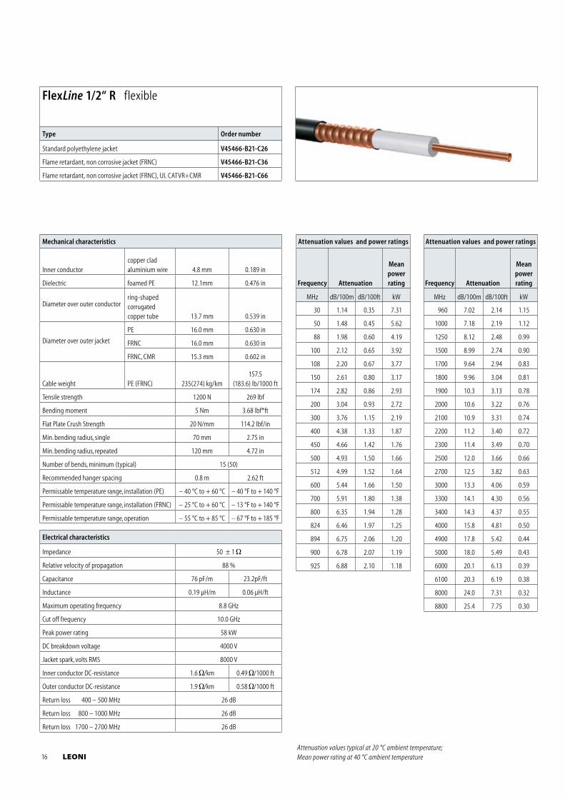
Mechanical characteristics
Inner conductorcopper clad aluminium wire 4.8 mm 0.189 in
Dielectric foamed PE 12.1mm 0.476 in
Diameter over outer conductorring-shaped corrugated copper tube 13.7 mm 0.539 in
Diameter over outer jacket
PE 16.0 mm 0.630 in
FRNC 16.0 mm 0.630 in
FRNC, CMR 15.3 mm 0.602 in
Cable weight PE (FRNC) 235(274) kg/km157.5
(183.6) lb/1000 ft
Tensile strength 1200 N 269 lbf
Bending moment 5 Nm 3.68 lbf*ft
Flat Plate Crush Strength 20 N/mm 114.2 lbf/in
Min. bending radius, single 70 mm 2.75 in
Min. bending radius, repeated 120 mm 4.72 in
Number of bends, minimum (typical) 15 (50)
Recommended hanger spacing 0.8 m 2.62 ft
Permissable temperature range, installation (PE) – 40 °C to + 60 °C – 40 °F to + 140 °F
Permissable temperature range, installation (FRNC) – 25 °C to + 60 °C – 13 °F to + 140 °F
Permissable temperature range, operation – 55 °C to + 85 °C – 67 °F to + 185 °F
Electrical characteristics
Impedance 50 ± 1
Relative velocity of propagation 88 %
Capacitance 76 pF/m 23.2pF/ft
Inductance 0.19 μH/m 0.06 μH/ft
Maximum operating frequency 8.8 GHz
Cut off frequency 10.0 GHz
Peak power rating 58 kW
DC breakdown voltage 4000 V
Jacket spark, volts RMS 8000 V
Inner conductor DC-resistance 1.6 /km 0.49 /1000 ft
Outer conductor DC-resistance 1.9 /km 0.58 /1000 ft
Return loss 400 – 500 MHz 26 dB
Return loss 800 – 1000 MHz 26 dB
Return loss 1700 – 2700 MHz 26 dB
Attenuation values and power ratings
Frequency Attenuation
Meanpowerrating
MHz dB/100m dB/100ft kW
30 1.14 0.35 7.31
50 1.48 0.45 5.62
88 1.98 0.60 4.19
100 2.12 0.65 3.92
108 2.20 0.67 3.77
150 2.61 0.80 3.17
174 2.82 0.86 2.93
200 3.04 0.93 2.72
300 3.76 1.15 2.19
400 4.38 1.33 1.87
450 4.66 1.42 1.76
500 4.93 1.50 1.66
512 4.99 1.52 1.64
600 5.44 1.66 1.50
700 5.91 1.80 1.38
800 6.35 1.94 1.28
824 6.46 1.97 1.25
894 6.75 2.06 1.20
900 6.78 2.07 1.19
925 6.88 2.10 1.18
Attenuation values and power ratings
Frequency Attenuation
Meanpowerrating
MHz dB/100m dB/100ft kW
960 7.02 2.14 1.15
1000 7.18 2.19 1.12
1250 8.12 2.48 0.99
1500 8.99 2.74 0.90
1700 9.64 2.94 0.83
1800 9.96 3.04 0.81
1900 10.3 3.13 0.78
2000 10.6 3.22 0.76
2100 10.9 3.31 0.74
2200 11.2 3.40 0.72
2300 11.4 3.49 0.70
2500 12.0 3.66 0.66
2700 12.5 3.82 0.63
3000 13.3 4.06 0.59
3300 14.1 4.30 0.56
3400 14.3 4.37 0.55
4000 15.8 4.81 0.50
4900 17.8 5.42 0.44
5000 18.0 5.49 0.43
6000 20.1 6.13 0.39
6100 20.3 6.19 0.38
8000 24.0 7.31 0.32
8800 25.4 7.75 0.30
FlexLine 1/2“ R flexible
Type Order number
Standard polyethylene jacket V45466-B21-C26
Flame retardant, non corrosive jacket (FRNC) V45466-B21-C36
Flame retardant, non corrosive jacket (FRNC), UL CATVR+CMR V45466-B21-C66
Attenuation values typical at 20 °C ambient temperature; Mean power rating at 40 °C ambient temperature 16 LEONI
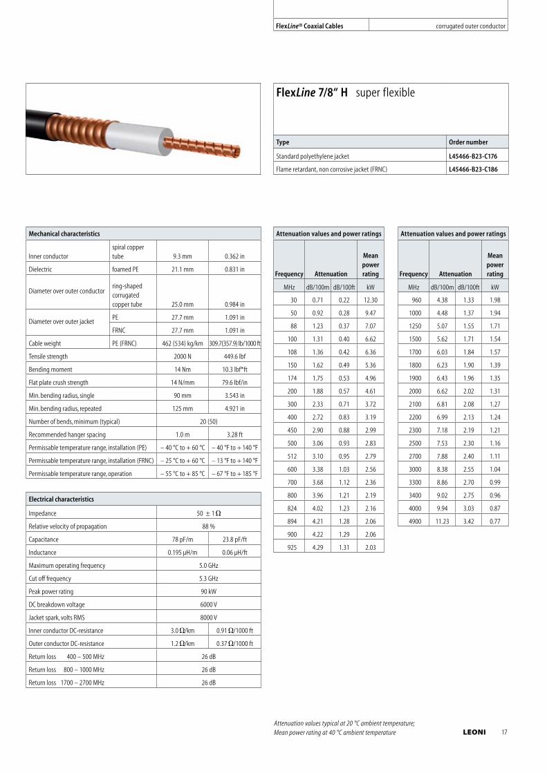
Mechanical characteristics
Inner conductorspiral copper tube 9.3 mm 0.362 in
Dielectric foamed PE 21.1 mm 0.831 in
Diameter over outer conductorring-shaped corrugated copper tube 25.0 mm 0.984 in
Diameter over outer jacketPE 27.7 mm 1.091 in
FRNC 27.7 mm 1.091 in
Cable weight PE (FRNC) 462 (534) kg/km 309.7(357.9) lb/1000 ft
Tensile strength 2000 N 449.6 lbf
Bending moment 14 Nm 10.3 lbf*ft
Flat plate crush strength 14 N/mm 79.6 lbf/in
Min. bending radius, single 90 mm 3.543 in
Min. bending radius, repeated 125 mm 4.921 in
Number of bends, minimum (typical) 20 (50)
Recommended hanger spacing 1.0 m 3.28 ft
Permissable temperature range, installation (PE) – 40 °C to + 60 °C – 40 °F to + 140 °F
Permissable temperature range, installation (FRNC) – 25 °C to + 60 °C – 13 °F to + 140 °F
Permissable temperature range, operation – 55 °C to + 85 °C – 67 °F to + 185 °F
Electrical characteristics
Impedance 50 ± 1
Relative velocity of propagation 88 %
Capacitance 78 pF/m 23.8 pF/ft
Inductance 0.195 μH/m 0.06 μH/ft
Maximum operating frequency 5.0 GHz
Cut off frequency 5.3 GHz
Peak power rating 90 kW
DC breakdown voltage 6000 V
Jacket spark, volts RMS 8000 V
Inner conductor DC-resistance 3.0 /km 0.91 /1000 ft
Outer conductor DC-resistance 1.2 /km 0.37 /1000 ft
Return loss 400 – 500 MHz 26 dB
Return loss 800 – 1000 MHz 26 dB
Return loss 1700 – 2700 MHz 26 dB
Attenuation values and power ratings
Frequency Attenuation
Meanpowerrating
MHz dB/100m dB/100ft kW
30 0.71 0.22 12.30
50 0.92 0.28 9.47
88 1.23 0.37 7.07
100 1.31 0.40 6.62
108 1.36 0.42 6.36
150 1.62 0.49 5.36
174 1.75 0.53 4.96
200 1.88 0.57 4.61
300 2.33 0.71 3.72
400 2.72 0.83 3.19
450 2.90 0.88 2.99
500 3.06 0.93 2.83
512 3.10 0.95 2.79
600 3.38 1.03 2.56
700 3.68 1.12 2.36
800 3.96 1.21 2.19
824 4.02 1.23 2.16
894 4.21 1.28 2.06
900 4.22 1.29 2.06
925 4.29 1.31 2.03
Attenuation values and power ratings
Frequency Attenuation
Meanpowerrating
MHz dB/100m dB/100ft kW
960 4.38 1.33 1.98
1000 4.48 1.37 1.94
1250 5.07 1.55 1.71
1500 5.62 1.71 1.54
1700 6.03 1.84 1.57
1800 6.23 1.90 1.39
1900 6.43 1.96 1.35
2000 6.62 2.02 1.31
2100 6.81 2.08 1.27
2200 6.99 2.13 1.24
2300 7.18 2.19 1.21
2500 7.53 2.30 1.16
2700 7.88 2.40 1.11
3000 8.38 2.55 1.04
3300 8.86 2.70 0.99
3400 9.02 2.75 0.96
4000 9.94 3.03 0.87
4900 11.23 3.42 0.77
FlexLine 7/8“ H super flexible
Type Order number
Standard polyethylene jacket L45466-B23-C176
Flame retardant, non corrosive jacket (FRNC) L45466-B23-C186
Attenuation values typical at 20 °C ambient temperature; Mean power rating at 40 °C ambient temperature
FlexLine® Coaxial Cables corrugated outer conductor
LEONI 17
Electrical characteristics
Impedance 50 ± 1
Relative velocity of propagation 88 %
Capacitance 76 pF/m 23.2pF/ft
Inductance 0.190 μH/m 0.06 μH/ft
Maximum operating frequency 5.0 GHz
Cut off frequency 5.3 GHz
Peak power rating 91 kW
DC breakdown voltage 6000 V
Jacket spark, volts RMS 8000 V
Inner conductor DC-resistance 1.65 /km 0.5 /1000 ft
Outer conductor DC-resistance 1.3 /km 0.4 /1000 ft
Return loss 400 – 500 MHz 26 dB
Return loss 800 – 1000 MHz 26 dB
Return loss 1700 – 2700 MHz 26 dB
Mechanical characteristics
Inner conductor copper tube 9.13 mm 0.359 in
Dielectric foamed PE 22.5 mm 0.886 in
Diameter over outer conductor
ring-shaped corrugated copper tube 25.0 mm 0.984 in
Diameter over outer jacket
PE 27.7 mm 1.091 in
FRNC 27.7 mm 1.091 in
FRNC, CMR 27.3 mm 1.075 in
Cable weight PE (FRNC) 495 (564) kg/km331.8
(378.0)lb/1000 ft
Tensile strength 2000 N 449.6 lbf
Bending moment 18 Nm 13.27 lbf*ft
Flat plate crush strength 14 N/mm 79.9 lbf/in
Min. bending radius, single 120 mm 4.724 in
Min. bending radius, repeated 240 mm 9.449 in
Number of bends, minimum (typical) 15 (50)
Recommended hanger spacing 1.0 m 3.28 ft
Permissable temperature range, installation (PE) – 40 °C to + 60 °C – 40 °F to + 140 °F
Permissable temperature range, installation (FRNC) – 25 °C to + 60 °C – 13 °F to + 140 °F
Permissable temperature range, operation – 55 °C to + 85 °C – 67 °F to + 185 °F
Attenuation values and power ratings
Frequency Attenuation
Meanpowerrating
MHz dB/100m dB/100ft kW
30 0.61 0.19 17.4
50 0.81 0.25 13.3
88 1.09 0.33 9.83
100 1.17 0.36 9.17
108 1.21 0.37 8.80
150 1.45 0.44 7.35
174 1.57 0.48 6.78
200 1.69 0.51 6.27
300 2.10 0.64 4.99
400 2.45 0.75 4.24
450 2.61 0.80 3.96
500 2.76 0.84 3.72
512 2.80 0.85 3.67
600 3.05 0.93 3.34
700 3.32 1.01 3.05
800 3.57 1.09 2.82
824 3.63 1.11 2.77
894 3.80 1.16 2.63
900 3.81 1.16 2.62
925 3.87 1.18 2.58
960 3.95 1.20 2.52
Attenuation values and power ratings
Frequency Attenuation
Meanpowerrating
MHz dB/100m dB/100ft kW
1000 4.04 1.23 2.46
1250 4.58 1.40 2.14
1500 5.08 1.55 1.91
1700 5.45 1.66 1.77
1800 5.63 1.72 1.70
1900 5.81 1.77 1.64
2000 5.98 1.82 1.59
2100 6.15 1.87 1.54
2200 6.32 1.93 1.50
2300 6.48 1.98 1.45
2500 6.80 2.07 1.38
2700 7.11 2.17 1.31
3000 7.57 2.31 1.22
3300 8.00 2.44 1.14
3400 8.15 2.48 1.12
4000 8.97 2.73 1.00
4900 10.1 3.09 0.88
5000 10.3 3.13 0.86
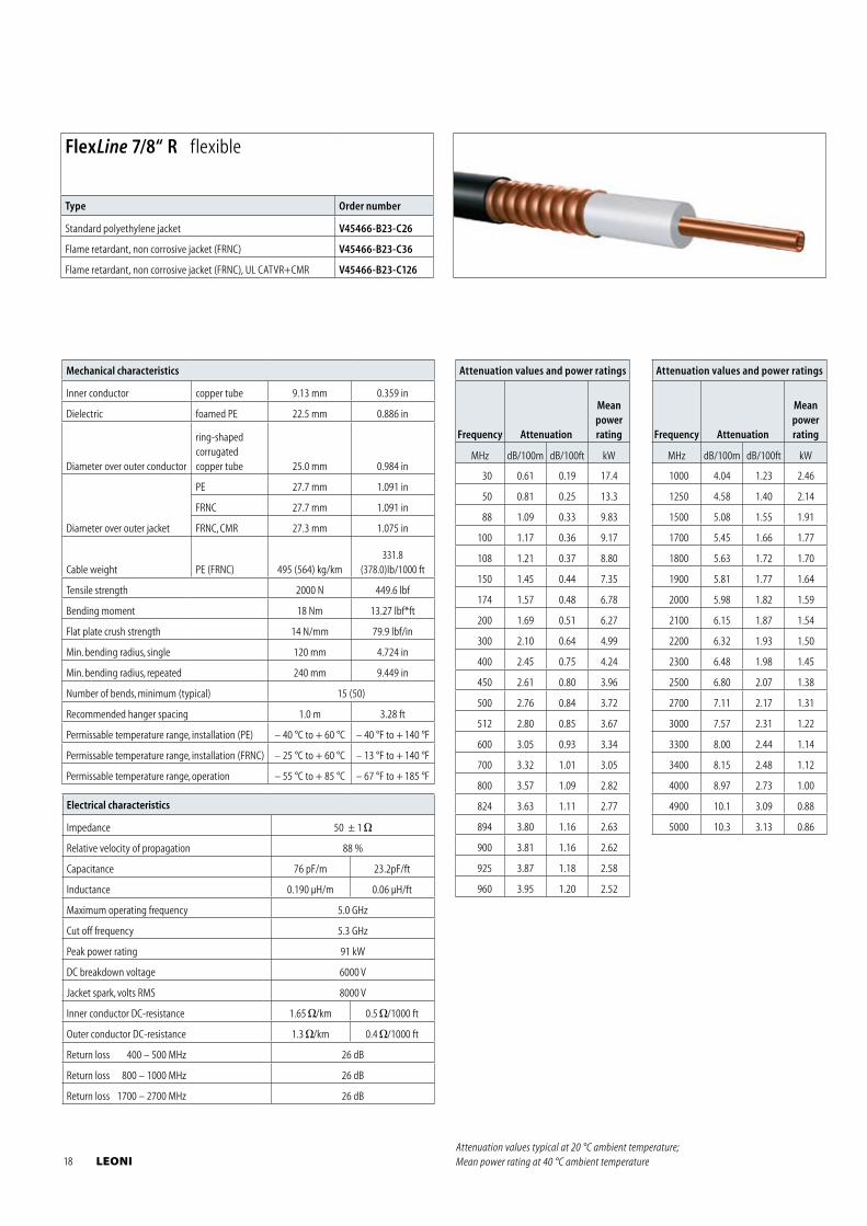
FlexLine 7/8“ R flexible
Type Order number
Standard polyethylene jacket V45466-B23-C26
Flame retardant, non corrosive jacket (FRNC) V45466-B23-C36
Flame retardant, non corrosive jacket (FRNC), UL CATVR+CMR V45466-B23-C126
Attenuation values typical at 20 °C ambient temperature; Mean power rating at 40 °C ambient temperature 18 LEONI
Electrical characteristics
Impedance 50 ± 1
Relative velocity of propagation 90 %
Capacitance 76 pF/m 23.2pF/ft
Inductance 0.190 μH/m 0.058 μH/ft
Maximum operating frequency 5.0 GHz
Cut off frequency 5.2 GHz
Peak power rating 90 kW
DC breakdown voltage 4000 V
Jacket spark, volts RMS 8000 V
Inner conductor DC-resistance 1.65 /km 0.5 /1000 ft
Outer conductor DC-resistance 1.3 /km 0.4 /1000 ft
Return loss 400 – 500 MHz 26 dB
Return loss 800 – 1000 MHz 26 dB
Return loss 1700 – 2700 MHz 26 dB
Mechanical characteristics
Inner conductor copper tube 9.3 mm 0.366 in
Dielectric foamed PE 22.5 mm 0.886 in
Diameter over outer conductor
ring-shaped corrugated copper tube 25.0 mm 0.984 in
Diameter over outer jacket
PE 27.7 mm 1.091 in
FRNC 27.7 mm 1.091 in
Cable weight PE (FRNC) 495 (564) kg/km 331.8(378.0)lb/1000 ft
Tensile strength 2000 N 449.6 lbf
Bending moment 18 Nm 13.27 lbf*ft
Flat plate crush strength 14 N/mm 79.9 lbf/in
Min. bending radius, single 120 mm 4.724 in
Min. bending radius, repeated 240 mm 9.449 in
Number of bends, minimum (typical) 15 (50)
Recommended hanger spacing 1.0 m 3.28 ft
Permissable temperature range, installation (PE) – 40 °C to + 60 °C – 40 °F to + 140 °F
Permissable temperature range, installation (FRNC) – 25 °C to + 60 °C – 13 °F to + 140 °F
Permissable temperature range, operation – 55 °C to + 85 °C – 67 °F to + 185 °F
Attenuation values and power ratings
Frequency Attenuation
Meanpowerrating
MHz dB/100m dB/100ft kW
30 0.61 0.19 17.4
50 0.78 0.24 13.3
88 1.04 0.31 9.83
100 1.11 0.34 9.17
108 1.16 0.35 8.80
150 1.37 0.42 7.35
174 1.48 0.45 6.78
200 1.59 0.48 6.27
300 1.97 0.60 4.99
400 2.29 0.70 4.24
450 2.44 0.74 3.96
500 2.58 0.79 3.72
512 2.61 0.80 3.67
600 2.84 0.87 3.34
700 3.09 0.94 3.05
800 3.32 1.01 2.82
824 3.37 1.03 2.77
Attenuation values and power ratings
Frequency Attenuation
Meanpowerrating
MHz dB/100m dB/100ft kW
894 3.52 1.07 2.63
900 3.54 1.08 2.62
925 3.59 1.09 2.58
960 3.66 1.12 2.52
1000 3.75 1.14 2.46
1250 4.24 1.29 2.14
1500 4.69 1.43 1.91
1700 5.03 1.53 1.77
1800 5.19 1.58 1.70
1900 5.35 1.63 1.64
2000 5.51 1.68 1.59
2100 5.66 1.73 1.54
2200 5.81 1.77 1.50
2300 5.97 1.82 1.45
2500 6.25 1.91 1.38
2700 6.53 1.99 1.31
3000 6.97 2.12 1.22
3300 7.35 2.24 1.14
3400 7.48 2.28 1.12
4000 8.22 2.51 1.00
4900 9.28 2.83 0.88
5000 9.39 2.86 0.86
FlexLine 7/8“ R flexible, low loss
Type Order number
Standard polyethylene jacket V45466-B23-C226
Flame retardant, non corrosive jacket (FRNC) V45466-B23-C236
Attenuation values typical at 20 °C ambient temperature; Mean power rating at 40 °C ambient temperature
FlexLine® Coaxial Cables corrugated outer conductor
LEONI 19
Electrical characteristics
Impedance 50 ± 1
Relative velocity of propagation 88 %
Capacitance 78 pF/m 23.2pF/ft
Inductance 0.190 μH/m 0.06 μH/ft
Maximum operating frequency 3.3 GHz
Cut off frequency 3.7 GHz
Peak power rating 200 kW
DC breakdown voltage 9000 V
Jacket spark, volts RMS 10000 V
Inner conductor DC-resistance 1.25 /km 0.38 /1000 ft
Outer conductor DC-resistance 0.6 /km 0.18 /1000 ft
Return loss 400 – 500 MHz 26 dB
Return loss 800 – 1000 MHz 26 dB
Return loss 1700 – 2700 MHz 26 dB
Mechanical characteristics
Inner conductor copper tube 12.7 mm 0.500 in
Dielectric foamed PE 32.5 mm 1.280 in
Diameter over outer conductor
ring-shaped corrugated copper tube 36.0 mm 1.417 in
Diameter over outer jacket
PE 39.5 mm 1.555 in
FRNC 39.5 mm 1.555 in
FRNC, CMR 38.3 mm 1.508 in
Cable weight PE (FRNC) 881(987) kg/km 590.5(661.5)lb/1000 ft
Tensile strength 2000 N 449.6 lbf
Bending moment 50 Nm 36.87 lbf*ft
Flat plate crush strength 14 N/mm 79.9 lbf/in
Min. bending radius, single 200 mm 7.87 in
Min. bending radius, repeated 380 mm 14.96 in
Number of bends, minimum (typical) 15 (50)
Recommended hanger spacing 1.2 m 3.93 ft
Permissable temperature range, installation (PE) – 40 °C to + 60 °C – 40 °F to + 140 °F
Permissable temperature range, installation (FRNC) – 25 °C to + 60 °C – 13 °F to + 140 °F
Permissable temperature range, operation – 55 °C to + 85 °C – 67 °F to + 185 °F
Attenuation values and power ratings
Frequency Attenuation
Meanpowerrating
MHz dB/100m dB/100ft kW
30 0.44 0.13 24.6
50 0.57 0.18 19.1
88 0.77 0.24 13.5
100 0.82 0.25 12.9
108 0.86 0.26 12.5
150 1.02 0.31 10.3
174 1.11 0.34 9.42
200 1.19 0.36 8.81
300 1.49 0.45 7.17
400 1.74 0.53 6.03
450 1.86 0.57 5.62
500 1.97 0.60 5.27
512 2.00 0.61 5.19
600 2.18 0.67 4.71
700 2.38 0.73 4.27
800 2.57 0.79 3.93
Attenuation values and power ratings
Frequency Attenuation
Meanpowerrating
MHz dB/100m dB/100ft kW
824 2.62 0.80 3.85
894 2.74 0.84 3.66
900 2.75 0.84 3.64
925 2.80 0.85 3.58
960 2.86 0.87 3.50
1000 2.93 0.89 3.40
1250 3.34 1.02 2.94
1500 3.72 1.13 2.61
1700 4.01 1.22 2.40
1800 4.15 1.26 2.31
1900 4.29 1.31 2.22
2000 4.42 1.35 2.15
2100 4.55 1.39 2.07
2200 4.69 1.43 2.01
2300 4.82 1.47 1.95
2500 5.07 1.55 1.84
2700 5.32 1.62 1.74
3000 5.68 1.73 1.62
3300 6.03 1.84 1.51
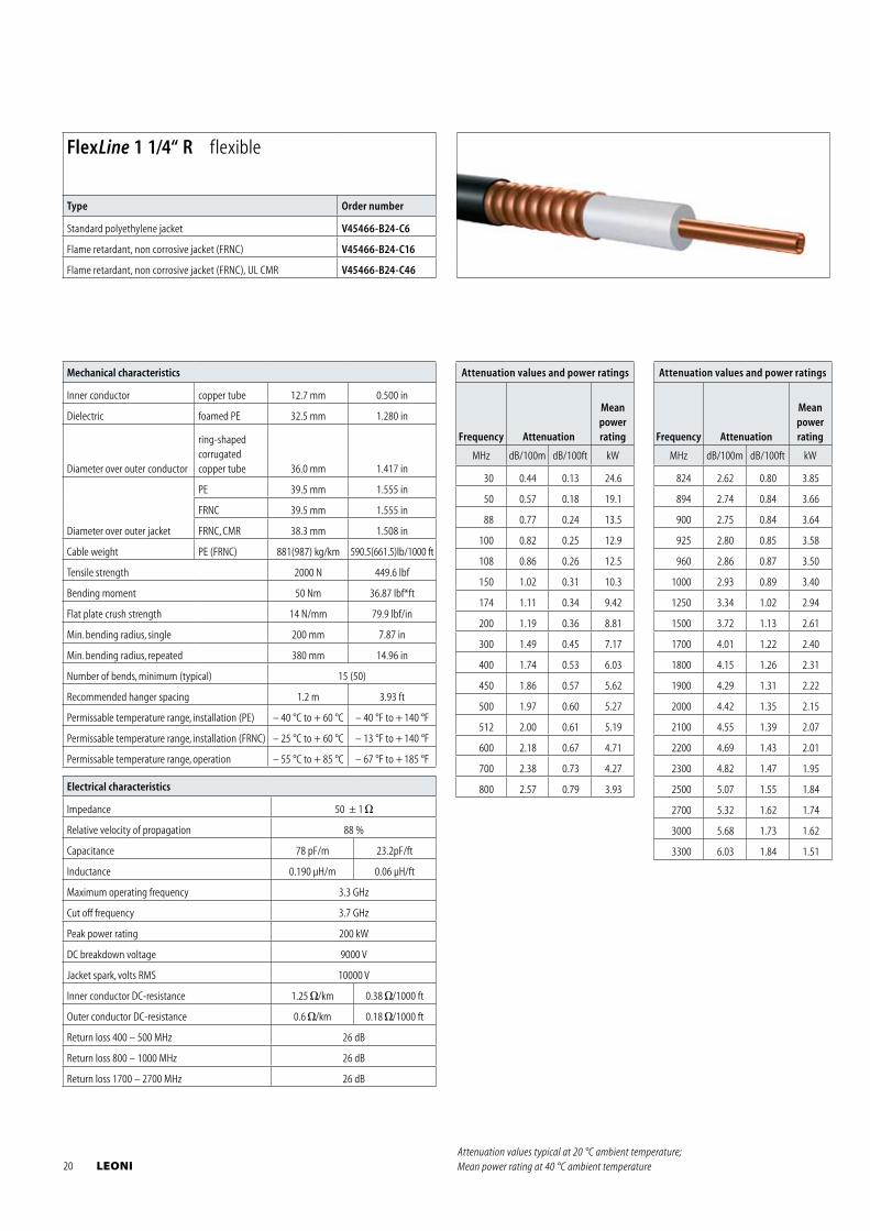
FlexLine 1 1/4“ R flexible
Type Order number
Standard polyethylene jacket V45466-B24-C6
Flame retardant, non corrosive jacket (FRNC) V45466-B24-C16
Flame retardant, non corrosive jacket (FRNC), UL CMR V45466-B24-C46
Attenuation values typical at 20 °C ambient temperature; Mean power rating at 40 °C ambient temperature 20 LEONI
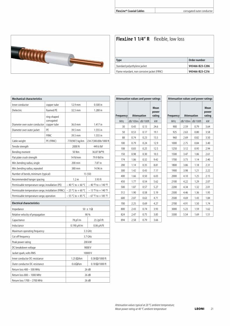
Electrical characteristics
Impedance 50 ± 1
Relative velocity of propagation 90 %
Capacitance 78 pF/m 23.2pF/ft
Inductance 0.190 μH/m 0.06 μH/ft
Maximum operating frequency 3.3 GHz
Cut off frequency 3.7 GHz
Peak power rating 200 kW
DC breakdown voltage 9000 V
Jacket spark, volts RMS 10000 V
Inner conductor DC-resistance 1.25 /km 0.38 /1000 ft
Outer conductor DC-resistance 0.6 /km 0.18 /1000 ft
Return loss 400 – 500 MHz 26 dB
Return loss 800 – 1000 MHz 26 dB
Return loss 1700 – 2700 MHz 26 dB
Mechanical characteristics
Inner conductor copper tube 12.9 mm 0.500 in
Dielectric foamed PE 32.5 mm 1.280 in
Diameter over outer conductor
ring-shaped corrugated copper tube 36.0 mm 1.417 in
Diameter over outer jacket PE 39.5 mm 1.555 in
FRNC 39.5 mm 1.555 in
Cable weight PE (FRNC) 770(987) kg/km 234.7(300.8)lb/1000 ft
Tensile strength 2000 N 449.6 lbf
Bending moment 50 Nm 36.87 lbf*ft
Flat plate crush strength 14 N/mm 79.9 lbf/in
Min. bending radius, single 200 mm 7.87 in
Min. bending radius, repeated 380 mm 14.96 in
Number of bends, minimum (typical) 15 (50)
Recommended hanger spacing 1.2 m 3.93 ft
Permissable temperature range, installation (PE) – 40 °C to + 60 °C – 40 °F to + 140 °F
Permissable temperature range, installation (FRNC) – 25 °C to + 60 °C – 13 °F to + 140 °F
Permissable temperature range, operation – 55 °C to + 85 °C – 67 °F to + 185 °F
Attenuation values and power ratings
Frequency Attenuation
Meanpowerrating
MHz dB/100m dB/100ft kW
30 0.43 0.13 24.6
50 0.53 0.17 19.1
88 0.74 0.23 13.5
100 0.79 0.24 12.9
108 0.83 0.25 12.5
150 0.98 0.30 10.3
174 1.06 0.32 9.42
200 1.14 0.35 8.81
300 1.42 0.43 7.17
400 1.66 0.50 6.03
450 1.77 0.54 5.62
500 1.87 0.57 5.27
512 1.90 0.58 5.19
600 2.07 0.63 4.71
700 2.25 0.69 4.27
800 2.43 0.74 3.93
824 2.47 0.75 3.85
894 2.58 0.79 3.66
Attenuation values and power ratings
Frequency Attenuation
Meanpowerrating
MHz dB/100m dB/100ft kW
900 2.59 0.79 3.64
925 2.63 0.80 3.58
960 2.69 0.82 3.50
1000 2.75 0.84 3.40
1250 3.12 0.95 2.94
1500 3.47 1.06 2.61
1700 3.73 1.14 2.40
1800 3.86 1.18 2.31
1900 3.98 1.21 2.22
2000 4.10 1.25 2.15
2100 4.22 1.29 2.07
2200 4.34 1.32 2.01
2300 4.46 1.36 1.95
2500 4.69 1.43 1.84
2700 4.91 1.50 1.74
3000 5.23 1.59 1.62
3300 5.54 1.69 1.51
FlexLine 1 1/4“ R flexible, low loss
Type Order number
Standard polyethylene jacket V45466-B23-C206
Flame retardant, non corrosive jacket (FRNC) V45466-B23-C216
Attenuation values typical at 20 °C ambient temperature; Mean power rating at 40 °C ambient temperature
FlexLine® Coaxial Cables corrugated outer conductor
LEONI 21
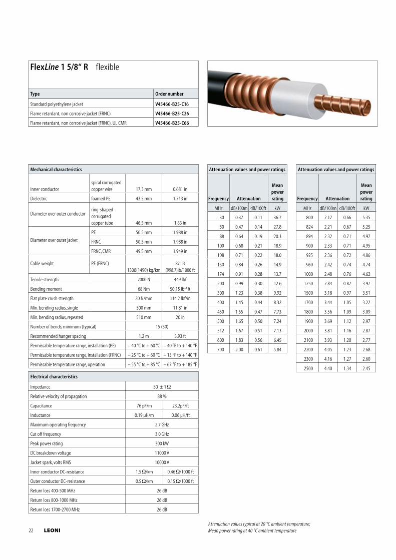
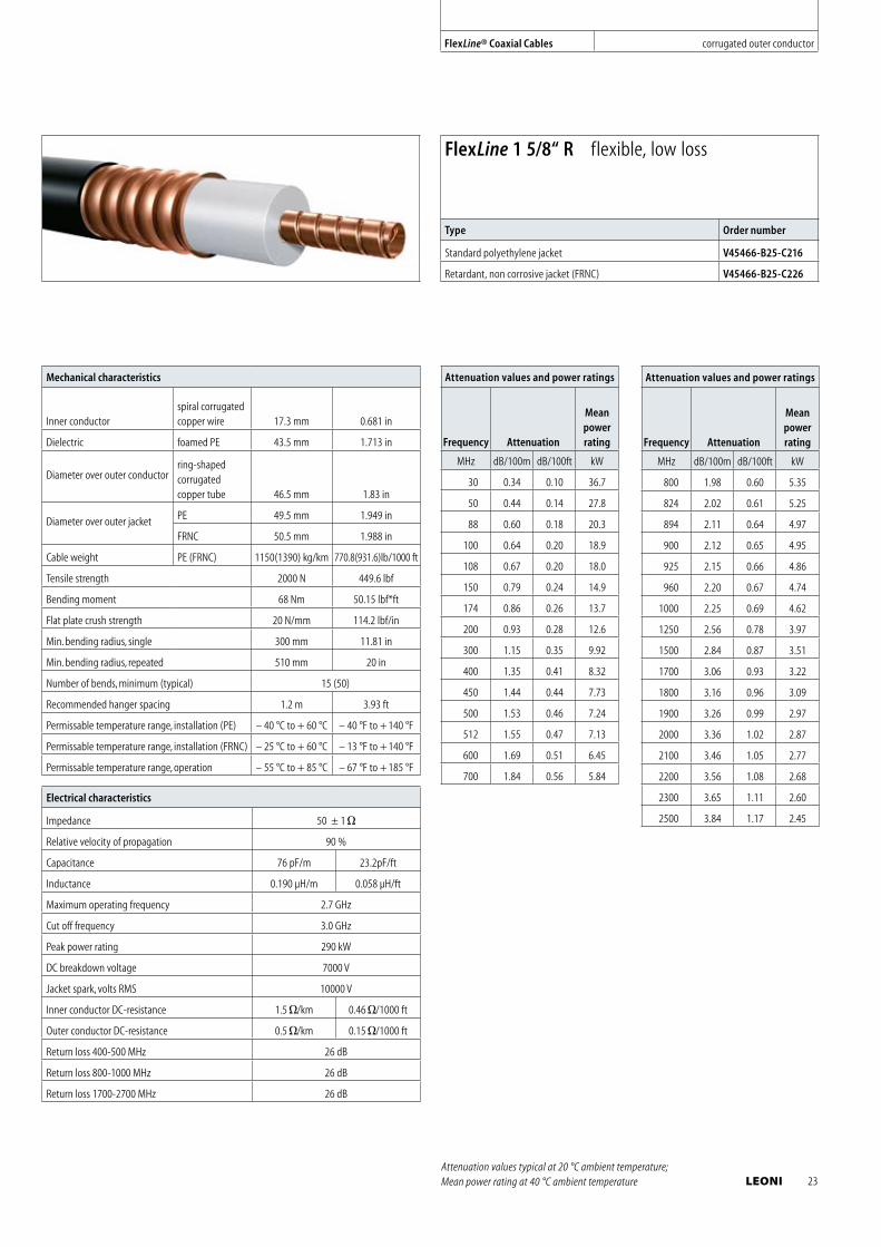
Mechanical characteristics
Inner conductorspiral corrugated copper wire 17.3 mm 0.681 in
Dielectric foamed PE 43.5 mm 1.713 in
Diameter over outer conductorring-shaped corrugated copper tube 46.5 mm 1.83 in
Diameter over outer jacket
PE 50.5 mm 1.988 in
FRNC 50.5 mm 1.988 in
FRNC, CMR 49.5 mm 1.949 in
Cable weight PE (FRNC)1300(1490) kg/km
871.3(998.7)lb/1000 ft
Tensile strength 2000 N 449 lbf
Bending moment 68 Nm 50.15 lbf*ft
Flat plate crush strength 20 N/mm 114.2 lbf/in
Min. bending radius, single 300 mm 11.81 in
Min. bending radius, repeated 510 mm 20 in
Number of bends, minimum (typical) 15 (50)
Recommended hanger spacing 1.2 m 3.93 ft
Permissable temperature range, installation (PE) – 40 °C to + 60 °C – 40 °F to + 140 °F
Permissable temperature range, installation (FRNC) – 25 °C to + 60 °C – 13 °F to + 140 °F
Permissable temperature range, operation – 55 °C to + 85 °C – 67 °F to + 185 °F
Attenuation values and power ratings
Frequency Attenuation
Meanpowerrating
MHz dB/100m dB/100ft kW
30 0.37 0.11 36.7
50 0.47 0.14 27.8
88 0.64 0.19 20.3
100 0.68 0.21 18.9
108 0.71 0.22 18.0
150 0.84 0.26 14.9
174 0.91 0.28 13.7
200 0.99 0.30 12.6
300 1.23 0.38 9.92
400 1.45 0.44 8.32
450 1.55 0.47 7.73
500 1.65 0.50 7.24
512 1.67 0.51 7.13
600 1.83 0.56 6.45
700 2.00 0.61 5.84
Attenuation values and power ratings
Frequency Attenuation
Meanpowerrating
MHz dB/100m dB/100ft kW
800 2.17 0.66 5.35
824 2.21 0.67 5.25
894 2.32 0.71 4.97
900 2.33 0.71 4.95
925 2.36 0.72 4.86
960 2.42 0.74 4.74
1000 2.48 0.76 4.62
1250 2.84 0.87 3.97
1500 3.18 0.97 3.51
1700 3.44 1.05 3.22
1800 3.56 1.09 3.09
1900 3.69 1.12 2.97
2000 3.81 1.16 2.87
2100 3.93 1.20 2.77
2200 4.05 1.23 2.68
2300 4.16 1.27 2.60
2500 4.40 1.34 2.45
Electrical characteristics
Impedance 50 ± 1
Relative velocity of propagation 88 %
Capacitance 76 pF/m 23.2pF/ft
Inductance 0.19 μH/m 0.06 μH/ft
Maximum operating frequency 2.7 GHz
Cut off frequency 3.0 GHz
Peak power rating 300 kW
DC breakdown voltage 11000 V
Jacket spark, volts RMS 10000 V
Inner conductor DC-resistance 1.5 /km 0.46 /1000 ft
Outer conductor DC-resistance 0.5 /km 0.15 /1000 ft
Return loss 400-500 MHz 26 dB
Return loss 800-1000 MHz 26 dB
Return loss 1700-2700 MHz 26 dB
FlexLine 1 5/8“ R flexible
Type Order number
Standard polyethylene jacket V45466-B25-C16
Flame retardant, non corrosive jacket (FRNC) V45466-B25-C26
Flame retardant, non corrosive jacket (FRNC), UL CMR V45466-B25-C66
Attenuation values typical at 20 °C ambient temperature; Mean power rating at 40 °C ambient temperature 22 LEONI
Mechanical characteristics
Inner conductorspiral corrugated copper wire 17.3 mm 0.681 in
Dielectric foamed PE 43.5 mm 1.713 in
Diameter over outer conductorring-shaped corrugated copper tube 46.5 mm 1.83 in
Diameter over outer jacket PE 49.5 mm 1.949 in
FRNC 50.5 mm 1.988 in
Cable weight PE (FRNC) 1150(1390) kg/km 770.8(931.6)lb/1000 ft
Tensile strength 2000 N 449.6 lbf
Bending moment 68 Nm 50.15 lbf*ft
Flat plate crush strength 20 N/mm 114.2 lbf/in
Min. bending radius, single 300 mm 11.81 in
Min. bending radius, repeated 510 mm 20 in
Number of bends, minimum (typical) 15 (50)
Recommended hanger spacing 1.2 m 3.93 ft
Permissable temperature range, installation (PE) – 40 °C to + 60 °C – 40 °F to + 140 °F
Permissable temperature range, installation (FRNC) – 25 °C to + 60 °C – 13 °F to + 140 °F
Permissable temperature range, operation – 55 °C to + 85 °C – 67 °F to + 185 °F
Electrical characteristics
Impedance 50 ± 1
Relative velocity of propagation 90 %
Capacitance 76 pF/m 23.2pF/ft
Inductance 0.190 μH/m 0.058 μH/ft
Maximum operating frequency 2.7 GHz
Cut off frequency 3.0 GHz
Peak power rating 290 kW
DC breakdown voltage 7000 V
Jacket spark, volts RMS 10000 V
Inner conductor DC-resistance 1.5 /km 0.46 /1000 ft
Outer conductor DC-resistance 0.5 /km 0.15 /1000 ft
Return loss 400-500 MHz 26 dB
Return loss 800-1000 MHz 26 dB
Return loss 1700-2700 MHz 26 dB
Attenuation values and power ratings
Frequency Attenuation
Meanpowerrating
MHz dB/100m dB/100ft kW
30 0.34 0.10 36.7
50 0.44 0.14 27.8
88 0.60 0.18 20.3
100 0.64 0.20 18.9
108 0.67 0.20 18.0
150 0.79 0.24 14.9
174 0.86 0.26 13.7
200 0.93 0.28 12.6
300 1.15 0.35 9.92
400 1.35 0.41 8.32
450 1.44 0.44 7.73
500 1.53 0.46 7.24
512 1.55 0.47 7.13
600 1.69 0.51 6.45
700 1.84 0.56 5.84
Attenuation values and power ratings
Frequency Attenuation
Meanpowerrating
MHz dB/100m dB/100ft kW
800 1.98 0.60 5.35
824 2.02 0.61 5.25
894 2.11 0.64 4.97
900 2.12 0.65 4.95
925 2.15 0.66 4.86
960 2.20 0.67 4.74
1000 2.25 0.69 4.62
1250 2.56 0.78 3.97
1500 2.84 0.87 3.51
1700 3.06 0.93 3.22
1800 3.16 0.96 3.09
1900 3.26 0.99 2.97
2000 3.36 1.02 2.87
2100 3.46 1.05 2.77
2200 3.56 1.08 2.68
2300 3.65 1.11 2.60
2500 3.84 1.17 2.45
FlexLine 1 5/8“ R flexible, low loss
Type Order number
Standard polyethylene jacket V45466-B25-C216
Retardant, non corrosive jacket (FRNC) V45466-B25-C226
Attenuation values typical at 20 °C ambient temperature; Mean power rating at 40 °C ambient temperature
FlexLine® Coaxial Cables corrugated outer conductor
LEONI 23
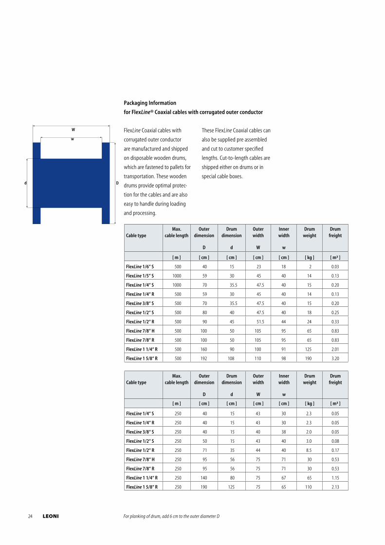
24 LEONI
FlexLine Coaxial cables with
corrugated outer conductor
are manu factured and shipped
on disposable wooden drums,
which are fastened to pallets for
transportation. These wooden
drums provide optimal protec-
tion for the cables and are also
easy to handle during loading
and processing.
D
w
d
W
For planking of drum, add 6 cm to the outer diameter D
Cable typeMax.
cable lengthOuter
dimension
D
Drum dimension
d
Outer width
W
Inner width
w
Drumweight
Drumfreight
[ m ] [ cm ] [ cm ] [ cm ] [ cm ] [ kg ] [ m³ ]
FlexLine 1/6“ S 500 40 15 23 18 2 0.03
FlexLine 1/5“ S 1000 59 30 45 40 14 0.13
FlexLine 1/4“ S 1000 70 35.5 47.5 40 15 0.20
FlexLine 1/4“ R 500 59 30 45 40 14 0.13
FlexLine 3/8“ S 500 70 35.5 47.5 40 15 0.20
FlexLine 1/2“ S 500 80 40 47.5 40 18 0.25
FlexLine 1/2“ R 500 90 45 51.5 44 24 0.33
FlexLine 7/8“ H 500 100 50 105 95 65 0.83
FlexLine 7/8“ R 500 100 50 105 95 65 0.83
FlexLine 1 1/4“ R 500 160 90 100 91 125 2.01
FlexLine 1 5/8“ R 500 192 108 110 98 190 3.20
Cable typeMax.
cable lengthOuter
dimension
D
Drum dimension
d
Outer width
W
Inner width
w
Drumweight
Drumfreight
[ m ] [ cm ] [ cm ] [ cm ] [ cm ] [ kg ] [ m³ ]
FlexLine 1/4“ S 250 40 15 43 30 2.3 0.05
FlexLine 1/4“ R 250 40 15 43 30 2.3 0.05
FlexLine 3/8“ S 250 40 15 40 38 2.0 0.05
FlexLine 1/2“ S 250 50 15 43 40 3.0 0.08
FlexLine 1/2“ R 250 71 35 44 40 8.5 0.17
FlexLine 7/8“ H 250 95 56 75 71 30 0.53
FlexLine 7/8“ R 250 95 56 75 71 30 0.53
FlexLine 1 1/4“ R 250 140 80 75 67 65 1.15
FlexLine 1 5/8“ R 250 190 125 75 65 110 2.13
Packaging Information
for FlexLine® Coaxial cables with corrugated outer conductor
These FlexLine Coaxial cables can
also be supplied pre assembled
and cut to customer specified
lengths. Cut-to-length cables are
shipped either on drums or in
special cable boxes.
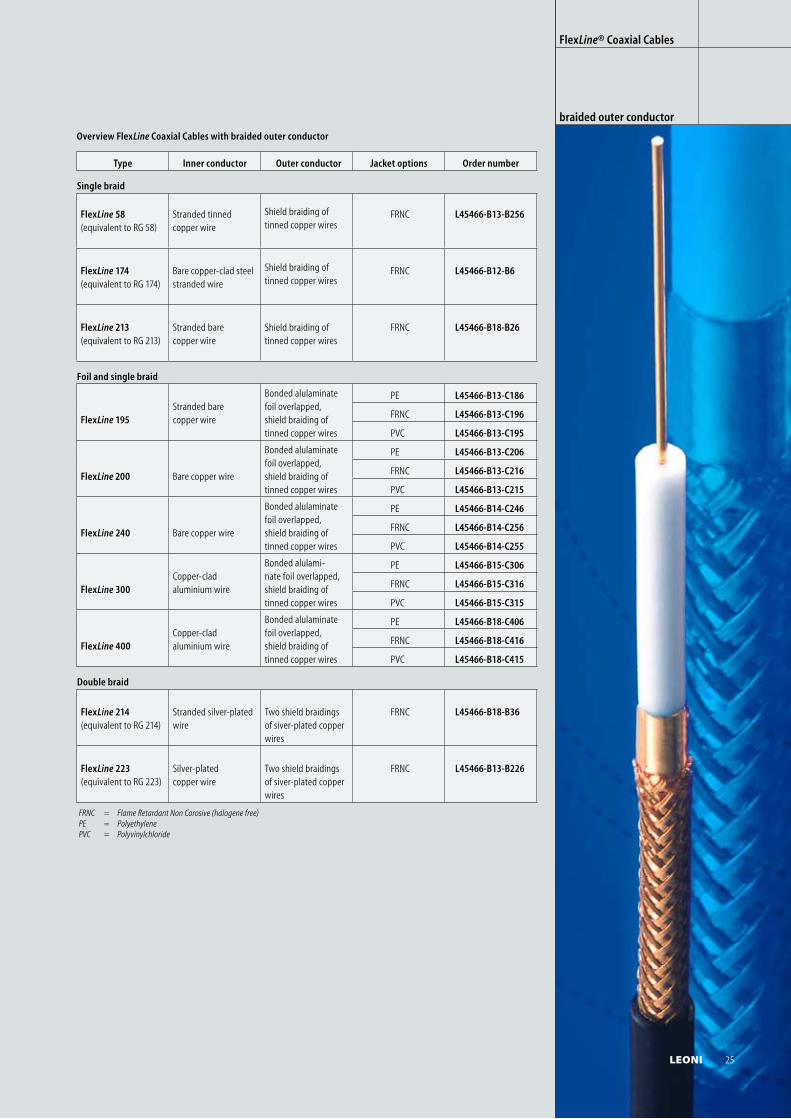
Overview FlexLine Coaxial Cables with braided outer conductor
Type Inner conductor Outer conductor Jacket options Order number
Single braid
FlexLine 58 (equivalent to RG 58)
Stranded tinned copper wire
Shield braiding of tinned copper wires
FRNC L45466-B13-B256
FlexLine 174(equivalent to RG 174)
Bare copper-clad steel stranded wire
Shield braiding of tinned copper wires
FRNC L45466-B12-B6
FlexLine 213(equivalent to RG 213)
Stranded bare copper wire
Shield braiding of tinned copper wires
FRNC L45466-B18-B26
Foil and single braid
FlexLine 195Stranded bare copper wire
Bonded alulaminate foil overlapped, shield braiding of tinned copper wires
PE L45466-B13-C186
FRNC L45466-B13-C196
PVC L45466-B13-C195
FlexLine 200 Bare copper wire
Bonded alulaminate foil overlapped, shield braiding of tinned copper wires
PE L45466-B13-C206
FRNC L45466-B13-C216
PVC L45466-B13-C215
FlexLine 240 Bare copper wire
Bonded alulaminate foil overlapped, shield braiding of tinned copper wires
PE L45466-B14-C246
FRNC L45466-B14-C256
PVC L45466-B14-C255
FlexLine 300Copper-clad aluminium wire
Bonded alulami-nate foil overlapped, shield braiding of tinned copper wires
PE L45466-B15-C306
FRNC L45466-B15-C316
PVC L45466-B15-C315
FlexLine 400Copper-clad aluminium wire
Bonded alulaminate foil overlapped, shield braiding of tinned copper wires
PE L45466-B18-C406
FRNC L45466-B18-C416
PVC L45466-B18-C415
Double braid
FlexLine 214(equivalent to RG 214)
Stranded silver-plated wire
Two shield braidings of siver-plated copper wires
FRNC L45466-B18-B36
FlexLine 223(equivalent to RG 223)
Silver-plated copper wire
Two shield braidings of siver-plated copper wires
FRNC L45466-B13-B226
FlexLine® Coaxial Cables
braided outer conductor
FRNC = Flame Retardant Non Corosive (halogene free) PE = Polyethylene PVC = Polyvinylchloride
LEONI 25
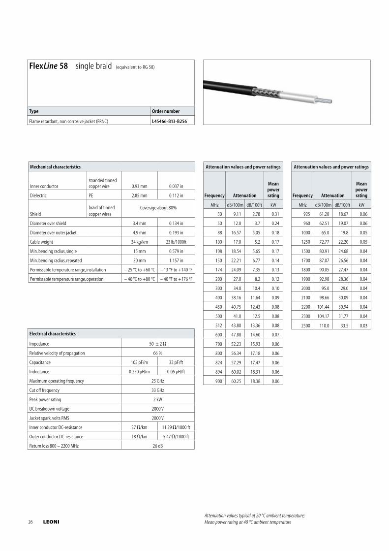
Electrical characteristics
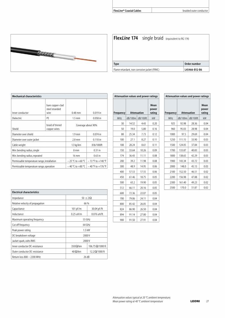
Impedance 50 ± 2
Relative velocity of propagation 66 %
Capacitance 105 pF/m 32 pF/ft
Inductance 0.250 μH/m 0.06 μH/ft
Maximum operating frequency 25 GHz
Cut off frequency 33 GHz
Peak power rating 2 kW
DC breakdown voltage 2000 V
Jacket spark, volts RMS 2000 V
Inner conductor DC-resistance 37 /km 11.29 /1000 ft
Outer conductor DC-resistance 18 /km 5.47 /1000 ft
Return loss 800 – 2200 MHz 26 dB
Mechanical characteristics
Inner conductorstranded tinned copper wire 0.93 mm 0.037 in
Dielectric PE 2.85 mm 0.112 in
Shieldbraid of tinned copper wires
Coverage about 80%
Diameter over shield 3.4 mm 0.134 in
Diameter over outer jacket 4.9 mm 0.193 in
Cable weight 34 kg/km 23 lb/1000ft
Min. bending radius, single 15 mm 0.579 in
Min. bending radius, repeated 30 mm 1.157 in
Permissable temperature range, installation – 25 °C to +60 °C – 13 °F to +140 °F
Permissable temperature range, operation – 40 °C to +80 °C – 40 °F to +176 °F
Attenuation values and power ratings
Frequency Attenuation
Meanpowerrating
MHz dB/100m dB/100ft kW
30 9.11 2.78 0.31
50 12.0 3.7 0.24
88 16.57 5.05 0.18
100 17.0 5.2 0.17
108 18.54 5.65 0.17
150 22.21 6.77 0.14
174 24.09 7.35 0.13
200 27.0 8.2 0.12
300 34.0 10.4 0.10
400 38.16 11.64 0.09
450 40.75 12.43 0.08
500 41.0 12.5 0.08
512 43.80 13.36 0.08
600 47.88 14.60 0.07
700 52.23 15.93 0.06
800 56.34 17.18 0.06
824 57.29 17.47 0.06
894 60.02 18.31 0.06
900 60.25 18.38 0.06
Attenuation values and power ratings
Frequency Attenuation
Meanpowerrating
MHz dB/100m dB/100ft kW
925 61.20 18.67 0.06
960 62.51 19.07 0.06
1000 65.0 19.8 0.05
1250 72.77 22.20 0.05
1500 80.91 24.68 0.04
1700 87.07 26.56 0.04
1800 90.05 27.47 0.04
1900 92.98 28.36 0.04
2000 95.0 29.0 0.04
2100 98.66 30.09 0.04
2200 101.44 30.94 0.04
2300 104.17 31.77 0.04
2500 110.0 33.5 0.03
FlexLine 58 single braid (equivalent to RG 58)
Type Order number
Flame retardant, non corrosive jacket (FRNC) L45466-B13-B256
Attenuation values typical at 20 °C ambient temperature; Mean power rating at 40 °C ambient temperature 26 LEONI
Electrical characteristics
Impedance 50 ± 2
Relative velocity of propagation 66 %
Capacitance 101 pF/m 30.04 pF/ft
Inductance 0.25 uH/m 0.076 uH/ft
Maximum operating frequency 55 GHz
Cut off frequency 64 GHz
Peak power rating 1.5 kW
DC breakdown voltage 2000 V
Jacket spark, volts RMS 2000 V
Inner conductor DC-resistance 350 /km 106.75 /1000 ft
Outer conductor DC-resistance 40 /km 12.2 /1000 ft
Return loss 800 – 2200 MHz 26 dB
Mechanical characteristics
Inner conductor
bare copper-clad steel stranded wire 0.48 mm 0.019 in
Dielectric PE 1.5 mm 0.058 in
Shieldbraid of tinned copper wires
Coverage about 90%
Diameter over shield 1.9 mm 0.074 in
Diameter over outer jacket 2.8 mm 0.110 in
Cable weight 12 kg/km 8 lb/1000ft
Min. bending radius, single 8 mm 0.31 in
Min. bending radius, repeated 16 mm 0.63 in
Permissable temperature range, installation – 25 °C to +60 °C – 13 °F to +140 °F
Permissable temperature range, operation – 40 °C to +80 °C – 40 °F to +176 °F
Attenuation values and power ratings
Frequency Attenuation
Meanpowerrating
MHz dB/100m dB/100ft kW
30 14.52 4.43 0.20
50 19.0 5,80 0.16
88 25.34 7.73 0.12
100 27.1 8.27 0.11
108 28.24 8.61 0.11
150 33.64 10.26 0.09
174 36.43 11.11 0.08
200 39.2 11.98 0.08
300 48.9 14.95 0.06
400 57.53 17.55 0.06
450 61.46 18.75 0.05
500 65.2 19.90 0.05
512 66.11 20.16 0.05
600 72.36 22.07 0.05
700 79.06 24.11 0.04
800 85.42 26.05 0.04
824 86.90 26.50 0.04
894 91.14 27.80 0.04
900 91.50 27.91 0.04
Attenuation values and power ratings
Frequency Attenuation
Meanpowerrating
MHz dB/100m dB/100ft kW
925 92.98 28.36 0.04
960 95.03 28.98 0.04
1000 97.5 29.69 0.04
1250 111.15 33.90 0.03
1500 124.05 37.84 0.03
1700 133.87 40.83 0.03
1800 138.65 42.29 0.03
1900 143.34 43.72 0.03
2000 148.0 45.13 0.03
2100 152.50 46.51 0.02
2200 156.98 47.88 0.02
2300 161.40 49.23 0.02
2500 170.0 51.87 0.02
FlexLine 174 single braid (equivalent to RG 174)
Type Order number
Flame retardant, non corrosive jacket (FRNC) L45466-B12-B6
Attenuation values typical at 20 °C ambient temperature; Mean power rating at 40 °C ambient temperature
FlexLine® Coaxial Cables braided outer conductor
LEONI 27
Electrical characteristics
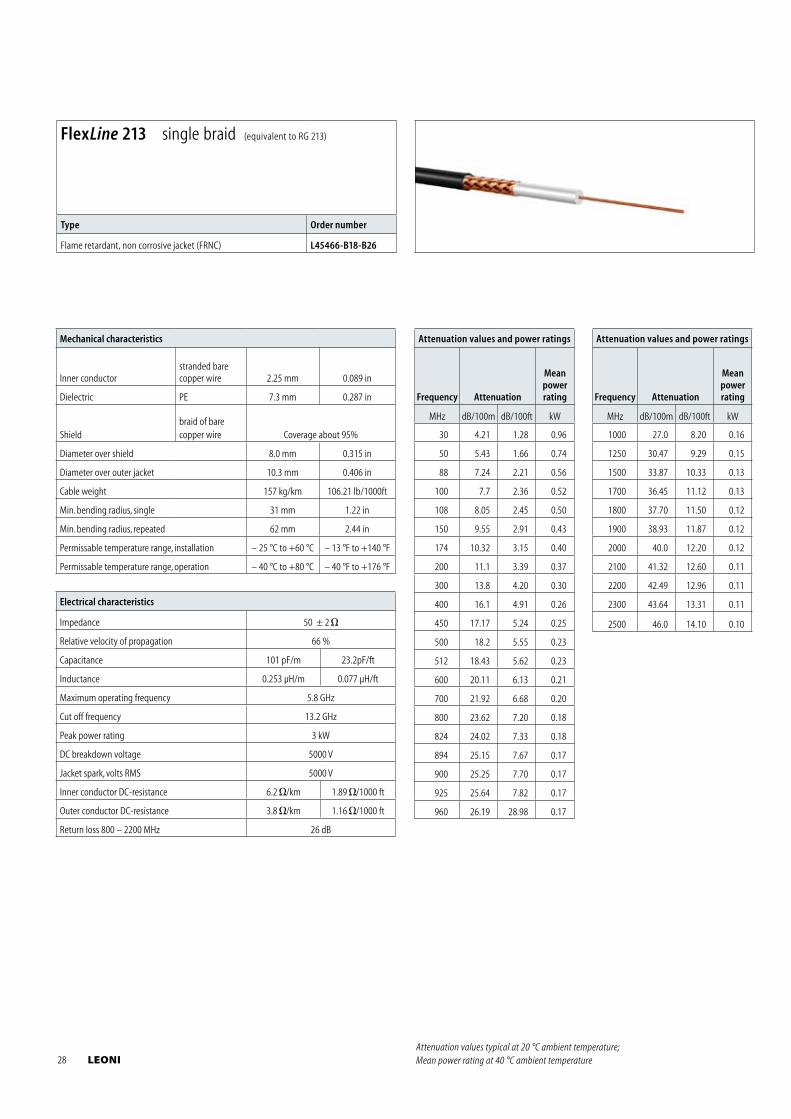
Impedance 50 ± 2
Relative velocity of propagation 66 %
Capacitance 101 pF/m 23.2pF/ft
Inductance 0.253 μH/m 0.077 μH/ft
Maximum operating frequency 5.8 GHz
Cut off frequency 13.2 GHz
Peak power rating 3 kW
DC breakdown voltage 5000 V
Jacket spark, volts RMS 5000 V
Inner conductor DC-resistance 6.2 /km 1.89 /1000 ft
Outer conductor DC-resistance 3.8 /km 1.16 /1000 ft
Return loss 800 – 2200 MHz 26 dB
Mechanical characteristics
Inner conductorstranded bare copper wire 2.25 mm 0.089 in
Dielectric PE 7.3 mm 0.287 in
Shieldbraid of bare copper wire Coverage about 95%
Diameter over shield 8.0 mm 0.315 in
Diameter over outer jacket 10.3 mm 0.406 in
Cable weight 157 kg/km 106.21 lb/1000ft
Min. bending radius, single 31 mm 1.22 in
Min. bending radius, repeated 62 mm 2.44 in
Permissable temperature range, installation – 25 °C to +60 °C – 13 °F to +140 °F
Permissable temperature range, operation – 40 °C to +80 °C – 40 °F to +176 °F
Attenuation values and power ratings
Frequency Attenuation
Meanpowerrating
MHz dB/100m dB/100ft kW
30 4.21 1.28 0.96
50 5.43 1.66 0.74
88 7.24 2.21 0.56
100 7.7 2.36 0.52
108 8.05 2.45 0.50
150 9.55 2.91 0.43
174 10.32 3.15 0.40
200 11.1 3.39 0.37
300 13.8 4.20 0.30
400 16.1 4.91 0.26
450 17.17 5.24 0.25
500 18.2 5.55 0.23
512 18.43 5.62 0.23
600 20.11 6.13 0.21
700 21.92 6.68 0.20
800 23.62 7.20 0.18
824 24.02 7.33 0.18
894 25.15 7.67 0.17
900 25.25 7.70 0.17
925 25.64 7.82 0.17
960 26.19 28.98 0.17
Attenuation values and power ratings
Frequency Attenuation
Meanpowerrating
MHz dB/100m dB/100ft kW
1000 27.0 8.20 0.16
1250 30.47 9.29 0.15
1500 33.87 10.33 0.13
1700 36.45 11.12 0.13
1800 37.70 11.50 0.12
1900 38.93 11.87 0.12
2000 40.0 12.20 0.12
2100 41.32 12.60 0.11
2200 42.49 12.96 0.11
2300 43.64 13.31 0.11
2500 46.0 14.10 0.10
FlexLine 213 single braid (equivalent to RG 213)
Type Order number
Flame retardant, non corrosive jacket (FRNC) L45466-B18-B26
Attenuation values typical at 20 °C ambient temperature; Mean power rating at 40 °C ambient temperature 28 LEONI
Electrical characteristics
Impedance 50 ± 2
Relative velocity of propagation 78%
Capacitance 82 pF/m 18.84 pF/ft
Inductance 0.220 μH/m 0.067 μH/ft
Maximum operating frequency 32 GHz
Cut off frequency 39 GHz
Peak power rating 2 kW
DC breakdown voltage 2000 V
Jacket spark, volts RMS 2000 V
Inner conductor DC-resistance 26 /km 7.90 /1000 ft
Outer conductor DC-resistance 16 /km 4.80 /1000 ft
Return loss 800 – 2200 MHz 23 dB
Mechanical characteristics
Inner conductor bare copper wire 0.95 mm 0.037 in
Dielectric foamed PE with skin
2.8 mm 0.110 in
Shield
bonded alulaminate foil
Coverage about 90 %
braid of tinned copper wire
Diameter over shield 3.4 mm 0.134 in
Diameter over outer jacket 4.9 mm 0.193 in
Cable weight 35 kg/km 23 lb/1000ft
Tensile strength 160 N 35.97 lbf
Min. bending radius, single 20 mm 0.772 in
Min. bending radius, repeated 50 mm 1.930 in
Number of bends, minimum (typical) 50
Permissable temperature range, installation – 25 °C to +60 °C – 13 °F to +140 °F
Permissable temperature range, operation – 40 °C to +80 °C – 40 °F to +176 °F
Attenuation values and power ratings
Frequency Attenuation
Meanpowerrating
MHz dB/100m dB/100ft kW
30 6.5 2.0 0.76
50 8.4 2.6 0.58
88 11.1 3.4 0.44
100 11.9 3.6 0.41
108 12.4 3.8 0.39
150 14.6 4.4 0.33
174 15.7 4.8 0.31
200 16.9 5.2 0.29
300 20.8 6.3 0.24
400 24.1 7.3 0.20
450 25.5 7.8 0.19
500 27.0 8.2 0.18
512 27.3 8.3 0.18
600 29.6 9.0 0.17
700 32.1 9.8 0.15
800 34.4 10.5 0.14
824 34.9 10.6 0.14
894 36.4 11.1 0.14
900 36.5 11.1 0.13
925 37.0 11.3 0.13
960 37.8 11.5 0.13
Attenuation values and power ratings
Frequency Attenuation
Meanpowerrating
MHz dB/100m dB/100ft kW
1000 38.6 11.8 0.13
1250 43.3 13.2 0.11
1500 47.7 14.5 0.10
1700 50.9 15.5 0.10
1800 52.5 16.0 0.09
1900 54.0 16.5 0.09
2000 55.4 16.9 0.09
2100 56.9 17.3 0.09
2200 58.3 17.8 0.09
2300 59.7 18.2 0.08
2500 62.4 19.0 0.08
2700 65.0 19.8 0.08
3000 68.8 21.0 0.07
3300 72.3 22.0 0.07
3400 73.5 22.4 0.07
4000 80.2 24.4 0.06
4900 89.5 27.3 0.06
5000 90.5 27.6 0.06
5800 98.1 29.9 0.05
FlexLine 195 foil and single braid
Type Order number
Standard polyethylene jacket (PE) L45466-B13-C186
Flame retardant, non corrosive jacket (FRNC) L45466-B13-C196
Standard polyvinylchloride jacket (PVC) L45466-B13-C195
Attenuation values typical at 20 °C ambient temperature; Mean power rating at 40 °C ambient temperature
FlexLine® Coaxial Cables braided outer conductor
LEONI 29
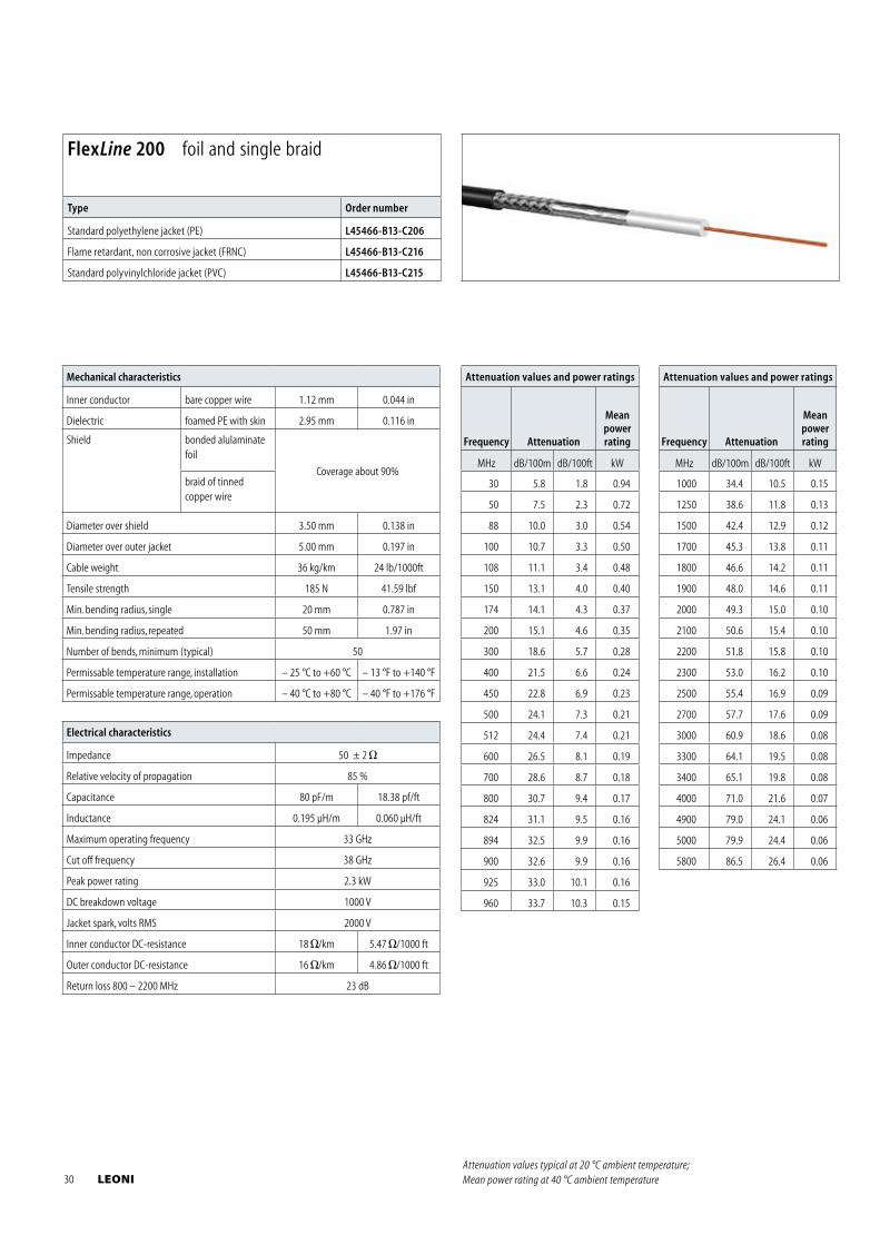
Electrical characteristics
Impedance 50 ± 2
Relative velocity of propagation 85 %
Capacitance 80 pF/m 18.38 pf/ft
Inductance 0.195 μH/m 0.060 μH/ft
Maximum operating frequency 33 GHz
Cut off frequency 38 GHz
Peak power rating 2.3 kW
DC breakdown voltage 1000 V
Jacket spark, volts RMS 2000 V
Inner conductor DC-resistance 18 /km 5.47 /1000 ft
Outer conductor DC-resistance 16 /km 4.86 /1000 ft
Return loss 800 – 2200 MHz 23 dB
Mechanical characteristics
Inner conductor bare copper wire 1.12 mm 0.044 in
Dielectric foamed PE with skin 2.95 mm 0.116 in
Shield bonded alulaminate foil
Coverage about 90%braid of tinned copper wire
Diameter over shield 3.50 mm 0.138 in
Diameter over outer jacket 5.00 mm 0.197 in
Cable weight 36 kg/km 24 lb/1000ft
Tensile strength 185 N 41.59 lbf
Min. bending radius, single 20 mm 0.787 in
Min. bending radius, repeated 50 mm 1.97 in
Number of bends, minimum (typical) 50
Permissable temperature range, installation – 25 °C to +60 °C – 13 °F to +140 °F
Permissable temperature range, operation – 40 °C to +80 °C – 40 °F to +176 °F
Attenuation values and power ratings
Frequency Attenuation
Meanpowerrating
MHz dB/100m dB/100ft kW
30 5.8 1.8 0.94
50 7.5 2.3 0.72
88 10.0 3.0 0.54
100 10.7 3.3 0.50
108 11.1 3.4 0.48
150 13.1 4.0 0.40
174 14.1 4.3 0.37
200 15.1 4.6 0.35
300 18.6 5.7 0.28
400 21.5 6.6 0.24
450 22.8 6.9 0.23
500 24.1 7.3 0.21
512 24.4 7.4 0.21
600 26.5 8.1 0.19
700 28.6 8.7 0.18
800 30.7 9.4 0.17
824 31.1 9.5 0.16
894 32.5 9.9 0.16
900 32.6 9.9 0.16
925 33.0 10.1 0.16
960 33.7 10.3 0.15
Attenuation values and power ratings
Frequency Attenuation
Meanpowerrating
MHz dB/100m dB/100ft kW
1000 34.4 10.5 0.15
1250 38.6 11.8 0.13
1500 42.4 12.9 0.12
1700 45.3 13.8 0.11
1800 46.6 14.2 0.11
1900 48.0 14.6 0.11
2000 49.3 15.0 0.10
2100 50.6 15.4 0.10
2200 51.8 15.8 0.10
2300 53.0 16.2 0.10
2500 55.4 16.9 0.09
2700 57.7 17.6 0.09
3000 60.9 18.6 0.08
3300 64.1 19.5 0.08
3400 65.1 19.8 0.08
4000 71.0 21.6 0.07
4900 79.0 24.1 0.06
5000 79.9 24.4 0.06
5800 86.5 26.4 0.06
FlexLine 200 foil and single braid
Type Order number
Standard polyethylene jacket (PE) L45466-B13-C206
Flame retardant, non corrosive jacket (FRNC) L45466-B13-C216
Standard polyvinylchloride jacket (PVC) L45466-B13-C215
Attenuation values typical at 20 °C ambient temperature; Mean power rating at 40 °C ambient temperature 30 LEONI
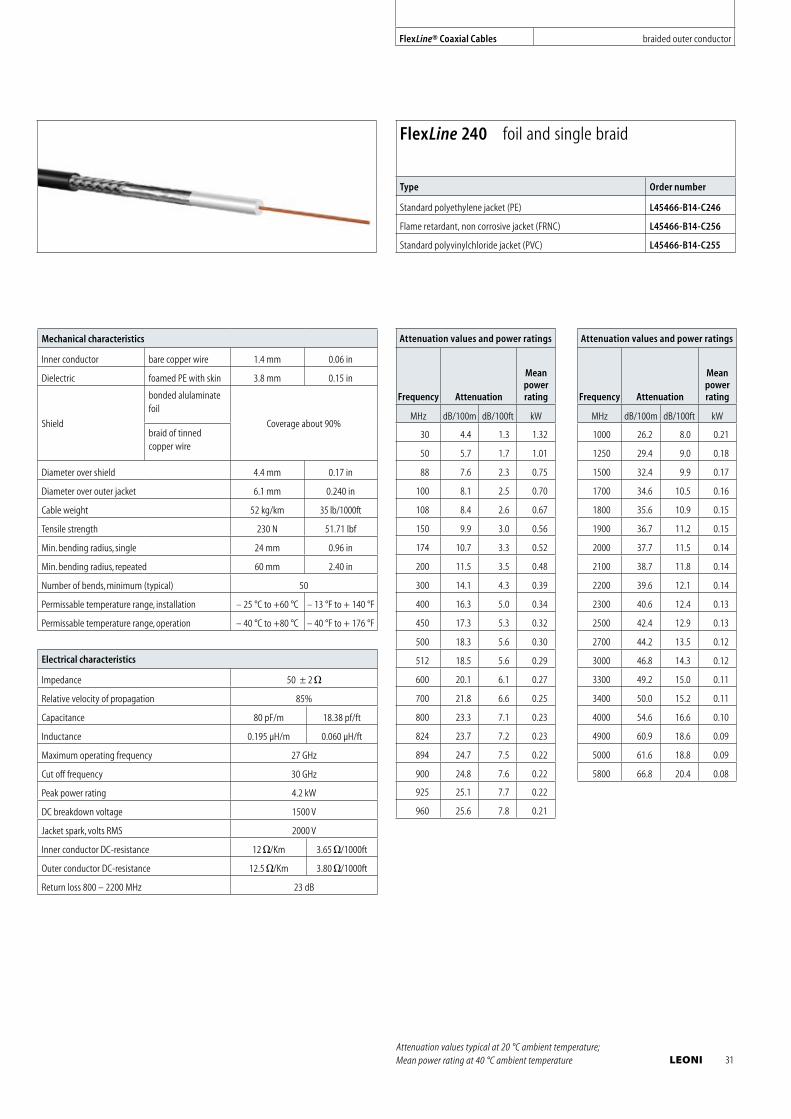
Electrical characteristics
Impedance 50 ± 2
Relative velocity of propagation 85%
Capacitance 80 pF/m 18.38 pf/ft
Inductance 0.195 μH/m 0.060 μH/ft
Maximum operating frequency 27 GHz
Cut off frequency 30 GHz
Peak power rating 4.2 kW
DC breakdown voltage 1500 V
Jacket spark, volts RMS 2000 V
Inner conductor DC-resistance 12 /Km 3.65 /1000ft
Outer conductor DC-resistance 12.5 /Km 3.80 /1000ft
Return loss 800 – 2200 MHz 23 dB
Mechanical characteristics
Inner conductor bare copper wire 1.4 mm 0.06 in
Dielectric foamed PE with skin 3.8 mm 0.15 in
Shield
bonded alulaminate foil
Coverage about 90%braid of tinned copper wire
Diameter over shield 4.4 mm 0.17 in
Diameter over outer jacket 6.1 mm 0.240 in
Cable weight 52 kg/km 35 lb/1000ft
Tensile strength 230 N 51.71 lbf
Min. bending radius, single 24 mm 0.96 in
Min. bending radius, repeated 60 mm 2.40 in
Number of bends, minimum (typical) 50
Permissable temperature range, installation – 25 °C to +60 °C – 13 °F to + 140 °F
Permissable temperature range, operation – 40 °C to +80 °C – 40 °F to + 176 °F
Attenuation values and power ratings
Frequency Attenuation
Meanpowerrating
MHz dB/100m dB/100ft kW
30 4.4 1.3 1.32
50 5.7 1.7 1.01
88 7.6 2.3 0.75
100 8.1 2.5 0.70
108 8.4 2.6 0.67
150 9.9 3.0 0.56
174 10.7 3.3 0.52
200 11.5 3.5 0.48
300 14.1 4.3 0.39
400 16.3 5.0 0.34
450 17.3 5.3 0.32
500 18.3 5.6 0.30
512 18.5 5.6 0.29
600 20.1 6.1 0.27
700 21.8 6.6 0.25
800 23.3 7.1 0.23
824 23.7 7.2 0.23
894 24.7 7.5 0.22
900 24.8 7.6 0.22
925 25.1 7.7 0.22
960 25.6 7.8 0.21
Attenuation values and power ratings
Frequency Attenuation
Meanpowerrating
MHz dB/100m dB/100ft kW
1000 26.2 8.0 0.21
1250 29.4 9.0 0.18
1500 32.4 9.9 0.17
1700 34.6 10.5 0.16
1800 35.6 10.9 0.15
1900 36.7 11.2 0.15
2000 37.7 11.5 0.14
2100 38.7 11.8 0.14
2200 39.6 12.1 0.14
2300 40.6 12.4 0.13
2500 42.4 12.9 0.13
2700 44.2 13.5 0.12
3000 46.8 14.3 0.12
3300 49.2 15.0 0.11
3400 50.0 15.2 0.11
4000 54.6 16.6 0.10
4900 60.9 18.6 0.09
5000 61.6 18.8 0.09
5800 66.8 20.4 0.08
FlexLine 240 foil and single braid
Type Order number
Standard polyethylene jacket (PE) L45466-B14-C246
Flame retardant, non corrosive jacket (FRNC) L45466-B14-C256
Standard polyvinylchloride jacket (PVC) L45466-B14-C255
Attenuation values typical at 20 °C ambient temperature; Mean power rating at 40 °C ambient temperature
FlexLine® Coaxial Cables braided outer conductor
LEONI 31
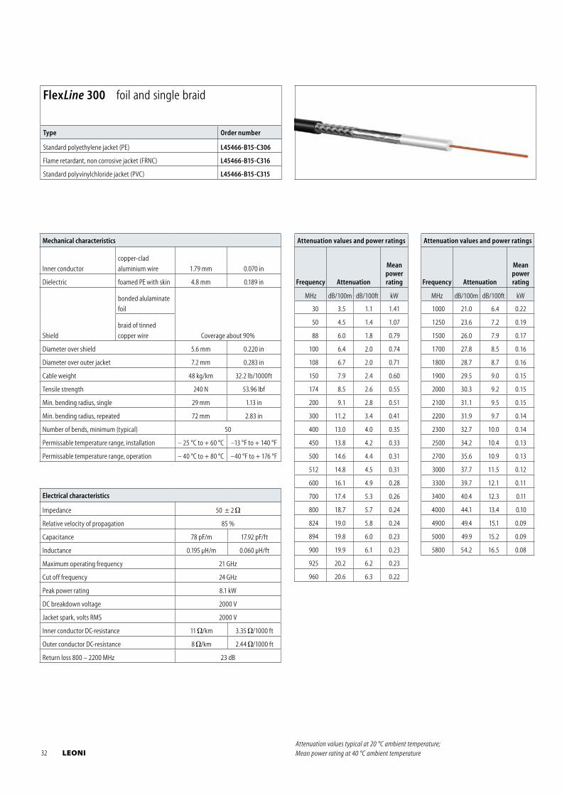
Electrical characteristics
Impedance 50 ± 2
Relative velocity of propagation 85 %
Capacitance 78 pF/m 17.92 pF/ft
Inductance 0.195 μH/m 0.060 μH/ft
Maximum operating frequency 21 GHz
Cut off frequency 24 GHz
Peak power rating 8.1 kW
DC breakdown voltage 2000 V
Jacket spark, volts RMS 2000 V
Inner conductor DC-resistance 11 /km 3.35 /1000 ft
Outer conductor DC-resistance 8 /km 2.44 /1000 ft
Return loss 800 – 2200 MHz 23 dB
Mechanical characteristics
Inner conductor
copper-clad
aluminium wire 1.79 mm 0.070 in
Dielectric foamed PE with skin 4.8 mm 0.189 in
Shield
bonded alulaminate
foil
Coverage about 90%
braid of tinned
copper wire
Diameter over shield 5.6 mm 0.220 in
Diameter over outer jacket 7.2 mm 0.283 in
Cable weight 48 kg/km 32.2 lb/1000ft
Tensile strength 240 N 53.96 lbf
Min. bending radius, single 29 mm 1.13 in
Min. bending radius, repeated 72 mm 2.83 in
Number of bends, minimum (typical) 50
Permissable temperature range, installation – 25 °C to + 60 °C –13 °F to + 140 °F
Permissable temperature range, operation – 40 °C to + 80 °C –40 °F to + 176 °F
Attenuation values and power ratings
Frequency Attenuation
Meanpowerrating
MHz dB/100m dB/100ft kW
30 3.5 1.1 1.41
50 4.5 1.4 1.07
88 6.0 1.8 0.79
100 6.4 2.0 0.74
108 6.7 2.0 0.71
150 7.9 2.4 0.60
174 8.5 2.6 0.55
200 9.1 2.8 0.51
300 11.2 3.4 0.41
400 13.0 4.0 0.35
450 13.8 4.2 0.33
500 14.6 4.4 0.31
512 14.8 4.5 0.31
600 16.1 4.9 0.28
700 17.4 5.3 0.26
800 18.7 5.7 0.24
824 19.0 5.8 0.24
894 19.8 6.0 0.23
900 19.9 6.1 0.23
925 20.2 6.2 0.23
960 20.6 6.3 0.22
Attenuation values and power ratings
Frequency Attenuation
Meanpowerrating
MHz dB/100m dB/100ft kW
1000 21.0 6.4 0.22
1250 23.6 7.2 0.19
1500 26.0 7.9 0.17
1700 27.8 8.5 0.16
1800 28.7 8.7 0.16
1900 29.5 9.0 0.15
2000 30.3 9.2 0.15
2100 31.1 9.5 0.15
2200 31.9 9.7 0.14
2300 32.7 10.0 0.14
2500 34.2 10.4 0.13
2700 35.6 10.9 0.13
3000 37.7 11.5 0.12
3300 39.7 12.1 0.11
3400 40.4 12.3 0.11
4000 44.1 13.4 0.10
4900 49.4 15.1 0.09
5000 49.9 15.2 0.09
5800 54.2 16.5 0.08
FlexLine 300 foil and single braid
Type Order number
Standard polyethylene jacket (PE) L45466-B15-C306
Flame retardant, non corrosive jacket (FRNC) L45466-B15-C316
Standard polyvinylchloride jacket (PVC) L45466-B15-C315
Attenuation values typical at 20 °C ambient temperature; Mean power rating at 40 °C ambient temperature 32 LEONI
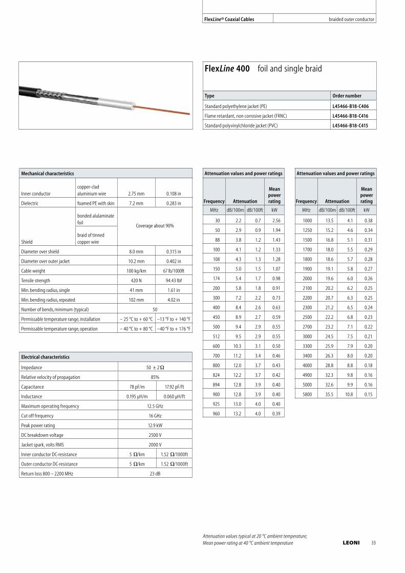
Electrical characteristics
Impedance 50 ± 2
Relative velocity of propagation 85%
Capacitance 78 pF/m 17.92 pF/ft
Inductance 0.195 μH/m 0.060 μH/ft
Maximum operating frequency 12.5 GHz
Cut off frequency 16 GHz
Peak power rating 12.9 kW
DC breakdown voltage 2500 V
Jacket spark, volts RMS 2000 V
Inner conductor DC-resistance 5 /km 1.52 /1000ft
Outer conductor DC-resistance 5 /km 1.52 /1000ft
Return loss 800 – 2200 MHz 23 dB
Mechanical characteristics
Inner conductorcopper-clad aluminium wire 2.75 mm 0.108 in
Dielectric foamed PE with skin 7.2 mm 0.283 in
Shield
bonded alulaminate foil
Coverage about 90%
braid of tinned copper wire
Diameter over shield 8.0 mm 0.315 in
Diameter over outer jacket 10.2 mm 0.402 in
Cable weight 100 kg/km 67 lb/1000ft
Tensile strength 420 N 94.43 lbf
Min. bending radius, single 41 mm 1.61 in
Min. bending radius, repeated 102 mm 4.02 in
Number of bends, minimum (typical) 50
Permissable temperature range, installation – 25 °C to + 60 °C –13 °F to + 140 °F
Permissable temperature range, operation – 40 °C to + 80 °C –40 °F to + 176 °F
Attenuation values and power ratings
Frequency Attenuation
Meanpowerrating
MHz dB/100m dB/100ft kW
30 2.2 0.7 2.56
50 2.9 0.9 1.94
88 3.8 1.2 1.43
100 4.1 1.2 1.33
108 4.3 1.3 1.28
150 5.0 1.5 1.07
174 5.4 1.7 0.98
200 5.8 1.8 0.91
300 7.2 2.2 0.73
400 8.4 2.6 0.63
450 8.9 2.7 0.59
500 9.4 2.9 0.55
512 9.5 2.9 0.55
600 10.3 3.1 0.50
700 11.2 3.4 0.46
800 12.0 3.7 0.43
824 12.2 3.7 0.42
894 12.8 3.9 0.40
900 12.8 3.9 0.40
925 13.0 4.0 0.40
960 13.2 4.0 0.39
Attenuation values and power ratings
Frequency Attenuation
Meanpowerrating
MHz dB/100m dB/100ft kW
1000 13.5 4.1 0.38
1250 15.2 4.6 0.34
1500 16.8 5.1 0.31
1700 18.0 5.5 0.29
1800 18.6 5.7 0.28
1900 19.1 5.8 0.27
2000 19.6 6.0 0.26
2100 20.2 6.2 0.25
2200 20.7 6.3 0.25
2300 21.2 6.5 0.24
2500 22.2 6.8 0.23
2700 23.2 7.1 0.22
3000 24.5 7.5 0.21
3300 25.9 7.9 0.20
3400 26.3 8.0 0.20
4000 28.8 8.8 0.18
4900 32.3 9.8 0.16
5000 32.6 9.9 0.16
5800 35.5 10.8 0.15
FlexLine 400 foil and single braid
Type Order number
Standard polyethylene jacket (PE) L45466-B18-C406
Flame retardant, non corrosive jacket (FRNC) L45466-B18-C416
Standard polyvinylchloride jacket (PVC) L45466-B18-C415
Attenuation values typical at 20 °C ambient temperature; Mean power rating at 40 °C ambient temperature
FlexLine® Coaxial Cables braided outer conductor
LEONI 33
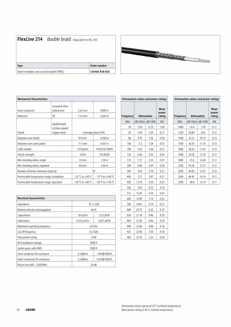
Electrical characteristics
Impedance 50 ± 2
Relative velocity of propagation 66 %
Capacitance 101 pF/m 23.2 pF/ft
Inductance 0.253 μH/m 0.077 μH/ft
Maximum operating frequency 5.8 GHz
Cut off frequency 13.2 GHz
Peak power rating 2 kW
DC breakdown voltage 5000 V
Jacket spark, volts RMS 2000 V
Inner conductor DC-resistance 6.2 /km 1.89 /1000 ft
Outer conductor DC-resistance 2.5 /km 0.76 /1000 ft
Return loss 800 – 2200 MHz 26 dB
Mechanical characteristics
Inner conductor
stranded silver-
plated wire 2.25 mm 0.089 in
Dielectric PE 7.25 mm 0.285 in
Shield
double braid
of silver-plated
copper wires Coverage about 95%
Diameter over shield 8.9 mm 0.350 in
Diameter over outer jacket 11.1 mm 0.437 in
Cable weight 215 kg/km 144.05 lb/1000ft
Tensile strength 720 N 161.88 lbf
Min. bending radius, single 33 mm 1.30 in
Min. bending radius, repeated 66 mm 2.60 in
Number of bends, minimum (typical) 50
Permissable temperature range, installation – 25 °C to +60 °C – 13 °F to +140 °F
Permissable temperature range, operation – 40 °C to +80 °C – 40 °F to +176 °F
Attenuation values and power ratings
Frequency Attenuation
Meanpowerrating
MHz dB/100m dB/100ft kW
30 2.58 0.79 1.00
50 3.44 1.05 0.77
88 4.79 1.46 0.58
100 5.2 1.58 0.55
108 5.43 1.66 0.52
150 6.66 2.03 0.44
174 7.31 2.23 0.41
200 8.00 2.44 0.38
300 10.4 3.18 0.31
400 12.7 3.87 0.27
450 13.76 4.20 0.26
500 14.8 4.52 0.24
512 15.06 4.59 0.24
600 16.84 5.14 0.22
700 18.81 5.74 0.21
800 20.72 6.32 0.19
824 21.18 6.46 0.19
894 22.48 6.86 0.18
900 22.60 6.89 0.18
925 23.06 7.03 0.18
960 23.70 7.23 0.18
Attenuation values and power ratings
Frequency Attenuation
Meanpowerrating
MHz dB/100m dB/100ft kW
1000 24.4 7.45 0.17
1250 28.89 8.81 0.15
1500 33.21 10.13 0.14
1700 36.59 11.16 0.13
1800 38.26 11.67 0.13
1900 39.92 12.18 0.12
2000 41.6 12.68 0.12
2100 43.20 13.17 0.12
2200 44.82 13.67 0.12
2300 46.43 14.16 0.11
2500 49.6 15.14 0.11
FlexLine 214 double braid (equivalent to RG 214)
Type Order number
Flame retardant, non corrosive jacket (FRNC) L45466-B18-B36
Attenuation values typical at 20 °C ambient temperature; Mean power rating at 40 °C ambient temperature 34 LEONI
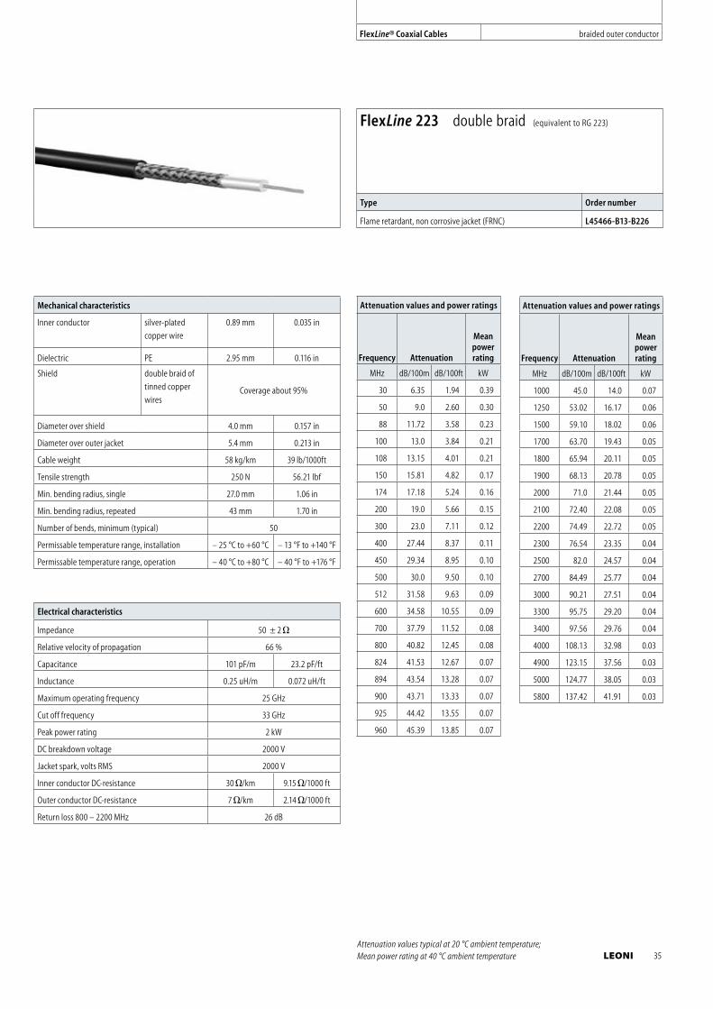
Electrical characteristics
Impedance 50 ± 2
Relative velocity of propagation 66 %
Capacitance 101 pF/m 23.2 pF/ft
Inductance 0.25 uH/m 0.072 uH/ft
Maximum operating frequency 25 GHz
Cut off frequency 33 GHz
Peak power rating 2 kW
DC breakdown voltage 2000 V
Jacket spark, volts RMS 2000 V
Inner conductor DC-resistance 30 /km 9.15 /1000 ft
Outer conductor DC-resistance 7 /km 2.14 /1000 ft
Return loss 800 – 2200 MHz 26 dB
Mechanical characteristics
Inner conductor silver-plated
copper wire
0.89 mm 0.035 in
Dielectric PE 2.95 mm 0.116 in
Shield double braid of
tinned copper
wiresCoverage about 95%
Diameter over shield 4.0 mm 0.157 in
Diameter over outer jacket 5.4 mm 0.213 in
Cable weight 58 kg/km 39 lb/1000ft
Tensile strength 250 N 56.21 lbf
Min. bending radius, single 27.0 mm 1.06 in
Min. bending radius, repeated 43 mm 1.70 in
Number of bends, minimum (typical) 50
Permissable temperature range, installation – 25 °C to +60 °C – 13 °F to +140 °F
Permissable temperature range, operation – 40 °C to +80 °C – 40 °F to +176 °F
Attenuation values and power ratings
Frequency Attenuation
Meanpowerrating
MHz dB/100m dB/100ft kW
30 6.35 1.94 0.39
50 9.0 2.60 0.30
88 11.72 3.58 0.23
100 13.0 3.84 0.21
108 13.15 4.01 0.21
150 15.81 4.82 0.17
174 17.18 5.24 0.16
200 19.0 5.66 0.15
300 23.0 7.11 0.12
400 27.44 8.37 0.11
450 29.34 8.95 0.10
500 30.0 9.50 0.10
512 31.58 9.63 0.09
600 34.58 10.55 0.09
700 37.79 11.52 0.08
800 40.82 12.45 0.08
824 41.53 12.67 0.07
894 43.54 13.28 0.07
900 43.71 13.33 0.07
925 44.42 13.55 0.07
960 45.39 13.85 0.07
Attenuation values and power ratings
Frequency Attenuation
Meanpowerrating
MHz dB/100m dB/100ft kW
1000 45.0 14.0 0.07
1250 53.02 16.17 0.06
1500 59.10 18.02 0.06
1700 63.70 19.43 0.05
1800 65.94 20.11 0.05
1900 68.13 20.78 0.05
2000 71.0 21.44 0.05
2100 72.40 22.08 0.05
2200 74.49 22.72 0.05
2300 76.54 23.35 0.04
2500 82.0 24.57 0.04
2700 84.49 25.77 0.04
3000 90.21 27.51 0.04
3300 95.75 29.20 0.04
3400 97.56 29.76 0.04
4000 108.13 32.98 0.03
4900 123.15 37.56 0.03
5000 124.77 38.05 0.03
5800 137.42 41.91 0.03
FlexLine 223 double braid (equivalent to RG 223)
Type Order number
Flame retardant, non corrosive jacket (FRNC) L45466-B13-B226
Attenuation values typical at 20 °C ambient temperature; Mean power rating at 40 °C ambient temperature
FlexLine® Coaxial Cables braided outer conductor
LEONI 35
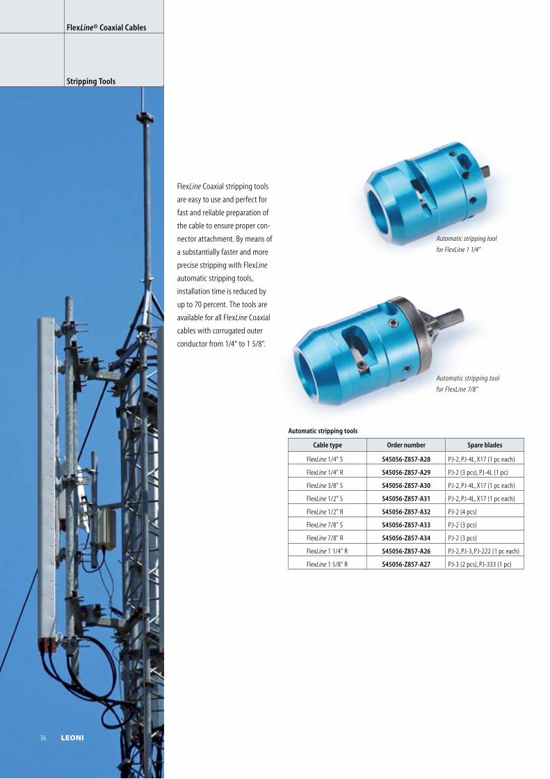
Automatic stripping tool
for FlexLine 7/8”
Automatic stripping tools
Cable type Order number Spare blades
FlexLine 1/4" S S45056-Z857-A28 PJ-2, PJ-4L, X17 (1 pc each)
FlexLine 1/4" R S45056-Z857-A29 PJ-2 (3 pcs), PJ-4L (1 pc)
FlexLine 3/8" S S45056-Z857-A30 PJ-2, PJ-4L, X17 (1 pc each)
FlexLine 1/2" S S45056-Z857-A31 PJ-2, PJ-4L, X17 (1 pc each)
FlexLine 1/2" R S45056-Z857-A32 PJ-2 (4 pcs)
FlexLine 7/8" S S45056-Z857-A33 PJ-2 (3 pcs)
FlexLine 7/8" R S45056-Z857-A34 PJ-2 (3 pcs)
FlexLine 1 1/4" R S45056-Z857-A26 PJ-2, PJ-3, PJ-222 (1 pc each)
FlexLine 1 5/8" R S45056-Z857-A27 PJ-3 (2 pcs), PJ-333 (1 pc)
Automatic stripping tool
for FlexLine 1 1/4”
FlexLine Coaxial stripping tools
are easy to use and perfect for
fast and reliable preparation of
the cable to ensure proper con-
nector attachment. By means of
a substantially faster and more
precise stripping with FlexLine
automatic stripping tools,
installation time is reduced by
up to 70 percent. The tools are
available for all FlexLine Coaxial
cables with corrugated outer
conductor from 1/4“ to 1 5/8“.
FlexLine® Coaxial Cables
Stripping Tools
36 LEONI
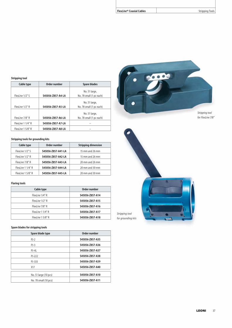
Flaring tools
Cable type Order number
FlexLine 1/4" R S45056-Z857-A14
FlexLine 1/2" R S45056-Z857-A15
FlexLine 7/8" R S45056-Z857-A16
FlexLine 1 1/4" R S45056-Z857-A17
FlexLine 1 5/8" R S45056-Z857-A18
Stripping tool
Cable type Order number Spare blades
FlexLine 1/2" S S45056-Z857-A4-LA
No. 51 large,
No. 78 small (1 pc each)
FlexLine 1/2" R S45056-Z857-A5-LA
No. 51 large,
No. 78 small (1 pc each)
FlexLine 7/8" R S45056-Z857-A6-LA
No. 51 large,
No. 78 small (1 pc each)
FlexLine 1 1/4" R S45056-Z857-A7-LA –
FlexLine 1 5/8" R S45056-Z857-A8-LA –
Stripping tools for grounding kits
Cable type Order number Stripping dimension
FlexLine 1/2" S S45056-Z857-A41-LA 15 mm and 26 mm
FlexLine 1/2" R S45056-Z857-A42-LA 15 mm and 26 mm
FlexLine 7/8" R S45056-Z857-A43-LA 20 mm and 26 mm
FlexLine 1 1/4" R S45056-Z857-A44-LA 20 mm and 30 mm
FlexLine 1 5/8" R S45056-Z857-A45-LA 20 mm and 30 mm
Stripping tool
for FlexLine 7/8”
Stripping tool
for grounding kits
Spare blades for stripping tools
Spare blade type Order number
PJ-2 S45056-Z857-A35
PJ-3 S45056-Z857-A36
PJ-4L S45056-Z857-A37
PJ-222 S45056-Z857-A38
PJ-333 S45056-Z857-A39
X17 S45056-Z857-A40
No. 51 large (10 pcs) S45056-Z857-A10
No. 78 small (10 pcs) S45056-Z857-A11
FlexLine® Coaxial Cables Stripping Tools
LEONI 37
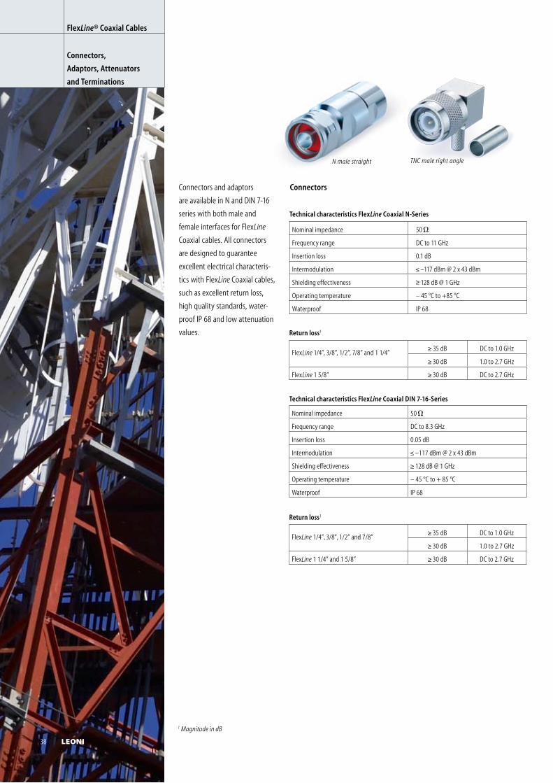
N male straight
Technical characteristics FlexLine Coaxial N-Series
Nominal impedance 50
Frequency range DC to 11 GHz
Insertion loss 0.1 dB
Intermodulation –117 dBm @ 2 x 43 dBm
Shielding effectiveness 128 dB @ 1 GHz
Operating temperature – 45 °C to +85 °C
Waterproof IP 68
Return loss1
FlexLine 1/4”, 3/8”, 1/2”, 7/8” and 1 1/4” 35 dB DC to 1.0 GHz
30 dB 1.0 to 2.7 GHz
FlexLine 1 5/8” 30 dB DC to 2.7 GHz
Technical characteristics FlexLine Coaxial DIN 7-16-Series
Nominal impedance 50
Frequency range DC to 8.3 GHz
Insertion loss 0.05 dB
Intermodulation –117 dBm @ 2 x 43 dBm
Shielding effectiveness 128 dB @ 1 GHz
Operating temperature – 45 °C to + 85 °C
Waterproof IP 68
Return loss1
FlexLine 1/4”, 3/8”, 1/2” and 7/8” 35 dB DC to 1.0 GHz
30 dB 1.0 to 2.7 GHz
FlexLine 1 1/4” and 1 5/8” 30 dB DC to 2.7 GHz
Connectors and adaptors
are available in N and DIN 7-16
series with both male and
female interfaces for FlexLine
Coaxial cables. All connectors
are designed to guarantee
excellent electrical characteris-
tics with FlexLine Coaxial cables,
such as excellent return loss,
high quality standards, water-
proof IP 68 and low attenuation
values.
FlexLine® Coaxial Cables
Connectors,
Adaptors, Attenuators
and Terminations
Connectors
1 Magnitude in dB
TNC male right angle
38 LEONI
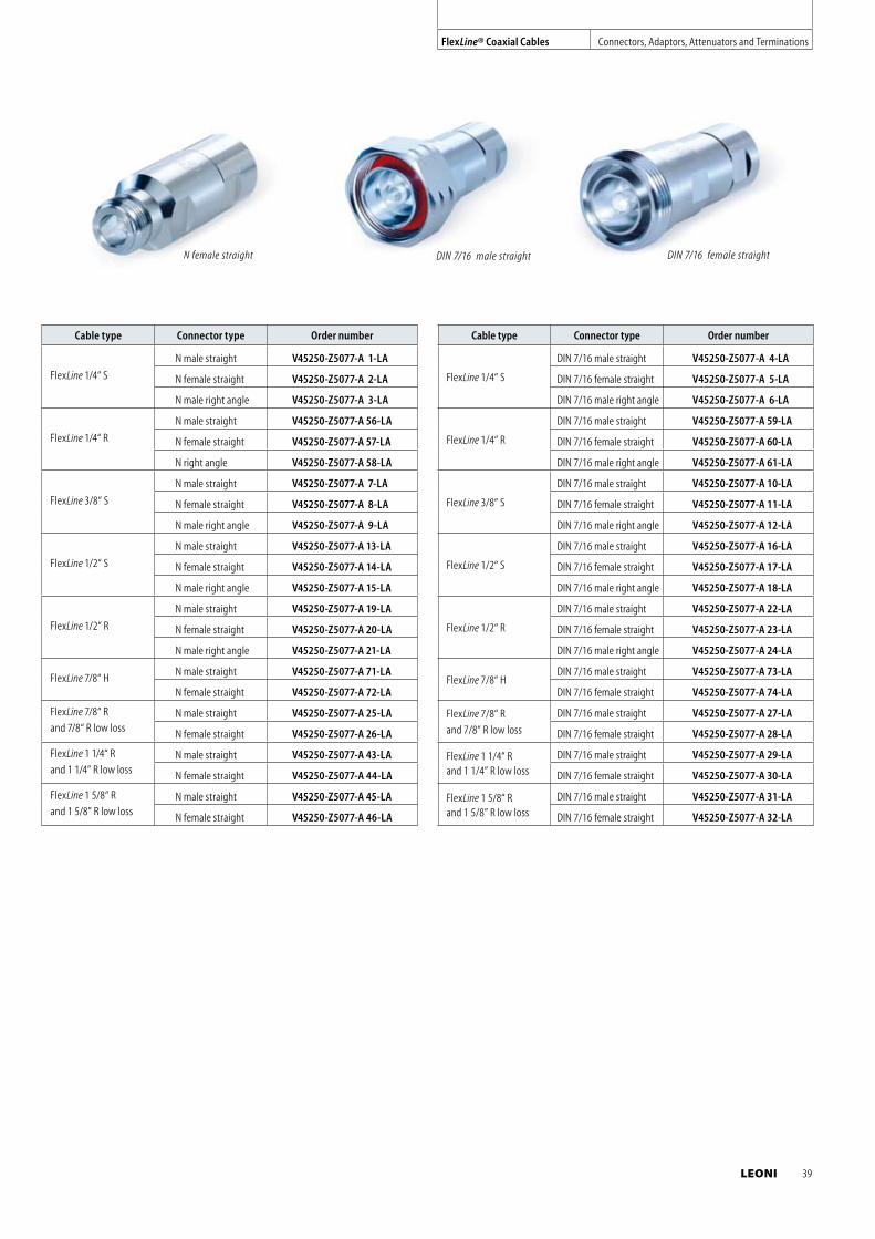
Cable type Connector type Order number
FlexLine 1/4“ S
N male straight V45250-Z5077-A 1-LA
N female straight V45250-Z5077-A 2-LA
N male right angle V45250-Z5077-A 3-LA
FlexLine 1/4“ R
N male straight V45250-Z5077-A 56-LA
N female straight V45250-Z5077-A 57-LA
N right angle V45250-Z5077-A 58-LA
FlexLine 3/8“ S
N male straight V45250-Z5077-A 7-LA
N female straight V45250-Z5077-A 8-LA
N male right angle V45250-Z5077-A 9-LA
FlexLine 1/2“ S
N male straight V45250-Z5077-A 13-LA
N female straight V45250-Z5077-A 14-LA
N male right angle V45250-Z5077-A 15-LA
FlexLine 1/2“ R
N male straight V45250-Z5077-A 19-LA
N female straight V45250-Z5077-A 20-LA
N male right angle V45250-Z5077-A 21-LA
FlexLine 7/8“ HN male straight V45250-Z5077-A 71-LA
N female straight V45250-Z5077-A 72-LA
FlexLine 7/8“ R
and 7/8“ R low lossN male straight V45250-Z5077-A 25-LA
N female straight V45250-Z5077-A 26-LA
FlexLine 1 1/4“ R
and 1 1/4” R low lossN male straight V45250-Z5077-A 43-LA
N female straight V45250-Z5077-A 44-LA
FlexLine 1 5/8“ R
and 1 5/8” R low lossN male straight V45250-Z5077-A 45-LA
N female straight V45250-Z5077-A 46-LA
Cable type Connector type Order number
FlexLine 1/4“ S
DIN 7/16 male straight V45250-Z5077-A 4-LA
DIN 7/16 female straight V45250-Z5077-A 5-LA
DIN 7/16 male right angle V45250-Z5077-A 6-LA
FlexLine 1/4“ R
DIN 7/16 male straight V45250-Z5077-A 59-LA
DIN 7/16 female straight V45250-Z5077-A 60-LA
DIN 7/16 male right angle V45250-Z5077-A 61-LA
FlexLine 3/8“ S
DIN 7/16 male straight V45250-Z5077-A 10-LA
DIN 7/16 female straight V45250-Z5077-A 11-LA
DIN 7/16 male right angle V45250-Z5077-A 12-LA
FlexLine 1/2“ S
DIN 7/16 male straight V45250-Z5077-A 16-LA
DIN 7/16 female straight V45250-Z5077-A 17-LA
DIN 7/16 male right angle V45250-Z5077-A 18-LA
FlexLine 1/2“ R
DIN 7/16 male straight V45250-Z5077-A 22-LA
DIN 7/16 female straight V45250-Z5077-A 23-LA
DIN 7/16 male right angle V45250-Z5077-A 24-LA
FlexLine 7/8“ HDIN 7/16 male straight V45250-Z5077-A 73-LA
DIN 7/16 female straight V45250-Z5077-A 74-LA
FlexLine 7/8“ R
and 7/8“ R low loss
DIN 7/16 male straight V45250-Z5077-A 27-LA
DIN 7/16 female straight V45250-Z5077-A 28-LA
FlexLine 1 1/4“ R and 1 1/4” R low loss
DIN 7/16 male straight V45250-Z5077-A 29-LA
DIN 7/16 female straight V45250-Z5077-A 30-LA
FlexLine 1 5/8“ R and 1 5/8” R low loss
DIN 7/16 male straight V45250-Z5077-A 31-LA
DIN 7/16 female straight V45250-Z5077-A 32-LA
DIN 7/16 male straight DIN 7/16 female straight
N female straight
FlexLine® Coaxial Cables Connectors, Adaptors, Attenuators and Terminations
LEONI 39
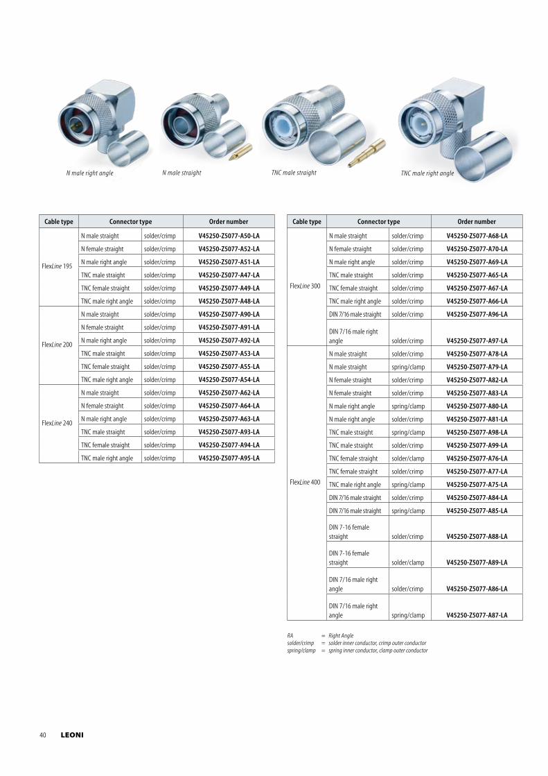
Cable type Connector type Order number
FlexLine 195
N male straight solder/crimp V45250-Z5077-A50-LA
N female straight solder/crimp V45250-Z5077-A52-LA
N male right angle solder/crimp V45250-Z5077-A51-LA
TNC male straight solder/crimp V45250-Z5077-A47-LA
TNC female straight solder/crimp V45250-Z5077-A49-LA
TNC male right angle solder/crimp V45250-Z5077-A48-LA
FlexLine 200
N male straight solder/crimp V45250-Z5077-A90-LA
N female straight solder/crimp V45250-Z5077-A91-LA
N male right angle solder/crimp V45250-Z5077-A92-LA
TNC male straight solder/crimp V45250-Z5077-A53-LA
TNC female straight solder/crimp V45250-Z5077-A55-LA
TNC male right angle solder/crimp V45250-Z5077-A54-LA
FlexLine 240
N male straight solder/crimp V45250-Z5077-A62-LA
N female straight solder/crimp V45250-Z5077-A64-LA
N male right angle solder/crimp V45250-Z5077-A63-LA
TNC male straight solder/crimp V45250-Z5077-A93-LA
TNC female straight solder/crimp V45250-Z5077-A94-LA
TNC male right angle solder/crimp V45250-Z5077-A95-LA
TNC male straight
N male straight
N male right angle
TNC male right angle
Cable type Connector type Order number
FlexLine 300
N male straight solder/crimp V45250-Z5077-A68-LA
N female straight solder/crimp V45250-Z5077-A70-LA
N male right angle solder/crimp V45250-Z5077-A69-LA
TNC male straight solder/crimp V45250-Z5077-A65-LA
TNC female straight solder/crimp V45250-Z5077-A67-LA
TNC male right angle solder/crimp V45250-Z5077-A66-LA
DIN 7/16 male straight solder/crimp V45250-Z5077-A96-LA
DIN 7/16 male right angle solder/crimp V45250-Z5077-A97-LA
FlexLine 400
N male straight solder/crimp V45250-Z5077-A78-LA
N male straight spring/clamp V45250-Z5077-A79-LA
N female straight solder/crimp V45250-Z5077-A82-LA
N female straight solder/crimp V45250-Z5077-A83-LA
N male right angle spring/clamp V45250-Z5077-A80-LA
N male right angle solder/crimp V45250-Z5077-A81-LA
TNC male straight spring/clamp V45250-Z5077-A98-LA
TNC male straight solder/crimp V45250-Z5077-A99-LA
TNC female straight solder/clamp V45250-Z5077-A76-LA
TNC female straight solder/crimp V45250-Z5077-A77-LA
TNC male right angle spring/clamp V45250-Z5077-A75-LA
DIN 7/16 male straight solder/crimp V45250-Z5077-A84-LA
DIN 7/16 male straight spring/clamp V45250-Z5077-A85-LA
DIN 7-16 female straight solder/crimp V45250-Z5077-A88-LA
DIN 7-16 female straight solder/clamp V45250-Z5077-A89-LA
DIN 7/16 male right angle solder/crimp V45250-Z5077-A86-LA
DIN 7/16 male right angle spring/clamp V45250-Z5077-A87-LA
RA = Right Anglesolder/crimp = solder inner conductor, crimp outer conductorspring/clamp = spring inner conductor, clamp outer conductor
40 LEONI
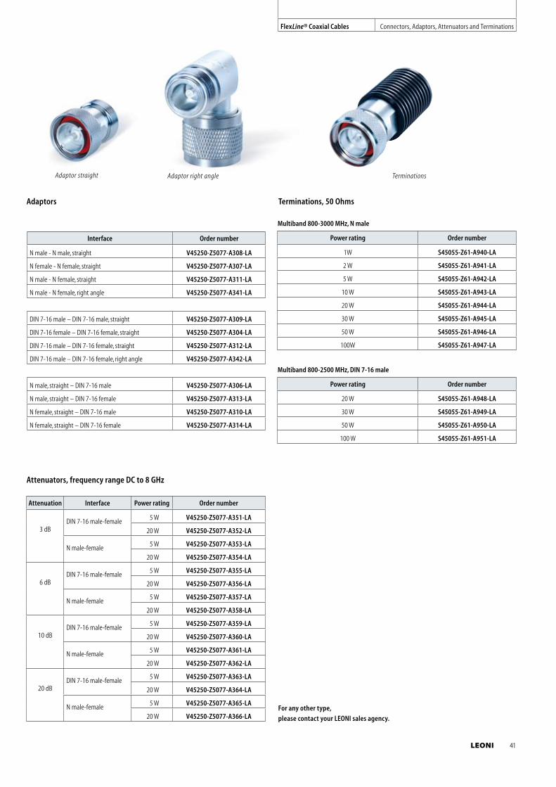
Attenuation Interface Power rating Order number
3 dBDIN 7-16 male-female 5 W V45250-Z5077-A351-LA
20 W V45250-Z5077-A352-LA
N male-female 5 W V45250-Z5077-A353-LA
20 W V45250-Z5077-A354-LA
6 dBDIN 7-16 male-female 5 W V45250-Z5077-A355-LA
20 W V45250-Z5077-A356-LA
N male-female 5 W V45250-Z5077-A357-LA
20 W V45250-Z5077-A358-LA
10 dBDIN 7-16 male-female 5 W V45250-Z5077-A359-LA
20 W V45250-Z5077-A360-LA
N male-female 5 W V45250-Z5077-A361-LA
20 W V45250-Z5077-A362-LA
20 dBDIN 7-16 male-female 5 W V45250-Z5077-A363-LA
20 W V45250-Z5077-A364-LA
N male-female 5 W V45250-Z5077-A365-LA
20 W V45250-Z5077-A366-LA
Interface Order number
N male - N male, straight V45250-Z5077-A308-LA
N female - N female, straight V45250-Z5077-A307-LA
N male - N female, straight V45250-Z5077-A311-LA
N male - N female, right angle V45250-Z5077-A341-LA
DIN 7-16 male – DIN 7-16 male, straight V45250-Z5077-A309-LA
DIN 7-16 female – DIN 7-16 female, straight V45250-Z5077-A304-LA
DIN 7-16 male – DIN 7-16 female, straight V45250-Z5077-A312-LA
DIN 7-16 male – DIN 7-16 female, right angle V45250-Z5077-A342-LA
N male, straight – DIN 7-16 male V45250-Z5077-A306-LA
N male, straight – DIN 7-16 female V45250-Z5077-A313-LA
N female, straight – DIN 7-16 male V45250-Z5077-A310-LA
N female, straight – DIN 7-16 female V45250-Z5077-A314-LA
Adaptor straight Adaptor right angle Terminations
Multiband 800-3000 MHz, N male
Power rating Order number
1W S45055-Z61-A940-LA
2 W S45055-Z61-A941-LA
5 W S45055-Z61-A942-LA
10 W S45055-Z61-A943-LA
20 W S45055-Z61-A944-LA
30 W S45055-Z61-A945-LA
50 W S45055-Z61-A946-LA
100W S45055-Z61-A947-LA
Multiband 800-2500 MHz, DIN 7-16 male
Power rating Order number
20 W S45055-Z61-A948-LA
30 W S45055-Z61-A949-LA
50 W S45055-Z61-A950-LA
100 W S45055-Z61-A951-LA
Terminations, 50 Ohms
For any other type,
please contact your LEONI sales agency.
Adaptors
FlexLine® Coaxial Cables Connectors, Adaptors, Attenuators and Terminations
Attenuators, frequency range DC to 8 GHz
LEONI 41
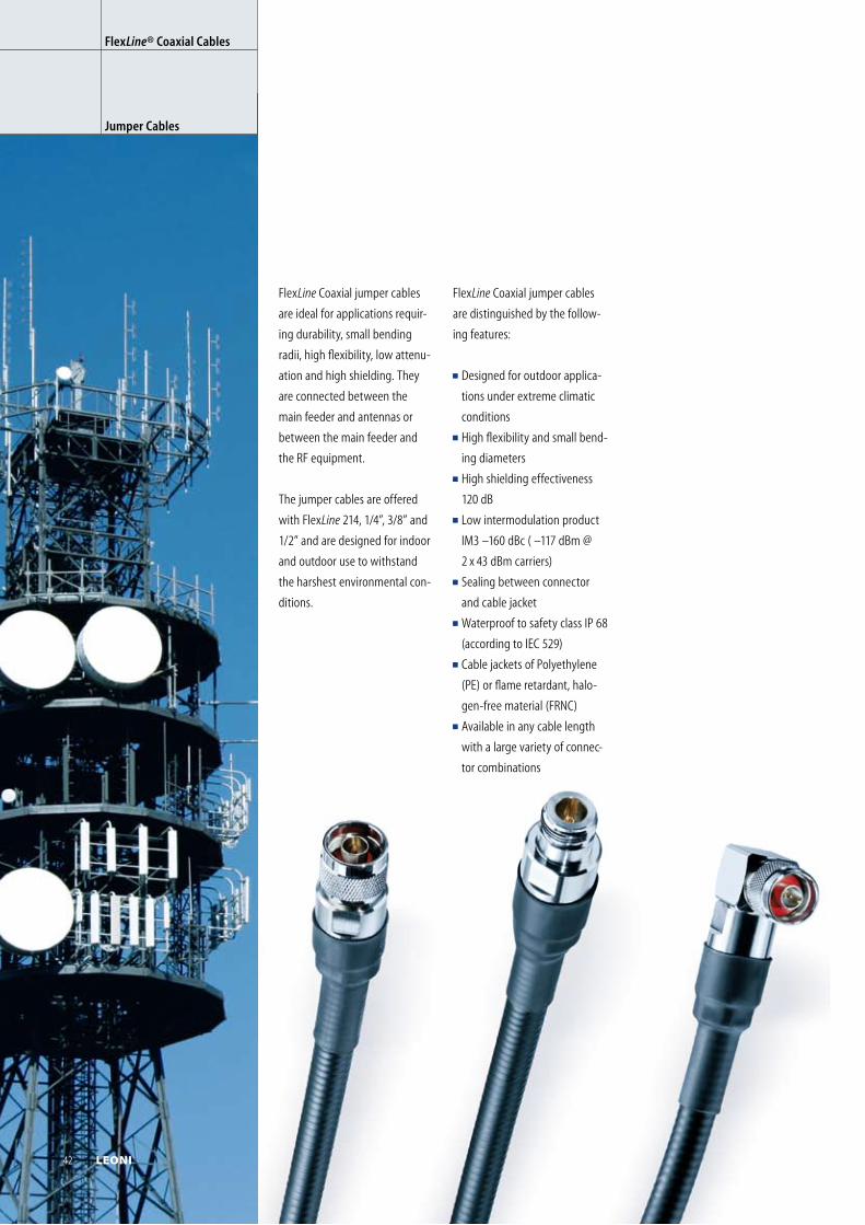
FlexLine Coaxial jumper cables
are ideal for applications requir-
ing durability, small bending
radii, high flexibility, low attenu-
ation and high shielding. They
are connected between the
main feeder and antennas or
between the main feeder and
the RF equipment.
The jumper cables are offered
with FlexLine 214, 1/4”, 3/8” and
1/2” and are designed for indoor
and outdoor use to withstand
the harshest environmental con-
ditions.
FlexLine Coaxial jumper cables
are distinguished by the follow-
ing features:
Designed for outdoor applica-
tions under extreme climatic
conditions
High flexibility and small bend-
ing dia meters
High shielding effectiveness
120 dB
Low intermodulation product
IM3 –160 dBc ( –117 dBm @
2 x 43 dBm carriers)
Sealing between connector
and cable jacket
Waterproof to safety class IP 68
(according to IEC 529)
Cable jackets of Polyethylene
(PE) or flame retardant, halo-
gen-free material (FRNC)
Available in any cable length
with a large variety of connec-
tor combinations
FlexLine® Coaxial Cables
Jumper Cables
42 LEONI
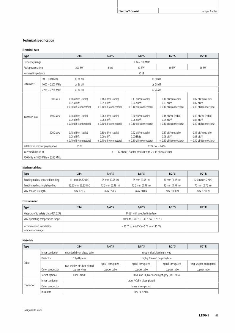
Technical specification
Electrical data
Type 214 1/4“ S 3/8“ S 1/2“ S 1/2“ R
Frequency range DC to 2700 MHz
Peak power rating 200 kW 8 kW 13 kW 19 kW 58 kW
Nominal impedance 50
Return loss1
30 – 1000 MHz 26 dB 30 dB
1000 – 2200 MHz 26 dB 28 dB
2200 – 2700 MHz 24 dB 26 dB
Insertion loss
900 MHz 0.18 dB/m (cable) 0.05 dB/ft
+ 0.10 dB (connectors)
0.18 dB/m (cable) 0.05 dB/ft
+ 0.10 dB (connectors)
0.13 dB/m (cable) 0.04 dB/ft
+ 0.10 dB (connectors)
0.10 dB/m (cable) 0.03 dB/ft
+ 0.10 dB (connectors)
0.07 dB/m (cable) 0.02 dB/ft
+ 0.10 dB (connectors)
1800 MHz 0.18 dB/m (cable) 0.05 dB/ft
+ 0.10 dB (connectors)
0.26 dB/m (cable) 0.08 dB/ft
+ 0.10 dB (connectors)
0.20 dB/m (cable) 0.06 dB/ft
+ 0.10 dB (connectors)
0.16 dB/m (cable)0.05 dB/ft
+ 0.10 dB (connectors)
0.10 dB/m (cable) 0.03 dB/ft
+ 0.10 dB (connectors)
2200 MHz 0.18 dB/m (cable) 0.05 dB/ft
+ 0.10 dB (connectors)
0.30 dB/m (cable) 0.09 dB/ft
+ 0.10 dB (connectors)
0.22 dB/m (cable) 0.07dB/ft
+ 0.10 dB (connectors)
0.17 dB/m (cable) 0.05 dB/ft
+ 0.10 dB (connectors)
0.11 dB/m (cable) 0.03 dB/ft
+ 0.10 dB (connectors)
Relatice velocity of propagation 65 % 82 % to – 84 %
Intermodulation at
900 MHz + 1800 MHz + 2200 MHz
– 117 dBm (3rd order product with 2 x 43 dBm carriers)
Mechanical data
Type 214 1/4“ S 3/8“ S 1/2“ S 1/2“ R
Bending radius, repeated bending 111 mm (4.370 in) 25 mm (0.98 in) 25 mm (0.98 in) 30 mm (1.18 in) 120 mm (4.72 in)
Bending radius, single bending 83.25 mm (3.278 in) 12.5 mm (0.49 in) 12.5 mm (0.49 in) 15 mm (0.59 in) 70 mm (2.76 in)
Max. tensile strength max. 420 N max. 350 N max. 600 N max. 1000 N max. 1200 N
Environment
Type 214 1/4“ S 3/8“ S 1/2“ S 1/2“ R
Waterproof to safety class (IEC 529) IP 682 with coupled interface
Max. operating temperature range – 40 °C to + 80 °C (– 40 °F to +176 °F)
recommended Installation temperature range
– 15 °C to + 60 °C (+5 °F to +140 °F)
Materials
Type 214 1/4“ S 3/8“ S 1/2“ S 1/2“ R
Cable
Inner conductor stranded silver-plated wire copper clad aluminum wire
Dielectric Polyethylene highly foamed polyethylene
Outer conductortwo shields of silver-plated
copper wires
spiral corrugated spiral corrugated spiral corrugated ring-shaped corrugated
copper tube copper tube copper tube copper tube
Jacket options FRNC, black FRNC and PE, black and light grey (RAL 7004)
Connector
Inner conductor brass / CuBe, silver-plated
Outer conductor brass, silver-plated
Insulator PP / PE / PTFE
1 Magnitude in dB
FlexLine® Coaxial Jumper Cables
LEONI 43
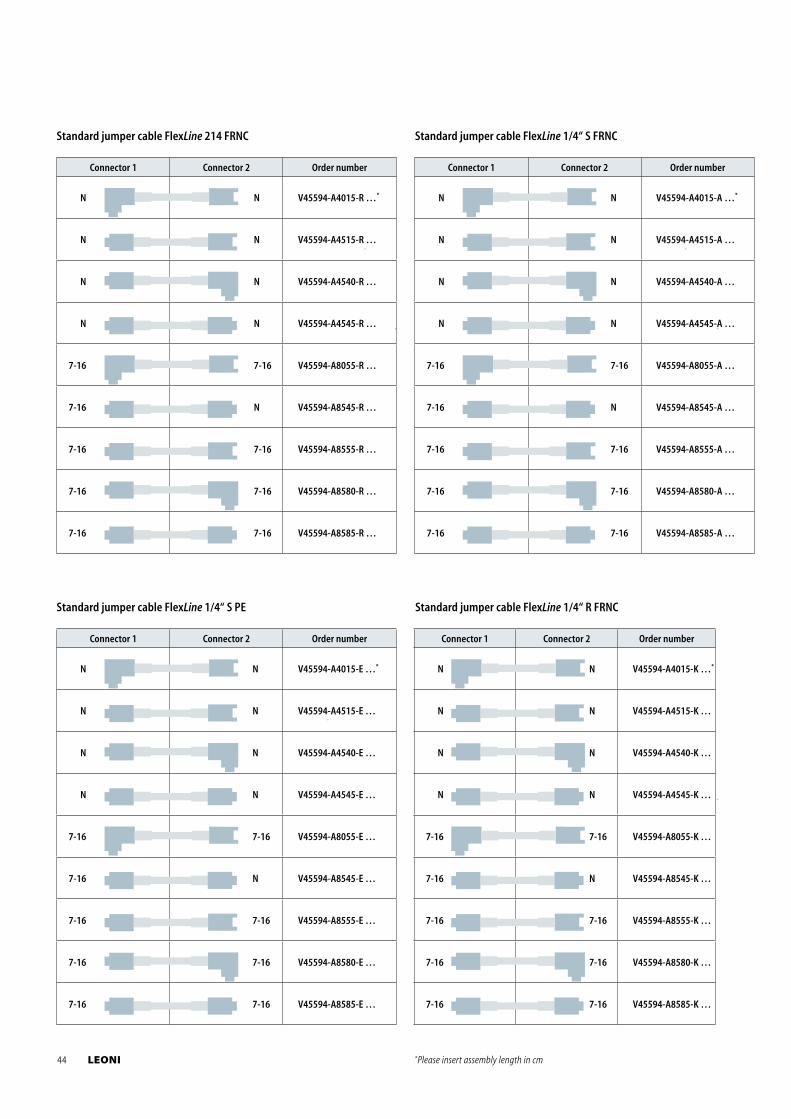
Standard jumper cable FlexLine 214 FRNC
Connector 1 Connector 2 Order number
N N V45594-A4015-R …*
N N V45594-A4515-R …
N N V45594-A4540-R …
N N V45594-A4545-R …
7-16 7-16 V45594-A8055-R …
7-16 N V45594-A8545-R …
7-16 7-16 V45594-A8555-R …
7-16 7-16 V45594-A8580-R …
7-16 7-16 V45594-A8585-R …
Standard jumper cable FlexLine 1/4“ S PE
Connector 1 Connector 2 Order number
N N V45594-A4015-E …*
N N V45594-A4515-E …
N N V45594-A4540-E …
N N V45594-A4545-E …
7-16 7-16 V45594-A8055-E …
7-16 N V45594-A8545-E …
7-16 7-16 V45594-A8555-E …
7-16 7-16 V45594-A8580-E …
7-16 7-16 V45594-A8585-E …
Standard jumper cable FlexLine 1/4“ S FRNC
Connector 1 Connector 2 Order number
N N V45594-A4015-A …*
N N V45594-A4515-A …
N N V45594-A4540-A …
N N V45594-A4545-A …
7-16 7-16 V45594-A8055-A …
7-16 N V45594-A8545-A …
7-16 7-16 V45594-A8555-A …
7-16 7-16 V45594-A8580-A …
7-16 7-16 V45594-A8585-A …
Standard jumper cable FlexLine 1/4“ R FRNC
Connector 1 Connector 2 Order number
N N V45594-A4015-K …*
N N V45594-A4515-K …
N N V45594-A4540-K …
N N V45594-A4545-K …
7-16 7-16 V45594-A8055-K …
7-16 N V45594-A8545-K …
7-16 7-16 V45594-A8555-K …
7-16 7-16 V45594-A8580-K …
7-16 7-16 V45594-A8585-K …
*Please insert assembly length in cm44 LEONI
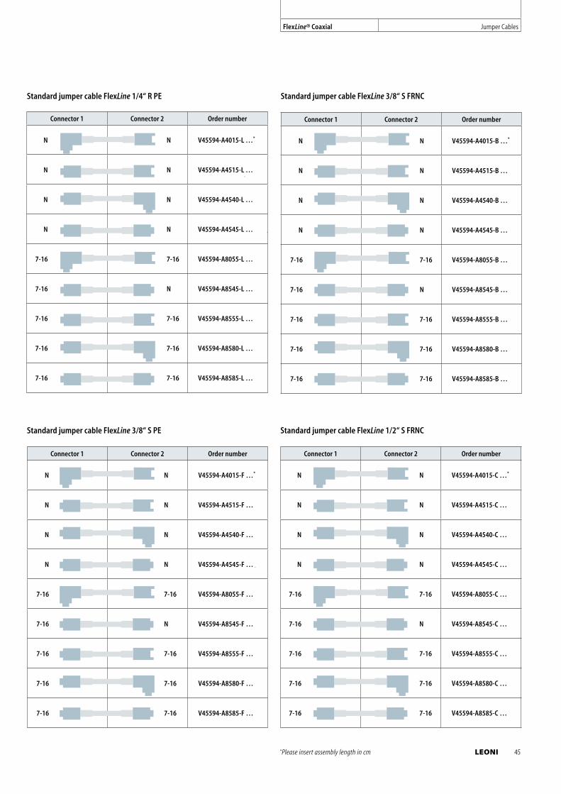
Standard jumper cable FlexLine 1/4“ R PE
Connector 1 Connector 2 Order number
N N V45594-A4015-L …*
N N V45594-A4515-L …
N N V45594-A4540-L …
N N V45594-A4545-L …
7-16 7-16 V45594-A8055-L …
7-16 N V45594-A8545-L …
7-16 7-16 V45594-A8555-L …
7-16 7-16 V45594-A8580-L …
7-16 7-16 V45594-A8585-L …
Standard jumper cable FlexLine 3/8“ S FRNC
Connector 1 Connector 2 Order number
N N V45594-A4015-B …*
N N V45594-A4515-B …
N N V45594-A4540-B …
N N V45594-A4545-B …
7-16 7-16 V45594-A8055-B …
7-16 N V45594-A8545-B …
7-16 7-16 V45594-A8555-B …
7-16 7-16 V45594-A8580-B …
7-16 7-16 V45594-A8585-B …
Standard jumper cable FlexLine 3/8“ S PE
Connector 1 Connector 2 Order number
N N V45594-A4015-F …*
N N V45594-A4515-F …
N N V45594-A4540-F …
N N V45594-A4545-F …
7-16 7-16 V45594-A8055-F …
7-16 N V45594-A8545-F …
7-16 7-16 V45594-A8555-F …
7-16 7-16 V45594-A8580-F …
7-16 7-16 V45594-A8585-F …
Standard jumper cable FlexLine 1/2“ S FRNC
Connector 1 Connector 2 Order number
N N V45594-A4015-C …*
N N V45594-A4515-C …
N N V45594-A4540-C …
N N V45594-A4545-C …
7-16 7-16 V45594-A8055-C …
7-16 N V45594-A8545-C …
7-16 7-16 V45594-A8555-C …
7-16 7-16 V45594-A8580-C …
7-16 7-16 V45594-A8585-C …
*Please insert assembly length in cm
FlexLine® Coaxial Jumper Cables
LEONI 45
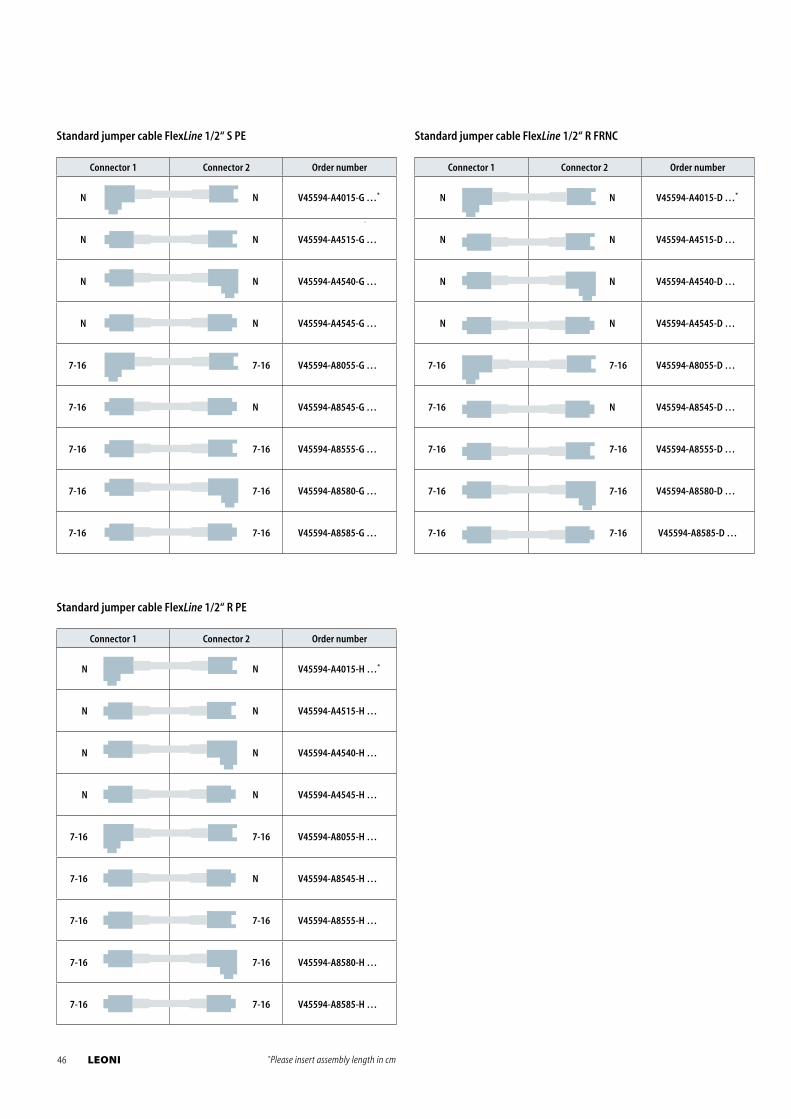
Standard jumper cable FlexLine 1/2“ S PE
Connector 1 Connector 2 Order number
N N V45594-A4015-G …*
N N V45594-A4515-G …
N N V45594-A4540-G …
N N V45594-A4545-G …
7-16 7-16 V45594-A8055-G …
7-16 N V45594-A8545-G …
7-16 7-16 V45594-A8555-G …
7-16 7-16 V45594-A8580-G …
7-16 7-16 V45594-A8585-G …
Standard jumper cable FlexLine 1/2“ R FRNC
Connector 1 Connector 2 Order number
N N V45594-A4015-D …*
N N V45594-A4515-D …
N N V45594-A4540-D …
N N V45594-A4545-D …
7-16 7-16 V45594-A8055-D …
7-16 N V45594-A8545-D …
7-16 7-16 V45594-A8555-D …
7-16 7-16 V45594-A8580-D …
7-16 7-16 V45594-A8585-D …
Standard jumper cable FlexLine 1/2“ R PE
Connector 1 Connector 2 Order number
N N V45594-A4015-H …*
N N V45594-A4515-H …
N N V45594-A4540-H …
N N V45594-A4545-H …
7-16 7-16 V45594-A8055-H …
7-16 N V45594-A8545-H …
7-16 7-16 V45594-A8555-H …
7-16 7-16 V45594-A8580-H …
7-16 7-16 V45594-A8585-H …
*Please insert assembly length in cm46 LEONI
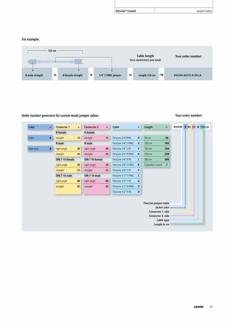
LEONI 47
For example:
150 cm
N male straigth + N female straight + 1/4“ S FRNC jumper = length 150 cm V45594-A4515-A150-LA
Your order number:Cable length (incl. connectors) you need:
Color + Connector 1 + Connector 2 + Cable + Length =
N female N female
black A straight 15 straight 15 FlexLine 214 FRNC R 50 cm 50
N male N male FlexLine 1/4” S FRNC A 100 cm 100
light grey B right angle 40 right angle 40 FlexLine 1/4” S PE E 150 cm 150
straight 45 straight 45 FlexLine 1/4” R FRNC K 250 cm 250
DIN 7-16 female DIN 7-16 female FlexLine 1/4” R PE L 300 cm 300
right angle 50 right angle 50 FlexLine 3/8” S FRNC B Customer´s need ?
straight 55 straight 55 FlexLine 3/8” S PE F
DIN 7-16 male DIN 7-16 male FlexLine 1/2” S FRNC C
right angle 80 right angle 80 FlexLine 1/2” S PE G
straight 85 straight 85 FlexLine 1/2” R FRNC D
FlexLine 1/2” R PE H
FlexLine jumper cable
Jacket color
Connector 1. side
Connector 2. side
Cable type
Length in cm
V45594 -A 85 55 -B 150-LA
Your order number:Order number generator for custom made jumper cables
FlexLine® Coaxial Jumper Cables
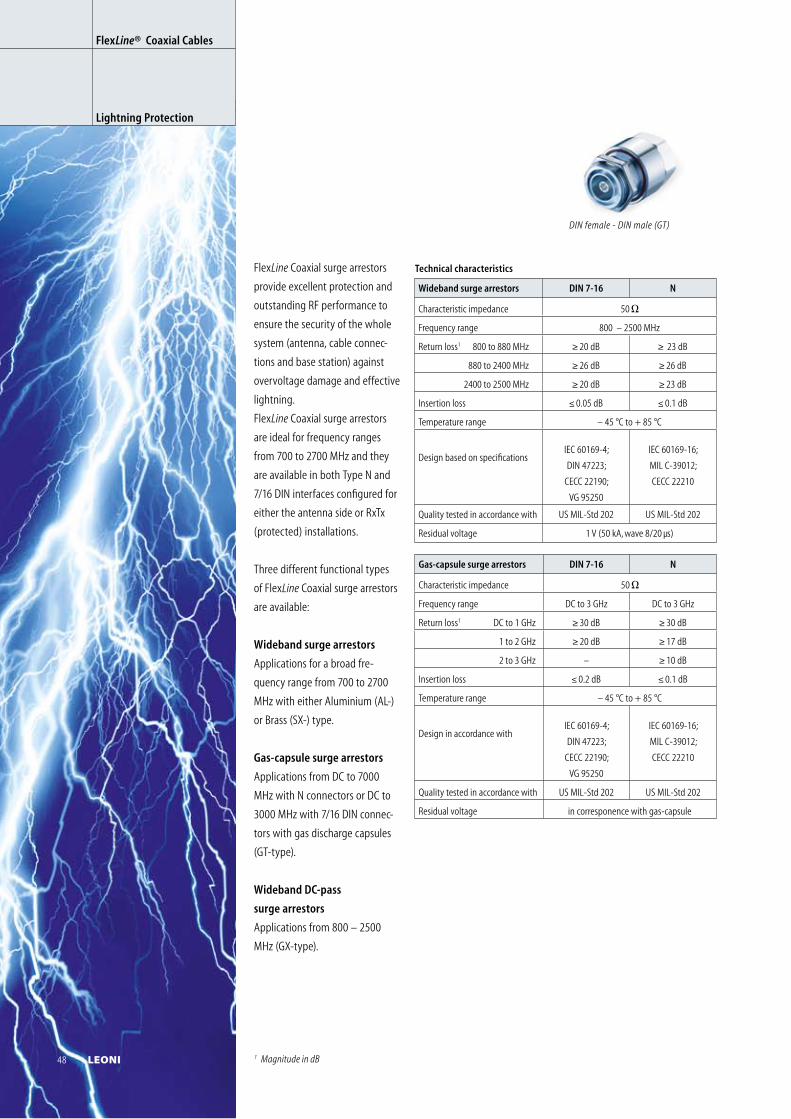
FlexLine Coaxial surge arrestors
provide excellent protection and
outstanding RF performance to
ensure the security of the whole
system (antenna, cable connec-
tions and base station) against
overvoltage damage and effective
lightning.
FlexLine Coaxial surge arrestors
are ideal for frequency ranges
from 700 to 2700 MHz and they
are available in both Type N and
7/16 DIN interfaces configured for
either the antenna side or RxTx
(protected) installations.
Three different functional types
of FlexLine Coaxial surge arrestors
are available:
Wideband surge arrestors
Applications for a broad fre-
quency range from 700 to 2700
MHz with either Aluminium (AL-)
or Brass (SX-) type.
Gas-capsule surge arrestors
Applications from DC to 7000
MHz with N connectors or DC to
3000 MHz with 7/16 DIN connec-
tors with gas discharge capsules
(GT-type).
Wideband DC-pass
surge arrestors
Applications from 800 – 2500
MHz (GX-type).
FlexLine ®
Gas-capsule surge arrestors DIN 7-16 N
Characteristic impedance 50
Frequency range DC to 3 GHz DC to 3 GHz
Return loss1 DC to 1 GHz 30 dB 30 dB
1 to 2 GHz 20 dB 17 dB
2 to 3 GHz – 10 dB
Insertion loss 0.2 dB 0.1 dB
Temperature range – 45 °C to + 85 °C
Design in accordance withIEC 60169-4;
DIN 47223;
CECC 22190;
VG 95250
IEC 60169-16;
MIL C-39012;
CECC 22210
Quality tested in accordance with US MIL-Std 202 US MIL-Std 202
Residual voltage in corresponence with gas-capsule
Wideband surge arrestors DIN 7-16 N
Characteristic impedance 50
Frequency range 800 – 2500 MHz
Return loss1 800 to 880 MHz 20 dB 23 dB
880 to 2400 MHz 26 dB 26 dB
2400 to 2500 MHz 20 dB 23 dB
Insertion loss 0.05 dB 0.1 dB
Temperature range – 45 °C to + 85 °C
Design based on specifications IEC 60169-4;
DIN 47223;
CECC 22190;
VG 95250
IEC 60169-16;
MIL C-39012;
CECC 22210
Quality tested in accordance with US MIL-Std 202 US MIL-Std 202
Residual voltage 1 V (50 kA, wave 8/20 s)
Technical characteristics
FlexLine® Coaxial Cables
Lightning Protection
1 Magnitude in dB
DIN female - DIN male (GT)
48 LEONI
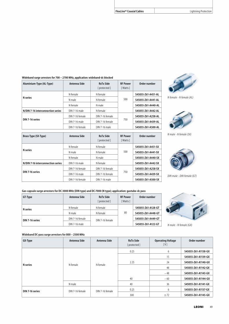
Gas-capsule surge arrestors for DC-3000 MHz (DIN type) and DC-7000 (N type); application: gastube-dc pass
GT-Type Antenna Side RxTx Side
[ protected ]
RF Power
[ Watts ]
Order number
N series N female N female
80
S45055-Z61-A128-GT
N male N female S45055-Z61-A448-GT
DIN 7-16 series DIN 7-16 female DIN 7-16 female S45055-Z61-A449-GT
DIN 7-16 male S45055-Z61-A122-GT
N male - N female (SX)
N male - N female (GX)
DIN male - DIN female (GT)
Wideband DC-pass surge arrestors for 800 – 2500 MHz
GX-Type Antenna Side Antenna Side RxTx Side
[ protected ]
Operating Voltage [ V ]
Order number
N series N female N female
0.25 6 S45055-Z61-A1138-GX
2.25
15 S45055-Z61-A1139-GX
24 S45055-Z61-A1140-GX
40
48 S45055-Z61-A1142-GX
– 48 S45055-Z61-A1143-GX
– 60 S45055-Z61-A1144-GX
N male 40 36 S45055-Z61-A1141-GX
DIN 7-16 series DIN 7-16 female DIN 7-16 female 0.25 6 S45055-Z61-A1137-GX
300 ± 72 S45055-Z61-A1145-GX
FlexLine® Coaxial Cables Lightning Protection
Wideband surge arrestors for 700 – 2700 MHz, application: wideband-dc blocked
Aluminium-Type (AL-Type) Antenna Side RxTx Side
[ protected ]
RF Power
[ Watts ]
Order number
N seriesN female N female
500
S45055-Z61-A451-AL
N male N female S45055-Z61-A441-AL
N female N male S45055-Z61-A440-AL
N/DIN 7-16 interconnection series DIN 7-16 male N female S45055-Z61-A442-AL
DIN 7-16 series
DIN 7-16 female DIN 7-16 female750
S45055-Z61-A258-AL
DIN 7-16 male DIN 7-16 female S45055-Z61-A439-AL
DIN 7-16 female DIN 7-16 male S45055-Z61-A500-AL
Brass Type (SX-Type) Antenna Side RxTx Side
[ protected ]
RF Power
[ Watts ]
Order number
N seriesN female N female
500
S45055-Z61-A451-SX
N male N female S45055-Z61-A441-SX
N female N male S45055-Z61-A440-SX
N/DIN 7-16 interconnection series DIN 7-16 male N female S45055-Z61-A442-SX
DIN 7-16 series
DIN 7-16 female DIN 7-16 female750
S45055-Z61-A258-SX
DIN 7-16 male DIN 7-16 female S45055-Z61-A439-SX
DIN 7-16 female DIN 7-16 male S45055-Z61-A500-SX
N female - N female (AL)
LEONI 49
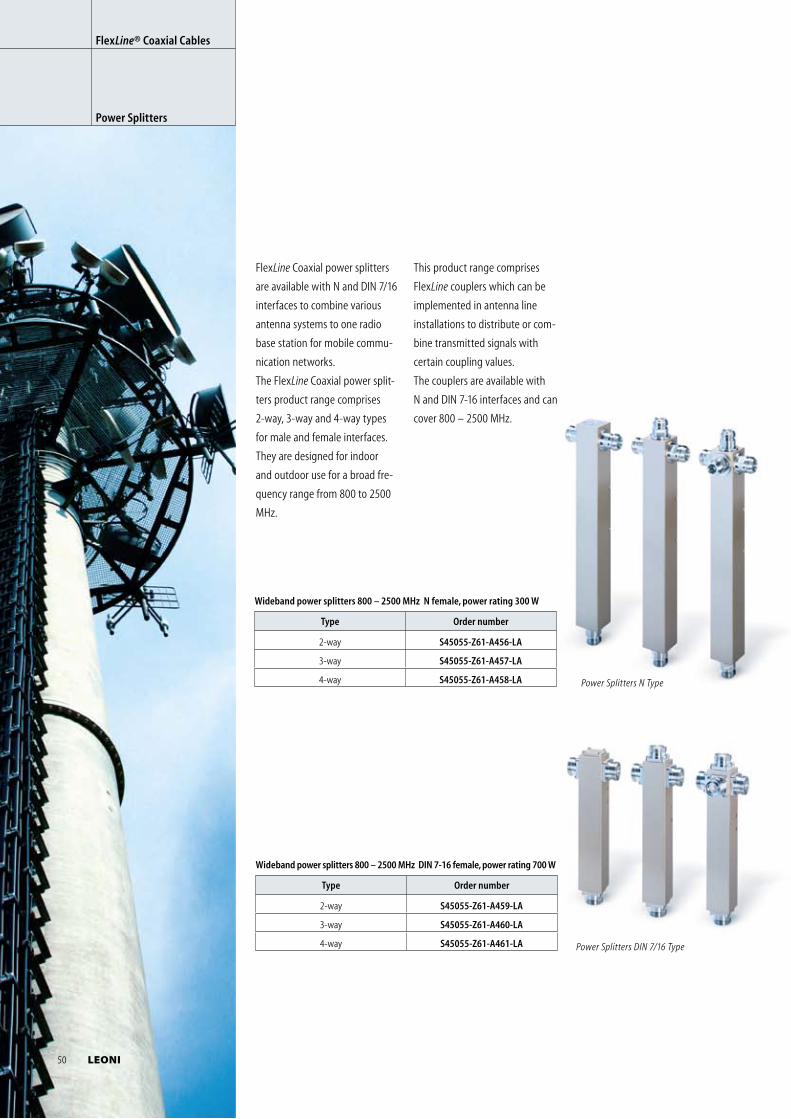
FlexLine Coaxial power splitters
are available with N and DIN 7/16
interfaces to combine various
antenna systems to one radio
base station for mobile commu-
nication networks.
The FlexLine Coaxial power split-
ters product range comprises
2-way, 3-way and 4-way types
for male and female interfaces.
They are designed for indoor
and outdoor use for a broad fre-
quency range from 800 to 2500
MHz.
Wideband power splitters 800 – 2500 MHz DIN 7-16 female, power rating 700 W
Type Order number
2-way S45055-Z61-A459-LA
3-way S45055-Z61-A460-LA
4-way S45055-Z61-A461-LA
Wideband power splitters 800 – 2500 MHz N female, power rating 300 W
Type Order number
2-way S45055-Z61-A456-LA
3-way S45055-Z61-A457-LA
4-way S45055-Z61-A458-LA Power Splitters N Type
Power Splitters DIN 7/16 Type
FlexLine® Coaxial Cables
Power Splitters
This product range comprises
FlexLine couplers which can be
implemented in antenna line
installations to distribute or com-
bine transmitted signals with
certain coupling values.
The couplers are available with
N and DIN 7-16 interfaces and can
cover 800 – 2500 MHz.
50 LEONI
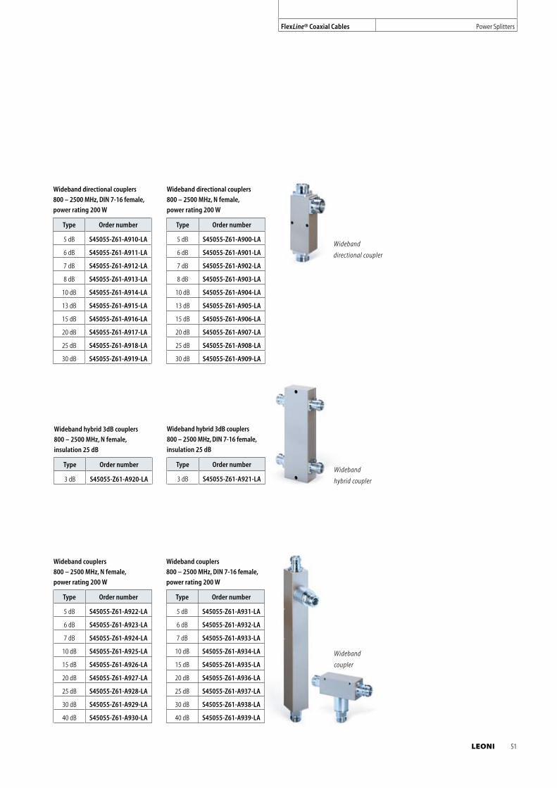
Wideband
directional coupler
Wideband couplers
800 – 2500 MHz, N female,
power rating 200 W
Type Order number
5 dB S45055-Z61-A922-LA
6 dB S45055-Z61-A923-LA
7 dB S45055-Z61-A924-LA
10 dB S45055-Z61-A925-LA
15 dB S45055-Z61-A926-LA
20 dB S45055-Z61-A927-LA
25 dB S45055-Z61-A928-LA
30 dB S45055-Z61-A929-LA
40 dB S45055-Z61-A930-LA
Wideband couplers
800 – 2500 MHz, DIN 7-16 female,
power rating 200 W
Type Order number
5 dB S45055-Z61-A931-LA
6 dB S45055-Z61-A932-LA
7 dB S45055-Z61-A933-LA
10 dB S45055-Z61-A934-LA
15 dB S45055-Z61-A935-LA
20 dB S45055-Z61-A936-LA
25 dB S45055-Z61-A937-LA
30 dB S45055-Z61-A938-LA
40 dB S45055-Z61-A939-LA
Wideband directional couplers
800 – 2500 MHz, DIN 7-16 female,
power rating 200 W
Type Order number
5 dB S45055-Z61-A910-LA
6 dB S45055-Z61-A911-LA
7 dB S45055-Z61-A912-LA
8 dB S45055-Z61-A913-LA
10 dB S45055-Z61-A914-LA
13 dB S45055-Z61-A915-LA
15 dB S45055-Z61-A916-LA
20 dB S45055-Z61-A917-LA
25 dB S45055-Z61-A918-LA
30 dB S45055-Z61-A919-LA
Wideband hybrid 3dB couplers
800 – 2500 MHz, N female,
insulation 25 dB
Type Order number
3 dB S45055-Z61-A920-LA
Wideband hybrid 3dB couplers
800 – 2500 MHz, DIN 7-16 female,
insulation 25 dB
Type Order number
3 dB S45055-Z61-A921-LA
Wideband directional couplers
800 – 2500 MHz, N female,
power rating 200 W
Type Order number
5 dB S45055-Z61-A900-LA
6 dB S45055-Z61-A901-LA
7 dB S45055-Z61-A902-LA
8 dB S45055-Z61-A903-LA
10 dB S45055-Z61-A904-LA
13 dB S45055-Z61-A905-LA
15 dB S45055-Z61-A906-LA
20 dB S45055-Z61-A907-LA
25 dB S45055-Z61-A908-LA
30 dB S45055-Z61-A909-LA
Wideband
coupler
Wideband
hybrid coupler
FlexLine® Coaxial Cables Power Splitters
LEONI 51
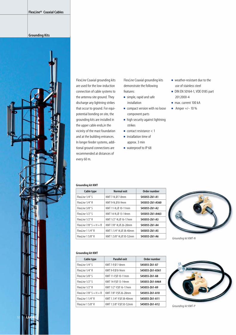
FlexLine® Coaxial Cables
Grounding Kits
FlexLine Coaxial grounding kits
are used for the low-induction
connection of cable systems to
the antenna site ground. They
discharge any lightning strikes
that occur to ground. For equi-
potential bonding on site, the
grounding kits are installed in
the upper cable ends,in the
vicinity of the mast foundation
and at the building entrances.
In longer feeder systems, addi-
tional ground connections are
recommended at distances of
every 60 m.
Grounding kit KMT
Cable type Normal exit Order number
FlexLine 1/4“ S KMT 7-N, Ø 7-8mm S45055-Z61-A1
FlexLine 1/4“ R KMT 9-N, Ø 8-9mm S45055-Z61-A560
FlexLine 3/8“ S KMT 11-N, Ø 10-11mm S45055-Z61-A2
FlexLine 1/2“ S KMT 14-N, Ø 13-14mm S45055-Z61-A463
FlexLine 1/2“ R KMT 1/2“-N, Ø 16-17mm S45055-Z61-A3
FlexLine 7/8“ S + H + R KMT 7/8“-N, Ø 26-28mm S45055-Z61-A4
FlexLine 1 1/4“ R KMT 1.1/4“-N, Ø 38-40mm S45055-Z61-A5
FlexLine 1 5/8“ R KMT 1.5/8“-N, Ø 50-52mm S45055-Z61-A6
Grounding kit KMT-P
Grounding kit KMT
Cable type Parallel exit Order number
FlexLine 1/4“ S KMT 7-P, Ø 7-8mm S45055-Z61-A7
FlexLine 1/4“ R KMT 9-P, Ø 8-9mm S45055-Z61-A561
FlexLine 3/8“ S KMT 11-P, Ø 10-11mm S45055-Z61-A8
FlexLine 1/2“ S KMT 14-P, Ø 13-14mm S45055-Z61-A464
FlexLine 1/2“ R KMT 1/2“-P, Ø 16-17mm S45055-Z61-A9
FlexLine 7/8“ S + H + R KMT 7/8“-P, Ø 26-28mm S45055-Z61-A10
FlexLine 1 1/4“ R KMT 1.1/4“-P, Ø 38-40mm S45055-Z61-A11
FlexLine 1 5/8“ R KMT 1.5/8“-P, Ø 50-52mm S45055-Z61-A12
Grounding kit KMT-N
FlexLine Coaxial grounding kits
demonstrate the following
features:
simple, rapid and safe
installation
compact version with no loose
component parts
high security against lightning
strikes
contact resistance < 1
installation time of
approx. 3 min
waterproof to IP 68
weather-resistant due to the
use of stainless steel
DIN EN 50164-1, VDE 0185 part
201:2000-4
max. current 100 kA
Amper +/– 10 %
52 LEONI
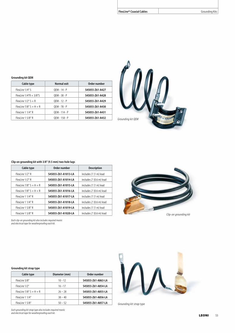
Grounding kit strap type
Cable type Diameter (mm) Order number
FlexLine 3/8“ 10 –12 S45055-Z61-A863-LA
FlexLine 1/2“ 16 –17 S45055-Z61-A854-LA
FlexLine 7/8“ S + H + R 26 – 28 S45055-Z61-A855-LA
FlexLine 1 1/4“ 38 – 40 S45055-Z61-A856-LA
FlexLine 1 5/8“ 50 – 52 S45055-Z61-A857-LA Grounding kit strap type
Grounding kit QEM
Grounding kit QEM
Cable type Normal exit Order number
FlexLine 1/4“ S QEM - 14 - P S45055-Z61-A427
FlexLine 1/4“R + 3/8“S QEM - 38 - P S45055-Z61-A428
FlexLine 1/2“ S + R QEM - 12 - P S45055-Z61-A429
FlexLine 7/8“ S + H + R QEM - 78 - P S45055-Z61-A430
FlexLine 1 1/4“ R QEM - 114 - P S45055-Z61-A431
FlexLine 1 5/8“ R QEM - 158 - P S45055-Z61-A432
Clip-on grounding kit
Clip-on grounding kit with 3/8” (9.5 mm) two-hole lugs
Cable type Order number Description
FlexLine 1/2" R S45055-Z61-A1013-LA includes 3' (1 m) lead
FlexLine 1/2" R S45055-Z61-A1014-LA includes 2' (0.6 m) lead
FlexLine 7/8" S + H + R S45055-Z61-A1015-LA includes 3' (1 m) lead
FlexLine 7/8" S + H + R S45055-Z61-A1016-LA includes 2' (0.6 m) lead
FlexLine 1 1/4" R S45055-Z61-A1017-LA includes 3' (1 m) lead
FlexLine 1 1/4" R S45055-Z61-A1018-LA includes 2' (0.6 m) lead
FlexLine 1 5/8" R S45055-Z61-A1019-LA includes 3' (1 m) lead
FlexLine 1 5/8" R S45055-Z61-A1020-LA includes 2' (0.6 m) lead
FlexLine® Coaxial Cables Grounding Kits
Each clip-on grounding kit also includes required mastic and electrical tape for weatherproofing each kit.
Each grounding kit strap type also includes required mastic and electrical tape for weatherproofing each kit.
LEONI 53
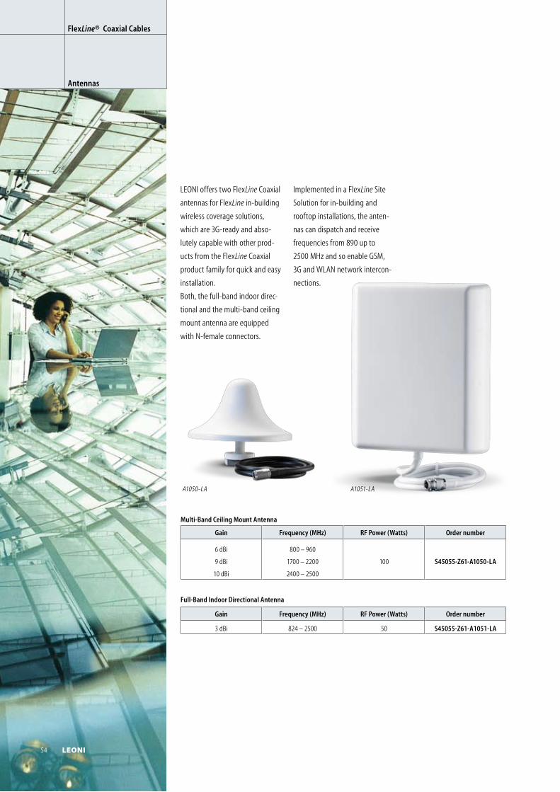
Multi-Band Ceiling Mount Antenna
Gain Frequency (MHz) RF Power (Watts) Order number
6 dBi
9 dBi
10 dBi
800 – 960
1700 – 2200
2400 – 2500
100 S45055-Z61-A1050-LA
Full-Band Indoor Directional Antenna
Gain Frequency (MHz) RF Power (Watts) Order number
3 dBi 824 – 2500 50 S45055-Z61-A1051-LA
A1050-LA
A1051-LA
LEONI offers two FlexLine Coaxial
antennas for FlexLine in-building
wireless coverage solutions,
which are 3G-ready and abso-
lutely capable with other prod-
ucts from the FlexLine Coaxial
product family for quick and easy
installation.
Both, the full-band indoor direc-
tional and the multi-band ceiling
mount antenna are equipped
with N-female connectors.
Implemented in a FlexLine Site
Solution for in-building and
rooftop installations, the anten-
nas can dispatch and receive
frequencies from 890 up to
2500 MHz and so enable GSM,
3G and WLAN network intercon-
nections.
FlexLine® Coaxial Cables
Antennas
54 LEONI
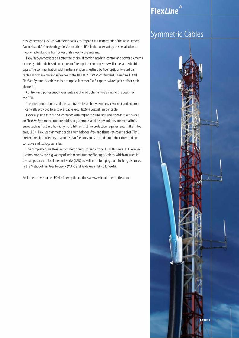
LEONI 55
Symmetric Cables
FlexLine ®
New generation FlexLine Symmetric cables correspond to the demands of the new Remote
Radio Head (RRH) technology for site solutions. RRH is characterised by the installation of
mobile radio station‘s transceiver units close to the antenna.
FlexLine Symmetric cables offer the choice of combining data, control and power elements
in one hybrid cable based on copper or fiber optic technologies as well as separated cable
types. The communication with the base station is realised by fiber optic or twisted pair
cables, which are making reference to the IEEE 802.16 WiMAX standard. Therefore, LEONI
FlexLine Symmetric cables either comprise Ethernet Cat 5 copper twisted pair or fiber optic
elements.
Control- and power supply elements are offered optionally referring to the design of
the RRH.
The interconnection of and the data transmission between transceiver unit and antenna
is generally provided by a coaxial cable, e.g. FlexLine Coaxial jumper cable.
Especially high mechanical demands with regard to sturdiness and resistance are placed
on FlexLine Symmetric outdoor cables to guarantee stability towards environmental influ-
ences such as frost and humidity. To fulfil the strict fire protection requirements in the indoor
area, LEONI FlexLine Symmetric cables with halogen-free and flame-retardant jacket (FRNC)
are required because they guarantee that fire does not spread through the cables and no
corrosive and toxic gases arise.
The comprehensive FlexLine Symmetric product range from LEONI Business Unit Telecom
is completed by the big variety of indoor and outdoor fiber optic cables, which are used in
the campus area of local area networks (LAN) as well as for bridging over the long distances
in the Metropolitan Area Network (MAN) and Wide Area Network (WAN).
Feel free to investigate LEONI‘s fiber optic solutions at www.leoni-fiber-optics.com.
LEONI 55
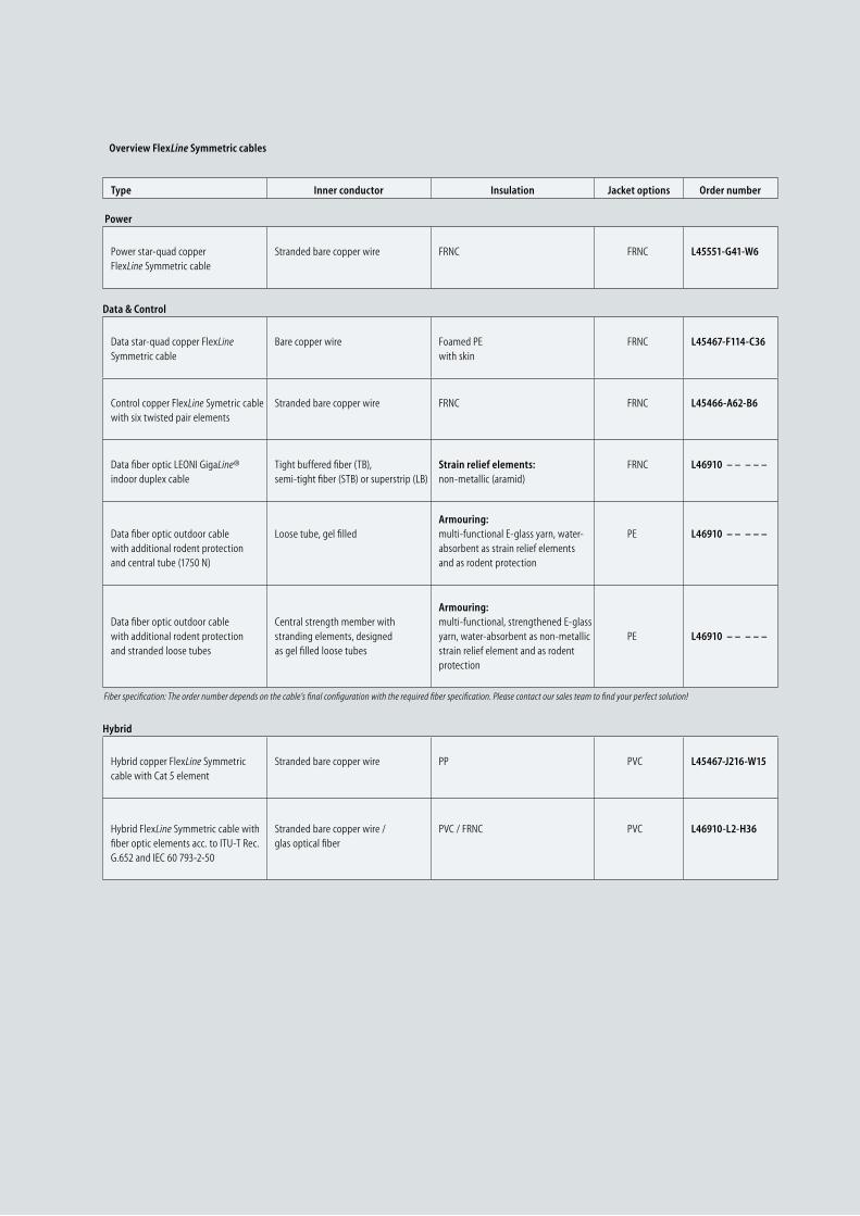
56 LEONI
Type Inner conductor Insulation Jacket options Order number
Power
Power star-quad copper FlexLine Symmetric cable
Stranded bare copper wire FRNC FRNC L45551-G41-W6
Data & Control
Data star-quad copper FlexLine Symmetric cable
Bare copper wire Foamed PE with skin
FRNC L45467-F114-C36
Control copper FlexLine Symetric cable with six twisted pair elements
Stranded bare copper wire FRNC FRNC L45466-A62-B6
Data fiber optic LEONI GigaLine® indoor duplex cable
Tight buffered fiber (TB), semi-tight fiber (STB) or superstrip (LB)
Strain relief elements: non-metallic (aramid)
FRNC
L46910 – – – – –
Data fiber optic outdoor cable with additional rodent protection and central tube (1750 N)
Loose tube, gel filledArmouring: multi-functional E-glass yarn, water-absorbent as strain relief elements and as rodent protection
PE L46910 – – – – –
Data fiber optic outdoor cable with additional rodent protection and stranded loose tubes
Central strength member with stranding elements, designed as gel filled loose tubes
Armouring: multi-functional, strength ened E-glass yarn, water-absorbent as non-metallic strain relief element and as rodent protection
PE L46910 – – – – –
Hybrid
Hybrid copper FlexLine Symmetric cable with Cat 5 element
Stranded bare copper wire PP PVC L45467-J216-W15
Hybrid FlexLine Symmetric cable with fiber optic elements acc. to ITU-T Rec. G.652 and IEC 60 793-2-50
Stranded bare copper wire / glas optical fiber
PVC / FRNC PVC L46910-L2-H36
Fiber specification: The order number depends on the cable’s final configuration with the required fiber specification. Please contact our sales team to find your perfect solution!
Overview FlexLine Symmetric cables
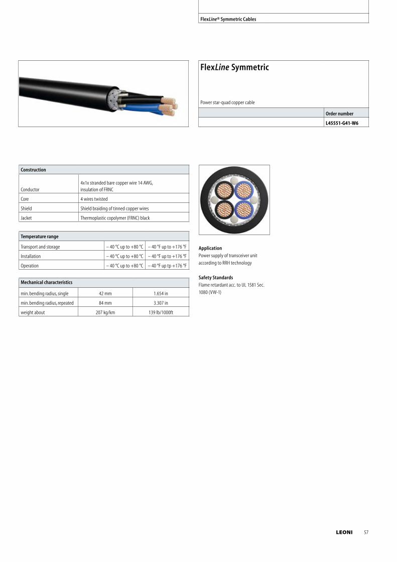
Mechanical characteristics
min. bending radius, single 42 mm 1.654 in
min. bending radius, repeated 84 mm 3.307 in
weight about 207 kg/km 139 lb/1000ft
Temperature range
Transport and storage – 40 °C up to +80 °C – 40 °F up to +176 °F
Installation – 40 °C up to +80 °C – 40 °F up to +176 °F
Operation – 40 °C up to +80 °C – 40 °F up tp +176 °F
Construction
Conductor4x1x stranded bare copper wire 14 AWG,insulation of FRNC
Core 4 wires twisted
Shield Shield braiding of tinned copper wires
Jacket Thermoplastic copolymer (FRNC) black
FlexLine Symmetric
Power star-quad copper cable
Order number
L45551-G41-W6
Application
Power supply of transceiver unit
according to RRH technology
Safety Standards
Flame retardant acc. to UL 1581 Sec.
1080 (VW-1)
FlexLine® Symmetric Cables
LEONI 57
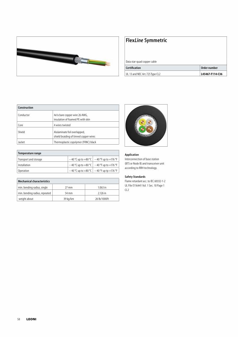
Mechanical characteristics
min. bending radius, single 27 mm 1.063 in
min. bending radius, repeated 54 mm 2.126 in
weight about 39 kg/km 26 lb/1000ft
Temperature range
Transport and storage – 40 °C up to +80 °C – 40 °F up to +176 °F
Installation – 40 °C up to +80 °C – 40 °F up to +176 °F
Operation – 40 °C up to +80 °C – 40 °F up tp +176 °F
Construction
Conductor 4x1x bare copper wire 26 AWG,
insulation of foamed PE with skin
Core 4 wires twisted
Shield Alulaminate foil overlapped,
shield braiding of tinned copper wires
Jacket Thermoplastic copolymer (FRNC) black
FlexLine Symmetric
Data star-quad copper cable
Certification Order number
UL 13 and NEC Art. 725 Type CL2 L45467-F114-C36
Application
Interconnection of base station
(BTS or Node B) and transceiver unit
according to RRH technology.
Safety Standards
Flame retardant acc. to IEC 60332-1-2
UL File E116441 Vol. 1 Sec. 10 Page 1
CL2
58 LEONI
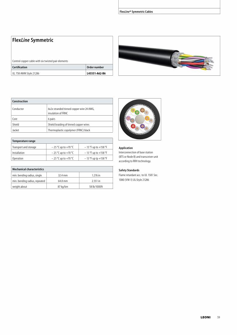
Mechanical characteristics
min. bending radius, single 32.4 mm 1.276 in
min. bending radius, repeated 64.8 mm 2.551 in
weight about 87 kg/km 58 lb/1000ft
Temperature range
Transport and storage – 25 °C up to +70 °C – 13 °F up to +158 °F
Installation – 25 °C up to +70 °C – 13 °F up to +158 °F
Operation – 25 °C up to +70 °C – 13 °F up tp +158 °F
Construction
Conductor 6x2x stranded tinned copper wire 24 AWG,
insulation of FRNC
Core 6 pairs
Shield Shield braiding of tinned copper wires
Jacket Thermoplastic copolymer (FRNC) black
FlexLine Symmetric
Control copper cable with six twisted pair elements
Certification Order number
UL 758 AWM Style 21286 L45551-A62-B6
Application
Interconnection of base station
(BTS or Node B) and transceiver unit
according to RRH technology.
Safety Standards
Flame retardant acc. to UL 1581 Sec.
1080 (VW-1) UL-Style 21286
FlexLine® Symmetric Cables
LEONI 59
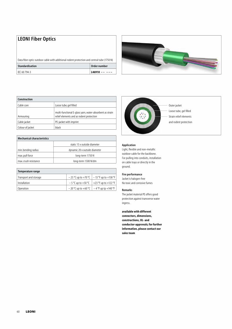
Mechanical characteristics
min. bending radius
static 15 x outside diameter
dynamic 20 x outside diameter
max. pull force long-term 1750 N
max. crush resistance long-term 1500 N/dm
Temperature range
Transport and storage – 25 °C up to +70 °C – 13 °F up to +158 °F
Installation – 5 °C up to +50 °C +23 °F up to +122 °F
Operation – 20 °C up to +60 °C – 4 °F up tp +140 °F
Construction
Cable core Loose tube, gel filled
Armouringmulti-functional E-glass yarn, water-absorbent as strain relief elements and as rodent protection
Cable jacket PE-jacket with imprint
Colour of jacket black
Outer jacket
Loose tube, gel filled
Strain relief elements
and rodent protection
LEONI Fiber Optics
Data fiber optic outdoor cable with additional rodent protection and central tube (1750 N)
Standardisation Order number
IEC 60 794-3 L46910 – – – – –
Application
Light, flexible and non-metallic
outdoor cable for the backbone.
For pulling into conduits, installation
on cable trays or directly in the
ground.
Fire performance
Jacket is halogen-free
No toxic and corrosive fumes
Remarks
The jacket material PE offers good
protection against transverse water
ingress.
available with different
connectors, dimensions,
constructions, UL- and
conductor-approvals; for further
information, please contact our
sales team
60 LEONI
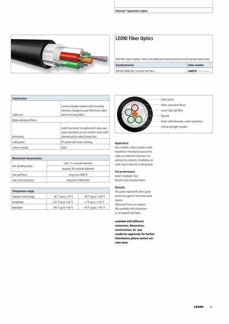
FlexLine® Symmetric Cables
Mechanical characteristics
min. bending radiusstatic 15 x outside diameter
dynamic 20 x outside diameter
max. pull force long-term 4000 N
max. crush resistance long-term 3000 N/dm
Temperature range
Transport and storage – 40 °C up to +70 °C – 40 °F up to +158 °F
Installation +23 °C up to +50 °C – 4 °F up to +122 °F
Operation – 40 °C up to +60 °C – 40 °F up tp +140 °F
Construction
Cable core
Central strength member with stranding
elements, designed as gel filled loose tubes
and if necessary fillers
Water-absorbent fleece
Armouring
multi-functional, strengthened E-glass yarn
water-absorbent as non-metallic strain relief
element and as rodent protection
Cable jacket PE-jacket with sinter marking
Colour of jacket black
Outer jacket
Water-absorbent fleece
Loose tube, gel filled
Ripcord
Strain relief elements, rodent protection
Central strength member
LEONI Fiber Optics
Data fiber optic outdoor cable with additional rodent protection and stranded loose tubes
Standardisation Order number
DIN VDE 0888, Part 3 and IEC 60 794-3 L46910 – – – – –
Application
Non-metallic, robust outdoor cable.
Installation-friendly because of the
cable core kept free of grease. For
pulling into conduits, installation on
cable trays or directly in the ground.
Fire performance
Jacket is halogen-free.
No toxic and corrosive fumes.
Remarks
The jacket material PE offers good
protection against transverse water
ingress.
Higher pull forces on request.
Also available with aluminium-
or corrugated steel tape.
available with different
connectors, dimensions,
constructions, UL- and
conductor-approvals; for further
information, please contact our
sales team
LEONI 61
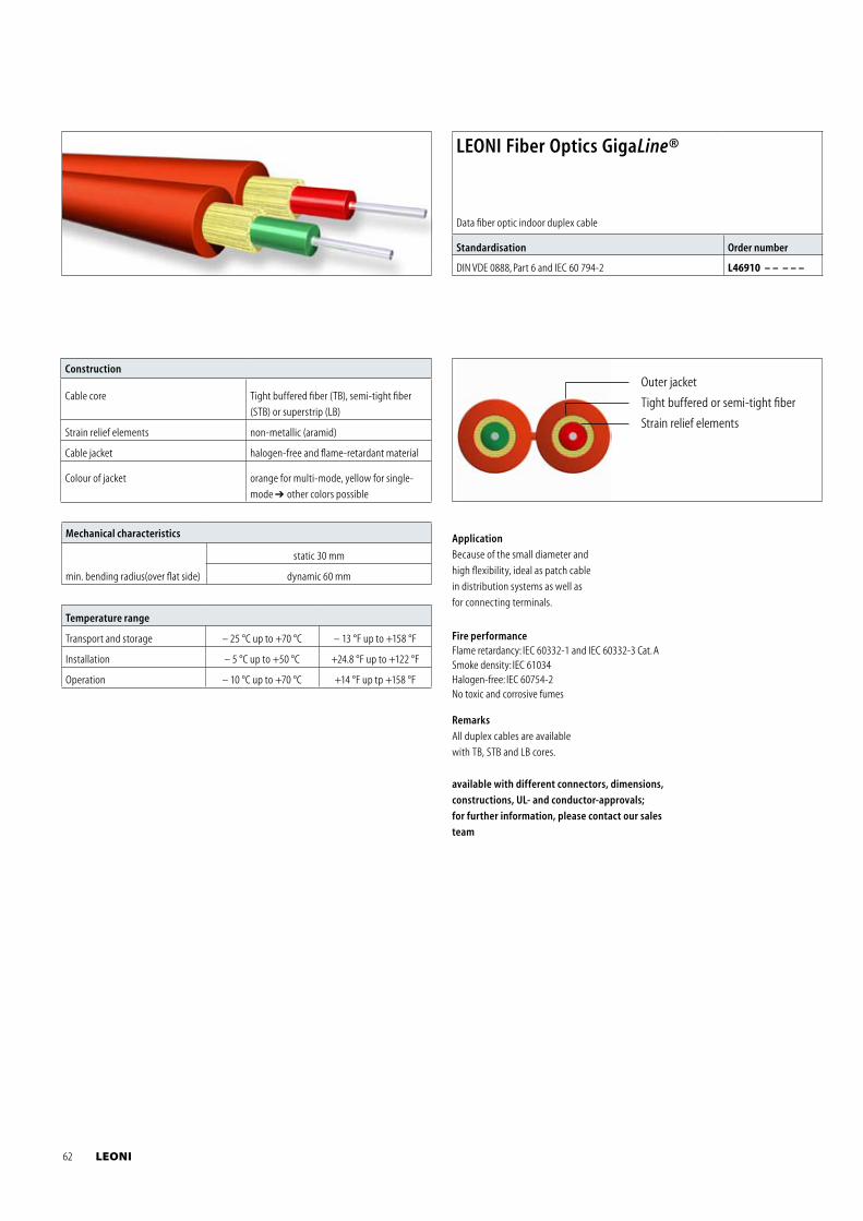
Outer jacket
Tight buffered or semi-tight fiber
Strain relief elements
Mechanical characteristics
min. bending radius(over flat side)
static 30 mm
dynamic 60 mm
Temperature range
Transport and storage – 25 °C up to +70 °C – 13 °F up to +158 °F
Installation – 5 °C up to +50 °C +24.8 °F up to +122 °F
Operation – 10 °C up to +70 °C +14 °F up tp +158 °F
Construction
Cable core Tight buffered fiber (TB), semi-tight fiber
(STB) or superstrip (LB)
Strain relief elements non-metallic (aramid)
Cable jacket halogen-free and flame-retardant material
Colour of jacket orange for multi-mode, yellow for single-
mode other colors possible
LEONI Fiber Optics GigaLine®
Data fiber optic indoor duplex cable
Standardisation Order number
DIN VDE 0888, Part 6 and IEC 60 794-2 L46910 – – – – –
Application
Because of the small diameter and
high flexibility, ideal as patch cable
in distribution systems as well as
for connecting terminals.
Fire performanceFlame retardancy: IEC 60332-1 and IEC 60332-3 Cat. ASmoke density: IEC 61034Halogen-free: IEC 60754-2No toxic and corrosive fumes
Remarks
All duplex cables are available
with TB, STB and LB cores.
available with different connectors, dimensions,
constructions, UL- and conductor-approvals;
for further information, please contact our sales
team
62 LEONI
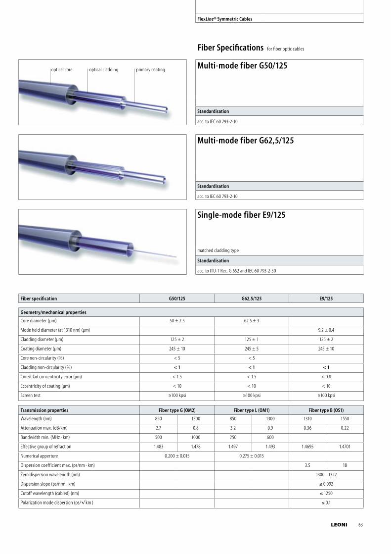
FlexLine® Symmetric Cables
Fiber Specifications for fiber optic cables
Transmission properties Fiber type G (OM2) Fiber type L (OM1) Fiber type B (OS1)
Wavelength (nm) 850 1300 850 1300 1310 1550
Attenuation max. (dB/km) 2.7 0.8 3.2 0.9 0.36 0.22
Bandwidth min. (MHz · km) 500 1000 250 600
Effective group of refraction 1.483 1.478 1.497 1.493 1.4695 1.4701
Numerical apperture 0.200 ± 0.015 0.275 ± 0.015
Dispersion coefficient max. (ps/nm · km) 3.5 18
Zero dispersion wavelength (nm) 1300 –1322
Dispersion slope (ps/nm2 · km) ≤ 0.092
Cutoff wavelength (cabled) (nm) ≤ 1250
Polarization mode dispersion (ps/√km ) ≤ 0.1
Geometry/mechanical properties
Core diameter (μm) 50 ± 2.5 62.5 ± 3
Mode field diameter (at 1310 nm) (μm) 9.2 ± 0.4
Cladding diameter (μm) 125 ± 2 125 ± 1 125 ± 2
Coating diameter (μm) 245 ± 10 245 ± 5 245 ± 10
Core non-circularity (%) < 5 < 5
Cladding non-circularity (%) < 1 < 1 < 1
Core/Clad concentricity error (μm) < 1.5 < 1.5 < 0.8
Eccentricity of coating (μm) < 10 < 10 < 10
Screen test ≥100 kpsi ≥100 kpsi ≥100 kpsi
Fiber specification G50/125 G62,5/125 E9/125
Multi-mode fiber G50/125
Standardisation
acc. to IEC 60 793-2-10
Multi-mode fiber G62,5/125
Standardisation
acc. to IEC 60 793-2-10
Single-mode fiber E9/125
matched cladding type
Standardisation
acc. to ITU-T Rec. G.652 and IEC 60 793-2-50
optical core optical cladding primary coating
LEONI 63
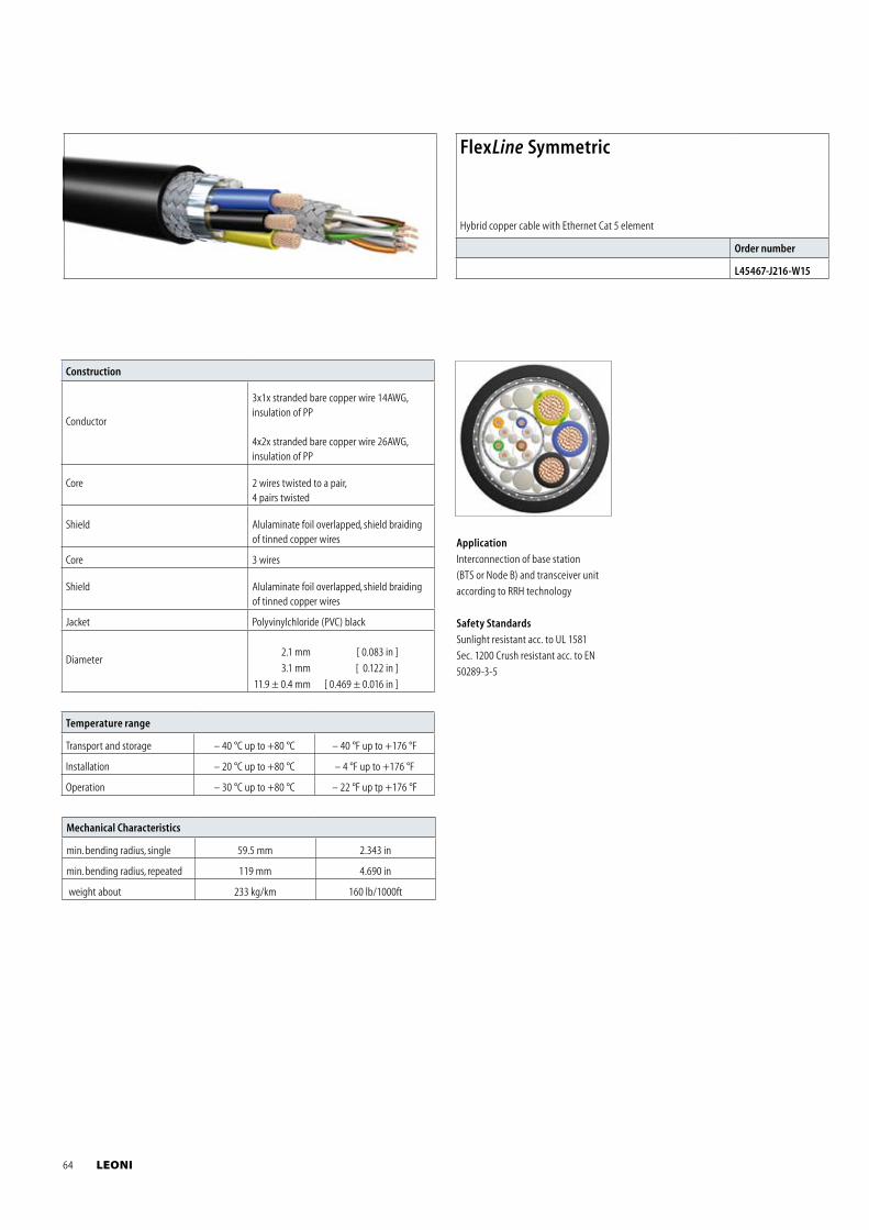
Mechanical Characteristics
min. bending radius, single 59.5 mm 2.343 in
min. bending radius, repeated 119 mm 4.690 in
weight about 233 kg/km 160 lb/1000ft
Temperature range
Transport and storage – 40 °C up to +80 °C – 40 °F up to +176 °F
Installation – 20 °C up to +80 °C – 4 °F up to +176 °F
Operation – 30 °C up to +80 °C – 22 °F up tp +176 °F
Construction
Conductor
3x1x stranded bare copper wire 14AWG,insulation of PP
4x2x stranded bare copper wire 26AWG,insulation of PP
Core 2 wires twisted to a pair, 4 pairs twisted
Shield Alulaminate foil overlapped, shield braiding of tinned copper wires
Core 3 wires
Shield Alulaminate foil overlapped, shield braiding of tinned copper wires
Jacket Polyvinylchloride (PVC) black
Diameter 2.1 mm [ 0.083 in ]
3.1 mm [ 0.122 in ]
11.9 ± 0.4 mm [ 0.469 ± 0.016 in ]
FlexLine Symmetric
Hybrid copper cable with Ethernet Cat 5 element
Order number
L45467-J216-W15
Application
Interconnection of base station
(BTS or Node B) and transceiver unit
according to RRH technology
Safety Standards
Sunlight resistant acc. to UL 1581
Sec. 1200 Crush resistant acc. to EN
50289-3-5
64 LEONI
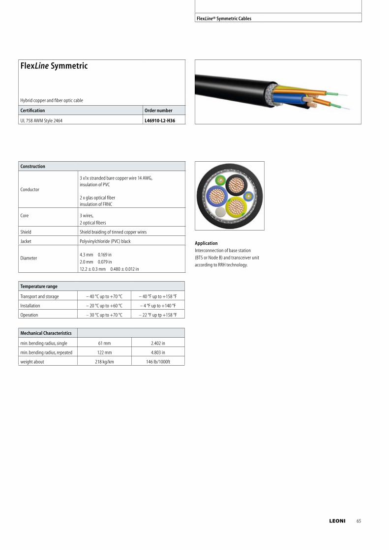
FlexLine® Symmetric Cables
Mechanical Characteristics
min. bending radius, single 61 mm 2.402 in
min. bending radius, repeated 122 mm 4.803 in
weight about 218 kg/km 146 lb/1000ft
Temperature range
Transport and storage – 40 °C up to +70 °C – 40 °F up to +158 °F
Installation – 20 °C up to +60 °C – 4 °F up to +140 °F
Operation – 30 °C up to +70 °C – 22 °F up tp +158 °F
Construction
Conductor
3 x1x stranded bare copper wire 14 AWG,insulation of PVC
2 x glas optical fiberinsulation of FRNC
Core 3 wires,
2 optical fibers
Shield Shield braiding of tinned copper wires
Jacket Polyvinylchloride (PVC) black
Diameter4.3 mm 0.169 in
2.0 mm 0.079 in
12.2 ± 0.3 mm 0.480 ± 0.012 in
FlexLine Symmetric
Hybrid copper and fiber optic cable
Certification Order number
UL 758 AWM Style 2464 L46910-L2-H36
Application
Interconnection of base station
(BTS or Node B) and transceiver unit
according to RRH technology.
LEONI 65
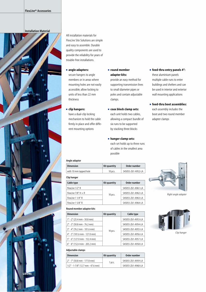
All installation materials for
FlexLine Site Solutions are simple
and easy to assemble. Durable
quality components are used to
provide the reliability for years of
trouble-free installations.
angle adapters:
secure hangers to angle
members or in areas where
mounting holes are not easily
accessible; allow locking to
units of less than 22 mm
thickness
clip hangers:
have a dual-clip locking
mechanism to hold the cable
firmly in place and offer diffe-
rent mounting options
Clip hanger
Cable type Kit quantity Order number
FlexLine 1/2" R
10 pcs.
S45055-Z61-A961-LA
FlexLine 7/8" H + R S45055-Z61-A962-LA
FlexLine 1 1/4" R S45055-Z61-A963-LA
FlexLine 1 5/8" R S45055-Z61-A964-LA
Adjustable clamps
Dimension Kit quantity Order number
2" - 7" (50.8 mm - 177.8 mm)1 pcs.
S45055-Z61-A959-LA
1/2" - 1-7/8" (12.7 mm - 47.6 mm) S45055-Z61-A960-LA
Angle adaptor
Dimension Kit quantity Order number
with 10 mm tapped hole 10 pcs. S45055-Z61-A952-LA
Clip hanger
FlexLine® Accessories
Installation Material
Round member adapter kits
Dimension Kit quantity Cable type
1" - 2" (25.4 mm - 50.8 mm)
10 pcs.
S45055-Z61-A953-LA
2" - 3" (50.8 mm - 76.2 mm) S45055-Z61-A954-LA
3" - 4" (76.2 mm - 101.6 mm) S45055-Z61-A955-LA
4" - 5" (101.6 mm - 127.0 mm) S45055-Z61-A956-LA
5" - 6" (127.0 mm - 152.4 mm) S45055-Z61-A957-LA
6" - 8" (152.4 mm - 203.2 mm) S45055-Z61-A958-LA
round member
adapter kits:
provide an easy method for
supporting transmission lines
to small diameter pipes or
poles and contain adjustable
clamps.
coax block clamp sets:
each unit holds two cables,
allowing a compact bundle of
six runs to be supported
by stacking three blocks
hanger clamp sets:
each set holds up to three runs
of cables in the smallest area
possible
feed-thru entry panels 4“:
these aluminium panels
multiple cable runs to enter
buildings and shelters and can
be used in interior and exterior
wall mounting applications
feed-thru boot assemblies:
each assembly includes the
boot and two round member
adapter clamps
Right angle adapter
66 LEONI
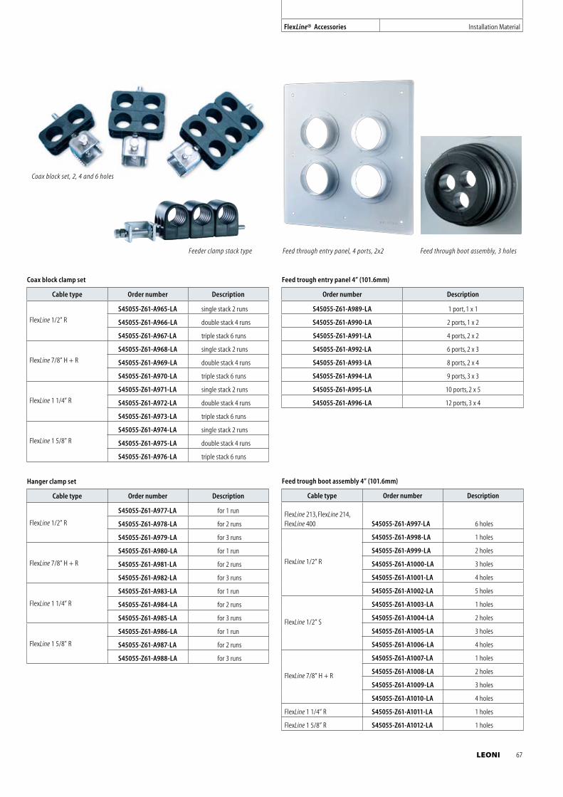
Coax block clamp set
Cable type Order number Description
FlexLine 1/2” R
S45055-Z61-A965-LA single stack 2 runs
S45055-Z61-A966-LA double stack 4 runs
S45055-Z61-A967-LA triple stack 6 runs
FlexLine 7/8” H + R
S45055-Z61-A968-LA single stack 2 runs
S45055-Z61-A969-LA double stack 4 runs
S45055-Z61-A970-LA triple stack 6 runs
FlexLine 1 1/4” R
S45055-Z61-A971-LA single stack 2 runs
S45055-Z61-A972-LA double stack 4 runs
S45055-Z61-A973-LA triple stack 6 runs
FlexLine 1 5/8" R
S45055-Z61-A974-LA single stack 2 runs
S45055-Z61-A975-LA double stack 4 runs
S45055-Z61-A976-LA triple stack 6 runs
Hanger clamp set
Cable type Order number Description
FlexLine 1/2” R
S45055-Z61-A977-LA for 1 run
S45055-Z61-A978-LA for 2 runs
S45055-Z61-A979-LA for 3 runs
FlexLine 7/8” H + R
S45055-Z61-A980-LA for 1 run
S45055-Z61-A981-LA for 2 runs
S45055-Z61-A982-LA for 3 runs
FlexLine 1 1/4” R
S45055-Z61-A983-LA for 1 run
S45055-Z61-A984-LA for 2 runs
S45055-Z61-A985-LA for 3 runs
FlexLine 1 5/8" R
S45055-Z61-A986-LA for 1 run
S45055-Z61-A987-LA for 2 runs
S45055-Z61-A988-LA for 3 runs
Feed trough entry panel 4” (101.6mm)
Order number Description
S45055-Z61-A989-LA 1 port, 1 x 1
S45055-Z61-A990-LA 2 ports, 1 x 2
S45055-Z61-A991-LA 4 ports, 2 x 2
S45055-Z61-A992-LA 6 ports, 2 x 3
S45055-Z61-A993-LA 8 ports, 2 x 4
S45055-Z61-A994-LA 9 ports, 3 x 3
S45055-Z61-A995-LA 10 ports, 2 x 5
S45055-Z61-A996-LA 12 ports, 3 x 4
Feed trough boot assembly 4” (101.6mm)
Cable type Order number Description
FlexLine 213, FlexLine 214, FlexLine 400 S45055-Z61-A997-LA 6 holes
FlexLine 1/2” R
S45055-Z61-A998-LA 1 holes
S45055-Z61-A999-LA 2 holes
S45055-Z61-A1000-LA 3 holes
S45055-Z61-A1001-LA 4 holes
S45055-Z61-A1002-LA 5 holes
FlexLine 1/2” S
S45055-Z61-A1003-LA 1 holes
S45055-Z61-A1004-LA 2 holes
S45055-Z61-A1005-LA 3 holes
S45055-Z61-A1006-LA 4 holes
FlexLine 7/8” H + R
S45055-Z61-A1007-LA 1 holes
S45055-Z61-A1008-LA 2 holes
S45055-Z61-A1009-LA 3 holes
S45055-Z61-A1010-LA 4 holes
FlexLine 1 1/4” R S45055-Z61-A1011-LA 1 holes
FlexLine 1 5/8” R S45055-Z61-A1012-LA 1 holes
Feed through boot assembly, 3 holesFeed through entry panel, 4 ports, 2x2
FlexLine® Accessories Installation Material
Feeder clamp stack type
Coax block set, 2, 4 and 6 holes
LEONI 67
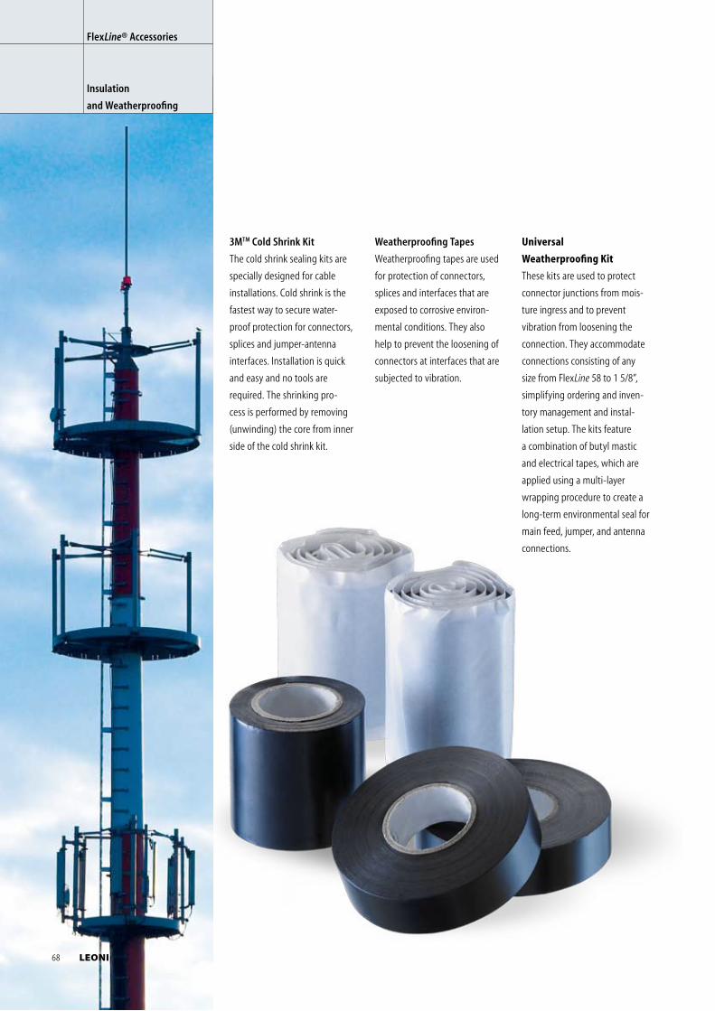
3MTM Cold Shrink Kit
The cold shrink sealing kits are
specially designed for cable
installations. Cold shrink is the
fastest way to secure water-
proof protection for connectors,
splices and jumper-antenna
interfaces. Installation is quick
and easy and no tools are
required. The shrinking pro-
cess is performed by removing
(unwinding) the core from inner
side of the cold shrink kit.
FlexLine® Accessories
Insulation
and Weatherproofing
Universal
Weather proofing Kit
These kits are used to protect
connector junctions from mois-
ture ingress and to prevent
vibration from loosening the
connection. They accommodate
connections consisting of any
size from FlexLine 58 to 1 5/8”,
simplifying ordering and inven-
tory management and instal-
lation setup. The kits feature
a combination of butyl mastic
and electrical tapes, which are
applied using a multi-layer
wrapping procedure to create a
long-term environmental seal for
main feed, jumper, and antenna
connections.
Weatherproofing Tapes
Weatherproofing tapes are used
for protection of connectors,
splices and interfaces that are
exposed to corrosive environ-
mental conditions. They also
help to prevent the loosening of
connectors at interfaces that are
subjected to vibration.
68 LEONI
3M Cold shrinkTM Supported cable types Application diameter Length Order number
Cold ShrinkTM jumper/antenna 1/2“ FlexLine 1/2” - Antenna connector 39.0 mm – 13.5 mm 150 mm (5.9 in) S45055-Z61-A433
Cold Shrink Coax-Kit 1/2“ to 7/8“ FlexLine 1/2” to FlexLine 7/8” 49.3 mm – 13.5 mm 220 mm (8.7 in) S45055-Z61-A434
Cold Shrink Coax-Kit 1/2“ to 1 5/8“ FlexLine 1/2” to FlexLine 1 5/8” 67.8 mm – 13.5 mm 280 mm (11 in) S45055-Z61-A435
3MTM Insulating material Dimensions Length per roll Operating temperature Order number
Scotchfil, Electrical insulation putty 38 mm x 3.20 mm (1.5 in x 0.125 in) 1.5 m (4.9 ft) up to +80 °C (176 °F) S45055-Z61-A436
Scotch 23, All voltage splicing tape 19 mm x 0.75 mm (0.75 in x 0.03 in) 9 m (29.5 ft) up to +90 °C (194 °F) S45055-Z61-A437
Scotch 710, Vinyl electrical tape 19 mm x 0.17 mm (0.75 in x 0.01 in) 20 m (65.6 ft) –10 °C to +90 °C (14 °F to 194 °F) S45055-Z61-A438
Scotch 33+, Vinyl electrical tape, bk 19 mm x 0.18 mm (0.75 in x 0.01 in) 6 m (19.7 ft) up to +105 °C (221 °F) S45055-Z61-A604
Scotch 33+, Vinyl electrical tape, bk 19 mm x 0.18 mm (0.75 in x 0.01 in) 20 m (65.6 ft) up to +105 °C (221 °F) S45055-Z61-A605
Scotch 33+, Vinyl electrical tape, bk 19 mm x 0.18 mm (0.75 in x 0.01 in) 33 m (9.8 ft) up to +105 °C (221 °F) S45055-Z61-A607
Scotch 33+, Vinyl electrical tape, gy 19 mm x 0.18 mm (0.75 in x 0.01 in) 20 m (65.6 ft) up to +105 °C (221 °F) S45055-Z61-A829
Insulating material Dimensions Length per roll Operating temperature Order number
SCAPA 34, Electrical insulation putty 38 mm x 3.00 mm (1.5 in x 0.125 in) 1.5 m (4.9 ft) – 30 °C to +90 °C (– 22 °F to 194 °F) S45055-Z61-A728
NAS 1, Self agglomerating silicon rubber tape 25 mm x 0.50 mm (0.98 in x 0.02 in) 1.0 m (3.3 ft) – 50 °C to +150 °C (– 58 °F to 302 °F) S45055-Z61-A444
NAS 10, Self agglomerating silicon rubber tape 25 mm x 0.50 mm (0.98 in x 0.02 in) 10 m (32.8 ft) – 50 °C to +150 °C (– 58 °F to 302 °F) S45055-Z61-A445
NEP 19, Self agglomerating tape 19 mm x 0,75 mm (0.75 in x 0.03 in) 10 m (32.8 ft) – 40 °C to +70 °C (– 40 °F to 158 °F) S45055-Z61-A705
Heat-shrinking tubes for the protection of cable joints
Supported cable types Application diameter Length Order number
MWT-M 25/ 8, Heat shrinking tubes FlexLine 1/2" to FlexLine 3/8" 25 mm (0.984 in) (shrinked 8 mm (0.315 in))
1 m (3.3 ft) S45055-Z61-A574
MWT-M 35/ 12, Heat shrinking tubes FlexLine 7/8" 35 mm (1.378 in) (shrinked 12 mm (0.472 in))
1 m (3.3 ft) S45055-Z61-A575
MWT-M 50/ 16, Heat shrinking tubes FlexLine 1 1/4" 50 mm (1.969 in) (shrinked 16 mm (0.630 in))
1 m (3.3 ft) S45055-Z61-A576
MWT-M 63/ 19, Heat shrinking tubes FlexLine 1 5/8" 63 mm (2.480 in) (shrinked 19 mm (0.748 in))
1 m (3.3 ft) S45055-Z61-A577
FlexLine® Accessories Insulation and Weatherproofing
Universal Weatherproofing kit for connection size Connections per kit Order number
6x butyl mastic tape & 3x wide electrical tape
1/2" to 7/8" 6
S45055-Z61-A1021-LA
1/2" to 1 1/4" 5
1/2" to 1 5/8" 4
1/2" to 1/2" 8
7/8" to 7/8" 4
1 1/4" to 1 1/4" 3
1 5/8" to 1 5/8" 2
LEONI 69
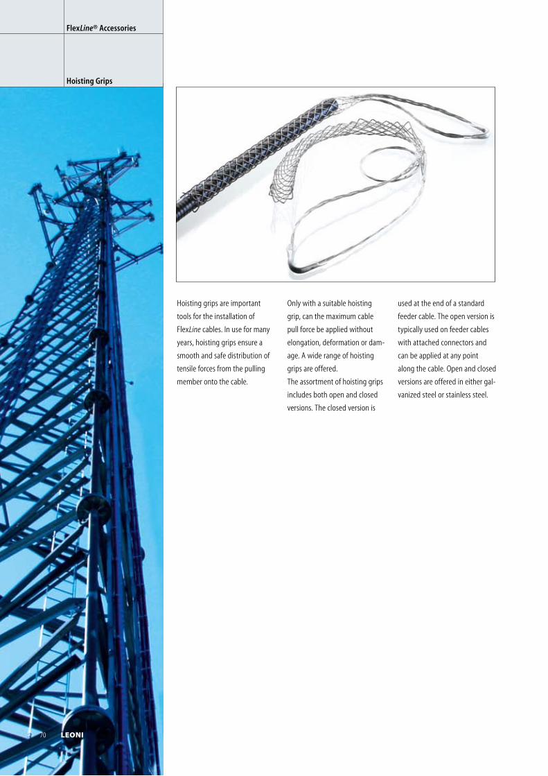
Hoisting grips are important
tools for the installation of
FlexLine cables. In use for many
years, hoisting grips ensure a
smooth and safe distribution of
tensile forces from the pulling
member onto the cable.
FlexLine® Accessories
Hoisting Grips
Only with a suitable hoisting
grip, can the maximum cable
pull force be applied without
elong ation, deformation or dam-
age. A wide range of hoisting
grips are offered.
The assortment of hoisting grips
includes both open and closed
versions. The closed version is
used at the end of a standard
feeder cable. The open version is
typically used on feeder cables
with attached connectors and
can be applied at any point
along the cable. Open and closed
versions are offered in either gal-
vanized steel or stainless steel.
70 LEONI
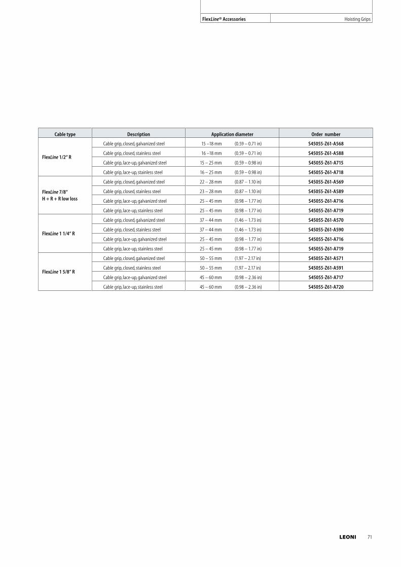
Cable type Description Application diameter Order number
FlexLine 1/2“ R
Cable grip, closed, galvanized steel 15 –18 mm (0.59 – 0.71 in) S45055-Z61-A568
Cable grip, closed, stainless steel 16 –18 mm (0.59 – 0.71 in) S45055-Z61-A588
Cable grip, lace-up, galvanized steel 15 – 25 mm (0.59 – 0.98 in) S45055-Z61-A715
Cable grip, lace-up, stainless steel 16 – 25 mm (0.59 – 0.98 in) S45055-Z61-A718
FlexLine 7/8“ H + R + R low loss
Cable grip, closed, galvanized steel 22 – 28 mm (0.87 – 1.10 in) S45055-Z61-A569
Cable grip, closed, stainless steel 23 – 28 mm (0.87 – 1.10 in) S45055-Z61-A589
Cable grip, lace-up, galvanized steel 25 – 45 mm (0.98 – 1.77 in) S45055-Z61-A716
Cable grip, lace-up, stainless steel 25 – 45 mm (0.98 – 1.77 in) S45055-Z61-A719
FlexLine 1 1/4“ R
Cable grip, closed, galvanized steel 37 – 44 mm (1.46 – 1.73 in) S45055-Z61-A570
Cable grip, closed, stainless steel 37 – 44 mm (1.46 – 1.73 in) S45055-Z61-A590
Cable grip, lace-up, galvanized steel 25 – 45 mm (0.98 – 1.77 in) S45055-Z61-A716
Cable grip, lace-up, stainless steel 25 – 45 mm (0.98 – 1.77 in) S45055-Z61-A719
FlexLine 1 5/8“ R
Cable grip, closed, galvanized steel 50 – 55 mm (1.97 – 2.17 in) S45055-Z61-A571
Cable grip, closed, stainless steel 50 – 55 mm (1.97 – 2.17 in) S45055-Z61-A591
Cable grip, lace-up, galvanized steel 45 – 60 mm (0.98 – 2.36 in) S45055-Z61-A717
Cable grip, lace-up, stainless steel 45 – 60 mm (0.98 – 2.36 in) S45055-Z61-A720
FlexLine® Accessories Hoisting Grips
LEONI 71
72 LEONI
Inner conductor
The inner conductors of corrugated FlexLine Coaxial cables consist of
copper wire, copperclad aluminium wire or a copper tube. For corru-
gated cables with small dimensions or braided FlexLine Coaxial cables,
wires or even litz wires are used to guarantee sufficient flexibility. The
inner conductors of corrugated FlexLine Coaxial cables with larger
dimensions are made of copper tubes. This ensures low weight as well
as the necessary flexibility. Spiral corrugation of the inner conductor
tube lends the corrugated FlexLine Coaxial cable additional flexibility.
Outer conductor
The outer conductor of corrugated FlexLine Coaxial cables is formed
by a welded copper tube with either spiral or ring-shaped corrugati-
ons. The welded copper tube guarantees RF shielding with screening
attenuation values in excess of 120 dB. Spiral corrugations, braids and
foils are used for highly flexible cable versions. The deep and tightly
spaced corrugations in the outer conductor of corrugated FlexLine
Coaxial cables result in the smallest possible bending radii and highest
flexibility. FlexLine Coaxial cables are often used for jumper cables.
Dielectric
In all FlexLine Coaxial cables, highly foamed polyethylene ensures
excellent attenuation to be achieved with the smallest possible
dimensions. A thin layer of unfoamed polyethylene is applied directly
to the inner conductor so that the dielectric can be stripped with ease.
A physical foaming process produces up to 80 % of the polyethylene
with a fine-pore, non-hygroscopic cell structure that lays the founda-
tion for the cable‘s electrical performance. High foaming means a high
proportion of air in the dielectric which results in lower weight, and
attenuation characteristics approaching those of air dielectric cables
of similar size.
Mechanical characteristics
Technical Data
FlexLine ®
Jacket options
Black polyethylene is the standard outer jacket for all FlexLine cables.
This material is suitable for indoor and outdoor use (also underground).
It is UV-resistant and halogen-free, and develops no corrosive gases in
case of fire.
For applications which demand flame-retardant cables an outer
cable jacket made of FRNC material (Flame Retardant Non Corrosive)
is available. The FRNC-material is also halogen-free and enables the
cable to comply with the various listed IEC, NEC and UL flame tests.
FRNC material is used as the standard outer jacket for FlexLine Coaxial
jumper cables. All FlexLine cable jackets are available in various colours
for both polyethylene and FRNC material.
Specifications according to IEC, NEC and UL
IEC 60754-1
Test on gases evolved during combustion of materials from cables part 1:
Determination of the amount of halogen acid gas
IEC 60754-2
Test on gases evolved during combustion of electric cables part 2:
Determination of degree of acidity of gases evolved during the combustion
of materials taken from electric cables by measuring pH and conductivity
IEC 61034
Measurement of smoke density of electric cables burning under defined conditions
IEC 60332-1
Tests on electric cables under fire conditions part 1:
Test on a single vertical insulated wire or cable
IEC 60332-3.C
Tests on electric cables under fire conditions part 3:
Tests on bunched wires or cables category C
UL 1581, sec. 1080
Vertical wire flame test ,VW-1
CATV
Community Antenna Television Systems compliant with the NEC
(National Electric Code) require a flame test in accordance with UL
(Underwriters Laboratories) 1685 vertical tray (UL1581 sec.1160).
Tensile strength
The tensile strength of a cable defines the maximum permissible
tensile force which may be applied to the cable during installation
or handling. The unit of measurement is Newton (N) and takes into
account all the materials used in the cable. Exceeding the quoted
values may result in impairment of the cable‘s mechanical or electri-
cal characteristics. The values are determined by technical measuring
instruments and include an additional safety factor.
Bending radius
Specific minimal bending radii are defined for all FlexLine types
and cable sizes. A distinction is drawn between single bending and
repeated bending. In the case of single bending, the cable should
not be bent back again after reaching its minimal bending radius.
Repeated bending allows the cable to be bent to the minimal bend-
ing radius at least 15 times. It is typical for a cable to be bent between
40 and 50 times without any impairment of its transmission charac-
teristics. A cable‘s behaviour and stability when subjected to repeated
bending is very important during installation and assembly.
Tests are conducted parallel to production by subjecting a cable
specimen to repeated alternating bends up to the minimal permis-
sible bending radius and then checking the cable‘s characteristics.
Corrugations of the outer conductor enable the smallest bending
radii with corrugated FlexLine Coaxial cables. Electrical and mechani-
cal values of all FlexLine cables remain stable even after repeated
bending. The minimum bending radii of FlexLine cables guarantee
simple and reliable installation of the cables, resulting in dependable
and endurable connections.
Pin = power input into a cable of a specific length in W; Pout = power at the other end of the cable in W; R = return loss in dB; r = reflection factor;
s = voltage standing wave ratio ( VSWR ); Z1 = input impedance of the cable in ; Z2 = impedance of the reflection wave in
FlexLine® Technical Data
LEONI 73
conduct or ‘arc’. The DC breakdown voltage depends on the type of
dielectric used and its dimensions. This value is established for each
cable size and forms the basis for determining and calculating the
permissible peak power rating.
Capacitance
For coaxial cables the capacitance is calculated directly from
the dimensions of the cable and the dielectric constant “ r” of the
dielectric. The relative dielectric constant depends on the material
used and the degree of foaming. The capacitance value depends on
the length of the cable and is expressed in farad /unit of length.
[ in F / m ]
Relative velocity of propagation
This defines the velocity of propagation of a wave along the cable in
relation to the speed of light in a vacuum. The relative velocity of
propagation depends essentially on the dielectric constant “ r”,
which is derived from the type of material used and its degree of
foaming. High foaming of the dielectric results in values of 88 % for
FlexLine Coaxial cables.
[ in % ]
Impedance
Impedance is defined by the ratio of wave voltages to wave currents
at each point along the transmission path. This ratio of voltage to
current is constant for the superimposed waves (going and reflected/
returning) and thus represents a characteristic parameter of the cable.
The impedance is dependent on the frequency but approximates to
a defined value for high frequencies. This property enables coaxial
cables to be divided into defined impedance classes. Typical examples
are 50 cables for antenna systems and 75 cables for television
systems. Corrugated cables are normally used for antenna systems and
have an impedance of 50 . Tolerances are held very low at
+/– 1 for excellent adaptation (for High Power types ± 2 ).
The following formula is used for calculating impedance values:
[ in ]
Temperature ranges
Temperature ranges are defined for cables in storage, during in-
stallation and operation. The following table shows the temperature
ranges which apply for cables with a standard polyethylene jacket or
FRNC jacket:
Polyethylene jacket FRNC jacket
Storage: – 70 °C to +85 °C – 70 °C to +85 °C
Installation: – 40 °C to +60 °C – 40 °C to +60 °C
Operation: – 55 °C to +85 °C – 55 °C to +85 °C
The cables are approved for continuous duty within these tempera-
ture ranges.
Recommended hanger spacing
Various aspects need to be considered when fastening corrugated
cables. Hangers must be spaced in accordance with specific values
that are dependent on the location, the environmental conditions
and the choice of installation materials. Extreme loads to the cable
due to icing or strong winds must be taken into account when calcu-
lating the distance between the hangers.
The recommended maximum hanger spacings for the various cable
sizes are shown in the following table:
FlexLine Coaxial with corrugated outer conductor
1/4“S 3/8“S 1/2“S 1/2“R 5/8“R 7/8“S 7/8“R 1 1/4“R 1 5/8“R
0.6 m 0.6 m 0.8 m 0.8 m 1.0 m 1.0 m 1.0 m 1.2 m 1.5 m
DC resistance
The direct current resistance denotes the ohmic value of the inner
or outer conductor based on a length of 1 km and expressed in /km.
It is dependent on the cross section of the conductor and on the con-
ductor materials (specific conductance).
DC breakdown voltage
The DC breakdown voltage is determined between the inner conduc-
tor and the outer conductor. It is defined as the voltage at which the
insulation between two conductors will fail and allow electricity to
Electrical characteristics
74 LEONI
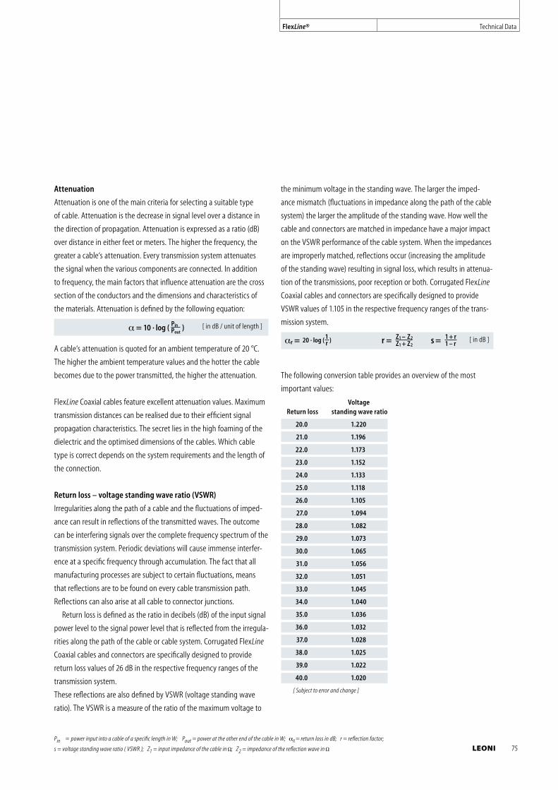
Attenuation
Attenuation is one of the main criteria for selecting a suitable type
of cable. Attenuation is the decrease in signal level over a distance in
the direction of propagation. Attenuation is expressed as a ratio (dB)
over distance in either feet or meters. The higher the frequency, the
greater a cable‘s attenuation. Every transmission system attenuates
the signal when the various components are connected. In addition
to frequency, the main factors that influence attenuation are the cross
section of the conductors and the dimensions and characteristics of
the materials. Attenuation is defined by the following equation:
[ in dB / unit of length ]
A cable‘s attenuation is quoted for an ambient temperature of 20 °C.
The higher the ambient temperature values and the hotter the cable
becomes due to the power transmitted, the higher the attenuation.
FlexLine Coaxial cables feature excellent attenuation values. Maximum
transmission distances can be realised due to their efficient signal
propagation characteristics. The secret lies in the high foaming of the
dielectric and the optimised dimensions of the cables. Which cable
type is correct depends on the system requirements and the length of
the connection.
Return loss – voltage standing wave ratio (VSWR)
Irregularities along the path of a cable and the fluctuations of imped-
ance can result in reflections of the transmitted waves. The outcome
can be interfering signals over the complete frequency spectrum of the
transmission system. Periodic deviations will cause immense interfer-
ence at a specific frequency through accumulation. The fact that all
manufacturing processes are subject to certain fluctuations, means
that reflections are to be found on every cable transmission path.
Reflections can also arise at all cable to connector junctions.
Return loss is defined as the ratio in decibels (dB) of the input signal
power level to the signal power level that is reflected from the irregula-
rities along the path of the cable or cable system. Corrugated FlexLine
Coaxial cables and connectors are specifically designed to provide
return loss values of 26 dB in the respective frequency ranges of the
transmission system.
These reflections are also defined by VSWR (voltage standing wave
ratio). The VSWR is a measure of the ratio of the maximum voltage to
Pin = power input into a cable of a specific length in W; Pout = power at the other end of the cable in W; R = return loss in dB; r = reflection factor;
s = voltage standing wave ratio ( VSWR ); Z1 = input impedance of the cable in ; Z2 = impedance of the reflection wave in
the minimum voltage in the standing wave. The larger the imped-
ance mismatch (fluctuations in impedance along the path of the cable
system) the larger the amplitude of the standing wave. How well the
cable and connectors are matched in impedance have a major impact
on the VSWR performance of the cable system. When the impedances
are improperly matched, reflections occur (increasing the amplitude
of the standing wave) resulting in signal loss, which results in attenua-
tion of the transmissions, poor reception or both. Corrugated FlexLine
Coaxial cables and connectors are specifically designed to provide
VSWR values of 1.105 in the respective frequency ranges of the trans-
mission system.
[ in dB ]
The following conversion table provides an overview of the most
important values:
Voltage Return loss standing wave ratio
20.0 1.220
21.0 1.196
22.0 1.173
23.0 1.152
24.0 1.133
25.0 1.118
26.0 1.105
27.0 1.094
28.0 1.082
29.0 1.073
30.0 1.065
31.0 1.056
32.0 1.051
33.0 1.045
34.0 1.040
35.0 1.036
36.0 1.032
37.0 1.028
38.0 1.025
39.0 1.022
40.0 1.020
[ Subject to error and change ]
FlexLine® Technical Data
LEONI 75
Passive intermodulation
Passive intermodulation represents a further potential source of
interference in the frequency range for transmission. It arises when
two transmission signals form intermodulation products as the result
of component nonlinearities (in this case cables and connectors). In
particular the product of the third order is critical because it lies in
the transmission range and can therefore interfere with the transmis-
sion signals.
Passive intermodulation mainly depends on the characteristics of
the materials and on the quality of contact between the cable and the
connector.
Resulting intermodulation products are measured by imputing
two signals with defined frequencies into the transmission system.
The degree of intermodulation is expressed as a signal level in either
dBm or dBc (dBc = in relation to the carrier signal).
The measurement is conducted using carrier signals at levels of
+43 dBm (20 W) and a frequency based on the range of application,
e.g. GSM 900 or GSM 1800. Typical measured values for FlexLine
Coaxial cable systems are < –117 dBm (< –160 dBc).
Cutoff frequency
Cutoff frequency is defined as the highest radio frequency that
will pass through the cables. Above this frequency there is a risk of
undefined modes (waves) arising and exerting a negative influence
(increased attenuation) on the transmission. The cutoff frequency for
each cable depends on the dimensions and materials.
The cutoff frequency can be calculated with the following equation:
[ in GHz ]
Maximum operating frequency
The maximum operating frequency is normally based on the cutoff
frequency and includes a defined safety factor.
Peak power rating
The peak power rating is the input power achieved when operating
the coaxial cable with the maximum RF operating voltage (peak
value). The measurement is limited by the DC breakdown voltage
between the cable‘s inner conductor and outer conductor. The peak
power rating is a calculated value which is independent of the fre-
quency.
Mean power rating
FlexLine Coaxial cables permit a continuous maximum temperature of
85 °C at the inner conductor, i.e. the heat generated by the continuous
power must not exceed this value. The crucial factor is the material of
the dielectric. The values quoted for the maximum continuous power
rating are based on an ambient temperature of 40 °C and a voltage
standing wave ratio of 1.0. The higher the ambient temperature, the
lower the maximum permissible continuous power rating. Increasing
the voltage standing wave ratio has the same effect. The continuous
power rating is also affected by other ambient conditions, e.g. direct
sunlight.
Shielding effectiveness
Shielding effectiveness is quoted as a measure of the shielding effect
of a cable‘s construction. It defines the logarithmic ratio of the power,
which is input into the cable to the power that is radiated from the
cable. On corrugated FlexLine Coaxial cables the shielding attenuation
is greater than 120 dB as a result of using a solid copper tube outer
conductor with an RF-tight weld. Braided FlexLine Coaxial cables that
contain a shielding foil typically achieve shielding effectiveness values
of only 90 dB.
. 100
76 LEONI

LEONI 77
LEONI quality management
A consistently high level of quality is vital for
our products. This means that the entire pro-
cess at LEONI – from a product s planning to
its completion – is constantly monitored.
Our quality management system is certified
in accordance with DIN/ISO 9001:2000 and is
updated permanently.
Environment-friendly and safe
Of course, halogen-free versions of a great
number of the cables in our range are also
available. This does reduce the strain in the
environment, it also means less smoke and
corrosive emissions in the case of a fire –
for your safety.
Quality and Environment
FlexLine ®
LEONI environmental management
For us, business success with ecological
responsibility is not a contradiction in terms.
Because of this, environmental protection is
an intrinsic element of our corporate activities.
Our environment management system is
certified as complying with DIN EN ISO 14001,
confirming that our environment policy is
effectively implemented.
India
LEONI Special Cables
(India) Pvt. Ltd.
A-405, Galleria
Hiranandani Gardens, Powai
Mumbai – 400076
India
Phone +91 (0)22 40056644, 45
Fax +91 (0)22 40056646
E-mail [email protected]
Germany (Headquarters)
LEONI Special Cables GmbH
Business Unit Telecom
Eschstrasse 1
26169 Friesoythe
Germany
Phone +49 (0)4491-292-292
Fax +49 (0)4491-292-169
E-mail [email protected]
www.leoni-telecom.com
Asia Pacific (Central office)
LEONI Special Cables GmbH
Representative Office Asia Pacific
S. Widjojo Centre, 10th floor
Jl. Jendral Sudirman Kav. 71
Jakarta 12190
Indonesia
Phone +62 (0)21-526-5767
Fax +62 (0)21-526-4340
E-mail [email protected]
China
LEONI Special Cables
(Changzhou) Co., Ltd.
Shanghai Office
Room 707 Aetna Mansion
No. 107 Zunyi Road
Changning Area, Shanghai 200051
China
Phone +86 (0)21-6237-5569
Fax +86 (0)21-6237-5589
E-mail [email protected]
www.leoni-special-cables.cn
Sales Network
FlexLine ®
78 LEONI
India
LEONI Special Cables
(India) Pvt. Ltd.
A-405, Galleria
Hiranandani Gardens, Powai
Mumbai – 400076
India
Phone +91 (0)22 40056644, 45
Fax +91 (0)22 40056646
E-mail [email protected]
Singapore
LEONI Special Cables GmbH
Branch Office Singapore
28, Gul Avenue
629668 Singapore
Phone +65 (0)6863-4966
Fax +65 (0)6863-4955
E-Mail [email protected]
LEONI 79

Eschstrasse 1
26169 Friesoythe
Germany
Phone +49 (0)4491 292 292
Fax +49 (0)4491 292 169
E-mail [email protected]
www.leoni-telecom.com
LEONI Special Cables GmbH
Business Unit Telecom