Embed Size (px)
Citation preview
Catalyst 2950 and Catalyst 2955 Switch Command ReferenceCisco IOS Release 12.1(22)EA11 and Later March 2008
Americas HeadquartersCisco Systems, Inc.170 West Tasman DriveSan Jose, CA 95134-1706 USAhttp://www.cisco.comTel: 408 526-4000
800 553-NETS (6387)Fax: 408 527-0883
Text Part Number: OL-10102-02

THE SPECIFICATIONS AND INFORMATION REGARDING THE PRODUCTS IN THIS MANUAL ARE SUBJECT TO CHANGE WITHOUT NOTICE. ALL STATEMENTS, INFORMATION, AND RECOMMENDATIONS IN THIS MANUAL ARE BELIEVED TO BE ACCURATE BUT ARE PRESENTED WITHOUT WARRANTY OF ANY KIND, EXPRESS OR IMPLIED. USERS MUST TAKE FULL RESPONSIBILITY FOR THEIR APPLICATION OF ANY PRODUCTS.
THE SOFTWARE LICENSE AND LIMITED WARRANTY FOR THE ACCOMPANYING PRODUCT ARE SET FORTH IN THE INFORMATION PACKET THAT SHIPPED WITH THE PRODUCT AND ARE INCORPORATED HEREIN BY THIS REFERENCE. IF YOU ARE UNABLE TO LOCATE THE SOFTWARE LICENSE OR LIMITED WARRANTY, CONTACT YOUR CISCO REPRESENTATIVE FOR A COPY.
The Cisco implementation of TCP header compression is an adaptation of a program developed by the University of California, Berkeley (UCB) as part of UCB’s public domain version of the UNIX operating system. All rights reserved. Copyright © 1981, Regents of the University of California.
NOTWITHSTANDING ANY OTHER WARRANTY HEREIN, ALL DOCUMENT FILES AND SOFTWARE OF THESE SUPPLIERS ARE PROVIDED “AS IS” WITH ALL FAULTS. CISCO AND THE ABOVE-NAMED SUPPLIERS DISCLAIM ALL WARRANTIES, EXPRESSED OR IMPLIED, INCLUDING, WITHOUT LIMITATION, THOSE OF MERCHANTABILITY, FITNESS FOR A PARTICULAR PURPOSE AND NONINFRINGEMENT OR ARISING FROM A COURSE OF DEALING, USAGE, OR TRADE PRACTICE.
IN NO EVENT SHALL CISCO OR ITS SUPPLIERS BE LIABLE FOR ANY INDIRECT, SPECIAL, CONSEQUENTIAL, OR INCIDENTAL DAMAGES, INCLUDING, WITHOUT LIMITATION, LOST PROFITS OR LOSS OR DAMAGE TO DATA ARISING OUT OF THE USE OR INABILITY TO USE THIS MANUAL, EVEN IF CISCO OR ITS SUPPLIERS HAVE BEEN ADVISED OF THE POSSIBILITY OF SUCH DAMAGES.
CCDE, CCVP, Cisco Eos, Cisco StadiumVision, the Cisco logo, DCE, and Welcome to the Human Network are trademarks; Changing the Way We Work, Live, Play, and Learn is a service mark; and Access Registrar, Aironet, AsyncOS, Bringing the Meeting To You, Catalyst, CCDA, CCDP, CCIE, CCIP, CCNA, CCNP, CCSP, Cisco, the Cisco Certified Internetwork Expert logo, Cisco IOS, Cisco Press, Cisco Systems, Cisco Systems Capital, the Cisco Systems logo, Cisco Unity, Collaboration Without Limitation, Enterprise/Solver, EtherChannel, EtherFast, EtherSwitch, Event Center, Fast Step, Follow Me Browsing, FormShare, GigaDrive, HomeLink, Internet Quotient, IOS, iPhone, IP/TV, iQ Expertise, the iQ logo, iQ Net Readiness Scorecard, iQuick Study, IronPort, the IronPort logo, LightStream, Linksys, MediaTone, MeetingPlace, MGX, Networkers, Networking Academy, Network Registrar, PCNow, PIX, PowerPanels, ProConnect, ScriptShare, SenderBase, SMARTnet, Spectrum Expert, StackWise, The Fastest Way to Increase Your Internet Quotient, TransPath, WebEx, and the WebEx logo are registered trademarks of Cisco Systems, Inc. and/or its affiliates in the United States and certain other countries.
All other trademarks mentioned in this document or Website are the property of their respective owners. The use of the word partner does not imply a partnership relationship between Cisco and any other company. (0801R)
Any Internet Protocol (IP) addresses used in this document are not intended to be actual addresses. Any examples, command display output, and figures included in the document are shown for illustrative purposes only. Any use of actual IP addresses in illustrative content is unintentional and coincidental.
Catalyst 2950 and Catalyst 2955 Switch Command Reference Copyright © 2006 - 2008 Cisco Systems, Inc. All rights reserved
OL-10102-02
C O N T E N T S
Preface xv
Audience xv
Purpose xv
Conventions xv
Related Publications xvi
Obtaining Documentation and Submitting a Service Request xvii
Using the Command-Line Interface 1-1
Type of Memory 1-1
Platforms 1-1
CLI Command Modes 1-2
User EXEC Mode 1-3
Privileged EXEC Mode 1-3
Global Configuration Mode 1-4
Interface Configuration Mode 1-4
config-vlan Mode 1-4
VLAN Configuration Mode 1-5
Line Configuration Mode 1-5
Command Summary 1-6
Catalyst 2950 and 2955 Cisco IOS Commands 2-1
aaa accounting dot1x 2-1
aaa authentication dot1x 2-3
access-list (IP extended) 2-5
access-list (IP standard) 2-8
archive download-sw 2-10
archive tar 2-12
archive upload-sw 2-15
auto qos voip 2-17
boot boothlpr 2-21
boot buffersize 2-22
boot config-file 2-23
boot enable-break 2-24
iiiCatalyst 2950 and Catalyst 2955 Switch Command Reference
Contents
boot helper 2-25
boot helper-config-file 2-26
boot manual 2-27
boot private-config-file 2-28
boot system 2-29
channel-group 2-30
channel-protocol 2-33
class 2-35
class-map 2-37
clear controllers ethernet-controller 2-39
clear controllers lre 2-41
clear controllers lre link monitor 2-42
clear controllers lre log 2-43
clear interface 2-44
clear lacp 2-45
clear lre rate selection 2-46
clear mac address-table 2-47
clear pagp 2-49
clear port-security 2-50
clear spanning-tree counters 2-52
clear spanning-tree detected-protocols 2-53
clear vmps statistics 2-54
clear vtp counters 2-55
cluster commander-address 2-56
cluster discovery hop-count 2-58
cluster enable 2-59
cluster holdtime 2-60
cluster management-vlan 2-61
cluster member 2-62
cluster run 2-64
cluster standby-group 2-65
cluster timer 2-67
controller longreachethernet 2-68
cpe duplex 2-69
cpe protected 2-71
ivCatalyst 2950 and Catalyst 2955 Switch Command Reference
OL-10102-02
Contents
cpe shutdown 2-72
cpe speed 2-74
cpe toggle 2-76
cpe type 2-78
define interface-range 2-79
delete 2-81
deny (access-list configuration) 2-82
deny (MAC access-list configuration) 2-85
dot1x 2-87
dot1x auth-fail max-attempts 2-89
dot1x auth-fail vlan 2-90
dot1x control-direction 2-92
dot1x default 2-94
dot1x guest-vlan 2-95
dot1x host-mode 2-97
dot1x initialize 2-98
dot1x max-req 2-99
dot1x multiple-hosts 2-100
dot1x port-control 2-101
dot1x re-authenticate 2-103
dot1x re-authentication 2-104
dot1x reauthentication 2-105
dot1x timeout 2-106
duplex 2-108
errdisable detect cause 2-110
errdisable recovery 2-112
flowcontrol 2-114
hw-module slot 2-118
interface 2-121
interface port-channel 2-123
interface range 2-124
interleave 2-126
ip access-group 2-128
ip access-list 2-130
ip address 2-132
vCatalyst 2950 and Catalyst 2955 Switch Command Reference
OL-10102-02
Contents
ip dhcp snooping 2-133
ip dhcp snooping information option 2-134
ip dhcp snooping information option allow-untrusted 2-136
ip dhcp snooping limit rate 2-138
ip dhcp snooping trust 2-139
ip dhcp snooping vlan 2-140
ip igmp filter 2-141
ip igmp max-groups 2-142
ip igmp profile 2-144
ip igmp snooping 2-146
ip igmp snooping mrouter learn pim v2 2-147
ip igmp snooping report-suppression 2-149
ip igmp snooping source-only-learning 2-151
ip igmp snooping vlan 2-153
ip igmp snooping vlan immediate-leave 2-154
ip igmp snooping vlan last-member-query interval 2-155
ip igmp snooping vlan mrouter 2-156
ip igmp snooping vlan static 2-158
ip ssh 2-159
lacp port-priority 2-161
lacp system-priority 2-163
link monitor 2-165
link monitor logging 2-166
link monitor threshold rserr 2-167
link monitor threshold snr 2-169
local duplex 2-170
local speed 2-171
logging lre 2-172
lre profile 2-173
lre rate selection sequence 2-175
lre sequence 2-177
lre syslog 2-179
lre upbo 2-180
lre upgrade default family 2-182
mac access-group 2-184
viCatalyst 2950 and Catalyst 2955 Switch Command Reference
OL-10102-02
Contents
mac access-list extended 2-186
mac address-table aging-time 2-188
mac address-table notification 2-190
mac address-table static 2-192
mac address-table static drop 2-194
macro apply 2-196
macro description 2-199
macro global 2-200
macro global description 2-202
macro name 2-203
margin 2-205
match 2-207
media-type 2-209
mls qos cos 2-211
mls qos map 2-213
mls qos trust 2-216
monitor session 2-219
mvr 2-222
mvr immediate 2-225
mvr type 2-227
mvr vlan group 2-229
pagp learn-method 2-230
pagp port-priority 2-232
permit (access-list configuration) 2-233
permit (MAC access-list configuration) 2-236
persistence 2-238
police 2-239
policy-map 2-241
port-channel load-balance 2-244
profile (interface configuration) 2-246
profile (sequence configuration) 2-248
rate selection 2-250
rate selection profile lock 2-251
rate selection sequence 2-252
rcommand 2-254
viiCatalyst 2950 and Catalyst 2955 Switch Command Reference
OL-10102-02
Contents
remote-span 2-256
rmon collection stats 2-258
service password-recovery 2-259
service-policy 2-261
set 2-262
setup express 2-264
show access-lists 2-266
show auto qos 2-268
show boot 2-271
show class-map 2-273
show cluster 2-275
show cluster candidates 2-277
show cluster members 2-279
show controllers ethernet-controller 2-281
show controllers lre cpe 2-290
show controllers lre actual 2-293
show controllers lre admin 2-296
show controllers lre link monitor 2-298
show controllers lre log 2-301
show controllers lre profile 2-303
show controllers lre sequence 2-306
show controllers lre status 2-308
show controllers lre version 2-313
show controllers utilization 2-314
show dot1x 2-316
show env 2-320
show errdisable recovery 2-321
show etherchannel 2-323
show file 2-326
show flowcontrol 2-329
show interfaces 2-331
show interfaces counters 2-340
show inventory 2-343
show ip access-lists 2-344
show ip dhcp snooping 2-346
viiiCatalyst 2950 and Catalyst 2955 Switch Command Reference
OL-10102-02
Contents
show ip dhcp snooping binding 2-347
show ip igmp profile 2-349
show ip igmp snooping 2-350
show ip igmp snooping querier detail 2-353
show lacp 2-355
show lre upgrade 2-357
show mac access-group 2-361
show mac address-table 2-363
show mac address-table multicast 2-366
show mac address-table notification 2-368
show mls masks 2-369
show mls qos interface 2-371
show mls qos maps 2-373
show monitor 2-375
show mvr 2-377
show mvr interface 2-378
show mvr members 2-380
show pagp 2-382
show parser macro 2-384
show policy-map 2-387
show port-security 2-389
show rps 2-391
show running-config vlan 2-393
show setup express 2-395
show spanning-tree 2-396
show storm-control 2-401
show system mtu 2-404
show udld 2-405
show version 2-408
show vlan 2-410
show vmps 2-413
show vtp 2-415
show wrr-queue bandwidth 2-420
show wrr-queue cos-map 2-421
shutdown 2-422
ixCatalyst 2950 and Catalyst 2955 Switch Command Reference
OL-10102-02
Contents
shutdown vlan 2-423
snmp-server enable traps 2-424
snmp-server host 2-427
snmp trap mac-notification 2-431
spanning-tree backbonefast 2-432
spanning-tree bpdufilter 2-433
spanning-tree bpduguard 2-435
spanning-tree cost 2-437
spanning-tree etherchannel guard misconfig 2-439
spanning-tree extend system-id 2-441
spanning-tree guard 2-443
spanning-tree link-type 2-445
spanning-tree loopguard default 2-446
spanning-tree mode 2-448
spanning-tree mst configuration 2-450
spanning-tree mst cost 2-452
spanning-tree mst forward-time 2-454
spanning-tree mst hello-time 2-455
spanning-tree mst max-age 2-456
spanning-tree mst max-hops 2-458
spanning-tree mst port-priority 2-459
spanning-tree mst priority 2-461
spanning-tree mst root 2-462
spanning-tree port-priority 2-464
spanning-tree portfast (global configuration) 2-466
spanning-tree portfast (interface configuration) 2-468
spanning-tree stack-port 2-470
spanning-tree uplinkfast 2-472
spanning-tree vlan 2-474
speed 2-477
storm-control 2-480
switchport access 2-483
switchport block 2-485
switchport host 2-487
switchport mode 2-489
xCatalyst 2950 and Catalyst 2955 Switch Command Reference
OL-10102-02
Contents
switchport nonegotiate 2-491
switchport port-security 2-493
switchport port-security aging 2-497
switchport priority extend 2-499
switchport protected 2-501
switchport trunk 2-502
switchport voice vlan 2-505
system mtu 2-507
traceroute mac 2-509
traceroute mac ip 2-512
udld 2-514
udld port 2-516
udld reset 2-518
upgrade binary 2-519
upgrade preserve 2-520
vlan (global configuration) 2-521
vlan (VLAN configuration) 2-527
vlan database 2-533
vmps reconfirm (global configuration) 2-536
vmps reconfirm (privileged EXEC) 2-537
vmps retry 2-538
vmps server 2-539
vtp (global configuration) 2-541
vtp (privileged EXEC) 2-545
vtp (VLAN configuration) 2-547
wrr-queue bandwidth 2-551
wrr-queue cos-map 2-553
Catalyst 2955 Alarm Commands A-1
alarm facility fcs-hysteresis A-2
alarm facility power-supply A-3
alarm facility temperature A-4
alarm profile (global configuration) A-6
alarm profile (interface configuration) A-8
fcs-threshold A-9
power-supply dual A-10
xiCatalyst 2950 and Catalyst 2955 Switch Command Reference
OL-10102-02
Contents
show alarm description port A-11
show alarm profile A-12
show alarm settings A-14
show env A-16
show facility-alarm relay A-18
show facility-alarm status A-19
show fcs-threshold A-20
test relay A-21
Catalyst 2950 and 2955 Switch Boot Loader Commands B-1
boot B-2
cat B-3
copy B-4
delete B-5
dir B-6
flash_init B-8
format B-9
fsck B-10
help B-11
load_helper B-12
memory B-13
mkdir B-15
more B-16
rename B-17
reset B-18
rmdir B-19
set B-20
type B-23
unset B-24
version B-26
Catalyst 2950 and 2955 Switch Debug Commands C-1
debug auto qos C-2
debug dot1x C-4
debug etherchannel C-5
debug lre C-6
xiiCatalyst 2950 and Catalyst 2955 Switch Command Reference
OL-10102-02
Contents
debug pagp C-7
debug pm C-8
debug spanning-tree C-10
debug spanning-tree backbonefast C-12
debug spanning-tree bpdu C-13
debug spanning-tree bpdu-opt C-14
debug spanning-tree mstp C-15
debug spanning-tree switch C-17
debug spanning-tree uplinkfast C-19
debug switch dhcp C-20
debug sw-vlan C-21
debug sw-vlan ifs C-23
debug sw-vlan notification C-24
debug sw-vlan vtp C-26
debug udld C-28
xiiiCatalyst 2950 and Catalyst 2955 Switch Command Reference
OL-10102-02

Contents
xivCatalyst 2950 and Catalyst 2955 Switch Command Reference
OL-10102-02
Preface
AudienceThis guide is for the networking professional using the Cisco IOS command-line interface (CLI) to manage the Catalyst 2950 and 2955 switches, hereafter referred to as the switches. Before using this guide, you should have experience working with the Cisco IOS and be familiar with the concepts and terminology of Ethernet and local area networking.
PurposeThe Catalyst 2950 switch is supported by either the standard software image (SI) or the enhanced software image (EI). The Catalyst 2955 and the Catalyst 2950 Long-Reach Ethernet (LRE) switches are supported only by the EI. The EI provides a richer set of features, including access control lists (ACLs), enhanced quality of service (QoS) features, extended-range VLANs, the IEEE 802.1s Multiple STP, Remote Switched Port Analyzer (RSPAN), and unicast MAC address filtering.
This guide provides the information you need about the commands that have been created or changed for use with the Catalyst 2950 family of switches. For information about the standard Cisco IOS Release 12.1 commands, see the Cisco IOS documentation set available from the Cisco.com home page by selecting Service and Support > Technical Documents. On the Cisco Product Documentation home page, select Release 12.1 from the Cisco IOS Software drop-down list.
This guide does not provide procedures for configuring your switch. For detailed configuration procedures, see the software configuration guide for this release.
This guide does not describe system messages you might encounter. For more information, see the system message guide for this release.
For documentation updates, see the release notes for this release.
ConventionsThis guide uses these conventions to convey instructions and information:
Command descriptions use these conventions:
• Commands and keywords are in boldface text.
• Arguments for which you supply values are in italic.
• Square brackets ([ ]) mean optional elements.
xvCatalyst 2950 and Catalyst 2955 Switch Command Reference
OL-10102-02
Preface
• Braces ({ }) group required choices, and vertical bars ( | ) separate the alternative elements.
• Braces and vertical bars within square brackets ([{ | }]) mean a required choice within an optional element.
Interactive examples use these conventions:
• Terminal sessions and system displays are in screen font.
• Information you enter is in boldface screen font.
• Nonprinting characters, such as passwords or tabs, are in angle brackets (< >).
Notes, cautions, and tips use these conventions and symbols:
Note Means reader take note. Notes contain helpful suggestions or references to materials not contained in this manual.
Caution Means reader be careful. In this situation, you might do something that could result in equipment damage or loss of data.
Related PublicationsThese documents provide complete information about the switch and are available from this URL:
http://www.cisco.com/en/US/products/ps6738/tsd_products_support_series_home.html
http://www.cisco.com/en/US/products/hw/switches/ps628/tsd_products_support_series_home.html
• Release Notes for the Catalyst 2955, Catalyst 2950, and Catalyst 2940 Switches
• Catalyst 2955, 2950 and 2940 Switch System Message Guide
Note Switch requirements and procedures for initial configurations and software upgrades tend to change and therefore appear only in the release notes. Before installing, configuring, or upgrading the switch, see the release notes on Cisco.com for the latest information.
For information about the switch, see these documents:
• Catalyst 2950 and Catalyst 2955 Switch Software Configuration Guide
• Catalyst 2950 and Catalyst 2955 Switch Command Reference
• Device manager online help (available on the switch)
• Catalyst 2950 Switch Hardware Installation Guide
• Catalyst 2950 Switch Getting Started Guide
• Regulatory Compliance and Safety Information for the Catalyst 2950 Switch
• Catalyst 2955 Hardware Installation Guide
For information about related products, see these documents:
• Catalyst GigaStack Gigabit Interface Converter Hardware Installation Guide
• CWDM Passive Optical System Installation Note
• 1000BASE-T Gigabit Interface Converter Installation Notes
xviCatalyst 2950 and Catalyst 2955 Switch Command Reference
OL-10102-02
Preface
• Cisco LRE CPE Hardware Installation Guide
• Installation and Warranty Notes for the Cisco LRE 48 POTS Splitter
• Getting Started with Cisco Network Assistant
• Release Notes for Cisco Network Assistant
• Cisco Small Form-Factor Pluggable Modules Installation Notes
• Cisco CWDM GBIC and CWDM SFP Installation Note
• For information about the Network Admission Control (NAC) features, see the Network Admission Control Software Configuration Guide
Obtaining Documentation and Submitting a Service RequestFor information on obtaining documentation, submitting a service request, and gathering additional information, see the monthly What’s New in Cisco Product Documentation, which also lists all new and revised Cisco technical documentation, at:
http://www.cisco.com/en/US/docs/general/whatsnew/whatsnew.html
Subscribe to the What’s New in Cisco Product Documentation as a Really Simple Syndication (RSS) feed and set content to be delivered directly to your desktop using a reader application. The RSS feeds are a free service and Cisco currently supports RSS version 2.0.
xviiCatalyst 2950 and Catalyst 2955 Switch Command Reference
OL-10102-02

Preface
xviiiCatalyst 2950 and Catalyst 2955 Switch Command Reference
OL-10102-02
Catalyst OL-10102-02
C H A P T E R 1
Using the Command-Line InterfaceThe Catalyst 2950 and 2955 switches are supported by Cisco IOS software. This chapter describes how to use the switch command-line interface (CLI) to configure the software features.
For a complete description of the commands that support these features, see Chapter 2, “Catalyst 2950 and 2955 Cisco IOS Commands.” For more information on Cisco IOS Release 12.1, see the command references for Cisco IOS Release 12.1 at this URL:
http://www.cisco.com/en/US/products/sw/iosswrel/ps1831/tsd_products_support_series_home.html
For task-oriented configuration steps, see the software configuration guide for this release.
The switches are preconfigured and begin forwarding packets as soon as they are attached to compatible devices.
Note In this document, IP refers to IP version 4 (IPv4). Layer 3 IP version 6 (IPv6) packets are treated as non-IP packets.
Type of MemoryThe switch flash memory stores the Cisco IOS software image, the startup and private configuration files, and helper files.
PlatformsThis software release runs on a variety of switches. For a complete list, see the release notes.
1-12950 and Catalyst 2955 Switch Command Reference
Chapter 1 Using the Command-Line Interface CLI Command Modes
CLI Command ModesThis section describes the CLI command mode structure. Command modes support specific Cisco IOS commands. For example, the interface type_number command works only when entered in global configuration mode. These are the main command modes:
• User EXEC
• Privileged EXEC
• Global configuration
• Interface configuration
• Config-vlan
• VLAN configuration
• Line configuration
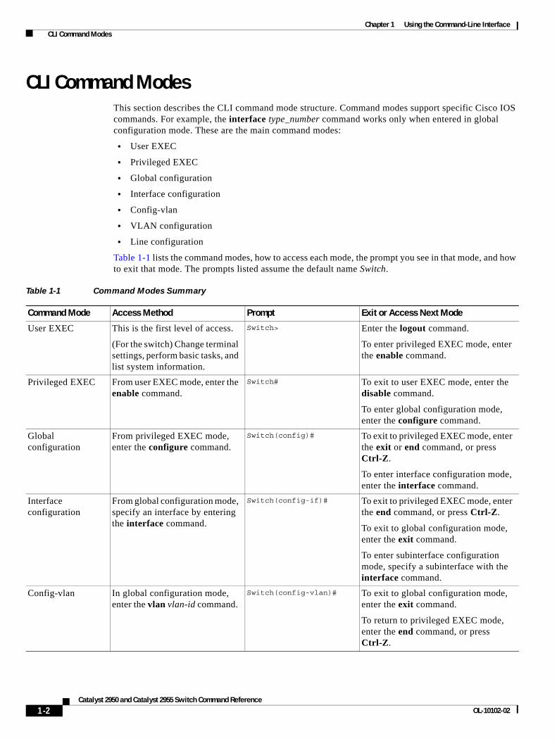
Table 1-1 lists the command modes, how to access each mode, the prompt you see in that mode, and how to exit that mode. The prompts listed assume the default name Switch.
Table 1-1 Command Modes Summary
Command Mode Access Method Prompt Exit or Access Next Mode
User EXEC This is the first level of access.
(For the switch) Change terminal settings, perform basic tasks, and list system information.
Switch> Enter the logout command.
To enter privileged EXEC mode, enter the enable command.
Privileged EXEC From user EXEC mode, enter the enable command.
Switch# To exit to user EXEC mode, enter the disable command.
To enter global configuration mode, enter the configure command.
Global configuration
From privileged EXEC mode, enter the configure command.
Switch(config)# To exit to privileged EXEC mode, enter the exit or end command, or press Ctrl-Z.
To enter interface configuration mode, enter the interface command.
Interface configuration
From global configuration mode, specify an interface by entering the interface command.
Switch(config-if)# To exit to privileged EXEC mode, enter the end command, or press Ctrl-Z.
To exit to global configuration mode, enter the exit command.
To enter subinterface configuration mode, specify a subinterface with the interface command.
Config-vlan In global configuration mode, enter the vlan vlan-id command.
Switch(config-vlan)# To exit to global configuration mode, enter the exit command.
To return to privileged EXEC mode, enter the end command, or press Ctrl-Z.
1-2Catalyst 2950 and Catalyst 2955 Switch Command Reference
OL-10102-02

Chapter 1 Using the Command-Line Interface CLI Command Modes
User EXEC ModeAfter you access the device, you are automatically in user EXEC command mode. The EXEC commands available at the user level are a subset of those available at the privileged level. In general, use the user EXEC commands to change terminal settings temporarily, to perform basic tests, and to list system information.
The supported commands can vary depending on the version of software in use. To view a comprehensive list of commands, enter a question mark (?) at the prompt.
Switch> ?
Privileged EXEC ModeBecause many of the privileged commands configure operating parameters, privileged access should be password-protected to prevent unauthorized use. The privileged command set includes those commands contained in user EXEC mode, as well as the configure command through which you access the remaining command modes.
If your system administrator has set a password, you are prompted to enter it before being granted access to privileged EXEC mode. The password does not appear on the screen and is case sensitive.
The privileged EXEC mode prompt is the device name followed by the pound sign (#).
Switch#
Enter the enable command to access privileged EXEC mode:
Switch> enable Switch#
The supported commands can vary depending on the version of software in use. To view a comprehensive list of commands, enter a question mark (?) at the prompt.
Switch# ?
To return to user EXEC mode, enter the disable command.
VLAN configuration
From privileged EXEC mode, enter the vlan database command.
Switch(vlan)# To exit to privileged EXEC mode, enter the exit command.
Line configuration From global configuration mode, specify a line by entering the line command.
Switch(config-line)# To exit to global configuration mode, enter the exit command.
To return to privileged EXEC mode, enter the end command, or press Ctrl-Z.
Table 1-1 Command Modes Summary (continued)
Command Mode Access Method Prompt Exit or Access Next Mode
1-3Catalyst 2950 and Catalyst 2955 Switch Command Reference
OL-10102-02
Chapter 1 Using the Command-Line Interface CLI Command Modes
Global Configuration ModeGlobal configuration commands apply to features that affect the device as a whole. Use the configure privileged EXEC command to enter global configuration mode. The default is to enter commands from the management console.
When you enter the configure command, a message prompts you for the source of the configuration commands:
Switch# configure Configuring from terminal, memory, or network [terminal]?
You can specify either the terminal or NVRAM as the source of configuration commands.
This example shows you how to access global configuration mode:
Switch# configure terminal Enter configuration commands, one per line. End with CNTL/Z.
The supported commands can vary depending on the version of software in use. To view a comprehensive list of commands, enter a question mark (?) at the prompt.
Switch(config)# ?
To exit global configuration command mode and to return to privileged EXEC mode, enter the end or exit command, or press Ctrl-Z.
Interface Configuration ModeInterface configuration commands modify the operation of the interface. Interface configuration commands always follow a global configuration command, which defines the interface type.
Use the interface type_number.subif command to access interface configuration mode. The new prompt shows interface configuration mode.
Switch(config-if)#
The supported commands can vary depending on the version of software in use. To view a comprehensive list of commands, enter a question mark (?) at the prompt.
Switch(config-if)# ?
To exit interface configuration mode and to return to global configuration mode, enter the exit command. To exit interface configuration mode and to return to privileged EXEC mode, enter the end command, or press Ctrl-Z.
config-vlan ModeUse this mode to configure normal-range VLANs (VLAN IDs 1 to 1005) or, when VTP mode is transparent, to configure extended-range VLANs (VLAN IDs 1006 to 4094). When VTP mode is transparent, the VLAN and VTP configuration is saved in the running configuration file, and you can save it to the switch startup configuration file by using the copy running-config startup-config privileged EXEC command. The configurations of VLAN IDs 1 to 1005 are saved in the VLAN database if VTP is in transparent or server mode. The extended-range VLAN configurations are not saved in the VLAN database.
1-4Catalyst 2950 and Catalyst 2955 Switch Command Reference
OL-10102-02
Chapter 1 Using the Command-Line Interface CLI Command Modes
Enter the vlan vlan-id global configuration command to access config-vlan mode:
Switch(config)# vlan 2000Switch(config-vlan)#
The supported keywords can vary but are similar to the commands available in VLAN configuration mode. To view a comprehensive list of commands, enter a question mark (?) at the prompt.
Switch(config-vlan)# ?
For extended-range VLANs, all characteristics except MTU size must remain at the default setting.
To return to global configuration mode, enter exit; to return to privileged EXEC mode, enter end. All commands except shutdown take effect when you exit config-vlan mode.
VLAN Configuration ModeYou can use the VLAN configuration commands to create or modify VLAN parameters for VLANs 1 to 1005. Enter the vlan database privileged EXEC command to access VLAN configuration mode:
Switch# vlan databaseSwitch(vlan)#
The supported commands can vary depending on the version of software in use. To view a comprehensive list of commands, enter a question mark (?) at the prompt.
Switch(vlan)# ?
To return to privileged EXEC mode, enter the abort command to abandon the proposed database. Otherwise, enter exit to implement the proposed new VLAN database and to return to privileged EXEC mode.
Line Configuration ModeLine configuration commands modify the operation of a terminal line. Line configuration commands always follow a line command, which defines a line number. Use these commands to change terminal parameter settings line-by-line or for a range of lines.
Use the line vty line_number [ending_line_number] command to enter line configuration mode. The new prompt indicates line configuration mode.
This example shows how to enter line configuration mode for virtual terminal line 7:
Switch(config)# line vty 0 7
The supported commands can vary depending on the version of software in use. To view a comprehensive list of commands, enter a question mark (?) at the prompt.
Switch(config-line)# ?
To exit line configuration mode and to return to global configuration mode, use the exit command. To exit line configuration mode and to return to privileged EXEC mode, enter the end command, or press Ctrl-Z.
1-5Catalyst 2950 and Catalyst 2955 Switch Command Reference
OL-10102-02
Chapter 1 Using the Command-Line Interface Command Summary
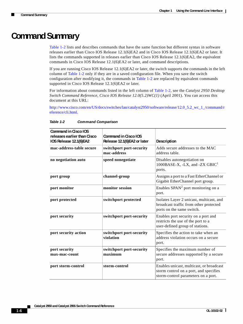
Command SummaryTable 1-2 lists and describes commands that have the same function but different syntax in software releases earlier than Cisco IOS Release 12.1(6)EA2 and in Cisco IOS Release 12.1(6)EA2 or later. It lists the commands supported in releases earlier than Cisco IOS Release 12.1(6)EA2, the equivalent commands in Cisco IOS Release 12.1(6)EA2 or later, and command descriptions.
If you are running Cisco IOS Release 12.1(6)EA2 or later, the switch supports the commands in the left column of Table 1-2 only if they are in a saved configuration file. When you save the switch configuration after modifying it, the commands in Table 1-2 are replaced by equivalent commands supported in Cisco IOS Release 12.1(6)EA2 or later.
For information about commands listed in the left column of Table 1-2, see the Catalyst 2950 Desktop Switch Command Reference, Cisco IOS Release 12.0(5.2)WC(1) (April 2001). You can access this document at this URL:
http://www.cisco.com/en/US/docs/switches/lan/catalyst2950/software/release/12.0_5.2_wc_1_/command/reference/cli.html.
Table 1-2 Command Comparison
Command in Cisco IOS releases earlier than Cisco IOS Release 12.1(6)EA2
Command in Cisco IOS Release 12.1(6)EA2 or later Description
mac-address-table secure switchport port-security mac-address
Adds secure addresses to the MAC address table.
no negotiation auto speed nonegotiate Disables autonegotiation on 1000BASE-X, -LX, and -ZX GBIC1 ports.
port group channel-group Assigns a port to a Fast EtherChannel or Gigabit EtherChannel port group.
port monitor monitor session Enables SPAN2 port monitoring on a port.
port protected switchport protected Isolates Layer 2 unicast, multicast, and broadcast traffic from other protected ports on the same switch.
port security switchport port-security Enables port security on a port and restricts the use of the port to a user-defined group of stations.
port security action switchport port-security violation
Specifies the action to take when an address violation occurs on a secure port.
port security max-mac-count
switchport port-security maximum
Specifies the maximum number of secure addresses supported by a secure port.
port storm-control storm-control Enables unicast, multicast, or broadcast storm control on a port, and specifies storm-control parameters on a port.
1-6Catalyst 2950 and Catalyst 2955 Switch Command Reference
OL-10102-02
Chapter 1 Using the Command-Line Interface Command Summary
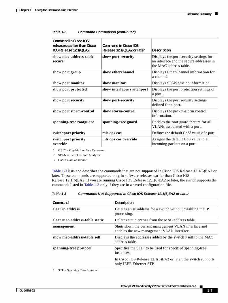
Table 1-3 lists and describes the commands that are not supported in Cisco IOS Release 12.1(6)EA2 or later. These commands are supported only in software releases earlier than Cisco IOS Release 12.1(6)EA2. If you are running Cisco IOS Release 12.1(6)EA2 or later, the switch supports the commands listed in Table 1-3 only if they are in a saved configuration file.
show mac-address-table secure
show port-security Displays the port security settings for an interface and the secure addresses in the MAC address table.
show port group show etherchannel Displays EtherChannel information for a channel.
show port monitor show monitor Displays SPAN session information.
show port protected show interfaces switchport Displays the port protection settings of a port.
show port security show port-security Displays the port security settings defined for a port.
show port storm-control show storm-control Displays the packet-storm control information.
spanning-tree rootguard spanning-tree guard Enables the root guard feature for all VLANs associated with a port.
switchport priority mls qos cos Defines the default CoS3 value of a port.
switchport priority override
mls qos cos override Assigns the default CoS value to all incoming packets on a port.
1. GBIC = Gigabit Interface Converter
2. SPAN = Switched Port Analyzer
3. CoS = class of service
Table 1-2 Command Comparison (continued)
Command in Cisco IOS releases earlier than Cisco IOS Release 12.1(6)EA2
Command in Cisco IOS Release 12.1(6)EA2 or later Description
Table 1-3 Commands Not Supported in Cisco IOS Release 12.1(6)EA2 or Later
Command Description
clear ip address Deletes an IP address for a switch without disabling the IP processing.
clear mac-address-table static Deletes static entries from the MAC address table.
management Shuts down the current management VLAN interface and enables the new management VLAN interface.
show mac-address-table self Displays the addresses added by the switch itself to the MAC address table.
spanning-tree protocol Specifies the STP1 to be used for specified spanning-tree instances.
In Cisco IOS Release 12.1(6)EA2 or later, the switch supports only IEEE Ethernet STP.
1. STP = Spanning Tree Protocol
1-7Catalyst 2950 and Catalyst 2955 Switch Command Reference
OL-10102-02

Chapter 1 Using the Command-Line Interface Command Summary
For detailed command syntax and descriptions, see Chapter 2, “Catalyst 2950 and 2955 Cisco IOS Commands.” For task-oriented configuration steps, see the software configuration guide for this release.
1-8Catalyst 2950 and Catalyst 2955 Switch Command Reference
OL-10102-02
Catalyst OL-10102-02
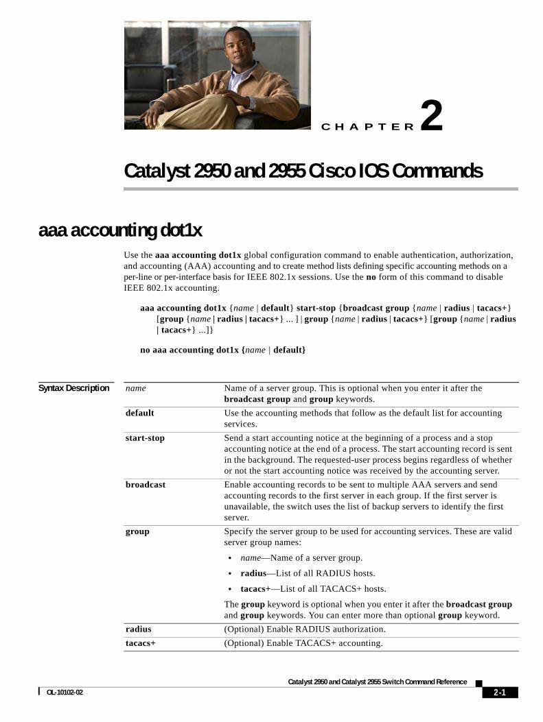
C H A P T E R 2
Catalyst 2950 and 2955 Cisco IOS Commandsaaa accounting dot1xUse the aaa accounting dot1x global configuration command to enable authentication, authorization, and accounting (AAA) accounting and to create method lists defining specific accounting methods on a per-line or per-interface basis for IEEE 802.1x sessions. Use the no form of this command to disable IEEE 802.1x accounting.
aaa accounting dot1x {name | default} start-stop {broadcast group {name | radius | tacacs+} [group {name | radius | tacacs+} ... ] | group {name | radius | tacacs+} [group {name | radius | tacacs+} ...]}
no aaa accounting dot1x {name | default}
Syntax Description name Name of a server group. This is optional when you enter it after the broadcast group and group keywords.
default Use the accounting methods that follow as the default list for accounting services.
start-stop Send a start accounting notice at the beginning of a process and a stop accounting notice at the end of a process. The start accounting record is sent in the background. The requested-user process begins regardless of whether or not the start accounting notice was received by the accounting server.
broadcast Enable accounting records to be sent to multiple AAA servers and send accounting records to the first server in each group. If the first server is unavailable, the switch uses the list of backup servers to identify the first server.
group Specify the server group to be used for accounting services. These are valid server group names:
• name—Name of a server group.
• radius—List of all RADIUS hosts.
• tacacs+—List of all TACACS+ hosts.
The group keyword is optional when you enter it after the broadcast group and group keywords. You can enter more than optional group keyword.
radius (Optional) Enable RADIUS authorization.
tacacs+ (Optional) Enable TACACS+ accounting.
2-12950 and Catalyst 2955 Switch Command Reference
Chapter 2 Catalyst 2950 and 2955 Cisco IOS Commands aaa accounting dot1x
Defaults AAA accounting is disabled.
Command Modes Global configuration
Command History
Usage Guidelines This command requires access to a RADIUS server.
Note We recommend that you enter the dot1x re-authentication interface configuration command before configuring IEEE 802.1x RADIUS accounting on an interface.
Examples This example shows how to configure IEEE 802.1x accounting:
Switch(config)# aaa new modelSwitch(config)# aaa accounting dot1x default start-stop group radius
Note The RADIUS authentication server must be properly configured to accept and log update or watchdog packets from the AAA client.
Related Commands
Release Modification
12.1(20)EA2 This command was introduced.
Command Description
aaa authentication dot1x
Specifies one or more AAA methods for use on interfaces running IEEE 802.1x.
dot1x reauthentication Enables or disables periodic re-authentication.
dot1x timeout reauth-period
Sets the number of seconds between re-authentication attempts.
2-2Catalyst 2950 and Catalyst 2955 Switch Command Reference
OL-10102-02
Chapter 2 Catalyst 2950 and 2955 Cisco IOS Commands aaa authentication dot1x
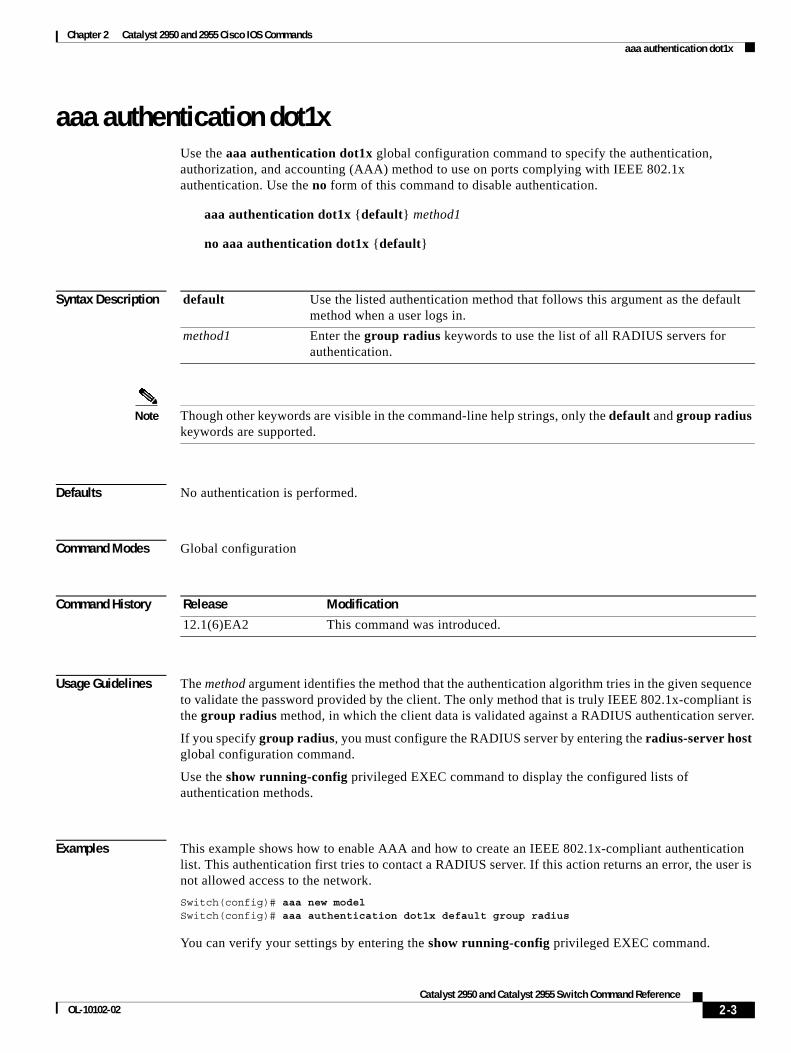
aaa authentication dot1xUse the aaa authentication dot1x global configuration command to specify the authentication, authorization, and accounting (AAA) method to use on ports complying with IEEE 802.1x authentication. Use the no form of this command to disable authentication.
aaa authentication dot1x {default} method1
no aaa authentication dot1x {default}
Syntax Description
Note Though other keywords are visible in the command-line help strings, only the default and group radius keywords are supported.
Defaults No authentication is performed.
Command Modes Global configuration
Command History
Usage Guidelines The method argument identifies the method that the authentication algorithm tries in the given sequence to validate the password provided by the client. The only method that is truly IEEE 802.1x-compliant is the group radius method, in which the client data is validated against a RADIUS authentication server.
If you specify group radius, you must configure the RADIUS server by entering the radius-server host global configuration command.
Use the show running-config privileged EXEC command to display the configured lists of authentication methods.
Examples This example shows how to enable AAA and how to create an IEEE 802.1x-compliant authentication list. This authentication first tries to contact a RADIUS server. If this action returns an error, the user is not allowed access to the network.
Switch(config)# aaa new modelSwitch(config)# aaa authentication dot1x default group radius
You can verify your settings by entering the show running-config privileged EXEC command.
default Use the listed authentication method that follows this argument as the default method when a user logs in.
method1 Enter the group radius keywords to use the list of all RADIUS servers for authentication.
Release Modification
12.1(6)EA2 This command was introduced.
2-3Catalyst 2950 and Catalyst 2955 Switch Command Reference
OL-10102-02
Chapter 2 Catalyst 2950 and 2955 Cisco IOS Commands aaa authentication dot1x
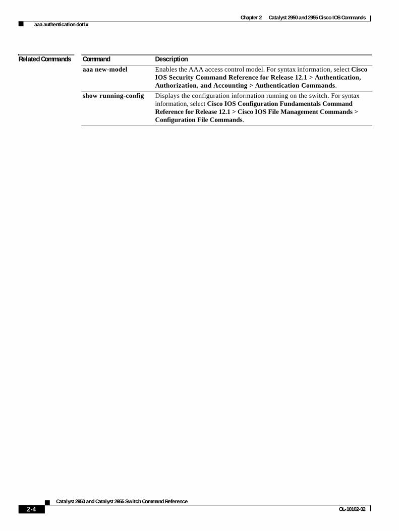
Related Commands Command Description
aaa new-model Enables the AAA access control model. For syntax information, select Cisco IOS Security Command Reference for Release 12.1 > Authentication, Authorization, and Accounting > Authentication Commands.
show running-config Displays the configuration information running on the switch. For syntax information, select Cisco IOS Configuration Fundamentals Command Reference for Release 12.1 > Cisco IOS File Management Commands > Configuration File Commands.
2-4Catalyst 2950 and Catalyst 2955 Switch Command Reference
OL-10102-02
Chapter 2 Catalyst 2950 and 2955 Cisco IOS Commands access-list (IP extended)
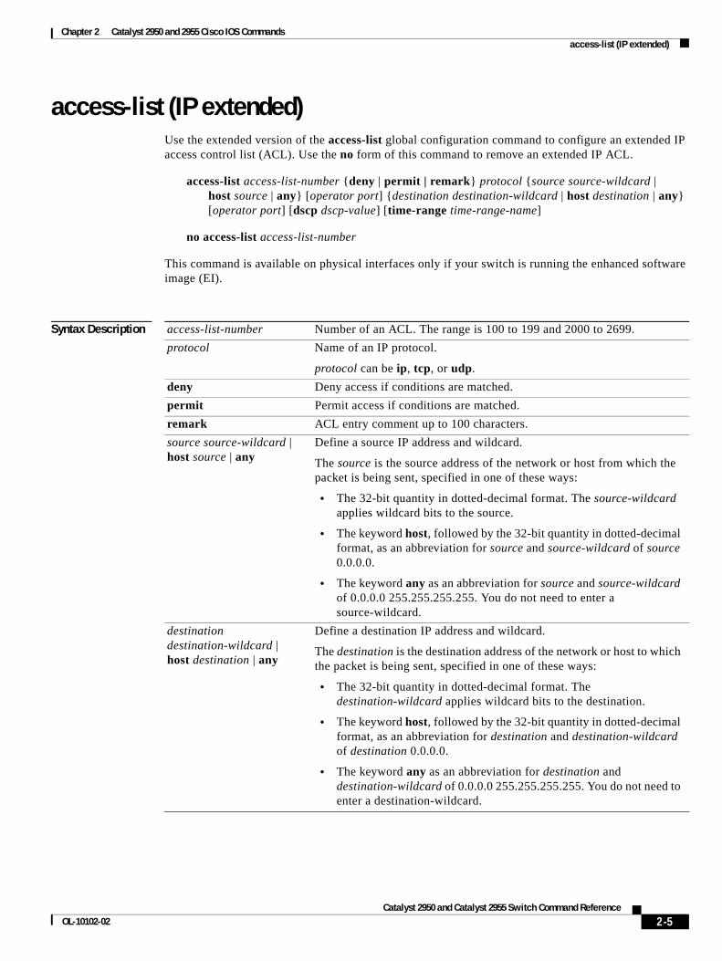
access-list (IP extended)Use the extended version of the access-list global configuration command to configure an extended IP access control list (ACL). Use the no form of this command to remove an extended IP ACL.
access-list access-list-number {deny | permit | remark} protocol {source source-wildcard | host source | any} [operator port] {destination destination-wildcard | host destination | any} [operator port] [dscp dscp-value] [time-range time-range-name]
no access-list access-list-number
This command is available on physical interfaces only if your switch is running the enhanced software image (EI).
Syntax Description access-list-number Number of an ACL. The range is 100 to 199 and 2000 to 2699.
protocol Name of an IP protocol.
protocol can be ip, tcp, or udp.
deny Deny access if conditions are matched.
permit Permit access if conditions are matched.
remark ACL entry comment up to 100 characters.
source source-wildcard | host source | any
Define a source IP address and wildcard.
The source is the source address of the network or host from which the packet is being sent, specified in one of these ways:
• The 32-bit quantity in dotted-decimal format. The source-wildcard applies wildcard bits to the source.
• The keyword host, followed by the 32-bit quantity in dotted-decimal format, as an abbreviation for source and source-wildcard of source 0.0.0.0.
• The keyword any as an abbreviation for source and source-wildcard of 0.0.0.0 255.255.255.255. You do not need to enter a source-wildcard.
destination destination-wildcard | host destination | any
Define a destination IP address and wildcard.
The destination is the destination address of the network or host to which the packet is being sent, specified in one of these ways:
• The 32-bit quantity in dotted-decimal format. The destination-wildcard applies wildcard bits to the destination.
• The keyword host, followed by the 32-bit quantity in dotted-decimal format, as an abbreviation for destination and destination-wildcard of destination 0.0.0.0.
• The keyword any as an abbreviation for destination and destination-wildcard of 0.0.0.0 255.255.255.255. You do not need to enter a destination-wildcard.
2-5Catalyst 2950 and Catalyst 2955 Switch Command Reference
OL-10102-02
Chapter 2 Catalyst 2950 and 2955 Cisco IOS Commands access-list (IP extended)
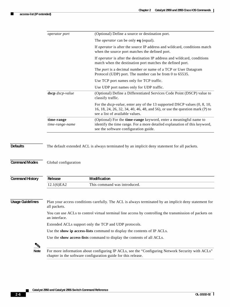
Defaults The default extended ACL is always terminated by an implicit deny statement for all packets.
Command Modes Global configuration
Command History
Usage Guidelines Plan your access conditions carefully. The ACL is always terminated by an implicit deny statement for all packets.
You can use ACLs to control virtual terminal line access by controlling the transmission of packets on an interface.
Extended ACLs support only the TCP and UDP protocols.
Use the show ip access-lists command to display the contents of IP ACLs.
Use the show access-lists command to display the contents of all ACLs.
Note For more information about configuring IP ACLs, see the “Configuring Network Security with ACLs” chapter in the software configuration guide for this release.
operator port (Optional) Define a source or destination port.
The operator can be only eq (equal).
If operator is after the source IP address and wildcard, conditions match when the source port matches the defined port.
If operator is after the destination IP address and wildcard, conditions match when the destination port matches the defined port.
The port is a decimal number or name of a TCP or User Datagram Protocol (UDP) port. The number can be from 0 to 65535.
Use TCP port names only for TCP traffic.
Use UDP port names only for UDP traffic.
dscp dscp-value (Optional) Define a Differentiated Services Code Point (DSCP) value to classify traffic.
For the dscp-value, enter any of the 13 supported DSCP values (0, 8, 10, 16, 18, 24, 26, 32, 34, 40, 46, 48, and 56), or use the question mark (?) to see a list of available values.
time-range time-range-name
(Optional) For the time-range keyword, enter a meaningful name to identify the time range. For a more detailed explanation of this keyword, see the software configuration guide.
Release Modification
12.1(6)EA2 This command was introduced.
2-6Catalyst 2950 and Catalyst 2955 Switch Command Reference
OL-10102-02
Chapter 2 Catalyst 2950 and 2955 Cisco IOS Commands access-list (IP extended)
Examples This example shows how to configure an extended IP ACL that allows only TCP traffic to the destination IP address 128.88.1.2 with a TCP port number of 25 and how to apply it to an interface:
Switch(config)# access-list 102 permit tcp any host 128.88.1.2 eq 25Switch(config)# interface fastethernet0/8Switch(config-if)# ip access-group 102 in
This is an example of an extended ACL that allows TCP traffic only from two specified networks. The wildcard bits apply to the host portions of the network addresses. Any host with a source address that does not match the ACL statements is denied.
access-list 104 permit tcp 192.5.0.0 0.0.255.255 anyaccess-list 104 permit tcp 128.88.0.0 0.0.255.255 any
Note In these examples, all other IP access is implicitly denied.
You can verify your settings by entering the show ip access-lists or show access-lists privileged EXEC command.
Related Commands Command Description
access-list (IP standard) Configures a standard IP ACL.
ip access-group Controls access to an interface.
show access-lists Displays ACLs configured on the switch.
show ip access-lists Displays IP ACLs configured on the switch.
2-7Catalyst 2950 and Catalyst 2955 Switch Command Reference
OL-10102-02
Chapter 2 Catalyst 2950 and 2955 Cisco IOS Commands access-list (IP standard)
access-list (IP standard)Use the standard version of the access-list global configuration command to configure a standard IP access control list (ACL). Use the no form of this command to remove a standard IP ACL.
access-list access-list-number {deny | permit | remark} {source source-wildcard | host source | any}
no access-list access-list-number
This command is available on physical interfaces only if your switch is running the enhanced software image (EI).
Syntax Description
Defaults The default standard ACL is always terminated by an implicit deny statement for all packets.
Command Modes Global configuration
Command History
Usage Guidelines Plan your access conditions carefully. The ACL is always terminated by an implicit deny statement for all packets.
You can use ACLs to control virtual terminal line access by controlling the transmission of packets on an interface.
Use the show ip access-lists command to display the contents of IP ACLs.
access-list-number Number of an ACL. The range is 1 to 99 and1300 to 1999.
deny Deny access if conditions are matched.
permit Permit access if conditions are matched.
remark ACL entry comment up to 100 characters.
source source-wildcard | host source | any
Define a source IP address and wildcard.
The source is the source address of the network or host from which the packet is being sent, specified in one of these ways:
• The 32-bit quantity in dotted-decimal format. The source-wildcard applies wildcard bits to the source.
• The keyword host, followed by the 32-bit quantity in dotted-decimal format, as an abbreviation for source and source-wildcard of source 0.0.0.0.
• The keyword any as an abbreviation for source and source-wildcard of 0.0.0.0 255.255.255.255. You do not need to enter a source-wildcard.
Release Modification
12.1(6)EA2 This command was introduced.
2-8Catalyst 2950 and Catalyst 2955 Switch Command Reference
OL-10102-02
Chapter 2 Catalyst 2950 and 2955 Cisco IOS Commands access-list (IP standard)
Use the show access-lists command to display the contents of all ACLs.
Note For more information about configuring IP ACLs, see the “Configuring Network Security with ACLs” chapter in the software configuration guide for this release.
Examples This example shows how to configure a standard IP ACL that allows only traffic from the host network 128.88.1.10 and how to apply it to an interface:
Switch(config)# access-list 12 permit host 128.88.1.10Switch(config)# interface gigabitethernet0/1Switch(config-if)# ip access-group 12 in
This is an example of an standard ACL that allows traffic only from three specified networks. The wildcard bits apply to the host portions of the network addresses. Any host with a source address that does not match the ACL statements is denied.
access-list 14 permit 192.5.34.0 0.0.0.255access-list 14 permit 128.88.0.0 0.0.0.255access-list 14 permit 36.1.1.0 0.0.0.255
Note In these examples, all other IP access is implicitly denied.
You can verify your settings by entering the show ip access-lists or show access-lists privileged EXEC command.
Related Commands Command Description
access-list (IP extended) Configures an extended IP ACL.
ip access-group Controls access to an interface.
show access-lists Displays ACLs configured on the switch.
show ip access-lists Displays IP ACLs configured on the switch.
2-9Catalyst 2950 and Catalyst 2955 Switch Command Reference
OL-10102-02
Chapter 2 Catalyst 2950 and 2955 Cisco IOS Commands archive download-sw
archive download-swUse the archive download-sw privileged EXEC command to download a new image from a TFTP server to a Catalyst 2950 Long-Reach Ethernet (LRE) switch and to overwrite or to keep the existing image.
archive download-sw {/force-reload | /imageonly | /leave-old-sw | /no-set-boot | /overwrite | /reload | /safe} source-url
This command is available only on the Catalyst 2950 LRE switches.
Syntax Description
Defaults Both the software image and device manager files are downloaded.
The new image is downloaded to the flash: file system.
The BOOT environment variable is changed to point to the new software image on the flash: file system.
Image names are case sensitive; the image file is provided in tar format.
Command Modes Privileged EXEC
/force-reload Unconditionally force a system reload after successfully downloading the software image.
/imageonly Download only the software image but not the files associated with the device manager. The device manager files for the existing version are deleted only if the existing version is being overwritten or removed.
/leave-old-sw Keep the old software version after a successful download.
/no-set-boot Do not alter the setting of the BOOT environment variable to point to the new software image after it is successfully downloaded.
/overwrite Overwrite the software image in flash memory with the downloaded image.
/reload Reload the system after successfully downloading the image unless the configuration has been changed and not been saved.
/safe Keep the current software image; do not delete it to make room for the new software image before the new image is downloaded. The current image is deleted after the download.
source-url The source URL alias for a local or network file system. These options are supported:
• The syntax for the local flash file system: flash:
• The syntax for the FTP: ftp:[[//username[:password]@location]/directory]/image-name.tar
• The syntax for the Remote Copy Protocol (RCP): rcp:[[//username@location]/directory]/image-name.tar
• The syntax for the TFTP: tftp:[[//location]/directory]/image-name.tar
The image-name.tar is the software image to download and install on the switch.
2-10Catalyst 2950 and Catalyst 2955 Switch Command Reference
OL-10102-02
Chapter 2 Catalyst 2950 and 2955 Cisco IOS Commands archive download-sw
Command History
Usage Guidelines Use the /overwrite option to overwrite the image on the flash device with the downloaded one.
If the flash device has sufficient space to hold two images and you want to overwrite one of these images with the same version, you must specify the /overwrite option.
If you specify the command without the /overwrite option, the download algorithm verifies that the new image is not the same as the one on the switch flash device. If the images are the same, the download does not occur. If the images are different, the old image is deleted, and the new one is downloaded.
The /imageonly option removes the device manager files for the existing image if the existing image is being removed or replaced. Only the software image (without the device manager files) is downloaded.
Using the /safe or /leave-old-sw option can cause the new image download to fail if there is insufficient flash space.
If you used the /leave-old-sw option and did not overwrite the old image when you downloaded the new one, you can remove the old image by using the delete privileged EXEC command. For more information, see the delete command.
If you leave the existing software in place before downloading the new image, an error results if the existing software prevents the new image from fitting onto flash memory.
After downloading a new image, enter the reload privileged EXEC command to begin using the new image, or specify the /reload or /force-reload option in the archive download-sw command.
Examples This example shows how to download a new image from a TFTP server at 172.20.129.10 and to overwrite the image on the switch:
Switch# archive download-sw /overwrite tftp://172.20.129.10/test-image.tar
This example shows how to download only the software image from a TFTP server at 172.20.129.10 to the switch:
Switch# archive download-sw /imageonly tftp://172.20.129.10/test-image.tar
This example shows how to keep the old software version after a successful download:
Switch# archive download-sw /leave-old-sw tftp://172.20.129.10/test-image.tar
Related Commands
Release Modification
12.1(11)YJ This command was introduced.
Command Description
archive tar Creates a tar file, lists the files in a tar file, or extracts the files from a tar file.
archive upload-sw Uploads an existing image on the switch to a server.
delete Deletes a file or directory on the flash memory device.
2-11Catalyst 2950 and Catalyst 2955 Switch Command Reference
OL-10102-02
Chapter 2 Catalyst 2950 and 2955 Cisco IOS Commands archive tar
archive tarUse the archive tar privileged EXEC command to create a tar file, to list files in a tar file, or to extract the files from a tar file.
archive tar {/create destination-url flash:/file-url} | {/table source-url} | {/xtract source-url flash:/file-url [dir/file...]}
Syntax Description /create destination-url flash:/file-url
Create a new tar file on the local or network file system.
For destination-url, specify the destination URL alias for the local or network file system and the name of the tar file to create. These options are supported:
• The syntax for the local flash file system: flash:
• The syntax for the FTP: ftp:[[//username[:password]@location]/directory]/tar-filename.tar
• The syntax for the Remote Copy Protocol (RCP) is: rcp:[[//username@location]/directory]/tar-filename.tar
• The syntax for the TFTP: tftp:[[//location]/directory]/tar-filename.tar
The tar-filename.tar is the tar file to be created.
For flash:/file-url, specify the location on the local flash file system from which the new tar file is created.
An optional list of files or directories within the source directory can be specified to write to the new tar file. If none are specified, all files and directories at this level are written to the newly created tar file.
2-12Catalyst 2950 and Catalyst 2955 Switch Command Reference
OL-10102-02
Chapter 2 Catalyst 2950 and 2955 Cisco IOS Commands archive tar
Defaults No default is defined.
Command Modes Privileged EXEC
Command History
Usage Guidelines Filenames and directory names are case sensitive.
Image names are case sensitive.
/table source-url Display the contents of an existing tar file to the screen.
For source-url, specify the source URL alias for the local or network file system. These options are supported:
• The syntax for the local flash file system: flash:
• The syntax for the FTP: ftp:[[//username[:password]@location]/directory]/tar-filename.tar
• The syntax for the RCP: rcp:[[//username@location]/directory]/tar-filename.tar
• The syntax for the TFTP: tftp:[[//location]/directory]/tar-filename.tar
The tar-filename.tar is the tar file to display.
/xtract source-url flash:/file-url [dir/file...]
Extract files from a tar file to the local file system.
For source-url, specify the source URL alias for the local file system. These options are supported:
• The syntax for the local flash file system: flash:
• The syntax for the FTP: ftp:[[//username[:password]@location]/directory]/tar-filename.tar
• The syntax for the RCP: rcp:[[//username@location]/directory]/tar-filename.tar
• The syntax for the TFTP: tftp:[[//location]/directory]/tar-filename.tar
The tar-filename.tar is the tar file from which to extract.
For flash:/file-url [dir/file...], specify the location on the local flash file system into which the tar file is extracted. Use the dir/file... option to specify an optional list of files or directories within the tar file to be extracted. If none are specified, all files and directories are extracted.
Release Modification
12.1(6)EA2 This command was introduced.
2-13Catalyst 2950 and Catalyst 2955 Switch Command Reference
OL-10102-02
Chapter 2 Catalyst 2950 and 2955 Cisco IOS Commands archive tar
Examples This example shows how to create a tar file. The command writes the contents of the new-configs directory on the local flash device to a file named saved.tar on the TFTP server at 172.20.136.9:
Switch# archive tar /create tftp:172.20.136.9/saved.tar flash:/new-configs
This example shows how to display the contents of the saved.tar file that is in flash memory. The contents of the tar file appear on the screen.
Switch # archive tar /table tftp://172.20.136.9/saved.tarLoading saved.tar from 172.20.136.9 (via Vlan1):!info (247 bytes)c2950lre-i6l2q4-mz.121/ (directory)c2950lre-i6l2q4-mz.121/html/ (directory)c2950lre-i6l2q4-mz.121/html/homepage.htm (3990 bytes)!
<output truncated>
c2950lre-i6l2q4-mz.121/lre-bin/CISCO585-LRE_MC8051boot_01.03.00.bin (688bytes)c2950lre-i6l2q4-mz.121/lre-bin/CISCO585-LRE_vdslsngl_51.00.00.bin (8896bytes)!!c2950lre-i6l2q4-mz.121/pef22824.bin (32768 bytes)!!!!!!!c2950lre-i6l2q4-mz.121/info (247 bytes)info.ver (247 bytes)[OK - 4279808/8559616 bytes]
This example shows how to extract the contents of a tar file on the TFTP server at 172.20.10.30. This command extracts just the new-configs directory into the root directory on the local flash file system. The remaining files in the saved.tar file are ignored.
Switch# archive tar /xtract tftp:/172.20.10.30/saved.tar flash:/ new-configs
Related Commands Command Description
archive download-sw Downloads a new image to the switch.
archive upload-sw Uploads an existing image on the switch to a server.
2-14Catalyst 2950 and Catalyst 2955 Switch Command Reference
OL-10102-02
Chapter 2 Catalyst 2950 and 2955 Cisco IOS Commands archive upload-sw
archive upload-swUse the archive upload-sw privileged EXEC command to upload an existing Long-Reach Ethernet (LRE) switch image to a server.
archive upload-sw [/version version_string] destination-url
This command is supported only on Catalyst 2950 LRE switches.
Syntax Description
Defaults The switch uploads the currently running image from the flash: file system.
Command Modes Privileged EXEC
Command History
Usage Guidelines Use the upload feature only if the files associated with the device manager have been installed with the existing image.
The files are uploaded in this sequence: info, the software image, the device manager files, LRE binary files, and info.ver. After these files are uploaded, the software creates the tar file.
Image names are case sensitive.
Examples This example shows how to upload the currently running image to a TFTP server at 172.20.140.2:
Switch# archive upload-sw tftp://172.20.140.2/test-image.tar
/version version_string (Optional) Specify the version string of the image to be uploaded.
destination-url The destination URL alias for a local or network file system. These options are supported:
• The syntax for the local flash file system: flash:
• The syntax for the FTP: ftp:[[//username[:password]@location]/directory]/image-name.tar
• The syntax for the Remote Copy Protocol (RCP): rcp:[[//username@location]/directory]/image-name.tar
• The syntax for the TFTP:
tftp:[[//location]/directory]/image-name.tar
The image-name.tar is the name of software image to be stored on the server.
Release Modification
12.1(11)YJ This command was introduced.
2-15Catalyst 2950 and Catalyst 2955 Switch Command Reference
OL-10102-02

Chapter 2 Catalyst 2950 and 2955 Cisco IOS Commands archive upload-sw
Related Commands Command Description
archive download-sw Downloads a new image to a Catalyst 2950 LRE switch.
archive tar Creates a tar file, lists the files in a tar file, or extracts the files from a tar file.
2-16Catalyst 2950 and Catalyst 2955 Switch Command Reference
OL-10102-02
Chapter 2 Catalyst 2950 and 2955 Cisco IOS Commands auto qos voip
auto qos voipUse the auto qos voip interface configuration command to configure automatic quality of service (auto-QoS) for voice over IP (VoIP) within a QoS domain. Use the no form of this command to change the auto-QoS configuration settings to the standard-QoS defaults.
auto qos voip {cisco-phone | cisco-softphone | trust}
no auto qos voip
This command is available only if your switch is running the enhanced software image (EI).
Syntax Description
Defaults Auto-QoS is disabled on all interfaces.
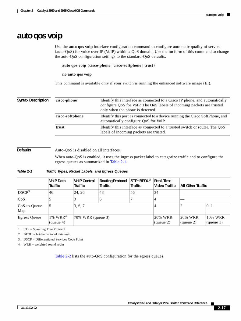
When auto-QoS is enabled, it uses the ingress packet label to categorize traffic and to configure the egress queues as summarized in Table 2-1.
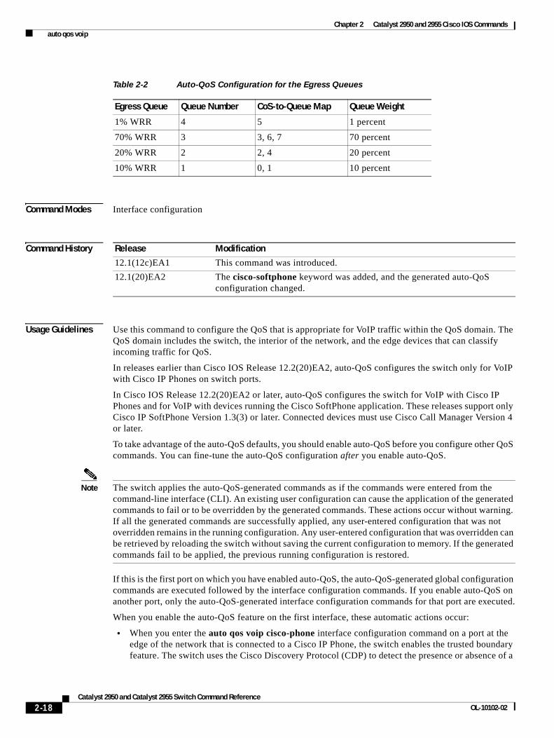
Table 2-2 lists the auto-QoS configuration for the egress queues.
cisco-phone Identify this interface as connected to a Cisco IP phone, and automatically configure QoS for VoIP. The QoS labels of incoming packets are trusted only when the phone is detected.
cisco-softphone Identify this port as connected to a device running the Cisco SoftPhone, and automatically configure QoS for VoIP.
trust Identify this interface as connected to a trusted switch or router. The QoS labels of incoming packets are trusted.
Table 2-1 Traffic Types, Packet Labels, and Egress Queues
VoIP Data Traffic
VoIP Control Traffic
Routing Protocol Traffic
STP1 BPDU2 Traffic
1. STP = Spanning Tree Protocol
2. BPDU = bridge protocol data unit
Real-Time Video Traffic All Other Traffic
DSCP3
3. DSCP = Differentiated Services Code Point
46 24, 26 48 56 34 —
CoS 5 3 6 7 4 —
CoS-to-Queue Map
5 3, 6, 7 4 2 0, 1
Egress Queue 1% WRR4 (queue 4)
4. WRR = weighted round robin
70% WRR (queue 3) 20% WRR (queue 2)
20% WRR (queue 2)
10% WRR (queue 1)
2-17Catalyst 2950 and Catalyst 2955 Switch Command Reference
OL-10102-02
Chapter 2 Catalyst 2950 and 2955 Cisco IOS Commands auto qos voip
Command Modes Interface configuration
Command History
Usage Guidelines Use this command to configure the QoS that is appropriate for VoIP traffic within the QoS domain. The QoS domain includes the switch, the interior of the network, and the edge devices that can classify incoming traffic for QoS.
In releases earlier than Cisco IOS Release 12.2(20)EA2, auto-QoS configures the switch only for VoIP with Cisco IP Phones on switch ports.
In Cisco IOS Release 12.2(20)EA2 or later, auto-QoS configures the switch for VoIP with Cisco IP Phones and for VoIP with devices running the Cisco SoftPhone application. These releases support only Cisco IP SoftPhone Version 1.3(3) or later. Connected devices must use Cisco Call Manager Version 4 or later.
To take advantage of the auto-QoS defaults, you should enable auto-QoS before you configure other QoS commands. You can fine-tune the auto-QoS configuration after you enable auto-QoS.
Note The switch applies the auto-QoS-generated commands as if the commands were entered from the command-line interface (CLI). An existing user configuration can cause the application of the generated commands to fail or to be overridden by the generated commands. These actions occur without warning. If all the generated commands are successfully applied, any user-entered configuration that was not overridden remains in the running configuration. Any user-entered configuration that was overridden can be retrieved by reloading the switch without saving the current configuration to memory. If the generated commands fail to be applied, the previous running configuration is restored.
If this is the first port on which you have enabled auto-QoS, the auto-QoS-generated global configuration commands are executed followed by the interface configuration commands. If you enable auto-QoS on another port, only the auto-QoS-generated interface configuration commands for that port are executed.
When you enable the auto-QoS feature on the first interface, these automatic actions occur:
• When you enter the auto qos voip cisco-phone interface configuration command on a port at the edge of the network that is connected to a Cisco IP Phone, the switch enables the trusted boundary feature. The switch uses the Cisco Discovery Protocol (CDP) to detect the presence or absence of a
Table 2-2 Auto-QoS Configuration for the Egress Queues
Egress Queue Queue Number CoS-to-Queue Map Queue Weight
1% WRR 4 5 1 percent
70% WRR 3 3, 6, 7 70 percent
20% WRR 2 2, 4 20 percent
10% WRR 1 0, 1 10 percent
Release Modification
12.1(12c)EA1 This command was introduced.
12.1(20)EA2 The cisco-softphone keyword was added, and the generated auto-QoS configuration changed.
2-18Catalyst 2950 and Catalyst 2955 Switch Command Reference
OL-10102-02
Chapter 2 Catalyst 2950 and 2955 Cisco IOS Commands auto qos voip
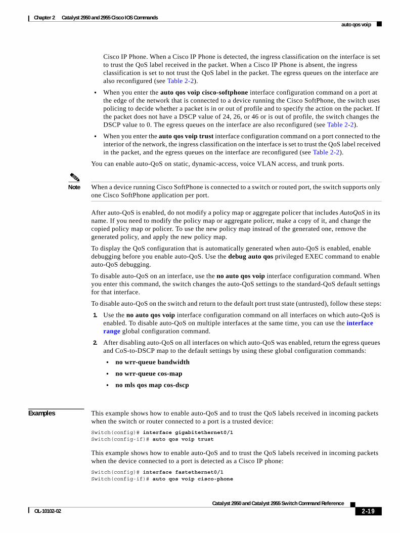
Cisco IP Phone. When a Cisco IP Phone is detected, the ingress classification on the interface is set to trust the QoS label received in the packet. When a Cisco IP Phone is absent, the ingress classification is set to not trust the QoS label in the packet. The egress queues on the interface are also reconfigured (see Table 2-2).
• When you enter the auto qos voip cisco-softphone interface configuration command on a port at the edge of the network that is connected to a device running the Cisco SoftPhone, the switch uses policing to decide whether a packet is in or out of profile and to specify the action on the packet. If the packet does not have a DSCP value of 24, 26, or 46 or is out of profile, the switch changes the DSCP value to 0. The egress queues on the interface are also reconfigured (see Table 2-2).
• When you enter the auto qos voip trust interface configuration command on a port connected to the interior of the network, the ingress classification on the interface is set to trust the QoS label received in the packet, and the egress queues on the interface are reconfigured (see Table 2-2).
You can enable auto-QoS on static, dynamic-access, voice VLAN access, and trunk ports.
Note When a device running Cisco SoftPhone is connected to a switch or routed port, the switch supports only one Cisco SoftPhone application per port.
After auto-QoS is enabled, do not modify a policy map or aggregate policer that includes AutoQoS in its name. If you need to modify the policy map or aggregate policer, make a copy of it, and change the copied policy map or policer. To use the new policy map instead of the generated one, remove the generated policy, and apply the new policy map.
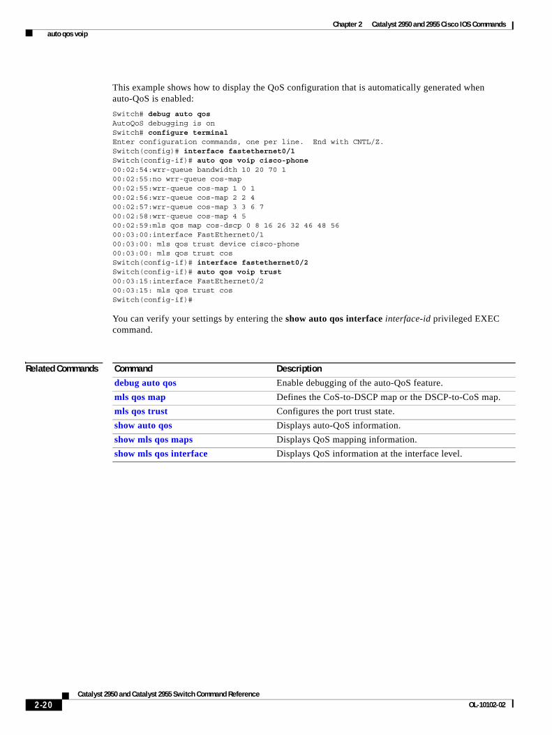
To display the QoS configuration that is automatically generated when auto-QoS is enabled, enable debugging before you enable auto-QoS. Use the debug auto qos privileged EXEC command to enable auto-QoS debugging.
To disable auto-QoS on an interface, use the no auto qos voip interface configuration command. When you enter this command, the switch changes the auto-QoS settings to the standard-QoS default settings for that interface.
To disable auto-QoS on the switch and return to the default port trust state (untrusted), follow these steps:
1. Use the no auto qos voip interface configuration command on all interfaces on which auto-QoS is enabled. To disable auto-QoS on multiple interfaces at the same time, you can use the interface range global configuration command.
2. After disabling auto-QoS on all interfaces on which auto-QoS was enabled, return the egress queues and CoS-to-DSCP map to the default settings by using these global configuration commands:
• no wrr-queue bandwidth
• no wrr-queue cos-map
• no mls qos map cos-dscp
Examples This example shows how to enable auto-QoS and to trust the QoS labels received in incoming packets when the switch or router connected to a port is a trusted device:
Switch(config)# interface gigabitethernet0/1Switch(config-if)# auto qos voip trust
This example shows how to enable auto-QoS and to trust the QoS labels received in incoming packets when the device connected to a port is detected as a Cisco IP phone:
Switch(config)# interface fastethernet0/1Switch(config-if)# auto qos voip cisco-phone
2-19Catalyst 2950 and Catalyst 2955 Switch Command Reference
OL-10102-02
Chapter 2 Catalyst 2950 and 2955 Cisco IOS Commands auto qos voip
This example shows how to display the QoS configuration that is automatically generated when auto-QoS is enabled:
Switch# debug auto qosAutoQoS debugging is onSwitch# configure terminalEnter configuration commands, one per line. End with CNTL/Z.Switch(config)# interface fastethernet0/1Switch(config-if)# auto qos voip cisco-phone00:02:54:wrr-queue bandwidth 10 20 70 100:02:55:no wrr-queue cos-map00:02:55:wrr-queue cos-map 1 0 100:02:56:wrr-queue cos-map 2 2 400:02:57:wrr-queue cos-map 3 3 6 700:02:58:wrr-queue cos-map 4 500:02:59:mls qos map cos-dscp 0 8 16 26 32 46 48 5600:03:00:interface FastEthernet0/100:03:00: mls qos trust device cisco-phone00:03:00: mls qos trust cosSwitch(config-if)# interface fastethernet0/2Switch(config-if)# auto qos voip trust00:03:15:interface FastEthernet0/200:03:15: mls qos trust cosSwitch(config-if)#
You can verify your settings by entering the show auto qos interface interface-id privileged EXEC command.
Related Commands Command Description
debug auto qos Enable debugging of the auto-QoS feature.
mls qos map Defines the CoS-to-DSCP map or the DSCP-to-CoS map.
mls qos trust Configures the port trust state.
show auto qos Displays auto-QoS information.
show mls qos maps Displays QoS mapping information.
show mls qos interface Displays QoS information at the interface level.
2-20Catalyst 2950 and Catalyst 2955 Switch Command Reference
OL-10102-02
Chapter 2 Catalyst 2950 and 2955 Cisco IOS Commands boot boothlpr
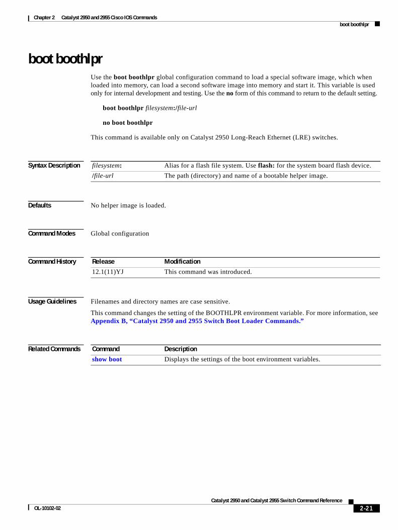
boot boothlprUse the boot boothlpr global configuration command to load a special software image, which when loaded into memory, can load a second software image into memory and start it. This variable is used only for internal development and testing. Use the no form of this command to return to the default setting.
boot boothlpr filesystem:/file-url
no boot boothlpr
This command is available only on Catalyst 2950 Long-Reach Ethernet (LRE) switches.
Syntax Description
Defaults No helper image is loaded.
Command Modes Global configuration
Command History
Usage Guidelines Filenames and directory names are case sensitive.
This command changes the setting of the BOOTHLPR environment variable. For more information, see Appendix B, “Catalyst 2950 and 2955 Switch Boot Loader Commands.”
Related Commands
filesystem: Alias for a flash file system. Use flash: for the system board flash device.
/file-url The path (directory) and name of a bootable helper image.
Release Modification
12.1(11)YJ This command was introduced.
Command Description
show boot Displays the settings of the boot environment variables.
2-21Catalyst 2950 and Catalyst 2955 Switch Command Reference
OL-10102-02
Chapter 2 Catalyst 2950 and 2955 Cisco IOS Commands boot buffersize
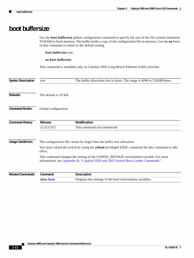
boot buffersizeUse the boot buffersize global configuration command to specify the size of the file system-simulated NVRAM in flash memory. The buffer holds a copy of the configuration file in memory. Use the no form of this command to return to the default setting.
boot buffersize size
no boot buffersize
This command is available only on Catalyst 2950 Long-Reach Ethernet (LRE) switches.
Syntax Description
Defaults The default is 32 KB.
Command Modes Global configuration
Command History
Usage Guidelines The configuration file cannot be larger than the buffer size allocation.
You must reload the switch by using the reload privileged EXEC command for this command to take effect.
This command changes the setting of the CONFIG_BUFSIZE environment variable. For more information, see Appendix B, “Catalyst 2950 and 2955 Switch Boot Loader Commands.”
Related Commands
size The buffer allocation size in bytes. The range is 4096 to 524288 bytes.
Release Modification
12.1(11)YJ This command was introduced.
Command Description
show boot Displays the settings of the boot environment variables.
2-22Catalyst 2950 and Catalyst 2955 Switch Command Reference
OL-10102-02
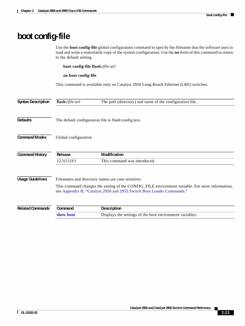
Chapter 2 Catalyst 2950 and 2955 Cisco IOS Commands boot config-file
boot config-fileUse the boot config-file global configuration command to specify the filename that the software uses to read and write a nonvolatile copy of the system configuration. Use the no form of this command to return to the default setting.
boot config-file flash:/file-url
no boot config-file
This command is available only on Catalyst 2950 Long-Reach Ethernet (LRE) switches.
Syntax Description
Defaults The default configuration file is flash:config.text.
Command Modes Global configuration
Command History
Usage Guidelines Filenames and directory names are case sensitive.
This command changes the setting of the CONFIG_FILE environment variable. For more information, see Appendix B, “Catalyst 2950 and 2955 Switch Boot Loader Commands.”
Related Commands
flash:/file-url The path (directory) and name of the configuration file.
Release Modification
12.1(11)YJ This command was introduced.
Command Description
show boot Displays the settings of the boot environment variables.
2-23Catalyst 2950 and Catalyst 2955 Switch Command Reference
OL-10102-02
Chapter 2 Catalyst 2950 and 2955 Cisco IOS Commands boot enable-break
boot enable-breakUse the boot enable-break global configuration command to enable interrupting the automatic boot process on a Catalyst 2950 Long-Reach Ethernet (LRE) switch. Use the no form of this command to return to the default setting.
boot enable-break
no boot enable-break
This command is available only on Catalyst 2950 LRE switches.
Syntax Description This command has no arguments or keywords.
Defaults The automatic start up process cannot be interrupted by pressing the Break key on the console.
Command Modes Global configuration
Command History
Usage Guidelines When you enter this command, you can interrupt the automatic boot process by pressing the Break key on the console after the flash file system is initialized.
Note Despite the setting of this command, you can interrupt the automatic boot process at any time by pressing the MODE button on the switch front panel.
This command changes the setting of the ENABLE_BREAK environment variable. For more information, see Appendix B, “Catalyst 2950 and 2955 Switch Boot Loader Commands.”
Related Commands
Release Modification
12.1(11)YJ This command was introduced.
Command Description
show boot Displays the settings of the boot environment variables.
2-24Catalyst 2950 and Catalyst 2955 Switch Command Reference
OL-10102-02
Chapter 2 Catalyst 2950 and 2955 Cisco IOS Commands boot helper
boot helperUse the boot helper global configuration command to dynamically load files during boot loader initialization to extend or to patch the functionality of the boot loader. Use the no form of this command to return to the default setting.
boot helper filesystem:/file-url ...
no boot helper
This command is available only on Catalyst 2950 Long-Reach Ethernet (LRE) switches.
Syntax Description
Defaults No helper files are loaded.
Command Modes Global configuration
Command History
Usage Guidelines Filenames and directory names are case sensitive.
This command changes the setting of the HELPER environment variable. For more information, see Appendix B, “Catalyst 2950 and 2955 Switch Boot Loader Commands.”
Related Commands
filesystem: Alias for a flash file system. Use flash: for the system board flash device.
/file-url The path (directory) and a list of loadable files to dynamically load during loader initialization. Separate each image name with a semicolon.
Release Modification
12.1(11)YJ This command was introduced.
Command Description
show boot Displays the settings of the boot environment variables.
2-25Catalyst 2950 and Catalyst 2955 Switch Command Reference
OL-10102-02
Chapter 2 Catalyst 2950 and 2955 Cisco IOS Commands boot helper-config-file
boot helper-config-fileUse the boot helper-config-file global configuration command to specify the name of the configuration file to be used by the Cisco IOS helper image. If this is not set, the file specified by the CONFIG_FILE environment variable is used by all versions of the software that are loaded. This variable is used only for internal development and testing. Use the no form of this command to return to the default setting.
boot helper-config-file filesystem:/file-url
no boot helper-config file
This command is available only on Catalyst 2950 Long-Reach Ethernet (LRE) switches.
Syntax Description
Defaults No helper configuration file is specified.
Command Modes Global configuration
Command History
Usage Guidelines Filenames and directory names are case sensitive.
This command changes the setting of the HELPER_CONFIG_FILE environment variable. For more information, see Appendix B, “Catalyst 2950 and 2955 Switch Boot Loader Commands.”
Related Commands
filesystem: Alias for a flash file system. Use flash: for the system board flash device.
/file-url The path (directory) and helper configuration file to load.
Release Modification
12.1(11)YJ This command was introduced.
Command Description
show boot Displays the settings of the boot environment variables.
2-26Catalyst 2950 and Catalyst 2955 Switch Command Reference
OL-10102-02
Chapter 2 Catalyst 2950 and 2955 Cisco IOS Commands boot manual
boot manualUse the boot manual global configuration command to enable starting the Catalyst 2950 Long-Reach Ethernet (LRE) switch manually during the next power on cycle. Use the no form of this command to return to the default setting.
boot manual
no boot manual
This command is available only on Catalyst 2950 LRE switches.
Syntax Description This command has no arguments or keywords.
Defaults During the next power on cycle, you cannot manually start an LRE switch.
Command Modes Global configuration
Command History
Usage Guidelines The next time you restart the system, the switch is in boot loader mode, which is shown by the switch: prompt. To power on the system, use the boot boot loader command, and specify the name of the bootable image.
This command changes the setting of the MANUAL_BOOT environment variable. For more information, see Appendix B, “Catalyst 2950 and 2955 Switch Boot Loader Commands.”
Related Commands
Release Modification
12.1(11)YJ This command was introduced.
Command Description
show boot Displays the settings of the boot environment variables.
2-27Catalyst 2950 and Catalyst 2955 Switch Command Reference
OL-10102-02
Chapter 2 Catalyst 2950 and 2955 Cisco IOS Commands boot private-config-file
boot private-config-fileUse the boot private-config-file global configuration command to specify the filename that the software uses to read and write a nonvolatile copy of the private configuration. Use the no form of this command to return to the default setting.
boot private-config-file filename
no boot private-config-file
Syntax Description
Defaults The default configuration file is private-config.text.
Command Modes Global configuration
Command History
Usage Guidelines Only the software can read and write a copy of the private configuration file. You cannot read, write, delete, or display a copy of this file.
Filenames are case sensitive.
Examples This example shows how to specify the name of the private configuration file as pconfig:
Switch(config)# boot private-config-file pconfig
Related Commands
filename The name of the private configuration file.
Release Modification
12.1(11)EA1 This command was introduced.
Command Description
show boot Displays the settings of the boot environment variables.
2-28Catalyst 2950 and Catalyst 2955 Switch Command Reference
OL-10102-02
Chapter 2 Catalyst 2950 and 2955 Cisco IOS Commands boot system
boot systemUse the boot system global configuration command to specify the software image to load during the next power on cycle. Use the no form of this command to return to the default setting.
boot system filesystem:/file-url ...
no boot system
This command is available only on Catalyst 2950 Long-Reach Ethernet (LRE) switches.
Syntax Description
Defaults The switch attempts to automatically power on the system by using information in the BOOT environment variable. If this variable is not set, the switch attempts to load and execute the first executable image it can by performing a recursive, depth-first search throughout the flash file system. In a depth-first search of a directory, each encountered subdirectory is completely searched before the switch continues to search in the original directory.
Command Modes Global configuration
Command History
Usage Guidelines Filenames and directory names are case sensitive.
If you are using the archive download-sw privileged EXEC command to maintain system images, you do not ever need to use the boot system command. The boot system command is automatically manipulated to load the downloaded image.
This command changes the setting of the BOOT environment variable. For more information, see Appendix B, “Catalyst 2950 and 2955 Switch Boot Loader Commands.”
Related Commands
filesystem: Alias for a flash file system. Use flash: for the system board flash device.
/file-url The path (directory) and name of a bootable image. Separate image names with a semicolon.
Release Modification
12.1(11)YJ This command was introduced.
Command Description
show boot Displays the settings of the boot environment variables.
2-29Catalyst 2950 and Catalyst 2955 Switch Command Reference
OL-10102-02
Chapter 2 Catalyst 2950 and 2955 Cisco IOS Commands channel-group
channel-groupUse the channel-group interface configuration command to assign an Ethernet interface to an EtherChannel group and to enable an EtherChannel mode. Use the no form of this command to remove an Ethernet interface from an EtherChannel group.
channel-group channel-group-number mode {active | {auto [non-silent]} | {desirable [non-silent]} | on | passive}
no channel-group
PAgP modes: channel-group channel-group-number mode {{auto [non-silent]} | {desirable [non-silent}}
LACP modes: channel-group channel-group-number mode {active | passive}
On mode: channel-group channel-group-number mode on
Syntax Description channel-group-number Specify the channel group number. The range is 1 to 6.
mode Specify the EtherChannel Port Aggregation Protocol (PAgP) or Link Aggregration Control Protocol (LACP). mode of the interface.
active Unconditionally enable LACP.
Active mode places an interface into a negotiating state in which the interface initiates negotiations with other interfaces by sending LACP packets. A channel is formed with another port group in either the active or passive mode. When active is enabled, silent operation is the default.
auto Enable PAgP only if a PAgP device is detected.
Auto mode places an interface into a passive negotiating state, in which the interface responds to PAgP packets it receives but does not initiate PAgP packet negotiation. A channel is formed only with another port group in desirable mode. When auto is enabled, silent operation is the default.
desirable Unconditionally enable PAgP.
Desirable mode places an interface into a negotiating state in which the interface initiates negotiations with other interfaces by sending PAgP packets. A channel is formed with another port group in either the desirable or auto mode. When desirable is enabled, silent operation is the default.
non-silent (Optional) Used with the auto or desirable keyword when PAgP traffic is expected from the other device.
2-30Catalyst 2950 and Catalyst 2955 Switch Command Reference
OL-10102-02
Chapter 2 Catalyst 2950 and 2955 Cisco IOS Commands channel-group
Defaults No channel groups are assigned.
There is no default mode.
Command Modes Interface configuration
Command History
Usage Guidelines You must specify the mode when entering this command. If the mode is not entered, an Ethernet interface is not assigned to an EtherChannel group, and an error message appears.
You do not have to create a port-channel interface before assigning a physical interface to a channel group. A port-channel interface is created automatically when the channel group gets its first physical interface.
You do not have to disable the IP address that is assigned to a physical interface that is part of a channel group, but we highly recommend that you do so.
You can create port channels by entering the interface port-channel global configuration command or when the channel group gets its first physical interface assignment. The port channels are not created at runtime or dynamically.
Any configuration or attribute changes you make to the port-channel interface are propagated to all interfaces within the same channel group as the port channel (for example, configuration changes are also propagated to the physical interfaces that are not part of the port channel, but are part of the channel group).
In the on mode, a PAgP EtherChannel exists only when a port group in on mode is connected to another port group in on mode.
If you do not specify non-silent with the auto or desirable mode, silent is assumed. The silent mode is used when the switch is connected to a device that is not PAgP-capable and seldom, if ever, sends packets. An example of a silent partner is a file server or a packet analyzer that is not generating traffic.
on Enable on mode.
In on mode, a usable EtherChannel exists only when both connected port groups are in the on mode.
This mode is not available on Long-Reach Ethernet (LRE) switches, because LRE interfaces do not support an EtherChannel-only mode.
passive Enable LACP only if an LACP device is detected.
Passive mode places an interface into a negotiating state in which the interface responds to LACP packets it receives but does not initiate LACP packet negotiation. A channel is formed only with another port group in active mode. When passive is enabled, silent operation is the default.
Release Modification
12.1(6)EA2 This command was introduced. It replaced the port group command.
12.1(12c)EA1 The active and passive keywords were added.
2-31Catalyst 2950 and Catalyst 2955 Switch Command Reference
OL-10102-02
Chapter 2 Catalyst 2950 and 2955 Cisco IOS Commands channel-group
In this case, running PAgP on a physical port prevents that port from ever becoming operational; however, it allows PAgP to operate, to attach the interface to a channel group, and to use the interface for transmission. Both ends of the link cannot be set to silent.
Note You cannot enable both PAgP and LACP modes on an EtherChannel group.
Caution You should use care when using the on mode. This is a manual configuration, and ports on both ends of the EtherChannel must have the same configuration. If the group is misconfigured, packet loss or spanning-tree loops can occur.
Do not configure a port that is an active or a not-yet-active member of an EtherChannel as an IEEE 802.1x port. If you try to enable IEEE 802.1x authentication on an EtherChannel port, an error message appears, and IEEE 802.1x authentication is not enabled.
Examples This example shows how to add an interface to the EtherChannel group specified as channel group 1:
Switch(config)# interface gigabitethernet0/1Switch(config-if)# channel-group 1 mode on
This example shows how to set an Etherchannel into PAgP mode:
Switch(config-if)# channel-group 1 mode auto Creating a port-channel interface Port-channel 1
This example shows how to set an Etherchannel into LACP mode:
Switch(config-if)# channel-group 1 mode passive Creating a port-channel interface Port-channel 1
You can verify your settings by entering the show etherchannel or show running-config privileged EXEC command.
Related Commands Command Description
interface port-channel Accesses or creates the port channel.
port-channel load-balance
Sets the load distribution method among the ports in the EtherChannel.
show etherchannel Displays EtherChannel information for a channel.
show running-config Displays the configuration information running on the switch. For syntax information, select Cisco IOS Configuration Fundamentals Command Reference for Release 12.1 > Cisco IOS File Management Commands > Configuration File Commands.
2-32Catalyst 2950 and Catalyst 2955 Switch Command Reference
OL-10102-02
Chapter 2 Catalyst 2950 and 2955 Cisco IOS Commands channel-protocol
channel-protocolUse the channel-protocol interface configuration command to configure an EtherChannel for the Port Aggregation Protocol (PAgP) or Link Aggregation Control Protocol (LACP). Use the no form of this command to disable PAgP or LACP on the EtherChannel.
channel-protocol {lacp | pagp}
no channel-protocol
Syntax Description
Defaults No protocol is assigned to the EtherChannel.
Command Modes Interface configuration
Command History
Usage Guidelines Use the channel-protocol command only to restrict a channel to LACP or PAgP.
You must use the channel-group interface command to configure the EtherChannel parameters. The channel-group command can also set the EtherChannel for a channel.
Note You cannot enable both PAgP and LACP modes on an EtherChannel group.
Caution Do not enable Layer 3 addresses on the physical EtherChannel interfaces. To prevent loops, do not assign bridge groups on the physical EtherChannel interfaces.
Examples This example shows how to set an EtherChannel into PAgP mode:
Switch(config-if)# channel-protocol pagp
This example shows how to set an EtherChannel into LACP mode:
Switch(config-if)# channel-protocol lacp
You can verify your settings by entering the show running-config privileged EXEC command.
lacp Configure an EtherChannel with the LACP protocol.
pagp Configure an EtherChannel with the PAgP protocol.
Release Modification
12.1(12c)EA1 This command was introduced.
2-33Catalyst 2950 and Catalyst 2955 Switch Command Reference
OL-10102-02
Chapter 2 Catalyst 2950 and 2955 Cisco IOS Commands channel-protocol
Related Commands Command Description
show lacp Display LACP information.
show pagp Display PAgP information.
show running-config Displays the current operating configuration. For syntax information, select Cisco IOS Configuration Fundamentals Command Reference for Release 12.1 > Cisco IOS File Management Commands > Configuration File Commands.
2-34Catalyst 2950 and Catalyst 2955 Switch Command Reference
OL-10102-02
Chapter 2 Catalyst 2950 and 2955 Cisco IOS Commands class
classUse the class policy-map configuration command to define a traffic classification for the policy to act on using the class-map name or access group. Use the no form of this command to delete an existing class map.
class class-map-name [access-group name acl-index-or-name]
no class class-map-name
This command is available only if your switch is running the enhanced software image (EI).
Syntax Description
Defaults No policy-map class maps are defined.
Command Modes Policy-map configuration
Command History
Usage Guidelines Before you use the class command, use the policy-map global configuration command to identify the policy map and to enter policy-map configuration mode. After you specify a policy map, you can configure a policy for new classes or modify a policy for any existing classes in that policy map. You attach the policy map to an interface by using the service-policy interface configuration command; however, you cannot attach one that uses an ACL classification to the egress direction.
The class name that you specify in the policy map ties the characteristics for that class to the class map and its match criteria as configured by using the class-map global configuration command.
The class command performs the same function as the class-map global configuration command. Use the class command when a new classification, which is not shared with any other ports, is needed. Use the class-map command when the map is shared among many ports.
Note In a policy map, the class named class-default is not supported. The switch does not filter traffic based on the policy map defined by the class class-default policy-map configuration command.
After entering the class command, you enter policy-map class configuration mode. These configuration commands are available:
• default: sets a command to its default.
class-map-name Name of the class map.
access-group name acl-index-or-name
(Optional) Number or name of an IP standard or extended access control list (ACL) or name of an extended MAC ACL. For an IP standard ACL, the index range is 1 to 99 and 1300 to 1999. For an IP extended ACL, the index range is 100 to 199 and 2000 to 2699.
Release Modification
12.1(6)EA2 This command was introduced.
2-35Catalyst 2950 and Catalyst 2955 Switch Command Reference
OL-10102-02
Chapter 2 Catalyst 2950 and 2955 Cisco IOS Commands class
• exit: exits policy-map class configuration mode and returns to policy-map configuration mode.
• no: returns a command to its default setting.
• set: specifies a Differentiated Services Code Point (DSCP) value to be assigned to the classified traffic. For more information, see the set command.
• police: defines a policer for the classified traffic. The policer specifies the bandwidth limitations and the action to take when the limits are exceeded. For more information, see the police command.
To return to policy-map configuration mode, use the exit command. To return to privileged EXEC mode, use the end command.
Note For more information about configuring ACLs, see the “Configuring Network Security with ACLs” chapter in the software configuration guide for this release.
Examples This example shows how to create a policy map named policy1. When attached to the ingress port, it matches all the incoming traffic defined in class1 and polices the traffic at an average rate of 1 Mbps and bursts at 131072 bytes. Traffic exceeding the profile is dropped.
Switch(config)# policy-map policy1Switch(config-pmap)# class class1Switch(config-pmap-c)# police 1000000 131072 exceed-action dropSwitch(config-pmap-c)# exitSwitch(config-pmap)#
You can verify your settings by entering the show policy-map privileged EXEC command.
Related Commands Command Description
class-map Creates a class map to be used for matching packets to the class whose name you specify.
match Defines the match criteria to classify traffic.
policy-map Creates or modifies a policy map that can be attached to multiple interfaces to specify a service policy.
show policy-map Displays quality of service (QoS) policy maps.
2-36Catalyst 2950 and Catalyst 2955 Switch Command Reference
OL-10102-02
Chapter 2 Catalyst 2950 and 2955 Cisco IOS Commands class-map
class-mapUse the class-map global configuration command to create a class map to be used for matching packets to the class whose name you specify and to enter class-map configuration mode. Use the no form of this command to delete an existing class map and to return to global configuration mode.
class-map class-map-name [match-all]
no class-map class-map-name [match-all]
This command is available only if your switch is running the enhanced software image (EI).
Syntax Description
Defaults No class maps are defined.
Command Modes Global configuration
Command History
Usage Guidelines Use this command to specify the name of the class for which you want to create or modify class-map match criteria and to enter class-map configuration mode. In this mode, you can enter one match command to configure the match criteria for this class.
The class-map command and its subcommands are used to define packet classification and marking as part of a globally named service policy applied on a per-interface basis.
In quality of service (QoS) class-map configuration mode, these configuration commands are available:
• exit: exits from QoS class-map configuration mode.
• no: removes a match statement from a class map.
• match: configures classification criteria. For more information, see the match class-map configuration command.
Only one match criterion per class map is supported. For example, when defining a class map, only one match command can be entered.
Only one access control list (ACL) can be configured in a class map. The ACL can have multiple access control entries (ACEs).
Note The switch does not support any deny conditions in an ACL configured in a class map.
class-map-name Name of the class map.
match-all (Optional) Perform a logical-AND of all matching statements under this class map. All criteria in the class map must be matched.
Release Modification
12.1(6)EA2 This command was introduced.
2-37Catalyst 2950 and Catalyst 2955 Switch Command Reference
OL-10102-02
Chapter 2 Catalyst 2950 and 2955 Cisco IOS Commands class-map
Note For more information about configuring ACLs, see the “Configuring Network Security with ACLs” chapter in the software configuration guide for this release.
Examples This example shows how to configure the class map named class1. class1 has one match criteria, which is a numbered ACL.
Switch(config)# access-list 103 permit tcp any any eq 80Switch(config)# class-map class1Switch(config-cmap)# match access-group 103Switch(config-cmap)# exit
You can verify your settings by entering the show class-map privileged EXEC command.
Related Commands Command Description
class Defines a traffic classification for the policy to act on by using the class-map name or access group.
match Defines the match criteria to classify traffic.
policy-map Creates or modifies a policy map that can be attached to multiple interfaces to specify a service policy.
show class-map Displays QoS class maps.
2-38Catalyst 2950 and Catalyst 2955 Switch Command Reference
OL-10102-02
Chapter 2 Catalyst 2950 and 2955 Cisco IOS Commands clear controllers ethernet-controller
clear controllers ethernet-controllerUse the clear controllers ethernet-controller privileged EXEC command to clear the Ethernet link transmit and receive statistics for a switch port and for a Long-Reach Ethernet (LRE) customer premises equipment (CPE) device.
clear controllers ethernet-controller interface-id [cpe [port port-id]]
Syntax Description
Defaults No default is defined.
Command Modes Privileged EXEC
Command History
Usage Guidelines The CPE Ethernet link is the connection between the CPE Ethernet port and the remote Ethernet device (such as a PC) connected to it. It is not the link between the switch LRE port and the LRE CPE device.
It takes the switch several seconds to clear the CPE Ethernet ports. The CPE Ethernet ports on CPE devices take longer to clear than all the other port types.
If you enter the clear controllers ethernet-controller privileged EXEC command without specifying an interface-id, the switch clears the Ethernet link statistics for all ports on the switch. If you specify an an interface, the switch clears the Ethernet link statistics for the specified port.
On a Catalyst 2950 LRE switch, if you use the cpe keyword, the switch clears the Ethernet statistics of the LRE chipset and of all these CPE Ethernet ports:
• Ethernet port on the Cisco 575 LRE CPE or the Cisco 576 LRE 997 CPE
• All four Ethernet ports on the Cisco 585 LRE CPE
If you enter the cpe port port-id keywords, the switch clears the Ethernet counters of the specified CPE Ethernet port.
Note The Cisco 585 LRE CPE Ethernet ports cannot be cleared on a per-port basis, even by using the port-id argument.
cpe Clear the LRE CPE port statistics for all CPE ports. This keyword is available only on a Catalyst 2950 LRE switch.
port port-id Clear the LRE CPE port statistics for a specific port. For port-id, the range is 1 to 4, depending on CPE device model.
This keyword is available only on a Catalyst 2950 LRE switch.
Release Modification
12.1(11)YJ This command was introduced.
2-39Catalyst 2950 and Catalyst 2955 Switch Command Reference
OL-10102-02
Chapter 2 Catalyst 2950 and 2955 Cisco IOS Commands clear controllers ethernet-controller
Examples This example shows how to clear the Ethernet link statistics for an LRE port:
Switch# clear controllers ethernet-controller longreachethernet0/1
This example clears the Ethernet statistics for all the CPE Ethernet ports on a Cisco 585 LRE CPE:
Switch# clear controllers ethernet-controller longreachethernet0/1 cpe
You can verify that information was deleted by entering the show controllers ethernet-controller user EXEC command.
Related Commands Command Description
show controllers ethernet-controller
Displays per-interface transmit and receive statistics read from the hardware, the interface internal registers, the statistics read from LRE and CPE ports.
2-40Catalyst 2950 and Catalyst 2955 Switch Command Reference
OL-10102-02
Chapter 2 Catalyst 2950 and 2955 Cisco IOS Commands clear controllers lre
clear controllers lreUse the clear controllers lre user EXEC command to reset an Long-Reach Ethernet (LRE) switch interface or a Cisco LRE customer premises equipment (CPE) device interface.
clear controllers lre {local link | remote [link | micro]} interface-id
This command is available only on Catalyst 2950 LRE switches.
Syntax Description
Defaults No default is defined.
Command Modes User EXEC
Command History
Usage Guidelines Use this command to reset a questionable local or remote interface.
The clear controllers lre remote micro command is not supported on the Cisco 575 LRE CPE and the Cisco 576 LRE 997 CPE devices.
Examples This example shows how to reset the local LRE interfaces on the switch:
Switch> clear controllers lre local link
This example shows how to reset the Cisco 575 LRE, Cisco 576 LRE 997 CPE, and the Cisco 585 LRE CPE devices connected to the switch:
Switch> clear controllers lre remote link
This example shows how to reset the Cisco 585 LRE CPE micro-controller connected to the switch:
Switch> clear controllers lre remote micro
Related Commands
local link Reset the LRE interfaces on the switch by resetting the interface.
remote link Reset the LRE interface on the CPE device.
remote micro Reset the Cisco 585 CPE device.
interface-id (Optional) ID of the switch port.
Release Modification
12.1(11)YJ This command was introduced.
Command Description
cpe shutdown Disables one or more CPE ports.
shutdown Disables a port.
2-41Catalyst 2950 and Catalyst 2955 Switch Command Reference
OL-10102-02
Chapter 2 Catalyst 2950 and 2955 Cisco IOS Commands clear controllers lre link monitor
clear controllers lre link monitorUse the clear controllers lre link monitor privileged EXEC command to clear Long-Reach Ethernet (LRE) link monitor data.
clear controllers lre link monitor interface-id
This command is available only on Catalyst 2950 LRE switches.
Syntax Description
Defaults No default is defined.
Command Modes Privileged EXEC
Command History
Usage Guidelines This command clears all collected link monitor data. New entries are added when a new polling cycle starts.
Examples This example shows how to clear link monitor data on an LRE port:
Switch# clear controllers lre link monitor longreachethernet0/2
Related Commands
interface-id ID of the LRE switch port.
Release Modification
12.1(11)YJ This command was introduced.
Command Description
link monitor Enables the LRE link monitor on a port.
link monitor logging Enables link monitor event logging per port.
link monitor threshold snr Sets a signal-to-noise margin for the LRE link monitor.
link monitor threshold rserr Sets a Reed-Solomon error threshold for the LRE link monitor.
show controllers lre link monitor Displays the LRE link monitor information.
2-42Catalyst 2950 and Catalyst 2955 Switch Command Reference
OL-10102-02
Chapter 2 Catalyst 2950 and 2955 Cisco IOS Commands clear controllers lre log
clear controllers lre logUse the clear controllers lre log privileged EXEC command to clear the history of link, configuration, and timer events for a specific Long-Reach Ethernet (LRE) port or for all switch LRE ports.
clear controllers lre log [interface-id]
This command is available only on Catalyst 2950 LRE switches.
Syntax Description
Defaults No default is defined.
Command Modes Privileged EXEC
Command History
Usage Guidelines Use the clear controllers lre log command without specifying a switch LRE port to delete the history of events on all LRE ports.
Examples This example shows how to delete the history of events on an LRE switch port:
Switch# clear controllers lre log longreachethernet0/3
You can verify that the information was deleted by entering the show controllers lre log privileged EXEC command.
Related Commands
interface-id (Optional) ID of the LRE switch port.
Release Modification
12.1(11)YJ This command was introduced.
Command Description
logging lre Sets the LRE logging level.
show controllers lre log Displays the history of link, configuration, and timer events for a LRE specific switch port or for all LRE switch ports.
2-43Catalyst 2950 and Catalyst 2955 Switch Command Reference
OL-10102-02
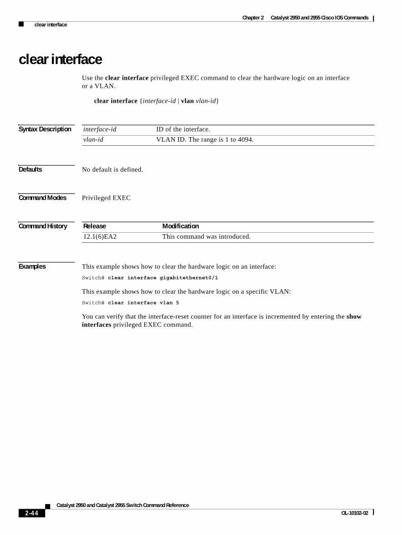
Chapter 2 Catalyst 2950 and 2955 Cisco IOS Commands clear interface
clear interfaceUse the clear interface privileged EXEC command to clear the hardware logic on an interface or a VLAN.
clear interface {interface-id | vlan vlan-id}
Syntax Description
Defaults No default is defined.
Command Modes Privileged EXEC
Command History
Examples This example shows how to clear the hardware logic on an interface:
Switch# clear interface gigabitethernet0/1
This example shows how to clear the hardware logic on a specific VLAN:
Switch# clear interface vlan 5
You can verify that the interface-reset counter for an interface is incremented by entering the show interfaces privileged EXEC command.
interface-id ID of the interface.
vlan-id VLAN ID. The range is 1 to 4094.
Release Modification
12.1(6)EA2 This command was introduced.
2-44Catalyst 2950 and Catalyst 2955 Switch Command Reference
OL-10102-02
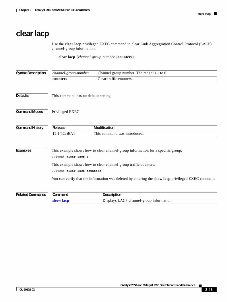
Chapter 2 Catalyst 2950 and 2955 Cisco IOS Commands clear lacp
clear lacpUse the clear lacp privileged EXEC command to clear Link Aggregration Control Protocol (LACP) channel-group information.
clear lacp {channel-group-number | counters}
Syntax Description
Defaults This command has no default setting.
Command Modes Privileged EXEC
Command History
Examples This example shows how to clear channel-group information for a specific group:
Switch# clear lacp 4
This example shows how to clear channel-group traffic counters:
Switch# clear lacp counters
You can verify that the information was deleted by entering the show lacp privileged EXEC command.
Related Commands
channel-group-number Channel group number. The range is 1 to 6.
counters Clear traffic counters.
Release Modification
12.1(12c)EA1 This command was introduced.
Command Description
show lacp Displays LACP channel-group information.
2-45Catalyst 2950 and Catalyst 2955 Switch Command Reference
OL-10102-02
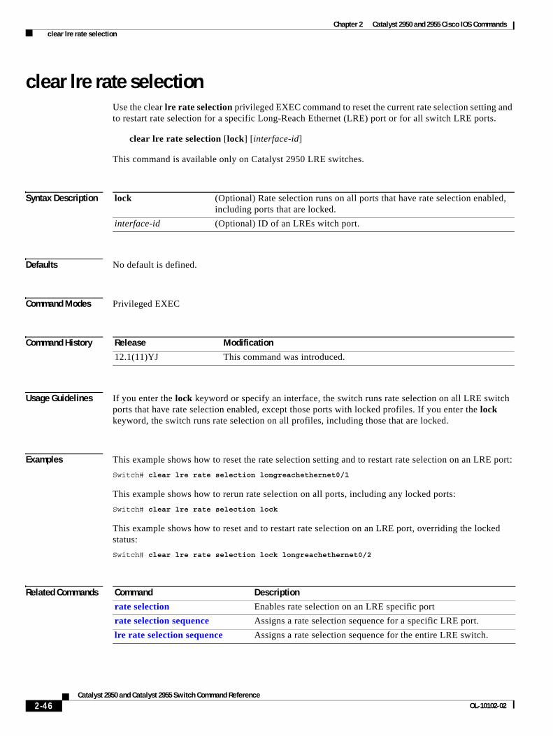
Chapter 2 Catalyst 2950 and 2955 Cisco IOS Commands clear lre rate selection
clear lre rate selectionUse the clear lre rate selection privileged EXEC command to reset the current rate selection setting and to restart rate selection for a specific Long-Reach Ethernet (LRE) port or for all switch LRE ports.
clear lre rate selection [lock] [interface-id]
This command is available only on Catalyst 2950 LRE switches.
Syntax Description
Defaults No default is defined.
Command Modes Privileged EXEC
Command History
Usage Guidelines If you enter the lock keyword or specify an interface, the switch runs rate selection on all LRE switch ports that have rate selection enabled, except those ports with locked profiles. If you enter the lock keyword, the switch runs rate selection on all profiles, including those that are locked.
Examples This example shows how to reset the rate selection setting and to restart rate selection on an LRE port:
Switch# clear lre rate selection longreachethernet0/1
This example shows how to rerun rate selection on all ports, including any locked ports:
Switch# clear lre rate selection lock
This example shows how to reset and to restart rate selection on an LRE port, overriding the locked status:
Switch# clear lre rate selection lock longreachethernet0/2
Related Commands
lock (Optional) Rate selection runs on all ports that have rate selection enabled, including ports that are locked.
interface-id (Optional) ID of an LREs witch port.
Release Modification
12.1(11)YJ This command was introduced.
Command Description
rate selection Enables rate selection on an LRE specific port
rate selection sequence Assigns a rate selection sequence for a specific LRE port.
lre rate selection sequence Assigns a rate selection sequence for the entire LRE switch.
2-46Catalyst 2950 and Catalyst 2955 Switch Command Reference
OL-10102-02
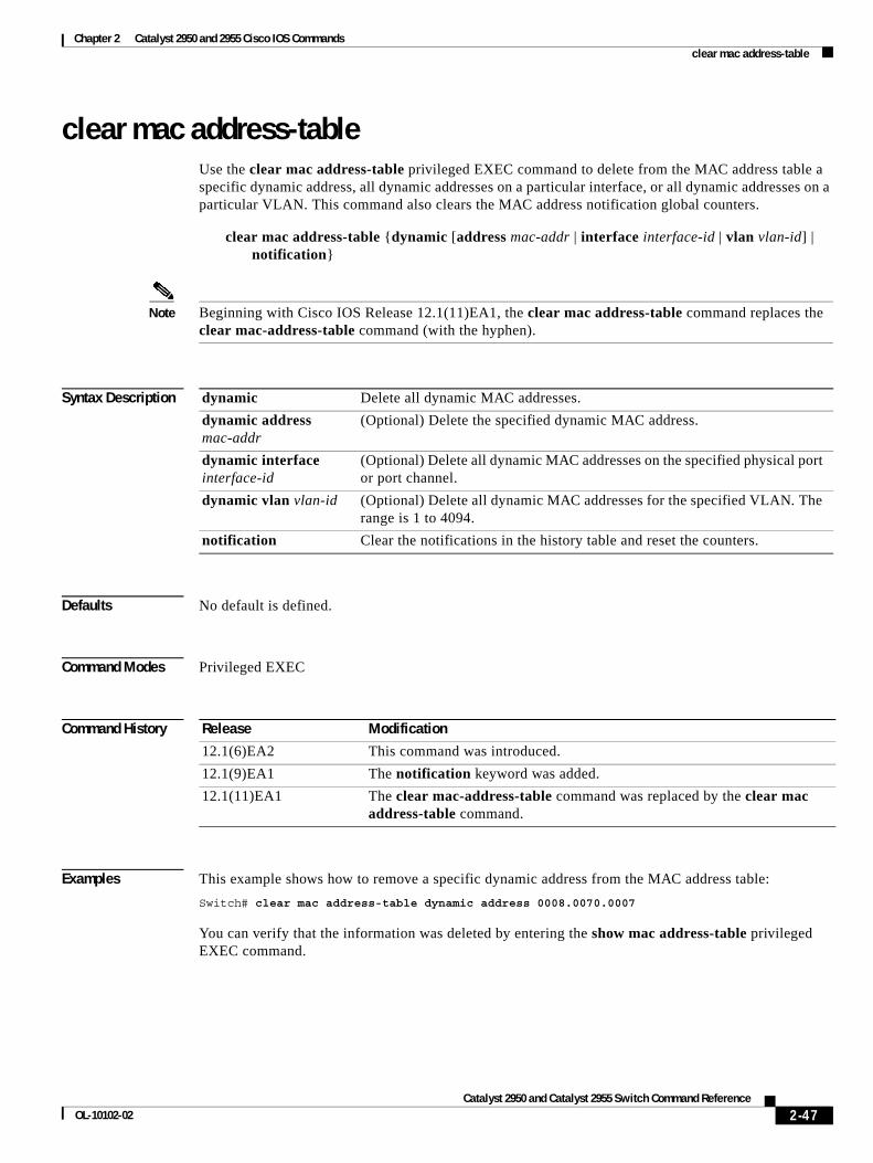
Chapter 2 Catalyst 2950 and 2955 Cisco IOS Commands clear mac address-table
clear mac address-tableUse the clear mac address-table privileged EXEC command to delete from the MAC address table a specific dynamic address, all dynamic addresses on a particular interface, or all dynamic addresses on a particular VLAN. This command also clears the MAC address notification global counters.
clear mac address-table {dynamic [address mac-addr | interface interface-id | vlan vlan-id] | notification}
Note Beginning with Cisco IOS Release 12.1(11)EA1, the clear mac address-table command replaces the clear mac-address-table command (with the hyphen).
Syntax Description
Defaults No default is defined.
Command Modes Privileged EXEC
Command History
Examples This example shows how to remove a specific dynamic address from the MAC address table:
Switch# clear mac address-table dynamic address 0008.0070.0007
You can verify that the information was deleted by entering the show mac address-table privileged EXEC command.
dynamic Delete all dynamic MAC addresses.
dynamic address mac-addr
(Optional) Delete the specified dynamic MAC address.
dynamic interface interface-id
(Optional) Delete all dynamic MAC addresses on the specified physical port or port channel.
dynamic vlan vlan-id (Optional) Delete all dynamic MAC addresses for the specified VLAN. The range is 1 to 4094.
notification Clear the notifications in the history table and reset the counters.
Release Modification
12.1(6)EA2 This command was introduced.
12.1(9)EA1 The notification keyword was added.
12.1(11)EA1 The clear mac-address-table command was replaced by the clear mac address-table command.
2-47Catalyst 2950 and Catalyst 2955 Switch Command Reference
OL-10102-02
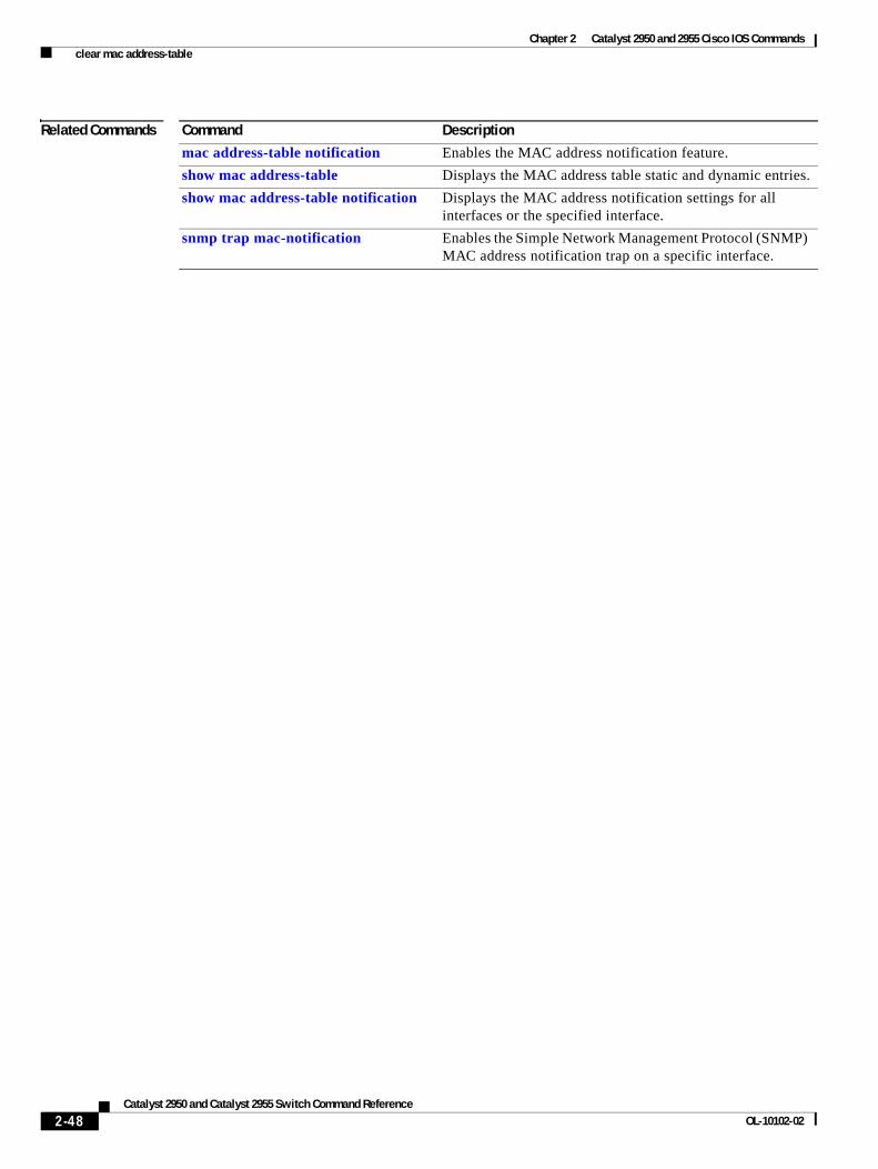
Chapter 2 Catalyst 2950 and 2955 Cisco IOS Commands clear mac address-table
Related Commands Command Description
mac address-table notification Enables the MAC address notification feature.
show mac address-table Displays the MAC address table static and dynamic entries.
show mac address-table notification Displays the MAC address notification settings for all interfaces or the specified interface.
snmp trap mac-notification Enables the Simple Network Management Protocol (SNMP) MAC address notification trap on a specific interface.
2-48Catalyst 2950 and Catalyst 2955 Switch Command Reference
OL-10102-02
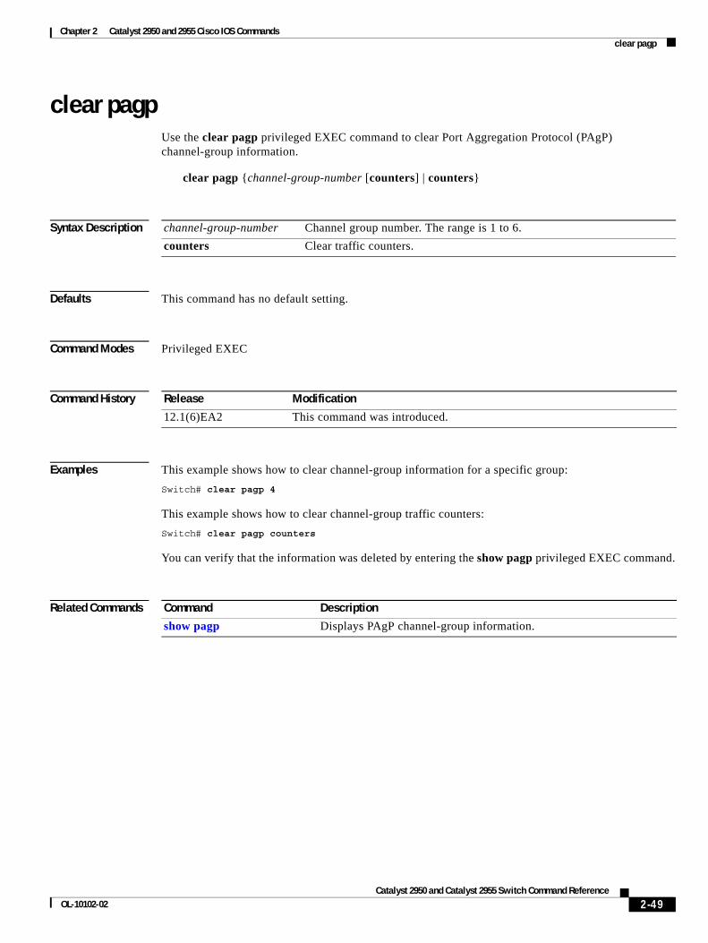
Chapter 2 Catalyst 2950 and 2955 Cisco IOS Commands clear pagp
clear pagpUse the clear pagp privileged EXEC command to clear Port Aggregation Protocol (PAgP) channel-group information.
clear pagp {channel-group-number [counters] | counters}
Syntax Description
Defaults This command has no default setting.
Command Modes Privileged EXEC
Command History
Examples This example shows how to clear channel-group information for a specific group:
Switch# clear pagp 4
This example shows how to clear channel-group traffic counters:
Switch# clear pagp counters
You can verify that the information was deleted by entering the show pagp privileged EXEC command.
Related Commands
channel-group-number Channel group number. The range is 1 to 6.
counters Clear traffic counters.
Release Modification
12.1(6)EA2 This command was introduced.
Command Description
show pagp Displays PAgP channel-group information.
2-49Catalyst 2950 and Catalyst 2955 Switch Command Reference
OL-10102-02
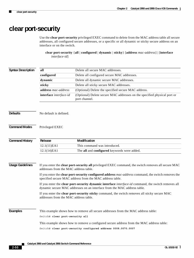
Chapter 2 Catalyst 2950 and 2955 Cisco IOS Commands clear port-security
clear port-securityUse the clear port-security privileged EXEC command to delete from the MAC address table all secure addresses, all configured secure addresses, or a specific or all dynamic or sticky secure address on an interface or on the switch.
clear port-security {all | configured | dynamic | sticky} [address mac-address] | [interface interface-id]
Syntax Description
Defaults No default is defined.
Command Modes Privileged EXEC
Command History
Usage Guidelines If you enter the clear port-security all privileged EXEC command, the switch removes all secure MAC addresses from the MAC address table.
If you enter the clear port-security configured address mac-address command, the switch removes the specified secure MAC address from the MAC address table.
If you enter the clear port-security dynamic interface interface-id command, the switch removes all dynamic secure MAC addresses on an interface from the MAC address table.
If you enter the clear port-security sticky command, the switch removes all sticky secure MAC addresses from the MAC address table.
Examples This example shows how to remove all secure addresses from the MAC address table:
Switch# clear port-security all
This example shows how to remove a configured secure address from the MAC address table:
Switch# clear port-security configured address 0008.0070.0007
all Delete all secure MAC addresses.
configured Delete all configured secure MAC addresses.
dynamic Delete all dynamic secure MAC addresses.
sticky Delete all sticky secure MAC addresses.
address mac-address (Optional) Delete the specified secure MAC address.
interface interface-id (Optional) Delete secure MAC addresses on the specified physical port or port channel.
Release Modification
12.1(11)EA1 This command was introduced.
12.1(14)EA1 The all and configured keywords were added.
2-50Catalyst 2950 and Catalyst 2955 Switch Command Reference
OL-10102-02
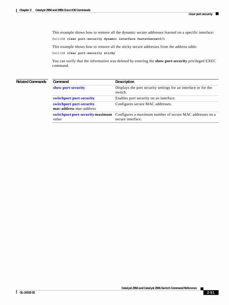
Chapter 2 Catalyst 2950 and 2955 Cisco IOS Commands clear port-security
This example shows how to remove all the dynamic secure addresses learned on a specific interface:
Switch# clear port-security dynamic interface fastethernet0/1
This example shows how to remove all the sticky secure addresses from the address table:
Switch# clear port-security sticky
You can verify that the information was deleted by entering the show port-security privileged EXEC command.
Related Commands Command Description
show port-security Displays the port security settings for an interface or for the switch.
switchport port-security Enables port security on an interface.
switchport port-security mac-address mac-address
Configures secure MAC addresses.
switchport port-security maximum value
Configures a maximum number of secure MAC addresses on a secure interface.
2-51Catalyst 2950 and Catalyst 2955 Switch Command Reference
OL-10102-02
Chapter 2 Catalyst 2950 and 2955 Cisco IOS Commands clear spanning-tree counters
clear spanning-tree countersUse the clear spanning-tree counters privileged EXEC command to clear the spanning-tree counters.
clear spanning-tree counters [interface interface-id]
Syntax Description
Defaults No default is defined.
Command Modes Privileged EXEC
Command History
Examples This example shows how to clear spanning-tree counters for all interfaces:
Switch# clear spanning-tree counters
Related Commands
interface interface-id (Optional) Clear all spanning-tree counters on the specified interface. If interface-id is not specified, spanning-tree counters are cleared for all interfaces.
Release Modification
12.1(13)EA1 This command was introduced.
Command Description
show spanning-tree Displays spanning-tree state information.
2-52Catalyst 2950 and Catalyst 2955 Switch Command Reference
OL-10102-02
Chapter 2 Catalyst 2950 and 2955 Cisco IOS Commands clear spanning-tree detected-protocols
clear spanning-tree detected-protocolsUse the clear spanning-tree detected-protocols privileged EXEC command to restart the protocol migration process (force the renegotiation with neighboring switches) on all interfaces or on the specified interface.
clear spanning-tree detected-protocols [interface interface-id]
Syntax Description
Command Modes Privileged EXEC
Command History
Usage Guidelines A switch running the rapid per-VLAN spanning-tree plus (rapid-PVST+) protocol or the Multiple Spanning Tree Protocol (MSTP) supports a built-in protocol migration mechanism that enables it to interoperate with legacy IEEE 802.1D switches. If a rapid-PVST+ switch or an MSTP switch receives a legacy IEEE 802.1D configuration bridge protocol data unit (BPDU) with the protocol version set to 0, it sends only IEEE 802.1D BPDUs on that port. A multiple spanning-tree (MST) switch can also detect that a port is at the boundary of a region when it receives a legacy BPDU, an MST BPDU (version 3) associated with a different region, or an RST BPDU (version 2).
However, the switch does not automatically revert to the rapid-PVST+ or the MSTP mode if it no longer receives IEEE 802.1D BPDUs because it cannot determine whether the legacy switch has been removed from the link unless the legacy switch is the designated switch. Use the clear spanning-tree detected-protocols command in this situation.
Examples This example shows how to restart the protocol migration process on an interface:
Switch# clear spanning-tree detected-protocols interface fastethernet0/1
interface interface-id (Optional) Restart the protocol migration process on the specified interface. Valid interfaces include physical ports, VLANs, and port channels. The VLAN range is 1 to 4094. The port-channel range is 1 to 6.
Release Modification
12.1(9)EA1 This command was introduced.
12.1(20)EA2 This command was added to the SI.
2-53Catalyst 2950 and Catalyst 2955 Switch Command Reference
OL-10102-02
Chapter 2 Catalyst 2950 and 2955 Cisco IOS Commands clear vmps statistics
clear vmps statisticsUse the clear vmps statistics privileged EXEC command to clear the statistics maintained by the VLAN Query Protocol (VQP) client.
clear vmps statistics
Syntax Description This command has no arguments or keywords.
Defaults No default is defined.
Command Modes Privileged EXEC
Command History
Examples This example shows how to clear VLAN Membership Policy Server (VMPS) statistics:
Switch# clear vmps statistics
You can verify that the information was deleted by entering the show vmps statistics privileged EXEC command.
Related Commands
Release Modification
12.1(6)EA2 This command was introduced.
Command Description
show vmps statistics Displays the VQP version, reconfirmation interval, retry count, VMPS IP addresses, and the current and primary servers.
2-54Catalyst 2950 and Catalyst 2955 Switch Command Reference
OL-10102-02
Chapter 2 Catalyst 2950 and 2955 Cisco IOS Commands clear vtp counters
clear vtp countersUse the clear vtp counters privileged EXEC command to clear the VLAN Trunking Protocol (VTP) and pruning counters.
clear vtp counters
Syntax Description This command has no arguments or keywords.
Defaults No default is defined.
Command Modes Privileged EXEC
Command History
Examples This example shows how to clear the VTP counters:
Switch# clear vtp counters
You can verify that the information was deleted by entering the show vtp counters privileged EXEC command.
Related Commands
Release Modification
12.0(5.2)WC(1) This command was introduced.
Command Description
show vtp counters Displays general information about the VTP management domain, status, and counters.
2-55Catalyst 2950 and Catalyst 2955 Switch Command Reference
OL-10102-02
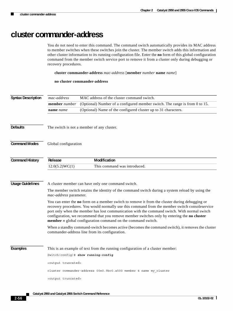
Chapter 2 Catalyst 2950 and 2955 Cisco IOS Commands cluster commander-address
cluster commander-address You do not need to enter this command. The command switch automatically provides its MAC address to member switches when these switches join the cluster. The member switch adds this information and other cluster information to its running configuration file. Enter the no form of this global configuration command from the member switch service port to remove it from a cluster only during debugging or recovery procedures.
cluster commander-address mac-address [member number name name]
no cluster commander-address
Syntax Description
Defaults The switch is not a member of any cluster.
Command Modes Global configuration
Command History
Usage Guidelines A cluster member can have only one command switch.
The member switch retains the identity of the command switch during a system reload by using the mac-address parameter.
You can enter the no form on a member switch to remove it from the cluster during debugging or recovery procedures. You would normally use this command from the member switch consoleservice port only when the member has lost communication with the command switch. With normal switch configuration, we recommend that you remove member switches only by entering the no cluster member n global configuration command on the command switch.
When a standby command-switch becomes active (becomes the command switch), it removes the cluster commander-address line from its configuration.
Examples This is an example of text from the running configuration of a cluster member:
Switch(config)# show running-config
<output truncated>
cluster commander-address 00e0.9bc0.a500 member 4 name my_cluster
<output truncated>
mac-address MAC address of the cluster command switch.
member number (Optional) Number of a configured member switch. The range is from 0 to 15.
name name (Optional) Name of the configured cluster up to 31 characters.
Release Modification
12.0(5.2)WC(1) This command was introduced.
2-56Catalyst 2950 and Catalyst 2955 Switch Command Reference
OL-10102-02
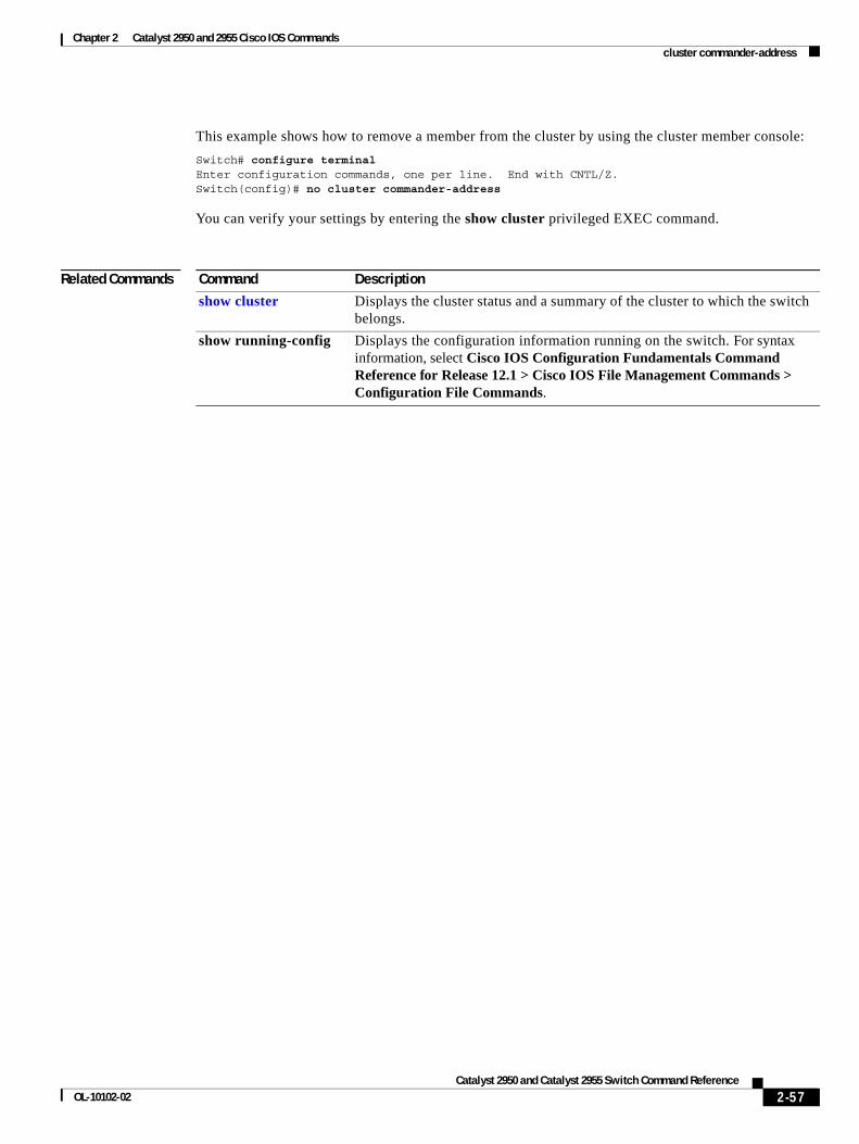
Chapter 2 Catalyst 2950 and 2955 Cisco IOS Commands cluster commander-address
This example shows how to remove a member from the cluster by using the cluster member console:
Switch# configure terminalEnter configuration commands, one per line. End with CNTL/Z.Switch(config)# no cluster commander-address
You can verify your settings by entering the show cluster privileged EXEC command.
Related Commands Command Description
show cluster Displays the cluster status and a summary of the cluster to which the switch belongs.
show running-config Displays the configuration information running on the switch. For syntax information, select Cisco IOS Configuration Fundamentals Command Reference for Release 12.1 > Cisco IOS File Management Commands > Configuration File Commands.
2-57Catalyst 2950 and Catalyst 2955 Switch Command Reference
OL-10102-02
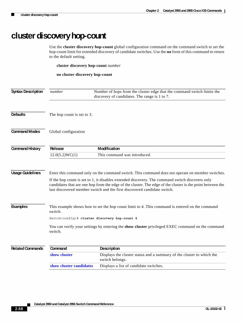
Chapter 2 Catalyst 2950 and 2955 Cisco IOS Commands cluster discovery hop-count
cluster discovery hop-countUse the cluster discovery hop-count global configuration command on the command switch to set the hop-count limit for extended discovery of candidate switches. Use the no form of this command to return to the default setting.
cluster discovery hop-count number
no cluster discovery hop-count
Syntax Description
Defaults The hop count is set to 3.
Command Modes Global configuration
Command History
Usage Guidelines Enter this command only on the command switch. This command does not operate on member switches.
If the hop count is set to 1, it disables extended discovery. The command switch discovers only candidates that are one hop from the edge of the cluster. The edge of the cluster is the point between the last discovered member switch and the first discovered candidate switch.
Examples This example shows how to set the hop count limit to 4. This command is entered on the command switch.
Switch(config)# cluster discovery hop-count 4
You can verify your settings by entering the show cluster privileged EXEC command on the command switch.
Related Commands
number Number of hops from the cluster edge that the command switch limits the discovery of candidates. The range is 1 to 7.
Release Modification
12.0(5.2)WC(1) This command was introduced.
Command Description
show cluster Displays the cluster status and a summary of the cluster to which the switch belongs.
show cluster candidates Displays a list of candidate switches.
2-58Catalyst 2950 and Catalyst 2955 Switch Command Reference
OL-10102-02
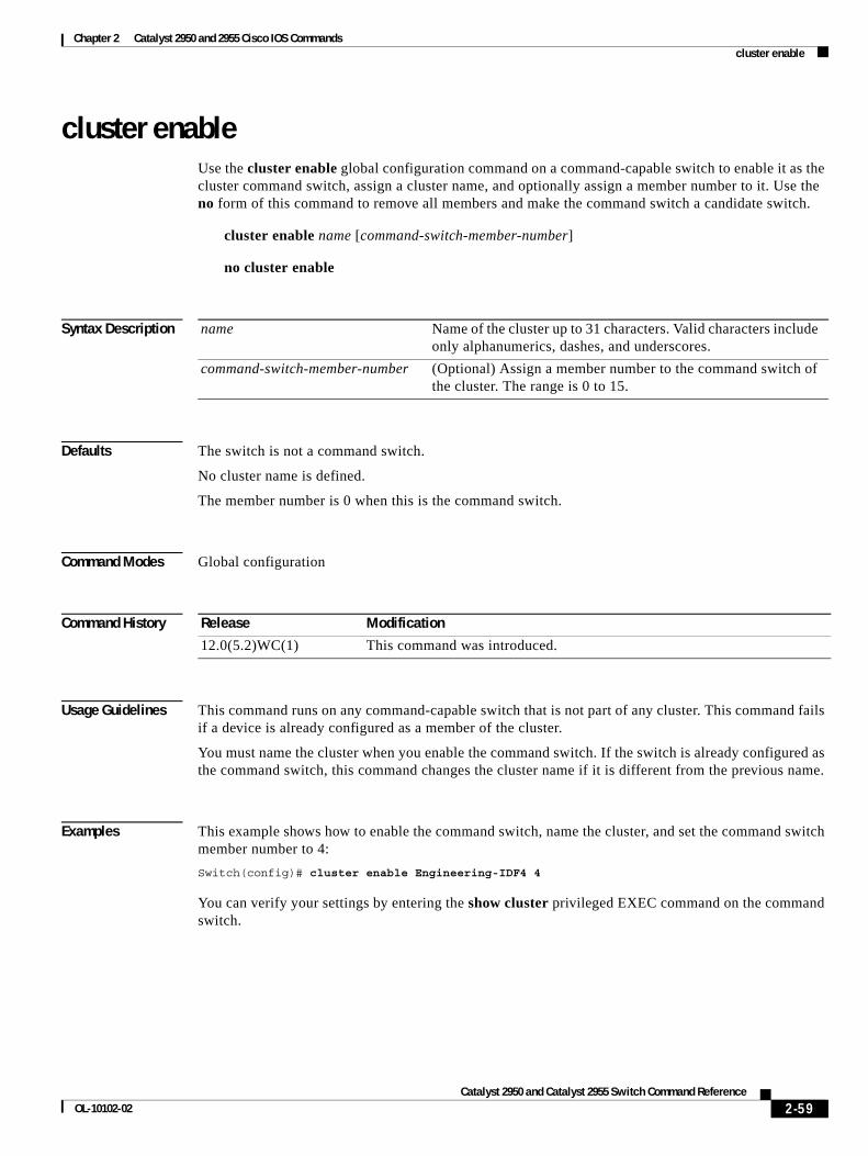
Chapter 2 Catalyst 2950 and 2955 Cisco IOS Commands cluster enable
cluster enableUse the cluster enable global configuration command on a command-capable switch to enable it as the cluster command switch, assign a cluster name, and optionally assign a member number to it. Use the no form of this command to remove all members and make the command switch a candidate switch.
cluster enable name [command-switch-member-number]
no cluster enable
Syntax Description
Defaults The switch is not a command switch.
No cluster name is defined.
The member number is 0 when this is the command switch.
Command Modes Global configuration
Command History
Usage Guidelines This command runs on any command-capable switch that is not part of any cluster. This command fails if a device is already configured as a member of the cluster.
You must name the cluster when you enable the command switch. If the switch is already configured as the command switch, this command changes the cluster name if it is different from the previous name.
Examples This example shows how to enable the command switch, name the cluster, and set the command switch member number to 4:
Switch(config)# cluster enable Engineering-IDF4 4
You can verify your settings by entering the show cluster privileged EXEC command on the command switch.
name Name of the cluster up to 31 characters. Valid characters include only alphanumerics, dashes, and underscores.
command-switch-member-number (Optional) Assign a member number to the command switch of the cluster. The range is 0 to 15.
Release Modification
12.0(5.2)WC(1) This command was introduced.
2-59Catalyst 2950 and Catalyst 2955 Switch Command Reference
OL-10102-02
Chapter 2 Catalyst 2950 and 2955 Cisco IOS Commands cluster holdtime
cluster holdtimeUse the cluster holdtime global configuration command on the command switch to set the duration in seconds before a switch (either the command or member switch) declares the other switch down after not receiving heartbeat messages. Use the no form of this command to return to the default setting.
cluster holdtime holdtime-in-secs
no cluster holdtime
Syntax Description
Defaults The holdtime is 80 seconds.
Command Modes Global configuration
Command History
Usage Guidelines Use this command with the cluster timer global configuration command only on the command switch. The command switch propagates the values to all its cluster members so that the setting is consistent among all switches in the cluster.
The holdtime is typically set as a multiple of the interval timer (cluster timer). For example, it takes (holdtime-in-secs divided by interval-in-secs) number of heartbeat messages to be missed in a row to declare a switch down.
Examples This example shows how to change the interval timer and the duration on the command switch:
Switch(config)# cluster timer 3Switch(config)# cluster holdtime 30
You can verify your settings by entering the show cluster privileged EXEC command.
Related Commands
holdtime-in-secs Duration in seconds before a switch (either a command or member switch) declares the other switch down. The range is 1 to 300 seconds.
Release Modification
12.0(5.2)WC(1) This command was introduced.
Command Description
show cluster Displays the cluster status and a summary of the cluster to which the switch belongs.
2-60Catalyst 2950 and Catalyst 2955 Switch Command Reference
OL-10102-02
Chapter 2 Catalyst 2950 and 2955 Cisco IOS Commands cluster management-vlan
cluster management-vlanUse the cluster management-vlan global configuration command on the command switch to change the management VLAN for the entire cluster. Use the no form of this command to change the management VLAN to VLAN 1.
cluster management-vlan n
no cluster management-vlan
Syntax Description
Defaults The default management VLAN is VLAN 1.
Command Modes Global configuration
Command History
Usage Guidelines Enter this command only on the command switch. This command changes the management VLAN of the command switch and member switches. Member switches must have either a trunk connection or connection to the new command-switch management VLAN to maintain communication with the command switch.
This command is not written to the configuration file.
Examples This example shows how to change the management VLAN to VLAN 5 on the entire cluster:
Switch(config)# cluster management-vlan 5
You can verify your settings by entering the show interfaces vlan vlan-id privileged EXEC command.
Related Commands
n VLAN ID of the new management VLAN. The range is 1 to 4094.
Release Modification
12.0(5.2)WC(1) This command was introduced.
Command Description
show interfaces Displays the administrative and operational status of a switching (nonrouting) port.
2-61Catalyst 2950 and Catalyst 2955 Switch Command Reference
OL-10102-02
Chapter 2 Catalyst 2950 and 2955 Cisco IOS Commands cluster member
cluster memberUse the cluster member global configuration command on the command switch to add members to a cluster. Use the no form of this command to remove members from the cluster.
cluster member [n] mac-address H.H.H [password enable-password] [vlan vlan-id]
no cluster member n
Syntax Description
Defaults A newly enabled command switch has no associated cluster members.
Command Modes Global configuration
Command History
Usage Guidelines Enter this command only on the command switch to add a member to or remove a member from the cluster. If you enter this command on a switch other than the command switch, the switch rejects the command and displays an error message.
You must enter a member number to remove a switch from the cluster. However, you do not need to enter a member number to add a switch to the cluster. The command switch selects the next available member number and assigns it to the switch that is joining the cluster.
You must enter the enable password of the candidate switch for authentication when it joins the cluster. The password is not saved in the running or startup configuration. After a candidate switch becomes a member of the cluster, its password becomes the same as the command-switch password.
If a switch does not have a configured host name, the command switch appends a member number to the command-switch host name and assigns it to the member switch.
If you do not specify a VLAN ID, the command switch automatically chooses a VLAN and adds the candidate to the cluster.
n (Optional) The number that identifies a cluster member. The range is 0 to 15.
mac-address H.H.H MAC address of the member switch in hexadecimal format.
password enable-password (Optional) Enable password of the candidate switch. The password is not required if there is no password on the candidate switch.
vlan vlan-id (Optional) VLAN ID through which the candidate is added to the cluster by the command switch. The range is 1 to 4094.
Release Modification
12.0(5.2)WC(1) This command was introduced.
2-62Catalyst 2950 and Catalyst 2955 Switch Command Reference
OL-10102-02
Chapter 2 Catalyst 2950 and 2955 Cisco IOS Commands cluster member
Examples This example shows how to add a switch as member 2 with MAC address 00E0.1E00.2222 and the password key to a cluster. The command switch adds the candidate to the cluster through VLAN 3.
Switch(config)# cluster member 2 mac-address 00E0.1E00.2222 password key vlan 3
This example shows how to add a switch with MAC address 00E0.1E00.3333 to the cluster. This switch does not have a password. The command switch selects the next available member number and assigns it to the switch joining the cluster.
Switch(config)# cluster member mac-address 00E0.1E00.3333
You can verify your settings by entering the show cluster members privileged EXEC command on the command switch.
Related Commands Command Description
show cluster Displays the cluster status and a summary of the cluster to which the switch belongs.
show cluster candidates Displays a list of candidate switches.
show cluster members Displays information about the cluster members.
2-63Catalyst 2950 and Catalyst 2955 Switch Command Reference
OL-10102-02
Chapter 2 Catalyst 2950 and 2955 Cisco IOS Commands cluster run
cluster runUse the cluster run global configuration command to enable clustering on a switch. Use the no form of this command to disable clustering on a switch.
cluster run
no cluster run
Defaults Clustering is enabled on all switches.
Command Modes Global configuration
Command History
Usage Guidelines When you enter the no cluster run command on a command switch, the command switch is disabled. Clustering is disabled, and the switch cannot become a candidate switch.
When you enter the no cluster run command on a member switch, it is removed from the cluster. Clustering is disabled, and the switch cannot become a candidate switch.
When you enter the no cluster run command on a switch that is not part of a cluster, clustering is disabled on this switch. This switch cannot then become a candidate switch.
Examples This example shows how to disable clustering on the command switch:
Switch(config)# no cluster run
You can verify that clustering is disabled by entering the show cluster privileged EXEC command.
Related Commands
Release Modification
12.0(5.2)WC(1) This command was introduced.
Command Description
show cluster Displays the cluster status and a summary of the cluster to which the switch belongs.
2-64Catalyst 2950 and Catalyst 2955 Switch Command Reference
OL-10102-02
Chapter 2 Catalyst 2950 and 2955 Cisco IOS Commands cluster standby-group
cluster standby-groupUse the cluster standby-group global configuration command to enable command switch redundancy by binding the Hot Standby Router Protocol (HSRP) standby group to the cluster. Use the no form of this command to unbind the cluster from the HSRP standby group.
cluster standby-group HSRP-group-name
no cluster standby-group
Syntax Description
Defaults The cluster is not bound to any HSRP group.
Command Modes Global configuration
Command History
Usage Guidelines You must enter this command only on the command switch. If you enter it on a member switch, an error message appears.
The command switch propagates the cluster-HSRP binding information to all members. Each member switch stores the binding information in its NVRAM.
The HSRP group name must be a valid standby group; otherwise, the command entry produces an error.
Use the same group name on all members of the HSRP standby group that is to be bound to the cluster. Use the same HSRP group name on all cluster-HSRP capable members for the HSRP group that is to be bound. (When not binding a cluster to an HSRP group, you can use different names on the cluster command and the member switches.)
Examples This example shows how to bind the HSRP group named my_hsrp to the cluster. This command is entered on the command switch.
Switch(config)# cluster standby-group my_hsrp
This example shows the error message when this command is entered on a command switch and the specified HSRP standby group does not exist:
Switch(config)# cluster standby-group my_hsrp%ERROR:Standby (my_hsrp) group does not exist
HSRP-group-name Name of the HSRP group that is bound to the cluster. The group name is limited to 32 characters.
Release Modification
12.0(5.2)WC(1) This command was introduced.
2-65Catalyst 2950 and Catalyst 2955 Switch Command Reference
OL-10102-02
Chapter 2 Catalyst 2950 and 2955 Cisco IOS Commands cluster standby-group
This example shows the error message when this command is entered on a member switch:
Switch(config)# cluster standby-group my_hsrp%ERROR:This command runs on a cluster command switch
You can verify your settings by entering the show cluster privileged EXEC command.
Related Commands Command Description
show cluster Displays the cluster status and a summary of the cluster to which the switch belongs.
show standby Displays standby group information.
standby ip Enables HSRP on the interface.
2-66Catalyst 2950 and Catalyst 2955 Switch Command Reference
OL-10102-02
Chapter 2 Catalyst 2950 and 2955 Cisco IOS Commands cluster timer
cluster timerUse the cluster timer global configuration command on the command switch to set the interval in seconds between heartbeat messages. Use the no form of this command to return to the default setting.
cluster timer interval-in-secs
no cluster timer
Syntax Description
Defaults The interval is 8 seconds.
Command Modes Global configuration
Command History
Usage Guidelines Use this command with the cluster holdtime global configuration command only on the command switch. The command switch propagates the values to all its cluster members so that the setting is consistent among all switches in the cluster.
The holdtime is typically set as a multiple of the heartbeat interval timer (cluster timer). For example, it takes (holdtime-in-secs divided by the interval-in-secs) number of heartbeat messages to be missed in a row to declare a switch down.
Examples This example shows how to change the heartbeat interval timer and the duration on the command switch:
Switch(config)# cluster timer 3Switch(config)# cluster holdtime 30
You can verify your settings by entering the show cluster privileged EXEC command.
Related Commands
interval-in-secs Interval in seconds between heartbeat messages. The range is 1 to 300 seconds.
Release Modification
12.0(5.2)WC(1) This command was introduced.
Command Description
show cluster Displays the cluster status and a summary of the cluster to which the switch belongs.
2-67Catalyst 2950 and Catalyst 2955 Switch Command Reference
OL-10102-02
Chapter 2 Catalyst 2950 and 2955 Cisco IOS Commands controller longreachethernet
controller longreachethernetUse the controller longreachethernet global configuration command to enter the controller configuration mode.
controller longreachethernet ctrlr-number
This command is available only on Catalyst 2950 Long-Reach Ethernet (LRE) switches.
Syntax Description
Defaults No default is defined.
Command Modes Global configuration
Command History
Usage Guidelines Use this command to enter the controller configuration mode. An LRE controller is the LRE chipset in the switch.
Examples This example shows how to enter the controller configuration mode for controller 0:
Switch(config)# controller longreachethernet 0Switch(config-controller)#
Related Commands
ctrlr-number LRE controller number. Controller numbers are device specific. The range is 0 to 2 on a 24-port LRE switch and 0 on an 8-port LRE switch.
Release Modification
12.1(11)YJ This command was introduced.
Command Description
upgrade binary Configures upgrades on either end of an LRE link.
upgrade preserve Prevents an upgrade of the local customer premises equipment (CPE) controller and all remote CPE devices connected to it.
2-68Catalyst 2950 and Catalyst 2955 Switch Command Reference
OL-10102-02
Chapter 2 Catalyst 2950 and 2955 Cisco IOS Commands cpe duplex
cpe duplexUse the cpe duplex interface configuration command to specify the duplex mode of operation for all customer premises equipment (CPE) ports. Use the no form of this command to return to the default setting.
cpe duplex {{auto | full | half} [port port-id]}
no cpe duplex {{auto | full | half} [port port-id]}
This command is available only on Catalyst 2950 Long-Reach Ethernet (LRE) switches.
Syntax Description
Defaults The default duplex mode is half.
Command Modes Interface configuration
Command History
Usage Guidelines Use the cpe duplex full command to set the duplex mode to full for all the CPE Ethernet ports. Use the auto keyword to set the CPE Ethernet ports to autonegotiate, and use the half keyword to force the duplex mode to half for all the CPE Ethernet ports.
If you do not enter the port keyword, the duplex setting is applied to all the CPE Ethernet ports. If you enter the port port-id keywords, the setting is applied to the specified CPE Ethernet port and overrides any global speed settings.
Use the cpe duplex full port 2 command to set the duplex mode of port 2 on a CPE device to full duplex. If you enter both a switch-wide command, such as the cpe duplex full command, and a port-specific commands, such as the cpe duplex full port 2 command, the switch adds both the configuration file, and the port-specific command takes priority over the switch-wide command.
Examples This example show how to set the CPE device to autonegotiate:
Switch# configure terminalSwitch(config)# interface longreachethernet0/2Switch(config-if)# cpe duplex auto
auto The port automatically detects whether to run in full- or half- duplex mode.
full The port is in full-duplex mode.
half The port is in half-duplex mode.
port port-id (Optional) CPE Ethernet port identifier. The range is 1to 4, depending on CPE device.
Release Modification
12.1(11)YJ This command was introduced.
2-69Catalyst 2950 and Catalyst 2955 Switch Command Reference
OL-10102-02
Chapter 2 Catalyst 2950 and 2955 Cisco IOS Commands cpe duplex
This example shows how to set a port on a Cisco 585 LRE CPE to full-duplex mode:
Switch# configure terminalSwitch(config)# interface longreachethernet0/3Switch(config-if)# cpe duplex full port 3
This example shows how to restore a port on a Cisco 585 LRE CPE to the default mode of half duplex:
Switch# configure terminalSwitch(config)# interface longreachethernet0/3Switch(config-if)# no cpe duplex full port 3
This example shows how the cpe duplex {auto | full | half} port port-id command works with the cpe duplex {auto | full | half} command. Port 1 is set to full duplex, port 2 is set to half duplex, and the remainder of the ports are set to autonegotiate.
Switch# configure terminalSwitch(config)# interface longreachethernet0/4Switch(config-if)# cpe duplex autoSwitch(config-if)# cpe duplex full port 1Switch(config-if)# cpe duplex half port 2
After the commands in the previous example are entered, this example shows how to set a port to autonegotiate:
Switch(config-if)# no cpe duplex full port 1
Related Commands Command Description
cpe speed Specifies the CPE port speed settings.
show interfaces cpe Displays CPE Ethernet ports connection, speed, or duplex status.
2-70Catalyst 2950 and Catalyst 2955 Switch Command Reference
OL-10102-02
Chapter 2 Catalyst 2950 and 2955 Cisco IOS Commands cpe protected
cpe protectedUse the cpe protected interface configuration command to restrict data traffic to individual ports on Cisco 585 LRE customer premises equipment (CPE) ports. Use the no form of this command to allow different ports on the same CPE device to exchange data directly.
cpe protected [port port-id]
no cpe protected [port port-id]
This command is available only on Catalyst 2950 Long-Reach Ethernet (LRE) switches.
Syntax Description
Defaults Traffic is not restricted to specific ports.
Command Modes Interface configuration
Command History
Usage Guidelines Even though you can protect an LRE interface by using the switchport protected interface configuration command, this command does not protect individual CPE Ethernet ports. Use the cpe protected command to ensure that data traffic from one CPE port is not accessed on any of the other three ports. Use the cpe protected command to restrict CPE traffic, either at the CPE device level or at the individual port level for data security. Use the cpe protected command without specifying a CPE port to protect data for all applicable CPE ports. Use the cpe protected port port-id command to protect a specific CPE Ethernet port.
When using this feature, always specify a minimum of two ports. A single port that is configured as protected has no effect. Data traffic does not flow between two ports that are protected.
Examples This example show how to protect CPE port 1 on an LRE port:
Switch# configure terminalSwitch(config)# interface longreachethernet0/1Switch(config-if)# cpe protected port 1
Related Commands
port port-id (Optional) CPE Ethernet port identifier. The range is 1 to 4, depending on CPE device.
Release Modification
12.1(11)YJ This command was introduced.
Command Description
show controllers lre cpe Shows CPE protected port information.
switchport protected Isolates unicast, multicast, and broadcast traffic at Layer 2 from other protected ports on the same switch.
2-71Catalyst 2950 and Catalyst 2955 Switch Command Reference
OL-10102-02
Chapter 2 Catalyst 2950 and 2955 Cisco IOS Commands cpe shutdown
cpe shutdownUse the cpe shutdown interface configuration command to disable one or more customer premises equipment (CPE) ports. Use the no form of this command to enable a port.
cpe shutdown [port port-id]
no cpe shutdown [port port-id]
This command is available only on Catalyst 2950 Long-Reach Ethernet (LRE) switches.
Syntax Description
Defaults The CPE ports are enabled.
Command Modes Interface configuration
Command History
Usage Guidelines If the port keyword is not specified, the value is applied globally to all the CPE Ethernet ports. If the port keyword is specified, the value is applied to the specific CPE Ethernet port and overrides any global speed settings.
The CPE Ethernet ports can be shut down at the CPE device level and the port level. If you add a configuration at the CPE device level and at the port level, you must enter the no form of the command for both configurations to return the port to the default state.
Examples This example shows how to disable all ports on the CPE device:
Switch# configure terminalSwitch(config)# interface longreachethernet0/2Switch(config-if)# cpe shutdown
This example shows how to disable port 2 on the CPE device:
Switch# configure terminalSwitch(config)# interface longreachethernet0/2Switch(config-if)# cpe shutdown port 2
port port-id (Optional) CPE Ethernet port identifier. The range is 1 to 4, depending on the CPE device.
Release Modification
12.1(11)YJ This command was introduced.
2-72Catalyst 2950 and Catalyst 2955 Switch Command Reference
OL-10102-02
Chapter 2 Catalyst 2950 and 2955 Cisco IOS Commands cpe shutdown
After the cpe shutdown port 2 command was entered in the previous example, this example shows how to enable all the CPE Ethernet ports that were not shut down. After the no cpe shutdown command is entered, port 2 is still shut down because the cpe shutdown port 2 command was entered in the previous example. Use the no cpe shutdown port 2 command to enable the port 2.
Switch# configure terminalSwitch(config)# interface longreahethernet0/2Switch(config-if)# no cpe shutdownSwitch(config-if)#
Related Commands Command Description
show interfaces cpe Displays CPE Ethernet ports connection, speed, or duplex status.
shutdown Disables a port.
2-73Catalyst 2950 and Catalyst 2955 Switch Command Reference
OL-10102-02
Chapter 2 Catalyst 2950 and 2955 Cisco IOS Commands cpe speed
cpe speedUse the cpe speed interface configuration command to set the speed of a customer premises equipment (CPE) port. Use the no form of this command to return to the default setting.
cpe speed {{auto | 10 | 100} [port port-id]}
no cpe speed {{auto | 10 | 100} [port port-id]}
This command is available only on Catalyst 2950 Long-Reach Ethernet (LRE) switches.
Syntax Description
Defaults The default speed is auto.
Command Modes Interface configuration
Command History
Usage Guidelines If you do not enter the port keyword, the speed setting is applied globally to all the CPE Ethernet ports. If you enter the port port-id keywords, the setting is applied to the specified CPE Ethernet port and overrides any global speed settings.
Examples This example shows how to set a port on a CPE to 100 Mbps:
Switch# configure terminalSwitch(config)# interface longreachethernet0/2Switch(config-if)# cpe speed 100 port 1
This example shows how to return the default speed setting on all CPE Ethernet ports that were not configured with the cpe speed {10 | 100} port port-id command:
Switch# configure terminalSwitch(config)# interface longreachethernet0/2Switch(config-if)# no cpe speed 100
auto Port automatically detects whether it should run at 10 or 100 Mbps.
10 Port runs at 10 Mbps.
100 Port runs at 100 Mbps.
port port-id (Optional) ID of the CPE Ethernet port. The range is 1 to 4, depending on the CPE device.
Release Modification
12.1(11)YJ This command was introduced.
2-74Catalyst 2950 and Catalyst 2955 Switch Command Reference
OL-10102-02
Chapter 2 Catalyst 2950 and 2955 Cisco IOS Commands cpe speed
This example shows how to set port 1 to 10 Mbps, port 2 to 100 Mbps, and the remainder of the ports to autonegotiate.
Switch# configure terminalSwitch(config)# interface longreachethernet0/4Switch(config-if)# cpe speed autoSwitch(config-if)# cpe speed 10 port 1Switch(config-if)# cpe speed 100 port 2
This example shows how to set port 1 to autonegotiate after the cpe speed 10 command is entered:
Switch(config-if)# no cpe speed 10 port
Related Commands Command Description
local duplex Sets the port speed for LRE ports.
show interfaces cpe Displays connection, speed, and duplex settings for CPE Ethernet ports attached to the specified LRE switch port
2-75Catalyst 2950 and Catalyst 2955 Switch Command Reference
OL-10102-02
Chapter 2 Catalyst 2950 and 2955 Cisco IOS Commands cpe toggle
cpe toggleUse the cpe toggle interface configuration command to enable the CPE toggle feature. When this feature is enabled, a remote customer premises equipment (CPE) link automatically transitions from down to up if the Long-Reach Ethernet (LRE) link comes up in less than 30 seconds. Use the no form of this command to disable the CPE toggle feature on a specific port or on the switch.
cpe toggle [port cpe-port-id]
no cpe toggle [port cpe-port-id]
This command is available only on Catalyst 2950 Long-Reach Ethernet (LRE) switches.
Syntax Description
Defaults CPE toggle is enabled on all interfaces.
Command Modes Interface configuration
Command History
Usage Guidelines A CPE Ethernet link is the connection between the CPE Ethernet port and the remote Ethernet device (such as a PC) connected to it. It is not the link between the switch LRE port and the LRE CPE device, which is referred to as the LRE link.
CPE toggle cannot be disabled on a Cisco 575 LRE or Cisco 576 LRE 997 CPE link.
You can disable CPE toggle on a link from a Cisco 585 LRE CPE to a remote Ethernet device. You can disable CPE toggle on all interfaces or on a specific interface by using the no cpe toggle [port cpe-port-id] interface configuration command. If CPE toggle is disabled and the LRE link comes up in less than 30 seconds, the CPE link transitions from down to up.
If the port keyword is not specified, this command applies to all Fast Ethernet ports on a CPE device. If the port keyword and a port ID are specified, this command applies to the specific Fast Ethernet port on the CPE and overrides the global configuration.
Examples This example shows how to disable CPE toggle on a CPE port:
Switch# configure terminalSwitch(config)# interface longreachethernet0/2Switch(config-if)# no cpe toggle
port cpe-port-id (Optional) The CPE port identifier. The range is 1 to 4.
Release Modification
12.1(11)YJ This command was introduced.
2-76Catalyst 2950 and Catalyst 2955 Switch Command Reference
OL-10102-02

Chapter 2 Catalyst 2950 and 2955 Cisco IOS Commands cpe toggle
Related Commands Command Description
show running-config Displays the configuration information running on the switch. For syntax information, select Cisco IOS Configuration Fundamentals Command Reference for Release 12.1 > Cisco IOS File Management Commands > Configuration File Commands.
2-77Catalyst 2950 and Catalyst 2955 Switch Command Reference
OL-10102-02
Chapter 2 Catalyst 2950 and 2955 Cisco IOS Commands cpe type
cpe typeUse the cpe type interface configuration command to set the type of customer premises equipment (CPE) port that is connected to a Long-Reach Ethernet (LRE) switch.
cpe type [cisco575-lre | cisco576-lre997 | cisco585-lre | unknown]
This command is available only on Catalyst 2950 LRE switches.
Syntax Description
Defaults The default CPE type is unknown.
Command Modes Interface configuration
Command History
Usage Guidelines This command can only be used when the port is shut down. If the link is active on a CPE device port, the switch detects the CPE device type and automatically modifies the configuration. You cannot change the CPE device type on active links. For example, if the active CPE device type is cisco575-lre, you cannot change the type to cisco585-lre or unknown.
Examples This example shows how to set the CPE device type to cisco585-lre while the link is down:
Switch# configure terminalSwitch(config)# interface longreachethernet0/2Switch(config-if)# cpe type cisco585-lre
Related Commands
cisco575-lre Model number of the Cisco 575 LRE CPE device.
cisco576-lre997 Model number of the Cisco 576 LRE 997 CPE device.
cisco585-lre Model number of the Cisco 585 LRE CPE device.
unknown An unknown CPE.
Release Modification
12.1(11)YJ This command was introduced.
12.1(11)YJ4 The cisco576-lre997 keyword was added.
Command Description
show interfaces cpe Displays connection, speed, and duplex settings for CPE Ethernet ports attached to the specified LRE switch port.
2-78Catalyst 2950 and Catalyst 2955 Switch Command Reference
OL-10102-02
Chapter 2 Catalyst 2950 and 2955 Cisco IOS Commands define interface-range
define interface-rangeUse the define interface-range global configuration command to create an interface-range macro. Use the no form of this command to delete the defined macro.
define interface-range macro-name interface-range
no define interface-range macro-name interface-range
Syntax Description
Defaults This command has no default setting.
Command Modes Global configuration
Command History
Usage Guidelines The macro name is a 32-character maximum character string.
A macro can contain up to five ranges.
All interfaces in a range must be the same type; that is, all Fast Ethernet ports, all Gigabit Ethernet ports, all EtherChannel ports, or all VLANs, but you can combine multiple interface types in a macro.
When entering the interface-range, use this format:
• type {first-interface} - {last-interface}
• You must add a space between the first interface number and the hyphen when entering an interface-range. For example, fastethernet0/1 -2 is a valid range; fastethernet0/1-2 is not a valid range.
Valid values for type and interface:
• vlan vlan-id, where vlan-id is 1 to 4094.
• port-channel port-channel-number, where port-channel-number is 1 to 6
• fastethernet interface-id
• gigabitethernet interface-id
• longreachethernet interface-id
VLAN interfaces must have been configured with the interface vlan command (the show running-config privileged EXEC command displays the configured VLAN interfaces). VLAN interfaces not displayed by the show running-config command cannot be used in interface-ranges.
macro-name Name of the interface-range macro; up to 32 characters.
interface-range Interface range; for valid values for interface ranges, see “Usage Guidelines.”
Release Modification
12.1(6)EA2 This command was introduced.
2-79Catalyst 2950 and Catalyst 2955 Switch Command Reference
OL-10102-02
Chapter 2 Catalyst 2950 and 2955 Cisco IOS Commands define interface-range
For physical interfaces, the interface-id is defined as a slot/number (where slot is always 0 for the switch), and the range can be entered as type 0/number - number (for example, fastethernet0/1 - 2). You can also enter multiple ranges.
When you define a range, you must enter a space before and after the hyphen (-):
interface range fastethernet0/1 - 2
When you define multiple ranges, you must enter a space before and after the comma (,):
interface range fastethernet0/1 - 2 , gigabitethernet0/1 - 2
Examples This example shows how to create a multiple-interface macro:
Switch(config)# define interface-range macro1 fastethernet0/3 -7 , gigabitethernet0/1
Related Commands Command Description
interface range Executes a command on multiple ports at the same time.
show running-config Displays the current operating configuration, including defined macros. For syntax information, select Cisco IOS Configuration Fundamentals Command Reference for Release 12.1 > Cisco IOS File Management Commands > Configuration File Commands.
2-80Catalyst 2950 and Catalyst 2955 Switch Command Reference
OL-10102-02
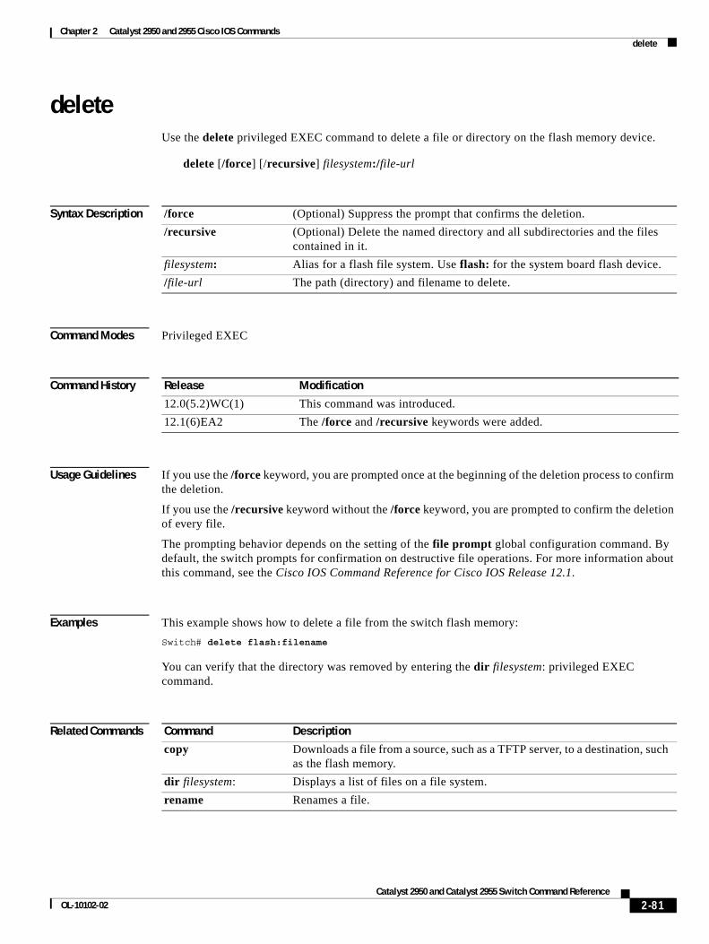
Chapter 2 Catalyst 2950 and 2955 Cisco IOS Commands delete
deleteUse the delete privileged EXEC command to delete a file or directory on the flash memory device.
delete [/force] [/recursive] filesystem:/file-url
Syntax Description
Command Modes Privileged EXEC
Command History
Usage Guidelines If you use the /force keyword, you are prompted once at the beginning of the deletion process to confirm the deletion.
If you use the /recursive keyword without the /force keyword, you are prompted to confirm the deletion of every file.
The prompting behavior depends on the setting of the file prompt global configuration command. By default, the switch prompts for confirmation on destructive file operations. For more information about this command, see the Cisco IOS Command Reference for Cisco IOS Release 12.1.
Examples This example shows how to delete a file from the switch flash memory:
Switch# delete flash:filename
You can verify that the directory was removed by entering the dir filesystem: privileged EXEC command.
Related Commands
/force (Optional) Suppress the prompt that confirms the deletion.
/recursive (Optional) Delete the named directory and all subdirectories and the files contained in it.
filesystem: Alias for a flash file system. Use flash: for the system board flash device.
/file-url The path (directory) and filename to delete.
Release Modification
12.0(5.2)WC(1) This command was introduced.
12.1(6)EA2 The /force and /recursive keywords were added.
Command Description
copy Downloads a file from a source, such as a TFTP server, to a destination, such as the flash memory.
dir filesystem: Displays a list of files on a file system.
rename Renames a file.
2-81Catalyst 2950 and Catalyst 2955 Switch Command Reference
OL-10102-02
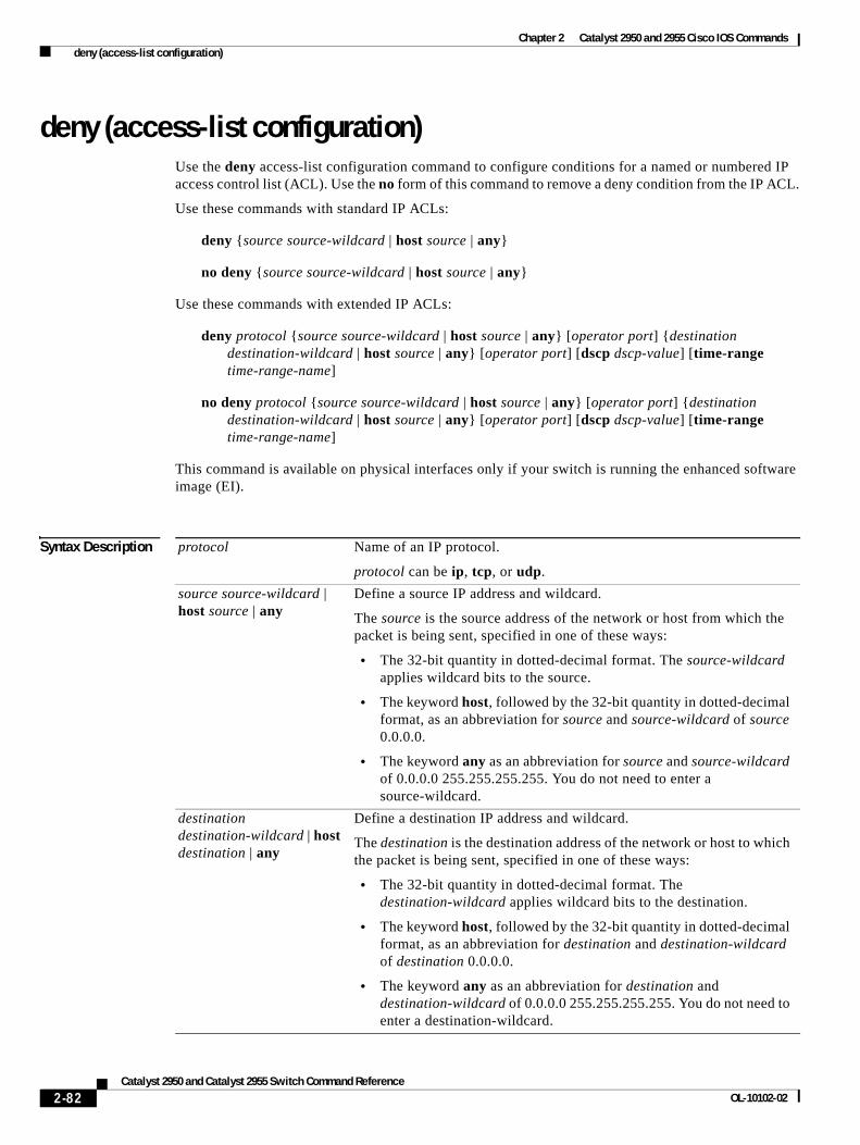
Chapter 2 Catalyst 2950 and 2955 Cisco IOS Commands deny (access-list configuration)
deny (access-list configuration)Use the deny access-list configuration command to configure conditions for a named or numbered IP access control list (ACL). Use the no form of this command to remove a deny condition from the IP ACL.
Use these commands with standard IP ACLs:
deny {source source-wildcard | host source | any}
no deny {source source-wildcard | host source | any}
Use these commands with extended IP ACLs:
deny protocol {source source-wildcard | host source | any} [operator port] {destination destination-wildcard | host source | any} [operator port] [dscp dscp-value] [time-range time-range-name]
no deny protocol {source source-wildcard | host source | any} [operator port] {destination destination-wildcard | host source | any} [operator port] [dscp dscp-value] [time-range time-range-name]
This command is available on physical interfaces only if your switch is running the enhanced software image (EI).
Syntax Description protocol Name of an IP protocol.
protocol can be ip, tcp, or udp.
source source-wildcard | host source | any
Define a source IP address and wildcard.
The source is the source address of the network or host from which the packet is being sent, specified in one of these ways:
• The 32-bit quantity in dotted-decimal format. The source-wildcard applies wildcard bits to the source.
• The keyword host, followed by the 32-bit quantity in dotted-decimal format, as an abbreviation for source and source-wildcard of source 0.0.0.0.
• The keyword any as an abbreviation for source and source-wildcard of 0.0.0.0 255.255.255.255. You do not need to enter a source-wildcard.
destination destination-wildcard | host destination | any
Define a destination IP address and wildcard.
The destination is the destination address of the network or host to which the packet is being sent, specified in one of these ways:
• The 32-bit quantity in dotted-decimal format. The destination-wildcard applies wildcard bits to the destination.
• The keyword host, followed by the 32-bit quantity in dotted-decimal format, as an abbreviation for destination and destination-wildcard of destination 0.0.0.0.
• The keyword any as an abbreviation for destination and destination-wildcard of 0.0.0.0 255.255.255.255. You do not need to enter a destination-wildcard.
2-82Catalyst 2950 and Catalyst 2955 Switch Command Reference
OL-10102-02
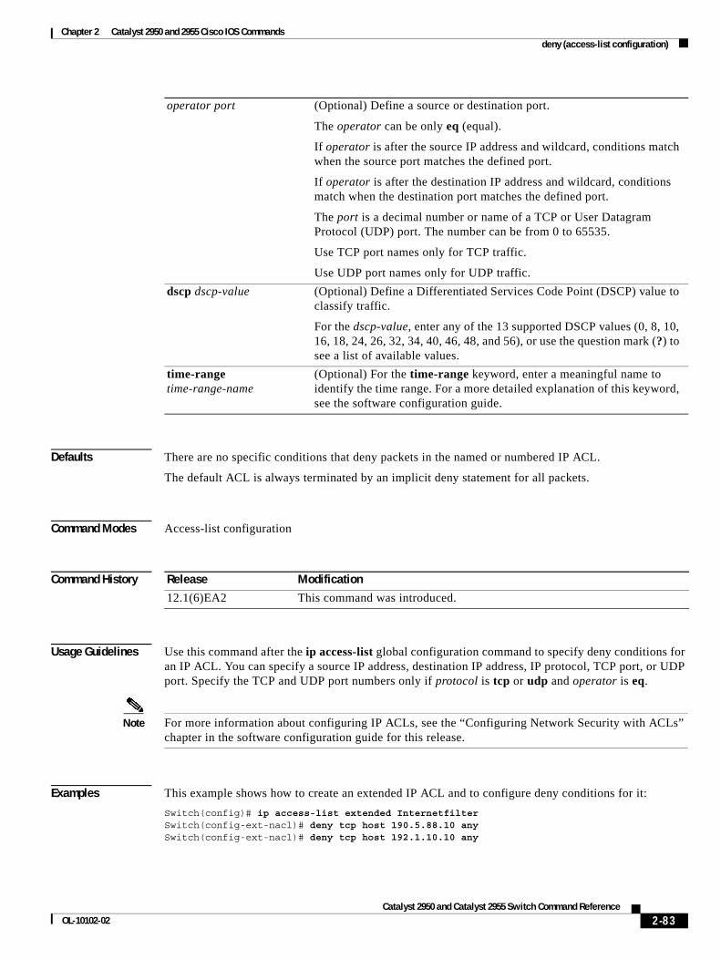
Chapter 2 Catalyst 2950 and 2955 Cisco IOS Commands deny (access-list configuration)
Defaults There are no specific conditions that deny packets in the named or numbered IP ACL.
The default ACL is always terminated by an implicit deny statement for all packets.
Command Modes Access-list configuration
Command History
Usage Guidelines Use this command after the ip access-list global configuration command to specify deny conditions for an IP ACL. You can specify a source IP address, destination IP address, IP protocol, TCP port, or UDP port. Specify the TCP and UDP port numbers only if protocol is tcp or udp and operator is eq.
Note For more information about configuring IP ACLs, see the “Configuring Network Security with ACLs” chapter in the software configuration guide for this release.
Examples This example shows how to create an extended IP ACL and to configure deny conditions for it:
Switch(config)# ip access-list extended InternetfilterSwitch(config-ext-nacl)# deny tcp host 190.5.88.10 anySwitch(config-ext-nacl)# deny tcp host 192.1.10.10 any
operator port (Optional) Define a source or destination port.
The operator can be only eq (equal).
If operator is after the source IP address and wildcard, conditions match when the source port matches the defined port.
If operator is after the destination IP address and wildcard, conditions match when the destination port matches the defined port.
The port is a decimal number or name of a TCP or User Datagram Protocol (UDP) port. The number can be from 0 to 65535.
Use TCP port names only for TCP traffic.
Use UDP port names only for UDP traffic.
dscp dscp-value (Optional) Define a Differentiated Services Code Point (DSCP) value to classify traffic.
For the dscp-value, enter any of the 13 supported DSCP values (0, 8, 10, 16, 18, 24, 26, 32, 34, 40, 46, 48, and 56), or use the question mark (?) to see a list of available values.
time-range time-range-name
(Optional) For the time-range keyword, enter a meaningful name to identify the time range. For a more detailed explanation of this keyword, see the software configuration guide.
Release Modification
12.1(6)EA2 This command was introduced.
2-83Catalyst 2950 and Catalyst 2955 Switch Command Reference
OL-10102-02
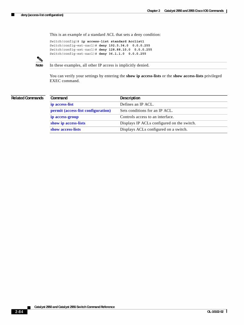
Chapter 2 Catalyst 2950 and 2955 Cisco IOS Commands deny (access-list configuration)
This is an example of a standard ACL that sets a deny condition:
Switch(config)# ip access-list standard Acclist1Switch(config-ext-nacl)# deny 192.5.34.0 0.0.0.255Switch(config-ext-nacl)# deny 128.88.10.0 0.0.0.255Switch(config-ext-nacl)# deny 36.1.1.0 0.0.0.255
Note In these examples, all other IP access is implicitly denied.
You can verify your settings by entering the show ip access-lists or the show access-lists privileged EXEC command.
Related Commands Command Description
ip access-list Defines an IP ACL.
permit (access-list configuration) Sets conditions for an IP ACL.
ip access-group Controls access to an interface.
show ip access-lists Displays IP ACLs configured on the switch.
show access-lists Displays ACLs configured on a switch.
2-84Catalyst 2950 and Catalyst 2955 Switch Command Reference
OL-10102-02
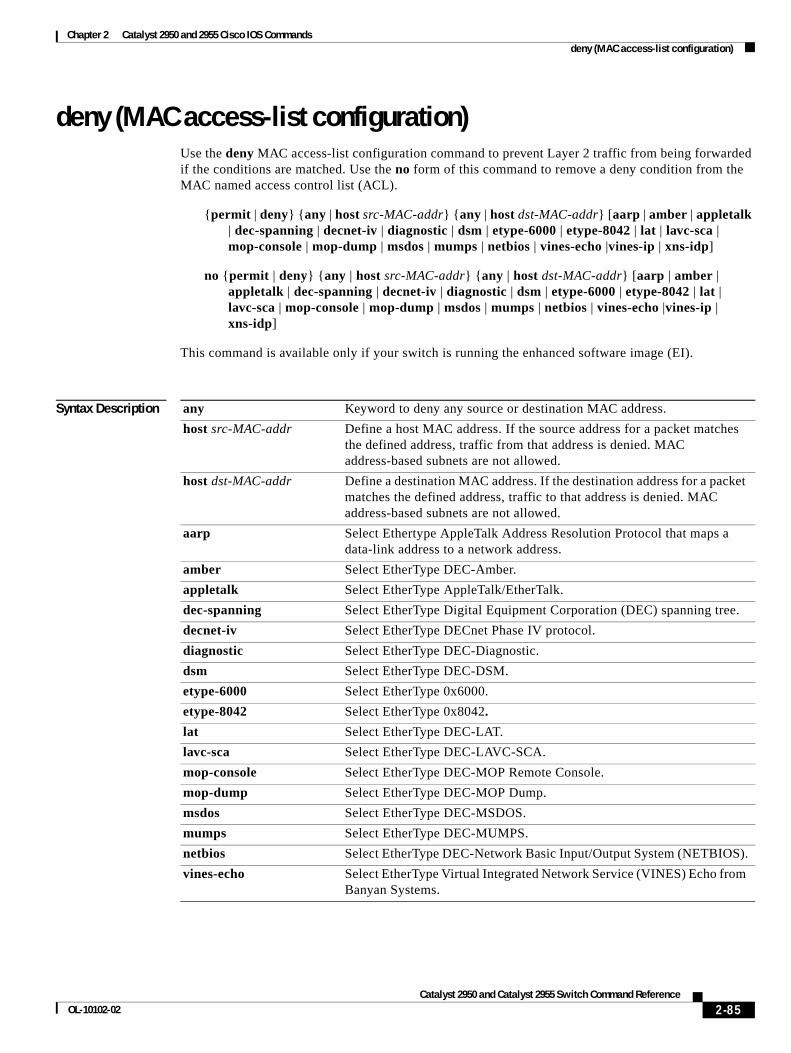
Chapter 2 Catalyst 2950 and 2955 Cisco IOS Commands deny (MAC access-list configuration)
deny (MAC access-list configuration)Use the deny MAC access-list configuration command to prevent Layer 2 traffic from being forwarded if the conditions are matched. Use the no form of this command to remove a deny condition from the MAC named access control list (ACL).
{permit | deny} {any | host src-MAC-addr} {any | host dst-MAC-addr} [aarp | amber | appletalk | dec-spanning | decnet-iv | diagnostic | dsm | etype-6000 | etype-8042 | lat | lavc-sca | mop-console | mop-dump | msdos | mumps | netbios | vines-echo |vines-ip | xns-idp]
no {permit | deny} {any | host src-MAC-addr} {any | host dst-MAC-addr} [aarp | amber | appletalk | dec-spanning | decnet-iv | diagnostic | dsm | etype-6000 | etype-8042 | lat | lavc-sca | mop-console | mop-dump | msdos | mumps | netbios | vines-echo |vines-ip | xns-idp]
This command is available only if your switch is running the enhanced software image (EI).
Syntax Description any Keyword to deny any source or destination MAC address.
host src-MAC-addr Define a host MAC address. If the source address for a packet matches the defined address, traffic from that address is denied. MAC address-based subnets are not allowed.
host dst-MAC-addr Define a destination MAC address. If the destination address for a packet matches the defined address, traffic to that address is denied. MAC address-based subnets are not allowed.
aarp Select Ethertype AppleTalk Address Resolution Protocol that maps a data-link address to a network address.
amber Select EtherType DEC-Amber.
appletalk Select EtherType AppleTalk/EtherTalk.
dec-spanning Select EtherType Digital Equipment Corporation (DEC) spanning tree.
decnet-iv Select EtherType DECnet Phase IV protocol.
diagnostic Select EtherType DEC-Diagnostic.
dsm Select EtherType DEC-DSM.
etype-6000 Select EtherType 0x6000.
etype-8042 Select EtherType 0x8042.
lat Select EtherType DEC-LAT.
lavc-sca Select EtherType DEC-LAVC-SCA.
mop-console Select EtherType DEC-MOP Remote Console.
mop-dump Select EtherType DEC-MOP Dump.
msdos Select EtherType DEC-MSDOS.
mumps Select EtherType DEC-MUMPS.
netbios Select EtherType DEC-Network Basic Input/Output System (NETBIOS).
vines-echo Select EtherType Virtual Integrated Network Service (VINES) Echo from Banyan Systems.
2-85Catalyst 2950 and Catalyst 2955 Switch Command Reference
OL-10102-02
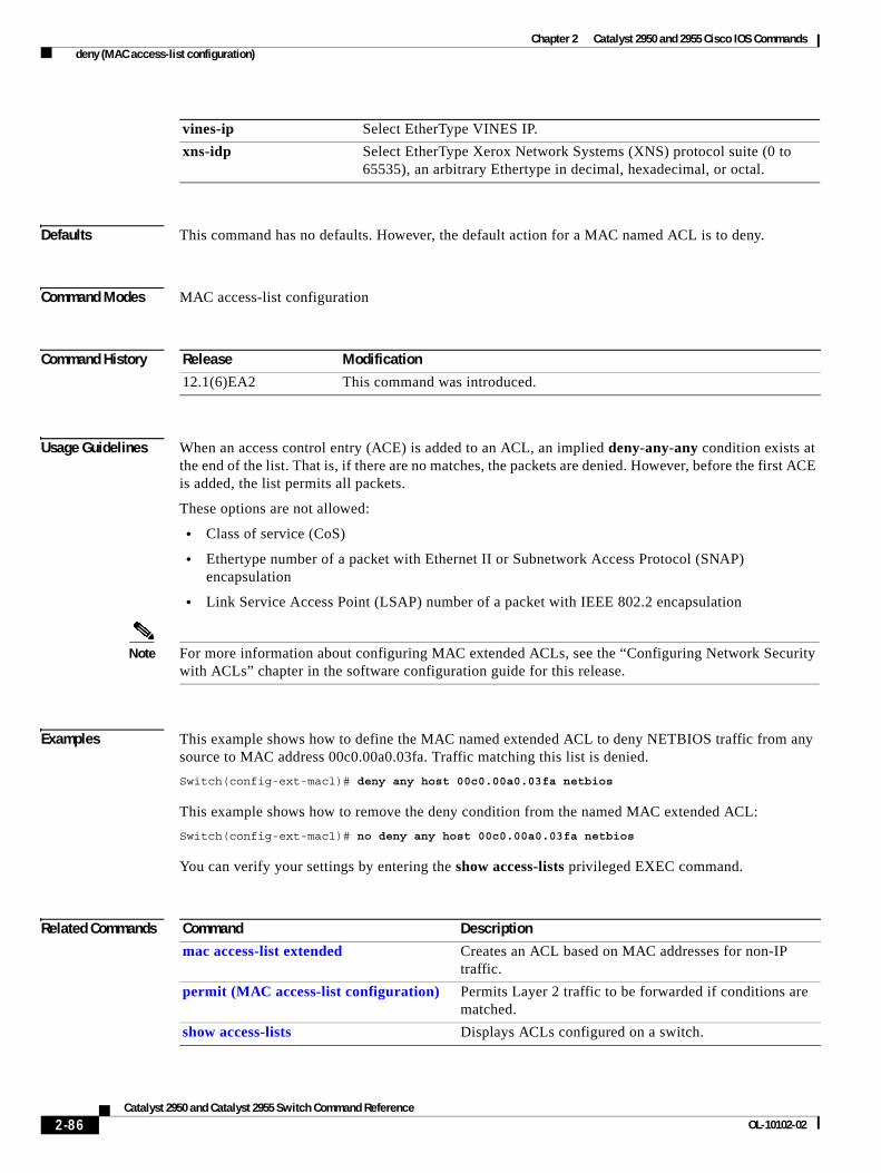
Chapter 2 Catalyst 2950 and 2955 Cisco IOS Commands deny (MAC access-list configuration)
Defaults This command has no defaults. However, the default action for a MAC named ACL is to deny.
Command Modes MAC access-list configuration
Command History
Usage Guidelines When an access control entry (ACE) is added to an ACL, an implied deny-any-any condition exists at the end of the list. That is, if there are no matches, the packets are denied. However, before the first ACE is added, the list permits all packets.
These options are not allowed:
• Class of service (CoS)
• Ethertype number of a packet with Ethernet II or Subnetwork Access Protocol (SNAP) encapsulation
• Link Service Access Point (LSAP) number of a packet with IEEE 802.2 encapsulation
Note For more information about configuring MAC extended ACLs, see the “Configuring Network Security with ACLs” chapter in the software configuration guide for this release.
Examples This example shows how to define the MAC named extended ACL to deny NETBIOS traffic from any source to MAC address 00c0.00a0.03fa. Traffic matching this list is denied.
Switch(config-ext-macl)# deny any host 00c0.00a0.03fa netbios
This example shows how to remove the deny condition from the named MAC extended ACL:
Switch(config-ext-macl)# no deny any host 00c0.00a0.03fa netbios
You can verify your settings by entering the show access-lists privileged EXEC command.
Related Commands
vines-ip Select EtherType VINES IP.
xns-idp Select EtherType Xerox Network Systems (XNS) protocol suite (0 to 65535), an arbitrary Ethertype in decimal, hexadecimal, or octal.
Release Modification
12.1(6)EA2 This command was introduced.
Command Description
mac access-list extended Creates an ACL based on MAC addresses for non-IP traffic.
permit (MAC access-list configuration) Permits Layer 2 traffic to be forwarded if conditions are matched.
show access-lists Displays ACLs configured on a switch.
2-86Catalyst 2950 and Catalyst 2955 Switch Command Reference
OL-10102-02
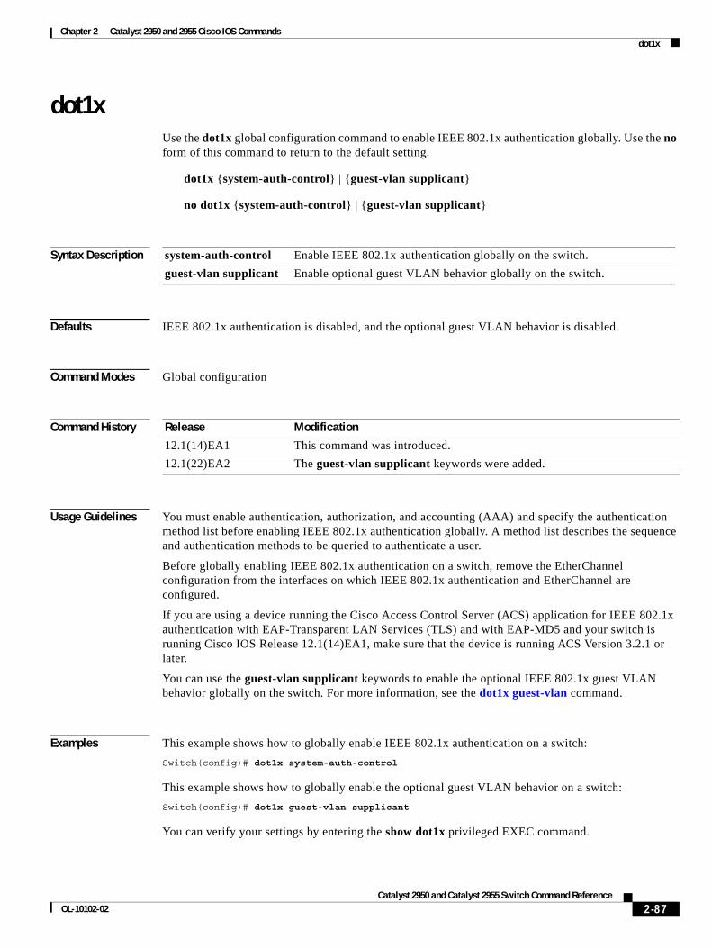
Chapter 2 Catalyst 2950 and 2955 Cisco IOS Commands dot1x
dot1xUse the dot1x global configuration command to enable IEEE 802.1x authentication globally. Use the no form of this command to return to the default setting.
dot1x {system-auth-control} | {guest-vlan supplicant}
no dot1x {system-auth-control} | {guest-vlan supplicant}
Syntax Description
Defaults IEEE 802.1x authentication is disabled, and the optional guest VLAN behavior is disabled.
Command Modes Global configuration
Command History
Usage Guidelines You must enable authentication, authorization, and accounting (AAA) and specify the authentication method list before enabling IEEE 802.1x authentication globally. A method list describes the sequence and authentication methods to be queried to authenticate a user.
Before globally enabling IEEE 802.1x authentication on a switch, remove the EtherChannel configuration from the interfaces on which IEEE 802.1x authentication and EtherChannel are configured.
If you are using a device running the Cisco Access Control Server (ACS) application for IEEE 802.1x authentication with EAP-Transparent LAN Services (TLS) and with EAP-MD5 and your switch is running Cisco IOS Release 12.1(14)EA1, make sure that the device is running ACS Version 3.2.1 or later.
You can use the guest-vlan supplicant keywords to enable the optional IEEE 802.1x guest VLAN behavior globally on the switch. For more information, see the dot1x guest-vlan command.
Examples This example shows how to globally enable IEEE 802.1x authentication on a switch:
Switch(config)# dot1x system-auth-control
This example shows how to globally enable the optional guest VLAN behavior on a switch:
Switch(config)# dot1x guest-vlan supplicant
You can verify your settings by entering the show dot1x privileged EXEC command.
system-auth-control Enable IEEE 802.1x authentication globally on the switch.
guest-vlan supplicant Enable optional guest VLAN behavior globally on the switch.
Release Modification
12.1(14)EA1 This command was introduced.
12.1(22)EA2 The guest-vlan supplicant keywords were added.
2-87Catalyst 2950 and Catalyst 2955 Switch Command Reference
OL-10102-02
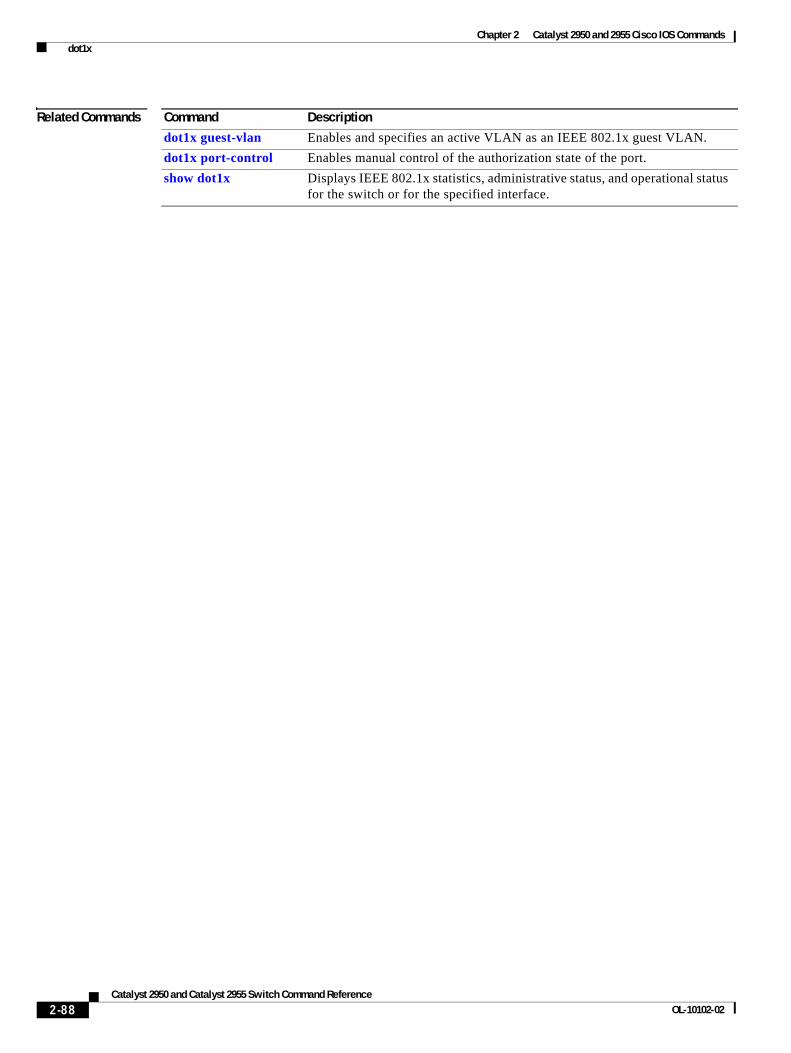
Chapter 2 Catalyst 2950 and 2955 Cisco IOS Commands dot1x
Related Commands Command Description
dot1x guest-vlan Enables and specifies an active VLAN as an IEEE 802.1x guest VLAN.
dot1x port-control Enables manual control of the authorization state of the port.
show dot1x Displays IEEE 802.1x statistics, administrative status, and operational status for the switch or for the specified interface.
2-88Catalyst 2950 and Catalyst 2955 Switch Command Reference
OL-10102-02
Chapter 2 Catalyst 2950 and 2955 Cisco IOS Commands dot1x auth-fail max-attempts
dot1x auth-fail max-attemptsUse the dot1x auth-fail max-attempts interface configuration command to configure the maximum number of authentication attempts allowed before a port is moved to the restricted VLAN. To return to the default setting, use the no form of this command.
dot1x auth-fail max-attempts max-attempts
no dot1x auth-fail max-attempts
Syntax Description
Defaults The default is 3 attempts.
Command Modes Interface configuration
Command History
Usage Guidelines If you reconfigure the maximum number of authentication failures allowed by the VLAN, the change takes effect after the re-authentication timer expires.
Examples This example shows how to set 2 as the maximum number of authentication attempts allowed before the port is moved to the restricted VLAN on Gigabit Ethernet interface 1:
Switch# configure terminal Enter configuration commands, one per line. End with CNTL/Z.Switch(config)# interface gigabitethernet0/1Switch(config-if)# dot1x auth-fail max-attempts 2Switch(config-if)# endSwitch(config)# endSwitch#
You can verify your settings by entering the show dot1x [interface interface-id] privileged EXEC command.
Related Commands
max-attempts Specify a maximum number of authentication attempts allowed before a port is moved to the restricted VLAN. The range is 1 to 3.
Release Modification
12.1(22)EA7 This command was introduced.
Command Description
dot1x auth-fail vlan [vlan id] Enables the optional restricted VLAN feature.
show dot1x [interface interface-id] Displays IEEE 802.1x status for the specified port.
2-89Catalyst 2950 and Catalyst 2955 Switch Command Reference
OL-10102-02
Chapter 2 Catalyst 2950 and 2955 Cisco IOS Commands dot1x auth-fail vlan
dot1x auth-fail vlan Use the dot1x auth-fail vlan interface configuration command to enable the restricted VLAN on a port. To return to the default setting, use the no form of this command.
dot1x auth-fail vlan vlan-id
no dot1x auth-fail vlan vlan-id
Syntax Description
Defaults No restricted VLAN is configured.
Command Modes Interface configuration
Command History
Usage Guidelines You can configure a restricted VLAN on ports configured as follows:
• single-host (default) mode only
• auto mode for authorization
You should enable re-authentication. The ports in restricted VLANs do not receive re-authentication requests if re-authentication is disabled. To start the re-authentication process, the restricted VLAN must receive a link down event or an Extensible Authentication Protocol (EAP) logoff event from the port. If the host is connected through a hub, the port might never receive a link down event and might not detect the new host until the next re-authentication attempt occurs. Therefore, re-authentication should be enabled.
If the user fails authentication, the port is moved to a restricted VLAN, and an EAP success message is sent to the user. Because the user is not notified of the authentication failure, there might be confusion as to why there is restricted access to the network. An EAP success message is sent for these reasons:
• If the EAP success message is not sent, the user tries to authenticate every 60 seconds (the default) by sending an EAP-start message.
• Some hosts (for example, devices running Windows XP) cannot implement DHCP until they receive an EAP success message.
A user might cache an incorrect username and password combination after receiving an EAP success message from the authenticator and re-use that information in every re-authentication. Until the user passes the correct username and password combination, the port remains in the restricted VLAN.
Internal VLANs that are used for Layer 3 ports cannot be configured as a restricted VLAN.
You cannot configure a VLAN to be both a restricted VLAN and a voice VLAN. If you do this, a syslog message appears.
vlan-id Specify a VLAN in the range of 1 to 4094.
Release Modification
12.1(22)EA7 This command was introduced.
2-90Catalyst 2950 and Catalyst 2955 Switch Command Reference
OL-10102-02
Chapter 2 Catalyst 2950 and 2955 Cisco IOS Commands dot1x auth-fail vlan
When a restricted VLAN port is moved to an unauthorized state, the authentication process is restarted. If the user fails the authentication process again, the authenticator waits in the held state. After the user has correctly re-authenticated, all IEEE 802.1x ports are reinitialized and treated as normal IEEE 802.1x ports.
When you reconfigure a restricted VLAN to a different VLAN, any ports in the restricted VLAN are also moved, and the ports stay in their current authorized state.
When you shut down or remove a restricted VLAN from the VLAN database, any ports in the restricted VLAN are immediately moved to an unauthorized state, and the authentication process is restarted. The authenticator does not wait in a held state because the restricted VLAN configuration still exists. While the restricted VLAN is inactive, all authentication attempts are counted. As soon as the restricted VLAN becomes active, the port is placed in the restricted VLAN.
The restricted VLAN is supported only in single-host mode (the default port mode).
When a port is placed in a restricted VLAN, the user’s MAC address is added to the MAC address table. If a new MAC address appears on the port, it is treated as a security violation.
Examples This example shows how to configure a restricted VLAN on Gigabit Ethernet interface 1:
Switch# configure terminal Enter configuration commands, one per line. End with CNTL/Z.Switch(config)# interface gigabitethernet0/1Switch(config-if)# dot1x auth-fail vlan 40Switch(config-if)# endSwitch(config)# endSwitch#
You can verify your configuration by entering the show dot1x [interface interface-id] privileged EXEC command.
Related Commands Command Description
dot1x auth-fail max-attempts [max-attempts]
Configures the number of authentication attempts allowed before assigning a user to the restricted VLAN.
show dot1x [interface interface-id] Displays IEEE 802.1x status for the specified port.
2-91Catalyst 2950 and Catalyst 2955 Switch Command Reference
OL-10102-02
Chapter 2 Catalyst 2950 and 2955 Cisco IOS Commands dot1x control-direction
dot1x control-directionUse the dot1x control-direction command to change the port to unidirectional or bidirectional control.
dot1x control-direction {in | both}
no dot1x control-direction {in | both}
Syntax Description
Command Default The port is set to bidirectional mode.
Command Modes Interface configuration
Command History
Usage Guidelines Using the keyword both or using the no form of this command are the same command.
The keyword both and the no form of the command change the port to its bidirectional default setting.
Examples This example shows how to enable unidirectional control:
Switch(config-if)# dot1x control-direction in
These examples show how to enable bidirectional control:
Switch(config-if)# dot1x control-direction bothSwitch(config-if)# no dot1x control-direction
You can verify your settings by entering the show dot1x all privileged EXEC command.
The show dot1x all privileged EXEC command output is the same for all switches except for the port names and the state of the port. If a host is attached to the port but is not yet authenticated, a display similar to this appears:
Supplicant MAC 0002.b39a.9275AuthSM State = CONNECTINGBendSM State = IDLEPortStatus = UNAUTHORIZED
dot1x control-direction in Enable unidirectional control on port.
dot1x control-direction both Enable bidirectional control on port.
Release Modification
12.1(22)EA6 This command was introduced.
2-92Catalyst 2950 and Catalyst 2955 Switch Command Reference
OL-10102-02
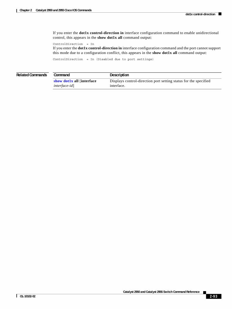
Chapter 2 Catalyst 2950 and 2955 Cisco IOS Commands dot1x control-direction
If you enter the dot1x control-direction in interface configuration command to enable unidirectional control, this appears in the show dot1x all command output:
ControlDirection = In
If you enter the dot1x control-direction in interface configuration command and the port cannot support this mode due to a configuration conflict, this appears in the show dot1x all command output:
ControlDirection = In (Disabled due to port settings)
Related Commands Command Description
show dot1x all [interface interface-id]
Displays control-direction port setting status for the specified interface.
2-93Catalyst 2950 and Catalyst 2955 Switch Command Reference
OL-10102-02
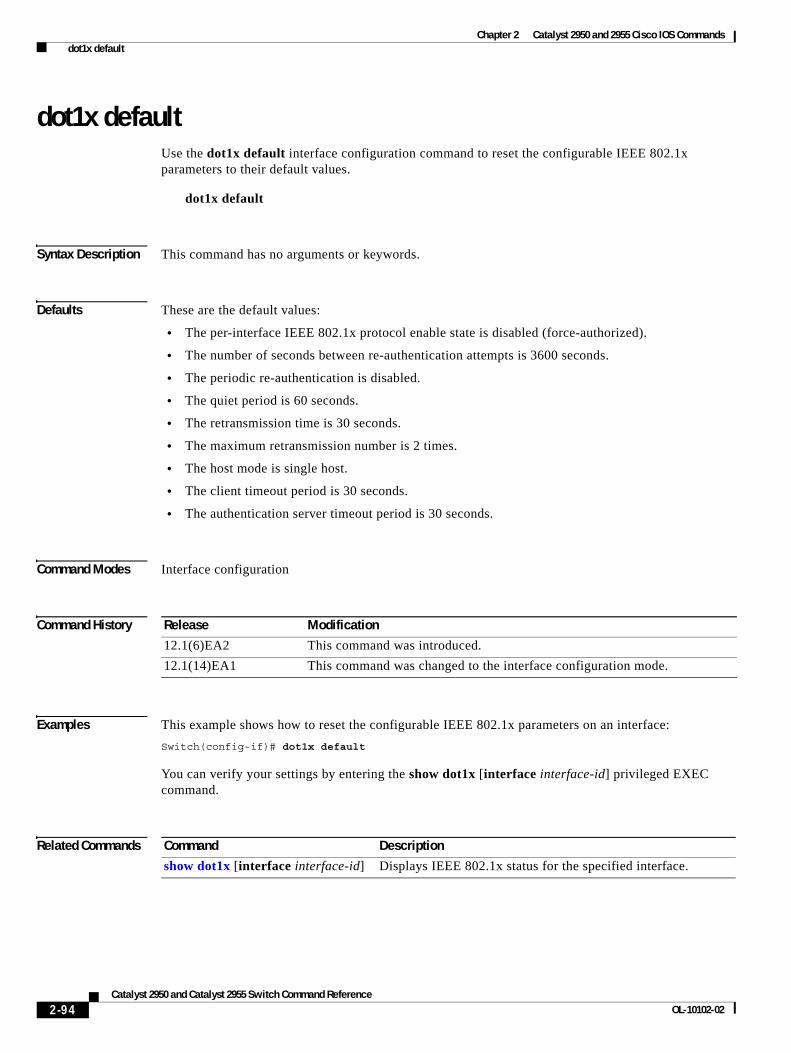
Chapter 2 Catalyst 2950 and 2955 Cisco IOS Commands dot1x default
dot1x defaultUse the dot1x default interface configuration command to reset the configurable IEEE 802.1x parameters to their default values.
dot1x default
Syntax Description This command has no arguments or keywords.
Defaults These are the default values:
• The per-interface IEEE 802.1x protocol enable state is disabled (force-authorized).
• The number of seconds between re-authentication attempts is 3600 seconds.
• The periodic re-authentication is disabled.
• The quiet period is 60 seconds.
• The retransmission time is 30 seconds.
• The maximum retransmission number is 2 times.
• The host mode is single host.
• The client timeout period is 30 seconds.
• The authentication server timeout period is 30 seconds.
Command Modes Interface configuration
Command History
Examples This example shows how to reset the configurable IEEE 802.1x parameters on an interface:
Switch(config-if)# dot1x default
You can verify your settings by entering the show dot1x [interface interface-id] privileged EXEC command.
Related Commands
Release Modification
12.1(6)EA2 This command was introduced.
12.1(14)EA1 This command was changed to the interface configuration mode.
Command Description
show dot1x [interface interface-id] Displays IEEE 802.1x status for the specified interface.
2-94Catalyst 2950 and Catalyst 2955 Switch Command Reference
OL-10102-02
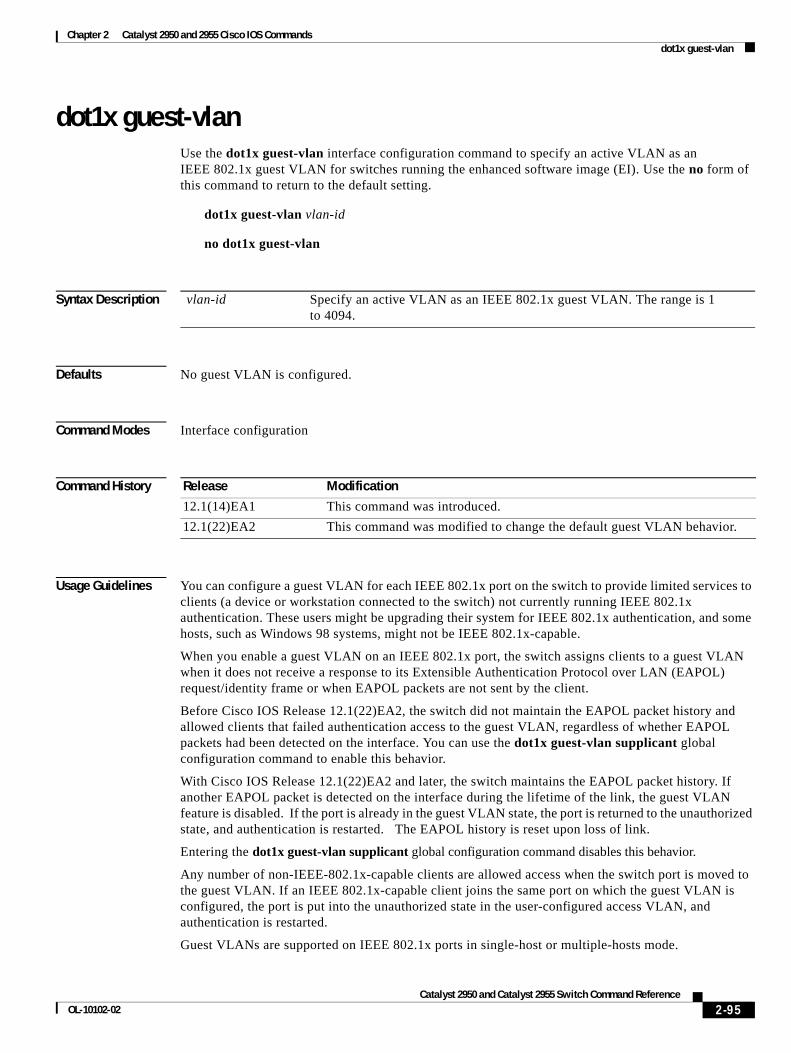
Chapter 2 Catalyst 2950 and 2955 Cisco IOS Commands dot1x guest-vlan
dot1x guest-vlanUse the dot1x guest-vlan interface configuration command to specify an active VLAN as an IEEE 802.1x guest VLAN for switches running the enhanced software image (EI). Use the no form of this command to return to the default setting.
dot1x guest-vlan vlan-id
no dot1x guest-vlan
Syntax Description
Defaults No guest VLAN is configured.
Command Modes Interface configuration
Command History
Usage Guidelines You can configure a guest VLAN for each IEEE 802.1x port on the switch to provide limited services to clients (a device or workstation connected to the switch) not currently running IEEE 802.1x authentication. These users might be upgrading their system for IEEE 802.1x authentication, and some hosts, such as Windows 98 systems, might not be IEEE 802.1x-capable.
When you enable a guest VLAN on an IEEE 802.1x port, the switch assigns clients to a guest VLAN when it does not receive a response to its Extensible Authentication Protocol over LAN (EAPOL) request/identity frame or when EAPOL packets are not sent by the client.
Before Cisco IOS Release 12.1(22)EA2, the switch did not maintain the EAPOL packet history and allowed clients that failed authentication access to the guest VLAN, regardless of whether EAPOL packets had been detected on the interface. You can use the dot1x guest-vlan supplicant global configuration command to enable this behavior.
With Cisco IOS Release 12.1(22)EA2 and later, the switch maintains the EAPOL packet history. If another EAPOL packet is detected on the interface during the lifetime of the link, the guest VLAN feature is disabled. If the port is already in the guest VLAN state, the port is returned to the unauthorized state, and authentication is restarted. The EAPOL history is reset upon loss of link.
Entering the dot1x guest-vlan supplicant global configuration command disables this behavior.
Any number of non-IEEE-802.1x-capable clients are allowed access when the switch port is moved to the guest VLAN. If an IEEE 802.1x-capable client joins the same port on which the guest VLAN is configured, the port is put into the unauthorized state in the user-configured access VLAN, and authentication is restarted.
Guest VLANs are supported on IEEE 802.1x ports in single-host or multiple-hosts mode.
vlan-id Specify an active VLAN as an IEEE 802.1x guest VLAN. The range is 1 to 4094.
Release Modification
12.1(14)EA1 This command was introduced.
12.1(22)EA2 This command was modified to change the default guest VLAN behavior.
2-95Catalyst 2950 and Catalyst 2955 Switch Command Reference
OL-10102-02
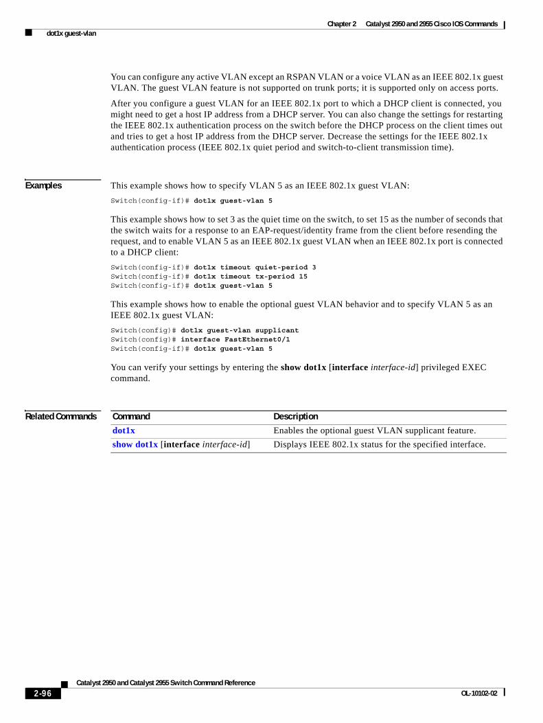
Chapter 2 Catalyst 2950 and 2955 Cisco IOS Commands dot1x guest-vlan
You can configure any active VLAN except an RSPAN VLAN or a voice VLAN as an IEEE 802.1x guest VLAN. The guest VLAN feature is not supported on trunk ports; it is supported only on access ports.
After you configure a guest VLAN for an IEEE 802.1x port to which a DHCP client is connected, you might need to get a host IP address from a DHCP server. You can also change the settings for restarting the IEEE 802.1x authentication process on the switch before the DHCP process on the client times out and tries to get a host IP address from the DHCP server. Decrease the settings for the IEEE 802.1x authentication process (IEEE 802.1x quiet period and switch-to-client transmission time).
Examples This example shows how to specify VLAN 5 as an IEEE 802.1x guest VLAN:
Switch(config-if)# dot1x guest-vlan 5
This example shows how to set 3 as the quiet time on the switch, to set 15 as the number of seconds that the switch waits for a response to an EAP-request/identity frame from the client before resending the request, and to enable VLAN 5 as an IEEE 802.1x guest VLAN when an IEEE 802.1x port is connected to a DHCP client:
Switch(config-if)# dot1x timeout quiet-period 3Switch(config-if)# dot1x timeout tx-period 15Switch(config-if)# dot1x guest-vlan 5
This example shows how to enable the optional guest VLAN behavior and to specify VLAN 5 as an IEEE 802.1x guest VLAN:
Switch(config)# dot1x guest-vlan supplicantSwitch(config)# interface FastEthernet0/1Switch(config-if)# dot1x guest-vlan 5
You can verify your settings by entering the show dot1x [interface interface-id] privileged EXEC command.
Related Commands Command Description
dot1x Enables the optional guest VLAN supplicant feature.
show dot1x [interface interface-id] Displays IEEE 802.1x status for the specified interface.
2-96Catalyst 2950 and Catalyst 2955 Switch Command Reference
OL-10102-02
Chapter 2 Catalyst 2950 and 2955 Cisco IOS Commands dot1x host-mode
dot1x host-modeUse the dot1x host-mode interface configuration command to allow a single host (client) or multiple hosts on an IEEE 802.1x-authorized port that has the dot1x port-control interface configuration command set to auto. Use the no form of this command to return to the default setting.
dot1x host-mode {multi-host | single-host}
no dot1x host-mode [multi-host | single-host]
Syntax Description
Defaults The default is single-host mode.
Command Modes Interface configuration
Command History
Usage Guidelines You can use this command to limit an IEEE 802.1x-enabled port to a single client or to attach multiple clients to an IEEE 802.1x-enabled port. In multiple-hosts mode, only one of the attached hosts must be successfully authorized for all hosts to be granted network access. If the port becomes unauthorized (re-authentication fails, or an Extensible Authentication Protocol over LAN [EAPOL]-logoff message is received), all attached clients are denied access to the network.
Before entering this command, make sure that the dot1x port-control interface configuration command is set to auto for the specified interface.
Examples This example shows how to enable IEEE 802.1x authentication globally, enable IEEE 802.1x authentication on an interface, and enable multiple-hosts mode:
Switch(config)# dot1x system-auth-controlSwitch(config)# interface fastethernet0/1Switch(config-if)# dot1x port-control autoSwitch(config-if)# dot1x host-mode multi-host
You can verify your settings by entering the show dot1x [interface interface-id] privileged EXEC command.
Related Commands
multi-host Enable multiple-hosts mode on the switch.
single-host Enable single-host mode on the switch.
Release Modification
12.1(14)EA1 This command was introduced. It replaces the dot1x multiple-hosts interface configuration command.
Command Description
show dot1x [interface interface-id] Displays IEEE 802.1x status for the specified interface.
2-97Catalyst 2950 and Catalyst 2955 Switch Command Reference
OL-10102-02
Chapter 2 Catalyst 2950 and 2955 Cisco IOS Commands dot1x initialize
dot1x initializeUse the dot1x initialize privileged EXEC command to manually return an IEEE 802.1x-enabled port to an unauthorized state before initiating a new authentication session on the interface.
dot1x initialize interface interface-id
Syntax Description This command has no arguments or keywords.
Defaults There is no default setting.
Command Modes Privileged EXEC
Command History
Usage Guidelines Use this command to manually return a device connected to a switch interface to an unauthorized state before initiating a new authentication session on the interface.
Examples This example shows how to manually return a device connected to a port to an unauthorized state:
Switch# dot1x initialize interface fastethernet0/1
You can verify your settings by entering the show dot1x [interface interface-id] privileged EXEC command.
Related Commands
Release Modification
12.1(14)EA1 This command was introduced.
Command Description
show dot1x [interface interface-id] Displays IEEE 802.1x status for the specified interface.
2-98Catalyst 2950 and Catalyst 2955 Switch Command Reference
OL-10102-02
Chapter 2 Catalyst 2950 and 2955 Cisco IOS Commands dot1x max-req
dot1x max-reqUse the dot1x max-req interface configuration command to set the maximum number of times that the switch sends an Extensible Authentication Protocol (EAP) frame from the authentication server (assuming that no response is received) to the client before restarting the authentication process. Use the no form of this command to return to the default setting.
dot1x max-req count
no dot1x max-req
Syntax Description
Defaults The default is 2.
Command Modes Interface configuration
Command History
Usage Guidelines You should change the default value of this command only to adjust for unusual circumstances such as unreliable links or specific behavioral problems with certain clients and authentication servers.
Examples This example shows how to set 5 as the number of times that the switch sends an EAP frame before restarting the authentication process:
Switch(config-if)# dot1x max-req 5
You can verify your settings by entering the show dot1x [interface interface-id] privileged EXEC command.
Related Commands
count Number of times that the switch sends an EAP frame from the authentication server before restarting the authentication process. The range is 1 to 10.
Release Modification
12.1(6)EA2 This command was introduced.
12.1(14)EA1 This command was changed to the interface configuration mode.
Command Description
dot1x timeout Sets the number of seconds that the switch waits for a response to an EAP-request/identity frame from the client before resending the request.
show dot1x [interface interface-id]
Displays IEEE 802.1x status for the specified interface.
2-99Catalyst 2950 and Catalyst 2955 Switch Command Reference
OL-10102-02
Chapter 2 Catalyst 2950 and 2955 Cisco IOS Commands dot1x multiple-hosts
dot1x multiple-hostsThis is an obsolete command.
In past releases, the dot1x multiple-hosts interface configuration command was used to allow multiple hosts (clients) on an IEEE 802.1x-authorized port.
Command History
Related Commands
Release Modification
12.1(6)EA2 This command was introduced.
12.1(14)EA1 The dot1x multiple-hosts interface configuration command was replaced by the dot1x host-mode interface configuration command.
Command Description
dot1x host-mode Set the IEEE 802.1x host mode on an interface.
show dot1x Displays IEEE 802.1x statistics, administrative status, and operational status for the switch or for the specified interface.
2-100Catalyst 2950 and Catalyst 2955 Switch Command Reference
OL-10102-02
Chapter 2 Catalyst 2950 and 2955 Cisco IOS Commands dot1x port-control
dot1x port-controlUse the dot1x port-control interface configuration command to enable manual control of the authorization state of the port. Use the no form of this command to return to the default setting.
dot1x port-control {auto | force-authorized | force-unauthorized}
no dot1x port-control
Syntax Description
Defaults The default is force-authorized.
Command Modes Interface configuration
Command History
Usage Guidelines You must enable IEEE 802.1x authentication globally on the switch by using the dot1x system-auth-control global configuration command before enabling IEEE 802.1x authentication on a specific interface.
The IEEE 802.1x protocol is supported on Layer 2 static-access ports.
You can use the auto keyword only if the port is not configured as one of these:
• Trunk port—If you try to enable IEEE 802.1x authentication on a trunk port, an error message appears, and IEEE 802.1x is not enabled. If you try to change the mode of an IEEE 802.1x-enabled port to trunk, the port mode is not changed.
• Dynamic ports—A port in dynamic mode can negotiate with its neighbor to become a trunk port. If you try to enable IEEE 802.1x authentication on a dynamic port, an error message appears, and IEEE 802.1x authentication is not enabled. If you try to change the mode of an IEEE 802.1x-enabled port to dynamic, the port mode is not changed.
auto Enable IEEE 802.1x authentication on the interface and cause the port to transition to the authorized or unauthorized state based on the IEEE 802.1x authentication exchange between the switch and the client.
force-authorized Disable IEEE 802.1x authentication on the interface and cause the port to transition to the authorized state without any authentication exchange required. The port sends and receives normal traffic without IEEE 802.1x-based authentication of the client.
force-unauthorized Deny all access through this interface by forcing the port to transition to the unauthorized state, ignoring all attempts by the client to authenticate. The switch cannot provide authentication services to the client through the interface.
Release Modification
12.1(6)EA2 This command was introduced.
2-101Catalyst 2950 and Catalyst 2955 Switch Command Reference
OL-10102-02
Chapter 2 Catalyst 2950 and 2955 Cisco IOS Commands dot1x port-control
• Dynamic-access ports—If you try to enable IEEE 802.1x authentication on a dynamic-access (VLAN Query Protocol [VQP]) port, an error message appears, and IEEE 802.1x authentication is not enabled. If you try to change an IEEE 802.1x-enabled port to dynamic VLAN assignment, an error message appears, and the VLAN configuration is not changed.
• EtherChannel port—Do not configure a port that is an active or a not-yet-active member of an EtherChannel as an IEEE 802.1x port. If you try to enable IEEE 802.1x authentication on an EtherChannel port, an error message appears, and IEEE 802.1x authentication is not enabled.
• Switched Port Analyzer (SPAN) destination port—You can enable IEEE 802.1x authentication on a SPAN source port but not on a SPAN destination port.
To disable IEEE 802.1x authentication globally on the switch, use the no dot1x system-auth-control global configuration command. To disable IEEE 802.1x authentication on a specific interface, use the no dot1x port-control interface configuration command.
Examples This example shows how to enable IEEE 802.1x authentication on an interface:
Switch(config)# interface fastethernet0/1Switch(config-if)# dot1x port-control auto
You can verify your settings by entering the show dot1x [interface interface-id] privileged EXEC command.
Related Commands Command Description
show dot1x [interface interface-id] Displays IEEE 802.1x status for the specified interface.
2-102Catalyst 2950 and Catalyst 2955 Switch Command Reference
OL-10102-02
Chapter 2 Catalyst 2950 and 2955 Cisco IOS Commands dot1x re-authenticate
dot1x re-authenticate Use the dot1x re-authenticate privileged EXEC command to manually initiate a re-authentication of the IEEE 802.1x-enabled port.
dot1x re-authenticate {interface interface-id}
Syntax Description
Defaults There is no default setting.
Command Modes Privileged EXEC
Command History
Usage Guidelines You can use this command to re-authenticate a client without waiting for the configured number of seconds between re-authentication attempts (re-authperiod) and automatic re-authentication.
Examples This example shows how to manually re-authenticate the device connected to an interface:
Switch# dot1x re-authenticate interface fastethernet0/1
Related Commands
interface interface-id Slot and port number of the interface to re-authenticate.
Release Modification
12.1(6)EA2 This command was introduced.
Command Description
show dot1x Displays IEEE 802.1x statistics, administrative status, and operational status for the switch or for the specified interface.
2-103Catalyst 2950 and Catalyst 2955 Switch Command Reference
OL-10102-02
Chapter 2 Catalyst 2950 and 2955 Cisco IOS Commands dot1x re-authentication
dot1x re-authentication This is an obsolete command.
In past releases, the dot1x re-authentication global configuration command was used to set the amount of time between periodic re-authentication attempts.
Command History
Related Commands
Release Modification
12.1(6)EA2 This command was introduced.
12.1(14)EA1 The dot1x reauthentication interface configuration command replaced the dot1x re-authentication global configuration command.
Command Description
dot1x reauthentication Sets the number of seconds between re-authentication attempts.
show dot1x Displays IEEE 802.1x statistics, administrative status, and operational status for the switch or for the specified interface.
2-104Catalyst 2950 and Catalyst 2955 Switch Command Reference
OL-10102-02
Chapter 2 Catalyst 2950 and 2955 Cisco IOS Commands dot1x reauthentication
dot1x reauthentication Use the dot1x reauthentication interface configuration command to enable periodic re-authentication of the client. Use the no form of this command to return to the default setting.
dot1x reauthentication
no dot1x reauthentication
Syntax Description This command has no arguments or keywords.
Defaults Periodic re-authentication is disabled.
Command Modes Interface configuration
Command History
Usage Guidelines You configure the amount of time between periodic re-authentication attempts by using the dot1x timeout reauth-period interface configuration command.
Examples This example shows how to disable periodic re-authentication of the client:
Switch(config-if)# no dot1x reauthentication
This example shows how to enable periodic re-authentication and to set the number of seconds between re-authentication attempts to 4000 seconds:
Switch(config-if)# dot1x reauthenticationSwitch(config-if)# dot1x timeout reauth-period 4000
You can verify your settings by entering the show dot1x [interface interface-id] privileged EXEC command.
Related Commands
Release Modification
12.1(14)EA1 This command was introduced. It replaces the dot1x re-authentication global configuration command (with the hyphen).
Command Description
dot1x timeout Sets the number of seconds between re-authentication attempts.
show dot1x [interface interface-id]
Displays IEEE 802.1x status for the specified interface.
2-105Catalyst 2950 and Catalyst 2955 Switch Command Reference
OL-10102-02
Chapter 2 Catalyst 2950 and 2955 Cisco IOS Commands dot1x timeout
dot1x timeoutUse the dot1x timeout interface configuration command to set the IEEE 802.1x timers. Use the no form of this command to return to the default setting.
dot1x timeout {quiet-period seconds | reauth-period {seconds | server} | server-timeout seconds | supp-timeout seconds | tx-period seconds}
no dot1x timeout {quiet-period | reauth-period | server-timeout | supp-timeout | tx-period}
Syntax Description
Defaults These are the defaults:
quiet-period is 60 seconds.
reauth-period is 3600 seconds.
server-timeout is 30 seconds.
supp-timeout is 30 seconds.
tx-period is 30 seconds.
Command Modes Interface configuration
Command History
quiet-period seconds
Number of seconds that the switch remains in the quiet state following a failed authentication exchange with the client. The range is 1 to 65535.
reauth-period seconds
Set the number of seconds between re-authentication attempts.
The keywords have these meanings:
• seconds—Sets the number of seconds from 1 to 65535; the default is 3600 seconds.
• server—Sets the number of seconds as the value of the Session-Timeout RADIUS attribute (Attribute[27]).
Note The server keyword is not supported on Catalyst 2950 LRE switches.
server-timeout seconds
Number of seconds that the switch waits for the retransmission of packets by the switch to the authentication server. The range is 1 to 65535.
supp-timeout seconds
Number of seconds that the switch waits for the retransmission of packets by the switch to the client. The range is 1 to 65535.
tx-period seconds Number of seconds that the switch waits for a response to an EAP-request/identity frame from the client before retransmitting the request. The range is 1 to 65535.
Release Modification
12.1(6)EA2 This command was introduced.
12.1(14)EA1 The supp-timeout and server-timeout keywords were added, and the command was changed to the interface configuration mode.
12.1(22)EA5 The reauth-period server keywords were added.
2-106Catalyst 2950 and Catalyst 2955 Switch Command Reference
OL-10102-02
Chapter 2 Catalyst 2950 and 2955 Cisco IOS Commands dot1x timeout
Usage Guidelines You should change the default values only to adjust for unusual circumstances such as unreliable links or specific behavioral problems with certain clients and authentication servers.
The dot1x timeout reauth-period interface configuration command affects the behavior of the switch only if you have enabled periodic re-authentication by using the dot1x reauthentication interface configuration command.
During the quiet period, the switch does not accept or initiate any authentication requests. If you want to provide a faster response time to the user, enter a number smaller than the default.
Examples This example shows how to enable periodic re-authentication and to set the number of seconds between re-authentication attempts to 4000 seconds:
Switch(config-if)# dot1x reauthenticationSwitch(config-if)# dot1x timeout reauth-period 4000
This example shows how to enable periodic re-authentication and to specify the value of the Session-Timeout RADIUS attribute as the number of seconds between re-authentication attempts:
Switch(config-if)# dot1x reauthenticationSwitch(config-if)# dot1x timeout reauth-period server
This example shows how to set the quiet time on the switch to 30 seconds:
Switch(config-if)# dot1x timeout quiet-period 30
This example shows how to set 60 as the number of seconds to wait for a response to an EAP-request/identity frame from the client before re-transmitting the request:
Switch(config-if)# dot1x timeout tx-period 60
This example shows how to set the switch-to-client retransmission time for the EAP request frame to 25 seconds:
Switch(config-if)# dot1x timeout supp-timeout 25
This example shows how to set the switch-to-authentication server retransmission time to 25 seconds:
Switch(config)# dot1x timeout server-timeout 25
This example shows how to return to the default re-authorization period:
Switch(config-if)# no dot1x timeout reauth-period
You can verify your settings by entering the show dot1x [interface interface-id] privileged EXEC command.
Related Commands Command Description
dot1x max-req Sets the maximum number of times that the switch sends an EAP-request/identity frame before restarting the authentication process.
dot1x reauthentication Enables periodic re-authentication of the client.
show dot1x [interface interface-id]
Displays IEEE 802.1x status for the specified interface.
2-107Catalyst 2950 and Catalyst 2955 Switch Command Reference
OL-10102-02
Chapter 2 Catalyst 2950 and 2955 Cisco IOS Commands duplex
duplexUse the duplex interface configuration command to specify the duplex mode of operation for the switch ports. Use the no form of this command to return to the default setting.
duplex {auto | full | half}
no duplex
Syntax Description
Defaults For Fast Ethernet and 10/100/1000 ports, the default is auto.
For the default duplex mode of the Gigabit Interface Converter (GBIC)-module ports, see the documentation that came with your GBIC module.
For small, form-factor pluggable (SFP) Gigabit Ethernet ports on Catalyst 2950 LRE switches, the default is auto.
Command Modes Interface configuration
Command History
Usage Guidelines Certain ports, such as GBIC module ports, can be configured to be either full duplex or half duplex. The applicability of this command depends on the device to which the switch is attached.
If the speed is set to auto, the switch negotiates with the device at the other end of the link for the speed setting and then forces the speed setting to the negotiated value. The duplex setting remains as configured on each end of the link, which could result in a duplex setting mismatch.
Beginning with Cisco IOS Release 12.1(22)EA1, you can configure the duplex setting when the speed is set to auto.
If both the speed and duplex are set to specific values, autonegotiation is disabled.
For Fast Ethernet ports, setting the port to auto has the same effect as specifying half if the attached device does not autonegotiate the duplex parameter.
The 100BASE-FX ports on Catalyst 2950C-24 switches do not support the duplex interface configuration command. These ports only operate in full-duplex and at 100 Mbps.
You can configure the 10/100/1000 ports on the Catalyst 2950T-24 and Catalyst 2950T-48-SI switches to autonegotiate the duplex mode by using the duplex auto interface configuration command. You can manually set the duplex mode to full by using the duplex full command. The 10/100/1000 ports support the half keyword only when the interface speed is 10 or 100 Mbps.
auto Port automatically detects whether it should run in full- or half-duplex mode.
full Port is in full-duplex mode.
half Port is in half-duplex mode.
Release Modification
12.0(5.2)WC(1) This command was introduced.
2-108Catalyst 2950 and Catalyst 2955 Switch Command Reference
OL-10102-02
Chapter 2 Catalyst 2950 and 2955 Cisco IOS Commands duplex
On Catalyst 2950 Long-Reach Ethernet (LRE) switches, use the duplex command to configure both the MAC and LRE chipsets.
A 10/100/1000 LRE switch port autonegotiates with the device at the other end of the link for the duplex setting and then forces the duplex setting to the negotiated value. A fiber-optic connection (SFP) also autonegotiates with the device at the other end of the link but only accepts a connection at full duplex.
The duplex setting for a SFP Gigabit Ethernet port has a close relationship to the setting for speed. Fiber-optic connections are always forced to 1000 Mbps and full-duplex mode. Copper connections can run at either full- or half-duplex mode for 10 or 100 Mbps but are can only run in full-duplex mode at 1000 Mbps. When you manually set the speed and duplex settings, autonegotiation is disabled, and speed and duplex settings can cause a mismatch.
Note For guidelines on setting the switch speed and duplex parameters, see the software configuration guide for this release.
Examples This example shows how to set a port to half duplex:
Switch(config)# interface fastethernet0/1Switch(config-if)# duplex half
This example shows how to set a port to full duplex:
Switch(config)# interface fastethernet0/1Switch(config-if)# duplex full
You can verify your settings by entering the show interfaces transceiver properties or show running-config privileged EXEC command.
Related Commands Command Description
cpe duplex Sets the duplex setting for customer premises equipment (CPE) Ethernet ports.
local duplex Sets the duplex mode on an LRE port.
show running-config Displays the configuration information running on the switch. For syntax information, select Cisco IOS Configuration Fundamentals Command Reference for Release 12.1 > Cisco IOS File Management Commands > Configuration File Commands.
speed Sets the port speed.
2-109Catalyst 2950 and Catalyst 2955 Switch Command Reference
OL-10102-02
Chapter 2 Catalyst 2950 and 2955 Cisco IOS Commands errdisable detect cause
errdisable detect causeUse the errdisable detect global configuration command to enable error disable detection. Use the no form of this command to disable this feature.
errdisable detect cause {all | dhcp-rate-limit | dtp-flap | gbic-invalid | link-flap | loopback | pagp-flap | vmps}
no errdisable detect cause {all | dhcp-rate-limit | dtp-flap | gbic-invalid | link-flap | loopback | pagp-flap | vmps}
Syntax Description
Defaults The default is all, enabled for all causes.
Command Modes Global configuration
Command History
Usage Guidelines A cause (for example, dtp-flap) is the reason why the error-disabled state occurred. When a cause is detected on an interface, the interface is placed in error-disabled state, an operational state similar to link-down state. If you do not enable errdisable recovery for the cause, the interface stays in the error-disabled state until you enter the shutdown and no shutdown interface configuration commands. If you enable the recovery for a cause, the interface is brought out of the error-disabled state and allowed to retry the operation again when all the causes have timed out.
You must enter the shutdown and then the no shutdown commands to manually recover an interface from the error-disabled state.
all Enable detection for all error disable causes.
dhcp-rate-limit Enable detection for the DHCP cause.
dtp-flap Enable detection for the Dynamic Trunking Protocol (DTP)-flap cause.
gbic-invalid Enable error detection for an invalid GBIC error-disable cause.
link-flap Enable detection for the link flap cause.
loopback Enable detection for the loopback cause.
pagp-flap Enable detection for the Port Aggregation Protocol (PAgP)-flap cause.
vmps Enable error detection for the VLAN Membership Policy Server (VMPS).
Release Modification
12.1(6)EA2 This command was introduced.
12.1(9)EA1 The bpduguard, rootguard, and udld keywords were removed. The gbic-invalid keyword was added.
12.1(19)EA1 The dhcp-rate-limit and loopback keywords were added.
12.1(14)EA1 The loopback keyword was added.
2-110Catalyst 2950 and Catalyst 2955 Switch Command Reference
OL-10102-02
Chapter 2 Catalyst 2950 and 2955 Cisco IOS Commands errdisable detect cause
Examples This example shows how to enable error disable detection for the link-flap error-disable cause:
Switch(config)# errdisable detect cause link-flap
You can verify your settings by entering the show errdisable detect privileged EXEC command.
Related Commands Command Description
errdisable recovery Configures the recovery mechanism variables.
show errdisable detect Displays errdisable detection status.
show interfaces trunk Displays interface status or a list of interfaces in error-disabled state.
2-111Catalyst 2950 and Catalyst 2955 Switch Command Reference
OL-10102-02
Chapter 2 Catalyst 2950 and 2955 Cisco IOS Commands errdisable recovery
errdisable recoveryUse the errdisable recovery global configuration command to configure the recover mechanism variables. Use the no form of this command to return to the default setting.
errdisable recovery {cause {all | bpduguard | channel-misconfig | dhcp-rate-limit | dtp-flap | gbic-invalid | link-flap | loopback | pagp-flap | psecure-violation | security-violation | udld | vmps}} | {interval interval}
no errdisable recovery {cause {all | bpduguard | channel-misconfig | dhcp-rate-limit | dtp-flap | gbic-invalid | link-flap | loopback | pagp-flap | psecure-violation | security-violation | udld | vmps}} | {interval interval}
Syntax Description
Note Though visible in the command-line help string, the unicast-flood keyword is not supported.
cause Enable error disable to recover from a specific cause.
all Enable the timer to recover from all error-disable causes.
bpduguard Enable the timer to recover from the bridge protocol data unit (BPDU)-guard error-disable state.
channel-misconfig Enable the timer to recover from the EtherChannel misconfiguration error-disable state.
dhcp-rate-limit Enable the timer to recover from the DHCP error-disable state.
dtp-flap Enable the timer to recover from the Dynamic Trunking Protocol (DTP)-flap error-disable state.
gbic-invalid Enable the timer to recover from an invalid GBIC error disable state.
link-flap Enable the timer to recover from the link-flap error-disable state.
loopback Enable the timer to recover from the loopback error-disable state.
pagp-flap Enable the timer to recover from the Port Aggregation Protocol (PAgP)-flap error-disable state.
psecure-violation Enable the timer to recover from a port security violation disable state.
security-violation Enable the timer to recover from an IEEE 802.1x violation disable state.
udld Enable the timer to recover from the UniDirectional Link Detection (UDLD) error-disable state.
vmps Enable the timer to recover from a VLAN Membership Policy Server (VMPS) error-disable state.
interval interval Specify the time to recover from specified error-disable state. The range is 30 to 86400 seconds. The same interval is applied to all causes. The default interval is 300 seconds.
Note The errdisable recovery timer initializes at a random differential from the configured interval value. The difference between the actual timeout value and the configured value can be up to 15 percent of the configured interval.
2-112Catalyst 2950 and Catalyst 2955 Switch Command Reference
OL-10102-02
Chapter 2 Catalyst 2950 and 2955 Cisco IOS Commands errdisable recovery
Defaults Recovery is disabled for all causes.
The default interval is 300 seconds.
Command Modes Global configuration
Command History
Usage Guidelines A cause (for example, bpduguard) is defined as the reason why the error-disabled state occurred. When a cause is detected on an interface, the interface is placed in error-disabled state, an operational state similar to link-down state. If you do not enable errdisable recovery for the cause, the interface stays in error-disabled state until you enter a shutdown and no shutdown interface configuration command. If you enable the recovery for a cause, the interface is brought out of the error-disabled state and allowed to retry the operation again when all the causes have timed out.
Otherwise, you must enter the shutdown and then no shutdown commands to manually recover an interface from the error-disabled state.
Examples This example shows how to enable the recovery timer for the BPDU guard error-disable cause:
Switch(config)# errdisable recovery cause bpduguard
This example shows how to set the timer to 500 seconds:
Switch(config)# errdisable recovery interval 500
You can verify your settings by entering the show errdisable recovery privileged EXEC command.
Related Commands
Release Modification
12.1(6)EA2 This command was introduced.
12.1(9)EA1 The gbic-invalid and psecure-violation keywords were added. The rootguard keyword was removed.
12.1(13)EA1 The channel-misconfig keyword was added.
12.1(19)EA1 The dhcp-rate-limit and loopback keywords were added.
Command Description
show errdisable recovery Displays errdisable recovery timer information.
show interfaces status Displays interface status.
2-113Catalyst 2950 and Catalyst 2955 Switch Command Reference
OL-10102-02
Chapter 2 Catalyst 2950 and 2955 Cisco IOS Commands flowcontrol
flowcontrolUse the flowcontrol interface configuration command to set the receive or send flow-control value for a Gigabit Ethernet interface. When flow control send is on for a device and it detects any congestion at its end, it notifies the link partner or the remote device of the congestion by sending a pause frame. When flow control receive is on for the remote device and it receives a pause frame, it stops sending any data packets. This prevents any loss of data packets during the congestion period.
Use the receive off and send off keywords to disable flow control.
flowcontrol {receive | send} {desired | off | on}
Note This flowcontrol command applies only to switch and module ports operating at 1000 Mbps.
Syntax Description
Defaults The defaults for 10/100/1000, GBIC-module ports, and small form-factor pluggable (SFP) -module ports are flowcontrol receive off and flowcontrol send desired.
Command Modes Interface configuration
Command History
receive Sets whether the interface can receive flow-control packets from a remote device.
send Sets whether the interface can send flow-control packets to a remote device.
desired When used with receive, allows an interface to operate with an attached device that is required to send flow-control packets or with an attached device that is not required to but can send flow-control packets. When used with send, the interface sends flow-control packets to a remote device if the remote device supports it.
off When used with receive, turns off an attached device’s ability to send flow-control packets to an interface. When used with send, turns off the local port’s ability to send flow-control packets to a remote device.
on When used with receive, allows an interface to operate with an attached device that is required to send flow-control packets or with an attached device that is not required to but can send flow-control packets. When used with send, the interface sends flow-control packets to a remote device if the remote device supports it.
Release Modification
12.0(5.2)WC(1) This command was introduced.
12.1(6)EA2 The asymmetric and symmetric keywords were replaced with the receive, send, off, on, and desired keywords.
2-114Catalyst 2950 and Catalyst 2955 Switch Command Reference
OL-10102-02
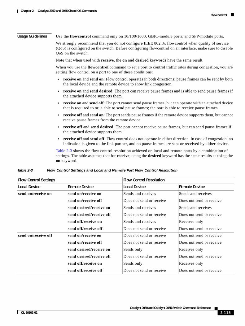
Chapter 2 Catalyst 2950 and 2955 Cisco IOS Commands flowcontrol
Usage Guidelines Use the flowcontrol command only on 10/100/1000, GBIC-module ports, and SFP-module ports.
We strongly recommend that you do not configure IEEE 802.3x flowcontrol when quality of service (QoS) is configured on the switch. Before configuring flowcontrol on an interface, make sure to disable QoS on the switch.
Note that when used with receive, the on and desired keywords have the same result.
When you use the flowcontrol command to set a port to control traffic rates during congestion, you are setting flow control on a port to one of these conditions:
• receive on and send on: Flow control operates in both directions; pause frames can be sent by both the local device and the remote device to show link congestion.
• receive on and send desired: The port can receive pause frames and is able to send pause frames if the attached device supports them.
• receive on and send off: The port cannot send pause frames, but can operate with an attached device that is required to or is able to send pause frames; the port is able to receive pause frames.
• receive off and send on: The port sends pause frames if the remote device supports them, but cannot receive pause frames from the remote device.
• receive off and send desired: The port cannot receive pause frames, but can send pause frames if the attached device supports them.
• receive off and send off: Flow control does not operate in either direction. In case of congestion, no indication is given to the link partner, and no pause frames are sent or received by either device.
Table 2-3 shows the flow control resolution achieved on local and remote ports by a combination of settings. The table assumes that for receive, using the desired keyword has the same results as using the on keyword.
Table 2-3 Flow Control Settings and Local and Remote Port Flow Control Resolution
Flow Control Settings Flow Control Resolution
Local Device Remote Device Local Device Remote Device
send on/receive on send on/receive on
send on/receive off
send desired/receive on
send desired/receive off
send off/receive on
send off/receive off
Sends and receives
Does not send or receive
Sends and receives
Does not send or receive
Sends and receives
Does not send or receive
Sends and receives
Does not send or receive
Sends and receives
Does not send or receive
Receives only
Does not send or receive
send on/receive off send on/receive on
send on/receive off
send desired/receive on
send desired/receive off
send off/receive on
send off/receive off
Does not send or receive
Does not send or receive
Sends only
Does not send or receive
Sends only
Does not send or receive
Does not send or receive
Does not send or receive
Receives only
Does not send or receive
Receives only
Does not send or receive
2-115Catalyst 2950 and Catalyst 2955 Switch Command Reference
OL-10102-02
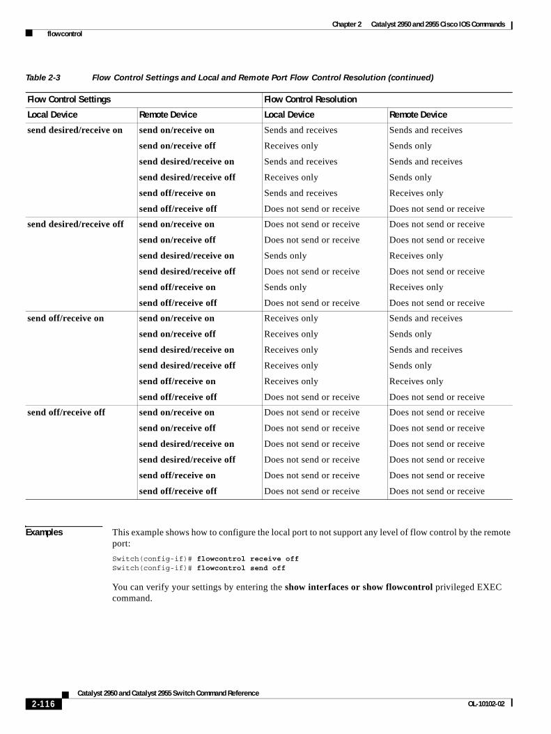
Chapter 2 Catalyst 2950 and 2955 Cisco IOS Commands flowcontrol
Examples This example shows how to configure the local port to not support any level of flow control by the remote port:
Switch(config-if)# flowcontrol receive offSwitch(config-if)# flowcontrol send off
You can verify your settings by entering the show interfaces or show flowcontrol privileged EXEC command.
send desired/receive on send on/receive on
send on/receive off
send desired/receive on
send desired/receive off
send off/receive on
send off/receive off
Sends and receives
Receives only
Sends and receives
Receives only
Sends and receives
Does not send or receive
Sends and receives
Sends only
Sends and receives
Sends only
Receives only
Does not send or receive
send desired/receive off send on/receive on
send on/receive off
send desired/receive on
send desired/receive off
send off/receive on
send off/receive off
Does not send or receive
Does not send or receive
Sends only
Does not send or receive
Sends only
Does not send or receive
Does not send or receive
Does not send or receive
Receives only
Does not send or receive
Receives only
Does not send or receive
send off/receive on send on/receive on
send on/receive off
send desired/receive on
send desired/receive off
send off/receive on
send off/receive off
Receives only
Receives only
Receives only
Receives only
Receives only
Does not send or receive
Sends and receives
Sends only
Sends and receives
Sends only
Receives only
Does not send or receive
send off/receive off send on/receive on
send on/receive off
send desired/receive on
send desired/receive off
send off/receive on
send off/receive off
Does not send or receive
Does not send or receive
Does not send or receive
Does not send or receive
Does not send or receive
Does not send or receive
Does not send or receive
Does not send or receive
Does not send or receive
Does not send or receive
Does not send or receive
Does not send or receive
Table 2-3 Flow Control Settings and Local and Remote Port Flow Control Resolution (continued)
Flow Control Settings Flow Control Resolution
Local Device Remote Device Local Device Remote Device
2-116Catalyst 2950 and Catalyst 2955 Switch Command Reference
OL-10102-02

Chapter 2 Catalyst 2950 and 2955 Cisco IOS Commands flowcontrol
Related Commands Command Description
show interfaces flowcontrol Displays interface input and output flow control settings and status.
show flowcontrol Displays flow control settings and status for specified interfaces or all interfaces on the switch.
2-117Catalyst 2950 and Catalyst 2955 Switch Command Reference
OL-10102-02
Chapter 2 Catalyst 2950 and 2955 Cisco IOS Commands hw-module slot
hw-module slotUse the hw-module slot privileged EXEC command to perform firmware upgrades on Long-Reach Ethernet (LRE) systems.
hw-module slot module-slot-number upgrade lre [force] [{local ctrlr-unit-number | remote interface-id}]
This command is available only on Catalyst 2950 LRE switches.
Syntax Description
Defaults No default is defined.
Command Modes Privileged EXEC
Command History
Usage Guidelines Use the hw-module slot command to start an LRE upgrade. You can start an LRE upgrade by using one of these methods:
• Upgrade all LRE local chipsets (controllers) and remote CPE devices by entering the hw-module slot module-slot-number upgrade lre command.
• Upgrade a single local LRE controller by entering the hw-module slot module-slot-number lre upgrade local ctrlr-unit-number command.
• Upgrade a single remote LRE CPE device by entering the hw-module slot module-slot number lre upgrade remote interface-id command.
You can use the force keyword to upgrade an LRE binary on a local LRE controller or a remote LRE CPE device, even though the device is already running the version of the desired LRE binary. The default behavior is to not upgrade LRE binaries that are already up to date.
During an upgrade, users on the LRE links being upgraded experience a temporary disruption of Ethernet connectivity. All LRE local and remote upgrades run concurrently and take 3 to 6 minutes to complete.
The command-line interface (CLI) is available while an LRE upgrade is in progress.
module-slot-number Physical slot that connects the local device (LRE switch) and the remote customer premises equipment (CPE) device for the upgrade.
force (Optional) LRE binaries update by force, even when the version of the LRE binary on the switch flash memory and the LRE binary in use are the same.
local ctrlr-unit-number (Optional) The single LRE chipset for a controller at the local end of the LRE Ethernet link.
remote interface-id (Optional) One or more chipsets on a single CPE device at the remote end of the LRE Ethernet link.
Release Modification
12.1(11)YJ This command was introduced.
2-118Catalyst 2950 and Catalyst 2955 Switch Command Reference
OL-10102-02
Chapter 2 Catalyst 2950 and 2955 Cisco IOS Commands hw-module slot
Once started, an LRE upgrade can only be stopped by physically changing the remote CPE device or by reloading the software on the Ethernet switch.
In most cases, configuration for upgrades is not necessary.
Examples This example shows how to start a system-wide LRE upgrade:
Switch# hw-module slot 0 upgrade lre
You are about to start an LRE upgrade on all LRE interfaces.Users on LRE links being upgraded will experience a temporarydisruption of Ethernet connectivity.
Start LRE upgrade ? [yes]:
Starting remote upgrade on CPE Lo0/1.Starting remote upgrade on CPE Lo0/2Starting remote upgrade on CPE Lo0/3Starting remote upgrade on CPE Lo0/4Starting remote upgrade on CPE Lo0/5Starting remote upgrade on CPE Lo0/6Starting remote upgrade on CPE Lo0/7Starting remote upgrade on CPE Lo0/8Starting upgrade on local controller LongReachEthernet 0Starting remote upgrade on CPE Lo0/9
<output truncated>
Starting remote upgrade on CPE Lo0/23Starting remote upgrade on CPE Lo0/24Starting upgrade on local controller LongReachEthernet 2
This example shows how to start an LRE upgrade on a single LRE controller in a switch. Specifying the interface-id as longreachethernet 0 causes an LRE upgrade to run on controller 0 in the switch.
Switch# hw-module slot 0 upgrade lre local longreachethernet 0You are about to start an LRE upgrade on local controller LongReachEthernet 0.Users on LRE links being upgraded will experience a temporarydisruption of Ethernet connectivity.
Start LRE upgrade ? [yes]:
Starting Upgrade on local controller LongReachEthernet 0
This example shows how to start an LRE upgrade on a single CPE device. Specifying the interface-id as longreachethernet 0 causes an LRE upgrade to run on the CPE device connected to the LRE port 1.
Switch# hw-module slot 0 upgrade lre remote longreachethernet0/1
You are about to start an LRE upgrade on CPE Lo0/1.Users on LRE links being upgraded will experience a temporarydisruption of Ethernet connectivity.
Start LRE upgrade ? [yes]:
Starting remote upgrade on CPE Lo0/1
2-119Catalyst 2950 and Catalyst 2955 Switch Command Reference
OL-10102-02
Chapter 2 Catalyst 2950 and 2955 Cisco IOS Commands hw-module slot
This example shows what happens when you attempt to update current firmware without using the force option:
Switch# hw-module slot 0 upgrade lre remote longreachethernet0/1
You are about to start an LRE upgrade on CPE Lo0/1.Users on LRE links being upgraded will experience a temporarydisruption of Ethernet connectivity.
Start LRE upgrade ? [yes]:
No upgrade required on CPE Lo0/1
This example shows how to use the force option when you attempt to update current firmware on a CPE:
Switch# hw-module slot 0 upgrade lre force remote longreachethernet0/1
You are about to start an LRE upgrade on CPE Lo0/1.Users on LRE links being upgraded will experience a temporarydisruption of Ethernet connectivity.
Start LRE upgrade ? [yes]:
Starting remote upgrade on CPE Lo0/1
Switch#
Related Commands Command Description
controller longreachethernet Allows you to enter controller mode.
show lre upgrade Displays the LRE binaries present on the system flash memory, the upgrade status on all ports in the switch, or the binaries on local and remote ends on all ports.
2-120Catalyst 2950 and Catalyst 2955 Switch Command Reference
OL-10102-02
Chapter 2 Catalyst 2950 and 2955 Cisco IOS Commands interface
interfaceUse the interface global configuration command to configure an interface type, create a switch virtual interface to be used as the management VLAN interface, and to enter interface configuration mode.
interface {interface-id | vlan number}
no interface {interface-id | vlan number}
Syntax Description
Defaults The default management VLAN interface is VLAN 1.
Command Modes Global configuration
Command History
Usage Guidelines When creating a management VLAN interface, a space between vlan and number is accepted.
Only one management VLAN interface can be active.
You cannot delete the management VLAN 1 interface.
You can use the no shutdown interface configuration command to shut down the active management VLAN interface and to enable a new one.
You can configure the management VLAN interface on static-access and trunk ports.
Examples This example shows how enter interface configuration mode for an interface:
Switch(config)# interface fastethernet0/2Switch(config-if)#
This example shows how to change the management VLAN from the default management VLAN to VLAN 3. This series of commands should only be entered from the service port. If these commands are entered through a Telnet session, the shutdown command disconnects the session, and there is no way to use IP to access the system.
Switch# configure terminalSwitch(config)# interface vlan 3Switch(config-if)# ip address 172.20.128.176 255.255.255.0Switch(config-if)# no shutdownSwitch(config-if)# exit
You can verify your settings by entering the show interfaces and show interfaces vlan vlan-id privileged EXEC commands.
interface-id Specify the interface type and number.
vlan number VLAN number from 1 to 4094 to be used as the management VLAN.
Release Modification
12.0(5.2)WC(1) This command was introduced.
2-121Catalyst 2950 and Catalyst 2955 Switch Command Reference
OL-10102-02
Chapter 2 Catalyst 2950 and 2955 Cisco IOS Commands interface
Related Commands Command Description
show interfaces Displays the administrative and operational status of a switching (nonrouting) port.
shutdown Disables a port and shuts down the management VLAN.
2-122Catalyst 2950 and Catalyst 2955 Switch Command Reference
OL-10102-02
Chapter 2 Catalyst 2950 and 2955 Cisco IOS Commands interface port-channel
interface port-channelUse the interface port-channel global configuration command to access or create the port-channel logical interface for Layer 2 interfaces. Use the no form of this command to remove the port channel.
interface port-channel port-channel-number
no interface port-channel port-channel-number
Syntax Description
Defaults No port-channel logical interfaces are defined.
Command Modes Global configuration
Command History
Usage Guidelines Only one port channel in a channel group is allowed.
Follow these guidelines when you use the interface port-channel command:
• If you want to use the Cisco Discovery Protocol (CDP), you must configure it only on the physical interface and not on the port-channel interface.
• On the port-channel interface, if you do not assign a static MAC address or if you assign a static MAC address and then later remove it, the switch automatically assigns a MAC address to the interface.
Examples This example shows how to create a port-channel interface with a port-channel number of 5:
Switch(config)# interface port-channel 5
You can verify your settings by entering the show running-config or show etherchannel channel-group-number detail privileged EXEC command.
Related Commands
port-channel-number Port-channel number. The range is 1 to 6.
Release Modification
12.1(6)EA2 This command was introduced.
Command Description
channel-group Assigns an Ethernet interface to an EtherChannel group.
show etherchannel Displays EtherChannel information for a channel.
show running-config Displays the configuration information running on the switch. For syntax information, select Cisco IOS Configuration Fundamentals Command Reference for Release 12.1 > Cisco IOS File Management Commands > Configuration File Commands.
2-123Catalyst 2950 and Catalyst 2955 Switch Command Reference
OL-10102-02
Chapter 2 Catalyst 2950 and 2955 Cisco IOS Commands interface range
interface rangeUse the interface range global configuration command to enter interface range configuration mode and to execute a command on multiple ports at the same time. Use the no form of this command to remove an interface range.
interface range {port-range | macro name}
no interface range {port-range | macro name}
Syntax Description
Defaults This command has no default setting.
Command Modes Global configuration
Command History
Usage Guidelines From the interface range configuration mode, all interface parameters that you enter are applied to all interfaces within the range.
For VLANs, you can use the interface range command only on existing VLAN interfaces. To display VLAN interfaces, enter the show running-config privileged EXEC command. VLANs not displayed cannot be used in the interface range command. The commands that you enter under the interface range command are applied to all existing VLAN interfaces in the range.
All configuration changes made to an interface range are saved to NVRAM, but the interface range itself is not saved to NVRAM.
You can enter the interface range in two ways:
• Specifying up to five interface ranges
• Specifying a previously defined interface-range macro
You can define up to five interface ranges with a single command, with each range separated by a comma (,).
All interfaces in a range must be the same type; that is, all Fast Ethernet ports, all Gigabit Ethernet ports, all EtherChannel ports, all Long-Reach Ethernet (LRE) ports, or all VLANs.
These are the valid values for port-range type and interface:
• vlan vlan-id, where vlan-id is from 1 to4094
• port-channel port-channel-number, where port-channel-number is from 1 to 6
port-range Port range. For a list of valid values for port-range, see the “Usage Guidelines” section.
macro name Specify the name of a macro.
Release Modification
12.1(6)EA2 This command was introduced.
2-124Catalyst 2950 and Catalyst 2955 Switch Command Reference
OL-10102-02
Chapter 2 Catalyst 2950 and 2955 Cisco IOS Commands interface range
• fastethernet interface-id
• gigabitethernet interface-id
• longreachethernet interface-id
For physical interfaces, the interface-id is defined as a slot/number (where slot is always 0 for the switch), and the range is entered as type 0/number - number (for example, fastethernet0/1 - 2). You can also enter multiple ranges.
When you define a range, you must enter a space before and after the hyphen (-):
interface range fastethernet0/1 - 2
When you define multiple ranges, you must enter a space before and after the comma (,):
interface range fastethernet0/3 - 7 , gigabitethernet0/1
You cannot specify both a macro and an interface range in the same command.
A single interface can also be specified in port-range. (The command is then similar to the interface interface-id global configuration command.)
Note For more information about configuring interface ranges, see the software configuration guide for this release.
Examples This example shows how to use the interface range command to enter interface range configuration mode and to enter commands for two ports:
Switch(config)# interface range fastethernet0/1 - 2Switch(config-if-range)#
This example shows how to use a port-range macro macro1 for the same function. The advantage is that you can reuse the macro1 until you delete it.
Switch(config)# define interface-range macro1 fastethernet0/1 - 2Switch(config)# interface range macro macro1Switch(config-if-range)#
Related Commands Command Description
show running-config Displays the configuration information running on the switch. For syntax information, select Cisco IOS Configuration Fundamentals Command Reference for Release 12.1 > Cisco IOS File Management Commands > Configuration File Commands.
2-125Catalyst 2950 and Catalyst 2955 Switch Command Reference
OL-10102-02
Chapter 2 Catalyst 2950 and 2955 Cisco IOS Commands interleave
interleave Use the interleave interface configuration command to set the interleave block size on the Long-Reach Ethernet (LRE) interfaces. Use the no form of this command to return to the default setting.
interleave {downstream value | upstream value}
no interleave {downstream value | upstream value}
This command is available only on Catalyst 2950 LRE switches.
Syntax Description
Defaults The default is 0 for low latency (LL) profiles and 16 for non-LL profiles.
Command Modes Interface configuration
Command History
Usage Guidelines The interleave delay is applicable only when the non-LL profiles are used. Existing LL profiles are supported.
Different ports with the same profile can have different interleave settings.
A lower value of interleave block size indicates less tolerance to noise and causes a lower latency of frame transmission. For example, lower values of interleave block size can be used for voice applications. A higher value of interleave block size indicates higher tolerance to noise and causes higher latency in the frame transmission. For example, higher values of interleave block size can be used for data applications.
If a lower latency of frame transmission is required, you can use a lower interleave value but you will have less tolerance to noise.
For information on configuring the interleave delay, see the switch software configuration guide for this release.
Examples This example shows how to specify an interleave value of 2 for both upstream and downstream ends of the link:
Switch(config-if)# interleave upstream 2 downstream 2
You can verify your settings by entering the show controllers lre status interleave privileged EXEC command.
downstream value Value at the local end of the link. Valid block size entries are 0, 1, 2, 8, or 16.
upstream value Value at the remote end of the link. Valid block size entries are 0, 1, 2, 8, or 16.
Release Modification
12.1(11)YJ4 This command was introduced.
2-126Catalyst 2950 and Catalyst 2955 Switch Command Reference
OL-10102-02

Chapter 2 Catalyst 2950 and 2955 Cisco IOS Commands interleave
Related Commands Command Description
show controllers lre status interleave
Displays the interleave block size values on the LRE interfaces.
2-127Catalyst 2950 and Catalyst 2955 Switch Command Reference
OL-10102-02
Chapter 2 Catalyst 2950 and 2955 Cisco IOS Commands ip access-group
ip access-groupUse the ip access-group interface configuration command to control access to an interface. Use the no form of this command to remove an access group from an interface.
ip access-group {access-list-number | name} in
no ip access-group {access-list-number | name} in
This command is available on physical interfaces only if your switch is running the enhanced software image (EI).
Syntax Description
Defaults No ACL is applied to the interface.
Command Modes Interface configuration
Command History
Usage Guidelines You can apply IP ACLs only to ingress interfaces. If a MAC access group is already defined for an interface, you cannot apply this command to the interface.
The ACLs can be standard or extended.
For standard ACLs, after receiving a packet, the switch checks the packet source address. If the source address matches a defined address in the ACL and the list permits the address, the switch forwards the packet.
For extended ACLs, after receiving the packet, the switch checks the match conditions in the ACL. If the conditions are matched, the switch forwards the packet.
If the specified ACL does not exist, the switch forwards all packets.
IP access groups can be separated on Layer 2 and Layer 3 interfaces.
Note For more information about configuring IP ACLs, see the “Configuring Network Security with ACLs” chapter in the software configuration guide for this release.
access-list-number Number of the IP access control list (ACL). The range is 1 to 199 and 1300 to 2699.
name Name of an IP ACL, specified in the ip access-list command.
Release Modification
12.1(6)EA2 This command was introduced.
2-128Catalyst 2950 and Catalyst 2955 Switch Command Reference
OL-10102-02
Chapter 2 Catalyst 2950 and 2955 Cisco IOS Commands ip access-group
Examples This example shows how to apply a numbered ACL to an interface:
Switch(config)# interface fastethernet0/1Switch(config-if)# ip access-group 101 in
You can verify your settings by entering the show access-lists or show ip access-lists privileged EXEC command.
Related Commands Command Description
access-list (IP extended) Defines an extended IP ACL.
access-list (IP standard) Defines a standard IP ACL.
deny (access-list configuration) Configures conditions for an IP ACL.
ip access-list Defines an IP ACL.
permit (access-list configuration) Configures conditions for an IP ACL.
show access-lists Displays ACLs configured on the switch.
show ip access-lists Displays IP ACLs configured on the switch.
2-129Catalyst 2950 and Catalyst 2955 Switch Command Reference
OL-10102-02
Chapter 2 Catalyst 2950 and 2955 Cisco IOS Commands ip access-list
ip access-listUse the ip access-list global configuration command to create an IP access control list (ACL) to be used for matching packets to an ACL whose name or number you specify and to enter access-list configuration mode. Use the no form of this command to delete an existing IP ACL and to return to global configuration mode.
ip access-list {extended | standard} {access-list-number | name}
no ip access-list {extended | standard} {access-list-number | name}
This command is available on physical interfaces only if your switch is running the enhanced software image (EI).
Syntax Description
Defaults No named or numbered IP ACLs are defined.
Command Modes Global configuration
Command History
Usage Guidelines Use this command to enter access-list configuration mode and to specify the name or number of the IP ACL for which you want to create or modify ACL match criteria. In this mode, you must enter the permit and deny commands to configure the permit and deny access conditions for this list.
Use the ip access-list command and its subcommands to define packet classification and marking as part of a globally-named service policy applied on a per-interface basis or as an IP access group applied on a per-interface basis.
Specifying standard or extended with the ip access-list command determines the prompt that you get when you enter access-list configuration mode.
Note For more information about configuring IP ACLs, see the “Configuring Network Security with ACLs” chapter in the software configuration guide for this release.
access-list-number Number of an ACL.
For standard IP ACLs, the range is 1 to 99 and 1300 to 1999.
For extended IP ACLs, the range 100 to 199 and 2000 to 2699.
name Name of an ACL.
The ACL name must begin with an alphabetic character to prevent ambiguity with numbered ACLs. A name also cannot contain a space or quotation mark.
Release Modification
12.1(6)EA2 This command was introduced.
2-130Catalyst 2950 and Catalyst 2955 Switch Command Reference
OL-10102-02
Chapter 2 Catalyst 2950 and 2955 Cisco IOS Commands ip access-list
Examples This example shows how to configure a standard ACL named Internetfilter1:
Switch(config)# ip access-list standard Internetfilter1Switch(config-std-nacl)# permit 192.5.34.0 0.0.0.255Switch(config-std-nacl)# permit 192.5.32.0 0.0.0.255Switch(config-std-nacl)# exit
This example shows how to configure an extended ACL named Internetfilter2:
Switch(config)# ip access-list extended Internetfilter2Switch(config-ext-nacl)# permit any 128.8.10.0 0.0.0.255 eq 80Switch(config-ext-nacl)# permit any 128.5.8.0 0.0.0.255 eq 80Switch(config-ext-nacl)# exit
Note In these examples, all other IP access is implicitly denied.
You can verify your settings by entering the show access-lists or show ip access-lists privileged EXEC command.
Related Commands Command Description
deny (access-list configuration) Configures conditions for an IP ACL.
ip access-group Controls access to an interface.
permit (access-list configuration) Configures conditions for an IP ACL.
service-policy Applies a policy map to the input of an interface.
show access-lists Displays ACLs configured on the switch.
show ip access-lists Displays IP ACLs configured on the switch.
2-131Catalyst 2950 and Catalyst 2955 Switch Command Reference
OL-10102-02
Chapter 2 Catalyst 2950 and 2955 Cisco IOS Commands ip address
ip addressUse the ip address interface configuration command to set an IP address for a switch. Use the no form of this command to remove an IP address or to disable IP processing.
ip address ip-address subnet-mask
no ip address ip-address subnet-mask
Syntax Description
Defaults No IP address is defined for the switch.
Command Modes Interface configuration
Command History
Usage Guidelines A switch can have one IP address.
The IP address of the switch can be accessed only by nodes connected to ports that belong to the management VLAN. The default for the management VLAN is VLAN 1, but you can configure a different VLAN as the management VLAN.
If you remove the IP address through a Telnet or Secure Shell (SSH) session, your connection to the switch is lost.
If your switch receives its IP address from a Bootstrap Protocol (BOOTP) or a DHCP server and you remove the switch IP address by using the no ip address command, IP processing is disabled, and the BOOTP or DHCP server cannot reassign the address.
Examples This example shows how to configure the IP address for the switch on a subnetted network:
Switch(config)# interface vlan 1Switch(config-if)# ip address 172.20.128.2 255.255.255.0
You can verify your settings by entering the show running-config privileged EXEC command.
Related Commands
ip-address IP address.
subnet-mask Mask for the associated IP subnet.
Release Modification
12.0(5.2)WC(1) This command was introduced.
Command Description
show running-config Displays the configuration information running on the switch. For syntax information, select Cisco IOS Configuration Fundamentals Command Reference for Release 12.1 > Cisco IOS File Management Commands > Configuration File Commands.
2-132Catalyst 2950 and Catalyst 2955 Switch Command Reference
OL-10102-02
Chapter 2 Catalyst 2950 and 2955 Cisco IOS Commands ip dhcp snooping
ip dhcp snoopingUse the ip dhcp snooping global configuration command to globally enable DHCP snooping. Use the no form of this command to return to the default setting.
ip dhcp snooping
no ip dhcp snooping
Syntax Description This command has no arguments or keywords.
Defaults DHCP snooping is disabled.
Command Modes Global configuration
Command History
Usage Guidelines You must globally enable DHCP snooping for any DHCP snooping configuration to take effect.
DHCP snooping is not active until snooping is enabled on a VLAN by using the ip dhcp snooping vlan vlan-id global configuration command.
Examples This example shows how to enable DHCP snooping:
Switch(config)# ip dhcp snooping
You can verify your settings by entering the show ip dhcp snooping privileged EXEC command.
Related Commands
Release Modification
12.1(19)EA1 This command was introduced.
Command Description
ip dhcp snooping vlan Enables DHCP snooping on a VLAN.
show ip dhcp snooping Displays the DHCP snooping configuration.
show ip dhcp snooping binding Displays the DHCP snooping binding information.
2-133Catalyst 2950 and Catalyst 2955 Switch Command Reference
OL-10102-02
Chapter 2 Catalyst 2950 and 2955 Cisco IOS Commands ip dhcp snooping information option
ip dhcp snooping information optionUse the ip dhcp snooping information option global configuration command to enable DHCP option-82 data insertion. Use the no form of this command to disable DHCP option-82 data insertion.
ip dhcp snooping information option
no ip dhcp snooping information option
Syntax Description This command has no arguments or keywords.
Defaults DHCP option-82 data insertion is enabled.
Command Modes Global configuration
Command History
Usage Guidelines You must globally enable DHCP snooping by using the ip dhcp snooping global configuration command for any DHCP snooping configuration to take effect.
When the option-82 feature is enabled and a switch receives a DHCP request from a host, it adds the option-82 information in the packet. The option-82 information contains the switch MAC address (the remote ID suboption) and the port identifier, vlan-mod-port, from which the packet is received (circuit ID suboption). The switch forwards the DHCP request that includes the option-82 field to the DHCP server.
When the DHCP server receives the packet, it can use the remote ID, the circuit ID, or both to assign IP addresses and implement policies, such as restricting the number of IP addresses that can be assigned to a single remote ID or a circuit ID. Then the DHCP server echoes the option-82 field in the DHCP reply.
The DHCP server unicasts the reply to the switch if the request was relayed to server by the switch. When the client and server are on the same subnet, the server broadcasts the reply. The switch inspects the remote ID and possibly the circuit ID fields to verify that it originally inserted the option-82 data. The switch removes the option-82 field and forwards the packet to the switch port that connects to the DHCP host that sent the DHCP request.
Examples This example shows how to enable DHCP option-82 data insertion:
Switch(config)# ip dhcp snooping information option
You can verify your settings by entering the show ip dhcp snooping privileged EXEC command.
Release Modification
12.1(19)EA1 This command was introduced.
2-134Catalyst 2950 and Catalyst 2955 Switch Command Reference
OL-10102-02

Chapter 2 Catalyst 2950 and 2955 Cisco IOS Commands ip dhcp snooping information option
Related Commands Command Description
show ip dhcp snooping Displays the DHCP snooping configuration.
show ip dhcp snooping binding Displays the DHCP snooping binding information.
2-135Catalyst 2950 and Catalyst 2955 Switch Command Reference
OL-10102-02
Chapter 2 Catalyst 2950 and 2955 Cisco IOS Commands ip dhcp snooping information option allow-untrusted
ip dhcp snooping information option allow-untrustedUse the ip dhcp snooping information option allow-untrusted global configuration command on an aggregation switch to configure it to accept DHCP packets with option-82 information that are received on untrusted ports that might be connected to an edge switch. Use the no form of this command to configure the switch to drop these packets from the edge switch.
ip dhcp snooping information option allow-untrusted
no ip dhcp snooping information option allow-untrusted
Syntax Description This command has no arguments or keywords.
Defaults The switch drops DHCP packets with option-82 information that are received on untrusted ports that might be connected to an edge switch.
Command Modes Global configuration
Command History
Usage Guidelines You might want an edge switch to which a host is connected to insert DHCP option-82 information at the edge of your network. You might also want to enable DHCP security features, such as DHCP snooping, IP source guard, or dynamic Address Resolution Protocol (ARP) inspection, on an aggregation switch. However, if DHCP snooping is enabled on the aggregation switch, the switch drops packets with option-82 information that are received on an untrusted port and does not learn DHCP snooping bindings for connected devices on a trusted interface.
If the edge switch to which a host is connected inserts option-82 information and you want to use DHCP snooping on an aggregation switch, enter the ip dhcp snooping information option allow-untrusted command on the aggregation switch. The aggregation switch can learn the bindings for a host even though the aggregation switch receives DHCP snooping packets on an untrusted port. You can also enable DHCP security features on the aggregation switch. The port on the edge switch to which the aggregation switch is connected must be configured as a trusted port.
Note Do not enter the ip dhcp snooping information option allow-untrusted command on an aggregation switch to which an untrusted device is connected. If you enter this command, an untrusted device might spoof the option-82 information.
Examples This example shows how to configure an access switch to not check the option-82 information in untrusted packets from an edge switch and to accept the packets:
Switch(config)# ip dhcp snooping information option allow-untrusted
Release Modification
12.1(22)EA3 This command was introduced.
2-136Catalyst 2950 and Catalyst 2955 Switch Command Reference
OL-10102-02

Chapter 2 Catalyst 2950 and 2955 Cisco IOS Commands ip dhcp snooping information option allow-untrusted
You can verify your settings by entering the show ip dhcp snooping privileged EXEC command.
Related Commands Command Description
show ip dhcp snooping Displays the DHCP snooping configuration.
show ip dhcp snooping binding Displays the DHCP snooping binding information.
2-137Catalyst 2950 and Catalyst 2955 Switch Command Reference
OL-10102-02
Chapter 2 Catalyst 2950 and 2955 Cisco IOS Commands ip dhcp snooping limit rate
ip dhcp snooping limit rateUse the ip dhcp snooping limit rate interface configuration command to configure the number of DHCP messages an interface can receive per second. Use the no form of this command to return to the default setting.
ip dhcp snooping limit rate rate
no ip dhcp snooping limit rate
Syntax Description
Defaults DHCP snooping rate limiting is disabled.
Command Modes Interface configuration
Command History
Usage Guidelines Normally, the rate limit applies to untrusted interfaces. If you want to configure rate limiting for trusted interfaces, keep in mind that trusted interfaces might aggregate DHCP traffic on multiple VLANs (some of which might not be snooped) in the switch, and you will need to adjust the interface rate limits to a higher value.
If the rate limit is exceeded, the interface is error-disabled. If you enabled error recovery by entering the errdisable recovery dhcp-rate-limit global configuration command, the interface retries the operation again when all the causes have timed out. If the error-recovery mechanism is not enabled, the interface stays in the error-disabled state until you enter the shutdown and no shutdown interface configuration commands.
Examples This example shows how to set a message rate limit of 150 messages per second on an interface:
Switch(config-if)# ip dhcp snooping limit rate 150
You can verify your settings by entering the show ip dhcp snooping privileged EXEC command.
Related Commands
rate Number of DHCP messages an interface can receive per second. The range is 1 to 4294967294.
Release Modification
12.1(19)EA1 This command was introduced.
Command Description
errdisable recovery Configures the recover mechanism.
show ip dhcp snooping Displays the DHCP snooping configuration.
show ip dhcp snooping binding Displays the DHCP snooping binding information.
2-138Catalyst 2950 and Catalyst 2955 Switch Command Reference
OL-10102-02
Chapter 2 Catalyst 2950 and 2955 Cisco IOS Commands ip dhcp snooping trust
ip dhcp snooping trustUse the ip dhcp snooping trust interface configuration command to configure a port as trusted for DHCP snooping purposes. Use the no form of this command to return to the default setting.
ip dhcp snooping trust
no ip dhcp snooping trust
Syntax Description This command has no arguments or keywords.
Defaults DHCP snooping trust is disabled.
Command Modes Interface configuration
Command History
Usage Guidelines Configure ports that are connected to a DHCP server or to other switches or routers as trusted. Configure ports that are connected to DHCP clients as untrusted.
Examples This example shows how to enable DHCP snooping trust on a port:
Switch(config-if)# ip dhcp snooping trust
You can verify your settings by entering the show ip dhcp snooping privileged EXEC command.
Related Commands
Release Modification
12.1(19)EA1 This command was introduced.
Command Description
show ip dhcp snooping Displays the DHCP snooping configuration.
show ip dhcp snooping binding Displays the DHCP snooping binding information.
2-139Catalyst 2950 and Catalyst 2955 Switch Command Reference
OL-10102-02
Chapter 2 Catalyst 2950 and 2955 Cisco IOS Commands ip dhcp snooping vlan
ip dhcp snooping vlanUse the ip dhcp snooping vlan global configuration command to enable DHCP snooping on a VLAN. Use the no form of this command to disable DHCP snooping on a VLAN.
ip dhcp snooping vlan vlan-id [vlan-id]
no ip dhcp snooping vlan vlan-id [vlan-id]
Syntax Description
Defaults DHCP snooping is disabled on all VLANs.
Command Modes Global configuration
Command History
Usage Guidelines You must first globally enable DHCP snooping before enabling DHCP snooping on a VLAN.
Examples This example shows how to enable DHCP snooping on VLAN 10:
Switch(config)# ip dhcp snooping vlan 10
You can verify your settings by entering the show ip dhcp snooping privileged EXEC command.
Related Commands
vlan vlan-id [vlan-id] Specify a VLAN ID or range of VLANs on which to enable DHCP snooping. The range is 1 to 4094.
You can enter a single VLAN ID identified by VLAN ID number, a series of VLAN IDs separated by commas, a range of VLAN IDs separated by hyphens, or a range of VLAN IDs separated by entering the starting and ending VLAN IDs separated by a space.
Release Modification
12.1(19)EA1 This command was introduced.
Command Description
show ip dhcp snooping Displays the DHCP snooping configuration.
show ip dhcp snooping binding Displays the DHCP snooping binding information.
2-140Catalyst 2950 and Catalyst 2955 Switch Command Reference
OL-10102-02
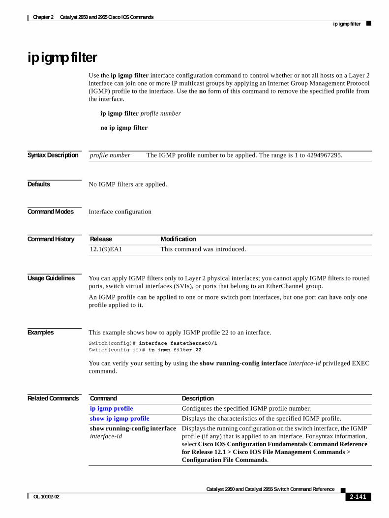
Chapter 2 Catalyst 2950 and 2955 Cisco IOS Commands ip igmp filter
ip igmp filterUse the ip igmp filter interface configuration command to control whether or not all hosts on a Layer 2 interface can join one or more IP multicast groups by applying an Internet Group Management Protocol (IGMP) profile to the interface. Use the no form of this command to remove the specified profile from the interface.
ip igmp filter profile number
no ip igmp filter
Syntax Description
Defaults No IGMP filters are applied.
Command Modes Interface configuration
Command History
Usage Guidelines You can apply IGMP filters only to Layer 2 physical interfaces; you cannot apply IGMP filters to routed ports, switch virtual interfaces (SVIs), or ports that belong to an EtherChannel group.
An IGMP profile can be applied to one or more switch port interfaces, but one port can have only one profile applied to it.
Examples This example shows how to apply IGMP profile 22 to an interface.
Switch(config)# interface fastethernet0/1Switch(config-if)# ip igmp filter 22
You can verify your setting by using the show running-config interface interface-id privileged EXEC command.
Related Commands
profile number The IGMP profile number to be applied. The range is 1 to 4294967295.
Release Modification
12.1(9)EA1 This command was introduced.
Command Description
ip igmp profile Configures the specified IGMP profile number.
show ip igmp profile Displays the characteristics of the specified IGMP profile.
show running-config interface interface-id
Displays the running configuration on the switch interface, the IGMP profile (if any) that is applied to an interface. For syntax information, select Cisco IOS Configuration Fundamentals Command Reference for Release 12.1 > Cisco IOS File Management Commands > Configuration File Commands.
2-141Catalyst 2950 and Catalyst 2955 Switch Command Reference
OL-10102-02
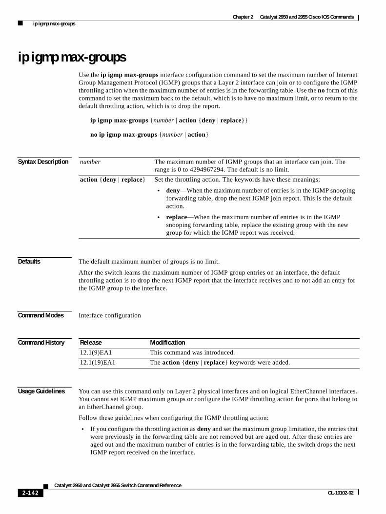
Chapter 2 Catalyst 2950 and 2955 Cisco IOS Commands ip igmp max-groups
ip igmp max-groupsUse the ip igmp max-groups interface configuration command to set the maximum number of Internet Group Management Protocol (IGMP) groups that a Layer 2 interface can join or to configure the IGMP throttling action when the maximum number of entries is in the forwarding table. Use the no form of this command to set the maximum back to the default, which is to have no maximum limit, or to return to the default throttling action, which is to drop the report.
ip igmp max-groups {number | action {deny | replace}}
no ip igmp max-groups {number | action}
Syntax Description
Defaults The default maximum number of groups is no limit.
After the switch learns the maximum number of IGMP group entries on an interface, the default throttling action is to drop the next IGMP report that the interface receives and to not add an entry for the IGMP group to the interface.
Command Modes Interface configuration
Command History
Usage Guidelines You can use this command only on Layer 2 physical interfaces and on logical EtherChannel interfaces. You cannot set IGMP maximum groups or configure the IGMP throttling action for ports that belong to an EtherChannel group.
Follow these guidelines when configuring the IGMP throttling action:
• If you configure the throttling action as deny and set the maximum group limitation, the entries that were previously in the forwarding table are not removed but are aged out. After these entries are aged out and the maximum number of entries is in the forwarding table, the switch drops the next IGMP report received on the interface.
number The maximum number of IGMP groups that an interface can join. The range is 0 to 4294967294. The default is no limit.
action {deny | replace} Set the throttling action. The keywords have these meanings:
• deny—When the maximum number of entries is in the IGMP snooping forwarding table, drop the next IGMP join report. This is the default action.
• replace—When the maximum number of entries is in the IGMP snooping forwarding table, replace the existing group with the new group for which the IGMP report was received.
Release Modification
12.1(9)EA1 This command was introduced.
12.1(19)EA1 The action {deny | replace} keywords were added.
2-142Catalyst 2950 and Catalyst 2955 Switch Command Reference
OL-10102-02
Chapter 2 Catalyst 2950 and 2955 Cisco IOS Commands ip igmp max-groups
• If you configure the throttling action as replace and set the maximum group limitation, the entries that were previously in the forwarding table are removed. When the maximum number of entries is in the forwarding table, the switch replaces a randomly selected multicast entry with the received IGMP report.
• When the maximum group limitation is set to the default (no maximum), entering the ip igmp max-groups {deny | replace} command has no effect.
Examples This example shows how to limit to 25 the number of IGMP groups that an interface can join:
Switch(config)# interface fastethernet0/1Switch(config-if)# ip igmp max-groups 25
This example shows how to configure the switch to replace the existing group with the new group for which the IGMP report was received when the maximum number of entries is in the forwarding table:
Switch(config)# interface gigabitethernet0/1Switch(config-if)# ip igmp max-groups action replace
You can verify your setting by using the show running-config interface interface-id privileged EXEC command.
Related Commands Command Description
show running-config interface interface-id
Displays the running configuration on the switch interface, including the maximum number of IGMP groups that an interface can join and the throttling action. For syntax information, select Cisco IOS Configuration Fundamentals Command Reference for Release 12.1 > Cisco IOS File Management Commands > Configuration File Commands.
2-143Catalyst 2950 and Catalyst 2955 Switch Command Reference
OL-10102-02
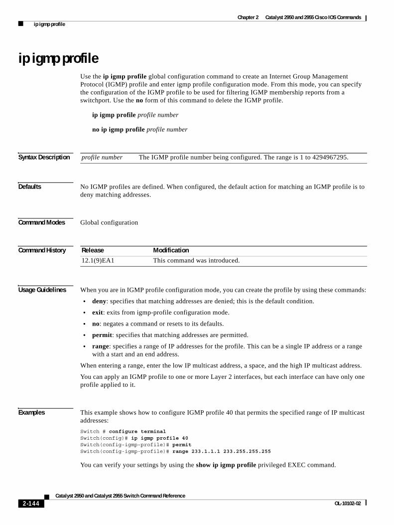
Chapter 2 Catalyst 2950 and 2955 Cisco IOS Commands ip igmp profile
ip igmp profileUse the ip igmp profile global configuration command to create an Internet Group Management Protocol (IGMP) profile and enter igmp profile configuration mode. From this mode, you can specify the configuration of the IGMP profile to be used for filtering IGMP membership reports from a switchport. Use the no form of this command to delete the IGMP profile.
ip igmp profile profile number
no ip igmp profile profile number
Syntax Description
Defaults No IGMP profiles are defined. When configured, the default action for matching an IGMP profile is to deny matching addresses.
Command Modes Global configuration
Command History
Usage Guidelines When you are in IGMP profile configuration mode, you can create the profile by using these commands:
• deny: specifies that matching addresses are denied; this is the default condition.
• exit: exits from igmp-profile configuration mode.
• no: negates a command or resets to its defaults.
• permit: specifies that matching addresses are permitted.
• range: specifies a range of IP addresses for the profile. This can be a single IP address or a range with a start and an end address.
When entering a range, enter the low IP multicast address, a space, and the high IP multicast address.
You can apply an IGMP profile to one or more Layer 2 interfaces, but each interface can have only one profile applied to it.
Examples This example shows how to configure IGMP profile 40 that permits the specified range of IP multicast addresses:
Switch # configure terminalSwitch(config)# ip igmp profile 40Switch(config-igmp-profile)# permitSwitch(config-igmp-profile)# range 233.1.1.1 233.255.255.255
You can verify your settings by using the show ip igmp profile privileged EXEC command.
profile number The IGMP profile number being configured. The range is 1 to 4294967295.
Release Modification
12.1(9)EA1 This command was introduced.
2-144Catalyst 2950 and Catalyst 2955 Switch Command Reference
OL-10102-02

Chapter 2 Catalyst 2950 and 2955 Cisco IOS Commands ip igmp profile
Related Commands Command Description
ip igmp filter Applies the IGMP profile to the specified interface.
show ip igmp profile Displays the characteristics of all IGMP profiles or the specified IGMP profile number.
2-145Catalyst 2950 and Catalyst 2955 Switch Command Reference
OL-10102-02
Chapter 2 Catalyst 2950 and 2955 Cisco IOS Commands ip igmp snooping
ip igmp snoopingUse the ip igmp snooping global configuration command to globally enable Internet Group Management Protocol (IGMP) snooping. Use the no form of this command to disable IGMP snooping.
ip igmp snooping
no ip igmp snooping
Syntax Description This command has no arguments or keywords.
Note Though visible in the command-line help string, the tcn keyword is not supported.
Defaults IGMP snooping is globally enabled.
Command Modes Global configuration
Command History
Usage Guidelines When IGMP snooping is globally enabled, IGMP snooping is enabled on all the existing VLAN interfaces. When IGMP snooping is globally disabled, IGMP snooping is disabled on all the existing VLAN interfaces.
The configuration is saved in NVRAM.
Examples This example shows how to globally enable IGMP snooping:
Switch(config)# ip igmp snooping
To verify your settings, enter the show ip igmp snooping privileged EXEC command.
Related Commands
Release Modification
12.0(5.2)WC(1) This command was introduced.
Command Description
ip igmp snooping vlan Enables IGMP snooping on a VLAN interface.
ip igmp snooping vlan immediate-leave Enables IGMP Immediate-Leave processing.
ip igmp snooping vlan mrouter Configures a Layer 2 port as a multicast router port.
ip igmp snooping vlan static Configures a Layer 2 port as a member of a group.
show ip igmp snooping Displays the IGMP snooping configuration.
2-146Catalyst 2950 and Catalyst 2955 Switch Command Reference
OL-10102-02
Chapter 2 Catalyst 2950 and 2955 Cisco IOS Commands ip igmp snooping mrouter learn pim v2
ip igmp snooping mrouter learn pim v2Use the ip igmp snooping mrouter learn pim v2 global configuration command to enable multicast router detection by Protocol-Independent Multicast protocol version 2 (PIMv2) packets when Internet Group Management Protocol (IGMP) snooping is enabled. Use the no form of this command to disable multicast router detection by PIMv2 packets.
ip igmp snooping mrouter learn pim v2
no ip igmp snooping mrouter learn pim v2
Syntax Description This command has no arguments or keywords.
Defaults Multicast router discovery using PIMv2 packets is enabled.
Command Modes Global configuration
Command History
Usage Guidelines When IGMP snooping is globally enabled, PIMv2 packets and IGMP query packets are used for multicast router discovery and sent to the switch CPU. This is the default condition. Use the no ip igmp snooping mrouter learn pim v2 global configuration command to disable multicast router discovery by PIMv2.
To prevent PIMv2 packets from being sent to the switch CPU, you must also disable source-only learning on the switch. Source-only learning sends IP multicast data packets to the CPU and PIMv2 packets are treated as IP multicast data. Use the no ip igmp snooping source-only learning global configuration command to disable source-only learning.
Examples This example shows how to prevent PIMv2 packets from being sent to the CPU, by disabling source-only learning and PIMv2 multicast router detection:
Switch(config)# no ip igmp snooping source-only-learningSwitch(config)# no ip igmp snooping mrouter learn pim v2
You can verify your settings by entering the show running-config | include mrouter learn pim v2 privileged EXEC command.
Release Modification
12.1(20)EA2 This command was introduced.
2-147Catalyst 2950 and Catalyst 2955 Switch Command Reference
OL-10102-02
Chapter 2 Catalyst 2950 and 2955 Cisco IOS Commands ip igmp snooping mrouter learn pim v2
Related Commands Command Description
ip igmp snooping Globally enables IGMP snooping.
ip igmp snooping source-only-learning
Enable IGMP snooping source-only learning. To prevent PIMv2 packets from being sent to the CPU, you must also use the no form of this command to disable source-only-learning.
show running-config | include mrouter learn pim v2
Displays the configuration information running on the switch. For syntax information, select Cisco IOS Configuration Fundamentals Command Reference for Release 12.1 > Cisco IOS File Management Commands > Configuration File Commands.
2-148Catalyst 2950 and Catalyst 2955 Switch Command Reference
OL-10102-02
Chapter 2 Catalyst 2950 and 2955 Cisco IOS Commands ip igmp snooping report-suppression
ip igmp snooping report-suppressionUse the ip igmp snooping report-suppression global configuration command to enable Internet Group Management Protocol (IGMP) report suppression. Use the no form of this command to disable IGMP report suppression and forward all IGMP reports to multicast routers.
ip igmp snooping report-suppression
no ip igmp snooping report-suppression
Syntax Description This command has no arguments or keywords.
Defaults IGMP report suppression is enabled.
Command Modes Global configuration
Command History
Usage Guidelines IGMP report suppression is supported only when the multicast query has IGMPv1 and IGMPv2 reports. This feature is not supported when the query includes IGMPv3 reports.
The switch uses IGMP report suppression to forward only one IGMP report per multicast router query to multicast devices. When IGMP router suppression is enabled (the default), the switch sends the first IGMP report from all hosts for a group to all the multicast routers. The switch does not send the remaining IGMP reports for the group to the multicast routers. This feature prevents duplicate reports from being sent to the multicast devices.
If the multicast router query includes requests only for IGMPv1 and IGMPv2 reports, the switch forwards only the first IGMPv1 or IGMPv2 report from all hosts for a group to all the multicast routers. If the multicast router query also includes requests for IGMPv3 reports, the switch forwards all IGMPv1, IGMPv2, and IGMPv3 reports for a group to the multicast devices.
If you disable IGMP report suppression by entering the no ip igmp snooping report-suppression command, all IGMP reports are forwarded to all the multicast routers.
Examples This example shows how to disable report suppression:
Switch(config)# no ip igmp snooping report-suppression
This example shows how to enable report suppression:
Switch(config)# ip igmp snooping report-suppression
You can verify your settings by entering the show ip igmp snooping privileged EXEC command.
Release Modification
12.1(14)EA1 This command was introduced.
2-149Catalyst 2950 and Catalyst 2955 Switch Command Reference
OL-10102-02
Chapter 2 Catalyst 2950 and 2955 Cisco IOS Commands ip igmp snooping report-suppression
Related Commands Command Description
ip igmp snooping Globally enables IGMP snooping. IGMP snooping must be globally enabled in order to be enabled on a VLAN.
show ip igmp snooping Displays the IGMP snooping configuration of the switch or the VLAN.
2-150Catalyst 2950 and Catalyst 2955 Switch Command Reference
OL-10102-02
Chapter 2 Catalyst 2950 and 2955 Cisco IOS Commands ip igmp snooping source-only-learning
ip igmp snooping source-only-learningUse the ip igmp snooping source-only-learning global configuration command to enable IP multicast-source-only learning on the switch and optionally set the aging time of the forwarding-table entries that are learned. Use the no form of this command to disable IP multicast-source-only learning or to disable aging.
ip igmp snooping source-only-learning [age-timer value]
no ip igmp snooping source-only-learning [age-timer]
Syntax Description
Defaults IP multicast-source-only learning is enabled.
The aging feature is enabled. The default is 600 seconds (10 minutes).
Command Modes Global configuration
Command History
Usage Guidelines When IP multicast-source-only learning is enabled, the switch learns the IP multicast group from the IP multicast data stream and only forwards traffic to the multicast router ports.
Note We strongly recommend that you do not disable IP multicast-source-only learning. IP multicast-source-only learning should be disabled only if your network is not composed of IP multicast-source-only networks and if disabling this learning method improves the network performance.
In a source-only network, switch ports are connected to multicast source ports and multicast router ports. The switch ports are not connected to hosts that send IGMP join or leave messages.
The switch learns about IP multicast groups from the IP multicast data stream by using the source-only learning method. The switch forwards traffic only to the multicast router ports. You can disable source-only learning by using the no ip igmp snooping source-only learning global configuration command.
age-timer (Optional) Configure the aging time of the forwarding-table entries that the switch learns by using the source-only learning method.
time Aging time is seconds. The range is 0 to 2880 seconds. If you set time to 0, aging of the forward-table entries is disabled.
Release Modification
12.1(11)EA1 This command was introduced.
2-151Catalyst 2950 and Catalyst 2955 Switch Command Reference
OL-10102-02
Chapter 2 Catalyst 2950 and 2955 Cisco IOS Commands ip igmp snooping source-only-learning
The aging time only affects the forwarding-table entries that the switch learns by using the source-only learning method. If the aging time is too long or is disabled, the forwarding table is filled with unused multicast addresses that the switch learned by using source-only learning or by using the IGMP join messages. When the switch receives traffic for new IP multicast groups, it floods the packet to all ports in the same VLAN. This unnecessary flooding can impact switch performance.
To disable the aging of the forwarding-table entries, enter the ip igmp snooping source-only-learning age-timer 0 global configuration command. If aging is disabled and you want to delete multicast addresses that the switch learned by using source-only learning, re-enable aging of the forwarding-table entries. The switch can now age out the multicast addresses that were learned by the source-only learning method and that re not in use.
If you disable source-only learning, the aging time has no effect on the switch.
Examples This example shows how to disable source-only learning:
Switch(config)# no ip igmp snooping source-only-learning
This example shows how to enable source-only learning:
Switch(config)# ip igmp snooping source-only-learning
This example shows how to set the aging time as 1200 seconds (20 minutes):
Switch(config)# ip igmp snooping source-only-learning age-timer 1200
This example shows how to disable aging of the forward-table entries:
Switch(config)# ip igmp snooping source-only-learning age-timer 0
You can verify your settings by entering the show running-config | include source-only-learning privileged EXEC command.
Related Commands Command Description
ip igmp snooping Globally enables IGMP snooping. IGMP snooping must be globally enabled in order to be enabled on a VLAN.
show running-config | include source-only-learning
Displays the configuration information running on the switch. For syntax information, select Cisco IOS Configuration Fundamentals Command Reference for Release 12.1 > Cisco IOS File Management Commands > Configuration File Commands.
2-152Catalyst 2950 and Catalyst 2955 Switch Command Reference
OL-10102-02
Chapter 2 Catalyst 2950 and 2955 Cisco IOS Commands ip igmp snooping vlan
ip igmp snooping vlanUse the ip igmp snooping vlan global configuration command to enable Internet Group Management Protocol (IGMP) snooping on a specific VLAN. Use the no form of this command to disable IGMP snooping on a VLAN interface.
ip igmp snooping vlan vlan-id
no ip igmp snooping vlan vlan-id
Syntax Description
Defaults IGMP snooping is enabled when each VLAN is created.
Command Modes Global configuration
Command History
Usage Guidelines This command automatically configures the VLAN if it is not already configured. The configuration is saved in NVRAM.
Examples This example shows how to enable IGMP snooping on VLAN 2:
Switch(config)# ip igmp snooping vlan 2
This example shows how to disable IGMP snooping on VLAN 2:
Switch(config)# no ip igmp snooping vlan 2
You can verify your settings by entering the show ip igmp snooping vlan privileged EXEC command.
Related Commands
vlan-id VLAN ID. The range is 1 to 4094.
Release Modification
12.0(5.2)WC(1) This command was introduced.
Command Description
ip igmp snooping Globally enables IGMP snooping. IGMP snooping must be globally enabled in order to be enabled on a VLAN.
ip igmp snooping vlan immediate-leave
Enables IGMP Immediate-Leave processing.
ip igmp snooping vlan mrouter Configures a Layer 2 port as a multicast router port.
ip igmp snooping vlan static Configures a Layer 2 port as a member of a group.
show ip igmp snooping Displays the IGMP snooping configuration.
2-153Catalyst 2950 and Catalyst 2955 Switch Command Reference
OL-10102-02
Chapter 2 Catalyst 2950 and 2955 Cisco IOS Commands ip igmp snooping vlan immediate-leave
ip igmp snooping vlan immediate-leaveUse the ip igmp snooping vlan immediate-leave global configuration command to enable Internet Group Management Protocol (IGMP) Immediate-Leave processing on a VLAN interface. Use the no form of this command to disable Immediate-Leave processing on the VLAN interface.
ip igmp snooping vlan vlan-id immediate-leave
no ip igmp snooping vlan vlan-id immediate-leave
Syntax Description
Defaults IGMP Immediate-Leave processing is disabled.
Command Modes Global configuration
Command History
Usage Guidelines Use the Immediate-Leave feature only when there is only one IP multicast receiver present on every port in the VLAN. The Immediate-Leave configuration is saved in NVRAM.
The Immediate-Leave feature is supported only with IGMP version 2 hosts.
Examples This example shows how to enable IGMP Immediate-Leave processing on VLAN 1:
Switch(config)# ip igmp snooping vlan 1 immediate-leave
This example shows how to disable IGMP Immediate-Leave processing on VLAN 1:
Switch(config)# no ip igmp snooping vlan 1 immediate-leave
You can verify your settings by entering the show ip igmp snooping vlan privileged EXEC command.
Related Commands
vlan-id VLAN ID value. The range is 1 to 4094.
Release Modification
12.0(5.2)WC(1) This command was introduced.
Command Description
ip igmp snooping Enables IGMP snooping.
ip igmp snooping vlan mrouter Configures a Layer 2 port as a multicast router port.
show ip igmp snooping Displays the IGMP snooping configuration.
ip igmp snooping vlan static Configures a Layer 2 port as a member of a group.
show mac address-table multicast Displays the Layer 2 multicast entries for a VLAN.
2-154Catalyst 2950 and Catalyst 2955 Switch Command Reference
OL-10102-02
Chapter 2 Catalyst 2950 and 2955 Cisco IOS Commands ip igmp snooping vlan last-member-query interval
ip igmp snooping vlan last-member-query intervalUse the ip igmp snooping vlan last-member-query-interval global configuration command to globally enable the Internet Group Management Protocol (IGMP) configurable-leave timer. Use the no form of this command to return the IGMP configurable-leave timer to the default setting (100 milliseconds).
ip igmp snooping vlan vlan-id last-member-query-interval time
no ip igmp snooping vlan vlan-id last-member-query-interval
Syntax Descriptiont
Defaults The default timeout setting is 100 milliseconds.
Command History
Usage Guidelines When IGMP snooping is globally enabled, IGMP snooping is enabled on all the existing VLAN interfaces. When IGMP snooping is globally disabled, IGMP snooping is disabled on all the existing VLAN interfaces.
The configuration is saved in NVRAM.
Examples This example shows how to globally enable the IGMP configurable-leave timer:
Switch(config)# ip igmp snooping vlan vlan-id last-member-query-interval time
To verify your settings, enter the show ip igmp snooping privileged EXEC command.
Related Commands
vlan-id VLAN ID value. The range is 1 to 4094.
time Interval time out in seconds. The range is 100 to 5000 milliseconds.
Release Modification
12.1(22)EA3 This command was introduced.
Command Description
ip igmp snooping vlan Enables IGMP snooping on a VLAN interface.
ip igmp snooping vlan immediate-leave Enables IGMP Immediate-Leave processing.
ip igmp snooping vlan mrouter Configures a Layer 2 port as a multicast router port.
ip igmp snooping vlan static Configures a Layer 2 port as a member of a group.
show ip igmp snooping Displays the IGMP snooping configuration.
2-155Catalyst 2950 and Catalyst 2955 Switch Command Reference
OL-10102-02
Chapter 2 Catalyst 2950 and 2955 Cisco IOS Commands ip igmp snooping vlan mrouter
ip igmp snooping vlan mrouterUse the ip igmp snooping vlan mrouter global configuration command to add a multicast router port and to configure the multicast router learning method. Use the no form of this command to remove the configuration.
ip igmp snooping vlan vlan-id mrouter {interface interface-id | learn {cgmp | pim-dvmrp}}
no ip igmp snooping vlan vlan-id mrouter {interface interface-id | learn {cgmp | pim-dvmrp}}
Syntax Description
Defaults The default learning method is pim-dvmrp.
Command Modes Global configuration
Command History
Usage Guidelines The CGMP learning method is useful for controlling traffic in Cisco router environments.
The configured learning method is saved in NVRAM.
Static connections to multicast routers are supported only on switch ports.
Examples This example shows how to configure an interface as a multicast router port:
Switch(config)# ip igmp snooping vlan 1 mrouter interface fastethernet0/1
This example shows how to specify the multicast router learning method as CGMP:
Switch(config)# no ip igmp snooping vlan 1 mrouter learn cgmp
You can verify your settings by entering the show ip igmp snooping mrouter privileged EXEC command.
vlan vlan-id Specify the VLAN ID. The range is 1 to 4094.
interface interface-id Specify the interface of the member port that is configured to a static router port.
learn {cgmp | pim-dvmrp} Specify the multicast router learning method. The keywords have these meanings:
• cgmp—Set the switch to learn multicast router ports by snooping on Cisco Group Management Protocol (CGMP) packets.
• pim-dvmrp—Set the switch to learn multicast router ports by snooping on IGMP queries and Protocol-Independent Multicasting-Distance Vector Multicast Routing Protocol (PIM-DVMRP) packets.
Release Modification
12.0(5.2)WC(1) This command was introduced.
2-156Catalyst 2950 and Catalyst 2955 Switch Command Reference
OL-10102-02
Chapter 2 Catalyst 2950 and 2955 Cisco IOS Commands ip igmp snooping vlan mrouter
Related Commands Command Description
ip igmp snooping Globally enables Internet Group Management Protocol (IGMP) snooping.
ip igmp snooping vlan Enables IGMP snooping on the VLAN interface.
ip igmp snooping vlan immediate-leave
Configures IGMP Immediate-Leave processing.
ip igmp snooping vlan static Configures a Layer 2 port as a member of a group.
show ip igmp snooping mrouter Displays the statically and dynamically learned multicast router ports.
2-157Catalyst 2950 and Catalyst 2955 Switch Command Reference
OL-10102-02
Chapter 2 Catalyst 2950 and 2955 Cisco IOS Commands ip igmp snooping vlan static
ip igmp snooping vlan staticUse the ip igmp snooping vlan vlan-id static global configuration command to add a Layer 2 port as a member of a multicast group. Use the no form of this command to remove the configuration.
ip igmp snooping vlan vlan-id static mac-address interface interface-id
no ip igmp snooping vlan vlan-id static mac-address interface interface-id
Syntax Description
Defaults None configured.
Command Modes Global configuration
Command History
Usage Guidelines The command is used to statically configure the IP multicast group member ports.
The static ports and groups are saved in NVRAM.
Static connections to multicast routers are supported only on switch ports.
Examples This example shows how to statically configure a host on an interface:
Switch(config)# ip igmp snooping vlan 1 static 0100.5e02.0203 interface fastethernet0/1Configuring port FastEthernet 0/1 on group 0100.5e02.0203
You can verify your settings by entering the show mac address-table multicast privileged EXEC command.
Related Commands
vlan vlan-id Specify the VLAN ID. The range is 1 to 4094.
static mac-address Specify the static group MAC address.
interface interface-id Specify the interface configured to a static router port.
Release Modification
12.0(5.2)WC(1) This command was introduced.
Command Description
ip igmp snooping Enables Internet Group Management Protocol (IGMP) snooping.
ip igmp snooping vlan Enables IGMP snooping on the VLAN interface.
ip igmp snooping vlan immediate-leave
Configures IGMP Immediate-Leave processing.
ip igmp snooping vlan mrouter Configures a Layer 2 port as a multicast router port.
show mac address-table multicast Displays the Layer 2 multicast entries for a VLAN.
2-158Catalyst 2950 and Catalyst 2955 Switch Command Reference
OL-10102-02
Chapter 2 Catalyst 2950 and 2955 Cisco IOS Commands ip ssh
ip sshUse the ip ssh global configuration command to configure the switch to run Secure Shell (SSH) version 1 or SSH version 2. Use the no form of this command to return to the default setting.
ip ssh version [1 | 2]
no ip ssh [1 | 2]
This command is available only when your switch is running the cryptographic (encrypted) software image.
Syntax Description
Defaults The default version is the latest SSH version supported by the SSH client.
Command Modes Global configuration
Command History
Usage Guidelines If you do not enter this command or if you do not specify a keyword, the SSH server selects the latest SSH version supported by the SSH client. For example, if the SSH client supports SSHv1 and SSHv2, the SSH server selects SSHv2.
The switch supports an SSHv1 or SSHv2 server. It also supports an SSHv1 client. For more information about the SSH server and the SSH client, see the software configuration guide for this release.
A Rivest, Shamir, and Adelman (RSA) key pair generated by an SSHv1 server can be used by an SSHv2 server, and the reverse.
Examples This example shows how to configure the switch to run SSH version 2:
Switch(config)# ip ssh version 2
You can verify your settings by entering the show ip ssh or show ssh privileged EXEC command.
1 (Optional) Configure the switch to run SSH version 1 (SSHv1).
2 (Optional) Configure the switch to run SSH version 2 (SSHv1).
Release Modification
12.1(19)EA1 This command was introduced.
2-159Catalyst 2950 and Catalyst 2955 Switch Command Reference
OL-10102-02
Chapter 2 Catalyst 2950 and 2955 Cisco IOS Commands ip ssh
Related Commands Command Description
show ip ssh Displays if the SSH server is enabled and displays the version and configuration information for the SSH server. For syntax information, select Cisco IOS Release 12.2 Configuration Guides and Command References > Cisco IOS Security Command Reference, Release 12.2 > Other Security Features > Secure Shell Commands.
show ssh Displays the status of the SSH server. For syntax information, select Cisco IOS Release 12.2 Configuration Guides and Command References > Cisco IOS Security Command Reference, Release 12.2 > Other Security Features > Secure Shell Commands.
2-160Catalyst 2950 and Catalyst 2955 Switch Command Reference
OL-10102-02
Chapter 2 Catalyst 2950 and 2955 Cisco IOS Commands lacp port-priority
lacp port-priorityUse the lacp port-priority interface configuration command to set the port priority for the Link Aggregration Control Protocol (LACP). Use the no form of this command to return to the default setting.
lacp port-priority priority-value
no lacp port-priority
Syntax Description
Defaults The default priority value is 32768.
Command Modes Interface configuration
Command History
Usage Guidelines This command only takes effect on EtherChannel interfaces that are already configured for LACP.
The lacp port-priority interface configuration command determines which ports are bundled and which ports are put in hot-standby mode when there are more than eight ports in an LACP channel group.
An LACP channel group can have up to 16 Ethernet ports of the same type. Up to eight ports can be active, and up to eight ports can be in standby mode.
In port-priority comparisons, a numerically lower value has a higher priority: When there are more than eight ports in an LACP channel-group, the eight ports with the numerically lowest values (highest priority values) for LACP port priority are bundled into the channel group, and the lower-priority ports are put in hot-standby mode. If two or more ports have the same LACP port priority (for example, they are configured with the default setting of 65535) an internal value for the port number determines the priority.
Note The LACP port priorities are only effective if the ports are on the switch that controls the LACP link. See the lacp system-priority global configuration command for determining which switch controls the link.
Use the show lacp internal privileged EXEC command to to display LACP port priorities and internal port number values.
For more information about configuring LACP on physical interfaces, see the “Configuring EtherChannels” chapter in the software configuration guide for this release.
priority-value Port priority for LACP. The range is from 1 to 65535.
Release Modification
12.1(12c)EA1 This command was introduced.
2-161Catalyst 2950 and Catalyst 2955 Switch Command Reference
OL-10102-02
Chapter 2 Catalyst 2950 and 2955 Cisco IOS Commands lacp port-priority
Examples This example shows set the port priority for LACP:
Switch(config)# lacp port-priority 32764
You can verify your settings by entering the show etherchannel privileged EXEC command.
Related Commands Command Description
lacp system-priority Globally sets the LACP priority.
2-162Catalyst 2950 and Catalyst 2955 Switch Command Reference
OL-10102-02
Chapter 2 Catalyst 2950 and 2955 Cisco IOS Commands lacp system-priority
lacp system-priorityUse the lacp system-priority global configuration command to set the system priority for Link Aggregration Control Protocol (LACP). Use the no form of this command to return to the default setting.
lacp system-priority priority-value
no lacp system-priority
Syntax Description
Defaults The default priority value is 32768.
Command Modes Global configuration
Command History
Usage Guidelines The lacp system-priority command determines which switch in an LACP link controls port priorities.
An LACP channel group can have up to 16 Ethernet ports of the same type. Up to eight ports can be active, and up to eight ports can be in standby mode. When there are more than eight ports in an LACP channel-group, the switch on the controlling end of the link uses port priorities to determine which ports are bundled into the channel and which ports are put in hot-standby mode. Port priorities on the other switch (the noncontrolling end of the link) are ignored.
In priority comparisons, numerically lower values have higher priority. Therefore, the system with the numerically lower value (higher priority value) for LACP system priority becomes the controlling system. If both switches have the same LACP system priority (for example, they are both configured with the default setting of 32768), the LACP system ID (the switch MAC address) determines which switch is in control.
The lacp system-priority command applies to all LACP EtherChannels on the switch.
Use the show etherchannel summary privileged EXEC command to see which ports are in the hot-standby mode (denoted with an H port-state flag in the output display).
For more information about configuring LACP on physical interfaces, see the “Configuring Etherchannels” chapter in the software configuration guide for this release.
Examples This example shows set the system priority for LACP:
Switch(config)# lacp system-priority 32764
You can verify your settings by entering the show lacp sys-id privileged EXEC command.
priority-value System priority for LACP. The range is from 1 to 65535.
Release Modification
12.1(12c)EA1 This command was introduced.
2-163Catalyst 2950 and Catalyst 2955 Switch Command Reference
OL-10102-02

Chapter 2 Catalyst 2950 and 2955 Cisco IOS Commands lacp system-priority
Related Commands Command Description
lacp port-priority Sets the LACP priority for a specific port.
2-164Catalyst 2950 and Catalyst 2955 Switch Command Reference
OL-10102-02
Chapter 2 Catalyst 2950 and 2955 Cisco IOS Commands link monitor
link monitorUse the link monitor interface configuration command to enable Long-Reach Ethernet (LRE) link monitoring on a port. Use the no form of this command to disable LRE link monitoring on a port.
link monitor
no link monitor
This command is available only on Catalyst 2950 LRE switches.
Syntax Description This command has no arguments or keywords.
Defaults LRE monitoring is enabled.
Command Modes Interface configuration
Command History
Usage Guidelines If the link is shut down, link monitor data is not collected.
Examples This example shows how to enable LRE link monitoring on an LRE port:
Switch# configure terminalSwitch(config)# interface longreachethernet0/1Switch(config-if)# link monitor
Related Commands
Release Modification
12.1(11)YJ This command was introduced.
Command Description
clear controllers lre link monitor Deletes LRE link monitor data.
link monitor logging Enables link monitor event logging per port.
link monitor threshold snr Sets a signal-to-noise margin for the LRE link monitor.
link monitor threshold rserr Sets a Reed-Solomon error threshold for the LRE link monitor.
show controllers lre link monitor Displays LRE link monitor information.
2-165Catalyst 2950 and Catalyst 2955 Switch Command Reference
OL-10102-02
Chapter 2 Catalyst 2950 and 2955 Cisco IOS Commands link monitor logging
link monitor loggingUse the link monitor logging interface configuration command to enable Long-Reach Ethernet (LRE) link monitoring event logging. Use the no form of this command to disable LRE link monitor logging.
link monitor logging
no link monitor logging
This command is available only on Catalyst 2950 LRE switches.
Syntax Description This command has no arguments or keywords.
Defaults LRE link monitoring event logging is disabled.
Command Modes Interface configuration
Command History
Usage Guidelines Events are logged in the system log when a configured threshold is crossed.
Examples This example shows how to enable LRE link monitoring logging on an LRE port:
Switch# configure terminalSwitch(config)# interface longreachethernet0/2Switch(config-if)# link monitor logging
Related Commands
Release Modification
12.1(11)YJ This command was introduced.
Command Description
clear controllers lre link monitor Deletes LRE link monitor data.
link monitor Enables the LRE link monitor on a port.
link monitor threshold snr Sets a signal-to-noise margin for the LRE link monitor.
link monitor threshold rserr Sets a Reed-Solomon error threshold for the LRE link monitor.
show controllers lre link monitor Displays the LRE link monitor information.
2-166Catalyst 2950 and Catalyst 2955 Switch Command Reference
OL-10102-02
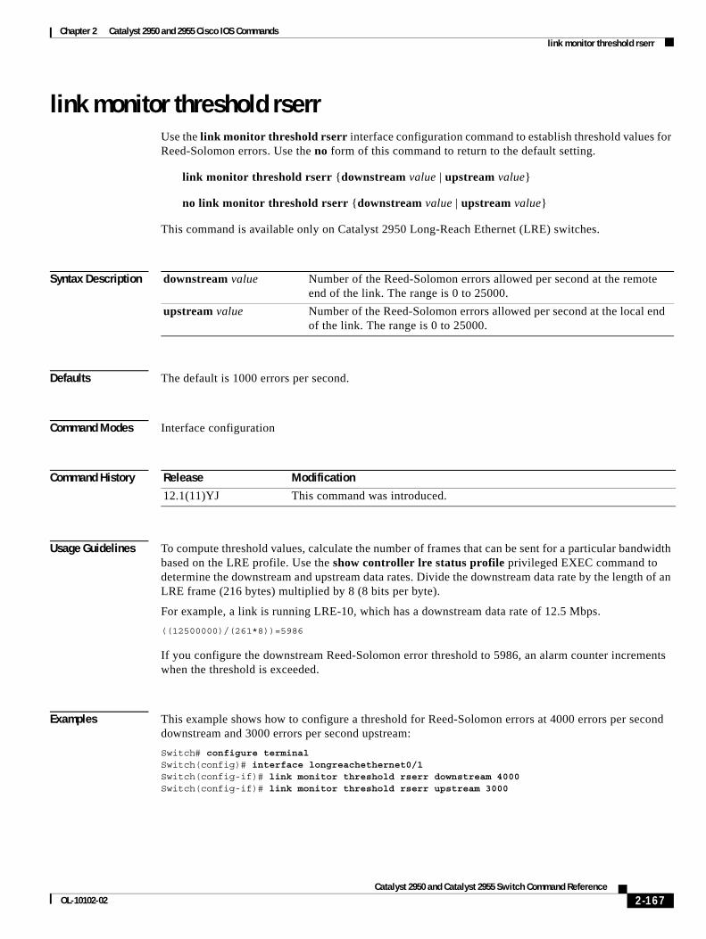
Chapter 2 Catalyst 2950 and 2955 Cisco IOS Commands link monitor threshold rserr
link monitor threshold rserrUse the link monitor threshold rserr interface configuration command to establish threshold values for Reed-Solomon errors. Use the no form of this command to return to the default setting.
link monitor threshold rserr {downstream value | upstream value}
no link monitor threshold rserr {downstream value | upstream value}
This command is available only on Catalyst 2950 Long-Reach Ethernet (LRE) switches.
Syntax Description
Defaults The default is 1000 errors per second.
Command Modes Interface configuration
Command History
Usage Guidelines To compute threshold values, calculate the number of frames that can be sent for a particular bandwidth based on the LRE profile. Use the show controller lre status profile privileged EXEC command to determine the downstream and upstream data rates. Divide the downstream data rate by the length of an LRE frame (216 bytes) multiplied by 8 (8 bits per byte).
For example, a link is running LRE-10, which has a downstream data rate of 12.5 Mbps.
((12500000)/(261*8))=5986
If you configure the downstream Reed-Solomon error threshold to 5986, an alarm counter increments when the threshold is exceeded.
Examples This example shows how to configure a threshold for Reed-Solomon errors at 4000 errors per second downstream and 3000 errors per second upstream:
Switch# configure terminalSwitch(config)# interface longreachethernet0/1Switch(config-if)# link monitor threshold rserr downstream 4000 Switch(config-if)# link monitor threshold rserr upstream 3000
downstream value Number of the Reed-Solomon errors allowed per second at the remote end of the link. The range is 0 to 25000.
upstream value Number of the Reed-Solomon errors allowed per second at the local end of the link. The range is 0 to 25000.
Release Modification
12.1(11)YJ This command was introduced.
2-167Catalyst 2950 and Catalyst 2955 Switch Command Reference
OL-10102-02
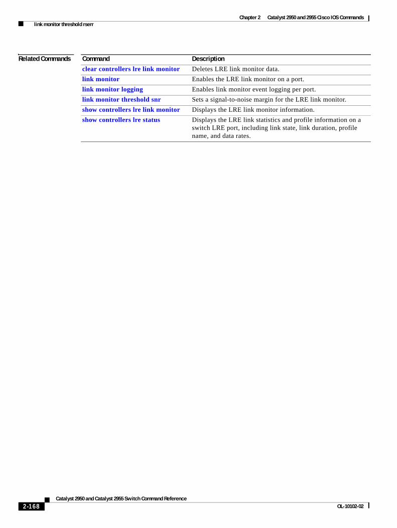
Chapter 2 Catalyst 2950 and 2955 Cisco IOS Commands link monitor threshold rserr
Related Commands Command Description
clear controllers lre link monitor Deletes LRE link monitor data.
link monitor Enables the LRE link monitor on a port.
link monitor logging Enables link monitor event logging per port.
link monitor threshold snr Sets a signal-to-noise margin for the LRE link monitor.
show controllers lre link monitor Displays the LRE link monitor information.
show controllers lre status Displays the LRE link statistics and profile information on a switch LRE port, including link state, link duration, profile name, and data rates.
2-168Catalyst 2950 and Catalyst 2955 Switch Command Reference
OL-10102-02
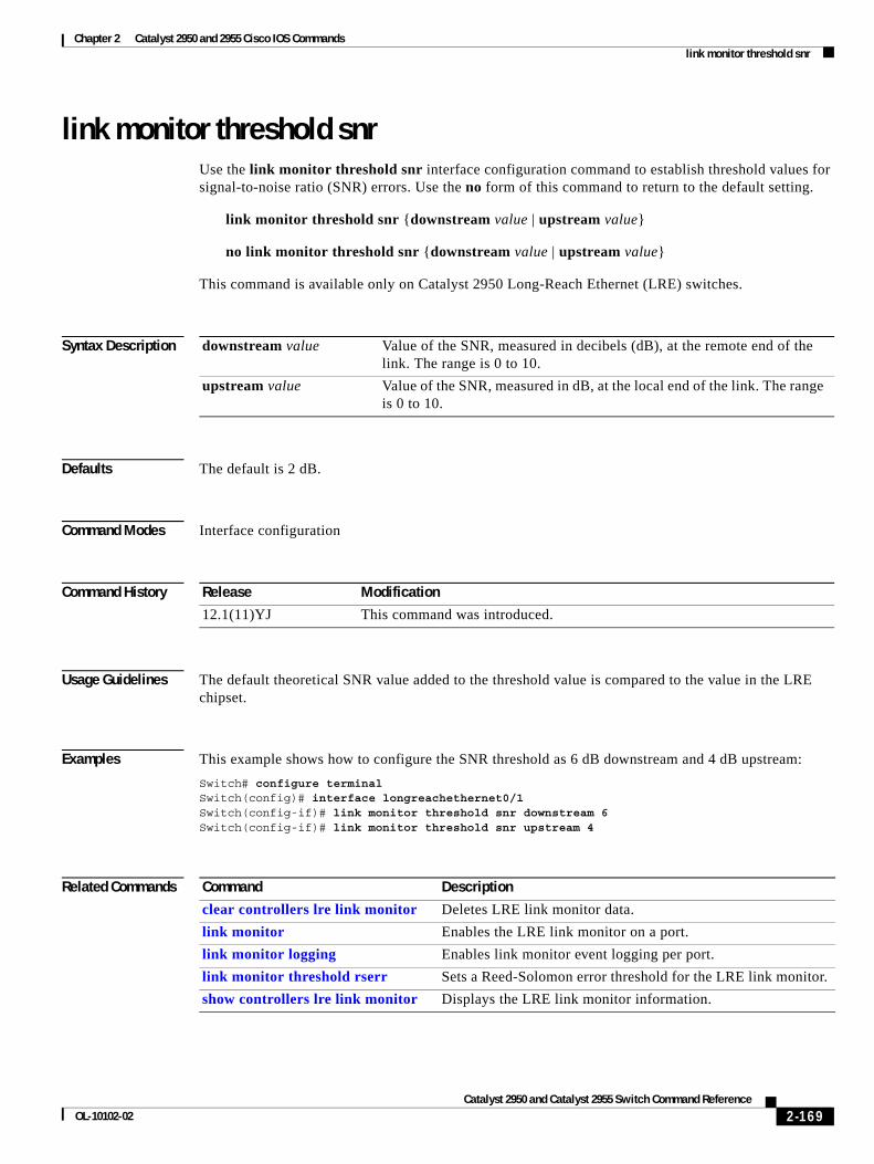
Chapter 2 Catalyst 2950 and 2955 Cisco IOS Commands link monitor threshold snr
link monitor threshold snrUse the link monitor threshold snr interface configuration command to establish threshold values for signal-to-noise ratio (SNR) errors. Use the no form of this command to return to the default setting.
link monitor threshold snr {downstream value | upstream value}
no link monitor threshold snr {downstream value | upstream value}
This command is available only on Catalyst 2950 Long-Reach Ethernet (LRE) switches.
Syntax Description
Defaults The default is 2 dB.
Command Modes Interface configuration
Command History
Usage Guidelines The default theoretical SNR value added to the threshold value is compared to the value in the LRE chipset.
Examples This example shows how to configure the SNR threshold as 6 dB downstream and 4 dB upstream:
Switch# configure terminalSwitch(config)# interface longreachethernet0/1Switch(config-if)# link monitor threshold snr downstream 6Switch(config-if)# link monitor threshold snr upstream 4
Related Commands
downstream value Value of the SNR, measured in decibels (dB), at the remote end of the link. The range is 0 to 10.
upstream value Value of the SNR, measured in dB, at the local end of the link. The range is 0 to 10.
Release Modification
12.1(11)YJ This command was introduced.
Command Description
clear controllers lre link monitor Deletes LRE link monitor data.
link monitor Enables the LRE link monitor on a port.
link monitor logging Enables link monitor event logging per port.
link monitor threshold rserr Sets a Reed-Solomon error threshold for the LRE link monitor.
show controllers lre link monitor Displays the LRE link monitor information.
2-169Catalyst 2950 and Catalyst 2955 Switch Command Reference
OL-10102-02
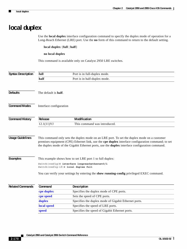
Chapter 2 Catalyst 2950 and 2955 Cisco IOS Commands local duplex
local duplexUse the local duplex interface configuration command to specify the duplex mode of operation for a Long-Reach Ethernet (LRE) port. Use the no form of this command to return to the default setting.
local duplex {full | half}
no local duplex
This command is available only on Catalyst 2950 LRE switches.
Syntax Description
Defaults The default is half.
Command Modes Interface configuration
Command History
Usage Guidelines This command only sets the duplex mode on an LRE port. To set the duplex mode on a customer premises equipment (CPE) Ethernet link, use the cpe duplex interface configuration command; to set the duplex mode of the Gigabit Ethernet ports, use the duplex interface configuration command.
Examples This example shows how to set LRE port 1 to full duplex:
Switch(config)# interface longreachethernet0/1Switch(config-if)# local duplex full
You can verify your settings by entering the show running-config privileged EXEC command.
Related Commands
full Port is in full-duplex mode.
half Port is in half-duplex mode.
Release Modification
12.1(11)YJ This command was introduced.
Command Description
cpe duplex Specifies the duplex mode of CPE ports.
cpe speed Sets the speed of CPE ports.
duplex Specifies the duplex mode of Gigabit Ethernet ports.
local speed Specifies the speed of LRE ports.
speed Specifies the speed of Gigabit Ethernet ports.
2-170Catalyst 2950 and Catalyst 2955 Switch Command Reference
OL-10102-02
Chapter 2 Catalyst 2950 and 2955 Cisco IOS Commands local speed
local speedUse the local speed interface configuration command to specify the speed of a Long-Reach Ethernet (LRE) interface. Use the no form of this command to return to the default setting.
local speed {10 | 100}
no local speed
This command is available only on Catalyst 2950 LRE switches.
Syntax Description
Defaults The default is 100 Mbps.
Command Modes Interface configuration
Command History
Usage Guidelines This command sets the speed only on an LRE link. To set the speed on a customer premises equipment (CPE) Ethernet link, use the cpe speed interface configuration command. To set the speed of the Gigabit Ethernet ports, use the speed interface configuration command.
Examples This example shows how to set LRE port 1 to 100 Mbps:
Switch(config)# interface longreachehernet1/1Switch(config-if)# local speed 100
You can verify your settings by entering the show running-config privileged EXEC command.
Related Commands
10 Specify that the LRE port run at 10 Mbps.
100 Specify that the LRE port run at 100 Mbps.
Release Modification
12.1(11)YJ This command was introduced.
Command Description
cpe duplex Specifies the duplex mode of CPE Ethernet ports.
cpe speed Specifies the speed of CPE Ethernet ports.
duplex Specifies the duplex mode of Gigabit Ethernet ports.
local duplex Specifies the duplex mode of operation for LRE ports.
speed Specifies the speed of Gigabit Ethernet ports.
2-171Catalyst 2950 and Catalyst 2955 Switch Command Reference
OL-10102-02
Chapter 2 Catalyst 2950 and 2955 Cisco IOS Commands logging lre
logging lreUse the logging lre interface configuration command to specify the mode in which to log Long-Reach Ethernet (LRE) events. Use the no form of this command to disable logging of events.
logging lre {event | extended | normal}
no logging lre {event | extended | normal}
This command is available only on Catalyst 2950 LRE switches.
Syntax Description
Defaults The default is normal.
Command Modes Interface configuration
Command History
Usage Guidelines This command is not needed for normal operation of the switch. However, it can be used as a diagnostic tool to analyze switch activity.
The maximum number of events that can be logged on a per-port basis is 50. The log overwrites itself when it is full.
Examples This example shows how to set logging for events:
Switch (config)# interface longreachethernet0/1Switch(config-if)# logging lre event
Related Commands
event Log events only.
extended Log events and all possible parameters.
normal Log events and some typical parameters.
Release Modification
12.1(11)YJ This command was introduced.
Command Description
clear controllers lre log Deletes the history of link, configuration, and timer events for a specific LRE port or for all switch LRE ports.
show controllers lre log Displays the history of link, configuration, and timer events for a specific LRE port or all switch LRE ports.
2-172Catalyst 2950 and Catalyst 2955 Switch Command Reference
OL-10102-02
Chapter 2 Catalyst 2950 and 2955 Cisco IOS Commands lre profile
lre profileUse the lre profile global configuration command to assign a Long-Reach Ethernet (LRE) profile to all switch LRE ports. Use the no form of this command to remove the profile.
lre profile profile-name
no lre profile profile-name
This command is available only on Catalyst 2950 LRE switches.
Syntax Description
Defaults The default for the Catalyst 2950ST-8 LRE and 2950ST-24 LRE switches is LRE-10. The default for the Catalyst 2950ST-24 LRE 997 switch is LRE-6.
Command Modes Global configuration
Command History
Usage Guidelines Unless you assign a profile, the switch uses the default global profile. The LRE-10 profile allows the upstream and downstream transmission rate on the LRE link to be 12.5 Mbps. The LRE-6 profile allows the upstream and downstream transmission rate on the LRE link to be 6.25 Mbps. Profiles assigned at the port level have priority over profiles assigned at the global level.
When assigning profiles to LRE ports, keep these considerations in mind:
• The default profile might not be the best choice for your environment.
• When you assign a different profile to a port, the port applies and uses the newly-assigned profile.
• If a Catalyst 2950ST-8 LRE or 2950ST-24 LRE switch is used with equipment directly connected to a public switched telephone network (PSTN) without a public branch exchange (PBX) between the LRE switch and the public telephone lines, Cisco recommends that you use either the LRE-998-15-4-M2 or LRE-997-10-4-M2 profiles globally.
Examples This example shows how to specify the LRE-8 profile on a Catalyst 2950ST-8 LRE or 2950ST-24 LRE switch:
Switch# configure terminalSwitch(config)# lre profile lre-8
You can verify your settings by entering the show controllers lre profile details privileged EXEC command.
profile-name Name of the profile. The profile name can be a Cisco-supplied profile or a user-created profile. For more details on Cisco-supplied profiles, see the software configuration guide for this release.
Release Modification
12.1(11)YJ This command was introduced.
2-173Catalyst 2950 and Catalyst 2955 Switch Command Reference
OL-10102-02
Chapter 2 Catalyst 2950 and 2955 Cisco IOS Commands lre profile
Related Commands Command Description
profile (sequence configuration) Adds an LRE profile to a rate selection sequence.
show controllers lre profile Displays LRE profile information.
2-174Catalyst 2950 and Catalyst 2955 Switch Command Reference
OL-10102-02
Chapter 2 Catalyst 2950 and 2955 Cisco IOS Commands lre rate selection sequence
lre rate selection sequenceUse the lre rate selection sequence global configuration command to assign the rate selection sequence for the entire switch. Use the no form of the command to delete the assigned sequence.
lre rate selection sequence sequence-name
no lre rate selection sequence sequence-name
This command is available only on Catalyst 2950 Long-Reach Ethernet (LRE) switches.
Syntax Description
Command Modes Global configuration
Command History
Usage Guidelines This command applies a sequence to all ports that have rate selection enabled. The command is rejected if the sequence is not configured with a profile.
When rate selection is enabled, profiles and sequences follow a predefined priority scheme that determines the rate for a port or for the entire switch. In general, sequences have priority over standalone profiles, and port configurations have priority over global configurations. These are the priority levels with rate selection enabled, from highest to lowest:
1. Per-port sequence
2. Global sequence
3. Port profile
4. Global profile
For further details on profiles, sequences, and their priority scheme, see the switch software configuration guide for this release.
Examples This example shows how to specify the sequence named lre-seq-upstream:
Switch# configure terminalSwitch(config)# lre rate selection sequence lre-seq-upstream
sequence-name Name of the rate selection sequence being applied.
Release Modification
12.1(11)YJ This command was introduced.
2-175Catalyst 2950 and Catalyst 2955 Switch Command Reference
OL-10102-02
Chapter 2 Catalyst 2950 and 2955 Cisco IOS Commands lre rate selection sequence
Related Commands Command Description
lre rate selection sequence Assigns a sequence to the entire switch.
lre sequence Creates user-defined rate selection sequences.
rate selection Enables rate selection on a specific port.
rate selection sequence Assigns a rate selection sequence for a specific port.
show controllers lre sequence Displays the list of sequences.
2-176Catalyst 2950 and Catalyst 2955 Switch Command Reference
OL-10102-02
Chapter 2 Catalyst 2950 and 2955 Cisco IOS Commands lre sequence
lre sequenceUse the lre sequence global configuration command to define a new sequence and to enter sequence configuration mode. Use the no form of this command to delete a user-configured sequence.
lre sequence sequence-name
no lre sequence sequence-name
This command is available only on Catalyst 2950 Long-Reach Ethernet (LRE) switches.
Syntax Description
Defaults No default is defined.
Command Modes Global configuration
Command History
Usage Guidelines This command creates a new sequence when the sequence name specified in the command does not match any of the existing configured sequences. When the sequence name specified in the command matches a configured sequence, a new sequence is not created.
The profiles can be edited from the sequence configuration mode. However, the system-defined sequences cannot be edited. If the sequence specified in this command is a system-defined sequence, the command is rejected. An error message appears if the sequence name matches the name of a system-defined sequence. Use the exit command to return to global configuration mode.
Examples This example shows how to specify the a user-defined sequence called myseq:
Switch# configure terminalSwitch(config)# lre sequence myseqSwitch(config-seq)#
This example shows how to create a user-defined sequence called corpseq, with two profiles in that sequence:
Switch# configure terminalSwitch(config)# lre sequence corpseqSwitch(config-seq)# profile lre-15-5Switch(config-seq)# profile lre-15-3Switch(config-seq)# exitSwitch(config)#
sequence-name Name of the sequence being created or modified.
Release Modification
12.1(11)YJ This command was introduced.
2-177Catalyst 2950 and Catalyst 2955 Switch Command Reference
OL-10102-02
Chapter 2 Catalyst 2950 and 2955 Cisco IOS Commands lre sequence
This example shows the error message that appears when you try to edit a system-defined sequence:
Switch(config)# lre sequence lre-seq-complete-reach
Error:Sequence LRE-SEQ-COMPLETE-REACH is a system defined sequence. Cannot edit this sequenceSwitch>(config)#
This example shows how to delete a user-defined sequence:
Switch# configure terminalSwitch(config)# no lre sequence myseqSwitch(config-seq)# exitSwitch(config)#
Related Commands Command Description
lre rate selection sequence Assigns sequences globally.
profile (interface configuration) Adds a profile to a sequence.
profile (sequence configuration) Adds a profile to a sequence.
2-178Catalyst 2950 and Catalyst 2955 Switch Command Reference
OL-10102-02
Chapter 2 Catalyst 2950 and 2955 Cisco IOS Commands lre syslog
lre syslogUse the lre syslog global configuration command to enable a Long-Reach Ethernet (LRE) switch to send the switch debugging messages to the LRE logging process and to the system message logging process. Use the no form of this command to disable the syslog export feature.
lre syslog
no lre syslog
This command is available only on Catalyst 2950 LRE switches.
Syntax Description This command has no arguments or keywords.
Defaults The syslog export feature is disabled.
Command Modes Global configuration
Command History
Usage Guidelines Before enabling the syslog export feature, follow these guidelines:
• Make sure that LRE logging is enabled.
• Make sure that the console severity in the system message logging configuration is set to debugging. For more information, see the “Configuring System Message Logging” chapter in the software configuration guide for this release.
In software releases earlier than Cisco IOS Release 12.1(14)EA1, the switch sends information only to the LRE logging process. To display the LRE events, use the show controllers lre log privileged EXEC command.
For more information, see the “Configuring LRE” chapter in the software configuration guide for this release.
Examples This example shows how to enable the syslog export feature:
Switch(config)# lre syslog
Related Commands
Release Modification
12.1(14)EA1 This command was introduced.
Command Description
show controllers lre log Displays the history of link, configuration, and timer events for a specific port or for all LRE switch ports.
2-179Catalyst 2950 and Catalyst 2955 Switch Command Reference
OL-10102-02
Chapter 2 Catalyst 2950 and 2955 Cisco IOS Commands lre upbo
lre upboUse the lre upbo global configuration command to configure the reference TX power level on the Long-Reach Ethernet (LRE) customer premises equipment (CPE) device. Use the no form of this command to return t to the default setting.
lre upbo {noise-model | offset value}
no lre upbo {noise-model | offset value}
This command is available only on Catalyst 2950 LRE switches.
Syntax Description
Defaults The default is the ETSI-E noise model.
Command Modes Global configuration
Command History
Usage Guidelines The upstream power back-off mechanism allows for normalization of the upstream receive power levels by requiring the CPE devices on shorter lines to transmit at a lower power level than the CPEs on longer lines. You can change the upstream power back-off values by either selecting a standard noise model or by setting an offset value for the default reference PSD.
Note The reference PSD number is based on an upstream carrier frequency of 4.8 MHz.
Table 2-4 shows the supported values for the noise models:
noise-model Specify the noise model. See Table 2-4 in the “Usage Guidelines” section for the supported values. Values are not case sensitive.
offset value Specify the offset value. The range is 300 to 800.
The offset value is calculated with reference to –140 decibels referenced to 1 milliwatt per hertz (dBm/Hz). For example, if you require a reference power spectral density (PSD) of –95.0 dBm/Hz, you need to enter an offset of 45.0 (–95.0 – [–140] = 45.0).
Note The LRE CPE PSD offset value is in 10*decibel (dB) (for example, 450 means 45.0 dB)
Release Modification
12.1(11)YJ4 This command was introduced.
2-180Catalyst 2950 and Catalyst 2955 Switch Command Reference
OL-10102-02
Chapter 2 Catalyst 2950 and 2955 Cisco IOS Commands lre upbo
You can use the offset values to adjust the CPE transmit reference PSD relative to the default reference of –140 dBm/Hz. Only reference PSD values greater than –140 dBm/Hz are supported. A zero value for the offset corresponds to a reference PSD of –140 dBm/Hz.
The smallest offset is 30 dBm/Hz and the corresponding value is 300.
Caution Changing the noise model while the switch is functioning in a network can disrupt the network operation.
When you enter the lre upbo command, all LRE links are reset to the up state.
Before configuring the reference TX power level, follow these guidelines:
• Verify how this command affects the network in a lab environment.
• Make sure all the CPEs in the production network are running the same LRE binary version. Use the show controllers lre cpe version privileged EXEC command to display the binary version on the all CPE device interfaces.
Examples This example shows how to set the noise model to ETSI-A:
Switch# configure terminalSwitch(config)# lre upbo etsi-a
This example shows how to set the offset value to 450 (45.0 dB):
Switch# configure terminalSwitch(config)# lre upbo offset 450
Related Commands
Table 2-4 Supported Values for Noise Model
ETSI Noise Model Supported Value for noise-model PSD
A ETSI-A –108.7106 dBm/Hz
B ETSI-B –108.7106 dBm/Hz
C ETSI-C –93.6154 dBm/Hz
D ETSI-D –104.7232 dBm/Hz
E ETSI-E –107.0455 dBm/Hz
F ETSI-F –90.6138 dBm/Hz
Command Description
show controllers lre cpe Displays information about the LRE CPE devices connected to an LRE switch.
show controllers lre status psd Displays the LRE line status parameters.
2-181Catalyst 2950 and Catalyst 2955 Switch Command Reference
OL-10102-02
Chapter 2 Catalyst 2950 and 2955 Cisco IOS Commands lre upgrade default family
lre upgrade default family Use the lre upgrade default family global configuration command to define a map between a Long-Reach Ethernet (LRE) device and an LRE binary. Use the no form of this command to return to the default setting.
lre upgrade default family device-family {model model {revision revision | binary LRE binary} | binary LRE binary}
no lre upgrade default family device-family {model model {revision revision | binary LRE binary} | binary LRE binary}
This command is available only on Catalyst 2950 LRE switches.
Syntax Description
Defaults No default is defined. The system selects the binary file.
Command Modes Global configuration
Command History
Usage Guidelines Use the lre upgrade default family device-family binary configuration command to override the default behavior for upgrading LRE firmware. Use this command when you want to upgrade all CPE devices or local controllers of a given family to an LRE binary version.
Note The name of the LRE binary must be entered as it appears in the flash memory. Use the show lre upgrade binaries command to determine the flash filename of an LRE binary.
Examples This example shows how to configure all CISCO585-LRE CPE devices to upgrade with the LRE binary file CISCO-585-LRE_vdslsngl_51.00.00:
Switch(config)# lre upgrade default family cisco585-lre binary cisco585-lre_vdslsngl_51.00.00.bin
device-family Type of device that contains the chipset to be upgraded. Valid values are cisco575-lre, cisco585-lre, cisco576-lre997, and cisco2950-lre.
model model Specify the model number of the device family; for example, a model can be cisco585-lre.
revision revision (Optional) Specify the revision of the target device.
binary LRE binary (Optional only if it is entered with the model keyword) Specify the LRE binary file being applied.
Release Modification
12.1(11)YJ This command was introduced.
12.1(11)YJ4 The cisco576-lre997 value was added.
2-182Catalyst 2950 and Catalyst 2955 Switch Command Reference
OL-10102-02
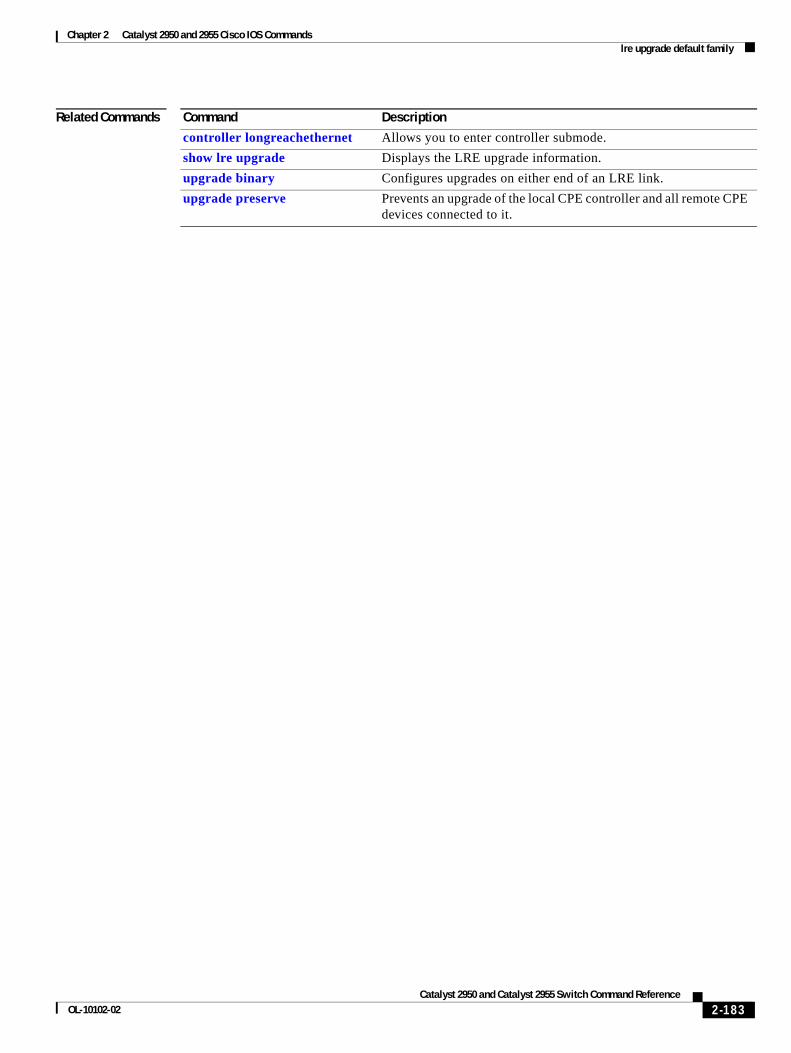
Chapter 2 Catalyst 2950 and 2955 Cisco IOS Commands lre upgrade default family
Related Commands Command Description
controller longreachethernet Allows you to enter controller submode.
show lre upgrade Displays the LRE upgrade information.
upgrade binary Configures upgrades on either end of an LRE link.
upgrade preserve Prevents an upgrade of the local CPE controller and all remote CPE devices connected to it.
2-183Catalyst 2950 and Catalyst 2955 Switch Command Reference
OL-10102-02
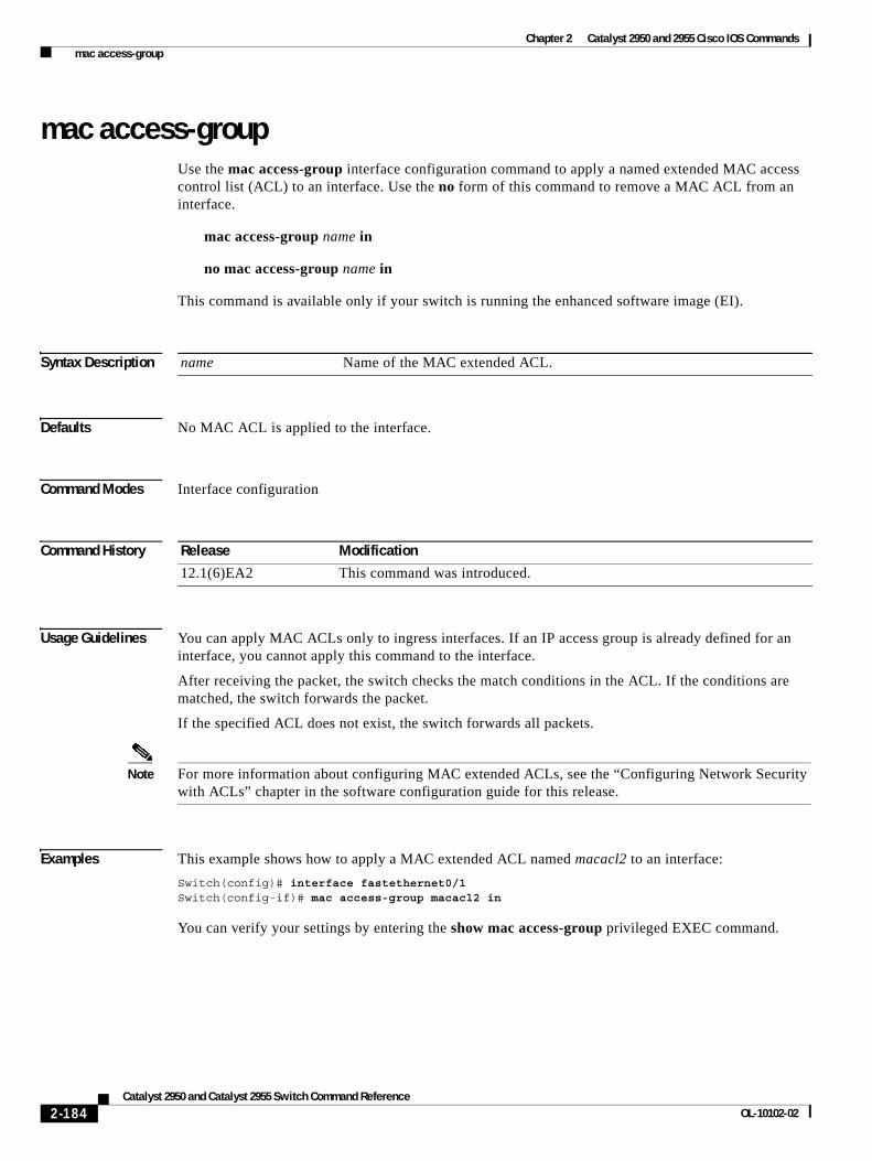
Chapter 2 Catalyst 2950 and 2955 Cisco IOS Commands mac access-group
mac access-groupUse the mac access-group interface configuration command to apply a named extended MAC access control list (ACL) to an interface. Use the no form of this command to remove a MAC ACL from an interface.
mac access-group name in
no mac access-group name in
This command is available only if your switch is running the enhanced software image (EI).
Syntax Description
Defaults No MAC ACL is applied to the interface.
Command Modes Interface configuration
Command History
Usage Guidelines You can apply MAC ACLs only to ingress interfaces. If an IP access group is already defined for an interface, you cannot apply this command to the interface.
After receiving the packet, the switch checks the match conditions in the ACL. If the conditions are matched, the switch forwards the packet.
If the specified ACL does not exist, the switch forwards all packets.
Note For more information about configuring MAC extended ACLs, see the “Configuring Network Security with ACLs” chapter in the software configuration guide for this release.
Examples This example shows how to apply a MAC extended ACL named macacl2 to an interface:
Switch(config)# interface fastethernet0/1Switch(config-if)# mac access-group macacl2 in
You can verify your settings by entering the show mac access-group privileged EXEC command.
name Name of the MAC extended ACL.
Release Modification
12.1(6)EA2 This command was introduced.
2-184Catalyst 2950 and Catalyst 2955 Switch Command Reference
OL-10102-02
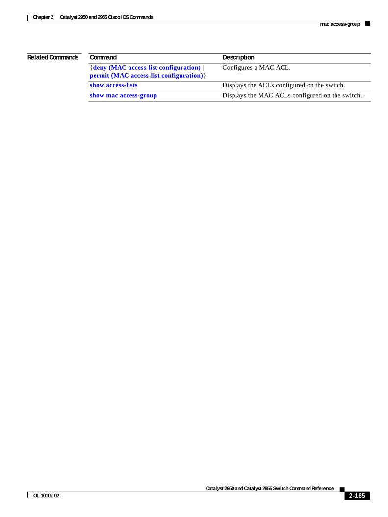
Chapter 2 Catalyst 2950 and 2955 Cisco IOS Commands mac access-group
Related Commands Command Description
{deny (MAC access-list configuration) | permit (MAC access-list configuration)}
Configures a MAC ACL.
show access-lists Displays the ACLs configured on the switch.
show mac access-group Displays the MAC ACLs configured on the switch.
2-185Catalyst 2950 and Catalyst 2955 Switch Command Reference
OL-10102-02
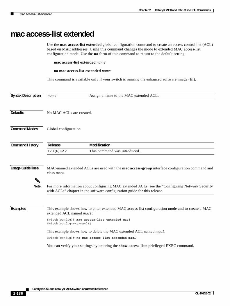
Chapter 2 Catalyst 2950 and 2955 Cisco IOS Commands mac access-list extended
mac access-list extendedUse the mac access-list extended global configuration command to create an access control list (ACL) based on MAC addresses. Using this command changes the mode to extended MAC access-list configuration mode. Use the no form of this command to return to the default setting.
mac access-list extended name
no mac access-list extended name
This command is available only if your switch is running the enhanced software image (EI).
Syntax Description
Defaults No MAC ACLs are created.
Command Modes Global configuration
Command History
Usage Guidelines MAC-named extended ACLs are used with the mac access-group interface configuration command and class maps.
Note For more information about configuring MAC extended ACLs, see the “Configuring Network Security with ACLs” chapter in the software configuration guide for this release.
Examples This example shows how to enter extended MAC access-list configuration mode and to create a MAC extended ACL named mac1:
Switch(config)# mac access-list extended mac1Switch(config-ext-macl)#
This example shows how to delete the MAC extended ACL named mac1:
Switch(config)# no mac access-list extended mac1
You can verify your settings by entering the show access-lists privileged EXEC command.
name Assign a name to the MAC extended ACL.
Release Modification
12.1(6)EA2 This command was introduced.
2-186Catalyst 2950 and Catalyst 2955 Switch Command Reference
OL-10102-02
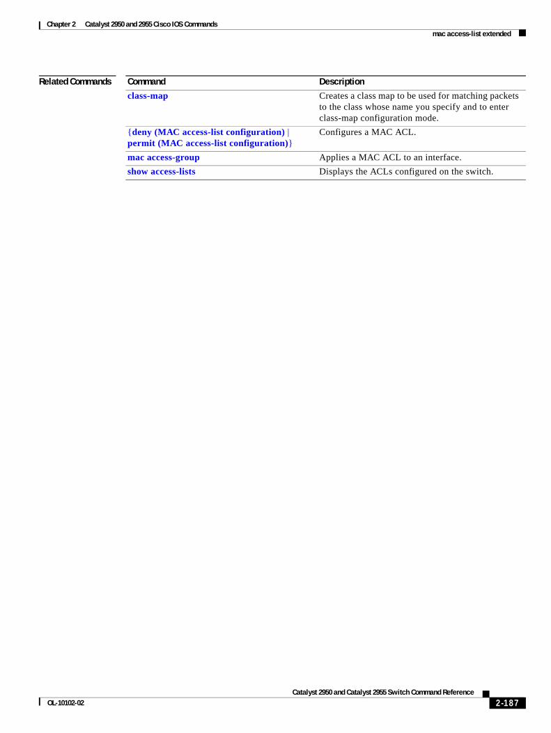
Chapter 2 Catalyst 2950 and 2955 Cisco IOS Commands mac access-list extended
Related Commands Command Description
class-map Creates a class map to be used for matching packets to the class whose name you specify and to enter class-map configuration mode.
{deny (MAC access-list configuration) | permit (MAC access-list configuration)}
Configures a MAC ACL.
mac access-group Applies a MAC ACL to an interface.
show access-lists Displays the ACLs configured on the switch.
2-187Catalyst 2950 and Catalyst 2955 Switch Command Reference
OL-10102-02
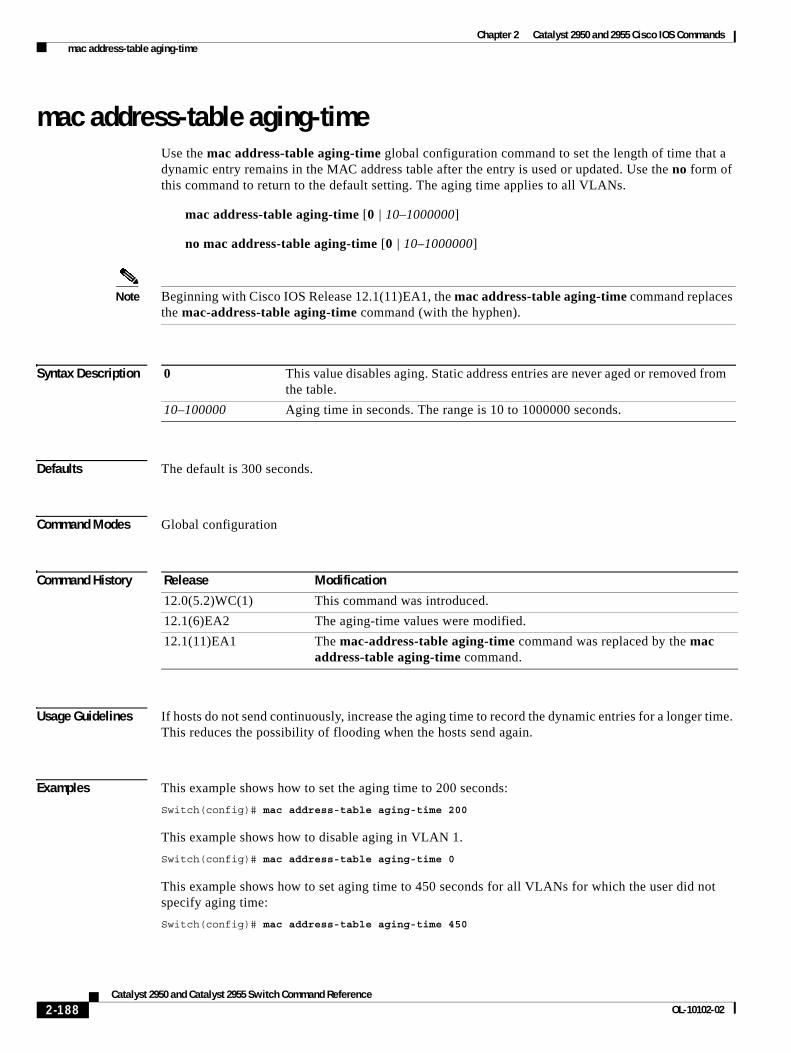
Chapter 2 Catalyst 2950 and 2955 Cisco IOS Commands mac address-table aging-time
mac address-table aging-timeUse the mac address-table aging-time global configuration command to set the length of time that a dynamic entry remains in the MAC address table after the entry is used or updated. Use the no form of this command to return to the default setting. The aging time applies to all VLANs.
mac address-table aging-time [0 | 10–1000000]
no mac address-table aging-time [0 | 10–1000000]
Note Beginning with Cisco IOS Release 12.1(11)EA1, the mac address-table aging-time command replaces the mac-address-table aging-time command (with the hyphen).
Syntax Description
Defaults The default is 300 seconds.
Command Modes Global configuration
Command History
Usage Guidelines If hosts do not send continuously, increase the aging time to record the dynamic entries for a longer time. This reduces the possibility of flooding when the hosts send again.
Examples This example shows how to set the aging time to 200 seconds:
Switch(config)# mac address-table aging-time 200
This example shows how to disable aging in VLAN 1.
Switch(config)# mac address-table aging-time 0
This example shows how to set aging time to 450 seconds for all VLANs for which the user did not specify aging time:
Switch(config)# mac address-table aging-time 450
0 This value disables aging. Static address entries are never aged or removed from the table.
10–100000 Aging time in seconds. The range is 10 to 1000000 seconds.
Release Modification
12.0(5.2)WC(1) This command was introduced.
12.1(6)EA2 The aging-time values were modified.
12.1(11)EA1 The mac-address-table aging-time command was replaced by the mac address-table aging-time command.
2-188Catalyst 2950 and Catalyst 2955 Switch Command Reference
OL-10102-02

Chapter 2 Catalyst 2950 and 2955 Cisco IOS Commands mac address-table aging-time
You can verify your settings by entering the show mac address-table privileged EXEC command.
Related Commands Command Description
clear mac address-table Deletes dynamic entries from the MAC address table.
show mac address-table Displays the MAC address table.
show mac address-table aging-time Displays the MAC address table aging time for all VLANs or the specified VLAN.
2-189Catalyst 2950 and Catalyst 2955 Switch Command Reference
OL-10102-02
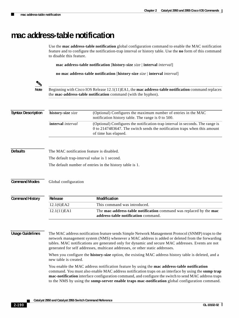
Chapter 2 Catalyst 2950 and 2955 Cisco IOS Commands mac address-table notification
mac address-table notificationUse the mac address-table notification global configuration command to enable the MAC notification feature and to configure the notification-trap interval or history table. Use the no form of this command to disable this feature.
mac address-table notification [history-size size | interval interval]
no mac address-table notification [history-size size | interval interval]
Note Beginning with Cisco IOS Release 12.1(11)EA1, the mac address-table notification command replaces the mac-address-table notification command (with the hyphen).
Syntax Description
Defaults The MAC notification feature is disabled.
The default trap-interval value is 1 second.
The default number of entries in the history table is 1.
Command Modes Global configuration
Command History
Usage Guidelines The MAC address notification feature sends Simple Network Management Protocol (SNMP) traps to the network management system (NMS) whenever a MAC address is added or deleted from the forwarding tables. MAC notifications are generated only for dynamic and secure MAC addresses. Events are not generated for self addresses, multicast addresses, or other static addresses.
When you configure the history-size option, the existing MAC address history table is deleted, and a new table is created.
You enable the MAC address notification feature by using the mac address-table notification command. You must also enable MAC address notification traps on an interface by using the snmp trap mac-notification interface configuration command, and configure the switch to send MAC address traps to the NMS by using the snmp-server enable traps mac-notification global configuration command.
history-size size (Optional) Configures the maximum number of entries in the MAC notification history table. The range is 0 to 500.
interval interval (Optional) Configures the notification-trap interval in seconds. The range is 0 to 2147483647. The switch sends the notification traps when this amount of time has elapsed.
Release Modification
12.1(6)EA2 This command was introduced.
12.1(11)EA1 The mac-address-table notification command was replaced by the mac address-table notification command.
2-190Catalyst 2950 and Catalyst 2955 Switch Command Reference
OL-10102-02
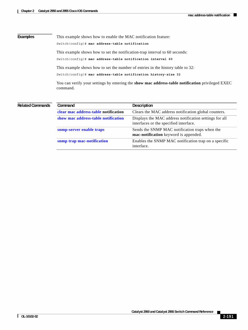
Chapter 2 Catalyst 2950 and 2955 Cisco IOS Commands mac address-table notification
Examples This example shows how to enable the MAC notification feature:
Switch(config)# mac address-table notification
This example shows how to set the notification-trap interval to 60 seconds:
Switch(config)# mac address-table notification interval 60
This example shows how to set the number of entries in the history table to 32:
Switch(config)# mac address-table notification history-size 32
You can verify your settings by entering the show mac address-table notification privileged EXEC command.
Related Commands Command Description
clear mac address-table notification Clears the MAC address notification global counters.
show mac address-table notification Displays the MAC address notification settings for all interfaces or the specified interface.
snmp-server enable traps Sends the SNMP MAC notification traps when the mac-notification keyword is appended.
snmp trap mac-notification Enables the SNMP MAC notification trap on a specific interface.
2-191Catalyst 2950 and Catalyst 2955 Switch Command Reference
OL-10102-02
Chapter 2 Catalyst 2950 and 2955 Cisco IOS Commands mac address-table static
mac address-table staticUse the mac address-table static global configuration command to add static addresses to the MAC address table. Use the no form of this command to remove static entries from the MAC address table.
mac address-table static mac-addr vlan vlan-id interface interface-id
no mac address-table static mac-addr vlan vlan-id [interface interface-id]
Note Beginning with Cisco IOS Release 12.1(11)EA1, the mac address-table static command replaces the mac-address-table static command (with the hyphen).
Syntax Description
Defaults None configured.
Command Modes Global configuration
Command History
Usage Guidelines Follow these guidelines when using this feature:
A static unicast MAC address can be assigned to one interface.
A static multicast MAC address can be assigned to one interface.
mac-addr Destination MAC address (unicast or multicast) to add to the address table. Packets with this destination address received in the specified VLAN are forwarded to the specified interface.
vlan vlan-id Specify the VLAN for which the packet with the specified MAC address is received. The range is 1 to 4094.
interface interface-id Interface to which the received packet is forwarded. Valid interfaces include physical ports and port channels.
Release Modification
12.0(5.2)WC(1) This command was introduced.
12.1(6)EA2 The interface keyword and parameters were changed.
12.1(11)EA1 The mac-address-table static command was replaced by the mac address-table static command.
2-192Catalyst 2950 and Catalyst 2955 Switch Command Reference
OL-10102-02
Chapter 2 Catalyst 2950 and 2955 Cisco IOS Commands mac address-table static
Examples This example shows how to add the static address 0004.5600.67ab to the MAC address table:
Switch(config)# mac address-table static 0004.5600.67ab vlan 1 interface fastethernet0/2
This example shows how to add the static address c2f3.220a.12f4 to the MAC address table. When a packet is received in VLAN 4 with this MAC address as its destination, the packet is forwarded to the specified interface.
Switch(config)# mac address-table static c2f3.220a.12f4 vlan 4 interface gigabitethernet0/1
You can verify your settings by entering the show mac address-table privileged EXEC command.
Related Commands Command Description
clear mac address-table Deletes entries from the MAC address table.
mac address-table aging-time Sets the length of time that a dynamic entry remains in the MAC address table after the entry is used or updated.
show mac address-table Displays the MAC address table.
show mac address-table static Displays static MAC address table entries only.
2-193Catalyst 2950 and Catalyst 2955 Switch Command Reference
OL-10102-02
Chapter 2 Catalyst 2950 and 2955 Cisco IOS Commands mac address-table static drop
mac address-table static dropUse the mac address-table static drop global configuration command to enable unicast MAC address filtering and to configure the switch to drop traffic with a specific source or destination MAC address. Use the no form of this command to return to the default setting.
mac address-table static mac-addr vlan vlan-id drop
no mac address-table static mac-addr vlan vlan-id
Syntax Description
Defaults Unicast MAC address filtering is disabled. The switch does not drop traffic for specific source or destination MAC addresses.
Command Modes Global configuration
Command History
Usage Guidelines Follow these guidelines when using this feature:
• Multicast MAC addresses, broadcast MAC addresses, and router MAC addresses are not supported. Packets that are forwarded to the CPU are also not supported.
• If you add a unicast MAC address as a static address and configure unicast MAC address filtering, the switch either adds the MAC address as a static address or drops packets with that MAC address, depending on which command was entered last. The second command that you entered overrides the first command.
For example, if you enter the mac address-table static mac-addr vlan vlan-id interface interface-id global configuration command followed by the mac address-table static mac-addr vlan vlan-id drop command, the switch drops packets with the specified MAC address as a source or destination.
If you enter the mac address-table static mac-addr vlan vlan-id drop global configuration command followed by the mac address-table static mac-addr vlan vlan-id interface interface-id command, the switch adds the MAC address as a static address.
mac-addr Unicast source or destination MAC address. Packets with this MAC address are dropped.
vlan vlan-id Specify the VLAN for which the packet with the specified MAC address is received. The range is 1 to 4094.
Release Modification
12.1(19)EA1 This command was introduced.
2-194Catalyst 2950 and Catalyst 2955 Switch Command Reference
OL-10102-02
Chapter 2 Catalyst 2950 and 2955 Cisco IOS Commands mac address-table static drop
Examples This example shows how to enable unicast MAC address filtering and to configure the switch to drop packets that have a source or destination address of c2f3.220a.12f4. When a packet is received in VLAN 4 with this MAC address as its source or destination, the packet is dropped.
Switch(config)# mac address-table static c2f3.220a.12f4 vlan 4 drop
This example shows how to disable unicast MAC address filtering:
Switch(config)# no mac address-table static c2f3.220a.12f4 vlan 4
You can verify your setting by entering the show mac address-table static privileged EXEC command.
Related Commands Command Description
show mac address-table static Displays only static MAC address table entries.
2-195Catalyst 2950 and Catalyst 2955 Switch Command Reference
OL-10102-02
Chapter 2 Catalyst 2950 and 2955 Cisco IOS Commands macro apply
macro applyUse the macro apply interface configuration command to apply a macro to an interface or to apply and trace a macro configuration on an interface.
macro {apply | trace} macro-name [parameter {value}] [parameter {value}] [parameter {value}]
Syntax Description
Defaults This command has no default setting.
Command Modes Interface configuration
Command History
Usage Guidelines You can use the macro trace macro-name interface configuration command to apply and show the macros running on an interface or to debug the macro to find any syntax or configuration errors.
If a command fails because of a syntax error or a configuration error when you apply a macro, the macro continues to apply the remaining commands to the interface.
When creating a macro that requires the assignment of unique values, use the parameter value keywords to designate values specific to the interface.
Keyword matching is case sensitive. All matching occurrences of the keyword are replaced with the corresponding value. Any full match of a keyword, even if it is part of a larger string, is considered a match and is replaced by the corresponding value.
Some macros might contain keywords that require a parameter value. You can use the macro apply macro-name ? command to view a list of any required values in the macro. If you apply a macro without entering the keyword values, the commands are invalid and are not applied.
There are Cisco-default Smartports macros embedded in the switch software. You can display these macros and the commands they contain by using the show parser macro user EXEC command.
apply Apply a macro to the specified interface.
trace Use the trace keyword to apply a macro to an interface and to debug the macro.
macro-name Specify the name of the macro.
parameter value (Optional) Specify unique parameter values that are specific to the interface. You can enter up to three keyword-value pairs. Parameter keyword matching is case sensitive. All matching occurrences of the keyword are replaced with the corresponding value.
Release Modification
12.1(19)EA1 This command was introduced.
12.1(20)EA1 The parameter value keywords were added.
2-196Catalyst 2950 and Catalyst 2955 Switch Command Reference
OL-10102-02
Chapter 2 Catalyst 2950 and 2955 Cisco IOS Commands macro apply
Follow these guidelines when you apply a Cisco-default Smartports macro on an interface:
• Display all macros on the switch by using the show parser macro user EXEC command. Display the contents of a specific macro by using the show parser macro name macro-name user EXEC command.
• Keywords that begin with $ mean that a unique parameter value is required. Append the Cisco-default macro with the required values by using the parameter value keywords.
The Cisco-default macros use the $ character to help identify required keywords. There is no restriction on using the $ character to define keywords when you create a macro.
When you apply a macro to an interface, the macro name is automatically added to the interface. You can display the applied commands and macro names by using the show running-configuration interface interface-id user EXEC command.
A macro applied to an interface range behaves the same way as a macro applied to a single interface. When you use an interface range, the macro is applied sequentially to each interface within the range. If a macro command fails on one interface, it is still applied to the remaining interfaces.
You can delete a macro-applied configuration on an interface by entering the default interface interface-id interface configuration command.
Examples After you have created a macro by using the macro name global configuration command, you can apply it to an interface. This example shows how to apply a user-created macro called duplex to an interface:
Switch(config-if)# macro apply duplex
To debug a macro, use the macro trace interface configuration command to find any syntax or configuration errors in the macro as it is applied to an interface. This example shows how troubleshoot the user-created macro called duplex on an interface:
Switch(config-if)# macro trace duplexApplying command...‘duplex auto’%Error Unknown error.Applying command...‘speed nonegotiate’
This example shows how to display the Cisco-default cisco-desktop macro and how to apply the macro and set the access VLAN ID to 25 on an interface:
Switch# show parser macro cisco-desktop--------------------------------------------------------------Macro name : cisco-desktopMacro type : default
# Basic interface - Enable data VLAN only# Recommended value for access vlan (AVID) should not be 1switchport access vlan $AVIDswitchport mode access
# Enable port security limiting port to a single# MAC address -- that of desktopswitchport port-securityswitchport port-security maximum 1
# Ensure port-security age is greater than one minute# and use inactivity timerswitchport port-security violation restrictswitchport port-security aging time 2switchport port-security aging type inactivity
2-197Catalyst 2950 and Catalyst 2955 Switch Command Reference
OL-10102-02
Chapter 2 Catalyst 2950 and 2955 Cisco IOS Commands macro apply
# Configure port as an edge network portspanning-tree portfastspanning-tree bpduguard enable--------------------------------------------------------------Switch#Switch# configure terminalSwitch(config)# interface fastethernet0/4Switch(config-if)# macro apply cisco-desktop $AVID 25
Related Commands Command Description
macro description Adds a description about the macros that are applied to an interface.
macro global Applies a macro on a switch or applies and traces a macro on a switch.
macro global description
Adds a description about the macros that are applied to the switch.
macro name Creates a macro.
show parser macro Displays the macro definition for all macros or for the specified macro.
2-198Catalyst 2950 and Catalyst 2955 Switch Command Reference
OL-10102-02
Chapter 2 Catalyst 2950 and 2955 Cisco IOS Commands macro description
macro descriptionUse the macro description interface configuration command to enter a description about which macros are applied to an interface. Use the no form of this command to remove the description.
macro description text
no macro description text
Syntax Description
Defaults This command has no default setting.
Command Modes Interface configuration
Command History
Usage Guidelines Use the description keyword to associate comment text, or the macro name, with an interface. When multiple macros are applied on a single interface, the description text will be from the last applied macro.
This example shows how to add a description to an interface:
Switch(config-if)# macro description duplex settings
You can verify your settings by entering the show parser macro description privileged EXEC command.
Related Commands
description text Enter a description about the macros that are applied to the specified interface.
Release Modification
12.1(19)EA1 This command was introduced.
Command Description
macro apply Applies a macro on an interface or applies and traces a macro on an interface.
macro global Applies a macro on a switch or applies and traces a macro on a switch
macro global description
Adds a description about the macros that are applied to the switch.
macro name Creates a macro.
show parser macro Displays the macro definition for all macros or for the specified macro.
2-199Catalyst 2950 and Catalyst 2955 Switch Command Reference
OL-10102-02

Chapter 2 Catalyst 2950 and 2955 Cisco IOS Commands macro global
macro globalUse the macro global global configuration command to apply a macro to a switch or to apply and trace a macro configuration on a switch.
macro global {apply | trace} macro-name [parameter {value}] [parameter {value}] [parameter {value}]
Syntax Description
Defaults This command has no default setting.
Command Modes Global configuration
Command History
Usage Guidelines You can use the macro trace macro-name global configuration command to apply and to show the macros running on a switch or to debug the macro to find any syntax or configuration errors.
If a command fails because of a syntax error or a configuration error when you apply a macro, the macro continues to apply the remaining commands to the switch.
When creating a macro that requires the assignment of unique values, use the parameter value keywords to designate values specific to the switch.
Keyword matching is case sensitive. All matching occurrences of the keyword are replaced with the corresponding value. Any full match of a keyword, even if it is part of a larger string, is considered a match and is replaced by the corresponding value.
Some macros might contain keywords that require a parameter value. You can use the macro global apply macro-name ? command to display a list of any required values in the macro. If you apply a macro without entering the keyword values, the commands are invalid and are not applied.
There are Cisco-default Smartports macros embedded in the switch software. You can display these macros and the commands they contain by using the show parser macro user EXEC command.
Follow these guidelines when you apply a Cisco-default Smartports macro on a switch:
• Display all macros on the switch by using the show parser macro user EXEC command. Display the contents of a specific macro by using the show parser macro name macro-name user EXEC command.
apply Apply a macro to the switch.
trace Use the trace keyword to apply a macro to a switch and to debug the macro.
macro-name Specify the name of the macro.
parameter value (Optional) Specify unique parameter values that are specific to the switch. You can enter up to three keyword-value pairs. Parameter keyword matching is case sensitive. All matching occurrences of the keyword are replaced with the corresponding value.
Release Modification
12.1(20)EA2 This command was introduced.
2-200Catalyst 2950 and Catalyst 2955 Switch Command Reference
OL-10102-02
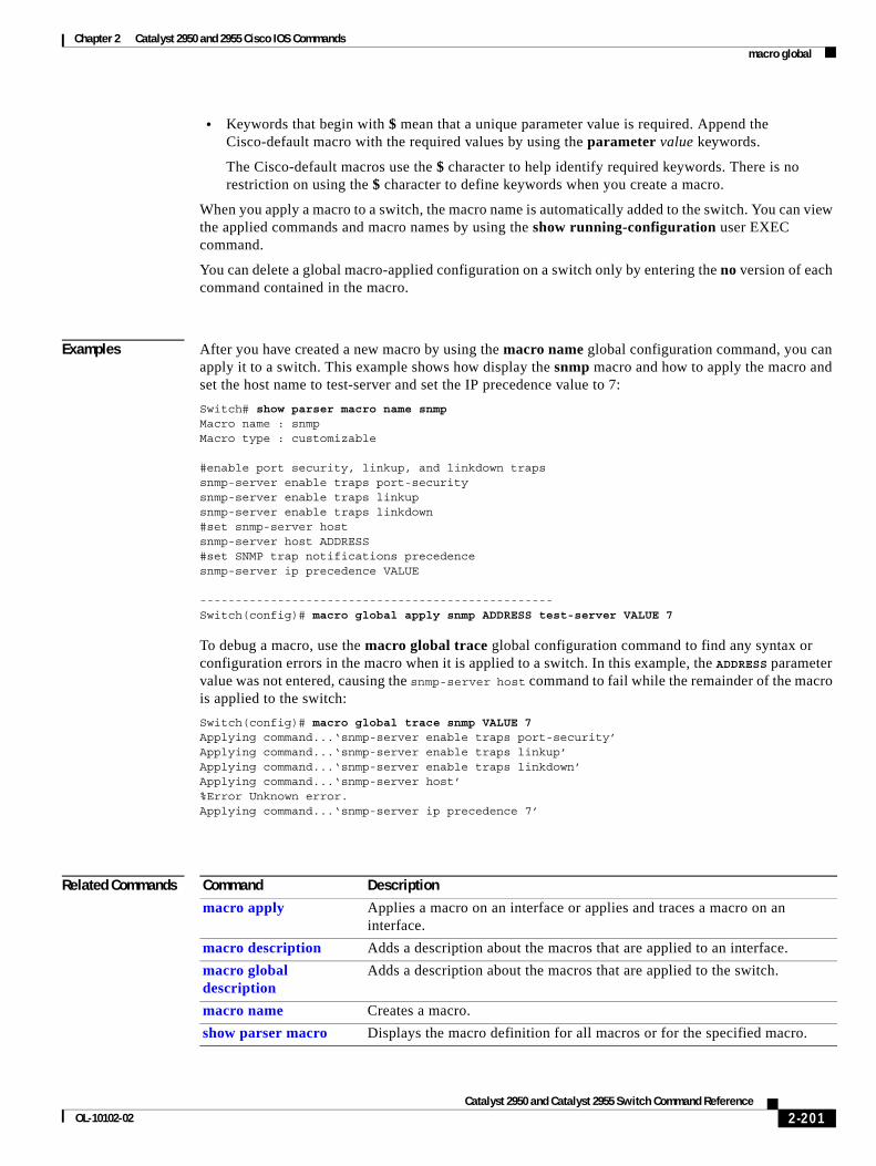
Chapter 2 Catalyst 2950 and 2955 Cisco IOS Commands macro global
• Keywords that begin with $ mean that a unique parameter value is required. Append the Cisco-default macro with the required values by using the parameter value keywords.
The Cisco-default macros use the $ character to help identify required keywords. There is no restriction on using the $ character to define keywords when you create a macro.
When you apply a macro to a switch, the macro name is automatically added to the switch. You can view the applied commands and macro names by using the show running-configuration user EXEC command.
You can delete a global macro-applied configuration on a switch only by entering the no version of each command contained in the macro.
Examples After you have created a new macro by using the macro name global configuration command, you can apply it to a switch. This example shows how display the snmp macro and how to apply the macro and set the host name to test-server and set the IP precedence value to 7:
Switch# show parser macro name snmpMacro name : snmpMacro type : customizable
#enable port security, linkup, and linkdown trapssnmp-server enable traps port-securitysnmp-server enable traps linkupsnmp-server enable traps linkdown#set snmp-server hostsnmp-server host ADDRESS#set SNMP trap notifications precedencesnmp-server ip precedence VALUE
--------------------------------------------------Switch(config)# macro global apply snmp ADDRESS test-server VALUE 7
To debug a macro, use the macro global trace global configuration command to find any syntax or configuration errors in the macro when it is applied to a switch. In this example, the ADDRESS parameter value was not entered, causing the snmp-server host command to fail while the remainder of the macro is applied to the switch:
Switch(config)# macro global trace snmp VALUE 7Applying command...‘snmp-server enable traps port-security’Applying command...‘snmp-server enable traps linkup’Applying command...‘snmp-server enable traps linkdown’Applying command...‘snmp-server host’%Error Unknown error.Applying command...‘snmp-server ip precedence 7’
Related Commands Command Description
macro apply Applies a macro on an interface or applies and traces a macro on an interface.
macro description Adds a description about the macros that are applied to an interface.
macro global description
Adds a description about the macros that are applied to the switch.
macro name Creates a macro.
show parser macro Displays the macro definition for all macros or for the specified macro.
2-201Catalyst 2950 and Catalyst 2955 Switch Command Reference
OL-10102-02
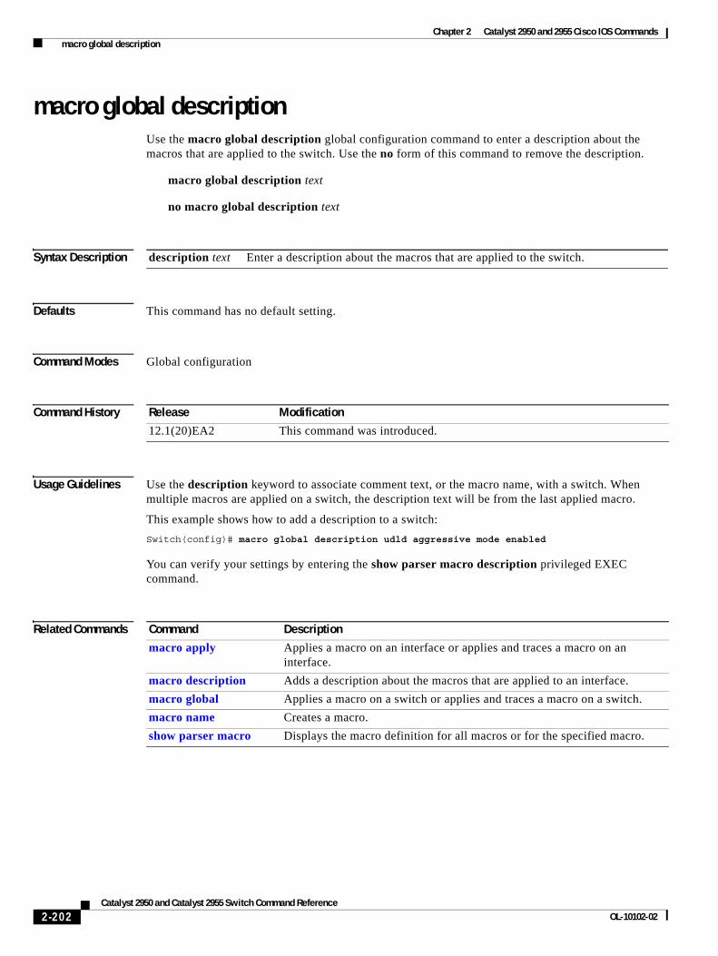
Chapter 2 Catalyst 2950 and 2955 Cisco IOS Commands macro global description
macro global descriptionUse the macro global description global configuration command to enter a description about the macros that are applied to the switch. Use the no form of this command to remove the description.
macro global description text
no macro global description text
Syntax Description
Defaults This command has no default setting.
Command Modes Global configuration
Command History
Usage Guidelines Use the description keyword to associate comment text, or the macro name, with a switch. When multiple macros are applied on a switch, the description text will be from the last applied macro.
This example shows how to add a description to a switch:
Switch(config)# macro global description udld aggressive mode enabled
You can verify your settings by entering the show parser macro description privileged EXEC command.
Related Commands
description text Enter a description about the macros that are applied to the switch.
Release Modification
12.1(20)EA2 This command was introduced.
Command Description
macro apply Applies a macro on an interface or applies and traces a macro on an interface.
macro description Adds a description about the macros that are applied to an interface.
macro global Applies a macro on a switch or applies and traces a macro on a switch.
macro name Creates a macro.
show parser macro Displays the macro definition for all macros or for the specified macro.
2-202Catalyst 2950 and Catalyst 2955 Switch Command Reference
OL-10102-02
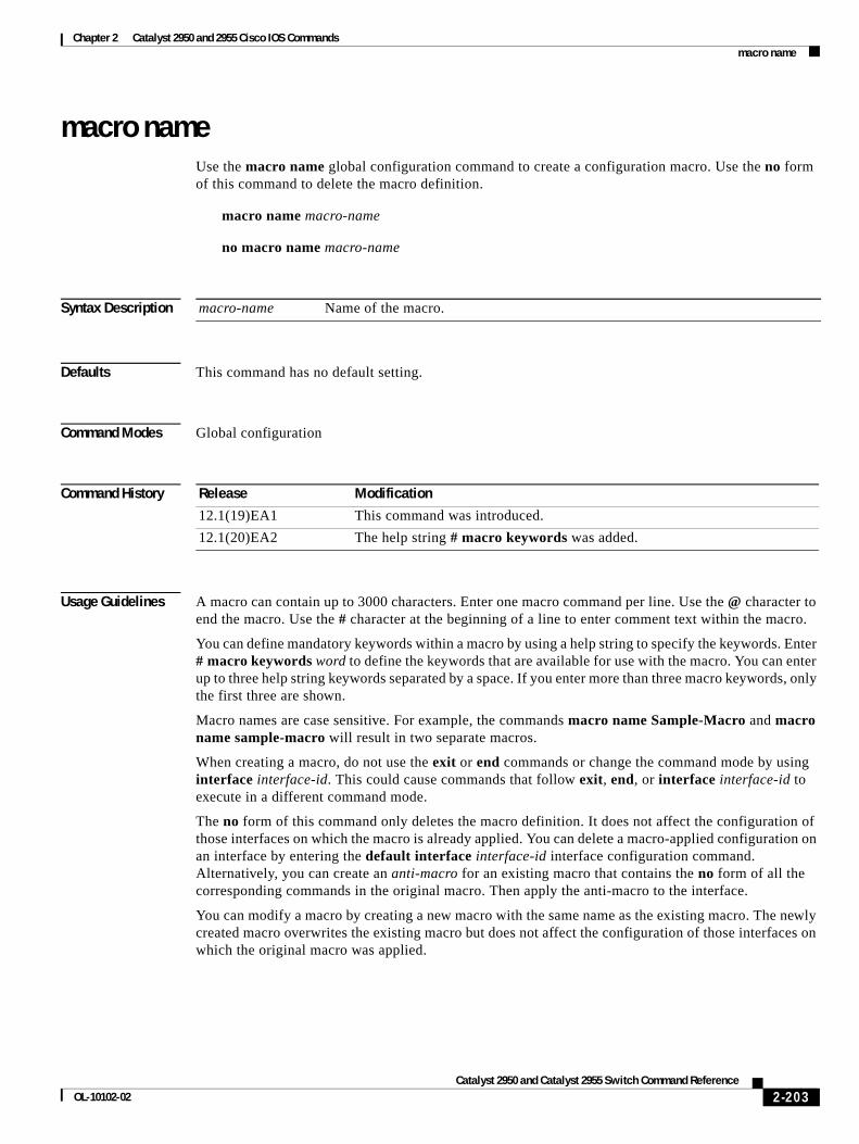
Chapter 2 Catalyst 2950 and 2955 Cisco IOS Commands macro name
macro nameUse the macro name global configuration command to create a configuration macro. Use the no form of this command to delete the macro definition.
macro name macro-name
no macro name macro-name
Syntax Description
Defaults This command has no default setting.
Command Modes Global configuration
Command History
Usage Guidelines A macro can contain up to 3000 characters. Enter one macro command per line. Use the @ character to end the macro. Use the # character at the beginning of a line to enter comment text within the macro.
You can define mandatory keywords within a macro by using a help string to specify the keywords. Enter # macro keywords word to define the keywords that are available for use with the macro. You can enter up to three help string keywords separated by a space. If you enter more than three macro keywords, only the first three are shown.
Macro names are case sensitive. For example, the commands macro name Sample-Macro and macro name sample-macro will result in two separate macros.
When creating a macro, do not use the exit or end commands or change the command mode by using interface interface-id. This could cause commands that follow exit, end, or interface interface-id to execute in a different command mode.
The no form of this command only deletes the macro definition. It does not affect the configuration of those interfaces on which the macro is already applied. You can delete a macro-applied configuration on an interface by entering the default interface interface-id interface configuration command. Alternatively, you can create an anti-macro for an existing macro that contains the no form of all the corresponding commands in the original macro. Then apply the anti-macro to the interface.
You can modify a macro by creating a new macro with the same name as the existing macro. The newly created macro overwrites the existing macro but does not affect the configuration of those interfaces on which the original macro was applied.
macro-name Name of the macro.
Release Modification
12.1(19)EA1 This command was introduced.
12.1(20)EA2 The help string # macro keywords was added.
2-203Catalyst 2950 and Catalyst 2955 Switch Command Reference
OL-10102-02
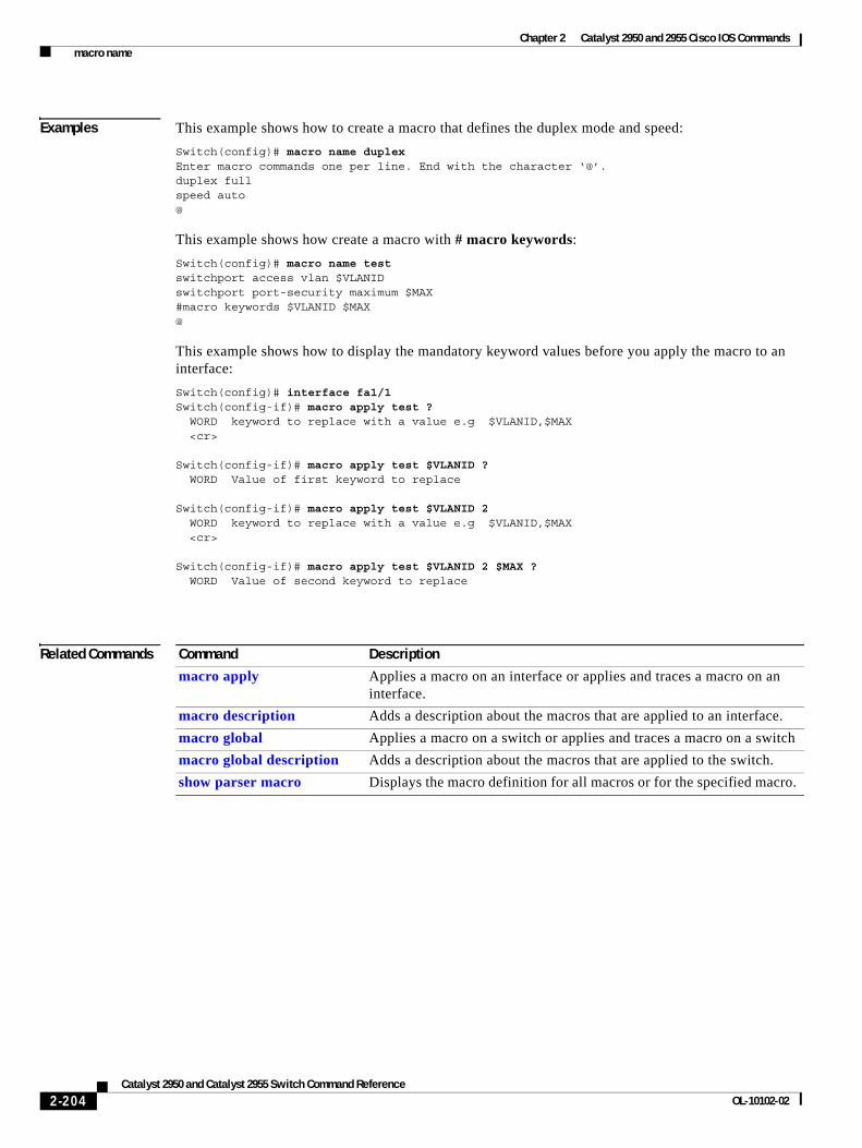
Chapter 2 Catalyst 2950 and 2955 Cisco IOS Commands macro name
Examples This example shows how to create a macro that defines the duplex mode and speed:
Switch(config)# macro name duplexEnter macro commands one per line. End with the character ‘@’.duplex fullspeed auto@
This example shows how create a macro with # macro keywords:
Switch(config)# macro name testswitchport access vlan $VLANIDswitchport port-security maximum $MAX#macro keywords $VLANID $MAX@
This example shows how to display the mandatory keyword values before you apply the macro to an interface:
Switch(config)# interface fa1/1Switch(config-if)# macro apply test ? WORD keyword to replace with a value e.g $VLANID,$MAX <cr>
Switch(config-if)# macro apply test $VLANID ? WORD Value of first keyword to replace
Switch(config-if)# macro apply test $VLANID 2 WORD keyword to replace with a value e.g $VLANID,$MAX <cr>
Switch(config-if)# macro apply test $VLANID 2 $MAX ? WORD Value of second keyword to replace
Related Commands Command Description
macro apply Applies a macro on an interface or applies and traces a macro on an interface.
macro description Adds a description about the macros that are applied to an interface.
macro global Applies a macro on a switch or applies and traces a macro on a switch
macro global description Adds a description about the macros that are applied to the switch.
show parser macro Displays the macro definition for all macros or for the specified macro.
2-204Catalyst 2950 and Catalyst 2955 Switch Command Reference
OL-10102-02
Chapter 2 Catalyst 2950 and 2955 Cisco IOS Commands margin
marginUse the margin interface configuration command to specify the margin value used to determine link quality during Long-Reach Ethernet (LRE) rate selection. Use the no form of this command to return to the default setting.
margin {downstream value | upstream value}
no margin {downstream value | upstream value}
This command is available only on Catalyst 2950 LRE switches.
Syntax Description
Defaults The default is 0 dB.
Command Modes Interface configuration
Command History
Usage Guidelines When rate selection is running, the signal-to-noise ratio (SNR) shows the link quality. The switch does not provide any internal mechanism to ensure link quality. There can be different requirements for link quality, depending on the required bit-error rate and the noise level of the environment. A noisier environment would require a higher SNR in order to provide a stable link. A lower bit-error rate would require a higher SNR. Typically a 6-dB margin provides an error rate of 10-21 bits.
To provide link stability, you should add a margin to the required SNR. You can configure your margins to an amount that is appropriate for the noise level of your environment. Increasing the margin requirement can cause the system to choose a lower profile, which would in turn translate to a lower rate but with a longer reach.
The switch does not guarantee any margins after a link is activated. Margins are only guaranteed when the link is established. When a link is activated, if the SNR requirements do not match the configured margin level, the link is not established.
Downstream means the remote end of the link and upstream the local end. The link has to satisfy both the local and remote margin requirements. If either one is not met, the link is advertised as down. This command has no significance if rate selection is not running on this interface.
Note Setting a margin requirement might cause the system to choose another profile, which might translate to a lower rate but a longer reach.
downstream value Value at the remote end of the link. The range is 0 to 10 decibels (dB).
upstream value Value at the local end of the link. The range is 0 to 10 dB.
Release Modification
12.1(11)YJ This command was introduced.
2-205Catalyst 2950 and Catalyst 2955 Switch Command Reference
OL-10102-02
Chapter 2 Catalyst 2950 and 2955 Cisco IOS Commands margin
For more information about link stability and margins, see the software configuration guide for this release.
Examples This example shows how to specify a margin of 2 dB for both upstream and downstream. If the SNR is 2 dB above the theoretical minimum for the chosen profile when the link is established, the link is classified as down and the next profile in the sequence is attempted.
Switch(config-if)# margin upstream 2 downstream 2
This example shows show to specify a margin of 1 dB for downstream:
Switch(config-if)# margin downstream 1
Related Commands Command Description
lre rate selection sequence Assigns a rate selection sequence for the entire switch.
rate selection Enables rate selection on a specific port.
rate selection sequence Assigns a rate selection sequence for a specific port.
2-206Catalyst 2950 and Catalyst 2955 Switch Command Reference
OL-10102-02
Chapter 2 Catalyst 2950 and 2955 Cisco IOS Commands match
matchUse the match class-map configuration command to define the match criteria to classify traffic. Use the no form of this command to remove the match criteria.
match {access-group acl-index | access-group name acl-name | ip dscp dscp-list}
no match {access-group acl-index | access-group name acl-name | ip dscp}
This command is available only if your switch is running the enhanced software image (EI).
Syntax Description
Defaults No match criteria are defined.
Command Modes Class-map configuration
Command History
Usage Guidelines Use the match command to specify which fields in the incoming packets are examined to classify the packets. Only IP access groups, MAC access groups, and classification based on DSCP values are supported.
Only one match command per class map is supported.
Note For more information about configuring ACLs, see the “Configuring Network Security with ACLs” chapter in the software configuration guide for this release.
access-group acl-index Number of an IP standard or extended access control list (ACL).
For an IP standard ACL, the ACL index range is 1 to 99 and 1300 to 1999. For an IP extended ACL, the ACL index range is 100 to 199 and 2000 to 2699.
access-group name acl-name
Name of an IP standard or extended ACL or name of an extended MAC ACL.
The ACL name must begin with an alphabetic character to prevent ambiguity with numbered ACLs. A name also cannot contain a space or quotation mark.
ip dscp dscp-list List of up to eight IP Differentiated Services Code Point (DSCP) values for each match statement to match against incoming packets. Separate each value with a space. The supported DSCP values are 0, 8, 10, 16, 18, 24, 26, 32, 34, 40, 46, 48, and 56.
Release Modification
12.1(6)EA2 This command was introduced.
2-207Catalyst 2950 and Catalyst 2955 Switch Command Reference
OL-10102-02
Chapter 2 Catalyst 2950 and 2955 Cisco IOS Commands match
Examples This example shows how to classify traffic on an interface by using the access group named acl2:
Switch(config)# class-map class2Switch(config-cmap)# match access-group name acl2Switch(config-cmap)# exit
You can verify your settings by entering the show class-map privileged EXEC command.
Related Commands Command Description
class Defines a traffic classification for a policy to act on using the class-map name or access group.
class-map Creates a class map to be used for matching packets to the class whose name you specify.
ip access-group Controls access to an interface.
mac access-group Applies a named extended MAC ACL to an interface.
show class-map Displays quality of service (QoS) class maps.
show policy-map Displays QoS policy maps.
2-208Catalyst 2950 and Catalyst 2955 Switch Command Reference
OL-10102-02
Chapter 2 Catalyst 2950 and 2955 Cisco IOS Commands media-type
media-typeUse the media-type interface configuration command to enable or disable fiber-optic or copper connections on a Long-Reach Ethernet (LRE) switch. You can also manually set the port to select a small form-factor pluggable (SFP) module connector or an RJ-45 connector. Use the no form of this command to return to the default setting.
media-type {auto-select | rj45 | sfp}
no media-type {auto-select | rj45 | sfp}
This command is available only on Catalyst 2950 LRE switches.
Syntax Description
Defaults The default is SFP module preferred.
Command Modes Interface configuration
Command History
Usage Guidelines If an LRE switch detects an SFP connector in the switch, whether or not a fiber-optic connector is connected to that connector, it attempts to establish a link by using the SFP module as the media type. This preference of a fiber-optic connection over a copper connection is called SFP-module preferred. To physically connect both fiber-optic and copper connections and to override the SFP-module-preferred setting, use the auto-select keyword, or manually configure the port by using the rj45 or sfp keyword.
Examples This example shows how to force the connection to a copper RJ-45 connection:
Switch# configure terminalSwitch(config)# interface gigabitethernet0/1Switch(config-if)# media-type rj45
You can verify your settings by using the show interfaces media or media interface-id privileged EXEC command.
auto-select First media-type detected makes the link.
rj45 RJ-45 copper connection makes the link even when a link is already established with fiber optic.
sfp SFP fiber-optic connection makes the link even when a link is already established with copper.
Release Modification
12.1(11)YJ This command was introduced.
2-209Catalyst 2950 and Catalyst 2955 Switch Command Reference
OL-10102-02
Chapter 2 Catalyst 2950 and 2955 Cisco IOS Commands media-type
Related Commands Command Description
show interfaces cpe Shows the status or resolution of the link.
2-210Catalyst 2950 and Catalyst 2955 Switch Command Reference
OL-10102-02
Chapter 2 Catalyst 2950 and 2955 Cisco IOS Commands mls qos cos
mls qos cosUse the mls qos cos interface configuration command to define the default class of service (CoS) value of a port or to assign the default CoS to all incoming packets on the port. Use the no form of this command to return to the default setting.
mls qos cos {default-cos | override}
no mls qos cos {default-cos | override}
Syntax Description
Defaults The default CoS value for a port is 0.
CoS override is disabled.
Command Modes Interface configuration
Command History
Usage Guidelines You can use the default value to assign CoS and DSCP values to all packets entering a port if the port has been configured by using the override keyword.
Use the override keyword when all incoming packets on certain ports deserve higher or lower priority than packets entering from other ports. Even if a port was previously set to trust DSCP or CoS, this command overrides that trust state, and all the incoming CoS values are assigned the default CoS value configured with the mls qos cos command. If an incoming packet is tagged, the CoS value of the packet is modified with the default CoS of the port at the ingress port.
Examples This example shows how to configure the default port CoS to 4:
Switch(config)# interface gigabitethernet0/1Switch(config-if)# mls qos trust cosSwitch(config-if)# mls qos cos 4
This example shows how to assign all the packets entering a port to the default port CoS value of 4:
Switch(config)# interface gigabitethernet0/1Switch(config-if)# mls qos cos 4Switch(config-if)# mls qos cos override
default-cos Assign a default CoS value to a port. If the port is CoS trusted and packets are untagged, the default CoS value becomes a CoS value used to select one output queue to index into the CoS-to-Differentiated Services Code Point (DSCP) map. The range is 0 to 7.
override Override the CoS of the incoming packets, and apply the default CoS value on the port to all incoming packets.
Release Modification
12.1(6)EA2 This command was introduced.
2-211Catalyst 2950 and Catalyst 2955 Switch Command Reference
OL-10102-02
Chapter 2 Catalyst 2950 and 2955 Cisco IOS Commands mls qos cos
You can verify your settings by entering the show mls qos interface privileged EXEC command.
Related Commands Command Description
mls qos map Defines the CoS-to-DSCP map or the DSCP-to-CoS map.
mls qos trust Configures the port trust state.
show mls qos interface Displays quality of service (QoS) information.
2-212Catalyst 2950 and Catalyst 2955 Switch Command Reference
OL-10102-02
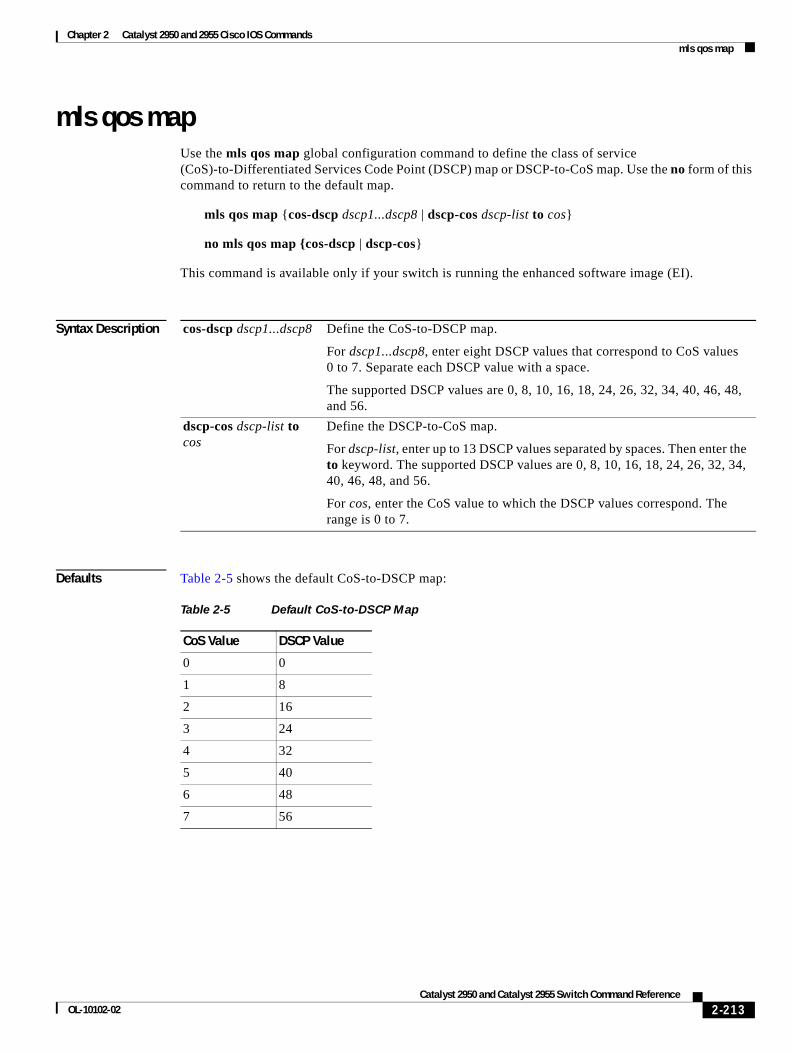
Chapter 2 Catalyst 2950 and 2955 Cisco IOS Commands mls qos map
mls qos mapUse the mls qos map global configuration command to define the class of service (CoS)-to-Differentiated Services Code Point (DSCP) map or DSCP-to-CoS map. Use the no form of this command to return to the default map.
mls qos map {cos-dscp dscp1...dscp8 | dscp-cos dscp-list to cos}
no mls qos map {cos-dscp | dscp-cos}
This command is available only if your switch is running the enhanced software image (EI).
Syntax Description
Defaults Table 2-5 shows the default CoS-to-DSCP map:
cos-dscp dscp1...dscp8 Define the CoS-to-DSCP map.
For dscp1...dscp8, enter eight DSCP values that correspond to CoS values 0 to 7. Separate each DSCP value with a space.
The supported DSCP values are 0, 8, 10, 16, 18, 24, 26, 32, 34, 40, 46, 48, and 56.
dscp-cos dscp-list to cos
Define the DSCP-to-CoS map.
For dscp-list, enter up to 13 DSCP values separated by spaces. Then enter the to keyword. The supported DSCP values are 0, 8, 10, 16, 18, 24, 26, 32, 34, 40, 46, 48, and 56.
For cos, enter the CoS value to which the DSCP values correspond. The range is 0 to 7.
Table 2-5 Default CoS-to-DSCP Map
CoS Value DSCP Value
0 0
1 8
2 16
3 24
4 32
5 40
6 48
7 56
2-213Catalyst 2950 and Catalyst 2955 Switch Command Reference
OL-10102-02
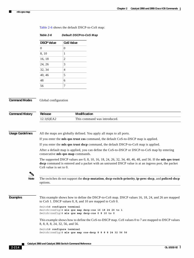
Chapter 2 Catalyst 2950 and 2955 Cisco IOS Commands mls qos map
Table 2-6 shows the default DSCP-to-CoS map:
Command Modes Global configuration
Command History
Usage Guidelines All the maps are globally defined. You apply all maps to all ports.
If you enter the mls qos trust cos command, the default CoS-to-DSCP map is applied.
If you enter the mls qos trust dscp command, the default DSCP-to-CoS map is applied.
After a default map is applied, you can define the CoS-to-DSCP or DSCP-to-CoS map by entering consecutive mls qos map commands.
The supported DSCP values are 0, 8, 10, 16, 18, 24, 26, 32, 34, 40, 46, 48, and 56. If the mls qos trust dscp command is entered and a packet with an untrusted DSCP value is at an ingress port, the packet CoS value is set to 0.
Note The switches do not support the dscp-mutation, dscp-switch-priority, ip-prec-dscp, and policed-dscp options.
Examples This example shows how to define the DSCP-to-CoS map. DSCP values 16, 18, 24, and 26 are mapped to CoS 1. DSCP values 0, 8, and 10 are mapped to CoS 0.
Switch# configure terminalSwitch(config)# mls qos map dscp-cos 16 18 24 26 to 1Switch(config)# mls qos map dscp-cos 0 8 10 to 0
This example shows how to define the CoS-to-DSCP map. CoS values 0 to 7 are mapped to DSCP values 8, 8, 8, 8, 24, 32, 56, and 56.
Switch# configure terminalSwitch(config)# mls qos map cos-dscp 8 8 8 8 24 32 56 56
Table 2-6 Default DSCP-to-CoS Map
DSCP Value CoS Value
0 0
8, 10 1
16, 18 2
24, 26 3
32, 34 4
40, 46 5
48 6
56 7
Release Modification
12.1(6)EA2 This command was introduced.
2-214Catalyst 2950 and Catalyst 2955 Switch Command Reference
OL-10102-02
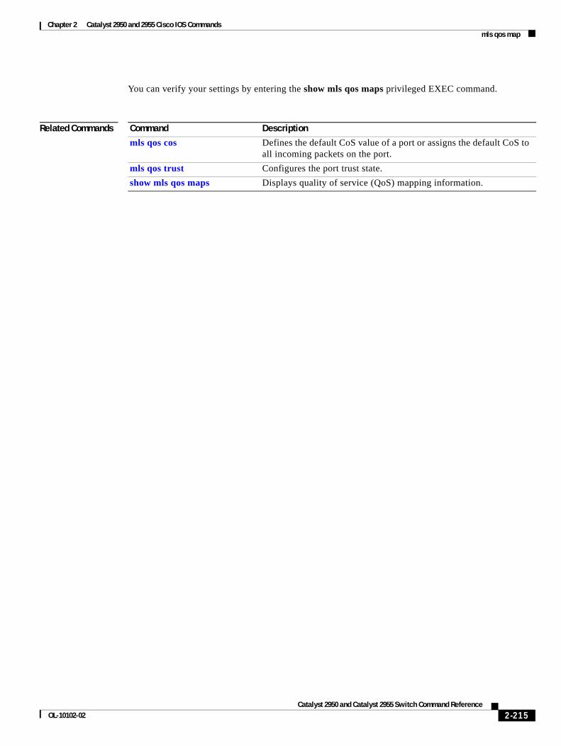
Chapter 2 Catalyst 2950 and 2955 Cisco IOS Commands mls qos map
You can verify your settings by entering the show mls qos maps privileged EXEC command.
Related Commands Command Description
mls qos cos Defines the default CoS value of a port or assigns the default CoS to all incoming packets on the port.
mls qos trust Configures the port trust state.
show mls qos maps Displays quality of service (QoS) mapping information.
2-215Catalyst 2950 and Catalyst 2955 Switch Command Reference
OL-10102-02
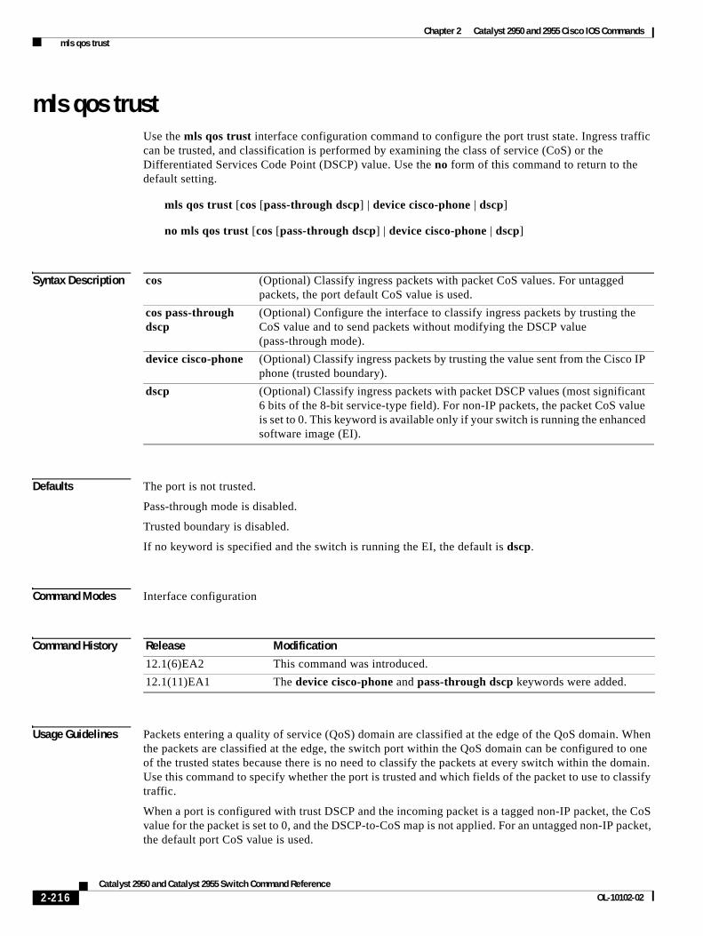
Chapter 2 Catalyst 2950 and 2955 Cisco IOS Commands mls qos trust
mls qos trustUse the mls qos trust interface configuration command to configure the port trust state. Ingress traffic can be trusted, and classification is performed by examining the class of service (CoS) or the Differentiated Services Code Point (DSCP) value. Use the no form of this command to return to the default setting.
mls qos trust [cos [pass-through dscp] | device cisco-phone | dscp]
no mls qos trust [cos [pass-through dscp] | device cisco-phone | dscp]
Syntax Description
Defaults The port is not trusted.
Pass-through mode is disabled.
Trusted boundary is disabled.
If no keyword is specified and the switch is running the EI, the default is dscp.
Command Modes Interface configuration
Command History
Usage Guidelines Packets entering a quality of service (QoS) domain are classified at the edge of the QoS domain. When the packets are classified at the edge, the switch port within the QoS domain can be configured to one of the trusted states because there is no need to classify the packets at every switch within the domain. Use this command to specify whether the port is trusted and which fields of the packet to use to classify traffic.
When a port is configured with trust DSCP and the incoming packet is a tagged non-IP packet, the CoS value for the packet is set to 0, and the DSCP-to-CoS map is not applied. For an untagged non-IP packet, the default port CoS value is used.
cos (Optional) Classify ingress packets with packet CoS values. For untagged packets, the port default CoS value is used.
cos pass-through dscp
(Optional) Configure the interface to classify ingress packets by trusting the CoS value and to send packets without modifying the DSCP value (pass-through mode).
device cisco-phone (Optional) Classify ingress packets by trusting the value sent from the Cisco IP phone (trusted boundary).
dscp (Optional) Classify ingress packets with packet DSCP values (most significant 6 bits of the 8-bit service-type field). For non-IP packets, the packet CoS value is set to 0. This keyword is available only if your switch is running the enhanced software image (EI).
Release Modification
12.1(6)EA2 This command was introduced.
12.1(11)EA1 The device cisco-phone and pass-through dscp keywords were added.
2-216Catalyst 2950 and Catalyst 2955 Switch Command Reference
OL-10102-02
Chapter 2 Catalyst 2950 and 2955 Cisco IOS Commands mls qos trust
If DSCP is trusted, the DSCP field of the IP packet is not modified. However, it is still possible that the CoS value of the packet is modified (according to the DSCP-to-CoS map).
If CoS is trusted, the CoS of the packet is not modified, but DSCP can be modified (according to the CoS-to-DSCP map) if it is an IP packet.
To return a port to the untrusted state, use the no mls qos trust interface configuration command.
The trusted boundary feature prevents security problems if users disconnect their PCs from networked Cisco IP phones and connect them into the switch port to take advantage of trusted CoS settings. You must globally enable the Cisco Discovery Protocol (CDP) on both the switch and on the interface connected to the IP phone. If the phone is not detected, trusted boundary disables the trust setting on the switch port and prevents misuse of a high-priority queue.
If trusted boundary is enabled and the no mls qos trust command is entered, the port returns to the untrusted state and cannot be configured to trust if it is connected to a Cisco IP phone.
To disable trusted boundary, use the no mls qos trust device interface configuration command.
In software releases earlier than Cisco IOS Release 12.1(11)EA1, the switch is in pass-through mode. It uses the CoS value of incoming packets without modifying the DSCP value and sends the packets from one of the four egress queues. You cannot enable or disable pass-through mode if your switch is running a software release earlier than Cisco IOS Release 12.1(11)EA1.
In Cisco IOS Release 12.1(11)EA1 or later, pass-through mode is disabled by default. The switch assigns a CoS value of 0 to all incoming packets without modifying the packets. It offers best-effort service to each packet regardless of the packet contents or size and sends it from a single egress queue.
You can enable pass-through mode on a switch running Cisco IOS Release 12.1(11)EA1 or later by using the mls qos trust cos pass-through dscp interface configuration command. To disable pass-through mode, use the no mls qos trust cos pass-through interface configuration command.
Note In software releases earlier than Cisco IOS Release 12.1(11)EA1, the mls qos trust command is available only when the switch is running the EI.
Examples This example shows how to configure a port to be a DSCP-trusted port:
Switch(config)# interface gigabitethernet0/1Switch(config-if)# mls qos trust dscp
This example shows how to specify that the Cisco IP phone is a trusted device:
Switch(config)# interface fastethernet0/1Switch(config-if)# mls qos trust device cisco-phone
This example shows how to configure the interface to trust the CoS of incoming packets and to send them without modifying the DSCP field:
Switch(config)# interface fastethernet0/1Switch(config-if)# mls qos trust cos pass-through dscp
You can verify your settings by entering the show mls qos interface privileged EXEC command.
2-217Catalyst 2950 and Catalyst 2955 Switch Command Reference
OL-10102-02
Chapter 2 Catalyst 2950 and 2955 Cisco IOS Commands mls qos trust
Related Commands Command Description
mls qos cos Defines the default CoS value of a port or assigns the default CoS to all incoming packets on the port.
mls qos map Defines the CoS-to-DSCP map or the DSCP-to-CoS map.
show mls qos interface Displays QoS information.
2-218Catalyst 2950 and Catalyst 2955 Switch Command Reference
OL-10102-02
Chapter 2 Catalyst 2950 and 2955 Cisco IOS Commands monitor session
monitor sessionUse the monitor session global configuration command to start a new Switched Port Analyzer (SPAN) or Remote SPAN (RSPAN) session. Use the no form of this command to remove the SPAN or the RSPAN session or to remove source or destination interfaces from the SPAN or RSPAN session.
monitor session session_number {destination {interface interface-id [, | -] [encapsulation {dot1q}] [ingress vlan vlan id] | remote vlan vlan-id reflector-port interface-id} | {source {interface interface-id [, | -] [both | rx | tx] | remote vlan vlan-id}}
no monitor session session_number {destination {interface interface-id [, | -] [encapsulation {dot1q}] [ingress vlan vlan id] | remote vlan vlan-id reflector-port interface-id} | {source {interface interface-id [, | -] [both | rx | tx] | remote vlan vlan-id}}
no monitor session {session_number | all | local | remote}
Syntax Description session_number Specify the session number identified with the SPAN or RSPAN session.
destination interface interface-id
Specify the destination interface for a local SPAN session. Valid interfaces are physical ports.
encapsulation (Optional) Specify the encapsulation header for outgoing packets through a destination port. If encapsulation type is not specified, packets are sent in native form. To reconfigure a destination port in native form, enter the command without the encapsulation keyword.
dot1q Specify the encapsulation type as IEEE 802.1Q.
ingress vlan vlan id (Optional) Specify whether forwarding is enabled for ingress traffic on the destination port. If encapsulation type is not specified, packets are sent in native form.
Ingress forwarding is not supported on RSPAN destination ports.
destination remote vlan vlan-id
Specify the destination remote VLAN for an RSPAN source session.
reflector-port interface-id
Specify the reflector port used for a source RSPAN session.
source interface interface-id
Specify the SPAN source interface type, slot, and port number. Valid interfaces include physical ports and port channels.
, (Optional) Specify a series of interfaces, or separate a range of interfaces from a previous range. Enter a space after the comma.
- (Optional) Specify a range of interfaces. Enter a space before and after the hyphen.
both, rx, tx (Optional) Specify the traffic direction for each source.
source remote vlan vlan-id
Specify the source RSPAN VLAN for an RSPAN destination session.
all, local, remote Specify all, local, or remote to clear all SPAN sessions, all local SPAN sessions, or all RSPAN sessions.
2-219Catalyst 2950 and Catalyst 2955 Switch Command Reference
OL-10102-02
Chapter 2 Catalyst 2950 and 2955 Cisco IOS Commands monitor session
Defaults On a source interface, the default is to monitor both received and transmitted traffic.
If encapsulation type is not specified on a destination port, packets are sent in native form with no encapsulation.
Ingress forwarding is disabled on SPAN destination ports.
Command Modes Global configuration
Command History
Usage Guidelines Traffic that enters or leaves source ports can be monitored by using SPAN or RSPAN. Traffic routed to source ports cannot be monitored.
You can configure (and store in NVRAM) one local SPAN session or multiple RSPAN sessions on a switch. The number of active sessions and combinations are subject to these restrictions:
• SPAN or RSPAN source (rx, tx, both): one active session limit. (SPAN and RSPAN are mutually exclusive on a source switch).
• RSPAN source sessions have one destination per session with an RSPAN VLAN associated for that session.
• Each RSPAN destination session has one or more destination interfaces for each RSPAN VLAN that it supports.
• RSPAN destination sessions are limited to two, or one if a local SPAN or a source RSPAN session is configured on the same switch.
You can monitor traffic on a single port or on a series or range of ports. You select a series or range of interfaces by using the [, | -] options.
If you specify a series of interfaces, you must enter a space before and after the comma. If you specify a range of interfaces, you must enter a space before and after the hyphen (-).
EtherChannel ports cannot be configured as SPAN or RSPAN destination or reflector ports. A physical port that is a member of an EtherChannel group can be used as a source or destination port. It cannot participate in the EtherChannel group while it is configured for SPAN or RSPAN.
A port used as a reflector port cannot be a SPAN or RSPAN source or destination port, nor can a port be a reflector port for more than one session at a time.
A port used as a destination port cannot be a SPAN or RSPAN source or reflector port, nor can a port be a destination port for more than one session at a time.
You can enable IEEE 802.1x authentication on a port that is an RSPAN destination port; however, IEEE 802.1x authentication is disabled until the port is removed as a RSPAN destination. (If IEEE 802.1x authentication is not available on the port, an error message is displayed.) You can enable IEEE 802.1x authentication on a SPAN or RSPAN source port but not on a SPAN destination port.
Release Modification
12.1(6)EA1 This command was introduced.
12.1(11)EA1 These RSPAN keywords were added: encapsulation, destination remote vlan reflector-port, source remote vlan, all, local, remote.
12.1(13)EA1 The ingress vlan keyword was added.
2-220Catalyst 2950 and Catalyst 2955 Switch Command Reference
OL-10102-02
Chapter 2 Catalyst 2950 and 2955 Cisco IOS Commands monitor session
If ingress forwarding is enabled, you can use the SPAN destination port to inject traffic from a network security device. For example, if you connect a Cisco Intrusion Detection System (IDS) Sensor Appliance to a destination port, the IDS device can send TCP Reset packets to close down the TCP session of a suspected attacker.
Examples This example shows how to create SPAN session 1 to monitor both sent and received traffic on source port 1 on destination port 8:
Switch(config)# monitor session 1 source interface fastethernet0/1 bothSwitch(config)# monitor session 1 destination interface fastethernet0/8
This example shows how to delete a destination port from an existing SPAN session:
Switch(config)# no monitor session 2 destination fastethernet0/4
This example shows how to configure RSPAN session 1 to monitor multiple source interfaces and to configure the destination RSPAN VLAN and the reflector-port:
Switch(config)# monitor session 1 source interface fastethernet0/10 txSwitch(config)# monitor session 1 source interface fastethernet0/2 rxSwitch(config)# monitor session 1 source interface port-channel 102 rxSwitch(config)# monitor session 1 destination remote vlan 901 reflector-port fastethernet0/1Switch(config)# end
This example shows how to configure the destination port for ingress traffic on VLAN 5 by using a security device that does not support IEEE 802.1Q encapsulation:
Switch(config)# monitor session 1 destination interface fastethernet0/5 ingress vlan 5
This example shows how to configure the destination port for ingress traffic on VLAN 5 by using a security device that supports IEEE 802.1Q encapsulation:
Switch(config)# monitor session 1 destination interface fastethernet0/5 encapsulation dot1q ingress vlan 5
This example shows how to disable ingress traffic forwarding on the destination port:
Switch(config)# monitor session 1 destination interface fastethernet0/5 encapsulation dot1q
You can verify your settings by entering the show monitor privileged EXEC command.
Related Commands Command Description
remote-span Configures an RSPAN VLAN in vlan configuration mode.
show monitor Displays SPAN and RSPAN session information.
2-221Catalyst 2950 and Catalyst 2955 Switch Command Reference
OL-10102-02
Chapter 2 Catalyst 2950 and 2955 Cisco IOS Commands mvr
mvrUse the mvr global configuration command without keywords to enable the multicast VLAN registration (MVR) feature on the switch. Use the no form of this command to disable MVR and its options. Use the command with keywords to set the MVR mode for a switch, to configure the MVR IP multicast address, to set the maximum time to wait for a query reply before removing a port from group membership, and to specify the MVR multicast VLAN. Use the no form of this command to return to the default settings.
mvr [group ip-address [count] | mode {compatible | dynamic} | querytime value | vlan vlan-id]
no mvr [group ip-address | mode {compatible | dynamic} | querytime value | vlan vlan-id]
Syntax Description
Defaults MVR is disabled.
The default MVR mode is compatible mode.
No IP multicast addresses are configured on the switch.
The default group IP address count is 0.
The default query response time is 5 tenths of or one-half second.
The default multicast VLAN for MVR is VLAN 1.
group ip-address (Optional) Statically configure an MVR group IP multicast address on the switch.
Use the no form of this command to remove a statically configured IP multicast address or contiguous addresses or, when no IP address is entered, to remove all statically configured MVR IP multicast addresses.
count (Optional) Configure multiple contiguous MVR group addresses. The range is 1 to 256. The default is 1.
mode (Optional) Specify the MVR mode of operation.
The default is compatible mode.
compatible Set MVR mode to provide compatibility with Catalyst 2900 XL and 3500 XL switches. This mode does not allow dynamic membership joins on source ports.
dynamic Set MVR mode to allow dynamic MVR membership on source ports.
querytime value (Optional) Set the maximum time to wait for Internet Group Management Protocol (IGMP) report memberships on a receiver port. This time applies only to receiver-port leave processing. When an IGMP query is sent from a receiver port, the switch waits for the default or configured MVR query time for an IGMP group membership report before removing the port from multicast group membership.
The value is the response time in units of tenths of a second. The default is 5 tenths or one-half second. The range is 1 to 100 tenths of a second.
Use the no form of the command to return to the default setting.
vlan vlan-id (Optional) Specify the VLAN on which MVR multicast data is expected to be received. This is also the VLAN to which all the source ports belong. The default is VLAN. The range is 1 to 4094.
2-222Catalyst 2950 and Catalyst 2955 Switch Command Reference
OL-10102-02
Chapter 2 Catalyst 2950 and 2955 Cisco IOS Commands mvr
Command Modes Global configuration
Command History
Usage Guidelines A maximum of 256 MVR multicast groups can be configured on a switch.
Use the mvr group command to statically configure all the IP multicast addresses that will take part in MVR. Any multicast data sent to a configured multicast address is sent to all the source ports on the switch and to all receiver ports registered to receive data on that IP multicast address.
Note The mvr group command prevents adding IP multicast addresses that cause address aliasing between MVR multicast groups or with the reserved IP multicast addresses (in the range 224.0.0.xx). Each IP multicast address translates to a multicast 48-bit MAC address. If the IP address being configured translates (aliases) to the same 48-bit MAC address as a previously configured IP multicast address or the reserved MAC multicast addresses, the command fails.
The mvr querytime parameter applies only to receiver ports.
The mvr group and mvr vlan commands only apply to ports configured as receiver ports.
If the switch MVR is interoperating with Catalyst 2900 XL or Catalyst 3500 XL switches, set the multicast mode to compatible.
When in compatible mode, MVR does not support IGMP dynamic joins on MVR source ports.
Examples This example shows how to enable MVR:
Switch(config)# mvr
This example shows how to configure 228.1.23.4 as an IP multicast address:
Switch(config)# mvr group 228.1.23.4
This command fails because of address aliasing:
Switch(config)# mvr group 230.1.23.4
Cannot add this IP address - aliases with previously configured IP address 228.1.23.4.
This example shows how to configure ten contiguous IP multicast groups with multicast addresses from 228.1.23.1 to 228.1.23.10:
Switch(config)# mvr group 228.1.23.1 10
This example shows how to set the maximum query response time as 1 second (10 tenths):
Switch(config)# mvr querytime 10
This example shows how to set VLAN 2 as the multicast VLAN:
Switch(config)# mvr vlan 2
Use the show mvr members privileged EXEC command to display the IP multicast group addresses configured on the switch.
Release Modification
12.1(6)EA2 This command was introduced.
2-223Catalyst 2950 and Catalyst 2955 Switch Command Reference
OL-10102-02
Chapter 2 Catalyst 2950 and 2955 Cisco IOS Commands mvr
You can verify your settings by entering the show mvr privileged EXEC command.
Related Commands Command Description
mvr immediate Enables the Immediate-Leave feature on an interface.
mvr type Configures a port as a receiver or source port.
mvr vlan group Configures a receiver port as a member of an MVR group.
show mvr Displays MVR global parameters or port parameters.
show mvr interface Displays the configured MVR interfaces with their type, status, and Immediate-Leave configuration.
show mvr interface interface-id member Displays all MVR groups of which the interface is a member.
show mvr members Displays all ports that are members of an MVR multicast group; if the group has no members, its status is shown as Inactive.
2-224Catalyst 2950 and Catalyst 2955 Switch Command Reference
OL-10102-02
Chapter 2 Catalyst 2950 and 2955 Cisco IOS Commands mvr immediate
mvr immediateUse the mvr immediate interface configuration command to enable the Immediate-Leave feature on an interface. Use the no form of this command to disable the feature on the interface.
mvr immediate
no mvr immediate
Syntax Description This command has no arguments or keywords.
Defaults The Immediate-Leave feature is disabled.
Command Modes Interface configuration
Command History
Usage Guidelines The Immediate-Leave feature applies only to receiver ports. When the Immediate-Leave feature is enabled, a receiver port leaves a multicast group more quickly. When the switch receives an Internet Group Management Protocol (IGMP) leave message from a group on a receiver port, it sends an IGMP query on that port and waits for IGMP group membership reports. If no reports are received in a configured time period, the receiver port is removed from multicast group membership. With the Immediate-Leave feature, an IGMP query is not sent from the receiver port on which the IGMP leave was received. As soon as the leave message is received, the receiver port is removed from multicast group membership, thus speeding up leave latency.
The Immediate-Leave feature should only be enabled on receiver ports to which a single receiver device is connected.
Examples This example shows how to enable the Immediate-Leave feature on a port:
Switch(config-if)# mvr immediate
You can verify your settings by entering the show mvr privileged EXEC command.
Release Modification
12.1(6)EA2 This command was introduced.
2-225Catalyst 2950 and Catalyst 2955 Switch Command Reference
OL-10102-02
Chapter 2 Catalyst 2950 and 2955 Cisco IOS Commands mvr immediate
Related Commands Command Description
mvr Enables multicast VLAN registration (MVR).
mvr type Configures a port as a receiver or source port.
mvr vlan group Configures a receiver port as a member of an MVR group.
show mvr Displays MVR global parameters or port parameters.
2-226Catalyst 2950 and Catalyst 2955 Switch Command Reference
OL-10102-02
Chapter 2 Catalyst 2950 and 2955 Cisco IOS Commands mvr type
mvr typeUse the mvr type interface configuration command to configure a port as a multicast VLAN registration (MVR) receiver or source port. Use the no form of this command to return to the default setting.
mvr type {receiver | source}
no mvr type {receiver | source}
Syntax Description
Defaults A port is configured as neither receiver nor source.
Command Modes Interface configuration
Command History
Usage Guidelines Configure a port as a source port if that port should be able to both send and receive multicast data bound for the configured multicast groups. Multicast data is received on all ports configured as source ports.
Configure a port as a receiver port if that port should only be able to receive multicast data and should not be able to send multicast data to the configured multicast groups. None of the receiver ports receives multicast data unless it sends an Internet Group Management Protocol (IGMP) group join message for a multicast group.
A receiver port configured as a static member of a multicast group remains a member until statically removed from membership.
Note All receiver ports must not be trunk ports and must not belong to the MVR source VLAN.
A port that is not taking part in MVR should not be configured as an MVR receiver port or source port. This port is a normal switch port and is able to send and receive multicast data with normal switch behavior.
receiver Port that receives multicast data and cannot send multicast data to multicast groups.
source Port that can send and receive multicast data to multicast groups.
Release Modification
12.1(6)EA2 This command was introduced.
2-227Catalyst 2950 and Catalyst 2955 Switch Command Reference
OL-10102-02
Chapter 2 Catalyst 2950 and 2955 Cisco IOS Commands mvr type
Examples This example shows how to configure a port as an MVR receiver port:
Switch(config)# interface fastethernet0/1Switch(config-if)# mvr type receiver
This example shows how to configure a port as an MVR source port:
Switch(config)# interface fastethernet0/3Switch(config-if)# mvr type source
You can verify your settings by entering the show mvr privileged EXEC command.
Related Commands Command Description
mvr Enables MVR.
mvr immediate Enables the Immediate-Leave feature on an interface.
mvr vlan group Configures a receiver port as a member of an MVR group.
show mvr Displays MVR global parameters or port parameters.
2-228Catalyst 2950 and Catalyst 2955 Switch Command Reference
OL-10102-02
Chapter 2 Catalyst 2950 and 2955 Cisco IOS Commands mvr vlan group
mvr vlan groupUse the mvr vlan group interface configuration command to statically configure a receiver port as a member of a multicast VLAN registration (MVR) group in a particular VLAN. Use the no form of this command to remove the port from the MVR group.
mvr vlan vlan-id group ip-address
no mvr vlan vlan-id group ip-address
Syntax Description
Defaults A port is configured as neither receiver nor source.
Command Modes Interface configuration
Command History
Usage Guidelines The receiver port belongs to a multicast VLAN.
The group address is configured as a MVR group address.
Examples This example shows how to configure a static MVR group entry on port 1 in VLAN 10:
Switch(config)# interface fastethernet0/1Switch(config-if)# mvr vlan 10 group 225.1.1.1
This example shows how to remove an entry on port 3 in VLAN 10:
Switch(config)# interface fastethernet0/3Switch(config-if)# no mvr 10 group 255.1.1.2
You can verify your settings by entering the show mvr privileged EXEC command.
Related Commands
vlan vlan-id Specify the VLAN ID to which the receiver port belongs. The range is 1 to 4094.
group ip-address Specify the MVR group address for which the interface is statically configured to be a member.
Release Modification
12.1(6)EA2 This command was introduced.
Command Description
mvr Enables MVR.
mvr immediate Enables the Immediate-Leave feature on an interface.
mvr type Configures a port as a receiver or source port.
show mvr Displays MVR global parameters or port parameters.
2-229Catalyst 2950 and Catalyst 2955 Switch Command Reference
OL-10102-02
Chapter 2 Catalyst 2950 and 2955 Cisco IOS Commands pagp learn-method
pagp learn-methodUse the pagp learn-method interface configuration command to set the source-address learning method of incoming packets received from an EtherChannel port. Use the no form of this command to return to the default setting.
pagp learn-method aggregation-port
no pagp learn-method
Syntax Description
Note Though visible in the command-line help strings, the physical-port keyword is not supported.
Defaults The default is aggregation-port (logical port channel).
Command Modes Interface configuration
Command History
Usage Guidelines The switch supports address learning only on aggregate ports even though the physical-port keyword is provided in the command-line interface (CLI). The pagp learn-method and the pagp port-priority interface configuration commands have no affect on the switch hardware.
Note You should not set the learn method to physical-port because the switch is an aggregate-learning device.
If the link partner to the switch is a physical learner that has the channel-group interface configuration command set to auto or desirable, the switch automatically uses the load-distribution method based on the source-MAC address, regardless of the configured load-distribution method.
If the link partner to the switch is a physical learner that has the channel-group interface configuration command set to on, set the load-distribution method based on the source-MAC address by using the port-channel load-balance src-mac global configuration command.
aggregation-port Specify address learning on the logical port-channel. The switch transmits packets to the source by using any of the interfaces in the EtherChannel. This setting is the default. With aggregate-port learning, it is not important on which physical port the packet arrives.
Release Modification
12.1(6)EA2 This command was introduced.
2-230Catalyst 2950 and Catalyst 2955 Switch Command Reference
OL-10102-02
Chapter 2 Catalyst 2950 and 2955 Cisco IOS Commands pagp learn-method
Examples This example shows how to set the learning method to aggregation-port (the default):
Switch(config-if)# pagp learn-method aggregation-port
You can verify your settings by entering the show running-config or show pagp channel-group-number internal privileged EXEC command.
Related Commands Command Description
channel-group Assigns an Ethernet interface to an EtherChannel group.
pagp port-priority Selects an interface through which all Port Aggregation Protocol (PAgP) traffic through the EtherChannel is sent.
show pagp Displays PAgP channel-group information.
show running-config Displays the configuration information running on the switch. For syntax information, select Cisco IOS Configuration Fundamentals Command Reference for Release 12.1 > Cisco IOS File Management Commands > Configuration File Commands.
2-231Catalyst 2950 and Catalyst 2955 Switch Command Reference
OL-10102-02
Chapter 2 Catalyst 2950 and 2955 Cisco IOS Commands pagp port-priority
pagp port-priorityYou do not need to enter this command. It is documented for informational purposes only. Though visible in the command-line help strings, the switch does not support the pagp port-priority command.
Use the pagp port-priority interface configuration command to select an interface through which all Port Aggregation Protocol (PAgP) traffic through the EtherChannel is sent. Use the no form of this command to return to the default setting.
pagp port-priority priority
no pagp port-priority
Syntax Description
Defaults The default value is 128.
Command Modes Interface configuration
Command History
Usage Guidelines The pagp learn-method and the pagp port-priority interface configuration commands have no affect on the switch hardware.
Note You should not change the port priority because the switch does not support this command.
Related Commands
priority A priority number ranging from 0 to 255.
Release Modification
12.1(6)EA2 This command was introduced.
Command Description
pagp learn-method Sets the source-address learning method of incoming packets received from an EtherChannel port.
show pagp Displays PAgP channel-group information.
show running-config Displays the configuration information running on the switch. For syntax information, select Cisco IOS Configuration Fundamentals Command Reference for Release 12.1 > Cisco IOS File Management Commands > Configuration File Commands.
2-232Catalyst 2950 and Catalyst 2955 Switch Command Reference
OL-10102-02
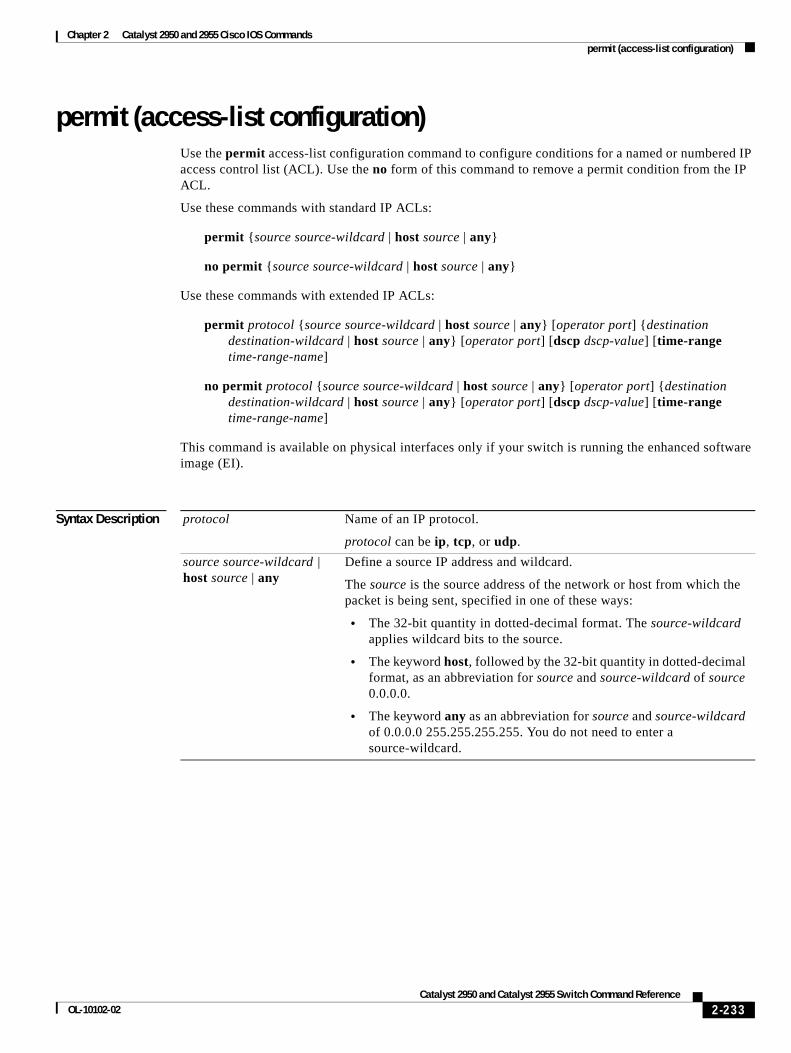
Chapter 2 Catalyst 2950 and 2955 Cisco IOS Commands permit (access-list configuration)
permit (access-list configuration)Use the permit access-list configuration command to configure conditions for a named or numbered IP access control list (ACL). Use the no form of this command to remove a permit condition from the IP ACL.
Use these commands with standard IP ACLs:
permit {source source-wildcard | host source | any}
no permit {source source-wildcard | host source | any}
Use these commands with extended IP ACLs:
permit protocol {source source-wildcard | host source | any} [operator port] {destination destination-wildcard | host source | any} [operator port] [dscp dscp-value] [time-range time-range-name]
no permit protocol {source source-wildcard | host source | any} [operator port] {destination destination-wildcard | host source | any} [operator port] [dscp dscp-value] [time-range time-range-name]
This command is available on physical interfaces only if your switch is running the enhanced software image (EI).
Syntax Description protocol Name of an IP protocol.
protocol can be ip, tcp, or udp.
source source-wildcard | host source | any
Define a source IP address and wildcard.
The source is the source address of the network or host from which the packet is being sent, specified in one of these ways:
• The 32-bit quantity in dotted-decimal format. The source-wildcard applies wildcard bits to the source.
• The keyword host, followed by the 32-bit quantity in dotted-decimal format, as an abbreviation for source and source-wildcard of source 0.0.0.0.
• The keyword any as an abbreviation for source and source-wildcard of 0.0.0.0 255.255.255.255. You do not need to enter a source-wildcard.
2-233Catalyst 2950 and Catalyst 2955 Switch Command Reference
OL-10102-02
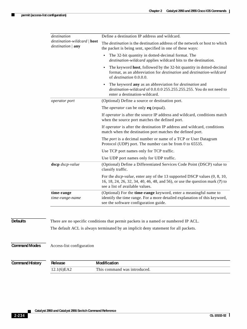
Chapter 2 Catalyst 2950 and 2955 Cisco IOS Commands permit (access-list configuration)
Defaults There are no specific conditions that permit packets in a named or numbered IP ACL.
The default ACL is always terminated by an implicit deny statement for all packets.
Command Modes Access-list configuration
Command History
destination destination-wildcard | host destination | any
Define a destination IP address and wildcard.
The destination is the destination address of the network or host to which the packet is being sent, specified in one of these ways:
• The 32-bit quantity in dotted-decimal format. The destination-wildcard applies wildcard bits to the destination.
• The keyword host, followed by the 32-bit quantity in dotted-decimal format, as an abbreviation for destination and destination-wildcard of destination 0.0.0.0.
• The keyword any as an abbreviation for destination and destination-wildcard of 0.0.0.0 255.255.255.255. You do not need to enter a destination-wildcard.
operator port (Optional) Define a source or destination port.
The operator can be only eq (equal).
If operator is after the source IP address and wildcard, conditions match when the source port matches the defined port.
If operator is after the destination IP address and wildcard, conditions match when the destination port matches the defined port.
The port is a decimal number or name of a TCP or User Datagram Protocol (UDP) port. The number can be from 0 to 65535.
Use TCP port names only for TCP traffic.
Use UDP port names only for UDP traffic.
dscp dscp-value (Optional) Define a Differentiated Services Code Point (DSCP) value to classify traffic.
For the dscp-value, enter any of the 13 supported DSCP values (0, 8, 10, 16, 18, 24, 26, 32, 34, 40, 46, 48, and 56), or use the question mark (?) to see a list of available values.
time-range time-range-name
(Optional) For the time-range keyword, enter a meaningful name to identify the time range. For a more detailed explanation of this keyword, see the software configuration guide.
Release Modification
12.1(6)EA2 This command was introduced.
2-234Catalyst 2950 and Catalyst 2955 Switch Command Reference
OL-10102-02
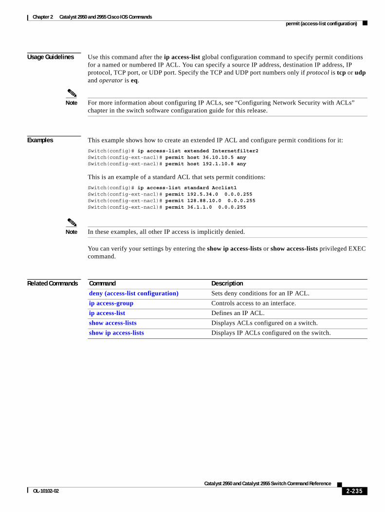
Chapter 2 Catalyst 2950 and 2955 Cisco IOS Commands permit (access-list configuration)
Usage Guidelines Use this command after the ip access-list global configuration command to specify permit conditions for a named or numbered IP ACL. You can specify a source IP address, destination IP address, IP protocol, TCP port, or UDP port. Specify the TCP and UDP port numbers only if protocol is tcp or udp and operator is eq.
Note For more information about configuring IP ACLs, see “Configuring Network Security with ACLs” chapter in the switch software configuration guide for this release.
Examples This example shows how to create an extended IP ACL and configure permit conditions for it:
Switch(config)# ip access-list extended Internetfilter2Switch(config-ext-nacl)# permit host 36.10.10.5 anySwitch(config-ext-nacl)# permit host 192.1.10.8 any
This is an example of a standard ACL that sets permit conditions:
Switch(config)# ip access-list standard Acclist1Switch(config-ext-nacl)# permit 192.5.34.0 0.0.0.255Switch(config-ext-nacl)# permit 128.88.10.0 0.0.0.255Switch(config-ext-nacl)# permit 36.1.1.0 0.0.0.255
Note In these examples, all other IP access is implicitly denied.
You can verify your settings by entering the show ip access-lists or show access-lists privileged EXEC command.
Related Commands Command Description
deny (access-list configuration) Sets deny conditions for an IP ACL.
ip access-group Controls access to an interface.
ip access-list Defines an IP ACL.
show access-lists Displays ACLs configured on a switch.
show ip access-lists Displays IP ACLs configured on the switch.
2-235Catalyst 2950 and Catalyst 2955 Switch Command Reference
OL-10102-02
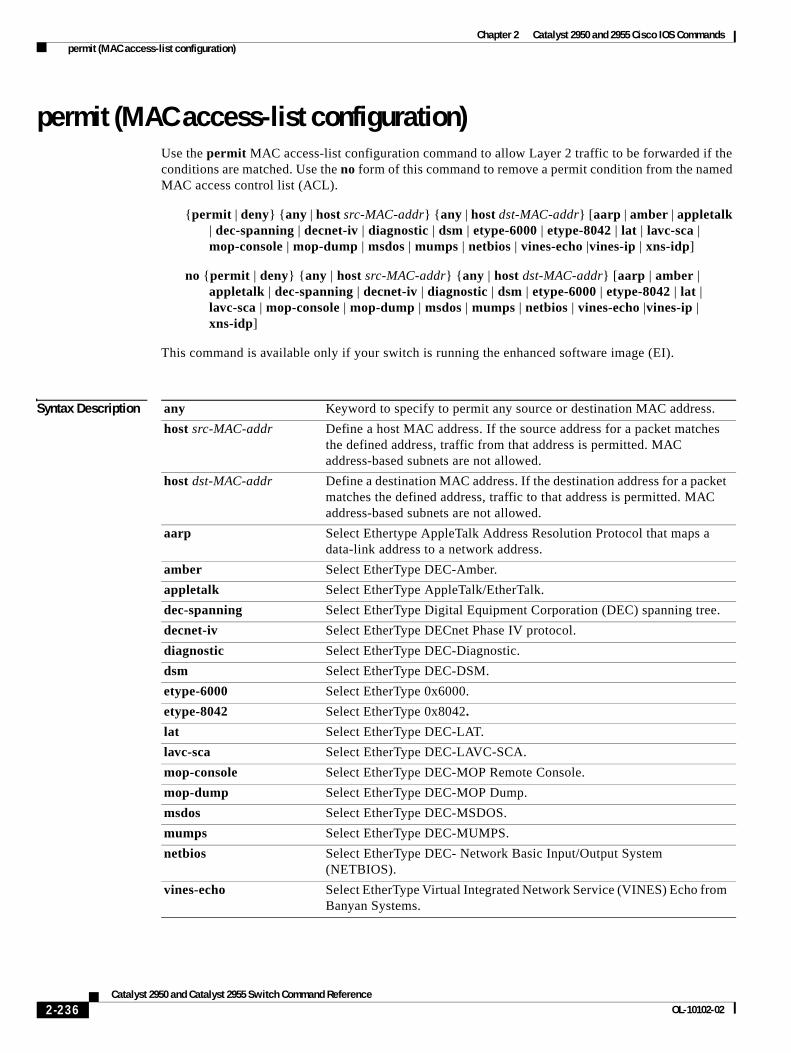
Chapter 2 Catalyst 2950 and 2955 Cisco IOS Commands permit (MAC access-list configuration)
permit (MAC access-list configuration)Use the permit MAC access-list configuration command to allow Layer 2 traffic to be forwarded if the conditions are matched. Use the no form of this command to remove a permit condition from the named MAC access control list (ACL).
{permit | deny} {any | host src-MAC-addr} {any | host dst-MAC-addr} [aarp | amber | appletalk | dec-spanning | decnet-iv | diagnostic | dsm | etype-6000 | etype-8042 | lat | lavc-sca | mop-console | mop-dump | msdos | mumps | netbios | vines-echo |vines-ip | xns-idp]
no {permit | deny} {any | host src-MAC-addr} {any | host dst-MAC-addr} [aarp | amber | appletalk | dec-spanning | decnet-iv | diagnostic | dsm | etype-6000 | etype-8042 | lat | lavc-sca | mop-console | mop-dump | msdos | mumps | netbios | vines-echo |vines-ip | xns-idp]
This command is available only if your switch is running the enhanced software image (EI).
Syntax Description any Keyword to specify to permit any source or destination MAC address.
host src-MAC-addr Define a host MAC address. If the source address for a packet matches the defined address, traffic from that address is permitted. MAC address-based subnets are not allowed.
host dst-MAC-addr Define a destination MAC address. If the destination address for a packet matches the defined address, traffic to that address is permitted. MAC address-based subnets are not allowed.
aarp Select Ethertype AppleTalk Address Resolution Protocol that maps a data-link address to a network address.
amber Select EtherType DEC-Amber.
appletalk Select EtherType AppleTalk/EtherTalk.
dec-spanning Select EtherType Digital Equipment Corporation (DEC) spanning tree.
decnet-iv Select EtherType DECnet Phase IV protocol.
diagnostic Select EtherType DEC-Diagnostic.
dsm Select EtherType DEC-DSM.
etype-6000 Select EtherType 0x6000.
etype-8042 Select EtherType 0x8042.
lat Select EtherType DEC-LAT.
lavc-sca Select EtherType DEC-LAVC-SCA.
mop-console Select EtherType DEC-MOP Remote Console.
mop-dump Select EtherType DEC-MOP Dump.
msdos Select EtherType DEC-MSDOS.
mumps Select EtherType DEC-MUMPS.
netbios Select EtherType DEC- Network Basic Input/Output System (NETBIOS).
vines-echo Select EtherType Virtual Integrated Network Service (VINES) Echo from Banyan Systems.
2-236Catalyst 2950 and Catalyst 2955 Switch Command Reference
OL-10102-02
Chapter 2 Catalyst 2950 and 2955 Cisco IOS Commands permit (MAC access-list configuration)
Defaults This command has no defaults. However, the default action for a MAC-named ACL is to deny.
Command Modes MAC access-list configuration
Command History
Usage Guidelines When an access control entry (ACE) is added to an ACL, an implied deny-any-any condition exists at the end of the list. That is, if there are no matches, the packets are denied. However, before the first ACE is added, the list permits all packets.
These options are not allowed:
• Class of service (CoS)
• Ethertype number of a packet with Ethernet II or Subnetwork Access Protocol (SNAP) encapsulation
• Link Service Access Point (LSAP) number of a packet with IEEE 802.2 encapsulation
Note For more information about configuring MAC extended ACLs, see the “Configuring Network Security with ACLs” chapter in the software configuration guide for this release.
Examples This example shows how to define the named MAC extended ACL to deny NETBIOS traffic from any source to MAC address 00c0.00a0.03fa. Traffic matching this list is allowed.
Switch(config-ext-macl)# permit any host 00c0.00a0.03fa netbios
This example shows how to remove the permit condition from the named MAC extended ACL:
Switch(config-ext-macl)# no permit any host 00c0.00a0.03fa netbios
You can verify your settings by entering the show access-lists privileged EXEC command.
Related Commands
vines-ip Select EtherType VINES IP.
xns-idp Select EtherType Xerox Network Systems (XNS) protocol suite (0 to 65535), an arbitrary Ethertype in decimal, hexadecimal, or octal.
Release Modification
12.1(6)EA2 This command was introduced.
Command Description
deny (MAC access-list configuration)
Prevents Layer 2 traffic from being forwarded if conditions are matched.
mac access-list extended Creates an ACL based on MAC addresses.
show access-lists Displays ACLs configured on a switch.
2-237Catalyst 2950 and Catalyst 2955 Switch Command Reference
OL-10102-02
Chapter 2 Catalyst 2950 and 2955 Cisco IOS Commands persistence
persistenceUse the persistence interface configuration command to set the amount of delay before the link reports a link failure. Use the no form of this command to return to the default setting.
persistence delay
no persistence delay
This command is available only on Catalyst 2950 Long-Reach Ethernet (LRE) switches.
Syntax Description
Defaults The default is enabled, and the duration is 3 seconds.
Command Modes Interface configuration
Command History
Usage Guidelines Enter the persistence interface configuration command before the link enters the profile link-up mode. If the link is already in the profile link-up mode when you enter this command, the new value does not go into effect immediately. Instead, it becomes effective after the profile link goes down and comes back up.
Examples: This example shows how to establish a delay of 1 second before the link reports a failure:
Switch(config)# interface longreachethernet0/1Switch(config-if)# persistence 1
You can verify your settings by entering the show controllers lre status privileged EXEC command.
Related Commands
delay The amount of time delay. The range is 1 to 20 seconds.
Release Modification
12.1(11)YJ This command was introduced.
Command Description
show controllers lre status Displays the status of persistence.
2-238Catalyst 2950 and Catalyst 2955 Switch Command Reference
OL-10102-02
Chapter 2 Catalyst 2950 and 2955 Cisco IOS Commands police
policeUse the police policy-map class configuration command to define a policer for classified traffic. Use the no form of this command to remove an existing policer.
police rate-bps burst-byte [exceed-action {drop | dscp dscp-value}]
no policerate-bps burst-byte [exceed-action {drop | dscp dscp-value}]
This command is available only if your switch is running the enhanced software image (EI).
Syntax Description
Defaults No policers are defined.
Command Modes Policy-map class configuration
Command History
Usage Guidelines You can configure up to six policers on ingress Fast Ethernet ports.
You can configure up to 60 policers on ingress Gigabit-capable Ethernet ports.
Policers cannot be configured on egress Fast Ethernet and Gigabit-capable Ethernet ports.
To return to policy-map configuration mode, use the exit command. To return to privileged EXEC mode, use the end command.
rate-bps Specify average traffic rate in bits per second (bps).
For 10/100 ports, the range is 1000000 to 100000000, and the granularity is 1 Mbps.
For Gigabit-capable Ethernet ports, the range is 8000000 to 1016000000, and the granularity is 8 Mbps.
burst-byte Specify the normal burst size in bytes.
For 10/100 ports, the burst size values are 4096, 8192, 16384, 32768, and 65536.
For Gigabit-capable Ethernet ports, the burst size values are 4096, 8192, 16384, 32768, 65536, 131072, 262144, and 524288.
exceed-action drop (Optional) When the specified rate is exceeded, specify that the switch drops the packet.
exceed-action dscp dscp-value
(Optional) When the specified rate is exceeded, specify that the switch changes the Differentiated Services Code Point (DSCP) of the packet to the specified dscp-value and then sends the packet.
Release Modification
12.1(6)EA2 This command was introduced.
2-239Catalyst 2950 and Catalyst 2955 Switch Command Reference
OL-10102-02
Chapter 2 Catalyst 2950 and 2955 Cisco IOS Commands police
Note For more information about configuring access control lists (ACLs), see the “Configuring Network Security with ACLs” chapter in the software configuration guide for this release.
Examples This example shows how to configure a policer that sets the DSCP value to 46 if traffic does not exceed a 1-Mbps average rate with a burst size of 65536 bytes and drops packets if traffic exceeds these conditions:
Switch(config)# policy-map policy1Switch(config-pmap)# class class1Switch(config-pmap-c)# set ip dscp 46Switch(config-pmap-c)# police 1000000 65536 exceed-action dropSwitch(config-pmap-c)# exit
You can verify your settings by entering the show policy-map privileged EXEC command.
Related Commands Command Description
policy-map Creates or modifies a policy map that can be attached to multiple interfaces, and enters policy-map configuration mode.
show policy-map Displays quality of service (QoS) policy maps.
2-240Catalyst 2950 and Catalyst 2955 Switch Command Reference
OL-10102-02
Chapter 2 Catalyst 2950 and 2955 Cisco IOS Commands policy-map
policy-mapUse the policy-map global configuration command to create or modify a policy map that can be attached to multiple interfaces and to enter policy-map configuration mode. Use the no form of this command to delete an existing policy map and to return to global configuration mode.
policy-map policy-map-name
no policy-map policy-map-name
This command is available only if your switch is running the enhanced software image (EI).
Syntax Description
Defaults No policy maps are defined.
Command Modes Global configuration
Command History
Usage Guidelines Entering the policy-map command enables the policy-map configuration mode. In this mode, you can can configure or modify the class policies for a policy map. These configuration commands are available:
• class: defines the classification match criteria for the specified class map. For more information, see the class command.
• description: describes the policy map (up to 200 characters).
• exit: exits policy-map configuration mode and returns to global configuration mode.
• no: removes a previously defined policy map.
• rename: renames the policy map.
Note In a policy map, the class named class-default is not supported. The switch does not filter traffic based on the policy map defined by the class class-default policy-map configuration command.
To return to global configuration mode, use the exit command. To return to privileged EXEC mode, use the end command.
Before you can configure policies for classes whose match criteria are defined in a class map, use the policy-map command to specify the name of the policy map to be created or modified.
You can configure class policies in a policy map only if the classes have match criteria defined for them. Use the class-map and match commands to configure the match criteria for a class. Only one match command per class map is supported.
policy-map-name Name of the policy map.
Release Modification
12.1(6)EA2 This command was introduced.
2-241Catalyst 2950 and Catalyst 2955 Switch Command Reference
OL-10102-02
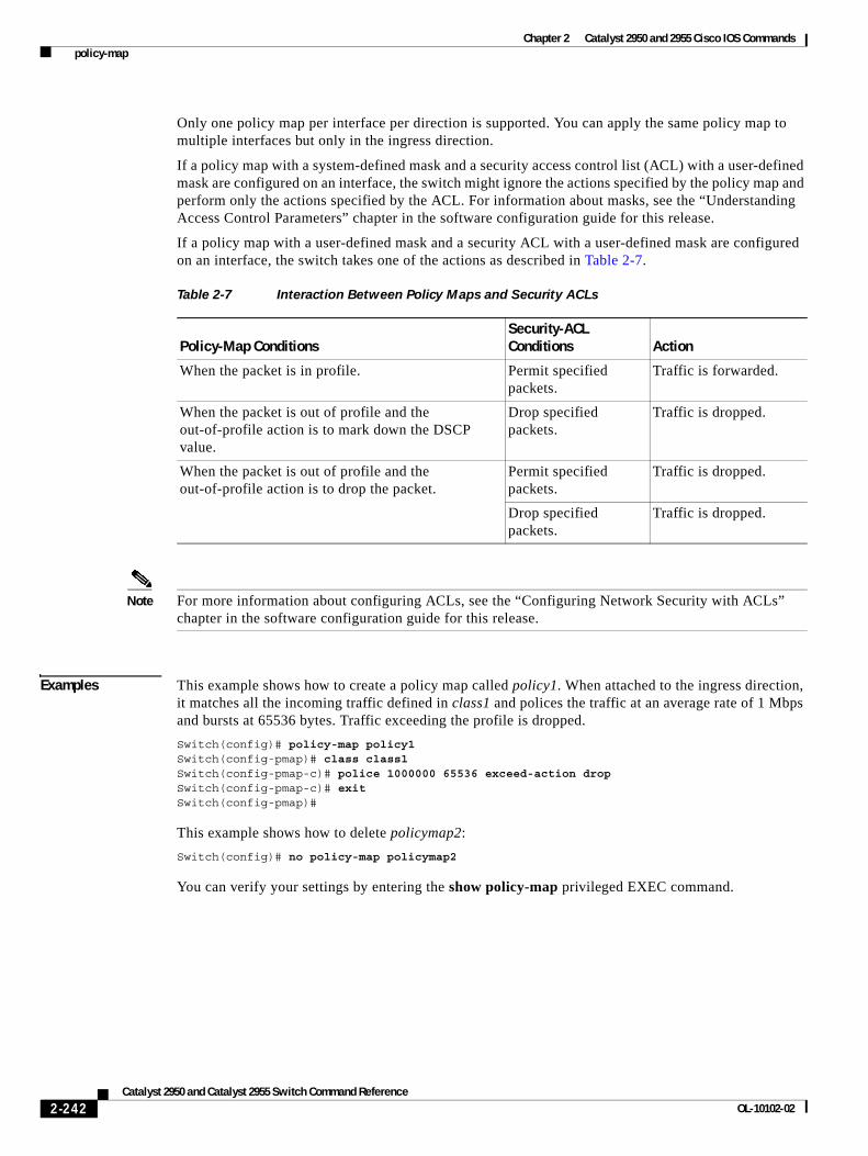
Chapter 2 Catalyst 2950 and 2955 Cisco IOS Commands policy-map
Only one policy map per interface per direction is supported. You can apply the same policy map to multiple interfaces but only in the ingress direction.
If a policy map with a system-defined mask and a security access control list (ACL) with a user-defined mask are configured on an interface, the switch might ignore the actions specified by the policy map and perform only the actions specified by the ACL. For information about masks, see the “Understanding Access Control Parameters” chapter in the software configuration guide for this release.
If a policy map with a user-defined mask and a security ACL with a user-defined mask are configured on an interface, the switch takes one of the actions as described in Table 2-7.
Note For more information about configuring ACLs, see the “Configuring Network Security with ACLs” chapter in the software configuration guide for this release.
Examples This example shows how to create a policy map called policy1. When attached to the ingress direction, it matches all the incoming traffic defined in class1 and polices the traffic at an average rate of 1 Mbps and bursts at 65536 bytes. Traffic exceeding the profile is dropped.
Switch(config)# policy-map policy1Switch(config-pmap)# class class1Switch(config-pmap-c)# police 1000000 65536 exceed-action dropSwitch(config-pmap-c)# exitSwitch(config-pmap)#
This example shows how to delete policymap2:
Switch(config)# no policy-map policymap2
You can verify your settings by entering the show policy-map privileged EXEC command.
Table 2-7 Interaction Between Policy Maps and Security ACLs
Policy-Map ConditionsSecurity-ACL Conditions Action
When the packet is in profile. Permit specified packets.
Traffic is forwarded.
When the packet is out of profile and the out-of-profile action is to mark down the DSCP value.
Drop specified packets.
Traffic is dropped.
When the packet is out of profile and the out-of-profile action is to drop the packet.
Permit specified packets.
Traffic is dropped.
Drop specified packets.
Traffic is dropped.
2-242Catalyst 2950 and Catalyst 2955 Switch Command Reference
OL-10102-02
Chapter 2 Catalyst 2950 and 2955 Cisco IOS Commands policy-map
Related Commands Command Description
class Defines the default CoS value of a port or assigns the default CoS to all incoming packets on the port.
class-map Creates a class map to be used for matching packets to the class whose name you specify.
police Defines a policer for classified traffic.
set Classifies IP traffic by setting a DSCP value in the packet.
show policy-map Displays quality of service (QoS) policy maps.
2-243Catalyst 2950 and Catalyst 2955 Switch Command Reference
OL-10102-02
Chapter 2 Catalyst 2950 and 2955 Cisco IOS Commands port-channel load-balance
port-channel load-balanceUse the port-channel load-balance global configuration command to set the load-distribution method among the ports in the EtherChannel. Use the no form of this command to return to the default setting.
port-channel load-balance method
no port-channel load-balance
Syntax Description
Defaults The default method is src-mac.
Command Modes Global configuration
Command History
Usage Guidelines If the link partner to the switch is a physical learner that has the channel-group interface configuration command set to auto or desirable, the switch automatically uses the load-distribution method based on the source-MAC address, regardless of the configured load-distribution method.
If the link partner to the switch is a physical learner that has the channel-group interface configuration command set to on, set the load-distribution method based on the source-MAC address by using the port-channel load-balance src-mac global configuration command.
Examples This example shows how to set the load-distribution method to dst-mac:
Switch(config)# port-channel load-balance dst-mac
You can verify your settings by entering the show etherchannel privileged EXEC command.
method Load distribution method.
These are the method values:
• src-mac—Load distribution using the source-MAC address.
• dst-mac—Load distribution using the destination-MAC address.
•
Release Modification
12.1(6)EA2 This command was introduced.
2-244Catalyst 2950 and Catalyst 2955 Switch Command Reference
OL-10102-02
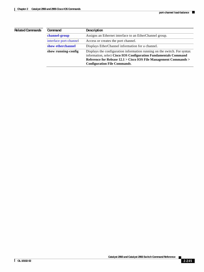
Chapter 2 Catalyst 2950 and 2955 Cisco IOS Commands port-channel load-balance
Related Commands Command Description
channel-group Assigns an Ethernet interface to an EtherChannel group.
interface port-channel Access or creates the port channel.
show etherchannel Displays EtherChannel information for a channel.
show running-config Displays the configuration information running on the switch. For syntax information, select Cisco IOS Configuration Fundamentals Command Reference for Release 12.1 > Cisco IOS File Management Commands > Configuration File Commands.
2-245Catalyst 2950 and Catalyst 2955 Switch Command Reference
OL-10102-02
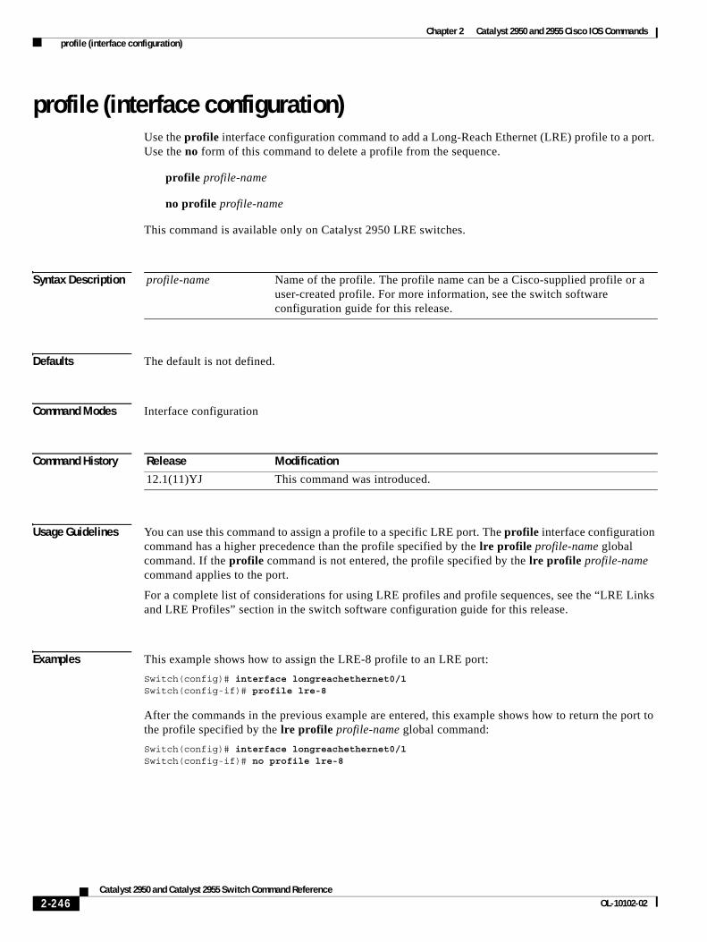
Chapter 2 Catalyst 2950 and 2955 Cisco IOS Commands profile (interface configuration)
profile (interface configuration)Use the profile interface configuration command to add a Long-Reach Ethernet (LRE) profile to a port. Use the no form of this command to delete a profile from the sequence.
profile profile-name
no profile profile-name
This command is available only on Catalyst 2950 LRE switches.
Syntax Description
Defaults The default is not defined.
Command Modes Interface configuration
Command History
Usage Guidelines You can use this command to assign a profile to a specific LRE port. The profile interface configuration command has a higher precedence than the profile specified by the lre profile profile-name global command. If the profile command is not entered, the profile specified by the lre profile profile-name command applies to the port.
For a complete list of considerations for using LRE profiles and profile sequences, see the “LRE Links and LRE Profiles” section in the switch software configuration guide for this release.
Examples This example shows how to assign the LRE-8 profile to an LRE port:
Switch(config)# interface longreachethernet0/1Switch(config-if)# profile lre-8
After the commands in the previous example are entered, this example shows how to return the port to the profile specified by the lre profile profile-name global command:
Switch(config)# interface longreachethernet0/1Switch(config-if)# no profile lre-8
profile-name Name of the profile. The profile name can be a Cisco-supplied profile or a user-created profile. For more information, see the switch software configuration guide for this release.
Release Modification
12.1(11)YJ This command was introduced.
2-246Catalyst 2950 and Catalyst 2955 Switch Command Reference
OL-10102-02

Chapter 2 Catalyst 2950 and 2955 Cisco IOS Commands profile (interface configuration)
Related Commands Command Description
lre rate selection sequence Assigns the rate selection sequence for the entire switch.
lre sequence Defines a new sequence.
rate selection Enables rate selection on a specific port.
rate selection sequence Assigns a rate selection sequence for a specific port.
show controllers lre profile Displays LRE profile information.
2-247Catalyst 2950 and Catalyst 2955 Switch Command Reference
OL-10102-02
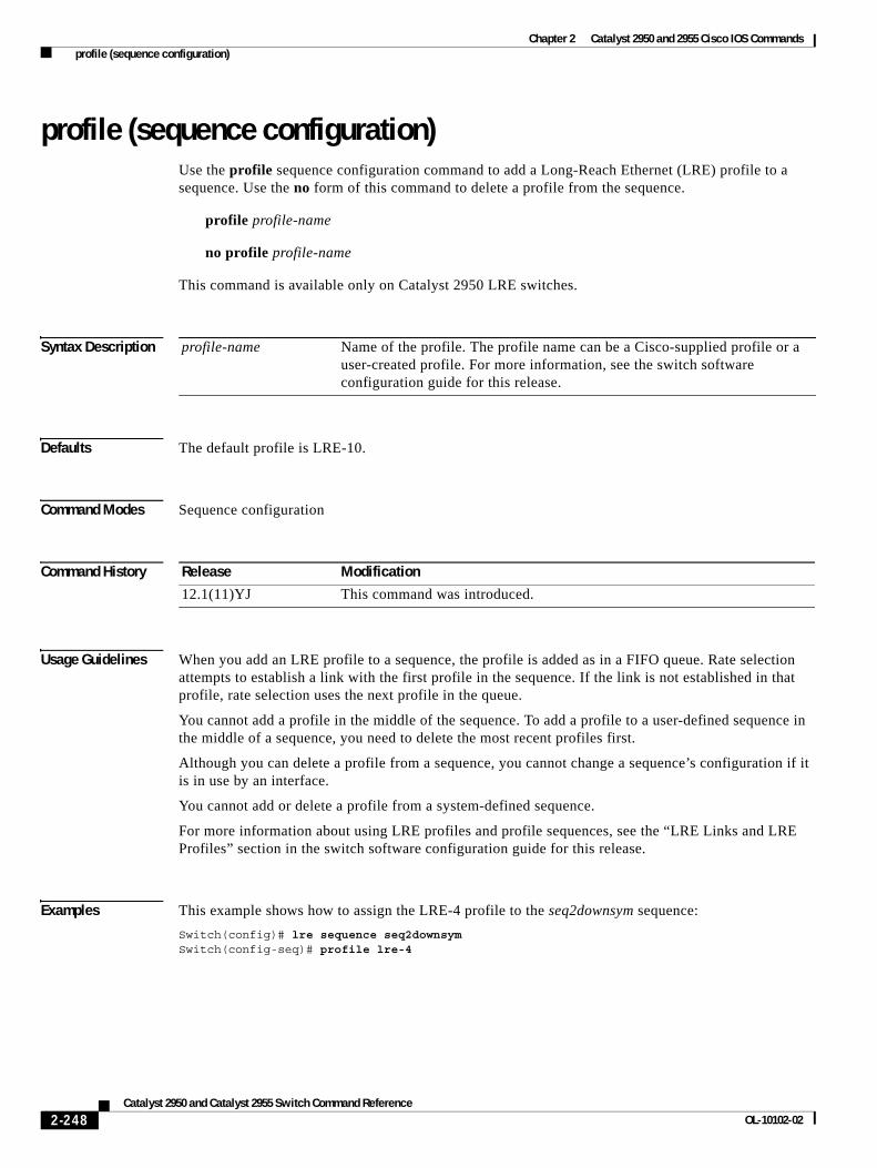
Chapter 2 Catalyst 2950 and 2955 Cisco IOS Commands profile (sequence configuration)
profile (sequence configuration)Use the profile sequence configuration command to add a Long-Reach Ethernet (LRE) profile to a sequence. Use the no form of this command to delete a profile from the sequence.
profile profile-name
no profile profile-name
This command is available only on Catalyst 2950 LRE switches.
Syntax Description
Defaults The default profile is LRE-10.
Command Modes Sequence configuration
Command History
Usage Guidelines When you add an LRE profile to a sequence, the profile is added as in a FIFO queue. Rate selection attempts to establish a link with the first profile in the sequence. If the link is not established in that profile, rate selection uses the next profile in the queue.
You cannot add a profile in the middle of the sequence. To add a profile to a user-defined sequence in the middle of a sequence, you need to delete the most recent profiles first.
Although you can delete a profile from a sequence, you cannot change a sequence’s configuration if it is in use by an interface.
You cannot add or delete a profile from a system-defined sequence.
For more information about using LRE profiles and profile sequences, see the “LRE Links and LRE Profiles” section in the switch software configuration guide for this release.
Examples This example shows how to assign the LRE-4 profile to the seq2downsym sequence:
Switch(config)# lre sequence seq2downsymSwitch(config-seq)# profile lre-4
profile-name Name of the profile. The profile name can be a Cisco-supplied profile or a user-created profile. For more information, see the switch software configuration guide for this release.
Release Modification
12.1(11)YJ This command was introduced.
2-248Catalyst 2950 and Catalyst 2955 Switch Command Reference
OL-10102-02

Chapter 2 Catalyst 2950 and 2955 Cisco IOS Commands profile (sequence configuration)
Related Commands Command Description
lre rate selection sequence Assigns the rate selection sequence for the entire switch.
lre sequence Defines a new sequence.
rate selection Enables rate selection on a specific port.
rate selection sequence Assigns a sequence for a specific port.
2-249Catalyst 2950 and Catalyst 2955 Switch Command Reference
OL-10102-02
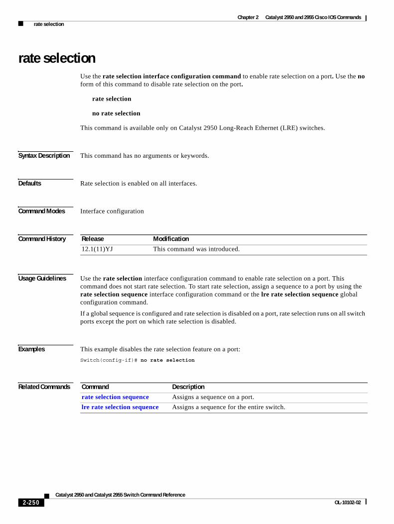
Chapter 2 Catalyst 2950 and 2955 Cisco IOS Commands rate selection
rate selectionUse the rate selection interface configuration command to enable rate selection on a port. Use the no form of this command to disable rate selection on the port.
rate selection
no rate selection
This command is available only on Catalyst 2950 Long-Reach Ethernet (LRE) switches.
Syntax Description This command has no arguments or keywords.
Defaults Rate selection is enabled on all interfaces.
Command Modes Interface configuration
Command History
Usage Guidelines Use the rate selection interface configuration command to enable rate selection on a port. This command does not start rate selection. To start rate selection, assign a sequence to a port by using the rate selection sequence interface configuration command or the lre rate selection sequence global configuration command.
If a global sequence is configured and rate selection is disabled on a port, rate selection runs on all switch ports except the port on which rate selection is disabled.
Examples This example disables the rate selection feature on a port:
Switch(config-if)# no rate selection
Related Commands
Release Modification
12.1(11)YJ This command was introduced.
Command Description
rate selection sequence Assigns a sequence on a port.
lre rate selection sequence Assigns a sequence for the entire switch.
2-250Catalyst 2950 and Catalyst 2955 Switch Command Reference
OL-10102-02
Chapter 2 Catalyst 2950 and 2955 Cisco IOS Commands rate selection profile lock
rate selection profile lockUse the rate selection profile lock interface configuration command to lock a profile in a port on which rate selection is enabled. Use the no form of this command to unlock a profile in a port.
rate selection profile lock
no rate selection profile lock
This command is available only on Catalyst 2950 Long-Reach Ethernet (LRE) switches.
Syntax Description This command has no arguments or keywords.
Command Modes Interface configuration
Command History
Usage Guidelines The rate selection profile lock interface configuration command does not enable rate selection. It only takes affect when a sequence is assigned to a port.
If rate selection is already converged on the port, this command causes the profile chosen by rate selection to immediately lock. During the lock process, the name of the profile appends to the end of this command. For example, if rate selection converges on LRE-15 and you enter the command, this locked configuration appears:
Switch(config-if)# rate selection profile lock LRE-15
If rate selection is not already converged on the port, this command has no immediate effect. However, when rate selection converges for that port, the profile is locked immediately, and the output of the running configuration is saved as in the previous example.
Examples This example shows how to lock a profile to a port that is running rate selection:
Switch(config-if)# rate selection profile lock
Related Commands
Release Modification
12.1(11)YJ This command was introduced.
Command Description
rate selection sequence Assigns a sequence on a port.
lre rate selection sequence Assigns a sequence for the entire switch.
show controllers lre status sequence
Displays information about the profiles and sequences when the sequence parameter is specified.
2-251Catalyst 2950 and Catalyst 2955 Switch Command Reference
OL-10102-02
Chapter 2 Catalyst 2950 and 2955 Cisco IOS Commands rate selection sequence
rate selection sequenceUse the rate selection sequence interface configuration command to assign a sequence to a port and to start rate selection. Use the no form of this command to remove a specific rate selection sequence on a port.
rate selection sequence sequence-name
no rate selection sequence sequence-name
This command is available only on Catalyst 2950 Long-Reach Ethernet (LRE) switches.
Syntax Description
Command Modes Interface configuration
Command History
Usage Guidelines A sequence is a list of profiles. Using the rate selection sequence interface configuration command overrides the default profile and assigns a sequence of your choice.
When rate selection is enabled, profiles and sequences follow a predefined priority scheme that determines the rate for a port or for the entire switch. In general, sequences have priority over standalone profiles, and per-port configurations have priority over global configurations. These are the priority levels with rate selection enabled, from highest to lowest:
1. Per-port sequence
2. Global sequence
3. Port profile
4. Global profile
Cisco provides a set of preconfigured sequences, called system-defined sequences. System-defined sequences cannot be modified. You can create or modify a sequence by using the profile interface configuration or the profile sequence configuration command.
The rate selection sequence command is rejected if the specified sequence does not exist or is a null sequence. A null sequence is a sequence that does not have any profiles.
For more details on profiles, sequences and their priority scheme, see the switch software configuration guide for this release.
Examples This example shows how to apply the CISCO-COMPLETE-SEQUENCE sequence to a port:
Switch(config-if)# rate selection sequence cisco-complete-sequence
sequence-name The name of the sequence being applied to the port. For names of system-supplied sequences, see the switch software configuration guide for this release.
Release Modification
12.1(11)YJ This command was introduced.
2-252Catalyst 2950 and Catalyst 2955 Switch Command Reference
OL-10102-02

Chapter 2 Catalyst 2950 and 2955 Cisco IOS Commands rate selection sequence
Related Commands Command Description
rate selection Enables rate selection on ports already configured for rate selection.
show controllers lre sequence
Displays the list of sequences.
2-253Catalyst 2950 and Catalyst 2955 Switch Command Reference
OL-10102-02
Chapter 2 Catalyst 2950 and 2955 Cisco IOS Commands rcommand
rcommand Use the rcommand user EXEC command to start a Telnet session and to enter commands from a cluster command switch for a member switch. To end the session, enter the exit command.
rcommand {n | commander | mac-address hw-addr}
Syntax Description
Command Modes User EXEC
Command History
Usage Guidelines If the switch is the cluster command switch but the member switch n does not exist, an error message appears. To obtain the switch number, enter the show cluster members privileged EXEC command on the command switch.
You can use this command to access a member switch from the command-switch prompt or to access a command switch from the member-switch prompt.
For Catalyst 2900 XL, 2940, 2950, 2955, 3500 XL, and 3550 switches, the Telnet session accesses the member-switch command-line interface (CLI) at the same privilege level as on the command switch. For example, if you enter this command at user level on the cluster command switch, the member switch is accessed at user level. If you use this command on the command switch at privileged level, the command accesses the remote device at privileged level. If you use an intermediate enable-level lower than privileged, access to the member switch is at user level.
For Catalyst 1900 and 2820 switches running standard edition software, the Telnet session accesses the menu console (the menu-driven interface) if the command switch is at privilege level 15. If the command switch is at privilege level 1, you are prompted for the password before being able to access the menu console. Command switch privilege levels map to the member switches running standard edition software as follows:
• If the command switch privilege level is from 1 to 14, the member switch is accessed at privilege level 1.
• If the command switch privilege level is 15, the member switch is accessed at privilege level 15.
This command does not work if the vty lines of the command switch have access-class configurations.
You are not prompted for a password because the member switches inherited the password of the command switch when they joined the cluster.
n Provide the number that identifies a cluster member. The range is 0 to 15.
commander Provide access to the command switch from a member switch.
mac-address hw-addr MAC address of the member switch.
Release Modification
12.0(5.2)WC(1) This command was introduced.
2-254Catalyst 2950 and Catalyst 2955 Switch Command Reference
OL-10102-02
Chapter 2 Catalyst 2950 and 2955 Cisco IOS Commands rcommand
Examples This example shows how to start a session with member 3. All subsequent commands are directed to member 3 until you enter the exit command or close the session.
Switch# rcommand 3Switch-3# show versionCisco Internet Operating System Software ......Switch-3# exitSwitch#
Related Commands Command Description
show cluster members Displays information about the cluster members.
2-255Catalyst 2950 and Catalyst 2955 Switch Command Reference
OL-10102-02
Chapter 2 Catalyst 2950 and 2955 Cisco IOS Commands remote-span
remote-spanUse the remote-span VLAN configuration command to add the Remote Switched Port Analyzer (RSPAN) feature to a VLAN. Use the no form of this command to remove the RSPAN feature from the VLAN.
remote-span
no remote-span
This command is available only if your switch is running the enhanced software image (EI).
Syntax Description This command has no arguments or keywords.
Defaults No RSPAN VLANs are defined.
Command Modes VLAN configuration
Command History
Usage Guidelines When a VLAN is converted from a normal VLAN to an RSPAN VLAN (or the reverse), the VLAN is first deleted and is then recreated with the new configuration. The RSPAN feature is propagated by VLAN Trunking Protocol (VTP) for VLAN-IDs that are lower than 1005.
Before you configure the RSPAN remote-span feature, use the vlan (global configuration) command to create the VLAN.
Examples This example shows how to configure an RSPAN VLAN:
Switch(config)# vlan 901Switch(config-vlan)# remote-span
This example shows how to remove the RSPAN feature from a VLAN:
Switch(config)# vlan 901Switch(config-vlan)# no remote-span
You can verify your settings by entering the show vlan user EXEC command.
Release Modification
12.1(11)EA1 This command was introduced.
2-256Catalyst 2950 and Catalyst 2955 Switch Command Reference
OL-10102-02
Chapter 2 Catalyst 2950 and 2955 Cisco IOS Commands remote-span
Related Commands Command Description
monitor session Enables SPAN and RSPAN monitoring on a port and configures a port as a source or destination port.
vlan (global configuration)
Enter VLAN configuration mode to configure or modify VLANs 1 to 4094.
2-257Catalyst 2950 and Catalyst 2955 Switch Command Reference
OL-10102-02
Chapter 2 Catalyst 2950 and 2955 Cisco IOS Commands rmon collection stats
rmon collection statsUse the rmon collection stats interface configuration command to collect Ethernet group statistics. The Ethernet group statistics include utilization statistics about broadcast and multicast packets and error statistics about Cyclic Redundancy Check (CRC) alignment errors and collisions. Use the no form of this command to return to the default setting.
rmon collection stats index [owner name]
no rmon collection stats index [owner name]
Syntax Description
Defaults The RMON statistics collection is disabled.
Command Modes Interface configuration
Command History
Usage Guidelines The RMON statistics collection command is based on hardware counters.
Examples This example shows how to collect RMON statistics for the owner root on an interface:
Switch(config)# interface fastethernet0/1Switch(config-if)# rmon collection stats 2 owner root
You can verify your settings by entering the show rmon statistics privileged EXEC command.
Related Commands
index Remote Network Monitoring (RMON) collection control index. The range is 1 to 65535.
owner name (Optional) Owner of the RMON collection.
Release Modification
12.0(5.2)WC(1) This command was introduced.
Command Description
show rmon statistics Displays RMON statistics.
For more information on this command, select Cisco IOS Configuration Fundamentals Command Reference for Release 12.1 > Cisco IOS System Management Commands > RMON Commands.
2-258Catalyst 2950 and Catalyst 2955 Switch Command Reference
OL-10102-02
Commands
Chapter 2 Catalyst 2950 and 2955 Cisco IOS2service password-recovery
service password-recoveryUse the service password-recovery global configuration command to enable the password-recovery mechanism (the default). An end user with physical access to the switch can hold down the Mode button and interrupt the boot process while the switch is powering up and can assign a new password. Use the no form of this command to disable part of the password-recovery functionality. When the password-recovery mechanism is disabled, interrupting the boot process is allowed only if the user agrees to set the system back to the default configuration.
service password-recovery
no service password-recovery
This command is available only on Catalyst 2950 Long-Reach Ethernet (LRE) switches.
Syntax Description This command has no arguments or keywords.
Defaults The password-recovery mechanism is enabled.
Command Modes Global configuration
Command History
Usage Guidelines This command is valid only on Catalyst 2950 LRE switches.
As a system administrator, you can use the no service password-recovery command to disable some of the functionality of the password recovery feature by allowing an end user to reset a password only by agreeing to return to the default configuration.
To use the password-recovery procedure, a user with physical access to the switch holds down the Mode button while the unit powers up and for a second or two after the LED above port 1X goes off. When the button is released, the system continues with initialization. If the password-recovery mechanism is disabled, this message appears:
The password-recovery mechanism has been triggered, butis currently disabled. Access to the boot loader promptthrough the password-recovery mechanism is disallowed atthis point. However, if you agree to let the system bereset back to the default system configuration, accessto the boot loader prompt can still be allowed.
Would you like to reset the system back to the default configuration (y/n)?
If the user chooses not to reset the system back to the default configuration, the normal boot process continues, as if the Mode button had not been pressed. If you choose to reset the system back to the default configuration, the configuration file in flash memory is deleted and the VLAN database file, flash:vlan.dat (if present) is deleted.
Release Modification
12.1(11)YJ This command was introduced.
2-259Catalyst 2950 and Catalyst 2955 Switch Command Reference
0L-10102-02
Chapter 2 Catalyst 2950 and 2955 Cisco IOS Commandsservice password-recovery
Note If you use the no service password-recovery command to control end user access to passwords, we recommend that you save a copy of the config file in a location away from the switch in case the end user uses the password recovery procedure and sets the system back to default values. Do not keep a backup copy of the config file on the switch. If the switch is operating in VTP transparent mode, we recommend that you also save a copy of the vlan.dat file in a location away from the switch.
You can verify if password recovery is enabled or disabled by entering the show version privileged EXEC command.
Examples This example shows how to disable password recovery on a switch so that a user can only reset a password by agreeing to return to the default configuration:
Switch(config)# no service-password recoverySwitch(config)# exit
Related Commands Command Description
show version Displays version information for the hardware and firmware.
2-260Catalyst 2950 and Catalyst 2955 Switch Command Reference
0L-10102-02
Chapter 2 Catalyst 2950 and 2955 Cisco IOS Commandsservice-policy
service-policyUse the service-policy interface configuration command to apply a policy map defined by the policy-map command to the input of a particular interface. Use the no form of this command to remove the policy map and interface association.
service-policy input policy-map-name
no service-policy input policy-map-name
This command is available only if your switch is running the enhanced software image (EI).
Syntax Description
Defaults No policy maps are attached to the interface.
Command Modes Interface configuration
Command History
Usage Guidelines Only one policy map per ingress interface is supported.
Service policy maps cannot be defined on egress interfaces.
Note For more information about configuring access control lists (ACLs), see the “Configuring Network Security with ACLs” chapter in the software configuration guide for this release.
Examples This example shows how to apply plcmap1 to an ingress interface:
Switch(config)# interface gigabitethernet0/17Switch(config-if)# service-policy input plcmap1
You can verify your settings by entering the show policy-map privileged EXEC command.
Related Commands
policy-map-name Apply the specified policy map to the input of an interface.
Release Modification
12.1(6)EA2 This command was introduced.
Command Description
policy-map Creates or modifies a policy map that can be attached to multiple interfaces to specify a service policy.
show policy-map Displays quality of service (QoS) policy maps.
2-261Catalyst 2950 and Catalyst 2955 Switch Command Reference
0L-10102-02
Chapter 2 Catalyst 2950 and 2955 Cisco IOS Commandsset
setUse the set policy-map class configuration command to classify IP traffic by setting a Differentiated Services Code Point (DSCP) value. Use the no form of this command to remove traffic classification.
set ip dscp new-dscp
no set ip dscp new-dscp
This command is available only if your switch is running the enhanced software image (EI).
Syntax Description
Defaults No traffic classification is defined.
Command Modes Policy-map class configuration
Command History
Usage Guidelines The set command can be used in a policy with a match command.
The set command sets the DSCP value for in-profile packets.
Note This command does not support IP precedence.
To return to policy-map configuration mode, use the exit command. To return to privileged EXEC mode, use the end command.
Note For more information about configuring access control lists (ACLs), see the “Configuring Network Security with ACLs” chapter in the software configuration guide for this release.
Examples This example shows how to assign a DSCP value of 10 to all FTP traffic without any policers:
Switch(config)# policy-map policy_ftpSwitch(config-pmap)# class ftp_classSwitch(config-pmap-c)# set ip dscp 10Switch(config-pmap)# exit
You can verify your settings by entering the show policy-map privileged EXEC command.
new-dscp New DSCP value assigned to the classified traffic.
The supported DSCP values are 0, 8, 10, 16, 18, 24, 26, 32, 34, 40, 46, 48, and 56.
Release Modification
12.1(6)EA2 This command was introduced.
2-262Catalyst 2950 and Catalyst 2955 Switch Command Reference
0L-10102-02

Chapter 2 Catalyst 2950 and 2955 Cisco IOS Commandsset
Related Commands Command Description
police Defines a policer for classified traffic.
policy-map Creates or modifies a policy map that can be attached to multiple interfaces to specify a service policy.
show policy-map Displays quality of service (QoS) policy maps.
2-263Catalyst 2950 and Catalyst 2955 Switch Command Reference
0L-10102-02
Chapter 2 Catalyst 2950 and 2955 Cisco IOS Commandssetup express
setup expressUse the setup express global configuration command to enable Express Setup mode on the switch. This is the default setting. Use the no form of this command to disable Express Setup mode.
setup express
no setup express
This command is available only on Catalyst 2950 switches.
Syntax Description This command has no arguments or keywords.
Defaults Express Setup is enabled.
Command Modes Global configuration
Command History
Usage Guidelines When Express Setup is enabled on a new (unconfigured) switch, pressing the Mode button for 2 seconds activates Express Setup. You can access the switch through an Ethernet port by using the IP address 10.0.0.1 and then can configure the switch with the web-based Express Setup program or the command-line interface (CLI)-based setup program.
When you press the Mode button for 2 seconds on a configured switch, the mode LEDs start blinking. If you press the Mode button for a total of 10 seconds, the switch configuration is deleted, and the switch reboots. The switch can then be configured like a new switch, either through the web-based Express Setup program or the CLI-based setup program.
Note As soon as you make any change to the switch configuration (including entering no at the beginning of the CLI-based setup program), configuration by Express Setup is no longer available. You can only run Express Setup again by pressing the Mode button for 10 seconds. This deletes the switch configuration and reboots the switch.
If Express Setup is active on the switch, entering the write memory or copy running-configuration startup-configuration privileged EXEC commands deactivates Express Setup. The IP address 10.0.0.1 is no longer valid on the switch, and your connection using this IP address ends.
The primary purpose of the no setup express command is to prevent someone from deleting the switch configuration by pressing the Mode button for 10 seconds.
Release Modification
12.1(14)EA1 This command was introduced.
2-264Catalyst 2950 and Catalyst 2955 Switch Command Reference
0L-10102-02
Chapter 2 Catalyst 2950 and 2955 Cisco IOS Commandssetup express
Examples This example shows how to enable Express Setup mode:
Switch(config)# setup express
You can verify that Express Setup mode is enabled by pressing the Mode button:
• On an unconfigured switch, the mode LEDs begin blinking green after 2 seconds.
• On a configured switch, the mode LEDs turn solid green after a total of 10 seconds.
Caution If you hold the Mode button down for a total of 10 seconds, the configuration is deleted, and the switch reboots.
This example shows how to disable Express Setup mode:
Switch(config)# no setup express
You can verify that Express Setup mode is disabled by pressing the Mode button. The mode LEDs only turn solid green or begin blinking green if Express Setup mode is enabled on the switch.
Related Commands Command Description
show setup express Displays if Express Setup mode is active on the switch.
2-265Catalyst 2950 and Catalyst 2955 Switch Command Reference
0L-10102-02
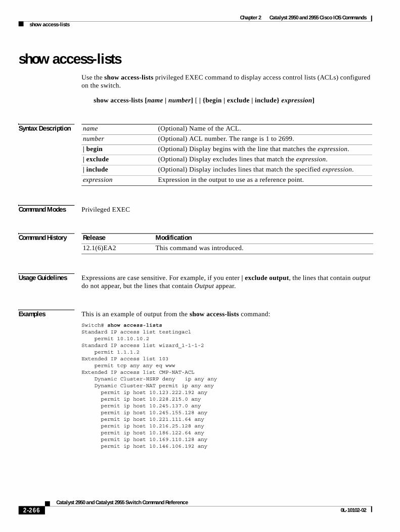
Chapter 2 Catalyst 2950 and 2955 Cisco IOS Commandsshow access-lists
show access-listsUse the show access-lists privileged EXEC command to display access control lists (ACLs) configured on the switch.
show access-lists [name | number] [ | {begin | exclude | include} expression]
Syntax Description
Command Modes Privileged EXEC
Command History
Usage Guidelines Expressions are case sensitive. For example, if you enter | exclude output, the lines that contain output do not appear, but the lines that contain Output appear.
Examples This is an example of output from the show access-lists command:
Switch# show access-listsStandard IP access list testingacl permit 10.10.10.2Standard IP access list wizard_1-1-1-2 permit 1.1.1.2Extended IP access list 103 permit tcp any any eq wwwExtended IP access list CMP-NAT-ACL Dynamic Cluster-HSRP deny ip any any Dynamic Cluster-NAT permit ip any any permit ip host 10.123.222.192 any permit ip host 10.228.215.0 any permit ip host 10.245.137.0 any permit ip host 10.245.155.128 any permit ip host 10.221.111.64 any permit ip host 10.216.25.128 any permit ip host 10.186.122.64 any permit ip host 10.169.110.128 any permit ip host 10.146.106.192 any
name (Optional) Name of the ACL.
number (Optional) ACL number. The range is 1 to 2699.
| begin (Optional) Display begins with the line that matches the expression.
| exclude (Optional) Display excludes lines that match the expression.
| include (Optional) Display includes lines that match the specified expression.
expression Expression in the output to use as a reference point.
Release Modification
12.1(6)EA2 This command was introduced.
2-266Catalyst 2950 and Catalyst 2955 Switch Command Reference
0L-10102-02
Chapter 2 Catalyst 2950 and 2955 Cisco IOS Commandsshow access-lists
Related Commands Command Description
access-list (IP extended) Configures an extended IP ACL on the switch.
access-list (IP standard) Configures a standard IP ACL on the switch.
ip access-list Configures an IP ACL on the switch.
mac access-list extended Creates an ACL based on MAC addresses.
show ip access-lists Displays the IP ACLs configured on a switch.
2-267Catalyst 2950 and Catalyst 2955 Switch Command Reference
0L-10102-02
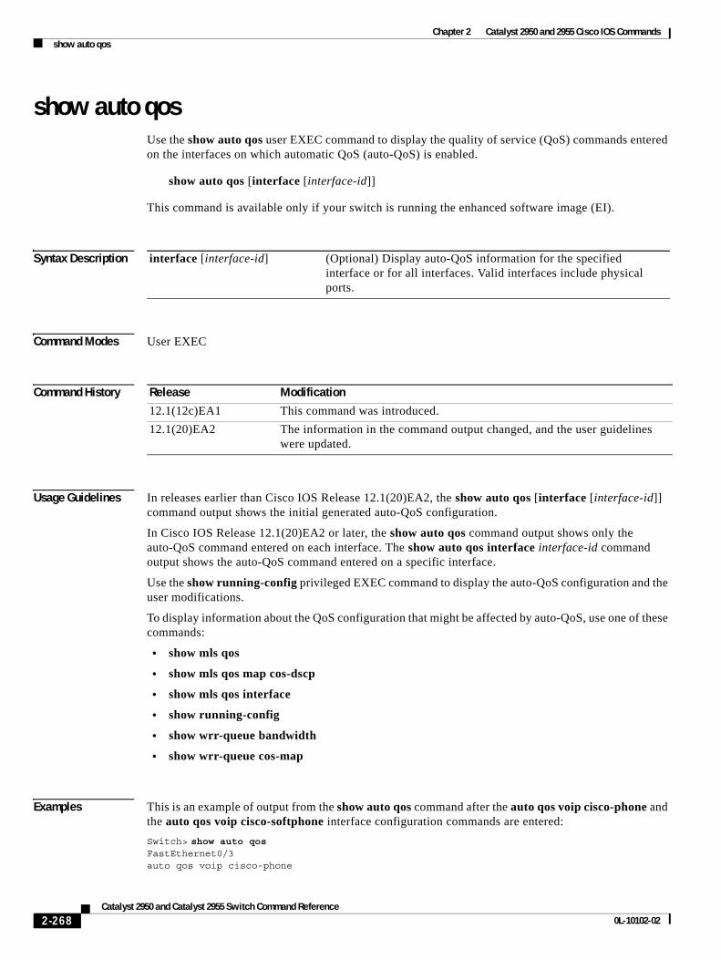
Chapter 2 Catalyst 2950 and 2955 Cisco IOS Commandsshow auto qos
show auto qosUse the show auto qos user EXEC command to display the quality of service (QoS) commands entered on the interfaces on which automatic QoS (auto-QoS) is enabled.
show auto qos [interface [interface-id]]
This command is available only if your switch is running the enhanced software image (EI).
Syntax Description
Command Modes User EXEC
Command History
Usage Guidelines In releases earlier than Cisco IOS Release 12.1(20)EA2, the show auto qos [interface [interface-id]] command output shows the initial generated auto-QoS configuration.
In Cisco IOS Release 12.1(20)EA2 or later, the show auto qos command output shows only the auto-QoS command entered on each interface. The show auto qos interface interface-id command output shows the auto-QoS command entered on a specific interface.
Use the show running-config privileged EXEC command to display the auto-QoS configuration and the user modifications.
To display information about the QoS configuration that might be affected by auto-QoS, use one of these commands:
• show mls qos
• show mls qos map cos-dscp
• show mls qos interface
• show running-config
• show wrr-queue bandwidth
• show wrr-queue cos-map
Examples This is an example of output from the show auto qos command after the auto qos voip cisco-phone and the auto qos voip cisco-softphone interface configuration commands are entered:
Switch> show auto qos FastEthernet0/3auto qos voip cisco-phone
interface [interface-id] (Optional) Display auto-QoS information for the specified interface or for all interfaces. Valid interfaces include physical ports.
Release Modification
12.1(12c)EA1 This command was introduced.
12.1(20)EA2 The information in the command output changed, and the user guidelines were updated.
2-268Catalyst 2950 and Catalyst 2955 Switch Command Reference
0L-10102-02
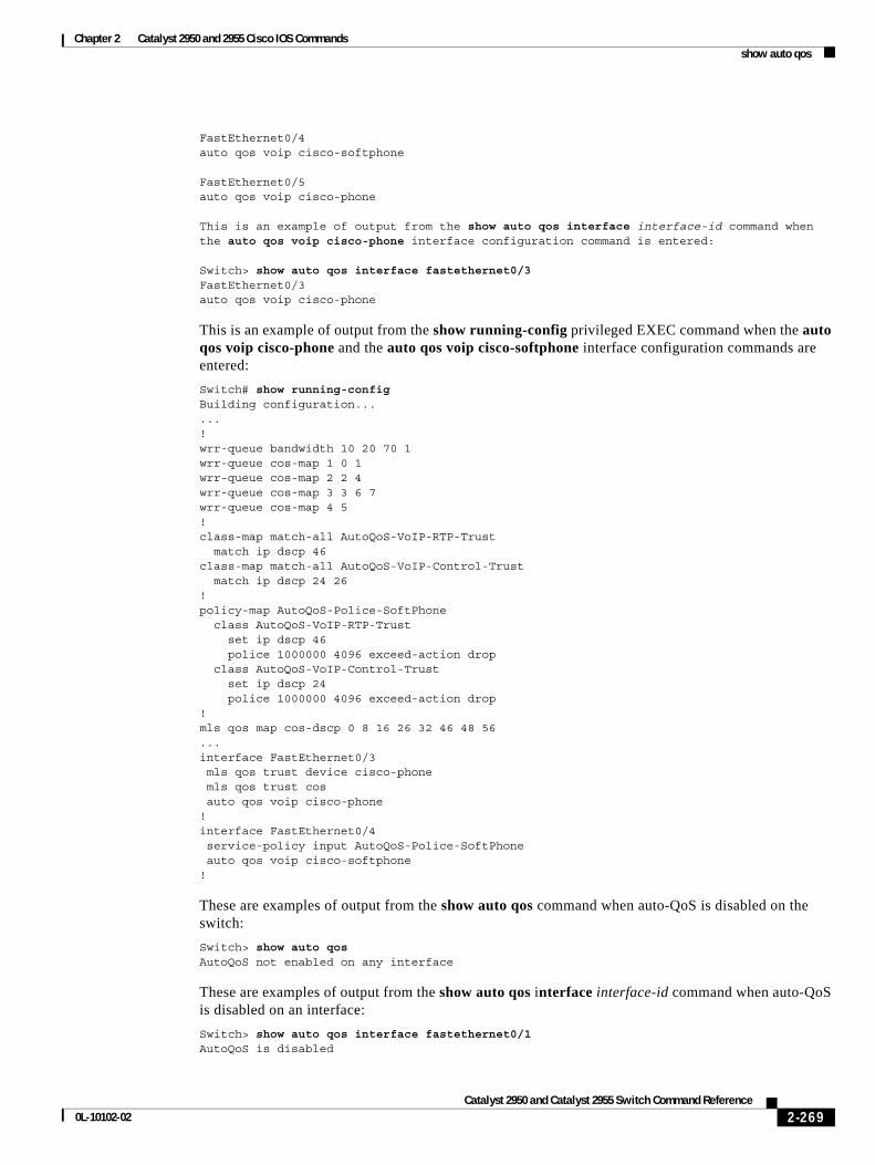
Chapter 2 Catalyst 2950 and 2955 Cisco IOS Commandsshow auto qos
FastEthernet0/4auto qos voip cisco-softphone
FastEthernet0/5auto qos voip cisco-phone
This is an example of output from the show auto qos interface interface-id command when the auto qos voip cisco-phone interface configuration command is entered:
Switch> show auto qos interface fastethernet0/3FastEthernet0/3auto qos voip cisco-phone
This is an example of output from the show running-config privileged EXEC command when the auto qos voip cisco-phone and the auto qos voip cisco-softphone interface configuration commands are entered:
Switch# show running-configBuilding configuration......!wrr-queue bandwidth 10 20 70 1wrr-queue cos-map 1 0 1wrr-queue cos-map 2 2 4wrr-queue cos-map 3 3 6 7wrr-queue cos-map 4 5!class-map match-all AutoQoS-VoIP-RTP-Trust match ip dscp 46class-map match-all AutoQoS-VoIP-Control-Trust match ip dscp 24 26!policy-map AutoQoS-Police-SoftPhone class AutoQoS-VoIP-RTP-Trust set ip dscp 46 police 1000000 4096 exceed-action drop class AutoQoS-VoIP-Control-Trust set ip dscp 24 police 1000000 4096 exceed-action drop!mls qos map cos-dscp 0 8 16 26 32 46 48 56...interface FastEthernet0/3 mls qos trust device cisco-phone mls qos trust cos auto qos voip cisco-phone!interface FastEthernet0/4 service-policy input AutoQoS-Police-SoftPhone auto qos voip cisco-softphone!
These are examples of output from the show auto qos command when auto-QoS is disabled on the switch:
Switch> show auto qos AutoQoS not enabled on any interface
These are examples of output from the show auto qos interface interface-id command when auto-QoS is disabled on an interface:
Switch> show auto qos interface fastethernet0/1AutoQoS is disabled
2-269Catalyst 2950 and Catalyst 2955 Switch Command Reference
0L-10102-02
Chapter 2 Catalyst 2950 and 2955 Cisco IOS Commandsshow auto qos
Related Commands Command Description
auto qos voip Automatically configures QoS for VoIP within a QoS domain.
2-270Catalyst 2950 and Catalyst 2955 Switch Command Reference
0L-10102-02
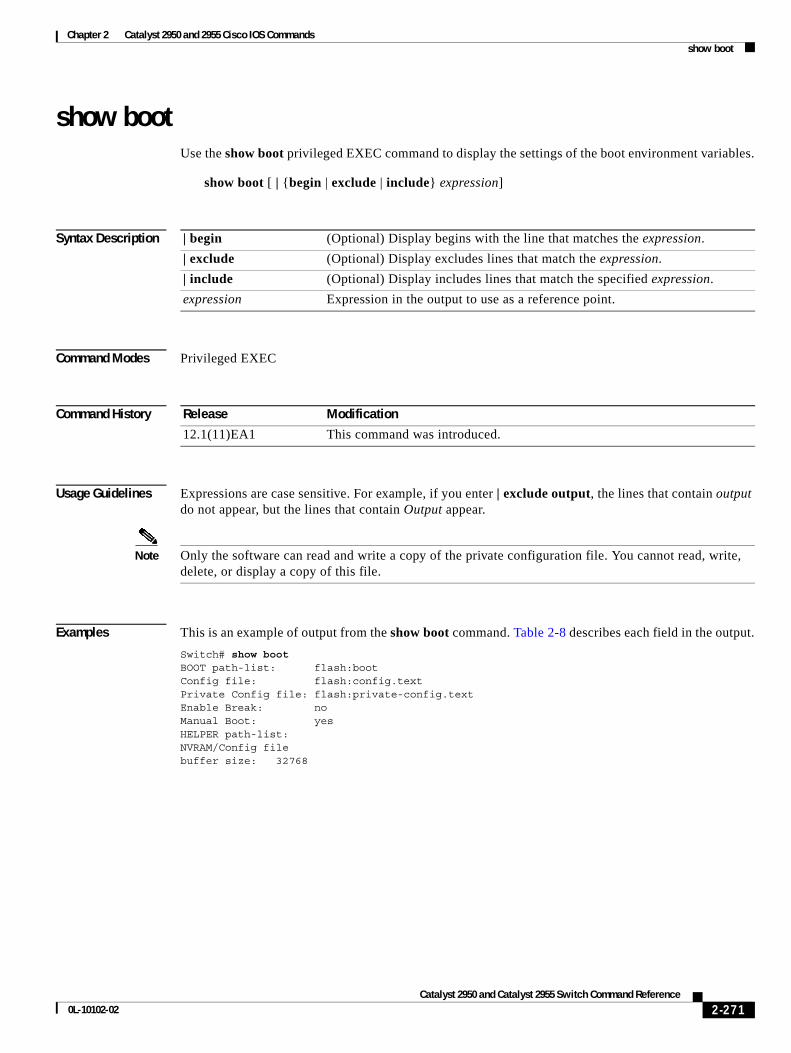
Chapter 2 Catalyst 2950 and 2955 Cisco IOS Commandsshow boot
show bootUse the show boot privileged EXEC command to display the settings of the boot environment variables.
show boot [ | {begin | exclude | include} expression]
Syntax Description
Command Modes Privileged EXEC
Command History
Usage Guidelines Expressions are case sensitive. For example, if you enter | exclude output, the lines that contain output do not appear, but the lines that contain Output appear.
Note Only the software can read and write a copy of the private configuration file. You cannot read, write, delete, or display a copy of this file.
Examples This is an example of output from the show boot command. Table 2-8 describes each field in the output.
Switch# show bootBOOT path-list: flash:bootConfig file: flash:config.textPrivate Config file: flash:private-config.textEnable Break: noManual Boot: yesHELPER path-list:NVRAM/Config file buffer size: 32768
| begin (Optional) Display begins with the line that matches the expression.
| exclude (Optional) Display excludes lines that match the expression.
| include (Optional) Display includes lines that match the specified expression.
expression Expression in the output to use as a reference point.
Release Modification
12.1(11)EA1 This command was introduced.
2-271Catalyst 2950 and Catalyst 2955 Switch Command Reference
0L-10102-02
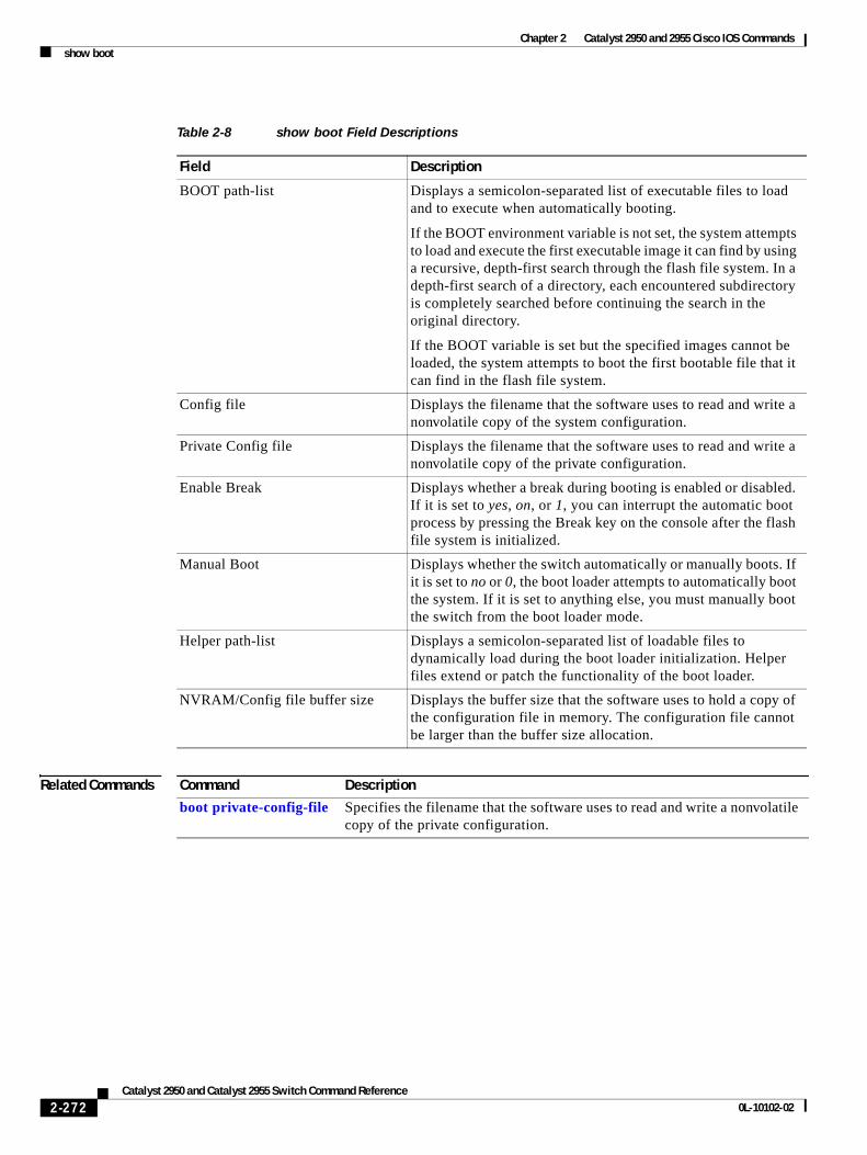
Chapter 2 Catalyst 2950 and 2955 Cisco IOS Commandsshow boot
Related Commands
Table 2-8 show boot Field Descriptions
Field Description
BOOT path-list Displays a semicolon-separated list of executable files to load and to execute when automatically booting.
If the BOOT environment variable is not set, the system attempts to load and execute the first executable image it can find by using a recursive, depth-first search through the flash file system. In a depth-first search of a directory, each encountered subdirectory is completely searched before continuing the search in the original directory.
If the BOOT variable is set but the specified images cannot be loaded, the system attempts to boot the first bootable file that it can find in the flash file system.
Config file Displays the filename that the software uses to read and write a nonvolatile copy of the system configuration.
Private Config file Displays the filename that the software uses to read and write a nonvolatile copy of the private configuration.
Enable Break Displays whether a break during booting is enabled or disabled. If it is set to yes, on, or 1, you can interrupt the automatic boot process by pressing the Break key on the console after the flash file system is initialized.
Manual Boot Displays whether the switch automatically or manually boots. If it is set to no or 0, the boot loader attempts to automatically boot the system. If it is set to anything else, you must manually boot the switch from the boot loader mode.
Helper path-list Displays a semicolon-separated list of loadable files to dynamically load during the boot loader initialization. Helper files extend or patch the functionality of the boot loader.
NVRAM/Config file buffer size Displays the buffer size that the software uses to hold a copy of the configuration file in memory. The configuration file cannot be larger than the buffer size allocation.
Command Description
boot private-config-file Specifies the filename that the software uses to read and write a nonvolatile copy of the private configuration.
2-272Catalyst 2950 and Catalyst 2955 Switch Command Reference
0L-10102-02
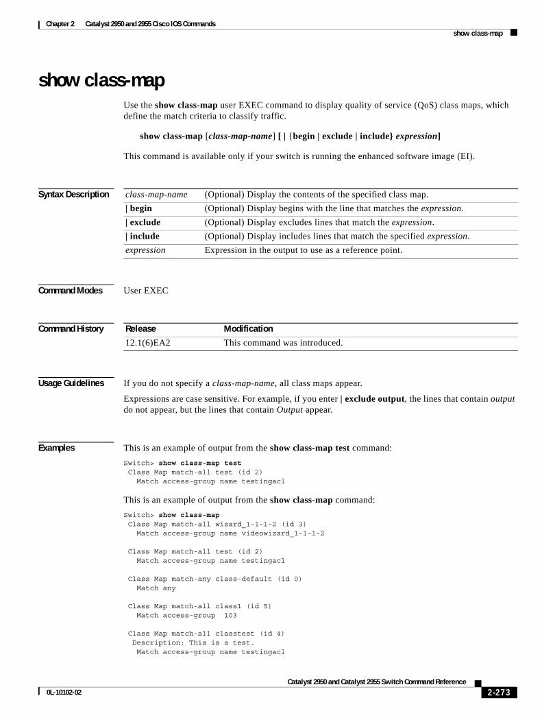
Chapter 2 Catalyst 2950 and 2955 Cisco IOS Commandsshow class-map
show class-mapUse the show class-map user EXEC command to display quality of service (QoS) class maps, which define the match criteria to classify traffic.
show class-map [class-map-name] [ | {begin | exclude | include} expression]
This command is available only if your switch is running the enhanced software image (EI).
Syntax Description
Command Modes User EXEC
Command History
Usage Guidelines If you do not specify a class-map-name, all class maps appear.
Expressions are case sensitive. For example, if you enter | exclude output, the lines that contain output do not appear, but the lines that contain Output appear.
Examples This is an example of output from the show class-map test command:
Switch> show class-map test Class Map match-all test (id 2) Match access-group name testingacl
This is an example of output from the show class-map command:
Switch> show class-map Class Map match-all wizard_1-1-1-2 (id 3) Match access-group name videowizard_1-1-1-2
Class Map match-all test (id 2) Match access-group name testingacl
Class Map match-any class-default (id 0) Match any
Class Map match-all class1 (id 5) Match access-group 103
Class Map match-all classtest (id 4) Description: This is a test. Match access-group name testingacl
class-map-name (Optional) Display the contents of the specified class map.
| begin (Optional) Display begins with the line that matches the expression.
| exclude (Optional) Display excludes lines that match the expression.
| include (Optional) Display includes lines that match the specified expression.
expression Expression in the output to use as a reference point.
Release Modification
12.1(6)EA2 This command was introduced.
2-273Catalyst 2950 and Catalyst 2955 Switch Command Reference
0L-10102-02
Chapter 2 Catalyst 2950 and 2955 Cisco IOS Commandsshow class-map
Related Commands Command Description
class-map Creates a class map to be used for matching packets to the class whose name you specify.
match Defines the match criteria to classify traffic.
2-274Catalyst 2950 and Catalyst 2955 Switch Command Reference
0L-10102-02
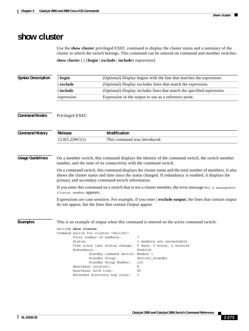
Chapter 2 Catalyst 2950 and 2955 Cisco IOS Commandsshow cluster
show clusterUse the show cluster privileged EXEC command to display the cluster status and a summary of the cluster to which the switch belongs. This command can be entered on command and member switches.
show cluster [ | {begin | exclude | include} expression]
Syntax Description
Command Modes Privileged EXEC
Command History
Usage Guidelines On a member switch, this command displays the identity of the command switch, the switch member number, and the state of its connectivity with the command switch.
On a command switch, this command displays the cluster name and the total number of members. It also shows the cluster status and time since the status changed. If redundancy is enabled, it displays the primary and secondary command-switch information.
If you enter this command on a switch that is not a cluster member, the error message Not a management cluster member appears.
Expressions are case sensitive. For example, if you enter | exclude output, the lines that contain output do not appear, but the lines that contain Output appear.
Examples This is an example of output when this command is entered on the active command switch:
Switch# show clusterCommand switch for cluster "Switch1" Total number of members: 7 Status: 1 members are unreachable Time since last status change: 0 days, 0 hours, 2 minutes Redundancy: Enabled Standby command switch: Member 1 Standby Group: Switch1_standby Standby Group Number: 110 Heartbeat interval: 8 Heartbeat hold-time: 80 Extended discovery hop count: 3
| begin (Optional) Display begins with the line that matches the expression.
| exclude (Optional) Display excludes lines that match the expression.
| include (Optional) Display includes lines that match the specified expression.
expression Expression in the output to use as a reference point.
Release Modification
12.0(5.2)WC(1) This command was introduced.
2-275Catalyst 2950 and Catalyst 2955 Switch Command Reference
0L-10102-02
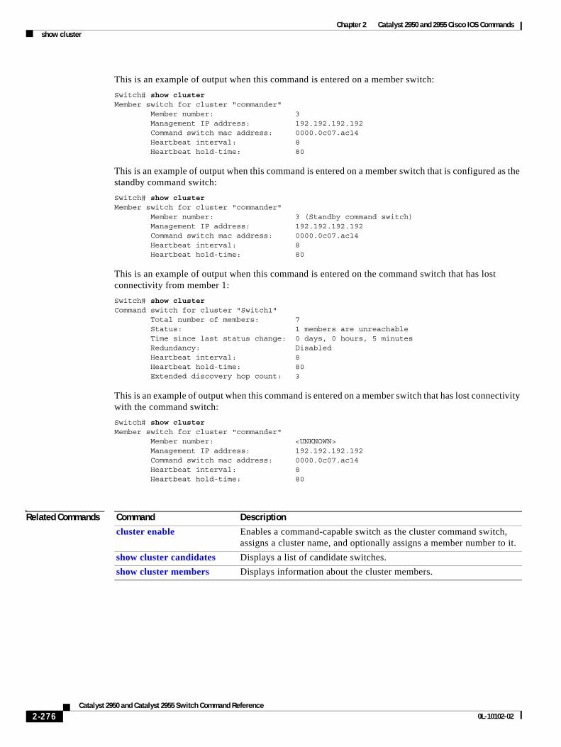
Chapter 2 Catalyst 2950 and 2955 Cisco IOS Commandsshow cluster
This is an example of output when this command is entered on a member switch:
Switch# show clusterMember switch for cluster "commander" Member number: 3 Management IP address: 192.192.192.192 Command switch mac address: 0000.0c07.ac14 Heartbeat interval: 8 Heartbeat hold-time: 80
This is an example of output when this command is entered on a member switch that is configured as the standby command switch:
Switch# show clusterMember switch for cluster "commander" Member number: 3 (Standby command switch) Management IP address: 192.192.192.192 Command switch mac address: 0000.0c07.ac14 Heartbeat interval: 8 Heartbeat hold-time: 80
This is an example of output when this command is entered on the command switch that has lost connectivity from member 1:
Switch# show clusterCommand switch for cluster "Switch1" Total number of members: 7 Status: 1 members are unreachable Time since last status change: 0 days, 0 hours, 5 minutes Redundancy: Disabled Heartbeat interval: 8 Heartbeat hold-time: 80 Extended discovery hop count: 3
This is an example of output when this command is entered on a member switch that has lost connectivity with the command switch:
Switch# show clusterMember switch for cluster "commander" Member number: <UNKNOWN> Management IP address: 192.192.192.192 Command switch mac address: 0000.0c07.ac14 Heartbeat interval: 8 Heartbeat hold-time: 80
Related Commands Command Description
cluster enable Enables a command-capable switch as the cluster command switch, assigns a cluster name, and optionally assigns a member number to it.
show cluster candidates Displays a list of candidate switches.
show cluster members Displays information about the cluster members.
2-276Catalyst 2950 and Catalyst 2955 Switch Command Reference
0L-10102-02
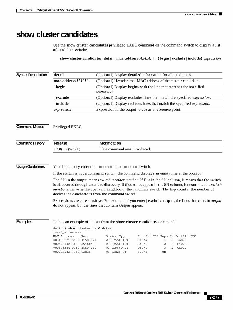
Chapter 2 Catalyst 2950 and 2955 Cisco IOS Commandsshow cluster candidates
show cluster candidatesUse the show cluster candidates privileged EXEC command on the command switch to display a list of candidate switches.
show cluster candidates [detail | mac-address H.H.H.] [ | {begin | exclude | include} expression]
Syntax Description
Command Modes Privileged EXEC
Command History
Usage Guidelines You should only enter this command on a command switch.
If the switch is not a command switch, the command displays an empty line at the prompt.
The SN in the output means switch member number. If E is in the SN column, it means that the switch is discovered through extended discovery. If E does not appear in the SN column, it means that the switch member number is the upstream neighbor of the candidate switch. The hop count is the number of devices the candidate is from the command switch.
Expressions are case sensitive. For example, if you enter | exclude output, the lines that contain output do not appear, but the lines that contain Output appear.
Examples This is an example of output from the show cluster candidates command:
Switch# show cluster candidates|---Upstream---|MAC Address Name Device Type PortIf FEC Hops SN PortIf FEC0030.85f5.8e80 3550-12T WS-C3550-12T Gi0/4 1 0 Fa0/1 0005.313c.5880 Switch2 WS-C3550-12T Gi0/1 2 E Gi0/5 0005.dcc8.01c0 2950-145 WS-C2950T-24 Fa0/1 3 E Gi0/2 0002.b922.7180 C2820 WS-C2820-24 Fa0/3 Up
detail (Optional) Display detailed information for all candidates.
mac-address H.H.H. (Optional) Hexadecimal MAC address of the cluster candidate.
| begin (Optional) Display begins with the line that matches the specified expression.
| exclude (Optional) Display excludes lines that match the specified expression.
| include (Optional) Display includes lines that match the specified expression.
expression Expression in the output to use as a reference point.
Release Modification
12.0(5.2)WC(1) This command was introduced.
2-277Catalyst 2950 and Catalyst 2955 Switch Command Reference
0L-10102-02
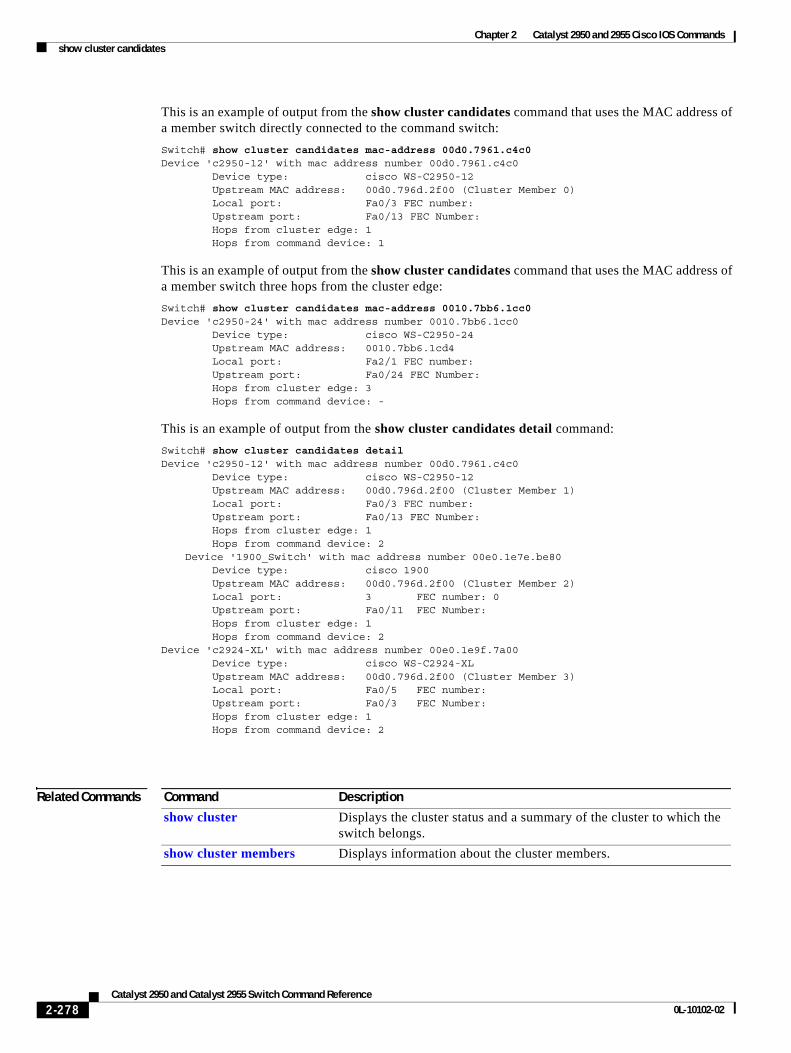
Chapter 2 Catalyst 2950 and 2955 Cisco IOS Commandsshow cluster candidates
This is an example of output from the show cluster candidates command that uses the MAC address of a member switch directly connected to the command switch:
Switch# show cluster candidates mac-address 00d0.7961.c4c0Device 'c2950-12' with mac address number 00d0.7961.c4c0 Device type: cisco WS-C2950-12 Upstream MAC address: 00d0.796d.2f00 (Cluster Member 0) Local port: Fa0/3 FEC number: Upstream port: Fa0/13 FEC Number: Hops from cluster edge: 1 Hops from command device: 1
This is an example of output from the show cluster candidates command that uses the MAC address of a member switch three hops from the cluster edge:
Switch# show cluster candidates mac-address 0010.7bb6.1cc0Device 'c2950-24' with mac address number 0010.7bb6.1cc0 Device type: cisco WS-C2950-24 Upstream MAC address: 0010.7bb6.1cd4 Local port: Fa2/1 FEC number: Upstream port: Fa0/24 FEC Number: Hops from cluster edge: 3 Hops from command device: -
This is an example of output from the show cluster candidates detail command:
Switch# show cluster candidates detailDevice 'c2950-12' with mac address number 00d0.7961.c4c0 Device type: cisco WS-C2950-12 Upstream MAC address: 00d0.796d.2f00 (Cluster Member 1) Local port: Fa0/3 FEC number: Upstream port: Fa0/13 FEC Number: Hops from cluster edge: 1 Hops from command device: 2
Device '1900_Switch' with mac address number 00e0.1e7e.be80 Device type: cisco 1900 Upstream MAC address: 00d0.796d.2f00 (Cluster Member 2) Local port: 3 FEC number: 0 Upstream port: Fa0/11 FEC Number: Hops from cluster edge: 1 Hops from command device: 2Device 'c2924-XL' with mac address number 00e0.1e9f.7a00 Device type: cisco WS-C2924-XL Upstream MAC address: 00d0.796d.2f00 (Cluster Member 3) Local port: Fa0/5 FEC number: Upstream port: Fa0/3 FEC Number: Hops from cluster edge: 1 Hops from command device: 2
Related Commands Command Description
show cluster Displays the cluster status and a summary of the cluster to which the switch belongs.
show cluster members Displays information about the cluster members.
2-278Catalyst 2950 and Catalyst 2955 Switch Command Reference
0L-10102-02
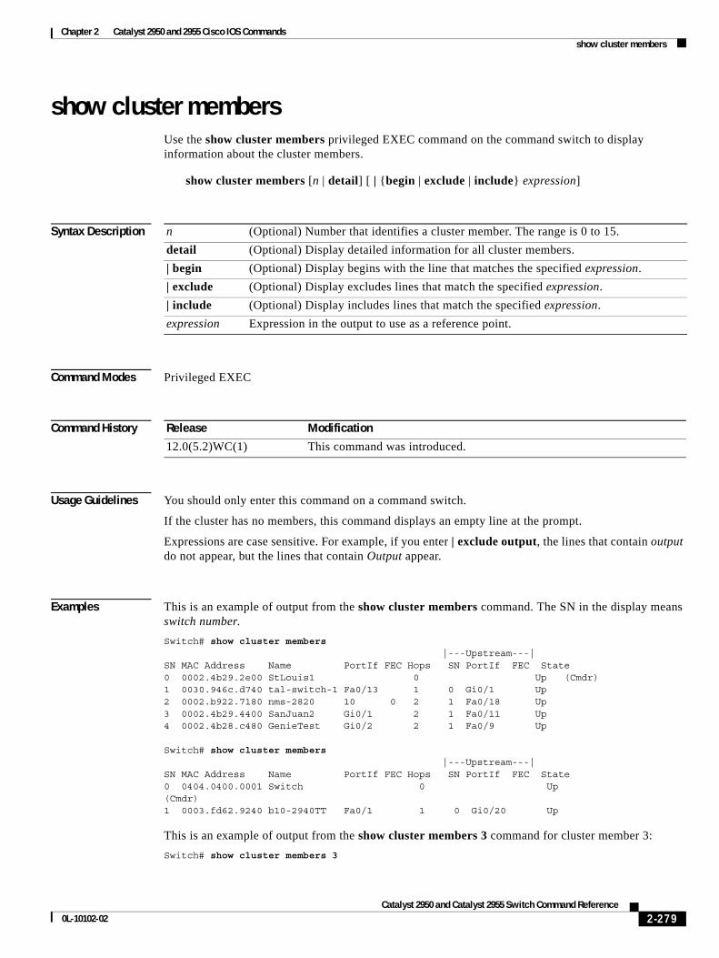
Chapter 2 Catalyst 2950 and 2955 Cisco IOS Commandsshow cluster members
show cluster members Use the show cluster members privileged EXEC command on the command switch to display information about the cluster members.
show cluster members [n | detail] [ | {begin | exclude | include} expression]
Syntax Description
Command Modes Privileged EXEC
Command History
Usage Guidelines You should only enter this command on a command switch.
If the cluster has no members, this command displays an empty line at the prompt.
Expressions are case sensitive. For example, if you enter | exclude output, the lines that contain output do not appear, but the lines that contain Output appear.
Examples This is an example of output from the show cluster members command. The SN in the display means switch number.
Switch# show cluster members |---Upstream---|SN MAC Address Name PortIf FEC Hops SN PortIf FEC State0 0002.4b29.2e00 StLouis1 0 Up (Cmdr)1 0030.946c.d740 tal-switch-1 Fa0/13 1 0 Gi0/1 Up2 0002.b922.7180 nms-2820 10 0 2 1 Fa0/18 Up3 0002.4b29.4400 SanJuan2 Gi0/1 2 1 Fa0/11 Up4 0002.4b28.c480 GenieTest Gi0/2 2 1 Fa0/9 Up
Switch# show cluster members |---Upstream---|SN MAC Address Name PortIf FEC Hops SN PortIf FEC State0 0404.0400.0001 Switch 0 Up(Cmdr)1 0003.fd62.9240 b10-2940TT Fa0/1 1 0 Gi0/20 Up
This is an example of output from the show cluster members 3 command for cluster member 3:
Switch# show cluster members 3
n (Optional) Number that identifies a cluster member. The range is 0 to 15.
detail (Optional) Display detailed information for all cluster members.
| begin (Optional) Display begins with the line that matches the specified expression.
| exclude (Optional) Display excludes lines that match the specified expression.
| include (Optional) Display includes lines that match the specified expression.
expression Expression in the output to use as a reference point.
Release Modification
12.0(5.2)WC(1) This command was introduced.
2-279Catalyst 2950 and Catalyst 2955 Switch Command Reference
0L-10102-02
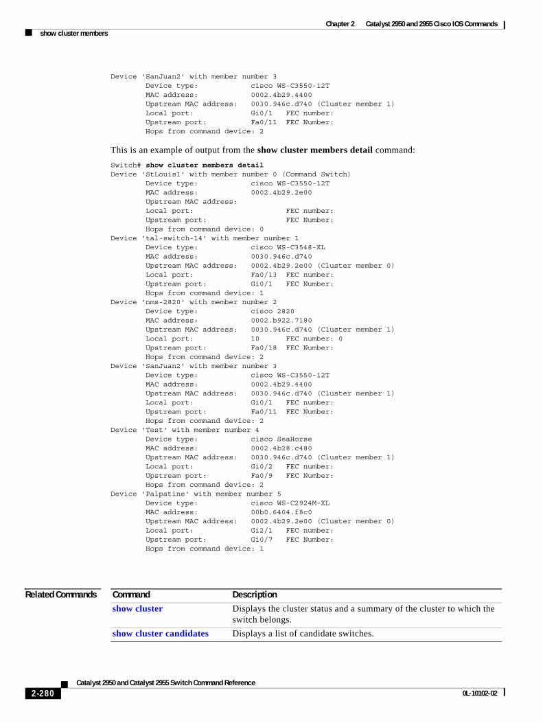
Chapter 2 Catalyst 2950 and 2955 Cisco IOS Commandsshow cluster members
Device 'SanJuan2' with member number 3 Device type: cisco WS-C3550-12T MAC address: 0002.4b29.4400 Upstream MAC address: 0030.946c.d740 (Cluster member 1) Local port: Gi0/1 FEC number: Upstream port: Fa0/11 FEC Number: Hops from command device: 2
This is an example of output from the show cluster members detail command:
Switch# show cluster members detailDevice 'StLouis1' with member number 0 (Command Switch) Device type: cisco WS-C3550-12T MAC address: 0002.4b29.2e00 Upstream MAC address: Local port: FEC number: Upstream port: FEC Number: Hops from command device: 0 Device 'tal-switch-14' with member number 1 Device type: cisco WS-C3548-XL MAC address: 0030.946c.d740 Upstream MAC address: 0002.4b29.2e00 (Cluster member 0) Local port: Fa0/13 FEC number: Upstream port: Gi0/1 FEC Number: Hops from command device: 1 Device 'nms-2820' with member number 2 Device type: cisco 2820 MAC address: 0002.b922.7180 Upstream MAC address: 0030.946c.d740 (Cluster member 1) Local port: 10 FEC number: 0 Upstream port: Fa0/18 FEC Number: Hops from command device: 2 Device 'SanJuan2' with member number 3 Device type: cisco WS-C3550-12T MAC address: 0002.4b29.4400 Upstream MAC address: 0030.946c.d740 (Cluster member 1) Local port: Gi0/1 FEC number: Upstream port: Fa0/11 FEC Number: Hops from command device: 2Device 'Test' with member number 4 Device type: cisco SeaHorse MAC address: 0002.4b28.c480 Upstream MAC address: 0030.946c.d740 (Cluster member 1) Local port: Gi0/2 FEC number: Upstream port: Fa0/9 FEC Number: Hops from command device: 2Device 'Palpatine' with member number 5 Device type: cisco WS-C2924M-XL MAC address: 00b0.6404.f8c0 Upstream MAC address: 0002.4b29.2e00 (Cluster member 0) Local port: Gi2/1 FEC number: Upstream port: Gi0/7 FEC Number: Hops from command device: 1
Related Commands Command Description
show cluster Displays the cluster status and a summary of the cluster to which the switch belongs.
show cluster candidates Displays a list of candidate switches.
2-280Catalyst 2950 and Catalyst 2955 Switch Command Reference
0L-10102-02
Chapter 2 Catalyst 2950 and 2955 Cisco IOS Commandsshow controllers ethernet-controller
show controllers ethernet-controllerUse the show controllers ethernet-controller privileged EXEC command without keywords to display per-interface send and receive statistics read from the hardware. Use this command with keywords to display the interface internal registers or to display the statistics read from Long-Reach Ethernet (LRE) and customer premises equipment (CPE) ports.
show controllers ethernet-controller interface-id [asic | cpe [port port-id] | phy 32] [ | {begin | exclude | include} expression]
Syntax Description
Command Modes Privileged EXEC (only supported with the interface-id keywords in user EXEC mode)
Command History
Usage Guidelines Use this command without keywords to display traffic statistics, particularly the RMON statistics for the interface. If this command is entered on a Catalyst 2950 LRE switch, the command output also shows the statistics for the LRE switch interfaces.
When you enter the asic or phy 32 keyword, the displayed information is primarily useful for Cisco technical support representatives troubleshooting the switch. When you enter the cpe keyword, the displayed information shows the traffic statistics for the connected CPE devices. The CPE Ethernet link on an LRE switch port is the connection between the Cisco LRE CPE and the remote Ethernet device (such as a PC) connected to it. It is not the link between the LRE switch port and the LRE CPE device.
interface-id ID of the switch interface.
asic (Optional) Display the state of the internal registers on the forwarding application-specific integrated circuit (ASIC) for the interface. This keyword is available only on non-LRE switches.
cpe [port port-id] (Optional) Display statistics from the LRE and Fast Ethernet ports on connected devices.
• port port-id—Display the Ethernet statistics of the designated CPE Ethernet port. The range is 1 to 4, depending on the CPE device.
These keywords are available only on LRE switches.
phy 32 (Optional) Display the status of the internal registers on the switch physical layer device (PHY) for the interface. This keyword is available only on non-LRE switches.
| begin (Optional) Display begins with the line that matches the expression.
| exclude (Optional) Display excludes lines that match the expression.
| include (Optional) Display includes lines that match the specified expression.
expression Expression in the output to use as a reference point.
Release Modification
12.1(6)EA2 This command was introduced.
12.1(11)YJ The cpe and port port-id keywords were added.
12.1(19)EA1 The phy keyword was changed to phy 32.
2-281Catalyst 2950 and Catalyst 2955 Switch Command Reference
0L-10102-02
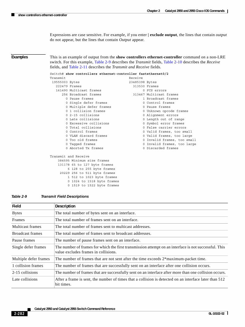
Chapter 2 Catalyst 2950 and 2955 Cisco IOS Commandsshow controllers ethernet-controller
Expressions are case sensitive. For example, if you enter | exclude output, the lines that contain output do not appear, but the lines that contain Output appear.
Examples This is an example of output from the show controllers ethernet-controller command on a non-LRE switch. For this example, Table 2-9 describes the Transmit fields, Table 2-10 describes the Receive fields, and Table 2-11 describes the Transmit and Receive fields.
Switch# show controllers ethernet-controller fastethernet0/2Transmit Receive 19555003 Bytes 23485398 Bytes 222479 Frames 313530 Frames 161490 Multicast frames 0 FCS errors 256 Broadcast frames 313467 Multicast frames 0 Pause frames 1 Broadcast frames 0 Single defer frames 0 Control frames 0 Multiple defer frames 0 Pause frames 0 1 collision frames 0 Unknown opcode frames 0 2-15 collisions 0 Alignment errors 0 Late collisions 0 Length out of range 0 Excessive collisions 0 Symbol error frames 0 Total collisions 0 False carrier errors 0 Control frames 0 Valid frames, too small 0 VLAN discard frames 0 Valid frames, too large 0 Too old frames 0 Invalid frames, too small 0 Tagged frames 0 Invalid frames, too large 0 Aborted Tx frames 0 Discarded frames
Transmit and Receive 384595 Minimum size frames 131178 65 to 127 byte frames 6 128 to 255 byte frames 20229 256 to 511 byte frames 1 512 to 1023 byte frames 0 1024 to 1518 byte frames 0 1519 to 1522 byte frames
Table 2-9 Transmit Field Descriptions
Field Description
Bytes The total number of bytes sent on an interface.
Frames The total number of frames sent on an interface.
Multicast frames The total number of frames sent to multicast addresses.
Broadcast frames The total number of frames sent to broadcast addresses.
Pause frames The number of pause frames sent on an interface.
Single defer frames The number of frames for which the first transmission attempt on an interface is not successful. This value excludes frames in collisions.
Multiple defer frames The number of frames that are not sent after the time exceeds 2*maximum-packet time.
1 collision frames The number of frames that are successfully sent on an interface after one collision occurs.
2-15 collisions The number of frames that are successfully sent on an interface after more than one collision occurs.
Late collisions After a frame is sent, the number of times that a collision is detected on an interface later than 512 bit times.
2-282Catalyst 2950 and Catalyst 2955 Switch Command Reference
0L-10102-02
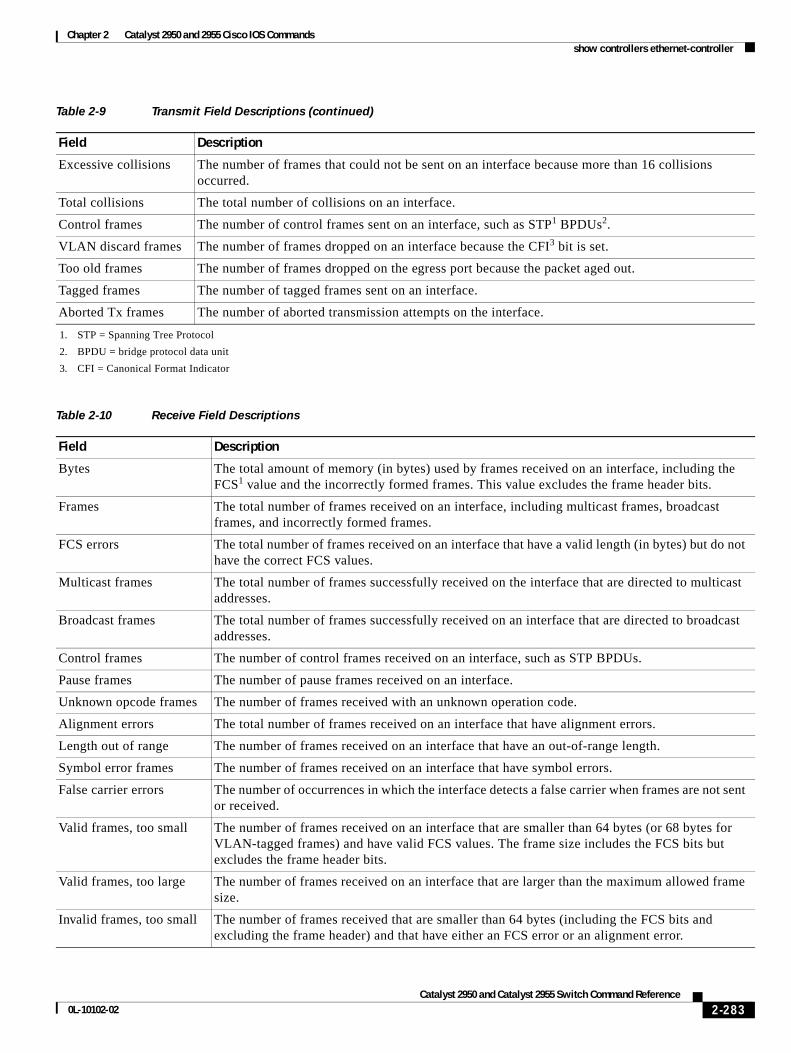
Chapter 2 Catalyst 2950 and 2955 Cisco IOS Commandsshow controllers ethernet-controller
Excessive collisions The number of frames that could not be sent on an interface because more than 16 collisions occurred.
Total collisions The total number of collisions on an interface.
Control frames The number of control frames sent on an interface, such as STP1 BPDUs2.
VLAN discard frames The number of frames dropped on an interface because the CFI3 bit is set.
Too old frames The number of frames dropped on the egress port because the packet aged out.
Tagged frames The number of tagged frames sent on an interface.
Aborted Tx frames The number of aborted transmission attempts on the interface.
1. STP = Spanning Tree Protocol
2. BPDU = bridge protocol data unit
3. CFI = Canonical Format Indicator
Table 2-10 Receive Field Descriptions
Field Description
Bytes The total amount of memory (in bytes) used by frames received on an interface, including the FCS1 value and the incorrectly formed frames. This value excludes the frame header bits.
Frames The total number of frames received on an interface, including multicast frames, broadcast frames, and incorrectly formed frames.
FCS errors The total number of frames received on an interface that have a valid length (in bytes) but do not have the correct FCS values.
Multicast frames The total number of frames successfully received on the interface that are directed to multicast addresses.
Broadcast frames The total number of frames successfully received on an interface that are directed to broadcast addresses.
Control frames The number of control frames received on an interface, such as STP BPDUs.
Pause frames The number of pause frames received on an interface.
Unknown opcode frames The number of frames received with an unknown operation code.
Alignment errors The total number of frames received on an interface that have alignment errors.
Length out of range The number of frames received on an interface that have an out-of-range length.
Symbol error frames The number of frames received on an interface that have symbol errors.
False carrier errors The number of occurrences in which the interface detects a false carrier when frames are not sent or received.
Valid frames, too small The number of frames received on an interface that are smaller than 64 bytes (or 68 bytes for VLAN-tagged frames) and have valid FCS values. The frame size includes the FCS bits but excludes the frame header bits.
Valid frames, too large The number of frames received on an interface that are larger than the maximum allowed frame size.
Invalid frames, too small The number of frames received that are smaller than 64 bytes (including the FCS bits and excluding the frame header) and that have either an FCS error or an alignment error.
Table 2-9 Transmit Field Descriptions (continued)
Field Description
2-283Catalyst 2950 and Catalyst 2955 Switch Command Reference
0L-10102-02
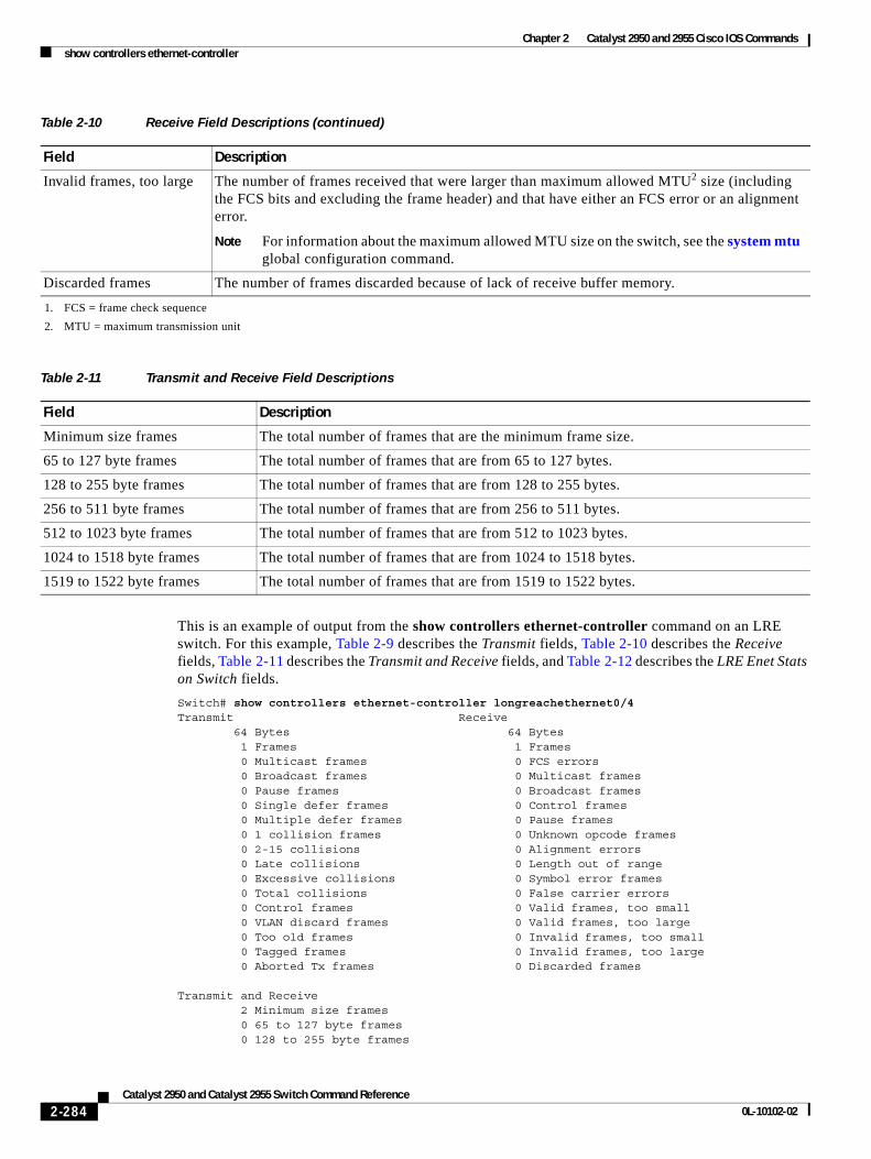
Chapter 2 Catalyst 2950 and 2955 Cisco IOS Commandsshow controllers ethernet-controller
This is an example of output from the show controllers ethernet-controller command on an LRE switch. For this example, Table 2-9 describes the Transmit fields, Table 2-10 describes the Receive fields, Table 2-11 describes the Transmit and Receive fields, and Table 2-12 describes the LRE Enet Stats on Switch fields.
Switch# show controllers ethernet-controller longreachethernet0/4Transmit Receive 64 Bytes 64 Bytes 1 Frames 1 Frames 0 Multicast frames 0 FCS errors 0 Broadcast frames 0 Multicast frames 0 Pause frames 0 Broadcast frames 0 Single defer frames 0 Control frames 0 Multiple defer frames 0 Pause frames 0 1 collision frames 0 Unknown opcode frames 0 2-15 collisions 0 Alignment errors 0 Late collisions 0 Length out of range 0 Excessive collisions 0 Symbol error frames 0 Total collisions 0 False carrier errors 0 Control frames 0 Valid frames, too small 0 VLAN discard frames 0 Valid frames, too large 0 Too old frames 0 Invalid frames, too small 0 Tagged frames 0 Invalid frames, too large 0 Aborted Tx frames 0 Discarded frames
Transmit and Receive 2 Minimum size frames 0 65 to 127 byte frames 0 128 to 255 byte frames
Invalid frames, too large The number of frames received that were larger than maximum allowed MTU2 size (including the FCS bits and excluding the frame header) and that have either an FCS error or an alignment error.
Note For information about the maximum allowed MTU size on the switch, see the system mtu global configuration command.
Discarded frames The number of frames discarded because of lack of receive buffer memory.
1. FCS = frame check sequence
2. MTU = maximum transmission unit
Table 2-11 Transmit and Receive Field Descriptions
Field Description
Minimum size frames The total number of frames that are the minimum frame size.
65 to 127 byte frames The total number of frames that are from 65 to 127 bytes.
128 to 255 byte frames The total number of frames that are from 128 to 255 bytes.
256 to 511 byte frames The total number of frames that are from 256 to 511 bytes.
512 to 1023 byte frames The total number of frames that are from 512 to 1023 bytes.
1024 to 1518 byte frames The total number of frames that are from 1024 to 1518 bytes.
1519 to 1522 byte frames The total number of frames that are from 1519 to 1522 bytes.
Table 2-10 Receive Field Descriptions (continued)
Field Description
2-284Catalyst 2950 and Catalyst 2955 Switch Command Reference
0L-10102-02
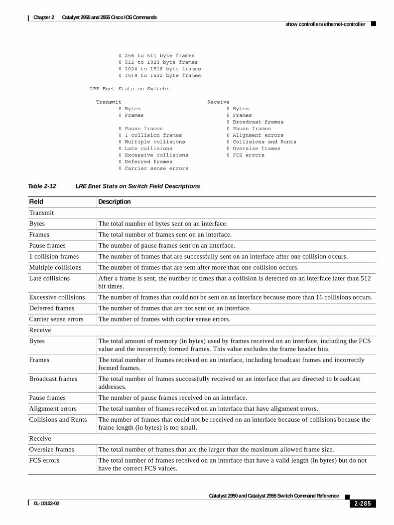
Chapter 2 Catalyst 2950 and 2955 Cisco IOS Commandsshow controllers ethernet-controller
0 256 to 511 byte frames 0 512 to 1023 byte frames 0 1024 to 1518 byte frames 0 1519 to 1522 byte frames
LRE Enet Stats on Switch:
Transmit Receive 0 Bytes 0 Bytes 0 Frames 0 Frames 0 Broadcast frames 0 Pause frames 0 Pause frames 0 1 collision frames 0 Alignment errors 0 Multiple collisions 0 Collisions and Runts 0 Late collisions 0 Oversize frames 0 Excessive collisions 0 FCS errors 0 Deferred frames 0 Carrier sense errors
Table 2-12 LRE Enet Stats on Switch Field Descriptions
Field Description
Transmit
Bytes The total number of bytes sent on an interface.
Frames The total number of frames sent on an interface.
Pause frames The number of pause frames sent on an interface.
1 collision frames The number of frames that are successfully sent on an interface after one collision occurs.
Multiple collisions The number of frames that are sent after more than one collision occurs.
Late collisions After a frame is sent, the number of times that a collision is detected on an interface later than 512 bit times.
Excessive collisions The number of frames that could not be sent on an interface because more than 16 collisions occurs.
Deferred frames The number of frames that are not sent on an interface.
Carrier sense errors The number of frames with carrier sense errors.
Receive
Bytes The total amount of memory (in bytes) used by frames received on an interface, including the FCS value and the incorrectly formed frames. This value excludes the frame header bits.
Frames The total number of frames received on an interface, including broadcast frames and incorrectly formed frames.
Broadcast frames The total number of frames successfully received on an interface that are directed to broadcast addresses.
Pause frames The number of pause frames received on an interface.
Alignment errors The total number of frames received on an interface that have alignment errors.
Collisions and Runts The number of frames that could not be received on an interface because of collisions because the frame length (in bytes) is too small.
Receive
Oversize frames The total number of frames that are the larger than the maximum allowed frame size.
FCS errors The total number of frames received on an interface that have a valid length (in bytes) but do not have the correct FCS values.
2-285Catalyst 2950 and Catalyst 2955 Switch Command Reference
0L-10102-02
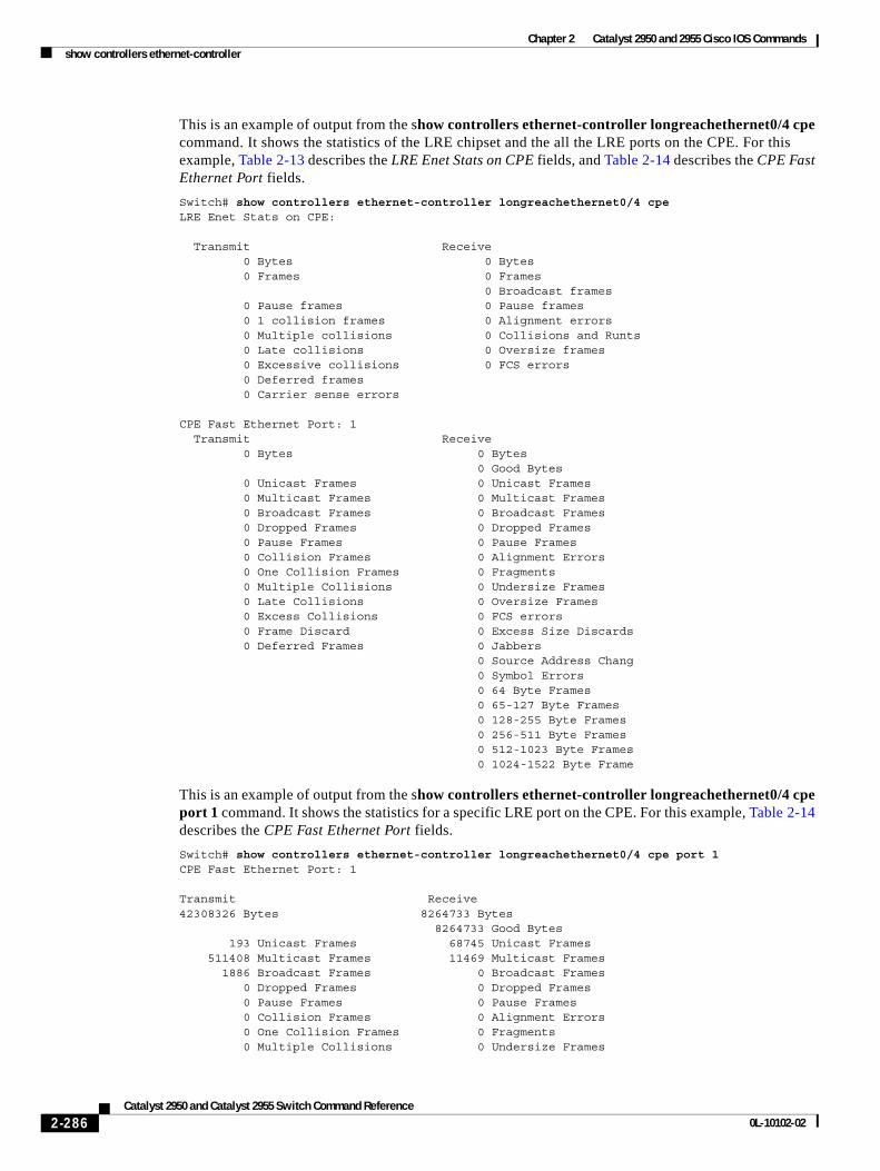
Chapter 2 Catalyst 2950 and 2955 Cisco IOS Commandsshow controllers ethernet-controller
This is an example of output from the show controllers ethernet-controller longreachethernet0/4 cpe command. It shows the statistics of the LRE chipset and the all the LRE ports on the CPE. For this example, Table 2-13 describes the LRE Enet Stats on CPE fields, and Table 2-14 describes the CPE Fast Ethernet Port fields.
Switch# show controllers ethernet-controller longreachethernet0/4 cpeLRE Enet Stats on CPE:
Transmit Receive 0 Bytes 0 Bytes 0 Frames 0 Frames 0 Broadcast frames 0 Pause frames 0 Pause frames 0 1 collision frames 0 Alignment errors 0 Multiple collisions 0 Collisions and Runts 0 Late collisions 0 Oversize frames 0 Excessive collisions 0 FCS errors 0 Deferred frames 0 Carrier sense errors
CPE Fast Ethernet Port: 1 Transmit Receive 0 Bytes 0 Bytes 0 Good Bytes 0 Unicast Frames 0 Unicast Frames 0 Multicast Frames 0 Multicast Frames 0 Broadcast Frames 0 Broadcast Frames 0 Dropped Frames 0 Dropped Frames 0 Pause Frames 0 Pause Frames 0 Collision Frames 0 Alignment Errors 0 One Collision Frames 0 Fragments 0 Multiple Collisions 0 Undersize Frames 0 Late Collisions 0 Oversize Frames 0 Excess Collisions 0 FCS errors 0 Frame Discard 0 Excess Size Discards 0 Deferred Frames 0 Jabbers 0 Source Address Chang 0 Symbol Errors 0 64 Byte Frames 0 65-127 Byte Frames 0 128-255 Byte Frames 0 256-511 Byte Frames 0 512-1023 Byte Frames 0 1024-1522 Byte Frame
This is an example of output from the show controllers ethernet-controller longreachethernet0/4 cpe port 1 command. It shows the statistics for a specific LRE port on the CPE. For this example, Table 2-14 describes the CPE Fast Ethernet Port fields.
Switch# show controllers ethernet-controller longreachethernet0/4 cpe port 1CPE Fast Ethernet Port: 1
Transmit Receive42308326 Bytes 8264733 Bytes 8264733 Good Bytes 193 Unicast Frames 68745 Unicast Frames 511408 Multicast Frames 11469 Multicast Frames 1886 Broadcast Frames 0 Broadcast Frames 0 Dropped Frames 0 Dropped Frames 0 Pause Frames 0 Pause Frames 0 Collision Frames 0 Alignment Errors 0 One Collision Frames 0 Fragments 0 Multiple Collisions 0 Undersize Frames
2-286Catalyst 2950 and Catalyst 2955 Switch Command Reference
0L-10102-02
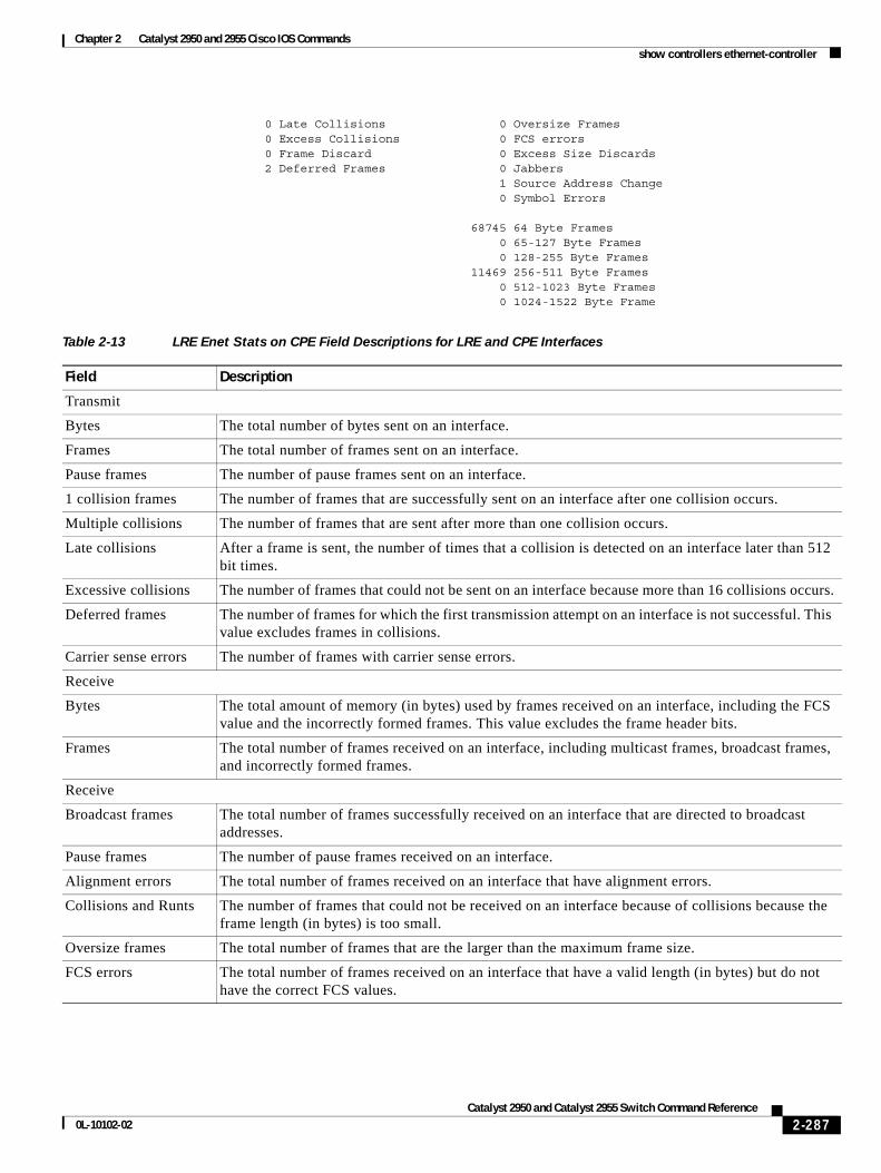
Chapter 2 Catalyst 2950 and 2955 Cisco IOS Commandsshow controllers ethernet-controller
0 Late Collisions 0 Oversize Frames 0 Excess Collisions 0 FCS errors 0 Frame Discard 0 Excess Size Discards 2 Deferred Frames 0 Jabbers 1 Source Address Change 0 Symbol Errors 68745 64 Byte Frames 0 65-127 Byte Frames 0 128-255 Byte Frames 11469 256-511 Byte Frames 0 512-1023 Byte Frames 0 1024-1522 Byte Frame
Table 2-13 LRE Enet Stats on CPE Field Descriptions for LRE and CPE Interfaces
Field Description
Transmit
Bytes The total number of bytes sent on an interface.
Frames The total number of frames sent on an interface.
Pause frames The number of pause frames sent on an interface.
1 collision frames The number of frames that are successfully sent on an interface after one collision occurs.
Multiple collisions The number of frames that are sent after more than one collision occurs.
Late collisions After a frame is sent, the number of times that a collision is detected on an interface later than 512 bit times.
Excessive collisions The number of frames that could not be sent on an interface because more than 16 collisions occurs.
Deferred frames The number of frames for which the first transmission attempt on an interface is not successful. This value excludes frames in collisions.
Carrier sense errors The number of frames with carrier sense errors.
Receive
Bytes The total amount of memory (in bytes) used by frames received on an interface, including the FCS value and the incorrectly formed frames. This value excludes the frame header bits.
Frames The total number of frames received on an interface, including multicast frames, broadcast frames, and incorrectly formed frames.
Receive
Broadcast frames The total number of frames successfully received on an interface that are directed to broadcast addresses.
Pause frames The number of pause frames received on an interface.
Alignment errors The total number of frames received on an interface that have alignment errors.
Collisions and Runts The number of frames that could not be received on an interface because of collisions because the frame length (in bytes) is too small.
Oversize frames The total number of frames that are the larger than the maximum frame size.
FCS errors The total number of frames received on an interface that have a valid length (in bytes) but do not have the correct FCS values.
2-287Catalyst 2950 and Catalyst 2955 Switch Command Reference
0L-10102-02
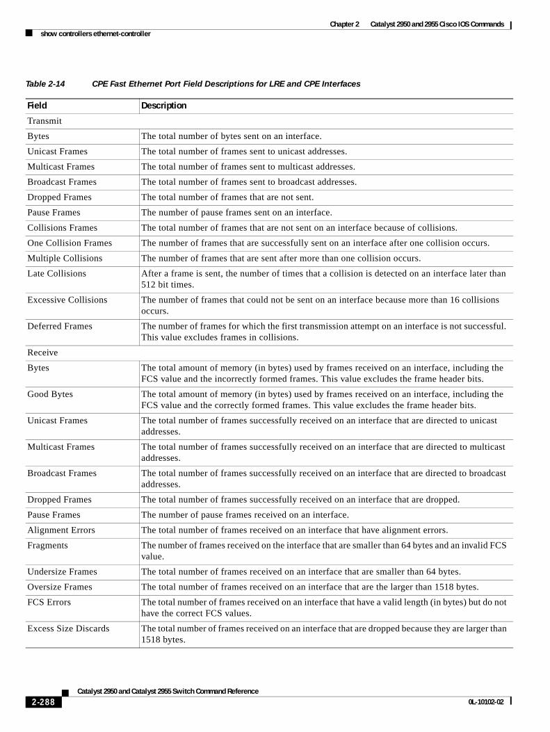
Chapter 2 Catalyst 2950 and 2955 Cisco IOS Commandsshow controllers ethernet-controller
Table 2-14 CPE Fast Ethernet Port Field Descriptions for LRE and CPE Interfaces
Field Description
Transmit
Bytes The total number of bytes sent on an interface.
Unicast Frames The total number of frames sent to unicast addresses.
Multicast Frames The total number of frames sent to multicast addresses.
Broadcast Frames The total number of frames sent to broadcast addresses.
Dropped Frames The total number of frames that are not sent.
Pause Frames The number of pause frames sent on an interface.
Collisions Frames The total number of frames that are not sent on an interface because of collisions.
One Collision Frames The number of frames that are successfully sent on an interface after one collision occurs.
Multiple Collisions The number of frames that are sent after more than one collision occurs.
Late Collisions After a frame is sent, the number of times that a collision is detected on an interface later than 512 bit times.
Excessive Collisions The number of frames that could not be sent on an interface because more than 16 collisions occurs.
Deferred Frames The number of frames for which the first transmission attempt on an interface is not successful. This value excludes frames in collisions.
Receive
Bytes The total amount of memory (in bytes) used by frames received on an interface, including the FCS value and the incorrectly formed frames. This value excludes the frame header bits.
Good Bytes The total amount of memory (in bytes) used by frames received on an interface, including the FCS value and the correctly formed frames. This value excludes the frame header bits.
Unicast Frames The total number of frames successfully received on an interface that are directed to unicast addresses.
Multicast Frames The total number of frames successfully received on an interface that are directed to multicast addresses.
Broadcast Frames The total number of frames successfully received on an interface that are directed to broadcast addresses.
Dropped Frames The total number of frames successfully received on an interface that are dropped.
Pause Frames The number of pause frames received on an interface.
Alignment Errors The total number of frames received on an interface that have alignment errors.
Fragments The number of frames received on the interface that are smaller than 64 bytes and an invalid FCS value.
Undersize Frames The total number of frames received on an interface that are smaller than 64 bytes.
Oversize Frames The total number of frames received on an interface that are the larger than 1518 bytes.
FCS Errors The total number of frames received on an interface that have a valid length (in bytes) but do not have the correct FCS values.
Excess Size Discards The total number of frames received on an interface that are dropped because they are larger than 1518 bytes.
2-288Catalyst 2950 and Catalyst 2955 Switch Command Reference
0L-10102-02
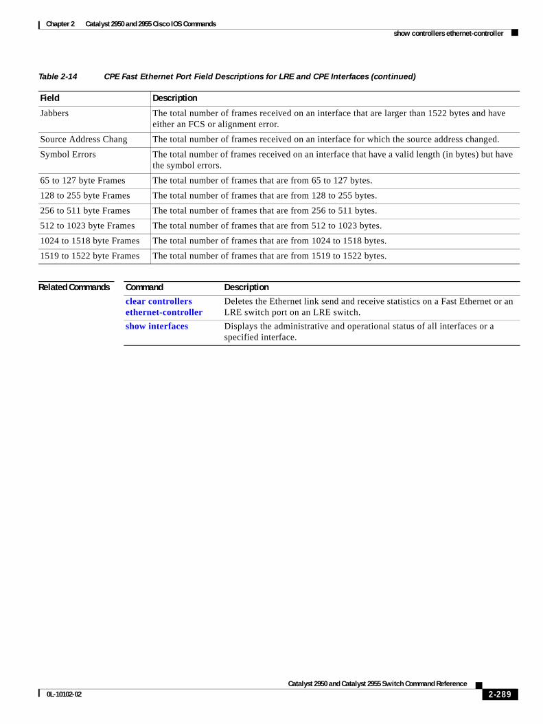
Chapter 2 Catalyst 2950 and 2955 Cisco IOS Commandsshow controllers ethernet-controller
Related Commands
Jabbers The total number of frames received on an interface that are larger than 1522 bytes and have either an FCS or alignment error.
Source Address Chang The total number of frames received on an interface for which the source address changed.
Symbol Errors The total number of frames received on an interface that have a valid length (in bytes) but have the symbol errors.
65 to 127 byte Frames The total number of frames that are from 65 to 127 bytes.
128 to 255 byte Frames The total number of frames that are from 128 to 255 bytes.
256 to 511 byte Frames The total number of frames that are from 256 to 511 bytes.
512 to 1023 byte Frames The total number of frames that are from 512 to 1023 bytes.
1024 to 1518 byte Frames The total number of frames that are from 1024 to 1518 bytes.
1519 to 1522 byte Frames The total number of frames that are from 1519 to 1522 bytes.
Table 2-14 CPE Fast Ethernet Port Field Descriptions for LRE and CPE Interfaces (continued)
Field Description
Command Description
clear controllers ethernet-controller
Deletes the Ethernet link send and receive statistics on a Fast Ethernet or an LRE switch port on an LRE switch.
show interfaces Displays the administrative and operational status of all interfaces or a specified interface.
2-289Catalyst 2950 and Catalyst 2955 Switch Command Reference
0L-10102-02
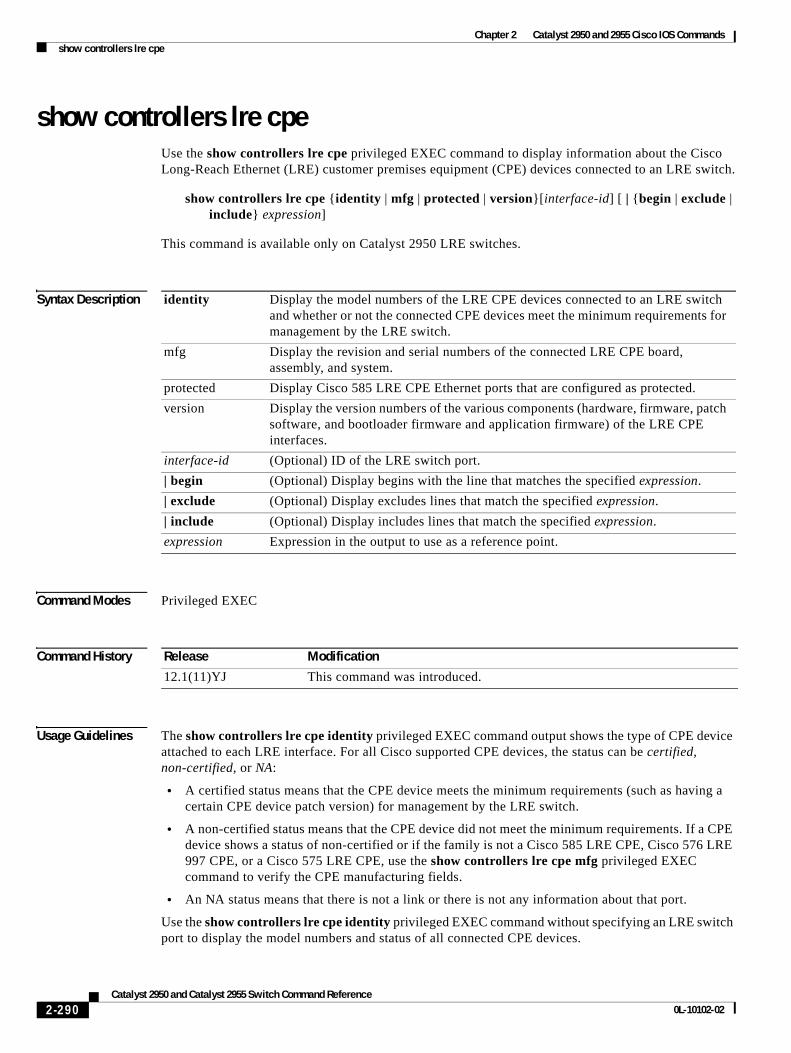
Chapter 2 Catalyst 2950 and 2955 Cisco IOS Commandsshow controllers lre cpe
show controllers lre cpeUse the show controllers lre cpe privileged EXEC command to display information about the Cisco Long-Reach Ethernet (LRE) customer premises equipment (CPE) devices connected to an LRE switch.
show controllers lre cpe {identity | mfg | protected | version}[interface-id] [ | {begin | exclude | include} expression]
This command is available only on Catalyst 2950 LRE switches.
Syntax Description
Command Modes Privileged EXEC
Command History
Usage Guidelines The show controllers lre cpe identity privileged EXEC command output shows the type of CPE device attached to each LRE interface. For all Cisco supported CPE devices, the status can be certified, non-certified, or NA:
• A certified status means that the CPE device meets the minimum requirements (such as having a certain CPE device patch version) for management by the LRE switch.
• A non-certified status means that the CPE device did not meet the minimum requirements. If a CPE device shows a status of non-certified or if the family is not a Cisco 585 LRE CPE, Cisco 576 LRE 997 CPE, or a Cisco 575 LRE CPE, use the show controllers lre cpe mfg privileged EXEC command to verify the CPE manufacturing fields.
• An NA status means that there is not a link or there is not any information about that port.
Use the show controllers lre cpe identity privileged EXEC command without specifying an LRE switch port to display the model numbers and status of all connected CPE devices.
identity Display the model numbers of the LRE CPE devices connected to an LRE switch and whether or not the connected CPE devices meet the minimum requirements for management by the LRE switch.
mfg Display the revision and serial numbers of the connected LRE CPE board, assembly, and system.
protected Display Cisco 585 LRE CPE Ethernet ports that are configured as protected.
version Display the version numbers of the various components (hardware, firmware, patch software, and bootloader firmware and application firmware) of the LRE CPE interfaces.
interface-id (Optional) ID of the LRE switch port.
| begin (Optional) Display begins with the line that matches the specified expression.
| exclude (Optional) Display excludes lines that match the specified expression.
| include (Optional) Display includes lines that match the specified expression.
expression Expression in the output to use as a reference point.
Release Modification
12.1(11)YJ This command was introduced.
2-290Catalyst 2950 and Catalyst 2955 Switch Command Reference
0L-10102-02
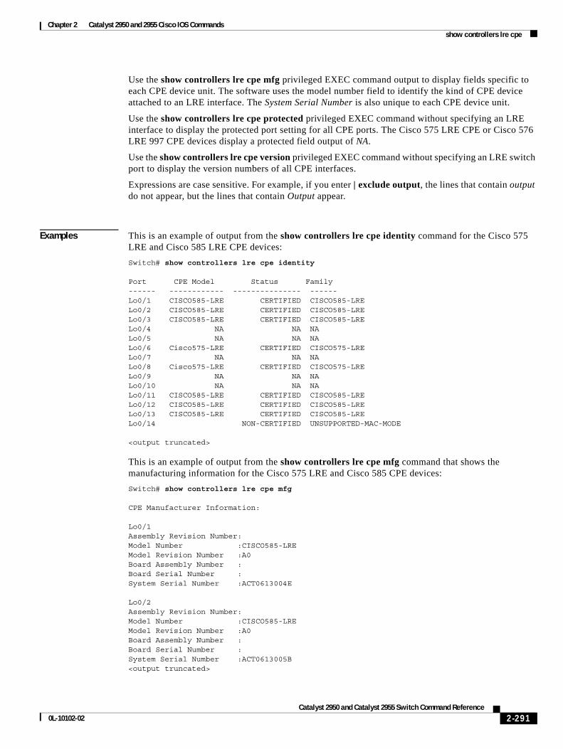
Chapter 2 Catalyst 2950 and 2955 Cisco IOS Commandsshow controllers lre cpe
Use the show controllers lre cpe mfg privileged EXEC command output to display fields specific to each CPE device unit. The software uses the model number field to identify the kind of CPE device attached to an LRE interface. The System Serial Number is also unique to each CPE device unit.
Use the show controllers lre cpe protected privileged EXEC command without specifying an LRE interface to display the protected port setting for all CPE ports. The Cisco 575 LRE CPE or Cisco 576 LRE 997 CPE devices display a protected field output of NA.
Use the show controllers lre cpe version privileged EXEC command without specifying an LRE switch port to display the version numbers of all CPE interfaces.
Expressions are case sensitive. For example, if you enter | exclude output, the lines that contain output do not appear, but the lines that contain Output appear.
Examples This is an example of output from the show controllers lre cpe identity command for the Cisco 575 LRE and Cisco 585 LRE CPE devices:
Switch# show controllers lre cpe identity
Port CPE Model Status Family------ ------------ --------------- ------Lo0/1 CISCO585-LRE CERTIFIED CISCO585-LRELo0/2 CISCO585-LRE CERTIFIED CISCO585-LRELo0/3 CISCO585-LRE CERTIFIED CISCO585-LRELo0/4 NA NA NALo0/5 NA NA NALo0/6 Cisco575-LRE CERTIFIED CISCO575-LRELo0/7 NA NA NALo0/8 Cisco575-LRE CERTIFIED CISCO575-LRELo0/9 NA NA NALo0/10 NA NA NALo0/11 CISCO585-LRE CERTIFIED CISCO585-LRELo0/12 CISCO585-LRE CERTIFIED CISCO585-LRELo0/13 CISCO585-LRE CERTIFIED CISCO585-LRELo0/14 NON-CERTIFIED UNSUPPORTED-MAC-MODE
<output truncated>
This is an example of output from the show controllers lre cpe mfg command that shows the manufacturing information for the Cisco 575 LRE and Cisco 585 CPE devices:
Switch# show controllers lre cpe mfg
CPE Manufacturer Information:
Lo0/1 Assembly Revision Number: Model Number :CISCO585-LRE Model Revision Number :A0 Board Assembly Number : Board Serial Number : System Serial Number :ACT0613004E
Lo0/2 Assembly Revision Number: Model Number :CISCO585-LRE Model Revision Number :A0 Board Assembly Number : Board Serial Number : System Serial Number :ACT0613005B <output truncated>
2-291Catalyst 2950 and Catalyst 2955 Switch Command Reference
0L-10102-02
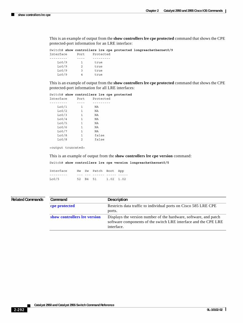
Chapter 2 Catalyst 2950 and 2955 Cisco IOS Commandsshow controllers lre cpe
This is an example of output from the show controllers lre cpe protected command that shows the CPE protected-port information for an LRE interface:
Switch# show controllers lre cpe protected longreachethernet0/9Interface Port Protected--------- ---- --------- Lo0/9 1 true Lo0/9 2 true Lo0/9 3 true Lo0/9 4 true
This is an example of output from the show controllers lre cpe protected command that shows the CPE protected-port information for all LRE interfaces:
Switch# show controllers lre cpe protectedInterface Port Protected--------- ---- --------- Lo0/1 1 NA Lo0/2 1 NA Lo0/3 1 NA Lo0/4 1 NA Lo0/5 1 NA Lo0/6 1 NA Lo0/7 1 NA Lo0/8 1 false Lo0/8 2 false
<output truncated>
This is an example of output from the show controllers lre cpe version command:
Switch# show controllers lre cpe version longreachethernet0/5
Interface Hw Sw Patch Boot App--------- --- --- ------ ----- -----Lo0/5 52 B4 51 1.02 1.02
Related Commands Command Description
cpe protected Restricts data traffic to individual ports on Cisco 585 LRE CPE ports.
show controllers lre version Displays the version number of the hardware, software, and patch software components of the switch LRE interface and the CPE LRE interface.
2-292Catalyst 2950 and Catalyst 2955 Switch Command Reference
0L-10102-02
Chapter 2 Catalyst 2950 and 2955 Cisco IOS Commandsshow controllers lre actual
show controllers lre actualUse the show controllers lre actual privileged EXEC command to display the actual values of the Long-Reach Ethernet (LRE) link on a specific LRE switch port.
show controllers lre interface-id actual {dsrserrs | link | rxpower | snr | txpower | usrserrs} [ | {begin | exclude | include} expression]
This command is available only on Catalyst 2950 LRE switches.
Syntax Description
Command Modes Privileged EXEC
Command History
Usage Guidelines You can use the SNR and Reed-Solomon error information to measure the quality of the LRE link. The SNR is the amount of increased received signal-power (in decibels) relative to the noise-power level that the switch can tolerate without disconnecting from the CPE device. The higher the ratio, the more resilient is the link.
The Reed-Solomon errors show the number of errors detected and corrected in the data being received on and sent from the switch LRE ports. Reed-Solomon errors are the result of noise exceeding the noise margin. For short bursts of noise (such as motor power on or power surges), the interleave feature prevents the loss of Ethernet data packets. Then the number of Reed-Solomon errors exceeds the number of Ethernet CRC errors.
The remote transmit power-rates from the connected CPE devices might be different from each other, depending on how long the cable is between the switch and the CPE device. A longer cable typically causes the CPE device to send a higher signal to overcome the loss effects of distance.
interface-id ID of the switch LRE port.
actual Display the LRE port current status, which might not be the same as the administratively configured settings.
dsrserrs Display the downstream Reed-Solomon errors on the LRE port.
usrserrs Display the upstream Reed-Solomon errors on the LRE port.
txpower Display the remote transmit power (dBm/Hz) on the LRE port.
rxpower Display the local receive power (dBm/Hz) on the customer premises equipment (CPE) port.
snr Display the signal-to-noise ratio (SNR) ratio on the LRE port.
link Display the LRE link status of the LRE port.
| begin (Optional) Display begins with the line that matches the specified expression.
| exclude (Optional) Display excludes lines that match the specified expression.
| include (Optional) Display includes lines that match the specified expression.
expression Expression in the output to use as a reference point.
Release Modification
12.1(11)YJ This command was introduced.
2-293Catalyst 2950 and Catalyst 2955 Switch Command Reference
0L-10102-02
Chapter 2 Catalyst 2950 and 2955 Cisco IOS Commandsshow controllers lre actual
The local receive-power actually displays the switch's adjustment to the incoming power level. These numbers might be different from LRE port to LRE port, as the length of the cables to the CPE devices might be different.
If the SNR is too low for the environment but the link still establishes, the Reed-Solomon error rate is high, and there might be link instability (as shown by the number of Fail events counted). If the network is being used for data only, a high incidence of Ethernet Frame Check Sequence (FCS) errors or micro-interruptions might be tolerable.
For more information about what can affect the LRE link and for the minimum required SNR ratios, see the “LRE Links and LRE Profiles” section in the “Configuring LRE” chapter of the switch software configuration guide for this release.
Expressions are case sensitive. For example, if you enter | exclude output, the lines that contain output do not appear, but the lines that contain Output appear.
Examples This is an example of output from the show controllers lre interface-id actual dsrserrs command on an LRE port:
Switch# show controllers lre longreachethernet0/2 actual dsrserrs0Switch#
This is an example of output from the show controllers lre interface-id actual link command on an LRE port:
Switch# show controllers lre longreachethernet0/2 actual linkUPSwitch#
This is an example of output from the show controllers lre interface-id actual rxpower command on an LRE port:
Switch# show controllers lre longreachethernet0/2 actual rxpower26.0Switch#
This is an example of output from the show controllers lre interface-id actual snr command on an LRE port:
Switch# show controllers lre longreachethernet0/2 actual snr27Switch#
This is an example of output from the show controllers lre interface-id actual txpower command on an LRE port:
Switch# show controllers lre longreachethernet0/2 actual txpower-89.7Switch#
This is an example of output from the show controllers lre interface-id actual usrserrs command on an LRE port:
Switch# show controllers lre longreachethernet0/2 actual usrserrs0Switch#
2-294Catalyst 2950 and Catalyst 2955 Switch Command Reference
0L-10102-02
Chapter 2 Catalyst 2950 and 2955 Cisco IOS Commandsshow controllers lre actual
This is an example of output from the show controllers lre interface-id actual link command on an LRE port:
Switch# show controllers lre longreachethernet0/1 actual linkDOWNSwitch#
Related Commands Command Description
show controllers lre admin Displays the administrative settings of the LRE link on a specific switch LRE port.
2-295Catalyst 2950 and Catalyst 2955 Switch Command Reference
0L-10102-02
Chapter 2 Catalyst 2950 and 2955 Cisco IOS Commandsshow controllers lre admin
show controllers lre adminUse the show controllers lre interface-id admin privileged EXEC command to display the administrative settings of the Long-Reach Ethernet (LRE) link for a specific switch LRE port.
show controllers lre interface-id admin {dsrate | usrate}[ |{begin | exclude | include} expression]
This command is available only on Catalyst 2950 LRE switches.
Syntax Description
Command Modes Privileged EXEC
Command History
Usage Guidelines This command displays the profile settings of an LRE switch port, even though they might not be active if a global profile is configured on the switch.
The upstream and downstream rates are defined by the profile on the switch LRE port. To change these rates, assign a different profile to the switch LRE port. For information about the LRE profiles, see the switch software configuration guide for this release.
Expressions are case sensitive. For example, if you enter | exclude output, the lines that contain output do not appear, but the lines that contain Output appear.
Examples This is an example of output from the show controllers lre interface-id admin dsrate and show controllers lre interface-id admin usrate commands:
Switch# show controllers lre longreachethernet0/1 admin usrate18.750Switch# show controllers lre longreachethernet0/1 admin dsrate16.667Switch# show controllers lre longreachethernet0/2 admin usrate12.500Switch# show controllers lre longreachethernet0/2 admin dsrate12.500
interface-id ID of the switch LRE port.
admin Display the administrative settings, which might not be the same as the actual values.
dsrate Display the downstream rate (in Mbps) of the LRE link.
usrate Display the upstream rate (in Mbps) of the LRE link.
| begin (Optional) Display begins with the line that matches the specified expression.
| exclude (Optional) Display excludes lines that match the specified expression.
| include (Optional) Display includes lines that match the specified expression.
expression Expression in the output to use as a reference point.
Release Modification
12.1(11)YJ This command was introduced.
2-296Catalyst 2950 and Catalyst 2955 Switch Command Reference
0L-10102-02

Chapter 2 Catalyst 2950 and 2955 Cisco IOS Commandsshow controllers lre admin
Related Commands Command Description
show controllers lre cpe identity Displays the actual values of the LRE link on a specific switch LRE port.
lre profile Assigns a profile to all switch LRE ports.
profile (interface configuration) Assigns a profile to a specific switch LRE port.
2-297Catalyst 2950 and Catalyst 2955 Switch Command Reference
0L-10102-02
Chapter 2 Catalyst 2950 and 2955 Cisco IOS Commandsshow controllers lre link monitor
show controllers lre link monitor Use the show controllers lre link monitor privileged EXEC command to display Long-Reach Ethernet (LRE) link monitor information.
show controllers lre monitor {errors | parameters | statistics} {local [interface-id] | remote [interface-id]} [ | {begin | exclude | include} expression]
This command is available only on Catalyst 2950 LRE switches.
Syntax Description
Command Modes Privileged EXEC
Command History
Usage Guidelines The link monitor process collects error information at 1-minute intervals for 15 minutes. After 15 minutes, the data is analyzed and stored before starting a new collection sequence. Up to 2 hours of link monitor data can be shown.
Local monitoring collects data from the LRE switch. Remote monitoring collects data from attached CPE device.
The Time heading in the show controllers lre link monitor errors command output shows the timestamp for the last collection sequence. The RS error count shows the cumulative error count from the last reading. Alignment errors, frame check sequence (FCS) errors, receive errors, and oversize errors are the Ethernet statistics collected either at the switch or at the CPE device.
The Time heading in the show controllers lre link monitor parameters command output shows the timestamp for the last collection sequence. The signal-to-noise (SNR) error counter, shown under the SNR Err heading, increments when the SNR value read from the chipset falls below the theoretical SNR added to the threshold.
errors Display the LRE Reed-Solomon (RS) errors and Ethernet errors
parameters Display the LRE operating parameter data collected by the link monitor.
statistics Display the LRE link monitor statistics.
local (Optional) Display data from the LRE switch controller.
remote (Optional) Display data from the customer premises equipment (CPE) device.
interface-id (Optional) ID of the switch LRE port.
| begin (Optional) Display begins with the line that matches the specified expression.
| exclude (Optional) Display excludes lines that match the specified expression.
| include (Optional) Display includes lines that match the specified expression.
expression Expression in the output to use as a reference point.
Release Modification
12.1(11)YJ This command was introduced.
2-298Catalyst 2950 and Catalyst 2955 Switch Command Reference
0L-10102-02
Chapter 2 Catalyst 2950 and 2955 Cisco IOS Commandsshow controllers lre link monitor
The Time heading in the show controllers lre link monitor statistics command output shows the timestamp for the last collection sequence. The RS error count shows the cumulative error count from the last reading. This count is cleared only when the interface is shut down or when the clear controllers lre link monitor privileged EXEC command is entered. The RS error alarm shows the number of 1 minute intervals that had RS errors above the configured threshold.
Use the show controllers lre monitor {errors | parameters | statistics} privileged EXEC command without specifying a switch interface to display data for all interfaces.
Expressions are case sensitive. For example, if you enter | exclude output, the lines that contain output do not appear, but the lines that contain Output appear.
Examples This is an example of output that shows how to display LRE RS and Ethernet errors for the LRE switch on an LRE port:
Switch# show controllers lre link monitor errors local longreachethernet0/1
LongReachEthernet0/1:LRE Link Health Monitor Error counts :Time RS Errors Align Errs FCS Errs Rcv Errs Oversz Errs-------- ---------- ---------- ---------- ---------- -----------14:42:28 41216 0 0 0 014:30:28 40960 0 0 0 014:15:28 40960 0 0 0 014:00:29 40704 0 0 0 013:45:28 40704 0 0 0 013:30:29 40448 0 0 0 013:15:29 40448 0 0 0 013:00:28 40448 0 0 0 0
This is an example of output that shows Reed-Solomon and Ethernet errors for a CPE device connected to an LRE port:
Switch# show controllers lre link monitor errors remote longreachethernet0/1
LongReachEthernet0/1:LRE Link Health Monitor Error counts :Time RS Errors Align Errs FCS Errs Rcv Errs Oversz Errs-------- ---------- ---------- ---------- ---------- -----------14:42:28 6400 45835 0 0 014:30:28 6400 45835 0 0 014:15:28 6400 45835 0 0 014:00:29 6400 45835 0 0 013:45:28 6144 45835 0 0 013:30:29 6144 45835 0 0 013:15:29 6144 45835 0 0 013:00:28 6144 45835 0 0 0
2-299Catalyst 2950 and Catalyst 2955 Switch Command Reference
0L-10102-02
Chapter 2 Catalyst 2950 and 2955 Cisco IOS Commandsshow controllers lre link monitor
This is an example that shows how to display all LRE link monitor parameters for the attached CPE device:
Switch# show controllers lre link monitor parameters remote
LongReachEthernet0/1: LRE Link Health Monitor Parameters : SNR Tx Power SwAGCGain Time Samples Min Max Err Min Max Min Max -------- ------- --- --- --- ------- ------- ------- -------00:32:30 2 0 0 0 - 85.6 - 85.6 - 2.0 - 2.0 00:30:30 15 0 0 0 - 85.6 - 85.6 - 2.0 - 2.0 00:15:30 15 0 0 0 - 85.6 - 85.6 - 2.0 - 2.0 00:00:30 15 0 0 0 - 85.6 - 85.6 - 2.0 - 2.0 23:45:30 15 0 0 0 - 85.6 - 85.6 - 2.0 - 2.0 23:30:30 15 0 0 0 - 85.6 - 85.6 - 2.0 - 2.0 23:15:30 15 0 0 0 - 85.6 - 85.6 - 2.0 - 2.0
<output truncated>
This is an example that shows how to display all LRE link monitor statistics for the LRE controller:
Switch# show controllers lre link monitor statistics local
LongReachEthernet0/1: LRE Link Health Monitor Stats : RS Errors Link Fail FreezeTime Samples Count Alarm Count Count -------- ------- --------------- ---------- ----------06:58:30 13 0 0 2 3 06:45:30 15 0 0 2 3 06:30:30 15 0 0 2 3 06:15:30 15 0 0 2 3 06:00:30 15 0 0 2 3 05:45:30 15 0 0 2 3 05:30:30 15 0 0 2 3 05:15:30 15 0 0 2 3
Related Commands Command Description
clear controllers lre link monitor Deletes LRE link monitor data.
link monitor Enables the LRE link monitor on a port.
link monitor logging Enables link monitor event logging per port.
link monitor threshold rserr Sets a Reed-Solomon error threshold for the LRE link monitor.
link monitor threshold snr Sets an signal-to-noise margin for the LRE link monitor.
2-300Catalyst 2950 and Catalyst 2955 Switch Command Reference
0L-10102-02
Chapter 2 Catalyst 2950 and 2955 Cisco IOS Commandsshow controllers lre log
show controllers lre logUse the show controllers lre log user EXEC command without keywords to display the history of link, configuration, and timer events for a specific Long-Reach Ethernet (LRE) port or for all switch LRE ports. Use this command with keywords to display information about the LRE event log level.
show controllers lre log [level] [interface-id] [ | {begin | exclude | include} expression]
This command is available only on Catalyst 2950 LRE switches.
Syntax Description
Command Modes User EXEC
Command History
Usage Guidelines Use the show controllers lre log command without specifying a switch LRE port to display the events for all LRE switch ports. The time-stamped and sequentially tagged log entries can be helpful in confirming LRE link drops and configuration changes.
Use the show controllers lre log level command without specifying an LRE switch port to list the log level for each LRE port on the switch.
Expressions are case sensitive. For example, if you enter | exclude output, the lines that contain output do not appear, but the lines that contain Output appear.
Examples This is an example of output from the show controllers lre log command that shows events on an LRE interface:
Switch> show controllers lre log longreachethernet0/5
LongReachEthernet0/5: Events Log: ================================== 1d00h: [0]: State RESTART: Got event:Reset
1d00h: [1]: State MODEZERO_APPLIED: Got event:Link Up
1d00h: [2]: State MODEZERO_APPLIED: Got event:Link Down
1d00h: [3]: State PROFILE_APPLIED: Got event:Link Up
level (Optional) Display information about the LRE event log level.
interface-id (Optional) ID of the switch LRE port.
| begin (Optional) Display begins with the line that matches the specified expression.
| exclude (Optional) Display excludes lines that match the specified expression.
| include (Optional) Display includes lines that match the specified expression.
expression Expression in the output to use as a reference point.
Release Modification
12.1(11)YJ This command was introduced.
2-301Catalyst 2950 and Catalyst 2955 Switch Command Reference
0L-10102-02

Chapter 2 Catalyst 2950 and 2955 Cisco IOS Commandsshow controllers lre log
1d00h: [4]: State PROFILE_LINKUP: Got event:Link Down
1d00h: [5]: State PROFILE_LINKUP: Got event:Link Up
1d00h: [6]: State PROFILE_LINKUP: Got event:Link Down
1d00h: [7]: State PROFILE_LINKUP: Got event:Link Up
This is an example of output from the show controllers lre log level command that displays the log level on an LRE port:
Switch> show controllers lre log level longreachethernet0/1Port Log Level================Lo0/1 Logging disabled
Related Commands Command Description
clear controllers ethernet-controller
Deletes the history of link, configuration, and timer events for a specific switch LRE port or for all LRE ports on the switch.
logging lre Specifies the logging level on the LRE port.
show controllers lre profile Displays the log level for a specific switch LRE port or for all LRE ports on the switch.
2-302Catalyst 2950 and Catalyst 2955 Switch Command Reference
0L-10102-02
Chapter 2 Catalyst 2950 and 2955 Cisco IOS Commandsshow controllers lre profile
show controllers lre profileUse the show controllers lre profile privileged EXEC command to display information about the Long-Reach Ethernet (LRE) profiles and sequences available on the switch.
show controllers lre profile {details | names} [ | {begin | exclude | include} expression]
This command is available only on Catalyst 2950 LRE switches.
Syntax Description
Command Modes Privileged EXEC
Command History
Usage Guidelines Use the show controllers lre profile details privileged EXEC command to see the profiles and sequences running on each port. This command also shows global profiles and sequences.
For information about LRE profiles supported on your switch and about LRE links, see the “LRE Profiles” section in the “Configuring LRE” chapter of the switch software configuration guide for this release.
Note Use the information in the software configuration guide only as a guideline. Factors such as the type of cable that you use, how it is bundled, and the interference and noise on the LRE link can affect the actual LRE link performance. Contact Cisco Systems for information about limitations and optimization of LRE link performance. The net data rates are slightly less than the gross data rates displayed by the show controllers lre profile names command output.
Expressions are case sensitive. For example, if you enter | exclude output, the lines that contain output do not appear, but the lines that contain Output appear.
details Display information about the LRE profiles and sequences available on the switch.
names Display information about the Long-Reach Ethernet (LRE) profiles available on the switch.
| begin (Optional) Display begins with the line that matches the expression.
| exclude (Optional) Display excludes lines that match the expression.
| include (Optional) Display includes lines that match the specified expression.
expression Expression in the output to use as a reference point.
Release Modification
12.1(11)YJ This command was introduced.
2-303Catalyst 2950 and Catalyst 2955 Switch Command Reference
0L-10102-02
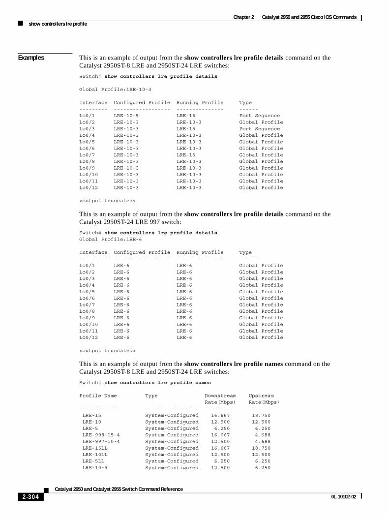
Chapter 2 Catalyst 2950 and 2955 Cisco IOS Commandsshow controllers lre profile
Examples This is an example of output from the show controllers lre profile details command on the Catalyst 2950ST-8 LRE and 2950ST-24 LRE switches:
Switch# show controllers lre profile details
Global Profile:LRE-10-3
Interface Configured Profile Running Profile Type--------- ------------------ --------------- ------Lo0/1 LRE-10-5 LRE-15 Port SequenceLo0/2 LRE-10-3 LRE-10-3 Global ProfileLo0/3 LRE-10-3 LRE-15 Port SequenceLo0/4 LRE-10-3 LRE-10-3 Global ProfileLo0/5 LRE-10-3 LRE-10-3 Global ProfileLo0/6 LRE-10-3 LRE-10-3 Global ProfileLo0/7 LRE-10-3 LRE-15 Global ProfileLo0/8 LRE-10-3 LRE-10-3 Global ProfileLo0/9 LRE-10-3 LRE-10-3 Global ProfileLo0/10 LRE-10-3 LRE-10-3 Global ProfileLo0/11 LRE-10-3 LRE-10-3 Global ProfileLo0/12 LRE-10-3 LRE-10-3 Global Profile
<output truncated>
This is an example of output from the show controllers lre profile details command on the Catalyst 2950ST-24 LRE 997 switch:
Switch# show controllers lre profile detailsGlobal Profile:LRE-6
Interface Configured Profile Running Profile Type--------- ------------------ --------------- ------Lo0/1 LRE-6 LRE-6 Global ProfileLo0/2 LRE-6 LRE-6 Global ProfileLo0/3 LRE-6 LRE-6 Global ProfileLo0/4 LRE-6 LRE-6 Global ProfileLo0/5 LRE-6 LRE-6 Global ProfileLo0/6 LRE-6 LRE-6 Global ProfileLo0/7 LRE-6 LRE-6 Global ProfileLo0/8 LRE-6 LRE-6 Global ProfileLo0/9 LRE-6 LRE-6 Global ProfileLo0/10 LRE-6 LRE-6 Global ProfileLo0/11 LRE-6 LRE-6 Global ProfileLo0/12 LRE-6 LRE-6 Global Profile
<output truncated>
This is an example of output from the show controllers lre profile names command on the Catalyst 2950ST-8 LRE and 2950ST-24 LRE switches:
Switch# show controllers lre profile names
Profile Name Type Downstream Upstream Rate(Mbps) Rate(Mbps)------------ ----------------- ---------- ---------- LRE-15 System-Configured 16.667 18.750 LRE-10 System-Configured 12.500 12.500 LRE-5 System-Configured 6.250 6.250 LRE-998-15-4 System-Configured 16.667 4.688 LRE-997-10-4 System-Configured 12.500 4.688 LRE-15LL System-Configured 16.667 18.750 LRE-10LL System-Configured 12.500 12.500 LRE-5LL System-Configured 6.250 6.250 LRE-10-5 System-Configured 12.500 6.250
2-304Catalyst 2950 and Catalyst 2955 Switch Command Reference
0L-10102-02
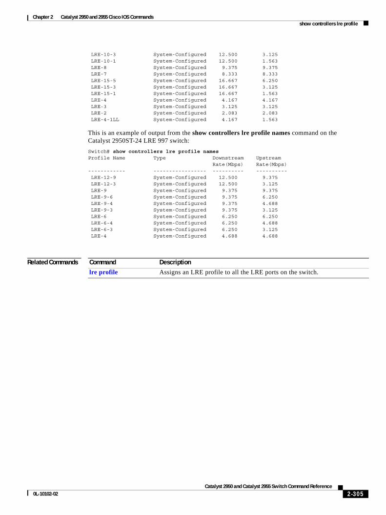
Chapter 2 Catalyst 2950 and 2955 Cisco IOS Commandsshow controllers lre profile
LRE-10-3 System-Configured 12.500 3.125 LRE-10-1 System-Configured 12.500 1.563 LRE-8 System-Configured 9.375 9.375 LRE-7 System-Configured 8.333 8.333 LRE-15-5 System-Configured 16.667 6.250 LRE-15-3 System-Configured 16.667 3.125 LRE-15-1 System-Configured 16.667 1.563 LRE-4 System-Configured 4.167 4.167 LRE-3 System-Configured 3.125 3.125 LRE-2 System-Configured 2.083 2.083 LRE-4-1LL System-Configured 4.167 1.563
This is an example of output from the show controllers lre profile names command on the Catalyst 2950ST-24 LRE 997 switch:
Switch# show controllers lre profile namesProfile Name Type Downstream Upstream Rate(Mbps) Rate(Mbps)------------ ----------------- ---------- ---------- LRE-12-9 System-Configured 12.500 9.375 LRE-12-3 System-Configured 12.500 3.125 LRE-9 System-Configured 9.375 9.375 LRE-9-6 System-Configured 9.375 6.250 LRE-9-4 System-Configured 9.375 4.688 LRE-9-3 System-Configured 9.375 3.125 LRE-6 System-Configured 6.250 6.250 LRE-6-4 System-Configured 6.250 4.688 LRE-6-3 System-Configured 6.250 3.125 LRE-4 System-Configured 4.688 4.688
Related Commands Command Description
lre profile Assigns an LRE profile to all the LRE ports on the switch.
2-305Catalyst 2950 and Catalyst 2955 Switch Command Reference
0L-10102-02
Chapter 2 Catalyst 2950 and 2955 Cisco IOS Commandsshow controllers lre sequence
show controllers lre sequenceUse the show controllers lre sequence privileged EXEC command to display the list of sequences, the profiles that are configured in that sequence, and the downstream and upstream rates of the corresponding profiles.
show controllers lre sequence [ | {begin | exclude | include} expression]
This command is available only on Catalyst 2950 LRE switches.
Syntax Description
Command Modes Privileged EXEC
Command History
Usage Guidelines Use the show controllers lre sequence command to display the list of sequences supported in the switch. This command displays the system-defined and user-defined sequences.
Expressions are case sensitive. For example, if you enter | exclude output, the lines that contain output do not appear, but the lines that contain Output appear.
Examples This is an example of output from the show controllers lre sequence command on the Catalyst 2950ST-8 LRE and 2950ST-24 LRE switches:
Switch# show controllers lre sequence
Global Sequence:LRE-SEQ-COMPLETE-REACH
Sequence:LRE-SEQ-COMPLETE-REACH Type:System-Configured
Profile Name Downstream Upstream Rate(Mbps) Rate(Mbps) -------------- ---------- ---------- LRE-15 16.667 18.750 LRE-10 12.500 12.500 LRE-15-5 16.667 6.250 LRE-10-5 12.500 6.250 LRE-8 9.375 9.375 LRE-7 8.333 8.333 LRE-15-3 16.667 3.125 LRE-10-3 12.500 3.125 LRE-5 6.250 6.250 LRE-15-1 16.667 1.563
| begin (Optional) Display begins with the line that matches the expression.
| exclude (Optional) Display excludes lines that match the expression.
| include (Optional) Display includes lines that match the specified expression.
expression Expression in the output to use as a reference point.
Release Modification
12.1(11)YJ This command was introduced.
2-306Catalyst 2950 and Catalyst 2955 Switch Command Reference
0L-10102-02
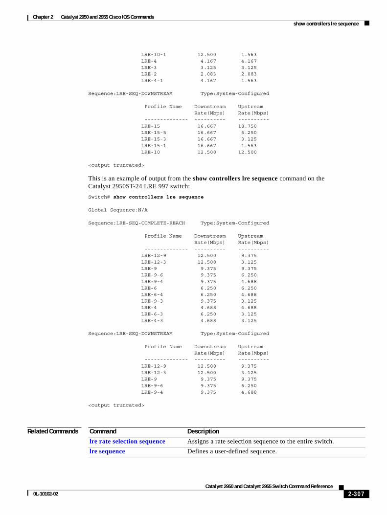
Chapter 2 Catalyst 2950 and 2955 Cisco IOS Commandsshow controllers lre sequence
LRE-10-1 12.500 1.563 LRE-4 4.167 4.167 LRE-3 3.125 3.125 LRE-2 2.083 2.083 LRE-4-1 4.167 1.563
Sequence:LRE-SEQ-DOWNSTREAM Type:System-Configured Profile Name Downstream Upstream Rate(Mbps) Rate(Mbps) -------------- ---------- ---------- LRE-15 16.667 18.750 LRE-15-5 16.667 6.250 LRE-15-3 16.667 3.125 LRE-15-1 16.667 1.563 LRE-10 12.500 12.500
<output truncated>
This is an example of output from the show controllers lre sequence command on the Catalyst 2950ST-24 LRE 997 switch:
Switch# show controllers lre sequence
Global Sequence:N/A
Sequence:LRE-SEQ-COMPLETE-REACH Type:System-Configured
Profile Name Downstream Upstream Rate(Mbps) Rate(Mbps) -------------- ---------- ---------- LRE-12-9 12.500 9.375 LRE-12-3 12.500 3.125 LRE-9 9.375 9.375 LRE-9-6 9.375 6.250 LRE-9-4 9.375 4.688 LRE-6 6.250 6.250 LRE-6-4 6.250 4.688 LRE-9-3 9.375 3.125 LRE-4 4.688 4.688 LRE-6-3 6.250 3.125 LRE-4-3 4.688 3.125
Sequence:LRE-SEQ-DOWNSTREAM Type:System-Configured
Profile Name Downstream Upstream Rate(Mbps) Rate(Mbps) -------------- ---------- ---------- LRE-12-9 12.500 9.375 LRE-12-3 12.500 3.125 LRE-9 9.375 9.375 LRE-9-6 9.375 6.250 LRE-9-4 9.375 4.688
<output truncated>
Related Commands Command Description
lre rate selection sequence Assigns a rate selection sequence to the entire switch.
lre sequence Defines a user-defined sequence.
2-307Catalyst 2950 and Catalyst 2955 Switch Command Reference
0L-10102-02
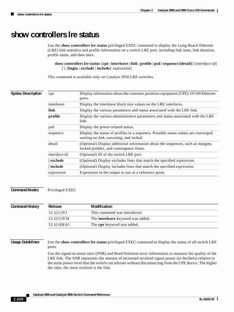
Chapter 2 Catalyst 2950 and 2955 Cisco IOS Commandsshow controllers lre status
show controllers lre statusUse the show controllers lre status privileged EXEC command to display the Long-Reach Ethernet (LRE) link statistics and profile information on a switch LRE port, including link state, link duration, profile name, and data rates.
show controllers lre status {cpe | interleave | link | profile | psd | sequence [detail]} [interface-id] [ | {begin | exclude | include} expression]
This command is available only on Catalyst 2950 LRE switches.
Syntax Description
Command Modes Privileged EXEC
Command History
Usage Guidelines Use the show controllers lre status privileged EXEC command to display the status of all switch LRE ports.
Use the signal-to-noise ratio (SNR) and Reed-Solomon error information to measure the quality of the LRE link. The SNR represents the amount of increased received signal power (in decibels) relative to the noise power-level that the switch can tolerate without disconnecting from the CPE device. The higher the ratio, the more resilient is the link.
cpe Display information about the customer premises equipment (CPE) 10/100 Ethernet ports.
interleave Display the interleave block size values on the LRE interfaces.
link Display the various parameters and status associated with the LRE link.
profile Display the various administrative parameters and status associated with the LRE link.
psd Display the power-related status.
sequence Display the status of profiles in a sequence. Possible status values are converged, waiting on link, executing, and locked.
detail (Optional) Display additional information about the sequences, such as margins, locked profiles, and convergence times.
interface-id (Optional) ID of the switch LRE port.
| exclude (Optional) Display excludes lines that match the specified expression.
| include (Optional) Display includes lines that match the specified expression.
expression Expression in the output to use as a reference point.
Release Modification
12.1(11)YJ This command was introduced.
12.1(11)YJ4 The interleave keyword was added.
12.1(14)EA1 The cpe keyword was added.
2-308Catalyst 2950 and Catalyst 2955 Switch Command Reference
0L-10102-02
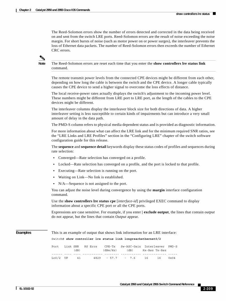
Chapter 2 Catalyst 2950 and 2955 Cisco IOS Commandsshow controllers lre status
The Reed-Solomon errors show the number of errors detected and corrected in the data being received on and sent from the switch LRE ports. Reed-Solomon errors are the result of noise exceeding the noise margin. For short bursts of noise (such as motor power on or power surges), the interleaver prevents the loss of Ethernet data packets. The number of Reed-Solomon errors then exceeds the number of Ethernet CRC errors.
Note The Reed-Solomon errors are reset each time that you enter the show controllers lre status link command.
The remote transmit power levels from the connected CPE devices might be different from each other, depending on how long the cable is between the switch and the CPE device. A longer cable typically causes the CPE device to send a higher signal to overcome the loss effects of distance.
The local receive-power rates actually displays the switch's adjustment to the incoming power level. These numbers might be different from LRE port to LRE port, as the length of the cables to the CPE devices might be different.
The interleaver columns display the interleaver block size for both directions of data. A higher interleaver setting is less susceptible to certain kinds of impairments but can introduce a very small amount of delay in the data path.
The PMD-S column refers to physical media dependent status and is provided as diagnostic information.
For more information about what can affect the LRE link and for the minimum required SNR ratios, see the “LRE Links and LRE Profiles” section in the “Configuring LRE” chapter of the switch software configuration guide for this release.
The sequence and sequence detail keywords display these status codes of profiles and sequences during rate selection:
• Converged—Rate selection has converged on a profile.
• Locked—Rate selection has converged on a profile, and the port is locked to that profile.
• Executing—Rate selection is running on the port.
• Waiting on Link—No link is established.
• N/A—Sequence is not assigned to the port.
You can adjust the noise level during convergence by using the margin interface configuration command.
Use the show controllers lre status cpe [interface-id] privileged EXEC command to display information about a specific CPE port or all the CPE ports.
Expressions are case sensitive. For example, if you enter | exclude output, the lines that contain output do not appear, but the lines that contain Output appear.
Examples This is an example of output that shows link information for an LRE interface:
Switch# show controller lre status link longreachethernet0/2
Port Link SNR RS Errs CPE-Tx Sw-AGC-Gain Interleaver PMD-S (dB) (dBm/Hz) (dB) Rx-Bsz Tx-Bsz ------ ---- ---- ----------- -------- ----------- ------------- -----Lo0/2 UP 41 4829 - 57.7 - 7.6 16 16 0x04
2-309Catalyst 2950 and Catalyst 2955 Switch Command Reference
0L-10102-02
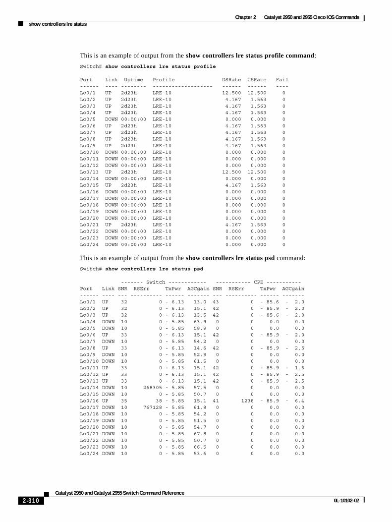
Chapter 2 Catalyst 2950 and 2955 Cisco IOS Commandsshow controllers lre status
This is an example of output from the show controllers lre status profile command:
Switch# show controllers lre status profile
Port Link Uptime Profile DSRate USRate Fail------ ---- -------- ------------------- ------ ------ ----Lo0/1 UP 2d23h LRE-10 12.500 12.500 0Lo0/2 UP 2d23h LRE-10 4.167 1.563 0Lo0/3 UP 2d23h LRE-10 4.167 1.563 0Lo0/4 UP 2d23h LRE-10 4.167 1.563 0Lo0/5 DOWN 00:00:00 LRE-10 0.000 0.000 0Lo0/6 UP 2d23h LRE-10 4.167 1.563 0Lo0/7 UP 2d23h LRE-10 4.167 1.563 0Lo0/8 UP 2d23h LRE-10 4.167 1.563 0Lo0/9 UP 2d23h LRE-10 4.167 1.563 0Lo0/10 DOWN 00:00:00 LRE-10 0.000 0.000 0Lo0/11 DOWN 00:00:00 LRE-10 0.000 0.000 0Lo0/12 DOWN 00:00:00 LRE-10 0.000 0.000 0Lo0/13 UP 2d23h LRE-10 12.500 12.500 0Lo0/14 DOWN 00:00:00 LRE-10 0.000 0.000 0Lo0/15 UP 2d23h LRE-10 4.167 1.563 0Lo0/16 DOWN 00:00:00 LRE-10 0.000 0.000 0Lo0/17 DOWN 00:00:00 LRE-10 0.000 0.000 0Lo0/18 DOWN 00:00:00 LRE-10 0.000 0.000 0Lo0/19 DOWN 00:00:00 LRE-10 0.000 0.000 0Lo0/20 DOWN 00:00:00 LRE-10 0.000 0.000 0Lo0/21 UP 2d23h LRE-10 4.167 1.563 0Lo0/22 DOWN 00:00:00 LRE-10 0.000 0.000 0Lo0/23 DOWN 00:00:00 LRE-10 0.000 0.000 0Lo0/24 DOWN 00:00:00 LRE-10 0.000 0.000 0
This is an example of output from the show controllers lre status psd command:
Switch# show controllers lre status psd
------- Switch ------------ ----------- CPE -----------Port Link SNR RSErr TxPwr AGCgain SNR RSErr TxPwr AGCgain------ ---- --- ---------- ------ ------- --- ---------- ------ -------Lo0/1 UP 32 0 - 6.13 13.0 43 0 - 85.6 - 2.0Lo0/2 UP 32 0 - 6.13 15.1 42 0 - 85.9 - 2.0Lo0/3 UP 32 0 - 6.13 13.5 42 0 - 85.6 - 2.0Lo0/4 DOWN 10 0 - 5.85 63.9 0 0 0.0 0.0Lo0/5 DOWN 10 0 - 5.85 58.9 0 0 0.0 0.0Lo0/6 UP 33 0 - 6.13 15.1 42 0 - 85.9 - 2.0Lo0/7 DOWN 10 0 - 5.85 54.2 0 0 0.0 0.0Lo0/8 UP 33 0 - 6.13 14.6 42 0 - 85.9 - 2.5Lo0/9 DOWN 10 0 - 5.85 52.9 0 0 0.0 0.0Lo0/10 DOWN 10 0 - 5.85 61.5 0 0 0.0 0.0Lo0/11 UP 33 0 - 6.13 15.1 42 0 - 85.9 - 1.6Lo0/12 UP 33 0 - 6.13 15.1 42 0 - 85.9 - 2.5Lo0/13 UP 33 0 - 6.13 15.1 42 0 - 85.9 - 2.5Lo0/14 DOWN 10 268305 - 5.85 57.5 0 0 0.0 0.0Lo0/15 DOWN 10 0 - 5.85 50.7 0 0 0.0 0.0Lo0/16 UP 35 38 - 5.85 15.1 41 1238 - 85.9 - 6.4Lo0/17 DOWN 10 767128 - 5.85 61.8 0 0 0.0 0.0Lo0/18 DOWN 10 0 - 5.85 54.2 0 0 0.0 0.0Lo0/19 DOWN 10 0 - 5.85 51.5 0 0 0.0 0.0Lo0/20 DOWN 10 0 - 5.85 54.7 0 0 0.0 0.0Lo0/21 DOWN 10 0 - 5.85 67.8 0 0 0.0 0.0Lo0/22 DOWN 10 0 - 5.85 50.7 0 0 0.0 0.0Lo0/23 DOWN 10 0 - 5.85 66.5 0 0 0.0 0.0Lo0/24 DOWN 10 0 - 5.85 53.6 0 0 0.0 0.0
2-310Catalyst 2950 and Catalyst 2955 Switch Command Reference
0L-10102-02
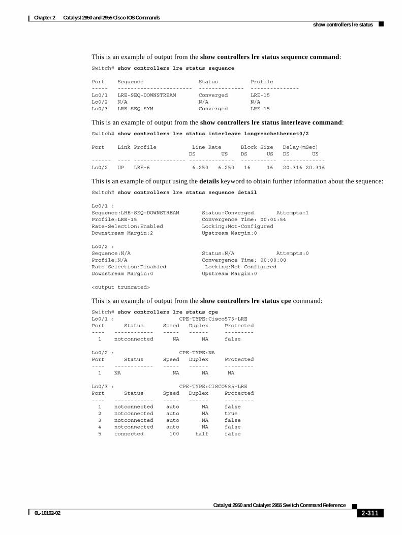
Chapter 2 Catalyst 2950 and 2955 Cisco IOS Commandsshow controllers lre status
This is an example of output from the show controllers lre status sequence command:
Switch# show controllers lre status sequence
Port Sequence Status Profile----- ----------------------- -------------- --------------- Lo0/1 LRE-SEQ-DOWNSTREAM Converged LRE-15 Lo0/2 N/A N/A N/A Lo0/3 LRE-SEQ-SYM Converged LRE-15
This is an example of output from the show controllers lre status interleave command:
Switch# show controllers lre status interleave longreachethernet0/2
Port Link Profile Line Rate Block Size Delay(mSec) DS US DS US DS US------ ---- ---------------- -------------- ----------- -------------Lo0/2 UP LRE-6 6.250 6.250 16 16 20.316 20.316
This is an example of output using the details keyword to obtain further information about the sequence:
Switch# show controllers lre status sequence detail
Lo0/1 :Sequence:LRE-SEQ-DOWNSTREAM Status:Converged Attempts:1Profile:LRE-15 Convergence Time: 00:01:54Rate-Selection:Enabled Locking:Not-ConfiguredDownstream Margin:2 Upstream Margin:0
Lo0/2 :Sequence:N/A Status:N/A Attempts:0Profile:N/A Convergence Time: 00:00:00Rate-Selection:Disabled Locking:Not-ConfiguredDownstream Margin:0 Upstream Margin:0
<output truncated>
This is an example of output from the show controllers lre status cpe command:
Switch# show controllers lre status cpeLo0/1 : CPE-TYPE:Cisco575-LREPort Status Speed Duplex Protected---- ------------ ----- ------ --------- 1 notconnected NA NA false
Lo0/2 : CPE-TYPE:NAPort Status Speed Duplex Protected---- ------------ ----- ------ --------- 1 NA NA NA NA
Lo0/3 : CPE-TYPE:CISCO585-LREPort Status Speed Duplex Protected---- ------------ ----- ------ --------- 1 notconnected auto NA false 2 notconnected auto NA true 3 notconnected auto NA false 4 notconnected auto NA false 5 connected 100 half false
2-311Catalyst 2950 and Catalyst 2955 Switch Command Reference
0L-10102-02
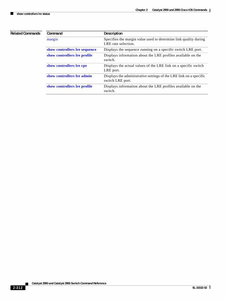
Chapter 2 Catalyst 2950 and 2955 Cisco IOS Commandsshow controllers lre status
Related Commands Command Description
margin Specifies the margin value used to determine link quality during LRE rate selection.
show controllers lre sequence Displays the sequence running on a specific switch LRE port.
show controllers lre profile Displays information about the LRE profiles available on the switch.
show controllers lre cpe Displays the actual values of the LRE link on a specific switch LRE port.
show controllers lre admin Displays the administrative settings of the LRE link on a specific switch LRE port.
show controllers lre profile Displays information about the LRE profiles available on the switch.
2-312Catalyst 2950 and Catalyst 2955 Switch Command Reference
0L-10102-02
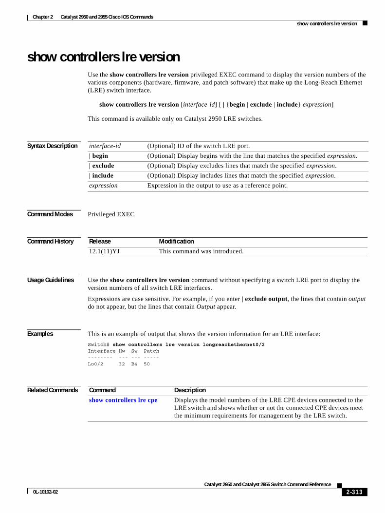
Chapter 2 Catalyst 2950 and 2955 Cisco IOS Commandsshow controllers lre version
show controllers lre versionUse the show controllers lre version privileged EXEC command to display the version numbers of the various components (hardware, firmware, and patch software) that make up the Long-Reach Ethernet (LRE) switch interface.
show controllers lre version [interface-id] [ | {begin | exclude | include} expression]
This command is available only on Catalyst 2950 LRE switches.
Syntax Description
Command Modes Privileged EXEC
Command History
Usage Guidelines Use the show controllers lre version command without specifying a switch LRE port to display the version numbers of all switch LRE interfaces.
Expressions are case sensitive. For example, if you enter | exclude output, the lines that contain output do not appear, but the lines that contain Output appear.
Examples This is an example of output that shows the version information for an LRE interface:
Switch# show controllers lre version longreachethernet0/2Interface Hw Sw Patch -------- --- --- -----Lo0/2 32 B4 50
Related Commands
interface-id (Optional) ID of the switch LRE port.
| begin (Optional) Display begins with the line that matches the specified expression.
| exclude (Optional) Display excludes lines that match the specified expression.
| include (Optional) Display includes lines that match the specified expression.
expression Expression in the output to use as a reference point.
Release Modification
12.1(11)YJ This command was introduced.
Command Description
show controllers lre cpe Displays the model numbers of the LRE CPE devices connected to the LRE switch and shows whether or not the connected CPE devices meet the minimum requirements for management by the LRE switch.
2-313Catalyst 2950 and Catalyst 2955 Switch Command Reference
0L-10102-02
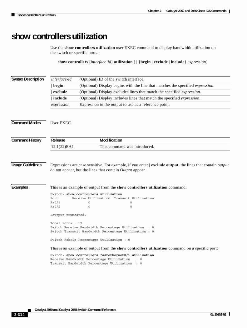
Chapter 2 Catalyst 2950 and 2955 Cisco IOS Commandsshow controllers utilization
show controllers utilizationUse the show controllers utilization user EXEC command to display bandwidth utilization on the switch or specific ports.
show controllers [interface-id] utilization [ | {begin | exclude | include} expression]
Syntax Description
Command Modes User EXEC
Command History
Usage Guidelines Expressions are case sensitive. For example, if you enter | exclude output, the lines that contain output do not appear, but the lines that contain Output appear.
Examples This is an example of output from the show controllers utilization command.
Switch> show controllers utilizationPort Receive Utilization Transmit UtilizationFa0/1 0 0Fa0/2 0 0
<output truncated>
Total Ports : 12Switch Receive Bandwidth Percentage Utilization : 0Switch Transmit Bandwidth Percentage Utilization : 0
Switch Fabric Percentage Utilization : 0
This is an example of output from the show controllers utilization command on a specific port:
Switch> show controllers fastethernet0/1 utilizationReceive Bandwidth Percentage Utilization : 0Transmit Bandwidth Percentage Utilization : 0
interface-id (Optional) ID of the switch interface.
| begin (Optional) Display begins with the line that matches the specified expression.
| exclude (Optional) Display excludes lines that match the specified expression.
| include (Optional) Display includes lines that match the specified expression.
expression Expression in the output to use as a reference point.
Release Modification
12.1(22)EA1 This command was introduced.
2-314Catalyst 2950 and Catalyst 2955 Switch Command Reference
0L-10102-02
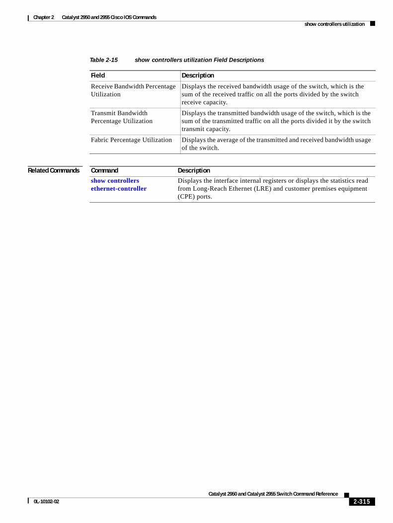
Chapter 2 Catalyst 2950 and 2955 Cisco IOS Commandsshow controllers utilization
Related Commands
Table 2-15 show controllers utilization Field Descriptions
Field Description
Receive Bandwidth Percentage Utilization
Displays the received bandwidth usage of the switch, which is the sum of the received traffic on all the ports divided by the switch receive capacity.
Transmit Bandwidth Percentage Utilization
Displays the transmitted bandwidth usage of the switch, which is the sum of the transmitted traffic on all the ports divided it by the switch transmit capacity.
Fabric Percentage Utilization Displays the average of the transmitted and received bandwidth usage of the switch.
Command Description
show controllers ethernet-controller
Displays the interface internal registers or displays the statistics read from Long-Reach Ethernet (LRE) and customer premises equipment (CPE) ports.
2-315Catalyst 2950 and Catalyst 2955 Switch Command Reference
0L-10102-02
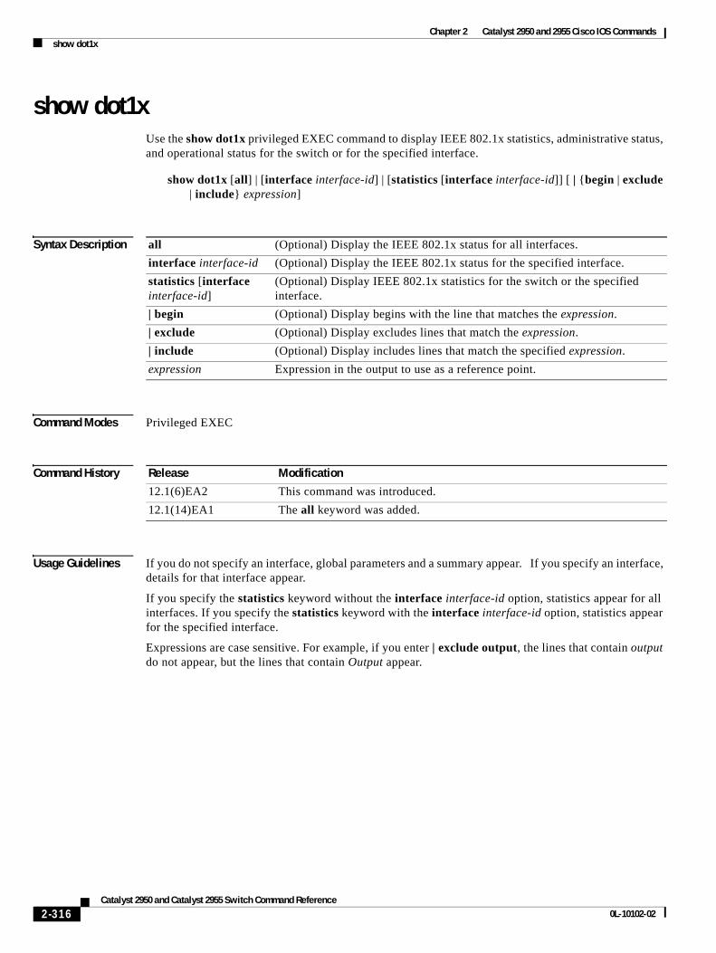
Chapter 2 Catalyst 2950 and 2955 Cisco IOS Commandsshow dot1x
show dot1x Use the show dot1x privileged EXEC command to display IEEE 802.1x statistics, administrative status, and operational status for the switch or for the specified interface.
show dot1x [all] | [interface interface-id] | [statistics [interface interface-id]] [ | {begin | exclude | include} expression]
Syntax Description
Command Modes Privileged EXEC
Command History
Usage Guidelines If you do not specify an interface, global parameters and a summary appear. If you specify an interface, details for that interface appear.
If you specify the statistics keyword without the interface interface-id option, statistics appear for all interfaces. If you specify the statistics keyword with the interface interface-id option, statistics appear for the specified interface.
Expressions are case sensitive. For example, if you enter | exclude output, the lines that contain output do not appear, but the lines that contain Output appear.
all (Optional) Display the IEEE 802.1x status for all interfaces.
interface interface-id (Optional) Display the IEEE 802.1x status for the specified interface.
statistics [interface interface-id]
(Optional) Display IEEE 802.1x statistics for the switch or the specified interface.
| begin (Optional) Display begins with the line that matches the expression.
| exclude (Optional) Display excludes lines that match the expression.
| include (Optional) Display includes lines that match the specified expression.
expression Expression in the output to use as a reference point.
Release Modification
12.1(6)EA2 This command was introduced.
12.1(14)EA1 The all keyword was added.
2-316Catalyst 2950 and Catalyst 2955 Switch Command Reference
0L-10102-02
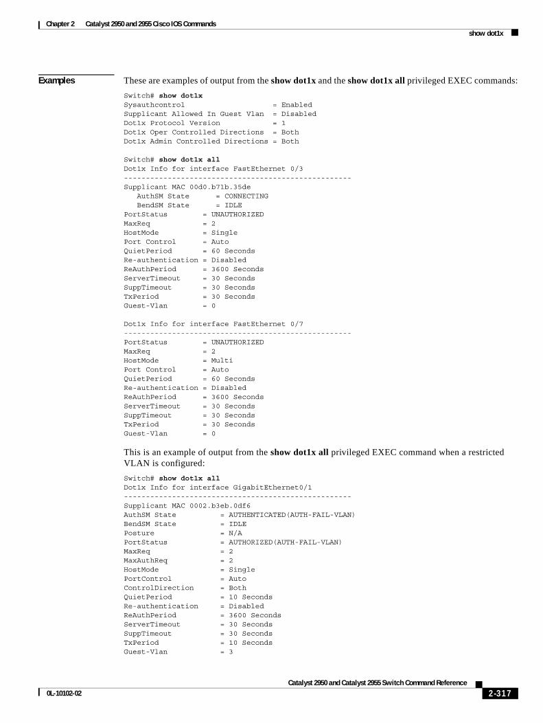
Chapter 2 Catalyst 2950 and 2955 Cisco IOS Commandsshow dot1x
Examples These are examples of output from the show dot1x and the show dot1x all privileged EXEC commands:
Switch# show dot1x Sysauthcontrol = Enabled Supplicant Allowed In Guest Vlan = DisabledDot1x Protocol Version = 1 Dot1x Oper Controlled Directions = Both Dot1x Admin Controlled Directions = Both
Switch# show dot1x allDot1x Info for interface FastEthernet 0/3 ----------------------------------------------------Supplicant MAC 00d0.b71b.35de AuthSM State = CONNECTING BendSM State = IDLEPortStatus = UNAUTHORIZEDMaxReq = 2 HostMode = Single Port Control = AutoQuietPeriod = 60 Seconds Re-authentication = Disabled ReAuthPeriod = 3600 SecondsServerTimeout = 30 Seconds SuppTimeout = 30 Seconds TxPeriod = 30 Seconds Guest-Vlan = 0
Dot1x Info for interface FastEthernet 0/7 ----------------------------------------------------PortStatus = UNAUTHORIZEDMaxReq = 2 HostMode = Multi Port Control = AutoQuietPeriod = 60 Seconds Re-authentication = Disabled ReAuthPeriod = 3600 SecondsServerTimeout = 30 Seconds SuppTimeout = 30 Seconds TxPeriod = 30 Seconds Guest-Vlan = 0
This is an example of output from the show dot1x all privileged EXEC command when a restricted VLAN is configured:
Switch# show dot1x allDot1x Info for interface GigabitEthernet0/1 ----------------------------------------------------Supplicant MAC 0002.b3eb.0df6AuthSM State = AUTHENTICATED(AUTH-FAIL-VLAN)BendSM State = IDLEPosture = N/APortStatus = AUTHORIZED(AUTH-FAIL-VLAN)MaxReq = 2 MaxAuthReq = 2 HostMode = Single PortControl = AutoControlDirection = BothQuietPeriod = 10 Seconds Re-authentication = Disabled ReAuthPeriod = 3600 SecondsServerTimeout = 30 Seconds SuppTimeout = 30 Seconds TxPeriod = 10 Seconds Guest-Vlan = 3
2-317Catalyst 2950 and Catalyst 2955 Switch Command Reference
0L-10102-02
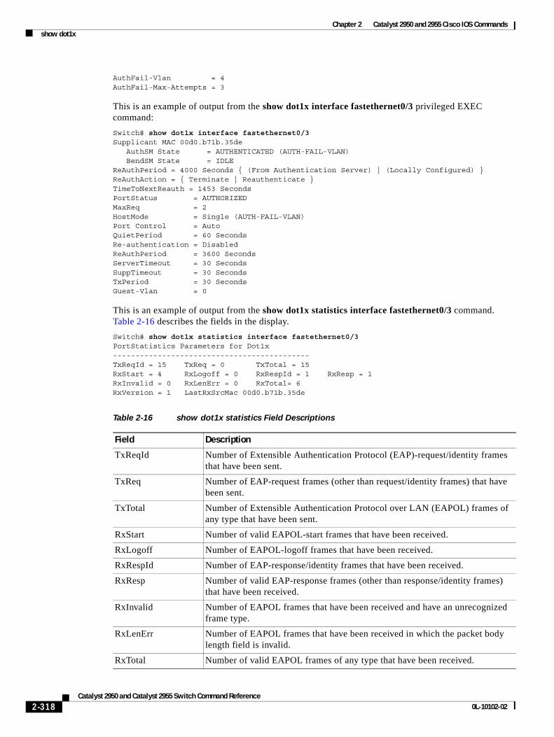
Chapter 2 Catalyst 2950 and 2955 Cisco IOS Commandsshow dot1x
AuthFail-Vlan = 4 AuthFail-Max-Attempts = 3
This is an example of output from the show dot1x interface fastethernet0/3 privileged EXEC command:
Switch# show dot1x interface fastethernet0/3Supplicant MAC 00d0.b71b.35de AuthSM State = AUTHENTICATED (AUTH-FAIL-VLAN) BendSM State = IDLEReAuthPeriod = 4000 Seconds { (From Authentication Server) | (Locally Configured) }ReAuthAction = { Terminate | Reauthenticate }TimeToNextReauth = 1453 SecondsPortStatus = AUTHORIZEDMaxReq = 2 HostMode = Single (AUTH-FAIL-VLAN) Port Control = AutoQuietPeriod = 60 Seconds Re-authentication = Disabled ReAuthPeriod = 3600 SecondsServerTimeout = 30 Seconds SuppTimeout = 30 Seconds TxPeriod = 30 Seconds Guest-Vlan = 0
This is an example of output from the show dot1x statistics interface fastethernet0/3 command. Table 2-16 describes the fields in the display.
Switch# show dot1x statistics interface fastethernet0/3PortStatistics Parameters for Dot1x --------------------------------------------TxReqId = 15 TxReq = 0 TxTotal = 15 RxStart = 4 RxLogoff = 0 RxRespId = 1 RxResp = 1RxInvalid = 0 RxLenErr = 0 RxTotal= 6RxVersion = 1 LastRxSrcMac 00d0.b71b.35de
Table 2-16 show dot1x statistics Field Descriptions
Field Description
TxReqId Number of Extensible Authentication Protocol (EAP)-request/identity frames that have been sent.
TxReq Number of EAP-request frames (other than request/identity frames) that have been sent.
TxTotal Number of Extensible Authentication Protocol over LAN (EAPOL) frames of any type that have been sent.
RxStart Number of valid EAPOL-start frames that have been received.
RxLogoff Number of EAPOL-logoff frames that have been received.
RxRespId Number of EAP-response/identity frames that have been received.
RxResp Number of valid EAP-response frames (other than response/identity frames) that have been received.
RxInvalid Number of EAPOL frames that have been received and have an unrecognized frame type.
RxLenErr Number of EAPOL frames that have been received in which the packet body length field is invalid.
RxTotal Number of valid EAPOL frames of any type that have been received.
2-318Catalyst 2950 and Catalyst 2955 Switch Command Reference
0L-10102-02
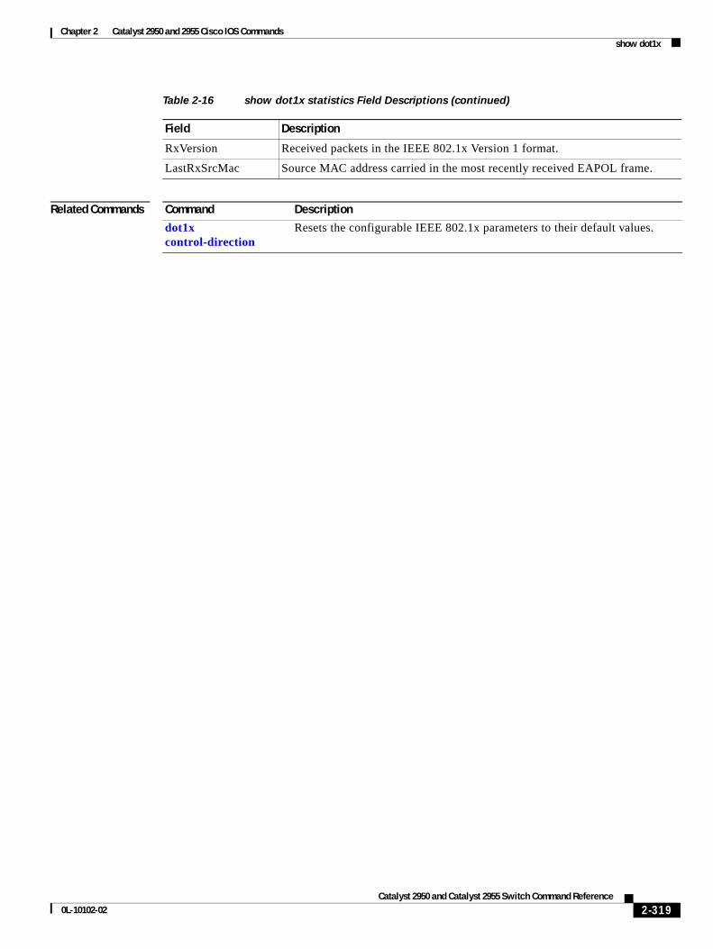
Chapter 2 Catalyst 2950 and 2955 Cisco IOS Commandsshow dot1x
Related Commands
RxVersion Received packets in the IEEE 802.1x Version 1 format.
LastRxSrcMac Source MAC address carried in the most recently received EAPOL frame.
Table 2-16 show dot1x statistics Field Descriptions (continued)
Field Description
Command Description
dot1x control-direction
Resets the configurable IEEE 802.1x parameters to their default values.
2-319Catalyst 2950 and Catalyst 2955 Switch Command Reference
0L-10102-02
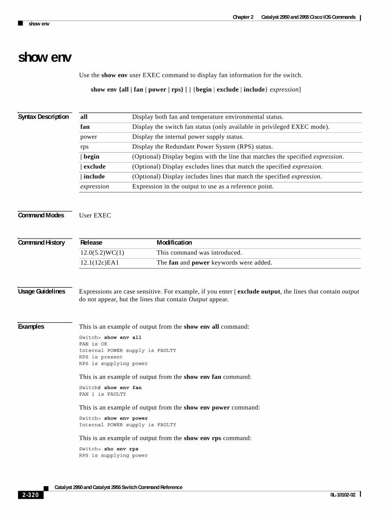
Chapter 2 Catalyst 2950 and 2955 Cisco IOS Commandsshow env
show envUse the show env user EXEC command to display fan information for the switch.
show env {all | fan | power | rps} [ | {begin | exclude | include} expression]
Syntax Description
Command Modes User EXEC
Command History
Usage Guidelines Expressions are case sensitive. For example, if you enter | exclude output, the lines that contain output do not appear, but the lines that contain Output appear.
Examples This is an example of output from the show env all command:
Switch> show env allFAN is OKInternal POWER supply is FAULTYRPS is presentRPS is supplying power
This is an example of output from the show env fan command:
Switch# show env fanFAN 1 is FAULTY
This is an example of output from the show env power command:
Switch> show env powerInternal POWER supply is FAULTY
This is an example of output from the show env rps command:
Switch> sho env rpsRPS is supplying power
all Display both fan and temperature environmental status.
fan Display the switch fan status (only available in privileged EXEC mode).
power Display the internal power supply status.
rps Display the Redundant Power System (RPS) status.| begin (Optional) Display begins with the line that matches the specified expression.
| exclude (Optional) Display excludes lines that match the specified expression.
| include (Optional) Display includes lines that match the specified expression.
expression Expression in the output to use as a reference point.
Release Modification
12.0(5.2)WC(1) This command was introduced.
12.1(12c)EA1 The fan and power keywords were added.
2-320Catalyst 2950 and Catalyst 2955 Switch Command Reference
0L-10102-02
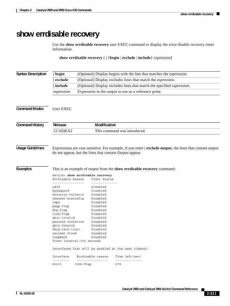
Chapter 2 Catalyst 2950 and 2955 Cisco IOS Commandsshow errdisable recovery
show errdisable recoveryUse the show errdisable recovery user EXEC command to display the error-disable recovery timer information.
show errdisable recovery [ | {begin | exclude | include} expression]
Syntax Description
Command Modes User EXEC
Command History
Usage Guidelines Expressions are case sensitive. For example, if you enter | exclude output, the lines that contain output do not appear, but the lines that contain Output appear.
Examples This is an example of output from the show errdisable recovery command:
Switch> show errdisable recoveryErrDisable Reason Timer Status----------------- --------------udld Disabledbpduguard Disabledsecurity-violatio Disabledchannel-misconfig Disabledvmps Disabledpagp-flap Disableddtp-flap Disabledlink-flap Disabledgbic-invalid Disabledpsecure-violation Disabledgbic-invalid Disableddhcp-rate-limit Disabledunicast-flood Disabledloopback DisabledTimer interval:300 seconds
Interfaces that will be enabled at the next timeout:
Interface Errdisable reason Time left(sec)--------- ----------------- --------------Gi0/1 link-flap 279
| begin (Optional) Display begins with the line that matches the expression.
| exclude (Optional) Display excludes lines that match the expression.
| include (Optional) Display includes lines that match the specified expression.
expression Expression in the output to use as a reference point.
Release Modification
12.1(6)EA2 This command was introduced.
2-321Catalyst 2950 and Catalyst 2955 Switch Command Reference
0L-10102-02
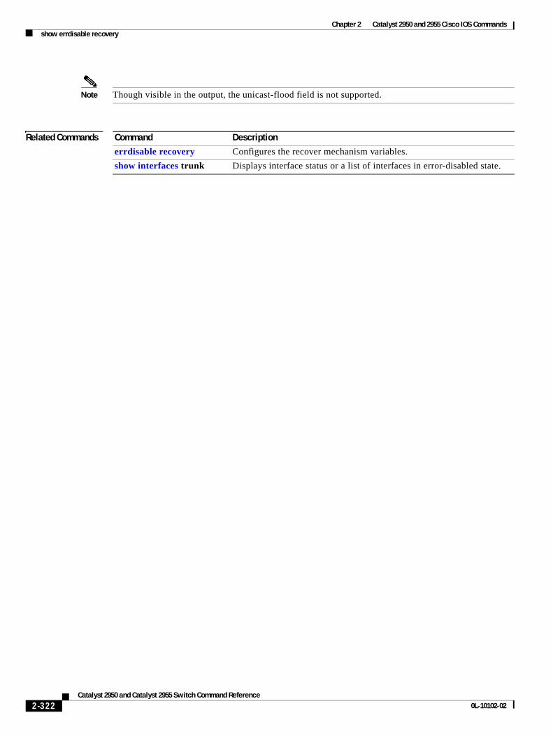
Chapter 2 Catalyst 2950 and 2955 Cisco IOS Commandsshow errdisable recovery
Note Though visible in the output, the unicast-flood field is not supported.
Related Commands Command Description
errdisable recovery Configures the recover mechanism variables.
show interfaces trunk Displays interface status or a list of interfaces in error-disabled state.
2-322Catalyst 2950 and Catalyst 2955 Switch Command Reference
0L-10102-02
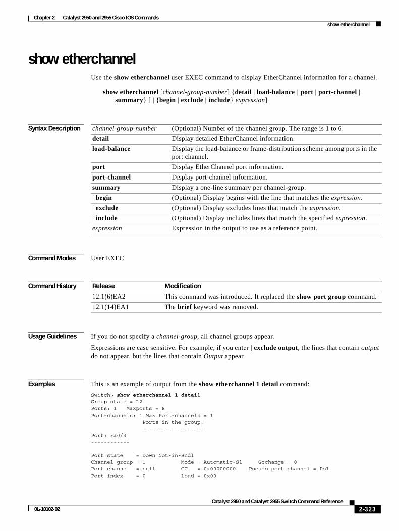
Chapter 2 Catalyst 2950 and 2955 Cisco IOS Commandsshow etherchannel
show etherchannelUse the show etherchannel user EXEC command to display EtherChannel information for a channel.
show etherchannel [channel-group-number] {detail | load-balance | port | port-channel | summary} [ | {begin | exclude | include} expression]
Syntax Description
Command Modes User EXEC
Command History
Usage Guidelines If you do not specify a channel-group, all channel groups appear.
Expressions are case sensitive. For example, if you enter | exclude output, the lines that contain output do not appear, but the lines that contain Output appear.
Examples This is an example of output from the show etherchannel 1 detail command:
Switch> show etherchannel 1 detailGroup state = L2Ports: 1 Maxports = 8Port-channels: 1 Max Port-channels = 1 Ports in the group: -------------------Port: Fa0/3------------
Port state = Down Not-in-BndlChannel group = 1 Mode = Automatic-Sl Gcchange = 0Port-channel = null GC = 0x00000000 Pseudo port-channel = Po1Port index = 0 Load = 0x00
channel-group-number (Optional) Number of the channel group. The range is 1 to 6.
detail Display detailed EtherChannel information.
load-balance Display the load-balance or frame-distribution scheme among ports in the port channel.
port Display EtherChannel port information.
port-channel Display port-channel information.
summary Display a one-line summary per channel-group.
| begin (Optional) Display begins with the line that matches the expression.
| exclude (Optional) Display excludes lines that match the expression.
| include (Optional) Display includes lines that match the specified expression.
expression Expression in the output to use as a reference point.
Release Modification
12.1(6)EA2 This command was introduced. It replaced the show port group command.
12.1(14)EA1 The brief keyword was removed.
2-323Catalyst 2950 and Catalyst 2955 Switch Command Reference
0L-10102-02
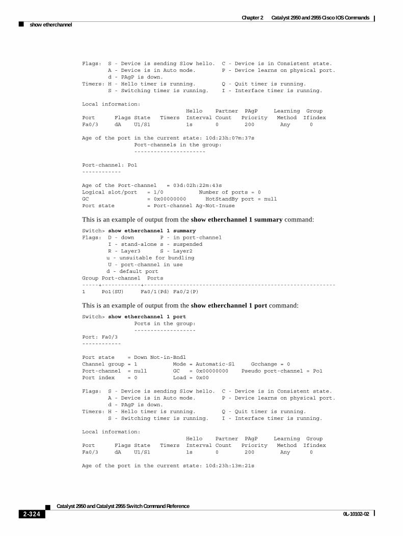
Chapter 2 Catalyst 2950 and 2955 Cisco IOS Commandsshow etherchannel
Flags: S - Device is sending Slow hello. C - Device is in Consistent state. A - Device is in Auto mode. P - Device learns on physical port. d - PAgP is down.Timers: H - Hello timer is running. Q - Quit timer is running. S - Switching timer is running. I - Interface timer is running.
Local information: Hello Partner PAgP Learning GroupPort Flags State Timers Interval Count Priority Method IfindexFa0/3 dA U1/S1 1s 0 200 Any 0
Age of the port in the current state: 10d:23h:07m:37s Port-channels in the group: ----------------------
Port-channel: Po1------------
Age of the Port-channel = 03d:02h:22m:43sLogical slot/port = 1/0 Number of ports = 0GC = 0x00000000 HotStandBy port = nullPort state = Port-channel Ag-Not-Inuse
This is an example of output from the show etherchannel 1 summary command:
Switch> show etherchannel 1 summaryFlags: D - down P - in port-channel I - stand-alone s - suspended R - Layer3 S - Layer2
u - unsuitable for bundling U - port-channel in use
d - default portGroup Port-channel Ports-----+------------+-----------------------------------------------------------1 Po1(SU) Fa0/1(Pd) Fa0/2(P)
This is an example of output from the show etherchannel 1 port command:
Switch> show etherchannel 1 port Ports in the group: -------------------Port: Fa0/3------------
Port state = Down Not-in-BndlChannel group = 1 Mode = Automatic-Sl Gcchange = 0Port-channel = null GC = 0x00000000 Pseudo port-channel = Po1Port index = 0 Load = 0x00
Flags: S - Device is sending Slow hello. C - Device is in Consistent state. A - Device is in Auto mode. P - Device learns on physical port. d - PAgP is down.Timers: H - Hello timer is running. Q - Quit timer is running. S - Switching timer is running. I - Interface timer is running.
Local information: Hello Partner PAgP Learning GroupPort Flags State Timers Interval Count Priority Method IfindexFa0/3 dA U1/S1 1s 0 200 Any 0
Age of the port in the current state: 10d:23h:13m:21s
2-324Catalyst 2950 and Catalyst 2955 Switch Command Reference
0L-10102-02

Chapter 2 Catalyst 2950 and 2955 Cisco IOS Commandsshow etherchannel
Related Commands Command Description
channel-group Assigns an Ethernet interface to an EtherChannel group.
interface port-channel Accesses or creates the port channel.
2-325Catalyst 2950 and Catalyst 2955 Switch Command Reference
0L-10102-02
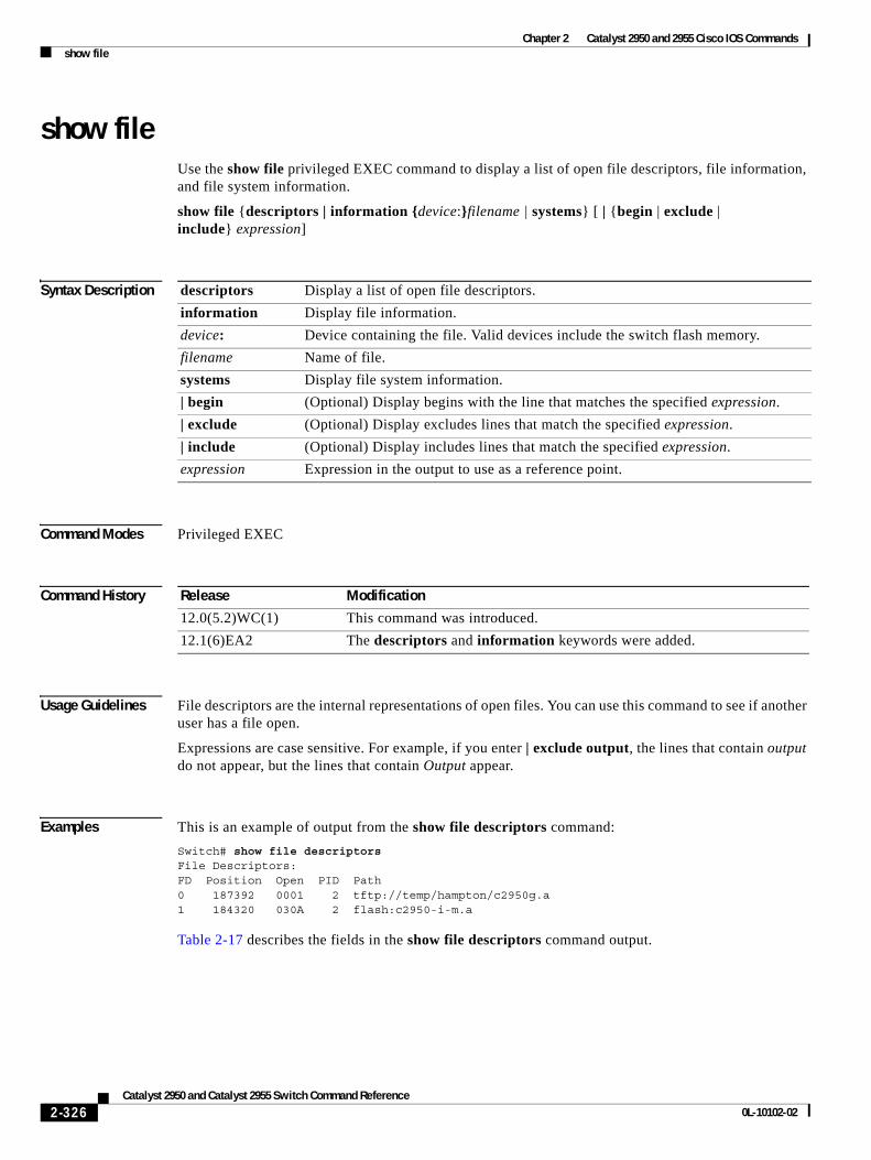
Chapter 2 Catalyst 2950 and 2955 Cisco IOS Commandsshow file
show fileUse the show file privileged EXEC command to display a list of open file descriptors, file information, and file system information.
show file {descriptors | information {device:}filename | systems} [ | {begin | exclude | include} expression]
Syntax Description
Command Modes Privileged EXEC
Command History
Usage Guidelines File descriptors are the internal representations of open files. You can use this command to see if another user has a file open.
Expressions are case sensitive. For example, if you enter | exclude output, the lines that contain output do not appear, but the lines that contain Output appear.
Examples This is an example of output from the show file descriptors command:
Switch# show file descriptorsFile Descriptors:FD Position Open PID Path0 187392 0001 2 tftp://temp/hampton/c2950g.a1 184320 030A 2 flash:c2950-i-m.a
Table 2-17 describes the fields in the show file descriptors command output.
descriptors Display a list of open file descriptors.
information Display file information.
device: Device containing the file. Valid devices include the switch flash memory.
filename Name of file.
systems Display file system information.
| begin (Optional) Display begins with the line that matches the specified expression.
| exclude (Optional) Display excludes lines that match the specified expression.
| include (Optional) Display includes lines that match the specified expression.
expression Expression in the output to use as a reference point.
Release Modification
12.0(5.2)WC(1) This command was introduced.
12.1(6)EA2 The descriptors and information keywords were added.
2-326Catalyst 2950 and Catalyst 2955 Switch Command Reference
0L-10102-02
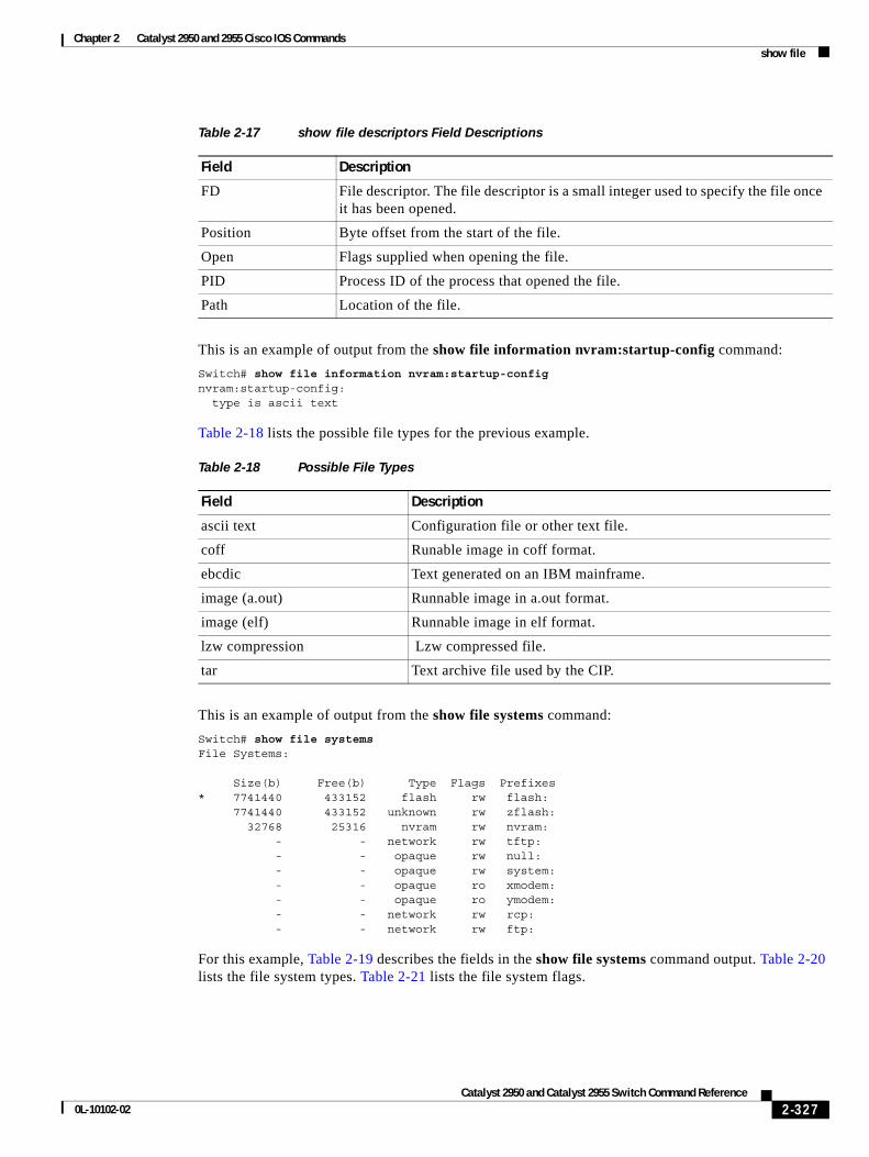
Chapter 2 Catalyst 2950 and 2955 Cisco IOS Commandsshow file
This is an example of output from the show file information nvram:startup-config command:
Switch# show file information nvram:startup-confignvram:startup-config: type is ascii text
Table 2-18 lists the possible file types for the previous example.
This is an example of output from the show file systems command:
Switch# show file systemsFile Systems:
Size(b) Free(b) Type Flags Prefixes* 7741440 433152 flash rw flash: 7741440 433152 unknown rw zflash: 32768 25316 nvram rw nvram: - - network rw tftp: - - opaque rw null: - - opaque rw system: - - opaque ro xmodem: - - opaque ro ymodem: - - network rw rcp: - - network rw ftp:
For this example, Table 2-19 describes the fields in the show file systems command output. Table 2-20 lists the file system types. Table 2-21 lists the file system flags.
Table 2-17 show file descriptors Field Descriptions
Field Description
FD File descriptor. The file descriptor is a small integer used to specify the file once it has been opened.
Position Byte offset from the start of the file.
Open Flags supplied when opening the file.
PID Process ID of the process that opened the file.
Path Location of the file.
Table 2-18 Possible File Types
Field Description
ascii text Configuration file or other text file.
coff Runable image in coff format.
ebcdic Text generated on an IBM mainframe.
image (a.out) Runnable image in a.out format.
image (elf) Runnable image in elf format.
lzw compression Lzw compressed file.
tar Text archive file used by the CIP.
2-327Catalyst 2950 and Catalyst 2955 Switch Command Reference
0L-10102-02
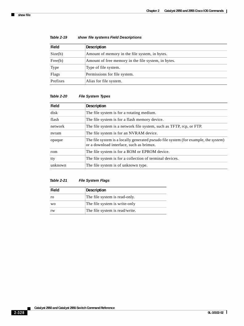
Chapter 2 Catalyst 2950 and 2955 Cisco IOS Commandsshow file
Table 2-19 show file systems Field Descriptions
Field Description
Size(b) Amount of memory in the file system, in bytes.
Free(b) Amount of free memory in the file system, in bytes.
Type Type of file system.
Flags Permissions for file system.
Prefixes Alias for file system.
Table 2-20 File System Types
Field Description
disk The file system is for a rotating medium.
flash The file system is for a flash memory device.
network The file system is a network file system, such as TFTP, rcp, or FTP.
nvram The file system is for an NVRAM device.
opaque The file system is a locally generated pseudo file system (for example, the system) or a download interface, such as brimux.
rom The file system is for a ROM or EPROM device.
tty The file system is for a collection of terminal devices.
unknown The file system is of unknown type.
Table 2-21 File System Flags
Field Description
ro The file system is read-only.
wo The file system is write-only
rw The file system is read/write.
2-328Catalyst 2950 and Catalyst 2955 Switch Command Reference
0L-10102-02
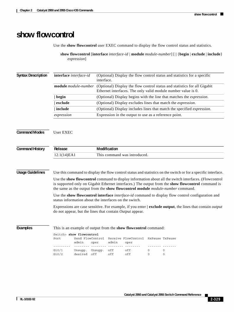
Chapter 2 Catalyst 2950 and 2955 Cisco IOS Commandsshow flowcontrol
show flowcontrolUse the show flowcontrol user EXEC command to display the flow control status and statistics.
show flowcontrol [interface interface-id | module module-number] [ | {begin | exclude | include} expression]
Syntax Description
Command Modes User EXEC
Command History
Usage Guidelines Use this command to display the flow control status and statistics on the switch or for a specific interface.
Use the show flowcontrol command to display information about all the switch interfaces. (Flowcontrol is supported only on Gigabit Ethernet interfaces.) The output from the show flowcontrol command is the same as the output from the show flowcontrol module module-number command.
Use the show flowcontrol interface interface-id command to display flow control configuration and status information about the interfaces on the switch.
Expressions are case sensitive. For example, if you enter | exclude output, the lines that contain output do not appear, but the lines that contain Output appear.
Examples This is an example of output from the show flowcontrol command:
Switch> show flowcontrolPort Send FlowControl Receive FlowControl RxPause TxPause admin oper admin oper--------- -------- -------- -------- -------- ------- -------Gi0/1 Unsupp. Unsupp. off off 0 0Gi0/2 desired off off off 0 0
interface interface-id (Optional) Display the flow control status and statistics for a specific interface.
module module-number (Optional) Display the flow control status and statistics for all Gigabit Ethernet interfaces. The only valid module number value is 0.
| begin (Optional) Display begins with the line that matches the expression.
| exclude (Optional) Display excludes lines that match the expression.
| include (Optional) Display includes lines that match the specified expression.
expression Expression in the output to use as a reference point.
Release Modification
12.1(14)EA1 This command was introduced.
2-329Catalyst 2950 and Catalyst 2955 Switch Command Reference
0L-10102-02
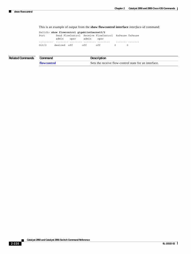
Chapter 2 Catalyst 2950 and 2955 Cisco IOS Commandsshow flowcontrol
This is an example of output from the show flowcontrol interface interface-id command:
Switch> show flowcontrol gigabitethernet0/2Port Send FlowControl Receive FlowControl RxPause TxPause admin oper admin oper--------- -------- -------- -------- -------- ------- -------Gi0/2 desired off off off 0 0
Related Commands Command Description
flowcontrol Sets the receive flow-control state for an interface.
2-330Catalyst 2950 and Catalyst 2955 Switch Command Reference
0L-10102-02
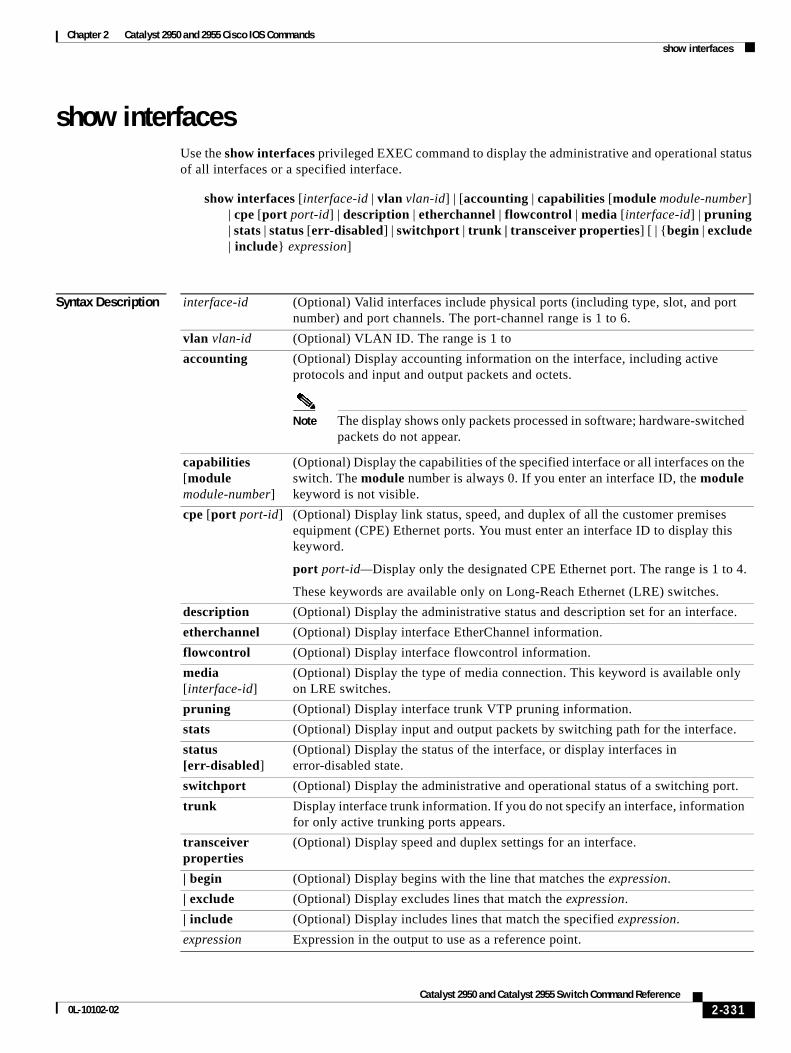
Chapter 2 Catalyst 2950 and 2955 Cisco IOS Commandsshow interfaces
show interfacesUse the show interfaces privileged EXEC command to display the administrative and operational status of all interfaces or a specified interface.
show interfaces [interface-id | vlan vlan-id] | [accounting | capabilities [module module-number] | cpe [port port-id] | description | etherchannel | flowcontrol | media [interface-id] | pruning | stats | status [err-disabled] | switchport | trunk | transceiver properties] [ | {begin | exclude | include} expression]
Syntax Description interface-id (Optional) Valid interfaces include physical ports (including type, slot, and port number) and port channels. The port-channel range is 1 to 6.
vlan vlan-id (Optional) VLAN ID. The range is 1 to
accounting (Optional) Display accounting information on the interface, including active protocols and input and output packets and octets.
Note The display shows only packets processed in software; hardware-switched packets do not appear.
capabilities [module module-number]
(Optional) Display the capabilities of the specified interface or all interfaces on the switch. The module number is always 0. If you enter an interface ID, the module keyword is not visible.
cpe [port port-id] (Optional) Display link status, speed, and duplex of all the customer premises equipment (CPE) Ethernet ports. You must enter an interface ID to display this keyword.
port port-id—Display only the designated CPE Ethernet port. The range is 1 to 4.
These keywords are available only on Long-Reach Ethernet (LRE) switches.
description (Optional) Display the administrative status and description set for an interface.
etherchannel (Optional) Display interface EtherChannel information.
flowcontrol (Optional) Display interface flowcontrol information.
media [interface-id]
(Optional) Display the type of media connection. This keyword is available only on LRE switches.
pruning (Optional) Display interface trunk VTP pruning information.
stats (Optional) Display input and output packets by switching path for the interface.
status [err-disabled]
(Optional) Display the status of the interface, or display interfaces in error-disabled state.
switchport (Optional) Display the administrative and operational status of a switching port.
trunk Display interface trunk information. If you do not specify an interface, information for only active trunking ports appears.
transceiver properties
(Optional) Display speed and duplex settings for an interface.
| begin (Optional) Display begins with the line that matches the expression.
| exclude (Optional) Display excludes lines that match the expression.
| include (Optional) Display includes lines that match the specified expression.
expression Expression in the output to use as a reference point.
2-331Catalyst 2950 and Catalyst 2955 Switch Command Reference
0L-10102-02
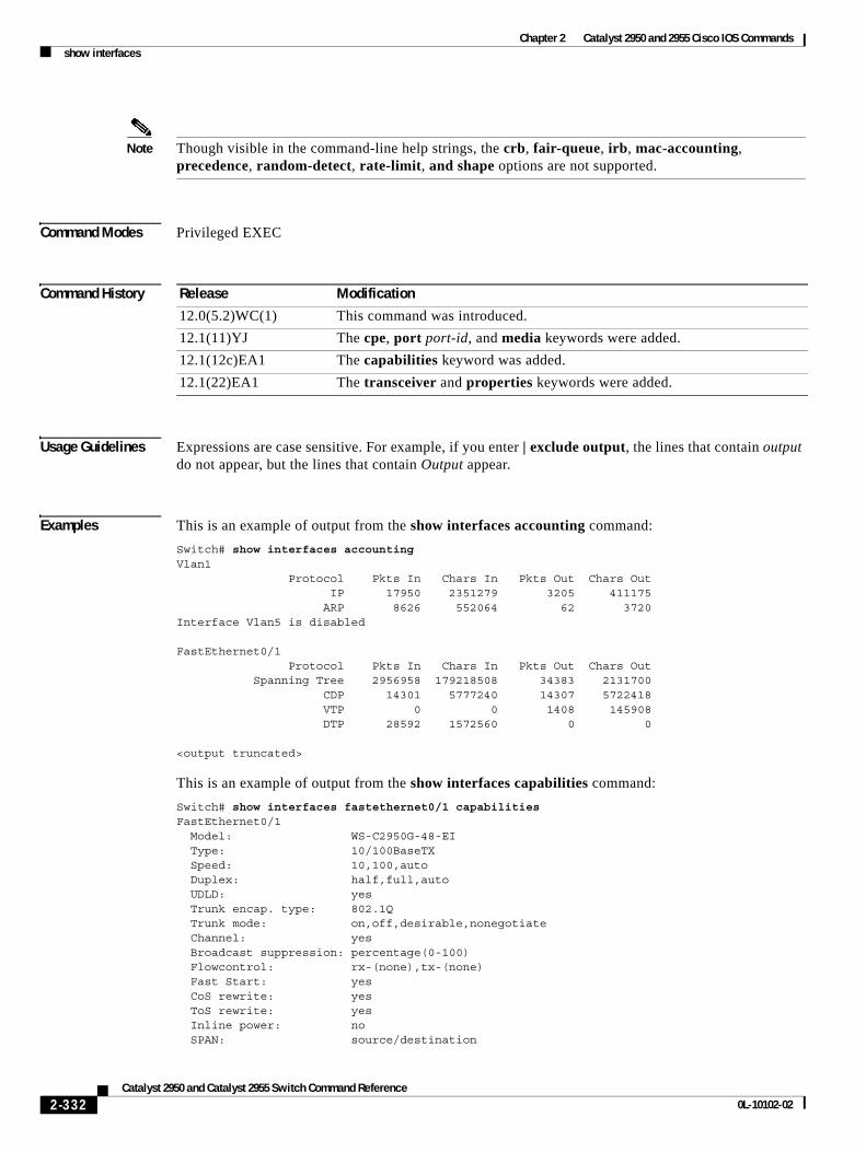
Chapter 2 Catalyst 2950 and 2955 Cisco IOS Commandsshow interfaces
Note Though visible in the command-line help strings, the crb, fair-queue, irb, mac-accounting, precedence, random-detect, rate-limit, and shape options are not supported.
Command Modes Privileged EXEC
Command History
Usage Guidelines Expressions are case sensitive. For example, if you enter | exclude output, the lines that contain output do not appear, but the lines that contain Output appear.
Examples This is an example of output from the show interfaces accounting command:
Switch# show interfaces accountingVlan1 Protocol Pkts In Chars In Pkts Out Chars Out IP 17950 2351279 3205 411175 ARP 8626 552064 62 3720Interface Vlan5 is disabled
FastEthernet0/1 Protocol Pkts In Chars In Pkts Out Chars Out Spanning Tree 2956958 179218508 34383 2131700 CDP 14301 5777240 14307 5722418 VTP 0 0 1408 145908 DTP 28592 1572560 0 0
<output truncated>
This is an example of output from the show interfaces capabilities command:
Switch# show interfaces fastethernet0/1 capabilities FastEthernet0/1 Model: WS-C2950G-48-EI Type: 10/100BaseTX Speed: 10,100,auto Duplex: half,full,auto UDLD: yes Trunk encap. type: 802.1Q Trunk mode: on,off,desirable,nonegotiate Channel: yes Broadcast suppression: percentage(0-100) Flowcontrol: rx-(none),tx-(none) Fast Start: yes CoS rewrite: yes ToS rewrite: yes Inline power: no SPAN: source/destination
Release Modification
12.0(5.2)WC(1) This command was introduced.
12.1(11)YJ The cpe, port port-id, and media keywords were added.
12.1(12c)EA1 The capabilities keyword was added.
12.1(22)EA1 The transceiver and properties keywords were added.
2-332Catalyst 2950 and Catalyst 2955 Switch Command Reference
0L-10102-02
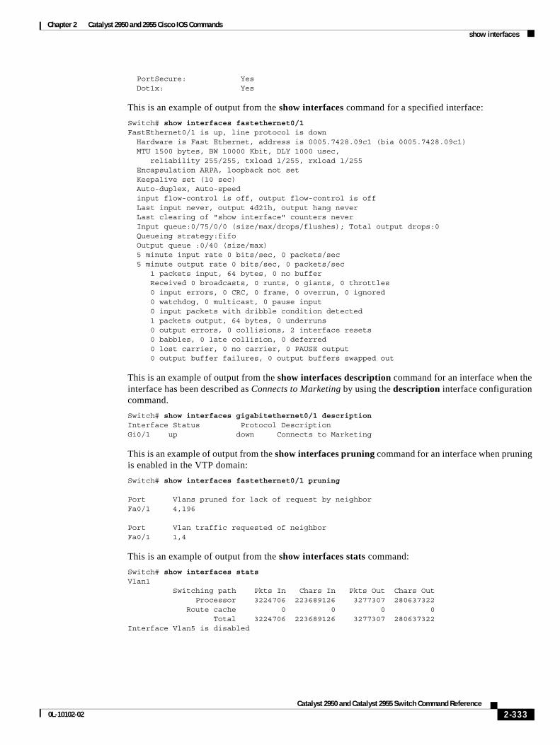
Chapter 2 Catalyst 2950 and 2955 Cisco IOS Commandsshow interfaces
PortSecure: Yes Dot1x: Yes
This is an example of output from the show interfaces command for a specified interface:
Switch# show interfaces fastethernet0/1 FastEthernet0/1 is up, line protocol is down Hardware is Fast Ethernet, address is 0005.7428.09c1 (bia 0005.7428.09c1) MTU 1500 bytes, BW 10000 Kbit, DLY 1000 usec, reliability 255/255, txload 1/255, rxload 1/255 Encapsulation ARPA, loopback not set Keepalive set (10 sec) Auto-duplex, Auto-speed input flow-control is off, output flow-control is off Last input never, output 4d21h, output hang never Last clearing of "show interface" counters never Input queue:0/75/0/0 (size/max/drops/flushes); Total output drops:0 Queueing strategy:fifo Output queue :0/40 (size/max) 5 minute input rate 0 bits/sec, 0 packets/sec 5 minute output rate 0 bits/sec, 0 packets/sec 1 packets input, 64 bytes, 0 no buffer Received 0 broadcasts, 0 runts, 0 giants, 0 throttles 0 input errors, 0 CRC, 0 frame, 0 overrun, 0 ignored 0 watchdog, 0 multicast, 0 pause input 0 input packets with dribble condition detected 1 packets output, 64 bytes, 0 underruns 0 output errors, 0 collisions, 2 interface resets 0 babbles, 0 late collision, 0 deferred 0 lost carrier, 0 no carrier, 0 PAUSE output 0 output buffer failures, 0 output buffers swapped out
This is an example of output from the show interfaces description command for an interface when the interface has been described as Connects to Marketing by using the description interface configuration command.
Switch# show interfaces gigabitethernet0/1 descriptionInterface Status Protocol DescriptionGi0/1 up down Connects to Marketing
This is an example of output from the show interfaces pruning command for an interface when pruning is enabled in the VTP domain:
Switch# show interfaces fastethernet0/1 pruning
Port Vlans pruned for lack of request by neighborFa0/1 4,196
Port Vlan traffic requested of neighborFa0/1 1,4
This is an example of output from the show interfaces stats command:
Switch# show interfaces statsVlan1 Switching path Pkts In Chars In Pkts Out Chars Out Processor 3224706 223689126 3277307 280637322 Route cache 0 0 0 0 Total 3224706 223689126 3277307 280637322Interface Vlan5 is disabled
2-333Catalyst 2950 and Catalyst 2955 Switch Command Reference
0L-10102-02
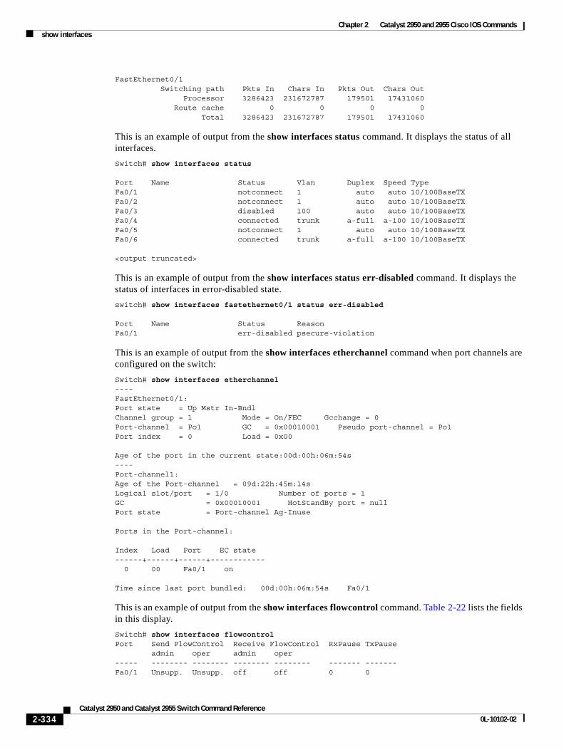
Chapter 2 Catalyst 2950 and 2955 Cisco IOS Commandsshow interfaces
FastEthernet0/1 Switching path Pkts In Chars In Pkts Out Chars Out Processor 3286423 231672787 179501 17431060 Route cache 0 0 0 0 Total 3286423 231672787 179501 17431060
This is an example of output from the show interfaces status command. It displays the status of all interfaces.
Switch# show interfaces status
Port Name Status Vlan Duplex Speed TypeFa0/1 notconnect 1 auto auto 10/100BaseTXFa0/2 notconnect 1 auto auto 10/100BaseTXFa0/3 disabled 100 auto auto 10/100BaseTXFa0/4 connected trunk a-full a-100 10/100BaseTXFa0/5 notconnect 1 auto auto 10/100BaseTXFa0/6 connected trunk a-full a-100 10/100BaseTX
<output truncated>
This is an example of output from the show interfaces status err-disabled command. It displays the status of interfaces in error-disabled state.
switch# show interfaces fastethernet0/1 status err-disabled
Port Name Status ReasonFa0/1 err-disabled psecure-violation
This is an example of output from the show interfaces etherchannel command when port channels are configured on the switch:
Switch# show interfaces etherchannel----FastEthernet0/1:Port state = Up Mstr In-Bndl Channel group = 1 Mode = On/FEC Gcchange = 0Port-channel = Po1 GC = 0x00010001 Pseudo port-channel = Po1Port index = 0 Load = 0x00
Age of the port in the current state:00d:00h:06m:54s----Port-channel1:Age of the Port-channel = 09d:22h:45m:14sLogical slot/port = 1/0 Number of ports = 1GC = 0x00010001 HotStandBy port = nullPort state = Port-channel Ag-Inuse
Ports in the Port-channel:
Index Load Port EC state------+------+------+------------ 0 00 Fa0/1 on
Time since last port bundled: 00d:00h:06m:54s Fa0/1
This is an example of output from the show interfaces flowcontrol command. Table 2-22 lists the fields in this display.
Switch# show interfaces flowcontrolPort Send FlowControl Receive FlowControl RxPause TxPause admin oper admin oper----- -------- -------- -------- -------- ------- -------Fa0/1 Unsupp. Unsupp. off off 0 0
2-334Catalyst 2950 and Catalyst 2955 Switch Command Reference
0L-10102-02
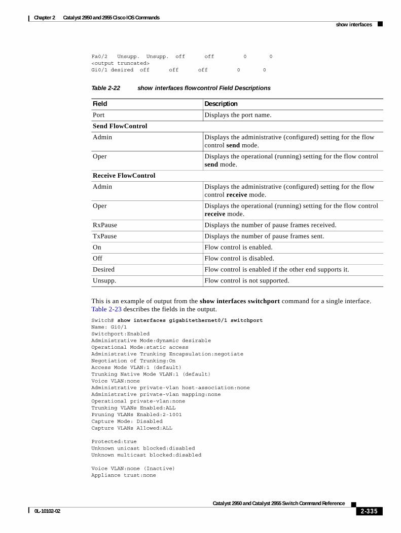
Chapter 2 Catalyst 2950 and 2955 Cisco IOS Commandsshow interfaces
Fa0/2 Unsupp. Unsupp. off off 0 0<output truncated>Gi0/1 desired off off off 0 0
This is an example of output from the show interfaces switchport command for a single interface. Table 2-23 describes the fields in the output.
Switch# show interfaces gigabitethernet0/1 switchportName: Gi0/1Switchport:EnabledAdministrative Mode:dynamic desirableOperational Mode:static accessAdministrative Trunking Encapsulation:negotiateNegotiation of Trunking:OnAccess Mode VLAN:1 (default)Trunking Native Mode VLAN:1 (default)Voice VLAN:noneAdministrative private-vlan host-association:noneAdministrative private-vlan mapping:noneOperational private-vlan:noneTrunking VLANs Enabled:ALLPruning VLANs Enabled:2-1001Capture Mode: DisabledCapture VLANs Allowed:ALL
Protected:trueUnknown unicast blocked:disabledUnknown multicast blocked:disabled
Voice VLAN:none (Inactive)Appliance trust:none
Table 2-22 show interfaces flowcontrol Field Descriptions
Field Description
Port Displays the port name.
Send FlowControl
Admin Displays the administrative (configured) setting for the flow control send mode.
Oper Displays the operational (running) setting for the flow control send mode.
Receive FlowControl
Admin Displays the administrative (configured) setting for the flow control receive mode.
Oper Displays the operational (running) setting for the flow control receive mode.
RxPause Displays the number of pause frames received.
TxPause Displays the number of pause frames sent.
On Flow control is enabled.
Off Flow control is disabled.
Desired Flow control is enabled if the other end supports it.
Unsupp. Flow control is not supported.
2-335Catalyst 2950 and Catalyst 2955 Switch Command Reference
0L-10102-02
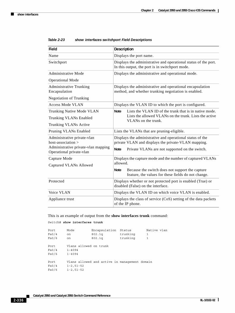
Chapter 2 Catalyst 2950 and 2955 Cisco IOS Commandsshow interfaces
This is an example of output from the show interfaces trunk command:
Switch# show interfaces trunk
Port Mode Encapsulation Status Native vlanFa0/4 on 802.1q trunking 1Fa0/6 on 802.1q trunking 1
Port Vlans allowed on trunkFa0/4 1-4094Fa0/6 1-4094
Port Vlans allowed and active in management domainFa0/4 1-2,51-52Fa0/6 1-2,51-52
Table 2-23 show interfaces switchport Field Descriptions
Field Description
Name Displays the port name.
Switchport Displays the administrative and operational status of the port. In this output, the port is in switchport mode.
Administrative Mode
Operational Mode
Displays the administrative and operational mode.
Administrative Trunking Encapsulation
Negotiation of Trunking
Displays the administrative and operational encapsulation method, and whether trunking negotiation is enabled.
Access Mode VLAN Displays the VLAN ID to which the port is configured.
Trunking Native Mode VLAN
Trunking VLANs Enabled
Trunking VLANs Active
Note Lists the VLAN ID of the trunk that is in native mode. Lists the allowed VLANs on the trunk. Lists the active VLANs on the trunk.
Pruning VLANs Enabled Lists the VLANs that are pruning-eligible.
Administrative private-vlan host-association > Administrative private-vlan mapping Operational private-vlan
Displays the administrative and operational status of the private VLAN and displays the private-VLAN mapping.
Note Private VLANs are not supported on the switch.
Capture Mode
Captured VLANs Allowed
Displays the capture mode and the number of captured VLANs allowed.
Note Because the switch does not support the capture feature, the values for these fields do not change.
Protected Displays whether or not protected port is enabled (True) or disabled (False) on the interface.
Voice VLAN Displays the VLAN ID on which voice VLAN is enabled.
Appliance trust Displays the class of service (CoS) setting of the data packets of the IP phone.
2-336Catalyst 2950 and Catalyst 2955 Switch Command Reference
0L-10102-02
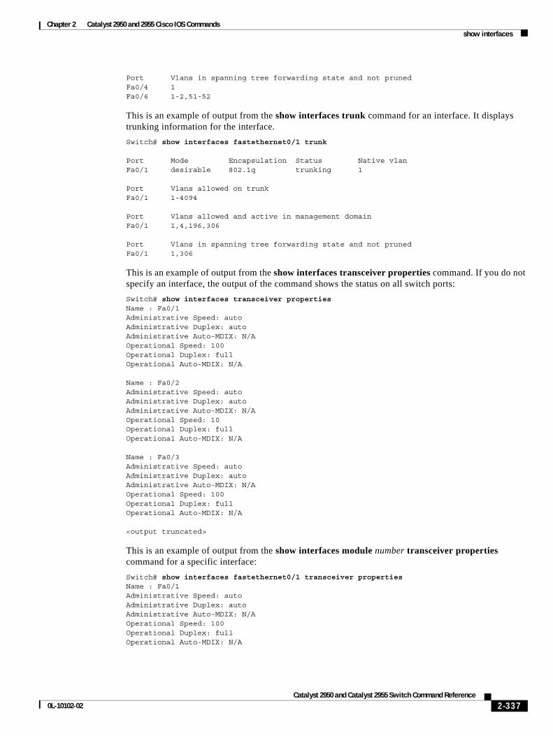
Chapter 2 Catalyst 2950 and 2955 Cisco IOS Commandsshow interfaces
Port Vlans in spanning tree forwarding state and not prunedFa0/4 1Fa0/6 1-2,51-52
This is an example of output from the show interfaces trunk command for an interface. It displays trunking information for the interface.
Switch# show interfaces fastethernet0/1 trunk
Port Mode Encapsulation Status Native vlanFa0/1 desirable 802.1q trunking 1
Port Vlans allowed on trunkFa0/1 1-4094
Port Vlans allowed and active in management domainFa0/1 1,4,196,306
Port Vlans in spanning tree forwarding state and not prunedFa0/1 1,306
This is an example of output from the show interfaces transceiver properties command. If you do not specify an interface, the output of the command shows the status on all switch ports:
Switch# show interfaces transceiver propertiesName : Fa0/1Administrative Speed: autoAdministrative Duplex: autoAdministrative Auto-MDIX: N/A Operational Speed: 100Operational Duplex: fullOperational Auto-MDIX: N/A
Name : Fa0/2Administrative Speed: autoAdministrative Duplex: autoAdministrative Auto-MDIX: N/A Operational Speed: 10Operational Duplex: fullOperational Auto-MDIX: N/A
Name : Fa0/3Administrative Speed: autoAdministrative Duplex: autoAdministrative Auto-MDIX: N/A Operational Speed: 100Operational Duplex: fullOperational Auto-MDIX: N/A
<output truncated>
This is an example of output from the show interfaces module number transceiver properties command for a specific interface:
Switch# show interfaces fastethernet0/1 transceiver propertiesName : Fa0/1Administrative Speed: autoAdministrative Duplex: autoAdministrative Auto-MDIX: N/A Operational Speed: 100Operational Duplex: fullOperational Auto-MDIX: N/A
2-337Catalyst 2950 and Catalyst 2955 Switch Command Reference
0L-10102-02
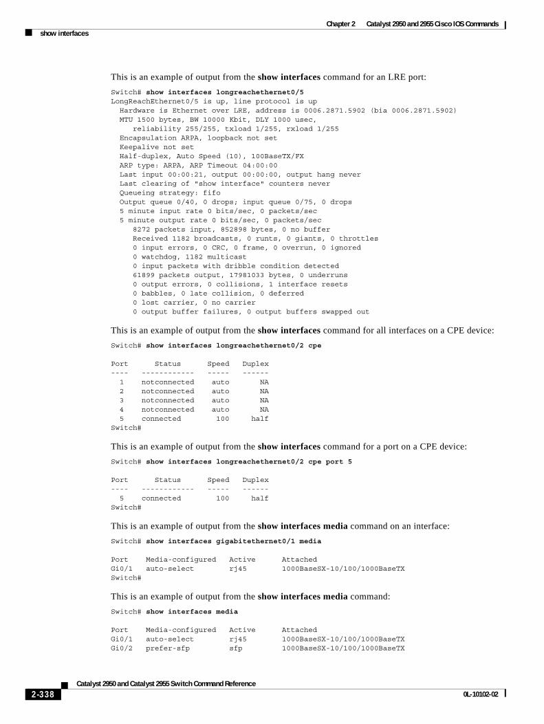
Chapter 2 Catalyst 2950 and 2955 Cisco IOS Commandsshow interfaces
This is an example of output from the show interfaces command for an LRE port:
Switch# show interfaces longreachethernet0/5LongReachEthernet0/5 is up, line protocol is up Hardware is Ethernet over LRE, address is 0006.2871.5902 (bia 0006.2871.5902) MTU 1500 bytes, BW 10000 Kbit, DLY 1000 usec, reliability 255/255, txload 1/255, rxload 1/255 Encapsulation ARPA, loopback not set Keepalive not set Half-duplex, Auto Speed (10), 100BaseTX/FX ARP type: ARPA, ARP Timeout 04:00:00 Last input 00:00:21, output 00:00:00, output hang never Last clearing of "show interface" counters never Queueing strategy: fifo Output queue 0/40, 0 drops; input queue 0/75, 0 drops 5 minute input rate 0 bits/sec, 0 packets/sec 5 minute output rate 0 bits/sec, 0 packets/sec 8272 packets input, 852898 bytes, 0 no buffer Received 1182 broadcasts, 0 runts, 0 giants, 0 throttles 0 input errors, 0 CRC, 0 frame, 0 overrun, 0 ignored 0 watchdog, 1182 multicast 0 input packets with dribble condition detected 61899 packets output, 17981033 bytes, 0 underruns 0 output errors, 0 collisions, 1 interface resets 0 babbles, 0 late collision, 0 deferred 0 lost carrier, 0 no carrier 0 output buffer failures, 0 output buffers swapped out
This is an example of output from the show interfaces command for all interfaces on a CPE device:
Switch# show interfaces longreachethernet0/2 cpe
Port Status Speed Duplex---- ------------ ----- ------ 1 notconnected auto NA 2 notconnected auto NA 3 notconnected auto NA 4 notconnected auto NA 5 connected 100 halfSwitch#
This is an example of output from the show interfaces command for a port on a CPE device:
Switch# show interfaces longreachethernet0/2 cpe port 5
Port Status Speed Duplex---- ------------ ----- ------ 5 connected 100 halfSwitch#
This is an example of output from the show interfaces media command on an interface:
Switch# show interfaces gigabitethernet0/1 media
Port Media-configured Active AttachedGi0/1 auto-select rj45 1000BaseSX-10/100/1000BaseTXSwitch#
This is an example of output from the show interfaces media command:
Switch# show interfaces media
Port Media-configured Active AttachedGi0/1 auto-select rj45 1000BaseSX-10/100/1000BaseTXGi0/2 prefer-sfp sfp 1000BaseSX-10/100/1000BaseTX
2-338Catalyst 2950 and Catalyst 2955 Switch Command Reference
0L-10102-02

Chapter 2 Catalyst 2950 and 2955 Cisco IOS Commandsshow interfaces
Related Commands Command Description
switchport access Configures a port as a static-access or dynamic-access port.
switchport protected Isolates Layer 2 unicast, multicast, and broadcast traffic from other protected ports on the same switch.
switchport trunk pruning Configures the VLAN pruning-eligible list for ports in trunking mode.
2-339Catalyst 2950 and Catalyst 2955 Switch Command Reference
0L-10102-02
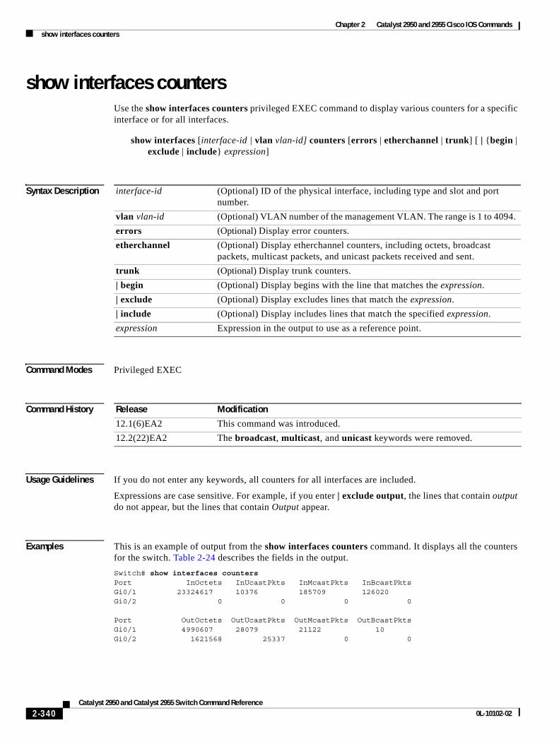
Chapter 2 Catalyst 2950 and 2955 Cisco IOS Commandsshow interfaces counters
show interfaces countersUse the show interfaces counters privileged EXEC command to display various counters for a specific interface or for all interfaces.
show interfaces [interface-id | vlan vlan-id] counters [errors | etherchannel | trunk] [ | {begin | exclude | include} expression]
Syntax Description
Command Modes Privileged EXEC
Command History
Usage Guidelines If you do not enter any keywords, all counters for all interfaces are included.
Expressions are case sensitive. For example, if you enter | exclude output, the lines that contain output do not appear, but the lines that contain Output appear.
Examples This is an example of output from the show interfaces counters command. It displays all the counters for the switch. Table 2-24 describes the fields in the output.
Switch# show interfaces countersPort InOctets InUcastPkts InMcastPkts InBcastPktsGi0/1 23324617 10376 185709 126020Gi0/2 0 0 0 0
Port OutOctets OutUcastPkts OutMcastPkts OutBcastPktsGi0/1 4990607 28079 21122 10Gi0/2 1621568 25337 0 0
interface-id (Optional) ID of the physical interface, including type and slot and port number.
vlan vlan-id (Optional) VLAN number of the management VLAN. The range is 1 to 4094.
errors (Optional) Display error counters.
etherchannel (Optional) Display etherchannel counters, including octets, broadcast packets, multicast packets, and unicast packets received and sent.
trunk (Optional) Display trunk counters.
| begin (Optional) Display begins with the line that matches the expression.
| exclude (Optional) Display excludes lines that match the expression.
| include (Optional) Display includes lines that match the specified expression.
expression Expression in the output to use as a reference point.
Release Modification
12.1(6)EA2 This command was introduced.
12.2(22)EA2 The broadcast, multicast, and unicast keywords were removed.
2-340Catalyst 2950 and Catalyst 2955 Switch Command Reference
0L-10102-02
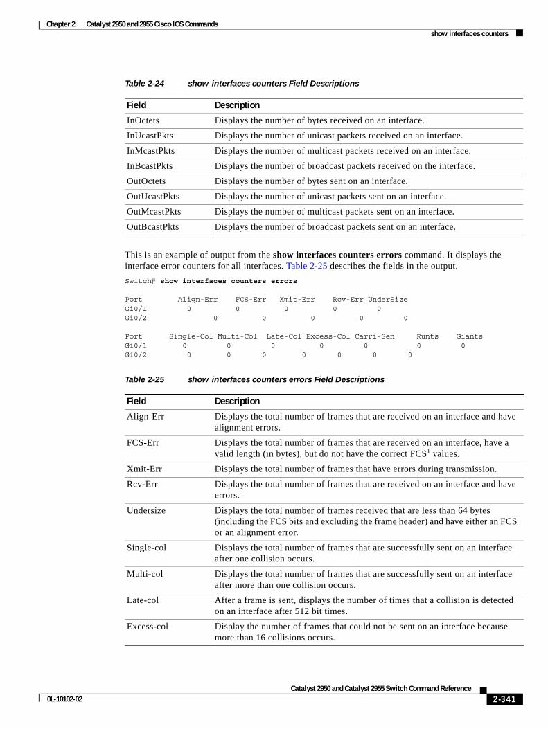
Chapter 2 Catalyst 2950 and 2955 Cisco IOS Commandsshow interfaces counters
This is an example of output from the show interfaces counters errors command. It displays the interface error counters for all interfaces. Table 2-25 describes the fields in the output.
Switch# show interfaces counters errors
Port Align-Err FCS-Err Xmit-Err Rcv-Err UnderSizeGi0/1 0 0 0 0 0Gi0/2 0 0 0 0 0
Port Single-Col Multi-Col Late-Col Excess-Col Carri-Sen Runts GiantsGi0/1 0 0 0 0 0 0 0Gi0/2 0 0 0 0 0 0 0
Table 2-24 show interfaces counters Field Descriptions
Field Description
InOctets Displays the number of bytes received on an interface.
InUcastPkts Displays the number of unicast packets received on an interface.
InMcastPkts Displays the number of multicast packets received on an interface.
InBcastPkts Displays the number of broadcast packets received on the interface.
OutOctets Displays the number of bytes sent on an interface.
OutUcastPkts Displays the number of unicast packets sent on an interface.
OutMcastPkts Displays the number of multicast packets sent on an interface.
OutBcastPkts Displays the number of broadcast packets sent on an interface.
Table 2-25 show interfaces counters errors Field Descriptions
Field Description
Align-Err Displays the total number of frames that are received on an interface and have alignment errors.
FCS-Err Displays the total number of frames that are received on an interface, have a valid length (in bytes), but do not have the correct FCS1 values.
Xmit-Err Displays the total number of frames that have errors during transmission.
Rcv-Err Displays the total number of frames that are received on an interface and have errors.
Undersize Displays the total number of frames received that are less than 64 bytes (including the FCS bits and excluding the frame header) and have either an FCS or an alignment error.
Single-col Displays the total number of frames that are successfully sent on an interface after one collision occurs.
Multi-col Displays the total number of frames that are successfully sent on an interface after more than one collision occurs.
Late-col After a frame is sent, displays the number of times that a collision is detected on an interface after 512 bit times.
Excess-col Display the number of frames that could not be sent on an interface because more than 16 collisions occurs.
2-341Catalyst 2950 and Catalyst 2955 Switch Command Reference
0L-10102-02
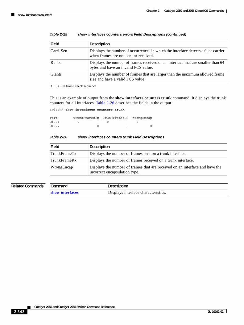
Chapter 2 Catalyst 2950 and 2955 Cisco IOS Commandsshow interfaces counters
This is an example of output from the show interfaces counters trunk command. It displays the trunk counters for all interfaces. Table 2-26 describes the fields in the output.
Switch# show interfaces counters trunk
Port TrunkFramesTx TrunkFramesRx WrongEncapGi0/1 0 0 0Gi0/2 0 0 0
Related Commands
Carri-Sen Displays the number of occurrences in which the interface detects a false carrier when frames are not sent or received.
Runts Displays the number of frames received on an interface that are smaller than 64 bytes and have an invalid FCS value.
Giants Displays the number of frames that are larger than the maximum allowed frame size and have a valid FCS value.
1. FCS = frame check sequence
Table 2-25 show interfaces counters errors Field Descriptions (continued)
Field Description
Table 2-26 show interfaces counters trunk Field Descriptions
Field Description
TrunkFrameTx Displays the number of frames sent on a trunk interface.
TrunkFrameRx Displays the number of frames received on a trunk interface.
WrongEncap Displays the number of frames that are received on an interface and have the incorrect encapsulation type.
Command Description
show interfaces Displays interface characteristics.
2-342Catalyst 2950 and Catalyst 2955 Switch Command Reference
0L-10102-02
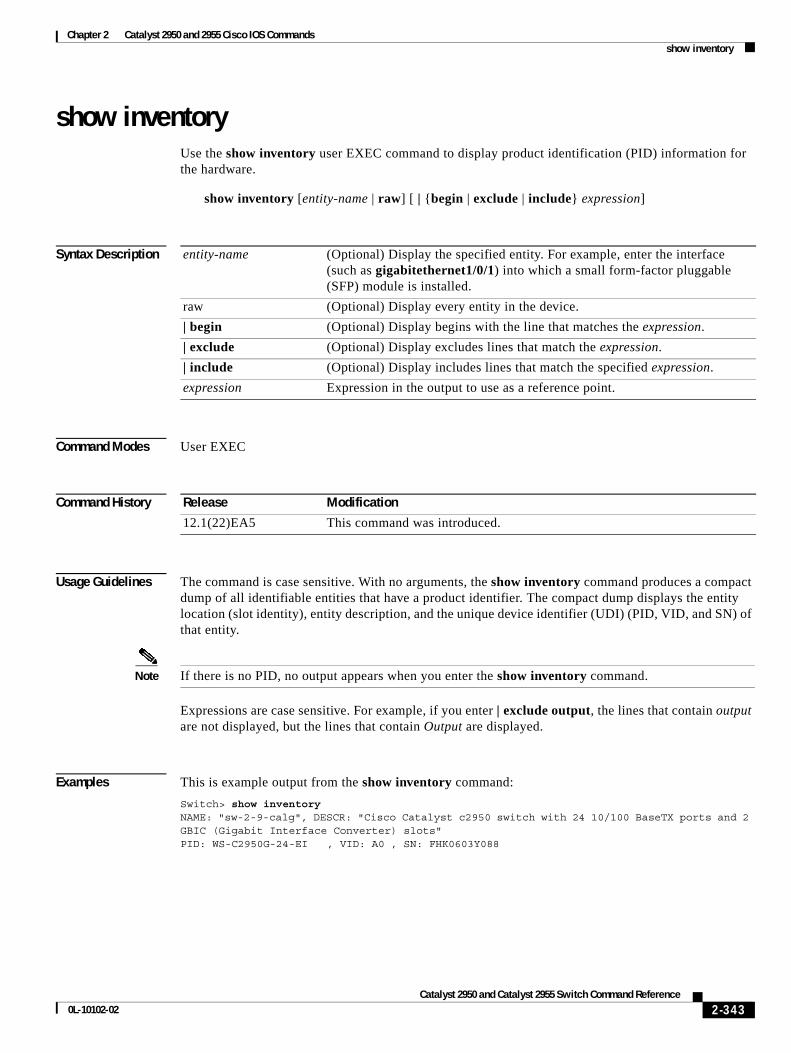
Chapter 2 Catalyst 2950 and 2955 Cisco IOS Commandsshow inventory
show inventoryUse the show inventory user EXEC command to display product identification (PID) information for the hardware.
show inventory [entity-name | raw] [ | {begin | exclude | include} expression]
Syntax Description
Command Modes User EXEC
Command History
Usage Guidelines The command is case sensitive. With no arguments, the show inventory command produces a compact dump of all identifiable entities that have a product identifier. The compact dump displays the entity location (slot identity), entity description, and the unique device identifier (UDI) (PID, VID, and SN) of that entity.
Note If there is no PID, no output appears when you enter the show inventory command.
Expressions are case sensitive. For example, if you enter | exclude output, the lines that contain output are not displayed, but the lines that contain Output are displayed.
Examples This is example output from the show inventory command:
Switch> show inventoryNAME: "sw-2-9-calg", DESCR: "Cisco Catalyst c2950 switch with 24 10/100 BaseTX ports and 2 GBIC (Gigabit Interface Converter) slots"PID: WS-C2950G-24-EI , VID: A0 , SN: FHK0603Y088
entity-name (Optional) Display the specified entity. For example, enter the interface (such as gigabitethernet1/0/1) into which a small form-factor pluggable (SFP) module is installed.
raw (Optional) Display every entity in the device.
| begin (Optional) Display begins with the line that matches the expression.
| exclude (Optional) Display excludes lines that match the expression.
| include (Optional) Display includes lines that match the specified expression.
expression Expression in the output to use as a reference point.
Release Modification
12.1(22)EA5 This command was introduced.
2-343Catalyst 2950 and Catalyst 2955 Switch Command Reference
0L-10102-02
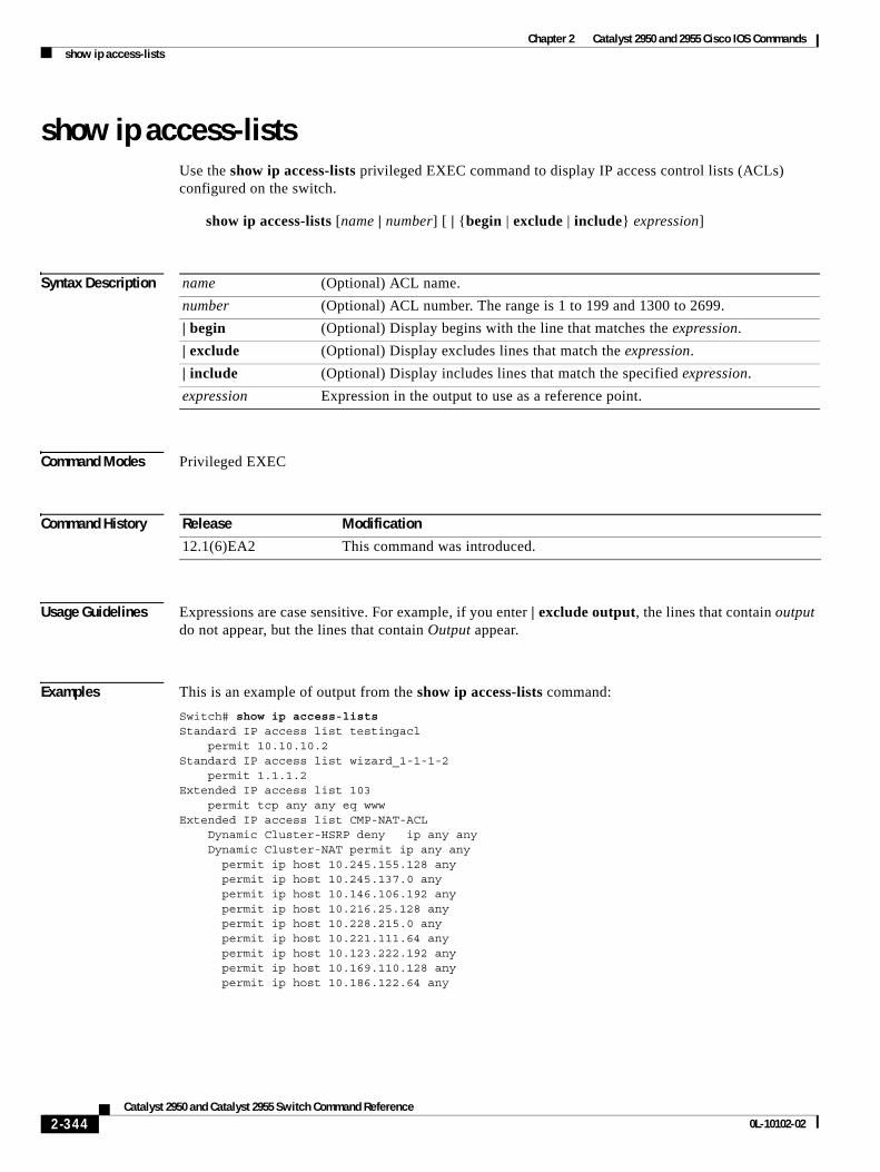
Chapter 2 Catalyst 2950 and 2955 Cisco IOS Commandsshow ip access-lists
show ip access-listsUse the show ip access-lists privileged EXEC command to display IP access control lists (ACLs) configured on the switch.
show ip access-lists [name | number] [ | {begin | exclude | include} expression]
Syntax Description
Command Modes Privileged EXEC
Command History
Usage Guidelines Expressions are case sensitive. For example, if you enter | exclude output, the lines that contain output do not appear, but the lines that contain Output appear.
Examples This is an example of output from the show ip access-lists command:
Switch# show ip access-listsStandard IP access list testingacl permit 10.10.10.2Standard IP access list wizard_1-1-1-2 permit 1.1.1.2Extended IP access list 103 permit tcp any any eq wwwExtended IP access list CMP-NAT-ACL Dynamic Cluster-HSRP deny ip any any Dynamic Cluster-NAT permit ip any any permit ip host 10.245.155.128 any permit ip host 10.245.137.0 any permit ip host 10.146.106.192 any permit ip host 10.216.25.128 any permit ip host 10.228.215.0 any permit ip host 10.221.111.64 any permit ip host 10.123.222.192 any permit ip host 10.169.110.128 any permit ip host 10.186.122.64 any
name (Optional) ACL name.
number (Optional) ACL number. The range is 1 to 199 and 1300 to 2699.
| begin (Optional) Display begins with the line that matches the expression.
| exclude (Optional) Display excludes lines that match the expression.
| include (Optional) Display includes lines that match the specified expression.
expression Expression in the output to use as a reference point.
Release Modification
12.1(6)EA2 This command was introduced.
2-344Catalyst 2950 and Catalyst 2955 Switch Command Reference
0L-10102-02
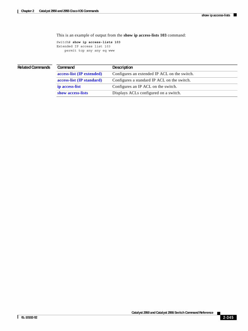
Chapter 2 Catalyst 2950 and 2955 Cisco IOS Commandsshow ip access-lists
This is an example of output from the show ip access-lists 103 command:
Switch# show ip access-lists 103Extended IP access list 103 permit tcp any any eq www
Related Commands Command Description
access-list (IP extended) Configures an extended IP ACL on the switch.
access-list (IP standard) Configures a standard IP ACL on the switch.
ip access-list Configures an IP ACL on the switch.
show access-lists Displays ACLs configured on a switch.
2-345Catalyst 2950 and Catalyst 2955 Switch Command Reference
0L-10102-02
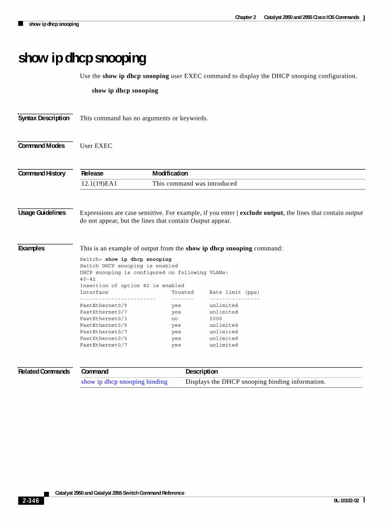
Chapter 2 Catalyst 2950 and 2955 Cisco IOS Commandsshow ip dhcp snooping
show ip dhcp snoopingUse the show ip dhcp snooping user EXEC command to display the DHCP snooping configuration.
show ip dhcp snooping
Syntax Description This command has no arguments or keywords.
Command Modes User EXEC
Command History
Usage Guidelines Expressions are case sensitive. For example, if you enter | exclude output, the lines that contain output do not appear, but the lines that contain Output appear.
Examples This is an example of output from the show ip dhcp snooping command:
Switch> show ip dhcp snoopingSwitch DHCP snooping is enabledDHCP snooping is configured on following VLANs:40-42Insertion of option 82 is enabledInterface Trusted Rate limit (pps)------------------------ ------- ----------------FastEthernet0/5 yes unlimitedFastEthernet0/7 yes unlimitedFastEthernet0/3 no 5000 FastEthernet0/5 yes unlimitedFastEthernet0/7 yes unlimitedFastEthernet0/5 yes unlimitedFastEthernet0/7 yes unlimited
Related Commands
Release Modification
12.1(19)EA1 This command was introduced
Command Description
show ip dhcp snooping binding Displays the DHCP snooping binding information.
2-346Catalyst 2950 and Catalyst 2955 Switch Command Reference
0L-10102-02
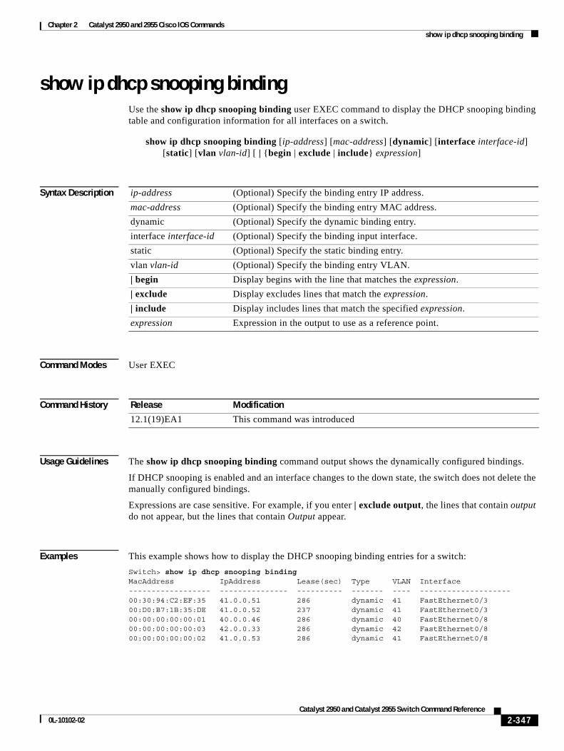
Chapter 2 Catalyst 2950 and 2955 Cisco IOS Commandsshow ip dhcp snooping binding
show ip dhcp snooping bindingUse the show ip dhcp snooping binding user EXEC command to display the DHCP snooping binding table and configuration information for all interfaces on a switch.
show ip dhcp snooping binding [ip-address] [mac-address] [dynamic] [interface interface-id] [static] [vlan vlan-id] [ | {begin | exclude | include} expression]
Syntax Description
Command Modes User EXEC
Command History
Usage Guidelines The show ip dhcp snooping binding command output shows the dynamically configured bindings.
If DHCP snooping is enabled and an interface changes to the down state, the switch does not delete the manually configured bindings.
Expressions are case sensitive. For example, if you enter | exclude output, the lines that contain output do not appear, but the lines that contain Output appear.
Examples This example shows how to display the DHCP snooping binding entries for a switch:
Switch> show ip dhcp snooping bindingMacAddress IpAddress Lease(sec) Type VLAN Interface------------------ --------------- ---------- ------- ---- --------------------00:30:94:C2:EF:35 41.0.0.51 286 dynamic 41 FastEthernet0/300:D0:B7:1B:35:DE 41.0.0.52 237 dynamic 41 FastEthernet0/300:00:00:00:00:01 40.0.0.46 286 dynamic 40 FastEthernet0/800:00:00:00:00:03 42.0.0.33 286 dynamic 42 FastEthernet0/800:00:00:00:00:02 41.0.0.53 286 dynamic 41 FastEthernet0/8
ip-address (Optional) Specify the binding entry IP address.
mac-address (Optional) Specify the binding entry MAC address.
dynamic (Optional) Specify the dynamic binding entry.
interface interface-id (Optional) Specify the binding input interface.
static (Optional) Specify the static binding entry.
vlan vlan-id (Optional) Specify the binding entry VLAN.
| begin Display begins with the line that matches the expression.
| exclude Display excludes lines that match the expression.
| include Display includes lines that match the specified expression.
expression Expression in the output to use as a reference point.
Release Modification
12.1(19)EA1 This command was introduced
2-347Catalyst 2950 and Catalyst 2955 Switch Command Reference
0L-10102-02
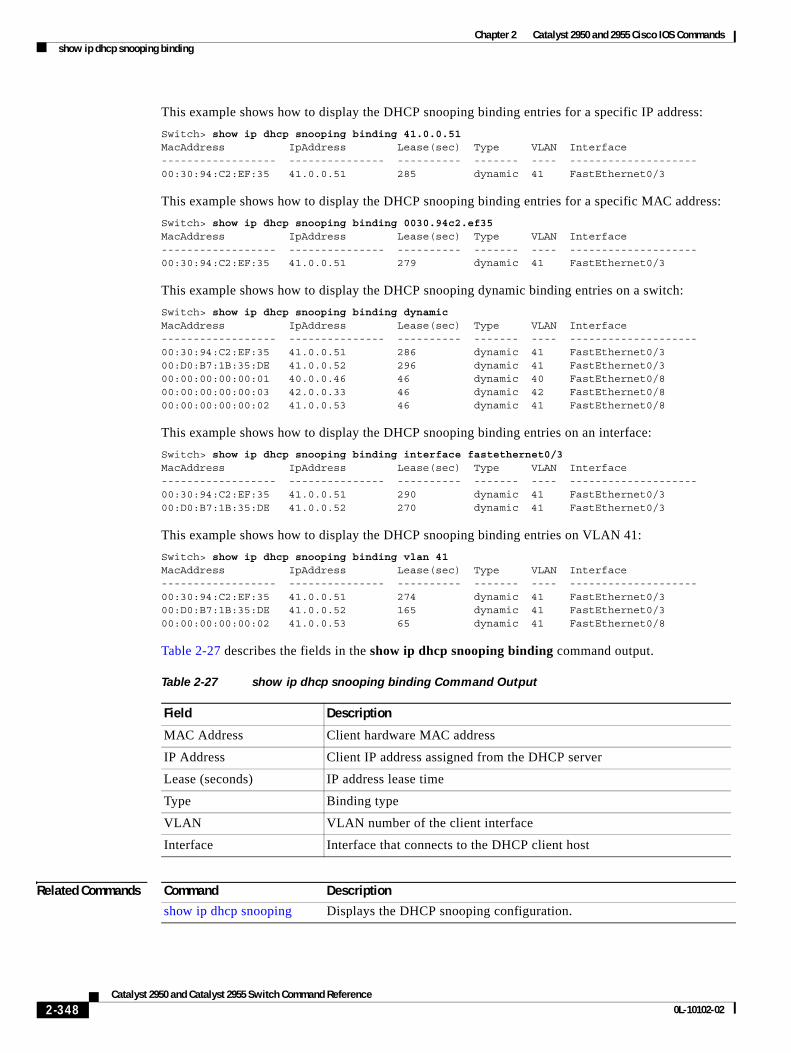
Chapter 2 Catalyst 2950 and 2955 Cisco IOS Commandsshow ip dhcp snooping binding
This example shows how to display the DHCP snooping binding entries for a specific IP address:
Switch> show ip dhcp snooping binding 41.0.0.51MacAddress IpAddress Lease(sec) Type VLAN Interface------------------ --------------- ---------- ------- ---- --------------------00:30:94:C2:EF:35 41.0.0.51 285 dynamic 41 FastEthernet0/3
This example shows how to display the DHCP snooping binding entries for a specific MAC address:
Switch> show ip dhcp snooping binding 0030.94c2.ef35MacAddress IpAddress Lease(sec) Type VLAN Interface------------------ --------------- ---------- ------- ---- --------------------00:30:94:C2:EF:35 41.0.0.51 279 dynamic 41 FastEthernet0/3
This example shows how to display the DHCP snooping dynamic binding entries on a switch:
Switch> show ip dhcp snooping binding dynamicMacAddress IpAddress Lease(sec) Type VLAN Interface------------------ --------------- ---------- ------- ---- --------------------00:30:94:C2:EF:35 41.0.0.51 286 dynamic 41 FastEthernet0/300:D0:B7:1B:35:DE 41.0.0.52 296 dynamic 41 FastEthernet0/300:00:00:00:00:01 40.0.0.46 46 dynamic 40 FastEthernet0/800:00:00:00:00:03 42.0.0.33 46 dynamic 42 FastEthernet0/800:00:00:00:00:02 41.0.0.53 46 dynamic 41 FastEthernet0/8
This example shows how to display the DHCP snooping binding entries on an interface:
Switch> show ip dhcp snooping binding interface fastethernet0/3MacAddress IpAddress Lease(sec) Type VLAN Interface------------------ --------------- ---------- ------- ---- --------------------00:30:94:C2:EF:35 41.0.0.51 290 dynamic 41 FastEthernet0/300:D0:B7:1B:35:DE 41.0.0.52 270 dynamic 41 FastEthernet0/3
This example shows how to display the DHCP snooping binding entries on VLAN 41:
Switch> show ip dhcp snooping binding vlan 41MacAddress IpAddress Lease(sec) Type VLAN Interface------------------ --------------- ---------- ------- ---- --------------------00:30:94:C2:EF:35 41.0.0.51 274 dynamic 41 FastEthernet0/300:D0:B7:1B:35:DE 41.0.0.52 165 dynamic 41 FastEthernet0/300:00:00:00:00:02 41.0.0.53 65 dynamic 41 FastEthernet0/8
Table 2-27 describes the fields in the show ip dhcp snooping binding command output.
Related Commands
Table 2-27 show ip dhcp snooping binding Command Output
Field Description
MAC Address Client hardware MAC address
IP Address Client IP address assigned from the DHCP server
Lease (seconds) IP address lease time
Type Binding type
VLAN VLAN number of the client interface
Interface Interface that connects to the DHCP client host
Command Description
show ip dhcp snooping Displays the DHCP snooping configuration.
2-348Catalyst 2950 and Catalyst 2955 Switch Command Reference
0L-10102-02
Chapter 2 Catalyst 2950 and 2955 Cisco IOS Commandsshow ip igmp profile
show ip igmp profileUse the show ip igmp profile privileged EXEC command to view all configured Internet Group Management Protocol (IGMP) profiles or a specified IGMP profile.
show ip igmp profile [profile number] [ | {begin | exclude | include} expression]
Syntax Description
Command Modes Privileged EXEC
Command History
Usage Guidelines Expressions are case sensitive. For example, if you enter | exclude output, the lines that contain output do not appear, but the lines that contain Output appear.
Examples These are examples of output from the show ip igmp profile privileged EXEC command, with and without specifying a profile number. If no profile number is entered, the display includes all profiles configured on the switch.
Switch# show ip igmp profile 40IGMP Profile 40 permit range 233.1.1.1 233.255.255.255
Switch# show ip igmp profileIGMP Profile 3 range 230.9.9.0 230.9.9.0IGMP Profile 4 permit range 229.9.9.0 229.255.255.255
Related Commands
profile number (Optional) The IGMP profile number to be displayed. The range is 1 to 4294967295. If no profile number is entered, all IGMP profiles appear.
| begin (Optional) Display begins with the line that matches the expression.
| exclude (Optional) Display excludes lines that match the expression.
| include (Optional) Display includes lines that match the specified expression.
expression Expression in the output to use as a reference point.
Release Modification
12.1(9)EA1 This command was introduced.
Command Description
ip igmp profile Configures the specified IGMP profile number.
2-349Catalyst 2950 and Catalyst 2955 Switch Command Reference
0L-10102-02
Chapter 2 Catalyst 2950 and 2955 Cisco IOS Commandsshow ip igmp snooping
show ip igmp snoopingUse the show ip igmp snooping user EXEC command to display the Internet Group Management Protocol (IGMP) snooping configuration of the switch or the VLAN. Use the mrouter keyword to display the dynamically learned and manually configured multicast router ports.
show ip igmp snooping [group | mrouter | querier] [vlan vlan-id] [ | {begin | exclude | include} expression]
Syntax Description
Command Modes User EXEC
Command History
Usage Guidelines Use this command to display snooping characteristics for the switch or for a specific VLAN.
You can also use the show mac address-table multicast privileged EXEC command to display entries in the MAC address table for a VLAN that has IGMP snooping enabled.
When multicast VLAN registration (MVR) is enabled, use the show ip igmp snooping mrouter command to display the IGMP snooping dynamically learned and manually configured multicast router ports.
Use the group keyword to display the multicast groups, the compatibility mode, and the ports that are associated with each group.
Use the show ip igmp snooping querier command to display the IGMP version and IP address of a detected device that sends IGMP query messages, also called a querier. A subnet can have multiple multicast routers but has only one IGMP querier. In a subnet running IGMPv2, one of the multicast routers is elected as the querier. The querier can be a Layer 3 switch. The command output also shows the VLAN and interface on which the querier was detected. If the querier is a multicast router, the output shows the Port field as Router.
group (Optional) Display information about the IGMP multicast groups, the compatibility mode, and the ports that are associated with each group.
mrouter (Optional) Display the IGMP snooping dynamically learned and manually configured multicast router ports.
querier (Optional) Display information about the IGMP version that an interface supports.
vlan vlan-id (Optional) Keyword and variable to specify a VLAN. The range is 1 to 4094. This keyword is available only in privileged EXEC mode.
| begin (Optional) Display begins with the line that matches the specified expression.
| exclude (Optional) Display excludes lines that match the specified expression.
| include (Optional) Display includes lines that match the specified expression.
expression Expression in the output to use as a reference point.
Release Modification
12.0(5.2)WC(1) This command was introduced.
12.1(19)EA1 The group and querier keywords were added.
2-350Catalyst 2950 and Catalyst 2955 Switch Command Reference
0L-10102-02
Chapter 2 Catalyst 2950 and 2955 Cisco IOS Commandsshow ip igmp snooping
Expressions are case sensitive. For example, if you enter | exclude output, the lines that contain output do not appear, but the lines that contain Output appear.
Examples This is an example of output from the show ip igmp snooping command:
Switch> show ip igmp snooping Global IGMP Snooping configuration:-----------------------------------IGMP snooping : EnabledIGMPv3 snooping (minimal) : EnabledReport suppression : EnabledTCN solicit query : DisabledTCN flood query count : 2Last member query interval : 100
Vlan 1:--------IGMP snooping :EnabledImmediate leave :DisabledMulticast router learning mode :pim-dvmrpSource only learning age timer :10CGMP interoperability mode :IGMP_ONLYLast member query interval :100
Vlan 2:--------IGMP snooping :EnabledImmediate leave :DisabledMulticast router learning mode :pim-dvmrpSource only learning age timer :10CGMP interoperability mode :IGMP_ONLYLast member query interval :100<output truncated>
This is an example of output from the show ip igmp snooping vlan 1 command:
Switch# show ip igmp snooping vlan 1Global IGMP Snooping configuration:-----------------------------------IGMP snooping : EnabledIGMPv3 snooping (minimal) : EnabledReport suppression : EnabledTCN solicit query : DisabledTCN flood query count : 2Last member query interval : 100
Vlan 1:--------IGMP snooping :EnabledImmediate leave :DisabledMulticast router learning mode :pim-dvmrpSource only learning age timer :10CGMP interoperability mode :IGMP_ONLYLast member query interval : 100
This is an example of output from the show ip igmp snooping mrouter vlan 1 command:
Note In this example, Fa0/3 is a dynamically learned router port, and Fa0/2 is a configured static router port.
2-351Catalyst 2950 and Catalyst 2955 Switch Command Reference
0L-10102-02
Chapter 2 Catalyst 2950 and 2955 Cisco IOS Commandsshow ip igmp snooping
Switch# show ip igmp snooping mrouter vlan 1Vlan ports---- ----- 1 Fa0/2(static), Fa0/3(dynamic)
This is an example of output from the show ip igmp snooping group vlan 1 command:
Switch# show ip igmp snooping group vlan 1Vlan Group Version Port List---------------------------------------------------------1 229.2.3.4 v3 fa0/1 fa0/31 224.1.1.1 v2 fa0/8
This is an example of output from the show ip igmp snooping querier command:
Switch> show ip igmp snooping querierVlan IP Address IGMP Version Port---------------------------------------------------1 172.20.50.11 v3 fa0/12 172.20.40.20 v2 Router
Related Commands Command Description
ip igmp snooping Enables IGMP snooping.
ip igmp snooping report-suppression
Enables IGMP report suppression.
ip igmp snooping source-only-learning
Enables IP multicast-source-only learning on the switch.
ip igmp snooping source-only-learning age-timer
Enables and configures the aging time of the forwarding-table entries that the switch learns by using the source-only learning method.
ip igmp snooping vlan vlan-id Enables IGMP snooping on the VLAN interface.
ip igmp snooping vlan immediate-leave
Configures IGMP Immediate-Leave processing.
ip igmp snooping vlan mrouter Configures a Layer 2 port as a multicast router port.
show mac address-table multicast Displays the Layer 2 multicast entries for a VLAN.
2-352Catalyst 2950 and Catalyst 2955 Switch Command Reference
0L-10102-02
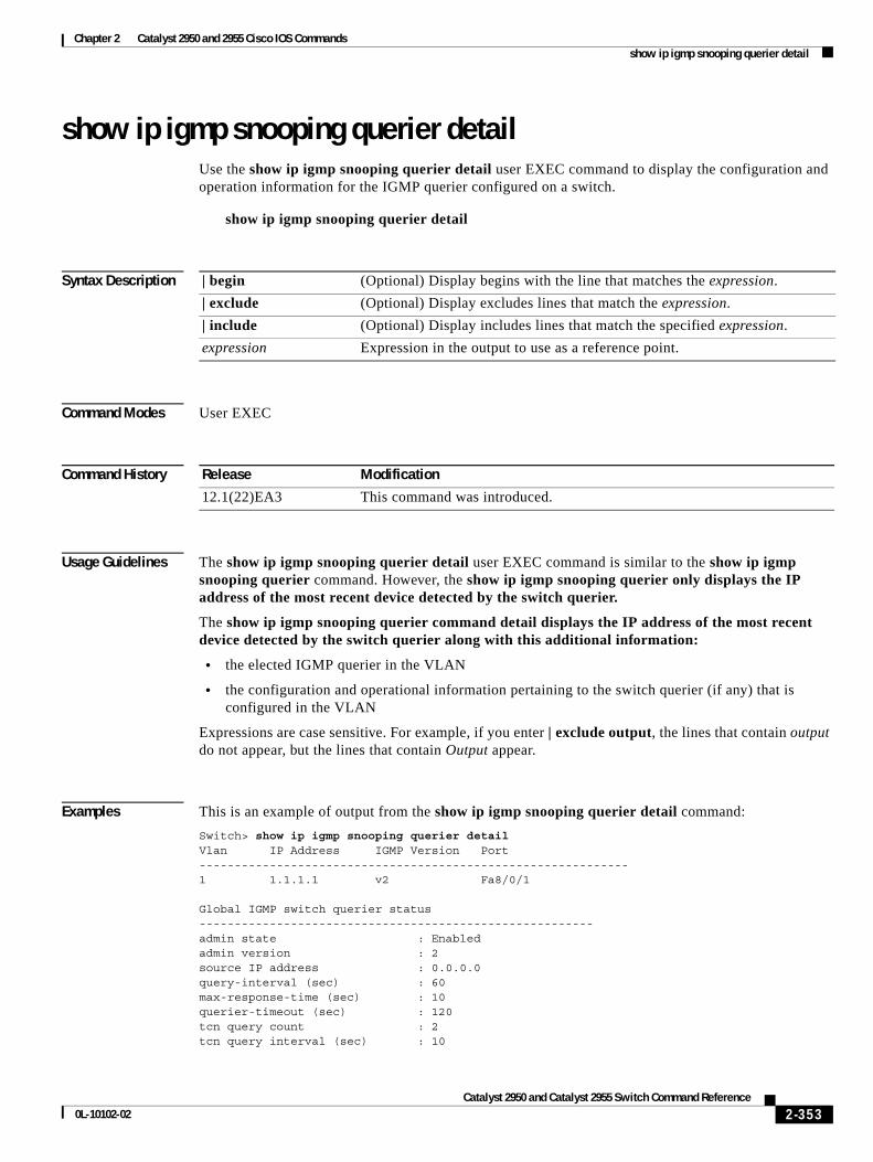
Chapter 2 Catalyst 2950 and 2955 Cisco IOS Commandsshow ip igmp snooping querier detail
show ip igmp snooping querier detailUse the show ip igmp snooping querier detail user EXEC command to display the configuration and operation information for the IGMP querier configured on a switch.
show ip igmp snooping querier detail
Syntax Description
Command Modes User EXEC
Command History
Usage Guidelines The show ip igmp snooping querier detail user EXEC command is similar to the show ip igmp snooping querier command. However, the show ip igmp snooping querier only displays the IP address of the most recent device detected by the switch querier.
The show ip igmp snooping querier command detail displays the IP address of the most recent device detected by the switch querier along with this additional information:
• the elected IGMP querier in the VLAN
• the configuration and operational information pertaining to the switch querier (if any) that is configured in the VLAN
Expressions are case sensitive. For example, if you enter | exclude output, the lines that contain output do not appear, but the lines that contain Output appear.
Examples This is an example of output from the show ip igmp snooping querier detail command:
Switch> show ip igmp snooping querier detailVlan IP Address IGMP Version Port-------------------------------------------------------------1 1.1.1.1 v2 Fa8/0/1
Global IGMP switch querier status--------------------------------------------------------admin state : Enabledadmin version : 2source IP address : 0.0.0.0 query-interval (sec) : 60max-response-time (sec) : 10querier-timeout (sec) : 120tcn query count : 2tcn query interval (sec) : 10
| begin (Optional) Display begins with the line that matches the expression.
| exclude (Optional) Display excludes lines that match the expression.
| include (Optional) Display includes lines that match the specified expression.
expression Expression in the output to use as a reference point.
Release Modification
12.1(22)EA3 This command was introduced.
2-353Catalyst 2950 and Catalyst 2955 Switch Command Reference
0L-10102-02
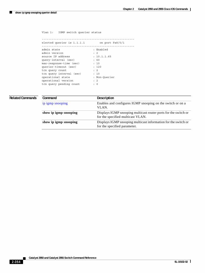
Chapter 2 Catalyst 2950 and 2955 Cisco IOS Commandsshow ip igmp snooping querier detail
Vlan 1: IGMP switch querier status
--------------------------------------------------------elected querier is 1.1.1.1 on port Fa8/0/1--------------------------------------------------------admin state : Enabledadmin version : 2source IP address : 10.1.1.65 query-interval (sec) : 60max-response-time (sec) : 10querier-timeout (sec) : 120tcn query count : 2tcn query interval (sec) : 10operational state : Non-Querieroperational version : 2tcn query pending count : 0
Related Commands Command Description
ip igmp snooping Enables and configures IGMP snooping on the switch or on a VLAN.
show ip igmp snooping Displays IGMP snooping multicast router ports for the switch or for the specified multicast VLAN.
show ip igmp snooping Displays IGMP snooping multicast information for the switch or for the specified parameter.
2-354Catalyst 2950 and Catalyst 2955 Switch Command Reference
0L-10102-02
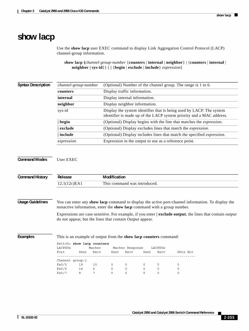
Chapter 2 Catalyst 2950 and 2955 Cisco IOS Commandsshow lacp
show lacpUse the show lacp user EXEC command to display Link Aggregation Control Protocol (LACP) channel-group information.
show lacp {channel-group-number {counters | internal | neighbor} | {counters | internal | neighbor | sys-id}} [ | {begin | exclude | include} expression]
Syntax Description
Command Modes User EXEC
Command History
Usage Guidelines You can enter any show lacp command to display the active port-channel information. To display the nonactive information, enter the show lacp command with a group number.
Expressions are case sensitive. For example, if you enter | exclude output, the lines that contain output do not appear, but the lines that contain Output appear.
Examples This is an example of output from the show lacp counters command:
Switch> show lacp countersLACPDUs Marker Marker Response LACPDUsPort Sent Recv Sent Recv Sent Recv Pkts Err---------------------------------------------------------------------Channel group:1Fa0/5 19 10 0 0 0 0 0 Fa0/6 14 6 0 0 0 0 0 Fa0/7 8 7 0 0 0 0 0
channel-group-number (Optional) Number of the channel group. The range is 1 to 6.
counters Display traffic information.
internal Display internal information.
neighbor Display neighbor information.
sys-id Display the system identifier that is being used by LACP. The system identifier is made up of the LACP system priority and a MAC address.
| begin (Optional) Display begins with the line that matches the expression.
| exclude (Optional) Display excludes lines that match the expression.
| include (Optional) Display includes lines that match the specified expression.
expression Expression in the output to use as a reference point.
Release Modification
12.1(12c)EA1 This command was introduced.
2-355Catalyst 2950 and Catalyst 2955 Switch Command Reference
0L-10102-02
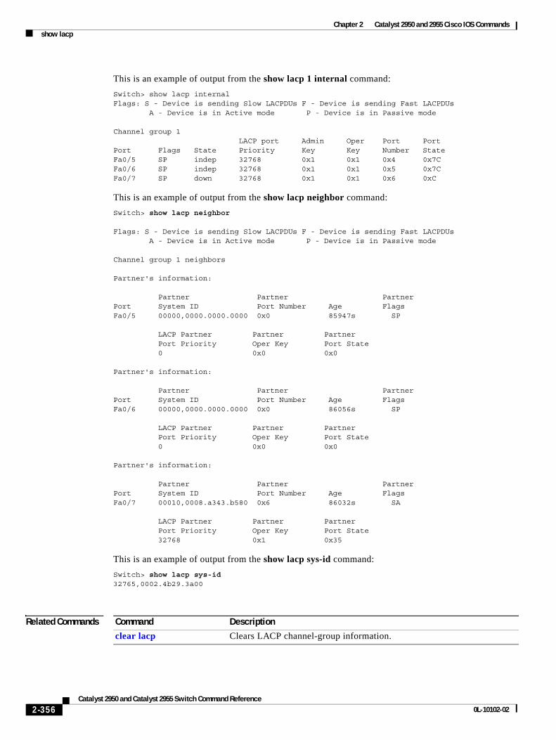
Chapter 2 Catalyst 2950 and 2955 Cisco IOS Commandsshow lacp
This is an example of output from the show lacp 1 internal command:
Switch> show lacp internal Flags: S - Device is sending Slow LACPDUs F - Device is sending Fast LACPDUs A - Device is in Active mode P - Device is in Passive mode Channel group 1 LACP port Admin Oper Port PortPort Flags State Priority Key Key Number StateFa0/5 SP indep 32768 0x1 0x1 0x4 0x7C Fa0/6 SP indep 32768 0x1 0x1 0x5 0x7C Fa0/7 SP down 32768 0x1 0x1 0x6 0xC
This is an example of output from the show lacp neighbor command:
Switch> show lacp neighbor
Flags: S - Device is sending Slow LACPDUs F - Device is sending Fast LACPDUs A - Device is in Active mode P - Device is in Passive mode Channel group 1 neighbors Partner's information: Partner Partner PartnerPort System ID Port Number Age FlagsFa0/5 00000,0000.0000.0000 0x0 85947s SP LACP Partner Partner Partner Port Priority Oper Key Port State 0 0x0 0x0
Partner's information: Partner Partner PartnerPort System ID Port Number Age FlagsFa0/6 00000,0000.0000.0000 0x0 86056s SP LACP Partner Partner Partner Port Priority Oper Key Port State 0 0x0 0x0 Partner's information: Partner Partner PartnerPort System ID Port Number Age FlagsFa0/7 00010,0008.a343.b580 0x6 86032s SA LACP Partner Partner Partner Port Priority Oper Key Port State 32768 0x1 0x35
This is an example of output from the show lacp sys-id command:
Switch> show lacp sys-id 32765,0002.4b29.3a00
Related Commands Command Description
clear lacp Clears LACP channel-group information.
2-356Catalyst 2950 and Catalyst 2955 Switch Command Reference
0L-10102-02
Chapter 2 Catalyst 2950 and 2955 Cisco IOS Commandsshow lre upgrade
show lre upgrade Use the show lre upgrade binaries privileged EXEC command to display the upgrade information for the Long-Reach Ethernet (LRE) switch.
show lre upgrade {binaries | status | version} [ | {begin | exclude | include} expression]
This command is available only on Catalyst 2950 LRE switches.
Syntax Description
Command Modes Privileged EXEC
Command History
Usage Guidelines Use the show lre upgrade binaries command to display the LRE binary information for each interface. The command output shows the path to the LRE binaries, which are always in the same directory as the Cisco IOS image. LRE binary file names consist of:
• The device family. A device family could be an LRE switch or a customer premises equipment (CPE) device.
• The function of the firmware, such as an upgrade for an application, the bootloader, or for the LRE chipset.
• The firmware version.
Files marked with an exclamation point (!) are version description files. A version description file is only for informational purposes and is not a candidate for upgrade. Version description files are used to determine whether or not a CPE device on an LRE link is running a supported LRE binary version.
Use the show lre upgrade status command during LRE upgrades to display both the local and remote upgrade status levels in progress on an LRE link. Status levels are:
• None—An upgrade is not in progress.
• Pending—An upgrade is initialized, but transfer has not begun.
• Active—Data transfer is in progress.
• Cmplt—An upgrade is complete.
binaries Display the LRE binaries present on the system flash memory.
status Display the upgrade status on all ports in the switch.
version Display the version of binaries on local and remote ends of an LRE link.
| begin (Optional) Display begins with the line that matches the specified expression.
| exclude (Optional) Display excludes lines that match the specified expression.
| include (Optional) Display includes lines that match the specified expression.
expression Expression in the output to use as a reference point.
Release Modification
12.1(11)YJ This command was introduced.
2-357Catalyst 2950 and Catalyst 2955 Switch Command Reference
0L-10102-02
Chapter 2 Catalyst 2950 and 2955 Cisco IOS Commandsshow lre upgrade
When an upgrade is running on an LRE switch controller, the status for the controller does not change from active to cmplt until all hardware elements finish upgrading.
Other information displayed includes the local current (lcl curr) and proposed configuration (cfg) for each LRE interface. File names consist of:
• The device family. A device family could be an LRE switch or a CPE device.
• The function of the firmware, such as an upgrade for an application, for the bootloader, or for the LRE or CPE chipsets.
• The firmware version.
During data transfer but before the upgrade completes, the status also shows the time in hours and minutes that the upgrade has been in progress and the number of attempts that were made.
The show lre upgrade version command displays the LRE binary version for each interface. It shows local current (lcl curr) and proposed configuration (cfg) for each LRE interface. File names consist of:
• The device family.
• The function of the firmware, such as an upgrade for an application, for the bootloader, or for the LRE chipsets of a CPE device.
• The firmware version.
Examples This example shows output from the show lre upgrade binaries command:
Switch# show lre upgrade binariesPath containing LRE binaries is flash:/c2950lre-i6l2q4-mz.121-0.18.YJ/lre-bin;
zflash:/c2950lre-i6l2q4-mz.121-0.18.YJ/lre-bin
LRE Binary: CISCO585-LRE_vdslsngl_51.00.00, Flash file name: CISCO585-LRE_vdslsngl_51.00.00.bin
LRE Binary: CISCO585-LRE_MC8051boot_01.03.00,Flash file name: CISCO585-LRE_MC8051boot_01.03.00.bin!
LRE Binary: CISCO585-LRE_MC8051boot_01.02.00,Flash file name: CISCO585-LRE_MC8051boot_01.02.00.bin!
LRE Binary: CISCO585-LRE_MC8051appl_01.03.00,Flash file name: CISCO585-LRE_MC8051appl_01.03.00.bin!
LRE Binary: CISCO585-LRE_MC8051appl_01.02.00,Flash file name: CISCO585-LRE_MC8051appl_01.02.00.bin!
LRE Binary: CISCO575-LRE_vdslsngl_50.00.00,Flash file name: CISCO575-LRE_vdslsngl_50.00.00.bin
LRE Binary: CISCO2950-LRE_vdsloctl_02.60.00,Flash file name: CISCO2950-LRE_vdsloctl_02.60.00.bin
LRE Binary: CISCO2950-LRE_vdsloctl_02.51.00,Flash file name: CISCO2950-LRE_vdsloctl_02.51.00.bin
LRE Binary: CISCO2950-LRE_vdsloctl_02.50.00, Flash file name: CISCO2950-LRE_vdsloctl_02.50.00.bin
2-358Catalyst 2950 and Catalyst 2955 Switch Command Reference
0L-10102-02
Chapter 2 Catalyst 2950 and 2955 Cisco IOS Commandsshow lre upgrade
This example shows the status of an upgrade after it starts, but before the data transfer begins:
Switch# show lre upgrade statusLo0/1: lcl curr:CISCO2950-LRE_vdsloctl_02.60.00 new:CISCO2950-LRE_vdsloctl_02.60.00 Status:Pending rmt curr:CISCO575-LRE_vdslsngl_52.00.00 new:CISCO575-LRE_vdslsngl_52.00.00 Status:PendingLo0/2: lcl curr:CISCO2950-LRE_vdsloctl_02.60.00 new:CISCO2950-LRE_vdsloctl_02.60.00 Status:Pending rmt curr:CISCO575-LRE_vdslsngl_52.00.00 new:CISCO575-LRE_vdslsngl_52.00.00 Status:PendingLo0/3: lcl curr:CISCO2950-LRE_vdsloctl_02.60.00 new:CISCO2950-LRE_vdsloctl_02.60.00 Status:Pending rmt curr:CISCO575-LRE_vdslsngl_52.00.00 new:CISCO575-LRE_vdslsngl_52.00.00 Status:PendingLo0/4: lcl curr:CISCO2950-LRE_vdsloctl_02.60.00 new:CISCO2950-LRE_vdsloctl_02.60.00 Status:Pending rmt curr:CISCO575-LRE_vdslsngl_52.00.00 new:CISCO575-LRE_vdslsngl_52.00.00 Status:Pending
<output truncated>
This example shows the status of an upgrade after data transfer is in progress:
Switch# show lre upgrade statusLo0/1: lcl curr:CISCO2950-LRE_vdsloctl_02.60.00 new:CISCO2950-LRE_vdsloctl_02.60.00 Status:Pending rmt curr:CISCO575-LRE_vdslsngl_52.00.00 new:CISCO575-LRE_vdslsngl_52.00.00 Status:Active 10 HHMM:0000, Attempt:001Lo0/2: lcl curr:CISCO2950-LRE_vdsloctl_02.60.00 new:CISCO2950-LRE_vdsloctl_02.60.00 Status:Pending rmt curr:CISCO575-LRE_vdslsngl_52.00.00 new:CISCO575-LRE_vdslsngl_52.00.00 Status:Active 09 HHMM:0000, Attempt:001Lo0/3: lcl curr:CISCO2950-LRE_vdsloctl_02.60.00 new:CISCO2950-LRE_vdsloctl_02.60.00 Status:Pending rmt curr:CISCO575-LRE_vdslsngl_52.00.00 new:CISCO575-LRE_vdslsngl_52.00.00 Status:Active 22 HHMM:0000, Attempt:001Lo0/4: lcl curr:CISCO2950-LRE_vdsloctl_02.60.00 new:CISCO2950-LRE_vdsloctl_02.60.00
<output truncated>
2-359Catalyst 2950 and Catalyst 2955 Switch Command Reference
0L-10102-02
Chapter 2 Catalyst 2950 and 2955 Cisco IOS Commandsshow lre upgrade
This example shows output from the show lre upgrade version command:
Switch# show lre upgrade version
Lo0/1: CPE:Family CISCO575-LRE, Model Cisco575-LRE , Rev A0 lcl curr:CISCO2950-LRE_vdsloctl_02.60.00 cfg:CISCO2950-LRE_vdsloctl_02.60.00 rmt curr:CISCO575-LRE_vdslsngl_52.00.00 cfg:CISCO575-LRE_vdslsngl_52.00.00Lo0/2: CPE:Family CISCO575-LRE, Model Cisco575-LRE , Rev A0 lcl curr:CISCO2950-LRE_vdsloctl_02.60.00 cfg:CISCO2950-LRE_vdsloctl_02.60.00 rmt curr:CISCO575-LRE_vdslsngl_52.00.00 cfg:CISCO575-LRE_vdslsngl_52.00.00Lo0/3: CPE:Family CISCO575-LRE, Model Cisco575-LRE , Rev A0 lcl curr:CISCO2950-LRE_vdsloctl_02.60.00 cfg:CISCO2950-LRE_vdsloctl_02.60.00 rmt curr:CISCO575-LRE_vdslsngl_52.00.00 cfg:CISCO575-LRE_vdslsngl_52.00.00Lo0/4: CPE:Family CISCO575-LRE, Model Cisco575-LRE , Rev A0 lcl curr:CISCO2950-LRE_vdsloctl_02.60.00 cfg:CISCO2950-LRE_vdsloctl_02.60.00 rmt curr:CISCO575-LRE_vdslsngl_52.00.00 cfg:CISCO575-LRE_vdslsngl_52.00.00Lo0/5: CPE:Family CISCO575-LRE, Model Cisco575-LRE , Rev A0 lcl curr:CISCO2950-LRE_vdsloctl_02.60.00 cfg:CISCO2950-LRE_vdsloctl_02.60.00 rmt curr:CISCO575-LRE_vdslsngl_52.00.00 cfg:CISCO575-LRE_vdslsngl_52.00.00
<output truncated>
Related Commands Command Description
show lre upgrade Displays the upgrade status on all ports in the switch or the versions of binaries on local and remote ends on all ports.
2-360Catalyst 2950 and Catalyst 2955 Switch Command Reference
0L-10102-02
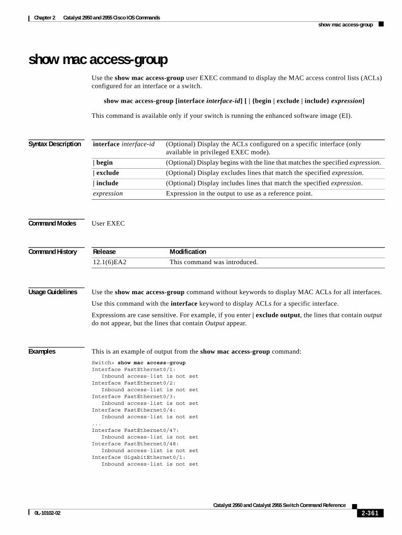
Chapter 2 Catalyst 2950 and 2955 Cisco IOS Commandsshow mac access-group
show mac access-groupUse the show mac access-group user EXEC command to display the MAC access control lists (ACLs) configured for an interface or a switch.
show mac access-group [interface interface-id] [ | {begin | exclude | include} expression]
This command is available only if your switch is running the enhanced software image (EI).
Syntax Description
Command Modes User EXEC
Command History
Usage Guidelines Use the show mac access-group command without keywords to display MAC ACLs for all interfaces.
Use this command with the interface keyword to display ACLs for a specific interface.
Expressions are case sensitive. For example, if you enter | exclude output, the lines that contain output do not appear, but the lines that contain Output appear.
Examples This is an example of output from the show mac access-group command:
Switch> show mac access-groupInterface FastEthernet0/1: Inbound access-list is not setInterface FastEthernet0/2: Inbound access-list is not setInterface FastEthernet0/3: Inbound access-list is not setInterface FastEthernet0/4: Inbound access-list is not set...Interface FastEthernet0/47: Inbound access-list is not setInterface FastEthernet0/48: Inbound access-list is not setInterface GigabitEthernet0/1: Inbound access-list is not set
interface interface-id (Optional) Display the ACLs configured on a specific interface (only available in privileged EXEC mode).
| begin (Optional) Display begins with the line that matches the specified expression.
| exclude (Optional) Display excludes lines that match the specified expression.
| include (Optional) Display includes lines that match the specified expression.
expression Expression in the output to use as a reference point.
Release Modification
12.1(6)EA2 This command was introduced.
2-361Catalyst 2950 and Catalyst 2955 Switch Command Reference
0L-10102-02
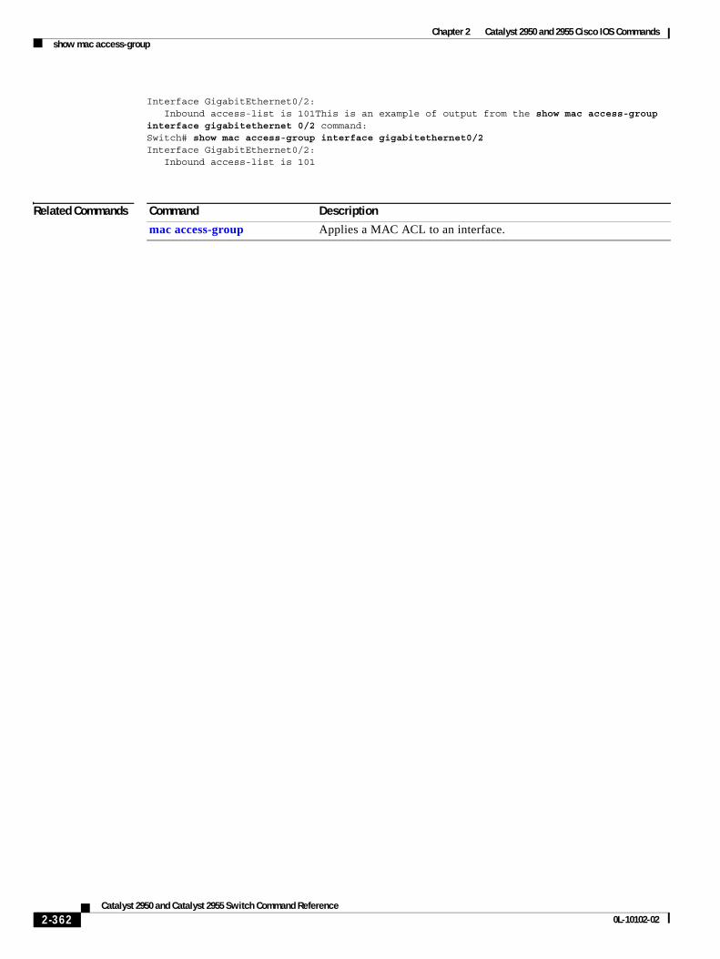
Chapter 2 Catalyst 2950 and 2955 Cisco IOS Commandsshow mac access-group
Interface GigabitEthernet0/2: Inbound access-list is 101This is an example of output from the show mac access-group interface gigabitethernet 0/2 command:Switch# show mac access-group interface gigabitethernet0/2Interface GigabitEthernet0/2: Inbound access-list is 101
Related Commands Command Description
mac access-group Applies a MAC ACL to an interface.
2-362Catalyst 2950 and Catalyst 2955 Switch Command Reference
0L-10102-02
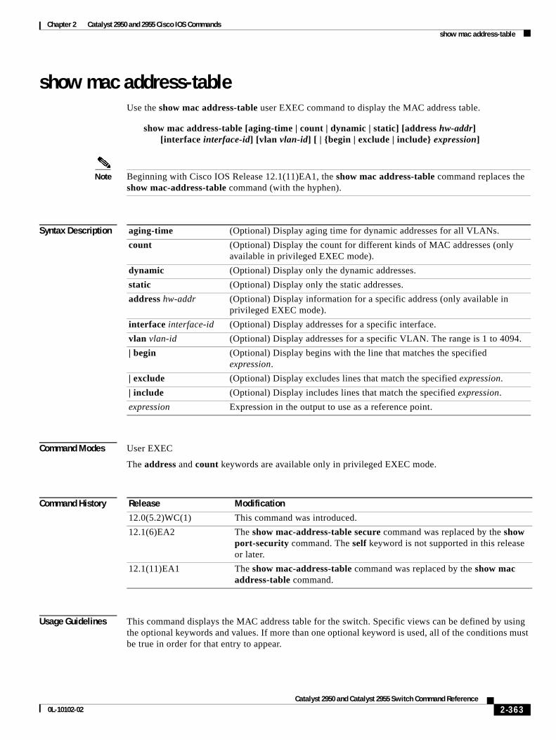
Chapter 2 Catalyst 2950 and 2955 Cisco IOS Commandsshow mac address-table
show mac address-tableUse the show mac address-table user EXEC command to display the MAC address table.
show mac address-table [aging-time | count | dynamic | static] [address hw-addr] [interface interface-id] [vlan vlan-id] [ | {begin | exclude | include} expression]
Note Beginning with Cisco IOS Release 12.1(11)EA1, the show mac address-table command replaces the show mac-address-table command (with the hyphen).
Syntax Description
Command Modes User EXEC
The address and count keywords are available only in privileged EXEC mode.
Command History
Usage Guidelines This command displays the MAC address table for the switch. Specific views can be defined by using the optional keywords and values. If more than one optional keyword is used, all of the conditions must be true in order for that entry to appear.
aging-time (Optional) Display aging time for dynamic addresses for all VLANs.
count (Optional) Display the count for different kinds of MAC addresses (only available in privileged EXEC mode).
dynamic (Optional) Display only the dynamic addresses.
static (Optional) Display only the static addresses.
address hw-addr (Optional) Display information for a specific address (only available in privileged EXEC mode).
interface interface-id (Optional) Display addresses for a specific interface.
vlan vlan-id (Optional) Display addresses for a specific VLAN. The range is 1 to 4094.
| begin (Optional) Display begins with the line that matches the specified expression.
| exclude (Optional) Display excludes lines that match the specified expression.
| include (Optional) Display includes lines that match the specified expression.
expression Expression in the output to use as a reference point.
Release Modification
12.0(5.2)WC(1) This command was introduced.
12.1(6)EA2 The show mac-address-table secure command was replaced by the show port-security command. The self keyword is not supported in this release or later.
12.1(11)EA1 The show mac-address-table command was replaced by the show mac address-table command.
2-363Catalyst 2950 and Catalyst 2955 Switch Command Reference
0L-10102-02
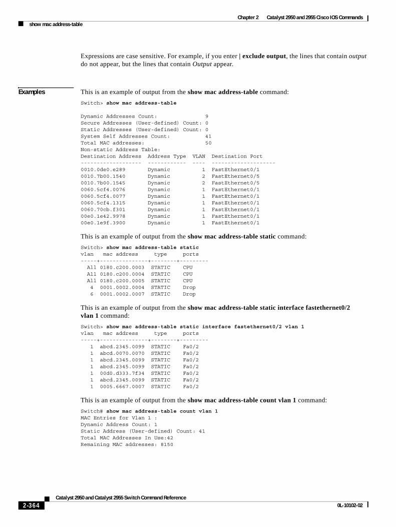
Chapter 2 Catalyst 2950 and 2955 Cisco IOS Commandsshow mac address-table
Expressions are case sensitive. For example, if you enter | exclude output, the lines that contain output do not appear, but the lines that contain Output appear.
Examples This is an example of output from the show mac address-table command:
Switch> show mac address-table
Dynamic Addresses Count: 9Secure Addresses (User-defined) Count: 0Static Addresses (User-defined) Count: 0System Self Addresses Count: 41Total MAC addresses: 50Non-static Address Table:Destination Address Address Type VLAN Destination Port------------------- ------------ ---- --------------------0010.0de0.e289 Dynamic 1 FastEthernet0/10010.7b00.1540 Dynamic 2 FastEthernet0/50010.7b00.1545 Dynamic 2 FastEthernet0/50060.5cf4.0076 Dynamic 1 FastEthernet0/10060.5cf4.0077 Dynamic 1 FastEthernet0/10060.5cf4.1315 Dynamic 1 FastEthernet0/10060.70cb.f301 Dynamic 1 FastEthernet0/100e0.1e42.9978 Dynamic 1 FastEthernet0/100e0.1e9f.3900 Dynamic 1 FastEthernet0/1
This is an example of output from the show mac address-table static command:
Switch> show mac address-table static vlan mac address type ports -----+---------------+--------+--------- All 0180.c200.0003 STATIC CPU All 0180.c200.0004 STATIC CPU All 0180.c200.0005 STATIC CPU 4 0001.0002.0004 STATIC Drop 6 0001.0002.0007 STATIC Drop
This is an example of output from the show mac address-table static interface fastethernet0/2 vlan 1 command:
Switch> show mac address-table static interface fastethernet0/2 vlan 1vlan mac address type ports -----+---------------+--------+--------- 1 abcd.2345.0099 STATIC Fa0/2 1 abcd.0070.0070 STATIC Fa0/2 1 abcd.2345.0099 STATIC Fa0/2 1 abcd.2345.0099 STATIC Fa0/2 1 00d0.d333.7f34 STATIC Fa0/2 1 abcd.2345.0099 STATIC Fa0/2 1 0005.6667.0007 STATIC Fa0/2
This is an example of output from the show mac address-table count vlan 1 command:
Switch# show mac address-table count vlan 1MAC Entries for Vlan 1 :Dynamic Address Count: 1Static Address (User-defined) Count: 41Total MAC Addresses In Use:42Remaining MAC addresses: 8150
2-364Catalyst 2950 and Catalyst 2955 Switch Command Reference
0L-10102-02
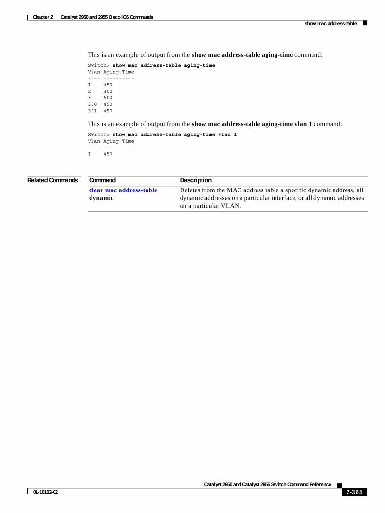
Chapter 2 Catalyst 2950 and 2955 Cisco IOS Commandsshow mac address-table
This is an example of output from the show mac address-table aging-time command:
Switch> show mac address-table aging-timeVlan Aging Time---- ----------1 4502 3003 600300 450301 450
This is an example of output from the show mac address-table aging-time vlan 1 command:
Switch> show mac address-table aging-time vlan 1Vlan Aging Time---- ----------1 450
Related Commands Command Description
clear mac address-table dynamic
Deletes from the MAC address table a specific dynamic address, all dynamic addresses on a particular interface, or all dynamic addresses on a particular VLAN.
2-365Catalyst 2950 and Catalyst 2955 Switch Command Reference
0L-10102-02
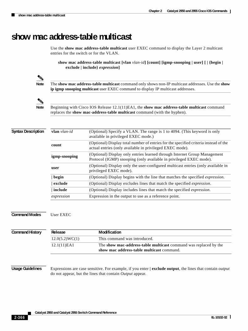
Chapter 2 Catalyst 2950 and 2955 Cisco IOS Commandsshow mac address-table multicast
show mac address-table multicastUse the show mac address-table multicast user EXEC command to display the Layer 2 multicast entries for the switch or for the VLAN.
show mac address-table multicast [vlan vlan-id] [count] [igmp-snooping | user] [ | {begin | exclude | include} expression]
Note The show mac address-table multicast command only shows non-IP multicast addresses. Use the show ip igmp snooping multicast user EXEC command to display IP multicast addresses.
Note Beginning with Cisco IOS Release 12.1(11)EA1, the show mac address-table multicast command replaces the show mac-address-table multicast command (with the hyphen).
Syntax Description
Command Modes User EXEC
Command History
Usage Guidelines Expressions are case sensitive. For example, if you enter | exclude output, the lines that contain output do not appear, but the lines that contain Output appear.
vlan vlan-id (Optional) Specify a VLAN. The range is 1 to 4094. (This keyword is only available in privileged EXEC mode.)
count (Optional) Display total number of entries for the specified criteria instead of the actual entries (only available in privileged EXEC mode).
igmp-snooping (Optional) Display only entries learned through Internet Group Management Protocol (IGMP) snooping (only available in privileged EXEC mode).
user (Optional) Display only the user-configured multicast entries (only available in privileged EXEC mode).
| begin (Optional) Display begins with the line that matches the specified expression.
| exclude (Optional) Display excludes lines that match the specified expression.
| include (Optional) Display includes lines that match the specified expression.
expression Expression in the output to use as a reference point.
Release Modification
12.0(5.2)WC(1) This command was introduced.
12.1(11)EA1 The show mac-address-table multicast command was replaced by the show mac address-table multicast command.
2-366Catalyst 2950 and Catalyst 2955 Switch Command Reference
0L-10102-02
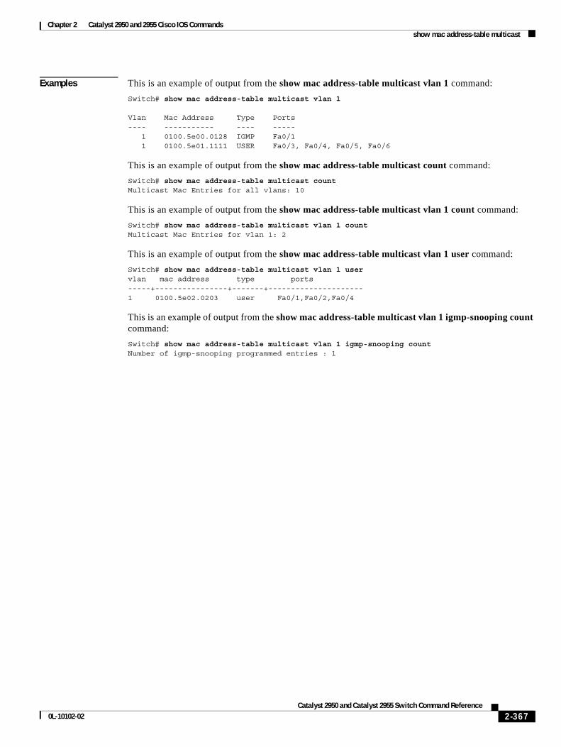
Chapter 2 Catalyst 2950 and 2955 Cisco IOS Commandsshow mac address-table multicast
Examples This is an example of output from the show mac address-table multicast vlan 1 command:
Switch# show mac address-table multicast vlan 1
Vlan Mac Address Type Ports---- ----------- ---- ----- 1 0100.5e00.0128 IGMP Fa0/1 1 0100.5e01.1111 USER Fa0/3, Fa0/4, Fa0/5, Fa0/6
This is an example of output from the show mac address-table multicast count command:
Switch# show mac address-table multicast countMulticast Mac Entries for all vlans: 10
This is an example of output from the show mac address-table multicast vlan 1 count command:
Switch# show mac address-table multicast vlan 1 countMulticast Mac Entries for vlan 1: 2
This is an example of output from the show mac address-table multicast vlan 1 user command:
Switch# show mac address-table multicast vlan 1 uservlan mac address type ports-----+----------------+-------+---------------------1 0100.5e02.0203 user Fa0/1,Fa0/2,Fa0/4
This is an example of output from the show mac address-table multicast vlan 1 igmp-snooping count command:
Switch# show mac address-table multicast vlan 1 igmp-snooping countNumber of igmp-snooping programmed entries : 1
2-367Catalyst 2950 and Catalyst 2955 Switch Command Reference
0L-10102-02
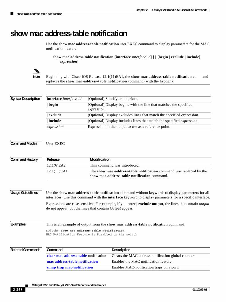
Chapter 2 Catalyst 2950 and 2955 Cisco IOS Commandsshow mac address-table notification
show mac address-table notificationUse the show mac address-table notification user EXEC command to display parameters for the MAC notification feature.
show mac address-table notification [interface interface-id] [ | {begin | exclude | include} expression]
Note Beginning with Cisco IOS Release 12.1(11)EA1, the show mac address-table notification command replaces the show mac-address-table notification command (with the hyphen).
Syntax Description
Command Modes User EXEC
Command History
Usage Guidelines Use the show mac address-table notification command without keywords to display parameters for all interfaces. Use this command with the interface keyword to display parameters for a specific interface.
Expressions are case sensitive. For example, if you enter | exclude output, the lines that contain output do not appear, but the lines that contain Output appear.
Examples This is an example of output from the show mac address-table notification command:
Switch> show mac address-table notificationMAC Notification Feature is Disabled on the switch
Related Commands
interface interface-id (Optional) Specify an interface.
| begin (Optional) Display begins with the line that matches the specified expression.
| exclude (Optional) Display excludes lines that match the specified expression.
| include (Optional) Display includes lines that match the specified expression.
expression Expression in the output to use as a reference point.
Release Modification
12.1(6)EA2 This command was introduced.
12.1(11)EA1 The show mac-address-table notification command was replaced by the show mac address-table notification command.
Command Description
clear mac address-table notification Clears the MAC address notification global counters.
mac address-table notification Enables the MAC notification feature.
snmp trap mac-notification Enables MAC-notification traps on a port.
2-368Catalyst 2950 and Catalyst 2955 Switch Command Reference
0L-10102-02
Chapter 2 Catalyst 2950 and 2955 Cisco IOS Commandsshow mls masks
show mls masksUse the show mls masks user EXEC command to display the details of the access control parameters (ACPs) used for quality of service (QoS) and security access control lists (ACLs).
show mls masks [qos | security] [ | {begin | exclude | include} expression]
This command is available only if your switch is running the enhanced software image (EI).
Syntax Description
Note ACPs are called masks in the command-line interface (CLI) commands and output.
Command Modes User EXEC
Command History
Usage Guidelines Use the show mls masks command without keywords to display all ACPs configured on the switch.
Use this command with the qos keyword to display the ACPs used for QoS ACLs.
Use this command with the security keyword to display the ACPs used for security ACLs.
Note You can configure up to four ACPs (QoS and security) on a switch.
Expressions are case sensitive. For example, if you enter | exclude output, the lines that contain output do not appear, but the lines that contain Output appear.
qos (Optional) Display ACPs used for QoS ACLs.
security (Optional) Display ACPs used for security ACLs.
| begin (Optional) Display begins with the line that matches the expression.
| exclude (Optional) Display excludes lines that match the expression.
| include (Optional) Display includes lines that match the specified expression.
expression Expression in the output to use as a reference point.
Release Modification
12.1(6)EA2 This command was introduced.
2-369Catalyst 2950 and Catalyst 2955 Switch Command Reference
0L-10102-02
Chapter 2 Catalyst 2950 and 2955 Cisco IOS Commandsshow mls masks
Examples This is an example of output from the show mls masks command:
Switch> show mls masks
Mask1 Type : qos Fields : ip-sa(0.0.0.255), ip-da(host), dest-port, ip-dscp Policymap: pmap1 Interfaces: Fa0/9, Gi0/1 Policymap: pmap2 Interfaces: Fa0/1, Fa0/5, Fa0/13Mask2 Type : security Fields : mac-sa (host), ethertype, ip-dscp Access-group: 3 Interfaces: Fa0/2, Fa0/6 Access-group: macag1 Interfaces: Fa0/16
In this example, Mask 1 is a QoS ACP consisting an IP source address (with wildcard bits 0.0.0.255), an IP destination address, and Layer 4 destination port fields. This ACP is used by the QoS policy maps pmap1 and pmap2.
Mask 2 is a security ACP consisting of a MAC source address and ethertype fields. This ACP is used by the MAC security access groups 3 and macag1.
Related Commands Command Description
ip access-group Applies an IP ACL to an interface.
mac access-group Applies a named extended MAC ACL to an interface.
policy-map Creates or modifies a policy map that can be attached to multiple interfaces, and enters policy-map configuration mode.
2-370Catalyst 2950 and Catalyst 2955 Switch Command Reference
0L-10102-02
Chapter 2 Catalyst 2950 and 2955 Cisco IOS Commandsshow mls qos interface
show mls qos interfaceUse the show mls qos interface user EXEC command to display quality of service (QoS) information at the interface level.
show mls qos interface [interface-id] [policers] [ | {begin | exclude | include} expression]
Syntax Description
Note Though visible in the command-line help strings, the vlan vlan-id option is not supported.
Command Modes User EXEC
Command History
Usage Guidelines Though visible in the command-line help string, the policers keyword is available only when your switch is running the EI.
Use the show mls qos interface command without keywords to display parameters for all interfaces.
Use the show mls qos interface interface-id command to display the parameters for a specific interface.
Expressions are case sensitive. For example, if you enter | exclude output, the lines that contain output do not appear, but the lines that contain Output appear.
Examples This is an example of output from the show mls qos interface command when the Cisco IP phone is a trusted device:
Switch> show mls qos interface fastethernet0/1FastEthernet0/1trust state:trust costrust mode:trust cosCOS override:disdefault COS:0pass-through:nonetrust device:cisco-phone
interface-id (Optional) Display QoS information for the specified interface.
policers (Optional) Display all the policers configured on the interface and their settings (available only when the switch is running the enhanced image [EI]).
| begin (Optional) Display begins with the line that matches the expression.
| exclude (Optional) Display excludes lines that match the expression.
| include (Optional) Display includes lines that match the specified expression.
expression Expression in the output to use as a reference point.
Release Modification
12.1(6)EA2 This command was introduced.
2-371Catalyst 2950 and Catalyst 2955 Switch Command Reference
0L-10102-02
Chapter 2 Catalyst 2950 and 2955 Cisco IOS Commandsshow mls qos interface
This is an example of output from the show mls qos interface command when pass-through mode is configured on an interface:
Switch> show mls qos interface fastethernet0/2FastEthernet0/2trust state:not trustedtrust mode:not trustedCOS override:disdefault COS:0pass-through:dscp
This is an example of output from the show mls qos interface-id policers command:
Switch> show mls qos interface fastethernet0/1 policersFastEthernet0/1policymap=pmtimerintype=Single rate=1000000, burst=4096type=Single rate=2000000, burst=4096
Related Commands Command Description
mls qos cos Defines the default class of service (CoS) value of a port or assigns the default CoS to all incoming packets on the port.
mls qos map Defines the class of service (CoS)-to-Differentiated Services Code Point (DSCP) map and DSCP-to-CoS map.
mls qos trust Configures the port trust state. Ingress traffic can be trusted and classification is performed by examining the CoS or DSCP value.
2-372Catalyst 2950 and Catalyst 2955 Switch Command Reference
0L-10102-02
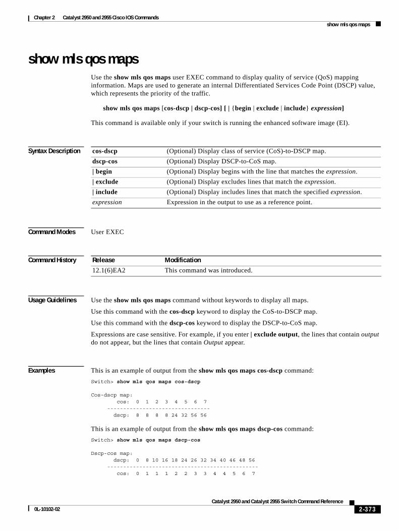
Chapter 2 Catalyst 2950 and 2955 Cisco IOS Commandsshow mls qos maps
show mls qos mapsUse the show mls qos maps user EXEC command to display quality of service (QoS) mapping information. Maps are used to generate an internal Differentiated Services Code Point (DSCP) value, which represents the priority of the traffic.
show mls qos maps [cos-dscp | dscp-cos] [ | {begin | exclude | include} expression]
This command is available only if your switch is running the enhanced software image (EI).
Syntax Description
Command Modes User EXEC
Command History
Usage Guidelines Use the show mls qos maps command without keywords to display all maps.
Use this command with the cos-dscp keyword to display the CoS-to-DSCP map.
Use this command with the dscp-cos keyword to display the DSCP-to-CoS map.
Expressions are case sensitive. For example, if you enter | exclude output, the lines that contain output do not appear, but the lines that contain Output appear.
Examples This is an example of output from the show mls qos maps cos-dscp command:
Switch> show mls qos maps cos-dscp
Cos-dscp map: cos: 0 1 2 3 4 5 6 7 -------------------------------- dscp: 8 8 8 8 24 32 56 56
This is an example of output from the show mls qos maps dscp-cos command:
Switch> show mls qos maps dscp-cos
Dscp-cos map: dscp: 0 8 10 16 18 24 26 32 34 40 46 48 56 ----------------------------------------------- cos: 0 1 1 1 2 2 3 3 4 4 5 6 7
cos-dscp (Optional) Display class of service (CoS)-to-DSCP map.
dscp-cos (Optional) Display DSCP-to-CoS map.
| begin (Optional) Display begins with the line that matches the expression.
| exclude (Optional) Display excludes lines that match the expression.
| include (Optional) Display includes lines that match the specified expression.
expression Expression in the output to use as a reference point.
Release Modification
12.1(6)EA2 This command was introduced.
2-373Catalyst 2950 and Catalyst 2955 Switch Command Reference
0L-10102-02
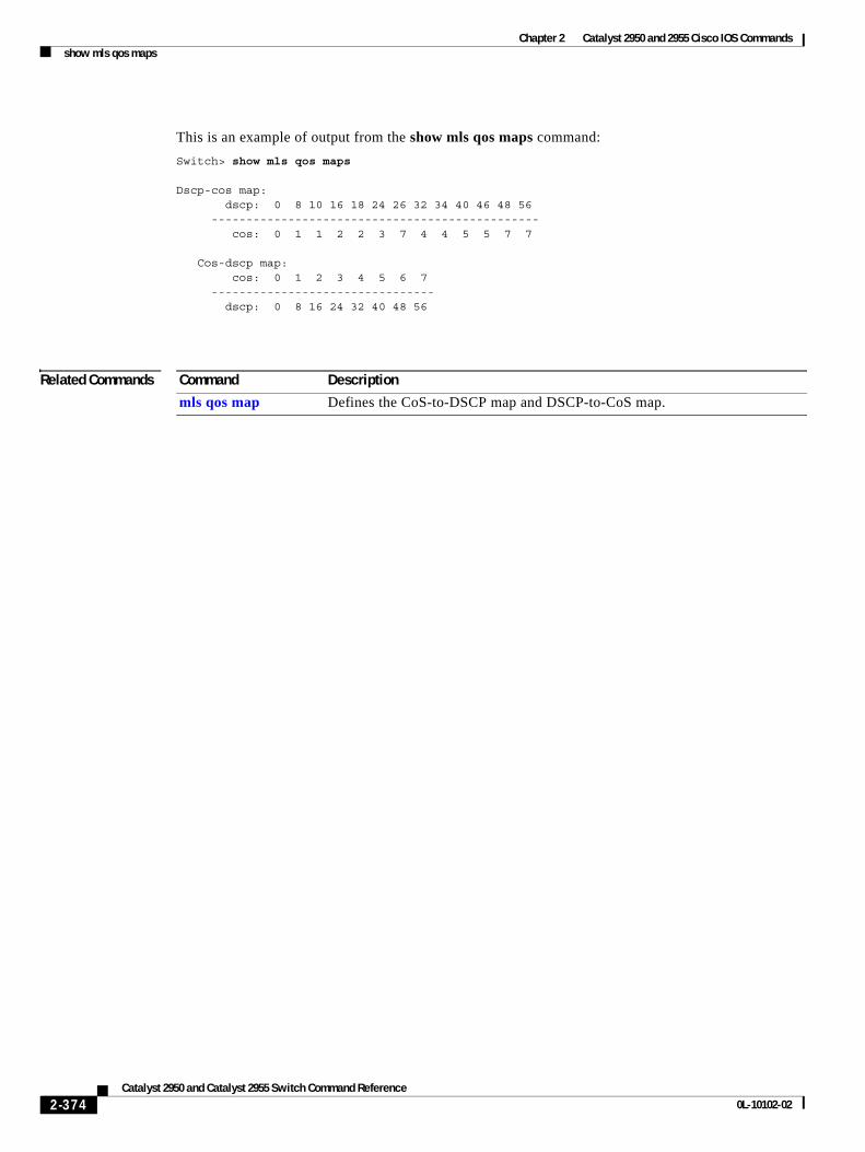
Chapter 2 Catalyst 2950 and 2955 Cisco IOS Commandsshow mls qos maps
This is an example of output from the show mls qos maps command:
Switch> show mls qos maps
Dscp-cos map: dscp: 0 8 10 16 18 24 26 32 34 40 46 48 56 ----------------------------------------------- cos: 0 1 1 2 2 3 7 4 4 5 5 7 7
Cos-dscp map: cos: 0 1 2 3 4 5 6 7 -------------------------------- dscp: 0 8 16 24 32 40 48 56
Related Commands Command Description
mls qos map Defines the CoS-to-DSCP map and DSCP-to-CoS map.
2-374Catalyst 2950 and Catalyst 2955 Switch Command Reference
0L-10102-02
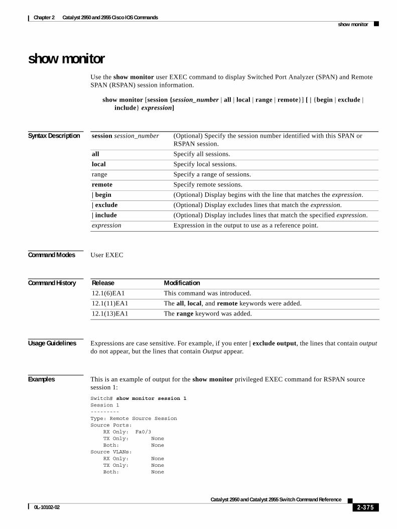
Chapter 2 Catalyst 2950 and 2955 Cisco IOS Commandsshow monitor
show monitorUse the show monitor user EXEC command to display Switched Port Analyzer (SPAN) and Remote SPAN (RSPAN) session information.
show monitor [session {session_number | all | local | range | remote}] [ | {begin | exclude | include} expression]
Syntax Description
Command Modes User EXEC
Command History
Usage Guidelines Expressions are case sensitive. For example, if you enter | exclude output, the lines that contain output do not appear, but the lines that contain Output appear.
Examples This is an example of output for the show monitor privileged EXEC command for RSPAN source session 1:
Switch# show monitor session 1Session 1---------Type: Remote Source SessionSource Ports: RX Only: Fa0/3 TX Only: None Both: None Source VLANs: RX Only: None TX Only: None Both: None
session session_number (Optional) Specify the session number identified with this SPAN or RSPAN session.
all Specify all sessions.
local Specify local sessions.
range Specify a range of sessions.
remote Specify remote sessions.
| begin (Optional) Display begins with the line that matches the expression.
| exclude (Optional) Display excludes lines that match the expression.
| include (Optional) Display includes lines that match the specified expression.
expression Expression in the output to use as a reference point.
Release Modification
12.1(6)EA1 This command was introduced.
12.1(11)EA1 The all, local, and remote keywords were added.
12.1(13)EA1 The range keyword was added.
2-375Catalyst 2950 and Catalyst 2955 Switch Command Reference
0L-10102-02
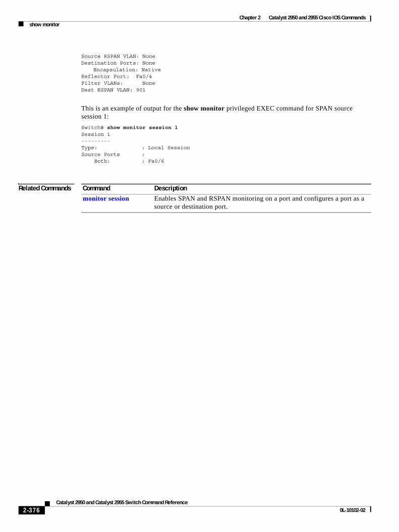
Chapter 2 Catalyst 2950 and 2955 Cisco IOS Commandsshow monitor
Source RSPAN VLAN: NoneDestination Ports: None
Encapsulation: NativeReflector Port: Fa0/4Filter VLANs: NoneDest RSPAN VLAN: 901
This is an example of output for the show monitor privileged EXEC command for SPAN source session 1:
Switch# show monitor session 1Session 1---------Type: : Local SessionSource Ports : Both: : Fa0/6
Related Commands Command Description
monitor session Enables SPAN and RSPAN monitoring on a port and configures a port as a source or destination port.
2-376Catalyst 2950 and Catalyst 2955 Switch Command Reference
0L-10102-02
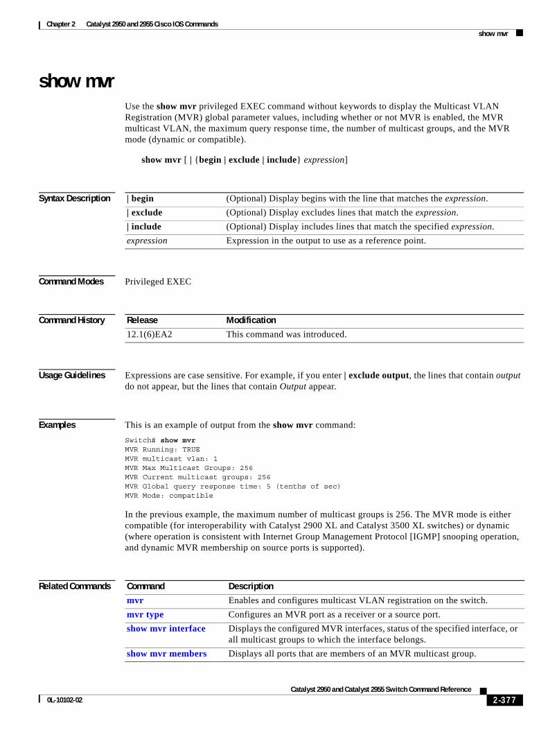
Chapter 2 Catalyst 2950 and 2955 Cisco IOS Commandsshow mvr
show mvrUse the show mvr privileged EXEC command without keywords to display the Multicast VLAN Registration (MVR) global parameter values, including whether or not MVR is enabled, the MVR multicast VLAN, the maximum query response time, the number of multicast groups, and the MVR mode (dynamic or compatible).
show mvr [ | {begin | exclude | include} expression]
Syntax Description
Command Modes Privileged EXEC
Command History
Usage Guidelines Expressions are case sensitive. For example, if you enter | exclude output, the lines that contain output do not appear, but the lines that contain Output appear.
Examples This is an example of output from the show mvr command:
Switch# show mvrMVR Running: TRUEMVR multicast vlan: 1MVR Max Multicast Groups: 256MVR Current multicast groups: 256MVR Global query response time: 5 (tenths of sec)MVR Mode: compatible
In the previous example, the maximum number of multicast groups is 256. The MVR mode is either compatible (for interoperability with Catalyst 2900 XL and Catalyst 3500 XL switches) or dynamic (where operation is consistent with Internet Group Management Protocol [IGMP] snooping operation, and dynamic MVR membership on source ports is supported).
Related Commands
| begin (Optional) Display begins with the line that matches the expression.
| exclude (Optional) Display excludes lines that match the expression.
| include (Optional) Display includes lines that match the specified expression.
expression Expression in the output to use as a reference point.
Release Modification
12.1(6)EA2 This command was introduced.
Command Description
mvr Enables and configures multicast VLAN registration on the switch.
mvr type Configures an MVR port as a receiver or a source port.
show mvr interface Displays the configured MVR interfaces, status of the specified interface, or all multicast groups to which the interface belongs.
show mvr members Displays all ports that are members of an MVR multicast group.
2-377Catalyst 2950 and Catalyst 2955 Switch Command Reference
0L-10102-02
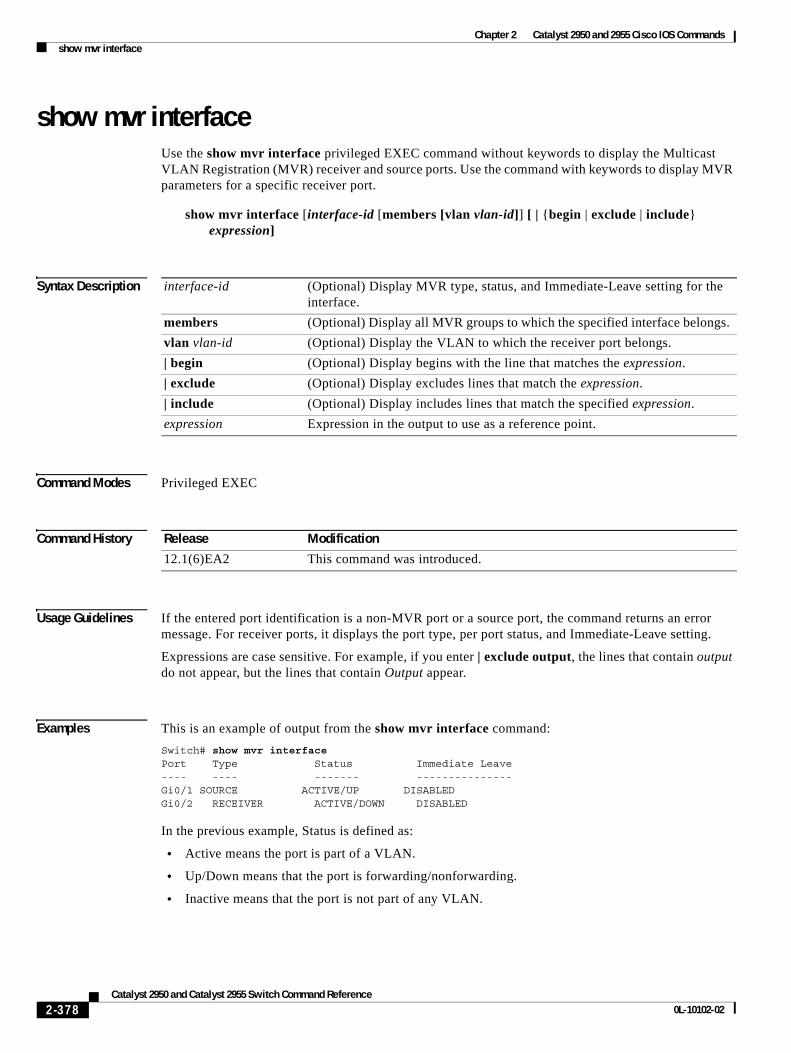
Chapter 2 Catalyst 2950 and 2955 Cisco IOS Commandsshow mvr interface
show mvr interfaceUse the show mvr interface privileged EXEC command without keywords to display the Multicast VLAN Registration (MVR) receiver and source ports. Use the command with keywords to display MVR parameters for a specific receiver port.
show mvr interface [interface-id [members [vlan vlan-id]] [ | {begin | exclude | include} expression]
Syntax Description
Command Modes Privileged EXEC
Command History
Usage Guidelines If the entered port identification is a non-MVR port or a source port, the command returns an error message. For receiver ports, it displays the port type, per port status, and Immediate-Leave setting.
Expressions are case sensitive. For example, if you enter | exclude output, the lines that contain output do not appear, but the lines that contain Output appear.
Examples This is an example of output from the show mvr interface command:
Switch# show mvr interfacePort Type Status Immediate Leave---- ---- ------- ---------------Gi0/1 SOURCE ACTIVE/UP DISABLEDGi0/2 RECEIVER ACTIVE/DOWN DISABLED
In the previous example, Status is defined as:
• Active means the port is part of a VLAN.
• Up/Down means that the port is forwarding/nonforwarding.
• Inactive means that the port is not part of any VLAN.
interface-id (Optional) Display MVR type, status, and Immediate-Leave setting for the interface.
members (Optional) Display all MVR groups to which the specified interface belongs.
vlan vlan-id (Optional) Display the VLAN to which the receiver port belongs.
| begin (Optional) Display begins with the line that matches the expression.
| exclude (Optional) Display excludes lines that match the expression.
| include (Optional) Display includes lines that match the specified expression.
expression Expression in the output to use as a reference point.
Release Modification
12.1(6)EA2 This command was introduced.
2-378Catalyst 2950 and Catalyst 2955 Switch Command Reference
0L-10102-02
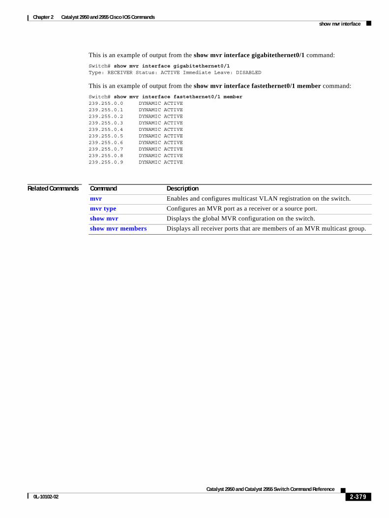
Chapter 2 Catalyst 2950 and 2955 Cisco IOS Commandsshow mvr interface
This is an example of output from the show mvr interface gigabitethernet0/1 command:
Switch# show mvr interface gigabitethernet0/1Type: RECEIVER Status: ACTIVE Immediate Leave: DISABLED
This is an example of output from the show mvr interface fastethernet0/1 member command:
Switch# show mvr interface fastethernet0/1 member239.255.0.0 DYNAMIC ACTIVE239.255.0.1 DYNAMIC ACTIVE239.255.0.2 DYNAMIC ACTIVE239.255.0.3 DYNAMIC ACTIVE239.255.0.4 DYNAMIC ACTIVE239.255.0.5 DYNAMIC ACTIVE239.255.0.6 DYNAMIC ACTIVE239.255.0.7 DYNAMIC ACTIVE239.255.0.8 DYNAMIC ACTIVE239.255.0.9 DYNAMIC ACTIVE
Related Commands Command Description
mvr Enables and configures multicast VLAN registration on the switch.
mvr type Configures an MVR port as a receiver or a source port.
show mvr Displays the global MVR configuration on the switch.
show mvr members Displays all receiver ports that are members of an MVR multicast group.
2-379Catalyst 2950 and Catalyst 2955 Switch Command Reference
0L-10102-02
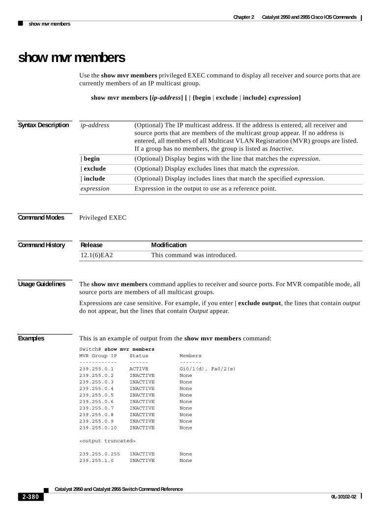
Chapter 2 Catalyst 2950 and 2955 Cisco IOS Commandsshow mvr members
show mvr membersUse the show mvr members privileged EXEC command to display all receiver and source ports that are currently members of an IP multicast group.
show mvr members [ip-address] [ | {begin | exclude | include} expression]
Syntax Description
Command Modes Privileged EXEC
Command History
Usage Guidelines The show mvr members command applies to receiver and source ports. For MVR compatible mode, all source ports are members of all multicast groups.
Expressions are case sensitive. For example, if you enter | exclude output, the lines that contain output do not appear, but the lines that contain Output appear.
Examples This is an example of output from the show mvr members command:
Switch# show mvr membersMVR Group IP Status Members------------ ------ -------239.255.0.1 ACTIVE Gi0/1(d), Fa0/2(s)239.255.0.2 INACTIVE None239.255.0.3 INACTIVE None239.255.0.4 INACTIVE None239.255.0.5 INACTIVE None239.255.0.6 INACTIVE None239.255.0.7 INACTIVE None239.255.0.8 INACTIVE None239.255.0.9 INACTIVE None239.255.0.10 INACTIVE None
<output truncated>
239.255.0.255 INACTIVE None239.255.1.0 INACTIVE None
ip-address (Optional) The IP multicast address. If the address is entered, all receiver and source ports that are members of the multicast group appear. If no address is entered, all members of all Multicast VLAN Registration (MVR) groups are listed. If a group has no members, the group is listed as Inactive.
| begin (Optional) Display begins with the line that matches the expression.
| exclude (Optional) Display excludes lines that match the expression.
| include (Optional) Display includes lines that match the specified expression.
expression Expression in the output to use as a reference point.
Release Modification
12.1(6)EA2 This command was introduced.
2-380Catalyst 2950 and Catalyst 2955 Switch Command Reference
0L-10102-02
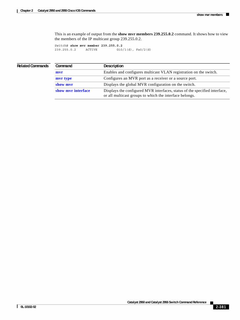
Chapter 2 Catalyst 2950 and 2955 Cisco IOS Commandsshow mvr members
This is an example of output from the show mvr members 239.255.0.2 command. It shows how to view the members of the IP multicast group 239.255.0.2.
Switch# show mvr member 239.255.0.2239.255.0.2 ACTIVE Gi0/1(d), Fa0/2(d)
Related Commands Command Description
mvr Enables and configures multicast VLAN registration on the switch.
mvr type Configures an MVR port as a receiver or a source port.
show mvr Displays the global MVR configuration on the switch.
show mvr interface Displays the configured MVR interfaces, status of the specified interface, or all multicast groups to which the interface belongs.
2-381Catalyst 2950 and Catalyst 2955 Switch Command Reference
0L-10102-02
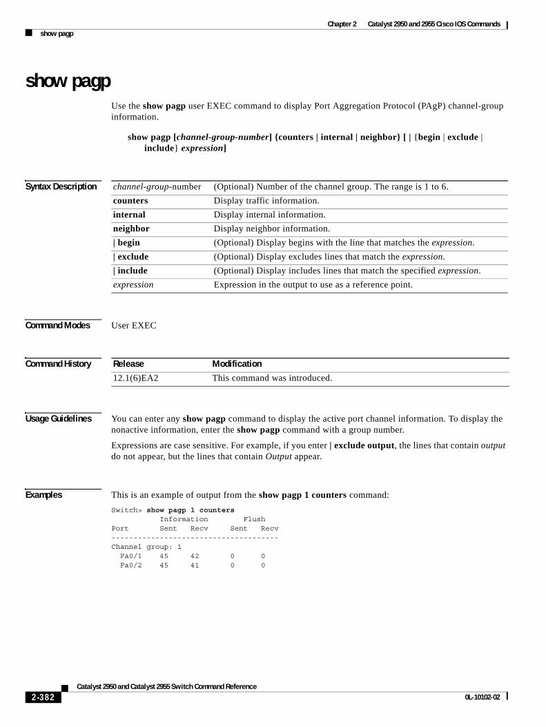
Chapter 2 Catalyst 2950 and 2955 Cisco IOS Commandsshow pagp
show pagpUse the show pagp user EXEC command to display Port Aggregation Protocol (PAgP) channel-group information.
show pagp [channel-group-number] {counters | internal | neighbor} [ | {begin | exclude | include} expression]
Syntax Description
Command Modes User EXEC
Command History
Usage Guidelines You can enter any show pagp command to display the active port channel information. To display the nonactive information, enter the show pagp command with a group number.
Expressions are case sensitive. For example, if you enter | exclude output, the lines that contain output do not appear, but the lines that contain Output appear.
Examples This is an example of output from the show pagp 1 counters command:
Switch> show pagp 1 counters Information FlushPort Sent Recv Sent Recv--------------------------------------Channel group: 1 Fa0/1 45 42 0 0 Fa0/2 45 41 0 0
channel-group-number (Optional) Number of the channel group. The range is 1 to 6.
counters Display traffic information.
internal Display internal information.
neighbor Display neighbor information.
| begin (Optional) Display begins with the line that matches the expression.
| exclude (Optional) Display excludes lines that match the expression.
| include (Optional) Display includes lines that match the specified expression.
expression Expression in the output to use as a reference point.
Release Modification
12.1(6)EA2 This command was introduced.
2-382Catalyst 2950 and Catalyst 2955 Switch Command Reference
0L-10102-02
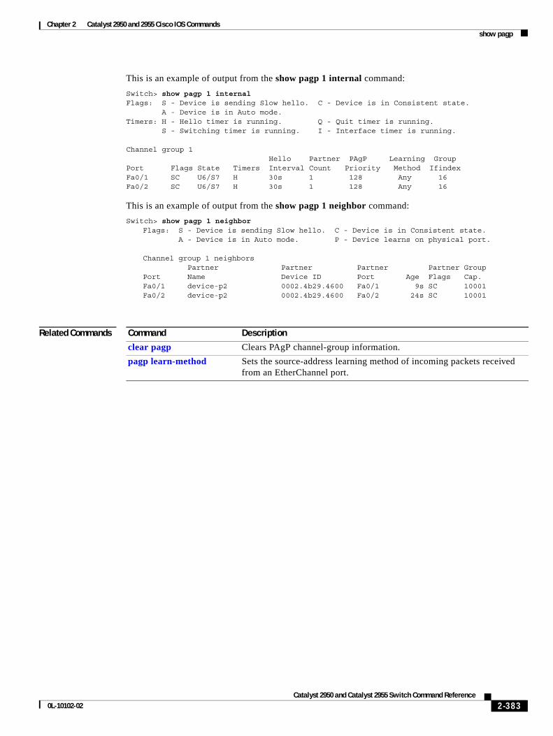
Chapter 2 Catalyst 2950 and 2955 Cisco IOS Commandsshow pagp
This is an example of output from the show pagp 1 internal command:
Switch> show pagp 1 internalFlags: S - Device is sending Slow hello. C - Device is in Consistent state. A - Device is in Auto mode.Timers: H - Hello timer is running. Q - Quit timer is running. S - Switching timer is running. I - Interface timer is running.
Channel group 1 Hello Partner PAgP Learning GroupPort Flags State Timers Interval Count Priority Method IfindexFa0/1 SC U6/S7 H 30s 1 128 Any 16Fa0/2 SC U6/S7 H 30s 1 128 Any 16
This is an example of output from the show pagp 1 neighbor command:
Switch> show pagp 1 neighborFlags: S - Device is sending Slow hello. C - Device is in Consistent state. A - Device is in Auto mode. P - Device learns on physical port.
Channel group 1 neighbors Partner Partner Partner Partner GroupPort Name Device ID Port Age Flags Cap.Fa0/1 device-p2 0002.4b29.4600 Fa0/1 9s SC 10001 Fa0/2 device-p2 0002.4b29.4600 Fa0/2 24s SC 10001
Related Commands Command Description
clear pagp Clears PAgP channel-group information.
pagp learn-method Sets the source-address learning method of incoming packets received from an EtherChannel port.
2-383Catalyst 2950 and Catalyst 2955 Switch Command Reference
0L-10102-02
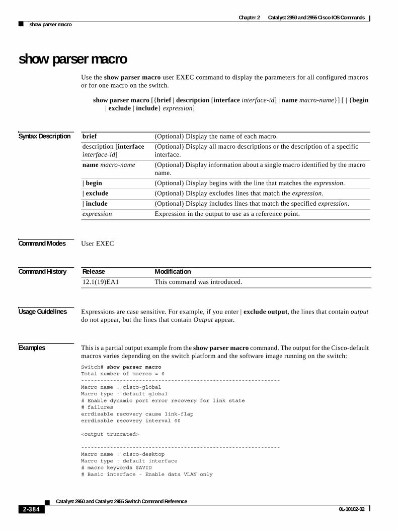
Chapter 2 Catalyst 2950 and 2955 Cisco IOS Commandsshow parser macro
show parser macroUse the show parser macro user EXEC command to display the parameters for all configured macros or for one macro on the switch.
show parser macro [{brief | description [interface interface-id] | name macro-name}] [ | {begin | exclude | include} expression]
Syntax Description
Command Modes User EXEC
Command History
Usage Guidelines Expressions are case sensitive. For example, if you enter | exclude output, the lines that contain output do not appear, but the lines that contain Output appear.
Examples This is a partial output example from the show parser macro command. The output for the Cisco-default macros varies depending on the switch platform and the software image running on the switch:
Switch# show parser macroTotal number of macros = 6--------------------------------------------------------------Macro name : cisco-globalMacro type : default global# Enable dynamic port error recovery for link state# failureserrdisable recovery cause link-flaperrdisable recovery interval 60
<output truncated>
--------------------------------------------------------------Macro name : cisco-desktopMacro type : default interface# macro keywords $AVID# Basic interface - Enable data VLAN only
brief (Optional) Display the name of each macro.
description [interface interface-id]
(Optional) Display all macro descriptions or the description of a specific interface.
name macro-name (Optional) Display information about a single macro identified by the macro name.
| begin (Optional) Display begins with the line that matches the expression.
| exclude (Optional) Display excludes lines that match the expression.
| include (Optional) Display includes lines that match the specified expression.
expression Expression in the output to use as a reference point.
Release Modification
12.1(19)EA1 This command was introduced.
2-384Catalyst 2950 and Catalyst 2955 Switch Command Reference
0L-10102-02
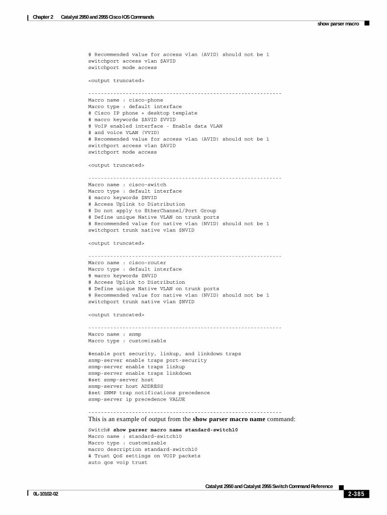
Chapter 2 Catalyst 2950 and 2955 Cisco IOS Commandsshow parser macro
# Recommended value for access vlan (AVID) should not be 1switchport access vlan $AVIDswitchport mode access
<output truncated>
--------------------------------------------------------------Macro name : cisco-phoneMacro type : default interface# Cisco IP phone + desktop template# macro keywords $AVID $VVID# VoIP enabled interface - Enable data VLAN# and voice VLAN (VVID)# Recommended value for access vlan (AVID) should not be 1switchport access vlan $AVIDswitchport mode access
<output truncated>
--------------------------------------------------------------Macro name : cisco-switchMacro type : default interface# macro keywords $NVID# Access Uplink to Distribution# Do not apply to EtherChannel/Port Group# Define unique Native VLAN on trunk ports# Recommended value for native vlan (NVID) should not be 1switchport trunk native vlan $NVID
<output truncated>
--------------------------------------------------------------Macro name : cisco-routerMacro type : default interface# macro keywords $NVID# Access Uplink to Distribution# Define unique Native VLAN on trunk ports# Recommended value for native vlan (NVID) should not be 1switchport trunk native vlan $NVID
<output truncated>
--------------------------------------------------------------Macro name : snmpMacro type : customizable
#enable port security, linkup, and linkdown trapssnmp-server enable traps port-securitysnmp-server enable traps linkupsnmp-server enable traps linkdown#set snmp-server hostsnmp-server host ADDRESS#set SNMP trap notifications precedencesnmp-server ip precedence VALUE
--------------------------------------------------------------
This is an example of output from the show parser macro name command:
Switch# show parser macro name standard-switch10Macro name : standard-switch10Macro type : customizablemacro description standard-switch10# Trust QoS settings on VOIP packetsauto qos voip trust
2-385Catalyst 2950 and Catalyst 2955 Switch Command Reference
0L-10102-02
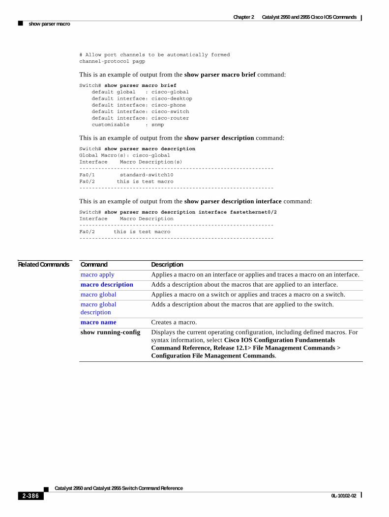
Chapter 2 Catalyst 2950 and 2955 Cisco IOS Commandsshow parser macro
# Allow port channels to be automatically formedchannel-protocol pagp
This is an example of output from the show parser macro brief command:
Switch# show parser macro brief default global : cisco-global default interface: cisco-desktop default interface: cisco-phone default interface: cisco-switch default interface: cisco-router customizable : snmp
This is an example of output from the show parser description command:
Switch# show parser macro description Global Macro(s): cisco-globalInterface Macro Description(s)--------------------------------------------------------------Fa0/1 standard-switch10Fa0/2 this is test macro--------------------------------------------------------------
This is an example of output from the show parser description interface command:
Switch# show parser macro description interface fastethernet0/2Interface Macro Description--------------------------------------------------------------Fa0/2 this is test macro--------------------------------------------------------------
Related Commands Command Description
macro apply Applies a macro on an interface or applies and traces a macro on an interface.
macro description Adds a description about the macros that are applied to an interface.
macro global Applies a macro on a switch or applies and traces a macro on a switch.
macro global description
Adds a description about the macros that are applied to the switch.
macro name Creates a macro.
show running-config Displays the current operating configuration, including defined macros. For syntax information, select Cisco IOS Configuration Fundamentals Command Reference, Release 12.1> File Management Commands > Configuration File Management Commands.
2-386Catalyst 2950 and Catalyst 2955 Switch Command Reference
0L-10102-02
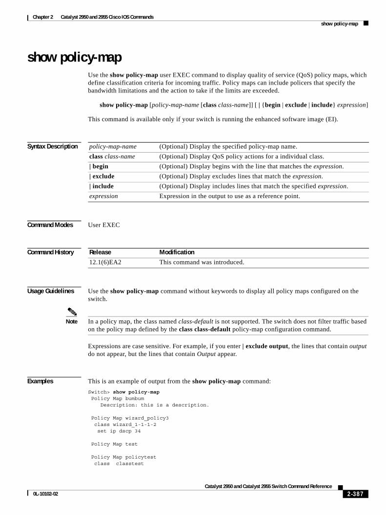
Chapter 2 Catalyst 2950 and 2955 Cisco IOS Commandsshow policy-map
show policy-mapUse the show policy-map user EXEC command to display quality of service (QoS) policy maps, which define classification criteria for incoming traffic. Policy maps can include policers that specify the bandwidth limitations and the action to take if the limits are exceeded.
show policy-map [policy-map-name [class class-name]] [ | {begin | exclude | include} expression]
This command is available only if your switch is running the enhanced software image (EI).
Syntax Description
Command Modes User EXEC
Command History
Usage Guidelines Use the show policy-map command without keywords to display all policy maps configured on the switch.
Note In a policy map, the class named class-default is not supported. The switch does not filter traffic based on the policy map defined by the class class-default policy-map configuration command.
Expressions are case sensitive. For example, if you enter | exclude output, the lines that contain output do not appear, but the lines that contain Output appear.
Examples This is an example of output from the show policy-map command:
Switch> show policy-map Policy Map bumbum Description: this is a description.
Policy Map wizard_policy3 class wizard_1-1-1-2 set ip dscp 34
Policy Map test
Policy Map policytest class classtest
policy-map-name (Optional) Display the specified policy-map name.
class class-name (Optional) Display QoS policy actions for a individual class.
| begin (Optional) Display begins with the line that matches the expression.
| exclude (Optional) Display excludes lines that match the expression.
| include (Optional) Display includes lines that match the specified expression.
expression Expression in the output to use as a reference point.
Release Modification
12.1(6)EA2 This command was introduced.
2-387Catalyst 2950 and Catalyst 2955 Switch Command Reference
0L-10102-02
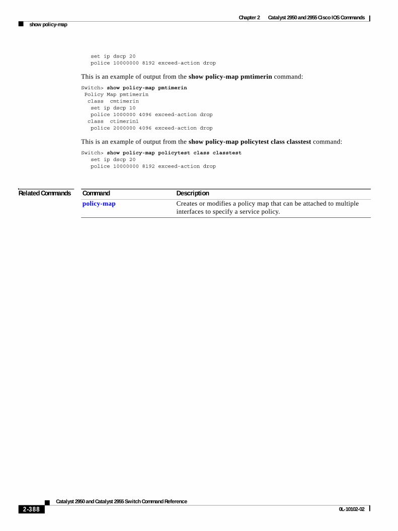
Chapter 2 Catalyst 2950 and 2955 Cisco IOS Commandsshow policy-map
set ip dscp 20 police 10000000 8192 exceed-action drop
This is an example of output from the show policy-map pmtimerin command:
Switch> show policy-map pmtimerin Policy Map pmtimerin class cmtimerin set ip dscp 10 police 1000000 4096 exceed-action drop class ctimerin1 police 2000000 4096 exceed-action drop
This is an example of output from the show policy-map policytest class classtest command:
Switch> show policy-map policytest class classtest set ip dscp 20 police 10000000 8192 exceed-action drop
Related Commands Command Description
policy-map Creates or modifies a policy map that can be attached to multiple interfaces to specify a service policy.
2-388Catalyst 2950 and Catalyst 2955 Switch Command Reference
0L-10102-02
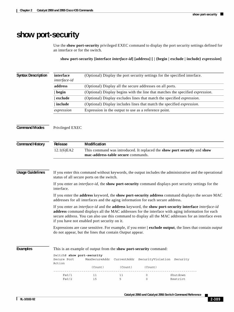
Chapter 2 Catalyst 2950 and 2955 Cisco IOS Commandsshow port-security
show port-security Use the show port-security privileged EXEC command to display the port security settings defined for an interface or for the switch.
show port-security [interface interface-id] [address] [ | {begin | exclude | include} expression]
Syntax Description
Command Modes Privileged EXEC
Command History
Usage Guidelines If you enter this command without keywords, the output includes the administrative and the operational status of all secure ports on the switch.
If you enter an interface-id, the show port-security command displays port security settings for the interface.
If you enter the address keyword, the show port-security address command displays the secure MAC addresses for all interfaces and the aging information for each secure address.
If you enter an interface-id and the address keyword, the show port-security interface interface-id address command displays all the MAC addresses for the interface with aging information for each secure address. You can also use this command to display all the MAC addresses for an interface even if you have not enabled port security on it.
Expressions are case sensitive. For example, if you enter | exclude output, the lines that contain output do not appear, but the lines that contain Output appear.
Examples This is an example of output from the show port-security command:
Switch# show port-securitySecure Port MaxSecureAddr CurrentAddr SecurityViolation SecurityAction (Count) (Count) (Count)---------------------------------------------------------------------------- Fa0/1 11 11 0 Shutdown Fa0/2 15 5 0 Restrict
interface interface-id
(Optional) Display the port security settings for the specified interface.
address (Optional) Display all the secure addresses on all ports.
| begin (Optional) Display begins with the line that matches the specified expression.
| exclude (Optional) Display excludes lines that match the specified expression.
| include (Optional) Display includes lines that match the specified expression.
expression Expression in the output to use as a reference point.
Release Modification
12.1(6)EA2 This command was introduced. It replaced the show port security and show mac-address-table secure commands.
2-389Catalyst 2950 and Catalyst 2955 Switch Command Reference
0L-10102-02
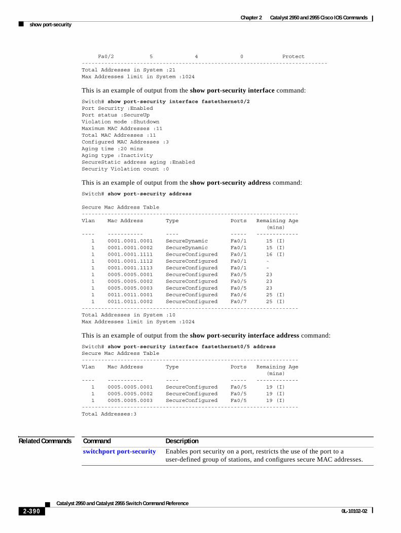
Chapter 2 Catalyst 2950 and 2955 Cisco IOS Commandsshow port-security
Fa0/2 5 4 0 Protect----------------------------------------------------------------------------Total Addresses in System :21Max Addresses limit in System :1024
This is an example of output from the show port-security interface command:
Switch# show port-security interface fastethernet0/2Port Security :EnabledPort status :SecureUpViolation mode :ShutdownMaximum MAC Addresses :11Total MAC Addresses :11Configured MAC Addresses :3Aging time :20 minsAging type :InactivitySecureStatic address aging :EnabledSecurity Violation count :0
This is an example of output from the show port-security address command:
Switch# show port-security address
Secure Mac Address Table-------------------------------------------------------------------Vlan Mac Address Type Ports Remaining Age (mins)---- ----------- ---- ----- ------------- 1 0001.0001.0001 SecureDynamic Fa0/1 15 (I) 1 0001.0001.0002 SecureDynamic Fa0/1 15 (I) 1 0001.0001.1111 SecureConfigured Fa0/1 16 (I) 1 0001.0001.1112 SecureConfigured Fa0/1 - 1 0001.0001.1113 SecureConfigured Fa0/1 - 1 0005.0005.0001 SecureConfigured Fa0/5 23 1 0005.0005.0002 SecureConfigured Fa0/5 23 1 0005.0005.0003 SecureConfigured Fa0/5 23 1 0011.0011.0001 SecureConfigured Fa0/6 25 (I) 1 0011.0011.0002 SecureConfigured Fa0/7 25 (I)-------------------------------------------------------------------Total Addresses in System :10Max Addresses limit in System :1024
This is an example of output from the show port-security interface address command:
Switch# show port-security interface fastethernet0/5 addressSecure Mac Address Table-------------------------------------------------------------------Vlan Mac Address Type Ports Remaining Age (mins)---- ----------- ---- ----- ------------- 1 0005.0005.0001 SecureConfigured Fa0/5 19 (I) 1 0005.0005.0002 SecureConfigured Fa0/5 19 (I) 1 0005.0005.0003 SecureConfigured Fa0/5 19 (I)-------------------------------------------------------------------Total Addresses:3
Related Commands Command Description
switchport port-security Enables port security on a port, restricts the use of the port to a user-defined group of stations, and configures secure MAC addresses.
2-390Catalyst 2950 and Catalyst 2955 Switch Command Reference
0L-10102-02
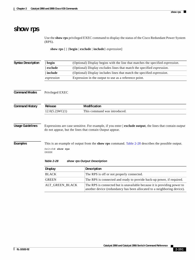
Chapter 2 Catalyst 2950 and 2955 Cisco IOS Commandsshow rps
show rpsUse the show rps privileged EXEC command to display the status of the Cisco Redundant Power System (RPS).
show rps [ | {begin | exclude | include} expression]
Syntax Description
Command Modes Privileged EXEC
Command History
Usage Guidelines Expressions are case sensitive. For example, if you enter | exclude output, the lines that contain output do not appear, but the lines that contain Output appear.
Examples This is an example of output from the show rps command. Table 2-28 describes the possible output.
Switch# show rpsGREEN
| begin (Optional) Display begins with the line that matches the specified expression.
| exclude (Optional) Display excludes lines that match the specified expression.
| include (Optional) Display includes lines that match the specified expression.
expression Expression in the output to use as a reference point.
Release Modification
12.0(5.2)WC(1) This command was introduced.
Table 2-28 show rps Output Description
Display Description
BLACK The RPS is off or not properly connected.
GREEN The RPS is connected and ready to provide back-up power, if required.
ALT_GREEN_BLACK The RPS is connected but is unavailable because it is providing power to another device (redundancy has been allocated to a neighboring device).
2-391Catalyst 2950 and Catalyst 2955 Switch Command Reference
0L-10102-02
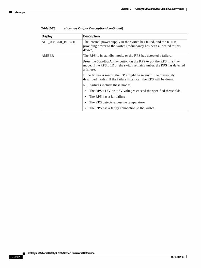
Chapter 2 Catalyst 2950 and 2955 Cisco IOS Commandsshow rps
ALT_AMBER_BLACK The internal power supply in the switch has failed, and the RPS is providing power to the switch (redundancy has been allocated to this device).
AMBER The RPS is in standby mode, or the RPS has detected a failure.
Press the Standby/Active button on the RPS to put the RPS in active mode. If the RPS LED on the switch remains amber, the RPS has detected a failure.
If the failure is minor, the RPS might be in any of the previously described modes. If the failure is critical, the RPS will be down.
RPS failures include these modes:
• The RPS +12V or -48V voltages exceed the specified thresholds.
• The RPS has a fan failure.
• The RPS detects excessive temperature.
• The RPS has a faulty connection to the switch.
Table 2-28 show rps Output Description (continued)
Display Description
2-392Catalyst 2950 and Catalyst 2955 Switch Command Reference
0L-10102-02
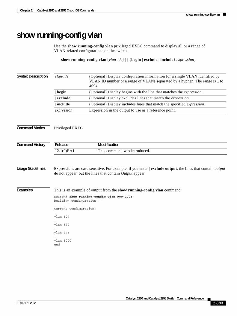
Chapter 2 Catalyst 2950 and 2955 Cisco IOS Commandsshow running-config vlan
show running-config vlanUse the show running-config vlan privileged EXEC command to display all or a range of VLAN-related configurations on the switch.
show running-config vlan [vlan-ids] [ | {begin | exclude | include} expression]
Syntax Description
Command Modes Privileged EXEC
Command History
Usage Guidelines Expressions are case sensitive. For example, if you enter | exclude output, the lines that contain output do not appear, but the lines that contain Output appear.
Examples This is an example of output from the show running-config vlan command:
Switch# show running-config vlan 900-2005Building configuration...
Current configuration:!vlan 107!vlan 120!vlan 925!vlan 1000end
vlan-ids (Optional) Display configuration information for a single VLAN identified by VLAN ID number or a range of VLANs separated by a hyphen. The range is 1 to 4094.
| begin (Optional) Display begins with the line that matches the expression.
| exclude (Optional) Display excludes lines that match the expression.
| include (Optional) Display includes lines that match the specified expression.
expression Expression in the output to use as a reference point.
Release Modification
12.1(9)EA1 This command was introduced.
2-393Catalyst 2950 and Catalyst 2955 Switch Command Reference
0L-10102-02
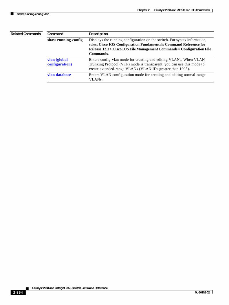
Chapter 2 Catalyst 2950 and 2955 Cisco IOS Commandsshow running-config vlan
Related Commands Command Description
show running-config Displays the running configuration on the switch. For syntax information, select Cisco IOS Configuration Fundamentals Command Reference for Release 12.1 > Cisco IOS File Management Commands > Configuration File Commands.
vlan (global configuration)
Enters config-vlan mode for creating and editing VLANs. When VLAN Trunking Protocol (VTP) mode is transparent, you can use this mode to create extended-range VLANs (VLAN IDs greater than 1005).
vlan database Enters VLAN configuration mode for creating and editing normal-range VLANs.
2-394Catalyst 2950 and Catalyst 2955 Switch Command Reference
0L-10102-02
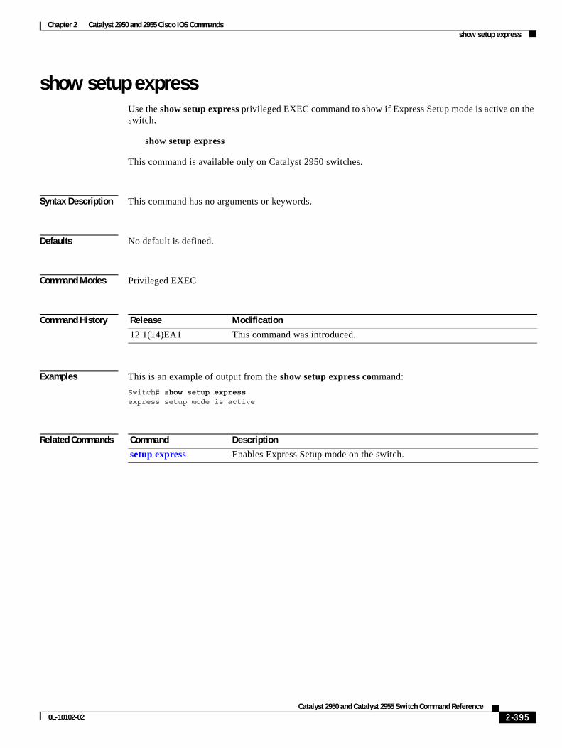
Chapter 2 Catalyst 2950 and 2955 Cisco IOS Commandsshow setup express
show setup expressUse the show setup express privileged EXEC command to show if Express Setup mode is active on the switch.
show setup express
This command is available only on Catalyst 2950 switches.
Syntax Description This command has no arguments or keywords.
Defaults No default is defined.
Command Modes Privileged EXEC
Command History
Examples This is an example of output from the show setup express command:
Switch# show setup expressexpress setup mode is active
Related Commands
Release Modification
12.1(14)EA1 This command was introduced.
Command Description
setup express Enables Express Setup mode on the switch.
2-395Catalyst 2950 and Catalyst 2955 Switch Command Reference
0L-10102-02
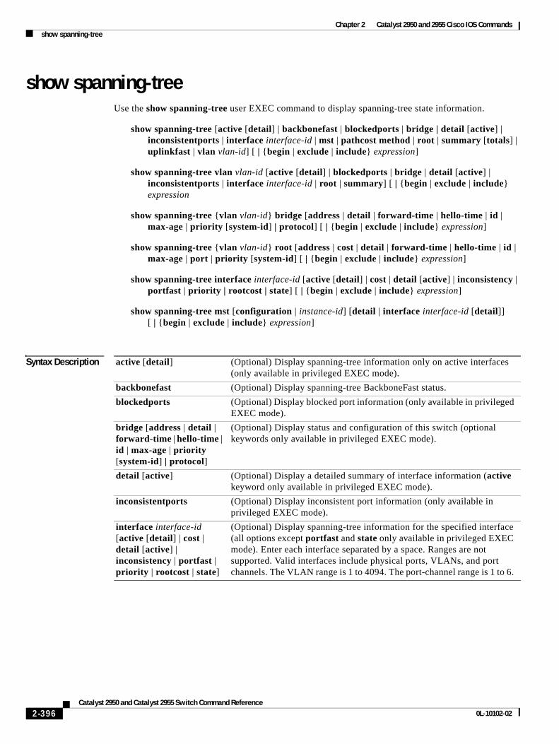
Chapter 2 Catalyst 2950 and 2955 Cisco IOS Commandsshow spanning-tree
show spanning-treeUse the show spanning-tree user EXEC command to display spanning-tree state information.
show spanning-tree [active [detail] | backbonefast | blockedports | bridge | detail [active] | inconsistentports | interface interface-id | mst | pathcost method | root | summary [totals] | uplinkfast | vlan vlan-id] [ | {begin | exclude | include} expression]
show spanning-tree vlan vlan-id [active [detail] | blockedports | bridge | detail [active] | inconsistentports | interface interface-id | root | summary] [ | {begin | exclude | include} expression
show spanning-tree {vlan vlan-id} bridge [address | detail | forward-time | hello-time | id | max-age | priority [system-id] | protocol] [ | {begin | exclude | include} expression]
show spanning-tree {vlan vlan-id} root [address | cost | detail | forward-time | hello-time | id | max-age | port | priority [system-id] [ | {begin | exclude | include} expression]
show spanning-tree interface interface-id [active [detail] | cost | detail [active] | inconsistency | portfast | priority | rootcost | state] [ | {begin | exclude | include} expression]
show spanning-tree mst [configuration | instance-id] [detail | interface interface-id [detail]] [ | {begin | exclude | include} expression]
Syntax Description active [detail] (Optional) Display spanning-tree information only on active interfaces (only available in privileged EXEC mode).
backbonefast (Optional) Display spanning-tree BackboneFast status.
blockedports (Optional) Display blocked port information (only available in privileged EXEC mode).
bridge [address | detail | forward-time | hello-time | id | max-age | priority [system-id] | protocol]
(Optional) Display status and configuration of this switch (optional keywords only available in privileged EXEC mode).
detail [active] (Optional) Display a detailed summary of interface information (active keyword only available in privileged EXEC mode).
inconsistentports (Optional) Display inconsistent port information (only available in privileged EXEC mode).
interface interface-id [active [detail] | cost | detail [active] | inconsistency | portfast | priority | rootcost | state]
(Optional) Display spanning-tree information for the specified interface (all options except portfast and state only available in privileged EXEC mode). Enter each interface separated by a space. Ranges are not supported. Valid interfaces include physical ports, VLANs, and port channels. The VLAN range is 1 to 4094. The port-channel range is 1 to 6.
2-396Catalyst 2950 and Catalyst 2955 Switch Command Reference
0L-10102-02
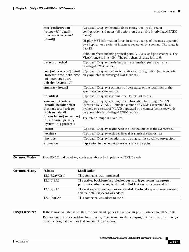
Chapter 2 Catalyst 2950 and 2955 Cisco IOS Commandsshow spanning-tree
Command Modes User EXEC; indicated keywords available only in privileged EXEC mode
Command History
Usage Guidelines If the vlan-id variable is omitted, the command applies to the spanning-tree instance for all VLANs.
Expressions are case sensitive. For example, if you enter | exclude output, the lines that contain output do not appear, but the lines that contain Output appear.
mst [configuration | instance-id] [detail | interface interface-id [detail]]
(Optional) Display the multiple spanning-tree (MST) region configuration and status (all options only available in privileged EXEC mode).
Display MST information for an instance, a range of instances separated by a hyphen, or a series of instances separated by a comma. The range is 0 to 15.
Valid interfaces include physical ports, VLANs, and port channels. The VLAN range is 1 to 4094. The port-channel range is 1 to 6.
pathcost method (Optional) Display the default path cost method (only available in privileged EXEC mode).
root [address | cost | detail | forward-time | hello-time | id | max-age | port | priority [system-id]]
(Optional) Display root switch status and configuration (all keywords only available in privileged EXEC mode).
summary [totals] (Optional) Display a summary of port states or the total lines of the spanning-tree state section.
uplinkfast (Optional) Display spanning-tree UplinkFast status.
vlan vlan-id [active [detail] | backbonefast | blockedports | bridge [address | detail | forward-time | hello-time | id | max-age | priority [system-id] | protocol]
(Optional) Display spanning-tree information for a single VLAN identified by VLAN ID number, a range of VLANs separated by a hyphen, or a series of VLANs separated by a comma (some keywords only available in privileged EXEC mode).
The VLAN range is 1 to 4094.
| begin (Optional) Display begins with the line that matches the expression.
| exclude (Optional) Display excludes lines that match the expression.
| include (Optional) Display includes lines that match the specified expression.
expression Expression in the output to use as a reference point.
Release Modification
12.0(5.2)WC(1) This command was introduced.
12.1(6)EA2 The active, backbonefast, blockedports, bridge, inconsistentports, pathcost method, root, total, and uplinkfast keywords were added.
12.1(9)EA1 The mst keyword and options were added. The brief keyword was removed, and the detail keyword was added.
12.1(20)EA2 This command was added to the SI.
2-397Catalyst 2950 and Catalyst 2955 Switch Command Reference
0L-10102-02
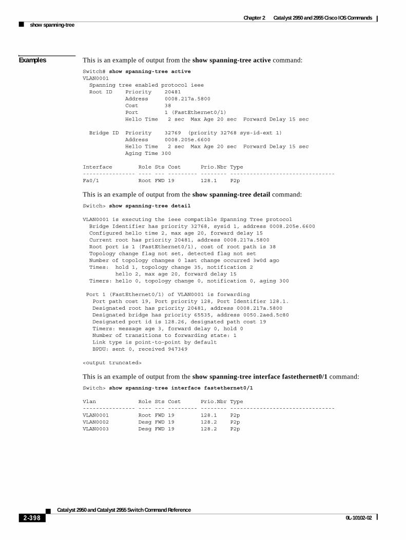
Chapter 2 Catalyst 2950 and 2955 Cisco IOS Commandsshow spanning-tree
Examples This is an example of output from the show spanning-tree active command:
Switch# show spanning-tree activeVLAN0001 Spanning tree enabled protocol ieee Root ID Priority 20481 Address 0008.217a.5800 Cost 38 Port 1 (FastEthernet0/1) Hello Time 2 sec Max Age 20 sec Forward Delay 15 sec
Bridge ID Priority 32769 (priority 32768 sys-id-ext 1) Address 0008.205e.6600 Hello Time 2 sec Max Age 20 sec Forward Delay 15 sec Aging Time 300
Interface Role Sts Cost Prio.Nbr Type---------------- ---- --- --------- -------- --------------------------------Fa0/1 Root FWD 19 128.1 P2p
This is an example of output from the show spanning-tree detail command:
Switch> show spanning-tree detail
VLAN0001 is executing the ieee compatible Spanning Tree protocol Bridge Identifier has priority 32768, sysid 1, address 0008.205e.6600 Configured hello time 2, max age 20, forward delay 15 Current root has priority 20481, address 0008.217a.5800 Root port is 1 (FastEthernet0/1), cost of root path is 38 Topology change flag not set, detected flag not set Number of topology changes 0 last change occurred 3w0d ago Times: hold 1, topology change 35, notification 2 hello 2, max age 20, forward delay 15 Timers: hello 0, topology change 0, notification 0, aging 300
Port 1 (FastEthernet0/1) of VLAN0001 is forwarding Port path cost 19, Port priority 128, Port Identifier 128.1. Designated root has priority 20481, address 0008.217a.5800 Designated bridge has priority 65535, address 0050.2aed.5c80 Designated port id is 128.26, designated path cost 19 Timers: message age 3, forward delay 0, hold 0 Number of transitions to forwarding state: 1 Link type is point-to-point by default BPDU: sent 0, received 947349
<output truncated>
This is an example of output from the show spanning-tree interface fastethernet0/1 command:
Switch> show spanning-tree interface fastethernet0/1
Vlan Role Sts Cost Prio.Nbr Type---------------- ---- --- --------- -------- --------------------------------VLAN0001 Root FWD 19 128.1 P2pVLAN0002 Desg FWD 19 128.2 P2p VLAN0003 Desg FWD 19 128.2 P2p
2-398Catalyst 2950 and Catalyst 2955 Switch Command Reference
0L-10102-02
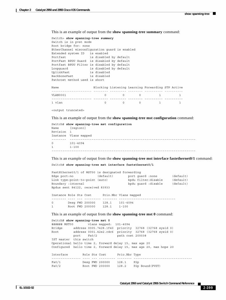
Chapter 2 Catalyst 2950 and 2955 Cisco IOS Commandsshow spanning-tree
This is an example of output from the show spanning-tree summary command:
Switch> show spanning-tree summarySwitch is in pvst modeRoot bridge for: noneEtherChannel misconfiguration guard is enabledExtended system ID is enabledPortfast is disabled by defaultPortFast BPDU Guard is disabled by defaultPortfast BPDU Filter is disabled by defaultLoopguard is disabled by defaultUplinkFast is disabledBackboneFast is disabledPathcost method used is short
Name Blocking Listening Learning Forwarding STP Active---------------------- -------- --------- -------- ---------- ----------VLAN0001 0 0 0 1 1---------------------- -------- --------- -------- ---------- ----------1 vlan 0 0 0 1 1
<output truncated>
This is an example of output from the show spanning-tree mst configuration command:
Switch# show spanning-tree mst configurationName [region1]Revision 1Instance Vlans mapped-------- ---------------------------------------------------------------------0 101-40941 1-100-------------------------------------------------------------------------------
This is an example of output from the show spanning-tree mst interface fastethernet0/1 command:
Switch# show spanning-tree mst interface fastethernet0/1
FastEthernet0/1 of MST00 is designated forwarding Edge port:no (default) port guard :none (default)Link type:point-to-point (auto) bpdu filter:disable (default)Boundary :internal bpdu guard :disable (default)Bpdus sent 84122, received 83933
Instance Role Sts Cost Prio.Nbr Vlans mapped-------- ---- --- --------- -------- -------------------------------0 Desg FWD 200000 128.1 101-40941 Root FWD 200000 128.1 1-100
This is an example of output from the show spanning-tree mst 0 command:
Switch# show spanning-tree mst 0###### MST00 vlans mapped: 101-4094Bridge address 0005.7428.1f40 priority 32768 (32768 sysid 0)Root address 0001.42e2.cdc6 priority 32768 (32768 sysid 0) port Fa0/2 path cost 200038 IST master this switchOperational hello time 2, forward delay 15, max age 20Configured hello time 2, forward delay 15, max age 20, max hops 20
Interface Role Sts Cost Prio.Nbr Type---------------- ---- --- --------- -------- --------------------------------Fa0/1 Desg FWD 200000 128.1 P2p Fa0/2 Root FWD 200000 128.2 P2p Bound(PVST)
2-399Catalyst 2950 and Catalyst 2955 Switch Command Reference
0L-10102-02
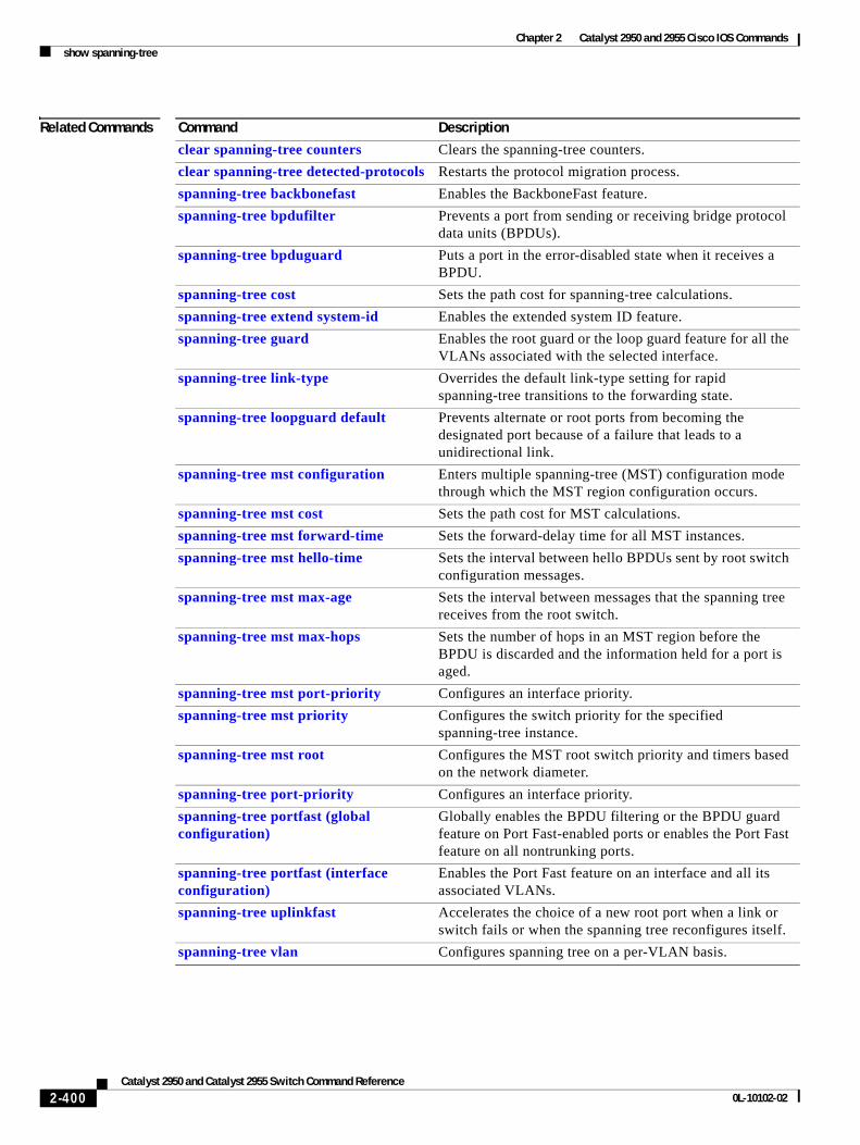
Chapter 2 Catalyst 2950 and 2955 Cisco IOS Commandsshow spanning-tree
Related Commands Command Description
clear spanning-tree counters Clears the spanning-tree counters.
clear spanning-tree detected-protocols Restarts the protocol migration process.
spanning-tree backbonefast Enables the BackboneFast feature.
spanning-tree bpdufilter Prevents a port from sending or receiving bridge protocol data units (BPDUs).
spanning-tree bpduguard Puts a port in the error-disabled state when it receives a BPDU.
spanning-tree cost Sets the path cost for spanning-tree calculations.
spanning-tree extend system-id Enables the extended system ID feature.
spanning-tree guard Enables the root guard or the loop guard feature for all the VLANs associated with the selected interface.
spanning-tree link-type Overrides the default link-type setting for rapid spanning-tree transitions to the forwarding state.
spanning-tree loopguard default Prevents alternate or root ports from becoming the designated port because of a failure that leads to a unidirectional link.
spanning-tree mst configuration Enters multiple spanning-tree (MST) configuration mode through which the MST region configuration occurs.
spanning-tree mst cost Sets the path cost for MST calculations.
spanning-tree mst forward-time Sets the forward-delay time for all MST instances.
spanning-tree mst hello-time Sets the interval between hello BPDUs sent by root switch configuration messages.
spanning-tree mst max-age Sets the interval between messages that the spanning tree receives from the root switch.
spanning-tree mst max-hops Sets the number of hops in an MST region before the BPDU is discarded and the information held for a port is aged.
spanning-tree mst port-priority Configures an interface priority.
spanning-tree mst priority Configures the switch priority for the specified spanning-tree instance.
spanning-tree mst root Configures the MST root switch priority and timers based on the network diameter.
spanning-tree port-priority Configures an interface priority.
spanning-tree portfast (global configuration)
Globally enables the BPDU filtering or the BPDU guard feature on Port Fast-enabled ports or enables the Port Fast feature on all nontrunking ports.
spanning-tree portfast (interface configuration)
Enables the Port Fast feature on an interface and all its associated VLANs.
spanning-tree uplinkfast Accelerates the choice of a new root port when a link or switch fails or when the spanning tree reconfigures itself.
spanning-tree vlan Configures spanning tree on a per-VLAN basis.
2-400Catalyst 2950 and Catalyst 2955 Switch Command Reference
0L-10102-02
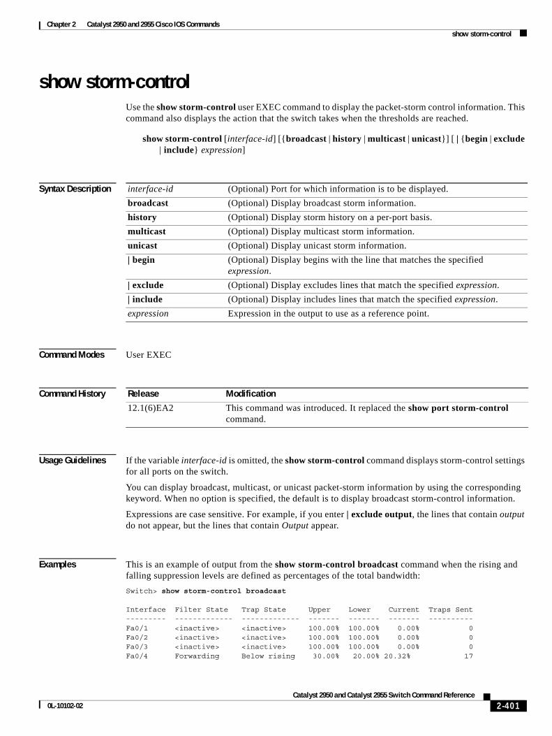
Chapter 2 Catalyst 2950 and 2955 Cisco IOS Commandsshow storm-control
show storm-control Use the show storm-control user EXEC command to display the packet-storm control information. This command also displays the action that the switch takes when the thresholds are reached.
show storm-control [interface-id] [{broadcast | history | multicast | unicast}] [ | {begin | exclude | include} expression]
Syntax Description
Command Modes User EXEC
Command History
Usage Guidelines If the variable interface-id is omitted, the show storm-control command displays storm-control settings for all ports on the switch.
You can display broadcast, multicast, or unicast packet-storm information by using the corresponding keyword. When no option is specified, the default is to display broadcast storm-control information.
Expressions are case sensitive. For example, if you enter | exclude output, the lines that contain output do not appear, but the lines that contain Output appear.
Examples This is an example of output from the show storm-control broadcast command when the rising and falling suppression levels are defined as percentages of the total bandwidth:
Switch> show storm-control broadcast
Interface Filter State Trap State Upper Lower Current Traps Sent--------- ------------- ------------- ------- ------- ------- ----------Fa0/1 <inactive> <inactive> 100.00% 100.00% 0.00% 0Fa0/2 <inactive> <inactive> 100.00% 100.00% 0.00% 0Fa0/3 <inactive> <inactive> 100.00% 100.00% 0.00% 0Fa0/4 Forwarding Below rising 30.00% 20.00% 20.32% 17
interface-id (Optional) Port for which information is to be displayed.
broadcast (Optional) Display broadcast storm information.
history (Optional) Display storm history on a per-port basis.
multicast (Optional) Display multicast storm information.
unicast (Optional) Display unicast storm information.
| begin (Optional) Display begins with the line that matches the specified expression.
| exclude (Optional) Display excludes lines that match the specified expression.
| include (Optional) Display includes lines that match the specified expression.
expression Expression in the output to use as a reference point.
Release Modification
12.1(6)EA2 This command was introduced. It replaced the show port storm-control command.
2-401Catalyst 2950 and Catalyst 2955 Switch Command Reference
0L-10102-02
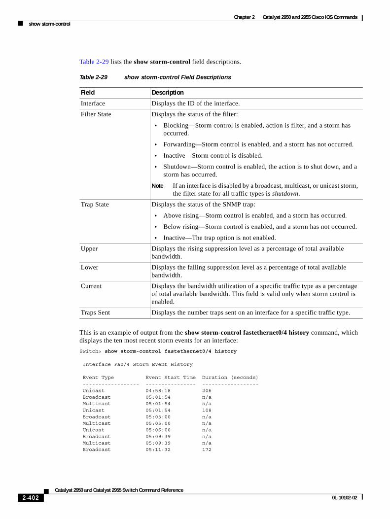
Chapter 2 Catalyst 2950 and 2955 Cisco IOS Commandsshow storm-control
Table 2-29 lists the show storm-control field descriptions.
This is an example of output from the show storm-control fastethernet0/4 history command, which displays the ten most recent storm events for an interface:
Switch> show storm-control fastethernet0/4 history
Interface Fa0/4 Storm Event History
Event Type Event Start Time Duration (seconds) ------------------ ---------------- ------------------ Unicast 04:58:18 206 Broadcast 05:01:54 n/a Multicast 05:01:54 n/a Unicast 05:01:54 108 Broadcast 05:05:00 n/a Multicast 05:05:00 n/a Unicast 05:06:00 n/a Broadcast 05:09:39 n/a Multicast 05:09:39 n/a Broadcast 05:11:32 172
Table 2-29 show storm-control Field Descriptions
Field Description
Interface Displays the ID of the interface.
Filter State Displays the status of the filter:
• Blocking—Storm control is enabled, action is filter, and a storm has occurred.
• Forwarding—Storm control is enabled, and a storm has not occurred.
• Inactive—Storm control is disabled.
• Shutdown—Storm control is enabled, the action is to shut down, and a storm has occurred.
Note If an interface is disabled by a broadcast, multicast, or unicast storm, the filter state for all traffic types is shutdown.
Trap State Displays the status of the SNMP trap:
• Above rising—Storm control is enabled, and a storm has occurred.
• Below rising—Storm control is enabled, and a storm has not occurred.
• Inactive—The trap option is not enabled.
Upper Displays the rising suppression level as a percentage of total available bandwidth.
Lower Displays the falling suppression level as a percentage of total available bandwidth.
Current Displays the bandwidth utilization of a specific traffic type as a percentage of total available bandwidth. This field is valid only when storm control is enabled.
Traps Sent Displays the number traps sent on an interface for a specific traffic type.
2-402Catalyst 2950 and Catalyst 2955 Switch Command Reference
0L-10102-02

Chapter 2 Catalyst 2950 and 2955 Cisco IOS Commandsshow storm-control
Note The duration field could be n/a when a storm is still present or when a new storm of a different type occurs before the current storm ends.
Related Commands Command Description
storm-control Enables broadcast, multicast, or unicast storm control on a port.
2-403Catalyst 2950 and Catalyst 2955 Switch Command Reference
0L-10102-02
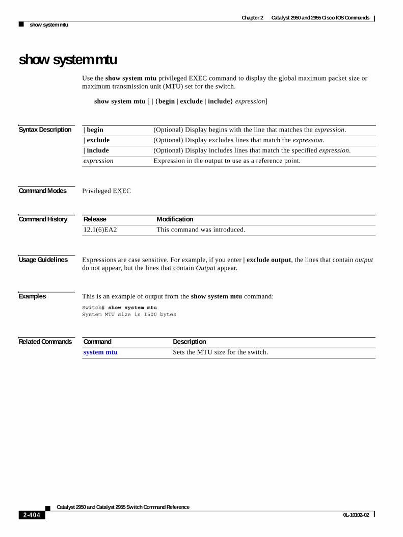
Chapter 2 Catalyst 2950 and 2955 Cisco IOS Commandsshow system mtu
show system mtuUse the show system mtu privileged EXEC command to display the global maximum packet size or maximum transmission unit (MTU) set for the switch.
show system mtu [ | {begin | exclude | include} expression]
Syntax Description
Command Modes Privileged EXEC
Command History
Usage Guidelines Expressions are case sensitive. For example, if you enter | exclude output, the lines that contain output do not appear, but the lines that contain Output appear.
Examples This is an example of output from the show system mtu command:
Switch# show system mtuSystem MTU size is 1500 bytes
Related Commands
| begin (Optional) Display begins with the line that matches the expression.
| exclude (Optional) Display excludes lines that match the expression.
| include (Optional) Display includes lines that match the specified expression.
expression Expression in the output to use as a reference point.
Release Modification
12.1(6)EA2 This command was introduced.
Command Description
system mtu Sets the MTU size for the switch.
2-404Catalyst 2950 and Catalyst 2955 Switch Command Reference
0L-10102-02
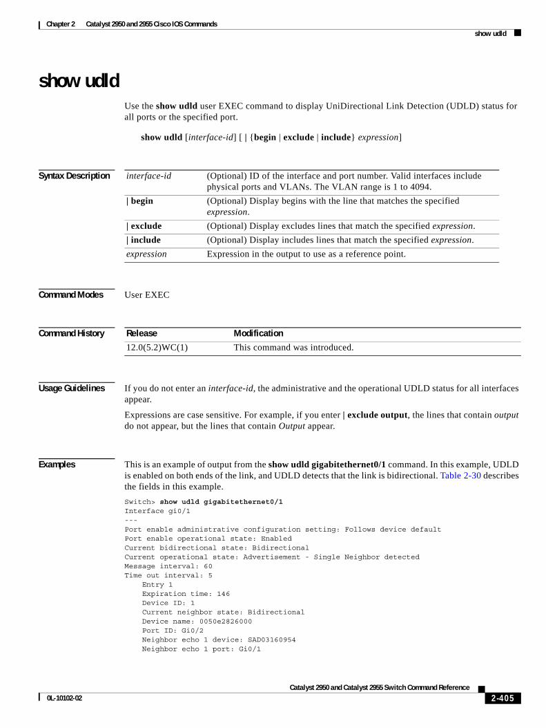
Chapter 2 Catalyst 2950 and 2955 Cisco IOS Commandsshow udld
show udldUse the show udld user EXEC command to display UniDirectional Link Detection (UDLD) status for all ports or the specified port.
show udld [interface-id] [ | {begin | exclude | include} expression]
Syntax Description
Command Modes User EXEC
Command History
Usage Guidelines If you do not enter an interface-id, the administrative and the operational UDLD status for all interfaces appear.
Expressions are case sensitive. For example, if you enter | exclude output, the lines that contain output do not appear, but the lines that contain Output appear.
Examples This is an example of output from the show udld gigabitethernet0/1 command. In this example, UDLD is enabled on both ends of the link, and UDLD detects that the link is bidirectional. Table 2-30 describes the fields in this example.
Switch> show udld gigabitethernet0/1Interface gi0/1---Port enable administrative configuration setting: Follows device defaultPort enable operational state: EnabledCurrent bidirectional state: BidirectionalCurrent operational state: Advertisement - Single Neighbor detectedMessage interval: 60Time out interval: 5 Entry 1 Expiration time: 146 Device ID: 1 Current neighbor state: Bidirectional Device name: 0050e2826000 Port ID: Gi0/2 Neighbor echo 1 device: SAD03160954 Neighbor echo 1 port: Gi0/1
interface-id (Optional) ID of the interface and port number. Valid interfaces include physical ports and VLANs. The VLAN range is 1 to 4094.
| begin (Optional) Display begins with the line that matches the specified expression.
| exclude (Optional) Display excludes lines that match the specified expression.
| include (Optional) Display includes lines that match the specified expression.
expression Expression in the output to use as a reference point.
Release Modification
12.0(5.2)WC(1) This command was introduced.
2-405Catalyst 2950 and Catalyst 2955 Switch Command Reference
0L-10102-02
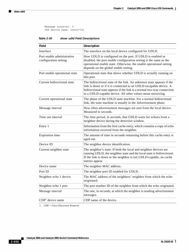
Chapter 2 Catalyst 2950 and 2955 Cisco IOS Commandsshow udld
Message interval: 5 CDP Device name: 066527791
Table 2-30 show udld Field Descriptions
Field Description
Interface The interface on the local device configured for UDLD.
Port enable administrative configuration setting
How UDLD is configured on the port. If UDLD is enabled or disabled, the port enable configuration setting is the same as the operational enable state. Otherwise, the enable operational setting depends on the global enable setting.
Port enable operational state Operational state that shows whether UDLD is actually running on this port.
Current bidirectional state The bidirectional state of the link. An unknown state appears if the link is down or if it is connected to an UDLD-incapable device. A bidirectional state appears if the link is a normal two-way connection to a UDLD-capable device. All other values mean miswiring.
Current operational state The phase of the UDLD state machine. For a normal bidirectional link, the state machine is usually in the Advertisement phase.
Message interval How often advertisement messages are sent from the local device. Measured in seconds.
Time out interval The time period, in seconds, that UDLD waits for echoes from a neighbor device during the detection window.
Entry 1 Information from the first cache entry, which contains a copy of echo information received from the neighbor.
Expiration time The amount of time in seconds remaining before this cache entry is aged out.
Device ID The neighbor device identification.
Current neighbor state The neighbor’s state. If both the local and neighbor devices are running UDLD, the neighbor state and the local state is bidirectional. If the link is down or the neighbor is not UDLD-capable, no cache entries appear.
Device name The neighbor MAC address.
Port ID The neighbor port ID enabled for UDLD.
Neighbor echo 1 device The MAC address of the neighbors’ neighbor from which the echo originated.
Neighbor echo 1 port The port number ID of the neighbor from which the echo originated.
Message interval The rate, in seconds, at which the neighbor is sending advertisement messages.
CDP1 device name
1. CDP = Cisco Discovery Protocol
CDP name of the device.
2-406Catalyst 2950 and Catalyst 2955 Switch Command Reference
0L-10102-02
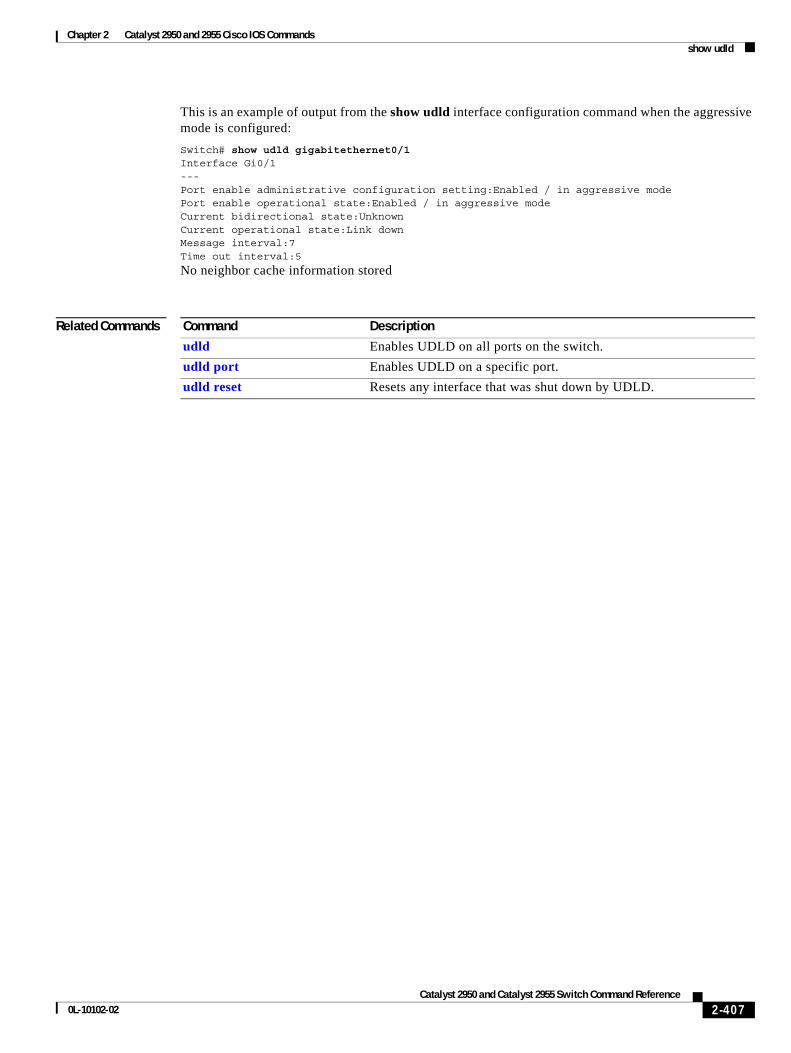
Chapter 2 Catalyst 2950 and 2955 Cisco IOS Commandsshow udld
This is an example of output from the show udld interface configuration command when the aggressive mode is configured:
Switch# show udld gigabitethernet0/1Interface Gi0/1---Port enable administrative configuration setting:Enabled / in aggressive modePort enable operational state:Enabled / in aggressive modeCurrent bidirectional state:UnknownCurrent operational state:Link downMessage interval:7Time out interval:5
No neighbor cache information stored
Related Commands Command Description
udld Enables UDLD on all ports on the switch.
udld port Enables UDLD on a specific port.
udld reset Resets any interface that was shut down by UDLD.
2-407Catalyst 2950 and Catalyst 2955 Switch Command Reference
0L-10102-02
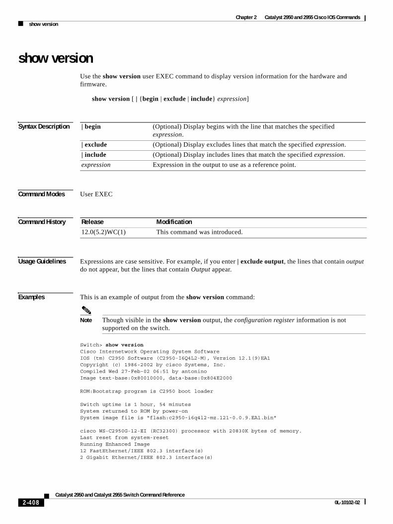
Chapter 2 Catalyst 2950 and 2955 Cisco IOS Commandsshow version
show versionUse the show version user EXEC command to display version information for the hardware and firmware.
show version [ | {begin | exclude | include} expression]
Syntax Description
Command Modes User EXEC
Command History
Usage Guidelines Expressions are case sensitive. For example, if you enter | exclude output, the lines that contain output do not appear, but the lines that contain Output appear.
Examples This is an example of output from the show version command:
Note Though visible in the show version output, the configuration register information is not supported on the switch.
Switch> show versionCisco Internetwork Operating System SoftwareIOS (tm) C2950 Software (C2950-I6Q4L2-M), Version 12.1(9)EA1Copyright (c) 1986-2002 by cisco Systems, Inc.Compiled Wed 27-Feb-02 06:51 by antoninoImage text-base:0x80010000, data-base:0x804E2000
ROM:Bootstrap program is C2950 boot loader
Switch uptime is 1 hour, 54 minutesSystem returned to ROM by power-onSystem image file is "flash:c2950-i6q4l2-mz.121-0.0.9.EA1.bin"
cisco WS-C2950G-12-EI (RC32300) processor with 20830K bytes of memory.Last reset from system-resetRunning Enhanced Image12 FastEthernet/IEEE 802.3 interface(s)2 Gigabit Ethernet/IEEE 802.3 interface(s)
| begin (Optional) Display begins with the line that matches the specified expression.
| exclude (Optional) Display excludes lines that match the specified expression.
| include (Optional) Display includes lines that match the specified expression.
expression Expression in the output to use as a reference point.
Release Modification
12.0(5.2)WC(1) This command was introduced.
2-408Catalyst 2950 and Catalyst 2955 Switch Command Reference
0L-10102-02

Chapter 2 Catalyst 2950 and 2955 Cisco IOS Commandsshow version
32K bytes of flash-simulated non-volatile configuration memory.Base ethernet MAC Address:00:05:74:28:09:C0Configuration register is 0xF<output truncated>
2-409Catalyst 2950 and Catalyst 2955 Switch Command Reference
0L-10102-02
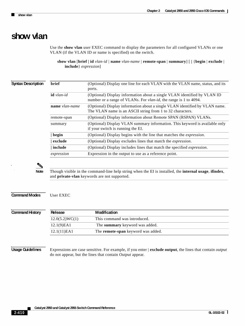
Chapter 2 Catalyst 2950 and 2955 Cisco IOS Commandsshow vlan
show vlanUse the show vlan user EXEC command to display the parameters for all configured VLANs or one VLAN (if the VLAN ID or name is specified) on the switch.
show vlan [brief | id vlan-id | name vlan-name | remote-span | summary] [ | {begin | exclude | include} expression]
Syntax Description
Syntax DescriptionNote Though visible in the command-line help string when the EI is installed, the internal usage, ifindex,
and private-vlan keywords are not supported.
Command Modes User EXEC
Command History
Usage Guidelines Expressions are case sensitive. For example, if you enter | exclude output, the lines that contain output do not appear, but the lines that contain Output appear.
brief (Optional) Display one line for each VLAN with the VLAN name, status, and its ports.
id vlan-id (Optional) Display information about a single VLAN identified by VLAN ID number or a range of VLANs. For vlan-id, the range is 1 to 4094.
name vlan-name (Optional) Display information about a single VLAN identified by VLAN name. The VLAN name is an ASCII string from 1 to 32 characters.
remote-span (Optional) Display information about Remote SPAN (RSPAN) VLANs.
summary (Optional) Display VLAN summary information. This keyword is available only if your switch is running the EI.
| begin (Optional) Display begins with the line that matches the expression.
| exclude (Optional) Display excludes lines that match the expression.
| include (Optional) Display includes lines that match the specified expression.
expression Expression in the output to use as a reference point.
Release Modification
12.0(5.2)WC(1) This command was introduced.
12.1(9)EA1 The summary keyword was added.
12.1(11)EA1 The remote-span keyword was added.
2-410Catalyst 2950 and Catalyst 2955 Switch Command Reference
0L-10102-02
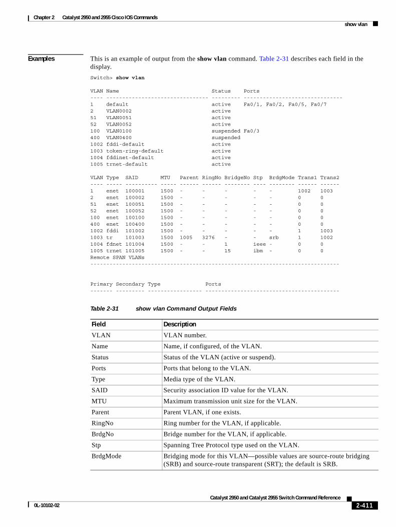
Chapter 2 Catalyst 2950 and 2955 Cisco IOS Commandsshow vlan
Examples This is an example of output from the show vlan command. Table 2-31 describes each field in the display.
Switch> show vlan
VLAN Name Status Ports---- -------------------------------- --------- -------------------------------1 default active Fa0/1, Fa0/2, Fa0/5, Fa0/72 VLAN0002 active51 VLAN0051 active52 VLAN0052 active100 VLAN0100 suspended Fa0/3400 VLAN0400 suspended1002 fddi-default active1003 token-ring-default active1004 fddinet-default active1005 trnet-default active
VLAN Type SAID MTU Parent RingNo BridgeNo Stp BrdgMode Trans1 Trans2---- ----- ---------- ----- ------ ------ -------- ---- -------- ------ ------1 enet 100001 1500 - - - - - 1002 10032 enet 100002 1500 - - - - - 0 051 enet 100051 1500 - - - - - 0 052 enet 100052 1500 - - - - - 0 0100 enet 100100 1500 - - - - - 0 0400 enet 100400 1500 - - - - - 0 01002 fddi 101002 1500 - - - - - 1 10031003 tr 101003 1500 1005 3276 - - srb 1 10021004 fdnet 101004 1500 - - 1 ieee - 0 01005 trnet 101005 1500 - - 15 ibm - 0 0Remote SPAN VLANs------------------------------------------------------------------------------
Primary Secondary Type Ports------- --------- ----------------- ------------------------------------------
Table 2-31 show vlan Command Output Fields
Field Description
VLAN VLAN number.
Name Name, if configured, of the VLAN.
Status Status of the VLAN (active or suspend).
Ports Ports that belong to the VLAN.
Type Media type of the VLAN.
SAID Security association ID value for the VLAN.
MTU Maximum transmission unit size for the VLAN.
Parent Parent VLAN, if one exists.
RingNo Ring number for the VLAN, if applicable.
BrdgNo Bridge number for the VLAN, if applicable.
Stp Spanning Tree Protocol type used on the VLAN.
BrdgMode Bridging mode for this VLAN—possible values are source-route bridging (SRB) and source-route transparent (SRT); the default is SRB.
2-411Catalyst 2950 and Catalyst 2955 Switch Command Reference
0L-10102-02
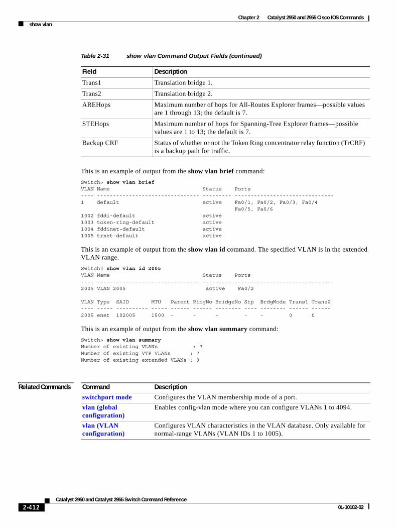
Chapter 2 Catalyst 2950 and 2955 Cisco IOS Commandsshow vlan
This is an example of output from the show vlan brief command:
Switch> show vlan briefVLAN Name Status Ports---- -------------------------------- --------- -------------------------------1 default active Fa0/1, Fa0/2, Fa0/3, Fa0/4 Fa0/5, Fa0/61002 fddi-default active1003 token-ring-default active1004 fddinet-default active1005 trnet-default active
This is an example of output from the show vlan id command. The specified VLAN is in the extended VLAN range.
Switch# show vlan id 2005VLAN Name Status Ports---- -------------------------------- --------- -------------------------------2005 VLAN 2005 active Fa0/2
VLAN Type SAID MTU Parent RingNo BridgeNo Stp BrdgMode Trans1 Trans2---- ----- ---------- ----- ------ ------ -------- ---- -------- ------ ------2005 enet 102005 1500 - - - - - 0 0
This is an example of output from the show vlan summary command:
Switch> show vlan summaryNumber of existing VLANs : 7Number of existing VTP VLANs : 7Number of existing extended VLANs : 0
Related Commands
Trans1 Translation bridge 1.
Trans2 Translation bridge 2.
AREHops Maximum number of hops for All-Routes Explorer frames—possible values are 1 through 13; the default is 7.
STEHops Maximum number of hops for Spanning-Tree Explorer frames—possible values are 1 to 13; the default is 7.
Backup CRF Status of whether or not the Token Ring concentrator relay function (TrCRF) is a backup path for traffic.
Table 2-31 show vlan Command Output Fields (continued)
Field Description
Command Description
switchport mode Configures the VLAN membership mode of a port.
vlan (global configuration)
Enables config-vlan mode where you can configure VLANs 1 to 4094.
vlan (VLAN configuration)
Configures VLAN characteristics in the VLAN database. Only available for normal-range VLANs (VLAN IDs 1 to 1005).
2-412Catalyst 2950 and Catalyst 2955 Switch Command Reference
0L-10102-02
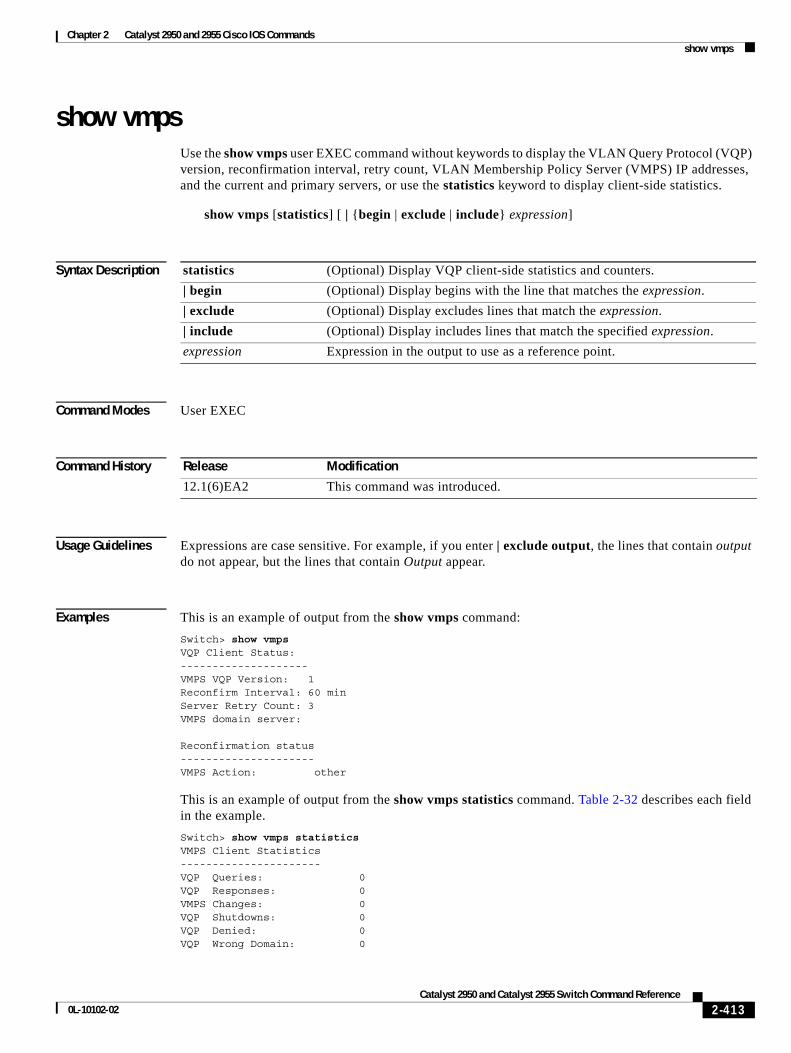
Chapter 2 Catalyst 2950 and 2955 Cisco IOS Commandsshow vmps
show vmpsUse the show vmps user EXEC command without keywords to display the VLAN Query Protocol (VQP) version, reconfirmation interval, retry count, VLAN Membership Policy Server (VMPS) IP addresses, and the current and primary servers, or use the statistics keyword to display client-side statistics.
show vmps [statistics] [ | {begin | exclude | include} expression]
Syntax Description
Command Modes User EXEC
Command History
Usage Guidelines Expressions are case sensitive. For example, if you enter | exclude output, the lines that contain output do not appear, but the lines that contain Output appear.
Examples This is an example of output from the show vmps command:
Switch> show vmpsVQP Client Status:--------------------VMPS VQP Version: 1Reconfirm Interval: 60 minServer Retry Count: 3VMPS domain server:
Reconfirmation status---------------------VMPS Action: other
This is an example of output from the show vmps statistics command. Table 2-32 describes each field in the example.
Switch> show vmps statisticsVMPS Client Statistics----------------------VQP Queries: 0VQP Responses: 0VMPS Changes: 0VQP Shutdowns: 0VQP Denied: 0VQP Wrong Domain: 0
statistics (Optional) Display VQP client-side statistics and counters.
| begin (Optional) Display begins with the line that matches the expression.
| exclude (Optional) Display excludes lines that match the expression.
| include (Optional) Display includes lines that match the specified expression.
expression Expression in the output to use as a reference point.
Release Modification
12.1(6)EA2 This command was introduced.
2-413Catalyst 2950 and Catalyst 2955 Switch Command Reference
0L-10102-02
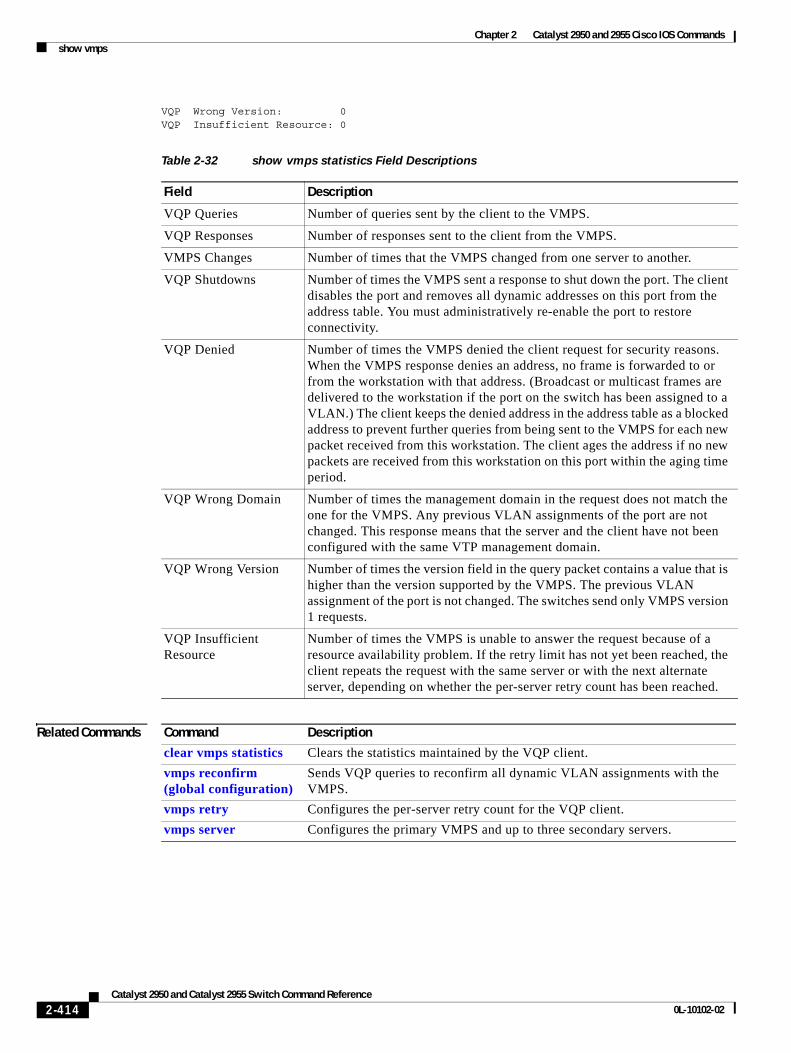
Chapter 2 Catalyst 2950 and 2955 Cisco IOS Commandsshow vmps
VQP Wrong Version: 0VQP Insufficient Resource: 0
Related Commands
Table 2-32 show vmps statistics Field Descriptions
Field Description
VQP Queries Number of queries sent by the client to the VMPS.
VQP Responses Number of responses sent to the client from the VMPS.
VMPS Changes Number of times that the VMPS changed from one server to another.
VQP Shutdowns Number of times the VMPS sent a response to shut down the port. The client disables the port and removes all dynamic addresses on this port from the address table. You must administratively re-enable the port to restore connectivity.
VQP Denied Number of times the VMPS denied the client request for security reasons. When the VMPS response denies an address, no frame is forwarded to or from the workstation with that address. (Broadcast or multicast frames are delivered to the workstation if the port on the switch has been assigned to a VLAN.) The client keeps the denied address in the address table as a blocked address to prevent further queries from being sent to the VMPS for each new packet received from this workstation. The client ages the address if no new packets are received from this workstation on this port within the aging time period.
VQP Wrong Domain Number of times the management domain in the request does not match the one for the VMPS. Any previous VLAN assignments of the port are not changed. This response means that the server and the client have not been configured with the same VTP management domain.
VQP Wrong Version Number of times the version field in the query packet contains a value that is higher than the version supported by the VMPS. The previous VLAN assignment of the port is not changed. The switches send only VMPS version 1 requests.
VQP Insufficient Resource
Number of times the VMPS is unable to answer the request because of a resource availability problem. If the retry limit has not yet been reached, the client repeats the request with the same server or with the next alternate server, depending on whether the per-server retry count has been reached.
Command Description
clear vmps statistics Clears the statistics maintained by the VQP client.
vmps reconfirm (global configuration)
Sends VQP queries to reconfirm all dynamic VLAN assignments with the VMPS.
vmps retry Configures the per-server retry count for the VQP client.
vmps server Configures the primary VMPS and up to three secondary servers.
2-414Catalyst 2950 and Catalyst 2955 Switch Command Reference
0L-10102-02
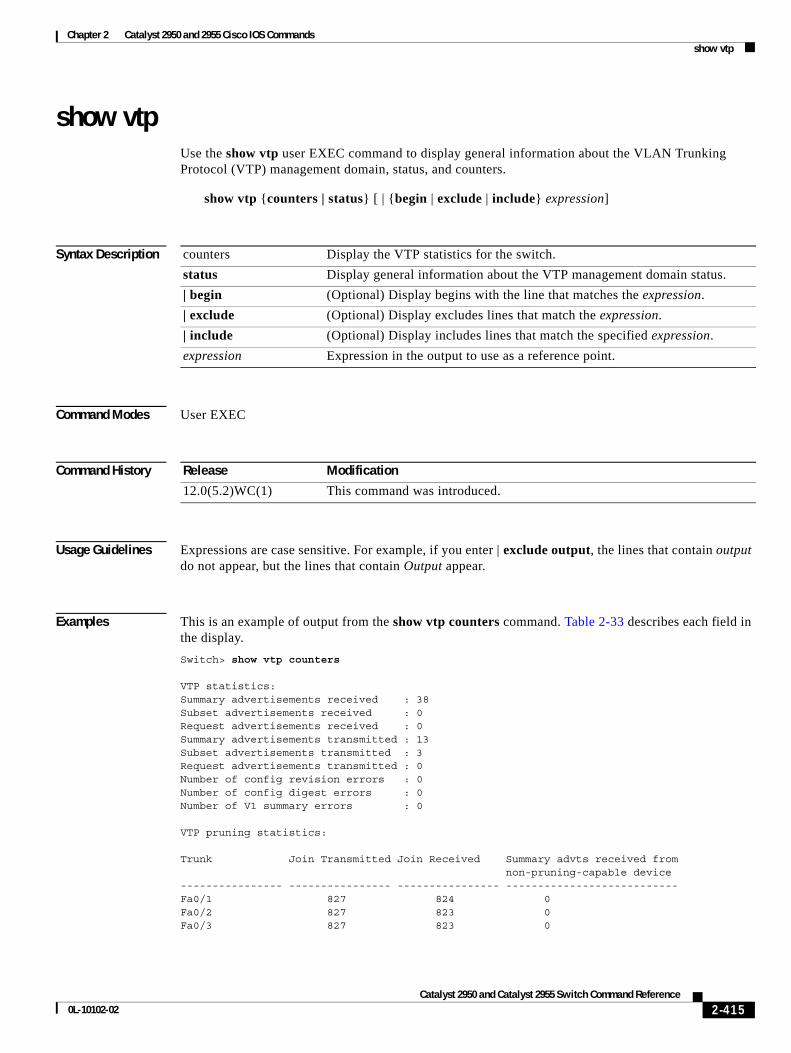
Chapter 2 Catalyst 2950 and 2955 Cisco IOS Commandsshow vtp
show vtpUse the show vtp user EXEC command to display general information about the VLAN Trunking Protocol (VTP) management domain, status, and counters.
show vtp {counters | status} [ | {begin | exclude | include} expression]
Syntax Description
Command Modes User EXEC
Command History
Usage Guidelines Expressions are case sensitive. For example, if you enter | exclude output, the lines that contain output do not appear, but the lines that contain Output appear.
Examples This is an example of output from the show vtp counters command. Table 2-33 describes each field in the display.
Switch> show vtp counters
VTP statistics:Summary advertisements received : 38Subset advertisements received : 0Request advertisements received : 0Summary advertisements transmitted : 13Subset advertisements transmitted : 3Request advertisements transmitted : 0Number of config revision errors : 0Number of config digest errors : 0Number of V1 summary errors : 0
VTP pruning statistics:
Trunk Join Transmitted Join Received Summary advts received from non-pruning-capable device---------------- ---------------- ---------------- ---------------------------Fa0/1 827 824 0Fa0/2 827 823 0 Fa0/3 827 823 0
counters Display the VTP statistics for the switch.
status Display general information about the VTP management domain status.
| begin (Optional) Display begins with the line that matches the expression.
| exclude (Optional) Display excludes lines that match the expression.
| include (Optional) Display includes lines that match the specified expression.
expression Expression in the output to use as a reference point.
Release Modification
12.0(5.2)WC(1) This command was introduced.
2-415Catalyst 2950 and Catalyst 2955 Switch Command Reference
0L-10102-02
Chapter 2 Catalyst 2950 and 2955 Cisco IOS Commandsshow vtp
Table 2-33 show vtp counters Field Descriptions
Field Description
Summary advertisements received
Number of summary advertisements received by this switch on its trunk ports. Summary advertisements contain the management domain name, the configuration revision number, the update timestamp and identity, the authentication checksum, and the number of subset advertisements to follow.
Subset advertisements received Number of subset advertisements received by this switch on its trunk ports. Subset advertisements contain all the information for one or more VLANs.
Request advertisements received Number of advertisement requests received by this switch on its trunk ports. Advertisement requests normally request information on all VLANs. They can also request information on a subset of VLANs.
Summary advertisements transmitted
Number of summary advertisements sent by this switch on its trunk ports. Summary advertisements contain the management domain name, the configuration revision number, the update timestamp and identity, the authentication checksum, and the number of subset advertisements to follow.
Subset advertisements transmitted
Number of subset advertisements sent by this switch on its trunk ports. Subset advertisements contain all the information for one or more VLANs.
Request advertisements transmitted
Number of advertisement requests sent by this switch on its trunk ports. Advertisement requests normally request information on all VLANs. They can also request information on a subset of VLANs.
Number of configuration revision errors
Number of revision errors.
Whenever you define a new VLAN, delete an existing one, suspend or resume an existing VLAN, or modify the parameters on an existing VLAN, the configuration revision number of the switch increments.
Revision errors increment whenever the switch receives an advertisement whose revision number matches the revision number of the switch, but the MD5 digest values do not match. This error means that the VTP password in the two switches is different or that the switches have different configurations.
These errors means that the switch is filtering incoming advertisements, which causes the VTP database to become unsynchronized across the network.
2-416Catalyst 2950 and Catalyst 2955 Switch Command Reference
0L-10102-02
Chapter 2 Catalyst 2950 and 2955 Cisco IOS Commandsshow vtp
This is an example of output from the show vtp status command. Table 2-34 describes each field in the display.
Switch> show vtp statusVTP Version : 2Configuration Revision : 0Maximum VLANs supported locally : 250Number of existing VLANs : 5VTP Operating Mode : ServerVTP Domain Name :VTP Pruning Mode : DisabledVTP V2 Mode : DisabledVTP Traps Generation : DisabledMD5 digest : 0xBF 0x86 0x94 0x45 0xFC 0xDF 0xB5 0x70Configuration last modified by 0.0.0.0 at 0-0-00 00:00:00Local updater ID is 172.20.135.196 on interface Vl1 (lowest numbered VLAN interface found)
Number of configuration digest errors
Number of MD5 digest errors.
Digest errors increment whenever the MD5 digest in the summary packet and the MD5 digest of the received advertisement calculated by the switch do not match. This error usually means that the VTP password in the two switches is different. To solve this problem, make sure the VTP password on all switches is the same.
These errors mean that the switch is filtering incoming advertisements, which causes the VTP database to become unsynchronized across the network.
Number of V1 summary errors Number of version 1 errors.
Version 1 summary errors increment whenever a switch in VTP V2 mode receives a VTP version 1 frame. These errors mean that at least one neighboring switch is either running VTP version 1 or VTP version 2 with V2-mode disabled. To solve this problem, change the configuration of the switches in VTP V2-mode to disabled.
Join Transmitted Number of VTP pruning messages sent on the trunk.
Join Received Number of VTP pruning messages received on the trunk.
Summary Advts Received from non-pruning-capable device
Number of VTP summary messages received on the trunk from devices that do not support pruning.
Table 2-33 show vtp counters Field Descriptions (continued)
Field Description
Table 2-34 show vtp status Field Descriptions
Field Description
VTP Version Displays the VTP version operating on the switch. By default, the switch implements version 1 but can be set to version 2.
Configuration Revision Current configuration revision number on this switch.
Maximum VLANs Supported Locally
Maximum number of VLANs supported locally.
Number of Existing VLANs Number of existing VLANs.
2-417Catalyst 2950 and Catalyst 2955 Switch Command Reference
0L-10102-02
Chapter 2 Catalyst 2950 and 2955 Cisco IOS Commandsshow vtp
VTP Operating Mode Displays the VTP operating mode, which can be server, client, or transparent.
Server: a switch in VTP server mode is enabled for VTP and sends advertisements. You can configure VLANs on it. The switch guarantees that it can recover all the VLAN information in the current VTP database from NVRAM after reboot. By default, every switch is a VTP server.
Note The switch automatically changes from VTP server mode to VTP client mode if it detects a failure while writing the configuration to NVRAM and cannot return to server mode until the NVRAM is functioning.
Client: a switch in VTP client mode is enabled for VTP, can send advertisements, but does not have enough nonvolatile storage to store VLAN configurations. You cannot configure VLANs on it. When a VTP client starts up, it does not send VTP advertisements until it receives advertisements to initialize its VLAN database.
Transparent: a switch in VTP transparent mode is disabled for VTP, does not send or learn from advertisements sent by other devices, and cannot affect VLAN configurations on other devices in the network. The switch receives VTP advertisements and forwards them on all trunk ports except the one on which the advertisement was received.
VTP Domain Name Name that identifies the administrative domain for the switch.
VTP Pruning Mode Displays whether pruning is enabled or disabled. Enabling pruning on a VTP server enables pruning for the entire management domain. Pruning restricts flooded traffic to those trunk links that the traffic must use to access the appropriate network devices.
VTP V2 Mode Displays if VTP version 2 mode is enabled. By default, all VTP version 2 switches operate in version 1 mode. Each VTP switch automatically detects the capabilities of all the other VTP devices. A network of VTP devices should be configured to version 2 only if all VTP switches in the network can operate in version 2 mode.
VTP Traps Generation Displays whether VTP traps are sent to a network management station.
MD5 Digest A 16-byte checksum of the VTP configuration.
Configuration Last Modified Displays the date and time of the last configuration modification. Displays the IP address of the switch that caused the configuration change to the database.
Table 2-34 show vtp status Field Descriptions (continued)
Field Description
2-418Catalyst 2950 and Catalyst 2955 Switch Command Reference
0L-10102-02

Chapter 2 Catalyst 2950 and 2955 Cisco IOS Commandsshow vtp
Related Commands Command Description
clear vtp counters Clears the VTP and pruning counters.
vtp (global configuration) Configures the VTP filename, interface name, domain name, and mode. You can save configuration resulting from this command in the switch configuration file.
vtp (privileged EXEC) Configures the VTP password, pruning, and version.
vtp (VLAN configuration) Configures the VTP domain name, password, pruning, and mode.
2-419Catalyst 2950 and Catalyst 2955 Switch Command Reference
0L-10102-02
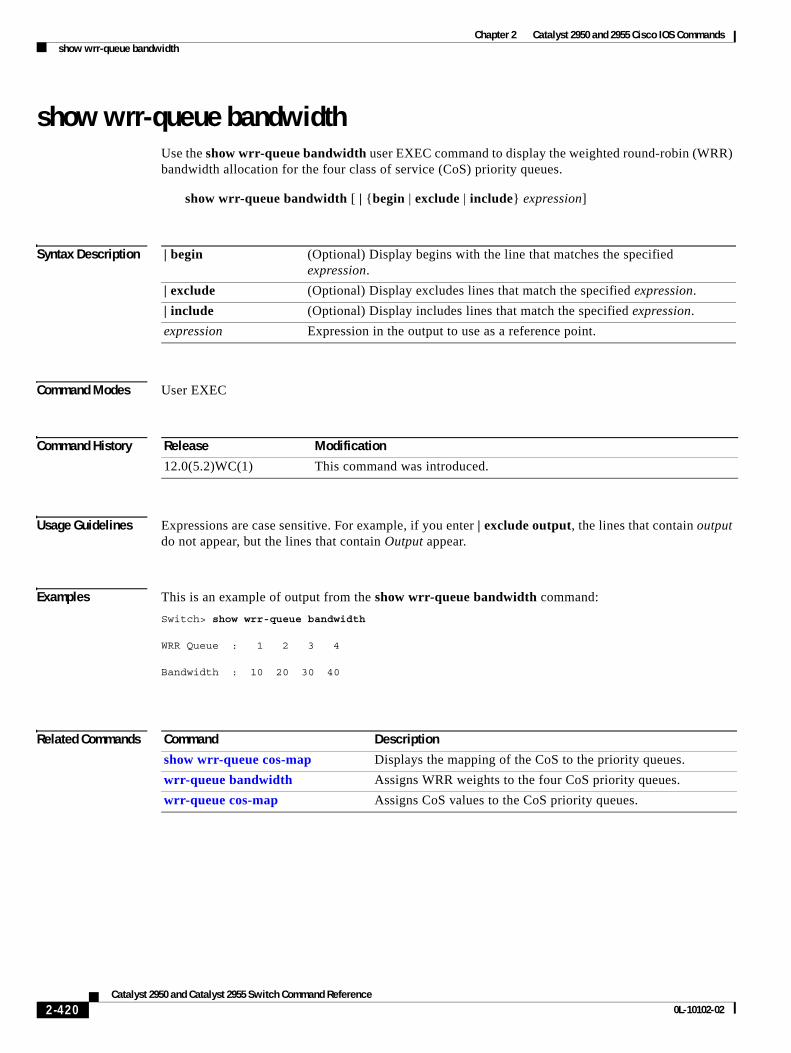
Chapter 2 Catalyst 2950 and 2955 Cisco IOS Commandsshow wrr-queue bandwidth
show wrr-queue bandwidthUse the show wrr-queue bandwidth user EXEC command to display the weighted round-robin (WRR) bandwidth allocation for the four class of service (CoS) priority queues.
show wrr-queue bandwidth [ | {begin | exclude | include} expression]
Syntax Description
Command Modes User EXEC
Command History
Usage Guidelines Expressions are case sensitive. For example, if you enter | exclude output, the lines that contain output do not appear, but the lines that contain Output appear.
Examples This is an example of output from the show wrr-queue bandwidth command:
Switch> show wrr-queue bandwidth
WRR Queue : 1 2 3 4
Bandwidth : 10 20 30 40
Related Commands
| begin (Optional) Display begins with the line that matches the specified expression.
| exclude (Optional) Display excludes lines that match the specified expression.
| include (Optional) Display includes lines that match the specified expression.
expression Expression in the output to use as a reference point.
Release Modification
12.0(5.2)WC(1) This command was introduced.
Command Description
show wrr-queue cos-map Displays the mapping of the CoS to the priority queues.
wrr-queue bandwidth Assigns WRR weights to the four CoS priority queues.
wrr-queue cos-map Assigns CoS values to the CoS priority queues.
2-420Catalyst 2950 and Catalyst 2955 Switch Command Reference
0L-10102-02
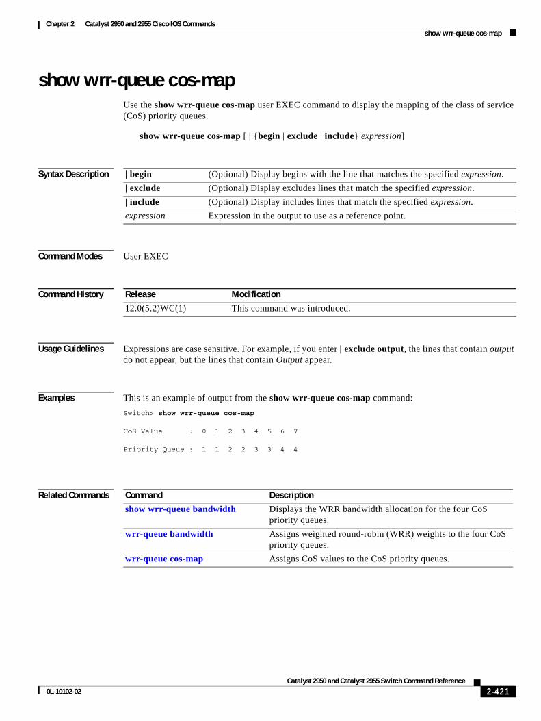
Chapter 2 Catalyst 2950 and 2955 Cisco IOS Commandsshow wrr-queue cos-map
show wrr-queue cos-mapUse the show wrr-queue cos-map user EXEC command to display the mapping of the class of service (CoS) priority queues.
show wrr-queue cos-map [ | {begin | exclude | include} expression]
Syntax Description
Command Modes User EXEC
Command History
Usage Guidelines Expressions are case sensitive. For example, if you enter | exclude output, the lines that contain output do not appear, but the lines that contain Output appear.
Examples This is an example of output from the show wrr-queue cos-map command:
Switch> show wrr-queue cos-map
CoS Value : 0 1 2 3 4 5 6 7
Priority Queue : 1 1 2 2 3 3 4 4
Related Commands
| begin (Optional) Display begins with the line that matches the specified expression.
| exclude (Optional) Display excludes lines that match the specified expression.
| include (Optional) Display includes lines that match the specified expression.
expression Expression in the output to use as a reference point.
Release Modification
12.0(5.2)WC(1) This command was introduced.
Command Description
show wrr-queue bandwidth Displays the WRR bandwidth allocation for the four CoS priority queues.
wrr-queue bandwidth Assigns weighted round-robin (WRR) weights to the four CoS priority queues.
wrr-queue cos-map Assigns CoS values to the CoS priority queues.
2-421Catalyst 2950 and Catalyst 2955 Switch Command Reference
0L-10102-02
Chapter 2 Catalyst 2950 and 2955 Cisco IOS Commandsshutdown
shutdown Use the shutdown interface configuration command to disable a port and to shut down the management VLAN. Use the no form of this command to enable a disabled port or to activate the management VLAN.
shutdown
no shutdown
Syntax Description This command has no arguments or keywords.
Command Modes Interface configuration
Command History
Usage Guidelines The shutdown interface configuration command for a port causes it to stop forwarding. You can enable the port with the no shutdown command.
The no shutdown command has no effect if the port is a static-access port assigned to a VLAN that has been deleted, suspended, or shut down. The port must first be a member of an active VLAN before it can be re-enabled.
Only one management VLAN interface can be active at a time. The remaining VLANs are shut down. In the show running-config command, the active management VLAN interface is the one without the shutdown command displayed.
When you enter the shutdown command on an LRE switch, the switch disables the interface by de-activating the MAC interface and the LRE chipset transmitter. Under some circumstances, the power emitted by LRE switch ports can affect other LRE switch ports. We recommend that ports that are not connected to CPE devices be shut down by using this command. You can also use this command to disable access to the switch from a particular port.
Examples This example shows how to disable a port and how to re-enable it:
Switch(config)# interface fastethernet0/1Switch(config-if)# shutdown
Switch(config-if)# no shutdown
You can verify your settings by entering the show interfaces privileged EXEC command.
Release Modification
12.0(5.2)WC(1) This command was introduced.
2-422Catalyst 2950 and Catalyst 2955 Switch Command Reference
0L-10102-02
Chapter 2 Catalyst 2950 and 2955 Cisco IOS Commandsshutdown vlan
shutdown vlanUse the shutdown vlan global configuration command to shut down (suspend) local traffic on the specified VLAN. Use the no form of this command to restart local traffic on the VLAN.
shutdown vlan vlan-id
no shutdown vlan vlan-id
Syntax Description
Defaults No default is defined.
Command Modes Global configuration
Command History
Usage Guidelines The shutdown vlan command does not change the VLAN information in the VTP database. It shuts down traffic locally, but the switch still advertises VTP information.
Examples This example shows how to shutdown traffic on VLAN 2:
Switch(config)# shutdown vlan 2
You can verify your setting by entering the show vlan privileged EXEC command.
Related Commands
vlan-id ID of the VLAN to be locally shut down. The range is 2 to 1001. VLANs defined as default VLANs under the VLAN Trunking Protocol (VTP), as well as extended-range VLANs (greater than 1005), cannot be shut down. The default VLANs are 1 and 1002 to 1005.
Release Modification
12.0(5.2)WC(1) This command was introduced.
Command Description
shutdown (config-vlan mode)
Shuts down local traffic on the VLAN when in config-VLAN mode (accessed by the vlan vlan-id global configuration command).
vlan (global configuration)
Enables config-vlan mode.
vlan database Enters VLAN configuration mode.
2-423Catalyst 2950 and Catalyst 2955 Switch Command Reference
0L-10102-02
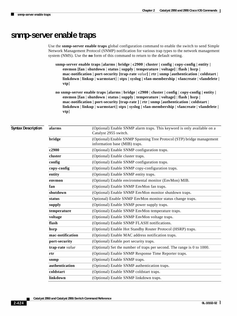
Chapter 2 Catalyst 2950 and 2955 Cisco IOS Commandssnmp-server enable traps
snmp-server enable traps Use the snmp-server enable traps global configuration command to enable the switch to send Simple Network Management Protocol (SNMP) notification for various trap types to the network management system (NMS). Use the no form of this command to return to the default setting.
snmp-server enable traps [alarms | bridge | c2900 | cluster | config | copy-config | entity | envmon [fan | shutdown | status | supply | temperature | voltage] | flash | hsrp | mac-notification | port-security [trap-rate value] | rtr | snmp [authentication | coldstart | linkdown | linkup | warmstart] | stpx | syslog | vlan-membership | vlancreate | vlandelete | vtp]
no snmp-server enable traps [alarms | bridge | c2900 | cluster | config | copy-config | entity | envmon [fan | shutdown | status | supply | temperature | voltage] | flash | hsrp | mac-notification | port-security [trap-rate ] | rtr | snmp [authentication | coldstart | linkdown | linkup | warmstart]| stpx | syslog | vlan-membership | vlancreate | vlandelete | vtp]
Syntax Description alarms (Optional) Enable SNMP alarm traps. This keyword is only available on a Catalyst 2955 switch.
bridge (Optional) Enable SNMP Spanning Tree Protocol (STP) bridge management information base (MIB) traps.
c2900 (Optional) Enable SNMP configuration traps.
cluster (Optional) Enable cluster traps.
config (Optional) Enable SNMP configuration traps.
copy-config (Optional) Enable SNMP copy-configuration traps.
entity (Optional) Enable SNMP entity traps.
envmon (Optional) Enable environmental monitor (EnvMon) MIB.
fan (Optional) Enable SNMP EnvMon fan traps.
shutdown (Optional) Enable SNMP EnvMon monitor shutdown traps.
status Optional) Enable SNMP EnvMon monitor status change traps.
supply (Optional) Enable SNMP power supply traps.
temperature (Optional) Enable SNMP EnvMon temperature traps.
voltage (Optional) Enable SNMP EnvMon voltage traps.
flash (Optional) Enable SNMP FLASH notifications.
hsrp (Optional) Enable Hot Standby Router Protocol (HSRP) traps.
mac-notification (Optional) Enable MAC address notification traps.
port-security (Optional) Enable port security traps.
trap-rate value (Optional) Set the number of traps per second. The range is 0 to 1000.
rtr (Optional) Enable SNMP Response Time Reporter traps.
snmp (Optional) Enable SNMP traps.
authentication (Optional) Enable SNMP authentication traps.
coldstart (Optional) Enable SNMP coldstart traps.
linkdown (Optional) Enable SNMP linkdown traps.
2-424Catalyst 2950 and Catalyst 2955 Switch Command Reference
0L-10102-02
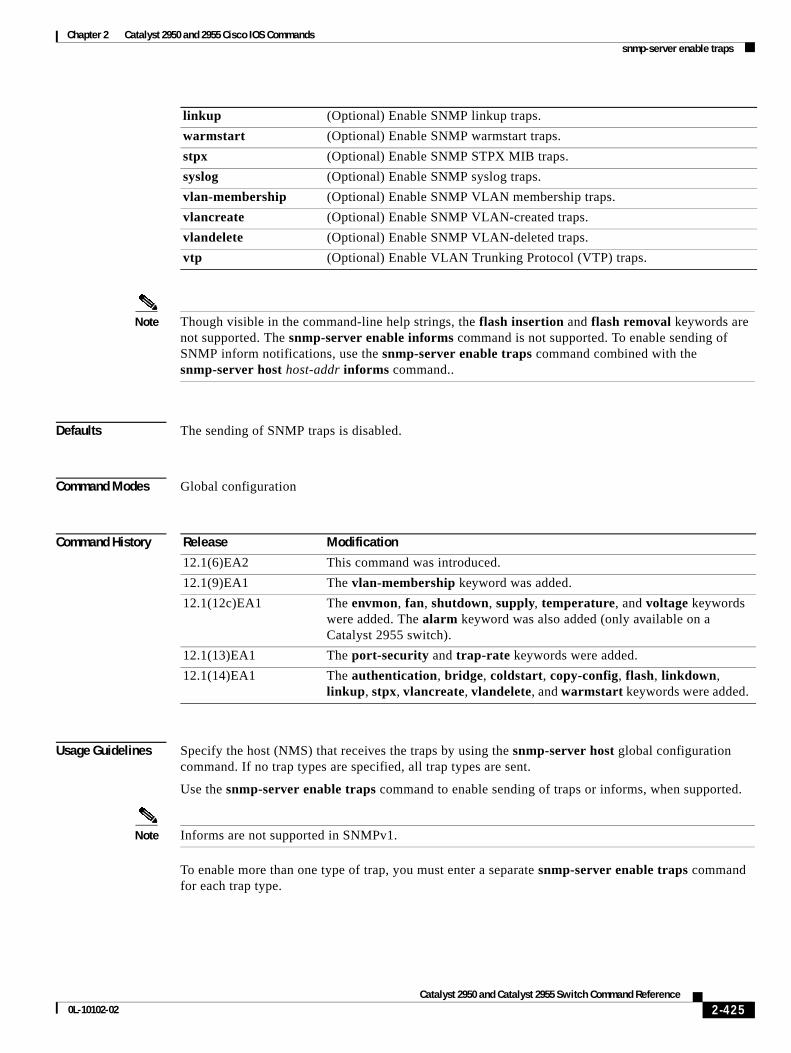
Chapter 2 Catalyst 2950 and 2955 Cisco IOS Commandssnmp-server enable traps
Note Though visible in the command-line help strings, the flash insertion and flash removal keywords are not supported. The snmp-server enable informs command is not supported. To enable sending of SNMP inform notifications, use the snmp-server enable traps command combined with the snmp-server host host-addr informs command..
Defaults The sending of SNMP traps is disabled.
Command Modes Global configuration
Command History
Usage Guidelines Specify the host (NMS) that receives the traps by using the snmp-server host global configuration command. If no trap types are specified, all trap types are sent.
Use the snmp-server enable traps command to enable sending of traps or informs, when supported.
Note Informs are not supported in SNMPv1.
To enable more than one type of trap, you must enter a separate snmp-server enable traps command for each trap type.
linkup (Optional) Enable SNMP linkup traps.
warmstart (Optional) Enable SNMP warmstart traps.
stpx (Optional) Enable SNMP STPX MIB traps.
syslog (Optional) Enable SNMP syslog traps.
vlan-membership (Optional) Enable SNMP VLAN membership traps.
vlancreate (Optional) Enable SNMP VLAN-created traps.
vlandelete (Optional) Enable SNMP VLAN-deleted traps.
vtp (Optional) Enable VLAN Trunking Protocol (VTP) traps.
Release Modification
12.1(6)EA2 This command was introduced.
12.1(9)EA1 The vlan-membership keyword was added.
12.1(12c)EA1 The envmon, fan, shutdown, supply, temperature, and voltage keywords were added. The alarm keyword was also added (only available on a Catalyst 2955 switch).
12.1(13)EA1 The port-security and trap-rate keywords were added.
12.1(14)EA1 The authentication, bridge, coldstart, copy-config, flash, linkdown, linkup, stpx, vlancreate, vlandelete, and warmstart keywords were added.
2-425Catalyst 2950 and Catalyst 2955 Switch Command Reference
0L-10102-02
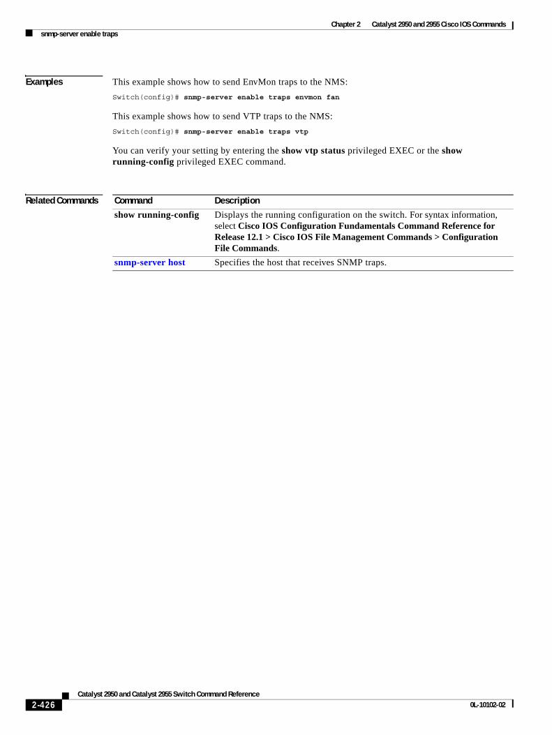
Chapter 2 Catalyst 2950 and 2955 Cisco IOS Commandssnmp-server enable traps
Examples This example shows how to send EnvMon traps to the NMS:
Switch(config)# snmp-server enable traps envmon fan
This example shows how to send VTP traps to the NMS:
Switch(config)# snmp-server enable traps vtp
You can verify your setting by entering the show vtp status privileged EXEC or the show running-config privileged EXEC command.
Related Commands Command Description
show running-config Displays the running configuration on the switch. For syntax information, select Cisco IOS Configuration Fundamentals Command Reference for Release 12.1 > Cisco IOS File Management Commands > Configuration File Commands.
snmp-server host Specifies the host that receives SNMP traps.
2-426Catalyst 2950 and Catalyst 2955 Switch Command Reference
0L-10102-02
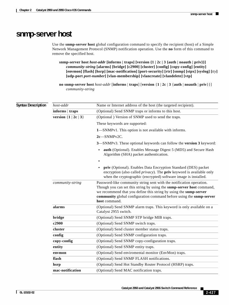
Chapter 2 Catalyst 2950 and 2955 Cisco IOS Commandssnmp-server host
snmp-server hostUse the snmp-server host global configuration command to specify the recipient (host) of a Simple Network Management Protocol (SNMP) notification operation. Use the no form of this command to remove the specified host.
snmp-server host host-addr [informs | traps] [version {1 | 2c | 3 {auth | noauth | priv}}] community-string [alarms] [bridge] [c2900] [cluster] [config] [copy-config] [entity] [envmon] [flash] [hsrp] [mac-notification] [port-security] [rtr] [snmp] [stpx] [syslog] [tty] [udp-port port-number] [vlan-membership] [vlancreate] [vlandelete] [vtp]
no snmp-server host host-addr [informs | traps] [version {1 | 2c | 3 {auth | noauth | priv}}] community-string
Syntax Description host-addr Name or Internet address of the host (the targeted recipient).
informs | traps (Optional) Send SNMP traps or informs to this host.
version {1 | 2c | 3} (Optional ) Version of SNMP used to send the traps.
These keywords are supported:
1—SNMPv1. This option is not available with informs.
2c—SNMPv2C.
3—SNMPv3. These optional keywords can follow the version 3 keyword:
• auth (Optional). Enables Message Digest 5 (MD5) and Secure Hash Algorithm (SHA) packet authentication.
•
• priv (Optional). Enables Data Encryption Standard (DES) packet encryption (also called privacy). The priv keyword is available only when the cryptographic (encrypted) software image is installed.
community-string Password-like community string sent with the notification operation. Though you can set this string by using the snmp-server host command, we recommend that you define this string by using the snmp-server community global configuration command before using the snmp-server host command.
alarms (Optional) Send SNMP alarm traps. This keyword is only available on a Catalyst 2955 switch.
bridge (Optional) Send SNMP STP bridge MIB traps.
c2900 (Optional) Send SNMP switch traps.
cluster (Optional) Send cluster member status traps.
config (Optional) Send SNMP configuration traps.
copy-config (Optional) Send SNMP copy-configuration traps.
entity (Optional) Send SNMP entity traps.
envmon (Optional) Send enviromental monitor (EnvMon) traps.
flash (Optional) Send SNMP FLASH notifications.
hsrp (Optional) Send Hot Standby Router Protocol (HSRP) traps.
mac-notification (Optional) Send MAC notification traps.
2-427Catalyst 2950 and Catalyst 2955 Switch Command Reference
0L-10102-02
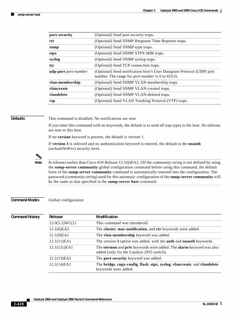
Chapter 2 Catalyst 2950 and 2955 Cisco IOS Commandssnmp-server host
Defaults This command is disabled. No notifications are sent.
If you enter this command with no keywords, the default is to send all trap types to the host. No informs are sent to this host.
If no version keyword is present, the default is version 1.
If version 3 is selected and no authentication keyword is entered, the default is the noauth (noAuthNoPriv) security level.
Note In releases earlier than Cisco IOS Release 12.1(6)EA2, ifIf the community-string is not defined by using the snmp-server community global configuration command before using this command, the default form of the snmp-server community command is automatically inserted into the configuration. The password (community-string) used for this automatic configuration of the snmp-server community will be the same as that specified in the snmp-server host command.
Command Modes Global configuration
Command History
port-security (Optional) Send port security traps.
rtr (Optional) Send SNMP Response Time Reporter traps.
snmp (Optional) Send SNMP-type traps.
stpx (Optional) Send SNMP STPX MIB traps.
syslog (Optional) Send SNMP syslog traps.
tty (Optional) Send TCP connection traps.
udp-port port-number (Optional) Send notification host’s User Datagram Protocol (UDP) port number. The range for port-number is 0 to 65535.
vlan-membership (Optional) Send SNMP VLAN membership traps.
vlancreate (Optional) Send SNMP VLAN-created traps.
vlandelete (Optional) Send SNMP VLAN-deleted traps.
vtp (Optional) Send VLAN Trunking Protocol (VTP) traps.
Release Modification
12.0(5.2)WC(1) This command was introduced.
12.1(6)EA2 The cluster, mac-notification, and rtr keywords were added.
12.1(9)EA1 The vlan-membership keyword was added.
12.1(11)EA1 The version 3 option was added, with the auth and noauth keywords.
12.1(12c)EA1 The envmon and priv keywords were added. The alarm keyword was also added (only for the Catalyst 2955 switch).
12.1(13)EA1 The port-security keyword was added.
12.1(14)EA1 The bridge, copy-config, flash, stpx, syslog, vlancreate, and vlandelete keywords were added.
2-428Catalyst 2950 and Catalyst 2955 Switch Command Reference
0L-10102-02
Chapter 2 Catalyst 2950 and 2955 Cisco IOS Commandssnmp-server host
Usage Guidelines SNMP notifications can be sent as traps or inform requests. Traps are unreliable because the receiver does not send acknowledgments when it receives traps. The sender cannot determine if the traps were received. However, an SNMP entity that receives an inform request acknowledges the message with an SNMP response PDU. If the sender never receives the response, the inform request can be sent again. Thus, informs are more likely to reach their intended destinations.
However, informs consume more resources in the agent and in the network. Unlike a trap, which is discarded as soon as it is sent, an inform request must be held in memory until a response is received or the request times out. Traps are also sent only once, but an inform might be retried several times. The retries increase traffic and contribute to a higher overhead on the network.
If you do not enter an snmp-server host command, no notifications are sent. To configure the switch to send SNMP notifications, you must enter at least one snmp-server host command. If you enter the command with no keywords, all trap types are enabled for the host. To enable multiple hosts, you must enter a separate snmp-server host command for each host. You can specify multiple notification types in the command for each host.
When multiple snmp-server host commands are given for the same host and kind of notification (trap or inform), each succeeding command overwrites the previous command. Only the last snmp-server host command is in effect. For example, if you enter an snmp-server host inform command for a host and then enter another snmp-server host inform command for the same host, the second command replaces the first.
The snmp-server host command is used with the snmp-server enable traps global configuration command. Use the snmp-server enable traps command to specify which SNMP notifications are sent globally. For a host to receive most notifications, at least one snmp-server enable traps command and the snmp-server host command for that host must be enabled. Some notification types cannot be controlled with the snmp-server enable traps command. For example, some notification types are always enabled. Other notification types are enabled by a different command.
The no snmp-server host command with no keywords disables traps, but not informs, to the host. To disable informs, use the no snmp-server host informs command.
Examples This example shows how to configure a unique SNMP community string named comaccess for traps and prevent SNMP polling access with this string through access list 10:
Switch(config)# snmp-server community comaccess ro 10Switch(config)# snmp-server host 172.20.2.160 comaccessSwitch(config)# access-list 10 deny any
This example shows how to send the SNMP traps to the host specified by the name myhost.cisco.com. The community string is defined as comaccess.
Switch(config)# snmp-server enable trapsSwitch(config)# snmp-server host myhost.cisco comaccess snmp
This example shows how to enable the switch to send all traps to the host myhost.cisco using the community string public:
Switch(config)# snmp-server enable trapsSwitch(config)# snmp-server host myhost.cisco public
This example shows how to enable the switch to send EnvMon traps to the host myhost.cisco using the community string public:
Switch(config)# snmp-server host myhost.cisco version 2c public envmon
2-429Catalyst 2950 and Catalyst 2955 Switch Command Reference
0L-10102-02
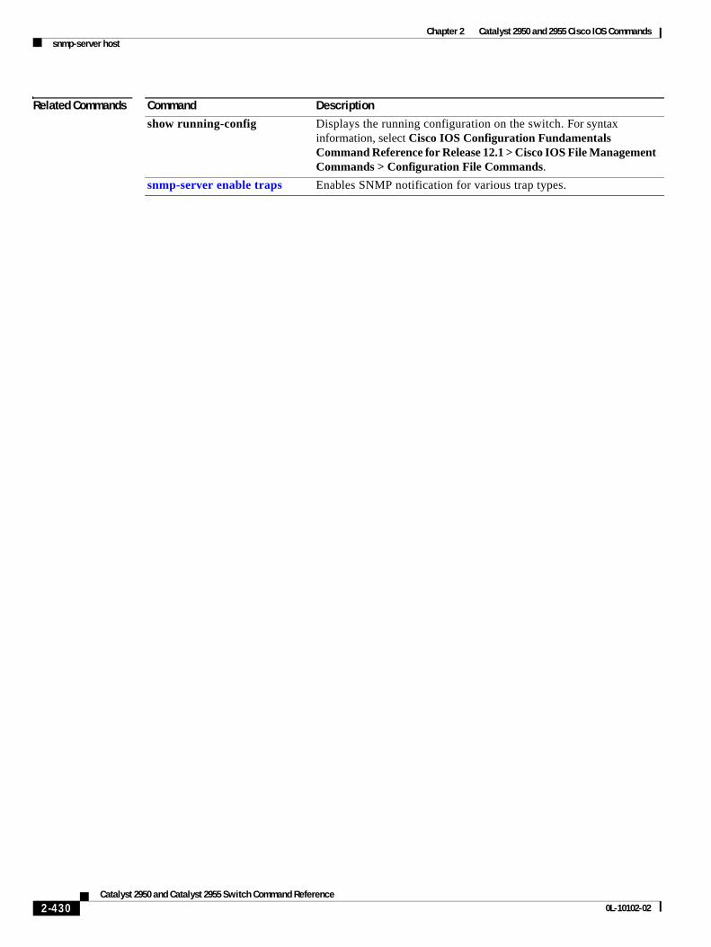
Chapter 2 Catalyst 2950 and 2955 Cisco IOS Commandssnmp-server host
Related Commands Command Description
show running-config Displays the running configuration on the switch. For syntax information, select Cisco IOS Configuration Fundamentals Command Reference for Release 12.1 > Cisco IOS File Management Commands > Configuration File Commands.
snmp-server enable traps Enables SNMP notification for various trap types.
2-430Catalyst 2950 and Catalyst 2955 Switch Command Reference
0L-10102-02
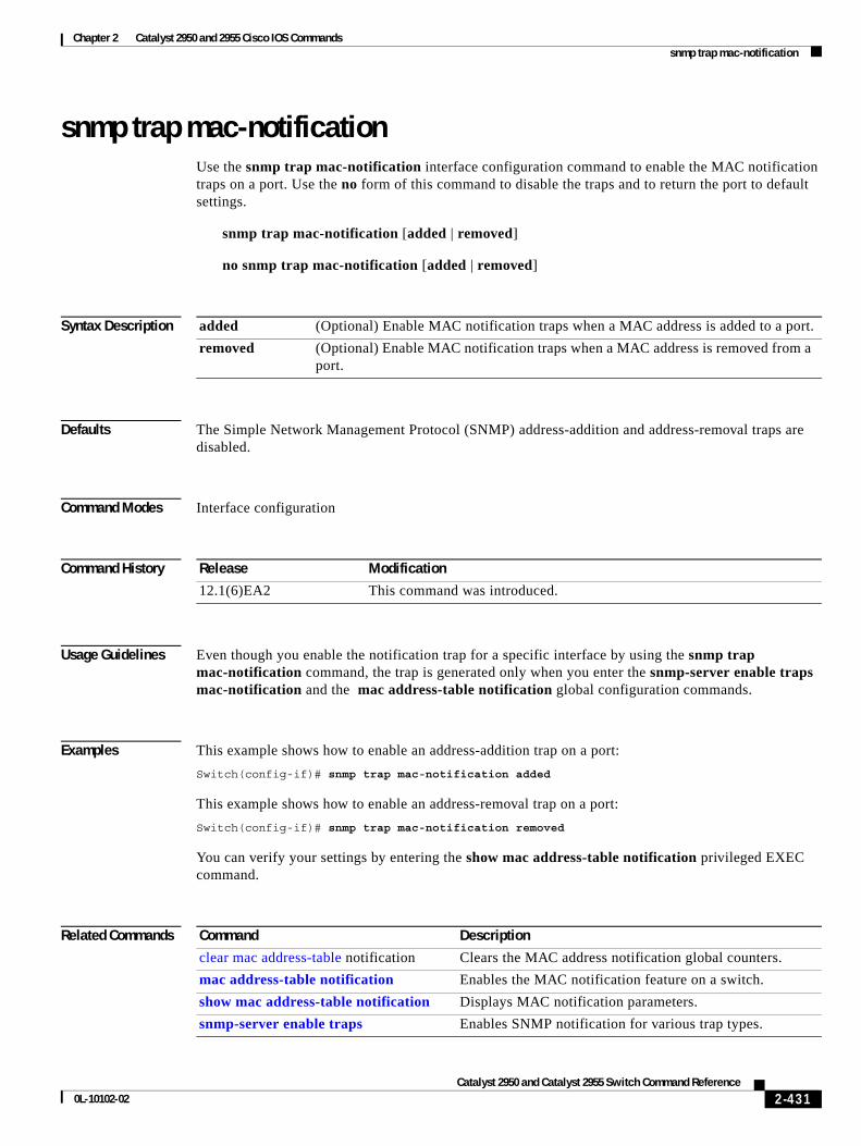
Chapter 2 Catalyst 2950 and 2955 Cisco IOS Commandssnmp trap mac-notification
snmp trap mac-notificationUse the snmp trap mac-notification interface configuration command to enable the MAC notification traps on a port. Use the no form of this command to disable the traps and to return the port to default settings.
snmp trap mac-notification [added | removed]
no snmp trap mac-notification [added | removed]
Syntax Description
Defaults The Simple Network Management Protocol (SNMP) address-addition and address-removal traps are disabled.
Command Modes Interface configuration
Command History
Usage Guidelines Even though you enable the notification trap for a specific interface by using the snmp trap mac-notification command, the trap is generated only when you enter the snmp-server enable traps mac-notification and the mac address-table notification global configuration commands.
Examples This example shows how to enable an address-addition trap on a port:
Switch(config-if)# snmp trap mac-notification added
This example shows how to enable an address-removal trap on a port:
Switch(config-if)# snmp trap mac-notification removed
You can verify your settings by entering the show mac address-table notification privileged EXEC command.
Related Commands
added (Optional) Enable MAC notification traps when a MAC address is added to a port.
removed (Optional) Enable MAC notification traps when a MAC address is removed from a port.
Release Modification
12.1(6)EA2 This command was introduced.
Command Description
clear mac address-table notification Clears the MAC address notification global counters.
mac address-table notification Enables the MAC notification feature on a switch.
show mac address-table notification Displays MAC notification parameters.
snmp-server enable traps Enables SNMP notification for various trap types.
2-431Catalyst 2950 and Catalyst 2955 Switch Command Reference
0L-10102-02
Chapter 2 Catalyst 2950 and 2955 Cisco IOS Commandsspanning-tree backbonefast
spanning-tree backbonefastUse the spanning-tree backbonefast global configuration command to enable the BackboneFast feature. Use the no form of this command to return to the default setting.
spanning-tree backbonefast
no spanning-tree backbonefast
Syntax Description This command has no arguments or keywords.
Defaults BackboneFast is disabled.
Command Modes Global configuration
Command History
Usage Guidelines You can configure the BackboneFast feature for rapid PVST+ or for multiple spanning-tree (MST) mode, but the feature remains disabled (inactive) until you change the spanning-tree mode to PVST+.
BackboneFast is started when a root port or blocked port on a switch receives inferior bridge protocol data units (BPDUs) from its designated bridge. An inferior BPDU identifies one switch as both the root bridge and the designated bridge. When a switch receives an inferior BPDU, it means that a link to which the switch is not directly connected (an indirect link) has failed (that is, the designated bridge has lost its connection to the root switch). If there are alternate paths to the root switch, BackboneFast causes the maximum aging time on the ports on which it received the inferior BPDU to expire and allows a blocked port to move immediately to the listening state. BackboneFast then transitions the interface to the forwarding state. For more information, see the software configuration guide for this release.
Enable BackboneFast on all supported switches to allow the detection of indirect link failures and to start the spanning-tree reconfiguration sooner.
Examples This example shows how to enable BackboneFast on the switch:
Switch(config)# spanning-tree backbonefast
You can verify your setting by entering the show spanning-tree summary privileged EXEC command.
Related Commands
Release Modification
12.1(6)EA2 This command was introduced.
Command Description
show spanning-tree summary Displays a summary of the spanning-tree port states.
2-432Catalyst 2950 and Catalyst 2955 Switch Command Reference
0L-10102-02
Chapter 2 Catalyst 2950 and 2955 Cisco IOS Commandsspanning-tree bpdufilter
spanning-tree bpdufilter Use the spanning-tree bpdufilter interface configuration command to prevent a port from sending or receiving bridge protocol data units (BPDUs). Use the no form of this command to return to the default setting.
spanning-tree bpdufilter {disable | enable}
no spanning-tree bpdufilter
Syntax Description
Defaults BPDU filtering is disabled.
Command Modes Interface configuration
Command History
Usage Guidelines You can enable the BPDU filtering feature when the switch is operating in the per-VLAN spanning-tree plus (PVST+), rapid-PVST+, or in the multiple spanning-tree (MST) mode.
Caution Enabling BPDU filtering on an interface is the same as disabling spanning tree on it and can result in spanning-tree loops.
You can globally enable BPDU filtering on all Port Fast-enabled ports by using the spanning-tree portfast bpdufilter default global configuration command.
You can use the spanning-tree bpdufilter interface configuration command to override the setting of the spanning-tree portfast bpdufilter default global configuration command.
Examples This example shows how to enable the BPDU filtering feature on a port:
Switch(config)# interface fastethernet0/1Switch(config-if)# spanning-tree bpdufilter enable
You can verify your setting by entering the show running-config privileged EXEC command.
disable Disable BPDU filtering on the specified interface.
enable Enable BPDU filtering on the specified interface.
Release Modification
12.1(9)EA1 This command was introduced.
2-433Catalyst 2950 and Catalyst 2955 Switch Command Reference
0L-10102-02

Chapter 2 Catalyst 2950 and 2955 Cisco IOS Commandsspanning-tree bpdufilter
Related Commands Command Description
show running-config Displays the current operating configuration. For syntax information, select Cisco IOS Configuration Fundamentals Command Reference for Release 12.1 > Cisco IOS File Management Commands > Configuration File Commands.
spanning-tree portfast (global configuration)
Globally enables the BPDU filtering or the BPDU guard feature on Port Fast-enabled ports or enables the Port Fast feature on all nontrunking ports.
spanning-tree portfast (interface configuration)
Enables the Port Fast feature on an interface and all its associated VLANs.
2-434Catalyst 2950 and Catalyst 2955 Switch Command Reference
0L-10102-02
Chapter 2 Catalyst 2950 and 2955 Cisco IOS Commandsspanning-tree bpduguard
spanning-tree bpduguard Use the spanning-tree bpduguard interface configuration command to put a port in the error-disabled state when it receives a bridge protocol data unit (BPDU). Use the no form of this command to return to the default setting.
spanning-tree bpduguard {disable | enable}
no spanning-tree bpduguard
Syntax Description
Defaults BPDU guard is disabled.
Command Modes Interface configuration
Command History
Usage Guidelines The BPDU guard feature provides a secure response to invalid configurations because you must manually put the port back in service. Use the BPDU guard feature in a service-provider network to prevent a port from being included in the spanning-tree topology.
You can enable the BPDU guard feature when the switch is operating in the per-VLAN spanning-tree plus (PVST+), rapid-PVST+, or the multiple spanning-tree (MST) mode.
You can globally enable BPDU guard on all Port Fast-enabled ports by using the spanning-tree portfast bpduguard default global configuration command.
You can use the spanning-tree bpduguard interface configuration command to override the setting of the spanning-tree portfast bpduguard default global configuration command.
Examples This example shows how to enable the BPDU guard feature on a port:
Switch(config)# interface fastethernet0/1Switch(config-if)# spanning-tree bpduguard enable
You can verify your setting by entering the show running-config privileged EXEC command.
disable Disable BPDU guard on the specified interface.
enable Enable BPDU guard on the specified interface.
Release Modification
12.1(9)EA1 This command was introduced.
2-435Catalyst 2950 and Catalyst 2955 Switch Command Reference
0L-10102-02
Chapter 2 Catalyst 2950 and 2955 Cisco IOS Commandsspanning-tree bpduguard
Related Commands Command Description
show running-config Displays the current operating configuration. For syntax information, select Cisco IOS Configuration Fundamentals Command Reference for Release 12.1 > Cisco IOS File Management Commands > Configuration File Commands.
spanning-tree portfast (global configuration)
Globally enables the BPDU filtering or the BPDU guard feature on Port Fast-enabled ports, or enables the Port Fast feature on all nontrunking ports.
spanning-tree portfast (interface configuration)
Enables the Port Fast feature on an interface and all its associated VLANs.
2-436Catalyst 2950 and Catalyst 2955 Switch Command Reference
0L-10102-02
Chapter 2 Catalyst 2950 and 2955 Cisco IOS Commandsspanning-tree cost
spanning-tree costUse the spanning-tree cost interface configuration command to set the path cost for spanning-tree calculations. If a loop occurs, spanning tree considers the path cost when selecting an interface to place in the forwarding state. Use the no form of this command to return to the default setting.
spanning-tree [vlan vlan-id] cost cost
no spanning-tree [vlan vlan-id] cost
Syntax Description
Defaults The default path cost is computed from the interface bandwidth setting. These are the IEEE default path cost values:
• 10 Mbps—100
• 100 Mbps—19
• 155 Mbps—14
• 1000 Mbps—4
• 1 Gbps—4
• 10 Gbps—2
• Speeds greater than 10 Gbps—1
Command Modes Interface configuration
Command History
Usage Guidelines When you configure the cost, higher values represent higher costs.
You can set a cost on a VLAN that does not exist. The setting takes effect when the VLAN exists.
If you configure an interface with both the spanning-tree vlan vlan-id cost cost command and the spanning-tree cost cost command, the spanning-tree vlan vlan-id cost cost command takes effect.
vlan vlan-id (Optional) VLAN range associated with a spanning-tree instance. You can specify a single VLAN identified by VLAN ID number, a range of VLANs separated by a hyphen, or a series of VLANs separated by a comma. The range is 1 to 4094.
cost Path cost can range from 1 to 200000000, with higher values meaning higher costs.
Release Modification
12.0(5.2)WC(1) This command was introduced.
12.1(9)EA1 The range for the cost variable increased.
2-437Catalyst 2950 and Catalyst 2955 Switch Command Reference
0L-10102-02
Chapter 2 Catalyst 2950 and 2955 Cisco IOS Commandsspanning-tree cost
Examples This example shows how to set a path cost of 250 on an interface:
Switch(config)# interface fastethernet0/4Switch(config-if)# spanning-tree cost 250
This example shows how to set a path cost of 300 for VLANs 10, 12 to 15, and 20:
Switch(config-if)# spanning-tree vlan 10,12-15,20 cost 300
You can verify your settings by entering the show spanning-tree interface interface-id privileged EXEC command.
Related Commands Command Description
show spanning-tree interface interface-id
Displays spanning-tree information for the specified interface.
spanning-tree port-priority Configures an interface priority.
spanning-tree vlan priority Sets the switch priority for the specified spanning-tree instance.
2-438Catalyst 2950 and Catalyst 2955 Switch Command Reference
0L-10102-02
Chapter 2 Catalyst 2950 and 2955 Cisco IOS Commandsspanning-tree etherchannel guard misconfig
spanning-tree etherchannel guard misconfigUse the spanning-tree etherchannel guard misconfig global configuration command to display an error message when the switch detects a loop that occurred because of an EtherChannel misconfiguration. Use the no form of this command to disable the feature.
spanning-tree etherchannel guard misconfig
no spanning-tree etherchannel guard misconfig
Syntax Description This command has no arguments or keywords.
Defaults EtherChannel guard is enabled on the switch.
Command Modes Global configuration
Command History
Usage Guidelines When the switch detects a loop that is caused by an EtherChannel misconfiguration, this error message appears:
PM-4-ERR_DISABLE: Channel-misconfig error detected on [chars], putting [chars] in err-disable state.
To determine which switch ports are in the misconfigured EtherChannel, use the show interfaces status err-disabled privileged EXEC command. To verify the EtherChannel configuration on a remote device, use the show etherchannel summary privileged EXEC command on the remote device.
When a port is in the error-disabled state because of an EtherChannel misconfiguration, you can bring it out of this state by entering the errdisable recovery cause channel-misconfig global configuration command, or you can manually re-enable it by entering the shutdown and no shutdown interface configuration commands.
Examples This example shows how to enable the EtherChannel guard misconfiguration feature:
Switch(config)# spanning-tree etherchannel guard misconfig
You can verify your settings by entering the show spanning-tree summary privileged EXEC command.
Release Modification
12.1(13)EA1 This command was introduced.
2-439Catalyst 2950 and Catalyst 2955 Switch Command Reference
0L-10102-02
Chapter 2 Catalyst 2950 and 2955 Cisco IOS Commandsspanning-tree etherchannel guard misconfig
Related Commands Command Description
errdisable recovery cause channel-misconfig
Enables the timer to recover from the EtherChannel misconfiguration error-disable state.
show etherchannel summary Displays EtherChannel information for a channel as a one-line summary per channel-group.
show interfaces status err-disabled
Displays the interfaces in the error-disabled state.
2-440Catalyst 2950 and Catalyst 2955 Switch Command Reference
0L-10102-02
Chapter 2 Catalyst 2950 and 2955 Cisco IOS Commandsspanning-tree extend system-id
spanning-tree extend system-idUse the spanning-tree extend system-id global configuration command to enable the extended system ID feature.
spanning-tree extend system-id
Note Though visible in the command-line help strings, the no version of this command is not supported. You cannot disable the extended system ID feature.
Syntax Description This command has no arguments or keywords.
Defaults The extended system ID is enabled.
Command Modes Global configuration
Command History
Usage Guidelines In Cisco IOS Release 12.1(9)EA1 and later, Catalyst 2950 switches support the IEEE 802.1t spanning-tree extensions, and some of the bits previously used for the switch priority are now used for the extended system ID (VLAN identifier for the per-VLAN spanning-tree plus [PVST+] and for rapid PVST+ or an instance identifier for the multiple spanning tree [MST]). In earlier releases, the switch priority is a 16-bit value.
The spanning tree uses the extended system ID, the switch priority, and the allocated spanning-tree MAC address to make the bridge ID unique for each VLAN or multiple spanning-tree instance. With earlier releases, spanning tree used one MAC address per VLAN to make the bridge ID unique for each VLAN.
Support for the extended system ID affects how you manually configure the root switch, the secondary root switch, and the switch priority of a VLAN. For more information, see the “spanning-tree mst root” and the “spanning-tree vlan” sections.
If your network consists of switches that do not support the extended system ID and switches that do support it, it is unlikely that the switch with the extended system ID support will become the root switch. The extended system ID increases the switch priority value every time the VLAN number is greater than the priority of the connected switches running older software.
Release Modification
12.1(9)EA1 This command was introduced.
2-441Catalyst 2950 and Catalyst 2955 Switch Command Reference
0L-10102-02

Chapter 2 Catalyst 2950 and 2955 Cisco IOS Commandsspanning-tree extend system-id
Related Commands Command Description
show spanning-tree summary Displays a summary of spanning-tree port states.
spanning-tree mst root Configures the multiple spanning-tree (MST) root switch priority and timers based on the network diameter.
spanning-tree vlan priority Sets the switch priority for the specified spanning-tree instance.
2-442Catalyst 2950 and Catalyst 2955 Switch Command Reference
0L-10102-02
Chapter 2 Catalyst 2950 and 2955 Cisco IOS Commandsspanning-tree guard
spanning-tree guardUse the spanning-tree guard interface configuration command to enable root guard or loop guard on all the VLANs associated with the selected interface. Root guard restricts which interface is allowed to be the spanning-tree root port or the path-to-the root for the switch. Loop guard prevents alternate or root ports from becoming designated ports when a failure creates a unidirectional link. Use the no form of this command to return to the default setting.
spanning-tree guard {loop | none | root}
no spanning-tree guard
Syntax Description
Defaults Root guard is disabled.
Loop guard is configured according to the spanning-tree loopguard default global configuration command (globally disabled).
Command Modes Interface configuration
Command History
Usage Guidelines You can enable root guard or loop guard when the switch is operating in the per-VLAN spanning-tree plus (PVST+), rapid-PVST+, or the multiple spanning-tree (MST) mode. However, you cannot enable both PVST+ and MST or both rapid PVST+ and MST at the same time.
When root guard is enabled, if spanning-tree calculations cause a port to be selected as the root port, the port transitions to the root-inconsistent (blocked) state to prevent the customer’s switch from becoming the root switch or being in the path to the root. The root port provides the best path from the switch to the root switch.
When the no spanning-tree guard or the no spanning-tree guard none command is entered, root guard is disabled for all VLANs on the selected interface. If this interface is in the root-inconsistent (blocked) state, it automatically transitions to the listening state.
Do not enable root guard on interfaces that will be used by the UplinkFast feature. With UplinkFast, the backup interfaces (in the blocked state) replace the root port in the case of a failure. However, if root guard is also enabled, all the backup interfaces used by the UplinkFast feature are placed in the root-inconsistent state (blocked) and prevented from reaching the forwarding state. The UplinkFast feature is not available when the switch is operating in rapid-PVST+ or MST mode.
loop Enable loop guard.
none Disable root guard or loop guard.
root Enable root guard.
Release Modification
12.1(6)EA2 This command was introduced. It replaced the spanning-tree rootguard command.
12.1(9)EA1 The loop keyword was added.
2-443Catalyst 2950 and Catalyst 2955 Switch Command Reference
0L-10102-02
Chapter 2 Catalyst 2950 and 2955 Cisco IOS Commandsspanning-tree guard
Loop guard is most effective when it is configured on the entire switched network. When the switch is operating in PVST+ or rapid-PVST+ mode, loop guard prevents alternate and root ports from becoming designated ports, and spanning tree does not send bridge protocol data units (BPDUs) on root or alternate ports. When the switch is operating in MST mode, BPDUs are not sent on nonboundary ports only if the port is blocked by loop guard in all MST instances. On a boundary port, loop guard blocks the port in all MST instances.
To disable root guard or loop guard, use the spanning-tree guard none interface configuration command. You cannot enable both root guard and loop guard at the same time.
You can override the setting of the spanning-tree loopguard default global configuration command by using the spanning-tree guard loop interface configuration command.
Examples This example shows how to enable root guard on all the VLANs associated with the specified interface:
Switch(config)# interface fastethernet0/1Switch(config-if)# spanning-tree guard root
This example shows how to enable loop guard on all the VLANs associated with the specified interface:
Switch(config)# interface fastethernet0/1Switch(config-if)# spanning-tree guard loop
You can verify your settings by entering the show running-config privileged EXEC command.
Related Commands Command Description
show running-config Displays the current operating configuration. For syntax information, select Cisco IOS Configuration Fundamentals Command Reference for Release 12.1 > Cisco IOS File Management Commands > Configuration File Commands.
spanning-tree cost Sets the path cost for spanning-tree calculations.
spanning-tree loopguard default Prevents alternate or root ports from becoming designated ports because of a failure that leads to a unidirectional link.
spanning-tree mst cost Configures the path cost for MST calculations.
spanning-tree mst port-priority Configures an interface priority.
spanning-tree mst root Configures the MST root switch priority and timers based on the network diameter.
spanning-tree port-priority Configures an interface priority.
spanning-tree vlan priority Sets the switch priority for the specified spanning-tree instance.
2-444Catalyst 2950 and Catalyst 2955 Switch Command Reference
0L-10102-02
Chapter 2 Catalyst 2950 and 2955 Cisco IOS Commandsspanning-tree link-type
spanning-tree link-typeUse the spanning-tree link-type interface configuration command to override the default link-type setting, which is determined by the duplex mode of the port, and to enable rapid spanning-tree transitions to the forwarding state. Use the no form of this command to return to the default setting.
spanning-tree link-type {point-to-point | shared}
no spanning-tree link-type
Syntax Description
Defaults The switch derives the link type of a port from the duplex mode. A full-duplex port is considered a point-to-point link, and a half-duplex port is considered a shared link.
Command Modes Interface configuration
Command History
Usage Guidelines You can override the default setting of the link type by using the spanning-tree link-type command; for example, a half-duplex link can be physically connected point-to-point to a single port on a remote switch running the Multiple Spanning Tree Protocol (MSTP) or the rapid per-VLAN spanning-tree plus (rapid-PVST+) protocol and be enabled for rapid transitions.
Examples This example shows how to specify the link type as shared (regardless of the duplex setting) and to prevent rapid transitions to the forwarding state:
Switch(config-if)# spanning-tree link-type shared
You can verify your settings by entering the show spanning-tree mst interface interface-id privileged EXEC command.
Related Commands
point-to-point Specify that the link type of a port is point-to-point.
shared Specify that the link type of a port is shared.
Release Modification
12.1(9)EA1 This command was introduced.
Command Description
show spanning-tree mst interface interface-id
Displays multiple spanning-tree (MST) information for the specified interface.
2-445Catalyst 2950 and Catalyst 2955 Switch Command Reference
0L-10102-02
Chapter 2 Catalyst 2950 and 2955 Cisco IOS Commandsspanning-tree loopguard default
spanning-tree loopguard defaultUse the spanning-tree loopguard default global configuration command to prevent alternate or root ports from becoming designated ports because of a failure that leads to a unidirectional link. Use the no form of this command to return to the default setting.
spanning-tree loopguard default
no spanning-tree loopguard default
Syntax Description This command has no arguments or keywords.
Defaults Loop guard is disabled.
Command Modes Global configuration
Command History
Usage Guidelines You can enable the loop guard feature when the switch is operating in the per-VLAN spanning-tree plus (PVST+), rapid-PVST+, or the multiple spanning-tree (MST) mode.
Loop guard is most effective when it is configured on the entire switched network. When the switch is operating in PVST+ or rapid-PVST+ mode, loop guard prevents alternate and root ports from becoming designated ports, and spanning tree does not send bridge protocol data units (BPDUs) on root or alternate ports. When the switch is operating in MST mode, BPDUs are not sent on nonboundary ports only if the port is blocked by loop guard in all MST instances. On a boundary port, loop guard blocks the port in all MST instances.
Loop guard operates only on ports that are considered point-to-point by the spanning tree.
You can override the setting of the spanning-tree loopguard default global configuration command by using the spanning-tree guard loop interface configuration command.
Examples This example shows how to globally enable loop guard:
Switch(config)# spanning-tree loopguard default
You can verify your settings by entering the show running-config privileged EXEC command.
Release Modification
12.1(9)EA1 This command was introduced.
2-446Catalyst 2950 and Catalyst 2955 Switch Command Reference
0L-10102-02

Chapter 2 Catalyst 2950 and 2955 Cisco IOS Commandsspanning-tree loopguard default
Related Commands Command Description
show running-config Displays the current operating configuration. For syntax information, select Cisco IOS Configuration Fundamentals Command Reference for Release 12.1 > Cisco IOS File Management Commands > Configuration File Commands.
spanning-tree guard loop Enables the loop guard feature on all the VLANs associated with the specified interface.
2-447Catalyst 2950 and Catalyst 2955 Switch Command Reference
0L-10102-02
Chapter 2 Catalyst 2950 and 2955 Cisco IOS Commandsspanning-tree mode
spanning-tree modeUse the spanning-tree mode global configuration command to enable per-VLAN spanning-tree plus PVST+), rapid PVST+, or multiple spanning tree (MST) on your switch. Use the no form of this command to return to the default setting.
spanning-tree mode {mst | pvst | rapid-pvst}
no spanning-tree mode
Syntax Description
Defaults The default mode is PVST+.
Command Modes Global configuration
Command History
Usage Guidelines The switch supports PVST+, rapid PVST+, and MSTP, but only one version can be active at any time. All VLANs run PVST+, all VLANs run rapid PVST+, or all VLANs run MSTP.
Caution Changing spanning-tree modes can disrupt traffic because all spanning-tree instances are stopped for the previous mode and restarted in the new mode.
When you enable the MST mode, RSTP is automatically enabled.
Examples This example shows to enable MST on the switch:
Switch(config)# spanning-tree mode mst
This example shows to enable rapid PVST+ on the switch:
Switch(config)# spanning-tree mode rapid-pvst
You can verify your setting by entering the show running-config privileged EXEC command.
mst Enable MST and Rapid Spanning Tree Protocol (RSTP) (based on IEEE 802.1s and IEEE 802.1w).
pvst Enable PVST+ (based on IEEE 802.1D).
rapid-pvst Enable rapid PVST+ (based on IEEE 802.1w).
Release Modification
12.1(9)EA1 This command was introduced.
12.1(13)EA1 The rapid-pvst keyword was added.
12.1(20)EA2 This command was added to the standard software image (SI).
2-448Catalyst 2950 and Catalyst 2955 Switch Command Reference
0L-10102-02

Chapter 2 Catalyst 2950 and 2955 Cisco IOS Commandsspanning-tree mode
Related Commands Command Description
show running-config Displays the current operating configuration. For syntax information, select Cisco IOS Configuration Fundamentals Command Reference for Release 12.1 > Cisco IOS File Management Commands > Configuration File Commands.
2-449Catalyst 2950 and Catalyst 2955 Switch Command Reference
0L-10102-02
Chapter 2 Catalyst 2950 and 2955 Cisco IOS Commandsspanning-tree mst configuration
spanning-tree mst configurationUse the spanning-tree mst configuration global configuration command to enter multiple spanning-tree (MST) configuration mode through which you configure the MST region. Use the no form of this command to return to the default settings.
spanning-tree mst configuration
no spanning-tree mst configuration
Syntax Description This command has no arguments or keywords.
Defaults The default mapping is that all VLANs are mapped to the common and internal spanning tree (CIST) instance (instance 0).
The default name is an empty string.
The revision number is 0.
Command Modes Global configuration
Command History
Usage Guidelines Entering the spanning-tree mst configuration command enables the MST configuration mode. These configuration commands are available:
• abort: exits the MST region configuration mode without applying configuration changes.
• exit: exits the MST region configuration mode and applies all configuration changes.
• instance instance-id vlan vlan-range: maps VLANs to an MST instance. The instance-id range is 1 to 15. The vlan-range range is 1 to 4094. You can specify a single VLAN identified by VLAN ID number, a range of VLANs separated by a hyphen, or a series of VLANs separated by a comma.
• name name: sets the configuration name. The name string has a maximum length of 32 characters and is case sensitive.
• no: negates the instance, name, and revision commands or sets them to their defaults.
• private-vlan: Though visible in the command-line help strings, this command is not supported.
• revision version: sets the configuration revision number. The range is 0 to 65535.
• show [current | pending]: displays the current or pending MST region configuration.
In MST mode, the switch supports up to 16 MST instances. The number of VLANs that can be mapped to a particular MST instance is unlimited.
Release Modification
12.1(9)EA1 This command was introduced.
12.1(20)EA2 This command was added to the standard software image (SI).
2-450Catalyst 2950 and Catalyst 2955 Switch Command Reference
0L-10102-02
Chapter 2 Catalyst 2950 and 2955 Cisco IOS Commandsspanning-tree mst configuration
When you map VLANs to an MST instance, the mapping is incremental, and the VLANs specified in the command are added to or removed from the VLANs that were previously mapped. To specify a range, use a hyphen; for example, instance 1 vlan 1-63 maps VLANs 1 to 63 to MST instance 1. To specify a series, use a comma; for example, instance 1 vlan 10, 20, 30 maps VLANs 10, 20, and 30 to MST instance 1.
All VLANs that are not explicitly mapped to an MST instance are mapped to the common and internal spanning tree (CIST) instance (instance 0) and cannot be unmapped from the CIST by using the no form of the command.
For two or more switches to be in the same MST region, they must have the same VLAN mapping, the same configuration revision number, and the same name.
Examples This example shows how to enter MST configuration mode, map VLAN 10 to 20 to MST instance 1, name the region region1, set the configuration revision to 1, display the pending configuration, apply the changes, and return to global configuration mode:
Switch# spanning-tree mst configurationSwitch(config-mst)# instance 1 vlan 10-20Switch(config-mst)# name region1Switch(config-mst)# revision 1Switch(config-mst)# show pendingPending MST configurationName [region1]Revision 1Instance Vlans Mapped-------- ---------------------0 1-9,21-40941 10-20-------------------------------
Switch(config-mst)# exitSwitch(config)#
This example shows how to add VLANs 1 to 100 to the ones already mapped (if any) to instance 2, to move VLANs 40 to 60 that were previously mapped to instance 2 to the CIST instance, to add VLAN 10 to instance 10, and to remove all the VLANs mapped to instance 2 and map them to the CIST instance:
Switch(config-mst)# instance 2 vlan 1-100Switch(config-mst)# no instance 2 vlan 40-60Switch(config-mst)# instance 10 vlan 10Switch(config-mst)# no instance 2
You can verify your settings by entering the show pending MST configuration command.
Related Commands Command Description
show spanning-tree mst configuration Displays the MST region configuration.
2-451Catalyst 2950 and Catalyst 2955 Switch Command Reference
0L-10102-02
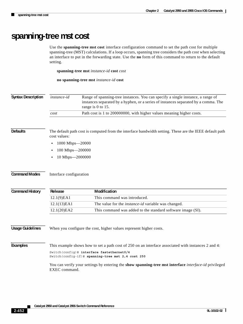
Chapter 2 Catalyst 2950 and 2955 Cisco IOS Commandsspanning-tree mst cost
spanning-tree mst costUse the spanning-tree mst cost interface configuration command to set the path cost for multiple spanning-tree (MST) calculations. If a loop occurs, spanning tree considers the path cost when selecting an interface to put in the forwarding state. Use the no form of this command to return to the default setting.
spanning-tree mst instance-id cost cost
no spanning-tree mst instance-id cost
Syntax Description
Defaults The default path cost is computed from the interface bandwidth setting. These are the IEEE default path cost values:
• 1000 Mbps—20000
• 100 Mbps—200000
• 10 Mbps—2000000
Command Modes Interface configuration
Command History
Usage Guidelines When you configure the cost, higher values represent higher costs.
Examples This example shows how to set a path cost of 250 on an interface associated with instances 2 and 4:
Switch(config)# interface fastethernet0/4Switch(config-if)# spanning-tree mst 2,4 cost 250
You can verify your settings by entering the show spanning-tree mst interface interface-id privileged EXEC command.
instance-id Range of spanning-tree instances. You can specify a single instance, a range of instances separated by a hyphen, or a series of instances separated by a comma. The range is 0 to 15.
cost Path cost is 1 to 200000000, with higher values meaning higher costs.
Release Modification
12.1(9)EA1 This command was introduced.
12.1(13)EA1 The value for the instance-id variable was changed.
12.1(20)EA2 This command was added to the standard software image (SI).
2-452Catalyst 2950 and Catalyst 2955 Switch Command Reference
0L-10102-02

Chapter 2 Catalyst 2950 and 2955 Cisco IOS Commandsspanning-tree mst cost
Related Commands Command Description
show spanning-tree mst interface interface-id
Displays MST information for the specified interface.
spanning-tree mst port-priority
Configures an interface priority.
spanning-tree mst priority Configures the switch priority for the specified spanning-tree instance.
2-453Catalyst 2950 and Catalyst 2955 Switch Command Reference
0L-10102-02
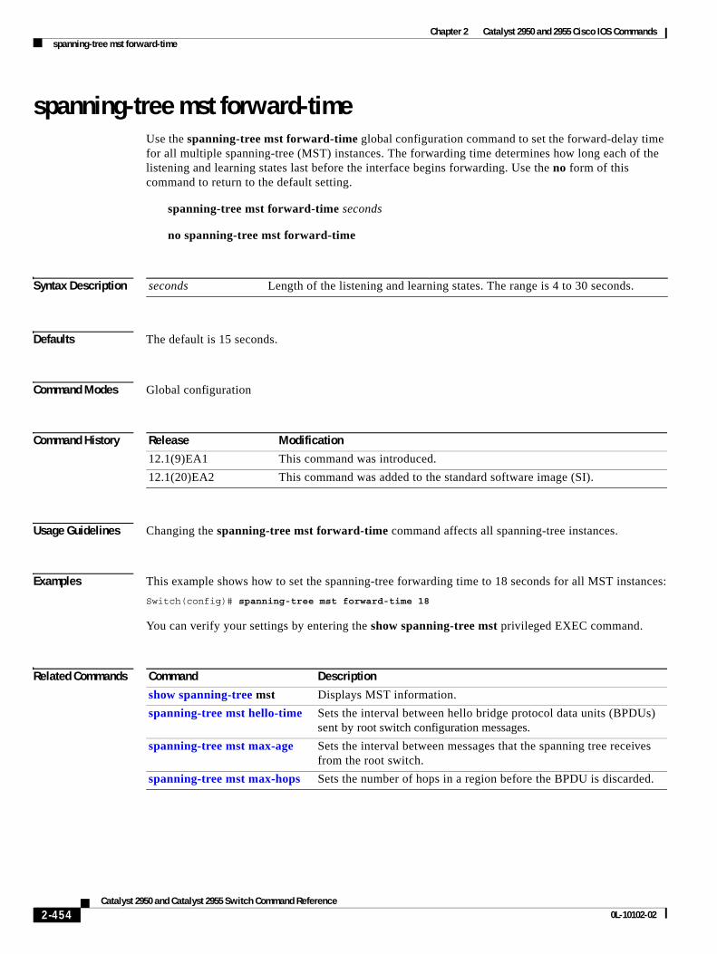
Chapter 2 Catalyst 2950 and 2955 Cisco IOS Commandsspanning-tree mst forward-time
spanning-tree mst forward-timeUse the spanning-tree mst forward-time global configuration command to set the forward-delay time for all multiple spanning-tree (MST) instances. The forwarding time determines how long each of the listening and learning states last before the interface begins forwarding. Use the no form of this command to return to the default setting.
spanning-tree mst forward-time seconds
no spanning-tree mst forward-time
Syntax Description
Defaults The default is 15 seconds.
Command Modes Global configuration
Command History
Usage Guidelines Changing the spanning-tree mst forward-time command affects all spanning-tree instances.
Examples This example shows how to set the spanning-tree forwarding time to 18 seconds for all MST instances:
Switch(config)# spanning-tree mst forward-time 18
You can verify your settings by entering the show spanning-tree mst privileged EXEC command.
Related Commands
seconds Length of the listening and learning states. The range is 4 to 30 seconds.
Release Modification
12.1(9)EA1 This command was introduced.
12.1(20)EA2 This command was added to the standard software image (SI).
Command Description
show spanning-tree mst Displays MST information.
spanning-tree mst hello-time Sets the interval between hello bridge protocol data units (BPDUs) sent by root switch configuration messages.
spanning-tree mst max-age Sets the interval between messages that the spanning tree receives from the root switch.
spanning-tree mst max-hops Sets the number of hops in a region before the BPDU is discarded.
2-454Catalyst 2950 and Catalyst 2955 Switch Command Reference
0L-10102-02
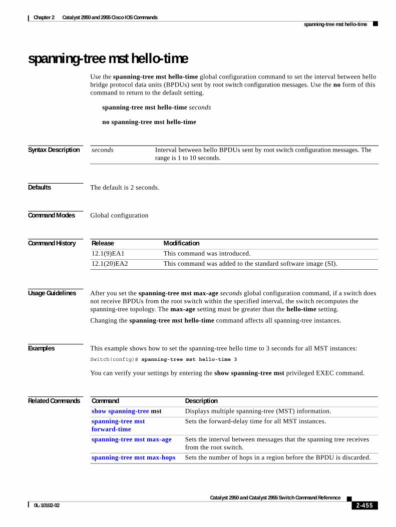
Chapter 2 Catalyst 2950 and 2955 Cisco IOS Commandsspanning-tree mst hello-time
spanning-tree mst hello-timeUse the spanning-tree mst hello-time global configuration command to set the interval between hello bridge protocol data units (BPDUs) sent by root switch configuration messages. Use the no form of this command to return to the default setting.
spanning-tree mst hello-time seconds
no spanning-tree mst hello-time
Syntax Description
Defaults The default is 2 seconds.
Command Modes Global configuration
Command History
Usage Guidelines After you set the spanning-tree mst max-age seconds global configuration command, if a switch does not receive BPDUs from the root switch within the specified interval, the switch recomputes the spanning-tree topology. The max-age setting must be greater than the hello-time setting.
Changing the spanning-tree mst hello-time command affects all spanning-tree instances.
Examples This example shows how to set the spanning-tree hello time to 3 seconds for all MST instances:
Switch(config)# spanning-tree mst hello-time 3
You can verify your settings by entering the show spanning-tree mst privileged EXEC command.
Related Commands
seconds Interval between hello BPDUs sent by root switch configuration messages. The range is 1 to 10 seconds.
Release Modification
12.1(9)EA1 This command was introduced.
12.1(20)EA2 This command was added to the standard software image (SI).
Command Description
show spanning-tree mst Displays multiple spanning-tree (MST) information.
spanning-tree mst forward-time
Sets the forward-delay time for all MST instances.
spanning-tree mst max-age Sets the interval between messages that the spanning tree receives from the root switch.
spanning-tree mst max-hops Sets the number of hops in a region before the BPDU is discarded.
2-455Catalyst 2950 and Catalyst 2955 Switch Command Reference
0L-10102-02
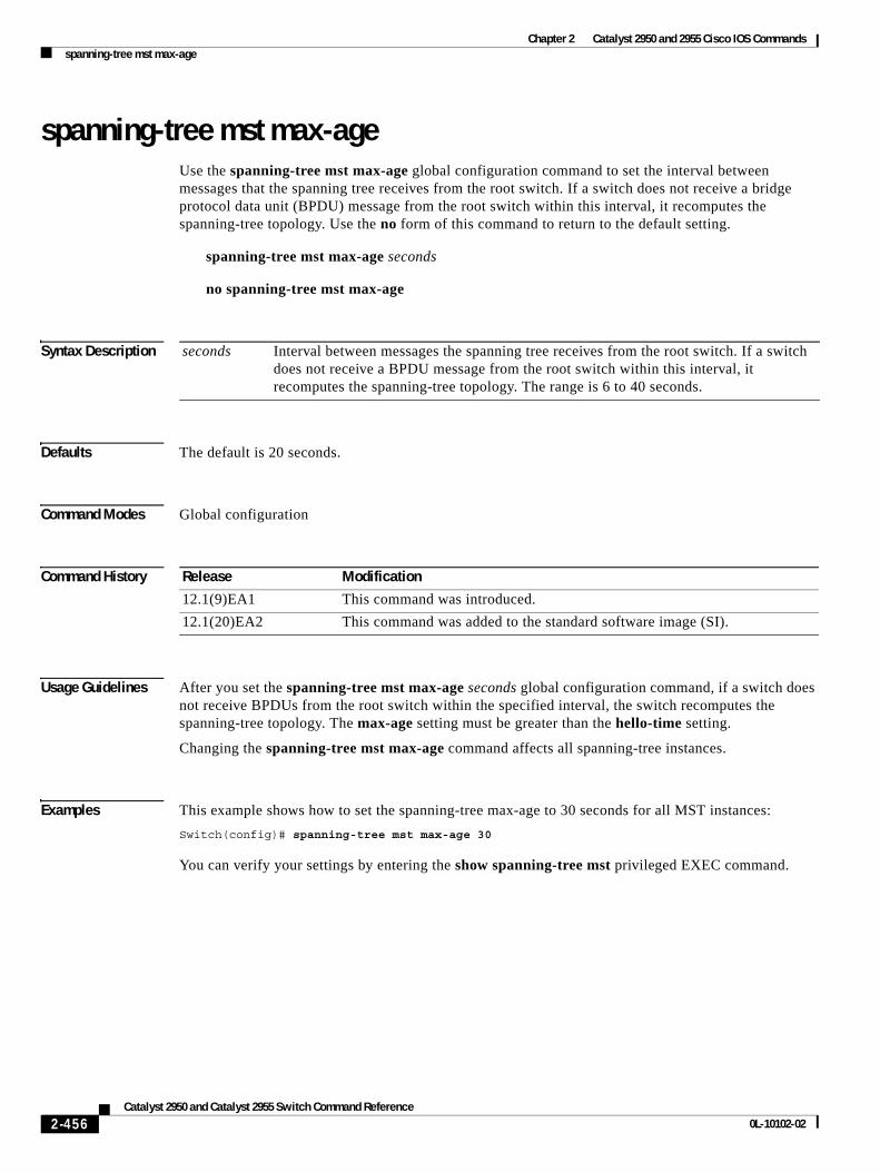
Chapter 2 Catalyst 2950 and 2955 Cisco IOS Commandsspanning-tree mst max-age
spanning-tree mst max-ageUse the spanning-tree mst max-age global configuration command to set the interval between messages that the spanning tree receives from the root switch. If a switch does not receive a bridge protocol data unit (BPDU) message from the root switch within this interval, it recomputes the spanning-tree topology. Use the no form of this command to return to the default setting.
spanning-tree mst max-age seconds
no spanning-tree mst max-age
Syntax Description
Defaults The default is 20 seconds.
Command Modes Global configuration
Command History
Usage Guidelines After you set the spanning-tree mst max-age seconds global configuration command, if a switch does not receive BPDUs from the root switch within the specified interval, the switch recomputes the spanning-tree topology. The max-age setting must be greater than the hello-time setting.
Changing the spanning-tree mst max-age command affects all spanning-tree instances.
Examples This example shows how to set the spanning-tree max-age to 30 seconds for all MST instances:
Switch(config)# spanning-tree mst max-age 30
You can verify your settings by entering the show spanning-tree mst privileged EXEC command.
seconds Interval between messages the spanning tree receives from the root switch. If a switch does not receive a BPDU message from the root switch within this interval, it recomputes the spanning-tree topology. The range is 6 to 40 seconds.
Release Modification
12.1(9)EA1 This command was introduced.
12.1(20)EA2 This command was added to the standard software image (SI).
2-456Catalyst 2950 and Catalyst 2955 Switch Command Reference
0L-10102-02

Chapter 2 Catalyst 2950 and 2955 Cisco IOS Commandsspanning-tree mst max-age
Related Commands Command Description
show spanning-tree mst Displays multiple spanning-tree (MST) information.
spanning-tree mst forward-time Sets the forward-delay time for all MST instances.
spanning-tree mst hello-time Sets the interval between hello BPDUs sent by root switch configuration messages.
spanning-tree mst max-hops Sets the number of hops in a region before the BPDU is discarded.
2-457Catalyst 2950 and Catalyst 2955 Switch Command Reference
0L-10102-02
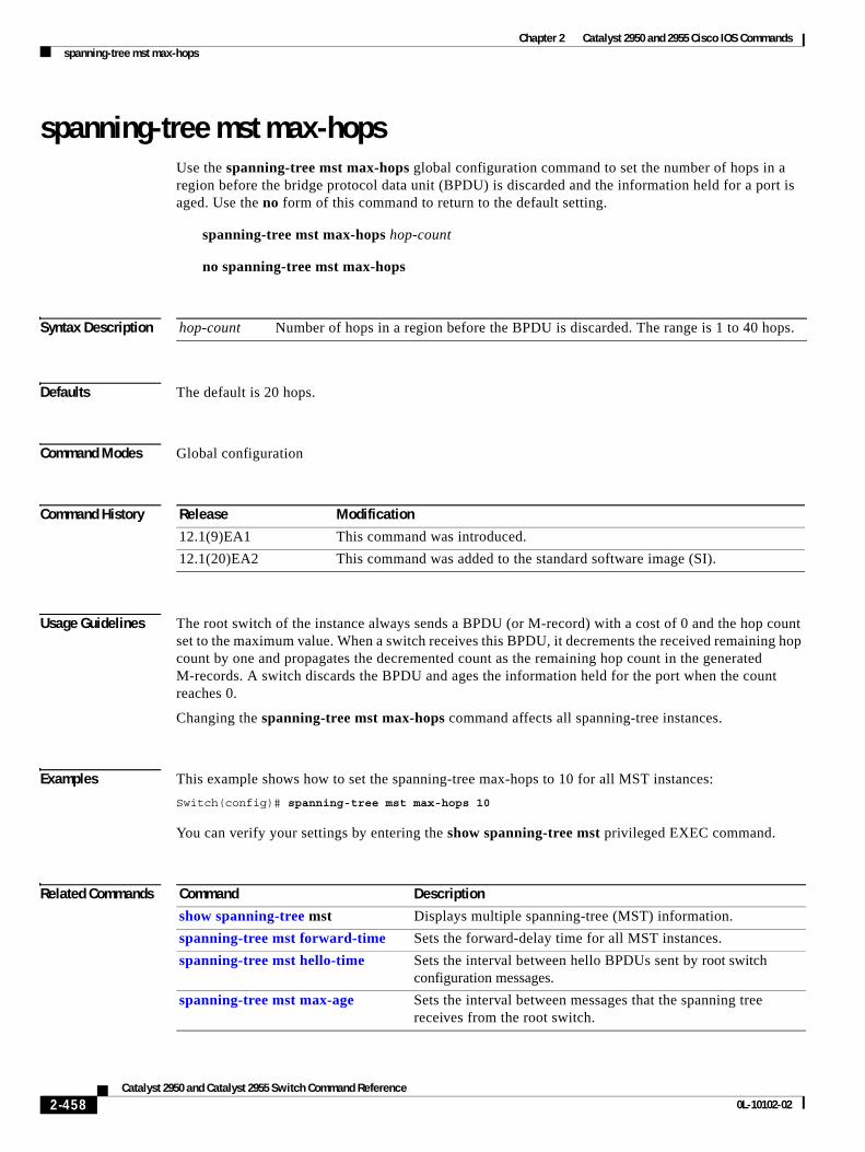
Chapter 2 Catalyst 2950 and 2955 Cisco IOS Commandsspanning-tree mst max-hops
spanning-tree mst max-hopsUse the spanning-tree mst max-hops global configuration command to set the number of hops in a region before the bridge protocol data unit (BPDU) is discarded and the information held for a port is aged. Use the no form of this command to return to the default setting.
spanning-tree mst max-hops hop-count
no spanning-tree mst max-hops
Syntax Description
Defaults The default is 20 hops.
Command Modes Global configuration
Command History
Usage Guidelines The root switch of the instance always sends a BPDU (or M-record) with a cost of 0 and the hop count set to the maximum value. When a switch receives this BPDU, it decrements the received remaining hop count by one and propagates the decremented count as the remaining hop count in the generated M-records. A switch discards the BPDU and ages the information held for the port when the count reaches 0.
Changing the spanning-tree mst max-hops command affects all spanning-tree instances.
Examples This example shows how to set the spanning-tree max-hops to 10 for all MST instances:
Switch(config)# spanning-tree mst max-hops 10
You can verify your settings by entering the show spanning-tree mst privileged EXEC command.
Related Commands
hop-count Number of hops in a region before the BPDU is discarded. The range is 1 to 40 hops.
Release Modification
12.1(9)EA1 This command was introduced.
12.1(20)EA2 This command was added to the standard software image (SI).
Command Description
show spanning-tree mst Displays multiple spanning-tree (MST) information.
spanning-tree mst forward-time Sets the forward-delay time for all MST instances.
spanning-tree mst hello-time Sets the interval between hello BPDUs sent by root switch configuration messages.
spanning-tree mst max-age Sets the interval between messages that the spanning tree receives from the root switch.
2-458Catalyst 2950 and Catalyst 2955 Switch Command Reference
0L-10102-02
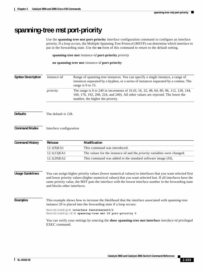
Chapter 2 Catalyst 2950 and 2955 Cisco IOS Commandsspanning-tree mst port-priority
spanning-tree mst port-priorityUse the spanning-tree mst port-priority interface configuration command to configure an interface priority. If a loop occurs, the Multiple Spanning Tree Protocol (MSTP) can determine which interface to put in the forwarding state. Use the no form of this command to return to the default setting.
spanning-tree mst instance-id port-priority priority
no spanning-tree mst instance-id port-priority
Syntax Description
Defaults The default is 128.
Command Modes Interface configuration
Command History
Usage Guidelines You can assign higher priority values (lower numerical values) to interfaces that you want selected first and lower priority values (higher numerical values) that you want selected last. If all interfaces have the same priority value, the MST puts the interface with the lowest interface number in the forwarding state and blocks other interfaces.
Examples This example shows how to increase the likelihood that the interface associated with spanning-tree instance 20 is placed into the forwarding state if a loop occurs:
Switch(config)# interface fastethernet0/2Switch(config-if)# spanning-tree mst 20 port-priority 0
You can verify your settings by entering the show spanning-tree mst interface interface-id privileged EXEC command.
instance-id Range of spanning-tree instances. You can specify a single instance, a range of instances separated by a hyphen, or a series of instances separated by a comma. The range is 0 to 15.
priority The range is 0 to 240 in increments of 16 (0, 16, 32, 48, 64, 80, 96, 112, 128, 144, 160, 176, 192, 208, 224, and 240). All other values are rejected. The lower the number, the higher the priority.
Release Modification
12.1(9)EA1 This command was introduced.
12.1(13)EA1 The values for the instance-id and the priority variables were changed.
12.1(20)EA2 This command was added to the standard software image (SI).
2-459Catalyst 2950 and Catalyst 2955 Switch Command Reference
0L-10102-02
Chapter 2 Catalyst 2950 and 2955 Cisco IOS Commandsspanning-tree mst port-priority
Related Commands Command Description
show spanning-tree mst interface interface-id
Displays MST information for the specified interface.
spanning-tree mst cost Sets the path cost for MST calculations.
spanning-tree mst priority Sets the switch priority for the specified spanning-tree instance.
2-460Catalyst 2950 and Catalyst 2955 Switch Command Reference
0L-10102-02
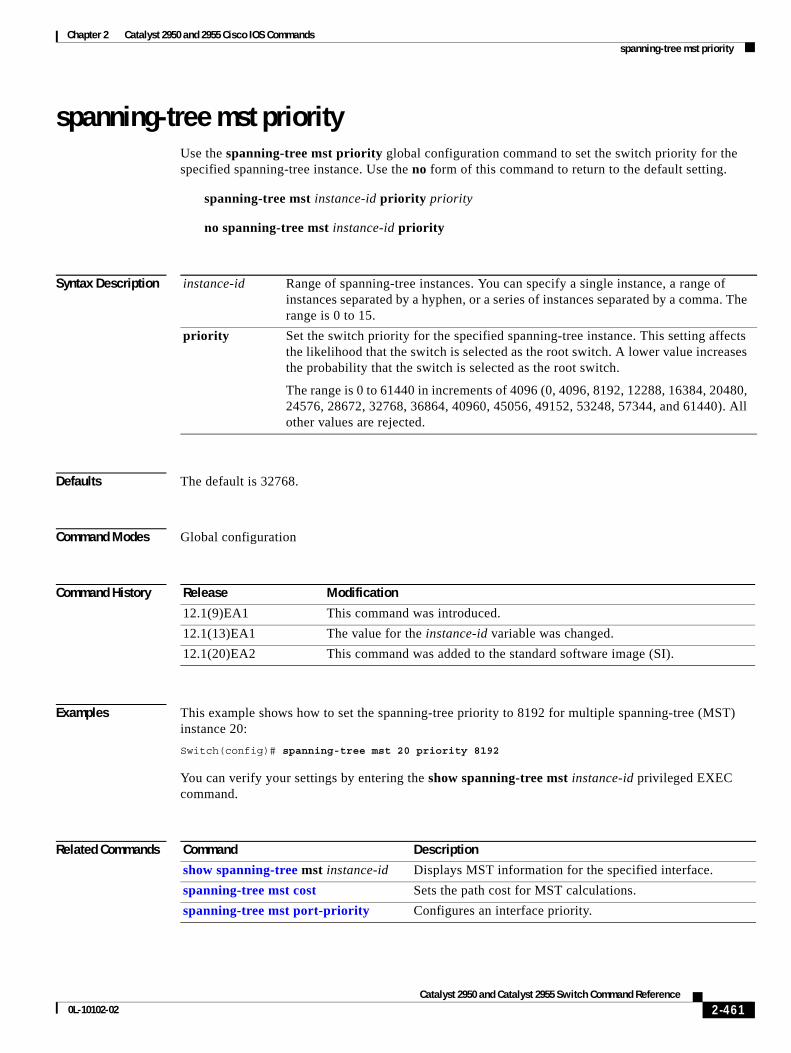
Chapter 2 Catalyst 2950 and 2955 Cisco IOS Commandsspanning-tree mst priority
spanning-tree mst priorityUse the spanning-tree mst priority global configuration command to set the switch priority for the specified spanning-tree instance. Use the no form of this command to return to the default setting.
spanning-tree mst instance-id priority priority
no spanning-tree mst instance-id priority
Syntax Description
Defaults The default is 32768.
Command Modes Global configuration
Command History
Examples This example shows how to set the spanning-tree priority to 8192 for multiple spanning-tree (MST) instance 20:
Switch(config)# spanning-tree mst 20 priority 8192
You can verify your settings by entering the show spanning-tree mst instance-id privileged EXEC command.
Related Commands
instance-id Range of spanning-tree instances. You can specify a single instance, a range of instances separated by a hyphen, or a series of instances separated by a comma. The range is 0 to 15.
priority Set the switch priority for the specified spanning-tree instance. This setting affects the likelihood that the switch is selected as the root switch. A lower value increases the probability that the switch is selected as the root switch.
The range is 0 to 61440 in increments of 4096 (0, 4096, 8192, 12288, 16384, 20480, 24576, 28672, 32768, 36864, 40960, 45056, 49152, 53248, 57344, and 61440). All other values are rejected.
Release Modification
12.1(9)EA1 This command was introduced.
12.1(13)EA1 The value for the instance-id variable was changed.
12.1(20)EA2 This command was added to the standard software image (SI).
Command Description
show spanning-tree mst instance-id Displays MST information for the specified interface.
spanning-tree mst cost Sets the path cost for MST calculations.
spanning-tree mst port-priority Configures an interface priority.
2-461Catalyst 2950 and Catalyst 2955 Switch Command Reference
0L-10102-02
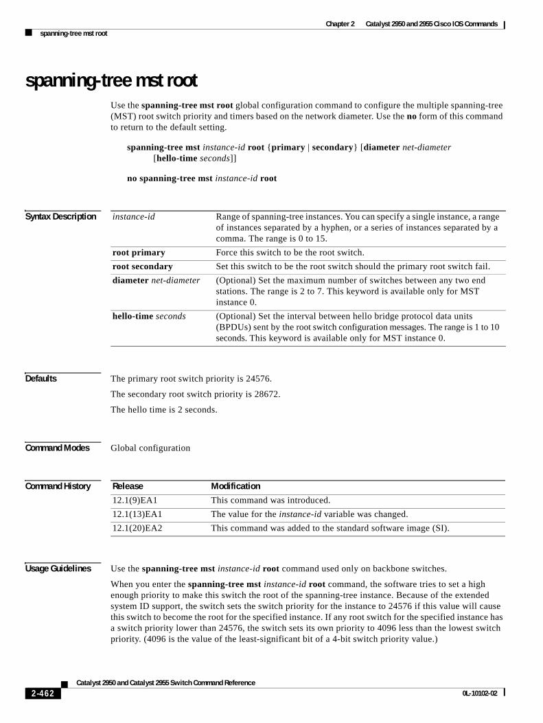
Chapter 2 Catalyst 2950 and 2955 Cisco IOS Commandsspanning-tree mst root
spanning-tree mst rootUse the spanning-tree mst root global configuration command to configure the multiple spanning-tree (MST) root switch priority and timers based on the network diameter. Use the no form of this command to return to the default setting.
spanning-tree mst instance-id root {primary | secondary} [diameter net-diameter [hello-time seconds]]
no spanning-tree mst instance-id root
Syntax Description
Defaults The primary root switch priority is 24576.
The secondary root switch priority is 28672.
The hello time is 2 seconds.
Command Modes Global configuration
Command History
Usage Guidelines Use the spanning-tree mst instance-id root command used only on backbone switches.
When you enter the spanning-tree mst instance-id root command, the software tries to set a high enough priority to make this switch the root of the spanning-tree instance. Because of the extended system ID support, the switch sets the switch priority for the instance to 24576 if this value will cause this switch to become the root for the specified instance. If any root switch for the specified instance has a switch priority lower than 24576, the switch sets its own priority to 4096 less than the lowest switch priority. (4096 is the value of the least-significant bit of a 4-bit switch priority value.)
instance-id Range of spanning-tree instances. You can specify a single instance, a range of instances separated by a hyphen, or a series of instances separated by a comma. The range is 0 to 15.
root primary Force this switch to be the root switch.
root secondary Set this switch to be the root switch should the primary root switch fail.
diameter net-diameter (Optional) Set the maximum number of switches between any two end stations. The range is 2 to 7. This keyword is available only for MST instance 0.
hello-time seconds (Optional) Set the interval between hello bridge protocol data units (BPDUs) sent by the root switch configuration messages. The range is 1 to 10 seconds. This keyword is available only for MST instance 0.
Release Modification
12.1(9)EA1 This command was introduced.
12.1(13)EA1 The value for the instance-id variable was changed.
12.1(20)EA2 This command was added to the standard software image (SI).
2-462Catalyst 2950 and Catalyst 2955 Switch Command Reference
0L-10102-02
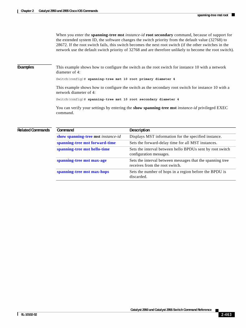
Chapter 2 Catalyst 2950 and 2955 Cisco IOS Commandsspanning-tree mst root
When you enter the spanning-tree mst instance-id root secondary command, because of support for the extended system ID, the software changes the switch priority from the default value (32768) to 28672. If the root switch fails, this switch becomes the next root switch (if the other switches in the network use the default switch priority of 32768 and are therefore unlikely to become the root switch).
Examples This example shows how to configure the switch as the root switch for instance 10 with a network diameter of 4:
Switch(config)# spanning-tree mst 10 root primary diameter 4
This example shows how to configure the switch as the secondary root switch for instance 10 with a network diameter of 4:
Switch(config)# spanning-tree mst 10 root secondary diameter 4
You can verify your settings by entering the show spanning-tree mst instance-id privileged EXEC command.
Related Commands Command Description
show spanning-tree mst instance-id Displays MST information for the specified instance.
spanning-tree mst forward-time Sets the forward-delay time for all MST instances.
spanning-tree mst hello-time Sets the interval between hello BPDUs sent by root switch configuration messages.
spanning-tree mst max-age Sets the interval between messages that the spanning tree receives from the root switch.
spanning-tree mst max-hops Sets the number of hops in a region before the BPDU is discarded.
2-463Catalyst 2950 and Catalyst 2955 Switch Command Reference
0L-10102-02
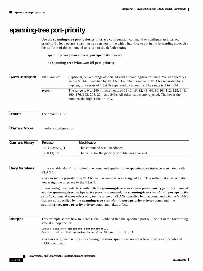
Chapter 2 Catalyst 2950 and 2955 Cisco IOS Commandsspanning-tree port-priority
spanning-tree port-priorityUse the spanning-tree port-priority interface configuration command to configure an interface priority. If a loop occurs, spanning tree can determine which interface to put in the forwarding state. Use the no form of this command to return to the default setting.
spanning-tree [vlan vlan-id] port-priority priority
no spanning-tree [vlan vlan-id] port-priority
Syntax Description
Defaults The default is 128.
Command Modes Interface configuration
Command History
Usage Guidelines If the variable vlan-id is omitted, the command applies to the spanning-tree instance associated with VLAN 1.
You can set the priority on a VLAN that has no interfaces assigned to it. The setting takes effect when you assign the interface to the VLAN.
If you configure an interface with both the spanning-tree vlan vlan-id port-priority priority command and the spanning-tree port-priority priority command, the spanning-tree vlan vlan-id port-priority priority command takes effect only on the range of VLANs specified by that command. On the VLANs that are not specified by the spanning-tree vlan vlan-id port-priority priority command, the spanning-tree port-priority priority command takes effect.
Examples This example shows how to increase the likelihood that the specified port will be put in the forwarding state if a loop occurs:
Switch(config)# interface fastethernet0/2Switch(config-if)# spanning-tree vlan 20 port-priority 0
You can verify your settings by entering the show spanning-tree interface interface-id privileged EXEC command.
vlan vlan-id (Optional) VLAN range associated with a spanning-tree instance. You can specify a single VLAN identified by VLAN ID number, a range of VLANs separated by a hyphen, or a series of VLANs separated by a comma. The range is 1 to 4094.
priority The range is 0 to 240 in increments of 16 (0, 16, 32, 48, 64, 80, 96, 112, 128, 144, 160, 176, 192, 208, 224, and 240). All other values are rejected. The lower the number, the higher the priority.
Release Modification
12.0(5.2)WC(1) This command was introduced.
12.1(13)EA1 The value for the priority variable was changed.
2-464Catalyst 2950 and Catalyst 2955 Switch Command Reference
0L-10102-02

Chapter 2 Catalyst 2950 and 2955 Cisco IOS Commandsspanning-tree port-priority
Related Commands Command Description
show spanning-tree interface interface-id
Displays spanning-tree information for the specified interface.
spanning-tree cost Sets the path cost for spanning-tree calculations.
spanning-tree vlan priority Sets the switch priority for the specified spanning-tree instance.
2-465Catalyst 2950 and Catalyst 2955 Switch Command Reference
0L-10102-02
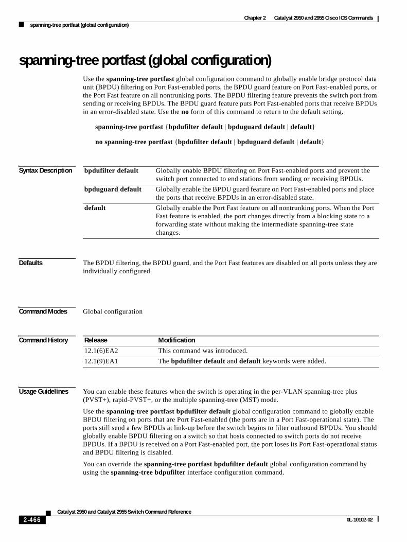
Chapter 2 Catalyst 2950 and 2955 Cisco IOS Commandsspanning-tree portfast (global configuration)
spanning-tree portfast (global configuration)Use the spanning-tree portfast global configuration command to globally enable bridge protocol data unit (BPDU) filtering on Port Fast-enabled ports, the BPDU guard feature on Port Fast-enabled ports, or the Port Fast feature on all nontrunking ports. The BPDU filtering feature prevents the switch port from sending or receiving BPDUs. The BPDU guard feature puts Port Fast-enabled ports that receive BPDUs in an error-disabled state. Use the no form of this command to return to the default setting.
spanning-tree portfast {bpdufilter default | bpduguard default | default}
no spanning-tree portfast {bpdufilter default | bpduguard default | default}
Syntax Description
Defaults The BPDU filtering, the BPDU guard, and the Port Fast features are disabled on all ports unless they are individually configured.
Command Modes Global configuration
Command History
Usage Guidelines You can enable these features when the switch is operating in the per-VLAN spanning-tree plus (PVST+), rapid-PVST+, or the multiple spanning-tree (MST) mode.
Use the spanning-tree portfast bpdufilter default global configuration command to globally enable BPDU filtering on ports that are Port Fast-enabled (the ports are in a Port Fast-operational state). The ports still send a few BPDUs at link-up before the switch begins to filter outbound BPDUs. You should globally enable BPDU filtering on a switch so that hosts connected to switch ports do not receive BPDUs. If a BPDU is received on a Port Fast-enabled port, the port loses its Port Fast-operational status and BPDU filtering is disabled.
You can override the spanning-tree portfast bpdufilter default global configuration command by using the spanning-tree bdpufilter interface configuration command.
bpdufilter default Globally enable BPDU filtering on Port Fast-enabled ports and prevent the switch port connected to end stations from sending or receiving BPDUs.
bpduguard default Globally enable the BPDU guard feature on Port Fast-enabled ports and place the ports that receive BPDUs in an error-disabled state.
default Globally enable the Port Fast feature on all nontrunking ports. When the Port Fast feature is enabled, the port changes directly from a blocking state to a forwarding state without making the intermediate spanning-tree state changes.
Release Modification
12.1(6)EA2 This command was introduced.
12.1(9)EA1 The bpdufilter default and default keywords were added.
2-466Catalyst 2950 and Catalyst 2955 Switch Command Reference
0L-10102-02
Chapter 2 Catalyst 2950 and 2955 Cisco IOS Commandsspanning-tree portfast (global configuration)
Caution Enabling BPDU filtering on an interface is the same as disabling spanning tree on it and can result in spanning-tree loops.
Use the spanning-tree portfast bpduguard default global configuration command to globally enable BPDU guard on ports that are in a Port Fast-operational state. In a valid configuration, Port Fast-enabled ports do not receive BPDUs. Receiving a BPDU on a Port Fast-enabled port signals an invalid configuration, such as the connection of an unauthorized device, and the BPDU guard feature puts the port in the error-disabled state. The BPDU guard feature provides a secure response to invalid configurations because you must manually put the port back in service. Use the BPDU guard feature in a service-provider network to prevent an access port from participating in the spanning tree.
You can override the spanning-tree portfast bpduguard default global configuration command by using the spanning-tree bdpuguard interface configuration command.
Use the spanning-tree portfast default global configuration command to globally enable the Port Fast feature on all nontrunking ports. Configure Port Fast only on ports that connect to end stations; otherwise, an accidental topology loop could cause a data packet loop and disrupt switch and network operation. A Port Fast-enabled port moves directly to the spanning-tree forwarding state when linkup occurs without waiting for the standard forward-delay time.
You can override the spanning-tree portfast default global configuration command by using the spanning-tree portfast interface configuration command. You can use the no spanning-tree portfast default global configuration command to disable Port Fast on all ports unless they are individually configured with the spanning-tree portfast interface configuration command.
Examples This example shows how to globally enable the BPDU filtering feature:
Switch(config)# spanning-tree portfast bpdufilter default
This example shows how to globally enable the BPDU guard feature:
Switch(config)# spanning-tree portfast bpduguard default
This example shows how to globally enable the Port Fast feature on all nontrunking ports:
Switch(config)# spanning-tree portfast default
You can verify your settings by entering the show running-config privileged EXEC command.
Related Commands Command Description
show running-config Displays the current operating configuration. For syntax information, select Cisco IOS Configuration Fundamentals Command Reference for Release 12.1 > Cisco IOS File Management Commands > Configuration File Commands.
spanning-tree bpdufilter Prevents a port from sending or receiving BPDUs.
spanning-tree bpduguard Puts a port in the error-disabled state when it receives a BPDU.
spanning-tree portfast (interface configuration)
Enables the Port Fast feature on an interface in all its associated VLANs.
2-467Catalyst 2950 and Catalyst 2955 Switch Command Reference
0L-10102-02
Chapter 2 Catalyst 2950 and 2955 Cisco IOS Commandsspanning-tree portfast (interface configuration)
spanning-tree portfast (interface configuration)Use the spanning-tree portfast interface configuration command to enable the Port Fast feature on an interface in all its associated VLANs. When the Port Fast feature is enabled, the interface changes directly from a blocking state to a forwarding state without making the intermediate spanning-tree state changes. Use the no form of this command to return to the default setting.
spanning-tree portfast [disable | trunk]
no spanning-tree portfast
Syntax Description
Defaults The Port Fast feature is disabled on all interfaces; however, it is automatically enabled on dynamic-access ports.
Command Modes Interface configuration
Command History
Usage Guidelines Use this feature only on interfaces that connect to end stations; otherwise, an accidental topology loop could cause a data packet loop and disrupt switch and network operation.
To enable Port Fast on trunk ports, you must use the spanning-tree portfast trunk interface configuration command. The spanning-tree portfast command is not supported on trunk ports.
You can enable this feature when the switch is operating in the per-VLAN spanning-tree plus (PVST+), rapid-PVST+, or the multiple spanning-tree (MST) mode.
This feature affects all VLANs on the interface.
A port with the Port Fast feature enabled is moved directly to the spanning-tree forwarding state without waiting the standard forward-time delay.
You can use the spanning-tree portfast default global configuration command to globally enable the Port Fast feature on all nontrunking interfaces. However, the spanning-tree portfast interface configuration command can override the global setting.
If you configure the spanning-tree portfast default global configuration command, you can disable Port Fast on an interface that is not a trunk interface by using the spanning-tree portfast disable interface configuration command.
disable (Optional) Disable the Port Fast feature on the specified interface.
trunk (Optional) Enable the Port Fast feature on a trunking interface.
Release Modification
12.0(5.2)WC(1) This command was introduced.
12.1(9)EA1 The disable and trunk keywords were added.
2-468Catalyst 2950 and Catalyst 2955 Switch Command Reference
0L-10102-02
Chapter 2 Catalyst 2950 and 2955 Cisco IOS Commandsspanning-tree portfast (interface configuration)
Examples This example shows how to enable the Port Fast feature on an interface:
Switch(config)# interface fastethernet0/2Switch(config-if)# spanning-tree portfast
You can verify your settings by entering the show running-config privileged EXEC command.
Related Commands Command Description
show running-config Displays the current operating configuration. For syntax information, select Cisco IOS Configuration Fundamentals Command Reference for Release 12.1 > Cisco IOS File Management Commands > Configuration File Commands.
spanning-tree bpdufilter Prevents a port from sending or receiving bridge protocol data units (BPDUs).
spanning-tree bpduguard Puts a port in the error-disabled state when it receives a BPDU.
spanning-tree portfast (global configuration)
Globally enables the BPDU filtering or the BPDU guard feature on Port Fast-enabled ports or enables the Port Fast feature on all nontrunking ports.
2-469Catalyst 2950 and Catalyst 2955 Switch Command Reference
0L-10102-02
Chapter 2 Catalyst 2950 and 2955 Cisco IOS Commandsspanning-tree stack-port
spanning-tree stack-portUse the spanning-tree stack-port interface configuration command to enable cross-stack UplinkFast (CSUF) on an interface and to accelerate the choice of a new root port when a link or switch fails or when spanning tree reconfigures itself. Use the no form of this command to return to the default setting.
spanning-tree stack-port
no spanning-tree stack-port
Syntax Description This command has no arguments or keywords.
Defaults CSUF is disabled on all interfaces.
Command Modes Interface configuration
Command History
Usage Guidelines This command is effective only if you enable the UplinkFast feature by using the spanning-tree uplinkfast global configuration command.
Use this command only on access switches.
The CSUF feature is supported only when the switch is running per-VLAN spanning-tree plus (PVST+). It is not supported when the switch is running rapid PVST+ or multiple spanning-tree (MST).
You can enable CSUF only on one stack-port Gigabit Interface Converter (GBIC) interface. The stack port connects to the GigaStack GBIC multidrop backbone. If you try to enable CSUF on a Fast Ethernet or a copper-based Gigabit Ethernet port, you receive an error message.
If CSUF is already enabled on an interface and you try to enable it on another interface, you receive an error message. You must disable CSUF on the first interface before enabling it on a new interface.
Examples This example shows how to enable CSUF on the GBIC interface:
Switch(config)# interface gigabitethernet0/1Switch(config-if)# spanning-tree stack-port
You can verify your settings by entering the show running-config privileged EXEC command.
Release Modification
12.1(6)EA2 This command was introduced.
2-470Catalyst 2950 and Catalyst 2955 Switch Command Reference
0L-10102-02

Chapter 2 Catalyst 2950 and 2955 Cisco IOS Commandsspanning-tree stack-port
Related Commands Command Description
show running-config Displays the current operating configuration. For syntax information, select Cisco IOS Configuration Fundamentals Command Reference for Release 12.1 > Cisco IOS File Management Commands > Configuration File Commands.
spanning-tree uplinkfast Accelerates the choice of a new root port when a link or switch fails or when spanning tree reconfigures itself.
2-471Catalyst 2950 and Catalyst 2955 Switch Command Reference
0L-10102-02
Chapter 2 Catalyst 2950 and 2955 Cisco IOS Commandsspanning-tree uplinkfast
spanning-tree uplinkfastUse the spanning-tree uplinkfast global configuration command to accelerate the choice of a new root port when a link or switch fails or when the spanning tree reconfigures itself. Use the no form of this command to return to the default setting.
spanning-tree uplinkfast [max-update-rate pkts-per-second]
no spanning-tree uplinkfast [max-update-rate]
Syntax Description
Defaults UplinkFast is disabled.
The update rate is 150 packets per second.
Command Modes Global configuration
Command History
Usage Guidelines Use this command only on access switches.
You can configure the UplinkFast feature for rapid PVST+ or for multiple spanning-tree (MST) mode, but the feature remains disabled (inactive) until you change the spanning-tree mode to PVST+.
When you enable UplinkFast, it is enabled for the entire switch and cannot be enabled for individual VLANs.
When UplinkFast is enabled, the switch priority of all VLANs is set to 49152. If you change the path cost to a value less than 3000 and you enable UplinkFast or UplinkFast is already enabled, the path cost of all interfaces and VLAN trunks is increased by 3000 (if you change the path cost to 3000 or above, the path cost is not altered). The changes to the switch priority and the path cost reduces the chance that the switch will become the root switch.
When UplinkFast is disabled, the switch priorities of all VLANs and path costs of all interfaces are set to default values if you did not modify them from their defaults.
When spanning tree detects that the root port has failed, UplinkFast immediately switches over to an alternate root port, changing the new root port directly to FORWARDING state. During this time, a topology change notification is sent.
max-update-rate pkts-per-second (Optional) The number of packets per second at which update packets are sent. The range is 0 to 32000.
Release Modification
12.0(5.2)WC(1) This command was introduced.
12.1(6)EA2 The pkts-per-second range was changed to 0 to 65535.
12.1(13)EA1 The range for the pkts-per-second was changed from 0 to 65535 to 0 to 32000.
2-472Catalyst 2950 and Catalyst 2955 Switch Command Reference
0L-10102-02
Chapter 2 Catalyst 2950 and 2955 Cisco IOS Commandsspanning-tree uplinkfast
Do not enable the root guard on interfaces that will be used by the UplinkFast feature. With UplinkFast, the backup interfaces (in the blocked state) replace the root port in the case of a failure. However, if root guard is also enabled, all the backup interfaces used by the UplinkFast feature are placed in the root-inconsistent state (blocked) and prevented from reaching the forwarding state.
If you set the max-update-rate to 0, station-learning frames are not generated, so the spanning-tree topology converges more slowly after a loss of connectivity.
Examples This example shows how to enable UplinkFast:
Switch(config)# spanning-tree uplinkfast
You can verify your setting by entering the show spanning-tree summary privileged EXEC command.
Related Commands Command Description
show spanning-tree summary Displays a summary of the spanning-tree port states.
spanning-tree stack-port Enables cross-stack UplinkFast (CSUF) on an interface and accelerates the choice of a new root port when a link or switch fails or when spanning tree reconfigures itself.
spanning-tree vlan root primary Forces this switch to be the root switch.
2-473Catalyst 2950 and Catalyst 2955 Switch Command Reference
0L-10102-02
Chapter 2 Catalyst 2950 and 2955 Cisco IOS Commandsspanning-tree vlan
spanning-tree vlanUse the spanning-tree vlan global configuration command to configure spanning tree on a per-VLAN basis. Use the no form of this command to return to the default setting.
spanning-tree vlan vlan-id {forward-time seconds | hello-time seconds | max-age seconds | priority priority | {root {primary | secondary} [diameter net-diameter [hello-time seconds]]}}
no spanning-tree vlan vlan-id [forward-time | hello-time | max-age | priority | root]
Syntax Description
Defaults Spanning tree is enabled on all VLANs.
The forward-delay time is 15 seconds.
The hello time is 2 seconds.
The max-age is 20 seconds.
The primary root switch priority is 24576.
The secondary root switch priority is 28672.
Command Modes Global configuration
vlan-id VLAN range associated with a spanning-tree instance. You can specify a single VLAN identified by VLAN ID number, a range of VLANs separated by a hyphen, or a series of VLANs separated by a comma. The range is 1 to 4094.
forward-time seconds Set the forward-delay time for the specified spanning-tree instance. The forwarding time determines how long each of the listening and learning states last before the interface begins forwarding. The range is 4 to 30 seconds.
hello-time seconds Set the interval between hello bridge protocol data units (BPDUs) sent by the root switch configuration messages. The range is 1 to 10 seconds.
max-age seconds Set the interval between messages the spanning tree receives from the root switch. If a switch does not receive a BPDU message from the root switch within this interval, it recomputes the spanning-tree topology. The range is 6 to 40 seconds.
priority priority Set the switch priority for the specified spanning-tree instance. This setting affects the likelihood that the switch is selected as the root switch. A lower value increases the probability that the switch is selected as the root switch.
The range is 0 to 61440 in increments of 4096 (4096, 8192, 12288, 16384, 20480, 24576, 28672, 32768, 36864, 40960, 45056, 49152, 53248, 57344, and 61440). All other values are rejected.
root primary Force this switch to be the root switch.
root secondary Set this switch to be the root switch should the primary root switch fail.
diameter net-diameter Set the maximum number of switches between any two end stations. The range is 2 to 7.
2-474Catalyst 2950 and Catalyst 2955 Switch Command Reference
0L-10102-02
Chapter 2 Catalyst 2950 and 2955 Cisco IOS Commandsspanning-tree vlan
Command History
Usage Guidelines Disabling the STP causes the VLAN to stop participating in the spanning-tree topology. Interfaces that are administratively down remain down. Received BPDUs are forwarded like other multicast frames. The switch does not detect and prevent loops in a VLAN if STP is disabled for that VLAN.
You can disable the STP on a VLAN that is not currently active and verify the change by using the show running-config or the show spanning-tree vlan vlan-id privileged EXEC command. The setting takes effect when the VLAN is activated.
When disabling or re-enabling the STP, you can specify a range of VLANs that you want to disable or enable.
When the STP is disabled and then enabled, all assigned VLANs continue to be its members. However, all spanning-tree bridge parameters are returned to their previous settings (the last setting before the VLAN was disabled).
You can enable spanning-tree options on a VLAN that has no interfaces assigned to it. The setting takes effect when you assign interfaces to it.
When setting the max-age seconds, if a switch does not receive BPDUs from the root switch within the specified interval, it recomputes the spanning-tree topology. The max-age setting must be greater than the hello-time setting.
The spanning-tree vlan vlan-id root command should be used only on backbone switches.
When you enter the spanning-tree vlan vlan-id root command, the software checks the switch priority of the current root switch for each VLAN. Because of the extended system ID support, the switch sets the switch priority for the specified VLAN to 24576 if this value will cause this switch to become the root for the specified VLAN. If any root switch for the specified VLAN has a switch priority lower than 24576, the switch sets its own priority for the specified VLAN to 4096 less than the lowest switch priority. (4096 is the value of the least-significant bit of a 4-bit switch priority value.)
When you enter the spanning-tree vlan vlan-id root primary command, the switch recalculates the forward-time, hello-time, max-age, and priority settings. If you previously configured these parameters, the switch overrides and recalculates them.
When you enter the spanning-tree vlan vlan-id root secondary command, because of support for the extended system ID, the software changes the switch priority from the default value (32768) to 28672. If the root switch should fail, this switch becomes the next root switch (if the other switches in the network use the default switch priority of 32768, and therefore, are unlikely to become the root switch).
Examples This example shows how to disable the STP on VLAN 5:
Switch(config)# no spanning-tree vlan 5
You can verify your setting by entering the show spanning-tree privileged EXEC command. In this instance, VLAN 5 does not appear in the list.
This example shows how to set the spanning-tree forwarding time to 18 seconds for VLANs 20 and 25:
Switch(config)# spanning-tree vlan 20,25 forward-time 18
Release Modification
12.0(5.2)WC(1) This command was introduced.
12.1(9)EA1 The priority priority range changed from 1 to 65535 to 1 to 61440 (in increments of 4096).
2-475Catalyst 2950 and Catalyst 2955 Switch Command Reference
0L-10102-02
Chapter 2 Catalyst 2950 and 2955 Cisco IOS Commandsspanning-tree vlan
This example shows how to set the spanning-tree hello-delay time to 3 seconds for VLANs 20 to 24:
Switch(config)# spanning-tree vlan 20-24 hello-time 3
This example shows how to set spanning-tree max-age to 30 seconds for VLAN 20:
Switch(config)# spanning-tree vlan 20 max-age 30
This example shows how to reset the max-age parameter to the default value for spanning-tree instances 100 and 105 to 108 :
Switch(config)# no spanning-tree vlan 100,105-108 max-age
This example shows how to set the spanning-tree priority to 8192 for VLAN 20:
Switch(config)# spanning-tree vlan 20 priority 8192
This example shows how to configure the switch as the root switch for VLAN 10 with a network diameter of 4:
Switch(config)# spanning-tree vlan 10 root primary diameter 4
This example shows how to configure the switch as the secondary root switch for VLAN 10 with a network diameter of 4:
Switch(config)# spanning-tree vlan 10 root secondary diameter 4
You can verify your settings by entering the show spanning-tree vlan vlan-id privileged EXEC command.
Related Commands Command Description
show spanning-tree vlan Displays spanning-tree information.
spanning-tree cost Sets the path cost for spanning-tree calculations.
spanning-tree guard Enables the root guard or the loop guard feature for all the VLANs associated with the selected interface.
spanning-tree port-priority Sets an interface priority.
spanning-tree portfast (global configuration)
Globally enables the BPDU filtering or the BPDU guard feature on Port Fast-enabled ports or enables the Port Fast feature on all nontrunking ports.
spanning-tree portfast (interface configuration)
Enables the Port Fast feature on an interface in all its associated VLANs.
spanning-tree uplinkfast Enables the UplinkFast feature, which accelerates the choice of a new root port.
2-476Catalyst 2950 and Catalyst 2955 Switch Command Reference
0L-10102-02
Chapter 2 Catalyst 2950 and 2955 Cisco IOS Commandsspeed
speedUse the speed interface configuration command to specify the speed of a port. Use the no form of this command to return to the default setting.
speed {10 | 100 | 1000 | auto [10 | 100 | 1000] | nonegotiate}
no speed
Note You cannot configure speed or duplex mode on Gigabit Interface Converter (GBIC) ports, but for certain types of GBICs, you can configure speed to not negotiate (nonegotiate) if they are connected to a device that does not support autonegotiation.
Syntax Description
Defaults For Fast Ethernet and 10/100/1000 ports, the default is auto.
For 100BASE-FX ports, the default is 100 Mbps.
For GBIC-module ports, the default is 1000 Mbps.
For small form-factor pluggable (SFP)-module ports, the default is auto.
Command Modes Interface configuration
Command History
Usage Guidelines The applicability of this command depends on the switch on which you enter it.
SFP ports only operate at 1000 Mbps, and those with a 1000 BASE-T module installed can only be configured for full-duplex mode.
10 Port runs at 10 Mbps.
100 Port runs at 100 Mbps.
1000 Port runs at 1000 Mbps (only valid for Gigabit Ethernet ports).
auto Port automatically detects whether it should run at 10 or 100 Mbps on Fast Ethernet ports or at 10, 100, or 1000 Mbps on 10/100/1000 and SFP-module ports. If you use the 10, 100, or 1000 keywords with the auto keyword, the port only autonegotiates at the specified speeds.
nonegotiate Autonegotiation is disabled, and the port runs at 1000 Mbps. This option is valid and visible only on 1000BASE-X, -LX, and -ZX GBIC ports. Gigastack GBICs and 1000BASE-T GBICs do not suport disabling of autonegotiation.
Release Modification
12.0(5.2)WC(1) This command was introduced.
12.1(11)EA1 The nonegotiate keyword was added.
12.1(22)EA1 Support for the 10, 100, and 1000 keywords with the auto keyword was added.
2-477Catalyst 2950 and Catalyst 2955 Switch Command Reference
0L-10102-02
Chapter 2 Catalyst 2950 and 2955 Cisco IOS Commandsspeed
If the speed is set to auto, the switch negotiates with the device at the other end of the link for the speed setting and then forces the speed setting to the negotiated value. The duplex setting remains as configured on each end of the link, which could result in a duplex setting mismatch. If both the speed and duplex are set to specific values, autonegotiation is disabled.
If the speed is set to auto and the 10, 100, or 1000 keywords are also used, the port only autonegotiates at the specified speeds.
On non-Long-Reach Ethernet (LRE) switches, Fast Ethernet ports, except for 100BASE-FX ports, can be configured at 10 or 100 Mbps. The 10/100/1000 Ethernet interfaces on the Catalyst 2950T-24, Catalyst 2950T-48-SI, and Catalyst 2955T-24 switches operate at 10 or 100 Mbps in either half- or full-duplex mode or at 1000 Mbps only in full-duplex mode.
You cannot configure the speed on GBIC interfaces, but you can configure the speed to not negotiate (nonegotiate) for the 1000BASE-SX, -LX, or -ZX GBICs, if they are connected to devices that do not support autonegotiation. GBIC-module ports support only 1000 Mbps. The speed values of 10 Mbps and 100 Mbps are not supported.
Note The 100BASE-FX and SFP ports do not support the speed command. These ports operate only at 100 Mbps and in full-duplex mode.
On LRE switches, LRE Gigabit Ethernet ports are set to auto by default. A copper connection (10/100/1000) autonegotiates with the device at the other end of the link for the speed setting and then forces the speed setting to the negotiated value. A fiber SFP connection also autonegotiates with the device at the other end of the link but only accepts a connection at 1000 Mbps.
On LRE switches, the speed setting for a Gigabit Ethernet port has a close relationship to the setting for duplex mode. Fiber SFP-module ports are always forced to 1000 Mbps and to full-duplex mode. Copper ports can run in either full- or half-duplex module at 10 or 100 Mbps but is forced to run in full-duplex mode at 1000Mbps. When you configure the speed and duplex settings, autonegotiation is disabled, and speed and duplex settings can cause a mismatch.
The speed command is not supported on LRE interfaces. Use the cpe speed interface configuration command to set the speed of individual customer premises equipment (CPE) ports.
Note For guidelines on setting the switch speed and duplex parameters, see the “Configuring the Switch Interfaces” and the “Configuring LRE” chapters in the switch software configuration guide for this release.
Examples This example shows how to set a port to 100 Mbps:
Switch(config)# interface fastethernet0/1Switch(config-if)# speed 100
This example shows how to set a port to autonegotiate the speed:
Switch(config)# interface fastethernet0/1Switch(config-if)# speed auto
This example shows how to set a port to autonegotiate at only 10 Mbps:
Switch(config)# interface fastethernet0/1Switch(config-if)# speed auto 10
2-478Catalyst 2950 and Catalyst 2955 Switch Command Reference
0L-10102-02
Chapter 2 Catalyst 2950 and 2955 Cisco IOS Commandsspeed
This example shows how to set a port to autonegotiate at only 10 or 100 Mbps:
Switch(config)# interface fastethernet0/1Switch(config-if)# speed auto 10 100
You can verify your settings by entering the show interfaces transceiver properties or the show running-config privileged EXEC command.
Related Commands Command Description
cpe speed Sets the speed of a CPE port.
duplex Specifies the duplex mode of operation for switch ports.
show controllers lre status
Display the status for rate selection. Use the sequence keyword to display the status of a sequence for an LRE interface.
show interfaces Displays the administrative and operational status of all interfaces or a specified interface.
show running-config Displays the current operating configuration. For syntax information, select Cisco IOS Configuration Fundamentals Command Reference for Release 12.1 > Cisco IOS File Management Commands > Configuration File Commands.
2-479Catalyst 2950 and Catalyst 2955 Switch Command Reference
0L-10102-02
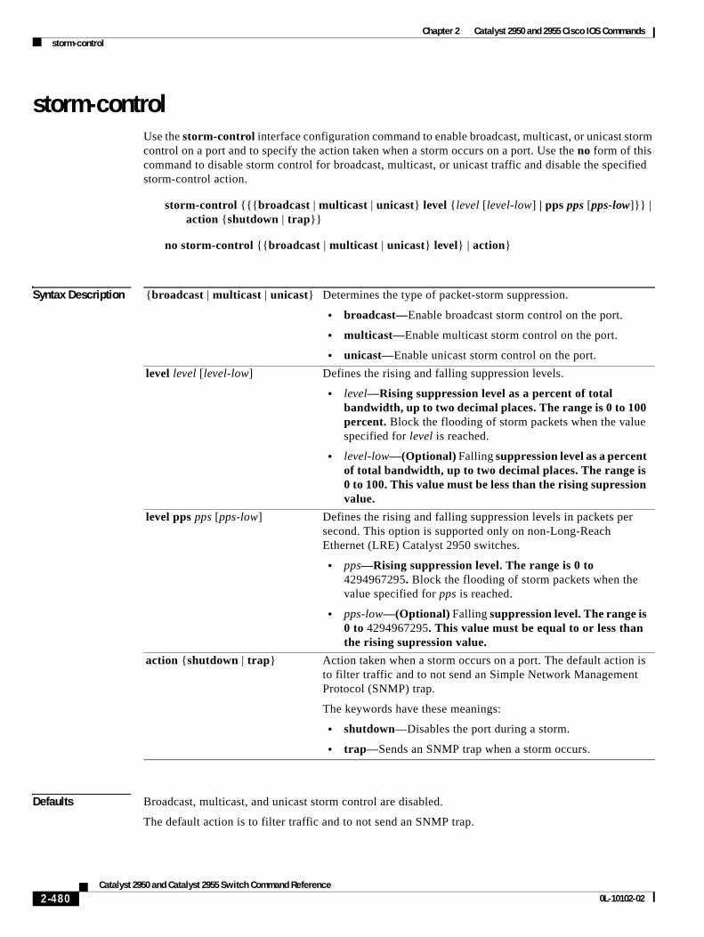
Chapter 2 Catalyst 2950 and 2955 Cisco IOS Commandsstorm-control
storm-control Use the storm-control interface configuration command to enable broadcast, multicast, or unicast storm control on a port and to specify the action taken when a storm occurs on a port. Use the no form of this command to disable storm control for broadcast, multicast, or unicast traffic and disable the specified storm-control action.
storm-control {{{broadcast | multicast | unicast} level {level [level-low] | pps pps [pps-low]}} | action {shutdown | trap}}
no storm-control {{broadcast | multicast | unicast} level} | action}
Syntax Description
Defaults Broadcast, multicast, and unicast storm control are disabled.
The default action is to filter traffic and to not send an SNMP trap.
{broadcast | multicast | unicast} Determines the type of packet-storm suppression.
• broadcast—Enable broadcast storm control on the port.
• multicast—Enable multicast storm control on the port.
• unicast—Enable unicast storm control on the port.
level level [level-low] Defines the rising and falling suppression levels.
• level—Rising suppression level as a percent of total bandwidth, up to two decimal places. The range is 0 to 100 percent. Block the flooding of storm packets when the value specified for level is reached.
• level-low—(Optional) Falling suppression level as a percent of total bandwidth, up to two decimal places. The range is 0 to 100. This value must be less than the rising supression value.
level pps pps [pps-low] Defines the rising and falling suppression levels in packets per second. This option is supported only on non-Long-Reach Ethernet (LRE) Catalyst 2950 switches.
• pps—Rising suppression level. The range is 0 to 4294967295. Block the flooding of storm packets when the value specified for pps is reached.
• pps-low—(Optional) Falling suppression level. The range is 0 to 4294967295. This value must be equal to or less than the rising supression value.
action {shutdown | trap} Action taken when a storm occurs on a port. The default action is to filter traffic and to not send an Simple Network Management Protocol (SNMP) trap.
The keywords have these meanings:
• shutdown—Disables the port during a storm.
• trap—Sends an SNMP trap when a storm occurs.
2-480Catalyst 2950 and Catalyst 2955 Switch Command Reference
0L-10102-02
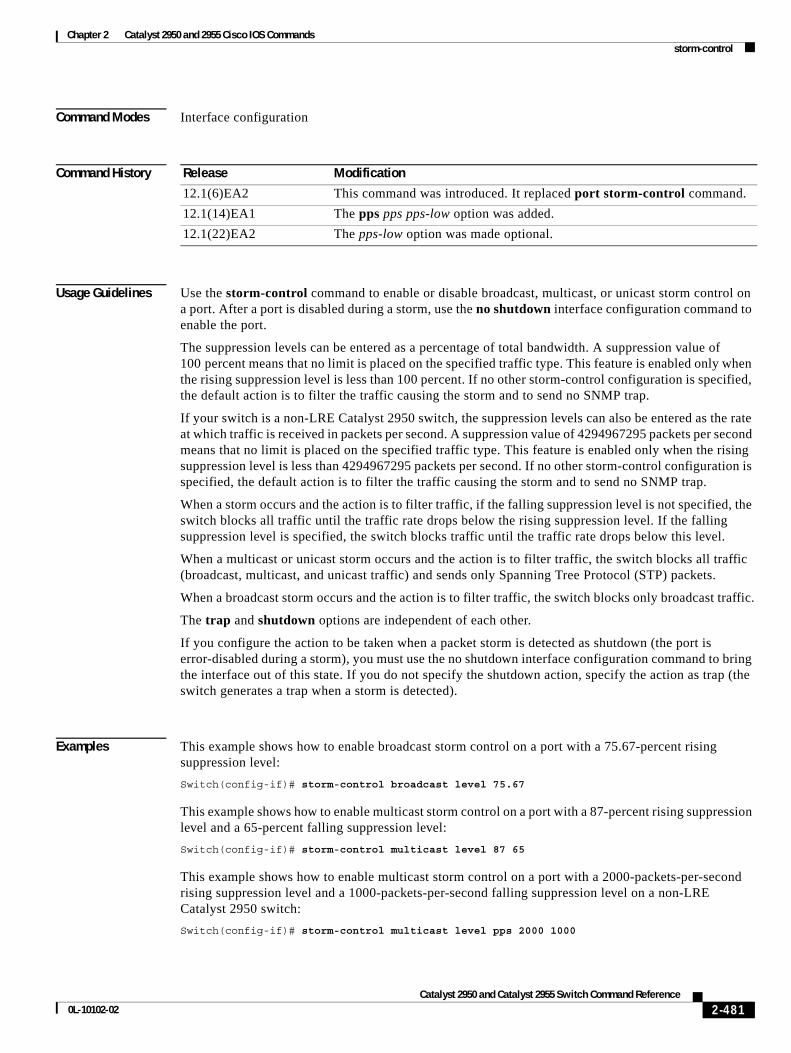
Chapter 2 Catalyst 2950 and 2955 Cisco IOS Commandsstorm-control
Command Modes Interface configuration
Command History
Usage Guidelines Use the storm-control command to enable or disable broadcast, multicast, or unicast storm control on a port. After a port is disabled during a storm, use the no shutdown interface configuration command to enable the port.
The suppression levels can be entered as a percentage of total bandwidth. A suppression value of 100 percent means that no limit is placed on the specified traffic type. This feature is enabled only when the rising suppression level is less than 100 percent. If no other storm-control configuration is specified, the default action is to filter the traffic causing the storm and to send no SNMP trap.
If your switch is a non-LRE Catalyst 2950 switch, the suppression levels can also be entered as the rate at which traffic is received in packets per second. A suppression value of 4294967295 packets per second means that no limit is placed on the specified traffic type. This feature is enabled only when the rising suppression level is less than 4294967295 packets per second. If no other storm-control configuration is specified, the default action is to filter the traffic causing the storm and to send no SNMP trap.
When a storm occurs and the action is to filter traffic, if the falling suppression level is not specified, the switch blocks all traffic until the traffic rate drops below the rising suppression level. If the falling suppression level is specified, the switch blocks traffic until the traffic rate drops below this level.
When a multicast or unicast storm occurs and the action is to filter traffic, the switch blocks all traffic (broadcast, multicast, and unicast traffic) and sends only Spanning Tree Protocol (STP) packets.
When a broadcast storm occurs and the action is to filter traffic, the switch blocks only broadcast traffic.
The trap and shutdown options are independent of each other.
If you configure the action to be taken when a packet storm is detected as shutdown (the port is error-disabled during a storm), you must use the no shutdown interface configuration command to bring the interface out of this state. If you do not specify the shutdown action, specify the action as trap (the switch generates a trap when a storm is detected).
Examples This example shows how to enable broadcast storm control on a port with a 75.67-percent rising suppression level:
Switch(config-if)# storm-control broadcast level 75.67
This example shows how to enable multicast storm control on a port with a 87-percent rising suppression level and a 65-percent falling suppression level:
Switch(config-if)# storm-control multicast level 87 65
This example shows how to enable multicast storm control on a port with a 2000-packets-per-second rising suppression level and a 1000-packets-per-second falling suppression level on a non-LRE Catalyst 2950 switch:
Switch(config-if)# storm-control multicast level pps 2000 1000
Release Modification
12.1(6)EA2 This command was introduced. It replaced port storm-control command.
12.1(14)EA1 The pps pps pps-low option was added.
12.1(22)EA2 The pps-low option was made optional.
2-481Catalyst 2950 and Catalyst 2955 Switch Command Reference
0L-10102-02
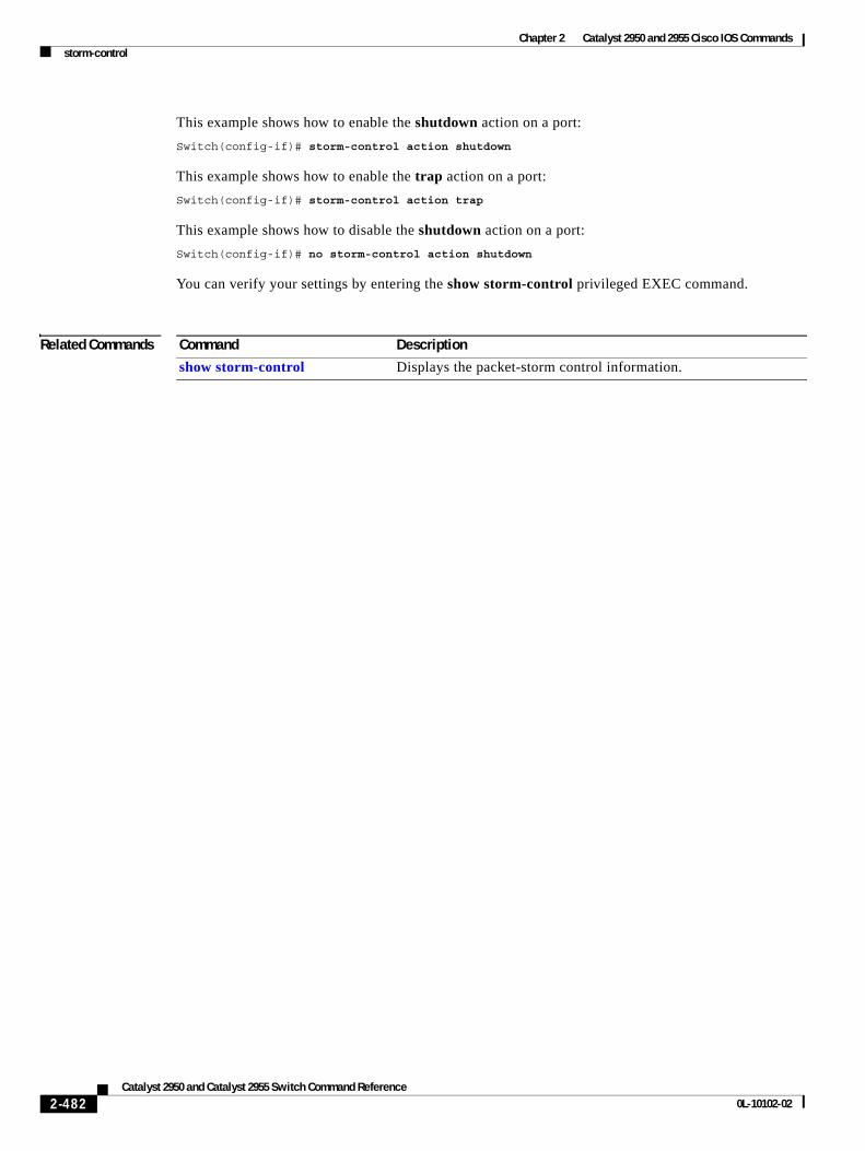
Chapter 2 Catalyst 2950 and 2955 Cisco IOS Commandsstorm-control
This example shows how to enable the shutdown action on a port:
Switch(config-if)# storm-control action shutdown
This example shows how to enable the trap action on a port:
Switch(config-if)# storm-control action trap
This example shows how to disable the shutdown action on a port:
Switch(config-if)# no storm-control action shutdown
You can verify your settings by entering the show storm-control privileged EXEC command.
Related Commands Command Description
show storm-control Displays the packet-storm control information.
2-482Catalyst 2950 and Catalyst 2955 Switch Command Reference
0L-10102-02
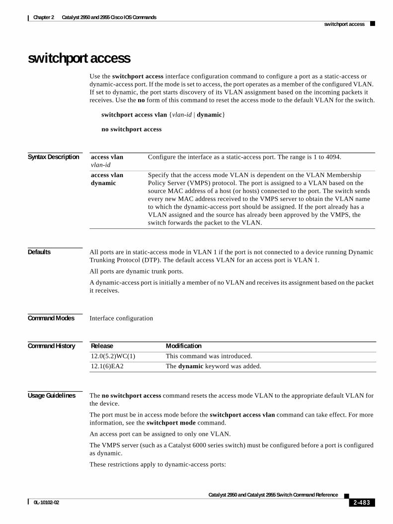
Chapter 2 Catalyst 2950 and 2955 Cisco IOS Commandsswitchport access
switchport accessUse the switchport access interface configuration command to configure a port as a static-access or dynamic-access port. If the mode is set to access, the port operates as a member of the configured VLAN. If set to dynamic, the port starts discovery of its VLAN assignment based on the incoming packets it receives. Use the no form of this command to reset the access mode to the default VLAN for the switch.
switchport access vlan {vlan-id | dynamic}
no switchport access
Syntax Description
Defaults All ports are in static-access mode in VLAN 1 if the port is not connected to a device running Dynamic Trunking Protocol (DTP). The default access VLAN for an access port is VLAN 1.
All ports are dynamic trunk ports.
A dynamic-access port is initially a member of no VLAN and receives its assignment based on the packet it receives.
Command Modes Interface configuration
Command History
Usage Guidelines The no switchport access command resets the access mode VLAN to the appropriate default VLAN for the device.
The port must be in access mode before the switchport access vlan command can take effect. For more information, see the switchport mode command.
An access port can be assigned to only one VLAN.
The VMPS server (such as a Catalyst 6000 series switch) must be configured before a port is configured as dynamic.
These restrictions apply to dynamic-access ports:
access vlan vlan-id
Configure the interface as a static-access port. The range is 1 to 4094.
access vlan dynamic
Specify that the access mode VLAN is dependent on the VLAN Membership Policy Server (VMPS) protocol. The port is assigned to a VLAN based on the source MAC address of a host (or hosts) connected to the port. The switch sends every new MAC address received to the VMPS server to obtain the VLAN name to which the dynamic-access port should be assigned. If the port already has a VLAN assigned and the source has already been approved by the VMPS, the switch forwards the packet to the VLAN.
Release Modification
12.0(5.2)WC(1) This command was introduced.
12.1(6)EA2 The dynamic keyword was added.
2-483Catalyst 2950 and Catalyst 2955 Switch Command Reference
0L-10102-02
Chapter 2 Catalyst 2950 and 2955 Cisco IOS Commandsswitchport access
• The software implements the VLAN Query Protocol (VQP) client, which can query a VMPS such as a Catalyst 6000 series switch. The VMPS server must be configured before a port is configured as dynamic.
• Use dynamic-access ports only to connect end stations. Connecting them to switches or routers that use bridging protocols can cause a loss of connectivity.
• Configure the network so that Spanning Tree Protocol (STP) does not put the dynamic-access port in an STP blocking state. The Port Fast feature is automatically enabled on dynamic-access ports.
• Dynamic-access ports can only be in one VLAN and do not use VLAN tagging.
• Dynamic-access ports cannot be configured as:
– Members of an EtherChannel port group (dynamic-access ports cannot be grouped with any other port, including other dynamic ports).
– Source or destination ports in a static address entry.
– Monitor ports.
Examples This example shows how to assign a port already in access mode to VLAN 2 (instead of the default VLAN 1):
Switch(config-if)# switchport access vlan 2
You can verify your settings by entering the show interfaces interface-id switchport privileged EXEC command and examining information in the Administrative Mode and Operational Mode rows.
Related Commands Command Description
show interfaces switchport
Displays the administrative and operational status of a switching (nonrouting) port, including port blocking and port protection settings.
switchport mode Configures the VLAN membership mode of a port.
2-484Catalyst 2950 and Catalyst 2955 Switch Command Reference
0L-10102-02
Chapter 2 Catalyst 2950 and 2955 Cisco IOS Commandsswitchport block
switchport block Use the switchport block interface configuration command to prevent forwarding of unknown multicast or unicast packets. Use the no form of this command to allow forwarding of unknown multicast or unicast packets.
switchport block {multicast | unicast}
no switchport block {multicast | unicast}
This command is available only on these switches:
• Catalyst 2950 Long-Reach Ethernet (LRE) switches running Cisco IOS Release 12.1(14)EA1 or later
• Catalyst 2950G-12-EI, 2950G-24-EI, 2950G-24-EI-DC, 2950G-48-EI, and 2955 switches running Cisco IOS Release 12.1(19)EA1 or later
Syntax Description
Defaults Unknown multicast and unicast traffic are not blocked.
Command Modes Interface configuration
Command History
Usage Guidelines By default, all traffic with unknown MAC addresses is sent to all ports. You can block unknown multicast or unicast traffic on protected or non-protected ports. If unknown multicast or unicast traffic is not blocked on a protected port, there could be security issues.
Blocking unknown multicast or unicast traffic is not automatically enabled on protected ports; you must explicitly configure it.
Note For more information about blocking packets, see the software configuration guide for this release.
Examples This example shows how to block unknown multicast traffic on an interface:
Switch(config-if)# switchport block multicast
You can verify your setting by entering the show interfaces interface-id switchport privileged EXEC command.
multicast Specify that unknown multicast traffic should be blocked.
unicast Specify that unknown unicast traffic should be blocked.
Release Modification
12.1(14)EA1 This command was introduced.
2-485Catalyst 2950 and Catalyst 2955 Switch Command Reference
0L-10102-02

Chapter 2 Catalyst 2950 and 2955 Cisco IOS Commandsswitchport block
Related Commands Command Description
show interfaces switchport Displays the administrative and operational status of a switching port, including port blocking and port protection settings.
2-486Catalyst 2950 and Catalyst 2955 Switch Command Reference
0L-10102-02
Chapter 2 Catalyst 2950 and 2955 Cisco IOS Commandsswitchport host
switchport hostUse the switchport host interface configuration command on the switch to optimize a Layer 2 port for a host connection. The no form of this command has no effect on the system.
switchport host
Syntax Description This command has no arguments or keywords.
Defaults The default is for the port to not be optimized for a host connection.
Command Modes Interface configuration
Command History
Usage Guidelines To optimize the port for a host connection, the switchport host command sets the switchport mode to access, enables spanning-tree Port Fast, and disables channel grouping. Only an end station can accept this configuration.
Because spanning-tree Port Fast is enabled, you should enter the switchport host command only on ports that are connected to a single host. Connecting other switches, hubs, concentrators, or bridges to a fast-start port can cause temporary spanning-tree loops.
Enable the switchport host command to decrease the time to start packet forwarding.
The no switchport host command has no affect. To return an interface to a configuration not optimized as a host connection, you can manually reconfigure switchport mode, spanning-tree Port Fast, and channel grouping. You can also use the default interface interface-id global config command to return the interface to its default state. However, this command also returns other interface configuration to the default.
Examples This example shows how to optimize the port configuration for a host connection:
Switch(config-if)# switchport host switchport mode will be set to access spanning-tree portfast will be enabled channel group will be disabled Switch(config-if)#
You can verify the effects of the command by entering the show interfaces interface-id switchport or show running-config interface interface-id privileged EXEC command.
Release Modification
12.1(20)EA1 This command was introduced.
2-487Catalyst 2950 and Catalyst 2955 Switch Command Reference
0L-10102-02
Chapter 2 Catalyst 2950 and 2955 Cisco IOS Commandsswitchport host
Related Commands Command Description
show interfaces switchport Displays the administrative and operational status of a switching (nonrouting) port, including switchport mode.
show running-config interface interface-id
Displays the running configuration on the interface.
2-488Catalyst 2950 and Catalyst 2955 Switch Command Reference
0L-10102-02
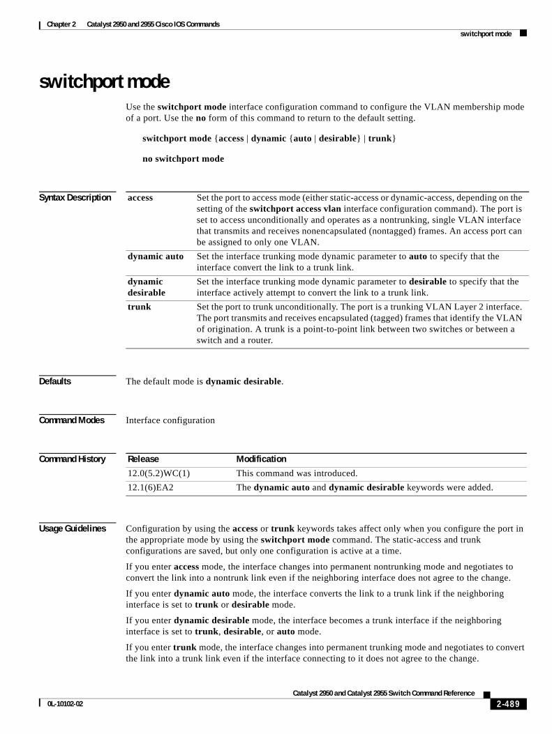
Chapter 2 Catalyst 2950 and 2955 Cisco IOS Commandsswitchport mode
switchport mode Use the switchport mode interface configuration command to configure the VLAN membership mode of a port. Use the no form of this command to return to the default setting.
switchport mode {access | dynamic {auto | desirable} | trunk}
no switchport mode
Syntax Description
Defaults The default mode is dynamic desirable.
Command Modes Interface configuration
Command History
Usage Guidelines Configuration by using the access or trunk keywords takes affect only when you configure the port in the appropriate mode by using the switchport mode command. The static-access and trunk configurations are saved, but only one configuration is active at a time.
If you enter access mode, the interface changes into permanent nontrunking mode and negotiates to convert the link into a nontrunk link even if the neighboring interface does not agree to the change.
If you enter dynamic auto mode, the interface converts the link to a trunk link if the neighboring interface is set to trunk or desirable mode.
If you enter dynamic desirable mode, the interface becomes a trunk interface if the neighboring interface is set to trunk, desirable, or auto mode.
If you enter trunk mode, the interface changes into permanent trunking mode and negotiates to convert the link into a trunk link even if the interface connecting to it does not agree to the change.
access Set the port to access mode (either static-access or dynamic-access, depending on the setting of the switchport access vlan interface configuration command). The port is set to access unconditionally and operates as a nontrunking, single VLAN interface that transmits and receives nonencapsulated (nontagged) frames. An access port can be assigned to only one VLAN.
dynamic auto Set the interface trunking mode dynamic parameter to auto to specify that the interface convert the link to a trunk link.
dynamic desirable
Set the interface trunking mode dynamic parameter to desirable to specify that the interface actively attempt to convert the link to a trunk link.
trunk Set the port to trunk unconditionally. The port is a trunking VLAN Layer 2 interface. The port transmits and receives encapsulated (tagged) frames that identify the VLAN of origination. A trunk is a point-to-point link between two switches or between a switch and a router.
Release Modification
12.0(5.2)WC(1) This command was introduced.
12.1(6)EA2 The dynamic auto and dynamic desirable keywords were added.
2-489Catalyst 2950 and Catalyst 2955 Switch Command Reference
0L-10102-02
Chapter 2 Catalyst 2950 and 2955 Cisco IOS Commandsswitchport mode
The no switchport mode form resets the mode to dynamic desirable.
Trunk ports cannot coexist on the same switch.
To autonegotiate trunking, the interfaces must be in the same VTP domain. Trunk negotiation is managed by the Dynamic Trunking Protocol (DTP), which is a point-to-point protocol. However, some internetworking devices might forward DTP frames improperly, which could cause misconfigurations. To avoid this, you should configure interfaces connected to devices that do not support DTP to not forward DTP frames, which turns off DTP.
• If you do not intend to trunk across those links, use the switchport mode access interface configuration command to disable trunking.
• To enable trunking to a device that does not support DTP, use the switchport mode trunk and switchport nonegotiate interface configuration commands to cause the interface to become a trunk but to not generate DTP frames.
• With GigaStack GBICs, dynamic trunking is only supported when two switches are connected by a single GigaStack GBIC link. If trunking is required when more than two switches in a stack are connected by GigaStack GBIC links, you must manually configure trunking in this manner:
– Manually shut down the GigaStack port by using the shutdown interface configuration command.
– Manually configure trunk mode on the GigaStack port by using the switchport mode trunk interface configuration command on both GBIC interfaces to cause the interfaces to become trunks.
– Use the no shutdown interface configuration command to bring up the GigaStack port.
Examples This example shows how to configure a port for access mode:
Switch(config-if)# switchport mode access
This example shows how set the interface to dynamic desirable mode:
Switch(config-if)# switchport mode dynamic desirable
This example shows how to configure a port for trunk mode:
Switch(config-if)# switchport mode trunk
You can verify your settings by entering the show interfaces interface-id switchport privileged EXEC command and examining information in the Administrative Mode and Operational Mode rows.
Related Commands Command Description
show interfaces switchport
Displays the administrative and operational status of a switching (nonrouting) port, including port blocking and port protection settings.
switchport access Configures a port as a static-access port.
switchport trunk Configures the trunk characteristics when an interface is in trunking mode.
2-490Catalyst 2950 and Catalyst 2955 Switch Command Reference
0L-10102-02
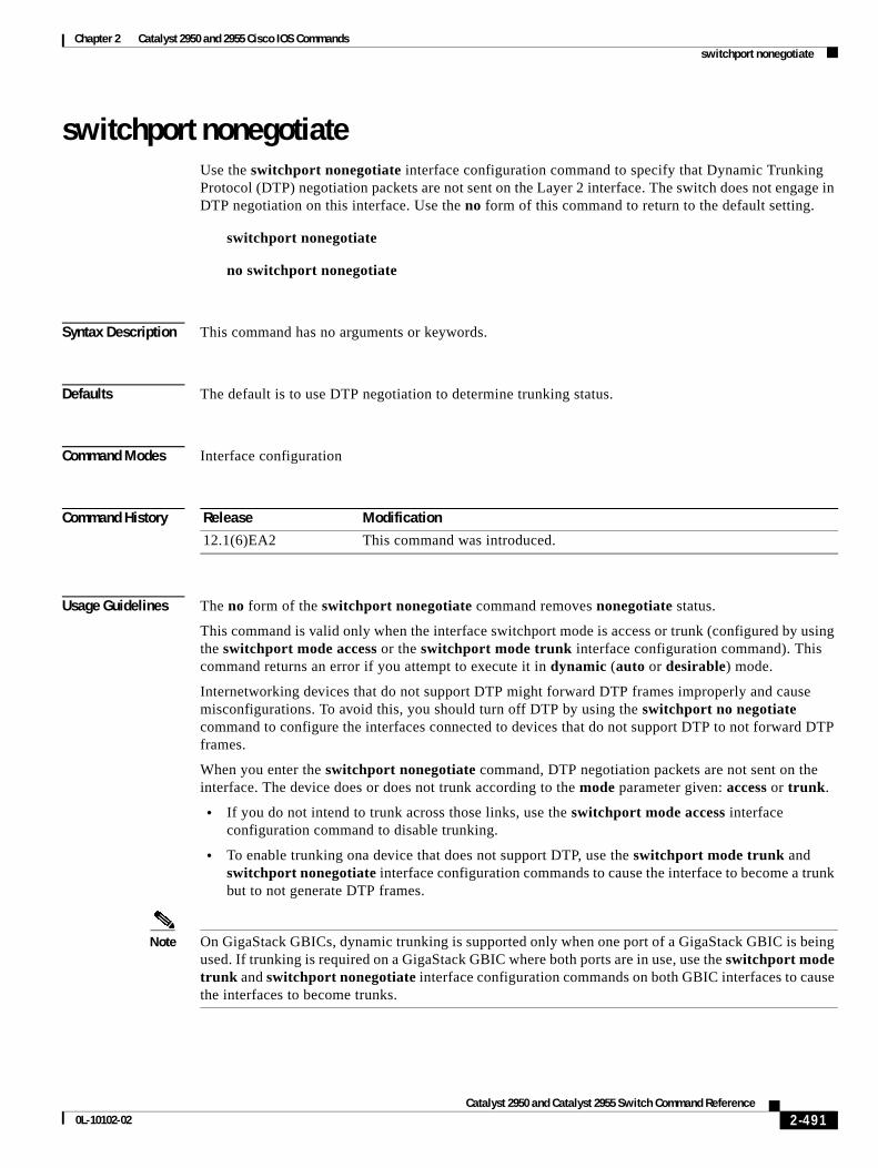
Chapter 2 Catalyst 2950 and 2955 Cisco IOS Commandsswitchport nonegotiate
switchport nonegotiateUse the switchport nonegotiate interface configuration command to specify that Dynamic Trunking Protocol (DTP) negotiation packets are not sent on the Layer 2 interface. The switch does not engage in DTP negotiation on this interface. Use the no form of this command to return to the default setting.
switchport nonegotiate
no switchport nonegotiate
Syntax Description This command has no arguments or keywords.
Defaults The default is to use DTP negotiation to determine trunking status.
Command Modes Interface configuration
Command History
Usage Guidelines The no form of the switchport nonegotiate command removes nonegotiate status.
This command is valid only when the interface switchport mode is access or trunk (configured by using the switchport mode access or the switchport mode trunk interface configuration command). This command returns an error if you attempt to execute it in dynamic (auto or desirable) mode.
Internetworking devices that do not support DTP might forward DTP frames improperly and cause misconfigurations. To avoid this, you should turn off DTP by using the switchport no negotiate command to configure the interfaces connected to devices that do not support DTP to not forward DTP frames.
When you enter the switchport nonegotiate command, DTP negotiation packets are not sent on the interface. The device does or does not trunk according to the mode parameter given: access or trunk.
• If you do not intend to trunk across those links, use the switchport mode access interface configuration command to disable trunking.
• To enable trunking ona device that does not support DTP, use the switchport mode trunk and switchport nonegotiate interface configuration commands to cause the interface to become a trunk but to not generate DTP frames.
Note On GigaStack GBICs, dynamic trunking is supported only when one port of a GigaStack GBIC is being used. If trunking is required on a GigaStack GBIC where both ports are in use, use the switchport mode trunk and switchport nonegotiate interface configuration commands on both GBIC interfaces to cause the interfaces to become trunks.
Release Modification
12.1(6)EA2 This command was introduced.
2-491Catalyst 2950 and Catalyst 2955 Switch Command Reference
0L-10102-02
Chapter 2 Catalyst 2950 and 2955 Cisco IOS Commandsswitchport nonegotiate
Examples This example shows how to cause an interface to refrain from negotiating trunking mode and to act as a trunk or access port (depending on the mode set):
Switch(config-if)# switchport nonegotiate
You can verify your setting by entering the show interfaces interface-id switchport privileged EXEC command.
Related Commands Command Description
show interfaces switchport Displays the administrative and operational status of a switching (nonrouting) port, including port blocking and port protection settings.
switchport mode Configures the VLAN membership mode of a port.
2-492Catalyst 2950 and Catalyst 2955 Switch Command Reference
0L-10102-02
Chapter 2 Catalyst 2950 and 2955 Cisco IOS Commandsswitchport port-security
switchport port-securityUse the switchport port-security interface configuration command without keywords to enable port security on an interface. Use the keywords to configure secure MAC addresses, a maximum number of secure MAC addresses, or the violation mode. Use the no form of this command to disable port security or to return to the default settings.
switchport port-security [mac-address mac-address] | [mac-address sticky [mac-address]] | [maximum value] | [violation {protect | restrict | shutdown}]
no switchport port-security [mac-address mac-address] | [mac-address sticky [mac-address]] | [maximum value] | [violation {protect | restrict | shutdown}]
Syntax Description mac-address mac-address (Optional) Specify a secure MAC address for the port by entering a 48-bit MAC address. You can add additional secure MAC addresses up to the maximum value configured.
mac-address sticky [mac-address]
(Optional) Enable the interface for sticky learning by entering only the mac-address sticky keywords. When sticky learning is enabled, the interface adds all secure MAC addresses that are dynamically learned to the running configuration and converts these addresses to sticky secure MAC addresses.
Specify a sticky secure MAC address by entering the mac-address sticky mac-address keywords.
Note Although you can specify a sticky secure MAC address by entering the mac-address sticky mac-address keywords, we recommend using the mac-address mac-address interface configuration command to enter static secure MAC addresses.
maximum value (Optional) Set the maximum number of secure MAC addresses for the interface. The range is 1 to 132. The default is 1.
violation (Optional) Set the security violation mode or the action to be taken if port security is violated. The default is shutdown.
protect (Optional) Set the security violation protect mode. When the number of secure MAC addresses reaches the limit allowed on the port, packets with unknown source addresses are dropped until you remove a sufficient number of secure MAC addresses or increase the number of maximum allowable addresses. You are not notified that a security violation has occurred.
2-493Catalyst 2950 and Catalyst 2955 Switch Command Reference
0L-10102-02
Chapter 2 Catalyst 2950 and 2955 Cisco IOS Commandsswitchport port-security
Defaults Port security is disabled.
When port security is enabled, if no keywords are entered, the default maximum number of secure MAC addresses is 1.
Sticky learning is disabled.
The default violation mode is shutdown.
Command Modes Interface configuration
Command History
Usage Guidelines A secure port can have 1 to 132 associated secure addresses. The total number of available secure addresses on the switch is 1024.
After you have set the maximum number of secure MAC addresses allowed on a port, you can add secure addresses to the address table by manually configuring them, by allowing the port to dynamically configure them, or by configuring some MAC addresses and allowing the rest to be dynamically configured.
You can delete dynamic secure MAC addresses from the address table by entering the clear port-security dynamic privileged EXEC command.
You can enable sticky learning on an interface by using the switchport port-security mac-address sticky interface configuration command. When you enter this command, the interface converts all the dynamic secure MAC addresses, including those that were dynamically learned before sticky learning was enabled, to sticky secure MAC addresses. It adds all the sticky secure MAC addresses to the running configuration.
restrict (Optional) Set the security violation restrict mode. When the number of secure MAC addresses reaches the limit allowed on the port, packets with unknown source addresses are dropped until you remove a sufficient number of secure MAC addresses or increase the number of maximum allowable addresses. In this mode, you are notified that a security violation has occurred. Specifically, an SNMP trap is sent, a syslog message is logged, and the violation counter increments.
shutdown (Optional) Set the security violation shutdown mode. In this mode, a port security violation causes the interface to immediately become error-disabled and turns off the port LED. It also sends an SNMP trap, logs a syslog message, and increments the violation counter. When a secure port is in the error-disabled state, you can bring it out of this state by entering the errdisable recovery cause psecure-violation global configuration command, or you can manually re-enable it by entering the shutdown and no shut down interface configuration commands.
Release Modification
12.1(6)EA2 This command was introduced. It replaced the port security and mac-address-table secure commands.
12.1(11)EA1 The mac-address sticky [mac-address] option was added.
2-494Catalyst 2950 and Catalyst 2955 Switch Command Reference
0L-10102-02
Chapter 2 Catalyst 2950 and 2955 Cisco IOS Commandsswitchport port-security
You can delete a sticky secure MAC addresses from the address table by using the clear port-security sticky mac-addr privileged EXEC command. To delete all the sticky addresses on an interface, use the clear port-security sticky interface-id privileged EXEC command.
If you disable sticky learning, the sticky secure MAC addresses are converted to dynamic secure addresses and are removed from the running configuration.
If you save the sticky secure MAC addresses in the configuration file, when the switch restarts or the interface shuts down, the interface does not need to relearn these addresses. If you do not save the configuration, they are lost.
If you specify restrict or shutdown, use the snmp-server host global configuration command to configure the Simple Network Management Protocol (SNMP) trap host to receive traps.
It is a security violation when one of these situations occurs:
• The maximum number of secure MAC addresses have been added to the address table, and a station whose MAC address is not in the address table attempts to access the interface.
• An address learned or configured on one secure interface is seen on another secure interface in the same VLAN.
When a secure port is in the error-disabled state, you can bring it out of this state by entering the errdisable recovery cause psecure-violation global configuration command, or you can manually re-enable it by entering the shutdown and no shut down interface configuration commands.
A secure port has these limitations:
• Port security can only be configured on static access ports.
• A secure port cannot be a dynamic port, a dynamic access port or a trunk port.
• A secure port cannot be a destination port for Switched Port Analyzer (SPAN).
• A secure port cannot belong to a Fast EtherChannel or Gigabit EtherChannel port group.
• You cannot configure static secure or sticky secure MAC addresses on a voice VLAN.
• When you enable port security on an interface that is also configured with a voice VLAN, set the maximum allowed secure addresses on the port to two. When the port is connected to a Cisco IP phone, the IP phone requires one MAC address. The Cisco IP phone address is learned on the voice VLAN, but is not learned on the access VLAN. If you connect a single PC to the Cisco IP phone, no additional MAC addresses are required. If you connect more than one PC to the Cisco IP phone, you must configure enough secure addresses to allow one for each PC and one for the phone
• If any type of port security is enabled on the access VLAN, dynamic port security is automatically enabled on the voice VLAN.
• You cannot configure port security on a per-VLAN basis.
• When a voice VLAN is configured on a secure port that is also configured as a sticky secure port, all addresses detected on the voice VLAN are learned as dynamic secure addresses while all addresses detected on the access VLAN (to which the port belongs) are learned as sticky secure addresses.
• The switch does not support port security aging of sticky secure MAC addresses.
Examples This example shows how to enable port security:
Switch(config-if)# switchport port-security
This example shows how to set the action that the port takes when an address violation occurs:
Switch(config-if)# switchport port-security violation shutdown
2-495Catalyst 2950 and Catalyst 2955 Switch Command Reference
0L-10102-02
Chapter 2 Catalyst 2950 and 2955 Cisco IOS Commandsswitchport port-security
This example shows how to set the maximum number of addresses that a port can learn to 20:
Switch(config-if)# switchport port-security maximum 20
This example shows how to enable sticky learning and to enter two sticky secure MAC addresses:
Switch(config-if)# switchport port-security mac-address sticky Switch(config-if)# switchport port-security mac-address sticky 0000.0000.4141Switch(config-if)# switchport port-security mac-address sticky 0000.0000.000f
You can verify your settings by entering the show port-security privileged EXEC command.
Related Commands Command Description
clear port-security Deletes from the MAC address table a specific dynamic secure address or all the dynamic secure addresses on an interface.
clear port-security sticky Deletes from the MAC address table a specific sticky secure address, all the sticky secure addresses on an interface, or all the sticky secure addresses on a switch.
show port-security Displays the port security settings defined for the port.
2-496Catalyst 2950 and Catalyst 2955 Switch Command Reference
0L-10102-02
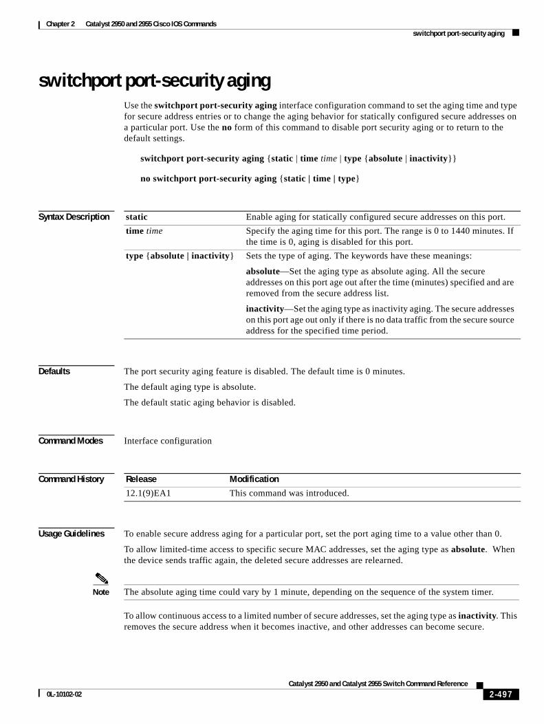
Chapter 2 Catalyst 2950 and 2955 Cisco IOS Commandsswitchport port-security aging
switchport port-security agingUse the switchport port-security aging interface configuration command to set the aging time and type for secure address entries or to change the aging behavior for statically configured secure addresses on a particular port. Use the no form of this command to disable port security aging or to return to the default settings.
switchport port-security aging {static | time time | type {absolute | inactivity}}
no switchport port-security aging {static | time | type}
Syntax Description
Defaults The port security aging feature is disabled. The default time is 0 minutes.
The default aging type is absolute.
The default static aging behavior is disabled.
Command Modes Interface configuration
Command History
Usage Guidelines To enable secure address aging for a particular port, set the port aging time to a value other than 0.
To allow limited-time access to specific secure MAC addresses, set the aging type as absolute. When the device sends traffic again, the deleted secure addresses are relearned.
Note The absolute aging time could vary by 1 minute, depending on the sequence of the system timer.
To allow continuous access to a limited number of secure addresses, set the aging type as inactivity. This removes the secure address when it becomes inactive, and other addresses can become secure.
static Enable aging for statically configured secure addresses on this port.
time time Specify the aging time for this port. The range is 0 to 1440 minutes. If the time is 0, aging is disabled for this port.
type {absolute | inactivity} Sets the type of aging. The keywords have these meanings:
absolute—Set the aging type as absolute aging. All the secure addresses on this port age out after the time (minutes) specified and are removed from the secure address list.
inactivity—Set the aging type as inactivity aging. The secure addresses on this port age out only if there is no data traffic from the secure source address for the specified time period.
Release Modification
12.1(9)EA1 This command was introduced.
2-497Catalyst 2950 and Catalyst 2955 Switch Command Reference
0L-10102-02
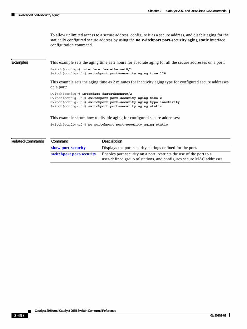
Chapter 2 Catalyst 2950 and 2955 Cisco IOS Commandsswitchport port-security aging
To allow unlimited access to a secure address, configure it as a secure address, and disable aging for the statically configured secure address by using the no switchport port-security aging static interface configuration command.
Examples This example sets the aging time as 2 hours for absolute aging for all the secure addresses on a port:
Switch(config)# interface fastethernet0/1Switch(config-if)# switchport port-security aging time 120
This example sets the aging time as 2 minutes for inactivity aging type for configured secure addresses on a port:
Switch(config)# interface fastethernet0/2Switch(config-if)# switchport port-security aging time 2 Switch(config-if)# switchport port-security aging type inactivity Switch(config-if)# switchport port-security aging static
This example shows how to disable aging for configured secure addresses:
Switch(config-if)# no switchport port-security aging static
Related Commands Command Description
show port-security Displays the port security settings defined for the port.
switchport port-security Enables port security on a port, restricts the use of the port to a user-defined group of stations, and configures secure MAC addresses.
2-498Catalyst 2950 and Catalyst 2955 Switch Command Reference
0L-10102-02
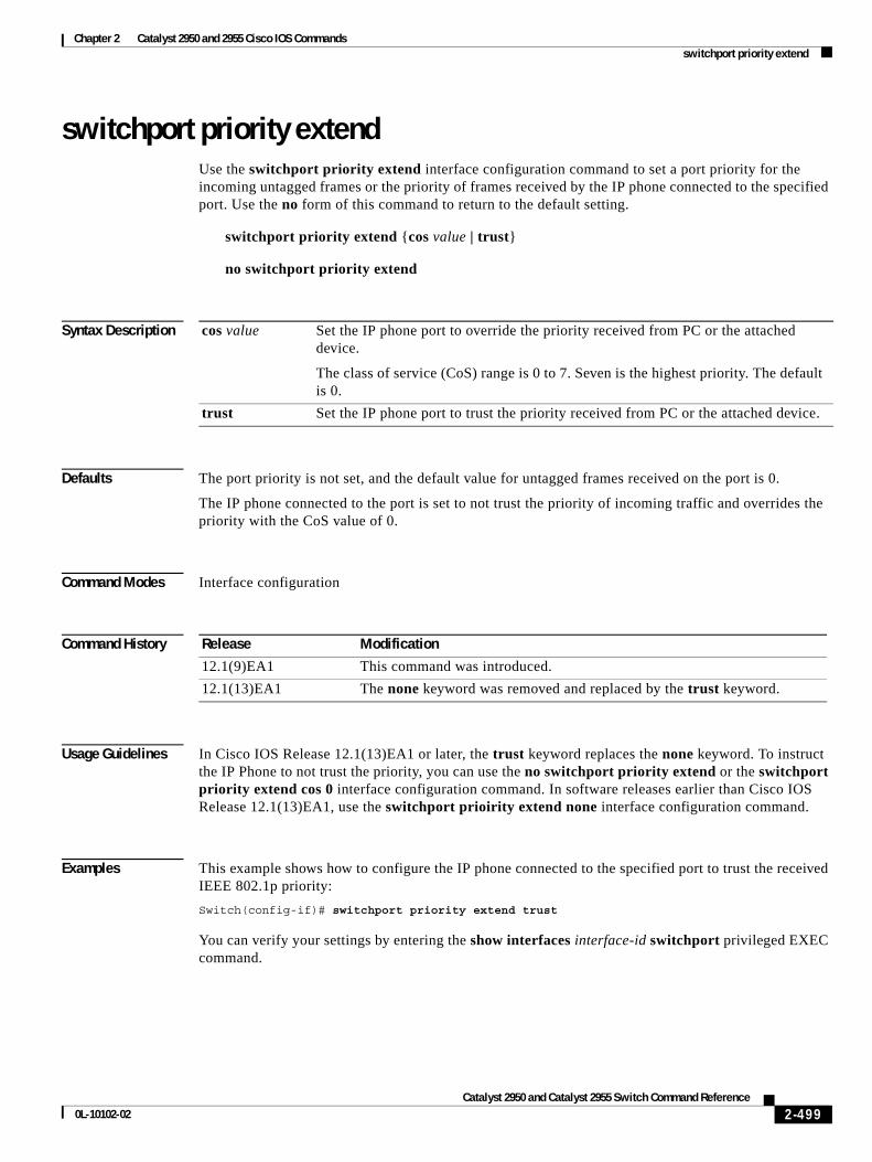
Chapter 2 Catalyst 2950 and 2955 Cisco IOS Commandsswitchport priority extend
switchport priority extendUse the switchport priority extend interface configuration command to set a port priority for the incoming untagged frames or the priority of frames received by the IP phone connected to the specified port. Use the no form of this command to return to the default setting.
switchport priority extend {cos value | trust}
no switchport priority extend
Syntax Description
Defaults The port priority is not set, and the default value for untagged frames received on the port is 0.
The IP phone connected to the port is set to not trust the priority of incoming traffic and overrides the priority with the CoS value of 0.
Command Modes Interface configuration
Command History
Usage Guidelines In Cisco IOS Release 12.1(13)EA1 or later, the trust keyword replaces the none keyword. To instruct the IP Phone to not trust the priority, you can use the no switchport priority extend or the switchport priority extend cos 0 interface configuration command. In software releases earlier than Cisco IOS Release 12.1(13)EA1, use the switchport prioirity extend none interface configuration command.
Examples This example shows how to configure the IP phone connected to the specified port to trust the received IEEE 802.1p priority:
Switch(config-if)# switchport priority extend trust
You can verify your settings by entering the show interfaces interface-id switchport privileged EXEC command.
cos value Set the IP phone port to override the priority received from PC or the attached device.
The class of service (CoS) range is 0 to 7. Seven is the highest priority. The default is 0.
trust Set the IP phone port to trust the priority received from PC or the attached device.
Release Modification
12.1(9)EA1 This command was introduced.
12.1(13)EA1 The none keyword was removed and replaced by the trust keyword.
2-499Catalyst 2950 and Catalyst 2955 Switch Command Reference
0L-10102-02

Chapter 2 Catalyst 2950 and 2955 Cisco IOS Commandsswitchport priority extend
Related Commands Command Description
show interfaces Displays the administrative and operational status of a port or all ports.
switchport voice vlan Configures the voice VLAN on the port.
2-500Catalyst 2950 and Catalyst 2955 Switch Command Reference
0L-10102-02
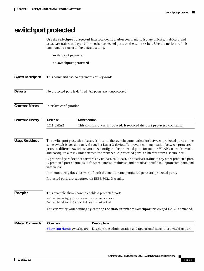
Chapter 2 Catalyst 2950 and 2955 Cisco IOS Commandsswitchport protected
switchport protectedUse the switchport protected interface configuration command to isolate unicast, multicast, and broadcast traffic at Layer 2 from other protected ports on the same switch. Use the no form of this command to return to the default setting.
switchport protected
no switchport protected
Syntax Description This command has no arguments or keywords.
Defaults No protected port is defined. All ports are nonprotected.
Command Modes Interface configuration
Command History
Usage Guidelines The switchport protection feature is local to the switch; communication between protected ports on the same switch is possible only through a Layer 3 device. To prevent communication between protected ports on different switches, you must configure the protected ports for unique VLANs on each switch and configure a trunk link between the switches. A protected port is different from a secure port.
A protected port does not forward any unicast, multicast, or broadcast traffic to any other protected port. A protected port continues to forward unicast, multicast, and broadcast traffic to unprotected ports and vice versa.
Port monitoring does not work if both the monitor and monitored ports are protected ports.
Protected ports are supported on IEEE 802.1Q trunks.
Examples This example shows how to enable a protected port:
Switch(config)# interface fastethernet0/3Switch(config-if)# switchport protected
You can verify your settings by entering the show interfaces switchport privileged EXEC command.
Related Commands
Release Modification
12.1(6)EA2 This command was introduced. It replaced the port protected command.
Command Description
show interfaces switchport Displays the administrative and operational staus of a switching port.
2-501Catalyst 2950 and Catalyst 2955 Switch Command Reference
0L-10102-02
Chapter 2 Catalyst 2950 and 2955 Cisco IOS Commandsswitchport trunk
switchport trunkUse the switchport trunk interface configuration command to set the trunk characteristics when the interface is in trunking mode. Use the no form of the command without keywords to reset all of the trunking characteristics to the defaults. Use the no form with keywords to reset those characteristics to the defaults.
switchport trunk {{allowed vlan vlan-list} | {native vlan vlan-id} | {pruning vlan vlan-list}}
no switchport trunk {{allowed vlan vlan-list} | {native vlan vlan-id} | {pruning vlan vlan-list}}
Syntax Description
The vlan-list format is all | none | [add | remove | except] vlan-atom where:
• all specifies all VLANs from 1 to 4094. This keyword is not allowed on commands that do not permit all VLANs in the list to be set at the same time.
• none means an empty list. This keyword is not allowed on commands that require certain VLANs to be set or at least one VLAN to be set.
• add adds the defined list of VLANs to those currently set instead of replacing the list. Valid IDs are 1 to 1005; extended-range VLAN IDs are valid in some cases.
Note You can add extended-range VLANs to the allowed VLAN list, but not to the pruning-eligible VLAN list.
Separate nonconsecutive VLAN IDs with a comma; do not enter a space after the comma. Use a hyphen to designate a range of IDs; do not enter a space before or after the hyphen.
• remove removes the defined list of VLANs from those currently set instead of replacing the list. Valid IDs are 2 to 1001; extended-range VLAN IDs are valid in some cases. You cannot remove VLAN 1 or VLANs 1002 to 1005 from the list.
Note You can remove extended-range VLANs (VLAN IDs greater than 1005) from the allowed VLAN list, but you cannot remove them from the pruning-eligible list.
Separate nonconsecutive VLAN IDs with a comma; do not enter a space after the comma. Use a hyphen to designate a range of IDs; do not enter a space before or after the hyphen.
• except lists the VLANs that should be calculated by inverting the defined list of VLANs. (VLANs are added except the ones specified.) Valid IDs are 1 to 1001. Separate nonconsecutive VLAN IDs with a comma; do not enter a space after the comma. Use a hyphen to designate a range of IDs; do not enter a space before or after the hyphen.
allowed vlan vlan-list Set the list of allowed VLANs that can receive and send traffic on this interface in tagged format when in trunking mode. See the following vlan-list format. The none keyword is not valid. The default is all.
native vlan vlan-id Set the native VLAN for sending and receiving untagged traffic when the interface is in IEEE 802.1Q trunking mode. The range is 1 to 4094.
pruning vlan vlan-list Set the list of VLANs that are enabled for VTP pruning when in trunking mode. The all keyword is not valid.
2-502Catalyst 2950 and Catalyst 2955 Switch Command Reference
0L-10102-02
Chapter 2 Catalyst 2950 and 2955 Cisco IOS Commandsswitchport trunk
• vlan-atom is either a single VLAN number from 1 to 4094, a list of nonconsecutive VLANs, or a continuous range of VLANs described by two VLAN numbers, the lower one first, separated by a hyphen.
For a list of nonconsecutive VLAN IDs, separate the VLAN IDs with a comma. Do not enter a space after the comma.
For a continuous range of VLAN IDs, use a hyphen to designate the range. Do not enter a space before or after the hyphen.
These are examples showing how to specify one or more VLANs:
– Single VLAN—101
– List of nonconsecutive VLANs—10,12,14,16,18
– Continuous range of VLANs—10-15
– List of VLAN continuous ranges—10-15,20-24
– List of nonconsecutive VLANs and VLAN continuous ranges—8,11,20-24,44
Defaults VLAN 1 is the default native VLAN ID on the port.
The default for all VLAN lists is to include all VLANs.
Command Modes Interface configuration
Command History
Usage Guidelines A trunk port cannot be a secure port or a monitor port. However, a static-access port can monitor a VLAN on a trunk port. The VLAN monitored is the one associated with the static-access port.
Allowed VLAN:
• To reduce the risk of spanning-tree loops or storms, you can disable VLAN 1 on any individual VLAN trunk port by removing VLAN 1 from the allowed list. This is known as VLAN 1 minimization. VLAN 1 minimization disables VLAN 1 (the default VLAN on all Cisco switch trunk ports) on an individual VLAN trunk link. As a result, no user traffic, including spanning-tree advertisements, is sent or received on VLAN 1.
When you remove VLAN 1 from a trunk port, the interface continues to send and receive management traffic, for example, Cisco Discovery Protocol (CDP), Port Aggregation Protocol (PAgP), Link Aggregation Control Protocol (LACP), Dynamic Trunking Protocol (DTP), and VLAN Trunking Protocol (VTP) in VLAN 1.
• The no form of the allowed vlan command resets the list to the default list, which allows all VLANs.
Native VLANs:
• All untagged traffic received on an IEEE 802.1Q trunk port is forwarded with the native VLAN configured for the port.
Release Modification
12.1(6)EA2 This command was introduced.
12.1(14)EA1 The allowed vlan vlan list add, remove, and except keywords were modified to accept the VLAN 1 and VLANs 1002 to 1005 values.
2-503Catalyst 2950 and Catalyst 2955 Switch Command Reference
0L-10102-02
Chapter 2 Catalyst 2950 and 2955 Cisco IOS Commandsswitchport trunk
• If a packet has a VLAN ID that is the same as the sending port native VLAN ID, the packet is sent without a tag; otherwise, the switch sends the packet with a tag.
• The no form of the native vlan command resets the native mode VLAN to the appropriate default VLAN for the device.
Trunk Pruning:
• The pruning-eligible list applies only to trunk ports.
• Each trunk port has its own eligibility list.
• If you do not want a VLAN to be pruned, remove it from the pruning-eligible list. VLANs that are pruning-ineligible receive flooded traffic.
• VLAN 1, VLANs 1002 to 1005, and extended-range VLANs (VLANs 1006 to 4094) cannot be pruned.
Note The switch does not support Inter-Switch Link (ISL) trunking.
Examples This example shows how to configure VLAN 3 as the default port to send all untagged traffic:
Switch(config-if)# switchport trunk native vlan 3
This example shows how to add VLANs 1, 2, 5, and 6 to the allowed list:
Switch(config-if)# switchport trunk allowed vlan add 1,2,5,6
This example shows how to remove VLANs 3 and 10 to 15 from the pruning-eligible list:
Switch(config-if)# switchport trunk pruning vlan remove 3,10-15
You can verify your settings by entering the show interfaces interface-id switchport privileged EXEC command.
Related Commands Command Description
show interfaces switchport Displays the administrative and operational status of a switching (nonrouting) port.
switchport mode Configures the VLAN membership mode of a port.
2-504Catalyst 2950 and Catalyst 2955 Switch Command Reference
0L-10102-02
Chapter 2 Catalyst 2950 and 2955 Cisco IOS Commandsswitchport voice vlan
switchport voice vlanUse the switchport voice vlan interface configuration command to configure voice VLAN on the port. Use the no form of this command to return to the default setting.
switchport voice vlan {vlan-id | dot1p | none | untagged}
no switchport voice vlan
Syntax Description
Defaults The switch default is not to automatically configure the telephone (none).
The telephone default is not to tag frames.
Command Modes Interface configuration
Command History
Usage Guidelines You should configure voice VLAN on access ports.
When you enable port security on an interface that is also configured with a voice VLAN, set the maximum allowed secure addresses on the port to two. When the port is connected to a Cisco IP phone, the IP phone requires one MAC address. The Cisco IP phone address is learned on the voice VLAN, but is not learned on the access VLAN. If you connect a single PC to the Cisco IP phone, no additional MAC addresses are required. If you connect more than one PC to the Cisco IP phone, you must configure enough secure addresses to allow one for each PC and one for the phone.
If any type of port security is enabled on the access VLAN, dynamic port security is automatically enabled on the voice VLAN.
You cannot configure static secure MAC addresses on the voice VLAN.
The Port Fast feature is automatically enabled when voice VLAN is configured. When you disable voice VLAN, the Port Fast feature is not automatically disabled.
vlan-id VLAN used for voice traffic. The range is 1 to 4094.
dot1p The telephone uses priority tagging and uses VLAN 0 (the native VLAN). By default, the Cisco IP phone forwards the voice traffic with an IEEE 802.1p priority of 5.
none The telephone is not instructed through the command-line interface (CLI) about the voice VLAN. The telephone uses the configuration from the telephone key pad.
untagged The telephone does not tag frames and uses VLAN 4095. The default for the telephone is untagged.
Release Modification
12.1(9)EA1 This command was introduced.
2-505Catalyst 2950 and Catalyst 2955 Switch Command Reference
0L-10102-02
Chapter 2 Catalyst 2950 and 2955 Cisco IOS Commandsswitchport voice vlan
Examples This example shows how to configure VLAN 2 as the voice VLAN:
Switch(config-if)# switchport voice vlan 2
You can verify your settings by entering the show interfaces interface-id switchport privileged EXEC command.
Related Commands Command Description
show interfaces interface-id switchport Displays the administrative and operational status of a switching (nonrouting) port.
switchport priority extend Determines how the device connected to the specified port handles priority traffic received on its incoming port.
2-506Catalyst 2950 and Catalyst 2955 Switch Command Reference
0L-10102-02
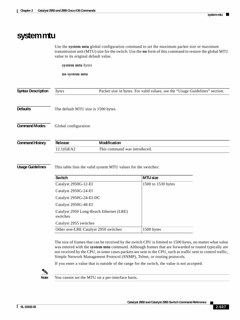
Chapter 2 Catalyst 2950 and 2955 Cisco IOS Commandssystem mtu
system mtuUse the system mtu global configuration command to set the maximum packet size or maximum transmission unit (MTU) size for the switch. Use the no form of this command to restore the global MTU value to its original default value.
system mtu bytes
no system mtu
Syntax Description
Defaults The default MTU size is 1500 bytes.
Command Modes Global configuration
Command History
Usage Guidelines This table lists the valid system MTU values for the switches:
The size of frames that can be received by the switch CPU is limited to 1500 bytes, no matter what value was entered with the system mtu command. Although frames that are forwarded or routed typically are not received by the CPU, in some cases packets are sent to the CPU, such as traffic sent to control traffic, Simple Network Management Protocol (SNMP), Telnet, or routing protocols.
If you enter a value that is outside of the range for the switch, the value is not accepted.
Note You cannot set the MTU on a per-interface basis.
bytes Packet size in bytes. For valid values, see the “Usage Guidelines” section.
Release Modification
12.1(6)EA2 This command was introduced.
Switch MTU size
Catalyst 2950G-12-EI
Catalyst 2950G-24-EI
Catalyst 2950G-24-EI-DC
Catalyst 2950G-48-EI
Catalyst 2950 Long-Reach Ethernet (LRE) switches
Catalyst 2955 switches
1500 to 1530 bytes
Other non-LRE Catalyst 2950 switches 1500 bytes
2-507Catalyst 2950 and Catalyst 2955 Switch Command Reference
0L-10102-02
Chapter 2 Catalyst 2950 and 2955 Cisco IOS Commandssystem mtu
Examples This example shows how to set the maximum packet size to 1528 bytes:
Switch(config)# system mtu 1528Switch(config)# exit
This example shows the response when you try to set a switch to an out-of-range number:
Switch(config)# system mtu 2000 ^% Invalid input detected at '^' marker.
You can verify your settings by entering the show system mtu privileged EXEC command.
Related Commands Command Description
show system mtu Displays the maximum packet size set for the switch.
2-508Catalyst 2950 and Catalyst 2955 Switch Command Reference
0L-10102-02
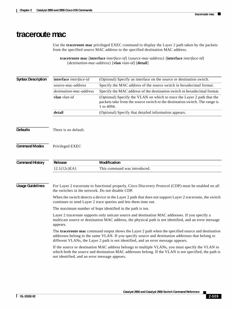
Commands
Chapter 2 Catalyst 2950 and 2955 Cisco IOS2traceroute mac
traceroute macUse the traceroute mac privileged EXEC command to display the Layer 2 path taken by the packets from the specified source MAC address to the specified destination MAC address.
tracetroute mac [interface interface-id] {source-mac-address} [interface interface-id] {destination-mac-address} [vlan vlan-id] [detail]
Syntax Description
Defaults There is no default.
Command Modes Privileged EXEC
Command History
Usage Guidelines For Layer 2 traceroute to functional properly, Cisco Discovery Protocol (CDP) must be enabled on all the switches in the network. Do not disable CDP.
When the switch detects a device in the Layer 2 path that does not support Layer 2 traceroute, the switch continues to send Layer 2 trace queries and lets them time out.
The maximum number of hops identified in the path is ten.
Layer 2 traceroute supports only unicast source and destination MAC addresses. If you specify a multicast source or destination MAC address, the physical path is not identified, and an error message appears.
The traceroute mac command output shows the Layer 2 path when the specified source and destination addresses belong to the same VLAN. If you specify source and destination addresses that belong to different VLANs, the Layer 2 path is not identified, and an error message appears.
If the source or destination MAC address belongs to multiple VLANs, you must specify the VLAN to which both the source and destination MAC addresses belong. If the VLAN is not specified, the path is not identified, and an error message appears.
interface interface-id (Optional) Specify an interface on the source or destination switch.
source-mac-address Specify the MAC address of the source switch in hexadecimal format.
destination-mac-address Specify the MAC address of the destination switch in hexadecimal format.
vlan vlan-id (Optional) Specify the VLAN on which to trace the Layer 2 path that the packets take from the source switch to the destination switch. The range is 1 to 4094.
detail (Optional) Specify that detailed information appears.
Release Modification
12.1(12c)EA1 This command was introduced.
2-509Catalyst 2950 and Catalyst 2955 Switch Command Reference
OL-10102-02
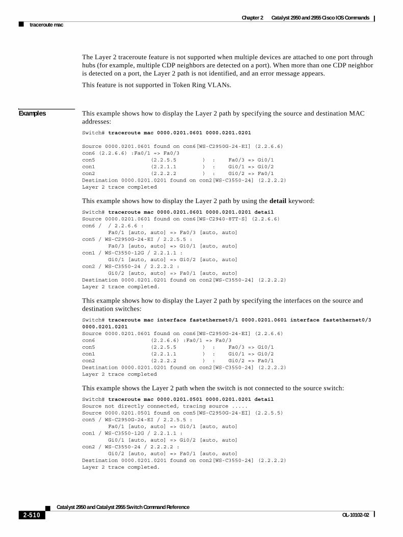
Chapter 2 Catalyst 2950 and 2955 Cisco IOS Commandstraceroute mac
The Layer 2 traceroute feature is not supported when multiple devices are attached to one port through hubs (for example, multiple CDP neighbors are detected on a port). When more than one CDP neighbor is detected on a port, the Layer 2 path is not identified, and an error message appears.
This feature is not supported in Token Ring VLANs.
Examples This example shows how to display the Layer 2 path by specifying the source and destination MAC addresses:
Switch# traceroute mac 0000.0201.0601 0000.0201.0201
Source 0000.0201.0601 found on con6[WS-C2950G-24-EI] (2.2.6.6)con6 (2.2.6.6) :Fa0/1 => Fa0/3con5 (2.2.5.5 ) : Fa0/3 => Gi0/1con1 (2.2.1.1 ) : Gi0/1 => Gi0/2con2 (2.2.2.2 ) : Gi0/2 => Fa0/1Destination 0000.0201.0201 found on con2[WS-C3550-24] (2.2.2.2)Layer 2 trace completed
This example shows how to display the Layer 2 path by using the detail keyword:
Switch# traceroute mac 0000.0201.0601 0000.0201.0201 detailSource 0000.0201.0601 found on con6[WS-C2940-8TT-S] (2.2.6.6)con6 / / 2.2.6.6 : Fa0/1 [auto, auto] => Fa0/3 [auto, auto]con5 / WS-C2950G-24-EI / 2.2.5.5 : Fa0/3 [auto, auto] => Gi0/1 [auto, auto]con1 / WS-C3550-12G / 2.2.1.1 : Gi0/1 [auto, auto] => Gi0/2 [auto, auto]con2 / WS-C3550-24 / 2.2.2.2 : Gi0/2 [auto, auto] => Fa0/1 [auto, auto]Destination 0000.0201.0201 found on con2[WS-C3550-24] (2.2.2.2)Layer 2 trace completed.
This example shows how to display the Layer 2 path by specifying the interfaces on the source and destination switches:
Switch# traceroute mac interface fastethernet0/1 0000.0201.0601 interface fastethernet0/3 0000.0201.0201Source 0000.0201.0601 found on con6[WS-C2950G-24-EI] (2.2.6.6)con6 (2.2.6.6) :Fa0/1 => Fa0/3con5 (2.2.5.5 ) : Fa0/3 => Gi0/1con1 (2.2.1.1 ) : Gi0/1 => Gi0/2con2 (2.2.2.2 ) : Gi0/2 => Fa0/1Destination 0000.0201.0201 found on con2[WS-C3550-24] (2.2.2.2)Layer 2 trace completed
This example shows the Layer 2 path when the switch is not connected to the source switch:
Switch# traceroute mac 0000.0201.0501 0000.0201.0201 detailSource not directly connected, tracing source .....Source 0000.0201.0501 found on con5[WS-C2950G-24-EI] (2.2.5.5)con5 / WS-C2950G-24-EI / 2.2.5.5 : Fa0/1 [auto, auto] => Gi0/1 [auto, auto]con1 / WS-C3550-12G / 2.2.1.1 : Gi0/1 [auto, auto] => Gi0/2 [auto, auto]con2 / WS-C3550-24 / 2.2.2.2 : Gi0/2 [auto, auto] => Fa0/1 [auto, auto]Destination 0000.0201.0201 found on con2[WS-C3550-24] (2.2.2.2)Layer 2 trace completed.
2-510Catalyst 2950 and Catalyst 2955 Switch Command Reference
OL-10102-02
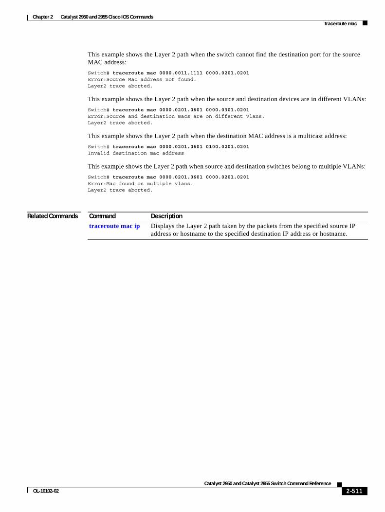
Chapter 2 Catalyst 2950 and 2955 Cisco IOS Commandstraceroute mac
This example shows the Layer 2 path when the switch cannot find the destination port for the source MAC address:
Switch# traceroute mac 0000.0011.1111 0000.0201.0201Error:Source Mac address not found. Layer2 trace aborted.
This example shows the Layer 2 path when the source and destination devices are in different VLANs:
Switch# traceroute mac 0000.0201.0601 0000.0301.0201Error:Source and destination macs are on different vlans. Layer2 trace aborted.
This example shows the Layer 2 path when the destination MAC address is a multicast address:
Switch# traceroute mac 0000.0201.0601 0100.0201.0201Invalid destination mac address
This example shows the Layer 2 path when source and destination switches belong to multiple VLANs:
Switch# traceroute mac 0000.0201.0601 0000.0201.0201Error:Mac found on multiple vlans.Layer2 trace aborted.
Related Commands Command Description
traceroute mac ip Displays the Layer 2 path taken by the packets from the specified source IP address or hostname to the specified destination IP address or hostname.
2-511Catalyst 2950 and Catalyst 2955 Switch Command Reference
OL-10102-02
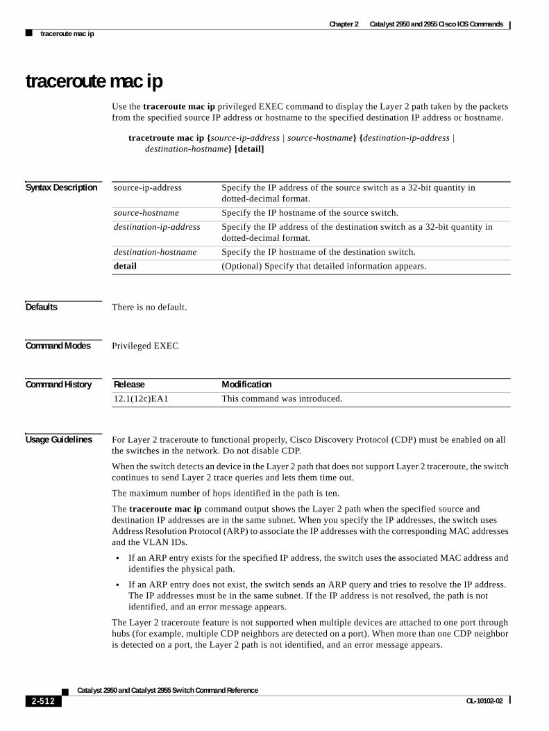
Chapter 2 Catalyst 2950 and 2955 Cisco IOS Commandstraceroute mac ip
traceroute mac ipUse the traceroute mac ip privileged EXEC command to display the Layer 2 path taken by the packets from the specified source IP address or hostname to the specified destination IP address or hostname.
tracetroute mac ip {source-ip-address | source-hostname} {destination-ip-address | destination-hostname} [detail]
Syntax Description
Defaults There is no default.
Command Modes Privileged EXEC
Command History
Usage Guidelines For Layer 2 traceroute to functional properly, Cisco Discovery Protocol (CDP) must be enabled on all the switches in the network. Do not disable CDP.
When the switch detects an device in the Layer 2 path that does not support Layer 2 traceroute, the switch continues to send Layer 2 trace queries and lets them time out.
The maximum number of hops identified in the path is ten.
The traceroute mac ip command output shows the Layer 2 path when the specified source and destination IP addresses are in the same subnet. When you specify the IP addresses, the switch uses Address Resolution Protocol (ARP) to associate the IP addresses with the corresponding MAC addresses and the VLAN IDs.
• If an ARP entry exists for the specified IP address, the switch uses the associated MAC address and identifies the physical path.
• If an ARP entry does not exist, the switch sends an ARP query and tries to resolve the IP address. The IP addresses must be in the same subnet. If the IP address is not resolved, the path is not identified, and an error message appears.
The Layer 2 traceroute feature is not supported when multiple devices are attached to one port through hubs (for example, multiple CDP neighbors are detected on a port). When more than one CDP neighbor is detected on a port, the Layer 2 path is not identified, and an error message appears.
source-ip-address Specify the IP address of the source switch as a 32-bit quantity in dotted-decimal format.
source-hostname Specify the IP hostname of the source switch.
destination-ip-address Specify the IP address of the destination switch as a 32-bit quantity in dotted-decimal format.
destination-hostname Specify the IP hostname of the destination switch.
detail (Optional) Specify that detailed information appears.
Release Modification
12.1(12c)EA1 This command was introduced.
2-512Catalyst 2950 and Catalyst 2955 Switch Command Reference
OL-10102-02
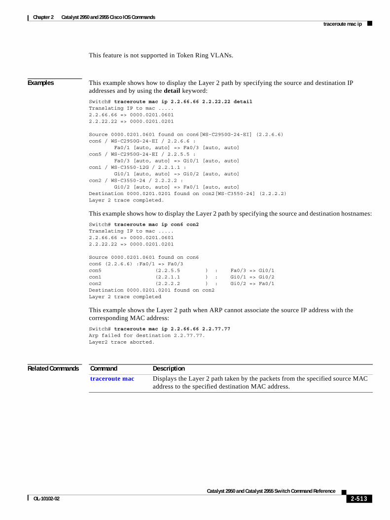
Chapter 2 Catalyst 2950 and 2955 Cisco IOS Commandstraceroute mac ip
This feature is not supported in Token Ring VLANs.
Examples This example shows how to display the Layer 2 path by specifying the source and destination IP addresses and by using the detail keyword:
Switch# traceroute mac ip 2.2.66.66 2.2.22.22 detailTranslating IP to mac ..... 2.2.66.66 => 0000.0201.06012.2.22.22 => 0000.0201.0201
Source 0000.0201.0601 found on con6[WS-C2950G-24-EI] (2.2.6.6)con6 / WS-C2950G-24-EI / 2.2.6.6 : Fa0/1 [auto, auto] => Fa0/3 [auto, auto]con5 / WS-C2950G-24-EI / 2.2.5.5 : Fa0/3 [auto, auto] => Gi0/1 [auto, auto]con1 / WS-C3550-12G / 2.2.1.1 : Gi0/1 [auto, auto] => Gi0/2 [auto, auto]con2 / WS-C3550-24 / 2.2.2.2 : Gi0/2 [auto, auto] => Fa0/1 [auto, auto]Destination 0000.0201.0201 found on con2[WS-C3550-24] (2.2.2.2)Layer 2 trace completed.
This example shows how to display the Layer 2 path by specifying the source and destination hostnames:
Switch# traceroute mac ip con6 con2Translating IP to mac ..... 2.2.66.66 => 0000.0201.06012.2.22.22 => 0000.0201.0201
Source 0000.0201.0601 found on con6con6 (2.2.6.6) :Fa0/1 => Fa0/3con5 (2.2.5.5 ) : Fa0/3 => Gi0/1con1 (2.2.1.1 ) : Gi0/1 => Gi0/2con2 (2.2.2.2 ) : Gi0/2 => Fa0/1Destination 0000.0201.0201 found on con2Layer 2 trace completed
This example shows the Layer 2 path when ARP cannot associate the source IP address with the corresponding MAC address:
Switch# traceroute mac ip 2.2.66.66 2.2.77.77Arp failed for destination 2.2.77.77.Layer2 trace aborted.
Related Commands Command Description
traceroute mac Displays the Layer 2 path taken by the packets from the specified source MAC address to the specified destination MAC address.
2-513Catalyst 2950 and Catalyst 2955 Switch Command Reference
OL-10102-02
Chapter 2 Catalyst 2950 and 2955 Cisco IOS Commandsudld
udldUse the udld global configuration command to enable aggressive or normal mode in the UniDirectional Link Detection (UDLD) and to set the configurable message timer. Use the no form of this command to return to the default settings.
udld {aggressive | enable | message time message-timer-interval}
no udld {aggressive | enable | message time}
Syntax Description
Defaults UDLD is disabled on all fiber-optic interfaces.
The message timer is set at 15 seconds.
Command Modes Global configuration
Command History
Usage Guidelines Use the udld global configuration command to enable UDLD only on fiber-optic ports. To enable UDLD on other interface types, use the udld interface configuration command.
UDLD supports two modes of operation: normal mode (the default) and aggressive mode. In normal mode, UDLD detects unidirectional links due to misconnected interfaces on fiber-optic connections. In aggressive mode, UDLD also detects unidirectional links due to one-way traffic on fiber-optic and twisted-pair links and due to misconnected interfaces on fiber-optic links. For information about normal and aggressive modes, see the “Understanding UDLD” section in the software configuration guide for this release.
If you change the message time between probe packets, you are making a trade-off between the detection speed and the CPU load. By decreasing the time, you can make the detection-response faster but increase the load on the CPU.
You can use these commands to reset an interface shut down by UDLD:
• The udld reset privileged EXEC command to reset all interfaces shut down by UDLD
• The shutdown and no shutdown interface configuration commands
aggressive Enable UDLD in aggressive mode on all fiber-optic interfaces.
enable Enable UDLD in normal mode on all fiber-optic interfaces.
message time message-timer-interval
Configure the period of time between UDLD probe messages on ports that are in the advertisement phase and are determined to be bidirectional. The range is 7 to 90 seconds.
Release Modification
12.0(5.2)WC(1) This command was introduced.
12.1(6)EA2 The udld enable global configuration command was changed to udld (global configuration).
2-514Catalyst 2950 and Catalyst 2955 Switch Command Reference
OL-10102-02
Chapter 2 Catalyst 2950 and 2955 Cisco IOS Commandsudld
• The no udld enable global configuration command followed by the udld {aggressive | enable} global configuration command to re-enable UDLD globally
• The no udld port enable interface configuration command followed by the udld port or udld port aggressive interface configuration command to re-enable UDLD on the specified interface
• The errdisable recovery cause udld and errdisable recovery interval interval global configuration commands to automatically recover from the UDLD error-disabled state
Examples This example shows how to enable UDLD in normal mode on all fiber-optic interfaces:
Switch(config)# udld enable
You can verify your settings by entering the show udld privileged EXEC command.
Related Commands Command Description
show running-config Displays the running configuration on the switch. For syntax information, select Cisco IOS Configuration Fundamentals Command Reference for Release 12.1 > Cisco IOS File Management Commands > Configuration File Commands.
show udld Displays the UDLD status for all ports or the specified port.
udld port Enables UDLD on an individual interface or prevents a fiber-optic interface from being enabled by the udld global configuration command.
udld reset Resets any interface shut down by UDLD and permits traffic to again pass through.
2-515Catalyst 2950 and Catalyst 2955 Switch Command Reference
OL-10102-02
Chapter 2 Catalyst 2950 and 2955 Cisco IOS Commandsudld port
udld port Use the udld port interface configuration command to enable UniDirectional Link Detection (UDLD) on an individual interface or to prevent a fiber-optic interface from being enabled by the udld global configuration command. Use the no form of this command to return to the udld global configuration command setting or to disable UDLD if entered for a nonfiber-optic port.
udld port [aggressive]
no udld port [aggressive]
Syntax Description
Defaults On fiber-optic interfaces, UDLD is not enabled, not in aggressive mode, and not disabled. For this reason, fiber-optic interfaces enable UDLD according to the state of the udld enable or udld aggressive global configuration command.
On nonfiber-optic interfaces, UDLD is disabled.
Command Modes Interface configuration
Command History
Usage Guidelines UDLD is supported on fiber- and copper-based Ethernet ports.
A UDLD-capable port cannot detect a unidirectional link if it is connected to a UDLD-incapable port of another switch.
This setting overrides the global UDLD configuration on the switch.
UDLD supports two modes of operation: normal mode (the default) and aggressive mode. In normal mode, UDLD detects unidirectional links due to misconnected interfaces on fiber-optic connections. In aggressive mode, UDLD also detects unidirectional links due to one-way traffic on fiber-optic and twisted-pair links and due to misconnected interfaces on fiber-optic links. For information about normal and aggressive modes, see the “Configuring UDLD” chapter in the software configuration guide for this release.
To enable UDLD in normal mode, use the udld port interface configuration command. To enable UDLD in aggressive mode, use the udld port aggressive interface configuration command.
Use the no udld port command on fiber-optic ports to return control of UDLD to the udld enable global configuration command or to disable UDLD on nonfiber-optic ports.
aggressive (Optional) Enable UDLD in aggressive mode on the specified interface.
Release Modification
12.0(5.2)WC(1) This command was introduced.
12.1(6)EA2 The aggressive keyword was added.
12.1(14)EA1 The port keyword was added. The enable keyword was removed.
12.1(20)EA2 The disable keyword was removed.
2-516Catalyst 2950 and Catalyst 2955 Switch Command Reference
OL-10102-02
Chapter 2 Catalyst 2950 and 2955 Cisco IOS Commandsudld port
Use the udld port aggressive command on fiber-optic ports to override the settings of the udld enable or udld aggressive global configuration command. Use the no form on fiber-optic ports to remove this setting and to return control of UDLD enabling to the udld global configuration command or to disable UDLD on nonfiber-optic ports.
If the switch software detects a Gigabit Interface Converter (GBIC) module change and the interface changes from fiber optic to nonfiber optic or from nonfiber optic to fiber optic, all configurations are maintained.
You can use these commands to reset an interface shut down by UDLD:
• The udld reset privileged EXEC command to reset all interfaces shut down by UDLD
• The shutdown and no shutdown interface configuration commands
• The no udld enable global configuration command followed by the udld {aggressive | enable} global configuration command to re-enable UDLD globally
• The no udld port interface configuration command followed by the udld port or udld port aggressive interface configuration command to re-enable UDLD on the specified interface
• The errdisable recovery cause udld and errdisable recovery interval interval global configuration commands to automatically recover from the UDLD error-disabled state
Examples This example shows how to enable UDLD in normal mode on an interface:
Switch(config)# interface fastethernet0/2Switch(config-if)# udld port
This example shows how to disable UDLD on a fiber-optic interface despite the setting of the udld global configuration command:
Switch(config)# interface gigabitethernet0/2Switch(config-if)# no udld port
You can verify your settings by entering the show running-config or show udld privileged EXEC command.
Related Commands Command Description
show running-config Displays the running configuration on the switch. For syntax information, select Cisco IOS Configuration Fundamentals Command Reference for Release 12.1 > Cisco IOS File Management Commands > Configuration File Commands.
show udld Displays UDLD status for all ports or the specified port.
udld Enables UDLD on all fiber-optic ports on the switch.
udld reset Resets all interfaces shut down by UDLD and permits traffic to again pass through.
2-517Catalyst 2950 and Catalyst 2955 Switch Command Reference
OL-10102-02
Chapter 2 Catalyst 2950 and 2955 Cisco IOS Commandsudld reset
udld resetUse the udld reset privileged EXEC command to reset all interfaces shut down by UniDirectional Link Detection (UDLD) and to permit traffic to again pass through. Other features, such as spanning tree, Port Aggregation Protocol (PAgP), and Dynamic Trunking Protocol (DTP), still have their normal effects, if enabled.
udld reset
Syntax Description This command has no arguments or keywords.
Command Modes Privileged EXEC
Command History
Usage Guidelines If the interface configuration is still enabled for UDLD, these ports begin to run UDLD again and might shut down for the same reason if the problem has not been corrected.
Examples This example shows how to reset all interfaces disabled by UDLD:
Switch# udld reset1 ports shutdown by UDLD were reset.
You can verify your settings by entering the show udld privileged EXEC command.
Related Commands
Release Modification
12.0(5.2)WC(1) This command was introduced.
Command Description
show running-config Displays the running configuration on the switch. For syntax information, select Cisco IOS Configuration Fundamentals Command Reference for Release 12.1 > Cisco IOS File Management Commands > Configuration File Commands.
show udld Displays UDLD status for all ports or the specified port.
udld Enables UDLD on all fiber-optic ports on the switch.
udld port Enables UDLD on an individual interface or prevents a fiber-optic interface from being enabled by the udld global configuration command.
2-518Catalyst 2950 and Catalyst 2955 Switch Command Reference
OL-10102-02
Chapter 2 Catalyst 2950 and 2955 Cisco IOS Commandsupgrade binary
upgrade binaryUse the upgrade binary controller configuration command to configure the behavior of a Long-Reach Ethernet (LRE) controller upgrade.
upgrade binary LRE binary [remote lre-interface]
no upgrade binary LRE binary [remote lre-interface]
This command is available only on a Catalyst 2950 LRE switch.
Syntax Description
Command Modes Controller configuration
Command History
Usage Guidelines Use this command only when you need to specify a particular upgrade binary file for a local controller in an LRE switch or for a remote CPE device connected to the controller. The default behavior for an upgrade is for the system to select the binary version. If you use the upgrade binary LRE binary command without parameters, the LRE binary is applied to the local controller when it is upgraded. If you specify the remote keyword and interface, the LRE binary is applied to the CPE device at the end of the remote LRE link at upgrade time.
Upgrade configurations given in the controller configuration mode take precedence over upgrade configurations given in the global configuration mode.
Examples This example shows how to configures a Cisco 585 LRE CPE on an LRE link to use version 51.00.00.bin the next time LRE update runs:
Switch# configure terminalSwitch(config)# controller longreachethernet 0Switch(config-controller)# upgrade binary cisco585-lre_vdslsngl_51.00.00.bin remote longreachethernet 0/1
Related Commands
LRE binary The LRE binary file name being applied.
remote lre-interface (Optional) The LRE interface. If you do not specify the remote parameter for the customer premises equipment (CPE) end of the LRE link, the local or controller end of the LRE link is implied.
Release Modification
12.1(11)YJ This command was introduced.
Command Description
upgrade preserve Prevents an upgrade of the local CPE controller and all remote CPE devices connected to it.
2-519Catalyst 2950 and Catalyst 2955 Switch Command Reference
OL-10102-02
Chapter 2 Catalyst 2950 and 2955 Cisco IOS Commandsupgrade preserve
upgrade preserveUse the upgrade preserve controller configuration command to prevent an upgrade from taking place on a controller in a Long-Reach Ethernet (LRE) switch and on all the devices that remotely connect to it. Use the no form of the command to allow upgrades on the devices.
upgrade preserve
no upgrade preserve
This command is available only on a Catalyst 2950 LRE switch.
Syntax Description This command has no arguments or keywords.
Command Modes Controller configuration
Command History
Usage Guidelines When you use the upgrade preserve controller configuration command, an LRE switch does not upgrade a controller and all the devices connected to it during an LRE upgrade. This command does not affect other controllers in the switch and their connected devices.
Examples This example shows how to prevent the controller 0, and the CPE devices attached to it, from being upgraded:
Switch# configure terminalSwitch(config)# controller longreachethernet 0Switch(config-controller)# upgrade preserve
Related Commands
Release Modification
12.1(11)YJ This command was introduced.
Command Description
controller longreachethernet Enter controller configuration mode.
upgrade binary Configures upgrades on either end of an LRE link.
2-520Catalyst 2950 and Catalyst 2955 Switch Command Reference
OL-10102-02
Chapter 2 Catalyst 2950 and 2955 Cisco IOS Commandsvlan (global configuration)
vlan (global configuration)Use the vlan global configuration command to add a VLAN and enter the config-vlan mode. Use the no form of this command to delete the VLAN. Configuration information for normal-range VLANs (VLAN IDs 1 to 1005) is always saved in the VLAN database. When VLAN Trunking Protocol (VTP) mode is transparent, you can create extended-range VLANs (VLAN IDs greater than 1005), and the VTP mode and domain name and the VLAN configuration are saved in the switch running configuration file. You can save these configurations in the switch startup configuration file by entering the copy running-config startup-config privileged EXEC command.
vlan vlan-id
no vlan vlan-id
Syntax Description
Defaults This command has no default settings.
Command Modes Global configuration
Command History
Usage Guidelines You must use the vlan vlan-id global configuration command to add extended-range VLANs (VLAN IDs 1006 to 4094). Before configuring VLANs in the extended range, you must use the vtp transparent global configuration or VLAN configuration command to put the switch in VTP transparent mode. Extended-range VLANs are not learned by VTP and are not added to the VLAN database, but when VTP mode is transparent, VTP mode and domain name and all VLAN configurations are saved in the running configuration, and you can save them in the switch startup configuration file.
When you save the VLAN and VTP configurations in the startup configuration file and reboot the switch, the configuration is determined in these ways:
• If both the VLAN database and the configuration file show the VTP mode as transparent and the VTP domain names match, the VLAN database is ignored. The VTP and VLAN configurations in the startup configuration file are used. The VLAN database revision number remains unchanged in the VLAN database.
• If the VTP mode is server, or if the startup VTP mode or domain names do not match the VLAN database, the VTP mode and the VLAN configuration for the first 1005 VLANs use the VLAN database information.
• If the image on the switch or the configuration file is earlier than Cisco IOS Release 12.1(9)EA1, the switch reboots with information in the VLAN database.
vlan-id ID of the VLAN to be added and configured. For vlan-id, the range is 1 to 4094. You can enter a single VLAN ID, a series of VLAN IDs separated by commas, or a range of VLAN IDs separated by hyphens.
Release Modification
12.1(9)EA1 This command was introduced.
2-521Catalyst 2950 and Catalyst 2955 Switch Command Reference
OL-10102-02
Chapter 2 Catalyst 2950 and 2955 Cisco IOS Commandsvlan (global configuration)
If you try to create an extended-range VLAN when the switch is not in VTP transparent mode, the VLAN is rejected, and you receive an error message.
If you enter an invalid VLAN ID, you receive an error message and do not enter config-vlan mode.
Entering the vlan command with a VLAN ID enables config-vlan mode. When you enter the VLAN ID of an existing VLAN, you do not create a new VLAN, but you can modify VLAN parameters for that VLAN. The specified VLANs are added or modified when you exit the config-vlan mode. Only the shutdown command (for VLANs 1 to 1005) takes effect immediately.
These configuration commands are available in config-vlan mode. The no form of each command returns the characteristic to its default state.
Note Although all commands are visible, the only VLAN configuration command supported on extended-range VLANs is mtu mtu-size. For extended-range VLANs, all other characteristics must remain at the default state.
• are are-number: defines the maximum number of all-routes explorer (ARE) hops for this VLAN. This keyword applies only to TrCRF VLANs. The ARE range is 0 to 13. The default is 7. If no value is entered, 0 is assumed to be the maximum.
• backupcrf: specifies the backup CRF mode. This keyword applies only to TrCRF VLANs.
– enable backup CRF mode for this VLAN.
– disable backup CRF mode for this VLAN (the default).
• bridge {bridge-number | type}: specifies the logical distributed source-routing bridge, the bridge that interconnects all logical rings having this VLAN as a parent VLAN in FDDI-NET, Token Ring-NET, and TrBRF VLANs. The bridge number range is 0 to 15. The default bridge number is 0 (no source-routing bridge) for FDDI-NET, TrBRF, and Token Ring-NET VLANs. The type keyword applies only to TrCRF VLANs and is one of these:
– srb (source-route bridging)
– srt (source-route transparent) bridging VLAN
• exit: applies changes, increments the VLAN database revision number (VLANs 1 to 1005 only), and exits config-vlan mode.
• media: defines the VLAN media type. See Table 2-35 for valid commands and syntax for different media types.
Note The switch supports only Ethernet ports. You configure only FDDI and Token Ring media-specific characteristics for VLAN Trunking Protocol (VTP) global advertisements to other switches. These VLANs are locally suspended.
– ethernet is Ethernet media type (the default).
– fddi is FDDI media type.
– fd-net is FDDI network entity title (NET) media type.
– tokenring is Token Ring media type if the VTP v2 mode is disabled, or TrCRF if the VTP version 2 (v) mode is enabled.
– tr-net is Token Ring network entity title (NET) media type if the VTP v2 mode is disabled or TrBRF media type if the VTP v2 mode is enabled.
2-522Catalyst 2950 and Catalyst 2955 Switch Command Reference
OL-10102-02
Chapter 2 Catalyst 2950 and 2955 Cisco IOS Commandsvlan (global configuration)
• mtu mtu-size: specifies the maximum transmission unit (MTU) (packet size in bytes). The range is 1500 to 18190. The default is 1500 bytes.
• name vlan-name: names the VLAN with an ASCII string from 1 to 32 characters that must be unique within the administrative domain. The default is VLANxxxx where xxxx represents four numeric digits (including leading zeros) equal to the VLAN ID number.
• no: negates a command or returns it to the default setting.
• parent parent-vlan-id: specifies the parent VLAN of an existing FDDI, Token Ring, or TrCRF VLAN. This parameter identifies the TrBRF to which a TrCRF belongs and is required when defining a TrCRF. The range is 0 to 1005. The default parent VLAN ID is 0 (no parent VLAN) for FDDI and Token Ring VLANs. For both Token Ring and TrCRF VLANs, the parent VLAN ID must already exist in the database and be associated with a Token Ring-NET or TrBRF VLAN.
• remote-span: adds the Remote SPAN (RSPAN) trait to the VLAN. When the RSPAN trait is added to an existing VLAN, the VLAN is first removed and then recreated with the RSPAN trait. Any access ports are deactivated until the RSPAN trait is removed. The new RSPAN VLAN is propagated via VTP for VLAN IDs less than 1005. This command is available only if your switch is running the EI.
• ring ring-number: defines the logical ring for an FDDI, Token Ring, or TrCRF VLAN. The range is 1 to 4095. The default for Token Ring VLANs is 0. For FDDI VLANs, there is no default.
• said said-value: specifies the security association identifier (SAID) as documented in IEEE 802.10. The range is 1 to 4294967294 that must be unique within the administrative domain. The default value is 100000 plus the VLAN ID number.
• shutdown: shuts down VLAN switching on the VLAN. This command takes effect immediately. Other commands take effect when you exit config-vlan mode.
• state: specifies the VLAN state:
– active means the VLAN is operational (the default).
– suspend means the VLAN is suspended. Suspended VLANs do not pass packets.
• ste ste-number: defines the maximum number of spanning-tree explorer (STE) hops. This keyword applies only to TrCRF VLANs. The range is 0 to 13. The default is 7.
• stp type: defines the spanning-tree type for FDDI-NET, Token Ring-NET, or TrBRF VLANs. For FDDI-NET VLANs, the default STP type is ieee. For Token Ring-NET VLANs, the default STP type is ibm. For FDDI and Token Ring VLANs, the default is no type specified.
– ieee for IEEE Ethernet STP running source-route transparent (SRT) bridging.
– ibm for IBM STP running source-route bridging (SRB).
– auto for STP running a combination of source-route transparent bridging (IEEE) and source-route bridging (IBM).
• tb-vlan1 tb-vlan1-id and tb-vlan2 tb-vlan2-id: specifies the first and second VLAN to which this VLAN is translationally bridged. Translational VLANs translate FDDI or Token Ring to Ethernet, for example. The range is 0 to 1005. If no value is specified, 0 (no transitional bridging) is assumed.
2-523Catalyst 2950 and Catalyst 2955 Switch Command Reference
OL-10102-02
Chapter 2 Catalyst 2950 and 2955 Cisco IOS Commandsvlan (global configuration)
Table 2-36 describes the rules for configuring VLANs.
Table 2-35 Valid Commands and Syntax for Different Media Types
Media Type Valid Syntax
Ethernet name vlan-name, media ethernet, state {suspend | active}, said said-value, mtu mtu-size, remote-span, tb-vlan1 tb-vlan1-id, tb-vlan2 tb-vlan2-id
FDDI name vlan-name, media fddi, state {suspend | active}, said said-value, mtu mtu-size, ring ring-number, parent parent-vlan-id, tb-vlan1 tb-vlan1-id, tb-vlan2 tb-vlan2-id
FDDI-NET name vlan-name, media fd-net, state {suspend | active}, said said-value, mtu mtu-size, bridge bridge-number, stp type {ieee | ibm | auto}, tb-vlan1 tb-vlan1-id, tb-vlan2 tb-vlan2-id
If VTP v2 mode is disabled, do not set the stp type to auto.
Token Ring VTP v1 mode is enabled.
name vlan-name, media tokenring, state {suspend | active}, said said-value, mtu mtu-size, ring ring-number, parent parent-vlan-id, tb-vlan1 tb-vlan1-id, tb-vlan2 tb-vlan2-id
Token Ring concentrator relay function (TrCRF)
VTP v2 mode is enabled.
name vlan-name, media tokenring, state {suspend | active}, said said-value, mtu mtu-size, ring ring-number, parent parent-vlan-id, bridge type {srb | srt}, are are-number, ste ste-number, backupcrf {enable | disable}, tb-vlan1 tb-vlan1-id, tb-vlan2 tb-vlan2-id
Token Ring-NET VTP v1 mode is enabled.
name vlan-name, media tr-net, state {suspend | active}, said said-value, mtu mtu-size, bridge bridge-number, stp type {ieee | ibm}, tb-vlan1 tb-vlan1-id, tb-vlan2 tb-vlan2-id
Token Ring bridge relay function (TrBRF)
VTP v2 mode is enabled.
name vlan-name, media tr-net, state {suspend | active}, said said-value, mtu mtu-size, bridge bridge-number, stp type {ieee | ibm | auto}, tb-vlan1 tb-vlan1-id, tb-vlan2 tb-vlan2-id
Table 2-36 VLAN Configuration Rules
Configuration Rule
VTP v2 mode is enabled, and you are configuring a TrCRF VLAN media type.
Specify a parent VLAN ID of a TrBRF that already exists in the database.
Specify a ring number. Do not leave this field blank.
Specify unique ring numbers when TrCRF VLANs have the same parent VLAN ID. Only one backup concentrator relay function (CRF) can be enabled.
VTP v2 mode is enabled, and you are configuring VLANs other than TrCRF media type.
Do not specify a backup CRF.
2-524Catalyst 2950 and Catalyst 2955 Switch Command Reference
OL-10102-02
Chapter 2 Catalyst 2950 and 2955 Cisco IOS Commandsvlan (global configuration)
Examples This example shows how to add an Ethernet VLAN with default media characteristics. The default includes a vlan-name of VLANxxx, where xxxx represents four numeric digits (including leading zeros) equal to the VLAN ID number. The default media option is ethernet; the state option is active. The default said-value variable is 100000 plus the VLAN ID; the mtu-size variable is 1500; the stp-type option is ieee. When you enter the exit config-vlan configuration command, the VLAN is added if it did not already exist; otherwise, this command does nothing.
This example shows how to create a new VLAN with all default characteristics and enter config-vlan mode:
Switch(config)# vlan 200Switch(config-vlan)# exitSwitch(config)#
This example shows how to create a new extended-range VLAN with all the default characteristics, to enter config-vlan mode, and to save the new VLAN in the switch startup configuration file:
Switch(config)# vtp mode transparentSwitch(config)# vlan 2000Switch(config-vlan)# endSwitch# copy running-config startup config
You can verify your setting by entering the show vlan privileged EXEC command.
VTP v2 mode is enabled, and you are configuring a TrBRF VLAN media type.
Specify a bridge number. Do not leave this field blank.
VTP v1 mode is enabled. No VLAN can have an STP type set to auto.
This rule applies to Ethernet, FDDI, FDDI-NET, Token Ring, and Token Ring-NET VLANs.
Add a VLAN that requires translational bridging (values are not set to zero).
The translational bridging VLAN IDs that are used must already exist in the database.
The translational bridging VLAN IDs that a configuration points to must also contain a pointer to the original VLAN in one of the translational bridging parameters (for example, Ethernet points to FDDI, and FDDI points to Ethernet).
The translational bridging VLAN IDs that a configuration points to must be different media types than the original VLAN (for example, Ethernet can point to Token Ring).
If both translational bridging VLAN IDs are configured, these VLANs must be different media types (for example, Ethernet can point to FDDI and Token Ring).
Table 2-36 VLAN Configuration Rules (continued)
Configuration Rule
2-525Catalyst 2950 and Catalyst 2955 Switch Command Reference
OL-10102-02
Chapter 2 Catalyst 2950 and 2955 Cisco IOS Commandsvlan (global configuration)
Related Commands Command Description
show running-config vlan Displays all or a range of VLAN-related configurations on the switch.
show vlan Displays the parameters for all configured VLANs or one VLAN (if the VLAN ID or name is specified) in the administrative domain.
vlan (VLAN configuration) Configures normal-range VLANs in the VLAN database.
2-526Catalyst 2950 and Catalyst 2955 Switch Command Reference
OL-10102-02
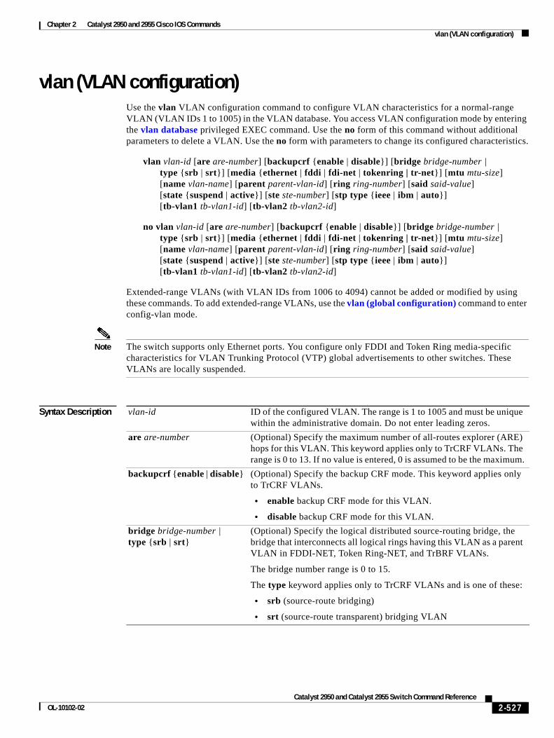
Chapter 2 Catalyst 2950 and 2955 Cisco IOS Commandsvlan (VLAN configuration)
vlan (VLAN configuration)Use the vlan VLAN configuration command to configure VLAN characteristics for a normal-range VLAN (VLAN IDs 1 to 1005) in the VLAN database. You access VLAN configuration mode by entering the vlan database privileged EXEC command. Use the no form of this command without additional parameters to delete a VLAN. Use the no form with parameters to change its configured characteristics.
vlan vlan-id [are are-number] [backupcrf {enable | disable}] [bridge bridge-number | type {srb | srt}] [media {ethernet | fddi | fdi-net | tokenring | tr-net}] [mtu mtu-size] [name vlan-name] [parent parent-vlan-id] [ring ring-number] [said said-value] [state {suspend | active}] [ste ste-number] [stp type {ieee | ibm | auto}] [tb-vlan1 tb-vlan1-id] [tb-vlan2 tb-vlan2-id]
no vlan vlan-id [are are-number] [backupcrf {enable | disable}] [bridge bridge-number | type {srb | srt}] [media {ethernet | fddi | fdi-net | tokenring | tr-net}] [mtu mtu-size] [name vlan-name] [parent parent-vlan-id] [ring ring-number] [said said-value] [state {suspend | active}] [ste ste-number] [stp type {ieee | ibm | auto}] [tb-vlan1 tb-vlan1-id] [tb-vlan2 tb-vlan2-id]
Extended-range VLANs (with VLAN IDs from 1006 to 4094) cannot be added or modified by using these commands. To add extended-range VLANs, use the vlan (global configuration) command to enter config-vlan mode.
Note The switch supports only Ethernet ports. You configure only FDDI and Token Ring media-specific characteristics for VLAN Trunking Protocol (VTP) global advertisements to other switches. These VLANs are locally suspended.
Syntax Description vlan-id ID of the configured VLAN. The range is 1 to 1005 and must be unique within the administrative domain. Do not enter leading zeros.
are are-number (Optional) Specify the maximum number of all-routes explorer (ARE) hops for this VLAN. This keyword applies only to TrCRF VLANs. The range is 0 to 13. If no value is entered, 0 is assumed to be the maximum.
backupcrf {enable | disable} (Optional) Specify the backup CRF mode. This keyword applies only to TrCRF VLANs.
• enable backup CRF mode for this VLAN.
• disable backup CRF mode for this VLAN.
bridge bridge-number | type {srb | srt}
(Optional) Specify the logical distributed source-routing bridge, the bridge that interconnects all logical rings having this VLAN as a parent VLAN in FDDI-NET, Token Ring-NET, and TrBRF VLANs.
The bridge number range is 0 to 15.
The type keyword applies only to TrCRF VLANs and is one of these:
• srb (source-route bridging)
• srt (source-route transparent) bridging VLAN
2-527Catalyst 2950 and Catalyst 2955 Switch Command Reference
OL-10102-02
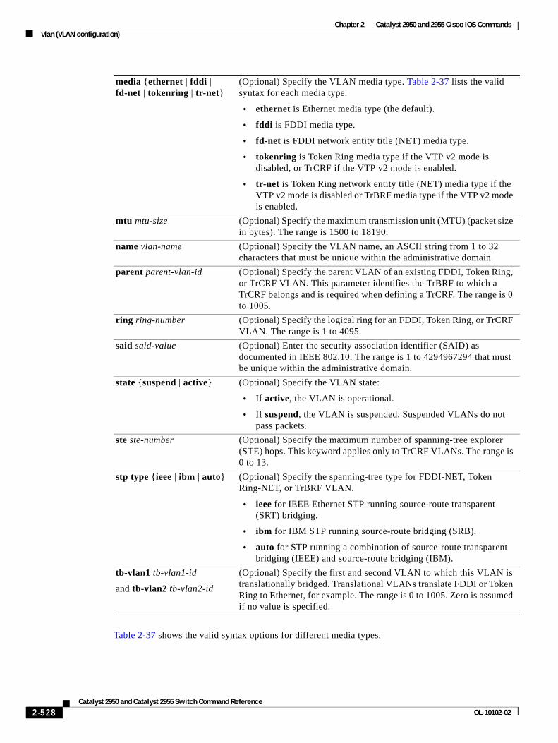
Chapter 2 Catalyst 2950 and 2955 Cisco IOS Commandsvlan (VLAN configuration)
Table 2-37 shows the valid syntax options for different media types.
media {ethernet | fddi | fd-net | tokenring | tr-net}
(Optional) Specify the VLAN media type. Table 2-37 lists the valid syntax for each media type.
• ethernet is Ethernet media type (the default).
• fddi is FDDI media type.
• fd-net is FDDI network entity title (NET) media type.
• tokenring is Token Ring media type if the VTP v2 mode is disabled, or TrCRF if the VTP v2 mode is enabled.
• tr-net is Token Ring network entity title (NET) media type if the VTP v2 mode is disabled or TrBRF media type if the VTP v2 mode is enabled.
mtu mtu-size (Optional) Specify the maximum transmission unit (MTU) (packet size in bytes). The range is 1500 to 18190.
name vlan-name (Optional) Specify the VLAN name, an ASCII string from 1 to 32 characters that must be unique within the administrative domain.
parent parent-vlan-id (Optional) Specify the parent VLAN of an existing FDDI, Token Ring, or TrCRF VLAN. This parameter identifies the TrBRF to which a TrCRF belongs and is required when defining a TrCRF. The range is 0 to 1005.
ring ring-number (Optional) Specify the logical ring for an FDDI, Token Ring, or TrCRF VLAN. The range is 1 to 4095.
said said-value (Optional) Enter the security association identifier (SAID) as documented in IEEE 802.10. The range is 1 to 4294967294 that must be unique within the administrative domain.
state {suspend | active} (Optional) Specify the VLAN state:
• If active, the VLAN is operational.
• If suspend, the VLAN is suspended. Suspended VLANs do not pass packets.
ste ste-number (Optional) Specify the maximum number of spanning-tree explorer (STE) hops. This keyword applies only to TrCRF VLANs. The range is 0 to 13.
stp type {ieee | ibm | auto} (Optional) Specify the spanning-tree type for FDDI-NET, Token Ring-NET, or TrBRF VLAN.
• ieee for IEEE Ethernet STP running source-route transparent (SRT) bridging.
• ibm for IBM STP running source-route bridging (SRB).
• auto for STP running a combination of source-route transparent bridging (IEEE) and source-route bridging (IBM).
tb-vlan1 tb-vlan1-id
and tb-vlan2 tb-vlan2-id
(Optional) Specify the first and second VLAN to which this VLAN is translationally bridged. Translational VLANs translate FDDI or Token Ring to Ethernet, for example. The range is 0 to 1005. Zero is assumed if no value is specified.
2-528Catalyst 2950 and Catalyst 2955 Switch Command Reference
OL-10102-02
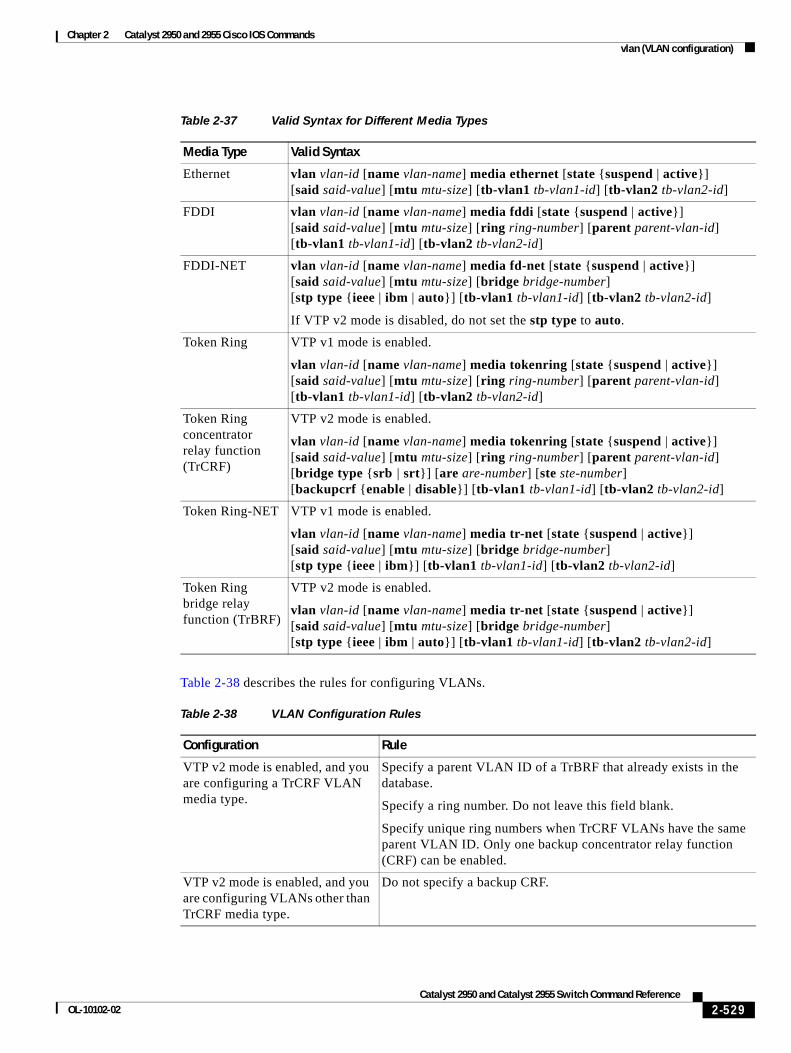
Chapter 2 Catalyst 2950 and 2955 Cisco IOS Commandsvlan (VLAN configuration)
Table 2-38 describes the rules for configuring VLANs.
Table 2-37 Valid Syntax for Different Media Types
Media Type Valid Syntax
Ethernet vlan vlan-id [name vlan-name] media ethernet [state {suspend | active}] [said said-value] [mtu mtu-size] [tb-vlan1 tb-vlan1-id] [tb-vlan2 tb-vlan2-id]
FDDI vlan vlan-id [name vlan-name] media fddi [state {suspend | active}] [said said-value] [mtu mtu-size] [ring ring-number] [parent parent-vlan-id] [tb-vlan1 tb-vlan1-id] [tb-vlan2 tb-vlan2-id]
FDDI-NET vlan vlan-id [name vlan-name] media fd-net [state {suspend | active}] [said said-value] [mtu mtu-size] [bridge bridge-number] [stp type {ieee | ibm | auto}] [tb-vlan1 tb-vlan1-id] [tb-vlan2 tb-vlan2-id]
If VTP v2 mode is disabled, do not set the stp type to auto.
Token Ring VTP v1 mode is enabled.
vlan vlan-id [name vlan-name] media tokenring [state {suspend | active}] [said said-value] [mtu mtu-size] [ring ring-number] [parent parent-vlan-id] [tb-vlan1 tb-vlan1-id] [tb-vlan2 tb-vlan2-id]
Token Ring concentrator relay function (TrCRF)
VTP v2 mode is enabled.
vlan vlan-id [name vlan-name] media tokenring [state {suspend | active}] [said said-value] [mtu mtu-size] [ring ring-number] [parent parent-vlan-id] [bridge type {srb | srt}] [are are-number] [ste ste-number] [backupcrf {enable | disable}] [tb-vlan1 tb-vlan1-id] [tb-vlan2 tb-vlan2-id]
Token Ring-NET VTP v1 mode is enabled.
vlan vlan-id [name vlan-name] media tr-net [state {suspend | active}] [said said-value] [mtu mtu-size] [bridge bridge-number] [stp type {ieee | ibm}] [tb-vlan1 tb-vlan1-id] [tb-vlan2 tb-vlan2-id]
Token Ring bridge relay function (TrBRF)
VTP v2 mode is enabled.
vlan vlan-id [name vlan-name] media tr-net [state {suspend | active}] [said said-value] [mtu mtu-size] [bridge bridge-number] [stp type {ieee | ibm | auto}] [tb-vlan1 tb-vlan1-id] [tb-vlan2 tb-vlan2-id]
Table 2-38 VLAN Configuration Rules
Configuration Rule
VTP v2 mode is enabled, and you are configuring a TrCRF VLAN media type.
Specify a parent VLAN ID of a TrBRF that already exists in the database.
Specify a ring number. Do not leave this field blank.
Specify unique ring numbers when TrCRF VLANs have the same parent VLAN ID. Only one backup concentrator relay function (CRF) can be enabled.
VTP v2 mode is enabled, and you are configuring VLANs other than TrCRF media type.
Do not specify a backup CRF.
2-529Catalyst 2950 and Catalyst 2955 Switch Command Reference
OL-10102-02
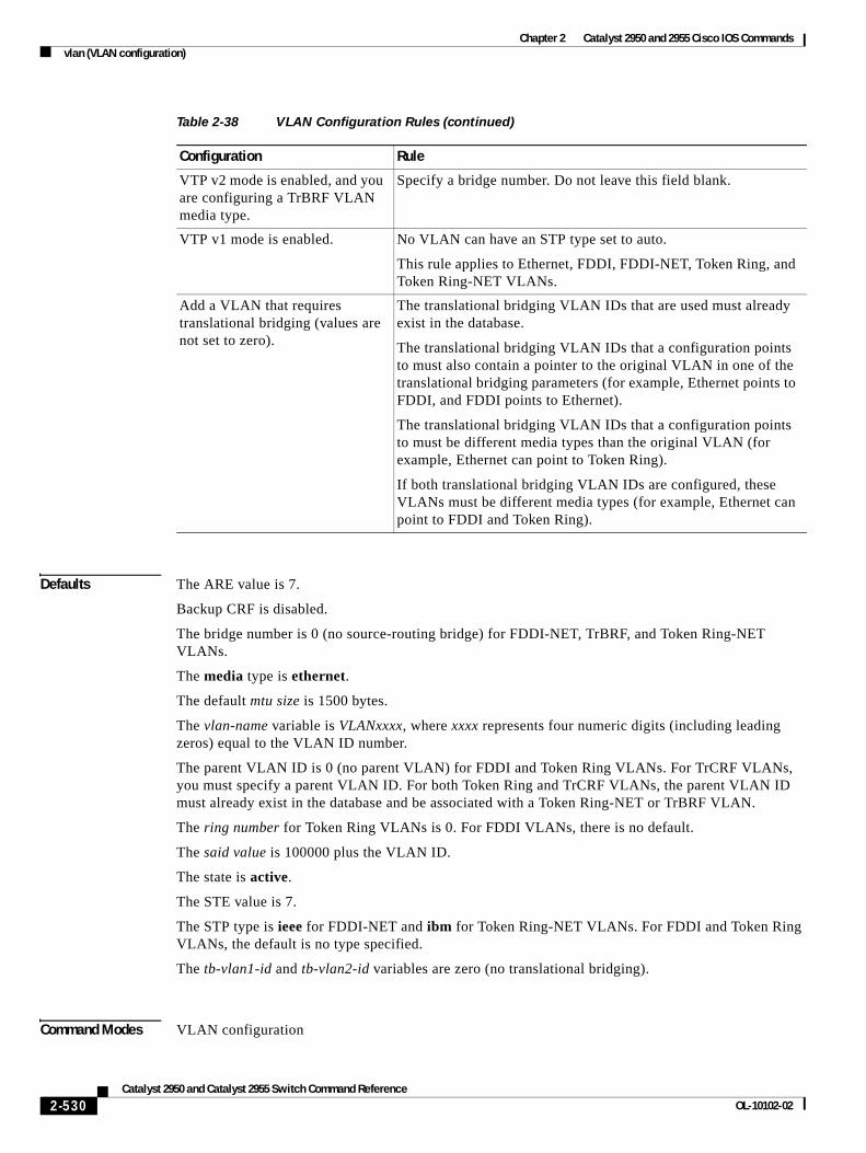
Chapter 2 Catalyst 2950 and 2955 Cisco IOS Commandsvlan (VLAN configuration)
Defaults The ARE value is 7.
Backup CRF is disabled.
The bridge number is 0 (no source-routing bridge) for FDDI-NET, TrBRF, and Token Ring-NET VLANs.
The media type is ethernet.
The default mtu size is 1500 bytes.
The vlan-name variable is VLANxxxx, where xxxx represents four numeric digits (including leading zeros) equal to the VLAN ID number.
The parent VLAN ID is 0 (no parent VLAN) for FDDI and Token Ring VLANs. For TrCRF VLANs, you must specify a parent VLAN ID. For both Token Ring and TrCRF VLANs, the parent VLAN ID must already exist in the database and be associated with a Token Ring-NET or TrBRF VLAN.
The ring number for Token Ring VLANs is 0. For FDDI VLANs, there is no default.
The said value is 100000 plus the VLAN ID.
The state is active.
The STE value is 7.
The STP type is ieee for FDDI-NET and ibm for Token Ring-NET VLANs. For FDDI and Token Ring VLANs, the default is no type specified.
The tb-vlan1-id and tb-vlan2-id variables are zero (no translational bridging).
Command Modes VLAN configuration
VTP v2 mode is enabled, and you are configuring a TrBRF VLAN media type.
Specify a bridge number. Do not leave this field blank.
VTP v1 mode is enabled. No VLAN can have an STP type set to auto.
This rule applies to Ethernet, FDDI, FDDI-NET, Token Ring, and Token Ring-NET VLANs.
Add a VLAN that requires translational bridging (values are not set to zero).
The translational bridging VLAN IDs that are used must already exist in the database.
The translational bridging VLAN IDs that a configuration points to must also contain a pointer to the original VLAN in one of the translational bridging parameters (for example, Ethernet points to FDDI, and FDDI points to Ethernet).
The translational bridging VLAN IDs that a configuration points to must be different media types than the original VLAN (for example, Ethernet can point to Token Ring).
If both translational bridging VLAN IDs are configured, these VLANs must be different media types (for example, Ethernet can point to FDDI and Token Ring).
Table 2-38 VLAN Configuration Rules (continued)
Configuration Rule
2-530Catalyst 2950 and Catalyst 2955 Switch Command Reference
OL-10102-02
Chapter 2 Catalyst 2950 and 2955 Cisco IOS Commandsvlan (VLAN configuration)
Command History
Usage Guidelines You can only use this command mode for configuring normal-range VLANs, that is, VLAN IDs 1 to 1005.
Note To configure extended-range VLANs (VLAN IDs 1006 to 4094), use the vlan global configuration command.
VLAN configuration is always saved in the VLAN database. If VTP mode is transparent, it is also saved in the switch running configuration file, along with the VTP mode and domain name. You can then save it in the switch startup configuration file by using the copy running-config startup-config privileged EXEC command.
When you save VLAN and VTP configuration in the startup configuration file and reboot the switch, the configuration is determined in these ways:
• If both the VLAN database and the configuration file show the VTP mode as transparent and the VTP domain names match, the VLAN database is ignored. The VTP and VLAN configurations in the startup configuration file are used. The VLAN database revision number remains unchanged in the VLAN database.
• If the VTP mode is server, or if the startup VTP mode or domain names do not match the VLAN database, the VTP mode and the VLAN configuration for the first 1005 VLANs use VLAN database information.
• If the image on the switch or the configuration file is earlier than Cisco IOS Release 12.1(9)EA1, the switch reboots with information in the VLAN database.
The following are the results of using the no vlan commands:
• When the no vlan vlan-id form is used, the VLAN is deleted. Deleting VLANs automatically resets to zero any other parent VLANs and translational bridging parameters that refer to the deleted VLAN.
• When the no vlan vlan-id bridge form is used, the VLAN source-routing bridge number returns to the default (0). The vlan vlan-id bridge command is used only for FDDI-NET and Token Ring-NET VLANs and is ignored in other VLAN types.
• When the no vlan vlan-id media form is used, the media type returns to the default (ethernet). Changing the VLAN media type (including the no form) resets the VLAN MTU to the default MTU for the type (unless the mtu keyword is also present in the command). It also resets the VLAN parent and translational bridging VLAN to the default (unless the parent, tb-vlan1, or tb-vlan2 are also present in the command).
• When the no vlan vlan-id mtu form is used, the VLAN MTU returns to the default for the applicable VLAN media type. You can also modify the MTU using the media keyword.
• When the no vlan vlan-id name vlan-name form is used, the VLAN name returns to the default name (VLANxxxx, where xxxx represent four numeric digits [including leading zeros] equal to the VLAN ID number).
• When the no vlan vlan-id parent form is used, the parent VLAN returns to the default (0). The parent VLAN resets to the default if the parent VLAN is deleted or if the media keyword changes the VLAN type or the VLAN type of the parent VLAN.
Release Modification
12.0(5.2)WC(1) This command was introduced.
12.1(13)EA1 The value for vlan-id variable was changed.
2-531Catalyst 2950 and Catalyst 2955 Switch Command Reference
OL-10102-02
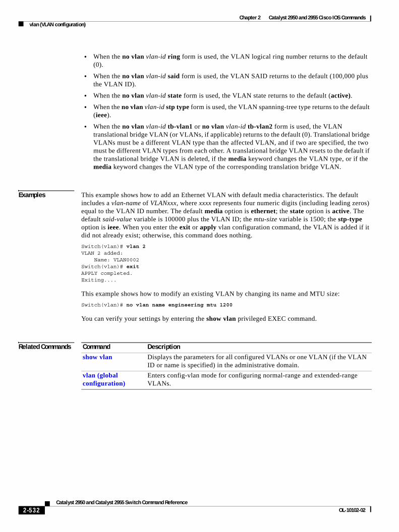
Chapter 2 Catalyst 2950 and 2955 Cisco IOS Commandsvlan (VLAN configuration)
• When the no vlan vlan-id ring form is used, the VLAN logical ring number returns to the default (0).
• When the no vlan vlan-id said form is used, the VLAN SAID returns to the default (100,000 plus the VLAN ID).
• When the no vlan vlan-id state form is used, the VLAN state returns to the default (active).
• When the no vlan vlan-id stp type form is used, the VLAN spanning-tree type returns to the default (ieee).
• When the no vlan vlan-id tb-vlan1 or no vlan vlan-id tb-vlan2 form is used, the VLAN translational bridge VLAN (or VLANs, if applicable) returns to the default (0). Translational bridge VLANs must be a different VLAN type than the affected VLAN, and if two are specified, the two must be different VLAN types from each other. A translational bridge VLAN resets to the default if the translational bridge VLAN is deleted, if the media keyword changes the VLAN type, or if the media keyword changes the VLAN type of the corresponding translation bridge VLAN.
Examples This example shows how to add an Ethernet VLAN with default media characteristics. The default includes a vlan-name of VLANxxx, where xxxx represents four numeric digits (including leading zeros) equal to the VLAN ID number. The default media option is ethernet; the state option is active. The default said-value variable is 100000 plus the VLAN ID; the mtu-size variable is 1500; the stp-type option is ieee. When you enter the exit or apply vlan configuration command, the VLAN is added if it did not already exist; otherwise, this command does nothing.
Switch(vlan)# vlan 2VLAN 2 added: Name: VLAN0002Switch(vlan)# exitAPPLY completed.Exiting....
This example shows how to modify an existing VLAN by changing its name and MTU size:
Switch(vlan)# no vlan name engineering mtu 1200
You can verify your settings by entering the show vlan privileged EXEC command.
Related Commands Command Description
show vlan Displays the parameters for all configured VLANs or one VLAN (if the VLAN ID or name is specified) in the administrative domain.
vlan (global configuration)
Enters config-vlan mode for configuring normal-range and extended-range VLANs.
2-532Catalyst 2950 and Catalyst 2955 Switch Command Reference
OL-10102-02
Chapter 2 Catalyst 2950 and 2955 Cisco IOS Commandsvlan database
vlan databaseUse the vlan database privileged EXEC command to enter VLAN configuration mode. From this mode, you can add, delete, and modify VLAN configurations for normal-range VLANs and globally propagate these changes by using the VLAN Trunking Protocol (VTP). Configuration information is saved in the VLAN database.
vlan database
Note VLAN configuration mode is only valid for VLAN IDs 1 to 1005.
Syntax Description This command has no arguments or keywords.
Defaults No default is defined.
Command Modes Privileged EXEC
Command History
Usage Guidelines You can use the VLAN database configuration commands to configure VLANs 1 to 1005. To configure extended-range VLANs (VLAN IDs 1006 to 4094),use the vlan (global configuration) command to enter config-vlan mode. You can also configure VLAN IDs 1 to 1005 by using the vlan global configuration command.
To return to the privileged EXEC mode from the VLAN configuration mode, enter the exit command.
Note This command mode is different from other modes because it is session-oriented. When you add, delete, or modify VLAN parameters, the changes are not applied until you exit the session by entering the apply or exit command. When the changes are applied, the VTP configuration version is incremented. You can also not apply the changes to the VTP database by entering abort.
Once you are in VLAN configuration mode, you can access the VLAN database and make changes by using these commands:
• vlan: accesses subcommands to add, delete, or modify values associated with a single VLAN. For more information, see the vlan (VLAN configuration) command.
• vtp: accesses subcommands to perform VTP administrative functions. For more information, see the vtp (VLAN configuration) command.
Release Modification
12.0(5.2)WC(1) This command was introduced.
2-533Catalyst 2950 and Catalyst 2955 Switch Command Reference
OL-10102-02
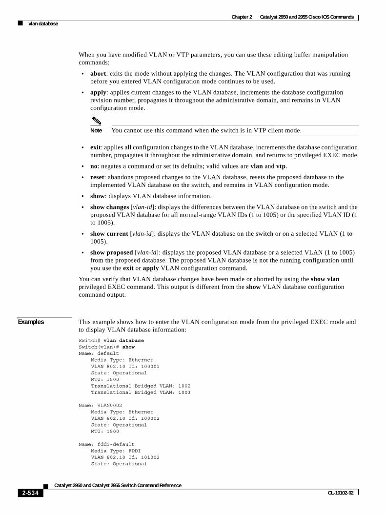
Chapter 2 Catalyst 2950 and 2955 Cisco IOS Commandsvlan database
When you have modified VLAN or VTP parameters, you can use these editing buffer manipulation commands:
• abort: exits the mode without applying the changes. The VLAN configuration that was running before you entered VLAN configuration mode continues to be used.
• apply: applies current changes to the VLAN database, increments the database configuration revision number, propagates it throughout the administrative domain, and remains in VLAN configuration mode.
Note You cannot use this command when the switch is in VTP client mode.
• exit: applies all configuration changes to the VLAN database, increments the database configuration number, propagates it throughout the administrative domain, and returns to privileged EXEC mode.
• no: negates a command or set its defaults; valid values are vlan and vtp.
• reset: abandons proposed changes to the VLAN database, resets the proposed database to the implemented VLAN database on the switch, and remains in VLAN configuration mode.
• show: displays VLAN database information.
• show changes [vlan-id]: displays the differences between the VLAN database on the switch and the proposed VLAN database for all normal-range VLAN IDs (1 to 1005) or the specified VLAN ID (1 to 1005).
• show current [vlan-id]: displays the VLAN database on the switch or on a selected VLAN (1 to 1005).
• show proposed [vlan-id]: displays the proposed VLAN database or a selected VLAN (1 to 1005) from the proposed database. The proposed VLAN database is not the running configuration until you use the exit or apply VLAN configuration command.
You can verify that VLAN database changes have been made or aborted by using the show vlan privileged EXEC command. This output is different from the show VLAN database configuration command output.
Examples This example shows how to enter the VLAN configuration mode from the privileged EXEC mode and to display VLAN database information:
Switch# vlan databaseSwitch(vlan)# showName: default Media Type: Ethernet VLAN 802.10 Id: 100001 State: Operational MTU: 1500 Translational Bridged VLAN: 1002 Translational Bridged VLAN: 1003
Name: VLAN0002 Media Type: Ethernet VLAN 802.10 Id: 100002 State: Operational MTU: 1500
Name: fddi-default Media Type: FDDI VLAN 802.10 Id: 101002 State: Operational
2-534Catalyst 2950 and Catalyst 2955 Switch Command Reference
OL-10102-02
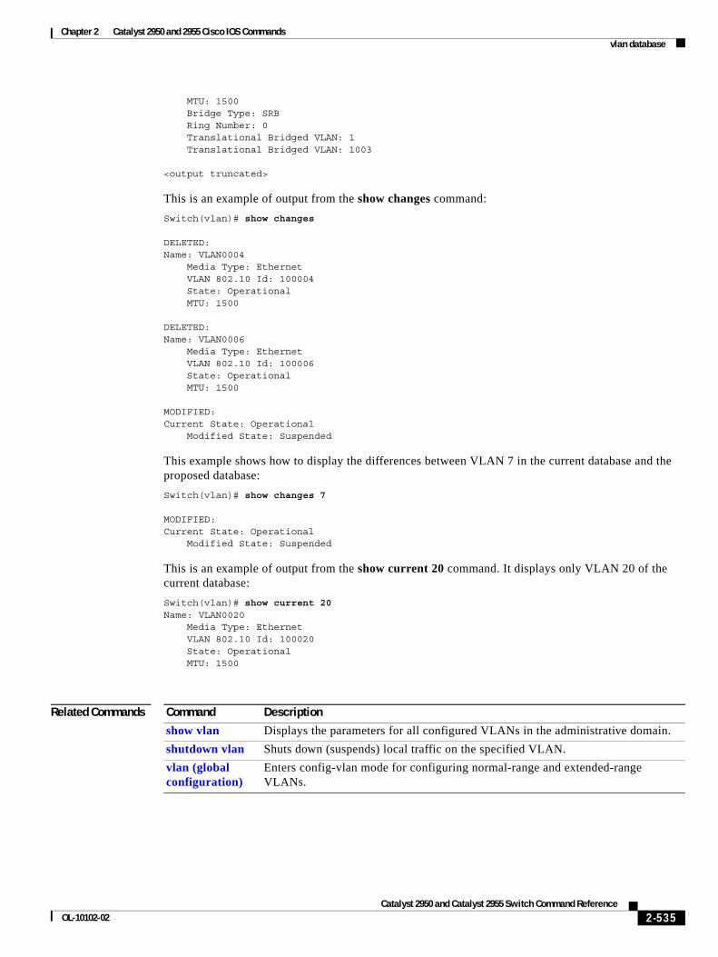
Chapter 2 Catalyst 2950 and 2955 Cisco IOS Commandsvlan database
MTU: 1500 Bridge Type: SRB Ring Number: 0 Translational Bridged VLAN: 1 Translational Bridged VLAN: 1003
<output truncated>
This is an example of output from the show changes command:
Switch(vlan)# show changes
DELETED:Name: VLAN0004 Media Type: Ethernet VLAN 802.10 Id: 100004 State: Operational MTU: 1500
DELETED:Name: VLAN0006 Media Type: Ethernet VLAN 802.10 Id: 100006 State: Operational MTU: 1500
MODIFIED:Current State: Operational Modified State: Suspended
This example shows how to display the differences between VLAN 7 in the current database and the proposed database:
Switch(vlan)# show changes 7
MODIFIED:Current State: Operational Modified State: Suspended
This is an example of output from the show current 20 command. It displays only VLAN 20 of the current database:
Switch(vlan)# show current 20Name: VLAN0020 Media Type: Ethernet VLAN 802.10 Id: 100020 State: Operational MTU: 1500
Related Commands Command Description
show vlan Displays the parameters for all configured VLANs in the administrative domain.
shutdown vlan Shuts down (suspends) local traffic on the specified VLAN.
vlan (global configuration)
Enters config-vlan mode for configuring normal-range and extended-range VLANs.
2-535Catalyst 2950 and Catalyst 2955 Switch Command Reference
OL-10102-02
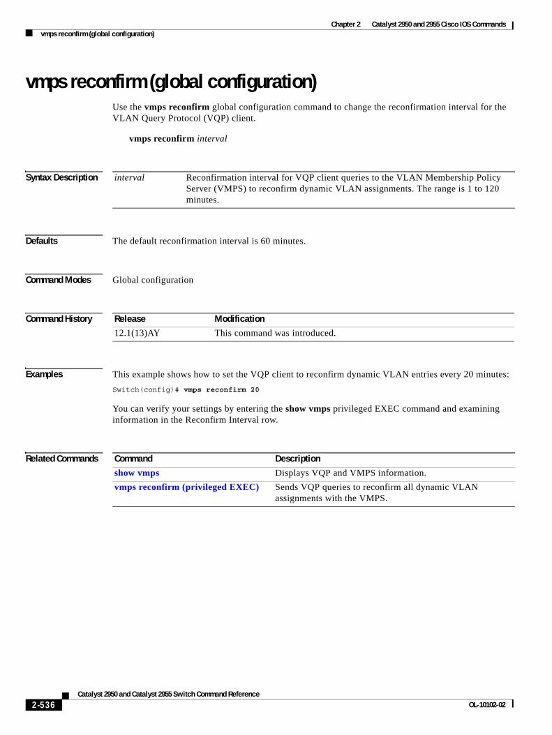
Chapter 2 Catalyst 2950 and 2955 Cisco IOS Commandsvmps reconfirm (global configuration)
vmps reconfirm (global configuration)Use the vmps reconfirm global configuration command to change the reconfirmation interval for the VLAN Query Protocol (VQP) client.
vmps reconfirm interval
Syntax Description
Defaults The default reconfirmation interval is 60 minutes.
Command Modes Global configuration
Command History
Examples This example shows how to set the VQP client to reconfirm dynamic VLAN entries every 20 minutes:
Switch(config)# vmps reconfirm 20
You can verify your settings by entering the show vmps privileged EXEC command and examining information in the Reconfirm Interval row.
Related Commands
interval Reconfirmation interval for VQP client queries to the VLAN Membership Policy Server (VMPS) to reconfirm dynamic VLAN assignments. The range is 1 to 120 minutes.
Release Modification
12.1(13)AY This command was introduced.
Command Description
show vmps Displays VQP and VMPS information.
vmps reconfirm (privileged EXEC) Sends VQP queries to reconfirm all dynamic VLAN assignments with the VMPS.
2-536Catalyst 2950 and Catalyst 2955 Switch Command Reference
OL-10102-02
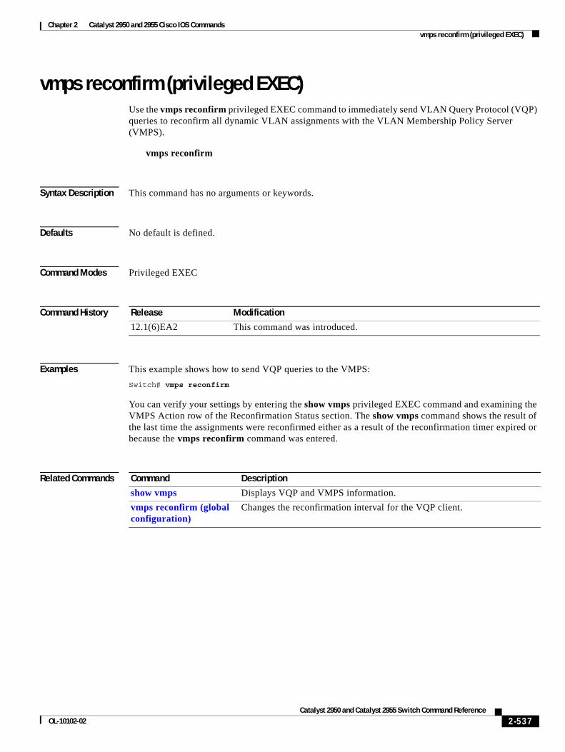
Chapter 2 Catalyst 2950 and 2955 Cisco IOS Commandsvmps reconfirm (privileged EXEC)
vmps reconfirm (privileged EXEC)Use the vmps reconfirm privileged EXEC command to immediately send VLAN Query Protocol (VQP) queries to reconfirm all dynamic VLAN assignments with the VLAN Membership Policy Server (VMPS).
vmps reconfirm
Syntax Description This command has no arguments or keywords.
Defaults No default is defined.
Command Modes Privileged EXEC
Command History
Examples This example shows how to send VQP queries to the VMPS:
Switch# vmps reconfirm
You can verify your settings by entering the show vmps privileged EXEC command and examining the VMPS Action row of the Reconfirmation Status section. The show vmps command shows the result of the last time the assignments were reconfirmed either as a result of the reconfirmation timer expired or because the vmps reconfirm command was entered.
Related Commands
Release Modification
12.1(6)EA2 This command was introduced.
Command Description
show vmps Displays VQP and VMPS information.
vmps reconfirm (global configuration)
Changes the reconfirmation interval for the VQP client.
2-537Catalyst 2950 and Catalyst 2955 Switch Command Reference
OL-10102-02
Chapter 2 Catalyst 2950 and 2955 Cisco IOS Commandsvmps retry
vmps retryUse the vmps retry global configuration command to configure the per-server retry count for the VLAN Query Protocol (VQP) client.
vmps retry count
Syntax Description
Defaults The default retry count is 3.
Command Modes Global configuration
Command History
Examples This example shows how to set the retry count to 7:
Switch(config)# vmps retry 7
You can verify your settings by entering the show vmps privileged EXEC command and examining information in the Server Retry Count row.
Related Commands
count Number of attempts to contact the VLAN Membership Policy Server (VMPS) by the client before querying the next server in the list. The range is 1 to 10.
Release Modification
12.1(6)EA2 This command was introduced.
Command Description
show vmps Displays VQP and VMPS information.
2-538Catalyst 2950 and Catalyst 2955 Switch Command Reference
OL-10102-02
Chapter 2 Catalyst 2950 and 2955 Cisco IOS Commandsvmps server
vmps serverUse the vmps server global configuration command to configure the primary VLAN Membership Policy Server (VMPS) and up to three secondary servers. Use the no form of this command to remove a VMPS server.
vmps server ipaddress [primary]
no vmps server [ipaddress]
Syntax Description
Defaults No primary or secondary VMPS servers are defined.
Command Modes Global configuration
Command History
Usage Guidelines The first server entered is automatically selected as the primary server whether or not the primary keyword is entered. The first server address can be overridden by using primary in a subsequent command.
If a member switch in a cluster configuration does not have an IP address, the cluster does not use the VMPS server configured for that member switch. Instead, the cluster uses the VMPS server on the command switch, and the command switch proxies the VMPS requests. The VMPS server treats the cluster as a single switch and uses the IP address of the command switch to respond to requests.
When using the no form without specifying the ipaddress, all configured servers are deleted. If you delete all servers when dynamic-access ports are present, the switch cannot forward packets from new sources on these ports because it cannot query the VMPS.
Examples This example shows how to configure the server with IP address 191.10.49.20 as the primary VMPS server. The servers with IP addresses 191.10.49.21 and 191.10.49.22 are configured as secondary servers.
Switch(config)# vmps server 191.10.49.20 primarySwitch(config)# vmps server 191.10.49.21Switch(config)# vmps server 191.10.49.22
ipaddress IP address or host name of the primary or secondary VMPS servers. If you specify a host name, the Domain Name System (DNS) server must be configured.
primary (Optional) Determines whether primary or secondary VMPS servers are being configured.
Release Modification
12.1(6)EA2 This command was introduced.
2-539Catalyst 2950 and Catalyst 2955 Switch Command Reference
OL-10102-02
Chapter 2 Catalyst 2950 and 2955 Cisco IOS Commandsvmps server
This example shows how to delete the server with IP address 191.10.49.21:
Switch(config)# no vmps server 191.10.49.21
You can verify your settings by entering the show vmps privileged EXEC command and examining information in the VMPS Domain Server row.
Related Commands Command Description
show vmps Displays VQP and VMPS information.
2-540Catalyst 2950 and Catalyst 2955 Switch Command Reference
OL-10102-02
Chapter 2 Catalyst 2950 and 2955 Cisco IOS Commandsvtp (global configuration)
vtp (global configuration)Use the vtp global configuration command to set or modify the VLAN Trunking Protocol (VTP) configuration characteristics. Use the no form of this command to remove the settings or to return to the default settings.
vtp {domain domain-name | file filename | interface name | mode {client | server | transparent} | password password | pruning | version number}
no vtp {file | interface | mode | password | pruning | version}
Syntax Description domain domain-name Specify the VTP domain name, an ASCII string from 1 to 32 characters that identifies the VTP administrative domain for the switch. The domain name is case sensitive.
file filename Specify the Cisco IOS file system file where the VTP VLAN configuration is stored.
interface name Specify the name of the interface providing the VTP ID updated for this device.
mode {client | server | transparent}
Specify the VTP device mode. The keywords have these meanings:
• client—Place the switch in VTP client mode. A switch in VTP client mode is enabled for VTP, and can send advertisements, but does not have enough nonvolatile storage to store VLAN configurations. You cannot configure VLANs on the switch. When a VTP client starts up, it does not send VTP advertisements until it receives advertisements to initialize its VLAN database.
• server—Place the switch in VTP server mode. A switch in VTP server mode is enabled for VTP and sends advertisements. You can configure VLANs on the switch. The switch can recover all the VLAN information in the current VTP database from nonvolatile storage after reboot.
• transparent—Place the switch in VTP transparent mode. A switch in VTP transparent mode is disabled for VTP, does not send advertisements or learn from advertisements sent by other devices, and cannot affect VLAN configurations on other devices in the network. The switch receives VTP advertisements and forwards them on all trunk ports except the one on which the advertisement was received.
When VTP mode is transparent, the mode and domain name are saved in the switch running configuration file, and you can save them in the switch startup configuration file by entering the copy running-config startup config privileged EXEC command.
password password Set the administrative domain password for the generation of the 16-byte secret value used in MD5 digest calculation to be sent in VTP advertisements and to validate received VTP advertisements. The password can be an ASCII string from 1 to 32 characters. The password is case sensitive.
pruning Enable VTP pruning on the switch.
version number Set VTP version to version 1 or version 2.
2-541Catalyst 2950 and Catalyst 2955 Switch Command Reference
OL-10102-02
Chapter 2 Catalyst 2950 and 2955 Cisco IOS Commandsvtp (global configuration)
Defaults The default filename is flash:vlan.dat.
The default mode is server mode.
No domain name or password is defined.
No password is configured.
Pruning is disabled.
The default version is version 1.
Command Modes Global configuration
Command History
Usage Guidelines When you save VTP mode and domain name and VLAN configurations in the switch startup configuration file and reboot the switch, the VTP and VLAN configurations are determined by these conditions:
• If both the VLAN database and the configuration file show the VTP mode as transparent and the VTP domain names match, the VLAN database is ignored. The VTP and VLAN configurations in the startup configuration file are used. The VLAN database revision number remains unchanged in the VLAN database.
• If the startup VTP mode is server mode, or the startup VTP mode or domain names do not match the VLAN database, the VTP mode and VLAN configuration information for the first 1005 VLAN IDs are determined by VLAN database information, and configuration for VLAN IDs greater than 1005 is determined by the switch configuration file.
• If the image on the switch or the configuration file is earlier than Cisco IOS Release 12.1(9)EA1, the switch reboots using the information in the VLAN database.
The vtp file filename cannot be used to load a new database; it renames only the file in which the existing database is stored.
Follow these guidelines when configuring a VTP domain name:
• The switch is in the no-management-domain state until you configure a domain name. While in the no-management-domain state, the switch does not send any VTP advertisements even if changes occur to the local VLAN configuration. The switch leaves the no-management-domain state after it receives the first VTP summary packet on any port that is trunking or after you configure a domain name by using the vtp domain command. If the switch receives its domain from a summary packet, it resets its configuration revision number to 0. After the switch leaves the no-management-domain state, it can not be configured to re-enter it until you clear the NVRAM and reload the software.
• Domain names are case-sensitive.
Release Modification
12.0(5.2)WC(1) This command was introduced.
12.1(6)EA2 The if-id keyword was added.
12.1(9)EA1 The domain and mode keywords were added. The if-id keyword was replaced by the interface keyword.
12.1(11)EA1 The password, pruning, and version keywords were added.
2-542Catalyst 2950 and Catalyst 2955 Switch Command Reference
OL-10102-02
Chapter 2 Catalyst 2950 and 2955 Cisco IOS Commandsvtp (global configuration)
• After you configure a domain name, it cannot be removed. You can only reassign it to a different domain.
Follow these guidelines when setting VTP mode:
• The no vtp mode command returns the switch to VTP server mode.
• The vtp mode server command is the same as no vtp mode except that it does not return an error if the switch is not in client or transparent mode.
• If the receiving switch is in client mode, the client switch changes its configuration to duplicate the configuration of the server. If you have switches in client mode, be sure to make all VTP or VLAN configuration changes on a switch in server mode. If the receiving switch is in server mode or transparent mode, the switch configuration is not changed.
• Switches in transparent mode do not participate in VTP. If you make VTP or VLAN configuration changes on a switch in transparent mode, the changes are not propagated to other switches in the network.
• If you change the VTP or VLAN configuration on a switch that is in server mode, that change is propagated to all the switches in the same VTP domain.
• The vtp mode transparent command disables VTP from the domain but does not remove the domain from the switch.
• The VTP mode must be transparent for you to add extended-range VLANs or for VTP and VLAN information to be saved in the running configuration file.
• If extended-range VLANs are configured on the switch and you attempt to set the VTP mode to server or client, you receive an error message, and the configuration is not allowed.
• VTP can be set to either server or client mode only when dynamic VLAN creation is disabled.
Follow these guidelines when setting a VTP password:
• Passwords are case sensitive. Passwords should match on all switches in the same domain.
• When you use the no vtp password form of the command, the switch returns to the no-password state.
Follow these guidelines when setting VTP pruning:
• VTP pruning removes information about each pruning-eligible VLAN from VTP updates if there are no stations belonging to that VLAN.
• If you enable pruning on the VTP server, it is enabled for the entire management domain for VLAN IDs 1 to 1005.
• Only VLANs in the pruning-eligible list can be pruned.
• Pruning is supported with VTP version 1 and version 2.
Follow these guidelines when setting the VTP version:
• Toggling the version 2 (v2) mode state modifies parameters of certain default VLANs.
• Each VTP switch automatically detects the capabilities of all the other VTP devices. To use version 2, all VTP switches in the network must support version 2; otherwise, you must configure them to operate in VTP version 1 mode.
• If all switches in a domain are VTP version 2-capable, you need only to configure version 2 on one switch; the version number is then propagated to the other version-2 capable switches in the VTP domain.
• If you are using VTP in a Token Ring environment, VTP version 2 must be enabled.
2-543Catalyst 2950 and Catalyst 2955 Switch Command Reference
OL-10102-02
Chapter 2 Catalyst 2950 and 2955 Cisco IOS Commandsvtp (global configuration)
• If you are configuring a Token Ring bridge relay function (TrBRF) or Token Ring concentrator relay function (TrCRF) VLAN media type, you must use version 2.
• If you are configuring a Token Ring or Token Ring-NET VLAN media type, you must use version 1.
You cannot save password, pruning, and version configurations in the switch configuration file.
Examples This example shows how to rename the filename for VTP configuration storage to vtpfilename:
Switch(config)# vtp file vtpfilename
This example shows how to clear the device storage filename:
Switch(config)# no vtp file vtpconfigClearing device storage filename.
This example shows how to specify the name of the interface providing the VTP updater ID for this device:
Switch(config)# vtp interface fastethernet
This example shows how to set the administrative domain for the switch:
Switch(config)# vtp domain OurDomainName
This example shows how to place the switch in VTP transparent mode:
Switch(config)# vtp mode transparent
This example shows how to configure the VTP domain password:
Switch(config)# vtp password ThisIsOurDomain’sPassword
This example shows how to enable pruning in the VLAN database:
Switch(config)# vtp pruningPruning switched ON
This example shows how to enable version 2 mode in the VLAN database:
Switch(config)# vtp version 2
You can verify your settings by entering the show vtp status privileged EXEC command.
Related Commands Command Description
show vtp status Displays the VTP statistics for the switch and general information about the VTP management domain status.
vtp (VLAN configuration)
Configures most VTP characteristics.
2-544Catalyst 2950 and Catalyst 2955 Switch Command Reference
OL-10102-02
Chapter 2 Catalyst 2950 and 2955 Cisco IOS Commandsvtp (privileged EXEC)
vtp (privileged EXEC)Use the vtp privileged EXEC command to configure the VLAN Trunking Protocol (VTP) password, pruning, and version. Use the no form of this command to return to the default settings.
vtp {password password | pruning | version number}
no vtp {password | pruning | version}
Note Beginning with Cisco IOS Release 12.1(11)EA1, these keywords are available in the vtp global configuration command. This command will become obsolete in a future release.
Syntax Description
Defaults No password is configured.
Pruning is disabled.
The default version is version 1.
Command Modes Privileged EXEC
Command History
Usage Guidelines Passwords are case sensitive. Passwords should match on all switches in the same domain.
When you use the no vtp password form of the command, the switch returns to the no-password state.
VTP pruning removes information about each pruning-eligible VLAN from VTP updates if there are no stations belonging to that VLAN.
If you enable pruning on the VTP server, it is enabled for the entire management domain for VLAN IDs 1 to 1005.
Only VLANs in the pruning-eligible list can be pruned.
Pruning is supported with VTP version 1 and version 2.
Toggling the version 2 (v2) mode state modifies parameters of certain default VLANs.
password password Set the administrative domain password for the generation of the 16-byte secret value used in MD5 digest calculation to be sent in VTP advertisements and to validate received VTP advertisements. The password can be an ASCII string from 1 to 32 characters. The password is case sensitive.
pruning Enable VTP pruning on the switch.
version number Set VTP version to version 1 or version 2.
Release Modification
12.1(9)EA1 This command was introduced.
2-545Catalyst 2950 and Catalyst 2955 Switch Command Reference
OL-10102-02
Chapter 2 Catalyst 2950 and 2955 Cisco IOS Commandsvtp (privileged EXEC)
Each VTP switch automatically detects the capabilities of all the other VTP devices. To use version 2, all VTP switches in the network must support version 2; otherwise, you must configure them to operate in VTP version 1 mode.
If all switches in a domain are VTP version 2-capable, you need only to configure version 2 on one switch; the version number is then propagated to the other version-2 capable switches in the VTP domain.
If you are using VTP in a Token Ring environment, VTP version 2 must be enabled.
If you are configuring a Token Ring bridge relay function (TrBRF) or Token Ring concentrator relay function (TrCRF) VLAN media type, you must use version 2.
If you are configuring a Token Ring or Token Ring-NET VLAN media type, you must use version 1.
You cannot save password, pruning, and version configuration in the switch configuration file.
Examples This example shows how to configure the VTP domain password:
Switch# vtp password ThisIsOurDomain’sPassword
This example shows how to enable pruning in the VLAN database:
Switch# vtp pruningPruning switched ON
This example shows how to enable version 2 mode in the VLAN database:
Switch# vtp version 2
You can verify your setting by entering the show vtp status privileged EXEC command.
Related Commands Command Description
show vtp status Displays the VTP statistics for the switch and general information about the VTP management domain status.
switchport trunk pruning
Configures the VLAN pruning-eligible list for ports in trunking mode.
vtp (global configuration)
Configures the VTP filename, interface, domain-name, and mode, which can be saved in the switch configuration file.
vtp (VLAN configuration)
Configures all VTP characteristics but cannot be saved to the switch configuration file.
2-546Catalyst 2950 and Catalyst 2955 Switch Command Reference
OL-10102-02
Chapter 2 Catalyst 2950 and 2955 Cisco IOS Commandsvtp (VLAN configuration)
vtp (VLAN configuration)Use the vtp VLAN configuration command to configure VLAN Trunking Protocol (VTP) characteristics. You access VLAN configuration mode by entering the vlan database privileged EXEC command. Use the no form of this command to return to the default settings, disable the characteristic, or remove the password.
vtp {domain domain-name | password password | pruning | v2-mode | {server | client | transparent}}
no vtp {client | password | pruning | transparent | v2-mode}
Note VTP configuration in VLAN configuration mode is saved in the VLAN database when applied.
Syntax Description
Defaults The default mode is server mode.
No domain name is defined.
No password is configured.
domain domain-name Set the VTP domain name by entering an ASCII string from 1 to 32 characters that identifies the VTP administrative domain for the switch. The domain name is case sensitive.
password password Set the administrative domain password for the generation of the 16-byte secret value used in MD5 digest calculation to be sent in VTP advertisements and to validate received VTP advertisements. The password can be an ASCII string from 1 to 32 characters. The password is case sensitive.
pruning Enable pruning in the VTP administrative domain. VTP pruning causes information about each pruning-eligible VLAN to be removed from VTP updates if there are no stations belonging to that VLAN.
v2-mode Enable VLAN Trunking Protocol (VTP) version 2 in the administrative domains.
client Place the switch in VTP client mode. A switch in VTP client mode is enabled for VTP, can send advertisements, but does not have enough nonvolatile storage to store VLAN configurations. You cannot configure VLANs on it. When a VTP client starts up, it does not send VTP advertisements until it receives advertisements to initialize its VLAN database.
server Place the switch in VTP server mode. A switch in VTP server mode is enabled for VTP and sends advertisements. You can configure VLANs on it. The switch can recover all the VLAN information in the current VTP database from nonvolatile storage after reboot.
transparent Place the switch in VTP transparent mode. A switch in VTP transparent mode is disabled for VTP, does not send advertisements or learn from advertisements sent by other devices, and cannot affect VLAN configurations on other devices in the network. The switch receives VTP advertisements and forwards them on all trunk ports except the one on which the advertisement was received.
2-547Catalyst 2950 and Catalyst 2955 Switch Command Reference
OL-10102-02
Chapter 2 Catalyst 2950 and 2955 Cisco IOS Commandsvtp (VLAN configuration)
Pruning is disabled.
VTP version 2 (v2 mode) is disabled.
Command Modes VLAN configuration
Command History
Usage Guidelines If VTP mode is transparent, the mode and domain name are saved in the switch running configuration file, and you can save the configuration in the switch startup configuration file by using the copy running-config startup-config privileged EXEC command.
Follow these guidelines when setting VTP mode:
• The no vtp client and no vtp transparent forms of the command return the switch to VTP server mode.
• The vtp server command is the same as no vtp client or no vtp transparent except that it does not return an error if the switch is not in client or transparent mode.
• If the receiving switch is in client mode, the client switch changes its configuration to duplicate the configuration of the server. If you have switches in client mode, make sure to make all VTP or VLAN configuration changes on a switch in server mode. If the receiving switch is in server mode or transparent mode, the switch configuration is not changed.
• Switches in transparent mode do not participate in VTP. If you make VTP or VLAN configuration changes on a switch in transparent mode, the changes are not propagated to other switches in the network.
• If you make a change to the VTP or VLAN configuration on a switch in server mode, that change is propagated to all the switches in the same VTP domain.
• The vtp transparent command disables VTP from the domain but does not remove the domain from the switch.
• The VTP mode must be transparent for you to add extended-range VLANs or for the VTP and the VLAN configurations to be saved in the running configuration file.
• If extended-range VLANs are configured on the switch and you attempt to set the VTP mode to server or client, you receive an error message and the configuration is not allowed.
• VTP can be set to either server or client mode only when dynamic VLAN creation is disabled.
Follow these guidelines when configuring a VTP domain name:
• The switch is in the no-management-domain state until you configure a domain name. While in the no-management-domain state, the switch does not send any VTP advertisements even if changes occur to the local VLAN configuration. The switch leaves the no-management-domain state after receiving the first VTP summary packet on any port that is currently trunking or after configuring a domain name using the vtp domain command. If the switch receives its domain from a summary packet, it resets its configuration revision number to zero. After the switch leaves the no-management-domain state, it can never be configured to reenter it until you clear the NVRAM and reload the software.
• Domain names are case sensitive.
Release Modification
12.0(5.2)WC(1) This command was introduced.
2-548Catalyst 2950 and Catalyst 2955 Switch Command Reference
OL-10102-02
Chapter 2 Catalyst 2950 and 2955 Cisco IOS Commandsvtp (VLAN configuration)
• After you configure a domain name, it cannot be removed. You can reassign it only to a different domain.
Follow these guidelines when configuring a VTP password:
• Passwords are case sensitive. Passwords should match on all switches in the same domain.
• When the no vtp password form of the command is used, the switch returns to the no-password state.
Follow these guidelines when enabling VTP pruning:
• If you enable pruning on the VTP server, it is enabled for the entire management domain.
• Only VLANs included in the pruning-eligible list can be pruned.
• Pruning is supported with VTP version 1 and version 2.
Follow these guidelines when enabling VTP version 2 (v2-mode):
• Toggling the version (v2-mode) state modifies certain parameters of certain default VLANs.
• Each VTP switch automatically detects the capabilities of all the other VTP devices. To use VTP version 2, all VTP switches in the network must support version 2; otherwise, you must configure them to operate in VTP version 1 (no vtp v2-mode).
• If all switches in a domain are VTP version 2-capable, you need only to enable VTP version 2 on one switch; the version number is then propagated to the other version-2 capable switches in the VTP domain.
• If you are using VTP in a Token Ring environment or configuring a Token Ring bridge relay function (TrBRF) or Token Ring concentrator relay function (TrCRF) VLAN media type, you must enable VTP version 2 (v2-mode).
• If you are configuring a Token Ring or Token Ring-NET VLAN media type, you must use VTP version 1.
Examples This example shows how to place the switch in VTP transparent mode:
Switch(vlan)# vtp transparentSetting device to VTP TRANSPARENT mode.
This example shows how to set the administrative domain for the switch:
Switch(vlan)# vtp domain OurDomainNameChanging VTP domain name from cisco to OurDomainName
This example shows how to configure the VTP domain password:
Switch(vlan)# vtp password privateSetting device VLAN database password to private.
This example shows how to enable pruning in the proposed new VLAN database:
Switch(vlan)# vtp pruningPruning switched ON
This example shows how to enable V2 mode in the proposed new VLAN database:
Switch(vlan)# vtp v2-modeV2 mode enabled.
You can verify your settings by entering the show vtp status privileged EXEC command.
2-549Catalyst 2950 and Catalyst 2955 Switch Command Reference
OL-10102-02
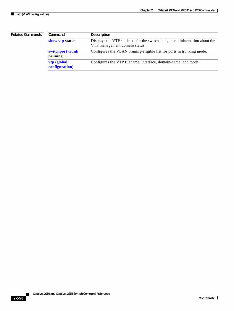
Chapter 2 Catalyst 2950 and 2955 Cisco IOS Commandsvtp (VLAN configuration)
Related Commands Command Description
show vtp status Displays the VTP statistics for the switch and general information about the VTP management domain status.
switchport trunk pruning
Configures the VLAN pruning-eligible list for ports in trunking mode.
vtp (global configuration)
Configures the VTP filename, interface, domain-name, and mode.
2-550Catalyst 2950 and Catalyst 2955 Switch Command Reference
OL-10102-02
Chapter 2 Catalyst 2950 and 2955 Cisco IOS Commandswrr-queue bandwidth
wrr-queue bandwidthUse the wrr-queue bandwidth global configuration command to assign weighted round-robin (WRR) weights to the four class of service (CoS) priority queues. Use the no form of this command to disable the WRR scheduler and enable the strict priority scheduler.
wrr-queue bandwidth weight1...weight4
no wrr-queue bandwidth
Syntax Description
Defaults WRR is disabled. The strict priority is the default scheduler.
Command Modes Global configuration
Command History
Usage Guidelines WRR allows bandwidth sharing at the egress port. This command defines the bandwidths for egress WRR through scheduling weights.
You can configure queues 1, 2, and 3 for WRR scheduling and queue 4 for strict priority. To configure queue 4 as the expedite queue, set weight4 to 0. When queue 4 is empty, packets from queues 1, 2, and 3 are sent according to the assigned WRR weights.
For more information about strict priority and WRR scheduling, see the “CoS and WRR” section in the “Configuring QoS” chapter of the software configuration guide for this release.
Examples This example shows how to assign WRR weights of 10, 20, 30, and 40 to the CoS priority queues 1, 2, 3, and 4:
Switch(config)# wrr-queue bandwidth 10 20 30 40
This example shows how to disable the WRR scheduler and enable the strict priority scheduler:
Switch(config)# no wrr-queue bandwidth
This example shows how to configure queue 4 as the expedite queue and to assign WRR weights of 10, 20, and 30 to the queues 1, 2, and 3:
Switch(config)# wrr-queue bandwidth 10 20 30 0
You can verify your settings by entering the show wrr-queue bandwidth privileged EXEC command.
weight1...weight4 The ratio of weight1, weight2, weight3, and weight4 determines the weights of the WRR scheduler. For weight1, weight2, and weight3, the range is 1 to 255. The range for weight4 is 0 to 255.
Release Modification
12.0(5.2)WC(1) This command was introduced.
12.1(12c)EA1 The range for weight4 was modified from 1 to 255 to 0 to 255.
2-551Catalyst 2950 and Catalyst 2955 Switch Command Reference
OL-10102-02
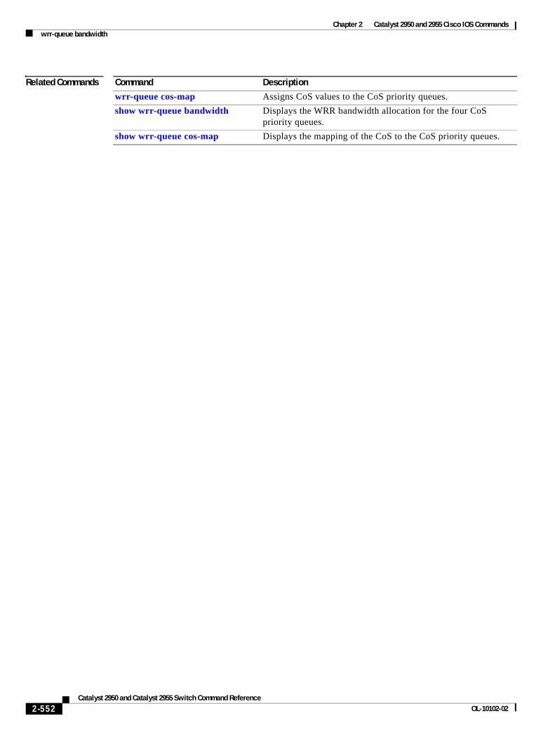
Chapter 2 Catalyst 2950 and 2955 Cisco IOS Commandswrr-queue bandwidth
Related Commands Command Description
wrr-queue cos-map Assigns CoS values to the CoS priority queues.
show wrr-queue bandwidth Displays the WRR bandwidth allocation for the four CoS priority queues.
show wrr-queue cos-map Displays the mapping of the CoS to the CoS priority queues.
2-552Catalyst 2950 and Catalyst 2955 Switch Command Reference
OL-10102-02
Chapter 2 Catalyst 2950 and 2955 Cisco IOS Commandswrr-queue cos-map
wrr-queue cos-mapUse the wrr-queue cos-map global configuration command to assign class of service (CoS) values to the CoS priority queues. Use the no form of this command to return to the default settings.
wrr-queue cos-map quid cos1...cosn
no wrr-queue cos-map [queue-id [cos1 ... cosn]]
Syntax Description
Defaults These are the default CoS values:
Command Modes Global configuration
Command History
Usage Guidelines CoS assigned at the ingress port is used to select a CoS priority at the egress port.
Examples This example shows how to map CoS values 0, 1, and 2 to CoS priority queue 1, value 3 to CoS priority queue 2, values 4 and 5 to CoS priority 3, and values 6 and 7 to CoS priority queue 4:
Switch(config)# wrr-queue cos-map 1 0 1 2Switch(config)# wrr-queue cos-map 2 3Switch(config)# wrr-queue cos-map 3 4 5Switch(config)# wrr-queue cos-map 4 6 7
This example shows how to map CoS values 0, 1, 2, and 3 to CoS priority queue 2:
Switch(config)# wrr-queue cos-map 2 0 1 2 3
After entering the wrr-queue cos-map 2 0 1 2 3 command, if all other priority queues use their default setting, this is the new mapping:
quid The queue id of the CoS priority queue. The range is 1 to 4 where 1 is the lowest CoS priority queue.
cos1...cosn The CoS values that are mapped to the queue id.
CoS Value CoS Priority Queues
0, 1 1
2, 3 2
4, 5 3
6, 7 4
Release Modification
12.0(5.2)WC(1) This command was introduced.
12.1(12c)EA1 CoS values were added to the no form of this command.
2-553Catalyst 2950 and Catalyst 2955 Switch Command Reference
OL-10102-02
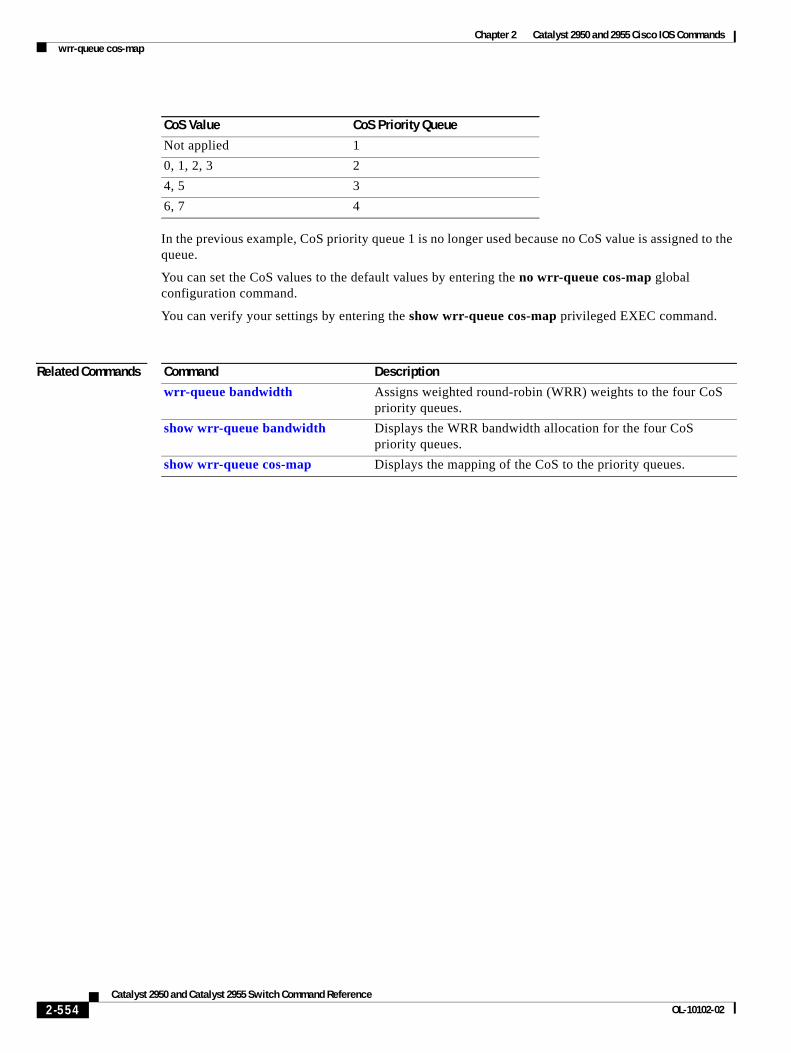
Chapter 2 Catalyst 2950 and 2955 Cisco IOS Commandswrr-queue cos-map
In the previous example, CoS priority queue 1 is no longer used because no CoS value is assigned to the queue.
You can set the CoS values to the default values by entering the no wrr-queue cos-map global configuration command.
You can verify your settings by entering the show wrr-queue cos-map privileged EXEC command.
Related Commands
CoS Value CoS Priority Queue
Not applied 1
0, 1, 2, 3 2
4, 5 3
6, 7 4
Command Description
wrr-queue bandwidth Assigns weighted round-robin (WRR) weights to the four CoS priority queues.
show wrr-queue bandwidth Displays the WRR bandwidth allocation for the four CoS priority queues.
show wrr-queue cos-map Displays the mapping of the CoS to the priority queues.
2-554Catalyst 2950 and Catalyst 2955 Switch Command Reference
OL-10102-02
Catalyst 2950 anOL-10102-02
A
P P E N D I X A Catalyst 2955 Alarm CommandsThis appendix describes the commands used to monitor switch conditions on the Catalyst 2955 switch. These commands are not supported on the Catalyst 2950 switch.
Note For more information about how to use the commands, see the “Configuring Catalyst 2955 Switch Alarms” chapter in the software configuration guide for this release.
A-1d Catalyst 2955 Switch Command Reference
Appendix A Catalyst 2955 Alarm Commands alarm facility fcs-hysteresis
alarm facility fcs-hysteresisUse the alarm facility fcs-hysteresis global configuration command to set the frame check sequence (FCS) error hysteresis threshold as a percentage of fluctuation from the FCS bit error rate. Use the no form of this command to set the FCS error hysteresis threshold to its default value.
alarm facility fcs-hysteresis percentage
no alarm facility fcs-hysteresis percentage
Syntax Description
Defaults The default threshold-value is 10 percent.
Command Modes Global configuration
Command History
Usage Guidelines Set a hysteresis threshold to prevent an alarm from triggering when the FCS bit error rate fluctuates near the configured bit error rate.
You set the FCS hysteresis threshold for all ports on the switch; you set the FCS error rate on a per-port basis by using the fcs-threshold interface configuration command.
If the threshold is not the default, it appears in the output of the show running-config privileged EXEC command.
Examples This example shows how to set the FCS error hysteresis to 5 percent. The alarm is not triggered unless the bit error rate is more than 5 percent from the configured FCS bit error rate.
Switch(config)# alarm facility fcs-hysteresis 5
Related Commands
percentage Hysteresis threshold fluctuation. The range is 1 to 10 percent.
Release Modification
12.1(12c)EA1 This command was introduced.
Command Description
fcs-threshold Sets an FCS error rate for an interface.
show running-config Displays the running configuration on the switch, including FCS hysteresis threshold if it is not set at the default. For syntax information, see the Cisco IOS Configuration Fundamentals Command Reference for Release 12.1 > Cisco IOS File Management Commands > Configuration File Commands.
A-2Catalyst 2950 and Catalyst 2955 Switch Command Reference
OL-10102-02
Appendix A Catalyst 2955 Alarm Commands alarm facility power-supply
alarm facility power-supplyUse the alarm facility power-supply global configuration command to set the alarm options for a missing or failing power supply when the system is operating in dual power-supply mode. Use the no form of the command to disable the specified setting.
alarm facility power-supply {notifies | relay {major | minor} | syslog}
no alarm facility power-supply {notifies | relay {major | minor} | syslog}
Syntax Description
Defaults A power supply alarm message is stored but not sent to an SNMP server, to a relay, or to a syslog server.
Command Modes Global configuration
Command History
Usage Guidelines Power supply alarms are generated only when the system is in dual power-supply mode. When a second power supply is connected, you must use the power-supply dual global configuration command to set dual power-mode operation.
Before you use the notifies keyword to sent alarm traps to an SNMP host, you need to set up an SNMP server by using the snmp-server enable traps global configuration command.
Examples This example shows how to set the power-supply monitoring alarm to go to the minor relay circuitry:
Switch(config)# alarm facility power-supply relay minor
Related Commands
notifies Send power supply alarm traps to a Simple Network Management Protocol (SNMP) server.
relay major Send the alarm to the major relay circuitry.
relay minor Send the alarm to the minor relay circuitry.
syslog Send power supply alarm traps to a syslog server.
Release Modification
12.1(12c)EA1 This command was introduced.
Command Description
power-supply dual Sets the switch to operate in dual power-supply mode.
show alarm settings Displays environmental alarm settings and options.
snmp-server enable traps Enables the switch to send SNMP notification for various trap types to the network management system (NMS).
A-3Catalyst 2950 and Catalyst 2955 Switch Command Reference
OL-10102-02
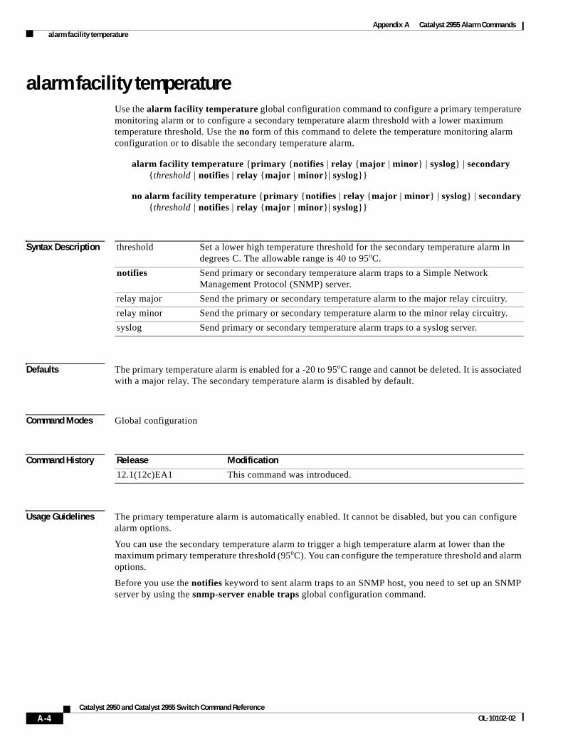
Appendix A Catalyst 2955 Alarm Commands alarm facility temperature
alarm facility temperatureUse the alarm facility temperature global configuration command to configure a primary temperature monitoring alarm or to configure a secondary temperature alarm threshold with a lower maximum temperature threshold. Use the no form of this command to delete the temperature monitoring alarm configuration or to disable the secondary temperature alarm.
alarm facility temperature {primary {notifies | relay {major | minor} | syslog} | secondary {threshold | notifies | relay {major | minor}| syslog}}
no alarm facility temperature {primary {notifies | relay {major | minor} | syslog} | secondary {threshold | notifies | relay {major | minor}| syslog}}
Syntax Description
Defaults The primary temperature alarm is enabled for a -20 to 95oC range and cannot be deleted. It is associated with a major relay. The secondary temperature alarm is disabled by default.
Command Modes Global configuration
Command History
Usage Guidelines The primary temperature alarm is automatically enabled. It cannot be disabled, but you can configure alarm options.
You can use the secondary temperature alarm to trigger a high temperature alarm at lower than the maximum primary temperature threshold (95oC). You can configure the temperature threshold and alarm options.
Before you use the notifies keyword to sent alarm traps to an SNMP host, you need to set up an SNMP server by using the snmp-server enable traps global configuration command.
threshold Set a lower high temperature threshold for the secondary temperature alarm in degrees C. The allowable range is 40 to 95oC.
notifies Send primary or secondary temperature alarm traps to a Simple Network Management Protocol (SNMP) server.
relay major Send the primary or secondary temperature alarm to the major relay circuitry.
relay minor Send the primary or secondary temperature alarm to the minor relay circuitry.
syslog Send primary or secondary temperature alarm traps to a syslog server.
Release Modification
12.1(12c)EA1 This command was introduced.
A-4Catalyst 2950 and Catalyst 2955 Switch Command Reference
OL-10102-02
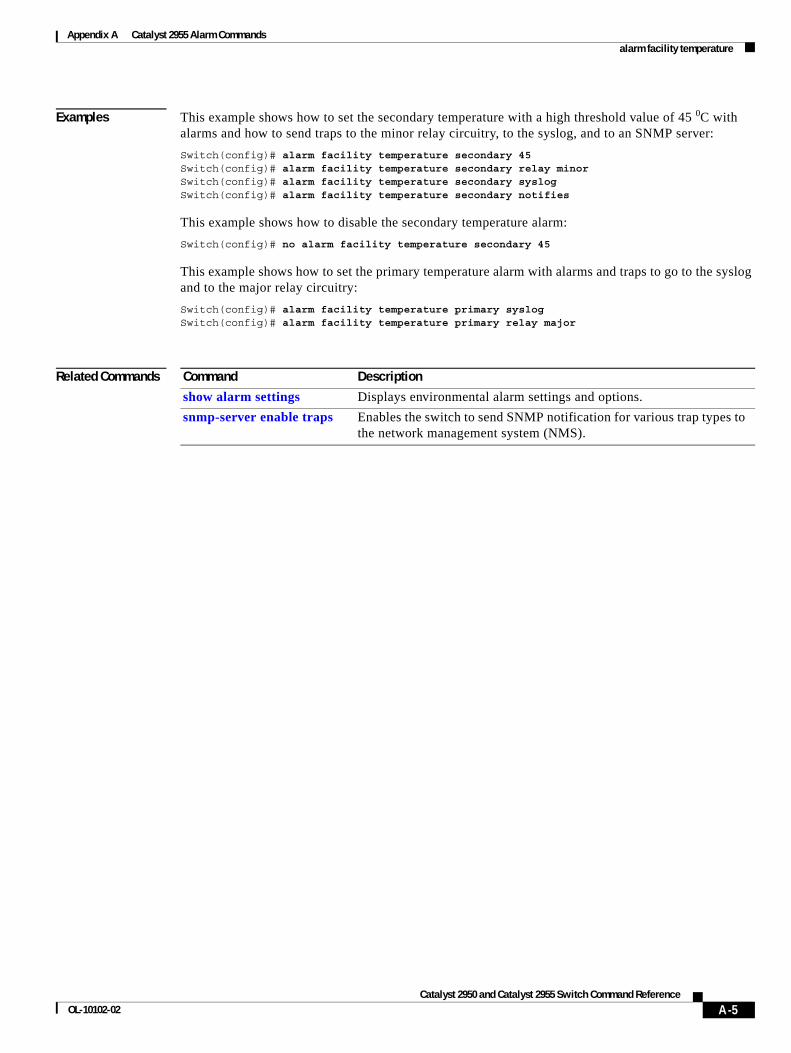
Appendix A Catalyst 2955 Alarm Commands alarm facility temperature
Examples This example shows how to set the secondary temperature with a high threshold value of 45 0C with alarms and how to send traps to the minor relay circuitry, to the syslog, and to an SNMP server:
Switch(config)# alarm facility temperature secondary 45Switch(config)# alarm facility temperature secondary relay minor Switch(config)# alarm facility temperature secondary syslogSwitch(config)# alarm facility temperature secondary notifies
This example shows how to disable the secondary temperature alarm:
Switch(config)# no alarm facility temperature secondary 45
This example shows how to set the primary temperature alarm with alarms and traps to go to the syslog and to the major relay circuitry:
Switch(config)# alarm facility temperature primary syslog Switch(config)# alarm facility temperature primary relay major
Related Commands Command Description
show alarm settings Displays environmental alarm settings and options.
snmp-server enable traps Enables the switch to send SNMP notification for various trap types to the network management system (NMS).
A-5Catalyst 2950 and Catalyst 2955 Switch Command Reference
OL-10102-02
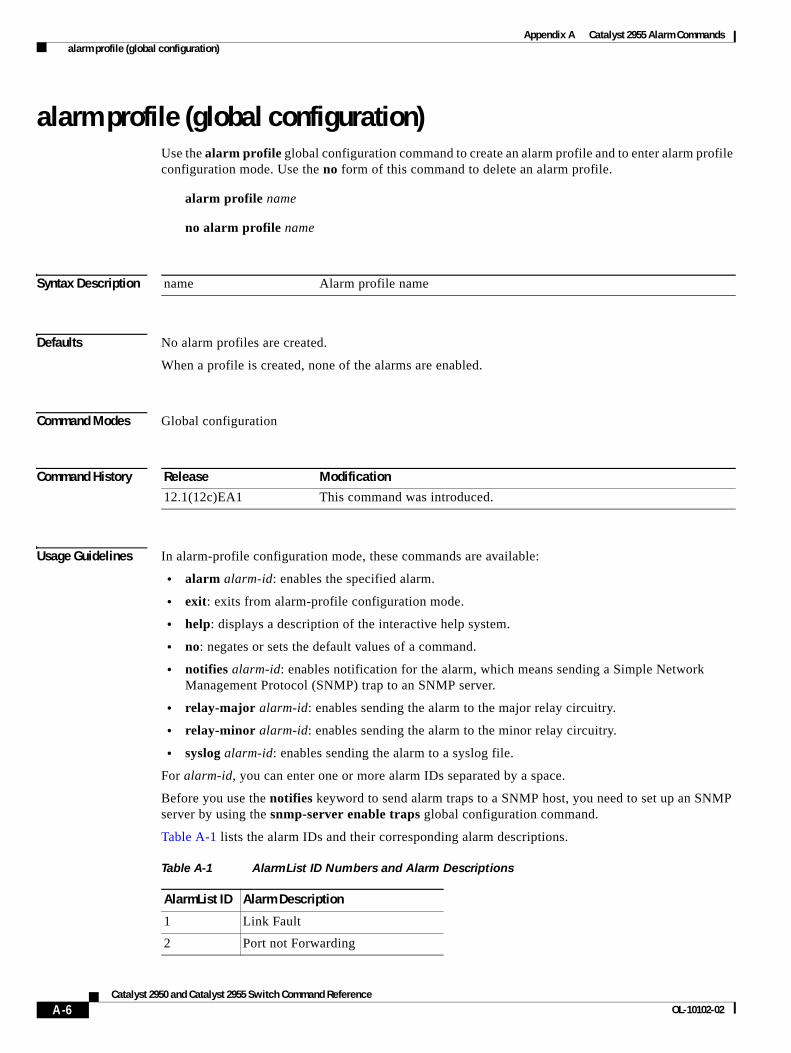
Appendix A Catalyst 2955 Alarm Commands alarm profile (global configuration)
alarm profile (global configuration)Use the alarm profile global configuration command to create an alarm profile and to enter alarm profile configuration mode. Use the no form of this command to delete an alarm profile.
alarm profile name
no alarm profile name
Syntax Description
Defaults No alarm profiles are created.
When a profile is created, none of the alarms are enabled.
Command Modes Global configuration
Command History
Usage Guidelines In alarm-profile configuration mode, these commands are available:
• alarm alarm-id: enables the specified alarm.
• exit: exits from alarm-profile configuration mode.
• help: displays a description of the interactive help system.
• no: negates or sets the default values of a command.
• notifies alarm-id: enables notification for the alarm, which means sending a Simple Network Management Protocol (SNMP) trap to an SNMP server.
• relay-major alarm-id: enables sending the alarm to the major relay circuitry.
• relay-minor alarm-id: enables sending the alarm to the minor relay circuitry.
• syslog alarm-id: enables sending the alarm to a syslog file.
For alarm-id, you can enter one or more alarm IDs separated by a space.
Before you use the notifies keyword to send alarm traps to a SNMP host, you need to set up an SNMP server by using the snmp-server enable traps global configuration command.
Table A-1 lists the alarm IDs and their corresponding alarm descriptions.
name Alarm profile name
Release Modification
12.1(12c)EA1 This command was introduced.
Table A-1 AlarmList ID Numbers and Alarm Descriptions
AlarmList ID Alarm Description
1 Link Fault
2 Port not Forwarding
A-6Catalyst 2950 and Catalyst 2955 Switch Command Reference
OL-10102-02
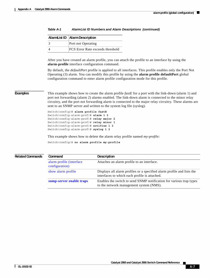
Appendix A Catalyst 2955 Alarm Commands alarm profile (global configuration)
After you have created an alarm profile, you can attach the profile to an interface by using the alarm-profile interface configuration command.
By default, the defaultPort profile is applied to all interfaces. This profile enables only the Port Not Operating (3) alarm. You can modify this profile by using the alarm profile defaultPort global configuration command to enter alarm profile configuration mode for this profile.
Examples This example shows how to create the alarm profile fastE for a port with the link-down (alarm 1) and port not forwarding (alarm 2) alarms enabled. The link-down alarm is connected to the minor relay circuitry, and the port not forwarding alarm is connected to the major relay circuitry. These alarms are sent to an SNMP server and written to the system log file (syslog).
Switch(config)# alarm profile fastESwitch(config-alarm-prof)# alarm 1 2Switch(config-alarm-prof)# relay major 2Switch(config-alarm-prof)# relay minor 1Switch(config-alarm-prof)# notifies 1 2Switch(config-alarm-prof)# syslog 1 2
This example shows how to delete the alarm relay profile named my-profile:
Switch(config)# no alarm profile my-profile
Related Commands
3 Port not Operating
4 FCS Error Rate exceeds threshold
Table A-1 AlarmList ID Numbers and Alarm Descriptions (continued)
AlarmList ID Alarm Description
Command Description
alarm profile (interface configuration)
Attaches an alarm profile to an interface.
show alarm profile Displays all alarm profiles or a specified alarm profile and lists the interfaces to which each profile is attached.
snmp-server enable traps Enables the switch to send SNMP notification for various trap types to the network management system (NMS).
A-7Catalyst 2950 and Catalyst 2955 Switch Command Reference
OL-10102-02
Appendix A Catalyst 2955 Alarm Commands alarm profile (interface configuration)
alarm profile (interface configuration)Use the alarm profile interface configuration command to attach an alarm profile to a port. Use the no form of this command to detach the profile from the port.
alarm profile name
no alarm profile
Syntax Description
Defaults The alarm profile defaultPort is applied to all interfaces. In this profile, only the Port is not Operating alarm is enabled.
Command Modes Interface configuration
Command History
Usage Guidelines Use the alarm profile global configuration command to create the alarm profile, enabling one or more alarms and specifying the alarm options.
You can attach only one alarm profile to an interface.
When you attach an alarm profile to an interface, it overwrites any previous alarm profile that was attached to the interface (including the defaultPort profile).
Examples This example shows how to attach an alarm profile named fastE to a port:
Switch(config)# interface fastethernet0/2Switch(config-if)# alarm profile fastE
This example shows how to detach the alarm profile from a port and return it to the defaultPort profile:
Switch(config)# interface fastethernet0/2Switch(config-if)# no alarm profile
Related Commands
name Alarm profile name
Release Modification
12.1(12c)EA1 This command was introduced.
Command Description
alarm profile (global configuration)
Creates or identifies an alarm profile and enters alarm-profile configuration mode.
show alarm profile Displays all alarm profiles or a specified alarm profile and lists the interfaces to which each profile is attached.
A-8Catalyst 2950 and Catalyst 2955 Switch Command Reference
OL-10102-02
Appendix A Catalyst 2955 Alarm Commands fcs-threshold
fcs-thresholdUse the fcs-threshold interface configuration command to set the frame check sequence (FCS) bit error rate. Use the no form of the command to return to the default setting.
fcs-threshold value
no fcs-threshold value
Syntax Description
Defaults The default for this bit error rate is 8, which is the bit error rate for Ethernet standard 10-8.
Command Modes Global configuration
Command History
Usage Guidelines The Ethernet standard calls for a maximum bit error rate of 10-8. In the Catalyst 2955 switch, the bit error rate configurable range is from 10-6 to 10-11. The bit error rate input to the switch is a positive exponent. To configure an bit error rate of 10-9, enter the value 9 for the exponent.
You can set an FCS error hysteresis threshold on the switch to prevent the toggle of the alarm when the actual bit error rate fluctuates near the configured bit error rate by using the alarm facility fcs hysteresis global configuration command.
Examples This example shows how to set the FCS bit error rate for a port to 10-10:
Switch(config)# interface fastethernet0/1Switch(config-if)# fcs-threshold 10
Related Commands
value Value ranges from 6 to 11, representing a bit error rate from 10-6 to 10-11.
Release Modification
12.1(12c)EA1 This command was introduced.
Command Description
alarm facility fcs-hysteresis Sets the FCS hysteresis threshold for the switch in a percentage of allowed fluctuation from the FCS bit error rate configured on a port.
show fcs-threshold Displays the FCS error bit rate settings on each interface as positive exponents.
A-9Catalyst 2950 and Catalyst 2955 Switch Command Reference
OL-10102-02
Appendix A Catalyst 2955 Alarm Commands power-supply dual
power-supply dualUse the power-supply dual global configuration command to set the dual power-supply mode of operation. Use the no form of this command to return to the default single power-supply mode.
power-supply dual
no power-supply dual
Syntax Description This command has no arguments or keywords.
Defaults By default, the system operates in single-power mode.
Command Modes Global configuration
Command History
Usage Guidelines The Catalyst 2955 switch has two DC power inputs. When the switch is connected to a second DC input and put in dual power-supply mode, the second power supply provides power to the switch if the primary supply fails.
When the switch is in dual power-supply mode, you can use the alarm-facility power supply global configuration command to set alarm options and to monitor for a missing or failed primary power supply.
Examples This example shows how to set the switch in a dual power-supply mode:
Switch(config)# power-supply dual
Related Commands
Release Modification
12.1(12c)EA1 This command was introduced.
Command Description
alarm facility power-supply Sets the switch to monitor for a missing or failed power supply and sets the alarm options.
show alarm settings Displays environmental alarm settings and options.
A-10Catalyst 2950 and Catalyst 2955 Switch Command Reference
OL-10102-02
Appendix A Catalyst 2955 Alarm Commands show alarm description port
show alarm description portUse the show alarm description port user EXEC command to display the alarm numbers with the text description.
show alarm description port [ | {begin | exclude | include} expression]
Syntax Description
Command Modes User EXEC
Command History
Usage Guidelines Expressions are case sensitive. For example, if you enter | exclude output, the lines that contain output do not appear, but the lines that contain Output appear.
Examples This is an example of output from the show alarm description port command. It shows the alarmIDs and their respective alarm descriptions.
Switch> show alarm description port 1 Link Fault 2 Port Not Forwarding 3 Port Not Operating 4 FCS Error Rate exceeds threshold
Related Commands
| begin (Optional) Display begins with the line that matches the expression.
| exclude (Optional) Display excludes lines that match the expression.
| include (Optional) Display includes lines that match the specified expression.
expression Expression in the output to use as a reference point.
Release Modification
12.1(12c)EA1 This command was introduced.
Command Description
alarm profile (global configuration)
Creates an alarm profile containing one or more alarm IDs and alarm options.
show alarm profile Displays all alarm profiles or a specified alarm profile and lists the interfaces to which each profile is attached.
A-11Catalyst 2950 and Catalyst 2955 Switch Command Reference
OL-10102-02
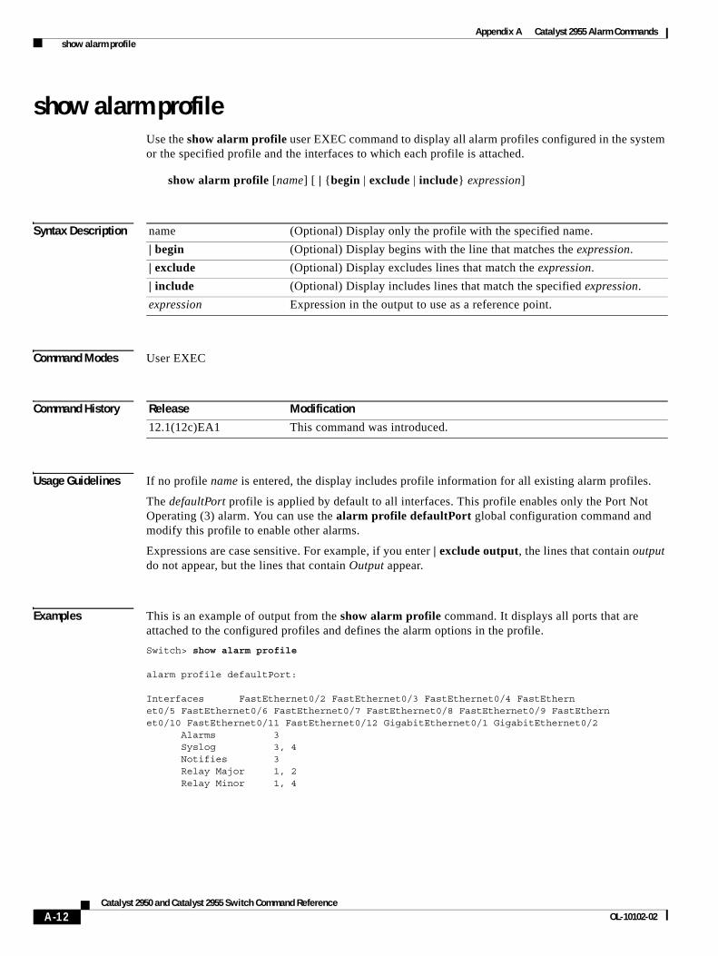
Appendix A Catalyst 2955 Alarm Commands show alarm profile
show alarm profileUse the show alarm profile user EXEC command to display all alarm profiles configured in the system or the specified profile and the interfaces to which each profile is attached.
show alarm profile [name] [ | {begin | exclude | include} expression]
Syntax Description
Command Modes User EXEC
Command History
Usage Guidelines If no profile name is entered, the display includes profile information for all existing alarm profiles.
The defaultPort profile is applied by default to all interfaces. This profile enables only the Port Not Operating (3) alarm. You can use the alarm profile defaultPort global configuration command and modify this profile to enable other alarms.
Expressions are case sensitive. For example, if you enter | exclude output, the lines that contain output do not appear, but the lines that contain Output appear.
Examples This is an example of output from the show alarm profile command. It displays all ports that are attached to the configured profiles and defines the alarm options in the profile.
Switch> show alarm profile
alarm profile defaultPort:
Interfaces FastEthernet0/2 FastEthernet0/3 FastEthernet0/4 FastEthernet0/5 FastEthernet0/6 FastEthernet0/7 FastEthernet0/8 FastEthernet0/9 FastEthernet0/10 FastEthernet0/11 FastEthernet0/12 GigabitEthernet0/1 GigabitEthernet0/2 Alarms 3 Syslog 3, 4 Notifies 3 Relay Major 1, 2 Relay Minor 1, 4
name (Optional) Display only the profile with the specified name.
| begin (Optional) Display begins with the line that matches the expression.
| exclude (Optional) Display excludes lines that match the expression.
| include (Optional) Display includes lines that match the specified expression.
expression Expression in the output to use as a reference point.
Release Modification
12.1(12c)EA1 This command was introduced.
A-12Catalyst 2950 and Catalyst 2955 Switch Command Reference
OL-10102-02
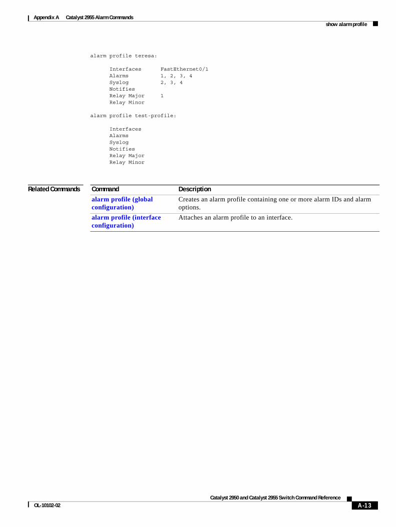
Appendix A Catalyst 2955 Alarm Commands show alarm profile
alarm profile teresa:
Interfaces FastEthernet0/1 Alarms 1, 2, 3, 4 Syslog 2, 3, 4 Notifies Relay Major 1 Relay Minor
alarm profile test-profile:
Interfaces Alarms Syslog Notifies Relay Major Relay Minor
Related Commands Command Description
alarm profile (global configuration)
Creates an alarm profile containing one or more alarm IDs and alarm options.
alarm profile (interface configuration)
Attaches an alarm profile to an interface.
A-13Catalyst 2950 and Catalyst 2955 Switch Command Reference
OL-10102-02
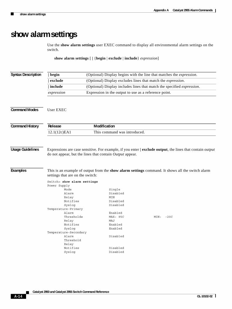
Appendix A Catalyst 2955 Alarm Commands show alarm settings
show alarm settingsUse the show alarm settings user EXEC command to display all environmental alarm settings on the switch.
show alarm settings [ | {begin | exclude | include} expression]
Syntax Description
Command Modes User EXEC
Command History
Usage Guidelines Expressions are case sensitive. For example, if you enter | exclude output, the lines that contain output do not appear, but the lines that contain Output appear.
Examples This is an example of output from the show alarm settings command. It shows all the switch alarm settings that are on the switch:
Switch> show alarm settingsPower Supply Mode Single Alarm Disabled Relay MIN Notifies Disabled Syslog DisabledTemperature-Primary Alarm Enabled Thresholds MAX: 95C MIN: -20C Relay MAJ Notifies Enabled Syslog EnabledTemperature-Secondary Alarm Disabled Threshold Relay Notifies Disabled Syslog Disabled
| begin (Optional) Display begins with the line that matches the expression.
| exclude (Optional) Display excludes lines that match the expression.
| include (Optional) Display includes lines that match the specified expression.
expression Expression in the output to use as a reference point.
Release Modification
12.1(12c)EA1 This command was introduced.
A-14Catalyst 2950 and Catalyst 2955 Switch Command Reference
OL-10102-02

Appendix A Catalyst 2955 Alarm Commands show alarm settings
Related Commands Command Description
alarm facility power-supply Sets power supply alarm options.
alarm facility temperature Sets temperature alarm options.
power-supply dual Sets dual power-supply mode.
A-15Catalyst 2950 and Catalyst 2955 Switch Command Reference
OL-10102-02
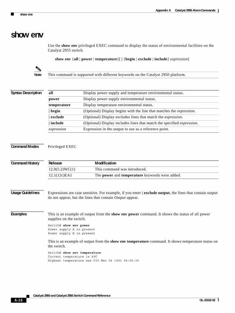
Appendix A Catalyst 2955 Alarm Commands show env
show envUse the show env privileged EXEC command to display the status of environmental facilities on the Catalyst 2955 switch.
show env {all | power | temperature}[ | {begin | exclude | include} expression]
Note This command is supported with different keywords on the Catalyst 2950 platform.
Syntax Description
Command Modes Privileged EXEC
Command History
Usage Guidelines Expressions are case sensitive. For example, if you enter | exclude output, the lines that contain output do not appear, but the lines that contain Output appear.
Examples This is an example of output from the show env power command. It shows the status of all power supplies on the switch.
Switch# show env powerPower supply A is presentPower supply B is present
This is an example of output from the show env temperature command. It shows temperature status on the switch.
Switch# show env temperatureCurrent temperature is 49CHighest temperature was 53C Mar 04 1993 04:06:36
all Display power supply and temperature environmental status.
power Display power supply environmental status.
temperature Display temperature environmental status.
| begin (Optional) Display begins with the line that matches the expression.
| exclude (Optional) Display excludes lines that match the expression.
| include (Optional) Display includes lines that match the specified expression.
expression Expression in the output to use as a reference point.
Release Modification
12.0(5.2)WC(1) This command was introduced.
12.1(12c)EA1 The power and temperature keywords were added.
A-16Catalyst 2950 and Catalyst 2955 Switch Command Reference
OL-10102-02
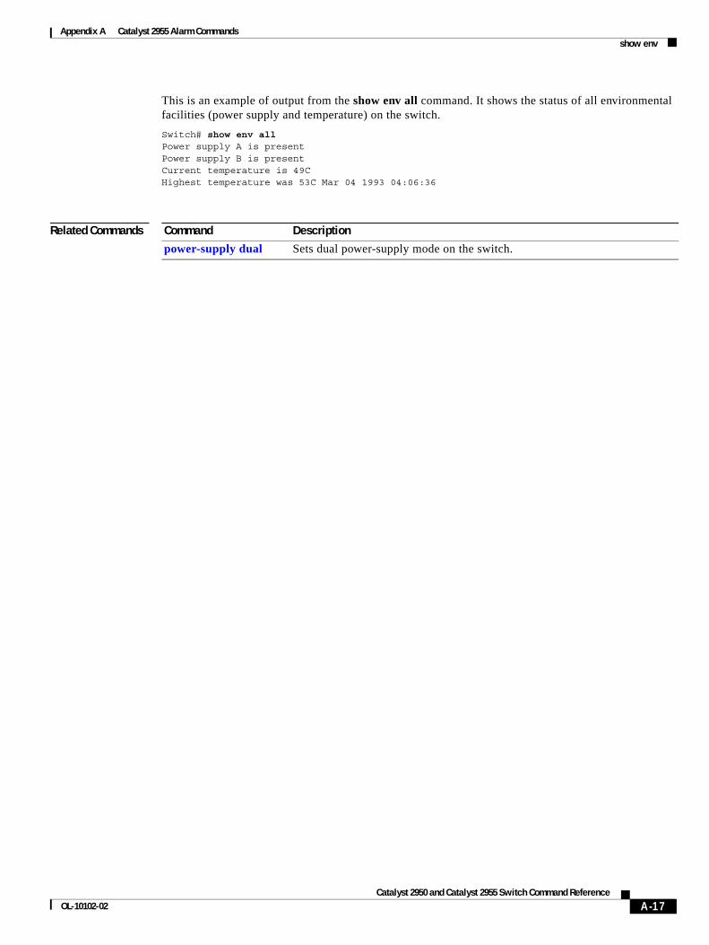
Appendix A Catalyst 2955 Alarm Commands show env
This is an example of output from the show env all command. It shows the status of all environmental facilities (power supply and temperature) on the switch.
Switch# show env allPower supply A is presentPower supply B is presentCurrent temperature is 49CHighest temperature was 53C Mar 04 1993 04:06:36
Related Commands Command Description
power-supply dual Sets dual power-supply mode on the switch.
A-17Catalyst 2950 and Catalyst 2955 Switch Command Reference
OL-10102-02
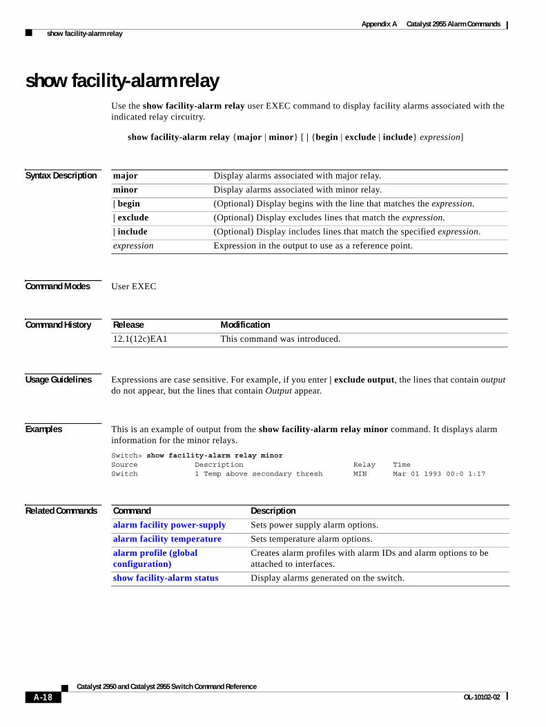
Appendix A Catalyst 2955 Alarm Commands show facility-alarm relay
show facility-alarm relayUse the show facility-alarm relay user EXEC command to display facility alarms associated with the indicated relay circuitry.
show facility-alarm relay {major | minor} [ | {begin | exclude | include} expression]
Syntax Description
Command Modes User EXEC
Command History
Usage Guidelines Expressions are case sensitive. For example, if you enter | exclude output, the lines that contain output do not appear, but the lines that contain Output appear.
Examples This is an example of output from the show facility-alarm relay minor command. It displays alarm information for the minor relays.
Switch> show facility-alarm relay minorSource Description Relay TimeSwitch 1 Temp above secondary thresh MIN Mar 01 1993 00:0 1:17
Related Commands
major Display alarms associated with major relay.
minor Display alarms associated with minor relay.
| begin (Optional) Display begins with the line that matches the expression.
| exclude (Optional) Display excludes lines that match the expression.
| include (Optional) Display includes lines that match the specified expression.
expression Expression in the output to use as a reference point.
Release Modification
12.1(12c)EA1 This command was introduced.
Command Description
alarm facility power-supply Sets power supply alarm options.
alarm facility temperature Sets temperature alarm options.
alarm profile (global configuration)
Creates alarm profiles with alarm IDs and alarm options to be attached to interfaces.
show facility-alarm status Display alarms generated on the switch.
A-18Catalyst 2950 and Catalyst 2955 Switch Command Reference
OL-10102-02
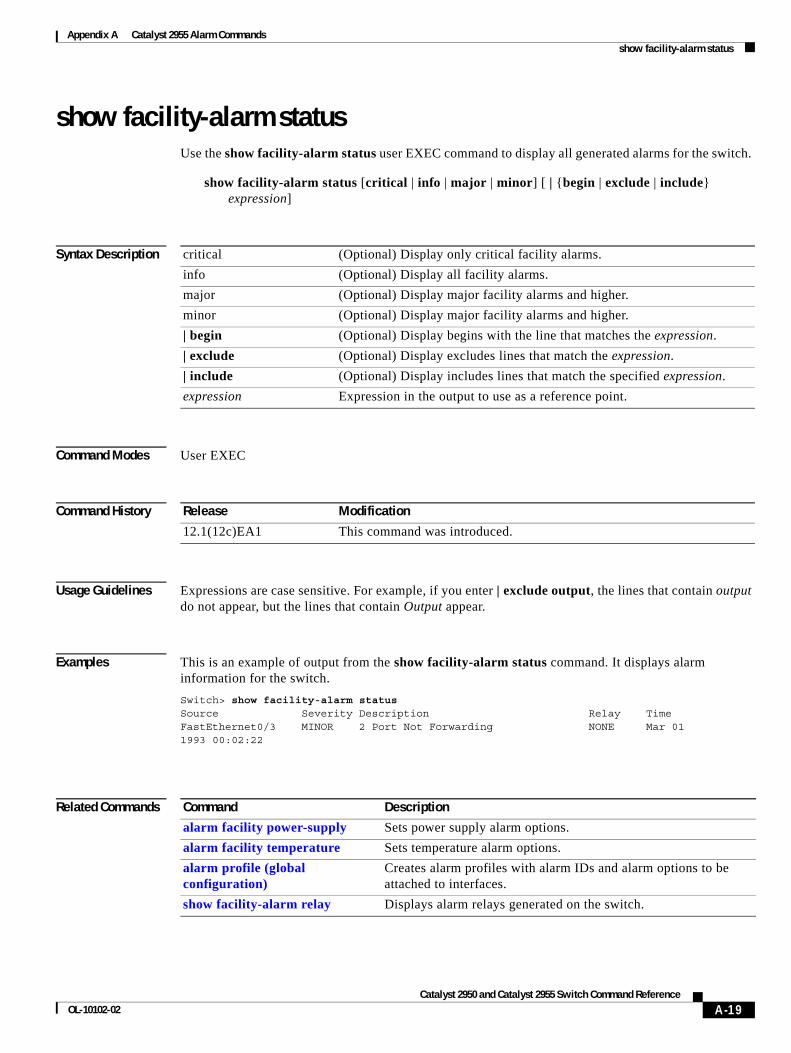
Appendix A Catalyst 2955 Alarm Commands show facility-alarm status
show facility-alarm statusUse the show facility-alarm status user EXEC command to display all generated alarms for the switch.
show facility-alarm status [critical | info | major | minor] [ | {begin | exclude | include} expression]
Syntax Description
Command Modes User EXEC
Command History
Usage Guidelines Expressions are case sensitive. For example, if you enter | exclude output, the lines that contain output do not appear, but the lines that contain Output appear.
Examples This is an example of output from the show facility-alarm status command. It displays alarm information for the switch.
Switch> show facility-alarm status Source Severity Description Relay TimeFastEthernet0/3 MINOR 2 Port Not Forwarding NONE Mar 011993 00:02:22
Related Commands
critical (Optional) Display only critical facility alarms.
info (Optional) Display all facility alarms.
major (Optional) Display major facility alarms and higher.
minor (Optional) Display major facility alarms and higher.
| begin (Optional) Display begins with the line that matches the expression.
| exclude (Optional) Display excludes lines that match the expression.
| include (Optional) Display includes lines that match the specified expression.
expression Expression in the output to use as a reference point.
Release Modification
12.1(12c)EA1 This command was introduced.
Command Description
alarm facility power-supply Sets power supply alarm options.
alarm facility temperature Sets temperature alarm options.
alarm profile (global configuration)
Creates alarm profiles with alarm IDs and alarm options to be attached to interfaces.
show facility-alarm relay Displays alarm relays generated on the switch.
A-19Catalyst 2950 and Catalyst 2955 Switch Command Reference
OL-10102-02
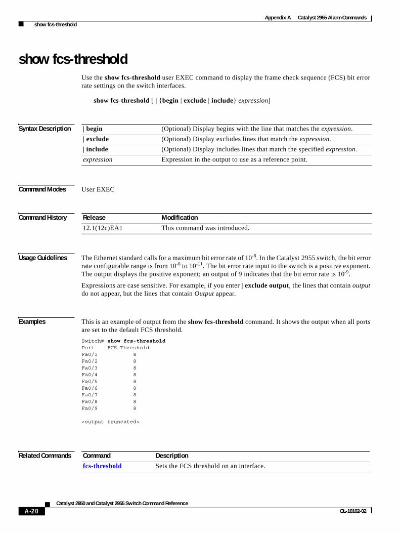
Appendix A Catalyst 2955 Alarm Commands show fcs-threshold
show fcs-thresholdUse the show fcs-threshold user EXEC command to display the frame check sequence (FCS) bit error rate settings on the switch interfaces.
show fcs-threshold [ | {begin | exclude | include} expression]
Syntax Description
Command Modes User EXEC
Command History
Usage Guidelines The Ethernet standard calls for a maximum bit error rate of 10-8. In the Catalyst 2955 switch, the bit error rate configurable range is from 10-6 to 10-11. The bit error rate input to the switch is a positive exponent. The output displays the positive exponent; an output of 9 indicates that the bit error rate is 10-9.
Expressions are case sensitive. For example, if you enter | exclude output, the lines that contain output do not appear, but the lines that contain Output appear.
Examples This is an example of output from the show fcs-threshold command. It shows the output when all ports are set to the default FCS threshold.
Switch# show fcs-thresholdPort FCS ThresholdFa0/1 8Fa0/2 8Fa0/3 8Fa0/4 8Fa0/5 8Fa0/6 8Fa0/7 8Fa0/8 8Fa0/9 8
<output truncated>
Related Commands
| begin (Optional) Display begins with the line that matches the expression.
| exclude (Optional) Display excludes lines that match the expression.
| include (Optional) Display includes lines that match the specified expression.
expression Expression in the output to use as a reference point.
Release Modification
12.1(12c)EA1 This command was introduced.
Command Description
fcs-threshold Sets the FCS threshold on an interface.
A-20Catalyst 2950 and Catalyst 2955 Switch Command Reference
OL-10102-02
Appendix A Catalyst 2955 Alarm Commands test relay
test relayUse the test relay privileged EXEC command to turn on or off the relay circuitry.
test relay {major | minor} {on| off}
Caution Using the test command alters the state (on or off) of a relay. Previous states are not saved.
Command Modes Privileged EXEC
Command History
Usage Guidelines You can use the test relay privileged EXEC command to check relay circuitry connections to the alert devices. The command provides a way to test alarm scanners without having to create an alarm condition.
Examples This example shows how to turn on the major relay circuitry:
Switch# test relay major on
Related Commands
Release Modification
12.1(12c)EA1 This command was introduced.
Command Description
show alarm profile Displays all alarm profiles or a specified alarm profile and lists the interfaces to which each profile is attached.
show alarm settings Displays environmental alarm settings and options.
show facility-alarm relay Displays alarm relays generated on the switch.
A-21Catalyst 2950 and Catalyst 2955 Switch Command Reference
OL-10102-02

Appendix A Catalyst 2955 Alarm Commands test relay
A-22Catalyst 2950 and Catalyst 2955 Switch Command Reference
OL-10102-02
Catalyst 2950 anOL-10102-02
A
P P E N D I X B Catalyst 2950 and 2955 Switch Boot Loader CommandsNote You can use the boot loader commands only on Catalyst 2950 Long-Reach Ethernet (LRE) switches.
During normal boot loader operation, you are not presented with the boot loader command-line prompt. You gain access to the boot loader command line if the switch is set to manually boot, if an error occurs during power-on self test (POST) DRAM testing, or if an error occurs while loading the operating system (a corrupted software image). You can also access the boot loader if you have lost or forgotten the switch password.
Note The default configuration for Catalyst 2950 LRE switches allows an end user with physical access to the switch to recover from a lost password by interrupting the boot process while the switch is powering up and then by entering a new password. The password recovery disable feature for Catalyst 2950 LRE switches allows the system administrator to protect access to the switch password by disabling part of this functionality and allowing the user to interrupt the boot process only by agreeing to set the system back to the default configuration. With password recovery disabled, the user can still interrupt the boot process and change the password, but the configuration file (config.text) and the VLAN database file (vlan.dat) are deleted. For more information, see the software configuration guide for this release.
You can access the boot loader through a switch console-port connection at 9600 bps. Unplug the switch power cord, and press the switch Mode button while reconnecting the power cord. You can release the Mode button a second or two after the LED above port 1 goes off. You should then see the boot loader Switch: prompt. The boot loader performs low-level CPU initialization, performs POST, and loads a default operating system image into memory.
B-1d Catalyst 2955 Switch Command Reference
Appendix B Catalyst 2950 and 2955 Switch Boot Loader Commands boot
bootUse the boot boot loader command to load and boot an executable image and to enter the command-line interface.
boot [-post] filesystem:/file-url ...
Syntax Description
Defaults The switch attempts to automatically boot the system by using information in the BOOT environment variable. If this variable is not set, the switch attempts to load and execute the first executable image it can by performing a recursive, depth-first search throughout the flash file system. In a depth-first search of a directory, each encountered subdirectory is completely searched before continuing the search in the original directory.
Command Modes Boot loader
Command History
Usage Guidelines When you enter the boot command without any arguments, the switch attempts to automatically boot the system by using the information in the BOOT environment variable, if any. If you supply an image name for the file-url variable, the boot command attempts to boot the specified image.
When you set boot loader boot command options, they are executed immediately and apply only to the current boot loader session. These settings are not saved for the next boot operation.
Filenames and directory names are case sensitive.
Examples This example shows how to boot the switch using the new-image.bin image:
switch: boot flash:/new-images/new-image.bin
After entering this command, you are prompted to start the setup program.
Related Commands
-post (Optional) Run the loaded image with an extended or comprehensive power-on self-test (POST). Using this keyword causes POST to take longer to complete.
filesystem: Alias for a flash file system. Use flash: for the system board flash device.
/file-url (Optional) Path (directory) and name of a bootable image. Separate the image names with a semicolon.
Release Modification
12.1(11)YJ This command was introduced.
Command Description
set Sets the BOOT environment variable to boot a specific image when the BOOT keyword is appended to the command.
B-2Catalyst 2950 and Catalyst 2955 Switch Command Reference
OL-10102-02
Appendix B Catalyst 2950 and 2955 Switch Boot Loader Commands cat
catUse the cat boot loader command to display the contents of one or more files.
cat filesystem:/file-url ...
Syntax Description
Command Modes Boot loader
Command History
Usage Guidelines Filenames and directory names are case sensitive.
If you specify a list of files, the contents of each file appear sequentially.
Examples This example shows how to display the contents of config.text in flash memory:
Switch: cat flash:/config.text!version 12.1no service padservice timestamps debug uptimeservice timestamps log uptimeno service password-encryptionservice internal!hostname corp-bigboy!!username admin privilege 15 password 0 cisco!<output truncated>
Related Commands
filesystem: Alias for a flash file system. Use flash: for the system board flash device.
/file-url Path (directory) and name of the files to display. Separate each filename with a space.
Release Modification
12.1(11)YJ This command was introduced.
Command Description
more Displays the contents of one or more files.
type Displays the contents of one or more files.
B-3Catalyst 2950 and Catalyst 2955 Switch Command Reference
OL-10102-02
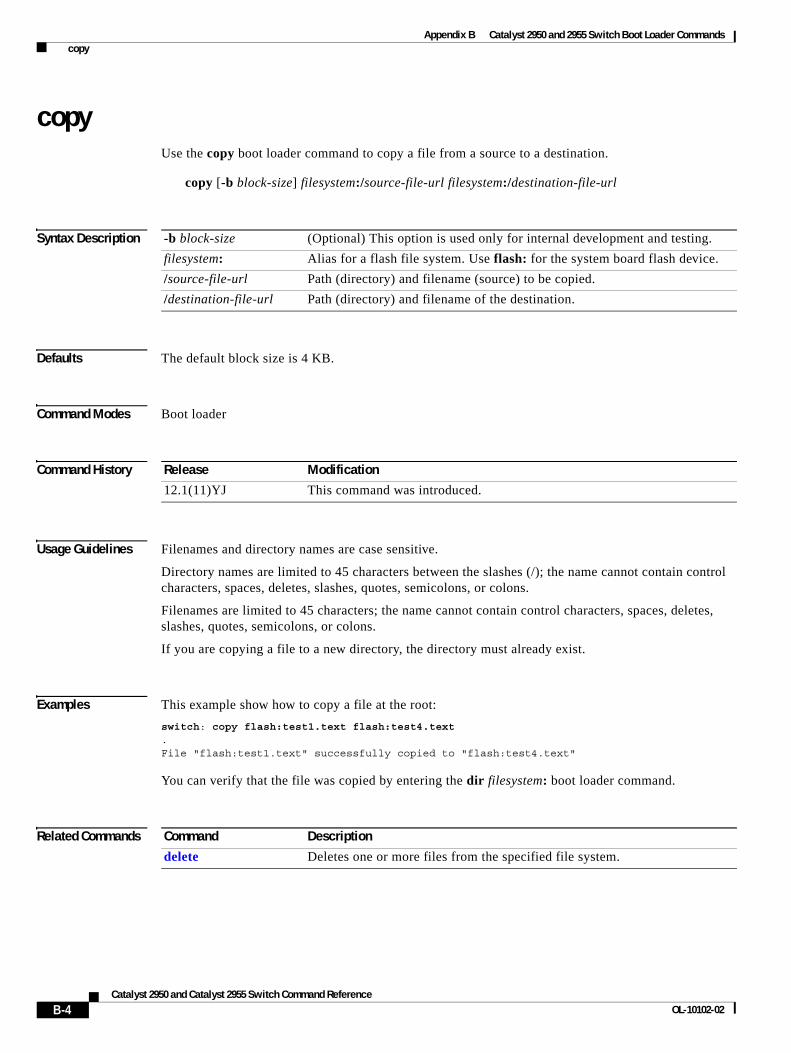
Appendix B Catalyst 2950 and 2955 Switch Boot Loader Commands copy
copyUse the copy boot loader command to copy a file from a source to a destination.
copy [-b block-size] filesystem:/source-file-url filesystem:/destination-file-url
Syntax Description
Defaults The default block size is 4 KB.
Command Modes Boot loader
Command History
Usage Guidelines Filenames and directory names are case sensitive.
Directory names are limited to 45 characters between the slashes (/); the name cannot contain control characters, spaces, deletes, slashes, quotes, semicolons, or colons.
Filenames are limited to 45 characters; the name cannot contain control characters, spaces, deletes, slashes, quotes, semicolons, or colons.
If you are copying a file to a new directory, the directory must already exist.
Examples This example show how to copy a file at the root:
switch: copy flash:test1.text flash:test4.text.File "flash:test1.text" successfully copied to "flash:test4.text"
You can verify that the file was copied by entering the dir filesystem: boot loader command.
Related Commands
-b block-size (Optional) This option is used only for internal development and testing.
filesystem: Alias for a flash file system. Use flash: for the system board flash device.
/source-file-url Path (directory) and filename (source) to be copied.
/destination-file-url Path (directory) and filename of the destination.
Release Modification
12.1(11)YJ This command was introduced.
Command Description
delete Deletes one or more files from the specified file system.
B-4Catalyst 2950 and Catalyst 2955 Switch Command Reference
OL-10102-02
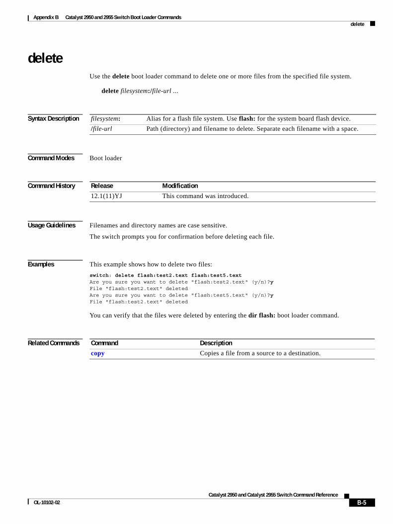
Appendix B Catalyst 2950 and 2955 Switch Boot Loader Commands delete
deleteUse the delete boot loader command to delete one or more files from the specified file system.
delete filesystem:/file-url ...
Syntax Description
Command Modes Boot loader
Command History
Usage Guidelines Filenames and directory names are case sensitive.
The switch prompts you for confirmation before deleting each file.
Examples This example shows how to delete two files:
switch: delete flash:test2.text flash:test5.textAre you sure you want to delete "flash:test2.text" (y/n)?yFile "flash:test2.text" deletedAre you sure you want to delete "flash:test5.text" (y/n)?yFile "flash:test2.text" deleted
You can verify that the files were deleted by entering the dir flash: boot loader command.
Related Commands
filesystem: Alias for a flash file system. Use flash: for the system board flash device.
/file-url Path (directory) and filename to delete. Separate each filename with a space.
Release Modification
12.1(11)YJ This command was introduced.
Command Description
copy Copies a file from a source to a destination.
B-5Catalyst 2950 and Catalyst 2955 Switch Command Reference
OL-10102-02
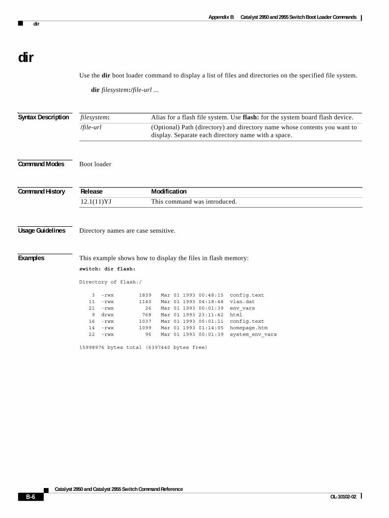
Appendix B Catalyst 2950 and 2955 Switch Boot Loader Commands dir
dirUse the dir boot loader command to display a list of files and directories on the specified file system.
dir filesystem:/file-url ...
Syntax Description
Command Modes Boot loader
Command History
Usage Guidelines Directory names are case sensitive.
Examples This example shows how to display the files in flash memory:
switch: dir flash:
Directory of flash:/
3 -rwx 1839 Mar 01 1993 00:48:15 config.text 11 -rwx 1140 Mar 01 1993 04:18:48 vlan.dat 21 -rwx 26 Mar 01 1993 00:01:39 env_vars 9 drwx 768 Mar 01 1993 23:11:42 html 16 -rwx 1037 Mar 01 1993 00:01:11 config.text 14 -rwx 1099 Mar 01 1993 01:14:05 homepage.htm 22 -rwx 96 Mar 01 1993 00:01:39 system_env_vars
15998976 bytes total (6397440 bytes free)
filesystem: Alias for a flash file system. Use flash: for the system board flash device.
/file-url (Optional) Path (directory) and directory name whose contents you want to display. Separate each directory name with a space.
Release Modification
12.1(11)YJ This command was introduced.
B-6Catalyst 2950 and Catalyst 2955 Switch Command Reference
OL-10102-02
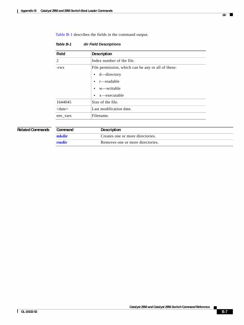
Appendix B Catalyst 2950 and 2955 Switch Boot Loader Commands dir
Table B-1 describes the fields in the command output.
Related Commands
Table B-1 dir Field Descriptions
Field Description
2 Index number of the file.
-rwx File permission, which can be any or all of these:
• d—directory
• r—readable
• w—writable
• x—executable
1644045 Size of the file.
<date> Last modification date.
env_vars Filename.
Command Description
mkdir Creates one or more directories.
rmdir Removes one or more directories.
B-7Catalyst 2950 and Catalyst 2955 Switch Command Reference
OL-10102-02
Appendix B Catalyst 2950 and 2955 Switch Boot Loader Commands flash_init
flash_initUse the flash_init boot loader command to initialize the flash file system.
flash_init
Syntax Description This command has no arguments or keywords.
Defaults The flash file system is automatically initialized during normal system operation.
Command Modes Boot loader
Command History
Usage Guidelines During the normal boot process, the flash file system is automatically initialized.
Use this command to manually initialize the flash file system. For example, you use this command during the recovery procedure for a lost or forgotten password.
Release Modification
12.1(11)YJ This command was introduced.
B-8Catalyst 2950 and Catalyst 2955 Switch Command Reference
OL-10102-02
Appendix B Catalyst 2950 and 2955 Switch Boot Loader Commands format
formatUse the format boot loader command to format the specified file system and destroy all data in that file system.
format filesystem:
Syntax Description
Command Modes Boot loader
Command History
Usage Guidelines
Caution Use this command with care; it destroys all data on the file system and renders your system unusable.
filesystem: Alias for a flash file system. Use flash: for the system board flash device.
Release Modification
12.1(11)YJ This command was introduced.
B-9Catalyst 2950 and Catalyst 2955 Switch Command Reference
OL-10102-02
Appendix B Catalyst 2950 and 2955 Switch Boot Loader Commands fsck
fsckUse the fsck boot loader command to check the file system for consistency.
fsck [-test | -f] filesystem:
Syntax Description
Defaults No file system check is performed.
Command Modes Boot loader
Command History
Usage Guidelines To stop an in-progress file system consistency check, disconnect the switch power and then reconnect the power.
Examples This example shows how to perform an extensive file system check on flash memory:
switch: fsck -test flash:
-test (Optional) Initialize the file system code and perform extra POST on flash memory. An extensive, nondestructive memory test is performed on every byte that makes up the file system.
-f (Optional) Initialize the file system code and perform a fast file consistency check. Cyclic redundancy checks (CRCs) in the flashfs sectors are not checked.
filesystem: Alias for a flash file system. Use flash: for the system board flash device.
Release Modification
12.1(11)YJ This command was introduced.
B-10Catalyst 2950 and Catalyst 2955 Switch Command Reference
OL-10102-02
Appendix B Catalyst 2950 and 2955 Switch Boot Loader Commands help
helpUse the help boot loader command to display the available commands.
help
Syntax Description This command has no arguments or keywords.
Command Modes Boot loader
Command History
Usage Guidelines You can also use the question mark (?) to display a list of available boot loader commands.
Release Modification
12.1(11)YJ This command was introduced.
B-11Catalyst 2950 and Catalyst 2955 Switch Command Reference
OL-10102-02
Appendix B Catalyst 2950 and 2955 Switch Boot Loader Commands load_helper
load_helperUse the load_helper boot loader command to load and initialize one or more helper images, which extend or patch the functionality of the boot loader.
load_helper filesystem:/file-url ...
Syntax Description
Defaults No helper files are loaded.
Command Modes Boot loader
Command History
Usage Guidelines The load_helper command searches for loadable files only if the HELPER environment variable is set.
Filenames and directory names are case sensitive.
filesystem: Alias for a flash file system. Use flash: for the system board flash device.
/file-url Path (directory) and a list of loadable helper files to dynamically load during loader initialization. Separate each image name with a semicolon.
Release Modification
12.1(11)YJ This command was introduced.
B-12Catalyst 2950 and Catalyst 2955 Switch Command Reference
OL-10102-02
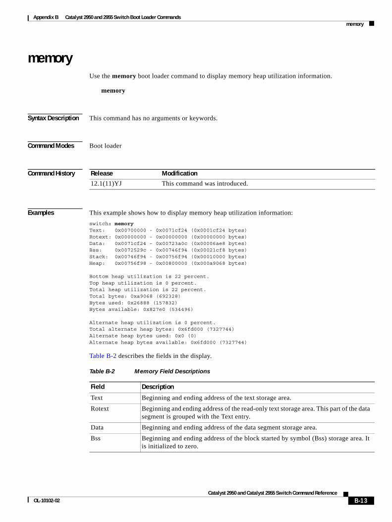
Appendix B Catalyst 2950 and 2955 Switch Boot Loader Commands memory
memoryUse the memory boot loader command to display memory heap utilization information.
memory
Syntax Description This command has no arguments or keywords.
Command Modes Boot loader
Command History
Examples This example shows how to display memory heap utilization information:
switch: memoryText: 0x00700000 - 0x0071cf24 (0x0001cf24 bytes)Rotext: 0x00000000 - 0x00000000 (0x00000000 bytes)Data: 0x0071cf24 - 0x00723a0c (0x00006ae8 bytes)Bss: 0x0072529c - 0x00746f94 (0x00021cf8 bytes)Stack: 0x00746f94 - 0x00756f94 (0x00010000 bytes)Heap: 0x00756f98 - 0x00800000 (0x000a9068 bytes)
Bottom heap utilization is 22 percent.Top heap utilization is 0 percent.Total heap utilization is 22 percent.Total bytes: 0xa9068 (692328)Bytes used: 0x26888 (157832)Bytes available: 0x827e0 (534496)
Alternate heap utilization is 0 percent.Total alternate heap bytes: 0x6fd000 (7327744)Alternate heap bytes used: 0x0 (0)Alternate heap bytes available: 0x6fd000 (7327744)
Table B-2 describes the fields in the display.
Release Modification
12.1(11)YJ This command was introduced.
Table B-2 Memory Field Descriptions
Field Description
Text Beginning and ending address of the text storage area.
Rotext Beginning and ending address of the read-only text storage area. This part of the data segment is grouped with the Text entry.
Data Beginning and ending address of the data segment storage area.
Bss Beginning and ending address of the block started by symbol (Bss) storage area. It is initialized to zero.
B-13Catalyst 2950 and Catalyst 2955 Switch Command Reference
OL-10102-02
Appendix B Catalyst 2950 and 2955 Switch Boot Loader Commands memory
Stack Beginning and ending address of the area in memory allocated to the software to store automatic variables, return addresses, and so forth.
Heap Beginning and ending address of the area in memory that memory is dynamically allocated to and freed from.
Table B-2 Memory Field Descriptions (continued)
Field Description
B-14Catalyst 2950 and Catalyst 2955 Switch Command Reference
OL-10102-02
Appendix B Catalyst 2950 and 2955 Switch Boot Loader Commands mkdir
mkdirUse the mkdir boot loader command to create one or more new directories on the specified file system.
mkdir filesystem:/directory-url ...
Syntax Description
Command Modes Boot loader
Command History
Usage Guidelines Directory names are case sensitive.
Directory names are limited to 45 characters between the slashes (/); the name cannot contain control characters, spaces, deletes, slashes, quotes, semicolons, or colons.
Examples This example shows how to make a directory called Saved_Configs:
switch: mkdir flash:Saved_ConfigsDirectory "flash:Saved_Configs" created
This example shows how to make two directories:
switch: mkdir flash:Saved_Configs1 flash:TestDirectory "flash:Saved_Configs1" createdDirectory "flash:Test" created
You can verify that the directory was created by entering the dir filesystem: boot loader command.
Related Commands
filesystem: Alias for a flash file system. Use flash: for the system board flash device.
/directory-url Name of the directories to create. Separate each directory name with a space.
Release Modification
12.1(11)YJ This command was introduced
Command Description
dir Displays a list of files and directories on the specified file system.
rmdir Removes one or more directories from the specified file system.
B-15Catalyst 2950 and Catalyst 2955 Switch Command Reference
OL-10102-02
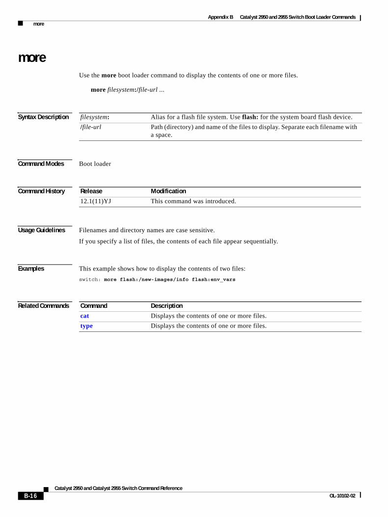
Appendix B Catalyst 2950 and 2955 Switch Boot Loader Commands more
moreUse the more boot loader command to display the contents of one or more files.
more filesystem:/file-url ...
Syntax Description
Command Modes Boot loader
Command History
Usage Guidelines Filenames and directory names are case sensitive.
If you specify a list of files, the contents of each file appear sequentially.
Examples This example shows how to display the contents of two files:
switch: more flash:/new-images/info flash:env_vars
Related Commands
filesystem: Alias for a flash file system. Use flash: for the system board flash device.
/file-url Path (directory) and name of the files to display. Separate each filename with a space.
Release Modification
12.1(11)YJ This command was introduced.
Command Description
cat Displays the contents of one or more files.
type Displays the contents of one or more files.
B-16Catalyst 2950 and Catalyst 2955 Switch Command Reference
OL-10102-02
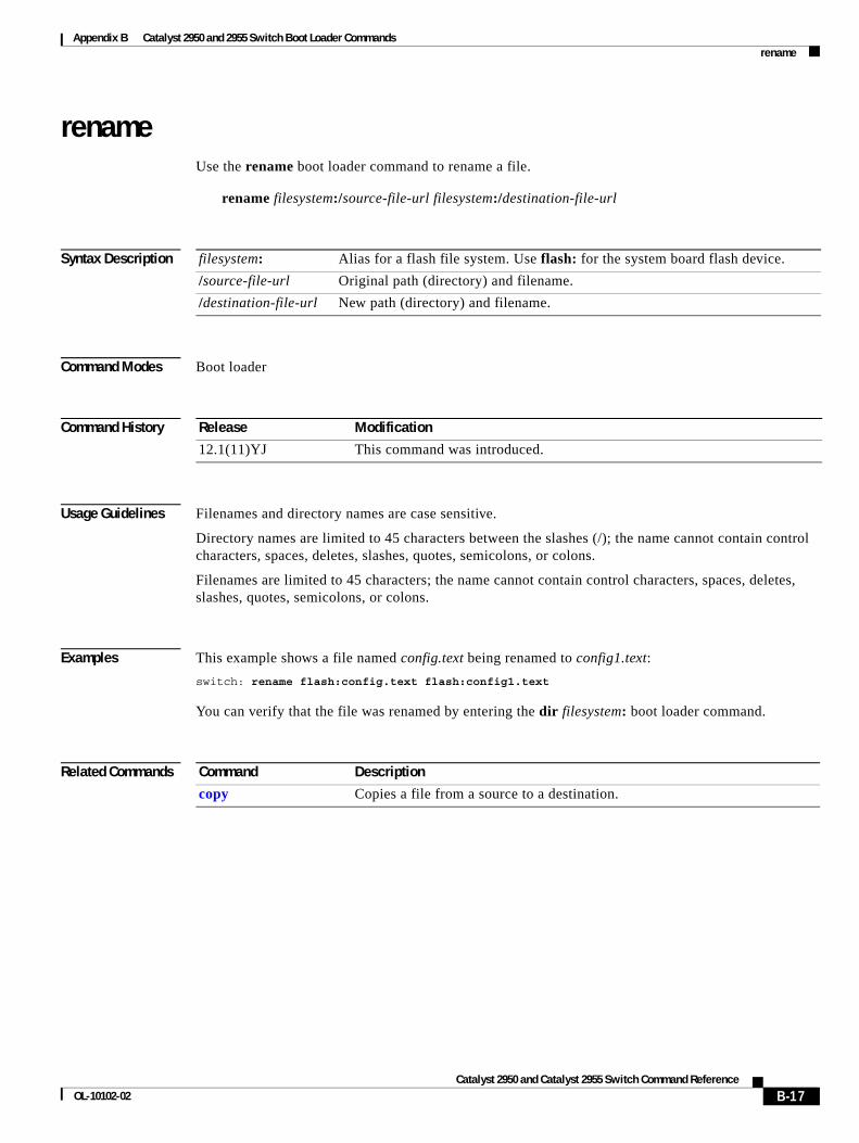
Appendix B Catalyst 2950 and 2955 Switch Boot Loader Commands rename
renameUse the rename boot loader command to rename a file.
rename filesystem:/source-file-url filesystem:/destination-file-url
Syntax Description
Command Modes Boot loader
Command History
Usage Guidelines Filenames and directory names are case sensitive.
Directory names are limited to 45 characters between the slashes (/); the name cannot contain control characters, spaces, deletes, slashes, quotes, semicolons, or colons.
Filenames are limited to 45 characters; the name cannot contain control characters, spaces, deletes, slashes, quotes, semicolons, or colons.
Examples This example shows a file named config.text being renamed to config1.text:
switch: rename flash:config.text flash:config1.text
You can verify that the file was renamed by entering the dir filesystem: boot loader command.
Related Commands
filesystem: Alias for a flash file system. Use flash: for the system board flash device.
/source-file-url Original path (directory) and filename.
/destination-file-url New path (directory) and filename.
Release Modification
12.1(11)YJ This command was introduced.
Command Description
copy Copies a file from a source to a destination.
B-17Catalyst 2950 and Catalyst 2955 Switch Command Reference
OL-10102-02
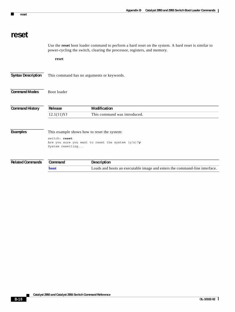
Appendix B Catalyst 2950 and 2955 Switch Boot Loader Commands reset
resetUse the reset boot loader command to perform a hard reset on the system. A hard reset is similar to power-cycling the switch, clearing the processor, registers, and memory.
reset
Syntax Description This command has no arguments or keywords.
Command Modes Boot loader
Command History
Examples This example shows how to reset the system:
switch: resetAre you sure you want to reset the system (y/n)?ySystem resetting...
Related Commands
Release Modification
12.1(11)YJ This command was introduced.
Command Description
boot Loads and boots an executable image and enters the command-line interface.
B-18Catalyst 2950 and Catalyst 2955 Switch Command Reference
OL-10102-02
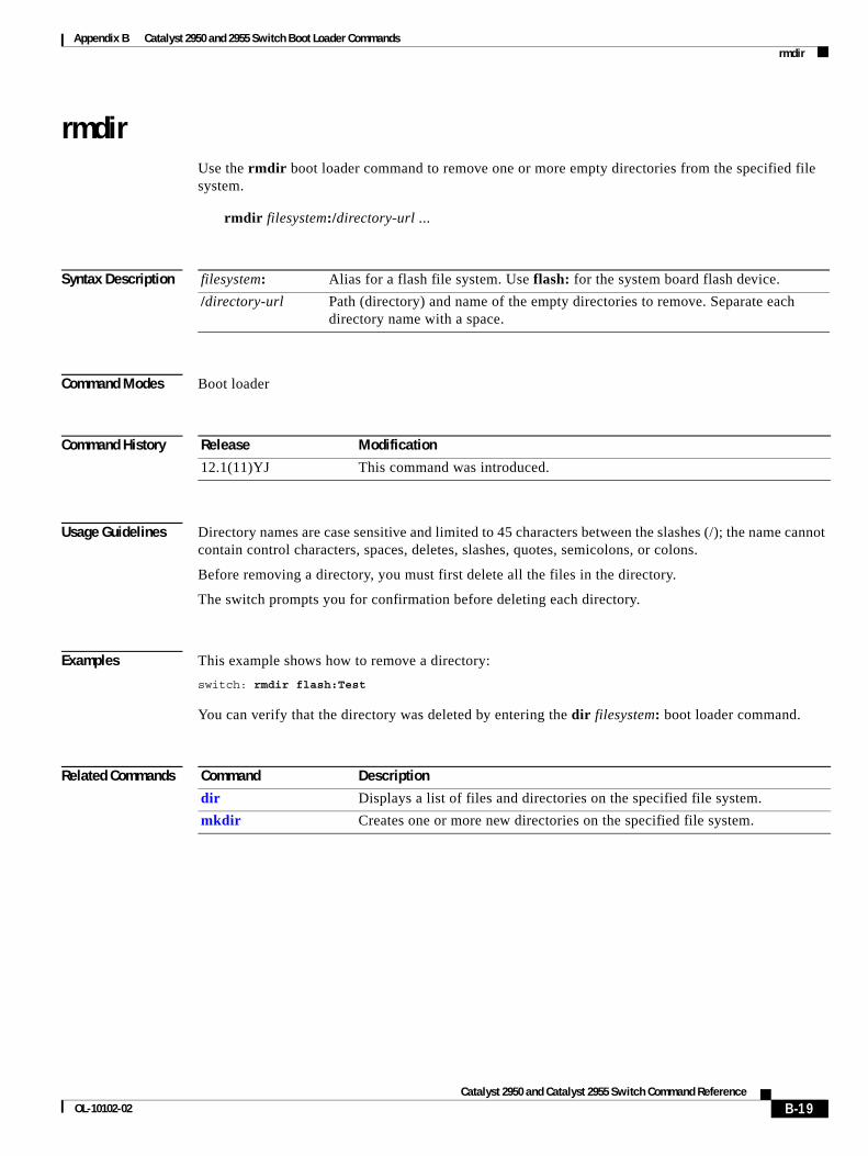
Appendix B Catalyst 2950 and 2955 Switch Boot Loader Commands rmdir
rmdirUse the rmdir boot loader command to remove one or more empty directories from the specified file system.
rmdir filesystem:/directory-url ...
Syntax Description
Command Modes Boot loader
Command History
Usage Guidelines Directory names are case sensitive and limited to 45 characters between the slashes (/); the name cannot contain control characters, spaces, deletes, slashes, quotes, semicolons, or colons.
Before removing a directory, you must first delete all the files in the directory.
The switch prompts you for confirmation before deleting each directory.
Examples This example shows how to remove a directory:
switch: rmdir flash:Test
You can verify that the directory was deleted by entering the dir filesystem: boot loader command.
Related Commands
filesystem: Alias for a flash file system. Use flash: for the system board flash device.
/directory-url Path (directory) and name of the empty directories to remove. Separate each directory name with a space.
Release Modification
12.1(11)YJ This command was introduced.
Command Description
dir Displays a list of files and directories on the specified file system.
mkdir Creates one or more new directories on the specified file system.
B-19Catalyst 2950 and Catalyst 2955 Switch Command Reference
OL-10102-02
Appendix B Catalyst 2950 and 2955 Switch Boot Loader Commands set
setUse the set boot loader command to set or display environment variables, which can be used to control the boot loader or any other software running on the switch.
set variable value
Note Under normal circumstances, it is not necessary to alter the setting of the environment variables.
Syntax Description variable value Use one of these keywords for variable and value:
MANUAL_BOOT—Decides whether the switch automatically or manually boots.
Valid values are 1, yes, 0, and no. If it is set to no or 0, the boot loader attempts to automatically boot the system. If it is set to anything else, you must manually boot the switch from the boot loader mode.
BOOT filesystem:/file-url—A semicolon-separated list of executable files to try to load and execute when automatically booting.
If the BOOT environment variable is not set, the system attempts to load and execute the first executable image it can find by using a recursive, depth-first search through the flash: file system. If the BOOT variable is set but the specified images cannot be loaded, the system attempts to boot the first bootable file that it can find in the flash file system.
ENABLE_BREAK—Decides whether the automatic boot process can be interrupted by using the Break key on the service port.
Valid values are 1, yes, on, 0, no, and off. If it is set to 1, yes, or on, you can interrupt the automatic boot process by pressing the Break key on the service port after the flash file system has initialized.
HELPER filesystem:/file-url—A semicolon-separated list of loadable files to dynamically load during the boot loader initialization. Helper files extend or patch the functionality of the boot loader.
PS1 prompt—A string that is used as the command-line prompt in boot loader mode.
CONFIG_FILE flash:/file-url—The filename that the software uses to read and write a nonvolatile copy of the system configuration.
CONFIG_BUFSIZE size—The buffer size that the software uses to hold a copy of the configuration file in memory. The configuration file cannot be larger than the buffer size allocation. The range is from 4096 to 524288 bytes.
BAUD rate—The rate in bits per second (bps) used for the service port. The software inherits the baud rate setting from the boot loader and continues to use this value unless the configuration file specifies another setting. The range is from 0 to 4294967295 bps. Valid values are 50, 75, 110, 150, 300, 600, 1200, 1800, 2000, 2400, 3600, 4800, 7200, 9600, 14400, 19200, 28800, 38400, 56000, 57600, 115200, and 128000.
The most commonly used values are 300, 1200, 2400, 9600, 19200, 57600, and 115200.
B-20Catalyst 2950 and Catalyst 2955 Switch Command Reference
OL-10102-02
Appendix B Catalyst 2950 and 2955 Switch Boot Loader Commands set
Defaults The environment variables have these default values:
MANUAL_BOOT: No (0)
BOOT: Null string
ENABLE_BREAK: No (Off or 0) (the automatic boot process cannot be interrupted by pressing the Break key on the service port).
HELPER: No default value (helper files are not automatically loaded).
PS1: switch:
CONFIG_FILE: config.text
CONFIG_BUFSIZE: 32 KB
BAUD: 9600 bps
BOOTHLPR: No default value (no helper images are specified).
HELPER_CONFIG_FILE: No default value (no helper configuration file is specified).
Note Environment variables that have values are stored in the flash file system in various files. The format of these files is that each line contains an environment variable name and an equal sign followed by the value of the variable. A variable has no value if it is not listed in this file; it has a value if it is listed in the file even if the value is a null string. A variable that is set to a null string (for example, “ ”) is a variable with a value. Many environment variables are predefined and have default values.
Command Modes Boot loader
Command History
BOOTHLPR filesystem:/file-url—The name of the Cisco IOS helper image that is first loaded into memory so that it can then load a second Cisco IOS image into memory and launch it. This variable is used only for internal development and testing.
HELPER_CONFIG_FILE filesystem:/file-url—The name of the configuration file to be used by the Cisco IOS helper image. If this is not set, the file specified by the CONFIG_FILE environment variable is used by all versions of the software that are loaded, including the helper image. This variable is used only for internal development and testing.
PASSWD_RECOVERY—Enables or disables the password recovery option. Valid values are yes, 1, no, or 2. The default is yes.
REBOOT_AFTER_CRASH—Sets the switch to reboot after an abnormal termination. Valid values are yes, 1, no, or 2. The default is yes.
Release Modification
12.1(11)YJ This command was introduced.
B-21Catalyst 2950 and Catalyst 2955 Switch Command Reference
OL-10102-02
Appendix B Catalyst 2950 and 2955 Switch Boot Loader Commands set
Usage Guidelines Environment variables are case sensitive and must be entered as documented.
Environment variables that have values are stored in flash memory outside of the flash file system.
Under normal circumstances, it is not necessary to alter the setting of the environment variables.
The MANUAL_BOOT environment variable can also be set by using the boot manual global configuration command.
The BOOT environment variable can also be set by using the boot system filesystem:/file-url global configuration command.
The ENABLE_BREAK environment variable can also be set by using the boot enable-break global configuration command.
The HELPER environment variable can also be set by using the boot helper filesystem:/file-url global configuration command.
The CONFIG_FILE environment variable can also be set by using the boot config-file flash:/file-url global configuration command.
The HELPER_CONFIG_FILE environment variable can also be set by using the boot helper-config-file filesystem:/file-url global configuration command.
The boot loader prompt string (PS1) can be up to 120 printable characters except the equal sign (=).
Examples This example shows how to change the boot loader prompt:
switch: set PS1 loader: loader:
You can verify your setting by using the set boot loader command.
Related Commands Command Description
unset Resets one or more environment variables to its previous setting.
B-22Catalyst 2950 and Catalyst 2955 Switch Command Reference
OL-10102-02
Appendix B Catalyst 2950 and 2955 Switch Boot Loader Commands type
typeUse the type boot loader command to display the contents of one or more files.
type filesystem:/file-url ...
Syntax Description
Command Modes Boot loader
Command History
Usage Guidelines Filenames and directory names are case sensitive.
If you specify a list of files, the contents of each file appear sequentially.
Examples This example shows how to display the contents of two files:
switch: type flash:/new-images/info flash:env_vars
Related Commands
filesystem: Alias for a flash file system. Use flash: for the system board flash device.
/file-url Path (directory) and name of the files to display. Separate each filename with a space.
Release Modification
12.1(11)YJ This command was introduced.
Command Description
cat Displays the contents of one or more files.
more Displays the contents of one or more files.
B-23Catalyst 2950 and Catalyst 2955 Switch Command Reference
OL-10102-02
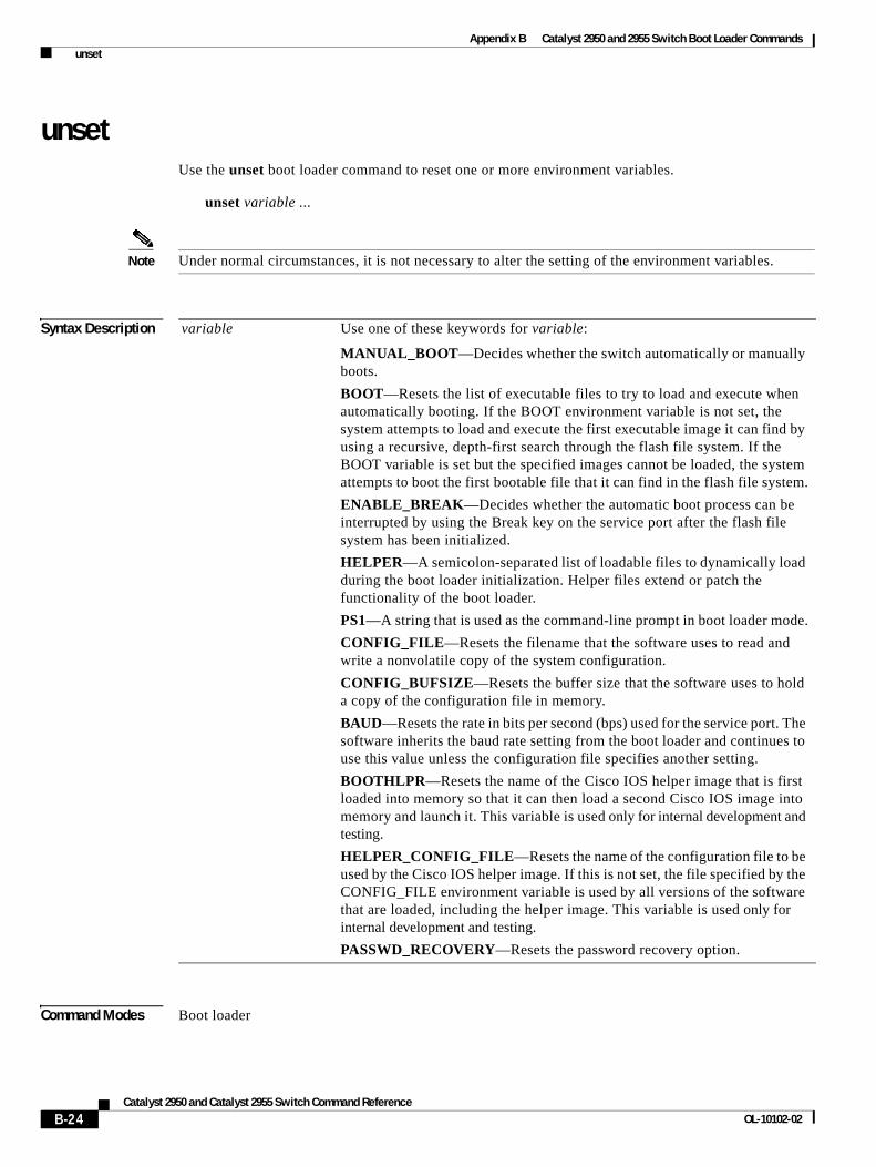
Appendix B Catalyst 2950 and 2955 Switch Boot Loader Commands unset
unsetUse the unset boot loader command to reset one or more environment variables.
unset variable ...
Note Under normal circumstances, it is not necessary to alter the setting of the environment variables.
Syntax Description
Command Modes Boot loader
variable Use one of these keywords for variable:
MANUAL_BOOT—Decides whether the switch automatically or manually boots.
BOOT—Resets the list of executable files to try to load and execute when automatically booting. If the BOOT environment variable is not set, the system attempts to load and execute the first executable image it can find by using a recursive, depth-first search through the flash file system. If the BOOT variable is set but the specified images cannot be loaded, the system attempts to boot the first bootable file that it can find in the flash file system.
ENABLE_BREAK—Decides whether the automatic boot process can be interrupted by using the Break key on the service port after the flash file system has been initialized.
HELPER—A semicolon-separated list of loadable files to dynamically load during the boot loader initialization. Helper files extend or patch the functionality of the boot loader.
PS1—A string that is used as the command-line prompt in boot loader mode.
CONFIG_FILE—Resets the filename that the software uses to read and write a nonvolatile copy of the system configuration.
CONFIG_BUFSIZE—Resets the buffer size that the software uses to hold a copy of the configuration file in memory.
BAUD—Resets the rate in bits per second (bps) used for the service port. The software inherits the baud rate setting from the boot loader and continues to use this value unless the configuration file specifies another setting.
BOOTHLPR—Resets the name of the Cisco IOS helper image that is first loaded into memory so that it can then load a second Cisco IOS image into memory and launch it. This variable is used only for internal development and testing.
HELPER_CONFIG_FILE—Resets the name of the configuration file to be used by the Cisco IOS helper image. If this is not set, the file specified by the CONFIG_FILE environment variable is used by all versions of the software that are loaded, including the helper image. This variable is used only for internal development and testing.
PASSWD_RECOVERY—Resets the password recovery option.
B-24Catalyst 2950 and Catalyst 2955 Switch Command Reference
OL-10102-02
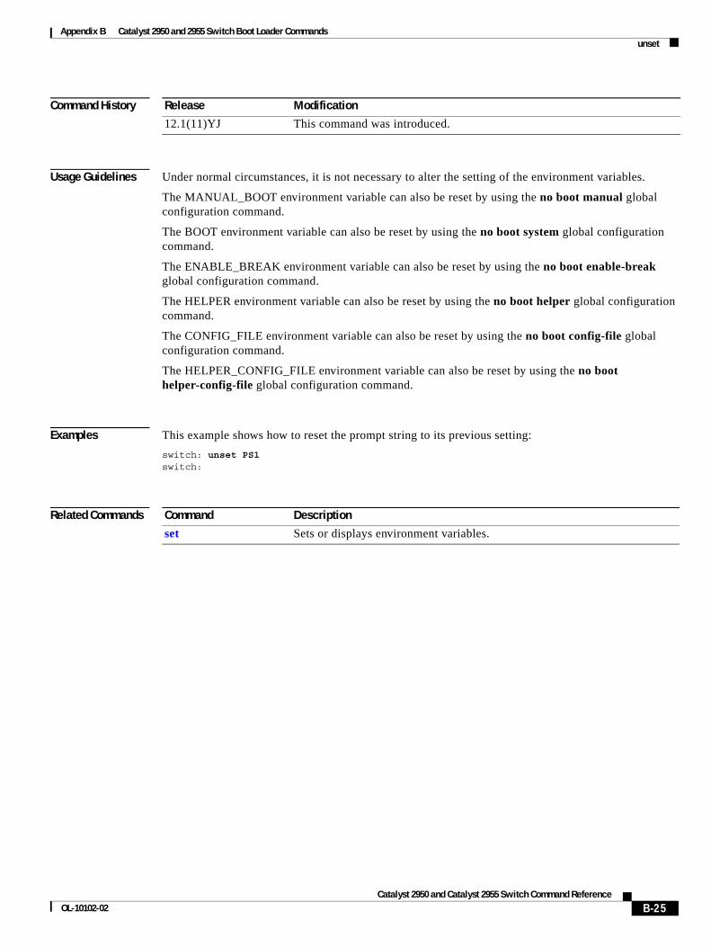
Appendix B Catalyst 2950 and 2955 Switch Boot Loader Commands unset
Command History
Usage Guidelines Under normal circumstances, it is not necessary to alter the setting of the environment variables.
The MANUAL_BOOT environment variable can also be reset by using the no boot manual global configuration command.
The BOOT environment variable can also be reset by using the no boot system global configuration command.
The ENABLE_BREAK environment variable can also be reset by using the no boot enable-break global configuration command.
The HELPER environment variable can also be reset by using the no boot helper global configuration command.
The CONFIG_FILE environment variable can also be reset by using the no boot config-file global configuration command.
The HELPER_CONFIG_FILE environment variable can also be reset by using the no boot helper-config-file global configuration command.
Examples This example shows how to reset the prompt string to its previous setting:
switch: unset PS1switch:
Related Commands
Release Modification
12.1(11)YJ This command was introduced.
Command Description
set Sets or displays environment variables.
B-25Catalyst 2950 and Catalyst 2955 Switch Command Reference
OL-10102-02
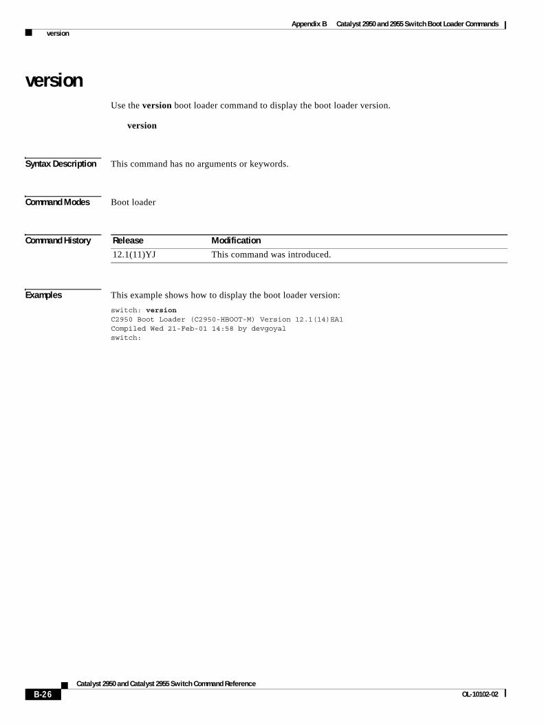
Appendix B Catalyst 2950 and 2955 Switch Boot Loader Commands version
versionUse the version boot loader command to display the boot loader version.
version
Syntax Description This command has no arguments or keywords.
Command Modes Boot loader
Command History
Examples This example shows how to display the boot loader version:
switch: versionC2950 Boot Loader (C2950-HBOOT-M) Version 12.1(14)EA1Compiled Wed 21-Feb-01 14:58 by devgoyalswitch:
Release Modification
12.1(11)YJ This command was introduced.
B-26Catalyst 2950 and Catalyst 2955 Switch Command Reference
OL-10102-02
Catalyst 2950 anOL-10102-02
A
P P E N D I X C Catalyst 2950 and 2955 Switch Debug CommandsThis appendix describes the Catalyst 2950- and Catalyst 2955-specific debug privileged EXEC commands. These commands are helpful in diagnosing and resolving internetworking problems and should be used only with the guidance of Cisco technical support staff.
Caution Because debugging output is assigned high priority in the CPU process, it can render the system unusable. For this reason, use the debug commands only to troubleshoot specific problems or during troubleshooting sessions with Cisco technical support staff. It is best to use the debug commands during periods of lower network traffic and fewer users. Debugging during these periods decreases the likelihood that increased debug command processing overhead will affect system use.
C-1d Catalyst 2955 Switch Command Reference
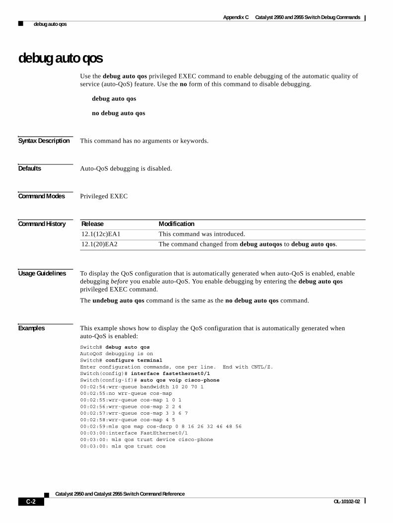
Appendix C Catalyst 2950 and 2955 Switch Debug Commands debug auto qos
debug auto qosUse the debug auto qos privileged EXEC command to enable debugging of the automatic quality of service (auto-QoS) feature. Use the no form of this command to disable debugging.
debug auto qos
no debug auto qos
Syntax Description This command has no arguments or keywords.
Defaults Auto-QoS debugging is disabled.
Command Modes Privileged EXEC
Command History
Usage Guidelines To display the QoS configuration that is automatically generated when auto-QoS is enabled, enable debugging before you enable auto-QoS. You enable debugging by entering the debug auto qos privileged EXEC command.
The undebug auto qos command is the same as the no debug auto qos command.
Examples This example shows how to display the QoS configuration that is automatically generated when auto-QoS is enabled:
Switch# debug auto qosAutoQoS debugging is onSwitch# configure terminalEnter configuration commands, one per line. End with CNTL/Z.Switch(config)# interface fastethernet0/1Switch(config-if)# auto qos voip cisco-phone00:02:54:wrr-queue bandwidth 10 20 70 100:02:55:no wrr-queue cos-map00:02:55:wrr-queue cos-map 1 0 100:02:56:wrr-queue cos-map 2 2 400:02:57:wrr-queue cos-map 3 3 6 700:02:58:wrr-queue cos-map 4 500:02:59:mls qos map cos-dscp 0 8 16 26 32 46 48 5600:03:00:interface FastEthernet0/100:03:00: mls qos trust device cisco-phone00:03:00: mls qos trust cos
Release Modification
12.1(12c)EA1 This command was introduced.
12.1(20)EA2 The command changed from debug autoqos to debug auto qos.
C-2Catalyst 2950 and Catalyst 2955 Switch Command Reference
OL-10102-02

Appendix C Catalyst 2950 and 2955 Switch Debug Commands debug auto qos
Related Commands Command Description
auto qos voip Configure auto-QoS for voice over IP (VoIP) within a QoS domain.
show auto qos Displays the configuration applied and the new defaults in effect when auto-QoS is enabled.
show debugging Displays information about the types of debugging that are enabled. For syntax information, select Cisco IOS Configuration Fundamentals Command Reference for IOS Release 12.1 > Cisco IOS System Management Commands > Troubleshooting Commands.
C-3Catalyst 2950 and Catalyst 2955 Switch Command Reference
OL-10102-02
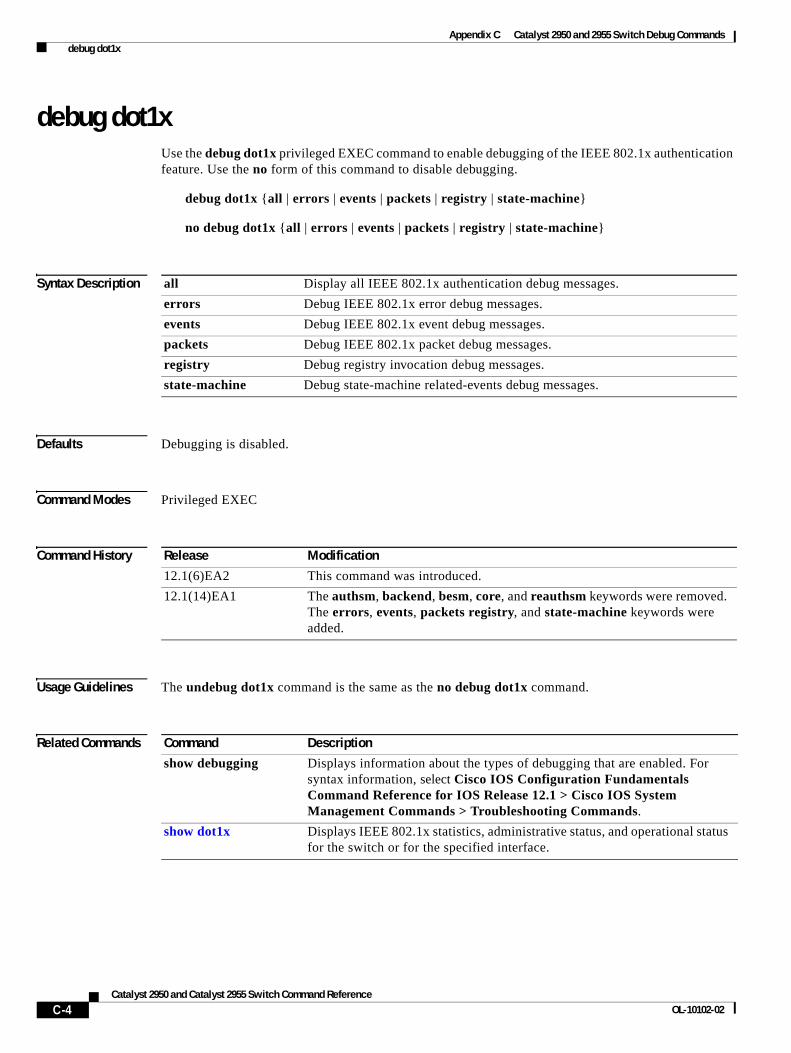
Appendix C Catalyst 2950 and 2955 Switch Debug Commands debug dot1x
debug dot1xUse the debug dot1x privileged EXEC command to enable debugging of the IEEE 802.1x authentication feature. Use the no form of this command to disable debugging.
debug dot1x {all | errors | events | packets | registry | state-machine}
no debug dot1x {all | errors | events | packets | registry | state-machine}
Syntax Description
Defaults Debugging is disabled.
Command Modes Privileged EXEC
Command History
Usage Guidelines The undebug dot1x command is the same as the no debug dot1x command.
Related Commands
all Display all IEEE 802.1x authentication debug messages.
errors Debug IEEE 802.1x error debug messages.
events Debug IEEE 802.1x event debug messages.
packets Debug IEEE 802.1x packet debug messages.
registry Debug registry invocation debug messages.
state-machine Debug state-machine related-events debug messages.
Release Modification
12.1(6)EA2 This command was introduced.
12.1(14)EA1 The authsm, backend, besm, core, and reauthsm keywords were removed. The errors, events, packets registry, and state-machine keywords were added.
Command Description
show debugging Displays information about the types of debugging that are enabled. For syntax information, select Cisco IOS Configuration Fundamentals Command Reference for IOS Release 12.1 > Cisco IOS System Management Commands > Troubleshooting Commands.
show dot1x Displays IEEE 802.1x statistics, administrative status, and operational status for the switch or for the specified interface.
C-4Catalyst 2950 and Catalyst 2955 Switch Command Reference
OL-10102-02
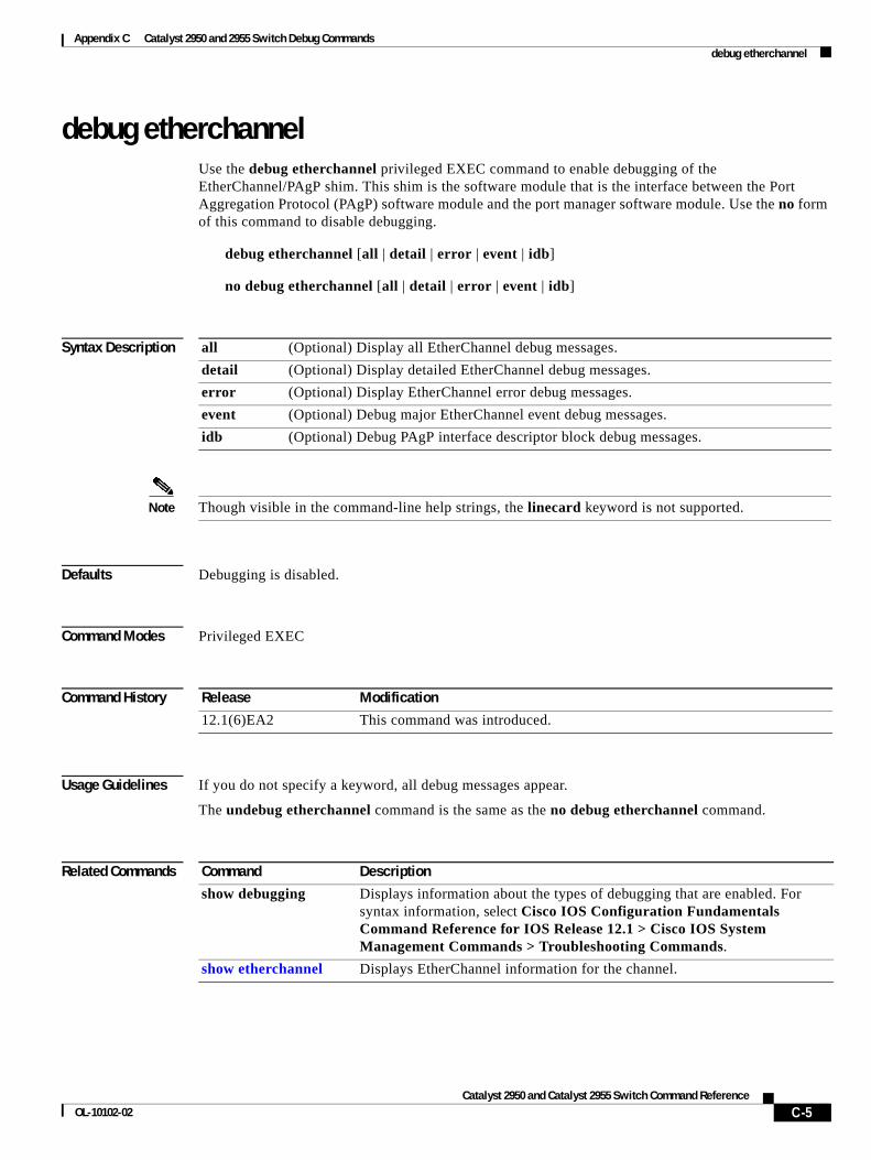
Appendix C Catalyst 2950 and 2955 Switch Debug Commands debug etherchannel
debug etherchannelUse the debug etherchannel privileged EXEC command to enable debugging of the EtherChannel/PAgP shim. This shim is the software module that is the interface between the Port Aggregation Protocol (PAgP) software module and the port manager software module. Use the no form of this command to disable debugging.
debug etherchannel [all | detail | error | event | idb]
no debug etherchannel [all | detail | error | event | idb]
Syntax Description
Note Though visible in the command-line help strings, the linecard keyword is not supported.
Defaults Debugging is disabled.
Command Modes Privileged EXEC
Command History
Usage Guidelines If you do not specify a keyword, all debug messages appear.
The undebug etherchannel command is the same as the no debug etherchannel command.
Related Commands
all (Optional) Display all EtherChannel debug messages.
detail (Optional) Display detailed EtherChannel debug messages.
error (Optional) Display EtherChannel error debug messages.
event (Optional) Debug major EtherChannel event debug messages.
idb (Optional) Debug PAgP interface descriptor block debug messages.
Release Modification
12.1(6)EA2 This command was introduced.
Command Description
show debugging Displays information about the types of debugging that are enabled. For syntax information, select Cisco IOS Configuration Fundamentals Command Reference for IOS Release 12.1 > Cisco IOS System Management Commands > Troubleshooting Commands.
show etherchannel Displays EtherChannel information for the channel.
C-5Catalyst 2950 and Catalyst 2955 Switch Command Reference
OL-10102-02
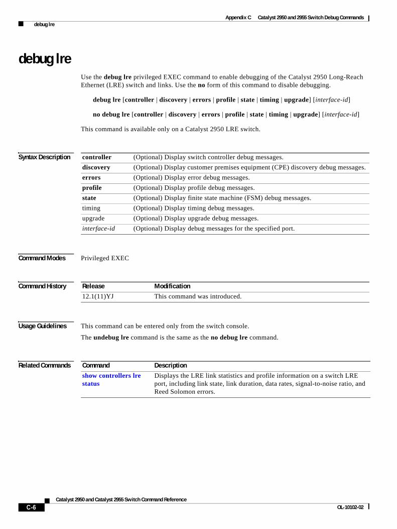
Appendix C Catalyst 2950 and 2955 Switch Debug Commands debug lre
debug lreUse the debug lre privileged EXEC command to enable debugging of the Catalyst 2950 Long-Reach Ethernet (LRE) switch and links. Use the no form of this command to disable debugging.
debug lre [controller | discovery | errors | profile | state | timing | upgrade] [interface-id]
no debug lre [controller | discovery | errors | profile | state | timing | upgrade] [interface-id]
This command is available only on a Catalyst 2950 LRE switch.
Syntax Description
Command Modes Privileged EXEC
Command History
Usage Guidelines This command can be entered only from the switch console.
The undebug lre command is the same as the no debug lre command.
Related Commands
controller (Optional) Display switch controller debug messages.
discovery (Optional) Display customer premises equipment (CPE) discovery debug messages.
errors (Optional) Display error debug messages.
profile (Optional) Display profile debug messages.
state (Optional) Display finite state machine (FSM) debug messages.
timing (Optional) Display timing debug messages.
upgrade (Optional) Display upgrade debug messages.
interface-id (Optional) Display debug messages for the specified port.
Release Modification
12.1(11)YJ This command was introduced.
Command Description
show controllers lre status
Displays the LRE link statistics and profile information on a switch LRE port, including link state, link duration, data rates, signal-to-noise ratio, and Reed Solomon errors.
C-6Catalyst 2950 and Catalyst 2955 Switch Command Reference
OL-10102-02
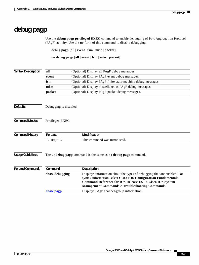
Appendix C Catalyst 2950 and 2955 Switch Debug Commands debug pagp
debug pagpUse the debug pagp privileged EXEC command to enable debugging of Port Aggregation Protocol (PAgP) activity. Use the no form of this command to disable debugging.
debug pagp [all | event | fsm | misc | packet]
no debug pagp [all | event | fsm | misc | packet]
Syntax Description
Defaults Debugging is disabled.
Command Modes Privileged EXEC
Command History
Usage Guidelines The undebug pagp command is the same as no debug pagp command.
Related Commands
all (Optional) Display all PAgP debug messages.
event (Optional) Display PAgP event debug messages.
fsm (Optional) Display PAgP finite state-machine debug messages.
misc (Optional) Display miscellaneous PAgP debug messages
packet (Optional) Display PAgP packet debug messages.
Release Modification
12.1(6)EA2 This command was introduced.
Command Description
show debugging Displays information about the types of debugging that are enabled. For syntax information, select Cisco IOS Configuration Fundamentals Command Reference for IOS Release 12.1 > Cisco IOS System Management Commands > Troubleshooting Commands.
show pagp Displays PAgP channel-group information.
C-7Catalyst 2950 and Catalyst 2955 Switch Command Reference
OL-10102-02
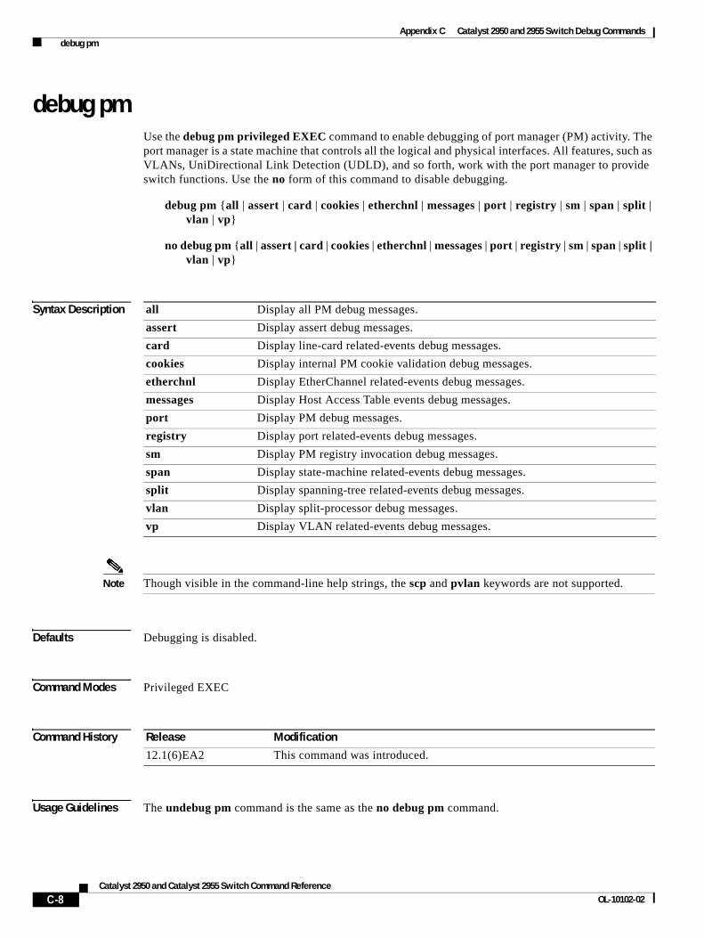
Appendix C Catalyst 2950 and 2955 Switch Debug Commands debug pm
debug pmUse the debug pm privileged EXEC command to enable debugging of port manager (PM) activity. The port manager is a state machine that controls all the logical and physical interfaces. All features, such as VLANs, UniDirectional Link Detection (UDLD), and so forth, work with the port manager to provide switch functions. Use the no form of this command to disable debugging.
debug pm {all | assert | card | cookies | etherchnl | messages | port | registry | sm | span | split | vlan | vp}
no debug pm {all | assert | card | cookies | etherchnl | messages | port | registry | sm | span | split | vlan | vp}
Syntax Description
Note Though visible in the command-line help strings, the scp and pvlan keywords are not supported.
Defaults Debugging is disabled.
Command Modes Privileged EXEC
Command History
Usage Guidelines The undebug pm command is the same as the no debug pm command.
all Display all PM debug messages.
assert Display assert debug messages.
card Display line-card related-events debug messages.
cookies Display internal PM cookie validation debug messages.
etherchnl Display EtherChannel related-events debug messages.
messages Display Host Access Table events debug messages.
port Display PM debug messages.
registry Display port related-events debug messages.
sm Display PM registry invocation debug messages.
span Display state-machine related-events debug messages.
split Display spanning-tree related-events debug messages.
vlan Display split-processor debug messages.
vp Display VLAN related-events debug messages.
Release Modification
12.1(6)EA2 This command was introduced.
C-8Catalyst 2950 and Catalyst 2955 Switch Command Reference
OL-10102-02

Appendix C Catalyst 2950 and 2955 Switch Debug Commands debug pm
Related Commands Command Description
show debugging Displays information about the types of debugging that are enabled. For syntax information, select Cisco IOS Configuration Fundamentals Command Reference for IOS Release 12.1 > Cisco IOS System Management Commands > Troubleshooting Commands.
C-9Catalyst 2950 and Catalyst 2955 Switch Command Reference
OL-10102-02
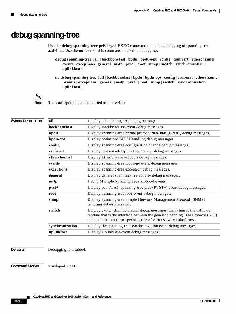
Appendix C Catalyst 2950 and 2955 Switch Debug Commands debug spanning-tree
debug spanning-treeUse the debug spanning-tree privileged EXEC command to enable debugging of spanning-tree activities. Use the no form of this command to disable debugging.
debug spanning-tree {all | backbonefast | bpdu | bpdu-opt | config | csuf/csrt | etherchannel | events | exceptions | general | mstp | pvst+ | root | snmp | switch | synchronization | uplinkfast}
no debug spanning-tree {all | backbonefast | bpdu | bpdu-opt | config | csuf/csrt | etherchannel | events | exceptions | general | mstp | pvst+ | root | snmp | switch | synchronization | uplinkfast}
Note The csuf option is not supported on the switch.
Syntax Description
Defaults Debugging is disabled.
Command Modes Privileged EXEC
all Display all spanning-tree debug messages.
backbonefast Display BackboneFast-event debug messages.
bpdu Display spanning-tree bridge protocol data unit (BPDU) debug messages.
bpdu-opt Display optimized BPDU handling debug messages.
config Display spanning-tree configuration change debug messages.
csuf/csrt Display cross-stack UplinkFast activity debug messages.
etherchannel Display EtherChannel-support debug messages.
events Display spanning-tree topology event debug messages.
exceptions Display spanning-tree exception debug messages.
general Display general spanning-tree activity debug messages.
mstp Debug Multiple Spanning Tree Protocol events.
pvst+ Display per-VLAN spanning-tree plus (PVST+) event debug messages.
root Display spanning-tree root-event debug messages.
snmp Display spanning-tree Simple Network Management Protocol (SNMP) handling debug messages.
switch Display switch shim command debug messages. This shim is the software module that is the interface between the generic Spanning Tree Protocol (STP) code and the platform-specific code of various switch platforms.
synchronization Display the spanning-tree synchronization event debug messages.
uplinkfast Display UplinkFast-event debug messages.
C-10Catalyst 2950 and Catalyst 2955 Switch Command Reference
OL-10102-02
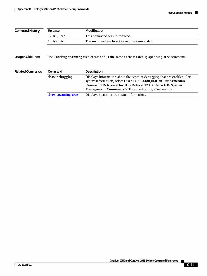
Appendix C Catalyst 2950 and 2955 Switch Debug Commands debug spanning-tree
Command History
Usage Guidelines The undebug spanning-tree command is the same as the no debug spanning-tree command.
Related Commands
Release Modification
12.1(6)EA2 This command was introduced.
12.1(9)EA1 The mstp and csuf/csrt keywords were added.
Command Description
show debugging Displays information about the types of debugging that are enabled. For syntax information, select Cisco IOS Configuration Fundamentals Command Reference for IOS Release 12.1 > Cisco IOS System Management Commands > Troubleshooting Commands.
show spanning-tree Displays spanning-tree state information.
C-11Catalyst 2950 and Catalyst 2955 Switch Command Reference
OL-10102-02
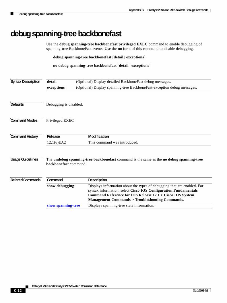
Appendix C Catalyst 2950 and 2955 Switch Debug Commands debug spanning-tree backbonefast
debug spanning-tree backbonefastUse the debug spanning-tree backbonefast privileged EXEC command to enable debugging of spanning-tree BackboneFast events. Use the no form of this command to disable debugging.
debug spanning-tree backbonefast [detail | exceptions]
no debug spanning-tree backbonefast [detail | exceptions]
Syntax Description
Defaults Debugging is disabled.
Command Modes Privileged EXEC
Command History
Usage Guidelines The undebug spanning-tree backbonefast command is the same as the no debug spanning-tree backbonefast command.
Related Commands
detail (Optional) Display detailed BackboneFast debug messages.
exceptions (Optional) Display spanning-tree BackboneFast-exception debug messages.
Release Modification
12.1(6)EA2 This command was introduced.
Command Description
show debugging Displays information about the types of debugging that are enabled. For syntax information, select Cisco IOS Configuration Fundamentals Command Reference for IOS Release 12.1 > Cisco IOS System Management Commands > Troubleshooting Commands.
show spanning-tree Displays spanning-tree state information.
C-12Catalyst 2950 and Catalyst 2955 Switch Command Reference
OL-10102-02
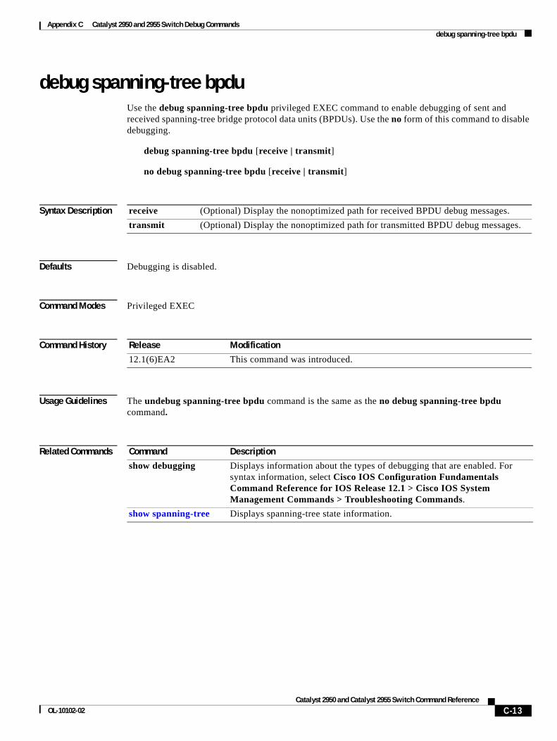
Appendix C Catalyst 2950 and 2955 Switch Debug Commands debug spanning-tree bpdu
debug spanning-tree bpduUse the debug spanning-tree bpdu privileged EXEC command to enable debugging of sent and received spanning-tree bridge protocol data units (BPDUs). Use the no form of this command to disable debugging.
debug spanning-tree bpdu [receive | transmit]
no debug spanning-tree bpdu [receive | transmit]
Syntax Description
Defaults Debugging is disabled.
Command Modes Privileged EXEC
Command History
Usage Guidelines The undebug spanning-tree bpdu command is the same as the no debug spanning-tree bpdu command.
Related Commands
receive (Optional) Display the nonoptimized path for received BPDU debug messages.
transmit (Optional) Display the nonoptimized path for transmitted BPDU debug messages.
Release Modification
12.1(6)EA2 This command was introduced.
Command Description
show debugging Displays information about the types of debugging that are enabled. For syntax information, select Cisco IOS Configuration Fundamentals Command Reference for IOS Release 12.1 > Cisco IOS System Management Commands > Troubleshooting Commands.
show spanning-tree Displays spanning-tree state information.
C-13Catalyst 2950 and Catalyst 2955 Switch Command Reference
OL-10102-02
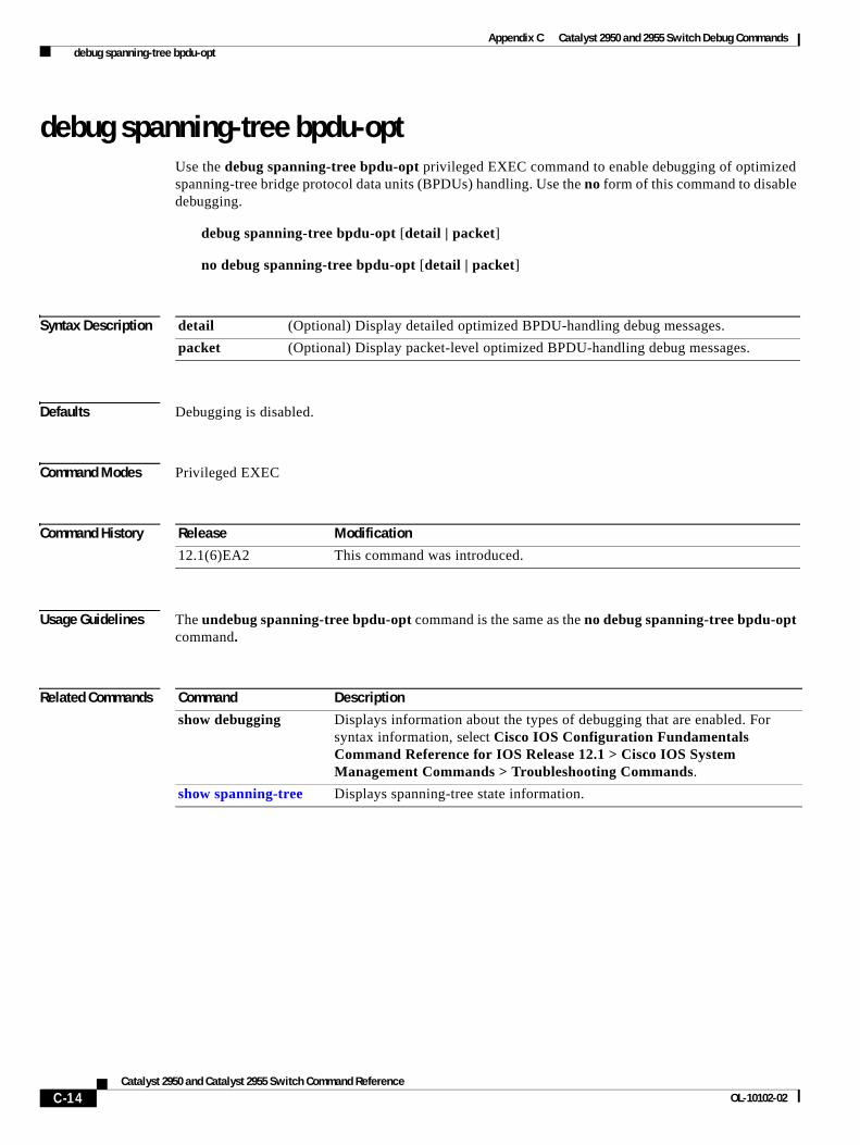
Appendix C Catalyst 2950 and 2955 Switch Debug Commands debug spanning-tree bpdu-opt
debug spanning-tree bpdu-optUse the debug spanning-tree bpdu-opt privileged EXEC command to enable debugging of optimized spanning-tree bridge protocol data units (BPDUs) handling. Use the no form of this command to disable debugging.
debug spanning-tree bpdu-opt [detail | packet]
no debug spanning-tree bpdu-opt [detail | packet]
Syntax Description
Defaults Debugging is disabled.
Command Modes Privileged EXEC
Command History
Usage Guidelines The undebug spanning-tree bpdu-opt command is the same as the no debug spanning-tree bpdu-opt command.
Related Commands
detail (Optional) Display detailed optimized BPDU-handling debug messages.
packet (Optional) Display packet-level optimized BPDU-handling debug messages.
Release Modification
12.1(6)EA2 This command was introduced.
Command Description
show debugging Displays information about the types of debugging that are enabled. For syntax information, select Cisco IOS Configuration Fundamentals Command Reference for IOS Release 12.1 > Cisco IOS System Management Commands > Troubleshooting Commands.
show spanning-tree Displays spanning-tree state information.
C-14Catalyst 2950 and Catalyst 2955 Switch Command Reference
OL-10102-02
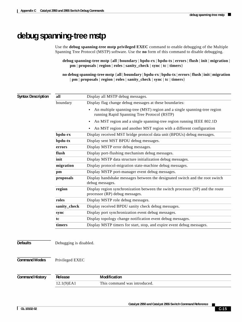
Appendix C Catalyst 2950 and 2955 Switch Debug Commands debug spanning-tree mstp
debug spanning-tree mstpUse the debug spanning-tree mstp privileged EXEC command to enable debugging of the Multiple Spanning Tree Protocol (MSTP) software. Use the no form of this command to disable debugging.
debug spanning-tree mstp {all | boundary | bpdu-rx | bpdu-tx | errors | flush | init | migration | pm | proposals | region | roles | sanity_check | sync | tc | timers}
no debug spanning-tree mstp {all | boundary | bpdu-rx | bpdu-tx | errors | flush | init | migration | pm | proposals | region | roles | sanity_check | sync | tc | timers}
Syntax Description
Defaults Debugging is disabled.
Command Modes Privileged EXEC
Command History
all Display all MSTP debug messages.
boundary Display flag change debug messages at these boundaries:
• An multiple spanning-tree (MST) region and a single spanning-tree region running Rapid Spanning Tree Protocol (RSTP)
• An MST region and a single spanning-tree region running IEEE 802.1D
• An MST region and another MST region with a different configuration
bpdu-rx Display received MST bridge protocol data unit (BPDUs) debug messages.
bpdu-tx Display sent MST BPDU debug messages.
errors Display MSTP error debug messages.
flush Display port-flushing mechanism debug messages.
init Display MSTP data structure initialization debug messages.
migration Display protocol-migration state-machine debug messages.
pm Display MSTP port-manager event debug messages.
proposals Display handshake messages between the designated switch and the root switch debug messages.
region Display region synchronization between the switch processor (SP) and the route processor (RP) debug messages.
roles Display MSTP role debug messages.
sanity_check Display received BPDU sanity check debug messages.
sync Display port synchronization event debug messages.
tc Display topology change notification event debug messages.
timers Display MSTP timers for start, stop, and expire event debug messages.
Release Modification
12.1(9)EA1 This command was introduced.
C-15Catalyst 2950 and Catalyst 2955 Switch Command Reference
OL-10102-02
Appendix C Catalyst 2950 and 2955 Switch Debug Commands debug spanning-tree mstp
Usage Guidelines The undebug spanning-tree mstp command is the same as the no debug spanning-tree mstp command.
Related Commands Command Description
show debugging Displays information about the types of debugging that are enabled. For syntax information, select Cisco IOS Configuration Fundamentals Command Reference for IOS Release 12.1 > Cisco IOS System Management Commands > Troubleshooting Commands.
show spanning-tree Displays spanning-tree state information.
C-16Catalyst 2950 and Catalyst 2955 Switch Command Reference
OL-10102-02
Appendix C Catalyst 2950 and 2955 Switch Debug Commands debug spanning-tree switch
debug spanning-tree switchUse the debug spanning-tree switch privileged EXEC command to enable debugging of the software interface between the Spanning Tree Protocol (STP) software module and the port manager software module. Use the no form of this command to disable debugging.
debug spanning-tree switch {all | errors | general | helper | pm | rx {decode | errors | interrupt | process} | state | tx [decode]}
no debug spanning-tree switch {all | errors | general | helper | pm | rx {decode | errors | interrupt | process} | state | tx [decode]}
Syntax Description
Defaults Debugging is disabled.
Command Modes Privileged EXEC
Command History
Usage Guidelines The undebug spanning-tree switch command is the same as the no debug spanning-tree switch command.
all Display all spanning-tree switch debug messages.
errors Display debug messages for the interface between the spanning-tree software module and the port manager software module.
general Display general event debug messages.
helper Display spanning-tree helper-task debug messages. Helper tasks handle bulk spanning-tree updates.
pm Display port-manager event debug messages.
rx Display received bridge protocol data unit (BPDU) handling debug messages. The keywords have these meanings:
• decode—Display decoded received packets.
• errors—Display receive error debug messages.
• interrupt—Display interrupt service request (ISR) debug messages.
• process—Display process receive BPDU debug messages.
state Display spanning-tree port state change debug messages.
tx [decode] Display transmitted BPDU handling debug messages. The keyword has this meaning:
• decode—(Optional) Display decoded transmitted packets.
Release Modification
12.1(6)EA2 This command was introduced.
12.1(9)EA1 The helper keyword was added.
C-17Catalyst 2950 and Catalyst 2955 Switch Command Reference
OL-10102-02

Appendix C Catalyst 2950 and 2955 Switch Debug Commands debug spanning-tree switch
Related Commands Command Description
show debugging Displays information about the types of debugging that are enabled. For syntax information, select Cisco IOS Configuration Fundamentals Command Reference for IOS Release 12.1 > Cisco IOS System Management Commands > Troubleshooting Commands.
show spanning-tree Displays spanning-tree state information.
C-18Catalyst 2950 and Catalyst 2955 Switch Command Reference
OL-10102-02
Appendix C Catalyst 2950 and 2955 Switch Debug Commands debug spanning-tree uplinkfast
debug spanning-tree uplinkfastUse the debug spanning-tree uplinkfast privileged EXEC command to enable debugging of spanning-tree UplinkFast events. Use the no form of this command to disable debugging.
debug spanning-tree uplinkfast [exceptions]
no debug spanning-tree uplinkfast [exceptions]
Syntax Description
Defaults Debugging is disabled.
Command Modes Privileged EXEC
Command History
Usage Guidelines The undebug spanning-tree uplinkfast command is the same as the no debug spanning-tree uplinkfast command.
Related Commands
exceptions (Optional) Display spanning-tree UplinkFast-exception debug messages.
Release Modification
12.1(6)EA2 This command was introduced.
Command Description
show debugging Displays information about the types of debugging that are enabled. For syntax information, select Cisco IOS Configuration Fundamentals Command Reference for IOS Release 12.1 > Cisco IOS System Management Commands > Troubleshooting Commands.
show spanning-tree Displays spanning-tree state information.
C-19Catalyst 2950 and Catalyst 2955 Switch Command Reference
OL-10102-02
Appendix C Catalyst 2950 and 2955 Switch Debug Commands debug switch dhcp
debug switch dhcpUse the debug switch dhcp privileged EXEC command to enable debugging of DHCP events. Use the no form of this command to disable debugging.
debug switch dhcp
no debug switch dhcp
Syntax Description This command has no arguments or keywords.
Defaults Debugging is disabled.
Command Modes Privileged EXEC
Command History
Usage Guidelines The undebug switch dhcp command is the same as the no debug switch dhcp command.
Related Commands
Release Modification
12.1(19)EA1 This command was introduced.
Command Description
show ip dhcp snooping Displays the DHCP snooping configuration.
show ip dhcp snooping binding Displays the DHCP snooping binding information.
C-20Catalyst 2950 and Catalyst 2955 Switch Command Reference
OL-10102-02
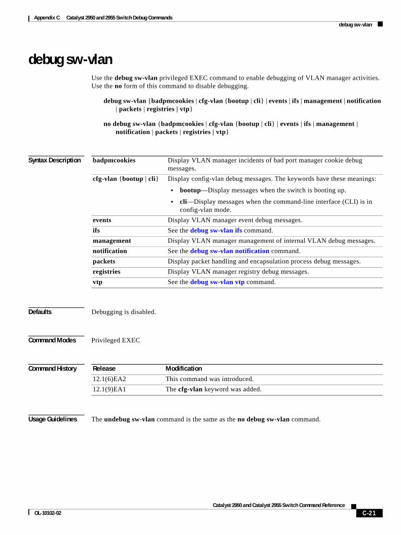
Appendix C Catalyst 2950 and 2955 Switch Debug Commands debug sw-vlan
debug sw-vlanUse the debug sw-vlan privileged EXEC command to enable debugging of VLAN manager activities. Use the no form of this command to disable debugging.
debug sw-vlan {badpmcookies | cfg-vlan {bootup | cli} | events | ifs | management | notification | packets | registries | vtp}
no debug sw-vlan {badpmcookies | cfg-vlan {bootup | cli} | events | ifs | management | notification | packets | registries | vtp}
Syntax Description
Defaults Debugging is disabled.
Command Modes Privileged EXEC
Command History
Usage Guidelines The undebug sw-vlan command is the same as the no debug sw-vlan command.
badpmcookies Display VLAN manager incidents of bad port manager cookie debug messages.
cfg-vlan {bootup | cli} Display config-vlan debug messages. The keywords have these meanings:
• bootup—Display messages when the switch is booting up.
• cli—Display messages when the command-line interface (CLI) is in config-vlan mode.
events Display VLAN manager event debug messages.
ifs See the debug sw-vlan ifs command.
management Display VLAN manager management of internal VLAN debug messages.
notification See the debug sw-vlan notification command.
packets Display packet handling and encapsulation process debug messages.
registries Display VLAN manager registry debug messages.
vtp See the debug sw-vlan vtp command.
Release Modification
12.1(6)EA2 This command was introduced.
12.1(9)EA1 The cfg-vlan keyword was added.
C-21Catalyst 2950 and Catalyst 2955 Switch Command Reference
OL-10102-02
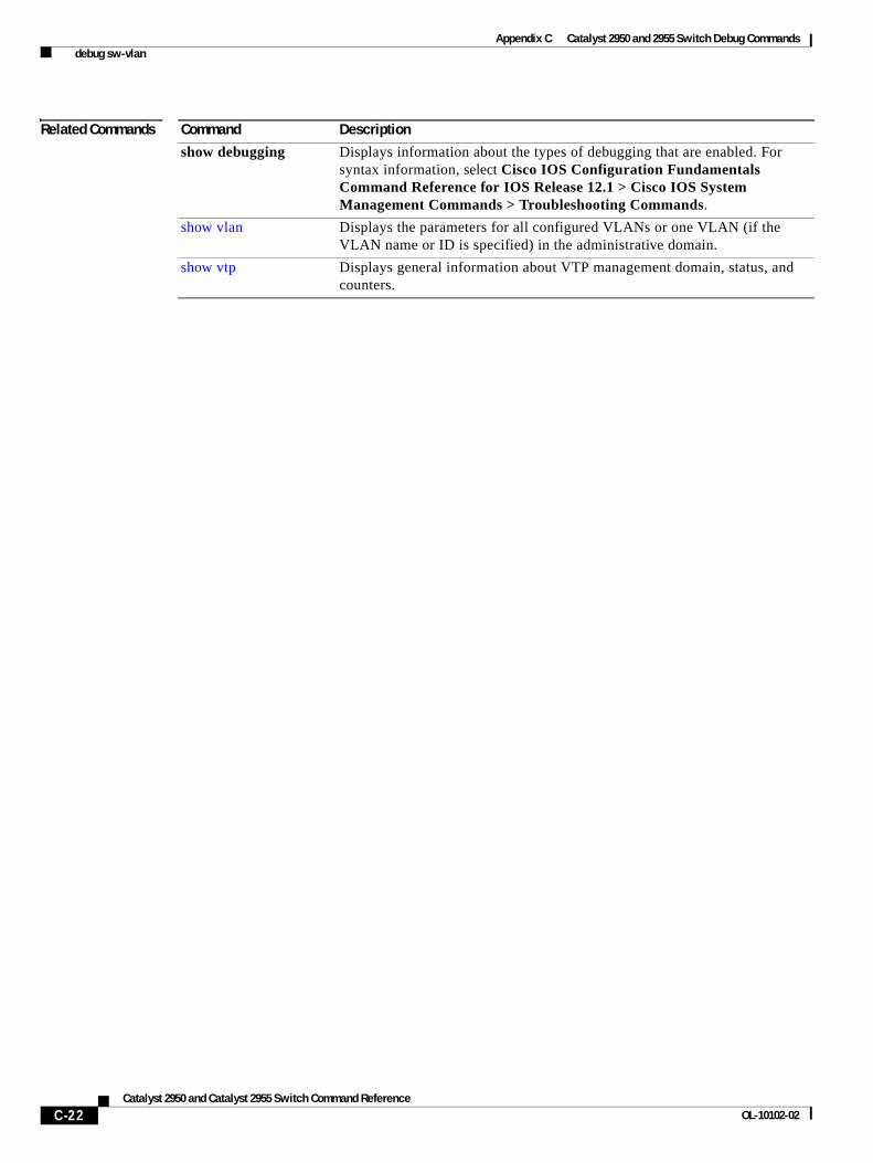
Appendix C Catalyst 2950 and 2955 Switch Debug Commands debug sw-vlan
Related Commands Command Description
show debugging Displays information about the types of debugging that are enabled. For syntax information, select Cisco IOS Configuration Fundamentals Command Reference for IOS Release 12.1 > Cisco IOS System Management Commands > Troubleshooting Commands.
show vlan Displays the parameters for all configured VLANs or one VLAN (if the VLAN name or ID is specified) in the administrative domain.
show vtp Displays general information about VTP management domain, status, and counters.
C-22Catalyst 2950 and Catalyst 2955 Switch Command Reference
OL-10102-02
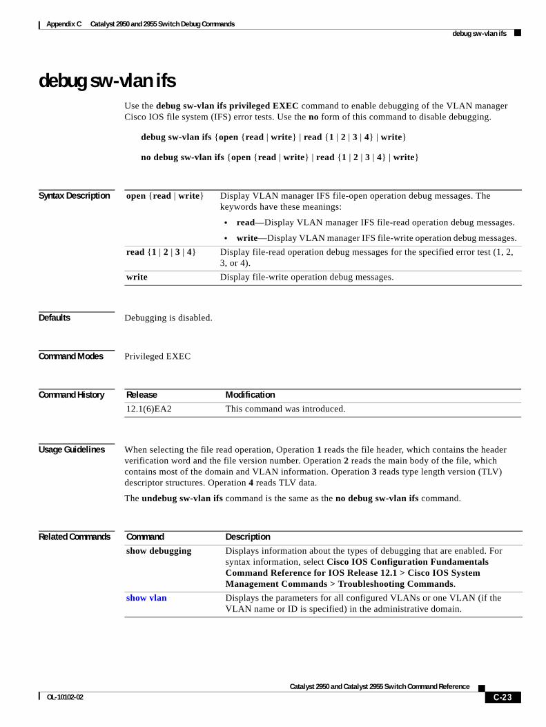
Appendix C Catalyst 2950 and 2955 Switch Debug Commands debug sw-vlan ifs
debug sw-vlan ifsUse the debug sw-vlan ifs privileged EXEC command to enable debugging of the VLAN manager Cisco IOS file system (IFS) error tests. Use the no form of this command to disable debugging.
debug sw-vlan ifs {open {read | write} | read {1 | 2 | 3 | 4} | write}
no debug sw-vlan ifs {open {read | write} | read {1 | 2 | 3 | 4} | write}
Syntax Description
Defaults Debugging is disabled.
Command Modes Privileged EXEC
Command History
Usage Guidelines When selecting the file read operation, Operation 1 reads the file header, which contains the header verification word and the file version number. Operation 2 reads the main body of the file, which contains most of the domain and VLAN information. Operation 3 reads type length version (TLV) descriptor structures. Operation 4 reads TLV data.
The undebug sw-vlan ifs command is the same as the no debug sw-vlan ifs command.
Related Commands
open {read | write} Display VLAN manager IFS file-open operation debug messages. The keywords have these meanings:
• read—Display VLAN manager IFS file-read operation debug messages.
• write—Display VLAN manager IFS file-write operation debug messages.
read {1 | 2 | 3 | 4} Display file-read operation debug messages for the specified error test (1, 2, 3, or 4).
write Display file-write operation debug messages.
Release Modification
12.1(6)EA2 This command was introduced.
Command Description
show debugging Displays information about the types of debugging that are enabled. For syntax information, select Cisco IOS Configuration Fundamentals Command Reference for IOS Release 12.1 > Cisco IOS System Management Commands > Troubleshooting Commands.
show vlan Displays the parameters for all configured VLANs or one VLAN (if the VLAN name or ID is specified) in the administrative domain.
C-23Catalyst 2950 and Catalyst 2955 Switch Command Reference
OL-10102-02
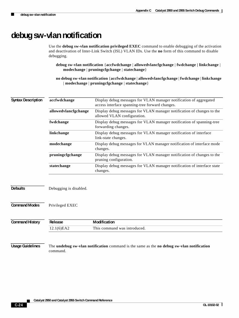
Appendix C Catalyst 2950 and 2955 Switch Debug Commands debug sw-vlan notification
debug sw-vlan notificationUse the debug sw-vlan notification privileged EXEC command to enable debugging of the activation and deactivation of Inter-Link Switch (ISL) VLAN IDs. Use the no form of this command to disable debugging.
debug sw-vlan notification {accfwdchange | allowedvlancfgchange | fwdchange | linkchange | modechange | pruningcfgchange | statechange}
no debug sw-vlan notification {accfwdchange | allowedvlancfgchange | fwdchange | linkchange | modechange | pruningcfgchange | statechange}
Syntax Description
Defaults Debugging is disabled.
Command Modes Privileged EXEC
Command History
Usage Guidelines The undebug sw-vlan notification command is the same as the no debug sw-vlan notification command.
accfwdchange Display debug messages for VLAN manager notification of aggregated access interface spanning-tree forward changes.
allowedvlancfgchange Display debug messages for VLAN manager notification of changes to the allowed VLAN configuration.
fwdchange Display debug messages for VLAN manager notification of spanning-tree forwarding changes.
linkchange Display debug messages for VLAN manager notification of interface link-state changes.
modechange Display debug messages for VLAN manager notification of interface mode changes.
pruningcfgchange Display debug messages for VLAN manager notification of changes to the pruning configuration.
statechange Display debug messages for VLAN manager notification of interface state changes.
Release Modification
12.1(6)EA2 This command was introduced.
C-24Catalyst 2950 and Catalyst 2955 Switch Command Reference
OL-10102-02

Appendix C Catalyst 2950 and 2955 Switch Debug Commands debug sw-vlan notification
Related Commands Command Description
show debugging Displays information about the types of debugging that are enabled. For syntax information, select Cisco IOS Configuration Fundamentals Command Reference for IOS Release 12.1 > Cisco IOS System Management Commands > Troubleshooting Commands.
show vlan Displays the parameters for all configured VLANs or one VLAN (if the VLAN name or ID is specified) in the administrative domain.
C-25Catalyst 2950 and Catalyst 2955 Switch Command Reference
OL-10102-02
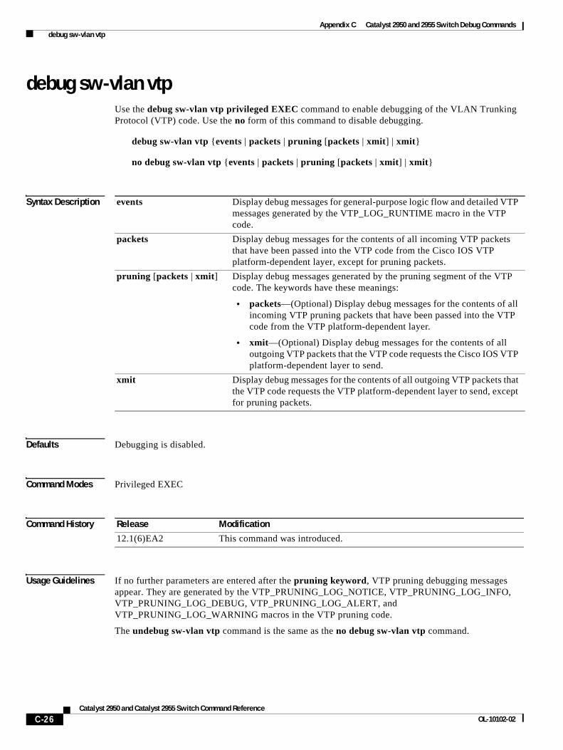
Appendix C Catalyst 2950 and 2955 Switch Debug Commands debug sw-vlan vtp
debug sw-vlan vtpUse the debug sw-vlan vtp privileged EXEC command to enable debugging of the VLAN Trunking Protocol (VTP) code. Use the no form of this command to disable debugging.
debug sw-vlan vtp {events | packets | pruning [packets | xmit] | xmit}
no debug sw-vlan vtp {events | packets | pruning [packets | xmit] | xmit}
Syntax Description
Defaults Debugging is disabled.
Command Modes Privileged EXEC
Command History
Usage Guidelines If no further parameters are entered after the pruning keyword, VTP pruning debugging messages appear. They are generated by the VTP_PRUNING_LOG_NOTICE, VTP_PRUNING_LOG_INFO, VTP_PRUNING_LOG_DEBUG, VTP_PRUNING_LOG_ALERT, and VTP_PRUNING_LOG_WARNING macros in the VTP pruning code.
The undebug sw-vlan vtp command is the same as the no debug sw-vlan vtp command.
events Display debug messages for general-purpose logic flow and detailed VTP messages generated by the VTP_LOG_RUNTIME macro in the VTP code.
packets Display debug messages for the contents of all incoming VTP packets that have been passed into the VTP code from the Cisco IOS VTP platform-dependent layer, except for pruning packets.
pruning [packets | xmit] Display debug messages generated by the pruning segment of the VTP code. The keywords have these meanings:
• packets—(Optional) Display debug messages for the contents of all incoming VTP pruning packets that have been passed into the VTP code from the VTP platform-dependent layer.
• xmit—(Optional) Display debug messages for the contents of all outgoing VTP packets that the VTP code requests the Cisco IOS VTP platform-dependent layer to send.
xmit Display debug messages for the contents of all outgoing VTP packets that the VTP code requests the VTP platform-dependent layer to send, except for pruning packets.
Release Modification
12.1(6)EA2 This command was introduced.
C-26Catalyst 2950 and Catalyst 2955 Switch Command Reference
OL-10102-02

Appendix C Catalyst 2950 and 2955 Switch Debug Commands debug sw-vlan vtp
Related Commands Command Description
show debugging Displays information about the types of debugging that are enabled. For syntax information, select Cisco IOS Configuration Fundamentals Command Reference for IOS Release 12.1 > Cisco IOS System Management Commands > Troubleshooting Commands.
show vtp Displays general information about VTP management domain, status, and counters.
C-27Catalyst 2950 and Catalyst 2955 Switch Command Reference
OL-10102-02
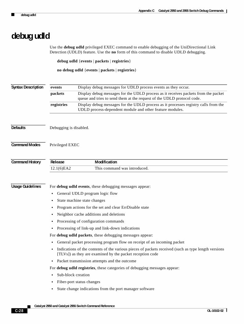
Appendix C Catalyst 2950 and 2955 Switch Debug Commands debug udld
debug udldUse the debug udld privileged EXEC command to enable debugging of the UniDirectional Link Detection (UDLD) feature. Use the no form of this command to disable UDLD debugging.
debug udld {events | packets | registries}
no debug udld {events | packets | registries}
Syntax Description
Defaults Debugging is disabled.
Command Modes Privileged EXEC
Command History
Usage Guidelines For debug udld events, these debugging messages appear:
• General UDLD program logic flow
• State machine state changes
• Program actions for the set and clear ErrDisable state
• Neighbor cache additions and deletions
• Processing of configuration commands
• Processing of link-up and link-down indications
For debug udld packets, these debugging messages appear:
• General packet processing program flow on receipt of an incoming packet
• Indications of the contents of the various pieces of packets received (such as type length versions [TLVs]) as they are examined by the packet reception code
• Packet transmission attempts and the outcome
For debug udld registries, these categories of debugging messages appear:
• Sub-block creation
• Fiber-port status changes
• State change indications from the port manager software
events Display debug messages for UDLD process events as they occur.
packets Display debug messages for the UDLD process as it receives packets from the packet queue and tries to send them at the request of the UDLD protocol code.
registries Display debug messages for the UDLD process as it processes registry calls from the UDLD process-dependent module and other feature modules.
Release Modification
12.1(6)EA2 This command was introduced.
C-28Catalyst 2950 and Catalyst 2955 Switch Command Reference
OL-10102-02
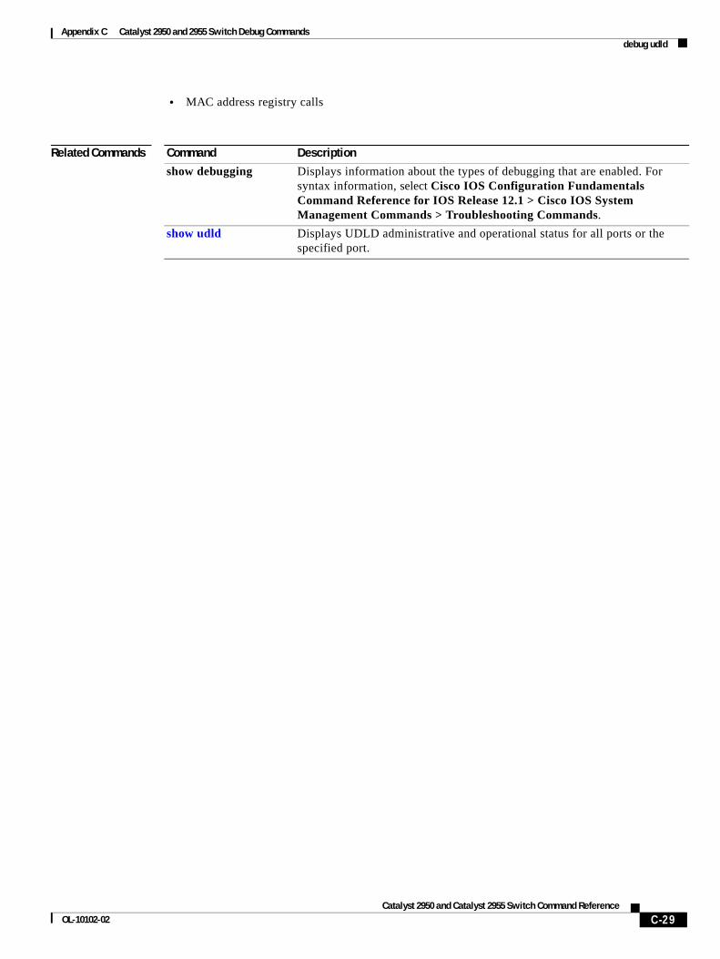
Appendix C Catalyst 2950 and 2955 Switch Debug Commands debug udld
• MAC address registry calls
Related Commands Command Description
show debugging Displays information about the types of debugging that are enabled. For syntax information, select Cisco IOS Configuration Fundamentals Command Reference for IOS Release 12.1 > Cisco IOS System Management Commands > Troubleshooting Commands.
show udld Displays UDLD administrative and operational status for all ports or the specified port.
C-29Catalyst 2950 and Catalyst 2955 Switch Command Reference
OL-10102-02

Appendix C Catalyst 2950 and 2955 Switch Debug Commands debug udld
C-30Catalyst 2950 and Catalyst 2955 Switch Command Reference
OL-10102-02
Catalyst OL-10102-02
I N D E X
Numerics
802.1X Port Based Authentication
enabling guest VLAN supplicant 2-89
A
aaa accounting dot1x command 2-1
aaa authentication command 2-3
abort command 2-534
access control entries
See ACEs
access control lists
See ACLs
access control parameters
See ACPs
access groups
IP 2-128
MAC
applying ACL to interface 2-184
displaying 2-361
access-list (IP extended) command 2-5
access-list (IP standard) command 2-8
access-list configuration mode
deny 2-82
entering 2-130
permit 2-233
access ports 2-489
ACEs 2-86, 2-237
ACLs
IP
applying to interface 2-128
deny 2-82
displaying 2-266, 2-344
permit 2-233
MAC
applying to interface 2-184
deny 2-85
displaying 2-266
permit 2-236
ACPs, displaying 2-369
aggregate-port learner 2-230
alarm command A-6
alarm facility fcs-hysteresis command A-2
alarm facility power-supply command A-3
alarm facility temperature command A-4
alarm IDs A-6, A-11
alarm profile
attaching to a port A-8
creating A-6
displaying A-12
alarm profile (global configuration) command A-6
alarm profile (interface configuration) command A-8
alarm profile configuration mode A-6
apply command 2-534
archive download-sw command 2-10
archive tar command 2-12
archive upload-sw command 2-15
authorization state of controlled port 2-101
autonegotiation of duplex mode 2-108
auto qos voip command 2-17
IN-12950 and Catalyst 2955 Switch Command Reference
Index
B
BackboneFast, for STP 2-432
boot boothlpr command 2-21
boot buffersize command 2-22
boot command B-2
boot config-file command 2-23
boot enable-break command 2-24
boot helper command 2-25
boot helper-config file command 2-26
booting
Cisco IOS image 2-29
interrupting 2-24
manually 2-27
booting, displaying environment variables 2-271
boot loader
accessing B-1
booting
Cisco IOS image B-2
helper image 2-25
directories
creating B-15
displaying a list of B-6
removing B-19
displaying
available commands B-11
memory heap utilization B-13
version B-26
environment variables
described B-20
displaying settings B-20
location of B-22
setting B-20
unsetting B-24
IN-2Catalyst 2950 and Catalyst 2955 Switch Command Reference
boot loader (continued)
files
copying B-4
deleting B-5
displaying a list of B-6
displaying the contents of B-3, B-16, B-23
renaming B-17
file system
formatting B-9
initializing Flash B-8
running a consistency check B-10
loading helper images B-12
prompt B-1
resetting the system B-18
boot manual command 2-27
boot private-config-file command 2-28
boot system command 2-29
BPDU filtering, for spanning tree 2-433, 2-466
BPDU guard, for spanning tree 2-435, 2-466
broadcast suppression level
configuring 2-480
displaying 2-401
C
cat command B-3
channel-group command 2-30
channel-protocol command 2-33
Cisco SoftPhone
auto-QoS configuration 2-17
trusting packets sent from 2-216
class command 2-35
class-map command 2-37
class maps
creating 2-37
defining the match criteria 2-207
displaying 2-273
class of service
See CoS
OL-10102-02
Index
clear controllers ethernet-controller command 2-39
clear controllers lre command 2-41
clear controllers lre link monitor command 2-42
clear controllers lre log command 2-43
clear interface command 2-44
clear lacp command 2-45
clear LRE configuration events 2-43
clear LRE timer events 2-43
clear mac address-table command 2-47
clear pagp command 2-49
clear port-security command 2-50
clear spanning-tree counters command 2-52
clear spanning-tree detected-protocols command 2-53
clear vmps statistics command 2-54
clear vtp counters command 2-55
cluster commander-address command 2-56
cluster discovery hop-count command 2-58
cluster enable command 2-59
cluster holdtime command 2-60
cluster management-vlan command 2-61
cluster member command 2-62
cluster run command 2-64
clusters
adding candidates 2-62
binding to HSRP 2-65
building manually 2-62
communicating with members by using Telnet 2-254
displaying
candidate switches 2-277
member switches 2-279
status 2-275
heartbeat messages
duration after which switch declared down 2-60
interval between 2-67
hop-count limit for extended discovery 2-58
HSRP standby groups 2-65
redundancy 2-65
SNMP trap 2-424
cluster standby-group command 2-65
OL-10102-02
cluster timer command 2-67
command modes defined 1-2
command switch
See clusters
configuration files
password recovery disable considerations B-1
setting the NVRAM size for 2-22
specifying the name 2-23
configuration files, private 2-28
configuring multiple interfaces 2-124 to 2-125
config-vlan mode
description 1-4
entering 2-521
summary 1-2
controller longreachethernet command 2-68
copy command B-4
CoS
default value, assigning to incoming packets 2-211
incoming value, overriding 2-211
priority queue, assigning values to 2-553
priority queue mapping, displaying 2-421
WRR bandwidth allocation, displaying 2-420
WRR weights, assigning to CoS priority queues 2-551
CoS-to-DSCP map
default 2-213
defining 2-213
cpe duplex command 2-69
CPE Ethernet ports, clearing 2-39
cpe protected command 2-71
cpe shutdown command 2-72
cpe speed command 2-74, 2-76
cpe type command 2-78
cross-stack UplinkFast, for STP 2-470
D
debug auto qos command C-2
debug dot1x command C-4
debug etherchannel command C-5
IN-3Catalyst 2950 and Catalyst 2955 Switch Command Reference
Index
debug lre command C-6
debug pagp command C-7
debug pm command C-8
debug spanning-tree backbonefast command C-12
debug spanning-tree bpdu command C-13
debug spanning-tree bpdu-opt command C-14
debug spanning-tree command C-10
debug spanning-tree mstp command C-15
debug spanning-tree switch command C-17
debug spanning-tree uplinkfast command C-19
debug switch dhcp command C-20
debug sw-vlan command C-21
debug sw-vlan ifs command C-23
debug sw-vlan notification command C-24
debug sw-vlan vtp command C-26
debug udld command C-28
defaultPort profile A-7, A-8
define interface-range command 2-79
delete command 2-81, B-5
delete LRE link history 2-43
delete LRE link monitor data 2-42
deny (access-list configuration) command 2-82
deny (MAC access-list configuration) command 2-85
DHCP, error recovery timer 2-112
DHCP snooping
accepting untrusted packets form edge switch 2-136
displaying
bindings 2-347
configuration 2-346
enabling
on a VLAN 2-140
option 82 2-134, 2-136
trust on an interface 2-139
rate limiting 2-138
dir command B-6
domain name, VTP 2-541, 2-547
dot1x auth-fail max-attempts 2-89
dot1x auth-fail vlan 2-90
dot1x command 2-87
IN-4Catalyst 2950 and Catalyst 2955 Switch Command Reference
dot1x default command 2-94
dot1x guest-vlan command 2-95
dot1x host-mode command 2-97
dot1x initialize command 2-98
dot1x max-req command 2-99
dot1x multiple-hosts command 2-100
dot1x port-control command 2-101
dot1x re-authenticate command 2-103
dot1x re-authentication command 2-104
dot1x reauthentication command 2-105
DSCP-to-CoS map
default 2-214
defining 2-213
DTP 2-490
DTP flap, error recovery timer 2-112
duplex command 2-108
dynamic-access ports, configuring 2-483
Dynamic Host Configuration Protocol (DHCP)
See DHCP snooping
Dynamic Trunking Protocol
See DTP
E
EAP-request/identity frame
maximum number to send 2-99
response time before retransmitting 2-106
environmental alarms, displaying A-14
environment variables, displaying 2-271
errdisable detect cause command 2-110
errdisable recovery command 2-112
OL-10102-02
Index
EtherChannel
creating port-channel logical interface 2-123
debug messages, displaying C-5 to C-7
displaying 2-323
LACP, modes 2-30
load-distribution methods 2-244
PAgP
aggregate-port learner 2-230
clearing channel-group information 2-45, 2-49
debug messages, displaying C-7
displaying 2-355, 2-382
error recovery timer 2-112
learn method 2-230
modes 2-30
priority of interface for transmitted traffic 2-232
Ethernet controller, internal register display 2-281
Ethernet link statistics 2-39
Ethernet statistics, collecting 2-258
exit command 2-534
expedite queue, QoS 2-551
express setup-related commands 2-264, 2-395
extended discovery of candidate switches 2-58
extended-range VLANs
and allowed VLAN list 2-502
and pruning-eligible list 2-502
configuring 2-521
extended system ID for STP 2-441
F
facility alarm relays, displaying A-18
facility alarm status, displaying A-19
fan information, displaying 2-320
FCS bit error rate
displaying A-20
fluctuation threshold A-2
setting A-9
FCS hysteresis threshold A-2
fcs-threshold command A-9
OL-10102-02
file name, VTP 2-541
files, deleting 2-81
flash_init command B-8
flowcontrol command 2-114
flow-control packets
receiving 2-114
sending 2-114
format command B-9
frame check sequence
See FCS
fsck command B-10
G
global configuration mode 1-2, 1-4
H
heartbeat messages
duration after which switch declared dead 2-60
interval between 2-67
help command B-11
holdtime for clusters 2-60
hop-count limit for clusters 2-58
host connection, port configuration 2-487
Hot Standby Router Protocol
See HSRP
HSRP
binding HSRP group to cluster 2-65
standby group 2-65
hw-module slot command 2-118
I
IDS, using with SPAN and RSPAN 2-221
IEEE 802.1x commands, authentication methods 2-3
IEEE 802.1x violation error recovery 2-112
IGMP filters, applying 2-141
IN-5Catalyst 2950 and Catalyst 2955 Switch Command Reference
Index
IGMP groups
configuring throttling action 2-142
setting maximum 2-142
IGMP profiles
creating 2-144
displaying 2-349
IGMP snooping
adding ports statically 2-158
compatibility mode, displaying 2-350
configuration, displaying 2-350
displaying 2-353
enabling 2-146
enabling the configurable-leave timer 2-155
IGMP version, displaying 2-350
Immediate-Leave processing 2-154
MAC address tables 2-366
multicast groups, displaying 2-350
multicast router detection 2-147
multicast router ports, displaying 2-350
multicast routers 2-156
per VLAN 2-153
report suppression 2-149
source-only-learning 2-151
source-only-learning aging time 2-151
images
See software images
Immediate-Leave feature, MVR 2-225
Immediate-Leave processing 2-154
interface command 2-121
interface configuration mode 1-2, 1-4
interface port-channel command 2-123
interface range command 2-124
interface-range macros 2-79
interfaces
configuring 2-108
configuring multiple 2-124 to 2-125
creating port-channel logical 2-123
disabling 2-422
restarting 2-422
IN-6Catalyst 2950 and Catalyst 2955 Switch Command Reference
interleave command 2-126
internal registers, displaying 2-281
Intrusion Detection System
See IDS
invalid GBIC
error detection for 2-110
error recovery timer 2-112
ip access-group command 2-128
ip access-list command 2-130
ip address command 2-132
ip addresses, setting 2-132
IP DHCP snooping
See DHCP snooping
ip dhcp snooping command 2-133
ip dhcp snooping information option allow-untrusted command 2-136
ip dhcp snooping information option command 2-134
ip dhcp snooping limit rate command 2-138
ip dhcp snooping trust command 2-139
ip dhcp snooping vlan command 2-140
ip igmp filter command 2-141
ip igmp max-groups command 2-142
ip igmp profile command 2-144
ip igmp snooping command 2-146
ip igmp snooping configurable-leave timer command 2-155
ip igmp snooping mrouter learn pim v2 command 2-147
ip igmp snooping report-suppression command 2-149
ip igmp snooping source-only-learning age-timer 2-151
ip igmp snooping source-only-learning command 2-151
ip igmp snooping vlan command 2-153
ip igmp snooping vlan immediate-leave command 2-154
ip igmp snooping vlan mrouter command 2-156
ip igmp snooping vlan static command 2-158
IP multicast addresses 2-222
IP phones
auto-QoS configuration 2-17
trusting packets sent from 2-216
ip ssh command 2-159
OL-10102-02
Index
IPv4 1-1
IPv6 1-1
IP version 4 1-1
IP version 6 1-1
J
jumbo frames
displaying setting 2-404
setting switch for 2-507
L
LACP
See EtherChannel
lacp port-priority command 2-161
lacp system-priority command 2-163
Layer 2 traceroute
IP addresses 2-512
MAC addresses 2-509
line configuration mode 1-3, 1-5
Link Aggregation Control Protocol
See EtherChannel
link flap
enable error detection for 2-110
enable timer to recover from error state 2-112
link statistics, clearing 2-39
load_helper command B-12
load-distribution methods for EtherChannel 2-244
local duplex command 2-170
local speed command 2-171
logging lre command 2-172
logical interface 2-123
loopback, error recovery timer 2-112
loop guard, for spanning tree 2-443, 2-446
LRE controller, defined 2-68
lre profile command 2-173
lre rate selection command 2-46
OL-10102-02
lre rate selection sequence command 2-175
lre sequence command 2-177
lre syslog command 2-179
lre upbo command 2-180
M
mac access-group command 2-184
MAC access-list configuration mode
deny 2-85
entering 2-186
permit 2-236
mac access-list extended command 2-186
MAC ACLs
deny 2-85
permit 2-236
MAC addresses
and port security 2-493
clearing notification global counters 2-47
displaying
aging time 2-363
dynamic 2-363
multicast entries 2-366
notification setting 2-368
number of addresses 2-363
per interface 2-363
per VLAN 2-363
secure 2-389
static 2-363
dynamic
aging time 2-188
deleting 2-47
displaying 2-363
enabling MAC address notification 2-190
secure
adding 2-493
displaying 2-389
IN-7Catalyst 2950 and Catalyst 2955 Switch Command Reference
Index
MAC addresses (continued)
static
adding 2-192
displaying 2-363
dropping on an interface 2-194
sticky
configuring manually 2-493
enabling sticky learning 2-493
learning dynamically 2-493
mac address-table aging-time command 2-188
mac address-table notification command 2-190
mac address-table static command 2-192
mac address-table static drop command 2-194
MAC-named extended ACLs 2-186
MAC notification feature
clearing global counters 2-47
configuring 2-190
enabling 2-190
macro description command 2-199
macro global command 2-200
macro global description command 2-202
macro name command 2-203
macros
adding a description 2-199
adding a global description 2-202
applying 2-200
creating 2-203
displaying 2-384
interface range 2-79
specifying parameter values 2-200
tracing 2-200
maps, QoS
defining 2-213
displaying 2-373
margin command 2-205
masks
See ACPs
match (class-map configuration) command 2-207
IN-8Catalyst 2950 and Catalyst 2955 Switch Command Reference
maximum transmission unit
See MTU
media-type command 2-209
member switches
See clusters
memory command B-13
mkdir command B-15
mls qos cos command 2-211
mls qos map command 2-213
mls qos trust command 2-216
mode, MVR 2-222
Mode button, and password recovery 2-259
monitor session command 2-219
more command B-16
MSTP
displaying 2-397
interoperability 2-53
link type 2-445
MST region
aborting changes 2-450
applying changes 2-450
configuration name 2-450
configuration revision number 2-450
current or pending display 2-450
displaying 2-397
MST configuration mode 2-450
VLANs-to-instance mapping 2-450
path cost 2-452
protocol mode 2-448
restart protocol migration process 2-53
root port
loop guard 2-443
preventing from becoming designated 2-443
restricting which can be root 2-443
root guard 2-443
OL-10102-02
Index
MSTP (continued)
root switch
affects of extended system ID 2-441
hello-time 2-455, 2-462
interval between BDPU messages 2-456
interval between hello BPDU messages 2-455, 2-462
max-age 2-456
maximum hop count before discarding BPDU 2-458
port priority for selection of 2-459
primary or secondary 2-462
switch priority 2-461
state changes
blocking to forwarding state 2-468
enabling BPDU filtering 2-433, 2-466
enabling BPDU guard 2-435, 2-466
enabling Port Fast 2-466, 2-468
forward-delay time 2-454
length of listening and learning states 2-454
rapid transition to forwarding 2-445
shutting down Port Fast-enabled ports 2-466
state information display 2-396
MTU
configuring size 2-507
displaying global setting 2-404
multicast groups
See IGMP snooping
multicast groups, MVR 2-223
multicast router detection 2-147
multicast router learning method 2-156
multicast router ports, configuring 2-156
multicast suppression level
configuring 2-480
displaying 2-401
enabling 2-480
multicast VLAN, MVR 2-222
multicast VLAN registration
See MVR
OL-10102-02
multiple hosts on authorized port 2-97
Multiple Spanning Tree Protocol
See MSTP
MVR
configuring 2-222
configuring interfaces 2-227
displaying 2-377
Immediate Leave feature 2-225
receiver port 2-227
source port 2-227
mvr command 2-222
mvr group command 2-223
mvr immediate command 2-225
mvr type command 2-227
mvr vlan group command 2-229
N
nonegotiate, speed 2-477
normal-range VLANs 2-521, 2-527
notifies command A-6
no vlan command 2-521, 2-531
O
option 82, DHCP snooping 2-134
P
PAgP
See EtherChannel
pagp learn-method command 2-230
pagp port-priority command 2-232
password, VTP 2-541, 2-545, 2-547
password-recovery mechanism, enabling and disabling 2-259
permit (access-list configuration) command 2-233
permit (MAC access-list configuration) command 2-236
persistence command 2-238
IN-9Catalyst 2950 and Catalyst 2955 Switch Command Reference
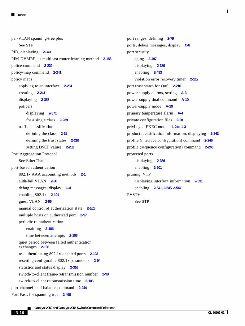
Index
per-VLAN spanning-tree plus
See STP
PID, displaying 2-343
PIM-DVMRP, as multicast router learning method 2-156
police command 2-239
policy-map command 2-241
policy maps
applying to an interface 2-261
creating 2-241
displaying 2-387
policers
displaying 2-371
for a single class 2-239
traffic classification
defining the class 2-35
defining the trust states 2-216
setting DSCP values 2-262
Port Aggregation Protocol
See EtherChannel
port-based authentication
802.1x AAA accounting methods 2-1
auth-fail VLAN 2-90
debug messages, display C-4
enabling 802.1x 2-101
guest VLAN 2-95
manual control of authorization state 2-101
multiple hosts on authorized port 2-97
periodic re-authentication
enabling 2-105
time between attempts 2-106
quiet period between failed authentication exchanges 2-106
re-authenticating 802.1x-enabled ports 2-103
resetting configurable 802.1x parameters 2-94
statistics and status display 2-316
switch-to-client frame-retransmission number 2-99
switch-to-client retransmission time 2-106
port-channel load-balance command 2-244
Port Fast, for spanning tree 2-468
IN-10Catalyst 2950 and Catalyst 2955 Switch Command Reference
port ranges, defining 2-79
ports, debug messages, display C-8
port security
aging 2-497
displaying 2-389
enabling 2-493
violation error recovery timer 2-112
port trust states for QoS 2-216
power supply alarms, setting A-3
power-supply dual command A-10
power-supply mode A-10
primary temperature alarm A-4
private configuration files 2-28
privileged EXEC mode 1-2 to 1-3
product identification information, displaying 2-343
profile (interface configuration) command 2-246
profile (sequence configuration) command 2-248
protected ports
displaying 2-336
enabling 2-501
pruning, VTP
displaying interface information 2-331
enabling 2-541, 2-545, 2-547
PVST+
See STP
OL-10102-02
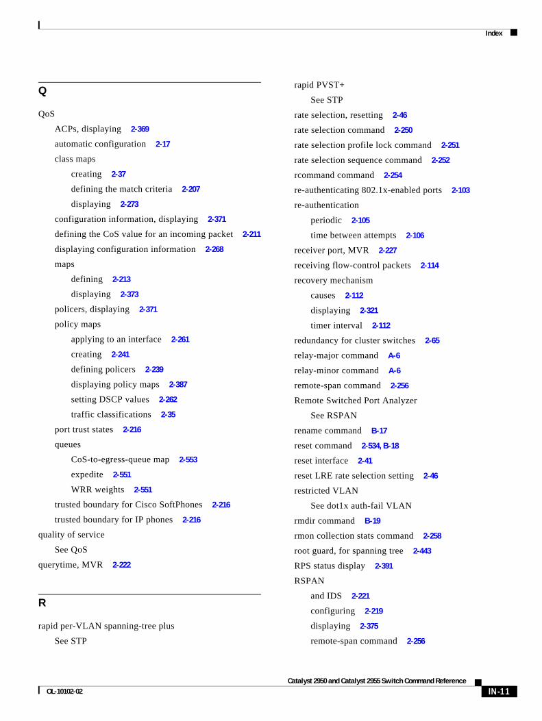
Index
Q
QoS
ACPs, displaying 2-369
automatic configuration 2-17
class maps
creating 2-37
defining the match criteria 2-207
displaying 2-273
configuration information, displaying 2-371
defining the CoS value for an incoming packet 2-211
displaying configuration information 2-268
maps
defining 2-213
displaying 2-373
policers, displaying 2-371
policy maps
applying to an interface 2-261
creating 2-241
defining policers 2-239
displaying policy maps 2-387
setting DSCP values 2-262
traffic classifications 2-35
port trust states 2-216
queues
CoS-to-egress-queue map 2-553
expedite 2-551
WRR weights 2-551
trusted boundary for Cisco SoftPhones 2-216
trusted boundary for IP phones 2-216
quality of service
See QoS
querytime, MVR 2-222
R
rapid per-VLAN spanning-tree plus
See STP
OL-10102-02
rapid PVST+
See STP
rate selection, resetting 2-46
rate selection command 2-250
rate selection profile lock command 2-251
rate selection sequence command 2-252
rcommand command 2-254
re-authenticating 802.1x-enabled ports 2-103
re-authentication
periodic 2-105
time between attempts 2-106
receiver port, MVR 2-227
receiving flow-control packets 2-114
recovery mechanism
causes 2-112
displaying 2-321
timer interval 2-112
redundancy for cluster switches 2-65
relay-major command A-6
relay-minor command A-6
remote-span command 2-256
Remote Switched Port Analyzer
See RSPAN
rename command B-17
reset command 2-534, B-18
reset interface 2-41
reset LRE rate selection setting 2-46
restricted VLAN
See dot1x auth-fail VLAN
rmdir command B-19
rmon collection stats command 2-258
root guard, for spanning tree 2-443
RPS status display 2-391
RSPAN
and IDS 2-221
configuring 2-219
displaying 2-375
remote-span command 2-256
IN-11Catalyst 2950 and Catalyst 2955 Switch Command Reference
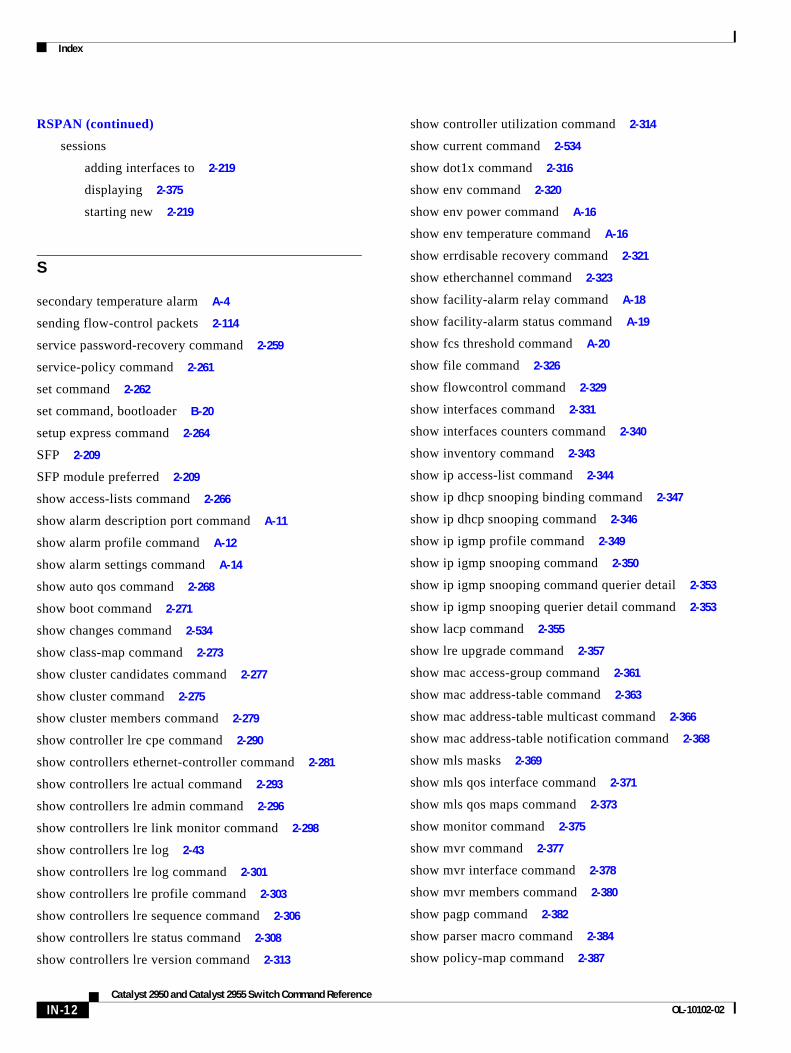
Index
RSPAN (continued)
sessions
adding interfaces to 2-219
displaying 2-375
starting new 2-219
S
secondary temperature alarm A-4
sending flow-control packets 2-114
service password-recovery command 2-259
service-policy command 2-261
set command 2-262
set command, bootloader B-20
setup express command 2-264
SFP 2-209
SFP module preferred 2-209
show access-lists command 2-266
show alarm description port command A-11
show alarm profile command A-12
show alarm settings command A-14
show auto qos command 2-268
show boot command 2-271
show changes command 2-534
show class-map command 2-273
show cluster candidates command 2-277
show cluster command 2-275
show cluster members command 2-279
show controller lre cpe command 2-290
show controllers ethernet-controller command 2-281
show controllers lre actual command 2-293
show controllers lre admin command 2-296
show controllers lre link monitor command 2-298
show controllers lre log 2-43
show controllers lre log command 2-301
show controllers lre profile command 2-303
show controllers lre sequence command 2-306
show controllers lre status command 2-308
show controllers lre version command 2-313
IN-12Catalyst 2950 and Catalyst 2955 Switch Command Reference
show controller utilization command 2-314
show current command 2-534
show dot1x command 2-316
show env command 2-320
show env power command A-16
show env temperature command A-16
show errdisable recovery command 2-321
show etherchannel command 2-323
show facility-alarm relay command A-18
show facility-alarm status command A-19
show fcs threshold command A-20
show file command 2-326
show flowcontrol command 2-329
show interfaces command 2-331
show interfaces counters command 2-340
show inventory command 2-343
show ip access-list command 2-344
show ip dhcp snooping binding command 2-347
show ip dhcp snooping command 2-346
show ip igmp profile command 2-349
show ip igmp snooping command 2-350
show ip igmp snooping command querier detail 2-353
show ip igmp snooping querier detail command 2-353
show lacp command 2-355
show lre upgrade command 2-357
show mac access-group command 2-361
show mac address-table command 2-363
show mac address-table multicast command 2-366
show mac address-table notification command 2-368
show mls masks 2-369
show mls qos interface command 2-371
show mls qos maps command 2-373
show monitor command 2-375
show mvr command 2-377
show mvr interface command 2-378
show mvr members command 2-380
show pagp command 2-382
show parser macro command 2-384
show policy-map command 2-387
OL-10102-02
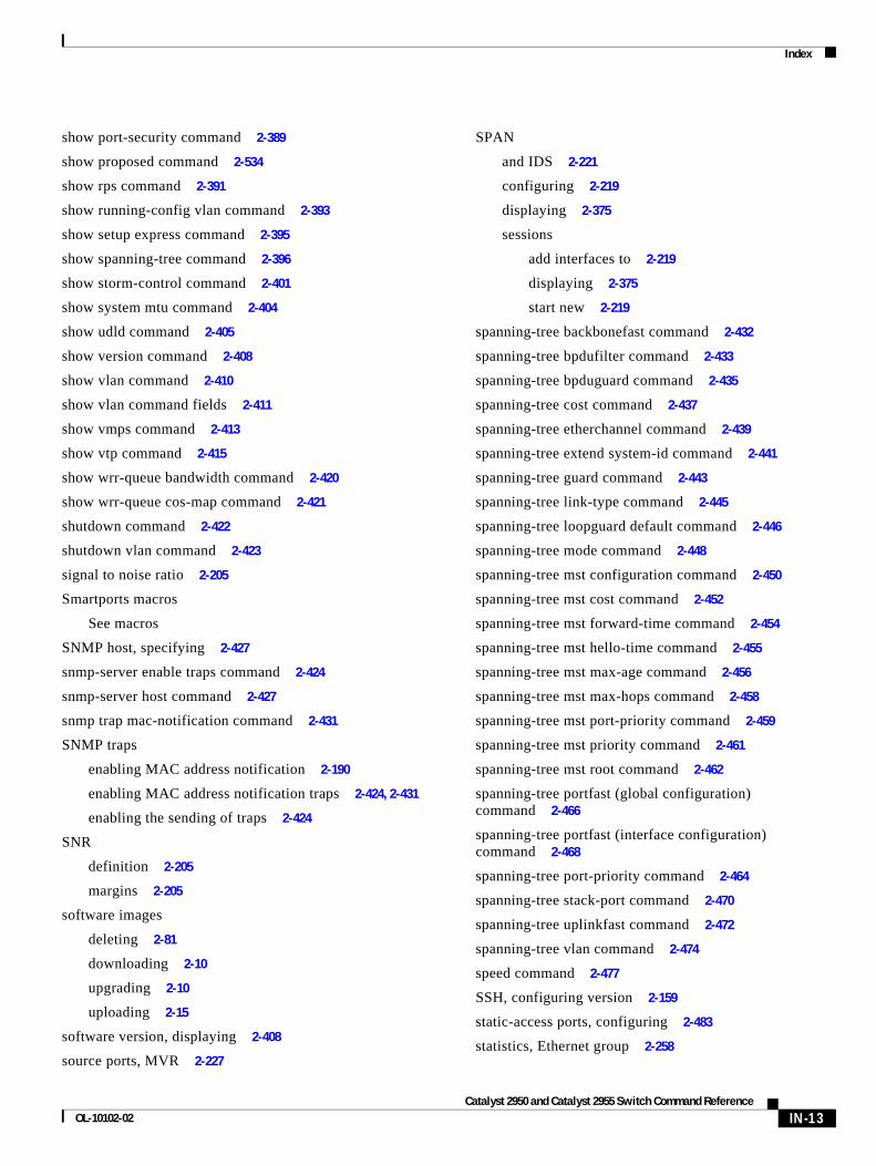
Index
show port-security command 2-389
show proposed command 2-534
show rps command 2-391
show running-config vlan command 2-393
show setup express command 2-395
show spanning-tree command 2-396
show storm-control command 2-401
show system mtu command 2-404
show udld command 2-405
show version command 2-408
show vlan command 2-410
show vlan command fields 2-411
show vmps command 2-413
show vtp command 2-415
show wrr-queue bandwidth command 2-420
show wrr-queue cos-map command 2-421
shutdown command 2-422
shutdown vlan command 2-423
signal to noise ratio 2-205
Smartports macros
See macros
SNMP host, specifying 2-427
snmp-server enable traps command 2-424
snmp-server host command 2-427
snmp trap mac-notification command 2-431
SNMP traps
enabling MAC address notification 2-190
enabling MAC address notification traps 2-424, 2-431
enabling the sending of traps 2-424
SNR
definition 2-205
margins 2-205
software images
deleting 2-81
downloading 2-10
upgrading 2-10
uploading 2-15
software version, displaying 2-408
source ports, MVR 2-227
OL-10102-02
SPAN
and IDS 2-221
configuring 2-219
displaying 2-375
sessions
add interfaces to 2-219
displaying 2-375
start new 2-219
spanning-tree backbonefast command 2-432
spanning-tree bpdufilter command 2-433
spanning-tree bpduguard command 2-435
spanning-tree cost command 2-437
spanning-tree etherchannel command 2-439
spanning-tree extend system-id command 2-441
spanning-tree guard command 2-443
spanning-tree link-type command 2-445
spanning-tree loopguard default command 2-446
spanning-tree mode command 2-448
spanning-tree mst configuration command 2-450
spanning-tree mst cost command 2-452
spanning-tree mst forward-time command 2-454
spanning-tree mst hello-time command 2-455
spanning-tree mst max-age command 2-456
spanning-tree mst max-hops command 2-458
spanning-tree mst port-priority command 2-459
spanning-tree mst priority command 2-461
spanning-tree mst root command 2-462
spanning-tree portfast (global configuration) command 2-466
spanning-tree portfast (interface configuration) command 2-468
spanning-tree port-priority command 2-464
spanning-tree stack-port command 2-470
spanning-tree uplinkfast command 2-472
spanning-tree vlan command 2-474
speed command 2-477
SSH, configuring version 2-159
static-access ports, configuring 2-483
statistics, Ethernet group 2-258
IN-13Catalyst 2950 and Catalyst 2955 Switch Command Reference
Index
sticky learning, enabling 2-493
storm control
broadcast, enabling 2-480
displaying 2-401
multicast, enabling 2-480
unicast, enabling 2-480
storm-control command 2-480
STP
BackboneFast 2-432
debug message display
BackboneFast events C-12
MSTP C-15
optimized BPDUs handling C-14
spanning-tree activity C-10
switch shim C-17
transmitted and received BPDUs C-13
UplinkFast C-19
detection of indirect link failures 2-432
EtherChannel misconfiguration 2-439
extended system ID 2-441
path cost 2-437
protocol mode 2-448
root port
accelerating choice of new 2-472
accelerating choice of new root in a stack 2-470
cross-stack UplinkFast 2-470
loop guard 2-443
preventing from becoming designated 2-443
restricting which can be root 2-443
root guard 2-443
UplinkFast 2-472
IN-14Catalyst 2950 and Catalyst 2955 Switch Command Reference
STP (continued)
root switch
affects of extended system ID 2-441, 2-475
hello-time 2-474
interval between BDPU messages 2-474
interval between hello BPDU messages 2-474
max-age 2-474
port priority for selection of 2-464
primary or secondary 2-474
switch priority 2-474
state changes
blocking to forwarding state 2-468
enabling BPDU filtering 2-433, 2-466
enabling BPDU guard 2-435, 2-466
enabling Port Fast 2-466, 2-468
enabling timer to recover from error state 2-112
forward-delay time 2-474
length of listening and learning states 2-474
shutting down Port Fast-enabled ports 2-466
state information display 2-396
VLAN options 2-461, 2-474
Switched Port Analyzer
See SPAN
switching characteristics
modifying 2-491
returning to interfaces 2-491
switchport access command 2-483
switchport block command 2-485
switchport host command 2-487
switchport mode command 2-489
switchport nonegotiate command 2-491
switchport port-security aging command 2-497
switchport port-security command 2-493
switchport priority extend command 2-499
switchport protected command 2-501
switchports, displaying 2-331
switchport trunk command 2-502
switchport voice vlan command 2-505
OL-10102-02
Index
syslog command A-6
system mtu command 2-507
T
tar files, creating, listing, and extracting 2-12
Telnet, using with cluster switches 2-254
temperature alarms, setting A-4
test relay command A-21
traceroute, Layer 2
See Layer 2 traceroute
traceroute mac command 2-509
traceroute mac ip command 2-512
trunk ports, configuring 2-489
trunks
allowed VLANs 2-502
native VLANs 2-502
pruning-eligible VLAN list 2-504
pruning VLANs 2-502
VLAN 1 minimization 2-503
trunks, to non-DTP device 2-490
trusted boundary for QoS 2-216
type command B-23
U
UDLD
aggressive mode 2-514, 2-516
debug messages, displaying C-28
enabling globally 2-514
enabling per interface 2-516
error recovery timer 2-112
message timer 2-514
normal mode 2-514, 2-516
resetting shutdown interfaces 2-518
status 2-405
udld command 2-514
udld port command 2-516
OL-10102-02
udld reset command 2-518
unicast suppression level
configuring 2-480
displaying 2-401
enabling 2-480
UniDirectional Link Detection
See UDLD
unknown multicast traffic, preventing 2-485
unknown unicast traffic, preventing 2-485
unset (boot loader) command B-24
upgrade binary command 2-519
upgrade preserve command 2-520
upgrading software images 2-10
UplinkFast, for STP 2-472
upstream power back-off
configuring 2-180
supported values 2-181
user EXEC mode 1-2, 1-3
V
version command B-26
VLAN
enabling guest VLAN supplicant 2-89
vlan (global configuration) command 2-521
vlan (VLAN configuration) command 2-527
VLAN configuration
rules 2-524, 2-529
saving 2-521, 2-531
VLAN configuration mode
commands
VLAN 2-527
VTP 2-547
entering 2-533
summary 1-3
vlan database command 2-533
VLAN ID range 2-521, 2-527
VLAN Query Protocol
See VQP
IN-15Catalyst 2950 and Catalyst 2955 Switch Command Reference
Index
VLANs
adding 2-521
configuring 2-521, 2-527
debug message display
ISL C-24
VLAN IOS file system error tests C-23
VLAN manager activity C-21
VTP C-26
displaying configurations 2-410
extended-range 2-521
MAC addresses
displaying 2-363
number of 2-363
media types 2-524, 2-529
normal-range 2-521, 2-527
saving the configuration 2-521
shutting down 2-423
SNMP traps for VTP 2-425, 2-428
trunks, VLAN 1 minimization 2-503
variables 2-527
VMPS
configuring servers 2-539
reconfirming dynamic VLAN assignments 2-537
vmps reconfirm (global configuration) command 2-536
vmps reconfirm (privileged EXEC) command 2-537
vmps retry command 2-538
vmps server command 2-539
voice VLAN
configuring 2-505
setting port priority 2-499
VQP
and dynamic-access ports 2-484
clearing client statistics 2-54
displaying information 2-413
per-server retry count 2-538
reconfirmation interval 2-536
reconfirming dynamic VLAN assignments 2-537
VTP
changing characteristics 2-541
IN-16Catalyst 2950 and Catalyst 2955 Switch Command Reference
VTP (continued)
clearing pruning counters 2-55
clearing VTP counters 2-55
configuring
domain name 2-541, 2-547
file name 2-541
mode 2-541, 2-547
password 2-541, 2-545, 2-547
counters display fields 2-416
displaying information 2-415
enabling
pruning 2-541, 2-545, 2-547
version 2 2-541, 2-545, 2-547
mode 2-541, 2-547
pruning 2-541, 2-545, 2-547
saving the configuration 2-521, 2-531
status display fields 2-417
vtp (global configuration) command 2-541
vtp (privileged EXEC) command 2-545
vtp (VLAN configuration) command 2-547
W
WRR, assigning weights to egress queues 2-551
wrr-queue bandwidth command 2-551
wrr-queue cos-map command 2-553
OL-10102-02