Embed Size (px)
Citation preview
Catalyst 2950 and Catalyst 2955 Switch System Message GuideCisco IOS Release 12.1(22)EA2October 2004
Corporate HeadquartersCisco Systems, Inc.170 West Tasman DriveSan Jose, CA 95134-1706 USAhttp://www.cisco.comTel: 408 526-4000
800 553-NETS (6387)Fax: 408 526-4100
Customer Order Number: DOC-7814233=Text Part Number: 78-14233-08
THE SPECIFICATIONS AND INFORMATION REGARDING THE PRODUCTS IN THIS MANUAL ARE SUBJECT TO CHANGE WITHOUT NOTICE. ALL STATEMENTS, INFORMATION, AND RECOMMENDATIONS IN THIS MANUAL ARE BELIEVED TO BE ACCURATE BUT ARE PRESENTED WITHOUT WARRANTY OF ANY KIND, EXPRESS OR IMPLIED. USERS MUST TAKE FULL RESPONSIBILITY FOR THEIR APPLICATION OF ANY PRODUCTS.
THE SOFTWARE LICENSE AND LIMITED WARRANTY FOR THE ACCOMPANYING PRODUCT ARE SET FORTH IN THE INFORMATION PACKET THAT SHIPPED WITH THE PRODUCT AND ARE INCORPORATED HEREIN BY THIS REFERENCE. IF YOU ARE UNABLE TO LOCATE THE SOFTWARE LICENSE OR LIMITED WARRANTY, CONTACT YOUR CISCO REPRESENTATIVE FOR A COPY.
The Cisco implementation of TCP header compression is an adaptation of a program developed by the University of California, Berkeley (UCB) as part of UCB’s public domain version of the UNIX operating system. All rights reserved. Copyright © 1981, Regents of the University of California.
NOTWITHSTANDING ANY OTHER WARRANTY HEREIN, ALL DOCUMENT FILES AND SOFTWARE OF THESE SUPPLIERS ARE PROVIDED “AS IS” WITH ALL FAULTS. CISCO AND THE ABOVE-NAMED SUPPLIERS DISCLAIM ALL WARRANTIES, EXPRESSED OR IMPLIED, INCLUDING, WITHOUT LIMITATION, THOSE OF MERCHANTABILITY, FITNESS FOR A PARTICULAR PURPOSE AND NONINFRINGEMENT OR ARISING FROM A COURSE OF DEALING, USAGE, OR TRADE PRACTICE.
IN NO EVENT SHALL CISCO OR ITS SUPPLIERS BE LIABLE FOR ANY INDIRECT, SPECIAL, CONSEQUENTIAL, OR INCIDENTAL DAMAGES, INCLUDING, WITHOUT LIMITATION, LOST PROFITS OR LOSS OR DAMAGE TO DATA ARISING OUT OF THE USE OR INABILITY TO USE THIS MANUAL, EVEN IF CISCO OR ITS SUPPLIERS HAVE BEEN ADVISED OF THE POSSIBILITY OF SUCH DAMAGES.
CCSP, the Cisco Square Bridge logo, Cisco Unity, Follow Me Browsing, FormShare, and StackWise are trademarks of Cisco Systems, Inc.; Changing the Way We Work, Live, Play, and Learn, and iQuick Study are service marks of Cisco Systems, Inc.; and Aironet, ASIST, BPX, Catalyst, CCDA, CCDP, CCIE, CCIP, CCNA, CCNP, Cisco, the Cisco Certified Internetwork Expert logo, Cisco IOS, Cisco Press, Cisco Systems, Cisco Systems Capital, the Cisco Systems logo, Empowering the Internet Generation, Enterprise/Solver, EtherChannel, EtherFast, EtherSwitch, Fast Step, GigaDrive, GigaStack, HomeLink, Internet Quotient, IOS, IP/TV, iQ Expertise, the iQ logo, iQ Net Readiness Scorecard, LightStream, Linksys, MeetingPlace, MGX, the Networkers logo, Networking Academy, Network Registrar, Packet, PIX, Post-Routing, Pre-Routing, ProConnect, RateMUX, Registrar, ScriptShare, SlideCast, SMARTnet, StrataView Plus, SwitchProbe, TeleRouter, The Fastest Way to Increase Your Internet Quotient, TransPath, and VCO are registered trademarks of Cisco Systems, Inc. and/or its affiliates in the United States and certain other countries.
All other trademarks mentioned in this document or Website are the property of their respective owners. The use of the word partner does not imply a partnership relationship between Cisco and any other company. (0406R)
Catalyst 2950 and Catalyst 2955 Switch System Message GuideCopyright © 2002–2004 Cisco Systems, Inc. All rights reserved.
Catalys78-14233-08
C O N T E N T S
Preface v
Audience v
Purpose v
Conventions v
Related Publications vi
Obtaining Documentation vii
Cisco.com vii
Ordering Documentation vii
Documentation Feedback vii
Obtaining Technical Assistance viii
Cisco Technical Support Website viii
Submitting a Service Request viii
Definitions of Service Request Severity ix
Obtaining Additional Publications and Information ix
C H A P T E R 1 System Message Overview 1-1
How to Read System Messages 1-1
Error Message Traceback Reports 1-4
Output Interpreter 1-4
Bug Toolkit 1-4
Contacting TAC 1-5
C H A P T E R 2 Message and Recovery Procedures 2-1
AUTOQOS Messages 2-2
CMP Messages 2-2
DOT1X Messages 2-3
DTP Messages 2-8
EC Messages 2-9
ENVIRONMENT Messages 2-13
ETHCNTR Messages 2-15
EXPRESS_SETUP Messages 2-17
GBIC Messages 2-18
GBIC_SECURITY Messages 2-20
iiit 2950 and Catalyst 2955 Switch System Message Guide
Contents
GBIC_SECURITY_CRYPT Messages 2-22
GBIC_SECURITY_UNIQUE Messages 2-23
GIGASTACK Messages 2-23
HWMATM_MOD Messages 2-24
LINK Messages 2-25
LRE_CPE Messages 2-26
LRE_LINK Messages 2-29
LRE_UPGRADE Messages 2-30
PHY Messages 2-31
PLATFORM_CAT2950 Messages 2-31
PLATFORM_CATALYST2950 Messages 2-36
PLATFORM_CATALYST2955 Messages 2-36
PM Messages 2-37
PORT SECURITY Messages 2-43
SPAN Messages 2-43
SPANTREE Messages 2-44
SPANTREE_FAST Messages 2-51
SPANTREE_VLAN_SWITCH Messages 2-52
STORM_CONTROL Messages 2-52
SW_VLAN Messages 2-52
UDLD Messages 2-57
UFAST_MCAST_SW Messages 2-59
A P P E N D I X A Security and QoS Configuration Messages A-1
IN D E X
ivCatalyst 2950 and Catalyst 2955 Switch System Message Guide
78-14233-08
Preface
AudienceThis guide is for the networking professional managing the Catalyst 2950 and Catalyst 2955 switches, hereafter referred to as the switch. Before using this guide, you should have experience working with the Cisco IOS and the switch software features.
PurposeThis guide describes only the Catalyst 2950- and Catalyst 2955-specific system messages that you might encounter. For a complete list of Cisco IOS system error messages, see the Cisco IOS Software System Error Messages, Cisco IOS Release 12.1.
This guide does not describe how to install your switch or how to configure software features on your switch. It also does not provide detailed information about commands that have been created or changed for use by the switch. For hardware installation information, see the hardware installation guide that shipped with your switch. For software information, see the software configuration guide and the command reference for this release.
ConventionsThis publication uses these conventions to convey instructions and information:
Command descriptions use these conventions:
• Commands and keywords are in boldface text.
• Arguments for which you supply values are in italic.
• Square brackets ([ ]) mean optional elements.
• Braces ({ }) group required choices, and vertical bars ( | ) separate the alternative elements.
• Braces and vertical bars within square brackets ([{ | }]) mean a required choice within an optional element.
vCatalyst 2950 and Catalyst 2955 Switch System Message Guide
78-14233-08
PrefaceRelated Publications
Interactive examples use these conventions:
• Terminal sessions and system displays are in screen font.
• Information you enter is in boldface screen font.
• Nonprinting characters, such as passwords or tabs, are in angle brackets (< >).
Notes use this convention and symbol:
Note Means reader take note. Notes contain helpful suggestions or references to materials not in this manual.
Related PublicationsThese documents provide complete information about the switch and are available from this Cisco.com site:
http://www.cisco.com/univercd/cc/td/doc/product/lan/cat2950/index.htm
You can order printed copies of documents with a DOC-xxxxxx= number from the Cisco.com sites and from the telephone numbers listed in the “Obtaining Documentation” section on page vii.
• Release Notes for the Catalyst 2950 and Catalyst 2955 Switches (not orderable but available on Cisco.com)
Note Switch requirements and procedures for initial configurations and software upgrades tend to change and therefore appear only in the release notes. Before installing, configuring, or upgrading the switch, see the release notes on Cisco.com for the latest information.
For information about the switch, see these documents:
• Catalyst 2950 and Catalyst 2955 Switch Software Configuration Guide (order number DOC-7811380=)
• Catalyst 2950 and Catalyst 2955 Switch Command Reference (order number DOC-7811381=)
• Catalyst 2950 and Catalyst 2955 Switch System Message Guide (order number DOC-7814233=)
• Device manager online help (available on the switch)
• Catalyst 2950 Desktop Switch Hardware Installation Guide (not orderable but available on Cisco.com)
• Catalyst 2950 Switch Getting Started Guide (order number DOC-1786521=)
• Regulatory Compliance and Safety Information for the Catalyst 2950 Switch (order number DOC-7816625=)
• Catalyst 2955 Switch Hardware Installation Guide (order number DOC-7814944=)
For information about related products, see these documents:
• Getting Started with Cisco Network Assistant (not orderable but available on Cisco.com)
• Release Notes for Cisco Network Assistant (not orderable but available on Cisco.com)
• Catalyst GigaStack Gigabit Interface Converter Hardware Installation Guide (order number DOC-786460=)
• CWDM Passive Optical System Installation Note (not orderable but is available on Cisco.com)
viCatalyst 2950 and Catalyst 2955 Switch System Message Guide
78-14233-08
PrefaceObtaining Documentation
• 1000BASE-T Gigabit Interface Converter Installation Notes (not orderable but is available on Cisco.com)
• Installation Notes for the Catalyst Family Small-Form-Factor Pluggable Modules (order number DOC-7815160=)
Obtaining DocumentationCisco documentation and additional literature are available on Cisco.com. Cisco also provides several ways to obtain technical assistance and other technical resources. These sections explain how to obtain technical information from Cisco Systems.
Cisco.comYou can access the most current Cisco documentation at this URL:
http://www.cisco.com/univercd/home/home.htm
You can access the Cisco website at this URL:
http://www.cisco.com
You can access international Cisco websites at this URL:
http://www.cisco.com/public/countries_languages.shtml
Ordering DocumentationYou can find instructions for ordering documentation at this URL:
http://www.cisco.com/univercd/cc/td/doc/es_inpck/pdi.htm
You can order Cisco documentation in these ways:
• Registered Cisco.com users (Cisco direct customers) can order Cisco product documentation from the Ordering tool:
http://www.cisco.com/en/US/partner/ordering/index.shtml
• Nonregistered Cisco.com users can order documentation through a local account representative by calling Cisco Systems Corporate Headquarters (California, USA) at 408 526-7208 or, elsewhere in North America, by calling 800 553-NETS (6387).
Documentation FeedbackYou can send comments about technical documentation to [email protected].
viiCatalyst 2950 and Catalyst 2955 Switch System Message Guide
78-14233-08
PrefaceObtaining Technical Assistance
You can submit comments by using the response card (if present) behind the front cover of your document or by writing to the following address:
Cisco SystemsAttn: Customer Document Ordering170 West Tasman DriveSan Jose, CA 95134-9883
We appreciate your comments.
Obtaining Technical AssistanceFor all customers, partners, resellers, and distributors who hold valid Cisco service contracts, Cisco Technical Support provides 24-hour-a-day, award-winning technical assistance. The Cisco Technical Support Website on Cisco.com features extensive online support resources. In addition, Cisco Technical Assistance Center (TAC) engineers provide telephone support. If you do not hold a valid Cisco service contract, contact your reseller.
Cisco Technical Support WebsiteThe Cisco Technical Support Website provides online documents and tools for troubleshooting and resolving technical issues with Cisco products and technologies. The website is available 24 hours a day, 365 days a year at this URL:
http://www.cisco.com/techsupport
Access to all tools on the Cisco Technical Support Website requires a Cisco.com user ID and password. If you have a valid service contract but do not have a user ID or password, you can register at this URL:
http://tools.cisco.com/RPF/register/register.do
Submitting a Service RequestUsing the online TAC Service Request Tool is the fastest way to open S3 and S4 service requests. (S3 and S4 service requests are those in which your network is minimally impaired or for which you require product information.) After you describe your situation, the TAC Service Request Tool automatically provides recommended solutions. If your issue is not resolved using the recommended resources, your service request will be assigned to a Cisco TAC engineer. The TAC Service Request Tool is located at this URL:
http://www.cisco.com/techsupport/servicerequest
For S1 or S2 service requests or if you do not have Internet access, contact the Cisco TAC by telephone. (S1 or S2 service requests are those in which your production network is down or severely degraded.) Cisco TAC engineers are assigned immediately to S1 and S2 service requests to help keep your business operations running smoothly.
To open a service request by telephone, use one of the following numbers:
Asia-Pacific: +61 2 8446 7411 (Australia: 1 800 805 227)EMEA: +32 2 704 55 55USA: 1 800 553 2447
viiiCatalyst 2950 and Catalyst 2955 Switch System Message Guide
78-14233-08
PrefaceObtaining Additional Publications and Information
For a complete list of Cisco TAC contacts, go to this URL:
http://www.cisco.com/techsupport/contacts
Definitions of Service Request SeverityTo ensure that all service requests are reported in a standard format, Cisco has established severity definitions.
Severity 1 (S1)—Your network is “down,” or there is a critical impact to your business operations. You and Cisco will commit all necessary resources around the clock to resolve the situation.
Severity 2 (S2)—Operation of an existing network is severely degraded, or significant aspects of your business operation are negatively affected by inadequate performance of Cisco products. You and Cisco will commit full-time resources during normal business hours to resolve the situation.
Severity 3 (S3)—Operational performance of your network is impaired, but most business operations remain functional. You and Cisco will commit resources during normal business hours to restore service to satisfactory levels.
Severity 4 (S4)—You require information or assistance with Cisco product capabilities, installation, or configuration. There is little or no effect on your business operations.
Obtaining Additional Publications and InformationInformation about Cisco products, technologies, and network solutions is available from various online and printed sources.
• Cisco Marketplace provides a variety of Cisco books, reference guides, and logo merchandise. Visit Cisco Marketplace, the company store, at this URL:
http://www.cisco.com/go/marketplace/
• The Cisco Product Catalog describes the networking products offered by Cisco Systems, as well as ordering and customer support services. Access the Cisco Product Catalog at this URL:
http://cisco.com/univercd/cc/td/doc/pcat/
• Cisco Press publishes a wide range of general networking, training and certification titles. Both new and experienced users will benefit from these publications. For current Cisco Press titles and other information, go to Cisco Press at this URL:
http://www.ciscopress.com
• Packet magazine is the Cisco Systems technical user magazine for maximizing Internet and networking investments. Each quarter, Packet delivers coverage of the latest industry trends, technology breakthroughs, and Cisco products and solutions, as well as network deployment and troubleshooting tips, configuration examples, customer case studies, certification and training information, and links to scores of in-depth online resources. You can access Packet magazine at this URL:
http://www.cisco.com/packet
ixCatalyst 2950 and Catalyst 2955 Switch System Message Guide
78-14233-08
PrefaceObtaining Additional Publications and Information
• iQ Magazine is the quarterly publication from Cisco Systems designed to help growing companies learn how they can use technology to increase revenue, streamline their business, and expand services. The publication identifies the challenges facing these companies and the technologies to help solve them, using real-world case studies and business strategies to help readers make sound technology investment decisions. You can access iQ Magazine at this URL:
http://www.cisco.com/go/iqmagazine
• Internet Protocol Journal is a quarterly journal published by Cisco Systems for engineering professionals involved in designing, developing, and operating public and private internets and intranets. You can access the Internet Protocol Journal at this URL:
http://www.cisco.com/ipj
• World-class networking training is available from Cisco. You can view current offerings at this URL:
http://www.cisco.com/en/US/learning/index.html
xCatalyst 2950 and Catalyst 2955 Switch System Message Guide
78-14233-08
Catalyst 2950 and Catal78-14233-08
C H A P T E R 1
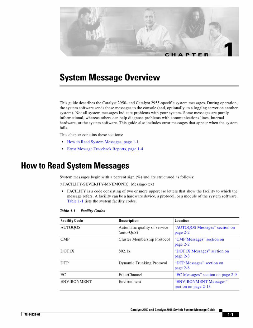
System Message OverviewThis guide describes the Catalyst 2950- and Catalyst 2955-specific system messages. During operation, the system software sends these messages to the console (and, optionally, to a logging server on another system). Not all system messages indicate problems with your system. Some messages are purely informational, whereas others can help diagnose problems with communications lines, internal hardware, or the system software. This guide also includes error messages that appear when the system fails.
This chapter contains these sections:
• How to Read System Messages, page 1-1
• Error Message Traceback Reports, page 1-4
How to Read System MessagesSystem messages begin with a percent sign (%) and are structured as follows:
%FACILITY-SEVERITY-MNEMONIC: Message-text
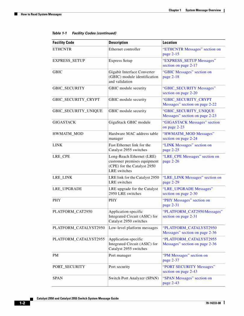
• FACILITY is a code consisting of two or more uppercase letters that show the facility to which the message refers. A facility can be a hardware device, a protocol, or a module of the system software. Table 1-1 lists the system facility codes.
Table 1-1 Facility Codes
Facility Code Description Location
AUTOQOS Automatic quality of service (auto-QoS)
“AUTOQOS Messages” section on page 2-2
CMP Cluster Membership Protocol “CMP Messages” section on page 2-2
DOT1X 802.1x “DOT1X Messages” section on page 2-3
DTP Dynamic Trunking Protocol “DTP Messages” section on page 2-8
EC EtherChannel “EC Messages” section on page 2-9
ENVIRONMENT Environment “ENVIRONMENT Messages” section on page 2-13
1-1yst 2955 Switch System Message Guide
Chapter 1 System Message OverviewHow to Read System Messages
ETHCNTR Ethernet controller “ETHCNTR Messages” section on page 2-15
EXPRESS_SETUP Express Setup “EXPRESS_SETUP Messages” section on page 2-17
GBIC Gigabit Interface Converter (GBIC) module identification and validation
“GBIC Messages” section on page 2-18
GBIC_SECURITY GBIC module security “GBIC_SECURITY Messages” section on page 2-20
GBIC_SECURITY_CRYPT GBIC module security “GBIC_SECURITY_CRYPT Messages” section on page 2-22
GBIC_SECURITY_UNIQUE GBIC module security “GBIC_SECURITY_UNIQUE Messages” section on page 2-23
GIGASTACK GigaStack GBIC module “GIGASTACK Messages” section on page 2-23
HWMATM_MOD Hardware MAC address table manager
“HWMATM_MOD Messages” section on page 2-24
LINK Fast Ethernet link for the Catalyst 2955 switches
“LINK Messages” section on page 2-25
LRE_CPE Long-Reach Ethernet (LRE) customer premises equipment (CPE) for the Catalyst 2950 LRE switches
“LRE_CPE Messages” section on page 2-26
LRE_LINK LRE link for the Catalyst 2950 LRE switches
“LRE_LINK Messages” section on page 2-29
LRE_UPGRADE LRE upgrade for the Catalyst 2950 LRE switches
“LRE_UPGRADE Messages” section on page 2-30
PHY PHY “PHY Messages” section on page 2-31
PLATFORM_CAT2950 Application-specific Integrated Circuit (ASIC) for Catalyst 2950 switches
“PLATFORM_CAT2950 Messages” section on page 2-31
PLATFORM_CATALYST2950 Low-level platform messages “PLATFORM_CATALYST2950 Messages” section on page 2-36
PLATFORM_CATALYST2955 Application-specific Integrated Circuit (ASIC) for Catalyst 2955 switches
“PLATFORM_CATALYST2955 Messages” section on page 2-36
PM Port manager “PM Messages” section on page 2-37
PORT_SECURITY Port security “PORT SECURITY Messages” section on page 2-43
SPAN Switch Port Analyzer (SPAN) “SPAN Messages” section on page 2-43
Table 1-1 Facility Codes (continued)
Facility Code Description Location
1-2Catalyst 2950 and Catalyst 2955 Switch System Message Guide
78-14233-08
Chapter 1 System Message OverviewHow to Read System Messages
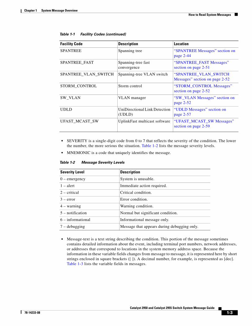
• SEVERITY is a single-digit code from 0 to 7 that reflects the severity of the condition. The lower the number, the more serious the situation. Table 1-2 lists the message severity levels.
• MNEMONIC is a code that uniquely identifies the message.
• Message-text is a text string describing the condition. This portion of the message sometimes contains detailed information about the event, including terminal port numbers, network addresses, or addresses that correspond to locations in the system memory address space. Because the information in these variable fields changes from message to message, it is represented here by short strings enclosed in square brackets ([ ]). A decimal number, for example, is represented as [dec]. Table 1-3 lists the variable fields in messages.
SPANTREE Spanning tree “SPANTREE Messages” section on page 2-44
SPANTREE_FAST Spanning-tree fast convergence
“SPANTREE_FAST Messages” section on page 2-51
SPANTREE_VLAN_SWITCH Spanning-tree VLAN switch “SPANTREE_VLAN_SWITCH Messages” section on page 2-52
STORM_CONTROL Storm control “STORM_CONTROL Messages” section on page 2-52
SW_VLAN VLAN manager “SW_VLAN Messages” section on page 2-52
UDLD UniDirectional Link Detection (UDLD)
“UDLD Messages” section on page 2-57
UFAST_MCAST_SW UplinkFast multicast software “UFAST_MCAST_SW Messages” section on page 2-59
Table 1-1 Facility Codes (continued)
Facility Code Description Location
Table 1-2 Message Severity Levels
Severity Level Description
0 – emergency System is unusable.
1 – alert Immediate action required.
2 – critical Critical condition.
3 – error Error condition.
4 – warning Warning condition.
5 – notification Normal but significant condition.
6 – informational Informational message only.
7 – debugging Message that appears during debugging only.
1-3Catalyst 2950 and Catalyst 2955 Switch System Message Guide
78-14233-08
Chapter 1 System Message OverviewError Message Traceback Reports
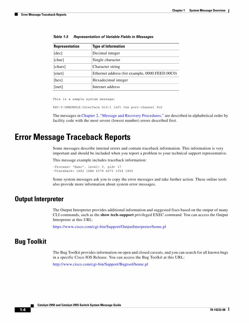
This is a sample system message:
%EC-5-UNBUNDLE:Interface Gi0/1 left the port-channel Po2
The messages in Chapter 2, “Message and Recovery Procedures,” are described in alphabetical order by facility code with the most severe (lowest number) errors described first.
Error Message Traceback ReportsSome messages describe internal errors and contain traceback information. This information is very important and should be included when you report a problem to your technical support representative.
This message example includes traceback information:
-Process= "Exec", level= 0, pid= 17-Traceback= 1A82 1AB4 6378 A072 1054 1860
Some system messages ask you to copy the error messages and take further action. These online tools also provide more information about system error messages.
Output InterpreterThe Output Interpreter provides additional information and suggested fixes based on the output of many CLI commands, such as the show tech-support privileged EXEC command. You can access the Output Interpreter at this URL:
https://www.cisco.com/cgi-bin/Support/OutputInterpreter/home.pl
Bug ToolkitThe Bug Toolkit provides information on open and closed caveats, and you can search for all known bugs in a specific Cisco IOS Release. You can access the Bug Toolkit at this URL:
http://www.cisco.com/cgi-bin/Support/Bugtool/home.pl
Table 1-3 Representation of Variable Fields in Messages
Representation Type of Information
[dec] Decimal integer
[char] Single character
[chars] Character string
[enet] Ethernet address (for example, 0000.FEED.00C0)
[hex] Hexadecimal integer
[inet] Internet address
1-4Catalyst 2950 and Catalyst 2955 Switch System Message Guide
78-14233-08
Chapter 1 System Message OverviewError Message Traceback Reports
Contacting TACIf you cannot determine the nature of the error, see the “Obtaining Documentation” section on page vii for more information.
1-5Catalyst 2950 and Catalyst 2955 Switch System Message Guide
78-14233-08

Chapter 1 System Message OverviewError Message Traceback Reports
1-6Catalyst 2950 and Catalyst 2955 Switch System Message Guide
78-14233-08
Catalyst 2950 and Catal78-14233-08
C H A P T E R 2
Message and Recovery ProceduresThis chapter describes the switch system messages in alphabetical order by facility. Within each facility, the messages are listed by severity levels 0 to 7: 0 is the highest severity level, and 7 is the lowest severity level. Each message is followed by an explanation and a recommended action.
Note The messages listed in this chapter do not include the date/time stamp designation that displays only if the software is configured for system log messaging.
This chapter contains these message categories:
• AUTOQOS Messages, page 2-2
• CMP Messages, page 2-2
• DOT1X Messages, page 2-3
• DTP Messages, page 2-8
• EC Messages, page 2-9
• ENVIRONMENT Messages, page 2-13
• ETHCNTR Messages, page 2-15
• EXPRESS_SETUP Messages, page 2-17
• GBIC Messages, page 2-18
• GBIC_SECURITY Messages, page 2-20
• GBIC_SECURITY_CRYPT Messages, page 2-22
• GBIC_SECURITY_UNIQUE Messages, page 2-23
• GIGASTACK Messages, page 2-23
• HWMATM_MOD Messages, page 2-24
• LINK Messages, page 2-25
• LRE_CPE Messages, page 2-26
• LRE_LINK Messages, page 2-29
• LRE_UPGRADE Messages, page 2-30
• PHY Messages, page 2-31
• PLATFORM_CAT2950 Messages, page 2-31
• PLATFORM_CATALYST2950 Messages, page 2-36
2-1yst 2955 Switch System Message Guide
Chapter 2 Message and Recovery ProceduresAUTOQOS Messages
• PLATFORM_CATALYST2955 Messages, page 2-36
• PM Messages, page 2-37
• PORT SECURITY Messages, page 2-43
• SPAN Messages, page 2-43
• SPANTREE Messages, page 2-44
• SPANTREE_FAST Messages, page 2-51
• SPANTREE_VLAN_SWITCH Messages, page 2-52
• STORM_CONTROL Messages, page 2-52
• SW_VLAN Messages, page 2-52
• UDLD Messages, page 2-57
• UFAST_MCAST_SW Messages, page 2-59
AUTOQOS MessagesThis section contains the automatic quality of service (auto-QoS) messages.
Error Message AUTOQOS-3-FEATURE_UNINITIALIZED: Feature not initialized in the platform, [chars].
Explanation This message means that the feature did not initialize and is not enabled on any interface. [chars] is the feature name, which is auto-QoS.
Recommended Action If this feature does not operate, reboot the system by using the reload privileged EXEC command. Verify that this feature is supported on your switch by checking the software configuration guide for this software release.
CMP MessagesThis section contains the Cluster Membership Protocol (CMP) messages.
Error Message CMP-5-ADD: The Device is added to the cluster (Cluster Name:[chars], CMDR IP Address [inet]).
Explanation This message means that the device is added to the cluster. [chars] is the cluster name, and [inet] is the Internet address of the command switch.
Recommended Action No action is required.
2-2Catalyst 2950 and Catalyst 2955 Switch System Message Guide
78-14233-08
Chapter 2 Message and Recovery ProceduresDOT1X Messages
Error Message CMP-5-MEMBER_CONFIG_UPDATE: Received member configuration from member [dec].
Explanation This message means that the active or standby command switch received a member configuration. [dec] is the member number of the sender.
Recommended Action No action is required.
Error Message CMP-5-MGMT_VLAN_CHNG: The management vlan has been changed to [dec].
Explanation This message means that the management VLAN has changed. [dec] is the new management VLAN number.
Recommended Action No action is required.
Error Message CMP-5-NBR_UPD_SIZE_TOO_BIG: Number of neighbors in neighbor update is [int], maximum number of neighbors allowed in neighbor update is [int].
Explanation This message means that the number of cluster neighbors in the clustering neighbor update packet exceeds the number of neighbors supported by the clustering module design. [int] is the number of cluster neighbors.
Recommended Action No action is required.
Error Message CMP-5-REMOVE: The Device is removed from the cluster (Cluster Name:[chars]).
Explanation This message means that the device is removed from the cluster. [chars] is the cluster name.
Recommended Action No action is required.
DOT1X MessagesThis section contains the 802.1x authorization messages.
Error Message DOT1X_MOD-3-NULLPTR: Unexpected null pointer in [chars] at [dec].
Explanation This message means that an internal software error occurred. [chars] is the software filename, and [dec] is the line number in the file.
Recommended Action Copy the error message exactly as it appears on the console or in the system log. Enter the show tech-support privileged EXEC command to gather data that might provide information about the error. If you cannot determine the nature of the error from the error message or from the show tech-support command display, call your Cisco technical support representative, and provide the representative with the gathered information.
2-3Catalyst 2950 and Catalyst 2955 Switch System Message Guide
78-14233-08
Chapter 2 Message and Recovery ProceduresDOT1X Messages
Error Message DOT1X-3-VLANINVALID: Received invalid vlan ([dec]) from RADIUS for [chars].
Explanation This message means that during 802.1x authorization, the RADIUS server provided a VLAN ID that is not configured on the switch.
Recommended Action Change the VLAN ID in the RADIUS configuration, or configure the VLAN on the switch.
Error Message DOT1X-3-VLANMALFORMED: Received malformed vlan from RADIUS for [chars].
Explanation This message means that during 802.1x authorization, the RADIUS server provided an invalid VLAN ID.
Recommended Action Correct the VLAN ID in the RADIUS configuration.
Error Message DOT1X-3-VOICEVLAN: Received voice vlan ([dec]) from RADIUS for [chars].
Explanation This message means that during 802.1x authorization, the RADIUS server provided a VLAN ID that conflicts with the voice VLAN ID on the port.
Recommended Action Change the VLAN ID in the RADIUS configuration, or change the voice VLAN on the switch port.
Error Message DOT1X-4-MEM_UNAVAIL: Memory was not available to perform the 802.1X action.
Explanation This message means that the system memory is not sufficient to perform the 802.1x authentication.
Recommended Action Reduce other system activity to reduce memory demands.
Error Message DOT1X-4-MSG_ERR: Unknown message event received.
Explanation This message means that the 802.1x process received an unknown message event.
Recommended Action Restart the 802.1x process by entering the dot1x system-auth-control global configuration command. If this message recurs, reload the device.
Error Message DOT1X-4-UNKN_ERR: An unknown operational error occurred.
Explanation This message means that the 802.1x process cannot operate because of an internal system error.
Recommended Action No action is required.
2-4Catalyst 2950 and Catalyst 2955 Switch System Message Guide
78-14233-08

Chapter 2 Message and Recovery ProceduresDOT1X Messages
Error Message DOT1X-5-ERR_CHANNELLING: Dot1x can not be enabled on Channelling ports.
Explanation This message means that 802.1x could not be enabled on the channeling port. Attempting to set 802.1x port-control to auto or force-unauthorized (force_unauth) mode on a channeling port, which is not allowed, causes this condition.
Recommended Action Disable channeling on the interface, and then enable 802.1x.
Error Message DOT1X-5-ERR_DYNAMIC: Dot1x can not be enabled on Dynamic ports.
Explanation This message means that 802.1x could not be enabled on the dynamic mode port. Attempting to set 802.1x port-control to auto or force-unauthorized (force_unauth) mode on a dynamic mode port, which is not allowed, causes this condition.
Recommended Action Disable dynamic mode on the interface, and then enable 802.1x.
Error Message DOT1X-5-ERR_DYNAMIC_VLAN: Dot1x can not be enabled on Dynamic VLAN ports.
Explanation This message means that 802.1x could not be enabled on the dynamic VLAN port. Attempting to set 802.1x port-control to auto or force-unauthorized (force_unauth) mode on a dynamic VLAN port, which is not allowed, causes this condition.
Recommended Action Disable dynamic VLAN configuration on the interface, and enable 802.1x.
Error Message DOT1X-5-ERR_INVALID_AAA_ATTR: Got invalid AAA attribute settings [chars]
Explanation This message means that the authorization settings are either unsupported or invalid.
Recommended Action Change the settings to valid values.
Error Message DOT1X-5-ERR_MULTI_ACCESS: Dot1x can not be enabled on voice vlan configured ports.
Explanation This message means that 802.1x could not be enabled on a voice VLAN-configured port. Attempting to set 802.1x port-control to auto or force-unauthorized (force_unauth) mode on a voice VLAN-configured port, which is not allowed, causes this condition.
Recommended Action Disable the voice VLAN on the interface, and enable 802.1x.
Error Message DOT1X-5-ERR_RADIUSVLAN_EQ_VVLAN: RADIUS attempted to assign a VLAN to Dot1x port [chars] whose Voice VLAN is same as AccessVlan
Explanation This message means that the RADIUS server attempted to assign a VLAN to a client on a port with a voice VLAN that is equal to the access VLAN.
Recommended Action Either update the RADIUS configuration to not assign the VLAN equal to the voice VLAN, or change the voice VLAN on this port.
2-5Catalyst 2950 and Catalyst 2955 Switch System Message Guide
78-14233-08
Chapter 2 Message and Recovery ProceduresDOT1X Messages
Error Message DOT1X-5-ERR_RSPAN_VLAN: Dot1x can not be enabled on ports configured in Remote SPAN vlan.
Explanation This message means that 802.1x could not be enabled on the remote SPAN VLAN port. Attempting to set 802.1x port-control to auto or force-unauthorized (force_unauth) mode on a port that is in a remote SPAN VLAN, which is not allowed, causes this condition.
Recommended Action Disable the remote SPAN on the VLAN, and enable 802.1x.
Error Message DOT1X-5-ERR_TRUNK: Dot1x can not be enabled on Trunk port.
Explanation This message means that 802.1x could not be enabled on the trunk port. Attempting to set 802.1x port-control to auto or force-unauthorized (force_unauth) mode on a trunk port, which is not allowed, causes this condition.
Recommended Action Disable trunking on the interface, and then enable 802.1x.
Error Message DOT1X-5-ERR_VLAN_INVALID: The VLAN [dec] is invalid and cannot be assigned for use on the 802.1X port [chars] Vlan
Explanation This message means that the specified VLAN is out of range and cannot be assigned again for use on this port.
Recommended Action Update the configuration to use a valid VLAN.
Error Message DOT1X-5-ERR_VLAN_NOT_ASSIGNABLE: RADIUS tried to assign a VLAN to dot1x port [chars] whose VLAN cannot be assigned
Explanation This message means that the RADIUS server tried to assign a VLAN to a client on a port whose VLAN cannot be changed, such as a routed port.
Recommended Action There is no recommended action.
Error Message DOT1X-5-ERR_VLAN_NOT_FOUND: Attempt to assign non-existent [chars] VLAN [chars] to dot1x port [chars]
Explanation This message means that an attempt to assign a VLAN to a client on a port fails because the VLAN was not found in the VTP database.
Recommended Action Verify that the VLAN exists, or use another VLAN.
Error Message DOT1X-5-ERR_VLAN_RESERVED: The VLAN [dec] is a reserved vlan and cannot be assigned for use on the Dot1x port [chars] Vlan
Explanation This message means that the specified VLAN is reserved and cannot be assigned for use on this port.
Recommended Action Update the configuration to not use this VLAN.
2-6Catalyst 2950 and Catalyst 2955 Switch System Message Guide
78-14233-08
Chapter 2 Message and Recovery ProceduresDOT1X Messages
Error Message DOT1X-5-ERR_VLAN_RSPAN_CONFIGURED: VLAN [dec] is configured as a Remote SPAN VLAN, which has Dot1x enabled interface(s) configured. Please disable Dot1x on all ports in this VLAN or do not enable RSPAN on this VLAN.
Explanation This message means that you should not enable RSPAN on a VLAN whose ports are configured with 802.1x enabled.
Recommended Action Either disable the RSPAN configuration on the VLAN, or disable 802.1x on all of the ports in this VLAN.
Error Message DOT1X-5-INVALID_INPUT: Dot1x Interface parameter is Invalid on interface [chars].
Explanation This message means that the 802.1x interface parameter is out of the specified range or is invalid.
Recommended Action See the CLI help by entering a ? after the command to see the valid range.
Error Message DOT1X-5-INVALID_MAC: Invalid MAC address (drop, zero, broadcast or multicast mac address) [enet] is trying to authenticate.
Explanation This message means that a MAC address that was either a zero, broadcast, or multicast address attempted authentication by using 802.1x. However, 802.1x authentication is allowed only for valid nonzero, nonbroadcast, or nonmulticast source MAC addresses.
Recommended Action Connect a host that has a valid 802.1x address to the 802.1x-enabled port.
Error Message DOT1X-5-NOT_DOT1X_CAPABLE: Dot1x disabled on interface [chars] because it is not an Ethernet interface.
Explanation This message means that you can enable 802.1x authentication only on Ethernet interfaces.
Recommended Action Enable 802.1x authentication only on Ethernet interfaces.
Error Message DOT1X-5-SECURITY_VIOLATION: Security violation on interface [chars], New MAC address [enet] is seen on the interface in [chars] mode.
Explanation This message means that the port on the specified interface is configured in single-host mode. Any new host that is detected on the interface is perceived as a security violation. The port has been disabled.
Recommended Action Verify that the port is configured to use only one host. Enter the shutdown command followed by the no shutdown interface configuration command to restart the port.
2-7Catalyst 2950 and Catalyst 2955 Switch System Message Guide
78-14233-08
Chapter 2 Message and Recovery ProceduresDTP Messages
DTP MessagesThis section contains the Dynamic Trunking Protocol (DTP) messages.
Error Message DTP-4-MEM_UNAVAIL: Memory was not available to perform the trunk negotiation action.
Explanation This message means that the system is unable to negotiate trunks because of a lack of memory.
Recommended Action Reduce other system activity to ease the memory demands.
Error Message DTP-4-TMRERR: An internal timer error occurred when trunking on interface [chars].
Explanation This message means that a timer used by the trunking protocol unexpectedly expired. [chars] is the trunked interface.
Recommended Action This error is internally corrected, and no long-term ramifications exist. However, if more problems with trunking occur, reload the switch by using the reload privileged EXEC command.
Error Message DTP-4-UNKN_ERR: An unknown operational error occurred.
Explanation This message means that the system is unable to negotiate trunks because an internal operation generated an unexpected error.
Recommended Action Reload the switch by using the reload privileged EXEC command.
Error Message DTP-5-DOMAINMISMATCH: Unable to perform trunk negotiation on port [chars] because of VTP domain mismatch.
Explanation This message means that the two ports involved in trunk negotiation belong to different VTP domains. Trunking is possible only when the ports involved belong to the same VTP domain. [chars] is the name of the interface.
Recommended Action Ensure that the two ports that are involved in trunk negotiation belong to the same VTP domain.
Error Message DTP-5-ILGLCFG: Illegal config (on, isl--on, dot1q) on [chars].
Explanation This message means that one end of the trunk is configured as on, ISL, and the other end is configured as on, 802.1Q. [chars] is the interface.
Recommended Action This configuration is illegal and will not establish a trunk between two switches. You must change the encapsulation type so that both ends of the trunk match.
2-8Catalyst 2950 and Catalyst 2955 Switch System Message Guide
78-14233-08
Chapter 2 Message and Recovery ProceduresEC Messages
Error Message DTP-5-NONTRUNKPORTON: Port [chars] has become non-trunk.
Explanation This message means that the interface changed from trunk to access. [chars] is the interface that changed.
Recommended Action This message is provided for information only.
Error Message DTP-5-TRUNKPORTCHG: Port [chars] has changed from [chars] trunk to [chars] trunk.
Explanation This message means that the encapsulation type of the trunk has changed. The first [chars] is the interface, the second [chars] is the original encapsulation type, and the third [chars] is the new encapsulation type.
Recommended Action This message is provided for information only.
Error Message DTP-5-TRUNKPORTON: Port [chars] has become [chars] trunk.
Explanation This message means that the interface changed from an access to a trunk. The first [chars] is the interface, and the second [chars] is the encapsulation.
Recommended Action This message is provided for information only.
EC MessagesThis section contains the EtherChannel, Link Aggregation Control Protocol (LACP), and Port Aggregation Protocol (PAgP) messages.
Error Message EC-4-NOMEM: Not enough memory available for [chars].
Explanation This message means that either the LACP or the PAgP EtherChannel could not obtain the memory it needed to initialize the required data structures. [chars] is the name of the data structure.
Recommended Action Find out more about the error by using the show tech-support privileged EXEC command and by copying the error message exactly as it appears on the console or system log and entering it in the Output Interpreter tool. Use the Bug Toolkit to look for similar reported problems. For more information about these online tools and about contacting Cisco, see the “Error Message Traceback Reports” section on page 1-4 for more information.
Error Message EC-5-BUNDLE: Interface [chars] joined port-channel [chars].
Explanation This message means that the listed interface joined the specified EtherChannel. The first [chars] is the physical interface, and the second [chars] is the EtherChannel interface.
Recommended Action No action is required.
2-9Catalyst 2950 and Catalyst 2955 Switch System Message Guide
78-14233-08
Chapter 2 Message and Recovery ProceduresEC Messages
Error Message EC-5-CANNOT_ALLOCATE_AGGREGATOR: Aggregator limit reached, cannot allocate aggregator for group [dec].
Explanation This message means that the aggregator cannot be allocated in the group.
Recommended Action Change the port attributes of the ports in the group so that they match and join the same aggregator.
Error Message EC-5-CANNOT_BUNDLE_LACP: [chars] is not compatible with aggregators in channel [dec] and cannot attach to them ([chars]).
Explanation This message means that the port has port attributes that are different from the port channel or ports within the port channel.
Recommended Action Change the port attributes so that they match the other ports in the EtherChannel.
Error Message EC-5-CANNOT_BUNDLE1: Port-channel [chars] is admin-down, port [chars] will remain stand-alone.
Explanation This message means that the EtherChannel is administratively shut down. The first [chars] is the EtherChannel interface, and the second [chars] is the physical interface.
Recommended Action Enable the EtherChannel by using the no shutdown interface configuration command.
Error Message EC-5-CANNOT_BUNDLE2: [chars] is not compatible with [chars] and will be suspended ([chars]).
Explanation This message means that the interface has different interface attributes than other ports in the port channel. For the interface to join the bundle (EtherChannel), change the interface attributes to match the EtherChannel attributes. The first [chars] is the interface to be bundled, the second [chars] is the physical interface that is already in the bundle, and the third [chars] is the reason for the incompatibility.
Recommended Action Change the interface attributes to match the EtherChannel attributes.
Error Message EC-5-COMPATIBLE: [chars] is compatible with port-channel members.
Explanation This message means that a port was not operational because its attributes were different from those of the port channel or ports within the port channel. The system has detected that the attributes of the port now match the port-channel attributes. [chars] is the affected port.
Recommended Action No action is required.
2-10Catalyst 2950 and Catalyst 2955 Switch System Message Guide
78-14233-08
Chapter 2 Message and Recovery ProceduresEC Messages
Error Message EC-5-DONTBNDL: [chars] suspended: incompatible partner port with [chars]
Explanation This message means that the configuration of the partner port differs from the configuration of other ports in the bundle. A port can only join the bundle when its global configuration and the configuration of the partner port are the same as other ports in the bundle.
Recommended Action Verify that the configuration of the partner ports is the same for all ports in the bundle.
Error Message EC-5-ERRPROT: Channel protocol mismatch for interface [chars] in group [dec]: the interface cannot be added to the channel group.
Explanation This message means that the interface cannot be added to the channel group by using the specified mode.
Recommended Action Change the channel group or the mode for the interface.
Error Message EC-5-ERRPROT2: Command rejected: the interface [chars] is already part of a channel with a different type of protocol enabled.
Explanation This message means that the interface cannot be selected for the specified protocol because it is already part of an EtherChannel group with a different protocol enabled.
Recommended Action Remove the interface from the EtherChannel group.
Error Message EC-5-ERRPROT3: Command rejected: the interface [chars] is already part of a channel.
Explanation This message means that the interface cannot be unselected for the specified protocol because it is already part of an EtherChannel group.
Recommended Action Remove the interface from the EtherChannel group.
Error Message EC-5-NOLACP: Invalid EC mode. LACP not enabled.
Explanation This message means that LACP is not included in the image on your switch. An EtherChannel cannot be set into any LACP mode.
Recommended Action Upgrade your switch with an image that supports LACP.
Error Message EC-5-NOPAGP: Invalid EC mode. PAgP not enabled.
Explanation This message means that PAgP is not included in the Cisco IOS image and that the EtherChannel mode cannot be set to desirable or auto.
Recommended Action Obtain an image with PAgP included, or set the mode to on by using the channel-group channel-group-number mode on interface configuration command.
2-11Catalyst 2950 and Catalyst 2955 Switch System Message Guide
78-14233-08
Chapter 2 Message and Recovery ProceduresEC Messages
Error Message EC-5-PORTDOWN: Shutting down [chars] as its port-channel is admin-down.
Explanation This message means that the administrative state of the port is down because its EtherChannel interface, which controls the state of the port, is down.
Recommended Action Enter the no shutdown interface configuration command on the aggregate port.
Error Message EC-5-STAYDOWN: no-shut not allowed on [chars]. Module [dec] not online.
Explanation This message means that an interface with an EtherChannel configuration cannot be enabled by using the no shutdown interface configuration command. It is a member of an EtherChannel group, and that EtherChannel group has been administratively shut down. The interface has an EtherChannel configuration, but no information is available yet about its port channel.
Recommended Action No action is required. Wait until the interface is online to determine the port-channel setting of the EtherChannel.
Error Message EC-5-STAYDOWN: [chars] will remain down as its port-channel [chars] is admin-down.
Explanation This message means that the administrative state of the aggregation port overrides that of the affected port. If the aggregation port is administratively down, all ports in the aggregation port are forced to be administratively down.
Recommended Action Enter the no shutdown interface configuration command on the EtherChannel interface to bring up the aggregation port.
Error Message EC-5-UNBUNDLE: Interface [chars] left the port-channel [chars].
Explanation This message means that the listed interface left the specified EtherChannel. The first [chars] is the physical interface, and the second [chars] is the EtherChannel.
Recommended Action No action is required.
Error Message EC-5-UNSUITABLE: [chars] will not join any port-channel, [chars].
Explanation This message means that one of the interfaces cannot join the EtherChannel because it is configured for PortFast, as a VLAN Membership Policy Server (VMPS), for 802.1x, as a voice VLAN, or as a Switched Port Analyzer (SPAN) destination port. All of these are unsuitable configurations for EtherChannels. The first [chars] is the interface name, and the second [chars] describes the details of the unsuitable configuration.
Recommended Action Reconfigure the port; remove the unsuitable configuration.
2-12Catalyst 2950 and Catalyst 2955 Switch System Message Guide
78-14233-08
Chapter 2 Message and Recovery ProceduresENVIRONMENT Messages
ENVIRONMENT MessagesThis section contains the Environment messages.
Error Message ENVIRONMENT-2-FAN_FAULT: FAN FAULT is detected.
Explanation This message means that an internal fan fault is detected.
Recommended Action Look at the switch to see if the fan is running, or use the show env privileged EXEC command to determine if a fan on the switch has failed. The switch can operate normally with one failed fan. Replace the switch at your convenience.
Error Message ENVIRONMENT-3-OVERTEMP:ASSERT MAJOR Switch Temp above max primary threshold.
Note This message applies only to the Catalyst 2955 switch.
Explanation This message means that the temperature inside the switch exceeds the maximum primary threshold. A major alarm is raised.
Recommended Action Use the show env privileged EXEC command to verify if an over-temperature condition exists. If an over-temperature condition does exist, place the switch in an environment that is within the switch operating temperature. For information about correct operating temperatures, see the Catalyst 2955 Switch Hardware Installation Guide.
Error Message ENVIRONMENT-3-OVERTEMP: CLEAR MAJOR Switch Temp above max primary threshold.
Note This message applies only to the Catalyst 2955 switch.
Explanation This message means that the temperature inside the switch is below the maximum primary threshold. A major alarm is cleared.
Recommended Action No action is required.
Error Message ENVIRONMENT-3-RPS_FAILED:ASSERT [chars] Switch Redundant Pwr missing or failed.
Note This message applies only to the Catalyst 2955 switch.
Explanation This message means that the redundant power supply for a system in dual-power mode is either missing or has failed. An associated [chars] alarm is raised. [chars] is the user-configured alarm for this failure.
Recommended Action No action is required.
2-13Catalyst 2950 and Catalyst 2955 Switch System Message Guide
78-14233-08
Chapter 2 Message and Recovery ProceduresENVIRONMENT Messages
Error Message ENVIRONMENT-3-RPS_FAILED:CLEAR [chars] Switch Redundant Pwr missing or failed.
Note This message applies only to the Catalyst 2955 switch.
Explanation This message means that the redundant power supply for a system in dual-power mode is detected or operational after a failure. An associated [chars] alarm is cleared. [chars] is the user-configured alarm for this failure.
Recommended Action Look at the redundant power supply and make sure that it is operating properly.
Error Message ENVIRONMENT-3-UNDERTEMP:ASSERT MAJOR Switch Temp below min primary
threshold.
Note This message applies only to the Catalyst 2955 switch.
Explanation This message means that the temperature inside the switch is below the minimum primary threshold. A major alarm is raised.
Recommended Action Use the show env privileged EXEC command to verify if an undertemperature condition exists. If an undertemperature condition does exist, place the switch in an environment that is within the switch operating temperature. For information about correct the operating temperature, see the Catalyst 2955 Switch Hardware Installation Guide.
Error Message ENVIRONMENT-3-UNDERTEMP:CLEAR MAJOR Switch Temp above min primary threshold.
Note This message applies only to the Catalyst 2955 switch.
Explanation This message means that the temperature inside the switch is above the minimum primary threshold. A major alarm is cleared.
Recommended Action No action is required.
Error Message ENVIRONMENT-4-CONFIG_OVERTEMP: ASSERT [chars] Switch Temp above secondary threshold.
Note This message applies only to the Catalyst 2955 switch.
Explanation This message means that the temperature inside the switch exceeds the configured threshold. An associated alarm is raised. [chars] is the user-configured alarm for this failure.
Recommended Action No action is required.
2-14Catalyst 2950 and Catalyst 2955 Switch System Message Guide
78-14233-08
Chapter 2 Message and Recovery ProceduresETHCNTR Messages
Error Message ENVIRONMENT-4-CONFIG_OVERTEMP: CLEAR [chars] Switch Temp above secondary threshold.
Note This message applies only to the Catalyst 2955 switch.
Explanation This message means that the temperature inside the switch is below the configured threshold. An associated alarm is cleared. [chars] is the user-configured alarm for this failure.
Recommended Action No action is required.
ETHCNTR MessagesThis section contains the Ethernet controller messages. These messages are a result of a failure of the switch software when trying to program the hardware. Most of these errors lead to incorrect switch behavior.
Error Message ETHCNTR-3-HALF_DUX_COLISION_EXCEED_THRESHOLD: Collision at [chars] exceed threshold. Consider as loop-back.
Explanation This message means that the collision at a half-duplex port exceeded the threshold, and the port is considered to be in the loop-back state. [chars] is the port where the threshold was exceeded.
Recommended Action No action is required on non-PoE switches. The port goes into error-disabled mode until the problem is resolved.
Error Message ETHCNTR-3-INVALIDMAP: Invalid map [dec] for address [enet].
Explanation This message means that an attempt to bridge a packet in software obtained an invalid result. [dec] is the map number, and [enet] is the Ethernet address.
Recommended Action Find out more about the error by using the show tech-support privileged EXEC command and by copying the error message exactly as it appears on the console or system log and entering it in the Output Interpreter tool. Use the Bug Toolkit to look for similar reported problems. For more information about these online tools and about contacting Cisco, see the “Error Message Traceback Reports” section on page 1-4 for more information.
Error Message ETHCNTR-3-LOOP_BACK_DETECTED:, Loop-back detected on [chars]. The port is forced to linkdown.
Explanation This message means that a loopback condition might be the result of a balun cable incorrectly connected into a port. [chars] is the port.
Recommended Action On non-PoE switches, check the cables. If a balun cable is connected and the loopback condition is desired, no action is required. Otherwise, connect the correct cable, and then enable the port up by entering the no shutdown interface configuration command.
2-15Catalyst 2950 and Catalyst 2955 Switch System Message Guide
78-14233-08
Chapter 2 Message and Recovery ProceduresETHCNTR Messages
Error Message ETHCNTR-3-RA_ALLOC_ERROR:RAM Access [chars] [chars] memory allocation failure.
Explanation This message means that a request to read from or write to the RAM access failed its memory allocation. The first [chars] is the RAM access command that failed, and the second [chars] describes whether processor memory allocation or I/O memory allocation failed.
Recommended Action Find out more about the error by using the show tech-support privileged EXEC command and by copying the error message exactly as it appears on the console or system log and entering it in the Output Interpreter tool. Use the Bug Toolkit to look for similar reported problems. For more information about these online tools and about contacting Cisco, see the “Error Message Traceback Reports” section on page 1-4 for more information.
Error Message ETHCNTR-3-RA_REPLY_ERROR: Invalid reply to RAM Access [chars] request ([hex]) from satellite [dec].
Explanation This message means that a request to read from or write to the satellite RAM produced an unexpected reply. [chars] is the request type (read or write), [hex] is the address, and [dec] is the satellite number.
Recommended Action Find out more about the error by using the show tech-support privileged EXEC command and by copying the error message exactly as it appears on the console or system log and entering it in the Output Interpreter tool. Use the Bug Toolkit to look for similar reported problems. For more information about these online tools and about contacting Cisco, see the “Error Message Traceback Reports” section on page 1-4 for more information.
Error Message ETHCNTR-3-UNEXPECTED_EVENT: Request [hex] encountered event [dec] in state [dec].
Explanation This message means that an unexpected event occurred during a RAM-access request. [hex] is a request identifier. The first [dec] is an event number, and the second [dec] is a state number.
Recommended Action Find out more about the error by using the show tech-support privileged EXEC command and by copying the error message exactly as it appears on the console or system log and entering it in the Output Interpreter tool. Use the Bug Toolkit to look for similar reported problems. For more information about these online tools and about contacting Cisco, see the “Error Message Traceback Reports” section on page 1-4 for more information.
2-16Catalyst 2950 and Catalyst 2955 Switch System Message Guide
78-14233-08
Chapter 2 Message and Recovery ProceduresEXPRESS_SETUP Messages
EXPRESS_SETUP MessagesThis section contains messages for the Express Setup feature.
Error Message EXPRESS_SETUP-3-UNABLE_TO_RESET_CONFIG<EMB_ErrMsgBody>: [chars]
Explanation This message means the system is unable to reset the configuration. [chars] is a text string that explains why the reset failed. For example, error renaming config file, error removing config file, or error removing private config file.
Recommended Action Find out more about the error by using the show tech-support privileged EXEC command and by copying the error message exactly as it appears on the console or system log and entering it in the Output Interpreter tool. Use the Bug Toolkit to look for similar reported problems. For more information about these online tools and about contacting Cisco, see the “Error Message Traceback Reports” section on page 1-4 for more information.
Error Message EXPRESS_SETUP-6-CONFIG_IS_RESET: [chars]
Explanation This message means that the configuration is reset. [chars] is a text message that clarifies the reset event, such as The configuration is reset and the system will now reboot.
Recommended Action No action is required.
Error Message EXPRESS_SETUP-6-MODE_ENTERED:
Explanation This message means that Express Setup mode is active.
Recommended Action No action is required.
Error Message EXPRESS_SETUP-6-MODE_EXITED
Explanation This message means that Express Setup mode is no longer active.
Recommended Action No action is required.
2-17Catalyst 2950 and Catalyst 2955 Switch System Message Guide
78-14233-08
Chapter 2 Message and Recovery ProceduresGBIC Messages
GBIC MessagesThis section contains Gigabit Interface Converter (GBIC) module identification and validation messages. When a GBIC module is inserted into the switch, the software reads information from the module that identifies its type, and for some types of GBIC modules, obtains additional information to validate the compatibility of the module.
Error Message GBIC_1000BASET-6-GBIC_1000BASET_DEFAULT_CONFIG: 1000BASE-T GBIC module is detected in [chars]. Speed and duplex will be autonegotiated.
Explanation This message means that a 1000BASE-T GBIC module is detected in the slot, and its speed and duplex are automatically negotiated. [chars] is the slot in which the module is installed.
Recommended Action No action is required.
Error Message GBIC_1000BASET-6-GBIC_1000BASET_NO_CONFIG_DUPLEX: Configuration ignored. 1000-BaseT GBIC modules only support autonegotiation on duplex.
Explanation This message means that autonegotiation was not used. The 1000BASE-T GBIC modules only support autonegotiation on duplex.
Recommended Action No action is required.
Error Message GBIC_1000BASET-6-GBIC_1000BASET_NO_CONFIG_NEGOTIATE: Configuration ignored. 1000BASE-T GBIC modules only support autonegotiation.
Explanation This message means that the disabling of autonegotiation was not used. The 1000BASE-T GBIC modules support autonegotiation.
Recommended Action No action is required.
Error Message GBIC_1000BASET-6-GBIC_1000BASET_NO_CONFIG_SPEED: Configuration ignored. 1000-BaseT GBIC modules only support autonegotiation on speed.
Explanation This message means that autonegotiation was ignored. The 1000BASE-T GBIC modules only support autonegotiated speed.
Recommended Action No action is required.
Error Message GBIC-4-CHECK_SUM_FAILED: GBIC EEPROM data check sum failed for GBIC interface [chars].
Explanation This message means that the GBIC module was identified as a Cisco GBIC module, but the system was unable to read vendor-data information to verify its accuracy. [chars] is the interface in which the module is installed.
Recommended Action Remove and re-insert the GBIC module. If it continues to fail after re-insertion, it might be defective.
2-18Catalyst 2950 and Catalyst 2955 Switch System Message Guide
78-14233-08
Chapter 2 Message and Recovery ProceduresGBIC Messages
Error Message GBIC-4-NOREAD_VNAME: Unable to read vendor name for GBIC interface [chars].
Explanation This message means that the GBIC module was identified as a Cisco GBIC module, but the system was unable to read the GBIC vendor name. [chars] is the interface in which the module is installed.
Recommended Action Remove and re-insert the GBIC module. If it continues to fail after re-insertion, it might be defective.
Error Message GBIC-4-NOREAD_VSDATA: Unable to read vendor-specific data for GBIC interface [chars].
Explanation This message means that the GBIC module was identified as a Cisco GBIC module, but the system was unable to read the identifying vendor-specific information to verify its authenticity. [chars] is the interface in which the module is installed.
Recommended Action Remove and re-insert the GBIC module. If it continues to fail after re-insertion, it might be defective.
Error Message GBIC-4-NOREAD_VSERNUM: Unable to read serial number for GBIC interface [chars].
Explanation This message means that the GBIC module was identified as a Cisco GBIC module, but the system was unable to read the serial number of the GBIC module. [chars] is the interface in which the module is installed.
Recommended Action Remove and re-insert the GBIC module. If it continues to fail after re-insertion, it might be defective.
Error Message GBIC-4-UNRECOGNIZED_EXTTYPE: GBIC interface [chars] has unrecognized extended type.
Explanation This message means that the GBIC module was identified as a Cisco GBIC module, but the system does not recognize its reported extended type code. [chars] is the interface in which the module is installed.
Recommended Action Check the list of supported GBIC modules for this version of the system software. An upgrade might be required for newer GBIC modules. Even if the module is unrecognized, it might still operate properly, but perhaps with limited functionality.
Error Message GBIC-4-XCVR_INTERR: Internal error occurred in setup for GBIC interface [chars].
Explanation This message means that the system could not allocate resources or had some other problem during the setup for the specified GBIC interface. [chars] is the interface in which the GBIC module is installed.
Recommended Action Reload the switch by using the reload privileged EXEC command. If the problem persists, call your Cisco technical support representative.
2-19Catalyst 2950 and Catalyst 2955 Switch System Message Guide
78-14233-08
Chapter 2 Message and Recovery ProceduresGBIC_SECURITY Messages
Error Message GBIC-6-SERDES_MODULE_UNKNOWN: Unrecognizable GBIC found in [chars] (module mask [hex]).
Explanation This message means that the GBIC module presented data to the system that did not correctly identify the type of the GBIC module. The switch will treat it as a generic GBIC module. [chars] is the name of the interface in which the unknown module is installed, and [hex] is the module type value returned by the module.
Recommended Action If the GBIC module fails to become operational, carefully remove and re-insert it in the slot. If it continues to fail after re-insertion, it might be defective or incompatible with the switch.
Error Message GBIC-6-SERDES_SERIAL_INV_DATA: Unrecognizable GBIC found in [chars] (serial data [hex]).
Explanation This message means that the GBIC module presented data to the system that did not correctly identify the type of the GBIC module. The switch will treat it as a generic GBIC module. [chars] is the name of the interface where the unrecognizable module is found, and [hex] is the data value returned by the module.
Recommended Action If the GBIC module fails to become operational, carefully remove and re-insert it in the slot. If it continues to fail after re-insertion, it might be defective or incompatible with the switch.
GBIC_SECURITY MessagesThis section contains the Cisco GBIC module security messages. The GBIC modules have a serial EEPROM that contains the serial number, security code, and cyclic redundancy check (CRC). When the GBIC module is inserted into the switch, the software reads the EEPROM to recompute the security code and CRC. The software generates an error message if the CRC is invalid or if the recomputed security code does not match the one stored in the EEPROM.
Error Message GBIC_SECURITY-4-DUPLICATE_SN: GBIC interface [dec] has the same serial number as another GBIC interface.
Explanation This message means that the GBIC module was identified as a Cisco GBIC module, but its serial number matches that of another interface on the system. [chars] is the interface in which the module is installed.
Recommended Action Cisco GBIC modules are assigned unique serial numbers. Verify that the module was obtained from Cisco or a supported vendor.
2-20Catalyst 2950 and Catalyst 2955 Switch System Message Guide
78-14233-08
Chapter 2 Message and Recovery ProceduresGBIC_SECURITY Messages
Error Message GBIC_SECURITY-4-GBIC_INTERR: Internal error occurred in setup for GBIC interface [chars].
Explanation This message means that the system could not allocate resources or had some other problem during the setup for the specified GBIC interface. [chars] is the interface in which the GBIC module is installed.
Recommended Action Reload the switch by using the reload privileged EXEC command. If the problem persists, call your Cisco technical support representative.
Error Message GBIC_SECURITY-4-ID_MISMATCH: Identification check failed for GBIC interface [chars].
Explanation This message means that the GBIC module was identified as a Cisco GBIC module, but the system was unable to verify its identity. [chars] is the interface in which the module is installed.
Recommended Action Check the list of supported GBIC modules for this version of the system software. An upgrade might be required for newer modules. Otherwise, verify that the module was obtained from Cisco or a supported vendor.
Error Message GBIC_SECURITY-4-UNRECOGNIZED_VENDOR: GBIC interface [chars] manufactured by an unrecognized vendor.
Explanation This message means that the GBIC module was identified as a Cisco GBIC module, but the system was unable to match its manufacturer with one of the known list of Cisco GBIC vendors. [chars] is the interface in which the module is installed.
Recommended Action Check the list of supported GBIC modules for this version of the system software. An upgrade might be required for newer modules.
Error Message GBIC_SECURITY-4-VN_DATA_CRC_ERROR: GBIC interface [chars] has bad crc.
Explanation This message means that the GBIC module was identified as a Cisco GBIC module, but it does not have a valid CRC in the EEPROM data. [chars] is the interface in which the module is installed.
Recommended Action Check the list of supported GBIC modules for this version of the system software. An upgrade might be required for newer modules. Even if unrecognized, the module might still operate properly, perhaps with limited functionality.
2-21Catalyst 2950 and Catalyst 2955 Switch System Message Guide
78-14233-08
Chapter 2 Message and Recovery ProceduresGBIC_SECURITY_CRYPT Messages
GBIC_SECURITY_CRYPT MessagesThis section contains the Cisco GBIC module security messages. The switch recognizes the GBIC module as a Cisco GBIC module but identifies another problem with it.
Error Message GBIC_SECURITY_CRYPT-4-ID_MISMATCH: Identification check failed for GBIC in port [dec].
Explanation This message means that the GBIC module was identified as a Cisco GBIC module, but the system was unable to verify its identity. [dec] is the interface in which the module is installed.
Recommended Action Verify that the software release that is running on the system supports the GBIC module. If the GBIC module is newer, a system software upgrade might be required. Otherwise, verify that the GBIC module was obtained from Cisco or from a supported vendor.
Error Message GBIC_SECURITY_CRYPT-4-UNRECOGNIZED_VENDOR: GBIC in port [dec] manufactured by an unrecognized vendor.
Explanation This message means that the GBIC module was identified as a Cisco GBIC module, but the system was unable to match its manufacturer with one on the known list of Cisco GBIC module vendors. [dec] is the interface in which the module is installed.
Recommended Action Verify that the Cisco IOS software running on the system supports the GBIC module. If the GBIC module is newer, a system software upgrade might be required.
Error Message GBIC_SECURITY_CRYPT-4-VN_DATA_CRC_ERROR: GBIC in port [dec] has bad crc.
Explanation This message means that the GBIC module was identified as a Cisco GBIC module, but it does not have a valid CRC in the EEPROM data. [dec] is the interface in which the module is installed.
Recommended Action Verify that the software release that is running on the system supports the GBIC module. If the GBIC module is newer, a system software upgrade might be required. Even if the GBIC module is unrecognized by the system, the GBIC module might still operate properly, but it will have limited functionality.
2-22Catalyst 2950 and Catalyst 2955 Switch System Message Guide
78-14233-08
Chapter 2 Message and Recovery ProceduresGBIC_SECURITY_UNIQUE Messages
GBIC_SECURITY_UNIQUE MessagesThis section contains the Cisco GBIC module security messages that identify whether the GBIC module is unique.
Error Message GBIC_SECURITY_UNIQUE-3-DUPLICATE_GBIC: GBIC interface [dec]/[dec] is a duplicate of GBIC interface [dec]/[dec].
Explanation This message means that the GBIC module was identified as a Cisco GBIC module, but its vendor ID and serial number match that of another interface in the system. The first [dec]/[dec] is the module number and the interface number of the GBIC module that caused the error message to occur. The second [dec]/[dec] is the module number and the interface number of the other GBIC module that is already installed in the system.
Recommended Action Cisco GBIC modules are assigned unique serial numbers. Verify that the GBIC module was obtained from Cisco or from a supported vendor.
Error Message GBIC_SECURITY_UNIQUE-4-DUPLICATE_SN: GBIC interface [dec]/[dec] has the same serial number as another GBIC interface.
Explanation This message means that the GBIC module was identified as a Cisco GBIC module, but its serial number matches that of another interface in the system. The first [dec]/[dec] is the module number and the interface number in which the module is installed. The second [dec]/[dec] is the duplicate module number and the interface number reported in the message.
Recommended Action Cisco GBIC modules are assigned unique serial numbers. Verify that the GBIC module was obtained from Cisco or from a supported vendor.
GIGASTACK MessagesThis section contains the GigaStack GBIC module messages.
Error Message GIGASTACK-1-NO_LOOP_DETECT: The link neighbor of link [dec] of GigaStack GBIC in [chars] did not respond to the loop detection request. If loop topology is deployed, make sure all switches in the stack are running the latest software.
Explanation This message means that no acknowledgement for the loop-detection request is received from one of the links on a GigaStack GBIC module. Either the neighboring switch does not support the GigaStack GBIC loop-breaking algorithm, or the link between the two GigaStack GBIC modules is broken. Under this condition, a GigaStack loop topology is not automatically detected, and the connectivity between switches in the stack can be lost. [dec] is the link number, and [chars] is the slot number.
Recommended Action If a loop topology is used with the GigaStack GBIC module, ensure that the latest software is running on all switches in the stack. Check the GigaStack GBIC modules involved to ensure that they are functioning.
2-23Catalyst 2950 and Catalyst 2955 Switch System Message Guide
78-14233-08
Chapter 2 Message and Recovery ProceduresHWMATM_MOD Messages
Error Message GIGASTACK-3-INIT_FAILURE: GigaStack GBIC in [chars] initialization failed.
Explanation This message means that the GigaStack GBIC module failed power-on self-test (POST). [chars] is the interface name.
Recommended Action Remove the GigaStack GBIC module, and re-insert it into the GBIC module slot.
Error Message GIGASTACK-6-LOOP_BROKEN: Link loss is detected in the GigaStack loop. Link 2 of the GigaStack GBIC in [chars] is re-enabled.
Explanation This message means that the loop formed by GigaStack GBIC modules is broken because of a link loss. Link 2 of the master loop breaker is re-enabled to replace the broken link. [chars] is the interface name.
Recommended Action No action is required.
Error Message GIGASTACK-6-LOOP_DETECTED: GigaStack GBIC in [chars] is selected as Master Loop Breaker. Link 2 of the GigaStack GBIC is disabled to break the loop.
Explanation This message means that a loop is detected in the stack, and this GigaStack GBIC module is selected as the master loop breaker. Link 2 of this GigaStack GBIC module is disabled to break the loop. [chars] is the interface name.
Recommended Action No action is required.
HWMATM_MOD MessagesThis section contains the hardware MAC address table manager (HW MATM) messages.
Error Message HWMATM_MOD-3-NULLPTR: Unexpected null pointer in [chars] at [dec].
Explanation This message means that an internal software error occurred. [chars] is the software filename, and [dec] is the line number in the file.
Recommended Action Copy the error message exactly as it appears on the console or in the system log. Enter the show tech-support privileged EXEC command to gather data that might provide information about the error. If you cannot determine the nature of the error from the error message or from the show tech-support command display, see the “Error Message Traceback Reports” section on page 1-4 for more information.
2-24Catalyst 2950 and Catalyst 2955 Switch System Message Guide
78-14233-08
Chapter 2 Message and Recovery ProceduresLINK Messages
LINK MessagesThis section contains the Fast Ethernet link-specific messages that apply only to the Catalyst 2955 switch.
Error Message LINK-3_FCS_ERROR:ASSERT [chars] [chars] FCS Error.
Explanation This message means that the frame check sequence (FCS) error rate exceeds the configured FCS error rate threshold. An associated alarm is raised. The first [chars] is the user configured alarm for this fault condition. The second [chars] is the interface.
Recommended Action Verify that there is not a loose connection between the cabling and the switch. If the problem persists, call your Cisco technical support representative.
Error Message LINK-3_FCS_ERROR:CLEAR [chars] [chars] FCS Error.
Explanation This message means that the frame check sequence (FCS) error rate is below the configured FCS error rate threshold. An associated alarm is cleared. The first [chars] is the user-configured alarm for this fault condition. The second [chars] is the interface.
Recommended Action No action is required.
Error Message LINK-3_LINK_FAULT:ASSERT [chars] [chars] Link Fault.
Explanation This message means that there is a physical link problem. An associated alarm is raised. The first [chars] is the user-configured alarm for this fault condition. The second [chars] is the interface.
Recommended Action Verify that there is not a loose connection between the cabling and the switch. If the problem persists, call your Cisco technical support representative.
Error Message LINK-3_LINK_FAULT:CLEAR [chars] [chars] Link Fault.
Explanation This message means that the previous physical link problem has been corrected. The associated alarm is cleared. The first [chars] is the user-configured alarm for this fault condition. The second [chars] is the interface.
Recommended Action No action is required.
2-25Catalyst 2950 and Catalyst 2955 Switch System Message Guide
78-14233-08
Chapter 2 Message and Recovery ProceduresLRE_CPE Messages
LRE_CPE MessagesThis section contains the Long-Reach Ethernet (LRE) customer premises equipment (CPE) initialization messages. These messages apply only to Catalyst 2950 LRE switches.
Error Message LRE_CPE-3-INVALIDMODE: CPE on interface [chars] is in invalid mode [chars].
Explanation This message means that the CPE is in a mode that is inconsistent with its other characteristics, such as the model number. The model number might imply a MAC mode while the CPE is in PHY mode. The first [chars] is the interface to which the CPE is connected, and the second [chars] is CPE mode.
Recommended Action Use the show controllers lre cpe mfg privileged EXEC command to verify that the Model Number field is correct. Use the hw-module slot module-slot # upgrade lre remote privileged EXEC command to ensure that the CPE has the latest supported firmware. If the CPE model number and firmware version are correct, use the shutdown interface configuration command followed by the no shutdown command to force the switch to reread CPE information. If the problem persists, contact your technical support representative.
Error Message LRE_CPE-3-INVALIDPATCH: CPE on interface [chars] has invalid LRE firmware.
Explanation This message means that the LRE firmware header does not have a valid signature, or that this firmware header information is inconsistent with the firmware contents. [chars] is the interface to which the CPE is connected.
Recommended Action Upgrade the firmware on the CPE to the latest supported version by using the hw-module slot module-slot # upgrade lre remote privileged EXEC command.
Error Message LRE_CPE-3-INVALIDPHY: CPE on interface [chars] has an unsupported Ethernet PHY.
Explanation This message means that the Ethernet PHY device on the CPE is not supported. This error occurs when the switch cannot recognize the PHY identifier of the PHY devices on the CPE. This error might be caused by these conditions: The software version on the switch is not compatible with this CPE, the CPE is not a Cisco-supported device, or the switch did not correctly read the PHY identifier from the CPE. [chars] is the interface to which the CPE is connected.
Recommended Action Verify that the CPE is a Cisco-supported device. Use the show controllers lre cpe mfg privileged EXEC command to verify that the Model Number field is correctly set. If the software version and CPE model number appear correct, enter the shutdown interface configuration command followed by the no shutdown command to force the switch to reread the PHY identifier. As a last resort, power cycle the CPE. If the error persists, contact your technical support representative.
2-26Catalyst 2950 and Catalyst 2955 Switch System Message Guide
78-14233-08
Chapter 2 Message and Recovery ProceduresLRE_CPE Messages
Error Message LRE_CPE-3-NOVERCKSUM: Could not fetch CPE firmware version and checksum on interface [chars].
Explanation This message means that the system could not obtain the CPE firmware version and checksum. If the CPE has the latest firmware and the CPE model number is correct, this error might be caused because the LRE link between the switch and the CPE is of poor quality. [chars] is the interface to which the CPE is connected.
Recommended Action Use the show controllers lre cpe mfg privileged EXEC command to verify that the Model Number field is correctly set for this CPE. Use the hw-module slot module-slot # lre upgrade remote privileged EXEC command to ensure that the CPE has the latest firmware. Use the shutdown interface configuration command followed by the no shutdown command to force the switch to get the CPE firmware version and checksum value. As a last resort, power cycle the CPE. If the problem persists, contact your technical support representative.
Error Message LRE_CPE-3-UNKNOWNMODEL: CPE has unrecognizable model number [chars] on interface [chars]
Explanation This message means that the Model Number field in the CPE EEPROM output does not match a known CPE model number. The first [chars] is the CPE model number, and the second [chars] is the interface to which the CPE is connected.
Recommended Action Use the show controllers lre cpe mfg privileged EXEC command to check the CPE model number. Verify that the model number is a Cisco-supported one. Use the shutdown interface configuration command followed by no shutdown command to force the switch to get the CPE model number. If the error message persists, copy the output of the show controllers lre cpe mfg command, and contact your technical support representative.
Error Message LRE_CPE-3-WRONGAPPVER: CPE on interface [chars] reported unsupported version of application firmware [chars]. Minimum application firmware version needed [chars]
Explanation This message means that each CPE requires a supported application firmware version to function correctly. This CPE has a application firmware version that predates the earliest supported version. The first [chars] is the interface to which the CPE is connected, the second [chars] is the application firmware version, and the third [chars] is the minimum firmware version required by the CPE.
Recommended Action Application firmware is not currently used on the CPE. This error message is for future use.
2-27Catalyst 2950 and Catalyst 2955 Switch System Message Guide
78-14233-08
Chapter 2 Message and Recovery ProceduresLRE_CPE Messages
Error Message LRE_CPE-3-WRONGBOOTVER: CPE on interface [chars] reported unsupported version of bootloader firmware [chars]. Minimum bootloader firmware version needed [chars]
Explanation This message means that each CPE requires a supported bootloader firmware version to function correctly. This CPE has a version that predates the earliest supported version. The first [chars] is the interface to which the CPE is connected, the second [chars] is the version of the unsupported bootloader firmware, and the third [chars] is the minimum firmware version.
Recommended Action Upgrade the bootloader firmware on the CPE to a version that supports the current requirements by using the hw-module slot module-slot # lre upgrade remote privileged EXEC command. If upgrading the CPE firmware does not solve the problem, force the switch to get the bootloader firmware version by entering the shutdown interface configuration command followed by no shutdown command. As a last resort, power cycle the CPE. If the problem persists, contact your technical support representative.
Error Message LRE_CPE-3-WRONGPATCH: CPE on interface [chars] has wrong patch version [hex]. Patch version [hex] or higher is needed for this CPE.
Explanation This message means that each CPE requires a supported patch version to function. This CPE has a patch version that predates the earliest supported version. This might occur because the switch was upgraded with the latest Cisco IOS software image, but the CPE firmware has not been upgraded. [chars] is the interface to which the CPE is connected, the first [hex] is the incorrect patch version, and the second [hex] is the minimum patch version.
Recommended Action Upgrade the CPE patch to the latest supported version by using the hw-module slot module-slot # upgrade lre remote privileged EXEC command.
Error Message LRE_CPE-5-SSNCHANGED: CPE unit on interface [chars] changed.
Explanation This message means that the CPE system serial number change. This occurs when the CPE unit on the interface was replaced. [chars] is the interface to which the CPE is connected.
Recommended Action No action is required.
2-28Catalyst 2950 and Catalyst 2955 Switch System Message Guide
78-14233-08
Chapter 2 Message and Recovery ProceduresLRE_LINK Messages
LRE_LINK MessagesThis section contains the Long-Reach Ethernet (LRE) link messages. These messages apply only to Catalyst 2950 LRE switches.
Error Message LRE_LINK-3-PROFILE_FAILURE: Interface [chars], profile [chars] failure
Explanation This message means that when the switch reloads or when the LRE link is lost, the LRE port first tries to briefly establish a link with the CPE in a common, reduced rate mode. The switch and CPE exchange configuration information to achieve the link rate of the profile configured for the port. When the reduced rate is achieved, the link is dropped briefly, and the LRE and CPE ports attempt to establish the profile link rate. If no LRE link is established after 30 seconds, this message appears, and the port LED is amber. The port continues to try to establish a link, starting with the reduced rate. If the switch or CPE is not operating properly, this message also appears.The first [chars] is the interface to which the CPE is connected, and the second [chars] is the profile name.
Recommended Action Change the profile on the port to one that has a lower rate or has a longer reach. Too many impairments might be on the connection between the switch and the CPE for the ports to sustain the profile rate. If the switch or CPE is not operating properly, contact Cisco Systems.
Error Message LRE_LINK-3-UPDOWN: Interface [chars], changed state to [chars]
Explanation This message means that the link between the LRE port and the CPE device has been lost and that no Ethernet traffic is being transferred. This could occur because the port was reconfigured, the profile that the ports uses was reconfigured, the LRE switch connector was disconnected or reconnected, the CPE LRE cable was disconnected, or the switch was power-cycled. It might also be caused by a substantial interruption of the signal or cabling between the LRE port and the CPE. The first [chars] is the interface to which the CPE is connected, and the second [chars] is the port status.
Recommended Action If the port or the profile in use is reconfigured, ignore this message. However, if the LRE link still down after a minute, the cable between the switch and the CPE might be disconnected, or the CPE might have lost power.
Error Message LRE_LINK-4-HEALTH_MON: Interface [chars], had crossed certain monitored thresholds
Explanation This message means that the link status monitor for the interface has detected conditions that have crossed the configured thresholds. [chars] is the interface to which the CPE is connected.
Recommended Action Enter the show controllers lre link monitor privileged EXEC command to obtain more information on this error. If the change in operating conditions was unexpected, confirm the configuration settings for the interface.
2-29Catalyst 2950 and Catalyst 2955 Switch System Message Guide
78-14233-08
Chapter 2 Message and Recovery ProceduresLRE_UPGRADE Messages
LRE_UPGRADE MessagesThis section contains the Long-Reach Ethernet (LRE) upgrade messages. These messages apply only to Catalyst 2950 LRE switches.
Error Message LRE_UPGRADE-3-INIT_SYSTEM: Upgrade module failed to initialize
Explanation This message means that the LRE upgrade module failed to initialize.
Recommended Action Copy the error message exactly as it appears on the console or in the system log, call your Cisco technical support representative, and provide the representative with the gathered information.
Error Message LRE_UPGRADE-3-LOCAL_FAILURE: Upgrade of local controller [chars] failed
Explanation This message means that LRE upgrade is unable to download firmware to a local controller. [chars] is the local controller.
Recommended Action Copy the error message exactly as it appears on the console or in the system log, call your Cisco technical support representative, and provide the representative with the gathered information.
Error Message LRE_UPGRADE-4-INIT_RESOURCE: [chars]
Explanation This message means that the LRE upgrade module cannot locate a required resource. [chars] is the missing resource. If the resource message is cannot locate lre firmware files, the LRE upgrade module might not have found a directory in flash memory named flash:/lre-bin. This directory stores the LRE-related firmware files for the LRE switch and LRE CPE devices. The upgrade module cannot initialize unless this directory already exists in flash memory.
Recommended Action Verify that the flash:/lre-bin directory exists. If the directory is missing, create an empty directory named flash:/lre-bin. Otherwise, report this message to your Cisco technical support representative.
Error Message LRE_UPGRADE-4-TERMINATE: Upgrade on [chars] terminated
Explanation This message means that the CPE was disconnected or changed in the middle of an upgrade. [chars] is the CPE.
Recommended Action No action is required.
2-30Catalyst 2950 and Catalyst 2955 Switch System Message Guide
78-14233-08
Chapter 2 Message and Recovery ProceduresPHY Messages
PHY MessagesThis section contains the PHY message.
Error Message PHY-4-MODULE_DUP: SFPs in [chars] and in [chars] have duplicate vendor-id and serial numbers.
Explanation This message means that the small form-factor pluggable (SFP) module was identified as a Cisco SFP, but its vendor ID and serial number match that of another SFP in the system. The first [chars] is the interface in which the SFP is installed, and the second [chars] is the interface where the duplicate SFP is installed.
Recommended Action Cisco SFP modules are assigned unique serial numbers. Verify that the module was obtained from Cisco or a supported vendor. Copy the message exactly as it appears on the console or in the system log. Research and attempt to resolve the error by using the Output Interpreter. Use the Bug Toolkit to look for similar reported problems. If you still require assistance, open a case with the TAC, or contact your Cisco technical support representative, and provide the representative with the gathered information. For more information about these online tools and about contacting Cisco, see the “Error Message Traceback Reports” section on page 1-4.
PLATFORM_CAT2950 MessagesThis section contains the application-specific integrated circuit (ASIC) driver-related messages.
Note Although the error message text refers to PLATFORM_CAT2950 messages, they also apply to the Catalyst 2940 switch.
Error Message PLATFORM_CAT2950-3-ASIC_BIST_FAILURE: C2950 BIST failed for memory [chars] count [dec].
Explanation This message means that, during power-on self-test (POST), the built-in memory test on the ASIC failed, which might occur because the ASIC has a defect. [chars] is the name of the ASIC memory table, and [dec] is the number of address failures in the built-in memory test.
Recommended Action Copy the error message exactly as it appears on the console or in the system log, call your Cisco technical support representative, and provide the representative with the gathered information.
2-31Catalyst 2950 and Catalyst 2955 Switch System Message Guide
78-14233-08
Chapter 2 Message and Recovery ProceduresPLATFORM_CAT2950 Messages
Error Message PLATFORM_CAT2950-3-ASIC_INIT_FAILURE: ASIC driver initialization has failed.
Explanation This message means that one of the steps in the ASIC initialization sequence failed. This might occur because of a failure in the peripheral component interconnect (PCI) configuration setup, the Inter-IC (I2C) initialization, the built-in self-test on the ASIC, or another initialization sequence. This failure might also occur because of an ASIC defect.
Recommended Action Copy the error message exactly as it appears on the console or in the system log, call your Cisco technical support representative, and provide the representative with the gathered information.
Error Message PLATFORM_CAT2950-3-GBP_FAILURE: Unable to initialize the external packet memory.
Explanation This message means that, during the switch driver initialization, there was an error in the external packet memory initialization, which might occur because of a defect in the ASIC or in the external SDRAM.
Recommended Action Copy the error message exactly as it appears on the console or in the system log, call your Cisco technical support representative, and provide the representative with the gathered information.
Error Message PLATFORM_CAT2950-3-GBP_INIT_FAILURE: GBP currently FULL or UNAVAILABLE.
Explanation This message means that, during the switch driver initialization, an error was detected in the external packet memory, which could be caused by a defect in the ASIC or in the external SDRAM.
Recommended Action Copy the error message exactly as it appears on the console or in the system log, call your Cisco technical support representative, and provide the representative with the gathered information.
Error Message PLATFORM_CAT2950-3-MEM_COPY_FAILURE: Invalid copy [dec] for table [chars].
Explanation This message means that there was an attempt to read or write an invalid copy of the switch internal memory. [dec] is the invalid copy number for the table, and [chars] is the name of the ASIC memory table.
Recommended Action If the message recurs, copy the error message exactly as it appears on the console or in the system log, call your Cisco technical support representative, and provide the representative with the gathered information.
2-32Catalyst 2950 and Catalyst 2955 Switch System Message Guide
78-14233-08
Chapter 2 Message and Recovery ProceduresPLATFORM_CAT2950 Messages
Error Message PLATFORM_CAT2950-3-MEM_INDEX_FAILURE: Invalid index [dec] for table [chars].
Explanation This message means that there was an attempt to access an invalid index of the switch internal memory. [dec] is the index number, and [chars] is the name of the ASIC memory table.
Recommended Action If the message recurs, copy the error message exactly as it appears on the console or in the system log, call your Cisco technical support representative, and provide the representative with the gathered information.
Error Message PLATFORM_CAT2950-3-MEM_INIT_FAILURE: The switch memory resources could not be allocated for [chars], initialization failed.
Explanation This message means that, during the switch driver initialization, driver-related memory resources could not be allocated, which might occur because of an ASIC defect. [chars] can be asic instance, switch ports, fast-ethernet queues, or gigabit queues.
Recommended Action Copy the error message exactly as it appears on the console or in the system log, call your Cisco technical support representative, and provide the representative with the gathered information.
Error Message PLATFORM_CAT2950-3-MEM_READ_FAILURE: Read memory failed for memory [chars] at index [dec].
Explanation This message means that an attempt to read a valid location in the internal chip memory failed, which might occur because of an ASIC defect. [chars] is the name of the ASIC memory table, and [dec] is the table index.
Recommended Action If the message recurs, copy the error message exactly as it appears on the console or in the system log, call your Cisco technical support representative, and provide the representative with the gathered information.
Error Message PLATFORM_CAT2950-3-MEM_WRITE_FAILURE: Write memory failed for memory [chars] at index [dec].
Explanation This message means that an attempt to write to a location in the internal chip memory failed, which might occur because of an invalid memory location or an ASIC defect. [chars] is the name of the ASIC memory table, and [dec] is the table index.
Recommended Action If the message recurs, copy the error message exactly as it appears on the console or in the system log, call your Cisco technical support representative, and provide the representative with the gathered information.
2-33Catalyst 2950 and Catalyst 2955 Switch System Message Guide
78-14233-08
Chapter 2 Message and Recovery ProceduresPLATFORM_CAT2950 Messages
Error Message PLATFORM_CAT2950-3-MIIM_OP_FAILURE: Unable to read PHY register at addr [hex] for phy id [hex].
Explanation This message means that there was a failure to read from or write to a PHY register on the switch, which might occur because of a defect in the media independent interface (MII)/Gigabit media independent interface (GMII) switch interface. The first [hex] is the register address, and the second [hex] is the PHY ID.
Recommended Action If the message recurs, copy the error message exactly as it appears on the console or in the system log, call your Cisco technical support representative, and provide the representative with the gathered information.
Error Message PLATFORM_CAT2950-3-PCI_FIND_FAILURE: The number of asics expected were [dec], PCI bus scan found [dec].
Explanation This message means that, during the switch driver initialization, the switch found an incorrect number of ASICs on the PCI bus or did not find any ASICs with a correct PCI value. This might occur because of a system PCI bus defect or an incompatible software version running on the switch. The first [dec] is the number of ASICs that the switch should find, and the second [dec] is the actual number of ASICs that the switch found.
Recommended Action Copy the error message exactly as it appears on the console or in the system log, call your Cisco technical support representative, and provide the representative with the gathered information.
Error Message PLATFORM_CAT2950-3-PCI_INIT_FAILURE: The PCI address space initialization failed.
Explanation This message means that, during the switch driver initialization, the PCI address space for the ASIC could not be initialized, which might occur because of a system PCI-bus problem.
Recommended Action Copy the error message exactly as it appears on the console or in the system log, call your Cisco technical support representative, and provide the representative with the gathered information.
Error Message PLATFORM_CAT2950-3-PCI_TEST_FAILURE: PCI address space test failed, Wrote [hex], read [hex], re-read [hex].
Explanation This message means that, during POST, the PCI address space for the ASIC was not mapped correctly. This might occur because of a system PCI-bus problem. The first [hex], the second [hex], and the third [hex] are test data.
Recommended Action Copy the error message exactly as it appears on the console or in the system log, call your Cisco technical support representative, and provide the representative with the gathered information.
2-34Catalyst 2950 and Catalyst 2955 Switch System Message Guide
78-14233-08
Chapter 2 Message and Recovery ProceduresPLATFORM_CAT2950 Messages
Error Message PLATFORM_CAT2950-3-REG_READ_FAILURE: Register read failed for [chars] in [chars]
Explanation This message means that the register read failed for register [chars] in [chars].An attempt to read a valid location in the internal chip register failed. This could be due to a hardware defect.
Recommended Action Copy the message exactly as it appears on the console or in the system log, call your Cisco technical support representative, and provide the representative with the gathered information.
Error Message PLATFORM_CAT2950-3-REG_WRITE_FAILURE: Register write failed for register [chars] in [chars]
Explanation This message means that an attempt to write to a location in the internal chip register failed. This might be caused by writing to an invalid register location or by a defect in the hardware.
Recommended Action Copy the message exactly as it appears on the console or in the system log, call your Cisco technical support representative, and provide the representative with the gathered information.
Error Message PLATFORM_CAT2950-3-SCHAN_OP_FAILURE: S-channel operation timeout for opcode [chars].
Explanation This message means that there was a failure to read or write to an ASIC register or a memory location because of an ASIC internal bus failure. [chars] is the operation code.
Recommended Action If the message recurs, copy the error message exactly as it appears on the console or in the system log, call your Cisco technical support representative, and provide the representative with the gathered information.
Error Message PLATFORM_CAT2950-3-SCHAN_READ_REG_FAILURE: S-channel operation read register failure at addr [hex].
Explanation This message means that there was a failure to read the ASIC registers, which might occur because of an invalid register address or internal bus failure. [hex] is the register address.
Recommended Action If the message recurs, copy the error message exactly as it appears on the console or in the system log, call your Cisco technical support representative, and provide the representative with the gathered information.
Error Message PLATFORM_CAT2950-3-SYSTEM_INFO_FAILURE: The board information could not be read correctly, initialization failed.
Explanation This message means that, during switch driver initialization, there was a failure to read the system board information, which might occur because of an ASIC problem.
Recommended Action Copy the error message exactly as it appears on the console or in the system log, call your Cisco technical support representative, and provide the representative with the gathered information.
2-35Catalyst 2950 and Catalyst 2955 Switch System Message Guide
78-14233-08
Chapter 2 Message and Recovery ProceduresPLATFORM_CATALYST2950 Messages
PLATFORM_CATALYST2950 MessagesThis section contains the Catalyst 2950 low-level platform message. This message appears when the switch attempts to display the failure message from the previous failure.
Note Although the error message text refers to the PLATFORM_CATALYST2950 message, it also applies to the Catalyst 2940 switch.
Error Message PLATFORM_CATALYST2950-1-CRASHED: [chars]
Explanation This message means that the system is attempting to display the failure message from the previous failure. [chars] is the failure message.
Recommended Action Copy the error message exactly as it appears on the console or in the system log, call your Cisco technical support representative, and provide the representative with the gathered information.
PLATFORM_CATALYST2955 MessagesThis section contains the application-specific integrated circuit (ASIC) driver-related messages for Catalyst 2955 switches.
Error Message PLATFORM_CATALYST2955-3-PORT_NOT_OPERATING: ASSERT [chars] [chars]
Explanation This message means that the port is not operating and the power-on self-test (POST) has failed. An associated alarm is raised. The first [chars] is the user-configured alarm for this failure. The second [chars] is the interface.
Recommended Action Copy the error message exactly as it appears on the console or in the system log, call your Cisco technical support representative, and provide the representative with the gathered information.
Error Message PLATFORM_CATALST2955-3-PORT_NOT_OPERATING: CLEAR [chars] [chars]
Explanation This message means that the failed port is shut down. An associated alarm is cleared. The first [chars] is the user-configured alarm for this failure. The second [chars] is the interface.
Recommended Action Copy the error message exactly as it appears on the console or in the system log, call your Cisco technical support representative, and provide the representative with the gathered information.
2-36Catalyst 2950 and Catalyst 2955 Switch System Message Guide
78-14233-08
Chapter 2 Message and Recovery ProceduresPM Messages
PM MessagesThis section contains the port manager messages. The port manager is a state machine that controls all the logical and physical interfaces. All features, such as VLANs, UDLD, and so forth, work with the port manager to provide switch functions.
Error Message PM-2-NOMEM: Not enough memory available for [chars].
Explanation This message means that the port manager subsystem could not obtain the memory it needed to initialize the specified operation. [chars] is the port manager operation.
Recommended Action Find out more about the error by using the show tech-support privileged EXEC command and by copying the error message exactly as it appears on the console or system log and entering it in the Output Interpreter tool. Use the Bug Toolkit to look for similar reported problems. For more information about these online tools and about contacting Cisco, see the “Error Message Traceback Reports” section on page 1-4 for more information.
Error Message PM-2-VLAN_ADD: Failed to add VLAN [dec] - [chars].
Explanation This message means that the software failed to add the VLAN to the VLAN Trunking Protocol (VTP) database. [dec] is the VLAN ID, and [chars] specifies the reason for the failure.
Recommended Action Find out more about the error by using the show tech-support privileged EXEC command and by copying the error message exactly as it appears on the console or system log and entering it in the Output Interpreter tool. Use the Bug Toolkit to look for similar reported problems. For more information about these online tools and about contacting Cisco, see the “Error Message Traceback Reports” section on page 1-4 for more information.
Error Message PM-3-INTERNALERROR: Port Manager Internal Software Error ([chars]: [chars]: [dec]: [chars])
Explanation This message means that there was an internal software error encountered in the Cisco IOS Port Manager. The first [chars] is the failure that occurred. The second [chars] is the source file where the failure occurred. [dec] is the line number in the file. The fourth [chars] is the name of the function in which the failure occurred.
Recommended Action Find out more about the error by using the show tech-support privileged EXEC command and by copying the error message exactly as it appears on the console or system log and entering it in the Output Interpreter tool. Use the Bug Toolkit to look for similar reported problems. For more information about these online tools and about contacting Cisco, see the “Error Message Traceback Reports” section on page 1-4 for more information.
2-37Catalyst 2950 and Catalyst 2955 Switch System Message Guide
78-14233-08
Chapter 2 Message and Recovery ProceduresPM Messages
Error Message PM-4-BAD_APP_ID: An invalid application id [dec] was detected.
Explanation This message means that the port manager detected an invalid request. [dec] is the application ID.
Recommended Action Find out more about the error by using the show tech-support privileged EXEC command and by copying the error message exactly as it appears on the console or system log and entering it in the Output Interpreter tool. Use the Bug Toolkit to look for similar reported problems. For more information about these online tools and about contacting Cisco, see the “Error Message Traceback Reports” section on page 1-4 for more information.
Error Message PM-4-BAD_APP_REQ: An invalid [chars] request by the '[chars]' application was detected.
Explanation This message means that the port manager detected an invalid request. The first [chars] is the invalid request, and the second [chars] is the application making the request.
Recommended Action Find out more about the error by using the show tech-support privileged EXEC command and by copying the error message exactly as it appears on the console or system log and entering it in the Output Interpreter tool. Use the Bug Toolkit to look for similar reported problems. For more information about these online tools and about contacting Cisco, see the “Error Message Traceback Reports” section on page 1-4 for more information.
Error Message PM-4-BAD_CARD_COOKIE: An invalid card cookie was detected.
Explanation This message means that the port manager detected an invalid request.
Recommended Action Find out more about the error by using the show tech-support privileged EXEC command and by copying the error message exactly as it appears on the console or system log and entering it in the Output Interpreter tool. Use the Bug Toolkit to look for similar reported problems. For more information about these online tools and about contacting Cisco, see the “Error Message Traceback Reports” section on page 1-4 for more information.
Error Message PM-4-BAD_CARD_SLOT: An invalid card slot ([dec]) was detected.
Explanation This message means that the port manager detected an invalid request. [dec] is the slot number.
Recommended Action Find out more about the error by using the show tech-support privileged EXEC command and by copying the error message exactly as it appears on the console or system log and entering it in the Output Interpreter tool. Use the Bug Toolkit to look for similar reported problems. For more information about these online tools and about contacting Cisco, see the “Error Message Traceback Reports” section on page 1-4 for more information.
2-38Catalyst 2950 and Catalyst 2955 Switch System Message Guide
78-14233-08
Chapter 2 Message and Recovery ProceduresPM Messages
Error Message PM-4-BAD_COOKIE: [chars] was detected.
Explanation This message means that the port manager detected an invalid request. [chars] is the invalid request.
Recommended Action Find out more about the error by using the show tech-support privileged EXEC command and by copying the error message exactly as it appears on the console or system log and entering it in the Output Interpreter tool. Use the Bug Toolkit to look for similar reported problems. For more information about these online tools and about contacting Cisco, see the “Error Message Traceback Reports” section on page 1-4 for more information.
Error Message PM-4-BAD_HA_ENTRY_EVENT: Invalid Host access entry event ([dec]) is received.
Explanation This message means that an invalid host access entry event was received; the host access table entry event should be an add, delete, or update event. [dec] is the event that is received.
Recommended Action Find out more about the error by using the show tech-support privileged EXEC command and by copying the error message exactly as it appears on the console or system log and entering it in the Output Interpreter tool. Use the Bug Toolkit to look for similar reported problems. For more information about these online tools and about contacting Cisco, see the “Error Message Traceback Reports” section on page 1-4 for more information.
Error Message PM-4-BAD_PORT_COOKIE: An invalid port cookie was detected.
Explanation This message means that the port manager detected an invalid request.
Recommended Action Find out more about the error by using the show tech-support privileged EXEC command and by copying the error message exactly as it appears on the console or system log and entering it in the Output Interpreter tool. Use the Bug Toolkit to look for similar reported problems. For more information about these online tools and about contacting Cisco, see the “Error Message Traceback Reports” section on page 1-4 for more information.
Error Message PM-4-BAD_PORT_NUMBER: An invalid port number ([dec]) was detected.
Explanation This message means that the port manager detected an invalid request. [dec] is the port number.
Recommended Action Find out more about the error by using the show tech-support privileged EXEC command and by copying the error message exactly as it appears on the console or system log and entering it in the Output Interpreter tool. Use the Bug Toolkit to look for similar reported problems. For more information about these online tools and about contacting Cisco, see the “Error Message Traceback Reports” section on page 1-4 for more information.
2-39Catalyst 2950 and Catalyst 2955 Switch System Message Guide
78-14233-08
Chapter 2 Message and Recovery ProceduresPM Messages
Error Message PM-4-BAD_VLAN_COOKIE: An invalid vlan cookie was detected.
Explanation This message means that the port manager detected an invalid request.
Recommended Action Find out more about the error by using the show tech-support privileged EXEC command and by copying the error message exactly as it appears on the console or system log and entering it in the Output Interpreter tool. Use the Bug Toolkit to look for similar reported problems. For more information about these online tools and about contacting Cisco, see the “Error Message Traceback Reports” section on page 1-4 for more information.
Error Message PM-4-BAD_VLAN_ID: An invalid vlan id ([dec]) was detected.
Explanation This message means that the port manager detected an invalid request. [dec] is the VLAN ID.
Recommended Action Find out more about the error by using the show tech-support privileged EXEC command and by copying the error message exactly as it appears on the console or system log and entering it in the Output Interpreter tool. Use the Bug Toolkit to look for similar reported problems. For more information about these online tools and about contacting Cisco, see the “Error Message Traceback Reports” section on page 1-4 for more information.
Error Message PM-4-ERR_DISABLE: [chars] error detected on [chars], putting [chars] in err-disable state.
Explanation This message means that the port manager detected a misconfiguration or misbehavior and placed the interface in an error-disabled state. A recovery is attempted after the configured retry time (the default is 5 minutes). [chars] is the port where the threshold was exceededThe first [chars] is the error, and the second and third [chars] are the affected interfaces.
Recommended Action Copy the error message exactly as it appears on the console or in the system log. Research and attempt to resolve the error by using the Output Interpreter. Enter the show tech-support user EXEC command to gather data that might help identify the nature of the error. Use the Bug Toolkit to look for similar reported problems. For more information about the online tools and about contacting Cisco, see the “Error Message Traceback Reports” section on page 1-4.
Error Message PM-4-ERR_RECOVER: Attempting to recover from [chars] err-disable state on [chars].
Explanation This message means that the port manager is attempting to bring the interface up after taking it down to the error-disabled state. The first [chars] is the error, and the second [chars] is the affected interface.
Recommended Action Find out more about the error by using the show tech-support privileged EXEC command and by copying the error message exactly as it appears on the console or system log and entering it in the Output Interpreter tool. Use the Bug Toolkit to look for similar reported problems. For more information about these online tools and about contacting Cisco, see the “Error Message Traceback Reports” section on page 1-4 for more information.
2-40Catalyst 2950 and Catalyst 2955 Switch System Message Guide
78-14233-08
Chapter 2 Message and Recovery ProceduresPM Messages
Error Message PM-4-EXT_VLAN_INUSE: VLAN [dec] currently in use by [chars].
Explanation This message means that the port manager failed to allocate the VLAN for external use because the VLAN is being used by another feature. [dec] is the VLAN that is being used, and [chars] is the feature that is using it.
Recommended Action Reconfigure the feature (for example, the routed port) to use another internal VLAN or to request another available VLAN.
Error Message PM-4-EXT_VLAN_NOTAVAIL: VLAN [dec] not available in Port Manager.
Explanation This message means that the port manager failed to allocate the requested VLAN. The VLAN is probably being used as an internal VLAN by other features. [dec] is the requested VLAN.
Recommended Action Try to configure a different VLAN on the device.
Error Message PM-4-INACTIVE: putting [chars] in inactive state because [chars].
Explanation This message means that the port manager has been blocked from creating a virtual port for the switch port and VLAN, causing the port to be in an inactive state. The first [chars] is the interface name. The second [chars] specifies the reason for the error message.
Recommended Action Find out more about the error by using the show tech-support privileged EXEC command and by copying the error message exactly as it appears on the console or system log and entering it in the Output Interpreter tool. Use the Bug Toolkit to look for similar reported problems. For more information about these online tools and about contacting Cisco, see the “Error Message Traceback Reports” section on page 1-4 for more information.
Error Message PM-4-INT_FAILUP: [chars] failed to come up. No internal VLAN available.
Explanation This message means that the port manager failed to allocate an internal VLAN, and the interface cannot come up. [chars] is the interface name.
Recommended Action Remove the extended-range VLAN by using the no vlan vlan-id global configuration command to make resources available.
Error Message PM-4-INT_VLAN_NOTAVAIL: Failed to allocate internal VLAN in Port Manager.
Explanation This message means that the port manager failed to find any available internal VLAN.
Recommended Action Delete some extended-range VLANs created by users, or remove some features (such as routed ports) that require internal VLAN allocation. To delete extended-range VLANs, use the no vlan vlan-id global configuration command. To delete a routed port, use the no switchport interface configuration command.
2-41Catalyst 2950 and Catalyst 2955 Switch System Message Guide
78-14233-08
Chapter 2 Message and Recovery ProceduresPM Messages
Error Message PM-4-INVALID_HOST_ACCESS_ENTRY: Invalid Host access entry type ([dec]) is received.
Explanation This message means that an invalid host access entry type was received; the host access entry should be a configured or dynamic type. [dec] is the entry type that is received.
Recommended Action Find out more about the error by using the show tech-support privileged EXEC command and by copying the error message exactly as it appears on the console or system log and entering it in the Output Interpreter tool. Use the Bug Toolkit to look for similar reported problems. For more information about these online tools and about contacting Cisco, see the “Error Message Traceback Reports” section on page 1-4 for more information.
Error Message PM-4-LIMITS: The number of vlan-port instances on [chars] exceeded the recommended limit of [dec].
Explanation This message means that the total number of individual VLAN ports, counted in the specified module or switch, has exceeded the module or switch limit specified in the error message. VLANs can be counted more than once; if VLAN 1 is carried on ten interfaces, it will count as ten VLAN ports. For some platforms, such as the Catalyst 6000, bundling is also ignored for purposes of this count; if eight interfaces on the same module are in one bundle, and the port channel is carrying VLAN 1, it will count as eight VLAN ports. [chars] is the module name (for example, switch or the module number), and [dec] is the recommended limit.
Recommended Action Reduce the number of trunks and VLANs configured in the specified module or switch. Keep the VLAN port count below the recommended limit specified in the software configuration guide. Use the show interface trunk privileged EXEC command to see the total number of trunks and VLANs.
Error Message PM-4-NO_SUBBLOCK: No PM subblock found for [chars].
Explanation This message means that the port manager failed to find the subblock for this interface. [chars] is the interface name.
Recommended Action Find out more about the error by using the show tech-support privileged EXEC command and by copying the error message exactly as it appears on the console or system log and entering it in the Output Interpreter tool. Use the Bug Toolkit to look for similar reported problems. For more information about these online tools and about contacting Cisco, see the “Error Message Traceback Reports” section on page 1-4 for more information.
Error Message PM-4-TOO_MANY_APP: Application '[chars]' exceeded registration limit.
Explanation This message means that the port manager detected an invalid request. [chars] is the application.
Recommended Action Find out more about the error by using the show tech-support privileged EXEC command and by copying the error message exactly as it appears on the console or system log and entering it in the Output Interpreter tool. Use the Bug Toolkit to look for similar reported problems. For more information about these online tools and about contacting Cisco, see the “Error Message Traceback Reports” section on page 1-4 for more information.
2-42Catalyst 2950 and Catalyst 2955 Switch System Message Guide
78-14233-08
Chapter 2 Message and Recovery ProceduresPORT SECURITY Messages
Error Message PM-4-UNKNOWN_HOST_ACCESS: Invalid Host access value ([dec]) is received.
Explanation This message means that the host access table is being accessed with an invalid host access value. [dec] is the value that is received.
Recommended Action Find out more about the error by using the show tech-support privileged EXEC command and by copying the error message exactly as it appears on the console or system log and entering it in the Output Interpreter tool. Use the Bug Toolkit to look for similar reported problems. For more information about these online tools and about contacting Cisco, see the “Error Message Traceback Reports” section on page 1-4 for more information.
Error Message PM-4-VMPS_CFG: Dynamic access VLAN [dec] same as voice vlan on [chars].
Explanation This message means that the access VLAN ID on the VMPS server is the same as the voice VLAN ID on the interface. [dec] is the access VLAN ID, and [chars] is the physical interface.
Recommended Action Assign the access VLAN on the VMPS server to a different VLAN ID from the voice VLAN ID.
PORT SECURITY MessagesThis section contains the port security message.
Error Message PORT_SECURITY-2-PSECURE_VIOLATION:Security violation occurred caused by MAC [enet] on port [chars].
Explanation This message means that an unauthorized device attempted to connect on a secure port. MAC [enet] is the MAC address of the unauthorized device, and port [chars] is the secure port.
Recommended Action Identify the device that attempted to connect on the secure port. Notify your network system administrator of this condition.
SPAN MessagesThis section contains the Switched Port Analyzer (SPAN) messages.
Error Message SPAN-3-MEM_UNAVAIL: Memory was not available to perform the SPAN operation.
Explanation This message means that the system was unable to perform a SPAN operation because of a lack of memory.
Recommended Action Reduce other system activity to ease the memory demands.
2-43Catalyst 2950 and Catalyst 2955 Switch System Message Guide
78-14233-08
Chapter 2 Message and Recovery ProceduresSPANTREE Messages
Error Message SPAN-3-UNKN_ERR: An internal error occurred during a SPAN operation.
Explanation This message means that SPAN detected an error in its internal operation.
Recommended Action The error might be transient. Try the SPAN operation again. If a second attempt also fails, reload the switch by using the reload privileged EXEC command to complete the operation.
Error Message SPAN-3-UNKN_ERR_PORT: An internal error occurred when configuring SPAN on port [chars].
Explanation This message means that SPAN detected an error in its internal operation. [chars] is the interface.
Recommended Action The error might be transient. Try the SPAN operation again. If the second attempt also fails, reload the switch by using the reload privileged EXEC command to complete the operation.
SPANTREE MessagesThis section contains the spanning-tree messages.
Error Message SPANTREE-2-BLOCK_BPDUGUARD: Received BPDU on port [chars] with BPDU Guard enabled. Disabling port.
Explanation This message means that a bridge protocol data unit (BPDU) was received on the interface specified in the error message that has the spanning-tree BPDU guard feature enabled. As a result, the interface was administratively shut down. [chars] is the interface.
Recommended Action Either remove the device sending BPDUs, or disable the BPDU guard feature. The BPDU guard feature can be locally configured on the interface or globally configured on all ports that have Port Fast enabled. After the conflict has been resolved, re-enable the interface by entering the no shutdown interface configuration command.
Error Message SPANTREE-2-BLOCK-PVID-LOCAL: Blocking [chars] on [chars] Inconsistent local vlan.
Explanation This message means that the spanning-tree port associated with the listed spanning-tree instance and interface will be held in the spanning-tree blocking state until the per-VLAN-ID (PVID) inconsistency is resolved. The listed spanning-tree instance is that of the native VLAN ID of the listed interface. The first [chars] is the interface, and the second [chars] is the spanning-tree instance.
Recommended Action Verify that the configuration of the native VLAN ID is consistent on the interfaces on each end of the 802.1Q trunk connection. When corrected, spanning tree automatically unblocks the interfaces, as appropriate.
2-44Catalyst 2950 and Catalyst 2955 Switch System Message Guide
78-14233-08
Chapter 2 Message and Recovery ProceduresSPANTREE Messages
Error Message SPANTREE-2-BLOCK-PVID-PEER: Blocking on [chars] [chars]. Inconsistent peer vlan.
Explanation This message means that the spanning-tree port associated with the listed spanning-tree instance and interface will be held in the spanning-tree blocking state until the port VLAN ID (PVID) inconsistency is resolved. The listed spanning-tree instance is that of the native VLAN ID of the interface on the peer switch to which the listed interface is connected. The first [chars] is the interface, and the second [chars] is the spanning-tree instance.
Recommended Action Verify that the configuration of the native VLAN ID is consistent on the interfaces on each end of the 802.1Q trunk connection. When it is corrected, spanning tree automatically unblocks the interfaces, as appropriate.
Error Message SPANTREE-2-CHNL_MISCFG: Detected loop due to etherchannel misconfiguration of [chars] [chars]
Explanation This message means that a loop that caused the misconfiguration of a channel group has been detected. An example of such a misconfiguration would be when the ports on one side of the EtherChannel either are not configured to be in the channel or failed to bundle for some reason. The other side has successfully bundled the ports into the EtherChannel.
Recommended Action Determine which local ports are involved by using the show interfaces status err-disabled privileged EXEC command, and then verify EtherChannel configuration on the remote device by using the show etherchannel summary user EXEC command on the remote device. When the configuration is corrected, enter shutdown and no shutdown interface configuration commands on the associated port-channel interface.
Error Message SPANTREE-2-LOOPGUARD_BLOCK: Loop guard blocking port [chars] on [chars].
Explanation This message means that the spanning-tree message age timer has expired because no bridge protocol data units (BPDUs) were received from the designated bridge. Because this condition could be caused by a unidirectional-link failure, the interface is put into the blocking state and marked as loop-guard-inconsistent to prevent possible loops from being created. The first [chars] is the name of this port, and the second [chars] is the spanning-tree mode displayed in the show spanning-tree privileged EXEC command.
Recommended Action Enter the show spanning-tree inconsistentports privileged EXEC command to review the list of interfaces with loop-guard inconsistencies. Determine why devices connected to the listed ports are not sending BPDUs. One reason might be that they are not running the Spanning Tree Protocol (STP). If so, you should disable loop guard on the inconsistent interfaces by using the spanning-tree guard none interface configuration command or by starting STP on the remote side of the links.
2-45Catalyst 2950 and Catalyst 2955 Switch System Message Guide
78-14233-08
Chapter 2 Message and Recovery ProceduresSPANTREE Messages
Error Message SPANTREE-2-LOOPGUARD_CONFIG_CHANGE: Loop guard [chars] on port [chars] on [chars].
Explanation This message means that the spanning-tree loop-guard configuration for the listed interface has been changed. If enabled, the interface is placed into the blocking state. It is marked as loop-guard-inconsistent when the message-age timer expires because no BPDUs were received from the designated bridge. This feature is mainly used to detect unidirectional links. The first [chars] is the loop-guard state (enable or disable), the second [chars] is the interface name, and the third [chars] is the spanning-tree instance.
Recommended Action Verify that this is the desired configuration for the listed interface. Correct it if this is not the desired configuration; otherwise, no further action is required.
Error Message SPANTREE-2-LOOPGUARD_UNBLOCK: Loop guard unblocking port [chars] on [chars].
Explanation This message means that the listed interface has received a BPDU, and, therefore, if the inconsistency was caused by a unidirectional link failure, the problem no longer exists. The loop-guard-inconsistency is cleared for the interface, which is taken out of the blocking state, if appropriate. The first [chars] is the name of this port, and the second [chars] is the spanning-tree mode displayed in the show spanning-tree privileged EXEC command.
Recommended Action No action is required.
Error Message SPANTREE-2-PVSTSIM_FAIL: Superior PVST BPDU received on VLAN [dec] port [chars], claiming root [dec]:[enet]. Invoking root guard to block the port.
Explanation This message means that when a per-VLAN spanning-tree plus (PVST+) switch is connected to a Multiple Spanning Tree Protocol (MSTP) switch, the internal spanning-tree (IST) root (MST00) becomes the root for all PVST+ spanning trees. A loop might be created if any of the PVST+ spanning trees have a better root than the IST. To prevent the loop, the port on the MSTP switch that receives the superior message from the PVST+ side is blocked by root guard. The first [dec] is the VLAN number, [chars] is the port name, and [dec]:[enet] is the priority and MAC address.
Recommended Action When STP is converging after a new switch or switch port is added to the topology, this condition might happen transiently, and the port automatically unblocks in these cases. If the port remains blocked, identify the root bridge as reported in the message, and configure a priority for the VLAN spanning tree so that it is not selected as the root. There could be other superior PVST+ roots (lower bridge ID, lower path cost, and so forth) than the message shows, and the port does not recover until all such roots are cleared. If you are unsure, disable and re-enable the port.
2-46Catalyst 2950 and Catalyst 2955 Switch System Message Guide
78-14233-08
Chapter 2 Message and Recovery ProceduresSPANTREE Messages
Error Message SPANTREE-2-RECV-1Q-NON-1QTRUNK: Received 802.1Q BPDU on non 802.1Q trunk [chars] [chars].
Explanation This message means that the listed interface on which a Shared Spanning Tree Protocol (SSTP) BPDU was received was in trunk mode but was not using 802.1Q encapsulation. The first [chars] is the port, and the second [chars] is the VLAN.
Recommended Action Verify that the configuration and operational state of the listed interface and that of the interface to which it is connected are in the same mode (access or trunk). If the mode is trunk, verify that both interfaces have the same encapsulation (ISL or 802.1Q). If the encapsulation types are different, use the switchport trunk encapsulation interface configuration command to make them consistent. When the encapsulation is consistent, spanning tree automatically unblocks the interface.
Error Message SPANTREE-2-RECV-BAD-TLV: Received SSTP BPDU with bad TLV on [chars] [chars].
Explanation This message means that the listed interface received a Shared Spanning Tree Protocol (SSTP) bridge protocol data unit (BPDU) without the VLAN ID tag. The BPDU is discarded. The first [chars] is the port, and the second [chars] is the VLAN that received the SSTP BPDU.
Recommended Action Find out more about the error by using the show tech-support privileged EXEC command and by copying the error message exactly as it appears on the console or system log and entering it in the Output Interpreter tool. Use the Bug Toolkit to look for similar reported problems. For more information about these online tools and about contacting Cisco, see the “Error Message Traceback Reports” section on page 1-4 for more information.
Error Message SPANTREE-2-RECV-PVID-ERR: Received BPDU with inconsistent peer vlan id [dec] on [chars] [chars].
Explanation This message means that the listed interface received an SSTP BPDU that is tagged with a VLAN ID that does not match the VLAN ID on which the BPDU was received. This occurs when the native VLAN is not consistently configured on both ends of an 802.1Q trunk. [dec] is the VLAN ID, the first [chars] is the port, and the second [chars] is the VLAN.
Recommended Action Verify that the configurations of the native VLAN ID are consistent on the interfaces on each end of the 802.1Q trunk connection. When the configurations are consistent, spanning tree automatically unblocks the interfaces.
2-47Catalyst 2950 and Catalyst 2955 Switch System Message Guide
78-14233-08
Chapter 2 Message and Recovery ProceduresSPANTREE Messages
Error Message SPANTREE-2-ROOTGUARD_BLOCK: Root guard blocking port [chars] on [chars].
Explanation This message means that on the listed interface a BPDU was received that advertises a superior spanning-tree root bridge (lower bridge ID, lower path cost, and so forth) than that in use. The interface is put into blocking state and marked as root-guard inconsistent to prevent a suboptimal spanning-tree topology from forming. The first [chars] is the name of this port, and the second [chars] is the spanning-tree instance on which this port was blocked.
Recommended Action Enter the show spanning-tree inconsistentports privileged EXEC command to review the list of interfaces with root-guard inconsistencies. Determine why devices connected to the listed ports are sending BPDUs with a superior root bridge, and take action to prevent more occurrences. When the inaccurate BPDUs have been stopped, the interfaces automatically recover and resume normal operation. Make sure that it is appropriate to have root guard enabled on the interface.
Error Message SPANTREE-2-ROOTGUARD_CONFIG_CHANGE: Root guard [chars] on port [chars] on [chars].
Explanation This message means that the spanning-tree root guard configuration for the listed interface has changed. If enabled, any BPDU received on this interface that advertises a superior spanning-tree root bridge (lower bridge ID, lower path cost, and so forth) to that already in use causes the interface to be put into the blocking state and marked as root-guard inconsistent. The first [chars] is the root-guard state (enable or disable), the second [chars] is the interface, and the third [chars] is the spanning-tree instance.
Recommended Action Verify that this is the desired configuration for the listed interface. Correct it if it is not the desired configuration; otherwise, no action is required.
Error Message SPANTREE-2-ROOTGUARD_UNBLOCK: Root guard unblocking port [chars] on [chars].
Explanation This message means that the listed interface is no longer receiving BPDUs advertising a superior root bridge (lower bridge ID, lower path cost, and so forth). The root-guard inconsistency is cleared for the interface, and the blocking state is removed from the interface. The first [chars] is the name of this port, and the second [chars] is the spanning-tree instance on which this port was blocked.
Recommended Action No action is required.
Error Message SPANTREE-2-UNBLOCK-CONSIST-PORT: Unblocking [chars] on [chars]. Port consistency restored.
Explanation This message means that the port VLAN ID or port type inconsistencies have been resolved and that spanning tree will unblock the listed interface of the listed spanning-tree instance as appropriate. The first [chars] is the interface, and the second [chars] is the spanning-tree instance.
Recommended Action No action is required.
2-48Catalyst 2950 and Catalyst 2955 Switch System Message Guide
78-14233-08
Chapter 2 Message and Recovery ProceduresSPANTREE Messages
Error Message SPANTREE-3-BAD_PORTNUM_SIZE: Rejected an attempt to set the port number field size to [dec] bits (valid range is [dec] to [dec] bits).
Explanation This message means that an error caused the platform-specific code to request more or fewer bits than are allowed. The spanning-tree port identifier is a 16-bit field. That is divided evenly between the port priority and port number, with each subfield being 8 bits. This allows the port number field to represent port numbers between 1 and 255. However, on systems with more than 255 ports, the size of the port number portion of the port ID must be increased to support the number of ports. This is performed by the STP subsystem at system initialization because the maximum number of ports on a particular platform does not change. The first [dec] is the number of bits for the port number, and the second and third [dec] describe the valid range.
Recommended Action Copy the message exactly as it appears on the console or in the system log. Research and attempt to resolve the error by using the Output Interpreter. Use the Bug Toolkit to look for similar reported problems. If you still require assistance, open a case with the TAC, or contact your Cisco technical support representative, and provide the representative with the gathered information. For more information about these online tools and about contacting Cisco, see the “Error Message Traceback Reports” section on page 1-4.
Error Message SPANTREE-3-PORT_SELF_LOOPED: [chars] disabled.- received BPDU src mac [enet] same as that of interface.
Explanation This message means that a BPDU was received on the listed interface with a source MAC address that matches the one assigned to the listed interface. This means that a port might be looped back to itself, possibly because of an installed diagnostic cable. The interface will be administratively shut down. [chars] is the interface that received the BPDU, and [enet] is the source MAC address.
Recommended Action Check the interface configuration and any cable connected to the interface. When the problem is resolved, re-enable the interface by entering the no shutdown interface configuration command.
Error Message SPANTREE-4-PORT_NOT_FORWARDING: [chars] [chars] [chars] [chars]
Explanation This message means that the port is not forwarding packets; that is, it is not in a forwarding state. The first [chars] is the error severity. The second [chars] is the port. The third [chars] is the interface. The fourth [chars] is the status of the interface.
Recommended Action Find out more about the error by using the show tech-support privileged EXEC command and by copying the error message exactly as it appears on the console or system log and entering it in the Output Interpreter tool. Use the Bug Toolkit to look for similar reported problems. For more information about these online tools and about contacting Cisco, see the “Error Message Traceback Reports” section on page 1-4 for more information.
2-49Catalyst 2950 and Catalyst 2955 Switch System Message Guide
78-14233-08
Chapter 2 Message and Recovery ProceduresSPANTREE Messages
Error Message SPANTREE-4-PORT_NOT_FORWARDING: [chars] [chars] [chars]
Note This message applies only to the Catalyst 2955 switch.
Explanation This message means that the port is not forwarding packets or is not in a forwarding state. The first [chars] is the alarm ASSERT or CLEAR action. The second [chars] is the user-configured alarm for this fault condition. The third [chars] is the interface.
Recommended Action Copy the error message exactly as it appears on the console or in the system log, call your Cisco technical support representative, and provide the representative with the gathered information.
Error Message SPANTREE-4-PORT_NOT_FORWARDING: ASSERT MINOR [char] Port Not Forwarding.
Explanation This message means that the port is not forwarding packets; that is, it is not in a forwarding state. [char] is the port.
Recommended Action Copy the error message exactly as it appears on the console or in the system log, call your Cisco technical support representative, and provide the representative with the gathered information.
Error Message SPANTREE-5-EXTENDED_SYSID: Extended SysId [chars] for type [chars].
Explanation This message means that the extended system ID feature is either enabled or disabled for the given type of spanning tree. If enabled, the spanning-tree instance identifier is stored in the lower portion of the bridge ID priority field and limits the allowed values for the bridge priority from 0 to 61440, in increments of 4096. If disabled, the bridge ID priority field consists only of the configured priority, but some spanning-tree features might not be available on a given platform (for example, support for 4096 VLANs). On some platforms, the extended system ID feature might be mandatory. The first [chars] is the extended system ID state (enable or disable), and the second [chars] is the spanning-tree instance.
Recommended Action No action is required.
Error Message SPANTREE-6-PORT_STATE: Port [chars] instance [dec] moving from [chars] to [chars].
Explanation This message means that the state of the port changed.
Recommended Action No action is required.
2-50Catalyst 2950 and Catalyst 2955 Switch System Message Guide
78-14233-08
Chapter 2 Message and Recovery ProceduresSPANTREE_FAST Messages
Error Message SPANTREE-7-BLOCK-PORT-TYPE: Blocking [chars] on [chars]. Inconsistent port type.
Explanation This message means that the listed interface is being held in the spanning-tree blocking state until the port-type inconsistency is resolved. The first [chars] is the interface, and the second [chars] is the spanning-tree instance.
Recommended Action Verify that the configuration and operational states of the listed interface and those of the interface to which it is connected are in the same mode (access or trunk). If the mode is trunk, verify that both interfaces have the same encapsulation (ISL or 802.1Q). When these parameters are consistent, spanning tree automatically unblocks the interface.
Error Message SPANTREE-7-RECV-1Q-NON-TRUNK: Received 802.1Q BPDU on non trunk [chars] [chars].
Explanation This message means that an SSTP bridge protocol data units (BPDU) was received on the listed interface, which is not an operational trunking interface. The first [chars] is the port name, and the second [chars] is the VLAN name.
Recommended Action Verify that the configuration and operational state of the listed interface and that of the interface to which it is connected are in the same mode (access or trunk). If the mode is trunk, verify that both interfaces have the same encapsulation (none, ISL, or 802.1Q). When these parameters are consistent, spanning tree automatically unblocks the interface.
SPANTREE_FAST MessagesThis section contains the spanning-tree fast-convergence message.
Error Message SPANTREE_FAST-7-PORT_FWD_UPLINK: [chars] [chars] moved to Forwarding (UplinkFast).
Explanation This message means that the listed interface has been selected as the new path to the root switch for the listed spanning-tree instance. The first [chars] is the spanning-tree instance, and the second [chars] is the interface.
Recommended Action No action is required.
2-51Catalyst 2950 and Catalyst 2955 Switch System Message Guide
78-14233-08
Chapter 2 Message and Recovery ProceduresSPANTREE_VLAN_SWITCH Messages
SPANTREE_VLAN_SWITCH MessagesThe section contains the per-VLAN spanning-tree-specific message.
Error Message SPANTREE_VLAN_SW-2-MAX_INSTANCE: Platform limit of [dec] STP instances exceeded. No instance created for [chars] (port [chars]).
Explanation This message means that the number of currently active VLAN spanning-tree instances has reached a platform-specific limit. No additional VLAN instances will be created until the number of existing instances drops below the platform limit. [dec] is the spanning-tree instance limit, and the first [chars] is the lowest VLAN number of those VLANs that are unable to have STP instances created.
Recommended Action Reduce the number of currently active spanning-tree instances by either disabling some of the currently active spanning-tree instances or deleting the VLANs associated with them. You must manually enable the spanning trees that generate this message.
STORM_CONTROL MessagesThis section contains the storm control messages.
Error Message STORM_CONTROL-2-SHUTDOWN: Storm control shut down [chars].
Explanation This message means that excessive traffic has been detected on a port that has been configured to be shut down if a storm event is detected. [chars] is the physical interface.
Recommended Action When the source of the packet storm has been fixed, re-enable the port by using the no shutdown interface configuration command.
SW_VLAN MessagesThis section contains the VLAN manager messages. The VLAN manager receives information from the VTP and enables the proper VLAN membership on all interfaces through the port manager.
Error Message SW_VLAN-3-VLAN_PM_NOTIFICATION_FAILURE: VLAN Manager synchronization failure with Port Manager over [chars].
Explanation This message means that the VLAN manager dropped a notification from the port manager because of a lack of ready pool space. [chars] is the type of port manager notification.
Recommended Action Find out more about the error by using the show tech-support privileged EXEC command and by copying the error message exactly as it appears on the console or system log and entering it in the Output Interpreter tool. Use the Bug Toolkit to look for similar reported problems. For more information about these online tools and about contacting Cisco, see the “Error Message Traceback Reports” section on page 1-4 for more information.
2-52Catalyst 2950 and Catalyst 2955 Switch System Message Guide
78-14233-08
Chapter 2 Message and Recovery ProceduresSW_VLAN Messages
Error Message SW_VLAN-3-VTP_PROTOCOL_ERROR: VTP protocol code internal error:[chars].
Explanation This message means that the VTP code encountered an unexpected error while processing a configuration request, a packet, or a timer expiration. [chars] is the internal error.
Recommended Action Find out more about the error by using the show tech-support privileged EXEC command and by copying the error message exactly as it appears on the console or system log and entering it in the Output Interpreter tool. Use the Bug Toolkit to look for similar reported problems. For more information about these online tools and about contacting Cisco, see the “Error Message Traceback Reports” section on page 1-4 for more information.
Error Message SW_VLAN-4-BAD_PM_VLAN_COOKIE_RETURNED: VLAN manager unexpectedly received a bad PM VLAN cookie from the Port Manager, VLAN indicated:[dec].
Explanation This message means that the VLAN manager received an upcall and a VLAN cookie from the port manager, which translated to a bad VLAN number. [dec] is the VLAN ID.
Recommended Action Find out more about the error by using the show tech-support privileged EXEC command and by copying the error message exactly as it appears on the console or system log and entering it in the Output Interpreter tool. Use the Bug Toolkit to look for similar reported problems. For more information about these online tools and about contacting Cisco, see the “Error Message Traceback Reports” section on page 1-4 for more information.
Error Message SW_VLAN-4-BAD_STARTUP_VLAN_CONFIG_FILE: Failed to configure VLAN from startup-config. Fallback to use VLAN configuration file from non-volatile memory.
Explanation This message means that the VLAN software did not use the VLAN configuration from the startup-configuration file. It will use the binary VLAN configuration file in NVRAM.
Recommended Action No action is required.
Error Message SW_VLAN-4-BAD_VLAN_CONFIGURATION_FILE: VLAN configuration file contained incorrect verification word:[hex].
Explanation This message means that the VLAN configuration file read by the VLAN manager did not begin with the correct value. The VLAN configuration file is invalid, and it has been rejected. [hex] is the incorrect verification value.
Recommended Action Find out more about the error by using the show tech-support privileged EXEC command and by copying the error message exactly as it appears on the console or system log and entering it in the Output Interpreter tool. Use the Bug Toolkit to look for similar reported problems. For more information about these online tools and about contacting Cisco, see the “Error Message Traceback Reports” section on page 1-4 for more information.
2-53Catalyst 2950 and Catalyst 2955 Switch System Message Guide
78-14233-08
Chapter 2 Message and Recovery ProceduresSW_VLAN Messages
Error Message SW_VLAN-4-BAD_VLAN_CONFIGURATION_FILE_VERSION: VLAN configuration file contained unknown file version:[dec].
Explanation This message means that the VLAN configuration file read by the VLAN manager contained an unrecognized file version number, which might mean an attempt to regress to an older version of the VLAN manager software. [dec] is the file version number.
Recommended Action Find out more about the error by using the show tech-support privileged EXEC command and by copying the error message exactly as it appears on the console or system log and entering it in the Output Interpreter tool. Use the Bug Toolkit to look for similar reported problems. For more information about these online tools and about contacting Cisco, see the “Error Message Traceback Reports” section on page 1-4 for more information.
Error Message SW_VLAN-4-BAD_VLAN_TIMER_ACTIVE_VALUE: Encountered incorrect VLAN timer active value:[chars].
Explanation This message means that, because of a software error, a VLAN timer was detected as active when it should have been inactive or is inactive when it should have been active. [chars] is the VLAN timer active value.
Recommended Action Find out more about the error by using the show tech-support privileged EXEC command and by copying the error message exactly as it appears on the console or system log and entering it in the Output Interpreter tool. Use the Bug Toolkit to look for similar reported problems. For more information about these online tools and about contacting Cisco, see the “Error Message Traceback Reports” section on page 1-4 for more information.
Error Message SW_VLAN-4-EXT_VLAN_CREATE_FAIL: Failed to create VLANs [chars]: [chars].
Explanation This message means that the software failed to create VLANs. The first [chars] is the Layer 2 VLAN list, and the second [chars] describes the reason for the failure.
Recommended Action Find out more about the error by using the show tech-support privileged EXEC command and by copying the error message exactly as it appears on the console or system log and entering it in the Output Interpreter tool. Use the Bug Toolkit to look for similar reported problems. For more information about these online tools and about contacting Cisco, see the “Error Message Traceback Reports” section on page 1-4 for more information.
Error Message SW_VLAN-4-EXT_VLAN_INTERNAL_ERROR: Extended VLAN manager received an internal error [dec] from [chars]: [chars].
Explanation This message means that an unexpected error code was received by the VLAN manager from the extended-range VLAN configuration software. [dec] is the error code. The first [chars] is the function, and the second [chars] describes the error code.
Recommended Action Find out more about the error by using the show tech-support privileged EXEC command and by copying the error message exactly as it appears on the console or system log and entering it in the Output Interpreter tool. Use the Bug Toolkit to look for similar reported problems. For more information about these online tools and about contacting Cisco, see the “Error Message Traceback Reports” section on page 1-4 for more information.
2-54Catalyst 2950 and Catalyst 2955 Switch System Message Guide
78-14233-08
Chapter 2 Message and Recovery ProceduresSW_VLAN Messages
Error Message SW_VLAN-4-EXT_VLAN_INVALID_DATABASE_DATA: Extended VLAN manager received bad data of type [chars]: value [dec] from function [chars].
Explanation This message means that invalid data was received by the extended-range VLAN manager from an extended-range VLAN configuration database routine. The first [chars] is the data type, [dec] is the number received, and the second [chars] is the function name.
Recommended Action Find out more about the error by using the show tech-support privileged EXEC command and by copying the error message exactly as it appears on the console or system log and entering it in the Output Interpreter tool. Use the Bug Toolkit to look for similar reported problems. For more information about these online tools and about contacting Cisco, see the “Error Message Traceback Reports” section on page 1-4 for more information.
Error Message SW_VLAN-4-IFS_FAILURE: VLAN manager encountered file operation error: call = [chars] / file = [chars] / code = [dec] ([chars]) / bytes transferred = [dec].
Explanation This message means that the VLAN manager received an unexpected error return from a Cisco IOS file system (IFS) call while reading the VLAN database. The first [chars] is the name of the function call, and the second [chars] is the file name. [dec] is the error code, the third [chars] is the textual interpretation of the error code, and the second [dec] is the number of bytes transferred.
Recommended Action Find out more about the error by using the show tech-support privileged EXEC command and by copying the error message exactly as it appears on the console or system log and entering it in the Output Interpreter tool. Use the Bug Toolkit to look for similar reported problems. For more information about these online tools and about contacting Cisco, see the “Error Message Traceback Reports” section on page 1-4 for more information.
Error Message SW_VLAN-4-NO_PM_COOKIE_RETURNED: VLAN manager unexpectedly received a null [chars] type cookie from the Port Manager, data reference:[chars].
Explanation This message means that the VLAN manager queried the port manager for a reference cookie but received a NULL pointer instead. The first [chars] is the type of port manager cookie, and the second [chars] is the interface or VLAN that is the source of the problem.
Recommended Action Find out more about the error by using the show tech-support privileged EXEC command and by copying the error message exactly as it appears on the console or system log and entering it in the Output Interpreter tool. Use the Bug Toolkit to look for similar reported problems. For more information about these online tools and about contacting Cisco, see the “Error Message Traceback Reports” section on page 1-4 for more information.
Error Message SW_VLAN-4-STARTUP_EXT_VLAN_CONFIG_FILE_FAILED: Failed to configure extended range VLAN from startup-config. Error [chars].
Explanation This message means that the VLAN software failed to use an extended-range VLAN configuration from the startup configuration file. All extended-range VLAN configurations are lost after the system boots up. [chars] is a description of the error code.
Recommended Action No action is required.
2-55Catalyst 2950 and Catalyst 2955 Switch System Message Guide
78-14233-08
Chapter 2 Message and Recovery ProceduresSW_VLAN Messages
Error Message SW_VLAN-4-VTP_INTERNAL_ERROR: VLAN manager received an internal error [dec] from vtp function [chars]:[chars].
Explanation This message means that the VLAN manager received an unexpected error code from the VTP configuration software. [dec] is the error code, the first [chars] is the VTP function, and the second [chars] is the error-code description.
Recommended Action Find out more about the error by using the show tech-support privileged EXEC command and by copying the error message exactly as it appears on the console or system log and entering it in the Output Interpreter tool. Use the Bug Toolkit to look for similar reported problems. For more information about these online tools and about contacting Cisco, see the “Error Message Traceback Reports” section on page 1-4 for more information.
Error Message SW_VLAN-4-VTP_INVALID_DATABASE_DATA: VLAN manager received bad data of type [chars]:value [dec] from vtp database function [chars].
Explanation This message means that the VLAN manager received invalid data from a VTP configuration database routine. The first [chars] is the data type, [dec] is the inappropriate value that was received, and the second [chars] is the VTP database function.
Recommended Action Find out more about the error by using the show tech-support privileged EXEC command and by copying the error message exactly as it appears on the console or system log and entering it in the Output Interpreter tool. Use the Bug Toolkit to look for similar reported problems. For more information about these online tools and about contacting Cisco, see the “Error Message Traceback Reports” section on page 1-4 for more information.
Error Message SW_VLAN-4-VTP_INVALID_EVENT_DATA: VLAN manager received bad data of type [chars]:value [dec] while being called to handle a [chars] event.
Explanation This message means that the VLAN manager received invalid data from the VTP configuration software. The first [chars] is the data type, [dec] is the value of that data, and the second [chars] is the VTP event.
Recommended Action Find out more about the error by using the show tech-support privileged EXEC command and by copying the error message exactly as it appears on the console or system log and entering it in the Output Interpreter tool. Use the Bug Toolkit to look for similar reported problems. For more information about these online tools and about contacting Cisco, see the “Error Message Traceback Reports” section on page 1-4 for more information.
Error Message SW_VLAN-4-VTP_SEM_BUSY: VTP semaphore is unavailable for function [chars]. Semaphore locked by [chars].
Explanation This message means that the VTP database is currently locked by another task and is not available. Retry the operation later. [chars] is the name of the function that has locked the VTP database.
Recommended Action Find out more about the error by using the show tech-support privileged EXEC command and by copying the error message exactly as it appears on the console or system log and entering it in the Output Interpreter tool. Use the Bug Toolkit to look for similar reported problems. For more information about these online tools and about contacting Cisco, see the “Error Message Traceback Reports” section on page 1-4 for more information.
2-56Catalyst 2950 and Catalyst 2955 Switch System Message Guide
78-14233-08
Chapter 2 Message and Recovery ProceduresUDLD Messages
Error Message SW_VLAN-4-VTP_USER_NOTIFICATION: VTP protocol user notification: [chars].
Explanation This message means that the VTP code encountered an unusual diagnostic situation. [chars] is a description of the situation.
Recommended Action Find out more about the error by using the show tech-support privileged EXEC command and by copying the error message exactly as it appears on the console or system log and entering it in the Output Interpreter tool. Use the Bug Toolkit to look for similar reported problems. For more information about these online tools and about contacting Cisco, see the “Error Message Traceback Reports” section on page 1-4 for more information.
Error Message SW_VLAN-6-OLD_CONFIG_FILE_READ: Old version [dec] VLAN configuration file detected and read OK. Version [dec] files will be written in the future.
Explanation This message means that the VLAN software detected an old version of the VLAN configuration file format. It interpreted the file without a problem, but it will create files using the new format in the future. The first [dec] is the old version number, and the second [dec] is the new version number.
Recommended Action No action is required.
Error Message SW_VLAN-6-VTP_MODE_CHANGE: VLAN manager changing device mode from [chars] to [chars].
Explanation This message means that an automatic VTP mode device change occurred upon receipt of a VLAN configuration database message containing more than a set number of VLANs. The first [chars] is the previous mode, and the second [chars] is the current mode.
Recommended Action No action is required.
UDLD MessagesThis section contains UniDirectional Link Detection (UDLD) messages.
Error Message UDLD-0-STOPPED: UDLD process stopped: [chars]
Explanation This message means that the UDLD process stopped because it cannot read the unique system identifier that UDLD uses. The system identifier identifies the device that is sending the UDLD packets. [chars] is the system identifier.
Recommended Action Reload the switch by using the reload privileged EXEC command. If the problem persists, enter the show tech-support privileged EXEC command to gather data that might provide information about the error and call your Cisco technical support representative.
2-57Catalyst 2950 and Catalyst 2955 Switch System Message Guide
78-14233-08
Chapter 2 Message and Recovery ProceduresUDLD Messages
Error Message UDLD-3-UDLD_IDB_ERROR: UDLD error handling [chars] interface:[chars].
Explanation This message means that a software error occurred in UDLD processing associated with a specific interface. The first [chars] is the event, and the second [chars] is the interface.
Recommended Action Find out more about the error by using the show tech-support privileged EXEC command and by copying the error message exactly as it appears on the console or system log and entering it in the Output Interpreter tool. Use the Bug Toolkit to look for similar reported problems. For more information about these online tools and about contacting Cisco, see the “Error Message Traceback Reports” section on page 1-4 for more information.
Error Message UDLD-3-UDLD_INTERNAL_ERROR: UDLD internal error:[chars].
Explanation This message means that a software check failed during UDLD processing. [chars] describes the internal error.
Recommended Action Find out more about the error by using the show tech-support privileged EXEC command and by copying the error message exactly as it appears on the console or system log and entering it in the Output Interpreter tool. Use the Bug Toolkit to look for similar reported problems. For more information about these online tools and about contacting Cisco, see the “Error Message Traceback Reports” section on page 1-4 for more information.
Error Message UDLD-3-UDLD_INTERNAL_IF_ERROR: UDLD internal error, interface [chars]:[chars].
Explanation This message means that a software check failed during UDLD processing. The first [chars] is the interface, and the second [chars] is a description of the error.
Recommended Action Find out more about the error by using the show tech-support privileged EXEC command and by copying the error message exactly as it appears on the console or system log and entering it in the Output Interpreter tool. Use the Bug Toolkit to look for similar reported problems. For more information about these online tools and about contacting Cisco, see the “Error Message Traceback Reports” section on page 1-4 for more information.
Error Message UDLD-4-UDLD_PORT_DISABLED: UDLD disabled interface [chars], [chars] detected.
Explanation This message means that the UDLD Protocol disabled an interface because it detected connections between neighbors that were functioning only in one direction, which might potentially cause spanning-tree loops or interfere with connectivity. The cause is likely to be hardware-related, either due to a bad port, a bad cable, or a misconfigured cable. The first [chars] is the interface, and the second [chars] is the error detected.
Recommended Action Find out more about the error by using the show tech-support privileged EXEC command and by copying the error message exactly as it appears on the console or system log and entering it in the Output Interpreter tool. Use the Bug Toolkit to look for similar reported problems. For more information about these online tools and about contacting Cisco, see the “Error Message Traceback Reports” section on page 1-4 for more information.
2-58Catalyst 2950 and Catalyst 2955 Switch System Message Guide
78-14233-08
Chapter 2 Message and Recovery ProceduresUFAST_MCAST_SW Messages
Error Message UDLD-6-UDLD_PORT_RESET: UDLD reset interface [chars].
Explanation This message means that the UDLD Protocol detected a unidirectional connection between neighbors. Reset the port that was disabled by UDLD by using the udld reset privileged EXEC command or through a hardware action such as a link-state change. [chars] is the interface.
Recommended Action Find out more about the error by using the show tech-support privileged EXEC command and by copying the error message exactly as it appears on the console or system log and entering it in the Output Interpreter tool. Use the Bug Toolkit to look for similar reported problems. For more information about these online tools and about contacting Cisco, see the “Error Message Traceback Reports” section on page 1-4 for more information.
UFAST_MCAST_SW MessagesThis section contains the UplinkFast multicast software (UFAST_MCAST_SW) messages. The switch sends these messages when UplinkFast is enabled, a new root port takes over, and fast relearn multicast packets are not sent.
Error Message UFAST_MCAST_SW-3-PROC_START_ERROR: No process available for transmitting UplinkFast packets.
Explanation This message means that no process is available for sending UplinkFast packets.
Recommended Action Reload the switch by using the reload privileged EXEC command. If this problem continues after you reload the switch, enter the show tech-support privileged EXEC command to gather data that might provide information about the error. If you cannot determine the nature of the error from the error message or from the show tech-support command display, see the “Error Message Traceback Reports” section on page 1-4 for more information.
Error Message UFAST_MCAST_SW-4-MEM_NOT_AVAILABLE: No memory is available for transmitting UplinkFast packets on Vlan [dec].
Explanation This message means that no memory is available for sending UplinkFast packets on VLAN [dec]. [dec] is the VLAN number.
Recommended Action Reduce other system activity to reduce memory demands.
2-59Catalyst 2950 and Catalyst 2955 Switch System Message Guide
78-14233-08
Chapter 2 Message and Recovery ProceduresUFAST_MCAST_SW Messages
2-60Catalyst 2950 and Catalyst 2955 Switch System Message Guide
78-14233-08
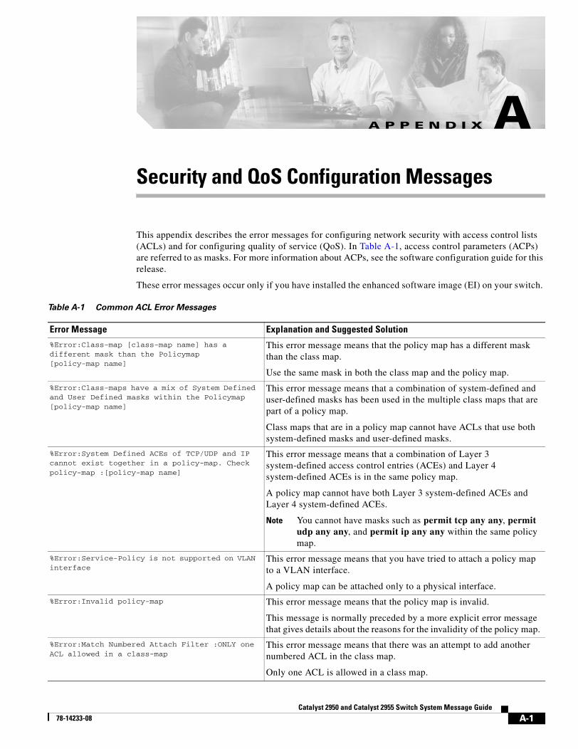
Catalyst 2950 and Catal78-14233-08
A P P E N D I X A
Security and QoS Configuration MessagesThis appendix describes the error messages for configuring network security with access control lists (ACLs) and for configuring quality of service (QoS). In Table A-1, access control parameters (ACPs) are referred to as masks. For more information about ACPs, see the software configuration guide for this release.
These error messages occur only if you have installed the enhanced software image (EI) on your switch.
Table A-1 Common ACL Error Messages
Error Message Explanation and Suggested Solution
%Error:Class-map [class-map name] has a different mask than the Policymap [policy-map name]
This error message means that the policy map has a different mask than the class map.
Use the same mask in both the class map and the policy map.
%Error:Class-maps have a mix of System Defined and User Defined masks within the Policymap [policy-map name]
This error message means that a combination of system-defined and user-defined masks has been used in the multiple class maps that are part of a policy map.
Class maps that are in a policy map cannot have ACLs that use both system-defined masks and user-defined masks.
%Error:System Defined ACEs of TCP/UDP and IP cannot exist together in a policy-map. Check policy-map :[policy-map name]
This error message means that a combination of Layer 3 system-defined access control entries (ACEs) and Layer 4 system-defined ACEs is in the same policy map.
A policy map cannot have both Layer 3 system-defined ACEs and Layer 4 system-defined ACEs.
Note You cannot have masks such as permit tcp any any, permit udp any any, and permit ip any any within the same policy map.
%Error:Service-Policy is not supported on VLAN interface
This error message means that you have tried to attach a policy map to a VLAN interface.
A policy map can be attached only to a physical interface.
%Error:Invalid policy-map This error message means that the policy map is invalid.
This message is normally preceded by a more explicit error message that gives details about the reasons for the invalidity of the policy map.
%Error:Match Numbered Attach Filter :ONLY one ACL allowed in a class-map
This error message means that there was an attempt to add another numbered ACL in the class map.
Only one ACL is allowed in a class map.
A-1yst 2955 Switch System Message Guide
Appendix A Security and QoS Configuration Messages
%Error:Deny ACE not supported in access-group within a class-map. Check class-map : [class-map name]
This error message means that a deny ACE has been entered in an access group within a class map.
A deny ACE is not supported in an access group within a class map.
%Error:System Defined and User Defined ACEs cannot exist together in access-group within a class-map. Check class-map : [class-map name]
This error message means that a combination of system-defined and user-defined masks has been used in an access group within a class map.
The access group in a class map cannot have ACLs that use both system-defined masks and user-defined masks.
%Error:System Defined ACEs of TCP/UDP and IP cannot exist together in access-group within a class-map.Check class-map :[class-map name]
This error message means that a combination of Layer 3 system-defined access control entries (ACEs) and Layer 4 system-defined ACEs has been configured in the same access group.
The access group in a class map cannot have cannot have both Layer 3 and Layer 4 system-defined ACEs.
%Error:Match Named Attach Filter :ONLY one ACL allowed in a class-map
This error message means that an attempt was made to add another ACL in the class map.
Only one ACL is allowed in a class map.
%Error:The ACL has a different mask than the Policy-map [policy-map name]
This error message means that an attempt was made to create an ACL with a different mask within a policy map.
All ACLs within the same class maps of a policy map must have the same mask.
%Error:Service policy cannot be configured This error message means that the policy map cannot be configured. The exact causes are provided in separate error messages that precede this error message.
The switches support the policy-map global configuration command with certain restrictions. For more information, see the command reference for this release.
%Error:Service policy cannot be supported - Policers required exceed Maximum Allowed on this interface
This error message means that the policy map cannot be supported because the required number of policers on this interface are more than permitted.
A Fast Ethernet port supports 6 policers, and a Gigabit Ethernet port supports 60 policers.
%Error:Service policy cannot be supported - Rules required exceed available resources in ASIC.
This error message means that the policy map cannot be supported because the required number of resources to support this policy map is not available in the hardware.
Reduce the number of resources on this policy map.
%Error:Removing service-policy policy-map name from interface interface_number
This error message means that a policy map was invalid and was removed from an interface.
If a policy map is attached to an interface and you modify the policy map so that it becomes invalid, the system removes the policy map from the interface.
Table A-1 Common ACL Error Messages (continued)
Error Message Explanation and Suggested Solution
A-2Catalyst 2950 and Catalyst 2955 Switch System Message Guide
78-14233-08
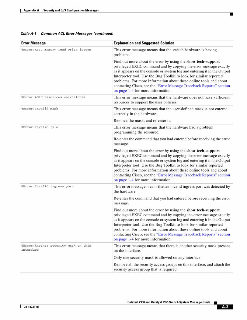
Appendix A Security and QoS Configuration Messages
%Error:ASIC memory read write issues This error message means that the switch hardware is having problems.
Find out more about the error by using the show tech-support privileged EXEC command and by copying the error message exactly as it appears on the console or system log and entering it in the Output Interpreter tool. Use the Bug Toolkit to look for similar reported problems. For more information about these online tools and about contacting Cisco, see the “Error Message Traceback Reports” section on page 1-4 for more information.
%Error:ASIC Resources unavailable This error message means that the hardware does not have sufficient resources to support the user policies.
%Error:Invalid mask This error message means that the user-defined mask is not entered correctly in the hardware.
Remove the mask, and re-enter it.
%Error:Invalid rule This error message means that the hardware had a problem programming the resource.
Re-enter the command that you had entered before receiving the error message.
Find out more about the error by using the show tech-support privileged EXEC command and by copying the error message exactly as it appears on the console or system log and entering it in the Output Interpreter tool. Use the Bug Toolkit to look for similar reported problems. For more information about these online tools and about contacting Cisco, see the “Error Message Traceback Reports” section on page 1-4 for more information.
%Error:Invalid ingress port This error message means that an invalid ingress port was detected by the hardware.
Re-enter the command that you had entered before receiving the error message.
Find out more about the error by using the show tech-support privileged EXEC command and by copying the error message exactly as it appears on the console or system log and entering it in the Output Interpreter tool. Use the Bug Toolkit to look for similar reported problems. For more information about these online tools and about contacting Cisco, see the “Error Message Traceback Reports” section on page 1-4 for more information.
%Error:Another security mask on this interface
This error message means that there is another security mask present on the interface.
Only one security mask is allowed on any interface.
Remove all the security access groups on this interface, and attach the security access group that is required.
Table A-1 Common ACL Error Messages (continued)
Error Message Explanation and Suggested Solution
A-3Catalyst 2950 and Catalyst 2955 Switch System Message Guide
78-14233-08
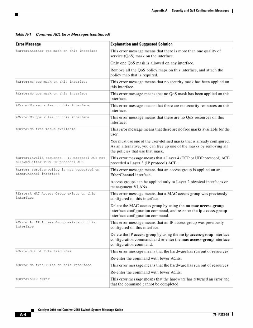
Appendix A Security and QoS Configuration Messages
%Error:Another qos mask on this interface This error message means that there is more than one quality of service (QoS) mask on the interface.
Only one QoS mask is allowed on any interface.
Remove all the QoS policy maps on this interface, and attach the policy map that is required.
%Error:No sec mask on this interface This error message means that no security mask has been applied on this interface.
%Error:No qos mask on this interface This error message means that no QoS mask has been applied on this interface.
%Error:No sec rules on this interface This error message means that there are no security resources on this interface.
%Error:No qos rules on this interface This error message means that there are no QoS resources on this interface.
%Error:No free masks available This error message means that there are no free masks available for the user.
You must use one of the user-defined masks that is already configured. As an alternative, you can free up one of the masks by removing all the policies that use that mask.
%Error:Invalid sequence - IP protocol ACE not allowed after TCP/UDP protocol ACE
This error message means that a Layer 4 (TCP or UDP protocol) ACE preceded a Layer 3 (IP protocol) ACE.
%Error: Service-Policy is not supported on EtherChannel interface
This error message means that an access group is applied on an EtherChannel interface.
Access groups can be applied only to Layer 2 physical interfaces or management VLANs.
%Error:A MAC Access Group exists on this interface
This error message means that a MAC access group was previously configured on this interface.
Delete the MAC access group by using the no mac access-group interface configuration command, and re-enter the ip access-group interface configuration command.
%Error:An IP Access Group exists on this interface
This error message means that an IP access group was previously configured on this interface.
Delete the IP access group by using the no ip access-group interface configuration command, and re-enter the mac access-group interface configuration command.
%Error:Out of Rule Resources This error message means that the hardware has run out of resources.
Re-enter the command with fewer ACEs.
%Error:No free rules on this interface This error message means that the hardware has run out of resources.
Re-enter the command with fewer ACEs.
%Error:ASIC error This error message means that the hardware has returned an error and that the command cannot be completed.
Table A-1 Common ACL Error Messages (continued)
Error Message Explanation and Suggested Solution
A-4Catalyst 2950 and Catalyst 2955 Switch System Message Guide
78-14233-08
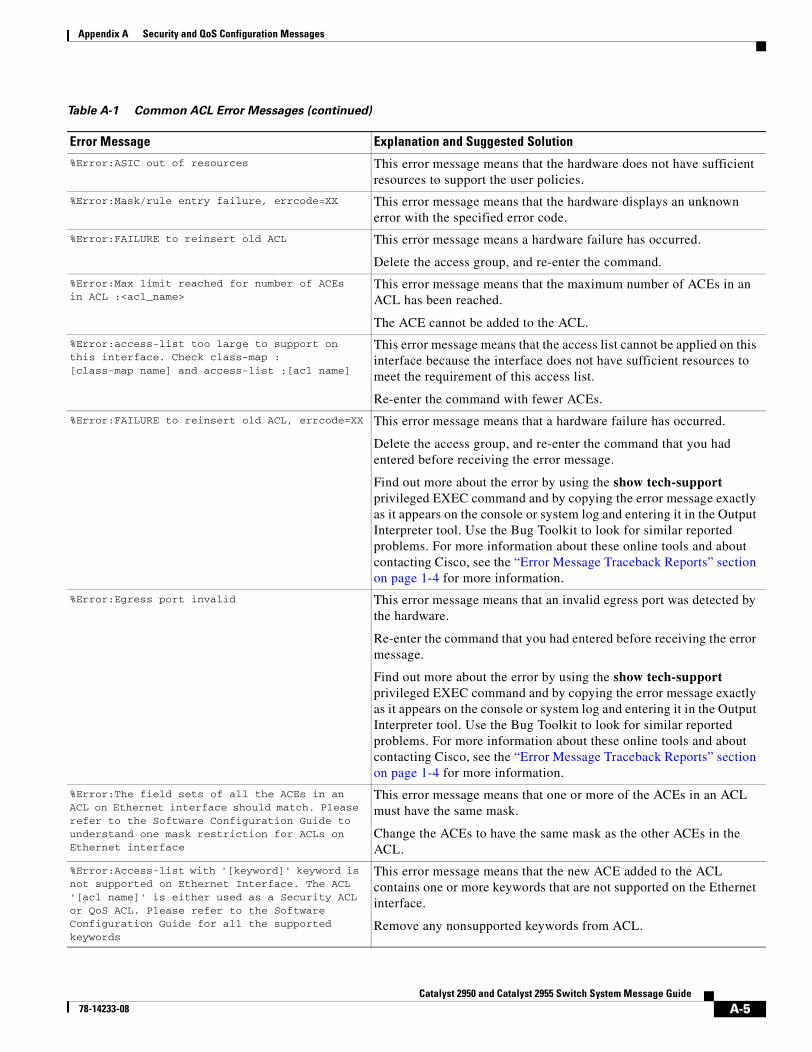
Appendix A Security and QoS Configuration Messages
%Error:ASIC out of resources This error message means that the hardware does not have sufficient resources to support the user policies.
%Error:Mask/rule entry failure, errcode=XX This error message means that the hardware displays an unknown error with the specified error code.
%Error:FAILURE to reinsert old ACL This error message means a hardware failure has occurred.
Delete the access group, and re-enter the command.
%Error:Max limit reached for number of ACEs in ACL :<acl_name>
This error message means that the maximum number of ACEs in an ACL has been reached.
The ACE cannot be added to the ACL.
%Error:access-list too large to support on this interface. Check class-map :[class-map name] and access-list :[acl name]
This error message means that the access list cannot be applied on this interface because the interface does not have sufficient resources to meet the requirement of this access list.
Re-enter the command with fewer ACEs.
%Error:FAILURE to reinsert old ACL, errcode=XX This error message means that a hardware failure has occurred.
Delete the access group, and re-enter the command that you had entered before receiving the error message.
Find out more about the error by using the show tech-support privileged EXEC command and by copying the error message exactly as it appears on the console or system log and entering it in the Output Interpreter tool. Use the Bug Toolkit to look for similar reported problems. For more information about these online tools and about contacting Cisco, see the “Error Message Traceback Reports” section on page 1-4 for more information.
%Error:Egress port invalid This error message means that an invalid egress port was detected by the hardware.
Re-enter the command that you had entered before receiving the error message.
Find out more about the error by using the show tech-support privileged EXEC command and by copying the error message exactly as it appears on the console or system log and entering it in the Output Interpreter tool. Use the Bug Toolkit to look for similar reported problems. For more information about these online tools and about contacting Cisco, see the “Error Message Traceback Reports” section on page 1-4 for more information.
%Error:The field sets of all the ACEs in an ACL on Ethernet interface should match. Please refer to the Software Configuration Guide to understand one mask restriction for ACLs on Ethernet interface
This error message means that one or more of the ACEs in an ACL must have the same mask.
Change the ACEs to have the same mask as the other ACEs in the ACL.
%Error:Access-list with '[keyword]' keyword is not supported on Ethernet Interface. The ACL '[acl name]' is either used as a Security ACL or QoS ACL. Please refer to the Software Configuration Guide for all the supported keywords
This error message means that the new ACE added to the ACL contains one or more keywords that are not supported on the Ethernet interface.
Remove any nonsupported keywords from ACL.
Table A-1 Common ACL Error Messages (continued)
Error Message Explanation and Suggested Solution
A-5Catalyst 2950 and Catalyst 2955 Switch System Message Guide
78-14233-08
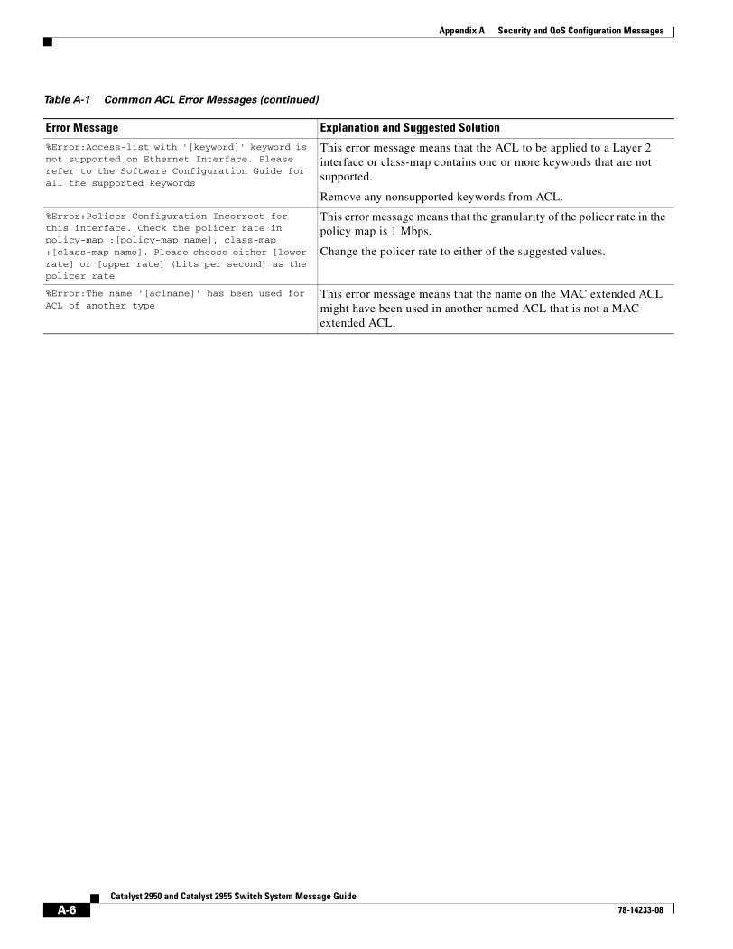
Appendix A Security and QoS Configuration Messages
%Error:Access-list with '[keyword]' keyword is not supported on Ethernet Interface. Please refer to the Software Configuration Guide for all the supported keywords
This error message means that the ACL to be applied to a Layer 2 interface or class-map contains one or more keywords that are not supported.
Remove any nonsupported keywords from ACL.
%Error:Policer Configuration Incorrect for this interface. Check the policer rate in policy-map :[policy-map name], class-map :[class-map name]. Please choose either [lower rate] or [upper rate] (bits per second) as the policer rate
This error message means that the granularity of the policer rate in the policy map is 1 Mbps.
Change the policer rate to either of the suggested values.
%Error:The name '[aclname]' has been used for ACL of another type
This error message means that the name on the MAC extended ACL might have been used in another named ACL that is not a MAC extended ACL.
Table A-1 Common ACL Error Messages (continued)
Error Message Explanation and Suggested Solution
A-6Catalyst 2950 and Catalyst 2955 Switch System Message Guide
78-14233-08
Catalyst 2950 and Catalyst78-14233-08
I N D E X
Numerics
802.1x authentication messages
See DOT1X messages
A
abbreviations
char, variable field 1-4
chars, variable field 1-4
dec, variable field 1-4
enet, variable field 1-4
hex, variable field 1-4
inet, variable field 1-4
access control list messages
See ACL messages
ACL messages A-1
application-specific integrated circuit driver-related messages
See ASIC driver-related messages
ASIC driver-related messages 2-31
audience v
authentication messages
See DOT1X messages
auto-QoS messages 2-2
B
bug toolkit 1-4
C
Catalyst 2950 ASIC messages 2-31
Cluster Membership Protocol messages
See CMP messages
CMP messages 2-2
codes 1-1
conventions
command v
for examples vi
publication v
text v
CPE_LRE messages 2-26
D
date/time stamp designations 2-1
documentation, related vi
document conventions v
DOT1X messages 2-3
DTP messages 2-8
Dynamic Trunking Protocol messages
See DTP messages
E
EC messages 2-9
ENVIRONMENT messages 2-13
ETHCNTR messages 2-15
EtherChannel messages
See EC messages
Ethernet controller messages
See ETHCNTR messages
examples, conventions for vi
EXPRESS_SETUP messages 2-17
IN-1 2955 Switch System Message Guide
Index
F
facility codes 1-1
description 1-1
table 1-1
Fast Ethernet link messages 2-25
G
GBIC messages
GigaStack GBIC module 2-23
identification and validation 2-18
security 2-20, 2-22
Gigabit Interface Converter messages
See GBIC messages
guide
audience v
purpose of v
H
hardware MAC address table manager messages
See HWMATM messages
HWMATM messages 2-24
L
LACP messages 2-9
Link Aggregation Protocol Control messages
See LACP messages
LINK messages 2-25
LRE
CPE Ethernet link messages 2-26
link messages 2-29
upgrade messages 2-30
LRE_LINK messages 2-29
LRE_UPGRADE messages 2-30
IN-2Catalyst 2950 and Catalyst 2955 Switch System Message Guide
M
MAC address table manager, hardware messages 2-24
message codes 1-1
messages
802.1x 2-3
ACL A-1
ASIC driver-related 2-31
auto-QoS 2-2
CMP 2-2
DOT1X 2-3
DTP 2-8
EC 2-9
ENVIRONMENT 2-13
ETHCNTR 2-15
Ethernet controller 2-15
EXPRESS_SETUP 2-17
GBIC
GigaStack 2-23
identification and validation 2-18
security 2-20, 2-22
HWMATM messages 2-24
LACP 2-9
LINK 2-25
LRE_CPE 2-26
LRE_LINK 2-29
LRE_UPGRADE 2-30
PAgP 2-9
per-VLAN spanning-tree 2-52
PHY 2-31
PLATFORM_CAT2950 2-31
PLATFORM_CATALYST2950 2-36
PLATFORM_CATALYST2955 2-36
PM 2-37
port manager 2-37
port security 2-43
QoS A-1
security A-1
SPAN 2-43
78-14233-08
Index
messages (continued)
spanning tree 2-44
spanning-tree fast convergence 2-51
storm control 2-52
UDLD 2-57
UFAST_MCAST_SW 2-59
VLAN manager 2-52
VTP 2-52
message severity levels
description 1-3
table 1-3
N
notes
date/time stamp designation 2-1
described vi
O
output interpreter 1-4
P
PAgP messages 2-9
per-VLAN spanning-tree messages
See SPANTREE_VLAN_SWITCH messages
PHY messages 2-31
PLATFORM_CATALYST2950 messages 2-36
PLATFORM_CATALYST2955 messages 2-36
platform messages
Catalyst 2950 2-31, 2-36
Catalyst 2955 2-36
PM messages 2-37
Port Aggregation Protocol messages
See PAgP messages
port manager messages
See PM messages
Ca78-14233-08
port security messages 2-43
publications, related vi
Q
QoS messages A-1
quality of service messages
See auto-QoS messages 2-2
See QoS messages
S
security messages A-1
severity levels
description 1-3
table 1-3
SPAN messages 2-43
spanning-tree fast-convergence messages
See SPANTREE_FAST messages
spanning-tree messages
See SPANTREE messages
spanning-tree per-VLAN messages
See SPANTREE_VLAN_SWITCH messages
SPANTREE_FAST messages 2-51
SPANTREE_VLAN_SWITCH messages 2-52
SPANTREE messages 2-44
storm control messages 2-52
SW_VLAN messages 2-52
Switched Port Analyzer messages
See SPAN messages
T
tables
message severity levels 1-3
variable fields 1-4
TAC, contacting 1-5
traceback reports 1-4
IN-3talyst 2950 and Catalyst 2955 Switch System Message Guide
Index
U
UDLD messages 2-57
UFAST_MCAST_SW messages 2-59
UniDirectional Link Detection messages
See UDLD messages
UplinkFast messages
See UFAST_MCAST_SW messages
V
variable fields
definition 1-4
table 1-4
VLAN manager messages
See SW_VLAN messages
VLAN Trunking Protocol messages
See SW_VLAN messages
VTP messages
See SW_VLAN messages
IN-4Catalyst 2950 and Catalyst 2955 Switch System Message Guide
78-14233-08