Embed Size (px)
Citation preview
Corporate HeadquartersCisco Systems, Inc.170 West Tasman DriveSan Jose, CA 95134-1706USAhttp://www.cisco.comTel: 408 526-4000
800 553-NETS (6387)Fax: 408 526-4100
Catalyst 2950 Desktop Switch Hardware Installation GuideJuly 2002
Customer Order Number: DOC-7811157=Text Part Number: 78-11157-03

THE SPECIFICATIONS AND INFORMATION REGARDING THE PRODUCTS IN THIS MANUAL ARE SUBJECT TO CHANGE WITHOUT NOTICE. ALL STATEMENTS, INFORMATION, AND RECOMMENDATIONS IN THIS MANUAL ARE BELIEVED TO BE ACCURATE BUT ARE PRESENTED WITHOUT WARRANTY OF ANY KIND, EXPRESS OR IMPLIED. USERS MUST TAKE FULL RESPONSIBILITY FOR THEIR APPLICATION OF ANY PRODUCTS.
THE SOFTWARE LICENSE AND LIMITED WARRANTY FOR THE ACCOMPANYING PRODUCT ARE SET FORTH IN THE INFORMATION PACKET THAT SHIPPED WITH THE PRODUCT AND ARE INCORPORATED HEREIN BY THIS REFERENCE. IF YOU ARE UNABLE TO LOCATE THE SOFTWARE LICENSE OR LIMITED WARRANTY, CONTACT YOUR CISCO REPRESENTATIVE FOR A COPY.
The following information is for FCC compliance of Class A devices: This equipment has been tested and found to comply with the limits for a Class A digital device, pursuant to part 15 of the FCC rules. These limits are designed to provide reasonable protection against harmful interference when the equipment is operated in a commercial environment. This equipment generates, uses, and can radiate radio-frequency energy and, if not installed and used in accordance with the instruction manual, may cause harmful interference to radio communications. Operation of this equipment in a residential area is likely to cause harmful interference, in which case users will be required to correct the interference at their own expense.
The following information is for FCC compliance of Class B devices: The equipment described in this manual generates and may radiate radio-frequency energy. If it is not installed in accordance with Cisco’s installation instructions, it may cause interference with radio and television reception. This equipment has been tested and found to comply with the limits for a Class B digital device in accordance with the specifications in part 15 of the FCC rules. These specifications are designed to provide reasonable protection against such interference in a residential installation. However, there is no guarantee that interference will not occur in a particular installation.
Modifying the equipment without Cisco’s written authorization may result in the equipment no longer complying with FCC requirements for Class A or Class B digital devices. In that event, your right to use the equipment may be limited by FCC regulations, and you may be required to correct any interference to radio or television communications at your own expense.
You can determine whether your equipment is causing interference by turning it off. If the interference stops, it was probably caused by the Cisco equipment or one of its peripheral devices. If the equipment causes interference to radio or television reception, try to correct the interference by using one or more of the following measures:
• Turn the television or radio antenna until the interference stops.
• Move the equipment to one side or the other of the television or radio.
• Move the equipment farther away from the television or radio.
• Plug the equipment into an outlet that is on a different circuit from the television or radio. (That is, make certain the equipment and the television or radio are on circuits controlled by different circuit breakers or fuses.)
Modifications to this product not authorized by Cisco Systems, Inc. could void the FCC approval and negate your authority to operate the product.
The Cisco implementation of TCP header compression is an adaptation of a program developed by the University of California, Berkeley (UCB) as part of UCB’s public domain version of the UNIX operating system. All rights reserved. Copyright © 1981, Regents of the University of California.
NOTWITHSTANDING ANY OTHER WARRANTY HEREIN, ALL DOCUMENT FILES AND SOFTWARE OF THESE SUPPLIERS ARE PROVIDED “AS IS” WITH ALL FAULTS. CISCO AND THE ABOVE-NAMED SUPPLIERS DISCLAIM ALL WARRANTIES, EXPRESSED OR IMPLIED, INCLUDING, WITHOUT LIMITATION, THOSE OF MERCHANTABILITY, FITNESS FOR A PARTICULAR PURPOSE AND NONINFRINGEMENT OR ARISING FROM A COURSE OF DEALING, USAGE, OR TRADE PRACTICE.
IN NO EVENT SHALL CISCO OR ITS SUPPLIERS BE LIABLE FOR ANY INDIRECT, SPECIAL, CONSEQUENTIAL, OR INCIDENTAL DAMAGES, INCLUDING, WITHOUT LIMITATION, LOST PROFITS OR LOSS OR DAMAGE TO DATA ARISING OUT OF THE USE OR INABILITY TO USE THIS MANUAL, EVEN IF CISCO OR ITS SUPPLIERS HAVE BEEN ADVISED OF THE POSSIBILITY OF SUCH DAMAGES.

Catalyst 2950 Desktop Switch Hardware Installation GuideCopyright © 2001–2002, Cisco Systems, Inc.All rights reserved.
CCIP, the Cisco Powered Network mark, the Cisco Systems Verified logo, Cisco Unity, Follow Me Browsing, FormShare, Internet Quotient, iQ Breakthrough, iQ Expertise, iQ FastTrack, the iQ Logo, iQ Net Readiness Scorecard, Networking Academy, ScriptShare, SMARTnet, TransPath, and Voice LAN are trademarks of Cisco Systems, Inc.; Changing the Way We Work, Live, Play, and Learn, Discover All That’s Possible, The Fastest Way to Increase Your Internet Quotient, and iQuick Study are service marks of Cisco Systems, Inc.; and Aironet, ASIST, BPX, Catalyst, CCDA, CCDP, CCIE, CCNA, CCNP, Cisco, the Cisco Certified Internetwork Expert logo, Cisco IOS, the Cisco IOS logo, Cisco Press, Cisco Systems, Cisco Systems Capital, the Cisco Systems logo, Empowering the Internet Generation, Enterprise/Solver, EtherChannel, EtherSwitch, Fast Step, GigaStack, IOS, IP/TV, LightStream, MGX, MICA, the Networkers logo, Network Registrar, Packet, PIX, Post-Routing, Pre-Routing, RateMUX, Registrar, SlideCast, StrataView Plus, Stratm, SwitchProbe, TeleRouter, and VCO are registered trademarks of Cisco Systems, Inc. and/or its affiliates in the U.S. and certain other countries.
All other trademarks mentioned in this document or Web site are the property of their respective owners. The use of the word partner does not imply a partnership relationship between Cisco and any other company. (0203R)

78-11157-03
C O N T E N T S
Cisco Limited Lifetime Hardware Warranty Terms xi
Preface xv
Audience xv
Purpose xv
Organization xvi
Conventions xvi
Related Publications xix
Obtaining Documentation xx
World Wide Web xx
Documentation CD-ROM xxi
Ordering Documentation xxi
Documentation Feedback xxi
Obtaining Technical Assistance xxii
Cisco.com xxii
Technical Assistance Center xxiii
Cisco TAC Website xxiii
Cisco TAC Escalation Center xxiv
C H A P T E R 1 Overview 1-1
Features 1-1
Front-Panel Description 1-3
10/100 Ports 1-6
10/100/1000 Ports 1-7
100BASE-FX and 1000BASE-SX Ports 1-8
vCatalyst 2950 Desktop Switch Hardware Installation Guide
Contents
GBIC Module Ports 1-8
LEDs 1-9
System LED 1-12
RPS LED 1-13
Port Mode and Port Status LEDs 1-13
Rear-Panel Description 1-20
Power Connectors 1-22
Internal Power Supply Connector 1-22
DC Power Connector 1-22
Cisco RPS Connector 1-23
Console Port 1-23
Management Options 1-23
C H A P T E R 2 Installation 2-1
Preparing for Installation 2-2
Warnings 2-2
EMC Regulatory Statements 2-4
U.S.A. 2-4
Taiwan 2-4
Japan 2-5
Korea 2-5
Hungary 2-6
Installation Guidelines 2-6
Verifying Package Contents 2-7
Installing the Switch in a Rack 2-9
Attaching the Brackets to the Switch 2-10
Mounting the Switch in a Rack 2-19
Attaching the Optional Cable Guide 2-19
Installing the Switch on a Table, Shelf, or Desk 2-20
viCatalyst 2950 Desktop Switch Hardware Installation Guide
78-11157-03
Contents
Installing the GBIC Modules 2-20
Powering On the Switch 2-22
Connecting to DC Power 2-23
Preparing for Installation 2-23
Grounding the Switch 2-24
Wiring the DC-Input Power Source 2-26
Running POST 2-32
Connecting to 10/100 and 10/100/1000 Ports 2-33
Connecting to 100BASE-FX and 1000BASE-SX Ports 2-37
Connecting to GBIC Module Ports 2-38
Connecting to 1000BASE-X GBIC Module Ports 2-39
Connecting to 1000BASE-T GBIC Module Ports 2-41
Connecting to GigaStack GBIC Module Ports 2-42
Connecting a PC or a Terminal to the Console Port 2-43
Where to Go Next 2-45
C H A P T E R 3 Troubleshooting 3-1
Understanding POST Results 3-2
Diagnosing Problems 3-2
A P P E N D I X A Technical Specifications A-1
A P P E N D I X B Connectors and Cables B-1
Connector Specifications B-1
10/100 Ports B-1
10/100/1000 Ports B-3
Connecting to 10BASE-T and 100BASE-TX Devices B-3
Connecting to 1000BASE-T Devices B-3
100BASE-FX and 1000BASE-SX Ports B-4
viiCatalyst 2950 Desktop Switch Hardware Installation Guide
78-11157-03
Contents
1000BASE-X GBIC Module Ports B-5
1000BASE-T GBIC Module Ports B-5
GigaStack GBIC Module Ports B-6
Console Port B-6
Cable and Adapter Specifications B-7
Two Twisted-Pair Cable Pinouts B-7
Four Twisted-Pair Cable Pinouts for 10/100 Ports B-8
Four Twisted-Pair Cable Pinouts for 1000BASE-T Ports B-9
Cable and Adapter Pinouts B-10
Connecting to a PC B-10
Connecting to a Terminal B-11
Identifying a Rollover Cable B-12
A P P E N D I X C Translated Safety Warnings C-1
Attaching the Cisco RPS (model PWR300-AC-RPS-N1) C-2
Lightning Activity Warning C-3
Installation Warning C-4
Main Disconnecting Device C-5
Chassis Warning—Rack-Mounting and Servicing C-6
Overtemperature Warning C-11
No On/Off Switch Warning C-12
Grounded Equipment Warning C-13
Product Disposal Warning C-14
Ground Connection Warning C-15
Jewelry Removal Warning C-17
Stacking the Chassis Warning C-19
Qualified Personnel Warning C-20
Class 1 Laser Product Warning C-21
viiiCatalyst 2950 Desktop Switch Hardware Installation Guide
78-11157-03
Contents
Laser Beam Exposure Warning C-22
Catalyst 2950G-24-EI-DC Service Requirement C-23
Restricted Area Equipment Installation C-24
Ethernet Cable Shielding in Offices C-25
DC Power Disconnection Warning C-26
Exposed DC Power Wire Warning C-29
Service Personnel Warning C-30
IN D E X
ixCatalyst 2950 Desktop Switch Hardware Installation Guide
78-11157-03

Contents
xCatalyst 2950 Desktop Switch Hardware Installation Guide
78-11157-03
Cisco Limited Lifetime Hardware Warranty Terms
There are special terms applicable to your hardware warranty as well as services you may use during the warranty period. Your formal Warranty Statement, including the warranty applicable to Cisco software, appears in the CD which accompanies your Cisco Product. Follow these steps to access and download the Cisco Information Packet and your warranty document from the CD or from Cisco.com.
1. Launch your browser and go to the following URL:
http://www.cisco.com/univercd/cc/td/doc/es_inpck/cetrans.htm
The Warranties and License Agreement page appears.
2. To view the Cisco Information Packet, perform these steps:
a. Click the Information Packet Number field and make sure that the part number 78-5235-02C0 is highlighted.
b. Select the language to view the document.
c. Click Go. The Information Packet page appears.
d. From this page you can review the document online or click the PDF icon to download and print the document in Adobe Portable Data File (PDF) format.
xiCatalyst 2950 Desktop Switch Hardware Installation Guide
78-11157-03
Cisco Limited Lifetime Hardware Warranty Terms
Note You must have Adobe Acrobat Reader in order to view and print a PDF file. If you do not have the viewer, click the Get Acrobat Reader icon at the bottom of the page to go to the Adobe.com website and download the reader.
3. To view translated and/or localized warranty information about your product, follow these steps:
a. Enter the following part number in the Warranty Document Number field:78-6310-02C0
b. Select the language to view the document.
c. Click Go. The Cisco Warranty page appears.
From this page you can review the document online or click the PDF icon to download and print the document in Adobe Portable Data File (PDF) format.
You may also contact our Service and Support website for assistance at:http://www.cisco.com/public/Support_root.shtml.
Duration of Hardware Warranty
As long as the original End User continues to own or use the Product, provided that: fan and power supply warranty is limited to five (5) years. In the event of discontinuance of product manufacture, Cisco warranty support is limited to five (5) years from the announcement of discontinuance.
Replacement, Repair or Refund Procedure for Hardware
Cisco or its service center will use commercially reasonable efforts to ship a replacement part within ten (10) working days after receipt of the RMA request. Actual delivery times may vary depending on Customer location.
Cisco reserves the right to refund the purchase price as its exclusive warranty remedy.
To Receive a Return Materials Authorization (RMA) Number
Please contact the party from whom you purchased the product. If you purchased the product directly from Cisco, contact your Cisco Sales and Service Representative.
xiiCatalyst 2950 Desktop Switch Hardware Installation Guide
78-11157-03
Cisco Limited Lifetime Hardware Warranty Terms
Complete the information below and keep for ready reference.
Product purchased from:
Their telephone number:
Product Model and Serial number:
Maintenance Contract number:
xiiiCatalyst 2950 Desktop Switch Hardware Installation Guide
78-11157-03

Cisco Limited Lifetime Hardware Warranty Terms
xivCatalyst 2950 Desktop Switch Hardware Installation Guide
78-11157-03
Preface
AudienceThis guide is for the networking or computer technician responsible for installing a Catalyst 2950 switch, hereafter referred to as the switch. We assume that you are familiar with the concepts and terminology of Ethernet and local area networking.
PurposeThis guide describes the hardware features of Catalyst 2950 switch. It describes the physical and performance characteristics of the switch, explains how to install a switch, and provides troubleshooting information.
This guide does not describe how to configure software features on your switch or describe the Catalyst 2950-specific system messages that you might encounter. It also does not provide information about command-line interface (CLI) commands that have been created or changed for use by the switch. For more information, refer to the software configuration, the system message, and the command reference guides for the switch.
xvCatalyst 2950 Desktop Switch Hardware Installation Guide
78-11157-03
PrefaceOrganization
OrganizationThis guide is organized into these chapters:
Chapter 1, “Overview,” describes the switch ports, the standards that they support, and the LEDs.
Chapter 2, “Installation,” contains the procedures for installing a switch on a rack, table, shelf, or desk. It also describes how to install Gigabit Interface Converter (GBIC) modules, how to power the switch, and how to make port connections.
Chapter 3, “Troubleshooting,” describes how to identify and resolve problems that might arise when you are installing a switch.
Appendix A, “Technical Specifications,” lists the physical and environmental specifications and the regulatory agency approvals.
Appendix B, “Connectors and Cables,” describes the connectors, cables, and adapters that you use to connect the switch to another device.
Appendix C, “Translated Safety Warnings,” contains translations in various languages of the warnings in this guide.
ConventionsThis publication uses these conventions and symbols for notes, cautions, and warnings:
Note Means reader take note. Notes contain helpful suggestions or references to materials not contained in this manual.
Caution Means reader be careful. In this situation, you might do something that could result in equipment damage or loss of data.
xviCatalyst 2950 Desktop Switch Hardware Installation Guide
78-11157-03
PrefaceConventions
Warning This warning symbol means danger. You are in a situation that could cause bodily injury. Before you work on any equipment, be aware of the hazards involved with electrical circuitry and be familiar with standard practices for preventing accidents. (To see translations of the warnings that appear in this publication, refer to the Appendix C, “Translated Safety Warnings.”)
Waarschuwing Dit waarschuwingssymbool betekent gevaar. U verkeert in een situatie die lichamelijk letsel kan veroorzaken. Voordat u aan enige apparatuur gaat werken, dient u zich bewust te zijn van de bij elektrische schakelingen betrokken risico’s en dient u op de hoogte te zijn van standaard maatregelen om ongelukken te voorkomen. (Voor vertalingen van de waarschuwingen die in deze publicatie verschijnen, kunt u het aanhangsel C “Translated Safety Warnings” (Vertalingen van veiligheidsvoorschriften) raadplegen.)
Varoitus Tämä varoitusmerkki merkitsee vaaraa. Olet tilanteessa, joka voi johtaa ruumiinvammaan. Ennen kuin työskentelet minkään laitteiston parissa, ota selvää sähkökytkentöihin liittyvistä vaaroista ja tavanomaisista onnettomuuksien ehkäisykeinoista. (Tässä julkaisussa esiintyvien varoitusten käännökset löydät liitteestä C "Translated Safety Warnings" (käännetyt turvallisuutta koskevat varoitukset).)
Attention Ce symbole d’avertissement indique un danger. Vous vous trouvez dans une situation pouvant entraîner des blessures. Avant d’accéder à cet équipement, soyez conscient des dangers posés par les circuits électriques et familiarisez-vous avec les procédures courantes de prévention des accidents. Pour obtenir les traductions des mises en garde figurant dans cette publication, veuillez consulter l’annexe intitulée C « Translated Safety Warnings » (Traduction des avis de sécurité).
xviiCatalyst 2950 Desktop Switch Hardware Installation Guide
78-11157-03
PrefaceConventions
Warnung Dieses Warnsymbol bedeutet Gefahr. Sie befinden sich in einer Situation, die zu einer Körperverletzung führen könnte. Bevor Sie mit der Arbeit an irgendeinem Gerät beginnen, seien Sie sich der mit elektrischen Stromkreisen verbundenen Gefahren und der Standardpraktiken zur Vermeidung von Unfällen bewußt. (Übersetzungen der in dieser Veröffentlichung enthaltenen Warnhinweise finden Sie im Anhang mit dem Titel C “Translated Safety Warnings” (Übersetzung der Warnhinweise).)
Avvertenza Questo simbolo di avvertenza indica un pericolo. Si è in una situazione che può causare infortuni. Prima di lavorare su qualsiasi apparecchiatura, occorre conoscere i pericoli relativi ai circuiti elettrici ed essere al corrente delle pratiche standard per la prevenzione di incidenti. La traduzione delle avvertenze riportate in questa pubblicazione si trova nell’appendice C, “Translated Safety Warnings” (Traduzione delle avvertenze di sicurezza).
Advarsel Dette varselsymbolet betyr fare. Du befinner deg i en situasjon som kan føre til personskade. Før du utfører arbeid på utstyr, må du være oppmerksom på de faremomentene som elektriske kretser innebærer, samt gjøre deg kjent med vanlig praksis når det gjelder å unngå ulykker. (Hvis du vil se oversettelser av de advarslene som finnes i denne publikasjonen, kan du se i vedlegget C "Translated Safety Warnings" [Oversatte sikkerhetsadvarsler].)
Aviso Este símbolo de aviso indica perigo. Encontra-se numa situação que lhe poderá causar danos fisicos. Antes de começar a trabalhar com qualquer equipamento, familiarize-se com os perigos relacionados com circuitos eléctricos, e com quaisquer práticas comuns que possam prevenir possíveis acidentes. (Para ver as traduções dos avisos que constam desta publicação, consulte o apêndice C “Translated Safety Warnings” - “Traduções dos Avisos de Segurança”).
xviiiCatalyst 2950 Desktop Switch Hardware Installation Guide
78-11157-03
PrefaceRelated Publications
Related PublicationsThese documents provide complete information about the switch and are available from this URL:
http://www.cisco.com/univercd/cc/td/doc/product/lan/cat2950/index.htm
You can order printed copies of documents with a DOC-xxxxxx= number from the Cisco.com sites and from the telephone numbers listed in the “Ordering Documentation” section on page xxi.
• Release Notes for the Catalyst 2950 Switch (not orderable but is available on Cisco.com)
Note Switch requirements and procedures for initial configurations and software upgrades tend to change and therefore appear only in the release notes. Before installing, configuring, or upgrading the switch, refer to the release notes on Cisco.com for the latest information.
¡Advertencia! Este símbolo de aviso significa peligro. Existe riesgo para su integridad física. Antes de manipular cualquier equipo, considerar los riesgos que entraña la corriente eléctrica y familiarizarse con los procedimientos estándar de prevención de accidentes. (Para ver traducciones de las advertencias que aparecen en esta publicación, consultar el apéndice titulado C “Translated Safety Warnings.”)
Varning! Denna varningssymbol signalerar fara. Du befinner dig i en situation som kan leda till personskada. Innan du utför arbete på någon utrustning måste du vara medveten om farorna med elkretsar och känna till vanligt förfarande för att förebygga skador. Se förklaringar av de varningar som förkommer i denna publikation i dokumentet Regulatory Compliance and Safety Information (Efterrättelse av föreskrifter och säkerhetsinformation), vilket medföljer denna anordning.
xixCatalyst 2950 Desktop Switch Hardware Installation Guide
78-11157-03
PrefaceObtaining Documentation
• Catalyst 2950 Desktop Switch Software Configuration Guide (order number DOC-7811380=)
• Catalyst 2950 Desktop Switch Command Reference (order number DOC-7811381=)
• Catalyst 2950 Desktop Switch System Message Guide (order number DOC-7814233=)
• Catalyst 2950 Desktop Switch Hardware Installation Guide (order number DOC-7811157=)
• Catalyst GigaStack Gigabit Interface Converter Hardware Installation Guide (order number DOC-786460=)
• Cluster Management Suite (CMS) online help (available only from the switch CMS software)
• Cisco RPS 300 Redundant Power System Hardware Installation Guide (order number DOC-7810372=)
• CWDM Passive Optical System Installation Note (not orderable but is available on Cisco.com)
• 1000BASE-T GBIC Installation Notes (not orderable but is available on Cisco.com)
Obtaining DocumentationThe following sections provide sources for obtaining documentation from Cisco Systems.
World Wide WebYou can access the most current Cisco documentation on the World Wide Web at the following URL:
http://www.cisco.com
Translated documentation is available at the following URL:
http://www.cisco.com/public/countries_languages.shtml
xxCatalyst 2950 Desktop Switch Hardware Installation Guide
78-11157-03
PrefaceObtaining Documentation
Documentation CD-ROMCisco documentation and additional literature are available in a Cisco Documentation CD-ROM package, which is shipped with your product. The Documentation CD-ROM is updated monthly and may be more current than printed documentation. The CD-ROM package is available as a single unit or through an annual subscription.
Ordering DocumentationCisco documentation is available in the following ways:
• Registered Cisco Direct Customers can order Cisco product documentation from the Networking Products MarketPlace:
http://www.cisco.com/cgi-bin/order/order_root.pl
• Registered Cisco.com users can order the Documentation CD-ROM through the online Subscription Store:
http://www.cisco.com/go/subscription
• Nonregistered Cisco.com users can order documentation through a local account representative by calling Cisco corporate headquarters (California, USA) at 408 526-7208 or, elsewhere in North America, by calling 800 553-NETS (6387).
Documentation FeedbackIf you are reading Cisco product documentation on the World Wide Web, you can send us your comments by completing the online survey. When you display the document listing for this platform, click Give Us Your Feedback. After you display the survey, select the manual that you wish to comment on. Click Submit to send your comments to the Cisco documentation group.
You can e-mail your comments to [email protected].
xxiCatalyst 2950 Desktop Switch Hardware Installation Guide
78-11157-03
PrefaceObtaining Technical Assistance
To submit your comments by mail, use the response card behind the front cover of your document, or write to the following address:
Cisco SystemsAttn: Document Resource Connection170 West Tasman DriveSan Jose, CA 95134-9883
We appreciate your comments.
Obtaining Technical AssistanceCisco provides Cisco.com as a starting point for all technical assistance. Customers and partners can obtain documentation, troubleshooting tips, and sample configurations from online tools by using the Cisco Technical Assistance Center (TAC) website. Cisco.com registered users have complete access to the technical support resources on the Cisco TAC website.
Cisco.comCisco.com is the foundation of a suite of interactive, networked services that provides immediate, open access to Cisco information, networking solutions, services, programs, and resources at any time, from anywhere in the world.
Cisco.com is a highly integrated Internet application and a powerful, easy-to-use tool that provides a broad range of features and services to help you to
• Streamline business processes and improve productivity
• Resolve technical issues with online support
• Download and test software packages
• Order Cisco learning materials and merchandise
• Register for online skill assessment, training, and certification programs
You can self-register on Cisco.com to obtain customized information and service. To access Cisco.com, go to the following URL:
http://www.cisco.com
xxiiCatalyst 2950 Desktop Switch Hardware Installation Guide
78-11157-03
PrefaceObtaining Technical Assistance
Technical Assistance CenterThe Cisco TAC is available to all customers who need technical assistance with a Cisco product, technology, or solution. Two types of support are available through the Cisco TAC: the Cisco TAC Web Site and the Cisco TAC Escalation Center.
Inquiries to Cisco TAC are categorized according to the urgency of the issue:
• Priority level 4 (P4)—You need information or assistance concerning Cisco product capabilities, product installation, or basic product configuration.
• Priority level 3 (P3)—Your network performance is degraded. Network functionality is noticeably impaired, but most business operations continue.
• Priority level 2 (P2)—Your production network is severely degraded, affecting significant aspects of business operations. No workaround is available.
• Priority level 1 (P1)—Your production network is down, and a critical impact to business operations will occur if service is not restored quickly. No workaround is available.
Which Cisco TAC resource you choose is based on the priority of the problem and the conditions of service contracts, when applicable.
Cisco TAC Website
The Cisco TAC website allows you to resolve P3 and P4 issues yourself, saving both cost and time. The site provides around-the-clock access to online tools, knowledge bases, and software. To access the Cisco TAC website, go to the following URL:
http://www.cisco.com/tac
All customers, partners, and resellers who have a valid Cisco services contract have complete access to the technical support resources on the Cisco TAC website. The Cisco TAC website requires a Cisco.com login ID and password. If you have a valid service contract but do not have a login ID or password, go to the following URL to register:
http://www.cisco.com/register/
xxiiiCatalyst 2950 Desktop Switch Hardware Installation Guide
78-11157-03
PrefaceObtaining Technical Assistance
If you cannot resolve your technical issues by using the Cisco TAC website, and you are a Cisco.com registered user, you can open a case online by using the TAC Case Open tool at the following URL:
http://www.cisco.com/tac/caseopen
If you have Internet access, it is recommended that you open P3 and P4 cases through the Cisco TAC website.
Cisco TAC Escalation Center
The Cisco TAC Escalation Center addresses issues that are classified as priority level 1 or priority level 2; these classifications are assigned when severe network degradation significantly impacts business operations. When you contact the TAC Escalation Center with a P1 or P2 problem, a Cisco TAC engineer will automatically open a case.
To obtain a directory of toll-free Cisco TAC telephone numbers for your country, go to the following URL:
http://www.cisco.com/warp/public/687/Directory/DirTAC.shtml
Before calling, please check with your network operations center to determine the level of Cisco support services to which your company is entitled; for example, SMARTnet, SMARTnet Onsite, or Network Supported Accounts (NSA). In addition, please have available your service agreement number and your product serial number.
xxivCatalyst 2950 Desktop Switch Hardware Installation Guide
78-11157-03
Catalyst 2950 Desktop Sw78-11157-03
C H A P T E R 1
OverviewThis chapter provides information about these topics:
• Features, page 1-1
• Front-Panel Description, page 1-3
• Rear-Panel Description, page 1-20
• Management Options, page 1-23
FeaturesThe Catalyst 2950 switches are stackable Ethernet switches to which you can connect workstations and other network devices, such as servers, routers, and other switches. The switches can be deployed as backbone switches, aggregating 10BASE-T, 100BASE-TX, and Gigabit Ethernet traffic from other network devices. Refer to the switch software configuration guide for examples showing how you might deploy the switches in your network.
Figure 1-1 through Figure 1-9 show the Catalyst 2950 switches.
These are the switch features:
• Hardware
– Catalyst 2950-12 switch—12 10/100 Ethernet ports
– Catalyst 2950-24 switch—24 10/100 Ethernet ports
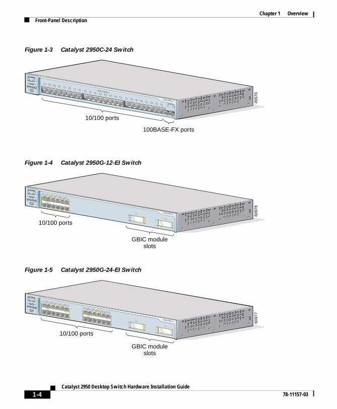
– Catalyst 2950C-24 switch—24 10/100 Ethernet ports and 2 100BASE-FX ports
1-1itch Hardware Installation Guide
Chapter 1 OverviewFeatures
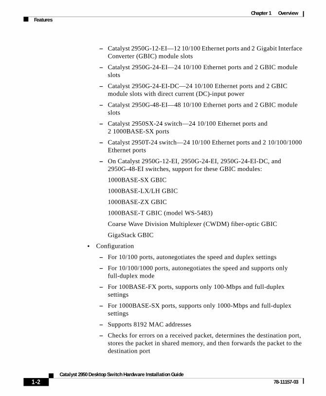
– Catalyst 2950G-12-EI—12 10/100 Ethernet ports and 2 Gigabit Interface Converter (GBIC) module slots
– Catalyst 2950G-24-EI—24 10/100 Ethernet ports and 2 GBIC module slots
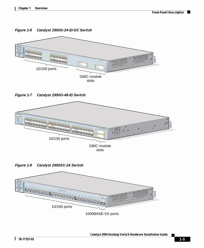
– Catalyst 2950G-24-EI-DC—24 10/100 Ethernet ports and 2 GBIC module slots with direct current (DC)-input power
– Catalyst 2950G-48-EI—48 10/100 Ethernet ports and 2 GBIC module slots
– Catalyst 2950SX-24 switch—24 10/100 Ethernet ports and 2 1000BASE-SX ports
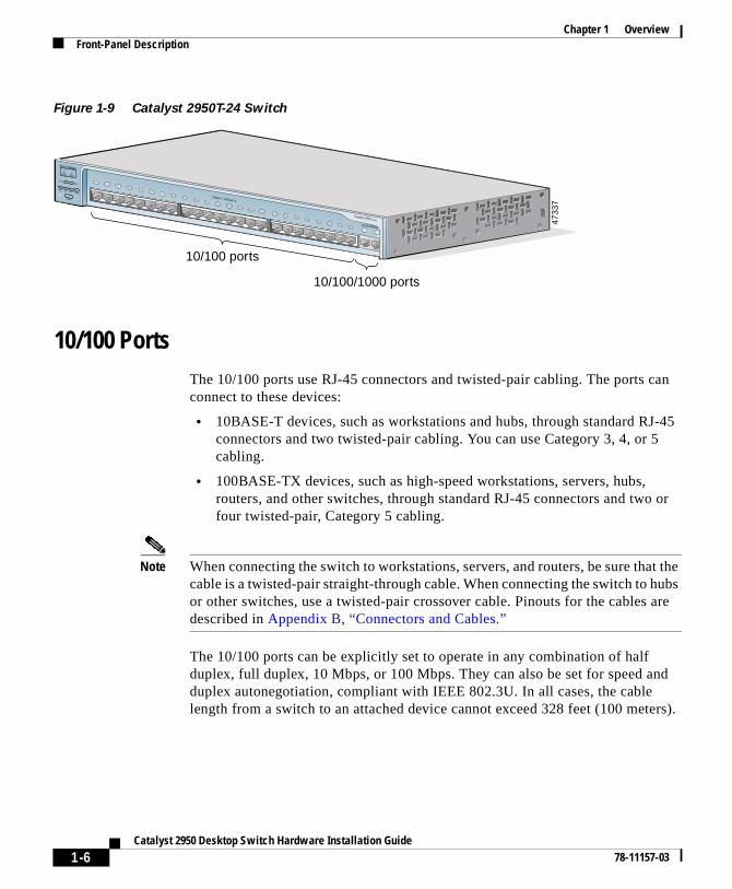
– Catalyst 2950T-24 switch—24 10/100 Ethernet ports and 2 10/100/1000 Ethernet ports
– On Catalyst 2950G-12-EI, 2950G-24-EI, 2950G-24-EI-DC, and 2950G-48-EI switches, support for these GBIC modules:
1000BASE-SX GBIC
1000BASE-LX/LH GBIC
1000BASE-ZX GBIC
1000BASE-T GBIC (model WS-5483)
Coarse Wave Division Multiplexer (CWDM) fiber-optic GBIC
GigaStack GBIC
• Configuration
– For 10/100 ports, autonegotiates the speed and duplex settings
– For 10/100/1000 ports, autonegotiates the speed and supports only full-duplex mode
– For 100BASE-FX ports, supports only 100-Mbps and full-duplex settings
– For 1000BASE-SX ports, supports only 1000-Mbps and full-duplex settings
– Supports 8192 MAC addresses
– Checks for errors on a received packet, determines the destination port, stores the packet in shared memory, and then forwards the packet to the destination port
1-2Catalyst 2950 Desktop Switch Hardware Installation Guide
78-11157-03
Chapter 1 OverviewFront-Panel Description
• Power redundancy
– Connection for an optional Cisco RPS 300 Redundant Power System (RPS) that uses alternating current (AC) input and supplies DC output to the switch
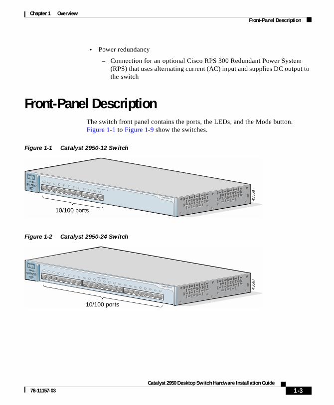
Front-Panel DescriptionThe switch front panel contains the ports, the LEDs, and the Mode button. Figure 1-1 to Figure 1-9 show the switches.
Figure 1-1 Catalyst 2950-12 Switch
Figure 1-2 Catalyst 2950-24 Switch
10/100 ports
4556
8
SYSTRPS
DUPLX
MODE
SPEEDUTIL
STAT
10Base-T / 100Base-TX
Catalyst 2950 SERIES
1x2x
3x4x
5x6x
7x8x
9x 10x 11x 12x
10/100 ports
4556
7
SYSTRPS
DUPLX
MODE
SPEEDUTIL
STAT
10Base-T / 100Base-TX
Catalyst 2950 SERIES
12
34x
5x6x
7x8x
9x10x
11x12x
13x14x
15x16x
17x18x
19x20x
21x22x
23x24x
1-3Catalyst 2950 Desktop Switch Hardware Installation Guide
78-11157-03
Chapter 1 OverviewFront-Panel Description
Figure 1-3 Catalyst 2950C-24 Switch
Figure 1-4 Catalyst 2950G-12-EI Switch
Figure 1-5 Catalyst 2950G-24-EI Switch
10/100 ports
100BASE-FX ports
4557
0
SYSTRPS
DUPLX
MODE
SPEEDUTIL
STAT
10BASE-T / 100BASE-TX
100BASE-FX
Catalyst 2950 SERIES
1x2x
3x4x
5x6x
7x8x
9x10x
11x12x
13x14x
15x16x
17x18x
19x20x
21x22x
23x24x
2526
SYSTRPS
DUPLX
MODE
SPEEDUTIL
STAT
Catalyst 2950 SERIES
1X
2X
11X
12X
1 2 3 4 5 6 7 8 9 10 11 12
1
2
10/100 ports
GBIC moduleslots
6097
860
977
SYSTRPS
DUPLX
MODE
SPEEDUTIL
STAT
Catalyst 2950 SERIES
1X
2X
11X
12X
1 2 3 4 5 6 7 8 9 10 11 12
1
13X
14X
23X
24X
13 14 15 16 17 18 19 20 21 22 23 24
2
10/100 ports
GBIC moduleslots
1-4Catalyst 2950 Desktop Switch Hardware Installation Guide
78-11157-03
Chapter 1 OverviewFront-Panel Description
Figure 1-6 Catalyst 2950G-24-EI-DC Switch
Figure 1-7 Catalyst 2950G-48-EI Switch
Figure 1-8 Catalyst 2950SX-24 Switch
6097
7
SYSTRPS
DUPLX
MODE
SPEEDUTIL
STAT
Catalyst 2950 SERIES
1X
2X
11X
12X
1 2 3 4 5 6 7 8 9 10 11 12
1
13X
14X
23X
24X
13 14 15 16 17 18 19 20 21 22 23 24
2
10/100 ports
GBIC moduleslots
Catalyst 2950 SERIES
1X
2X
17X
18X
33X
34X
15X
16X
31X
32X
47X
48X
1 2 3 4 5 6 7 8 9 10 11 12 13 14 15 1617 18 19 20 21 22 23 24 25 26 27 28 29 30 31 32
33 34 35 36 37 38 39 40 41 42 43 44 45 46 47
1
48
2
SYSTRPSSTATUTILDUPLXSPEED
MODE
10/100 ports
GBIC moduleslots
6550
7
10/100 ports
1000BASE-SX ports
7451
6
SYSTRPS
DUPLX
MODE
SPEEDUTIL
STAT
10BASE-T / 100BASE-TX
1000BASE-SX
Catalyst 2950 SERIES
1x2x
3x4x
5x6x
7x8x
9x10x
11x12x
13x14x
15x16x
17x18x
19x20x
21x22x
23x24x
2526
1-5Catalyst 2950 Desktop Switch Hardware Installation Guide
78-11157-03
Chapter 1 OverviewFront-Panel Description
Figure 1-9 Catalyst 2950T-24 Switch
10/100 PortsThe 10/100 ports use RJ-45 connectors and twisted-pair cabling. The ports can connect to these devices:
• 10BASE-T devices, such as workstations and hubs, through standard RJ-45 connectors and two twisted-pair cabling. You can use Category 3, 4, or 5 cabling.
• 100BASE-TX devices, such as high-speed workstations, servers, hubs, routers, and other switches, through standard RJ-45 connectors and two or four twisted-pair, Category 5 cabling.
Note When connecting the switch to workstations, servers, and routers, be sure that the cable is a twisted-pair straight-through cable. When connecting the switch to hubs or other switches, use a twisted-pair crossover cable. Pinouts for the cables are described in Appendix B, “Connectors and Cables.”
The 10/100 ports can be explicitly set to operate in any combination of half duplex, full duplex, 10 Mbps, or 100 Mbps. They can also be set for speed and duplex autonegotiation, compliant with IEEE 802.3U. In all cases, the cable length from a switch to an attached device cannot exceed 328 feet (100 meters).
10/100 ports
10/100/1000 ports
4733
7
SYSTRPS
DUPLX
MODE
SPEEDUTIL
STAT
10Base-T / 100Base-TX
10/100/100Base-T
Catalyst 2950 SERIES
1x2x
3x4x
5x6x
7x8x
9x10x
11x12x
13x14x
15x16x
17x18x
19x20x
21x22x
23x24x
12
1-6Catalyst 2950 Desktop Switch Hardware Installation Guide
78-11157-03
Chapter 1 OverviewFront-Panel Description
When set for autonegotiation, a port senses the speed and duplex settings of the attached device and advertises its own capabilities. If the attached device supports autonegotiation, the port negotiates the best connection (that is, the fastest line speed that both devices support and full-duplex transmission, if the attached device supports it) and configures itself accordingly.
10/100/1000 PortsThe 10/100/1000 ports on the Catalyst 2950T-24 switches use RJ-45 connectors and twisted-pair cabling. The ports can connect to these devices:
• 10BASE-T devices, such as workstations and hubs, through standard RJ-45 connectors and two or four twisted-pair, Category 5 cabling.
• 100BASE-TX devices, such as high-speed workstations, servers, hubs, routers, and other switches, through standard RJ-45 connectors and two or four twisted-pair, Category 5 cabling.
• 1000BASE-T devices, such as high-speed workstations, servers, hubs, routers, and other switches, through standard RJ-45 connectors and four twisted-pair, Category 5 cabling.
Note When connecting the switch to a 1000BASE-T device, be sure to use a four twisted-pair, Category 5 cable.
Note When connecting the switch to workstations, servers, and routers, be sure to use a twisted-pair straight-through cable. When connecting the switch to hubs or other switches, use a twisted-pair crossover cable. Pinouts for the cables are described in Appendix B, “Connectors and Cables.”
The 10/100/1000 ports on the Catalyst 2950T-24 switches can be explicitly set to operate at 10, 100, or 1000 Mbps but only in full-duplex mode. They can also be set for speed autonegotiation, compliant with IEEE 802.3AB. In all cases, the cable length from a switch to an attached device cannot exceed 328 feet (100 meter).
1-7Catalyst 2950 Desktop Switch Hardware Installation Guide
78-11157-03
Chapter 1 OverviewFront-Panel Description
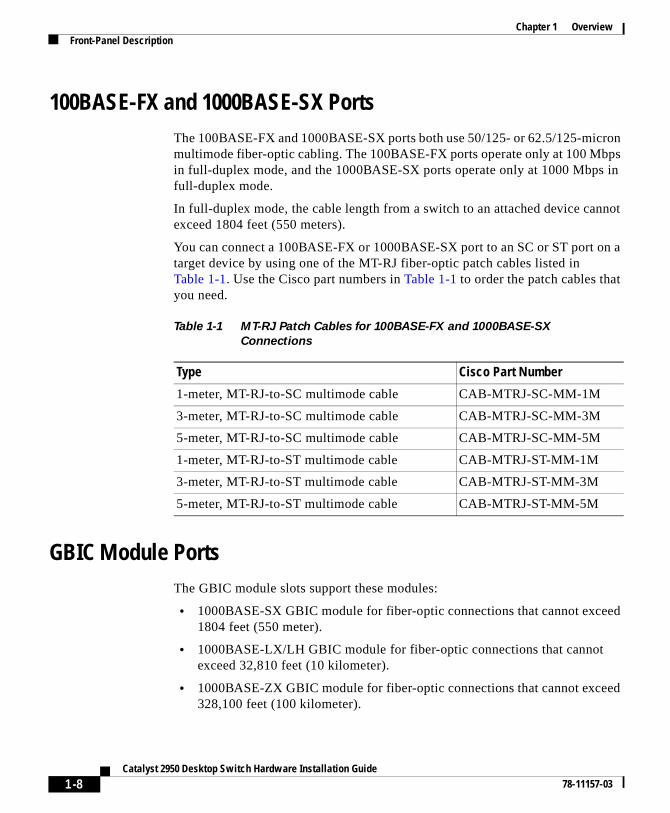
100BASE-FX and 1000BASE-SX PortsThe 100BASE-FX and 1000BASE-SX ports both use 50/125- or 62.5/125-micron multimode fiber-optic cabling. The 100BASE-FX ports operate only at 100 Mbps in full-duplex mode, and the 1000BASE-SX ports operate only at 1000 Mbps in full-duplex mode.
In full-duplex mode, the cable length from a switch to an attached device cannot exceed 1804 feet (550 meters).
You can connect a 100BASE-FX or 1000BASE-SX port to an SC or ST port on a target device by using one of the MT-RJ fiber-optic patch cables listed in Table 1-1. Use the Cisco part numbers in Table 1-1 to order the patch cables that you need.
GBIC Module PortsThe GBIC module slots support these modules:
• 1000BASE-SX GBIC module for fiber-optic connections that cannot exceed 1804 feet (550 meter).
• 1000BASE-LX/LH GBIC module for fiber-optic connections that cannot exceed 32,810 feet (10 kilometer).
• 1000BASE-ZX GBIC module for fiber-optic connections that cannot exceed 328,100 feet (100 kilometer).
Table 1-1 MT-RJ Patch Cables for 100BASE-FX and 1000BASE-SX
Connections
Type Cisco Part Number
1-meter, MT-RJ-to-SC multimode cable CAB-MTRJ-SC-MM-1M
3-meter, MT-RJ-to-SC multimode cable CAB-MTRJ-SC-MM-3M
5-meter, MT-RJ-to-SC multimode cable CAB-MTRJ-SC-MM-5M
1-meter, MT-RJ-to-ST multimode cable CAB-MTRJ-ST-MM-1M
3-meter, MT-RJ-to-ST multimode cable CAB-MTRJ-ST-MM-3M
5-meter, MT-RJ-to-ST multimode cable CAB-MTRJ-ST-MM-5M
1-8Catalyst 2950 Desktop Switch Hardware Installation Guide
78-11157-03
Chapter 1 OverviewFront-Panel Description
• 1000BASE-T GBIC module for copper connections that cannot exceed 328 feet (100 meter).
• CWDM GBIC module for single-mode fiber-optic connections that cannot exceed 393,719 feet (120 kilometer).
• GigaStack GBIC module for creating a 1-Gbps stack configuration of up to nine supported switches. The GigaStack GBIC supports one full-duplex link (in a point-to-point configuration) or up to nine half-duplex links (in a stack configuration) to other Gigabit Ethernet devices. Using the required Cisco proprietary signaling and cabling, the GigaStack GBIC-to-GigaStack GBIC connection cannot exceed 3 feet (1 meter).
Note Cisco-approved GBIC modules have a serial EEPROM that contains the module serial number, the vendor name and ID, a unique security code, and cyclic redundancy check (CRC). When a GBIC module is inserted in the switch, the switch software reads the EEPROM to check the serial number, vendor name, and vendor ID and recomputes the security code and CRC. If the serial number, the vendor name or ID, security code, or CRC is invalid, the switch places the interface in an error-disabled state.
Note If you are using a non-Cisco approved GBIC module, remove the GBIC module from the switch, and replace it with a Cisco-approved module.
For more information about these GBIC modules, refer to your GBIC documentation.
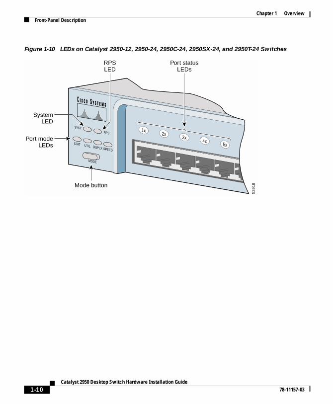
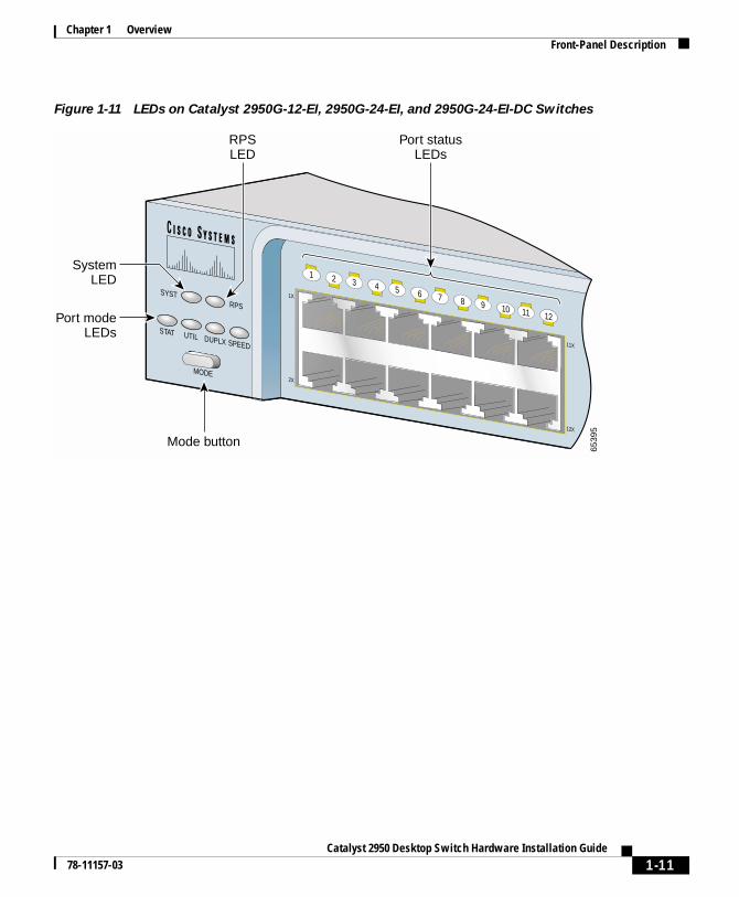
LEDsYou can use the LEDs to monitor switch activity and performance. Figure 1-10, Figure 1-11, and Figure 1-12 show the location of the LEDs and the Mode button that you use to select the port mode. Changing the port mode changes the information provided by each port status LED.
All of the LEDs described in this section except the utilization meter (UTIL) are visible in the Cluster Management Suite (CMS). The switch software configuration guide describes how to use CMS to configure and monitor individual switches and switch clusters.
1-9Catalyst 2950 Desktop Switch Hardware Installation Guide
78-11157-03
Chapter 1 OverviewFront-Panel Description
Figure 1-10 LEDs on Catalyst 2950-12, 2950-24, 2950C-24, 2950SX-24, and 2950T-24 Switches
SYSTRPS
DUPLX
MODE
SPEEDUTIL
STAT
1x2x
3x4x
5x6x
5291
8Mode button
Port modeLEDs
SystemLED
Port statusLEDs
RPSLED
1-10Catalyst 2950 Desktop Switch Hardware Installation Guide
78-11157-03
Chapter 1 OverviewFront-Panel Description
Figure 1-11 LEDs on Catalyst 2950G-12-EI, 2950G-24-EI, and 2950G-24-EI-DC Switches
SYSTRPS
DUPLX
MODE
SPEEDUTIL
STAT
1X
2X
11X
12X
1 2 3 4 5 6 7 8 9 10 11 12
6539
5
Mode button
Port modeLEDs
SystemLED
Port statusLEDs
RPSLED
1-11Catalyst 2950 Desktop Switch Hardware Installation Guide
78-11157-03
Chapter 1 OverviewFront-Panel Description
Figure 1-12 LEDs on Catalyst 2950G-48-EI Switches
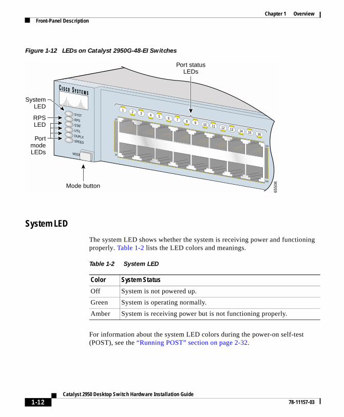
System LED
The system LED shows whether the system is receiving power and functioning properly. Table 1-2 lists the LED colors and meanings.
For information about the system LED colors during the power-on self-test (POST), see the “Running POST” section on page 2-32.
1X
2X
15X
16X
1 2 3 4 5 6 7 8 9 10 11 12 13 14 15 16
SYSTRPSSTATUTILDUPLXSPEED
MODE
Mode button
PortmodeLEDs
SystemLED
RPSLED
Port statusLEDs
6550
8
Table 1-2 System LED
Color System Status
Off System is not powered up.
Green System is operating normally.
Amber System is receiving power but is not functioning properly.
1-12Catalyst 2950 Desktop Switch Hardware Installation Guide
78-11157-03
Chapter 1 OverviewFront-Panel Description
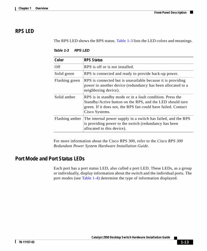
RPS LED
The RPS LED shows the RPS status. Table 1-3 lists the LED colors and meanings.
For more information about the Cisco RPS 300, refer to the Cisco RPS 300 Redundant Power System Hardware Installation Guide.
Port Mode and Port Status LEDs
Each port has a port status LED, also called a port LED. These LEDs, as a group or individually, display information about the switch and the individual ports. The port modes (see Table 1-4) determine the type of information displayed.
Table 1-3 RPS LED
Color RPS Status
Off RPS is off or is not installed.
Solid green RPS is connected and ready to provide back-up power.
Flashing green RPS is connected but is unavailable because it is providing power to another device (redundancy has been allocated to a neighboring device).
Solid amber RPS is in standby mode or in a fault condition. Press the Standby/Active button on the RPS, and the LED should turn green. If it does not, the RPS fan could have failed. Contact Cisco Systems.
Flashing amber The internal power supply in a switch has failed, and the RPS is providing power to the switch (redundancy has been allocated to this device).
1-13Catalyst 2950 Desktop Switch Hardware Installation Guide
78-11157-03
Chapter 1 OverviewFront-Panel Description
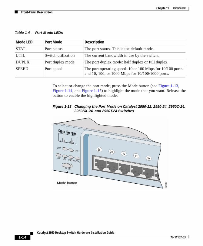
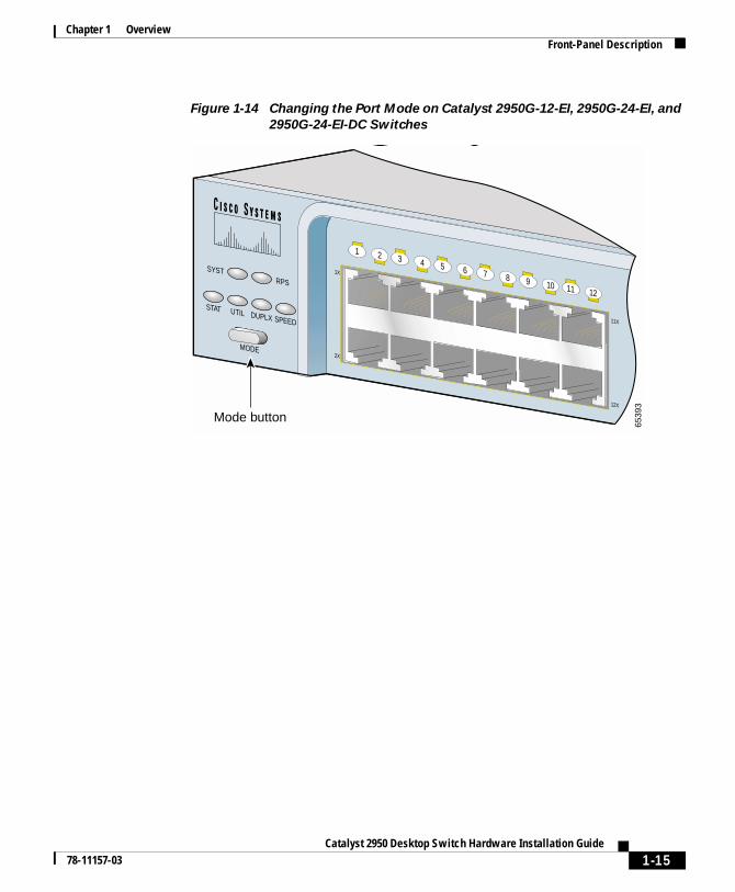
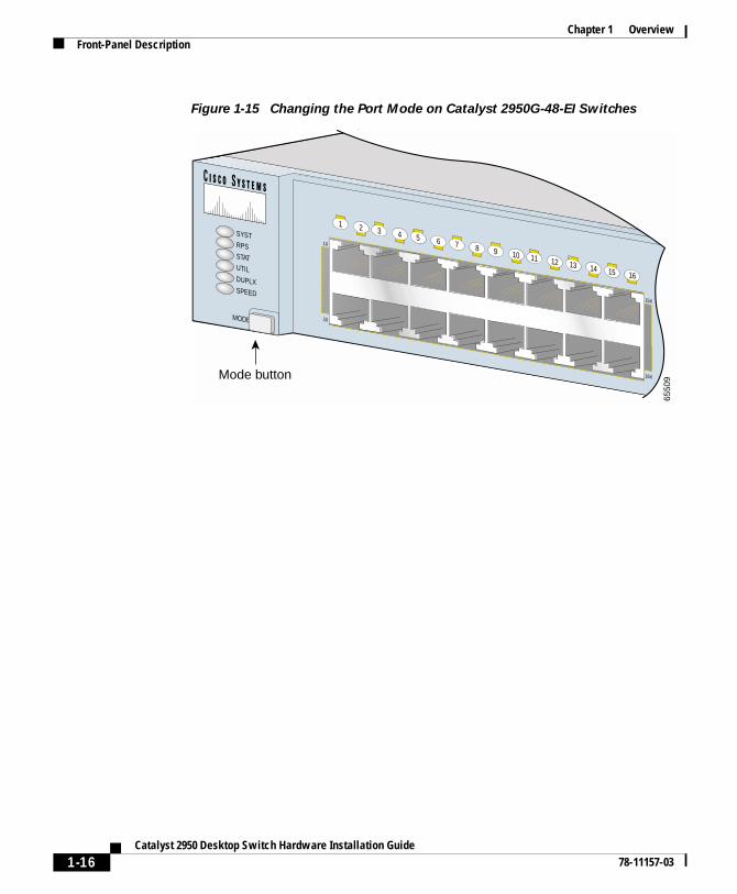
To select or change the port mode, press the Mode button (see Figure 1-13, Figure 1-14, and Figure 1-15) to highlight the mode that you want. Release the button to enable the highlighted mode.
Figure 1-13 Changing the Port Mode on Catalyst 2950-12, 2950-24, 2950C-24,
2950SX-24, and 2950T-24 Switches
Table 1-4 Port Mode LEDs
Mode LED Port Mode Description
STAT Port status The port status. This is the default mode.
UTIL Switch utilization The current bandwidth in use by the switch.
DUPLX Port duplex mode The port duplex mode: half duplex or full duplex.
SPEED Port speed The port operating speed: 10 or 100 Mbps for 10/100 ports and 10, 100, or 1000 Mbps for 10/100/1000 ports.
SYSTRPS
DUPLX
MODE
SPEEDUTIL
STAT
1x2x
3x4x
5x6x
5291
7Mode button
1-14Catalyst 2950 Desktop Switch Hardware Installation Guide
78-11157-03
Chapter 1 OverviewFront-Panel Description
Figure 1-14 Changing the Port Mode on Catalyst 2950G-12-EI, 2950G-24-EI, and
2950G-24-EI-DC Switches
SYSTRPS
DUPLX
MODE
SPEEDUTIL
STAT
1X
2X
11X
12X
1 2 3 4 5 6 7 8 9 10 11 12
6539
3
Mode button
1-15Catalyst 2950 Desktop Switch Hardware Installation Guide
78-11157-03
Chapter 1 OverviewFront-Panel Description
Figure 1-15 Changing the Port Mode on Catalyst 2950G-48-EI Switches
1X
2X
15X
16X
1 2 3 4 5 6 7 8 9 10 11 12 13 14 15 16
SYSTRPSSTATUTILDUPLXSPEED
MODE
Mode button
6550
9
1-16Catalyst 2950 Desktop Switch Hardware Installation Guide
78-11157-03
Chapter 1 OverviewFront-Panel Description
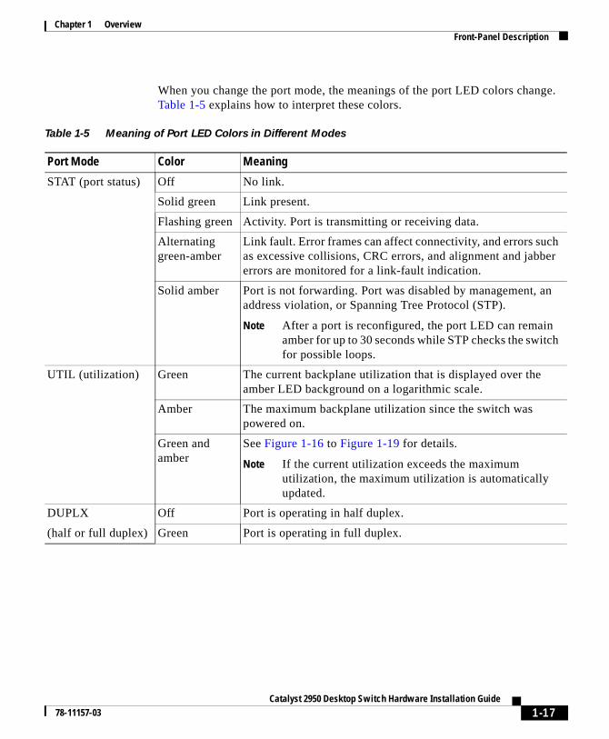
When you change the port mode, the meanings of the port LED colors change. Table 1-5 explains how to interpret these colors.
Table 1-5 Meaning of Port LED Colors in Different Modes
Port Mode Color Meaning
STAT (port status) Off No link.
Solid green Link present.
Flashing green Activity. Port is transmitting or receiving data.
Alternating green-amber
Link fault. Error frames can affect connectivity, and errors such as excessive collisions, CRC errors, and alignment and jabber errors are monitored for a link-fault indication.
Solid amber Port is not forwarding. Port was disabled by management, an address violation, or Spanning Tree Protocol (STP).
Note After a port is reconfigured, the port LED can remain amber for up to 30 seconds while STP checks the switch for possible loops.
UTIL (utilization) Green The current backplane utilization that is displayed over the amber LED background on a logarithmic scale.
Amber The maximum backplane utilization since the switch was powered on.
Green and amber
See Figure 1-16 to Figure 1-19 for details.
Note If the current utilization exceeds the maximum utilization, the maximum utilization is automatically updated.
DUPLX Off Port is operating in half duplex.
(half or full duplex) Green Port is operating in full duplex.
1-17Catalyst 2950 Desktop Switch Hardware Installation Guide
78-11157-03
Chapter 1 OverviewFront-Panel Description
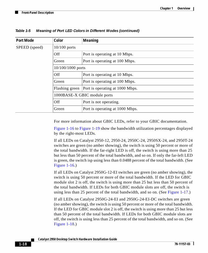
For more information about GBIC LEDs, refer to your GBIC documentation.
Figure 1-16 to Figure 1-19 show the bandwidth utilization percentages displayed by the right-most LEDs.
If all LEDs on Catalyst 2950-12, 2950-24, 2950C-24, 2950SX-24, and 2950T-24 switches are green (no amber showing), the switch is using 50 percent or more of the total bandwidth. If the far-right LED is off, the switch is using more than 25 but less than 50 percent of the total bandwidth, and so on. If only the far-left LED is green, the switch isp using less than 0.0488 percent of the total bandwidth. (See Figure 1-16.)
If all LEDs on Catalyst 2950G-12-EI switches are green (no amber showing), the switch is using 50 percent or more of the total bandwidth. If the LED for GBIC module slot 2 is off, the switch is using more than 25 but less than 50 percent of the total bandwidth. If LEDs for both GBIC module slots are off, the switch is using less than 25 percent of the total bandwidth, and so on. (See Figure 1-17.)
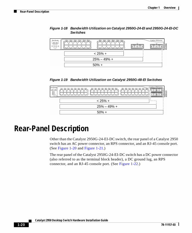
If all LEDs on Catalyst 2950G-24-EI and 2950G-24-EI-DC switches are green (no amber showing), the switch is using 50 percent or more of the total bandwidth. If the LED for GBIC module slot 2 is off, the switch is using more than 25 but less than 50 percent of the total bandwidth. If LEDs for both GBIC module slots are off, the switch is using less than 25 percent of the total bandwidth, and so on. (See Figure 1-18.)
SPEED (speed) 10/100 ports
Off Port is operating at 10 Mbps.
Green Port is operating at 100 Mbps.
10/100/1000 ports
Off Port is operating at 10 Mbps.
Green Port is operating at 100 Mbps.
Flashing green Port is operating at 1000 Mbps.
1000BASE-X GBIC module ports
Off Port is not operating.
Green Port is operating at 1000 Mbps.
Table 1-5 Meaning of Port LED Colors in Different Modes (continued)
Port Mode Color Meaning
1-18Catalyst 2950 Desktop Switch Hardware Installation Guide
78-11157-03
Chapter 1 OverviewFront-Panel Description
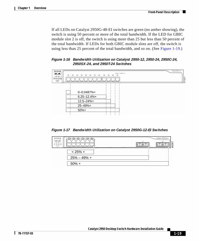
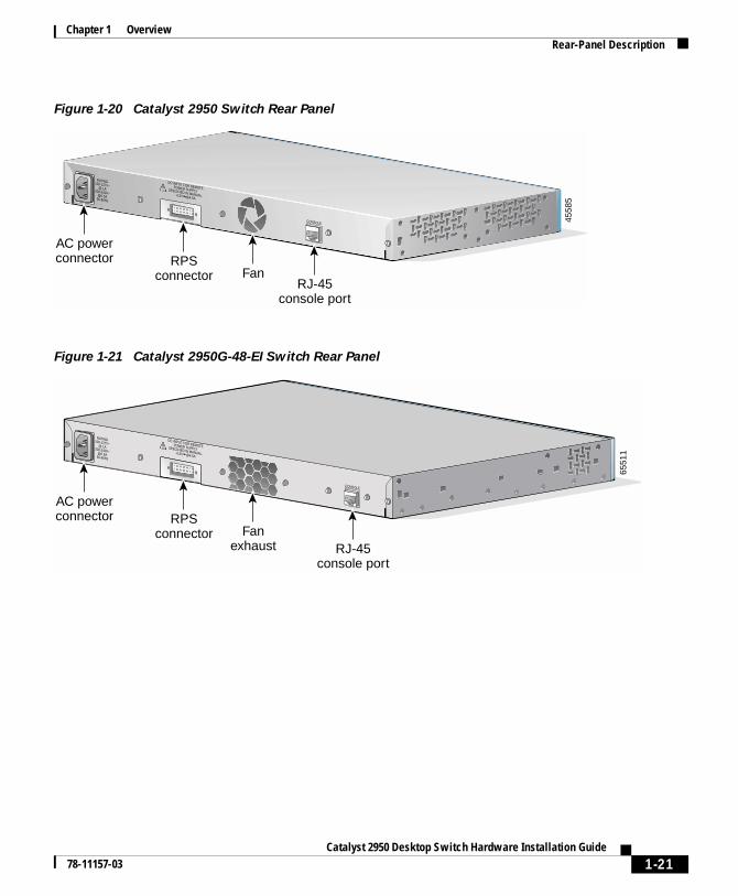
If all LEDs on Catalyst 2950G-48-EI switches are green (no amber showing), the switch is using 50 percent or more of the total bandwidth. If the LED for GBIC module slot 2 is off, the switch is using more than 25 but less than 50 percent of the total bandwidth. If LEDs for both GBIC module slots are off, the switch is using less than 25 percent of the total bandwidth, and so on. (See Figure 1-19.)
Figure 1-16 Bandwidth Utilization on Catalyst 2950-12, 2950-24, 2950C-24,
2950SX-24, and 2950T-24 Switches
Figure 1-17 Bandwidth Utilization on Catalyst 2950G-12-EI Switches
1x 2x 3x 4x 5x 6x 7x 8x 9x 10x 11x 12xSYST RPS
DUPLX
MODE
SPEEDUTILSTAT
Catalyst 2950 SERIES
10Base-T / 100Base-TX
4726
7
6.25–12.4%+12.5–24%+
0–0.0487%+
25–49%+50%+
MODE 6539
72
Catalyst 2950
1
< 25% +
25% – 49% +
50% +
1
1X
2X
11X
12X
2 3 4 5 6 7 8 9 10 11 12
STAT
SYST RPS
UTIL DUPLX SPEED
1-19Catalyst 2950 Desktop Switch Hardware Installation Guide
78-11157-03
Chapter 1 OverviewRear-Panel Description
Figure 1-18 Bandwidth Utilization on Catalyst 2950G-24-EI and 2950G-24-EI-DC
Switches
Figure 1-19 Bandwidth Utilization on Catalyst 2950G-48-EI Switches
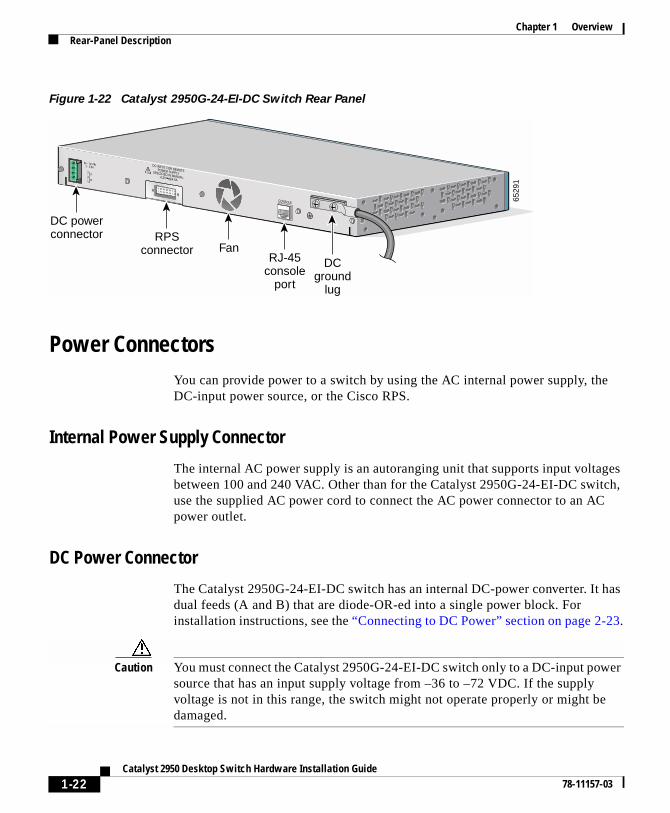
Rear-Panel DescriptionOther than the Catalyst 2950G-24-EI-DC switch, the rear panel of a Catalyst 2950 switch has an AC power connector, an RPS connector, and an RJ-45 console port. (See Figure 1-20 and Figure 1-21.)
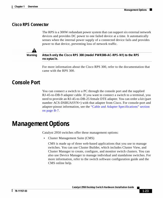
The rear panel of the Catalyst 2950G-24-EI-DC switch has a DC power connector (also referred to as the terminal block header), a DC ground lug, an RPS connector, and an RJ-45 console port. (See Figure 1-22.)
MODE 6539
62
Catalyst 2950
1
< 25% +
25% – 49% +
50% +
1
1X
2X
11X
12X
13X
14X
15X
16X
2 3 4 5 6 7 8 9 10 11 12 13 14 15 16 17 18 19 20 21 22 23 24
STAT
SYST RPS
UTIL DUPLX SPEED
6551
0
2
Catalyst 2950
1
< 25% +
11X
2X
15X
16X
2 3 24 5 6 7 8 9 10 11 12 13 14 15 16 1717X
18X
31X
32X
18 19 20 21 22 23 24 25 26 27 28 29 31 31 32 3333X
34X
47X
48X
34 35 36 37 38 39 40 41 42 43 44 45 46 47 48
50% +
25% – 49% +
SYSTRPSSTATUTILDUPLXSPEED
MODE
1-20Catalyst 2950 Desktop Switch Hardware Installation Guide
78-11157-03
Chapter 1 OverviewRear-Panel Description
Figure 1-20 Catalyst 2950 Switch Rear Panel
Figure 1-21 Catalyst 2950G-48-EI Switch Rear Panel
RATING100-127V~@ [email protected]
DC INPUT FOR REMOTEPOWER SUPPLYSPECIFIED IN MANUAL.+12V @4.5A
CONSOLE
AC powerconnector RPS
connector FanRJ-45
console port
4558
5
RATING100-127V~@ [email protected]
DC INPUT FOR REMOTEPOWER SUPPLYSPECIFIED IN MANUAL.+12V @4.5A
CONSOLE
AC powerconnector RPS
connector Fanexhaust RJ-45
console port
6551
1
1-21Catalyst 2950 Desktop Switch Hardware Installation Guide
78-11157-03
Chapter 1 OverviewRear-Panel Description
Figure 1-22 Catalyst 2950G-24-EI-DC Switch Rear Panel
Power ConnectorsYou can provide power to a switch by using the AC internal power supply, the DC-input power source, or the Cisco RPS.
Internal Power Supply Connector
The internal AC power supply is an autoranging unit that supports input voltages between 100 and 240 VAC. Other than for the Catalyst 2950G-24-EI-DC switch, use the supplied AC power cord to connect the AC power connector to an AC power outlet.
DC Power Connector
The Catalyst 2950G-24-EI-DC switch has an internal DC-power converter. It has dual feeds (A and B) that are diode-OR-ed into a single power block. For installation instructions, see the “Connecting to DC Power” section on page 2-23.
Caution You must connect the Catalyst 2950G-24-EI-DC switch only to a DC-input power source that has an input supply voltage from –36 to –72 VDC. If the supply voltage is not in this range, the switch might not operate properly or might be damaged.
DC INPUT FOR REMOTEPOWER SUPPLYSPECIFIED IN MANUAL.+12V @4.5A
36 - 72V 1 - 0.5A
A
B
CONSOLE
DC powerconnector RPS
connector FanRJ-45
consoleport
DCground
lug
6529
1
1-22Catalyst 2950 Desktop Switch Hardware Installation Guide
78-11157-03
Chapter 1 OverviewManagement Options
Cisco RPS Connector
The RPS is a 300W redundant power system that can support six external network devices and provides DC power to one failed device at a time. It automatically senses when the internal power supply of a connected device fails and provides power to that device, preventing loss of network traffic.
Warning Attach only the Cisco RPS 300 (model PWR300-AC-RPS-N1) to the RPS receptacle.
For more information about the Cisco RPS 300, refer to the documentation that came with the RPS 300.
Console PortYou can connect a switch to a PC through the console port and the supplied RJ-45-to-DB-9 adapter cable. If you want to connect a switch to a terminal, you need to provide an RJ-45-to-DB-25 female DTE adapter. You can order a kit (part number ACS-DSBUASYN=) with that adapter from Cisco. For console-port and adapter-pinout information, see the “Cable and Adapter Specifications” section on page B-7.
Management OptionsCatalyst 2950 switches offer these management options:
• Cluster Management Suite (CMS)
CMS is made up of three web-based applications that you use to manage switches. You can use Cluster Builder, which includes Cluster View, and Cluster Manager to create, configure, and monitor switch clusters. You can also use Device Manager to manage individual and standalone switches. For more information, refer to the switch software configuration guide and the CMS online help.
1-23Catalyst 2950 Desktop Switch Hardware Installation Guide
78-11157-03
Chapter 1 OverviewManagement Options
• IOS command-line interface (CLI)
You can manage switches by using command-line entries. To access the CLI, connect a PC or terminal directly to the console port on the switch rear panel. If the switch is attached to your network, you can use a Telnet connection to manage the switch from a remote location. For more information, refer to the switch command reference.
• CiscoView application
You can use the CiscoView device-management application to set configuration parameters and to view switch status and performance information. This application, which you purchase separately, can be a standalone application or part of an Simple Network Management Protocol (SNMP) network-management platform. For more information, refer to the documentation that came with your CiscoView application.
• SNMP network management
You can manage switches by using an SNMP-compatible management station running platforms such as HP OpenView and SunNet Manager. The switch supports a comprehensive set of MIB extensions and MIB II, the IEEE 802.1D bridge MIB, and four Remote Monitoring (RMON) groups. For more information, refer to the documentation that came with your SNMP application.
• Cisco Intelligence Engine 2100 (IE2100)
• The Cisco IE200 Series Configuration Registrar is a network management device that works with embedded Cisco Networking Services (CNS) agents in the switch software. You can automate initial configurations and configuration updates by generating switch-specific configuration changes, sending them to the switch, executing the configuration change, and logging the results. For more information, refer to the switch software configuration guide and the documentation that came with your application.
1-24Catalyst 2950 Desktop Switch Hardware Installation Guide
78-11157-03
Catalyst 2950 Desktop Sw78-11157-03
C H A P T E R 2
InstallationThis chapter describes how to install your switch, interpret the power-on self-test (POST), and connect the switch to other devices. Read these topics and perform the procedures in this order:
• Preparing for Installation, page 2-2
• Installing the Switch in a Rack, page 2-9
• Installing the Switch on a Table, Shelf, or Desk, page 2-20
• Installing the GBIC Modules, page 2-20
• Powering On the Switch, page 2-22
• Connecting to DC Power, page 2-23
• Running POST, page 2-32
• Connecting to 10/100 and 10/100/1000 Ports, page 2-33
• Connecting to 100BASE-FX and 1000BASE-SX Ports, page 2-37
• Connecting to GBIC Module Ports, page 2-38
• Connecting a PC or a Terminal to the Console Port, page 2-43
• Where to Go Next, page 2-45
2-1itch Hardware Installation Guide
Chapter 2 InstallationPreparing for Installation
Preparing for InstallationThis section provides information about these topics:
• Warnings, page 2-2
• EMC Regulatory Statements, page 2-4
• Installation Guidelines, page 2-6
• Verifying Package Contents, page 2-7
WarningsThese warnings are translated into several languages in Appendix C, “Translated Safety Warnings.”
Warning This equipment is to be installed and maintained by service personnel only as defined by AS/NZS 3260 Clause 1.2.14.3 Service Personnel.
Warning Only trained and qualified personnel should be allowed to install or replace this equipment.
Warning Read the installation instructions before you connect the system to its power source.
Warning Unplug the power cord before you work on a system that does not have an on/off switch.
Warning Do not stack the chassis on any other equipment. If the chassis falls, it can cause severe bodily injury and equipment damage.
2-2Catalyst 2950 Desktop Switch Hardware Installation Guide
78-11157-03
Chapter 2 InstallationPreparing for Installation
Warning The plug-socket combination must be accessible at all times because it serves as the main disconnecting device.
Warning To prevent the switch from overheating, do not operate it in an area that exceeds the maximum recommended ambient temperature of 113° F (45° C). To prevent airflow restriction, allow at least 3 inches (7.6 cm) of clearance around the ventilation openings.
Warning When installing the unit, always make the ground connection first and disconnect it last.
Warning This equipment is intended to be grounded. Ensure that the host is connected to earth ground during normal use.
Warning Before working on equipment that is connected to power lines, remove jewelry (including rings, necklaces, and watches). Metal objects will heat up when connected to power and ground and can cause serious burns or weld the metal object to the terminals.
Warning Do not work on the system or connect or disconnect cables during periods of lightning activity.
Warning Ultimate disposal of this product should be handled according to all national laws and regulations.
Warning Attach only the Cisco RPS (model PWR300-AC-RPS-N1) to the RPS receptacle.
2-3Catalyst 2950 Desktop Switch Hardware Installation Guide
78-11157-03
Chapter 2 InstallationPreparing for Installation
Warning Class 1 laser product
Warning Avoid exposure to the laser beam.
EMC Regulatory StatementsThis section includes specific regulatory statements about the Catalyst 2950 switches.
U.S.A.
U.S. regulatory information for this product is in the front matter of this manual.
Taiwan
This is a Class A Information product. When used in a residential environment, it may cause radio frequency interference. Under such circumstances, the user may be requested to take appropriate countermeasures.
2-4Catalyst 2950 Desktop Switch Hardware Installation Guide
78-11157-03
Chapter 2 InstallationPreparing for Installation
Japan
This is a Class A product based on the standard of the Voluntary Control Council for Interference by Information Technology Equipment (VCCI). If this equipment is used in a domestic environment, radio disturbance may arise. When such trouble occurs, the user may be required to take corrective actions.
Korea
Warning This is a Class A Device and is registered for EMC requirements for industrial use. The seller or buyer should be aware of this. If this type was sold or purchased by mistake, it should be replaced with a residential-use type.
4646
4
2-5Catalyst 2950 Desktop Switch Hardware Installation Guide
78-11157-03
Chapter 2 InstallationPreparing for Installation
Hungary
This equipment is a Class A product and should be used and installed properly according to the Hungarian EMC Class A requirements (MSZEN55022). Class A equipment is designed for typical commercial establishments for which special conditions of installation and protection distance are used.
Figyelmeztetés a felhasználói kézikönyv számára:Ez a berendezés “A” osztályú termék, felhasználására és üzembe helyezésére a magyar EMC “A” osztályú követelményeknek (MSZ EN 55022) megfeleloen kerülhet sor, illetve ezen “A” osztályú berendezések csak megfelelo kereskedelmi forrásból származhatnak, amelyek biztosítják a megfelelo speciális üzembe helyezési körülményeket és biztonságos üzemelési távolságok alkalmazását.
Installation GuidelinesWhen determining where to place the switch, observe these guidelines.
• For 10/100 ports and 10/100/1000 ports, the cable length from a switch to an attached device cannot exceed 328 feet (100 meters).
• For 100BASE-FX ports, the cable length from a switch to an attached device cannot exceed 6562 feet (2 kilometers).
• For 1000BASE-SX ports and 1000BASE-SX GBIC module ports, the cable length from a switch to an attached device cannot exceed 1804 feet (550 meters).
• For 1000BASE-LX/LH GBIC module ports, the cable length from a switch to an attached device cannot exceed 32,810 feet (10 kilometers).
• For 1000BASE-ZX GBIC module ports, the cable length from a switch to an attached device cannot exceed 328,100 feet (100 kilometers).
• For 1000BASE-T GBIC module ports, the cable length from switch to an attached device cannot exceed 328 feet (100 meters).
• For Coarse Wave Division Multiplexing (CWDM) GBIC module ports, the cable length from a switch to an attached device cannot exceed 393,719 feet (120 kilometers). For specific cable lengths, refer to the CWDM GBIC module documentation.
• For GigaStack GBIC module ports, the cable length from a switch to an attached device cannot exceed 3 feet (1 meter).
2-6Catalyst 2950 Desktop Switch Hardware Installation Guide
78-11157-03
Chapter 2 InstallationPreparing for Installation
• Operating environment is within the ranges listed in Appendix A, “Technical Specifications.”
• Clearance to front and rear panels meet these conditions:
– Front-panel LEDs can be easily read.
– Access to ports is sufficient for unrestricted cabling.
– Rear-panel AC power connector is within reach of an AC power outlet.
– Rear-panel direct current (DC) power connector is within reach of a circuit breaker.
• Airflow around the switch and through the vents is unrestricted.
• Temperature around the unit does not exceed 113°F (45°C).
Note If the switch is installed in a closed or multirack assembly, the temperature around it might be greater than normal room temperature.
• Cabling is away from sources of electrical noise, such as radios, power lines, and fluorescent lighting fixtures.
Verifying Package Contents
Note Carefully remove the contents from the shipping container, and check each item for damage. If any item is missing or damaged, contact your Cisco representative or reseller for support. Return all packing materials to the shipping container and save them.
The switch is shipped with these items:
• This Catalyst 2950 Desktop Switch Hardware Installation Guide
• Where to Find the Catalyst 2950 Documentation flyer
• Cisco Documentation CD-ROM
• AC power cord
2-7Catalyst 2950 Desktop Switch Hardware Installation Guide
78-11157-03
Chapter 2 InstallationPreparing for Installation
• Mounting kit containing these items:
– Four rubber feet for mounting the switch on a table, shelf, or desk
– Two 19-inch or 24-inch rack-mounting brackets
– Six number-8 Phillips flat-head screws for attaching the brackets to the switch
– Four number-8 Phillips truss-head screws for attaching the brackets to the switch
– Four number-12 Phillips machine screws for attaching the brackets to a rack
– One cable guide and one black Phillips machine screw for attaching the cable guide to one of the mounting brackets
• DC-switch kit containing these items:
– One DC terminal block plug (also called a terminal block header)
– One ground lug
– Two number-10-32 screws for attaching the ground lug to the switch
– Two 23-inch rack-mounting brackets (with 1-inch spacing for telco racks)
– Four number-8 Phillips truss-head screws for attaching the brackets to the switch
– Two number-12 Phillips machine screws for attaching the brackets to a rack
Note The DC-switch kit ships only with the Catalyst 2950G-24-EI-DC switch.
• One RJ-45-to-DB-9 adapter cable
• Cisco Information Packet, containing safety and support information
If you want to connect a terminal to the switch console port, you need to provide an RJ-45-to-DB-25 female DTE adapter. You can order a kit (part number ACS-DSBUASYN=) with that adapter from Cisco.
2-8Catalyst 2950 Desktop Switch Hardware Installation Guide
78-11157-03
Chapter 2 InstallationInstalling the Switch in a Rack
You can connect a 100BASE-FX or 1000BASE-SX port to an SC or ST port on a target device by using one of the MT-RJ fiber-optic patch cables listed in Table 2-1. Use the Cisco part numbers in Table 2-1 to order the patch cables that you need.
Installing the Switch in a Rack
Warning To prevent bodily injury when mounting or servicing this unit in a rack, you must take special precautions to ensure that the system remains stable. The following guidelines are provided to ensure your safety:
• This unit should be mounted at the bottom of the rack if it is the only unit in the rack.
• When mounting this unit in a partially filled rack, load the rack from the bottom to the top with the heaviest component at the bottom of the rack.
• If the rack is provided with stabilizing devices, install the stabilizers before mounting or servicing the unit in the rack.
Note Figure 2-1 to Figure 2-17 show the Catalyst 2950-24, 2950G-24-EI-DC, and 2950G-48-EI switches as examples. You can install other Catalyst 2950 switches in a rack as shown in these illustrations.
Table 2-1 MT-RJ Patch Cables for 100BASE-FX and 1000BASE-SX Connections
Type Cisco Part Number
1-meter, MT-RJ-to-SC multimode cable CAB-MTRJ-SC-MM-1M
3-meter, MT-RJ-to-SC multimode cable CAB-MTRJ-SC-MM-3M
5-meter, MT-RJ-to-SC multimode cable CAB-MTRJ-SC-MM-5M
1-meter, MT-RJ-to-ST multimode cable CAB-MTRJ-ST-MM-1M
3-meter, MT-RJ-to-ST multimode cable CAB-MTRJ-ST-MM-3M
5-meter, MT-RJ-to-ST multimode cable CAB-MTRJ-ST-MM-5M
2-9Catalyst 2950 Desktop Switch Hardware Installation Guide
78-11157-03
Chapter 2 InstallationInstalling the Switch in a Rack
To install the switch in a 19-, 23-, or 24-inch rack, follow these steps:
• Attaching the Brackets to the Switch, page 2-10
• Mounting the Switch in a Rack, page 2-19
• Attaching the Optional Cable Guide, page 2-19
Note Installing the Catalyst 2950G-48-EI switch in a 23-inch or 24-inch rack requires an optional bracket kit not included with the switch. You can order a kit containing the 23-inch or 24-inch rack-mounting brackets and hardware from Cisco (part number RCKMNT-1RU=).
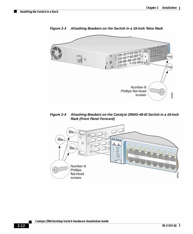
Attaching the Brackets to the SwitchThe bracket orientation and the screws that you use depend on whether you are attaching the brackets to a 19-, 23-, or 24-inch rack. Follow these guidelines:
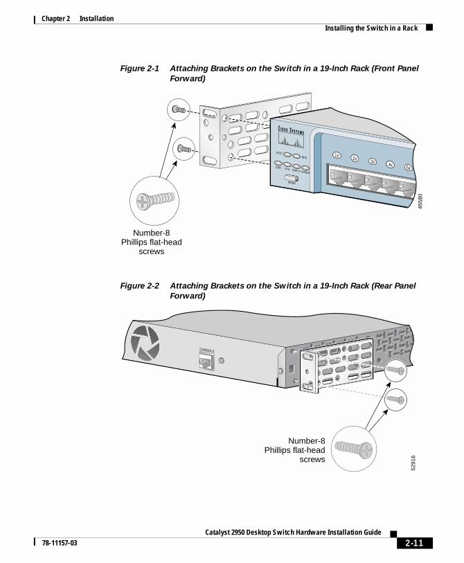
• When mounting a switch other than a Catalyst 2950G-48-EI switch in a 19-inch rack, use two Phillips flat-head screws to attach the long side of the 19- or 24-inch bracket to the switch. See Figure 2-1, Figure 2-2, and Figure 2-3.
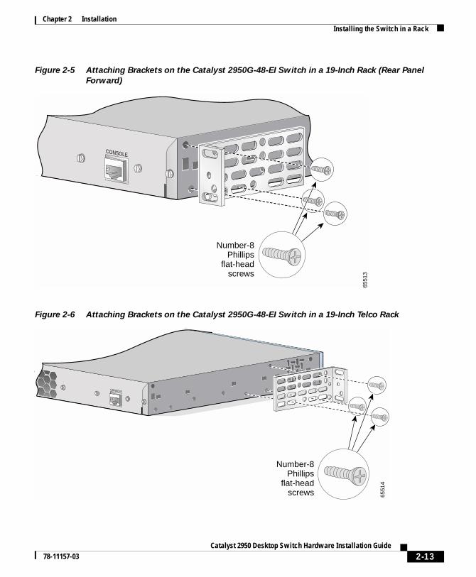
• When mounting a Catalyst 2950G-48-EI switch in a 19-inch rack, use three Phillips flat-head screws to attach the long side of the 19- or 24-inch bracket to the switch. See Figure 2-4, Figure 2-5, and Figure 2-6.
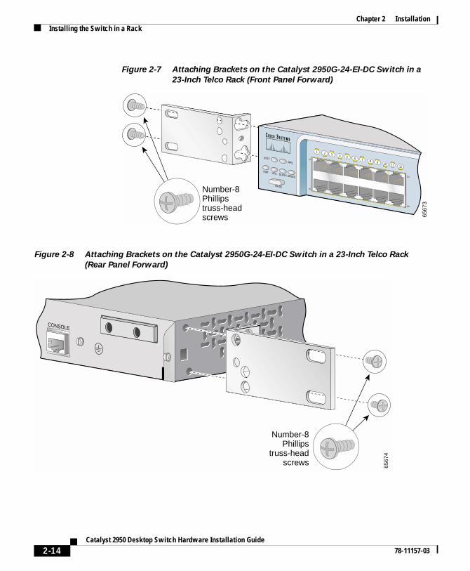
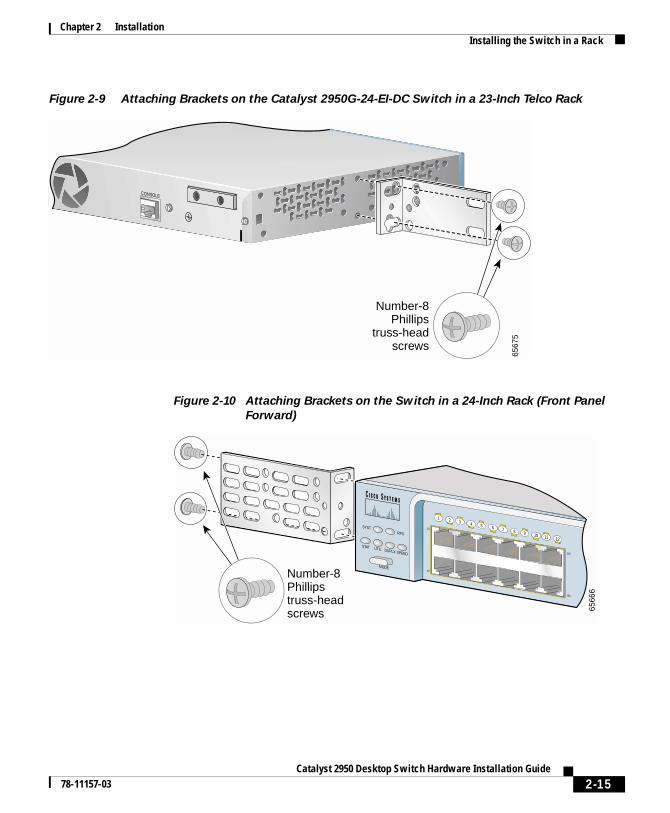
• When mounting a Catalyst 2950G-24-EI-DC switch in a 23-inch rack, use two Phillips truss-head screws to attach the 23-inch bracket to the switch. See Figure 2-7, Figure 2-8, and Figure 2-9.
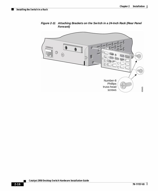
• When mounting a switch other than a Catalyst 2950G-48-EI switch in a 24-inch rack, use two Phillips truss-head screws to attach the 19- or 24-inch bracket to the switch. See Figure 2-10, Figure 2-11, and Figure 2-12.
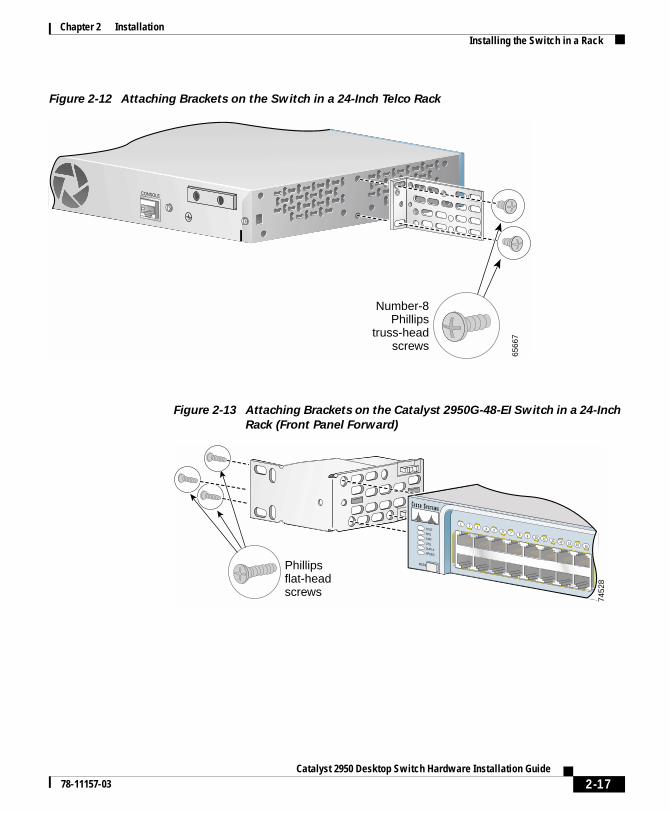
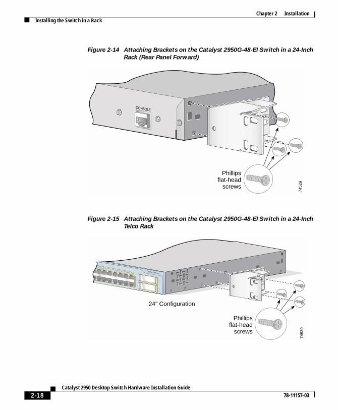
• When mounting a Catalyst 2950G-48-EI switch in a 24-inch rack, use three Phillips flat-head screws to attach the 24-inch bracket (part number RCKMNT-1RU=) to the switch. See Figure 2-13, Figure 2-14, and Figure 2-15.
Figure 2-1 to Figure 2-15 show how to attach a bracket to one side of the switch. Follow the same steps to attach the second bracket to the opposite side of the switch.
2-10Catalyst 2950 Desktop Switch Hardware Installation Guide
78-11157-03
Chapter 2 InstallationInstalling the Switch in a Rack
Figure 2-1 Attaching Brackets on the Switch in a 19-Inch Rack (Front Panel
Forward)
Figure 2-2 Attaching Brackets on the Switch in a 19-Inch Rack (Rear Panel
Forward)
SYSTRPS
DUPLX
MODE
SPEEDUTIL
STAT
1x 2x 3x 4x 5x
4558
0
Number-8Phillips flat-head
screws
CONSOLE
Number-8Phillips flat-head
screws
5291
6
2-11Catalyst 2950 Desktop Switch Hardware Installation Guide
78-11157-03
Chapter 2 InstallationInstalling the Switch in a Rack
Figure 2-3 Attaching Brackets on the Switch in a 19-Inch Telco Rack
Figure 2-4 Attaching Brackets on the Catalyst 2950G-48-EI Switch in a 19-Inch
Rack (Front Panel Forward)
CONSOLE
4558
2
Number-8Phillips flat-head
screws
SYSTRPSSTATUTILDUPLXSPEED
MODE
1X
2X
15X
16X
1 2 3 4 5 6 7 8 9 10 11 12 13 14 15 16
Number-8Phillipsflat-headscrews 65
512
2-12Catalyst 2950 Desktop Switch Hardware Installation Guide
78-11157-03
Chapter 2 InstallationInstalling the Switch in a Rack
Figure 2-5 Attaching Brackets on the Catalyst 2950G-48-EI Switch in a 19-Inch Rack (Rear Panel
Forward)
Figure 2-6 Attaching Brackets on the Catalyst 2950G-48-EI Switch in a 19-Inch Telco Rack
CONSOLE
Number-8Phillips
flat-headscrews
6551
3
CONSOLE
6551
4
Number-8Phillips
flat-headscrews
2-13Catalyst 2950 Desktop Switch Hardware Installation Guide
78-11157-03
Chapter 2 InstallationInstalling the Switch in a Rack
Figure 2-7 Attaching Brackets on the Catalyst 2950G-24-EI-DC Switch in a
23-Inch Telco Rack (Front Panel Forward)
Figure 2-8 Attaching Brackets on the Catalyst 2950G-24-EI-DC Switch in a 23-Inch Telco Rack
(Rear Panel Forward)
SYSTRPS
DUPLX
MODE
SPEEDUTIL
STAT
1X
2X
11X
12X
1 2 3 4 5 6 7 8 9 10 11 12
6567
3
Number-8Phillipstruss-headscrews
CONSOLE
Number-8Phillips
truss-headscrews 65
674
2-14Catalyst 2950 Desktop Switch Hardware Installation Guide
78-11157-03
Chapter 2 InstallationInstalling the Switch in a Rack
Figure 2-9 Attaching Brackets on the Catalyst 2950G-24-EI-DC Switch in a 23-Inch Telco Rack
Figure 2-10 Attaching Brackets on the Switch in a 24-Inch Rack (Front Panel
Forward)
CONSOLE
6567
5
Number-8Phillips
truss-headscrews
SYSTRPS
DUPLX
MODE
SPEEDUTIL
STAT
1X
2X
11X
12X
1 2 3 4 5 6 7 8 9 10 11 12
6566
6
Number-8Phillipstruss-headscrews
2-15Catalyst 2950 Desktop Switch Hardware Installation Guide
78-11157-03
Chapter 2 InstallationInstalling the Switch in a Rack
Figure 2-11 Attaching Brackets on the Switch in a 24-Inch Rack (Rear Panel
Forward)
CONSOLE
Number-8Phillips
truss-headscrews 65
665
2-16Catalyst 2950 Desktop Switch Hardware Installation Guide
78-11157-03
Chapter 2 InstallationInstalling the Switch in a Rack
Figure 2-12 Attaching Brackets on the Switch in a 24-Inch Telco Rack
Figure 2-13 Attaching Brackets on the Catalyst 2950G-48-EI Switch in a 24-Inch
Rack (Front Panel Forward)
CONSOLE
6566
7
Number-8Phillips
truss-headscrews
SYSTRPSSTATUTILDUPLXSPEED
MODE
1X
2X
15X
16X
1 2 3 4 5 6 7 8 9 10 11 12 13 14 15 16
7452
8
Phillipsflat-headscrews
2-17Catalyst 2950 Desktop Switch Hardware Installation Guide
78-11157-03
Chapter 2 InstallationInstalling the Switch in a Rack
Figure 2-14 Attaching Brackets on the Catalyst 2950G-48-EI Switch in a 24-Inch
Rack (Rear Panel Forward)
Figure 2-15 Attaching Brackets on the Catalyst 2950G-48-EI Switch in a 24-Inch
Telco Rack
CONSOLE
7452
9
Phillipsflat-head
screws
Catalyst 2950 SERIES
33X
34X
47X
48X
33 34 35 36 37 38 39 40 41 42 43 44 45 46 47
1
48
2
7453
0
Phillipsflat-head
screws
24" Configuration
2-18Catalyst 2950 Desktop Switch Hardware Installation Guide
78-11157-03
Chapter 2 InstallationInstalling the Switch in a Rack
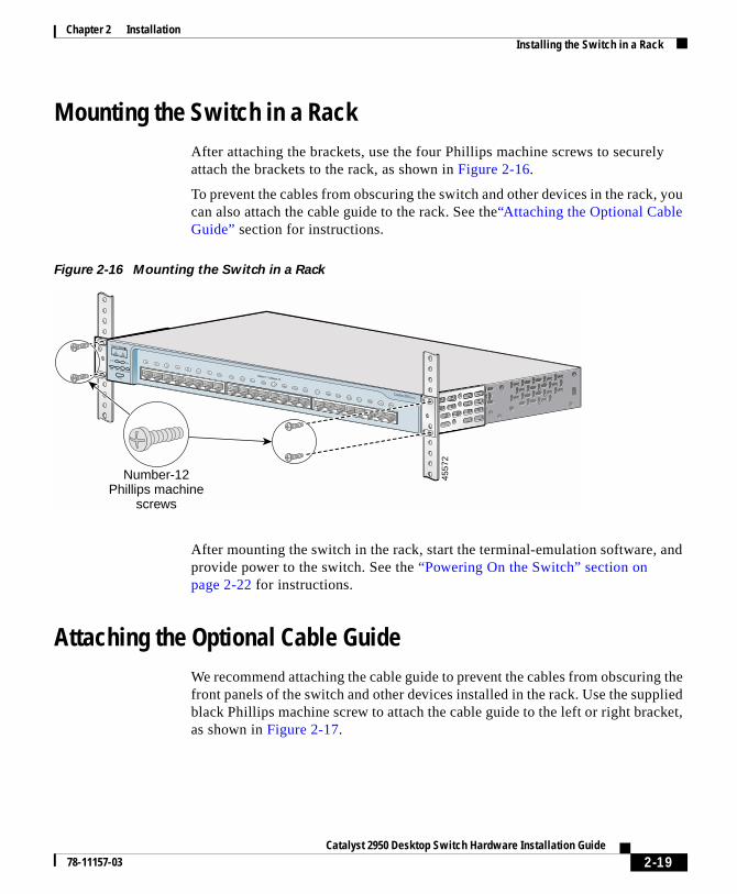
Mounting the Switch in a RackAfter attaching the brackets, use the four Phillips machine screws to securely attach the brackets to the rack, as shown in Figure 2-16.
To prevent the cables from obscuring the switch and other devices in the rack, you can also attach the cable guide to the rack. See the“Attaching the Optional Cable Guide” section for instructions.
Figure 2-16 Mounting the Switch in a Rack
After mounting the switch in the rack, start the terminal-emulation software, and provide power to the switch. See the “Powering On the Switch” section on page 2-22 for instructions.
Attaching the Optional Cable GuideWe recommend attaching the cable guide to prevent the cables from obscuring the front panels of the switch and other devices installed in the rack. Use the supplied black Phillips machine screw to attach the cable guide to the left or right bracket, as shown in Figure 2-17.
SYSTRPS
DUPLX
MODE
SPEEDUTIL
STAT
10Base-T / 100Base-TX
Catalyst 2950 SERIES
1x 2x 3x 4x 5x 6x 7x 8x9x 10x 11x 12x 13x 14x 15x 16x 17x 18x 19x 20x 21x 22x 23x 24x
4557
2
Number-12Phillips machine
screws
2-19Catalyst 2950 Desktop Switch Hardware Installation Guide
78-11157-03
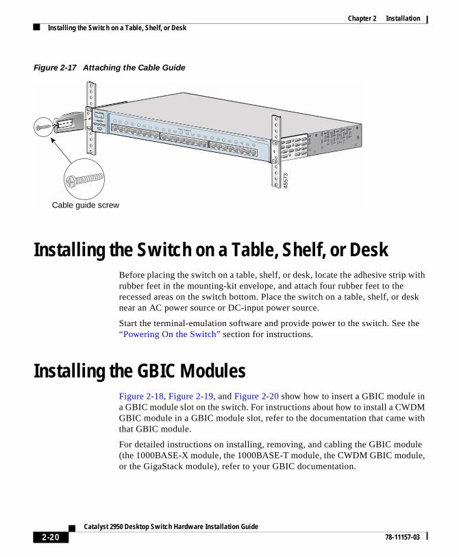
Chapter 2 InstallationInstalling the Switch on a Table, Shelf, or Desk
Figure 2-17 Attaching the Cable Guide
Installing the Switch on a Table, Shelf, or DeskBefore placing the switch on a table, shelf, or desk, locate the adhesive strip with rubber feet in the mounting-kit envelope, and attach four rubber feet to the recessed areas on the switch bottom. Place the switch on a table, shelf, or desk near an AC power source or DC-input power source.
Start the terminal-emulation software and provide power to the switch. See the “Powering On the Switch” section for instructions.
Installing the GBIC ModulesFigure 2-18, Figure 2-19, and Figure 2-20 show how to insert a GBIC module in a GBIC module slot on the switch. For instructions about how to install a CWDM GBIC module in a GBIC module slot, refer to the documentation that came with that GBIC module.
For detailed instructions on installing, removing, and cabling the GBIC module (the 1000BASE-X module, the 1000BASE-T module, the CWDM GBIC module, or the GigaStack module), refer to your GBIC documentation.
SYSTRPS
DUPLX
MODE
SPEEDUTIL
STAT
10Base-T / 100Base-TX
Catalyst 2950 SERIES
4557
3
Cable guide screw
1x2x
3x4x
5x6x
7x8x
9x10x 11x 12x 13x 14x 15x 16x
17x 18x 19x 20x 21x 22x 23x 24x
2-20Catalyst 2950 Desktop Switch Hardware Installation Guide
78-11157-03
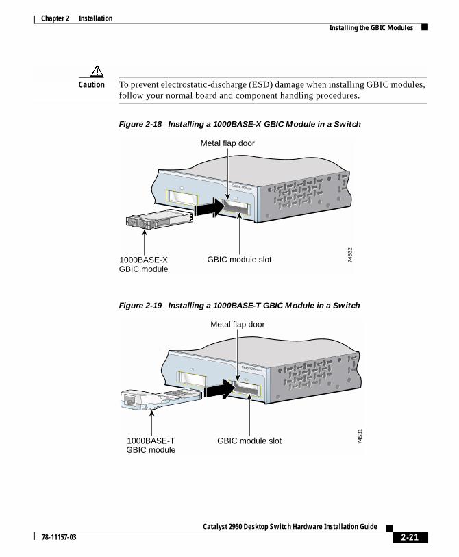
Chapter 2 InstallationInstalling the GBIC Modules
Caution To prevent electrostatic-discharge (ESD) damage when installing GBIC modules, follow your normal board and component handling procedures.
Figure 2-18 Installing a 1000BASE-X GBIC Module in a Switch
Figure 2-19 Installing a 1000BASE-T GBIC Module in a Switch
Catalyst 2950 SERIES1
2
7453
2
Metal flap door
GBIC module slot1000BASE-XGBIC module
Catalyst 2950 SERIES1
2
7453
1
Metal flap door
GBIC module slot1000BASE-TGBIC module
2-21Catalyst 2950 Desktop Switch Hardware Installation Guide
78-11157-03
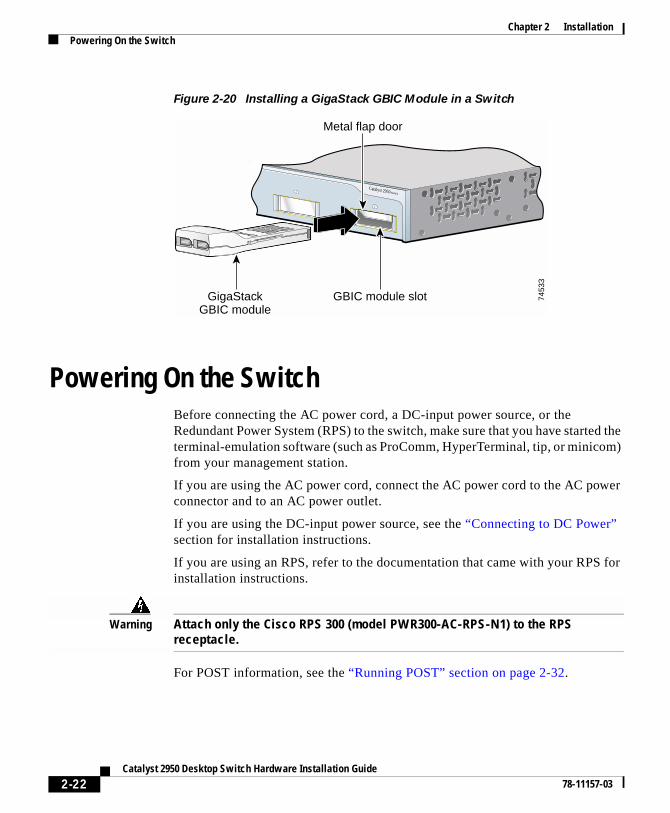
Chapter 2 InstallationPowering On the Switch
Figure 2-20 Installing a GigaStack GBIC Module in a Switch
Powering On the SwitchBefore connecting the AC power cord, a DC-input power source, or the Redundant Power System (RPS) to the switch, make sure that you have started the terminal-emulation software (such as ProComm, HyperTerminal, tip, or minicom) from your management station.
If you are using the AC power cord, connect the AC power cord to the AC power connector and to an AC power outlet.
If you are using the DC-input power source, see the “Connecting to DC Power” section for installation instructions.
If you are using an RPS, refer to the documentation that came with your RPS for installation instructions.
Warning Attach only the Cisco RPS 300 (model PWR300-AC-RPS-N1) to the RPS receptacle.
For POST information, see the “Running POST” section on page 2-32.
Catalyst 2950 SERIES1
2
7453
3
Metal flap door
GBIC module slotGigaStackGBIC module
2-22Catalyst 2950 Desktop Switch Hardware Installation Guide
78-11157-03
Chapter 2 InstallationConnecting to DC Power
Connecting to DC PowerTo connect the Catalyst 2950G-24-EI-DC switch to a DC-input power source, follow these steps:
• Preparing for Installation, page 2-23
• Grounding the Switch, page 2-24
• Wiring the DC-Input Power Source, page 2-26
Warning The Catalyst 2950G-24-EI-DC contains no field-replaceable units (FRUs). Do not open the chassis or attempt to remove or replace any components. For information about obtaining service for this unit, contact your reseller or Cisco sales representative.
Warning The equipment is to be installed in a restricted access area.
Warning Ethernet cables must be shielded when used in a central office environment.
Preparing for InstallationLocate the DC terminal block plug, the ground lug, and the two number-10-32 screws in the DC-switch kit.
Obtain these necessary tools and equipment:
• Ratcheting torque screwdriver with a Phillips head that exerts up to 15 pound-force inches (lbf-in.) of pressure
• Panduit crimping tool with optional controlled cycle mechanism (model CT-700, CT-720, CT-920, CT-920CH, CT-930, or CT-940CH)
• 6-gauge copper ground wire (insulated or noninsulated)
• Four leads of 18-gauge copper wire
• Wire-stripping tools for stripping 6- and 18-gauge wires
2-23Catalyst 2950 Desktop Switch Hardware Installation Guide
78-11157-03
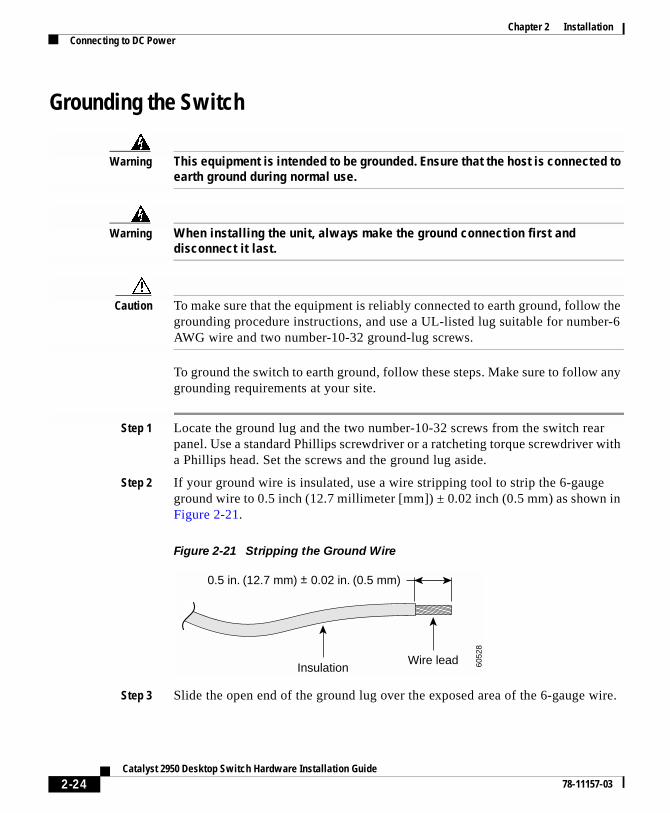
Chapter 2 InstallationConnecting to DC Power
Grounding the Switch
Warning This equipment is intended to be grounded. Ensure that the host is connected to earth ground during normal use.
Warning When installing the unit, always make the ground connection first and disconnect it last.
Caution To make sure that the equipment is reliably connected to earth ground, follow the grounding procedure instructions, and use a UL-listed lug suitable for number-6 AWG wire and two number-10-32 ground-lug screws.
To ground the switch to earth ground, follow these steps. Make sure to follow any grounding requirements at your site.
Step 1 Locate the ground lug and the two number-10-32 screws from the switch rear panel. Use a standard Phillips screwdriver or a ratcheting torque screwdriver with a Phillips head. Set the screws and the ground lug aside.
Step 2 If your ground wire is insulated, use a wire stripping tool to strip the 6-gauge ground wire to 0.5 inch (12.7 millimeter [mm]) ± 0.02 inch (0.5 mm) as shown in Figure 2-21.
Figure 2-21 Stripping the Ground Wire
Step 3 Slide the open end of the ground lug over the exposed area of the 6-gauge wire.
InsulationWire lead
0.5 in. (12.7 mm) ± 0.02 in. (0.5 mm)
6052
8
2-24Catalyst 2950 Desktop Switch Hardware Installation Guide
78-11157-03
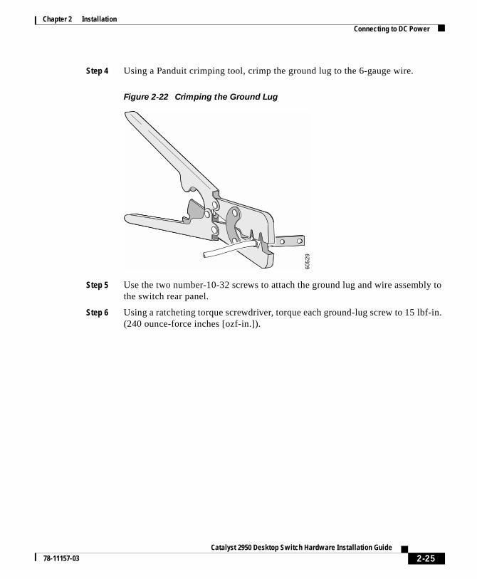
Chapter 2 InstallationConnecting to DC Power
Step 4 Using a Panduit crimping tool, crimp the ground lug to the 6-gauge wire.
Figure 2-22 Crimping the Ground Lug
Step 5 Use the two number-10-32 screws to attach the ground lug and wire assembly to the switch rear panel.
Step 6 Using a ratcheting torque screwdriver, torque each ground-lug screw to 15 lbf-in. (240 ounce-force inches [ozf-in.]).
6052
9
2-25Catalyst 2950 Desktop Switch Hardware Installation Guide
78-11157-03
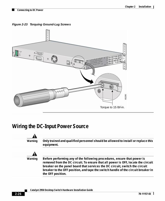
Chapter 2 InstallationConnecting to DC Power
Figure 2-23 Torquing Ground-Lug Screws
Wiring the DC-Input Power Source
Warning Only trained and qualified personnel should be allowed to install or replace this equipment.
Warning Before performing any of the following procedures, ensure that power is removed from the DC circuit. To ensure that all power is OFF, locate the circuit breaker on the panel board that services the DC circuit, switch the circuit breaker to the OFF position, and tape the switch handle of the circuit breaker in the OFF position.
DC INPUT FOR REMOTEPOWER SUPPLYSPECIFIED IN MANUAL.+12V @4.5A
36 - 72V 1 - 0.5A
CONSOLE
A
B
6529
5
Torque to 15 lbf-in.
2-26Catalyst 2950 Desktop Switch Hardware Installation Guide
78-11157-03
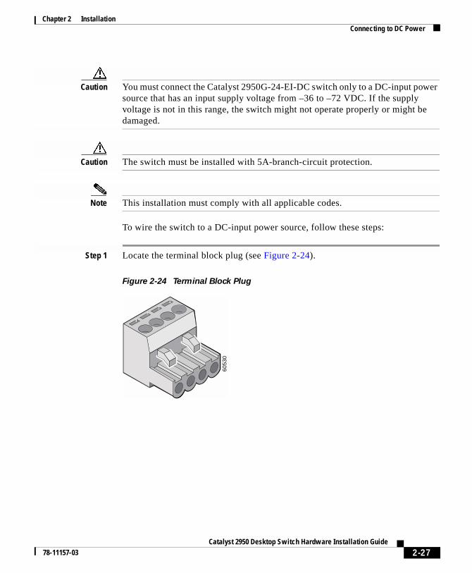
Chapter 2 InstallationConnecting to DC Power
Caution You must connect the Catalyst 2950G-24-EI-DC switch only to a DC-input power source that has an input supply voltage from –36 to –72 VDC. If the supply voltage is not in this range, the switch might not operate properly or might be damaged.
Caution The switch must be installed with 5A-branch-circuit protection.
Note This installation must comply with all applicable codes.
To wire the switch to a DC-input power source, follow these steps:
Step 1 Locate the terminal block plug (see Figure 2-24).
Figure 2-24 Terminal Block Plug
6053
0
2-27Catalyst 2950 Desktop Switch Hardware Installation Guide
78-11157-03
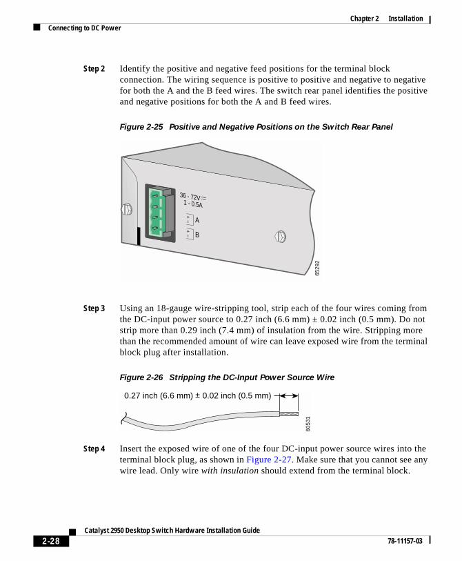
Chapter 2 InstallationConnecting to DC Power
Step 2 Identify the positive and negative feed positions for the terminal block connection. The wiring sequence is positive to positive and negative to negative for both the A and the B feed wires. The switch rear panel identifies the positive and negative positions for both the A and B feed wires.
Figure 2-25 Positive and Negative Positions on the Switch Rear Panel
Step 3 Using an 18-gauge wire-stripping tool, strip each of the four wires coming from the DC-input power source to 0.27 inch (6.6 mm) ± 0.02 inch (0.5 mm). Do not strip more than 0.29 inch (7.4 mm) of insulation from the wire. Stripping more than the recommended amount of wire can leave exposed wire from the terminal block plug after installation.
Figure 2-26 Stripping the DC-Input Power Source Wire
Step 4 Insert the exposed wire of one of the four DC-input power source wires into the terminal block plug, as shown in Figure 2-27. Make sure that you cannot see any wire lead. Only wire with insulation should extend from the terminal block.
36 - 72V 1 - 0.5A
A
B
6529
2
0.27 inch (6.6 mm) ± 0.02 inch (0.5 mm)
6053
1
2-28Catalyst 2950 Desktop Switch Hardware Installation Guide
78-11157-03
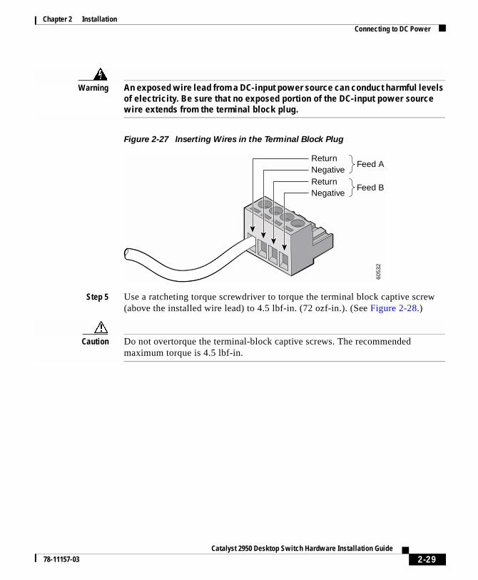
Chapter 2 InstallationConnecting to DC Power
Warning An exposed wire lead from a DC-input power source can conduct harmful levels of electricity. Be sure that no exposed portion of the DC-input power source wire extends from the terminal block plug.
Figure 2-27 Inserting Wires in the Terminal Block Plug
Step 5 Use a ratcheting torque screwdriver to torque the terminal block captive screw (above the installed wire lead) to 4.5 lbf-in. (72 ozf-in.). (See Figure 2-28.)
Caution Do not overtorque the terminal-block captive screws. The recommended maximum torque is 4.5 lbf-in.
6053
2
ReturnNegativeReturn
Feed A
Feed BNegative
2-29Catalyst 2950 Desktop Switch Hardware Installation Guide
78-11157-03
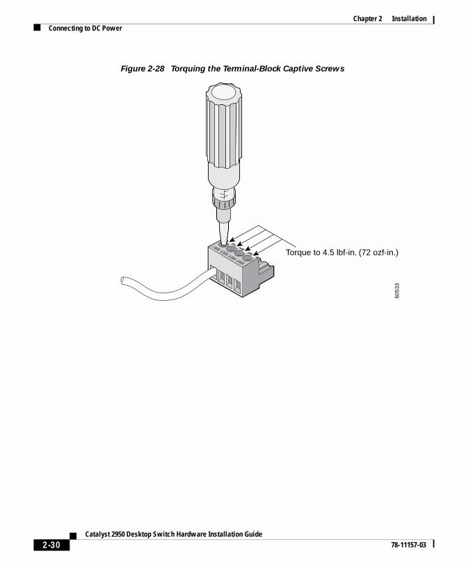
Chapter 2 InstallationConnecting to DC Power
Figure 2-28 Torquing the Terminal-Block Captive Screws
6053
3
Torque to 4.5 lbf-in. (72 ozf-in.)
2-30Catalyst 2950 Desktop Switch Hardware Installation Guide
78-11157-03
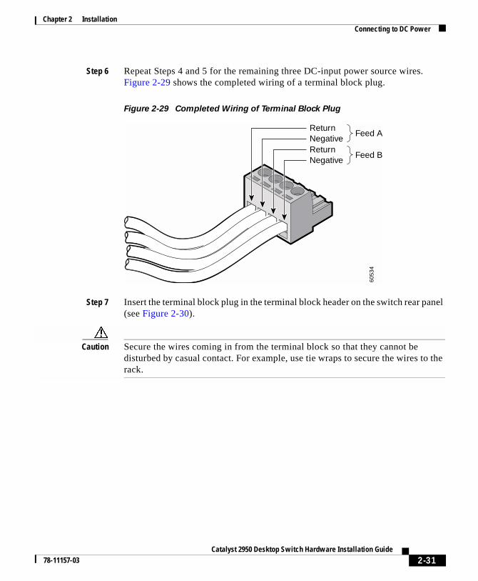
Chapter 2 InstallationConnecting to DC Power
Step 6 Repeat Steps 4 and 5 for the remaining three DC-input power source wires. Figure 2-29 shows the completed wiring of a terminal block plug.
Figure 2-29 Completed Wiring of Terminal Block Plug
Step 7 Insert the terminal block plug in the terminal block header on the switch rear panel (see Figure 2-30).
Caution Secure the wires coming in from the terminal block so that they cannot be disturbed by casual contact. For example, use tie wraps to secure the wires to the rack.
6053
4
ReturnNegativeReturnNegative
Feed A
Feed B
2-31Catalyst 2950 Desktop Switch Hardware Installation Guide
78-11157-03
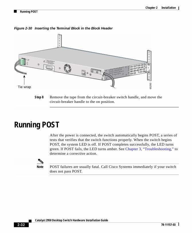
Chapter 2 InstallationRunning POST
Figure 2-30 Inserting the Terminal Block in the Block Header
Step 8 Remove the tape from the circuit-breaker switch handle, and move the circuit-breaker handle to the on position.
Running POSTAfter the power is connected, the switch automatically begins POST, a series of tests that verifies that the switch functions properly. When the switch begins POST, the system LED is off. If POST completes successfully, the LED turns green. If POST fails, the LED turns amber. See Chapter 3, “Troubleshooting,” to determine a corrective action.
Note POST failures are usually fatal. Call Cisco Systems immediately if your switch does not pass POST.
DC INPUT FOR REMOTEPOWER SUPPLYSPECIFIED IN MANUAL.+12V @4.5A
36 - 72V 1 - 0.5A
CONSOLE
A
B
Tie wrap 6529
3
2-32Catalyst 2950 Desktop Switch Hardware Installation Guide
78-11157-03
Chapter 2 InstallationConnecting to 10/100 and 10/100/1000 Ports
Connecting to 10/100 and 10/100/1000 PortsThe 10/100 ports configure themselves to operate at the speed and duplex settings of attached devices.They operate at 10 or 100 Mbps in half- or full-duplex mode. If the attached devices do not support autonegotiation, you can explicitly set the speed and duplex parameters.
The 10/100/1000 ports configure themselves to operate at the speed setting of attached devices.These ports on Catalyst 2950T-24 switches operate at 10, 100, or 1000 Mbps only in full-duplex mode. If the attached devices do not support autonegotiation, you can explicitly set the speed parameter.
Connecting devices that do not autonegotiate or devices with manually set speed and duplex parameters can reduce performance or result in link failures between the devices. To maximize performance, choose one of these methods for configuring the ports:
• Let the ports autonegotiate both speed and duplex for 10/100 ports and only speed for 10/100/1000 ports.
• Set the speed and duplex parameters on both ends of the connection.
When connecting the ports on the Catalyst 2950G-24-EI-DC switches to other devices, follow these guidelines:
Caution To comply with the intrabuilding lightning surge requirements, intrabuilding wiring must be shielded, and the shield for the wiring must be grounded at both ends.
Caution The Catalyst 2950G-24-EI-DC switch is suitable only for intrabuilding or nonexposed wiring connections.
2-33Catalyst 2950 Desktop Switch Hardware Installation Guide
78-11157-03
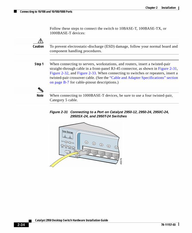
Chapter 2 InstallationConnecting to 10/100 and 10/100/1000 Ports
Follow these steps to connect the switch to 10BASE-T, 100BASE-TX, or 1000BASE-T devices:
Caution To prevent electrostatic-discharge (ESD) damage, follow your normal board and component handling procedures.
Step 1 When connecting to servers, workstations, and routers, insert a twisted-pair straight-through cable in a front-panel RJ-45 connector, as shown in Figure 2-31, Figure 2-32, and Figure 2-33. When connecting to switches or repeaters, insert a twisted-pair crossover cable. (See the “Cable and Adapter Specifications” section on page B-7 for cable-pinout descriptions.)
Note When connecting to 1000BASE-T devices, be sure to use a four twisted-pair, Category 5 cable.
Figure 2-31 Connecting to a Port on Catalyst 2950-12, 2950-24, 2950C-24,
2950SX-24, and 2950T-24 Switches
SYSTRPS
DUPLX
MODE
SPEEDUTIL
STAT
4557
6
1x 2x 3x 4x 5x
2-34Catalyst 2950 Desktop Switch Hardware Installation Guide
78-11157-03
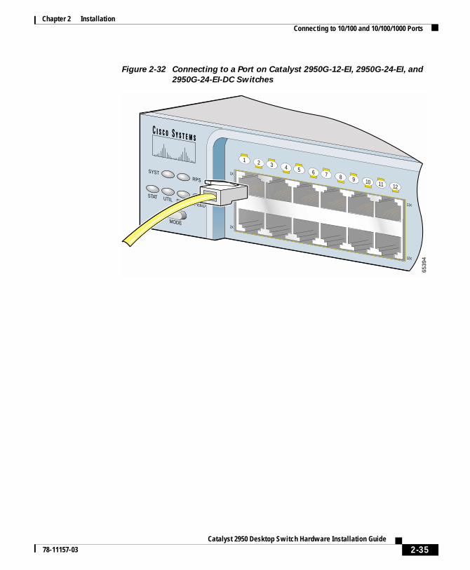
Chapter 2 InstallationConnecting to 10/100 and 10/100/1000 Ports
Figure 2-32 Connecting to a Port on Catalyst 2950G-12-EI, 2950G-24-EI, and
2950G-24-EI-DC Switches
SYSTRPS
DUPLX
MODE
SPEEDUTIL
STAT
6539
4
1X
2X
11X
12X
1 2 3 4 5 6 7 8 9 10 11 12
2-35Catalyst 2950 Desktop Switch Hardware Installation Guide
78-11157-03
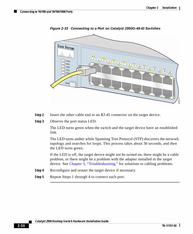
Chapter 2 InstallationConnecting to 10/100 and 10/100/1000 Ports
Figure 2-33 Connecting to a Port on Catalyst 2950G-48-EI Switches
Step 2 Insert the other cable end in an RJ-45 connector on the target device.
Step 3 Observe the port status LED.
The LED turns green when the switch and the target device have an established link.
The LED turns amber while Spanning Tree Protocol (STP) discovers the network topology and searches for loops. This process takes about 30 seconds, and then the LED turns green.
If the LED is off, the target device might not be turned on, there might be a cable problem, or there might be a problem with the adapter installed in the target device. See Chapter 3, “Troubleshooting,” for solutions to cabling problems.
Step 4 Reconfigure and restart the target device if necessary.
Step 5 Repeat Steps 1 through 4 to connect each port.
1X
2X
15X
16X
1 2 3 4 5 6 7 8 9 10 11 12 13 14 15 16
SYSTRPSSTATUTILDUPLXSPEED
MODE
6551
7
2-36Catalyst 2950 Desktop Switch Hardware Installation Guide
78-11157-03
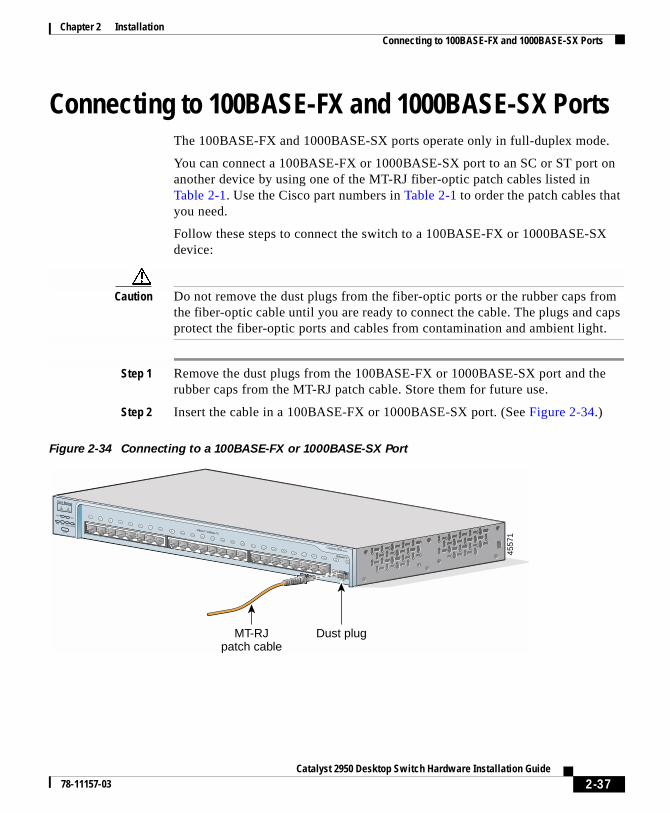
Chapter 2 InstallationConnecting to 100BASE-FX and 1000BASE-SX Ports
Connecting to 100BASE-FX and 1000BASE-SX PortsThe 100BASE-FX and 1000BASE-SX ports operate only in full-duplex mode.
You can connect a 100BASE-FX or 1000BASE-SX port to an SC or ST port on another device by using one of the MT-RJ fiber-optic patch cables listed in Table 2-1. Use the Cisco part numbers in Table 2-1 to order the patch cables that you need.
Follow these steps to connect the switch to a 100BASE-FX or 1000BASE-SX device:
Caution Do not remove the dust plugs from the fiber-optic ports or the rubber caps from the fiber-optic cable until you are ready to connect the cable. The plugs and caps protect the fiber-optic ports and cables from contamination and ambient light.
Step 1 Remove the dust plugs from the 100BASE-FX or 1000BASE-SX port and the rubber caps from the MT-RJ patch cable. Store them for future use.
Step 2 Insert the cable in a 100BASE-FX or 1000BASE-SX port. (See Figure 2-34.)
Figure 2-34 Connecting to a 100BASE-FX or 1000BASE-SX Port
4557
1SYST
RPS
DUPLX
MODE
SPEEDUTIL
STAT
10Base-T / 100Base-TX
100Base-FX
Catalyst 2950 SERIES
MT-RJpatch cable
Dust plug
1x2x
3x4x
5x6x
7x8x
9x10x
11x12x
13x14x
15x16x
17x18x
19x20x
21x22x 23x
24x
2625
2-37Catalyst 2950 Desktop Switch Hardware Installation Guide
78-11157-03
Chapter 2 InstallationConnecting to GBIC Module Ports
Step 3 Insert the other cable end in an SC or ST port on the target device.
Step 4 Observe the port status LED.
The LED turns green when the switch and the target device have an established link.
The LED turns amber while STP discovers the network topology and searches for loops. This process takes about 30 seconds, and then the port LED turns green.
If the LED is off, the target device might not be turned on, there might be a cable problem, or there might be a problem with the adapter installed in the target device. See Chapter 3, “Troubleshooting,” for solutions to cabling problems.
Step 5 Reconfigure and restart the target device if necessary.
Step 6 Repeat Steps 1 through 5 to connect each port.
Connecting to GBIC Module PortsThese sections describe how to connect to a GBIC module port.
• Connecting to 1000BASE-X GBIC Module Ports, page 2-39
• Connecting to 1000BASE-T GBIC Module Ports, page 2-41
• Connecting to GigaStack GBIC Module Ports, page 2-42
For instructions about how to connect to the CWDM GBIC module ports, refer to the documentation that came with that GBIC module.
For detailed instructions about installing, removing, and connecting to the GBIC module (the 1000BASE-X module, the 1000BASE-T module, the CWDM GBIC module, or the GigaStack module), refer to the GBIC documentation.
2-38Catalyst 2950 Desktop Switch Hardware Installation Guide
78-11157-03
Chapter 2 InstallationConnecting to GBIC Module Ports
When connecting the ports on the Catalyst 2950G-24-EI-DC switches to other devices, follow these guidelines:
Caution To comply with the intrabuilding lightning surge requirements, intrabuilding wiring must be shielded, and the shield for the wiring must be grounded at both ends.
Caution The Catalyst 2950G-24-EI-DC switch is suitable only for intrabuilding or nonexposed wiring connections.
Connecting to 1000BASE-X GBIC Module Ports
Caution Do not remove the rubber plugs from the GBIC module port or the rubber caps from the fiber-optic cable until you are ready to connect the cable. The plugs and caps protect the GBIC module ports and cables from contamination and ambient light.
After installing the 1000BASE-X GBIC in the GBIC module slot, follow these steps:
Step 1 Remove the rubber plugs from the GBIC module port, and store them for future use.
Step 2 Insert the SC connector in the fiber-optic receptacle (see Figure 2-35).
2-39Catalyst 2950 Desktop Switch Hardware Installation Guide
78-11157-03
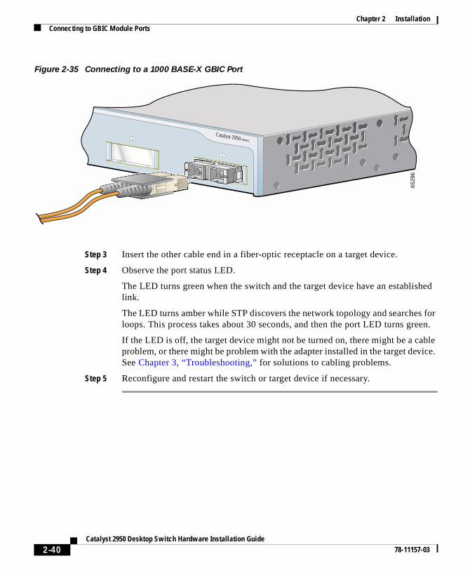
Chapter 2 InstallationConnecting to GBIC Module Ports
Figure 2-35 Connecting to a 1000 BASE-X GBIC Port
Step 3 Insert the other cable end in a fiber-optic receptacle on a target device.
Step 4 Observe the port status LED.
The LED turns green when the switch and the target device have an established link.
The LED turns amber while STP discovers the network topology and searches for loops. This process takes about 30 seconds, and then the port LED turns green.
If the LED is off, the target device might not be turned on, there might be a cable problem, or there might be problem with the adapter installed in the target device. See Chapter 3, “Troubleshooting,” for solutions to cabling problems.
Step 5 Reconfigure and restart the switch or target device if necessary.
Catalyst 2950 SERIES1
2
6529
6
2-40Catalyst 2950 Desktop Switch Hardware Installation Guide
78-11157-03
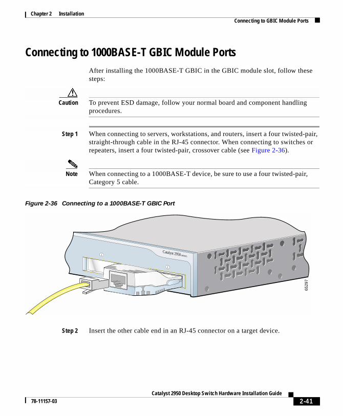
Chapter 2 InstallationConnecting to GBIC Module Ports
Connecting to 1000BASE-T GBIC Module PortsAfter installing the 1000BASE-T GBIC in the GBIC module slot, follow these steps:
Caution To prevent ESD damage, follow your normal board and component handling procedures.
Step 1 When connecting to servers, workstations, and routers, insert a four twisted-pair, straight-through cable in the RJ-45 connector. When connecting to switches or repeaters, insert a four twisted-pair, crossover cable (see Figure 2-36).
Note When connecting to a 1000BASE-T device, be sure to use a four twisted-pair, Category 5 cable.
Figure 2-36 Connecting to a 1000BASE-T GBIC Port
Step 2 Insert the other cable end in an RJ-45 connector on a target device.
Catalyst 2950 SERIES1
2
6529
7
2-41Catalyst 2950 Desktop Switch Hardware Installation Guide
78-11157-03
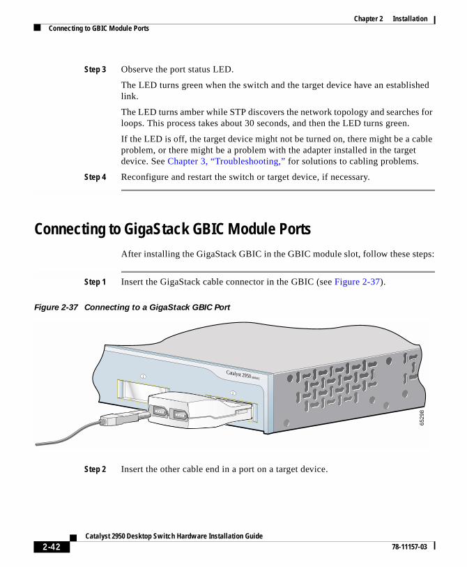
Chapter 2 InstallationConnecting to GBIC Module Ports
Step 3 Observe the port status LED.
The LED turns green when the switch and the target device have an established link.
The LED turns amber while STP discovers the network topology and searches for loops. This process takes about 30 seconds, and then the LED turns green.
If the LED is off, the target device might not be turned on, there might be a cable problem, or there might be a problem with the adapter installed in the target device. See Chapter 3, “Troubleshooting,” for solutions to cabling problems.
Step 4 Reconfigure and restart the switch or target device, if necessary.
Connecting to GigaStack GBIC Module PortsAfter installing the GigaStack GBIC in the GBIC module slot, follow these steps:
Step 1 Insert the GigaStack cable connector in the GBIC (see Figure 2-37).
Figure 2-37 Connecting to a GigaStack GBIC Port
Step 2 Insert the other cable end in a port on a target device.
Catalyst 2950 SERIES1
2
6529
8
2-42Catalyst 2950 Desktop Switch Hardware Installation Guide
78-11157-03
Chapter 2 InstallationConnecting a PC or a Terminal to the Console Port
Step 3 Observe the port status LED.
The LED turns green when the switch and the target device have an established link.
The LED turns amber while STP discovers the network topology and searches for loops. This process takes about 30 seconds, and then the port LED turns green.
If the LED is off, the target device might not be turned on, there might be a cable problem, or there might be a problem with the adapter installed in the target device. See Chapter 3, “Troubleshooting,” for solutions to cabling problems.
Step 4 Reconfigure and restart the switch or target device, if necessary.
Connecting a PC or a Terminal to the Console PortIf you want to connect a PC to the console port, use the supplied RJ-45-to-DB-9 adapter cable. If you want to connect a terminal to the console port, you need to provide an RJ-45-to-DB-25 female DTE adapter. You can order a kit (part number ACS-DSBUASYN=) with that adapter from Cisco. For console-port and adapter-pinout information, see the“Cable and Adapter Specifications” section on page B-7.
The PC or terminal must support VT100 terminal emulation. The terminal-emulation software—frequently a PC application such as HyperTerminal or Procomm Plus—makes communication between the switch and your PC or terminal possible during the setup program.
Follow these steps to connect your PC or terminal to the console port:
Step 1 Make sure that your terminal-emulation software is configured to communicate with the switch through hardware flow control.
Step 2 Configure the baud rate and character format of the PC or terminal to match these console-port default characteristics:
• 9600 baud
• Eight data bits
• One stop bit
• No parity
2-43Catalyst 2950 Desktop Switch Hardware Installation Guide
78-11157-03
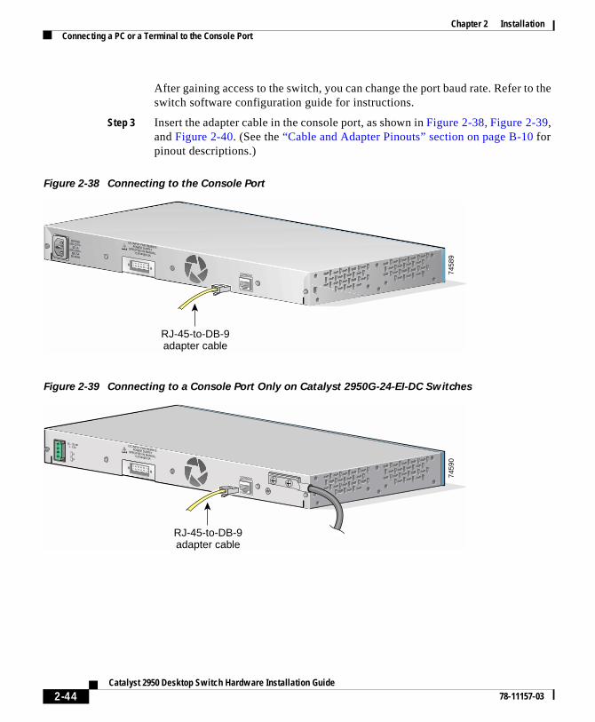
Chapter 2 InstallationConnecting a PC or a Terminal to the Console Port
After gaining access to the switch, you can change the port baud rate. Refer to the switch software configuration guide for instructions.
Step 3 Insert the adapter cable in the console port, as shown in Figure 2-38, Figure 2-39, and Figure 2-40. (See the “Cable and Adapter Pinouts” section on page B-10 for pinout descriptions.)
Figure 2-38 Connecting to the Console Port
Figure 2-39 Connecting to a Console Port Only on Catalyst 2950G-24-EI-DC Switches
RATING100-127V~@ [email protected]
DC INPUT FOR REMOTEPOWER SUPPLYSPECIFIED IN MANUAL.+12V @4.5A
CONSOLE
RJ-45-to-DB-9adapter cable
7458
9DC INPUT FOR REMOTEPOWER SUPPLYSPECIFIED IN MANUAL.+12V @4.5A
36 - 72V 1 - 0.5A
CONSOLE
A
B
7459
0
RJ-45-to-DB-9adapter cable
2-44Catalyst 2950 Desktop Switch Hardware Installation Guide
78-11157-03
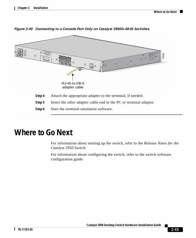
Chapter 2 InstallationWhere to Go Next
Figure 2-40 Connecting to a Console Port Only on Catalyst 2950G-48-EI Switches
Step 4 Attach the appropriate adapter to the terminal, if needed.
Step 5 Insert the other adapter cable end in the PC or terminal adapter.
Step 6 Start the terminal-emulation software.
Where to Go NextFor information about starting up the switch, refer to the Release Notes for the Catalyst 2950 Switch.
For information about configuring the switch, refer to the switch software configuration guide.
RATING100-127V~@ [email protected]
DC INPUT FOR REMOTEPOWER SUPPLYSPECIFIED IN MANUAL.+12V @4.5A
CONSOLE
RJ-45-to-DB-9adapter cable
7459
1
2-45Catalyst 2950 Desktop Switch Hardware Installation Guide
78-11157-03

Chapter 2 InstallationWhere to Go Next
2-46Catalyst 2950 Desktop Switch Hardware Installation Guide
78-11157-03
Catalyst 2950 Desktop Sw78-11157-03
C H A P T E R 3
TroubleshootingThe front-panel LEDs provide troubleshooting information about the switch. They show power-on self-test (POST) failures, port-connectivity problems, and overall switch performance. For a full description of the LEDs, see the “LEDs” section on page 1-9.
You can also get statistics from the Cluster Management Suite (CMS), the command-line interface (CLI), the Cisco Intelligence Engine 2100 (IE2100) Series Configuration Registrar, or a Simple Network Management Protocol (SNMP) workstation. Refer to the switch software configuration guide, the switch command reference, or the documentation that came with your IE2100 or SNMP application for details.
This chapter provides these topics for troubleshooting problems:
• Understanding POST Results, page 3-2
• Diagnosing Problems, page 3-2
3-1itch Hardware Installation Guide
Chapter 3 TroubleshootingUnderstanding POST Results
Understanding POST ResultsWhile the switch powers on, it automatically begins POST, a series of tests that verifies that the switch functions properly. When the switch begins POST, the system LED is off. If POST completes successfully, the LED turns green. If POST fails, the LED turns amber.
Note POST failures are usually fatal. Call Cisco Systems if your switch does not pass POST.
Diagnosing ProblemsCommon switch problems fall into these categories:
• Poor performance
• No connectivity
• Corrupted software
Table 3-1 describes how to detect and solve these problems.
3-2Catalyst 2950 Desktop Switch Hardware Installation Guide
78-11157-03
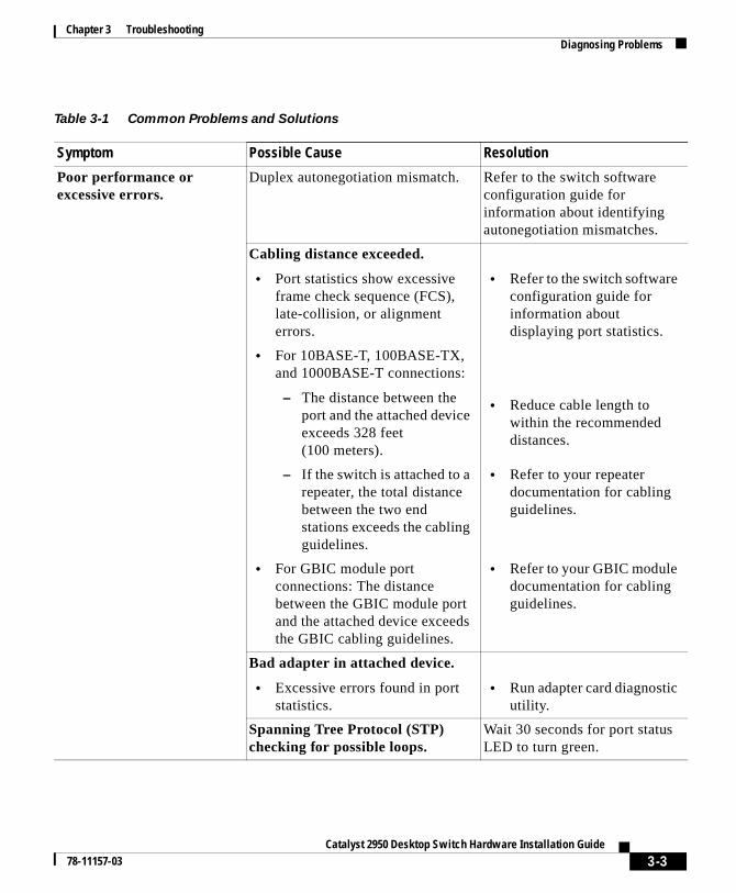
Chapter 3 TroubleshootingDiagnosing Problems
Table 3-1 Common Problems and Solutions
Symptom Possible Cause Resolution
Poor performance or excessive errors.
Duplex autonegotiation mismatch. Refer to the switch software configuration guide for information about identifying autonegotiation mismatches.
Cabling distance exceeded.
• Port statistics show excessive frame check sequence (FCS), late-collision, or alignment errors.
• Refer to the switch software configuration guide for information about displaying port statistics.
• For 10BASE-T, 100BASE-TX, and 1000BASE-T connections:
– The distance between the port and the attached device exceeds 328 feet(100 meters).
• Reduce cable length to within the recommended distances.
– If the switch is attached to a repeater, the total distance between the two end stations exceeds the cabling guidelines.
• Refer to your repeater documentation for cabling guidelines.
• For GBIC module port connections: The distance between the GBIC module port and the attached device exceeds the GBIC cabling guidelines.
• Refer to your GBIC module documentation for cabling guidelines.
Bad adapter in attached device.
• Excessive errors found in port statistics.
• Run adapter card diagnostic utility.
Spanning Tree Protocol (STP) checking for possible loops.
Wait 30 seconds for port status LED to turn green.
3-3Catalyst 2950 Desktop Switch Hardware Installation Guide
78-11157-03
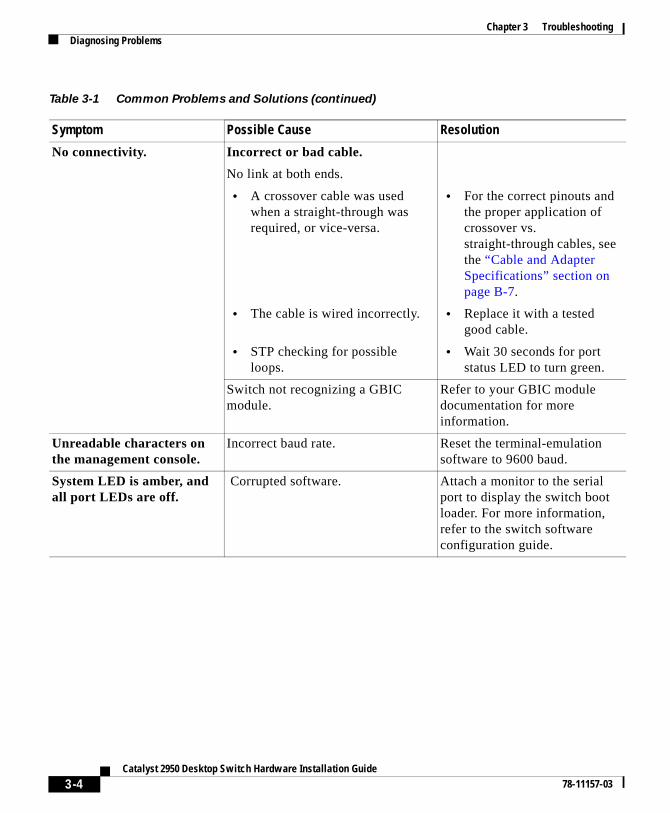
Chapter 3 TroubleshootingDiagnosing Problems
No connectivity. Incorrect or bad cable.
No link at both ends.
• A crossover cable was used when a straight-through was required, or vice-versa.
• For the correct pinouts and the proper application of crossover vs. straight-through cables, see the “Cable and Adapter Specifications” section on page B-7.
• The cable is wired incorrectly. • Replace it with a tested good cable.
• STP checking for possible loops.
• Wait 30 seconds for port status LED to turn green.
Switch not recognizing a GBIC module.
Refer to your GBIC module documentation for more information.
Unreadable characters on the management console.
Incorrect baud rate. Reset the terminal-emulation software to 9600 baud.
System LED is amber, and all port LEDs are off.
Corrupted software. Attach a monitor to the serial port to display the switch boot loader. For more information, refer to the switch software configuration guide.
Table 3-1 Common Problems and Solutions (continued)
Symptom Possible Cause Resolution
3-4Catalyst 2950 Desktop Switch Hardware Installation Guide
78-11157-03
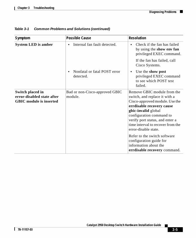
Chapter 3 TroubleshootingDiagnosing Problems
System LED is amber • Internal fan fault detected. • Check if the fan has failed by using the show env fan privileged EXEC command.
If the fan has failed, call Cisco Systems.
• Nonfatal or fatal POST error detected.
• Use the show post privileged EXEC command to see which POST test failed.
Switch placed in error-disabled state after GBIC module is inserted
Bad or non-Cisco-approved GBIC module.
Remove GBIC module from the switch, and replace it with a Cisco-approved module. Use the errdisable recovery cause gbic-invalid global configuration command to verify port status, and enter a time interval to recover from the error-disable state.
Refer to the switch software configuration guide for information about the errdisable recovery command.
Table 3-1 Common Problems and Solutions (continued)
Symptom Possible Cause Resolution
3-5Catalyst 2950 Desktop Switch Hardware Installation Guide
78-11157-03

Chapter 3 TroubleshootingDiagnosing Problems
3-6Catalyst 2950 Desktop Switch Hardware Installation Guide
78-11157-03
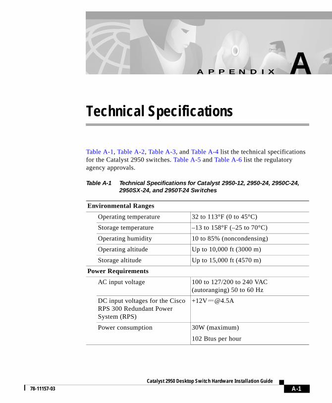
Catalyst 2950 Desktop Sw78-11157-03
A
P P E N D I X A Technical SpecificationsTable A-1, Table A-2, Table A-3, and Table A-4 list the technical specifications for the Catalyst 2950 switches. Table A-5 and Table A-6 list the regulatory agency approvals.
Table A-1 Technical Specifications for Catalyst 2950-12, 2950-24, 2950C-24,
2950SX-24, and 2950T-24 Switches
Environmental Ranges
Operating temperature 32 to 113°F (0 to 45°C)
Storage temperature –13 to 158°F (–25 to 70°C)
Operating humidity 10 to 85% (noncondensing)
Operating altitude Up to 10,000 ft (3000 m)
Storage altitude Up to 15,000 ft (4570 m)
Power Requirements
AC input voltage 100 to 127/200 to 240 VAC (autoranging) 50 to 60 Hz
DC input voltages for the Cisco RPS 300 Redundant Power System (RPS)
+12V @4.5A
Power consumption 30W (maximum)
102 Btus per hour
A-1itch Hardware Installation Guide
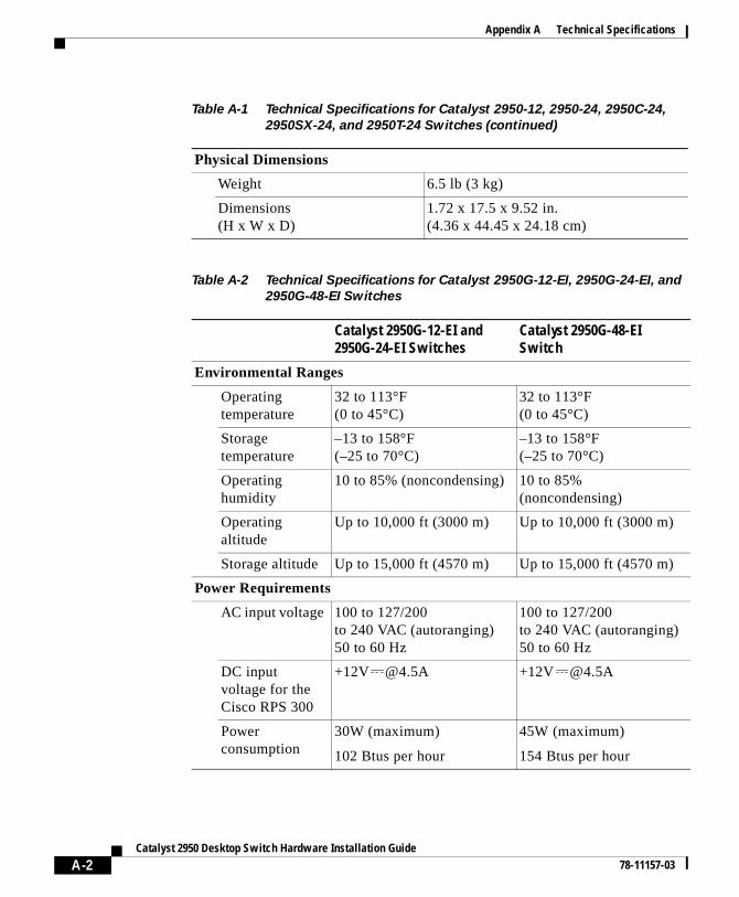
Appendix A Technical Specifications
Physical Dimensions
Weight 6.5 lb (3 kg)
Dimensions (H x W x D)
1.72 x 17.5 x 9.52 in. (4.36 x 44.45 x 24.18 cm)
Table A-2 Technical Specifications for Catalyst 2950G-12-EI, 2950G-24-EI, and
2950G-48-EI Switches
Catalyst 2950G-12-EI and 2950G-24-EI Switches
Catalyst 2950G-48-EI Switch
Environmental Ranges
Operating temperature
32 to 113°F(0 to 45°C)
32 to 113°F(0 to 45°C)
Storage temperature
–13 to 158°F (–25 to 70°C)
–13 to 158°F (–25 to 70°C)
Operating humidity
10 to 85% (noncondensing) 10 to 85% (noncondensing)
Operating altitude
Up to 10,000 ft (3000 m) Up to 10,000 ft (3000 m)
Storage altitude Up to 15,000 ft (4570 m) Up to 15,000 ft (4570 m)
Power Requirements
AC input voltage 100 to 127/200to 240 VAC (autoranging) 50 to 60 Hz
100 to 127/200to 240 VAC (autoranging) 50 to 60 Hz
DC input voltage for the Cisco RPS 300
+12V @4.5A +12V @4.5A
Power consumption
30W (maximum)
102 Btus per hour
45W (maximum)
154 Btus per hour
Table A-1 Technical Specifications for Catalyst 2950-12, 2950-24, 2950C-24,
2950SX-24, and 2950T-24 Switches (continued)
A-2Catalyst 2950 Desktop Switch Hardware Installation Guide
78-11157-03
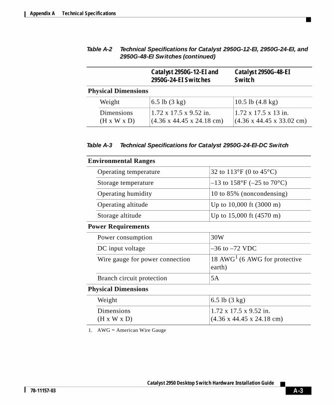
Appendix A Technical Specifications
Physical Dimensions
Weight 6.5 lb (3 kg) 10.5 lb (4.8 kg)
Dimensions(H x W x D)
1.72 x 17.5 x 9.52 in. (4.36 x 44.45 x 24.18 cm)
1.72 x 17.5 x 13 in. (4.36 x 44.45 x 33.02 cm)
Table A-3 Technical Specifications for Catalyst 2950G-24-EI-DC Switch
Environmental Ranges
Operating temperature 32 to 113°F (0 to 45°C)
Storage temperature –13 to 158°F (–25 to 70°C)
Operating humidity 10 to 85% (noncondensing)
Operating altitude Up to 10,000 ft (3000 m)
Storage altitude Up to 15,000 ft (4570 m)
Power Requirements
Power consumption 30W
DC input voltage –36 to –72 VDC
Wire gauge for power connection 18 AWG1 (6 AWG for protective earth)
1. AWG = American Wire Gauge
Branch circuit protection 5A
Physical Dimensions
Weight 6.5 lb (3 kg)
Dimensions(H x W x D)
1.72 x 17.5 x 9.52 in. (4.36 x 44.45 x 24.18 cm)
Table A-2 Technical Specifications for Catalyst 2950G-12-EI, 2950G-24-EI, and
2950G-48-EI Switches (continued)
Catalyst 2950G-12-EI and 2950G-24-EI Switches
Catalyst 2950G-48-EI Switch
A-3Catalyst 2950 Desktop Switch Hardware Installation Guide
78-11157-03
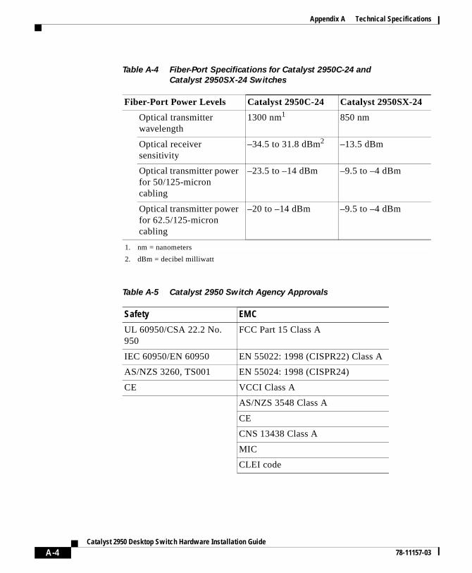
Appendix A Technical Specifications
Table A-4 Fiber-Port Specifications for Catalyst 2950C-24 and
Catalyst 2950SX-24 Switches
Fiber-Port Power Levels Catalyst 2950C-24 Catalyst 2950SX-24
Optical transmitter wavelength
1300 nm1 850 nm
Optical receiver sensitivity
–34.5 to 31.8 dBm2 –13.5 dBm
Optical transmitter power for 50/125-micron cabling
–23.5 to –14 dBm –9.5 to –4 dBm
Optical transmitter power for 62.5/125-micron cabling
–20 to –14 dBm –9.5 to –4 dBm
1. nm = nanometers
2. dBm = decibel milliwatt
Table A-5 Catalyst 2950 Switch Agency Approvals
Safety EMC
UL 60950/CSA 22.2 No. 950
FCC Part 15 Class A
IEC 60950/EN 60950 EN 55022: 1998 (CISPR22) Class A
AS/NZS 3260, TS001 EN 55024: 1998 (CISPR24)
CE VCCI Class A
AS/NZS 3548 Class A
CE
CNS 13438 Class A
MIC
CLEI code
A-4Catalyst 2950 Desktop Switch Hardware Installation Guide
78-11157-03
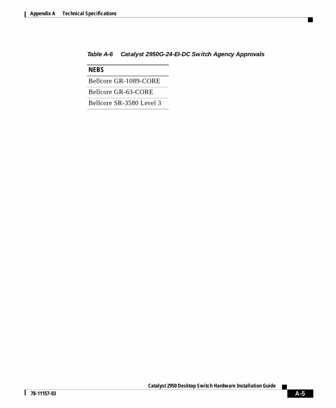
Appendix A Technical Specifications
Table A-6 Catalyst 2950G-24-EI-DC Switch Agency Approvals
NEBS
Bellcore GR-1089-CORE
Bellcore GR-63-CORE
Bellcore SR-3580 Level 3
A-5Catalyst 2950 Desktop Switch Hardware Installation Guide
78-11157-03

Appendix A Technical Specifications
A-6Catalyst 2950 Desktop Switch Hardware Installation Guide
78-11157-03
Catalyst 2950 Desktop Sw78-11157-03
A
P P E N D I X B Connectors and CablesThis appendix describes the connectors, cables, and adapters that you use to connect the switch to other devices.
Connector SpecificationsThese sections describe the connectors used with the Catalyst 2950 switches and contains this information:
• 10/100 Ports, page B-1
• 10/100/1000 Ports, page B-3
• 100BASE-FX and 1000BASE-SX Ports, page B-4
• GigaStack GBIC Module Ports, page B-6
• Console Port, page B-6
10/100 PortsThe 10/100 Ethernet ports use standard RJ-45 connectors and Ethernet pinouts with internal crossovers, as shown by an X in the port name. These ports have the transmit (TD) and receive (RD) signals internally crossed so that a twisted-pair straight-through cable and adapter can be attached to the port. Figure B-1 shows the pinout.
B-1itch Hardware Installation Guide
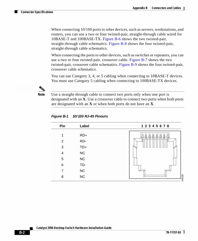
Appendix B Connectors and CablesConnector Specifications
When connecting 10/100 ports to other devices, such as servers, workstations, and routers, you can use a two or four twisted-pair, straight-through cable wired for 10BASE-T and 100BASE-TX. Figure B-6 shows the two twisted-pair, straight-through cable schematics. Figure B-8 shows the four twisted-pair, straight-through cable schematics.
When connecting the ports to other devices, such as switches or repeaters, you can use a two or four twisted-pair, crossover cable. Figure B-7 shows the two twisted-pair, crossover cable schematics. Figure B-9 shows the four twisted-pair, crossover cable schematics.
You can use Category 3, 4, or 5 cabling when connecting to 10BASE-T devices. You must use Category 5 cabling when connecting to 100BASE-TX devices.
Note Use a straight-through cable to connect two ports only when one port is designated with an X. Use a crossover cable to connect two ports when both ports are designated with an X or when both ports do not have an X.
Figure B-1 10/100 RJ-45 Pinouts
H53
18
2 31 4 5 6 7 8Pin Label
1
2
3
4
5
6
7
8
RD+
RD-
TD+
NC
NC
TD-
NC
NC
B-2Catalyst 2950 Desktop Switch Hardware Installation Guide
78-11157-03
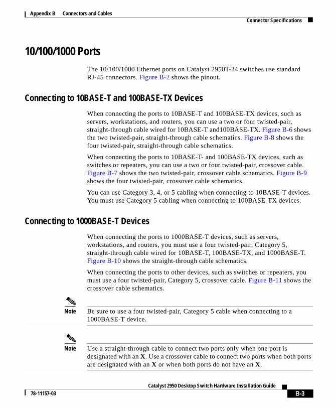
Appendix B Connectors and CablesConnector Specifications
10/100/1000 PortsThe 10/100/1000 Ethernet ports on Catalyst 2950T-24 switches use standard RJ-45 connectors. Figure B-2 shows the pinout.
Connecting to 10BASE-T and 100BASE-TX Devices
When connecting the ports to 10BASE-T and 100BASE-TX devices, such as servers, workstations, and routers, you can use a two or four twisted-pair, straight-through cable wired for 10BASE-T and100BASE-TX. Figure B-6 shows the two twisted-pair, straight-through cable schematics. Figure B-8 shows the four twisted-pair, straight-through cable schematics.
When connecting the ports to 10BASE-T- and 100BASE-TX devices, such as switches or repeaters, you can use a two or four twisted-pair, crossover cable. Figure B-7 shows the two twisted-pair, crossover cable schematics. Figure B-9 shows the four twisted-pair, crossover cable schematics.
You can use Category 3, 4, or 5 cabling when connecting to 10BASE-T devices. You must use Category 5 cabling when connecting to 100BASE-TX devices.
Connecting to 1000BASE-T Devices
When connecting the ports to 1000BASE-T devices, such as servers, workstations, and routers, you must use a four twisted-pair, Category 5, straight-through cable wired for 10BASE-T, 100BASE-TX, and 1000BASE-T. Figure B-10 shows the straight-through cable schematics.
When connecting the ports to other devices, such as switches or repeaters, you must use a four twisted-pair, Category 5, crossover cable. Figure B-11 shows the crossover cable schematics.
Note Be sure to use a four twisted-pair, Category 5 cable when connecting to a 1000BASE-T device.
Note Use a straight-through cable to connect two ports only when one port is designated with an X. Use a crossover cable to connect two ports when both ports are designated with an X or when both ports do not have an X.
B-3Catalyst 2950 Desktop Switch Hardware Installation Guide
78-11157-03
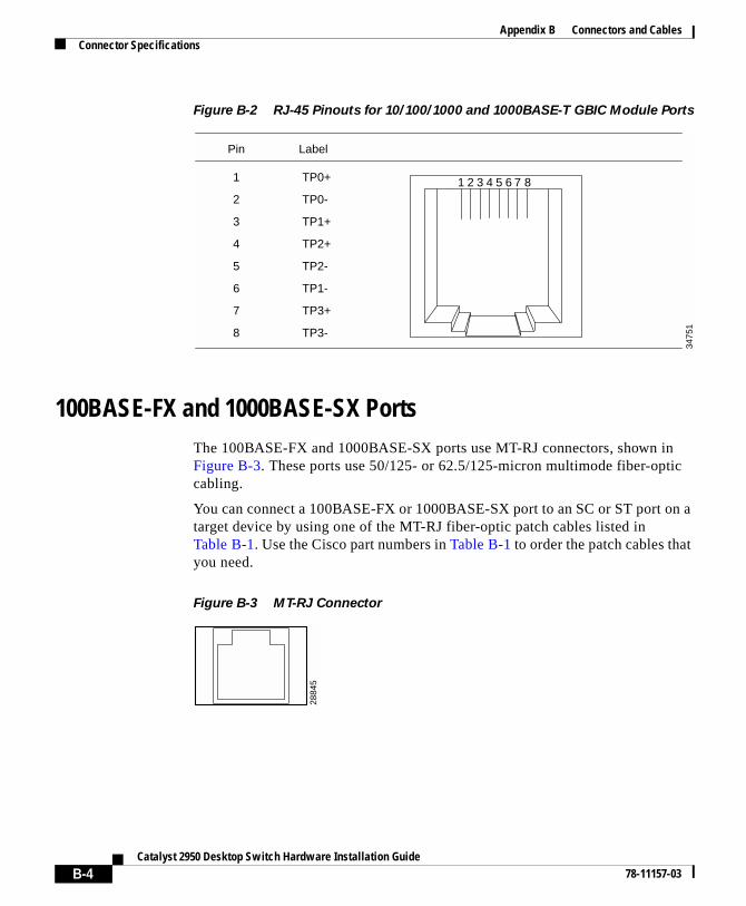
Appendix B Connectors and CablesConnector Specifications
Figure B-2 RJ-45 Pinouts for 10/100/1000 and 1000BASE-T GBIC Module Ports
100BASE-FX and 1000BASE-SX PortsThe 100BASE-FX and 1000BASE-SX ports use MT-RJ connectors, shown in Figure B-3. These ports use 50/125- or 62.5/125-micron multimode fiber-optic cabling.
You can connect a 100BASE-FX or 1000BASE-SX port to an SC or ST port on a target device by using one of the MT-RJ fiber-optic patch cables listed in Table B-1. Use the Cisco part numbers in Table B-1 to order the patch cables that you need.
Figure B-3 MT-RJ Connector
1 2 3 4 5 6 7 8
Pin Label
1
2
3
4
5
6
7
8
TP0+
TP0-
TP1+
TP2+
TP2-
TP1-
TP3+
TP3-
3475
1
2884
5
B-4Catalyst 2950 Desktop Switch Hardware Installation Guide
78-11157-03
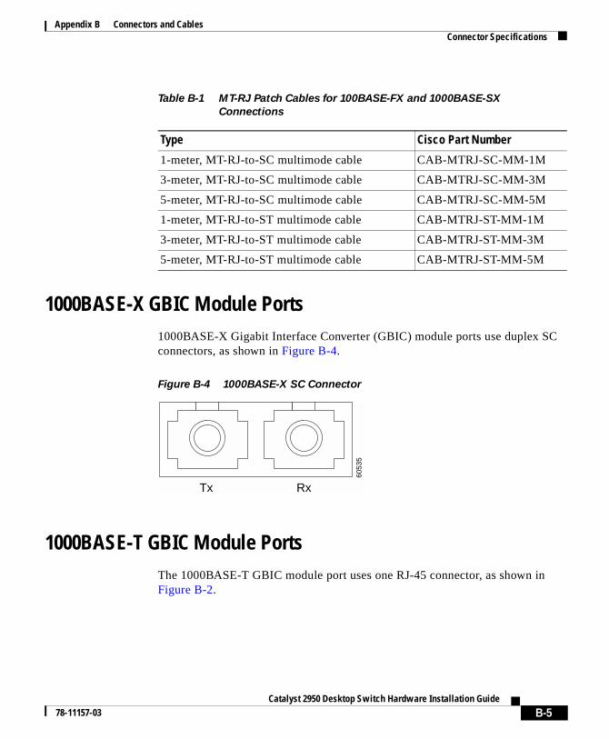
Appendix B Connectors and CablesConnector Specifications
1000BASE-X GBIC Module Ports1000BASE-X Gigabit Interface Converter (GBIC) module ports use duplex SC connectors, as shown in Figure B-4.
Figure B-4 1000BASE-X SC Connector
1000BASE-T GBIC Module PortsThe 1000BASE-T GBIC module port uses one RJ-45 connector, as shown in Figure B-2.
Table B-1 MT-RJ Patch Cables for 100BASE-FX and 1000BASE-SX
Connections
Type Cisco Part Number
1-meter, MT-RJ-to-SC multimode cable CAB-MTRJ-SC-MM-1M
3-meter, MT-RJ-to-SC multimode cable CAB-MTRJ-SC-MM-3M
5-meter, MT-RJ-to-SC multimode cable CAB-MTRJ-SC-MM-5M
1-meter, MT-RJ-to-ST multimode cable CAB-MTRJ-ST-MM-1M
3-meter, MT-RJ-to-ST multimode cable CAB-MTRJ-ST-MM-3M
5-meter, MT-RJ-to-ST multimode cable CAB-MTRJ-ST-MM-5M
6053
5
Tx Rx
B-5Catalyst 2950 Desktop Switch Hardware Installation Guide
78-11157-03
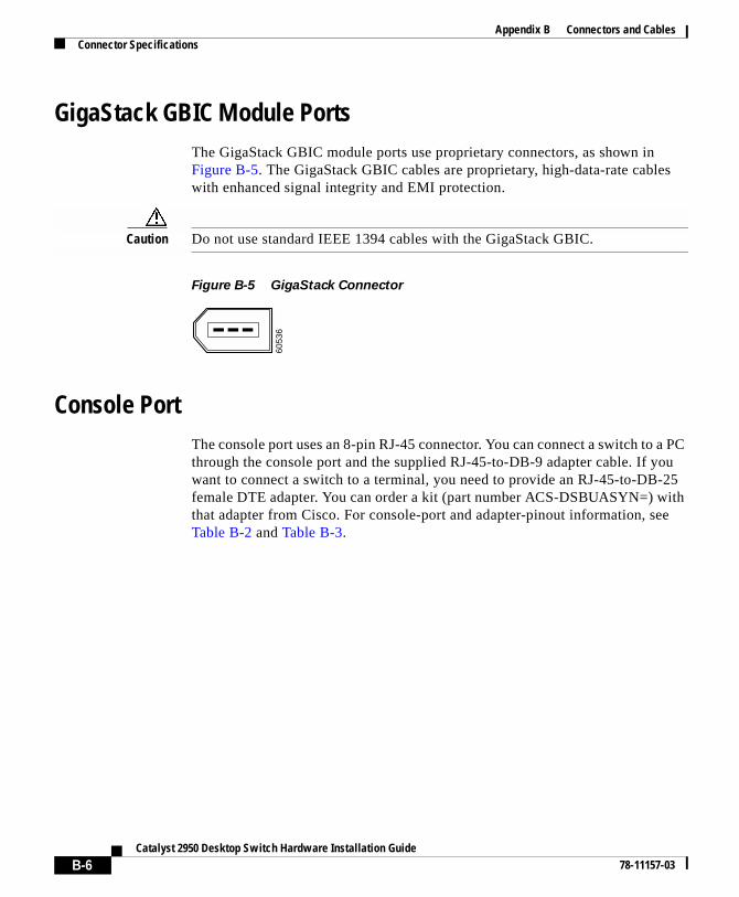
Appendix B Connectors and CablesConnector Specifications
GigaStack GBIC Module PortsThe GigaStack GBIC module ports use proprietary connectors, as shown in Figure B-5. The GigaStack GBIC cables are proprietary, high-data-rate cables with enhanced signal integrity and EMI protection.
Caution Do not use standard IEEE 1394 cables with the GigaStack GBIC.
Figure B-5 GigaStack Connector
Console PortThe console port uses an 8-pin RJ-45 connector. You can connect a switch to a PC through the console port and the supplied RJ-45-to-DB-9 adapter cable. If you want to connect a switch to a terminal, you need to provide an RJ-45-to-DB-25 female DTE adapter. You can order a kit (part number ACS-DSBUASYN=) with that adapter from Cisco. For console-port and adapter-pinout information, see Table B-2 and Table B-3.
6053
6
B-6Catalyst 2950 Desktop Switch Hardware Installation Guide
78-11157-03
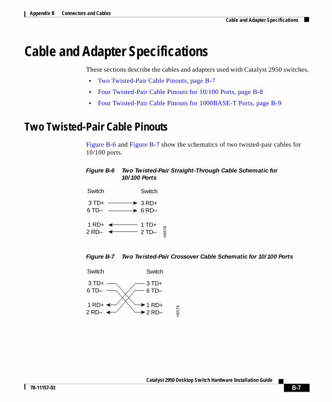
Appendix B Connectors and CablesCable and Adapter Specifications
Cable and Adapter SpecificationsThese sections describe the cables and adapters used with Catalyst 2950 switches.
• Two Twisted-Pair Cable Pinouts, page B-7
• Four Twisted-Pair Cable Pinouts for 10/100 Ports, page B-8
• Four Twisted-Pair Cable Pinouts for 1000BASE-T Ports, page B-9
Two Twisted-Pair Cable PinoutsFigure B-6 and Figure B-7 show the schematics of two twisted-pair cables for 10/100 ports.
Figure B-6 Two Twisted-Pair Straight-Through Cable Schematic for
10/100 Ports
Figure B-7 Two Twisted-Pair Crossover Cable Schematic for 10/100 Ports
Switch
3 TD+6 TD–
1 RD+2 RD–
Switch
3 RD+6 RD–
1 TD+2 TD–
H55
78
Switch
3 TD+6 TD–
1 RD+2 RD–
Switch
3 TD+6 TD–
1 RD+2 RD–
H55
79
B-7Catalyst 2950 Desktop Switch Hardware Installation Guide
78-11157-03
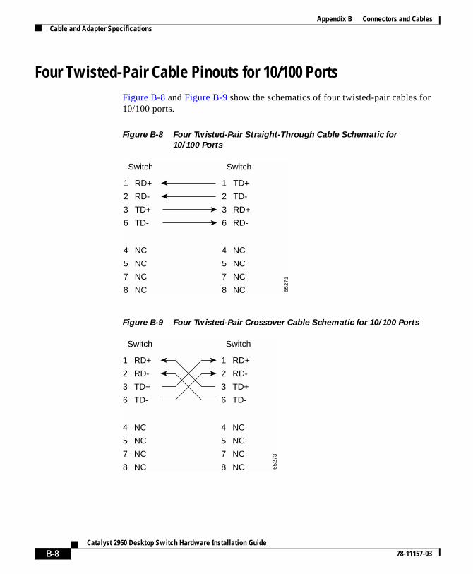
Appendix B Connectors and CablesCable and Adapter Specifications
Four Twisted-Pair Cable Pinouts for 10/100 PortsFigure B-8 and Figure B-9 show the schematics of four twisted-pair cables for 10/100 ports.
Figure B-8 Four Twisted-Pair Straight-Through Cable Schematic for
10/100 Ports
Figure B-9 Four Twisted-Pair Crossover Cable Schematic for 10/100 Ports
1 RD+
2 RD-
3 TD+
6 TD-
1 TD+
Switch Switch
2 TD-
3 RD+
6 RD-
4 NC
5 NC
7 NC
8 NC
4 NC
5 NC
7 NC
8 NC 6527
1
1 RD+
2 RD-
3 TD+
6 TD-
1 RD+
Switch Switch
2 RD-
3 TD+
6 TD-
4 NC
5 NC
7 NC
8 NC
4 NC
5 NC
7 NC
8 NC 6527
3
B-8Catalyst 2950 Desktop Switch Hardware Installation Guide
78-11157-03
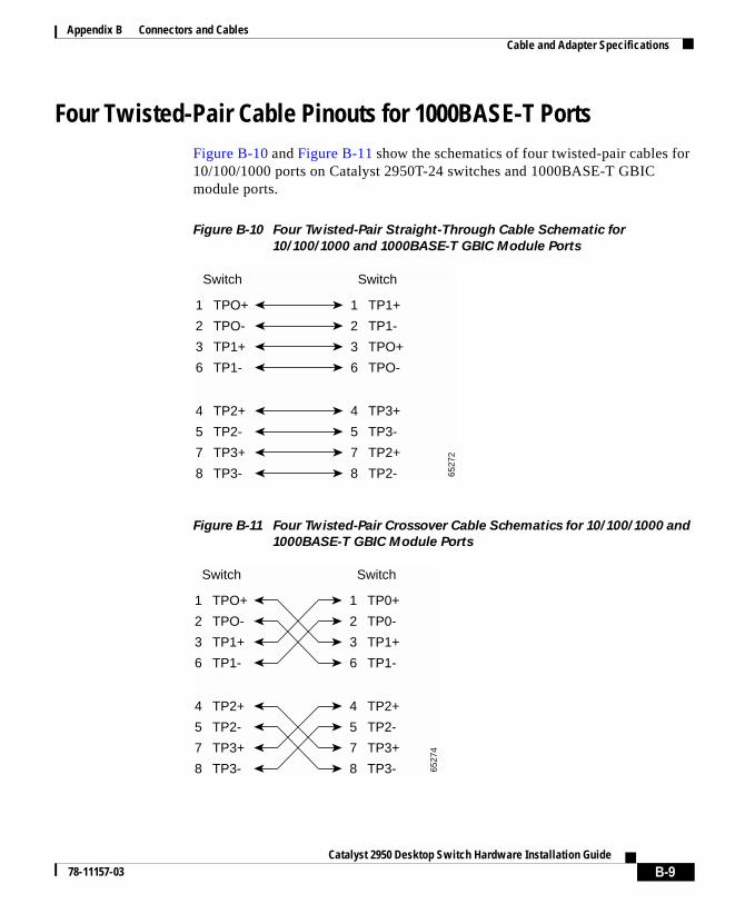
Appendix B Connectors and CablesCable and Adapter Specifications
Four Twisted-Pair Cable Pinouts for 1000BASE-T PortsFigure B-10 and Figure B-11 show the schematics of four twisted-pair cables for 10/100/1000 ports on Catalyst 2950T-24 switches and 1000BASE-T GBIC module ports.
Figure B-10 Four Twisted-Pair Straight-Through Cable Schematic for
10/100/1000 and 1000BASE-T GBIC Module Ports
Figure B-11 Four Twisted-Pair Crossover Cable Schematics for 10/100/1000 and
1000BASE-T GBIC Module Ports
1 TPO+
2 TPO-
3 TP1+
6 TP1-
1 TP1+
Switch Switch
2 TP1-
3 TPO+
6 TPO-
4 TP2+
5 TP2-
7 TP3+
8 TP3-
4 TP3+
5 TP3-
7 TP2+
8 TP2- 6527
2
1 TPO+
2 TPO-
3 TP1+
6 TP1-
1 TP0+
Switch Switch
2 TP0-
3 TP1+
6 TP1-
4 TP2+
5 TP2-
7 TP3+
8 TP3-
4 TP2+
5 TP2-
7 TP3+
8 TP3- 6527
4
B-9Catalyst 2950 Desktop Switch Hardware Installation Guide
78-11157-03
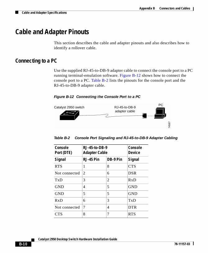
Appendix B Connectors and CablesCable and Adapter Specifications
Cable and Adapter PinoutsThis section describes the cable and adapter pinouts and also describes how to identify a rollover cable.
Connecting to a PC
Use the supplied RJ-45-to-DB-9 adapter cable to connect the console port to a PC running terminal-emulation software. Figure B-12 shows how to connect the console port to a PC. Table B-2 lists the pinouts for the console port and the RJ-45-to-DB-9 adapter cable.
Figure B-12 Connecting the Console Port to a PC
Table B-2 Console Port Signaling and RJ-45-to-DB-9 Adapter Cabling
ConsolePort (DTE)
RJ-45-to-DB-9 Adapter Cable
ConsoleDevice
Signal RJ-45 Pin DB-9 Pin Signal
RTS 1 8 CTS
Not connected 2 6 DSR
TxD 3 2 RxD
GND 4 5 GND
GND 5 5 GND
RxD 6 3 TxD
Not connected 7 4 DTR
CTS 8 7 RTS
PC
7458
7
RJ-45-to-DB-9adapter cable
Catalyst 2950 switch
B-10Catalyst 2950 Desktop Switch Hardware Installation Guide
78-11157-03
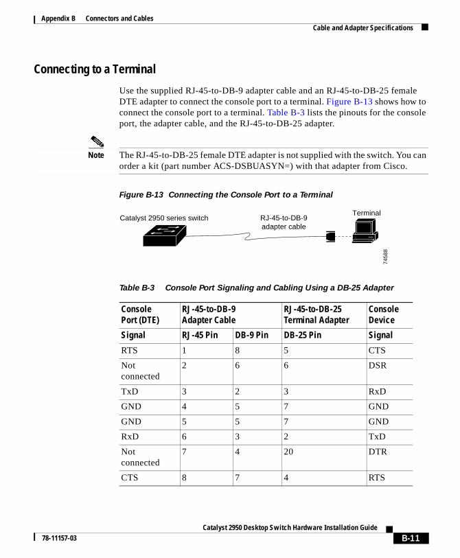
Appendix B Connectors and CablesCable and Adapter Specifications
Connecting to a Terminal
Use the supplied RJ-45-to-DB-9 adapter cable and an RJ-45-to-DB-25 female DTE adapter to connect the console port to a terminal. Figure B-13 shows how to connect the console port to a terminal. Table B-3 lists the pinouts for the console port, the adapter cable, and the RJ-45-to-DB-25 adapter.
Note The RJ-45-to-DB-25 female DTE adapter is not supplied with the switch. You can order a kit (part number ACS-DSBUASYN=) with that adapter from Cisco.
Figure B-13 Connecting the Console Port to a Terminal
Table B-3 Console Port Signaling and Cabling Using a DB-25 Adapter
ConsolePort (DTE)
RJ-45-to-DB-9Adapter Cable
RJ-45-to-DB-25Terminal Adapter
ConsoleDevice
Signal RJ-45 Pin DB-9 Pin DB-25 Pin Signal
RTS 1 8 5 CTS
Not connected
2 6 6 DSR
TxD 3 2 3 RxD
GND 4 5 7 GND
GND 5 5 7 GND
RxD 6 3 2 TxD
Not connected
7 4 20 DTR
CTS 8 7 4 RTS
Terminal
7458
8
RJ-45-to-DB-9adapter cable
Catalyst 2950 series switch
B-11Catalyst 2950 Desktop Switch Hardware Installation Guide
78-11157-03
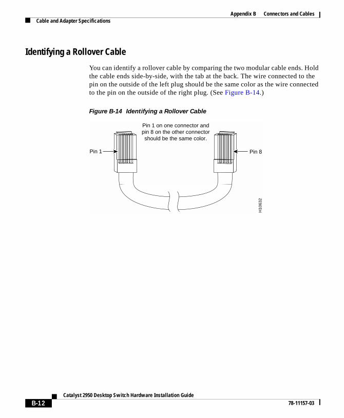
Appendix B Connectors and CablesCable and Adapter Specifications
Identifying a Rollover Cable
You can identify a rollover cable by comparing the two modular cable ends. Hold the cable ends side-by-side, with the tab at the back. The wire connected to the pin on the outside of the left plug should be the same color as the wire connected to the pin on the outside of the right plug. (See Figure B-14.)
Figure B-14 Identifying a Rollover Cable
Pin 1
H10
632
Pin 8
Pin 1 on one connector and pin 8 on the other connectorshould be the same color.
B-12Catalyst 2950 Desktop Switch Hardware Installation Guide
78-11157-03

Catalyst 2950 Desktop Sw78-11157-03
A
P P E N D I X C Translated Safety WarningsThis appendix repeats in multiple languages the warnings in this guide. These translated warnings can be used with other documents related to this guide.
C-1itch Hardware Installation Guide
Appendix C Translated Safety WarningsAttaching the Cisco RPS (model PWR300-AC-RPS-N1)
Attaching the Cisco RPS (model PWR300-AC-RPS-N1)
Warning Attach only the Cisco RPS (model PWR300-AC-RPS-N1) to the RPS receptacle.
Waarschuwing: Slechts de Cisco RPS (model PWR300-AC-RPS-N1) aan de RPS contactdoos verbinden.
Varoitus Kiinnitä RPS-vastakappaleeseen vain Cisco RPS (malli PWR300-AC-RPS-N1).
Avertissement : Raccordez le bloc d’alimentation Cisco RPS (modèle PWR300-AC-RPS-N1) uniquement au connecteur RPS.
Warnung: An die RPS-Steckhülse darf nur das Cisco RPS (Modell PWR300-AC-RPSN1) angeschlossen werden.
Avvertenza. Collegare soltanto il Cisco RPS (modello PWR300-AC-RPS-N1) alla presa RPS.
Advarsel! Koble bare Cisco RPS (modell PWR300-AC-RPS-N1) til RPS-stikkontakten.
Aviso Anexe o RPS Cisco (modelo PWR300-AC-RPS-N1) apenas ao receptáculo RPS.
Aviso: Sólo conecte el Cisco RPS (modelo PWR300-AC-RPS-N1) al receptáculo RPS.
Varning! Koppla endast Ciscos RPS (modell PWR300-AC-RPS-N1) till RPS-uttaget.
C-2Catalyst 2950 Desktop Switch Hardware Installation Guide
78-11157-03
Appendix C Translated Safety WarningsLightning Activity Warning
Lightning Activity Warning
Warning Do not work on the system or connect or disconnect cables during periods of lightning activity.
Waarschuwing Tijdens onweer dat gepaard gaat met bliksem, dient u niet aan het systeem te werken of kabels aan te sluiten of te ontkoppelen.
Varoitus Älä työskentele järjestelmän parissa äläkä yhdistä tai irrota kaapeleita ukkosilmalla.
Attention Ne pas travailler sur le système ni brancher ou débrancher les câbles pendant un orage.
Warnung Arbeiten Sie nicht am System und schließen Sie keine Kabel an bzw. trennen Sie keine ab, wenn es gewittert.
Avvertenza Non lavorare sul sistema o collegare oppure scollegare i cavi durante un temporale con fulmini.
Advarsel Utfør aldri arbeid på systemet, eller koble kabler til eller fra systemet når det tordner eller lyner.
Aviso Não trabalhe no sistema ou ligue e desligue cabos durante períodos de mau tempo (trovoada).
¡Advertencia! No operar el sistema ni conectar o desconectar cables durante el transcurso de descargas eléctricas en la atmósfera.
Varning! Vid åska skall du aldrig utföra arbete på systemet eller ansluta eller koppla loss kablar.
C-3Catalyst 2950 Desktop Switch Hardware Installation Guide
78-11157-03
Appendix C Translated Safety WarningsInstallation Warning
Installation Warning
Warning Read the installation instructions before you connect the system to its power source.
Waarschuwing Raadpleeg de installatie-aanwijzingen voordat u het systeem met de voeding verbindt.
Varoitus Lue asennusohjeet ennen järjestelmän yhdistämistä virtalähteeseen.
Attention Avant de brancher le système sur la source d'alimentation, consulter les directives d'installation.
Warnung Lesen Sie die Installationsanweisungen, bevor Sie das System an die Stromquelle anschließen.
Avvertenza Consultare le istruzioni di installazione prima di collegare il sistema all’alimentatore.
Advarsel Les installasjonsinstruksjonene før systemet kobles til strømkilden.
Aviso Leia as instruções de instalação antes de ligar o sistema à sua fonte de energia.
¡Advertencia! Ver las instrucciones de instalación antes de conectar el sistema a la red de alimentación.
Varning! Läs installationsanvisningarna innan du kopplar systemet till dess strömförsörjningsenhet.
C-4Catalyst 2950 Desktop Switch Hardware Installation Guide
78-11157-03
Appendix C Translated Safety WarningsMain Disconnecting Device
Main Disconnecting Device
Warning The plug-socket combination must be accessible at all times because it serves as the main disconnecting device.
Waarschuwing De combinatie van de stekker en het elektrisch contactpunt moet te allen tijde toegankelijk zijn omdat deze het hoofdmechanisme vormt voor verbreking van de aansluiting.
Varoitus Pistoke/liitinkohta toimii pääkatkaisumekanismina. Pääsy siihen on pidettävä aina esteettömänä.
Attention La combinaison de prise de courant doit être accessible à tout moment parce qu'elle fait office de système principal de déconnexion.
Warnung Der Netzkabelanschluß am Gerät muß jederzeit zugänglich sein, weil er als primäre Ausschaltvorrichtung dient.
Avvertenza Il gruppo spina-presa deve essere sempre accessibile, poiché viene utilizzato come dispositivo di scollegamento principale.
Advarsel Kombinasjonen støpsel/uttak må alltid være tilgjengelig ettersom den fungerer som hovedfrakoplingsenhet.
Aviso A combinação ficha-tomada deverá ser sempre acessível, porque funciona como interruptor principal.
¡Advertencia! El conjunto de clavija y toma ha de encontrarse siempre accesible ya que hace las veces de dispositivo de desconexión principal.
Varning! Man måste alltid kunna komma åt stickproppen i uttaget, eftersom denna koppling utgör den huvudsakliga frånkopplingsanordningen.
C-5Catalyst 2950 Desktop Switch Hardware Installation Guide
78-11157-03
Appendix C Translated Safety WarningsChassis Warning—Rack-Mounting and Servicing
Chassis Warning—Rack-Mounting and Servicing
Warning To prevent bodily injury when mounting or servicing this unit in a rack, you must take special precautions to ensure that the system remains stable. The following guidelines are provided to ensure your safety:
• This unit should be mounted at the bottom of the rack if it is the only unit in the rack.
• When mounting this unit in a partially filled rack, load the rack from the bottom to the top with the heaviest component at the bottom of the rack.
• If the rack is provided with stabilizing devices, install the stabilizers before mounting or servicing the unit in the rack.
Waarschuwing Om lichamelijk letsel te voorkomen wanneer u dit toestel in een rek monteert of het daar een servicebeurt geeft, moet u speciale voorzorgsmaatregelen nemen om ervoor te zorgen dat het toestel stabiel blijft. De onderstaande richtlijnen worden verstrekt om uw veiligheid te verzekeren:
• Dit toestel dient onderaan in het rek gemonteerd te worden als het toestel het enige in het rek is.
• Wanneer u dit toestel in een gedeeltelijk gevuld rek monteert, dient u het rek van onderen naar boven te laden met het zwaarste onderdeel onderaan in het rek.
• Als het rek voorzien is van stabiliseringshulpmiddelen, dient u de stabilisatoren te monteren voordat u het toestel in het rek monteert of het daar een servicebeurt geeft.
C-6Catalyst 2950 Desktop Switch Hardware Installation Guide
78-11157-03
Appendix C Translated Safety WarningsChassis Warning—Rack-Mounting and Servicing
Varoitus Kun laite asetetaan telineeseen tai huolletaan sen ollessa telineessä, on noudatettava erityisiä varotoimia järjestelmän vakavuuden säilyttämiseksi, jotta vältytään loukkaantumiselta. Noudata seuraavia turvallisuusohjeita:
• Jos telineessä ei ole muita laitteita, aseta laite telineen alaosaan.
• Jos laite asetetaan osaksi täytettyyn telineeseen, aloita kuormittaminen sen alaosasta kaikkein raskaimmalla esineellä ja siirry sitten sen yläosaan.
• Jos telinettä varten on vakaimet, asenna ne ennen laitteen asettamista telineeseen tai sen huoltamista siinä.
Attention Pour éviter toute blessure corporelle pendant les opérations de montage ou de réparation de cette unité en casier, il convient de prendre des précautions spéciales afin de maintenir la stabilité du système. Les directives ci-dessous sont destinées à assurer la protection du personnel:
• Si cette unité constitue la seule unité montée en casier, elle doit être placée dans le bas.
• Si cette unité est montée dans un casier partiellement rempli, charger le casier de bas en haut en plaçant l'élément le plus lourd dans le bas.
• Si le casier est équipé de dispositifs stabilisateurs, installer les stabilisateurs avant de monter ou de réparer l'unité en casier.
C-7Catalyst 2950 Desktop Switch Hardware Installation Guide
78-11157-03
Appendix C Translated Safety WarningsChassis Warning—Rack-Mounting and Servicing
Warnung Zur Vermeidung von Körperverletzung beim Anbringen oder Warten dieser Einheit in einem Gestell müssen Sie besondere Vorkehrungen treffen, um sicherzustellen, daß das System stabil bleibt. Die folgenden Richtlinien sollen zur Gewährleistung Ihrer Sicherheit dienen:
• Wenn diese Einheit die einzige im Gestell ist, sollte sie unten im Gestell angebracht werden.
• Bei Anbringung dieser Einheit in einem zum Teil gefüllten Gestell ist das Gestell von unten nach oben zu laden, wobei das schwerste Bauteil unten im Gestell anzubringen ist.
• Wird das Gestell mit Stabilisierungszubehör geliefert, sind zuerst die Stabilisatoren zu installieren, bevor Sie die Einheit im Gestell anbringen oder sie warten.
Avvertenza Per evitare infortuni fisici durante il montaggio o la manutenzione di questa unità in un supporto, occorre osservare speciali precauzioni per garantire che il sistema rimanga stabile. Le seguenti direttive vengono fornite per garantire la sicurezza personale:
• Questa unità deve venire montata sul fondo del supporto, se si tratta dell’unica unità da montare nel supporto.
• Quando questa unità viene montata in un supporto parzialmente pieno, caricare il supporto dal basso all’alto, con il componente più pesante sistemato sul fondo del supporto.
• Se il supporto è dotato di dispositivi stabilizzanti, installare tali dispositivi prima di montare o di procedere alla manutenzione dell’unità nel supporto.
C-8Catalyst 2950 Desktop Switch Hardware Installation Guide
78-11157-03
Appendix C Translated Safety WarningsChassis Warning—Rack-Mounting and Servicing
Advarsel Unngå fysiske skader under montering eller reparasjonsarbeid på denne enheten når den befinner seg i et kabinett. Vær nøye med at systemet er stabilt. Følgende retningslinjer er gitt for å verne om sikkerheten:
• Denne enheten bør monteres nederst i kabinettet hvis dette er den eneste enheten i kabinettet.
• Ved montering av denne enheten i et kabinett som er delvis fylt, skal kabinettet lastes fra bunnen og opp med den tyngste komponenten nederst i kabinettet.
• Hvis kabinettet er utstyrt med stabiliseringsutstyr, skal stabilisatorene installeres før montering eller utføring av reparasjonsarbeid på enheten i kabinettet.
Aviso Para se prevenir contra danos corporais ao montar ou reparar esta unidade numa estante, deverá tomar precauções especiais para se certificar de que o sistema possui um suporte estável. As seguintes directrizes ajudá-lo-ão a efectuar o seu trabalho com segurança:
• Esta unidade deverá ser montada na parte inferior da estante, caso seja esta a única unidade a ser montada.
• Ao montar esta unidade numa estante parcialmente ocupada, coloque os itens mais pesados na parte inferior da estante, arrumando-os de baixo para cima.
• Se a estante possuir um dispositivo de estabilização, instale-o antes de montar ou reparar a unidade.
C-9Catalyst 2950 Desktop Switch Hardware Installation Guide
78-11157-03
Appendix C Translated Safety WarningsChassis Warning—Rack-Mounting and Servicing
¡Advertencia! Para evitar lesiones durante el montaje de este equipo sobre un bastidor, o posteriormente durante su mantenimiento, se debe poner mucho cuidado en que el sistema quede bien estable. Para garantizar su seguridad, proceda según las siguientes instrucciones:
• Colocar el equipo en la parte inferior del bastidor, cuando sea la única unidad en el mismo.
• Cuando este equipo se vaya a instalar en un bastidor parcialmente ocupado, comenzar la instalación desde la parte inferior hacia la superior colocando el equipo más pesado en la parte inferior.
• Si el bastidor dispone de dispositivos estabilizadores, instalar éstos antes de montar o proceder al mantenimiento del equipo instalado en el bastidor.
Varning! För att undvika kroppsskada när du installerar eller utför underhållsarbete på denna enhet på en ställning måste du vidta särskilda försiktighetsåtgärder för att försäkra dig om att systemet står stadigt. Följande riktlinjer ges för att trygga din säkerhet:
• Om denna enhet är den enda enheten på ställningen skall den installeras längst ned på ställningen.
• Om denna enhet installeras på en delvis fylld ställning skall ställningen fyllas nedifrån och upp, med de tyngsta enheterna längst ned på ställningen.
• Om ställningen är försedd med stabiliseringsdon skall dessa monteras fast innan enheten installeras eller underhålls på ställningen.
C-10Catalyst 2950 Desktop Switch Hardware Installation Guide
78-11157-03
Appendix C Translated Safety WarningsOvertemperature Warning
Overtemperature Warning
Warning To prevent the switch from overheating, do not operate it in an area that exceeds the maximum recommended ambient temperature of 104°F (40°C). To prevent airflow restriction, allow at least 3 inches (7.6 cm) of clearance around the ventilation openings.
Waarschuwing Om oververhitting van de schakelaar te voorkomen, mag u die niet bedienen in een ruimte die de maximale aanbevolen omgevingstemperatuur van 104°F (40°C) overschrijdt. Om beperking van de luchtstroom te voorkomen, dient u ten minste 3 inch (7,6 cm) speling te laten rondom de ventilatie-openingen.
Varoitus Estääksesi kytkimen ylikuumenemisen älä käytä sitä sellaisissa paikoissa, joiden lämpötila ylittää ympäristön enimmäislämpötilaksi suositellun 40°C. Jätä vähintään 7,6 cm:n vapaa tila tuuletusaukkojen ympärille, jotta ilma pääsee vapaasti virtaamaan.
Attention Pour éviter une surchauffe du commutateur, ne pas le faire fonctionner dans un local dont la température ambiante dépasse le maximum recommandé de 40°C (104°F). Pour faciliter la circulation d'air, aménager un dégagement d'au moins 7,6 cm (3 pouces) autour des bouches d'aération.
Warnung Um eine Überhitzung des Schalters zu vermeiden, ist das System nicht in einem Bereich zu betreiben, in dem die empfohlene Höchsttemperatur von 40°C überschritten wird. Damit der Luftfluß nicht behindert wird, ist ein Freiraum von mindestens 7,6 cm um die Belüftungsöffnungen herum einzuhalten.
Avvertenza Per evitare il surriscaldamento dell’interruttore, non usare l'apparecchiatura in un’area che supera la temperatura ambientale minima consigliata di 40°C. Per evitare una limitazione del flusso dell’aria, lasciare come minimo uno spazio libero di 7,6 cm intorno alle aperture di ventilazione.
C-11Catalyst 2950 Desktop Switch Hardware Installation Guide
78-11157-03
Appendix C Translated Safety WarningsNo On/Off Switch Warning
No On/Off Switch Warning
Advarsel For å unngå at bryteren overopphetes skal utstyret ikke brukes på steder hvor anbefalt maks omgivelsestemperatur overstiger 104 grader Farenheit (40°C). La det være minst 3 tommer (7,6 cm) klaring rundt ventilasjonsåpningene for at luftsirkulasjonen skal være uhindret.
Aviso Para evitar sobreaquecimento do interruptor, não utilize o equipamento numa àrea que exceda uma temperatura máxima de 40°C. Para evitar o bloqueamento da circulação de ar, deixe pelo menos um espaço de 7.6 cm em volta das aberturas de ventilação.
¡Advertencia! Para evitar que el interruptor se recaliente, no se debe usar en áreas cuya temperatura ambiente exceda la máxima recomendada, esto es, 40°C (104°F). Para no entorpecer la corriente de aire, dejar por lo menos 7,6 cm (3 pulgadas) de espacio muerto alrededor de la rejilla de ventilación.
Varning! För att undvika överhettning av strömbrytaren skall den inte användas i utrymme vars temperatur överskrider den maximalt rekommenderade omgivningstemperaturen 40°C. Kontrollera att det finns minst 7,6 cm fritt utrymme runt ventilationsöppningarna så att luftflödet inte begränsas.
Warning Unplug the power cord before you work on a system that does not have an on/off switch.
Waarschuwing Voordat u aan een systeem werkt dat geen aan/uit schakelaar heeft, dient u de stekker van het netsnoer uit het stopcontact te halen.
Varoitus Ennen kuin teet mitään sellaiselle järjestelmälle, jossa ei ole kaksiasentokytkintä, kytke irti virtajohto.
C-12Catalyst 2950 Desktop Switch Hardware Installation Guide
78-11157-03
Appendix C Translated Safety WarningsGrounded Equipment Warning
Grounded Equipment Warning
Attention Avant de travailler sur un système non équipé d'un commutateur marche-arrêt, débrancher le cordon d'alimentation.
Warnung Bevor Sie an einem System ohne Ein/Aus-Schalter arbeiten, ziehen Sie das Netzkabel heraus.
Avvertenza Prima di lavorare su un sistema che non è dotato di un interruttore on/off, scollegare il cavo di alimentazione.
Advarsel Før det skal utføres arbeid på et system som ikke har en av/på-bryter, skal strømledningen trekkes ut.
Aviso Antes de começar a trabalhar num sistema que não possua um interruptor ON/OFF, desligue o cabo de alimentação.
¡Advertencia! Antes de trabajar sobre cualquier sistema que carezca de interruptor de Encendido/Apagado (ON/OFF), desenchufar el cable de alimentación.
Varning! Dra ur nätsladden innan du utför arbete på ett system utan strömbrytare.
Warning This equipment is intended to be grounded. Ensure that the host is connected to earth ground during normal use.
Waarschuwing Deze apparatuur hoort geaard te worden Zorg dat de host-computer tijdens normaal gebruik met aarde is verbonden.
Varoitus Tämä laitteisto on tarkoitettu maadoitettavaksi. Varmista, että isäntälaite on yhdistetty maahan normaalikäytön aikana.
C-13Catalyst 2950 Desktop Switch Hardware Installation Guide
78-11157-03
Appendix C Translated Safety WarningsProduct Disposal Warning
Product Disposal Warning
Attention Cet équipement doit être relié à la terre. S’assurer que l’appareil hôte est relié à la terre lors de l’utilisation normale.
Warnung Dieses Gerät muß geerdet werden. Stellen Sie sicher, daß das Host-Gerät während des normalen Betriebs an Erde gelegt ist.
Avvertenza Questa apparecchiatura deve essere collegata a massa. Accertarsi che il dispositivo host sia collegato alla massa di terra durante il normale utilizzo.
Advarsel Dette utstyret skal jordes. Forviss deg om vertsterminalen er jordet ved normalt bruk.
Aviso Este equipamento deverá estar ligado à terra. Certifique-se que o host se encontra ligado à terra durante a sua utilização normal.
¡Advertencia! Este equipo debe conectarse a tierra. Asegurarse de que el equipo principal esté conectado a tierra durante el uso normal.
Varning! Denna utrustning är avsedd att jordas. Se till att värdenheten är jordad vid normal användning.
Warning Ultimate disposal of this product should be handled according to all national laws and regulations.
Waarschuwing Dit produkt dient volgens alle landelijke wetten en voorschriften te worden afgedankt.
Varoitus Tämän tuotteen lopullisesta hävittämisestä tulee huolehtia kaikkia valtakunnallisia lakeja ja säännöksiä noudattaen.
C-14Catalyst 2950 Desktop Switch Hardware Installation Guide
78-11157-03
Appendix C Translated Safety WarningsGround Connection Warning
Ground Connection Warning
Attention La mise au rebut définitive de ce produit doit être effectuée conformément à toutes les lois et réglementations en vigueur.
Warnung Dieses Produkt muß den geltenden Gesetzen und Vorschriften entsprechend entsorgt werden.
Avvertenza L'eliminazione finale di questo prodotto deve essere eseguita osservando le normative italiane vigenti in materia.
Advarsel Endelig disponering av dette produktet må skje i henhold til nasjonale lover og forskrifter.
Aviso A descartagem final deste produto deverá ser efectuada de acordo com os regulamentos e a legislação nacional.
¡Advertencia! El desecho final de este producto debe realizarse según todas las leyes y regulaciones nacionales.
Varning! Vid deponering hanteras produkten enligt gällande lagar och bestämmelser.
Warning When installing the unit, always make the ground connection first and disconnect it last.
Waarschuwing Bij de installatie van het toestel moet de aardverbinding altijd het eerste worden gemaakt en het laatste worden losgemaakt.
Varoitus Laitetta asennettaessa on maahan yhdistäminen aina tehtävä ensiksi ja maadoituksen irti kytkeminen viimeiseksi.
C-15Catalyst 2950 Desktop Switch Hardware Installation Guide
78-11157-03
Appendix C Translated Safety WarningsGround Connection Warning
Attention Lors de l’installation de l’appareil, la mise à la terre doit toujours être connectée en premier et déconnectée en dernier.
Warnung Der Erdanschluß muß bei der Installation der Einheit immer zuerst hergestellt und zuletzt abgetrennt werden.
Avvertenza In fase di installazione dell'unità, eseguire sempre per primo il collegamento a massa e disconnetterlo per ultimo.
Advarsel Når enheten installeres, må jordledningen alltid tilkobles først og frakobles sist.
Aviso Ao instalar a unidade, a ligação à terra deverá ser sempre a primeira a ser ligada, e a última a ser desligada.
¡Advertencia! Al instalar el equipo, conectar la tierra la primera y desconectarla la última.
Varning! Vid installation av enheten måste jordledningen alltid anslutas först och kopplas bort sist.
C-16Catalyst 2950 Desktop Switch Hardware Installation Guide
78-11157-03
Appendix C Translated Safety WarningsJewelry Removal Warning
Jewelry Removal Warning
Warning Before working on equipment that is connected to power lines, remove jewelry (including rings, necklaces, and watches). Metal objects will heat up when connected to power and ground and can cause serious burns or weld the metal object to the terminals.
Waarschuwing Alvorens aan apparatuur te werken die met elektrische leidingen is verbonden, sieraden (inclusief ringen, kettingen en horloges) verwijderen. Metalen voorwerpen worden warm wanneer ze met stroom en aarde zijn verbonden, en kunnen ernstige brandwonden veroorzaken of het metalen voorwerp aan de aansluitklemmen lassen.
Varoitus Ennen kuin työskentelet voimavirtajohtoihin kytkettyjen laitteiden parissa, ota pois kaikki korut (sormukset, kaulakorut ja kellot mukaan lukien). Metalliesineet kuumenevat, kun ne ovat yhteydessä sähkövirran ja maan kanssa, ja ne voivat aiheuttaa vakavia palovammoja tai hitsata metalliesineet kiinni liitäntänapoihin.
Attention Avant d’accéder à cet équipement connecté aux lignes électriques, ôter tout bijou (anneaux, colliers et montres compris). Lorsqu’ils sont branchés à l’alimentation et reliés à la terre, les objets métalliques chauffent, ce qui peut provoquer des blessures graves ou souder l’objet métallique aux bornes.
Warnung Vor der Arbeit an Geräten, die an das Netz angeschlossen sind, jeglichen Schmuck (einschließlich Ringe, Ketten und Uhren) abnehmen. Metallgegenstände erhitzen sich, wenn sie an das Netz und die Erde angeschlossen werden, und können schwere Verbrennungen verursachen oder an die Anschlußklemmen angeschweißt werden.
C-17Catalyst 2950 Desktop Switch Hardware Installation Guide
78-11157-03
Appendix C Translated Safety WarningsJewelry Removal Warning
Avvertenza Prima di intervenire su apparecchiature collegate alle linee di alimentazione, togliersi qualsiasi monile (inclusi anelli, collane, braccialetti ed orologi). Gli oggetti metallici si riscaldano quando sono collegati tra punti di alimentazione e massa: possono causare ustioni gravi oppure il metallo può saldarsi ai terminali.
Advarsel Fjern alle smykker (inkludert ringer, halskjeder og klokker) før du skal arbeide på utstyr som er koblet til kraftledninger. Metallgjenstander som er koblet til kraftledninger og jord blir svært varme og kan forårsake alvorlige brannskader eller smelte fast til polene.
Aviso Antes de trabalhar em equipamento que esteja ligado a linhas de corrente, retire todas as jóias que estiver a usar (incluindo anéis, fios e relógios). Os objectos metálicos aquecerão em contacto com a corrente e em contacto com a ligação à terra, podendo causar queimaduras graves ou ficarem soldados aos terminais.
¡Advertencia! Antes de operar sobre equipos conectados a líneas de alimentación, quitarse las joyas (incluidos anillos, collares y relojes). Los objetos de metal se calientan cuando se conectan a la alimentación y a tierra, lo que puede ocasionar quemaduras graves o que los objetos metálicos queden soldados a los bornes.
Varning! Tag av alla smycken (inklusive ringar, halsband och armbandsur) innan du arbetar på utrustning som är kopplad till kraftledningar. Metallobjekt hettas upp när de kopplas ihop med ström och jord och kan förorsaka allvarliga brännskador; metallobjekt kan också sammansvetsas med kontakterna.
C-18Catalyst 2950 Desktop Switch Hardware Installation Guide
78-11157-03
Appendix C Translated Safety WarningsStacking the Chassis Warning
Stacking the Chassis Warning
Warning Do not stack the chassis on any other equipment. If the chassis falls, it can cause severe bodily injury and equipment damage.
Waarschuwing Het chassis mag niet op andere apparatuur gestapeld te worden. Als het chassis mocht vallen, kan dit ernstig lichamelijk letsel en beschadiging van de apparatuur veroorzaken.
Varoitus Älä aseta asennuspohjaa minkään muun laitteen päälle. Asennuspohja voi pudotessaan aiheuttaa vaikean ruumiinvamman tai laitevaurion.
Avertissement Ne placez pas ce châssis sur un autre appareil. En cas de chute, il pourrait provoquer de graves blessures corporelles et d'importants dommages.
Achtung Das Gehäuse nicht auf andere Geräte stellen. Wenn das Gehäuse herunterfällt, besteht Gefahr schwerer Personenverletzungen und Geräteschäden.
Avvertenza Non collocare lo chassis su nessun altro apparecchio. Se lo chassis cade, può causare lesioni gravi e danni alle apparecchiature.
Advarsel Stable ikke kabinettet oppå annet utstyr. Hvis kabinettet faller, kan det forårsake alvorlig skade på mennesker og utstyr.
Aviso Não coloque o chassis em cima de qualquer outro equipamento. Se o chassis cair, poderá causar ferimentos graves e danos no equipamento.
C-19Catalyst 2950 Desktop Switch Hardware Installation Guide
78-11157-03

Appendix C Translated Safety WarningsQualified Personnel Warning
Qualified Personnel Warning
¡Atención! No apilar los chasis sobre ningún otro equipo. Si el chasis se cae al suelo puede causar graves lesiones físicas y daños al equipo.
Varning Placera inte chassit ovanpå annan utrustning. Om chassit faller kan allvarlig kroppsskada såväl som skada på utrustningen uppstå.
Warning Only trained and qualified personnel should be allowed to install or replace this equipment.
Waarschuwing Installatie en reparaties mogen uitsluitend door getraind en bevoegd personeel uitgevoerd worden.
Varoitus Ainoastaan koulutettu ja pätevä henkilökunta saa asentaa tai vaihtaa tämän laitteen.
Avertissement Tout installation ou remplacement de l'appareil doit être réalisé par du personnel qualifié et compétent.
Achtung Gerät nur von geschultem, qualifiziertem Personal installieren oder auswechseln lassen.
Avvertenza Solo personale addestrato e qualificato deve essere autorizzato ad installare o sostituire questo apparecchio.
Advarsel Kun kvalifisert personell med riktig opplæring bør montere eller bytte ut dette utstyret.
Aviso Este equipamento deverá ser instalado ou substituído apenas por pessoal devidamente treinado e qualificado.
C-20Catalyst 2950 Desktop Switch Hardware Installation Guide
78-11157-03
Appendix C Translated Safety WarningsClass 1 Laser Product Warning
Class 1 Laser Product Warning
¡Atención! Estos equipos deben ser instalados y reemplazados exclusivamente por personal técnico adecuadamente preparado y capacitado.
Varning Denna utrustning ska endast installeras och bytas ut av utbildad och kvalificerad personal.
Warning Class 1 Laser Product
Waarschuwing: Waarschuwing voor klasse 1 laserprodukten
Varoitus: lasertuote luokka 1
Avertissement : Produits Laser Class 1
Warnung: Produkt-Warnhinweis zu Lasergeräten der Klasse 1
Avvertenza. Prodotto Laser di Classe 1
Advarsel! Advarsel for laserprodukter i klasse 1
Aviso Aviso sobre produtos a laser da Classe 1
Aviso É Aviso sobre producto láser de Clase 1
Varning! Varning beträffande laserprodukt, klass 1
C-21Catalyst 2950 Desktop Switch Hardware Installation Guide
78-11157-03
Appendix C Translated Safety WarningsLaser Beam Exposure Warning
Laser Beam Exposure Warning
Warning Avoid exposure to the laser beam.
Waarschuwing Vermijd blootstelling aan de straal.
Varoitus Vältä säteelle altistumista.
Attention Eviter toute exposition au faisceau.
Warnung Schützen Sie sich vor Strahlung.
Avvertenza Evitare l’esposizione al raggio.
Advarsel Unngå å bli utsatt for strålen.
Aviso Evite exposição ao raio.
¡Advertencia! Evitar la exposición al haz.
Varning! Utsätt dig inte för laserstrålningen.
C-22Catalyst 2950 Desktop Switch Hardware Installation Guide
78-11157-03
Appendix C Translated Safety WarningsCatalyst 2950G-24-EI-DC Service Requirement
Catalyst 2950G-24-EI-DC Service Requirement
Warning The Catalyst 2950G-24-EI-DC contains no field-replaceable units (FRUs). Do not open the chassis or attempt to remove or replace any components. For information about obtaining service for this unit, contact your reseller or Cisco sales representative.
Waarschuwing De Catalyst 2950G-24-EI-DC bevat geen FRU's (field-replaceable units ofwel veldvervangbare eenheden). Open het chassis niet en probeer geen onderdelen te verwijderen of te vervangen. Voor informatie omtrent het onderhoud voor deze eenheid dient u contact op te nemen met uw doorverkoper of verkoopvertegenwoordiger van Cisco.
Varoitus Catalyst 2950G-24-EI-DC ei sisällä kenttäkorjattavia laitteita. Runkoa ei saa avata, eikä osia saa yrittää poistaa tai korjata. Laitteen huoltoa koskevia tietoja saa jälleenmyyjältä tai Ciscon myyntiedustajalta.
Attention Le Catalyst 2950G-24-EI-DC ne dispose pas d'unités remplaçables sur site (FRU). Il est recommandé de ne pas ouvrir le châssis ni de retirer ou remplacer des composants. Pour plus de détails sur la maintenance de cette unité, contactez votre revendeur ou votre ingénieur commercial Cisco.
Warnung Der Catalyst 2950G-24-EI-DC enthält keine vor Ort austauschbaren Einheiten (FRUs). Das Gehäuse nicht öffnen und Komponenten nicht entfernen oder ersetzen. Serviceinformationen zu dieser Einheit erhalten Sie von Ihrem Wiederverkäufer oder von Ihrem Cisco-Vertreter.
Avvertenza Catalyst 2950G-24-EI-DC non ha componenti sostituibili sul posto (FRU). Non aprite lo chassis o tentate di rimuovere o sostituire componenti. Per maggiori informazioni sui servizi di assistenza per questo dispositivo, contattate il vostro rivenditore Cisco.
C-23Catalyst 2950 Desktop Switch Hardware Installation Guide
78-11157-03
Appendix C Translated Safety WarningsRestricted Area Equipment Installation
Restricted Area Equipment Installation
Advarsel Catalyst 2950G-24-EI-DC inneholder ingen kunde-utskiftbare deler (FRU-deler). Gjør ikke forsøk på å åpne kabinettet eller fjerne eller skifte ut noen av komponentene. Ta kontakt med forhandleren eller en Cisco-salgsrepresentant for informasjon om hvor det kan utføres service på enheten.
Aviso O interruptor Catalisador 2950G-24-EI-DC não contém nenhuma unidade substituível em campo. Não abrir o chassis ou tentar remover ou substituir quaisquer componentes. Para mais informações sobre a manutenção desta unidade, contactar o seu revendedor ou um representante de vendas da Cisco.
¡Advertencia! El Catalyst 2950G-24-EI-DC no contiene componentes reemplazables en las instalaciones (Field-Replaceable Units, FRU). No abra el chasis ni intente reemplazar componentes. Para más información sobre cómo reparar este aparato, póngase en contacto con su distribuidor o representante de Cisco.
Varning! Catalyst 2950G-24-EI-DC innehåller inte några enheter som kan bytas ut på fältet. Öppna inte chassit och försök inte heller att ta bort eller byta ut några delar. Kontakta återförsäljaren eller representanten för Cisco om du behöver information om service av enheten.
Warning The equipment is to be installed in a restricted access area.
Waarschuwing De uitrusting dient geïnstalleerd te worden in een gebied met beperkte toegang.
Varoitus Laite tulee asentaa tilaan, johon on rajoitettu pääsy.
C-24Catalyst 2950 Desktop Switch Hardware Installation Guide
78-11157-03
Appendix C Translated Safety WarningsEthernet Cable Shielding in Offices
Ethernet Cable Shielding in Offices
Attention Cet équipement doit être installé uniquement dans une zone à accès limité.
Warnung Die Ausrüstung muß in einem Bereich installiert werden, der gegen unbefugtes Betreten geschützt ist.
Avvertenza Installate questo apparato unicamente in zone di accesso regolamentate.
Advarsel Utstyret skal installeres på et sted med begrenset adgang.
Aviso O equipamento é para ser instalado numa área de acesso restrito.
¡Advertencia! El equipo debe instalarse en una zona de acceso restringido.
Varning! Utrustningen måste installeras på plats med åtkomst endast för behörig personal.
Warning Ethernet cables must be shielded when used in a central office environment.
Waarschuwing Ethernetkabels dienen beveiligd te worden als ze in een centrale kantooromgeving worden gebruikt.
Varoitus Ethernet-kaapelit täytyy suojata, kun niitä käytetään yleisessä toimistoympäristössä.
Attention Pour une utilisation en site central, les câbles Ethernet doivent être impérativement blindés.
C-25Catalyst 2950 Desktop Switch Hardware Installation Guide
78-11157-03
Appendix C Translated Safety WarningsDC Power Disconnection Warning
DC Power Disconnection Warning
Warnung Ethernet-Kabel müssen abgeschirmt werden, wenn sie in einer Zentrale eingesetzt werden.
Avvertenza I cavi Ethernet devono essere schermati se utilizzati in un ambiente di ufficio centrale.
Advarsel Ethernet-kabler skal være skjermet når de brukes i et sentralt kontormiljø.
Aviso Os cabos “Ethernet” deverão estar armados quando usados em ambiente de escritório central.
¡Advertencia! Los cables Ethernet deben estar protegidos cuando se usen dentro de una oficina central.
Varning! Ethernetkablar måste vara avskärmade vid användning i central kontorsmiljö.
Warning Before performing any of the following procedures, ensure that power is removed from the DC circuit. To ensure that all power is OFF, locate the circuit breaker on the panel board that services the DC circuit, switch the circuit breaker to the OFF position, and tape the switch handle of the circuit breaker in the OFF position.
Waarschuwing Voordat u een van de onderstaande procedures uitvoert, dient u te controleren of de stroom naar het gelijkstroom circuit uitgeschakeld is. Om u ervan te verzekeren dat alle stroom UIT is geschakeld, kiest u op het schakelbord de stroomverbreker die het gelijkstroom circuit bedient, draait de stroomverbreker naar de UIT positie en plakt de schakelaarhendel van de stroomverbreker met plakband in de UIT positie vast.
C-26Catalyst 2950 Desktop Switch Hardware Installation Guide
78-11157-03
Appendix C Translated Safety WarningsDC Power Disconnection Warning
Varoitus Varmista, että tasavirtapiirissä ei ole virtaa ennen seuraavien toimenpiteiden suorittamista. Varmistaaksesi, että virta on KATKAISTU täysin, paikanna tasavirrasta huolehtivassa kojetaulussa sijaitseva suojakytkin, käännä suojakytkin KATKAISTU-asentoon ja teippaa suojakytkimen varsi niin, että se pysyy KATKAISTU-asennossa.
Attention Avant de pratiquer l'une quelconque des procédures ci-dessous, vérifier que le circuit en courant continu n'est plus sous tension. Pour en être sûr, localiser le disjoncteur situé sur le panneau de service du circuit en courant continu, placer le disjoncteur en position fermée (OFF) et, à l'aide d'un ruban adhésif, bloquer la poignée du disjoncteur en position OFF.
Warnung Vor Ausführung der folgenden Vorgänge ist sicherzustellen, daß die Gleichstromschaltung keinen Strom erhält. Um sicherzustellen, daß sämtlicher Strom abgestellt ist, machen Sie auf der Schalttafel den Unterbrecher für die Gleichstromschaltung ausfindig, stellen Sie den Unterbrecher auf AUS, und kleben Sie den Schaltergriff des Unterbrechers mit Klebeband in der AUS-Stellung fest.
Avvertenza Prima di svolgere una qualsiasi delle procedure seguenti, verificare che il circuito CC non sia alimentato. Per verificare che tutta l’alimentazione sia scollegata (OFF), individuare l’interruttore automatico sul quadro strumenti che alimenta il circuito CC, mettere l’interruttore in posizione OFF e fissarlo con nastro adesivo in tale posizione.
Advarsel Før noen av disse prosedyrene utføres, kontroller at strømmen er frakoblet likestrømkretsen. Sørg for at all strøm er slått AV. Dette gjøres ved å lokalisere strømbryteren på brytertavlen som betjener likestrømkretsen, slå strømbryteren AV og teipe bryterhåndtaket på strømbryteren i AV-stilling.
C-27Catalyst 2950 Desktop Switch Hardware Installation Guide
78-11157-03
Appendix C Translated Safety WarningsDC Power Disconnection Warning
Aviso Antes de executar um dos seguintes procedimentos, certifique-se que desligou a fonte de alimentação de energia do circuito de corrente contínua. Para se assegurar que toda a corrente foi DESLIGADA, localize o disjuntor no painel que serve o circuito de corrente contínua e coloque-o na posição OFF (Desligado), segurando nessa posição a manivela do interruptor do disjuntor com fita isoladora.
¡Advertencia! Antes de proceder con los siguientes pasos, comprobar que la alimentación del circuito de corriente continua (CC) esté cortada (OFF). Para asegurarse de que toda la alimentación esté cortada (OFF), localizar el interruptor automático en el panel que alimenta al circuito de corriente continua, cambiar el interruptor automático a la posición de Apagado (OFF), y sujetar con cinta la palanca del interruptor automático en posición de Apagado (OFF).
Varning! Innan du utför någon av följande procedurer måste du kontrollera att strömförsörjningen till likströmskretsen är bruten. Kontrollera att all strömförsörjning är BRUTEN genom att slå AV det överspänningsskydd som skyddar likströmskretsen och tejpa fast överspänningsskyddets omkopplare i FRÅN-läget.
C-28Catalyst 2950 Desktop Switch Hardware Installation Guide
78-11157-03
Appendix C Translated Safety WarningsExposed DC Power Wire Warning
Exposed DC Power Wire Warning
Warning An exposed wire lead from a DC-input power source can conduct harmful levels of electricity. Be sure that no exposed portion of the DC-input power source wire extends from the terminal block plug.
Waarschuwing Een blootgestelde verbindingsdraad van een ingangsgelijkstroombron kan gevaarlijke elektriciteitsniveaus geleiden. Zorg ervoor dat geen blootgesteld deel van het draad van de ingangsgelijkstroombron zich uitstrekt vanuit het aansluitblok van de terminal.
Varoitus Tasavirtalähteestä tuleva avoin johto voi johtaa vaarallisen määrän sähköä. Varmista, ettei kaapelikengän pistokkeesta tule esille lainkaan tasavirtajohdon avointa osaa.
Attention Pour éviter tout risque de choc électrique, vérifiez que les câbles d'alimentation secteur sont protégés par une gaine. Aucun fil dénudé ne doit apparaître hors du bloc d'alimentation du terminal.
Warnung Eine ungeschützte Kabelleitung von einer Gleichstrom-Eingangsspannungsquelle kann schädliche Elektrizitätslevel führen. Achten Sie darauf, daß von dem Klemmleistenstecker aus kein ungeschütztes Eingangsgleichstromkabel freiliegt.
Avvertenza Un cavo elettrico scoperto proveniente da un alimentatore DC-INPUT può trasmettere scariche elettriche ad elevata tensione. Assicuratevi che i cavi in uscita dall'alimentatore DC-input non presentino punti scoperti.
Advarsel En avdekket ledning fra en likestrømskilde kan lede farlig elektrisitet. Kontroller at ingen avdekkede deler av ledningen til likestrømskilden stikker ut av terminalens koblingsblokk.
C-29Catalyst 2950 Desktop Switch Hardware Installation Guide
78-11157-03
Appendix C Translated Safety WarningsService Personnel Warning
Service Personnel Warning
Aviso Um fio condutor exposto de uma unidade de entrada de DC (corrente contínua) pode transportar níveis perigosos de electricidade. Certifique-se de que nenhuma secção exposta de um fio condutor da fonte de energia de entrada de DC se extende a partir da ficha da placa de terminais.
¡Advertencia! Un cable desnudo de una fuente de entrada de alimentación de corriente directa (DC) puede conducir niveles de electricidad peligrosos. Asegúrese de que ninguna parte del cable de la fuente de alimentación de DC de entrada sale del enchufe del bloque de terminal.
Varning! En blottad trådledning från en likströmsförsörjningsenhet kan utgöra en ledare för skadliga elektricitetsnivåer. Se till att inte någon blottad ledningsdel från likströmsförsörjningsenheten sticker ut från stiftplinten.
Warning This equipment is to be installed and maintained by service personnel only as defined by AS/NZS 3260 Clause 1.2.14.3 Service Personnel.
Waarschuwing Deze apparatuur mag slechts geïnstalleerd en onderhouden worden door servicepersoneel conform de definitie van AS/NZS 3260 Clausule 1.2.14.3 Service Personnel.
Varoitus Tämän laitteen saa asentaa tai huoltaa ainoastaan Australiassa ja Uudessa Seelannissa sovellettavan AS/NZS 3260 -standardin kohdan 1.2.14.3 Service Personnel määrittelemä huoltohenkilöstö.
Attention Cet équipement ne doit être installé et entretenu que par du personnel d’entretien comme défini par la réglementation AS/NZS 3260 Clause 1.2.14.3 Service Personnel.
C-30Catalyst 2950 Desktop Switch Hardware Installation Guide
78-11157-03
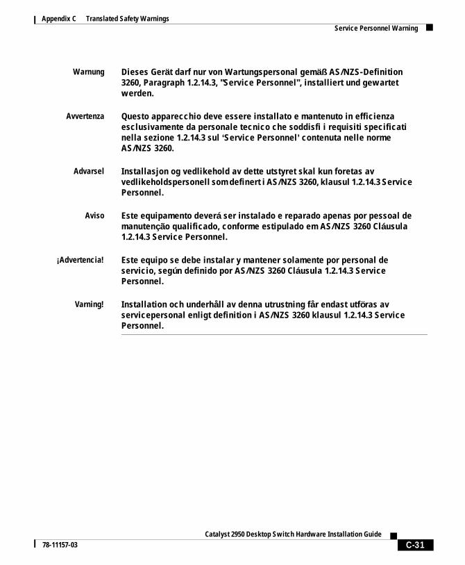
Appendix C Translated Safety WarningsService Personnel Warning
Warnung Dieses Gerät darf nur von Wartungspersonal gemäß AS/NZS-Definition 3260, Paragraph 1.2.14.3, "Service Personnel", installiert und gewartet werden.
Avvertenza Questo apparecchio deve essere installato e mantenuto in efficienza esclusivamente da personale tecnico che soddisfi i requisiti specificati nella sezione 1.2.14.3 sul ‘Service Personnel’ contenuta nelle norme AS/NZS 3260.
Advarsel Installasjon og vedlikehold av dette utstyret skal kun foretas av vedlikeholdspersonell som definert i AS/NZS 3260, klausul 1.2.14.3 Service Personnel.
Aviso Este equipamento deverá ser instalado e reparado apenas por pessoal de manutenção qualificado, conforme estipulado em AS/NZS 3260 Cláusula 1.2.14.3 Service Personnel.
¡Advertencia! Este equipo se debe instalar y mantener solamente por personal de servicio, según definido por AS/NZS 3260 Cláusula 1.2.14.3 Service Personnel.
Varning! Installation och underhåll av denna utrustning får endast utföras av servicepersonal enligt definition i AS/NZS 3260 klausul 1.2.14.3 Service Personnel.
C-31Catalyst 2950 Desktop Switch Hardware Installation Guide
78-11157-03

Appendix C Translated Safety WarningsService Personnel Warning
C-32Catalyst 2950 Desktop Switch Hardware Installation Guide
78-11157-03
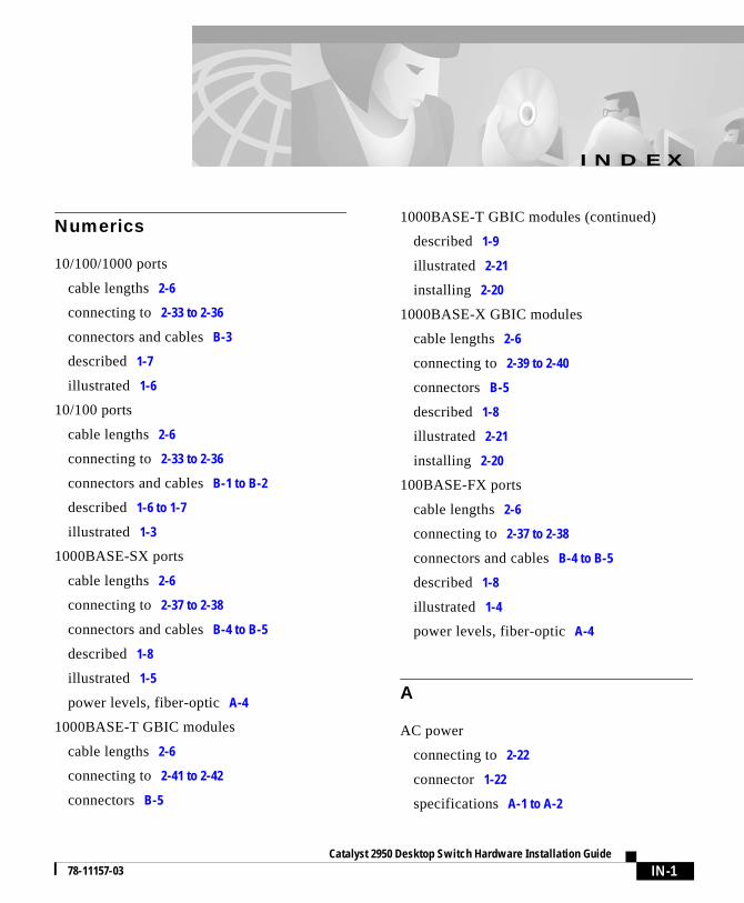
Catalyst 2950 Desktop 78-11157-03
I N D E X
Numerics
10/100/1000 ports
cable lengths 2-6
connecting to 2-33 to 2-36
connectors and cables B-3
described 1-7
illustrated 1-6
10/100 ports
cable lengths 2-6
connecting to 2-33 to 2-36
connectors and cables B-1 to B-2
described 1-6 to 1-7
illustrated 1-3
1000BASE-SX ports
cable lengths 2-6
connecting to 2-37 to 2-38
connectors and cables B-4 to B-5
described 1-8
illustrated 1-5
power levels, fiber-optic A-4
1000BASE-T GBIC modules
cable lengths 2-6
connecting to 2-41 to 2-42
connectors B-5
1000BASE-T GBIC modules (continued)
described 1-9
illustrated 2-21
installing 2-20
1000BASE-X GBIC modules
cable lengths 2-6
connecting to 2-39 to 2-40
connectors B-5
described 1-8
illustrated 2-21
installing 2-20
100BASE-FX ports
cable lengths 2-6
connecting to 2-37 to 2-38
connectors and cables B-4 to B-5
described 1-8
illustrated 1-4
power levels, fiber-optic A-4
A
AC power
connecting to 2-22
connector 1-22
specifications A-1 to A-2
IN-1Switch Hardware Installation Guide
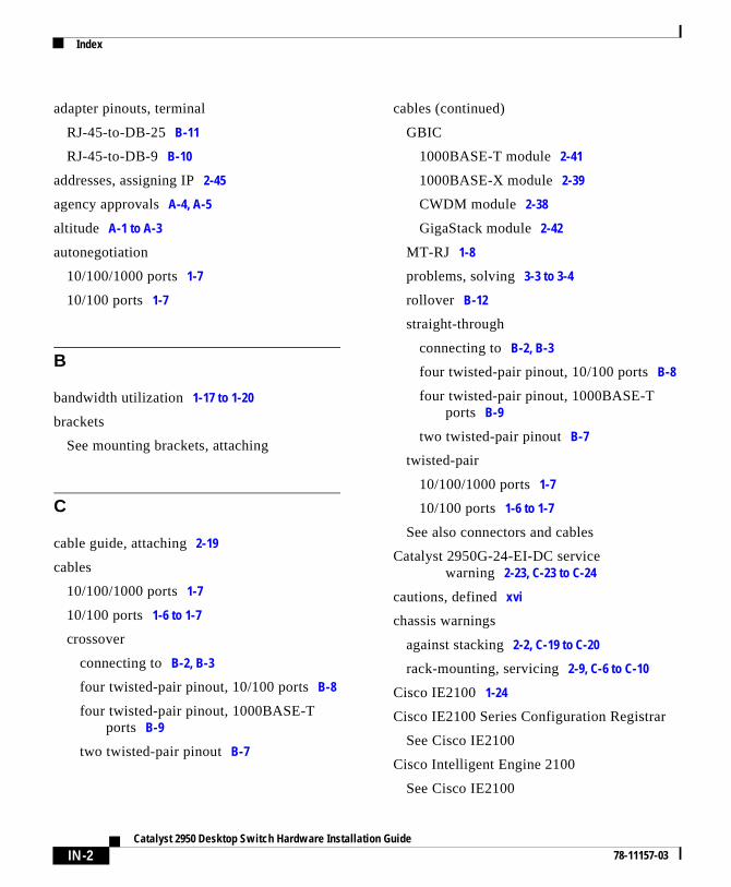
Index
adapter pinouts, terminal
RJ-45-to-DB-25 B-11
RJ-45-to-DB-9 B-10
addresses, assigning IP 2-45
agency approvals A-4, A-5
altitude A-1 to A-3
autonegotiation
10/100/1000 ports 1-7
10/100 ports 1-7
B
bandwidth utilization 1-17 to 1-20
brackets
See mounting brackets, attaching
C
cable guide, attaching 2-19
cables
10/100/1000 ports 1-7
10/100 ports 1-6 to 1-7
crossover
connecting to B-2, B-3
four twisted-pair pinout, 10/100 ports B-8
four twisted-pair pinout, 1000BASE-T ports B-9
two twisted-pair pinout B-7
IN-2Catalyst 2950 Desktop Switch Hardware Installation
cables (continued)
GBIC
1000BASE-T module 2-41
1000BASE-X module 2-39
CWDM module 2-38
GigaStack module 2-42
MT-RJ 1-8
problems, solving 3-3 to 3-4
rollover B-12
straight-through
connecting to B-2, B-3
four twisted-pair pinout, 10/100 ports B-8
four twisted-pair pinout, 1000BASE-T ports B-9
two twisted-pair pinout B-7
twisted-pair
10/100/1000 ports 1-7
10/100 ports 1-6 to 1-7
See also connectors and cables
Catalyst 2950G-24-EI-DC service warning 2-23, C-23 to C-24
cautions, defined xvi
chassis warnings
against stacking 2-2, C-19 to C-20
rack-mounting, servicing 2-9, C-6 to C-10
Cisco IE2100 1-24
Cisco IE2100 Series Configuration Registrar
See Cisco IE2100
Cisco Intelligent Engine 2100
See Cisco IE2100
Guide78-11157-03
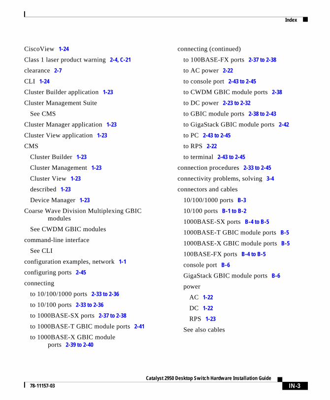
Index
CiscoView 1-24
Class 1 laser product warning 2-4, C-21
clearance 2-7
CLI 1-24
Cluster Builder application 1-23
Cluster Management Suite
See CMS
Cluster Manager application 1-23
Cluster View application 1-23
CMS
Cluster Builder 1-23
Cluster Management 1-23
Cluster View 1-23
described 1-23
Device Manager 1-23
Coarse Wave Division Multiplexing GBIC modules
See CWDM GBIC modules
command-line interface
See CLI
configuration examples, network 1-1
configuring ports 2-45
connecting
to 10/100/1000 ports 2-33 to 2-36
to 10/100 ports 2-33 to 2-36
to 1000BASE-SX ports 2-37 to 2-38
to 1000BASE-T GBIC module ports 2-41
to 1000BASE-X GBIC module ports 2-39 to 2-40
Catalyst 295078-11157-03
connecting (continued)
to 100BASE-FX ports 2-37 to 2-38
to AC power 2-22
to console port 2-43 to 2-45
to CWDM GBIC module ports 2-38
to DC power 2-23 to 2-32
to GBIC module ports 2-38 to 2-43
to GigaStack GBIC module ports 2-42
to PC 2-43 to 2-45
to RPS 2-22
to terminal 2-43 to 2-45
connection procedures 2-33 to 2-45
connectivity problems, solving 3-4
connectors and cables
10/100/1000 ports B-3
10/100 ports B-1 to B-2
1000BASE-SX ports B-4 to B-5
1000BASE-T GBIC module ports B-5
1000BASE-X GBIC module ports B-5
100BASE-FX ports B-4 to B-5
console port B-6
GigaStack GBIC module ports B-6
power
AC 1-22
DC 1-22
RPS 1-23
See also cables
IN-3 Desktop Switch Hardware Installation Guide
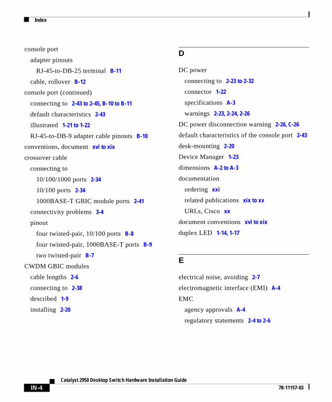
Index
console port
adapter pinouts
RJ-45-to-DB-25 terminal B-11
cable, rollover B-12
console port (continued)
connecting to 2-43 to 2-45, B-10 to B-11
default characteristics 2-43
illustrated 1-21 to 1-22
RJ-45-to-DB-9 adapter cable pinouts B-10
conventions, document xvi to xix
crossover cable
connecting to
10/100/1000 ports 2-34
10/100 ports 2-34
1000BASE-T GBIC module ports 2-41
connectivity problems 3-4
pinout
four twisted-pair, 10/100 ports B-8
four twisted-pair, 1000BASE-T ports B-9
two twisted-pair B-7
CWDM GBIC modules
cable lengths 2-6
connecting to 2-38
described 1-9
installing 2-20
IN-4Catalyst 2950 Desktop Switch Hardware Installation
D
DC power
connecting to 2-23 to 2-32
connector 1-22
specifications A-3
warnings 2-23, 2-24, 2-26
DC power disconnection warning 2-26, C-26
default characteristics of the console port 2-43
desk-mounting 2-20
Device Manager 1-23
dimensions A-2 to A-3
documentation
ordering xxi
related publications xix to xx
URLs, Cisco xx
document conventions xvi to xix
duplex LED 1-14, 1-17
E
electrical noise, avoiding 2-7
electromagnetic interface (EMI) A-4
EMC
agency approvals A-4
regulatory statements 2-4 to 2-6
Guide78-11157-03
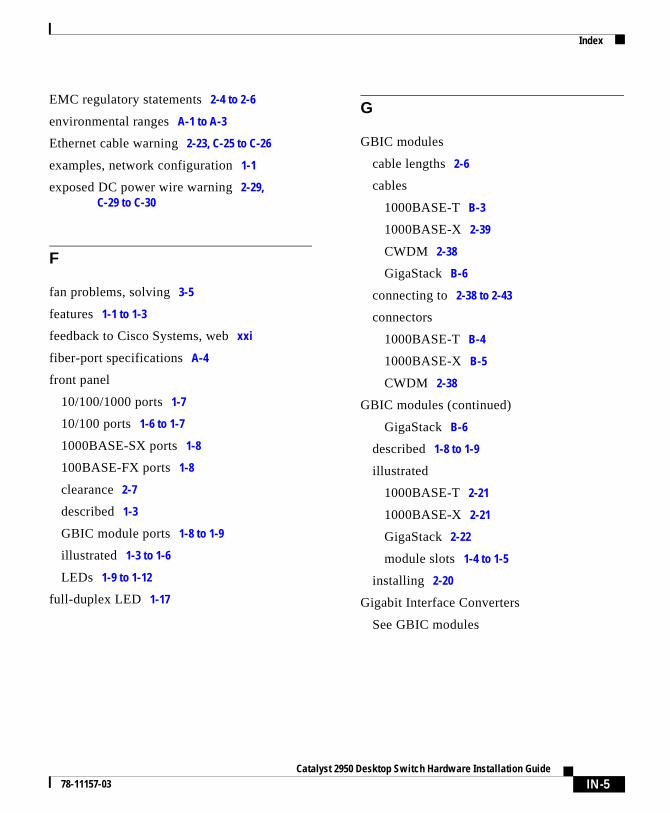
Index
EMC regulatory statements 2-4 to 2-6
environmental ranges A-1 to A-3
Ethernet cable warning 2-23, C-25 to C-26
examples, network configuration 1-1
exposed DC power wire warning 2-29, C-29 to C-30
F
fan problems, solving 3-5
features 1-1 to 1-3
feedback to Cisco Systems, web xxi
fiber-port specifications A-4
front panel
10/100/1000 ports 1-7
10/100 ports 1-6 to 1-7
1000BASE-SX ports 1-8
100BASE-FX ports 1-8
clearance 2-7
described 1-3
GBIC module ports 1-8 to 1-9
illustrated 1-3 to 1-6
LEDs 1-9 to 1-12
full-duplex LED 1-17
Catalyst 295078-11157-03
G
GBIC modules
cable lengths 2-6
cables
1000BASE-T B-3
1000BASE-X 2-39
CWDM 2-38
GigaStack B-6
connecting to 2-38 to 2-43
connectors
1000BASE-T B-4
1000BASE-X B-5
CWDM 2-38
GBIC modules (continued)
GigaStack B-6
described 1-8 to 1-9
illustrated
1000BASE-T 2-21
1000BASE-X 2-21
GigaStack 2-22
module slots 1-4 to 1-5
installing 2-20
Gigabit Interface Converters
See GBIC modules
IN-5 Desktop Switch Hardware Installation Guide
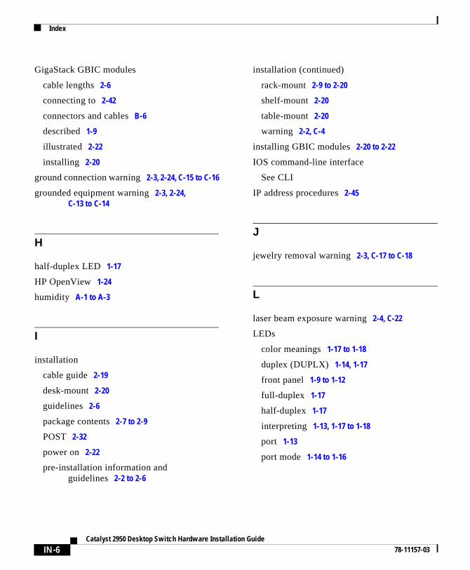
Index
GigaStack GBIC modules
cable lengths 2-6
connecting to 2-42
connectors and cables B-6
described 1-9
illustrated 2-22
installing 2-20
ground connection warning 2-3, 2-24, C-15 to C-16
grounded equipment warning 2-3, 2-24, C-13 to C-14
H
half-duplex LED 1-17
HP OpenView 1-24
humidity A-1 to A-3
I
installation
cable guide 2-19
desk-mount 2-20
guidelines 2-6
package contents 2-7 to 2-9
POST 2-32
power on 2-22
pre-installation information and guidelines 2-2 to 2-6
IN-6Catalyst 2950 Desktop Switch Hardware Installation
installation (continued)
rack-mount 2-9 to 2-20
shelf-mount 2-20
table-mount 2-20
warning 2-2, C-4
installing GBIC modules 2-20 to 2-22
IOS command-line interface
See CLI
IP address procedures 2-45
J
jewelry removal warning 2-3, C-17 to C-18
L
laser beam exposure warning 2-4, C-22
LEDs
color meanings 1-17 to 1-18
duplex (DUPLX) 1-14, 1-17
front panel 1-9 to 1-12
full-duplex 1-17
half-duplex 1-17
interpreting 1-13, 1-17 to 1-18
port 1-13
port mode 1-14 to 1-16
Guide78-11157-03
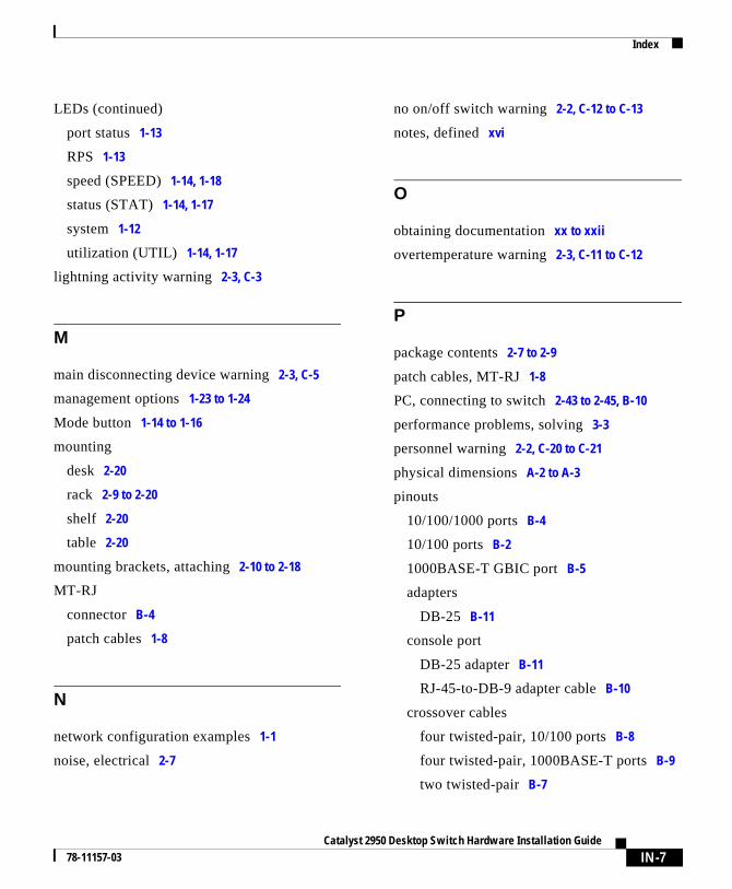
Index
LEDs (continued)
port status 1-13
RPS 1-13
speed (SPEED) 1-14, 1-18
status (STAT) 1-14, 1-17
system 1-12
utilization (UTIL) 1-14, 1-17
lightning activity warning 2-3, C-3
M
main disconnecting device warning 2-3, C-5
management options 1-23 to 1-24
Mode button 1-14 to 1-16
mounting
desk 2-20
rack 2-9 to 2-20
shelf 2-20
table 2-20
mounting brackets, attaching 2-10 to 2-18
MT-RJ
connector B-4
patch cables 1-8
N
network configuration examples 1-1
noise, electrical 2-7
Catalyst 295078-11157-03
no on/off switch warning 2-2, C-12 to C-13
notes, defined xvi
O
obtaining documentation xx to xxii
overtemperature warning 2-3, C-11 to C-12
P
package contents 2-7 to 2-9
patch cables, MT-RJ 1-8
PC, connecting to switch 2-43 to 2-45, B-10
performance problems, solving 3-3
personnel warning 2-2, C-20 to C-21
physical dimensions A-2 to A-3
pinouts
10/100/1000 ports B-4
10/100 ports B-2
1000BASE-T GBIC port B-5
adapters
DB-25 B-11
console port
DB-25 adapter B-11
RJ-45-to-DB-9 adapter cable B-10
crossover cables
four twisted-pair, 10/100 ports B-8
four twisted-pair, 1000BASE-T ports B-9
two twisted-pair B-7
IN-7 Desktop Switch Hardware Installation Guide
Index
pinouts (continued)
RJ-45-to-DB-25 terminal adapter B-11
RJ-45-to-DB-9 adapter cable B-10
RJ-45-to-DB-9 PC adapter cable B-10
straight-through cables
four twisted-pair, 10/100 ports B-8
four twisted-pair, 1000BASE-T ports B-9
two twisted-pair B-7
port
LEDs 1-9 to 1-12, 1-13
mode
changing 1-14 to 1-16
LEDs 1-9 to 1-12, 1-14 to 1-16
selecting 1-14 to 1-16
ports
See 10/100 ports, 10/100/1000 ports, 100BASE-FX ports, GBIC module ports, and console ports
POST
description 2-32
problems, solving 3-5
results 2-32
power
agency approvals A-5
connecting to
AC 2-22
DC 2-23 to 2-32
RPS 2-22
requirements A-1 to A-3
IN-8Catalyst 2950 Desktop Switch Hardware Installation
power (continued)
supply
AC connector 1-22
DC connector 1-22
RPS connector 1-23
power connectors 1-22 to 1-23
power on 2-22
procedures
connecting to DC power 2-23 to 2-32
connection 2-33 to 2-45
installation 2-9 to 2-20
IP address 2-45
power on 2-22
product disposal warning 2-3, C-14 to C-15
publications, related xix to xx
Q
qualified personnel warning 2-2, C-20 to C-21
R
rack-mounting
bracket mounting points 2-10 to 2-18
procedures 2-9 to 2-20
warning 2-9, C-6 to C-10
rear panel
clearance 2-7
console port connector 1-23
Guide78-11157-03
Index
rear panel (continued)
described 1-20
illustrated 1-21 to 1-22
power connectors 1-22 to 1-23
Redundant Power System
See RPS
regulatory statements, EMC 2-4 to 2-6
related publications xix to xx
restricted access area warning 2-23, C-24 to C-25
rollover cable B-12
RPS
connecting to 2-22
connector 1-23
described 1-23
LED 1-9, 1-13
warning 2-3, C-2
S
safety agency approvals A-4
safety warnings 2-2 to 2-4, C-1 to C-31
service personnel warning 2-2, C-30 to C-31
shelf-mounting 2-20
SNMP network management platforms 1-24
software switch management 1-23 to 1-24
specifications A-1 to A-5
speed LED 1-14, 1-18
stacking the chassis warning 2-2, C-19 to C-20
Catalyst 295078-11157-03
status LED 1-14, 1-17
straight-through cable
connecting to
10/100/1000 ports 2-34
10/100 ports 2-34
1000BASE-T GBIC module ports 2-41
connectivity problems 3-4
pinout
four twisted-pair, 10/100 ports B-8
four twisted-pair, 1000BASE-T ports B-9
two twisted-pair B-7
SunNet Manager 1-24
switch, power-on 2-22
system LED 1-12
T
table-mounting 2-20
technical assistance xxii to xxiv
technical specifications A-1 to A-5
Telnet, and accessing the CLI 1-24
temperature
operating A-1 to A-3
warning 2-3, C-11 to C-12
terminal, connecting to a switch 2-43 to 2-45, B-11
terminal-emulation software 2-43
translated warnings C-1 to C-31
IN-9 Desktop Switch Hardware Installation Guide
Index
troubleshooting 3-1
diagnosing problems 3-2 to 3-5
understanding POST results 3-2
U
URLs, Cisco xx
utilization
bandwidth 1-17 to 1-20
LED 1-14, 1-17
V
verifying package contents 2-7 to 2-9
W
warnings
DC power 2-23, 2-24, 2-26
defined xvii to xix
installation 2-2 to 2-4
translated C-1 to C-31
IN-10Catalyst 2950 Desktop Switch Hardware Installation
Guide78-11157-03