Embed Size (px)
Citation preview
Americas HeadquartersCisco Systems, Inc.170 West Tasman DriveSan Jose, CA 95134-1706 USAhttp://www.cisco.comTel: 408 526-4000
800 553-NETS (6387)Fax: 408 527-0883
Catalyst 3560 Switch Hardware Installation GuideMarch 2010
Text Part Number: OL-6337-07

THE SPECIFICATIONS AND INFORMATION REGARDING THE PRODUCTS IN THIS MANUAL ARE SUBJECT TO CHANGE WITHOUT NOTICE. ALL STATEMENTS, INFORMATION, AND RECOMMENDATIONS IN THIS MANUAL ARE BELIEVED TO BE ACCURATE BUT ARE PRESENTED WITHOUT WARRANTY OF ANY KIND, EXPRESS OR IMPLIED. USERS MUST TAKE FULL RESPONSIBILITY FOR THEIR APPLICATION OF ANY PRODUCTS.
THE SOFTWARE LICENSE AND LIMITED WARRANTY FOR THE ACCOMPANYING PRODUCT ARE SET FORTH IN THE INFORMATION PACKET THAT SHIPPED WITH THE PRODUCT AND ARE INCORPORATED HEREIN BY THIS REFERENCE. IF YOU ARE UNABLE TO LOCATE THE SOFTWARE LICENSE OR LIMITED WARRANTY, CONTACT YOUR CISCO REPRESENTATIVE FOR A COPY.
The following information is for FCC compliance of Class A devices: This equipment has been tested and found to comply with the limits for a Class A digital device, pursuant to part 15 of the FCC rules. These limits are designed to provide reasonable protection against harmful interference when the equipment is operated in a commercial environment. This equipment generates, uses, and can radiate radio-frequency energy and, if not installed and used in accordance with the instruction manual, may cause harmful interference to radio communications. Operation of this equipment in a residential area is likely to cause harmful interference, in which case users will be required to correct the interference at their own expense.
The following information is for FCC compliance of Class B devices: The equipment described in this manual generates and may radiate radio-frequency energy. If it is not installed in accordance with Cisco’s installation instructions, it may cause interference with radio and television reception. This equipment has been tested and found to comply with the limits for a Class B digital device in accordance with the specifications in part 15 of the FCC rules. These specifications are designed to provide reasonable protection against such interference in a residential installation. However, there is no guarantee that interference will not occur in a particular installation.
Modifying the equipment without Cisco’s written authorization may result in the equipment no longer complying with FCC requirements for Class A or Class B digital devices. In that event, your right to use the equipment may be limited by FCC regulations, and you may be required to correct any interference to radio or television communications at your own expense.
You can determine whether your equipment is causing interference by turning it off. If the interference stops, it was probably caused by the Cisco equipment or one of its peripheral devices. If the equipment causes interference to radio or television reception, try to correct the interference by using one or more of the following measures:
• Turn the television or radio antenna until the interference stops.
• Move the equipment to one side or the other of the television or radio.
• Move the equipment farther away from the television or radio.
• Plug the equipment into an outlet that is on a different circuit from the television or radio. (That is, make certain the equipment and the television or radio are on circuits controlled by different circuit breakers or fuses.)
Modifications to this product not authorized by Cisco Systems, Inc. could void the FCC approval and negate your authority to operate the product.
The Cisco implementation of TCP header compression is an adaptation of a program developed by the University of California, Berkeley (UCB) as part of UCB’s public domain version of the UNIX operating system. All rights reserved. Copyright © 1981, Regents of the University of California.
NOTWITHSTANDING ANY OTHER WARRANTY HEREIN, ALL DOCUMENT FILES AND SOFTWARE OF THESE SUPPLIERS ARE PROVIDED “AS IS” WITH ALL FAULTS. CISCO AND THE ABOVE-NAMED SUPPLIERS DISCLAIM ALL WARRANTIES, EXPRESSED OR IMPLIED, INCLUDING, WITHOUT LIMITATION, THOSE OF MERCHANTABILITY, FITNESS FOR A PARTICULAR PURPOSE AND NONINFRINGEMENT OR ARISING FROM A COURSE OF DEALING, USAGE, OR TRADE PRACTICE.
IN NO EVENT SHALL CISCO OR ITS SUPPLIERS BE LIABLE FOR ANY INDIRECT, SPECIAL, CONSEQUENTIAL, OR INCIDENTAL DAMAGES, INCLUDING, WITHOUT LIMITATION, LOST PROFITS OR LOSS OR DAMAGE TO DATA ARISING OUT OF THE USE OR INABILITY TO USE THIS MANUAL, EVEN IF CISCO OR ITS SUPPLIERS HAVE BEEN ADVISED OF THE POSSIBILITY OF SUCH DAMAGES.
CCDE, CCENT, CCSI, Cisco Eos, Cisco Explorer, Cisco HealthPresence, Cisco IronPort, the Cisco logo, Cisco Nurse Connect, Cisco Pulse, Cisco SensorBase, Cisco StackPower, Cisco StadiumVision, Cisco TelePresence, Cisco TrustSec, Cisco Unified Computing System, Cisco WebEx, DCE, Flip Channels, Flip for Good, Flip Mino, Flipshare (Design), Flip Ultra, Flip Video, Flip Video (Design), Instant Broadband, and Welcome to the Human Network are trademarks; Changing the Way We Work, Live, Play, and Learn, Cisco Capital, Cisco Capital (Design), Cisco:Financed (Stylized), Cisco Store, Flip Gift Card, and One Million Acts of Green are service marks; and Access Registrar, Aironet, AllTouch, AsyncOS, Bringing the Meeting To You, Catalyst, CCDA, CCDP, CCIE, CCIP, CCNA, CCNP, CCSP, CCVP, Cisco, the Cisco Certified Internetwork Expert logo, Cisco IOS, Cisco Lumin, Cisco Nexus, Cisco Press, Cisco Systems, Cisco Systems Capital, the Cisco Systems logo, Cisco Unity, Collaboration Without Limitation, Continuum, EtherFast, EtherSwitch, Event Center, Explorer, Follow Me Browsing, GainMaker, iLYNX, IOS, iPhone, IronPort, the IronPort logo, Laser Link, LightStream, Linksys, MeetingPlace, MeetingPlace Chime Sound, MGX, Networkers, Networking Academy, PCNow, PIX, PowerKEY, PowerPanels, PowerTV, PowerTV (Design), PowerVu, Prisma, ProConnect, ROSA, SenderBase, SMARTnet, Spectrum Expert, StackWise, WebEx, and the WebEx logo are registered trademarks of Cisco and/or its affiliates in the United States and certain other countries.
All other trademarks mentioned in this document or website are the property of their respective owners. The use of the word partner does not imply a partnership relationship between Cisco and any other company. (1002R)
Any Internet Protocol (IP) addresses used in this document are not intended to be actual addresses. Any examples, command display output, and figures included in the document are shown for illustrative purposes only. Any use of actual IP addresses in illustrative content is unintentional and coincidental.
Catalyst 3560 Switch Hardware Installation Guide © 2004–2010 Cisco Systems, Inc. All rights reserved.
OL-6337-07
C O N T E N T S
Preface vii
Audience i-vii
Purpose i-vii
Conventions i-vii
Related Publications i-viii
Obtaining Documentation and Submitting a Service Request i-ix
C H A P T E R 1 Product Overview 1-1
Setting Up the Switch 1-1
Features 1-1
Front Panel Description 1-3
Fast Ethernet Switch Front Panel Descriptions 1-3
Gigabit Ethernet Switch Front Panel Descriptions 1-6
10/100 and 10/100/1000 Ports 1-8
PoE Ports 1-9
SFP Module Slots 1-10
SFP Modules 1-10
SFP Module Patch Cable 1-10
Dual-Purpose Port 1-10
LEDs 1-11
System LED 1-11
RPS LED 1-12
Port LEDs and Modes 1-13
Dual-Purpose Port LEDs 1-15
Cable Guard 1-15
Rear Panel Description 1-15
Internal Power Supply 1-18
DC Power Connector 1-18
Cisco RPS 1-19
Cisco RPS 2300 1-19
Cisco RPS 675 1-19
Console Port 1-19
Security Slots 1-20
Management Options 1-20
iiiCatalyst 3560 Switch Hardware Installation Guide
Contents
Network Configurations 1-21
C H A P T E R 2 Switch Installation (24- and 48-Port Switches) 2-1
Preparing for Installation 2-1
Warnings 2-2
Installation Guidelines 2-5
Box Contents 2-6
Tools and Equipment 2-6
Verifying Switch Operation 2-6
Powering Off the Switch 2-7
Installing the Switch 2-7
Rack-Mounting 2-7
Removing Screws from the Switch 2-8
Attaching Brackets to the Catalyst 3560 Switch 2-8
Mounting the Switch in a Rack 2-10
Attaching the Cable Guide 2-11
Wall-Mounting 2-12
Attaching the Brackets to the Switch for Wall Mounting 2-12
Attaching the RPS Connector Cover 2-13
Mounting the Switch on a Wall 2-14
Table- or Shelf- Mounting 2-15
Installing and Removing SFP Modules 2-15
Installing SFP Modules into SFP Module Slots 2-16
Removing SFP Modules from SFP Module Slots 2-17
Inserting and Removing the SFP Module Patch Cable 2-18
10/100 or 10/100/1000 Ports 2-19
Connecting the Switch to Compatible Devices 2-20
Connecting to 10BASE-T or 100BASE-TX Devices 2-20
Connecting to Fiber-Optic SFP Modules 2-21
Connecting to 1000BASE-T SFP Modules 2-22
Connecting to a Dual-Purpose Port 2-23
Where to Go Next 2-24
C H A P T E R 3 Switch Installation (8- and 12-Port Switches) 3-1
Preparing for Installation 3-1
Warnings 3-2
Installation Guidelines 3-5
Equipment That You Supply 3-6
ivCatalyst 3560 Switch Hardware Installation Guide
OL-6337-07
Contents
Box Contents 3-7
Tools and Equipment 3-7
Verifying Switch Operation 3-7
Powering Off the Switch 3-7
Installing the Switch 3-7
Desk or Shelf Mounting 3-8
Desk or Shelf Mounting (Unsecured) 3-8
Desk or Shelf Mounting (Secured) 3-8
Under the Desk or Shelf Mounting 3-9
Wall-Mounting (with Mounting Screws) 3-12
Magnet Mounting 3-15
Rack-Mounting 3-16
Attaching Brackets to the Switch 3-16
Mounting the Switch in a 19-Inch Rack 3-17
Wall-Mounting (with Rack-Mount Brackets) 3-17
Securing the AC Power Cord 3-19
Where to Go Next 3-20
C H A P T E R 4 Troubleshooting 4-1
Diagnosing Problems 4-1
Evaluate Switch POST Results 4-2
Monitor Switch LEDs 4-2
Verify Switch Connections 4-2
Bad or Damaged Cable 4-2
Ethernet and Fiber Cables 4-3
Link Status 4-3
Transceiver Module Port Issues 4-3
Port and Interface Settings 4-4
Ping the End Device 4-4
Spanning Tree Loops 4-4
Monitor Switch Performance 4-4
Speed, Duplex, and Autonegotiation 4-4
Autonegotiation and Network Interface Cards 4-5
Cabling Distance 4-5
Clearing the Switch IP Address and Configuration 4-5
Locating the Switch Serial Number 4-6
vCatalyst 3560 Switch Hardware Installation Guide
OL-6337-07
Contents
A P P E N D I X A Technical Specifications A-1
A P P E N D I X B Connector and Cable Specifications B-1
Connector Specifications B-1
10/100 and 10/100/1000 Ports B-1
SFP Module Ports B-2
Dual-Purpose Ports B-3
Console Port B-3
Cable and Adapter Specifications B-4
SFP Module Cable Specifications B-4
Two Twisted-Pair Cable Pinouts B-5
Four Twisted-Pair Cable Pinouts for 1000BASE-T Ports B-6
Identifying a Crossover Cable B-6
Adapter Pinouts B-7
A P P E N D I X C Connecting to DC Power C-1
Connecting to DC Power C-1
Preparing for Installation C-2
Grounding the Switch C-2
Wiring the DC-Input Power Source C-5
A P P E N D I X D Configuring the Switch with the CLI-Based Setup Program D-1
Preparing for Setup D-1
Completing the Setup Program D-3
I N D E X
viCatalyst 3560 Switch Hardware Installation Guide
OL-6337-07
Preface
Audience This guide is for the networking or computer technician responsible for installing the Catalyst 3560 switch, hereafter known as the switch. We assume that you are familiar with the concepts and terminology of Ethernet and local area networking. If you are interested in more training and education in these areas, learning opportunities including training courses, self-study options, seminars, and career certifications programs are available on the Cisco Training & Events web page:
http://www.cisco.com/web/learning/index.html
PurposeThis guide describes the hardware features of the Catalyst 3560 switch. It describes the physical and performance characteristics of the switch, explains how to install it, and provides troubleshooting information.
This guide does not describe system messages that you might receive or how to configure your switch. For more information, see the switch software configuration guide, the switch command reference, and the switch system message guide on the Cisco.com Product Documentation home page. For information about the standard Cisco IOS Release 12.2 commands, see the Cisco IOS documentation set available from the Cisco.com home page at Products & Services > Technical Support & Documentation > See Documentation > Cisco IOS Software.
ConventionsThis document uses these conventions and symbols for notes, cautions, and warnings:
Note Means reader take note. Notes contain helpful suggestions or references to materials not contained in this manual.
Caution Means reader be careful. In this situation, you might do something that could result in equipment damage or loss of data.
viiCatalyst 3560 Switch Hardware Installation Guide
OL-6337-07
PrefaceRelated Publications
Warning IMPORTANT SAFETY INSTRUCTIONS This warning symbol means danger. You are in a situation that could cause bodily injury. Before you work on any equipment, be aware of the hazards involved with electrical circuitry and be familiar with standard practices for preventing accidents. Use the statement number provided at the end of each warning to locate its translation in the translated safety warnings that accompanied this device. Statement 1071 SAVE THESE INSTRUCTIONS
The safety warnings for this product are translated into several languages in the Regulatory Compliance and Safety Information for the Catalyst 3560 Switch guide. The EMC regulatory statements are also included in that guide.
Related PublicationsThese documents provide complete information about the switch and are available from this Cisco.com site:
http://www.cisco.com/en/US/products/hw/switches/ps5528/tsd_products_support_series_home.html
• Release Notes for the Catalyst 3750, 3560, 2970, and 2960 Switches
Note Before installing, configuring, or upgrading the switch, see the release notes on Cisco.com for the latest information.
• Catalyst 3560 Switch Software Configuration Guide
• Catalyst 3560 Switch Command Reference
• Catalyst 3750, 3560, 3550, 2970, and 2960 Switch System Message Guide
• Catalyst 3560 Switch Getting Started Guide
• Regulatory Compliance and Safety Information for the Catalyst 3560 Switch
• Device manager online help (available on the switch)
• Cisco Network Assistant online help (available on the switch)
For information about related products, see these documents:
• Getting Started with Cisco Network Assistant
• Release Notes for Cisco Network Assistant
• Cisco Small Form-Factor Pluggable Modules Installation Notes
• Cisco CWDM GBIC and CWDM SFP Installation Note
• Cisco RPS 2300 Redundant Power System Hardware Installation Guide
• Cisco RPS 675 Redundant Power System Hardware Installation Guide
These compatibility matrix documents are available from this Cisco.com site:
http://www.cisco.com/en/US/products/hw/modules/ps5455/products_device_support_tables_list.html
• Cisco Gigabit Ethernet Transceiver Modules Compatibility Matrix
• Cisco 100-Megabit Ethernet SFP Modules Compatibility Matrix
• Cisco CWDM SFP Transceiver Compatibility Matrix
viiiCatalyst 3560 Switch Hardware Installation Guide
OL-6337-07
PrefaceObtaining Documentation and Submitting a Service Request
• Cisco Small Form-Factor Pluggable Modules Compatibility Matrix
• Compatibility Matrix for 1000BASE-T Small Form-Factor Pluggable Modules
Obtaining Documentation and Submitting a Service RequestFor information on obtaining documentation, submitting a service request, and gathering additional information, see the monthly What’s New in Cisco Product Documentation, which also lists all new and revised Cisco technical documentation, at:
http://www.cisco.com/en/US/docs/general/whatsnew/whatsnew.html
Subscribe to the What’s New in Cisco Product Documentation as a Really Simple Syndication (RSS) feed and set content to be delivered directly to your desktop using a reader application. The RSS feeds are a free service and Cisco currently supports RSS version 2.0.
ixCatalyst 3560 Switch Hardware Installation Guide
OL-6337-07

PrefaceObtaining Documentation and Submitting a Service Request
xCatalyst 3560 Switch Hardware Installation Guide
OL-6337-07
OL-6337-07
C H A P T E R 1
Product OverviewThe Catalyst 3560 switch—also referred to as the switch—is an Ethernet switch to which you can connect devices like workstations, Cisco Wireless Access Points, Cisco IP Phones, and other network devices such as servers, routers, and other switches. This chapter provides a functional overview of the Catalyst 3560 switch. These topics are included:
• Setting Up the Switch, page 1-1
• Features, page 1-1
• Front Panel Description, page 1-3
• Rear Panel Description, page 1-15
• Management Options, page 1-20
Setting Up the SwitchSee the Catalyst 3560 Switch Getting Started Guide for instructions on how to use Express Setup to initially configure your Catalyst switch. The getting started guide provides switch management options, basic rack-mounting procedures, port and module connections, power connection procedures, and troubleshooting help.
For instructions on setting up your switch using the command-line interface (CLI), see Appendix D, “Configuring the Switch with the CLI-Based Setup Program.”
FeaturesThe 24- and 48-port Catalyst 3560 switches can be deployed as backbone switches, aggregating 10BASE-T and 100BASE-TX Ethernet traffic from other network devices. The Catalyst 3560-8PC and the Catalyst 3560-12PC-S compact switches provide the same Power over Ethernet (PoE) connectivity and can be deployed outside the traditional wiring closet environment, such as in office workspaces and classrooms. The switches are hot-swappable. See the switch software configuration guide for examples of how you might deploy the switch.
For power redundancy, all but the Catalyst 3560 8- and 12-port switches include connections for an optional Cisco RPS 2300 or Cisco RPS 675 that operates on AC power and supplies backup DC power to the switches.
1-1Catalyst 3560 Switch Hardware Installation Guide
Chapter 1 Product OverviewFeatures
Supported SFP modules:
• 100BASE-BX10 (only Catalyst 3560 8- and 12-port switches)
• 100BASE-FX
• 100BASE-LX (only Catalyst 3560 8- and 12-port switches)
• 1000BASE-BX10
• 1000BASE-LX
• 1000BASE-SX
• 1000BASE-T (only Catalyst 3560 24- and 48-port switches)
• 1000BASE-ZX
• Coarse Wavelength-Division Multiplexing (CWDM)
• SFP module patch cable. (CAB-SFP-50CM=.) Switches running Cisco IOS Release 12.2(25)SEB or later support this patch cable.
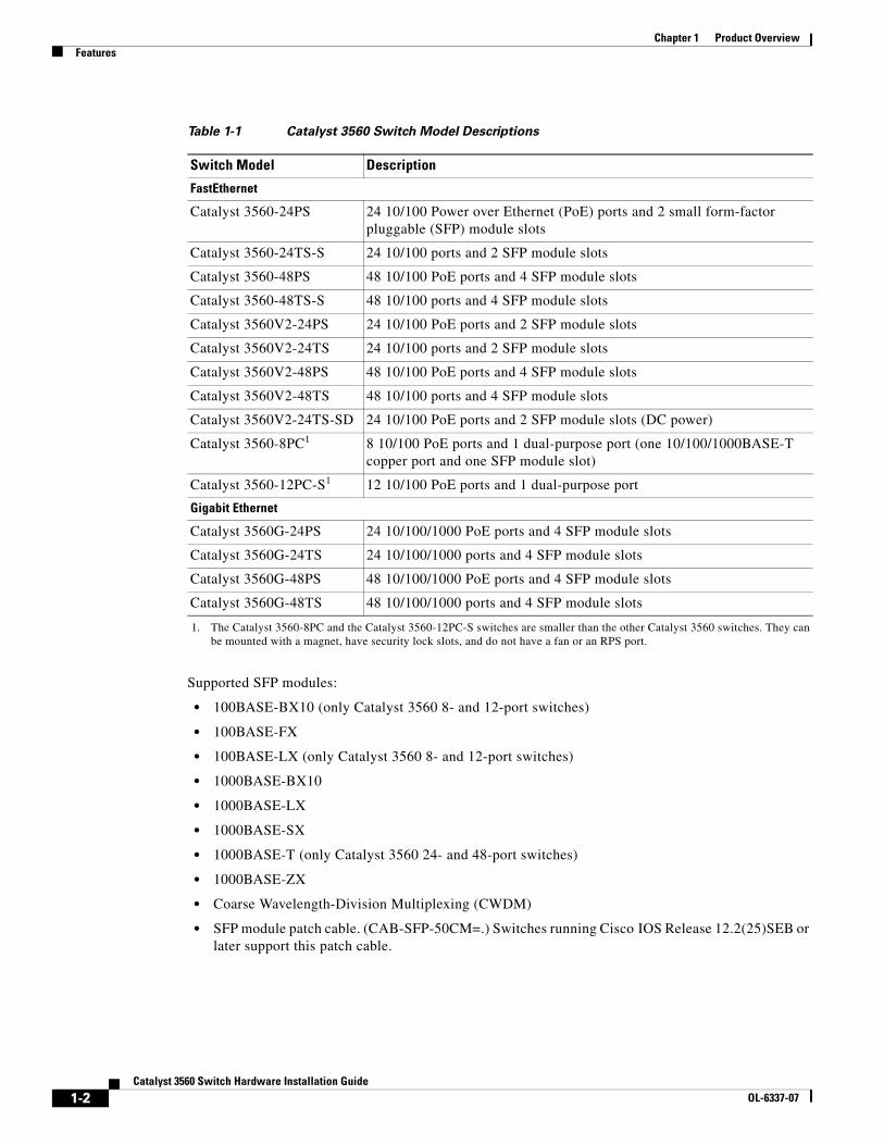
Table 1-1 Catalyst 3560 Switch Model Descriptions
Switch Model Description
FastEthernet
Catalyst 3560-24PS 24 10/100 Power over Ethernet (PoE) ports and 2 small form-factor pluggable (SFP) module slots
Catalyst 3560-24TS-S 24 10/100 ports and 2 SFP module slots
Catalyst 3560-48PS 48 10/100 PoE ports and 4 SFP module slots
Catalyst 3560-48TS-S 48 10/100 ports and 4 SFP module slots
Catalyst 3560V2-24PS 24 10/100 PoE ports and 2 SFP module slots
Catalyst 3560V2-24TS 24 10/100 ports and 2 SFP module slots
Catalyst 3560V2-48PS 48 10/100 PoE ports and 4 SFP module slots
Catalyst 3560V2-48TS 48 10/100 ports and 4 SFP module slots
Catalyst 3560V2-24TS-SD 24 10/100 PoE ports and 2 SFP module slots (DC power)
Catalyst 3560-8PC1
1. The Catalyst 3560-8PC and the Catalyst 3560-12PC-S switches are smaller than the other Catalyst 3560 switches. They can be mounted with a magnet, have security lock slots, and do not have a fan or an RPS port.
8 10/100 PoE ports and 1 dual-purpose port (one 10/100/1000BASE-T copper port and one SFP module slot)
Catalyst 3560-12PC-S1 12 10/100 PoE ports and 1 dual-purpose port
Gigabit Ethernet
Catalyst 3560G-24PS 24 10/100/1000 PoE ports and 4 SFP module slots
Catalyst 3560G-24TS 24 10/100/1000 ports and 4 SFP module slots
Catalyst 3560G-48PS 48 10/100/1000 PoE ports and 4 SFP module slots
Catalyst 3560G-48TS 48 10/100/1000 ports and 4 SFP module slots
1-2Catalyst 3560 Switch Hardware Installation Guide
OL-6337-07
Chapter 1 Product OverviewFront Panel Description
Configuration:
• For 10/100 and 10/100/1000 ports, the speed and duplex settings are autonegotiated.
• For 10/100 and 10/100/1000 ports, PoE settings are autonegotiated.
• For 1000BASE-T SFP module ports, the speed and duplex settings are autonegotiated.
Front Panel Description • Fast Ethernet Switch Front Panel Descriptions, page 1-3
• Gigabit Ethernet Switch Front Panel Descriptions, page 1-6
• 10/100 and 10/100/1000 Ports, page 1-8
• PoE Ports, page 1-9
• SFP Module Slots, page 1-10
• Dual-Purpose Port, page 1-10
• LEDs, page 1-11
• Cable Guard, page 1-15
Fast Ethernet Switch Front Panel Descriptions • Catalyst 3560-24PS and 3560V2-24PS Switch Front Panel, Figure 1-1 on page 1-3
• Catalyst 3560-24TS-S, 3560V2-24TS, and 3560V2-24TS-SD Switch Front Panel, Figure 1-2 on page 1-4
• Catalyst 3560-48PS and 3560V2-48PS Switch Front Panel, Figure 1-3 on page 1-4
• Catalyst 3560-48TS-S and 3560V2-48TS Switch Front Panel, Figure 1-4 on page 1-5
• Catalyst 3560-8PC Switch Front Panel, Figure 1-5 on page 1-5
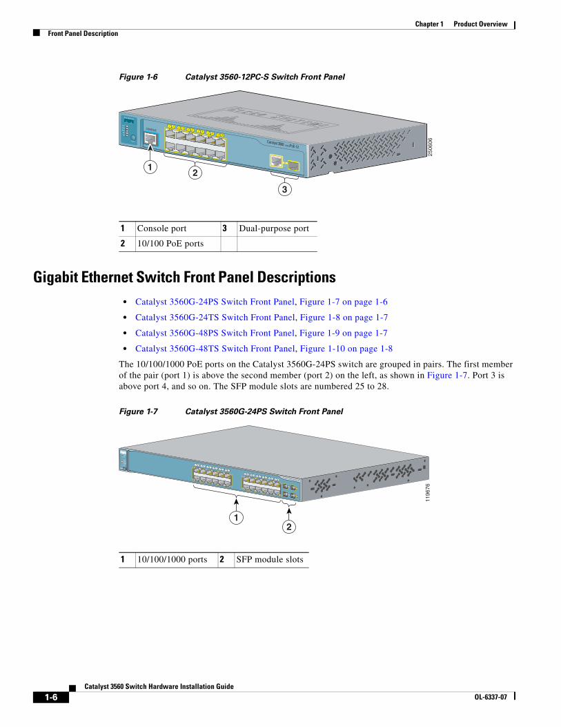
• Catalyst 3560-12PC-S Switch Front Panel, Figure 1-6 on page 1-6
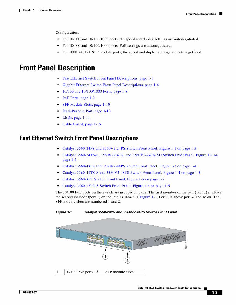
The 10/100 PoE ports on the switch are grouped in pairs. The first member of the pair (port 1) is above the second member (port 2) on the left, as shown in Figure 1-1. Port 3 is above port 4, and so on. The SFP module slots are numbered 1 and 2.
Figure 1-1 Catalyst 3560-24PS and 3560V2-24PS Switch Front Panel
1 10/100 PoE ports 2 SFP module slots
9791
2
2
Catalyst 3560 SERIES PoE-24
SYSTRPS
STATDUPLXSPEEDPoE
MODE
1
1 23 4
5 67 8
9 1011 12
1415 16
17 1819 20
21 2223 24
13
12
1X
2X
11X
12X
13X
14X
23X
24X
1-3Catalyst 3560 Switch Hardware Installation Guide
OL-6337-07
Chapter 1 Product OverviewFront Panel Description
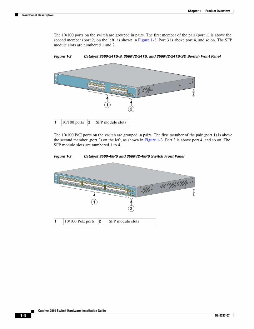
The 10/100 ports on the switch are grouped in pairs. The first member of the pair (port 1) is above the second member (port 2) on the left, as shown in Figure 1-2. Port 3 is above port 4, and so on. The SFP module slots are numbered 1 and 2.
Figure 1-2 Catalyst 3560-24TS-S, 3560V2-24TS, and 3560V2-24TS-SD Switch Front Panel
The 10/100 PoE ports on the switch are grouped in pairs. The first member of the pair (port 1) is above the second member (port 2) on the left, as shown in Figure 1-3. Port 3 is above port 4, and so on. The SFP module slots are numbered 1 to 4.
Figure 1-3 Catalyst 3560-48PS and 3560V2-48PS Switch Front Panel
1 10/100 ports 2 SFP module slots
1268
08
2
Catalyst 3560 SERIES
MODE
1
1 23 4
5 67 8
9 1011 12
1415 16
17 1819 20
21 2223 24
13
1X
2X
11X
12X
13X
14X
23X
24X
RPS
STATDUPLXSPEED
SYST
12
1 10/100 PoE ports 2 SFP module slots
9791
1
2
1
Catalyst 3560 SERIES PoE-48
SYSTRPS
STATDUPLXSPEEDPoE
MODE
1 25 6 7 8 9 10 11 12 13 14 15 16
3 41X
2X
15X
16X
17 1821 22 23 24 25 26 27 28 29 30 31 32
19 2017X
18X
31X
32X
33 3437 38 39 40 41 42 43 44 45 46 47 48
35 3633X
34X
47X
48X
1
2
3
4
1-4Catalyst 3560 Switch Hardware Installation Guide
OL-6337-07
Chapter 1 Product OverviewFront Panel Description
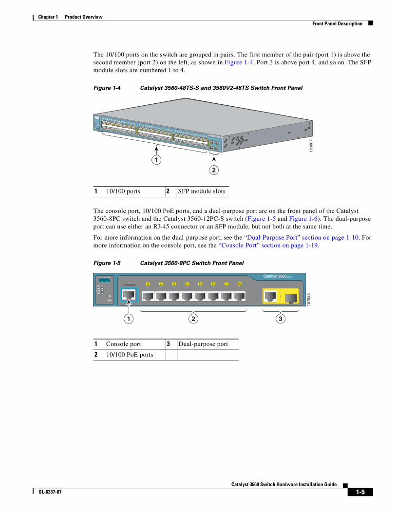
The 10/100 ports on the switch are grouped in pairs. The first member of the pair (port 1) is above the second member (port 2) on the left, as shown in Figure 1-4. Port 3 is above port 4, and so on. The SFP module slots are numbered 1 to 4.
Figure 1-4 Catalyst 3560-48TS-S and 3560V2-48TS Switch Front Panel
The console port, 10/100 PoE ports, and a dual-purpose port are on the front panel of the Catalyst 3560-8PC switch and the Catalyst 3560-12PC-S switch (Figure 1-5 and Figure 1-6). The dual-purpose port can use either an RJ-45 connector or an SFP module, but not both at the same time.
For more information on the dual-purpose port, see the “Dual-Purpose Port” section on page 1-10. For more information on the console port, see the “Console Port” section on page 1-19.
Figure 1-5 Catalyst 3560-8PC Switch Front Panel
1 10/100 ports 2 SFP module slots
1268
07
2
1
Catalyst 3560 SERIES
SYSTRPS
STATDUPLXSPEED
MODE
1 25 6 7 8 9 10 11 12 13 14 15 16
3 41X
2X
15X
16X
17 1821 22 23 24 25 26 27 28 29 30 31 32
19 2017X
18X
31X
32X
33 3437 38 39 40 41 42 43 44 45 46 47 48
35 3633X
34X
47X
48X
1
2
3
4
1 Console port 3 Dual-purpose port
2 10/100 PoE ports
2 3
Catalyst 2960 Series
CONSOLE 1x
SPD DPLX STAT SYST
MODE
2x 3x 4x 5x 6x 7x 8x
1
1
1578
22
1-5Catalyst 3560 Switch Hardware Installation Guide
OL-6337-07
Chapter 1 Product OverviewFront Panel Description
Figure 1-6 Catalyst 3560-12PC-S Switch Front Panel
Gigabit Ethernet Switch Front Panel Descriptions • Catalyst 3560G-24PS Switch Front Panel, Figure 1-7 on page 1-6
• Catalyst 3560G-24TS Switch Front Panel, Figure 1-8 on page 1-7
• Catalyst 3560G-48PS Switch Front Panel, Figure 1-9 on page 1-7
• Catalyst 3560G-48TS Switch Front Panel, Figure 1-10 on page 1-8
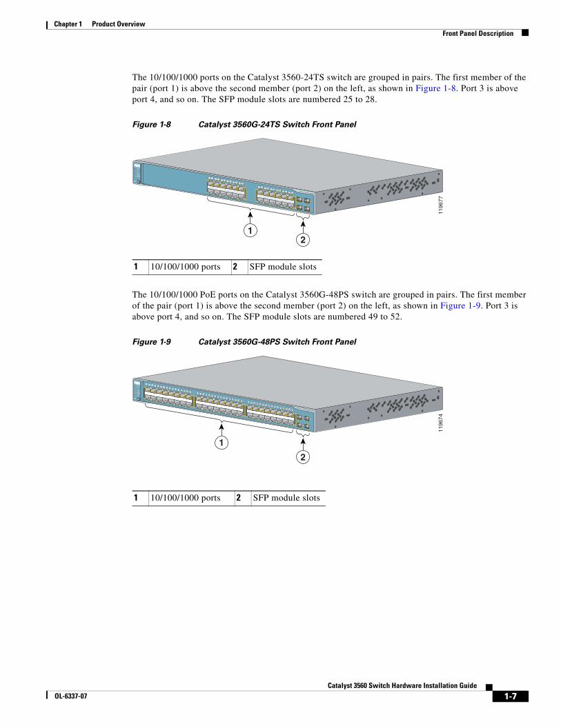
The 10/100/1000 PoE ports on the Catalyst 3560G-24PS switch are grouped in pairs. The first member of the pair (port 1) is above the second member (port 2) on the left, as shown in Figure 1-7. Port 3 is above port 4, and so on. The SFP module slots are numbered 25 to 28.
Figure 1-7 Catalyst 3560G-24PS Switch Front Panel
1 Console port 3 Dual-purpose port
2 10/100 PoE ports
2
3
1
CONSOLE
Catalyst 3560 SERIES PoE-12
PoESPD
DPLXSTATSYST
MODE
1
1 23 4
67 8
9 1011 12
5
2506
06
1 10/100/1000 ports 2 SFP module slots
1196
76
2
Catalyst 3560G SERIES PoE-24
MODE
1
1 23 4
5 67 8
9 1011 12
1415 16
17 1819 20
21 2223 24
13
1X
2X
11X
12X
13X
14X
23X
24X
RPS
STATDUPLXSPEEDPoE
SYST
25
26
27
28
1-6Catalyst 3560 Switch Hardware Installation Guide
OL-6337-07
Chapter 1 Product OverviewFront Panel Description
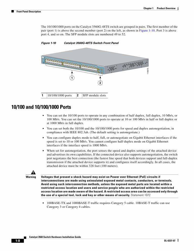
The 10/100/1000 ports on the Catalyst 3560-24TS switch are grouped in pairs. The first member of the pair (port 1) is above the second member (port 2) on the left, as shown in Figure 1-8. Port 3 is above port 4, and so on. The SFP module slots are numbered 25 to 28.
Figure 1-8 Catalyst 3560G-24TS Switch Front Panel
The 10/100/1000 PoE ports on the Catalyst 3560G-48PS switch are grouped in pairs. The first member of the pair (port 1) is above the second member (port 2) on the left, as shown in Figure 1-9. Port 3 is above port 4, and so on. The SFP module slots are numbered 49 to 52.
Figure 1-9 Catalyst 3560G-48PS Switch Front Panel
1 10/100/1000 ports 2 SFP module slots
1196
77
2
Catalyst 3560G SERIES
MODE
1
1 23 4
5 67 8
9 1011 12
1415 16
17 1819 20
21 2223 24
13
1X
2X
11X
12X
13X
14X
23X
24X
RPS
STATDUPLXSPEED
SYST
25
26
27
28
1 10/100/1000 ports 2 SFP module slots
1196
74
2
1
Catalyst 3560G SERIES PoE-48
SYSTRPS
STATDUPLXSPEEDPoE
MODE
1 25 6 7 8 9 10 11 12 13 14 15 16
3 41X
2X
15X
16X
17 1821 22 23 24 25 26 27 28 29 30 31 32
19 2017X
18X
31X
32X
33 3437 38 39 40 41 42 43 44 45 46 47 48
35 3633X
34X
47X
48X
49
50
51
52
1-7Catalyst 3560 Switch Hardware Installation Guide
OL-6337-07
Chapter 1 Product OverviewFront Panel Description
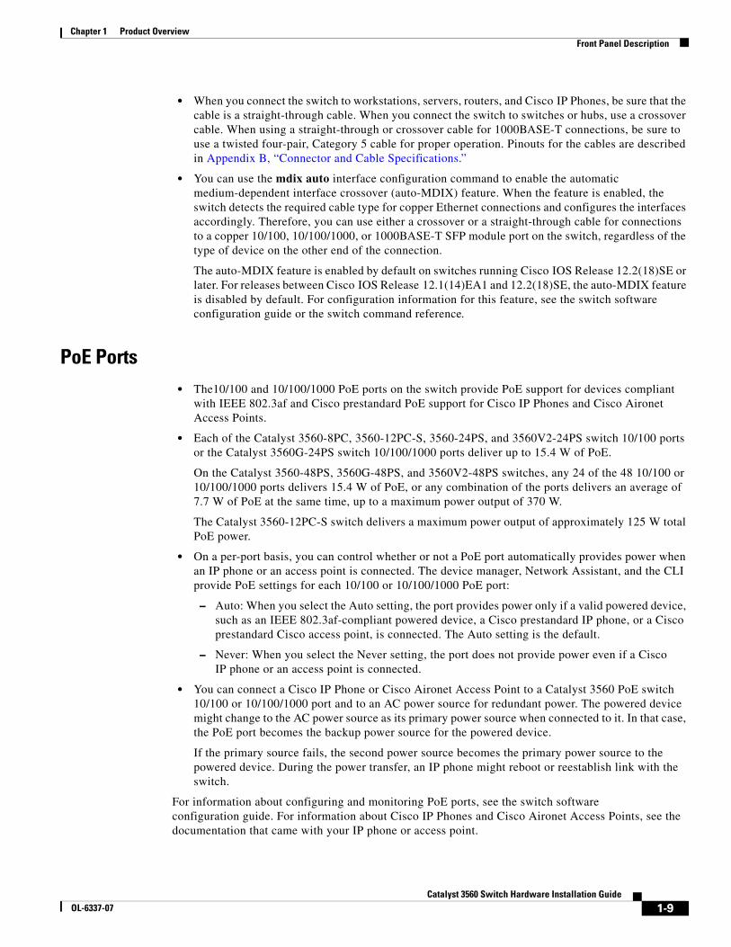
The 10/100/1000 ports on the Catalyst 3560G-48TS switch are grouped in pairs. The first member of the pair (port 1) is above the second member (port 2) on the left, as shown in Figure 1-10. Port 3 is above port 4, and so on. The SFP module slots are numbered 49 to 52.
Figure 1-10 Catalyst 3560G-48TS Switch Front Panel
10/100 and 10/100/1000 Ports • You can set the 10/100 ports to operate in any combination of half duplex, full duplex, 10 Mb/s, or
100 Mb/s. You can set the 10/100/1000 ports to operate at 10 or 100 Mb/s in half or full duplex or at 1000 Mb/s in full duplex.
• You can set both the 10/100 and the 10/100/1000 ports for speed and duplex autonegotiation, in compliance with IEEE 802.3ab. (The default setting is autonegotiate.)
• You can configure duplex mode to half, full, or autonegotiate on Gigabit Ethernet interfaces if the speed is set to 10 or 100 Mb/s. You cannot configure half-duplex mode on Gigabit Ethernet interfaces if the interface speed is 1000 Mb/s.
• When set for autonegotiation, the port senses the speed and duplex settings of the attached device and advertises its own capabilities. If the connected device also supports autonegotiation, the switch port negotiates the best connection (the fastest line speed that both devices support and full-duplex transmission if the attached device supports it) and configures itself accordingly. In all cases, the attached device must be within 328 feet (100 meters).
Warning Voltages that present a shock hazard may exist on Power over Ethernet (PoE) circuits if interconnections are made using uninsulated exposed metal contacts, conductors, or terminals. Avoid using such interconnection methods, unless the exposed metal parts are located within a restricted access location and users and service people who are authorized within the restricted access location are made aware of the hazard. A restricted access area can be accessed only through the use of a special tool, lock and key or other means of security. Statement 1072
• 100BASE-TX and 1000BASE-T traffic requires Category 5 cable. 10BASE-T traffic can use Category 3 or Category 4 cables.
1 10/100/1000 ports 2 SFP module slots
1196
75
2
1
Catalyst 3560G SERIES
SYSTRPS
STATDUPLXSPEED
MODE
1 25 6 7 8 9 10 11 12 13 14 15 16
3 41X
2X
15X
16X
17 1821 22 23 24 25 26 27 28 29 30 31 32
19 2017X
18X
31X
32X
33 3437 38 39 40 41 42 43 44 45 46 47 48
35 3633X
34X
47X
48X
49
50
51
52
1-8Catalyst 3560 Switch Hardware Installation Guide
OL-6337-07
Chapter 1 Product OverviewFront Panel Description
• When you connect the switch to workstations, servers, routers, and Cisco IP Phones, be sure that the cable is a straight-through cable. When you connect the switch to switches or hubs, use a crossover cable. When using a straight-through or crossover cable for 1000BASE-T connections, be sure to use a twisted four-pair, Category 5 cable for proper operation. Pinouts for the cables are described in Appendix B, “Connector and Cable Specifications.”
• You can use the mdix auto interface configuration command to enable the automatic medium-dependent interface crossover (auto-MDIX) feature. When the feature is enabled, the switch detects the required cable type for copper Ethernet connections and configures the interfaces accordingly. Therefore, you can use either a crossover or a straight-through cable for connections to a copper 10/100, 10/100/1000, or 1000BASE-T SFP module port on the switch, regardless of the type of device on the other end of the connection.
The auto-MDIX feature is enabled by default on switches running Cisco IOS Release 12.2(18)SE or later. For releases between Cisco IOS Release 12.1(14)EA1 and 12.2(18)SE, the auto-MDIX feature is disabled by default. For configuration information for this feature, see the switch software configuration guide or the switch command reference.
PoE Ports • The10/100 and 10/100/1000 PoE ports on the switch provide PoE support for devices compliant
with IEEE 802.3af and Cisco prestandard PoE support for Cisco IP Phones and Cisco Aironet Access Points.
• Each of the Catalyst 3560-8PC, 3560-12PC-S, 3560-24PS, and 3560V2-24PS switch 10/100 ports or the Catalyst 3560G-24PS switch 10/100/1000 ports deliver up to 15.4 W of PoE.
On the Catalyst 3560-48PS, 3560G-48PS, and 3560V2-48PS switches, any 24 of the 48 10/100 or 10/100/1000 ports delivers 15.4 W of PoE, or any combination of the ports delivers an average of 7.7 W of PoE at the same time, up to a maximum power output of 370 W.
The Catalyst 3560-12PC-S switch delivers a maximum power output of approximately 125 W total PoE power.
• On a per-port basis, you can control whether or not a PoE port automatically provides power when an IP phone or an access point is connected. The device manager, Network Assistant, and the CLI provide PoE settings for each 10/100 or 10/100/1000 PoE port:
– Auto: When you select the Auto setting, the port provides power only if a valid powered device, such as an IEEE 802.3af-compliant powered device, a Cisco prestandard IP phone, or a Cisco prestandard Cisco access point, is connected. The Auto setting is the default.
– Never: When you select the Never setting, the port does not provide power even if a Cisco IP phone or an access point is connected.
• You can connect a Cisco IP Phone or Cisco Aironet Access Point to a Catalyst 3560 PoE switch 10/100 or 10/100/1000 port and to an AC power source for redundant power. The powered device might change to the AC power source as its primary power source when connected to it. In that case, the PoE port becomes the backup power source for the powered device.
If the primary source fails, the second power source becomes the primary power source to the powered device. During the power transfer, an IP phone might reboot or reestablish link with the switch.
For information about configuring and monitoring PoE ports, see the switch software configuration guide. For information about Cisco IP Phones and Cisco Aironet Access Points, see the documentation that came with your IP phone or access point.
1-9Catalyst 3560 Switch Hardware Installation Guide
OL-6337-07
Chapter 1 Product OverviewFront Panel Description
Many legacy powered devices, including older Cisco IP phones and access points that do not fully support IEEE 802.3af, might not support PoE when connected to the switches by a crossover cable.
SFP Module SlotsSee the release notes for the latest list of supported SFP modules.
SFP Modules
The switch uses Gigabit Ethernet SFP modules to establish fiber-optic and 1000BASE-T connections. These transceiver modules are field-replaceable, providing uplink interfaces when inserted in an SFP module slot. Use fiber-optic cables with LC or MT-RJ connectors to connect to a fiber-optic SFP module. Use a Category 5 cable with RJ-45 connectors to connect to a copper SFP module.
For more information about SFP modules, see your SFP module documentation or the release note for your switch software.
SFP Module Patch Cable
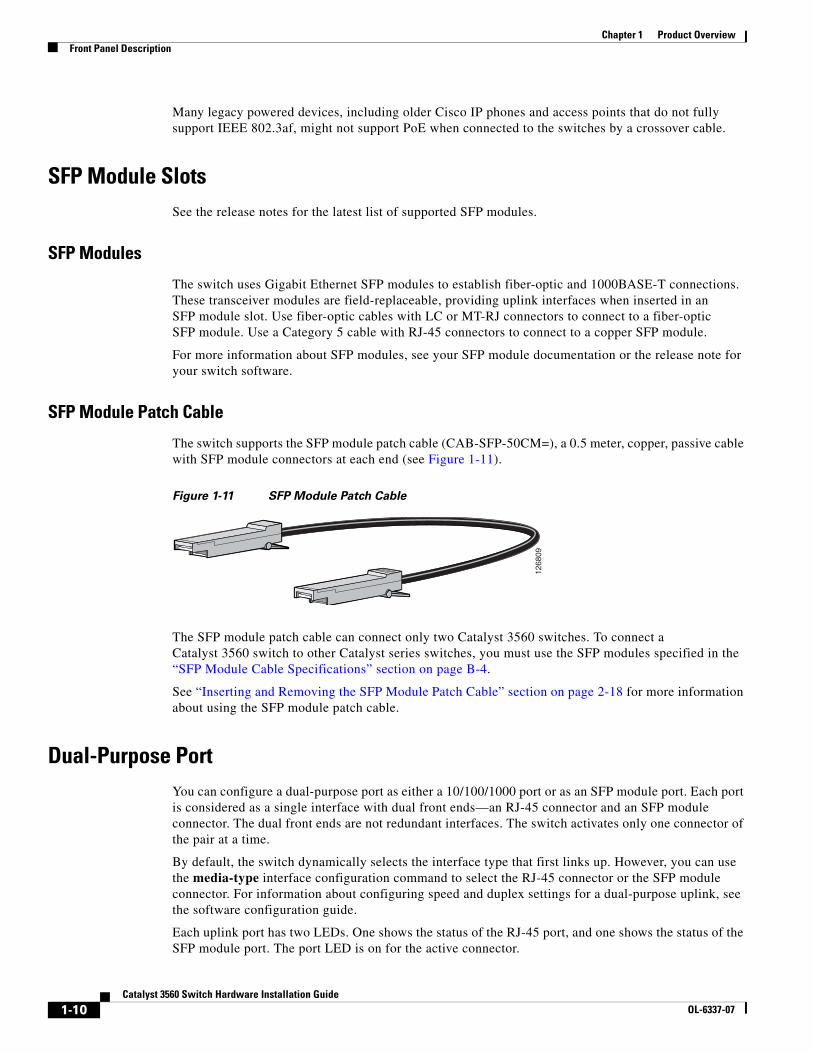
The switch supports the SFP module patch cable (CAB-SFP-50CM=), a 0.5 meter, copper, passive cable with SFP module connectors at each end (see Figure 1-11).
Figure 1-11 SFP Module Patch Cable
The SFP module patch cable can connect only two Catalyst 3560 switches. To connect a Catalyst 3560 switch to other Catalyst series switches, you must use the SFP modules specified in the “SFP Module Cable Specifications” section on page B-4.
See “Inserting and Removing the SFP Module Patch Cable” section on page 2-18 for more information about using the SFP module patch cable.
Dual-Purpose PortYou can configure a dual-purpose port as either a 10/100/1000 port or as an SFP module port. Each port is considered as a single interface with dual front ends—an RJ-45 connector and an SFP module connector. The dual front ends are not redundant interfaces. The switch activates only one connector of the pair at a time.
By default, the switch dynamically selects the interface type that first links up. However, you can use the media-type interface configuration command to select the RJ-45 connector or the SFP module connector. For information about configuring speed and duplex settings for a dual-purpose uplink, see the software configuration guide.
Each uplink port has two LEDs. One shows the status of the RJ-45 port, and one shows the status of the SFP module port. The port LED is on for the active connector.
1268
09
1-10Catalyst 3560 Switch Hardware Installation Guide
OL-6337-07
Chapter 1 Product OverviewFront Panel Description
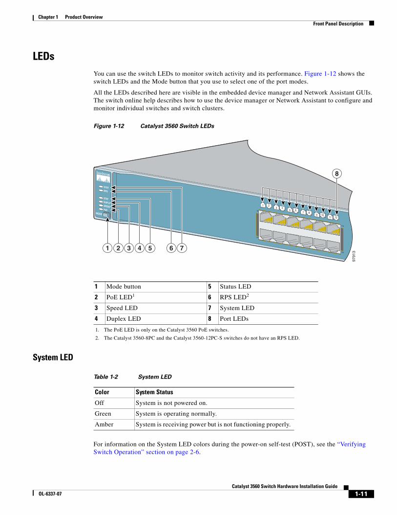
LEDsYou can use the switch LEDs to monitor switch activity and its performance. Figure 1-12 shows the switch LEDs and the Mode button that you use to select one of the port modes.
All the LEDs described here are visible in the embedded device manager and Network Assistant GUIs. The switch online help describes how to use the device manager or Network Assistant to configure and monitor individual switches and switch clusters.
Figure 1-12 Catalyst 3560 Switch LEDs
System LED
For information on the System LED colors during the power-on self-test (POST), see the “Verifying Switch Operation” section on page 2-6.
1 Mode button 5 Status LED
2 PoE LED1
1. The PoE LED is only on the Catalyst 3560 PoE switches.
6 RPS LED2
2. The Catalyst 3560-8PC and the Catalyst 3560-12PC-S switches do not have an RPS LED.
3 Speed LED 7 System LED
4 Duplex LED 8 Port LEDs
Table 1-2 System LED
Color System Status
Off System is not powered on.
Green System is operating normally.
Amber System is receiving power but is not functioning properly.
1X
2X
11X
12X
1 23 4
5 67 8
9 1011 12
SYSTRPS
STATDUPLXSPEEDPoE
MODE
8
2 3 4 5 6 71
9791
3
1-11Catalyst 3560 Switch Hardware Installation Guide
OL-6337-07
Chapter 1 Product OverviewFront Panel Description
RPS LED
Note The Catalyst 3560-8PC and Catalyst 3560-12PC-S switches do not have an RPS LED.
For more information about the Cisco RPS 2300 and the RPS 675, see the Cisco Redundant Power System 2300 Hardware Installation Guide and the Cisco RPS 675 Redundant Power System Hardware Installation Guide.
Table 1-3 RPS LED
Color RPS Status
Off RPS is off or not properly connected.
Green RPS is connected and ready to provide back-up power, if required.
Blinking green RPS is connected but is unavailable because it is providing power to another device (redundancy has been allocated to a neighboring device).
Amber The RPS is in standby mode or in a fault condition. Press the Standby/Active button on the RPS, and the LED should turn green. If it does not, the RPS fan might have failed. Contact Cisco.
Blinking amber The internal power supply in a switch has failed, and the RPS is providing power to the switch (redundancy has been allocated to this device).
1-12Catalyst 3560 Switch Hardware Installation Guide
OL-6337-07
Chapter 1 Product OverviewFront Panel Description
Port LEDs and Modes
The port LEDs, as a group or individually, display information about the switch and about the individual ports:
Even if the PoE mode is not selected, the PoE LED shows PoE problems when they are detected. The PoE LED applies only to Catalyst 3560 switches that support PoE.
To select or change a mode, press the Mode button until the desired mode is highlighted. When you change port modes, the meanings of the port LED colors also change. Table 1-6 explains how to interpret the port LED colors in different port modes.
Table 1-4 Modes for Port LEDs
Selected Mode LED Port Mode Description
STAT Port status The port status. This is the default mode.
DUPLX Port duplex mode The port duplex mode: full duplex or half duplex.
SPEED Port speed The port operating speed: 10, 100, or 10001 Mb/s.
1. When installed in Catalyst 3560 switches, 1000BASE-T SFP modules can operate at 10, 100, or 1000 Mb/s in full-duplex mode or at 10 or 100 Mb/s in half-duplex mode.
PoE PoE port power The PoE status.
Table 1-5 PoE Mode LED
Color PoE Status
Off PoE mode is not selected. None of the 10/100 or 10/100/1000 PoE ports have been denied power or are in a fault condition.
Green PoE mode is selected, and the PoE status is shown on the port LEDs.
Blinking amber PoE mode is not selected. At least one of the 10/100 or 10/100/1000 PoE ports has been denied power, or at least one of the ports has a PoE fault.
1-13Catalyst 3560 Switch Hardware Installation Guide
OL-6337-07
Chapter 1 Product OverviewFront Panel Description
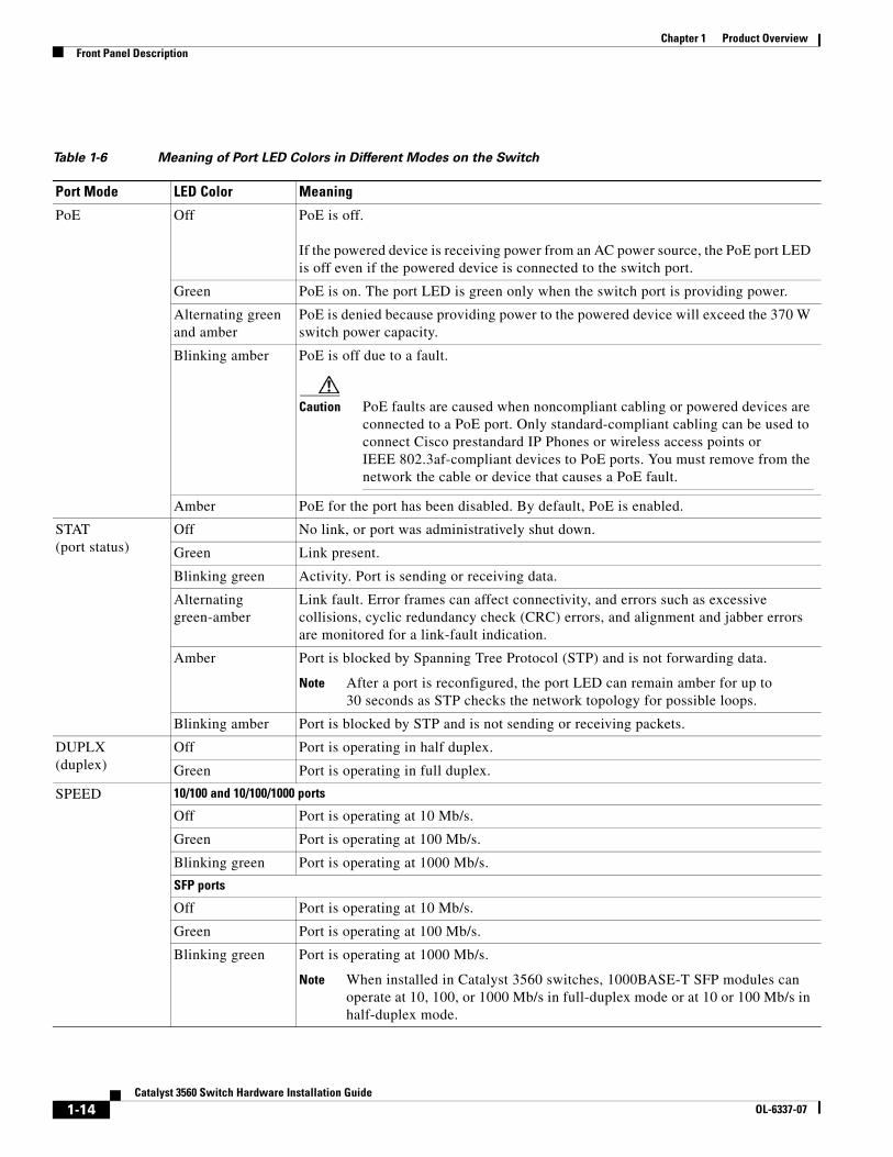
Table 1-6 Meaning of Port LED Colors in Different Modes on the Switch
Port Mode LED Color Meaning
PoE Off PoE is off. If the powered device is receiving power from an AC power source, the PoE port LED is off even if the powered device is connected to the switch port.
Green PoE is on. The port LED is green only when the switch port is providing power.
Alternating green and amber
PoE is denied because providing power to the powered device will exceed the 370 W switch power capacity.
Blinking amber PoE is off due to a fault.
Caution PoE faults are caused when noncompliant cabling or powered devices are connected to a PoE port. Only standard-compliant cabling can be used to connect Cisco prestandard IP Phones or wireless access points or IEEE 802.3af-compliant devices to PoE ports. You must remove from the network the cable or device that causes a PoE fault.
Amber PoE for the port has been disabled. By default, PoE is enabled.
STAT (port status)
Off No link, or port was administratively shut down.
Green Link present.
Blinking green Activity. Port is sending or receiving data.
Alternating green-amber
Link fault. Error frames can affect connectivity, and errors such as excessive collisions, cyclic redundancy check (CRC) errors, and alignment and jabber errors are monitored for a link-fault indication.
Amber Port is blocked by Spanning Tree Protocol (STP) and is not forwarding data.
Note After a port is reconfigured, the port LED can remain amber for up to 30 seconds as STP checks the network topology for possible loops.
Blinking amber Port is blocked by STP and is not sending or receiving packets.
DUPLX (duplex)
Off Port is operating in half duplex.
Green Port is operating in full duplex.
SPEED 10/100 and 10/100/1000 ports
Off Port is operating at 10 Mb/s.
Green Port is operating at 100 Mb/s.
Blinking green Port is operating at 1000 Mb/s.
SFP ports
Off Port is operating at 10 Mb/s.
Green Port is operating at 100 Mb/s.
Blinking green Port is operating at 1000 Mb/s.
Note When installed in Catalyst 3560 switches, 1000BASE-T SFP modules can operate at 10, 100, or 1000 Mb/s in full-duplex mode or at 10 or 100 Mb/s in half-duplex mode.
1-14Catalyst 3560 Switch Hardware Installation Guide
OL-6337-07
Chapter 1 Product OverviewRear Panel Description
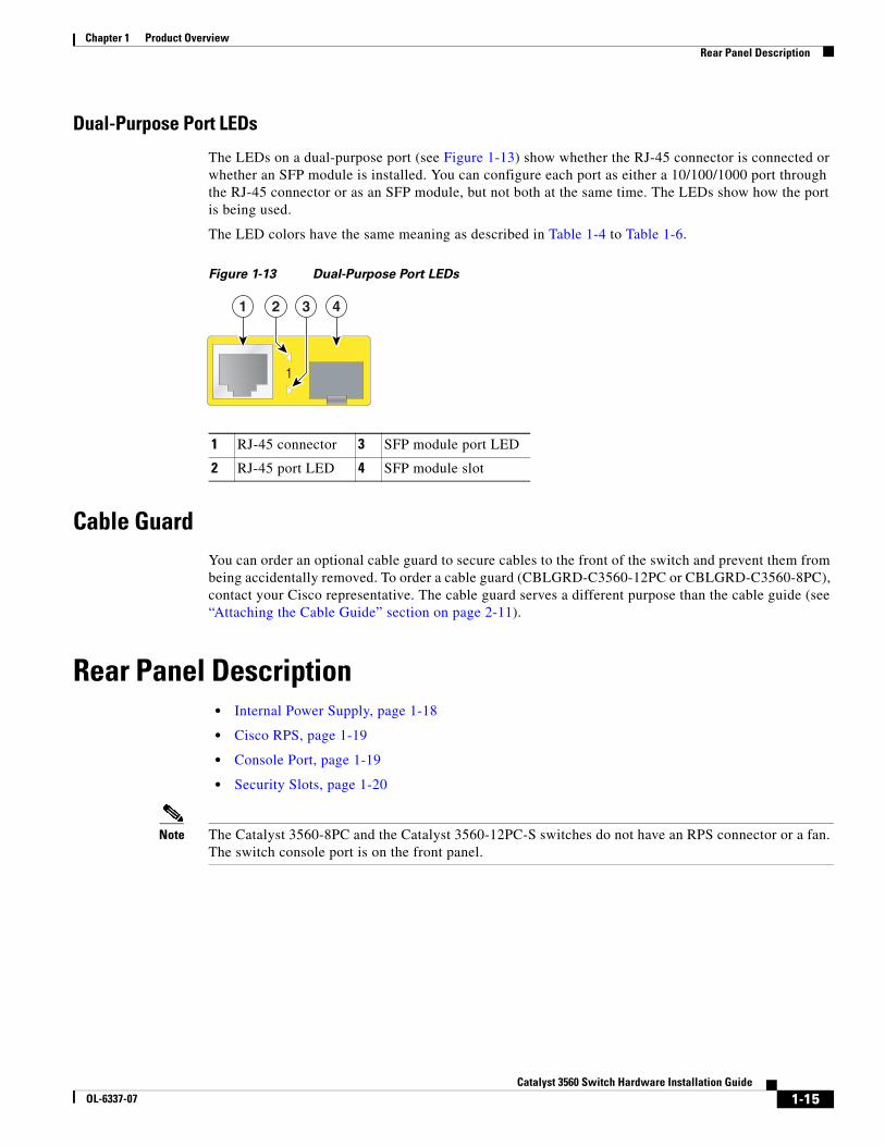
Dual-Purpose Port LEDs
The LEDs on a dual-purpose port (see Figure 1-13) show whether the RJ-45 connector is connected or whether an SFP module is installed. You can configure each port as either a 10/100/1000 port through the RJ-45 connector or as an SFP module, but not both at the same time. The LEDs show how the port is being used.
The LED colors have the same meaning as described in Table 1-4 to Table 1-6.
Figure 1-13 Dual-Purpose Port LEDs
Cable GuardYou can order an optional cable guard to secure cables to the front of the switch and prevent them from being accidentally removed. To order a cable guard (CBLGRD-C3560-12PC or CBLGRD-C3560-8PC), contact your Cisco representative. The cable guard serves a different purpose than the cable guide (see “Attaching the Cable Guide” section on page 2-11).
Rear Panel Description • Internal Power Supply, page 1-18
• Cisco RPS, page 1-19
• Console Port, page 1-19
• Security Slots, page 1-20
Note The Catalyst 3560-8PC and the Catalyst 3560-12PC-S switches do not have an RPS connector or a fan. The switch console port is on the front panel.
1 RJ-45 connector 3 SFP module port LED
2 RJ-45 port LED 4 SFP module slot
1
41 2 3
1-15Catalyst 3560 Switch Hardware Installation Guide
OL-6337-07
Chapter 1 Product OverviewRear Panel Description
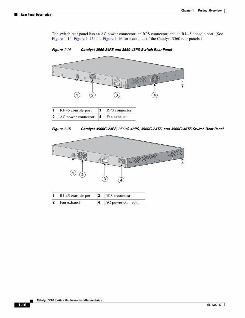
The switch rear panel has an AC power connector, an RPS connector, and an RJ-45 console port. (See Figure 1-14, Figure 1-15, and Figure 1-16 for examples of the Catalyst 3560 rear panels.)
Figure 1-14 Catalyst 3560-24PS and 3560-48PS Switch Rear Panel
Figure 1-15 Catalyst 3560G-24PS, 3560G-48PS, 3560G-24TS, and 3560G-48TS Switch Rear Panel
1 RJ-45 console port 3 RPS connector
2 AC power connector 4 Fan exhaust
RATING100-200V ~5.0A-2.5A, 50-60 HZ
CONSOLE
DC INPUTS FOR REMOTEPOWER SUPPLYSPECIFIED IN MANUAL+12v @7.5A -48 @7.8A
9791
4
1 2 3 4
1 RJ-45 console port 3 RPS connector
2 Fan exhaust 4 AC power connector
CONSOLE
DC INPUTS FOR REMOTEPOWER SUPPLYSPECIFIED IN MANUAL
1196
78
1 23 4
1-16Catalyst 3560 Switch Hardware Installation Guide
OL-6337-07
Chapter 1 Product OverviewRear Panel Description
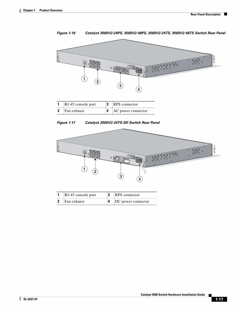
Figure 1-16 Catalyst 3560V2-24PS, 3560V2-48PS, 3560V2-24TS, 3560V2-48TS Switch Rear Panel
Figure 1-17 Catalyst 3560V2-24TS-SD Switch Rear Panel
1 RJ-45 console port 3 RPS connector
2 Fan exhaust 4 AC power connector
2746
70
CONSOLE
12
34
1 RJ-45 console port 3 RPS connector
2 Fan exhaust 4 DC power connector
2746
71
CONSOLE
12
34
1-17Catalyst 3560 Switch Hardware Installation Guide
OL-6337-07
Chapter 1 Product OverviewRear Panel Description
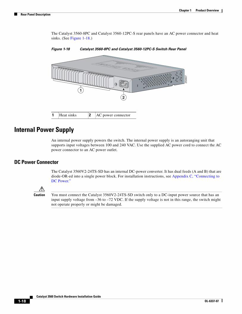
The Catalyst 3560-8PC and Catalyst 3560-12PC-S rear panels have an AC power connector and heat sinks. (See Figure 1-18.)
Figure 1-18 Catalyst 3560-8PC and Catalyst 3560-12PC-S Switch Rear Panel
Internal Power SupplyAn internal power supply powers the switch. The internal power supply is an autoranging unit that supports input voltages between 100 and 240 VAC. Use the supplied AC power cord to connect the AC power connector to an AC power outlet.
DC Power Connector
The Catalyst 3560V2-24TS-SD has an internal DC-power converter. It has dual feeds (A and B) that are diode-OR-ed into a single power block. For installation instructions, see Appendix C, “Connecting to DC Power.”
Caution You must connect the Catalyst 3560V2-24TS-SD switch only to a DC-input power source that has an input supply voltage from –36 to –72 VDC. If the supply voltage is not in this range, the switch might not operate properly or might be damaged.
1 Heat sinks 2 AC power connector
1
2
2506
07
1-18Catalyst 3560 Switch Hardware Installation Guide
OL-6337-07
Chapter 1 Product OverviewRear Panel Description
Cisco RPSDepending on the switch model, you can connect the switch to either of these Cisco redundant power systems (RPS) to provide backup power if the switch power supply fails:
• “Cisco RPS 2300” section on page 1-19
• “Cisco RPS 675” section on page 1-19
Connect the switch and the Cisco RPS to the same AC power source. Use the RPS connector cable supplied with the RPS to connect the RPS to the switch.
Note When an RPS is connected to the Catalyst 3560V2-24TS-SD switch, the switch is not Network Equipment Building Systems (NEBS) compliant.
Note The Catalyst 3560-8PC and Catalyst 3560-12PC-S switches do not have an RPS connector.
For complete information about the Cisco RPS products, including compatibility matrixes listing the supported RPS for each Catalyst 3560 switch, see the RPS documents on Cisco.com:
http://www.cisco.com/en/US/products/ps7148/prod_installation_guides_list.html
Cisco RPS 2300
The Cisco RPS 2300 is a redundant power system that supports six network switches and provides power to one or two failed switches at a time. It automatically senses when the internal power supply of a connected switch fails and provides power to the failed switch, preventing loss of network traffic.
The Cisco RPS 2300 has two output levels: -52 V and 12 V. The maximum output power depends on the installed power-supply modules.
Cisco RPS 675
The Cisco 675 RPS is a redundant power system that supports six network devices and provides power to one failed switch at a time. It automatically senses when the internal power supply of a connected switch fails and provides power to the failed switch, preventing loss of network traffic.
The Cisco RPS 675 has two output levels: –48 V and 12 V. The maximum output power is 675 W.
Console PortYou can connect the switch to a PC by means of the console port and the supplied RJ-45-to-DB-9 female cable. If you want to connect the switch console port to a terminal, you need to provide an RJ-45-to-DB-25 female DTE adapter. You can order a kit (part number ACS-DSBUASYN=) containing that adapter from Cisco. For console port and adapter pinout information, see the “Connector and Cable Specifications” section on page B-1.
1-19Catalyst 3560 Switch Hardware Installation Guide
OL-6337-07
Chapter 1 Product OverviewManagement Options
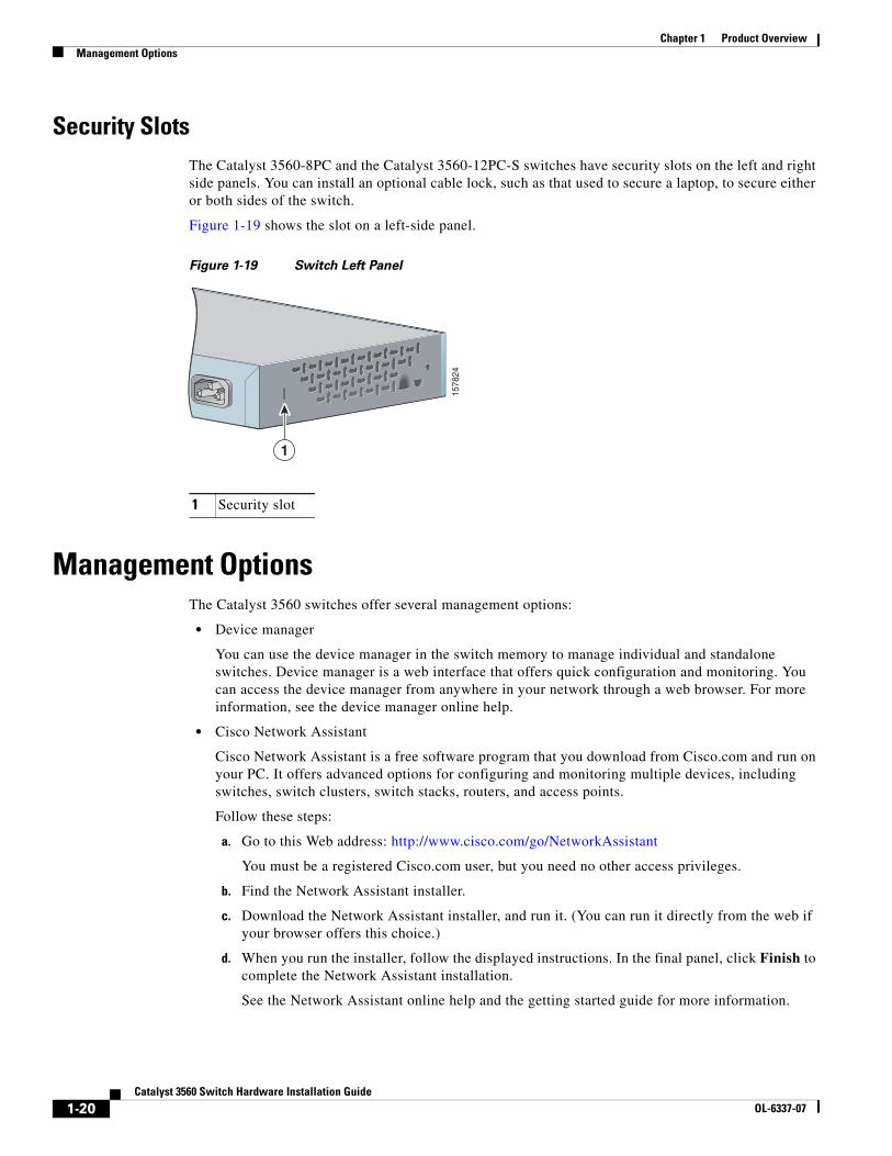
Security SlotsThe Catalyst 3560-8PC and the Catalyst 3560-12PC-S switches have security slots on the left and right side panels. You can install an optional cable lock, such as that used to secure a laptop, to secure either or both sides of the switch.
Figure 1-19 shows the slot on a left-side panel.
Figure 1-19 Switch Left Panel
Management OptionsThe Catalyst 3560 switches offer several management options:
• Device manager
You can use the device manager in the switch memory to manage individual and standalone switches. Device manager is a web interface that offers quick configuration and monitoring. You can access the device manager from anywhere in your network through a web browser. For more information, see the device manager online help.
• Cisco Network Assistant
Cisco Network Assistant is a free software program that you download from Cisco.com and run on your PC. It offers advanced options for configuring and monitoring multiple devices, including switches, switch clusters, switch stacks, routers, and access points.
Follow these steps:
a. Go to this Web address: http://www.cisco.com/go/NetworkAssistant
You must be a registered Cisco.com user, but you need no other access privileges.
b. Find the Network Assistant installer.
c. Download the Network Assistant installer, and run it. (You can run it directly from the web if your browser offers this choice.)
d. When you run the installer, follow the displayed instructions. In the final panel, click Finish to complete the Network Assistant installation.
See the Network Assistant online help and the getting started guide for more information.
1 Security slot
115
7824
1-20Catalyst 3560 Switch Hardware Installation Guide
OL-6337-07
Chapter 1 Product OverviewManagement Options
• Cisco IOS CLI
The switch CLI is based on Cisco IOS software and is enhanced to support desktop-switching features. You can fully configure and monitor the switch and switch cluster members from the CLI. You can access the CLI either by connecting your management station directly to the switch console port or by using Telnet from a remote management station. See the Catalyst 3560 Switch Command Reference on Cisco.com for more information.
For setup instructions that use the CLI, go to Appendix D, “Configuring the Switch with the CLI-Based Setup Program.”
• CiscoView application
The CiscoView device-management application displays the switch image that you can use to set configuration parameters and to view switch status and performance information. The CiscoView application, which you purchase separately, can be a standalone application or part of a Simple Network Management Protocol (SNMP) platform. See the CiscoView documentation for more information.
• SNMP network management
You can manage switches from a SNMP-compatible management station that is running platforms such as HP OpenView or SunNet Manager. The switch supports a comprehensive set of Management Information Base (MIB) extensions and four Remote Monitoring (RMON) groups. See the switch software configuration guide on Cisco.com and the documentation that came with your SNMP application for more information.
Network ConfigurationsSee the switch software configuration guide on Cisco.com for an explanation of network configuration concepts. The software configuration guide also provides examples of network configurations that use the switch to create dedicated network segments that are interconnected through Ethernet connections.
1-21Catalyst 3560 Switch Hardware Installation Guide
OL-6337-07

Chapter 1 Product OverviewManagement Options
1-22Catalyst 3560 Switch Hardware Installation Guide
OL-6337-07
OL-6337-07
C H A P T E R 2
Switch Installation (24- and 48-Port Switches)This chapter describes how to install the Catalyst 3560 24- and 48-port switches, including how to interpret the power-on self-test (POST) that ensures proper operation. It also describes how to make connections to the switch.
For installation information for the Catalyst 3560-8PC and Catalyst 3560 12-PC-S switches, see Chapter 3, “Switch Installation (8- and 12-Port Switches).”
The instructions in this chapter for connecting to the switch ports and for installing, and connecting to the SFP modules apply to all Catalyst 3560 switches.
Read the topics and perform the procedures in this order:
• Preparing for Installation, page 2-1
• Verifying Switch Operation, page 2-6
• Installing the Switch, page 2-7
• Installing and Removing SFP Modules, page 2-15
• Inserting and Removing the SFP Module Patch Cable, page 2-18
• 10/100 or 10/100/1000 Ports, page 2-19
• Connecting the Switch to Compatible Devices, page 2-20
• Where to Go Next, page 2-24
Preparing for Installation • Warnings, page 2-2
• Installation Guidelines, page 2-5
• Box Contents, page 2-6
• Tools and Equipment, page 2-6
2-1Catalyst 3560 Switch Hardware Installation Guide
Chapter 2 Switch Installation (24- and 48-Port Switches)Preparing for Installation
WarningsThese warnings are translated into several languages in the Regulatory Compliance and Safety Information for the Catalyst 3560 Switch.
Warning To prevent the switch from overheating, do not operate it in an area that exceeds the maximum recommended ambient temperature of 113•F (45•C). To prevent airflow restriction, allow at least 3 inches (7.6 cm) of clearance around the ventilation openings. Statement 17B
Warning Before working on equipment that is connected to power lines, remove jewelry (including rings, necklaces, and watches). Metal objects will heat up when connected to power and ground and can cause serious burns or weld the metal object to the terminals. Statement 43
Warning Do not stack the chassis on any other equipment. If the chassis falls, it can cause severe bodily injury and equipment damage. Statement 48
Warning An exposed wire lead from a DC-input power source can conduct harmful levels of electricity. Be sure that no exposed portion of the DC-input power source wire extends from the terminal block plug. Statement 122
Warning Blank faceplates (filler panels) serve three important functions: they prevent exposure to hazardous voltages and currents inside the chassis; they contain electromagnetic interference (EMI) that might disrupt other equipment; and they direct the flow of cooling air through the chassis. Do not operate the system unless all cards and faceplates are in place. Statement 156
Warning Ethernet cables must be shielded when used in a central office environment. Statement 171
Warning If a redundant power system (RPS) is not connected to the switch, install an RPS connector cover on the back of the switch. Statement 265
Warning Attach only the following Cisco RPS model to the RPS receptacle: PWR-RPS2300 / PWR675-AC-RPS-N1 Statement 370
Warning Read the wall-mounting instructions carefully before beginning installation. Failure to use the correct hardware or to follow the correct procedures could result in a hazardous situation to people and damage to the system. Statement 378
2-2Catalyst 3560 Switch Hardware Installation Guide
OL-6337-07

Chapter 2 Switch Installation (24- and 48-Port Switches)Preparing for Installation
Warning Do not work on the system or connect or disconnect cables during periods of lightning activity. Statement 1001
Warning Before performing any of the following procedures, ensure that power is removed from the DC circuit. Statement 1003
Warning Read the installation instructions before connecting the system to the power source. Statement 1004
Warning This product relies on the building’s installation for short-circuit (overcurrent) protection. Ensure that the protective device is rated not greater than: 5 A Statement 1005
Warning Class 1 laser product. Statement 1008
Warning This unit is intended for installation in restricted access areas. A restricted access area can be accessed only through the use of a special tool, lock and key, or other means of security. Statement 1017
Warning The plug-socket combination must be accessible at all times, because it serves as the main disconnecting device. Statement 1019
Warning A readily accessible two-poled disconnect device must be incorporated in the fixed wiring. Statement 1022
Warning To prevent bodily injury when mounting or servicing this unit in a rack, you must take special precautions to ensure that the system remains stable. The following guidelines are provided to ensure your safety:
• This unit should be mounted at the bottom of the rack if it is the only unit in the rack.
• When mounting this unit in a partially filled rack, load the rack from the bottom to the top with the heaviest component at the bottom of the rack.
• If the rack is provided with stabilizing devices, install the stabilizers before mounting or servicing the unit in the rack. Statement 1006
2-3Catalyst 3560 Switch Hardware Installation Guide
OL-6337-07
Chapter 2 Switch Installation (24- and 48-Port Switches)Preparing for Installation
Warning This equipment must be grounded. Never defeat the ground conductor or operate the equipment in the absence of a suitably installed ground conductor. Contact the appropriate electrical inspection authority or an electrician if you are uncertain that suitable grounding is available. Statement 1024
Warning This unit might have more than one power supply connection. All connections must be removed to de-energize the unit. Statement 1028
Warning Only trained and qualified personnel should be allowed to install, replace, or service this equipment. Statement 1030
Warning Ultimate disposal of this product should be handled according to all national laws and regulations. Statement 1040
Warning For connections outside the building where the equipment is installed, the following ports must be connected through an approved network termination unit with integral circuit protection: 10/100/1000 Ethernet. Statement 1044
Warning When installing or replacing the unit, the ground connection must always be made first and disconnected last. Statement 1046
Warning This warning symbol means danger. You are in a situation that could cause bodily injury. Before you work on any equipment, be aware of the hazards involved with electrical circuitry and be familiar with standard practices for preventing accidents. Use the statement number provided at the end of each warning to locate its translation in the translated safety warnings that accompanied this device. Statement 1071
Warning Voltages that present a shock hazard may exist on Power over Ethernet (PoE) circuits if interconnections are made using uninsulated exposed metal contacts, conductors, or terminals. Avoid using such interconnection methods, unless the exposed metal parts are located within a restricted access location and users and service people who are authorized within the restricted access location are made aware of the hazard. A restricted access area can be accessed only through the use of a special tool, lock and key or other means of security. Statement 1072
Warning No user-serviceable parts inside. Do not open. Statement 1073
Warning Installation of the equipment must comply with local and national electrical codes. Statement 1074
2-4Catalyst 3560 Switch Hardware Installation Guide
OL-6337-07
Chapter 2 Switch Installation (24- and 48-Port Switches)Preparing for Installation
Statement 371—Power Cable and AC Adapter
Caution To comply with the Telcordia GR-1089 Network Equipment Building Systems (NEBS) standard for electromagnetic compatibility and safety, connect the ethernet cables only to intrabuilding or nonexposed wiring or cabling.
Caution To comply with the Telcordia GR-1089 NEBS standard, PoE or non-PoE 10/100/1000 Ethernet port cables that exit from either the left side or right side of the switch should be routed and tied to the nearest rack metal hardware.
Note The grounding architecture of this product is DC-isolated (DC-I).
Installation GuidelinesWhen you determine where to place the switch, be sure to observe these requirements:
• The operating environment is within the ranges listed in Appendix A, “Technical Specifications.”
• Airflow around the switch and through the vents is unrestricted.
• Clearance to front and rear panels meets these conditions:
– You can easily read the front-panel indicators.
– Access to ports is sufficient for unrestricted cabling.
– The rear-panel power connector is within reach of an AC power receptacle.
• Temperature around the unit does not exceed 113°F (45°C).
If the switch is installed in a closed or multirack assembly, the temperature around it might be greater than normal room temperature.
• Cabling is away from sources of electrical noise, such as radios, power lines, and fluorescent lighting fixtures. Make sure the cabling is safely away from other devices that might damage the cables.
• For copper Ethernet ports, including 10/100 ports, 10/100/1000 ports, and 1000BASE-T SFP module ports, cable lengths from the switch to connected devices can be up to 328 feet (100 meters).
• The cables meet the specifications in Table B-1 on page B-4, which lists the cable specifications for 1000BASE-X and 100BASE-X SFP modules for the Catalyst 3560 switch. Catalyst 3560 switch SFP ports use both GLC-GE-100XX and GLC-FE-100XX SFP modules.
When you use shorter lengths of single-mode fiber cable, you might need to insert an inline optical attenuator in the link to avoid overloading the receiver.
2-5Catalyst 3560 Switch Hardware Installation Guide
OL-6337-07
Chapter 2 Switch Installation (24- and 48-Port Switches)Verifying Switch Operation
When the fiber-optic cable span is less than 15.43 miles (25 km), you should insert a 5-decibel (dB) or 10-dB inline optical attenuator between the fiber-optic cable plant and the receiving port on the 1000BASE-ZX SFP module at each end of the link.
• Cisco Ethernet Switches are equipped with cooling mechanisms, such as fans and blowers. However, these fans and blowers can draw dust and other particles, causing contaminant buildup inside the chassis, which can result in a system malfunction.
You must install this equipment in an environment as free as possible from dust and foreign conductive material (such as metal flakes from construction activities).
These standards provide guidelines for acceptable working environments and acceptable levels of suspended particulate matter:
– Network Equipment Building Systems (NEBS) GR-63-CORE
– National Electrical Manufacturers Association (NEMA) Type 1
– International Electrotechnical Commission (IEC) IP-20
This applies to all Cisco Ethernet switches except for this compact model:
– Catalyst 3560-8PC switch—8 10/100 PoE ports and 1 dual-purpose port (one 10/100/1000BASE-T copper port and one SFP module slot)
Box ContentsThe switch getting started guide on Cisco.com describes the box contents. If any item is missing or damaged, contact your Cisco representative or reseller for support.
Tools and EquipmentYou need to supply a number-2 Phillips screwdriver to rack-mount the switch.
Verifying Switch OperationBefore you install the switch in a rack, on a wall, or on a table or shelf, you should power the switch and verify that the switch passes POST. See Section 3, “Running Express Setup,” in the getting started guide for the steps required to connect a PC to the switch and to run Express Setup.
If your configuration has an RPS, connect the switch and the RPS to the same AC power source. See the “Cisco RPS” section on page 1-19, and see the Cisco RPS documentation for more information.
Note When you connect the RPS to the switch, put the RPS in standby mode. Set the RPS to active mode during normal operation.
To power on the switch, connect one end of the AC power cord to the AC power connector on the switch, and connect the other end of the power cord to an AC power outlet.
Warning Attach only the following Cisco RPS model to the RPS receptacle: PWR-RPS2300, PWR675-AC-RPS-N1=. Statement 370
2-6Catalyst 3560 Switch Hardware Installation Guide
OL-6337-07
Chapter 2 Switch Installation (24- and 48-Port Switches)Installing the Switch
As the switch powers on, it begins the POST, a series of tests that runs automatically to ensure that the switch functions properly. LEDs can blink during the test. POST lasts approximately 1 minute. When the switch begins POST, the System, RPS, Status, Duplex, and Speed LEDs turn green. The System LED blinks green, and the other LEDs remain solid green.
When the POST completes successfully, the System LED remains green. The RPS LED remains green for some time and then reflects the switch operating status. The other LEDs turn off and then reflect the switch operating status. If a switch fails POST, the System LED turns amber.
POST failures are usually fatal. Call Cisco technical support representative if your switch fails POST.
Powering Off the SwitchAfter a successful POST, disconnect the power cord from the switch. Install the switch in a rack, on a wall, on a table, or on a shelf as described in the “Installing the Switch” section on page 2-7.
Installing the Switch • Rack-Mounting, page 2-7
• Wall-Mounting, page 2-12
• Table- or Shelf- Mounting, page 2-15
Rack-Mounting • Removing Screws from the Switch, page 2-8
• Attaching Brackets to the Catalyst 3560 Switch, page 2-8
• Mounting the Switch in a Rack, page 2-10
• Attaching the Cable Guide, page 2-11
Installing the switch in a 24-inch rack requires an optional bracket kit that contains the 24-inch rack-mounting brackets and hardware (RCKMNT-1RU=).
Warning To prevent bodily injury when mounting or servicing this unit in a rack, you must take special precautions to ensure that the system remains stable. The following guidelines are provided to ensure your safety:
• This unit should be mounted at the bottom of the rack if it is the only unit in the rack.
• When mounting this unit in a partially filled rack, load the rack from the bottom to the top with the heaviest component at the bottom of the rack.
• If the rack is provided with stabilizing devices, install the stabilizers before mounting or servicing the unit in the rack. Statement 1006
2-7Catalyst 3560 Switch Hardware Installation Guide
OL-6337-07
Chapter 2 Switch Installation (24- and 48-Port Switches)Installing the Switch
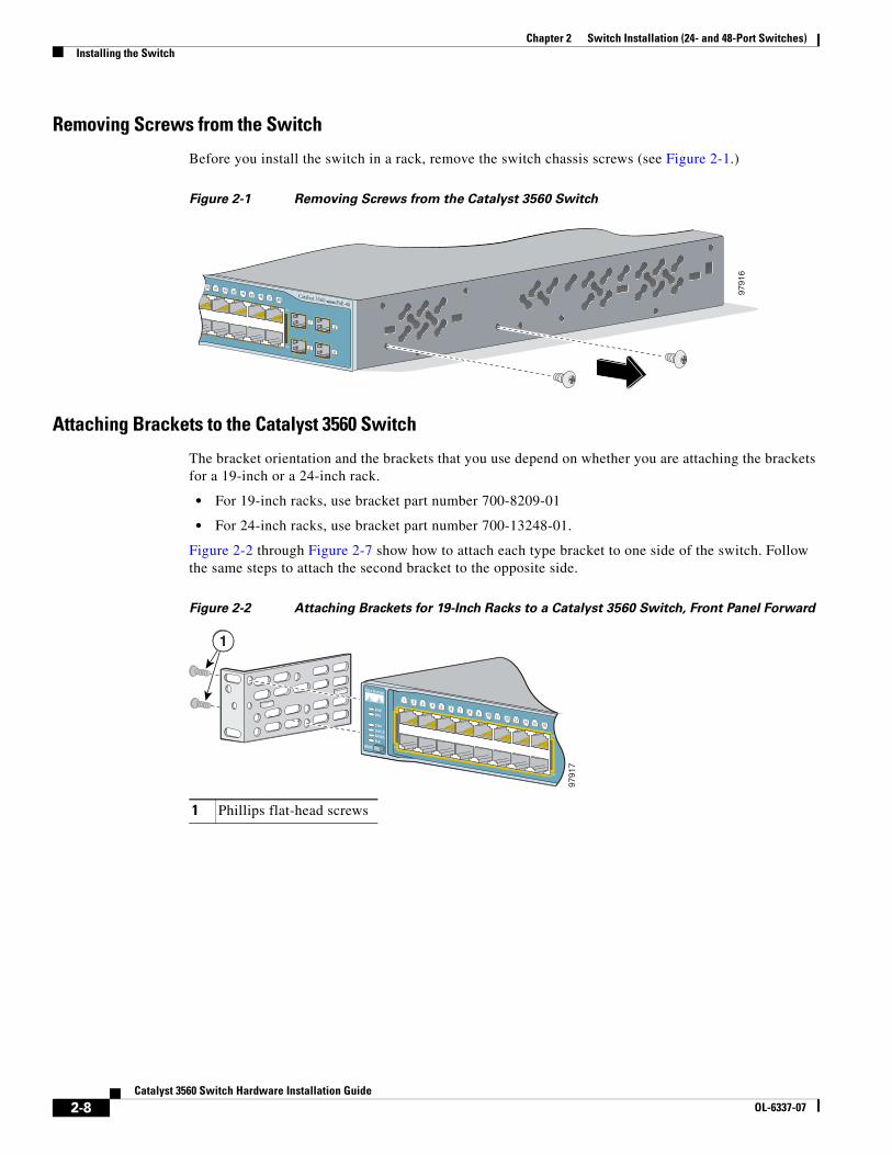
Removing Screws from the Switch
Before you install the switch in a rack, remove the switch chassis screws (see Figure 2-1.)
Figure 2-1 Removing Screws from the Catalyst 3560 Switch
Attaching Brackets to the Catalyst 3560 Switch
The bracket orientation and the brackets that you use depend on whether you are attaching the brackets for a 19-inch or a 24-inch rack.
• For 19-inch racks, use bracket part number 700-8209-01
• For 24-inch racks, use bracket part number 700-13248-01.
Figure 2-2 through Figure 2-7 show how to attach each type bracket to one side of the switch. Follow the same steps to attach the second bracket to the opposite side.
Figure 2-2 Attaching Brackets for 19-Inch Racks to a Catalyst 3560 Switch, Front Panel Forward
40 41 42 43 44 45 46 47 48
47X
48X
9791
6
Catalyst 3560 SERIES PoE-48
1
2
3
4
1 Phillips flat-head screws
1
SYSTRPS
STATDUPLXSPEEDPoE
MODE
1 25 6 7 8 9 10 11 12 13 14 15 16
3 41X
2X
15X
16X
9791
7
2-8Catalyst 3560 Switch Hardware Installation Guide
OL-6337-07
Chapter 2 Switch Installation (24- and 48-Port Switches)Installing the Switch
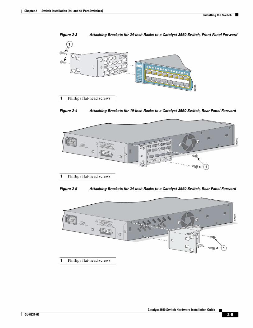
Figure 2-3 Attaching Brackets for 24-Inch Racks to a Catalyst 3560 Switch, Front Panel Forward
Figure 2-4 Attaching Brackets for 19-Inch Racks to a Catalyst 3560 Switch, Rear Panel Forward
Figure 2-5 Attaching Brackets for 24-Inch Racks to a Catalyst 3560 Switch, Rear Panel Forward
1 Phillips flat-head screws
SYSTRPS
STATDUPLXSPEEDPoE
MODE
1 25 6 7 8 9 10 11 12 13 14 15 16
3 41X
2X
15X
16X
9791
8
1
1 Phillips flat-head screws
RATING100-200V ~5.0A-2.5A, 50-60 HZ
DC INPUTS FOR REMOTEPOWER SUPPLYSPECIFIED IN MANUAL+12v @7.5A -48 @7.8A
9791
9
1
1 Phillips flat-head screws
RATING100-200V ~5.0A-2.5A, 50-60 HZ
DC INPUTS FOR REMOTEPOWER SUPPLYSPECIFIED IN MANUAL+12v @7.5A -48 @7.8A
9792
0
1
2-9Catalyst 3560 Switch Hardware Installation Guide
OL-6337-07

Chapter 2 Switch Installation (24- and 48-Port Switches)Installing the Switch
Figure 2-6 Attaching Brackets for 19-Inch Telco Racks to a Catalyst 3560 Switch
Figure 2-7 Attaching Brackets for 24-Inch Telco Racks to a Catalyst 3560 Switch
Mounting the Switch in a Rack
After the brackets are attached to the switch, use the four supplied number-12 Phillips machine screws to securely attach the brackets to the rack, as shown in Figure 2-8.
Figure 2-8 Mounting the Catalyst 3560 Switch in a Rack
1 Phillips flat-head screws
40 41 42 43 44 45 46 47 48
47X
48X
9792
1
Catalyst 3560 SERIES PoE-48
1
2
3
4
1
1 Phillips flat-head screws
40 41 42 43 44 45 46 47 48
47X
48X
9792
2
Catalyst 3560 SERIES PoE-48
1
2
3
41
1 Phillips machine screws
Catalyst 3560 SERIES PoE-48
SYSTRPS
STATDUPLXSPEEDPoE
MODE
1
2
3
4
1 25 6 7 8 9 10 11 12 13 14 15 16
3 41X
2X
15X
16X
17 1821 22 23 24 25 26 27 28 29 30 31 32
19 2017X
18X
31X
32X
33 3437 38 39 40 41 42 43 44 45 46 47 48
35 3633X
34X
47X
48X
9792
31
2-10Catalyst 3560 Switch Hardware Installation Guide
OL-6337-07
Chapter 2 Switch Installation (24- and 48-Port Switches)Installing the Switch
After the switch is mounted in the rack:
1. Power on the switch. See the “Verifying Switch Operation” section on page 2-6.
2. Connect to a 10/100 or 10/100/1000 port, and run Express Setup. See the Catalyst 3560 Switch Getting Started Guide for instructions. To use the CLI setup program, see Appendix D, “Configuring the Switch with the CLI-Based Setup Program.”
3. Connect to the front-panel ports.
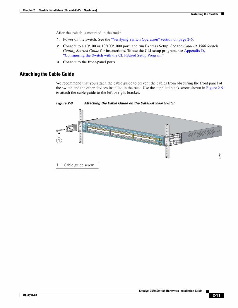
Attaching the Cable Guide
We recommend that you attach the cable guide to prevent the cables from obscuring the front panel of the switch and the other devices installed in the rack. Use the supplied black screw shown in Figure 2-9 to attach the cable guide to the left or right bracket.
Figure 2-9 Attaching the Cable Guide on the Catalyst 3560 Switch
1 Cable guide screw
Catalyst 3560 SERIES PoE-48
SYSTRPS
STATDUPLXSPEEDPoE
MODE
1
2
3
4
1 25 6 7 8 9 10 11 12 13 14 15 16
3 41X
2X
15X
16X
17 1821 22 23 24 25 26 27 28 29 30 31 32
19 2017X
18X
31X
32X
33 3437 38 39 40 41 42 43 44 45 46 47 48
35 3633X
34X
47X
48X
1
9792
4
2-11Catalyst 3560 Switch Hardware Installation Guide
OL-6337-07
Chapter 2 Switch Installation (24- and 48-Port Switches)Installing the Switch
Wall-MountingThese switches wall-mount only with the front panel facing up:
• Catalyst 3560-24PS, 3560-24TS-S, 3560-48PS, and 3560-48TS-S
• Catalyst 3560G-24PS, 3560G-24TS, 3560G-48PS, and 3560G-48TS
These switches wall-mount with the front panel facing up or down:
• Catalyst 3560V2-24PS, 3560V2-24TS, 3560V2-48PS, and 3560V2-48TS
The illustrations in this section show the Catalyst 3560G-48PS switch as an example.
Caution You must install the RPS connector cover before wall-mounting the switch.
Warning Read the wall-mounting instructions carefully before beginning installation. Failure to use the correct hardware or to follow the correct procedures could result in a hazardous situation to people and damage to the system. Statement 378
To install the switch on a wall, follow the instructions in these procedures:
• Attaching the Brackets to the Switch for Wall Mounting, page 2-12
• Attaching the RPS Connector Cover, page 2-13
• Mounting the Switch on a Wall, page 2-14
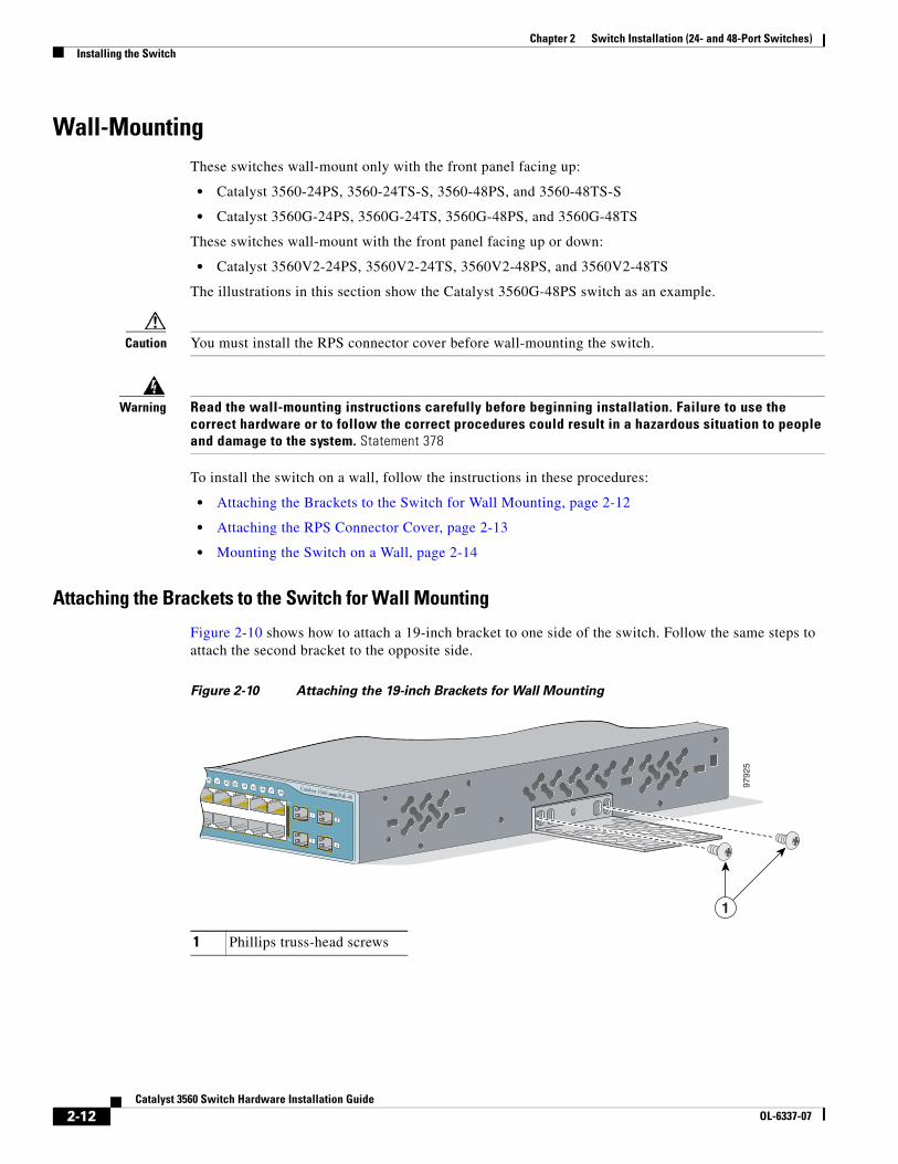
Attaching the Brackets to the Switch for Wall Mounting
Figure 2-10 shows how to attach a 19-inch bracket to one side of the switch. Follow the same steps to attach the second bracket to the opposite side.
Figure 2-10 Attaching the 19-inch Brackets for Wall Mounting
1 Phillips truss-head screws
40 41 42 43 44 45 46 47 48
47X
48X
9792
5
Catalyst 3560 SERIES PoE-48
1
2
3
4
1
2-12Catalyst 3560 Switch Hardware Installation Guide
OL-6337-07
Chapter 2 Switch Installation (24- and 48-Port Switches)Installing the Switch
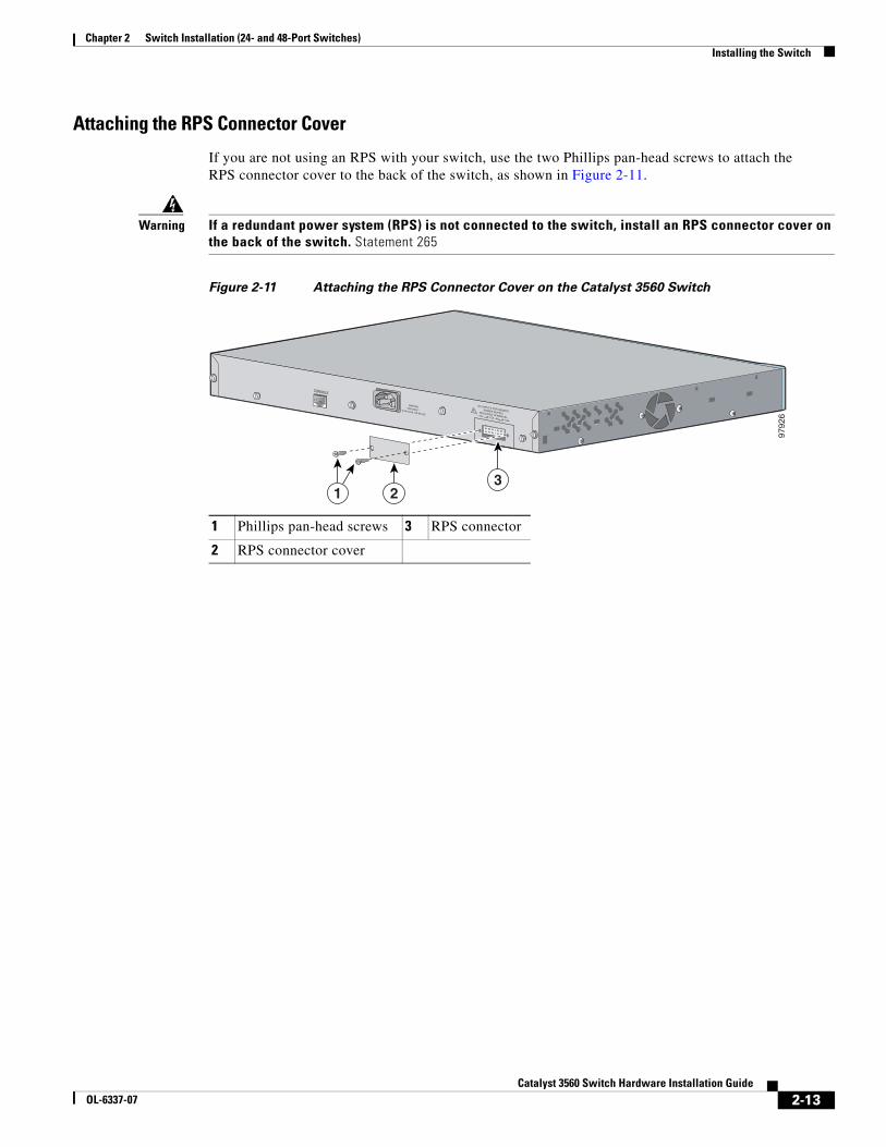
Attaching the RPS Connector Cover
If you are not using an RPS with your switch, use the two Phillips pan-head screws to attach the RPS connector cover to the back of the switch, as shown in Figure 2-11.
Warning If a redundant power system (RPS) is not connected to the switch, install an RPS connector cover on the back of the switch. Statement 265
Figure 2-11 Attaching the RPS Connector Cover on the Catalyst 3560 Switch
1 Phillips pan-head screws 3 RPS connector
2 RPS connector cover
9792
6
RATING100-200V ~5.0A-2.5A, 50-60 HZ
CONSOLE
DC INPUTS FOR REMOTEPOWER SUPPLYSPECIFIED IN MANUAL+12v @7.5A -48 @7.8A
23
1
2-13Catalyst 3560 Switch Hardware Installation Guide
OL-6337-07
Chapter 2 Switch Installation (24- and 48-Port Switches)Installing the Switch
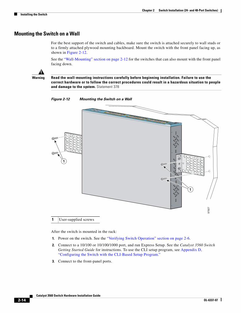
Mounting the Switch on a Wall
For the best support of the switch and cables, make sure the switch is attached securely to wall studs or to a firmly attached plywood mounting backboard. Mount the switch with the front panel facing up, as shown in Figure 2-12.
See the “Wall-Mounting” section on page 2-12 for the switches that can also mount with the front panel facing down.
Warning Read the wall-mounting instructions carefully before beginning installation. Failure to use the correct hardware or to follow the correct procedures could result in a hazardous situation to people and damage to the system. Statement 378
Figure 2-12 Mounting the Switch on a Wall
After the switch is mounted in the rack:
1. Power on the switch. See the “Verifying Switch Operation” section on page 2-6.
2. Connect to a 10/100 or 10/100/1000 port, and run Express Setup. See the Catalyst 3560 Switch Getting Started Guide for instructions. To use the CLI setup program, see Appendix D, “Configuring the Switch with the CLI-Based Setup Program.”
3. Connect to the front-panel ports.
1 User-supplied screws
9792
7
Catalyst 3750 SERIES
13X
14X
SYST RPS MASTR STAT DUPLX SPEED STACKMODE
2X
2X
2X
1
1
2-14Catalyst 3560 Switch Hardware Installation Guide
OL-6337-07
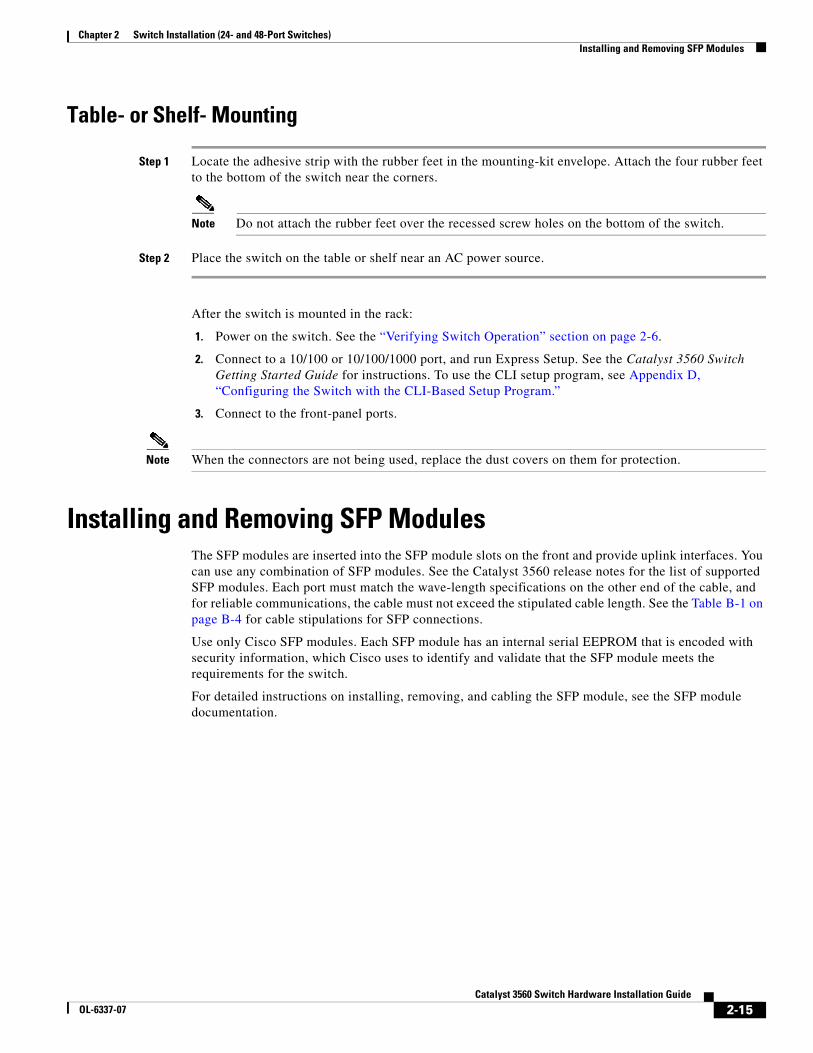
Chapter 2 Switch Installation (24- and 48-Port Switches)Installing and Removing SFP Modules
Table- or Shelf- Mounting
Step 1 Locate the adhesive strip with the rubber feet in the mounting-kit envelope. Attach the four rubber feet to the bottom of the switch near the corners.
Note Do not attach the rubber feet over the recessed screw holes on the bottom of the switch.
Step 2 Place the switch on the table or shelf near an AC power source.
After the switch is mounted in the rack:
1. Power on the switch. See the “Verifying Switch Operation” section on page 2-6.
2. Connect to a 10/100 or 10/100/1000 port, and run Express Setup. See the Catalyst 3560 Switch Getting Started Guide for instructions. To use the CLI setup program, see Appendix D, “Configuring the Switch with the CLI-Based Setup Program.”
3. Connect to the front-panel ports.
Note When the connectors are not being used, replace the dust covers on them for protection.
Installing and Removing SFP ModulesThe SFP modules are inserted into the SFP module slots on the front and provide uplink interfaces. You can use any combination of SFP modules. See the Catalyst 3560 release notes for the list of supported SFP modules. Each port must match the wave-length specifications on the other end of the cable, and for reliable communications, the cable must not exceed the stipulated cable length. See the Table B-1 on page B-4 for cable stipulations for SFP connections.
Use only Cisco SFP modules. Each SFP module has an internal serial EEPROM that is encoded with security information, which Cisco uses to identify and validate that the SFP module meets the requirements for the switch.
For detailed instructions on installing, removing, and cabling the SFP module, see the SFP module documentation.
2-15Catalyst 3560 Switch Hardware Installation Guide
OL-6337-07
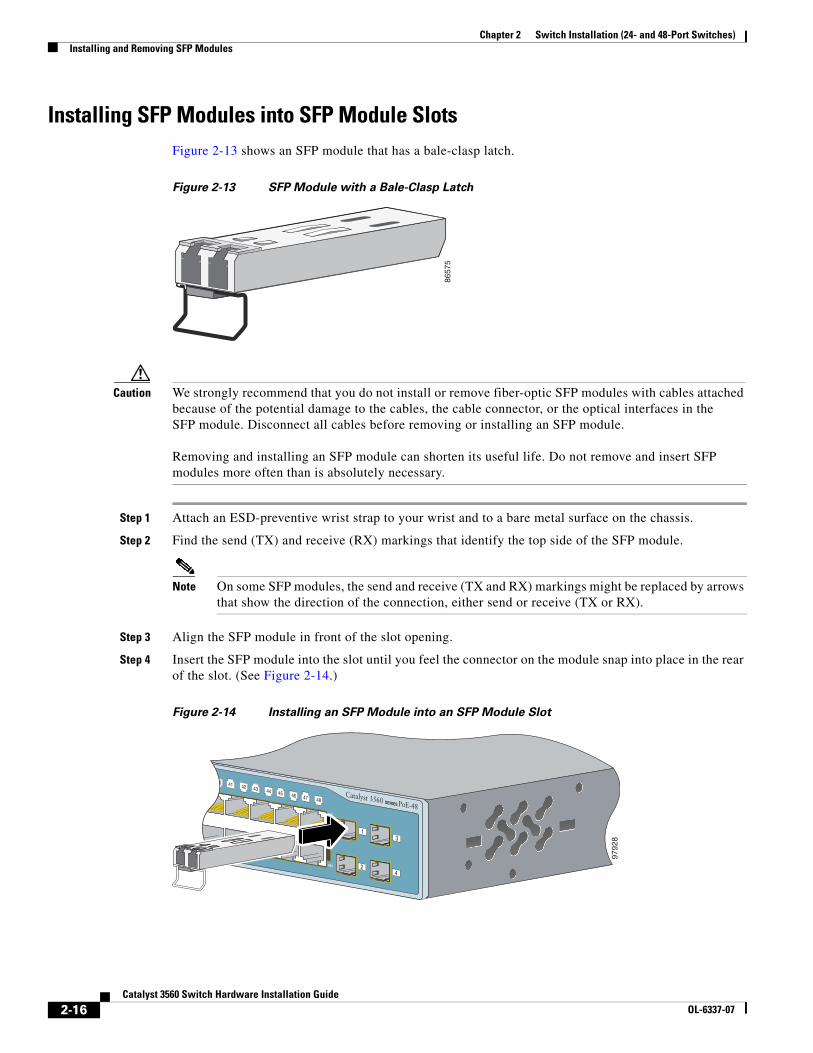
Chapter 2 Switch Installation (24- and 48-Port Switches)Installing and Removing SFP Modules
Installing SFP Modules into SFP Module SlotsFigure 2-13 shows an SFP module that has a bale-clasp latch.
Figure 2-13 SFP Module with a Bale-Clasp Latch
Caution We strongly recommend that you do not install or remove fiber-optic SFP modules with cables attached because of the potential damage to the cables, the cable connector, or the optical interfaces in the SFP module. Disconnect all cables before removing or installing an SFP module. Removing and installing an SFP module can shorten its useful life. Do not remove and insert SFP modules more often than is absolutely necessary.
Step 1 Attach an ESD-preventive wrist strap to your wrist and to a bare metal surface on the chassis.
Step 2 Find the send (TX) and receive (RX) markings that identify the top side of the SFP module.
Note On some SFP modules, the send and receive (TX and RX) markings might be replaced by arrows that show the direction of the connection, either send or receive (TX or RX).
Step 3 Align the SFP module in front of the slot opening.
Step 4 Insert the SFP module into the slot until you feel the connector on the module snap into place in the rear of the slot. (See Figure 2-14.)
Figure 2-14 Installing an SFP Module into an SFP Module Slot
8657
5
40 41 42 43 44 45 46 47 48
47X
48X
Catalyst 3560 SERIES PoE-48
1
2
3
4
9792
8
2-16Catalyst 3560 Switch Hardware Installation Guide
OL-6337-07
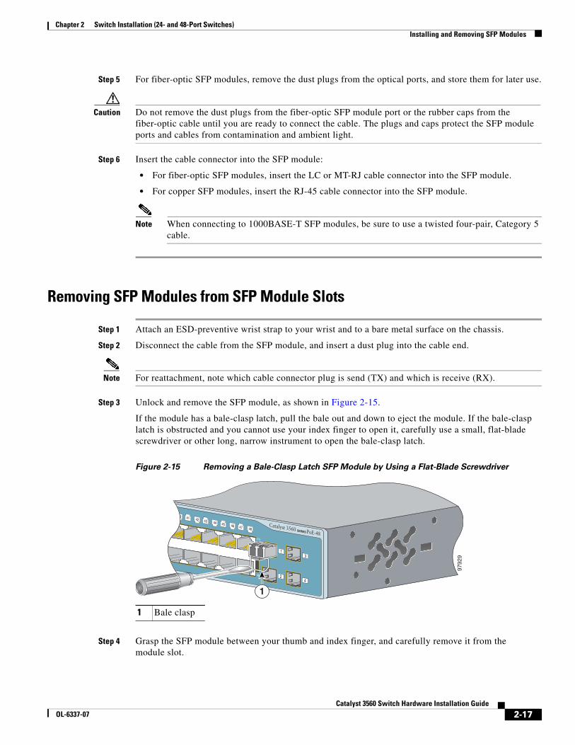
Chapter 2 Switch Installation (24- and 48-Port Switches)Installing and Removing SFP Modules
Step 5 For fiber-optic SFP modules, remove the dust plugs from the optical ports, and store them for later use.
Caution Do not remove the dust plugs from the fiber-optic SFP module port or the rubber caps from the fiber-optic cable until you are ready to connect the cable. The plugs and caps protect the SFP module ports and cables from contamination and ambient light.
Step 6 Insert the cable connector into the SFP module:
• For fiber-optic SFP modules, insert the LC or MT-RJ cable connector into the SFP module.
• For copper SFP modules, insert the RJ-45 cable connector into the SFP module.
Note When connecting to 1000BASE-T SFP modules, be sure to use a twisted four-pair, Category 5 cable.
Removing SFP Modules from SFP Module Slots
Step 1 Attach an ESD-preventive wrist strap to your wrist and to a bare metal surface on the chassis.
Step 2 Disconnect the cable from the SFP module, and insert a dust plug into the cable end.
Note For reattachment, note which cable connector plug is send (TX) and which is receive (RX).
Step 3 Unlock and remove the SFP module, as shown in Figure 2-15.
If the module has a bale-clasp latch, pull the bale out and down to eject the module. If the bale-clasp latch is obstructed and you cannot use your index finger to open it, carefully use a small, flat-blade screwdriver or other long, narrow instrument to open the bale-clasp latch.
Figure 2-15 Removing a Bale-Clasp Latch SFP Module by Using a Flat-Blade Screwdriver
Step 4 Grasp the SFP module between your thumb and index finger, and carefully remove it from the module slot.
1 Bale clasp
40 41 42 43 44 45 46 47 48
47X
48X
Catalyst 3560 SERIES PoE-48
1
2
3
4
9792
9
1
2-17Catalyst 3560 Switch Hardware Installation Guide
OL-6337-07
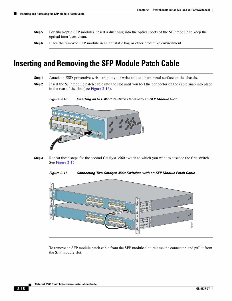
Chapter 2 Switch Installation (24- and 48-Port Switches)Inserting and Removing the SFP Module Patch Cable
Step 5 For fiber-optic SFP modules, insert a dust plug into the optical ports of the SFP module to keep the optical interfaces clean.
Step 6 Place the removed SFP module in an antistatic bag or other protective environment.
Inserting and Removing the SFP Module Patch Cable
Step 1 Attach an ESD-preventive wrist strap to your wrist and to a bare metal surface on the chassis.
Step 2 Insert the SFP module patch cable into the slot until you feel the connector on the cable snap into place in the rear of the slot (see Figure 2-16).
Figure 2-16 Inserting an SFP Module Patch Cable into an SFP Module Slot
Step 3 Repeat these steps for the second Catalyst 3560 switch to which you want to cascade the first switch. See Figure 2-17.
Figure 2-17 Connecting Two Catalyst 3560 Switches with an SFP Module Patch Cable
To remove an SFP module patch cable from the SFP module slot, release the connector, and pull it from the SFP module slot.
1268
10
Catalyst 3560 SERIES
1415 16
17 1819 20
21 2223 24
13
13X
14X
23X
24X 12
Catalyst 3560 SERIES
MODE
1 23 4
5 67 8
9 1011 12
1415 16
17 1819 20
21 2223 24
13
1X
2X
11X
12X
13X
14X
23X
24X
RPS
STATDUPLXSPEED
SYST
12 12
6811
Catalyst 3560 SERIES
MODE
1 23 4
5 67 8
9 1011 12
1415 16
17 1819 20
21 2223 24
13
1X
2X
11X
12X
13X
14X
23X
24X
RPS
STATDUPLXSPEED
SYST
12
2-18Catalyst 3560 Switch Hardware Installation Guide
OL-6337-07
Chapter 2 Switch Installation (24- and 48-Port Switches)10/100 or 10/100/1000 Ports
10/100 or 10/100/1000 PortsThe switch 10/100 and 10/100/1000 ports configure themselves to operate at the speed of attached devices. If the attached ports do not support autonegotiation, you can explicitly set the speed and duplex parameters. Connecting devices that do not autonegotiate or that have their speed and duplex parameters manually set can reduce performance or result in no linkage.
Note You can configure duplex mode to half, full, or autonegotiate on Gigabit Ethernet interfaces if the speed is set to 10 or 100 Mb/s. You cannot configure half-duplex mode on Gigabit Ethernet interfaces if the interface speed is 1000 Mb/s.
Warning Voltages that present a shock hazard may exist on Power over Ethernet (PoE) circuits if interconnections are made using uninsulated exposed metal contacts, conductors, or terminals. Avoid using such interconnection methods, unless the exposed metal parts are located within a restricted access location and users and service people who are authorized within the restricted access location are made aware of the hazard. A restricted access area can be accessed only through the use of a special tool, lock and key or other means of security. Statement 1072
To maximize performance, choose one of these methods for configuring the Ethernet ports:
• Let the ports autonegotiate both speed and duplex.
• Set the port speed and duplex parameters on both ends of the connection.
You can configure the 10/100 or 10/100/1000 ports on the Catalyst 3560 PoE switches either to automatically provide PoE if a Cisco IP Phone, Cisco Aironet Access Point, or end device compliant with IEEE 802.3af is connected or to never provide PoE, even if an IP phone or an access point is connected. The default setting is Auto. To prevent electrostatic-discharge (ESD) damage, follow your normal board and component handling procedures.
Caution PoE faults are caused when noncompliant cabling or powered devices are connected to a PoE port. Only standard-compliant cabling can be used to connect Cisco prestandard IP Phones or wireless access points or IEEE 802.3af-compliant devices to PoE ports. You must remove a cable or device that causes a PoE fault from the network.
You can use the mdix auto interface configuration command in the CLI to enable the automatic medium-dependent interface crossover (auto-MDIX) feature. When the auto-MDIX feature is enabled, the switch detects the required cable type for copper Ethernet connections and configures the interfaces accordingly. Therefore, you can use either a crossover or a straight-through cable for connections to a copper 10/100, 10/100/1000, or 1000BASE-T SFP module port on the switch, regardless of the type of device on the other end of the connection.
The auto-MDIX feature is enabled by default on switches running Cisco IOS Release 12.2(18)SE or later. For releases between Cisco IOS Release 12.1(14)EA1 and 12.2(18)SE, the auto-MDIX feature is disabled by default. For configuration information for this feature, see the switch software configuration guide or the switch command reference.
2-19Catalyst 3560 Switch Hardware Installation Guide
OL-6337-07
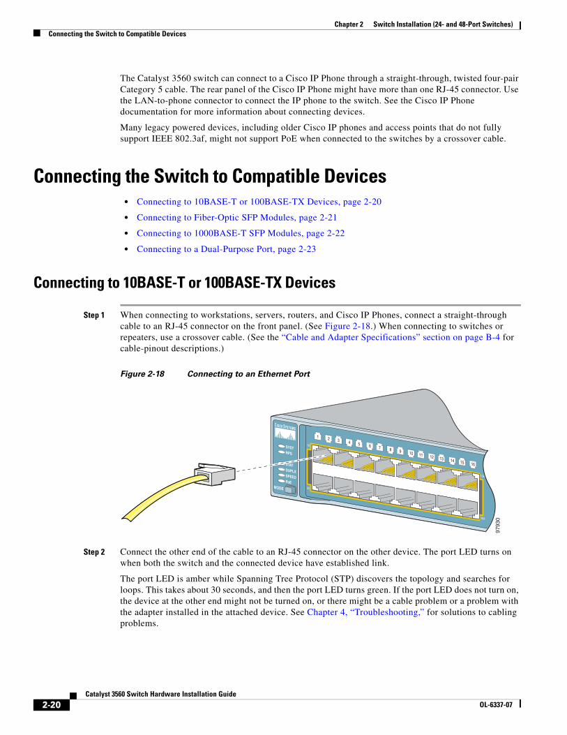
Chapter 2 Switch Installation (24- and 48-Port Switches)Connecting the Switch to Compatible Devices
The Catalyst 3560 switch can connect to a Cisco IP Phone through a straight-through, twisted four-pair Category 5 cable. The rear panel of the Cisco IP Phone might have more than one RJ-45 connector. Use the LAN-to-phone connector to connect the IP phone to the switch. See the Cisco IP Phone documentation for more information about connecting devices.
Many legacy powered devices, including older Cisco IP phones and access points that do not fully support IEEE 802.3af, might not support PoE when connected to the switches by a crossover cable.
Connecting the Switch to Compatible Devices • Connecting to 10BASE-T or 100BASE-TX Devices, page 2-20
• Connecting to Fiber-Optic SFP Modules, page 2-21
• Connecting to 1000BASE-T SFP Modules, page 2-22
• Connecting to a Dual-Purpose Port, page 2-23
Connecting to 10BASE-T or 100BASE-TX Devices
Step 1 When connecting to workstations, servers, routers, and Cisco IP Phones, connect a straight-through cable to an RJ-45 connector on the front panel. (See Figure 2-18.) When connecting to switches or repeaters, use a crossover cable. (See the “Cable and Adapter Specifications” section on page B-4 for cable-pinout descriptions.)
Figure 2-18 Connecting to an Ethernet Port
Step 2 Connect the other end of the cable to an RJ-45 connector on the other device. The port LED turns on when both the switch and the connected device have established link.
The port LED is amber while Spanning Tree Protocol (STP) discovers the topology and searches for loops. This takes about 30 seconds, and then the port LED turns green. If the port LED does not turn on, the device at the other end might not be turned on, or there might be a cable problem or a problem with the adapter installed in the attached device. See Chapter 4, “Troubleshooting,” for solutions to cabling problems.
SYSTRPS
STATDUPLXSPEEDPoE
MODE
1 25 6 7 8 9 10 11 12 13 14 15 16
3 41X
2X
15X
16X
9793
0
2-20Catalyst 3560 Switch Hardware Installation Guide
OL-6337-07
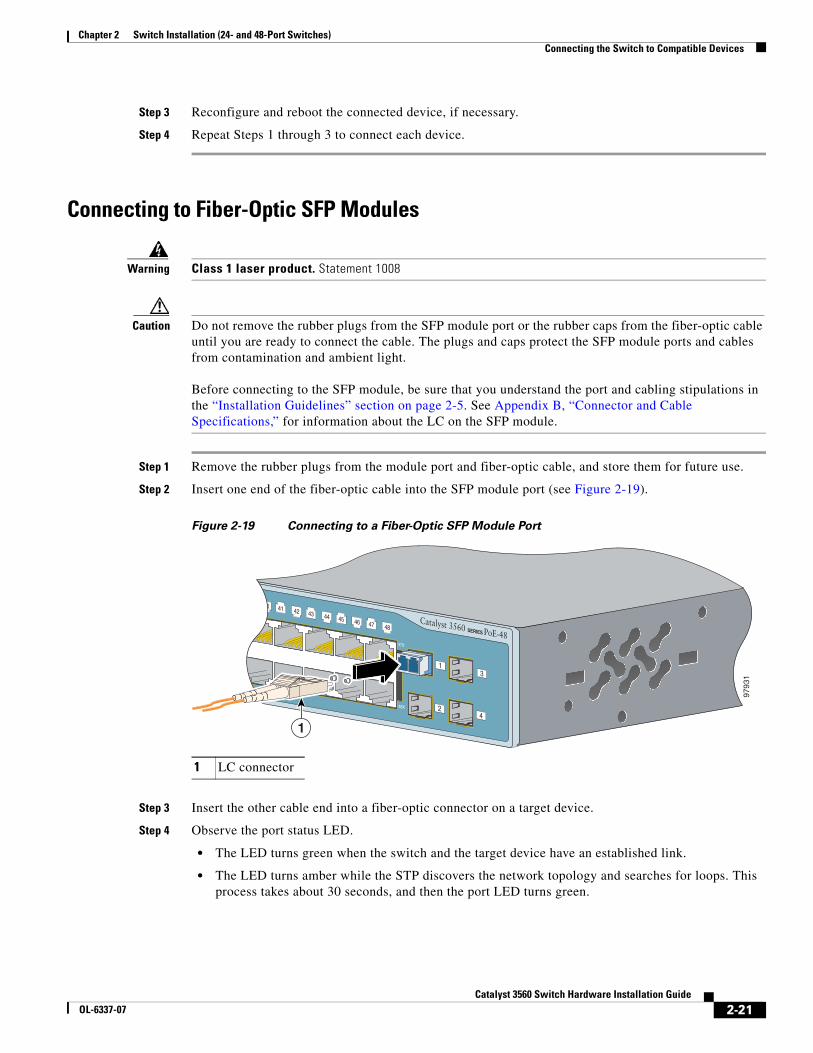
Chapter 2 Switch Installation (24- and 48-Port Switches)Connecting the Switch to Compatible Devices
Step 3 Reconfigure and reboot the connected device, if necessary.
Step 4 Repeat Steps 1 through 3 to connect each device.
Connecting to Fiber-Optic SFP Modules
Warning Class 1 laser product. Statement 1008
Caution Do not remove the rubber plugs from the SFP module port or the rubber caps from the fiber-optic cable until you are ready to connect the cable. The plugs and caps protect the SFP module ports and cables from contamination and ambient light. Before connecting to the SFP module, be sure that you understand the port and cabling stipulations in the “Installation Guidelines” section on page 2-5. See Appendix B, “Connector and Cable Specifications,” for information about the LC on the SFP module.
Step 1 Remove the rubber plugs from the module port and fiber-optic cable, and store them for future use.
Step 2 Insert one end of the fiber-optic cable into the SFP module port (see Figure 2-19).
Figure 2-19 Connecting to a Fiber-Optic SFP Module Port
Step 3 Insert the other cable end into a fiber-optic connector on a target device.
Step 4 Observe the port status LED.
• The LED turns green when the switch and the target device have an established link.
• The LED turns amber while the STP discovers the network topology and searches for loops. This process takes about 30 seconds, and then the port LED turns green.
1 LC connector
40 41 42 43 44 45 46 47 48
47X
48X
Catalyst 3560 SERIES PoE-48
1
2
3
4
9793
1
1
2-21Catalyst 3560 Switch Hardware Installation Guide
OL-6337-07
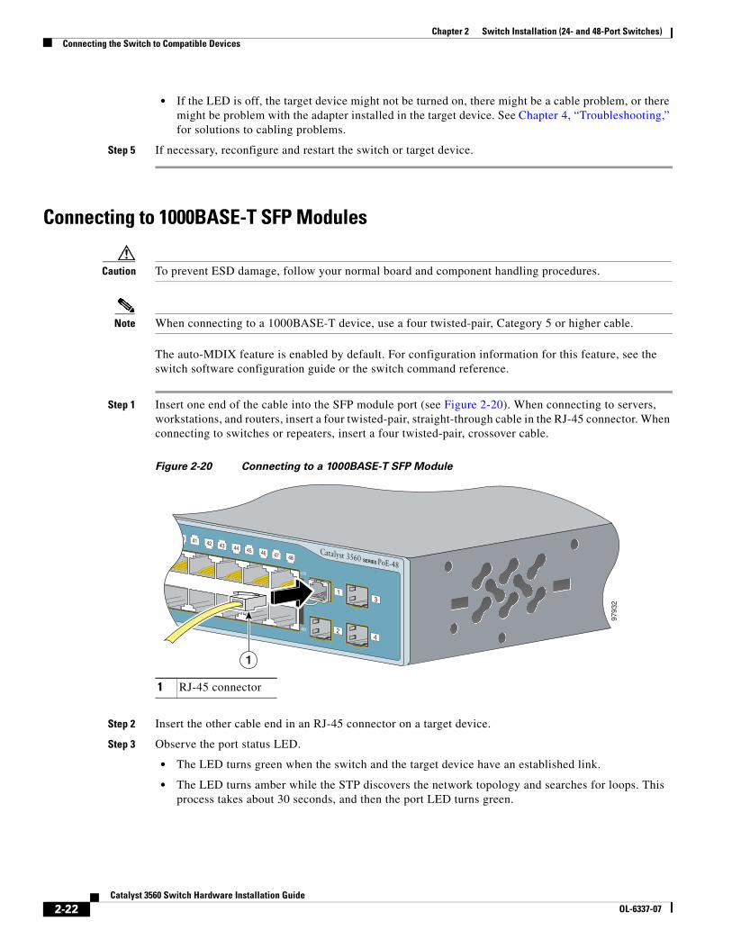
Chapter 2 Switch Installation (24- and 48-Port Switches)Connecting the Switch to Compatible Devices
• If the LED is off, the target device might not be turned on, there might be a cable problem, or there might be problem with the adapter installed in the target device. See Chapter 4, “Troubleshooting,” for solutions to cabling problems.
Step 5 If necessary, reconfigure and restart the switch or target device.
Connecting to 1000BASE-T SFP Modules
Caution To prevent ESD damage, follow your normal board and component handling procedures.
Note When connecting to a 1000BASE-T device, use a four twisted-pair, Category 5 or higher cable.
The auto-MDIX feature is enabled by default. For configuration information for this feature, see the switch software configuration guide or the switch command reference.
Step 1 Insert one end of the cable into the SFP module port (see Figure 2-20). When connecting to servers, workstations, and routers, insert a four twisted-pair, straight-through cable in the RJ-45 connector. When connecting to switches or repeaters, insert a four twisted-pair, crossover cable.
Figure 2-20 Connecting to a 1000BASE-T SFP Module
Step 2 Insert the other cable end in an RJ-45 connector on a target device.
Step 3 Observe the port status LED.
• The LED turns green when the switch and the target device have an established link.
• The LED turns amber while the STP discovers the network topology and searches for loops. This process takes about 30 seconds, and then the port LED turns green.
1 RJ-45 connector
40 41 42 43 44 45 46 47 48
47X
48X
Catalyst 3560 SERIES PoE-48
1
2
3
4
9793
2
1
2-22Catalyst 3560 Switch Hardware Installation Guide
OL-6337-07
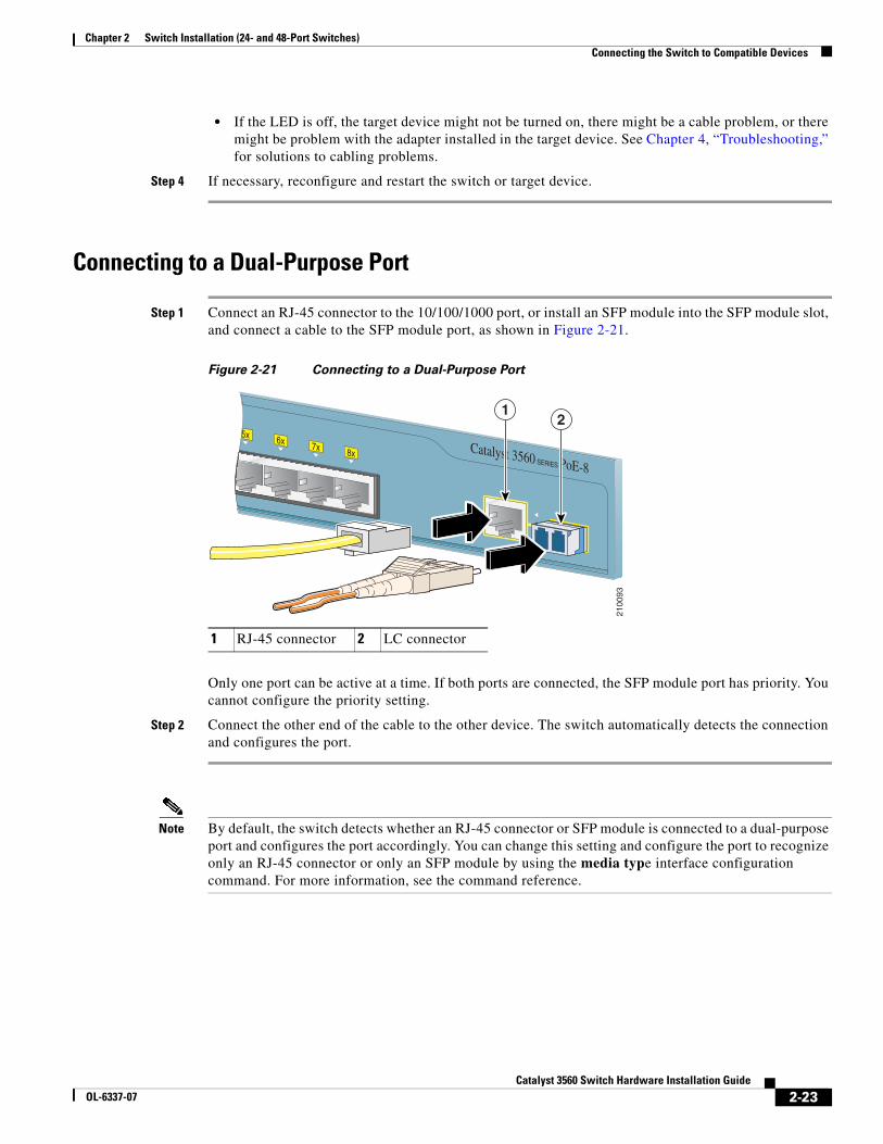
Chapter 2 Switch Installation (24- and 48-Port Switches)Connecting the Switch to Compatible Devices
• If the LED is off, the target device might not be turned on, there might be a cable problem, or there might be problem with the adapter installed in the target device. See Chapter 4, “Troubleshooting,” for solutions to cabling problems.
Step 4 If necessary, reconfigure and restart the switch or target device.
Connecting to a Dual-Purpose Port
Step 1 Connect an RJ-45 connector to the 10/100/1000 port, or install an SFP module into the SFP module slot, and connect a cable to the SFP module port, as shown in Figure 2-21.
Figure 2-21 Connecting to a Dual-Purpose Port
Only one port can be active at a time. If both ports are connected, the SFP module port has priority. You cannot configure the priority setting.
Step 2 Connect the other end of the cable to the other device. The switch automatically detects the connection and configures the port.
Note By default, the switch detects whether an RJ-45 connector or SFP module is connected to a dual-purpose port and configures the port accordingly. You can change this setting and configure the port to recognize only an RJ-45 connector or only an SFP module by using the media type interface configuration command. For more information, see the command reference.
1 RJ-45 connector 2 LC connector
2100
93
5x 6x 7x 8x
1
Catalyst 3560 SERIES PoE-8
12
2-23Catalyst 3560 Switch Hardware Installation Guide
OL-6337-07
Chapter 2 Switch Installation (24- and 48-Port Switches)Where to Go Next
Where to Go NextIf the default configuration is satisfactory, the switch does not need further configuration. You can use any of these management options to change the default configuration:
• Start the device manager, which is in the switch memory, to manage individual switches. The device manager is a web interface that offers quick configuration and monitoring. You can access the device manager from anywhere in your network through a web browser. For more information, see the device manager online help.
• Start the Network Assistant application, which is described in the Getting Started with Cisco Network Assistant guide. Through this GUI, you can configure and monitor a switch cluster or an individual switch.
• Use the CLI from the console to configure the switch as a member of a cluster or as an individual switch. See the Catalyst 3560 Switch Software Configuration Guide and the Catalyst 3560 Switch Command Reference on Cisco.com for information on using the CLI with a Catalyst 3560 switch.
• Start an SNMP application such as the CiscoView application.
2-24Catalyst 3560 Switch Hardware Installation Guide
OL-6337-07
OL-6337-07
C H A P T E R 3
Switch Installation (8- and 12-Port Switches)This chapter describes how to start your switch installation, including how to interpret the power-on self-test (POST) that ensures proper operation. It also describes how to install the switch.
Note This chapter describes the installation information specific to the Catalyst 3560-8PC and Catalyst 3560-12PC-S switches. For installing the other Catalyst 3560 switches, see Chapter 2, “Switch Installation (24- and 48-Port Switches).”
Read the topics and perform the procedures in this order:
• Preparing for Installation, page 3-1
• Verifying Switch Operation, page 3-7
• Installing the Switch, page 3-7
• Where to Go Next, page 3-20
For information about connecting to the switch, see the “Connecting the Switch to Compatible Devices” section on page 2-20
Preparing for Installation • Warnings, page 3-2
• Installation Guidelines, page 3-5
• Equipment That You Supply, page 3-6
• Box Contents, page 3-7
• Tools and Equipment, page 3-7
3-1Catalyst 3560 Switch Hardware Installation Guide
Chapter 3 Switch Installation (8- and 12-Port Switches)Preparing for Installation
WarningsThese warnings are translated into several languages in the Regulatory Compliance and Safety Information for the Catalyst 3560 Switch.
Warning To prevent the switch from overheating, do not operate it in an area that exceeds the maximum recommended ambient temperature of 113•F (45•C). To prevent airflow restriction, allow at least 3 inches (7.6 cm) of clearance around the ventilation openings. Statement 17B
Warning Before working on equipment that is connected to power lines, remove jewelry (including rings, necklaces, and watches). Metal objects will heat up when connected to power and ground and can cause serious burns or weld the metal object to the terminals. Statement 43
Warning Do not stack the chassis on any other equipment. If the chassis falls, it can cause severe bodily injury and equipment damage. Statement 48
Warning An exposed wire lead from a DC-input power source can conduct harmful levels of electricity. Be sure that no exposed portion of the DC-input power source wire extends from the terminal block plug. Statement 122
Warning Blank faceplates (filler panels) serve three important functions: they prevent exposure to hazardous voltages and currents inside the chassis; they contain electromagnetic interference (EMI) that might disrupt other equipment; and they direct the flow of cooling air through the chassis. Do not operate the system unless all cards and faceplates are in place. Statement 156
Warning Ethernet cables must be shielded when used in a central office environment. Statement 171
Warning If a redundant power system (RPS) is not connected to the switch, install an RPS connector cover on the back of the switch. Statement 265
Warning Attach only the following Cisco RPS model to the RPS receptacle: PWR-RPS2300 / PWR675-AC-RPS-N1 Statement 370
Warning Read the wall-mounting instructions carefully before beginning installation. Failure to use the correct hardware or to follow the correct procedures could result in a hazardous situation to people and damage to the system. Statement 378
3-2Catalyst 3560 Switch Hardware Installation Guide
OL-6337-07
Chapter 3 Switch Installation (8- and 12-Port Switches)Preparing for Installation
Warning Do not work on the system or connect or disconnect cables during periods of lightning activity. Statement 1001
Warning Before performing any of the following procedures, ensure that power is removed from the DC circuit. Statement 1003
Warning Read the installation instructions before connecting the system to the power source. Statement 1004
Warning This product relies on the building’s installation for short-circuit (overcurrent) protection. Ensure that the protective device is rated not greater than: 5 A Statement 1005
Warning Class 1 laser product. Statement 1008
Warning This unit is intended for installation in restricted access areas. A restricted access area can be accessed only through the use of a special tool, lock and key, or other means of security. Statement 1017
Warning The plug-socket combination must be accessible at all times, because it serves as the main disconnecting device. Statement 1019
Warning A readily accessible two-poled disconnect device must be incorporated in the fixed wiring. Statement 1022
Warning To prevent bodily injury when mounting or servicing this unit in a rack, you must take special precautions to ensure that the system remains stable. The following guidelines are provided to ensure your safety:
• This unit should be mounted at the bottom of the rack if it is the only unit in the rack.
• When mounting this unit in a partially filled rack, load the rack from the bottom to the top with the heaviest component at the bottom of the rack.
• If the rack is provided with stabilizing devices, install the stabilizers before mounting or servicing the unit in the rack. Statement 1006
3-3Catalyst 3560 Switch Hardware Installation Guide
OL-6337-07
Chapter 3 Switch Installation (8- and 12-Port Switches)Preparing for Installation
Warning This equipment must be grounded. Never defeat the ground conductor or operate the equipment in the absence of a suitably installed ground conductor. Contact the appropriate electrical inspection authority or an electrician if you are uncertain that suitable grounding is available. Statement 1024
Warning This unit might have more than one power supply connection. All connections must be removed to de-energize the unit. Statement 1028
Warning Only trained and qualified personnel should be allowed to install, replace, or service this equipment. Statement 1030
Warning Ultimate disposal of this product should be handled according to all national laws and regulations. Statement 1040
Warning For connections outside the building where the equipment is installed, the following ports must be connected through an approved network termination unit with integral circuit protection: 10/100/1000 Ethernet. Statement 1044
Warning When installing or replacing the unit, the ground connection must always be made first and disconnected last. Statement 1046
Warning This warning symbol means danger. You are in a situation that could cause bodily injury. Before you work on any equipment, be aware of the hazards involved with electrical circuitry and be familiar with standard practices for preventing accidents. Use the statement number provided at the end of each warning to locate its translation in the translated safety warnings that accompanied this device. Statement 1071
Warning Voltages that present a shock hazard may exist on Power over Ethernet (PoE) circuits if interconnections are made using uninsulated exposed metal contacts, conductors, or terminals. Avoid using such interconnection methods, unless the exposed metal parts are located within a restricted access location and users and service people who are authorized within the restricted access location are made aware of the hazard. A restricted access area can be accessed only through the use of a special tool, lock and key or other means of security. Statement 1072
Warning No user-serviceable parts inside. Do not open. Statement 1073
Warning Installation of the equipment must comply with local and national electrical codes. Statement 1074
3-4Catalyst 3560 Switch Hardware Installation Guide
OL-6337-07
Chapter 3 Switch Installation (8- and 12-Port Switches)Preparing for Installation
Statement 371—Power Cable and AC Adapter
Caution To comply with the Telcordia GR-1089 Network Equipment Building Systems (NEBS) standard for electromagnetic compatibility and safety, connect the ethernet cables only to intrabuilding or nonexposed wiring or cabling.
Caution To comply with the Telcordia GR-1089 NEBS standard, PoE or non-PoE 10/100/1000 Ethernet port cables that exit from either the left side or right side of the switch should be routed and tied to the nearest rack metal hardware.
Note The grounding architecture of this product is DC-isolated (DC-I).
Installation GuidelinesWhen you determine where to place the switch, be sure to observe these requirements:
• The operating environment is within the ranges listed in Appendix A, “Technical Specifications.”
• Airflow around the switch and through the vents is unrestricted. Allow at least 3 inches (7.6 cm) of clearance on all sides and ventilation openings, particularly if you stack the switches or place them side by side.
• You have allowed at least 1.75 inches (4 cm) of clearance above each switch in the rack.
• Clearance to front and rear panels is such that
– You can easily read the front-panel indicators.
– Access to ports is sufficient for unrestricted cabling.
– The rear-panel power connector is within reach of an AC power receptacle.
• Temperature around the unit does not exceed 113°F (45°C).
If the switch is installed in a closed environment or in a multirack assembly, the temperature around it might be greater than normal room temperature.
• The heat sinks and the bottom of the switch might be hot to the touch if the switch is operating at its maximum temperature 113°F (45°C) and is in an environment that exceeds normal room temperature (such as in a closet, in a cabinet, or in a closed or multirack assembly).
• No other items are placed on the top of the switch.
• The switch is not wall-mounted with its front panel facing up or sideways. According to safety regulations, wall-mount the switch with its front panel facing down to prevent airflow restriction and to provide easier access to the cables.
3-5Catalyst 3560 Switch Hardware Installation Guide
OL-6337-07
Chapter 3 Switch Installation (8- and 12-Port Switches)Preparing for Installation
• Cabling is away from sources of electrical noise, such as radios, power lines, and fluorescent lighting fixtures. Make sure the cabling is safely away from other devices that might damage the cables.
• For copper Ethernet ports, including 10/100 ports, 10/100/1000 ports, and 1000BASE-T SFP module ports, cable lengths from the switch to connected devices can be up to 328 feet (100 meters).
• The cables meet the specifications in Table B-1 on page B-4, which lists the cable specifications for 1000BASE-X and 100BASE-X SFP modules for the Catalyst 3560 switch. Catalyst 3560 switch SFP ports use both GLC-GE-100XX and GLC-FE-100XX SFP modules.
When you use shorter lengths of single-mode fiber cable, you might need to insert an inline optical attenuator in the link to avoid overloading the receiver.
When the fiber-optic cable span is less than 15.43 miles (25 km), you should insert a 5-decibel (dB) or 10-dB inline optical attenuator between the fiber-optic cable plant and the receiving port on the 1000BASE-ZX SFP module at each end of the link.
• Cisco Ethernet Switches are equipped with cooling mechanisms, such as fans and blowers. However, these fans and blowers can draw dust and other particles, causing contaminant buildup inside the chassis, which can result in a system malfunction.
You must install this equipment in an environment as free as possible from dust and foreign conductive material (such as metal flakes from construction activities).
These standards provide guidelines for acceptable working environments and acceptable levels of suspended particulate matter:
– Network Equipment Building Systems (NEBS) GR-63-CORE
– National Electrical Manufacturers Association (NEMA) Type 1
– International Electrotechnical Commission (IEC) IP-20
This applies to all Cisco Ethernet switches except for this compact model:
– Catalyst 3560-8PC switch—8 10/100 PoE ports and 1 dual-purpose port (one 10/100/1000BASE-T copper port and one SFP module slot)
Equipment That You SupplyYou need this equipment to install the switch:
• Number-2 Phillips screwdriver
• Drill with a #27 drill bit (0.144-inch [3.7 mm])
You can order an optional cable guard to secure cables to the front of the switch and to prevent accidental removal. To order a cable guard (CBLGRD-C3560-12PC or CBLGRD-C3560-8PC), contact your Cisco representative.
The switch has security slots in the left and right side panels. You can install an optional cable lock, such as the type that is used to secure a laptop, to secure either or both sides of the switch. Cable locks are available from most computer accessory suppliers.
Installing the switch in a 19-inch rack requires an optional bracket kit that is not included but which you can order, RCKMNT-19-CMPCT=.
If you want to connect a terminal to the switch console port, you need to provide an RJ-45-to-DB-25 female DTE adapter. You can order a kit (part number ACS-DSBUASYN=) with that adapter from Cisco.
3-6Catalyst 3560 Switch Hardware Installation Guide
OL-6337-07
Chapter 3 Switch Installation (8- and 12-Port Switches)Verifying Switch Operation
Box ContentsThe switch getting started guide on Cisco.com describes the box contents. If any item is missing or damaged, contact your Cisco representative or reseller for support.
Tools and EquipmentYou need to supply a number-2 Phillips screwdriver to rack-mount the switch.
Verifying Switch OperationBefore you install the switch, power it on and verify that it passes POST. See the getting started guide for the steps required to connect a PC to the switch and to run Express Setup. To power on the switch, connect one end of the AC power cord to the AC power connector on the switch, and connect the other end of the power cord to an AC power outlet.
When the switch powers on, it automatically begins the POST, a series of tests that verifies that the switch functions properly. When the switch begins POST, the system LED slowly blinks green. When POST completes, the system LED blinks amber. If POST fails, the system LED remains amber. If POST completes successfully, the system LED rapidly blinks green.
Call Cisco technical support representative if your switch fails POST.
Powering Off the SwitchAfter a successful POST, disconnect the power cord from the switch. Install the switch in a rack, on a wall, on a table, or on a shelf as described in the “Installing the Switch” section on page 3-7.
Installing the Switch • Desk or Shelf Mounting, page 3-8
• Wall-Mounting (with Mounting Screws), page 3-12
• Magnet Mounting, page 3-15
• Rack-Mounting, page 3-16
• Wall-Mounting (with Rack-Mount Brackets), page 3-17
• Securing the AC Power Cord, page 3-19
Before installing the switch, review the “Installation Guidelines” section on page 3-5.
3-7Catalyst 3560 Switch Hardware Installation Guide
OL-6337-07
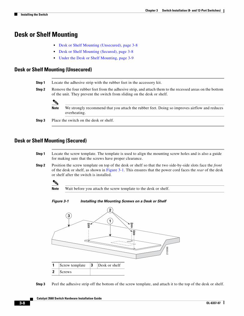
Chapter 3 Switch Installation (8- and 12-Port Switches)Installing the Switch
Desk or Shelf Mounting • Desk or Shelf Mounting (Unsecured), page 3-8
• Desk or Shelf Mounting (Secured), page 3-8
• Under the Desk or Shelf Mounting, page 3-9
Desk or Shelf Mounting (Unsecured)
Step 1 Locate the adhesive strip with the rubber feet in the accessory kit.
Step 2 Remove the four rubber feet from the adhesive strip, and attach them to the recessed areas on the bottom of the unit. They prevent the switch from sliding on the desk or shelf.
Note We strongly recommend that you attach the rubber feet. Doing so improves airflow and reduces overheating.
Step 3 Place the switch on the desk or shelf.
Desk or Shelf Mounting (Secured)
Step 1 Locate the screw template. The template is used to align the mounting screw holes and is also a guide for making sure that the screws have proper clearance.
Step 2 Position the screw template on top of the desk or shelf so that the two side-by-side slots face the front of the desk or shelf, as shown in Figure 3-1. This ensures that the power cord faces the rear of the desk or shelf after the switch is installed.
Note Wait before you attach the screw template to the desk or shelf.
Figure 3-1 Installing the Mounting Screws on a Desk or Shelf
Step 3 Peel the adhesive strip off the bottom of the screw template, and attach it to the top of the desk or shelf.
1 Screw template 3 Desk or shelf
2 Screws
13
2
2100
96
3-8Catalyst 3560 Switch Hardware Installation Guide
OL-6337-07
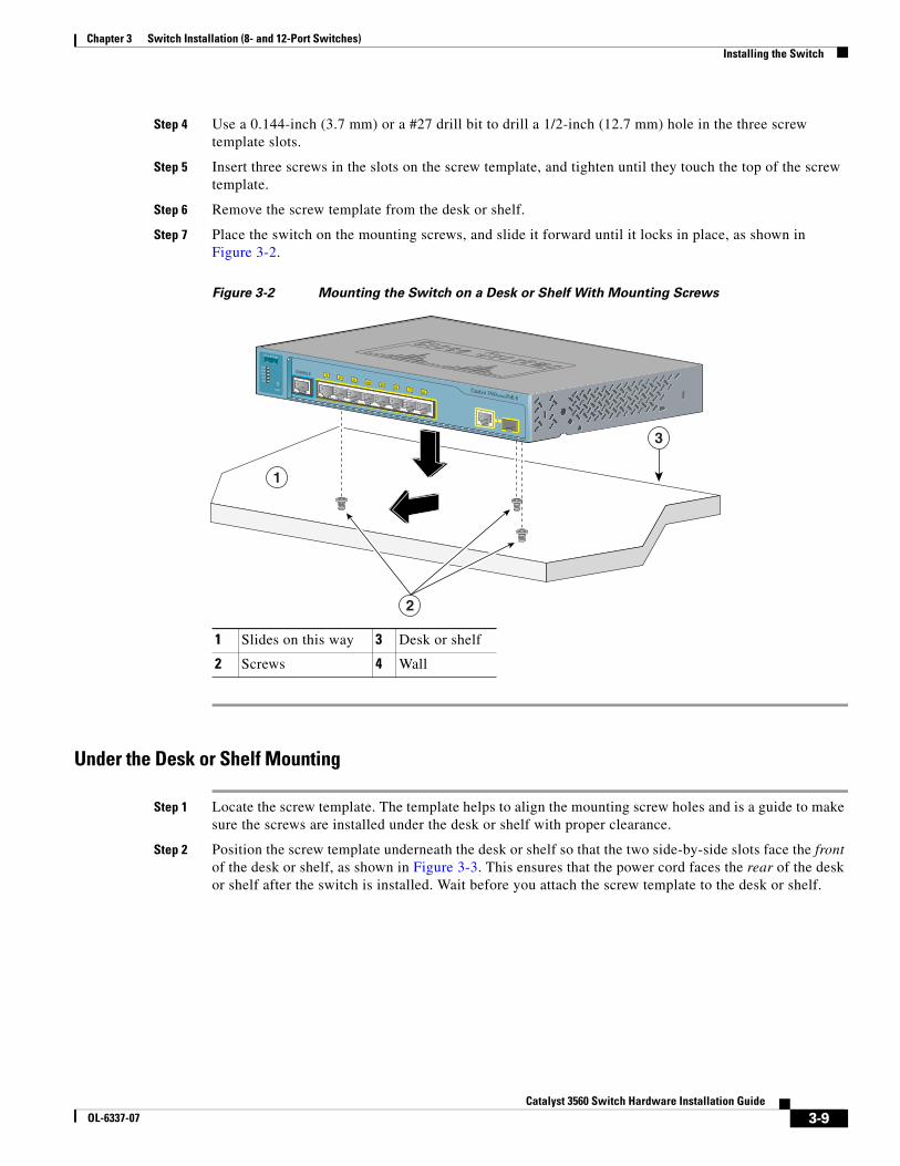
Chapter 3 Switch Installation (8- and 12-Port Switches)Installing the Switch
Step 4 Use a 0.144-inch (3.7 mm) or a #27 drill bit to drill a 1/2-inch (12.7 mm) hole in the three screw template slots.
Step 5 Insert three screws in the slots on the screw template, and tighten until they touch the top of the screw template.
Step 6 Remove the screw template from the desk or shelf.
Step 7 Place the switch on the mounting screws, and slide it forward until it locks in place, as shown in Figure 3-2.
Figure 3-2 Mounting the Switch on a Desk or Shelf With Mounting Screws
Under the Desk or Shelf Mounting
Step 1 Locate the screw template. The template helps to align the mounting screw holes and is a guide to make sure the screws are installed under the desk or shelf with proper clearance.
Step 2 Position the screw template underneath the desk or shelf so that the two side-by-side slots face the front of the desk or shelf, as shown in Figure 3-3. This ensures that the power cord faces the rear of the desk or shelf after the switch is installed. Wait before you attach the screw template to the desk or shelf.
1 Slides on this way 3 Desk or shelf
2 Screws 4 Wall
3
2
1
1
CONSOLE 1x 2x 3x 4x 5x 6x 7x 8x Catalyst 3560 SERIES PoE-8
PoESPD
DPLXSTAT
SYST
MODE
3-9Catalyst 3560 Switch Hardware Installation Guide
OL-6337-07
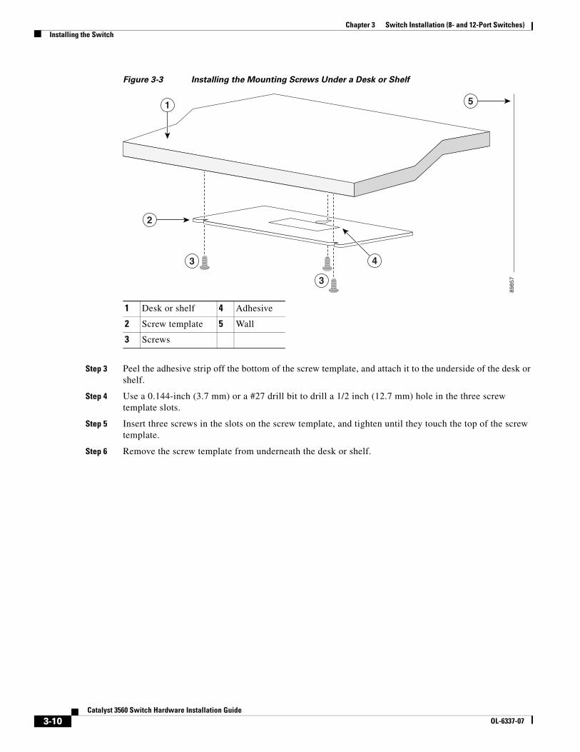
Chapter 3 Switch Installation (8- and 12-Port Switches)Installing the Switch
Figure 3-3 Installing the Mounting Screws Under a Desk or Shelf
Step 3 Peel the adhesive strip off the bottom of the screw template, and attach it to the underside of the desk or shelf.
Step 4 Use a 0.144-inch (3.7 mm) or a #27 drill bit to drill a 1/2 inch (12.7 mm) hole in the three screw template slots.
Step 5 Insert three screws in the slots on the screw template, and tighten until they touch the top of the screw template.
Step 6 Remove the screw template from underneath the desk or shelf.
1 Desk or shelf 4 Adhesive
2 Screw template 5 Wall
3 Screws
1
4
5
2
3
3
8985
7
3-10Catalyst 3560 Switch Hardware Installation Guide
OL-6337-07
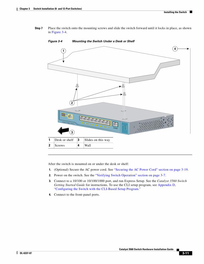
Chapter 3 Switch Installation (8- and 12-Port Switches)Installing the Switch
Step 7 Place the switch onto the mounting screws and slide the switch forward until it locks in place, as shown in Figure 3-4.
Figure 3-4 Mounting the Switch Under a Desk or Shelf
After the switch is mounted on or under the desk or shelf:
1. (Optional) Secure the AC power cord. See “Securing the AC Power Cord” section on page 3-19.
2. Power on the switch. See the “Verifying Switch Operation” section on page 3-7.
3. Connect to a 10/100 or 10/100/1000 port, and run Express Setup. See the Catalyst 3560 Switch Getting Started Guide for instructions. To use the CLI setup program, see Appendix D, “Configuring the Switch with the CLI-Based Setup Program.”
4. Connect to the front-panel ports.
1 Desk or shelf 3 Slides on this way
2 Screws 4 Wall
1x2x
3x4x
5x6x
7x8x
1
Catalyst 3560 SERIES PoE-8
SYSTSTATDPLXSPD
SYST
CONSOLE
4
3
1
2
3-11Catalyst 3560 Switch Hardware Installation Guide
OL-6337-07
Chapter 3 Switch Installation (8- and 12-Port Switches)Installing the Switch
Wall-Mounting (with Mounting Screws)Mount the switch with the front panel facing down (as shown in Figure 3-5 on page 3-13 and Figure 3-6 on page 3-14.)
Warning Read the wall-mounting instructions carefully before beginning installation. Failure to use the correct hardware or to follow the correct procedures could result in a hazardous situation to people and damage to the system. Statement 378
Caution Do not wall-mount the switch with its front panel facing up or sideways. According to safety regulations, wall-mount the switch with its front panel facing down to improve airflow and to provide easier access to the cables.
Step 1 Locate the screw template. The template is used to align the mounting screw holes.
Step 2 Position the screw template so that the two side-by-side slots face toward the floor, as shown in Figure 3-5.
For the best support of the switch and cables, make sure the switch is attached securely to a wall stud or to a firmly attached plywood mounting backboard.
Note Wait before you attach the screw template to the wall.
3-12Catalyst 3560 Switch Hardware Installation Guide
OL-6337-07
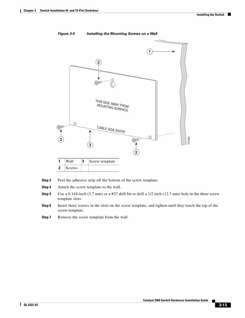
Chapter 3 Switch Installation (8- and 12-Port Switches)Installing the Switch
Figure 3-5 Installing the Mounting Screws on a Wall
Step 3 Peel the adhesive strip off the bottom of the screw template.
Step 4 Attach the screw template to the wall.
Step 5 Use a 0.144-inch (3.7 mm) or a #27 drill bit to drill a 1/2 inch (12.7 mm) hole in the three screw template slots.
Step 6 Insert three screws in the slots on the screw template, and tighten until they touch the top of the screw template.
Step 7 Remove the screw template from the wall.
1 Wall 3 Screw template
2 Screws
CABLE SIDE ENTRY
THIS SIDE AWAY FROM MOUNTING SURFACE
2
32
2
1
1578
28
3-13Catalyst 3560 Switch Hardware Installation Guide
OL-6337-07
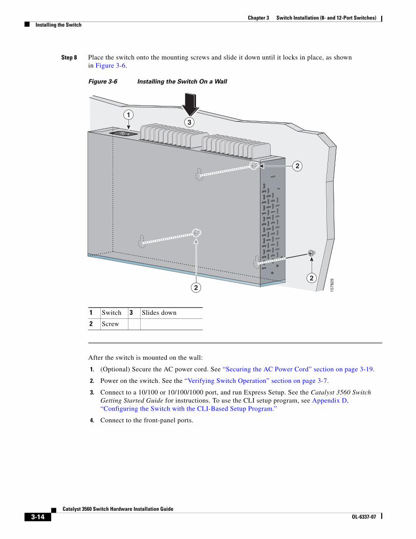
Chapter 3 Switch Installation (8- and 12-Port Switches)Installing the Switch
Step 8 Place the switch onto the mounting screws and slide it down until it locks in place, as shown in Figure 3-6.
Figure 3-6 Installing the Switch On a Wall
After the switch is mounted on the wall:
1. (Optional) Secure the AC power cord. See “Securing the AC Power Cord” section on page 3-19.
2. Power on the switch. See the “Verifying Switch Operation” section on page 3-7.
3. Connect to a 10/100 or 10/100/1000 port, and run Express Setup. See the Catalyst 3560 Switch Getting Started Guide for instructions. To use the CLI setup program, see Appendix D, “Configuring the Switch with the CLI-Based Setup Program.”
4. Connect to the front-panel ports.
1 Switch 3 Slides down
2 Screw
31
22 15
7829
2
3-14Catalyst 3560 Switch Hardware Installation Guide
OL-6337-07
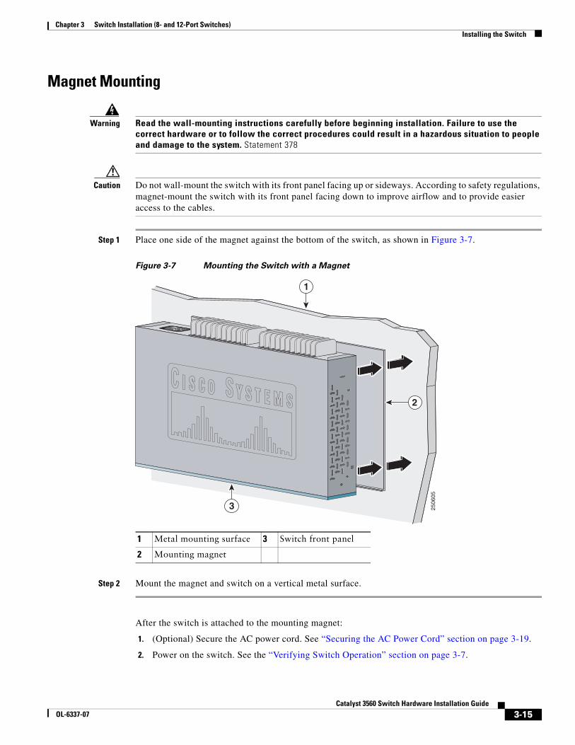
Chapter 3 Switch Installation (8- and 12-Port Switches)Installing the Switch
Magnet Mounting
Warning Read the wall-mounting instructions carefully before beginning installation. Failure to use the correct hardware or to follow the correct procedures could result in a hazardous situation to people and damage to the system. Statement 378
Caution Do not wall-mount the switch with its front panel facing up or sideways. According to safety regulations, magnet-mount the switch with its front panel facing down to improve airflow and to provide easier access to the cables.
Step 1 Place one side of the magnet against the bottom of the switch, as shown in Figure 3-7.
Figure 3-7 Mounting the Switch with a Magnet
Step 2 Mount the magnet and switch on a vertical metal surface.
After the switch is attached to the mounting magnet:
1. (Optional) Secure the AC power cord. See “Securing the AC Power Cord” section on page 3-19.
2. Power on the switch. See the “Verifying Switch Operation” section on page 3-7.
1 Metal mounting surface 3 Switch front panel
2 Mounting magnet
2506
05
2
1
3
3-15Catalyst 3560 Switch Hardware Installation Guide
OL-6337-07
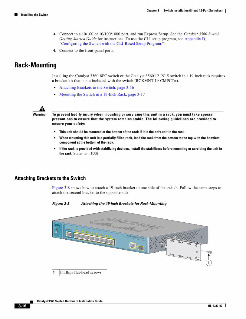
Chapter 3 Switch Installation (8- and 12-Port Switches)Installing the Switch
3. Connect to a 10/100 or 10/100/1000 port, and run Express Setup. See the Catalyst 3560 Switch Getting Started Guide for instructions. To use the CLI setup program, see Appendix D, “Configuring the Switch with the CLI-Based Setup Program.”
4. Connect to the front-panel ports.
Rack-MountingInstalling the Catalyst 3560-8PC switch or the Catalyst 3560 12-PC-S switch in a 19-inch rack requires a bracket kit that is not included with the switch (RCKMNT-19-CMPCT=).
• Attaching Brackets to the Switch, page 3-16
• Mounting the Switch in a 19-Inch Rack, page 3-17
Attaching Brackets to the Switch
Figure 3-8 shows how to attach a 19-inch bracket to one side of the switch. Follow the same steps to attach the second bracket to the opposite side.
Figure 3-8 Attaching the 19-inch Brackets for Rack-Mounting
Warning To prevent bodily injury when mounting or servicing this unit in a rack, you must take special precautions to ensure that the system remains stable. The following guidelines are provided to ensure your safety:
• This unit should be mounted at the bottom of the rack if it is the only unit in the rack.
• When mounting this unit in a partially filled rack, load the rack from the bottom to the top with the heaviest component at the bottom of the rack.
• If the rack is provided with stabilizing devices, install the stabilizers before mounting or servicing the unit in the rack. Statement 1006
1 Phillips flat-head screws
1
CONSOLE 1x 2x 3x 4x 5x 6x 7x 8x Catalyst 3560 SERIES PoE-8
PoESPD
DPLXSTAT
SYST
MODE
1
3-16Catalyst 3560 Switch Hardware Installation Guide
OL-6337-07
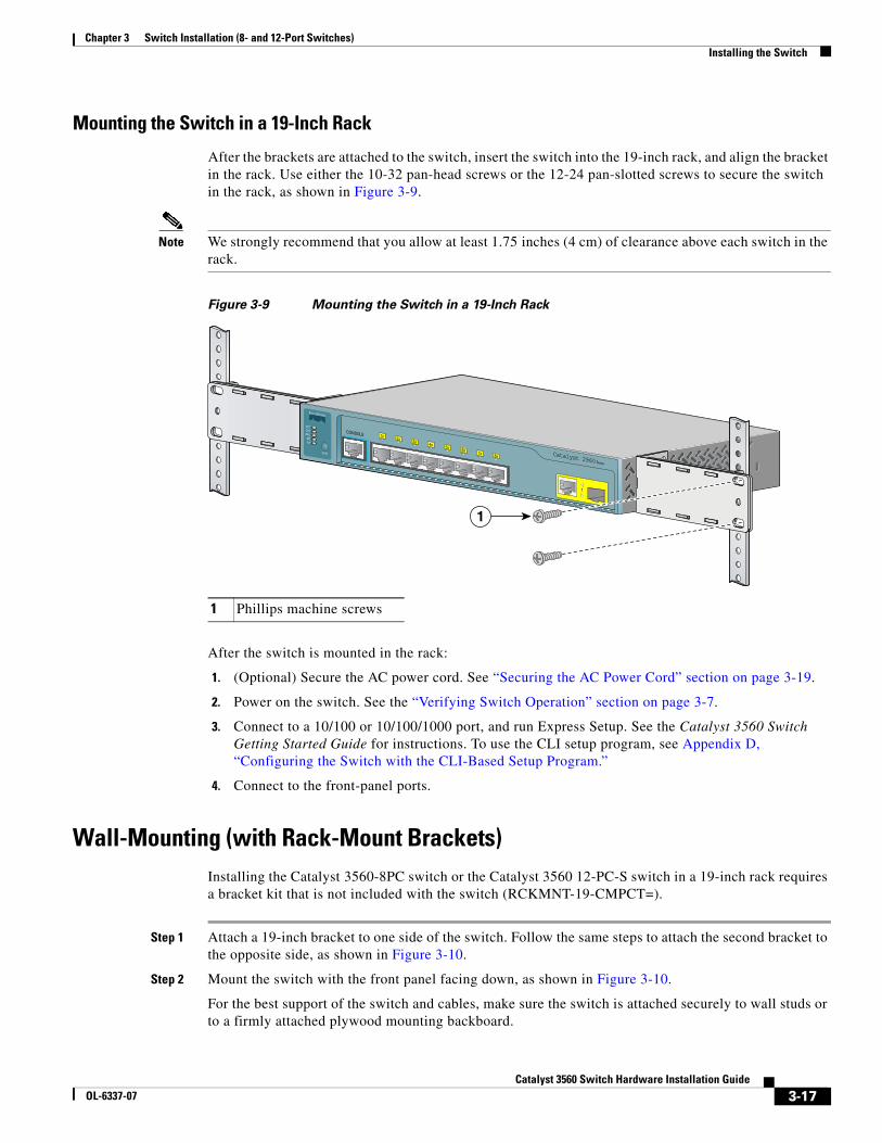
Chapter 3 Switch Installation (8- and 12-Port Switches)Installing the Switch
Mounting the Switch in a 19-Inch Rack
After the brackets are attached to the switch, insert the switch into the 19-inch rack, and align the bracket in the rack. Use either the 10-32 pan-head screws or the 12-24 pan-slotted screws to secure the switch in the rack, as shown in Figure 3-9.
Note We strongly recommend that you allow at least 1.75 inches (4 cm) of clearance above each switch in the rack.
Figure 3-9 Mounting the Switch in a 19-Inch Rack
After the switch is mounted in the rack:
1. (Optional) Secure the AC power cord. See “Securing the AC Power Cord” section on page 3-19.
2. Power on the switch. See the “Verifying Switch Operation” section on page 3-7.
3. Connect to a 10/100 or 10/100/1000 port, and run Express Setup. See the Catalyst 3560 Switch Getting Started Guide for instructions. To use the CLI setup program, see Appendix D, “Configuring the Switch with the CLI-Based Setup Program.”
4. Connect to the front-panel ports.
Wall-Mounting (with Rack-Mount Brackets)Installing the Catalyst 3560-8PC switch or the Catalyst 3560 12-PC-S switch in a 19-inch rack requires a bracket kit that is not included with the switch (RCKMNT-19-CMPCT=).
Step 1 Attach a 19-inch bracket to one side of the switch. Follow the same steps to attach the second bracket to the opposite side, as shown in Figure 3-10.
Step 2 Mount the switch with the front panel facing down, as shown in Figure 3-10.
For the best support of the switch and cables, make sure the switch is attached securely to wall studs or to a firmly attached plywood mounting backboard.
1 Phillips machine screws
2x 3x 4x 5x 6x 7x 8x
1
Catalyst 2960 Series
CONSOLE 1xPoESPD
DPLXSTAT
SYST
MODE
1
3-17Catalyst 3560 Switch Hardware Installation Guide
OL-6337-07
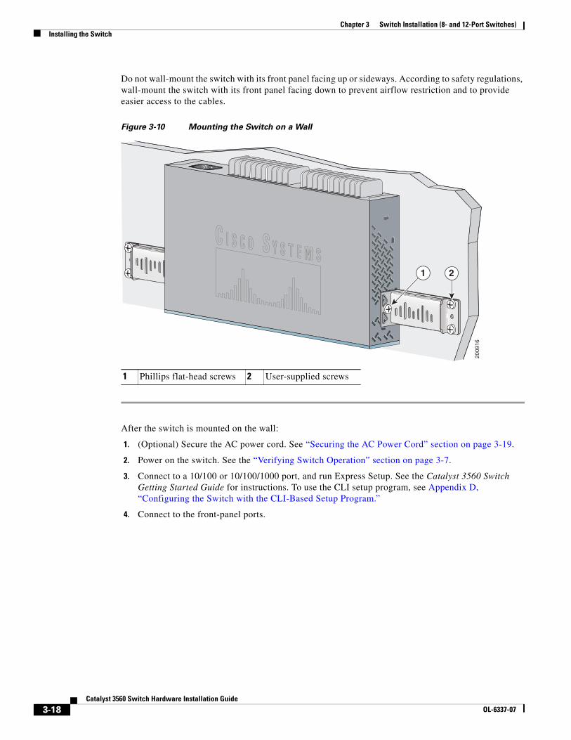
Chapter 3 Switch Installation (8- and 12-Port Switches)Installing the Switch
Do not wall-mount the switch with its front panel facing up or sideways. According to safety regulations, wall-mount the switch with its front panel facing down to prevent airflow restriction and to provide easier access to the cables.
Figure 3-10 Mounting the Switch on a Wall
After the switch is mounted on the wall:
1. (Optional) Secure the AC power cord. See “Securing the AC Power Cord” section on page 3-19.
2. Power on the switch. See the “Verifying Switch Operation” section on page 3-7.
3. Connect to a 10/100 or 10/100/1000 port, and run Express Setup. See the Catalyst 3560 Switch Getting Started Guide for instructions. To use the CLI setup program, see Appendix D, “Configuring the Switch with the CLI-Based Setup Program.”
4. Connect to the front-panel ports.
1 Phillips flat-head screws 2 User-supplied screws
2009
16
1 2
3-18Catalyst 3560 Switch Hardware Installation Guide
OL-6337-07
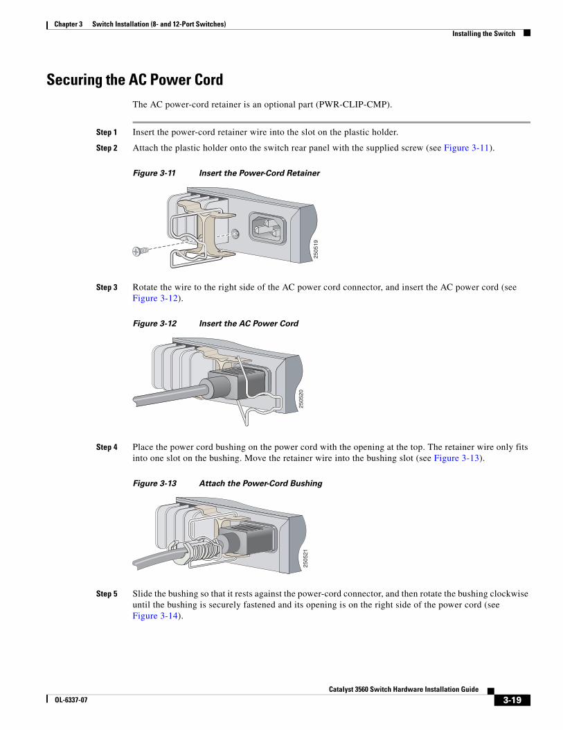
Chapter 3 Switch Installation (8- and 12-Port Switches)Installing the Switch
Securing the AC Power Cord The AC power-cord retainer is an optional part (PWR-CLIP-CMP).
Step 1 Insert the power-cord retainer wire into the slot on the plastic holder.
Step 2 Attach the plastic holder onto the switch rear panel with the supplied screw (see Figure 3-11).
Figure 3-11 Insert the Power-Cord Retainer
Step 3 Rotate the wire to the right side of the AC power cord connector, and insert the AC power cord (see Figure 3-12).
Figure 3-12 Insert the AC Power Cord
Step 4 Place the power cord bushing on the power cord with the opening at the top. The retainer wire only fits into one slot on the bushing. Move the retainer wire into the bushing slot (see Figure 3-13).
Figure 3-13 Attach the Power-Cord Bushing
Step 5 Slide the bushing so that it rests against the power-cord connector, and then rotate the bushing clockwise until the bushing is securely fastened and its opening is on the right side of the power cord (see Figure 3-14).
2505
19
2505
2025
0521
3-19Catalyst 3560 Switch Hardware Installation Guide
OL-6337-07
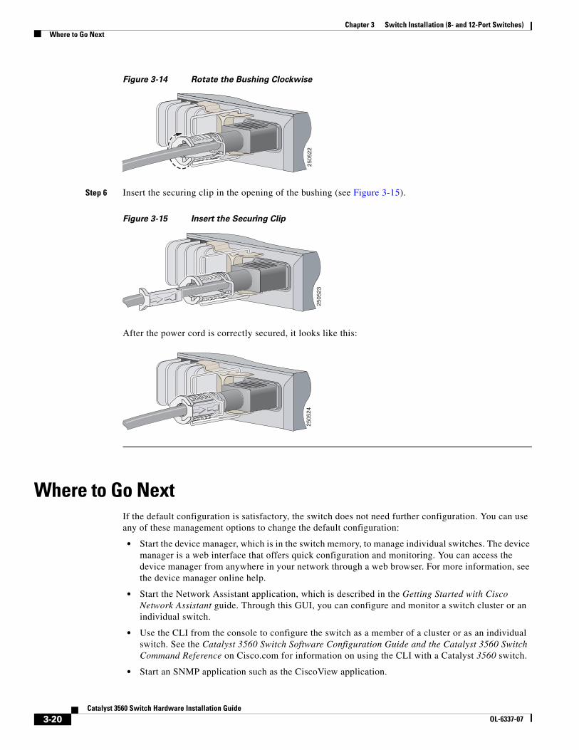
Chapter 3 Switch Installation (8- and 12-Port Switches)Where to Go Next
Figure 3-14 Rotate the Bushing Clockwise
Step 6 Insert the securing clip in the opening of the bushing (see Figure 3-15).
Figure 3-15 Insert the Securing Clip
After the power cord is correctly secured, it looks like this:
Where to Go NextIf the default configuration is satisfactory, the switch does not need further configuration. You can use any of these management options to change the default configuration:
• Start the device manager, which is in the switch memory, to manage individual switches. The device manager is a web interface that offers quick configuration and monitoring. You can access the device manager from anywhere in your network through a web browser. For more information, see the device manager online help.
• Start the Network Assistant application, which is described in the Getting Started with Cisco Network Assistant guide. Through this GUI, you can configure and monitor a switch cluster or an individual switch.
• Use the CLI from the console to configure the switch as a member of a cluster or as an individual switch. See the Catalyst 3560 Switch Software Configuration Guide and the Catalyst 3560 Switch Command Reference on Cisco.com for information on using the CLI with a Catalyst 3560 switch.
• Start an SNMP application such as the CiscoView application.
2505
22
2505
2 3
2505
24
3-20Catalyst 3560 Switch Hardware Installation Guide
OL-6337-07
OL-6337-07
C H A P T E R 4
TroubleshootingThe LEDs on the front panel provide troubleshooting information about the switch. They show failures in the power-on self-test (POST), port-connectivity problems, and overall switch performance. For a full description of the switch LEDs, see the “LEDs” section on page 1-11.
You can also get statistics from the browser interface, from the command-line interface (CLI), or from a Simple Network Management Protocol (SNMP) workstation. See the software configuration guide, the switch command reference guide on Cisco.com, or the documentation that came with your SNMP application for details.
This chapter describes these topics for troubleshooting problems:
• Diagnosing Problems, page 4-1
• Clearing the Switch IP Address and Configuration, page 4-5
• Locating the Switch Serial Number, page 4-6
Diagnosing ProblemsThe LEDs on the front panel provide troubleshooting information about the switch. They show POST failures, port-connectivity problems, and overall switch performance. You can also get statistics from the CLI or from an SNMP workstation. See the software configuration guide and the switch command reference on Cisco.com or the documentation that came with your SNMP application for more information.
• Evaluate Switch POST Results, page 4-2
• Monitor Switch LEDs, page 4-2
• Verify Switch Connections, page 4-2
• Monitor Switch Performance, page 4-4
4-1Catalyst 3560 Switch Hardware Installation Guide
Chapter 4 TroubleshootingDiagnosing Problems
Evaluate Switch POST ResultsAs the switch powers on, it begins the POST, a series of tests that runs automatically to ensure that the switch functions properly. It might take several minutes for the switch to complete POST.
When the switch begins POST, the system LED slowly blinks green. When POST completes, the system LED blinks amber. If POST fails, the system LED remains amber. If POST completes successfully, the system LED rapidly blinks green.
Note POST failures are usually fatal. Contact your Cisco technical support representative if your switch does not pass POST.
Monitor Switch LEDsLook at the port LEDs for troubleshooting information about the switch. See the “LEDs” section on page 1-11 for descriptions of the LED colors and their meanings.
Verify Switch ConnectionsReview these sections when troubleshooting switch connectivity problems:
• Bad or Damaged Cable, page 4-2
• Ethernet and Fiber Cables, page 4-3
• Link Status, page 4-3
• Transceiver Module Port Issues, page 4-3
• Port and Interface Settings, page 4-4
• Ping the End Device, page 4-4
• Spanning Tree Loops, page 4-4
Bad or Damaged Cable
Always look at the cable for marginal damage or failure. A cable might connect at the physical layer but then cause packet corruption because of subtle damage to its wiring or connectors. You can identify this situation because the port will have many packet errors, or the port constantly loses and regains link. In these situations:
• Change the copper or fiber-optic cable with a known, good cable if necessary.
• Look for broken or missing pins on cable connectors.
• Rule out any insufficient patch panel connections or media convertors between the source and the destination. If possible, bypass the patch panel or eliminate faulty media convertors, such as fiber-optic-to-copper convertors.
• Try using the cable in another port or interface to see if the problem also exists there.
4-2Catalyst 3560 Switch Hardware Installation Guide
OL-6337-07
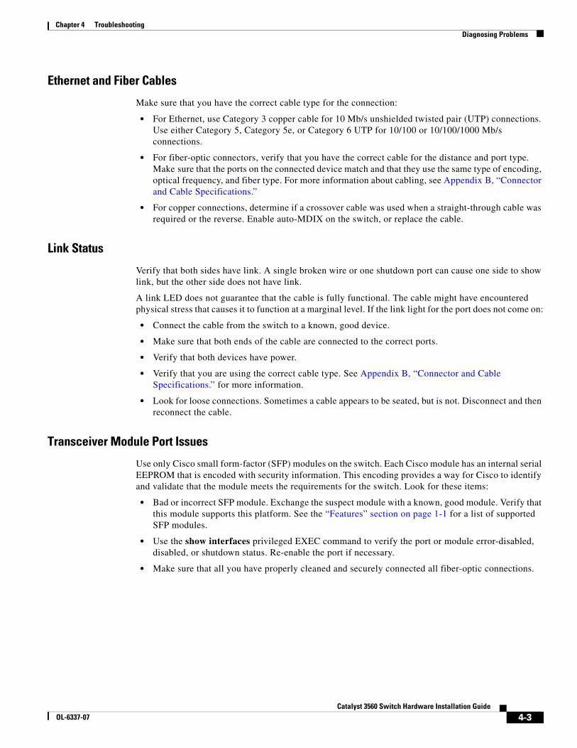
Chapter 4 TroubleshootingDiagnosing Problems
Ethernet and Fiber Cables
Make sure that you have the correct cable type for the connection:
• For Ethernet, use Category 3 copper cable for 10 Mb/s unshielded twisted pair (UTP) connections. Use either Category 5, Category 5e, or Category 6 UTP for 10/100 or 10/100/1000 Mb/s connections.
• For fiber-optic connectors, verify that you have the correct cable for the distance and port type. Make sure that the ports on the connected device match and that they use the same type of encoding, optical frequency, and fiber type. For more information about cabling, see Appendix B, “Connector and Cable Specifications.”
• For copper connections, determine if a crossover cable was used when a straight-through cable was required or the reverse. Enable auto-MDIX on the switch, or replace the cable.
Link Status
Verify that both sides have link. A single broken wire or one shutdown port can cause one side to show link, but the other side does not have link.
A link LED does not guarantee that the cable is fully functional. The cable might have encountered physical stress that causes it to function at a marginal level. If the link light for the port does not come on:
• Connect the cable from the switch to a known, good device.
• Make sure that both ends of the cable are connected to the correct ports.
• Verify that both devices have power.
• Verify that you are using the correct cable type. See Appendix B, “Connector and Cable Specifications.” for more information.
• Look for loose connections. Sometimes a cable appears to be seated, but is not. Disconnect and then reconnect the cable.
Transceiver Module Port Issues
Use only Cisco small form-factor (SFP) modules on the switch. Each Cisco module has an internal serial EEPROM that is encoded with security information. This encoding provides a way for Cisco to identify and validate that the module meets the requirements for the switch. Look for these items:
• Bad or incorrect SFP module. Exchange the suspect module with a known, good module. Verify that this module supports this platform. See the “Features” section on page 1-1 for a list of supported SFP modules.
• Use the show interfaces privileged EXEC command to verify the port or module error-disabled, disabled, or shutdown status. Re-enable the port if necessary.
• Make sure that all you have properly cleaned and securely connected all fiber-optic connections.
4-3Catalyst 3560 Switch Hardware Installation Guide
OL-6337-07
Chapter 4 TroubleshootingDiagnosing Problems
Port and Interface Settings
An obvious but sometimes overlooked cause of port connectivity failure is a disabled port. Verify that the port or interface is not disabled or for some reason powered off. If a port or interface is manually shut down on one or the other side of the link, the link does not come up until you re-enable the port. Use the show interfaces privileged EXEC command to verify the port or interface error-disabled, disabled, or shutdown status on both sides of the connection. If necessary, re-enable the port or the interface.
Ping the End Device
Verify the end device connection by first pinging it from the directly connected switch, and then work your way back port by port, interface by interface, trunk by trunk, until you find the source of the connectivity issue. Make sure that each switch can identify the end device MAC address in its Content-Addressable Memory (CAM) table.
Spanning Tree Loops
Spanning Tree Protocol (STP) loops can cause serious performance issues that might appear to be port or interface problems. In this situation, the switch bandwidth is used repeatedly by the same frames, crowding out legitimate traffic.
A unidirectional link can cause loops. This occurs when the traffic that the switch sends is received by its neighbor, but the switch does not receive the traffic that is sent from the neighbor. A broken fiber-optic cable, other cabling, or a port issue could cause this one-way communication.
You can enable the UniDirectional Link Detection (UDLD) protocol on the switch to help identify difficult-to-find unidirectional link problems. UDLD supports a normal mode of operation (the default) and an aggressive mode. In normal mode, UDLD detects unidirectional links because of incorrectly connected interfaces on fiber-optic connections. In aggressive mode, UDLD also detects unidirectional links caused by one-way traffic on fiber-optic and twisted-pair links and by incorrectly connected interfaces on fiber-optic links. For information about enabling UDLD on the switch, see the “Understanding UDLD” section in the software configuration guide.
Monitor Switch PerformanceReview these sections when you troubleshoot switch performance problems:
• Speed, Duplex, and Autonegotiation, page 4-4
• Autonegotiation and Network Interface Cards, page 4-5
• Cabling Distance, page 4-5
Speed, Duplex, and Autonegotiation
If the port statistics show a large number of alignment errors, frame check sequence (FCS), or late-collisions errors, a speed or duplex mismatch might be the problem.
A common issue with speed and duplex occurs when the duplex settings are mismatched between two switches, between a switch and a router, or between the switch and a workstation or server. This can happen when you manually set the speed and duplex or because of autonegotiation issues between the two devices.
4-4Catalyst 3560 Switch Hardware Installation Guide
OL-6337-07
Chapter 4 TroubleshootingClearing the Switch IP Address and Configuration
These circumstances can result in a mismatch:
• A manually set speed or duplex parameter is different from the manually set speed or duplex parameter on the connected port.
• A port is set to autonegotiate, and the connected port is set to full duplex with no autonegotiation.
To maximize switch performance and to ensure a link, follow one of these guidelines when you set or change the settings for duplex and speed:
• Let both ports autonegotiate both speed and duplex.
• Manually set the speed and duplex parameters for the ports on both ends of the connection.
• If a remote device does not autonegotiate, configure the duplex settings on the two ports to match. The speed parameter can adjust itself even if the connected port does not autonegotiate.
Autonegotiation and Network Interface Cards
Problems sometimes occur between the switch and third-party network interface cards (NICs). By default, the switch ports and interfaces are set to autonegotiate. It is common for devices such as laptop computers or other devices to also be set to autonegotiate, yet sometimes autonegotiation issues occur.
To troubleshoot autonegotiation problems, try to manually set both sides of the connection. If this does not solve the problem, the firmware or software on your NIC card might be causing the problem. Upgrade the NIC card driver to the latest version available from the manufacturer.
Cabling Distance
If the port statistics show excessive FCS, late-collision, or alignment errors, verify that the cable distance from the switch to the connected device meets the recommended guidelines. See Appendix B, “Connector and Cable Specifications,” for cabling guidelines.
Clearing the Switch IP Address and ConfigurationIf you have configured a new switch with an incorrect IP address, you can clear the IP address that is configured on the switch.
Caution This procedure clears the IP address and all configuration information that is stored on the switch. Do not follow this procedure unless you want to completely reconfigure the switch.
Follow these steps to return your switch to the factory default settings:
1. Press and hold the Mode button.
The switch LEDs begin blinking after about 2 seconds. If the switch is not configured, the LEDs above the Mode button turn green. You can omit this step and run Express Setup to configure the switch.
2. Continue holding down the Mode button. The LEDs stop blinking after an additional 8 seconds, and then the switch reboots.
4-5Catalyst 3560 Switch Hardware Installation Guide
OL-6337-07
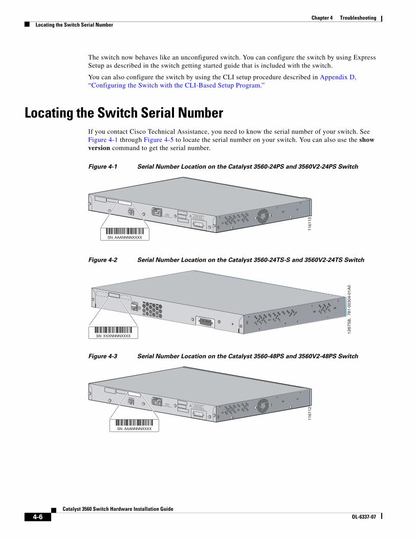
Chapter 4 TroubleshootingLocating the Switch Serial Number
The switch now behaves like an unconfigured switch. You can configure the switch by using Express Setup as described in the switch getting started guide that is included with the switch.
You can also configure the switch by using the CLI setup procedure described in Appendix D, “Configuring the Switch with the CLI-Based Setup Program.”
Locating the Switch Serial NumberIf you contact Cisco Technical Assistance, you need to know the serial number of your switch. See Figure 4-1 through Figure 4-5 to locate the serial number on your switch. You can also use the show version command to get the serial number.
Figure 4-1 Serial Number Location on the Catalyst 3560-24PS and 3560V2-24PS Switch
Figure 4-2 Serial Number Location on the Catalyst 3560-24TS-S and 3560V2-24TS Switch
Figure 4-3 Serial Number Location on the Catalyst 3560-48PS and 3560V2-48PS Switch
RATING100-200V ~5.0A-2.5A, 50-60 HZ
CONSOLE
DC INPUTS FOR REMOTEPOWER SUPPLYSPECIFIED IN MANUAL+12v @7.5A -48 @7.8A
1161
13
SN: AAANNNNXXXX
CONSOLE
126758,
781
-003
04-0
1A0
SN: XXXNNNNXXXX
RATING100-200V ~5.0A-2.5A, 50-60 HZ
CONSOLE
DC INPUTS FOR REMOTEPOWER SUPPLYSPECIFIED IN MANUAL+12v @7.5A -48 @7.8A
1161
12
SN: AAANNNNXXXX
4-6Catalyst 3560 Switch Hardware Installation Guide
OL-6337-07
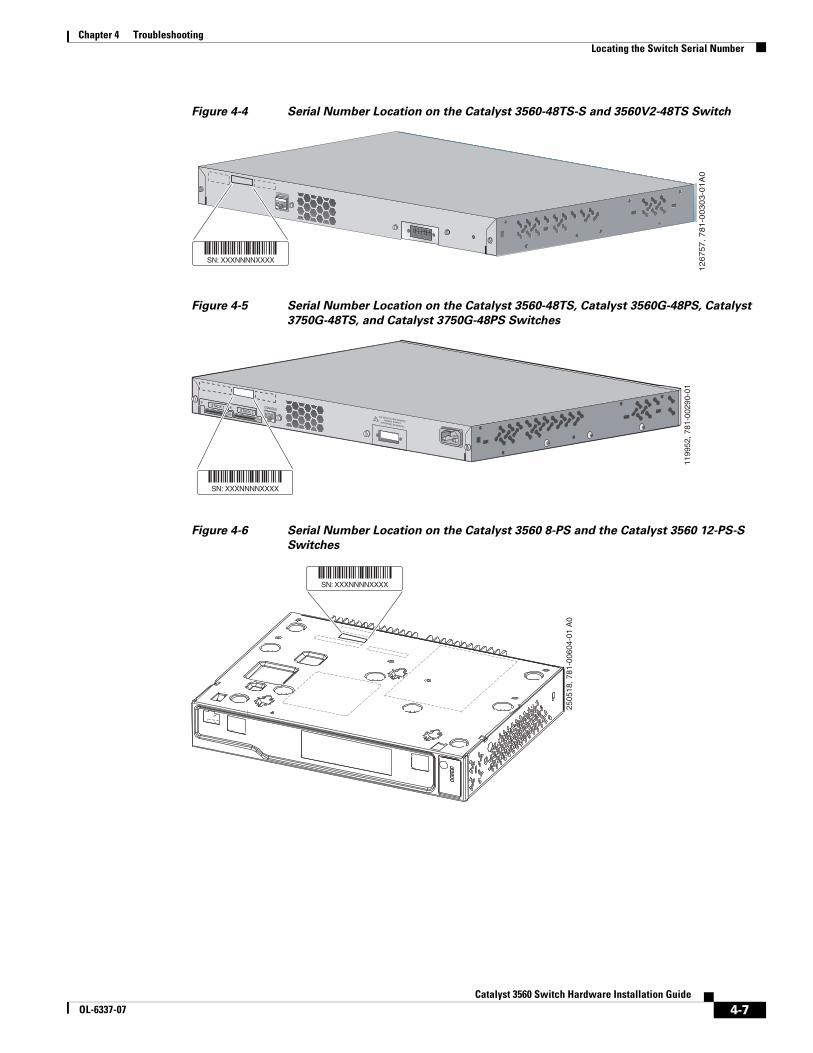
Chapter 4 TroubleshootingLocating the Switch Serial Number
Figure 4-4 Serial Number Location on the Catalyst 3560-48TS-S and 3560V2-48TS Switch
Figure 4-5 Serial Number Location on the Catalyst 3560-48TS, Catalyst 3560G-48PS, Catalyst
3750G-48TS, and Catalyst 3750G-48PS Switches
Figure 4-6 Serial Number Location on the Catalyst 3560 8-PS and the Catalyst 3560 12-PS-S
Switches
CONSOLE
126757, 781-0
0303-0
1A
0
SN: XXXNNNNXXXX
CONSOLE
DC INPUTS FOR REMOTEPOWER SUPPLYSPECIFIED IN MANUAL
1199
52, 7
81-0
0290
-01
STACK 1STACK 2
SN: XXXNNNNXXXX
2505
18, 7
81-0
0604
-01
A0
SN: XXXNNNNXXXX
4-7Catalyst 3560 Switch Hardware Installation Guide
OL-6337-07

Chapter 4 TroubleshootingLocating the Switch Serial Number
4-8Catalyst 3560 Switch Hardware Installation Guide
OL-6337-07
CatalOL-6337-07
A
P P E N D I X A Technical Specifications• Table A-1 on page A-1, Environmental Ranges for all Catalyst 3560 Switches
• Table A-2 on page A-2, Technical Specifications for the Catalyst 3560-24PS Switch
• Table A-3 on page A-2, Specifications for the Catalyst 3560-48PS Switch
• Table A-4 on page A-3, Specifications for the Catalyst 3560-24TS-S Switch
• Table A-5 on page A-3, Specifications for the Catalyst 3560-48TS-S Switch
• Table A-6 on page A-3, Specifications for the Catalyst 3560-8PC and Catalyst 3560-12PC Switches
• Table A-7 on page A-4, Specifications for the Catalyst 3560G-24TS Switch
• Table A-8 on page A-4, Specifications for the Catalyst 3560G-24PS Switch
• Table A-9 on page A-5, Specifications for the Catalyst 3560G-48TS Switch
• Table A-10 on page A-5, Specifications for the Catalyst 3560G-48PS Switch
• Table A-11 on page A-5, Specifications for the Catalyst 3560V2-48PS and 3560V2-24PS Switch
• Table A-12 on page A-6, Specifications for the Catalyst 3560V2-48TS and 3560V2-24TS Switch
• Table A-13 on page A-6, Specifications for the Catalyst 3560V2-24TS-SD Switch
Table A-1 Environmental Ranges for all Catalyst 3560 Switches
Operating temperature 32 to 113°F (0 to 45°C)
Storage temperature –13 to 158°F (–25 to 70°C)
Relative humidity 10 to 85% (noncondensing)
Operating altitude Up to 10,000 ft (3049 m)
Storage altitude Up to 15,000 ft (4573 m)
A-1yst 3560 Switch Hardware Installation Guide
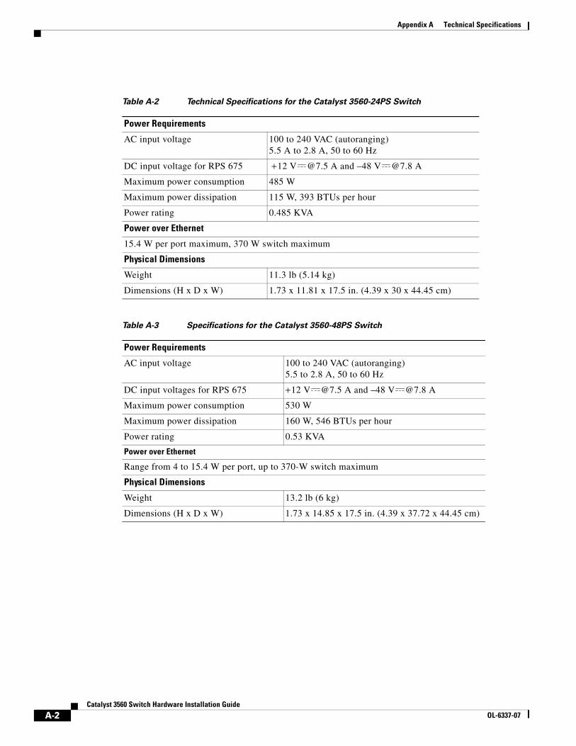
Appendix A Technical Specifications
Table A-2 Technical Specifications for the Catalyst 3560-24PS Switch
Power Requirements
AC input voltage 100 to 240 VAC (autoranging) 5.5 A to 2.8 A, 50 to 60 Hz
DC input voltage for RPS 675 + 12 V @7.5 A and –48 V @7.8 A
Maximum power consumption 485 W
Maximum power dissipation 115 W, 393 BTUs per hour
Power rating 0.485 KVA
Power over Ethernet
15.4 W per port maximum, 370 W switch maximum
Physical Dimensions
Weight 11.3 lb (5.14 kg)
Dimensions (H x D x W) 1.73 x 11.81 x 17.5 in. (4.39 x 30 x 44.45 cm)
Table A-3 Specifications for the Catalyst 3560-48PS Switch
Power Requirements
AC input voltage 100 to 240 VAC (autoranging) 5.5 to 2.8 A, 50 to 60 Hz
DC input voltages for RPS 675 + 12 V @7.5 A and –48 V @7.8 A
Maximum power consumption 530 W
Maximum power dissipation 160 W, 546 BTUs per hour
Power rating 0.53 KVA
Power over Ethernet
Range from 4 to 15.4 W per port, up to 370-W switch maximum
Physical Dimensions
Weight 13.2 lb (6 kg)
Dimensions (H x D x W) 1.73 x 14.85 x 17.5 in. (4.39 x 37.72 x 44.45 cm)
A-2Catalyst 3560 Switch Hardware Installation Guide
OL-6337-07
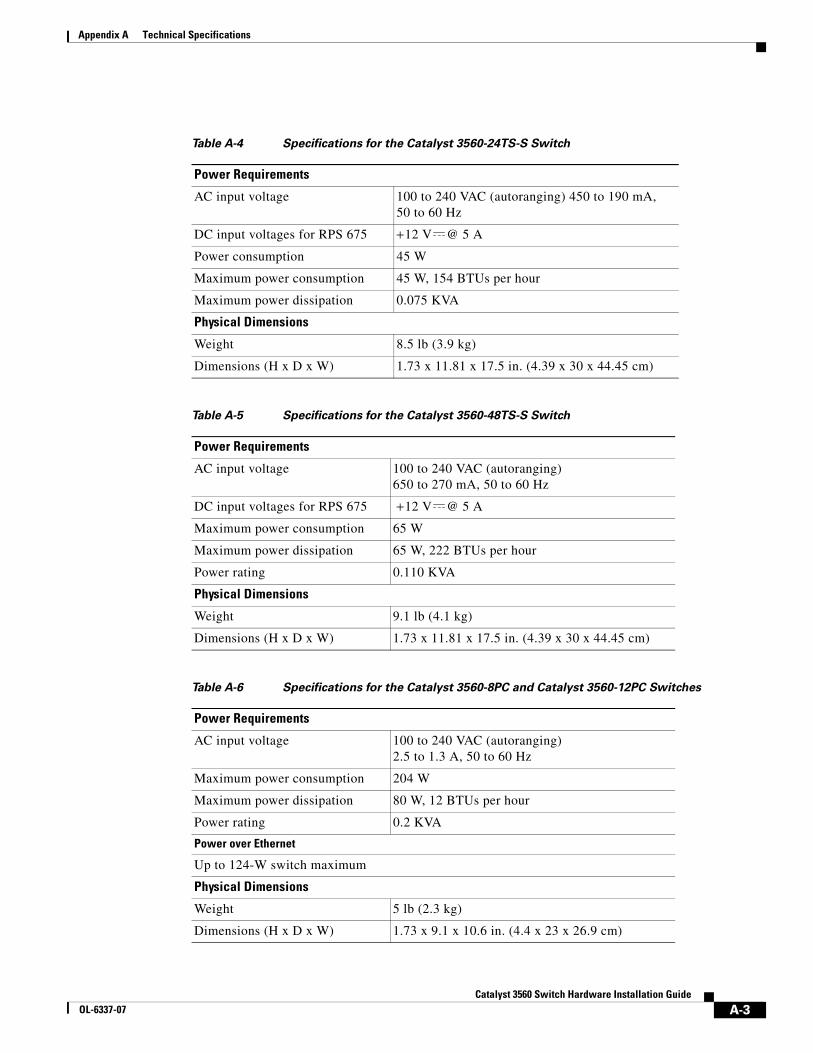
Appendix A Technical Specifications
Table A-4 Specifications for the Catalyst 3560-24TS-S Switch
Power Requirements
AC input voltage 100 to 240 VAC (autoranging) 450 to 190 mA, 50 to 60 Hz
DC input voltages for RPS 675 + 12 V @ 5 A
Power consumption 45 W
Maximum power consumption 45 W, 154 BTUs per hour
Maximum power dissipation 0.075 KVA
Physical Dimensions
Weight 8.5 lb (3.9 kg)
Dimensions (H x D x W) 1.73 x 11.81 x 17.5 in. (4.39 x 30 x 44.45 cm)
Table A-5 Specifications for the Catalyst 3560-48TS-S Switch
Power Requirements
AC input voltage 100 to 240 VAC (autoranging) 650 to 270 mA, 50 to 60 Hz
DC input voltages for RPS 675 + 12 V @ 5 A
Maximum power consumption 65 W
Maximum power dissipation 65 W, 222 BTUs per hour
Power rating 0.110 KVA
Physical Dimensions
Weight 9.1 lb (4.1 kg)
Dimensions (H x D x W) 1.73 x 11.81 x 17.5 in. (4.39 x 30 x 44.45 cm)
Table A-6 Specifications for the Catalyst 3560-8PC and Catalyst 3560-12PC Switches
Power Requirements
AC input voltage 100 to 240 VAC (autoranging) 2.5 to 1.3 A, 50 to 60 Hz
Maximum power consumption 204 W
Maximum power dissipation 80 W, 12 BTUs per hour
Power rating 0.2 KVA
Power over Ethernet
Up to 124-W switch maximum
Physical Dimensions
Weight 5 lb (2.3 kg)
Dimensions (H x D x W) 1.73 x 9.1 x 10.6 in. (4.4 x 23 x 26.9 cm)
A-3Catalyst 3560 Switch Hardware Installation Guide
OL-6337-07
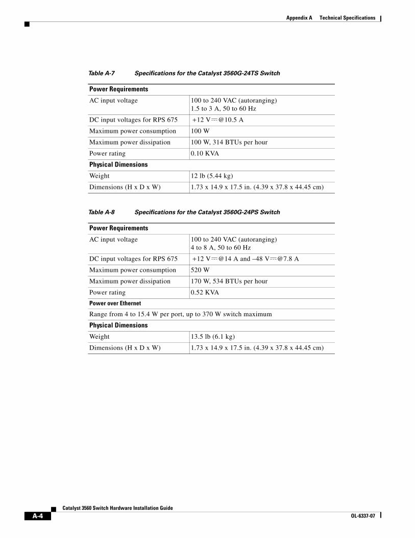
Appendix A Technical Specifications
Table A-7 Specifications for the Catalyst 3560G-24TS Switch
Power Requirements
AC input voltage 100 to 240 VAC (autoranging) 1.5 to 3 A, 50 to 60 Hz
DC input voltages for RPS 675 + 12 V @10.5 A
Maximum power consumption 100 W
Maximum power dissipation 100 W, 314 BTUs per hour
Power rating 0.10 KVA
Physical Dimensions
Weight 12 lb (5.44 kg)
Dimensions (H x D x W) 1.73 x 14.9 x 17.5 in. (4.39 x 37.8 x 44.45 cm)
Table A-8 Specifications for the Catalyst 3560G-24PS Switch
Power Requirements
AC input voltage 100 to 240 VAC (autoranging) 4 to 8 A, 50 to 60 Hz
DC input voltages for RPS 675 + 12 V @14 A and –48 V @7.8 A
Maximum power consumption 520 W
Maximum power dissipation 170 W, 534 BTUs per hour
Power rating 0.52 KVA
Power over Ethernet
Range from 4 to 15.4 W per port, up to 370 W switch maximum
Physical Dimensions
Weight 13.5 lb (6.1 kg)
Dimensions (H x D x W) 1.73 x 14.9 x 17.5 in. (4.39 x 37.8 x 44.45 cm)
A-4Catalyst 3560 Switch Hardware Installation Guide
OL-6337-07
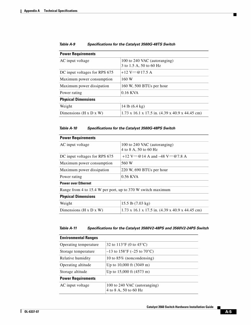
Appendix A Technical Specifications
Table A-9 Specifications for the Catalyst 3560G-48TS Switch
Power Requirements
AC input voltage 100 to 240 VAC (autoranging) 3 to 1.5 A, 50 to 60 Hz
DC input voltages for RPS 675 + 12 V @17.5 A
Maximum power consumption 160 W
Maximum power dissipation 160 W, 500 BTUs per hour
Power rating 0.16 KVA
Physical Dimensions
Weight 14 lb (6.4 kg)
Dimensions (H x D x W) 1.73 x 16.1 x 17.5 in. (4.39 x 40.9 x 44.45 cm)
Table A-10 Specifications for the Catalyst 3560G-48PS Switch
Power Requirements
AC input voltage 100 to 240 VAC (autoranging) 4 to 8 A, 50 to 60 Hz
DC input voltages for RPS 675 + 12 V @14 A and –48 V @7.8 A
Maximum power consumption 560 W
Maximum power dissipation 220 W, 690 BTUs per hour
Power rating 0.56 KVA
Power over Ethernet
Range from 4 to 15.4 W per port, up to 370 W switch maximum
Physical Dimensions
Weight 15.5 lb (7.03 kg)
Dimensions (H x D x W) 1.73 x 16.1 x 17.5 in. (4.39 x 40.9 x 44.45 cm)
Table A-11 Specifications for the Catalyst 3560V2-48PS and 3560V2-24PS Switch
Environmental Ranges
Operating temperature 32 to 113°F (0 to 45°C)
Storage temperature –13 to 158°F (–25 to 70°C)
Relative humidity 10 to 85% (noncondensing)
Operating altitude Up to 10,000 ft (3049 m)
Storage altitude Up to 15,000 ft (4573 m)
Power Requirements
AC input voltage 100 to 240 VAC (autoranging) 4 to 8 A, 50 to 60 Hz
A-5Catalyst 3560 Switch Hardware Installation Guide
OL-6337-07
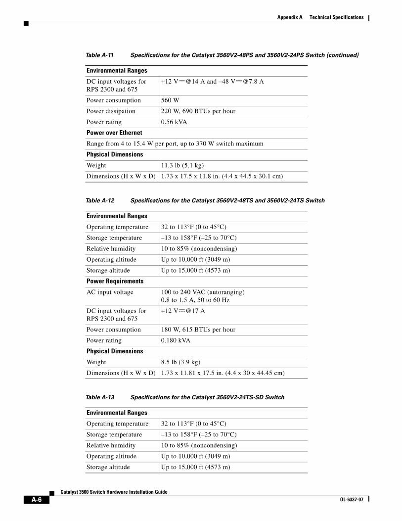
Appendix A Technical Specifications
DC input voltages for RPS 2300 and 675
+12 V @14 A and –48 V @7.8 A
Power consumption 560 W
Power dissipation 220 W, 690 BTUs per hour
Power rating 0.56 kVA
Power over Ethernet
Range from 4 to 15.4 W per port, up to 370 W switch maximum
Physical Dimensions
Weight 11.3 lb (5.1 kg)
Dimensions (H x W x D) 1.73 x 17.5 x 11.8 in. (4.4 x 44.5 x 30.1 cm)
Table A-12 Specifications for the Catalyst 3560V2-48TS and 3560V2-24TS Switch
Environmental Ranges
Operating temperature 32 to 113°F (0 to 45°C)
Storage temperature –13 to 158°F (–25 to 70°C)
Relative humidity 10 to 85% (noncondensing)
Operating altitude Up to 10,000 ft (3049 m)
Storage altitude Up to 15,000 ft (4573 m)
Power Requirements
AC input voltage 100 to 240 VAC (autoranging) 0.8 to 1.5 A, 50 to 60 Hz
DC input voltages for RPS 2300 and 675
+12 V @17 A
Power consumption 180 W, 615 BTUs per hour
Power rating 0.180 kVA
Physical Dimensions
Weight 8.5 lb (3.9 kg)
Dimensions (H x W x D) 1.73 x 11.81 x 17.5 in. (4.4 x 30 x 44.45 cm)
Table A-13 Specifications for the Catalyst 3560V2-24TS-SD Switch
Environmental Ranges
Operating temperature 32 to 113°F (0 to 45°C)
Storage temperature –13 to 158°F (–25 to 70°C)
Relative humidity 10 to 85% (noncondensing)
Operating altitude Up to 10,000 ft (3049 m)
Storage altitude Up to 15,000 ft (4573 m)
Table A-11 Specifications for the Catalyst 3560V2-48PS and 3560V2-24PS Switch (continued)
Environmental Ranges
A-6Catalyst 3560 Switch Hardware Installation Guide
OL-6337-07
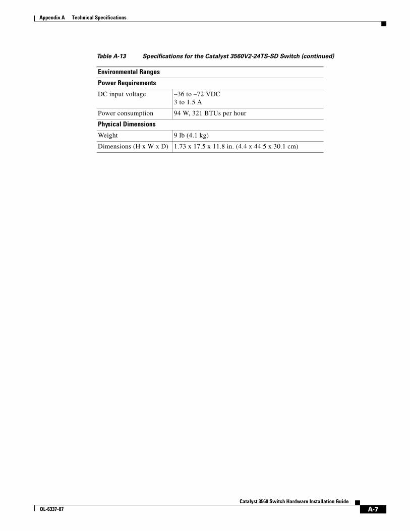
Appendix A Technical Specifications
Power Requirements
DC input voltage –36 to –72 VDC 3 to 1.5 A
Power consumption 94 W, 321 BTUs per hour
Physical Dimensions
Weight 9 lb (4.1 kg)
Dimensions (H x W x D) 1.73 x 17.5 x 11.8 in. (4.4 x 44.5 x 30.1 cm)
Table A-13 Specifications for the Catalyst 3560V2-24TS-SD Switch (continued)
Environmental Ranges
A-7Catalyst 3560 Switch Hardware Installation Guide
OL-6337-07

Appendix A Technical Specifications
A-8Catalyst 3560 Switch Hardware Installation Guide
OL-6337-07
CatalOL-6337-07
A
P P E N D I X B Connector and Cable SpecificationsThis appendix describes the Catalyst 3560 switch ports and the cables and adapters that you use to connect the switch to other devices and includes these sections:
• “Connector Specifications” section on page B-1
• “Cable and Adapter Specifications” section on page B-4
Connector Specifications • 10/100 and 10/100/1000 Ports, page B-1
• SFP Module Ports, page B-2
• Dual-Purpose Ports, page B-3
• Console Port, page B-3
10/100 and 10/100/1000 PortsThe 10/100 and 10/100/1000 Ethernet ports use standard RJ-45 connectors and Ethernet pinouts with internal crossovers. These ports have the send (TD) and receive (RD) signals internally crossed so that a twisted-pair straight-through cable and adapter can be attached to the port. Figure B-1 shows the pinout for a 10/100 port.
B-1yst 3560 Switch Hardware Installation Guide
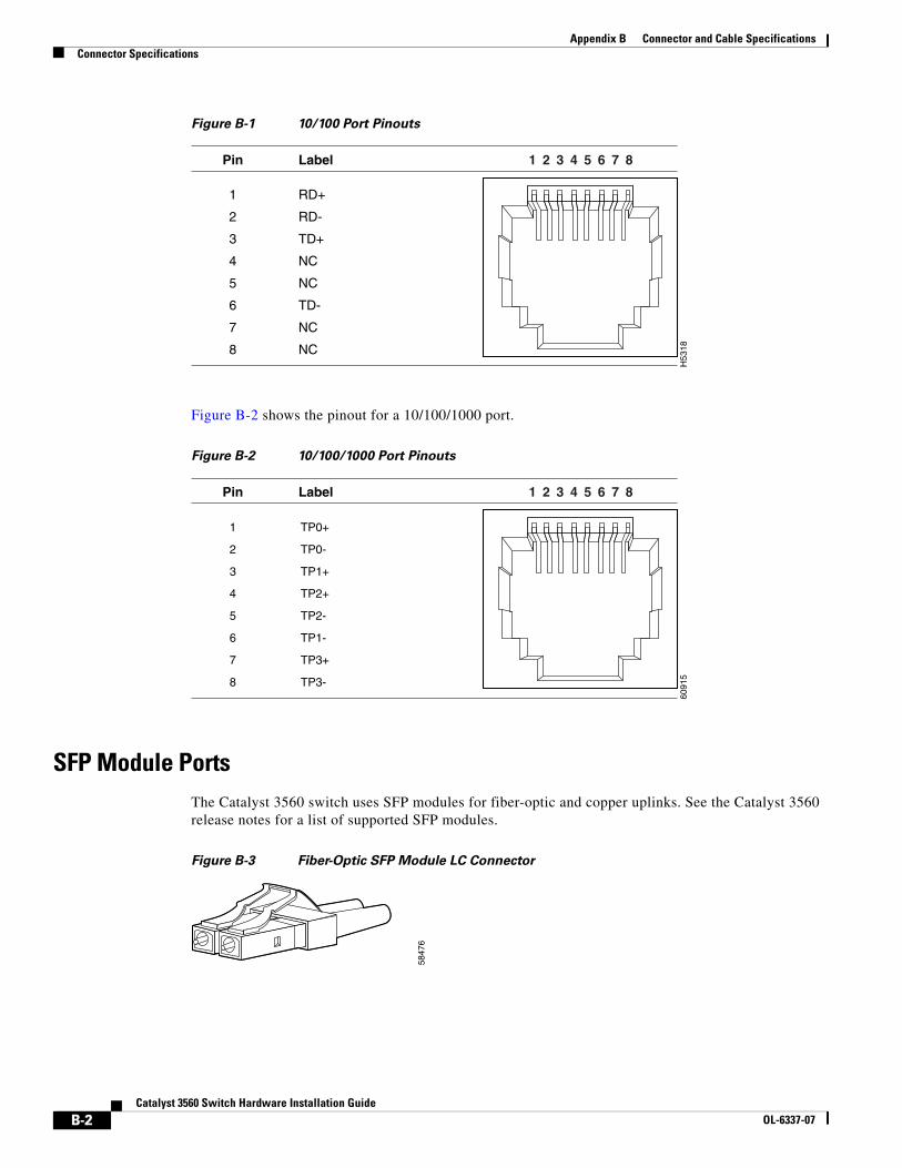
Appendix B Connector and Cable SpecificationsConnector Specifications
Figure B-1 10/100 Port Pinouts
Figure B-2 shows the pinout for a 10/100/1000 port.
Figure B-2 10/100/1000 Port Pinouts
SFP Module PortsThe Catalyst 3560 switch uses SFP modules for fiber-optic and copper uplinks. See the Catalyst 3560 release notes for a list of supported SFP modules.
Figure B-3 Fiber-Optic SFP Module LC Connector
H53
18
2 31 4 5 6 7 8Pin Label
1
2
3
4
5
6
7
8
RD+
RD-
TD+
NC
NC
TD-
NC
NC
6091
5
2 31 4 5 6 7 8Pin Label
1
2
3
4
5
6
7
8
TP0+
TP0-
TP1+
TP2+
TP2-
TP1-
TP3+
TP3-
5847
6
B-2Catalyst 3560 Switch Hardware Installation Guide
OL-6337-07

Appendix B Connector and Cable SpecificationsConnector Specifications
Figure B-4 Copper SFP Module RJ-45 Connector
Dual-Purpose PortsThe Ethernet port on a dual-purpose port uses standard RJ-45 connectors. Figure B-5 shows the pinouts.
Figure B-5 10/100/1000 Port Pinouts
The SFP module slot on a dual-purpose port uses SFP modules for fiber-optic and copper uplink ports. See the Catalyst 3560 release notes for a list of supported SFP modules.
Note The auto-MDIX feature is enabled by default. For configuration information for this feature, see the switch software configuration guide or the switch command reference.
Console PortThe console port uses an 8-pin RJ-45 connector, described in Table B-2 and Table B-3. The RJ-45-to-DB-9 adapter cable connects the console port of the switch to a console PC. You need an RJ-45-to-DB-25 female DTE adapter (ACS-DSBUASYN=) to connect the switch console port to a terminal. For console port and adapter pinout information, see Table B-2 and Table B-3.
6091
5
2 31 4 5 6 7 8Pin Label
1
2
3
4
5
6
7
8
TP0+
TP0-
TP1+
TP2+
TP2-
TP1-
TP3+
TP3-
6091
5
2 31 4 5 6 7 8Pin Label
1
2
3
4
5
6
7
8
TP0+
TP0-
TP1+
TP2+
TP2-
TP1-
TP3+
TP3-
B-3Catalyst 3560 Switch Hardware Installation Guide
OL-6337-07
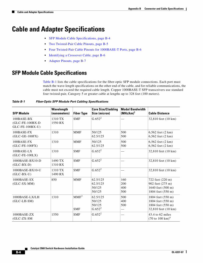
Appendix B Connector and Cable SpecificationsCable and Adapter Specifications
Cable and Adapter Specifications • SFP Module Cable Specifications, page B-4
• Two Twisted-Pair Cable Pinouts, page B-5
• Four Twisted-Pair Cable Pinouts for 1000BASE-T Ports, page B-6
• Identifying a Crossover Cable, page B-6
• Adapter Pinouts, page B-7
SFP Module Cable SpecificationsTable B-1 lists the cable specifications for the fiber-optic SFP module connections. Each port must match the wave-length specifications on the other end of the cable, and for reliable communications, the cable must not exceed the required cable length. Copper 1000BASE-T SFP transceivers use standard four twisted-pair, Category 5 or greater cable at lengths up to 328 feet (100 meters).
Table B-1 Fiber-Optic SFP Module Port Cabling Specifications
SFP ModuleWavelength (nanometers) Fiber Type
Core Size/Cladding Size (micron)
Modal Bandwidth (MHz/km)1 Cable Distance
100BASE-BX (GLC-FE-100BX-D GLC-FE-100BX-U)
1310 TX 1550 RX
SMF G.6522 — 32,810 feet (10 km)
100BASE-FX (GLC-GE-100FX)
1310 MMF 50/125 62.5/125
500 500
6,562 feet (2 km) 6,562 feet (2 km)
100BASE-FX (GLC-FE-100FX)
1310 MMF 50/125 62.5/125
500 500
6,562 feet (2 km) 6,562 feet (2 km)
100BASE-LX (GLC-FE-100LX)
1310 SMF G.6522 — 32,810 feet (10 km)
1000BASE-BX10-D (GLC-BX-D)
1490 TX 1310 RX
SMF G.6522 — 32,810 feet (10 km)
1000BASE-BX10-U (GLC-BX-U)
1310 TX 1490 RX
SMF G.6522 — 32,810 feet (10 km)
1000BASE-SX (GLC-SX-MM)
850 MMF 62.5/125 62.5/125 50/125 50/125
160 200 400 500
722 feet (220 m) 902 feet (275 m) 1640 feet (500 m) 1804 feet (550 m)
1000BASE-LX/LH (GLC-LH-SM)
1310 MMF3 SMF
62.5/125 50/125 50/125 G.6522
500 400 500 —
1804 feet (550 m) 1804 feet (550 m) 1804 feet (550 m) 32,810 feet (10 km)
1000BASE-ZX (GLC-ZX-SM
1550 SMF G.6522 — 43.4 to 62 miles (70 to 100 km)4
B-4Catalyst 3560 Switch Hardware Installation Guide
OL-6337-07
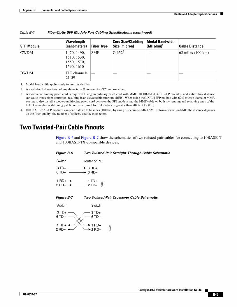
Appendix B Connector and Cable SpecificationsCable and Adapter Specifications
Two Twisted-Pair Cable PinoutsFigure B-6 and Figure B-7 show the schematics of two twisted-pair cables for connecting to 10BASE-T- and 100BASE-TX-compatible devices.
Figure B-6 Two Twisted-Pair Straight-Through Cable Schematic
Figure B-7 Two Twisted-Pair Crossover Cable Schematic
CWDM 1470, 1490, 1510, 1530, 1550, 1570, 1590, 1610
SMF G.6522 — 62 miles (100 km)
DWDM ITU channels 21-59
— — — —
1. Modal bandwidth applies only to multimode fiber.
2. A mode-field diameter/cladding diameter = 9 micrometers/125 micrometers
3. A mode-conditioning patch cord is required. Using an ordinary patch cord with MMF, 1000BASE-LX/LH SFP modules, and a short link distance can cause transceiver saturation, resulting in an elevated bit error rate (BER). When using the LX/LH SFP module with 62.5-micron diameter MMF, you must also install a mode-conditioning patch cord between the SFP module and the MMF cable on both the sending and receiving ends of the link. The mode-conditioning patch cord is required for link distances greater than 984 feet (300 m).
4. 1000BASE-ZX SFP modules can send data up to 62 miles (100 km) by using dispersion-shifted SMF or low-attenuation SMF; the distance depends on the fiber quality, the number of splices, and the connectors.
Table B-1 Fiber-Optic SFP Module Port Cabling Specifications (continued)
SFP ModuleWavelength (nanometers) Fiber Type
Core Size/Cladding Size (micron)
Modal Bandwidth (MHz/km)1 Cable Distance
Switch
3 TD+6 TD–
1 RD+2 RD–
Router or PC
3 RD+6 RD–
1 TD+2 TD–
H55
78
Switch
3 TD+6 TD–
1 RD+2 RD–
Switch
3 TD+6 TD–
1 RD+2 RD–
H55
79
B-5Catalyst 3560 Switch Hardware Installation Guide
OL-6337-07
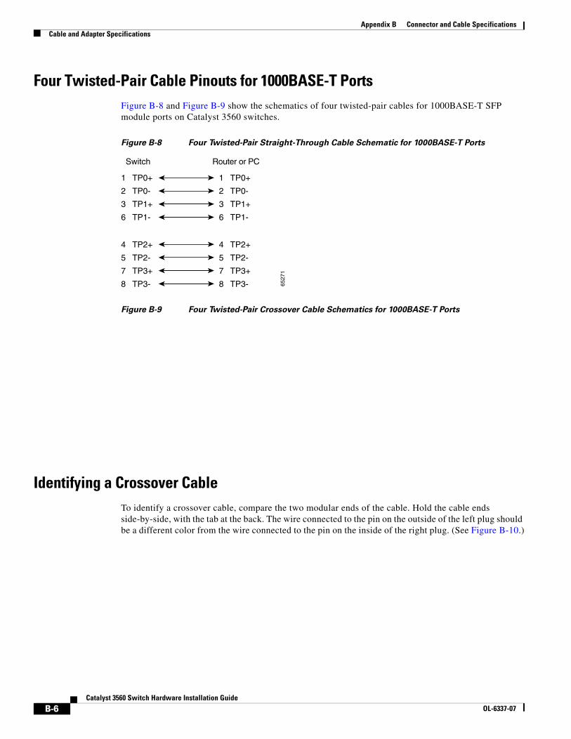
Appendix B Connector and Cable SpecificationsCable and Adapter Specifications
Four Twisted-Pair Cable Pinouts for 1000BASE-T PortsFigure B-8 and Figure B-9 show the schematics of four twisted-pair cables for 1000BASE-T SFP module ports on Catalyst 3560 switches.
Figure B-8 Four Twisted-Pair Straight-Through Cable Schematic for 1000BASE-T Ports
Figure B-9 Four Twisted-Pair Crossover Cable Schematics for 1000BASE-T Ports
Identifying a Crossover CableTo identify a crossover cable, compare the two modular ends of the cable. Hold the cable ends side-by-side, with the tab at the back. The wire connected to the pin on the outside of the left plug should be a different color from the wire connected to the pin on the inside of the right plug. (See Figure B-10.)
1 TP0+
2 TP0-
3 TP1+
6 TP1-
1 TP0+
2 TP0-
3 TP1+
6 TP1-
Switch Router or PC
4 TP2+
5 TP2-
7 TP3+
8 TP3-
4 TP2+
5 TP2-
7 TP3+
8 TP3- 6527
1
B-6Catalyst 3560 Switch Hardware Installation Guide
OL-6337-07
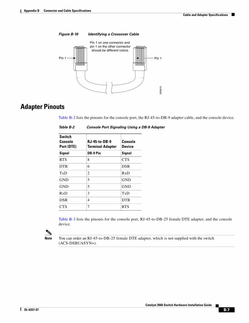
Appendix B Connector and Cable SpecificationsCable and Adapter Specifications
Figure B-10 Identifying a Crossover Cable
Adapter PinoutsTable B-2 lists the pinouts for the console port, the RJ-45-to-DB-9 adapter cable, and the console device.
Table B-3 lists the pinouts for the console port, RJ-45-to-DB-25 female DTE adapter, and the console device.
Note You can order an RJ-45-to-DB-25 female DTE adapter, which is not supplied with the switch (ACS-DSBUASYN=).
Pin 1
2009
15
Pin 1
Pin 1 on one connector and pin 1 on the other connectorshould be different colors.
Table B-2 Console Port Signaling Using a DB-9 Adapter
Switch Console Port (DTE)
RJ-45-to-DB-9 Terminal Adapter
Console Device
Signal DB-9 Pin Signal
RTS 8 CTS
DTR 6 DSR
TxD 2 RxD
GND 5 GND
GND 5 GND
RxD 3 TxD
DSR 4 DTR
CTS 7 RTS
B-7Catalyst 3560 Switch Hardware Installation Guide
OL-6337-07
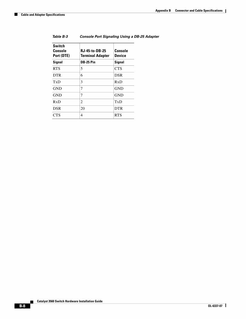
Appendix B Connector and Cable SpecificationsCable and Adapter Specifications
Table B-3 Console Port Signaling Using a DB-25 Adapter
Switch Console Port (DTE)
RJ-45-to-DB-25 Terminal Adapter
Console Device
Signal DB-25 Pin Signal
RTS 5 CTS
DTR 6 DSR
TxD 3 RxD
GND 7 GND
GND 7 GND
RxD 2 TxD
DSR 20 DTR
CTS 4 RTS
B-8Catalyst 3560 Switch Hardware Installation Guide
OL-6337-07

CatalOL-6337-07
A
P P E N D I X C Connecting to DC PowerThis appendix describes how to make DC power connections to the Catalyst 3560V2-24TS-SD switch. See “Switch Installation (24- and 48-Port Switches)” and “Switch Installation (8- and 12-Port Switches)” for instructions on installing the switch.
Connecting to DC Power To connect the Catalyst 3560V2-24TS-SD switch to a DC-input power source, follow the steps in these sections:
• Preparing for Installation, page C-2
• Grounding the Switch, page C-2
• Wiring the DC-Input Power Source, page C-5
Warning This unit is intended for installation in restricted access areas. A restricted access area can be accessed only through the use of a special tool, lock and key, or other means of security. Statement 1017
Note We recommend that you use 18 AWG copper wiring for Network Equipment Building Systems (NEBS) installation. This guideline follows the standard guidelines for DC power wiring in the Central Office.
Note When an RPS is connected to the Catalyst 3560V2-24TS-SD switch, the switch is not NEBS compliant.
Note The grounding architecture of this product is DC-isolated (DC-I).
Caution To comply with the intrabuilding lightning surge requirements, intrabuilding wiring must be shielded, and the shield for the wiring must be grounded at both ends.
C-1yst 3560 Switch Hardware Installation Guide
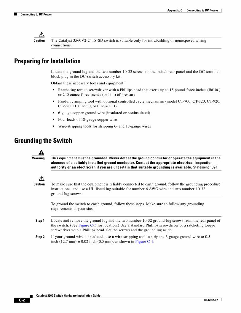
Appendix C Connecting to DC PowerConnecting to DC Power
Caution The Catalyst 3560V2-24TS-SD switch is suitable only for intrabuilding or nonexposed wiring connections.
Preparing for InstallationLocate the ground lug and the two number-10-32 screws on the switch rear panel and the DC terminal block plug in the DC-switch accessory kit.
Obtain these necessary tools and equipment:
• Ratcheting torque screwdriver with a Phillips head that exerts up to 15 pound-force inches (lbf-in.) or 240 ounce-force inches (ozf-in.) of pressure
• Panduit crimping tool with optional controlled cycle mechanism (model CT-700, CT-720, CT-920, CT-920CH, CT-930, or CT-940CH)
• 6-gauge copper ground wire (insulated or noninsulated)
• Four leads of 18-gauge copper wire
• Wire-stripping tools for stripping 6- and 18-gauge wires
Grounding the Switch
Warning This equipment must be grounded. Never defeat the ground conductor or operate the equipment in the absence of a suitably installed ground conductor. Contact the appropriate electrical inspection authority or an electrician if you are uncertain that suitable grounding is available. Statement 1024
Caution To make sure that the equipment is reliably connected to earth ground, follow the grounding procedure instructions, and use a UL-listed lug suitable for number-6 AWG wire and two number-10-32 ground-lug screws.
To ground the switch to earth ground, follow these steps. Make sure to follow any grounding requirements at your site.
Step 1 Locate and remove the ground lug and the two number-10-32 ground-lug screws from the rear panel of the switch. (See Figure C-3 for location.) Use a standard Phillips screwdriver or a ratcheting torque screwdriver with a Phillips head. Set the screws and the ground lug aside.
Step 2 If your ground wire is insulated, use a wire stripping tool to strip the 6-gauge ground wire to 0.5 inch (12.7 mm) ± 0.02 inch (0.5 mm), as shown in Figure C-1.
C-2Catalyst 3560 Switch Hardware Installation Guide
OL-6337-07
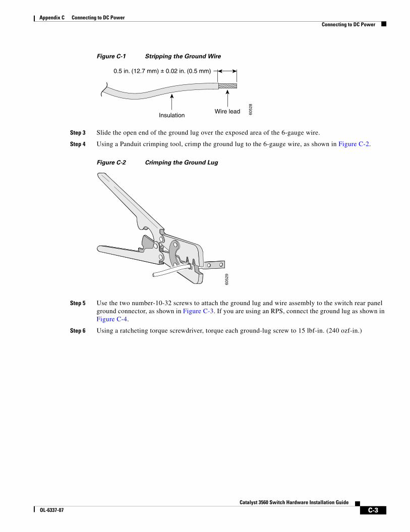
Appendix C Connecting to DC PowerConnecting to DC Power
Figure C-1 Stripping the Ground Wire
Step 3 Slide the open end of the ground lug over the exposed area of the 6-gauge wire.
Step 4 Using a Panduit crimping tool, crimp the ground lug to the 6-gauge wire, as shown in Figure C-2.
Figure C-2 Crimping the Ground Lug
Step 5 Use the two number-10-32 screws to attach the ground lug and wire assembly to the switch rear panel ground connector, as shown in Figure C-3. If you are using an RPS, connect the ground lug as shown in Figure C-4.
Step 6 Using a ratcheting torque screwdriver, torque each ground-lug screw to 15 lbf-in. (240 ozf-in.)
InsulationWire lead
0.5 in. (12.7 mm) ± 0.02 in. (0.5 mm)
6052
8
6052
9
C-3Catalyst 3560 Switch Hardware Installation Guide
OL-6337-07
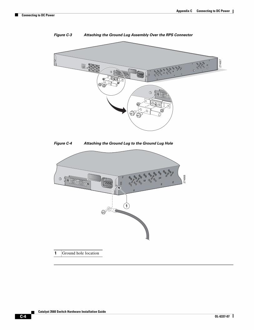
Appendix C Connecting to DC PowerConnecting to DC Power
Figure C-3 Attaching the Ground Lug Assembly Over the RPS Connector
Figure C-4 Attaching the Ground Lug to the Ground Lug Hole
2746
67
CONSOLE
1 Ground hole location
2746
68
1
C-4Catalyst 3560 Switch Hardware Installation Guide
OL-6337-07
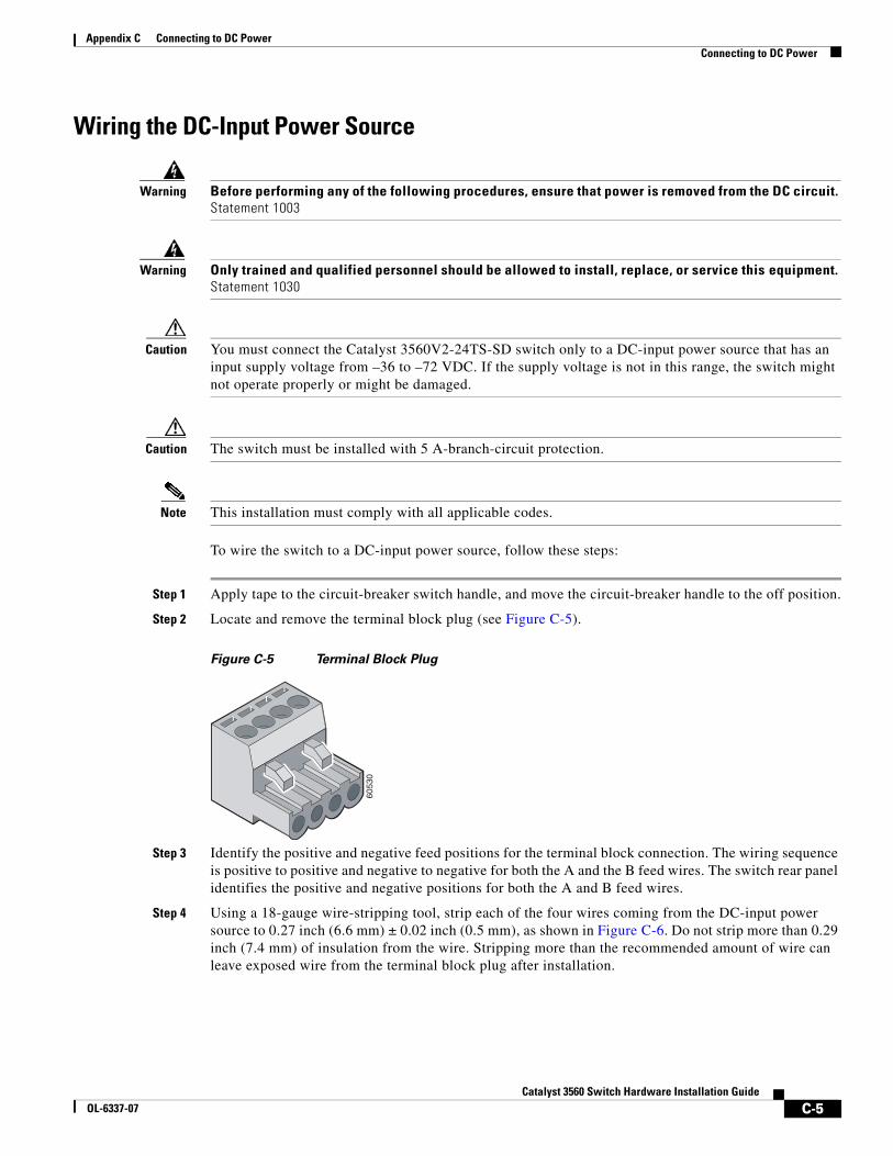
Appendix C Connecting to DC PowerConnecting to DC Power
Wiring the DC-Input Power Source
Warning Before performing any of the following procedures, ensure that power is removed from the DC circuit. Statement 1003
Warning Only trained and qualified personnel should be allowed to install, replace, or service this equipment. Statement 1030
Caution You must connect the Catalyst 3560V2-24TS-SD switch only to a DC-input power source that has an input supply voltage from –36 to –72 VDC. If the supply voltage is not in this range, the switch might not operate properly or might be damaged.
Caution The switch must be installed with 5 A-branch-circuit protection.
Note This installation must comply with all applicable codes.
To wire the switch to a DC-input power source, follow these steps:
Step 1 Apply tape to the circuit-breaker switch handle, and move the circuit-breaker handle to the off position.
Step 2 Locate and remove the terminal block plug (see Figure C-5).
Figure C-5 Terminal Block Plug
Step 3 Identify the positive and negative feed positions for the terminal block connection. The wiring sequence is positive to positive and negative to negative for both the A and the B feed wires. The switch rear panel identifies the positive and negative positions for both the A and B feed wires.
Step 4 Using a 18-gauge wire-stripping tool, strip each of the four wires coming from the DC-input power source to 0.27 inch (6.6 mm) ± 0.02 inch (0.5 mm), as shown in Figure C-6. Do not strip more than 0.29 inch (7.4 mm) of insulation from the wire. Stripping more than the recommended amount of wire can leave exposed wire from the terminal block plug after installation.
6053
0
C-5Catalyst 3560 Switch Hardware Installation Guide
OL-6337-07
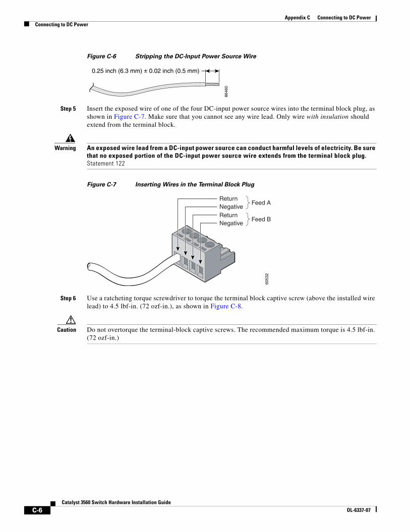
Appendix C Connecting to DC PowerConnecting to DC Power
Figure C-6 Stripping the DC-Input Power Source Wire
Step 5 Insert the exposed wire of one of the four DC-input power source wires into the terminal block plug, as shown in Figure C-7. Make sure that you cannot see any wire lead. Only wire with insulation should extend from the terminal block.
Warning An exposed wire lead from a DC-input power source can conduct harmful levels of electricity. Be sure that no exposed portion of the DC-input power source wire extends from the terminal block plug. Statement 122
Figure C-7 Inserting Wires in the Terminal Block Plug
Step 6 Use a ratcheting torque screwdriver to torque the terminal block captive screw (above the installed wire lead) to 4.5 lbf-in. (72 ozf-in.), as shown in Figure C-8.
Caution Do not overtorque the terminal-block captive screws. The recommended maximum torque is 4.5 lbf-in. (72 ozf-in.)
0.25 inch (6.3 mm) ± 0.02 inch (0.5 mm)
8646
0
6053
2
ReturnNegativeReturn
Feed A
Feed BNegative
C-6Catalyst 3560 Switch Hardware Installation Guide
OL-6337-07
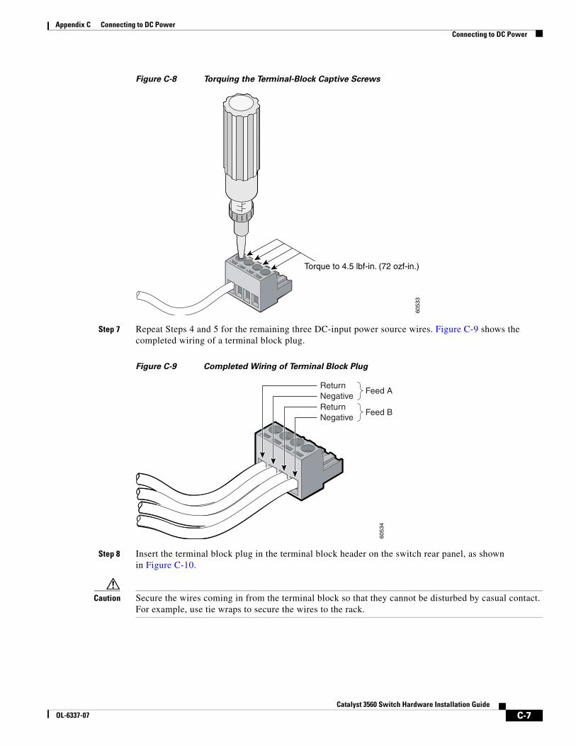
Appendix C Connecting to DC PowerConnecting to DC Power
Figure C-8 Torquing the Terminal-Block Captive Screws
Step 7 Repeat Steps 4 and 5 for the remaining three DC-input power source wires. Figure C-9 shows the completed wiring of a terminal block plug.
Figure C-9 Completed Wiring of Terminal Block Plug
Step 8 Insert the terminal block plug in the terminal block header on the switch rear panel, as shown in Figure C-10.
Caution Secure the wires coming in from the terminal block so that they cannot be disturbed by casual contact. For example, use tie wraps to secure the wires to the rack.
6053
3
Torque to 4.5 lbf-in. (72 ozf-in.)
6053
4ReturnNegativeReturnNegative
Feed A
Feed B
C-7Catalyst 3560 Switch Hardware Installation Guide
OL-6337-07
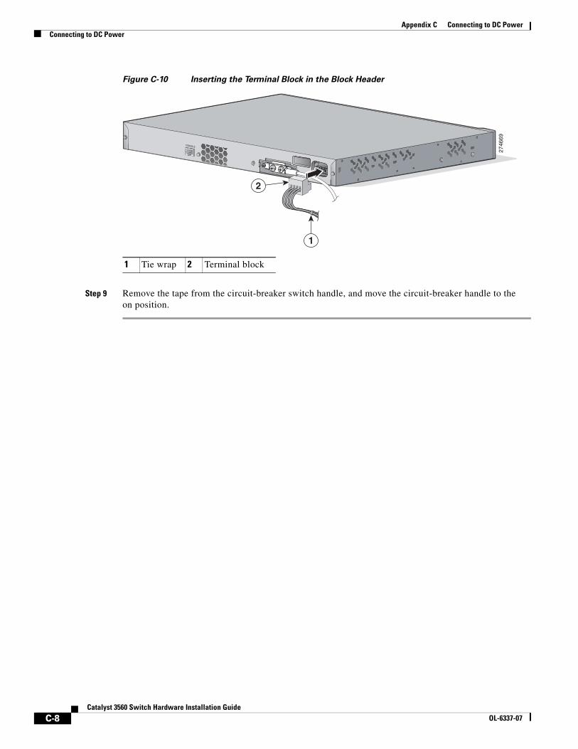
Appendix C Connecting to DC PowerConnecting to DC Power
Figure C-10 Inserting the Terminal Block in the Block Header
Step 9 Remove the tape from the circuit-breaker switch handle, and move the circuit-breaker handle to the on position.
1 Tie wrap 2 Terminal block
2746
69
CONSOLE
1
2
C-8Catalyst 3560 Switch Hardware Installation Guide
OL-6337-07
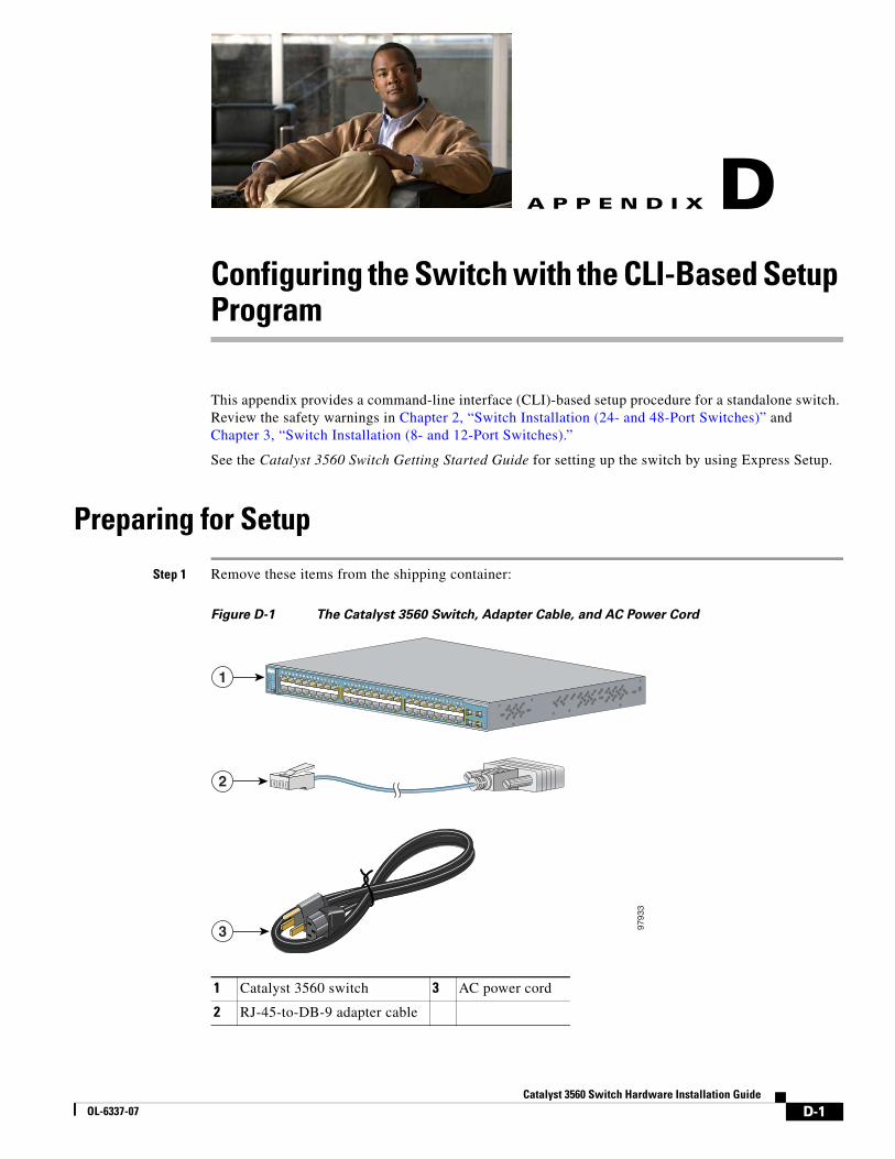
CatalOL-6337-07
A
P P E N D I X D Configuring the Switch with the CLI-Based Setup ProgramThis appendix provides a command-line interface (CLI)-based setup procedure for a standalone switch. Review the safety warnings in Chapter 2, “Switch Installation (24- and 48-Port Switches)” and Chapter 3, “Switch Installation (8- and 12-Port Switches).”
See the Catalyst 3560 Switch Getting Started Guide for setting up the switch by using Express Setup.
Preparing for Setup
Step 1 Remove these items from the shipping container:
Figure D-1 The Catalyst 3560 Switch, Adapter Cable, and AC Power Cord
1 Catalyst 3560 switch 3 AC power cord
2 RJ-45-to-DB-9 adapter cable
Catalyst 3560 SERIES PoE-48
SYSTRPS
STATDUPLXSPEEDPoE
MODE
1
2
3
4
1 25 6 7 8 9 10 11 12 13 14 15 16
3 41X
2X
15X
16X
17 1821 22 23 24 25 26 27 28 29 30 31 32
19 2017X
18X
31X
32X
33 3437 38 39 40 41 42 43 44 45 46 47 48
35 3633X
34X
47X
48X
1
2
3 9793
3
D-1yst 3560 Switch Hardware Installation Guide
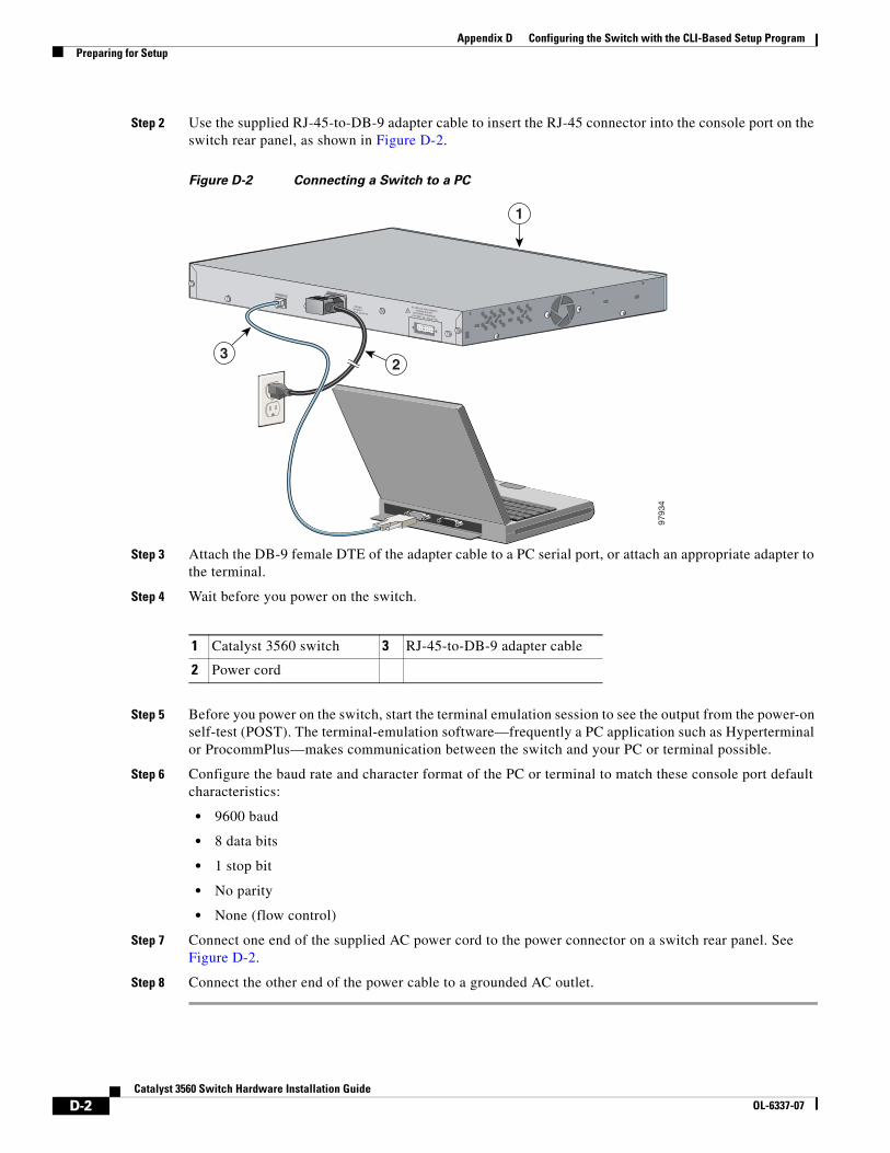
Appendix D Configuring the Switch with the CLI-Based Setup ProgramPreparing for Setup
Step 2 Use the supplied RJ-45-to-DB-9 adapter cable to insert the RJ-45 connector into the console port on the switch rear panel, as shown in Figure D-2.
Figure D-2 Connecting a Switch to a PC
Step 3 Attach the DB-9 female DTE of the adapter cable to a PC serial port, or attach an appropriate adapter to the terminal.
Step 4 Wait before you power on the switch.
Step 5 Before you power on the switch, start the terminal emulation session to see the output from the power-on self-test (POST). The terminal-emulation software—frequently a PC application such as Hyperterminal or ProcommPlus—makes communication between the switch and your PC or terminal possible.
Step 6 Configure the baud rate and character format of the PC or terminal to match these console port default characteristics:
• 9600 baud
• 8 data bits
• 1 stop bit
• No parity
• None (flow control)
Step 7 Connect one end of the supplied AC power cord to the power connector on a switch rear panel. See Figure D-2.
Step 8 Connect the other end of the power cable to a grounded AC outlet.
1 Catalyst 3560 switch 3 RJ-45-to-DB-9 adapter cable
2 Power cord
RATING100-200V ~5.0A-2.5A, 50-60 HZ
CONSOLE
DC INPUTS FOR REMOTEPOWER SUPPLYSPECIFIED IN MANUAL+12v @7.5A -48 @7.8A
23
9793
4
1
D-2Catalyst 3560 Switch Hardware Installation Guide
OL-6337-07
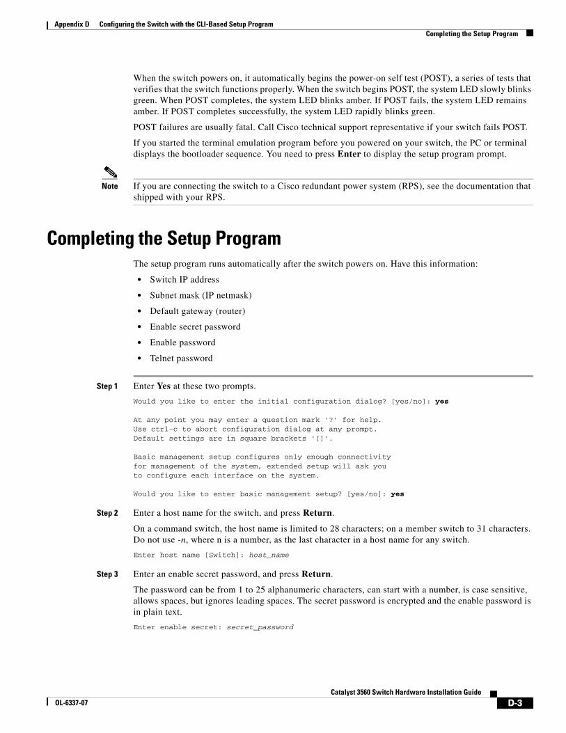
Appendix D Configuring the Switch with the CLI-Based Setup ProgramCompleting the Setup Program
When the switch powers on, it automatically begins the power-on self test (POST), a series of tests that verifies that the switch functions properly. When the switch begins POST, the system LED slowly blinks green. When POST completes, the system LED blinks amber. If POST fails, the system LED remains amber. If POST completes successfully, the system LED rapidly blinks green.
POST failures are usually fatal. Call Cisco technical support representative if your switch fails POST.
If you started the terminal emulation program before you powered on your switch, the PC or terminal displays the bootloader sequence. You need to press Enter to display the setup program prompt.
Note If you are connecting the switch to a Cisco redundant power system (RPS), see the documentation that shipped with your RPS.
Completing the Setup ProgramThe setup program runs automatically after the switch powers on. Have this information:
• Switch IP address
• Subnet mask (IP netmask)
• Default gateway (router)
• Enable secret password
• Enable password
• Telnet password
Step 1 Enter Yes at these two prompts.
Would you like to enter the initial configuration dialog? [yes/no]: yes
At any point you may enter a question mark '?' for help.Use ctrl-c to abort configuration dialog at any prompt.Default settings are in square brackets '[]'.
Basic management setup configures only enough connectivityfor management of the system, extended setup will ask youto configure each interface on the system.
Would you like to enter basic management setup? [yes/no]: yes
Step 2 Enter a host name for the switch, and press Return.
On a command switch, the host name is limited to 28 characters; on a member switch to 31 characters. Do not use -n, where n is a number, as the last character in a host name for any switch.
Enter host name [Switch]: host_name
Step 3 Enter an enable secret password, and press Return.
The password can be from 1 to 25 alphanumeric characters, can start with a number, is case sensitive, allows spaces, but ignores leading spaces. The secret password is encrypted and the enable password is in plain text.
Enter enable secret: secret_password
D-3Catalyst 3560 Switch Hardware Installation Guide
OL-6337-07
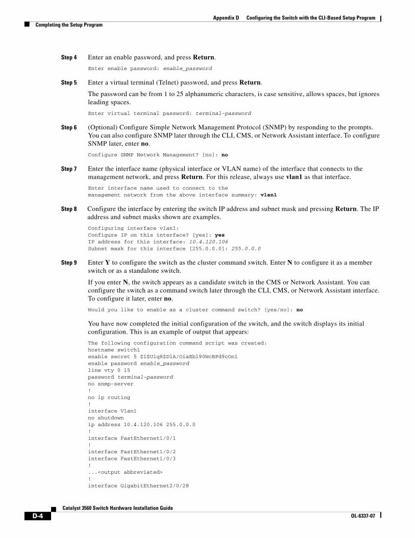
Appendix D Configuring the Switch with the CLI-Based Setup ProgramCompleting the Setup Program
Step 4 Enter an enable password, and press Return.
Enter enable password: enable_password
Step 5 Enter a virtual terminal (Telnet) password, and press Return.
The password can be from 1 to 25 alphanumeric characters, is case sensitive, allows spaces, but ignores leading spaces.
Enter virtual terminal password: terminal-password
Step 6 (Optional) Configure Simple Network Management Protocol (SNMP) by responding to the prompts. You can also configure SNMP later through the CLI, CMS, or Network Assistant interface. To configure SNMP later, enter no.
Configure SNMP Network Management? [no]: no
Step 7 Enter the interface name (physical interface or VLAN name) of the interface that connects to the management network, and press Return. For this release, always use vlan1 as that interface.
Enter interface name used to connect to themanagement network from the above interface summary: vlan1
Step 8 Configure the interface by entering the switch IP address and subnet mask and pressing Return. The IP address and subnet masks shown are examples.
Configuring interface vlan1:Configure IP on this interface? [yes]: yes IP address for this interface: 10.4.120.106Subnet mask for this interface [255.0.0.0]: 255.0.0.0
Step 9 Enter Y to configure the switch as the cluster command switch. Enter N to configure it as a member switch or as a standalone switch.
If you enter N, the switch appears as a candidate switch in the CMS or Network Assistant. You can configure the switch as a command switch later through the CLI, CMS, or Network Assistant interface. To configure it later, enter no.
Would you like to enable as a cluster command switch? [yes/no]: no
You have now completed the initial configuration of the switch, and the switch displays its initial configuration. This is an example of output that appears:
The following configuration command script was created:hostname switch1enable secret 5 $1$Ulq8$DlA/OiaEbl90WcBPd9cOn1enable password enable_passwordline vty 0 15password terminal-passwordno snmp-server!no ip routing!interface Vlan1no shutdownip address 10.4.120.106 255.0.0.0!interface FastEthernet1/0/1!interface FastEthernet1/0/2interface FastEthernet1/0/3!...<output abbreviated>!interface GigabitEthernet2/0/28
D-4Catalyst 3560 Switch Hardware Installation Guide
OL-6337-07
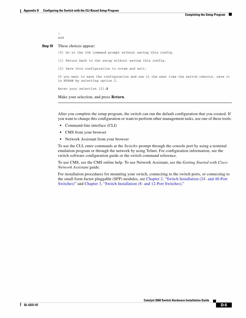
Appendix D Configuring the Switch with the CLI-Based Setup ProgramCompleting the Setup Program
!end
Step 10 These choices appear:
[0] Go to the IOS command prompt without saving this config.
[1] Return back to the setup without saving this config.
[2] Save this configuration to nvram and exit.
If you want to save the configuration and use it the next time the switch reboots, save it in NVRAM by selecting option 2.
Enter your selection [2]:2
Make your selection, and press Return.
After you complete the setup program, the switch can run the default configuration that you created. If you want to change this configuration or want to perform other management tasks, use one of these tools:
• Command-line interface (CLI)
• CMS from your browser
• Network Assistant from your browser
To use the CLI, enter commands at the Switch> prompt through the console port by using a terminal emulation program or through the network by using Telnet. For configuration information, see the switch software configuration guide or the switch command reference.
To use CMS, see the CMS online help. To use Network Assistant, see the Getting Started with Cisco Network Assistant guide.
For installation procedures for mounting your switch, connecting to the switch ports, or connecting to the small form-factor pluggable (SFP) modules, see Chapter 2, “Switch Installation (24- and 48-Port Switches)” and Chapter 3, “Switch Installation (8- and 12-Port Switches).”
D-5Catalyst 3560 Switch Hardware Installation Guide
OL-6337-07

Appendix D Configuring the Switch with the CLI-Based Setup ProgramCompleting the Setup Program
D-6Catalyst 3560 Switch Hardware Installation Guide
OL-6337-07
OL-6337-07
I N D E X
Numerics
10/100/1000 ports
auto-MDIX feature 1-9
cable lengths 2-5, 3-6
connectors and cables B-1
described 1-8
dual-purpose ports 1-10
illustrated 1-7
pinouts B-2
PoE 1-9
10/100 ports
auto-MDIX feature 1-9
cable lengths 2-5, 3-6
connecting to 2-19
connectors and cables B-1
described 1-8
illustrated 1-3
PoE 1-9
1000BASE-T SFP module
ports cable lengths 2-5, 3-6
5 A-branch circuit protection caution C-5
A
AC power
connecting to 2-6, 3-7
connector 1-19
specifications A-2
adapter pinouts, terminal
RJ-45-to-DB-25 B-7
RJ-45-to-DB-9 B-7
auto-MDIX 2-19, B-3
autonegotiation 1-8
troubleshooting 4-4
C
cable guard 1-15
cable guide, attaching 2-11
cable lengths 2-5, 3-5
cables
crossover
four twisted-pair pinout, 1000BASE-T ports B-6
identifying B-6
two twisted-pair pinout, 10/100 ports B-5
for connecting 1000BASE-T modules 2-22
for SFP modules B-4
straight-through
four twisted-pair pinout, 1000BASE-T ports B-6
two twisted-pair pinout B-5
See also connectors and cables
cabling
10/100/1000 ports 2-19
10/100 ports 1-8, 2-19, B-2
auto-MDIX B-3
pinouts B-5
See also connectors and cables
cautions i-vii
5 A-branch-circuit protection C-5
DC power C-5
electromagnetic safety 2-5, 3-5
grounding procedure C-2
lightning surge requirements C-1
nonexposed wiring connections C-2
secure terminal block wires C-7
IN-1Catalyst 3560 Switch Hardware Installation Guide
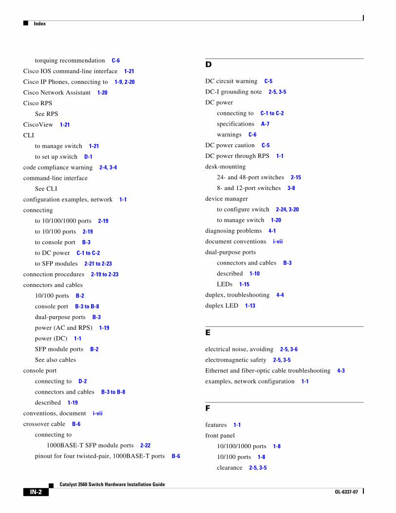
Index
torquing recommendation C-6
Cisco IOS command-line interface 1-21
Cisco IP Phones, connecting to 1-9, 2-20
Cisco Network Assistant 1-20
Cisco RPS
See RPS
CiscoView 1-21
CLI
to manage switch 1-21
to set up switch D-1
code compliance warning 2-4, 3-4
command-line interface
See CLI
configuration examples, network 1-1
connecting
to 10/100/1000 ports 2-19
to 10/100 ports 2-19
to console port B-3
to DC power C-1 to C-2
to SFP modules 2-21 to 2-23
connection procedures 2-19 to 2-23
connectors and cables
10/100 ports B-2
console port B-3 to B-8
dual-purpose ports B-3
power (AC and RPS) 1-19
power (DC) 1-1
SFP module ports B-2
See also cables
console port
connecting to D-2
connectors and cables B-3 to B-8
described 1-19
conventions, document i-vii
crossover cable B-6
connecting to
1000BASE-T SFP module ports 2-22
pinout for four twisted-pair, 1000BASE-T ports B-6
IN-2Catalyst 3560 Switch Hardware Installation Guide
D
DC circuit warning C-5
DC-I grounding note 2-5, 3-5
DC power
connecting to C-1 to C-2
specifications A-7
warnings C-6
DC power caution C-5
DC power through RPS 1-1
desk-mounting
24- and 48-port switches 2-15
8- and 12-port switches 3-8
device manager
to configure switch 2-24, 3-20
to manage switch 1-20
diagnosing problems 4-1
document conventions i-vii
dual-purpose ports
connectors and cables B-3
described 1-10
LEDs 1-15
duplex, troubleshooting 4-4
duplex LED 1-13
E
electrical noise, avoiding 2-5, 3-6
electromagnetic safety 2-5, 3-5
Ethernet and fiber-optic cable troubleshooting 4-3
examples, network configuration 1-1
F
features 1-1
front panel
10/100/1000 ports 1-8
10/100 ports 1-8
clearance 2-5, 3-5
OL-6337-07
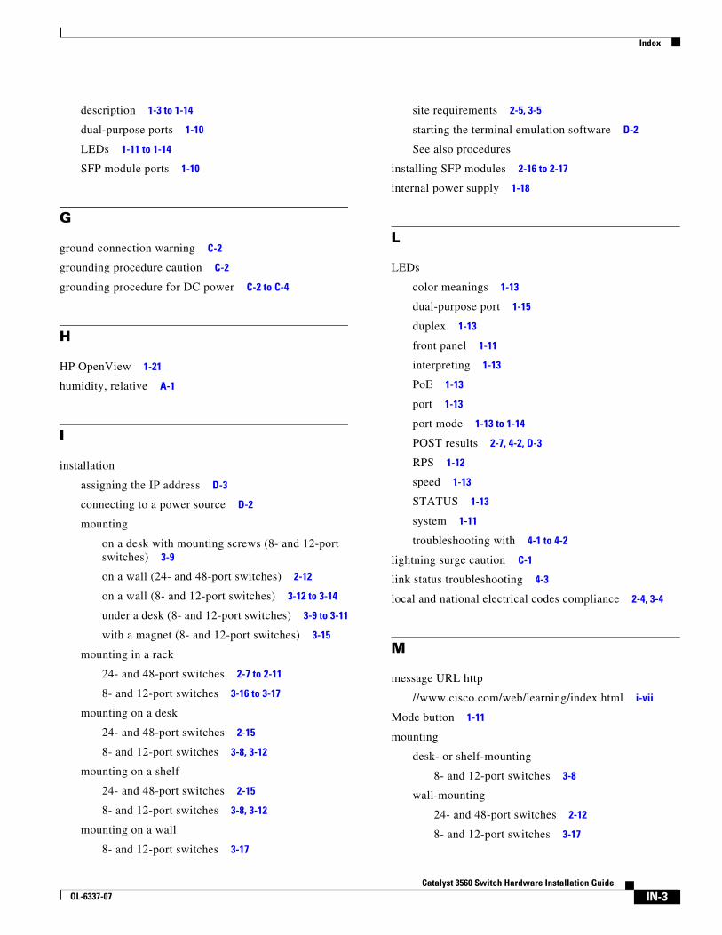
Index
description 1-3 to 1-14
dual-purpose ports 1-10
LEDs 1-11 to 1-14
SFP module ports 1-10
G
ground connection warning C-2
grounding procedure caution C-2
grounding procedure for DC power C-2 to C-4
H
HP OpenView 1-21
humidity, relative A-1
I
installation
assigning the IP address D-3
connecting to a power source D-2
mounting
on a desk with mounting screws (8- and 12-port switches) 3-9
on a wall (24- and 48-port switches) 2-12
on a wall (8- and 12-port switches) 3-12 to 3-14
under a desk (8- and 12-port switches) 3-9 to 3-11
with a magnet (8- and 12-port switches) 3-15
mounting in a rack
24- and 48-port switches 2-7 to 2-11
8- and 12-port switches 3-16 to 3-17
mounting on a desk
24- and 48-port switches 2-15
8- and 12-port switches 3-8, 3-12
mounting on a shelf
24- and 48-port switches 2-15
8- and 12-port switches 3-8, 3-12
mounting on a wall
8- and 12-port switches 3-17
OL-6337-07
site requirements 2-5, 3-5
starting the terminal emulation software D-2
See also procedures
installing SFP modules 2-16 to 2-17
internal power supply 1-18
L
LEDs
color meanings 1-13
dual-purpose port 1-15
duplex 1-13
front panel 1-11
interpreting 1-13
PoE 1-13
port 1-13
port mode 1-13 to 1-14
POST results 2-7, 4-2, D-3
RPS 1-12
speed 1-13
STATUS 1-13
system 1-11
troubleshooting with 4-1 to 4-2
lightning surge caution C-1
link status troubleshooting 4-3
local and national electrical codes compliance 2-4, 3-4
M
message URL http
//www.cisco.com/web/learning/index.html i-vii
Mode button 1-11
mounting
desk- or shelf-mounting
8- and 12-port switches 3-8
wall-mounting
24- and 48-port switches 2-12
8- and 12-port switches 3-17
IN-3Catalyst 3560 Switch Hardware Installation Guide
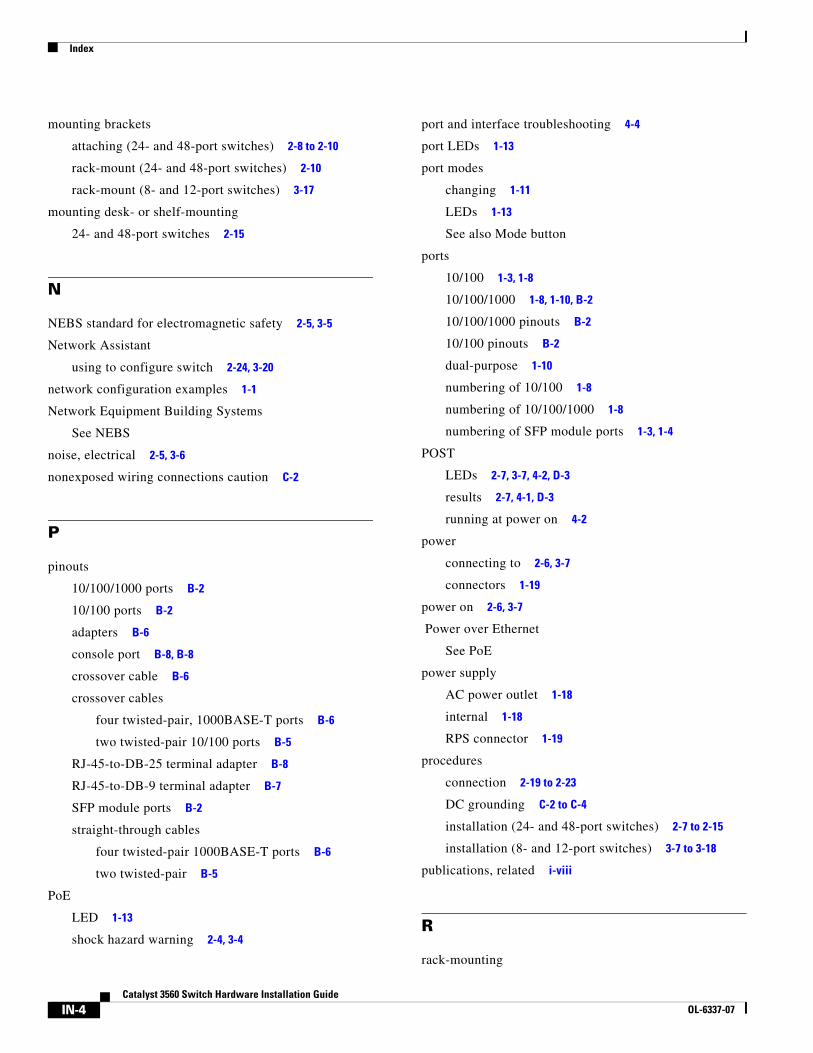
Index
mounting brackets
attaching (24- and 48-port switches) 2-8 to 2-10
rack-mount (24- and 48-port switches) 2-10
rack-mount (8- and 12-port switches) 3-17
mounting desk- or shelf-mounting
24- and 48-port switches 2-15
N
NEBS standard for electromagnetic safety 2-5, 3-5
Network Assistant
using to configure switch 2-24, 3-20
network configuration examples 1-1
Network Equipment Building Systems
See NEBS
noise, electrical 2-5, 3-6
nonexposed wiring connections caution C-2
P
pinouts
10/100/1000 ports B-2
10/100 ports B-2
adapters B-6
console port B-8, B-8
crossover cable B-6
crossover cables
four twisted-pair, 1000BASE-T ports B-6
two twisted-pair 10/100 ports B-5
RJ-45-to-DB-25 terminal adapter B-8
RJ-45-to-DB-9 terminal adapter B-7
SFP module ports B-2
straight-through cables
four twisted-pair 1000BASE-T ports B-6
two twisted-pair B-5
PoE
LED 1-13
shock hazard warning 2-4, 3-4
IN-4Catalyst 3560 Switch Hardware Installation Guide
port and interface troubleshooting 4-4
port LEDs 1-13
port modes
changing 1-11
LEDs 1-13
See also Mode button
ports
10/100 1-3, 1-8
10/100/1000 1-8, 1-10, B-2
10/100/1000 pinouts B-2
10/100 pinouts B-2
dual-purpose 1-10
numbering of 10/100 1-8
numbering of 10/100/1000 1-8
numbering of SFP module ports 1-3, 1-4
POST
LEDs 2-7, 3-7, 4-2, D-3
results 2-7, 4-1, D-3
running at power on 4-2
power
connecting to 2-6, 3-7
connectors 1-19
power on 2-6, 3-7
Power over Ethernet
See PoE
power supply
AC power outlet 1-18
internal 1-18
RPS connector 1-19
procedures
connection 2-19 to 2-23
DC grounding C-2 to C-4
installation (24- and 48-port switches) 2-7 to 2-15
installation (8- and 12-port switches) 3-7 to 3-18
publications, related i-viii
R
rack-mounting
OL-6337-07
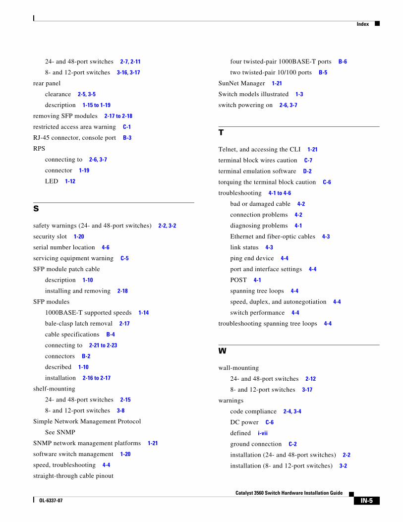
Index
24- and 48-port switches 2-7, 2-11
8- and 12-port switches 3-16, 3-17
rear panel
clearance 2-5, 3-5
description 1-15 to 1-19
removing SFP modules 2-17 to 2-18
restricted access area warning C-1
RJ-45 connector, console port B-3
RPS
connecting to 2-6, 3-7
connector 1-19
LED 1-12
S
safety warnings (24- and 48-port switches) 2-2, 3-2
security slot 1-20
serial number location 4-6
servicing equipment warning C-5
SFP module patch cable
description 1-10
installing and removing 2-18
SFP modules
1000BASE-T supported speeds 1-14
bale-clasp latch removal 2-17
cable specifications B-4
connecting to 2-21 to 2-23
connectors B-2
described 1-10
installation 2-16 to 2-17
shelf-mounting
24- and 48-port switches 2-15
8- and 12-port switches 3-8
Simple Network Management Protocol
See SNMP
SNMP network management platforms 1-21
software switch management 1-20
speed, troubleshooting 4-4
straight-through cable pinout
OL-6337-07
four twisted-pair 1000BASE-T ports B-6
two twisted-pair 10/100 ports B-5
SunNet Manager 1-21
Switch models illustrated 1-3
switch powering on 2-6, 3-7
T
Telnet, and accessing the CLI 1-21
terminal block wires caution C-7
terminal emulation software D-2
torquing the terminal block caution C-6
troubleshooting 4-1 to 4-6
bad or damaged cable 4-2
connection problems 4-2
diagnosing problems 4-1
Ethernet and fiber-optic cables 4-3
link status 4-3
ping end device 4-4
port and interface settings 4-4
POST 4-1
spanning tree loops 4-4
speed, duplex, and autonegotiation 4-4
switch performance 4-4
troubleshooting spanning tree loops 4-4
W
wall-mounting
24- and 48-port switches 2-12
8- and 12-port switches 3-17
warnings
code compliance 2-4, 3-4
DC power C-6
defined i-vii
ground connection C-2
installation (24- and 48-port switches) 2-2
installation (8- and 12-port switches) 3-2
IN-5Catalyst 3560 Switch Hardware Installation Guide

Index
PoE shock hazard 2-4, 3-4
removing power from DC circuit C-5
restricted access area C-1
servicing equipment C-5
IN-6Catalyst 3560 Switch Hardware Installation Guide
OL-6337-07