Embed Size (px)
Citation preview
Catalyst 3750 Switch Command ReferenceCisco IOS Release 12.2(25)SEEFebruary 2006
Corporate HeadquartersCisco Systems, Inc.170 West Tasman DriveSan Jose, CA 95134-1706 USAhttp://www.cisco.comTel: 408 526-4000
800 553-NETS (6387)Fax: 408 526-4100
Text Part Number: OL-8552-01

THE SPECIFICATIONS AND INFORMATION REGARDING THE PRODUCTS IN THIS MANUAL ARE SUBJECT TO CHANGE WITHOUT NOTICE. ALL STATEMENTS, INFORMATION, AND RECOMMENDATIONS IN THIS MANUAL ARE BELIEVED TO BE ACCURATE BUT ARE PRESENTED WITHOUT WARRANTY OF ANY KIND, EXPRESS OR IMPLIED. USERS MUST TAKE FULL RESPONSIBILITY FOR THEIR APPLICATION OF ANY PRODUCTS.
THE SOFTWARE LICENSE AND LIMITED WARRANTY FOR THE ACCOMPANYING PRODUCT ARE SET FORTH IN THE INFORMATION PACKET THAT SHIPPED WITH THE PRODUCT AND ARE INCORPORATED HEREIN BY THIS REFERENCE. IF YOU ARE UNABLE TO LOCATE THE SOFTWARE LICENSE OR LIMITED WARRANTY, CONTACT YOUR CISCO REPRESENTATIVE FOR A COPY.
The Cisco implementation of TCP header compression is an adaptation of a program developed by the University of California, Berkeley (UCB) as part of UCB’s public domain version of the UNIX operating system. All rights reserved. Copyright © 1981, Regents of the University of California.
NOTWITHSTANDING ANY OTHER WARRANTY HEREIN, ALL DOCUMENT FILES AND SOFTWARE OF THESE SUPPLIERS ARE PROVIDED “AS IS” WITH ALL FAULTS. CISCO AND THE ABOVE-NAMED SUPPLIERS DISCLAIM ALL WARRANTIES, EXPRESSED OR IMPLIED, INCLUDING, WITHOUT LIMITATION, THOSE OF MERCHANTABILITY, FITNESS FOR A PARTICULAR PURPOSE AND NONINFRINGEMENT OR ARISING FROM A COURSE OF DEALING, USAGE, OR TRADE PRACTICE.
IN NO EVENT SHALL CISCO OR ITS SUPPLIERS BE LIABLE FOR ANY INDIRECT, SPECIAL, CONSEQUENTIAL, OR INCIDENTAL DAMAGES, INCLUDING, WITHOUT LIMITATION, LOST PROFITS OR LOSS OR DAMAGE TO DATA ARISING OUT OF THE USE OR INABILITY TO USE THIS MANUAL, EVEN IF CISCO OR ITS SUPPLIERS HAVE BEEN ADVISED OF THE POSSIBILITY OF SUCH DAMAGES.
CCSP, CCVP, the Cisco Square Bridge logo, Follow Me Browsing, and StackWise are trademarks of Cisco Systems, Inc.; Changing the Way We Work, Live, Play, and Learn, and iQuick Study are service marks of Cisco Systems, Inc.; and Access Registrar, Aironet, BPX, Catalyst, CCDA, CCDP, CCIE, CCIP, CCNA, CCNP, Cisco, the Cisco Certified Internetwork Expert logo, Cisco IOS, Cisco Press, Cisco Systems, Cisco Systems Capital, the Cisco Systems logo, Cisco Unity, Enterprise/Solver, EtherChannel, EtherFast, EtherSwitch, Fast Step, FormShare, GigaDrive, GigaStack, HomeLink, Internet Quotient, IOS, IP/TV, iQ Expertise, the iQ logo, iQ Net Readiness Scorecard, LightStream, Linksys, MeetingPlace, MGX, the Networkers logo, Networking Academy, Network Registrar, Packet, PIX, Post-Routing, Pre-Routing, ProConnect, RateMUX, ScriptShare, SlideCast, SMARTnet, The Fastest Way to Increase Your Internet Quotient, and TransPath are registered trademarks of Cisco Systems, Inc. and/or its affiliates in the United States and certain other countries.
All other trademarks mentioned in this document or Website are the property of their respective owners. The use of the word partner does not imply a partnership relationship between Cisco and any other company. (0601R)
Any Internet Protocol (IP) addresses used in this document are not intended to be actual addresses. Any examples, command display output, and figures included in the document are shown for illustrative purposes only. Any use of actual IP addresses in illustrative content is unintentional and coincidental.
Catalyst 3750 Switch Command ReferenceCopyright ©2006 Cisco Systems, Inc. All rights reserved.
OL-8552-01
C O N T E N T S
Preface xix
Audience xix
Purpose xix
Conventions xx
Related Publications xx
Obtaining Documentation xxi
Cisco.com xxi
Product Documentation DVD xxii
Ordering Documentation xxii
Documentation Feedback xxii
Cisco Product Security Overview xxii
Reporting Security Problems in Cisco Products xxiii
Obtaining Technical Assistance xxiv
Cisco Technical Support & Documentation Website xxiv
Submitting a Service Request xxiv
Definitions of Service Request Severity xxv
Obtaining Additional Publications and Information xxv
C H A P T E R 1 Using the Command-Line Interface 1-1
Accessing the Switch 1-1
CLI Command Modes 1-2
User EXEC Mode 1-3
Privileged EXEC Mode 1-3
Global Configuration Mode 1-4
Interface Configuration Mode 1-4
config-vlan Mode 1-4
VLAN Configuration Mode 1-5
Line Configuration Mode 1-5
Commands Changed in Cisco IOS 12.2(18)SE 1-6
C H A P T E R 2 Catalyst 3750 Switch Cisco IOS Commands 2-1
aaa accounting dot1x 2-1
aaa authentication dot1x 2-3
iiiCatalyst 3750 Switch Command Reference
Contents
aaa authorization network 2-5
action 2-6
archive copy-sw 2-8
archive download-sw 2-11
archive tar 2-15
archive upload-sw 2-18
arp access-list 2-20
auto qos voip 2-22
boot auto-copy-sw 2-27
boot boothlpr 2-28
boot config-file 2-29
boot enable-break 2-30
boot helper 2-31
boot helper-config-file 2-32
boot manual 2-33
boot private-config-file 2-34
boot system 2-35
channel-group 2-37
channel-protocol 2-41
class 2-42
class-map 2-44
clear dot1x 2-46
clear eap 2-47
clear ip arp inspection log 2-48
clear ip arp inspection statistics 2-49
clear ip dhcp snooping database 2-50
clear ipc 2-51
clear l2protocol-tunnel counters 2-52
clear lacp 2-53
clear mac address-table 2-54
clear mac address-table move update 2-56
clear pagp 2-57
clear port-security 2-58
clear spanning-tree counters 2-60
clear spanning-tree detected-protocols 2-61
ivCatalyst 3750 Switch Command Reference
OL-8552-01
Contents
clear vmps statistics 2-62
clear vtp counters 2-63
cluster commander-address 2-64
cluster discovery hop-count 2-66
cluster enable 2-67
cluster holdtime 2-69
cluster member 2-70
cluster outside-interface 2-72
cluster run 2-73
cluster standby-group 2-74
cluster timer 2-76
define interface-range 2-77
delete 2-79
deny (ARP access-list configuration) 2-80
deny (IPv6 access-list configuration) 2-82
deny (MAC access-list configuration) 2-87
diagnostic monitor 2-90
diagnostic schedule 2-93
diagnostic start 2-95
dot1x 2-97
dot1x auth-fail max-attempts 2-99
dot1x auth-fail vlan 2-101
dot1x control-direction 2-103
dot1x critical (global configuration) 2-105
dot1x critical (interface configuration) 2-107
dot1x default 2-109
dot1x guest-vlan 2-110
dot1x host-mode 2-113
dot1x initialize 2-115
dot1x mac-auth-bypass 2-116
dot1x max-reauth-req 2-118
dot1x max-req 2-119
dot1x multiple-hosts 2-120
dot1x pae 2-121
dot1x port-control 2-122
vCatalyst 3750 Switch Command Reference
OL-8552-01
Contents
dot1x re-authenticate 2-124
dot1x re-authentication 2-125
dot1x reauthentication 2-126
dot1x timeout 2-127
duplex 2-130
errdisable detect cause 2-132
errdisable recovery 2-134
exception crashinfo 2-137
flowcontrol 2-138
interface port-channel 2-140
interface range 2-142
interface vlan 2-144
ip access-group 2-146
ip address 2-149
ip arp inspection filter vlan 2-151
ip arp inspection limit 2-153
ip arp inspection log-buffer 2-155
ip arp inspection trust 2-157
ip arp inspection validate 2-159
ip arp inspection vlan 2-161
ip arp inspection vlan logging 2-162
ip dhcp snooping 2-164
ip dhcp snooping binding 2-165
ip dhcp snooping database 2-167
ip dhcp snooping information option 2-169
ip dhcp snooping information option allow-untrusted 2-171
ip dhcp snooping information option format remote-id 2-173
ip dhcp snooping limit rate 2-174
ip dhcp snooping trust 2-175
ip dhcp snooping verify 2-176
ip dhcp snooping vlan 2-177
ip dhcp snooping vlan information option format-type circuit-id string 2-178
ip igmp filter 2-180
ip igmp max-groups 2-181
ip igmp profile 2-183
viCatalyst 3750 Switch Command Reference
OL-8552-01
Contents
ip igmp snooping 2-185
ip igmp snooping last-member-query-interval 2-187
ip igmp snooping querier 2-189
ip igmp snooping report-suppression 2-191
ip igmp snooping tcn 2-193
ip igmp snooping tcn flood 2-195
ip igmp snooping vlan immediate-leave 2-196
ip igmp snooping vlan mrouter 2-197
ip igmp snooping vlan static 2-199
ip snap forwarding 2-201
ip source binding 2-202
ip ssh 2-204
ip verify source 2-206
ipv6 access-list 2-207
ipv6 mld snooping 2-209
ipv6 mld snooping last-listener-query-count 2-211
ipv6 mld snooping last-listener-query-interval 2-213
ipv6 mld snooping listener-message-suppression 2-215
ipv6 mld snooping robustness-variable 2-217
ipv6 mld snooping tcn 2-219
ipv6 mld snooping vlan 2-221
ipv6 traffic-filter 2-223
l2protocol-tunnel 2-225
l2protocol-tunnel cos 2-228
lacp port-priority 2-229
lacp system-priority 2-231
link state group 2-233
link state track 2-235
logging event power-inline-status 2-236
logging file 2-237
mac access-group 2-239
mac access-list extended 2-241
mac address-table aging-time 2-243
mac address-table move update 2-244
mac address-table notification 2-246
viiCatalyst 3750 Switch Command Reference
OL-8552-01
Contents
mac address-table static 2-248
mac address-table static drop 2-249
macro apply 2-251
macro description 2-254
macro global 2-255
macro global description 2-258
macro name 2-259
match (access-map configuration) 2-261
match (class-map configuration) 2-263
mdix auto 2-265
mls qos 2-267
mls qos aggregate-policer 2-269
mls qos cos 2-271
mls qos dscp-mutation 2-273
mls qos map 2-275
mls qos queue-set output buffers 2-279
mls qos queue-set output threshold 2-281
mls qos rewrite ip dscp 2-283
mls qos srr-queue input bandwidth 2-285
mls qos srr-queue input buffers 2-287
mls qos srr-queue input cos-map 2-289
mls qos srr-queue input dscp-map 2-291
mls qos srr-queue input priority-queue 2-293
mls qos srr-queue input threshold 2-295
mls qos srr-queue output cos-map 2-297
mls qos srr-queue output dscp-map 2-299
mls qos trust 2-301
mls qos vlan-based 2-303
monitor session 2-304
mvr (global configuration) 2-309
mvr (interface configuration) 2-312
pagp learn-method 2-315
pagp port-priority 2-317
permit (ARP access-list configuration) 2-319
permit (IPv6 access-list configuration) 2-321
viiiCatalyst 3750 Switch Command Reference
OL-8552-01
Contents
permit (MAC access-list configuration) 2-327
police 2-330
police aggregate 2-332
policy-map 2-334
port-channel load-balance 2-337
power inline 2-339
power inline consumption 2-342
priority-queue 2-344
private-vlan 2-346
private-vlan mapping 2-349
queue-set 2-351
radius-server dead-criteria 2-352
radius-server host 2-354
rcommand 2-356
reload 2-358
remote command 2-360
remote-span 2-361
renew ip dhcp snooping database 2-363
rmon collection stats 2-365
sdm prefer 2-366
service password-recovery 2-371
service-policy 2-373
session 2-376
set 2-377
setup 2-379
setup express 2-382
show access-lists 2-384
show archive status 2-387
show arp access-list 2-389
show auto qos 2-390
show boot 2-394
show cable-diagnostics tdr 2-396
show class-map 2-398
show cluster 2-399
show cluster candidates 2-401
ixCatalyst 3750 Switch Command Reference
OL-8552-01
Contents
show cluster members 2-403
show controllers cpu-interface 2-405
show controllers ethernet-controller 2-407
show controllers power inline 2-415
show controllers tcam 2-417
show controllers utilization 2-419
show diagnostic 2-421
show dot1q-tunnel 2-424
show dot1x 2-425
show dtp 2-429
show eap 2-431
show env 2-434
show errdisable detect 2-437
show errdisable flap-values 2-439
show errdisable recovery 2-441
show etherchannel 2-443
show flowcontrol 2-446
show idprom 2-448
show interfaces 2-451
show interfaces counters 2-460
show inventory 2-463
show ip arp inspection 2-464
show ip dhcp snooping 2-467
show ip dhcp snooping binding 2-468
show ip dhcp snooping database 2-470
show ip igmp profile 2-472
show ip igmp snooping 2-473
show ip igmp snooping groups 2-476
show ip igmp snooping mrouter 2-478
show ip igmp snooping querier 2-480
show ip source binding 2-482
show ip verify source 2-484
show ipc 2-486
show ipv6 access-list 2-490
show ipv6 mld snooping 2-492
xCatalyst 3750 Switch Command Reference
OL-8552-01
Contents
show ipv6 mld snooping address 2-494
show ipv6 mld snooping mrouter 2-496
show ipv6 mld snooping querier 2-498
show l2protocol-tunnel 2-500
show lacp 2-503
show link state group 2-507
show mac access-group 2-509
show mac address-table 2-511
show mac address-table address 2-513
show mac address-table aging-time 2-515
show mac address-table count 2-517
show mac address-table dynamic 2-519
show mac address-table interface 2-521
show mac address-table move update 2-523
show mac address-table notification 2-525
show mac address-table static 2-527
show mac address-table vlan 2-529
show mls qos 2-531
show mls qos aggregate-policer 2-532
show mls qos input-queue 2-533
show mls qos interface 2-535
show mls qos maps 2-539
show mls qos queue-set 2-542
show mls qos vlan 2-544
show monitor 2-545
show mvr 2-548
show mvr interface 2-550
show mvr members 2-552
show pagp 2-554
show parser macro 2-556
show policy-map 2-559
show port-security 2-561
show power inline 2-564
show sdm prefer 2-567
show setup express 2-571
xiCatalyst 3750 Switch Command Reference
OL-8552-01
Contents
show spanning-tree 2-572
show storm-control 2-579
show switch 2-581
show system mtu 2-584
show udld 2-585
show version 2-588
show vlan 2-590
show vlan access-map 2-595
show vlan filter 2-596
show vmps 2-597
show vtp 2-600
shutdown 2-605
shutdown vlan 2-606
snmp-server enable traps 2-607
snmp-server host 2-611
snmp trap mac-notification 2-615
spanning-tree backbonefast 2-617
spanning-tree bpdufilter 2-618
spanning-tree bpduguard 2-620
spanning-tree cost 2-622
spanning-tree etherchannel guard misconfig 2-624
spanning-tree extend system-id 2-626
spanning-tree guard 2-628
spanning-tree link-type 2-630
spanning-tree loopguard default 2-632
spanning-tree mode 2-634
spanning-tree mst configuration 2-636
spanning-tree mst cost 2-638
spanning-tree mst forward-time 2-640
spanning-tree mst hello-time 2-641
spanning-tree mst max-age 2-642
spanning-tree mst max-hops 2-643
spanning-tree mst port-priority 2-645
spanning-tree mst pre-standard 2-647
spanning-tree mst priority 2-648
xiiCatalyst 3750 Switch Command Reference
OL-8552-01
Contents
spanning-tree mst root 2-649
spanning-tree port-priority 2-651
spanning-tree portfast (global configuration) 2-653
spanning-tree portfast (interface configuration) 2-655
spanning-tree transmit hold-count 2-657
spanning-tree uplinkfast 2-658
spanning-tree vlan 2-660
speed 2-663
srr-queue bandwidth limit 2-665
srr-queue bandwidth shape 2-667
srr-queue bandwidth share 2-669
stack-mac persistent timer 2-671
storm-control 2-673
switch priority 2-676
switch provision 2-677
switch renumber 2-679
switchport 2-681
switchport access 2-683
switchport backup interface 2-685
switchport block 2-688
switchport host 2-689
switchport mode 2-690
switchport mode private-vlan 2-693
switchport nonegotiate 2-695
switchport port-security 2-697
switchport port-security aging 2-702
switchport priority extend 2-704
switchport private-vlan 2-706
switchport protected 2-708
switchport trunk 2-710
switchport voice vlan 2-713
system env temperature threshold yellow 2-715
system mtu 2-717
test cable-diagnostics tdr 2-719
traceroute mac 2-720
xiiiCatalyst 3750 Switch Command Reference
OL-8552-01
Contents
traceroute mac ip 2-723
trust 2-725
udld 2-727
udld port 2-729
udld reset 2-731
vlan (global configuration) 2-732
vlan (VLAN configuration) 2-738
vlan access-map 2-744
vlan database 2-746
vlan dot1q tag native 2-749
vlan filter 2-751
vmps reconfirm (privileged EXEC) 2-753
vmps reconfirm (global configuration) 2-754
vmps retry 2-755
vmps server 2-756
vtp (global configuration) 2-758
vtp (VLAN configuration) 2-762
A P P E N D I X A Catalyst 3750 Switch Boot Loader Commands A-1
boot A-2
cat A-4
copy A-5
delete A-6
dir A-7
flash_init A-9
format A-10
fsck A-11
help A-12
load_helper A-13
memory A-14
mkdir A-16
more A-17
rename A-18
reset A-19
rmdir A-20
set A-21
xivCatalyst 3750 Switch Command Reference
OL-8552-01
Contents
type A-24
unset A-25
version A-27
A P P E N D I X B Catalyst 3750 Switch Debug Commands B-1
debug auto qos B-2
debug backup B-4
debug cluster B-5
debug dot1x B-7
debug dtp B-9
debug eap B-10
debug etherchannel B-12
debug ilpower B-14
debug ip dhcp snooping B-15
debug ip verify source packet B-16
debug interface B-17
debug ip igmp filter B-19
debug ip igmp max-groups B-20
debug ip igmp snooping B-21
debug lacp B-22
debug mac-notification B-23
debug matm B-24
debug matm move update B-25
debug monitor B-26
debug mvrdbg B-28
debug nvram B-29
debug pagp B-30
debug platform acl B-31
debug platform backup interface B-32
debug platform cli-redirection main B-33
debug platform configuration B-34
debug platform cpu-queues B-35
debug platform device-manager B-37
debug platform dot1x B-38
debug platform etherchannel B-39
debug platform fallback-bridging B-40
xvCatalyst 3750 Switch Command Reference
OL-8552-01
Contents
debug platform forw-tcam B-41
debug platform frontend-controller B-42
debug platform ip arp inspection B-44
debug platform ip dhcp B-45
debug platform ip igmp snooping B-46
debug platform ip multicast B-48
debug platform ip unicast B-50
debug platform ipc B-52
debug platform led B-53
debug platform matm B-54
debug platform messaging application B-56
debug platform phy B-58
debug platform pm B-60
debug platform port-asic B-62
debug platform port-security B-63
debug platform qos-acl-tcam B-64
debug platform remote-commands B-65
debug platform resource-manager B-66
debug platform snmp B-67
debug platform span B-68
debug platform stack-manager B-69
debug platform supervisor-asic B-70
debug platform sw-bridge B-71
debug platform tcam B-72
debug platform udld B-75
debug platform vlan B-76
debug pm B-77
debug port-security B-79
debug qos-manager B-80
debug spanning-tree B-81
debug spanning-tree backbonefast B-83
debug spanning-tree bpdu B-84
debug spanning-tree bpdu-opt B-85
debug spanning-tree mstp B-86
debug spanning-tree switch B-88
xviCatalyst 3750 Switch Command Reference
OL-8552-01
Contents
debug spanning-tree uplinkfast B-90
debug sw-vlan B-91
debug sw-vlan ifs B-93
debug sw-vlan notification B-95
debug sw-vlan vtp B-97
debug udld B-99
debug vqpc B-101
A P P E N D I X C Catalyst 3750 Switch Show Platform Commands C-1
show platform acl C-2
show platform backup interface C-3
show platform configuration C-4
show platform etherchannel C-5
show platform forward C-6
show platform frontend-controller C-8
show platform ip igmp snooping C-9
show platform ip multicast C-11
show platform ip unicast C-12
show platform ip unicast vrf compaction C-14
show platform ip unicast vrf tcam-label C-15
show platform ipc trace C-16
show platform ipv6 unicast C-17
show platform layer4op C-19
show platform mac-address-table C-20
show platform messaging C-21
show platform monitor C-22
show platform mvr table C-23
show platform pm C-24
show platform port-asic C-25
show platform port-security C-30
show platform qos C-31
show platform resource-manager C-32
show platform snmp counters C-34
show platform spanning-tree C-35
show platform stp-instance C-36
show platform stack-manager C-37
xviiCatalyst 3750 Switch Command Reference
OL-8552-01

Contents
show platform tb C-39
show platform tcam C-41
show platform vlan C-44
IN D E X
xviiiCatalyst 3750 Switch Command Reference
OL-8552-01
Preface
AudienceThis guide is for the networking professional using the Cisco IOS command-line interface (CLI) to manage the Catalyst 3750 switch, hereafter referred to as the switch. Before using this guide, you should have experience working with the Cisco IOS commands and the switch software features. Before using this guide, you should have experience working with the concepts and terminology of Ethernet and local area networking.
Purpose The Catalyst 3750 switch is supported by either the IP base image, formerly known as the standard multilayer image (SMI), or the IP services image, formerly known as the enhanced multilayer image (EMI). The IP base image provides Layer 2+ features including access control lists (ACLs), quality of service (QoS), static routing, and the Routing Information Protocol (RIP). The IP services image provides a richer set of enterprise-class features. It includes Layer 2+ features and full Layer 3 routing (IP unicast routing, IP multicast routing, and fallback bridging). To distinguish it from the Layer 2+ static routing and RIP, the IP services image includes protocols such as the Enhanced Interior Gateway Routing Protocol (EIGRP) and Open Shortest Path First (OSPF) Protocol.
This guide provides the information that you need about the Layer 2 and Layer 3 commands that have been created or changed for use with the Catalyst 3750 switches. For information about the standard Cisco IOS Release 12.2 commands, see the Cisco IOS documentation set available from the Cisco.com home page by selecting Technical Support & Documentation > Cisco IOS Software.
This guide does not provide procedures for configuring your switch. For detailed configuration procedures, see the software configuration guide for this release.
This guide does not describe system messages you might encounter. For more information, see the system message guide for this release.
For documentation updates, see the release notes for this release.
xixCatalyst 3750 Switch Command Reference
OL-8552-01
PrefaceConventions
ConventionsThis publication uses these conventions to convey instructions and information:
Command descriptions use these conventions:
• Commands and keywords are in boldface text.
• Arguments for which you supply values are in italic.
• Square brackets ([ ]) means optional elements.
• Braces ({}) group required choices, and vertical bars ( | ) separate the alternative elements.
• Braces and vertical bars within square brackets ([{ | }]) mean a required choice within an optional element.
Interactive examples use these conventions:
• Terminal sessions and system displays are in screen font.
• Information you enter is in boldface screen font.
• Nonprinting characters, such as passwords or tabs, are in angle brackets (< >).
Notes, cautions, and warnings use these conventions and symbols:
Note Means reader take note. Notes contain helpful suggestions or references to materials not contained in this manual.
Caution Means reader be careful. In this situation, you might do something that could result in equipment damage or loss of data.
Related PublicationsThese documents provide complete information about the switch and are available from this Cisco.com site:
http://www.cisco.com/en/US/products/hw/switches/ps5023/tsd_products_support_series_home.html
Note Before installing, configuring, or upgrading the switch, see these documents:
• For initial configuration information, see the “Using Express Setup” chapter in the getting started guide or the “Configuring the Switch with the CLI-Based Setup Program” appendix in the hardware installation guide.
• For device manager requirements, see the “System Requirements” section in the release notes (not orderable but available on Cisco.com).
• For Network Assistant requirements, see the Getting Started with Cisco Network Assistant (not orderable but available on Cisco.com).
xxCatalyst 3750 Switch Command Reference
OL-8552-01
PrefaceObtaining Documentation
• For cluster requirements, see the Release Notes for Cisco Network Assistant (not orderable but available on Cisco.com).
• For upgrade information, see the “Downloading Software” section in the release notes.
You can order printed copies of documents with a DOC-xxxxxx= number from the Cisco.com sites and from the telephone numbers listed in the “Obtaining Documentation” section on page xxi.
• Release Notes for the Catalyst 3750, 3560, 2970, and 2960 Switches (not orderable but available on Cisco.com)
• Catalyst 3750 Switch Software Configuration Guide (not orderable but available on Cisco.com)
• Catalyst 3750 Switch Command Reference (not orderable but available on Cisco.com)
• Device manager online help (available on the switch)
• Catalyst 3750 Switch Hardware Installation Guide (not orderable but available on Cisco.com)
• Catalyst 3750 Switch Getting Started Guide (order number DOC-7816663=)
• Regulatory Compliance and Safety Information for the Catalyst 3750 Switch (order number DOC-7816664)
• Catalyst 3750, 3560, 3550, 2970, and 2960 Switch System Message Guide (not orderable but available on Cisco.com)
• Getting Started with Cisco Network Assistant (not orderable but available on Cisco.com)
• Release Notes for Cisco Network Assistant (not orderable but available on Cisco.com)
• Cisco Small Form-Factor Pluggable Modules Installation Notes (order number DOC-7815160=)
• Cisco CWDM GBIC and CWDM SFP Modules Installation Note (not orderable but available on Cisco.com)
• Cisco RPS 300 Redundant Power System Hardware Installation Guide (order number DOC-7810372=)
• Cisco RPS 675 Redundant Power System Hardware Installation Guide (order number DOC-7815201=)
• For information about the Network Admission Control (NAC) features, see the Network Admission Control Software Configuration Guide (not orderable but available on Cisco.com)
Obtaining DocumentationCisco documentation and additional literature are available on Cisco.com. Cisco also provides several ways to obtain technical assistance and other technical resources. These sections explain how to obtain technical information from Cisco Systems.
Cisco.comYou can access the most current Cisco documentation at this URL:
http://www.cisco.com/techsupport
You can access the Cisco website at this URL:
http://www.cisco.com
xxiCatalyst 3750 Switch Command Reference
OL-8552-01
PrefaceDocumentation Feedback
You can access international Cisco websites at this URL:
http://www.cisco.com/public/countries_languages.shtml
Product Documentation DVDThe Product Documentation DVD is a comprehensive library of technical product documentation on a portable medium. The DVD enables you to access multiple versions of installation, configuration, and command guides for Cisco hardware and software products. With the DVD, you have access to the same HTML documentation that is found on the Cisco website without being connected to the Internet. Certain products also have .PDF versions of the documentation available.
The Product Documentation DVD is available as a single unit or as a subscription. Registered Cisco.com users (Cisco direct customers) can order a Product Documentation DVD (product number DOC-DOCDVD= or DOC-DOCDVD=SUB) from Cisco Marketplace at this URL:
http://www.cisco.com/go/marketplace/
Ordering DocumentationRegistered Cisco.com users may order Cisco documentation at the Product Documentation Store in the Cisco Marketplace at this URL:
http://www.cisco.com/go/marketplace/
Nonregistered Cisco.com users can order technical documentation from 8:00 a.m. to 5:00 p.m. (0800 to 1700) PDT by calling 1 866 463-3487 in the United States and Canada, or elsewhere by calling 011 408 519-5055. You can also order documentation by e-mail at [email protected] or by fax at 1 408 519-5001 in the United States and Canada, or elsewhere at 011 408 519-5001.
Documentation FeedbackYou can rate and provide feedback about Cisco technical documents by completing the online feedback form that appears with the technical documents on Cisco.com.
You can submit comments about Cisco documentation by using the response card (if present) behind the front cover of your document or by writing to the following address:
Cisco SystemsAttn: Customer Document Ordering170 West Tasman DriveSan Jose, CA 95134-9883
We appreciate your comments.
Cisco Product Security OverviewCisco provides a free online Security Vulnerability Policy portal at this URL:
http://www.cisco.com/en/US/products/products_security_vulnerability_policy.html
xxiiCatalyst 3750 Switch Command Reference
OL-8552-01
PrefaceCisco Product Security Overview
From this site, you will find information about how to:
• Report security vulnerabilities in Cisco products.
• Obtain assistance with security incidents that involve Cisco products.
• Register to receive security information from Cisco.
A current list of security advisories, security notices, and security responses for Cisco products is available at this URL:
http://www.cisco.com/go/psirt
To see security advisories, security notices, and security responses as they are updated in real time, you can subscribe to the Product Security Incident Response Team Really Simple Syndication (PSIRT RSS) feed. Information about how to subscribe to the PSIRT RSS feed is found at this URL:
http://www.cisco.com/en/US/products/products_psirt_rss_feed.html
Reporting Security Problems in Cisco ProductsCisco is committed to delivering secure products. We test our products internally before we release them, and we strive to correct all vulnerabilities quickly. If you think that you have identified a vulnerability in a Cisco product, contact PSIRT:
• For Emergencies only —[email protected]
An emergency is either a condition in which a system is under active attack or a condition for which a severe and urgent security vulnerability should be reported. All other conditions are considered nonemergencies.
• For Nonemergencies — [email protected]
In an emergency, you can also reach PSIRT by telephone:
• 1 877 228-7302
• 1 408 525-6532
Tip We encourage you to use Pretty Good Privacy (PGP) or a compatible product (for example, GnuPG) to encrypt any sensitive information that you send to Cisco. PSIRT can work with information that has been encrypted with PGP versions 2.x through 9.x.
Never use a revoked or an expired encryption key. The correct public key to use in your correspondence with PSIRT is the one linked in the Contact Summary section of the Security Vulnerability Policy page at this URL:
http://www.cisco.com/en/US/products/products_security_vulnerability_policy.html
The link on this page has the current PGP key ID in use.
If you do not have or use PGP, contact PSIRT at the aforementioned e-mail addresses or phone numbers before sending any sensitive material to find other means of encrypting the data.
xxiiiCatalyst 3750 Switch Command Reference
OL-8552-01
PrefaceObtaining Technical Assistance
Obtaining Technical AssistanceCisco Technical Support provides 24-hour-a-day award-winning technical assistance. The Cisco Technical Support & Documentation website on Cisco.com features extensive online support resources. In addition, if you have a valid Cisco service contract, Cisco Technical Assistance Center (TAC) engineers provide telephone support. If you do not have a valid Cisco service contract, contact your reseller.
Cisco Technical Support & Documentation WebsiteThe Cisco Technical Support & Documentation website provides online documents and tools for troubleshooting and resolving technical issues with Cisco products and technologies. The website is available 24 hours a day, at this URL:
http://www.cisco.com/techsupport
Access to all tools on the Cisco Technical Support & Documentation website requires a Cisco.com user ID and password. If you have a valid service contract but do not have a user ID or password, you can register at this URL:
http://tools.cisco.com/RPF/register/register.do
Note Use the Cisco Product Identification (CPI) tool to locate your product serial number before submitting a web or phone request for service. You can access the CPI tool from the Cisco Technical Support & Documentation website by clicking the Tools & Resources link under Documentation & Tools. Choose Cisco Product Identification Tool from the Alphabetical Index drop-down list, or click the Cisco Product Identification Tool link under Alerts & RMAs. The CPI tool offers three search options: by product ID or model name; by tree view; or for certain products, by copying and pasting show command output. Search results show an illustration of your product with the serial number label location highlighted. Locate the serial number label on your product and record the information before placing a service call.
Submitting a Service RequestUsing the online TAC Service Request Tool is the fastest way to open S3 and S4 service requests. (S3 and S4 service requests are those in which your network is minimally impaired or for which you require product information.) After you describe your situation, the TAC Service Request Tool provides recommended solutions. If your issue is not resolved using the recommended resources, your service request is assigned to a Cisco engineer. The TAC Service Request Tool is located at this URL:
http://www.cisco.com/techsupport/servicerequest
For S1 or S2 service requests, or if you do not have Internet access, contact the Cisco TAC by telephone. (S1 or S2 service requests are those in which your production network is down or severely degraded.) Cisco engineers are assigned immediately to S1 and S2 service requests to help keep your business operations running smoothly.
To open a service request by telephone, use one of the following numbers:
Asia-Pacific: +61 2 8446 7411 (Australia: 1 800 805 227)EMEA: +32 2 704 55 55USA: 1 800 553-2447
xxivCatalyst 3750 Switch Command Reference
OL-8552-01
PrefaceObtaining Additional Publications and Information
For a complete list of Cisco TAC contacts, go to this URL:
http://www.cisco.com/techsupport/contacts
Definitions of Service Request SeverityTo ensure that all service requests are reported in a standard format, Cisco has established severity definitions.
Severity 1 (S1)—An existing network is down, or there is a critical impact to your business operations. You and Cisco will commit all necessary resources around the clock to resolve the situation.
Severity 2 (S2)—Operation of an existing network is severely degraded, or significant aspects of your business operations are negatively affected by inadequate performance of Cisco products. You and Cisco will commit full-time resources during normal business hours to resolve the situation.
Severity 3 (S3)—Operational performance of the network is impaired, while most business operations remain functional. You and Cisco will commit resources during normal business hours to restore service to satisfactory levels.
Severity 4 (S4)—You require information or assistance with Cisco product capabilities, installation, or configuration. There is little or no effect on your business operations.
Obtaining Additional Publications and InformationInformation about Cisco products, technologies, and network solutions is available from various online and printed sources.
• The Cisco Product Quick Reference Guide is a handy, compact reference tool that includes brief product overviews, key features, sample part numbers, and abbreviated technical specifications for many Cisco products that are sold through channel partners. It is updated twice a year and includes the latest Cisco offerings. To order and find out more about the Cisco Product Quick Reference Guide, go to this URL:
http://www.cisco.com/go/guide
• Cisco Marketplace provides a variety of Cisco books, reference guides, documentation, and logo merchandise. Visit Cisco Marketplace, the company store, at this URL:
http://www.cisco.com/go/marketplace/
• Cisco Press publishes a wide range of general networking, training and certification titles. Both new and experienced users will benefit from these publications. For current Cisco Press titles and other information, go to Cisco Press at this URL:
http://www.ciscopress.com
• Packet magazine is the Cisco Systems technical user magazine for maximizing Internet and networking investments. Each quarter, Packet delivers coverage of the latest industry trends, technology breakthroughs, and Cisco products and solutions, as well as network deployment and troubleshooting tips, configuration examples, customer case studies, certification and training information, and links to scores of in-depth online resources. You can access Packet magazine at this URL:
http://www.cisco.com/packet
xxvCatalyst 3750 Switch Command Reference
OL-8552-01
PrefaceObtaining Additional Publications and Information
• iQ Magazine is the quarterly publication from Cisco Systems designed to help growing companies learn how they can use technology to increase revenue, streamline their business, and expand services. The publication identifies the challenges facing these companies and the technologies to help solve them, using real-world case studies and business strategies to help readers make sound technology investment decisions. You can access iQ Magazine at this URL:
http://www.cisco.com/go/iqmagazine
or view the digital edition at this URL:
http://ciscoiq.texterity.com/ciscoiq/sample/
• Internet Protocol Journal is a quarterly journal published by Cisco Systems for engineering professionals involved in designing, developing, and operating public and private internets and intranets. You can access the Internet Protocol Journal at this URL:
http://www.cisco.com/ipj
• Networking products offered by Cisco Systems, as well as customer support services, can be obtained at this URL:
http://www.cisco.com/en/US/products/index.html
• Networking Professionals Connection is an interactive website for networking professionals to share questions, suggestions, and information about networking products and technologies with Cisco experts and other networking professionals. Join a discussion at this URL:
http://www.cisco.com/discuss/networking
• World-class networking training is available from Cisco. You can view current offerings at this URL:
http://www.cisco.com/en/US/learning/index.html
xxviCatalyst 3750 Switch Command Reference
OL-8552-01
CaOL-8552-01
C H A P T E R 1
Using the Command-Line InterfaceThe Catalyst 3750 switch is supported by Cisco IOS software. This chapter describes how to use the switch command-line interface (CLI) to configure software features.
For a complete description of the commands that support these features, see Chapter 2, “Catalyst 3750 Switch Cisco IOS Commands.” For information on the boot loader commands, see Appendix A, “Catalyst 3750 Switch Boot Loader Commands.” For information on the debug commands, see Appendix B, “Catalyst 3750 Switch Debug Commands.” For information on the show platform commands, see Appendix C, “Catalyst 3750 Switch Show Platform Commands.” For more information on Cisco IOS Release 12.2, see the Cisco IOS Release 12.2 Command Summary.
For task-oriented configuration steps, see the software configuration guide for this release.
In this document, IP refers to IP version 4 (IPv4) unless there is a specific reference to IP version 6 (IPv6).
Accessing the SwitchYou manage the switch stack and the stack member interfaces through the stack master. You cannot manage stack members on an individual switch basis. You can connect to the stack master through the console port of one or more stack members. Be careful with using multiple CLI sessions to the stack master. Commands you enter in one session are not displayed in the other sessions. Therefore, it is possible to lose track of the session from which you entered commands.
Note We recommend using one CLI session when managing the switch stack.
If you want to configure a specific stack member port, you must include the stack member number in the CLI command interface notation. For more information about interface notations, see the “Configuring Interfaces” chapter in the software configuration guide for this release.
To debug a specific stack member, you can access it from the stack master by using the session stack-member-number privileged EXEC command. The stack member number is appended to the system prompt. For example, Switch-2# is the prompt in privileged EXEC mode for stack member 2, and the system prompt for the stack master is Switch. Only the show and debug commands are available in a CLI session to a specific stack member.
1-1talyst 3750 Switch Command Reference
Chapter 1 Using the Command-Line InterfaceCLI Command Modes
CLI Command ModesThis section describes the CLI command mode structure. Command modes support specific Cisco IOS commands. For example, the interface interface-id command only works when entered in global configuration mode.
These are the main command modes for the switch:
• User EXEC
• Privileged EXEC
• Global configuration
• Interface configuration
• Config-vlan
• VLAN configuration
• Line configuration
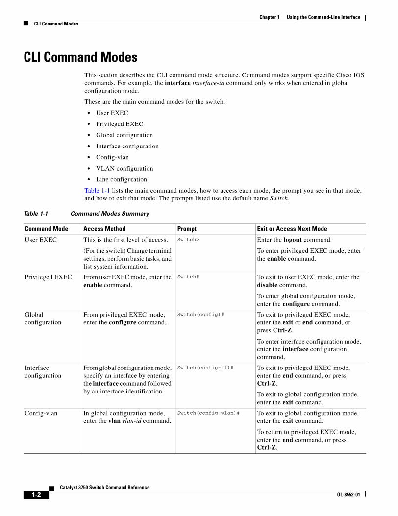
Table 1-1 lists the main command modes, how to access each mode, the prompt you see in that mode, and how to exit that mode. The prompts listed use the default name Switch.
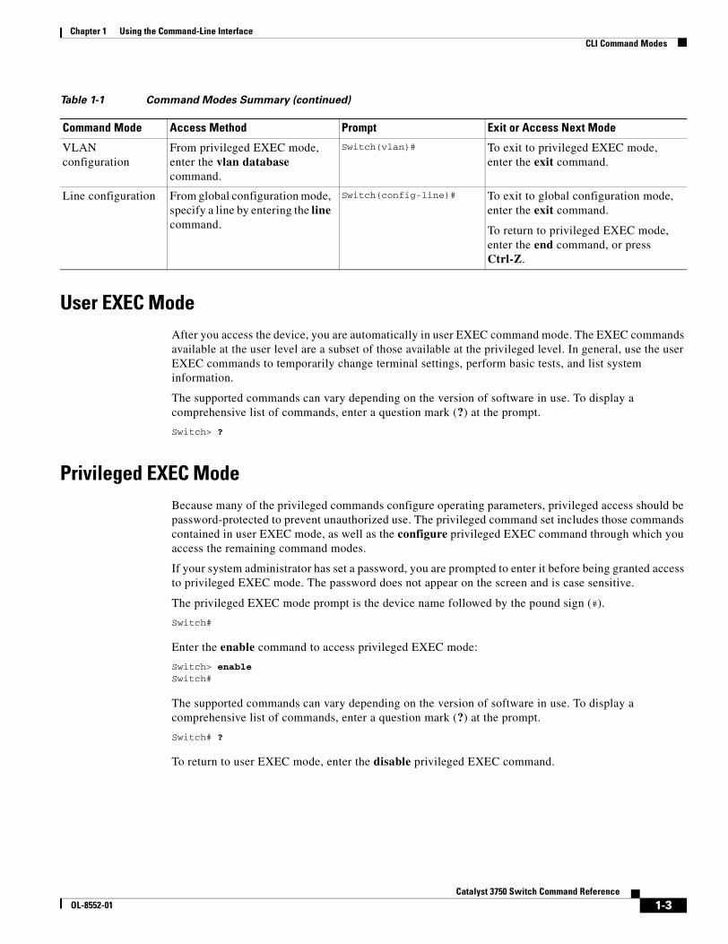
Table 1-1 Command Modes Summary
Command Mode Access Method Prompt Exit or Access Next Mode
User EXEC This is the first level of access.
(For the switch) Change terminal settings, perform basic tasks, and list system information.
Switch> Enter the logout command.
To enter privileged EXEC mode, enter the enable command.
Privileged EXEC From user EXEC mode, enter the enable command.
Switch# To exit to user EXEC mode, enter the disable command.
To enter global configuration mode, enter the configure command.
Global configuration
From privileged EXEC mode, enter the configure command.
Switch(config)# To exit to privileged EXEC mode, enter the exit or end command, or press Ctrl-Z.
To enter interface configuration mode, enter the interface configuration command.
Interface configuration
From global configuration mode, specify an interface by entering the interface command followed by an interface identification.
Switch(config-if)# To exit to privileged EXEC mode, enter the end command, or press Ctrl-Z.
To exit to global configuration mode, enter the exit command.
Config-vlan In global configuration mode, enter the vlan vlan-id command.
Switch(config-vlan)# To exit to global configuration mode, enter the exit command.
To return to privileged EXEC mode, enter the end command, or press Ctrl-Z.
1-2Catalyst 3750 Switch Command Reference
OL-8552-01
Chapter 1 Using the Command-Line InterfaceCLI Command Modes
User EXEC Mode After you access the device, you are automatically in user EXEC command mode. The EXEC commands available at the user level are a subset of those available at the privileged level. In general, use the user EXEC commands to temporarily change terminal settings, perform basic tests, and list system information.
The supported commands can vary depending on the version of software in use. To display a comprehensive list of commands, enter a question mark (?) at the prompt.
Switch> ?
Privileged EXEC ModeBecause many of the privileged commands configure operating parameters, privileged access should be password-protected to prevent unauthorized use. The privileged command set includes those commands contained in user EXEC mode, as well as the configure privileged EXEC command through which you access the remaining command modes.
If your system administrator has set a password, you are prompted to enter it before being granted access to privileged EXEC mode. The password does not appear on the screen and is case sensitive.
The privileged EXEC mode prompt is the device name followed by the pound sign (#).
Switch#
Enter the enable command to access privileged EXEC mode:
Switch> enable Switch#
The supported commands can vary depending on the version of software in use. To display a comprehensive list of commands, enter a question mark (?) at the prompt.
Switch# ?
To return to user EXEC mode, enter the disable privileged EXEC command.
VLAN configuration
From privileged EXEC mode, enter the vlan database command.
Switch(vlan)# To exit to privileged EXEC mode, enter the exit command.
Line configuration From global configuration mode, specify a line by entering the line command.
Switch(config-line)# To exit to global configuration mode, enter the exit command.
To return to privileged EXEC mode, enter the end command, or press Ctrl-Z.
Table 1-1 Command Modes Summary (continued)
Command Mode Access Method Prompt Exit or Access Next Mode
1-3Catalyst 3750 Switch Command Reference
OL-8552-01
Chapter 1 Using the Command-Line InterfaceCLI Command Modes
Global Configuration ModeGlobal configuration commands apply to features that affect the device as a whole. Use the configure privileged EXEC command to enter global configuration mode. The default is to enter commands from the management console.
When you enter the configure command, a message prompts you for the source of the configuration commands:
Switch# configure Configuring from terminal, memory, or network [terminal]?
You can specify either the terminal or NVRAM as the source of configuration commands.
This example shows you how to access global configuration mode:
Switch# configure terminal Enter configuration commands, one per line. End with CNTL/Z.
The supported commands can vary depending on the version of software in use. To display a comprehensive list of commands, enter a question mark (?) at the prompt.
Switch(config)# ?
To exit global configuration command mode and to return to privileged EXEC mode, enter the end or exit command, or press Ctrl-Z.
Interface Configuration ModeInterface configuration commands modify the operation of the interface. Interface configuration commands always follow a global configuration command, which defines the interface type.
Use the interface interface-id command to access interface configuration mode. The new prompt means interface configuration mode.
Switch(config-if)#
The supported commands can vary depending on the version of software in use. To display a comprehensive list of commands, enter a question mark (?) at the prompt.
Switch(config-if)# ?
To exit interface configuration mode and to return to global configuration mode, enter the exit command. To exit interface configuration mode and to return to privileged EXEC mode, enter the end command, or press Ctrl-Z.
config-vlan ModeUse this mode to configure normal-range VLANs (VLAN IDs 1 to 1005) or, when VTP mode is transparent, to configure extended-range VLANs (VLAN IDs 1006 to 4094). When VTP mode is transparent, the VLAN and VTP configuration is saved in the running configuration file, and you can save it to the switch startup configuration file by using the copy running-config startup-config privileged EXEC command. The configurations of VLAN IDs 1 to 1005 are saved in the VLAN database if VTP is in transparent or server mode. The extended-range VLAN configurations are not saved in the VLAN database.
1-4Catalyst 3750 Switch Command Reference
OL-8552-01
Chapter 1 Using the Command-Line InterfaceCLI Command Modes
Enter the vlan vlan-id global configuration command to access config-vlan mode:
Switch(config)# vlan 2000Switch(config-vlan)#
The supported keywords can vary but are similar to the commands available in VLAN configuration mode. To display a comprehensive list of commands, enter a question mark (?) at the prompt.
Switch(config-vlan)# ?
For extended-range VLANs, all characteristics except the MTU size must remain at the default setting.
To return to global configuration mode, enter exit; to return to privileged EXEC mode, enter end. All the commands except shutdown take effect when you exit config-vlan mode.
VLAN Configuration ModeYou can use the VLAN configuration commands to create or modify VLAN parameters for VLAN IDs 1 to 1005.
Enter the vlan database privileged EXEC command to access VLAN configuration mode:
Switch# vlan databaseSwitch(vlan)#
The supported commands can vary depending on the version of software in use. To display a comprehensive list of commands, enter a question mark (?) at the prompt.
Switch(vlan)# ?
To return to privileged EXEC mode, enter the abort VLAN configuration command to abandon the proposed database. Otherwise, enter exit to implement the proposed new VLAN database and to return to privileged EXEC mode. When you enter exit or apply, the configuration is saved in the VLAN database; configuration from VLAN configuration mode cannot be saved in the switch configuration file.
Line Configuration ModeLine configuration commands modify the operation of a terminal line. Line configuration commands always follow a line command, which defines a line number. Use these commands to change terminal parameter settings line-by-line or for a range of lines.
Use the line vty line_number [ending_line_number] command to enter line configuration mode. The new prompt means line configuration mode. The following example shows how to enter line configuration mode for virtual terminal line 7:
Switch(config)# line vty 0 7
The supported commands can vary depending on the version of software in use. To display a comprehensive list of commands, enter a question mark (?) at the prompt.
Switch(config-line)# ?
To exit line configuration mode and to return to global configuration mode, use the exit command. To exit line configuration mode and to return to privileged EXEC mode, enter the end command, or press Ctrl-Z.
1-5Catalyst 3750 Switch Command Reference
OL-8552-01
Chapter 1 Using the Command-Line InterfaceCommands Changed in Cisco IOS 12.2(18)SE
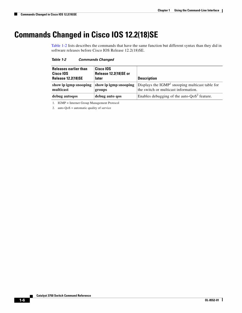
Commands Changed in Cisco IOS 12.2(18)SETable 1-2 lists describes the commands that have the same function but different syntax than they did in software releases before Cisco IOS Release 12.2(18)SE.
Table 1-2 Commands Changed
Releases earlier than Cisco IOS Release 12.2(18)SE
Cisco IOS Release 12.2(18)SE or later Description
show ip igmp snooping multicast
show ip igmp snooping groups
Displays the IGMP1 snooping multicast table for the switch or multicast information.
1. IGMP = Internet Group Management Protocol
debug autoqos debug auto qos Enables debugging of the auto-QoS2 feature.
2. auto-QoS = automatic quality of service
1-6Catalyst 3750 Switch Command Reference
OL-8552-01
CaOL-8552-01
C H A P T E R 2
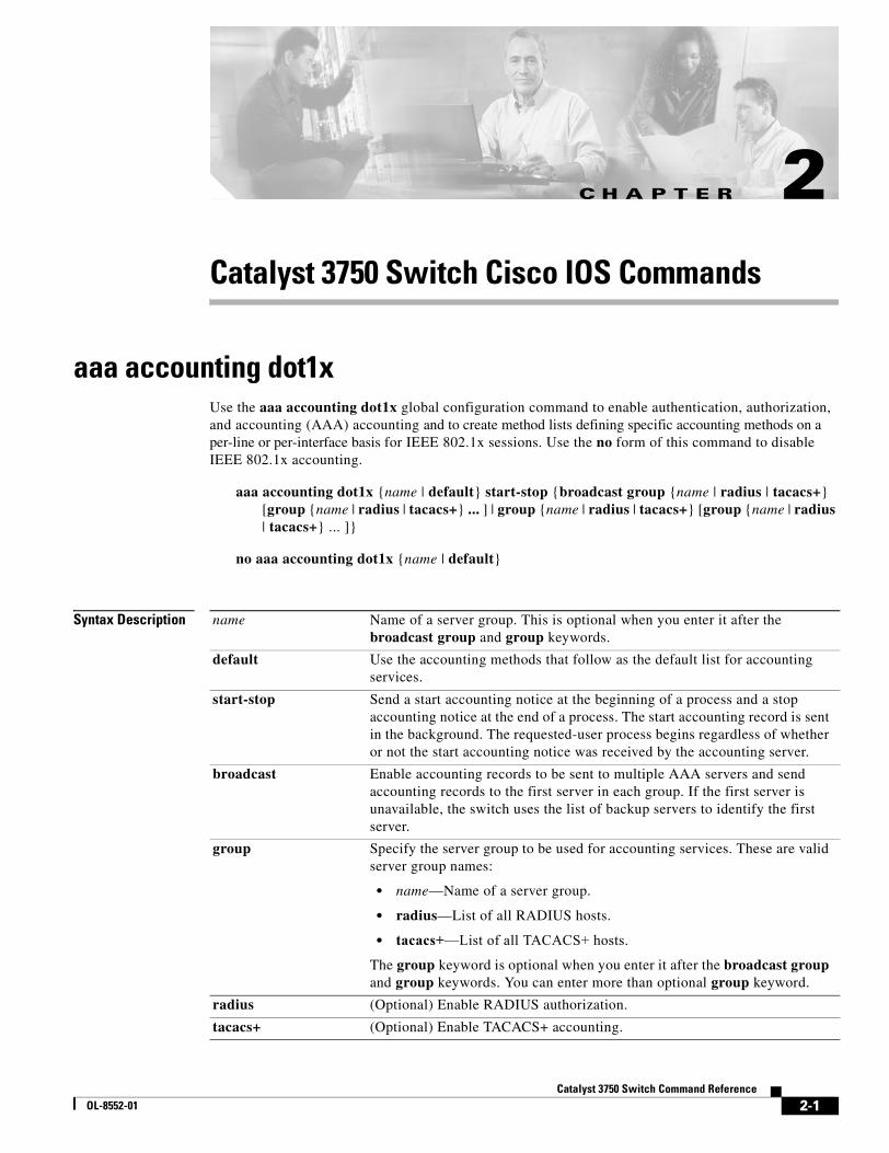
Catalyst 3750 Switch Cisco IOS Commandsaaa accounting dot1xUse the aaa accounting dot1x global configuration command to enable authentication, authorization, and accounting (AAA) accounting and to create method lists defining specific accounting methods on a per-line or per-interface basis for IEEE 802.1x sessions. Use the no form of this command to disable IEEE 802.1x accounting.
aaa accounting dot1x {name | default} start-stop {broadcast group {name | radius | tacacs+} [group {name | radius | tacacs+} ... ] | group {name | radius | tacacs+} [group {name | radius | tacacs+} ... ]}
no aaa accounting dot1x {name | default}
Syntax Description name Name of a server group. This is optional when you enter it after the broadcast group and group keywords.
default Use the accounting methods that follow as the default list for accounting services.
start-stop Send a start accounting notice at the beginning of a process and a stop accounting notice at the end of a process. The start accounting record is sent in the background. The requested-user process begins regardless of whether or not the start accounting notice was received by the accounting server.
broadcast Enable accounting records to be sent to multiple AAA servers and send accounting records to the first server in each group. If the first server is unavailable, the switch uses the list of backup servers to identify the first server.
group Specify the server group to be used for accounting services. These are valid server group names:
• name—Name of a server group.
• radius—List of all RADIUS hosts.
• tacacs+—List of all TACACS+ hosts.
The group keyword is optional when you enter it after the broadcast group and group keywords. You can enter more than optional group keyword.
radius (Optional) Enable RADIUS authorization.
tacacs+ (Optional) Enable TACACS+ accounting.
2-1talyst 3750 Switch Command Reference
Chapter 2 Catalyst 3750 Switch Cisco IOS Commandsaaa accounting dot1x
Defaults AAA accounting is disabled.
Command Modes Global configuration
Command History
Usage Guidelines This command requires access to a RADIUS server.
We recommend that you enter the dot1x reauthentication interface configuration command before configuring IEEE 802.1x RADIUS accounting on an interface.
Examples This example shows how to configure IEEE 802.1x accounting:
Switch(config)# aaa new-modelSwitch(config)# aaa accounting dot1x default start-stop group radius
Note The RADIUS authentication server must be properly configured to accept and log update or watchdog packets from the AAA client.
Related Commands
Release Modification
12.2(20)SE This command was introduced.
Command Description
aaa authentication dot1x
Specifies one or more AAA methods for use on interfaces running IEEE 802.1x.
aaa new-model Enables the AAA access control model. For syntax information, see the Cisco IOS Security Command Reference, Release 12.2 > Authentication, Authorization, and Accounting > Authentication Commands.
dot1x reauthentication Enables or disables periodic reauthentication.
dot1x timeout reauth-period
Sets the number of seconds between re-authentication attempts.
2-2Catalyst 3750 Switch Command Reference
OL-8552-01
Chapter 2 Catalyst 3750 Switch Cisco IOS Commandsaaa authentication dot1x
aaa authentication dot1xUse the aaa authentication dot1x global configuration command on the switch stack or on a standalone switch to specify the authentication, authorization, and accounting (AAA) method to use on ports complying with the IEEE 802.1x authentication. Use the no form of this command to disable authentication.
aaa authentication dot1x {default} method1
no aaa authentication dot1x {default}
Syntax Description
Note Though other keywords are visible in the command-line help strings, only the default and group radius keywords are supported.
Defaults No authentication is performed.
Command Modes Global configuration
Command History
Usage Guidelines The method argument identifies the method that the authentication algorithm tries in the given sequence to validate the password provided by the client. The only method that is truly IEEE 802.1x-compliant is the group radius method, in which the client data is validated against a RADIUS authentication server.
If you specify group radius, you must configure the RADIUS server by entering the radius-server host global configuration command.
Use the show running-config privileged EXEC command to display the configured lists of authentication methods.
Examples This example shows how to enable AAA and how to create an IEEE 802.1x-compliant authentication list. This authentication first tries to contact a RADIUS server. If this action returns an error, the user is not allowed access to the network.
default Use the listed authentication method that follows this argument as the default method when a user logs in.
method1 Enter the group radius keywords to use the list of all RADIUS servers for authentication.
Release Modification
12.1(11)AX This command was introduced.
2-3Catalyst 3750 Switch Command Reference
OL-8552-01
Chapter 2 Catalyst 3750 Switch Cisco IOS Commandsaaa authentication dot1x
Switch(config)# aaa new-modelSwitch(config)# aaa authentication dot1x default group radius
You can verify your settings by entering the show running-config privileged EXEC command.
Related Commands Command Description
aaa new-model Enables the AAA access control model. For syntax information, see the Cisco IOS Security Command Reference, Release 12.2 > Authentication, Authorization, and Accounting > Authentication Commands.
show running-config Displays the current operating configuration. For syntax information, select Cisco IOS Configuration Fundamentals Command Reference, Release 12.2 > File Management Commands > Configuration File Management Commands.
2-4Catalyst 3750 Switch Command Reference
OL-8552-01
Chapter 2 Catalyst 3750 Switch Cisco IOS Commandsaaa authorization network
aaa authorization network Use the aaa authorization network global configuration command on the switch stack or on a standalone switch to the configure the switch to use user-RADIUS authorization for all network-related service requests, such as IEEE 802.1x per-user access control lists (ACLs) or VLAN assignment. Use the no form of this command to disable the switch for RADIUS user authorization.
aaa authorization network default group radius
no aaa authorization network default
Syntax Description
Defaults Authorization is disabled.
Command Modes Global configuration
Command History
Usage Guidelines Use the aaa authorization network default group radius global configuration command to allow the switch to download IEEE 802.1x authorization parameters from the RADIUS servers in the default authorization list. The authorization parameters are used by features such as per-user ACLs or VLAN assignment to get parameters from the RADIUS servers.
Use the show running-config privileged EXEC command to display the configured lists of authorization methods.
Examples This example shows how to configure the switch for user RADIUS authorization for all network-related service requests:
Switch(config)# aaa authorization network default group radius
You can verify your settings by entering the show running-config privileged EXEC command.
Related Commands
default group radius
Use the list of all RADIUS hosts in the server group as the default authorization list.
Release Modification
12.1(11)AX This command was introduced.
Command Description
show running-config Displays the current operating configuration. For syntax information, select Cisco IOS Configuration Fundamentals Command Reference, Release 12.2 > File Management Commands > Configuration File Management Commands.
2-5Catalyst 3750 Switch Command Reference
OL-8552-01
Chapter 2 Catalyst 3750 Switch Cisco IOS Commandsaction
actionUse the action access-map configuration command on the switch stack or on a standalone switch to set the action for the VLAN access map entry. Use the no form of this command to return to the default setting.
action {drop | forward}
no action
Syntax Description
Defaults The default action is to forward packets.
Command Modes Access-map configuration
Command History
Usage Guidelines You enter access-map configuration mode by using the vlan access-map global configuration command.
If the action is drop, you should define the access map, including configuring any access control list (ACL) names in match clauses, before applying the map to a VLAN, or all packets could be dropped.
In access-map configuration mode, use the match access-map configuration command to define the match conditions for a VLAN map. Use the action command to set the action that occurs when a packet matches the conditions.
The drop and forward parameters are not used in the no form of the command.
Examples This example shows how to identify and apply a VLAN access map vmap4 to VLANs 5 and 6 that causes the VLAN to forward an IP packet if the packet matches the conditions defined in access list al2:
Switch(config)# vlan access-map vmap4Switch(config-access-map)# match ip address al2Switch(config-access-map)# action forwardSwitch(config-access-map)# exitSwitch(config)# vlan filter vmap4 vlan-list 5-6
You can verify your settings by entering the show vlan access-map privileged EXEC command.
drop Drop the packet when the specified conditions are matched.
forward Forward the packet when the specified conditions are matched.
Release Modification
12.1(11)AX This command was introduced.
2-6Catalyst 3750 Switch Command Reference
OL-8552-01
Chapter 2 Catalyst 3750 Switch Cisco IOS Commandsaction
Related Commands Command Description
access-list {deny | permit} Configures a standard numbered ACL. For syntax information, select Cisco IOS IP Command Reference, Volume 1 of 3:Addressing and Services, Release 12.2 > IP Services Commands.
ip access-list Creates a named access list. For syntax information, select Cisco IOS IP Command Reference, Volume 1 of 3:Addressing and Services, Release 12.2 > IP Services Commands.
mac access-list extended Creates a named MAC address access list.
match (class-map configuration)
Defines the match conditions for a VLAN map.
show vlan access-map Displays the VLAN access maps created on the switch.
vlan access-map Creates a VLAN access map.
2-7Catalyst 3750 Switch Command Reference
OL-8552-01
Chapter 2 Catalyst 3750 Switch Cisco IOS Commandsarchive copy-sw
archive copy-swUse the archive copy-sw privileged EXEC command on the stack master to copy the running image from the flash memory on one stack member to the flash memory on one or more other stack members.
archive copy-sw [/destination-system destination-stack-member-number] [/force-reload] [leave-old-sw] [/no-set-boot] [/overwrite] [/reload] [/safe] source-stack-member-number
Syntax Description
Command Modes Privileged EXEC
Command History
Usage Guidelines The current software image is not overwritten with the copied image.
Both the software image and HTML files are copied.
The new image is copied to the flash: file system.
The BOOT environment variable is changed to point to the new software image on the flash: file system.
Image names are case sensitive; the image file is provided in tar format.
Note To successfully use the archive copy-sw privileged EXEC command, you must have downloaded from a TFTP server the images for both the stack member switch being added and the stack master. You use the archive download-sw privileged EXEC command to perform the download.
/destination-system destination-stack-member-number
(Optional) The number of the stack member to which to copy the running image. The range is 1 to 9.
/force-reload (Optional) Unconditionally force a system reload after successfully downloading the software image.
/leave-old-sw (Optional) Keep the old software version after a successful download.
/no-set-boot (Optional) Do not alter the setting of the BOOT environment variable to point to the new software image after it is successfully downloaded.
/overwrite (Optional) Overwrite the software image in flash memory with the downloaded one.
/reload (Optional) Reload the system after downloading the image unless the configuration has been changed and not been saved.
/safe (Optional) Keep the current software image; do not delete it to make room for the new software image before the new image is downloaded. The current image is deleted after the download.
source-stack-member-number
The number of the stack member from which to copy the running image. The range is 1 to 9.
Release Modification
12.1(11)AX This command was introduced.
2-8Catalyst 3750 Switch Command Reference
OL-8552-01
Chapter 2 Catalyst 3750 Switch Cisco IOS Commandsarchive copy-sw
At least one stack member must be running the image that is to be copied to the switch that has incompatible software.
You can copy the image to more than one specific stack member by repeating the /destination-system destination-stack-member-number option in the command for each stack member to be upgraded. If you do not specify the destination-stack-member-number, the default is to copy the running image file to all stack members.
Using the /safe or /leave-old-sw option can cause the new copied image to fail if there is insufficient flash memory. If leaving the software in place would prevent the new image from fitting in flash memory due to space constraints, an error results.
If you used the /leave-old-sw option and did not overwrite the old image when you copied the new one, you can remove the old image by using the delete privileged EXEC command. For more information, see the “delete” section on page 2-79.
Use the /overwrite option to overwrite the image on the flash device with the copied one.
If you specify the command without the /overwrite option, the algorithm verifies that the new image is not the same as the one on the switch flash device or is not running on any stack members. If the images are the same, the copy does not occur. If the images are different, the old image is deleted, and the new one is copied.
After copying a new image, enter the reload privileged EXEC command to begin using the new image, or specify the /reload or /force-reload option in the archive copy-sw command.
You can enter one or more of these options with the source-stack-member-number option:
• /destination-system destination-stack-member-number
• /force-reload
• /leave-old-sw
• /no-set-boot
• /overwrite
• /reload
• /safe
If you enter the source-stack-member-number option before one of the previous options, you can enter only the archive copy-sw source-stack-member-number command.
These are examples of how you can enter the archive copy-sw command:
• To copy the running image from a stack member to another stack member and to overwrite the software image in the second stack member’s flash memory (if it already exists) with the copied one, enter the archive copy-sw /destination destination-stack-member-number /overwrite source-stack-member-number command.
• To copy the running image from a stack member to another stack member, keep the current software image, and reload the system after the image copies, enter the archive copy-sw /destination destination-stack-member-number /safe /reload source-stack-member-number command.
2-9Catalyst 3750 Switch Command Reference
OL-8552-01
Chapter 2 Catalyst 3750 Switch Cisco IOS Commandsarchive copy-sw
Examples This example shows how to copy the running image from stack member 6 to stack member 8:
Switch# archive copy-sw /destination-system 8 6
This example shows how to copy the running image from stack member 6 to all the other stack members:
Switch# archive copy-sw 6
This example shows how to copy the running image from stack member 5 to stack member 7. If the image being copied already exists on the second stack member’s flash memory, it can be overwritten with the copied one. The system reloads after the image is copied:
Switch# archive copy-sw /destination-system 7 /overwrite /force-reload 5
Related Commands Command Description
archive download-sw Downloads a new image from a TFTP server to the switch.
archive tar Creates a tar file, lists the files in a tar file, or extracts the files from a tar file.
archive upload-sw Uploads an existing image on the switch to a server.
delete Deletes a file or directory on the flash memory device.
2-10Catalyst 3750 Switch Command Reference
OL-8552-01
Chapter 2 Catalyst 3750 Switch Cisco IOS Commandsarchive download-sw
archive download-swUse the archive download-sw privileged EXEC command on the switch stack or on a standalone switch to download a new image from a TFTP server to the switch or switch stack and to overwrite or keep the existing image.
archive download-sw {/force-reload | /imageonly | /leave-old-sw | /no-set-boot | /no-version-check | /destination-system stack-member-number | /only-system-type system-type | /overwrite | /reload | /safe} source-url
Syntax Description /force-reload Unconditionally force a system reload after successfully downloading the software image.
/imageonly Download only the software image but not the HTML files associated with the embedded device manager. The HTML files for the existing version are deleted only if the existing version is being overwritten or removed.
/leave-old-sw Keep the old software version after a successful download.
/no-set-boot Do not alter the setting of the BOOT environment variable to point to the new software image after it is successfully downloaded.
/no-version-check Download the software image without checking the compatibility of the stack protocol version on the image and on the switch stack.
/destination-system stack-member-number
Specify the specific stack member to be upgraded. The range is 1 to 9.
/only-system-type system-type
Specify the specific system type to be upgraded. The range is 0 to FFFFFFFF.
/overwrite Overwrite the software image in flash memory with the downloaded one.
/reload Reload the system after successfully downloading the image unless the configuration has been changed and not been saved.
2-11Catalyst 3750 Switch Command Reference
OL-8552-01
Chapter 2 Catalyst 3750 Switch Cisco IOS Commandsarchive download-sw
/safe Keep the current software image; do not delete it to make room for the new software image before the new image is downloaded. The current image is deleted after the download.
source-url The source URL alias for a local or network file system. These options are supported:
• The syntax for the local flash file system on the standalone switch or the stack master:flash:
The syntax for the local flash file system on a stack member:flash member number:
• The syntax for the FTP: ftp:[[//username[:password]@location]/directory]/image-name.tar
• The syntax for an HTTP server:http://[[username:password]@]{hostname | host-ip}[/directory]/image-name.tar
• The syntax for a secure HTTP server:https://[[username:password]@]{hostname | host-ip}[/directory]/image-name.tar
• The syntax for the Remote Copy Protocol (RCP): rcp:[[//username@location]/directory]/image-name.tar
• The syntax for the TFTP:tftp:[[//location]/directory]/image-name.tar
The image-name.tar is the software image to download and install on the switch.
2-12Catalyst 3750 Switch Command Reference
OL-8552-01
Chapter 2 Catalyst 3750 Switch Cisco IOS Commandsarchive download-sw
Defaults The current software image is not overwritten with the downloaded image.
Both the software image and HTML files are downloaded.
The new image is downloaded to the flash: file system.
The BOOT environment variable is changed to point to the new software image on the flash: file system.
Image names are case sensitive; the image file is provided in tar format.
Compatibility of the stack protocol version on the image to be downloaded is checked with the version on the switch stack.
Command Modes Privileged EXEC
Command History
Usage Guidelines The /imageonly option removes the HTML files for the existing image if the existing image is being removed or replaced. Only the Cisco IOS image (without the HTML files) is downloaded.
Using the /safe or /leave-old-sw option can cause the new image download to fail if there is insufficient flash memory. If leaving the software in place prevents the new image from fitting in flash memory due to space constraints, an error results.
If you used the /leave-old-sw option and did not overwrite the old image when you downloaded the new one, you can remove the old image by using the delete privileged EXEC command. For more information, see the “delete” section on page 2-79.
Use the /no-version-check option if you want to download an image that has a different stack protocol version than the one existing on the switch stack. You must use this option with the /destination-system option to specify the specific stack member to be upgraded with the image.
Note Use the /no-version-check option with care. All stack members, including the stack master, must have the same stack protocol version to be in the same switch stack. This option allows an image to be downloaded without first confirming the compatibility of its stack protocol version with the version of the switch stack.
You can upgrade more than one specific stack member by repeating the /destination-system option in the command for each stack member to be upgraded.
Use the /overwrite option to overwrite the image on the flash device with the downloaded one.
If you specify the command without the /overwrite option, the download algorithm verifies that the new image is not the same as the one on the switch flash device or is not running on any stack members. If the images are the same, the download does not occur. If the images are different, the old image is deleted, and the new one is downloaded.
After downloading a new image, enter the reload privileged EXEC command to begin using the new image, or specify the /reload or /force-reload option in the archive download-sw command.
Release Modification
12.1(11)AX This command was introduced.
12.2(20)SE The http and https keywords were added.
2-13Catalyst 3750 Switch Command Reference
OL-8552-01
Chapter 2 Catalyst 3750 Switch Cisco IOS Commandsarchive download-sw
Examples This example shows how to download a new image from a TFTP server at 172.20.129.10 and overwrite the image on the switch:
Switch# archive download-sw /overwrite tftp://172.20.129.10/test-image.tar
This example shows how to download only the software image from a TFTP server at 172.20.129.10 to the switch:
Switch# archive download-sw /imageonly tftp://172.20.129.10/test-image.tar
This example shows how to keep the old software version after a successful download:
Switch# archive download-sw /leave-old-sw tftp://172.20.129.10/test-image.tar
This example shows how to upgrade stack members 6 and 8:
Switch# archive download-sw /imageonly /destination-system 6 /destination-system 8 tftp://172.20.129.10/test-image.tar
Related Commands Command Description
archive copy-sw Copies the running image from the flash memory on one stack member to the flash memory on one or more other stack members.
archive tar Creates a tar file, lists the files in a tar file, or extracts the files from a tar file.
archive upload-sw Uploads an existing image on the switch to a server.
delete Deletes a file or directory on the flash memory device.
2-14Catalyst 3750 Switch Command Reference
OL-8552-01
Chapter 2 Catalyst 3750 Switch Cisco IOS Commandsarchive tar
archive tarUse the archive tar privileged EXEC command on the switch stack or on a standalone switch to create a tar file, list files in a tar file, or extract the files from a tar file.
archive tar {/create destination-url flash:/file-url} | {/table source-url} | {/xtract source-url flash:/file-url [dir/file...]}
Syntax Description /create destination-url flash:/file-url
Create a new tar file on the local or network file system.
For destination-url, specify the destination URL alias for the local or network file system and the name of the tar file to create. These options are supported:
• The syntax for the local flash filesystem:flash:
• The syntax for the FTP: ftp:[[//username[:password]@location]/directory]/tar-filename.tar
• The syntax for an HTTP server:http://[[username:password]@]{hostname | host-ip}[/directory]/image-name.tar
• The syntax for a secure HTTP server:https://[[username:password]@]{hostname | host-ip}[/directory]/image-name.tar
• The syntax for the Remote Copy Protocol (RCP) is: rcp:[[//username@location]/directory]/tar-filename.tar
• The syntax for the TFTP: tftp:[[//location]/directory]/tar-filename.tar
The tar-filename.tar is the tar file to be created.
For flash:/file-url, specify the location on the local flash file system from which the new tar file is created.
An optional list of files or directories within the source directory can be specified to write to the new tar file. If none are specified, all files and directories at this level are written to the newly created tar file.
2-15Catalyst 3750 Switch Command Reference
OL-8552-01
Chapter 2 Catalyst 3750 Switch Cisco IOS Commandsarchive tar
Defaults None
/table source-url Display the contents of an existing tar file to the screen.
For source-url, specify the source URL alias for the local or network file system. These options are supported:
• The syntax for the local flash file system:flash:
• The syntax for the FTP:ftp:[[//username[:password]@location]/directory]/tar-filename.tar
• The syntax for an HTTP server:http://[[username:password]@]{hostname | host-ip}[/directory]/image-name.tar
• The syntax for a secure HTTP server:https://[[username:password]@]{hostname | host-ip}[/directory]/image-name.tar
• The syntax for the RCP: rcp:[[//username@location]/directory]/tar-filename.tar
• The syntax for the TFTP: tftp:[[//location]/directory]/tar-filename.tar
The tar-filename.tar is the tar file to display.
/xtract source-url flash:/file-url [dir/file...]
Extract files from a tar file to the local file system.
For source-url, specify the source URL alias for the local file system. These options are supported:
• The syntax for the local flash file system:flash:
• The syntax for the FTP: ftp:[[//username[:password]@location]/directory]/tar-filename.tar
• The syntax for an HTTP server:http://[[username:password]@]{hostname | host-ip}[/directory]/image-name.tar
• The syntax for a secure HTTP server:https://[[username:password]@]{hostname | host-ip}[/directory]/image-name.tar
• The syntax for the RCP: rcp:[[//username@location]/directory]/tar-filename.tar
• The syntax for the TFTP: tftp:[[//location]/directory]/tar-filename.tar
The tar-filename.tar is the tar file from which to extract.
For flash:/file-url [dir/file...], specify the location on the local flash file system into which the tar file is extracted. Use the dir/file... option to specify an optional list of files or directories within the tar file to be extracted. If none are specified, all files and directories are extracted.
2-16Catalyst 3750 Switch Command Reference
OL-8552-01
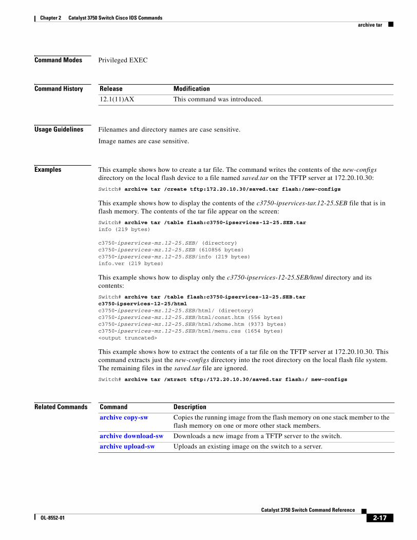
Chapter 2 Catalyst 3750 Switch Cisco IOS Commandsarchive tar
Command Modes Privileged EXEC
Command History
Usage Guidelines Filenames and directory names are case sensitive.
Image names are case sensitive.
Examples This example shows how to create a tar file. The command writes the contents of the new-configs directory on the local flash device to a file named saved.tar on the TFTP server at 172.20.10.30:
Switch# archive tar /create tftp:172.20.10.30/saved.tar flash:/new-configs
This example shows how to display the contents of the c3750-ipservices-tar.12-25.SEB file that is in flash memory. The contents of the tar file appear on the screen:
Switch# archive tar /table flash:c3750-ipservices-12-25.SEB.tarinfo (219 bytes)
c3750-ipservices-mz.12-25.SEB/ (directory)c3750-ipservices-mz.12-25.SEB (610856 bytes)c3750-ipservices-mz.12-25.SEB/info (219 bytes)info.ver (219 bytes)
This example shows how to display only the c3750-ipservices-12-25.SEB/html directory and its contents:
Switch# archive tar /table flash:c3750-ipservices-12-25.SEB.tar c3750-ipservices-12-25/htmlc3750-ipservices-mz.12-25.SEB/html/ (directory)c3750-ipservices-mz.12-25.SEB/html/const.htm (556 bytes)c3750-ipservices-mz.12-25.SEB/html/xhome.htm (9373 bytes)c3750-ipservices-mz.12-25.SEB/html/menu.css (1654 bytes)<output truncated>
This example shows how to extract the contents of a tar file on the TFTP server at 172.20.10.30. This command extracts just the new-configs directory into the root directory on the local flash file system. The remaining files in the saved.tar file are ignored.
Switch# archive tar /xtract tftp:/172.20.10.30/saved.tar flash:/ new-configs
Related Commands
Release Modification
12.1(11)AX This command was introduced.
Command Description
archive copy-sw Copies the running image from the flash memory on one stack member to the flash memory on one or more other stack members.
archive download-sw Downloads a new image from a TFTP server to the switch.
archive upload-sw Uploads an existing image on the switch to a server.
2-17Catalyst 3750 Switch Command Reference
OL-8552-01
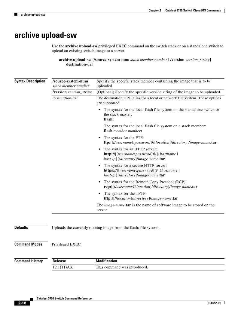
Chapter 2 Catalyst 3750 Switch Cisco IOS Commandsarchive upload-sw
archive upload-swUse the archive upload-sw privileged EXEC command on the switch stack or on a standalone switch to upload an existing switch image to a server.
archive upload-sw [/source-system-num stack member number | /version version_string] destination-url
Syntax Description
Defaults Uploads the currently running image from the flash: file system.
Command Modes Privileged EXEC
Command History
/source-system-num stack member number
Specify the specific stack member containing the image that is to be uploaded.
/version version_string (Optional) Specify the specific version string of the image to be uploaded.
destination-url The destination URL alias for a local or network file system. These options are supported:
• The syntax for the local flash file system on the standalone switch or the stack master:flash:
The syntax for the local flash file system on a stack member:flash member number:
• The syntax for the FTP: ftp:[[//username[:password]@location]/directory]/image-name.tar
• The syntax for an HTTP server:http://[[username:password]@]{hostname | host-ip}[/directory]/image-name.tar
• The syntax for a secure HTTP server:https://[[username:password]@]{hostname | host-ip}[/directory]/image-name.tar
• The syntax for the Remote Copy Protocol (RCP): rcp:[[//username@location]/directory]/image-name.tar
• The syntax for the TFTP:tftp:[[//location]/directory]/image-name.tar
The image-name.tar is the name of software image to be stored on the server.
Release Modification
12.1(11)AX This command was introduced.
2-18Catalyst 3750 Switch Command Reference
OL-8552-01
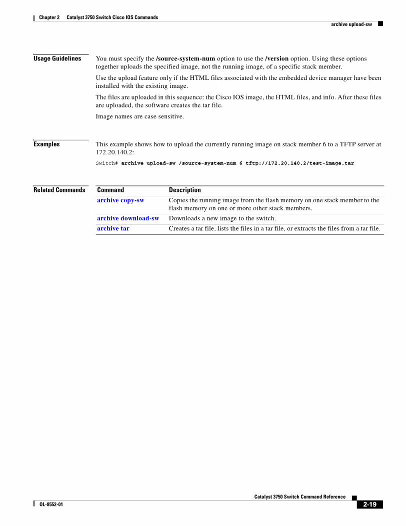
Chapter 2 Catalyst 3750 Switch Cisco IOS Commandsarchive upload-sw
Usage Guidelines You must specify the /source-system-num option to use the /version option. Using these options together uploads the specified image, not the running image, of a specific stack member.
Use the upload feature only if the HTML files associated with the embedded device manager have been installed with the existing image.
The files are uploaded in this sequence: the Cisco IOS image, the HTML files, and info. After these files are uploaded, the software creates the tar file.
Image names are case sensitive.
Examples This example shows how to upload the currently running image on stack member 6 to a TFTP server at 172.20.140.2:
Switch# archive upload-sw /source-system-num 6 tftp://172.20.140.2/test-image.tar
Related Commands Command Description
archive copy-sw Copies the running image from the flash memory on one stack member to the flash memory on one or more other stack members.
archive download-sw Downloads a new image to the switch.
archive tar Creates a tar file, lists the files in a tar file, or extracts the files from a tar file.
2-19Catalyst 3750 Switch Command Reference
OL-8552-01
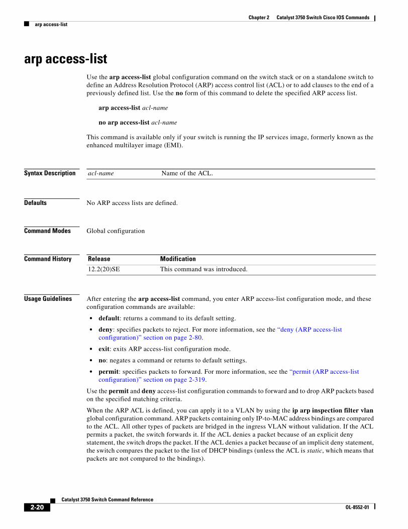
Chapter 2 Catalyst 3750 Switch Cisco IOS Commandsarp access-list
arp access-listUse the arp access-list global configuration command on the switch stack or on a standalone switch to define an Address Resolution Protocol (ARP) access control list (ACL) or to add clauses to the end of a previously defined list. Use the no form of this command to delete the specified ARP access list.
arp access-list acl-name
no arp access-list acl-name
This command is available only if your switch is running the IP services image, formerly known as the enhanced multilayer image (EMI).
Syntax Description
Defaults No ARP access lists are defined.
Command Modes Global configuration
Command History
Usage Guidelines After entering the arp access-list command, you enter ARP access-list configuration mode, and these configuration commands are available:
• default: returns a command to its default setting.
• deny: specifies packets to reject. For more information, see the “deny (ARP access-list configuration)” section on page 2-80.
• exit: exits ARP access-list configuration mode.
• no: negates a command or returns to default settings.
• permit: specifies packets to forward. For more information, see the “permit (ARP access-list configuration)” section on page 2-319.
Use the permit and deny access-list configuration commands to forward and to drop ARP packets based on the specified matching criteria.
When the ARP ACL is defined, you can apply it to a VLAN by using the ip arp inspection filter vlan global configuration command. ARP packets containing only IP-to-MAC address bindings are compared to the ACL. All other types of packets are bridged in the ingress VLAN without validation. If the ACL permits a packet, the switch forwards it. If the ACL denies a packet because of an explicit deny statement, the switch drops the packet. If the ACL denies a packet because of an implicit deny statement, the switch compares the packet to the list of DHCP bindings (unless the ACL is static, which means that packets are not compared to the bindings).
acl-name Name of the ACL.
Release Modification
12.2(20)SE This command was introduced.
2-20Catalyst 3750 Switch Command Reference
OL-8552-01
Chapter 2 Catalyst 3750 Switch Cisco IOS Commandsarp access-list
Examples This example shows how to define an ARP access list and to permit both ARP requests and ARP responses from a host with an IP address of 1.1.1.1 and a MAC address of 0000.0000.abcd:
Switch(config)# arp access-list static-hostsSwitch(config-arp-nacl)# permit ip host 1.1.1.1 mac host 00001.0000.abcdSwitch(config-arp-nacl)# end
You can verify your settings by entering the show arp access-list privileged EXEC command.
Related Commands Command Description
deny (ARP access-list configuration)
Denies an ARP packet based on matches compared against the DHCP bindings.
ip arp inspection filter vlan
Permits ARP requests and responses from a host configured with a static IP address.
permit (ARP access-list configuration)
Permits an ARP packet based on matches compared against the DHCP bindings.
show arp access-list Displays detailed information about ARP access lists.
2-21Catalyst 3750 Switch Command Reference
OL-8552-01
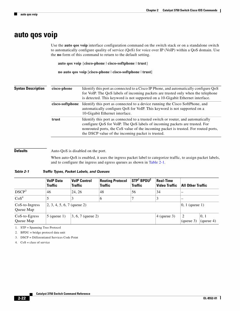
Chapter 2 Catalyst 3750 Switch Cisco IOS Commandsauto qos voip
auto qos voip Use the auto qos voip interface configuration command on the switch stack or on a standalone switch to automatically configure quality of service (QoS) for voice over IP (VoIP) within a QoS domain. Use the no form of this command to return to the default setting.
auto qos voip {cisco-phone | cisco-softphone | trust}
no auto qos voip [cisco-phone | cisco-softphone | trust]
Syntax Description
Defaults Auto-QoS is disabled on the port.
When auto-QoS is enabled, it uses the ingress packet label to categorize traffic, to assign packet labels, and to configure the ingress and egress queues as shown in Table 2-1.
cisco-phone Identify this port as connected to a Cisco IP Phone, and automatically configure QoS for VoIP. The QoS labels of incoming packets are trusted only when the telephone is detected. This keyword is not supported on a 10-Gigabit Ethernet interface.
cisco-softphone Identify this port as connected to a device running the Cisco SoftPhone, and automatically configure QoS for VoIP. This keyword is not supported on a 10-Gigabit Ethernet interface.
trust Identify this port as connected to a trusted switch or router, and automatically configure QoS for VoIP. The QoS labels of incoming packets are trusted. For nonrouted ports, the CoS value of the incoming packet is trusted. For routed ports, the DSCP value of the incoming packet is trusted.
Table 2-1 Traffic Types, Packet Labels, and Queues
VoIP Data Traffic
VoIP Control Traffic
Routing Protocol Traffic
STP1 BPDU2 Traffic
1. STP = Spanning Tree Protocol
2. BPDU = bridge protocol data unit
Real-Time Video Traffic All Other Traffic
DSCP3
3. DSCP = Differentiated Services Code Point
46 24, 26 48 56 34 –
CoS4
4. CoS = class of service
5 3 6 7 3 –
CoS-to-Ingress Queue Map
2, 3, 4, 5, 6, 7 (queue 2) 0, 1 (queue 1)
CoS-to-Egress Queue Map
5 (queue 1) 3, 6, 7 (queue 2) 4 (queue 3) 2 (queue 3)
0, 1 (queue 4)
2-22Catalyst 3750 Switch Command Reference
OL-8552-01
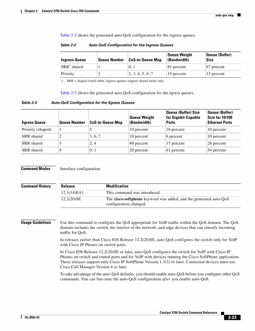
Chapter 2 Catalyst 3750 Switch Cisco IOS Commandsauto qos voip
Table 2-2 shows the generated auto-QoS configuration for the ingress queues.
Table 2-3 shows the generated auto-QoS configuration for the egress queues.
Command Modes Interface configuration
Command History
Usage Guidelines Use this command to configure the QoS appropriate for VoIP traffic within the QoS domain. The QoS domain includes the switch, the interior of the network, and edge devices that can classify incoming traffic for QoS.
In releases earlier than Cisco IOS Release 12.2(20)SE, auto-QoS configures the switch only for VoIP with Cisco IP Phones on switch ports.
In Cisco IOS Release 12.2(20)SE or later, auto-QoS configures the switch for VoIP with Cisco IP Phones on switch and routed ports and for VoIP with devices running the Cisco SoftPhone application. These releases support only Cisco IP SoftPhone Version 1.3(3) or later. Connected devices must use Cisco Call Manager Version 4 or later.
To take advantage of the auto-QoS defaults, you should enable auto-QoS before you configure other QoS commands. You can fine-tune the auto-QoS configuration after you enable auto-QoS.
Table 2-2 Auto-QoS Configuration for the Ingress Queues
Ingress Queue Queue Number CoS-to-Queue MapQueue Weight (Bandwidth)
Queue (Buffer) Size
SRR1 shared
1. SRR = shaped round robin. Ingress queues support shared mode only.
1 0, 1 81 percent 67 percent
Priority 2 2, 3, 4, 5, 6, 7 19 percent 33 percent
Table 2-3 Auto-QoS Configuration for the Egress Queues
Egress Queue Queue Number CoS-to-Queue MapQueue Weight (Bandwidth)
Queue (Buffer) Size for Gigabit-Capable Ports
Queue (Buffer) Size for 10/100 Ethernet Ports
Priority (shaped) 1 5 10 percent 16 percent 10 percent
SRR shared 2 3, 6, 7 10 percent 6 percent 10 percent
SRR shared 3 2, 4 60 percent 17 percent 26 percent
SRR shared 4 0, 1 20 percent 61 percent 54 percent
Release Modification
12.1(14)EA1 This command was introduced.
12.2(20)SE The cisco-softphone keyword was added, and the generated auto-QoS configuration changed.
2-23Catalyst 3750 Switch Command Reference
OL-8552-01
Chapter 2 Catalyst 3750 Switch Cisco IOS Commandsauto qos voip
Note The switch applies the auto-QoS-generated commands as if the commands were entered from the command-line interface (CLI). An existing user configuration can cause the application of the generated commands to fail or to be overridden by the generated commands. These actions occur without warning. If all the generated commands are successfully applied, any user-entered configuration that was not overridden remains in the running configuration. Any user-entered configuration that was overridden can be retrieved by reloading the switch without saving the current configuration to memory. If the generated commands fail to be applied, the previous running configuration is restored.
If this is the first port on which you have enabled auto-QoS, the auto-QoS-generated global configuration commands are executed followed by the interface configuration commands. If you enable auto-QoS on another port, only the auto-QoS-generated interface configuration commands for that port are executed.
When you enable the auto-QoS feature on the first port, these automatic actions occur:
• QoS is globally enabled (mls qos global configuration command), and other global configuration commands are added.
• When you enter the auto qos voip cisco-phone interface configuration command on a port at the edge of the network that is connected to a Cisco IP Phone, the switch enables the trusted boundary feature. The switch uses the Cisco Discovery Protocol (CDP) to detect the presence or absence of a Cisco IP Phone. When a Cisco IP Phone is detected, the ingress classification on the port is set to trust the QoS label received in the packet. When a Cisco IP Phone is absent, the ingress classification is set to not trust the QoS label in the packet. The switch configures ingress and egress queues on the port according to the settings in Table 2-2 and Table 2-3.
• When you enter the auto qos voip cisco-softphone interface configuration command on a port at the edge of the network that is connected to a device running the Cisco SoftPhone, the switch uses policing to decide whether a packet is in or out of profile and to specify the action on the packet. If the packet does not have a DSCP value of 24, 26, or 46 or is out of profile, the switch changes the DSCP value to 0. The switch configures ingress and egress queues on the port according to the settings in Table 2-2 and Table 2-3.
• When you enter the auto qos voip trust interface configuration command on a port connected to the interior of the network, the switch trusts the CoS value for nonrouted ports or the DSCP value for routed ports in ingress packets (the assumption is that traffic has already been classified by other edge devices). The switch configures the ingress and egress queues on the port according to the settings in Table 2-2 and Table 2-3.
You can enable auto-QoS on static, dynamic-access, and voice VLAN access, and trunk ports. When enabling auto-QoS with a Cisco IP Phone on a routed port, you must assign a static IP address to the IP phone.
Note When a device running Cisco SoftPhone is connected to a switch or routed port, the switch supports only one Cisco SoftPhone application per port.
After auto-QoS is enabled, do not modify a policy map or aggregate policer that includes AutoQoS in its name. If you need to modify the policy map or aggregate policer, make a copy of it, and change the copied policy map or policer. To use the new policy map instead of the generated one, remove the generated policy map from the interface, and apply the new policy map.
To display the QoS configuration that is automatically generated when auto-QoS is enabled, enable debugging before you enable auto-QoS. Use the debug auto qos privileged EXEC command to enable auto-QoS debugging. For more information, see the debug auto qos command.
2-24Catalyst 3750 Switch Command Reference
OL-8552-01
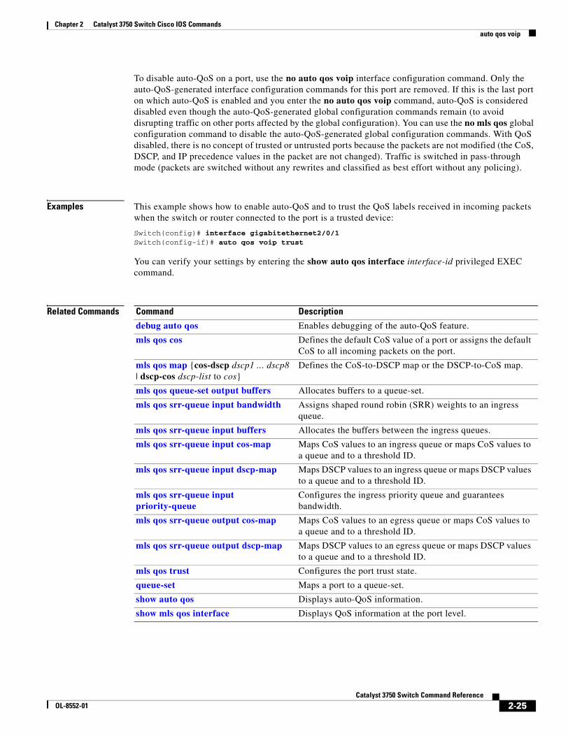
Chapter 2 Catalyst 3750 Switch Cisco IOS Commandsauto qos voip
To disable auto-QoS on a port, use the no auto qos voip interface configuration command. Only the auto-QoS-generated interface configuration commands for this port are removed. If this is the last port on which auto-QoS is enabled and you enter the no auto qos voip command, auto-QoS is considered disabled even though the auto-QoS-generated global configuration commands remain (to avoid disrupting traffic on other ports affected by the global configuration). You can use the no mls qos global configuration command to disable the auto-QoS-generated global configuration commands. With QoS disabled, there is no concept of trusted or untrusted ports because the packets are not modified (the CoS, DSCP, and IP precedence values in the packet are not changed). Traffic is switched in pass-through mode (packets are switched without any rewrites and classified as best effort without any policing).
Examples This example shows how to enable auto-QoS and to trust the QoS labels received in incoming packets when the switch or router connected to the port is a trusted device:
Switch(config)# interface gigabitethernet2/0/1Switch(config-if)# auto qos voip trust
You can verify your settings by entering the show auto qos interface interface-id privileged EXEC command.
Related Commands Command Description
debug auto qos Enables debugging of the auto-QoS feature.
mls qos cos Defines the default CoS value of a port or assigns the default CoS to all incoming packets on the port.
mls qos map {cos-dscp dscp1 ... dscp8 | dscp-cos dscp-list to cos}
Defines the CoS-to-DSCP map or the DSCP-to-CoS map.
mls qos queue-set output buffers Allocates buffers to a queue-set.
mls qos srr-queue input bandwidth Assigns shaped round robin (SRR) weights to an ingress queue.
mls qos srr-queue input buffers Allocates the buffers between the ingress queues.
mls qos srr-queue input cos-map Maps CoS values to an ingress queue or maps CoS values to a queue and to a threshold ID.
mls qos srr-queue input dscp-map Maps DSCP values to an ingress queue or maps DSCP values to a queue and to a threshold ID.
mls qos srr-queue input priority-queue
Configures the ingress priority queue and guarantees bandwidth.
mls qos srr-queue output cos-map Maps CoS values to an egress queue or maps CoS values to a queue and to a threshold ID.
mls qos srr-queue output dscp-map Maps DSCP values to an egress queue or maps DSCP values to a queue and to a threshold ID.
mls qos trust Configures the port trust state.
queue-set Maps a port to a queue-set.
show auto qos Displays auto-QoS information.
show mls qos interface Displays QoS information at the port level.
2-25Catalyst 3750 Switch Command Reference
OL-8552-01
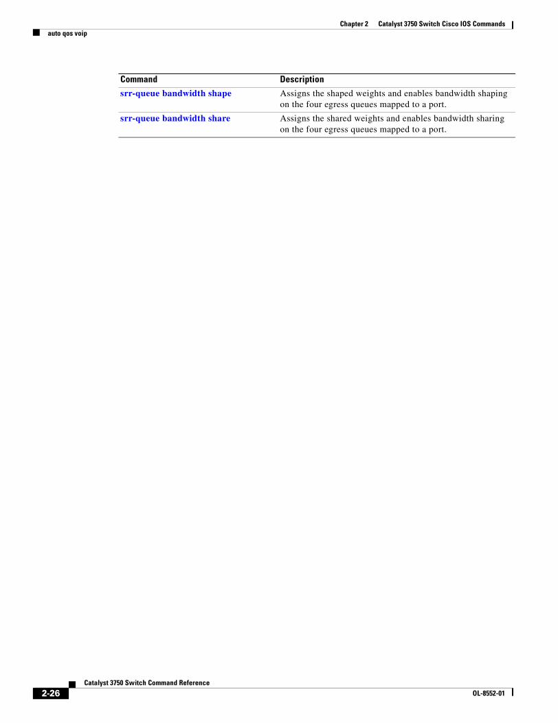
Chapter 2 Catalyst 3750 Switch Cisco IOS Commandsauto qos voip
srr-queue bandwidth shape Assigns the shaped weights and enables bandwidth shaping on the four egress queues mapped to a port.
srr-queue bandwidth share Assigns the shared weights and enables bandwidth sharing on the four egress queues mapped to a port.
Command Description
2-26Catalyst 3750 Switch Command Reference
OL-8552-01
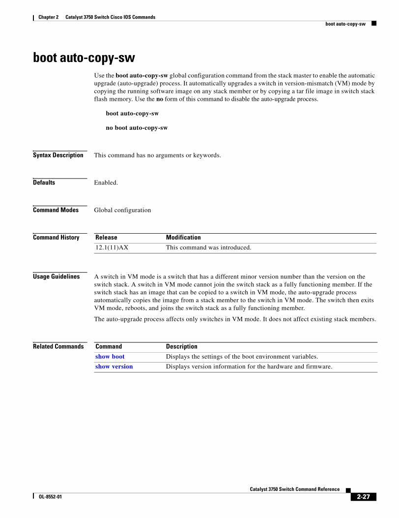
Chapter 2 Catalyst 3750 Switch Cisco IOS Commandsboot auto-copy-sw
boot auto-copy-swUse the boot auto-copy-sw global configuration command from the stack master to enable the automatic upgrade (auto-upgrade) process. It automatically upgrades a switch in version-mismatch (VM) mode by copying the running software image on any stack member or by copying a tar file image in switch stack flash memory. Use the no form of this command to disable the auto-upgrade process.
boot auto-copy-sw
no boot auto-copy-sw
Syntax Description This command has no arguments or keywords.
Defaults Enabled.
Command Modes Global configuration
Command History
Usage Guidelines A switch in VM mode is a switch that has a different minor version number than the version on the switch stack. A switch in VM mode cannot join the switch stack as a fully functioning member. If the switch stack has an image that can be copied to a switch in VM mode, the auto-upgrade process automatically copies the image from a stack member to the switch in VM mode. The switch then exits VM mode, reboots, and joins the switch stack as a fully functioning member.
The auto-upgrade process affects only switches in VM mode. It does not affect existing stack members.
Related Commands
Release Modification
12.1(11)AX This command was introduced.
Command Description
show boot Displays the settings of the boot environment variables.
show version Displays version information for the hardware and firmware.
2-27Catalyst 3750 Switch Command Reference
OL-8552-01
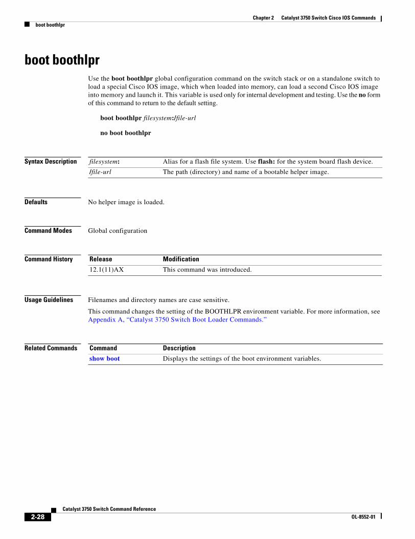
Chapter 2 Catalyst 3750 Switch Cisco IOS Commandsboot boothlpr
boot boothlprUse the boot boothlpr global configuration command on the switch stack or on a standalone switch to load a special Cisco IOS image, which when loaded into memory, can load a second Cisco IOS image into memory and launch it. This variable is used only for internal development and testing. Use the no form of this command to return to the default setting.
boot boothlpr filesystem:/file-url
no boot boothlpr
Syntax Description
Defaults No helper image is loaded.
Command Modes Global configuration
Command History
Usage Guidelines Filenames and directory names are case sensitive.
This command changes the setting of the BOOTHLPR environment variable. For more information, see Appendix A, “Catalyst 3750 Switch Boot Loader Commands.”
Related Commands
filesystem: Alias for a flash file system. Use flash: for the system board flash device.
/file-url The path (directory) and name of a bootable helper image.
Release Modification
12.1(11)AX This command was introduced.
Command Description
show boot Displays the settings of the boot environment variables.
2-28Catalyst 3750 Switch Command Reference
OL-8552-01
Chapter 2 Catalyst 3750 Switch Cisco IOS Commandsboot config-file
boot config-fileUse the boot config-file global configuration command on a standalone switch to specify the filename that Cisco IOS uses to read and write a nonvolatile copy of the system configuration. Use the no form of this command to return to the default setting.
boot config-file flash:/file-url
no boot config-file
Syntax Description
Defaults The default configuration file is flash:config.text.
Command Modes Global configuration
Command History
Usage Guidelines This command works properly only from a standalone switch.
Filenames and directory names are case sensitive.
This command changes the setting of the CONFIG_FILE environment variable. For more information, see Appendix A, “Catalyst 3750 Switch Boot Loader Commands.”
Related Commands
flash:/file-url The path (directory) and name of the configuration file.
Release Modification
12.1(11)AX This command was introduced.
Command Description
show boot Displays the settings of the boot environment variables.
2-29Catalyst 3750 Switch Command Reference
OL-8552-01
Chapter 2 Catalyst 3750 Switch Cisco IOS Commandsboot enable-break
boot enable-breakUse the boot enable-break global configuration command on a standalone switch to enable interrupting the automatic boot process. Use the no form of this command to return to the default setting.
boot enable-break
no boot enable-break
Syntax Description This command has no arguments or keywords.
Defaults Disabled. The automatic boot process cannot be interrupted by pressing the Break key on the console.
Command Modes Global configuration
Command History
Usage Guidelines This command works properly only from a standalone switch.
When you enter this command, you can interrupt the automatic boot process by pressing the Break key on the console after the flash file system is initialized.
Note Despite the setting of this command, you can interrupt the automatic boot process at any time by pressing the MODE button on the switch front panel.
This command changes the setting of the ENABLE_BREAK environment variable. For more information, see Appendix A, “Catalyst 3750 Switch Boot Loader Commands.”
Related Commands
Release Modification
12.1(11)AX This command was introduced.
Command Description
show boot Displays the settings of the boot environment variables.
2-30Catalyst 3750 Switch Command Reference
OL-8552-01
Chapter 2 Catalyst 3750 Switch Cisco IOS Commandsboot helper
boot helperUse the boot helper global configuration command on the switch stack or on a standalone switch to dynamically load files during boot loader initialization to extend or patch the functionality of the boot loader. Use the no form of this command to return to the default.
boot helper filesystem:/file-url ...
no boot helper
Syntax Description
Defaults No helper files are loaded.
Command Modes Global configuration
Command History
Usage Guidelines This variable is used only for internal development and testing.
Filenames and directory names are case sensitive.
This command changes the setting of the HELPER environment variable. For more information, see Appendix A, “Catalyst 3750 Switch Boot Loader Commands.”
Related Commands
filesystem: Alias for a flash file system. Use flash: for the system board flash device.
/file-url The path (directory) and a list of loadable files to dynamically load during loader initialization. Separate each image name with a semicolon.
Release Modification
12.1(11)AX This command was introduced.
Command Description
show boot Displays the settings of the boot environment variables.
2-31Catalyst 3750 Switch Command Reference
OL-8552-01
Chapter 2 Catalyst 3750 Switch Cisco IOS Commandsboot helper-config-file
boot helper-config-fileUse the boot helper-config-file global configuration command on the switch stack or on a standalone switch to specify the name of the configuration file to be used by the Cisco IOS helper image. If this is not set, the file specified by the CONFIG_FILE environment variable is used by all versions of Cisco IOS that are loaded. Use the no form of this command to return to the default setting.
boot helper-config-file filesystem:/file-url
no boot helper-config file
Syntax Description
Defaults No helper configuration file is specified.
Command Modes Global configuration
Command History
Usage Guidelines This variable is used only for internal development and testing.
Filenames and directory names are case sensitive.
This command changes the setting of the HELPER_CONFIG_FILE environment variable. For more information, see Appendix A, “Catalyst 3750 Switch Boot Loader Commands.”
Related Commands
filesystem: Alias for a flash file system. Use flash: for the system board flash device.
/file-url The path (directory) and helper configuration file to load.
Release Modification
12.1(11)AX This command was introduced.
Command Description
show boot Displays the settings of the boot environment variables.
2-32Catalyst 3750 Switch Command Reference
OL-8552-01
Chapter 2 Catalyst 3750 Switch Cisco IOS Commandsboot manual
boot manualUse the boot manual global configuration command on a standalone switch to enable manually booting the switch during the next boot cycle. Use the no form of this command to return to the default setting.
boot manual
no boot manual
Syntax Description This command has no arguments or keywords.
Defaults Manual booting is disabled.
Command Modes Global configuration
Command History
Usage Guidelines This command works properly only from a standalone switch.
The next time you reboot the system, the switch is in boot loader mode, which is shown by the switch: prompt. To boot the system, use the boot boot loader command, and specify the name of the bootable image.
This command changes the setting of the MANUAL_BOOT environment variable. For more information, see Appendix A, “Catalyst 3750 Switch Boot Loader Commands.”
Related Commands
Release Modification
12.1(11)AX This command was introduced.
Command Description
show boot Displays the settings of the boot environment variables.
2-33Catalyst 3750 Switch Command Reference
OL-8552-01
Chapter 2 Catalyst 3750 Switch Cisco IOS Commandsboot private-config-file
boot private-config-fileUse the boot private-config-file global configuration command on a standalone switch to specify the filename that Cisco IOS uses to read and write a nonvolatile copy of the private configuration. Use the no form of this command to return to the default setting.
boot private-config-file filename
no boot private-config-file
Syntax Description
Defaults The default configuration file is private-config.
Command Modes Global configuration
Command History
Usage Guidelines This command works properly only from a standalone switch.
Filenames are case sensitive.
Examples This example shows how to specify the name of the private configuration file to be pconfig:
Switch(config)# boot private-config-file pconfig
Related Commands
filename The name of the private configuration file.
Release Modification
12.1(11)AX This command was introduced.
Command Description
show boot Displays the settings of the boot environment variables.
2-34Catalyst 3750 Switch Command Reference
OL-8552-01
Chapter 2 Catalyst 3750 Switch Cisco IOS Commandsboot system
boot systemUse the boot system global configuration command on the switch stack or on a standalone switch to specify the Cisco IOS image to load during the next boot cycle. Use the no form of this command to return to the default setting.
boot system {filesystem:/file-url ...| switch {number | all}}
no boot system
no boot system switch {number | all}
Syntax Description
Defaults The switch attempts to automatically boot the system by using information in the BOOT environment variable. If this variable is not set, the switch attempts to load and execute the first executable image it can by performing a recursive, depth-first search throughout the flash file system. In a depth-first search of a directory, each encountered subdirectory is completely searched before continuing the search in the original directory.
Command Modes Global configuration
Command History
Usage Guidelines Filenames and directory names are case sensitive.
If you enter the boot system filesystem:/file-url command on the stack master, the specified software image is loaded only on the stack master during the next boot cycle.
On the stack master, use the boot system switch number command to specify that the software image is loaded on the specified stack member during the next boot cycle. Use the boot system switch all command to specify that the software image is loaded on all the stack members during the next boot cycle.
filesystem: Alias for a flash file system. Use flash: for the system board flash device.
/file-url The path (directory) and name of a bootable image. Separate image names with a semicolon.
switch Specify the switches on which the Cisco IOS image is loaded.
number Specify a stack member.
all Specify all stack members.
Release Modification
12.1(11)AX This command was introduced.
12.2(25)SEA The switch {number | all} keywords were added. The boot system command now works properly on switch stacks and standalone switches.
2-35Catalyst 3750 Switch Command Reference
OL-8552-01
Chapter 2 Catalyst 3750 Switch Cisco IOS Commandsboot system
When you enter the boot system switch number or the boot system switch all command on the stack master, the stack master checks if a software image is already on the stack member (except on the stack master). If the software image does not exist on the stack member (for example, stack member 1), an error message like this appears:
%Command to set boot system switch all xxx on switch=1 failed
If you are using the archive download-sw privileged EXEC command to maintain system images, you never need to use the boot system command. The boot system command is automatically manipulated to load the downloaded image.
This command changes the setting of the BOOT environment variable. For more information, see Appendix A, “Catalyst 3750 Switch Boot Loader Commands.”
Related Commands Command Description
show boot Displays the settings of the boot environment variables.
2-36Catalyst 3750 Switch Command Reference
OL-8552-01
Chapter 2 Catalyst 3750 Switch Cisco IOS Commandschannel-group
channel-groupUse the channel-group interface configuration command on the switch stack or on a standalone switch to assign an Ethernet port to an EtherChannel group, to enable an EtherChannel mode, or both. Use the no form of this command to remove an Ethernet port from an EtherChannel group.
channel-group channel-group-number mode {active | {auto [non-silent]} | {desirable [non-silent]} | on | passive}
no channel-group
PAgP modes: channel-group channel-group-number mode {{auto [non-silent]} | {desirable [non-silent}}
LACP modes: channel-group channel-group-number mode {active | passive}
On mode: channel-group channel-group-number mode on
Syntax Description channel-group-number Specify the channel group number. The range is 1 to 48.
mode Specify the EtherChannel mode.
active Unconditionally enable Link Aggregation Control Protocol (LACP).
Active mode places a port into a negotiating state in which the port initiates negotiations with other ports by sending LACP packets. A channel is formed with another port group in either the active or passive mode.
auto Enable the Port Aggregation Protocol (PAgP) only if a PAgP device is detected.
Auto mode places a port into a passive negotiating state in which the port responds to PAgP packets it receives but does not start PAgP packet negotiation. A channel is formed only with another port group in desirable mode. When auto is enabled, silent operation is the default.
desirable Unconditionally enable PAgP.
Desirable mode places a port into an active negotiating state in which the port starts negotiations with other ports by sending PAgP packets. An EtherChannel is formed with another port group that is in the desirable or auto mode. When desirable is enabled, silent operation is the default.
non-silent (Optional) Use in PAgP mode with the auto or desirable keyword when traffic is expected from the other device.
on Enable on mode.
In on mode, a usable EtherChannel exists only when both connected port groups are in the on mode.
passive Enable LACP only if a LACP device is detected.
Passive mode places a port into a negotiating state in which the port responds to received LACP packets but does not initiate LACP packet negotiation. A channel is formed only with another port group in active mode.
2-37Catalyst 3750 Switch Command Reference
OL-8552-01
Chapter 2 Catalyst 3750 Switch Cisco IOS Commandschannel-group
Defaults No channel groups are assigned.
No mode is configured.
Command Modes Interface configuration
Command History
Usage Guidelines For Layer 2 EtherChannels, you do not have to create a port-channel interface first by using the interface port-channel global configuration command before assigning a physical port to a channel group. Instead, you can use the channel-group interface configuration command. It automatically creates the port-channel interface when the channel group gets its first physical port if the logical interface is not already created. If you create the port-channel interface first, the channel-group-number can be the same as the port-channel-number, or you can use a new number. If you use a new number, the channel-group command dynamically creates a new port channel.
You do not have to disable the IP address that is assigned to a physical port that is part of a channel group, but we strongly recommend that you do so.
You create Layer 3 port channels by using the interface port-channel command followed by the no switchport interface configuration command. You should manually configure the port-channel logical interface before putting the interface into the channel group.
After you configure an EtherChannel, configuration changes that you make on the port-channel interface apply to all the physical ports assigned to the port-channel interface. Configuration changes applied to the physical port affect only the port where you apply the configuration. To change the parameters of all ports in an EtherChannel, apply configuration commands to the port-channel interface, for example, spanning-tree commands or commands to configure a Layer 2 EtherChannel as a trunk.
If you do not specify non-silent with the auto or desirable mode, silent is assumed. The silent mode is used when the switch is connected to a device that is not PAgP-capable and seldom, if ever, sends packets. A example of a silent partner is a file server or a packet analyzer that is not generating traffic. In this case, running PAgP on a physical port prevents that port from ever becoming operational. However, it allows PAgP to operate, to attach the port to a channel group, and to use the port for transmission. Both ends of the link cannot be set to silent.
In the on mode, an EtherChannel exists only when a port group in the on mode is connected to another port group in the on mode.
Caution You should use care when using the on mode. This is a manual configuration, and ports on both ends of the EtherChannel must have the same configuration. If the group is misconfigured, packet loss or spanning-tree loops can occur.
Release Modification
12.1(11)AX This command was introduced.
12.1(14)EA1 The active and passive keywords were added.
12.2(25)SE The channel-group-number range was changed from 1 to 12 to 1 to 48.
12.2(25)SEC LACP can now negotiate cross-stack EtherChannel.
2-38Catalyst 3750 Switch Command Reference
OL-8552-01
Chapter 2 Catalyst 3750 Switch Cisco IOS Commandschannel-group
A cross-stack EtherChannel supports up to two 10-Gigabit Ethernet interfaces.
Do not configure an EtherChannel in both the PAgP and LACP modes. EtherChannel groups running PAgP and LACP can coexist on the same switch or on different switches in the stack (but not in a cross-stack configuration). Individual EtherChannel groups can run either PAgP or LACP, but they cannot interoperate.
If you set the protocol by using the channel-protocol interface configuration command, the setting is not overridden by the channel-group interface configuration command.
Do not configure a port that is an active or a not-yet-active member of an EtherChannel as an IEEE 802.1x port. If you try to enable IEEE 802.1x authentication on an EtherChannel port, an error message appears, and IEEE 802.1x authentication is not enabled.
Note If IEEE 802.1x authentication is enabled on a not-yet active port of an EtherChannel in software releases earlier than Cisco IOS Release 12.2(18)SE, the port does not join the EtherChannel.
Do not configure a secure port as part of an EtherChannel or an EtherChannel port as a secure port.
For a complete list of configuration guidelines, see the “Configuring EtherChannels” chapter in the software configuration guide for this release.
Caution Do not enable Layer 3 addresses on the physical EtherChannel ports. Do not assign bridge groups on the physical EtherChannel ports because it creates loops.
Examples This example shows how to configure an EtherChannel on a single switch in the stack. It assigns two static-access ports in VLAN 10 to channel 5 with the PAgP mode desirable:
Switch# configure terminal Switch(config)# interface range gigabitethernet2/0/1 -2 Switch(config-if-range)# switchport mode accessSwitch(config-if-range)# switchport access vlan 10Switch(config-if-range)# channel-group 5 mode desirable Switch(config-if-range)# end
This example shows how to configure an EtherChannel on a single switch in the stack. It assigns two static-access ports in VLAN 10 to channel 5 with the LACP mode active:
Switch# configure terminal Switch(config)# interface range gigabitethernet2/0/1 -2 Switch(config-if-range)# switchport mode accessSwitch(config-if-range)# switchport access vlan 10Switch(config-if-range)# channel-group 5 mode active Switch(config-if-range)# end
2-39Catalyst 3750 Switch Command Reference
OL-8552-01
Chapter 2 Catalyst 3750 Switch Cisco IOS Commandschannel-group
This example shows how to configure a cross-stack EtherChannel. It uses LACP passive mode and assigns two ports on stack member 2 and one port on stack member 3 as static-access ports in VLAN 10 to channel 5:
Switch# configure terminal Switch(config)# interface range gigabitethernet2/0/4 -5 Switch(config-if-range)# switchport mode accessSwitch(config-if-range)# switchport access vlan 10Switch(config-if-range)# channel-group 5 mode passive Switch(config-if-range)# exitSwitch(config)# interface gigabitethernet3/0/3 Switch(config-if)# switchport mode accessSwitch(config-if)# switchport access vlan 10Switch(config-if)# channel-group 5 mode passive Switch(config-if)# exit
You can verify your settings by entering the show running-config privileged EXEC command.
Related Commands Command Description
channel-protocol Restricts the protocol used on a port to manage channeling.
interface port-channel Accesses or creates the port channel.
show etherchannel Displays EtherChannel information for a channel.
show lacp Displays LACP channel-group information.
show pagp Displays PAgP channel-group information.
show running-config Displays the current operating configuration. For syntax information, select Cisco IOS Configuration Fundamentals Command Reference, Release 12.2 > File Management Commands > Configuration File Management Commands.
2-40Catalyst 3750 Switch Command Reference
OL-8552-01
Chapter 2 Catalyst 3750 Switch Cisco IOS Commandschannel-protocol
channel-protocol Use the channel-protocol interface configuration command on the switch stack or on a standalone switch to restrict the protocol used on a port to manage channeling. Use the no form of this command to return to the default setting.
channel-protocol {lacp | pagp}
no channel-protocol
Syntax Description
Defaults No protocol is assigned to the EtherChannel.
Command Modes Interface configuration
Command History
Usage Guidelines Use the channel-protocol command only to restrict a channel to LACP or PAgP. If you set the protocol by using the channel-protocol command, the setting is not overridden by the channel-group interface configuration command.
You must use the channel-group interface configuration command to configure the EtherChannel parameters. The channel-group command also can set the mode for the EtherChannel.
You cannot enable both the PAgP and LACP modes on an EtherChannel group.
PAgP and LACP are not compatible; both ends of a channel must use the same protocol.
Examples This example shows how to specify LACP as the protocol that manages the EtherChannel:
Switch(config-if)# channel-protocol lacp
You can verify your settings by entering the show etherchannel [channel-group-number] protocol privileged EXEC command.
Related Commands
lacp Configure an EtherChannel with the Link Aggregation Control Protocol (LACP).
pagp Configure an EtherChannel with the Port Aggregation Protocol (PAgP).
Release Modification
12.1(14)EA1 This command was introduced.
Command Description
channel-group Assigns an Ethernet port to an EtherChannel group.
show etherchannel protocol Displays protocol information the EtherChannel.
2-41Catalyst 3750 Switch Command Reference
OL-8552-01
Chapter 2 Catalyst 3750 Switch Cisco IOS Commandsclass
classUse the class policy-map configuration command on the switch stack or on a standalone switch to define a traffic classification match criteria (through the police, set, and trust policy-map class configuration commands) for the specified class-map name. Use the no form of this command to delete an existing class map.
class class-map-name
no class class-map-name
Syntax Description
Defaults No policy map class-maps are defined.
Command Modes Policy-map configuration
Command History
Usage Guidelines Before using the class command, you must use the policy-map global configuration command to identify the policy map and to enter policy-map configuration mode. After specifying a policy map, you can configure a policy for new classes or modify a policy for any existing classes in that policy map. You attach the policy map to a port by using the service-policy interface configuration command.
After entering the class command, you enter policy-map class configuration mode, and these configuration commands are available:
• exit: exits policy-map class configuration mode and returns to policy-map configuration mode.
• no: returns a command to its default setting.
• police: defines a policer or aggregate policer for the classified traffic. The policer specifies the bandwidth limitations and the action to take when the limits are exceeded. For more information, see the police and police aggregate policy-map class commands.
• set: specifies a value to be assigned to the classified traffic. For more information, see the set command.
• trust: defines a trust state for traffic classified with the class or the class-map command. For more information, see the trust command.
To return to policy-map configuration mode, use the exit command. To return to privileged EXEC mode, use the end command.
The class command performs the same function as the class-map global configuration command. Use the class command when a new classification, which is not shared with any other ports, is needed. Use the class-map command when the map is shared among many ports.
class-map-name Name of the class map.
Release Modification
12.1(11)AX This command was introduced.
2-42Catalyst 3750 Switch Command Reference
OL-8552-01
Chapter 2 Catalyst 3750 Switch Cisco IOS Commandsclass
Examples This example shows how to create a policy map called policy1. When attached to the ingress direction, it matches all the incoming traffic defined in class1, sets the IP Differentiated Services Code Point (DSCP) to 10, and polices the traffic at an average rate of 1 Mbps and bursts at 20 KB. Traffic exceeding the profile is marked down to a DSCP value gotten from the policed-DSCP map and then sent.
Switch(config)# policy-map policy1Switch(config-pmap)# class class1Switch(config-pmap-c)# set dscp 10Switch(config-pmap-c)# police 1000000 20000 exceed-action policed-dscp-transmitSwitch(config-pmap-c)# exit
You can verify your settings by entering the show policy-map privileged EXEC command.
Related Commands Command Description
class-map Creates a class map to be used for matching packets to the class whose name you specify.
police Defines a policer for classified traffic.
policy-map Creates or modifies a policy map that can be attached to multiple ports to specify a service policy.
set Classifies IP traffic by setting a DSCP or IP-precedence value in the packet.
show policy-map Displays quality of service (QoS) policy maps.
trust Defines a trust state for the traffic classified through the class policy-map configuration command or the class-map global configuration command.
2-43Catalyst 3750 Switch Command Reference
OL-8552-01
Chapter 2 Catalyst 3750 Switch Cisco IOS Commandsclass-map
class-mapUse the class-map global configuration command on the switch stack or on a standalone switch to create a class map to be used for matching packets to the class whose name you specify and to enter class-map configuration mode. Use the no form of this command to delete an existing class map and to return to global configuration mode.
class-map [match-all | match-any] class-map-name
no class-map [match-all | match-any] class-map-name
Syntax Description
Defaults No class maps are defined.
If neither the match-all or match-any keyword is specified, the default is match-all.
Command Modes Global configuration
Command History
Usage Guidelines Use this command to specify the name of the class for which you want to create or modify class-map match criteria and to enter class-map configuration mode.
The class-map command and its subcommands are used to define packet classification, marking, and aggregate policing as part of a globally named service policy applied on a per-port basis.
After you are in quality of service (QoS) class-map configuration mode, these configuration commands are available:
• description: describes the class map (up to 200 characters). The show class-map privileged EXEC command displays the description and the name of the class-map.
• exit: exits from QoS class-map configuration mode.
• match: configures classification criteria. For more information, see the match (class-map configuration) command.
• no: removes a match statement from a class map.
• rename: renames the current class map. If you rename a class map with a name that is already used, the message A class-map with this name already exists appears.
match-all (Optional) Perform a logical-AND of all matching statements under this class map. All criteria in the class map must be matched.
match-any (Optional) Perform a logical-OR of the matching statements under this class map. One or more criteria must be matched.
class-map-name Name of the class map.
Release Modification
12.1(11)AX This command was introduced.
2-44Catalyst 3750 Switch Command Reference
OL-8552-01
Chapter 2 Catalyst 3750 Switch Cisco IOS Commandsclass-map
To define packet classification on a physical-port basis, only one match command per class map is supported. In this situation, the match-all and match-any keywords are equivalent.
Only one access control list (ACL) can be configured in a class map. The ACL can have multiple access control entries (ACEs).
Examples This example shows how to configure the class map called class1 with one match criterion, which is an access list called 103:
Switch(config)# access-list 103 permit any any dscp 10Switch(config)# class-map class1Switch(config-cmap)# match access-group 103Switch(config-cmap)# exit
This example shows how to delete the class map class1:
Switch(config)# no class-map class1
You can verify your settings by entering the show class-map privileged EXEC command.
Related Commands Command Description
class Defines a traffic classification match criteria (through the police, set, and trust policy-map class configuration commands) for the specified class-map name.
match (class-map configuration)
Defines the match criteria to classify traffic.
policy-map Creates or modifies a policy map that can be attached to multiple ports to specify a service policy.
show class-map Displays QoS class maps.
2-45Catalyst 3750 Switch Command Reference
OL-8552-01
Chapter 2 Catalyst 3750 Switch Cisco IOS Commandsclear dot1x
clear dot1xUse the clear dot1x privileged EXEC command on the switch stack or on a standalone switch to clear IEEE 802.1x information for the switch or for the specified port.
clear dot1x {all | interface interface-id}
Syntax Description
Defaults No default is defined.
Command Modes Privileged EXEC
Command History
Usage Guidelines You can clear all the information by using the clear dot1x all command, or you can clear only the information for the specified interface by using the clear dot1x interface interface-id command.
Examples This example shows how to clear all IEEE 8021.x information:
Switch# clear dot1x all
This example shows how to clear IEEE 8021.x information for the specified interface:
Switch# clear dot1x interface gigabithethernet1/0/1
You can verify that the information was deleted by entering the show dot1x privileged EXEC command.
Related Commands
all Clear all IEEE 802.1x information for the switch.
interface interface-id Clear IEEE 802.1x information for the specified interface.
Release Modification
12.2(25)SEE This command was introduced.
Command Description
show dot1x Displays IEEE 802.1x statistics, administrative status, and operational status for the switch or for the specified port.
2-46Catalyst 3750 Switch Command Reference
OL-8552-01
Chapter 2 Catalyst 3750 Switch Cisco IOS Commandsclear eap
clear eapUse the clear eap privileged EXEC command on the switch stack or on a standalone switch to clear Extensible Authentication Protocol (EAP) session information for the switch or for the specified port.
clear eap sessions [credentials name [interface interface-id] | interface interface-id | method name | transport name] [credentials name | interface interface-id | transport name] ...
Syntax Description
Defaults No default is defined.
Command Modes Privileged EXEC
Command History
Usage Guidelines You can clear all counters by using the clear eap command, or you can clear only the specific information by using the keywords.
Examples This example shows how to clear all EAP information:
Switch# clear eap
This example shows how to clear EAP-session credential information for the specified profile:
Switch# clear eap sessions credential type1
You can verify that the information was deleted by entering the show dot1x privileged EXEC command.
Related Commands
credentials name Clear EAP credential information for the specified profile.
interface interface-id Clear EAP information for the specified interface.
method name Clear EAP information for the specified method.
transport name Clear EAP transport information for the specified lower level.
Release Modification
12.2(25)SEE This command was introduced.
Command Description
show eap Displays EAP registration and session information for the switch or for the specified port
2-47Catalyst 3750 Switch Command Reference
OL-8552-01
Chapter 2 Catalyst 3750 Switch Cisco IOS Commandsclear ip arp inspection log
clear ip arp inspection logUse the clear ip arp inspection log privileged EXEC command on the switch stack or on a standalone switch to clear the dynamic Address Resolution Protocol (ARP) inspection log buffer.
clear ip arp inspection log
Syntax Description This command has no arguments or keywords.
Defaults No default is defined.
Command Modes Privileged EXEC
Command History
Examples This example shows how to clear the contents of the log buffer:
Switch# clear ip arp inspection log
You can verify that the log was cleared by entering the show ip arp inspection log privileged command.
Related Commands
Release Modification
12.2(20)SE This command was introduced.
Command Description
arp access-list Defines an ARP access control list (ACL).
ip arp inspection log-buffer Configures the dynamic ARP inspection logging buffer.
ip arp inspection vlan logging
Controls the type of packets that are logged per VLAN.
show inventory log Displays the configuration and contents of the dynamic ARP inspection log buffer.
2-48Catalyst 3750 Switch Command Reference
OL-8552-01
Chapter 2 Catalyst 3750 Switch Cisco IOS Commandsclear ip arp inspection statistics
clear ip arp inspection statisticsUse the clear ip arp inspection statistics privileged EXEC command on the switch stack or on a standalone switch to clear the dynamic Address Resolution Protocol (ARP) inspection statistics.
clear ip arp inspection statistics [vlan vlan-range]
Syntax Description
Defaults No default is defined.
Command Modes Privileged EXEC
Command History
Examples This example shows how to clear the statistics for VLAN 1:
Switch# clear ip arp inspection statistics vlan 1
You can verify that the statistics were deleted by entering the show ip arp inspection statistics vlan 1 privileged EXEC command.
Related Commands
vlan vlan-range (Optional) Clear statistics for the specified VLAN or VLANs.
You can specify a single VLAN identified by VLAN ID number, a range of VLANs separated by a hyphen, or a series of VLANs separated by a comma. The range is 1 to 4094.
Release Modification
12.2(20)SE This command was introduced.
Command Description
show inventory statistics Displays statistics for forwarded, dropped, MAC validation failure, and IP validation failure packets for all VLANs or the specified VLAN.
2-49Catalyst 3750 Switch Command Reference
OL-8552-01
Chapter 2 Catalyst 3750 Switch Cisco IOS Commandsclear ip dhcp snooping database
clear ip dhcp snooping databaseUse the clear ip dhcp snooping database privileged EXEC command on the switch stack or on a standalone switch to clear the DHCP binding database agent statistics.
clear ip dhcp snooping database statistics
This command is available only if your switch is running the IP services image, formerly known as the enhanced multilayer image (EMI).
Syntax Description
Defaults No default is defined.
Command Modes Privileged EXEC
Command History
Usage Guidelines When you enter the clear ip dhcp snooping database statistics command, the switch does not update the entries in the binding database and in the binding file before clearing the statistics.
Examples This example shows how to clear the DHCP snooping binding database agent statistics:
Switch# clear ip dhcp snooping database statistics
You can verify that the statistics were cleared by entering the show ip dhcp snooping database privileged EXEC command.
Related Commands
statistics Clear the DHCP snooping binding database agent statistics.
Release Modification
12.2(20)SE This command was introduced.
Command Description
ip dhcp snooping Enables DHCP snooping on a VLAN.
ip dhcp snooping database Configures the DHCP snooping binding database agent or the binding file.
show ip dhcp snooping binding Displays the status of DHCP snooping database agent.
2-50Catalyst 3750 Switch Command Reference
OL-8552-01
Chapter 2 Catalyst 3750 Switch Cisco IOS Commandsclear ipc
clear ipcUse the clear ipc privileged EXEC command on the switch stack or on a standalone switch to clear Interprocess Communications Protocol (IPC) statistics.
clear ipc {queue-statistics | statistics}
Syntax Description
Defaults No default is defined.
Command Modes Privileged EXEC
Command History
Usage Guidelines You can clear all statistics by using the clear ipc statistics command, or you can clear only the queue statistics by using the clear ipc queue-statistics command.
Examples This example shows how to clear all statistics:
Switch# clear ipc statistics
This example shows how to clear only the queue statistics:
Switch# clear ipc queue-statistics
You can verify that the statistics were deleted by entering the show ipc rpc or the show ipc session privileged EXEC command.
Related Commands
queue-statistics Clear the IPC queue statistics.
statistics Clear the IPC statistics.
Release Modification
12.2(18)SE This command was introduced.
Command Description
show ipc {rpc | session} Displays the IPC multicast routing statistics.
2-51Catalyst 3750 Switch Command Reference
OL-8552-01
Chapter 2 Catalyst 3750 Switch Cisco IOS Commandsclear l2protocol-tunnel counters
clear l2protocol-tunnel countersUse the clear l2protocol-tunnel counters privileged EXEC command on the switch stack or on a standalone switch to clear the protocol counters in protocol tunnel ports.
clear l2protocol-tunnel counters [interface-id]
Syntax Description
Defaults No default is defined.
Command Modes Privileged EXEC
Command History
Usage Guidelines Use this command to clear protocol tunnel counters on the switch or on the specified interface.
Examples This example shows how to clear Layer 2 protocol tunnel counters on an interface:
Switch# clear l2protocol-tunnel counters gigabitethernet0/3
Related Commands
interface-id (Optional) Specify interface (physical interface or port channel) for which protocol counters are to be cleared.
Release Modification
12.2(25)SE This command was introduced.
Command Description
show l2protocol-tunnel Displays information about ports configured for Layer 2 protocol tunneling.
2-52Catalyst 3750 Switch Command Reference
OL-8552-01
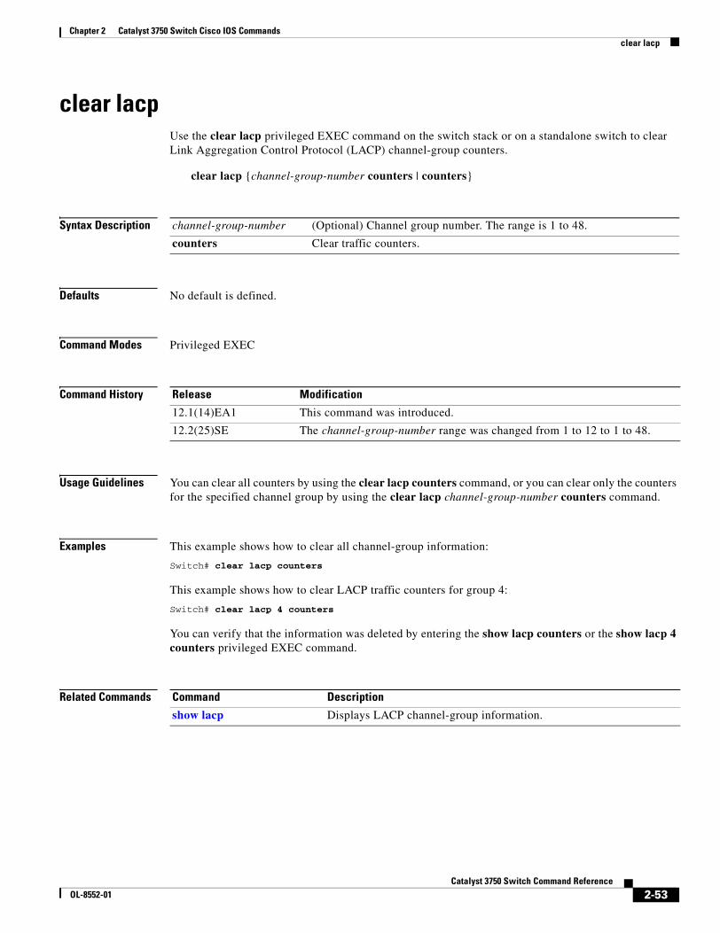
Chapter 2 Catalyst 3750 Switch Cisco IOS Commandsclear lacp
clear lacp Use the clear lacp privileged EXEC command on the switch stack or on a standalone switch to clear Link Aggregation Control Protocol (LACP) channel-group counters.
clear lacp {channel-group-number counters | counters}
Syntax Description
Defaults No default is defined.
Command Modes Privileged EXEC
Command History
Usage Guidelines You can clear all counters by using the clear lacp counters command, or you can clear only the counters for the specified channel group by using the clear lacp channel-group-number counters command.
Examples This example shows how to clear all channel-group information:
Switch# clear lacp counters
This example shows how to clear LACP traffic counters for group 4:
Switch# clear lacp 4 counters
You can verify that the information was deleted by entering the show lacp counters or the show lacp 4 counters privileged EXEC command.
Related Commands
channel-group-number (Optional) Channel group number. The range is 1 to 48.
counters Clear traffic counters.
Release Modification
12.1(14)EA1 This command was introduced.
12.2(25)SE The channel-group-number range was changed from 1 to 12 to 1 to 48.
Command Description
show lacp Displays LACP channel-group information.
2-53Catalyst 3750 Switch Command Reference
OL-8552-01
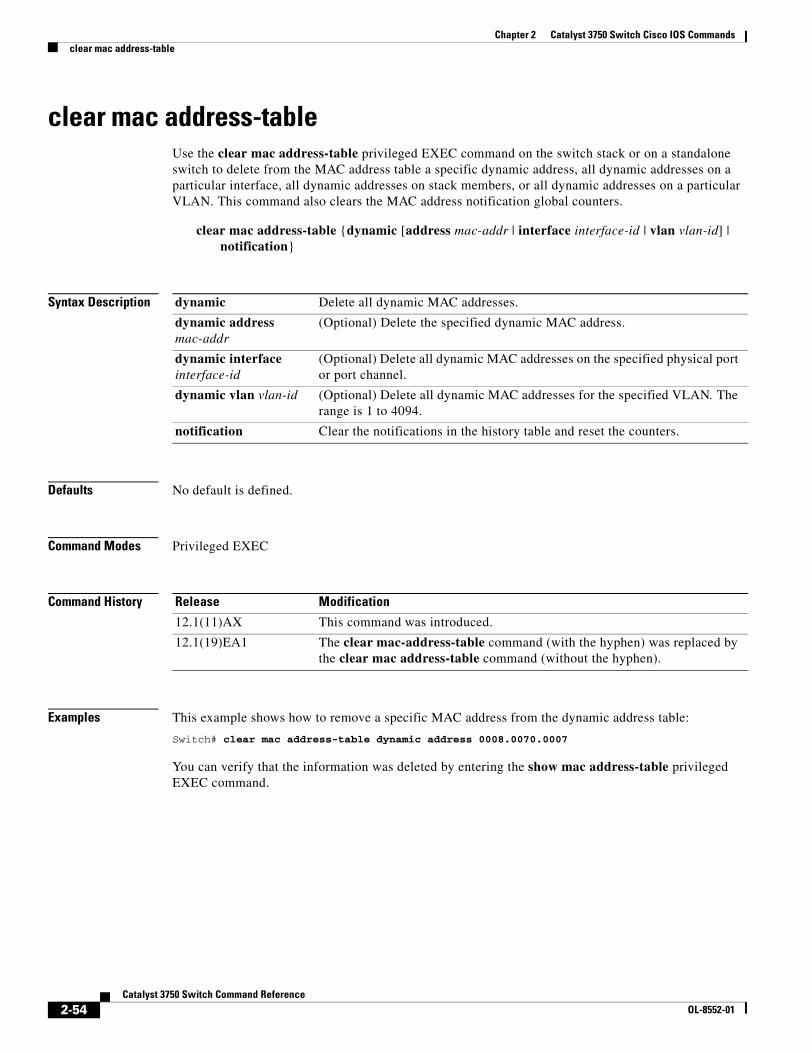
Chapter 2 Catalyst 3750 Switch Cisco IOS Commandsclear mac address-table
clear mac address-tableUse the clear mac address-table privileged EXEC command on the switch stack or on a standalone switch to delete from the MAC address table a specific dynamic address, all dynamic addresses on a particular interface, all dynamic addresses on stack members, or all dynamic addresses on a particular VLAN. This command also clears the MAC address notification global counters.
clear mac address-table {dynamic [address mac-addr | interface interface-id | vlan vlan-id] | notification}
Syntax Description
Defaults No default is defined.
Command Modes Privileged EXEC
Command History
Examples This example shows how to remove a specific MAC address from the dynamic address table:
Switch# clear mac address-table dynamic address 0008.0070.0007
You can verify that the information was deleted by entering the show mac address-table privileged EXEC command.
dynamic Delete all dynamic MAC addresses.
dynamic address mac-addr
(Optional) Delete the specified dynamic MAC address.
dynamic interface interface-id
(Optional) Delete all dynamic MAC addresses on the specified physical port or port channel.
dynamic vlan vlan-id (Optional) Delete all dynamic MAC addresses for the specified VLAN. The range is 1 to 4094.
notification Clear the notifications in the history table and reset the counters.
Release Modification
12.1(11)AX This command was introduced.
12.1(19)EA1 The clear mac-address-table command (with the hyphen) was replaced by the clear mac address-table command (without the hyphen).
2-54Catalyst 3750 Switch Command Reference
OL-8552-01
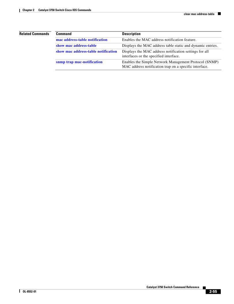
Chapter 2 Catalyst 3750 Switch Cisco IOS Commandsclear mac address-table
Related Commands Command Description
mac address-table notification Enables the MAC address notification feature.
show mac address-table Displays the MAC address table static and dynamic entries.
show mac address-table notification Displays the MAC address notification settings for all interfaces or the specified interface.
snmp trap mac-notification Enables the Simple Network Management Protocol (SNMP) MAC address notification trap on a specific interface.
2-55Catalyst 3750 Switch Command Reference
OL-8552-01
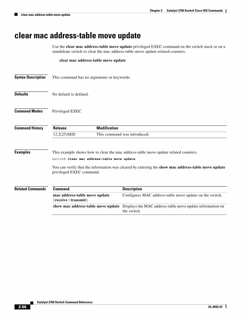
Chapter 2 Catalyst 3750 Switch Cisco IOS Commandsclear mac address-table move update
clear mac address-table move updateUse the clear mac address-table move update privileged EXEC command on the switch stack or on a standalone switch to clear the mac address-table-move update-related counters.
clear mac address-table move update
Syntax Description This command has no arguments or keywords.
Defaults No default is defined.
Command Modes Privileged EXEC
Command History
Examples This example shows how to clear the mac address-table move update related counters.
Switch# clear mac address-table move update
You can verify that the information was cleared by entering the show mac address-table move update privileged EXEC command.
Related Commands
Release Modification
12.2(25)SED This command was introduced.
Command Description
mac address-table move update {receive | transmit}
Configures MAC address-table move update on the switch.
show mac address-table move update Displays the MAC address-table move update information on the switch.
2-56Catalyst 3750 Switch Command Reference
OL-8552-01
Chapter 2 Catalyst 3750 Switch Cisco IOS Commandsclear pagp
clear pagpUse the clear pagp privileged EXEC command on the switch stack or on a standalone switch to clear Port Aggregation Protocol (PAgP) channel-group information.
clear pagp {channel-group-number counters | counters}
Syntax Description
Defaults No default is defined.
Command Modes Privileged EXEC
Command History
Usage Guidelines You can clear all counters by using the clear pagp counters command, or you can clear only the counters for the specified channel group by using the clear pagp channel-group-number counters command.
Examples This example shows how to clear all channel-group information:
Switch# clear pagp counters
This example shows how to clear PAgP traffic counters for group 10:
Switch# clear pagp 10 counters
You can verify that information was deleted by entering the show pagp privileged EXEC command.
Related Commands
channel-group-number (Optional) Channel group number. The range is 1 to 48.
counters Clear traffic counters.
Release Modification
12.1(11)AX This command was introduced.
12.2(25)SE The channel-group-number range was changed from 1 to 12 to 1 to 48.
Command Description
show pagp Displays PAgP channel-group information.
2-57Catalyst 3750 Switch Command Reference
OL-8552-01
Chapter 2 Catalyst 3750 Switch Cisco IOS Commandsclear port-security
clear port-securityUse the clear port-security privileged EXEC command on the switch stack or on a standalone switch to delete from the MAC address table all secure addresses or all secure addresses of a specific type (configured, dynamic, or sticky) on the switch or on an interface.
clear port-security {all | configured | dynamic | sticky} [[address mac-addr | interface interface-id] [vlan {vlan-id | {access | voice}}]]
Syntax Description
Defaults No default is defined.
Command Modes Privileged EXEC
Command History
Examples This example shows how to clear all secure addresses from the MAC address table:
Switch# clear port-security all
This example shows how to remove a specific configured secure address from the MAC address table:
Switch# clear port-security configured address 0008.0070.0007
all Delete all secure MAC addresses.
configured Delete configured secure MAC addresses.
dynamic Delete secure MAC addresses auto-learned by hardware.
sticky Delete secure MAC addresses, either auto-learned or configured.
address mac-addr (Optional) Delete the specified dynamic secure MAC address.
interface interface-id (Optional) Delete all the dynamic secure MAC addresses on the specified physical port or VLAN.
vlan (Optional) Delete the specified secure MAC address from the specified VLAN. Enter one of these options after you enter the vlan keyword:
• vlan-id—On a trunk port, specify the VLAN ID of the VLAN on which this address should be cleared.
• access—On an access port, clear the specified secure MAC address on the access VLAN.
• voice—On an access port, clear the specified secure MAC address on the voice VLAN.
Note The voice keyword is available only if voice VLAN is configured on a port and if that port is not the access VLAN.
Release Modification
12.2(25)SEA This command was introduced.
12.2(25)SEB The access and voice keywords were added.
2-58Catalyst 3750 Switch Command Reference
OL-8552-01
Chapter 2 Catalyst 3750 Switch Cisco IOS Commandsclear port-security
This example shows how to remove all the dynamic secure addresses learned on a specific interface:
Switch# clear port-security dynamic interface gigabitethernet1/0/1
This example shows how to remove all the dynamic secure addresses from the address table:
Switch# clear port-security dynamic
You can verify that the information was deleted by entering the show port-security privileged EXEC command.
Related Commands Command Description
switchport port-security Enables port security on an interface.
switchport port-security mac-address mac-address
Configures secure MAC addresses.
switchport port-security maximum value
Configures a maximum number of secure MAC addresses on a secure interface.
show port-security Displays the port security settings defined for an interface or for the switch.
2-59Catalyst 3750 Switch Command Reference
OL-8552-01
Chapter 2 Catalyst 3750 Switch Cisco IOS Commandsclear spanning-tree counters
clear spanning-tree countersUse the clear spanning-tree counters privileged EXEC command on the switch stack or on a standalone switch to clear the spanning-tree counters.
clear spanning-tree counters [interface interface-id]
Syntax Description
Defaults No default is defined.
Command Modes Privileged EXEC
Command History
Usage Guidelines If the interface-id is not specified, spanning-tree counters are cleared for all interfaces.
Examples This example shows how to clear spanning-tree counters for all interfaces:
Switch# clear spanning-tree counters
Related Commands
interface interface-id (Optional) Clear all spanning-tree counters on the specified interface. Valid interfaces include physical ports, VLANs, and port channels. The VLAN range is 1 to 4094. The port-channel range is 1 to 48.
Release Modification
12.1(14)EA1 This command was introduced.
Command Description
show spanning-tree Displays spanning-tree state information.
2-60Catalyst 3750 Switch Command Reference
OL-8552-01
Chapter 2 Catalyst 3750 Switch Cisco IOS Commandsclear spanning-tree detected-protocols
clear spanning-tree detected-protocols Use the clear spanning-tree detected-protocols privileged EXEC command on the switch stack or on a standalone switch to restart the protocol migration process (force the renegotiation with neighboring switches) on all interfaces or on the specified interface.
clear spanning-tree detected-protocols [interface interface-id]
Syntax Description
Defaults No default is defined.
Command Modes Privileged EXEC
Command History
Usage Guidelines A switch running the rapid per-VLAN spanning-tree plus (rapid-PVST+) protocol or the Multiple Spanning Tree Protocol (MSTP) supports a built-in protocol migration mechanism that enables it to interoperate with legacy IEEE 802.1D switches. If a rapid-PVST+ switch or an MSTP switch receives a legacy IEEE 802.1D configuration bridge protocol data unit (BPDU) with the protocol version set to 0, it sends only IEEE 802.1D BPDUs on that port. A multiple spanning-tree (MST) switch can also detect that a port is at the boundary of a region when it receives a legacy BPDU, an MST BPDU (Version 3) associated with a different region, or a rapid spanning-tree (RST) BPDU (Version 2).
However, the switch does not automatically revert to the rapid-PVST+ or the MSTP mode if it no longer receives IEEE 802.1D BPDUs because it cannot learn whether the legacy switch has been removed from the link unless the legacy switch is the designated switch. Use the clear spanning-tree detected-protocols command in this situation.
Examples This example shows how to restart the protocol migration process on a port:
Switch# clear spanning-tree detected-protocols interface gigabitethernet2/0/1
Related Commands
interface interface-id (Optional) Restart the protocol migration process on the specified interface. Valid interfaces include physical ports, VLANs, and port channels. The VLAN range is 1 to 4094. The port-channel range is 1 to 48.
Release Modification
12.1(14)EA1 This command was introduced.
Command Description
show spanning-tree Displays spanning-tree state information.
spanning-tree link-type Overrides the default link-type setting and enables rapid spanning-tree changes to the forwarding state.
2-61Catalyst 3750 Switch Command Reference
OL-8552-01
Chapter 2 Catalyst 3750 Switch Cisco IOS Commandsclear vmps statistics
clear vmps statisticsUse the clear vmps statistics privileged EXEC command on the switch stack or on a standalone switch to clear the statistics maintained by the VLAN Query Protocol (VQP) client.
clear vmps statistics
Syntax Description This command has no arguments or keywords.
Defaults No default is defined.
Command Modes Privileged EXEC
Command History
Examples This example shows how to clear VLAN Membership Policy Server (VMPS) statistics:
Switch# clear vmps statistics
You can verify that information was deleted by entering the show vmps statistics privileged EXEC command.
Related Commands
Release Modification
12.1(11)AX This command was introduced.
Command Description
show vmps Displays the VQP version, reconfirmation interval, retry count, VMPS IP addresses, and the current and primary servers.
2-62Catalyst 3750 Switch Command Reference
OL-8552-01
Chapter 2 Catalyst 3750 Switch Cisco IOS Commandsclear vtp counters
clear vtp countersUse the clear vtp counters privileged EXEC command on the switch stack or on a standalone switch to clear the VLAN Trunking Protocol (VTP) and pruning counters.
clear vtp counters
Syntax Description This command has no arguments or keywords.
Defaults No default is defined.
Command Modes Privileged EXEC
Command History
Examples This example shows how to clear the VTP counters:
Switch# clear vtp counters
You can verify that information was deleted by entering the show vtp counters privileged EXEC command.
Related Commands
Release Modification
12.1(11)AX This command was introduced.
Command Description
show vtp Displays general information about the VTP management domain, status, and counters.
2-63Catalyst 3750 Switch Command Reference
OL-8552-01
Chapter 2 Catalyst 3750 Switch Cisco IOS Commandscluster commander-address
cluster commander-address You do not need to enter this command from the switch stack or from a standalone cluster member switch. The cluster command switch automatically provides its MAC address to cluster member switches when these switches join the cluster. The cluster member switch adds this information and other cluster information to its running configuration file. Use the no form of this global configuration command from the cluster member switch console port to remove the switch from a cluster only during debugging or recovery procedures.
cluster commander-address mac-address [member number name name]
no cluster commander-address
Syntax Description
Defaults The switch is not a member of any cluster.
Command Modes Global configuration
Command History
Usage Guidelines This command is available only on the cluster command switch stack or the cluster command switch.
A cluster member can have only one cluster command switch.
The cluster member switch retains the identity of the cluster command switch during a system reload by using the mac-address parameter.
You can enter the no form on a cluster member switch to remove it from the cluster during debugging or recovery procedures. You would normally use this command from the cluster member switch console port only when the member has lost communication with the cluster command switch. With normal switch configuration, we recommend that you remove cluster member switches only by entering the no cluster member n global configuration command on the cluster command switch.
When a standby cluster command switch becomes active (becomes the cluster command switch), it removes the cluster commander address line from its configuration.
mac-address MAC address of the cluster command switch.
member number (Optional) Number of a configured cluster member switch. The range is 0 to 15.
name name (Optional) Name of the configured cluster up to 31 characters.
Release Modification
12.1(11)AX This command was introduced.
2-64Catalyst 3750 Switch Command Reference
OL-8552-01
Chapter 2 Catalyst 3750 Switch Cisco IOS Commandscluster commander-address
Examples This is partial sample output from the running configuration of a cluster member.
Switch(config)# show running-configuration
<output truncated>
cluster commander-address 00e0.9bc0.a500 member 4 name my_cluster
<output truncated>
This example shows how to remove a member from the cluster by using the cluster member console.
Switch # configure terminalEnter configuration commands, one per line. End with CNTL/Z.Switch(config)# no cluster commander-address
You can verify your settings by entering the show cluster privileged EXEC command.
Related Commands Command Description
show cluster Displays the cluster status and a summary of the cluster to which the switch belongs.
2-65Catalyst 3750 Switch Command Reference
OL-8552-01
Chapter 2 Catalyst 3750 Switch Cisco IOS Commandscluster discovery hop-count
cluster discovery hop-countUse the cluster discovery hop-count global configuration command on the switch stack or on the a cluster command switch on the cluster command switch to set the hop-count limit for extended discovery of candidate switches. Use the no form of this command to return to the default setting.
cluster discovery hop-count number
no cluster discovery hop-count
Syntax Description
Defaults The hop count is set to 3.
Command Modes Global configuration
Command History
Usage Guidelines This command is available only on the cluster command switch stack or cluster command switch. This command does not operate on cluster member switches.
If the hop count is set to 1, it disables extended discovery. The cluster command switch discovers only candidates that are one hop from the edge of the cluster. The edge of the cluster is the point between the last discovered cluster member switch and the first discovered candidate switch.
Examples This example shows how to set hop count limit to 4. This command is executed on the cluster command switch.
Switch(config)# cluster discovery hop-count 4
You can verify your setting by entering the show cluster privileged EXEC command.
Related Commands
number Number of hops from the cluster edge that the cluster command switch limits the discovery of candidates. The range is 1 to 7.
Release Modification
12.1(11)AX This command was introduced.
Command Description
show cluster Displays the cluster status and a summary of the cluster to which the switch belongs.
show cluster candidates Displays a list of candidate switches.
2-66Catalyst 3750 Switch Command Reference
OL-8552-01
Chapter 2 Catalyst 3750 Switch Cisco IOS Commandscluster enable
cluster enableUse the cluster enable global configuration command on a command-capable switch or switch stack to enable it as the cluster command switch, assign a cluster name, and to optionally assign a member number to it. Use the no form of the command to remove all members and to make the cluster command switch a candidate switch.
cluster enable name [command-switch-member-number]
no cluster enable
Syntax Description
Defaults The switch is not a cluster command switch.
No cluster name is defined.
The member number is 0 when the switch is the cluster command switch.
Command Modes Global configuration
Command History
Usage Guidelines Enter this command on any command-capable switch that is not part of any cluster. This command fails if a device is already configured as a member of the cluster.
You must name the cluster when you enable the cluster command switch. If the switch is already configured as the cluster command switch, this command changes the cluster name if it is different from the previous cluster name.
Examples This example shows how to enable the cluster command switch, name the cluster, and set the cluster command switch member number to 4.
Switch(config)# cluster enable Engineering-IDF4 4
You can verify your setting by entering the show cluster privileged EXEC command on the cluster command switch.
name Name of the cluster up to 31 characters. Valid characters include only alphanumerics, dashes, and underscores.
command-switch-member-number (Optional) Assign a member number to the cluster command switch of the cluster. The range is 0 to 15.
Release Modification
12.1(11)AX This command was introduced.
2-67Catalyst 3750 Switch Command Reference
OL-8552-01

Chapter 2 Catalyst 3750 Switch Cisco IOS Commandscluster enable
Related Commands Command Description
show cluster Displays the cluster status and a summary of the cluster to which the switch belongs.
2-68Catalyst 3750 Switch Command Reference
OL-8552-01
Chapter 2 Catalyst 3750 Switch Cisco IOS Commandscluster holdtime
cluster holdtimeUse the cluster holdtime global configuration command on the switch stack or on the a cluster command switch to set the duration in seconds before a switch (either the command or cluster member switch) declares the other switch down after not receiving heartbeat messages. Use the no form of this command to set the duration to the default value.
cluster holdtime holdtime-in-secs
no cluster holdtime
Syntax Description
Defaults The default holdtime is 80 seconds.
Command Modes Global configuration
Command History
Usage Guidelines Enter this command with the cluster timer global configuration command only on the cluster command switch. The cluster command switch propagates the values to all its cluster members so that the setting is consistent among all switches in the cluster.
The holdtime is typically set as a multiple of the interval timer (cluster timer). For example, it takes (holdtime-in-secs divided by the interval-in-secs) number of heartbeat messages to be missed in a row to declare a switch down.
Examples This example shows how to change the interval timer and the duration on the cluster command switch.
Switch(config)# cluster timer 3Switch(config)# cluster holdtime 30
You can verify your settings by entering the show cluster privileged EXEC command.
Related Commands
holdtime-in-secs Duration in seconds before a switch (either a command or cluster member switch) declares the other switch down. The range is 1 to 300 seconds.
Release Modification
12.1(11)AX This command was introduced.
Command Description
show cluster Displays the cluster status and a summary of the cluster to which the switch belongs.
2-69Catalyst 3750 Switch Command Reference
OL-8552-01
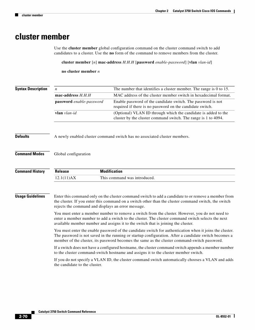
Chapter 2 Catalyst 3750 Switch Cisco IOS Commandscluster member
cluster memberUse the cluster member global configuration command on the cluster command switch to add candidates to a cluster. Use the no form of the command to remove members from the cluster.
cluster member [n] mac-address H.H.H [password enable-password] [vlan vlan-id]
no cluster member n
Syntax Description
Defaults A newly enabled cluster command switch has no associated cluster members.
Command Modes Global configuration
Command History
Usage Guidelines Enter this command only on the cluster command switch to add a candidate to or remove a member from the cluster. If you enter this command on a switch other than the cluster command switch, the switch rejects the command and displays an error message.
You must enter a member number to remove a switch from the cluster. However, you do not need to enter a member number to add a switch to the cluster. The cluster command switch selects the next available member number and assigns it to the switch that is joining the cluster.
You must enter the enable password of the candidate switch for authentication when it joins the cluster. The password is not saved in the running or startup configuration. After a candidate switch becomes a member of the cluster, its password becomes the same as the cluster command-switch password.
If a switch does not have a configured hostname, the cluster command switch appends a member number to the cluster command-switch hostname and assigns it to the cluster member switch.
If you do not specify a VLAN ID, the cluster command switch automatically chooses a VLAN and adds the candidate to the cluster.
n The number that identifies a cluster member. The range is 0 to 15.
mac-address H.H.H MAC address of the cluster member switch in hexadecimal format.
password enable-password Enable password of the candidate switch. The password is not required if there is no password on the candidate switch.
vlan vlan-id (Optional) VLAN ID through which the candidate is added to the cluster by the cluster command switch. The range is 1 to 4094.
Release Modification
12.1(11)AX This command was introduced.
2-70Catalyst 3750 Switch Command Reference
OL-8552-01
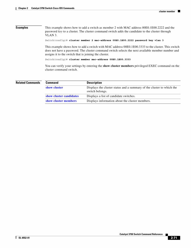
Chapter 2 Catalyst 3750 Switch Cisco IOS Commandscluster member
Examples This example shows how to add a switch as member 2 with MAC address 00E0.1E00.2222 and the password key to a cluster. The cluster command switch adds the candidate to the cluster through VLAN 3.
Switch(config)# cluster member 2 mac-address 00E0.1E00.2222 password key vlan 3
This example shows how to add a switch with MAC address 00E0.1E00.3333 to the cluster. This switch does not have a password. The cluster command switch selects the next available member number and assigns it to the switch that is joining the cluster.
Switch(config)# cluster member mac-address 00E0.1E00.3333
You can verify your settings by entering the show cluster members privileged EXEC command on the cluster command switch.
Related Commands Command Description
show cluster Displays the cluster status and a summary of the cluster to which the switch belongs.
show cluster candidates Displays a list of candidate switches.
show cluster members Displays information about the cluster members.
2-71Catalyst 3750 Switch Command Reference
OL-8552-01
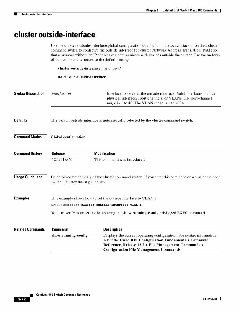
Chapter 2 Catalyst 3750 Switch Cisco IOS Commandscluster outside-interface
cluster outside-interfaceUse the cluster outside-interface global configuration command on the switch stack or on the a cluster command switch to configure the outside interface for cluster Network Address Translation (NAT) so that a member without an IP address can communicate with devices outside the cluster. Use the no form of this command to return to the default setting.
cluster outside-interface interface-id
no cluster outside-interface
Syntax Description
Defaults The default outside interface is automatically selected by the cluster command switch.
Command Modes Global configuration
Command History
Usage Guidelines Enter this command only on the cluster command switch. If you enter this command on a cluster member switch, an error message appears.
Examples This example shows how to set the outside interface to VLAN 1:
Switch(config)# cluster outside-interface vlan 1
You can verify your setting by entering the show running-config privileged EXEC command.
Related Commands
interface-id Interface to serve as the outside interface. Valid interfaces include physical interfaces, port-channels, or VLANs. The port-channel range is 1 to 48. The VLAN range is 1 to 4094.
Release Modification
12.1(11)AX This command was introduced.
Command Description
show running-config Displays the current operating configuration. For syntax information, select the Cisco IOS Configuration Fundamentals Command Reference, Release 12.2 > File Management Commands > Configuration File Management Commands.
2-72Catalyst 3750 Switch Command Reference
OL-8552-01
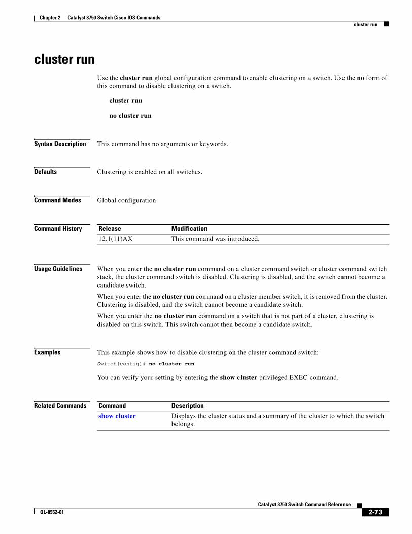
Chapter 2 Catalyst 3750 Switch Cisco IOS Commandscluster run
cluster runUse the cluster run global configuration command to enable clustering on a switch. Use the no form of this command to disable clustering on a switch.
cluster run
no cluster run
Syntax Description This command has no arguments or keywords.
Defaults Clustering is enabled on all switches.
Command Modes Global configuration
Command History
Usage Guidelines When you enter the no cluster run command on a cluster command switch or cluster command switch stack, the cluster command switch is disabled. Clustering is disabled, and the switch cannot become a candidate switch.
When you enter the no cluster run command on a cluster member switch, it is removed from the cluster. Clustering is disabled, and the switch cannot become a candidate switch.
When you enter the no cluster run command on a switch that is not part of a cluster, clustering is disabled on this switch. This switch cannot then become a candidate switch.
Examples This example shows how to disable clustering on the cluster command switch:
Switch(config)# no cluster run
You can verify your setting by entering the show cluster privileged EXEC command.
Related Commands
Release Modification
12.1(11)AX This command was introduced.
Command Description
show cluster Displays the cluster status and a summary of the cluster to which the switch belongs.
2-73Catalyst 3750 Switch Command Reference
OL-8552-01
Chapter 2 Catalyst 3750 Switch Cisco IOS Commandscluster standby-group
cluster standby-groupUse the cluster standby-group global configuration command to enable cluster command-switch redundancy by binding the cluster to an existing Hot Standby Router Protocol (HSRP). Entering the routing-redundancy keyword enables the same HSRP group to be used for cluster command-switch redundancy and routing redundancy. Use the no form of this command to return to the default setting.
cluster standby-group HSRP-group-name [routing-redundancy]
no cluster standby-group
Syntax Description
Defaults The cluster is not bound to any HSRP group.
Command Modes Global configuration
Command History
Usage Guidelines Enter this command only on the cluster command switch. If you enter it on a cluster member switch, an error message appears.
The cluster command switch propagates the cluster-HSRP binding information to all cluster-HSRP capable members. Each cluster member switch stores the binding information in its NVRAM. The HSRP group name must be a valid standby group; otherwise, the command exits with an error.
The same group name should be used on all members of the HSRP standby group that is to be bound to the cluster. The same HSRP group name should also be used on all cluster-HSRP capable members for the HSRP group that is to be bound. (When not binding a cluster to an HSRP group, you can use different names on the cluster commander and the members.)
Examples This example shows how to bind the HSRP group named my_hsrp to the cluster. This command is executed on the cluster command switch.
Switch(config)# cluster standby-group my_hsrp
This example shows how to use the same HSRP group named my_hsrp for routing redundancy and cluster redundancy.
Switch(config)# cluster standby-group my_hsrp routing-redundancy
HSRP-group-name Name of the HSRP group that is bound to the cluster. The group name is limited to 32 characters.
routing-redundancy (Optional) Enable the same HSRP standby group to be used for cluster command-switch redundancy and routing redundancy.
Release Modification
12.1(11)AX This command was introduced.
2-74Catalyst 3750 Switch Command Reference
OL-8552-01
Chapter 2 Catalyst 3750 Switch Cisco IOS Commandscluster standby-group
This example shows the error message when this command is executed on a cluster command switch and the specified HSRP standby group does not exist:
Switch(config)# cluster standby-group my_hsrp %ERROR: Standby (my_hsrp) group does not exist
This example shows the error message when this command is executed on a cluster member switch:
Switch(config)# cluster standby-group my_hsrp routing-redundancy%ERROR: This command runs on a cluster command switch
You can verify your settings by entering the show cluster privileged EXEC command. The output shows whether redundancy is enabled in the cluster.
Related Commands Command Description
standby ip Enables HSRP on the interface. For syntax information, select Cisco IOS IP Command Reference, Volume 1 of 3:Addressing and Services, Release 12.2 > IP Services Commands.
show cluster Displays the cluster status and a summary of the cluster to which the switch belongs.
show standby Displays standby group information. For syntax information, select Cisco IOS IP Command Reference, Volume 1 of 3:Addressing and Services, Release 12.2 > IP Services Commands.
2-75Catalyst 3750 Switch Command Reference
OL-8552-01
Chapter 2 Catalyst 3750 Switch Cisco IOS Commandscluster timer
cluster timerUse the cluster timer global configuration command on the switch stack or on the a cluster command switch to set the interval in seconds between heartbeat messages. Use the no form of this command to set the interval to the default value.
cluster timer interval-in-secs
no cluster timer
Syntax Description
Defaults The interval is 8 seconds.
Command Modes Global configuration
Command History
Usage Guidelines Enter this command with the cluster holdtime global configuration command only on the cluster command switch. The cluster command switch propagates the values to all its cluster members so that the setting is consistent among all switches in the cluster.
The holdtime is typically set as a multiple of the heartbeat interval timer (cluster timer). For example, it takes (holdtime-in-secs divided by the interval-in-secs) number of heartbeat messages to be missed in a row to declare a switch down.
Examples This example shows how to change the heartbeat interval timer and the duration on the cluster command switch:
Switch(config)# cluster timer 3Switch(config)# cluster holdtime 30
You can verify your settings by entering the show cluster privileged EXEC command.
Related Commands
interval-in-secs Interval in seconds between heartbeat messages. The range is 1 to 300 seconds.
Release Modification
12.1(11)AX This command was introduced.
Command Description
show cluster Displays the cluster status and a summary of the cluster to which the switch belongs.
2-76Catalyst 3750 Switch Command Reference
OL-8552-01
Chapter 2 Catalyst 3750 Switch Cisco IOS Commandsdefine interface-range
define interface-rangeUse the define interface-range global configuration command on the switch stack or on a standalone switch to create an interface-range macro. Use the no form of this command to delete the defined macro.
define interface-range macro-name interface-range
no define interface-range macro-name interface-range
Syntax Description
Defaults This command has no default setting.
Command Modes Global configuration
Command History
Usage Guidelines The macro name is a 32-character maximum character string.
A macro can contain up to five ranges.
All interfaces in a range must be the same type; that is, all Fast Ethernet ports, all Gigabit Ethernet ports, all EtherChannel ports, or all VLANs, but you can combine multiple interface types in a macro.
When entering the interface-range, use this format:
• type {first-interface} - {last-interface}
• You must add a space between the first interface number and the hyphen when entering an interface-range. For example, gigabitethernet 1/0/1 - 2 is a valid range; gigabitethernet 1/0/1-2 is not a valid range
Valid values for type and interface:
• vlan vlan-id - vlan-ID, where the VLAN ID is 1 to 4094
VLAN interfaces must have been configured with the interface vlan command (the show running-config privileged EXEC command displays the configured VLAN interfaces). VLAN interfaces not displayed by the show running-config command cannot be used in interface-ranges.
• port-channel port-channel-number, where port-channel-number is from 1 to 48
• fastethernet stack member/module/{first port} - {last port}
• gigabitethernet stack member/module/{first port} - {last port}
For physical interfaces:
• stack member is the number used to identify the switch within the stack. The number ranges from 1 to 9 and is assigned to the switch the first time the stack member initializes.
macro-name Name of the interface-range macro; up to 32 characters.
interface-range Interface range; for valid values for interface ranges, see “Usage Guidelines.”
Release Modification
12.1(11)AX This command was introduced.
2-77Catalyst 3750 Switch Command Reference
OL-8552-01
Chapter 2 Catalyst 3750 Switch Cisco IOS Commandsdefine interface-range
• module is always 0.
• the range is type stack member/0/number - number (for example, gigabitethernet 1/0/1 - 2).
When you define a range, you must enter a space before the hyphen (-), for example:
gigabitethernet1/0/1 - 2
You can also enter multiple ranges. When you define multiple ranges, you must enter a space after the first entry before the comma (,). The space after the comma is optional, for example:
fastethernet1/0/3, gigabitethernet1/0/1 - 2
fastethernet1/0/3 -4, gigabitethernet1/0/1 - 2
Examples This example shows how to create a multiple-interface macro:
Switch(config)# define interface-range macro1 fastethernet1/0/1 - 2, gigabitethernet1/0/1 - 2
Related Commands Command Description
interface range Executes a command on multiple ports at the same time.
show running-config Displays the current operating configuration, including defined macros. For syntax information, select Cisco IOS Configuration Fundamentals Command Reference, Release 12.2 > File Management Commands > Configuration File Management Commands.
2-78Catalyst 3750 Switch Command Reference
OL-8552-01
Chapter 2 Catalyst 3750 Switch Cisco IOS Commandsdelete
deleteUse the delete privileged EXEC command on the switch stack or on a standalone switch to delete a file or directory on the flash memory device.
delete [/force] [/recursive] filesystem:/file-url
Syntax Description
Command Modes Privileged EXEC
Command History
Usage Guidelines If you use the /force keyword, you are prompted once at the beginning of the deletion process to confirm the deletion.
If you use the /recursive keyword without the /force keyword, you are prompted to confirm the deletion of every file.
The prompting behavior depends on the setting of the file prompt global configuration command. By default, the switch prompts for confirmation on destructive file operations. For more information about this command, see the Cisco IOS Command Reference for Release 12.1.
Examples This example shows how to remove the directory that contains the old software image after a successful download of a new image:
Switch# delete /force /recursive flash:/old-image
You can verify that the directory was removed by entering the dir filesystem: privileged EXEC command.
Related Commands
/force (Optional) Suppress the prompt that confirms the deletion.
/recursive (Optional) Delete the named directory and all subdirectories and the files contained in it.
filesystem: Alias for a flash file system.
The syntax for the local flash file system on the stack member or the stack master:flash:
From the stack master, the syntax for the local flash file system on a stack member:flash member number:
/file-url The path (directory) and filename to delete.
Release Modification
12.1(11)AX This command was introduced.
Command Description
archive download-sw Downloads a new image to the switch and overwrites or keeps the existing image.
2-79Catalyst 3750 Switch Command Reference
OL-8552-01
Chapter 2 Catalyst 3750 Switch Cisco IOS Commandsdeny (ARP access-list configuration)
deny (ARP access-list configuration)Use the deny Address Resolution Protocol (ARP) access-list configuration command on the switch stack or on a standalone switch to deny an ARP packet based on matches against the DHCP bindings. Use the no form of this command to remove the specified access control entry (ACE) from the access list.
deny {[request] ip {any | host sender-ip | sender-ip sender-ip-mask} mac {any | host sender-mac | sender-mac sender-mac-mask} | response ip {any | host sender-ip | sender-ip sender-ip-mask} [{any | host target-ip | target-ip target-ip-mask}] mac {any | host sender-mac | sender-mac sender-mac-mask} [{any | host target-mac | target-mac target-mac-mask}]} [log]
no deny {[request] ip {any | host sender-ip | sender-ip sender-ip-mask} mac {any | host sender-mac | sender-mac sender-mac-mask} | response ip {any | host sender-ip | sender-ip sender-ip-mask} [{any | host target-ip | target-ip target-ip-mask}] mac {any | host sender-mac | sender-mac sender-mac-mask} [{any | host target-mac | target-mac target-mac-mask}]} [log]
This command is available only if your switch is running the IP services image, formerly known as the enhanced multilayer image (EMI).
Syntax Description
Defaults There are no default settings. However, at the end of the ARP access list, there is an implicit deny ip any mac any command.
Command Modes ARP access-list configuration
request (Optional) Define a match for the ARP request. When request is not specified, matching is performed against all ARP packets.
ip Specify the sender IP address.
any Deny any IP or MAC address.
host sender-ip Deny the specified sender IP address.
sender-ip sender-ip-mask Deny the specified range of sender IP addresses.
mac Deny the sender MAC address.
host sender-mac Deny a specific sender MAC address.
sender-mac sender-mac-mask
Deny the specified range of sender MAC addresses.
response ip Define the IP address values for the ARP responses.
host target-ip Deny the specified target IP address.
target-ip target-ip-mask Deny the specified range of target IP addresses.
mac Deny the MAC address values for the ARP responses.
host target-mac Deny the specified target MAC address.
target-mac target-mac-mask
Deny the specified range of target MAC addresses.
log (Optional) Log a packet when it matches the ACE.
2-80Catalyst 3750 Switch Command Reference
OL-8552-01
Chapter 2 Catalyst 3750 Switch Cisco IOS Commandsdeny (ARP access-list configuration)
Command History
Usage Guidelines You can add deny clauses to drop ARP packets based on matching criteria.
Examples This example shows how to define an ARP access list and to deny both ARP requests and ARP responses from a host with an IP address of 1.1.1.1 and a MAC address of 0000.0000.abcd:
Switch(config)# arp access-list static-hostsSwitch(config-arp-nacl)# deny ip host 1.1.1.1 mac host 0000.0000.abcdSwitch(config-arp-nacl)# end
You can verify your settings by entering the show arp access-list privileged EXEC command.
Related Commands
Release Modification
12.2(20)SE This command was introduced.
Command Description
arp access-list Defines an ARP access control list (ACL).
ip arp inspection filter vlan Permits ARP requests and responses from a host configured with a static IP address.
permit (ARP access-list configuration)
Permits an ARP packet based on matches against the DHCP bindings.
show arp access-list Displays detailed information about ARP access lists.
2-81Catalyst 3750 Switch Command Reference
OL-8552-01
Chapter 2 Catalyst 3750 Switch Cisco IOS Commandsdeny (IPv6 access-list configuration)
deny (IPv6 access-list configuration) Use the deny command in IPv6 access list configuration mode on the switch stack or on a standalone switch to set deny conditions for an IPv6 access list. Use the no form of this command to remove the deny conditions.
deny {protocol} {source-ipv6-prefix/prefix-length | any | host source-ipv6-address} [operator [port-number]] {destination-ipv6-prefix/prefix-length | any | host destination-ipv6-address} [operator [port-number]] [dscp value] [fragments] [log] [log-input] [sequence value] [time-range name]
no deny {protocol} {source-ipv6-prefix/prefix-length | any | host source-ipv6-address} [operator [port-number]] {destination-ipv6-prefix/prefix-length | any | host destination-ipv6-address} [operator [port-number]] [dscp value] [fragments] [log] [log-input] [sequence value] [time-range name]
Internet Control Message Protocol
deny icmp {source-ipv6-prefix/prefix-length | any | host source-ipv6-address} [operator [port-number]] {destination-ipv6-prefix/prefix-length | any | host destination-ipv6-address} [operator [port-number]] [icmp-type [icmp-code] | icmp-message] [dscp value] [log] [log-input] [sequence value] [time-range name]
Transmission Control Protocol
deny tcp {source-ipv6-prefix/prefix-length | any | host source-ipv6-address} [operator [port-number]] {destination-ipv6-prefix/prefix-length | any | host destination-ipv6-address} [operator [port-number]] [ack] [dscp value] [established] [fin] [log] [log-input] [neq {port | protocol}] [psh] [range {port | protocol}] [rst] [sequence value] [syn] [time-range name] [urg]
User Datagram Protocol
deny udp {source-ipv6-prefix/prefix-length | any | host source-ipv6-address} [operator [port-number]] {destination-ipv6-prefix/prefix-length | any | host destination-ipv6-address} [operator [port-number]] [dscp value] [log] [log-input] [neq {port | protocol}] [range {port | protocol}] [sequence value] [time-range name]
Note This command is available only if the switch stack is running the advanced IP services image and you have configured a dual IPv4 and IPv6 Switch Database Management (SDM) template on the switch.
2-82Catalyst 3750 Switch Command Reference
OL-8552-01
Chapter 2 Catalyst 3750 Switch Cisco IOS Commandsdeny (IPv6 access-list configuration)
Syntax Description protocol Name or number of an Internet protocol. It can be one of the keywords ahp, esp, icmp, ipv6, pcp, sctp, tcp, or udp, or an integer in the range from 0 to 255 representing an IPv6 protocol number.
source-ipv6-prefix/prefix-length
The source IPv6 network or class of networks about which to set deny conditions.
This argument must be in the form documented in RFC 2373 where the address is specified in hexadecimal using 16-bit values between colons.
Note Although the CLI help shows a prefix-length range of /0 to /128, the switch supports IPv6 address-matching only for prefixes in the range of /0 to /64 and extended universal identifier (EUI)-based /128 prefixes for aggregatable global unicast and link-local host addresses.
any An abbreviation for the IPv6 prefix ::/0.
host source-ipv6-address The source IPv6 host address for which to set deny conditions.
This source-ipv6-address argument must be in the form documented in RFC 2373 where the address is specified in hexadecimal using 16-bit values between colons.
operator [port-number] (Optional) Specify an operator that compares the source or destination ports of the specified protocol. Operators are lt (less than), gt (greater than), eq (equal), neq (not equal), and range (inclusive range).
If the operator is positioned after the source-ipv6-prefix/prefix-length argument, it must match the source port.
If the operator is positioned after the destination-ipv6-prefix/prefix-length argument, it must match the destination port.
The range operator requires two port numbers. All other operators require one port number.
The optional port-number argument is a decimal number or the name of a TCP or a UDP port. A port number is a number from 0 to 65535. TCP port names can be used only when filtering TCP. UDP port names can be used only when filtering UDP.
destination-ipv6-prefix/prefix-length
The destination IPv6 network or class of networks for which to set deny conditions.
This argument must be in the form documented in RFC 2373 where the address is specified in hexadecimal using 16-bit values between colons.
Note Although the CLI help shows a prefix-length range of /0 to /128, the switch supports IPv6 address-matching only for prefixes in the range of /0 to /64 and EUI-based /128 prefixes for aggregatable global unicast and link-local host addresses.
host destination-ipv6-address
The destination IPv6 host address for which to set deny conditions.
This destination-ipv6-address argument must be in the form documented in RFC 2373 where the address is specified in hexadecimal using 16-bit values between colons.
dscp value (Optional) Match a differentiated services code point value against the traffic class value in the Traffic Class field of each IPv6 packet header. The acceptable range is from 0 to 63.
2-83Catalyst 3750 Switch Command Reference
OL-8552-01
Chapter 2 Catalyst 3750 Switch Cisco IOS Commandsdeny (IPv6 access-list configuration)
fragments (Optional) Match non-initial fragmented packets where the fragment extension header contains a non-zero fragment offset. The fragments keyword is an option only if the protocol is ipv6 and the operator [port-number] arguments are not specified.
log (Optional) Send an informational logging message to the console about the packet that matches the entry. (The level of messages sent to the console is controlled by the logging console command.)
The message includes the access list name and sequence number, whether the packet was denied; the protocol, whether it was TCP, UDP, ICMP, or a number; and, if appropriate, the source and destination addresses and source and destination port numbers. The message is generated for the first packet that matches, and then at 5-minute intervals, including the number of packets denied in the prior 5-minute interval.
Note Logging is not supported for port ACLs.
log-input (Optional) Provide the same function as the log keyword, except that the logging message also includes the receiving interface.
sequence value (Optional) Specify the sequence number for the access list statement. The acceptable range is from 1 to 4294967295.
time-range name (Optional) Specify the time range that applies to the deny statement. The name of the time range and its restrictions are specified by the time-range and absolute or periodic commands, respectively.
icmp-type (Optional) Specify an ICMP message type for filtering ICMP packets. ICMP packets can be filtered by an ICMP message type. The type is a number from 0 to 255.
icmp-code (Optional) Specify an ICMP message code for filtering ICMP packets. ICMP packets that are filtered by ICMP message type can also be filtered by the ICMP message code. The code is a number from 0 to 255.
icmp-message (Optional) Specify an ICMP message name for filtering ICMP packets. ICMP packets can be filtered by an ICMP message name or an ICMP message type and code. The possible names are listed in the “Usage Guidelines” section.
ack (Optional) Only for the TCP protocol: Acknowledgment (ACK) bit set.
established (Optional) Only for the TCP protocol: Means the connection has been established. A match occurs if the TCP datagram has the ACK or RST bits set. The nonmatching case is that of the initial TCP datagram to form a connection.
fin (Optional) Only for the TCP protocol: Fin bit set; no more data from sender.
neq {port | protocol} (Optional) Match only packets that are not on a given port number.
psh (Optional) Only for the TCP protocol: Push function bit set.
range {port | protocol} (Optional) Match only packets in the range of port numbers.
rst (Optional) Only for the TCP protocol: Reset bit set.
syn (Optional) Only for the TCP protocol: Synchronize bit set.
urg (Optional) Only for the TCP protocol: Urgent pointer bit set.
2-84Catalyst 3750 Switch Command Reference
OL-8552-01
Chapter 2 Catalyst 3750 Switch Cisco IOS Commandsdeny (IPv6 access-list configuration)
Note Although visible in the command-line help strings, the flow-label, routing, and undetermined-transport keywords are not supported.
Defaults No IPv6 access list is defined.
Command Modes IPv6 access list configuration
Command History
Usage Guidelines The deny (IPv6 access-list configuration mode) command is similar to the deny (IPv4 access-list configuration mode) command, except that it is IPv6-specific.
Use the deny (IPv6) command after the ipv6 access-list command to enter IPv6 access list configuration mode and to define the conditions under which a packet passes the access list.
Specifying IPv6 for the protocol argument matches against the IPv6 header of the packet.
By default, the first statement in an access list is number 10, and the subsequent statements are numbered in increments of 10.
You can add permit, deny, or remark statements to an existing access list without re-entering the entire list. To add a new statement anywhere other than at the end of the list, create a new statement with an appropriate entry number that falls between two existing entry numbers to show where it belongs.
Note Every IPv6 ACL has implicit permit icmp any any nd-na, permit icmp any any nd-ns, and deny ipv6 any any statements as its last match conditions. The two permit conditions allow ICMPv6 neighbor discovery. To disallow ICMPv6 neighbor discovery and to deny icmp any any nd-na or icmp any any nd-ns, there must be an explicit deny entry in the ACL. For the implicit deny ipv6 any any statement to take effect, an IPv6 ACL must contain at least one entry.
The IPv6 neighbor discovery process uses the IPv6 network layer service. Therefore, by default, IPv6 ACLs implicitly allow IPv6 neighbor discovery packets to be sent and received on an interface. In IPv4, the Address Resolution Protocol (ARP), which is equivalent to the IPv6 neighbor discovery process, uses a separate data-link layer protocol. Therefore, by default, IPv4 ACLs implicitly allow ARP packets to be sent and received on an interface.
Both the source-ipv6-prefix/prefix-length and destination-ipv6-prefix/prefix-length arguments are used for traffic filtering. (The source prefix filters traffic based upon the traffic source; the destination prefix filters traffic based upon the traffic destination.)
The switch supports only prefixes from /0 to /64 and EUI-based /128 prefixes for aggregatable global unicast and link-local host addresses.
The fragments keyword is an option only if the protocol is ipv6 and the operator [port-number] arguments are not specified.
Release Modification
12.2(25)SED This command was introduced.
2-85Catalyst 3750 Switch Command Reference
OL-8552-01
Chapter 2 Catalyst 3750 Switch Cisco IOS Commandsdeny (IPv6 access-list configuration)
This is a list of ICMP message names:
Examples This example configures the IPv6 access list named CISCO and applies the access list to outbound traffic on a Layer 3 interface. The first deny entry in the list prevents all packets that have a destination TCP port number greater than 5000 from leaving the interface. The second deny entry in the list prevents all packets that have a source UDP port number less than 5000 from leaving the interface. The second deny also logs all matches to the console. The first permit entry in the list permits all ICMP packets to leave the interface. The second permit entry in the list permits all other traffic to leave the interface. The second permit entry is necessary because an implicit deny-all condition is at the end of each IPv6 access list.
Switch(config)# ipv6 access-list CISCOSwitch(config-ipv6-acl)# deny tcp any any gt 5000Switch config-ipv6-acl)# deny ::/0 lt 5000 ::/0 logSwitch(config-ipv6-acl)# permit icmp any anySwitch(config-ipv6-acl)# permit any anySwitch(config-ipv6-acl)# exitSwitch(config)# interface gigabitethernet1/0/3Switch(config-if)# no switchportSwitch(config-if)# ipv6 address 2001::/64 eui-64Switch(config-if)# ipv6 traffic-filter CISCO out
Related Commands
beyond-scope destination-unreachable
echo-reply echo-request
header hop-limit
mld-query mld-reduction
mld-report nd-na
nd-ns next-header
no-admin no-route
packet-too-big parameter-option
parameter-problem port-unreachable
reassembly-timeout renum-command
renum-result renum-seq-number
router-advertisement router-renumbering
router-solicitation time-exceeded
unreachable
Command Description
ipv6 access-list Defines an IPv6 access list and enters IPv6 access list configuration mode.
ipv6 traffic-filter Filters incoming or outgoing IPv6 traffic on an interface.
permit (IPv6 access-list configuration)
Sets permit conditions for an IPv6 access list.
show ipv6 access-list Displays the contents of all current IPv6 access lists.
2-86Catalyst 3750 Switch Command Reference
OL-8552-01
Chapter 2 Catalyst 3750 Switch Cisco IOS Commandsdeny (MAC access-list configuration)
deny (MAC access-list configuration)Use the deny MAC access-list configuration command on the switch stack or on a standalone switch to prevent non-IP traffic from being forwarded if the conditions are matched. Use the no form of this command to remove a deny condition from the named MAC access list.
{deny | permit} {any | host src-MAC-addr | src-MAC-addr mask} {any | host dst-MAC-addr | dst-MAC-addr mask} [type mask | aarp | amber | cos cos | dec-spanning | decnet-iv | diagnostic | dsm | etype-6000 | etype-8042 | lat | lavc-sca | lsap lsap mask |mop-console | mop-dump | msdos | mumps | netbios | vines-echo | vines-ip | xns-idp]
no {deny | permit} {any | host src-MAC-addr | src-MAC-addr mask} {any | host dst-MAC-addr | dst-MAC-addr mask} [type mask | aarp | amber | cos cos | dec-spanning | decnet-iv | diagnostic | dsm | etype-6000 | etype-8042 | lat | lavc-sca | lsap lsap mask | mop-console | mop-dump | msdos | mumps | netbios | vines-echo | vines-ip | xns-idp]
Syntax Description any Keyword to specify to deny any source or destination MAC address.
host src MAC-addr |src-MAC-addr mask
Define a host MAC address and optional subnet mask. If the source address for a packet matches the defined address, non-IP traffic from that address is denied.
host dst-MAC-addr | dst-MAC-addr mask
Define a destination MAC address and optional subnet mask. If the destination address for a packet matches the defined address, non-IP traffic to that address is denied.
type mask (Optional) Use the Ethertype number of a packet with Ethernet II or SNAP encapsulation to identify the protocol of the packet.
The type is 0 to 65535, specified in hexadecimal.
The mask is a mask of don’t care bits applied to the Ethertype before testing for a match.
aarp (Optional) Select Ethertype AppleTalk Address Resolution Protocol that maps a data-link address to a network address.
amber (Optional) Select EtherType DEC-Amber.
cos cos (Optional) Select a class of service (CoS) number from 0 to 7 to set priority. Filtering on CoS can be performed only in hardware. A warning message reminds the user if the cos option is configured.
dec-spanning (Optional) Select EtherType Digital Equipment Corporation (DEC) spanning tree.
decnet-iv (Optional) Select EtherType DECnet Phase IV protocol.
diagnostic (Optional) Select EtherType DEC-Diagnostic.
dsm (Optional) Select EtherType DEC-DSM.
etype-6000 (Optional) Select EtherType 0x6000.
etype-8042 (Optional) Select EtherType 0x8042.
lat (Optional) Select EtherType DEC-LAT.
lavc-sca (Optional) Select EtherType DEC-LAVC-SCA.
2-87Catalyst 3750 Switch Command Reference
OL-8552-01
Chapter 2 Catalyst 3750 Switch Cisco IOS Commandsdeny (MAC access-list configuration)
Note Though visible in the command-line help strings, appletalk is not supported as a matching condition.
To filter IPX traffic, you use the type mask or lsap lsap mask keywords, depending on the type of IPX encapsulation being used. Filter criteria for IPX encapsulation types as specified in Novell terminology and Cisco IOS terminology are listed in Table 2-4.
Defaults This command has no defaults. However; the default action for a MAC-named ACL is to deny.
Command Modes MAC-access list configuration
Command History
lsap lsap-number mask (Optional) Use the LSAP number (0 to 65535) of a packet with 802.2 encapsulation to identify the protocol of the packet.
mask is a mask of don’t care bits applied to the LSAP number before testing for a match.
mop-console (Optional) Select EtherType DEC-MOP Remote Console.
mop-dump (Optional) Select EtherType DEC-MOP Dump.
msdos (Optional) Select EtherType DEC-MSDOS.
mumps (Optional) Select EtherType DEC-MUMPS.
netbios (Optional) Select EtherType DEC- Network Basic Input/Output System (NETBIOS).
vines-echo (Optional) Select EtherType Virtual Integrated Network Service (VINES) Echo from Banyan Systems.
vines-ip (Optional) Select EtherType VINES IP.
xns-idp (Optional) Select EtherType Xerox Network Systems (XNS) protocol suite (0 to 65535), an arbitrary Ethertype in decimal, hexadecimal, or octal.
Table 2-4 IPX Filtering Criteria
IPX Encapsulation Type
Filter CriterionCisco IOS Name Novel Name
arpa Ethernet II Ethertype 0x8137
snap Ethernet-snap Ethertype 0x8137
sap Ethernet 802.2 LSAP 0xE0E0
novell-ether Ethernet 802.3 LSAP 0xFFFF
Release Modification
12.1(11)AX This command was introduced.
2-88Catalyst 3750 Switch Command Reference
OL-8552-01
Chapter 2 Catalyst 3750 Switch Cisco IOS Commandsdeny (MAC access-list configuration)
Usage Guidelines You enter MAC-access list configuration mode by using the mac access-list extended global configuration command.
If you use the host keyword, you cannot enter an address mask; if you do not use the host keyword, you must enter an address mask.
When an access control entry (ACE) is added to an access control list, an implied deny-any-any condition exists at the end of the list. That is, if there are no matches, the packets are denied. However, before the first ACE is added, the list permits all packets.
For more information about named MAC extended access lists, see the software configuration guide for this release.
Examples This example shows how to define the named MAC extended access list to deny NETBIOS traffic from any source to MAC address 00c0.00a0.03fa. Traffic matching this list is denied.
Switch(config-ext-macl)# deny any host 00c0.00a0.03fa netbios.
This example shows how to remove the deny condition from the named MAC extended access list:
Switch(config-ext-macl)# no deny any 00c0.00a0.03fa 0000.0000.0000 netbios.
This example denies all packets with Ethertype 0x4321:
Switch(config-ext-macl)# deny any any 0x4321 0
You can verify your settings by entering the show access-lists privileged EXEC command.
Related Commands Command Description
mac access-list extended Creates an access list based on MAC addresses for non-IP traffic.
permit (MAC access-list configuration)
Permits non-IP traffic to be forwarded if conditions are matched.
show access-lists Displays access control lists configured on a switch.
2-89Catalyst 3750 Switch Command Reference
OL-8552-01
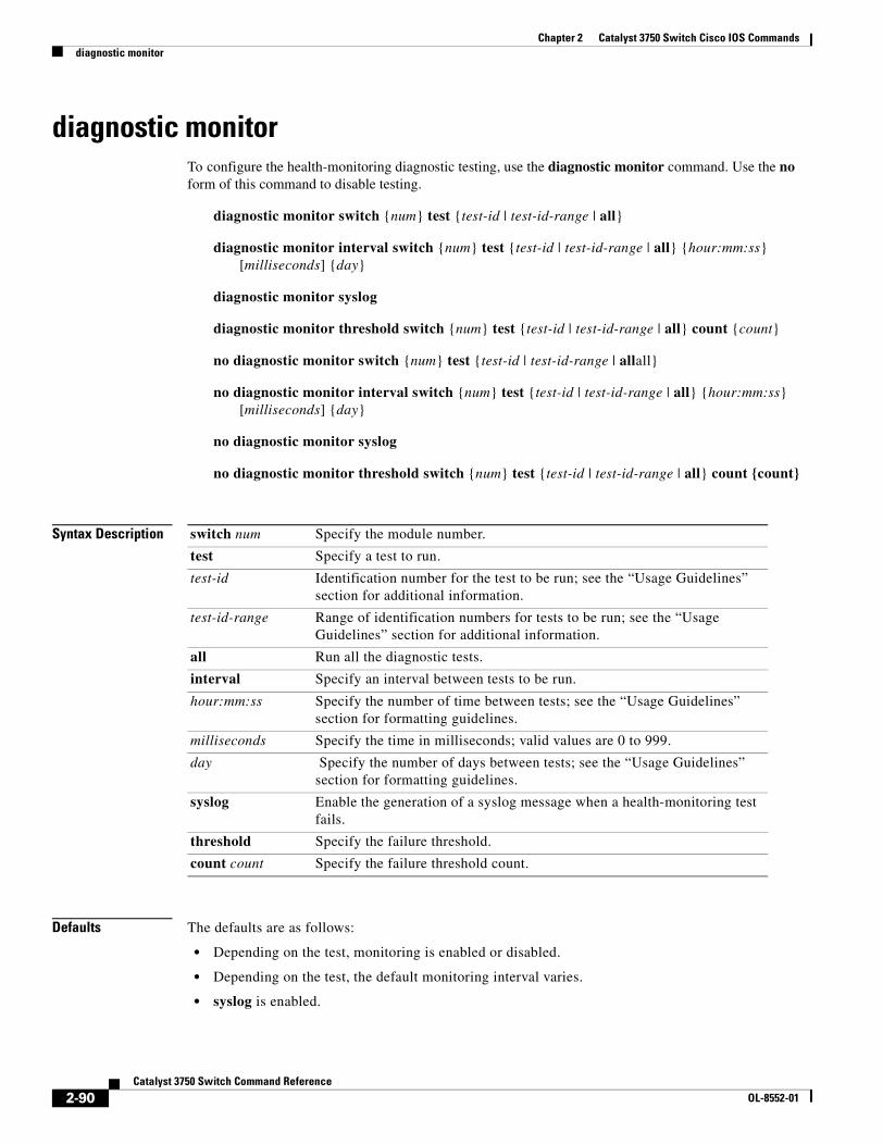
Chapter 2 Catalyst 3750 Switch Cisco IOS Commandsdiagnostic monitor
diagnostic monitorTo configure the health-monitoring diagnostic testing, use the diagnostic monitor command. Use the no form of this command to disable testing.
diagnostic monitor switch {num} test {test-id | test-id-range | all}
diagnostic monitor interval switch {num} test {test-id | test-id-range | all} {hour:mm:ss} [milliseconds] {day}
diagnostic monitor syslog
diagnostic monitor threshold switch {num} test {test-id | test-id-range | all} count {count}
no diagnostic monitor switch {num} test {test-id | test-id-range | allall}
no diagnostic monitor interval switch {num} test {test-id | test-id-range | all} {hour:mm:ss} [milliseconds] {day}
no diagnostic monitor syslog
no diagnostic monitor threshold switch {num} test {test-id | test-id-range | all} count {count}
Syntax Description
Defaults The defaults are as follows:
• Depending on the test, monitoring is enabled or disabled.
• Depending on the test, the default monitoring interval varies.
• syslog is enabled.
switch num Specify the module number.
test Specify a test to run.
test-id Identification number for the test to be run; see the “Usage Guidelines” section for additional information.
test-id-range Range of identification numbers for tests to be run; see the “Usage Guidelines” section for additional information.
all Run all the diagnostic tests.
interval Specify an interval between tests to be run.
hour:mm:ss Specify the number of time between tests; see the “Usage Guidelines” section for formatting guidelines.
milliseconds Specify the time in milliseconds; valid values are 0 to 999.
day Specify the number of days between tests; see the “Usage Guidelines” section for formatting guidelines.
syslog Enable the generation of a syslog message when a health-monitoring test fails.
threshold Specify the failure threshold.
count count Specify the failure threshold count.
2-90Catalyst 3750 Switch Command Reference
OL-8552-01
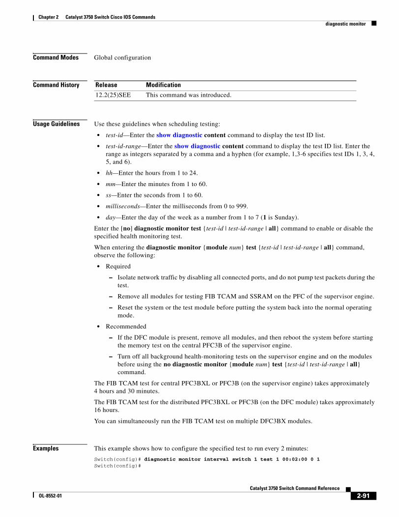
Chapter 2 Catalyst 3750 Switch Cisco IOS Commandsdiagnostic monitor
Command Modes Global configuration
Command History
Usage Guidelines Use these guidelines when scheduling testing:
• test-id—Enter the show diagnostic content command to display the test ID list.
• test-id-range—Enter the show diagnostic content command to display the test ID list. Enter the range as integers separated by a comma and a hyphen (for example, 1,3-6 specifies test IDs 1, 3, 4, 5, and 6).
• hh—Enter the hours from 1 to 24.
• mm—Enter the minutes from 1 to 60.
• ss—Enter the seconds from 1 to 60.
• milliseconds—Enter the milliseconds from 0 to 999.
• day—Enter the day of the week as a number from 1 to 7 (1 is Sunday).
Enter the [no] diagnostic monitor test {test-id | test-id-range | all} command to enable or disable the specified health monitoring test.
When entering the diagnostic monitor {module num} test {test-id | test-id-range | all} command, observe the following:
• Required
– Isolate network traffic by disabling all connected ports, and do not pump test packets during the test.
– Remove all modules for testing FIB TCAM and SSRAM on the PFC of the supervisor engine.
– Reset the system or the test module before putting the system back into the normal operating mode.
• Recommended
– If the DFC module is present, remove all modules, and then reboot the system before starting the memory test on the central PFC3B of the supervisor engine.
– Turn off all background health-monitoring tests on the supervisor engine and on the modules before using the no diagnostic monitor {module num} test {test-id | test-id-range | all} command.
The FIB TCAM test for central PFC3BXL or PFC3B (on the supervisor engine) takes approximately 4 hours and 30 minutes.
The FIB TCAM test for the distributed PFC3BXL or PFC3B (on the DFC module) takes approximately 16 hours.
You can simultaneously run the FIB TCAM test on multiple DFC3BX modules.
Examples This example shows how to configure the specified test to run every 2 minutes:
Switch(config)# diagnostic monitor interval switch 1 test 1 00:02:00 0 1Switch(config)#
Release Modification
12.2(25)SEE This command was introduced.
2-91Catalyst 3750 Switch Command Reference
OL-8552-01
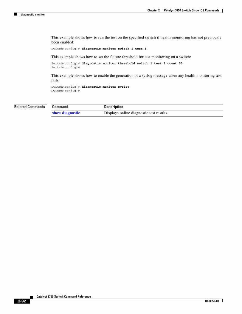
Chapter 2 Catalyst 3750 Switch Cisco IOS Commandsdiagnostic monitor
This example shows how to run the test on the specified switch if health monitoring has not previously been enabled:
Switch(config)# diagnostic monitor switch 1 test 1
This example shows how to set the failure threshold for test monitoring on a switch:
Switch(config)# diagnostic monitor threshold switch 1 test 1 count 50Switch(config)#
This example shows how to enable the generation of a syslog message when any health monitoring test fails:
Switch(config)# diagnostic monitor syslogSwitch(config)#
Related Commands Command Description
show diagnostic Displays online diagnostic test results.
2-92Catalyst 3750 Switch Command Reference
OL-8552-01
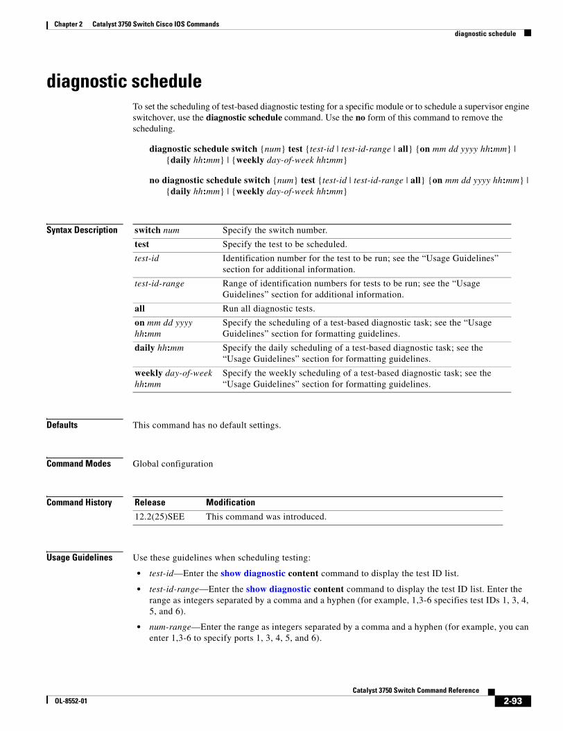
Chapter 2 Catalyst 3750 Switch Cisco IOS Commandsdiagnostic schedule
diagnostic schedule To set the scheduling of test-based diagnostic testing for a specific module or to schedule a supervisor engine switchover, use the diagnostic schedule command. Use the no form of this command to remove the scheduling.
diagnostic schedule switch {num} test {test-id | test-id-range | all} {on mm dd yyyy hh:mm} | {daily hh:mm} | {weekly day-of-week hh:mm}
no diagnostic schedule switch {num} test {test-id | test-id-range | all} {on mm dd yyyy hh:mm} | {daily hh:mm} | {weekly day-of-week hh:mm}
Syntax Description
Defaults This command has no default settings.
Command Modes Global configuration
Command History
Usage Guidelines Use these guidelines when scheduling testing:
• test-id—Enter the show diagnostic content command to display the test ID list.
• test-id-range—Enter the show diagnostic content command to display the test ID list. Enter the range as integers separated by a comma and a hyphen (for example, 1,3-6 specifies test IDs 1, 3, 4, 5, and 6).
• num-range—Enter the range as integers separated by a comma and a hyphen (for example, you can enter 1,3-6 to specify ports 1, 3, 4, 5, and 6).
switch num Specify the switch number.
test Specify the test to be scheduled.
test-id Identification number for the test to be run; see the “Usage Guidelines” section for additional information.
test-id-range Range of identification numbers for tests to be run; see the “Usage Guidelines” section for additional information.
all Run all diagnostic tests.
on mm dd yyyy hh:mm
Specify the scheduling of a test-based diagnostic task; see the “Usage Guidelines” section for formatting guidelines.
daily hh:mm Specify the daily scheduling of a test-based diagnostic task; see the “Usage Guidelines” section for formatting guidelines.
weekly day-of-week hh:mm
Specify the weekly scheduling of a test-based diagnostic task; see the “Usage Guidelines” section for formatting guidelines.
Release Modification
12.2(25)SEE This command was introduced.
2-93Catalyst 3750 Switch Command Reference
OL-8552-01
Chapter 2 Catalyst 3750 Switch Cisco IOS Commandsdiagnostic schedule
• mm—Spell out the month, such as January, February ... December (either upper case or lower case characters).
• dd—Enter the day as a 2-digit number.
• yyyy—Enter the year as a 4-digit number.
• hh:mm—Enter the time as a 2-digit number (for a 24-hour clock) for hours:minutes; the colon (:) is required.
• day-of-week—Spell out the day of the week, such as Monday, Tuesday... Sunday (either upper case or lower case characters).
Enter the show diagnostic content command to display the test ID list.
You can use the diagnostic schedule module active-sup-slot test test-id command to schedule a switchover from the active supervisor engine to the standby supervisor engine.
Enter the show diagnostic content active-sup-slot command to display the test ID list and look for the test ID in the ScheduleSwitchover field.
You can specify a periodic switchover (daily or weekly) or a single switchover occurrence at a specific time by using these commands:
• diagnostic schedule module active-sup-slot test test-id on mm dd yyyy hh:mm
• diagnostic schedule module active-sup-slot test test-id daily hh:mm
• diagnostic schedule module active-sup-slot test test-id weekly day-of-week hh:mm
Note To avoid system downtime if the standby supervisor engine cannot switch over the system, we recommend that you schedule a switchover from the standby supervisor engine to the active supervisor engine 10 minutes after the switchover occurs. See the “Examples” section for additional information.
Examples This example shows how to schedule diagnostic testing on a specific date and time for a specific switch:
Switch(config)# diagnostic schedule switch 1 test 1,2,4-6 on january 3 2006 23:32Switch(config)#
This example shows how to schedule diagnostic testing to occur weekly at a certain time for a specific switch:
Switch(config)# diagnostic schedule switch 1 test 1,2,4-6 weekly friday 09:23Switch(config)#
Related Commands Command Description
show diagnostic Displays online diagnostic test results.
2-94Catalyst 3750 Switch Command Reference
OL-8552-01
Chapter 2 Catalyst 3750 Switch Cisco IOS Commandsdiagnostic start
diagnostic startTo run the specified diagnostic test, use the diagnostic start command.
diagnostic start switch {num} test {test-id | test-id-range | basic | non-disruptive | all}
Syntax Description
Defaults This command has no default settings.
Command Modes Privileged EXEC
Command History
Usage Guidelines
Note Do not enter the diagnostic start module x test all command on systems that are configured with a DFC3A because this command causes the TCAM test to fail.
Enter the show diagnostic content command to display the test ID list.
Enter the test-id-range or port#-range as integers separated by a comma and a hyphen (for example, 1,3-6 specifies test IDs 1, 3, 4, 5, and 6).
Use the diagnostic stop command to stop the testing process.
Examples This example shows how to start a diagnostic test on a specific switch:
Switch# diagnostic start switch 1 test 1Switch#06:27:50: %DIAG-6-TEST_RUNNING: Switch 1: Running TestPortAsicStackPortLoopback{ID=1} ...(switch-1)06:27:51: %DIAG-6-TEST_OK: Switch 1: TestPortAsicStackPortLoopback{ID=1} has completedsuccessfully (switch-1)Switch#
switch num Specify the module number.
test Specify a test to run.
test-id Identification number for the test to be run; see the “Usage Guidelines” section for additional information.
test-id-range Range of identification numbers for tests to be run; see the “Usage Guidelines” section for additional information.
basic Run basic on-demand diagnostic tests.
non-disruptive Run the nondisruptive health-monitoring tests.
all Run all diagnostic tests.
Release Modification
12.2(25)SEE This command was introduced.
2-95Catalyst 3750 Switch Command Reference
OL-8552-01
Chapter 2 Catalyst 3750 Switch Cisco IOS Commandsdiagnostic start
This example shows how to start diagnostics test 2 on a switch that will disrupt normal system operation:
Switch# diagnostic start switch 1 test 2Switch 1: Running test(s) 2 will cause the switch under test to reload after completion ofthe test list.Switch 1: Running test(s) 2 may disrupt normal system operationDo you want to continue? [no]: ySwitch#16:43:29: %STACKMGR-4-STACK_LINK_CHANGE: Stack Port 2 Switch 2 has changed to state DOWN16:43:30: %STACKMGR-4-STACK_LINK_CHANGE: Stack Port 1 Switch 9 has changed to state DOWN16:43:30: %STACKMGR-4-SWITCH_REMOVED: Switch 1 has been REMOVED from the stackSwitch#16:44:35: %STACKMGR-4-STACK_LINK_CHANGE: Stack Port 1 Switch 2 has changed to state UP16:44:37: %STACKMGR-4-STACK_LINK_CHANGE: Stack Port 2 Switch 2 has changed to state UP16:44:45: %STACKMGR-4-SWITCH_ADDED: Switch 1 has been ADDED to the stack16:45:00: %STACKMGR-5-SWITCH_READY: Switch 1 is READY16:45:00: %STACKMGR-4-STACK_LINK_CHANGE: Stack Port 1 Switch 1 has changed to state UP16:45:00: %STACKMGR-4-STACK_LINK_CHANGE: Stack Port 2 Switch 1 has changed to state UP00:00:20: %STACKMGR-4-SWITCH_ADDED: Switch 1 has been ADDED to the stack (Switch-1)00:00:20: %STACKMGR-4-SWITCH_ADDED: Switch 2 has been ADDED to the stack (Switch-1)00:00:25: %SPANTREE-5-EXTENDED_SYSID: Extended SysId enabled for type vlan (Switch-1)00:00:29: %SYS-5-CONFIG_I: Configured from memory by console (Switch-1)00:00:29: %STACKMGR-5-SWITCH_READY: Switch 2 is READY (Switch-1)00:00:29: %STACKMGR-5-MASTER_READY: Master Switch 2 is READY (Switch-1)00:00:30: %STACKMGR-5-SWITCH_READY: Switch 1 is READY (Switch-1)00:00:30: %DIAG-6-TEST_RUNNING: Switch 1: Running TestPortAsicLoopback{ID=2} ...(Switch-1)00:00:30: %DIAG-6-TEST_OK: Switch 1: TestPortAsicLoopback{ID=2} has completed successfully(Switch-1)
This message appears if the test can cause the switch to lose stack connectivity:
Switch 3: Running test(s) 2 will cause the switch under test to reload after completion ofthe test list.Switch 3: Running test(s) 2 may disrupt normal system operationDo you want to continue? [no]:
This message appears if the test will cause a stack partition:
Switch 6: Running test(s) 2 will cause the switch under test to reload after completion ofthe test list.Switch 6: Running test(s) 2 will partition stackSwitch 6: Running test(s) 2 may disrupt normal system operationDo you want to continue? [no]:
Related Commands Command Description
show diagnostic Displays online diagnostic test results.
2-96Catalyst 3750 Switch Command Reference
OL-8552-01
Chapter 2 Catalyst 3750 Switch Cisco IOS Commandsdot1x
dot1xUse the dot1x global configuration command on the switch stack or on a standalone switch to globally enable IEEE 802.1x authentication. Use the no form of this command to return to the default setting.
dot1x {critical {eapol | recovery delay milliseconds} | system-auth-control}
no dot1x {credentials | critical {eapol | recovery delay} | system-auth-control}
Note Though visible in the command-line help strings, the credentials name keywords are not supported.
Syntax Description
Defaults IEEE 802.1x authentication is disabled.
Command Modes Global configuration
Command History
Usage Guidelines You must enable authentication, authorization, and accounting (AAA) and specify the authentication method list before globally enabling IEEE 802.1x authentication. A method list describes the sequence and authentication methods to be used to authenticate a user.
Before globally enabling IEEE 802.1x authentication on a switch, remove the EtherChannel configuration from the interfaces on which IEEE 802.1x authentication and EtherChannel are configured.
If you are using a device running the Cisco Access Control Server (ACS) application for IEEE 802.1x authentication with EAP-Transparent LAN Services (TLS) and with EAP-MD5 and your switch is running Cisco IOS Release 12.1(14)EA1, make sure that the device is running ACS Version 3.2.1 or later.
Examples This example shows how to globally enable IEEE 802.1x authentication on a switch:
Switch(config)# dot1x system-auth-control
critical {eapol | recovery delay milliseconds}
Configure the inaccessible authentication bypass parameters. For more information, see the dot1x critical (global configuration) command.
system-auth-control Enable IEEE 802.1x authentication globally on the switch.
Release Modification
12.1(14)EA1 This command was introduced.
12.2(25)SE The guest-vlan supplicant keywords were added.
12.2(25)SEE The critical {eapol | recovery delay milliseconds} keywords were added. The guest-vlan supplicant keyword was removed.
2-97Catalyst 3750 Switch Command Reference
OL-8552-01
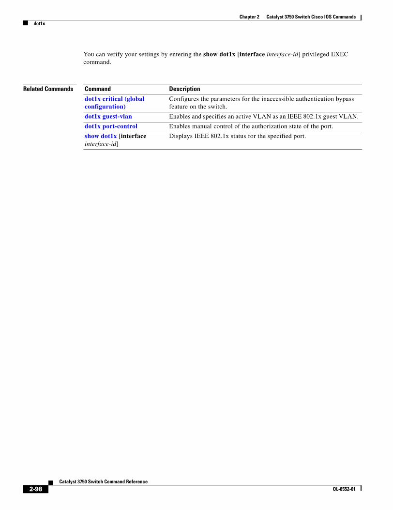
Chapter 2 Catalyst 3750 Switch Cisco IOS Commandsdot1x
You can verify your settings by entering the show dot1x [interface interface-id] privileged EXEC command.
Related Commands Command Description
dot1x critical (global configuration)
Configures the parameters for the inaccessible authentication bypass feature on the switch.
dot1x guest-vlan Enables and specifies an active VLAN as an IEEE 802.1x guest VLAN.
dot1x port-control Enables manual control of the authorization state of the port.
show dot1x [interface interface-id]
Displays IEEE 802.1x status for the specified port.
2-98Catalyst 3750 Switch Command Reference
OL-8552-01
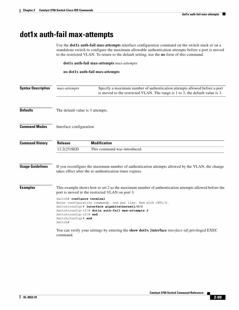
Chapter 2 Catalyst 3750 Switch Cisco IOS Commandsdot1x auth-fail max-attempts
dot1x auth-fail max-attemptsUse the dot1x auth-fail max-attempts interface configuration command on the switch stack or on a standalone switch to configure the maximum allowable authentication attempts before a port is moved to the restricted VLAN. To return to the default setting, use the no form of this command.
dot1x auth-fail max-attempts max-attempts
no dot1x auth-fail max-attempts
Syntax Description
Defaults The default value is 3 attempts.
Command Modes Interface configuration
Command History
Usage Guidelines If you reconfigure the maximum number of authentication attempts allowed by the VLAN, the change takes effect after the re-authentication timer expires.
Examples This example shows how to set 2 as the maximum number of authentication attempts allowed before the port is moved to the restricted VLAN on port 3:
Switch# configure terminal Enter configuration commands, one per line. End with CNTL/Z.Switch(config)# interface gigabitethernet1/0/3Switch(config-if)# dot1x auth-fail max-attempts 2Switch(config-if)# endSwitch(config)# endSwitch#
You can verify your settings by entering the show dot1x [interface interface-id] privileged EXEC command.
max-attempts Specify a maximum number of authentication attempts allowed before a port is moved to the restricted VLAN. The range is 1 to 3, the default value is 3.
Release Modification
12.2(25)SED This command was introduced.
2-99Catalyst 3750 Switch Command Reference
OL-8552-01
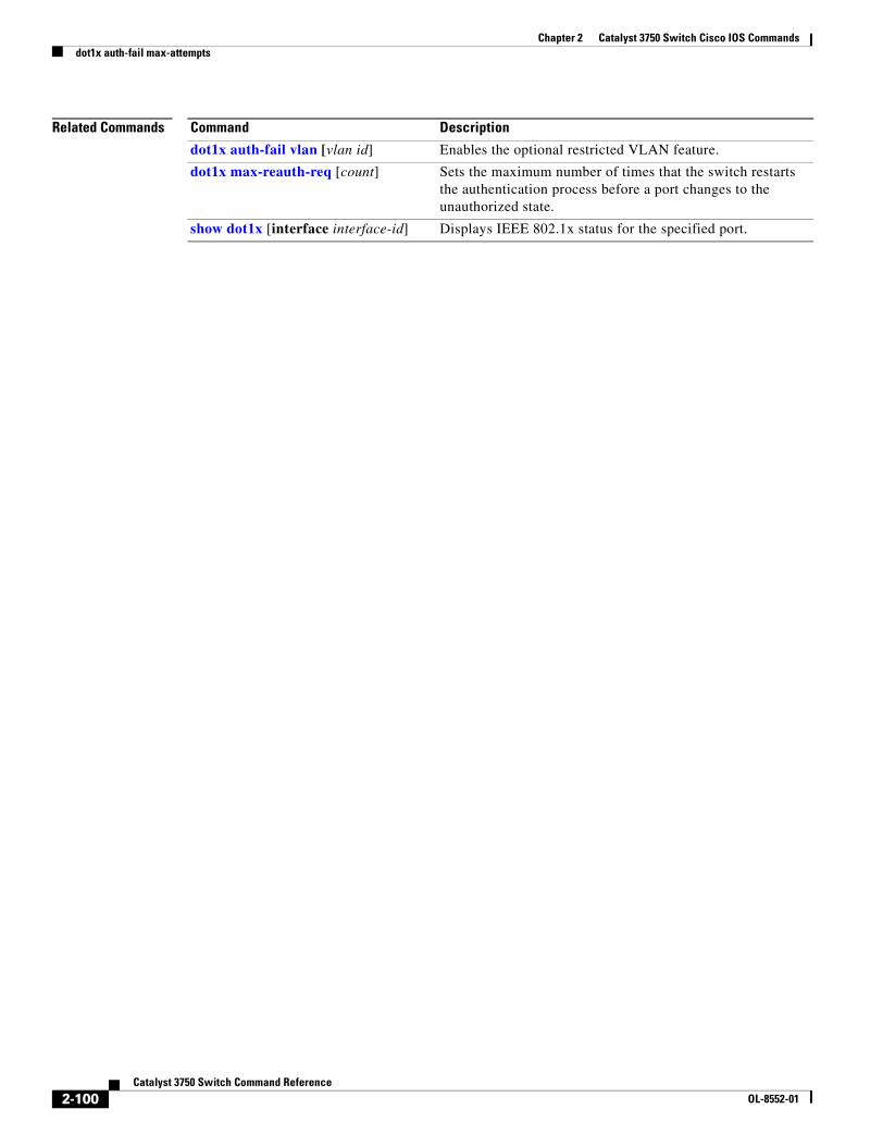
Chapter 2 Catalyst 3750 Switch Cisco IOS Commandsdot1x auth-fail max-attempts
Related Commands Command Description
dot1x auth-fail vlan [vlan id] Enables the optional restricted VLAN feature.
dot1x max-reauth-req [count] Sets the maximum number of times that the switch restarts the authentication process before a port changes to the unauthorized state.
show dot1x [interface interface-id] Displays IEEE 802.1x status for the specified port.
2-100Catalyst 3750 Switch Command Reference
OL-8552-01
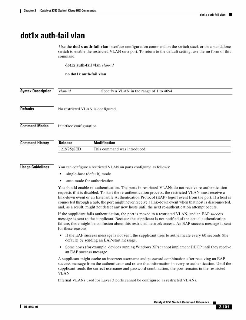
Chapter 2 Catalyst 3750 Switch Cisco IOS Commandsdot1x auth-fail vlan
dot1x auth-fail vlan Use the dot1x auth-fail vlan interface configuration command on the switch stack or on a standalone switch to enable the restricted VLAN on a port. To return to the default setting, use the no form of this command.
dot1x auth-fail vlan vlan-id
no dot1x auth-fail vlan
Syntax Description
Defaults No restricted VLAN is configured.
Command Modes Interface configuration
Command History
Usage Guidelines You can configure a restricted VLAN on ports configured as follows:
• single-host (default) mode
• auto mode for authorization
You should enable re-authentication. The ports in restricted VLANs do not receive re-authentication requests if it is disabled. To start the re-authentication process, the restricted VLAN must receive a link-down event or an Extensible Authentication Protocol (EAP) logoff event from the port. If a host is connected through a hub, the port might never receive a link-down event when that host is disconnected, and, as a result, might not detect any new hosts until the next re-authentication attempt occurs.
If the supplicant fails authentication, the port is moved to a restricted VLAN, and an EAP success message is sent to the supplicant. Because the supplicant is not notified of the actual authentication failure, there might be confusion about this restricted network access. An EAP success message is sent for these reasons:
• If the EAP success message is not sent, the supplicant tries to authenticate every 60 seconds (the default) by sending an EAP-start message.
• Some hosts (for example, devices running Windows XP) cannot implement DHCP until they receive an EAP success message.
A supplicant might cache an incorrect username and password combination after receiving an EAP success message from the authenticator and re-use that information in every re-authentication. Until the supplicant sends the correct username and password combination, the port remains in the restricted VLAN.
Internal VLANs used for Layer 3 ports cannot be configured as restricted VLANs.
vlan-id Specify a VLAN in the range of 1 to 4094.
Release Modification
12.2(25)SED This command was introduced.
2-101Catalyst 3750 Switch Command Reference
OL-8552-01
Chapter 2 Catalyst 3750 Switch Cisco IOS Commandsdot1x auth-fail vlan
You cannot configure a VLAN to be both a restricted VLAN and a voice VLAN. If you do this, a syslog message is generated.
When a restricted VLAN port is moved to an unauthorized state, the authentication process restarts. If the supplicant fails the authentication process again, the authenticator waits in the held state. After the supplicant has correctly re-authenticated, all IEEE 802.1x ports are reinitialized and treated as normal IEEE 802.1x ports.
When you reconfigure a restricted VLAN as a different VLAN, any ports in the restricted VLAN are also moved, and the ports stay in their currently authorized state.
When you shut down or remove a restricted VLAN from the VLAN database, any ports in the restricted VLAN are immediately moved to an unauthorized state, and the authentication process restarts. The authenticator does not wait in a held state because the restricted VLAN configuration still exists. While the restricted VLAN is inactive, all authentication attempts are counted so that when the restricted VLAN becomes active, the port is immediately placed in the restricted VLAN.
The restricted VLAN is supported only in single host mode (the default port mode). For this reason, when a port is placed in a restricted VLAN, the supplicant’s MAC address is added to the MAC address table, and any other MAC address that appears on the port is treated as a security violation.
Examples This example shows how to configure a restricted VLAN on port 1:
Switch# configure terminal Enter configuration commands, one per line. End with CNTL/Z.Switch(config)# interface gigabitethernet1/0/1Switch(config-if)# dot1x auth-fail vlan 40Switch(config-if)# endSwitch(config)# endSwitch#
You can verify your configuration by entering the show dot1x [interface interface-id] privileged EXEC command.
Related Commands Command Description
dot1x auth-fail max-attempts [max-attempts]
Configures the number of authentication attempts allowed before assigning a supplicant to the restricted VLAN.
show dot1x [interface interface-id] Displays IEEE 802.1x status for the specified port.
2-102Catalyst 3750 Switch Command Reference
OL-8552-01
Chapter 2 Catalyst 3750 Switch Cisco IOS Commandsdot1x control-direction
dot1x control-directionUse the dot1x control-direction interface configuration command to enable the IEEE 802.1x authentication with the wake-on-LAN (WoL) feature and to configure the port control as unidirectional or bidirectional. Use the no form of this command to return to the default setting.
dot1x control-direction {both | in}
no dot1x control-direction
Syntax Description
Defaults The port is in bidirectional mode.
Command Modes Interface configuration
Command History
Usage Guidelines Use the both keyword or the no form of this command to return to the default setting, bidirectional mode.
For more information about WoL, see the “Using IEEE 802.1x Authentication with Wake-on-LAN” section in the “Configuring IEEE 802.1x Port-Based Authentication” chapter in the software configuration guide.
Examples This example shows how to enable unidirectional control:
Switch(config-if)# dot1x control-direction in
These examples show how to enable bidirectional control:
Switch(config-if)# dot1x control-direction both
You can verify your settings by entering the show dot1x all privileged EXEC command.
The show dot1x all privileged EXEC command output is the same for all switches except for the port names and the state of the port. If a host is attached to the port but is not yet authenticated, a display similar to this appears:
Supplicant MAC 0002.b39a.9275AuthSM State = CONNECTINGBendSM State = IDLEPortStatus = UNAUTHORIZED
both Enable bidirectional control on port. The port cannot receive packets from or send packets to the host.
in Enable unidirectional control on port. The port can send packets to the host but cannot receive packets from the host.
Release Modification
12.2(25)SEC This command was introduced.
2-103Catalyst 3750 Switch Command Reference
OL-8552-01
Chapter 2 Catalyst 3750 Switch Cisco IOS Commandsdot1x control-direction
If you enter the dot1x control-direction in interface configuration command to enable unidirectional control, this appears in the show dot1x all command output:
ControlDirection = In
If you enter the dot1x control-direction in interface configuration command and the port cannot support this mode due to a configuration conflict, this appears in the show dot1x all command output:
ControlDirection = In (Disabled due to port settings)
Related Commands Command Description
show dot1x [all | interface interface-id]
Displays control-direction port setting status for the specified interface.
2-104Catalyst 3750 Switch Command Reference
OL-8552-01
Chapter 2 Catalyst 3750 Switch Cisco IOS Commandsdot1x critical (global configuration)
dot1x critical (global configuration)Use the dot1x critical global configuration command onthe switch stack or on a standalone switch to configure the parameters for the inaccessible authentication bypass feature, also referred to as critical authentication or the authentication, authorization, and accounting (AAA) fail policy. To return to default settings, use the no form of this command.
dot1x critical {eapol | recovery delay milliseconds}
no dot1x critical {eapol | recovery delay}
Syntax Description
Defaults The switch does not send an EAPOL-Success message to the host when the switch successfully authenticates the critical port by putting the critical port in the critical-authentication state.
The recovery delay period is 1000 milliseconds (1 second).
Command Modes Global configuration
Command History
Usage Guidelines Use the eapol keyword to specify that the switch sends an EAPOL-Success message when the switch puts the critical port in the critical-authentication state.
Use the recovery delay milliseconds keyword to set the recovery delay period during which the switch waits to re-initialize a critical port when a RADIUS server that was unavailable becomes available. The default recovery delay period is 100 milliseconds. A port can be re-initialized every second.
To enable inaccessible authentication bypass on a port, use the dot1x critical interface configuration command. To configure the access VLAN to which the switch assigns a critical port, use the dot1x critical vlan vlan-id interface configuration command.
Examples This example shows how to set 200 as the the recovery delay period on the switch:
Switch# dot1x critical recovery delay 200
You can verify your configuration by entering the show dot1x privileged EXEC command.
eapol Specify that the switch sends an EAPOL-Success message when the switch puts the critical port in the critical-authentication state.
recovery delay milliseconds Set the recovery delay period in milliseconds. The range is from 1 to 10000 milliseconds.
Release Modification
12.2(25)SEE This command was introduced.
2-105Catalyst 3750 Switch Command Reference
OL-8552-01
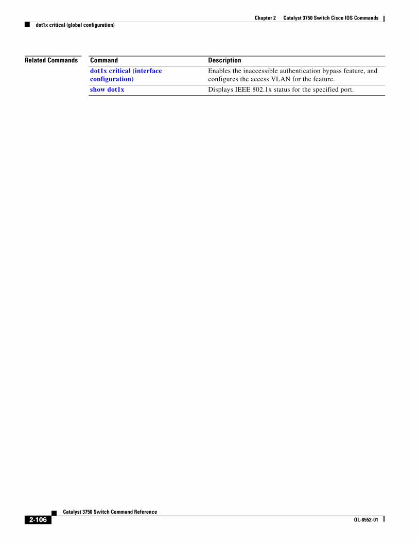
Chapter 2 Catalyst 3750 Switch Cisco IOS Commandsdot1x critical (global configuration)
Related Commands Command Description
dot1x critical (interface configuration)
Enables the inaccessible authentication bypass feature, and configures the access VLAN for the feature.
show dot1x Displays IEEE 802.1x status for the specified port.
2-106Catalyst 3750 Switch Command Reference
OL-8552-01
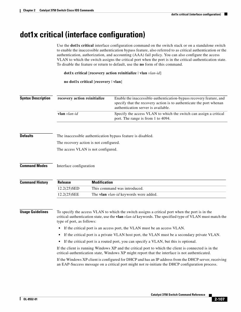
Chapter 2 Catalyst 3750 Switch Cisco IOS Commandsdot1x critical (interface configuration)
dot1x critical (interface configuration)Use the dot1x critical interface configuration command on the switch stack or on a standalone switch to enable the inaccessible authentication bypass feature, also referred to as critical authentication or the authentication, authorization, and accounting (AAA) fail policy. You can also configure the access VLAN to which the switch assigns the critical port when the port is in the critical-authentication state. To disable the feature or return to default, use the no form of this command.
dot1x critical [recovery action reinitialize | vlan vlan-id]
no dot1x critical [recovery | vlan]
Syntax Description
Defaults The inaccessible authentication bypass feature is disabled.
The recovery action is not configured.
The access VLAN is not configured.
Command Modes Interface configuration
Command History
Usage Guidelines To specify the access VLAN to which the switch assigns a critical port when the port is in the critical-authentication state, use the vlan vlan-id keywords. The specified type of VLAN must match the type of port, as follows:
• If the critical port is an access port, the VLAN must be an access VLAN.
• If the critical port is a private VLAN host port, the VLAN must be a secondary private VLAN.
• If the critical port is a routed port, you can specify a VLAN, but this is optional.
If the client is running Windows XP and the critical port to which the client is connected is in the critical-authentication state, Windows XP might report that the interface is not authenticated.
If the Windows XP client is configured for DHCP and has an IP address from the DHCP server, receiving an EAP-Success message on a critical port might not re-initiate the DHCP configuration process.
recovery action reinitialize Enable the inaccessible-authentication-bypass recovery feature, and specify that the recovery action is to authenticate the port whenan authentication server is available.
vlan vlan-id Specify the access VLAN to which the switch can assign a critical port. The range is from 1 to 4094.
Release Modification
12.2(25)SED This command was introduced.
12.2(25)SEE The vlan vlan-id keywords were added.
2-107Catalyst 3750 Switch Command Reference
OL-8552-01
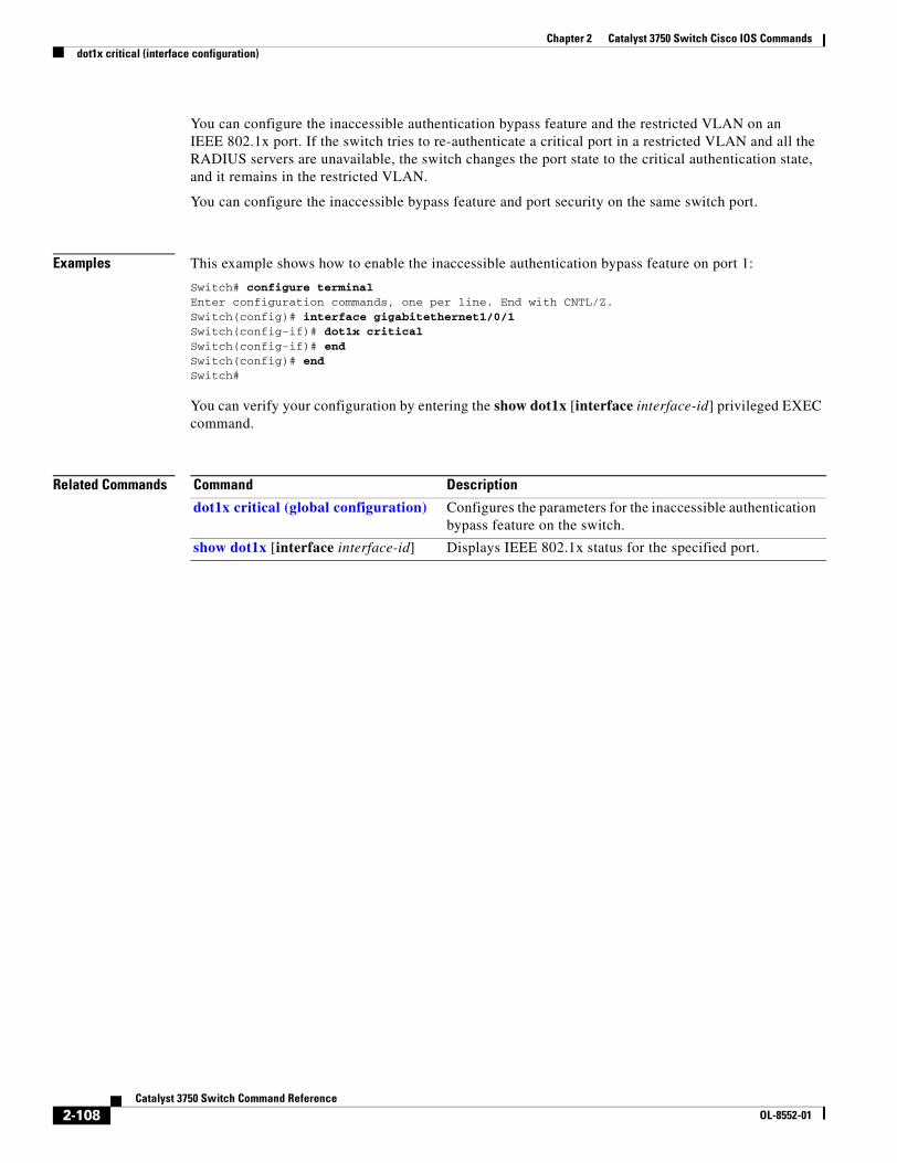
Chapter 2 Catalyst 3750 Switch Cisco IOS Commandsdot1x critical (interface configuration)
You can configure the inaccessible authentication bypass feature and the restricted VLAN on an IEEE 802.1x port. If the switch tries to re-authenticate a critical port in a restricted VLAN and all the RADIUS servers are unavailable, the switch changes the port state to the critical authentication state, and it remains in the restricted VLAN.
You can configure the inaccessible bypass feature and port security on the same switch port.
Examples This example shows how to enable the inaccessible authentication bypass feature on port 1:
Switch# configure terminal Enter configuration commands, one per line. End with CNTL/Z.Switch(config)# interface gigabitethernet1/0/1Switch(config-if)# dot1x criticalSwitch(config-if)# endSwitch(config)# endSwitch#
You can verify your configuration by entering the show dot1x [interface interface-id] privileged EXEC command.
Related Commands Command Description
dot1x critical (global configuration) Configures the parameters for the inaccessible authentication bypass feature on the switch.
show dot1x [interface interface-id] Displays IEEE 802.1x status for the specified port.
2-108Catalyst 3750 Switch Command Reference
OL-8552-01
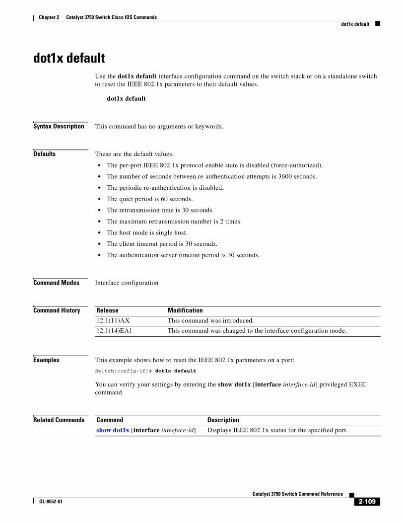
Chapter 2 Catalyst 3750 Switch Cisco IOS Commandsdot1x default
dot1x defaultUse the dot1x default interface configuration command on the switch stack or on a standalone switch to reset the IEEE 802.1x parameters to their default values.
dot1x default
Syntax Description This command has no arguments or keywords.
Defaults These are the default values:
• The per-port IEEE 802.1x protocol enable state is disabled (force-authorized).
• The number of seconds between re-authentication attempts is 3600 seconds.
• The periodic re-authentication is disabled.
• The quiet period is 60 seconds.
• The retransmission time is 30 seconds.
• The maximum retransmission number is 2 times.
• The host mode is single host.
• The client timeout period is 30 seconds.
• The authentication server timeout period is 30 seconds.
Command Modes Interface configuration
Command History
Examples This example shows how to reset the IEEE 802.1x parameters on a port:
Switch(config-if)# dot1x default
You can verify your settings by entering the show dot1x [interface interface-id] privileged EXEC command.
Related Commands
Release Modification
12.1(11)AX This command was introduced.
12.1(14)EA1 This command was changed to the interface configuration mode.
Command Description
show dot1x [interface interface-id] Displays IEEE 802.1x status for the specified port.
2-109Catalyst 3750 Switch Command Reference
OL-8552-01
Chapter 2 Catalyst 3750 Switch Cisco IOS Commandsdot1x guest-vlan
dot1x guest-vlanUse the dot1x guest-vlan interface configuration command on the switch stack or on a standalone switch to specify an active VLAN as an IEEE 802.1x guest VLAN. Use the no form of this command to return to the default setting.
dot1x guest-vlan vlan-id
no dot1x guest-vlan
Syntax Description
Defaults No guest VLAN is configured.
Command Modes Interface configuration
Command History
Usage Guidelines You can configure a guest VLAN on one of these switch ports:
• A static-access port that belongs to a nonprivate VLAN.
• A private-VLAN port that belongs to a secondary private VLAN. All the hosts connected to the switch port are assigned to private VLANs, whether or not the posture validation was successful. The switch determines the primary private VLAN by using the primary- and secondary-private-VLAN associations on the switch.
For each IEEE 802.1x port on the switch, you can configure a guest VLAN to provide limited services to clients (a device or workstation connected to the switch) not running IEEE 802.1x authentication. These users might be upgrading their systems for IEEE 802.1x authentication, and some hosts, such as Windows 98 systems, might not be IEEE 802.1x-capable.
When you enable a guest VLAN on an IEEE 802.1x port, the switch assigns clients to a guest VLAN when it does not receive a response to its Extensible Authentication Protocol over LAN (EAPOL) request/identity frame or when EAPOL packets are not sent by the client.
With Cisco IOS Release 12.2(25)SE and later, the switch maintains the EAPOL packet history. If another EAPOL packet is detected on the interface during the lifetime of the link, the guest VLAN feature is disabled. If the port is already in the guest VLAN state, the port returns to the unauthorized state, and authentication restarts. The EAPOL history is reset upon loss of link.
vlan-id Specify an active VLAN as an IEEE 802.1x guest VLAN. The range is 1 to 4094.
Release Modification
12.1(14)EA1 This command was introduced.
12.2(25)SE This command was modified to change the default guest VLAN behavior.
12.2(25)SEC The usage guidelines were modified.
2-110Catalyst 3750 Switch Command Reference
OL-8552-01
Chapter 2 Catalyst 3750 Switch Cisco IOS Commandsdot1x guest-vlan
Before Cisco IOS Release 12.2(25)SE, the switch did not maintain the EAPOL packet history and allowed clients that failed authentication access to the guest VLAN, regardless of whether EAPOL packets had been detected on the interface. In Cisco IOS Release 12.2(25)SE, you can use the dot1x guest-vlan supplicant global configuration command to enable this optional behavior.
However, in Cisco IOS Release 12.2(25)SEE, the dot1x guest-vlan supplicant global configuration command is no longer supported. You can use a restricted VLAN to allow clients that failed authentication access to the network by entering the dot1x auth-fail vlan vlan-id interface configuration command.
Any number of non-IEEE 802.1x-capable clients are allowed access when the switch port is moved to the guest VLAN. If an IEEE 802.1x-capable client joins the same port on which the guest VLAN is configured, the port is put into the unauthorized state in the RADIUS-configured or user-configured access VLAN, and authentication is restarted.
Guest VLANs are supported on IEEE 802.1x ports in single-host or multiple-hosts mode.
You can configure any active VLAN except an Remote Switched Port Analyzer (RSPAN) VLAN, a primary private VLAN, or a voice VLAN as an IEEE 802.1x guest VLAN. The guest VLAN feature is not supported on internal VLANs (routed ports) or trunk ports; it is supported only on access ports.
After you configure a guest VLAN for an IEEE 802.1x port to which a DHCP client is connected, you might need to get a host IP address from a DHCP server. You can change the settings for restarting the IEEE 802.1x authentication process on the switch before the DHCP process on the client times out and tries to get a host IP address from the DHCP server. Decrease the settings for the IEEE 802.1x authentication process (dot1x timeout quiet-period and dot1x timeout tx-period interface configuration commands). The amount to decrease the settings depends on the connected IEEE 802.1x client type.
The switch supports MAC authentication bypass in Cisco IOS Release 12.2(25)SEE and later. When MAC authentication bypass is enabled on an IEEE 802.1x port, the switch can authorize clients based on the client MAC address when IEEE 802.1x authentication times out while waiting for an EAPOL message exchange. After detecting a client on an IEEE 802.1x port, the switch waits for an Ethernet packet from the client. The switch sends the authentication server a RADIUS-access/request frame with a username and password based on the MAC address. If authorization succeeds, the switch grants the client access to the network. If authorization fails, the switch assigns the port to the guest VLAN, if one is specified. For more information, see the “Using IEEE 802.1x Authentication with MAC Authentication Bypass” section in the “Configuring IEEE 802.1x Port-Based Authentication” chapter of the software configuration guide.
Examples This example shows how to specify VLAN 5 as an IEEE 802.1x guest VLAN:
Switch(config-if)# dot1x guest-vlan 5
This example shows how to set 3 as the quiet time on the switch, to set 15 as the number of seconds that the switch waits for a response to an EAP-request/identity frame from the client before resending the request, and to enable VLAN 2 as an IEEE 802.1x guest VLAN when an IEEE 802.1x port is connected to a DHCP client:
Switch(config-if)# dot1x timeout quiet-period 3Switch(config-if)# dot1x timeout tx-period 15Switch(config-if)# dot1x guest-vlan 2
This example shows how to enable the optional guest VLAN behavior and to specify VLAN 5 as an IEEE 802.1x guest VLAN:
Switch(config)# dot1x guest-vlan supplicantSwitch(config)# interface gigabitethernet2/0/1
2-111Catalyst 3750 Switch Command Reference
OL-8552-01
Chapter 2 Catalyst 3750 Switch Cisco IOS Commandsdot1x guest-vlan
Switch(config-if)# dot1x guest-vlan 5
You can verify your settings by entering the show dot1x [interface interface-id] privileged EXEC command.
Related Commands Command Description
dot1x Enables the optional guest VLAN supplicant feature.
show dot1x [interface interface-id] Displays IEEE 802.1x status for the specified port.
2-112Catalyst 3750 Switch Command Reference
OL-8552-01
Chapter 2 Catalyst 3750 Switch Cisco IOS Commandsdot1x host-mode
dot1x host-modeUse the dot1x host-mode interface configuration command on the switch stack or on a standalone switch to allow a single host (client) or multiple hosts on an IEEE 802.1x-authorized port that has the dot1x port-control interface configuration command set to auto. Use the no form of this command to return to the default setting.
dot1x host-mode {multi-host | single-host}
no dot1x host-mode [multi-host | single-host]
Syntax Description
Defaults The default is single-host mode.
Command Modes Interface configuration
Command History
Usage Guidelines Use this command to limit an IEEE 802.1x-enabled port to a single client or to attach multiple clients to an IEEE 802.1x-enabled port. In multiple-hosts mode, only one of the attached hosts needs to be successfully authorized for all hosts to be granted network access. If the port becomes unauthorized (re-authentication fails or an Extensible Authentication Protocol over LAN [EAPOL]-logoff message is received), all attached clients are denied access to the network.
Before entering this command, make sure that the dot1x port-control interface configuration command is set to auto for the specified port.
Examples This example shows how to enable IEEE 802.1x authentication globally, to enable IEEE 802.1x authentication on a port, and to enable multiple-hosts mode:
Switch(config)# dot1x system-auth-controlSwitch(config)# interface gigabitethernet2/0/1Switch(config-if)# dot1x port-control autoSwitch(config-if)# dot1x host-mode multi-host
You can verify your settings by entering the show dot1x [interface interface-id] privileged EXEC command.
multi-host Enable multiple-hosts mode on the switch.
single-host Enable single-host mode on the switch.
Release Modification
12.1(14)EA1 This command was introduced. It replaces the dot1x multiple-hosts interface configuration command.
2-113Catalyst 3750 Switch Command Reference
OL-8552-01

Chapter 2 Catalyst 3750 Switch Cisco IOS Commandsdot1x host-mode
Related Commands Command Description
show dot1x [interface interface-id] Displays IEEE 802.1x status for the specified port.
2-114Catalyst 3750 Switch Command Reference
OL-8552-01
Chapter 2 Catalyst 3750 Switch Cisco IOS Commandsdot1x initialize
dot1x initializeUse the dot1x initialize privileged EXEC command on the switch stack or on a standalone switch to manually return the specified IEEE 802.1x-enabled port to an unauthorized state before initiating a new authentication session on the port.
dot1x initialize [interface interface-id]
Syntax Description
Defaults There is no default setting.
Command Modes Privileged EXEC
Command History
Usage Guidelines Use this command to initialize the IEEE 802.1x state machines and to set up a fresh environment for authentication. After you enter this command, the port status becomes unauthorized.
There is not a no form of this command.
Examples This example shows how to manually initialize a port:
Switch# dot1x initialize interface gigabitethernet2/0/2
You can verify the unauthorized port status by entering the show dot1x [interface interface-id] privileged EXEC command.
Related Commands
interface interface-id (Optional) Port to be initialized.
Release Modification
12.1(14)EA1 This command was introduced.
Command Description
show dot1x [interface interface-id] Displays IEEE 802.1x status for the specified port.
2-115Catalyst 3750 Switch Command Reference
OL-8552-01
Chapter 2 Catalyst 3750 Switch Cisco IOS Commandsdot1x mac-auth-bypass
dot1x mac-auth-bypassUse the dot1x mac-auth-bypass interface configuration command on the switch stack or on a standalone switch to enable the MAC authentication bypass feature. Use the no form of this command to disable MAC authentication bypass feature.
dot1x mac-auth-bypass [eap]
no dot1x mac-auth-bypass
Syntax Description
Defaults MAC authentication bypass is disabled.
Command Modes Interface configuration
Command History
Usage Guidelines Unless otherwise stated, the MAC authentication bypass usage guidelines are the same as the IEEE 802.1x authentication guidelines.
If you disable MAC authentication bypass from a port after the port has been authenticated with its MAC address, the port state is not affected.
If the port is in the unauthorized state and the client MAC address is not the authentication-server database, the port remains in the unauthorized state. However, if the client MAC address is added to the database, the switch can use MAC authentication bypass to re-authorize the port.
If the port is in the authorized state, the port remains in this state until re-authorization occurs.
If an EAPOL packet is detected on the interface during the lifetime of the link, the switch determines that the device connected to that interface is an IEEE 802.1x-capable supplicant and uses IEEE 802.1x authentication (not MAC authentication bypass) to authorize the interface.
Clients that were authorized with MAC authentication bypass can be re-authenticated.
For more information about how MAC authentication bypass and IEEE 802.lx authentication interact, see the “Understanding IEEE 802.1x Authentication with MAC Authentication Bypass” section and the “IEEE 802.1x Authentication Configuration Guidelines” section in the “Configuring IEEE 802.1x Port-Based Authentication” chapter of the software configuration guide.
Examples This example shows how to enable MAC authentication bypass and to configure the switch to use EAP for authentication:
Switch(config-if)# dot1x mac-auth-bypass eap
eap (Optional) Configure the switch to use Extensible Authentication Protocol (EAP) for authentication.
Release Modification
12.2(25)SEE This command was introduced.
2-116Catalyst 3750 Switch Command Reference
OL-8552-01
Chapter 2 Catalyst 3750 Switch Cisco IOS Commandsdot1x mac-auth-bypass
You can verify your settings by entering the show dot1x [interface interface-id] privileged EXEC command.
Related Commands Command Description
show dot1x [interface interface-id]
Displays IEEE 802.1x status for the specified port.
2-117Catalyst 3750 Switch Command Reference
OL-8552-01
Chapter 2 Catalyst 3750 Switch Cisco IOS Commandsdot1x max-reauth-req
dot1x max-reauth-reqUse the dot1x max-reauth-req interface configuration command on the switch stack or on a standalone switch to set the maximum number of times that the switch restarts the authentication process before a port changes to the unauthorized state. Use the no form of this command to return to the default setting.
dot1x max-reauth-req count
no dot1x max-reauth-req
Syntax Description
Defaults The default is 2 times.
Command Modes Interface configuration
Command History
Usage Guidelines You should change the default value of this command only to adjust for unusual circumstances such as unreliable links or specific behavioral problems with certain clients and authentication servers.
Examples This example shows how to set 4 as the number of times that the switch restarts the authentication process before the port changes to the unauthorized state:
Switch(config-if)# dot1x max-reauth-req 4
You can verify your settings by entering the show dot1x [interface interface-id] privileged EXEC command.
Related Commands
count Number of times that the switch restarts the authentication process before the port changes to the unauthorized state. The range is 0 to 10.
Release Modification
12.2(18)SE This command was introduced.
12.2(25)SEC The count range was changed.
Command Description
dot1x max-req Sets the maximum number of times that the switch forwards an EAP frame (assuming that no response is received) to the authentication server before restarting the authentication process .
dot1x timeout tx-period Sets the number of seconds that the switch waits for a response to an EAP-request/identity frame from the client before resending the request.
show dot1x [interface interface-id]
Displays IEEE 802.1x status for the specified port.
2-118Catalyst 3750 Switch Command Reference
OL-8552-01
Chapter 2 Catalyst 3750 Switch Cisco IOS Commandsdot1x max-req
dot1x max-reqUse the dot1x max-req interface configuration command on the switch stack or on a standalone switch to set the maximum number of times that the switch sends an Extensible Authentication Protocol (EAP) frame from the authentication server (assuming that no response is received) to the client before restarting the authentication process. Use the no form of this command to return to the default setting.
dot1x max-req count
no dot1x max-req
Syntax Description
Defaults The default is 2 times.
Command Modes Interface configuration
Command History
Usage Guidelines You should change the default value of this command only to adjust for unusual circumstances such as unreliable links or specific behavioral problems with certain clients and authentication servers.
Examples This example shows how to set 5 as the number of times that the switch sends an EAP frame from the authentication server to the client before restarting the authentication process:
Switch(config-if)# dot1x max-req 5
You can verify your settings by entering the show dot1x [interface interface-id] privileged EXEC command.
Related Commands
count Number of times that the switch resends an EAP frame from the authentication server before restarting the authentication process. The range is 1 to 10.
Release Modification
12.1(11)AX This command was introduced.
12.1(14)EA1 This command was changed to the interface configuration mode.
Command Description
dot1x timeout tx-period Sets the number of seconds that the switch waits for a response to an EAP-request/identity frame from the client before resending the request.
show dot1x [interface interface-id]
Displays IEEE 802.1x status for the specified port.
2-119Catalyst 3750 Switch Command Reference
OL-8552-01
Chapter 2 Catalyst 3750 Switch Cisco IOS Commandsdot1x multiple-hosts
dot1x multiple-hostsThis is an obsolete command.
In past releases, the dot1x multiple-hosts interface configuration command was used on the switch stack or on a standalone switch to allow multiple hosts (clients) on an IEEE 802.1x-authorized port.
Command History
Related Commands
Release Modification
12.1(11)AX This command was introduced.
12.1(14)EA1 The dot1x multiple-hosts interface configuration command was replaced by the dot1x host-mode interface configuration command.
Command Description
dot1x host-mode Sets the IEEE 802.1x host mode on a port.
show dot1x Displays IEEE 802.1x statistics, administrative status, and operational status for the switch or for the specified port.
2-120Catalyst 3750 Switch Command Reference
OL-8552-01
Chapter 2 Catalyst 3750 Switch Cisco IOS Commandsdot1x pae
dot1x paeUse the dot1x pae interface configuration command on the switch stack or on a standalone switch to configure the port as an IEEE 802.1x port access entity (PAE) authenticator. Use the no form of this command to disable IEEE 802.1x authentication on the port.
dot1x pae authenticator
no dot1x pae
Syntax Description This command has no arguments or keywords.
Defaults The port is not an IEEE 802.1x PAE authenticator, and IEEE 802.1x authentication is disabled on the port.
Command Modes Interface configuration
Command History
Usage Guidelines Use the no dot1x pae interface configuration command to disable IEEE 802.1x authentication on the port.
When you configure IEEE 802.1x authentication ona port, such as entering the dot1x port-control interface configuration command, the switch automatically configures the port as an EEE 802.1x authenticator. After the no dot1x pae interface configuration command is entered, the Authenticator PAE operation is enabled.
Examples This example shows how to disable IEEE 802.1x authentication on the port:
Switch(config-if)# no dot1x pae
You can verify your settings by entering the show dot1x or show eap privileged EXEC command.
Related Commands
Release Modification
12.2(25)SEE This command was introduced.
Command Description
show dot1x Displays IEEE 802.1x statistics, administrative status, and operational status for the switch or for the specified port.
show eap Displays EAP registration and session information for the switch or for the specified port.
2-121Catalyst 3750 Switch Command Reference
OL-8552-01
Chapter 2 Catalyst 3750 Switch Cisco IOS Commandsdot1x port-control
dot1x port-controlUse the dot1x port-control interface configuration command on the switch stack or on a standalone switch to enable manual control of the authorization state of the port. Use the no form of this command to return to the default setting.
dot1x port-control {auto | force-authorized | force-unauthorized}
no dot1x port-control
Syntax Description
Defaults The default is force-authorized.
Command Modes Interface configuration
Command History
Usage Guidelines You must globally enable IEEE 802.1x authentication on the switch by using the dot1x system-auth-control global configuration command before enabling IEEE 802.1x authentication on a specific port.
The IEEE 802.1x protocol is supported on Layer 2 static-access ports, voice VLAN ports, and Layer 3 routed ports.
You can use the auto keyword only if the port is not configured as one of these:
• Trunk port—If you try to enable IEEE 802.1x authentication on a trunk port, an error message appears, and IEEE 802.1x is not enabled. If you try to change the mode of an IEEE 802.1x-enabled port to trunk, an error message appears, and the port mode is not changed.
• Dynamic ports—A port in dynamic mode can negotiate with its neighbor to become a trunk port. If you try to enable IEEE 802.1x authentication on a dynamic port, an error message appears, and IEEE 802.1x authentication is not enabled. If you try to change the mode of an IEEE 802.1x-enabled port to dynamic, an error message appears, and the port mode is not changed.
auto Enable IEEE 802.1x authentication on the port and cause the port to change to the authorized or unauthorized state based on the IEEE 802.1x authentication exchange between the switch and the client.
force-authorized Disable IEEE 802.1x authentication on the port and cause the port to transition to the authorized state without an authentication exchange. The port sends and receives normal traffic without IEEE 802.1x-based authentication of the client.
force-unauthorized Deny all access through this port by forcing the port to change to the unauthorized state, ignoring all attempts by the client to authenticate. The switch cannot provide authentication services to the client through the port.
Release Modification
12.1(11)AX This command was introduced.
2-122Catalyst 3750 Switch Command Reference
OL-8552-01
Chapter 2 Catalyst 3750 Switch Cisco IOS Commandsdot1x port-control
• Dynamic-access ports—If you try to enable IEEE 802.1x authentication on a dynamic-access (VLAN Query Protocol [VQP]) port, an error message appears, and IEEE 802.1x authentication is not enabled. If you try to change an IEEE 802.1x-enabled port to dynamic VLAN assignment, an error message appears, and the VLAN configuration is not changed.
• EtherChannel port—Do not configure a port that is an active or a not-yet-active member of an EtherChannel as an IEEE 802.1x port. If you try to enable IEEE 802.1x authentication on an EtherChannel port, an error message appears, and IEEE 802.1x authentication is not enabled.
Note In software releases earlier than Cisco IOS Release 12.2(18)SE, if IEEE 802.1x authentication is enabled on a not-yet active port of an EtherChannel, the port does not join the EtherChannel.
• Switched Port Analyzer (SPAN) and Remote SPAN (RSPAN) destination ports—You can enable IEEE 802.1x authentication on a port that is a SPAN or RSPAN destination port. However, IEEE 802.1x authentication is disabled until the port is removed as a SPAN or RSPAN destination. You can enable IEEE 802.1x authentication on a SPAN or RSPAN source port.
To globally disable IEEE 802.1x authentication on the switch, use the no dot1x system-auth-control global configuration command. To disable IEEE 802.1x authentication on a specific port or to return to the default setting, use the no dot1x port-control interface configuration command.
Examples This example shows how to enable IEEE 802.1x authentication on a port:
Switch(config)# interface gigabitethernet2/0/1Switch(config-if)# dot1x port-control auto
You can verify your settings by entering the show dot1x [interface interface-id] privileged EXEC command.
Related Commands Command Description
show dot1x [interface interface-id] Displays IEEE 802.1x status for the specified port.
2-123Catalyst 3750 Switch Command Reference
OL-8552-01
Chapter 2 Catalyst 3750 Switch Cisco IOS Commandsdot1x re-authenticate
dot1x re-authenticate Use the dot1x re-authenticate privileged EXEC command on the switch stack or on a standalone switch to manually initiate a re-authentication of the specified IEEE 802.1x-enabled port.
dot1x re-authenticate [interface interface-id]
Syntax Description
Defaults There is no default setting.
Command Modes Privileged EXEC
Command History
Usage Guidelines You can use this command to re-authenticate a client without waiting for the configured number of seconds between re-authentication attempts (re-authperiod) and automatic re-authentication.
Examples This example shows how to manually re-authenticate the device connected to a port:
Switch# dot1x re-authenticate interface gigabitethernet2/0/1
Related Commands
interface interface-id (Optional) Stack switch number, module, and port number of the interface to re-authenticate.
Release Modification
12.1(11)AX This command was introduced.
Command Description
dot1x reauthentication Enables periodic re-authentication of the client.
dot1x timeout reauth-period Sets the number of seconds between re-authentication attempts.
2-124Catalyst 3750 Switch Command Reference
OL-8552-01
Chapter 2 Catalyst 3750 Switch Cisco IOS Commandsdot1x re-authentication
dot1x re-authentication This is an obsolete command.
In past releases, the dot1x re-authentication global configuration command was used on the switch stack or on a standalone switch to set the amount of time between periodic re-authentication attempts.
Command History
Related Commands
Release Modification
12.1(11)AX This command was introduced.
12.1(14)EA1 The dot1x reauthentication interface configuration command replaced the dot1x re-authentication global configuration command.
Command Description
dot1x reauthentication Sets the number of seconds between re-authentication attempts.
show dot1x Displays IEEE 802.1x statistics, administrative status, and operational status for the switch or for the specified port.
2-125Catalyst 3750 Switch Command Reference
OL-8552-01
Chapter 2 Catalyst 3750 Switch Cisco IOS Commandsdot1x reauthentication
dot1x reauthentication Use the dot1x reauthentication interface configuration command on the switch stack or on a standalone switch to enable periodic re-authentication of the client. Use the no form of this command to return to the default setting.
dot1x reauthentication
no dot1x reauthentication
Syntax Description This command has no arguments or keywords.
Defaults Periodic re-authentication is disabled.
Command Modes Interface configuration
Command History
Usage Guidelines You configure the amount of time between periodic re-authentication attempts by using the dot1x timeout reauth-period interface configuration command.
Examples This example shows how to disable periodic re-authentication of the client:
Switch(config-if)# no dot1x reauthentication
This example shows how to enable periodic re-authentication and to set the number of seconds between re-authentication attempts to 4000 seconds:
Switch(config-if)# dot1x reauthenticationSwitch(config-if)# dot1x timeout reauth-period 4000
You can verify your settings by entering the show dot1x [interface interface-id] privileged EXEC command.
Related Commands
Release Modification
12.1(14)EA1 This command was introduced. It replaces the dot1x re-authentication global configuration command (with the hyphen).
Command Description
dot1x re-authenticate Manually initiates a re-authentication of all IEEE 802.1x-enabled ports.
dot1x timeout reauth-period Sets the number of seconds between re-authentication attempts.
show dot1x [interface interface-id]
Displays IEEE 802.1x status for the specified port.
2-126Catalyst 3750 Switch Command Reference
OL-8552-01
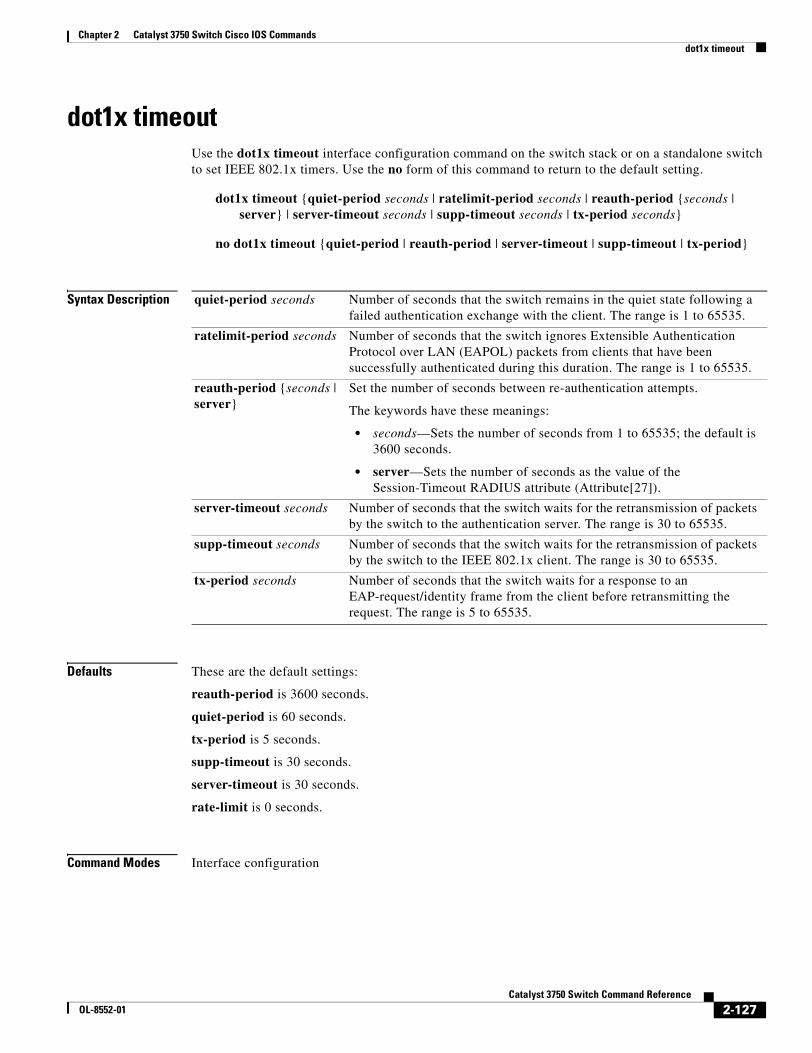
Chapter 2 Catalyst 3750 Switch Cisco IOS Commandsdot1x timeout
dot1x timeout Use the dot1x timeout interface configuration command on the switch stack or on a standalone switch to set IEEE 802.1x timers. Use the no form of this command to return to the default setting.
dot1x timeout {quiet-period seconds | ratelimit-period seconds | reauth-period {seconds | server} | server-timeout seconds | supp-timeout seconds | tx-period seconds}
no dot1x timeout {quiet-period | reauth-period | server-timeout | supp-timeout | tx-period}
Syntax Description
Defaults These are the default settings:
reauth-period is 3600 seconds.
quiet-period is 60 seconds.
tx-period is 5 seconds.
supp-timeout is 30 seconds.
server-timeout is 30 seconds.
rate-limit is 0 seconds.
Command Modes Interface configuration
quiet-period seconds Number of seconds that the switch remains in the quiet state following a failed authentication exchange with the client. The range is 1 to 65535.
ratelimit-period seconds Number of seconds that the switch ignores Extensible Authentication Protocol over LAN (EAPOL) packets from clients that have been successfully authenticated during this duration. The range is 1 to 65535.
reauth-period {seconds | server}
Set the number of seconds between re-authentication attempts.
The keywords have these meanings:
• seconds—Sets the number of seconds from 1 to 65535; the default is 3600 seconds.
• server—Sets the number of seconds as the value of the Session-Timeout RADIUS attribute (Attribute[27]).
server-timeout seconds Number of seconds that the switch waits for the retransmission of packets by the switch to the authentication server. The range is 30 to 65535.
supp-timeout seconds Number of seconds that the switch waits for the retransmission of packets by the switch to the IEEE 802.1x client. The range is 30 to 65535.
tx-period seconds Number of seconds that the switch waits for a response to an EAP-request/identity frame from the client before retransmitting the request. The range is 5 to 65535.
2-127Catalyst 3750 Switch Command Reference
OL-8552-01
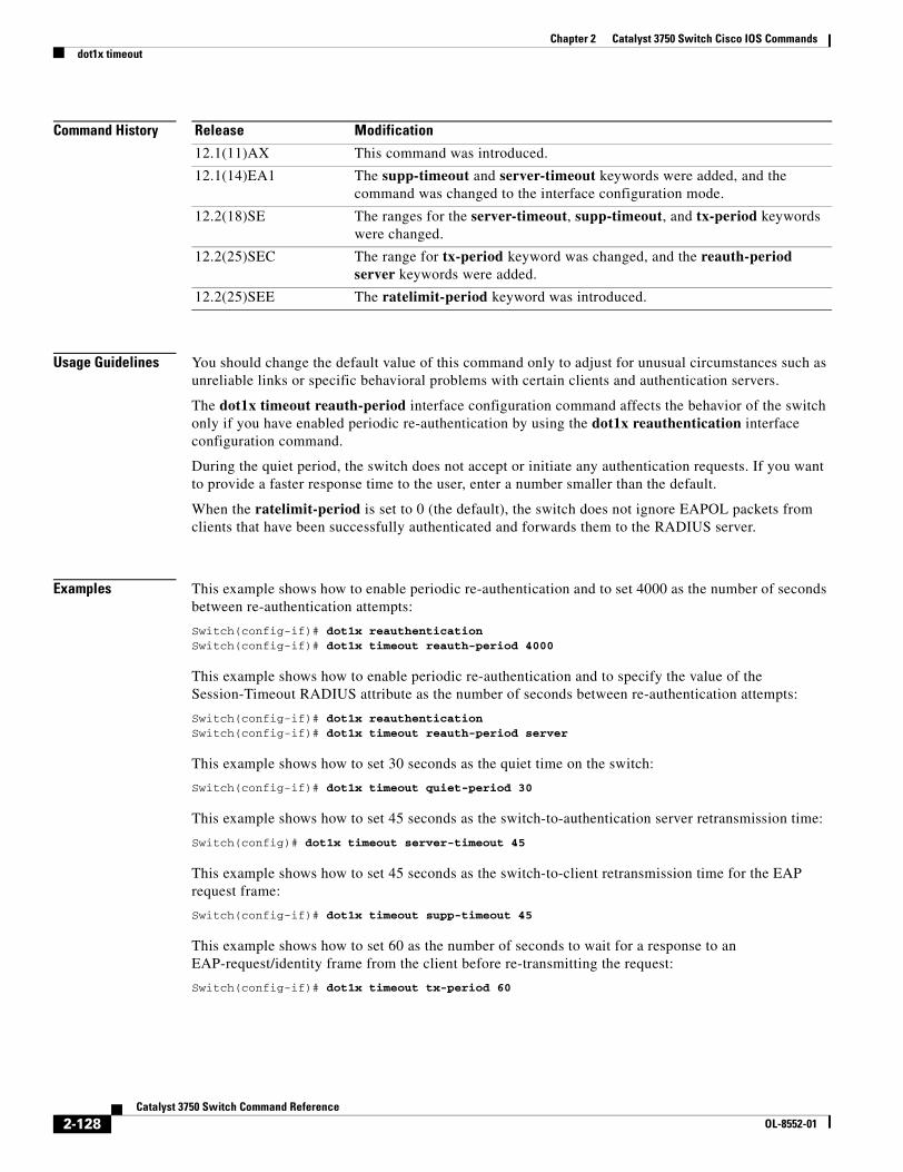
Chapter 2 Catalyst 3750 Switch Cisco IOS Commandsdot1x timeout
Command History
Usage Guidelines You should change the default value of this command only to adjust for unusual circumstances such as unreliable links or specific behavioral problems with certain clients and authentication servers.
The dot1x timeout reauth-period interface configuration command affects the behavior of the switch only if you have enabled periodic re-authentication by using the dot1x reauthentication interface configuration command.
During the quiet period, the switch does not accept or initiate any authentication requests. If you want to provide a faster response time to the user, enter a number smaller than the default.
When the ratelimit-period is set to 0 (the default), the switch does not ignore EAPOL packets from clients that have been successfully authenticated and forwards them to the RADIUS server.
Examples This example shows how to enable periodic re-authentication and to set 4000 as the number of seconds between re-authentication attempts:
Switch(config-if)# dot1x reauthenticationSwitch(config-if)# dot1x timeout reauth-period 4000
This example shows how to enable periodic re-authentication and to specify the value of the Session-Timeout RADIUS attribute as the number of seconds between re-authentication attempts:
Switch(config-if)# dot1x reauthenticationSwitch(config-if)# dot1x timeout reauth-period server
This example shows how to set 30 seconds as the quiet time on the switch:
Switch(config-if)# dot1x timeout quiet-period 30
This example shows how to set 45 seconds as the switch-to-authentication server retransmission time:
Switch(config)# dot1x timeout server-timeout 45
This example shows how to set 45 seconds as the switch-to-client retransmission time for the EAP request frame:
Switch(config-if)# dot1x timeout supp-timeout 45
This example shows how to set 60 as the number of seconds to wait for a response to an EAP-request/identity frame from the client before re-transmitting the request:
Switch(config-if)# dot1x timeout tx-period 60
Release Modification
12.1(11)AX This command was introduced.
12.1(14)EA1 The supp-timeout and server-timeout keywords were added, and the command was changed to the interface configuration mode.
12.2(18)SE The ranges for the server-timeout, supp-timeout, and tx-period keywords were changed.
12.2(25)SEC The range for tx-period keyword was changed, and the reauth-period server keywords were added.
12.2(25)SEE The ratelimit-period keyword was introduced.
2-128Catalyst 3750 Switch Command Reference
OL-8552-01
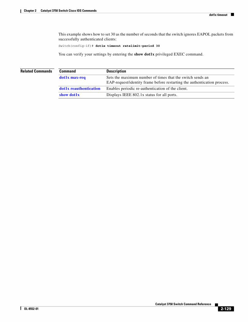
Chapter 2 Catalyst 3750 Switch Cisco IOS Commandsdot1x timeout
This example shows how to set 30 as the number of seconds that the switch ignores EAPOL packets from successfully authenticated clients:
Switch(config-if)# dot1x timeout ratelimit-period 30
You can verify your settings by entering the show dot1x privileged EXEC command.
Related Commands Command Description
dot1x max-req Sets the maximum number of times that the switch sends an EAP-request/identity frame before restarting the authentication process.
dot1x reauthentication Enables periodic re-authentication of the client.
show dot1x Displays IEEE 802.1x status for all ports.
2-129Catalyst 3750 Switch Command Reference
OL-8552-01
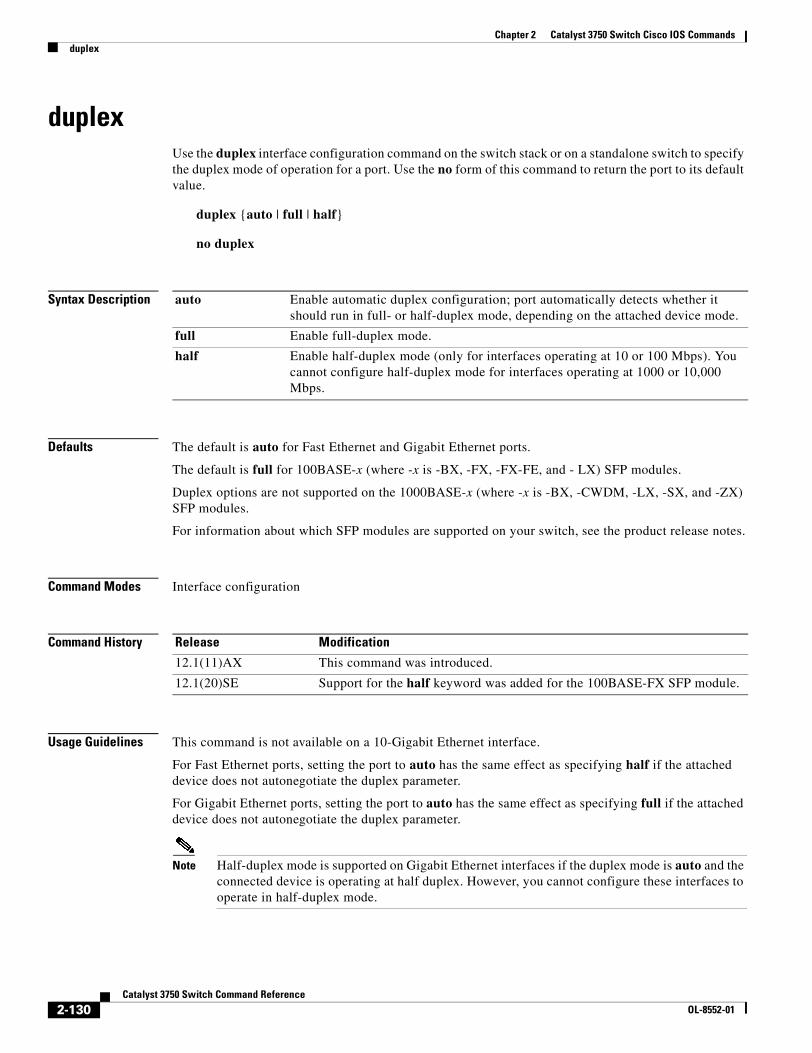
Chapter 2 Catalyst 3750 Switch Cisco IOS Commandsduplex
duplexUse the duplex interface configuration command on the switch stack or on a standalone switch to specify the duplex mode of operation for a port. Use the no form of this command to return the port to its default value.
duplex {auto | full | half}
no duplex
Syntax Description
Defaults The default is auto for Fast Ethernet and Gigabit Ethernet ports.
The default is full for 100BASE-x (where -x is -BX, -FX, -FX-FE, and - LX) SFP modules.
Duplex options are not supported on the 1000BASE-x (where -x is -BX, -CWDM, -LX, -SX, and -ZX) SFP modules.
For information about which SFP modules are supported on your switch, see the product release notes.
Command Modes Interface configuration
Command History
Usage Guidelines This command is not available on a 10-Gigabit Ethernet interface.
For Fast Ethernet ports, setting the port to auto has the same effect as specifying half if the attached device does not autonegotiate the duplex parameter.
For Gigabit Ethernet ports, setting the port to auto has the same effect as specifying full if the attached device does not autonegotiate the duplex parameter.
Note Half-duplex mode is supported on Gigabit Ethernet interfaces if the duplex mode is auto and the connected device is operating at half duplex. However, you cannot configure these interfaces to operate in half-duplex mode.
auto Enable automatic duplex configuration; port automatically detects whether it should run in full- or half-duplex mode, depending on the attached device mode.
full Enable full-duplex mode.
half Enable half-duplex mode (only for interfaces operating at 10 or 100 Mbps). You cannot configure half-duplex mode for interfaces operating at 1000 or 10,000 Mbps.
Release Modification
12.1(11)AX This command was introduced.
12.1(20)SE Support for the half keyword was added for the 100BASE-FX SFP module.
2-130Catalyst 3750 Switch Command Reference
OL-8552-01
Chapter 2 Catalyst 3750 Switch Cisco IOS Commandsduplex
Certain ports can be configured to be either full duplex or half duplex. Applicability of this command depends on the device to which the switch is attached.
If both ends of the line support autonegotiation, we highly recommend using the default autonegotiation settings. If one interface supports autonegotiation and the other end does not, configure duplex and speed on both interfaces; do use the auto setting on the supported side.
If the speed is set to auto, the switch negotiates with the device at the other end of the link for the speed setting and then forces the speed setting to the negotiated value. The duplex setting remains as configured on each end of the link, which could result in a duplex setting mismatch.
Beginning with Cisco IOS Release 12.2(20)SE1, you can configure the duplex setting when the speed is set to auto.
Caution Changing the interface speed and duplex mode configuration might shut down and re-enable the interface during the reconfiguration.
For guidelines on setting the switch speed and duplex parameters, see the “Configuring Interface Characteristics” chapter in the software configuration guide for this release.
Examples This example shows how to configure an interface for full-duplex operation:
Switch(config)# interface gigabitethernet1/0/1Switch(config-if)# duplex full
You can verify your setting by entering the show interfaces privileged EXEC command.
Related Commands Command Description
show interfaces Displays the interface settings on the switch.
speed Sets the speed on a 10/100 or 10/100/1000 Mbps interface.
2-131Catalyst 3750 Switch Command Reference
OL-8552-01
Chapter 2 Catalyst 3750 Switch Cisco IOS Commandserrdisable detect cause
errdisable detect causeUse the errdisable detect cause global configuration command on the switch stack or on a standalone switch to enable error-disabled detection for a specific cause or all causes. Use the no form of this command to disable the error-disabled detection feature.
errdisable detect cause {all | arp-inspection | dhcp-rate-limit | dtp-flap | gbic-invalid | l2ptguard | link-flap | loopback | pagp-flap}
no errdisable detect cause {all | arp-inspection | dhcp-rate-limit | dtp-flap | gbic-invalid | l2ptguard | link-flap | pagp-flap}
Syntax Description
Command Default Detection is enabled for all causes.
Command Modes Global configuration
Command History
all Enable error detection for all error-disabled causes.
arp-inspection Enable error detection for dynamic Address Resolution Protocol (ARP) inspection.
dhcp-rate-limit Enable error detection for DHCP snooping.
dtp-flap Enable error detection for the Dynamic Trunking Protocol (DTP) flapping.
gbic-invalid Enable error detection for an invalid Gigabit Interface Converter (GBIC) module.
Note On the Catalyst 3750 switch, this error refers to an invalid small form-factor pluggable (SFP) module.
l2ptguard Enable error detection for a Layer 2 protocol-tunnel error-disabled cause.
link-flap Enable error detection for link-state flapping.
loopback Enable error detection for detected loopbacks.
pagp-flap Enable error detection for the Port Aggregation Protocol (PAgP) flap error-disabled cause.
Release Modification
12.1(11)AX This command was introduced.
12.1(14)EA1 The loopback keyword was added.
12.1(19)EA1 The dhcp-rate-limit keyword was added.
12.2(20)SE The arp-inspection keyword was added.
12.2(25)SE The l2ptguard keyword was added.
2-132Catalyst 3750 Switch Command Reference
OL-8552-01
Chapter 2 Catalyst 3750 Switch Cisco IOS Commandserrdisable detect cause
Usage Guidelines A cause (all, dhcp-rate-limit, and so forth) is the reason why the error-disabled state occurred. When a cause is detected on an interface, the interface is placed in an error-disabled state, an operational state that is similar to a link-down state.
If you set a recovery mechanism for the cause by entering the errdisable recovery global configuration command for the cause, the interface is brought out of the error-disabled state and allowed to retry the operation when all causes have timed out. If you do not set a recovery mechanism, you must enter the shutdown and then the no shutdown commands to manually recover an interface from the error-disabled state.
Examples This example shows how to enable error-disabled detection for the link-flap error-disabled cause:
Switch(config)# errdisable detect cause link-flap
You can verify your setting by entering the show errdisable detect privileged EXEC command.
Related Commands Command Description
show errdisable detect Displays error-disabled detection information.
show interfaces status err-disabled Displays interface status or a list of interfaces in the error-disabled state.
2-133Catalyst 3750 Switch Command Reference
OL-8552-01
Chapter 2 Catalyst 3750 Switch Cisco IOS Commandserrdisable recovery
errdisable recoveryUse the errdisable recovery global configuration command on the switch stack or on a standalone switch to configure the recover mechanism variables. Use the no form of this command to return to the default setting.
errdisable recovery {cause {all | arp-inspection | bpduguard | channel-misconfig | dhcp-rate-limit | dtp-flap | gbic-invalid | l2ptguard | link-flap | loopback | pagp-flap | psecure-violation | security-violation | udld | vmps} | {interval interval}
no errdisable recovery {cause {all | arp-inspection | bpduguard | channel-misconfig | dhcp-rate-limit | dtp-flap | gbic-invalid | l2ptguard | link-flap | loopback | pagp-flap | psecure-violation | security-violation | udld | vmps} | {interval interval}
Syntax Description cause Enable the error-disabled mechanism to recover from a specific cause.
all Enable the timer to recover from all error-disabled causes.
bpduguard Enable the timer to recover from the bridge protocol data unit (BPDU) guard error-disabled state.
arp-inspection Enable the timer to recover from the Address Resolution Protocol (ARP) inspection error-disabled state.
channel-misconfig Enable the timer to recover from the EtherChannel misconfiguration error-disabled state.
dhcp-rate-limit Enable the timer to recover from the DHCP snooping error-disabled state.
dtp-flap Enable the timer to recover from the Dynamic Trunking Protocol (DTP) flap error-disabled state.
gbic-invalid Enable the timer to recover from an invalid Gigabit Interface Converter (GBIC) module error-disabled state.
Note On the Catalyst 3750 switch, this error refers to an invalid small form-factor pluggable (SFP) error-disabled state.
l2ptguard Enable the timer to recover from a Layer 2 protocol tunnel error-disabled state.
link-flap Enable the timer to recover from the link-flap error-disabled state.
loopback Enable the timer to recover from a loopback error-disabled state.
pagp-flap Enable the timer to recover from the Port Aggregation Protocol (PAgP)-flap error-disabled state.
psecure-violation Enable the timer to recover from a port security violation disable state.
security-violation Enable the timer to recover from an IEEE 802.1x-violation disabled state.
udld Enable the timer to recover from the UniDirectional Link Detection (UDLD) error-disabled state.
2-134Catalyst 3750 Switch Command Reference
OL-8552-01
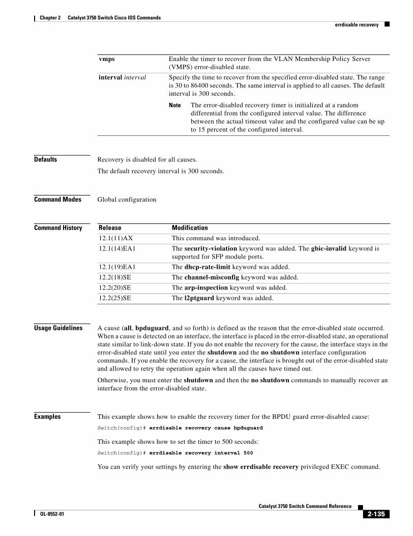
Chapter 2 Catalyst 3750 Switch Cisco IOS Commandserrdisable recovery
Defaults Recovery is disabled for all causes.
The default recovery interval is 300 seconds.
Command Modes Global configuration
Command History
Usage Guidelines A cause (all, bpduguard, and so forth) is defined as the reason that the error-disabled state occurred. When a cause is detected on an interface, the interface is placed in the error-disabled state, an operational state similar to link-down state. If you do not enable the recovery for the cause, the interface stays in the error-disabled state until you enter the shutdown and the no shutdown interface configuration commands. If you enable the recovery for a cause, the interface is brought out of the error-disabled state and allowed to retry the operation again when all the causes have timed out.
Otherwise, you must enter the shutdown and then the no shutdown commands to manually recover an interface from the error-disabled state.
Examples This example shows how to enable the recovery timer for the BPDU guard error-disabled cause:
Switch(config)# errdisable recovery cause bpduguard
This example shows how to set the timer to 500 seconds:
Switch(config)# errdisable recovery interval 500
You can verify your settings by entering the show errdisable recovery privileged EXEC command.
vmps Enable the timer to recover from the VLAN Membership Policy Server (VMPS) error-disabled state.
interval interval Specify the time to recover from the specified error-disabled state. The range is 30 to 86400 seconds. The same interval is applied to all causes. The default interval is 300 seconds.
Note The error-disabled recovery timer is initialized at a random differential from the configured interval value. The difference between the actual timeout value and the configured value can be up to 15 percent of the configured interval.
Release Modification
12.1(11)AX This command was introduced.
12.1(14)EA1 The security-violation keyword was added. The gbic-invalid keyword is supported for SFP module ports.
12.1(19)EA1 The dhcp-rate-limit keyword was added.
12.2(18)SE The channel-misconfig keyword was added.
12.2(20)SE The arp-inspection keyword was added.
12.2(25)SE The l2ptguard keyword was added.
2-135Catalyst 3750 Switch Command Reference
OL-8552-01

Chapter 2 Catalyst 3750 Switch Cisco IOS Commandserrdisable recovery
Related Commands Command Description
show errdisable recovery Displays error-disabled recovery timer information.
show interfaces status err-disabled
Displays interface status or a list of interfaces in error-disabled state.
2-136Catalyst 3750 Switch Command Reference
OL-8552-01
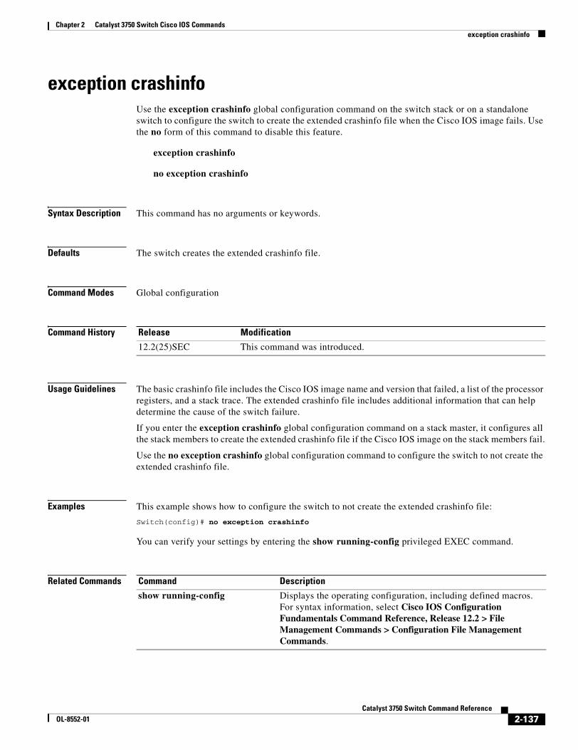
Chapter 2 Catalyst 3750 Switch Cisco IOS Commandsexception crashinfo
exception crashinfo Use the exception crashinfo global configuration command on the switch stack or on a standalone switch to configure the switch to create the extended crashinfo file when the Cisco IOS image fails. Use the no form of this command to disable this feature.
exception crashinfo
no exception crashinfo
Syntax Description This command has no arguments or keywords.
Defaults The switch creates the extended crashinfo file.
Command Modes Global configuration
Command History
Usage Guidelines The basic crashinfo file includes the Cisco IOS image name and version that failed, a list of the processor registers, and a stack trace. The extended crashinfo file includes additional information that can help determine the cause of the switch failure.
If you enter the exception crashinfo global configuration command on a stack master, it configures all the stack members to create the extended crashinfo file if the Cisco IOS image on the stack members fail.
Use the no exception crashinfo global configuration command to configure the switch to not create the extended crashinfo file.
Examples This example shows how to configure the switch to not create the extended crashinfo file:
Switch(config)# no exception crashinfo
You can verify your settings by entering the show running-config privileged EXEC command.
Related Commands
Release Modification
12.2(25)SEC This command was introduced.
Command Description
show running-config Displays the operating configuration, including defined macros. For syntax information, select Cisco IOS Configuration Fundamentals Command Reference, Release 12.2 > File Management Commands > Configuration File Management Commands.
2-137Catalyst 3750 Switch Command Reference
OL-8552-01
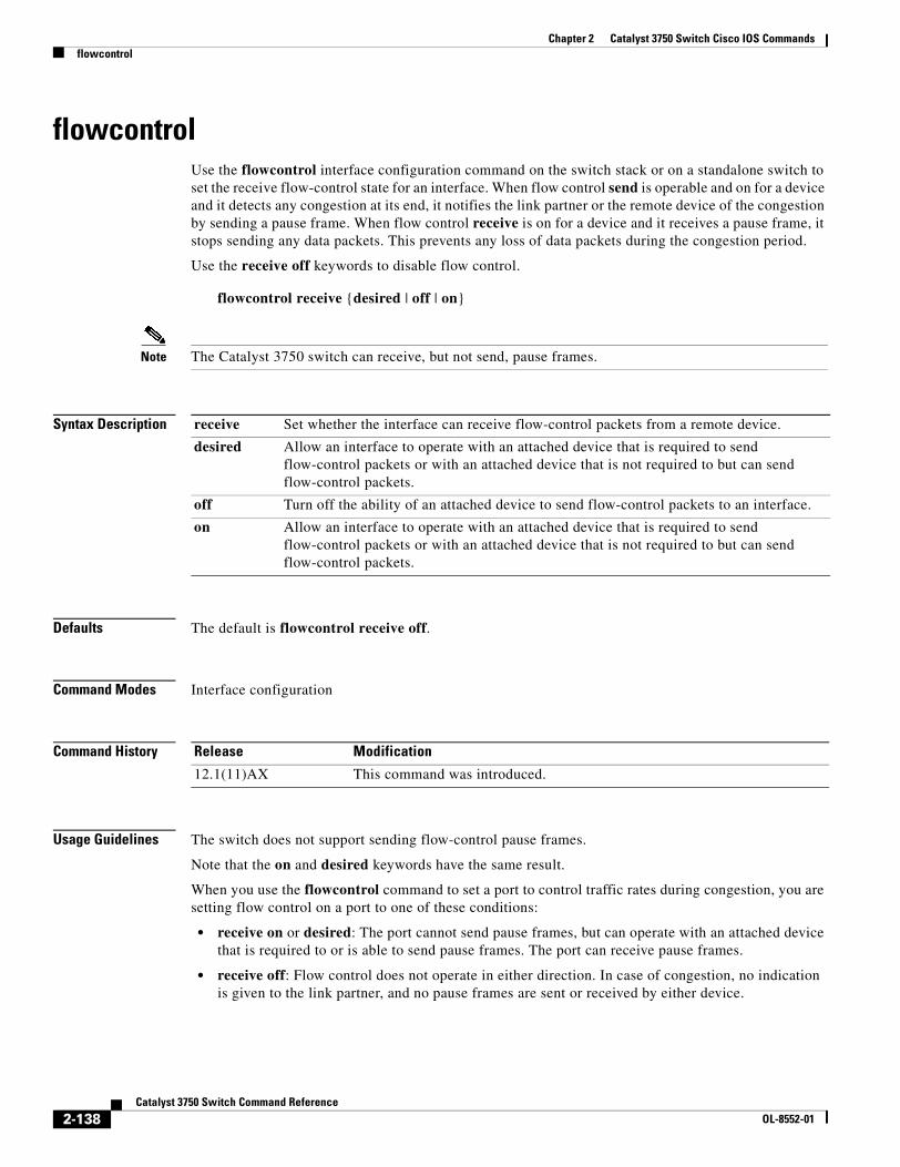
Chapter 2 Catalyst 3750 Switch Cisco IOS Commandsflowcontrol
flowcontrolUse the flowcontrol interface configuration command on the switch stack or on a standalone switch to set the receive flow-control state for an interface. When flow control send is operable and on for a device and it detects any congestion at its end, it notifies the link partner or the remote device of the congestion by sending a pause frame. When flow control receive is on for a device and it receives a pause frame, it stops sending any data packets. This prevents any loss of data packets during the congestion period.
Use the receive off keywords to disable flow control.
flowcontrol receive {desired | off | on}
Note The Catalyst 3750 switch can receive, but not send, pause frames.
Syntax Description
Defaults The default is flowcontrol receive off.
Command Modes Interface configuration
Command History
Usage Guidelines The switch does not support sending flow-control pause frames.
Note that the on and desired keywords have the same result.
When you use the flowcontrol command to set a port to control traffic rates during congestion, you are setting flow control on a port to one of these conditions:
• receive on or desired: The port cannot send pause frames, but can operate with an attached device that is required to or is able to send pause frames. The port can receive pause frames.
• receive off: Flow control does not operate in either direction. In case of congestion, no indication is given to the link partner, and no pause frames are sent or received by either device.
receive Set whether the interface can receive flow-control packets from a remote device.
desired Allow an interface to operate with an attached device that is required to send flow-control packets or with an attached device that is not required to but can send flow-control packets.
off Turn off the ability of an attached device to send flow-control packets to an interface.
on Allow an interface to operate with an attached device that is required to send flow-control packets or with an attached device that is not required to but can send flow-control packets.
Release Modification
12.1(11)AX This command was introduced.
2-138Catalyst 3750 Switch Command Reference
OL-8552-01
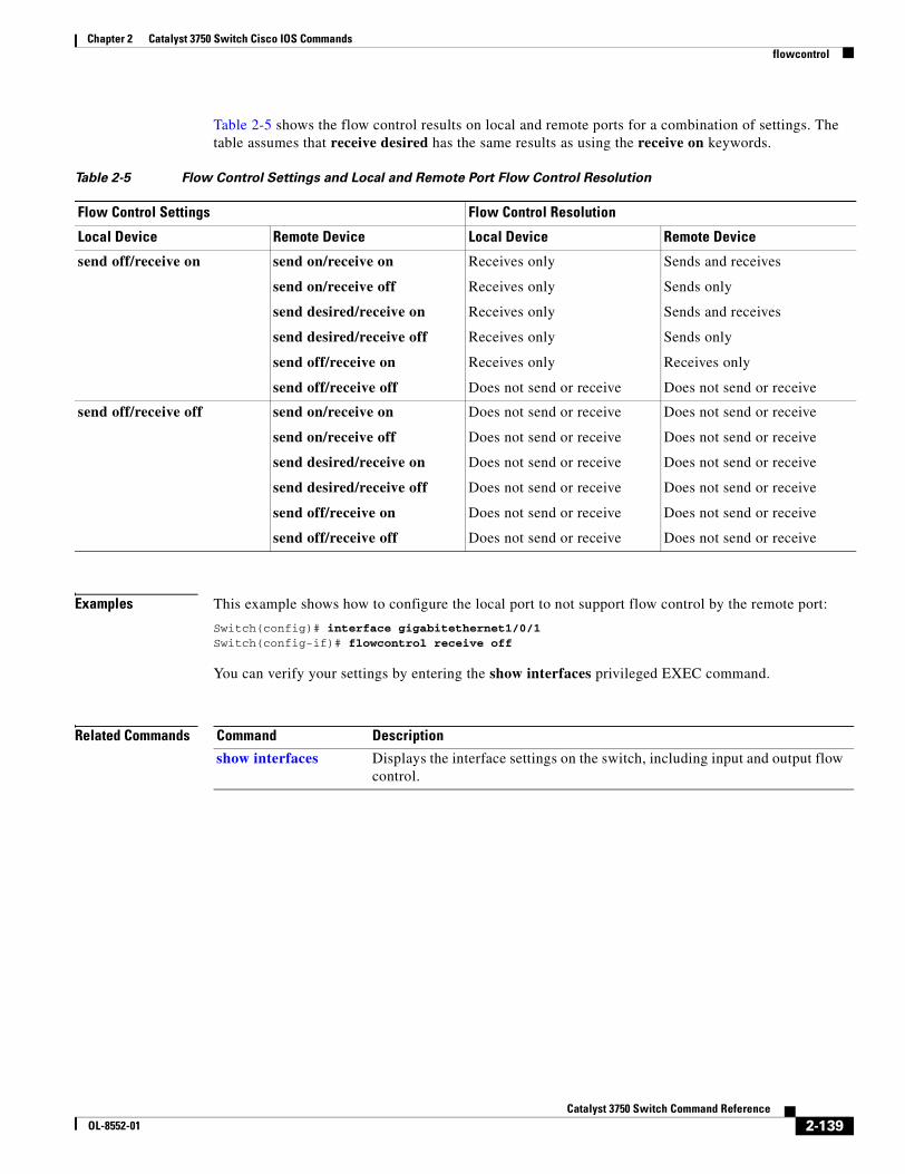
Chapter 2 Catalyst 3750 Switch Cisco IOS Commandsflowcontrol
Table 2-5 shows the flow control results on local and remote ports for a combination of settings. The table assumes that receive desired has the same results as using the receive on keywords.
Examples This example shows how to configure the local port to not support flow control by the remote port:
Switch(config)# interface gigabitethernet1/0/1Switch(config-if)# flowcontrol receive off
You can verify your settings by entering the show interfaces privileged EXEC command.
Related Commands
Table 2-5 Flow Control Settings and Local and Remote Port Flow Control Resolution
Flow Control Settings Flow Control Resolution
Local Device Remote Device Local Device Remote Device
send off/receive on send on/receive on
send on/receive off
send desired/receive on
send desired/receive off
send off/receive on
send off/receive off
Receives only
Receives only
Receives only
Receives only
Receives only
Does not send or receive
Sends and receives
Sends only
Sends and receives
Sends only
Receives only
Does not send or receive
send off/receive off send on/receive on
send on/receive off
send desired/receive on
send desired/receive off
send off/receive on
send off/receive off
Does not send or receive
Does not send or receive
Does not send or receive
Does not send or receive
Does not send or receive
Does not send or receive
Does not send or receive
Does not send or receive
Does not send or receive
Does not send or receive
Does not send or receive
Does not send or receive
Command Description
show interfaces Displays the interface settings on the switch, including input and output flow control.
2-139Catalyst 3750 Switch Command Reference
OL-8552-01
Chapter 2 Catalyst 3750 Switch Cisco IOS Commandsinterface port-channel
interface port-channelUse the interface port-channel global configuration command on the switch stack or on a standalone switch to access or create the port-channel logical interface. Use the no form of this command to remove the port-channel.
interface port-channel port-channel-number
no interface port-channel port-channel-number
Syntax Description
Defaults No port-channel logical interfaces are defined.
Command Modes Global configuration
Command History
Usage Guidelines For Layer 2 EtherChannels, you do not have to create a port-channel interface first before assigning a physical port to a channel group. Instead, you can use the channel-group interface configuration command. It automatically creates the port-channel interface when the channel group gets its first physical port. If you create the port-channel interface first, the channel-group-number can be the same as the port-channel-number, or you can use a new number. If you use a new number, the channel-group command dynamically creates a new port channel.
You create Layer 3 port channels by using the interface port-channel command followed by the no switchport interface configuration command. You should manually configure the port-channel logical interface before putting the interface into the channel group.
Only one port channel in a channel group is allowed.
Caution When using a port-channel interface as a routed port, do not assign Layer 3 addresses on the physical ports that are assigned to the channel group.
Caution Do not assign bridge groups on the physical ports in a channel group used as a Layer 3 port-channel interface because it creates loops. You must also disable spanning tree.
port-channel-number Port-channel number. The range is 1 to 48.
Release Modification
12.1(11)AX This command was introduced.
12.2(25)SE The port-channel-number range was changed from 1 to 12 to 1 to 48.
2-140Catalyst 3750 Switch Command Reference
OL-8552-01
Chapter 2 Catalyst 3750 Switch Cisco IOS Commandsinterface port-channel
Follow these guidelines when you use the interface port-channel command:
• If you want to use the Cisco Discovery Protocol (CDP), you must configure it only on the physical port and not on the port-channel interface.
• Do not configure a port that is an active member of an EtherChannel as an IEEE 802.1x port. If IEEE 802.1x is enabled on a not-yet active port of an EtherChannel, the port does not join the EtherChannel.
For a complete list of configuration guidelines, see the “Configuring EtherChannels” chapter in the software configuration guide for this release.
Examples This example shows how to create a port-channel interface with a port channel number of 5:
Switch(config)# interface port-channel 5
You can verify your setting by entering the show running-config privileged EXEC or show etherchannel channel-group-number detail privileged EXEC command.
Related Commands Command Description
channel-group Assigns an Ethernet port to an EtherChannel group.
show etherchannel Displays EtherChannel information for a channel.
show running-config Displays the current operating configuration. For syntax information, select Cisco IOS Configuration Fundamentals Command Reference, Release 12.2 > File Management Commands > Configuration File Management Commands.
2-141Catalyst 3750 Switch Command Reference
OL-8552-01
Chapter 2 Catalyst 3750 Switch Cisco IOS Commandsinterface range
interface rangeUse the interface range global configuration command on the switch stack or on a standalone switch to enter interface range configuration mode and to execute a command on multiple ports at the same time. Use the no form of this command to remove an interface range.
interface range {port-range | macro name}
no interface range {port-range | macro name}
Syntax Description
Defaults This command has no default setting.
Command Modes Global configuration
Command History
Usage Guidelines When you enter interface range configuration mode, all interface parameters you enter are attributed to all interfaces within the range.
For VLANs, you can use the interface range command only on existing VLAN switch virtual interfaces (SVIs). To display VLAN SVIs, enter the show running-config privileged EXEC command. VLANs not displayed cannot be used in the interface range command. The commands entered under interface range command are applied to all existing VLAN SVIs in the range.
All configuration changes made to an interface range are saved to NVRAM, but the interface range itself is not saved to NVRAM.
You can enter the interface range in two ways:
• Specifying up to five interface ranges
• Specifying a previously defined interface-range macro
All interfaces in a range must be the same type; that is, all Fast Ethernet ports, all Gigabit Ethernet ports, all EtherChannel ports, or all VLANs. However, you can define up to five interface ranges with a single command, with each range separated by a comma.
Valid values for port-range type and interface:
• vlan vlan-ID - vlan-ID, where VLAN ID is from 1 to 4094
• fastethernet stack member/module/{first port} - {last port}, where module is always 0
port-range Port range. For a list of valid values for port-range, see the “Usage Guidelines” section.
macro name Specify the name of a macro.
Release Modification
12.1(11)AX This command was introduced.
2-142Catalyst 3750 Switch Command Reference
OL-8552-01
Chapter 2 Catalyst 3750 Switch Cisco IOS Commandsinterface range
• gigabitethernet stack member/module/{first port} - {last port}, where module is always 0
For physical interfaces:
– stack member is the number used to identify the switch within the stack. The number ranges from 1 to 9 and is assigned to the switch the first time the stack member initializes.
– module is always 0
– the range is type stack member/0/number - number (for example, gigabitethernet1/0/1 - 2)
• port-channel port-channel-number - port-channel-number, where port-channel-number is from 1 to 48
Note When you use the interface range command with port channels, the first and last port channel number in the range must be active port channels.
When you define a range, you must enter a space between the first entry and the hyphen (-):
interface range gigabitethernet1/0/1 -2
When you define multiple ranges, you must still enter a space after the first entry and before the comma (,):
interface range fastethernet1/0/1 - 2, gigabitethernet1/0/1 - 2
You cannot specify both a macro and an interface range in the same command.
You can also specify a single interface in port-range. The command is then similar to the interface interface-id global configuration command.
For more information about configuring interface ranges, see the software configuration guide for this release.
Examples This example shows how to use the interface range command to enter interface-range configuration mode to apply commands to two ports:
Switch(config)# interface range gigabitethernet1/0/1 - 2Switch(config-if-range)#
This example shows how to use a port-range macro macro1 for the same function. The advantage is that you can reuse macro1 until you delete it.
Switch(config)# define interface-range macro1 gigabitethernet1/0/1 - 2Switch(config)# interface range macro macro1Switch(config-if-range)#
Related Commands Command Description
define interface-range Creates an interface range macro.
show running-config Displays the configuration information currently running on the switch. For syntax information, select Cisco IOS Configuration Fundamentals Command Reference, Release 12.2 > File Management Commands > Configuration File Management Commands.
2-143Catalyst 3750 Switch Command Reference
OL-8552-01
Chapter 2 Catalyst 3750 Switch Cisco IOS Commandsinterface vlan
interface vlanUse the interface vlan global configuration command on the switch stack or on a standalone switch to create or access a dynamic switch virtual interface (SVI) and to enter interface configuration mode. Use the no form of this command to delete an SVI.
interface vlan vlan-id
no interface vlan vlan-id
Syntax Description
Defaults The default VLAN interface is VLAN 1.
Command Modes Global configuration
Command History
Usage Guidelines SVIs are created the first time that you enter the interface vlan vlan-id command for a particular VLAN. The vlan-id corresponds to the VLAN-tag associated with data frames on an ISL or IEEE 802.1Q encapsulated trunk or the VLAN ID configured for an access port.
Note When you create an SVI, it does not become active until it is associated with a physical port.
If you delete an SVI by entering the no interface vlan vlan-id command, the deleted interface is no longer visible in the output from the show interfaces privileged EXEC command.
Note You cannot delete the VLAN 1 interface.
You can re-instate a deleted SVI by entering the interface vlan vlan-id command for the deleted interface. The interface comes back up, but the previous configuration is gone.
The interrelationship between the number of SVIs configured on a switch stack and the number of other features being configured might have an impact on CPU utilization due to hardware limitations. You can use the sdm prefer global configuration command to reallocate system hardware resources based on templates and feature tables. For more information, see the sdm prefer command.
vlan-id VLAN number. The range is 1 to 4094.
Release Modification
12.1(11)AX This command was introduced.
2-144Catalyst 3750 Switch Command Reference
OL-8552-01
Chapter 2 Catalyst 3750 Switch Cisco IOS Commandsinterface vlan
Examples This example shows how to create a new SVI with VLAN ID 23 and to enter interface configuration mode:
Switch(config)# interface vlan 23Switch(config-if)#
You can verify your setting by entering the show interfaces and show interfaces vlan vlan-id privileged EXEC commands.
Related Commands Command Description
show interfaces vlan vlan-id Displays the administrative and operational status of all interfaces or the specified VLAN.
2-145Catalyst 3750 Switch Command Reference
OL-8552-01
Chapter 2 Catalyst 3750 Switch Cisco IOS Commandsip access-group
ip access-groupUse the ip access-group interface configuration command on the switch stack or on a standalone switch to control access to a Layer 2 or Layer 3 interface. Use the no form of this command to remove all access groups or the specified access group from the interface.
ip access-group {access-list-number | name} {in | out}
no ip access-group [access-list-number | name] {in | out}
Syntax Description
Defaults No access list is applied to the interface.
Command Modes Interface configuration
Command History
Usage Guidelines You can apply named or numbered standard or extended IP access lists to an interface. To define an access list by name, use the ip access-list global configuration command. To define a numbered access list, use the access list global configuration command. You can used numbered standard access lists ranging from 1 to 99 and 1300 to 1999 or extended access lists ranging from 100 to 199 and 2000 to 2699.
You can use this command to apply an access list to a Layer 2 or Layer 3 interface. However, note these limitations for Layer 2 interfaces (port ACLs):
• You can only apply ACLs in the inbound direction; the out keyword is not supported for Layer 2 interfaces.
• You can only apply one IP ACL and one MAC ACL per interface.
• Layer 2 interfaces do not support logging; if the log keyword is specified in the IP ACL, it is ignored.
• An IP ACL applied to a Layer 2 interface only filters IP packets. To filter non-IP packets, use the mac access-group interface configuration command with MAC extended ACLs.
access-list-number The number of the IP access control list (ACL). The range is 1 to 199 or 1300 to 2699.
name The name of an IP ACL, specified in the ip access-list global configuration command.
in Specify filtering on inbound packets.
out Specify filtering on outbound packets. This keyword is valid only on Layer 3 interfaces.
Release Modification
12.1(11)AX This command was introduced.
12.1(14)EA1 This command support was extended to Layer 2 interfaces.
2-146Catalyst 3750 Switch Command Reference
OL-8552-01
Chapter 2 Catalyst 3750 Switch Cisco IOS Commandsip access-group
You can use router ACLs, input port ACLs, and VLAN maps on the same switch. However, a port ACL takes precedence over a router ACL or VLAN map:
• When an input port ACL is applied to an interface and a VLAN map is applied to a VLAN that the interface is a member of, incoming packets received on ports with the ACL applied are filtered by the port ACL. Other packets are filtered by the VLAN map.
• When an input router ACL and input port ACLs exist in an switch virtual interface (SVI), incoming packets received on ports to which a port ACL is applied are filtered by the port ACL. Incoming routed IP packets received on other ports are filtered by the router ACL. Other packets are not filtered.
• When an output router ACL and input port ACLs exist in an SVI, incoming packets received on the ports to which a port ACL is applied are filtered by the port ACL. Outgoing routed IP packets are filtered by the router ACL. Other packets are not filtered.
• When a VLAN map, input router ACLs, and input port ACLs exist in an SVI, incoming packets received on the ports to which a port ACL is applied are only filtered by the port ACL. Incoming routed IP packets received on other ports are filtered by both the VLAN map and the router ACL. Other packets are filtered only by the VLAN map.
• When a VLAN map, output router ACLs, and input port ACLs exist in an SVI, incoming packets received on the ports to which a port ACL is applied are only filtered by the port ACL. Outgoing routed IP packets are filtered by both the VLAN map and the router ACL. Other packets are filtered only by the VLAN map.
You can apply IP ACLs to both outbound or inbound Layer 3 interfaces.
A Layer 3 interface can have one IP ACL applied in each direction.
You can configure only one VLAN map and one router ACL in each direction (input/output) on a VLAN interface.
For standard inbound access lists, after the switch receives a packet, it checks the source address of the packet against the access list. IP extended access lists can optionally check other fields in the packet, such as the destination IP address, protocol type, or port numbers. If the access list permits the packet, the switch continues to process the packet. If the access list denies the packet, the switch discards the packet. If the access list has been applied to a Layer 3 interface, discarding a packet (by default) causes the generation of an Internet Control Message Protocol (ICMP) Host Unreachable message. ICMP Host Unreachable messages are not generated for packets discarded on a Layer 2 interface.
For standard outbound access lists, after receiving a packet and sending it to a controlled interface, the switch checks the packet against the access list. If the access list permits the packet, the switch sends the packet. If the access list denies the packet, the switch discards the packet and, by default, generates an ICMP Host Unreachable message.
If the specified access list does not exist, all packets are passed.
Examples This example shows how to apply IP access list 101 to inbound packets on a port:
Switch(config)# interface gigabitethernet1/0/1Switch(config-if)# ip access-group 101 in
You can verify your settings by entering the show ip interface, show access-lists, or show ip access-lists privileged EXEC command.
2-147Catalyst 3750 Switch Command Reference
OL-8552-01
Chapter 2 Catalyst 3750 Switch Cisco IOS Commandsip access-group
Related Commands Command Description
access list Configures a numbered ACL. For syntax information, select Cisco IOS IP Command Reference, Volume 1 of 3:Addressing and Services, Release 12.2 > IP Services Commands
ip access-list Configures a named ACL. For syntax information, select Cisco IOS IP Command Reference, Volume 1 of 3:Addressing and Services, Release 12.2 > IP Services Commands.
show access-lists Displays ACLs configured on the switch.
show ip access-lists Displays IP ACLs configured on the switch. For syntax information, select Cisco IOS IP Command Reference, Volume 1 of 3:Addressing and Services, Release 12.2 > IP Services Commands.
show ip interface Displays information about interface status and configuration. For syntax information, select Cisco IOS IP Command Reference, Volume 1 of 3:Addressing and Services, Release 12.2 > IP Services Commands.
2-148Catalyst 3750 Switch Command Reference
OL-8552-01
Chapter 2 Catalyst 3750 Switch Cisco IOS Commandsip address
ip addressUse the ip address interface configuration command on the switch stack or on a standalone switch to set an IP address for the Layer 2 switch or an IP address for each switch virtual interface (SVI) or routed port on the Layer 3 switch. Use the no form of this command to remove an IP address or to disable IP processing.
ip address ip-address subnet-mask [secondary]
no ip address [ip-address subnet-mask] [secondary]
Syntax Description
Defaults No IP address is defined.
Command Modes Interface configuration
Command History
Usage Guidelines If you remove the switch IP address through a Telnet session, your connection to the switch will be lost.
Hosts can find subnet masks using the Internet Control Message Protocol (ICMP) Mask Request message. Routers respond to this request with an ICMP Mask Reply message.
You can disable IP processing on a particular interface by removing its IP address with the no ip address command. If the switch detects another host using one of its IP addresses, it will send an error message to the console.
You can use the optional keyword secondary to specify an unlimited number of secondary addresses. Secondary addresses are treated like primary addresses, except the system never generates datagrams other than routing updates with secondary source addresses. IP broadcasts and ARP requests are handled properly, as are interface routes in the IP routing table.
Note If any router on a network segment uses a secondary address, all other devices on that same segment must also use a secondary address from the same network or subnet. Inconsistent use of secondary addresses on a network segment can very quickly cause routing loops.
When you are routing Open Shortest Path First (OSPF), ensure that all secondary addresses of an interface fall into the same OSPF area as the primary addresses.
ip-address IP address.
subnet-mask Mask for the associated IP subnet.
secondary (Optional) Specifies that the configured address is a secondary IP address. If this keyword is omitted, the configured address is the primary IP address.
Release Modification
12.1(11)AX This command was introduced.
2-149Catalyst 3750 Switch Command Reference
OL-8552-01
Chapter 2 Catalyst 3750 Switch Cisco IOS Commandsip address
If your switch receives its IP address from a Bootstrap Protocol (BOOTP) or a DHCP server and you remove the switch IP address by using the no ip address command, IP processing is disabled, and the BOOTP or the DHCP server cannot reassign the address.
A Layer 3 switch can have an IP address assigned to each routed port and SVI. The number of routed ports and SVIs that you can configure is not limited by software; however, the interrelationship between this number and the number of other features being configured might have an impact on CPU utilization due to hardware limitations. You can use the sdm prefer global configuration command to reallocate system hardware resources based on templates and feature tables. For more information, see the sdm prefer command.
Examples This example shows how to configure the IP address for the Layer 2 switch on a subnetted network:
Switch(config)# interface vlan 1Switch(config-if)# ip address 172.20.128.2 255.255.255.0
This example shows how to configure the IP address for a port on the Layer 3 switch:
Switch(config)# ip multicast-routingSwitch(config)# interface gigabitethernet6/0/1Switch(config-if)# no switchportSwitch(config-if)# ip address 172.20.128.2 255.255.255.0
You can verify your settings by entering the show running-config privileged EXEC command.
Related Commands Command Description
show running-config Displays the running configuration on the switch. For syntax information, select Cisco IOS Configuration Fundamentals Command Reference, Release 12.2 > File Management Commands > Configuration File Management Commands.
2-150Catalyst 3750 Switch Command Reference
OL-8552-01
Chapter 2 Catalyst 3750 Switch Cisco IOS Commandsip arp inspection filter vlan
ip arp inspection filter vlanUse the ip arp inspection filter vlan global configuration command on the switch stack or on a standalone switch to permit or deny Address Resolution Protocol (ARP) requests and responses from a host configured with a static IP address when dynamic ARP inspection is enabled. Use the no form of this command to return to the default settings.
ip arp inspection filter arp-acl-name vlan vlan-range [static]
no ip arp inspection filter arp-acl-name vlan vlan-range [static]
Syntax Description
Defaults No defined ARP ACLs are applied to any VLAN.
Command Modes Global configuration
Command History
Usage Guidelines When an ARP ACL is applied to a VLAN for dynamic ARP inspection, only the ARP packets with IP-to-MAC address bindings are compared against the ACL. If the ACL permits a packet, the switch forwards it. All other packet types are bridged in the ingress VLAN without validation.
If the switch denies a packet because of an explicit deny statement in the ACL, the packet is dropped. If the switch denies a packet because of an implicit deny statement, the packet is then compared against the list of DHCP bindings (unless the ACL is static, which means that packets are not compared against the bindings).
Use the arp access-list acl-name global configuration command to define the ARP ACL or to add clauses to the end of a predefined list.
arp-acl-name ARP access control list (ACL) name.
vlan-range VLAN number or range.
You can specify a single VLAN identified by VLAN ID number, a range of VLANs separated by a hyphen, or a series of VLANs separated by a comma. The range is 1 to 4094.
static (Optional) Specify static to treat implicit denies in the ARP ACL as explicit denies and to drop packets that do not match any previous clauses in the ACL. DHCP bindings are not used.
If you do not specify this keyword, it means that there is no explicit deny in the ACL that denies the packet, and DHCP bindings determine whether a packet is permitted or denied if the packet does not match any clauses in the ACL.
Release Modification
12.2(20)SE This command was introduced.
2-151Catalyst 3750 Switch Command Reference
OL-8552-01
Chapter 2 Catalyst 3750 Switch Cisco IOS Commandsip arp inspection filter vlan
Examples This example shows how to apply the ARP ACL static-hosts to VLAN 1 for dynamic ARP inspection:
Switch(config)# ip arp inspection filter static-hosts vlan 1
You can verify your settings by entering the show ip arp inspection vlan 1 privileged EXEC command.
Related Commands Command Description
arp access-list Defines an ARP ACL.
deny (ARP access-list configuration)
Denies an ARP packet based on matches against the DHCP bindings.
permit (ARP access-list configuration)
Permits an ARP packet based on matches against the DHCP bindings.
show arp access-list Displays detailed information about ARP access lists.
show inventory vlan vlan-range
Displays the configuration and the operating state of dynamic ARP inspection for the specified VLAN.
2-152Catalyst 3750 Switch Command Reference
OL-8552-01
Chapter 2 Catalyst 3750 Switch Cisco IOS Commandsip arp inspection limit
ip arp inspection limitUse the ip arp inspection limit interface configuration command on the switch stack or on a standalone switch to limit the rate of incoming Address Resolution Protocol (ARP) requests and responses on an interface. It prevents dynamic ARP inspection from using all of the switch resources if a denial-of-service attack occurs. Use the no form of this command to return to the default settings.
ip arp inspection limit {rate pps [burst interval seconds] | none}
no ip arp inspection limit
Syntax Description
Defaults The rate is 15 pps on untrusted interfaces, assuming that the network is a switched network with a host connecting to as many as 15 new hosts per second.
The rate is unlimited on all trusted interfaces.
The burst interval is 1 second.
Command Modes Interface configuration
Command History
Usage Guidelines The rate applies to both trusted and untrusted interfaces. Configure appropriate rates on trunks to process packets across multiple dynamic ARP inspection-enabled VLANs, or use the none keyword to make the rate unlimited.
After a switch receives more than the configured rate of packets every second consecutively over a number of burst seconds, the interface is placed into an error-disabled state.
Unless you explicitly configure a rate limit on an interface, changing the trust state of the interface also changes its rate limit to the default value for that trust state. After you configure the rate limit, the interface retains the rate limit even when its trust state is changed. If you enter the no ip arp inspection limit interface configuration command, the interface reverts to its default rate limit.
You should configure trunk ports with higher rates to reflect their aggregation. When the rate of incoming packets exceeds the user-configured rate, the switch places the interface into an error-disabled state. The error-disabled recovery feature automatically removes the port from the error-disabled state according to the recovery setting.
rate pps Specify an upper limit for the number of incoming packets processed per second. The range is 0 to 2048 packets per second (pps).
burst interval seconds (Optional) Specify the consecutive interval in seconds, over which the interface is monitored for a high rate of ARP packets.The range is 1 to 15 seconds.
none Specify no upper limit for the rate of incoming ARP packets that can be processed.
Release Modification
12.2(20)SE This command was introduced.
2-153Catalyst 3750 Switch Command Reference
OL-8552-01
Chapter 2 Catalyst 3750 Switch Cisco IOS Commandsip arp inspection limit
The rate limit is calculated separately on each switch in a switch stack. For a cross-stack EtherChannel, this means that the actual rate limit might be higher than the configured value. For example, if you set the rate limit to 30 pps on an EtherChannel that has one port on switch 1 and one port on switch 2, each port can receive packets at 29 pps without causing the EtherChannel to become error-disabled.
The rate of incoming ARP packets on EtherChannel ports equals the sum of the incoming rate of ARP packets from all the channel members. Configure the rate limit for EtherChannel ports only after examining the rate of incoming ARP packets on all the channel members.
Examples This example shows how to limit the rate of incoming ARP requests on a port to 25 pps and to set the interface monitoring interval to 5 consecutive seconds:
Switch(config)# interface gigabitethernet1/0/1Switch(config-if)# ip arp inspection limit rate 25 burst interval 5
You can verify your settings by entering the show ip arp inspection interfaces interface-id privileged EXEC command.
Related Commands Command Description
show inventory interfaces
Displays the trust state and the rate limit of ARP packets for the specified interface or all interfaces.
2-154Catalyst 3750 Switch Command Reference
OL-8552-01
Chapter 2 Catalyst 3750 Switch Cisco IOS Commandsip arp inspection log-buffer
ip arp inspection log-bufferUse the ip arp inspection log-buffer global configuration command on the switch stack or on a standalone switch to configure the dynamic Address Resolution Protocol (ARP) inspection logging buffer. Use the no form of this command to return to the default settings.
ip arp inspection log-buffer {entries number | logs number interval seconds}
no ip arp inspection log-buffer {entries | logs}
Syntax Description
Defaults When dynamic ARP inspection is enabled, denied or dropped ARP packets are logged.
The number of log entries is 32.
The number of system messages is limited to 5 per second.
The logging-rate interval is 1 second.
Command Modes Global configuration
Command History
Usage Guidelines A value of 0 is not allowed for both the logs and the interval keywords.
The logs and interval settings interact. If the logs number X is greater than interval seconds Y, X divided by Y (X/Y) system messages are sent every second. Otherwise, one system message is sent every Y divided by X (Y/X) seconds. For example, if the logs number is 20 and the interval seconds is 4, the switch generates system messages for five entries every second while there are entries in the log buffer.
A log buffer entry can represent more than one packet. For example, if an interface receives many packets on the same VLAN with the same ARP parameters, the switch combines the packets as one entry in the log buffer and generates a system message as a single entry.
If the log buffer overflows, it means that a log event does not fit into the log buffer, and the output display for the show ip arp inspection log privileged EXEC command is affected. A -- in the output display appears in place of all data except the packet count and the time. No other statistics are provided for the entry. If you see this entry in the display, increase the number of entries in the log buffer, or increase the logging rate.
entries number Number of entries to be logged in the buffer. The range is 0 to 1024.
logs number interval seconds
Number of entries needed in the specified interval to generate system messages.
For logs number, the range is 0 to 1024. A 0 value means that the entry is placed in the log buffer, but a system message is not generated.
For interval seconds, the range is 0 to 86400 seconds (1 day). A 0 value means that a system message is immediately generated (and the log buffer is always empty).
Release Modification
12.2(20)SE This command was introduced.
2-155Catalyst 3750 Switch Command Reference
OL-8552-01
Chapter 2 Catalyst 3750 Switch Cisco IOS Commandsip arp inspection log-buffer
The log buffer configuration applies to each stack member in a switch stack. Each stack member has the specified logs number entries and generates system messages at the configured rate. For example, if the interval (rate) is one entry per second, up to five system messages are generated per second in a five-member switch stack.
Examples This example shows how to configure the logging buffer to hold up to 45 entries:
Switch(config)# ip arp inspection log-buffer entries 45
This example shows how to configure the logging rate to 20 log entries per 4 seconds. With this configuration, the switch generates system messages for five entries every second while there are entries in the log buffer.
Switch(config)# ip arp inspection log-buffer logs 20 interval 4
You can verify your settings by entering the show ip arp inspection log privileged EXEC command.
Related Commands Command Description
arp access-list Defines an ARP access control list (ACL).
clear ip arp inspection log Clears the dynamic ARP inspection log buffer.
ip arp inspection vlan logging Controls the type of packets that are logged per VLAN.
show inventory log Displays the configuration and contents of the dynamic ARP inspection log buffer.
2-156Catalyst 3750 Switch Command Reference
OL-8552-01
Chapter 2 Catalyst 3750 Switch Cisco IOS Commandsip arp inspection trust
ip arp inspection trustUse the ip arp inspection trust interface configuration command on the switch stack or on a standalone switch to configure an interface trust state that determines which incoming Address Resolution Protocol (ARP) packets are inspected. Use the no form of this command to return to the default setting.
ip arp inspection trust
no ip arp inspection trust
This command is available only if your switch is running the IP services image, formerly known as the enhanced multilayer image (EMI).
Syntax Description This command has no arguments or keywords.
Defaults The interface is untrusted.
Command Modes Interface configuration
Command History
Usage Guidelines The switch does not check ARP packets that it receives on the trusted interface; it simply forwards the packets.
For untrusted interfaces, the switch intercepts all ARP requests and responses. It verifies that the intercepted packets have valid IP-to-MAC address bindings before updating the local cache and before forwarding the packet to the appropriate destination. The switch drops invalid packets and logs them in the log buffer according to the logging configuration specified with the ip arp inspection vlan logging global configuration command.
Examples This example shows how to configure a port to be trusted:
Switch(config)# interface gigabitethernet1/0/1Switch(config-if)# ip arp inspection trust
You can verify your setting by entering the show ip arp inspection interfaces interface-id privileged EXEC command.
Release Modification
12.2(20)SE This command was introduced.
2-157Catalyst 3750 Switch Command Reference
OL-8552-01
Chapter 2 Catalyst 3750 Switch Cisco IOS Commandsip arp inspection trust
Related Commands Command Description
ip arp inspection log-buffer
Configures the dynamic ARP inspection logging buffer.
show inventory interfaces
Displays the trust state and the rate limit of ARP packets for the specified interface or all interfaces.
show inventory log Displays the configuration and contents of the dynamic ARP inspection log buffer.
2-158Catalyst 3750 Switch Command Reference
OL-8552-01
Chapter 2 Catalyst 3750 Switch Cisco IOS Commandsip arp inspection validate
ip arp inspection validateUse the ip arp inspection validate global configuration command on the switch stack or on a standalone switch to perform specific checks for dynamic Address Resolution Protocol (ARP) inspection. Use the no form of this command to return to the default settings.
ip arp inspection validate {[src-mac] [dst-mac] [ip]}
no ip arp inspection validate [src-mac] [dst-mac] [ip]
This command is available only if your switch is running the IP services image, formerly known as the enhanced multilayer image (EMI).
Syntax Description
Defaults No checks are performed.
Command Modes Global configuration
Command History
Usage Guidelines You must specify at least one of the keywords. Each command overrides the configuration of the previous command; that is, if a command enables src-mac and dst-mac validations, and a second command enables IP validation only, the src-mac and dst-mac validations are disabled as a result of the second command.
If you first specify the src-mac keyword, you also can specify the dst-mac and ip keywords. If you first specify the ip keyword, no other keywords can be specified.
The no form of the command disables only the specified checks. If none of the options are enabled, all checks are disabled.
src-mac Compare the source MAC address in the Ethernet header against the sender MAC address in the ARP body. This check is performed on both ARP requests and responses.
When enabled, packets with different MAC addresses are classified as invalid and are dropped.
dst-mac Compare the destination MAC address in the Ethernet header against the target MAC address in ARP body. This check is performed for ARP responses.
When enabled, packets with different MAC addresses are classified as invalid and are dropped.
ip Compare the ARP body for invalid and unexpected IP addresses. Addresses include 0.0.0.0, 255.255.255.255, and all IP multicast addresses.
Sender IP addresses are compared in all ARP requests and responses. Target IP addresses are checked only in ARP responses.
Release Modification
12.2(20)SE This command was introduced.
2-159Catalyst 3750 Switch Command Reference
OL-8552-01
Chapter 2 Catalyst 3750 Switch Cisco IOS Commandsip arp inspection validate
Examples This example show how to enable source MAC validation:
Switch(config)# ip arp inspection validate src-mac
You can verify your setting by entering the show ip arp inspection vlan vlan-range privileged EXEC command.
Related Commands Command Description
show inventory vlan vlan-range
Displays the configuration and the operating state of dynamic ARP inspection for the specified VLAN.
2-160Catalyst 3750 Switch Command Reference
OL-8552-01
Chapter 2 Catalyst 3750 Switch Cisco IOS Commandsip arp inspection vlan
ip arp inspection vlanUse the ip arp inspection vlan global configuration command on the switch stack or on a standalone switch to enable dynamic Address Resolution Protocol (ARP) inspection on a per-VLAN basis. Use the no form of this command to return to the default setting.
ip arp inspection vlan vlan-range
no ip arp inspection vlan vlan-range
This command is available only if your switch is running the IP services image, formerly known as the enhanced multilayer image (EMI).
Syntax Description
Defaults ARP inspection is disabled on all VLANs.
Command Modes Global configuration
Command History
Usage Guidelines You must specify the VLANs on which to enable dynamic ARP inspection.
Dynamic ARP inspection is supported on access ports, trunk ports, EtherChannel ports, or private VLAN ports.
Examples This example shows how to enable dynamic ARP inspection on VLAN 1:
Switch(config)# ip arp inspection vlan 1
You can verify your setting by entering the show ip arp inspection vlan vlan-range privileged EXEC command.
Related Commands
vlan-range VLAN number or range.
You can specify a single VLAN identified by VLAN ID number, a range of VLANs separated by a hyphen, or a series of VLANs separated by a comma. The range is 1 to 4094.
Release Modification
12.2(20)SE This command was introduced.
Command Description
arp access-list Defines an ARP access control list (ACL).
show inventory vlan vlan-range
Displays the configuration and the operating state of dynamic ARP inspection for the specified VLAN.
2-161Catalyst 3750 Switch Command Reference
OL-8552-01
Chapter 2 Catalyst 3750 Switch Cisco IOS Commandsip arp inspection vlan logging
ip arp inspection vlan loggingUse the ip arp inspection vlan logging global configuration command on the switch stack or on a standalone switch to control the type of packets that are logged per VLAN. Use the no form of this command to disable this logging control.
ip arp inspection vlan vlan-range logging {acl-match {matchlog | none} | dhcp-bindings {all | none | permit}}
no ip arp inspection vlan vlan-range logging {acl-match | dhcp-bindings}
This command is available only if your switch is running the IP services image, formerly known as the enhanced multilayer image (EMI).
Syntax Description
Defaults All denied or all dropped packets are logged.
Command Modes Global configuration
Command History
vlan-range Specify the VLANs configured for logging.
You can specify a single VLAN identified by VLAN ID number, a range of VLANs separated by a hyphen, or a series of VLANs separated by a comma. The range is 1 to 4094.
acl-match {matchlog | none}
Specify that the logging of packets is based on access control list (ACL) matches.
The keywords have these meanings:
• matchlog—Log packets based on the logging configuration specified in the access control entries (ACE). If you specify the matchlog keyword in this command and the log keyword in the permit or deny ARP access-list configuration command, Address Resolution Protocol (ARP) packets permitted or denied by the ACL are logged.
• none—Do not log packets that match ACLs.
dhcp-bindings {permit | all | none}
Specify the logging of packets is based on Dynamic Host Configuration Protocol (DHCP) binding matches.
The keywords have these meanings:
• all—Log all packets that match DHCP bindings.
• none—Do not log packets that match DHCP bindings.
• permit—Log DHCP-binding permitted packets.
Release Modification
12.2(20)SE This command was introduced.
2-162Catalyst 3750 Switch Command Reference
OL-8552-01
Chapter 2 Catalyst 3750 Switch Cisco IOS Commandsip arp inspection vlan logging
Usage Guidelines The term logged means that the entry is placed into the log buffer and that a system message is generated.
The acl-match and dhcp-bindings keywords merge with each other; that is, when you configure an ACL match, the DHCP bindings configuration is not disabled. Use the no form of the command to reset the logging criteria to their defaults. If neither option is specified, all types of logging are reset to log when ARP packets are denied. These are the options:
• acl-match—Logging on ACL matches is reset to log on deny.
• dhcp-bindings—Logging on DHCP binding matches is reset to log on deny.
If neither the acl-match or the dhcp-bindings keywords are specified, all denied packets are logged.
The implicit deny at the end of an ACL does not include the log keyword. This means that when you use the static keyword in the ip arp inspection filter vlan global configuration command, the ACL overrides the DHCP bindings. Some denied packets might not be logged unless you explicitly specify the deny ip any mac any log ACE at the end of the ARP ACL.
Examples This example shows how to configure ARP inspection on VLAN 1 to log packets that match the permit commands in the ACL:
Switch(config)# arp access-list test1Switch(config-arp-nacl)# permit request ip any mac any logSwitch(config-arp-nacl)# permit response ip any any mac any any logSwitch(config-arp-nacl)# exitSwitch(config)# ip arp inspection vlan 1 logging acl-match matchlog
You can verify your settings by entering the show ip arp inspection vlan vlan-range privileged EXEC command.
Related Commands Command Description
arp access-list Defines an ARP ACL.
clear ip arp inspection log Clears the dynamic ARP inspection log buffer.
ip arp inspection log-buffer Configures the dynamic ARP inspection logging buffer.
show inventory log Displays the configuration and contents of the dynamic ARP inspection log buffer.
show inventory vlan vlan-range
Displays the configuration and the operating state of dynamic ARP inspection for the specified VLAN.
2-163Catalyst 3750 Switch Command Reference
OL-8552-01
Chapter 2 Catalyst 3750 Switch Cisco IOS Commandsip dhcp snooping
ip dhcp snoopingUse the ip dhcp snooping global configuration command on the switch stack or on a standalone switch to globally enable DHCP snooping. Use the no form of this command to return to the default setting.
ip dhcp snooping
no ip dhcp snooping
Syntax Description This command has no arguments or keywords.
Defaults DHCP snooping is disabled.
Command Modes Global configuration
Command History
Usage Guidelines For any DHCP snooping configuration to take effect, you must globally enable DHCP snooping.
DHCP snooping is not active until you enable snooping on a VLAN by using the ip dhcp snooping vlan vlan-id global configuration command.
Examples This example shows how to enable DHCP snooping:
Switch(config)# ip dhcp snooping
You can verify your settings by entering the show ip dhcp snooping user EXEC command.
Related Commands
Release Modification
12.1(19)EA1 This command was introduced.
Command Description
ip dhcp snooping vlan Enables DHCP snooping on a VLAN.
show ip dhcp snooping Displays the DHCP snooping configuration.
show ip dhcp snooping binding Displays the DHCP snooping binding information.
2-164Catalyst 3750 Switch Command Reference
OL-8552-01
Chapter 2 Catalyst 3750 Switch Cisco IOS Commandsip dhcp snooping binding
ip dhcp snooping bindingUse the ip dhcp snooping binding privileged EXEC command on the switch stack or on a standalone switch to configure the DHCP snooping binding database and to add binding entries to the database. Use the no form of this command to delete entries from the binding database.
ip dhcp snooping binding mac-address vlan vlan-id ip-address interface interface-id expiry seconds
no ip dhcp snooping binding mac-address vlan vlan-id ip-address interface interface-id
This command is available only if your switch is running the IP services image, formerly known as the enhanced multilayer image (EMI).
Syntax Description
Defaults No default database is defined.
Command Modes Privileged EXEC
Command History
Usage Guidelines Use this command when you are testing or debugging the switch.
In the DHCP snooping binding database, each database entry, also referred to a binding, has an IP address, an associated MAC address, the lease time (in hexadecimal format), the interface to which the binding applies, and the VLAN to which the interface belongs. The database can have up to 8192 bindings.
Use the show ip dhcp snooping binding privileged EXEC command to display only the configured bindings. Use the show ip source binding privileged EXEC command to display the dynamically and statically configured bindings.
mac-address Specify a MAC address.
vlan vlan-id Specify a VLAN number. The range is 1 to 4094.
ip-address Specify an IP address.
interface interface-id Specify an interface on which to add or delete a binding entry.
expiry seconds Specify the interval (in seconds) after which the binding entry is no longer valid. The range is 1 to 4294967295.
Release Modification
12.2(20)SE This command was introduced.
2-165Catalyst 3750 Switch Command Reference
OL-8552-01
Chapter 2 Catalyst 3750 Switch Cisco IOS Commandsip dhcp snooping binding
Examples This example shows how to generate a DHCP binding configuration with an expiration time of 1000 seconds on a port in VLAN 1:
Switch# ip dhcp snooping binding 0001.1234.1234 vlan 1 172.20.50.5 interface gigabitethernet1/0/1 expiry 1000
You can verify your settings by entering the show ip dhcp snooping binding or the show ip dhcp source binding privileged EXEC command.
Related Commands Command Description
ip dhcp snooping Enables DHCP snooping on a VLAN.
show ip dhcp snooping binding Displays the dynamically configured bindings in the DHCP snooping binding database and the configuration information.
show ip source binding Displays the dynamically and statically configured bindings in the DHCP snooping binding database.
2-166Catalyst 3750 Switch Command Reference
OL-8552-01
Chapter 2 Catalyst 3750 Switch Cisco IOS Commandsip dhcp snooping database
ip dhcp snooping databaseUse the ip dhcp snooping database global configuration command on the switch stack or on a standalone switch to configure the DHCP snooping binding database agent. Use the no form of this command to disable the agent, to reset the timeout value, or to reset the write-delay value.
ip dhcp snooping database {{flash[number]:/filename | ftp://user:password@host/filename | http://[[username:password]@]{hostname | host-ip}[/directory]/image-name.tar | rcp://user@host/filename | tftp://host/filename} | timeout seconds | write-delay seconds}
no ip dhcp snooping database [timeout | write-delay]
This command is available only if your switch is running the IP services image, formerly known as the enhanced multilayer image (EMI).
Syntax Description
Defaults The URL for the database agent or binding file is not defined.
The timeout value is 300 seconds (5 minutes).
The write-delay value is 300 seconds (5 minutes).
Command Modes Global configuration
flash[number]:/filename Specify that the database agent or the binding file is in the flash memory.
(Optional) Use the number parameter to specify the stack member number of the stack master. The range for number is 1 to 9.
ftp://user:password@host/filename Specify that the database agent or the binding file is on an FTP server.
http://[[username:password]@]{hostname | host-ip}[/directory]/image-name.tar
Specify that the database agent or the binding file is on an FTP server.
rcp://user@host/filename Specify that the database agent or the binding file is on a Remote Control Protocol (RCP) server.
tftp://host/filename Specify that the database agent or the binding file is on a TFTP server.
timeout seconds Specify (in seconds) how long to wait for the database transfer process to finish before stopping.
The default is 300 seconds. The range is 0 to 86400. Use 0 to define an infinite duration, which means to continue trying the transfer indefinitely.
write-delay seconds Specify (in seconds) the duration for which the transfer should be delayed after the binding database changes. The default is 300 seconds. The range is 15 to 86400.
2-167Catalyst 3750 Switch Command Reference
OL-8552-01
Chapter 2 Catalyst 3750 Switch Cisco IOS Commandsip dhcp snooping database
Command History
Usage Guidelines The DHCP snooping binding database can have up to 8192 bindings.
To ensure that the lease time in the database is accurate, we recommend that Network Time Protocol (NTP) is enabled and configured for these features:
• NTP authentication
• NTP peer and server associations
• NTP broadcast service
• NTP access restrictions
• NTP packet source IP address
If NTP is configured, the switch writes binding changes to the binding file only when the switch system clock is synchronized with NTP.
Because both NVRAM and the flash memory have limited storage capacities, we recommend that you store a binding file on a TFTP server. You must create an empty file at the configured URL on network-based URLs (such as TFTP and FTP) before the switch can first write bindings to the binding file at that URL.
Use the ip dhcp snooping database flash[number]:/filename command to save the DHCP snooping binding database in the stack master NVRAM. The database is not saved in a stack member NVRAM.
If you set the ip dhcp snooping database timeout command to 0 seconds and the database is being written to a TFTP file, if the TFTP server goes down, the database agent continues to try the transfer indefinitely. No other transfer can be initiated while this one is in progress. This might be inconsequential because if the server is down, no file can be written to it.
Use the no ip dhcp snooping database command to disable the agent.
Use the no ip dhcp snooping database timeout command to reset the timeout value.
Use the no ip dhcp snooping database write-delay command to reset the write-delay value.
Examples This example shows how to store a binding file at an IP address of 10.1.1.1 that is in a directory called directory. A file named file must be present on the TFTP server.
Switch(config)# ip dhcp snooping database tftp://10.1.1.1/directory/file
This example shows how to store a binding file called file01.txt in the stack master NVRAM:
Switch(config)# ip dhcp snooping database flash:file01.txt
You can verify your settings by entering the show ip dhcp snooping database privileged EXEC command.
Related Commands
Release Modification
12.2(20)SE This command was introduced.
Command Description
ip dhcp snooping Enables DHCP snooping on a VLAN.
ip dhcp snooping binding Configures the DHCP snooping binding database.
show ip dhcp snooping database Displays the status of DHCP snooping database agent.
2-168Catalyst 3750 Switch Command Reference
OL-8552-01
Chapter 2 Catalyst 3750 Switch Cisco IOS Commandsip dhcp snooping information option
ip dhcp snooping information optionUse the ip dhcp snooping information option global configuration command on the switch stack or on a standalone switch to enable DHCP option-82 data insertion. Use the no form of this command to disable DHCP option-82 data insertion.
ip dhcp snooping information option
no ip dhcp snooping information option
Syntax Description This command has no arguments or keywords.
Defaults DHCP option-82 data is inserted.
Command Modes Global configuration
Command History
Usage Guidelines You must globally enable DHCP snooping by using the ip dhcp snooping global configuration command for any DHCP snooping configuration to take effect.
When the option-82 feature is enabled and a switch receives a DHCP request from a host, it adds the option-82 information in the packet. The option-82 information contains the switch MAC address (the remote ID suboption) and the port identifier, vlan-mod-port, from which the packet is received (circuit ID suboption). The switch forwards the DHCP request that includes the option-82 field to the DHCP server.
When the DHCP server receives the packet, it can use the remote ID, the circuit ID, or both to assign IP addresses and implement policies, such as restricting the number of IP addresses that can be assigned to a single remote ID or a circuit ID. Then the DHCP server echoes the option-82 field in the DHCP reply.
The DHCP server unicasts the reply to the switch if the request was relayed to the server by the switch. When the client and server are on the same subnet, the server broadcasts the reply. The switch inspects the remote ID and possibly the circuit ID fields to verify that it originally inserted the option-82 data. The switch removes the option-82 field and forwards the packet to the switch port that connects to the DHCP host that sent the DHCP request.
Examples This example shows how to enable DHCP option-82 data insertion:
Switch(config)# ip dhcp snooping information option
You can verify your settings by entering the show ip dhcp snooping user EXEC command.
Release Modification
12.1(19)EA1 This command was introduced.
2-169Catalyst 3750 Switch Command Reference
OL-8552-01

Chapter 2 Catalyst 3750 Switch Cisco IOS Commandsip dhcp snooping information option
Related Commands Command Description
show ip dhcp snooping Displays the DHCP snooping configuration.
show ip dhcp snooping binding Displays the DHCP snooping binding information.
2-170Catalyst 3750 Switch Command Reference
OL-8552-01
Chapter 2 Catalyst 3750 Switch Cisco IOS Commandsip dhcp snooping information option allow-untrusted
ip dhcp snooping information option allow-untrustedUse the ip dhcp snooping information option allow-untrusted global configuration command on an aggregation switch to configure it to accept DHCP packets with option-82 information that are received on untrusted ports that might be connected to an edge switch. Use the no form of this command to return to the default setting.
ip dhcp snooping information option allow-untrusted
no ip dhcp snooping information option allow-untrusted
Syntax Description This command has no arguments or keywords.
Defaults The switch drops DHCP packets with option-82 information that are received on untrusted ports that might be connected to an edge switch.
Command Modes Global configuration
Command History
Usage Guidelines You might want an edge switch to which a host is connected to insert DHCP option-82 information at the edge of your network. You might also want to enable DHCP security features, such as DHCP snooping, IP source guard, or dynamic Address Resolution Protocol (ARP) inspection, on an aggregation switch. However, if DHCP snooping is enabled on the aggregation switch, the switch drops packets with option-82 information that are received on an untrusted port and does not learn DHCP snooping bindings for connected devices on a trusted interface.
If the edge switch to which a host is connected inserts option-82 information and you want to use DHCP snooping on an aggregation switch, enter the ip dhcp snooping information option allow-untrusted command on the aggregation switch. The aggregation switch can learn the bindings for a host even though the aggregation switch receives DHCP snooping packets on an untrusted port. You can also enable DHCP security features on the aggregation switch. The port on the edge switch to which the aggregation switch is connected must be configured as a trusted port.
Note Do not enter the ip dhcp snooping information option allow-untrusted command on an aggregation switch to which an untrusted device is connected. If you enter this command, an untrusted device might spoof the option-82 information.
Release Modification
12.2(25)SEA This command was introduced.
2-171Catalyst 3750 Switch Command Reference
OL-8552-01
Chapter 2 Catalyst 3750 Switch Cisco IOS Commandsip dhcp snooping information option allow-untrusted
Examples This example shows how to configure an access switch to not check the option-82 information in untrusted packets from an edge switch and to accept the packets:
Switch(config)# ip dhcp snooping information option allow-untrusted
You can verify your settings by entering the show ip dhcp snooping user EXEC command.
Related Commands Command Description
show ip dhcp snooping Displays the DHCP snooping configuration.
show ip dhcp snooping binding Displays the DHCP snooping binding information.
2-172Catalyst 3750 Switch Command Reference
OL-8552-01
Chapter 2 Catalyst 3750 Switch Cisco IOS Commandsip dhcp snooping information option format remote-id
ip dhcp snooping information option format remote-idUse the ip dhcp snooping information option format remote-id global configuration command on the switch stack or on a standalone switch to configure the option-82 remote-ID suboption. Use the no form of this command to configure the default remote-ID suboption.
ip dhcp snooping information option format remote-id [string ASCII-string | hostname]
no ip dhcp snooping information option format remote-id
Syntax Description
Defaults The switch MAC address is the remote ID.
Command Modes Global configuration
Command History
Usage Guidelines You must globally enable DHCP snooping by using the ip dhcp snooping global configuration command for any DHCP snooping configuration to take effect.
When the option-82 feature is enabled, the default remote-ID suboption is the switch MAC address. This command allows you to configure either the switch hostname or a string of up to 63 ASCII characters (but no spaces) to be the remote ID.
Note If the hostname exceeds 63 characters, it will be truncated to 63 characters in the remote-ID configuration.
Examples This example shows how to configure the option- 82 remote-ID suboption:
Switch(config)# ip dhcp snooping information option format remote-id hostname
You can verify your settings by entering the show ip dhcp snooping user EXEC command.
Related Commands
string ASCII-string Specify a remote ID, using from 1 to 63 ASCII characters (no spaces).
hostname Specify the switch hostname as the remote ID.
Release Modification
12.2(25)SEE This command was introduced.
Command Description
ip dhcp snooping vlan information option format-type circuit-id string
Configures the option-82 circuit-ID suboption.
show ip dhcp snooping Displays the DHCP snooping configuration.
2-173Catalyst 3750 Switch Command Reference
OL-8552-01
Chapter 2 Catalyst 3750 Switch Cisco IOS Commandsip dhcp snooping limit rate
ip dhcp snooping limit rateUse the ip dhcp snooping limit rate interface configuration command on the switch stack or on a standalone switch to configure the number of DHCP messages an interface can receive per second. Use the no form of this command to return to the default setting.
ip dhcp snooping limit rate rate
no ip dhcp snooping limit rate
Syntax Description
Defaults DHCP snooping rate limiting is disabled.
Command Modes Interface configuration
Command History
Usage Guidelines Normally, the rate limit applies to untrusted interfaces. If you want to configure rate limiting for trusted interfaces, keep in mind that trusted interfaces might aggregate DHCP traffic on multiple VLANs (some of which might not be snooped) in the switch, and you will need to adjust the interface rate limits to a higher value.
If the rate limit is exceeded, the interface is error-disabled. If you enabled error recovery by entering the errdisable recovery dhcp-rate-limit global configuration command, the interface retries the operation again when all the causes have timed out. If the error-recovery mechanism is not enabled, the interface stays in the error-disabled state until you enter the shutdown and no shutdown interface configuration commands.
Examples This example shows how to set a message rate limit of 150 messages per second on an interface:
Switch(config-if)# ip dhcp snooping limit rate 150
You can verify your settings by entering the show ip dhcp snooping user EXEC command.
Related Commands
rate Number of DHCP messages an interface can receive per second. The range is 1 to 2048.
Release Modification
12.1(19)EA1 This command was introduced.
12.2(18)SE The range was changed to 1 to 2048.
Command Description
errdisable recovery Configures the recover mechanism.
show ip dhcp snooping Displays the DHCP snooping configuration.
show ip dhcp snooping binding Displays the DHCP snooping binding information.
2-174Catalyst 3750 Switch Command Reference
OL-8552-01
Chapter 2 Catalyst 3750 Switch Cisco IOS Commandsip dhcp snooping trust
ip dhcp snooping trustUse the ip dhcp snooping trust interface configuration command on the switch stack or on a standalone switch to configure a port as trusted for DHCP snooping purposes. Use the no form of this command to return to the default setting.
ip dhcp snooping trust
no ip dhcp snooping trust
Syntax Description This command has no arguments or keywords.
Defaults DHCP snooping trust is disabled.
Command Modes Interface configuration
Command History
Usage Guidelines Configure as trusted ports those that are connected to a DHCP server or to other switches or routers. Configure as untrusted ports those that are connected to DHCP clients.
Examples This example shows how to enable DHCP snooping trust on a port:
Switch(config-if)# ip dhcp snooping trust
You can verify your settings by entering the show ip dhcp snooping user EXEC command.
Related Commands
Release Modification
12.1(19)EA1 This command was introduced.
Command Description
show ip dhcp snooping Displays the DHCP snooping configuration.
show ip dhcp snooping binding Displays the DHCP snooping binding information.
2-175Catalyst 3750 Switch Command Reference
OL-8552-01
Chapter 2 Catalyst 3750 Switch Cisco IOS Commandsip dhcp snooping verify
ip dhcp snooping verifyUse the ip dhcp snooping verify global configuration command on the switch stack or on a standalone switch to configure the switch to verify on an untrusted port that the source MAC address in a DHCP packet matches the client hardware address. Use the no form of this command to configure the switch to not verify the MAC addresses.
ip dhcp snooping verify mac-address
no ip dhcp snooping verify mac-address
Syntax Description This command has no arguments or keywords.
Defaults The switch verifies the source MAC address in a DHCP packet that is received on untrusted ports matches the client hardware address in the packet.
Command Modes Global configuration
Command History
Usage Guidelines In a service-provider network, when a switch receives a packet from a DHCP client on an untrusted port, it automatically verifies that the source MAC address and the DHCP client hardware address match. If the addresses match, the switch forwards the packet. If the addresses do not match, the switch drops the packet.
Examples This example shows how to disable the MAC address verification:
Switch(config)# no ip dhcp snooping verify mac-address
You can verify your settings by entering the show ip dhcp snooping user EXEC command.
Related Commands
Release Modification
12.2(18)SE This command was introduced.
Command Description
show ip dhcp snooping Displays the DHCP snooping configuration.
2-176Catalyst 3750 Switch Command Reference
OL-8552-01
Chapter 2 Catalyst 3750 Switch Cisco IOS Commandsip dhcp snooping vlan
ip dhcp snooping vlanUse the ip dhcp snooping vlan global configuration command on the switch stack or on a standalone switch to enable DHCP snooping on a VLAN. Use the no form of this command to return to the default setting.
ip dhcp snooping vlan vlan-range
no ip dhcp snooping vlan vlan-range
Syntax Description
Defaults DHCP snooping is disabled on all VLANs.
Command Modes Global configuration
Command History
Usage Guidelines You must first globally enable DHCP snooping before enabling DHCP snooping on a VLAN.
Examples This example shows how to enable DHCP snooping on VLAN 10:
Switch(config)# ip dhcp snooping vlan 10
You can verify your settings by entering the show ip dhcp snooping user EXEC command.
Related Commands
vlan vlan-range Specify a VLAN ID or a range of VLANs on which to enable DHCP snooping. The range is 1 to 4094.
You can enter a single VLAN ID identified by VLAN ID number, a series of VLAN IDs separated by commas, a range of VLAN IDs separated by hyphens, or a range of VLAN IDs separated by entering the starting and ending VLAN IDs separated by a space.
Release Modification
12.1(19)EA1 This command was introduced.
Command Description
show ip dhcp snooping Displays the DHCP snooping configuration.
show ip dhcp snooping binding Displays the DHCP snooping binding information.
2-177Catalyst 3750 Switch Command Reference
OL-8552-01
Chapter 2 Catalyst 3750 Switch Cisco IOS Commandsip dhcp snooping vlan information option format-type circuit-id string
ip dhcp snooping vlan information option format-type circuit-id string
Use the ip dhcp snooping vlan information option format-type circuit-id string interface configuration command on the switch stack or on a standalone switch to configure the option-82 circuit-ID suboption. Use the no form of this command to configure the default circuit-ID suboption.
ip dhcp snooping vlan vlan information option format-type circuit-id string ASCII-string
no ip dhcp snooping vlan vlan information option format-type circuit-id string
Syntax Description
Defaults The switch VLAN and the port identifier, in the format vlan-mod-port, is the default circuit ID.
Command Modes Interface configuration
Command History
Usage Guidelines You must globally enable DHCP snooping by using the ip dhcp snooping global configuration command for any DHCP snooping configuration to take effect.
When the option-82 feature is enabled, the default circuit-ID suboption is the switch VLAN and the port identifier, in the format vlan-mod-port. This command allows you to configure a string of ASCII characters to be the circuit ID.
Note When configuring a large number of circuit IDs on a switch, consider the impact of lengthy character strings on the NVRAM or flash memory. If the circuit-ID configurations, combined with other data, exceed the capacity of the NVRAM or the flash memory, an error message appears.
Examples This example shows how to configure the option-82 circuit-ID suboption:
Switch(config-if)# ip dhcp snooping vlan 250 information option format-type circuit-id string customerABC-250-0-0
You can verify your settings by entering the show ip dhcp snooping user EXEC command.
vlan vlan Specify the VLAN ID. The range is 1 to 4094.
string ASCII-string Specify a circuit ID, using from 3 to 63 ASCII characters (no spaces).
Release Modification
12.2(25)SEE This command was introduced.
2-178Catalyst 3750 Switch Command Reference
OL-8552-01
Chapter 2 Catalyst 3750 Switch Cisco IOS Commandsip dhcp snooping vlan information option format-type circuit-id string
Note The show ip dhcp snooping user EXEC command only displays the global command output, including a remote-ID configuration. It does not display any per-interface, per-VLAN string that you have configured for the circuit ID.
Related Commands Command Description
ip dhcp snooping information option format remote-id
Configures the option-82 remote-ID suboption.
show ip dhcp snooping Displays the DHCP snooping configuration.
2-179Catalyst 3750 Switch Command Reference
OL-8552-01
Chapter 2 Catalyst 3750 Switch Cisco IOS Commandsip igmp filter
ip igmp filterUse the ip igmp filter interface configuration command on the switch stack or on a standalone switch to control whether or not all hosts on a Layer 2 interface can join one or more IP multicast groups by applying an Internet Group Management Protocol (IGMP) profile to the interface. Use the no form of this command to remove the specified profile from the interface.
ip igmp filter profile number
no ip igmp filter
Syntax Description
Defaults No IGMP filters are applied.
Command Modes Interface configuration
Command History
Usage Guidelines You can apply IGMP filters only to Layer 2 physical interfaces; you cannot apply IGMP filters to routed ports, switch virtual interfaces (SVIs), or ports that belong to an EtherChannel group.
An IGMP profile can be applied to one or more switch port interfaces, but one port can have only one profile applied to it.
Examples This example shows how to apply IGMP profile 22 to a port:
Switch(config)# interface gigabitethernet1/0/2Switch(config-if)# ip igmp filter 22
You can verify your setting by using the show running-config privileged EXEC command and by specifying an interface.
Related Commands
profile number The IGMP profile number to be applied. The range is 1 to 4294967295.
Release Modification
12.1(11)AX This command was introduced.
Command Description
ip igmp profile Configures the specified IGMP profile number.
show ip igmp profile Displays the characteristics of the specified IGMP profile.
show running-config interface interface-id
Displays the running configuration on the switch interface, including the IGMP profile (if any) that is applied to an interface. For syntax information, select Cisco IOS Configuration Fundamentals Command Reference, Release 12.2 > File Management Commands > Configuration File Management Commands.
2-180Catalyst 3750 Switch Command Reference
OL-8552-01
Chapter 2 Catalyst 3750 Switch Cisco IOS Commandsip igmp max-groups
ip igmp max-groupsUse the ip igmp max-groups interface configuration command on the switch stack or on a standalone switch to set the maximum number of Internet Group Management Protocol (IGMP) groups that a Layer 2 interface can join or to configure the IGMP throttling action when the maximum number of entries is in the forwarding table. Use the no form of this command to set the maximum back to the default, which is to have no maximum limit, or to return to the default throttling action, which is to drop the report.
ip igmp max-groups {number | action {deny | replace}}
no ip igmp max-groups {number | action}
Syntax Description
Defaults The default maximum number of groups is no limit.
After the switch learns the maximum number of IGMP group entries on an interface, the default throttling action is to drop the next IGMP report that the interface receives and to not add an entry for the IGMP group to the interface.
Command Modes Interface configuration
Command History
Usage Guidelines You can use this command only on Layer 2 physical interfaces and on logical EtherChannel interfaces. You cannot set IGMP maximum groups for routed ports, switch virtual interfaces (SVIs), or ports that belong to an EtherChannel group.
number The maximum number of IGMP groups that an interface can join. The range is 0 to 4294967294. The default is no limit.
action deny When the maximum number of entries is in the IGMP snooping forwarding table, drop the next IGMP join report. This is the default action.
action replace
When the maximum number of entries is in the IGMP snooping forwarding table, replace the existing group with the new group for which the IGMP report was received.
Release Modification
12.1(11)AX This command was introduced.
12.1(19)EA1 The action {deny | replace} keywords were added.
2-181Catalyst 3750 Switch Command Reference
OL-8552-01
Chapter 2 Catalyst 3750 Switch Cisco IOS Commandsip igmp max-groups
Follow these guidelines when configuring the IGMP throttling action:
• If you configure the throttling action as deny and set the maximum group limitation, the entries that were previously in the forwarding table are not removed but are aged out. After these entries are aged out, when the maximum number of entries is in the forwarding table, the switch drops the next IGMP report received on the interface.
• If you configure the throttling action as replace and set the maximum group limitation, the entries that were previously in the forwarding table are removed. When the maximum number of entries is in the forwarding table, the switch replaces a randomly selected multicast entry with the received IGMP report.
• When the maximum group limitation is set to the default (no maximum), entering the ip igmp max-groups {deny | replace} command has no effect.
Examples This example shows how to limit to 25 the number of IGMP groups that a port can join:
Switch(config)# interface gigabitethernet1/0/2Switch(config-if)# ip igmp max-groups 25
This example shows how to configure the switch to replace the existing group with the new group for which the IGMP report was received when the maximum number of entries is in the forwarding table:
Switch(config)# interface gigabitethernet2/0/1Switch(config-if)# ip igmp max-groups action replace
You can verify your setting by using the show running-config privileged EXEC command and by specifying an interface.
Related Commands Command Description
show running-config interface interface-id
Displays the running configuration on the switch interface, including the maximum number of IGMP groups that an interface can join and the throttling action. For syntax information, select Cisco IOS Configuration Fundamentals Command Reference, Release 12.2 > File Management Commands > Configuration File Management Commands.
2-182Catalyst 3750 Switch Command Reference
OL-8552-01
Chapter 2 Catalyst 3750 Switch Cisco IOS Commandsip igmp profile
ip igmp profileUse the ip igmp profile global configuration command on the switch stack or on a standalone switch to create an Internet Group Management Protocol (IGMP) profile and enter IGMP profile configuration mode. From this mode, you can specify the configuration of the IGMP profile to be used for filtering IGMP membership reports from a switchport. Use the no form of this command to delete the IGMP profile.
ip igmp profile profile number
no ip igmp profile profile number
Syntax Description
Defaults No IGMP profiles are defined. When configured, the default action for matching an IGMP profile is to deny matching addresses.
Command Modes Global configuration
Command History
Usage Guidelines When you are in IGMP profile configuration mode, you can create the profile by using these commands:
• deny: specifies that matching addresses are denied; this is the default condition.
• exit: exits from igmp-profile configuration mode.
• no: negates a command or resets to its defaults.
• permit: specifies that matching addresses are permitted.
• range: specifies a range of IP addresses for the profile. This can be a single IP address or a range with a start and an end address.
When entering a range, enter the low IP multicast address, a space, and the high IP multicast address.
You can apply an IGMP profile to one or more Layer 2 interfaces, but each interface can have only one profile applied to it.
Examples This example shows how to configure IGMP profile 40 that permits the specified range of IP multicast addresses:
Switch(config)# ip igmp profile 40Switch(config-igmp-profile)# permitSwitch(config-igmp-profile)# range 233.1.1.1 233.255.255.255
You can verify your settings by using the show ip igmp profile privileged EXEC command.
profile number The IGMP profile number being configured. The range is 1 to 4294967295.
Release Modification
12.1(11)AX This command was introduced.
2-183Catalyst 3750 Switch Command Reference
OL-8552-01
Chapter 2 Catalyst 3750 Switch Cisco IOS Commandsip igmp profile
Related Commands Command Description
ip igmp filter Applies the IGMP profile to the specified interface.
show ip igmp profile Displays the characteristics of all IGMP profiles or the specified IGMP profile number.
2-184Catalyst 3750 Switch Command Reference
OL-8552-01
Chapter 2 Catalyst 3750 Switch Cisco IOS Commandsip igmp snooping
ip igmp snoopingUse the ip igmp snooping global configuration command on the switch stack or on a standalone switch to globally enable Internet Group Management Protocol (IGMP) snooping on the switch or to enable it on a per-VLAN basis. Use the no form of this command to return to the default setting.
ip igmp snooping [vlan vlan-id]
no ip igmp snooping [vlan vlan-id]
Syntax Description
Defaults IGMP snooping is globally enabled on the switch.
IGMP snooping is enabled on VLAN interfaces.
Command Modes Global configuration
Command History
Usage Guidelines When IGMP snooping is enabled globally, it is enabled in all the existing VLAN interfaces. When IGMP snooping is globally disabled, it is disabled on all the existing VLAN interfaces.
VLAN IDs 1002 to 1005 are reserved for Token Ring and FDDI VLANs and cannot be used in IGMP snooping.
Examples This example shows how to globally enable IGMP snooping:
Switch(config)# ip igmp snooping
This example shows how to enable IGMP snooping on VLAN 1:
Switch(config)# ip igmp snooping vlan 1
You can verify your settings by entering the show ip igmp snooping privileged EXEC command.
vlan vlan-id (Optional) Enable IGMP snooping on the specified VLAN. The range is 1 to 1001 and 1006 to 4094.
Release Modification
12.1(11)AX This command was introduced.
2-185Catalyst 3750 Switch Command Reference
OL-8552-01
Chapter 2 Catalyst 3750 Switch Cisco IOS Commandsip igmp snooping
Related Commands Command Description
ip igmp snooping report-suppression Enables IGMP report suppression.
show ip igmp snooping Displays the snooping configuration.
show ip igmp snooping groups Displays IGMP snooping multicast information.
show ip igmp snooping mrouter Displays the IGMP snooping router ports.
show ip igmp snooping querier Displays the configuration and operation information for the IGMP querier configured on a switch.
2-186Catalyst 3750 Switch Command Reference
OL-8552-01
Chapter 2 Catalyst 3750 Switch Cisco IOS Commandsip igmp snooping last-member-query-interval
ip igmp snooping last-member-query-intervalUse the ip igmp snooping last-member-query-interval global configuration command on the switch stack or on a standalone switch to enable the Internet Group Management Protocol (IGMP) configurable-leave timer globally or on a per-VLAN basis. Use the no form of this command to return to the default setting.
ip igmp snooping [vlan vlan-id] last-member-query-interval time
no ip igmp snooping [vlan vlan-id] last-member-query-interval
Syntax Descriptiont
Defaults The default timeout setting is 1000 milliseconds.
Command Modes Global configuration
Command History
Usage Guidelines When IGMP snooping is globally enabled, IGMP snooping is enabled on all the existing VLAN interfaces. When IGMP snooping is globally disabled, IGMP snooping is disabled on all the existing VLAN interfaces.
VLAN IDs 1002 to 1005 are reserved for Token Ring and FDDI VLANs and cannot be used in IGMP snooping.
Configuring the leave timer on a VLAN overrides the global setting.
The IGMP configurable leave time is only supported on devices running IGMP Version 2.
The configuration is saved in NVRAM.
Examples This example shows how to globally enable the IGMP leave timer for 2000 milliseconds:
Switch(config)# ip igmp snooping last-member-query-interval 2000
This example shows how to configure the IGMP leave timer for 3000 milliseconds on VLAN 1:
Switch(config)# ip igmp snooping vlan 1 last-member-query-interval 3000
You can verify your settings by entering the show ip igmp snooping privileged EXEC command.
vlan vlan-id (Optional) Enable IGMP snooping and the leave timer on the specified VLAN. The range is 1 to 1001 and 1006 to 4094.
time Interval time out in seconds. The range is 100 to 5000 milliseconds.
Release Modification
12.2(25)SEB This command was introduced.
2-187Catalyst 3750 Switch Command Reference
OL-8552-01
Chapter 2 Catalyst 3750 Switch Cisco IOS Commandsip igmp snooping last-member-query-interval
Related Commands Command Description
ip igmp snooping Enables IGMP snooping on the switch or on a VLAN.
ip igmp snooping vlan immediate-leave Enables IGMP Immediate-Leave processing.
ip igmp snooping vlan mrouter Configures a Layer 2 port as a multicast router port.
ip igmp snooping vlan static Configures a Layer 2 port as a member of a group.
show ip igmp snooping Displays the IGMP snooping configuration.
2-188Catalyst 3750 Switch Command Reference
OL-8552-01
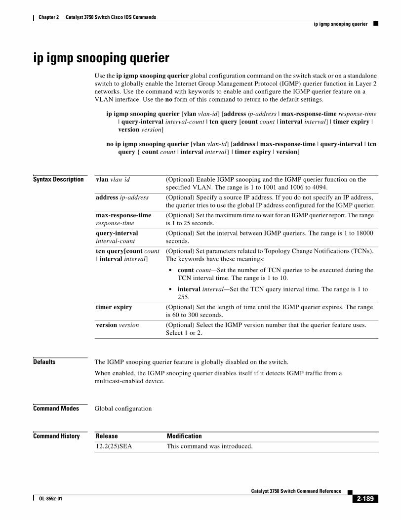
Chapter 2 Catalyst 3750 Switch Cisco IOS Commandsip igmp snooping querier
ip igmp snooping querierUse the ip igmp snooping querier global configuration command on the switch stack or on a standalone switch to globally enable the Internet Group Management Protocol (IGMP) querier function in Layer 2 networks. Use the command with keywords to enable and configure the IGMP querier feature on a VLAN interface. Use the no form of this command to return to the default settings.
ip igmp snooping querier [vlan vlan-id] [address ip-address | max-response-time response-time | query-interval interval-count | tcn query [count count | interval interval] | timer expiry | version version]
no ip igmp snooping querier [vlan vlan-id] [address | max-response-time | query-interval | tcn query { count count | interval interval} | timer expiry | version]
Syntax Description
Defaults The IGMP snooping querier feature is globally disabled on the switch.
When enabled, the IGMP snooping querier disables itself if it detects IGMP traffic from a multicast-enabled device.
Command Modes Global configuration
Command History
vlan vlan-id (Optional) Enable IGMP snooping and the IGMP querier function on the specified VLAN. The range is 1 to 1001 and 1006 to 4094.
address ip-address (Optional) Specify a source IP address. If you do not specify an IP address, the querier tries to use the global IP address configured for the IGMP querier.
max-response-time response-time
(Optional) Set the maximum time to wait for an IGMP querier report. The range is 1 to 25 seconds.
query-interval interval-count
(Optional) Set the interval between IGMP queriers. The range is 1 to 18000 seconds.
tcn query[count count | interval interval]
(Optional) Set parameters related to Topology Change Notifications (TCNs). The keywords have these meanings:
• count count—Set the number of TCN queries to be executed during the TCN interval time. The range is 1 to 10.
• interval interval—Set the TCN query interval time. The range is 1 to 255.
timer expiry (Optional) Set the length of time until the IGMP querier expires. The range is 60 to 300 seconds.
version version (Optional) Select the IGMP version number that the querier feature uses. Select 1 or 2.
Release Modification
12.2(25)SEA This command was introduced.
2-189Catalyst 3750 Switch Command Reference
OL-8552-01
Chapter 2 Catalyst 3750 Switch Cisco IOS Commandsip igmp snooping querier
Usage Guidelines Use this command to enable IGMP snooping to detect the IGMP version and IP address of a device that sends IGMP query messages, which is also called a querier.
By default, the IGMP snooping querier is configured to detect devices that use IGMP Version 2 (IGMPv2) but does not detect clients that are using IGMP Version 1 (IGMPv1). You can manually configure the max-response-time value when devices use IGMPv2. You cannot configure the max-response-time when devices use IGMPv1. (The value cannot be configured and is set to zero).
Non-RFC compliant devices running IGMPv1 might reject IGMP general query messages that have a non-zero value as the max-response-time value. If you want the devices to accept the IGMP general query messages, configure the IGMP snooping querier to run IGMPv1.
VLAN IDs 1002 to 1005 are reserved for Token Ring and FDDI VLANs and cannot be used in IGMP snooping.
Examples This example shows how to globally enable the IGMP snooping querier feature:
Switch(config)# ip igmp snooping querier
This example shows how to set the IGMP snooping querier maximum response time to 25 seconds:
Switch(config)# ip igmp snooping querier max-response-time 25
This example shows how to set the IGMP snooping querier interval time to 60 seconds:
Switch(config)# ip igmp snooping querier query-interval 60
This example shows how to set the IGMP snooping querier TCN query count to 25:
Switch(config)# ip igmp snooping querier tcn count 25
This example shows how to set the IGMP snooping querier timeout to 60 seconds:
Switch(config)# ip igmp snooping querier timeout expiry 60
This example shows how to set the IGMP snooping querier feature to version 2:
Switch(config)# ip igmp snooping querier version 2
You can verify your settings by entering the show ip igmp snooping privileged EXEC command.
Related Commands Command Description
ip igmp snooping report-suppression Enables IGMP report suppression.
show ip igmp snooping Displays the IGMP snooping configuration.
show ip igmp snooping groups Displays IGMP snooping multicast information.
show ip igmp snooping mrouter Displays the IGMP snooping router ports.
2-190Catalyst 3750 Switch Command Reference
OL-8552-01
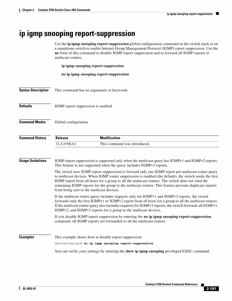
Chapter 2 Catalyst 3750 Switch Cisco IOS Commandsip igmp snooping report-suppression
ip igmp snooping report-suppressionUse the ip igmp snooping report-suppression global configuration command on the switch stack or on a standalone switch to enable Internet Group Management Protocol (IGMP) report suppression. Use the no form of this command to disable IGMP report suppression and to forward all IGMP reports to multicast routers.
ip igmp snooping report-suppression
no ip igmp snooping report-suppression
Syntax Description This command has no arguments or keywords.
Defaults IGMP report suppression is enabled.
Command Modes Global configuration
Command History
Usage Guidelines IGMP report suppression is supported only when the multicast query has IGMPv1 and IGMPv2 reports. This feature is not supported when the query includes IGMPv3 reports.
The switch uses IGMP report suppression to forward only one IGMP report per multicast router query to multicast devices. When IGMP router suppression is enabled (the default), the switch sends the first IGMP report from all hosts for a group to all the multicast routers. The switch does not send the remaining IGMP reports for the group to the multicast routers. This feature prevents duplicate reports from being sent to the multicast devices.
If the multicast router query includes requests only for IGMPv1 and IGMPv2 reports, the switch forwards only the first IGMPv1 or IGMPv2 report from all hosts for a group to all the multicast routers. If the multicast router query also includes requests for IGMPv3 reports, the switch forwards all IGMPv1, IGMPv2, and IGMPv3 reports for a group to the multicast devices.
If you disable IGMP report suppression by entering the no ip igmp snooping report-suppression command, all IGMP reports are forwarded to all the multicast routers.
Examples This example shows how to disable report suppression:
Switch(config)# no ip igmp snooping report-suppression
You can verify your settings by entering the show ip igmp snooping privileged EXEC command.
Release Modification
12.1(19)EA1 This command was introduced.
2-191Catalyst 3750 Switch Command Reference
OL-8552-01
Chapter 2 Catalyst 3750 Switch Cisco IOS Commandsip igmp snooping report-suppression
Related Commands Command Description
ip igmp snooping Enables IGMP snooping on the switch or on a VLAN.
show ip igmp snooping Displays the IGMP snooping configuration of the switch or the VLAN.
2-192Catalyst 3750 Switch Command Reference
OL-8552-01
Chapter 2 Catalyst 3750 Switch Cisco IOS Commandsip igmp snooping tcn
ip igmp snooping tcn Use the ip igmp snooping tcn global configuration command on the switch stack or on a standalone switch to configure the Internet Group Management Protocol (IGMP) Topology Change Notification (TCN) behavior. Use the no form of this command to return to the default settings.
ip igmp snooping tcn {flood query count count | query solicit}
no ip igmp snooping tcn {flood query count | query solicit}
Syntax Description
Defaults The TCN flood query count is 2.
The TCN query solicitation is disabled.
Command Modes Global configuration
Command History
Usage Guidelines Use ip igmp snooping tcn flood query count global configuration command to control the time that multicast traffic is flooded after a TCN event. If you set the TCN flood query count to 1 by using the ip igmp snooping tcn flood query count command, the flooding stops after receiving 1 general query. If you set the count to 7, the flooding of multicast traffic due to the TCN event lasts until 7 general queries are received. Groups are relearned based on the general queries received during the TCN event.
Use the ip igmp snooping tcn query solicit global configuration command to enable the switch to send the global leave message whether or not it is the spanning-tree root. This command also speeds the process of recovering from the flood mode caused during a TCN event.
Examples This example shows how to specify 7 as the number of IGMP general queries for which the multicast traffic is flooded:
Switch(config)# no ip igmp snooping tcn flood query count 7
You can verify your settings by entering the show ip igmp snooping privileged EXEC command.
flood query count count Specify the number of IGMP general queries for which the multicast traffic is flooded. The range is 1 to 10.
query solicit Send an IGMP leave message (global leave) to speed the process of recovering from the flood mode caused during a TCN event.
Release Modification
12.2(25)SEB This command was introduced.
2-193Catalyst 3750 Switch Command Reference
OL-8552-01
Chapter 2 Catalyst 3750 Switch Cisco IOS Commandsip igmp snooping tcn
Related Commands Command Description
ip igmp snooping Enables IGMP snooping on the switch or on a VLAN.
ip igmp snooping tcn flood Specifies flooding on an interface as the IGMP snooping spanning-tree TCN behavior.
show ip igmp snooping Displays the IGMP snooping configuration of the switch or the VLAN.
2-194Catalyst 3750 Switch Command Reference
OL-8552-01
Chapter 2 Catalyst 3750 Switch Cisco IOS Commandsip igmp snooping tcn flood
ip igmp snooping tcn flood Use the ip igmp snooping tcn flood interface configuration command on the switch stack or on a standalone switch to specify multicast flooding as the Internet Group Management Protocol (IGMP) snooping spanning-tree Topology Change Notification (TCN) behavior. Use the no form of this command to disable the multicast flooding.
ip igmp snooping tcn flood
no ip igmp snooping tcn flood
Syntax Description This command has no arguments or keywords.
Defaults Multicast flooding is enabled on an interface during a spanning-tree TCN event.
Command Modes Interface configuration
Command History
Usage Guidelines When the switch receives a TCN, multicast traffic is flooded to all the ports until two general queries are received. If the switch has many ports with attached hosts that are subscribed to different multicast groups, the flooding might exceed the capacity of the link and cause packet loss.
You can change the flooding query count by using the ip igmp snooping tcn flood query count count global configuration command.
Examples This example shows how to disable the multicast flooding on an interface:
Switch(config)# interface gigabitethernet1/0/2Switch(config-if)# no ip igmp snooping tcn flood
You can verify your settings by entering the show ip igmp snooping privileged EXEC command.
Related Commands
Release Modification
12.2(25)SEB This command was introduced.
Command Description
ip igmp snooping Enables IGMP snooping on the switch or on a VLAN.
ip igmp snooping tcn Configures the IGMP TCN behavior on the switch.
show ip igmp snooping Displays the IGMP snooping configuration of the switch or the VLAN.
2-195Catalyst 3750 Switch Command Reference
OL-8552-01
Chapter 2 Catalyst 3750 Switch Cisco IOS Commandsip igmp snooping vlan immediate-leave
ip igmp snooping vlan immediate-leaveUse the ip igmp snooping immediate-leave global configuration command on the switch stack or on a standalone switch to enable Internet Group Management Protocol (IGMP) snooping immediate-leave processing on a per-VLAN basis. Use the no form of this command to return to the default setting.
ip igmp snooping vlan vlan-id immediate-leave
no ip igmp snooping vlan vlan-id immediate-leave
Syntax Description
Defaults IGMP immediate-leave processing is disabled.
Command Modes Global configuration
Command History
Usage Guidelines VLAN IDs 1002 to 1005 are reserved for Token Ring and FDDI VLANs and cannot be used in IGMP snooping.
You should configure the Immediate- Leave feature only when there is a maximum of one receiver on every port in the VLAN. The configuration is saved in NVRAM.
The Immediate-Leave feature is supported only with IGMP Version 2 hosts.
Examples This example shows how to enable IGMP immediate-leave processing on VLAN 1:
Switch(config)# ip igmp snooping vlan 1 immediate-leave
You can verify your settings by entering the show ip igmp snooping privileged EXEC command.
Related Commands
vlan-id Enable IGMP snooping and the Immediate-Leave feature on the specified VLAN. The range is 1 to 1001 and 1006 to 4094.
Release Modification
12.1(11)AX This command was introduced.
Command Description
ip igmp snooping report-suppression Enables IGMP report suppression.
show ip igmp snooping Displays the snooping configuration.
show ip igmp snooping groups Displays IGMP snooping multicast information.
show ip igmp snooping mrouter Displays the IGMP snooping router ports.
show ip igmp snooping querier Displays the configuration and operation information for the IGMP querier configured on a switch.
2-196Catalyst 3750 Switch Command Reference
OL-8552-01
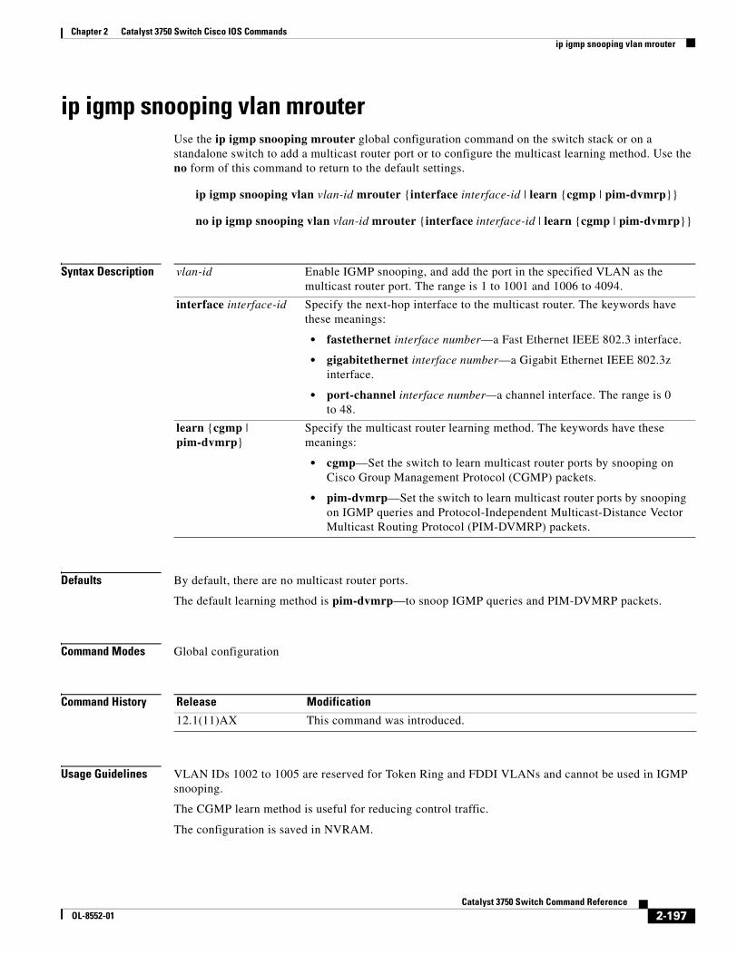
Chapter 2 Catalyst 3750 Switch Cisco IOS Commandsip igmp snooping vlan mrouter
ip igmp snooping vlan mrouterUse the ip igmp snooping mrouter global configuration command on the switch stack or on a standalone switch to add a multicast router port or to configure the multicast learning method. Use the no form of this command to return to the default settings.
ip igmp snooping vlan vlan-id mrouter {interface interface-id | learn {cgmp | pim-dvmrp}}
no ip igmp snooping vlan vlan-id mrouter {interface interface-id | learn {cgmp | pim-dvmrp}}
Syntax Description
Defaults By default, there are no multicast router ports.
The default learning method is pim-dvmrp—to snoop IGMP queries and PIM-DVMRP packets.
Command Modes Global configuration
Command History
Usage Guidelines VLAN IDs 1002 to 1005 are reserved for Token Ring and FDDI VLANs and cannot be used in IGMP snooping.
The CGMP learn method is useful for reducing control traffic.
The configuration is saved in NVRAM.
vlan-id Enable IGMP snooping, and add the port in the specified VLAN as the multicast router port. The range is 1 to 1001 and 1006 to 4094.
interface interface-id Specify the next-hop interface to the multicast router. The keywords have these meanings:
• fastethernet interface number—a Fast Ethernet IEEE 802.3 interface.
• gigabitethernet interface number—a Gigabit Ethernet IEEE 802.3z interface.
• port-channel interface number—a channel interface. The range is 0 to 48.
learn {cgmp | pim-dvmrp}
Specify the multicast router learning method. The keywords have these meanings:
• cgmp—Set the switch to learn multicast router ports by snooping on Cisco Group Management Protocol (CGMP) packets.
• pim-dvmrp—Set the switch to learn multicast router ports by snooping on IGMP queries and Protocol-Independent Multicast-Distance Vector Multicast Routing Protocol (PIM-DVMRP) packets.
Release Modification
12.1(11)AX This command was introduced.
2-197Catalyst 3750 Switch Command Reference
OL-8552-01
Chapter 2 Catalyst 3750 Switch Cisco IOS Commandsip igmp snooping vlan mrouter
Examples This example shows how to configure a port as a multicast router port:
Switch(config)# ip igmp snooping vlan 1 mrouter interface gigabitethernet1/0/2
This example shows how to specify the multicast router learning method as CGMP:
Switch(config)# ip igmp snooping vlan 1 mrouter learn cgmp
You can verify your settings by entering the show ip igmp snooping privileged EXEC command.
Related Commands Command Description
ip igmp snooping report-suppression Enables IGMP report suppression.
show ip igmp snooping Displays the snooping configuration.
show ip igmp snooping groups Displays IGMP snooping multicast information.
show ip igmp snooping mrouter Displays the IGMP snooping router ports.
show ip igmp snooping querier Displays the configuration and operation information for the IGMP querier configured on a switch.
2-198Catalyst 3750 Switch Command Reference
OL-8552-01
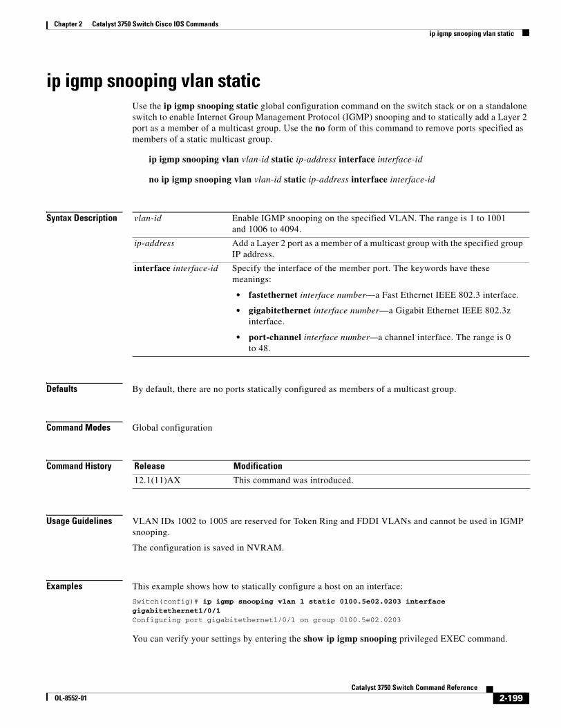
Chapter 2 Catalyst 3750 Switch Cisco IOS Commandsip igmp snooping vlan static
ip igmp snooping vlan staticUse the ip igmp snooping static global configuration command on the switch stack or on a standalone switch to enable Internet Group Management Protocol (IGMP) snooping and to statically add a Layer 2 port as a member of a multicast group. Use the no form of this command to remove ports specified as members of a static multicast group.
ip igmp snooping vlan vlan-id static ip-address interface interface-id
no ip igmp snooping vlan vlan-id static ip-address interface interface-id
Syntax Description
Defaults By default, there are no ports statically configured as members of a multicast group.
Command Modes Global configuration
Command History
Usage Guidelines VLAN IDs 1002 to 1005 are reserved for Token Ring and FDDI VLANs and cannot be used in IGMP snooping.
The configuration is saved in NVRAM.
Examples This example shows how to statically configure a host on an interface:
Switch(config)# ip igmp snooping vlan 1 static 0100.5e02.0203 interface gigabitethernet1/0/1Configuring port gigabitethernet1/0/1 on group 0100.5e02.0203
You can verify your settings by entering the show ip igmp snooping privileged EXEC command.
vlan-id Enable IGMP snooping on the specified VLAN. The range is 1 to 1001 and 1006 to 4094.
ip-address Add a Layer 2 port as a member of a multicast group with the specified group IP address.
interface interface-id Specify the interface of the member port. The keywords have these meanings:
• fastethernet interface number—a Fast Ethernet IEEE 802.3 interface.
• gigabitethernet interface number—a Gigabit Ethernet IEEE 802.3z interface.
• port-channel interface number—a channel interface. The range is 0 to 48.
Release Modification
12.1(11)AX This command was introduced.
2-199Catalyst 3750 Switch Command Reference
OL-8552-01
Chapter 2 Catalyst 3750 Switch Cisco IOS Commandsip igmp snooping vlan static
Related Commands Command Description
ip igmp snooping report-suppression Enables IGMP report suppression.
show ip igmp snooping Displays the snooping configuration.
show ip igmp snooping groups Displays IGMP snooping multicast information.
show ip igmp snooping mrouter Displays the IGMP snooping router ports.
show ip igmp snooping querier Displays the configuration and operation information for the IGMP querier configured on a switch.
2-200Catalyst 3750 Switch Command Reference
OL-8552-01
Chapter 2 Catalyst 3750 Switch Cisco IOS Commandsip snap forwarding
ip snap forwardingUse the ip snap forwarding global configuration command on the switch stack or on a standalone switch to enable forwarding of IP Version 4 (IPv4) and IP Version 6 (IPv6) frames with Subnetwork Access Protocol (SNAP) encapsulation. Use no form of this command to disable forwarding of these frames.
ip snap forwarding
no ip snap forwarding
Syntax Description This command has no arguments or keywords.
Defaults The switch does not forward IPv4 and IPv6 frames with SNAP encapsulation.
Command Modes Global configuration
Command History
Usage Guidelines Use the ip snap forwarding global configuration command to enable forwarding of IPv4 and IPv6 frames with SNAP encapsulation.
If a switch that is joining the stack does not support forwarding of IPv4 and IPv6 frames with SNAP encapsulation, all the switches in the stack do not forward the IPv4 and IPv6 frames, and this forwarding feature is disabled.
Examples This example shows how to enable forwarding of IPv4 and IPv6 frames with SNAP encapsulation:
Switch(config)# ip snap forwarding
You can verify your settings by entering the show running-config privileged EXEC command.
Related Commands
Release Modification
12.2(25)SEC This command was introduced.
Command Description
show running-config Displays the running configuration on the switch. For syntax information, select Cisco IOS Configuration Fundamentals Command Reference, Release 12.2 > File Management Commands > Configuration File Management Commands.
2-201Catalyst 3750 Switch Command Reference
OL-8552-01
Chapter 2 Catalyst 3750 Switch Cisco IOS Commandsip source binding
ip source bindingUse the ip source binding global configuration command on the switch stack or on a standalone switch to configure static IP source bindings on the switch. Use the no form of this command to delete static bindings.
ip source binding mac-address vlan vlan-id ip-address interface interface-id
no source binding mac-address vlan vlan-id ip-address interface interface-id
This command is available only if your switch is running the IP services image, formerly known as the enhanced multilayer image (EMI).
Syntax Description
Defaults No IP source bindings are configured.
Command Modes Global configuration
Command History
Usage Guidelines A static IP source binding entry has an IP address, its associated MAC address, and its associated VLAN number. The entry is based on the MAC address and the VLAN number. If you modify an entry by changing only the IP address, the switch updates the entry instead creating a new one.
Examples This example shows how to add a static IP source binding:
Switch(config)# ip source binding 0001.1234.1234 vlan 1 172.20.50.5 interface gigabitethernet1/0/1
This example shows how to add a static binding and then modify the IP address for it:
Switch(config)# ip source binding 0001.1357.0007 vlan 1 172.20.50.25 interface gigabitethernet1/0/1 Switch(config)# ip source binding 0001.1357.0007 vlan 1 172.20.50.30 interface gigabitethernet1/0/1
You can verify your settings by entering the show ip source binding privileged EXEC command.
mac-address Specify a MAC address.
vlan vlan-id Specify a VLAN number. The range is from 1 to 4094.
ip-address Specify an IP address.
interface interface-id Specify an interface on which to add or delete an IP source binding.
Release Modification
12.2(20)SE This command was introduced.
2-202Catalyst 3750 Switch Command Reference
OL-8552-01

Chapter 2 Catalyst 3750 Switch Cisco IOS Commandsip source binding
Related Commands Command Description
ip verify source Enables IP source guard on an interface.
show ip source binding Displays the IP source bindings on the switch.
show ip verify source Displays the IP source guard configuration on the switch or on a specific interface.
2-203Catalyst 3750 Switch Command Reference
OL-8552-01
Chapter 2 Catalyst 3750 Switch Cisco IOS Commandsip ssh
ip sshUse the ip ssh global configuration command on the switch stack or on a standalone switch to configure the switch to run Secure Shell (SSH) Version 1 or SSH Version 2. This command is available only when your switch is running the cryptographic (encrypted) software image. Use the no form of this command to return to the default setting.
ip ssh version [1 | 2]
no ip ssh version [1 | 2]
Syntax Description
Defaults The default version is the latest SSH version supported by the SSH client.
Command Modes Global configuration
Command History
Usage Guidelines If you do not enter this command or if you do not specify a keyword, the SSH server selects the latest SSH version supported by the SSH client. For example, if the SSH client supports SSHv1 and SSHv2, the SSH server selects SSHv2.
The switch supports an SSHv1 or an SSHv2 server. It also supports an SSHv1 client. For more information about the SSH server and the SSH client, see the software configuration guide for this release.
A Rivest, Shamir, and Adelman (RSA) key pair generated by an SSHv1 server can be used by an SSHv2 server and the reverse.
Examples This example shows how to configure the switch to run SSH Version 2:
Switch(config)# ip ssh version 2
You can verify your settings by entering the show ip ssh or show ssh privileged EXEC command.
1 (Optional) Configure the switch to run SSH Version 1 (SSHv1).
2 (Optional) Configure the switch to run SSH Version 2 (SSHv1).
Release Modification
12.1(19)EA1 This command was introduced.
2-204Catalyst 3750 Switch Command Reference
OL-8552-01
Chapter 2 Catalyst 3750 Switch Cisco IOS Commandsip ssh
Related Commands Command Description
show ip ssh Displays if the SSH server is enabled and displays the version and configuration information for the SSH server. For syntax information, select Cisco IOS Release 12.2 Configuration Guides and Command References > Cisco IOS Security Command Reference, Release 12.2 > Other Security Features > Secure Shell Commands.
show ssh Displays the status of the SSH server. For syntax information, select Cisco IOS Release 12.2 Configuration Guides and Command References > Cisco IOS Security Command Reference, Release 12.2 > Other Security Features > Secure Shell Commands.
2-205Catalyst 3750 Switch Command Reference
OL-8552-01
Chapter 2 Catalyst 3750 Switch Cisco IOS Commandsip verify source
ip verify sourceUse the ip verify source interface configuration command on the switch stack or on a standalone switch to enable IP source guard on an interface. Use the no form of this command to disable IP source guard.
ip verify source [port-security]
no ip verify source
Syntax Description
Defaults IP source guard is disabled.
Command Modes Interface configuration
Command History
Usage Guidelines To enable IP source guard with source IP address filtering, use the ip verify source interface configuration command.
To enable IP source guard with source IP and MAC address filtering, use the ip verify source port-security interface configuration command.
To enable IP source guard with source IP and MAC address filtering, you must enable port security on the interface.
Examples This example shows how to enable IP source guard with source IP address filtering:
Switch(config-if)# ip verify source
This example shows how to enable IP source guard with source IP and MAC address filtering:
Switch(config-if)# ip verify source port-security
You can verify your settings by entering the show ip source binding privileged EXEC command.
Related Commands
port-security (Optional) Enable IP source guard with IP and MAC address filtering.
If you do not enter the port-security keyword, IP source guard with IP address filtering is enabled.
Release Modification
12.2(20)SE This command was introduced.
Command Description
ip source binding Configures static bindings on the switch.
show ip verify source Displays the IP source guard configuration on the switch or on a specific interface.
2-206Catalyst 3750 Switch Command Reference
OL-8552-01
Chapter 2 Catalyst 3750 Switch Cisco IOS Commandsipv6 access-list
ipv6 access-list Use the ipv6 access-list global configuration command on the switch stack or on a standalone switch to define an IPv6 access list and to place the switch in IPv6 access list configuration mode. To remove the access list, use the no form of this command.
ipv6 access-list access-list-name
no ipv6 access-list access-list-name
Note This command is available only if the switch stack is running the advanced IP services image and you have configured a dual IPv4 and IPv6 Switch Database Management (SDM) template on the switch.
Syntax Description
Defaults No IPv6 access list is defined.
Command Modes Global configuration
Command History
Usage Guidelines To configure the dual IPv4 and IPv6 template, enter the sdm prefer dual-ipv4-and-ipv6 {default | vlan) global configuration command and reload the switch.
The ipv6 access-list command is similar to the ip access-list command, except that it is IPv6-specific.
Note IPv6 ACLs are defined by a unique name (IPv6 does not support numbered ACLs). An IPv4 ACL and an IPv6 ACL cannot share the same name.
See the ipv6 access-list and permit (IPv6 access-list configuration) commands for more information on filtering IPv6 traffic based on IPv6 option headers and optional, upper-layer protocol-type information. See the “Examples” section for an example of a translated IPv6 ACL configuration.
Note Every IPv6 ACL has implicit permit icmp any any nd-na, permit icmp any any nd-ns, and deny ipv6 any any statements as its last match conditions. The two permit conditions allow ICMPv6 neighbor discovery. To disallow ICMPv6 neighbor discovery and to deny icmp any any nd-na or icmp any any nd-ns, there must be an explicit deny entry in the ACL. For the implicit deny ipv6 any any statement to take effect, an IPv6 ACL must contain at least one entry.
The IPv6 neighbor discovery process makes use of the IPv6 network layer service; therefore, by default,
access-list-name Name of the IPv6 access list. Names cannot contain a space or quotation mark or begin with a numeric.
Release Modification
12.2(25)SED This command was introduced.
2-207Catalyst 3750 Switch Command Reference
OL-8552-01
Chapter 2 Catalyst 3750 Switch Cisco IOS Commandsipv6 access-list
IPv6 ACLs implicitly allow IPv6 neighbor discovery packets to be sent and received on an interface. In IPv4, the Address Resolution Protocol (ARP), which is equivalent to the IPv6 neighbor discovery process, uses a separate data-link layer protocol; therefore, by default, IPv4 ACLs implicitly allow ARP packets to be sent and received on an interface.
Use the ipv6 traffic-filter interface configuration command with the access-list-name argument to apply an IPv6 ACL to an IPv6 interface. You can apply inbound and outbound IPv6 ACLs to Layer 3 physical interfaces or switch virtual interfaces for routed ACLs, but only inbound IPv6 ACLs to Layer 2 interfaces for port ACLs.
Note An IPv6 ACL applied to an interface with the ipv6 traffic-filter command filters traffic that is forwarded by the switch and does not filter traffic generated by the switch.
Examples This example puts the switch in IPv6 access list configuration mode and configures the IPv6 ACL named list2 and applies the ACL to outbound traffic on an interface. The first ACL entry prevents all packets from the network FE80:0:0:2::/64 (packets that have the link-local prefix FE80:0:0:2 as the first 64 bits of their source IPv6 address) from leaving the interface. The second entry in the ACL permits all other traffic to leave the interface. The second entry is necessary because an implicit deny-all condition is at the end of each IPv6 ACL.
Switch(config)# ipv6 access-list list2Switch(config-ipv6-acl)# deny FE80:0:0:2::/64 anySwitch(config-ipv6-acl)# permit any anySwitch(config-ipv6-acl)# exitSwitch(config)# interface gigabitethernet1/0/3Switch(config-if)# no switchportSwitch(config-if)# ipv6 address 2001::/64 eui-64Switch(config-if)# ipv6 traffic-filter list2 out
Note IPv6 ACLs that rely on the implicit deny condition or specify a deny any any statement to filter traffic should contain permit statements for link-local addresses to avoid the filtering of protocol packets. Additionally IPv6 ACLs that use deny statements to filter traffic should also use a permit any any statement as the last statement in the list.
Related Commands Command Description
deny (IPv6 access-list configuration)
Sets deny conditions for an IPv6 access list.
ipv6 traffic-filter Filters incoming or outgoing IPv6 traffic on an interface.
permit (IPv6 access-list configuration)
Sets permit conditions for an IPv6 access list.
show ipv6 access-list Displays the contents of all current IPv6 access lists.
2-208Catalyst 3750 Switch Command Reference
OL-8552-01
Chapter 2 Catalyst 3750 Switch Cisco IOS Commandsipv6 mld snooping
ipv6 mld snoopingUse the ipv6 mld snooping global configuration command on the switch stack or on a standalone switch without keywords to enable IP version 6 (IPv6) Multicast Listener Discovery (MLD) snooping globally or on the specified VLAN. Use the no form of this command to disable MLD snooping on the switch or switch stack or the VLAN.
ipv6 mld snooping [vlan vlan-id]
no ipv6 mld snooping [vlan vlan-id]
Note This command is available only if the switch stack is running the advanced IP services image and you have configured a dual IPv4 and IPv6 Switch Database Management (SDM) template on the switch.
Syntax Description
Defaults MLD snooping is globally disabled on the switch.
MLD snooping is enabled on all VLANs. However, MLD snooping must be globally enabled before VLAN snooping will take place.
Command Modes Global configuration
Command History
Usage Guidelines To configure the dual IPv4 and IPv6 template, enter the sdm prefer dual-ipv4-and-ipv6 {default | vlan) global configuration command and reload the switch.
When MLD snooping is globally disabled, it is disabled on all the existing VLAN interfaces. When you globally enable MLD snooping, it is enabled on all VLAN interfaces that are in the default state (enabled). VLAN configuration will override global configuration on interfaces on which MLD snooping has been disabled.
If MLD snooping is globally disabled, you cannot enable it on a VLAN. If MLD snooping is globally enabled, you can disable it on individual VLANs.
When the IPv6 multicast router is a Catalyst 6500 switch and you are using extended VLANs (in the range 1006 to 4094), IPv6 MLD snooping must be enabled on the extended VLAN on the Catalyst 6500 switch in order for the Catalyst 3750 or Catalyst 3560 switch to receive queries on the VLAN. For normal-range VLANs (1 to 1005), it is not necessary to enable IPv6 MLD snooping on the VLAN on the Catalyst 6500 switch.
VLAN numbers 1002 through 1005 are reserved for Token Ring and FDDI VLANs and cannot be used in MLD snooping.
vlan vlan-id (Optional) Enable or disable IPv6 MLD snooping on the specified VLAN. The VLAN ID range is 1 to 1001 and 1006 to 4094.
Release Modification
12.2(25)SED This command was introduced.
2-209Catalyst 3750 Switch Command Reference
OL-8552-01
Chapter 2 Catalyst 3750 Switch Cisco IOS Commandsipv6 mld snooping
Examples This example shows how to globally enable MLD snooping:
Switch(config)# ipv6 mld snooping
This example shows how to disable MLD snooping on a VLAN:
Switch(config)# no ipv6 mld snooping vlan 11
You can verify your settings by entering the show ipv6 mld snooping user EXEC command.
Related Commands Command Description
sdm prefer Configures an SDM template to optimize system resources based on how the switch is being used.
show ipv6 mld snooping Displays MLD snooping configuration.
2-210Catalyst 3750 Switch Command Reference
OL-8552-01
Chapter 2 Catalyst 3750 Switch Cisco IOS Commandsipv6 mld snooping last-listener-query-count
ipv6 mld snooping last-listener-query-countUse the ipv6 mld snooping last-listener-query-count global configuration command on the switch stack or on a standalone switch to configure IP version 6 (IPv6) Multicast Listener Discovery Mulitcast Address Specific Queries (MASQs) or that will be sent before aging out a client. Use the no form of this command to reset the query count to the default settings.
ipv6 mld snooping [vlan vlan-id] last-listener-query-count integer_value
no ipv6 mld snooping [vlan vlan-id] last-listener-query-count
Note This command is available only if the switch stack is running the advanced IP services image and you have configured a dual IPv4 and IPv6 Switch Database Management (SDM) template on the switch.
Syntax Description
Command Default The default global count is 2.
The default VLAN count is 0 (the global count is used).
Command Modes Global configuration
Command History
Usage Guidelines To configure the dual IPv4 and IPv6 template, enter the sdm prefer dual-ipv4-and-ipv6 {default | vlan) global configuration command and reload the switch.
In MLD snooping, the IPv6 multicast router periodically sends out queries to hosts belonging to the multicast group. If a host wants to leave a multicast group, it can silently leave or it can respond to the query with a Multicast Listener Done message (equivalent to an IGMP Leave message). When Immediate Leave is not configured (which it should not be if multiple clients for a group exist on the same port), the configured last-listener query count determines the number of MASQs that are sent before an MLD client is aged out.
When the last-listener query count is set for a VLAN, this count overrides the value configured globally.When the VLAN count is not configured (set to the default of 0), the global count is used.
VLAN numbers 1002 through 1005 are reserved for Token Ring and FDDI VLANs and cannot be used in MLD snooping.
vlan vlan-id (Optional) Configure last-listener query count on the specified VLAN. The VLAN ID range is 1 to 1001 and 1006 to 4094.
integer_value The range is 1 to 7.
Release Modification
12.2(25)SED This command was introduced.
2-211Catalyst 3750 Switch Command Reference
OL-8552-01
Chapter 2 Catalyst 3750 Switch Cisco IOS Commandsipv6 mld snooping last-listener-query-count
Examples This example shows how to globally set the last-listener query count:
Switch(config)# ipv6 mld snooping last-listener-query-count 1
This example shows how to set the last-listener query count for VLAN 10:
Switch(config)# ipv6 mld snooping vlan 10 last-listener-query-count 3
You can verify your settings by entering the show ipv6 mld snooping [vlan vlan-id] user EXEC command.
Related Commands Command Description
ipv6 mld snooping last-listener-query-interval Sets IPv6 MLD snooping last-listener query interval.
sdm prefer Configures an SDM template to optimize system resources based on how the switch is being used.
show ipv6 mld snooping querier Displays MLD snooping configuration.
2-212Catalyst 3750 Switch Command Reference
OL-8552-01
Chapter 2 Catalyst 3750 Switch Cisco IOS Commandsipv6 mld snooping last-listener-query-interval
ipv6 mld snooping last-listener-query-intervalUse the ipv6 mld snooping last-listener-query-interval global configuration command on the switch stack or on a standalone switch to configure IP version 6 (IPv6) Multicast Listener Discovery (MLD) snooping last-listener query interval on the switch or on a VLAN. This time interval is the maximum time that a multicast router waits after issuing a Mulitcast Address Specific Query (MASQ) before deleting a port from the multicast group. Use the no form of this command to reset the query time to the default settings.
ipv6 mld snooping [vlan vlan-id] last-listener-query-interval integer_value
no ipv6 mld snooping [vlan vlan-id] last-listener-query-interval
Note This command is available only if the switch stack is running the advanced IP services image and you have configured a dual IPv4 and IPv6 Switch Database Management (SDM) template on the switch.
Syntax Description
Command Default The default global query interval (maximum response time) is 1000 (1 second).
The default VLAN query interval (maximum response time) is 0 (the global count is used).
Command Modes Global configuration
Command History
Usage Guidelines To configure the dual IPv4 and IPv6 template, enter the sdm prefer dual-ipv4-and-ipv6 {default | vlan) global configuration command and reload the switch.
In MLD snooping, when the IPv6 multicast router receives an MLD leave message, it sends out queries to hosts belonging to the multicast group. If there are no responses from a port to a MASQ for a length of time, the router deletes the port from the membership database of the multicast address. The last listener query interval is the maximum time that the router waits before deleting a nonresponsive port from the multicast group.
When a VLAN query interval is set, this overrides the global query interval. When the VLAN interval is set at 0, the global value is used.
VLAN numbers 1002 through 1005 are reserved for Token Ring and FDDI VLANs and cannot be used in MLD snooping.
vlan vlan-id (Optional) Configure last-listener query interval on the specified VLAN. The VLAN ID range is 1 to 1001 and 1006 to 4094.
integer_value Set the time period (in thousands of a second) that a multicast router to wait after issuing a MASQ before deleting a port from the multicast group. The range is 100 to 32,768. The default is 1000 (1 second),
Release Modification
12.2(25)SED This command was introduced.
2-213Catalyst 3750 Switch Command Reference
OL-8552-01
Chapter 2 Catalyst 3750 Switch Cisco IOS Commandsipv6 mld snooping last-listener-query-interval
Examples This example shows how to globally set the last-listener query interval to 2 seconds:
Switch(config)# ipv6 mld snooping last-listener-query-interval 2000
This example shows how to set the last-listener query interval for VLAN 1 to 5.5 seconds:
Switch(config)# ipv6 mld snooping vlan 1 last-listener-query-interval 5500
You can verify your settings by entering the show ipv6 MLD snooping [vlan vlan-id] user EXEC command.
Related Commands Command Description
ipv6 mld snooping last-listener-query-count Sets IPv6 MLD snooping last-listener query count.
sdm prefer Configures an SDM template to optimize system resources based on how the switch is being used.
show ipv6 mld snooping querier Sets IPv6 MLD snooping last-listener query interval.
2-214Catalyst 3750 Switch Command Reference
OL-8552-01
Chapter 2 Catalyst 3750 Switch Cisco IOS Commandsipv6 mld snooping listener-message-suppression
ipv6 mld snooping listener-message-suppressionUse the ipv6 mld snooping listener-message-suppression global configuration command on the switch stack or on a standalone switch to enable IP version 6 (IPv6) Multicast Listener Discovery (MLD) snooping listener message suppression. Use the no form of this command to disable MLD snooping listener message suppression.
ipv6 mld snooping listener-message-suppression
no ipv6 mld snooping listener-message-suppression
Note This command is available only if the switch stack is running the advanced IP services image and you have configured a dual IPv4 and IPv6 Switch Database Management (SDM) template on the switch.
Command Default The default is for MLD snooping listener message suppression to be disabled.
Command Modes Global configuration
Command History
Usage Guidelines To configure the dual IPv4 and IPv6 template, enter the sdm prefer dual-ipv4-and-ipv6 {default | vlan) global configuration command and reload the switch.
MLD snooping listener message suppression is equivalent to IGMP snooping report suppression. When enabled, received MLDv1 reports to a group are forwarded to IPv6 multicast routers only once in every report-forward time. This prevents the forwarding of duplicate reports.
Examples This example shows how to enable MLD snooping listener-message-suppression:
Switch(config)# ipv6 mld snooping listener-message-suppression
This example shows how to disable MLD snooping listener-message-suppression:
Switch(config)# no ipv6 mld snooping listener-message-suppression
You can verify your settings by entering the show ipv6 mld snooping [vlan vlan-id] user EXEC command.
Release Modification
12.2(25)SED This command was introduced.
2-215Catalyst 3750 Switch Command Reference
OL-8552-01
Chapter 2 Catalyst 3750 Switch Cisco IOS Commandsipv6 mld snooping listener-message-suppression
Related Commands Command Description
ipv6 mld snooping Enables IPv6 MLD snooping.
sdm prefer Configures an SDM template to optimize system resources based on how the switch is being used.
show ipv6 mld snooping Displays MLD snooping configuration.
2-216Catalyst 3750 Switch Command Reference
OL-8552-01
Chapter 2 Catalyst 3750 Switch Cisco IOS Commandsipv6 mld snooping robustness-variable
ipv6 mld snooping robustness-variableUse the ipv6 mld snooping robustness-variable global configuration command on the switch stack or on a standalone switch to configure the number of IP version 6 (IPv6) Multicast Listener Discovery (MLD) queries that the switch sends before deleting a listener that does not respond, or enter a VLAN ID to configure on a per-VLAN basis. Use the no form of this command to reset the variable to the default settings.
ipv6 mld snooping [vlan vlan-id] robustness-variable integer_value
no ipv6 mld snooping [vlan vlan-id] robustness-variable
Note This command is available only if the switch stack is running the advanced IP services image and you have configured a dual IPv4 and IPv6 Switch Database Management (SDM) template on the switch.
Syntax Description
Command Default The default global robustness variable (number of queries before deleting a listener) is 2.
The default VLAN robustness variable (number of queries before aging out a multicast address) is 0, which means that the system uses the global robustness variable for aging out the listener.
Command Modes Global configuration
Command History
Usage Guidelines To configure the dual IPv4 and IPv6 template, enter the sdm prefer dual-ipv4-and-ipv6 {default | vlan) global configuration command and reload the switch.
Robustness is measured in terms of the number of MLDv1 queries sent with no response before a port is removed from a multicast group. A port is deleted when there are no MLDv1 reports received for the configured number of MLDv1 queries. The global value determines the number of queries that the switch waits before deleting a listener that does not respond and applies to all VLANs that do not have a VLAN value set.
The robustness value configured for a VLAN overrides the global value. If the VLAN robustness value is 0 (the default), the global value is used.
VLAN numbers 1002 through 1005 are reserved for Token Ring and FDDI VLANs and cannot be used in MLD snooping.
vlan vlan-id (Optional) Configure the robustness variable on the specified VLAN. The VLAN ID range is 1 to 1001 and 1006 to 4094.
integer_value The range is 1 to 3.
Release Modification
12.2(25)SED This command was introduced.
2-217Catalyst 3750 Switch Command Reference
OL-8552-01
Chapter 2 Catalyst 3750 Switch Cisco IOS Commandsipv6 mld snooping robustness-variable
Examples This example shows how to configure the global robustness variable so that the switch sends out three queries before it deletes a listener port that does not respond:
Switch(config)# ipv6 mld snooping robustness-variable 3
This example shows how to configure the robustness variable for VLAN 1. This value overrides the global configuration for the VLAN:
Switch(config)# ipv6 mld snooping vlan 1 robustness-variable 1
You can verify your settings by entering the show ipv6 MLD snooping [vlan vlan-id] user EXEC command.
Related Commands Command Description
ipv6 mld snooping last-listener-query-count Sets IPv6 MLD snooping last-listener query count.
sdm prefer Configures an SDM template to optimize system resources based on how the switch is being used.
show ipv6 mld snooping Displays MLD snooping configuration.
2-218Catalyst 3750 Switch Command Reference
OL-8552-01
Chapter 2 Catalyst 3750 Switch Cisco IOS Commandsipv6 mld snooping tcn
ipv6 mld snooping tcnUse the ipv6 mld snooping tcn global configuration commands on the switch stack or on a standalone switch to configure IP version 6 (IPv6) Multicast Listener Discovery (MLD) Topology Change Notifications (TCNs). Use the no form of the commands to reset the default settings.
ipv6 mld snooping tcn {flood query count integer_value | query solicit}
no ipv6 mld snooping tcn {flood query count integer_value | query solicit}
Note This command is available only if the switch stack is running the advanced IP services image and you have configured a dual IPv4 and IPv6 Switch Database Management (SDM) template on the switch.
Syntax Description
Command Default TCN query soliciting is disabled.
When enabled, the default flood query count is 2.
Command Modes Global configuration
Command History
Usage Guidelines To configure the dual IPv4 and IPv6 template, enter the sdm prefer dual-ipv4-and-ipv6 {default | vlan) global configuration command and reload the switch.
Examples This example shows how to enable TCN query soliciting:
Switch(config)# ipv6 mld snooping tcn query solicit.
This example shows how to set the flood query count to 5:
Switch(config)# ipv6 mld snooping tcn flood query count 5.
You can verify your settings by entering the show ipv6 MLD snooping [vlan vlan-id] user EXEC command.
flood query count integer_value
Set the flood query count, which is the number of queries that are sent before forwarding multicast data to only those ports requesting to receive it. The range is 1 to 10.
query solicit Enable soliciting of TCN queries.
Release Modification
12.2(25)SED This command was introduced.
2-219Catalyst 3750 Switch Command Reference
OL-8552-01
Chapter 2 Catalyst 3750 Switch Cisco IOS Commandsipv6 mld snooping tcn
Related Commands Command Description
sdm prefer Configures an SDM template to optimize system resources based on how the switch is being used.
show ipv6 mld snooping Displays MLD snooping configuration.
2-220Catalyst 3750 Switch Command Reference
OL-8552-01

Chapter 2 Catalyst 3750 Switch Cisco IOS Commandsipv6 mld snooping vlan
ipv6 mld snooping vlanUse the ipv6 mld snooping vlan global configuration command on the switch stack or on a standalone switch to configure IP version 6 (IPv6) Multicast Listener Discovery (MLD) snooping parameters on the VLAN interface. Use the no form of this command to reset the parameters to the default settings.
ipv6 mld snooping vlan vlan-id [immediate-leave | mrouter interface interface-id | static ipv6-multicast-address interface interface-id]
no ipv6 mld snooping vlan vlan-id [immediate-leave | mrouter interface interface-id | static ip-address interface interface-id]
Note This command is available only if the switch stack is running the advanced IP services image and you have configured a dual IPv4 and IPv6 Switch Database Management (SDM) template on the switch.
Syntax Description
Command Default MLD snooping Immediate-Leave processing is disabled.
By default, there are no static IPv6 multicast groups.
By default, there are no multicast router ports.
Command Modes Global configuration
Command History
Usage Guidelines To configure the dual IPv4 and IPv6 template, enter the sdm prefer dual-ipv4-and-ipv6 {default | vlan) global configuration command and reload the switch.
You should only configure the Immediate-Leave feature when there is only one receiver on every port in the VLAN. The configuration is saved in NVRAM.
The static keyword is used for configuring the MLD member ports statically.
vlan vlan-id Specify a VLAN number. The range is 1 to 1001 and 1006 to 4094.
immediate-leave (Optional) Enable MLD Immediate-Leave processing on a VLAN interface. Use the no form of the command to disable the Immediate Leave feature on the interface.
mrouter interface (Optional) Configure a multicast router port. The no form of the command removes the configuration.
static ipv6-multicast-address (Optional) Configure a multicast group with the specified IPv6 multicast address.
interface interface-id Add a Layer 2 port to the group. The mrouter or static interface can be a physical port or a port-channel interface in the range of 1 to 48.
Release Modification
12.2(25)SED This command was introduced.
2-221Catalyst 3750 Switch Command Reference
OL-8552-01
Chapter 2 Catalyst 3750 Switch Cisco IOS Commandsipv6 mld snooping vlan
The configuration and the static ports and groups are saved in NVRAM.
When the IPv6 multicast router is a Catalyst 6500 switch and you are using extended VLANs (in the range 1006 to 4094), IPv6 MLD snooping must be enabled on the extended VLAN on the Catalyst 6500 switch in order for the Catalyst 3750 or Catalyst 3560 switch to receive queries on the VLAN. For normal-range VLANs (1 to 1005), it is not necessary to enable IPv6 MLD snooping on the VLAN on the Catalyst 6500 switch.
VLAN numbers 1002 through 1005 are reserved for Token Ring and FDDI VLANs and cannot be used in MLD snooping.
Examples This example shows how to enable MLD Immediate-Leave processing on VLAN 1:
Switch(config)# ipv6 mld snooping vlan 1 immediate-leave
This example shows how to disable MLD Immediate-Leave processing on VLAN 1:
Switch(config)# no ipv6 mld snooping vlan 1 immediate-leave
This example shows how to configure a port as a multicast router port:
Switch(config)# ipv6 mld snooping vlan 1 mrouter interface gigabitethernet1/0/2
This example shows how to configure a static multicast group:
Switch(config)# ipv6 mld snooping vlan 2 static FF12::34 interface gigabitethernet1/0/2
You can verify your settings by entering the show ipv6 mld snooping vlan vlan-id user EXEC command.
Related Commands Command Description
ipv6 mld snooping Enables IPv6 MLD snooping.
ipv6 mld snooping vlan Configures IPv6 MLD snooping on the VLAN.
sdm prefer Configures an SDM template to optimize system resources based on how the switch is being used.
show ipv6 mld snooping Displays IPv6 MLD snooping configuration.
2-222Catalyst 3750 Switch Command Reference
OL-8552-01
Chapter 2 Catalyst 3750 Switch Cisco IOS Commandsipv6 traffic-filter
ipv6 traffic-filterUse the ipv6 traffic-filter interface configuration command on the switch stack or on a standalone switch to filter IPv6 traffic on an interface. You can filter both incoming or outgoing IPv6 traffic on Layer 3 interfaces (router ACLs), but only incoming traffic on Layer 2 interfaces (port ACLs). Use the no form of this command to disable the filtering of IPv6 traffic on an interface.
ipv6 traffic-filter access-list-name {in | out}
no ipv6 traffic-filter access-list-name {in | out}
Note This command is available only if the switch stack is running the advanced IP services image and you have configured a dual IPv4 and IPv6 Switch Database Management (SDM) template on the switch.
Syntax Description
Defaults Filtering of IPv6 traffic on an interface is not configured.
Command Modes Interface configuration
Command History
Usage Guidelines To configure the dual IPv4 and IPv6 template, enter the sdm prefer dual-ipv4-and-ipv6 {default | vlan) global configuration command and reload the switch.
You can use the ipv6 traffic-filter command on physical interfaces (Layer 2 or Layer 3 ports), Layer 3 port channels, or switch virtual interfaces (SVIs).
The switch supports inbound and outbound filtering on Layer 3 interfaces (router ACLs), but only inbound filtering on Layer 2 ports (port ACLs).
If any port ACL (IPv4, IPv6, or MAC) is applied to an interface, that port ACL is used to filter packets, and any router ACLs attached to the SVI of the port VLAN are ignored.
access-list-name Specify an IPv6 access name.
in Specify incoming IPv6 traffic.
out Specify outgoing IPv6 traffic.
Note This keyword is not supported on Layer 2 interfaces.
Release Modification
12.2(25)SED This command was introduced.
2-223Catalyst 3750 Switch Command Reference
OL-8552-01
Chapter 2 Catalyst 3750 Switch Cisco IOS Commandsipv6 traffic-filter
Examples This example filters inbound IPv6 traffic on an IPv6-configured interface as defined by the access list named cisco:
Switch (config)# interface gigabitethernet1/0/1Switch(config-if)# no switchportSwitch(config-if)# ipv6 address 2001::/64 eui-64Switch(config-if)# ipv6 traffic-filter cisco in
Related Commands Command Description
ipv6 access-list Defines an IPv6 access list and sets deny or permit conditions for the defined access list.
show ipv6 access-list Displays the contents of all current IPv6 access lists.
show ipv6 interface Displays the usability status of interfaces configured for IPv6.
2-224Catalyst 3750 Switch Command Reference
OL-8552-01
Chapter 2 Catalyst 3750 Switch Cisco IOS Commandsl2protocol-tunnel
l2protocol-tunnelUse the l2protocol-tunnel interface configuration command on the switch stack or on a standalone switch to enable tunneling of Layer 2 protocols on an access port, IEEE 802.1Q tunnel port, or a port channel. You can enable tunneling for Cisco Discovery Protocol (CDP), Spanning Tree Protocol (STP), or VLAN Trunking Protocol (VTP) packets. You can also enable point-to-point tunneling for Port Aggregation Protocol (PAgP), Link Aggregation Control Protocol (LACP), or UniDirectional Link Detection (UDLD) packets. Use the no form of this command to disable tunneling on the interface.
l2protocol-tunnel [cdp | stp | vtp] [point-to-point [pagp | lacp | udld]] | [shutdown-threshold[cdp | stp | vtp] [point-to-point [pagp | lacp | udld]]] value] | [drop-threshold [cdp | stp | vtp] [point-to-point [pagp | lacp | udld]] value]
no l2protocol-tunnel [cdp | stp | vtp] [point-to-point [pagp | lacp | udld]] | [shutdown-threshold[cdp | stp | vtp] [point-to-point [pagp | lacp | udld]]] | [drop-threshold [cdp | stp | vtp] [point-to-point [pagp | lacp | udld]]]
Syntax Description
Defaults The default is that no Layer 2 protocol packets are tunneled.
The default is no shutdown threshold for the number of Layer 2 protocol packets.
The default is no drop threshold for the number of Layer 2 protocol packets.
l2protocol-tunnel Enable point-to-multipoint tunneling of CDP, STP, and VTP packets.
cdp (Optional) Enable tunneling of CDP, specify a shutdown threshold for CDP, or specify a drop threshold for CDP.
stp (Optional) Enable tunneling of STP, specify a shutdown threshold for STP, or specify a drop threshold for STP.
vtp (Optional) Enable tunneling or VTP, specify a shutdown threshold for VTP, or specify a drop threshold for VTP.
point-to-point (Optional) Enable point-to point tunneling of PAgP, LACP, and UDLD packets.
pagp (Optional) Enable point-to-point tunneling of PAgP, specify a shutdown threshold for PAgP, or specify a drop threshold for PAgP.
lacp (Optional) Enable point-to-point tunneling of LACP, specify a shutdown threshold for LACP, or specify a drop threshold for LACP.
udld (Optional) Enable point-to-point tunneling of UDLD, specify a shutdown threshold for UDLD, or specify a drop threshold for UDLD.
shutdown-threshold (Optional) Set a shutdown threshold for the maximum rate of Layer 2 protocol packets per second to be received before an interface is shut down.
drop-threshold (Optional) Set a drop threshold for the maximum rate of Layer 2 protocol packets per second to be received before an interface drops packets.
value Specify a threshold in packets per second to be received for encapsulation before the interface shuts down, or specify the threshold before the interface drops packets. The range is 1 to 4096. The default is no threshold.
2-225Catalyst 3750 Switch Command Reference
OL-8552-01
Chapter 2 Catalyst 3750 Switch Cisco IOS Commandsl2protocol-tunnel
Command Modes Interface configuration
Command History
Usage Guidelines You must enter this command, with or without protocol types, to tunnel Layer 2 packets.
If you enter this command for a port channel, all ports in the channel must have the same configuration.
Layer 2 protocol tunneling across a service-provider network ensures that Layer 2 information is propagated across the network to all customer locations. When protocol tunneling is enabled, protocol packets are encapsulated with a well-known Cisco multicast address for transmission across the network. When the packets reach their destination, the well-known MAC address is replaced by the Layer 2 protocol MAC address.
You can enable Layer 2 protocol tunneling for CDP, STP, and VTP individually or for all three protocols.
In a service-provider network, you can use Layer 2 protocol tunneling to enhance the creation of EtherChannels by emulating a point-to-point network topology. When protocol tunneling is enabled on the service-provider switch for PAgP or LACP, remote customer switches receive the protocol data units (PDUs) and can negotiate automatic creation of EtherChannels.
To enable tunneling of PAgP, LACP, and UDLD packets, you must have a point-to-point network topology. To decrease the link-down detection time, you should also enable UDLD on the interface when you enable tunneling of PAgP or LACP packets.
You can enable point-to-point protocol tunneling for PAgP, LACP, and UDLD individually or for all three protocols.
Caution PAgP, LACP, and UDLD tunneling is only intended to emulate a point-to-point topology. An erroneous configuration that sends tunneled packets to many ports could lead to a network failure.
Enter the shutdown-threshold keyword to control the number of protocol packets per second that are received on an interface before it shuts down. When no protocol option is specified with the keyword, the threshold is applied to each of the tunneled Layer 2 protocol types. If you also set a drop threshold on the interface, the shutdown-threshold value must be greater than or equal to the drop-threshold value.
When the shutdown threshold is reached, the interface is error-disabled. If you enable error recovery by entering the errdisable recovery cause l2ptguard global configuration command, the interface is brought out of the error-disabled state and allowed to retry the operation again when all the causes have timed out. If the error recovery mechanism is not enabled for l2ptguard, the interface stays in the error-disabled state until you enter the shutdown and no shutdown interface configuration commands.
Enter the drop-threshold keyword to control the number of protocol packets per second that are received on an interface before it drops packets. When no protocol option is specified with a keyword, the threshold is applied to each of the tunneled Layer 2 protocol types. If you also set a shutdown threshold on the interface, the drop-threshold value must be less than or equal to the shutdown-threshold value.
Release Modification
12.2(25)SE This command was introduced.
2-226Catalyst 3750 Switch Command Reference
OL-8552-01
Chapter 2 Catalyst 3750 Switch Cisco IOS Commandsl2protocol-tunnel
When the drop threshold is reached, the interface drops Layer 2 protocol packets until the rate at which they are received is below the drop threshold.
The configuration is saved in NVRAM.
For more information about Layer 2 protocol tunneling, see the software configuration guide for this release.
Examples This example shows how to enable protocol tunneling for CDP packets and to configure the shutdown threshold as 50 packets per second:
Switch(config-if)# l2protocol-tunnel cdpSwitch(config-if)# l2protocol-tunnel shutdown-threshold cdp 50
This example shows how to enable protocol tunneling for STP packets and to configure the drop threshold as 400 packets per second:
Switch(config-if)# l2protocol-tunnel stpSwitch(config-if)# l2protocol-tunnel drop-threshold stp 400
This example shows how to enable point-to-point protocol tunneling for PAgP and UDLD packets and to configure the PAgP drop threshold as 1000 packets per second:
Switch(config-if)# l2protocol-tunnel point-to-point pagpSwitch(config-if)# l2protocol-tunnel point-to-point udldSwitch(config-if)# l2protocol-tunnel drop-threshold point-to-point pagp 1000
Related Commands Command Description
l2protocol-tunnel cos Configures a class of service (CoS) value for all tunneled Layer 2 protocol packets.
show errdisable recovery Displays error-disabled recovery timer information.
show l2protocol-tunnel Displays information about ports configured for Layer 2 protocol tunneling, including port, protocol, class of service (CoS), and threshold.
2-227Catalyst 3750 Switch Command Reference
OL-8552-01
Chapter 2 Catalyst 3750 Switch Cisco IOS Commandsl2protocol-tunnel cos
l2protocol-tunnel cosUse the l2protocol-tunnel cos global configuration command on the switch stack or on a standalone switch to configure class of service (CoS) value for all tunneled Layer 2 protocol packets. Use the no form of this command to return to the default setting.
l2protocol-tunnel cos value
no l2protocol-tunnel cos
Syntax Description
Defaults The default is to use the CoS value configured for data on the interface. If no CoS value is configured, the default is 5 for all tunneled Layer 2 protocol packets.
Command Modes Global configuration
Command History
Usage Guidelines When enabled, the tunneled Layer 2 protocol packets use this CoS value.
The value is saved in NVRAM.
Examples This example shows how to configure a Layer-2 protocol-tunnel CoS value of 7:
Switch(config)# l2protocol-tunnel cos 7
Related Commands
value Specify CoS priority value for tunneled Layer 2 protocol packets. If a CoS value is configured for data packets for the interface, the default is to use this CoS value. If no CoS value is configured for the interface, the default is 5. The range is 0 to 7, with 7 being the highest priority.
Release Modification
12.2(25)SE This command was introduced.
Command Description
show l2protocol-tunnel Displays information about ports configured for Layer 2 protocol tunneling, including CoS.
2-228Catalyst 3750 Switch Command Reference
OL-8552-01
Chapter 2 Catalyst 3750 Switch Cisco IOS Commandslacp port-priority
lacp port-priority Use the lacp port-priority interface configuration command on the switch stack or on a standalone switch to configure the port priority for the Link Aggregation Control Protocol (LACP). Use the no form of this command to return to the default setting.
lacp port-priority priority
no lacp port-priority
Syntax Description
Defaults The default is 32768.
Command Modes Interface configuration
Command History
Usage Guidelines The lacp port-priority interface configuration command determines which ports are bundled and which ports are put in hot-standby mode when there are more than eight ports in an LACP channel group.
An LACP channel group can have up to 16 Ethernet ports of the same type. Up to eight ports can be active, and up to eight ports can be in standby mode.
In port-priority comparisons, a numerically lower value has a higher priority: When there are more than eight ports in an LACP channel-group, the eight ports with the numerically lowest values (highest priority values) for LACP port priority are bundled into the channel group, and the lower-priority ports are put in hot-standby mode. If two or more ports have the same LACP port priority (for example, they are configured with the default setting of 65535) an internal value for the port number determines the priority.
Note The LACP port priorities are only effective if the ports are on the switch that controls the LACP link. See the lacp system-priority global configuration command for determining which switch controls the link.
Use the show lacp internal privileged EXEC command to display LACP port priorities and internal port number values.
For information about configuring LACP on physical ports, see the “Configuring EtherChannels” chapter in the software configuration guide for this release.
priority Port priority for LACP. The range is 1 to 65535.
Release Modification
12.1(14)EA1 This command was introduced.
2-229Catalyst 3750 Switch Command Reference
OL-8552-01
Chapter 2 Catalyst 3750 Switch Cisco IOS Commandslacp port-priority
Examples This example shows how to configure the LACP port priority on a port:
Switch(config)# interface gigabitethernet2/0/1Switch(config-if)# lacp port-priority 1000
You can verify your settings by entering the show lacp [channel-group-number] internal privileged EXEC command.
Related Commands Command Description
channel-group Assigns an Ethernet port to an EtherChannel group.
lacp system-priority Configures the LACP system priority.
show lacp [channel-group-number] internal
Displays internal information for all channel groups or for the specified channel group.
2-230Catalyst 3750 Switch Command Reference
OL-8552-01
Chapter 2 Catalyst 3750 Switch Cisco IOS Commandslacp system-priority
lacp system-priority Use the lacp system-priority global configuration command on the switch stack or on a standalone switch to configure the system priority for the Link Aggregation Control Protocol (LACP). Use the no form of this command to return to the default setting.
lacp system-priority priority
no lacp system-priority
Syntax Description
Defaults The default is 32768.
Command Modes Global configuration
Command History
Usage Guidelines The lacp system-priority command determines which switch in an LACP link controls port priorities.
An LACP channel group can have up to 16 Ethernet ports of the same type. Up to eight ports can be active, and up to eight ports can be in standby mode. When there are more than eight ports in an LACP channel-group, the switch on the controlling end of the link uses port priorities to determine which ports are bundled into the channel and which ports are put in hot-standby mode. Port priorities on the other switch (the noncontrolling end of the link) are ignored.
In priority comparisons, numerically lower values have higher priority. Therefore, the system with the numerically lower value (higher priority value) for LACP system priority becomes the controlling system. If both switches have the same LACP system priority (for example, they are both configured with the default setting of 32768), the LACP system ID (the switch MAC address) determines which switch is in control.
The lacp system-priority command applies to all LACP EtherChannels on the switch.
Use the show etherchannel summary privileged EXEC command to see which ports are in the hot-standby mode (denoted with an H port-state flag in the output display).
For more information about configuring LACP on physical ports, see the “Configuring EtherChannels” chapter in the software configuration guide for this release.
Examples This example shows how to set the LACP system priority:
Switch(config)# lacp system-priority 20000
You can verify your settings by entering the show lacp sys-id privileged EXEC command.
priority System priority for LACP. The range is 1 to 65535.
Release Modification
12.1(14)EA1 This command was introduced.
2-231Catalyst 3750 Switch Command Reference
OL-8552-01

Chapter 2 Catalyst 3750 Switch Cisco IOS Commandslacp system-priority
Related Commands Command Description
channel-group Assigns an Ethernet port to an EtherChannel group.
lacp port-priority Configures the LACP port priority.
show lacp sys-id Displays the system identifier that is being used by LACP.
2-232Catalyst 3750 Switch Command Reference
OL-8552-01
Chapter 2 Catalyst 3750 Switch Cisco IOS Commandslink state group
link state groupUse the link state group interface configuration command to configure a port as a member of a link-state group. Use the no form of this command to remove the port from the link-state group.
link state group [number] {upstream | downstream}
no link state group [number] {upstream | downstream}
Syntax Description
Defaults The default group is group 1.
Command Modes Interface configuration
Command History
Usage Guidelines Use the link state group interface configuration command to configure a port as an upstream or downstream port for a specific link-state group. If the group number is omitted, the default group is assumed.
An interface can be an aggregation of ports (an EtherChannel), a single switch port in access or trunk mode, or a routed port. Each downstream interface can be associated with one or more upstream interfaces. Upstream interfaces can be bundled together, and each downstream interface can be associated with a single group consisting of multiple upstream interfaces, referred to as link-state groups.
The link state of the downstream interfaces are dependent on the link state of the upstream interfaces in the associated link-state group. If all of the upstream interfaces in a link-state group are in a link-down state, the associated downstream interfaces are forced into a link-down state. If any one of the upstream interfaces in the link-state group is in a link-up state, the associated downstream interfaces are allowed to change to, or remain in, a link-up state.
Follow these guidelines to avoid configuration problems:
• An interface that is defined as an upstream interface cannot also be defined as a downstream interface in the same or a different link-state group. The reverse is also true.
• An interface cannot be a member of more than one link-state group.
• You can configure only ten link-state groups per switch.
number (Optional) Specify the link-state group number. The group number can be 1 to 10.The default is 1.
upstream Configure a port as an upstream port for a specific link-state group.
downstream Configure a port as a downstream port for a specific link-state group.
Release Modification
12.2(25)SEE This command was introduced.
2-233Catalyst 3750 Switch Command Reference
OL-8552-01
Chapter 2 Catalyst 3750 Switch Cisco IOS Commandslink state group
Examples This example shows how to configure the interfaces as upstream in group 2:
Switch# configure terminal Switch(config)# interface range gigabitethernet1/0/11 - 14 Switch(config-if-range)# link state group 2 downstreamSwitch(config-if-range)# endSwitch(config-if)# end
You can verify your settings by entering the show running-config privileged EXEC command.
Related Commands Command Description
link state track Enables a link-state group.
show link state group Displays the link-state group information.
show running-config Displays the current operating configuration. For syntax information, select Cisco IOS Configuration Fundamentals Command Reference for Release 12.2 > Cisco IOS File Management Commands > Configuration File Commands.
2-234Catalyst 3750 Switch Command Reference
OL-8552-01
Chapter 2 Catalyst 3750 Switch Cisco IOS Commandslink state track
link state trackUse the link state track user EXEC command to enable a link-state group. Use the no form of this command to disable a link-state group.
link state track [number]
no link state track [number]
Syntax Description
Defaults Link-state tracking is disabled for all groups.
Command Modes Global configuration
Command History
Usage Guidelines Use the link state track global configuration command to enable a link-state group.
Examples This example shows how enable link-state group 2:
Switch(config)# link state track 2
You can verify your settings by entering the show running-config privileged EXEC command.
Related Commands
number (Optional) Specify the link-state group number. The group number can be 1 to 10. The default is 1.
Release Modification
12.2(25)SEE This command was introduced.
Command Description
link state group Configures an interface as a member of a link-state group.
show link state group Displays the link-state group information.
show running-config Displays the current operating configuration. For syntax information, select Cisco IOS Configuration Fundamentals Command Reference for Release 12.2 > Cisco IOS File Management Commands > Configuration File Commands.
2-235Catalyst 3750 Switch Command Reference
OL-8552-01
Chapter 2 Catalyst 3750 Switch Cisco IOS Commandslogging event power-inline-status
logging event power-inline-statusUse the logging event power-inline-status interface configuration command to enable the logging of Power over Ethernet (PoE) events. Use the no form of this command to disable the logging of PoE status events; however, the no form of this command does not disable PoE error events.
logging event power-inline-status
no logging event power-inline-status
Syntax Description
Defaults Logging of PoE events is enabled.
Command Modes Interface configuration
Command History
Usage Guidelines The power-inline-status keyword is available only on PoE interfaces.
Examples This example shows how to enable logging of PoE events on a port:
Switch(config-if)# interface fastethernet1/0/1Switch(config-if)# logging event power-inline-status Switch(config-if)#
Related Commands
power-inline-status Enable the logging of PoE messages.
Release Modification
12.1(19)EA1 This command was introduced.
Command Description
power inline Configures the power management mode for the specified PoE port or for all PoE ports.
show controllers power inline
Displays the values in the registers of the specified PoE controller.
2-236Catalyst 3750 Switch Command Reference
OL-8552-01
Chapter 2 Catalyst 3750 Switch Cisco IOS Commandslogging file
logging fileUse the logging file global configuration command on the switch stack or on a standalone switch to set logging file parameters. Use the no form of this command to return to the default setting.
logging file filesystem:filename [max-file-size | nomax [min-file-size]] [severity-level-number | type]
no logging file filesystem:filename [severity-level-number | type]
Syntax Description
Defaults The minimum file size is 2048 bytes; the maximum file size is 4096 bytes.
The default severity level is 7 (debugging messages and numerically lower levels).
Command Modes Global configuration
filesystem:filename Alias for a flash file system. Contains the path and name of the file that contains the log messages.
The syntax for the local flash file system on the stack member or the stack master:flash:
From the stack master, the syntax for the local flash file system on a stack member:flash member number
max-file-size (Optional) Specify the maximum logging file size. The range is 4096 to 2147483647.
nomax (Optional) Specify the maximum file size of 2147483647.
min-file-size (Optional) Specify the minimum logging file size. The range is 1024 to 2147483647.
severity-level-number (Optional) Specify the logging severity level. The range is 0 to 7. See the type option for the meaning of each level.
type (Optional) Specify the logging type. These keywords are valid:
• emergencies—System is unusable (severity 0).
• alerts—Immediate action needed (severity 1).
• critical—Critical conditions (severity 2).
• errors—Error conditions (severity 3).
• warnings—Warning conditions (severity 4).
• notifications—Normal but significant messages (severity 5).
• informational—Information messages (severity 6).
• debugging—Debugging messages (severity 7).
2-237Catalyst 3750 Switch Command Reference
OL-8552-01
Chapter 2 Catalyst 3750 Switch Cisco IOS Commandslogging file
Command History
Usage Guidelines The log file is stored in ASCII text format in an internal buffer on a standalone switch, and in the case of a switch stack, on the stack master. If a standalone switch or the stack master fails, the log is lost unless you had previously saved it to flash memory by using the logging file flash:filename global configuration command.
After saving the log to flash memory by using the logging file flash:filename global configuration command, you can use the more flash:filename privileged EXEC command to display its contents.
The command rejects the minimum file size if it is greater than the maximum file size minus 1024; the minimum file size then becomes the maximum file size minus 1024.
Specifying a level causes messages at that level and numerically lower levels to be displayed.
Examples This example shows how to save informational log messages to a file in flash memory:
Switch(config)# logging file flash:logfile informational
You can verify your setting by entering the show running-config privileged EXEC command.
Related Commands
Release Modification
12.1(11)AX This command was introduced.
Command Description
show running-config Displays the running configuration on the switch. For syntax information, select Cisco IOS Configuration Fundamentals Command Reference, Release 12.2 > File Management Commands > Configuration File Management Commands.
2-238Catalyst 3750 Switch Command Reference
OL-8552-01
Chapter 2 Catalyst 3750 Switch Cisco IOS Commandsmac access-group
mac access-groupUse the mac access-group interface configuration command on the switch stack or on a standalone switch to apply a MAC access control list (ACL) to a Layer 2 interface. Use the no form of this command to remove all MAC ACLs or the specified MAC ACL from the interface. You create the MAC ACL by using the mac access-list extended global configuration command.
mac access-group {name} in
no mac access-group {name}
Syntax Description
Defaults No MAC ACL is applied to the interface.
Command Modes Interface configuration (Layer 2 interfaces only)
Command History
Usage Guidelines You can apply MAC ACLs only to ingress Layer 2 interfaces. You cannot apply MAC ACLs to Layer 3 interfaces.
On Layer 2 interfaces, you can filter IP traffic by using IP access lists and non-IP traffic by using MAC access lists. You can filter both IP and non-IP traffic on the same Layer 2 interface by applying both an IP ACL and a MAC ACL to the interface. You can apply no more than one IP access list and one MAC access list to the same Layer 2 interface.
If a MAC ACL is already configured on a Layer 2 interface and you apply a new MAC ACL to the interface, the new ACL replaces the previously configured one.
If you apply an ACL to a Layer 2 interface on a switch, and the switch has an input Layer 3 ACL or a VLAN map applied to a VLAN that the interface is a member of, the ACL applied to the Layer 2 interface takes precedence.
When an inbound packet is received on an interface with a MAC ACL applied, the switch checks the match conditions in the ACL. If the conditions are matched, the switch forwards or drops the packet, according to the ACL.
If the specified ACL does not exist, the switch forwards all packets.
For more information about configuring MAC extended ACLs, see the “Configuring Network Security with ACLs” chapter in the software configuration guide for this release.
name Specify a named MAC access list.
in Specify that the ACL is applied in the ingress direction. Outbound ACLs are not supported on Layer 2 interfaces.
Release Modification
12.1(14)EA1 This command was introduced.
2-239Catalyst 3750 Switch Command Reference
OL-8552-01
Chapter 2 Catalyst 3750 Switch Cisco IOS Commandsmac access-group
Examples This example shows how to apply a MAC extended ACL named macacl2 to an interface:
Switch(config)# interface gigabitethernet1/0/1Switch(config-if)# mac access-group macacl2 in
You can verify your settings by entering the show mac access-group privileged EXEC command. You can see configured ACLs on the switch by entering the show access-lists privileged EXEC command.
Related Commands Command Description
show access-lists Displays the ACLs configured on the switch.
show mac access-group Displays the MAC ACLs configured on the switch.
show running-config Displays the running configuration on the switch. For syntax information, select Cisco IOS Configuration Fundamentals Command Reference, Release 12.2 > File Management Commands > Configuration File Management Commands.
2-240Catalyst 3750 Switch Command Reference
OL-8552-01
Chapter 2 Catalyst 3750 Switch Cisco IOS Commandsmac access-list extended
mac access-list extendedUse the mac access-list extended global configuration command on the switch stack or on a standalone switch to create an access list based on MAC addresses for non-IP traffic. Using this command puts you in the extended MAC access-list configuration mode. Use the no form of this command to return to the default setting.
mac access-list extended name
no mac access-list extended name
Syntax Description
Defaults By default, there are no MAC access lists created.
Command Modes Global configuration
Command History
Usage Guidelines MAC named extended lists are used with VLAN maps and class maps.
You can apply named MAC extended ACLs to VLAN maps or to Layer 2 interfaces; you cannot apply named MAC extended ACLs to Layer 3 interfaces.
Entering the mac access-list extended command enables the MAC access-list configuration mode. These configuration commands are available:
• default: sets a command to its default.
• deny: specifies packets to reject. For more information, see the deny (MAC access-list configuration) MAC access-list configuration command.
• exit: exits from MAC access-list configuration mode.
• no: negates a command or sets its defaults.
• permit: specifies packets to forward. For more information, see the permit (MAC access-list configuration) command.
For more information about MAC extended access lists, see the software configuration guide for this release.
name Assign a name to the MAC extended access list.
Release Modification
12.1(11)AX This command was introduced.
2-241Catalyst 3750 Switch Command Reference
OL-8552-01
Chapter 2 Catalyst 3750 Switch Cisco IOS Commandsmac access-list extended
Examples This example shows how to create a MAC named extended access list named mac1 and to enter extended MAC access-list configuration mode:
Switch(config)# mac access-list extended mac1Switch(config-ext-macl)#
This example shows how to delete MAC named extended access list mac1:
Switch(config)# no mac access-list extended mac1
You can verify your settings by entering the show access-lists privileged EXEC command.
Related Commands Command Description
deny (MAC access-list configuration)
permit (MAC access-list configuration)
Configures the MAC ACL (in extended MAC-access list configuration mode).
show access-lists Displays the access lists configured on the switch.
vlan access-map Defines a VLAN map and enters access-map configuration mode where you can specify a MAC ACL to match and the action to be taken.
2-242Catalyst 3750 Switch Command Reference
OL-8552-01
Chapter 2 Catalyst 3750 Switch Cisco IOS Commandsmac address-table aging-time
mac address-table aging-timeUse the mac address-table aging-time global configuration command on the switch stack or on a standalone switch to set the length of time that a dynamic entry remains in the MAC address table after the entry is used or updated. Use the no form of this command to return to the default setting. The aging time applies to all VLANs or a specified VLAN.
mac address-table aging-time {0 | 10-1000000} [vlan vlan-id]
no mac address-table aging-time {0 | 10-1000000} [vlan vlan-id]
Syntax Description
Defaults The default is 300 seconds.
Command Modes Global configuration
Command History
Usage Guidelines If hosts do not send continuously, increase the aging time to record the dynamic entries for a longer time. Increasing the time can reduce the possibility of flooding when the hosts send again.
If you do not specify a specific VLAN, this command sets the aging time for all VLANs.
Examples This example shows how to set the aging time to 200 seconds for all VLANs:
Switch(config)# mac address-table aging-time 200
You can verify your setting by entering the show mac address-table aging-time privileged EXEC command.
Related Commands
0 This value disables aging. Static address entries are never aged or removed from the table.
10-1000000 Aging time in seconds. The range is 10 to 1000000 seconds.
vlan vlan-id (Optional) Specify the VLAN ID to which to apply the aging time. The range is 1 to 4094.
Release Modification
12.1(11)AX This command was introduced.
12.1(19)EA1 The mac-address-table aging-time command (with the hyphen) was replaced by the mac address-table aging-time command (without the hyphen).
Command Description
show mac address-table aging-time Displays the MAC address table aging time for all VLANs or the specified VLAN.
2-243Catalyst 3750 Switch Command Reference
OL-8552-01
Chapter 2 Catalyst 3750 Switch Cisco IOS Commandsmac address-table move update
mac address-table move updateUse the mac address-table move update global configuration command on the switch stack or on a standalone switch to enable the MAC address-table move update feature. Use the no form of this command to return to the default setting.
mac address-table move update {receive | transmit}
no mac address-table move update {receive | transmit}
Syntax Description
Command Modes Global configuration.
Defaults By default, the MAC address-table move update feature is disabled.
Command History
Usage Guidelines The MAC address-table move update feature allows the switch to provide rapid bidirectional convergence if a primary (forwarding) link goes down and the standby link begins forwarding traffic.
You can configure the access switch to send the MAC address-table move update messages if the primary link goes down and the standby link comes up. You can configure the uplink switches to receive and process the MAC address-table move update messages.
Examples This example shows how to configure an access switch to send MAC address-table move update messages:
Switch# configure terminal Switch(conf)# mac address-table move update transmitSwitch(conf)# end
This example shows how to configure an uplink switch to get and process MAC address-table move update messages:
Switch# configure terminal Switch(conf)# mac address-table move update receiveSwitch(conf)# end
You can verify your settings by entering the show mac address-table move update privileged EXEC command.
receive Specify that the switch processes MAC address-table move update messages.
transmit Specify that the switch sends MAC address-table move update messages to other switches in the network if the primary link goes down and the standby link comes up.
Release Modification
12.2(25)SED This command was introduced.
2-244Catalyst 3750 Switch Command Reference
OL-8552-01

Chapter 2 Catalyst 3750 Switch Cisco IOS Commandsmac address-table move update
Related Commands Command Description
clear mac address-table move update
Clears the MAC address-table move update global counters.
debug matm move update Debugs the MAC address-table move update message processing.
show mac address-table move update
Displays the MAC address-table move update information on the switch.
2-245Catalyst 3750 Switch Command Reference
OL-8552-01
Chapter 2 Catalyst 3750 Switch Cisco IOS Commandsmac address-table notification
mac address-table notificationUse the mac address-table notification global configuration command on the switch stack or on a standalone switch to enable the MAC address notification feature on the switch stack. Use the no form of this command to return to the default setting.
mac address-table notification [history-size value] | [interval value]
no mac address-table notification [history-size | interval]
Syntax Description
Defaults By default, the MAC address notification feature is disabled.
The default trap interval value is 1 second.
The default number of entries in the history table is 1.
Command Modes Global configuration
Command History
Usage Guidelines The MAC address notification feature sends Simple Network Management Protocol (SNMP) traps to the network management system (NMS) whenever a new MAC address is added or an old address is deleted from the forwarding tables. MAC notifications are generated only for dynamic and secure MAC addresses. Events are not generated for self addresses, multicast addresses, or other static addresses.
When you configure the history-size option, the existing MAC address history table is deleted, and a new table is created.
You enable the MAC address notification feature by using the mac address-table notification command. You must also enable MAC address notification traps on an interface by using the snmp trap mac-notification interface configuration command and configure the switch to send MAC address traps to the NMS by using the snmp-server enable traps mac-notification global configuration command.
history-size value (Optional) Configure the maximum number of entries in the MAC notification history table. The range is 0 to 500 entries.
interval value (Optional) Set the notification trap interval. The switch stack sends the notification traps when this amount of time has elapsed. The range is 0 to 2147483647 seconds.
Release Modification
12.1(11)AX This command was introduced.
12.1(19)EA1 The mac-address-table notification command (with the hyphen) was replaced by the mac address-table notification command (without the hyphen).
2-246Catalyst 3750 Switch Command Reference
OL-8552-01
Chapter 2 Catalyst 3750 Switch Cisco IOS Commandsmac address-table notification
Examples This example shows how to enable the MAC address-table notification feature, set the interval time to 60 seconds, and set the history-size to 100 entries:
Switch(config)# mac address-table notificationSwitch(config)# mac address-table notification interval 60 Switch(config)# mac address-table notification history-size 100
You can verify your settings by entering the show mac address-table notification privileged EXEC command.
Related Commands Command Description
clear mac address-table notification Clears the MAC address notification global counters.
show mac address-table notification Displays the MAC address notification settings on all interfaces or on the specified interface.
snmp-server enable traps Sends the SNMP MAC notification traps when the mac-notification keyword is appended.
snmp trap mac-notification Enables the SNMP MAC notification trap on a specific interface.
2-247Catalyst 3750 Switch Command Reference
OL-8552-01
Chapter 2 Catalyst 3750 Switch Cisco IOS Commandsmac address-table static
mac address-table staticUse the mac address-table static global configuration command on the switch stack or on a standalone switch to add static addresses to the MAC address table. Use the no form of this command to remove static entries from the table.
mac address-table static mac-addr vlan vlan-id interface interface-id
no mac address-table static mac-addr vlan vlan-id [interface interface-id]
Syntax Description
Defaults No static addresses are configured.
Command Modes Global configuration
Command History
Examples This example shows how to add the static address c2f3.220a.12f4 to the MAC address table. When a packet is received in VLAN 4 with this MAC address as its destination, the packet is forwarded to the specified interface:
Switch(config)# mac address-table static c2f3.220a.12f4 vlan 4 interface gigabitethernet6/0/1
You can verify your setting by entering the show mac address-table privileged EXEC command.
Related Commands
mac-addr Destination MAC address (unicast or multicast) to add to the address table. Packets with this destination address received in the specified VLAN are forwarded to the specified interface.
vlan vlan-id Specify the VLAN for which the packet with the specified MAC address is received. The range is 1 to 4094.
interface interface-id Interface to which the received packet is forwarded. Valid interfaces include physical ports and port channels.
Release Modification
12.1(11)AX This command was introduced.
12.1(19)EA1 The mac-address-table static command (with the hyphen) was replaced by the mac address-table static command (without the hyphen).
Command Description
show mac address-table static Displays static MAC address table entries only.
2-248Catalyst 3750 Switch Command Reference
OL-8552-01
Chapter 2 Catalyst 3750 Switch Cisco IOS Commandsmac address-table static drop
mac address-table static dropUse the mac address-table static drop global configuration command on the switch stack or on a standalone switch to enable unicast MAC address filtering and to configure the switch to drop traffic with a specific source or destination MAC address. Use the no form of this command to return to the default setting.
mac address-table static mac-addr vlan vlan-id drop
no mac address-table static mac-addr vlan vlan-id
Syntax Description
Defaults Unicast MAC address filtering is disabled. The switch does not drop traffic for specific source or destination MAC addresses.
Command Modes Global configuration
Command History
Usage Guidelines Follow these guidelines when using this feature:
• Multicast MAC addresses, broadcast MAC addresses, and router MAC addresses are not supported. Packets that are forwarded to the CPU are also not supported.
• If you add a unicast MAC address as a static address and configure unicast MAC address filtering, the switch either adds the MAC address as a static address or drops packets with that MAC address, depending on which command was entered last. The second command that you entered overrides the first command.
For example, if you enter the mac address-table static mac-addr vlan vlan-id interface interface-id global configuration command followed by the mac address-table static mac-addr vlan vlan-id drop command, the switch drops packets with the specified MAC address as a source or destination.
If you enter the mac address-table static mac-addr vlan vlan-id drop global configuration command followed by the mac address-table static mac-addr vlan vlan-id interface interface-id command, the switch adds the MAC address as a static address.
mac-addr Unicast source or destination MAC address. Packets with this MAC address are dropped.
vlan vlan-id Specify the VLAN for which the packet with the specified MAC address is received. Valid VLAN IDs are 1 to 4094.
Release Modification
12.1(19)EA1 This command was introduced.
2-249Catalyst 3750 Switch Command Reference
OL-8552-01
Chapter 2 Catalyst 3750 Switch Cisco IOS Commandsmac address-table static drop
Examples This example shows how to enable unicast MAC address filtering and to configure the switch to drop packets that have a source or destination address of c2f3.220a.12f4. When a packet is received in VLAN 4 with this MAC address as its source or destination, the packet is dropped:
Switch(config)# mac address-table static c2f3.220a.12f4 vlan 4 drop
This example shows how to disable unicast MAC address filtering:
Switch(config)# no mac address-table static c2f3.220a.12f4 vlan 4
You can verify your setting by entering the show mac address-table static privileged EXEC command.
Related Commands Command Description
show mac address-table static Displays only static MAC address table entries.
2-250Catalyst 3750 Switch Command Reference
OL-8552-01
Chapter 2 Catalyst 3750 Switch Cisco IOS Commandsmacro apply
macro applyUse the macro apply interface configuration command on the switch stack or on a standalone switch to apply a macro to an interface or to apply and trace a macro configuration on an interface.
macro {apply | trace} macro-name [parameter {value}] [parameter {value}][parameter {value}]
Syntax Description
Defaults This command has no default setting.
Command Modes Interface configuration
Command History
Usage Guidelines You can use the macro trace macro-name interface configuration command to apply and show the macros running on an interface or to debug the macro to find any syntax or configuration errors.
If a command fails because of a syntax error or a configuration error when you apply a macro, the macro continues to apply the remaining commands to the interface.
When creating a macro that requires the assignment of unique values, use the parameter value keywords to designate values specific to the interface.
Keyword matching is case sensitive. All matching occurrences of the keyword are replaced with the corresponding value. Any full match of a keyword, even if it is part of a larger string, is considered a match and is replaced by the corresponding value.
Some macros might contain keywords that require a parameter value. You can use the macro apply macro-name ? command to display a list of any required values in the macro. If you apply a macro without entering the keyword values, the commands are invalid and are not applied.
There are Cisco-default Smartports macros embedded in the switch software. You can display these macros and the commands they contain by using the show parser macro user EXEC command.
apply Apply a macro to the specified interface.
trace Use the trace keyword to apply a macro to an interface and to debug the macro.
macro-name Specify the name of the macro.
parameter value (Optional) Specify unique parameter values that are specific to the interface. You can enter up to three keyword-value pairs. Parameter keyword matching is case sensitive. All matching occurrences of the keyword are replaced with the corresponding value.
Release Modification
12.1(19)EA1 This command was introduced.
12.2(18)SE The parameter value keywords were added.
2-251Catalyst 3750 Switch Command Reference
OL-8552-01
Chapter 2 Catalyst 3750 Switch Cisco IOS Commandsmacro apply
Follow these guidelines when you apply a Cisco-default Smartports macro on an interface:
• Display all macros on the switch by using the show parser macro user EXEC command. Display the contents of a specific macro by using the show parser macro name macro-name user EXEC command.
• Keywords that begin with $ mean that a unique parameter value is required. Append the Cisco-default macro with the required values by using the parameter value keywords.
The Cisco-default macros use the $ character to help identify required keywords. There is no restriction on using the $ character to define keywords when you create a macro.
When you apply a macro to an interface, the macro name is automatically added to the interface. You can display the applied commands and macro names by using the show running-configuration interface interface-id user EXEC command.
A macro applied to an interface range behaves the same way as a macro applied to a single interface. When you use an interface range, the macro is applied sequentially to each interface within the range. If a macro command fails on one interface, it is still applied to the remaining interfaces.
You can delete a macro-applied configuration on an interface by entering the default interface interface-id interface configuration command.
Examples After you have created a macro by using the macro name global configuration command, you can apply it to an interface. This example shows how to apply a user-created macro called duplex to an interface:
Switch(config-if)# macro apply duplex
To debug a macro, use the macro trace interface configuration command to find any syntax or configuration errors in the macro as it is applied to an interface. This example shows how troubleshoot the user-created macro called duplex on an interface:
Switch(config-if)# macro trace duplexApplying command...‘duplex auto’%Error Unknown error.Applying command...‘speed nonegotiate’
This example shows how to display the Cisco-default cisco-desktop macro and how to apply the macro and set the access VLAN ID to 25 on an interface:
Switch# show parser macro cisco-desktop--------------------------------------------------------------Macro name : cisco-desktopMacro type : default
# Basic interface - Enable data VLAN only# Recommended value for access vlan (AVID) should not be 1switchport access vlan $AVIDswitchport mode access
# Enable port security limiting port to a single# MAC address -- that of desktopswitchport port-securityswitchport port-security maximum 1
# Ensure port-security age is greater than one minute# and use inactivity timerswitchport port-security violation restrictswitchport port-security aging time 2switchport port-security aging type inactivity
2-252Catalyst 3750 Switch Command Reference
OL-8552-01
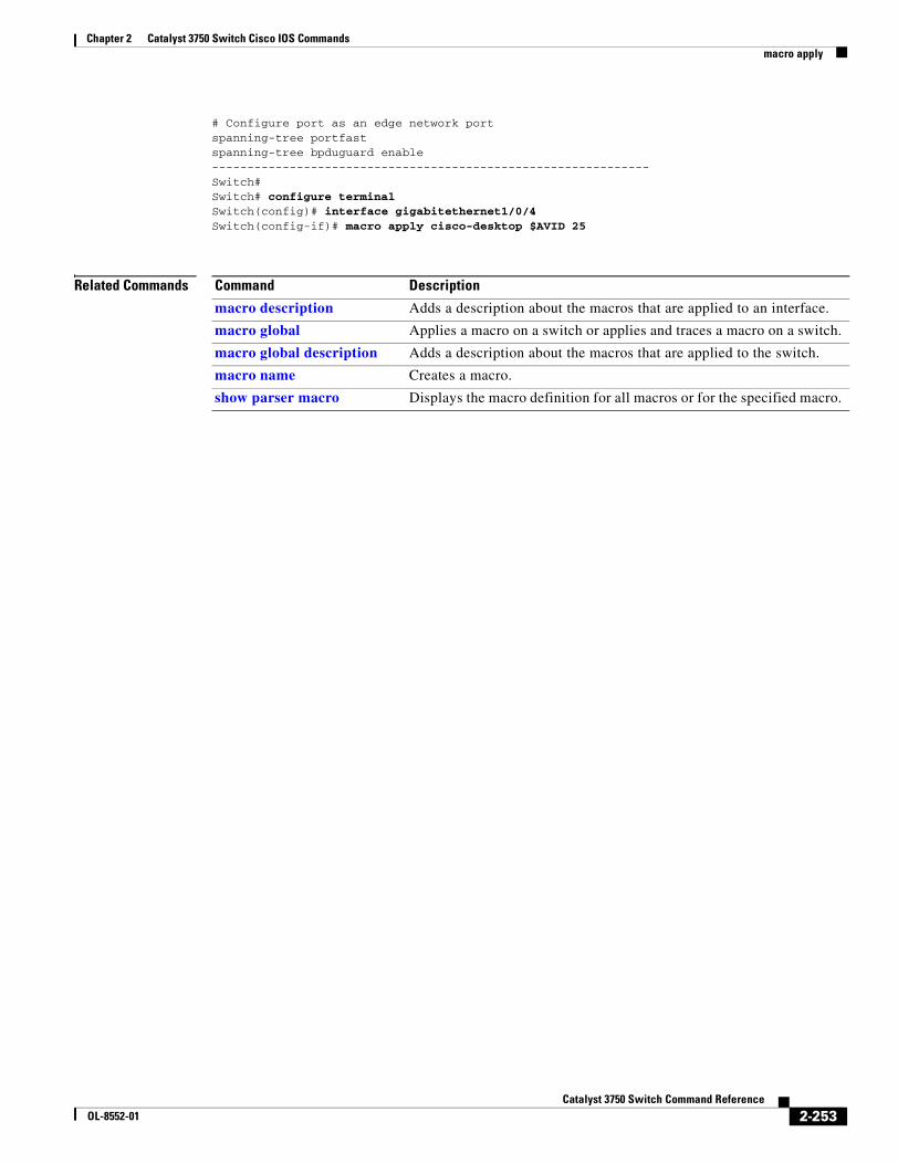
Chapter 2 Catalyst 3750 Switch Cisco IOS Commandsmacro apply
# Configure port as an edge network portspanning-tree portfastspanning-tree bpduguard enable--------------------------------------------------------------Switch#Switch# configure terminalSwitch(config)# interface gigabitethernet1/0/4Switch(config-if)# macro apply cisco-desktop $AVID 25
Related Commands Command Description
macro description Adds a description about the macros that are applied to an interface.
macro global Applies a macro on a switch or applies and traces a macro on a switch.
macro global description Adds a description about the macros that are applied to the switch.
macro name Creates a macro.
show parser macro Displays the macro definition for all macros or for the specified macro.
2-253Catalyst 3750 Switch Command Reference
OL-8552-01
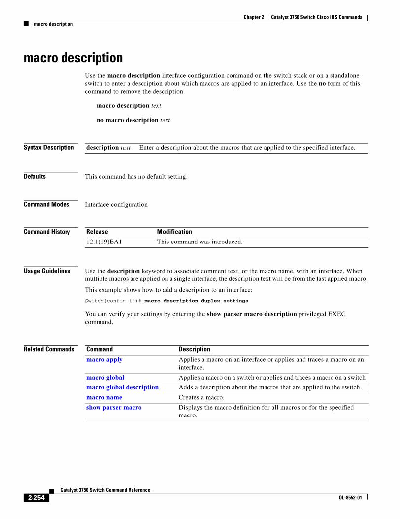
Chapter 2 Catalyst 3750 Switch Cisco IOS Commandsmacro description
macro descriptionUse the macro description interface configuration command on the switch stack or on a standalone switch to enter a description about which macros are applied to an interface. Use the no form of this command to remove the description.
macro description text
no macro description text
Syntax Description
Defaults This command has no default setting.
Command Modes Interface configuration
Command History
Usage Guidelines Use the description keyword to associate comment text, or the macro name, with an interface. When multiple macros are applied on a single interface, the description text will be from the last applied macro.
This example shows how to add a description to an interface:
Switch(config-if)# macro description duplex settings
You can verify your settings by entering the show parser macro description privileged EXEC command.
Related Commands
description text Enter a description about the macros that are applied to the specified interface.
Release Modification
12.1(19)EA1 This command was introduced.
Command Description
macro apply Applies a macro on an interface or applies and traces a macro on an interface.
macro global Applies a macro on a switch or applies and traces a macro on a switch
macro global description Adds a description about the macros that are applied to the switch.
macro name Creates a macro.
show parser macro Displays the macro definition for all macros or for the specified macro.
2-254Catalyst 3750 Switch Command Reference
OL-8552-01
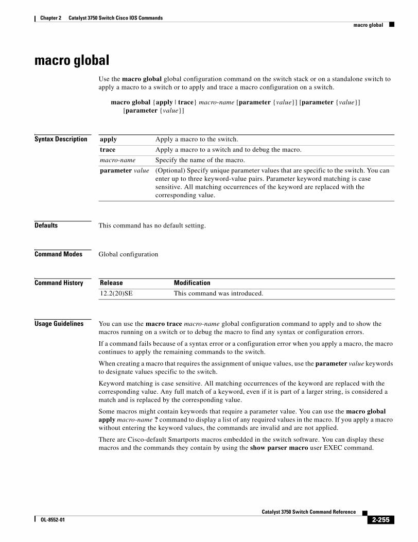
Chapter 2 Catalyst 3750 Switch Cisco IOS Commandsmacro global
macro globalUse the macro global global configuration command on the switch stack or on a standalone switch to apply a macro to a switch or to apply and trace a macro configuration on a switch.
macro global {apply | trace} macro-name [parameter {value}] [parameter {value}] [parameter {value}]
Syntax Description
Defaults This command has no default setting.
Command Modes Global configuration
Command History
Usage Guidelines You can use the macro trace macro-name global configuration command to apply and to show the macros running on a switch or to debug the macro to find any syntax or configuration errors.
If a command fails because of a syntax error or a configuration error when you apply a macro, the macro continues to apply the remaining commands to the switch.
When creating a macro that requires the assignment of unique values, use the parameter value keywords to designate values specific to the switch.
Keyword matching is case sensitive. All matching occurrences of the keyword are replaced with the corresponding value. Any full match of a keyword, even if it is part of a larger string, is considered a match and is replaced by the corresponding value.
Some macros might contain keywords that require a parameter value. You can use the macro global apply macro-name ? command to display a list of any required values in the macro. If you apply a macro without entering the keyword values, the commands are invalid and are not applied.
There are Cisco-default Smartports macros embedded in the switch software. You can display these macros and the commands they contain by using the show parser macro user EXEC command.
apply Apply a macro to the switch.
trace Apply a macro to a switch and to debug the macro.
macro-name Specify the name of the macro.
parameter value (Optional) Specify unique parameter values that are specific to the switch. You can enter up to three keyword-value pairs. Parameter keyword matching is case sensitive. All matching occurrences of the keyword are replaced with the corresponding value.
Release Modification
12.2(20)SE This command was introduced.
2-255Catalyst 3750 Switch Command Reference
OL-8552-01
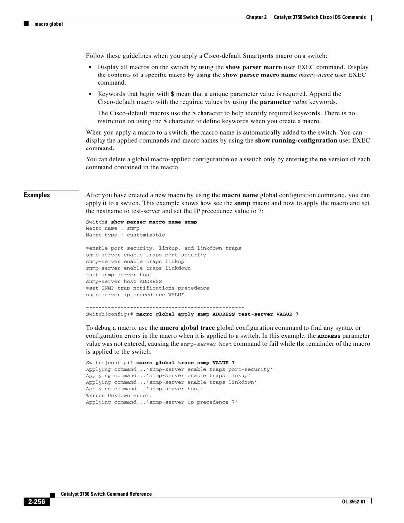
Chapter 2 Catalyst 3750 Switch Cisco IOS Commandsmacro global
Follow these guidelines when you apply a Cisco-default Smartports macro on a switch:
• Display all macros on the switch by using the show parser macro user EXEC command. Display the contents of a specific macro by using the show parser macro name macro-name user EXEC command.
• Keywords that begin with $ mean that a unique parameter value is required. Append the Cisco-default macro with the required values by using the parameter value keywords.
The Cisco-default macros use the $ character to help identify required keywords. There is no restriction on using the $ character to define keywords when you create a macro.
When you apply a macro to a switch, the macro name is automatically added to the switch. You can display the applied commands and macro names by using the show running-configuration user EXEC command.
You can delete a global macro-applied configuration on a switch only by entering the no version of each command contained in the macro.
Examples After you have created a new macro by using the macro name global configuration command, you can apply it to a switch. This example shows how see the snmp macro and how to apply the macro and set the hostname to test-server and set the IP precedence value to 7:
Switch# show parser macro name snmpMacro name : snmpMacro type : customizable
#enable port security, linkup, and linkdown trapssnmp-server enable traps port-securitysnmp-server enable traps linkupsnmp-server enable traps linkdown#set snmp-server hostsnmp-server host ADDRESS#set SNMP trap notifications precedencesnmp-server ip precedence VALUE
--------------------------------------------------Switch(config)# macro global apply snmp ADDRESS test-server VALUE 7
To debug a macro, use the macro global trace global configuration command to find any syntax or configuration errors in the macro when it is applied to a switch. In this example, the ADDRESS parameter value was not entered, causing the snmp-server host command to fail while the remainder of the macro is applied to the switch:
Switch(config)# macro global trace snmp VALUE 7Applying command...‘snmp-server enable traps port-security’Applying command...‘snmp-server enable traps linkup’Applying command...‘snmp-server enable traps linkdown’Applying command...‘snmp-server host’%Error Unknown error.Applying command...‘snmp-server ip precedence 7’
2-256Catalyst 3750 Switch Command Reference
OL-8552-01
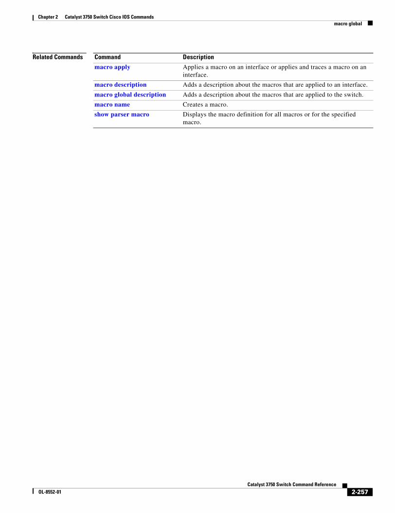
Chapter 2 Catalyst 3750 Switch Cisco IOS Commandsmacro global
Related Commands Command Description
macro apply Applies a macro on an interface or applies and traces a macro on an interface.
macro description Adds a description about the macros that are applied to an interface.
macro global description Adds a description about the macros that are applied to the switch.
macro name Creates a macro.
show parser macro Displays the macro definition for all macros or for the specified macro.
2-257Catalyst 3750 Switch Command Reference
OL-8552-01
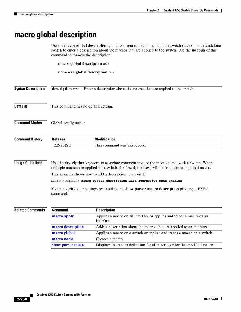
Chapter 2 Catalyst 3750 Switch Cisco IOS Commandsmacro global description
macro global descriptionUse the macro global description global configuration command on the switch stack or on a standalone switch to enter a description about the macros that are applied to the switch. Use the no form of this command to remove the description.
macro global description text
no macro global description text
Syntax Description
Defaults This command has no default setting.
Command Modes Global configuration
Command History
Usage Guidelines Use the description keyword to associate comment text, or the macro name, with a switch. When multiple macros are applied on a switch, the description text will be from the last applied macro.
This example shows how to add a description to a switch:
Switch(config)# macro global description udld aggressive mode enabled
You can verify your settings by entering the show parser macro description privileged EXEC command.
Related Commands
description text Enter a description about the macros that are applied to the switch.
Release Modification
12.2(20)SE This command was introduced.
Command Description
macro apply Applies a macro on an interface or applies and traces a macro on an interface.
macro description Adds a description about the macros that are applied to an interface.
macro global Applies a macro on a switch or applies and traces a macro on a switch.
macro name Creates a macro.
show parser macro Displays the macro definition for all macros or for the specified macro.
2-258Catalyst 3750 Switch Command Reference
OL-8552-01
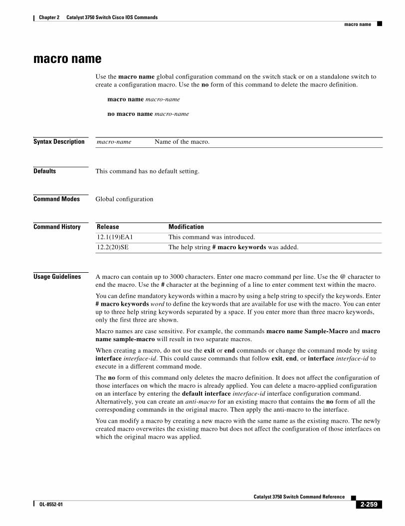
Chapter 2 Catalyst 3750 Switch Cisco IOS Commandsmacro name
macro nameUse the macro name global configuration command on the switch stack or on a standalone switch to create a configuration macro. Use the no form of this command to delete the macro definition.
macro name macro-name
no macro name macro-name
Syntax Description
Defaults This command has no default setting.
Command Modes Global configuration
Command History
Usage Guidelines A macro can contain up to 3000 characters. Enter one macro command per line. Use the @ character to end the macro. Use the # character at the beginning of a line to enter comment text within the macro.
You can define mandatory keywords within a macro by using a help string to specify the keywords. Enter # macro keywords word to define the keywords that are available for use with the macro. You can enter up to three help string keywords separated by a space. If you enter more than three macro keywords, only the first three are shown.
Macro names are case sensitive. For example, the commands macro name Sample-Macro and macro name sample-macro will result in two separate macros.
When creating a macro, do not use the exit or end commands or change the command mode by using interface interface-id. This could cause commands that follow exit, end, or interface interface-id to execute in a different command mode.
The no form of this command only deletes the macro definition. It does not affect the configuration of those interfaces on which the macro is already applied. You can delete a macro-applied configuration on an interface by entering the default interface interface-id interface configuration command. Alternatively, you can create an anti-macro for an existing macro that contains the no form of all the corresponding commands in the original macro. Then apply the anti-macro to the interface.
You can modify a macro by creating a new macro with the same name as the existing macro. The newly created macro overwrites the existing macro but does not affect the configuration of those interfaces on which the original macro was applied.
macro-name Name of the macro.
Release Modification
12.1(19)EA1 This command was introduced.
12.2(20)SE The help string # macro keywords was added.
2-259Catalyst 3750 Switch Command Reference
OL-8552-01
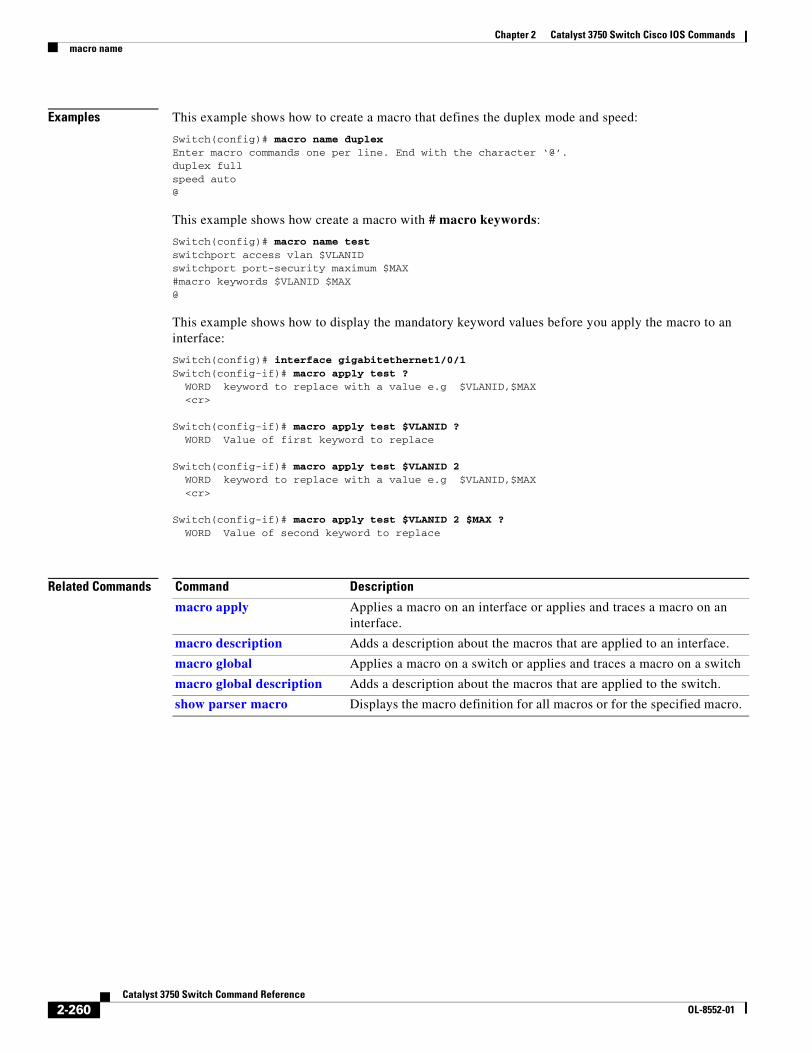
Chapter 2 Catalyst 3750 Switch Cisco IOS Commandsmacro name
Examples This example shows how to create a macro that defines the duplex mode and speed:
Switch(config)# macro name duplexEnter macro commands one per line. End with the character ‘@’.duplex fullspeed auto@
This example shows how create a macro with # macro keywords:
Switch(config)# macro name testswitchport access vlan $VLANIDswitchport port-security maximum $MAX#macro keywords $VLANID $MAX@
This example shows how to display the mandatory keyword values before you apply the macro to an interface:
Switch(config)# interface gigabitethernet1/0/1Switch(config-if)# macro apply test ? WORD keyword to replace with a value e.g $VLANID,$MAX <cr>
Switch(config-if)# macro apply test $VLANID ? WORD Value of first keyword to replace
Switch(config-if)# macro apply test $VLANID 2 WORD keyword to replace with a value e.g $VLANID,$MAX <cr>
Switch(config-if)# macro apply test $VLANID 2 $MAX ? WORD Value of second keyword to replace
Related Commands Command Description
macro apply Applies a macro on an interface or applies and traces a macro on an interface.
macro description Adds a description about the macros that are applied to an interface.
macro global Applies a macro on a switch or applies and traces a macro on a switch
macro global description Adds a description about the macros that are applied to the switch.
show parser macro Displays the macro definition for all macros or for the specified macro.
2-260Catalyst 3750 Switch Command Reference
OL-8552-01
Chapter 2 Catalyst 3750 Switch Cisco IOS Commandsmatch (access-map configuration)
match (access-map configuration)Use the match access-map configuration command on the switch stack or on a standalone switch to set the VLAN map to match packets against one or more access lists. Use the no form of this command to remove the match parameters.
match {ip address {name | number} [name | number] [name | number]...} | {mac address {name} [name] [name]...}
no match {ip address {name | number} [name | number] [name | number]...} | {mac address {name} [name] [name]...}
Syntax Description
Defaults The default action is to have no match parameters applied to a VLAN map.
Command Modes Access-map configuration
Command History
Usage Guidelines You enter access-map configuration mode by using the vlan access-map global configuration command.
You must enter one access list name or number; others are optional. You can match packets against one or more access lists. Matching any of the lists counts as a match of the entry.
In access-map configuration mode, use the match command to define the match conditions for a VLAN map applied to a VLAN. Use the action command to set the action that occurs when the packet matches the conditions.
Packets are matched only against access lists of the same protocol type; IP packets are matched against IP access lists, and all other packets are matched against MAC access lists.
Both IP and MAC addresses can be specified for the same map entry.
ip address Set the access map to match packets against an IP address access list.
mac address Set the access map to match packets against a MAC address access list.
name Name of the access list to match packets against.
number Number of the access list to match packets against. This option is not valid for MAC access lists.
Release Modification
12.1(11)AX This command was introduced.
2-261Catalyst 3750 Switch Command Reference
OL-8552-01
Chapter 2 Catalyst 3750 Switch Cisco IOS Commandsmatch (access-map configuration)
Examples This example shows how to define and apply a VLAN access map vmap4 to VLANs 5 and 6 that will cause the interface to drop an IP packet if the packet matches the conditions defined in access list al2.
Switch(config)# vlan access-map vmap4Switch(config-access-map)# match ip address al2Switch(config-access-map)# action dropSwitch(config-access-map)# exitSwitch(config)# vlan filter vmap4 vlan-list 5-6
You can verify your settings by entering the show vlan access-map privileged EXEC command.
Related Commands Command Description
access-list Configures a standard numbered ACL. For syntax information, select Cisco IOS IP Command Reference, Volume 1 of 3:Addressing and Services, Release 12.2 > IP Services Commands.
action Specifies the action to be taken if the packet matches an entry in an access control list (ACL).
ip access list Creates a named access list. For syntax information, select Cisco IOS IP Command Reference, Volume 1 of 3:Addressing and Services, Release 12.2 > IP Services Commands.
mac access-list extended Creates a named MAC address access list.
show vlan access-map Displays the VLAN access maps created on the switch.
vlan access-map Creates a VLAN access map.
2-262Catalyst 3750 Switch Command Reference
OL-8552-01
Chapter 2 Catalyst 3750 Switch Cisco IOS Commandsmatch (class-map configuration)
match (class-map configuration)Use the match class-map configuration command on the switch stack or on a standalone switch to define the match criteria to classify traffic. Use the no form of this command to remove the match criteria.
match {access-group acl-index-or-name | input-interface interface-id-list | ip dscp dscp-list | ip precedence ip-precedence-list}
no match {access-group acl-index-or-name | input-interface interface-id-list | ip dscp dscp-list | ip precedence ip-precedence-list}
Syntax Description
Defaults No match criteria are defined.
Command Modes Class-map configuration
Command History
Usage Guidelines The match command is used to specify which fields in the incoming packets are examined to classify the packets. Only the IP access group or the MAC access group matching to the Ether Type/Len are supported.
To define packet classification on a physical-port basis, only one match command per class map is supported. In this situation, the match-all and match-any keywords are equivalent.
access-group acl-index-or-name
Number or name of an IP standard or extended access control list (ACL) or MAC ACL. For an IP standard ACL, the ACL index range is 1 to 99 and 1300 to 1999. For an IP extended ACL, the ACL index range is 100 to 199 and 2000 to 2699.
input-interface interface-id-list
Specify the physical ports to which the interface-level class map in a hierarchical policy map applies. This command can only be used in the child-level policy map and must be the only match condition in the child-level policy map. You can specify up to six entries in the list by specifying a port (counts as one entry), a list of ports separated by a space (each port counts as an entry), or a range of ports separated by a hyphen (counts as two entries).
ip dscp dscp-list List of up to eight IP Differentiated Services Code Point (DSCP) values to match against incoming packets. Separate each value with a space. The range is 0 to 63. You also can enter a mnemonic name for a commonly-used value.
ip precedence ip-precedence-list
List of up to eight IP-precedence values to match against incoming packets. Separate each value with a space. The range is 0 to 7. You also can enter a mnemonic name for a commonly-used value
Release Modification
12.1(11)AX This command was introduced.
12.2(25)SE The input-interface interface-id-list keyword was added.
2-263Catalyst 3750 Switch Command Reference
OL-8552-01
Chapter 2 Catalyst 3750 Switch Cisco IOS Commandsmatch (class-map configuration)
For the match ip dscp dscp-list or the match ip precedence ip-precedence-list command, you can enter a mnemonic name for a commonly used value. For example, you can enter the match ip dscp af11 command, which is the same as entering the match ip dscp 10 command. You can enter the match ip precedence critical command, which is the same as entering the match ip precedence 5 command. For a list of supported mnemonics, enter the match ip dscp ? or the match ip precedence ? command to see the command-line help strings.
Use the input-interface interface-id-list keyword when you are configuring an interface-level class map in a hierarchical policy map. For the interface-id-list, you can specify up to six entries.
Examples This example shows how to create a class map called class2, which matches all the incoming traffic with DSCP values of 10, 11, and 12:
Switch(config)# class-map class2Switch(config-cmap)# match ip dscp 10 11 12Switch(config-cmap)# exit
This example shows how to create a class map called class3, which matches all the incoming traffic with IP-precedence values of 5, 6, and 7:
Switch(config)# class-map class3Switch(config-cmap)# match ip precedence 5 6 7 Switch(config-cmap)# exit
This example shows how to delete the IP-precedence match criteria and to classify traffic using acl1:
Switch(config)# class-map class2Switch(config-cmap)# match ip precedence 5 6 7 Switch(config-cmap)# no match ip precedenceSwitch(config-cmap)# match access-group acl1Switch(config-cmap)# exit
This example shows how to specify a list of physical ports to which an interface-level class map in a hierarchical policy map applies:
Switch(config)# class-map match-all class4Switch(config-cmap)# match input-interface gigabitethernet2/0/1 gigabitethernet2/0/2Switch(config-cmap)# exit
This example shows how to specify a range of physical ports to which an interface-level class map in a hierarchical policy map applies:
Switch(config)# class-map match-all class4Switch(config-cmap)# match input-interface gigabitethernet2/0/1 - gigabitethernet2/0/5Switch(config-cmap)# exit
You can verify your settings by entering the show class-map privileged EXEC command.
Related Commands Command Description
class-map Creates a class map to be used for matching packets to the class whose name you specify.
show class-map Displays quality of service (QoS) class maps.
2-264Catalyst 3750 Switch Command Reference
OL-8552-01
Chapter 2 Catalyst 3750 Switch Cisco IOS Commandsmdix auto
mdix autoUse the mdix auto interface configuration command on the switch stack or on a standalone switch to enable the automatic medium-dependent interface crossover (auto-MDIX) feature on the interface. When auto-MDIX is enabled, the interface automatically detects the required cable connection type (straight-through or crossover) and configures the connection appropriately. Use the no form of this command to disable auto-MDIX.
mdix auto
no mdix auto
Syntax Description This command has no arguments or keywords.
Defaults Auto-MDIX is enabled.
Command Modes Interface configuration
Command History
Usage Guidelines When you enable auto-MDIX on an interface, you must also set the interface speed and duplex to auto so that the feature operates correctly.
When auto-MDIX (and autonegotiation of speed and duplex) is enabled on one or both of connected interfaces, link up occurs, even if the cable type (straight-through or crossover) is incorrect.
Auto-MDIX is supported on all 10/100 and 10/100/1000 Mbps interfaces and on 10/100/1000BASE-TX small form-factor pluggable (SFP) module interfaces. It is not supported on 1000BASE-SX or -LX SFP module interfaces.
Examples This example shows how to enable auto-MDIX on a port:
Switch# configure terminalSwitch(config)# interface gigabitethernet1/0/1Switch(config-if)# speed autoSwitch(config-if)# duplex autoSwitch(config-if)# mdix autoSwitch(config-if)# end
You can verify the operational state of auto-MDIX on the interface by entering the show controllers ethernet-controller interface-id phy privileged EXEC command.
Release Modification
12.1(14)EA1 This command was introduced.
12.2(18)SE The default setting changed from disabled to enabled.
2-265Catalyst 3750 Switch Command Reference
OL-8552-01

Chapter 2 Catalyst 3750 Switch Cisco IOS Commandsmdix auto
Related Commands Command Description
show controllers ethernet-controller interface-id phy
Displays general information about internal registers of an interface, including the operational state of auto-MDIX.
2-266Catalyst 3750 Switch Command Reference
OL-8552-01
Chapter 2 Catalyst 3750 Switch Cisco IOS Commandsmls qos
mls qosUse the mls qos global configuration command on the switch stack or on a standalone switch to enable quality of service (QoS) for the entire switch. When the mls qos command is entered, QoS is enabled with the default parameters on all ports in the system. Use the no form of this command to reset all the QoS-related statistics and to disable the QoS features for the entire switch.
mls qos
no mls qos
Syntax Description This command has no arguments or keywords.
Defaults QoS is disabled. There is no concept of trusted or untrusted ports because the packets are not modified (the CoS, DSCP, and IP precedence values in the packet are not changed). Traffic is switched in pass-through mode (packets are switched without any rewrites and classified as best effort without any policing).
When QoS is enabled with the mls qos global configuration command and all other QoS settings are set to their defaults, traffic is classified as best effort (the DSCP and CoS value is set to 0) without any policing. No policy maps are configured. The default port trust state on all ports is untrusted. The default ingress and egress queue settings are in effect.
Command Modes Global configuration
Command History
Usage Guidelines QoS must be globally enabled to use QoS classification, policing, mark down or drop, queueing, and traffic shaping features. You can create a policy-map and attach it to a port before entering the mls qos command. However, until you enter the mls qos command, QoS processing is disabled.
Policy-maps and class-maps used to configure QoS are not deleted from the configuration by the no mls qos command, but entries corresponding to policy maps are removed from the switch hardware to save system resources. To re-enable QoS with the previous configurations, use the mls qos command.
Toggling the QoS status of the switch with this command modifies (reallocates) the sizes of the queues. During the queue size modification, the queue is temporarily shut down during the hardware reconfiguration, and the switch drops newly arrived packets for this queue.
Examples This example shows how to enable QoS on the switch:
Switch(config)# mls qos
You can verify your settings by entering the show mls qos privileged EXEC command.
Release Modification
12.1(11)AX This command was introduced.
2-267Catalyst 3750 Switch Command Reference
OL-8552-01

Chapter 2 Catalyst 3750 Switch Cisco IOS Commandsmls qos
Related Commands Command Description
show mls qos Displays QoS information.
2-268Catalyst 3750 Switch Command Reference
OL-8552-01
Chapter 2 Catalyst 3750 Switch Cisco IOS Commandsmls qos aggregate-policer
mls qos aggregate-policerUse the mls qos aggregate-policer global configuration command on the switch stack or on a standalone switch to define policer parameters, which can be shared by multiple classes within the same policy map. A policer defines a maximum permissible rate of transmission, a maximum burst size for transmissions, and an action to take if either maximum is exceeded. Use the no form of this command to delete an aggregate policer.
mls qos aggregate-policer aggregate-policer-name rate-bps burst-byte exceed-action {drop | policed-dscp-transmit}
no mls qos aggregate-policer aggregate-policer-name
Syntax Description
Defaults No aggregate policers are defined.
Command Modes Global configuration
Command History
Usage Guidelines Define an aggregate policer if the policer is shared with multiple classes.
Policers for a port cannot be shared with other policers for another port; traffic from two different ports cannot be aggregated for policing purposes.
The port ASIC device, which controls more than one physical port, supports 256 policers (255 policers plus 1 no policer). The maximum number of policers supported per port is 64. Policers are allocated on demand by the software and are constrained by the hardware and ASIC boundaries. You cannot reserve policers per port (there is no guarantee that a port will be assigned to any policer).
You apply an aggregate policer to multiple classes in the same policy map; you cannot use an aggregate policer across different policy maps.
aggregate-policer-name Name of the aggregate policer referenced by the police aggregate policy-map class configuration command.
rate-bps Specify the average traffic rate in bits per second (bps). The range is 8000 to 1000000000.
burst-byte Specify the normal burst size in bytes. The range is 8000 to 1000000.
exceed-action drop When the specified rate is exceeded, specify that the switch drop the packet.
exceed-action policed-dscp-transmit
When the specified rate is exceeded, specify that the switch change the Differentiated Services Code Point (DSCP) of the packet to that specified in the policed-DSCP map and then send the packet.
Release Modification
12.1(11)AX This command was introduced.
2-269Catalyst 3750 Switch Command Reference
OL-8552-01
Chapter 2 Catalyst 3750 Switch Cisco IOS Commandsmls qos aggregate-policer
You cannot delete an aggregate policer if it is being used in a policy map. You must first use the no police aggregate aggregate-policer-name policy-map class configuration command to delete the aggregate policer from all policy maps before using the no mls qos aggregate-policer aggregate-policer-name command.
Policing uses a token-bucket algorithm. You configure the bucket depth (the maximum burst that is tolerated before the bucket overflows) by using the burst-byte option of the police policy-map class configuration command or the mls qos aggregate-policer global configuration command. You configure how fast (the average rate) that the tokens are removed from the bucket by using the rate-bps option of the police policy-map class configuration command or the mls qos aggregate-policer global configuration command. For more information, see the software configuration guide for this release.
Examples This example shows how to define the aggregate policer parameters and how to apply the policer to multiple classes in a policy map:
Switch(config)# mls qos aggregate-policer agg_policer1 1000000 1000000 exceed-action dropSwitch(config)# policy-map policy2Switch(config-pmap)# class class1Switch(config-pmap-c)# police aggregate agg_policer1Switch(config-pmap-c)# exitSwitch(config-pmap)# class class2 Switch(config-pmap-c)# set dscp 10Switch(config-pmap-c)# police aggregate agg_policer1Switch(config-pmap-c)# exitSwitch(config-pmap)# class class3Switch(config-pmap-c)# trust dscpSwitch(config-pmap-c)# police aggregate agg_policer2Switch(config-pmap-c)# exit
You can verify your settings by entering the show mls qos aggregate-policer privileged EXEC command.
Related Commands Command Description
police aggregate Creates a policer that is shared by different classes.
show mls qos aggregate-policer Displays the quality of service (QoS) aggregate policer configuration.
2-270Catalyst 3750 Switch Command Reference
OL-8552-01
Chapter 2 Catalyst 3750 Switch Cisco IOS Commandsmls qos cos
mls qos cosUse the mls qos cos interface configuration command on the switch stack or on a standalone switch to define the default class of service (CoS) value of a port or to assign the default CoS to all incoming packets on the port. Use the no form of this command to return to the default setting.
mls qos cos {default-cos | override}
no mls qos cos {default-cos | override}
Syntax Description
Defaults The default CoS value for a port is 0.
CoS override is disabled.
Command Modes Interface configuration
Command History
Usage Guidelines You can use the default value to assign a CoS and Differentiated Services Code Point (DSCP) value to all incoming packets that are untagged (if the incoming packet does not have a CoS value). You also can assign a default CoS and DSCP value to all incoming packets by using the override keyword.
Use the override keyword when all incoming packets on certain ports deserve higher or lower priority than packets entering from other ports. Even if a port is previously set to trust DSCP, CoS, or IP precedence, this command overrides the previously configured trust state, and all the incoming CoS values are assigned the default CoS value configured with the mls qos cos command. If an incoming packet is tagged, the CoS value of the packet is modified with the default CoS of the port at the ingress port.
default-cos Assign a default CoS value to a port. If packets are untagged, the default CoS value becomes the packet CoS value. The CoS range is 0 to 7.
override Override the CoS of the incoming packets, and apply the default CoS value on the port to all incoming packets.
Release Modification
12.1(11)AX This command was introduced.
2-271Catalyst 3750 Switch Command Reference
OL-8552-01
Chapter 2 Catalyst 3750 Switch Cisco IOS Commandsmls qos cos
Examples This example shows how to configure the default port CoS to 4 on a port:
Switch(config)# interface gigabitethernet2/0/1Switch(config-if)# mls qos trust cosSwitch(config-if)# mls qos cos 4
This example shows how to assign all the packets entering a port to the default port CoS value of 4 on a port:
Switch(config)# interface gigabitethernet2/0/1Switch(config-if)# mls qos cos 4Switch(config-if)# mls qos cos override
You can verify your settings by entering the show mls qos interface privileged EXEC command.
Related Commands Command Description
show mls qos interface Displays quality of service (QoS) information.
2-272Catalyst 3750 Switch Command Reference
OL-8552-01
Chapter 2 Catalyst 3750 Switch Cisco IOS Commandsmls qos dscp-mutation
mls qos dscp-mutationUse the mls qos dscp-mutation interface configuration command on the switch stack or on a standalone switch to apply a Differentiated Services Code Point (DSCP)-to-DSCP-mutation map to a DSCP-trusted port. Use the no form of this command to return the map to the default settings (no DSCP mutation).
mls qos dscp-mutation dscp-mutation-name
no mls qos dscp-mutation dscp-mutation-name
Syntax Description
Defaults The default DSCP-to-DSCP-mutation map is a null map, which maps incoming DSCPs to the same DSCP values.
Command Modes Interface configuration
Command History
Usage Guidelines If two quality of service (QoS) domains have different DSCP definitions, use the DSCP-to-DSCP-mutation map to translate one set of DSCP values to match the definition of another domain. You apply the DSCP-to-DSCP-mutation map to the receiving port (ingress mutation) at the boundary of a quality of service (QoS) administrative domain.
With ingress mutation, the new DSCP value overwrites the one in the packet, and QoS handles the packet with this new value. The switch sends the packet out the port with the new DSCP value.
You can configure multiple DSCP-to-DSCP-mutation maps on ingress ports.
You apply the map only to DSCP-trusted ports. If you apply the DSCP mutation map to an untrusted port, to class of service (CoS) or IP-precedence trusted port, the command has no immediate effect until the port becomes DSCP-trusted.
Examples This example shows how to define the DSCP-to-DSCP-mutation map named dscpmutation1and to apply the map to a port:
Switch(config)# mls qos map dscp-mutation dscpmutation1 10 11 12 13 to 30Switch(config)# interface gigabitethernet3/0/1Switch(config-if)# mls qos trust dscpSwitch(config-if)# mls qos dscp-mutation dscpmutation1
dscp-mutation-name Name of the DSCP-to-DSCP-mutation map. This map was previously defined with the mls qos map dscp-mutation global configuration command.
Release Modification
12.1(11)AX This command was introduced.
2-273Catalyst 3750 Switch Command Reference
OL-8552-01
Chapter 2 Catalyst 3750 Switch Cisco IOS Commandsmls qos dscp-mutation
This example show how to remove the DSCP-to-DSCP-mutation map name dscpmutation1 from the port and to reset the map to the default:
Switch(config-if)# no mls qos dscp-mutation dscpmutation1
You can verify your settings by entering the show mls qos maps privileged EXEC command.
Related Commands Command Description
mls qos map dscp-mutation Defines the DSCP-to-DSCP-mutation map.
mls qos trust Configures the port trust state.
show mls qos maps Displays QoS mapping information.
2-274Catalyst 3750 Switch Command Reference
OL-8552-01
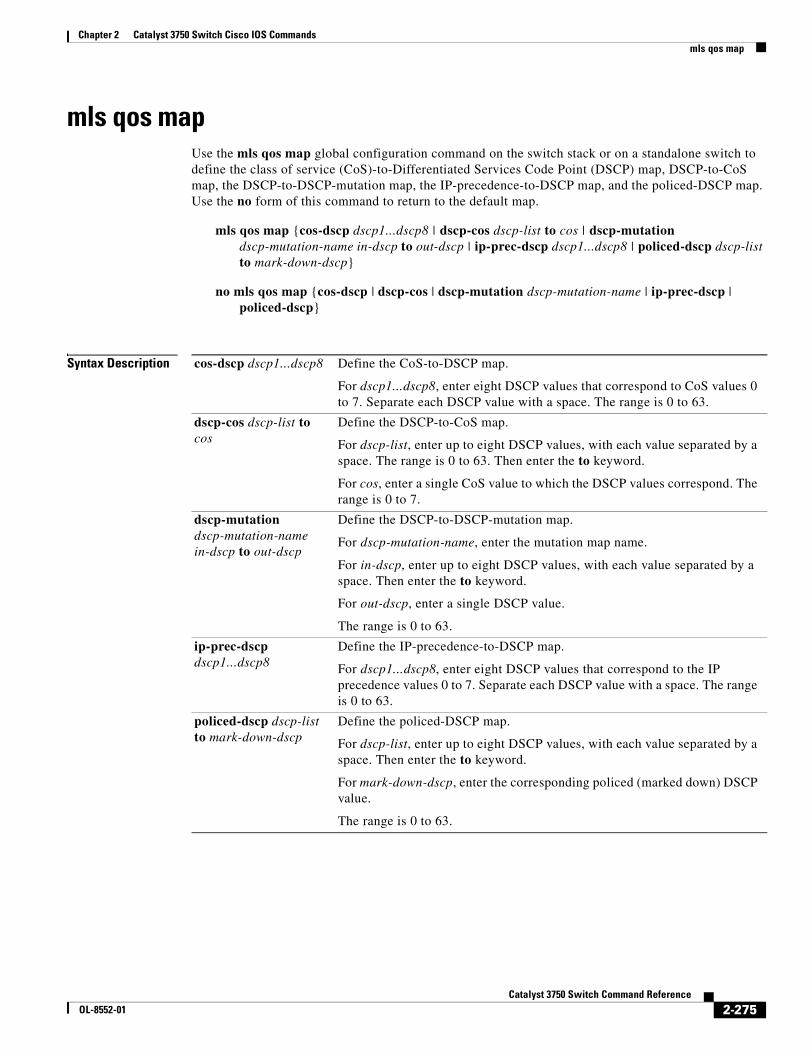
Chapter 2 Catalyst 3750 Switch Cisco IOS Commandsmls qos map
mls qos mapUse the mls qos map global configuration command on the switch stack or on a standalone switch to define the class of service (CoS)-to-Differentiated Services Code Point (DSCP) map, DSCP-to-CoS map, the DSCP-to-DSCP-mutation map, the IP-precedence-to-DSCP map, and the policed-DSCP map. Use the no form of this command to return to the default map.
mls qos map {cos-dscp dscp1...dscp8 | dscp-cos dscp-list to cos | dscp-mutation dscp-mutation-name in-dscp to out-dscp | ip-prec-dscp dscp1...dscp8 | policed-dscp dscp-list to mark-down-dscp}
no mls qos map {cos-dscp | dscp-cos | dscp-mutation dscp-mutation-name | ip-prec-dscp | policed-dscp}
Syntax Description cos-dscp dscp1...dscp8 Define the CoS-to-DSCP map.
For dscp1...dscp8, enter eight DSCP values that correspond to CoS values 0 to 7. Separate each DSCP value with a space. The range is 0 to 63.
dscp-cos dscp-list to cos
Define the DSCP-to-CoS map.
For dscp-list, enter up to eight DSCP values, with each value separated by a space. The range is 0 to 63. Then enter the to keyword.
For cos, enter a single CoS value to which the DSCP values correspond. The range is 0 to 7.
dscp-mutation dscp-mutation-name in-dscp to out-dscp
Define the DSCP-to-DSCP-mutation map.
For dscp-mutation-name, enter the mutation map name.
For in-dscp, enter up to eight DSCP values, with each value separated by a space. Then enter the to keyword.
For out-dscp, enter a single DSCP value.
The range is 0 to 63.
ip-prec-dscp dscp1...dscp8
Define the IP-precedence-to-DSCP map.
For dscp1...dscp8, enter eight DSCP values that correspond to the IP precedence values 0 to 7. Separate each DSCP value with a space. The range is 0 to 63.
policed-dscp dscp-list to mark-down-dscp
Define the policed-DSCP map.
For dscp-list, enter up to eight DSCP values, with each value separated by a space. Then enter the to keyword.
For mark-down-dscp, enter the corresponding policed (marked down) DSCP value.
The range is 0 to 63.
2-275Catalyst 3750 Switch Command Reference
OL-8552-01
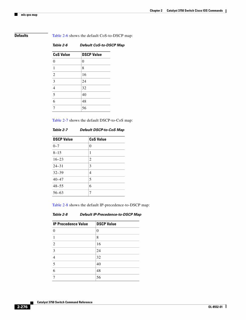
Chapter 2 Catalyst 3750 Switch Cisco IOS Commandsmls qos map
Defaults Table 2-6 shows the default CoS-to-DSCP map:
Table 2-7 shows the default DSCP-to-CoS map:
Table 2-8 shows the default IP-precedence-to-DSCP map:
Table 2-6 Default CoS-to-DSCP Map
CoS Value DSCP Value
0 0
1 8
2 16
3 24
4 32
5 40
6 48
7 56
Table 2-7 Default DSCP-to-CoS Map
DSCP Value CoS Value
0–7 0
8–15 1
16–23 2
24–31 3
32–39 4
40–47 5
48–55 6
56–63 7
Table 2-8 Default IP-Precedence-to-DSCP Map
IP Precedence Value DSCP Value
0 0
1 8
2 16
3 24
4 32
5 40
6 48
7 56
2-276Catalyst 3750 Switch Command Reference
OL-8552-01
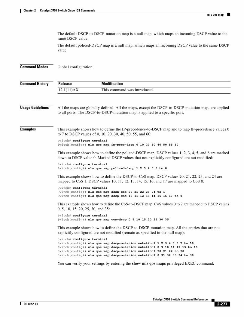
Chapter 2 Catalyst 3750 Switch Cisco IOS Commandsmls qos map
The default DSCP-to-DSCP-mutation map is a null map, which maps an incoming DSCP value to the same DSCP value.
The default policed-DSCP map is a null map, which maps an incoming DSCP value to the same DSCP value.
Command Modes Global configuration
Command History
Usage Guidelines All the maps are globally defined. All the maps, except the DSCP-to-DSCP-mutation map, are applied to all ports. The DSCP-to-DSCP-mutation map is applied to a specific port.
Examples This example shows how to define the IP-precedence-to-DSCP map and to map IP-precedence values 0 to 7 to DSCP values of 0, 10, 20, 30, 40, 50, 55, and 60:
Switch# configure terminalSwitch(config)# mls qos map ip-prec-dscp 0 10 20 30 40 50 55 60
This example shows how to define the policed-DSCP map. DSCP values 1, 2, 3, 4, 5, and 6 are marked down to DSCP value 0. Marked DSCP values that not explicitly configured are not modified:
Switch# configure terminalSwitch(config)# mls qos map policed-dscp 1 2 3 4 5 6 to 0
This example shows how to define the DSCP-to-CoS map. DSCP values 20, 21, 22, 23, and 24 are mapped to CoS 1. DSCP values 10, 11, 12, 13, 14, 15, 16, and 17 are mapped to CoS 0:
Switch# configure terminalSwitch(config)# mls qos map dscp-cos 20 21 22 23 24 to 1Switch(config)# mls qos map dscp-cos 10 11 12 13 14 15 16 17 to 0
This example shows how to define the CoS-to-DSCP map. CoS values 0 to 7 are mapped to DSCP values 0, 5, 10, 15, 20, 25, 30, and 35:
Switch# configure terminalSwitch(config)# mls qos map cos-dscp 0 5 10 15 20 25 30 35
This example shows how to define the DSCP-to-DSCP-mutation map. All the entries that are not explicitly configured are not modified (remain as specified in the null map):
Switch# configure terminalSwitch(config)# mls qos map dscp-mutation mutation1 1 2 3 4 5 6 7 to 10Switch(config)# mls qos map dscp-mutation mutation1 8 9 10 11 12 13 to 10Switch(config)# mls qos map dscp-mutation mutation1 20 21 22 to 20Switch(config)# mls qos map dscp-mutation mutation1 0 31 32 33 34 to 30
You can verify your settings by entering the show mls qos maps privileged EXEC command.
Release Modification
12.1(11)AX This command was introduced.
2-277Catalyst 3750 Switch Command Reference
OL-8552-01

Chapter 2 Catalyst 3750 Switch Cisco IOS Commandsmls qos map
Related Commands Command Description
mls qos dscp-mutation Applies a DSCP-to-DSCP-mutation map to a DSCP-trusted port.
show mls qos maps Displays quality of service (QoS) mapping information.
2-278Catalyst 3750 Switch Command Reference
OL-8552-01
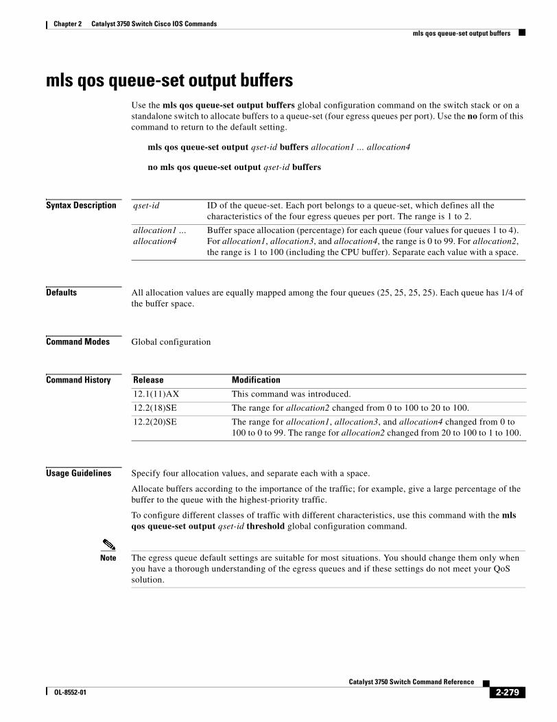
Chapter 2 Catalyst 3750 Switch Cisco IOS Commandsmls qos queue-set output buffers
mls qos queue-set output buffersUse the mls qos queue-set output buffers global configuration command on the switch stack or on a standalone switch to allocate buffers to a queue-set (four egress queues per port). Use the no form of this command to return to the default setting.
mls qos queue-set output qset-id buffers allocation1 ... allocation4
no mls qos queue-set output qset-id buffers
Syntax Description
Defaults All allocation values are equally mapped among the four queues (25, 25, 25, 25). Each queue has 1/4 of the buffer space.
Command Modes Global configuration
Command History
Usage Guidelines Specify four allocation values, and separate each with a space.
Allocate buffers according to the importance of the traffic; for example, give a large percentage of the buffer to the queue with the highest-priority traffic.
To configure different classes of traffic with different characteristics, use this command with the mls qos queue-set output qset-id threshold global configuration command.
Note The egress queue default settings are suitable for most situations. You should change them only when you have a thorough understanding of the egress queues and if these settings do not meet your QoS solution.
qset-id ID of the queue-set. Each port belongs to a queue-set, which defines all the characteristics of the four egress queues per port. The range is 1 to 2.
allocation1 ... allocation4
Buffer space allocation (percentage) for each queue (four values for queues 1 to 4). For allocation1, allocation3, and allocation4, the range is 0 to 99. For allocation2, the range is 1 to 100 (including the CPU buffer). Separate each value with a space.
Release Modification
12.1(11)AX This command was introduced.
12.2(18)SE The range for allocation2 changed from 0 to 100 to 20 to 100.
12.2(20)SE The range for allocation1, allocation3, and allocation4 changed from 0 to 100 to 0 to 99. The range for allocation2 changed from 20 to 100 to 1 to 100.
2-279Catalyst 3750 Switch Command Reference
OL-8552-01
Chapter 2 Catalyst 3750 Switch Cisco IOS Commandsmls qos queue-set output buffers
Examples This example shows how to map a port to queue-set 2. It allocates 40 percent of the buffer space to egress queue 1 and 20 percent to egress queues 2, 3, and 4:
Switch(config)# mls qos queue-set output 2 buffers 40 20 20 20Switch(config)# interface gigabitethernet2/0/1Switch(config-if)# queue-set 2
You can verify your settings by entering the show mls qos interface [interface-id] buffers or the show mls qos queue-set privileged EXEC command.
Related Commands Command Description
mls qos queue-set output threshold Configures the weighted tail-drop (WTD) thresholds, guarantees the availability of buffers, and configures the maximum memory allocation to a queue-set.
queue-set Maps a port to a queue-set.
show mls qos interface buffers Displays quality of service (QoS) information.
show mls qos queue-set Displays egress queue settings for the queue-set.
2-280Catalyst 3750 Switch Command Reference
OL-8552-01
Chapter 2 Catalyst 3750 Switch Cisco IOS Commandsmls qos queue-set output threshold
mls qos queue-set output thresholdUse the mls qos queue-set output threshold global configuration command on the switch stack or on a standalone switch to configure the weighted tail-drop (WTD) thresholds, to guarantee the availability of buffers, and to configure the maximum memory allocation to a queue-set (four egress queues per port). Use the no form of this command to return to the default setting.
mls qos queue-set output qset-id threshold queue-id drop-threshold1 drop-threshold2 reserved-threshold maximum-threshold
no mls qos queue-set output qset-id threshold [queue-id]
Syntax Description
Defaults When quality of service (QoS) is enabled, WTD is enabled.
Table 2-9 shows the default WTD threshold settings.
Command Modes Global configuration
Command History
qset-id ID of the queue-set. Each port belongs to a queue-set, which defines all the characteristics of the four egress queues per port. The range is 1 to 2.
queue-id Specific queue in the queue-set on which the command is performed. The range is 1 to 4.
drop-threshold1 drop-threshold2
Two WTD thresholds expressed as a percentage of the queue’s allocated memory. The range is 1 to 400 percent.
reserved-threshold Amount of memory to be guaranteed (reserved) for the queue and expressed as a percentage of the allocated memory. The range is 1 to 100 percent.
maximum-threshold Enable a queue in the full condition to get more buffers than are reserved for it. This is the maximum memory the queue can have before the packets are dropped. The range is 1 to 400 percent.
Table 2-9 Default Egress Queue WTD Threshold Settings
Feature Queue 1 Queue 2 Queue 3 Queue 4
WTD Drop Threshold 1 100 percent 200 percent 100 percent 100 percent
WTD Drop Threshold 2 100 percent 200 percent 100 percent 100 percent
Reserved Threshold 50 percent 100 percent 50 percent 50 percent
Maximum Threshold 400 percent 400 percent 400 percent 400 percent
Release Modification
12.1(11)AX This command was introduced.
2-281Catalyst 3750 Switch Command Reference
OL-8552-01
Chapter 2 Catalyst 3750 Switch Cisco IOS Commandsmls qos queue-set output threshold
Usage Guidelines Use the mls qos queue-set output qset-id buffers global configuration command to allocate a fixed number of buffers to the four queues in a queue-set.
The drop-threshold percentages can exceed 100 percent and can be up to the maximum (if the maximum threshold exceeds 100 percent).
Note The egress queue default settings are suitable for most situations. You should change them only when you have a thorough understanding of the egress queues and if these settings do not meet your QoS solution.
The switch uses a buffer allocation scheme to reserve a minimum amount of buffers for each egress queue, to prevent any queue or port from consuming all the buffers and depriving other queues, and to decide whether to grant buffer space to a requesting queue. The switch decides whether the target queue has not consumed more buffers than its reserved amount (under-limit), whether it has consumed all of its maximum buffers (over-limit), and whether the common pool is empty (no free buffers) or not empty (free buffers). If the queue is not over-limit, the switch can allocate buffer space from the reserved pool or from the common pool (if it is not empty). If there are no free buffers in the common pool or if the queue is over-limit, the switch drops the frame.
Examples This example shows how to map a port to queue-set 2. It configures the drop thresholds for queue 2 to 40 and 60 percent of the allocated memory, guarantees (reserves) 100 percent of the allocated memory, and configures 200 percent as the maximum memory this queue can have before packets are dropped:
Switch(config)# mls qos queue-set output 2 threshold 2 40 60 100 200Switch(config)# interface gigabitethernet2/0/1Switch(config-if)# queue-set 2
You can verify your settings by entering the show mls qos interface [interface-id] buffers or the show mls qos queue-set privileged EXEC command.
Related Commands Command Description
mls qos queue-set output buffers Allocates buffers to a queue-set.
queue-set Maps a port to a queue-set.
show mls qos interface buffers Displays QoS information.
show mls qos queue-set Displays egress queue settings for the queue-set.
2-282Catalyst 3750 Switch Command Reference
OL-8552-01
Chapter 2 Catalyst 3750 Switch Cisco IOS Commandsmls qos rewrite ip dscp
mls qos rewrite ip dscpUse the mls qos rewrite ip dscp global configuration command on the switch stack or on a standalone switch to configure the switch to change (rewrite) the Differentiated Services Code Point (DSCP) field of an incoming IP packet. Use the no form of this command to configure the switch to not modify (rewrite) the DSCP field of the packet and to enable DSCP transparency.
mls qos rewrite ip dscp
no mls qos rewrite ip dscp
Syntax Description This command has no arguments or keywords.
Defaults DSCP transparency is disabled. The switch changes the DSCP field of the incoming IP packet.
Command Modes Global configuration
Command History
Usage Guidelines DSCP transparency affects only the DSCP field of a packet at the egress. If DSCP transparency is enabled by using the no mls qos rewrite ip dscp command, the switch does not modify the DSCP field in the incoming packet, and the DSCP field in the outgoing packet is the same as that in the incoming packet.
Note Enabling DSCP transparency does not affect the port trust settings on IEEE 802.1Q tunneling ports.
By default, DSCP transparency is disabled. The switch modifies the DSCP field in an incoming packet, and the DSCP field in the outgoing packet is based on the quality of service (QoS) configuration, including the port trust setting, policing and marking, and the DSCP-to-DSCP mutation map.
Regardless of the DSCP transparency configuration, the switch modifies the internal DSCP value of the packet that the switch uses to generate a class of service (CoS) value representing the priority of the traffic. The switch also uses the internal DSCP value to select an egress queue and threshold.
For example, if QoS is enabled and an incoming packet has a DSCP value of 32, the switch might modify the internal DSCP value based on the policy-map configuration and change the internal DSCP value to 16. If DSCP transparency is enabled, the outgoing DSCP value is 32 (same as the incoming value). If DSCP transparency is disabled, the outgoing DSCP value is 16 because it is based on the internal DSCP value.
Release Modification
12.2(25)SE This command was introduced.
2-283Catalyst 3750 Switch Command Reference
OL-8552-01

Chapter 2 Catalyst 3750 Switch Cisco IOS Commandsmls qos rewrite ip dscp
Examples This example shows how to enable DSCP transparency and configure the switch to not change the DSCP value of the incoming IP packet:
Switch(config)# mls qosSwitch(config)# no mls qos rewrite ip dscp
This example shows how to disable DSCP transparency and configure the switch to change the DSCP value of the incoming IP packet:
Switch(config)# mls qosSwitch(config)# mls qos rewrite ip dscp
You can verify your settings by entering the show running config | include rewrite privileged EXEC command.
Related Commands Command Description
mls qos Enables QoS globally.
show mls qos Displays QoS information.
show running-config | include rewrite
Displays the DSCP transparency setting. For syntax information, select Cisco IOS Release 12.2 Configuration Guides and Command References > Cisco IOS Fundamentals Command Reference, Release 12.2 > File Management Commands > Configuration File Management Commands.
2-284Catalyst 3750 Switch Command Reference
OL-8552-01
Chapter 2 Catalyst 3750 Switch Cisco IOS Commandsmls qos srr-queue input bandwidth
mls qos srr-queue input bandwidthUse the mls qos srr-queue input bandwidth global configuration command on the switch stack or on a standalone switch to assign shaped round robin (SRR) weights to an ingress queue. The ratio of the weights is the ratio of the frequency in which the SRR scheduler dequeues packets from each queue. Use the no form of this command to return to the default setting.
mls qos srr-queue input bandwidth weight1 weight2
no mls qos srr-queue input bandwidth
Syntax Description
Defaults Weight1 and weight2 are 4 (1/2 of the bandwidth is equally shared between the two queues).
Command Modes Global configuration
Command History
Usage Guidelines SRR services the priority queue for its configured weight as specified by the bandwidth keyword in the mls qos srr-queue input priority-queue queue-id bandwidth weight global configuration command. Then SRR shares the remaining bandwidth with both ingress queues and services them as specified by the weights configured with the mls qos srr-queue input bandwidth weight1 weight2 global configuration command.
You specify which ingress queue is the priority queue by using the mls qos srr-queue input priority-queue global configuration command.
Examples This example shows how to assign the ingress bandwidth for the queues in the stack. Priority queueing is disabled, and the shared bandwidth ratio allocated to queue 1 is 25/(25+75) and to queue 2 is 75/(25+75):
Switch(config)# mls qos srr-queue input priority-queue 2 bandwidth 0Switch(config)# mls qos srr-queue input bandwidth 25 75
In this example, queue 2 has three times the bandwidth of queue 1; queue 2 is serviced three times as often as queue 1.
weight1 weight2 Ratio of weight1 and weight2 determines the ratio of the frequency in which the SRR scheduler dequeues packets from ingress queues 1 and 2. The range is 1 to 100. Separate each value with a space.
Release Modification
12.1(11)AX This command was introduced.
2-285Catalyst 3750 Switch Command Reference
OL-8552-01

Chapter 2 Catalyst 3750 Switch Cisco IOS Commandsmls qos srr-queue input bandwidth
This example shows how to assign the ingress bandwidths for the queues in the stack. Queue 1 is the priority queue with 10 percent of the bandwidth allocated to it. The bandwidth ratio allocated to queues 1 and 2 is 4/(4+4). SRR services queue 1 (the priority queue) first for its configured 10 percent bandwidth. Then SRR equally shares the remaining 90 percent of the bandwidth between queues 1 and 2 by allocating 45 percent to each queue:
Switch(config)# mls qos srr-queue input priority-queue 1 bandwidth 10Switch(config)# mls qos srr-queue input bandwidth 4 4
You can verify your settings by entering the show mls qos interface [interface-id] queueing or the show mls qos input-queue privileged EXEC command.
Related Commands Command Description
mls qos srr-queue input buffers Allocates the buffers between the ingress queues.
mls qos srr-queue input cos-map Maps class of service (CoS) values to an ingress queue or maps CoS values to a queue and to a threshold ID.
mls qos srr-queue input dscp-map Maps Differentiated Services Code Point (DSCP) values to an ingress queue or maps DSCP values to a queue and to a threshold ID.
mls qos srr-queue input priority-queue Configures the ingress priority queue and guarantees bandwidth.
mls qos srr-queue input threshold Assigns weighted tail-drop (WTD) threshold percentages to an ingress queue.
show mls qos input-queue Displays ingress queue settings.
show mls qos interface queueing Displays quality of service (QoS) information.
2-286Catalyst 3750 Switch Command Reference
OL-8552-01
Chapter 2 Catalyst 3750 Switch Cisco IOS Commandsmls qos srr-queue input buffers
mls qos srr-queue input buffersUse the mls qos srr-queue input buffers global configuration command on the switch stack or on a standalone switch to allocate the buffers between the ingress queues. Use the no form of this command to return to the default setting.
mls qos srr-queue input buffers percentage1 percentage2
no mls qos srr-queue input buffers
Syntax Description
Defaults Ninety percent of the buffers is allocated to queue 1, and 10 percent of the buffers is allocated to queue 2.
Command Modes Global configuration
Command History
Usage Guidelines You should allocate the buffers so that the queues can handle any incoming bursty traffic.
Examples This example shows how to allocate 60 percent of the buffer space to ingress queue 1 and 40 percent of the buffer space to ingress queue 2:
Switch(config)# mls qos srr-queue input buffers 60 40
You can verify your settings by entering the show mls qos interface [interface-id] buffers or the show mls qos input-queue privileged EXEC command.
Related Commands
percentage1 percentage2
Percentage of buffers allocated to ingress queues 1 and 2. The range is 0 to 100. Separate each value with a space.
Release Modification
12.1(11)AX This command was introduced.
Command Description
mls qos srr-queue input bandwidth Assigns shaped round robin (SRR) weights to an ingress queue.
mls qos srr-queue input cos-map Maps class of service (CoS) values to an ingress queue or maps CoS values to a queue and to a threshold ID.
mls qos srr-queue input dscp-map Maps Differentiated Services Code Point (DSCP) values to an ingress queue or maps DSCP values to a queue and to a threshold ID.
mls qos srr-queue input priority-queue Configures the ingress priority queue and guarantees bandwidth.
2-287Catalyst 3750 Switch Command Reference
OL-8552-01
Chapter 2 Catalyst 3750 Switch Cisco IOS Commandsmls qos srr-queue input buffers
mls qos srr-queue input threshold Assigns weighted tail-drop (WTD) threshold percentages to an ingress queue.
show mls qos input-queue Displays ingress queue settings.
show mls qos interface buffers Displays quality of service (QoS) information.
Command Description
2-288Catalyst 3750 Switch Command Reference
OL-8552-01
Chapter 2 Catalyst 3750 Switch Cisco IOS Commandsmls qos srr-queue input cos-map
mls qos srr-queue input cos-mapUse the mls qos srr-queue input cos-map global configuration command on the switch stack or on a standalone switch to map class of service (CoS) values to an ingress queue or to map CoS values to a queue and to a threshold ID. Use the no form of this command to return to the default setting.
mls qos srr-queue input cos-map queue queue-id {cos1...cos8 | threshold threshold-id cos1...cos8}
no mls qos srr-queue input cos-map
Syntax Description
Defaults Table 2-10 shows the default CoS input queue threshold map:
Command Modes Global configuration
Command History
queue queue-id Specify a queue number.
For queue-id, the range is 1 to 2.
cos1...cos8 Map CoS values to an ingress queue.
For cos1...cos8, enter up to eight values, and separate each value with a space. The range is 0 to 7.
threshold threshold-id cos1...cos8
Map CoS values to a queue threshold ID.
For threshold-id, the range is 1 to 3.
For cos1...cos8, enter up to eight values, and separate each value with a space. The range is 0 to 7.
Table 2-10 Default CoS Input Queue Threshold Map
CoS Value Queue ID - Threshold ID
0–4 1–1
5 2–1
6, 7 1–1
Release Modification
12.1(11)AX This command was introduced.
2-289Catalyst 3750 Switch Command Reference
OL-8552-01
Chapter 2 Catalyst 3750 Switch Cisco IOS Commandsmls qos srr-queue input cos-map
Usage Guidelines The CoS assigned at the ingress port selects an ingress or egress queue and threshold.
The drop-threshold percentage for threshold 3 is predefined. It is set to the queue-full state. You can assign two weighted tail-drop (WTD) threshold percentages to an ingress queue by using the mls qos srr-queue input threshold global configuration command.
You can map each CoS value to a different queue and threshold combination, allowing the frame to follow different behavior.
Examples This example shows how to map CoS values 0 to 3 to ingress queue 1 and to threshold ID 1 with a drop threshold of 50 percent. It maps CoS values 4 and 5 to ingress queue 1 and to threshold ID 2 with a drop threshold of 70 percent:
Switch(config)# mls qos srr-queue input cos-map queue 1 threshold 1 0 1 2 3Switch(config)# mls qos srr-queue input cos-map queue 1 threshold 2 4 5Switch(config)# mls qos srr-queue input threshold 1 50 70
You can verify your settings by entering the show mls qos maps privileged EXEC command.
Related Commands Command Description
mls qos srr-queue input bandwidth Assigns shaped round robin (SRR) weights to an ingress queue.
mls qos srr-queue input buffers Allocates the buffers between the ingress queues.
mls qos srr-queue input dscp-map Maps Differentiated Services Code Point (DSCP) values to an ingress queue or maps DSCP values to a queue and to a threshold ID.
mls qos srr-queue input priority-queue Configures the ingress priority queue and guarantees bandwidth.
mls qos srr-queue input threshold Assigns WTD threshold percentages to an ingress queue.
show mls qos maps Displays QoS mapping information.
2-290Catalyst 3750 Switch Command Reference
OL-8552-01
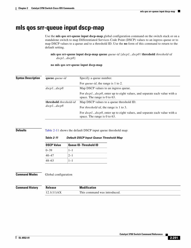
Chapter 2 Catalyst 3750 Switch Cisco IOS Commandsmls qos srr-queue input dscp-map
mls qos srr-queue input dscp-mapUse the mls qos srr-queue input dscp-map global configuration command on the switch stack or on a standalone switch to map Differentiated Services Code Point (DSCP) values to an ingress queue or to map DSCP values to a queue and to a threshold ID. Use the no form of this command to return to the default setting.
mls qos srr-queue input dscp-map queue queue-id {dscp1...dscp8 | threshold threshold-id dscp1...dscp8}
no mls qos srr-queue input dscp-map
Syntax Description
Defaults Table 2-11 shows the default DSCP input queue threshold map:
Command Modes Global configuration
Command History
queue queue-id Specify a queue number.
For queue-id, the range is 1 to 2.
dscp1...dscp8 Map DSCP values to an ingress queue.
For dscp1...dscp8, enter up to eight values, and separate each value with a space. The range is 0 to 63.
threshold threshold-id dscp1...dscp8
Map DSCP values to a queue threshold ID.
For threshold-id, the range is 1 to 3.
For dscp1...dscp8, enter up to eight values, and separate each value with a space. The range is 0 to 63.
Table 2-11 Default DSCP Input Queue Threshold Map
DSCP Value Queue ID–Threshold ID
0–39 1–1
40–47 2–1
48–63 1–1
Release Modification
12.1(11)AX This command was introduced.
2-291Catalyst 3750 Switch Command Reference
OL-8552-01
Chapter 2 Catalyst 3750 Switch Cisco IOS Commandsmls qos srr-queue input dscp-map
Usage Guidelines The DSCP assigned at the ingress port selects an ingress or egress queue and threshold.
The drop-threshold percentage for threshold 3 is predefined. It is set to the queue-full state. You can assign two weighted tail-drop (WTD) threshold percentages to an ingress queue by using the mls qos srr-queue input threshold global configuration command.
You can map each DSCP value to a different queue and threshold combination, allowing the frame to follow different behavior.
You can map up to eight DSCP values per command.
Examples This example shows how to map DSCP values 0 to 6 to ingress queue 1 and to threshold 1 with a drop threshold of 50 percent. It maps DSCP values 20 to 26 to ingress queue 1 and to threshold 2 with a drop threshold of 70 percent:
Switch(config)# mls qos srr-queue input dscp-map queue 1 threshold 1 0 1 2 3 4 5 6Switch(config)# mls qos srr-queue input dscp-map queue 1 threshold 2 20 21 22 23 24 25 26Switch(config)# mls qos srr-queue input threshold 1 50 70
You can verify your settings by entering the show mls qos maps privileged EXEC command.
Related Commands Command Description
mls qos srr-queue input bandwidth Assigns shaped round robin (SRR) weights to an ingress queue.
mls qos srr-queue input buffers Allocates the buffers between the ingress queues.
mls qos srr-queue input cos-map Maps class of service (CoS) values to an ingress queue or maps CoS values to a queue and to threshold ID.
mls qos srr-queue input priority-queue Configures the ingress priority queue and guarantees bandwidth.
mls qos srr-queue input threshold Assigns WTD threshold percentages to an ingress queue.
show mls qos maps Displays QoS mapping information.
2-292Catalyst 3750 Switch Command Reference
OL-8552-01
Chapter 2 Catalyst 3750 Switch Cisco IOS Commandsmls qos srr-queue input priority-queue
mls qos srr-queue input priority-queueUse the mls qos srr-queue input priority-queue global configuration command on the switch stack or on a standalone switch to configure the ingress priority queue and to guarantee bandwidth on the stack ring if the ring is congested. Use the no form of this command to return to the default setting.
mls qos srr-queue input priority-queue queue-id bandwidth weight
no mls qos srr-queue input priority-queue queue-id
Syntax Description
Defaults The priority queue is queue 2, and 10 percent of the bandwidth is allocated to it.
Command Modes Global configuration
Command History
Usage Guidelines You should use the priority queue only for traffic that needs to be expedited (for example, voice traffic, which needs minimum delay and jitter).
The priority queue is guaranteed part of the bandwidth on the stack ring, which reduces the delay and jitter under heavy network traffic on an oversubscribed stack (when there is more traffic than the backplane can carry, and the queues are full and dropping frames).
The amount of bandwidth that can be guaranteed is restricted because a large value affects the entire stack and can degrade the stack performance.
Shaped round robin (SRR) services the priority queue for its configured weight as specified by the bandwidth keyword in the mls qos srr-queue input priority-queue queue-id bandwidth weight global configuration command. Then SRR shares the remaining bandwidth with both ingress queues and services them as specified by the weights configured with the mls qos srr-queue input bandwidth weight1 weight2 global configuration command.
To disable priority queueing, set the bandwidth weight to 0, for example, mls qos srr-queue input priority-queue queue-id bandwidth 0.
queue-id Ingress queue ID. The range is 1 to 2.
bandwidth weight Bandwidth percentage of the stack ring. The range is 0 to 40.
Release Modification
12.1(11)AX This command was introduced.
2-293Catalyst 3750 Switch Command Reference
OL-8552-01
Chapter 2 Catalyst 3750 Switch Cisco IOS Commandsmls qos srr-queue input priority-queue
Examples This example shows how to assign the ingress bandwidths for the queues in the stack. Queue 1 is the priority queue with 10 percent of the bandwidth allocated to it. The bandwidth ratio allocated to queues 1 and 2 is 4/(4+4). SRR services queue 1 (the priority queue) first for its configured 10 percent bandwidth. Then SRR equally shares the remaining 90 percent of the bandwidth between queues 1 and 2 by allocating 45 percent to each queue:
Switch(config)# mls qos srr-queue input priority-queue 1 bandwidth 10Switch(config)# mls qos srr-queue input bandwidth 4 4
You can verify your settings by entering the show mls qos interface [interface-id] queueing or the show mls qos input-queue privileged EXEC command.
Related Commands Command Description
mls qos srr-queue input bandwidth Assigns shaped round robin (SRR) weights to an ingress queue.
mls qos srr-queue input buffers Allocates the buffers between the ingress queues.
mls qos srr-queue input cos-map Maps class of service (CoS) values to an ingress queue or maps CoS values to a queue and to a threshold ID.
mls qos srr-queue input dscp-map Maps Differentiated Services Code Point (DSCP) values to an ingress queue or maps DSCP values to a queue and to a threshold ID.
mls qos srr-queue input threshold Assigns weighted tail-drop (WTD) threshold percentages to an ingress queue.
show mls qos input-queue Displays ingress queue settings.
show mls qos interface queueing Displays quality of service (QoS) information.
2-294Catalyst 3750 Switch Command Reference
OL-8552-01
Chapter 2 Catalyst 3750 Switch Cisco IOS Commandsmls qos srr-queue input threshold
mls qos srr-queue input thresholdUse the mls qos srr-queue input threshold global configuration command on the switch stack or on a standalone switch to assign weighted tail-drop (WTD) threshold percentages to an ingress queue. Use the no form of this command to return to the default setting.
mls qos srr-queue input threshold queue-id threshold-percentage1 threshold-percentage2
no mls qos srr-queue input threshold queue-id
Syntax Description
Defaults When quality of service (QoS) is enabled, WTD is enabled.
The two WTD thresholds are set to 100 percent.
Command Modes Global configuration
Command History
Usage Guidelines QoS uses the CoS-to-threshold map or the DSCP-to-threshold map to decide which class of service (CoS) or Differentiated Services Code Points (DSCPs) values are mapped to threshold 1 and to threshold 2. If threshold 1 is exceeded, packets with CoS or DSCPs assigned to this threshold are dropped until the threshold is no longer exceeded. However, packets assigned to threshold 2 continue to be queued and sent as long as the second threshold is not exceeded.
Each queue has two configurable (explicit) drop threshold and one preset (implicit) drop threshold (full).
You configure the CoS-to-threshold map by using the mls qos srr-queue input cos-map global configuration command. You configure the DSCP-to-threshold map by using the mls qos srr-queue input dscp-map global configuration command.
Examples This example shows how to configure the tail-drop thresholds for the two queues. The queue 1 thresholds are 50 percent and 100 percent, and the queue 2 thresholds are 70 percent and 100 percent:
Switch(config)# mls qos srr-queue input threshold 1 50 100Switch(config)# mls qos srr-queue input threshold 2 70 100
You can verify your settings by entering the show mls qos interface [interface-id] buffers or the show mls qos input-queue privileged EXEC command.
queue-id ID of the ingress queue. The range is 1 to 2.
threshold-percentage1 threshold-percentage2
Two WTD threshold percentage values. Each threshold value is a percentage of the total number of queue descriptors allocated for the queue. Separate each value with a space. The range is 1 to 100.
Release Modification
12.1(11)AX This command was introduced.
2-295Catalyst 3750 Switch Command Reference
OL-8552-01
Chapter 2 Catalyst 3750 Switch Cisco IOS Commandsmls qos srr-queue input threshold
Related Commands Command Description
mls qos srr-queue input bandwidth Assigns shaped round robin (SRR) weights to an ingress queue.
mls qos srr-queue input buffers Allocates the buffers between the ingress queues.
mls qos srr-queue input cos-map Maps class of service (CoS) values to an ingress queue or maps CoS values to a queue and to a threshold ID.
mls qos srr-queue input dscp-map Maps Differentiated Services Code Point (DSCP) values to an ingress queue or maps DSCP values to a queue and to a threshold ID.
mls qos srr-queue input priority-queue Configures the ingress priority queue and guarantees bandwidth.
show mls qos input-queue Displays ingress queue settings.
show mls qos interface buffers Displays quality of service (QoS) information.
2-296Catalyst 3750 Switch Command Reference
OL-8552-01
Chapter 2 Catalyst 3750 Switch Cisco IOS Commandsmls qos srr-queue output cos-map
mls qos srr-queue output cos-mapUse the mls qos srr-queue output cos-map global configuration command on the switch stack or on a standalone switch to map class of service (CoS) values to an egress queue or to map CoS values to a queue and to a threshold ID. Use the no form of this command to return to the default setting.
mls qos srr-queue output cos-map queue queue-id {cos1...cos8 | threshold threshold-id cos1...cos8}
no mls qos srr-queue output cos-map
Syntax Description
Defaults Table 2-12 shows the default CoS output queue threshold map:
Command Modes Global configuration
Command History
queue queue-id Specify a queue number.
For queue-id, the range is 1 to 4.
cos1...cos8 Map CoS values to an egress queue.
For cos1...cos8, enter up to eight values, and separate each value with a space. The range is 0 to 7.
threshold threshold-id cos1...cos8
Map CoS values to a queue threshold ID.
For threshold-id, the range is 1 to 3.
For cos1...cos8, enter up to eight values, and separate each value with a space. The range is 0 to 7.
Table 2-12 Default Cos Output Queue Threshold Map
CoS Value Queue ID–Threshold ID
0, 1 2–1
2, 3 3–1
4 4–1
5 1–1
6, 7 4–1
Release Modification
12.1(11)AX This command was introduced.
2-297Catalyst 3750 Switch Command Reference
OL-8552-01
Chapter 2 Catalyst 3750 Switch Cisco IOS Commandsmls qos srr-queue output cos-map
Usage Guidelines The drop-threshold percentage for threshold 3 is predefined. It is set to the queue-full state.
Note The egress queue default settings are suitable for most situations. You should change them only when you have a thorough understanding of the egress queues and if these settings do not meet your quality of service (QoS) solution.
You can assign two weighted tail-drop (WTD) threshold percentages to an egress queue by using the mls qos queue-set output qset-id threshold global configuration command.
You can map each CoS value to a different queue and threshold combination, allowing the frame to follow different behavior.
Examples This example shows how to map a port to queue-set 1. It maps CoS values 0 to 3 to egress queue 1 and to threshold ID 1. It configures the drop thresholds for queue 1 to 50 and 70 percent of the allocated memory, guarantees (reserves) 100 percent of the allocated memory, and configures 200 percent as the maximum memory that this queue can have before packets are dropped.
Switch(config)# mls qos srr-queue output cos-map queue 1 threshold 1 0 1 2 3Switch(config)# mls qos queue-set output 1 threshold 1 50 70 100 200Switch(config)# interface gigabitethernet2/0/1Switch(config-if)# queue-set 1
You can verify your settings by entering the show mls qos maps, the show mls qos interface [interface-id] buffers, or the show mls qos queue-set privileged EXEC command.
Related Commands Command Description
mls qos srr-queue output dscp-map Maps Differentiated Services Code Point (DSCP) values to an egress queue or maps DSCP values to a queue and to a threshold ID.
mls qos queue-set output threshold Configures the WTD thresholds, guarantees the availability of buffers, and configures the maximum memory allocation to a queue-set.
queue-set Maps a port to a queue-set.
show mls qos interface buffers Displays QoS information.
show mls qos maps Displays QoS mapping information.
show mls qos queue-set Displays egress queue settings for the queue-set.
2-298Catalyst 3750 Switch Command Reference
OL-8552-01
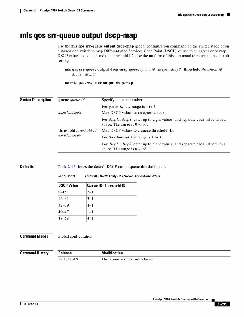
Chapter 2 Catalyst 3750 Switch Cisco IOS Commandsmls qos srr-queue output dscp-map
mls qos srr-queue output dscp-mapUse the mls qos srr-queue output dscp-map global configuration command on the switch stack or on a standalone switch to map Differentiated Services Code Point (DSCP) values to an egress or to map DSCP values to a queue and to a threshold ID. Use the no form of this command to return to the default setting.
mls qos srr-queue output dscp-map queue queue-id {dscp1...dscp8 | threshold threshold-id dscp1...dscp8}
no mls qos srr-queue output dscp-map
Syntax Description
Defaults Table 2-13 shows the default DSCP output queue threshold map:
Command Modes Global configuration
Command History
queue queue-id Specify a queue number.
For queue-id, the range is 1 to 4.
dscp1...dscp8 Map DSCP values to an egress queue.
For dscp1...dscp8, enter up to eight values, and separate each value with a space. The range is 0 to 63.
threshold threshold-id dscp1...dscp8
Map DSCP values to a queue threshold ID.
For threshold-id, the range is 1 to 3.
For dscp1...dscp8, enter up to eight values, and separate each value with a space. The range is 0 to 63.
Table 2-13 Default DSCP Output Queue Threshold Map
DSCP Value Queue ID–Threshold ID
0–15 2–1
16–31 3–1
32–39 4–1
40–47 1–1
48–63 4–1
Release Modification
12.1(11)AX This command was introduced.
2-299Catalyst 3750 Switch Command Reference
OL-8552-01
Chapter 2 Catalyst 3750 Switch Cisco IOS Commandsmls qos srr-queue output dscp-map
Usage Guidelines The drop-threshold percentage for threshold 3 is predefined. It is set to the queue-full state.
Note The egress queue default settings are suitable for most situations. You should change them only when you have a thorough understanding of the egress queues and if these settings do not meet your QoS solution.
You can assign two weighted tail-drop (WTD) threshold percentages to an egress queue by using the mls qos queue-set output qset-id threshold global configuration command.
You can map each DSCP value to a different queue and threshold combination, allowing the frame to follow different behavior.
You can map up to eight DSCP values per command.
Examples This example shows how to map a port to queue-set 1. It maps DSCP values 0 to 3 to egress queue 1 and to threshold ID 1. It configures the drop thresholds for queue 1 to 50 and 70 percent of the allocated memory, guarantees (reserves) 100 percent of the allocated memory, and configures 200 percent as the maximum memory that this queue can have before packets are dropped.
Switch(config)# mls qos srr-queue output dscp-map queue 1 threshold 1 0 1 2 3Switch(config)# mls qos queue-set output 1 threshold 1 50 70 100 200Switch(config)# interface gigabitethernet2/0/1Switch(config-if)# queue-set 1
You can verify your settings by entering the show mls qos maps, the show mls qos interface [interface-id] buffers, or the show mls qos queue-set privileged EXEC command.
Related Commands Command Description
mls qos srr-queue output cos-map Maps class of service (CoS) values to an egress queue or maps CoS values to a queue and to a threshold ID.
mls qos queue-set output threshold Configures the WTD thresholds, guarantees the availability of buffers, and configures the maximum memory allocation to a queue-set.
queue-set Maps a port to a queue-set.
show mls qos interface buffers Displays quality of service (QoS) information.
show mls qos maps Displays QoS mapping information.
show mls qos queue-set Displays egress queue settings for the queue-set.
2-300Catalyst 3750 Switch Command Reference
OL-8552-01
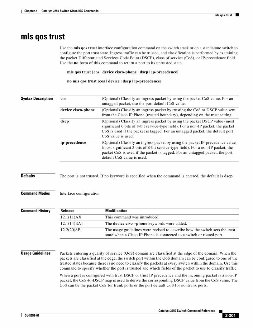
Chapter 2 Catalyst 3750 Switch Cisco IOS Commandsmls qos trust
mls qos trustUse the mls qos trust interface configuration command on the switch stack or on a standalone switch to configure the port trust state. Ingress traffic can be trusted, and classification is performed by examining the packet Differentiated Services Code Point (DSCP), class of service (CoS), or IP-precedence field. Use the no form of this command to return a port to its untrusted state.
mls qos trust [cos | device cisco-phone | dscp | ip-precedence]
no mls qos trust [cos | device | dscp | ip-precedence]
Syntax Description
Defaults The port is not trusted. If no keyword is specified when the command is entered, the default is dscp.
Command Modes Interface configuration
Command History
Usage Guidelines Packets entering a quality of service (QoS) domain are classified at the edge of the domain. When the packets are classified at the edge, the switch port within the QoS domain can be configured to one of the trusted states because there is no need to classify the packets at every switch within the domain. Use this command to specify whether the port is trusted and which fields of the packet to use to classify traffic.
When a port is configured with trust DSCP or trust IP precedence and the incoming packet is a non-IP packet, the CoS-to-DSCP map is used to derive the corresponding DSCP value from the CoS value. The CoS can be the packet CoS for trunk ports or the port default CoS for nontrunk ports.
cos (Optional) Classify an ingress packet by using the packet CoS value. For an untagged packet, use the port default CoS value.
device cisco-phone (Optional) Classify an ingress packet by trusting the CoS or DSCP value sent from the Cisco IP Phone (trusted boundary), depending on the trust setting.
dscp (Optional) Classify an ingress packet by using the packet DSCP value (most significant 6 bits of 8-bit service-type field). For a non-IP packet, the packet CoS is used if the packet is tagged. For an untagged packet, the default port CoS value is used.
ip-precedence (Optional) Classify an ingress packet by using the packet IP-precedence value (most significant 3 bits of 8-bit service-type field). For a non-IP packet, the packet CoS is used if the packet is tagged. For an untagged packet, the port default CoS value is used.
Release Modification
12.1(11)AX This command was introduced.
12.1(14)EA1 The device cisco-phone keywords were added.
12.2(20)SE The usage guidelines were revised to describe how the switch sets the trust state when a Cisco IP Phone is connected to a switch or routed port.
2-301Catalyst 3750 Switch Command Reference
OL-8552-01
Chapter 2 Catalyst 3750 Switch Cisco IOS Commandsmls qos trust
If the DSCP is trusted, the DSCP field of the IP packet is not modified. However, it is still possible that the CoS value of the packet is modified (according to DSCP-to-CoS map).
If the CoS is trusted, the CoS field of the packet is not modified, but the DSCP can be modified (according to CoS-to-DSCP map) if the packet is an IP packet.
The trusted boundary feature prevents security problems if users disconnect their PCs from networked Cisco IP Phones and connect them to the switch port to take advantage of trusted CoS or DSCP settings. You must globally enable the Cisco Discovery Protocol (CDP) on the switch and on the port connected to the IP phone. If the telephone is not detected, trusted boundary disables the trusted setting on the switch or routed port and prevents misuse of a high-priority queue.
If you configure the trust setting for DSCP or IP precedence, the DSCP or IP precedence values in the incoming packets are trusted. If you configure the mls qos cos override interface configuration command on the switch port connected to the IP phone, the switch overrides the CoS of the incoming voice and data packets and assigns the default CoS value to them.
For an inter-QoS domain boundary, you can configure the port to the DSCP-trusted state and apply the DSCP-to-DSCP-mutation map if the DSCP values are different between the QoS domains.
Classification using a port trust state (for example, mls qos trust [cos | dscp | ip-precedence] and a policy map (for example, service-policy input policy-map-name) are mutually exclusive. The last one configured overwrites the previous configuration.
Examples This example shows how to configure a port to trust the IP precedence field in the incoming packet:
Switch(config)# interface gigabitethernet2/0/1Switch(config-if)# mls qos trust ip-precedence
This example shows how to specify that the Cisco IP Phone connected on a port is a trusted device:
Switch(config)# interface gigabitethernet2/0/1Switch(config-if)# mls qos trust device cisco-phone
You can verify your settings by entering the show mls qos interface privileged EXEC command.
Related Commands Command Description
mls qos cos Defines the default CoS value of a port or assigns the default CoS to all incoming packets on the port.
mls qos dscp-mutation Applies a DSCP-to DSCP-mutation map to a DSCP-trusted port.
mls qos map Defines the CoS-to-DSCP map, DSCP-to-CoS map, the DSCP-to-DSCP-mutation map, the IP-precedence-to-DSCP map, and the policed-DSCP map.
show mls qos interface Displays QoS information.
2-302Catalyst 3750 Switch Command Reference
OL-8552-01
Chapter 2 Catalyst 3750 Switch Cisco IOS Commandsmls qos vlan-based
mls qos vlan-basedUse the mls qos vlan-based interface configuration command on the switch stack or on a standalone switch to enable VLAN-based quality of service (QoS) on the physical port. Use the no form of this command to disable this feature.
mls qos vlan-based
no mls qos vlan-based
Syntax Description There are no arguments or keywords.
Defaults VLAN-based QoS is disabled.
Command Modes Interface configuration
Command History
Usage Guidelines Before attaching a hierarchical policy map to a switch virtual interface (SVI), use the mls qos vlan-based interface configuration command on a physical port if the port is to be specified in the secondary interface level of the hierarchical policy map.
When you configure hierarchical policing, the hierarchical policy map is attached to the SVI and affects all traffic belonging to the VLAN. The individual policer in the interface-level traffic classification only affects the physical ports specified for that classification.
For detailed instructions about configuring hierarchical policy maps, see the “Classifying, Policing, and Marking Traffic by Using Hierarchical Policy Maps” section in the software configuration guide for this release.
Examples This example shows how to enable VLAN-based policing on a physical port:
Switch(config)# interface gigabitethernet2/0/1Switch(config-if)# mls qos vlan-based
You can verify your settings by entering the show mls qos interface privileged EXEC command.
Related Commands
Release Modification
12.2(25)SE This command was introduced.
Command Description
show mls qos interface Displays QoS information.
2-303Catalyst 3750 Switch Command Reference
OL-8552-01
Chapter 2 Catalyst 3750 Switch Cisco IOS Commandsmonitor session
monitor sessionUse the monitor session global configuration command on the switch stack or on a standalone switch to start a new Switched Port Analyzer (SPAN) session or Remote SPAN (RSPAN) source or destination session, to enable ingress traffic on the destination port for a network security device (such as a Cisco IDS Sensor Appliance), to add or delete interfaces or VLANs to or from an existing SPAN or RSPAN session, and to limit (filter) SPAN source traffic to specific VLANs. Use the no form of this command to remove the SPAN or RSPAN session or to remove source or destination interfaces or filters from the SPAN or RSPAN session. For destination interfaces, the encapsulation options are ignored with the no form of the command.
monitor session session_number destination {interface interface-id [, | -] [encapsulation replicate] [ingress {dot1q vlan vlan-id | isl | untagged vlan vlan-id | vlan vlan-id}]} | {remote vlan vlan-id}
monitor session session_number filter vlan vlan-id [, | -]
monitor session session_number source {interface interface-id [, | -] [both | rx | tx]} | {vlan vlan-id [, | -] [both | rx | tx]}| {remote vlan vlan-id}
no monitor session {session_number | all | local | remote}
no monitor session session_number destination {interface interface-id [, | -] [encapsulation replicate] [ingress {dot1q vlan vlan-id | isl | untagged vlan vlan-id | vlan vlan-id}]} | {remote vlan vlan-id}
no monitor session session_number filter vlan vlan-id [, | -]
no monitor session session_number source {interface interface-id [, | -] [both | rx | tx]} | {vlan vlan-id [, | -] [both | rx | tx]} | {remote vlan vlan-id}
Syntax Description session_number Specify the session number identified with the SPAN or RSPAN session. The range is 1 to 66.
destination Specify the SPAN or RSPAN destination. A destination must be a physical port.
interface interface-id Specify the destination or source interface for a SPAN or RSPAN session. Valid interfaces are physical ports (including type, stack member, module, and port number). For source interface, port channel is also a valid interface type, and the valid range is 1 to 48.
encapsulation replicate (Optional) Specify that the destination interface replicates the source interface encapsulation method. If not selected, the default is to send packets in native form (untagged).
These keywords are valid only for local SPAN. For RSPAN, the RSPAN VLAN ID overwrites the original VLAN ID; therefore, packets are always sent untagged.
ingress (Optional) Enable ingress traffic forwarding.
dot1q vlan vlan-id Accept incoming packets with IEEE 802.1Q encapsulation with the specified VLAN as the default VLAN.
isl Specify ingress forwarding using ISL encapsulation.
2-304Catalyst 3750 Switch Command Reference
OL-8552-01
Chapter 2 Catalyst 3750 Switch Cisco IOS Commandsmonitor session
Defaults No monitor sessions are configured.
On a source interface, the default is to monitor both received and transmitted traffic.
On a trunk interface used as a source port, all VLANs are monitored.
If encapsulation replicate is not specified on a local SPAN destination port, packets are sent in native form with no encapsulation tag.
Ingress forwarding is disabled on destination ports.
Command Modes Global configuration
Command History
untagged vlan vlan-id Accept incoming packets with untagged encapsulation with the specified VLAN as the default VLAN.
vlan vlan-id When used with only the ingress keyword, set default VLAN for ingress traffic.
remote vlan vlan-id Specify the remote VLAN for an RSPAN source or destination session. The range is 2 to 1001 and 1006 to 4094.
The RSPAN VLAN cannot be VLAN 1 (the default VLAN) or VLAN IDs 1002 to 1005 (reserved for Token Ring and FDDI VLANs).
, (Optional) Specify a series of interfaces or VLANs, or separate a range of interfaces or VLANs from a previous range. Enter a space before and after the comma.
- (Optional) Specify a range of interfaces or VLANs. Enter a space before and after the hyphen.
filter vlan vlan-id Specify a list of VLANs as filters on trunk source ports to limit SPAN source traffic to specific VLANs. The vlan-id range is 1 to 4094.
source Specify the SPAN or RSPAN source. A source can be a physical port, a port channel, or a VLAN.
both, rx, tx (Optional) Specify the traffic direction to monitor. If you do not specify a traffic direction, the source interface sends both transmitted and received traffic.
source vlan vlan-id Specify the SPAN source interface as a VLAN ID. The range is 1 to 4094.
all, local, remote Specify all, local, or remote with the no monitor session command to clear all SPAN and RSPAN, all local SPAN, or all RSPAN sessions.
Release Modification
12.1(11)AX This command was introduced.
12.1(14)EA1 The ingress {dot1q vlan vlan-id | isl | untagged vlan vlan-id | vlan vlan-id} keywords were added.
2-305Catalyst 3750 Switch Command Reference
OL-8552-01
Chapter 2 Catalyst 3750 Switch Cisco IOS Commandsmonitor session
Usage Guidelines Traffic that enters or leaves source ports or source VLANs can be monitored by using SPAN or RSPAN. Traffic routed to source ports or source VLANs cannot be monitored.
You can set a combined maximum of two local SPAN sessions and RSPAN source sessions. You can have a total of 66 SPAN and RSPAN sessions on a switch or switch stack.
You can have a maximum of 64 destination ports on a switch stack.
If a 10-Gigabit Ethernet port is configured as a SPAN or RSPAN destination port, the line rate of the link decreases.
Each session can include multiple ingress or egress source ports or VLANs, but you cannot combine source ports and source VLANs in a single session. Each session can include multiple destination ports.
When you use VLAN-based SPAN (VSPAN) to analyze network traffic in a VLAN or set of VLANs, all active ports in the source VLANs become source ports for the SPAN or RSPAN session. Trunk ports are included as source ports for VSPAN, and only packets with the monitored VLAN ID are sent to the destination port.
You can monitor traffic on a single port or VLAN or on a series or range of ports or VLANs. You select a series or range of interfaces or VLANs by using the [, | -] options.
If you specify a series of VLANs or interfaces, you must enter a space before and after the comma. If you specify a range of VLANs or interfaces, you must enter a space before and after the hyphen (-).
EtherChannel ports cannot be configured as SPAN or RSPAN destination ports. A physical port that is a member of an EtherChannel group can be used as a destination port, but it cannot participate in the EtherChannel group while it is as a SPAN destination.
A private-VLAN port cannot be configured as a SPAN destination port.
You can monitor individual ports while they participate in an EtherChannel, or you can monitor the entire EtherChannel bundle by specifying the port-channel number as the RSPAN source interface.
A port used as a destination port cannot be a SPAN or RSPAN source, nor can a port be a destination port for more than one session at a time.
You can enable IEEE 802.1x authentication on a port that is a SPAN or RSPAN destination port; however, IEEE 802.1x authentication is disabled until the port is removed as a SPAN destination. (If IEEE 802.1x authentication is not available on the port, the switch returns an error message.) You can enable IEEE 802.1x authentication on a SPAN or RSPAN source port.
VLAN filtering refers to analyzing network traffic on a selected set of VLANs on trunk source ports. By default, all VLANs are monitored on trunk source ports. You can use the monitor session session_number filter vlan vlan-id command to limit SPAN traffic on trunk source ports to only the specified VLANs.
VLAN monitoring and VLAN filtering are mutually exclusive. If a VLAN is a source, VLAN filtering cannot be enabled. If VLAN filtering is configured, a VLAN cannot become a source.
If ingress traffic forwarding is enabled for a network security device, the destination port forwards traffic at Layer 2.
Destination ports can be configured to act in these ways:
• When you enter monitor session session_number destination interface interface-id with no other keywords, egress encapsulation is untagged, and ingress forwarding is not enabled.
• When you enter monitor session session_number destination interface interface-id ingress, egress encapsulation is untagged; ingress encapsulation depends on the keywords that follow—dot1q, isl, or untagged.
2-306Catalyst 3750 Switch Command Reference
OL-8552-01
Chapter 2 Catalyst 3750 Switch Cisco IOS Commandsmonitor session
• When you enter monitor session session_number destination interface interface-id encapsulation replicate with no other keywords, egress encapsulation replicates the source interface encapsulation; ingress forwarding is not enabled. (This applies to local SPAN only; RSPAN does not support encapsulation replication.)
• When you enter monitor session session_number destination interface interface-id encapsulation replicate ingress, egress encapsulation replicates the source interface encapsulation; ingress encapsulation depends on the keywords that follow—dot1q, isl, or untagged. (This applies to local SPAN only; RSPAN does not support encapsulation replication.)
Examples This example shows how to create a local SPAN session 1 to monitor both sent and received traffic on source port 1 on stack member 1 to destination port 2 on stack member 2:
Switch(config)# monitor session 1 source interface gigabitethernet1/0/1 bothSwitch(config)# monitor session 1 destination interface gigabitethernet1/0/2
This example shows how to delete a destination port from an existing local SPAN session:
Switch(config)# no monitor session 2 destination gigabitethernet1/0/2
This example shows how to limit SPAN traffic in an existing session only to specific VLANs:
Switch(config)# monitor session 1 filter vlan 100 - 304
This example shows how to configure RSPAN source session 1 to monitor multiple source interfaces and to configure the destination RSPAN VLAN 900.
Switch(config)# monitor session 1 source interface gigabitethernet1/0/1 Switch(config)# monitor session 1 source interface port-channel 2 txSwitch(config)# monitor session 1 destination remote vlan 900Switch(config)# end
This example shows how to configure an RSPAN destination session 10 in the switch receiving the monitored traffic.
Switch(config)# monitor session 10 source remote vlan 900Switch(config)# monitor session 10 destination interface gigabitethernet1/0/2
This example shows how to configure the destination port for ingress traffic on VLAN 5 by using a security device that supports IEEE 802.1Q encapsulation. Egress traffic replicates the source; ingress traffic uses IEEE 802.1Q encapsulation.
Switch(config)# monitor session 2 destination interface gigabitethernet1/0/2 encapsulation replicate ingress dot1q vlan 5
This example shows how to configure the destination port for ingress traffic on VLAN 5 by using a security device that does not support encapsulation. Egress traffic replicates the source encapsulation; ingress traffic is untagged.
Switch(config)# monitor session 2 destination interface gigabitethernet1/0/2 encapsulation replicate ingress untagged vlan 5
You can verify your settings by entering the show monitor privileged EXEC command. You can display SPAN and RSPAN configuration on the switch by entering the show running-config privileged EXEC command. SPAN information appears near the end of the output.
2-307Catalyst 3750 Switch Command Reference
OL-8552-01
Chapter 2 Catalyst 3750 Switch Cisco IOS Commandsmonitor session
Related Commands Command Description
remote-span Configures an RSPAN VLAN in vlan configuration mode.
show monitor Displays SPAN and RSPAN session information.
show running-config Displays the current operating configuration. For syntax information, select Cisco IOS Configuration Fundamentals Command Reference, Release 12.2 > File Management Commands > Configuration File Management Commands.
2-308Catalyst 3750 Switch Command Reference
OL-8552-01
Chapter 2 Catalyst 3750 Switch Cisco IOS Commandsmvr (global configuration)
mvr (global configuration)Use the mvr global configuration command without keywords on the switch stack or on a standalone switch to enable the multicast VLAN registration (MVR) feature on the switch. Use the command with keywords to set the MVR mode for a switch, configure the MVR IP multicast address, set the maximum time to wait for a query reply before removing a port from group membership, and to specify the MVR multicast VLAN. Use the no form of this command to return to the default settings.
mvr [group ip-address [count] | mode [compatible | dynamic] | querytime value | vlan vlan-id]
no mvr [group ip-address | mode [compatible | dynamic] | querytime value | vlan vlan-id]
Syntax Description
Defaults MVR is disabled by default.
The default MVR mode is compatible mode.
No IP multicast addresses are configured on the switch by default.
The default group ip address count is 0.
The default query response time is 5 tenths of or one-half second.
The default multicast VLAN for MVR is VLAN 1.
group ip-address Statically configure an MVR group IP multicast address on the switch.
Use the no form of this command to remove a statically configured IP multicast address or contiguous addresses or, when no IP address is entered, to remove all statically configured MVR IP multicast addresses.
count (Optional) Configure multiple contiguous MVR group addresses. The range is 1 to 256; the default is 1.
mode (Optional) Specify the MVR mode of operation.
The default is compatible mode.
compatible Set MVR mode to provide compatibility with Catalyst 2900 XL and Catalyst 3500 XL switches. This mode does not allow dynamic membership joins on source ports.
dynamic Set MVR mode to allow dynamic MVR membership on source ports.
querytime value (Optional) Set the maximum time to wait for IGMP report memberships on a receiver port. This time applies only to receiver-port leave processing. When an IGMP query is sent from a receiver port, the switch waits for the default or configured MVR querytime for an IGMP group membership report before removing the port from multicast group membership.
The value is the response time in units of tenths of a second. The range is 1 to 100; the default is 5 tenths or one-half second.
Use the no form of the command to return to the default setting.
vlan vlan-id (Optional) Specify the VLAN on which MVR multicast data is expected to be received. This is also the VLAN to which all the source ports belong. The range is 1 to 4094; the default is VLAN 1.
2-309Catalyst 3750 Switch Command Reference
OL-8552-01
Chapter 2 Catalyst 3750 Switch Cisco IOS Commandsmvr (global configuration)
Command Modes Global configuration
Command History
Usage Guidelines A maximum of 256 MVR multicast groups can be configured on a switch.
Use the mvr group command to statically set up all the IP multicast addresses that will take part in MVR. Any multicast data sent to a configured multicast address is sent to all the source ports on the switch and to all receiver ports that have registered to receive data on that IP multicast address.
MVR supports aliased IP multicast addresses on the switch. However, if the switch is interoperating with Catalyst 3550 or Catalyst 3500 XL switches, you should not configure IP addresses that alias between themselves or with the reserved IP multicast addresses (in the range 224.0.0.xxx).
The mvr querytime command applies only to receiver ports.
If the switch MVR is interoperating with Catalyst 2900 XL or Catalyst 3500 XL switches, set the multicast mode to compatible.
When operating in compatible mode, MVR does not support IGMP dynamic joins on MVR source ports.
MVR can coexist with IGMP snooping on a switch.
Multicast routing and MVR cannot coexist on a switch. If you enable multicast routing and a multicast routing protocol while MVR is enabled, MVR is disabled and a warning message appears. If you try to enable MVR while multicast routing and a multicast routing protocol are enabled, the operation to enable MVR is cancelled with an Error message.
Examples This example shows how to enable MVR:
Switch(config)# mvr
Use the show mvr privileged EXEC command to display the current setting for maximum multicast groups.
This example shows how to configure 228.1.23.4 as an IP multicast address:
Switch(config)# mvr group 228.1.23.4
This example shows how to configure ten contiguous IP multicast groups with multicast addresses from 228.1.23.1 to 228.1.23.10:
Switch(config)# mvr group 228.1.23.1 10
Use the show mvr members privileged EXEC command to display the IP multicast group addresses configured on the switch.
This example shows how to set the maximum query response time as one second (10 tenths):
Switch(config)# mvr querytime 10
This example shows how to set VLAN 2 as the multicast VLAN:
Switch(config)# mvr vlan 2
You can verify your settings by entering the show mvr privileged EXEC command.
Release Modification
12.1(11)AX This command was introduced.
2-310Catalyst 3750 Switch Command Reference
OL-8552-01
Chapter 2 Catalyst 3750 Switch Cisco IOS Commandsmvr (global configuration)
Related Commands Command Description
mvr (interface configuration) Configures MVR ports.
show mvr Displays MVR global parameters or port parameters.
show mvr interface Displays the configured MVR interfaces with their type, status, and Immediate Leave configuration. Also displays all MVR groups of which the interface is a member.
show mvr members Displays all ports that are members of an MVR multicast group; if the group has no members, its status is shown as Inactive.
2-311Catalyst 3750 Switch Command Reference
OL-8552-01
Chapter 2 Catalyst 3750 Switch Cisco IOS Commandsmvr (interface configuration)
mvr (interface configuration)Use the mvr interface configuration command on the switch stack or on a standalone switch to configure a Layer 2 port as a multicast VLAN registration (MVR) receiver or source port, to set the Immediate Leave feature, and to statically assign a port to an IP multicast VLAN and IP address. Use the no form of this command to return to the default settings.
mvr [immediate | type {receiver | source} | vlan vlan-id group [ip-address]]
no mvr [immediate | type {source | receiver}| vlan vlan-id group [ip-address]]
Syntax Description
Defaults A port is configured as neither a receiver nor a source.
The Immediate Leave feature is disabled on all ports.
No receiver port is a member of any configured multicast group.
Command Modes Interface configuration
Command History
immediate (Optional) Enable the Immediate Leave feature of MVR on a port. Use the no mvr immediate command to disable the feature.
type (Optional) Configure the port as an MVR receiver port or a source port.
The default port type is neither an MVR source nor a receiver port. The no mvr type command resets the port as neither a source or a receiver port.
receiver Configure the port as a subscriber port that can only receive multicast data. Receiver ports cannot belong to the multicast VLAN.
source Configure the port as an uplink port that can send and receive multicast data for the configured multicast groups. All source ports on a switch belong to a single multicast VLAN.
vlan vlan-id group (Optional) Add the port as a static member of the multicast group with the specified VLAN ID.
The no mvr vlan vlan-id group command removes a port on a VLAN from membership in an IP multicast address group.
ip-address (Optional) Statically configure the specified MVR IP multicast group address for the specified multicast VLAN ID. This is the IP address of the multicast group that the port is joining.
Release Modification
12.1(11)AX This command was introduced.
2-312Catalyst 3750 Switch Command Reference
OL-8552-01
Chapter 2 Catalyst 3750 Switch Cisco IOS Commandsmvr (interface configuration)
Usage Guidelines Configure a port as a source port if that port should be able to both send and receive multicast data bound for the configured multicast groups. Multicast data is received on all ports configured as source ports.
Receiver ports cannot be trunk ports. Receiver ports on a switch can be in different VLANs, but should not belong to the multicast VLAN.
A port that is not taking part in MVR should not be configured as an MVR receiver port or a source port. A non-MVR port is a normal switch port, able to send and receive multicast data with normal switch behavior.
When Immediate Leave is enabled, a receiver port leaves a multicast group more quickly. Without Immediate Leave, when the switch receives an IGMP leave message from a group on a receiver port, it sends out an IGMP MAC-based query on that port and waits for IGMP group membership reports. If no reports are received in a configured time period, the receiver port is removed from multicast group membership. With Immediate Leave, an IGMP MAC-based query is not sent from the receiver port on which the IGMP leave was received. As soon as the leave message is received, the receiver port is removed from multicast group membership, which speeds up leave latency.
The Immediate Leave feature should be enabled only on receiver ports to which a single receiver device is connected.
The mvr vlan group command statically configures ports to receive multicast traffic sent to the IP multicast address. A port statically configured as a member of group remains a member of the group until statically removed. In compatible mode, this command applies only to receiver ports; in dynamic mode, it can also apply to source ports. Receiver ports can also dynamically join multicast groups by using IGMP join messages.
When operating in compatible mode, MVR does not support IGMP dynamic joins on MVR source ports.
An MVR port cannot be a private-VLAN port.
Examples This example shows how to configure a port as an MVR receiver port:
Switch(config)# interface gigabitethernet1/0/1Switch(config-if)# mvr type receiver
Use the show mvr interface privileged EXEC command to display configured receiver ports and source ports.
This example shows how to enable Immediate Leave on a port:
Switch(config)# interface gigabitethernet1/0/1Switch(config-if)# mvr immediate
This example shows how to add a port on VLAN 1 as a static member of IP multicast group 228.1.23.4:
Switch(config)# interface gigabitethernet1/0/2Switch(config-if)# mvr vlan1 group 230.1.23.4
You can verify your settings by entering the show mvr members privileged EXEC command.
2-313Catalyst 3750 Switch Command Reference
OL-8552-01
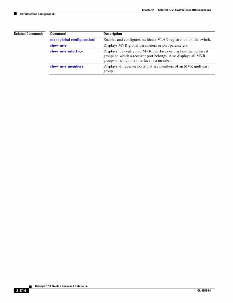
Chapter 2 Catalyst 3750 Switch Cisco IOS Commandsmvr (interface configuration)
Related Commands Command Description
mvr (global configuration) Enables and configures multicast VLAN registration on the switch.
show mvr Displays MVR global parameters or port parameters.
show mvr interface Displays the configured MVR interfaces or displays the multicast groups to which a receiver port belongs. Also displays all MVR groups of which the interface is a member.
show mvr members Displays all receiver ports that are members of an MVR multicast group.
2-314Catalyst 3750 Switch Command Reference
OL-8552-01
Chapter 2 Catalyst 3750 Switch Cisco IOS Commandspagp learn-method
pagp learn-methodUse the pagp learn-method interface configuration command on the switch stack or on a standalone switch to learn the source address of incoming packets received from an EtherChannel port. Use the no form of this command to return to the default setting.
pagp learn-method {aggregation-port | physical-port}
no pagp learn-method
Syntax Description
Defaults The default is aggregation-port (logical port channel).
Command Modes Interface configuration
Command History
Usage Guidelines The learn method must be configured the same at both ends of the link.
Note The Catalyst 3750 switch supports address learning only on aggregate ports even though the physical-port keyword is provided in the command-line interface (CLI). The pagp learn-method and the pagp port-priority interface configuration commands have no effect on the switch hardware, but they are required for PAgP interoperability with devices that only support address learning by physical ports, such as the Catalyst 1900 switch.
When the link partner to the Catalyst 3750 switch is a physical learner, we recommend that you configure the switch as a physical-port learner by using the pagp learn-method physical-port interface configuration command and to set the load-distribution method based on the source MAC address by using the port-channel load-balance src-mac global configuration command. Use the pagp learn-method interface configuration command only in this situation.
aggregation-port Specify address learning on the logical port-channel. The switch sends packets to the source using any of the ports in the EtherChannel. This setting is the default. With aggregate-port learning, it is not important on which physical port the packet arrives.
physical-port Specify address learning on the physical port within the EtherChannel. The switch sends packets to the source using the same port in the EtherChannel from which it learned the source address. The other end of the channel uses the same port in the channel for a particular destination MAC or IP address.
Release Modification
12.1(11)AX This command was introduced.
2-315Catalyst 3750 Switch Command Reference
OL-8552-01
Chapter 2 Catalyst 3750 Switch Cisco IOS Commandspagp learn-method
Examples This example shows how to set the learning method to learn the address on the physical port within the EtherChannel:
Switch(config-if)# pagp learn-method physical-port
This example shows how to set the learning method to learn the address on the port-channel within the EtherChannel:
Switch(config-if)# pagp learn-method aggregation-port
You can verify your settings by entering the show running-config privileged EXEC command or the show pagp channel-group-number internal privileged EXEC command.
Related Commands Command Description
pagp port-priority Selects a port over which all traffic through the EtherChannel is sent.
show pagp Displays PAgP channel-group information.
show running-config Displays the current operating configuration. For syntax information, select Cisco IOS Configuration Fundamentals Command Reference, Release 12.2 > File Management Commands > Configuration File Management Commands.
2-316Catalyst 3750 Switch Command Reference
OL-8552-01
Chapter 2 Catalyst 3750 Switch Cisco IOS Commandspagp port-priority
pagp port-priorityUse the pagp port-priority interface configuration command on the switch stack or on a standalone switch to select a port over which all Port Aggregation Protocol (PAgP) traffic through the EtherChannel is sent. If all unused ports in the EtherChannel are in hot-standby mode, they can be placed into operation if the currently selected port and link fails. Use the no form of this command to return to the default setting.
pagp port-priority priority
no pagp port-priority
Syntax Description
Defaults The default is 128.
Command Modes Interface configuration
Command History
Usage Guidelines The physical port with the highest priority that is operational and has membership in the same EtherChannel is the one selected for PAgP transmission.
Note The Catalyst 3750 switch supports address learning only on aggregate ports even though the physical-port keyword is provided in the command-line interface (CLI). The pagp learn-method and the pagp port-priority interface configuration commands have no effect on the switch hardware, but they are required for PAgP interoperability with devices that only support address learning by physical ports, such as the Catalyst 1900 switch.
When the link partner to the Catalyst 3750 switch is a physical learner, we recommend that you configure the switch as a physical-port learner by using the pagp learn-method physical-port interface configuration command and to set the load-distribution method based on the source MAC address by using the port-channel load-balance src-mac global configuration command. Use the pagp learn-method interface configuration command only in this situation.
Examples This example shows how to set the port priority to 200:
Switch(config-if)# pagp port-priority 200
You can verify your setting by entering the show running-config privileged EXEC command or the show pagp channel-group-number internal privileged EXEC command.
priority A priority number ranging from 0 to 255.
Release Modification
12.1(11)AX This command was introduced.
2-317Catalyst 3750 Switch Command Reference
OL-8552-01

Chapter 2 Catalyst 3750 Switch Cisco IOS Commandspagp port-priority
Related Commands Command Description
pagp learn-method Provides the ability to learn the source address of incoming packets.
show pagp Displays PAgP channel-group information.
show running-config Displays the current operating configuration. For syntax information, select Cisco IOS Configuration Fundamentals Command Reference, Release 12.2 > File Management Commands > Configuration File Management Commands.
2-318Catalyst 3750 Switch Command Reference
OL-8552-01
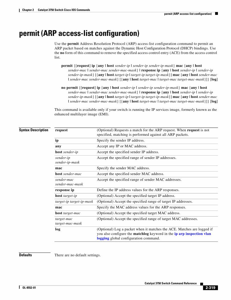
Chapter 2 Catalyst 3750 Switch Cisco IOS Commandspermit (ARP access-list configuration)
permit (ARP access-list configuration)Use the permit Address Resolution Protocol (ARP) access-list configuration command to permit an ARP packet based on matches against the Dynamic Host Configuration Protocol (DHCP) bindings. Use the no form of this command to remove the specified access control entry (ACE) from the access control list.
permit {[request] ip {any | host sender-ip | sender-ip sender-ip-mask} mac {any | host sender-mac | sender-mac sender-mac-mask} | response ip {any | host sender-ip | sender-ip sender-ip-mask} [{any | host target-ip | target-ip target-ip-mask}] mac {any | host sender-mac | sender-mac sender-mac-mask} [{any | host target-mac | target-mac target-mac-mask}]} [log]
no permit {[request] ip {any | host sender-ip | sender-ip sender-ip-mask} mac {any | host sender-mac | sender-mac sender-mac-mask} | response ip {any | host sender-ip | sender-ip sender-ip-mask} [{any | host target-ip | target-ip target-ip-mask}] mac {any | host sender-mac | sender-mac sender-mac-mask} [{any | host target-mac | target-mac target-mac-mask}]} [log]
This command is available only if your switch is running the IP services image, formerly known as the enhanced multilayer image (EMI).
Syntax Description
Defaults There are no default settings.
request (Optional) Requests a match for the ARP request. When request is not specified, matching is performed against all ARP packets.
ip Specify the sender IP address.
any Accept any IP or MAC address.
host sender-ip Accept the specified sender IP address.
sender-ip sender-ip-mask
Accept the specified range of sender IP addresses.
mac Specify the sender MAC address.
host sender-mac Accept the specified sender MAC address.
sender-mac sender-mac-mask
Accept the specified range of sender MAC addresses.
response ip Define the IP address values for the ARP responses.
host target-ip (Optional) Accept the specified target IP address.
target-ip target-ip-mask (Optional) Accept the specified range of target IP addresses.
mac Specify the MAC address values for the ARP responses.
host target-mac (Optional) Accept the specified target MAC address.
target-mac target-mac-mask
(Optional) Accept the specified range of target MAC addresses.
log (Optional) Log a packet when it matches the ACE. Matches are logged if you also configure the matchlog keyword in the ip arp inspection vlan logging global configuration command.
2-319Catalyst 3750 Switch Command Reference
OL-8552-01
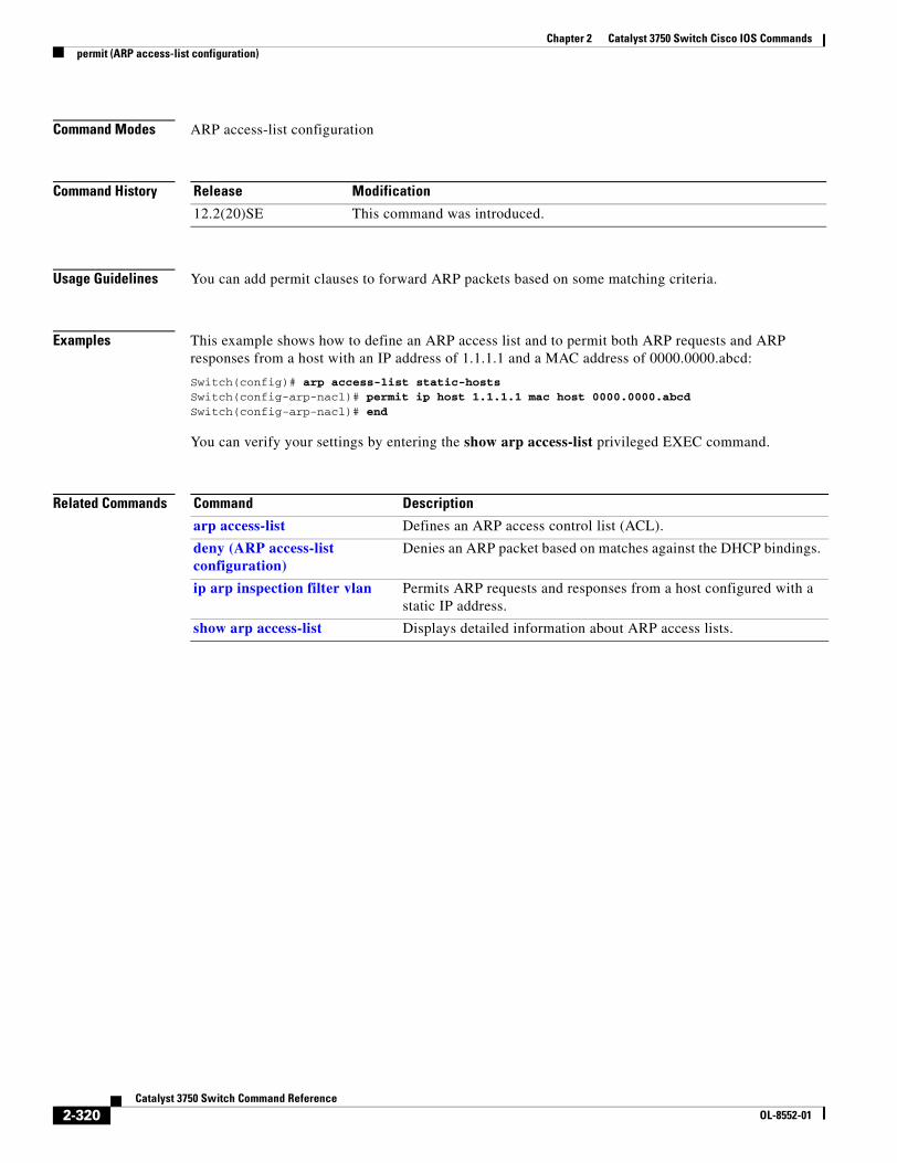
Chapter 2 Catalyst 3750 Switch Cisco IOS Commandspermit (ARP access-list configuration)
Command Modes ARP access-list configuration
Command History
Usage Guidelines You can add permit clauses to forward ARP packets based on some matching criteria.
Examples This example shows how to define an ARP access list and to permit both ARP requests and ARP responses from a host with an IP address of 1.1.1.1 and a MAC address of 0000.0000.abcd:
Switch(config)# arp access-list static-hostsSwitch(config-arp-nacl)# permit ip host 1.1.1.1 mac host 0000.0000.abcdSwitch(config-arp-nacl)# end
You can verify your settings by entering the show arp access-list privileged EXEC command.
Related Commands
Release Modification
12.2(20)SE This command was introduced.
Command Description
arp access-list Defines an ARP access control list (ACL).
deny (ARP access-list configuration)
Denies an ARP packet based on matches against the DHCP bindings.
ip arp inspection filter vlan Permits ARP requests and responses from a host configured with a static IP address.
show arp access-list Displays detailed information about ARP access lists.
2-320Catalyst 3750 Switch Command Reference
OL-8552-01
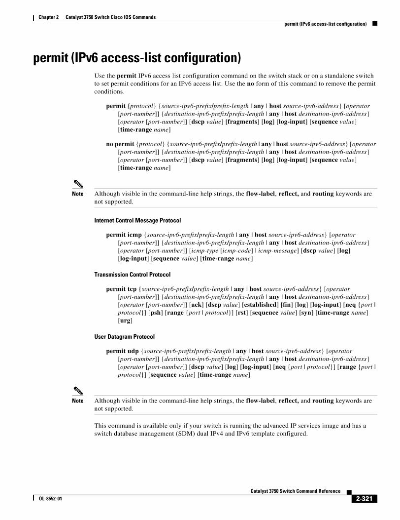
Chapter 2 Catalyst 3750 Switch Cisco IOS Commandspermit (IPv6 access-list configuration)
permit (IPv6 access-list configuration)Use the permit IPv6 access list configuration command on the switch stack or on a standalone switch to set permit conditions for an IPv6 access list. Use the no form of this command to remove the permit conditions.
permit {protocol} {source-ipv6-prefix/prefix-length | any | host source-ipv6-address} [operator [port-number]] {destination-ipv6-prefix/prefix-length | any | host destination-ipv6-address} [operator [port-number]] [dscp value] [fragments] [log] [log-input] [sequence value] [time-range name]
no permit {protocol} {source-ipv6-prefix/prefix-length | any | host source-ipv6-address} [operator [port-number]] {destination-ipv6-prefix/prefix-length | any | host destination-ipv6-address} [operator [port-number]] [dscp value] [fragments] [log] [log-input] [sequence value] [time-range name]
Note Although visible in the command-line help strings, the flow-label, reflect, and routing keywords are not supported.
Internet Control Message Protocol
permit icmp {source-ipv6-prefix/prefix-length | any | host source-ipv6-address} [operator [port-number]] {destination-ipv6-prefix/prefix-length | any | host destination-ipv6-address} [operator [port-number]] [icmp-type [icmp-code] | icmp-message] [dscp value] [log] [log-input] [sequence value] [time-range name]
Transmission Control Protocol
permit tcp {source-ipv6-prefix/prefix-length | any | host source-ipv6-address} [operator [port-number]] {destination-ipv6-prefix/prefix-length | any | host destination-ipv6-address} [operator [port-number]] [ack] [dscp value] [established] [fin] [log] [log-input] [neq {port | protocol}] [psh] [range {port | protocol}] [rst] [sequence value] [syn] [time-range name] [urg]
User Datagram Protocol
permit udp {source-ipv6-prefix/prefix-length | any | host source-ipv6-address} [operator [port-number]] {destination-ipv6-prefix/prefix-length | any | host destination-ipv6-address} [operator [port-number]] [dscp value] [log] [log-input] [neq {port | protocol}] [range {port | protocol}] [sequence value] [time-range name]
Note Although visible in the command-line help strings, the flow-label, reflect, and routing keywords are not supported.
This command is available only if your switch is running the advanced IP services image and has a switch database management (SDM) dual IPv4 and IPv6 template configured.
2-321Catalyst 3750 Switch Command Reference
OL-8552-01
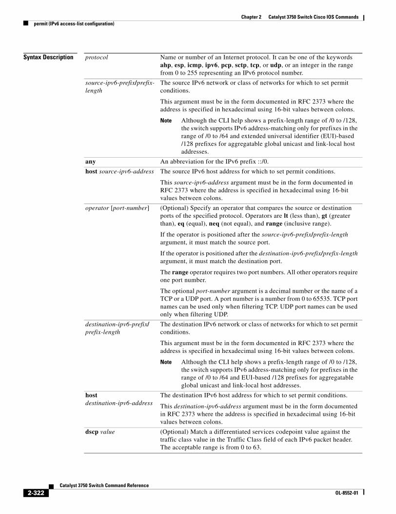
Chapter 2 Catalyst 3750 Switch Cisco IOS Commandspermit (IPv6 access-list configuration)
Syntax Description protocol Name or number of an Internet protocol. It can be one of the keywords ahp, esp, icmp, ipv6, pcp, sctp, tcp, or udp, or an integer in the range from 0 to 255 representing an IPv6 protocol number.
source-ipv6-prefix/prefix-length
The source IPv6 network or class of networks for which to set permit conditions.
This argument must be in the form documented in RFC 2373 where the address is specified in hexadecimal using 16-bit values between colons.
Note Although the CLI help shows a prefix-length range of /0 to /128, the switch supports IPv6 address-matching only for prefixes in the range of /0 to /64 and extended universal identifier (EUI)-based /128 prefixes for aggregatable global unicast and link-local host addresses.
any An abbreviation for the IPv6 prefix ::/0.
host source-ipv6-address The source IPv6 host address for which to set permit conditions.
This source-ipv6-address argument must be in the form documented in RFC 2373 where the address is specified in hexadecimal using 16-bit values between colons.
operator [port-number] (Optional) Specify an operator that compares the source or destination ports of the specified protocol. Operators are lt (less than), gt (greater than), eq (equal), neq (not equal), and range (inclusive range).
If the operator is positioned after the source-ipv6-prefix/prefix-length argument, it must match the source port.
If the operator is positioned after the destination-ipv6-prefix/prefix-length argument, it must match the destination port.
The range operator requires two port numbers. All other operators require one port number.
The optional port-number argument is a decimal number or the name of a TCP or a UDP port. A port number is a number from 0 to 65535. TCP port names can be used only when filtering TCP. UDP port names can be used only when filtering UDP.
destination-ipv6-prefix/prefix-length
The destination IPv6 network or class of networks for which to set permit conditions.
This argument must be in the form documented in RFC 2373 where the address is specified in hexadecimal using 16-bit values between colons.
Note Although the CLI help shows a prefix-length range of /0 to /128, the switch supports IPv6 address-matching only for prefixes in the range of /0 to /64 and EUI-based /128 prefixes for aggregatable global unicast and link-local host addresses.
host destination-ipv6-address
The destination IPv6 host address for which to set permit conditions.
This destination-ipv6-address argument must be in the form documented in RFC 2373 where the address is specified in hexadecimal using 16-bit values between colons.
dscp value (Optional) Match a differentiated services codepoint value against the traffic class value in the Traffic Class field of each IPv6 packet header. The acceptable range is from 0 to 63.
2-322Catalyst 3750 Switch Command Reference
OL-8552-01
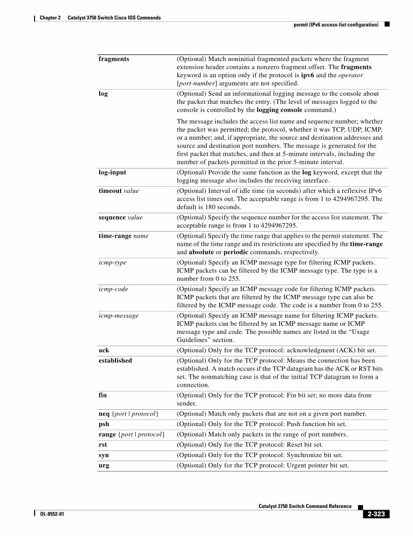
Chapter 2 Catalyst 3750 Switch Cisco IOS Commandspermit (IPv6 access-list configuration)
fragments (Optional) Match noninitial fragmented packets where the fragment extension header contains a nonzero fragment offset. The fragments keyword is an option only if the protocol is ipv6 and the operator [port-number] arguments are not specified.
log (Optional) Send an informational logging message to the console about the packet that matches the entry. (The level of messages logged to the console is controlled by the logging console command.)
The message includes the access list name and sequence number; whether the packet was permitted; the protocol, whether it was TCP, UDP, ICMP, or a number; and, if appropriate, the source and destination addresses and source and destination port numbers. The message is generated for the first packet that matches, and then at 5-minute intervals, including the number of packets permitted in the prior 5-minute interval.
log-input (Optional) Provide the same function as the log keyword, except that the logging message also includes the receiving interface.
timeout value (Optional) Interval of idle time (in seconds) after which a reflexive IPv6 access list times out. The acceptable range is from 1 to 4294967295. The default is 180 seconds.
sequence value (Optional) Specify the sequence number for the access list statement. The acceptable range is from 1 to 4294967295.
time-range name (Optional) Specify the time range that applies to the permit statement. The name of the time range and its restrictions are specified by the time-range and absolute or periodic commands, respectively.
icmp-type (Optional) Specify an ICMP message type for filtering ICMP packets. ICMP packets can be filtered by the ICMP message type. The type is a number from 0 to 255.
icmp-code (Optional) Specify an ICMP message code for filtering ICMP packets. ICMP packets that are filtered by the ICMP message type can also be filtered by the ICMP message code. The code is a number from 0 to 255.
icmp-message (Optional) Specify an ICMP message name for filtering ICMP packets. ICMP packets can be filtered by an ICMP message name or ICMP message type and code. The possible names are listed in the “Usage Guidelines” section.
ack (Optional) Only for the TCP protocol: acknowledgment (ACK) bit set.
established (Optional) Only for the TCP protocol: Means the connection has been established. A match occurs if the TCP datagram has the ACK or RST bits set. The nonmatching case is that of the initial TCP datagram to form a connection.
fin (Optional) Only for the TCP protocol: Fin bit set; no more data from sender.
neq {port | protocol} (Optional) Match only packets that are not on a given port number.
psh (Optional) Only for the TCP protocol: Push function bit set.
range {port | protocol} (Optional) Match only packets in the range of port numbers.
rst (Optional) Only for the TCP protocol: Reset bit set.
syn (Optional) Only for the TCP protocol: Synchronize bit set.
urg (Optional) Only for the TCP protocol: Urgent pointer bit set.
2-323Catalyst 3750 Switch Command Reference
OL-8552-01
Chapter 2 Catalyst 3750 Switch Cisco IOS Commandspermit (IPv6 access-list configuration)
Defaults No IPv6 access list is defined.
Command Modes IPv6 access-list configuration
Command History
Usage Guidelines The permit (IPv6 access-list configuration mode) command is similar to the permit (IPv4 access-list configuration mode) command, except that it is IPv6-specific.
Use the permit (IPv6) command after the ipv6 access-list command to enter IPv6 access-list configuration mode and to define the conditions under which a packet passes the access list.
Specifying IPv6 for the protocol argument matches against the IPv6 header of the packet.
By default, the first statement in an access list is number 10, and the subsequent statements are incremented by 10.
You can add permit, deny, or remark statements to an existing access list without re-entering the entire list. To add a new statement anywhere other than at the end of the list, create a new statement with an appropriate entry number that falls between two existing entry numbers to show where it belongs.
See the ipv6 access-list command for more information on defining IPv6 ACLs.
Note Every IPv6 ACL has implicit permit icmp any any nd-na, permit icmp any any nd-ns, and deny ipv6 any any statements as its last match conditions. The two permit conditions allow ICMPv6 neighbor discovery. To disallow ICMPv6 neighbor discovery and to deny icmp any any nd-na or icmp any any nd-ns, there must be an explicit deny entry in the ACL. For the implicit deny ipv6 any any statement to take effect, an IPv6 ACL must contain at least one entry.
The IPv6 neighbor discovery process uses the IPv6 network layer service. Therefore, by default, IPv6 ACLs implicitly allow IPv6 neighbor discovery packets to be sent and received on an interface. In IPv4, the Address Resolution Protocol (ARP), which is equivalent to the IPv6 neighbor discovery process, uses a separate data link layer protocol. Therefore, by default, IPv4 ACLs implicitly allow ARP packets to be sent and received on an interface.
Both the source-ipv6-prefix/prefix-length and destination-ipv6-prefix/prefix-length arguments are used for traffic filtering (the source prefix filters traffic based upon the traffic source; the destination prefix filters traffic based upon the traffic destination).
The switch supports only prefixes from /0 to /64 and EUI-based /128 prefixes for aggregatable global unicast and link-local host addresses.
The fragments keyword is an option only if the operator [port-number] arguments are not specified.
Release Modification
12.2(25)SED This command was introduced.
2-324Catalyst 3750 Switch Command Reference
OL-8552-01
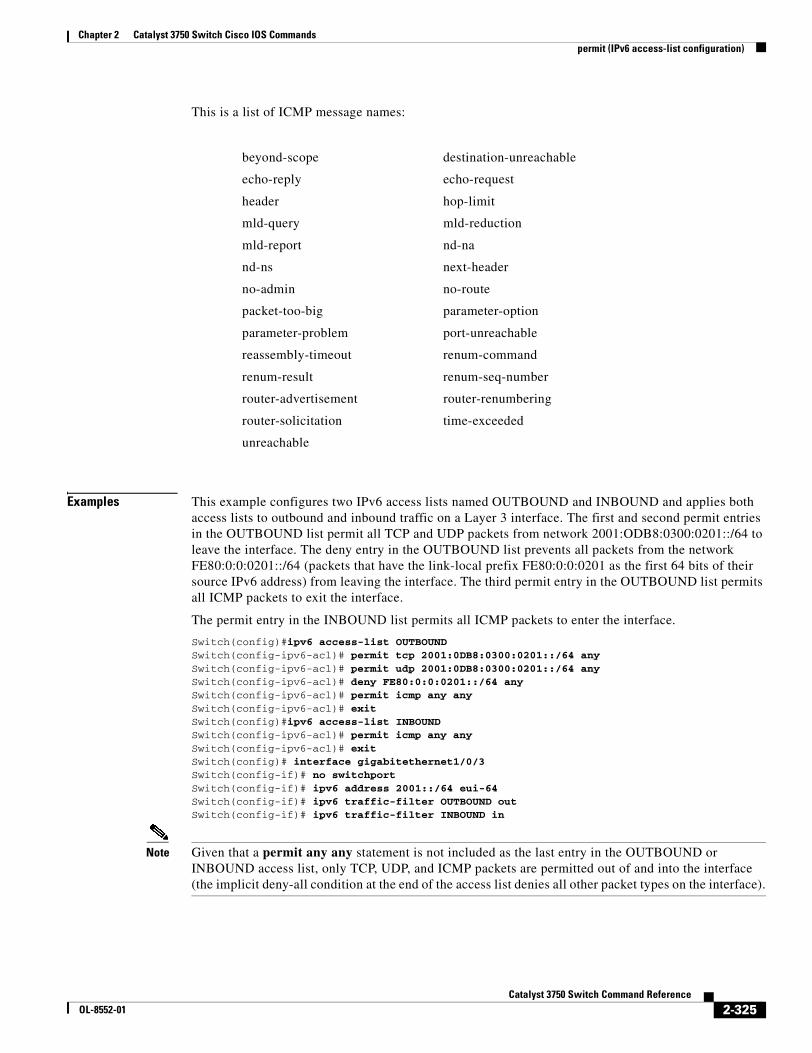
Chapter 2 Catalyst 3750 Switch Cisco IOS Commandspermit (IPv6 access-list configuration)
This is a list of ICMP message names:
Examples This example configures two IPv6 access lists named OUTBOUND and INBOUND and applies both access lists to outbound and inbound traffic on a Layer 3 interface. The first and second permit entries in the OUTBOUND list permit all TCP and UDP packets from network 2001:ODB8:0300:0201::/64 to leave the interface. The deny entry in the OUTBOUND list prevents all packets from the network FE80:0:0:0201::/64 (packets that have the link-local prefix FE80:0:0:0201 as the first 64 bits of their source IPv6 address) from leaving the interface. The third permit entry in the OUTBOUND list permits all ICMP packets to exit the interface.
The permit entry in the INBOUND list permits all ICMP packets to enter the interface.
Switch(config)#ipv6 access-list OUTBOUNDSwitch(config-ipv6-acl)# permit tcp 2001:0DB8:0300:0201::/64 any Switch(config-ipv6-acl)# permit udp 2001:0DB8:0300:0201::/64 any Switch(config-ipv6-acl)# deny FE80:0:0:0201::/64 anySwitch(config-ipv6-acl)# permit icmp any anySwitch(config-ipv6-acl)# exitSwitch(config)#ipv6 access-list INBOUNDSwitch(config-ipv6-acl)# permit icmp any anySwitch(config-ipv6-acl)# exitSwitch(config)# interface gigabitethernet1/0/3Switch(config-if)# no switchportSwitch(config-if)# ipv6 address 2001::/64 eui-64Switch(config-if)# ipv6 traffic-filter OUTBOUND outSwitch(config-if)# ipv6 traffic-filter INBOUND in
Note Given that a permit any any statement is not included as the last entry in the OUTBOUND or INBOUND access list, only TCP, UDP, and ICMP packets are permitted out of and into the interface (the implicit deny-all condition at the end of the access list denies all other packet types on the interface).
beyond-scope destination-unreachable
echo-reply echo-request
header hop-limit
mld-query mld-reduction
mld-report nd-na
nd-ns next-header
no-admin no-route
packet-too-big parameter-option
parameter-problem port-unreachable
reassembly-timeout renum-command
renum-result renum-seq-number
router-advertisement router-renumbering
router-solicitation time-exceeded
unreachable
2-325Catalyst 3750 Switch Command Reference
OL-8552-01
Chapter 2 Catalyst 3750 Switch Cisco IOS Commandspermit (IPv6 access-list configuration)
Related Commands Command Description
ipv6 access-list Defines an IPv6 access list and enters IPv6 access list configuration mode.
ipv6 traffic-filter Filters incoming or outgoing IPv6 traffic on an interface.
deny (IPv6 access-list configuration)
Sets deny conditions for an IPv6 access list.
show ipv6 access-list Displays the contents of all current IPv6 access lists.
2-326Catalyst 3750 Switch Command Reference
OL-8552-01
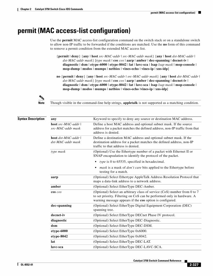
Chapter 2 Catalyst 3750 Switch Cisco IOS Commandspermit (MAC access-list configuration)
permit (MAC access-list configuration)Use the permit MAC access-list configuration command on the switch stack or on a standalone switch to allow non-IP traffic to be forwarded if the conditions are matched. Use the no form of this command to remove a permit condition from the extended MAC access list.
{permit | deny} {any | host src-MAC-addr | src-MAC-addr mask} {any | host dst-MAC-addr | dst-MAC-addr mask} [type mask | cos cos | aarp | amber | dec-spanning | decnet-iv | diagnostic | dsm | etype-6000 | etype-8042 | lat | lavc-sca | lsap lsap mask | mop-console | mop-dump | msdos | mumps | netbios | vines-echo | vines-ip | xns-idp]
no {permit | deny} {any | host src-MAC-addr | src-MAC-addr mask} {any | host dst-MAC-addr | dst-MAC-addr mask} [type mask | cos cos | aarp | amber | dec-spanning | decnet-iv | diagnostic | dsm | etype-6000 | etype-8042 | lat | lavc-sca | lsap lsap mask | mop-console | mop-dump | msdos | mumps | netbios | vines-echo |vines-ip | xns-idp]
Note Though visible in the command-line help strings, appletalk is not supported as a matching condition.
Syntax Description any Keyword to specify to deny any source or destination MAC address.
host src-MAC-addr |src-MAC-addr mask
Define a host MAC address and optional subnet mask. If the source address for a packet matches the defined address, non-IP traffic from that address is denied.
host dst-MAC-addr | dst-MAC-addr mask
Define a destination MAC address and optional subnet mask. If the destination address for a packet matches the defined address, non-IP traffic to that address is denied.
type mask (Optional) Use the Ethertype number of a packet with Ethernet II or SNAP encapsulation to identify the protocol of the packet.
• type is 0 to 65535, specified in hexadecimal.
• mask is a mask of don’t care bits applied to the Ethertype before testing for a match.
aarp (Optional) Select Ethertype AppleTalk Address Resolution Protocol that maps a data-link address to a network address.
amber (Optional) Select EtherType DEC-Amber.
cos cos (Optional) Select an arbitrary class of service (CoS) number from 0 to 7 to set priority. Filtering on CoS can be performed only in hardware. A warning message appears if the cos option is configured.
dec-spanning (Optional) Select EtherType Digital Equipment Corporation (DEC) spanning tree.
decnet-iv (Optional) Select EtherType DECnet Phase IV protocol.
diagnostic (Optional) Select EtherType DEC-Diagnostic.
dsm (Optional) Select EtherType DEC-DSM.
etype-6000 (Optional) Select EtherType 0x6000.
etype-8042 (Optional) Select EtherType 0x8042.
lat (Optional) Select EtherType DEC-LAT.
lavc-sca (Optional) Select EtherType DEC-LAVC-SCA.
2-327Catalyst 3750 Switch Command Reference
OL-8552-01
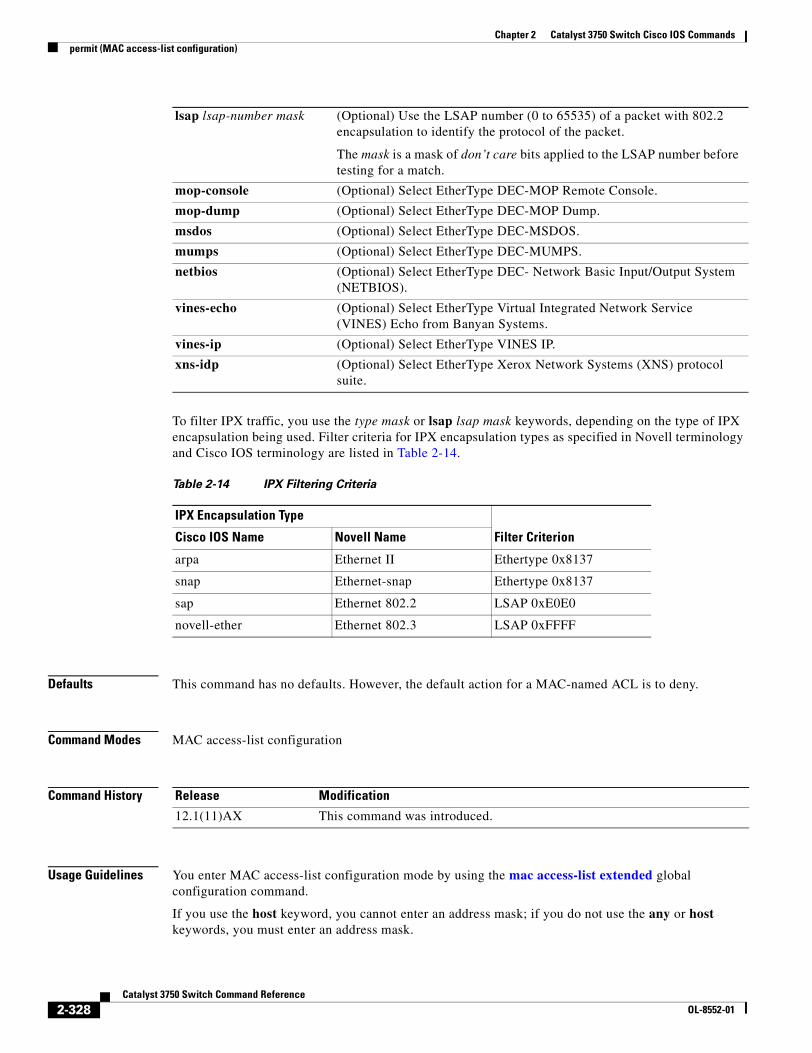
Chapter 2 Catalyst 3750 Switch Cisco IOS Commandspermit (MAC access-list configuration)
To filter IPX traffic, you use the type mask or lsap lsap mask keywords, depending on the type of IPX encapsulation being used. Filter criteria for IPX encapsulation types as specified in Novell terminology and Cisco IOS terminology are listed in Table 2-14.
Defaults This command has no defaults. However, the default action for a MAC-named ACL is to deny.
Command Modes MAC access-list configuration
Command History
Usage Guidelines You enter MAC access-list configuration mode by using the mac access-list extended global configuration command.
If you use the host keyword, you cannot enter an address mask; if you do not use the any or host keywords, you must enter an address mask.
lsap lsap-number mask (Optional) Use the LSAP number (0 to 65535) of a packet with 802.2 encapsulation to identify the protocol of the packet.
The mask is a mask of don’t care bits applied to the LSAP number before testing for a match.
mop-console (Optional) Select EtherType DEC-MOP Remote Console.
mop-dump (Optional) Select EtherType DEC-MOP Dump.
msdos (Optional) Select EtherType DEC-MSDOS.
mumps (Optional) Select EtherType DEC-MUMPS.
netbios (Optional) Select EtherType DEC- Network Basic Input/Output System (NETBIOS).
vines-echo (Optional) Select EtherType Virtual Integrated Network Service (VINES) Echo from Banyan Systems.
vines-ip (Optional) Select EtherType VINES IP.
xns-idp (Optional) Select EtherType Xerox Network Systems (XNS) protocol suite.
Table 2-14 IPX Filtering Criteria
IPX Encapsulation Type
Filter CriterionCisco IOS Name Novell Name
arpa Ethernet II Ethertype 0x8137
snap Ethernet-snap Ethertype 0x8137
sap Ethernet 802.2 LSAP 0xE0E0
novell-ether Ethernet 802.3 LSAP 0xFFFF
Release Modification
12.1(11)AX This command was introduced.
2-328Catalyst 3750 Switch Command Reference
OL-8552-01
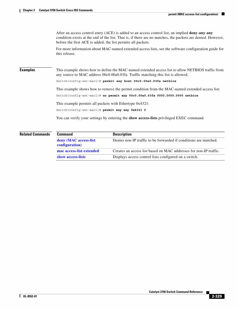
Chapter 2 Catalyst 3750 Switch Cisco IOS Commandspermit (MAC access-list configuration)
After an access control entry (ACE) is added to an access control list, an implied deny-any-any condition exists at the end of the list. That is, if there are no matches, the packets are denied. However, before the first ACE is added, the list permits all packets.
For more information about MAC-named extended access lists, see the software configuration guide for this release.
Examples This example shows how to define the MAC-named extended access list to allow NETBIOS traffic from any source to MAC address 00c0.00a0.03fa. Traffic matching this list is allowed.
Switch(config-ext-macl)# permit any host 00c0.00a0.03fa netbios
This example shows how to remove the permit condition from the MAC-named extended access list:
Switch(config-ext-macl)# no permit any 00c0.00a0.03fa 0000.0000.0000 netbios
This example permits all packets with Ethertype 0x4321:
Switch(config-ext-macl)# permit any any 0x4321 0
You can verify your settings by entering the show access-lists privileged EXEC command.
Related Commands Command Description
deny (MAC access-list configuration)
Denies non-IP traffic to be forwarded if conditions are matched.
mac access-list extended Creates an access list based on MAC addresses for non-IP traffic.
show access-lists Displays access control lists configured on a switch.
2-329Catalyst 3750 Switch Command Reference
OL-8552-01
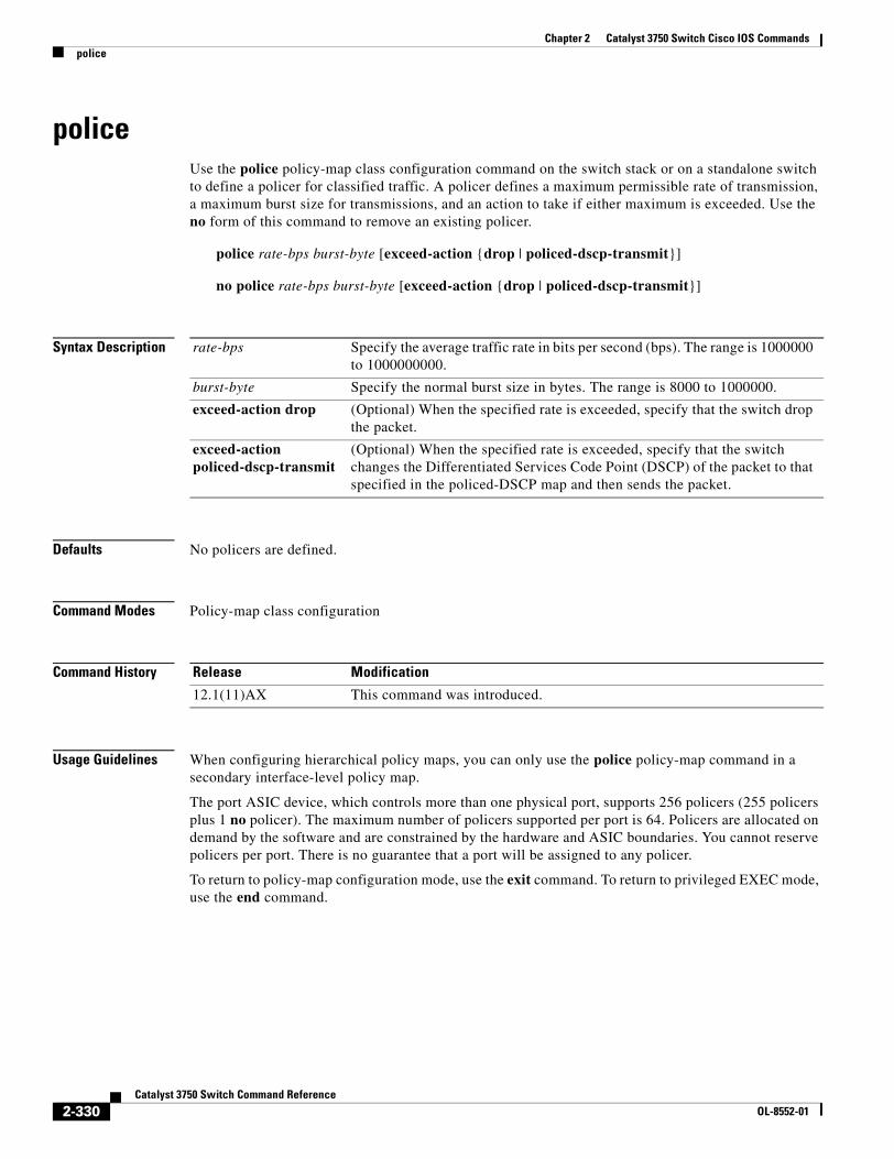
Chapter 2 Catalyst 3750 Switch Cisco IOS Commandspolice
policeUse the police policy-map class configuration command on the switch stack or on a standalone switch to define a policer for classified traffic. A policer defines a maximum permissible rate of transmission, a maximum burst size for transmissions, and an action to take if either maximum is exceeded. Use the no form of this command to remove an existing policer.
police rate-bps burst-byte [exceed-action {drop | policed-dscp-transmit}]
no police rate-bps burst-byte [exceed-action {drop | policed-dscp-transmit}]
Syntax Description
Defaults No policers are defined.
Command Modes Policy-map class configuration
Command History
Usage Guidelines When configuring hierarchical policy maps, you can only use the police policy-map command in a secondary interface-level policy map.
The port ASIC device, which controls more than one physical port, supports 256 policers (255 policers plus 1 no policer). The maximum number of policers supported per port is 64. Policers are allocated on demand by the software and are constrained by the hardware and ASIC boundaries. You cannot reserve policers per port. There is no guarantee that a port will be assigned to any policer.
To return to policy-map configuration mode, use the exit command. To return to privileged EXEC mode, use the end command.
rate-bps Specify the average traffic rate in bits per second (bps). The range is 1000000 to 1000000000.
burst-byte Specify the normal burst size in bytes. The range is 8000 to 1000000.
exceed-action drop (Optional) When the specified rate is exceeded, specify that the switch drop the packet.
exceed-action policed-dscp-transmit
(Optional) When the specified rate is exceeded, specify that the switch changes the Differentiated Services Code Point (DSCP) of the packet to that specified in the policed-DSCP map and then sends the packet.
Release Modification
12.1(11)AX This command was introduced.
2-330Catalyst 3750 Switch Command Reference
OL-8552-01
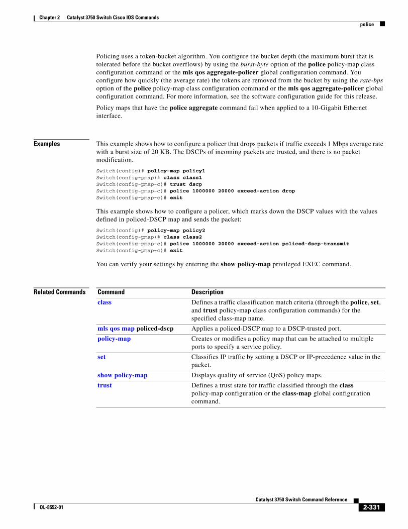
Chapter 2 Catalyst 3750 Switch Cisco IOS Commandspolice
Policing uses a token-bucket algorithm. You configure the bucket depth (the maximum burst that is tolerated before the bucket overflows) by using the burst-byte option of the police policy-map class configuration command or the mls qos aggregate-policer global configuration command. You configure how quickly (the average rate) the tokens are removed from the bucket by using the rate-bps option of the police policy-map class configuration command or the mls qos aggregate-policer global configuration command. For more information, see the software configuration guide for this release.
Policy maps that have the police aggregate command fail when applied to a 10-Gigabit Ethernet interface.
Examples This example shows how to configure a policer that drops packets if traffic exceeds 1 Mbps average rate with a burst size of 20 KB. The DSCPs of incoming packets are trusted, and there is no packet modification.
Switch(config)# policy-map policy1Switch(config-pmap)# class class1Switch(config-pmap-c)# trust dscpSwitch(config-pmap-c)# police 1000000 20000 exceed-action dropSwitch(config-pmap-c)# exit
This example shows how to configure a policer, which marks down the DSCP values with the values defined in policed-DSCP map and sends the packet:
Switch(config)# policy-map policy2Switch(config-pmap)# class class2Switch(config-pmap-c)# police 1000000 20000 exceed-action policed-dscp-transmitSwitch(config-pmap-c)# exit
You can verify your settings by entering the show policy-map privileged EXEC command.
Related Commands Command Description
class Defines a traffic classification match criteria (through the police, set, and trust policy-map class configuration commands) for the specified class-map name.
mls qos map policed-dscp Applies a policed-DSCP map to a DSCP-trusted port.
policy-map Creates or modifies a policy map that can be attached to multiple ports to specify a service policy.
set Classifies IP traffic by setting a DSCP or IP-precedence value in the packet.
show policy-map Displays quality of service (QoS) policy maps.
trust Defines a trust state for traffic classified through the class policy-map configuration or the class-map global configuration command.
2-331Catalyst 3750 Switch Command Reference
OL-8552-01
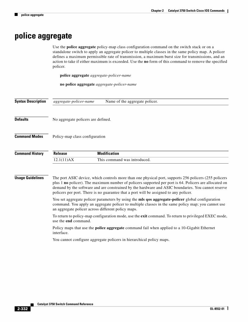
Chapter 2 Catalyst 3750 Switch Cisco IOS Commandspolice aggregate
police aggregateUse the police aggregate policy-map class configuration command on the switch stack or on a standalone switch to apply an aggregate policer to multiple classes in the same policy map. A policer defines a maximum permissible rate of transmission, a maximum burst size for transmissions, and an action to take if either maximum is exceeded. Use the no form of this command to remove the specified policer.
police aggregate aggregate-policer-name
no police aggregate aggregate-policer-name
Syntax Description
Defaults No aggregate policers are defined.
Command Modes Policy-map class configuration
Command History
Usage Guidelines The port ASIC device, which controls more than one physical port, supports 256 policers (255 policers plus 1 no policer). The maximum number of policers supported per port is 64. Policers are allocated on demand by the software and are constrained by the hardware and ASIC boundaries. You cannot reserve policers per port. There is no guarantee that a port will be assigned to any policer.
You set aggregate policer parameters by using the mls qos aggregate-policer global configuration command. You apply an aggregate policer to multiple classes in the same policy map; you cannot use an aggregate policer across different policy maps.
To return to policy-map configuration mode, use the exit command. To return to privileged EXEC mode, use the end command.
Policy maps that use the police aggregate command fail when applied to a 10-Gigabit Ethernet interface.
You cannot configure aggregate policers in hierarchical policy maps.
aggregate-policer-name Name of the aggregate policer.
Release Modification
12.1(11)AX This command was introduced.
2-332Catalyst 3750 Switch Command Reference
OL-8552-01
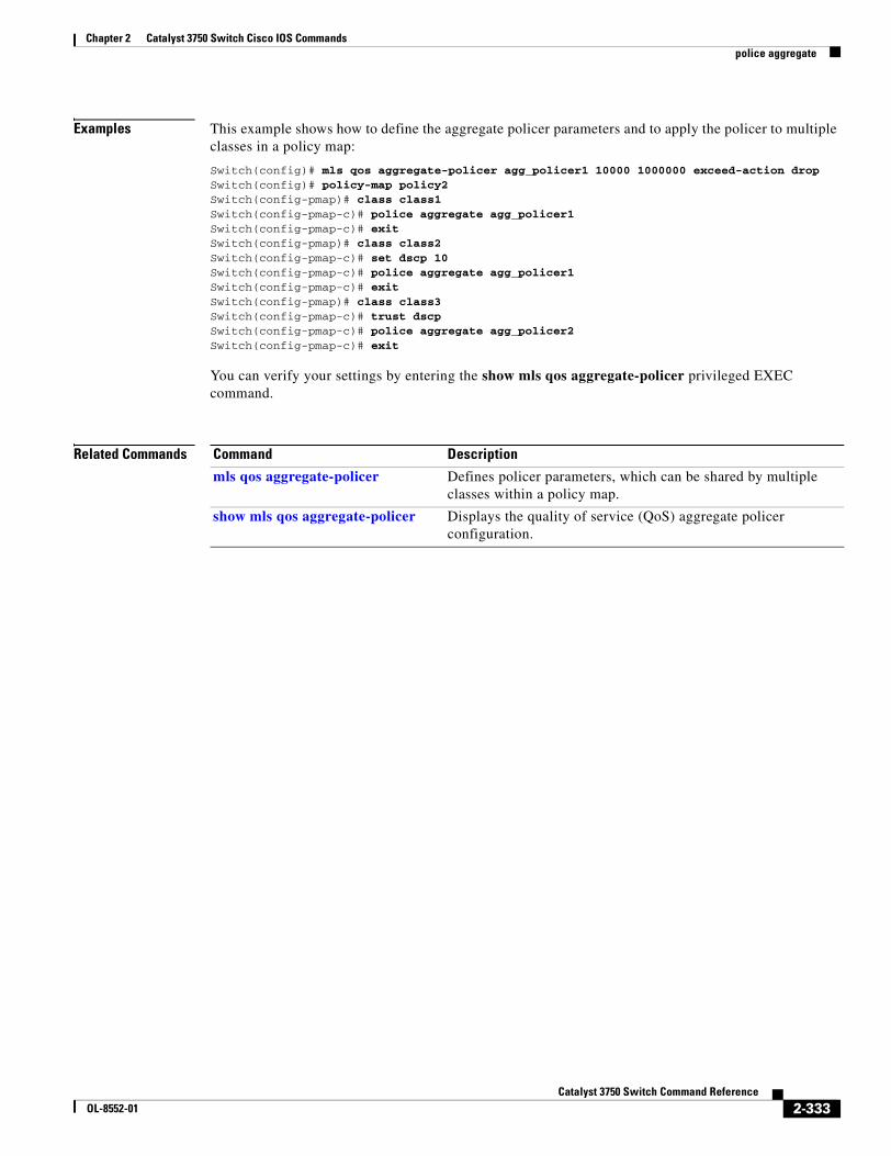
Chapter 2 Catalyst 3750 Switch Cisco IOS Commandspolice aggregate
Examples This example shows how to define the aggregate policer parameters and to apply the policer to multiple classes in a policy map:
Switch(config)# mls qos aggregate-policer agg_policer1 10000 1000000 exceed-action dropSwitch(config)# policy-map policy2Switch(config-pmap)# class class1Switch(config-pmap-c)# police aggregate agg_policer1Switch(config-pmap-c)# exitSwitch(config-pmap)# class class2Switch(config-pmap-c)# set dscp 10Switch(config-pmap-c)# police aggregate agg_policer1Switch(config-pmap-c)# exitSwitch(config-pmap)# class class3Switch(config-pmap-c)# trust dscpSwitch(config-pmap-c)# police aggregate agg_policer2Switch(config-pmap-c)# exit
You can verify your settings by entering the show mls qos aggregate-policer privileged EXEC command.
Related Commands Command Description
mls qos aggregate-policer Defines policer parameters, which can be shared by multiple classes within a policy map.
show mls qos aggregate-policer Displays the quality of service (QoS) aggregate policer configuration.
2-333Catalyst 3750 Switch Command Reference
OL-8552-01
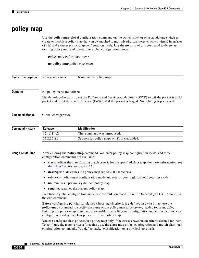
Chapter 2 Catalyst 3750 Switch Cisco IOS Commandspolicy-map
policy-mapUse the policy-map global configuration command on the switch stack or on a standalone switch to create or modify a policy map that can be attached to multiple physical ports or switch virtual interfaces (SVIs) and to enter policy-map configuration mode. Use the no form of this command to delete an existing policy map and to return to global configuration mode.
policy-map policy-map-name
no policy-map policy-map-name
Syntax Description
Defaults No policy maps are defined.
The default behavior is to set the Differentiated Services Code Point (DSCP) to 0 if the packet is an IP packet and to set the class of service (CoS) to 0 if the packet is tagged. No policing is performed.
Command Modes Global configuration
Command History
Usage Guidelines After entering the policy-map command, you enter policy-map configuration mode, and these configuration commands are available:
• class: defines the classification match criteria for the specified class map. For more information, see the “class” section on page 2-42.
• description: describes the policy map (up to 200 characters).
• exit: exits policy-map configuration mode and returns you to global configuration mode.
• no: removes a previously defined policy map.
• rename: renames the current policy map.
To return to global configuration mode, use the exit command. To return to privileged EXEC mode, use the end command.
Before configuring policies for classes whose match criteria are defined in a class map, use the policy-map command to specify the name of the policy map to be created, added to, or modified. Entering the policy-map command also enables the policy-map configuration mode in which you can configure or modify the class policies for that policy map.
You can configure class policies in a policy map only if the classes have match criteria defined for them. To configure the match criteria for a class, use the class-map global configuration and match class-map configuration commands. You define packet classification on a physical-port basis.
policy-map-name Name of the policy map.
Release Modification
12.1(11)AX This command was introduced.
12.2(25)SE Support for policy maps on SVIs was added.
2-334Catalyst 3750 Switch Command Reference
OL-8552-01
Chapter 2 Catalyst 3750 Switch Cisco IOS Commandspolicy-map
Only one policy map per ingress port or SVI is supported. You can apply the same policy map to multiple physical ports or SVIs.
In software releases earlier than Cisco IOS Release 12.2(25)SE, you can apply a policy map and configure policing only on physical ports. You can configure the trust state, set a new DSCP or IP precedence value in the packet, or define an individual or aggregate policer. For more information, see the “Policing on Physical Ports” section in the “Configuring QoS” chapter of the software configuration guide for this release.
In Cisco IOS Release 12.2(25)SE or later, you can apply a nonhierarchical policy maps to physical ports or to SVIs. A nonhierarchical policy map is the same as a port-based policy maps in software releases earlier than Cisco IOS Release 12.2(25)SE. However, a hierarchical policy map can only be applied to SVIs.
A hierarchical policy map has two levels. The first level, the VLAN level, specifies the actions to be taken against a traffic flow on an SVI. The second level, the interface level, specifies the actions to be taken against the traffic on the physical ports that belong to the SVI and are specified in the interface-level policy map.
In a primary VLAN-level policy map, you can only configure the trust state or set a new DSCP or IP precedence value in the packet. In a secondary interface-level policy map, you can only configure individual policers on physical ports that belong to the SVI.
After the hierarchical policy map is attached to an SVI, an interface-level policy map cannot be modified or removed from the hierarchical policy map. A new interface-level policy map also cannot be added to the hierarchical policy map. If you want these changes to occur, the hierarchical policy map must first be removed from the SVI.
For more information about hierarchical policy maps, see the “Policing on SVIs” section in the “Configuring QoS” chapter of the software configuration guide for this release.
Examples This example shows how to create a policy map called policy1. When attached to the ingress port, it matches all the incoming traffic defined in class1, sets the IP DSCP to 10, and polices the traffic at an average rate of 1 Mbps and bursts at 20 KB. Traffic exceeding the profile is marked down to a DSCP value gotten from the policed-DSCP map and then sent.
Switch(config)# policy-map policy1Switch(config-pmap)# class class1Switch(config-pmap-c)# set dscp 10Switch(config-pmap-c)# police 1000000 20000 exceed-action policed-dscp-transmitSwitch(config-pmap-c)# exit
This example shows how to configure multiple classes in a policy map called policymap2:
Switch(config)# policy-map policymap2Switch(config-pmap)# class class1Switch(config-pmap-c)# set dscp 10Switch(config-pmap-c)# police 100000 20000 exceed-action policed-dscp-transmitSwitch(config-pmap-c)# exitSwitch(config-pmap)# class class2Switch(config-pmap-c)# trust dscpSwitch(config-pmap-c)# police 100000 20000 exceed-action dropSwitch(config-pmap-c)# exitSwitch(config-pmap)# class class3Switch(config-pmap-c)# set dscp 0 (no policer)Switch(config-pmap-c)# exit
2-335Catalyst 3750 Switch Command Reference
OL-8552-01
Chapter 2 Catalyst 3750 Switch Cisco IOS Commandspolicy-map
This example shows how to create a hierarchical policy map and attach it to an SVI:
Switch(config)# class-map cm-non-intSwitch(config-cmap)# match access-group 101Switch(config-cmap)# exitSwitch(config)# class-map cm-non-int-2Switch(config-cmap)# match access-group 102Switch(config-cmap)# exitSwitch(config)# class-map cm-test-intSwitch(config-cmap)# match input-interface gigabitethernet2/0/2 - gigabitethernet2/0/3Switch(config-cmap)# exitSwitch(config)# policy-map pm-test-intSwitch(config-pmap)# class cm-test-intSwitch(config-pmap-c)# police 18000000 8000 exceed-action dropSwitch(config-pmap-c)# exitSwitch(config-pmap)# exitSwitch(config)# policy-map pm-test-pm-2Switch(config-pmap)# class cm-non-intSwitch(config-pmap-c)# set dscp 7Switch(config-pmap-c)# service-policy pm-test-int Switch(config-pmap)# class cm-non-int-2Switch(config-pmap-c)# set dscp 15Switch(config-pmap-c)# service-policy pm-test-int Switch(config-pmap-c)# endSwitch(config-cmap)# exitSwitch(config)# interface vlan 10Switch(config-if)# service-policy input pm-test-pm-2
This example shows how to delete policymap2:
Switch(config)# no policy-map policymap2
You can verify your settings by entering the show policy-map privileged EXEC command.
Related Commands Command Description
class Defines a traffic classification match criteria (through the police, set, and trust policy-map class configuration command) for the specified class-map name.
class-map Creates a class map to be used for matching packets to the class whose name you specify.
service-policy Applies a policy map to a port.
show mls qos vlan Displays the quality of service (QoS) policy maps attached to an SVI.
show policy-map Displays QoS policy maps.
2-336Catalyst 3750 Switch Command Reference
OL-8552-01
Chapter 2 Catalyst 3750 Switch Cisco IOS Commandsport-channel load-balance
port-channel load-balanceUse the port-channel load-balance global configuration command on the switch stack or on a standalone switch to set the load-distribution method among the ports in the EtherChannel. Use the no form of this command to return to the default setting.
port-channel load-balance {dst-ip | dst-mac | src-dst-ip | src-dst-mac | src-ip | src-mac}
no port-channel load-balance
Syntax Description
Defaults The default is src-mac.
Command Modes Global configuration
Command History
Usage Guidelines For information about when to use these forwarding methods, see the “Configuring EtherChannels” chapter in the software configuration guide for this release.
Examples This example shows how to set the load-distribution method to dst-mac:
Switch(config)# port-channel load-balance dst-mac
You can verify your setting by entering the show running-config privileged EXEC command or the show etherchannel load-balance privileged EXEC command.
dst-ip Load distribution is based on the destination host IP address.
dst-mac Load distribution is based on the destination host MAC address. Packets to the same destination are sent on the same port, but packets to different destinations are sent on different ports in the channel.
src-dst-ip Load distribution is based on the source and destination host IP address.
src-dst-mac Load distribution is based on the source and destination host MAC address.
src-ip Load distribution is based on the source host IP address.
src-mac Load distribution is based on the source MAC address. Packets from different hosts use different ports in the channel, but packets from the same host use the same port.
Release Modification
12.1(11)AX This command was introduced.
2-337Catalyst 3750 Switch Command Reference
OL-8552-01

Chapter 2 Catalyst 3750 Switch Cisco IOS Commandsport-channel load-balance
Related Commands Command Description
interface port-channel Accesses or creates the port channel.
show etherchannel Displays EtherChannel information for a channel.
show running-config Displays the current operating configuration. For syntax information, select Cisco IOS Configuration Fundamentals Command Reference, Release 12.2 > File Management Commands > Configuration File Management Commands.
2-338Catalyst 3750 Switch Command Reference
OL-8552-01
Chapter 2 Catalyst 3750 Switch Cisco IOS Commandspower inline
power inlineUse the power inline interface configuration command on the switch stack or on a standalone switch to configure the power management mode on the Power over Ethernet (PoE) ports. Use the no form of this command to return to the default settings.
power inline {auto [max max-wattage] | never | static [max max-wattage]}
no power inline {auto | never | static}
Syntax Description
Defaults The default is auto (enabled).
The maximum wattage is 15400 milliwatts.
Command Modes Interface configuration
Command History
Usage Guidelines This command is supported only on PoE-capable ports. If you enter this command on a port that does not support PoE, this error message appears:
Switch(config)# interface gigabitethernet1/0/1Switch(config-if)# power inline auto ^% Invalid input detected at '^' marker.
In a switch stack, this command is supported on all ports in the stack that support PoE.
Use the max max-wattage option to disallow higher-power powered devices. With this configuration, when the powered device sends Cisco Discovery Protocol (CDP) messages requesting more power than the maximum wattage, the switch removes power from the port. If the powered-device IEEE class maximum is greater than the maximum wattage, the switch does not power the device. The power is reclaimed into the global power budget.
auto Enable powered-device detection. If enough power is available, automatically allocate power to the PoE port after device detection.
max max-wattage (Optional) Limit the power allowed on the port. The range is 4000 to 15400 milliwatts. If no value is specified, the maximum is allowed.
never Disable device detection, and disable power to the port.
static Enable powered-device detection. Pre-allocate (reserve) power for a port before the switch discovers the powered device.
Release Modification
12.1(19)EA1 This command was introduced.
12.2(25)SE The static and max max-wattage options were added.
2-339Catalyst 3750 Switch Command Reference
OL-8552-01
Chapter 2 Catalyst 3750 Switch Cisco IOS Commandspower inline
Note The switch never powers any Class 0 or Class 3 device if the power inline max max-wattage command is configured for less than 15.4 W.
If the switch denies power to a powered device (the powered device requests more power through CDP messages or if the IEEE class maximum is greater than the maximum wattage), the PoE port is in a power-deny state. The switch generates a system message, and the Oper column in the show power inline user EXEC command output shows power-deny.
Use the power inline static max max-wattage command to give a port high priority. The switch allocates PoE to a port configured in static mode before allocating power to a port configured in auto mode. The switch reserves power for the static port when it is configured rather than upon device discovery. The switch reserves the power on a static port even when there is no connected device and whether or not the port is in a shutdown or in a no shutdown state. The switch allocates the configured maximum wattage to the port, and the amount is never adjusted through the IEEE class or by CDP messages from the powered device. Because power is pre-allocated, any powered device that uses less than or equal to the maximum wattage is guaranteed power when it is connected to a static port. However, if the powered device IEEE class is greater than the maximum wattage, the switch does not supply power to it. If the switch learns through CDP messages that the powered device needs more than the maximum wattage, the powered device is shut down.
If the switch cannot pre-allocate power when a port is in static mode (for example, because the entire power budget is already allocated to other auto or static ports), this message appears: Command rejected: power inline static: pwr not available. The port configuration remains unchanged.
When you configure a port by using the power inline auto or the power inline static interface configuration command, the port autonegotiates by using the configured speed and duplex settings. This is necessary to determine the power requirements of the connected device (whether or not it is a powered device). After the power requirements have been determined, the switch hardcodes the interface by using the configured speed and duplex settings without resetting the interface.
When you configure a port by using the power inline never command, the port reverts to the configured speed and duplex settings.
If a port has a Cisco powered device connected to it, you should not use the power inline never command to configure the port. A false link-up can occur on the port, placing it into an error-disabled state.
Caution In releases earlier than Cisco IOS Release 12.2(20)SE1, power was sometimes still applied to a PoE port even after a powered device was removed. This could cause damage to a nonpowered device when it was later connected to that port. Make sure that your switch is running Cisco IOS Release 12.2(20)SE1 or later.
Examples This example shows how to enable detection of a powered device and to automatically power a PoE port:
Switch(config)# interface fastethernet1/0/2Switch(config-if)# power inline auto
This example shows how to configure a PoE port to allow a Class 1 or a Class 2 powered device:
Switch(config)# interface fastethernet1/0/2Switch(config-if)# power inline auto max 7000
2-340Catalyst 3750 Switch Command Reference
OL-8552-01
Chapter 2 Catalyst 3750 Switch Cisco IOS Commandspower inline
This example shows how to disable powered-device detection and to not power a PoE port:
Switch(config)# interface fastethernet1/0/2Switch(config-if)# power inline never
You can verify your settings by entering the show power inline user EXEC command.
Related Commands Command Description
logging event power-inline-status
Enables the logging of PoE events.
show controllers power inline
Displays the values in the registers of the specified PoE controller.
show power inline Displays the PoE status for the specified PoE port or for all PoE ports.
2-341Catalyst 3750 Switch Command Reference
OL-8552-01
Chapter 2 Catalyst 3750 Switch Cisco IOS Commandspower inline consumption
power inline consumptionUse the power inline consumption global or interface configuration command on the switch stack or on a standalone switch to override the amount of power specified by the IEEE classification for the device by specifying the wattage used by each powered device. Use the no form of this command to return to the default power setting.
power inline consumption default wattage
no power inline consumption default
Syntax Description
Defaults The default power on each Power over Ethernet (PoE) port is 15400 milliwatts.
Command Modes Global configuration
Interface configuration
Command History
Usage Guidelines When Cisco powered devices are connected to PoE ports, the switch uses Cisco Discovery Protocol (CDP) to determine the actual power consumption of the devices, and the switch adjusts the power budget accordingly. This does not apply to IEEE third-party powered devices. For these devices, when the switch grants a power request, the switch adjusts the power budget according to the powered-device IEEE classification. If the powered device is a Class 0 (class status unknown) or a Class 3, the switch budgets 15400 milliwatts for the device, regardless of the actual amount of power needed. If the powered device reports a higher class than its actual consumption or does not support power classification (defaults to Class 0), the switch can power fewer devices because it uses the IEEE class information to track the global power budget.
By using the power inline consumption wattage configuration command, you can override the default power requirement specified by the IEEE classification. The difference between what is mandated by the IEEE classification and what is actually needed by the device is reclaimed into the global power budget for use by additional devices. You can then extend the switch power budget and use it more effectively.
For example, if the switch budgets 15400 milliwatts on each PoE port, you can connect only 24 Class 0 powered devices. If your Class 0 device power requirement is actually 5000 milliwatts, you can set the consumption wattage to 5000 milliwatts and connect up to 48 devices. The total PoE output power available on a 24-port or 48-port switch is 370,000 milliwatts.
wattage Specify the power that the switch budgets for the port. The range is 4000 to 15400 milliwatts.
Release Modification
12.2(25)SEC This command was introduced.
2-342Catalyst 3750 Switch Command Reference
OL-8552-01
Chapter 2 Catalyst 3750 Switch Cisco IOS Commandspower inline consumption
Caution You should carefully plan your switch power budget and make certain not to oversubscribe the power supply.
When you enter the power inline consumption default wattage or the no power inline consumption default command, this caution message appears:
%CAUTION: Interface interface-id: Misconfiguring the 'power inline consumption/allocation' command may cause damage to the switch and void your warranty. Take precaution not to oversubscribe the power supply. Refer to documentation.
Note When you manually configure the power budget, you must also consider the power loss over the cable between the switch and the powered device.
For more information about the IEEE power classifications, see the “Configuring Interface Characteristics” chapter in the software configuration guide for this release.
This command is supported only on PoE-capable ports. If you enter this command on a switch or port that does not support PoE, an error message appears.
In a switch stack, this command is supported on all switches or ports in the stack that support PoE.
Examples By using the global configuration command, this example shows how to configure the switch to budget 5000 milliwatts to each PoE port:
Switch(config)# power inline consumption default 5000%CAUTION: Interface Gi1/0/1: Misconfiguring the 'power inline consumption/allocation' command may cause damage to the switch and void your warranty. Take precaution not to oversubscribe the power supply. Refer to documentation.
By using the interface configuration command, this example shows how to configure the switch to budget 12000 milliwatts to the powered device connected to a specific PoE port:
Switch(config)# interface gigabitethernet1/0/2Switch(config-if)# power inline consumption default 12000%CAUTION: Interface Gi1/0/2: Misconfiguring the 'power inline consumption/allocation' command may cause damage to the switch and void your warranty. Take precaution not to oversubscribe the power supply. Refer to documentation.
You can verify your settings by entering the show power inline consumption default privileged EXEC command.
Related Commands Command Description
power inline Configures the power management mode on PoE ports.
show power inline Displays the PoE status for the specified PoE port or for all PoE ports.
2-343Catalyst 3750 Switch Command Reference
OL-8552-01
Chapter 2 Catalyst 3750 Switch Cisco IOS Commandspriority-queue
priority-queueUse the priority-queue interface configuration command to enable the egress expedite queue on a port. Use the no form of this command to return to the default setting.
priority-queue out
no priority-queue out
Syntax Description
Defaults The egress expedite queue is disabled.
Command Modes Interface configuration
Command History
Usage Guidelines When you configure the priority-queue out command, the shaped round robin (SRR) weight ratios are affected because there is one fewer queue participating in SRR. This means that weight1 in the srr-queue bandwidth shape or the srr-queue bandwidth shape interface configuration command is ignored (not used in the ratio calculation). The expedite queue is a priority queue, and it is serviced until empty before the other queues are serviced.
Follow these guidelines when the expedite queue is enabled or the egress queues are serviced based on their SRR weights:
• If the egress expedite queue is enabled, it overrides the SRR shaped and shared weights for queue 1.
• If the egress expedite queue is disabled and the SRR shaped and shared weights are configured, the shaped mode overrides the shared mode for queue 1, and SRR services this queue in shaped mode.
• If the egress expedite queue is disabled and the SRR shaped weights are not configured, SRR services the queue in shared mode.
Examples This example shows how to enable the egress expedite queue when the SRR weights are configured. The egress expedite queue overrides the configured SRR weights.
Switch(config)# interface gigabitethernet1/0/2Switch(config-if)# srr-queue bandwidth shape 25 0 0 0Switch(config-if)# srr-queue bandwidth share 30 20 25 25Switch(config-if)# priority-queue out
out Enable the egress expedite queue.
Release Modification
12.1(19)EA1 This command was introduced.
2-344Catalyst 3750 Switch Command Reference
OL-8552-01
Chapter 2 Catalyst 3750 Switch Cisco IOS Commandspriority-queue
This example shows how to disable the egress expedite queue after the SRR shaped and shared weights are configured. The shaped mode overrides the shared mode.
Switch(config)# interface gigabitethernet1/0/2Switch(config-if)# srr-queue bandwidth shape 25 0 0 0Switch(config-if)# srr-queue bandwidth share 30 20 25 25Switch(config-if)# no priority-queue out
You can verify your settings by entering the show mls qos interface interface-id queueing or the show running-config privileged EXEC command.
Related Commands Command Description
show mls qos interface queueing Displays the queueing strategy (SRR, priority queueing), the weights corresponding to the queues, and the CoS-to-egress-queue map.
srr-queue bandwidth shape Assigns the shaped weights and enables bandwidth shaping on the four egress queues mapped to a port.
srr-queue bandwidth share Assigns the shared weights and enables bandwidth sharing on the four egress queues mapped to a port.
2-345Catalyst 3750 Switch Command Reference
OL-8552-01
Chapter 2 Catalyst 3750 Switch Cisco IOS Commandsprivate-vlan
private-vlanUse the private-vlan VLAN configuration command on the switch stack or on a standalone switch to configure private VLANs and to configure the association between private-VLAN primary and secondary VLANs. Use the no form of this command to return the VLAN to normal VLAN configuration.
private-vlan {association [add | remove] secondary-vlan-list | community | isolated | primary}
no private-vlan {association | community | isolated | primary}
Syntax Description
Defaults The default is to have no private VLANs configured.
Command Modes VLAN configuration
Command History
Usage Guidelines Before configuring private VLANs, you must disable VTP (VTP mode transparent). After you configure a private VLAN, you should not change the VTP mode to client or server.
VTP does not propagate private-VLAN configuration. You must manually configure private VLANs on all switches in the Layer 2 network to merge their Layer 2 databases and to prevent flooding of private-VLAN traffic.
You cannot include VLAN 1 or VLANs 1002 to 1005 in the private-VLAN configuration. Extended VLANs (VLAN IDs 1006 to 4094) can be configured in private VLANs.
association Create an association between the primary VLAN and a secondary VLAN.
secondary-vlan-list Specify one or more secondary VLANs to be associated with a primary VLAN in a private VLAN.
add Associate a secondary VLAN to a primary VLAN.
remove Clear the association between a secondary VLAN and a primary VLAN.
community Designate the VLAN as a community VLAN.
isolated Designate the VLAN as a community VLAN.
primary Designate the VLAN as a community VLAN.
Release Modification
12.2(20)SE This command was introduced.
2-346Catalyst 3750 Switch Command Reference
OL-8552-01
Chapter 2 Catalyst 3750 Switch Cisco IOS Commandsprivate-vlan
You can associate a secondary (isolated or community) VLAN with only one primary VLAN. A primary VLAN can have one isolated VLAN and multiple community VLANs associated with it.
• A secondary VLAN cannot be configured as a primary VLAN.
• The secondary_vlan_list parameter cannot contain spaces. It can contain multiple comma-separated items. Each item can be a single private-VLAN ID or a hyphenated range of private-VLAN IDs. The list can contain one isolated VLAN and multiple community VLANs.
• If you delete either the primary or secondary VLANs, the ports associated with the VLAN become inactive.
A community VLAN carries traffic among community ports and from community ports to the promiscuous ports on the corresponding primary VLAN.
An isolated VLAN is used by isolated ports to communicate with promiscuous ports. It does not carry traffic to other community ports or isolated ports with the same primary vlan domain.
A primary VLAN is the VLAN that carries traffic from a gateway to customer end stations on private ports.
Configure Layer 3 VLAN interfaces (SVIs) only for primary VLANs. You cannot configure Layer 3 VLAN interfaces for secondary VLANs. SVIs for secondary VLANs are inactive while the VLAN is configured as a secondary VLAN.
The private-vlan commands do not take effect until you exit from VLAN configuration mode.
Do not configure private-VLAN ports as EtherChannels. While a port is part of the private-VLAN configuration, any EtherChannel configuration for it is inactive.
Do not configure a private VLAN as a Remote Switched Port Analyzer (RSPAN) VLAN.
Do not configure a private VLAN as a voice VLAN.
Do not configure fallback bridging on switches with private VLANs.
Although a private VLAN contains more than one VLAN, only one STP instance runs for the entire private VLAN. When a secondary VLAN is associated with the primary VLAN, the STP parameters of the primary VLAN are propagated to the secondary VLAN.
For information about configuring host ports and promiscuous ports, see the switchport mode private-vlan command.
For more information about private-VLAN interaction with other features, see the software configuration guide for this release.
2-347Catalyst 3750 Switch Command Reference
OL-8552-01
Chapter 2 Catalyst 3750 Switch Cisco IOS Commandsprivate-vlan
Examples This example shows how to configure VLAN 20 as a primary VLAN, VLAN 501 as an isolated VLAN, and VLANs 502 and 503 as community VLANs, and to associate them in a private VLAN:
Switch# configure terminal Switch(config)# vlan 20 Switch(config-vlan)# private-vlan primary Switch(config-vlan)# exit Switch(config)# vlan 501 Switch(config-vlan)# private-vlan isolated Switch(config-vlan)# exit Switch(config)# vlan 502 Switch(config-vlan)# private-vlan community Switch(config-vlan)# exit Switch(config)# vlan 503 Switch(config-vlan)# private-vlan community Switch(config-vlan)# exit Switch(config)# vlan 20 Switch(config-vlan)# private-vlan association 501-503Switch(config-vlan)# end
You can verify your setting by entering the show vlan private-vlan or show interfaces status privileged EXEC command.
Related Commands Command Description
show interfaces status Displays the status of interfaces, including the VLANs to which they belong.
show vlan private-vlan Displays the private VLANs and VLAN associations configured on the switch stack.
switchport mode private-vlan Configures a private-VLAN port as a host port or promiscuous port.
2-348Catalyst 3750 Switch Command Reference
OL-8552-01
Chapter 2 Catalyst 3750 Switch Cisco IOS Commandsprivate-vlan mapping
private-vlan mappingUse the private-vlan mapping interface configuration command on a switch virtual interface (SVI) on the switch stack or on a standalone switch to create a mapping between a private-VLAN primary and secondary VLANs so that both VLANs share the same primary VLAN SVI. Use the no form of this command to remove private-VLAN mappings from the SVI.
private-vlan mapping {[add | remove] secondary-vlan-list}
no private-vlan mapping
Syntax Description
Defaults The default is to have no private VLAN SVI mapping configured.
Command Modes Interface configuration
Command History
Usage Guidelines The switch must be in VTP transparent mode when you configure private VLANs.
The SVI of the primary VLAN is created at Layer 3.
Configure Layer 3 VLAN interfaces (SVIs) only for primary VLANs. You cannot configure Layer 3 VLAN interfaces for secondary VLANs. SVIs for secondary VLANs are inactive while the VLAN is configured as a secondary VLAN.
The secondary_vlan_list parameter cannot contain spaces. It can contain multiple comma-separated items. Each item can be a single private-VLAN ID or a hyphenated range of private-VLAN IDs. The list can contain one isolated VLAN and multiple community VLANs.
Traffic that is received on the secondary VLAN is routed by the SVI of the primary VLAN.
A secondary VLAN can be mapped to only one primary SVI. IF you configure the primary VLAN as a secondary VLAN, all SVIs specified in this command are brought down.
If you configure a mapping between two VLANs that do not have a valid Layer 2 private-VLAN association, the mapping configuration does not take effect.
secondary-vlan-list Specify one or more secondary VLANs to be mapped to the primary VLAN SVI.
add (Optional) Map the secondary VLAN to the primary VLAN SVI.
remove (Optional) Remove the mapping between the secondary VLAN and the primary VLAN SVI.
Release Modification
12.2(20)SE This command was introduced.
2-349Catalyst 3750 Switch Command Reference
OL-8552-01
Chapter 2 Catalyst 3750 Switch Cisco IOS Commandsprivate-vlan mapping
Examples This example shows how to map the interface of VLAN 20 to the SVI of VLAN 18:
Switch# configure terminal Switch# interface vlan 18Switch(config-if)# private-vlan mapping 20 Switch(config-vlan)# end
This example shows how to permit routing of secondary VLAN traffic from secondary VLANs 303 to 305 and 307 through VLAN 20 SVI:
Switch# configure terminal Switch# interface vlan 20Switch(config-if)# private-vlan mapping 303-305, 307Switch(config-vlan)# end
You can verify your setting by entering the show interfaces private-vlan mapping privileged EXEC command.
Related Commands Command Description
show interfaces private-vlan mapping
Display private-VLAN mapping information for the VLAN SVIs.
2-350Catalyst 3750 Switch Command Reference
OL-8552-01
Chapter 2 Catalyst 3750 Switch Cisco IOS Commandsqueue-set
queue-setUse the queue-set interface configuration command on the switch stack or on a standalone switch to map a port to a queue-set. Use the no form of this command to return to the default setting.
queue-set qset-id
no queue-set qset-id
Syntax Description
Defaults The queue-set ID is 1.
Command Modes Interface configuration
Command History
Examples This example shows how to map a port to queue-set 2:
Switch(config)# interface gigabitethernet2/0/1Switch(config-if)# queue-set 2
You can verify your settings by entering the show mls qos interface [interface-id] buffers privileged EXEC command.
Related Commands
qset-id ID of the queue-set. Each port belongs to a queue-set, which defines all the characteristics of the four egress queues per port. The range is 1 to 2.
Release Modification
12.1(11)AX This command was introduced.
Command Description
mls qos queue-set output buffers Allocates buffers to a queue-set.
mls qos queue-set output threshold Configures the weighted tail-drop (WTD) thresholds, guarantees the availability of buffers, and configures the maximum memory allocation to a queue-set.
show mls qos interface buffers Displays quality of service (QoS) information.
2-351Catalyst 3750 Switch Command Reference
OL-8552-01
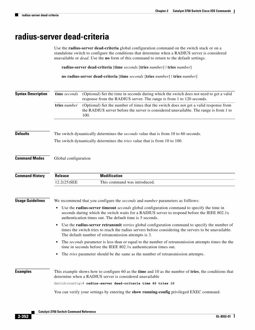
Chapter 2 Catalyst 3750 Switch Cisco IOS Commandsradius-server dead-criteria
radius-server dead-criteriaUse the radius-server dead-criteria global configuration command on the switch stack or on a standalone switch to configure the conditions that determine when a RADIUS server is considered unavailable or dead. Use the no form of this command to return to the default settings.
radius-server dead-criteria [time seconds [tries number] | tries number]
no radius-server dead-criteria [time seconds [tries number] | tries number]
Syntax Description
Defaults The switch dynamically determines the seconds value that is from 10 to 60 seconds.
The switch dynamically determines the tries value that is from 10 to 100.
Command Modes Global configuration
Command History
Usage Guidelines We recommend that you configure the seconds and number parameters as folllows:
• Use the radius-server timeout seconds global configuration command to specify the time in seconds during which the switch waits for a RADIUS server to respond before the IEEE 802.1x authentication times out. The default time is 5 seconds.
• Use the radius-server retransmit retries global configuration command to specify the number of times the switch tries to reach the radius servers before considering the servers to be unavailable. The default number of retransmission attempts is 3.
• The seconds parameter is less than or equal to the number of retransmission attempts times the the time in seconds before the IEEE 802.1x authentication times out.
• The tries parameter should be the same as the number of retransmission attempts.
Examples This example shows how to configure 60 as the time and 10 as the number of tries, the conditions that determine when a RADIUS server is considered unavailable
Switch(config)# radius-server dead-criteria time 60 tries 10
You can verify your settings by entering the show running-config privileged EXEC command.
time seconds (Optional) Set the time in seconds during which the switch does not need to get a valid response from the RADIUS server. The range is from 1 to 120 seconds.
tries number (Optional) Set the number of times that the switch does not get a valid response from the RADIUS server before the server is considered unavailable. The range is from 1 to 100.
Release Modification
12.2(25)SEE This command was introduced.
2-352Catalyst 3750 Switch Command Reference
OL-8552-01
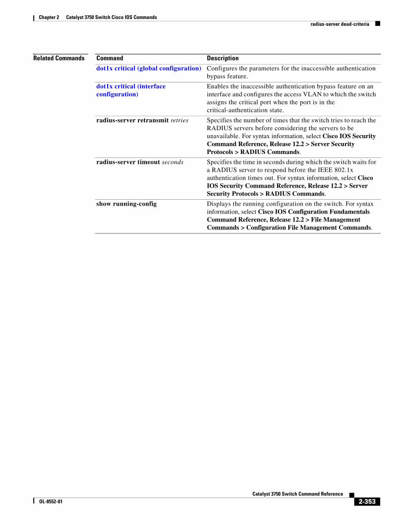
Chapter 2 Catalyst 3750 Switch Cisco IOS Commandsradius-server dead-criteria
Related Commands Command Description
dot1x critical (global configuration) Configures the parameters for the inaccessible authentication bypass feature.
dot1x critical (interface configuration)
Enables the inaccessible authentication bypass feature on an interface and configures the access VLAN to which the switch assigns the critical port when the port is in the critical-authentication state.
radius-server retransmit retries Specifies the number of times that the switch tries to reach the RADIUS servers before considering the servers to be unavailable. For syntax information, select Cisco IOS Security Command Reference, Release 12.2 > Server Security Protocols > RADIUS Commands.
radius-server timeout seconds Specifies the time in seconds during which the switch waits for a RADIUS server to respond before the IEEE 802.1x authentication times out. For syntax information, select Cisco IOS Security Command Reference, Release 12.2 > Server Security Protocols > RADIUS Commands.
show running-config Displays the running configuration on the switch. For syntax information, select Cisco IOS Configuration Fundamentals Command Reference, Release 12.2 > File Management Commands > Configuration File Management Commands.
2-353Catalyst 3750 Switch Command Reference
OL-8552-01
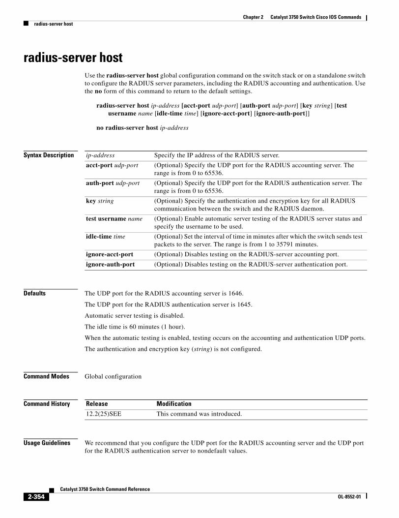
Chapter 2 Catalyst 3750 Switch Cisco IOS Commandsradius-server host
radius-server hostUse the radius-server host global configuration command on the switch stack or on a standalone switch to configure the RADIUS server parameters, including the RADIUS accounting and authentication. Use the no form of this command to return to the default settings.
radius-server host ip-address [acct-port udp-port] [auth-port udp-port] [key string] [test username name [idle-time time] [ignore-acct-port] [ignore-auth-port]]
no radius-server host ip-address
Syntax Description
Defaults The UDP port for the RADIUS accounting server is 1646.
The UDP port for the RADIUS authentication server is 1645.
Automatic server testing is disabled.
The idle time is 60 minutes (1 hour).
When the automatic testing is enabled, testing occurs on the accounting and authentication UDP ports.
The authentication and encryption key (string) is not configured.
Command Modes Global configuration
Command History
Usage Guidelines We recommend that you configure the UDP port for the RADIUS accounting server and the UDP port for the RADIUS authentication server to nondefault values.
ip-address Specify the IP address of the RADIUS server.
acct-port udp-port (Optional) Specify the UDP port for the RADIUS accounting server. The range is from 0 to 65536.
auth-port udp-port (Optional) Specify the UDP port for the RADIUS authentication server. The range is from 0 to 65536.
key string (Optional) Specify the authentication and encryption key for all RADIUS communication between the switch and the RADIUS daemon.
test username name (Optional) Enable automatic server testing of the RADIUS server status and specify the username to be used.
idle-time time (Optional) Set the interval of time in minutes after which the switch sends test packets to the server. The range is from 1 to 35791 minutes.
ignore-acct-port (Optional) Disables testing on the RADIUS-server accounting port.
ignore-auth-port (Optional) Disables testing on the RADIUS-server authentication port.
Release Modification
12.2(25)SEE This command was introduced.
2-354Catalyst 3750 Switch Command Reference
OL-8552-01
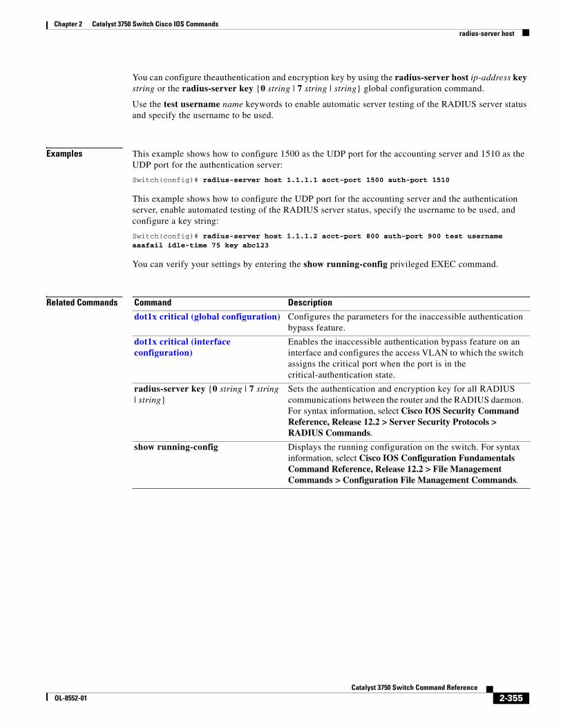
Chapter 2 Catalyst 3750 Switch Cisco IOS Commandsradius-server host
You can configure theauthentication and encryption key by using the radius-server host ip-address key string or the radius-server key {0 string | 7 string | string} global configuration command.
Use the test username name keywords to enable automatic server testing of the RADIUS server status and specify the username to be used.
Examples This example shows how to configure 1500 as the UDP port for the accounting server and 1510 as the UDP port for the authentication server:
Switch(config)# radius-server host 1.1.1.1 acct-port 1500 auth-port 1510
This example shows how to configure the UDP port for the accounting server and the authentication server, enable automated testing of the RADIUS server status, specify the username to be used, and configure a key string:
Switch(config)# radius-server host 1.1.1.2 acct-port 800 auth-port 900 test username aaafail idle-time 75 key abc123
You can verify your settings by entering the show running-config privileged EXEC command.
Related Commands Command Description
dot1x critical (global configuration) Configures the parameters for the inaccessible authentication bypass feature.
dot1x critical (interface configuration)
Enables the inaccessible authentication bypass feature on an interface and configures the access VLAN to which the switch assigns the critical port when the port is in the critical-authentication state.
radius-server key {0 string | 7 string | string}
Sets the authentication and encryption key for all RADIUS communications between the router and the RADIUS daemon. For syntax information, select Cisco IOS Security Command Reference, Release 12.2 > Server Security Protocols > RADIUS Commands.
show running-config Displays the running configuration on the switch. For syntax information, select Cisco IOS Configuration Fundamentals Command Reference, Release 12.2 > File Management Commands > Configuration File Management Commands.
2-355Catalyst 3750 Switch Command Reference
OL-8552-01
Chapter 2 Catalyst 3750 Switch Cisco IOS Commandsrcommand
rcommand Use the rcommand user EXEC command on the switch stack or on the cluster command switch to start a Telnet session and to execute commands on a cluster member switch from the cluster command switch or the switch stack. To end the session, enter the exit command.
rcommand {n | commander | mac-address hw-addr}
Syntax Description
Command Modes User EXEC
Command History
Usage Guidelines This command is available only on the cluster command switch stack or cluster command switch.
If the switch is the cluster command switch but the cluster member switch n does not exist, an error message appears. To get the switch number, enter the show cluster members privileged EXEC command on the cluster command switch.
You can use this command to access a cluster member switch from the cluster command-switch prompt or to access a cluster command switch from the member-switch prompt.
For Catalyst 2900 XL, 3500 XL, 2950, 2960, 2970, 3550, 3560, and 3750 switches, the Telnet session accesses the member-switch command-line interface (CLI) at the same privilege level as on the cluster command switch. For example, if you execute this command at user level on the cluster command switch, the cluster member switch is accessed at user level. If you use this command on the cluster command switch at privileged level, the command accesses the remote device at privileged level. If you use an intermediate enable-level lower than privileged, access to the cluster member switch is at user level.
For Catalyst 1900 and 2820 switches running standard edition software, the Telnet session accesses the menu console (the menu-driven interface) if the cluster command switch is at privilege level 15. If the cluster command switch is at privilege level 1, you are prompted for the password before being able to access the menu console. Cluster command switch privilege levels map to the cluster member switches running standard edition software as follows:
• If the cluster command switch privilege level is from 1 to 14, the cluster member switch is accessed at privilege level 1.
• If the cluster command switch privilege level is 15, the cluster member switch is accessed at privilege level 15.
The Catalyst 1900 and 2820 CLI is available only on switches running Enterprise Edition Software.
n Provide the number that identifies a cluster member. The range is 0 to 15.
commander Provide access to the cluster command switch from a cluster member switch.
mac-address hw-addr MAC address of the cluster member switch.
Release Modification
12.1(11)AX This command was introduced.
2-356Catalyst 3750 Switch Command Reference
OL-8552-01
Chapter 2 Catalyst 3750 Switch Cisco IOS Commandsrcommand
This command will not work if the vty lines of the cluster command switch have access-class configurations.
You are not prompted for a password because the cluster member switches inherited the password of the cluster command switch when they joined the cluster.
Examples This example shows how to start a session with member 3. All subsequent commands are directed to member 3 until you enter the exit command or close the session.
Switch# rcommand 3Switch-3# show versionCisco Internet Operating System Software ......Switch-3# exitSwitch#
Related Commands Command Description
show cluster members Displays information about the cluster members.
2-357Catalyst 3750 Switch Command Reference
OL-8552-01
Chapter 2 Catalyst 3750 Switch Cisco IOS Commandsreload
reloadUse the reload privileged EXEC command to reload the stack member and to put a configuration change into effect.
reload [LINE | at | cancel | in | slot stack-member-number | standby-cpu]
Syntax Description
Defaults Immediately reloads the stack member and puts a configuration change into effect.
Command Modes Privilege EXEC
Command History
Usage Guidelines If there is more than one switch in the switch stack, and you enter the reload slot stack-member-number command, you are not prompted to save the configuration.
Examples This example shows how to reload the switch stack:
Switch(config)# reloadSystem configuration has been modified. Save? [yes/no]: yProceed to reload the whole Stack? [confirm] y
This example shows how to reload a specific stack member:
Switch(config)# reload slot 6Proceed with reload? [confirm]y
This example shows how to reload a single-switch switch stack (there is only one member switch):
Switch(config)# reload slot 3System configuration has been modified. Save? [yes/no]: yProceed to reload the whole Stack? [confirm] y
LINE Specify the reason for the reload.
at Specify the time in hh:mm for the reload to occur.
cancel Cancel the pending reload.
in Specify a time interval in mmm or hhh:mm for reloads to occur.
slot stack-member-number Save the changes on the specified stack member and restart it.
standby-cpu Reload the standby route processor (RP).
Release Modification
12.1(11)AX This command was introduced.
2-358Catalyst 3750 Switch Command Reference
OL-8552-01
Chapter 2 Catalyst 3750 Switch Cisco IOS Commandsreload
Related Commands Command Description
rcommand Accesses a specific stack member.
switch priority Changes the stack member priority value.
switch renumber Changes the stack member number.
show switch Displays information about the switch stack and its stack members.
2-359Catalyst 3750 Switch Command Reference
OL-8552-01
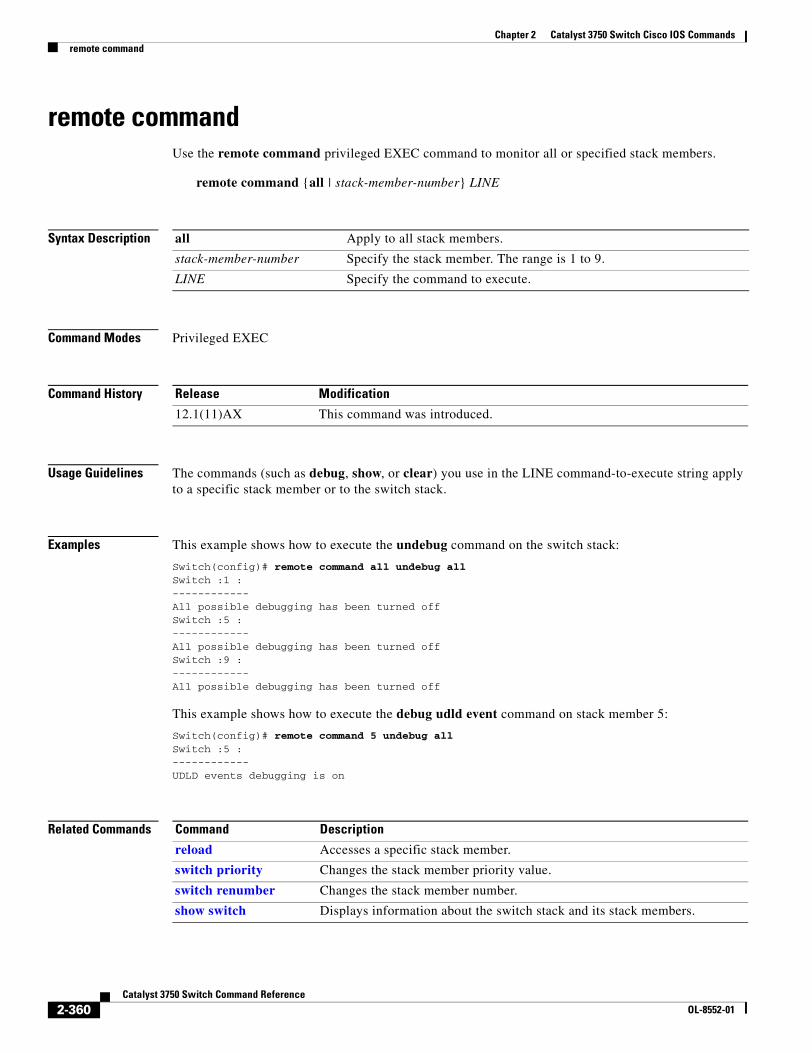
Chapter 2 Catalyst 3750 Switch Cisco IOS Commandsremote command
remote commandUse the remote command privileged EXEC command to monitor all or specified stack members.
remote command {all | stack-member-number} LINE
Syntax Description
Command Modes Privileged EXEC
Command History
Usage Guidelines The commands (such as debug, show, or clear) you use in the LINE command-to-execute string apply to a specific stack member or to the switch stack.
Examples This example shows how to execute the undebug command on the switch stack:
Switch(config)# remote command all undebug allSwitch :1 : ------------ All possible debugging has been turned off Switch :5 : ------------ All possible debugging has been turned off Switch :9 : ------------ All possible debugging has been turned off
This example shows how to execute the debug udld event command on stack member 5:
Switch(config)# remote command 5 undebug allSwitch :5 : ------------ UDLD events debugging is on
Related Commands
all Apply to all stack members.
stack-member-number Specify the stack member. The range is 1 to 9.
LINE Specify the command to execute.
Release Modification
12.1(11)AX This command was introduced.
Command Description
reload Accesses a specific stack member.
switch priority Changes the stack member priority value.
switch renumber Changes the stack member number.
show switch Displays information about the switch stack and its stack members.
2-360Catalyst 3750 Switch Command Reference
OL-8552-01
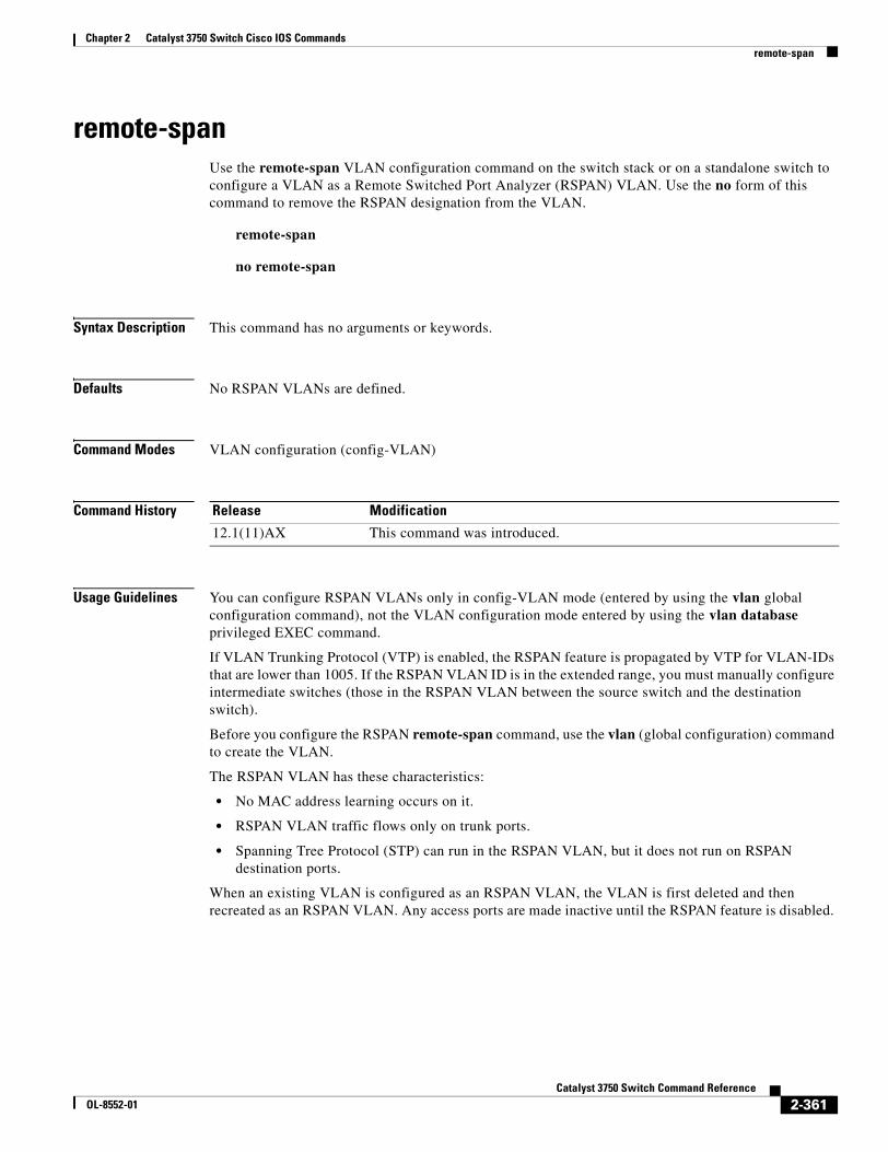
Chapter 2 Catalyst 3750 Switch Cisco IOS Commandsremote-span
remote-spanUse the remote-span VLAN configuration command on the switch stack or on a standalone switch to configure a VLAN as a Remote Switched Port Analyzer (RSPAN) VLAN. Use the no form of this command to remove the RSPAN designation from the VLAN.
remote-span
no remote-span
Syntax Description This command has no arguments or keywords.
Defaults No RSPAN VLANs are defined.
Command Modes VLAN configuration (config-VLAN)
Command History
Usage Guidelines You can configure RSPAN VLANs only in config-VLAN mode (entered by using the vlan global configuration command), not the VLAN configuration mode entered by using the vlan database privileged EXEC command.
If VLAN Trunking Protocol (VTP) is enabled, the RSPAN feature is propagated by VTP for VLAN-IDs that are lower than 1005. If the RSPAN VLAN ID is in the extended range, you must manually configure intermediate switches (those in the RSPAN VLAN between the source switch and the destination switch).
Before you configure the RSPAN remote-span command, use the vlan (global configuration) command to create the VLAN.
The RSPAN VLAN has these characteristics:
• No MAC address learning occurs on it.
• RSPAN VLAN traffic flows only on trunk ports.
• Spanning Tree Protocol (STP) can run in the RSPAN VLAN, but it does not run on RSPAN destination ports.
When an existing VLAN is configured as an RSPAN VLAN, the VLAN is first deleted and then recreated as an RSPAN VLAN. Any access ports are made inactive until the RSPAN feature is disabled.
Release Modification
12.1(11)AX This command was introduced.
2-361Catalyst 3750 Switch Command Reference
OL-8552-01
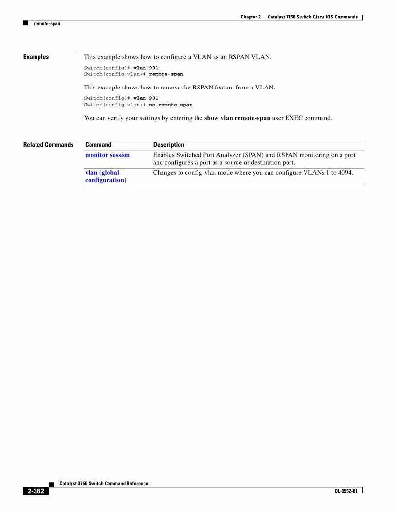
Chapter 2 Catalyst 3750 Switch Cisco IOS Commandsremote-span
Examples This example shows how to configure a VLAN as an RSPAN VLAN.
Switch(config)# vlan 901Switch(config-vlan)# remote-span
This example shows how to remove the RSPAN feature from a VLAN.
Switch(config)# vlan 901Switch(config-vlan)# no remote-span
You can verify your settings by entering the show vlan remote-span user EXEC command.
Related Commands Command Description
monitor session Enables Switched Port Analyzer (SPAN) and RSPAN monitoring on a port and configures a port as a source or destination port.
vlan (global configuration)
Changes to config-vlan mode where you can configure VLANs 1 to 4094.
2-362Catalyst 3750 Switch Command Reference
OL-8552-01
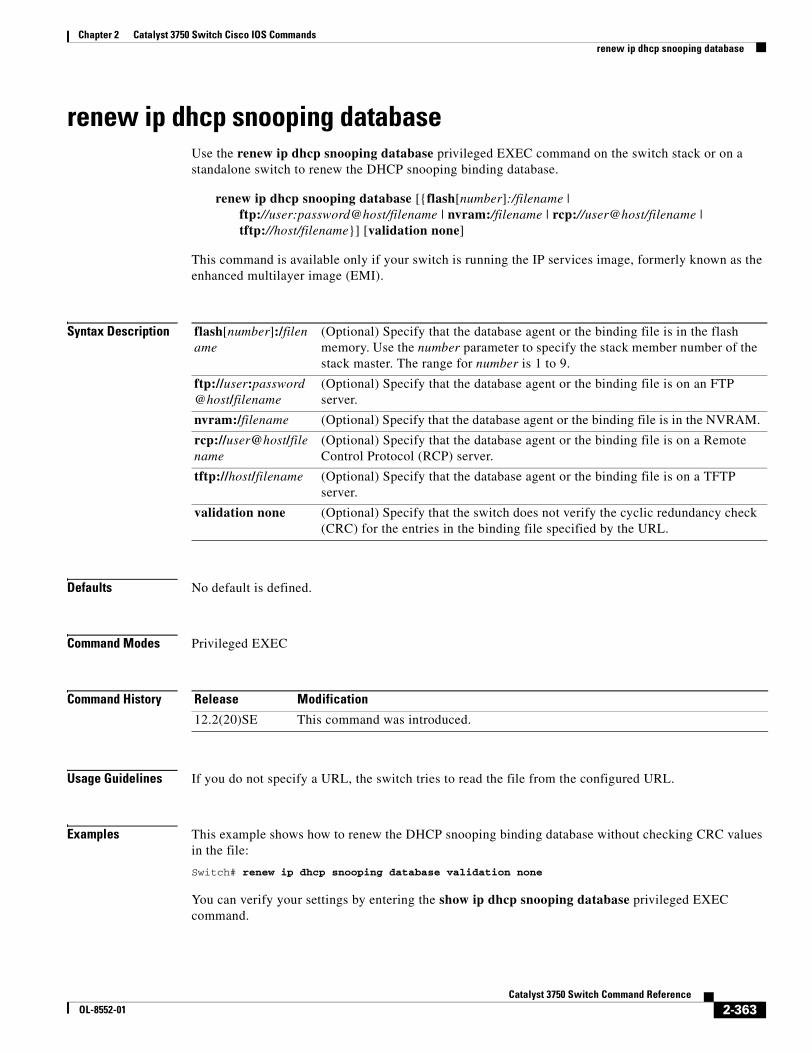
Chapter 2 Catalyst 3750 Switch Cisco IOS Commandsrenew ip dhcp snooping database
renew ip dhcp snooping databaseUse the renew ip dhcp snooping database privileged EXEC command on the switch stack or on a standalone switch to renew the DHCP snooping binding database.
renew ip dhcp snooping database [{flash[number]:/filename | ftp://user:password@host/filename | nvram:/filename | rcp://user@host/filename | tftp://host/filename}] [validation none]
This command is available only if your switch is running the IP services image, formerly known as the enhanced multilayer image (EMI).
Syntax Description
Defaults No default is defined.
Command Modes Privileged EXEC
Command History
Usage Guidelines If you do not specify a URL, the switch tries to read the file from the configured URL.
Examples This example shows how to renew the DHCP snooping binding database without checking CRC values in the file:
Switch# renew ip dhcp snooping database validation none
You can verify your settings by entering the show ip dhcp snooping database privileged EXEC command.
flash[number]:/filename
(Optional) Specify that the database agent or the binding file is in the flash memory. Use the number parameter to specify the stack member number of the stack master. The range for number is 1 to 9.
ftp://user:password@host/filename
(Optional) Specify that the database agent or the binding file is on an FTP server.
nvram:/filename (Optional) Specify that the database agent or the binding file is in the NVRAM.
rcp://user@host/filename
(Optional) Specify that the database agent or the binding file is on a Remote Control Protocol (RCP) server.
tftp://host/filename (Optional) Specify that the database agent or the binding file is on a TFTP server.
validation none (Optional) Specify that the switch does not verify the cyclic redundancy check (CRC) for the entries in the binding file specified by the URL.
Release Modification
12.2(20)SE This command was introduced.
2-363Catalyst 3750 Switch Command Reference
OL-8552-01

Chapter 2 Catalyst 3750 Switch Cisco IOS Commandsrenew ip dhcp snooping database
Related Commands Command Description
ip dhcp snooping Enables DHCP snooping on a VLAN.
ip dhcp snooping binding Configures the DHCP snooping binding database.
show ip dhcp snooping database Displays the status of the DHCP snooping database agent.
2-364Catalyst 3750 Switch Command Reference
OL-8552-01
ommands
Chapter 2 Catalyst 3750 Switch Cisco IOS C2 ]rmon collection stats
rmon collection statsUse the rmon collection stats interface configuration command on the switch stack or on a standalone switch to collect Ethernet group statistics, which include usage statistics about broadcast and multicast packets, and error statistics about cyclic redundancy check (CRC) alignment errors and collisions. Use the no form of this command to return to the default setting.
rmon collection stats index [owner name]
no rmon collection stats index [owner name]
Syntax Description
Defaults The RMON statistics collection is disabled.
Command Modes Interface configuration
Command History
Usage Guidelines The RMON statistics collection command is based on hardware counters.
Examples This example shows how to collect RMON statistics for the owner root:
Switch(config)# interface gigabitethernet2/0/1Switch(config-if)# rmon collection stats 2 owner root
You can verify your setting by entering the show rmon statistics privileged EXEC command.
Related Commands
index Remote Network Monitoring (RMON) collection control index. The range is 1 to 65535.
owner name (Optional) Owner of the RMON collection.
Release Modification
12.1(11)AX This command was introduced.
Command Description
show rmon statistics Displays RMON statistics.
For syntax information, select Cisco IOS Configuration Fundamentals Command Reference, Release 12.2 > System Management Commands > RMON Commands.
2-365Catalyst 3750 Switch Command Reference
OL-8552-01
Chapter 2 Catalyst 3750 Switch Cisco IOS Commandssdm prefer
sdm preferUse the sdm prefer global configuration command on the switch stack or on a standalone switch to configure the template used in Switch Database Management (SDM) resource allocation. You can use a template to allocate system resources to best support the features being used in your application. Use a template to provide maximum system usage for unicast routing or for VLAN configuration, to change an aggregator template (Catalyst 3750-12S only) to a desktop template, or to select the dual IPv4 and IPv6 template to support IPv6 forwarding (supported only when the switch stack is running the advanced IP services image). Use the no form of this command to return to the default template.
sdm prefer {access | default | dual-ipv4-and-ipv6 {default | routing | vlan} | routing | vlan} [desktop]
no sdm prefer
Syntax Description
Defaults The default template provides a balance to all features.
Command Modes Global configuration
Command History
access Provide maximum system usage for access control lists (ACLs). Use this template if you have a large number of ACLs.
default Sets the switch to use the default template. On Catalyst 3750-12S switches, use with the desktop keyword to set the switch to the default desktop template. (Use the no sdm prefer command to set a desktop switch to the default desktop template or to set an aggregator switch to the default aggregator template.)
dual-ipv4-and-ipv6 {default | routing | vlan}
Select a template that supports both IPv4 and IPv6 routing.
• default—Provide balance to IPv4 and IPv6 Layer 2 and Layer 3 functionality.
• routing—Provide maximum system usage for IPv4 and IPv6 routing, including IPv4 policy-based routing.
• vlan—Provide maximum system usage for IPv4 and IPv6 VLANs.
Note Though visible on all switches, this option is supported only if the switch stack or switch is running the advanced IP services image.
routing Provide maximum system usage for unicast routing. You would typically use this template for a router or aggregator in the middle of a network.
vlan Provide maximum system usage for VLANs. This template maximizes system resources for use as a Layer 2 switch with no routing.
desktop Use only on a Catalyst 3750-12S switch (where aggregator templates are the default) to select the desktop default, routing, or vlan template.
Release Modification
12.1(11)AX This command was introduced.
12.1(14)EA1 The aggregator templates were added.
2-366Catalyst 3750 Switch Command Reference
OL-8552-01
Chapter 2 Catalyst 3750 Switch Cisco IOS Commandssdm prefer
Usage Guidelines You must reload the switch for the configuration to take effect. If you enter the show sdm prefer command before you enter the reload privileged EXEC command, the show sdm prefer command shows the template currently in use and the template that will become active after a reload.
Desktop switches support only desktop templates; an aggregator switch (Catalyst 3750-12S) supports both desktop and aggregator templates. On an aggregator switch, if you do not enter the desktop keyword, the aggregator templates are selected.
All stack members use the same SDM desktop or aggregator template, stored on the stack master. When a new switch member is added to a stack, as with the switch configuration file and VLAN database file, the SDM configuration that is stored on the stack master overrides the template configured on an individual switch.
To route IPv6 packets in a stack of switches, all switches in the stack should be running the advanced IP services image. The IPv6 packets are routed in hardware across the stack, as long as the packet does not have exceptions (IPv6Options) and the switches have not run out of hardware resources.
If a stack member cannot support the template that is running on the master switch, the switch goes into SDM mismatch mode, the master switch does not attempt to change the SDM template, and the switch cannot be a functioning member of the stack.
• If the master switch is a Catalyst 3750-12S, and you change the template from an aggregator template to a desktop template and reload the switch, the entire stack operates with the selected desktop template. This could cause configuration losses if the number of ternary content addressable memory (TCAM) entries exceeds the desktop template sizes.
• If you change the template on a Catalyst 3750-12S master from a desktop template to an aggregator template and reload the switch, any desktop switches that were part of the stack go into SDM mismatch mode.
• If you add a Catalyst 3750-12S switch that is running the aggregator template to a stack that has a desktop switch as the stack master, the stack operates with the desktop template selected on the stack master. This could cause configuration losses on the Catalyst 3750-12S stack member if the number of TCAM entries on it exceeds desktop template sizes.
For more information about stacking, see the “Managing Switch Stacks” chapter in the software configuration guide.
The access template maximizes system resources for access control lists (ACLs) as required to accommodate a large number of ACLs.
The default templates balance the use of system resources.
Use the sdm prefer vlan [desktop] global configuration command only on switches intended for Layer 2 switching with no routing. When you use the VLAN template, no system resources are reserved for routing entries, and any routing is done through software. This overloads the CPU and severely degrades routing performance.
Do not use the routing template if you do not have routing enabled on your switch. Entering the sdm prefer routing [desktop] global configuration command prevents other features from using the memory allocated to unicast routing in the routing template.
12.2(25)SEA The dual-ipv4-and-ipv6 templates were added.
12.2(25)SED The access templates were added.
12.2(25)SEE The dual-ipv4-and-ipv6 routing template was added.
Release Modification
2-367Catalyst 3750 Switch Command Reference
OL-8552-01
Chapter 2 Catalyst 3750 Switch Cisco IOS Commandssdm prefer
Do not use the ipv4-and-ipv6 templates if you do not plan to enable IPv6 routing on the switch. Entering the sdm prefer ipv4-and-ipv6 {default | routing | vlan} [desktop] global configuration command divides resources between IPv4 and IPv6, limiting those allocated to IPv4 forwarding.
Table 2-15 lists the approximate number of each resource supported in each of the IPv4-only templates for a desktop or aggregator switch. The values in the template are based on eight routed interfaces and approximately one thousand VLANs and represent the approximate hardware boundaries set when a template is selected. If a section of a hardware resource is full, all processing overflow is sent to the CPU, seriously impacting switch performance.
Table 2-16lists the approximate number of each resource supported in each of the dual IPv4-and IPv6 templates for a desktop or aggregator switch.
Table 2-15 Approximate Number of Feature Resources Allowed by IPv4Templates
Resource
Desktop Templates Aggregator Templates
Access Default Routing VLAN Access Default Routing VLAN
Unicast MAC addresses 4 K 6 K 3 K 12 K 6 K 6 K 6 K 12 K
Internet Group Management Protocol (IGMP) groups and multicast routes
1 K 1 K 1 K 1 K 1 K 1 K 1 K 1 K
Unicast routes 6 K 8 K 11 K 0 12 K 12 K 20 K 0
• Directly connected hosts 4 K 6 K 3 K 0 6 K 6 K 6 K 0
• Indirect routes 2 K 2 K 8 K 0 6 K 6 K 14 K 0
Policy-based routing access control entries (ACEs)
512 0 512 0 512 0 512 0
Quality of service (QoS) classification ACEs 512 512 512 512 896 896 512 896
Security ACEs 2 K 1 K 1 K 1 K 4 K 1 K 1 K 1 K
Layer 2 VLANs 1 K 1 K 1 K 1 K 1 K 1 K 1 K 1 K
Table 2-16 Approximate Feature Resources Allowed by Dual IPv4-IPv6 Templates
Resource
Desktop IPv4-and-IPv6 Templates Aggregator IPv4-and-IPv6 Templates
Default Routing VLAN Default Routing VLAN
Unicast MAC addresses 2 K 1536 8 K 2 K 2K 8 K
IPv4 IGMP groups and multicast routes 1 K 1K 1 K 1 K 1 K 0
Total IPv4 unicast routes: 3 K 2816 0 3 K 8K 0
• Directly connected IPv4 hosts 2 K 1536 0 2 K 2K 0
• Indirect IPv4 routes 1 K 1280 0 1 K 6K 1 K
IPv6 multicast groups 1 K 1152 1 K 1 K 2176 1 K
Total IPv6 unicast routes: 3 K 2816 0 3 K 8K 0
• Directly connected IPv6 addresses 2 K 1536 0 2 K 2K 0
• Indirect IPv6 unicast routes 1 K 1280 0 1 K 6K 0
IPv4 policy-based routing ACEs 0 256 0 0 512 0
IPv4 or MAC QoS ACEs (total) 512 512 512 876 896 876
2-368Catalyst 3750 Switch Command Reference
OL-8552-01
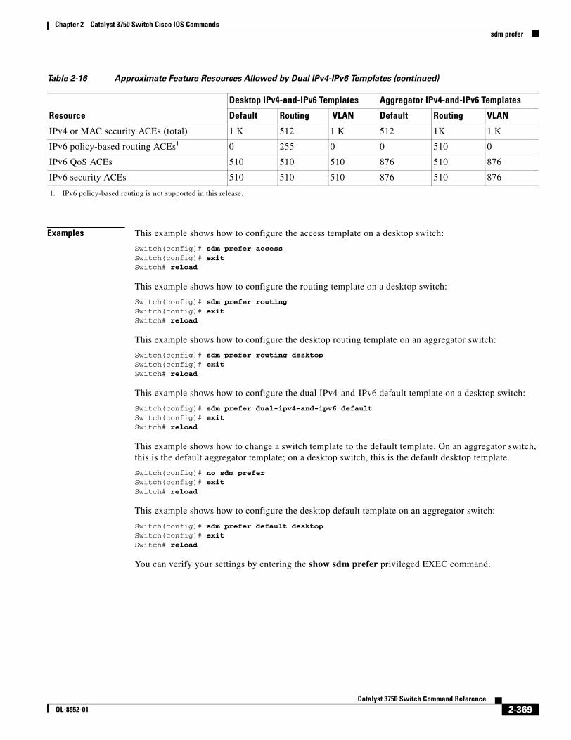
Chapter 2 Catalyst 3750 Switch Cisco IOS Commandssdm prefer
Examples This example shows how to configure the access template on a desktop switch:
Switch(config)# sdm prefer accessSwitch(config)# exitSwitch# reload
This example shows how to configure the routing template on a desktop switch:
Switch(config)# sdm prefer routingSwitch(config)# exitSwitch# reload
This example shows how to configure the desktop routing template on an aggregator switch:
Switch(config)# sdm prefer routing desktopSwitch(config)# exitSwitch# reload
This example shows how to configure the dual IPv4-and-IPv6 default template on a desktop switch:
Switch(config)# sdm prefer dual-ipv4-and-ipv6 defaultSwitch(config)# exitSwitch# reload
This example shows how to change a switch template to the default template. On an aggregator switch, this is the default aggregator template; on a desktop switch, this is the default desktop template.
Switch(config)# no sdm preferSwitch(config)# exitSwitch# reload
This example shows how to configure the desktop default template on an aggregator switch:
Switch(config)# sdm prefer default desktopSwitch(config)# exitSwitch# reload
You can verify your settings by entering the show sdm prefer privileged EXEC command.
IPv4 or MAC security ACEs (total) 1 K 512 1 K 512 1K 1 K
IPv6 policy-based routing ACEs1 0 255 0 0 510 0
IPv6 QoS ACEs 510 510 510 876 510 876
IPv6 security ACEs 510 510 510 876 510 876
1. IPv6 policy-based routing is not supported in this release.
Table 2-16 Approximate Feature Resources Allowed by Dual IPv4-IPv6 Templates (continued)
Resource
Desktop IPv4-and-IPv6 Templates Aggregator IPv4-and-IPv6 Templates
Default Routing VLAN Default Routing VLAN
2-369Catalyst 3750 Switch Command Reference
OL-8552-01
Chapter 2 Catalyst 3750 Switch Cisco IOS Commandssdm prefer
Related Commands Command Description
show sdm prefer Displays the current SDM template in use or displays the templates that can be used, with approximate resource allocation per feature.
2-370Catalyst 3750 Switch Command Reference
OL-8552-01
Chapter 2 Catalyst 3750 Switch Cisco IOS Commandsservice password-recovery
service password-recoveryUse the service password-recovery global configuration command on the switch stack or on a standalone switch to enable the password-recovery mechanism (the default). This mechanism allows an end user with physical access to the switch to hold down the Mode button and interrupt the boot process while the switch is powering up and to assign a new password. Use the no form of this command to disable part of the password-recovery functionality. When the password-recovery mechanism is disabled, interrupting the boot process is allowed only if the user agrees to set the system back to the default configuration.
service password-recovery
no service password-recovery
Syntax Description This command has no arguments or keywords.
Defaults The password-recovery mechanism is enabled.
Command Modes Global configuration
Command History
Usage Guidelines As a system administrator, you can use the no service password-recovery command to disable some of the functionality of the password recovery feature by allowing an end user to reset a password only by agreeing to return to the default configuration.
To use the password-recovery procedure, a user with physical access to the switch holds down the Mode button while the unit powers up and for a second or two after the LED above port 1X turns off. When the button is released, the system continues with initialization. If the password-recovery mechanism is disabled, this message appears:
The password-recovery mechanism has been triggered, butis currently disabled. Access to the boot loader promptthrough the password-recovery mechanism is disallowed atthis point. However, if you agree to let the system bereset back to the default system configuration, accessto the boot loader prompt can still be allowed.
Would you like to reset the system back to the default configuration (y/n)?
If the user chooses not to reset the system to the default configuration, the normal boot process continues, as if the Mode button had not been pressed. If you choose to reset the system to the default configuration, the configuration file in flash memory is deleted, and the VLAN database file, flash:vlan.dat (if present), is deleted.
Release Modification
12.1(11)AX This command was introduced.
2-371Catalyst 3750 Switch Command Reference
OL-8552-01
Chapter 2 Catalyst 3750 Switch Cisco IOS Commandsservice password-recovery
Note If you use the no service password-recovery command to control end user access to passwords, we recommend that you save a copy of the config file in a location away from the switch in case the end user uses the password recovery procedure and sets the system back to default values. Do not keep a backup copy of the config file on the switch.
If the switch is operating in VTP transparent mode, we recommend that you also save a copy of the vlan.dat file in a location away from the switch.
When you enter the service password-recovery or no service password-recovery command on the stack master, it is propagated throughout the stack and applied to all switches in the stack.
You can verify if password recovery is enabled or disabled by entering the show version privileged EXEC command.
Examples This example shows how to disable password recovery on a switch or switch stack so that a user can only reset a password by agreeing to return to the default configuration.
Switch(config)# no service-password recoverySwitch(config)# exit
Related Commands Command Description
show version Displays version information for the hardware and firmware.
2-372Catalyst 3750 Switch Command Reference
OL-8552-01
Chapter 2 Catalyst 3750 Switch Cisco IOS Commandsservice-policy
service-policyUse the service-policy interface configuration command on the switch stack or on a standalone switch to apply a policy map defined by the policy-map command to the input of a physical port or a switch virtual interface (SVI). Use the no form of this command to remove the policy map and port association.
service-policy input policy-map-name
no service-policy input policy-map-name
Syntax Description
Note Though visible in the command-line help strings, the history keyword is not supported, and you should ignore the statistics that it gathers. The output keyword is also not supported.
Defaults No policy maps are attached to the port.
Command Modes Interface configuration
Command History
Usage Guidelines Only one policy map per ingress port is supported. In software releases earlier than Cisco IOS Release 12.2(25)SE, policy maps can be configured only on physical ports.
In Cisco IOS Release 12.2(25)SE or later, policy maps can be configured on physical ports or on SVIs. When VLAN-based quality of service (QoS) is disabled by using the no mls qos vlan-based interface configuration command on a physical port, you can configure a port-based policy map on the port. If VLAN-based QoS is enabled by using the mls qos vlan-based interface configuration command on a physical port, the switch removes the previously configured port-based policy map. After a hierarchical policy map is configured and applied on an SVI, the interface-level policy map takes effect on the interface.
In software releases earlier than Cisco IOS Release 12.2(25)SE, you can apply a policy map only to the incoming traffic on a physical port. In Cisco IOS Release 12.2(25)SE or later, you can apply a policy map to incoming traffic on a physical port or on an SVI. In Cisco IOS Release 12.2(25)SED or later, you can configure different interface-level policy maps for each class defined in the VLAN-level policy map. For more information about hierarchical policy maps, see the “Configuring QoS” chapter in the software configuration guide for this release.
input policy-map-name Apply the specified policy map to the input of a physical port or an SVI.
Release Modification
12.1(11)AX This command was introduced.
12.2(25)SE A policy map can now be applied to a physical port or an SVI.
12.2(25)SED Hierarchical policy-maps can now be applied to an SVI.
2-373Catalyst 3750 Switch Command Reference
OL-8552-01
Chapter 2 Catalyst 3750 Switch Cisco IOS Commandsservice-policy
Classification using a port trust state (for example, mls qos trust [cos | dscp | ip-precedence] and a policy map (for example, service-policy input policy-map-name) are mutually exclusive. The last one configured overwrites the previous configuration.
Policy maps that use the police aggregate command fail when applied to a 10-Gigabit Ethernet interface.
Examples This example shows how to apply plcmap1 to an physical ingress port:
Switch(config)# interface gigabitethernet2/0/1Switch(config-if)# service-policy input plcmap1
This example shows how to remove plcmap2 from a physical port:
Switch(config)# interface gigabitethernet2/0/2Switch(config-if)# no service-policy input plcmap2
This example shows how to apply plcmap1 to an ingress SVI when VLAN-based QoS is enabled:
Switch(config)# interface vlan 10Switch(config-if)# service-policy input plcmap1
This example shows how to create a hierarchical policy map and attach it to an SVI:
Switch>enableSwitch#config tEnter configuration commands, one per line. End with CNTL/Z.Switch(config)#access-list 101 permit ip any any Switch(config)#class-map cm-1 Switch(config-cmap)#match access 101 Switch(config-cmap)#exit Switch(config)#exit Switch#Switch# Switch#config t Enter configuration commands, one per line. End with CNTL/Z.Switch(config)#class-map cm-interface-1Switch(config-cmap)#match input g3/0/1 - g3/0/2 Switch(config-cmap)#exitSwitch(config)#policy-map port-plcmap Switch(config-pmap)#class-map cm-interface-1 Switch(config-pmap-c)#police 900000 9000 exc policed-dscp-transmit Switch(config-pmap-c)#exit Switch(config-pmap)#exitSwitch(config)#policy-map vlan-plcmap Switch(config-pmap)#class-map cm-1 Switch(config-pmap-c)#set dscp 7 Switch(config-pmap-c)#service-policy port-plcmap-1 Switch(config-pmap-c)#exit Switch(config-pmap)#class-map cm-2Switch(config-pmap-c)#match ip dscp 2Switch(config-pmap-c)#service-policy port-plcmap-1Switch(config-pmap)#exitSwitch(config-pmap)#class-map cm-3Switch(config-pmap-c)#match ip dscp 3Switch(config-pmap-c)#service-policy port-plcmap-2Switch(config-pmap)#exitSwitch(config-pmap)#class-map cm-4Switch(config-pmap-c)#trust dscp Switch(config-pmap)#exitSwitch(config)#int vlan 10Switch(config-if)# Switch(config-if)#ser input vlan-plcmap Switch(config-if)#exit
2-374Catalyst 3750 Switch Command Reference
OL-8552-01
Chapter 2 Catalyst 3750 Switch Cisco IOS Commandsservice-policy
Switch(config)#exit Switch#
You can verify your settings by entering the show running-config privileged EXEC command.
Related Commands Command Description
policy-map Creates or modifies a policy map that can be attached to multiple ports to specify a service policy.
show policy-map Displays QoS policy maps.
show running-config Displays the running configuration on the switch. For syntax information, select Cisco IOS Configuration Fundamentals Command Reference, Release 12.2 > File Management Commands > Configuration File Management Commands.
2-375Catalyst 3750 Switch Command Reference
OL-8552-01
Chapter 2 Catalyst 3750 Switch Cisco IOS Commandssession
sessionUse the session privileged EXEC command on the stack master to access a specific stack member.
session stack-member-number
Syntax Description
Defaults No default is defined.
Command Modes Privileged EXEC
Command History
Usage Guidelines When you access the stack member, its stack member number is appended to the system prompt.
Examples This example shows how to access stack member 6:
Switch# session 6Switch-6#
Related Commands
stack-member-number Specify the stack member number. The range is 1 to 9.
Release Modification
12.1(11)AX This command was introduced.
Command Description
reload Reloads the stack member and puts a configuration change into effect.
switch priority Changes the stack member priority value.
switch renumber Changes the stack member number.
show switch Displays information about the switch stack and its stack members.
2-376Catalyst 3750 Switch Command Reference
OL-8552-01
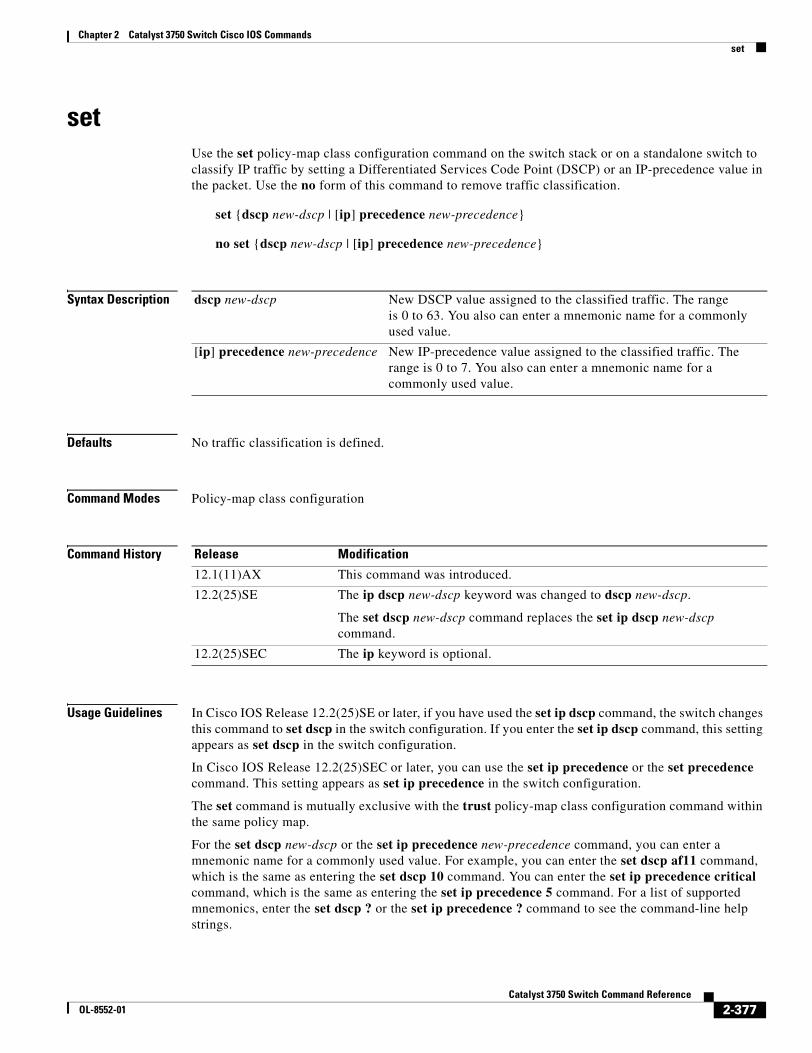
Chapter 2 Catalyst 3750 Switch Cisco IOS Commandsset
setUse the set policy-map class configuration command on the switch stack or on a standalone switch to classify IP traffic by setting a Differentiated Services Code Point (DSCP) or an IP-precedence value in the packet. Use the no form of this command to remove traffic classification.
set {dscp new-dscp | [ip] precedence new-precedence}
no set {dscp new-dscp | [ip] precedence new-precedence}
Syntax Description
Defaults No traffic classification is defined.
Command Modes Policy-map class configuration
Command History
Usage Guidelines In Cisco IOS Release 12.2(25)SE or later, if you have used the set ip dscp command, the switch changes this command to set dscp in the switch configuration. If you enter the set ip dscp command, this setting appears as set dscp in the switch configuration.
In Cisco IOS Release 12.2(25)SEC or later, you can use the set ip precedence or the set precedence command. This setting appears as set ip precedence in the switch configuration.
The set command is mutually exclusive with the trust policy-map class configuration command within the same policy map.
For the set dscp new-dscp or the set ip precedence new-precedence command, you can enter a mnemonic name for a commonly used value. For example, you can enter the set dscp af11 command, which is the same as entering the set dscp 10 command. You can enter the set ip precedence critical command, which is the same as entering the set ip precedence 5 command. For a list of supported mnemonics, enter the set dscp ? or the set ip precedence ? command to see the command-line help strings.
dscp new-dscp New DSCP value assigned to the classified traffic. The range is 0 to 63. You also can enter a mnemonic name for a commonly used value.
[ip] precedence new-precedence New IP-precedence value assigned to the classified traffic. The range is 0 to 7. You also can enter a mnemonic name for a commonly used value.
Release Modification
12.1(11)AX This command was introduced.
12.2(25)SE The ip dscp new-dscp keyword was changed to dscp new-dscp.
The set dscp new-dscp command replaces the set ip dscp new-dscp command.
12.2(25)SEC The ip keyword is optional.
2-377Catalyst 3750 Switch Command Reference
OL-8552-01
Chapter 2 Catalyst 3750 Switch Cisco IOS Commandsset
To return to policy-map configuration mode, use the exit command. To return to privileged EXEC mode, use the end command.
Examples This example shows how to assign DSCP 10 to all FTP traffic without any policers:
Switch(config)# policy-map policy_ftpSwitch(config-pmap)# class ftp_classSwitch(config-pmap-c)# set dscp 10Switch(config-pmap)# exit
You can verify your settings by entering the show policy-map privileged EXEC command.
Related Commands Command Description
class Defines a traffic classification match criteria (through the police, set, and trust policy-map class configuration commands) for the specified class-map name.
police Defines a policer for classified traffic.
policy-map Creates or modifies a policy map that can be attached to multiple ports to specify a service policy.
show policy-map Displays QoS policy maps.
trust Defines a trust state for traffic classified through the class policy-map configuration command or the class-map global configuration command.
2-378Catalyst 3750 Switch Command Reference
OL-8552-01
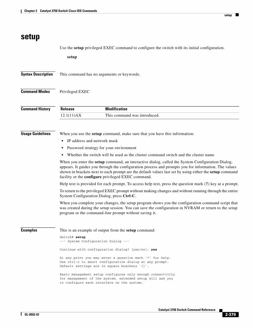
Chapter 2 Catalyst 3750 Switch Cisco IOS Commandssetup
setupUse the setup privileged EXEC command to configure the switch with its initial configuration.
setup
Syntax Description This command has no arguments or keywords.
Command Modes Privileged EXEC
Command History
Usage Guidelines When you use the setup command, make sure that you have this information:
• IP address and network mask
• Password strategy for your environment
• Whether the switch will be used as the cluster command switch and the cluster name
When you enter the setup command, an interactive dialog, called the System Configuration Dialog, appears. It guides you through the configuration process and prompts you for information. The values shown in brackets next to each prompt are the default values last set by using either the setup command facility or the configure privileged EXEC command.
Help text is provided for each prompt. To access help text, press the question mark (?) key at a prompt.
To return to the privileged EXEC prompt without making changes and without running through the entire System Configuration Dialog, press Ctrl-C.
When you complete your changes, the setup program shows you the configuration command script that was created during the setup session. You can save the configuration in NVRAM or return to the setup program or the command-line prompt without saving it.
Examples This is an example of output from the setup command:
Switch# setup--- System Configuration Dialog ---
Continue with configuration dialog? [yes/no]: yes
At any point you may enter a question mark '?' for help.Use ctrl-c to abort configuration dialog at any prompt.Default settings are in square brackets '[]'.
Basic management setup configures only enough connectivityfor management of the system, extended setup will ask youto configure each interface on the system.
Release Modification
12.1(11)AX This command was introduced.
2-379Catalyst 3750 Switch Command Reference
OL-8552-01
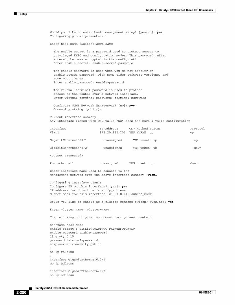
Chapter 2 Catalyst 3750 Switch Cisco IOS Commandssetup
Would you like to enter basic management setup? [yes/no]: yesConfiguring global parameters:
Enter host name [Switch]:host-name
The enable secret is a password used to protect access to privileged EXEC and configuration modes. This password, after entered, becomes encrypted in the configuration. Enter enable secret: enable-secret-password
The enable password is used when you do not specify an enable secret password, with some older software versions, and some boot images. Enter enable password: enable-password
The virtual terminal password is used to protect access to the router over a network interface. Enter virtual terminal password: terminal-password
Configure SNMP Network Management? [no]: yes Community string [public]:
Current interface summaryAny interface listed with OK? value “NO” does not have a valid configuration
Interface IP-Address OK? Method Status ProtocolVlan1 172.20.135.202 YES NVRAM up up
GigabitEthernet6/0/1 unassigned YES unset up up
GigabitEthernet6/0/2 unassigned YES unset up down
<output truncated>
Port-channel1 unassigned YES unset up down
Enter interface name used to connect to themanagement network from the above interface summary: vlan1
Configuring interface vlan1:Configure IP on this interface? [yes]: yes IP address for this interface: ip_addressSubnet mask for this interface [255.0.0.0]: subnet_mask
Would you like to enable as a cluster command switch? [yes/no]: yes
Enter cluster name: cluster-name
The following configuration command script was created:
hostname host-nameenable secret 5 $1$LiBw$0Xc1wyT.PXPkuhFwqyhVi0enable password enable-passwordline vty 0 15password terminal-passwordsnmp-server community public!no ip routing!interface GigabitEthernet6/0/1no ip address!interface GigabitEthernet6/0/2no ip address
2-380Catalyst 3750 Switch Command Reference
OL-8552-01
Chapter 2 Catalyst 3750 Switch Cisco IOS Commandssetup
!
cluster enable cluster-name!endUse this configuration? [yes/no]: yes![0] Go to the IOS command prompt without saving this config.
[1] Return back to the setup without saving this config.
[2] Save this configuration to nvram and exit.
Enter your selection [2]:
Related Commands Command Description
show running-config Displays the running configuration on the switch. For syntax information, select Cisco IOS Configuration Fundamentals Command Reference, Release 12.2 > File Management Commands > Configuration File Management Commands.
show version Displays version information for the hardware and firmware.
2-381Catalyst 3750 Switch Command Reference
OL-8552-01
Chapter 2 Catalyst 3750 Switch Cisco IOS Commandssetup express
setup expressUse the setup express global configuration command to enable Express Setup mode on the switch stack or on a standalone switch. Use the no form of this command to disable Express Setup mode.
setup express
no setup express
Syntax Description This command has no arguments or keywords.
Defaults Express Setup is enabled.
Command Modes Global configuration
Command History
Usage Guidelines When Express Setup is enabled on a new (unconfigured) switch, pressing the Mode button for 2 seconds activates Express Setup. You can access the switch through an Ethernet port by using the IP address 10.0.0.1 and then can configure the switch with the web-based Express Setup program or the command-line interface (CLI)-based setup program.
When you press the Mode button for 2 seconds on a configured switch, the LEDs above the Mode button start blinking. If you press the Mode button for a total of 10 seconds, the switch configuration is deleted, and the switch reboots. The switch can then be configured like a new switch, either through the web-based Express Setup program or the CLI-based setup program.
Note As soon as you make any change to the switch configuration (including entering no at the beginning of the CLI-based setup program), configuration by Express Setup is no longer available. You can only run Express Setup again by pressing the Mode button for 10 seconds. This deletes the switch configuration and reboots the switch.
If Express Setup is active on the switch, entering the write memory or copy running-configuration startup-configuration privileged EXEC commands deactivates Express Setup. The IP address 10.0.0.1 is no longer valid on the switch, and your connection using this IP address ends.
The primary purpose of the no setup express command is to prevent someone from deleting the switch configuration by pressing the Mode button for 10 seconds.
Release Modification
12.1(14)EA1 This command was introduced.
2-382Catalyst 3750 Switch Command Reference
OL-8552-01
Chapter 2 Catalyst 3750 Switch Cisco IOS Commandssetup express
Examples This example shows how to enable Express Setup mode:
Switch(config)# setup express
You can verify that Express Setup mode is enabled by pressing the Mode button:
• On an unconfigured switch, the LEDs above the Mode button turn solid green after 3 seconds.
• On a configured switch, the mode LEDs begin blinking after 2 seconds and turn solid green after 10 seconds.
Caution If you hold the Mode button down for a total of 10 seconds, the configuration is deleted, and the switch reboots.
This example shows how to disable Express Setup mode:
Switch(config)# no setup express
You can verify that Express Setup mode is disabled by pressing the Mode button. The mode LEDs do not turn solid green or begin blinking green if Express Setup mode is not enabled on the switch.
Related Commands Command Description
show setup express Displays if Express Setup mode is active.
2-383Catalyst 3750 Switch Command Reference
OL-8552-01
Chapter 2 Catalyst 3750 Switch Cisco IOS Commandsshow access-lists
show access-listsUse the show access-lists privileged EXEC command to display access control lists (ACLs) configured on the switch.
show access-lists [name | number | hardware counters | ipc] [ | {begin | exclude | include} expression]
Syntax Description
Note Though visible in the command-line help strings, the rate-limit keywords are not supported.
Command Modes Privileged EXEC
Command History
Usage Guidelines The switch supports only IP standard and extended access lists. Therefore, the allowed numbers are only 1 to 199 and 1300 to 2699.
This command also displays the MAC ACLs that are configured.
Expressions are case sensitive. For example, if you enter | exclude output, the lines that contain output are not displayed, but the lines that contain Output are displayed.
Examples This is an example of output from the show access-lists command:
Switch# show access-listsStandard IP access list 1 10 permit 1.1.1.1 20 permit 2.2.2.2 30 permit any 40 permit 0.255.255.255, wildcard bits 12.0.0.0
name (Optional) Name of the ACL.
number (Optional) ACL number. The range is 1 to 2699.
hardware counters (Optional) Display global hardware ACL statistics for switched and routed packets.
ipc (Optional) Display Interprocess Communication (IPC) protocol access-list configuration download information.
| begin (Optional) Display begins with the line that matches the expression.
| exclude (Optional) Display excludes lines that match the expression.
| include (Optional) Display includes lines that match the specified expression.
expression Expression in the output to use as a reference point.
Release Modification
12.1(11)AX This command was introduced.
12.1(14)EA1 The ipc keyword was added.
2-384Catalyst 3750 Switch Command Reference
OL-8552-01
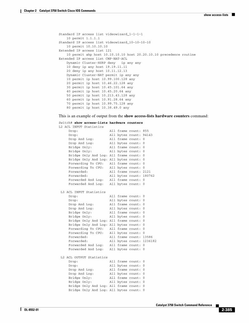
Chapter 2 Catalyst 3750 Switch Cisco IOS Commandsshow access-lists
Standard IP access list videowizard_1-1-1-1 10 permit 1.1.1.1Standard IP access list videowizard_10-10-10-10 10 permit 10.10.10.10Extended IP access list 121 10 permit ahp host 10.10.10.10 host 20.20.10.10 precedence routineExtended IP access list CMP-NAT-ACL Dynamic Cluster-HSRP deny ip any any 10 deny ip any host 19.19.11.11 20 deny ip any host 10.11.12.13 Dynamic Cluster-NAT permit ip any any 10 permit ip host 10.99.100.128 any 20 permit ip host 10.46.22.128 any 30 permit ip host 10.45.101.64 any 40 permit ip host 10.45.20.64 any 50 permit ip host 10.213.43.128 any 60 permit ip host 10.91.28.64 any 70 permit ip host 10.99.75.128 any 80 permit ip host 10.38.49.0 any
This is an example of output from the show access-lists hardware counters command:
Switch# show access-lists hardware countersL2 ACL INPUT Statistics Drop: All frame count: 855 Drop: All bytes count: 94143 Drop And Log: All frame count: 0 Drop And Log: All bytes count: 0 Bridge Only: All frame count: 0 Bridge Only: All bytes count: 0 Bridge Only And Log: All frame count: 0 Bridge Only And Log: All bytes count: 0 Forwarding To CPU: All frame count: 0 Forwarding To CPU: All bytes count: 0 Forwarded: All frame count: 2121 Forwarded: All bytes count: 180762 Forwarded And Log: All frame count: 0 Forwarded And Log: All bytes count: 0
L3 ACL INPUT Statistics Drop: All frame count: 0 Drop: All bytes count: 0 Drop And Log: All frame count: 0 Drop And Log: All bytes count: 0 Bridge Only: All frame count: 0 Bridge Only: All bytes count: 0 Bridge Only And Log: All frame count: 0 Bridge Only And Log: All bytes count: 0 Forwarding To CPU: All frame count: 0 Forwarding To CPU: All bytes count: 0 Forwarded: All frame count: 13586 Forwarded: All bytes count: 1236182 Forwarded And Log: All frame count: 0 Forwarded And Log: All bytes count: 0
L2 ACL OUTPUT Statistics Drop: All frame count: 0 Drop: All bytes count: 0 Drop And Log: All frame count: 0 Drop And Log: All bytes count: 0 Bridge Only: All frame count: 0 Bridge Only: All bytes count: 0 Bridge Only And Log: All frame count: 0 Bridge Only And Log: All bytes count: 0
2-385Catalyst 3750 Switch Command Reference
OL-8552-01
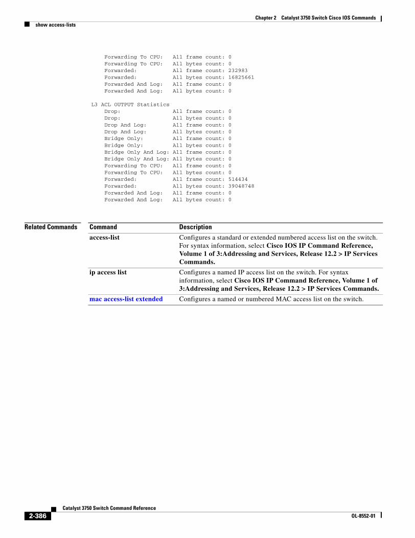
Chapter 2 Catalyst 3750 Switch Cisco IOS Commandsshow access-lists
Forwarding To CPU: All frame count: 0 Forwarding To CPU: All bytes count: 0 Forwarded: All frame count: 232983 Forwarded: All bytes count: 16825661 Forwarded And Log: All frame count: 0 Forwarded And Log: All bytes count: 0
L3 ACL OUTPUT Statistics Drop: All frame count: 0 Drop: All bytes count: 0 Drop And Log: All frame count: 0 Drop And Log: All bytes count: 0 Bridge Only: All frame count: 0 Bridge Only: All bytes count: 0 Bridge Only And Log: All frame count: 0 Bridge Only And Log: All bytes count: 0 Forwarding To CPU: All frame count: 0 Forwarding To CPU: All bytes count: 0 Forwarded: All frame count: 514434 Forwarded: All bytes count: 39048748 Forwarded And Log: All frame count: 0 Forwarded And Log: All bytes count: 0
Related Commands Command Description
access-list Configures a standard or extended numbered access list on the switch. For syntax information, select Cisco IOS IP Command Reference, Volume 1 of 3:Addressing and Services, Release 12.2 > IP Services Commands.
ip access list Configures a named IP access list on the switch. For syntax information, select Cisco IOS IP Command Reference, Volume 1 of 3:Addressing and Services, Release 12.2 > IP Services Commands.
mac access-list extended Configures a named or numbered MAC access list on the switch.
2-386Catalyst 3750 Switch Command Reference
OL-8552-01
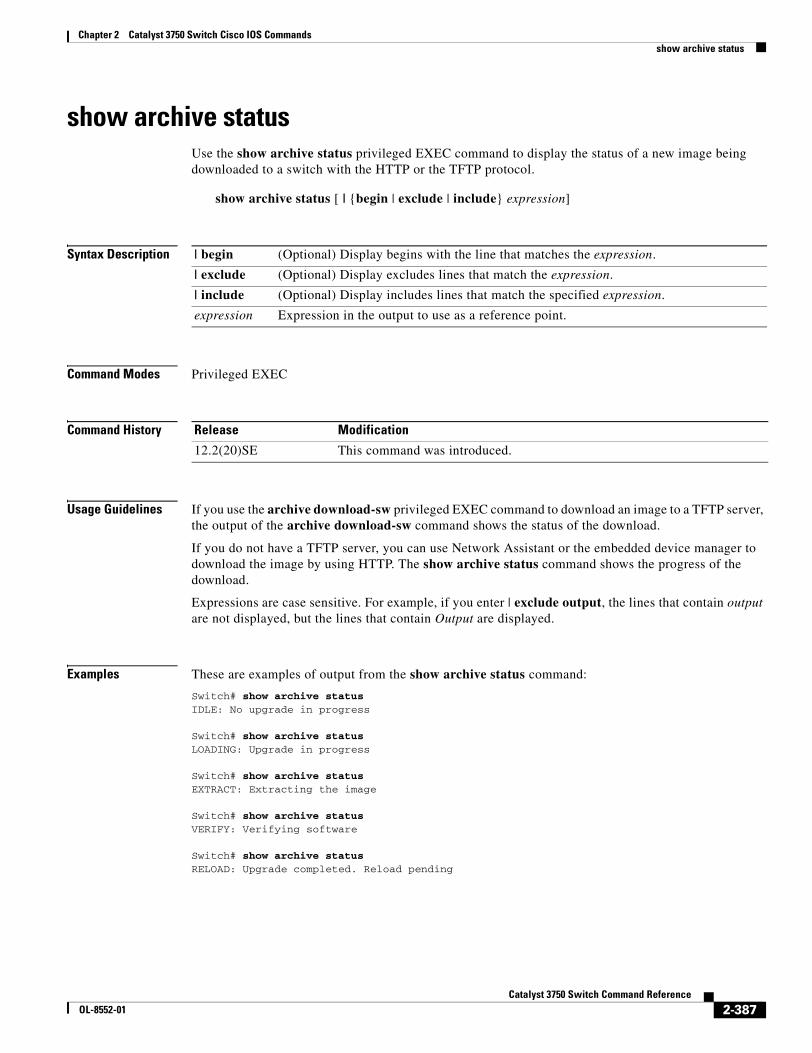
Chapter 2 Catalyst 3750 Switch Cisco IOS Commandsshow archive status
show archive statusUse the show archive status privileged EXEC command to display the status of a new image being downloaded to a switch with the HTTP or the TFTP protocol.
show archive status [ | {begin | exclude | include} expression]
Syntax Description
Command Modes Privileged EXEC
Command History
Usage Guidelines If you use the archive download-sw privileged EXEC command to download an image to a TFTP server, the output of the archive download-sw command shows the status of the download.
If you do not have a TFTP server, you can use Network Assistant or the embedded device manager to download the image by using HTTP. The show archive status command shows the progress of the download.
Expressions are case sensitive. For example, if you enter | exclude output, the lines that contain output are not displayed, but the lines that contain Output are displayed.
Examples These are examples of output from the show archive status command:
Switch# show archive statusIDLE: No upgrade in progress
Switch# show archive statusLOADING: Upgrade in progress
Switch# show archive statusEXTRACT: Extracting the image
Switch# show archive statusVERIFY: Verifying software
Switch# show archive statusRELOAD: Upgrade completed. Reload pending
| begin (Optional) Display begins with the line that matches the expression.
| exclude (Optional) Display excludes lines that match the expression.
| include (Optional) Display includes lines that match the specified expression.
expression Expression in the output to use as a reference point.
Release Modification
12.2(20)SE This command was introduced.
2-387Catalyst 3750 Switch Command Reference
OL-8552-01

Chapter 2 Catalyst 3750 Switch Cisco IOS Commandsshow archive status
Related Commands Command Description
archive download-sw Downloads a new image from a TFTP server to the switch.
2-388Catalyst 3750 Switch Command Reference
OL-8552-01
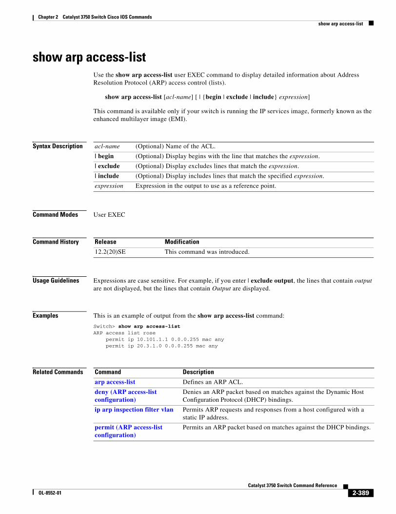
Chapter 2 Catalyst 3750 Switch Cisco IOS Commandsshow arp access-list
show arp access-listUse the show arp access-list user EXEC command to display detailed information about Address Resolution Protocol (ARP) access control (lists).
show arp access-list [acl-name] [ | {begin | exclude | include} expression]
This command is available only if your switch is running the IP services image, formerly known as the enhanced multilayer image (EMI).
Syntax Description
Command Modes User EXEC
Command History
Usage Guidelines Expressions are case sensitive. For example, if you enter | exclude output, the lines that contain output are not displayed, but the lines that contain Output are displayed.
Examples This is an example of output from the show arp access-list command:
Switch> show arp access-listARP access list rose permit ip 10.101.1.1 0.0.0.255 mac any permit ip 20.3.1.0 0.0.0.255 mac any
Related Commands
acl-name (Optional) Name of the ACL.
| begin (Optional) Display begins with the line that matches the expression.
| exclude (Optional) Display excludes lines that match the expression.
| include (Optional) Display includes lines that match the specified expression.
expression Expression in the output to use as a reference point.
Release Modification
12.2(20)SE This command was introduced.
Command Description
arp access-list Defines an ARP ACL.
deny (ARP access-list configuration)
Denies an ARP packet based on matches against the Dynamic Host Configuration Protocol (DHCP) bindings.
ip arp inspection filter vlan Permits ARP requests and responses from a host configured with a static IP address.
permit (ARP access-list configuration)
Permits an ARP packet based on matches against the DHCP bindings.
2-389Catalyst 3750 Switch Command Reference
OL-8552-01
Chapter 2 Catalyst 3750 Switch Cisco IOS Commandsshow auto qos
show auto qos Use the show auto qos user EXEC command to display the quality of service (QoS) commands entered on the interfaces on which automatic QoS (auto-QoS) is enabled.
show auto qos [interface [interface-id]]
Syntax Description
Command Modes User EXEC
Command History
Usage Guidelines In releases earlier than Cisco IOS Release 12.2(20)SE, the show auto qos [interface [interface-id]] command output shows the initial generated auto-QoS configuration.
In Cisco IOS Release 12.2(20)SE or later, the show auto qos command output shows only the auto-QoS command entered on each interface. The show auto qos interface interface-id command output shows the auto-QoS command entered on a specific interface.
Use the show running-config privileged EXEC command to display the auto-QoS configuration and the user modifications.
To display information about the QoS configuration that might be affected by auto-QoS, use one of these commands:
• show mls qos
• show mls qos maps cos-dscp
• show mls qos interface [interface-id] [buffers | queueing]
• show mls qos maps [cos-dscp | cos-input-q | cos-output-q | dscp-cos | dscp-input-q | dscp-output-q]
• show mls qos input-queue
• show running-config
interface [interface-id] (Optional) Display auto-QoS information for the specified port or for all ports. Valid interfaces include physical ports.
Release Modification
12.1(14)EA1 This command was introduced.
12.2(20)SE The information in the command output changed, and the user guidelines were updated.
2-390Catalyst 3750 Switch Command Reference
OL-8552-01
Chapter 2 Catalyst 3750 Switch Cisco IOS Commandsshow auto qos
Examples This is an example of output from the show auto qos command after the auto qos voip cisco-phone and the auto qos voip cisco-softphone interface configuration commands are entered:
Switch> show auto qos GigabitEthernet2/0/4auto qos voip cisco-softphone
GigabitEthernet2/0/5auto qos voip cisco-phone
GigabitEthernet2/0/6auto qos voip cisco-phone
This is an example of output from the show auto qos interface interface-id command when the auto qos voip cisco-phone interface configuration command is entered:
Switch> show auto qos interface gigabitethernet 2/0/5GigabitEthernet2/0/5auto qos voip cisco-phone
This is an example of output from the show running-config privileged EXEC command when the auto qos voip cisco-phone and the auto qos voip cisco-softphone interface configuration commands are entered:
Switch# show running-configBuilding configuration......mls qos map policed-dscp 24 26 46 to 0mls qos map cos-dscp 0 8 16 26 32 46 48 56mls qos srr-queue input bandwidth 90 10mls qos srr-queue input threshold 1 8 16mls qos srr-queue input threshold 2 34 66mls qos srr-queue input buffers 67 33mls qos srr-queue input cos-map queue 1 threshold 2 1mls qos srr-queue input cos-map queue 1 threshold 3 0mls qos srr-queue input cos-map queue 2 threshold 1 2mls qos srr-queue input cos-map queue 2 threshold 2 4 6 7mls qos srr-queue input cos-map queue 2 threshold 3 3 5mls qos srr-queue input dscp-map queue 1 threshold 2 9 10 11 12 13 14 15mls qos srr-queue input dscp-map queue 1 threshold 3 0 1 2 3 4 5 6 7mls qos srr-queue input dscp-map queue 1 threshold 3 32mls qos srr-queue input dscp-map queue 2 threshold 1 16 17 18 19 20 21 22 23mls qos srr-queue input dscp-map queue 2 threshold 2 33 34 35 36 37 38 39 48mls qos srr-queue input dscp-map queue 2 threshold 2 49 50 51 52 53 54 55 56mls qos srr-queue input dscp-map queue 2 threshold 2 57 58 59 60 61 62 63mls qos srr-queue input dscp-map queue 2 threshold 3 24 25 26 27 28 29 30 31mls qos srr-queue input dscp-map queue 2 threshold 3 40 41 42 43 44 45 46 47mls qos srr-queue output cos-map queue 1 threshold 3 5mls qos srr-queue output cos-map queue 2 threshold 3 3 6 7mls qos srr-queue output cos-map queue 3 threshold 3 2 4mls qos srr-queue output cos-map queue 4 threshold 2 1mls qos srr-queue output cos-map queue 4 threshold 3 0mls qos srr-queue output dscp-map queue 1 threshold 3 40 41 42 43 44 45 46 47mls qos srr-queue output dscp-map queue 2 threshold 3 24 25 26 27 28 29 30 31mls qos srr-queue output dscp-map queue 2 threshold 3 48 49 50 51 52 53 54 55mls qos srr-queue output dscp-map queue 2 threshold 3 56 57 58 59 60 61 62 63mls qos srr-queue output dscp-map queue 3 threshold 3 16 17 18 19 20 21 22 23mls qos srr-queue output dscp-map queue 3 threshold 3 32 33 34 35 36 37 38 39mls qos srr-queue output dscp-map queue 4 threshold 1 8mls qos srr-queue output dscp-map queue 4 threshold 2 9 10 11 12 13 14 15mls qos srr-queue output dscp-map queue 4 threshold 3 0 1 2 3 4 5 6 7mls qos queue-set output 1 threshold 1 100 100 100 100mls qos queue-set output 1 threshold 2 75 75 75 250
2-391Catalyst 3750 Switch Command Reference
OL-8552-01
Chapter 2 Catalyst 3750 Switch Cisco IOS Commandsshow auto qos
mls qos queue-set output 1 threshold 3 75 150 100 300mls qos queue-set output 1 threshold 4 50 100 75 400mls qos queue-set output 2 threshold 1 100 100 100 100mls qos queue-set output 2 threshold 2 35 35 35 35mls qos queue-set output 2 threshold 3 55 82 100 182mls qos queue-set output 2 threshold 4 90 250 100 400mls qos queue-set output 1 buffers 15 20 20 45mls qos queue-set output 2 buffers 24 20 26 30mls qos...!class-map match-all AutoQoS-VoIP-RTP-Trust match ip dscp efclass-map match-all AutoQoS-VoIP-Control-Trust match ip dscp cs3 af31!policy-map AutoQoS-Police-SoftPhone class AutoQoS-VoIP-RTP-Trust set dscp ef police 320000 8000 exceed-action policed-dscp-transmit class AutoQoS-VoIP-Control-Trust set dscp cs3 police 32000 8000 exceed-action policed-dscp-transmit!...!interface GigabitEthernet2/0/4 switchport mode access switchport port-security maximum 400 service-policy input AutoQoS-Police-SoftPhone speed 100 duplex half srr-queue bandwidth share 10 10 60 20 srr-queue bandwidth shape 10 0 0 0 auto qos voip cisco-softphone!interface GigabitEthernet2/0/5 switchport mode access switchport port-security maximum 1999 speed 100 duplex full srr-queue bandwidth share 10 10 60 20 srr-queue bandwidth shape 10 0 0 0 mls qos trust device cisco-phone mls qos trust cos auto qos voip cisco-phone!interface GigabitEthernet2/0/6 switchport trunk encapsulation dot1q switchport trunk native vlan 2 switchport mode access speed 10 srr-queue bandwidth share 10 10 60 20 srr-queue bandwidth shape 10 0 0 0 mls qos trust device cisco-phone mls qos trust cos auto qos voip cisco-phone!<output truncated>
2-392Catalyst 3750 Switch Command Reference
OL-8552-01
Chapter 2 Catalyst 3750 Switch Cisco IOS Commandsshow auto qos
This is an example of output from the show auto qos interface interface-id command when the auto qos voip cisco-phone interface configuration command is entered:
Switch> show auto qos interface fastethernet1/0/2FastEthernet1/0/2auto qos voip cisco-phone
These are examples of output from the show auto qos command when auto-QoS is disabled on the switch:
Switch> show auto qosAutoQoS not enabled on any interface
These are examples of output from the show auto qos interface interface-id command when auto-QoS is disabled on an interface:
Switch> show auto qos interface gigabitethernet3/0/1AutoQoS is disabled
Related Commands Command Description
auto qos voip Automatically configures QoS for VoIP within a QoS domain.
debug auto qos Enables debugging of the auto-QoS feature.
2-393Catalyst 3750 Switch Command Reference
OL-8552-01
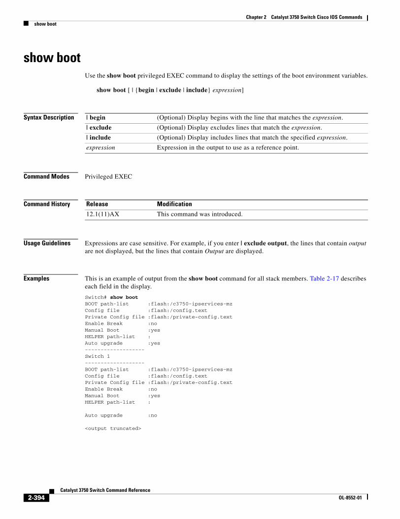
Chapter 2 Catalyst 3750 Switch Cisco IOS Commandsshow boot
show bootUse the show boot privileged EXEC command to display the settings of the boot environment variables.
show boot [ | {begin | exclude | include} expression]
Syntax Description
Command Modes Privileged EXEC
Command History
Usage Guidelines Expressions are case sensitive. For example, if you enter | exclude output, the lines that contain output are not displayed, but the lines that contain Output are displayed.
Examples This is an example of output from the show boot command for all stack members. Table 2-17 describes each field in the display.
Switch# show bootBOOT path-list :flash:/c3750-ipservices-mzConfig file :flash:/config.textPrivate Config file :flash:/private-config.textEnable Break :noManual Boot :yesHELPER path-list :Auto upgrade :yes-------------------Switch 1-------------------BOOT path-list :flash:/c3750-ipservices-mzConfig file :flash:/config.textPrivate Config file :flash:/private-config.textEnable Break :noManual Boot :yesHELPER path-list :
Auto upgrade :no
<output truncated>
| begin (Optional) Display begins with the line that matches the expression.
| exclude (Optional) Display excludes lines that match the expression.
| include (Optional) Display includes lines that match the specified expression.
expression Expression in the output to use as a reference point.
Release Modification
12.1(11)AX This command was introduced.
2-394Catalyst 3750 Switch Command Reference
OL-8552-01
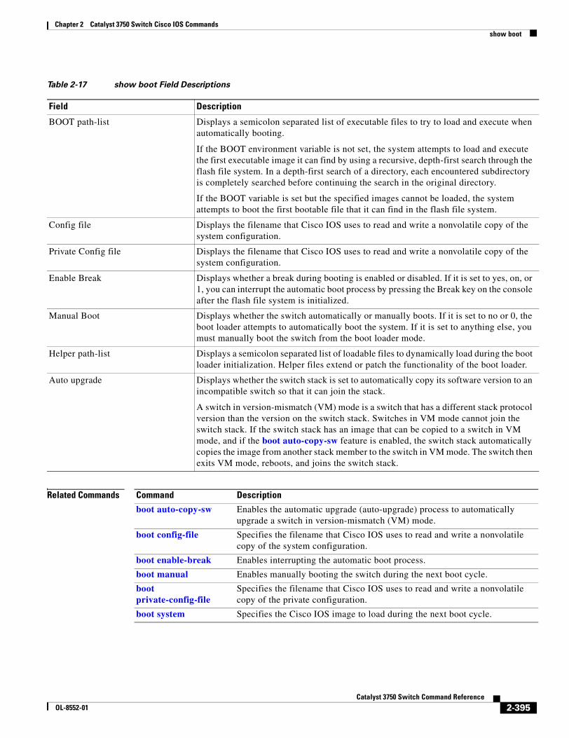
Chapter 2 Catalyst 3750 Switch Cisco IOS Commandsshow boot
Related Commands
Table 2-17 show boot Field Descriptions
Field Description
BOOT path-list Displays a semicolon separated list of executable files to try to load and execute when automatically booting.
If the BOOT environment variable is not set, the system attempts to load and execute the first executable image it can find by using a recursive, depth-first search through the flash file system. In a depth-first search of a directory, each encountered subdirectory is completely searched before continuing the search in the original directory.
If the BOOT variable is set but the specified images cannot be loaded, the system attempts to boot the first bootable file that it can find in the flash file system.
Config file Displays the filename that Cisco IOS uses to read and write a nonvolatile copy of the system configuration.
Private Config file Displays the filename that Cisco IOS uses to read and write a nonvolatile copy of the system configuration.
Enable Break Displays whether a break during booting is enabled or disabled. If it is set to yes, on, or 1, you can interrupt the automatic boot process by pressing the Break key on the console after the flash file system is initialized.
Manual Boot Displays whether the switch automatically or manually boots. If it is set to no or 0, the boot loader attempts to automatically boot the system. If it is set to anything else, you must manually boot the switch from the boot loader mode.
Helper path-list Displays a semicolon separated list of loadable files to dynamically load during the boot loader initialization. Helper files extend or patch the functionality of the boot loader.
Auto upgrade Displays whether the switch stack is set to automatically copy its software version to an incompatible switch so that it can join the stack.
A switch in version-mismatch (VM) mode is a switch that has a different stack protocol version than the version on the switch stack. Switches in VM mode cannot join the switch stack. If the switch stack has an image that can be copied to a switch in VM mode, and if the boot auto-copy-sw feature is enabled, the switch stack automatically copies the image from another stack member to the switch in VM mode. The switch then exits VM mode, reboots, and joins the switch stack.
Command Description
boot auto-copy-sw Enables the automatic upgrade (auto-upgrade) process to automatically upgrade a switch in version-mismatch (VM) mode.
boot config-file Specifies the filename that Cisco IOS uses to read and write a nonvolatile copy of the system configuration.
boot enable-break Enables interrupting the automatic boot process.
boot manual Enables manually booting the switch during the next boot cycle.
boot private-config-file
Specifies the filename that Cisco IOS uses to read and write a nonvolatile copy of the private configuration.
boot system Specifies the Cisco IOS image to load during the next boot cycle.
2-395Catalyst 3750 Switch Command Reference
OL-8552-01
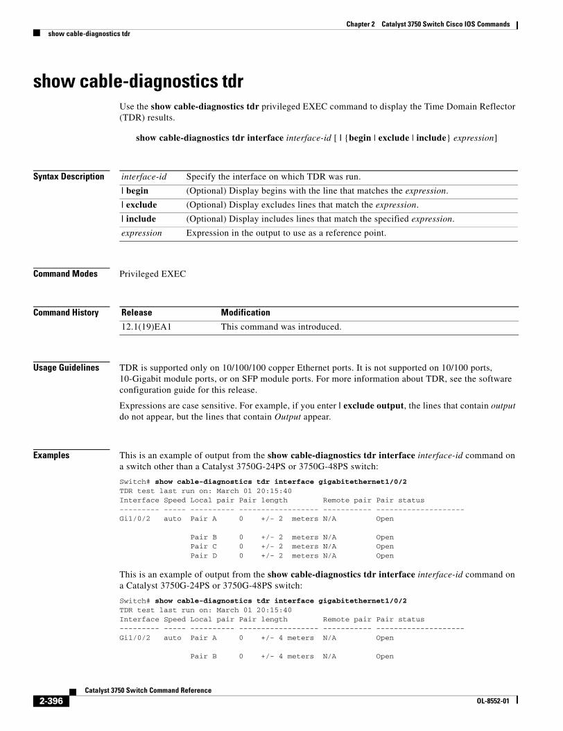
Chapter 2 Catalyst 3750 Switch Cisco IOS Commandsshow cable-diagnostics tdr
show cable-diagnostics tdrUse the show cable-diagnostics tdr privileged EXEC command to display the Time Domain Reflector (TDR) results.
show cable-diagnostics tdr interface interface-id [ | {begin | exclude | include} expression]
Syntax Description
Command Modes Privileged EXEC
Command History
Usage Guidelines TDR is supported only on 10/100/100 copper Ethernet ports. It is not supported on 10/100 ports, 10-Gigabit module ports, or on SFP module ports. For more information about TDR, see the software configuration guide for this release.
Expressions are case sensitive. For example, if you enter | exclude output, the lines that contain output do not appear, but the lines that contain Output appear.
Examples This is an example of output from the show cable-diagnostics tdr interface interface-id command on a switch other than a Catalyst 3750G-24PS or 3750G-48PS switch:
Switch# show cable-diagnostics tdr interface gigabitethernet1/0/2TDR test last run on: March 01 20:15:40Interface Speed Local pair Pair length Remote pair Pair status--------- ----- ---------- ------------------ ----------- --------------------Gi1/0/2 auto Pair A 0 +/- 2 meters N/A Open
Pair B 0 +/- 2 meters N/A OpenPair C 0 +/- 2 meters N/A OpenPair D 0 +/- 2 meters N/A Open
This is an example of output from the show cable-diagnostics tdr interface interface-id command on a Catalyst 3750G-24PS or 3750G-48PS switch:
Switch# show cable-diagnostics tdr interface gigabitethernet1/0/2TDR test last run on: March 01 20:15:40Interface Speed Local pair Pair length Remote pair Pair status--------- ----- ---------- ------------------ ----------- --------------------Gi1/0/2 auto Pair A 0 +/- 4 meters N/A Open Pair B 0 +/- 4 meters N/A Open
interface-id Specify the interface on which TDR was run.
| begin (Optional) Display begins with the line that matches the expression.
| exclude (Optional) Display excludes lines that match the expression.
| include (Optional) Display includes lines that match the specified expression.
expression Expression in the output to use as a reference point.
Release Modification
12.1(19)EA1 This command was introduced.
2-396Catalyst 3750 Switch Command Reference
OL-8552-01
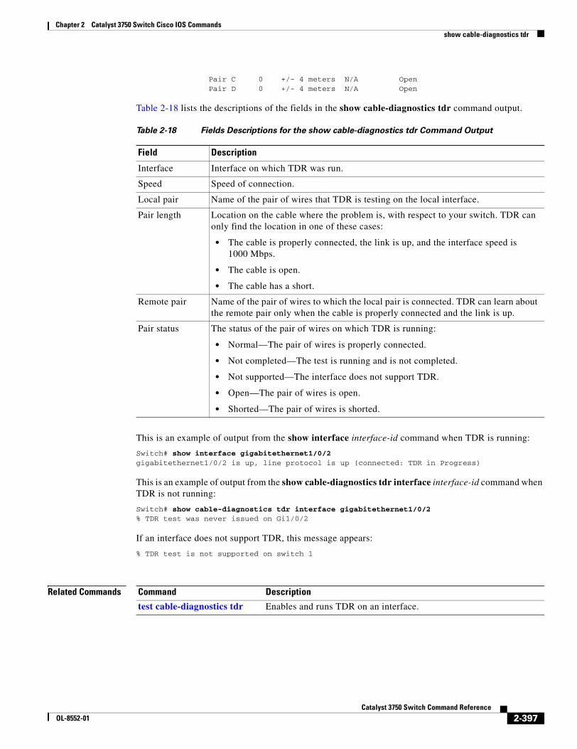
Chapter 2 Catalyst 3750 Switch Cisco IOS Commandsshow cable-diagnostics tdr
Pair C 0 +/- 4 meters N/A Open Pair D 0 +/- 4 meters N/A Open
Table 2-18 lists the descriptions of the fields in the show cable-diagnostics tdr command output.
This is an example of output from the show interface interface-id command when TDR is running:
Switch# show interface gigabitethernet1/0/2gigabitethernet1/0/2 is up, line protocol is up (connected: TDR in Progress)
This is an example of output from the show cable-diagnostics tdr interface interface-id command when TDR is not running:
Switch# show cable-diagnostics tdr interface gigabitethernet1/0/2% TDR test was never issued on Gi1/0/2
If an interface does not support TDR, this message appears:
% TDR test is not supported on switch 1
Related Commands
Table 2-18 Fields Descriptions for the show cable-diagnostics tdr Command Output
Field Description
Interface Interface on which TDR was run.
Speed Speed of connection.
Local pair Name of the pair of wires that TDR is testing on the local interface.
Pair length Location on the cable where the problem is, with respect to your switch. TDR can only find the location in one of these cases:
• The cable is properly connected, the link is up, and the interface speed is 1000 Mbps.
• The cable is open.
• The cable has a short.
Remote pair Name of the pair of wires to which the local pair is connected. TDR can learn about the remote pair only when the cable is properly connected and the link is up.
Pair status The status of the pair of wires on which TDR is running:
• Normal—The pair of wires is properly connected.
• Not completed—The test is running and is not completed.
• Not supported—The interface does not support TDR.
• Open—The pair of wires is open.
• Shorted—The pair of wires is shorted.
Command Description
test cable-diagnostics tdr Enables and runs TDR on an interface.
2-397Catalyst 3750 Switch Command Reference
OL-8552-01
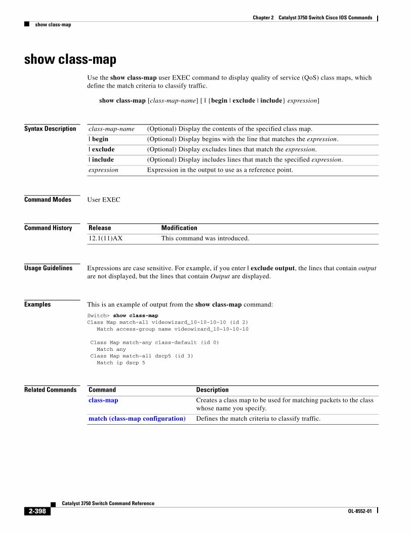
Chapter 2 Catalyst 3750 Switch Cisco IOS Commandsshow class-map
show class-mapUse the show class-map user EXEC command to display quality of service (QoS) class maps, which define the match criteria to classify traffic.
show class-map [class-map-name] [ | {begin | exclude | include} expression]
Syntax Description
Command Modes User EXEC
Command History
Usage Guidelines Expressions are case sensitive. For example, if you enter | exclude output, the lines that contain output are not displayed, but the lines that contain Output are displayed.
Examples This is an example of output from the show class-map command:
Switch> show class-map Class Map match-all videowizard_10-10-10-10 (id 2) Match access-group name videowizard_10-10-10-10
Class Map match-any class-default (id 0) Match any Class Map match-all dscp5 (id 3) Match ip dscp 5
Related Commands
class-map-name (Optional) Display the contents of the specified class map.
| begin (Optional) Display begins with the line that matches the expression.
| exclude (Optional) Display excludes lines that match the expression.
| include (Optional) Display includes lines that match the specified expression.
expression Expression in the output to use as a reference point.
Release Modification
12.1(11)AX This command was introduced.
Command Description
class-map Creates a class map to be used for matching packets to the class whose name you specify.
match (class-map configuration) Defines the match criteria to classify traffic.
2-398Catalyst 3750 Switch Command Reference
OL-8552-01
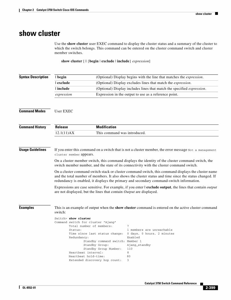
Chapter 2 Catalyst 3750 Switch Cisco IOS Commandsshow cluster
show clusterUse the show cluster user EXEC command to display the cluster status and a summary of the cluster to which the switch belongs. This command can be entered on the cluster command switch and cluster member switches.
show cluster [ | {begin | exclude | include} expression]
Syntax Description
Command Modes User EXEC
Command History
Usage Guidelines If you enter this command on a switch that is not a cluster member, the error message Not a management cluster member appears.
On a cluster member switch, this command displays the identity of the cluster command switch, the switch member number, and the state of its connectivity with the cluster command switch.
On a cluster command switch stack or cluster command switch, this command displays the cluster name and the total number of members. It also shows the cluster status and time since the status changed. If redundancy is enabled, it displays the primary and secondary command-switch information.
Expressions are case sensitive. For example, if you enter | exclude output, the lines that contain output are not displayed, but the lines that contain Output are displayed.
Examples This is an example of output when the show cluster command is entered on the active cluster command switch:
Switch> show clusterCommand switch for cluster “Ajang” Total number of members: 7 Status: 1 members are unreachable Time since last status change: 0 days, 0 hours, 2 minutes Redundancy: Enabled Standby command switch: Member 1 Standby Group: Ajang_standby Standby Group Number: 110 Heartbeat interval: 8 Heartbeat hold-time: 80 Extended discovery hop count: 3
| begin (Optional) Display begins with the line that matches the expression.
| exclude (Optional) Display excludes lines that match the expression.
| include (Optional) Display includes lines that match the specified expression.
expression Expression in the output to use as a reference point.
Release Modification
12.1(11)AX This command was introduced.
2-399Catalyst 3750 Switch Command Reference
OL-8552-01
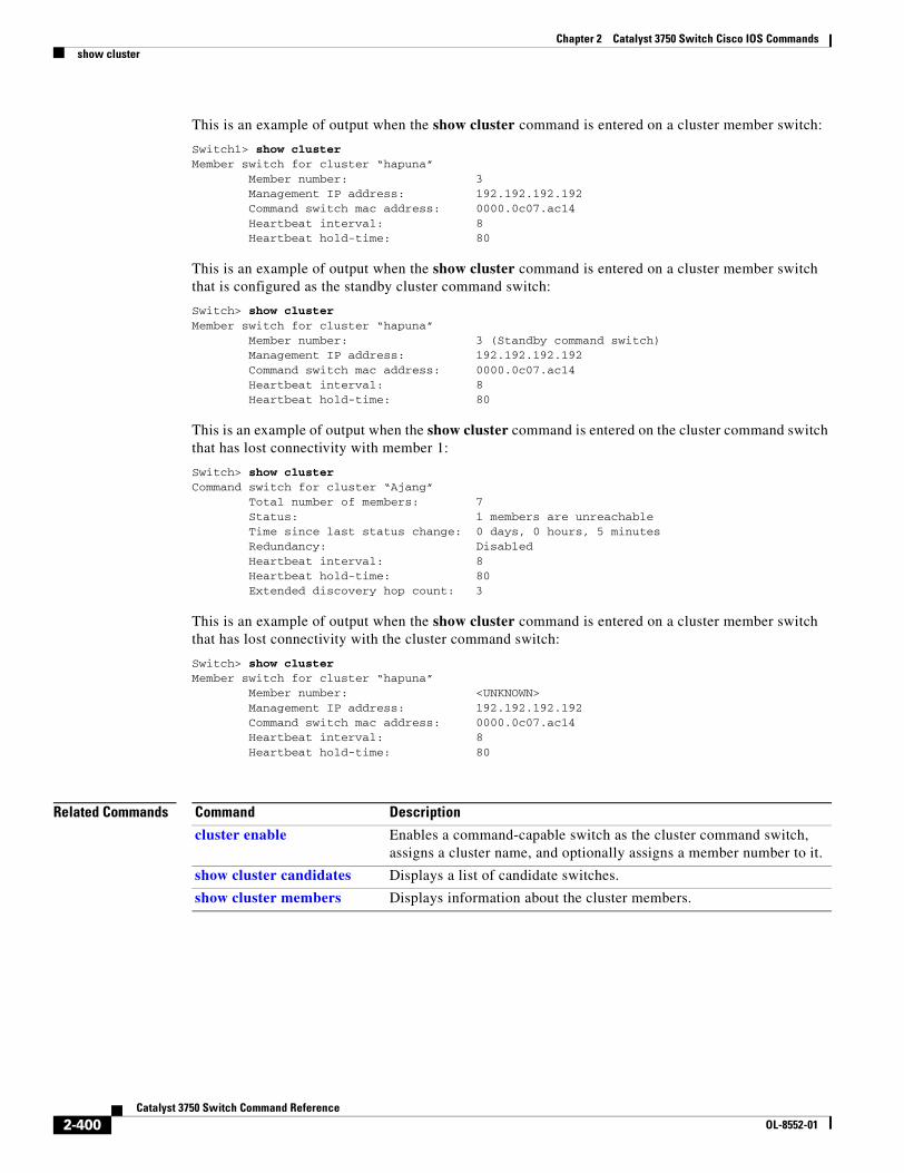
Chapter 2 Catalyst 3750 Switch Cisco IOS Commandsshow cluster
This is an example of output when the show cluster command is entered on a cluster member switch:
Switch1> show clusterMember switch for cluster “hapuna” Member number: 3 Management IP address: 192.192.192.192 Command switch mac address: 0000.0c07.ac14 Heartbeat interval: 8 Heartbeat hold-time: 80
This is an example of output when the show cluster command is entered on a cluster member switch that is configured as the standby cluster command switch:
Switch> show clusterMember switch for cluster “hapuna” Member number: 3 (Standby command switch) Management IP address: 192.192.192.192 Command switch mac address: 0000.0c07.ac14 Heartbeat interval: 8 Heartbeat hold-time: 80
This is an example of output when the show cluster command is entered on the cluster command switch that has lost connectivity with member 1:
Switch> show clusterCommand switch for cluster “Ajang” Total number of members: 7 Status: 1 members are unreachable Time since last status change: 0 days, 0 hours, 5 minutes Redundancy: Disabled Heartbeat interval: 8 Heartbeat hold-time: 80 Extended discovery hop count: 3
This is an example of output when the show cluster command is entered on a cluster member switch that has lost connectivity with the cluster command switch:
Switch> show clusterMember switch for cluster “hapuna” Member number: <UNKNOWN> Management IP address: 192.192.192.192 Command switch mac address: 0000.0c07.ac14 Heartbeat interval: 8 Heartbeat hold-time: 80
Related Commands Command Description
cluster enable Enables a command-capable switch as the cluster command switch, assigns a cluster name, and optionally assigns a member number to it.
show cluster candidates Displays a list of candidate switches.
show cluster members Displays information about the cluster members.
2-400Catalyst 3750 Switch Command Reference
OL-8552-01
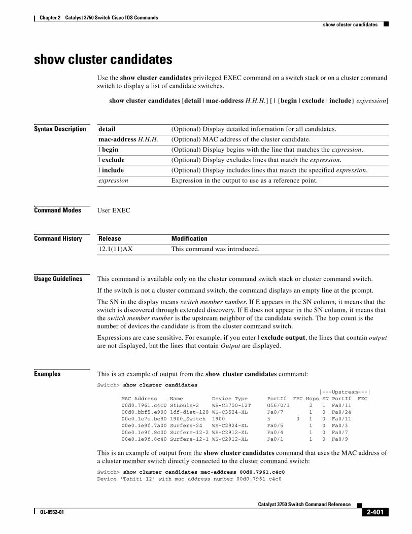
Chapter 2 Catalyst 3750 Switch Cisco IOS Commandsshow cluster candidates
show cluster candidatesUse the show cluster candidates privileged EXEC command on a switch stack or on a cluster command switch to display a list of candidate switches.
show cluster candidates [detail | mac-address H.H.H.] [ | {begin | exclude | include} expression]
Syntax Description
Command Modes User EXEC
Command History
Usage Guidelines This command is available only on the cluster command switch stack or cluster command switch.
If the switch is not a cluster command switch, the command displays an empty line at the prompt.
The SN in the display means switch member number. If E appears in the SN column, it means that the switch is discovered through extended discovery. If E does not appear in the SN column, it means that the switch member number is the upstream neighbor of the candidate switch. The hop count is the number of devices the candidate is from the cluster command switch.
Expressions are case sensitive. For example, if you enter | exclude output, the lines that contain output are not displayed, but the lines that contain Output are displayed.
Examples This is an example of output from the show cluster candidates command:
Switch> show cluster candidates |---Upstream---|MAC Address Name Device Type PortIf FEC Hops SN PortIf FEC00d0.7961.c4c0 StLouis-2 WS-C3750-12T Gi6/0/1 2 1 Fa0/11 00d0.bbf5.e900 ldf-dist-128 WS-C3524-XL Fa0/7 1 0 Fa0/24 00e0.1e7e.be80 1900_Switch 1900 3 0 1 0 Fa0/11 00e0.1e9f.7a00 Surfers-24 WS-C2924-XL Fa0/5 1 0 Fa0/3 00e0.1e9f.8c00 Surfers-12-2 WS-C2912-XL Fa0/4 1 0 Fa0/7 00e0.1e9f.8c40 Surfers-12-1 WS-C2912-XL Fa0/1 1 0 Fa0/9
This is an example of output from the show cluster candidates command that uses the MAC address of a cluster member switch directly connected to the cluster command switch:
Switch> show cluster candidates mac-address 00d0.7961.c4c0Device 'Tahiti-12' with mac address number 00d0.7961.c4c0
detail (Optional) Display detailed information for all candidates.
mac-address H.H.H. (Optional) MAC address of the cluster candidate.
| begin (Optional) Display begins with the line that matches the expression.
| exclude (Optional) Display excludes lines that match the expression.
| include (Optional) Display includes lines that match the specified expression.
expression Expression in the output to use as a reference point.
Release Modification
12.1(11)AX This command was introduced.
2-401Catalyst 3750 Switch Command Reference
OL-8552-01
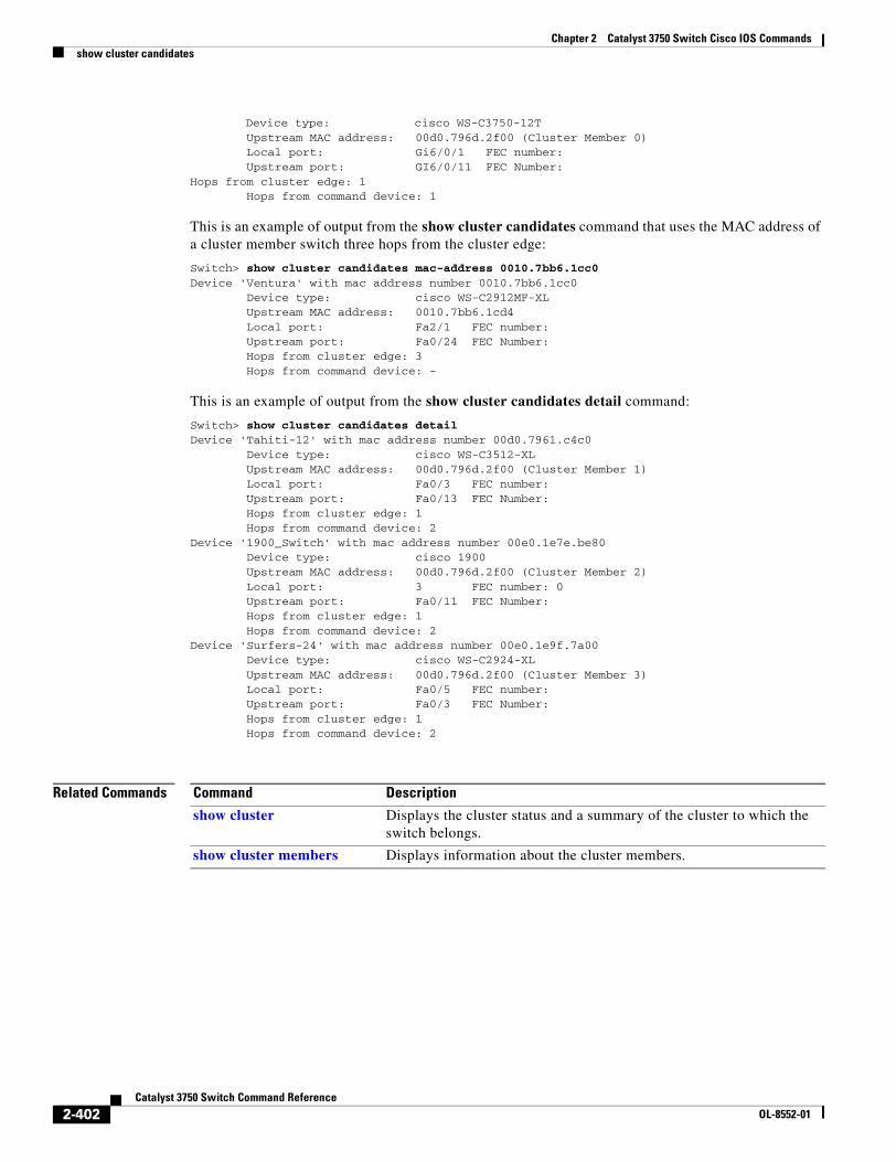
Chapter 2 Catalyst 3750 Switch Cisco IOS Commandsshow cluster candidates
Device type: cisco WS-C3750-12T Upstream MAC address: 00d0.796d.2f00 (Cluster Member 0) Local port: Gi6/0/1 FEC number: Upstream port: GI6/0/11 FEC Number:Hops from cluster edge: 1 Hops from command device: 1
This is an example of output from the show cluster candidates command that uses the MAC address of a cluster member switch three hops from the cluster edge:
Switch> show cluster candidates mac-address 0010.7bb6.1cc0Device 'Ventura' with mac address number 0010.7bb6.1cc0 Device type: cisco WS-C2912MF-XL Upstream MAC address: 0010.7bb6.1cd4 Local port: Fa2/1 FEC number: Upstream port: Fa0/24 FEC Number: Hops from cluster edge: 3 Hops from command device: -
This is an example of output from the show cluster candidates detail command:
Switch> show cluster candidates detailDevice 'Tahiti-12' with mac address number 00d0.7961.c4c0 Device type: cisco WS-C3512-XL Upstream MAC address: 00d0.796d.2f00 (Cluster Member 1) Local port: Fa0/3 FEC number: Upstream port: Fa0/13 FEC Number: Hops from cluster edge: 1 Hops from command device: 2Device '1900_Switch' with mac address number 00e0.1e7e.be80 Device type: cisco 1900 Upstream MAC address: 00d0.796d.2f00 (Cluster Member 2) Local port: 3 FEC number: 0 Upstream port: Fa0/11 FEC Number: Hops from cluster edge: 1 Hops from command device: 2Device 'Surfers-24' with mac address number 00e0.1e9f.7a00 Device type: cisco WS-C2924-XL Upstream MAC address: 00d0.796d.2f00 (Cluster Member 3) Local port: Fa0/5 FEC number: Upstream port: Fa0/3 FEC Number: Hops from cluster edge: 1 Hops from command device: 2
Related Commands Command Description
show cluster Displays the cluster status and a summary of the cluster to which the switch belongs.
show cluster members Displays information about the cluster members.
2-402Catalyst 3750 Switch Command Reference
OL-8552-01
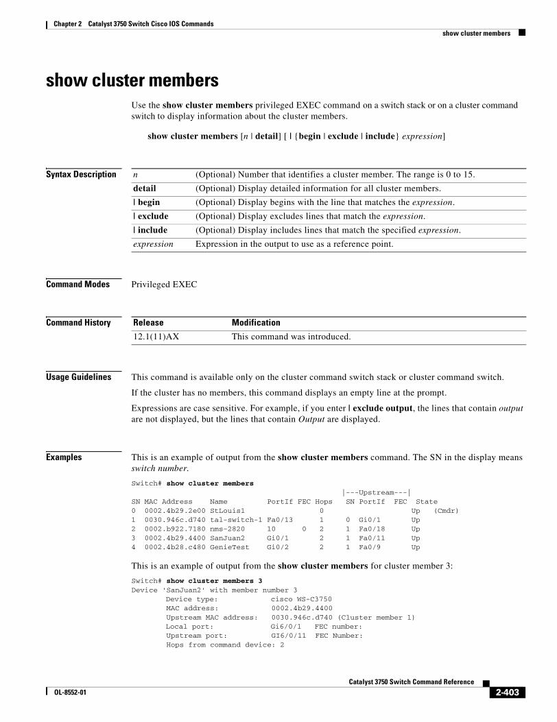
Chapter 2 Catalyst 3750 Switch Cisco IOS Commandsshow cluster members
show cluster members Use the show cluster members privileged EXEC command on a switch stack or on a cluster command switch to display information about the cluster members.
show cluster members [n | detail] [ | {begin | exclude | include} expression]
Syntax Description
Command Modes Privileged EXEC
Command History
Usage Guidelines This command is available only on the cluster command switch stack or cluster command switch.
If the cluster has no members, this command displays an empty line at the prompt.
Expressions are case sensitive. For example, if you enter | exclude output, the lines that contain output are not displayed, but the lines that contain Output are displayed.
Examples This is an example of output from the show cluster members command. The SN in the display means switch number.
Switch# show cluster members |---Upstream---|SN MAC Address Name PortIf FEC Hops SN PortIf FEC State0 0002.4b29.2e00 StLouis1 0 Up (Cmdr)1 0030.946c.d740 tal-switch-1 Fa0/13 1 0 Gi0/1 Up2 0002.b922.7180 nms-2820 10 0 2 1 Fa0/18 Up3 0002.4b29.4400 SanJuan2 Gi0/1 2 1 Fa0/11 Up4 0002.4b28.c480 GenieTest Gi0/2 2 1 Fa0/9 Up
This is an example of output from the show cluster members for cluster member 3:
Switch# show cluster members 3Device 'SanJuan2' with member number 3 Device type: cisco WS-C3750 MAC address: 0002.4b29.4400 Upstream MAC address: 0030.946c.d740 (Cluster member 1) Local port: Gi6/0/1 FEC number: Upstream port: GI6/0/11 FEC Number: Hops from command device: 2
n (Optional) Number that identifies a cluster member. The range is 0 to 15.
detail (Optional) Display detailed information for all cluster members.
| begin (Optional) Display begins with the line that matches the expression.
| exclude (Optional) Display excludes lines that match the expression.
| include (Optional) Display includes lines that match the specified expression.
expression Expression in the output to use as a reference point.
Release Modification
12.1(11)AX This command was introduced.
2-403Catalyst 3750 Switch Command Reference
OL-8552-01
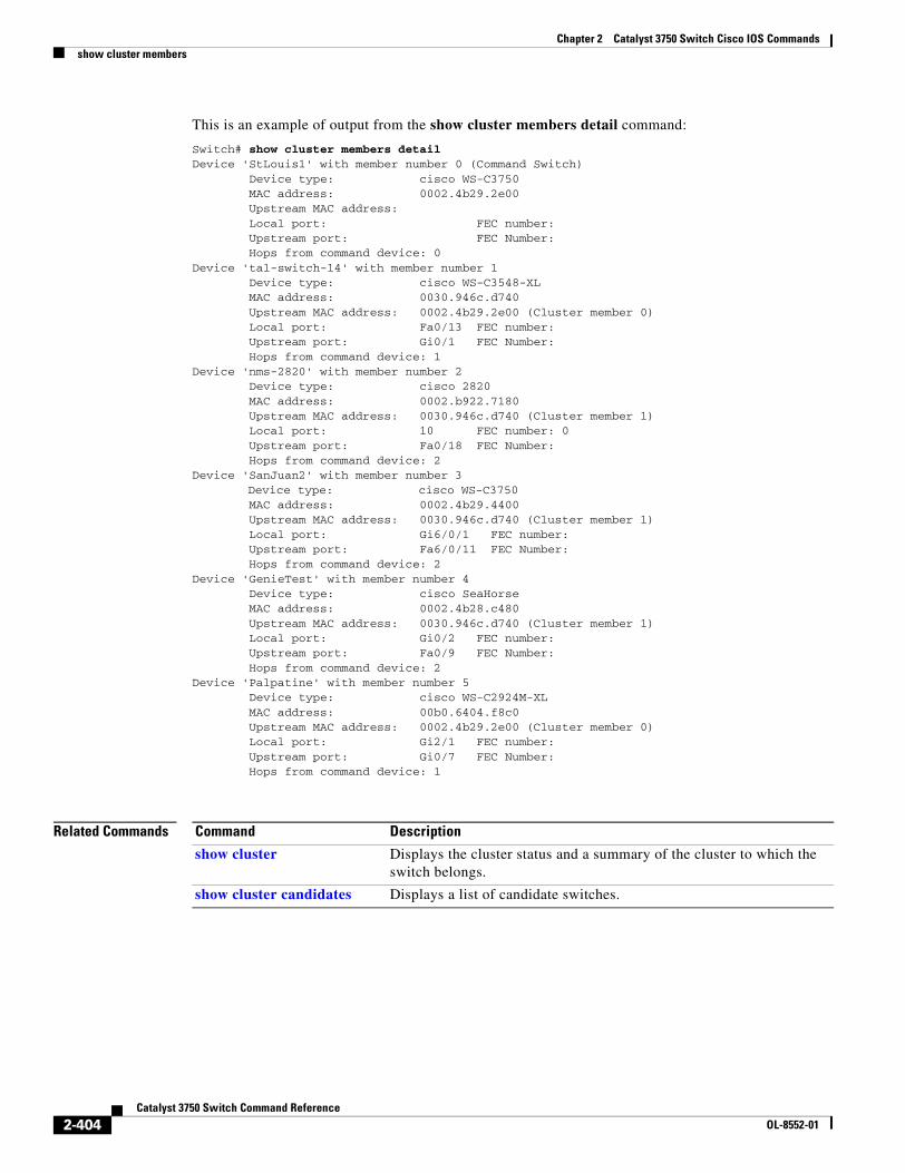
Chapter 2 Catalyst 3750 Switch Cisco IOS Commandsshow cluster members
This is an example of output from the show cluster members detail command:
Switch# show cluster members detailDevice 'StLouis1' with member number 0 (Command Switch) Device type: cisco WS-C3750 MAC address: 0002.4b29.2e00 Upstream MAC address: Local port: FEC number: Upstream port: FEC Number: Hops from command device: 0 Device 'tal-switch-14' with member number 1 Device type: cisco WS-C3548-XL MAC address: 0030.946c.d740 Upstream MAC address: 0002.4b29.2e00 (Cluster member 0) Local port: Fa0/13 FEC number: Upstream port: Gi0/1 FEC Number: Hops from command device: 1 Device 'nms-2820' with member number 2 Device type: cisco 2820 MAC address: 0002.b922.7180 Upstream MAC address: 0030.946c.d740 (Cluster member 1) Local port: 10 FEC number: 0 Upstream port: Fa0/18 FEC Number: Hops from command device: 2 Device 'SanJuan2' with member number 3 Device type: cisco WS-C3750 MAC address: 0002.4b29.4400 Upstream MAC address: 0030.946c.d740 (Cluster member 1) Local port: Gi6/0/1 FEC number: Upstream port: Fa6/0/11 FEC Number: Hops from command device: 2Device 'GenieTest' with member number 4 Device type: cisco SeaHorse MAC address: 0002.4b28.c480 Upstream MAC address: 0030.946c.d740 (Cluster member 1) Local port: Gi0/2 FEC number: Upstream port: Fa0/9 FEC Number: Hops from command device: 2Device 'Palpatine' with member number 5 Device type: cisco WS-C2924M-XL MAC address: 00b0.6404.f8c0 Upstream MAC address: 0002.4b29.2e00 (Cluster member 0) Local port: Gi2/1 FEC number: Upstream port: Gi0/7 FEC Number: Hops from command device: 1
Related Commands Command Description
show cluster Displays the cluster status and a summary of the cluster to which the switch belongs.
show cluster candidates Displays a list of candidate switches.
2-404Catalyst 3750 Switch Command Reference
OL-8552-01
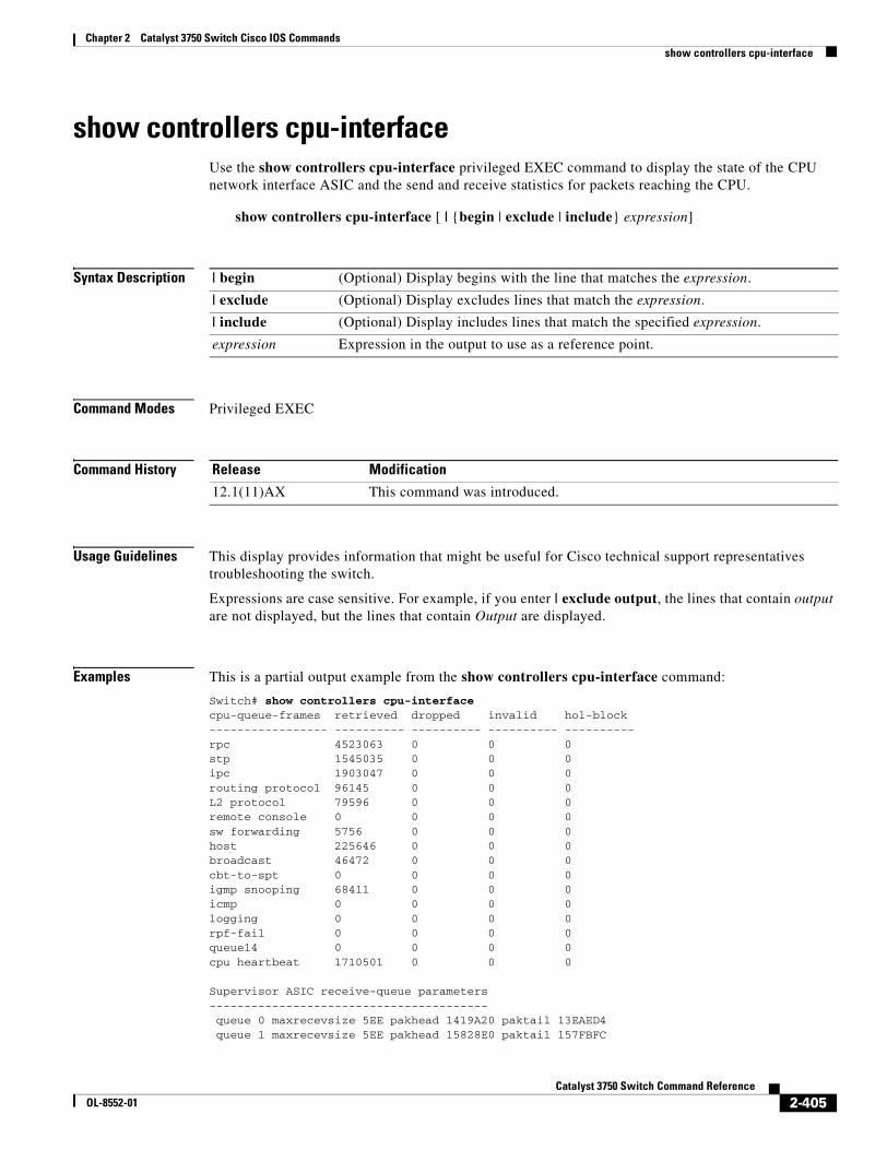
Chapter 2 Catalyst 3750 Switch Cisco IOS Commandsshow controllers cpu-interface
show controllers cpu-interfaceUse the show controllers cpu-interface privileged EXEC command to display the state of the CPU network interface ASIC and the send and receive statistics for packets reaching the CPU.
show controllers cpu-interface [ | {begin | exclude | include} expression]
Syntax Description
Command Modes Privileged EXEC
Command History
Usage Guidelines This display provides information that might be useful for Cisco technical support representatives troubleshooting the switch.
Expressions are case sensitive. For example, if you enter | exclude output, the lines that contain output are not displayed, but the lines that contain Output are displayed.
Examples This is a partial output example from the show controllers cpu-interface command:
Switch# show controllers cpu-interfacecpu-queue-frames retrieved dropped invalid hol-block----------------- ---------- ---------- ---------- ----------rpc 4523063 0 0 0stp 1545035 0 0 0ipc 1903047 0 0 0routing protocol 96145 0 0 0L2 protocol 79596 0 0 0remote console 0 0 0 0sw forwarding 5756 0 0 0host 225646 0 0 0broadcast 46472 0 0 0cbt-to-spt 0 0 0 0igmp snooping 68411 0 0 0icmp 0 0 0 0logging 0 0 0 0rpf-fail 0 0 0 0queue14 0 0 0 0cpu heartbeat 1710501 0 0 0
Supervisor ASIC receive-queue parameters---------------------------------------- queue 0 maxrecevsize 5EE pakhead 1419A20 paktail 13EAED4 queue 1 maxrecevsize 5EE pakhead 15828E0 paktail 157FBFC
| begin (Optional) Display begins with the line that matches the expression.
| exclude (Optional) Display excludes lines that match the expression.
| include (Optional) Display includes lines that match the specified expression.
expression Expression in the output to use as a reference point.
Release Modification
12.1(11)AX This command was introduced.
2-405Catalyst 3750 Switch Command Reference
OL-8552-01
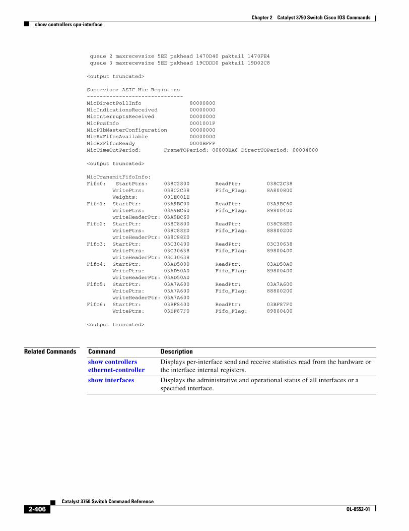
Chapter 2 Catalyst 3750 Switch Cisco IOS Commandsshow controllers cpu-interface
queue 2 maxrecevsize 5EE pakhead 1470D40 paktail 1470FE4 queue 3 maxrecevsize 5EE pakhead 19CDDD0 paktail 19D02C8
<output truncated>
Supervisor ASIC Mic Registers------------------------------MicDirectPollInfo 80000800MicIndicationsReceived 00000000MicInterruptsReceived 00000000MicPcsInfo 0001001FMicPlbMasterConfiguration 00000000MicRxFifosAvailable 00000000MicRxFifosReady 0000BFFFMicTimeOutPeriod: FrameTOPeriod: 00000EA6 DirectTOPeriod: 00004000
<output truncated>
MicTransmitFifoInfo:Fifo0: StartPtrs: 038C2800 ReadPtr: 038C2C38 WritePtrs: 038C2C38 Fifo_Flag: 8A800800 Weights: 001E001EFifo1: StartPtr: 03A9BC00 ReadPtr: 03A9BC60 WritePtrs: 03A9BC60 Fifo_Flag: 89800400 writeHeaderPtr: 03A9BC60Fifo2: StartPtr: 038C8800 ReadPtr: 038C88E0 WritePtrs: 038C88E0 Fifo_Flag: 88800200 writeHeaderPtr: 038C88E0Fifo3: StartPtr: 03C30400 ReadPtr: 03C30638 WritePtrs: 03C30638 Fifo_Flag: 89800400 writeHeaderPtr: 03C30638Fifo4: StartPtr: 03AD5000 ReadPtr: 03AD50A0 WritePtrs: 03AD50A0 Fifo_Flag: 89800400 writeHeaderPtr: 03AD50A0Fifo5: StartPtr: 03A7A600 ReadPtr: 03A7A600 WritePtrs: 03A7A600 Fifo_Flag: 88800200 writeHeaderPtr: 03A7A600Fifo6: StartPtr: 03BF8400 ReadPtr: 03BF87F0 WritePtrs: 03BF87F0 Fifo_Flag: 89800400
<output truncated>
Related Commands Command Description
show controllers ethernet-controller
Displays per-interface send and receive statistics read from the hardware or the interface internal registers.
show interfaces Displays the administrative and operational status of all interfaces or a specified interface.
2-406Catalyst 3750 Switch Command Reference
OL-8552-01
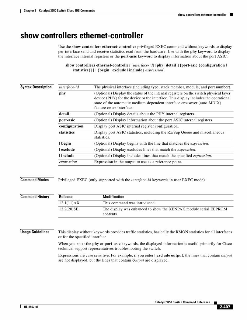
Chapter 2 Catalyst 3750 Switch Cisco IOS Commandsshow controllers ethernet-controller
show controllers ethernet-controller Use the show controllers ethernet-controller privileged EXEC command without keywords to display per-interface send and receive statistics read from the hardware. Use with the phy keyword to display the interface internal registers or the port-asic keyword to display information about the port ASIC.
show controllers ethernet-controller [interface-id] [phy [detail]] [port-asic {configuration | statistics}] [ | {begin | exclude | include} expression]
Syntax Description
Command Modes Privileged EXEC (only supported with the interface-id keywords in user EXEC mode)
Command History
Usage Guidelines This display without keywords provides traffic statistics, basically the RMON statistics for all interfaces or for the specified interface.
When you enter the phy or port-asic keywords, the displayed information is useful primarily for Cisco technical support representatives troubleshooting the switch.
Expressions are case sensitive. For example, if you enter | exclude output, the lines that contain output are not displayed, but the lines that contain Output are displayed.
interface-id The physical interface (including type, stack member, module, and port number).
phy (Optional) Display the status of the internal registers on the switch physical layer device (PHY) for the device or the interface. This display includes the operational state of the automatic medium-dependent interface crossover (auto-MDIX) feature on an interface.
detail (Optional) Display details about the PHY internal registers.
port-asic (Optional) Display information about the port ASIC internal registers.
configuration Display port ASIC internal register configuration.
statistics Display port ASIC statistics, including the Rx/Sup Queue and miscellaneous statistics.
| begin (Optional) Display begins with the line that matches the expression.
| exclude (Optional) Display excludes lines that match the expression.
| include (Optional) Display includes lines that match the specified expression.
expression Expression in the output to use as a reference point.
Release Modification
12.1(11)AX This command was introduced.
12.2(20)SE The display was enhanced to show the XENPAK module serial EEPROM contents.
2-407Catalyst 3750 Switch Command Reference
OL-8552-01
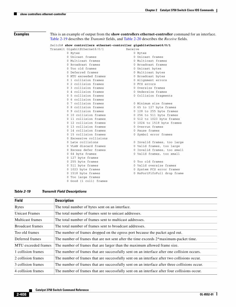
Chapter 2 Catalyst 3750 Switch Cisco IOS Commandsshow controllers ethernet-controller
Examples This is an example of output from the show controllers ethernet-controller command for an interface. Table 2-19 describes the Transmit fields, and Table 2-20 describes the Receive fields.
Switch# show controllers ethernet-controller gigabitethernet6/0/1Transmit GigabitEthernet6/0/1 Receive 0 Bytes 0 Bytes 0 Unicast frames 0 Unicast frames 0 Multicast frames 0 Multicast frames 0 Broadcast frames 0 Broadcast frames 0 Too old frames 0 Unicast bytes 0 Deferred frames 0 Multicast bytes 0 MTU exceeded frames 0 Broadcast bytes 0 1 collision frames 0 Alignment errors 0 2 collision frames 0 FCS errors 0 3 collision frames 0 Oversize frames 0 4 collision frames 0 Undersize frames 0 5 collision frames 0 Collision fragments 0 6 collision frames 0 7 collision frames 0 Minimum size frames 0 8 collision frames 0 65 to 127 byte frames 0 9 collision frames 0 128 to 255 byte frames 0 10 collision frames 0 256 to 511 byte frames 0 11 collision frames 0 512 to 1023 byte frames 0 12 collision frames 0 1024 to 1518 byte frames 0 13 collision frames 0 Overrun frames 0 14 collision frames 0 Pause frames 0 15 collision frames 0 Symbol error frames 0 Excessive collisions 0 Late collisions 0 Invalid frames, too large 0 VLAN discard frames 0 Valid frames, too large 0 Excess defer frames 0 Invalid frames, too small 0 64 byte frames 0 Valid frames, too small 0 127 byte frames 0 255 byte frames 0 Too old frames 0 511 byte frames 0 Valid oversize frames 0 1023 byte frames 0 System FCS error frames 0 1518 byte frames 0 RxPortFifoFull drop frame 0 Too large frames 0 Good (1 coll) frames
Table 2-19 Transmit Field Descriptions
Field Description
Bytes The total number of bytes sent on an interface.
Unicast Frames The total number of frames sent to unicast addresses.
Multicast frames The total number of frames sent to multicast addresses.
Broadcast frames The total number of frames sent to broadcast addresses.
Too old frames The number of frames dropped on the egress port because the packet aged out.
Deferred frames The number of frames that are not sent after the time exceeds 2*maximum-packet time.
MTU exceeded frames The number of frames that are larger than the maximum allowed frame size.
1 collision frames The number of frames that are successfully sent on an interface after one collision occurs.
2 collision frames The number of frames that are successfully sent on an interface after two collisions occur.
3 collision frames The number of frames that are successfully sent on an interface after three collisions occur.
4 collision frames The number of frames that are successfully sent on an interface after four collisions occur.
2-408Catalyst 3750 Switch Command Reference
OL-8552-01
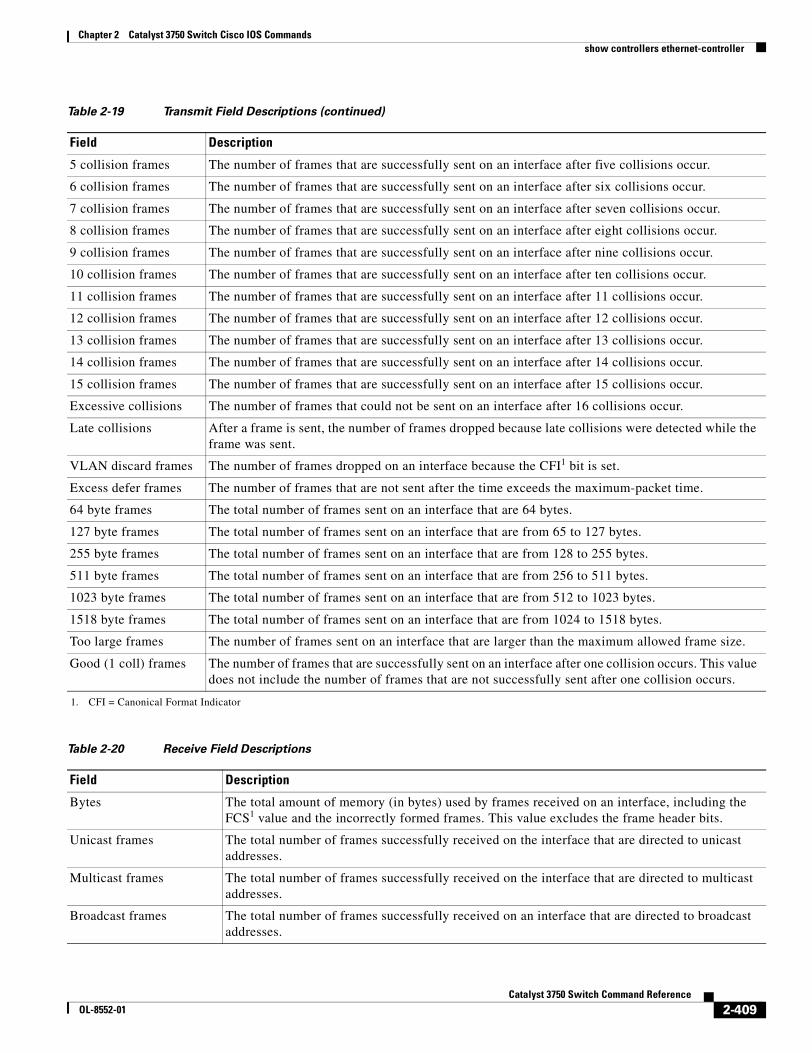
Chapter 2 Catalyst 3750 Switch Cisco IOS Commandsshow controllers ethernet-controller
5 collision frames The number of frames that are successfully sent on an interface after five collisions occur.
6 collision frames The number of frames that are successfully sent on an interface after six collisions occur.
7 collision frames The number of frames that are successfully sent on an interface after seven collisions occur.
8 collision frames The number of frames that are successfully sent on an interface after eight collisions occur.
9 collision frames The number of frames that are successfully sent on an interface after nine collisions occur.
10 collision frames The number of frames that are successfully sent on an interface after ten collisions occur.
11 collision frames The number of frames that are successfully sent on an interface after 11 collisions occur.
12 collision frames The number of frames that are successfully sent on an interface after 12 collisions occur.
13 collision frames The number of frames that are successfully sent on an interface after 13 collisions occur.
14 collision frames The number of frames that are successfully sent on an interface after 14 collisions occur.
15 collision frames The number of frames that are successfully sent on an interface after 15 collisions occur.
Excessive collisions The number of frames that could not be sent on an interface after 16 collisions occur.
Late collisions After a frame is sent, the number of frames dropped because late collisions were detected while the frame was sent.
VLAN discard frames The number of frames dropped on an interface because the CFI1 bit is set.
Excess defer frames The number of frames that are not sent after the time exceeds the maximum-packet time.
64 byte frames The total number of frames sent on an interface that are 64 bytes.
127 byte frames The total number of frames sent on an interface that are from 65 to 127 bytes.
255 byte frames The total number of frames sent on an interface that are from 128 to 255 bytes.
511 byte frames The total number of frames sent on an interface that are from 256 to 511 bytes.
1023 byte frames The total number of frames sent on an interface that are from 512 to 1023 bytes.
1518 byte frames The total number of frames sent on an interface that are from 1024 to 1518 bytes.
Too large frames The number of frames sent on an interface that are larger than the maximum allowed frame size.
Good (1 coll) frames The number of frames that are successfully sent on an interface after one collision occurs. This value does not include the number of frames that are not successfully sent after one collision occurs.
1. CFI = Canonical Format Indicator
Table 2-20 Receive Field Descriptions
Field Description
Bytes The total amount of memory (in bytes) used by frames received on an interface, including the FCS1 value and the incorrectly formed frames. This value excludes the frame header bits.
Unicast frames The total number of frames successfully received on the interface that are directed to unicast addresses.
Multicast frames The total number of frames successfully received on the interface that are directed to multicast addresses.
Broadcast frames The total number of frames successfully received on an interface that are directed to broadcast addresses.
Table 2-19 Transmit Field Descriptions (continued)
Field Description
2-409Catalyst 3750 Switch Command Reference
OL-8552-01
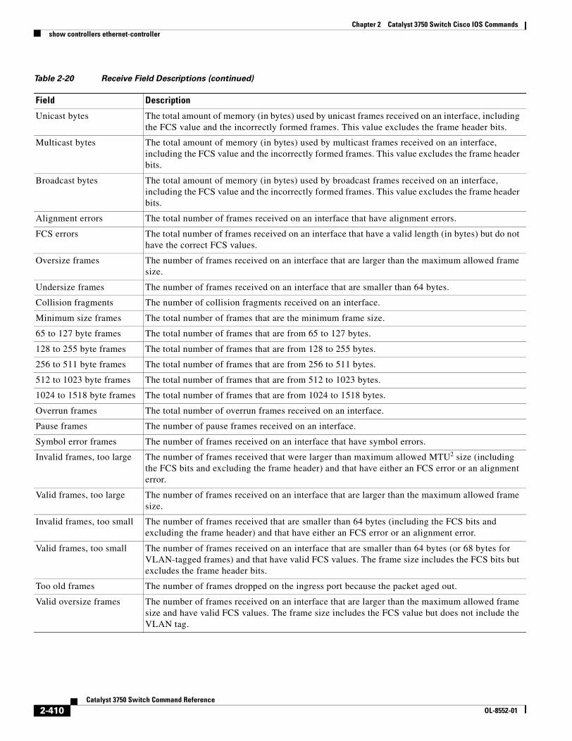
Chapter 2 Catalyst 3750 Switch Cisco IOS Commandsshow controllers ethernet-controller
Unicast bytes The total amount of memory (in bytes) used by unicast frames received on an interface, including the FCS value and the incorrectly formed frames. This value excludes the frame header bits.
Multicast bytes The total amount of memory (in bytes) used by multicast frames received on an interface, including the FCS value and the incorrectly formed frames. This value excludes the frame header bits.
Broadcast bytes The total amount of memory (in bytes) used by broadcast frames received on an interface, including the FCS value and the incorrectly formed frames. This value excludes the frame header bits.
Alignment errors The total number of frames received on an interface that have alignment errors.
FCS errors The total number of frames received on an interface that have a valid length (in bytes) but do not have the correct FCS values.
Oversize frames The number of frames received on an interface that are larger than the maximum allowed frame size.
Undersize frames The number of frames received on an interface that are smaller than 64 bytes.
Collision fragments The number of collision fragments received on an interface.
Minimum size frames The total number of frames that are the minimum frame size.
65 to 127 byte frames The total number of frames that are from 65 to 127 bytes.
128 to 255 byte frames The total number of frames that are from 128 to 255 bytes.
256 to 511 byte frames The total number of frames that are from 256 to 511 bytes.
512 to 1023 byte frames The total number of frames that are from 512 to 1023 bytes.
1024 to 1518 byte frames The total number of frames that are from 1024 to 1518 bytes.
Overrun frames The total number of overrun frames received on an interface.
Pause frames The number of pause frames received on an interface.
Symbol error frames The number of frames received on an interface that have symbol errors.
Invalid frames, too large The number of frames received that were larger than maximum allowed MTU2 size (including the FCS bits and excluding the frame header) and that have either an FCS error or an alignment error.
Valid frames, too large The number of frames received on an interface that are larger than the maximum allowed frame size.
Invalid frames, too small The number of frames received that are smaller than 64 bytes (including the FCS bits and excluding the frame header) and that have either an FCS error or an alignment error.
Valid frames, too small The number of frames received on an interface that are smaller than 64 bytes (or 68 bytes for VLAN-tagged frames) and that have valid FCS values. The frame size includes the FCS bits but excludes the frame header bits.
Too old frames The number of frames dropped on the ingress port because the packet aged out.
Valid oversize frames The number of frames received on an interface that are larger than the maximum allowed frame size and have valid FCS values. The frame size includes the FCS value but does not include the VLAN tag.
Table 2-20 Receive Field Descriptions (continued)
Field Description
2-410Catalyst 3750 Switch Command Reference
OL-8552-01
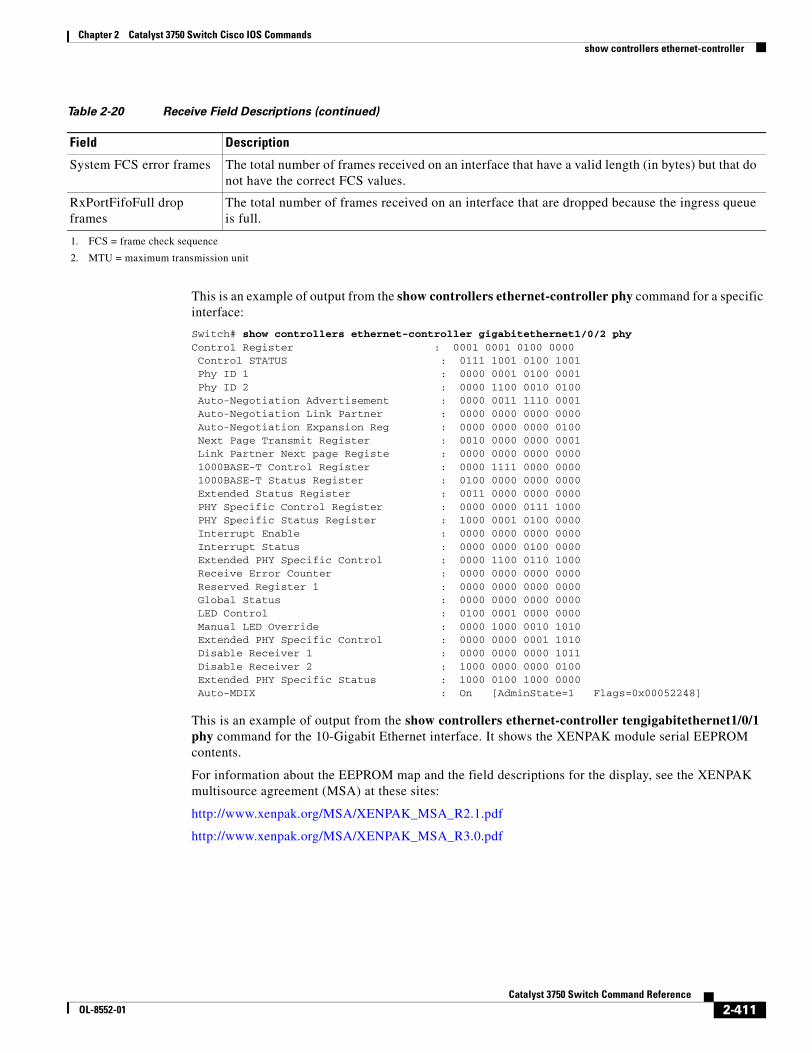
Chapter 2 Catalyst 3750 Switch Cisco IOS Commandsshow controllers ethernet-controller
This is an example of output from the show controllers ethernet-controller phy command for a specific interface:
Switch# show controllers ethernet-controller gigabitethernet1/0/2 phyControl Register : 0001 0001 0100 0000 Control STATUS : 0111 1001 0100 1001 Phy ID 1 : 0000 0001 0100 0001 Phy ID 2 : 0000 1100 0010 0100 Auto-Negotiation Advertisement : 0000 0011 1110 0001 Auto-Negotiation Link Partner : 0000 0000 0000 0000 Auto-Negotiation Expansion Reg : 0000 0000 0000 0100 Next Page Transmit Register : 0010 0000 0000 0001 Link Partner Next page Registe : 0000 0000 0000 0000 1000BASE-T Control Register : 0000 1111 0000 0000 1000BASE-T Status Register : 0100 0000 0000 0000 Extended Status Register : 0011 0000 0000 0000 PHY Specific Control Register : 0000 0000 0111 1000 PHY Specific Status Register : 1000 0001 0100 0000 Interrupt Enable : 0000 0000 0000 0000 Interrupt Status : 0000 0000 0100 0000 Extended PHY Specific Control : 0000 1100 0110 1000 Receive Error Counter : 0000 0000 0000 0000 Reserved Register 1 : 0000 0000 0000 0000 Global Status : 0000 0000 0000 0000 LED Control : 0100 0001 0000 0000 Manual LED Override : 0000 1000 0010 1010 Extended PHY Specific Control : 0000 0000 0001 1010 Disable Receiver 1 : 0000 0000 0000 1011 Disable Receiver 2 : 1000 0000 0000 0100 Extended PHY Specific Status : 1000 0100 1000 0000 Auto-MDIX : On [AdminState=1 Flags=0x00052248]
This is an example of output from the show controllers ethernet-controller tengigabitethernet1/0/1 phy command for the 10-Gigabit Ethernet interface. It shows the XENPAK module serial EEPROM contents.
For information about the EEPROM map and the field descriptions for the display, see the XENPAK multisource agreement (MSA) at these sites:
http://www.xenpak.org/MSA/XENPAK_MSA_R2.1.pdf
http://www.xenpak.org/MSA/XENPAK_MSA_R3.0.pdf
System FCS error frames The total number of frames received on an interface that have a valid length (in bytes) but that do not have the correct FCS values.
RxPortFifoFull drop frames
The total number of frames received on an interface that are dropped because the ingress queue is full.
1. FCS = frame check sequence
2. MTU = maximum transmission unit
Table 2-20 Receive Field Descriptions (continued)
Field Description
2-411Catalyst 3750 Switch Command Reference
OL-8552-01
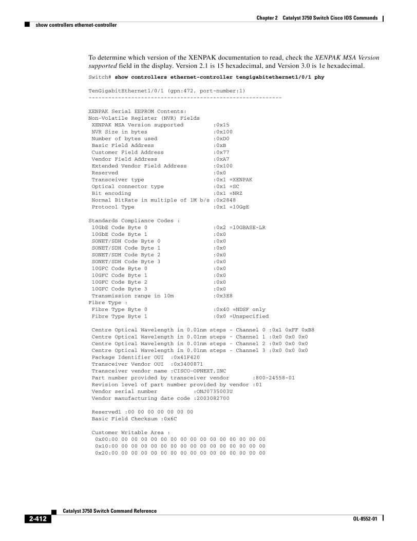
Chapter 2 Catalyst 3750 Switch Cisco IOS Commandsshow controllers ethernet-controller
To determine which version of the XENPAK documentation to read, check the XENPAK MSA Version supported field in the display. Version 2.1 is 15 hexadecimal, and Version 3.0 is 1e hexadecimal.
Switch# show controllers ethernet-controller tengigabitethernet1/0/1 phy
TenGigabitEthernet1/0/1 (gpn:472, port-number:1)-----------------------------------------------------------
XENPAK Serial EEPROM Contents:Non-Volatile Register (NVR) Fields XENPAK MSA Version supported :0x15 NVR Size in bytes :0x100 Number of bytes used :0xD0 Basic Field Address :0xB Customer Field Address :0x77 Vendor Field Address :0xA7 Extended Vendor Field Address :0x100 Reserved :0x0 Transceiver type :0x1 =XENPAK Optical connector type :0x1 =SC Bit encoding :0x1 =NRZ Normal BitRate in multiple of 1M b/s :0x2848 Protocol Type :0x1 =10GgE
Standards Compliance Codes : 10GbE Code Byte 0 :0x2 =10GBASE-LR 10GbE Code Byte 1 :0x0 SONET/SDH Code Byte 0 :0x0 SONET/SDH Code Byte 1 :0x0 SONET/SDH Code Byte 2 :0x0 SONET/SDH Code Byte 3 :0x0 10GFC Code Byte 0 :0x0 10GFC Code Byte 1 :0x0 10GFC Code Byte 2 :0x0 10GFC Code Byte 3 :0x0 Transmission range in 10m :0x3E8Fibre Type : Fibre Type Byte 0 :0x40 =NDSF only Fibre Type Byte 1 :0x0 =Unspecified
Centre Optical Wavelength in 0.01nm steps - Channel 0 :0x1 0xFF 0xB8 Centre Optical Wavelength in 0.01nm steps - Channel 1 :0x0 0x0 0x0 Centre Optical Wavelength in 0.01nm steps - Channel 2 :0x0 0x0 0x0 Centre Optical Wavelength in 0.01nm steps - Channel 3 :0x0 0x0 0x0 Package Identifier OUI :0x41F420 Transceiver Vendor OUI :0x3400871 Transceiver vendor name :CISCO-OPNEXT,INC Part number provided by transceiver vendor :800-24558-01 Revision level of part number provided by vendor :01 Vendor serial number :ONJ0735003U Vendor manufacturing date code :2003082700
Reserved1 :00 00 00 00 00 00 00 Basic Field Checksum :0x6C
Customer Writable Area : 0x00:00 00 00 00 00 00 00 00 00 00 00 00 00 00 00 00 0x10:00 00 00 00 00 00 00 00 00 00 00 00 00 00 00 00 0x20:00 00 00 00 00 00 00 00 00 00 00 00 00 00 00 00
2-412Catalyst 3750 Switch Command Reference
OL-8552-01
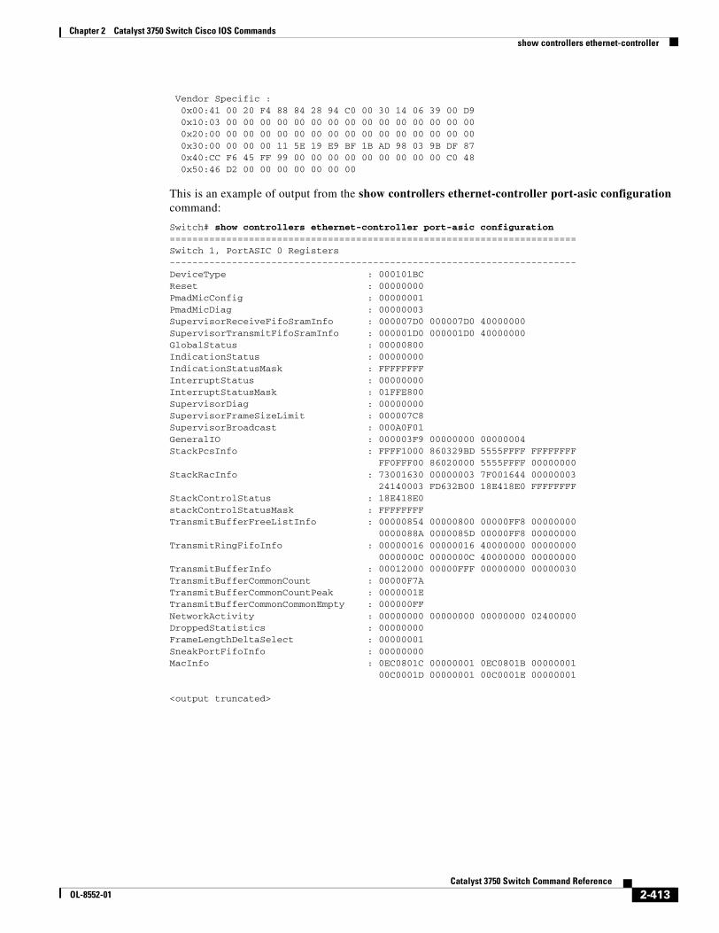
Chapter 2 Catalyst 3750 Switch Cisco IOS Commandsshow controllers ethernet-controller
Vendor Specific : 0x00:41 00 20 F4 88 84 28 94 C0 00 30 14 06 39 00 D9 0x10:03 00 00 00 00 00 00 00 00 00 00 00 00 00 00 00 0x20:00 00 00 00 00 00 00 00 00 00 00 00 00 00 00 00 0x30:00 00 00 00 11 5E 19 E9 BF 1B AD 98 03 9B DF 87 0x40:CC F6 45 FF 99 00 00 00 00 00 00 00 00 00 C0 48 0x50:46 D2 00 00 00 00 00 00 00
This is an example of output from the show controllers ethernet-controller port-asic configuration command:
Switch# show controllers ethernet-controller port-asic configuration========================================================================Switch 1, PortASIC 0 Registers------------------------------------------------------------------------DeviceType : 000101BCReset : 00000000PmadMicConfig : 00000001PmadMicDiag : 00000003SupervisorReceiveFifoSramInfo : 000007D0 000007D0 40000000SupervisorTransmitFifoSramInfo : 000001D0 000001D0 40000000GlobalStatus : 00000800IndicationStatus : 00000000IndicationStatusMask : FFFFFFFFInterruptStatus : 00000000InterruptStatusMask : 01FFE800SupervisorDiag : 00000000SupervisorFrameSizeLimit : 000007C8SupervisorBroadcast : 000A0F01GeneralIO : 000003F9 00000000 00000004StackPcsInfo : FFFF1000 860329BD 5555FFFF FFFFFFFF FF0FFF00 86020000 5555FFFF 00000000StackRacInfo : 73001630 00000003 7F001644 00000003 24140003 FD632B00 18E418E0 FFFFFFFFStackControlStatus : 18E418E0stackControlStatusMask : FFFFFFFFTransmitBufferFreeListInfo : 00000854 00000800 00000FF8 00000000 0000088A 0000085D 00000FF8 00000000TransmitRingFifoInfo : 00000016 00000016 40000000 00000000 0000000C 0000000C 40000000 00000000TransmitBufferInfo : 00012000 00000FFF 00000000 00000030TransmitBufferCommonCount : 00000F7ATransmitBufferCommonCountPeak : 0000001ETransmitBufferCommonCommonEmpty : 000000FFNetworkActivity : 00000000 00000000 00000000 02400000DroppedStatistics : 00000000FrameLengthDeltaSelect : 00000001SneakPortFifoInfo : 00000000MacInfo : 0EC0801C 00000001 0EC0801B 00000001 00C0001D 00000001 00C0001E 00000001
<output truncated>
2-413Catalyst 3750 Switch Command Reference
OL-8552-01
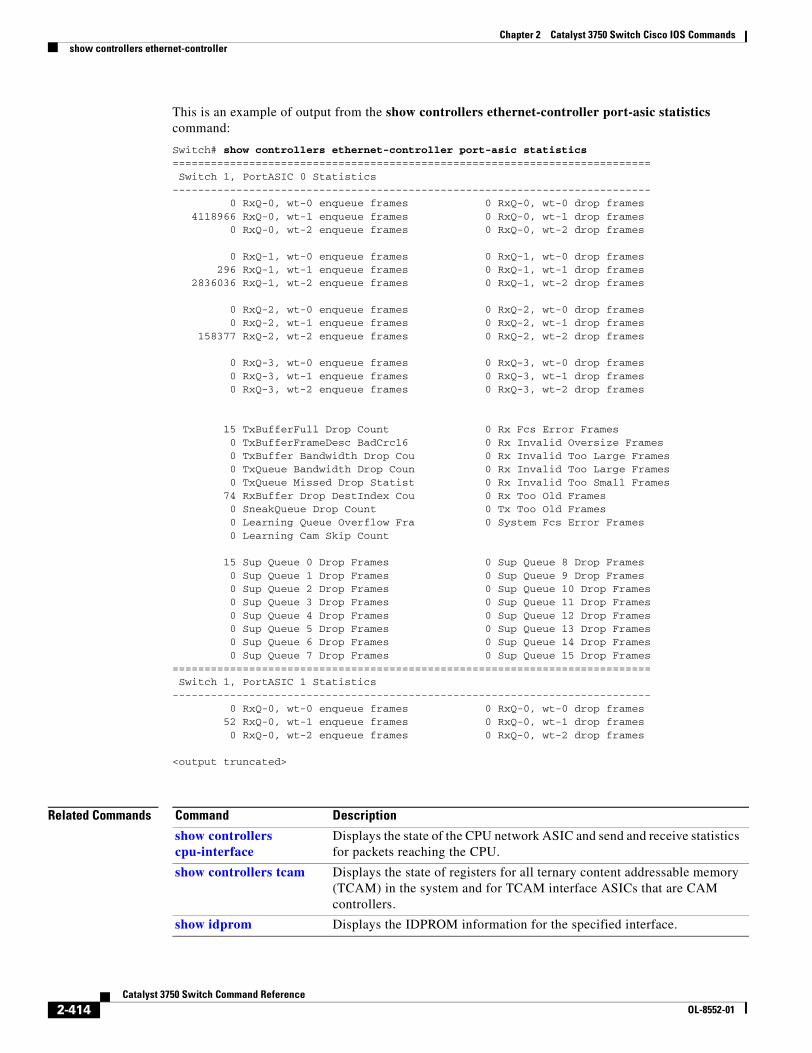
Chapter 2 Catalyst 3750 Switch Cisco IOS Commandsshow controllers ethernet-controller
This is an example of output from the show controllers ethernet-controller port-asic statistics command:
Switch# show controllers ethernet-controller port-asic statistics=========================================================================== Switch 1, PortASIC 0 Statistics--------------------------------------------------------------------------- 0 RxQ-0, wt-0 enqueue frames 0 RxQ-0, wt-0 drop frames 4118966 RxQ-0, wt-1 enqueue frames 0 RxQ-0, wt-1 drop frames 0 RxQ-0, wt-2 enqueue frames 0 RxQ-0, wt-2 drop frames
0 RxQ-1, wt-0 enqueue frames 0 RxQ-1, wt-0 drop frames 296 RxQ-1, wt-1 enqueue frames 0 RxQ-1, wt-1 drop frames 2836036 RxQ-1, wt-2 enqueue frames 0 RxQ-1, wt-2 drop frames
0 RxQ-2, wt-0 enqueue frames 0 RxQ-2, wt-0 drop frames 0 RxQ-2, wt-1 enqueue frames 0 RxQ-2, wt-1 drop frames 158377 RxQ-2, wt-2 enqueue frames 0 RxQ-2, wt-2 drop frames
0 RxQ-3, wt-0 enqueue frames 0 RxQ-3, wt-0 drop frames 0 RxQ-3, wt-1 enqueue frames 0 RxQ-3, wt-1 drop frames 0 RxQ-3, wt-2 enqueue frames 0 RxQ-3, wt-2 drop frames
15 TxBufferFull Drop Count 0 Rx Fcs Error Frames 0 TxBufferFrameDesc BadCrc16 0 Rx Invalid Oversize Frames 0 TxBuffer Bandwidth Drop Cou 0 Rx Invalid Too Large Frames 0 TxQueue Bandwidth Drop Coun 0 Rx Invalid Too Large Frames 0 TxQueue Missed Drop Statist 0 Rx Invalid Too Small Frames 74 RxBuffer Drop DestIndex Cou 0 Rx Too Old Frames 0 SneakQueue Drop Count 0 Tx Too Old Frames 0 Learning Queue Overflow Fra 0 System Fcs Error Frames 0 Learning Cam Skip Count
15 Sup Queue 0 Drop Frames 0 Sup Queue 8 Drop Frames 0 Sup Queue 1 Drop Frames 0 Sup Queue 9 Drop Frames 0 Sup Queue 2 Drop Frames 0 Sup Queue 10 Drop Frames 0 Sup Queue 3 Drop Frames 0 Sup Queue 11 Drop Frames 0 Sup Queue 4 Drop Frames 0 Sup Queue 12 Drop Frames 0 Sup Queue 5 Drop Frames 0 Sup Queue 13 Drop Frames 0 Sup Queue 6 Drop Frames 0 Sup Queue 14 Drop Frames 0 Sup Queue 7 Drop Frames 0 Sup Queue 15 Drop Frames=========================================================================== Switch 1, PortASIC 1 Statistics--------------------------------------------------------------------------- 0 RxQ-0, wt-0 enqueue frames 0 RxQ-0, wt-0 drop frames 52 RxQ-0, wt-1 enqueue frames 0 RxQ-0, wt-1 drop frames 0 RxQ-0, wt-2 enqueue frames 0 RxQ-0, wt-2 drop frames
<output truncated>
Related Commands Command Description
show controllers cpu-interface
Displays the state of the CPU network ASIC and send and receive statistics for packets reaching the CPU.
show controllers tcam Displays the state of registers for all ternary content addressable memory (TCAM) in the system and for TCAM interface ASICs that are CAM controllers.
show idprom Displays the IDPROM information for the specified interface.
2-414Catalyst 3750 Switch Command Reference
OL-8552-01
Chapter 2 Catalyst 3750 Switch Cisco IOS Commandsshow controllers power inline
show controllers power inlineUse the show controllers power inline user EXEC command to display the values in the registers of the specified Power over Ethernet (PoE) controller.
show controllers power inline [instance] [module switch-number] [ | {begin | exclude | include} expression]
Syntax Description
Command Modes User EXEC
Command History
Usage Guidelines For the Catalyst 3750-48PS switches, the instance range is 0 to 11.
For the Catalyst 3750-24PS switches, the instance range is 0 to 5.
For the Catalyst 3750G-48PS switches, the instance range is 0 to 2. For instances other than 0 to 2, the switches provides no output.
For the Catalyst 3750G-24PS switches, the instance range is 0 to 1. For instances other than 0 to 1, the switches provides no output.
Though visible on all switches, this command is valid only for PoE switches. It provides no information for switches that do not support PoE.
The output provides information that might be useful for Cisco technical support representatives troubleshooting the switch.
Expressions are case sensitive. For example, if you enter | exclude output, the lines that contain output do not appear, but the lines that contain Output appear.
instance (Optional) Power controller instance, where each instance corresponds to four ports. See the “Usage Guidelines” section for more information. If no instance is specified, information for all instances appear.
module switch number
(Optional) Limit the display to ports on the specified stack member. The switch number is 1 to 9.
| begin (Optional) Display begins with the line that matches the expression.
| exclude (Optional) Display excludes lines that match the expression.
| include (Optional) Display includes lines that match the specified expression.
expression Expression in the output to use as a reference point.
Release Modification
12.1(19)EA1 This command was introduced.
2-415Catalyst 3750 Switch Command Reference
OL-8552-01
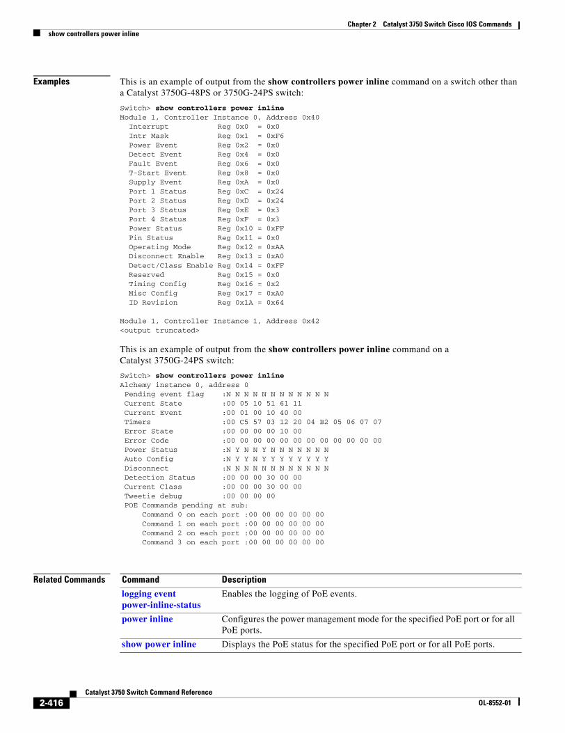
Chapter 2 Catalyst 3750 Switch Cisco IOS Commandsshow controllers power inline
Examples This is an example of output from the show controllers power inline command on a switch other than a Catalyst 3750G-48PS or 3750G-24PS switch:
Switch> show controllers power inlineModule 1, Controller Instance 0, Address 0x40 Interrupt Reg 0x0 = 0x0 Intr Mask Reg 0x1 = 0xF6 Power Event Reg 0x2 = 0x0 Detect Event Reg 0x4 = 0x0 Fault Event Reg 0x6 = 0x0 T-Start Event Reg 0x8 = 0x0 Supply Event Reg 0xA = 0x0 Port 1 Status Reg 0xC = 0x24 Port 2 Status Reg 0xD = 0x24 Port 3 Status Reg 0xE = 0x3 Port 4 Status Reg 0xF = 0x3 Power Status Reg 0x10 = 0xFF Pin Status Reg 0x11 = 0x0 Operating Mode Reg 0x12 = 0xAA Disconnect Enable Reg 0x13 = 0xA0 Detect/Class Enable Reg 0x14 = 0xFF Reserved Reg 0x15 = 0x0 Timing Config Reg 0x16 = 0x2 Misc Config Reg 0x17 = 0xA0 ID Revision Reg 0x1A = 0x64
Module 1, Controller Instance 1, Address 0x42<output truncated>
This is an example of output from the show controllers power inline command on a Catalyst 3750G-24PS switch:
Switch> show controllers power inlineAlchemy instance 0, address 0 Pending event flag :N N N N N N N N N N N N Current State :00 05 10 51 61 11 Current Event :00 01 00 10 40 00 Timers :00 C5 57 03 12 20 04 B2 05 06 07 07 Error State :00 00 00 00 10 00 Error Code :00 00 00 00 00 00 00 00 00 00 00 00 Power Status :N Y N N Y N N N N N N N Auto Config :N Y Y N Y Y Y Y Y Y Y Y Disconnect :N N N N N N N N N N N N Detection Status :00 00 00 30 00 00 Current Class :00 00 00 30 00 00 Tweetie debug :00 00 00 00 POE Commands pending at sub: Command 0 on each port :00 00 00 00 00 00 Command 1 on each port :00 00 00 00 00 00 Command 2 on each port :00 00 00 00 00 00 Command 3 on each port :00 00 00 00 00 00
Related Commands Command Description
logging event power-inline-status
Enables the logging of PoE events.
power inline Configures the power management mode for the specified PoE port or for all PoE ports.
show power inline Displays the PoE status for the specified PoE port or for all PoE ports.
2-416Catalyst 3750 Switch Command Reference
OL-8552-01
Chapter 2 Catalyst 3750 Switch Cisco IOS Commandsshow controllers tcam
show controllers tcam Use the show controllers tcam privileged EXEC command to display the state of the registers for all ternary content addressable memory (TCAM) in the system and for all TCAM interface ASICs that are CAM controllers.
show controllers tcam [asic [number]] [detail] [ | {begin | exclude | include} expression]
Syntax Description
Command Modes Privileged EXEC
Command History
Usage Guidelines This display provides information that might be useful for Cisco technical support representatives troubleshooting the switch.
Expressions are case sensitive. For example, if you enter | exclude output, the lines that contain output do not appear, but the lines that contain Output appear.
Examples This is an example of output from the show controllers tcam command:
Switch# show controllers tcam------------------------------------------------------------------------TCAM-0 Registers------------------------------------------------------------------------ REV: 00B30103 SIZE: 00080040 ID: 00000000 CCR: 00000000_F0000020
RPID0: 00000000_00000000 RPID1: 00000000_00000000 RPID2: 00000000_00000000 RPID3: 00000000_00000000
asic (Optional) Display port ASIC TCAM information.
number (Optional) Display information for the specified port ASIC number. The range is from 0 to 15.
detail (Optional) Display detailed TCAM register information.
| begin (Optional) Display begins with the line that matches the expression.
| exclude (Optional) Display excludes lines that match the expression.
| include (Optional) Display includes lines that match the specified expression.
expression Expression in the output to use as a reference point.
Release Modification
12.1(11)AX This command was introduced.
12.1(14)EA1 The asic [number] keywords were added.
2-417Catalyst 3750 Switch Command Reference
OL-8552-01
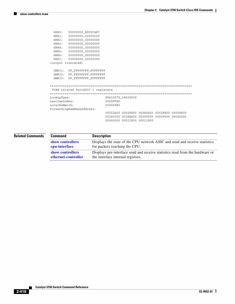
Chapter 2 Catalyst 3750 Switch Cisco IOS Commandsshow controllers tcam
HRR0: 00000000_E000CAFC HRR1: 00000000_00000000 HRR2: 00000000_00000000 HRR3: 00000000_00000000 HRR4: 00000000_00000000 HRR5: 00000000_00000000 HRR6: 00000000_00000000 HRR7: 00000000_00000000<output truncated>
GMR31: FF_FFFFFFFF_FFFFFFFF GMR32: FF_FFFFFFFF_FFFFFFFF GMR33: FF_FFFFFFFF_FFFFFFFF
============================================================================= TCAM related PortASIC 1 registers=============================================================================LookupType: 89A1C67D_24E35F00LastCamIndex: 0000FFE0LocalNoMatch: 000069E0ForwardingRamBaseAddress: 00022A00 0002FE00 00040600 0002FE00 0000D400 00000000 003FBA00 00009000 00009000 00040600 00000000 00012800 00012900
Related Commands Command Description
show controllers cpu-interface
Displays the state of the CPU network ASIC and send and receive statistics for packets reaching the CPU.
show controllers ethernet-controller
Displays per-interface send and receive statistics read from the hardware or the interface internal registers.
2-418Catalyst 3750 Switch Command Reference
OL-8552-01
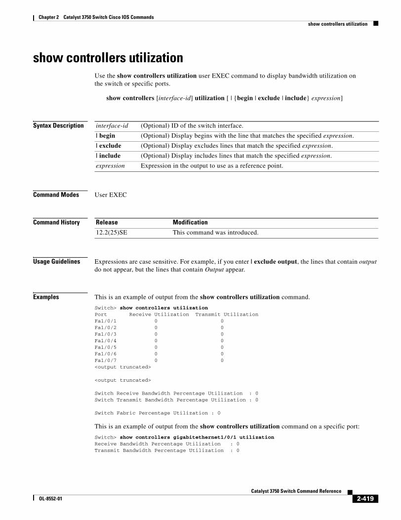
Chapter 2 Catalyst 3750 Switch Cisco IOS Commandsshow controllers utilization
show controllers utilizationUse the show controllers utilization user EXEC command to display bandwidth utilization on the switch or specific ports.
show controllers [interface-id] utilization [ | {begin | exclude | include} expression]
Syntax Description
Command Modes User EXEC
Command History
Usage Guidelines Expressions are case sensitive. For example, if you enter | exclude output, the lines that contain output do not appear, but the lines that contain Output appear.
Examples This is an example of output from the show controllers utilization command.
Switch> show controllers utilizationPort Receive Utilization Transmit UtilizationFa1/0/1 0 0Fa1/0/2 0 0Fa1/0/3 0 0Fa1/0/4 0 0Fa1/0/5 0 0Fa1/0/6 0 0Fa1/0/7 0 0<output truncated>
<output truncated>
Switch Receive Bandwidth Percentage Utilization : 0Switch Transmit Bandwidth Percentage Utilization : 0
Switch Fabric Percentage Utilization : 0
This is an example of output from the show controllers utilization command on a specific port:
Switch> show controllers gigabitethernet1/0/1 utilizationReceive Bandwidth Percentage Utilization : 0Transmit Bandwidth Percentage Utilization : 0
interface-id (Optional) ID of the switch interface.
| begin (Optional) Display begins with the line that matches the specified expression.
| exclude (Optional) Display excludes lines that match the specified expression.
| include (Optional) Display includes lines that match the specified expression.
expression Expression in the output to use as a reference point.
Release Modification
12.2(25)SE This command was introduced.
2-419Catalyst 3750 Switch Command Reference
OL-8552-01
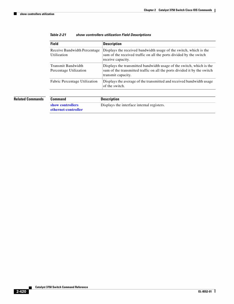
Chapter 2 Catalyst 3750 Switch Cisco IOS Commandsshow controllers utilization
Related Commands
Table 2-21 show controllers utilization Field Descriptions
Field Description
Receive Bandwidth Percentage Utilization
Displays the received bandwidth usage of the switch, which is the sum of the received traffic on all the ports divided by the switch receive capacity.
Transmit Bandwidth Percentage Utilization
Displays the transmitted bandwidth usage of the switch, which is the sum of the transmitted traffic on all the ports divided it by the switch transmit capacity.
Fabric Percentage Utilization Displays the average of the transmitted and received bandwidth usage of the switch.
Command Description
show controllers ethernet-controller
Displays the interface internal registers.
2-420Catalyst 3750 Switch Command Reference
OL-8552-01
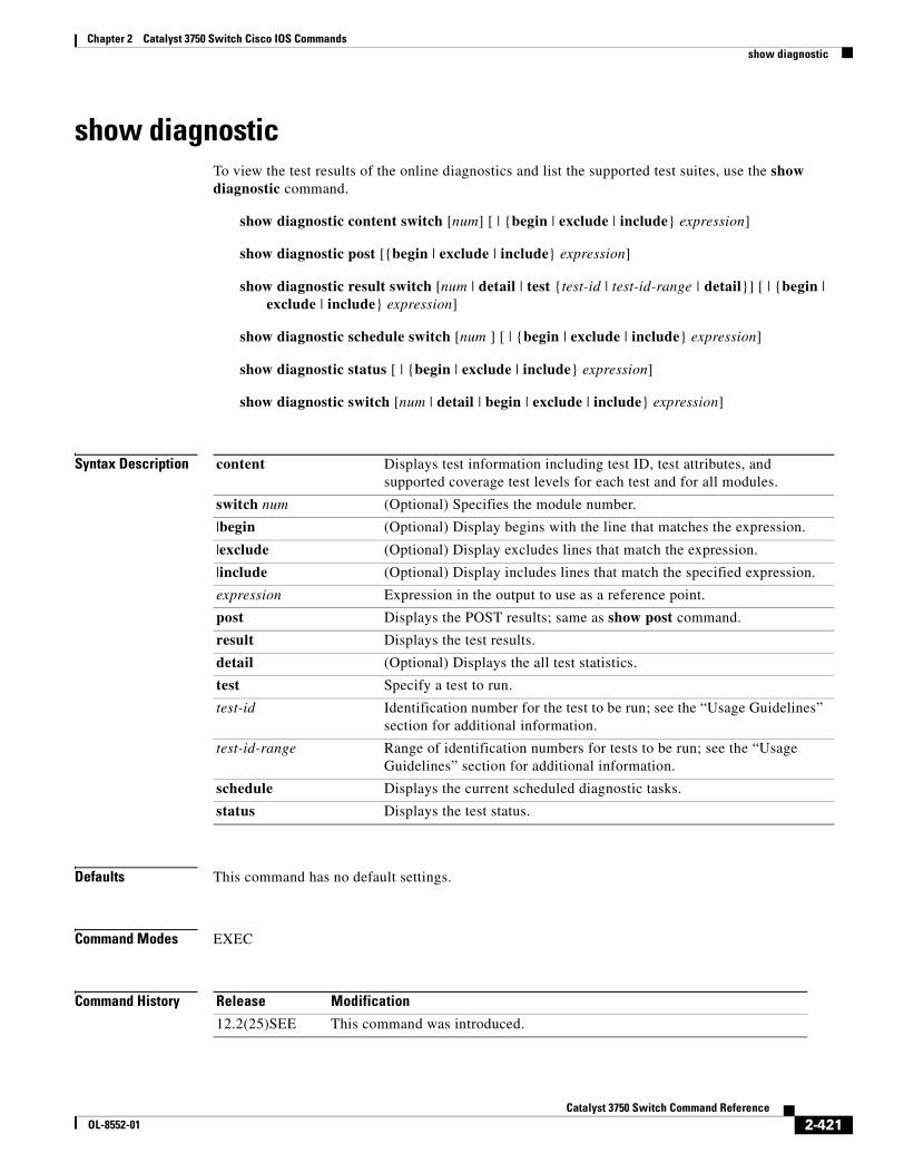
Chapter 2 Catalyst 3750 Switch Cisco IOS Commandsshow diagnostic
show diagnosticTo view the test results of the online diagnostics and list the supported test suites, use the show diagnostic command.
show diagnostic content switch [num] [ | {begin | exclude | include} expression]
show diagnostic post [{begin | exclude | include} expression]
show diagnostic result switch [num | detail | test {test-id | test-id-range | detail}] [ | {begin | exclude | include} expression]
show diagnostic schedule switch [num ] [ | {begin | exclude | include} expression]
show diagnostic status [ | {begin | exclude | include} expression]
show diagnostic switch [num | detail | begin | exclude | include} expression]
Syntax Description
Defaults This command has no default settings.
Command Modes EXEC
Command History
content Displays test information including test ID, test attributes, and supported coverage test levels for each test and for all modules.
switch num (Optional) Specifies the module number.
|begin (Optional) Display begins with the line that matches the expression.
|exclude (Optional) Display excludes lines that match the expression.
|include (Optional) Display includes lines that match the specified expression.
expression Expression in the output to use as a reference point.
post Displays the POST results; same as show post command.
result Displays the test results.
detail (Optional) Displays the all test statistics.
test Specify a test to run.
test-id Identification number for the test to be run; see the “Usage Guidelines” section for additional information.
test-id-range Range of identification numbers for tests to be run; see the “Usage Guidelines” section for additional information.
schedule Displays the current scheduled diagnostic tasks.
status Displays the test status.
Release Modification
12.2(25)SEE This command was introduced.
2-421Catalyst 3750 Switch Command Reference
OL-8552-01
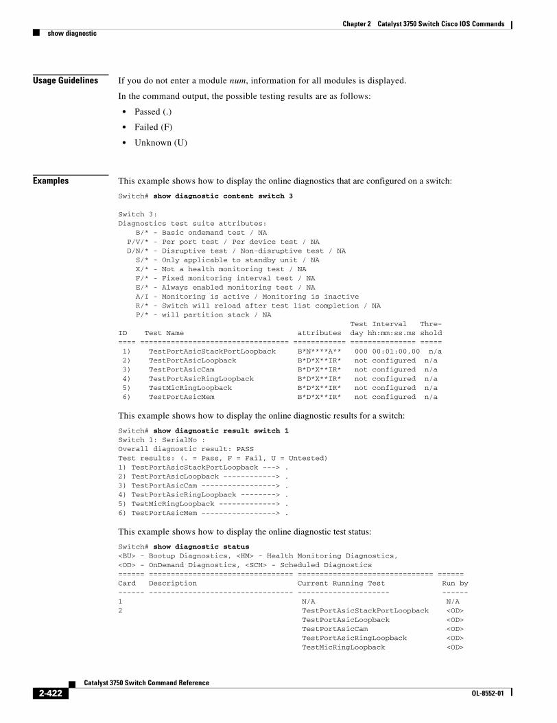
Chapter 2 Catalyst 3750 Switch Cisco IOS Commandsshow diagnostic
Usage Guidelines If you do not enter a module num, information for all modules is displayed.
In the command output, the possible testing results are as follows:
• Passed (.)
• Failed (F)
• Unknown (U)
Examples This example shows how to display the online diagnostics that are configured on a switch:
Switch# show diagnostic content switch 3
Switch 3:Diagnostics test suite attributes:
B/* - Basic ondemand test / NAP/V/* - Per port test / Per device test / NAD/N/* - Disruptive test / Non-disruptive test / NA
S/* - Only applicable to standby unit / NAX/* - Not a health monitoring test / NAF/* - Fixed monitoring interval test / NAE/* - Always enabled monitoring test / NAA/I - Monitoring is active / Monitoring is inactiveR/* - Switch will reload after test list completion / NAP/* - will partition stack / NA
Test Interval Thre-ID Test Name attributes day hh:mm:ss.ms shold==== ================================== ============ =============== =====1) TestPortAsicStackPortLoopback B*N****A** 000 00:01:00.00 n/a2) TestPortAsicLoopback B*D*X**IR* not configured n/a3) TestPortAsicCam B*D*X**IR* not configured n/a4) TestPortAsicRingLoopback B*D*X**IR* not configured n/a5) TestMicRingLoopback B*D*X**IR* not configured n/a6) TestPortAsicMem B*D*X**IR* not configured n/a
This example shows how to display the online diagnostic results for a switch:
Switch# show diagnostic result switch 1Switch 1: SerialNo :Overall diagnostic result: PASSTest results: (. = Pass, F = Fail, U = Untested)1) TestPortAsicStackPortLoopback ---> .2) TestPortAsicLoopback ------------> .3) TestPortAsicCam -----------------> .4) TestPortAsicRingLoopback --------> .5) TestMicRingLoopback -------------> .6) TestPortAsicMem -----------------> .
This example shows how to display the online diagnostic test status:
Switch# show diagnostic status<BU> - Bootup Diagnostics, <HM> - Health Monitoring Diagnostics,<OD> - OnDemand Diagnostics, <SCH> - Scheduled Diagnostics====== ================================= =============================== ======Card Description Current Running Test Run by------ --------------------------------- --------------------- ------1 N/A N/A2 TestPortAsicStackPortLoopback <OD>
TestPortAsicLoopback <OD>TestPortAsicCam <OD>TestPortAsicRingLoopback <OD>TestMicRingLoopback <OD>
2-422Catalyst 3750 Switch Command Reference
OL-8552-01
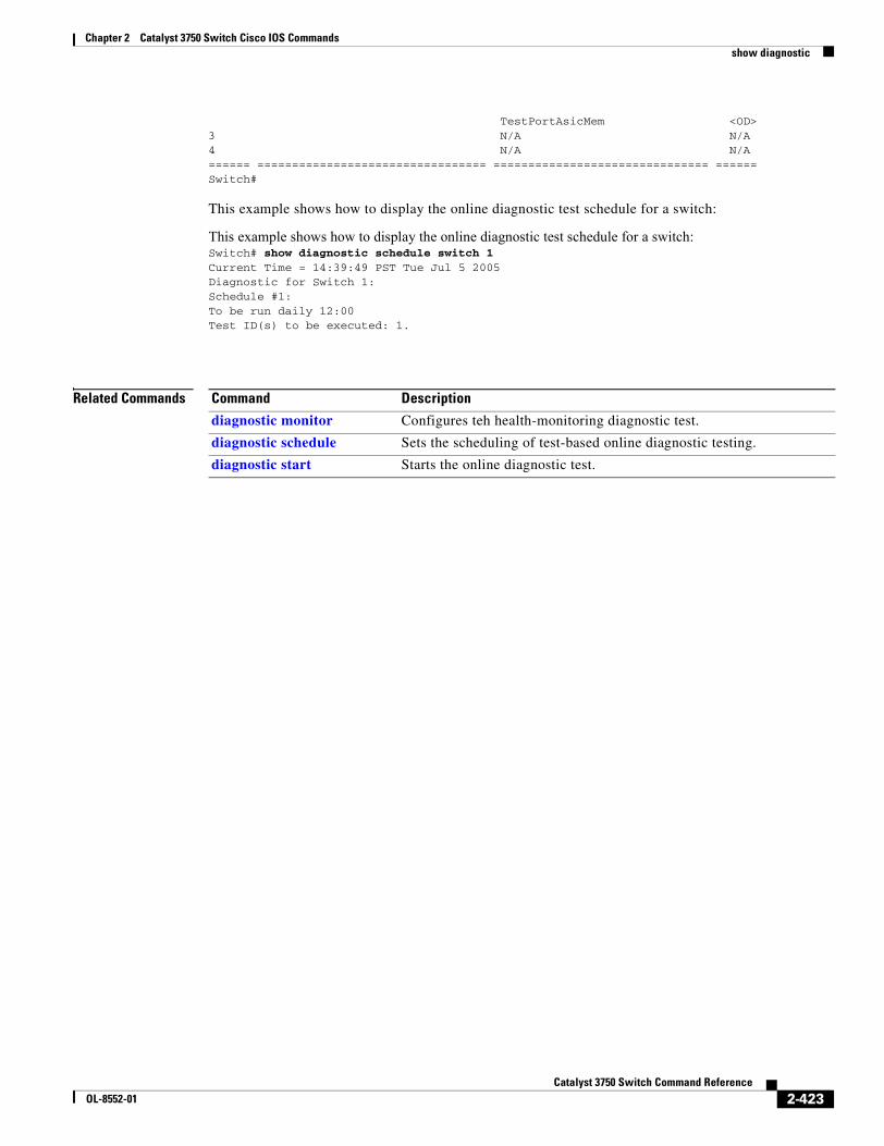
Chapter 2 Catalyst 3750 Switch Cisco IOS Commandsshow diagnostic
TestPortAsicMem <OD>3 N/A N/A4 N/A N/A====== ================================= =============================== ======Switch#
This example shows how to display the online diagnostic test schedule for a switch:
This example shows how to display the online diagnostic test schedule for a switch:Switch# show diagnostic schedule switch 1Current Time = 14:39:49 PST Tue Jul 5 2005Diagnostic for Switch 1:Schedule #1:To be run daily 12:00Test ID(s) to be executed: 1.
Related Commands Command Description
diagnostic monitor Configures teh health-monitoring diagnostic test.
diagnostic schedule Sets the scheduling of test-based online diagnostic testing.
diagnostic start Starts the online diagnostic test.
2-423Catalyst 3750 Switch Command Reference
OL-8552-01
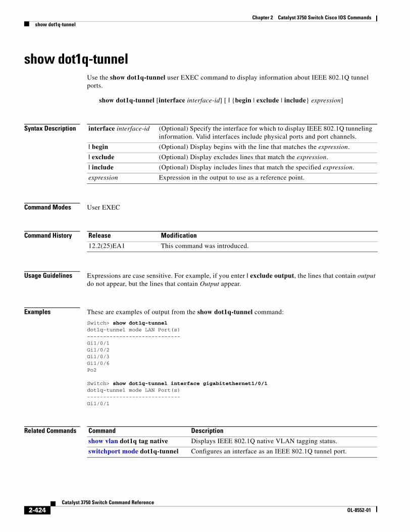
Chapter 2 Catalyst 3750 Switch Cisco IOS Commandsshow dot1q-tunnel
show dot1q-tunnelUse the show dot1q-tunnel user EXEC command to display information about IEEE 802.1Q tunnel ports.
show dot1q-tunnel [interface interface-id] [ | {begin | exclude | include} expression]
Syntax Description
Command Modes User EXEC
Command History
Usage Guidelines Expressions are case sensitive. For example, if you enter | exclude output, the lines that contain output do not appear, but the lines that contain Output appear.
Examples These are examples of output from the show dot1q-tunnel command:
Switch> show dot1q-tunneldot1q-tunnel mode LAN Port(s)-----------------------------Gi1/0/1Gi1/0/2Gi1/0/3Gi1/0/6Po2
Switch> show dot1q-tunnel interface gigabitethernet1/0/1 dot1q-tunnel mode LAN Port(s)-----------------------------Gi1/0/1
Related Commands
interface interface-id (Optional) Specify the interface for which to display IEEE 802.1Q tunneling information. Valid interfaces include physical ports and port channels.
| begin (Optional) Display begins with the line that matches the expression.
| exclude (Optional) Display excludes lines that match the expression.
| include (Optional) Display includes lines that match the specified expression.
expression Expression in the output to use as a reference point.
Release Modification
12.2(25)EA1 This command was introduced.
Command Description
show vlan dot1q tag native Displays IEEE 802.1Q native VLAN tagging status.
switchport mode dot1q-tunnel Configures an interface as an IEEE 802.1Q tunnel port.
2-424Catalyst 3750 Switch Command Reference
OL-8552-01
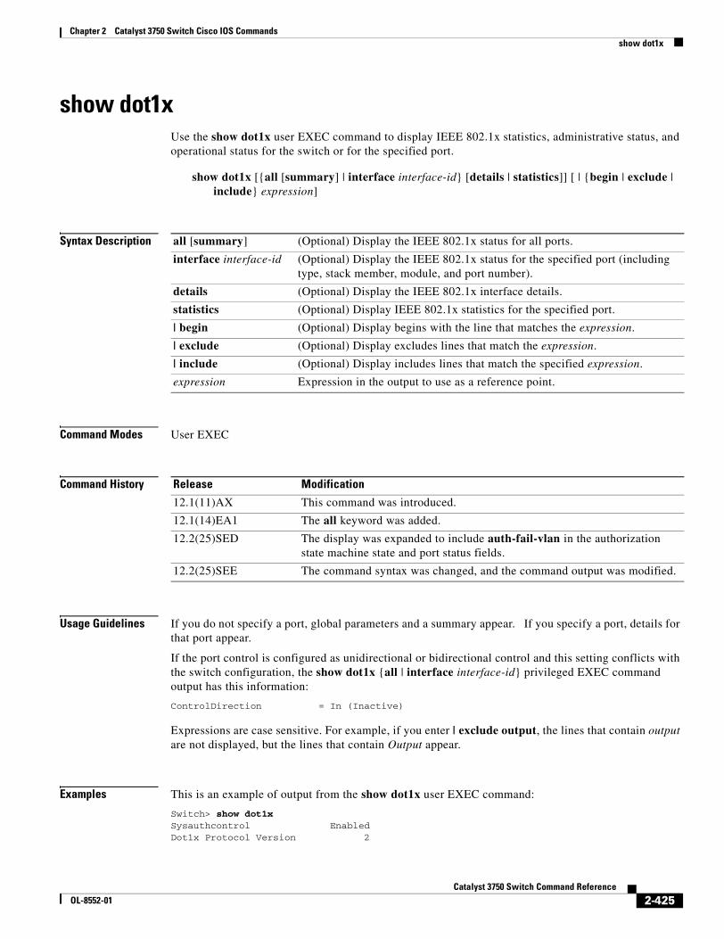
Chapter 2 Catalyst 3750 Switch Cisco IOS Commandsshow dot1x
show dot1xUse the show dot1x user EXEC command to display IEEE 802.1x statistics, administrative status, and operational status for the switch or for the specified port.
show dot1x [{all [summary] | interface interface-id} [details | statistics]] [ | {begin | exclude | include} expression]
Syntax Description
Command Modes User EXEC
Command History
Usage Guidelines If you do not specify a port, global parameters and a summary appear. If you specify a port, details for that port appear.
If the port control is configured as unidirectional or bidirectional control and this setting conflicts with the switch configuration, the show dot1x {all | interface interface-id} privileged EXEC command output has this information:
ControlDirection = In (Inactive)
Expressions are case sensitive. For example, if you enter | exclude output, the lines that contain output are not displayed, but the lines that contain Output appear.
Examples This is an example of output from the show dot1x user EXEC command:
Switch> show dot1x Sysauthcontrol EnabledDot1x Protocol Version 2
all [summary] (Optional) Display the IEEE 802.1x status for all ports.
interface interface-id (Optional) Display the IEEE 802.1x status for the specified port (including type, stack member, module, and port number).
details (Optional) Display the IEEE 802.1x interface details.
statistics (Optional) Display IEEE 802.1x statistics for the specified port.
| begin (Optional) Display begins with the line that matches the expression.
| exclude (Optional) Display excludes lines that match the expression.
| include (Optional) Display includes lines that match the specified expression.
expression Expression in the output to use as a reference point.
Release Modification
12.1(11)AX This command was introduced.
12.1(14)EA1 The all keyword was added.
12.2(25)SED The display was expanded to include auth-fail-vlan in the authorization state machine state and port status fields.
12.2(25)SEE The command syntax was changed, and the command output was modified.
2-425Catalyst 3750 Switch Command Reference
OL-8552-01
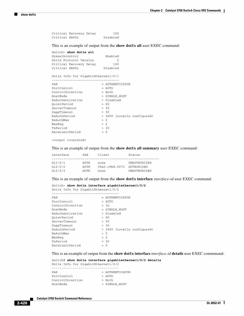
Chapter 2 Catalyst 3750 Switch Cisco IOS Commandsshow dot1x
Critical Recovery Delay 100Critical EAPOL Disabled
This is an example of output from the show dot1x all user EXEC command:
Switch> show dot1x allSysauthcontrol EnabledDot1x Protocol Version 2Critical Recovery Delay 100Critical EAPOL Disabled
Dot1x Info for GigabitEthernet1/0/1-----------------------------------PAE = AUTHENTICATORPortControl = AUTOControlDirection = BothHostMode = SINGLE_HOSTReAuthentication = DisabledQuietPeriod = 60ServerTimeout = 30SuppTimeout = 30ReAuthPeriod = 3600 (Locally configured)ReAuthMax = 2MaxReq = 2TxPeriod = 30RateLimitPeriod = 0
<output truncated>
This is an example of output from the show dot1x all summary user EXEC command:
Interface PAE Client Status--------------------------------------------------------Gi2/0/1 AUTH none UNAUTHORIZEDGi2/0/2 AUTH 00a0.c9b8.0072 AUTHORIZEDGi2/0/3 AUTH none UNAUTHORIZED
This is an example of output from the show dot1x interface interface-id user EXEC command:
Switch> show dot1x interface gigabitethernet1/0/2Dot1x Info for GigabitEthernet1/0/2-----------------------------------PAE = AUTHENTICATORPortControl = AUTOControlDirection = InHostMode = SINGLE_HOSTReAuthentication = DisabledQuietPeriod = 60ServerTimeout = 30SuppTimeout = 30ReAuthPeriod = 3600 (Locally configured)ReAuthMax = 2MaxReq = 2TxPeriod = 30RateLimitPeriod = 0
This is an example of output from the show dot1x interface interface-id details user EXEC commmand:
Switch# show dot1x interface gigabitethernet1/0/2 detailsDot1x Info for GigabitEthernet1/0/2-----------------------------------PAE = AUTHENTICATORPortControl = AUTOControlDirection = BothHostMode = SINGLE_HOST
2-426Catalyst 3750 Switch Command Reference
OL-8552-01
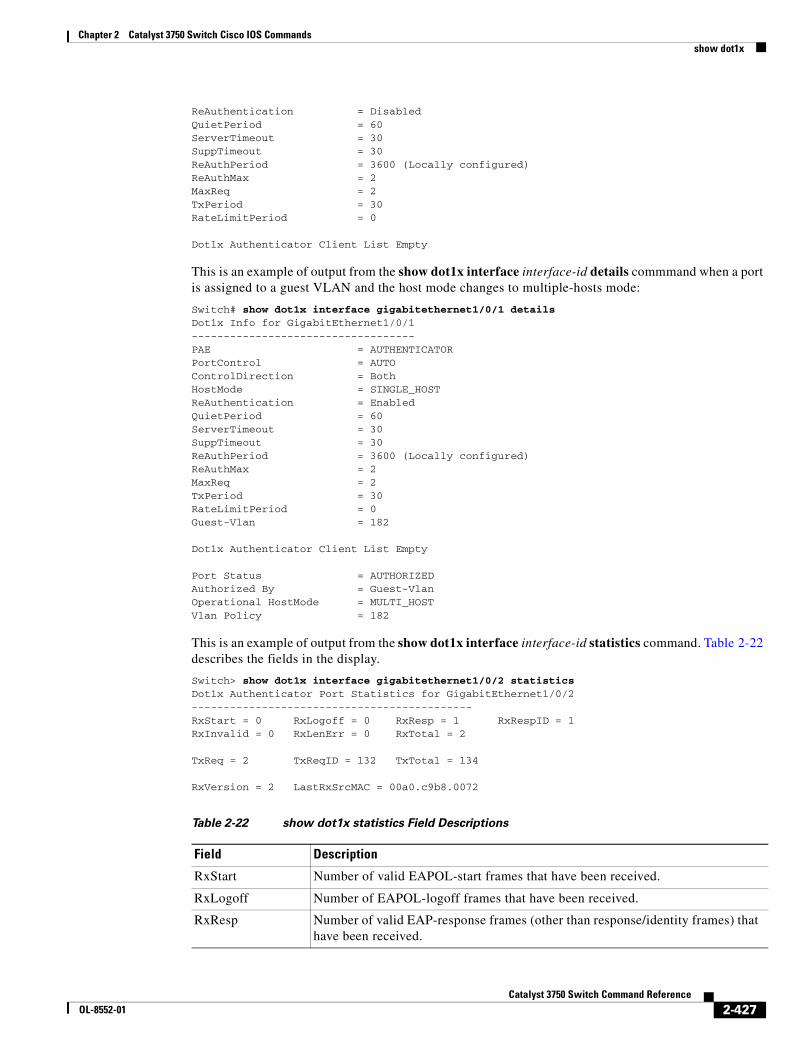
Chapter 2 Catalyst 3750 Switch Cisco IOS Commandsshow dot1x
ReAuthentication = DisabledQuietPeriod = 60ServerTimeout = 30SuppTimeout = 30ReAuthPeriod = 3600 (Locally configured)ReAuthMax = 2MaxReq = 2TxPeriod = 30RateLimitPeriod = 0
Dot1x Authenticator Client List Empty
This is an example of output from the show dot1x interface interface-id details commmand when a port is assigned to a guest VLAN and the host mode changes to multiple-hosts mode:
Switch# show dot1x interface gigabitethernet1/0/1 detailsDot1x Info for GigabitEthernet1/0/1-----------------------------------PAE = AUTHENTICATORPortControl = AUTOControlDirection = Both HostMode = SINGLE_HOSTReAuthentication = EnabledQuietPeriod = 60ServerTimeout = 30SuppTimeout = 30ReAuthPeriod = 3600 (Locally configured)ReAuthMax = 2MaxReq = 2TxPeriod = 30RateLimitPeriod = 0Guest-Vlan = 182
Dot1x Authenticator Client List Empty
Port Status = AUTHORIZEDAuthorized By = Guest-VlanOperational HostMode = MULTI_HOST Vlan Policy = 182
This is an example of output from the show dot1x interface interface-id statistics command. Table 2-22 describes the fields in the display.
Switch> show dot1x interface gigabitethernet1/0/2 statisticsDot1x Authenticator Port Statistics for GigabitEthernet1/0/2--------------------------------------------RxStart = 0 RxLogoff = 0 RxResp = 1 RxRespID = 1RxInvalid = 0 RxLenErr = 0 RxTotal = 2
TxReq = 2 TxReqID = 132 TxTotal = 134
RxVersion = 2 LastRxSrcMAC = 00a0.c9b8.0072
Table 2-22 show dot1x statistics Field Descriptions
Field Description
RxStart Number of valid EAPOL-start frames that have been received.
RxLogoff Number of EAPOL-logoff frames that have been received.
RxResp Number of valid EAP-response frames (other than response/identity frames) that have been received.
2-427Catalyst 3750 Switch Command Reference
OL-8552-01
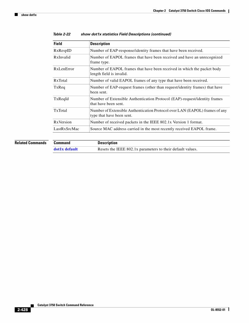
Chapter 2 Catalyst 3750 Switch Cisco IOS Commandsshow dot1x
Related Commands
RxRespID Number of EAP-response/identity frames that have been received.
RxInvalid Number of EAPOL frames that have been received and have an unrecognized frame type.
RxLenError Number of EAPOL frames that have been received in which the packet body length field is invalid.
RxTotal Number of valid EAPOL frames of any type that have been received.
TxReq Number of EAP-request frames (other than request/identity frames) that have been sent.
TxReqId Number of Extensible Authentication Protocol (EAP)-request/identity frames that have been sent.
TxTotal Number of Extensible Authentication Protocol over LAN (EAPOL) frames of any type that have been sent.
RxVersion Number of received packets in the IEEE 802.1x Version 1 format.
LastRxSrcMac Source MAC address carried in the most recently received EAPOL frame.
Table 2-22 show dot1x statistics Field Descriptions (continued)
Field Description
Command Description
dot1x default Resets the IEEE 802.1x parameters to their default values.
2-428Catalyst 3750 Switch Command Reference
OL-8552-01
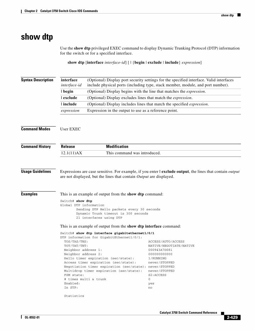
Chapter 2 Catalyst 3750 Switch Cisco IOS Commandsshow dtp
show dtpUse the show dtp privileged EXEC command to display Dynamic Trunking Protocol (DTP) information for the switch or for a specified interface.
show dtp [interface interface-id] [ | {begin | exclude | include} expression]
Syntax Description
Command Modes User EXEC
Command History
Usage Guidelines Expressions are case sensitive. For example, if you enter | exclude output, the lines that contain output are not displayed, but the lines that contain Output are displayed.
Examples This is an example of output from the show dtp command:
Switch# show dtpGlobal DTP information Sending DTP Hello packets every 30 seconds Dynamic Trunk timeout is 300 seconds 21 interfaces using DTP
This is an example of output from the show dtp interface command:
Switch# show dtp interface gigabitethernet1/0/1DTP information for GigabitEthernet1/0/1: TOS/TAS/TNS: ACCESS/AUTO/ACCESS TOT/TAT/TNT: NATIVE/NEGOTIATE/NATIVE Neighbor address 1: 000943A7D081 Neighbor address 2: 000000000000 Hello timer expiration (sec/state): 1/RUNNING Access timer expiration (sec/state): never/STOPPED Negotiation timer expiration (sec/state): never/STOPPED Multidrop timer expiration (sec/state): never/STOPPED FSM state: S2:ACCESS # times multi & trunk 0 Enabled: yes In STP: no
Statistics
interface interface-id
(Optional) Display port security settings for the specified interface. Valid interfaces include physical ports (including type, stack member, module, and port number).
| begin (Optional) Display begins with the line that matches the expression.
| exclude (Optional) Display excludes lines that match the expression.
| include (Optional) Display includes lines that match the specified expression.
expression Expression in the output to use as a reference point.
Release Modification
12.1(11)AX This command was introduced.
2-429Catalyst 3750 Switch Command Reference
OL-8552-01
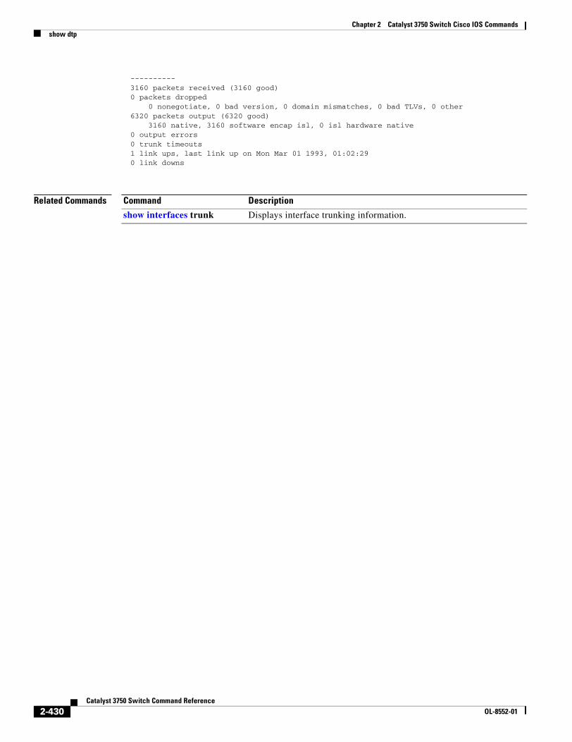
Chapter 2 Catalyst 3750 Switch Cisco IOS Commandsshow dtp
---------- 3160 packets received (3160 good) 0 packets dropped 0 nonegotiate, 0 bad version, 0 domain mismatches, 0 bad TLVs, 0 other 6320 packets output (6320 good) 3160 native, 3160 software encap isl, 0 isl hardware native 0 output errors 0 trunk timeouts 1 link ups, last link up on Mon Mar 01 1993, 01:02:29 0 link downs
Related Commands Command Description
show interfaces trunk Displays interface trunking information.
2-430Catalyst 3750 Switch Command Reference
OL-8552-01
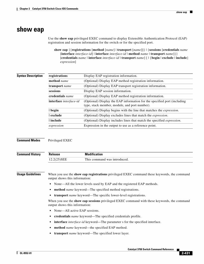
Chapter 2 Catalyst 3750 Switch Cisco IOS Commandsshow eap
show eapUse the show eap privileged EXEC command to display Extensible Authentication Protocol (EAP) registration and session information for the switch or for the specified port.
show eap {{registrations [method [name] | transport [name]]} | {sessions [credentials name [interface interface-id] | interface interface-id | method name | transport name]}} [credentials name | interface interface-id | transport name] [ | {begin | exclude | include} expression]
Syntax Description
Command Modes Privileged EXEC
Command History
Usage Guidelines When you use the show eap registrations privileged EXEC command these keywords, the command output shows this information:
• None—All the lower levels used by EAP and the registered EAP methods.
• method name keyword—The specified method registrations.
• transport name keyword—The specific lower-level registrations.
When you use the show eap sessions privileged EXEC command with these keywords, the command output shows this information:
• None—All active EAP sessions.
• credentials name keyword—The specified credentials profile.
• interface interface-id keyword—The parameter s for the specified interface.
• method name keyword—the specified EAP method.
• transport name keyword—The specified lower layer.
registrations Display EAP registration information.
method name (Optional) Display EAP method registration information.
transport name (Optional) Display EAP transport registration information.
sessions Display EAP session information.
credentials name (Optional) Display EAP method registration information.
interface interface-id (Optional) Display the EAP information for the specified port (including type, stack member, module, and port number).
| begin (Optional) Display begins with the line that matches the expression.
| exclude (Optional) Display excludes lines that match the expression.
| include (Optional) Display includes lines that match the specified expression.
expression Expression in the output to use as a reference point.
Release Modification
12.2(25)SEE This command was introduced.
2-431Catalyst 3750 Switch Command Reference
OL-8552-01
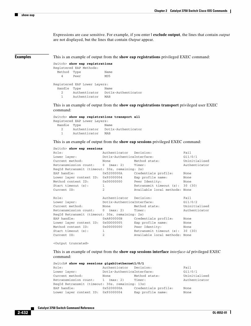
Chapter 2 Catalyst 3750 Switch Cisco IOS Commandsshow eap
Expressions are case sensitive. For example, if you enter | exclude output, the lines that contain output are not displayed, but the lines that contain Output appear.
Examples This is an example of output from the show eap registrations privileged EXEC command:
Switch> show eap registrationsRegistered EAP Methods: Method Type Name 4 Peer MD5
Registered EAP Lower Layers: Handle Type Name 2 Authenticator Dot1x-Authenticator 1 Authenticator MAB
This is an example of output from the show eap registrations transport privileged user EXEC command:
Switch> show eap registrations transport allRegistered EAP Lower Layers: Handle Type Name 2 Authenticator Dot1x-Authenticator 1 Authenticator MAB
This is an example of output from the show eap sessions privileged EXEC command:
Switch> show eap sessions Role: Authenticator Decision: FailLower layer: Dot1x-AuthenticaInterface: Gi1/0/1Current method: None Method state: UninitialisedRetransmission count: 0 (max: 2) Timer: AuthenticatorReqId Retransmit (timeout: 30s, remaining: 2s)EAP handle: 0x5200000A Credentials profile: NoneLower layer context ID: 0x93000004 Eap profile name: NoneMethod context ID: 0x00000000 Peer Identity: NoneStart timeout (s): 1 Retransmit timeout (s): 30 (30)Current ID: 2 Available local methods: None
Role: Authenticator Decision: FailLower layer: Dot1x-AuthenticaInterface: Gi1/0/2Current method: None Method state: UninitialisedRetransmission count: 0 (max: 2) Timer: AuthenticatorReqId Retransmit (timeout: 30s, remaining: 2s)EAP handle: 0xA800000B Credentials profile: NoneLower layer context ID: 0x0D000005 Eap profile name: NoneMethod context ID: 0x00000000 Peer Identity: NoneStart timeout (s): 1 Retransmit timeout (s): 30 (30)Current ID: 2 Available local methods: None
<Output truncated>
This is an example of output from the show eap sessions interface interface-id privileged EXEC command:
Switch# show eap sessions gigabitethernet1/0/1Role: Authenticator Decision: FailLower layer: Dot1x-AuthenticaInterface: Gi1/0/1Current method: None Method state: UninitialisedRetransmission count: 1 (max: 2) Timer: AuthenticatorReqId Retransmit (timeout: 30s, remaining: 13s)EAP handle: 0x5200000A Credentials profile: NoneLower layer context ID: 0x93000004 Eap profile name: None
2-432Catalyst 3750 Switch Command Reference
OL-8552-01

Chapter 2 Catalyst 3750 Switch Cisco IOS Commandsshow eap
Method context ID: 0x00000000 Peer Identity: NoneStart timeout (s): 1 Retransmit timeout (s): 30 (30)Current ID: 2 Available local methods: None
Related Commands Command Description
clear eap Clears EAP session information for the switch or for the specified port.
2-433Catalyst 3750 Switch Command Reference
OL-8552-01
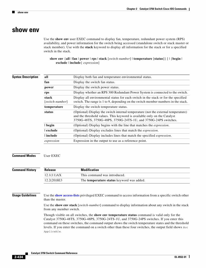
Chapter 2 Catalyst 3750 Switch Cisco IOS Commandsshow env
show envUse the show env user EXEC command to display fan, temperature, redundant power system (RPS) availability, and power information for the switch being accessed (standalone switch or stack master or stack member). Use with the stack keyword to display all information for the stack or for a specified switch in the stack.
show env {all | fan | power | rps | stack [switch-number] | temperature [status]} [ | {begin | exclude | include} expression]
Syntax Description
Command Modes User EXEC
Command History
Usage Guidelines Use the show access-lists privileged EXEC command to access information from a specific switch other than the master.
Use the show env stack [switch-number] command to display information about any switch in the stack from any member switch.
Though visible on all switches, the show env temperature status command is valid only for the Catalyst 3750G-48TS, 3750G-48PS, 3750G-24TS-1U, and 3750G-24PS switches. If you enter this command on these switches, the command output shows the switch temperature states and the threshold levels. If you enter the command on a switch other than these four switches, the output field shows Not Applicable.
all Display both fan and temperature environmental status.
fan Display the switch fan status.
power Display the switch power status.
rps Display whether an RPS 300 Redundant Power System is connected to the switch.
stack [switch-number]
Display all environmental status for each switch in the stack or for the specified switch. The range is 1 to 9, depending on the switch member numbers in the stack.
temperature Display the switch temperature status.
status (Optional) Display the switch internal temperature (not the external temperature) and the threshold values. This keyword is available only on the Catalyst 3750G-48TS, 3750G-48PS, 3750G-24TS-1U, and 3750G-24PS switches.
| begin (Optional) Display begins with the line that matches the expression.
| exclude (Optional) Display excludes lines that match the expression.
| include (Optional) Display includes lines that match the specified expression.
expression Expression in the output to use as a reference point.
Release Modification
12.1(11)AX This command was introduced.
12.2(20)SE3 The temperature status keyword was added.
2-434Catalyst 3750 Switch Command Reference
OL-8552-01
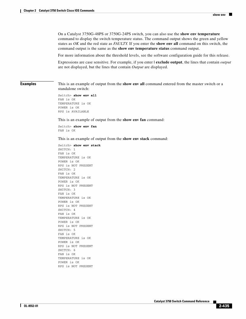
Chapter 2 Catalyst 3750 Switch Cisco IOS Commandsshow env
On a Catalyst 3750G-48PS or 3750G-24PS switch, you can also use the show env temperature command to display the switch temperature status. The command output shows the green and yellow states as OK and the red state as FAULTY. If you enter the show env all command on this switch, the command output is the same as the show env temperature status command output.
For more information about the threshold levels, see the software configuration guide for this release.
Expressions are case sensitive. For example, if you enter | exclude output, the lines that contain output are not displayed, but the lines that contain Output are displayed.
Examples This is an example of output from the show env all command entered from the master switch or a standalone switch:
Switch> show env allFAN is OKTEMPERATURE is OKPOWER is OKRPS is AVAILABLE
This is an example of output from the show env fan command:
Switch> show env fanFAN is OK
This is an example of output from the show env stack command:
Switch> show env stackSWITCH: 1FAN is OKTEMPERATURE is OKPOWER is OKRPS is NOT PRESENTSWITCH: 2FAN is OKTEMPERATURE is OKPOWER is OKRPS is NOT PRESENTSWITCH: 3FAN is OKTEMPERATURE is OKPOWER is OKRPS is NOT PRESENTSWITCH: 4FAN is OKTEMPERATURE is OKPOWER is OKRPS is NOT PRESENTSWITCH: 5FAN is OKTEMPERATURE is OKPOWER is OKRPS is NOT PRESENTSWITCH: 6FAN is OKTEMPERATURE is OKPOWER is OKRPS is NOT PRESENT
2-435Catalyst 3750 Switch Command Reference
OL-8552-01
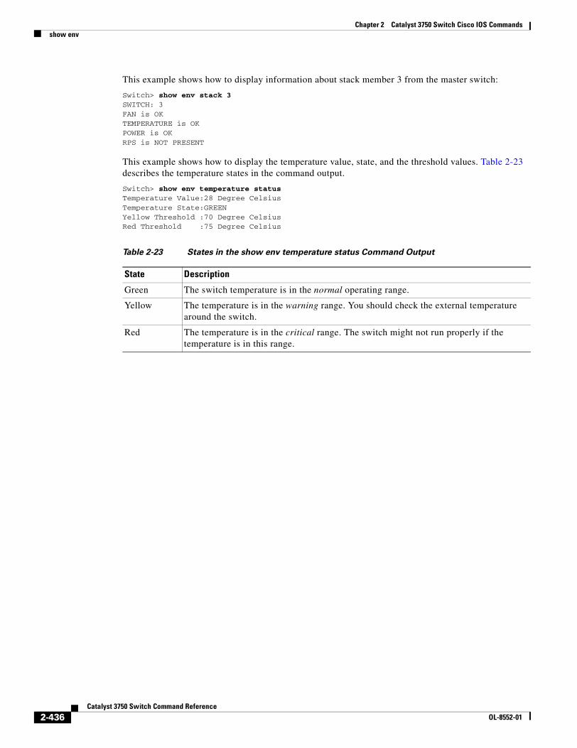
Chapter 2 Catalyst 3750 Switch Cisco IOS Commandsshow env
This example shows how to display information about stack member 3 from the master switch:
Switch> show env stack 3SWITCH: 3FAN is OKTEMPERATURE is OKPOWER is OKRPS is NOT PRESENT
This example shows how to display the temperature value, state, and the threshold values. Table 2-23 describes the temperature states in the command output.
Switch> show env temperature statusTemperature Value:28 Degree CelsiusTemperature State:GREENYellow Threshold :70 Degree CelsiusRed Threshold :75 Degree Celsius
Table 2-23 States in the show env temperature status Command Output
State Description
Green The switch temperature is in the normal operating range.
Yellow The temperature is in the warning range. You should check the external temperature around the switch.
Red The temperature is in the critical range. The switch might not run properly if the temperature is in this range.
2-436Catalyst 3750 Switch Command Reference
OL-8552-01
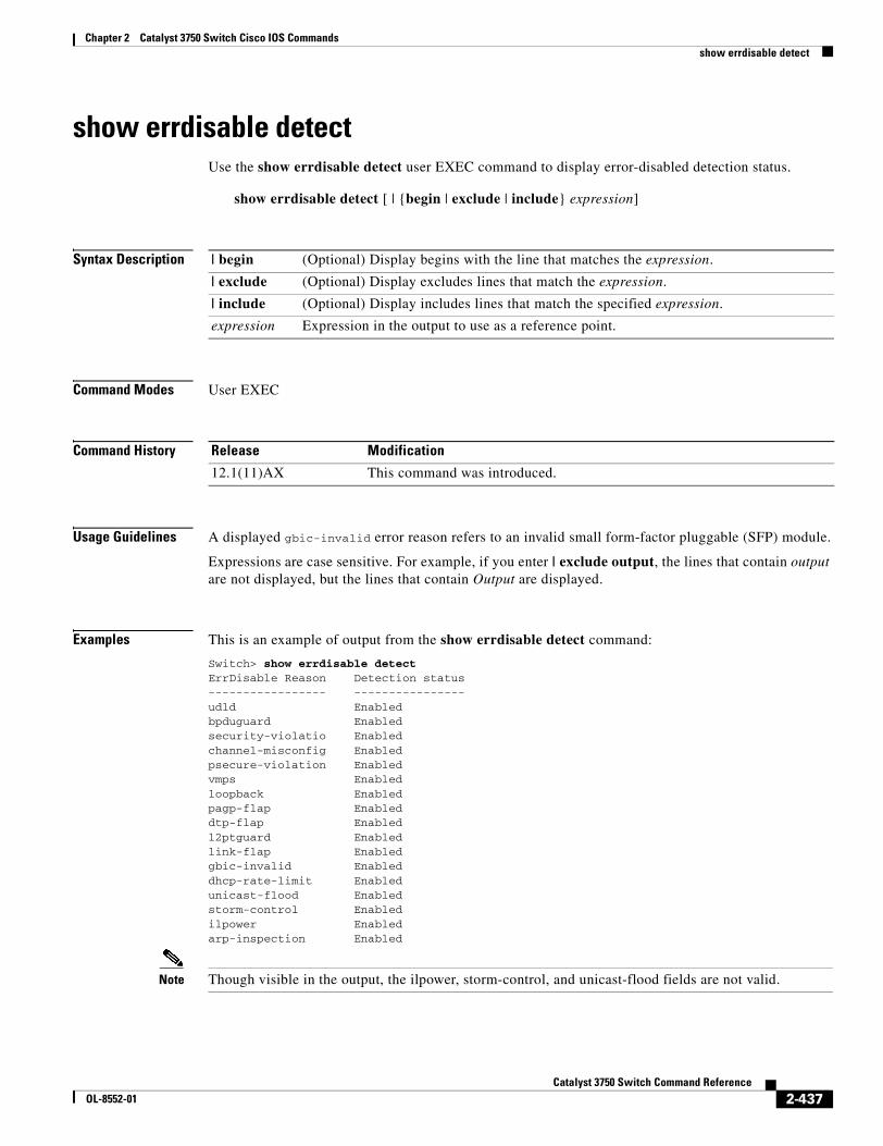
Chapter 2 Catalyst 3750 Switch Cisco IOS Commandsshow errdisable detect
show errdisable detectUse the show errdisable detect user EXEC command to display error-disabled detection status.
show errdisable detect [ | {begin | exclude | include} expression]
Syntax Description
Command Modes User EXEC
Command History
Usage Guidelines A displayed gbic-invalid error reason refers to an invalid small form-factor pluggable (SFP) module.
Expressions are case sensitive. For example, if you enter | exclude output, the lines that contain output are not displayed, but the lines that contain Output are displayed.
Examples This is an example of output from the show errdisable detect command:
Switch> show errdisable detectErrDisable Reason Detection status----------------- ----------------udld Enabledbpduguard Enabledsecurity-violatio Enabledchannel-misconfig Enabledpsecure-violation Enabledvmps Enabledloopback Enabledpagp-flap Enableddtp-flap Enabledl2ptguard Enabledlink-flap Enabledgbic-invalid Enableddhcp-rate-limit Enabledunicast-flood Enabledstorm-control Enabledilpower Enabledarp-inspection Enabled
Note Though visible in the output, the ilpower, storm-control, and unicast-flood fields are not valid.
| begin (Optional) Display begins with the line that matches the expression.
| exclude (Optional) Display excludes lines that match the expression.
| include (Optional) Display includes lines that match the specified expression.
expression Expression in the output to use as a reference point.
Release Modification
12.1(11)AX This command was introduced.
2-437Catalyst 3750 Switch Command Reference
OL-8552-01
Chapter 2 Catalyst 3750 Switch Cisco IOS Commandsshow errdisable detect
Related Commands Command Description
errdisable detect cause Enables error-disabled detection for a specific cause or all causes.
show errdisable flap-values Displays error condition recognition information.
show errdisable recovery Displays error-disabled recovery timer information.
show interfaces status Displays interface status or a list of interfaces in error-disabled state.
2-438Catalyst 3750 Switch Command Reference
OL-8552-01
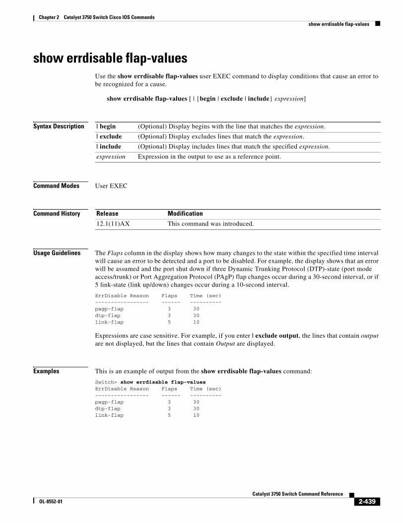
Chapter 2 Catalyst 3750 Switch Cisco IOS Commandsshow errdisable flap-values
show errdisable flap-valuesUse the show errdisable flap-values user EXEC command to display conditions that cause an error to be recognized for a cause.
show errdisable flap-values [ | {begin | exclude | include} expression]
Syntax Description
Command Modes User EXEC
Command History
Usage Guidelines The Flaps column in the display shows how many changes to the state within the specified time interval will cause an error to be detected and a port to be disabled. For example, the display shows that an error will be assumed and the port shut down if three Dynamic Trunking Protocol (DTP)-state (port mode access/trunk) or Port Aggregation Protocol (PAgP) flap changes occur during a 30-second interval, or if 5 link-state (link up/down) changes occur during a 10-second interval.
ErrDisable Reason Flaps Time (sec)----------------- ------ ----------pagp-flap 3 30dtp-flap 3 30link-flap 5 10
Expressions are case sensitive. For example, if you enter | exclude output, the lines that contain output are not displayed, but the lines that contain Output are displayed.
Examples This is an example of output from the show errdisable flap-values command:
Switch> show errdisable flap-valuesErrDisable Reason Flaps Time (sec)----------------- ------ ----------pagp-flap 3 30dtp-flap 3 30link-flap 5 10
| begin (Optional) Display begins with the line that matches the expression.
| exclude (Optional) Display excludes lines that match the expression.
| include (Optional) Display includes lines that match the specified expression.
expression Expression in the output to use as a reference point.
Release Modification
12.1(11)AX This command was introduced.
2-439Catalyst 3750 Switch Command Reference
OL-8552-01
Chapter 2 Catalyst 3750 Switch Cisco IOS Commandsshow errdisable flap-values
Related Commands Command Description
errdisable detect cause Enables error-disabled detection for a specific cause or all causes.
show errdisable detect Displays error-disabled detection status.
show errdisable recovery Displays error-disabled recovery timer information.
show interfaces status Displays interface status or a list of interfaces in error-disabled state.
2-440Catalyst 3750 Switch Command Reference
OL-8552-01
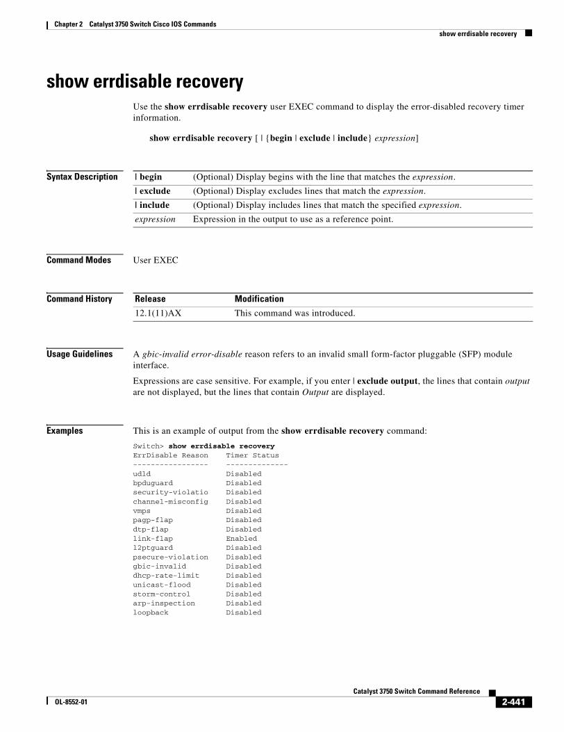
Chapter 2 Catalyst 3750 Switch Cisco IOS Commandsshow errdisable recovery
show errdisable recoveryUse the show errdisable recovery user EXEC command to display the error-disabled recovery timer information.
show errdisable recovery [ | {begin | exclude | include} expression]
Syntax Description
Command Modes User EXEC
Command History
Usage Guidelines A gbic-invalid error-disable reason refers to an invalid small form-factor pluggable (SFP) module interface.
Expressions are case sensitive. For example, if you enter | exclude output, the lines that contain output are not displayed, but the lines that contain Output are displayed.
Examples This is an example of output from the show errdisable recovery command:
Switch> show errdisable recoveryErrDisable Reason Timer Status----------------- --------------udld Disabledbpduguard Disabledsecurity-violatio Disabledchannel-misconfig Disabledvmps Disabledpagp-flap Disableddtp-flap Disabledlink-flap Enabledl2ptguard Disabledpsecure-violation Disabledgbic-invalid Disableddhcp-rate-limit Disabledunicast-flood Disabledstorm-control Disabledarp-inspection Disabledloopback Disabled
| begin (Optional) Display begins with the line that matches the expression.
| exclude (Optional) Display excludes lines that match the expression.
| include (Optional) Display includes lines that match the specified expression.
expression Expression in the output to use as a reference point.
Release Modification
12.1(11)AX This command was introduced.
2-441Catalyst 3750 Switch Command Reference
OL-8552-01
Chapter 2 Catalyst 3750 Switch Cisco IOS Commandsshow errdisable recovery
Timer interval:300 seconds
Interfaces that will be enabled at the next timeout:
Interface Errdisable reason Time left(sec)--------- ----------------- --------------Gi1/0/2 link-flap 279
Note Though visible in the output, the unicast-flood field is not valid.
Related Commands Command Description
errdisable recovery Configures the recover mechanism variables.
show errdisable detect Displays error-disabled detection status.
show errdisable flap-values Displays error condition recognition information.
show interfaces status Displays interface status or a list of interfaces in error-disabled state.
2-442Catalyst 3750 Switch Command Reference
OL-8552-01
Chapter 2 Catalyst 3750 Switch Cisco IOS Commandsshow etherchannel
show etherchannel Use the show etherchannel user EXEC command to display EtherChannel information for a channel.
show etherchannel [channel-group-number {detail | port | port-channel | protocol | summary}] {detail | load-balance | port | port-channel | protocol | summary} [ | {begin | exclude | include} expression]
Syntax Description
Command Modes User EXEC
Command History
Usage Guidelines If you do not specify a channel-group, all channel groups are displayed.
In the output, the Passive port list field is displayed only for Layer 3 port channels. This field means that the physical port, which is still not up, is configured to be in the channel group (and indirectly is in the only port channel in the channel group).
Expressions are case sensitive. For example, if you enter | exclude output, the lines that contain output are not displayed, but the lines that contain Output are displayed.
channel-group-number (Optional) Number of the channel group. The range is 1 to 48.
detail Display detailed EtherChannel information.
load-balance Display the load-balance or frame-distribution scheme among ports in the port channel.
port Display EtherChannel port information.
port-channel Display port-channel information.
protocol Display the protocol that is being used in the EtherChannel.
summary Display a one-line summary per channel-group.
| begin (Optional) Display begins with the line that matches the expression.
| exclude (Optional) Display excludes lines that match the expression.
| include (Optional) Display includes lines that match the specified expression.
expression Expression in the output to use as a reference point.
Release Modification
12.1(11)AX This command was introduced.
12.1(14)EA1 The protocol keyword was added.
12.2(25)SE The channel-group-number range was changed from 1 to 12 to 1 to 48.
2-443Catalyst 3750 Switch Command Reference
OL-8552-01
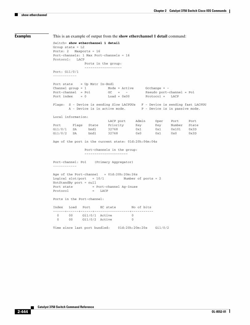
Chapter 2 Catalyst 3750 Switch Cisco IOS Commandsshow etherchannel
Examples This is an example of output from the show etherchannel 1 detail command:
Switch> show etherchannel 1 detailGroup state = L2Ports: 2 Maxports = 16Port-channels: 1 Max Port-channels = 16Protocol: LACP Ports in the group: -------------------Port: Gi1/0/1------------
Port state = Up Mstr In-BndlChannel group = 1 Mode = Active Gcchange = -Port-channel = Po1 GC = - Pseudo port-channel = Po1Port index = 0 Load = 0x00 Protocol = LACP
Flags: S - Device is sending Slow LACPDUs F - Device is sending fast LACPDU A - Device is in active mode. P - Device is in passive mode.
Local information: LACP port Admin Oper Port PortPort Flags State Priority Key Key Number StateGi1/0/1 SA bndl 32768 0x1 0x1 0x101 0x3DGi1/0/2 SA bndl 32768 0x0 0x1 0x0 0x3D
Age of the port in the current state: 01d:20h:06m:04s Port-channels in the group: ----------------------
Port-channel: Po1 (Primary Aggregator)------------
Age of the Port-channel = 01d:20h:20m:26sLogical slot/port = 10/1 Number of ports = 2HotStandBy port = nullPort state = Port-channel Ag-InuseProtocol = LACP
Ports in the Port-channel:
Index Load Port EC state No of bits------+------+------+------------------+----------- 0 00 Gi1/0/1 Active 0 0 00 Gi1/0/2 Active 0
Time since last port bundled: 01d:20h:20m:20s Gi1/0/2
2-444Catalyst 3750 Switch Command Reference
OL-8552-01
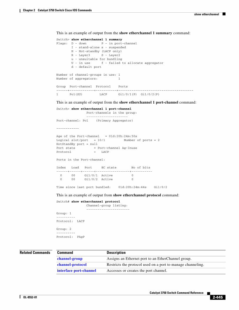
Chapter 2 Catalyst 3750 Switch Cisco IOS Commandsshow etherchannel
This is an example of output from the show etherchannel 1 summary command:
Switch> show etherchannel 1 summaryFlags: D - down P - in port-channel I - stand-alone s - suspended H - Hot-standby (LACP only) R - Layer3 S - Layer2 u - unsuitable for bundling U - in use f - failed to allocate aggregator d - default port
Number of channel-groups in use: 1Number of aggregators: 1
Group Port-channel Protocol Ports------+-------------+-----------+----------------------------------------1 Po1(SU) LACP Gi1/0/1(P) Gi1/0/2(P)
This is an example of output from the show etherchannel 1 port-channel command:
Switch> show etherchannel 1 port-channel Port-channels in the group: ----------------------Port-channel: Po1 (Primary Aggregator)
------------
Age of the Port-channel = 01d:20h:24m:50sLogical slot/port = 10/1 Number of ports = 2HotStandBy port = nullPort state = Port-channel Ag-InuseProtocol = LACP
Ports in the Port-channel:
Index Load Port EC state No of bits------+------+------+------------------+----------- 0 00 Gi1/0/1 Active 0 0 00 Gi1/0/2 Active 0
Time since last port bundled: 01d:20h:24m:44s Gi1/0/2
This is an example of output from show etherchannel protocol command:
Switch# show etherchannel protocol Channel-group listing: -----------------------Group: 1----------Protocol: LACP
Group: 2----------Protocol: PAgP
Related Commands Command Description
channel-group Assigns an Ethernet port to an EtherChannel group.
channel-protocol Restricts the protocol used on a port to manage channeling.
interface port-channel Accesses or creates the port channel.
2-445Catalyst 3750 Switch Command Reference
OL-8552-01
Chapter 2 Catalyst 3750 Switch Cisco IOS Commandsshow flowcontrol
show flowcontrolUse the show flowcontrol user EXEC command to display the flow control status and statistics.
show flowcontrol [interface interface-id | module number] [ | {begin | exclude | include} expression]
Syntax Description
Command Modes User EXEC
Command History
Usage Guidelines Use this command to display the flow control status and statistics on the switch or for a specific interface.
Use the show flowcontrol command to display information about all the switch interfaces. For a standalone switch, the output from the show flowcontrol command is the same as the output from the show flowcontrol module number command.
Use the show flowcontrol interface interface-id command to display information about a specific interface.
Expressions are case sensitive. For example, if you enter | exclude output, the lines that contain output do not appear, but the lines that contain Output appear.
Examples This is an example of output from the show flowcontrol command.
Switch> show flowcontrolPort Send FlowControl Receive FlowControl RxPause TxPause admin oper admin oper--------- -------- -------- -------- -------- ------- -------Gi2/0/1 Unsupp. Unsupp. off off 0 0Gi2/0/2 desired off off off 0 0Gi2/0/3 desired off off off 0 0<output truncated>
interface interface-id (Optional) Display the flow control status and statistics for a specific interface.
module number (Optional) Display the flow control status and statistics for all interfaces on the specified stack member. The range is 1 to 9. This option is not available if you have entered a specific interface ID.
| begin (Optional) Display begins with the line that matches the expression.
| exclude (Optional) Display excludes lines that match the expression.
| include (Optional) Display includes lines that match the specified expression.
expression Expression in the output to use as a reference point.
Release Modification
12.1(14)EA1 This command was introduced.
2-446Catalyst 3750 Switch Command Reference
OL-8552-01
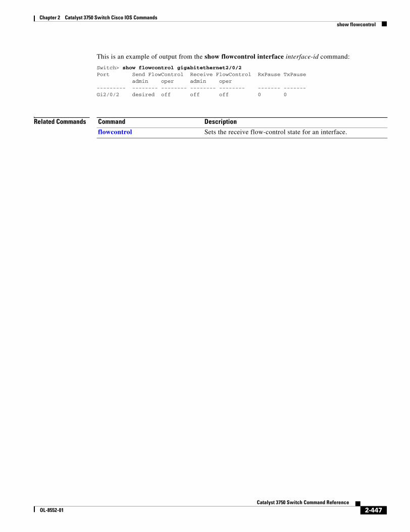
Chapter 2 Catalyst 3750 Switch Cisco IOS Commandsshow flowcontrol
This is an example of output from the show flowcontrol interface interface-id command:
Switch> show flowcontrol gigabitethernet2/0/2Port Send FlowControl Receive FlowControl RxPause TxPause admin oper admin oper--------- -------- -------- -------- -------- ------- -------Gi2/0/2 desired off off off 0 0
Related Commands Command Description
flowcontrol Sets the receive flow-control state for an interface.
2-447Catalyst 3750 Switch Command Reference
OL-8552-01
Chapter 2 Catalyst 3750 Switch Cisco IOS Commandsshow idprom
show idpromUse the show idprom user EXEC command to display the IDPROM information for the specified interface.
show idprom {interface interface-id} [detail] [ | {begin | exclude | include} expression]
Syntax Description
Command Modes User EXEC
Command History
Usage Guidelines This command applies only to 10-Gigabit Ethernet interfaces.
Expressions are case sensitive. For example, if you enter | exclude output, the lines that contain output do not appear, but the lines that contain Output appear.
Examples This is an example of output from the show idprom interface tengigabitethernet1/0/1 command for the 10-Gigabit Ethernet interface. It shows the XENPAK module serial EEPROM contents.
For information about the EEPROM map and the field descriptions for the display, see the XENPAK multisource agreement (MSA) at these sites:
http://www.xenpak.org/MSA/XENPAK_MSA_R2.1.pdf
http://www.xenpak.org/MSA/XENPAK_MSA_R3.0.pdf
interface interface-id Display the IDPROM information for the specified 10-Gigabit Ethernet interface.
detail (Optional) Display detailed hexidecimal IDPROM information.
| begin (Optional) Display begins with the line that matches the expression.
| exclude (Optional) Display excludes lines that match the expression.
| include (Optional) Display includes lines that match the specified expression.
expression Expression in the output to use as a reference point.
Release Modification
12.2(20)SE1 This command was introduced.
2-448Catalyst 3750 Switch Command Reference
OL-8552-01
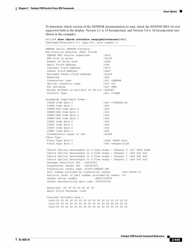
Chapter 2 Catalyst 3750 Switch Cisco IOS Commandsshow idprom
To determine which version of the XENPAK documentation to read, check the XENPAK MSA Version supported field in the display. Version 2.1 is 15 hexadecimal, and Version 3.0 is 1E hexadecimal (not shown in the example).
Switch# show idprom interface tengigabitethernet1/0/1TenGigabitEthernet1/0/1 (gpn:472, port-number:1)-----------------------------------------------------------XENPAK Serial EEPROM Contents:Non-Volatile Register (NVR) Fields XENPAK MSA Version supported :0x15 NVR Size in bytes :0x100 Number of bytes used :0xD0 Basic Field Address :0xB Customer Field Address :0x77 Vendor Field Address :0xA7 Extended Vendor Field Address :0x100 Reserved :0x0 Transceiver type :0x1 =XENPAK Optical connector type :0x1 =SC Bit encoding :0x1 =NRZ Normal BitRate in multiple of 1M b/s :0x2848 Protocol Type :0x1 =10GgE
Standards Compliance Codes : 10GbE Code Byte 0 :0x2 =10GBASE-LR 10GbE Code Byte 1 :0x0 SONET/SDH Code Byte 0 :0x0 SONET/SDH Code Byte 1 :0x0 SONET/SDH Code Byte 2 :0x0 SONET/SDH Code Byte 3 :0x0 10GFC Code Byte 0 :0x0 10GFC Code Byte 1 :0x0 10GFC Code Byte 2 :0x0 10GFC Code Byte 3 :0x0 Transmission range in 10m :0x3E8Fibre Type : Fibre Type Byte 0 :0x40 =NDSF only Fibre Type Byte 1 :0x0 =Unspecified
Centre Optical Wavelength in 0.01nm steps - Channel 0 :0x1 0xFF 0xB8 Centre Optical Wavelength in 0.01nm steps - Channel 1 :0x0 0x0 0x0 Centre Optical Wavelength in 0.01nm steps - Channel 2 :0x0 0x0 0x0 Centre Optical Wavelength in 0.01nm steps - Channel 3 :0x0 0x0 0x0 Package Identifier OUI :0x41F420 Transceiver Vendor OUI :0x3400871 Transceiver vendor name :CISCO-OPNEXT,INC Part number provided by transceiver vendor :800-24558-01 Revision level of part number provided by vendor :01 Vendor serial number :ONJ0735003U Vendor manufacturing date code :2003082700
Reserved1 :00 00 00 00 00 00 00 Basic Field Checksum :0x6C
Customer Writable Area : 0x00:00 00 00 00 00 00 00 00 00 00 00 00 00 00 00 00 0x10:00 00 00 00 00 00 00 00 00 00 00 00 00 00 00 00 0x20:00 00 00 00 00 00 00 00 00 00 00 00 00 00 00 00
2-449Catalyst 3750 Switch Command Reference
OL-8552-01
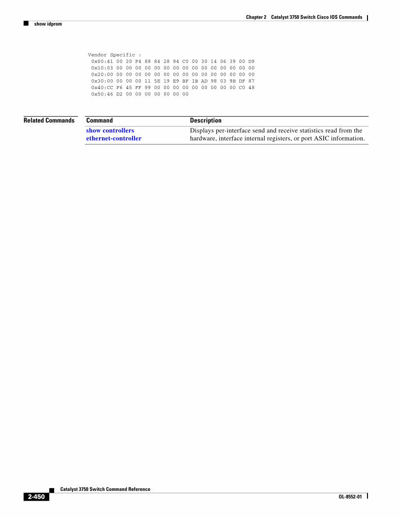
Chapter 2 Catalyst 3750 Switch Cisco IOS Commandsshow idprom
Vendor Specific : 0x00:41 00 20 F4 88 84 28 94 C0 00 30 14 06 39 00 D9 0x10:03 00 00 00 00 00 00 00 00 00 00 00 00 00 00 00 0x20:00 00 00 00 00 00 00 00 00 00 00 00 00 00 00 00 0x30:00 00 00 00 11 5E 19 E9 BF 1B AD 98 03 9B DF 87 0x40:CC F6 45 FF 99 00 00 00 00 00 00 00 00 00 C0 48 0x50:46 D2 00 00 00 00 00 00 00
Related Commands Command Description
show controllers ethernet-controller
Displays per-interface send and receive statistics read from the hardware, interface internal registers, or port ASIC information.
2-450Catalyst 3750 Switch Command Reference
OL-8552-01
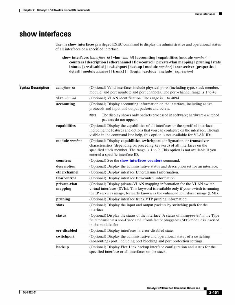
Chapter 2 Catalyst 3750 Switch Cisco IOS Commandsshow interfaces
show interfacesUse the show interfaces privileged EXEC command to display the administrative and operational status of all interfaces or a specified interface.
show interfaces [interface-id | vlan vlan-id] [accounting | capabilities [module number] | counters | description | etherchannel | flowcontrol | private-vlan mapping | pruning | stats | status [err-disabled] | switchport [backup | module number] | transceiver [properties | detail] [module number] | trunk] [ | {begin | exclude | include} expression]
Syntax Description interface-id (Optional) Valid interfaces include physical ports (including type, stack member, module, and port number) and port channels. The port-channel range is 1 to 48.
vlan vlan-id (Optional) VLAN identification. The range is 1 to 4094.
accounting (Optional) Display accounting information on the interface, including active protocols and input and output packets and octets.
Note The display shows only packets processed in software; hardware-switched packets do not appear.
capabilities (Optional) Display the capabilities of all interfaces or the specified interface, including the features and options that you can configure on the interface. Though visible in the command line help, this option is not available for VLAN IDs.
module number (Optional) Display capabilities, switchport configuration, or transceiver characteristics (depending on preceding keyword) of all interfaces on the specified stack member. The range is 1 to 9. This option is not available if you entered a specific interface ID.
counters (Optional) See the show interfaces counters command.
description (Optional) Display the administrative status and description set for an interface.
etherchannel (Optional) Display interface EtherChannel information.
flowcontrol (Optional) Display interface flowcontrol information
private-vlan mapping
(Optional) Display private-VLAN mapping information for the VLAN switch virtual interfaces (SVIs). This keyword is available only if your switch is running the IP services image, formerly known as the enhanced multilayer image (EMI).
pruning (Optional) Display interface trunk VTP pruning information.
stats (Optional) Display the input and output packets by switching path for the interface.
status (Optional) Display the status of the interface. A status of unsupported in the Type field means that a non-Cisco small form-factor pluggable (SFP) module is inserted in the module slot.
err-disabled (Optional) Display interfaces in error-disabled state.
switchport (Optional) Display the administrative and operational status of a switching (nonrouting) port, including port blocking and port protection settings.
backup (Optional) Display Flex Link backup interface configuration and status for the specified interface or all interfaces on the stack.
2-451Catalyst 3750 Switch Command Reference
OL-8552-01
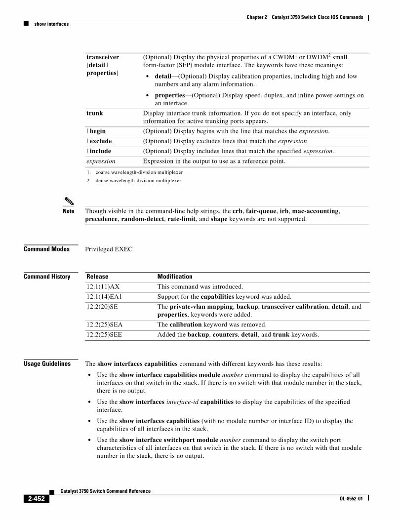
Chapter 2 Catalyst 3750 Switch Cisco IOS Commandsshow interfaces
Note Though visible in the command-line help strings, the crb, fair-queue, irb, mac-accounting, precedence, random-detect, rate-limit, and shape keywords are not supported.
Command Modes Privileged EXEC
Command History
Usage Guidelines The show interfaces capabilities command with different keywords has these results:
• Use the show interface capabilities module number command to display the capabilities of all interfaces on that switch in the stack. If there is no switch with that module number in the stack, there is no output.
• Use the show interfaces interface-id capabilities to display the capabilities of the specified interface.
• Use the show interfaces capabilities (with no module number or interface ID) to display the capabilities of all interfaces in the stack.
• Use the show interface switchport module number command to display the switch port characteristics of all interfaces on that switch in the stack. If there is no switch with that module number in the stack, there is no output.
transceiver [detail | properties]
(Optional) Display the physical properties of a CWDM1 or DWDM2 small form-factor (SFP) module interface. The keywords have these meanings:
• detail—(Optional) Display calibration properties, including high and low numbers and any alarm information.
• properties—(Optional) Display speed, duplex, and inline power settings on an interface.
trunk Display interface trunk information. If you do not specify an interface, only information for active trunking ports appears.
| begin (Optional) Display begins with the line that matches the expression.
| exclude (Optional) Display excludes lines that match the expression.
| include (Optional) Display includes lines that match the specified expression.
expression Expression in the output to use as a reference point.
1. coarse wavelength-division multiplexer
2. dense wavelength-division multiplexer
Release Modification
12.1(11)AX This command was introduced.
12.1(14)EA1 Support for the capabilities keyword was added.
12.2(20)SE The private-vlan mapping, backup, transceiver calibration, detail, and properties, keywords were added.
12.2(25)SEA The calibration keyword was removed.
12.2(25)SEE Added the backup, counters, detail, and trunk keywords.
2-452Catalyst 3750 Switch Command Reference
OL-8552-01
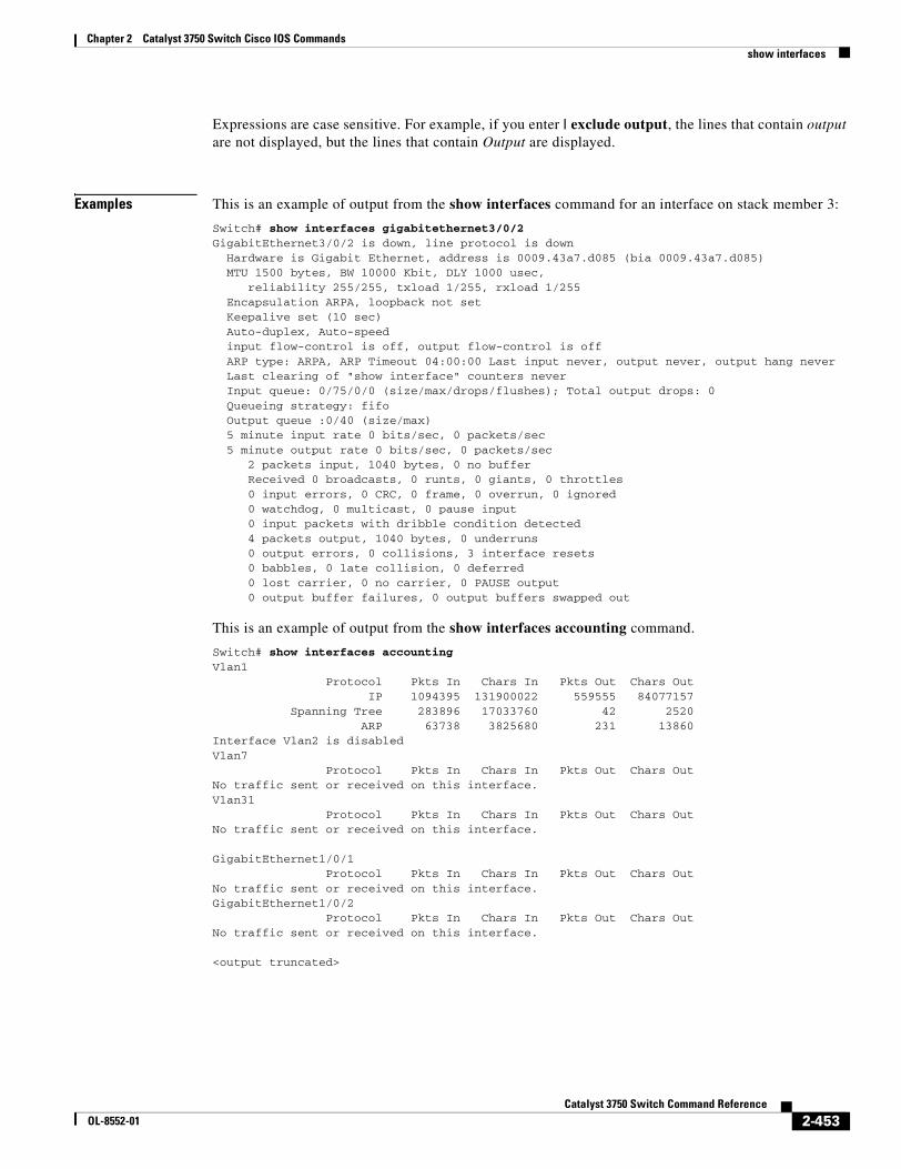
Chapter 2 Catalyst 3750 Switch Cisco IOS Commandsshow interfaces
Expressions are case sensitive. For example, if you enter | exclude output, the lines that contain output are not displayed, but the lines that contain Output are displayed.
Examples This is an example of output from the show interfaces command for an interface on stack member 3:
Switch# show interfaces gigabitethernet3/0/2 GigabitEthernet3/0/2 is down, line protocol is down Hardware is Gigabit Ethernet, address is 0009.43a7.d085 (bia 0009.43a7.d085) MTU 1500 bytes, BW 10000 Kbit, DLY 1000 usec, reliability 255/255, txload 1/255, rxload 1/255 Encapsulation ARPA, loopback not set Keepalive set (10 sec) Auto-duplex, Auto-speed input flow-control is off, output flow-control is off ARP type: ARPA, ARP Timeout 04:00:00 Last input never, output never, output hang never Last clearing of "show interface" counters never Input queue: 0/75/0/0 (size/max/drops/flushes); Total output drops: 0 Queueing strategy: fifo Output queue :0/40 (size/max) 5 minute input rate 0 bits/sec, 0 packets/sec 5 minute output rate 0 bits/sec, 0 packets/sec 2 packets input, 1040 bytes, 0 no buffer Received 0 broadcasts, 0 runts, 0 giants, 0 throttles 0 input errors, 0 CRC, 0 frame, 0 overrun, 0 ignored 0 watchdog, 0 multicast, 0 pause input 0 input packets with dribble condition detected 4 packets output, 1040 bytes, 0 underruns 0 output errors, 0 collisions, 3 interface resets 0 babbles, 0 late collision, 0 deferred 0 lost carrier, 0 no carrier, 0 PAUSE output 0 output buffer failures, 0 output buffers swapped out
This is an example of output from the show interfaces accounting command.
Switch# show interfaces accountingVlan1 Protocol Pkts In Chars In Pkts Out Chars Out IP 1094395 131900022 559555 84077157 Spanning Tree 283896 17033760 42 2520 ARP 63738 3825680 231 13860Interface Vlan2 is disabledVlan7 Protocol Pkts In Chars In Pkts Out Chars OutNo traffic sent or received on this interface.Vlan31 Protocol Pkts In Chars In Pkts Out Chars OutNo traffic sent or received on this interface.
GigabitEthernet1/0/1 Protocol Pkts In Chars In Pkts Out Chars OutNo traffic sent or received on this interface.GigabitEthernet1/0/2 Protocol Pkts In Chars In Pkts Out Chars OutNo traffic sent or received on this interface.
<output truncated>
2-453Catalyst 3750 Switch Command Reference
OL-8552-01
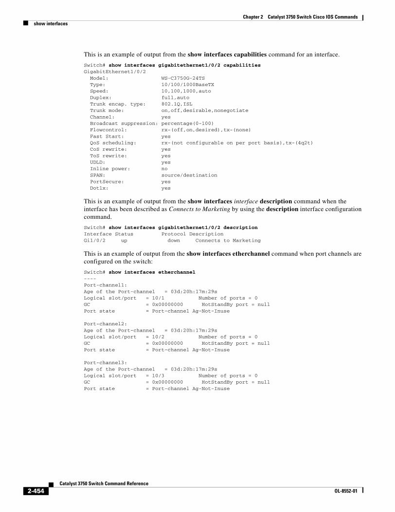
Chapter 2 Catalyst 3750 Switch Cisco IOS Commandsshow interfaces
This is an example of output from the show interfaces capabilities command for an interface.
Switch# show interfaces gigabitethernet1/0/2 capabilitiesGigabitEthernet1/0/2 Model: WS-C3750G-24TS Type: 10/100/1000BaseTX Speed: 10,100,1000,auto Duplex: full,auto Trunk encap. type: 802.1Q,ISL Trunk mode: on,off,desirable,nonegotiate Channel: yes Broadcast suppression: percentage(0-100) Flowcontrol: rx-(off,on,desired),tx-(none) Fast Start: yes QoS scheduling: rx-(not configurable on per port basis),tx-(4q2t) CoS rewrite: yes ToS rewrite: yes UDLD: yes Inline power: no SPAN: source/destination PortSecure: yes Dot1x: yes
This is an example of output from the show interfaces interface description command when the interface has been described as Connects to Marketing by using the description interface configuration command.
Switch# show interfaces gigabitethernet1/0/2 descriptionInterface Status Protocol DescriptionGi1/0/2 up down Connects to Marketing
This is an example of output from the show interfaces etherchannel command when port channels are configured on the switch:
Switch# show interfaces etherchannel----Port-channel1:Age of the Port-channel = 03d:20h:17m:29sLogical slot/port = 10/1 Number of ports = 0GC = 0x00000000 HotStandBy port = nullPort state = Port-channel Ag-Not-Inuse
Port-channel2:Age of the Port-channel = 03d:20h:17m:29sLogical slot/port = 10/2 Number of ports = 0GC = 0x00000000 HotStandBy port = nullPort state = Port-channel Ag-Not-Inuse
Port-channel3:Age of the Port-channel = 03d:20h:17m:29sLogical slot/port = 10/3 Number of ports = 0GC = 0x00000000 HotStandBy port = nullPort state = Port-channel Ag-Not-Inuse
2-454Catalyst 3750 Switch Command Reference
OL-8552-01
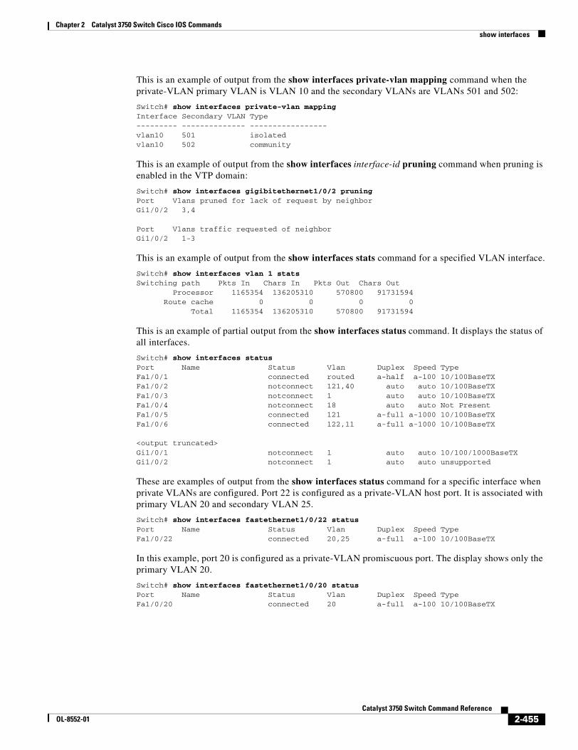
Chapter 2 Catalyst 3750 Switch Cisco IOS Commandsshow interfaces
This is an example of output from the show interfaces private-vlan mapping command when the private-VLAN primary VLAN is VLAN 10 and the secondary VLANs are VLANs 501 and 502:
Switch# show interfaces private-vlan mappingInterface Secondary VLAN Type--------- -------------- -----------------vlan10 501 isolatedvlan10 502 community
This is an example of output from the show interfaces interface-id pruning command when pruning is enabled in the VTP domain:
Switch# show interfaces gigibitethernet1/0/2 pruningPort Vlans pruned for lack of request by neighborGi1/0/2 3,4
Port Vlans traffic requested of neighborGi1/0/2 1-3
This is an example of output from the show interfaces stats command for a specified VLAN interface.
Switch# show interfaces vlan 1 statsSwitching path Pkts In Chars In Pkts Out Chars Out Processor 1165354 136205310 570800 91731594 Route cache 0 0 0 0 Total 1165354 136205310 570800 91731594
This is an example of partial output from the show interfaces status command. It displays the status of all interfaces.
Switch# show interfaces statusPort Name Status Vlan Duplex Speed TypeFa1/0/1 connected routed a-half a-100 10/100BaseTXFa1/0/2 notconnect 121,40 auto auto 10/100BaseTXFa1/0/3 notconnect 1 auto auto 10/100BaseTXFa1/0/4 notconnect 18 auto auto Not PresentFa1/0/5 connected 121 a-full a-1000 10/100BaseTXFa1/0/6 connected 122,11 a-full a-1000 10/100BaseTX
<output truncated>Gi1/0/1 notconnect 1 auto auto 10/100/1000BaseTXGi1/0/2 notconnect 1 auto auto unsupported
These are examples of output from the show interfaces status command for a specific interface when private VLANs are configured. Port 22 is configured as a private-VLAN host port. It is associated with primary VLAN 20 and secondary VLAN 25.
Switch# show interfaces fastethernet1/0/22 statusPort Name Status Vlan Duplex Speed TypeFa1/0/22 connected 20,25 a-full a-100 10/100BaseTX
In this example, port 20 is configured as a private-VLAN promiscuous port. The display shows only the primary VLAN 20.
Switch# show interfaces fastethernet1/0/20 statusPort Name Status Vlan Duplex Speed TypeFa1/0/20 connected 20 a-full a-100 10/100BaseTX
2-455Catalyst 3750 Switch Command Reference
OL-8552-01
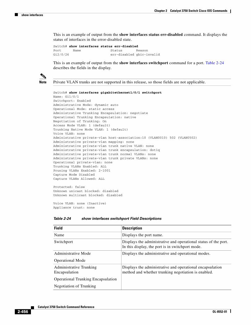
Chapter 2 Catalyst 3750 Switch Cisco IOS Commandsshow interfaces
This is an example of output from the show interfaces status err-disabled command. It displays the status of interfaces in the error-disabled state.
Switch# show interfaces status err-disabled Port Name Status ReasonGi2/0/26 err-disabled gbic-invalid
This is an example of output from the show interfaces switchport command for a port. Table 2-24 describes the fields in the display.
Note Private VLAN trunks are not supported in this release, so those fields are not applicable.
Switch# show interfaces gigabitethernet1/0/1 switchportName: Gi1/0/1Switchport: EnabledAdministrative Mode: dynamic autoOperational Mode: static accessAdministrative Trunking Encapsulation: negotiateOperational Trunking Encapsulation: nativeNegotiation of Trunking: OnAccess Mode VLAN: 1 (default)Trunking Native Mode VLAN: 1 (default)Voice VLAN: noneAdministrative private-vlan host-association:10 (VLAN0010) 502 (VLAN0502)Administrative private-vlan mapping: none Administrative private-vlan trunk native VLAN: noneAdministrative private-vlan trunk encapsulation: dot1qAdministrative private-vlan trunk normal VLANs: noneAdministrative private-vlan trunk private VLANs: noneOperational private-vlan: noneTrunking VLANs Enabled: ALLPruning VLANs Enabled: 2-1001Capture Mode DisabledCapture VLANs Allowed: ALL
Protected: falseUnknown unicast blocked: disabledUnknown multicast blocked: disabled
Voice VLAN: none (Inactive)Appliance trust: none
Table 2-24 show interfaces switchport Field Descriptions
Field Description
Name Displays the port name.
Switchport Displays the administrative and operational status of the port. In this display, the port is in switchport mode.
Administrative Mode
Operational Mode
Displays the administrative and operational modes.
Administrative Trunking Encapsulation
Operational Trunking Encapsulation
Negotiation of Trunking
Displays the administrative and operational encapsulation method and whether trunking negotiation is enabled.
2-456Catalyst 3750 Switch Command Reference
OL-8552-01
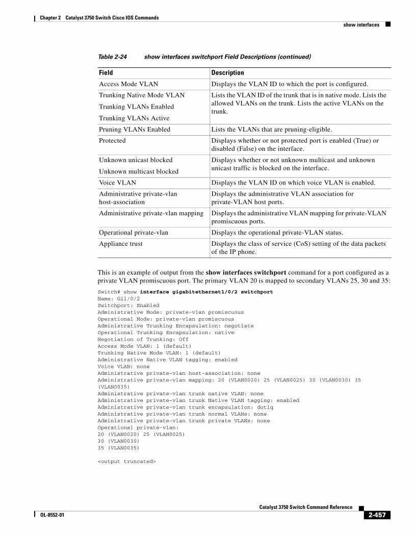
Chapter 2 Catalyst 3750 Switch Cisco IOS Commandsshow interfaces
This is an example of output from the show interfaces switchport command for a port configured as a private VLAN promiscuous port. The primary VLAN 20 is mapped to secondary VLANs 25, 30 and 35:
Switch# show interface gigabitethernet1/0/2 switchportName: Gi1/0/2Switchport: EnabledAdministrative Mode: private-vlan promiscuousOperational Mode: private-vlan promiscuousAdministrative Trunking Encapsulation: negotiateOperational Trunking Encapsulation: nativeNegotiation of Trunking: OffAccess Mode VLAN: 1 (default)Trunking Native Mode VLAN: 1 (default)Administrative Native VLAN tagging: enabledVoice VLAN: noneAdministrative private-vlan host-association: noneAdministrative private-vlan mapping: 20 (VLAN0020) 25 (VLAN0025) 30 (VLAN0030) 35 (VLAN0035)Administrative private-vlan trunk native VLAN: noneAdministrative private-vlan trunk Native VLAN tagging: enabledAdministrative private-vlan trunk encapsulation: dot1qAdministrative private-vlan trunk normal VLANs: noneAdministrative private-vlan trunk private VLANs: noneOperational private-vlan:20 (VLAN0020) 25 (VLAN0025)30 (VLAN0030)35 (VLAN0035)
<output truncated>
Access Mode VLAN Displays the VLAN ID to which the port is configured.
Trunking Native Mode VLAN
Trunking VLANs Enabled
Trunking VLANs Active
Lists the VLAN ID of the trunk that is in native mode. Lists the allowed VLANs on the trunk. Lists the active VLANs on the trunk.
Pruning VLANs Enabled Lists the VLANs that are pruning-eligible.
Protected Displays whether or not protected port is enabled (True) or disabled (False) on the interface.
Unknown unicast blocked
Unknown multicast blocked
Displays whether or not unknown multicast and unknown unicast traffic is blocked on the interface.
Voice VLAN Displays the VLAN ID on which voice VLAN is enabled.
Administrative private-vlan host-association
Displays the administrative VLAN association for private-VLAN host ports.
Administrative private-vlan mapping Displays the administrative VLAN mapping for private-VLAN promiscuous ports.
Operational private-vlan Displays the operational private-VLAN status.
Appliance trust Displays the class of service (CoS) setting of the data packets of the IP phone.
Table 2-24 show interfaces switchport Field Descriptions (continued)
Field Description
2-457Catalyst 3750 Switch Command Reference
OL-8552-01
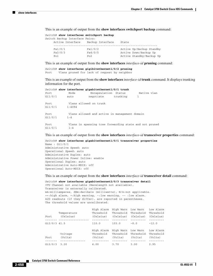
Chapter 2 Catalyst 3750 Switch Cisco IOS Commandsshow interfaces
This is an example of output from the show interfaces switchport backup command:
Switch# show interfaces switchport backupSwitch Backup Interface Pairs:
Active Interface Backup Interface State -------------------------------------------------------------- Fa1/0/1 Fa1/0/2 Active Up/Backup Standby Fa3/0/3 Fa4/0/5 Active Down/Backup Up Po1 Po2 Active Standby/Backup Up
This is an example of output from the show interfaces interface-id pruning command:
Switch# show interfaces gigibitethernet1/0/2 pruningPort Vlans pruned for lack of request by neighbor
This is an example of output from the show interfaces interface-id trunk command. It displays trunking information for the port.
Switch# show interfaces gigabitethernet1/0/1 trunkPort Mode Encapsulation Status Native vlanGi1/0/1 auto negotiate trunking 1
Port Vlans allowed on trunkGi1/0/1 1-4094
Port Vlans allowed and active in management domainGi1/0/1 1-4
Port Vlans in spanning tree forwarding state and not prunedGi1/0/1 1-4
This is an example of output from the show interfaces interface-id transceiver properties command:
Switch# show interfaces gigabitethernet1/0/1 transceiver propertiesName : Gi1/0/1Administrative Speed: auto Operational Speed: auto Administrative Duplex: autoAdministrative Power Inline: enableOperational Duplex: autoAdministrative Auto-MDIX: offOperational Auto-MDIX: off
This is an example of output from the show interfaces interface-id transceiver detail command:
Switch# show interfaces gigabitethernet2/0/3 transceiver detailITU Channel not available (Wavelength not available),Transceiver is externally calibrated.mA:milliamperes, dBm:decibels (milliwatts), N/A:not applicable.++:high alarm, +:high warning, -:low warning, -- :low alarm.A2D readouts (if they differ), are reported in parentheses.The threshold values are uncalibrated.
High Alarm High Warn Low Warn Low Alarm Temperature Threshold Threshold Threshold ThresholdPort (Celsius) (Celsius) (Celsius) (Celsius) (Celsius)------- ------------------ ---------- --------- --------- ---------Gi2/0/3 41.5 110.0 103.0 -8.0 -12.0
High Alarm High Warn Low Warn Low Alarm Voltage Threshold Threshold Threshold ThresholdPort (Volts) (Volts) (Volts) (Volts) (Volts)------- --------------- ---------- --------- --------- ---------Gi2/0/3 3.20 4.00 3.70 3.00 2.95
2-458Catalyst 3750 Switch Command Reference
OL-8552-01
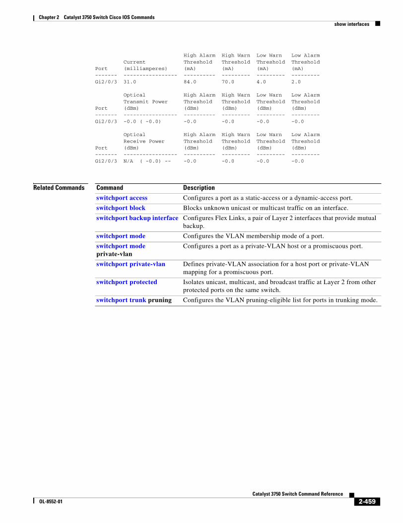
Chapter 2 Catalyst 3750 Switch Cisco IOS Commandsshow interfaces
High Alarm High Warn Low Warn Low Alarm Current Threshold Threshold Threshold ThresholdPort (milliamperes) (mA) (mA) (mA) (mA)------- ----------------- ---------- --------- --------- ---------Gi2/0/3 31.0 84.0 70.0 4.0 2.0
Optical High Alarm High Warn Low Warn Low Alarm Transmit Power Threshold Threshold Threshold ThresholdPort (dBm) (dBm) (dBm) (dBm) (dBm)------- ----------------- ---------- --------- --------- ---------Gi2/0/3 -0.0 ( -0.0) -0.0 -0.0 -0.0 -0.0
Optical High Alarm High Warn Low Warn Low Alarm Receive Power Threshold Threshold Threshold ThresholdPort (dBm) (dBm) (dBm) (dBm) (dBm)------- ----------------- ---------- --------- --------- ---------Gi2/0/3 N/A ( -0.0) -- -0.0 -0.0 -0.0 -0.0
Related Commands Command Description
switchport access Configures a port as a static-access or a dynamic-access port.
switchport block Blocks unknown unicast or multicast traffic on an interface.
switchport backup interface Configures Flex Links, a pair of Layer 2 interfaces that provide mutual backup.
switchport mode Configures the VLAN membership mode of a port.
switchport mode private-vlan
Configures a port as a private-VLAN host or a promiscuous port.
switchport private-vlan Defines private-VLAN association for a host port or private-VLAN mapping for a promiscuous port.
switchport protected Isolates unicast, multicast, and broadcast traffic at Layer 2 from other protected ports on the same switch.
switchport trunk pruning Configures the VLAN pruning-eligible list for ports in trunking mode.
2-459Catalyst 3750 Switch Command Reference
OL-8552-01
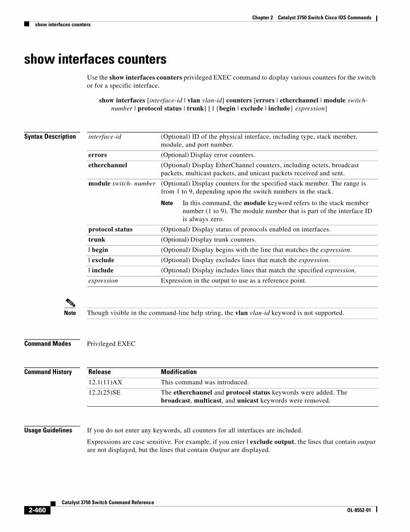
Chapter 2 Catalyst 3750 Switch Cisco IOS Commandsshow interfaces counters
show interfaces countersUse the show interfaces counters privileged EXEC command to display various counters for the switch or for a specific interface.
show interfaces [interface-id | vlan vlan-id] counters [errors | etherchannel | module switch- number | protocol status | trunk] [ | {begin | exclude | include} expression]
Syntax Description
Note Though visible in the command-line help string, the vlan vlan-id keyword is not supported.
Command Modes Privileged EXEC
Command History
Usage Guidelines If you do not enter any keywords, all counters for all interfaces are included.
Expressions are case sensitive. For example, if you enter | exclude output, the lines that contain output are not displayed, but the lines that contain Output are displayed.
interface-id (Optional) ID of the physical interface, including type, stack member, module, and port number.
errors (Optional) Display error counters.
etherchannel (Optional) Display EtherChannel counters, including octets, broadcast packets, multicast packets, and unicast packets received and sent.
module switch- number (Optional) Display counters for the specified stack member. The range is from 1 to 9, depending upon the switch numbers in the stack.
Note In this command, the module keyword refers to the stack member number (1 to 9). The module number that is part of the interface ID is always zero.
protocol status (Optional) Display status of protocols enabled on interfaces.
trunk (Optional) Display trunk counters.
| begin (Optional) Display begins with the line that matches the expression.
| exclude (Optional) Display excludes lines that match the expression.
| include (Optional) Display includes lines that match the specified expression.
expression Expression in the output to use as a reference point.
Release Modification
12.1(11)AX This command was introduced.
12.2(25)SE The etherchannel and protocol status keywords were added. The broadcast, multicast, and unicast keywords were removed.
2-460Catalyst 3750 Switch Command Reference
OL-8552-01
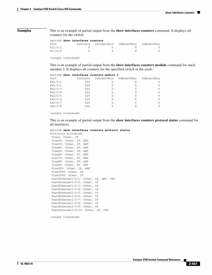
Chapter 2 Catalyst 3750 Switch Cisco IOS Commandsshow interfaces counters
Examples This is an example of partial output from the show interfaces counters command. It displays all counters for the switch.
Switch# show interfaces countersPort InOctets InUcastPkts InMcastPkts InBcastPktsGi1/0/1 0 0 0 0Gi1/0/2 0 0 0 0
<output truncated>
This is an example of partial output from the show interfaces counters module command for stack member 2. It displays all counters for the specified switch in the stack.
Switch# show interfaces counters module 2Port InOctets InUcastPkts InMcastPkts InBcastPktsFa2/0/1 520 2 0 0Fa2/0/2 520 2 0 0Fa2/0/3 520 2 0 0Fa2/0/4 520 2 0 0Fa2/0/5 520 2 0 0Fa2/0/6 520 2 0 0Fa2/0/7 520 2 0 0Fa2/0/8 520 2 0 0
<output truncated>
This is an example of partial output from the show interfaces counters protocol status command for all interfaces.
Switch# show interfaces counters protocol statusProtocols allocated: Vlan1: Other, IP Vlan20: Other, IP, ARP Vlan30: Other, IP, ARP Vlan40: Other, IP, ARP Vlan50: Other, IP, ARP Vlan60: Other, IP, ARP Vlan70: Other, IP, ARP Vlan80: Other, IP, ARP Vlan90: Other, IP, ARP Vlan900: Other, IP, ARP Vlan3000: Other, IP Vlan3500: Other, IP FastEthernet1/0/1: Other, IP, ARP, CDP FastEthernet1/0/2: Other, IP FastEthernet1/0/3: Other, IP FastEthernet1/0/4: Other, IP FastEthernet1/0/5: Other, IP FastEthernet1/0/6: Other, IP FastEthernet1/0/7: Other, IP FastEthernet1/0/8: Other, IP FastEthernet1/0/9: Other, IP FastEthernet1/0/10: Other, IP, CDP
<output truncated>
2-461Catalyst 3750 Switch Command Reference
OL-8552-01
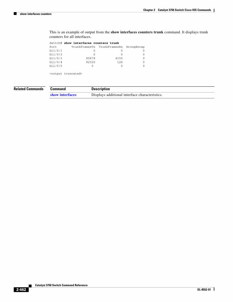
Chapter 2 Catalyst 3750 Switch Cisco IOS Commandsshow interfaces counters
This is an example of output from the show interfaces counters trunk command. It displays trunk counters for all interfaces.
Switch# show interfaces counters trunkPort TrunkFramesTx TrunkFramesRx WrongEncapGi1/0/1 0 0 0Gi1/0/2 0 0 0Gi1/0/3 80678 4155 0Gi1/0/4 82320 126 0Gi1/0/5 0 0 0
<output truncated>
Related Commands Command Description
show interfaces Displays additional interface characteristics.
2-462Catalyst 3750 Switch Command Reference
OL-8552-01
Chapter 2 Catalyst 3750 Switch Cisco IOS Commandsshow inventory
show inventoryUse the show inventory user EXEC command to display product identification (PID) information for the hardware.
show inventory [entity-name | raw] [ | {begin | exclude | include} expression]
Syntax Description
Command Modes User EXEC
Command History
Usage Guidelines The command is case sensitive. With no arguments, the show inventory command produces a compact dump of all identifiable entities that have a product identifier. The compact dump displays the entity location (slot identity), entity description, and the unique device identifier (UDI) (PID, VID, and SN) of that entity.
Note If there is no PID, no output appears when you enter the show inventory command.
Expressions are case sensitive. For example, if you enter | exclude output, the lines that contain output are not displayed, but the lines that contain Output are displayed.
Examples This is example output from the show inventory command:
Switch> show inventoryNAME: "5", DESCR: "WS-C3750G-12S"PID: WS-C3750G-12S-S , VID: E0 , SN: CAT0749R204
entity-name (Optional) Display the specified entity. For example, enter the interface (such as gigabitethernet1/0/1) into which a small form-factor pluggable (SFP) module is installed.
raw (Optional) Display every entity in the device.
| begin (Optional) Display begins with the line that matches the expression.
| exclude (Optional) Display excludes lines that match the expression.
| include (Optional) Display includes lines that match the specified expression.
expression Expression in the output to use as a reference point.
Release Modification
12.2(25)SEC This command was introduced.
2-463Catalyst 3750 Switch Command Reference
OL-8552-01
Chapter 2 Catalyst 3750 Switch Cisco IOS Commandsshow ip arp inspection
show ip arp inspectionUse the show ip arp inspection privileged EXEC command to display the configuration and the operating state of dynamic Address Resolution Protocol (ARP) inspection or the status of this feature for all VLANs or for the specified interface or VLAN.
show ip arp inspection [interfaces [interface-id] | log | statistics [vlan vlan-range] | vlan vlan-range] [ | {begin | exclude | include} expression]
This command is available only if your switch is running the IP services image, formerly known as the enhanced multilayer image (EMI).
Syntax Description
Command Modes Privileged EXEC
Command History
interfaces [interface-id] (Optional) Display the trust state and the rate limit of ARP packets for the specified interface or all interfaces. Valid interfaces include physical ports and port channels.
log (Optional) Display the configuration and contents of the dynamic ARP inspection log buffer.
statistics [vlan vlan-range] (Optional) Display statistics for forwarded, dropped, MAC validation failure, IP validation failure, access control list (ACL) permitted and denied, and DHCP permitted and denied packets for the specified VLAN. If no VLANs are specified or if a range is specified, display information only for VLANs with dynamic ARP inspection enabled (active).
You can specify a single VLAN identified by VLAN ID number, a range of VLANs separated by a hyphen, or a series of VLANs separated by a comma. The range is 1 to 4094.
vlan vlan-range (Optional) Display the configuration and the operating state of dynamic ARP inspection for the specified VLAN. If no VLANs are specified or if a range is specified, display information only for VLANs with dynamic ARP inspection enabled (active).
You can specify a single VLAN identified by VLAN ID number, a range of VLANs separated by a hyphen, or a series of VLANs separated by a comma. The range is 1 to 4094.
| begin (Optional) Display begins with the line that matches the expression.
| exclude (Optional) Display excludes lines that match the expression.
| include (Optional) Display includes lines that match the specified expression.
expression Expression in the output to use as a reference point.
Release Modification
12.2(20)SE This command was introduced.
2-464Catalyst 3750 Switch Command Reference
OL-8552-01
Chapter 2 Catalyst 3750 Switch Cisco IOS Commandsshow ip arp inspection
Usage Guidelines Expressions are case sensitive. For example, if you enter | exclude output, the lines that contain output are not displayed, but the lines that contain Output are displayed.
Examples This is an example of output from the show ip arp inspection interfaces command:
Switch# show ip arp inspection interfacesInterface Trust State Rate (pps) Burst Interval
--------------- ----------- ---------- -------------- Gi1/0/1 Untrusted 15 1 Gi1/0/2 Untrusted 15 1 Gi1/0/3 Untrusted 15 1
This is an example of output from the show ip arp inspection interfaces interface-id command:
Switch# show ip arp inspection interfaces gigabitethernet1/0/1Interface Trust State Rate (pps) Burst Interval--------------- ----------- ---------- --------------
Gi1/0/1 Untrusted 15 1
This is an example of output from the show ip arp inspection log command. It shows the contents of the log buffer before the buffers are cleared:
Switch# show ip arp inspection logTotal Log Buffer Size : 32Syslog rate : 10 entries per 300 seconds.
Interface Vlan Sender MAC Sender IP Num Pkts Reason Time---------- ---- -------------- --------------- --------- ----------- ----Gi1/0/1 5 0003.0000.d673 192.2.10.4 5 DHCP Deny 19:39:01 UTC Mon Mar 1 1993Gi1/0/1 5 0001.0000.d774 128.1.9.25 6 DHCP Deny 19:39:02 UTC Mon Mar 1 1993Gi1/0/1 5 0001.c940.1111 10.10.10.1 7 DHCP Deny 19:39:03 UTC Mon Mar 1 1993Gi1/0/1 5 0001.c940.1112 10.10.10.2 8 DHCP Deny 19:39:04 UTC Mon Mar 1 1993Gi1/0/1 5 0001.c940.1114 173.1.1.1 10 DHCP Deny 19:39:06 UTC Mon Mar 1 1993Gi1/0/1 5 0001.c940.1115 173.1.1.2 11 DHCP Deny 19:39:07 UTC Mon Mar 1 1993Gi1/0/1 5 0001.c940.1116 173.1.1.3 12 DHCP Deny 19:39:08 UTC Mon Mar 1 1993
If the log buffer overflows, it means that a log event does not fit into the log buffer, and the display for the show ip arp inspection log privileged EXEC command is affected. A -- in the display appears in place of all data except the packet count and the time. No other statistics are provided for the entry. If you see this entry in the display, increase the number of entries in the log buffer, or increase the logging rate in the ip arp inspection log-buffer global configuration command.
This is an example of output from the show ip arp inspection statistics command. It shows the statistics for packets that have been processed by dynamic ARP inspection for all active VLANs.
Switch# show ip arp inspection statisticsVlan Forwarded Dropped DHCP Drops ACL Drops ---- --------- ------- ---------- --------- 5 3 4618 4605 4 2000 0 0 0 0
2-465Catalyst 3750 Switch Command Reference
OL-8552-01
Chapter 2 Catalyst 3750 Switch Cisco IOS Commandsshow ip arp inspection
Vlan DHCP Permits ACL Permits Source MAC Failures ---- ------------ ----------- ------------------- 5 0 12 0 2000 0 0 0
Vlan Dest MAC Failures IP Validation Failures ---- ----------------- ---------------------- 5 0 9 2000 0 0
For the show ip arp inspection statistics command, the switch increments the number of forwarded packets for each ARP request and response packet on a trusted dynamic ARP inspection port. The switch increments the number of ACL or DHCP permitted packets for each packet that is denied by source MAC, destination MAC, or IP validation checks, and the switch increments the appropriate failure count.
This is an example of output from the show ip arp inspection statistics vlan 5 command. It shows statistics for packets that have been processed by dynamic ARP for VLAN 5.
Switch# show ip arp inspection statistics vlan 5Vlan Forwarded Dropped DHCP Drops ACL Drops ---- --------- ------- ---------- --------- 5 3 4618 4605 4
Vlan DHCP Permits ACL Permits Source MAC Failures ---- ------------ ----------- ------------------- 5 0 12 0
Vlan Dest MAC Failures IP Validation Failures Invalid Protocol Data ---- ----------------- ---------------------- --------------------- 5 0 9 3
This is an example of output from the show ip arp inspection vlan 5 command. It shows the configuration and the operating state of dynamic ARP inspection for VLAN 5.
Switch# show ip arp inspection vlan 5Source Mac Validation :EnabledDestination Mac Validation :EnabledIP Address Validation :Enabled
Vlan Configuration Operation ACL Match Static ACL ---- ------------- --------- --------- ---------- 5 Enabled Active second No
Vlan ACL Logging DHCP Logging ---- ----------- ------------ 5 Acl-Match All
Related Commands Command Description
arp access-list Defines an ARP ACL.
clear ip arp inspection log Clears the dynamic ARP inspection log buffer.
clear ip arp inspection statistics Clears the dynamic ARP inspection statistics.
ip arp inspection log-buffer Configures the dynamic ARP inspection logging buffer.
ip arp inspection vlan logging Controls the type of packets that are logged per VLAN.
show arp access-list Displays detailed information about ARP access lists.
2-466Catalyst 3750 Switch Command Reference
OL-8552-01
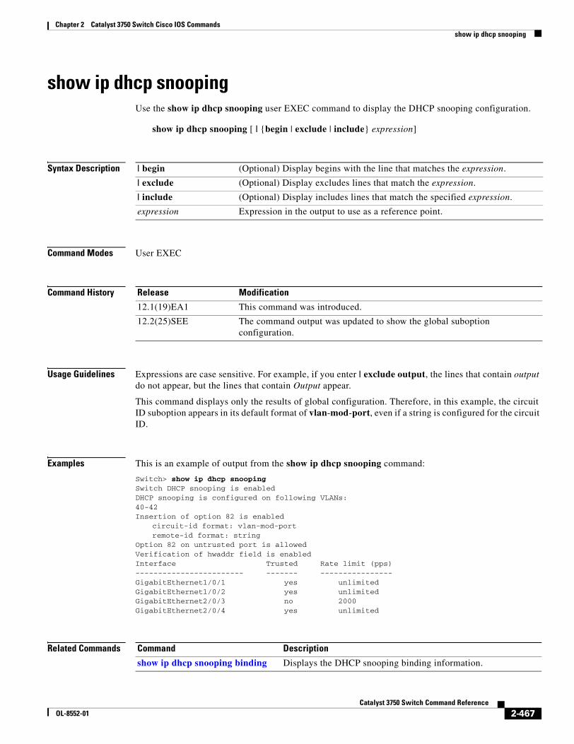
Chapter 2 Catalyst 3750 Switch Cisco IOS Commandsshow ip dhcp snooping
show ip dhcp snoopingUse the show ip dhcp snooping user EXEC command to display the DHCP snooping configuration.
show ip dhcp snooping [ | {begin | exclude | include} expression]
Syntax Description
Command Modes User EXEC
Command History
Usage Guidelines Expressions are case sensitive. For example, if you enter | exclude output, the lines that contain output do not appear, but the lines that contain Output appear.
This command displays only the results of global configuration. Therefore, in this example, the circuit ID suboption appears in its default format of vlan-mod-port, even if a string is configured for the circuit ID.
Examples This is an example of output from the show ip dhcp snooping command:
Switch> show ip dhcp snoopingSwitch DHCP snooping is enabledDHCP snooping is configured on following VLANs:40-42Insertion of option 82 is enabled
circuit-id format: vlan-mod-portremote-id format: string
Option 82 on untrusted port is allowed Verification of hwaddr field is enabledInterface Trusted Rate limit (pps)------------------------ ------- ----------------GigabitEthernet1/0/1 yes unlimitedGigabitEthernet1/0/2 yes unlimitedGigabitEthernet2/0/3 no 2000 GigabitEthernet2/0/4 yes unlimited
Related Commands
| begin (Optional) Display begins with the line that matches the expression.
| exclude (Optional) Display excludes lines that match the expression.
| include (Optional) Display includes lines that match the specified expression.
expression Expression in the output to use as a reference point.
Release Modification
12.1(19)EA1 This command was introduced.
12.2(25)SEE The command output was updated to show the global suboption configuration.
Command Description
show ip dhcp snooping binding Displays the DHCP snooping binding information.
2-467Catalyst 3750 Switch Command Reference
OL-8552-01
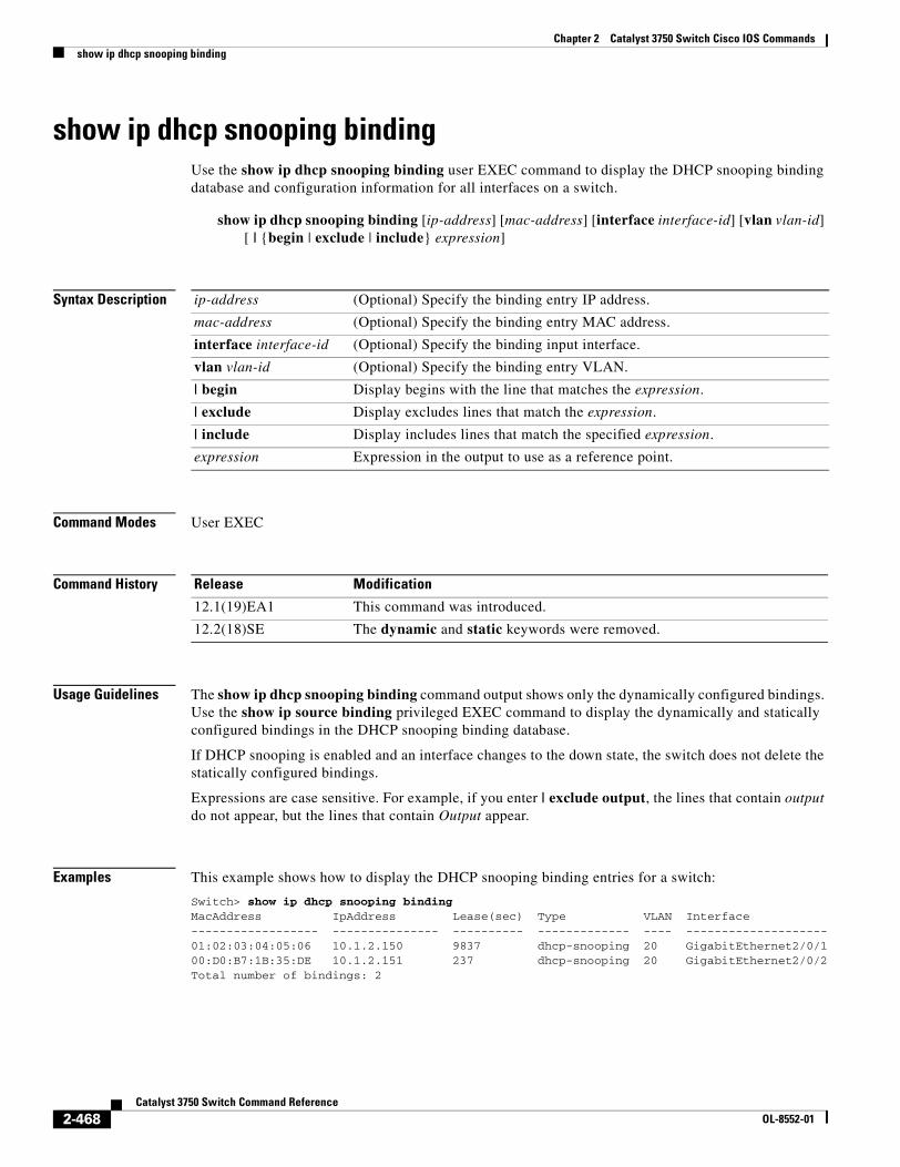
Chapter 2 Catalyst 3750 Switch Cisco IOS Commandsshow ip dhcp snooping binding
show ip dhcp snooping bindingUse the show ip dhcp snooping binding user EXEC command to display the DHCP snooping binding database and configuration information for all interfaces on a switch.
show ip dhcp snooping binding [ip-address] [mac-address] [interface interface-id] [vlan vlan-id] [ | {begin | exclude | include} expression]
Syntax Description
Command Modes User EXEC
Command History
Usage Guidelines The show ip dhcp snooping binding command output shows only the dynamically configured bindings. Use the show ip source binding privileged EXEC command to display the dynamically and statically configured bindings in the DHCP snooping binding database.
If DHCP snooping is enabled and an interface changes to the down state, the switch does not delete the statically configured bindings.
Expressions are case sensitive. For example, if you enter | exclude output, the lines that contain output do not appear, but the lines that contain Output appear.
Examples This example shows how to display the DHCP snooping binding entries for a switch:
Switch> show ip dhcp snooping bindingMacAddress IpAddress Lease(sec) Type VLAN Interface------------------ --------------- ---------- ------------- ---- --------------------01:02:03:04:05:06 10.1.2.150 9837 dhcp-snooping 20 GigabitEthernet2/0/100:D0:B7:1B:35:DE 10.1.2.151 237 dhcp-snooping 20 GigabitEthernet2/0/2Total number of bindings: 2
ip-address (Optional) Specify the binding entry IP address.
mac-address (Optional) Specify the binding entry MAC address.
interface interface-id (Optional) Specify the binding input interface.
vlan vlan-id (Optional) Specify the binding entry VLAN.
| begin Display begins with the line that matches the expression.
| exclude Display excludes lines that match the expression.
| include Display includes lines that match the specified expression.
expression Expression in the output to use as a reference point.
Release Modification
12.1(19)EA1 This command was introduced.
12.2(18)SE The dynamic and static keywords were removed.
2-468Catalyst 3750 Switch Command Reference
OL-8552-01
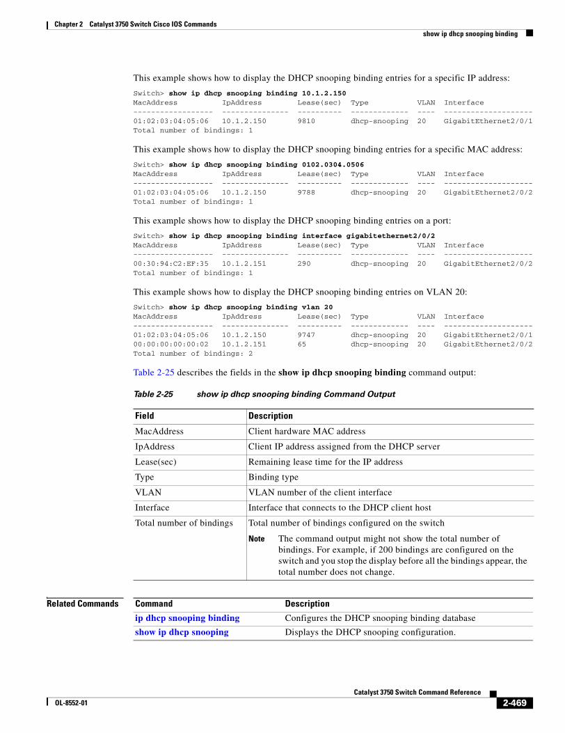
Chapter 2 Catalyst 3750 Switch Cisco IOS Commandsshow ip dhcp snooping binding
This example shows how to display the DHCP snooping binding entries for a specific IP address:
Switch> show ip dhcp snooping binding 10.1.2.150MacAddress IpAddress Lease(sec) Type VLAN Interface------------------ --------------- ---------- ------------- ---- --------------------01:02:03:04:05:06 10.1.2.150 9810 dhcp-snooping 20 GigabitEthernet2/0/1Total number of bindings: 1
This example shows how to display the DHCP snooping binding entries for a specific MAC address:
Switch> show ip dhcp snooping binding 0102.0304.0506MacAddress IpAddress Lease(sec) Type VLAN Interface------------------ --------------- ---------- ------------- ---- --------------------01:02:03:04:05:06 10.1.2.150 9788 dhcp-snooping 20 GigabitEthernet2/0/2Total number of bindings: 1
This example shows how to display the DHCP snooping binding entries on a port:
Switch> show ip dhcp snooping binding interface gigabitethernet2/0/2MacAddress IpAddress Lease(sec) Type VLAN Interface------------------ --------------- ---------- ------------- ---- --------------------00:30:94:C2:EF:35 10.1.2.151 290 dhcp-snooping 20 GigabitEthernet2/0/2Total number of bindings: 1
This example shows how to display the DHCP snooping binding entries on VLAN 20:
Switch> show ip dhcp snooping binding vlan 20MacAddress IpAddress Lease(sec) Type VLAN Interface------------------ --------------- ---------- ------------- ---- --------------------01:02:03:04:05:06 10.1.2.150 9747 dhcp-snooping 20 GigabitEthernet2/0/100:00:00:00:00:02 10.1.2.151 65 dhcp-snooping 20 GigabitEthernet2/0/2Total number of bindings: 2
Table 2-25 describes the fields in the show ip dhcp snooping binding command output:
Related Commands
Table 2-25 show ip dhcp snooping binding Command Output
Field Description
MacAddress Client hardware MAC address
IpAddress Client IP address assigned from the DHCP server
Lease(sec) Remaining lease time for the IP address
Type Binding type
VLAN VLAN number of the client interface
Interface Interface that connects to the DHCP client host
Total number of bindings Total number of bindings configured on the switch
Note The command output might not show the total number of bindings. For example, if 200 bindings are configured on the switch and you stop the display before all the bindings appear, the total number does not change.
Command Description
ip dhcp snooping binding Configures the DHCP snooping binding database
show ip dhcp snooping Displays the DHCP snooping configuration.
2-469Catalyst 3750 Switch Command Reference
OL-8552-01
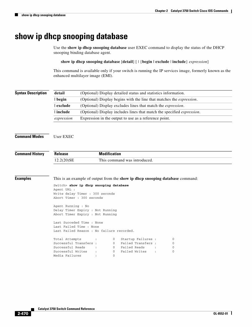
Chapter 2 Catalyst 3750 Switch Cisco IOS Commandsshow ip dhcp snooping database
show ip dhcp snooping databaseUse the show ip dhcp snooping database user EXEC command to display the status of the DHCP snooping binding database agent.
show ip dhcp snooping database [detail] [ | {begin | exclude | include} expression]
This command is available only if your switch is running the IP services image, formerly known as the enhanced multilayer image (EMI).
Syntax Description
Command Modes User EXEC
Command History
Examples This is an example of output from the show ip dhcp snooping database command:
Switch> show ip dhcp snooping databaseAgent URL : Write delay Timer : 300 secondsAbort Timer : 300 seconds
Agent Running : NoDelay Timer Expiry : Not RunningAbort Timer Expiry : Not Running
Last Succeded Time : NoneLast Failed Time : NoneLast Failed Reason : No failure recorded.
Total Attempts : 0 Startup Failures : 0Successful Transfers : 0 Failed Transfers : 0Successful Reads : 0 Failed Reads : 0Successful Writes : 0 Failed Writes : 0Media Failures : 0
detail (Optional) Display detailed status and statistics information.
| begin (Optional) Display begins with the line that matches the expression.
| exclude (Optional) Display excludes lines that match the expression.
| include (Optional) Display includes lines that match the specified expression.
expression Expression in the output to use as a reference point.
Release Modification
12.2(20)SE This command was introduced.
2-470Catalyst 3750 Switch Command Reference
OL-8552-01
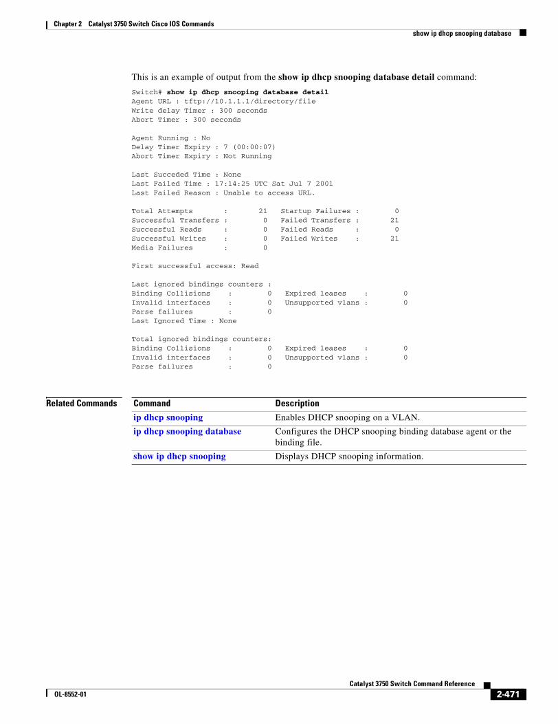
Chapter 2 Catalyst 3750 Switch Cisco IOS Commandsshow ip dhcp snooping database
This is an example of output from the show ip dhcp snooping database detail command:
Switch# show ip dhcp snooping database detail Agent URL : tftp://10.1.1.1/directory/fileWrite delay Timer : 300 secondsAbort Timer : 300 seconds
Agent Running : NoDelay Timer Expiry : 7 (00:00:07)Abort Timer Expiry : Not Running
Last Succeded Time : NoneLast Failed Time : 17:14:25 UTC Sat Jul 7 2001Last Failed Reason : Unable to access URL.
Total Attempts : 21 Startup Failures : 0Successful Transfers : 0 Failed Transfers : 21Successful Reads : 0 Failed Reads : 0Successful Writes : 0 Failed Writes : 21Media Failures : 0
First successful access: Read
Last ignored bindings counters :Binding Collisions : 0 Expired leases : 0Invalid interfaces : 0 Unsupported vlans : 0Parse failures : 0Last Ignored Time : None
Total ignored bindings counters:Binding Collisions : 0 Expired leases : 0Invalid interfaces : 0 Unsupported vlans : 0Parse failures : 0
Related Commands Command Description
ip dhcp snooping Enables DHCP snooping on a VLAN.
ip dhcp snooping database Configures the DHCP snooping binding database agent or the binding file.
show ip dhcp snooping Displays DHCP snooping information.
2-471Catalyst 3750 Switch Command Reference
OL-8552-01
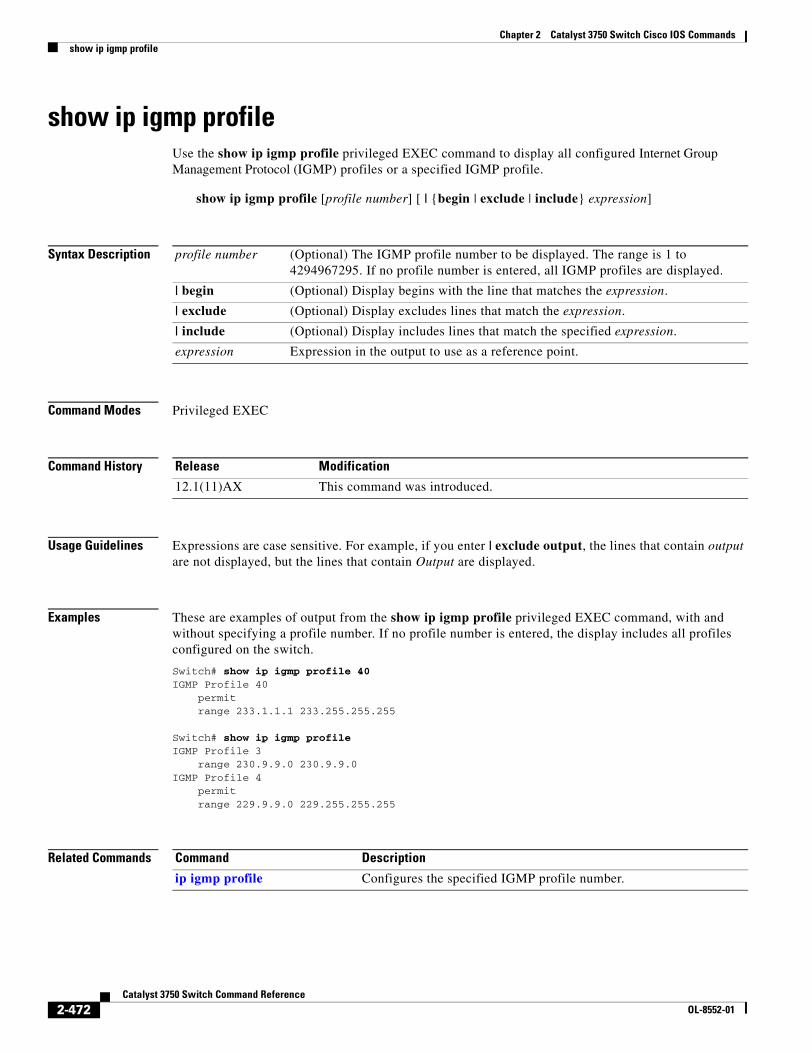
Chapter 2 Catalyst 3750 Switch Cisco IOS Commandsshow ip igmp profile
show ip igmp profileUse the show ip igmp profile privileged EXEC command to display all configured Internet Group Management Protocol (IGMP) profiles or a specified IGMP profile.
show ip igmp profile [profile number] [ | {begin | exclude | include} expression]
Syntax Description
Command Modes Privileged EXEC
Command History
Usage Guidelines Expressions are case sensitive. For example, if you enter | exclude output, the lines that contain output are not displayed, but the lines that contain Output are displayed.
Examples These are examples of output from the show ip igmp profile privileged EXEC command, with and without specifying a profile number. If no profile number is entered, the display includes all profiles configured on the switch.
Switch# show ip igmp profile 40IGMP Profile 40 permit range 233.1.1.1 233.255.255.255
Switch# show ip igmp profileIGMP Profile 3 range 230.9.9.0 230.9.9.0IGMP Profile 4 permit range 229.9.9.0 229.255.255.255
Related Commands
profile number (Optional) The IGMP profile number to be displayed. The range is 1 to 4294967295. If no profile number is entered, all IGMP profiles are displayed.
| begin (Optional) Display begins with the line that matches the expression.
| exclude (Optional) Display excludes lines that match the expression.
| include (Optional) Display includes lines that match the specified expression.
expression Expression in the output to use as a reference point.
Release Modification
12.1(11)AX This command was introduced.
Command Description
ip igmp profile Configures the specified IGMP profile number.
2-472Catalyst 3750 Switch Command Reference
OL-8552-01
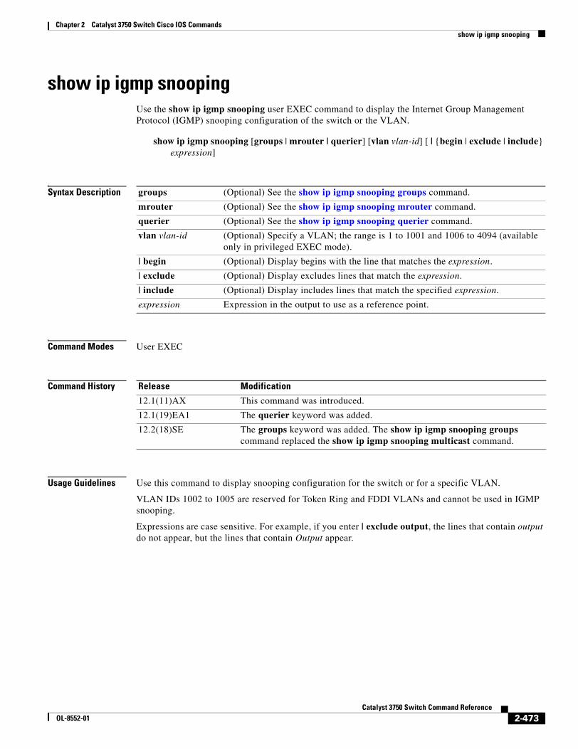
Chapter 2 Catalyst 3750 Switch Cisco IOS Commandsshow ip igmp snooping
show ip igmp snoopingUse the show ip igmp snooping user EXEC command to display the Internet Group Management Protocol (IGMP) snooping configuration of the switch or the VLAN.
show ip igmp snooping [groups | mrouter | querier] [vlan vlan-id] [ | {begin | exclude | include} expression]
Syntax Description
Command Modes User EXEC
Command History
Usage Guidelines Use this command to display snooping configuration for the switch or for a specific VLAN.
VLAN IDs 1002 to 1005 are reserved for Token Ring and FDDI VLANs and cannot be used in IGMP snooping.
Expressions are case sensitive. For example, if you enter | exclude output, the lines that contain output do not appear, but the lines that contain Output appear.
groups (Optional) See the show ip igmp snooping groups command.
mrouter (Optional) See the show ip igmp snooping mrouter command.
querier (Optional) See the show ip igmp snooping querier command.
vlan vlan-id (Optional) Specify a VLAN; the range is 1 to 1001 and 1006 to 4094 (available only in privileged EXEC mode).
| begin (Optional) Display begins with the line that matches the expression.
| exclude (Optional) Display excludes lines that match the expression.
| include (Optional) Display includes lines that match the specified expression.
expression Expression in the output to use as a reference point.
Release Modification
12.1(11)AX This command was introduced.
12.1(19)EA1 The querier keyword was added.
12.2(18)SE The groups keyword was added. The show ip igmp snooping groups command replaced the show ip igmp snooping multicast command.
2-473Catalyst 3750 Switch Command Reference
OL-8552-01
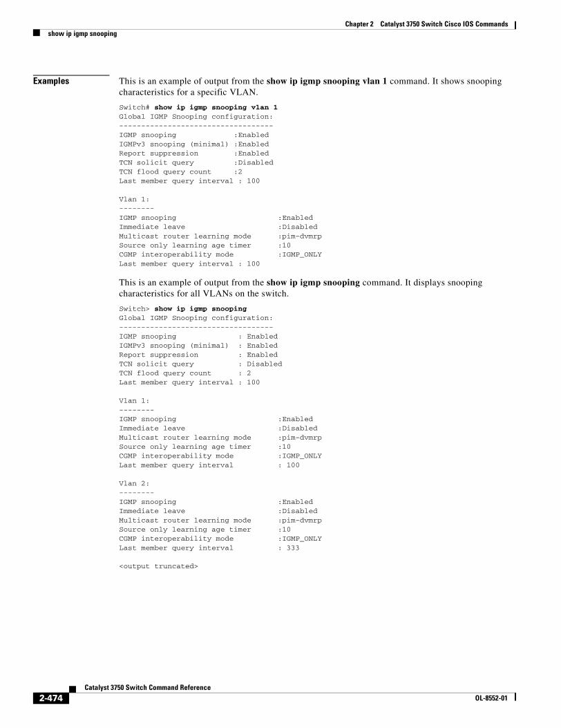
Chapter 2 Catalyst 3750 Switch Cisco IOS Commandsshow ip igmp snooping
Examples This is an example of output from the show ip igmp snooping vlan 1 command. It shows snooping characteristics for a specific VLAN.
Switch# show ip igmp snooping vlan 1Global IGMP Snooping configuration:-----------------------------------IGMP snooping :EnabledIGMPv3 snooping (minimal) :EnabledReport suppression :EnabledTCN solicit query :DisabledTCN flood query count :2Last member query interval : 100
Vlan 1:--------IGMP snooping :EnabledImmediate leave :DisabledMulticast router learning mode :pim-dvmrpSource only learning age timer :10CGMP interoperability mode :IGMP_ONLYLast member query interval : 100
This is an example of output from the show ip igmp snooping command. It displays snooping characteristics for all VLANs on the switch.
Switch> show ip igmp snooping Global IGMP Snooping configuration:-----------------------------------IGMP snooping : EnabledIGMPv3 snooping (minimal) : EnabledReport suppression : EnabledTCN solicit query : DisabledTCN flood query count : 2Last member query interval : 100
Vlan 1:--------IGMP snooping :EnabledImmediate leave :DisabledMulticast router learning mode :pim-dvmrpSource only learning age timer :10CGMP interoperability mode :IGMP_ONLYLast member query interval : 100
Vlan 2:--------IGMP snooping :EnabledImmediate leave :DisabledMulticast router learning mode :pim-dvmrpSource only learning age timer :10CGMP interoperability mode :IGMP_ONLYLast member query interval : 333
<output truncated>
2-474Catalyst 3750 Switch Command Reference
OL-8552-01
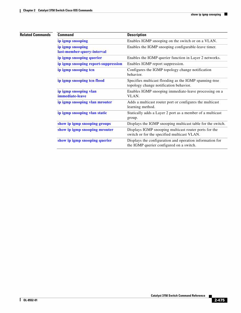
Chapter 2 Catalyst 3750 Switch Cisco IOS Commandsshow ip igmp snooping
Related Commands Command Description
ip igmp snooping Enables IGMP snooping on the switch or on a VLAN.
ip igmp snooping last-member-query-interval
Enables the IGMP snooping configurable-leave timer.
ip igmp snooping querier Enables the IGMP querier function in Layer 2 networks.
ip igmp snooping report-suppression Enables IGMP report suppression.
ip igmp snooping tcn Configures the IGMP topology change notification behavior.
ip igmp snooping tcn flood Specifies multicast flooding as the IGMP spanning-tree topology change notification behavior.
ip igmp snooping vlan immediate-leave
Enables IGMP snooping immediate-leave processing on a VLAN.
ip igmp snooping vlan mrouter Adds a multicast router port or configures the multicast learning method.
ip igmp snooping vlan static Statically adds a Layer 2 port as a member of a multicast group.
show ip igmp snooping groups Displays the IGMP snooping multicast table for the switch.
show ip igmp snooping mrouter Displays IGMP snooping multicast router ports for the switch or for the specified multicast VLAN.
show ip igmp snooping querier Displays the configuration and operation information for the IGMP querier configured on a switch.
2-475Catalyst 3750 Switch Command Reference
OL-8552-01
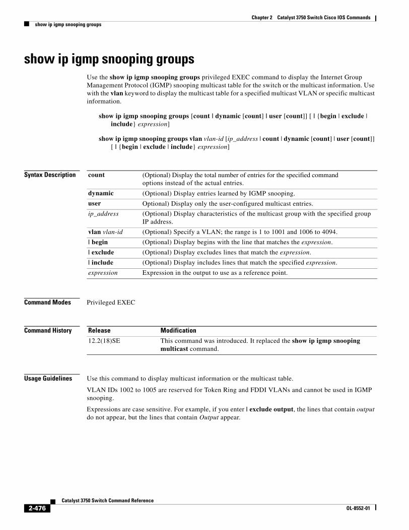
Chapter 2 Catalyst 3750 Switch Cisco IOS Commandsshow ip igmp snooping groups
show ip igmp snooping groupsUse the show ip igmp snooping groups privileged EXEC command to display the Internet Group Management Protocol (IGMP) snooping multicast table for the switch or the multicast information. Use with the vlan keyword to display the multicast table for a specified multicast VLAN or specific multicast information.
show ip igmp snooping groups [count | dynamic [count] | user [count]] [ | {begin | exclude | include} expression]
show ip igmp snooping groups vlan vlan-id [ip_address | count | dynamic [count] | user [count]] [ | {begin | exclude | include} expression]
Syntax Description
Command Modes Privileged EXEC
Command History
Usage Guidelines Use this command to display multicast information or the multicast table.
VLAN IDs 1002 to 1005 are reserved for Token Ring and FDDI VLANs and cannot be used in IGMP snooping.
Expressions are case sensitive. For example, if you enter | exclude output, the lines that contain output do not appear, but the lines that contain Output appear.
count (Optional) Display the total number of entries for the specified commandoptions instead of the actual entries.
dynamic (Optional) Display entries learned by IGMP snooping.
user Optional) Display only the user-configured multicast entries.
ip_address (Optional) Display characteristics of the multicast group with the specified group IP address.
vlan vlan-id (Optional) Specify a VLAN; the range is 1 to 1001 and 1006 to 4094.
| begin (Optional) Display begins with the line that matches the expression.
| exclude (Optional) Display excludes lines that match the expression.
| include (Optional) Display includes lines that match the specified expression.
expression Expression in the output to use as a reference point.
Release Modification
12.2(18)SE This command was introduced. It replaced the show ip igmp snooping multicast command.
2-476Catalyst 3750 Switch Command Reference
OL-8552-01
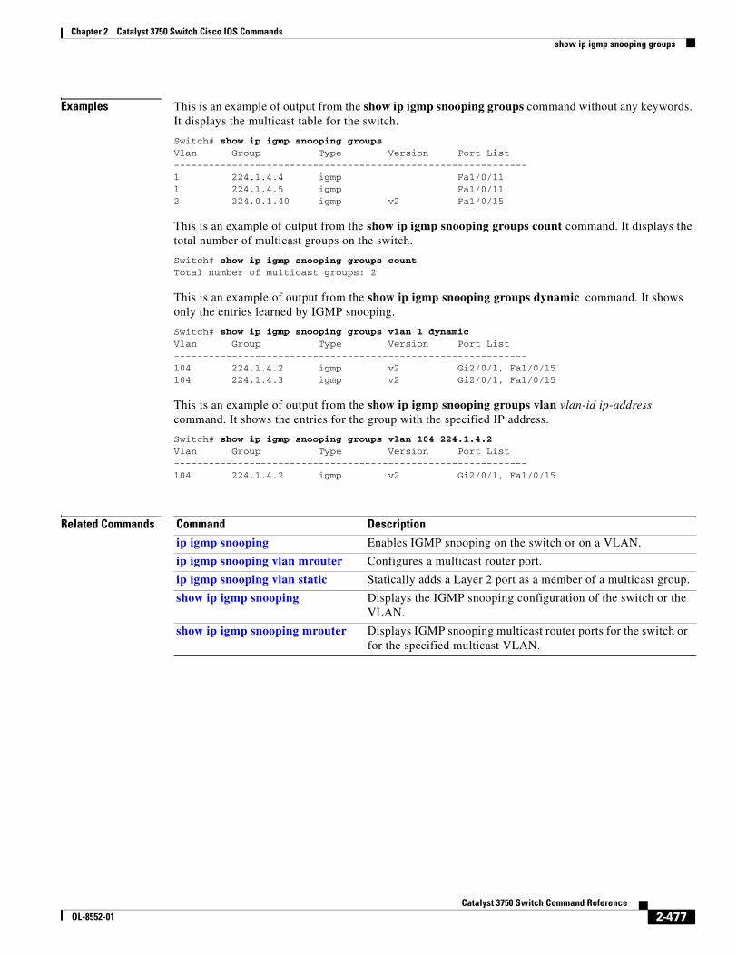
Chapter 2 Catalyst 3750 Switch Cisco IOS Commandsshow ip igmp snooping groups
Examples This is an example of output from the show ip igmp snooping groups command without any keywords. It displays the multicast table for the switch.
Switch# show ip igmp snooping groupsVlan Group Type Version Port List-------------------------------------------------------------1 224.1.4.4 igmp Fa1/0/111 224.1.4.5 igmp Fa1/0/112 224.0.1.40 igmp v2 Fa1/0/15
This is an example of output from the show ip igmp snooping groups count command. It displays the total number of multicast groups on the switch.
Switch# show ip igmp snooping groups countTotal number of multicast groups: 2
This is an example of output from the show ip igmp snooping groups dynamic command. It shows only the entries learned by IGMP snooping.
Switch# show ip igmp snooping groups vlan 1 dynamicVlan Group Type Version Port List-------------------------------------------------------------104 224.1.4.2 igmp v2 Gi2/0/1, Fa1/0/15104 224.1.4.3 igmp v2 Gi2/0/1, Fa1/0/15
This is an example of output from the show ip igmp snooping groups vlan vlan-id ip-address command. It shows the entries for the group with the specified IP address.
Switch# show ip igmp snooping groups vlan 104 224.1.4.2Vlan Group Type Version Port List-------------------------------------------------------------104 224.1.4.2 igmp v2 Gi2/0/1, Fa1/0/15
Related Commands Command Description
ip igmp snooping Enables IGMP snooping on the switch or on a VLAN.
ip igmp snooping vlan mrouter Configures a multicast router port.
ip igmp snooping vlan static Statically adds a Layer 2 port as a member of a multicast group.
show ip igmp snooping Displays the IGMP snooping configuration of the switch or the VLAN.
show ip igmp snooping mrouter Displays IGMP snooping multicast router ports for the switch or for the specified multicast VLAN.
2-477Catalyst 3750 Switch Command Reference
OL-8552-01
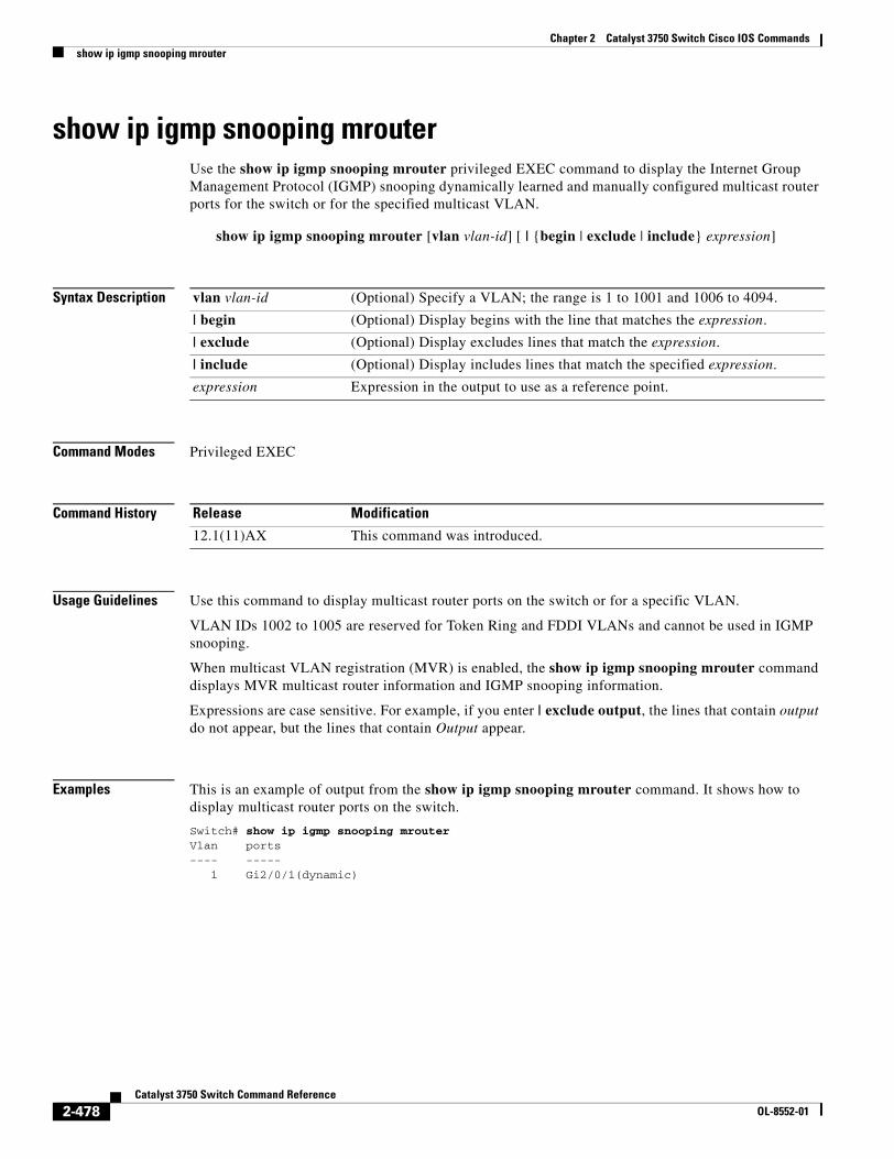
Chapter 2 Catalyst 3750 Switch Cisco IOS Commandsshow ip igmp snooping mrouter
show ip igmp snooping mrouterUse the show ip igmp snooping mrouter privileged EXEC command to display the Internet Group Management Protocol (IGMP) snooping dynamically learned and manually configured multicast router ports for the switch or for the specified multicast VLAN.
show ip igmp snooping mrouter [vlan vlan-id] [ | {begin | exclude | include} expression]
Syntax Description
Command Modes Privileged EXEC
Command History
Usage Guidelines Use this command to display multicast router ports on the switch or for a specific VLAN.
VLAN IDs 1002 to 1005 are reserved for Token Ring and FDDI VLANs and cannot be used in IGMP snooping.
When multicast VLAN registration (MVR) is enabled, the show ip igmp snooping mrouter command displays MVR multicast router information and IGMP snooping information.
Expressions are case sensitive. For example, if you enter | exclude output, the lines that contain output do not appear, but the lines that contain Output appear.
Examples This is an example of output from the show ip igmp snooping mrouter command. It shows how to display multicast router ports on the switch.
Switch# show ip igmp snooping mrouterVlan ports---- ----- 1 Gi2/0/1(dynamic)
vlan vlan-id (Optional) Specify a VLAN; the range is 1 to 1001 and 1006 to 4094.
| begin (Optional) Display begins with the line that matches the expression.
| exclude (Optional) Display excludes lines that match the expression.
| include (Optional) Display includes lines that match the specified expression.
expression Expression in the output to use as a reference point.
Release Modification
12.1(11)AX This command was introduced.
2-478Catalyst 3750 Switch Command Reference
OL-8552-01
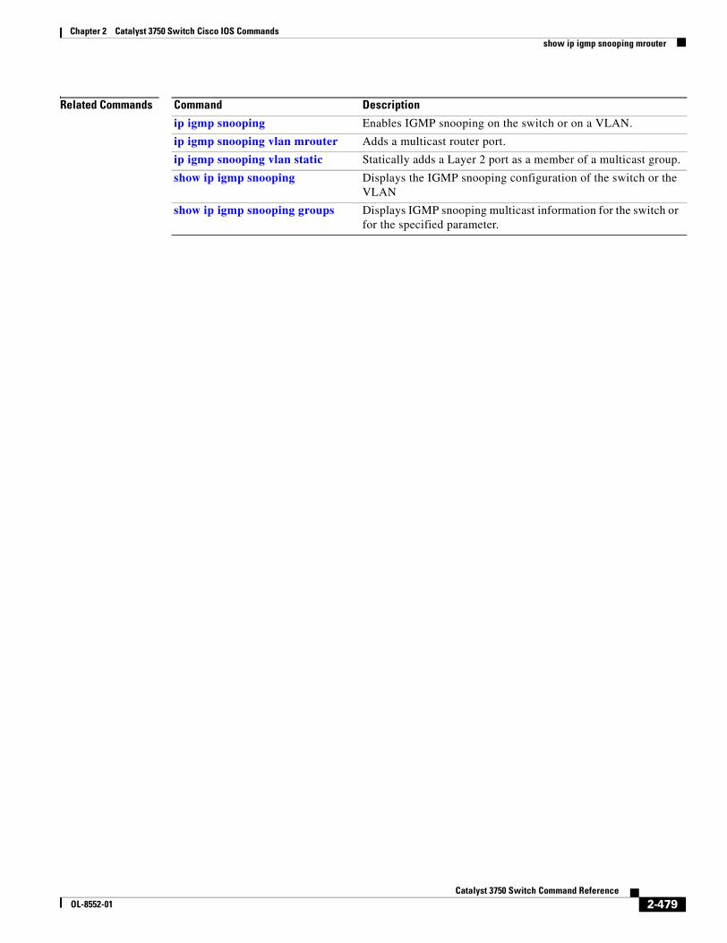
Chapter 2 Catalyst 3750 Switch Cisco IOS Commandsshow ip igmp snooping mrouter
Related Commands Command Description
ip igmp snooping Enables IGMP snooping on the switch or on a VLAN.
ip igmp snooping vlan mrouter Adds a multicast router port.
ip igmp snooping vlan static Statically adds a Layer 2 port as a member of a multicast group.
show ip igmp snooping Displays the IGMP snooping configuration of the switch or the VLAN
show ip igmp snooping groups Displays IGMP snooping multicast information for the switch or for the specified parameter.
2-479Catalyst 3750 Switch Command Reference
OL-8552-01
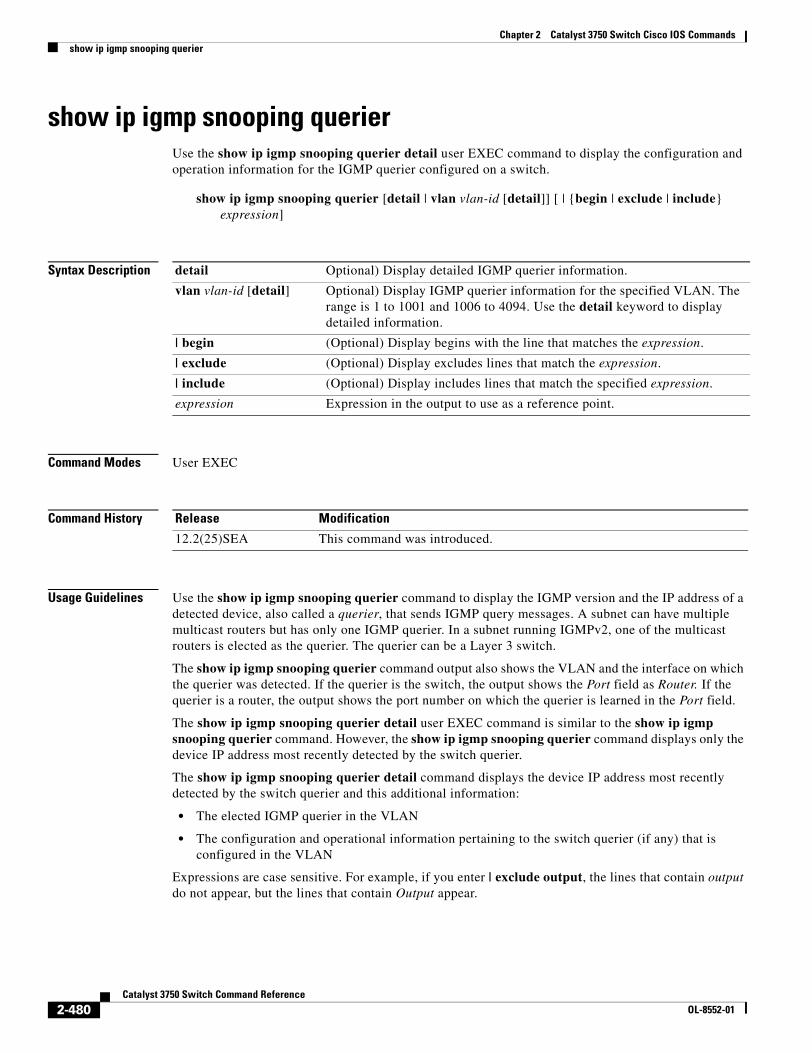
Chapter 2 Catalyst 3750 Switch Cisco IOS Commandsshow ip igmp snooping querier
show ip igmp snooping querierUse the show ip igmp snooping querier detail user EXEC command to display the configuration and operation information for the IGMP querier configured on a switch.
show ip igmp snooping querier [detail | vlan vlan-id [detail]] [ | {begin | exclude | include} expression]
Syntax Description
Command Modes User EXEC
Command History
Usage Guidelines Use the show ip igmp snooping querier command to display the IGMP version and the IP address of a detected device, also called a querier, that sends IGMP query messages. A subnet can have multiple multicast routers but has only one IGMP querier. In a subnet running IGMPv2, one of the multicast routers is elected as the querier. The querier can be a Layer 3 switch.
The show ip igmp snooping querier command output also shows the VLAN and the interface on which the querier was detected. If the querier is the switch, the output shows the Port field as Router. If the querier is a router, the output shows the port number on which the querier is learned in the Port field.
The show ip igmp snooping querier detail user EXEC command is similar to the show ip igmp snooping querier command. However, the show ip igmp snooping querier command displays only the device IP address most recently detected by the switch querier.
The show ip igmp snooping querier detail command displays the device IP address most recently detected by the switch querier and this additional information:
• The elected IGMP querier in the VLAN
• The configuration and operational information pertaining to the switch querier (if any) that is configured in the VLAN
Expressions are case sensitive. For example, if you enter | exclude output, the lines that contain output do not appear, but the lines that contain Output appear.
detail Optional) Display detailed IGMP querier information.
vlan vlan-id [detail] Optional) Display IGMP querier information for the specified VLAN. The range is 1 to 1001 and 1006 to 4094. Use the detail keyword to display detailed information.
| begin (Optional) Display begins with the line that matches the expression.
| exclude (Optional) Display excludes lines that match the expression.
| include (Optional) Display includes lines that match the specified expression.
expression Expression in the output to use as a reference point.
Release Modification
12.2(25)SEA This command was introduced.
2-480Catalyst 3750 Switch Command Reference
OL-8552-01
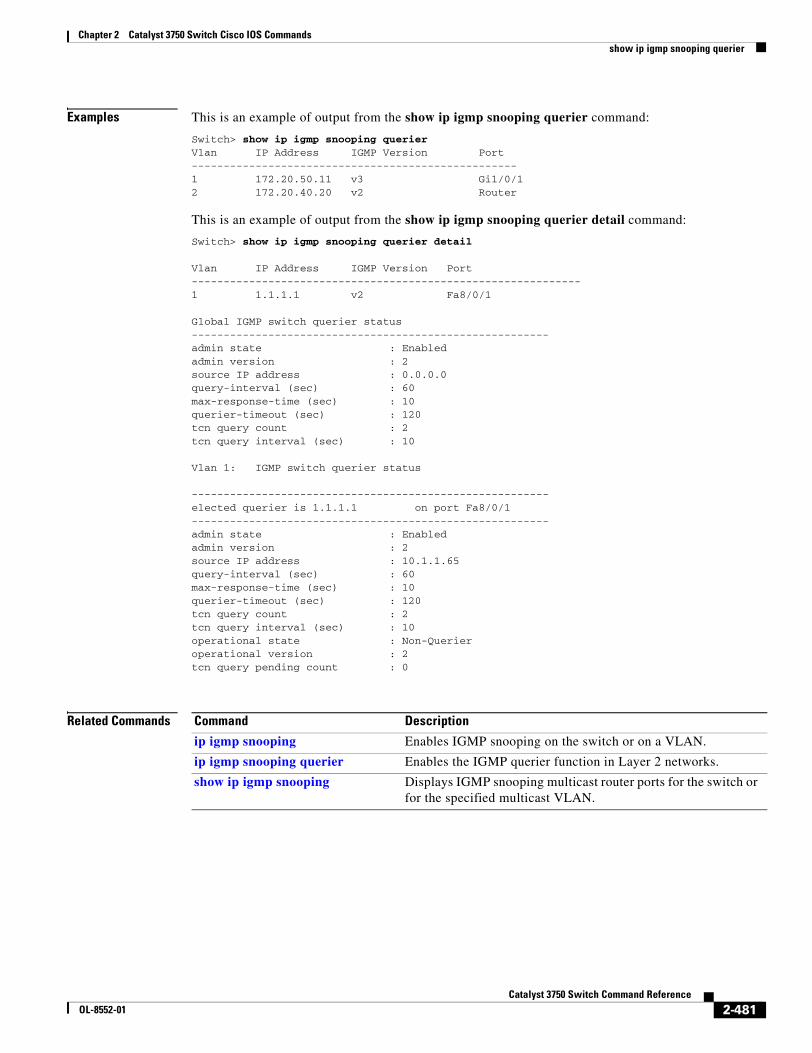
Chapter 2 Catalyst 3750 Switch Cisco IOS Commandsshow ip igmp snooping querier
Examples This is an example of output from the show ip igmp snooping querier command:
Switch> show ip igmp snooping querierVlan IP Address IGMP Version Port---------------------------------------------------1 172.20.50.11 v3 Gi1/0/12 172.20.40.20 v2 Router
This is an example of output from the show ip igmp snooping querier detail command:
Switch> show ip igmp snooping querier detail
Vlan IP Address IGMP Version Port-------------------------------------------------------------1 1.1.1.1 v2 Fa8/0/1
Global IGMP switch querier status--------------------------------------------------------admin state : Enabledadmin version : 2source IP address : 0.0.0.0 query-interval (sec) : 60max-response-time (sec) : 10querier-timeout (sec) : 120tcn query count : 2tcn query interval (sec) : 10
Vlan 1: IGMP switch querier status
--------------------------------------------------------elected querier is 1.1.1.1 on port Fa8/0/1--------------------------------------------------------admin state : Enabledadmin version : 2source IP address : 10.1.1.65 query-interval (sec) : 60max-response-time (sec) : 10querier-timeout (sec) : 120tcn query count : 2tcn query interval (sec) : 10operational state : Non-Querieroperational version : 2tcn query pending count : 0
Related Commands Command Description
ip igmp snooping Enables IGMP snooping on the switch or on a VLAN.
ip igmp snooping querier Enables the IGMP querier function in Layer 2 networks.
show ip igmp snooping Displays IGMP snooping multicast router ports for the switch or for the specified multicast VLAN.
2-481Catalyst 3750 Switch Command Reference
OL-8552-01
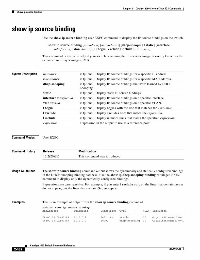
Chapter 2 Catalyst 3750 Switch Cisco IOS Commandsshow ip source binding
show ip source bindingUse the show ip source binding user EXEC command to display the IP source bindings on the switch.
show ip source binding [ip-address] [mac-address] [dhcp-snooping | static] [interface interface-id] [vlan vlan-id] [ | {begin | exclude | include} expression]
This command is available only if your switch is running the IP services image, formerly known as the enhanced multilayer image (EMI).
Syntax Description
Command Modes User EXEC
Command History
Usage Guidelines The show ip source binding command output shows the dynamically and statically configured bindings in the DHCP snooping binding database. Use the show ip dhcp snooping binding privileged EXEC command to display only the dynamically configured bindings.
Expressions are case sensitive. For example, if you enter | exclude output, the lines that contain output do not appear, but the lines that contain Output appear.
Examples This is an example of output from the show ip source binding command:
Switch> show ip source bindingMacAddress IpAddress Lease(sec) Type VLAN Interface-------------- --------------- ---------- ------------- ---- --------------------00:00:00:0A:00:0B 11.0.0.1 infinite static 10 GigabitEthernet1/0/100:00:00:0A:00:0A 11.0.0.2 10000 dhcp-snooping 10 GigabitEthernet1/0/1
ip-address (Optional) Display IP source bindings for a specific IP address.
mac-address (Optional) Display IP source bindings for a specific MAC address.
dhcp-snooping (Optional) Display IP source bindings that were learned by DHCP snooping.
static (Optional) Display static IP source bindings.
interface interface-id (Optional) Display IP source bindings on a specific interface.
vlan vlan-id (Optional) Display IP source bindings on a specific VLAN.
| begin (Optional) Display begins with the line that matches the expression.
| exclude (Optional) Display excludes lines that match the expression.
| include (Optional) Display includes lines that match the specified expression.
expression Expression in the output to use as a reference point.
Release Modification
12.2(20)SE This command was introduced.
2-482Catalyst 3750 Switch Command Reference
OL-8552-01

Chapter 2 Catalyst 3750 Switch Cisco IOS Commandsshow ip source binding
Related Commands Command Description
ip dhcp snooping binding Configures the DHCP snooping binding database.
ip source binding Configures static IP source bindings on the switch.
2-483Catalyst 3750 Switch Command Reference
OL-8552-01
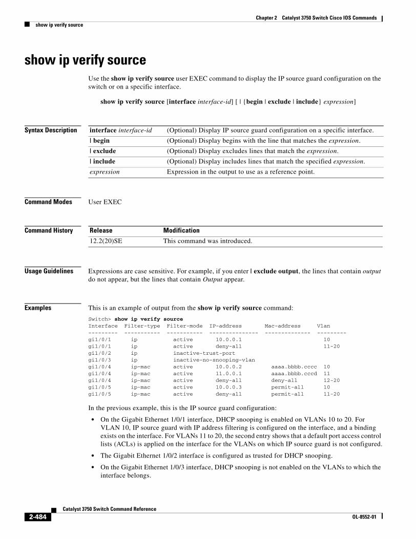
Chapter 2 Catalyst 3750 Switch Cisco IOS Commandsshow ip verify source
show ip verify sourceUse the show ip verify source user EXEC command to display the IP source guard configuration on the switch or on a specific interface.
show ip verify source [interface interface-id] [ | {begin | exclude | include} expression]
Syntax Description
Command Modes User EXEC
Command History
Usage Guidelines Expressions are case sensitive. For example, if you enter | exclude output, the lines that contain output do not appear, but the lines that contain Output appear.
Examples This is an example of output from the show ip verify source command:
Switch> show ip verify sourceInterface Filter-type Filter-mode IP-address Mac-address Vlan--------- ----------- ----------- --------------- -------------- ---------gi1/0/1 ip active 10.0.0.1 10gi1/0/1 ip active deny-all 11-20gi1/0/2 ip inactive-trust-portgi1/0/3 ip inactive-no-snooping-vlangi1/0/4 ip-mac active 10.0.0.2 aaaa.bbbb.cccc 10gi1/0/4 ip-mac active 11.0.0.1 aaaa.bbbb.cccd 11gi1/0/4 ip-mac active deny-all deny-all 12-20gi1/0/5 ip-mac active 10.0.0.3 permit-all 10gi1/0/5 ip-mac active deny-all permit-all 11-20
In the previous example, this is the IP source guard configuration:
• On the Gigabit Ethernet 1/0/1 interface, DHCP snooping is enabled on VLANs 10 to 20. For VLAN 10, IP source guard with IP address filtering is configured on the interface, and a binding exists on the interface. For VLANs 11 to 20, the second entry shows that a default port access control lists (ACLs) is applied on the interface for the VLANs on which IP source guard is not configured.
• The Gigabit Ethernet 1/0/2 interface is configured as trusted for DHCP snooping.
• On the Gigabit Ethernet 1/0/3 interface, DHCP snooping is not enabled on the VLANs to which the interface belongs.
interface interface-id (Optional) Display IP source guard configuration on a specific interface.
| begin (Optional) Display begins with the line that matches the expression.
| exclude (Optional) Display excludes lines that match the expression.
| include (Optional) Display includes lines that match the specified expression.
expression Expression in the output to use as a reference point.
Release Modification
12.2(20)SE This command was introduced.
2-484Catalyst 3750 Switch Command Reference
OL-8552-01
Chapter 2 Catalyst 3750 Switch Cisco IOS Commandsshow ip verify source
• On the Gigabit Ethernet 1/0/4 interface, IP source guard with source IP and MAC address filtering is enabled, and static IP source bindings are configured on VLANs 10 and 11. For VLANs 12 to 20, the default port ACL is applied on the interface for the VLANs on which IP source guard is not configured.
• On the Gigabit Ethernet 1/0/5 interface, IP source guard with source IP and MAC address filtering is enabled and configured with a static IP binding, but port security is disabled. The switch cannot filter source MAC addresses.
This is an example of output on an interface on which IP source guard is disabled:
Switch> show ip verify source gigabitethernet1/0/6IP source guard is not configured on the interface gi1/0/6.
Related Commands Command Description
ip verify source Enables IP source guard on an interface.
2-485Catalyst 3750 Switch Command Reference
OL-8552-01
Chapter 2 Catalyst 3750 Switch Cisco IOS Commandsshow ipc
show ipcUse the show ipc user EXEC command to display Interprocess Communications Protocol (IPC) configuration, status, and statistics on a switch stack or a standalone switch.
show ipc {mcast {appclass | groups | status} | nodes | ports [open] | queue | rpc | session {all | rx | tx} [verbose] | status [cumlulative] | zones} [ | {begin | exclude | include} expression]
Syntax Description
Command Modes User EXEC
Command History
mcast {appclass | groups | status}
Display the IPC multicast routing information. The keywords have these meanings:
• appclass—Display the IPC multicast application classes.
• groups—Display the IPC multicast groups.
• status—Display the IPC multicast routing status.
nodes Display participating nodes.
ports [open] Display local IPC ports. The keyword has this meaning:
• open—(Optional) Display only the open ports.
queue Display the contents of the IPC transmission queue.
rpc Display the IPC remote-procedure statistics.
session {all | rx | tx} Display the IPC session statistics (available only in privileged EXEC mode). The keywords have these meanings:
• all—Display all the session statistics.
• rx—Display the sessions statistics for traffic that the switch receives
• tx—Display the sessions statistics for traffic that the switch forwards.
verbose (Optional) Display detailed statistics (available only in privileged EXEC mode).
status [cumlulative] Display the status of the local IPC server. The keyword has this meaning:
• cumlulative—(Optional) Display the status of the local IPC server since the switch was started or restarted.
zones Display the participating IPC zones. The switch supports a single IPC zone.
| begin (Optional) Display begins with the line that matches the expression.
| exclude (Optional) Display excludes lines that match the expression.
| include (Optional) Display includes lines that match the specified expression.
expression Expression in the output to use as a reference point.
Release Modification
12.1(11)AX This command was introduced.
12.2(18)SE The mcast {appclass | groups | status}, rpc, session {all | rx | tx} [verbose], and cumulative keywords were added.
2-486Catalyst 3750 Switch Command Reference
OL-8552-01
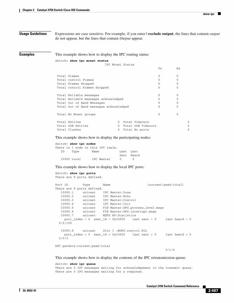
Chapter 2 Catalyst 3750 Switch Cisco IOS Commandsshow ipc
Usage Guidelines Expressions are case sensitive. For example, if you enter | exclude output, the lines that contain output do not appear, but the lines that contain Output appear.
Examples This example shows how to display the IPC routing status:
Switch> show ipc mcast status IPC Mcast Status Tx Rx
Total Frames 0 0 Total control Frames 0 0 Total Frames dropped 0 0 Total control Frames dropped 0 0
Total Reliable messages 0 0 Total Reliable messages acknowledged 0 0 Total Out of Band Messages 0 0 Total Out of Band messages acknowledged 0 0
Total No Mcast groups 0 0
Total Retries 0 Total Timeouts 0 Total OOB Retries 0 Total OOB Timeouts 0 Total flushes 0 Total No ports 0
This example shows how to display the participating nodes:
Switch> show ipc nodesThere is 1 node in this IPC realm. ID Type Name Last Last Sent Heard 10000 Local IPC Master 0 0
This example shows how to display the local IPC ports:
Switch> show ipc portsThere are 8 ports defined.
Port ID Type Name (current/peak/total)There are 8 ports defined. 10000.1 unicast IPC Master:Zone 10000.2 unicast IPC Master:Echo 10000.3 unicast IPC Master:Control 10000.4 unicast IPC Master:Init 10000.5 unicast FIB Master:DFS.process_level.msgs 10000.6 unicast FIB Master:DFS.interrupt.msgs 10000.7 unicast MDFS RP:Statistics port_index = 0 seat_id = 0x10000 last sent = 0 last heard = 0 0/2/159
10000.8 unicast Slot 1 :MDFS.control.RIL port_index = 0 seat_id = 0x10000 last sent = 0 last heard = 0 0/0/0
RPC packets:current/peak/total 0/1/4
This example shows how to display the contents of the IPC retransmission queue:
Switch> show ipc queueThere are 0 IPC messages waiting for acknowledgement in the transmit queue.There are 0 IPC messages waiting for a response.
2-487Catalyst 3750 Switch Command Reference
OL-8552-01
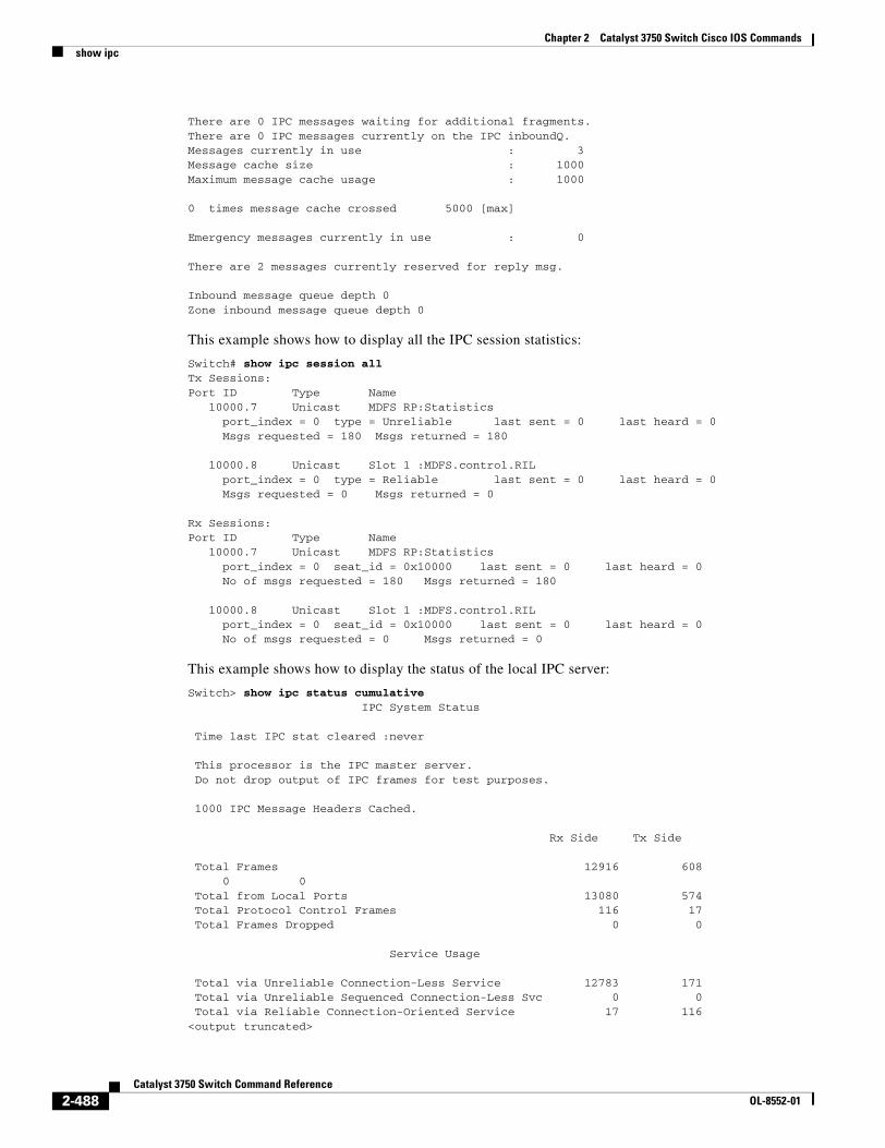
Chapter 2 Catalyst 3750 Switch Cisco IOS Commandsshow ipc
There are 0 IPC messages waiting for additional fragments.There are 0 IPC messages currently on the IPC inboundQ.Messages currently in use : 3Message cache size : 1000Maximum message cache usage : 1000
0 times message cache crossed 5000 [max]
Emergency messages currently in use : 0
There are 2 messages currently reserved for reply msg.
Inbound message queue depth 0Zone inbound message queue depth 0
This example shows how to display all the IPC session statistics:
Switch# show ipc session allTx Sessions:Port ID Type Name 10000.7 Unicast MDFS RP:Statistics port_index = 0 type = Unreliable last sent = 0 last heard = 0 Msgs requested = 180 Msgs returned = 180
10000.8 Unicast Slot 1 :MDFS.control.RIL port_index = 0 type = Reliable last sent = 0 last heard = 0 Msgs requested = 0 Msgs returned = 0
Rx Sessions:Port ID Type Name 10000.7 Unicast MDFS RP:Statistics port_index = 0 seat_id = 0x10000 last sent = 0 last heard = 0 No of msgs requested = 180 Msgs returned = 180
10000.8 Unicast Slot 1 :MDFS.control.RIL port_index = 0 seat_id = 0x10000 last sent = 0 last heard = 0 No of msgs requested = 0 Msgs returned = 0
This example shows how to display the status of the local IPC server:
Switch> show ipc status cumulative IPC System Status
Time last IPC stat cleared :never
This processor is the IPC master server. Do not drop output of IPC frames for test purposes.
1000 IPC Message Headers Cached.
Rx Side Tx Side
Total Frames 12916 608 0 0 Total from Local Ports 13080 574 Total Protocol Control Frames 116 17 Total Frames Dropped 0 0
Service Usage
Total via Unreliable Connection-Less Service 12783 171 Total via Unreliable Sequenced Connection-Less Svc 0 0 Total via Reliable Connection-Oriented Service 17 116<output truncated>
2-488Catalyst 3750 Switch Command Reference
OL-8552-01

Chapter 2 Catalyst 3750 Switch Cisco IOS Commandsshow ipc
Related Commands Command Description
clear ipc Clears the IPC multicast routing statistics.
2-489Catalyst 3750 Switch Command Reference
OL-8552-01
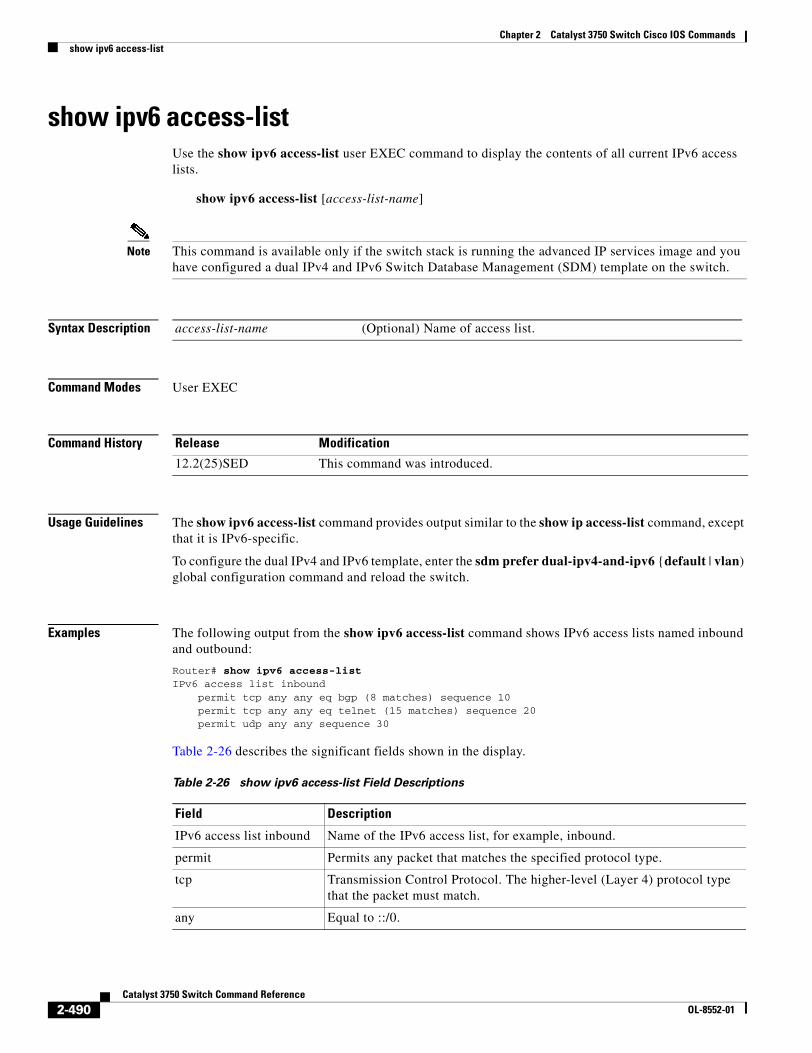
Chapter 2 Catalyst 3750 Switch Cisco IOS Commandsshow ipv6 access-list
show ipv6 access-listUse the show ipv6 access-list user EXEC command to display the contents of all current IPv6 access lists.
show ipv6 access-list [access-list-name]
Note This command is available only if the switch stack is running the advanced IP services image and you have configured a dual IPv4 and IPv6 Switch Database Management (SDM) template on the switch.
Syntax Description
Command Modes User EXEC
Command History
Usage Guidelines The show ipv6 access-list command provides output similar to the show ip access-list command, except that it is IPv6-specific.
To configure the dual IPv4 and IPv6 template, enter the sdm prefer dual-ipv4-and-ipv6 {default | vlan) global configuration command and reload the switch.
Examples The following output from the show ipv6 access-list command shows IPv6 access lists named inbound and outbound:
Router# show ipv6 access-listIPv6 access list inbound permit tcp any any eq bgp (8 matches) sequence 10 permit tcp any any eq telnet (15 matches) sequence 20 permit udp any any sequence 30
Table 2-26 describes the significant fields shown in the display.
access-list-name (Optional) Name of access list.
Release Modification
12.2(25)SED This command was introduced.
Table 2-26 show ipv6 access-list Field Descriptions
Field Description
IPv6 access list inbound Name of the IPv6 access list, for example, inbound.
permit Permits any packet that matches the specified protocol type.
tcp Transmission Control Protocol. The higher-level (Layer 4) protocol type that the packet must match.
any Equal to ::/0.
2-490Catalyst 3750 Switch Command Reference
OL-8552-01
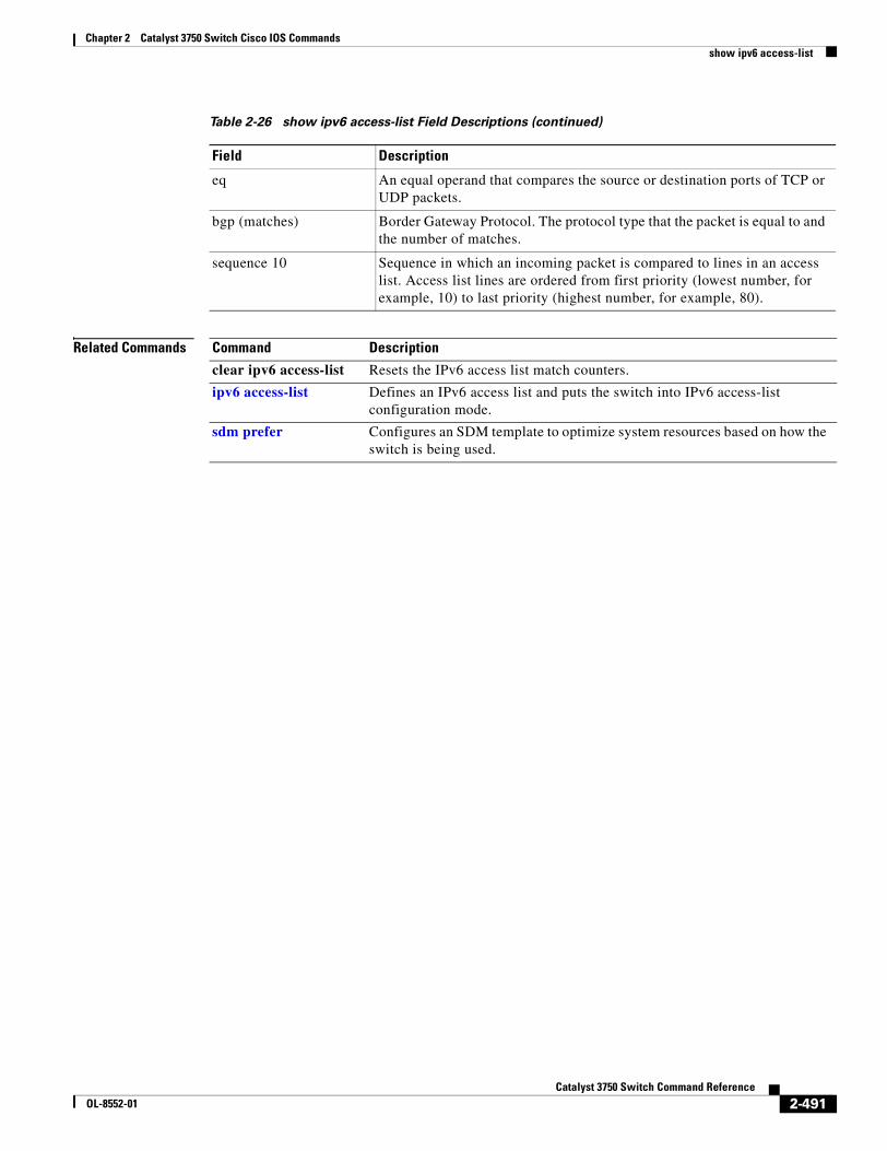
Chapter 2 Catalyst 3750 Switch Cisco IOS Commandsshow ipv6 access-list
Related Commands
eq An equal operand that compares the source or destination ports of TCP or UDP packets.
bgp (matches) Border Gateway Protocol. The protocol type that the packet is equal to and the number of matches.
sequence 10 Sequence in which an incoming packet is compared to lines in an access list. Access list lines are ordered from first priority (lowest number, for example, 10) to last priority (highest number, for example, 80).
Table 2-26 show ipv6 access-list Field Descriptions (continued)
Field Description
Command Description
clear ipv6 access-list Resets the IPv6 access list match counters.
ipv6 access-list Defines an IPv6 access list and puts the switch into IPv6 access-list configuration mode.
sdm prefer Configures an SDM template to optimize system resources based on how the switch is being used.
2-491Catalyst 3750 Switch Command Reference
OL-8552-01
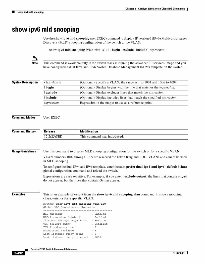
Chapter 2 Catalyst 3750 Switch Cisco IOS Commandsshow ipv6 mld snooping
show ipv6 mld snoopingUse the show ipv6 mld snooping user EXEC command to display IP version 6 (IPv6) Multicast Listener Discovery (MLD) snooping configuration of the switch or the VLAN.
show ipv6 mld snooping [vlan vlan-id] [ | {begin | exclude | include} expression]
Note This command is available only if the switch stack is running the advanced IP services image and you have configured a dual IPv4 and IPv6 Switch Database Management (SDM) template on the switch.
Syntax Description
Command Modes User EXEC
Command History
Usage Guidelines Use this command to display MLD snooping configuration for the switch or for a specific VLAN.
VLAN numbers 1002 through 1005 are reserved for Token Ring and FDDI VLANs and cannot be used in MLD snooping.
To configure the dual IPv4 and IPv6 template, enter the sdm prefer dual-ipv4-and-ipv6 {default | vlan) global configuration command and reload the switch.
Expressions are case sensitive. For example, if you enter | exclude output, the lines that contain output do not appear, but the lines that contain Output appear.
Examples This is an example of output from the show ipv6 mld snooping vlan command. It shows snooping characteristics for a specific VLAN.
Switch> show ipv6 mld snooping vlan 100Global MLD Snooping configuration:-------------------------------------------MLD snooping : EnabledMLDv2 snooping (minimal) : EnabledListener message suppression : EnabledTCN solicit query : DisabledTCN flood query count : 2Robustness variable : 3Last listener query count : 2Last listener query interval : 1000
vlan vlan-id (Optional) Specify a VLAN; the range is 1 to 1001 and 1006 to 4094.
| begin (Optional) Display begins with the line that matches the expression.
| exclude (Optional) Display excludes lines that match the expression.
| include (Optional) Display includes lines that match the specified expression.
expression Expression in the output to use as a reference point.
Release Modification
12.2(25)SED This command was introduced.
2-492Catalyst 3750 Switch Command Reference
OL-8552-01
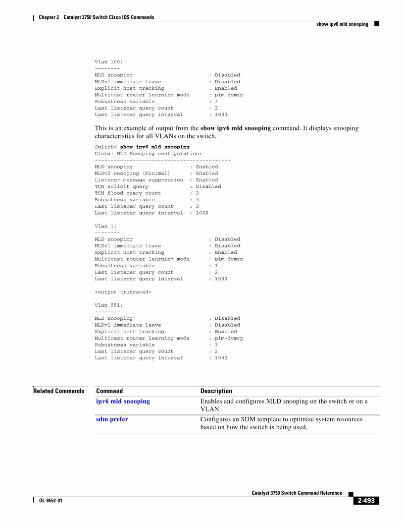
Chapter 2 Catalyst 3750 Switch Cisco IOS Commandsshow ipv6 mld snooping
Vlan 100:--------MLD snooping : DisabledMLDv1 immediate leave : DisabledExplicit host tracking : EnabledMulticast router learning mode : pim-dvmrpRobustness variable : 3Last listener query count : 2Last listener query interval : 1000
This is an example of output from the show ipv6 mld snooping command. It displays snooping characteristics for all VLANs on the switch.
Switch> show ipv6 mld snoopingGlobal MLD Snooping configuration:-------------------------------------------MLD snooping : EnabledMLDv2 snooping (minimal) : EnabledListener message suppression : EnabledTCN solicit query : DisabledTCN flood query count : 2Robustness variable : 3Last listener query count : 2Last listener query interval : 1000
Vlan 1:--------MLD snooping : DisabledMLDv1 immediate leave : DisabledExplicit host tracking : EnabledMulticast router learning mode : pim-dvmrpRobustness variable : 1Last listener query count : 2Last listener query interval : 1000
<output truncated>
Vlan 951:--------MLD snooping : DisabledMLDv1 immediate leave : DisabledExplicit host tracking : EnabledMulticast router learning mode : pim-dvmrpRobustness variable : 3Last listener query count : 2Last listener query interval : 1000
Related Commands Command Description
ipv6 mld snooping Enables and configures MLD snooping on the switch or on a VLAN.
sdm prefer Configures an SDM template to optimize system resources based on how the switch is being used.
2-493Catalyst 3750 Switch Command Reference
OL-8552-01
Chapter 2 Catalyst 3750 Switch Cisco IOS Commandsshow ipv6 mld snooping address
show ipv6 mld snooping addressUse the show ipv6 mld snooping address user EXEC command to display all or specified IP version 6 (IPv6) multicast address information maintained by Multicast Listener Discovery (MLD) snooping.
show ipv6 mld snooping address [[vlan vlan-id] [ipv6 address]] [vlan vlan-id] [count | dynamic | user] [ | {begin | exclude | include} expression]
Note This command is available only if the switch stack is running the advanced IP services image and you have configured a dual IPv4 and IPv6 Switch Database Management (SDM) template on the switch.
Syntax Description
Command Modes User EXEC
Command History
Usage Guidelines Use this command to display IPv6 multicast address information.
You can enter an IPv6 multicast address only after you enter a VLAN ID.
VLAN numbers 1002 through 1005 are reserved for Token Ring and FDDI VLANs and cannot be used in MLD snooping.
Use the dynamic keyword to display information only about groups that are learned. Use the user keyword to display information only about groups that have been configured.
To configure the dual IPv4 and IPv6 template, enter the sdm prefer dual-ipv4-and-ipv6 {default | vlan) global configuration command and reload the switch.
Expressions are case sensitive. For example, if you enter | exclude output, the lines that contain output do not appear, but the lines that contain Output appear.
vlan vlan-id (Optional) Specify a VLAN about which to show MLD snooping multicast address information. The VLAN ID range is 1 to 1001 and 1006 to 4094.
ipv6-multicast-address (Optional) Display information about the specified IPv6 multicast address. This keyword is only available when a VLAN ID is entered.
count (Optional) Display the number of multicast groups on the switch or in the specified VLAN.
dynamic (Optional) Display MLD snooping learned group information.
user (Optional) Display MLD snooping user-configured group information.
| begin (Optional) Display begins with the line that matches the expression.
| exclude (Optional) Display excludes lines that match the expression.
| include (Optional) Display includes lines that match the specified expression.
expression Expression in the output to use as a reference point.
Release Modification
12.2(25)SED This command was introduced.
2-494Catalyst 3750 Switch Command Reference
OL-8552-01
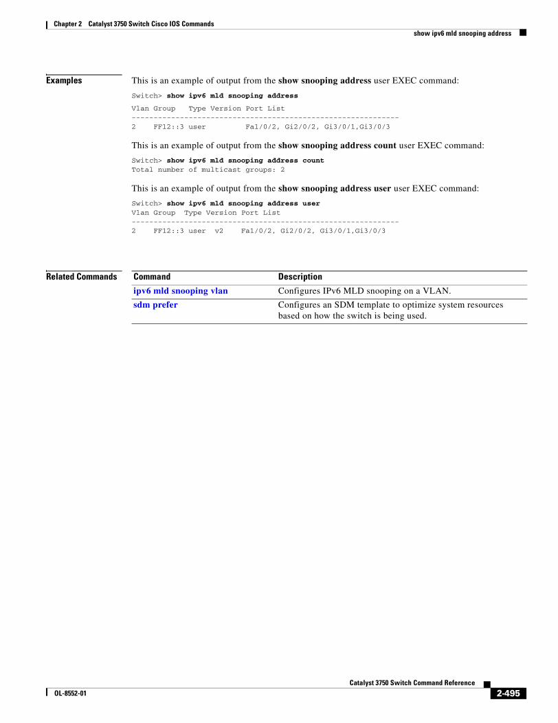
Chapter 2 Catalyst 3750 Switch Cisco IOS Commandsshow ipv6 mld snooping address
Examples This is an example of output from the show snooping address user EXEC command:
Switch> show ipv6 mld snooping address
Vlan Group Type Version Port List-------------------------------------------------------------2 FF12::3 user Fa1/0/2, Gi2/0/2, Gi3/0/1,Gi3/0/3
This is an example of output from the show snooping address count user EXEC command:
Switch> show ipv6 mld snooping address countTotal number of multicast groups: 2
This is an example of output from the show snooping address user user EXEC command:
Switch> show ipv6 mld snooping address userVlan Group Type Version Port List-------------------------------------------------------------2 FF12::3 user v2 Fa1/0/2, Gi2/0/2, Gi3/0/1,Gi3/0/3
Related Commands Command Description
ipv6 mld snooping vlan Configures IPv6 MLD snooping on a VLAN.
sdm prefer Configures an SDM template to optimize system resources based on how the switch is being used.
2-495Catalyst 3750 Switch Command Reference
OL-8552-01
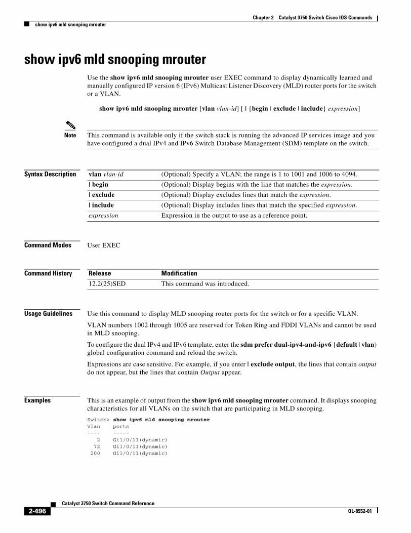
Chapter 2 Catalyst 3750 Switch Cisco IOS Commandsshow ipv6 mld snooping mrouter
show ipv6 mld snooping mrouterUse the show ipv6 mld snooping mrouter user EXEC command to display dynamically learned and manually configured IP version 6 (IPv6) Multicast Listener Discovery (MLD) router ports for the switch or a VLAN.
show ipv6 mld snooping mrouter [vlan vlan-id] [ | {begin | exclude | include} expression]
Note This command is available only if the switch stack is running the advanced IP services image and you have configured a dual IPv4 and IPv6 Switch Database Management (SDM) template on the switch.
Syntax Description
Command Modes User EXEC
Command History
Usage Guidelines Use this command to display MLD snooping router ports for the switch or for a specific VLAN.
VLAN numbers 1002 through 1005 are reserved for Token Ring and FDDI VLANs and cannot be used in MLD snooping.
To configure the dual IPv4 and IPv6 template, enter the sdm prefer dual-ipv4-and-ipv6 {default | vlan) global configuration command and reload the switch.
Expressions are case sensitive. For example, if you enter | exclude output, the lines that contain output do not appear, but the lines that contain Output appear.
Examples This is an example of output from the show ipv6 mld snooping mrouter command. It displays snooping characteristics for all VLANs on the switch that are participating in MLD snooping.
Switch> show ipv6 mld snooping mrouterVlan ports---- ----- 2 Gi1/0/11(dynamic) 72 Gi1/0/11(dynamic) 200 Gi1/0/11(dynamic)
vlan vlan-id (Optional) Specify a VLAN; the range is 1 to 1001 and 1006 to 4094.
| begin (Optional) Display begins with the line that matches the expression.
| exclude (Optional) Display excludes lines that match the expression.
| include (Optional) Display includes lines that match the specified expression.
expression Expression in the output to use as a reference point.
Release Modification
12.2(25)SED This command was introduced.
2-496Catalyst 3750 Switch Command Reference
OL-8552-01
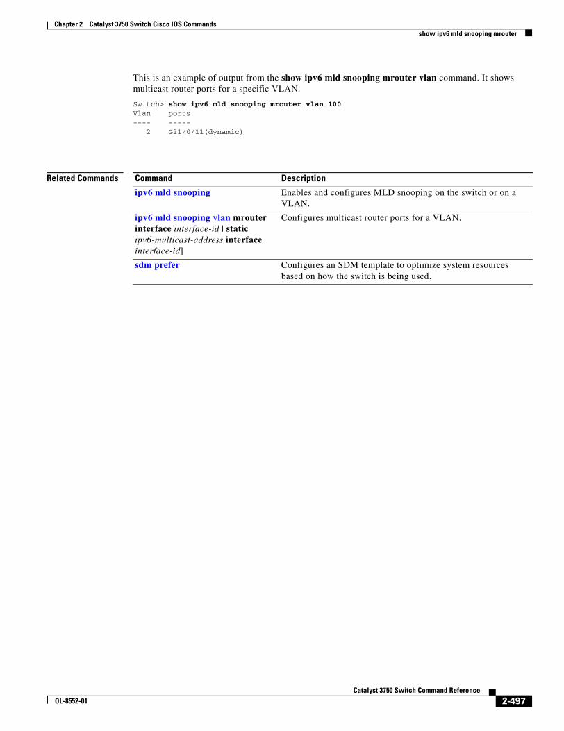
Chapter 2 Catalyst 3750 Switch Cisco IOS Commandsshow ipv6 mld snooping mrouter
This is an example of output from the show ipv6 mld snooping mrouter vlan command. It shows multicast router ports for a specific VLAN.
Switch> show ipv6 mld snooping mrouter vlan 100Vlan ports---- ----- 2 Gi1/0/11(dynamic)
Related Commands Command Description
ipv6 mld snooping Enables and configures MLD snooping on the switch or on a VLAN.
ipv6 mld snooping vlan mrouter interface interface-id | static ipv6-multicast-address interface interface-id]
Configures multicast router ports for a VLAN.
sdm prefer Configures an SDM template to optimize system resources based on how the switch is being used.
2-497Catalyst 3750 Switch Command Reference
OL-8552-01
Chapter 2 Catalyst 3750 Switch Cisco IOS Commandsshow ipv6 mld snooping querier
show ipv6 mld snooping querierUse the show ipv6 mld snooping querier user EXEC command to display IP version 6 (IPv6) Multicast Listener Discovery (MLD) snooping querier-related information most recently received by the switch or the VLAN.
show ipv6 mld snooping querier [vlan vlan-id] [detail] [ | {begin | exclude | include} expression]
Note This command is available only if the switch stack is running the advanced IP services image and you have configured a dual IPv4 and IPv6 Switch Database Management (SDM) template on the switch.
Syntax Description
Command Modes User EXEC
Command History
Usage Guidelines Use the show ipv6 mld snooping querier command to display the MLD version and IPv6 address of a detected device that sends MLD query messages, which is also called a querier. A subnet can have multiple multicast routers but has only one MLD querier. The querier can be a Layer 3 switch.
The show ipv6 mld snooping querier command output also shows the VLAN and interface on which the querier was detected. If the querier is the switch, the output shows the Port field as Router. If the querier is a router, the output shows the port number on which the querier is learned in the Port field.
The output of the show ipv6 mld snoop querier vlan command displays the information received in response to a query message from an external or internal querier. It does not display user-configured VLAN values, such as the snooping robustness variable on the particular VLAN. This querier information is used only on the MASQ message that is sent by the switch. It does not override the user-configured robustness variable that is used for aging out a member that does not respond to query messages.
VLAN numbers 1002 through 1005 are reserved for Token Ring and FDDI VLANs and cannot be used in MLD snooping.
To configure the dual IPv4 and IPv6 template, enter the sdm prefer dual-ipv4-and-ipv6 {default | vlan) global configuration command and reload the switch.
vlan vlan-id (Optional) Specify a VLAN; the range is 1 to 1001 and 1006 to 4094.
detail (Optional) Display MLD snooping detailed querier information for the switch or for the VLAN.
| begin (Optional) Display begins with the line that matches the expression.
| exclude (Optional) Display excludes lines that match the expression.
| include (Optional) Display includes lines that match the specified expression.
expression Expression in the output to use as a reference point.
Release Modification
12.2(25)SED This command was introduced.
2-498Catalyst 3750 Switch Command Reference
OL-8552-01
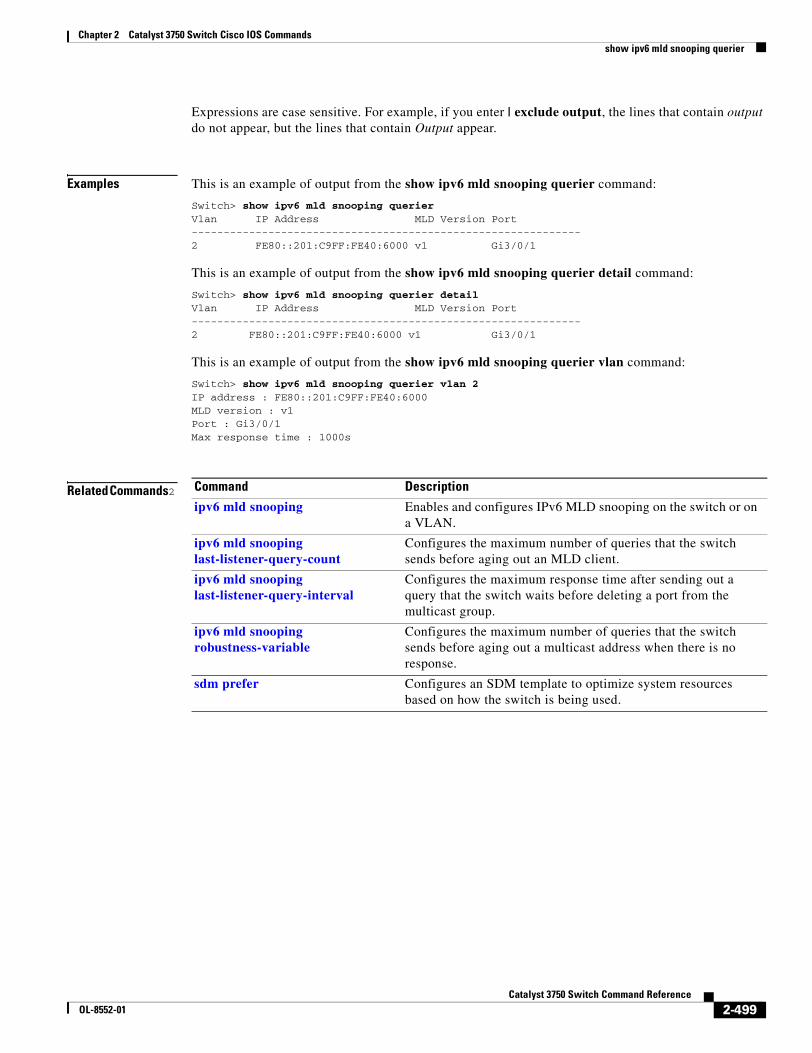
Chapter 2 Catalyst 3750 Switch Cisco IOS Commandsshow ipv6 mld snooping querier
Expressions are case sensitive. For example, if you enter | exclude output, the lines that contain output do not appear, but the lines that contain Output appear.
Examples This is an example of output from the show ipv6 mld snooping querier command:
Switch> show ipv6 mld snooping querierVlan IP Address MLD Version Port-------------------------------------------------------------2 FE80::201:C9FF:FE40:6000 v1 Gi3/0/1
This is an example of output from the show ipv6 mld snooping querier detail command:
Switch> show ipv6 mld snooping querier detailVlan IP Address MLD Version Port-------------------------------------------------------------2 FE80::201:C9FF:FE40:6000 v1 Gi3/0/1
This is an example of output from the show ipv6 mld snooping querier vlan command:
Switch> show ipv6 mld snooping querier vlan 2IP address : FE80::201:C9FF:FE40:6000 MLD version : v1Port : Gi3/0/1Max response time : 1000s
Related Commands2 Command Description
ipv6 mld snooping Enables and configures IPv6 MLD snooping on the switch or on a VLAN.
ipv6 mld snooping last-listener-query-count
Configures the maximum number of queries that the switch sends before aging out an MLD client.
ipv6 mld snooping last-listener-query-interval
Configures the maximum response time after sending out a query that the switch waits before deleting a port from the multicast group.
ipv6 mld snooping robustness-variable
Configures the maximum number of queries that the switch sends before aging out a multicast address when there is no response.
sdm prefer Configures an SDM template to optimize system resources based on how the switch is being used.
2-499Catalyst 3750 Switch Command Reference
OL-8552-01
Chapter 2 Catalyst 3750 Switch Cisco IOS Commandsshow l2protocol-tunnel
show l2protocol-tunnelUse the show l2protocol-tunnel user EXEC command to display information about Layer 2 protocol tunnel ports. Displays information for interfaces with protocol tunneling enabled.
show l2protocol-tunnel [interface interface-id] [summary] [ | {begin | exclude | include} expression]
Syntax Description
Command Modes User EXEC
Command History
Usage Guidelines After enabling Layer 2 protocol tunneling on an access or IEEE 802.1Q tunnel port by using the l2protocol-tunnel interface configuration command, you can configure some or all of these parameters:
• Protocol type to be tunneled
• Shutdown threshold
• Drop threshold
If you enter the show l2protocol-tunnel [interface interface-id] command, only information about the active ports on which all the parameters are configured appears.
If you enter the show l2protocol-tunnel summary command, only information about the active ports on which some or all of the parameters are configured appears.
Expressions are case sensitive. For example, if you enter | exclude output, the lines that contain output do not appear, but the lines that contain Output appear.
interface interface-id (Optional) Specify the interface for which protocol tunneling information appears. Valid interfaces are physical ports and port channels; the port channel range is 1 to 48.
summary (Optional) Display only Layer 2 protocol summary information.
| begin (Optional) Display begins with the line that matches the expression.
| exclude (Optional) Display excludes lines that match the expression.
| include (Optional) Display includes lines that match the specified expression.
expression Expression in the output to use as a reference point.
Release Modification
12.2(25)SE This command was introduced.
2-500Catalyst 3750 Switch Command Reference
OL-8552-01
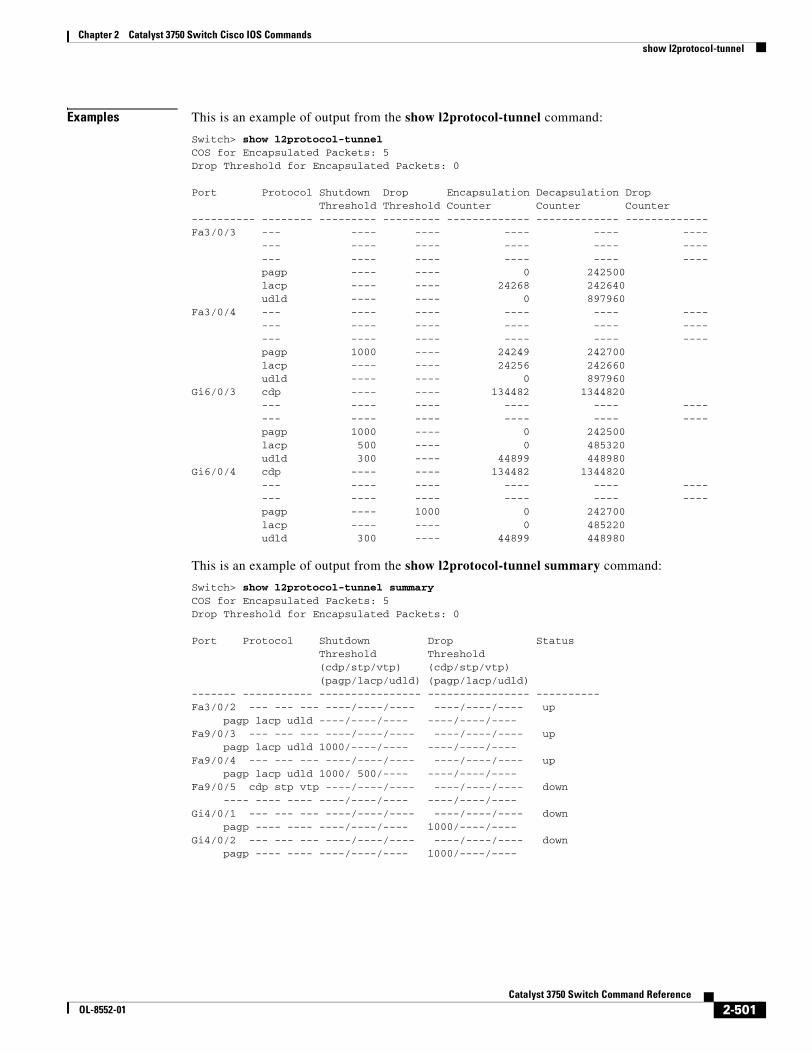
Chapter 2 Catalyst 3750 Switch Cisco IOS Commandsshow l2protocol-tunnel
Examples This is an example of output from the show l2protocol-tunnel command:
Switch> show l2protocol-tunnelCOS for Encapsulated Packets: 5Drop Threshold for Encapsulated Packets: 0
Port Protocol Shutdown Drop Encapsulation Decapsulation Drop Threshold Threshold Counter Counter Counter---------- -------- --------- --------- ------------- ------------- -------------Fa3/0/3 --- ---- ---- ---- ---- ---- --- ---- ---- ---- ---- ---- --- ---- ---- ---- ---- ---- pagp ---- ---- 0 242500 lacp ---- ---- 24268 242640 udld ---- ---- 0 897960Fa3/0/4 --- ---- ---- ---- ---- ---- --- ---- ---- ---- ---- ---- --- ---- ---- ---- ---- ---- pagp 1000 ---- 24249 242700 lacp ---- ---- 24256 242660 udld ---- ---- 0 897960Gi6/0/3 cdp ---- ---- 134482 1344820 --- ---- ---- ---- ---- ---- --- ---- ---- ---- ---- ---- pagp 1000 ---- 0 242500 lacp 500 ---- 0 485320 udld 300 ---- 44899 448980Gi6/0/4 cdp ---- ---- 134482 1344820 --- ---- ---- ---- ---- ---- --- ---- ---- ---- ---- ---- pagp ---- 1000 0 242700 lacp ---- ---- 0 485220 udld 300 ---- 44899 448980
This is an example of output from the show l2protocol-tunnel summary command:
Switch> show l2protocol-tunnel summaryCOS for Encapsulated Packets: 5Drop Threshold for Encapsulated Packets: 0
Port Protocol Shutdown Drop Status Threshold Threshold (cdp/stp/vtp) (cdp/stp/vtp) (pagp/lacp/udld) (pagp/lacp/udld)------- ----------- ---------------- ---------------- ----------Fa3/0/2 --- --- --- ----/----/---- ----/----/---- up pagp lacp udld ----/----/---- ----/----/----Fa9/0/3 --- --- --- ----/----/---- ----/----/---- up pagp lacp udld 1000/----/---- ----/----/----Fa9/0/4 --- --- --- ----/----/---- ----/----/---- up pagp lacp udld 1000/ 500/---- ----/----/----Fa9/0/5 cdp stp vtp ----/----/---- ----/----/---- down ---- ---- ---- ----/----/---- ----/----/----Gi4/0/1 --- --- --- ----/----/---- ----/----/---- down pagp ---- ---- ----/----/---- 1000/----/----Gi4/0/2 --- --- --- ----/----/---- ----/----/---- down pagp ---- ---- ----/----/---- 1000/----/----
2-501Catalyst 3750 Switch Command Reference
OL-8552-01
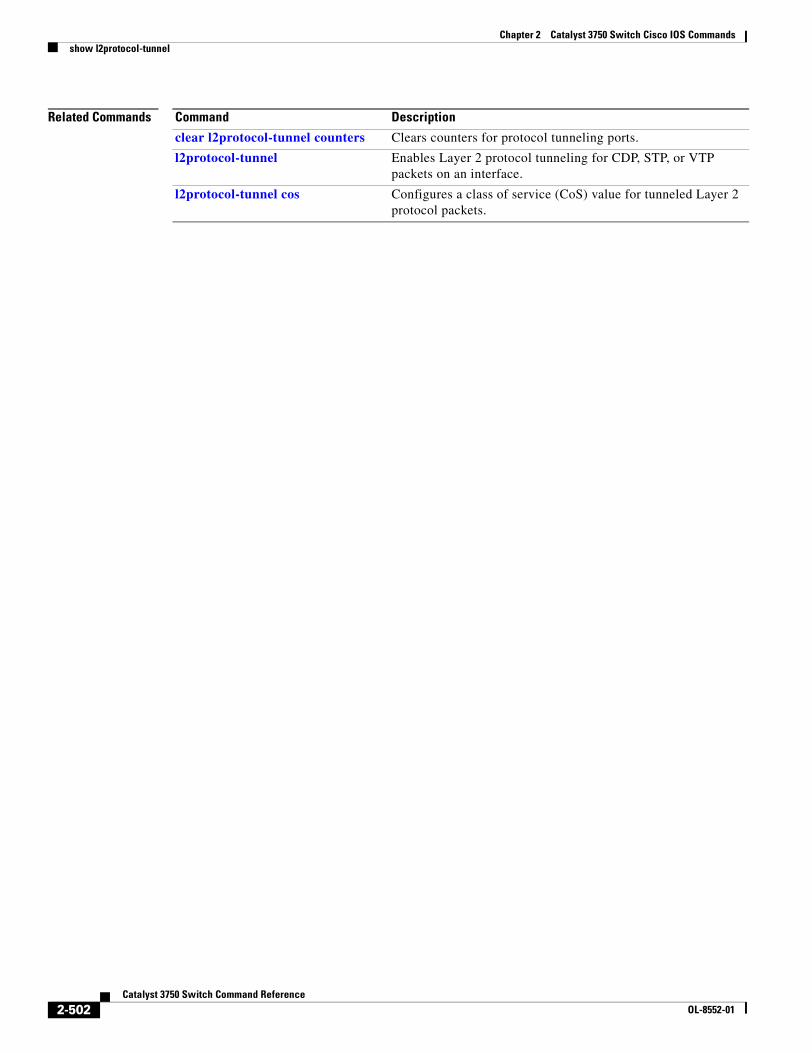
Chapter 2 Catalyst 3750 Switch Cisco IOS Commandsshow l2protocol-tunnel
Related Commands Command Description
clear l2protocol-tunnel counters Clears counters for protocol tunneling ports.
l2protocol-tunnel Enables Layer 2 protocol tunneling for CDP, STP, or VTP packets on an interface.
l2protocol-tunnel cos Configures a class of service (CoS) value for tunneled Layer 2 protocol packets.
2-502Catalyst 3750 Switch Command Reference
OL-8552-01
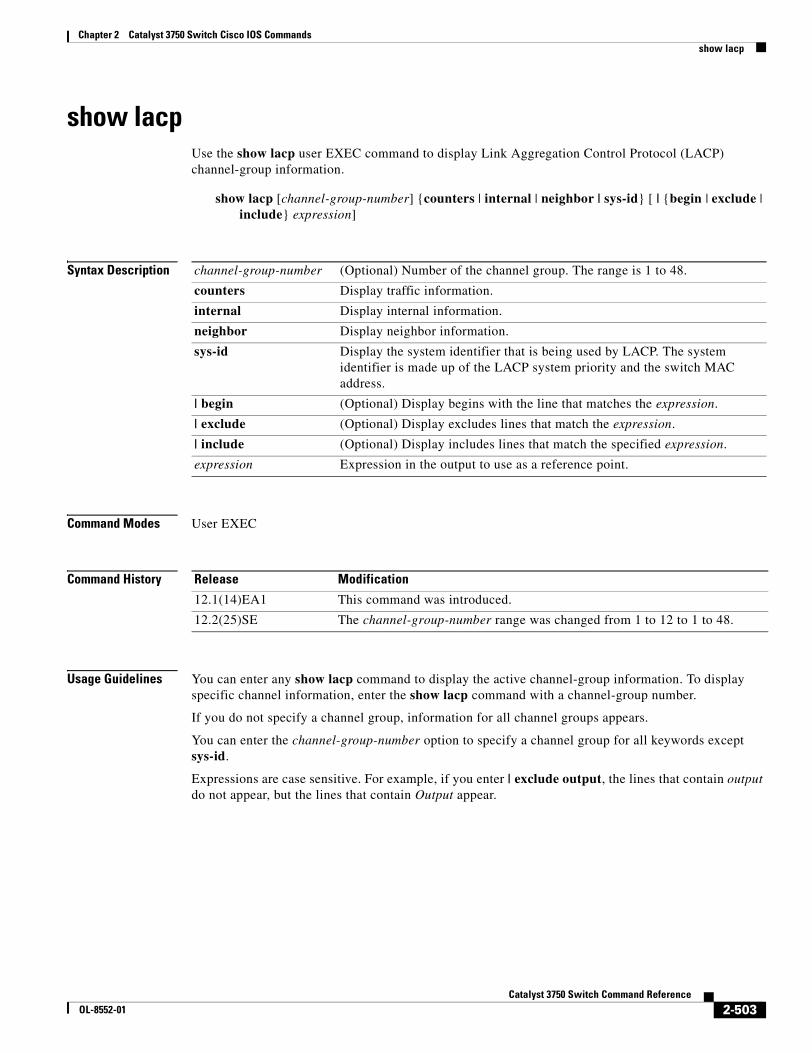
Chapter 2 Catalyst 3750 Switch Cisco IOS Commandsshow lacp
show lacp Use the show lacp user EXEC command to display Link Aggregation Control Protocol (LACP) channel-group information.
show lacp [channel-group-number] {counters | internal | neighbor | sys-id} [ | {begin | exclude | include} expression]
Syntax Description
Command Modes User EXEC
Command History
Usage Guidelines You can enter any show lacp command to display the active channel-group information. To display specific channel information, enter the show lacp command with a channel-group number.
If you do not specify a channel group, information for all channel groups appears.
You can enter the channel-group-number option to specify a channel group for all keywords except sys-id.
Expressions are case sensitive. For example, if you enter | exclude output, the lines that contain output do not appear, but the lines that contain Output appear.
channel-group-number (Optional) Number of the channel group. The range is 1 to 48.
counters Display traffic information.
internal Display internal information.
neighbor Display neighbor information.
sys-id Display the system identifier that is being used by LACP. The system identifier is made up of the LACP system priority and the switch MAC address.
| begin (Optional) Display begins with the line that matches the expression.
| exclude (Optional) Display excludes lines that match the expression.
| include (Optional) Display includes lines that match the specified expression.
expression Expression in the output to use as a reference point.
Release Modification
12.1(14)EA1 This command was introduced.
12.2(25)SE The channel-group-number range was changed from 1 to 12 to 1 to 48.
2-503Catalyst 3750 Switch Command Reference
OL-8552-01
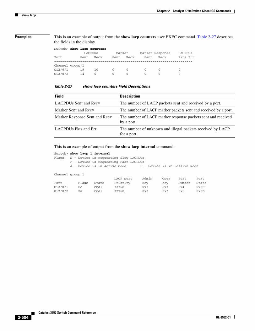
Chapter 2 Catalyst 3750 Switch Cisco IOS Commandsshow lacp
Examples This is an example of output from the show lacp counters user EXEC command. Table 2-27 describes the fields in the display.
Switch> show lacp counters LACPDUs Marker Marker Response LACPDUsPort Sent Recv Sent Recv Sent Recv Pkts Err---------------------------------------------------------------------Channel group:1Gi2/0/1 19 10 0 0 0 0 0 Gi2/0/2 14 6 0 0 0 0 0
This is an example of output from the show lacp internal command:
Switch> show lacp 1 internal Flags: S - Device is requesting Slow LACPDUs F - Device is requesting Fast LACPDUs A - Device is in Active mode P - Device is in Passive mode
Channel group 1 LACP port Admin Oper Port PortPort Flags State Priority Key Key Number StateGi2/0/1 SA bndl 32768 0x3 0x3 0x4 0x3D Gi2/0/2 SA bndl 32768 0x3 0x3 0x5 0x3D
Table 2-27 show lacp counters Field Descriptions
Field Description
LACPDUs Sent and Recv The number of LACP packets sent and received by a port.
Marker Sent and Recv The number of LACP marker packets sent and received by a port.
Marker Response Sent and Recv The number of LACP marker response packets sent and received by a port.
LACPDUs Pkts and Err The number of unknown and illegal packets received by LACP for a port.
2-504Catalyst 3750 Switch Command Reference
OL-8552-01
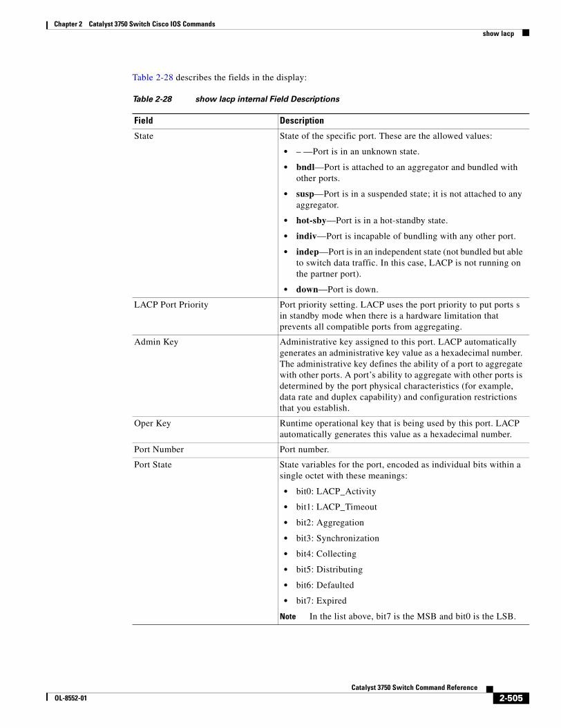
Chapter 2 Catalyst 3750 Switch Cisco IOS Commandsshow lacp
Table 2-28 describes the fields in the display:
Table 2-28 show lacp internal Field Descriptions
Field Description
State State of the specific port. These are the allowed values:
• – —Port is in an unknown state.
• bndl—Port is attached to an aggregator and bundled with other ports.
• susp—Port is in a suspended state; it is not attached to any aggregator.
• hot-sby—Port is in a hot-standby state.
• indiv—Port is incapable of bundling with any other port.
• indep—Port is in an independent state (not bundled but able to switch data traffic. In this case, LACP is not running on the partner port).
• down—Port is down.
LACP Port Priority Port priority setting. LACP uses the port priority to put ports s in standby mode when there is a hardware limitation that prevents all compatible ports from aggregating.
Admin Key Administrative key assigned to this port. LACP automatically generates an administrative key value as a hexadecimal number. The administrative key defines the ability of a port to aggregate with other ports. A port’s ability to aggregate with other ports is determined by the port physical characteristics (for example, data rate and duplex capability) and configuration restrictions that you establish.
Oper Key Runtime operational key that is being used by this port. LACP automatically generates this value as a hexadecimal number.
Port Number Port number.
Port State State variables for the port, encoded as individual bits within a single octet with these meanings:
• bit0: LACP_Activity
• bit1: LACP_Timeout
• bit2: Aggregation
• bit3: Synchronization
• bit4: Collecting
• bit5: Distributing
• bit6: Defaulted
• bit7: Expired
Note In the list above, bit7 is the MSB and bit0 is the LSB.
2-505Catalyst 3750 Switch Command Reference
OL-8552-01
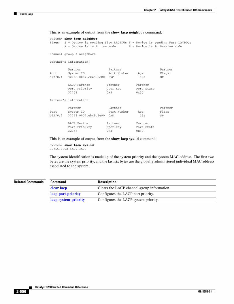
Chapter 2 Catalyst 3750 Switch Cisco IOS Commandsshow lacp
This is an example of output from the show lacp neighbor command:
Switch> show lacp neighbor Flags: S - Device is sending Slow LACPDUs F - Device is sending Fast LACPDUs A - Device is in Active mode P - Device is in Passive mode
Channel group 3 neighbors
Partner’s information:
Partner Partner PartnerPort System ID Port Number Age FlagsGi2/0/1 32768,0007.eb49.5e80 0xC 19s SP
LACP Partner Partner Partner Port Priority Oper Key Port State 32768 0x3 0x3C
Partner’s information:
Partner Partner PartnerPort System ID Port Number Age FlagsGi2/0/2 32768,0007.eb49.5e80 0xD 15s SP
LACP Partner Partner Partner Port Priority Oper Key Port State 32768 0x3 0x3C
This is an example of output from the show lacp sys-id command:
Switch> show lacp sys-id 32765,0002.4b29.3a00
The system identification is made up of the system priority and the system MAC address. The first two bytes are the system priority, and the last six bytes are the globally administered individual MAC address associated to the system.
Related Commands Command Description
clear lacp Clears the LACP channel-group information.
lacp port-priority Configures the LACP port priority.
lacp system-priority Configures the LACP system priority.
2-506Catalyst 3750 Switch Command Reference
OL-8552-01
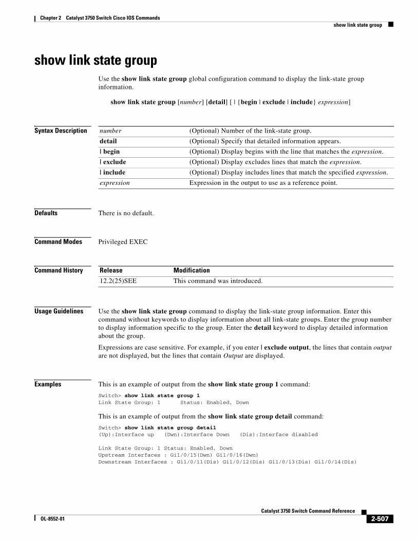
Chapter 2 Catalyst 3750 Switch Cisco IOS Commandsshow link state group
show link state groupUse the show link state group global configuration command to display the link-state group information.
show link state group [number] [detail] [ | {begin | exclude | include} expression]
Syntax Description
Defaults There is no default.
Command Modes Privileged EXEC
Command History
Usage Guidelines Use the show link state group command to display the link-state group information. Enter this command without keywords to display information about all link-state groups. Enter the group number to display information specific to the group. Enter the detail keyword to display detailed information about the group.
Expressions are case sensitive. For example, if you enter | exclude output, the lines that contain output are not displayed, but the lines that contain Output are displayed.
Examples This is an example of output from the show link state group 1 command:
Switch> show link state group 1Link State Group: 1 Status: Enabled, Down
This is an example of output from the show link state group detail command:
Switch> show link state group detail(Up):Interface up (Dwn):Interface Down (Dis):Interface disabled
Link State Group: 1 Status: Enabled, DownUpstream Interfaces : Gi1/0/15(Dwn) Gi1/0/16(Dwn)Downstream Interfaces : Gi1/0/11(Dis) Gi1/0/12(Dis) Gi1/0/13(Dis) Gi1/0/14(Dis)
number (Optional) Number of the link-state group.
detail (Optional) Specify that detailed information appears.
| begin (Optional) Display begins with the line that matches the expression.
| exclude (Optional) Display excludes lines that match the expression.
| include (Optional) Display includes lines that match the specified expression.
expression Expression in the output to use as a reference point.
Release Modification
12.2(25)SEE This command was introduced.
2-507Catalyst 3750 Switch Command Reference
OL-8552-01
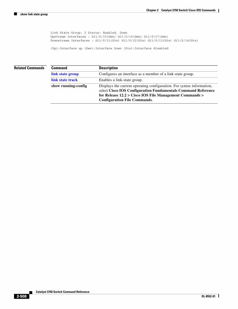
Chapter 2 Catalyst 3750 Switch Cisco IOS Commandsshow link state group
Link State Group: 2 Status: Enabled, DownUpstream Interfaces : Gi1/0/15(Dwn) Gi1/0/16(Dwn) Gi1/0/17(Dwn)Downstream Interfaces : Gi1/0/11(Dis) Gi1/0/12(Dis) Gi1/0/13(Dis) Gi1/0/14(Dis)
(Up):Interface up (Dwn):Interface Down (Dis):Interface disabled
Related Commands Command Description
link state group Configures an interface as a member of a link-state group.
link state track Enables a link-state group.
show running-config Displays the current operating configuration. For syntax information, select Cisco IOS Configuration Fundamentals Command Reference for Release 12.2 > Cisco IOS File Management Commands > Configuration File Commands.
2-508Catalyst 3750 Switch Command Reference
OL-8552-01
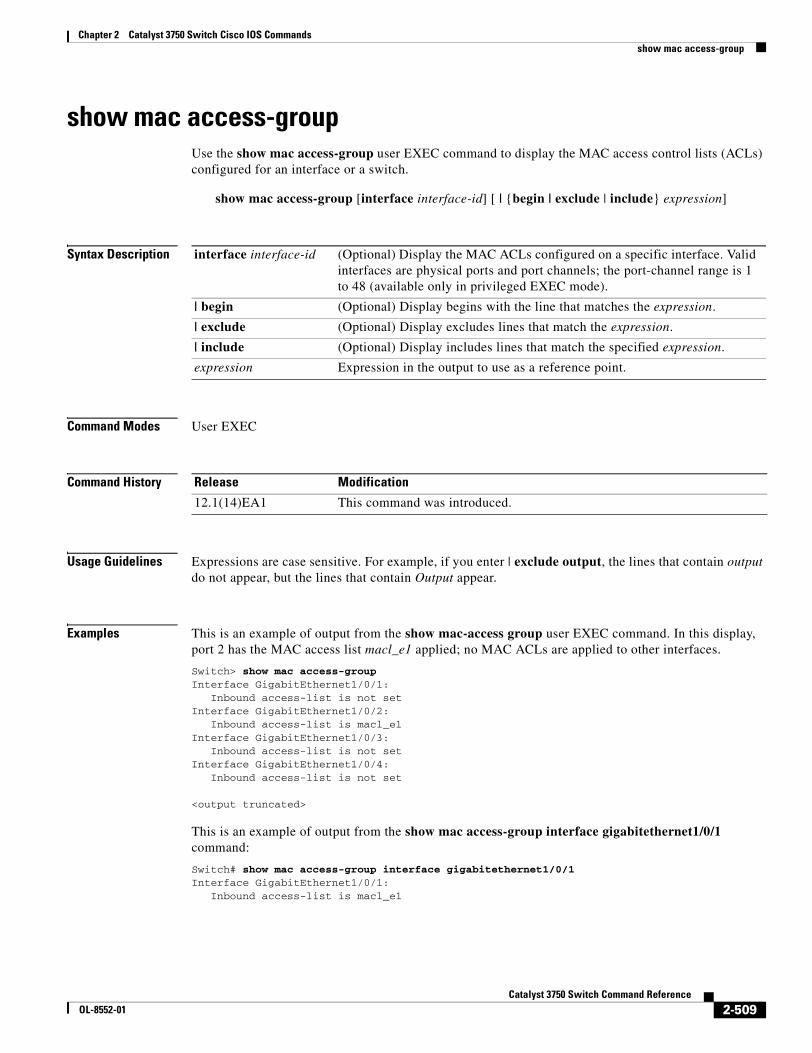
Chapter 2 Catalyst 3750 Switch Cisco IOS Commandsshow mac access-group
show mac access-groupUse the show mac access-group user EXEC command to display the MAC access control lists (ACLs) configured for an interface or a switch.
show mac access-group [interface interface-id] [ | {begin | exclude | include} expression]
Syntax Description
Command Modes User EXEC
Command History
Usage Guidelines Expressions are case sensitive. For example, if you enter | exclude output, the lines that contain output do not appear, but the lines that contain Output appear.
Examples This is an example of output from the show mac-access group user EXEC command. In this display, port 2 has the MAC access list macl_e1 applied; no MAC ACLs are applied to other interfaces.
Switch> show mac access-group Interface GigabitEthernet1/0/1: Inbound access-list is not setInterface GigabitEthernet1/0/2: Inbound access-list is macl_e1Interface GigabitEthernet1/0/3: Inbound access-list is not setInterface GigabitEthernet1/0/4: Inbound access-list is not set
<output truncated>
This is an example of output from the show mac access-group interface gigabitethernet1/0/1 command:
Switch# show mac access-group interface gigabitethernet1/0/1Interface GigabitEthernet1/0/1: Inbound access-list is macl_e1
interface interface-id (Optional) Display the MAC ACLs configured on a specific interface. Valid interfaces are physical ports and port channels; the port-channel range is 1 to 48 (available only in privileged EXEC mode).
| begin (Optional) Display begins with the line that matches the expression.
| exclude (Optional) Display excludes lines that match the expression.
| include (Optional) Display includes lines that match the specified expression.
expression Expression in the output to use as a reference point.
Release Modification
12.1(14)EA1 This command was introduced.
2-509Catalyst 3750 Switch Command Reference
OL-8552-01

Chapter 2 Catalyst 3750 Switch Cisco IOS Commandsshow mac access-group
Related Commands Command Description
mac access-group Applies a MAC access group to an interface.
2-510Catalyst 3750 Switch Command Reference
OL-8552-01
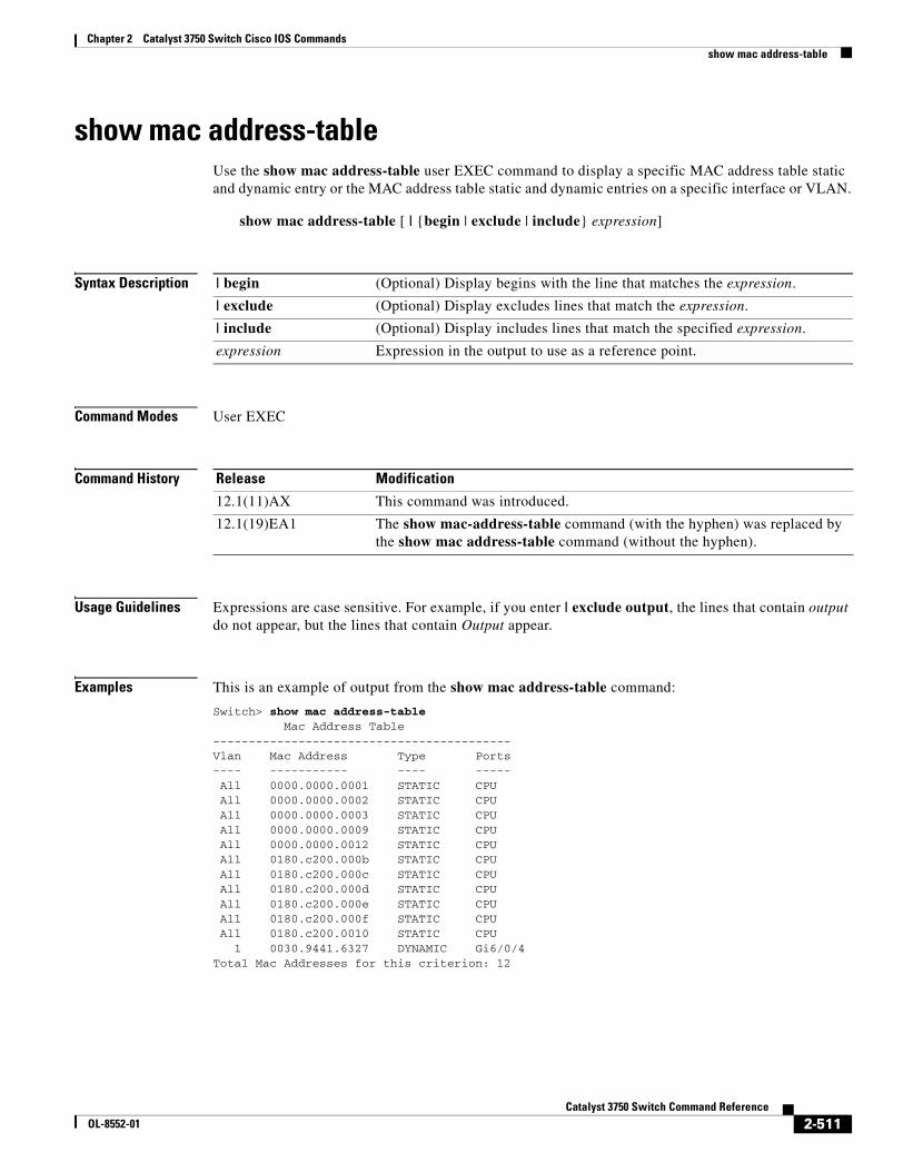
Chapter 2 Catalyst 3750 Switch Cisco IOS Commandsshow mac address-table
show mac address-tableUse the show mac address-table user EXEC command to display a specific MAC address table static and dynamic entry or the MAC address table static and dynamic entries on a specific interface or VLAN.
show mac address-table [ | {begin | exclude | include} expression]
Syntax Description
Command Modes User EXEC
Command History
Usage Guidelines Expressions are case sensitive. For example, if you enter | exclude output, the lines that contain output do not appear, but the lines that contain Output appear.
Examples This is an example of output from the show mac address-table command:
Switch> show mac address-table Mac Address Table------------------------------------------Vlan Mac Address Type Ports---- ----------- ---- ----- All 0000.0000.0001 STATIC CPU All 0000.0000.0002 STATIC CPU All 0000.0000.0003 STATIC CPU All 0000.0000.0009 STATIC CPU All 0000.0000.0012 STATIC CPU All 0180.c200.000b STATIC CPU All 0180.c200.000c STATIC CPU All 0180.c200.000d STATIC CPU All 0180.c200.000e STATIC CPU All 0180.c200.000f STATIC CPU All 0180.c200.0010 STATIC CPU 1 0030.9441.6327 DYNAMIC Gi6/0/4Total Mac Addresses for this criterion: 12
| begin (Optional) Display begins with the line that matches the expression.
| exclude (Optional) Display excludes lines that match the expression.
| include (Optional) Display includes lines that match the specified expression.
expression Expression in the output to use as a reference point.
Release Modification
12.1(11)AX This command was introduced.
12.1(19)EA1 The show mac-address-table command (with the hyphen) was replaced by the show mac address-table command (without the hyphen).
2-511Catalyst 3750 Switch Command Reference
OL-8552-01
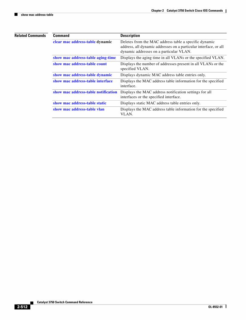
Chapter 2 Catalyst 3750 Switch Cisco IOS Commandsshow mac address-table
Related Commands Command Description
clear mac address-table dynamic Deletes from the MAC address table a specific dynamic address, all dynamic addresses on a particular interface, or all dynamic addresses on a particular VLAN.
show mac address-table aging-time Displays the aging time in all VLANs or the specified VLAN.
show mac address-table count Displays the number of addresses present in all VLANs or the specified VLAN.
show mac address-table dynamic Displays dynamic MAC address table entries only.
show mac address-table interface Displays the MAC address table information for the specified interface.
show mac address-table notification Displays the MAC address notification settings for all interfaces or the specified interface.
show mac address-table static Displays static MAC address table entries only.
show mac address-table vlan Displays the MAC address table information for the specified VLAN.
2-512Catalyst 3750 Switch Command Reference
OL-8552-01
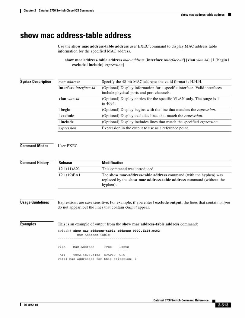
Chapter 2 Catalyst 3750 Switch Cisco IOS Commandsshow mac address-table address
show mac address-table addressUse the show mac address-table address user EXEC command to display MAC address table information for the specified MAC address.
show mac address-table address mac-address [interface interface-id] [vlan vlan-id] [ | {begin | exclude | include} expression]
Syntax Description
Command Modes User EXEC
Command History
Usage Guidelines Expressions are case sensitive. For example, if you enter | exclude output, the lines that contain output do not appear, but the lines that contain Output appear.
Examples This is an example of output from the show mac address-table address command:
Switch# show mac address-table address 0002.4b28.c482 Mac Address Table------------------------------------------
Vlan Mac Address Type Ports---- ----------- ---- ----- All 0002.4b28.c482 STATIC CPUTotal Mac Addresses for this criterion: 1
mac-address Specify the 48-bit MAC address; the valid format is H.H.H.
interface interface-id (Optional) Display information for a specific interface. Valid interfaces include physical ports and port channels.
vlan vlan-id (Optional) Display entries for the specific VLAN only. The range is 1 to 4094.
| begin (Optional) Display begins with the line that matches the expression.
| exclude (Optional) Display excludes lines that match the expression.
| include (Optional) Display includes lines that match the specified expression.
expression Expression in the output to use as a reference point.
Release Modification
12.1(11)AX This command was introduced.
12.1(19)EA1 The show mac-address-table address command (with the hyphen) was replaced by the show mac address-table address command (without the hyphen).
2-513Catalyst 3750 Switch Command Reference
OL-8552-01
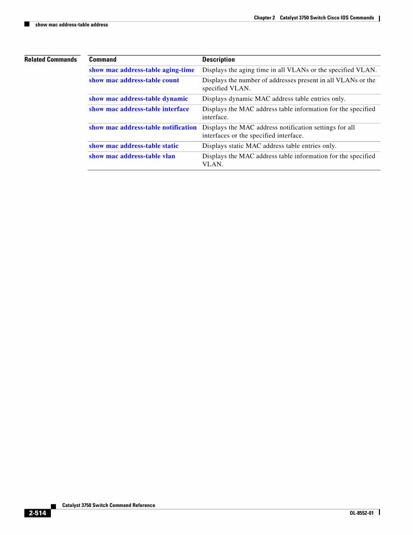
Chapter 2 Catalyst 3750 Switch Cisco IOS Commandsshow mac address-table address
Related Commands Command Description
show mac address-table aging-time Displays the aging time in all VLANs or the specified VLAN.
show mac address-table count Displays the number of addresses present in all VLANs or the specified VLAN.
show mac address-table dynamic Displays dynamic MAC address table entries only.
show mac address-table interface Displays the MAC address table information for the specified interface.
show mac address-table notification Displays the MAC address notification settings for all interfaces or the specified interface.
show mac address-table static Displays static MAC address table entries only.
show mac address-table vlan Displays the MAC address table information for the specified VLAN.
2-514Catalyst 3750 Switch Command Reference
OL-8552-01
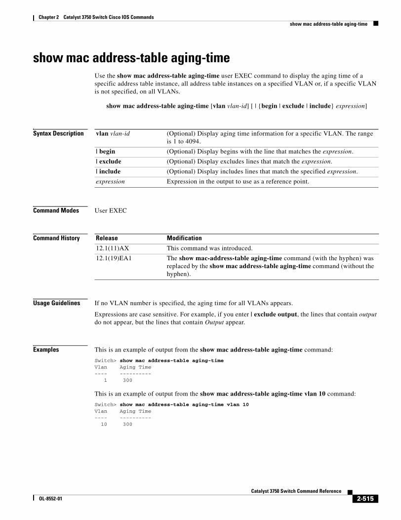
Chapter 2 Catalyst 3750 Switch Cisco IOS Commandsshow mac address-table aging-time
show mac address-table aging-timeUse the show mac address-table aging-time user EXEC command to display the aging time of a specific address table instance, all address table instances on a specified VLAN or, if a specific VLAN is not specified, on all VLANs.
show mac address-table aging-time [vlan vlan-id] [ | {begin | exclude | include} expression]
Syntax Description
Command Modes User EXEC
Command History
Usage Guidelines If no VLAN number is specified, the aging time for all VLANs appears.
Expressions are case sensitive. For example, if you enter | exclude output, the lines that contain output do not appear, but the lines that contain Output appear.
Examples This is an example of output from the show mac address-table aging-time command:
Switch> show mac address-table aging-timeVlan Aging Time---- ---------- 1 300
This is an example of output from the show mac address-table aging-time vlan 10 command:
Switch> show mac address-table aging-time vlan 10Vlan Aging Time---- ---------- 10 300
vlan vlan-id (Optional) Display aging time information for a specific VLAN. The range is 1 to 4094.
| begin (Optional) Display begins with the line that matches the expression.
| exclude (Optional) Display excludes lines that match the expression.
| include (Optional) Display includes lines that match the specified expression.
expression Expression in the output to use as a reference point.
Release Modification
12.1(11)AX This command was introduced.
12.1(19)EA1 The show mac-address-table aging-time command (with the hyphen) was replaced by the show mac address-table aging-time command (without the hyphen).
2-515Catalyst 3750 Switch Command Reference
OL-8552-01
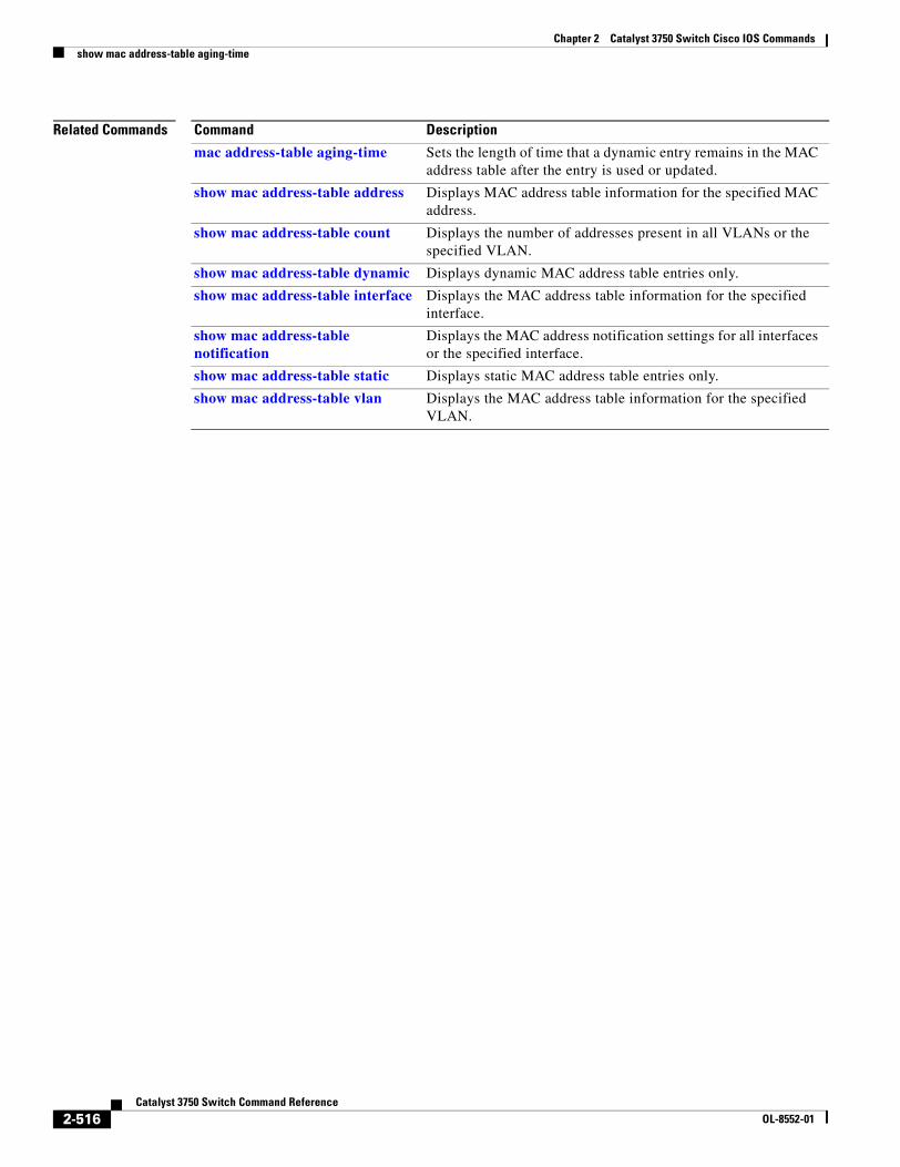
Chapter 2 Catalyst 3750 Switch Cisco IOS Commandsshow mac address-table aging-time
Related Commands Command Description
mac address-table aging-time Sets the length of time that a dynamic entry remains in the MAC address table after the entry is used or updated.
show mac address-table address Displays MAC address table information for the specified MAC address.
show mac address-table count Displays the number of addresses present in all VLANs or the specified VLAN.
show mac address-table dynamic Displays dynamic MAC address table entries only.
show mac address-table interface Displays the MAC address table information for the specified interface.
show mac address-table notification
Displays the MAC address notification settings for all interfaces or the specified interface.
show mac address-table static Displays static MAC address table entries only.
show mac address-table vlan Displays the MAC address table information for the specified VLAN.
2-516Catalyst 3750 Switch Command Reference
OL-8552-01
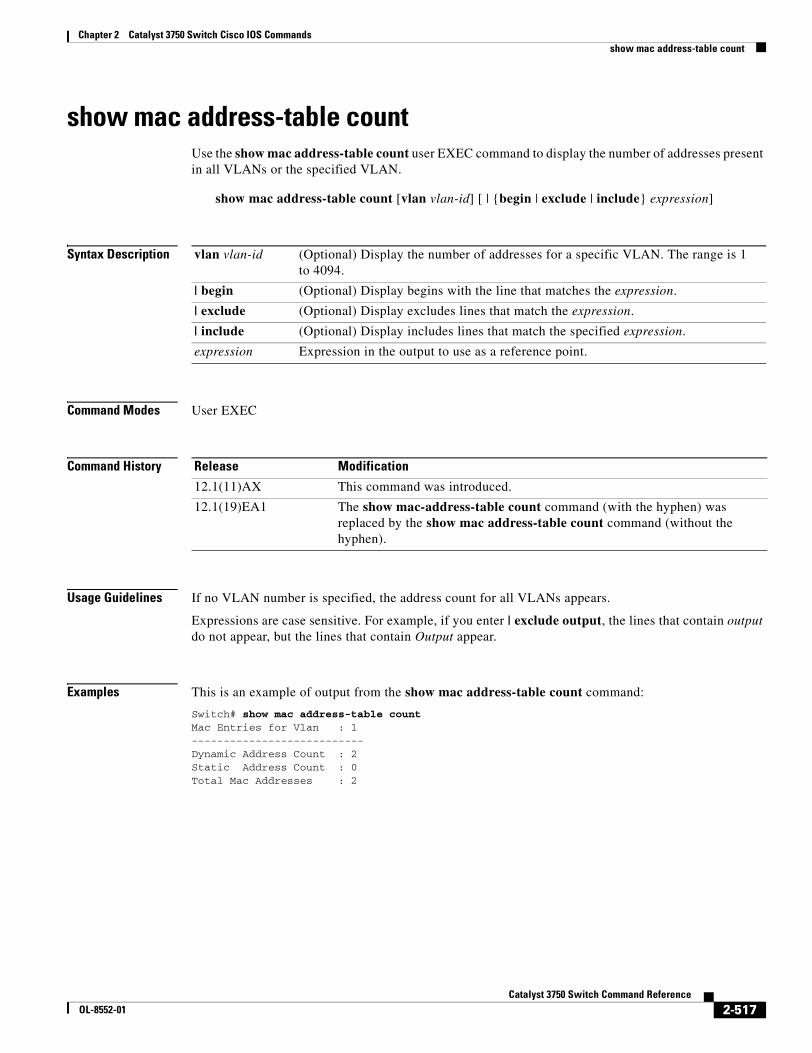
Chapter 2 Catalyst 3750 Switch Cisco IOS Commandsshow mac address-table count
show mac address-table countUse the show mac address-table count user EXEC command to display the number of addresses present in all VLANs or the specified VLAN.
show mac address-table count [vlan vlan-id] [ | {begin | exclude | include} expression]
Syntax Description
Command Modes User EXEC
Command History
Usage Guidelines If no VLAN number is specified, the address count for all VLANs appears.
Expressions are case sensitive. For example, if you enter | exclude output, the lines that contain output do not appear, but the lines that contain Output appear.
Examples This is an example of output from the show mac address-table count command:
Switch# show mac address-table countMac Entries for Vlan : 1---------------------------Dynamic Address Count : 2Static Address Count : 0Total Mac Addresses : 2
vlan vlan-id (Optional) Display the number of addresses for a specific VLAN. The range is 1 to 4094.
| begin (Optional) Display begins with the line that matches the expression.
| exclude (Optional) Display excludes lines that match the expression.
| include (Optional) Display includes lines that match the specified expression.
expression Expression in the output to use as a reference point.
Release Modification
12.1(11)AX This command was introduced.
12.1(19)EA1 The show mac-address-table count command (with the hyphen) was replaced by the show mac address-table count command (without the hyphen).
2-517Catalyst 3750 Switch Command Reference
OL-8552-01
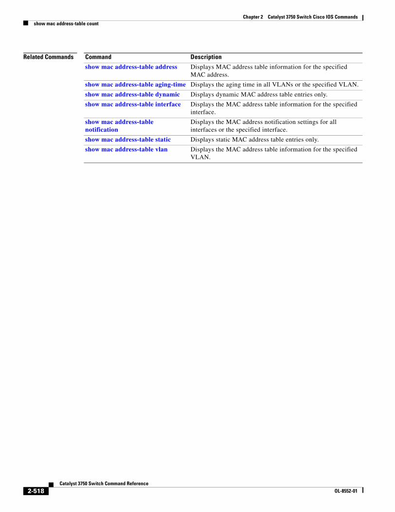
Chapter 2 Catalyst 3750 Switch Cisco IOS Commandsshow mac address-table count
Related Commands Command Description
show mac address-table address Displays MAC address table information for the specified MAC address.
show mac address-table aging-time Displays the aging time in all VLANs or the specified VLAN.
show mac address-table dynamic Displays dynamic MAC address table entries only.
show mac address-table interface Displays the MAC address table information for the specified interface.
show mac address-table notification
Displays the MAC address notification settings for all interfaces or the specified interface.
show mac address-table static Displays static MAC address table entries only.
show mac address-table vlan Displays the MAC address table information for the specified VLAN.
2-518Catalyst 3750 Switch Command Reference
OL-8552-01
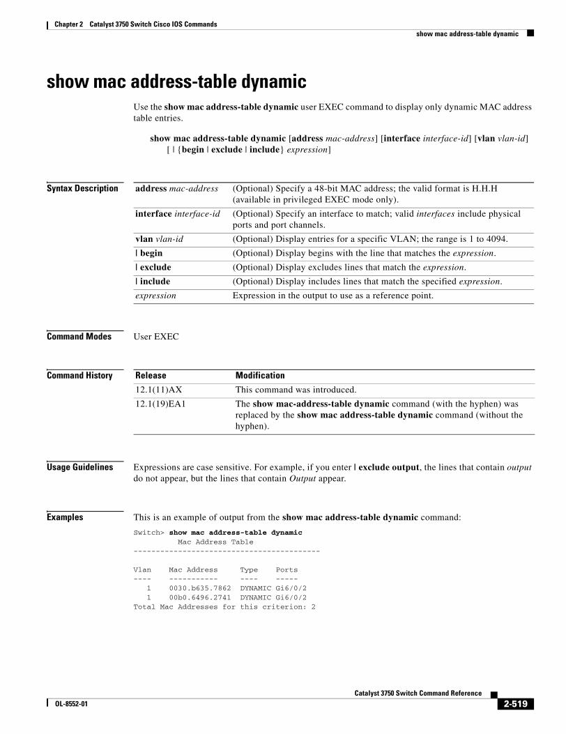
Chapter 2 Catalyst 3750 Switch Cisco IOS Commandsshow mac address-table dynamic
show mac address-table dynamicUse the show mac address-table dynamic user EXEC command to display only dynamic MAC address table entries.
show mac address-table dynamic [address mac-address] [interface interface-id] [vlan vlan-id] [ | {begin | exclude | include} expression]
Syntax Description
Command Modes User EXEC
Command History
Usage Guidelines Expressions are case sensitive. For example, if you enter | exclude output, the lines that contain output do not appear, but the lines that contain Output appear.
Examples This is an example of output from the show mac address-table dynamic command:
Switch> show mac address-table dynamic Mac Address Table------------------------------------------
Vlan Mac Address Type Ports---- ----------- ---- ----- 1 0030.b635.7862 DYNAMIC Gi6/0/2 1 00b0.6496.2741 DYNAMIC Gi6/0/2Total Mac Addresses for this criterion: 2
address mac-address (Optional) Specify a 48-bit MAC address; the valid format is H.H.H (available in privileged EXEC mode only).
interface interface-id (Optional) Specify an interface to match; valid interfaces include physical ports and port channels.
vlan vlan-id (Optional) Display entries for a specific VLAN; the range is 1 to 4094.
| begin (Optional) Display begins with the line that matches the expression.
| exclude (Optional) Display excludes lines that match the expression.
| include (Optional) Display includes lines that match the specified expression.
expression Expression in the output to use as a reference point.
Release Modification
12.1(11)AX This command was introduced.
12.1(19)EA1 The show mac-address-table dynamic command (with the hyphen) was replaced by the show mac address-table dynamic command (without the hyphen).
2-519Catalyst 3750 Switch Command Reference
OL-8552-01
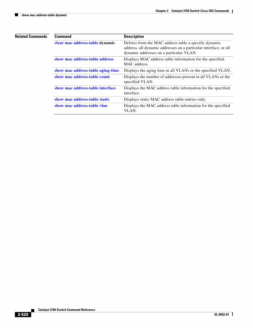
Chapter 2 Catalyst 3750 Switch Cisco IOS Commandsshow mac address-table dynamic
Related Commands Command Description
clear mac address-table dynamic Deletes from the MAC address table a specific dynamic address, all dynamic addresses on a particular interface, or all dynamic addresses on a particular VLAN.
show mac address-table address Displays MAC address table information for the specified MAC address.
show mac address-table aging-time Displays the aging time in all VLANs or the specified VLAN.
show mac address-table count Displays the number of addresses present in all VLANs or the specified VLAN.
show mac address-table interface Displays the MAC address table information for the specified interface.
show mac address-table static Displays static MAC address table entries only.
show mac address-table vlan Displays the MAC address table information for the specified VLAN.
2-520Catalyst 3750 Switch Command Reference
OL-8552-01
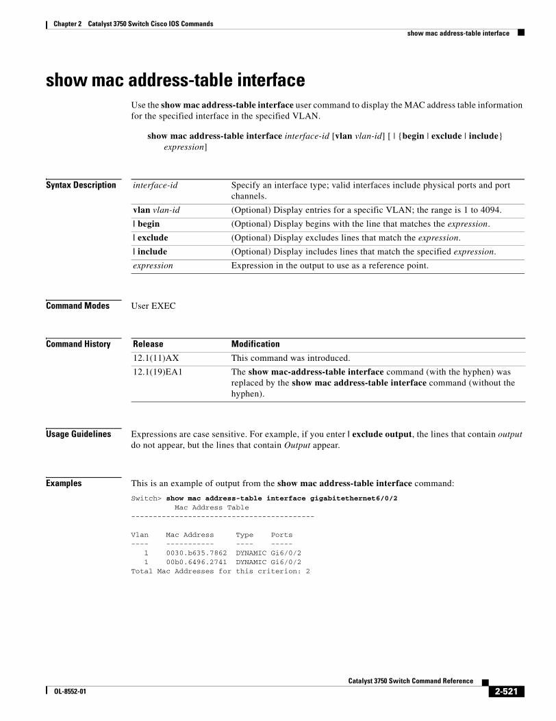
Chapter 2 Catalyst 3750 Switch Cisco IOS Commandsshow mac address-table interface
show mac address-table interfaceUse the show mac address-table interface user command to display the MAC address table information for the specified interface in the specified VLAN.
show mac address-table interface interface-id [vlan vlan-id] [ | {begin | exclude | include} expression]
Syntax Description
Command Modes User EXEC
Command History
Usage Guidelines Expressions are case sensitive. For example, if you enter | exclude output, the lines that contain output do not appear, but the lines that contain Output appear.
Examples This is an example of output from the show mac address-table interface command:
Switch> show mac address-table interface gigabitethernet6/0/2 Mac Address Table------------------------------------------
Vlan Mac Address Type Ports---- ----------- ---- ----- 1 0030.b635.7862 DYNAMIC Gi6/0/2 1 00b0.6496.2741 DYNAMIC Gi6/0/2Total Mac Addresses for this criterion: 2
interface-id Specify an interface type; valid interfaces include physical ports and port channels.
vlan vlan-id (Optional) Display entries for a specific VLAN; the range is 1 to 4094.
| begin (Optional) Display begins with the line that matches the expression.
| exclude (Optional) Display excludes lines that match the expression.
| include (Optional) Display includes lines that match the specified expression.
expression Expression in the output to use as a reference point.
Release Modification
12.1(11)AX This command was introduced.
12.1(19)EA1 The show mac-address-table interface command (with the hyphen) was replaced by the show mac address-table interface command (without the hyphen).
2-521Catalyst 3750 Switch Command Reference
OL-8552-01
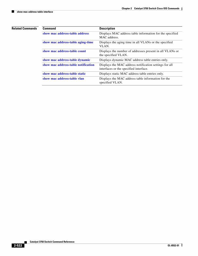
Chapter 2 Catalyst 3750 Switch Cisco IOS Commandsshow mac address-table interface
Related Commands Command Description
show mac address-table address Displays MAC address table information for the specified MAC address.
show mac address-table aging-time Displays the aging time in all VLANs or the specified VLAN.
show mac address-table count Displays the number of addresses present in all VLANs or the specified VLAN.
show mac address-table dynamic Displays dynamic MAC address table entries only.
show mac address-table notification Displays the MAC address notification settings for all interfaces or the specified interface.
show mac address-table static Displays static MAC address table entries only.
show mac address-table vlan Displays the MAC address table information for the specified VLAN.
2-522Catalyst 3750 Switch Command Reference
OL-8552-01
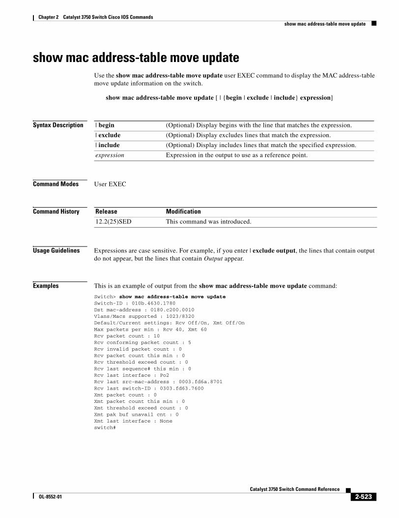
Chapter 2 Catalyst 3750 Switch Cisco IOS Commandsshow mac address-table move update
show mac address-table move updateUse the show mac address-table move update user EXEC command to display the MAC address-table move update information on the switch.
show mac address-table move update [ | {begin | exclude | include} expression]
Syntax Description
Command Modes User EXEC
Command History
Usage Guidelines Expressions are case sensitive. For example, if you enter | exclude output, the lines that contain output do not appear, but the lines that contain Output appear.
Examples This is an example of output from the show mac address-table move update command:
Switch> show mac address-table move updateSwitch-ID : 010b.4630.1780Dst mac-address : 0180.c200.0010Vlans/Macs supported : 1023/8320Default/Current settings: Rcv Off/On, Xmt Off/OnMax packets per min : Rcv 40, Xmt 60Rcv packet count : 10Rcv conforming packet count : 5Rcv invalid packet count : 0Rcv packet count this min : 0Rcv threshold exceed count : 0Rcv last sequence# this min : 0Rcv last interface : Po2Rcv last src-mac-address : 0003.fd6a.8701Rcv last switch-ID : 0303.fd63.7600Xmt packet count : 0Xmt packet count this min : 0Xmt threshold exceed count : 0Xmt pak buf unavail cnt : 0Xmt last interface : Noneswitch#
| begin (Optional) Display begins with the line that matches the expression.
| exclude (Optional) Display excludes lines that match the expression.
| include (Optional) Display includes lines that match the specified expression.
expression Expression in the output to use as a reference point.
Release Modification
12.2(25)SED This command was introduced.
2-523Catalyst 3750 Switch Command Reference
OL-8552-01
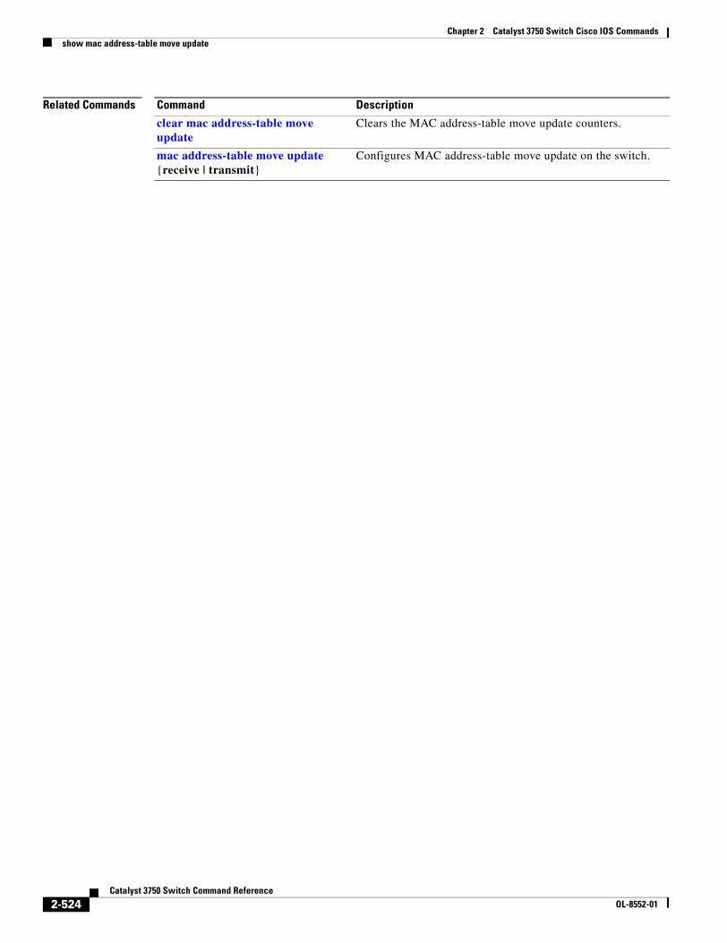
Chapter 2 Catalyst 3750 Switch Cisco IOS Commandsshow mac address-table move update
Related Commands Command Description
clear mac address-table move update
Clears the MAC address-table move update counters.
mac address-table move update {receive | transmit}
Configures MAC address-table move update on the switch.
2-524Catalyst 3750 Switch Command Reference
OL-8552-01
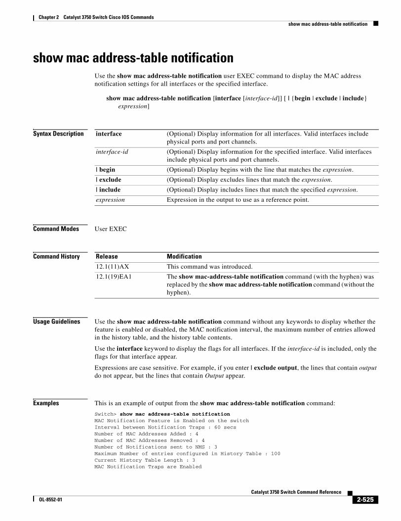
Chapter 2 Catalyst 3750 Switch Cisco IOS Commandsshow mac address-table notification
show mac address-table notificationUse the show mac address-table notification user EXEC command to display the MAC address notification settings for all interfaces or the specified interface.
show mac address-table notification [interface [interface-id]] [ | {begin | exclude | include} expression]
Syntax Description
Command Modes User EXEC
Command History
Usage Guidelines Use the show mac address-table notification command without any keywords to display whether the feature is enabled or disabled, the MAC notification interval, the maximum number of entries allowed in the history table, and the history table contents.
Use the interface keyword to display the flags for all interfaces. If the interface-id is included, only the flags for that interface appear.
Expressions are case sensitive. For example, if you enter | exclude output, the lines that contain output do not appear, but the lines that contain Output appear.
Examples This is an example of output from the show mac address-table notification command:
Switch> show mac address-table notificationMAC Notification Feature is Enabled on the switchInterval between Notification Traps : 60 secsNumber of MAC Addresses Added : 4Number of MAC Addresses Removed : 4Number of Notifications sent to NMS : 3Maximum Number of entries configured in History Table : 100Current History Table Length : 3MAC Notification Traps are Enabled
interface (Optional) Display information for all interfaces. Valid interfaces include physical ports and port channels.
interface-id (Optional) Display information for the specified interface. Valid interfaces include physical ports and port channels.
| begin (Optional) Display begins with the line that matches the expression.
| exclude (Optional) Display excludes lines that match the expression.
| include (Optional) Display includes lines that match the specified expression.
expression Expression in the output to use as a reference point.
Release Modification
12.1(11)AX This command was introduced.
12.1(19)EA1 The show mac-address-table notification command (with the hyphen) was replaced by the show mac address-table notification command (without the hyphen).
2-525Catalyst 3750 Switch Command Reference
OL-8552-01
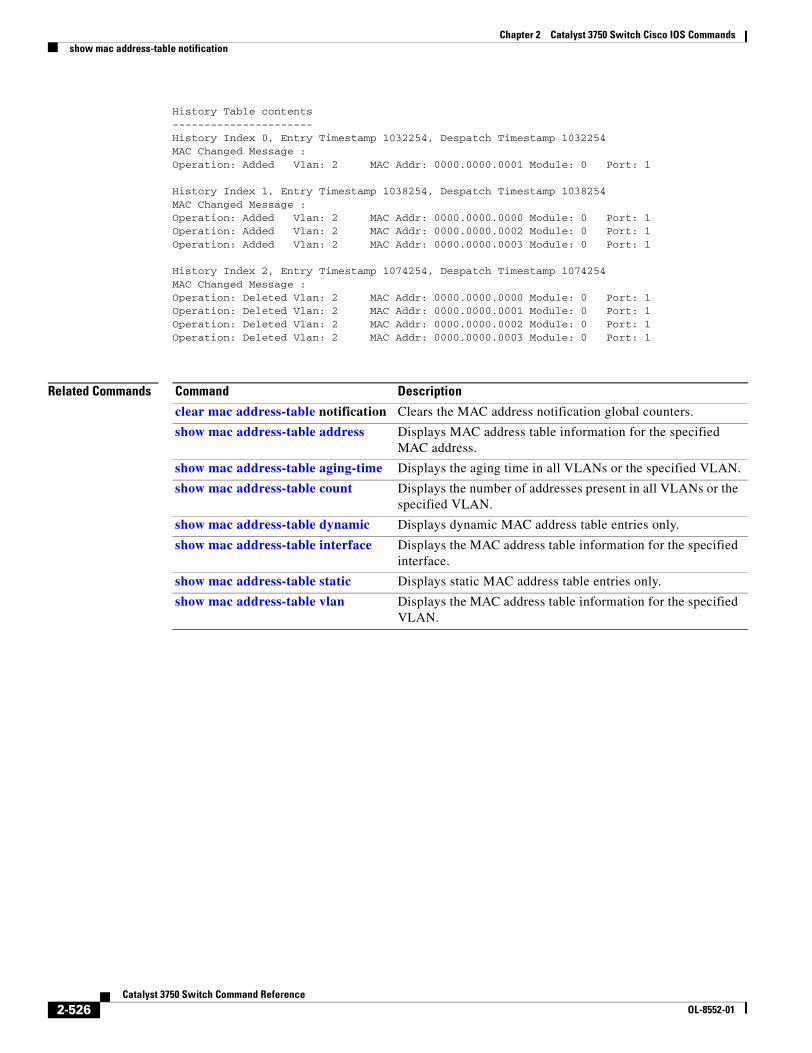
Chapter 2 Catalyst 3750 Switch Cisco IOS Commandsshow mac address-table notification
History Table contents----------------------History Index 0, Entry Timestamp 1032254, Despatch Timestamp 1032254MAC Changed Message :Operation: Added Vlan: 2 MAC Addr: 0000.0000.0001 Module: 0 Port: 1
History Index 1, Entry Timestamp 1038254, Despatch Timestamp 1038254MAC Changed Message :Operation: Added Vlan: 2 MAC Addr: 0000.0000.0000 Module: 0 Port: 1Operation: Added Vlan: 2 MAC Addr: 0000.0000.0002 Module: 0 Port: 1Operation: Added Vlan: 2 MAC Addr: 0000.0000.0003 Module: 0 Port: 1
History Index 2, Entry Timestamp 1074254, Despatch Timestamp 1074254MAC Changed Message :Operation: Deleted Vlan: 2 MAC Addr: 0000.0000.0000 Module: 0 Port: 1Operation: Deleted Vlan: 2 MAC Addr: 0000.0000.0001 Module: 0 Port: 1Operation: Deleted Vlan: 2 MAC Addr: 0000.0000.0002 Module: 0 Port: 1Operation: Deleted Vlan: 2 MAC Addr: 0000.0000.0003 Module: 0 Port: 1
Related Commands Command Description
clear mac address-table notification Clears the MAC address notification global counters.
show mac address-table address Displays MAC address table information for the specified MAC address.
show mac address-table aging-time Displays the aging time in all VLANs or the specified VLAN.
show mac address-table count Displays the number of addresses present in all VLANs or the specified VLAN.
show mac address-table dynamic Displays dynamic MAC address table entries only.
show mac address-table interface Displays the MAC address table information for the specified interface.
show mac address-table static Displays static MAC address table entries only.
show mac address-table vlan Displays the MAC address table information for the specified VLAN.
2-526Catalyst 3750 Switch Command Reference
OL-8552-01
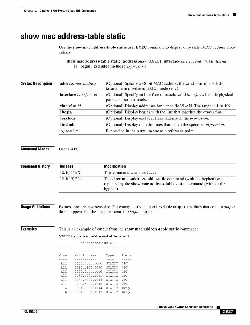
Chapter 2 Catalyst 3750 Switch Cisco IOS Commandsshow mac address-table static
show mac address-table staticUse the show mac address-table static user EXEC command to display only static MAC address table entries.
show mac address-table static [address mac-address] [interface interface-id] [vlan vlan-id] [ | {begin | exclude | include} expression]
Syntax Description
Command Modes User EXEC
Command History
Usage Guidelines Expressions are case sensitive. For example, if you enter | exclude output, the lines that contain output do not appear, but the lines that contain Output appear.
Examples This is an example of output from the show mac address-table static command:
Switch> show mac address-table static
Mac Address Table------------------------------------------
Vlan Mac Address Type Ports---- ----------- ---- ----- All 0100.0ccc.cccc STATIC CPU All 0180.c200.0000 STATIC CPU All 0100.0ccc.cccd STATIC CPU All 0180.c200.0001 STATIC CPUAll 0180.c200.0004 STATIC CPU
All 0180.c200.0005 STATIC CPU 4 0001.0002.0004 STATIC Drop 6 0001.0002.0007 STATIC Drop
address mac-address (Optional) Specify a 48-bit MAC address; the valid format is H.H.H (available in privileged EXEC mode only).
interface interface-id (Optional) Specify an interface to match; valid interfaces include physical ports and port channels.
vlan vlan-id (Optional) Display addresses for a specific VLAN. The range is 1 to 4094.
| begin (Optional) Display begins with the line that matches the expression.
| exclude (Optional) Display excludes lines that match the expression.
| include (Optional) Display includes lines that match the specified expression.
expression Expression in the output to use as a reference point.
Release Modification
12.1(11)AX This command was introduced.
12.1(19)EA1 The show mac-address-table static command (with the hyphen) was replaced by the show mac address-table static command (without the hyphen).
2-527Catalyst 3750 Switch Command Reference
OL-8552-01
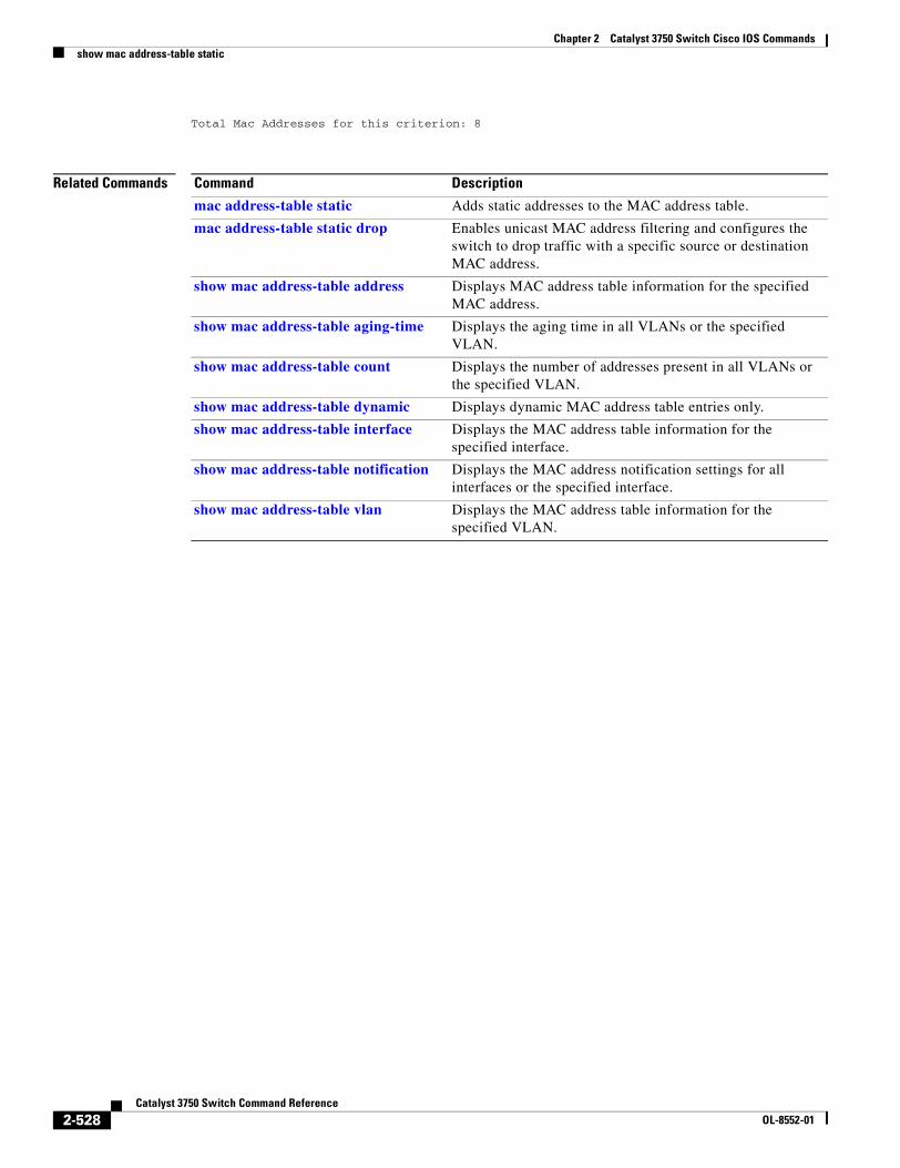
Chapter 2 Catalyst 3750 Switch Cisco IOS Commandsshow mac address-table static
Total Mac Addresses for this criterion: 8
Related Commands Command Description
mac address-table static Adds static addresses to the MAC address table.
mac address-table static drop Enables unicast MAC address filtering and configures the switch to drop traffic with a specific source or destination MAC address.
show mac address-table address Displays MAC address table information for the specified MAC address.
show mac address-table aging-time Displays the aging time in all VLANs or the specified VLAN.
show mac address-table count Displays the number of addresses present in all VLANs or the specified VLAN.
show mac address-table dynamic Displays dynamic MAC address table entries only.
show mac address-table interface Displays the MAC address table information for the specified interface.
show mac address-table notification Displays the MAC address notification settings for all interfaces or the specified interface.
show mac address-table vlan Displays the MAC address table information for the specified VLAN.
2-528Catalyst 3750 Switch Command Reference
OL-8552-01
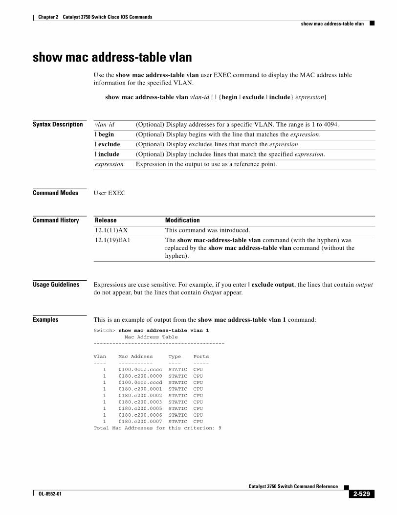
Chapter 2 Catalyst 3750 Switch Cisco IOS Commandsshow mac address-table vlan
show mac address-table vlanUse the show mac address-table vlan user EXEC command to display the MAC address table information for the specified VLAN.
show mac address-table vlan vlan-id [ | {begin | exclude | include} expression]
Syntax Description
Command Modes User EXEC
Command History
Usage Guidelines Expressions are case sensitive. For example, if you enter | exclude output, the lines that contain output do not appear, but the lines that contain Output appear.
Examples This is an example of output from the show mac address-table vlan 1 command:
Switch> show mac address-table vlan 1 Mac Address Table------------------------------------------
Vlan Mac Address Type Ports---- ----------- ---- ----- 1 0100.0ccc.cccc STATIC CPU 1 0180.c200.0000 STATIC CPU 1 0100.0ccc.cccd STATIC CPU 1 0180.c200.0001 STATIC CPU 1 0180.c200.0002 STATIC CPU 1 0180.c200.0003 STATIC CPU
1 0180.c200.0005 STATIC CPU 1 0180.c200.0006 STATIC CPU 1 0180.c200.0007 STATIC CPUTotal Mac Addresses for this criterion: 9
vlan-id (Optional) Display addresses for a specific VLAN. The range is 1 to 4094.
| begin (Optional) Display begins with the line that matches the expression.
| exclude (Optional) Display excludes lines that match the expression.
| include (Optional) Display includes lines that match the specified expression.
expression Expression in the output to use as a reference point.
Release Modification
12.1(11)AX This command was introduced.
12.1(19)EA1 The show mac-address-table vlan command (with the hyphen) was replaced by the show mac address-table vlan command (without the hyphen).
2-529Catalyst 3750 Switch Command Reference
OL-8552-01
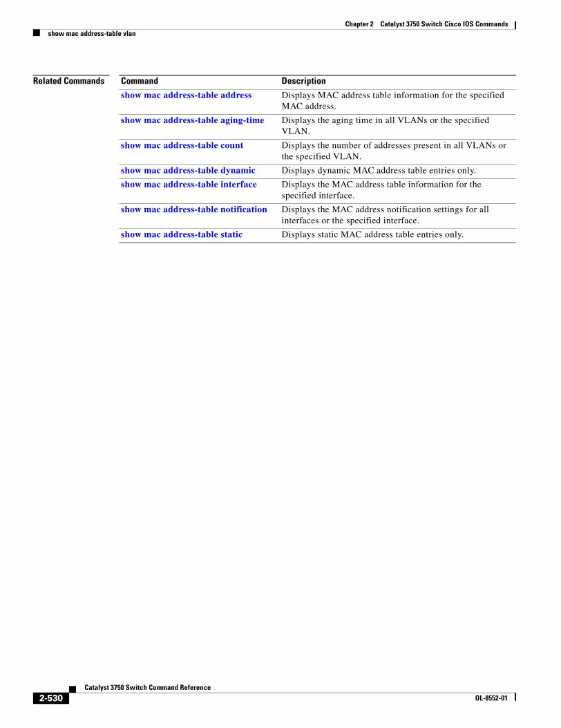
Chapter 2 Catalyst 3750 Switch Cisco IOS Commandsshow mac address-table vlan
Related Commands Command Description
show mac address-table address Displays MAC address table information for the specified MAC address.
show mac address-table aging-time Displays the aging time in all VLANs or the specified VLAN.
show mac address-table count Displays the number of addresses present in all VLANs or the specified VLAN.
show mac address-table dynamic Displays dynamic MAC address table entries only.
show mac address-table interface Displays the MAC address table information for the specified interface.
show mac address-table notification Displays the MAC address notification settings for all interfaces or the specified interface.
show mac address-table static Displays static MAC address table entries only.
2-530Catalyst 3750 Switch Command Reference
OL-8552-01
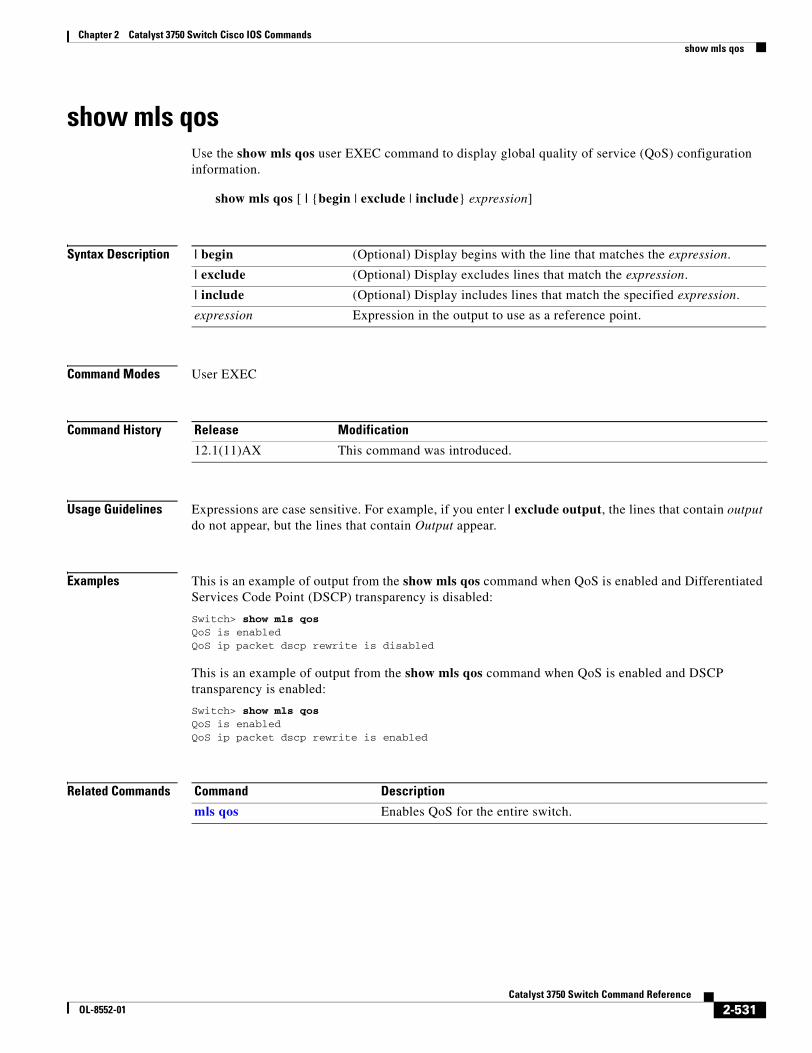
Chapter 2 Catalyst 3750 Switch Cisco IOS Commandsshow mls qos
show mls qosUse the show mls qos user EXEC command to display global quality of service (QoS) configuration information.
show mls qos [ | {begin | exclude | include} expression]
Syntax Description
Command Modes User EXEC
Command History
Usage Guidelines Expressions are case sensitive. For example, if you enter | exclude output, the lines that contain output do not appear, but the lines that contain Output appear.
Examples This is an example of output from the show mls qos command when QoS is enabled and Differentiated Services Code Point (DSCP) transparency is disabled:
Switch> show mls qosQoS is enabledQoS ip packet dscp rewrite is disabled
This is an example of output from the show mls qos command when QoS is enabled and DSCP transparency is enabled:
Switch> show mls qosQoS is enabledQoS ip packet dscp rewrite is enabled
Related Commands
| begin (Optional) Display begins with the line that matches the expression.
| exclude (Optional) Display excludes lines that match the expression.
| include (Optional) Display includes lines that match the specified expression.
expression Expression in the output to use as a reference point.
Release Modification
12.1(11)AX This command was introduced.
Command Description
mls qos Enables QoS for the entire switch.
2-531Catalyst 3750 Switch Command Reference
OL-8552-01
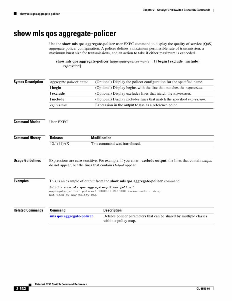
Chapter 2 Catalyst 3750 Switch Cisco IOS Commandsshow mls qos aggregate-policer
show mls qos aggregate-policerUse the show mls qos aggregate-policer user EXEC command to display the quality of service (QoS) aggregate policer configuration. A policer defines a maximum permissible rate of transmission, a maximum burst size for transmissions, and an action to take if either maximum is exceeded.
show mls qos aggregate-policer [aggregate-policer-name] [ | {begin | exclude | include} expression]
Syntax Description
Command Modes User EXEC
Command History
Usage Guidelines Expressions are case sensitive. For example, if you enter | exclude output, the lines that contain output do not appear, but the lines that contain Output appear.
Examples This is an example of output from the show mls qos aggregate-policer command:
Switch> show mls qos aggregate-policer policer1aggregate-policer policer1 1000000 2000000 exceed-action dropNot used by any policy map
Related Commands
aggregate-policer-name (Optional) Display the policer configuration for the specified name.
| begin (Optional) Display begins with the line that matches the expression.
| exclude (Optional) Display excludes lines that match the expression.
| include (Optional) Display includes lines that match the specified expression.
expression Expression in the output to use as a reference point.
Release Modification
12.1(11)AX This command was introduced.
Command Description
mls qos aggregate-policer Defines policer parameters that can be shared by multiple classes within a policy map.
2-532Catalyst 3750 Switch Command Reference
OL-8552-01
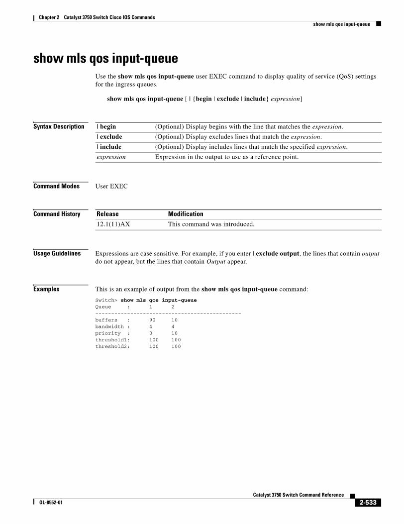
Chapter 2 Catalyst 3750 Switch Cisco IOS Commandsshow mls qos input-queue
show mls qos input-queueUse the show mls qos input-queue user EXEC command to display quality of service (QoS) settings for the ingress queues.
show mls qos input-queue [ | {begin | exclude | include} expression]
Syntax Description
Command Modes User EXEC
Command History
Usage Guidelines Expressions are case sensitive. For example, if you enter | exclude output, the lines that contain output do not appear, but the lines that contain Output appear.
Examples This is an example of output from the show mls qos input-queue command:
Switch> show mls qos input-queueQueue : 1 2----------------------------------------------buffers : 90 10bandwidth : 4 4priority : 0 10threshold1: 100 100threshold2: 100 100
| begin (Optional) Display begins with the line that matches the expression.
| exclude (Optional) Display excludes lines that match the expression.
| include (Optional) Display includes lines that match the specified expression.
expression Expression in the output to use as a reference point.
Release Modification
12.1(11)AX This command was introduced.
2-533Catalyst 3750 Switch Command Reference
OL-8552-01
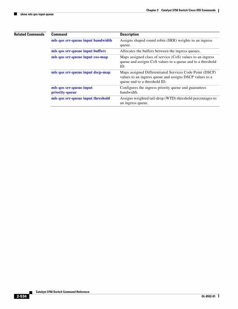
Chapter 2 Catalyst 3750 Switch Cisco IOS Commandsshow mls qos input-queue
Related Commands Command Description
mls qos srr-queue input bandwidth Assigns shaped round robin (SRR) weights to an ingress queue.
mls qos srr-queue input buffers Allocates the buffers between the ingress queues.
mls qos srr-queue input cos-map Maps assigned class of service (CoS) values to an ingress queue and assigns CoS values to a queue and to a threshold ID.
mls qos srr-queue input dscp-map Maps assigned Differentiated Services Code Point (DSCP) values to an ingress queue and assigns DSCP values to a queue and to a threshold ID.
mls qos srr-queue input priority-queue
Configures the ingress priority queue and guarantees bandwidth.
mls qos srr-queue input threshold Assigns weighted tail-drop (WTD) threshold percentages to an ingress queue.
2-534Catalyst 3750 Switch Command Reference
OL-8552-01
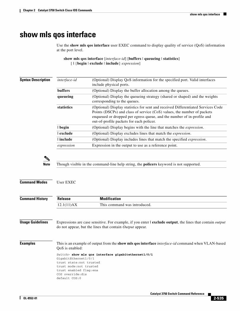
Chapter 2 Catalyst 3750 Switch Cisco IOS Commandsshow mls qos interface
show mls qos interfaceUse the show mls qos interface user EXEC command to display quality of service (QoS) information at the port level.
show mls qos interface [interface-id] [buffers | queueing | statistics] [ | {begin | exclude | include} expression]
Syntax Description
Note Though visible in the command-line help string, the policers keyword is not supported.
Command Modes User EXEC
Command History
Usage Guidelines Expressions are case sensitive. For example, if you enter | exclude output, the lines that contain output do not appear, but the lines that contain Output appear.
Examples This is an example of output from the show mls qos interface interface-id command when VLAN-based QoS is enabled:
Switch> show mls qos interface gigabitethernet1/0/1GigabitEthernet1/0/1trust state:not trustedtrust mode:not trustedtrust enabled flag:enaCOS override:disdefault COS:0
interface-id (Optional) Display QoS information for the specified port. Valid interfaces include physical ports.
buffers (Optional) Display the buffer allocation among the queues.
queueing (Optional) Display the queueing strategy (shared or shaped) and the weights corresponding to the queues.
statistics (Optional) Display statistics for sent and received Differentiated Services Code Points (DSCPs) and class of service (CoS) values, the number of packets enqueued or dropped per egress queue, and the number of in-profile and out-of-profile packets for each policer.
| begin (Optional) Display begins with the line that matches the expression.
| exclude (Optional) Display excludes lines that match the expression.
| include (Optional) Display includes lines that match the specified expression.
expression Expression in the output to use as a reference point.
Release Modification
12.1(11)AX This command was introduced.
2-535Catalyst 3750 Switch Command Reference
OL-8552-01
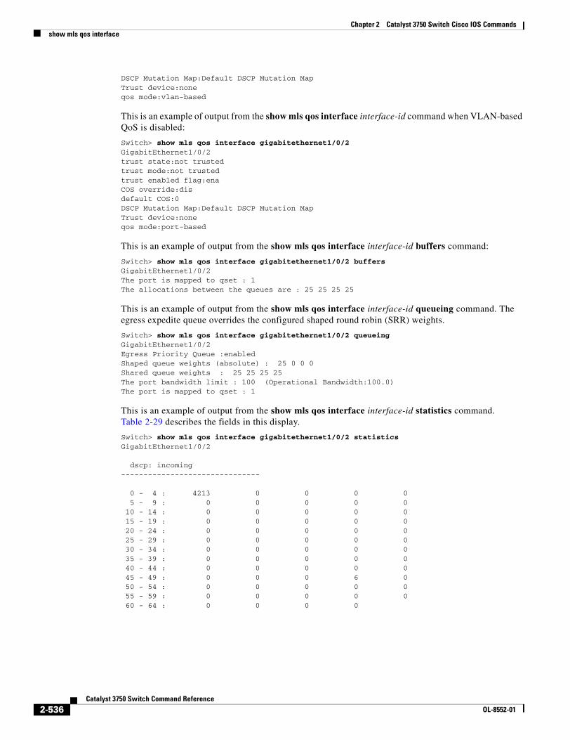
Chapter 2 Catalyst 3750 Switch Cisco IOS Commandsshow mls qos interface
DSCP Mutation Map:Default DSCP Mutation MapTrust device:noneqos mode:vlan-based
This is an example of output from the show mls qos interface interface-id command when VLAN-based QoS is disabled:
Switch> show mls qos interface gigabitethernet1/0/2GigabitEthernet1/0/2trust state:not trustedtrust mode:not trustedtrust enabled flag:enaCOS override:disdefault COS:0DSCP Mutation Map:Default DSCP Mutation MapTrust device:noneqos mode:port-based
This is an example of output from the show mls qos interface interface-id buffers command:
Switch> show mls qos interface gigabitethernet1/0/2 buffersGigabitEthernet1/0/2The port is mapped to qset : 1The allocations between the queues are : 25 25 25 25
This is an example of output from the show mls qos interface interface-id queueing command. The egress expedite queue overrides the configured shaped round robin (SRR) weights.
Switch> show mls qos interface gigabitethernet1/0/2 queueingGigabitEthernet1/0/2Egress Priority Queue :enabledShaped queue weights (absolute) : 25 0 0 0Shared queue weights : 25 25 25 25The port bandwidth limit : 100 (Operational Bandwidth:100.0)The port is mapped to qset : 1
This is an example of output from the show mls qos interface interface-id statistics command. Table 2-29 describes the fields in this display.
Switch> show mls qos interface gigabitethernet1/0/2 statisticsGigabitEthernet1/0/2
dscp: incoming-------------------------------
0 - 4 : 4213 0 0 0 0 5 - 9 : 0 0 0 0 0 10 - 14 : 0 0 0 0 0 15 - 19 : 0 0 0 0 0 20 - 24 : 0 0 0 0 0 25 - 29 : 0 0 0 0 0 30 - 34 : 0 0 0 0 0 35 - 39 : 0 0 0 0 0 40 - 44 : 0 0 0 0 0 45 - 49 : 0 0 0 6 0 50 - 54 : 0 0 0 0 0 55 - 59 : 0 0 0 0 0 60 - 64 : 0 0 0 0
2-536Catalyst 3750 Switch Command Reference
OL-8552-01
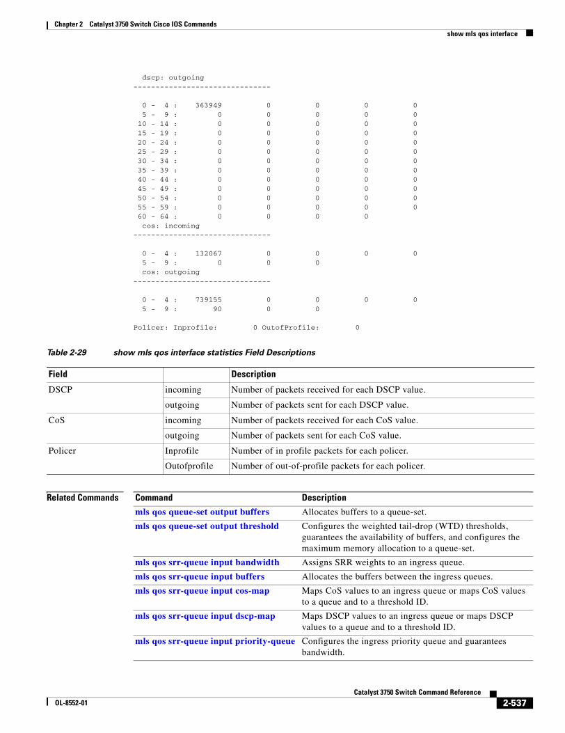
Chapter 2 Catalyst 3750 Switch Cisco IOS Commandsshow mls qos interface
dscp: outgoing-------------------------------
0 - 4 : 363949 0 0 0 0 5 - 9 : 0 0 0 0 0 10 - 14 : 0 0 0 0 0 15 - 19 : 0 0 0 0 0 20 - 24 : 0 0 0 0 0 25 - 29 : 0 0 0 0 0 30 - 34 : 0 0 0 0 0 35 - 39 : 0 0 0 0 0 40 - 44 : 0 0 0 0 0 45 - 49 : 0 0 0 0 0 50 - 54 : 0 0 0 0 0 55 - 59 : 0 0 0 0 0 60 - 64 : 0 0 0 0 cos: incoming-------------------------------
0 - 4 : 132067 0 0 0 0 5 - 9 : 0 0 0 cos: outgoing-------------------------------
0 - 4 : 739155 0 0 0 0 5 - 9 : 90 0 0
Policer: Inprofile: 0 OutofProfile: 0
Related Commands
Table 2-29 show mls qos interface statistics Field Descriptions
Field Description
DSCP incoming Number of packets received for each DSCP value.
outgoing Number of packets sent for each DSCP value.
CoS incoming Number of packets received for each CoS value.
outgoing Number of packets sent for each CoS value.
Policer Inprofile Number of in profile packets for each policer.
Outofprofile Number of out-of-profile packets for each policer.
Command Description
mls qos queue-set output buffers Allocates buffers to a queue-set.
mls qos queue-set output threshold Configures the weighted tail-drop (WTD) thresholds, guarantees the availability of buffers, and configures the maximum memory allocation to a queue-set.
mls qos srr-queue input bandwidth Assigns SRR weights to an ingress queue.
mls qos srr-queue input buffers Allocates the buffers between the ingress queues.
mls qos srr-queue input cos-map Maps CoS values to an ingress queue or maps CoS values to a queue and to a threshold ID.
mls qos srr-queue input dscp-map Maps DSCP values to an ingress queue or maps DSCP values to a queue and to a threshold ID.
mls qos srr-queue input priority-queue Configures the ingress priority queue and guarantees bandwidth.
2-537Catalyst 3750 Switch Command Reference
OL-8552-01
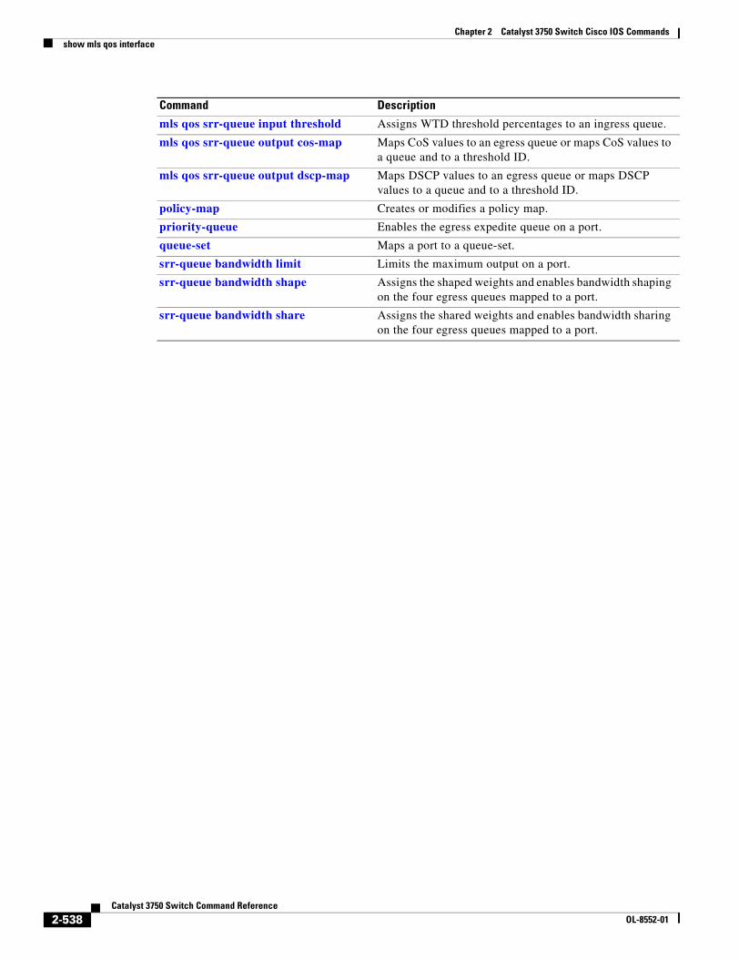
Chapter 2 Catalyst 3750 Switch Cisco IOS Commandsshow mls qos interface
mls qos srr-queue input threshold Assigns WTD threshold percentages to an ingress queue.
mls qos srr-queue output cos-map Maps CoS values to an egress queue or maps CoS values to a queue and to a threshold ID.
mls qos srr-queue output dscp-map Maps DSCP values to an egress queue or maps DSCP values to a queue and to a threshold ID.
policy-map Creates or modifies a policy map.
priority-queue Enables the egress expedite queue on a port.
queue-set Maps a port to a queue-set.
srr-queue bandwidth limit Limits the maximum output on a port.
srr-queue bandwidth shape Assigns the shaped weights and enables bandwidth shaping on the four egress queues mapped to a port.
srr-queue bandwidth share Assigns the shared weights and enables bandwidth sharing on the four egress queues mapped to a port.
Command Description
2-538Catalyst 3750 Switch Command Reference
OL-8552-01
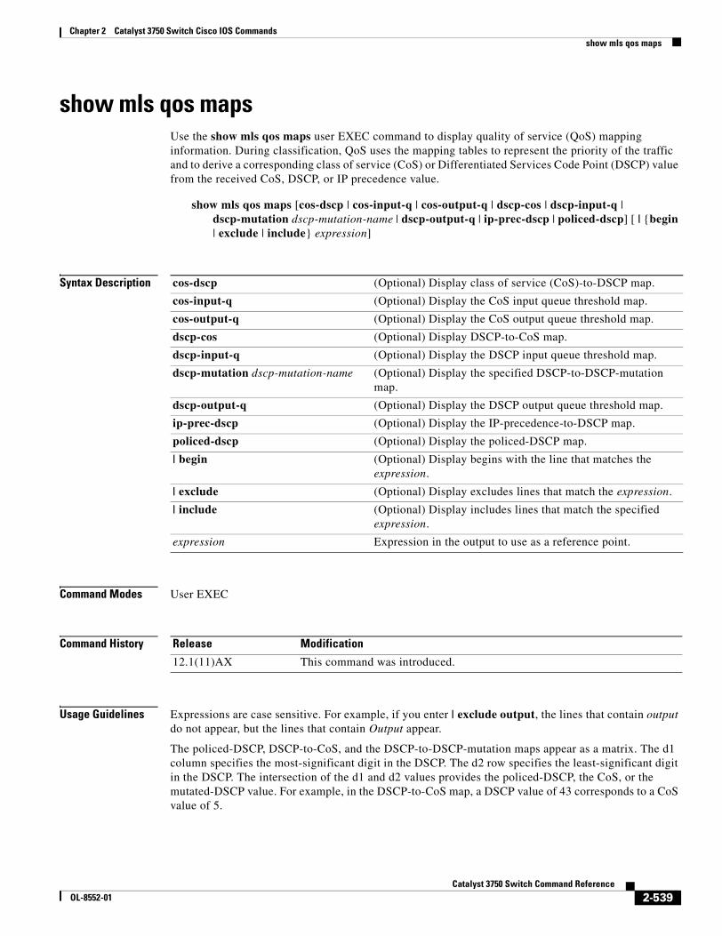
Chapter 2 Catalyst 3750 Switch Cisco IOS Commandsshow mls qos maps
show mls qos mapsUse the show mls qos maps user EXEC command to display quality of service (QoS) mapping information. During classification, QoS uses the mapping tables to represent the priority of the traffic and to derive a corresponding class of service (CoS) or Differentiated Services Code Point (DSCP) value from the received CoS, DSCP, or IP precedence value.
show mls qos maps [cos-dscp | cos-input-q | cos-output-q | dscp-cos | dscp-input-q | dscp-mutation dscp-mutation-name | dscp-output-q | ip-prec-dscp | policed-dscp] [ | {begin | exclude | include} expression]
Syntax Description
Command Modes User EXEC
Command History
Usage Guidelines Expressions are case sensitive. For example, if you enter | exclude output, the lines that contain output do not appear, but the lines that contain Output appear.
The policed-DSCP, DSCP-to-CoS, and the DSCP-to-DSCP-mutation maps appear as a matrix. The d1 column specifies the most-significant digit in the DSCP. The d2 row specifies the least-significant digit in the DSCP. The intersection of the d1 and d2 values provides the policed-DSCP, the CoS, or the mutated-DSCP value. For example, in the DSCP-to-CoS map, a DSCP value of 43 corresponds to a CoS value of 5.
cos-dscp (Optional) Display class of service (CoS)-to-DSCP map.
cos-input-q (Optional) Display the CoS input queue threshold map.
cos-output-q (Optional) Display the CoS output queue threshold map.
dscp-cos (Optional) Display DSCP-to-CoS map.
dscp-input-q (Optional) Display the DSCP input queue threshold map.
dscp-mutation dscp-mutation-name (Optional) Display the specified DSCP-to-DSCP-mutation map.
dscp-output-q (Optional) Display the DSCP output queue threshold map.
ip-prec-dscp (Optional) Display the IP-precedence-to-DSCP map.
policed-dscp (Optional) Display the policed-DSCP map.
| begin (Optional) Display begins with the line that matches the expression.
| exclude (Optional) Display excludes lines that match the expression.
| include (Optional) Display includes lines that match the specified expression.
expression Expression in the output to use as a reference point.
Release Modification
12.1(11)AX This command was introduced.
2-539Catalyst 3750 Switch Command Reference
OL-8552-01
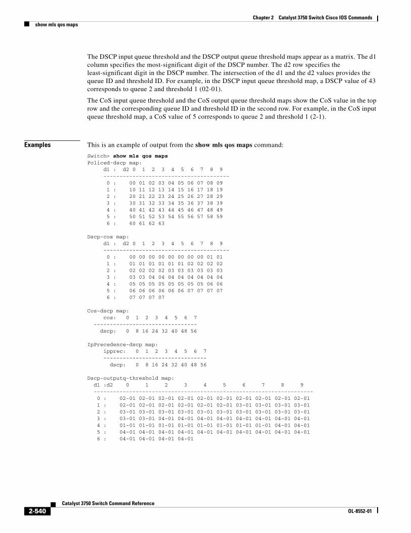
Chapter 2 Catalyst 3750 Switch Cisco IOS Commandsshow mls qos maps
The DSCP input queue threshold and the DSCP output queue threshold maps appear as a matrix. The d1 column specifies the most-significant digit of the DSCP number. The d2 row specifies the least-significant digit in the DSCP number. The intersection of the d1 and the d2 values provides the queue ID and threshold ID. For example, in the DSCP input queue threshold map, a DSCP value of 43 corresponds to queue 2 and threshold 1 (02-01).
The CoS input queue threshold and the CoS output queue threshold maps show the CoS value in the top row and the corresponding queue ID and threshold ID in the second row. For example, in the CoS input queue threshold map, a CoS value of 5 corresponds to queue 2 and threshold 1 (2-1).
Examples This is an example of output from the show mls qos maps command:
Switch> show mls qos mapsPoliced-dscp map: d1 : d2 0 1 2 3 4 5 6 7 8 9 --------------------------------------- 0 : 00 01 02 03 04 05 06 07 08 09 1 : 10 11 12 13 14 15 16 17 18 19 2 : 20 21 22 23 24 25 26 27 28 29 3 : 30 31 32 33 34 35 36 37 38 39 4 : 40 41 42 43 44 45 46 47 48 49 5 : 50 51 52 53 54 55 56 57 58 59 6 : 60 61 62 63
Dscp-cos map: d1 : d2 0 1 2 3 4 5 6 7 8 9 --------------------------------------- 0 : 00 00 00 00 00 00 00 00 01 01 1 : 01 01 01 01 01 01 02 02 02 02 2 : 02 02 02 02 03 03 03 03 03 03 3 : 03 03 04 04 04 04 04 04 04 04 4 : 05 05 05 05 05 05 05 05 06 06 5 : 06 06 06 06 06 06 07 07 07 07 6 : 07 07 07 07
Cos-dscp map: cos: 0 1 2 3 4 5 6 7 -------------------------------- dscp: 0 8 16 24 32 40 48 56
IpPrecedence-dscp map: ipprec: 0 1 2 3 4 5 6 7 -------------------------------- dscp: 0 8 16 24 32 40 48 56
Dscp-outputq-threshold map: d1 :d2 0 1 2 3 4 5 6 7 8 9 -------------------------------------------------------------------- 0 : 02-01 02-01 02-01 02-01 02-01 02-01 02-01 02-01 02-01 02-01 1 : 02-01 02-01 02-01 02-01 02-01 02-01 03-01 03-01 03-01 03-01 2 : 03-01 03-01 03-01 03-01 03-01 03-01 03-01 03-01 03-01 03-01 3 : 03-01 03-01 04-01 04-01 04-01 04-01 04-01 04-01 04-01 04-01 4 : 01-01 01-01 01-01 01-01 01-01 01-01 01-01 01-01 04-01 04-01 5 : 04-01 04-01 04-01 04-01 04-01 04-01 04-01 04-01 04-01 04-01 6 : 04-01 04-01 04-01 04-01
2-540Catalyst 3750 Switch Command Reference
OL-8552-01
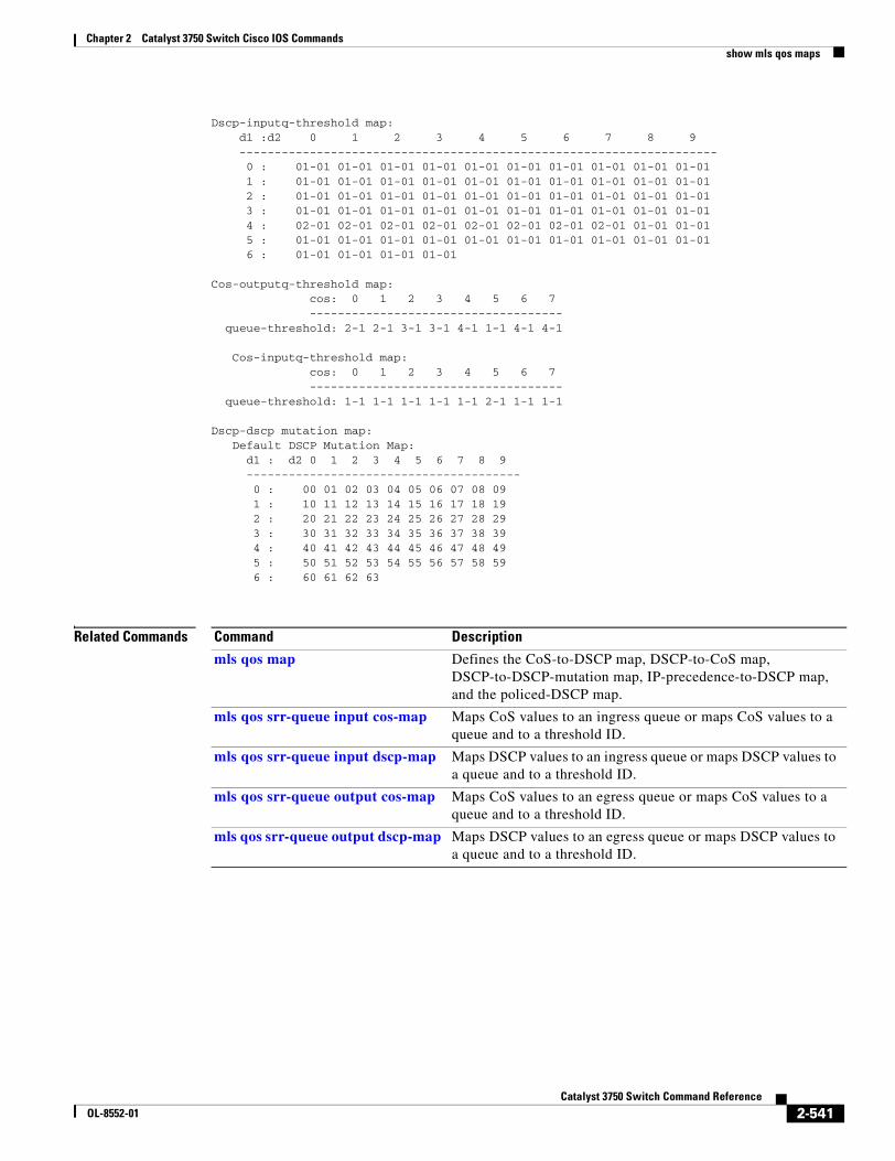
Chapter 2 Catalyst 3750 Switch Cisco IOS Commandsshow mls qos maps
Dscp-inputq-threshold map: d1 :d2 0 1 2 3 4 5 6 7 8 9 -------------------------------------------------------------------- 0 : 01-01 01-01 01-01 01-01 01-01 01-01 01-01 01-01 01-01 01-01 1 : 01-01 01-01 01-01 01-01 01-01 01-01 01-01 01-01 01-01 01-01 2 : 01-01 01-01 01-01 01-01 01-01 01-01 01-01 01-01 01-01 01-01 3 : 01-01 01-01 01-01 01-01 01-01 01-01 01-01 01-01 01-01 01-01 4 : 02-01 02-01 02-01 02-01 02-01 02-01 02-01 02-01 01-01 01-01 5 : 01-01 01-01 01-01 01-01 01-01 01-01 01-01 01-01 01-01 01-01 6 : 01-01 01-01 01-01 01-01
Cos-outputq-threshold map: cos: 0 1 2 3 4 5 6 7 ------------------------------------ queue-threshold: 2-1 2-1 3-1 3-1 4-1 1-1 4-1 4-1
Cos-inputq-threshold map: cos: 0 1 2 3 4 5 6 7 ------------------------------------ queue-threshold: 1-1 1-1 1-1 1-1 1-1 2-1 1-1 1-1
Dscp-dscp mutation map: Default DSCP Mutation Map: d1 : d2 0 1 2 3 4 5 6 7 8 9 --------------------------------------- 0 : 00 01 02 03 04 05 06 07 08 09 1 : 10 11 12 13 14 15 16 17 18 19 2 : 20 21 22 23 24 25 26 27 28 29 3 : 30 31 32 33 34 35 36 37 38 39 4 : 40 41 42 43 44 45 46 47 48 49 5 : 50 51 52 53 54 55 56 57 58 59 6 : 60 61 62 63
Related Commands Command Description
mls qos map Defines the CoS-to-DSCP map, DSCP-to-CoS map, DSCP-to-DSCP-mutation map, IP-precedence-to-DSCP map, and the policed-DSCP map.
mls qos srr-queue input cos-map Maps CoS values to an ingress queue or maps CoS values to a queue and to a threshold ID.
mls qos srr-queue input dscp-map Maps DSCP values to an ingress queue or maps DSCP values to a queue and to a threshold ID.
mls qos srr-queue output cos-map Maps CoS values to an egress queue or maps CoS values to a queue and to a threshold ID.
mls qos srr-queue output dscp-map Maps DSCP values to an egress queue or maps DSCP values to a queue and to a threshold ID.
2-541Catalyst 3750 Switch Command Reference
OL-8552-01
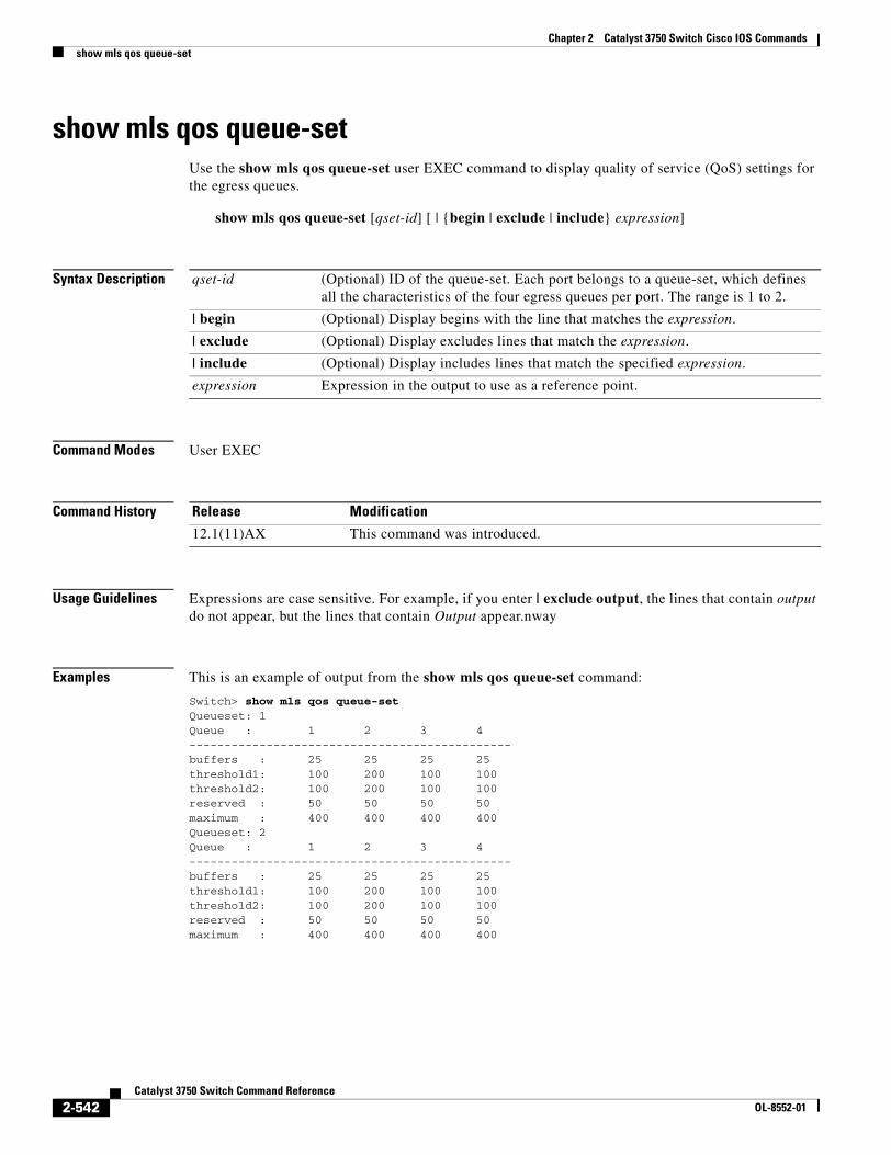
Chapter 2 Catalyst 3750 Switch Cisco IOS Commandsshow mls qos queue-set
show mls qos queue-setUse the show mls qos queue-set user EXEC command to display quality of service (QoS) settings for the egress queues.
show mls qos queue-set [qset-id] [ | {begin | exclude | include} expression]
Syntax Description
Command Modes User EXEC
Command History
Usage Guidelines Expressions are case sensitive. For example, if you enter | exclude output, the lines that contain output do not appear, but the lines that contain Output appear.nway
Examples This is an example of output from the show mls qos queue-set command:
Switch> show mls qos queue-setQueueset: 1Queue : 1 2 3 4----------------------------------------------buffers : 25 25 25 25threshold1: 100 200 100 100threshold2: 100 200 100 100reserved : 50 50 50 50maximum : 400 400 400 400Queueset: 2Queue : 1 2 3 4----------------------------------------------buffers : 25 25 25 25threshold1: 100 200 100 100threshold2: 100 200 100 100reserved : 50 50 50 50maximum : 400 400 400 400
qset-id (Optional) ID of the queue-set. Each port belongs to a queue-set, which defines all the characteristics of the four egress queues per port. The range is 1 to 2.
| begin (Optional) Display begins with the line that matches the expression.
| exclude (Optional) Display excludes lines that match the expression.
| include (Optional) Display includes lines that match the specified expression.
expression Expression in the output to use as a reference point.
Release Modification
12.1(11)AX This command was introduced.
2-542Catalyst 3750 Switch Command Reference
OL-8552-01

Chapter 2 Catalyst 3750 Switch Cisco IOS Commandsshow mls qos queue-set
Related Commands Command Description
mls qos queue-set output buffers Allocates buffers to the queue-set.
mls qos queue-set output threshold Configures the weighted tail-drop (WTD) thresholds, guarantees the availability of buffers, and configures the maximum memory allocation of the queue-set.
2-543Catalyst 3750 Switch Command Reference
OL-8552-01
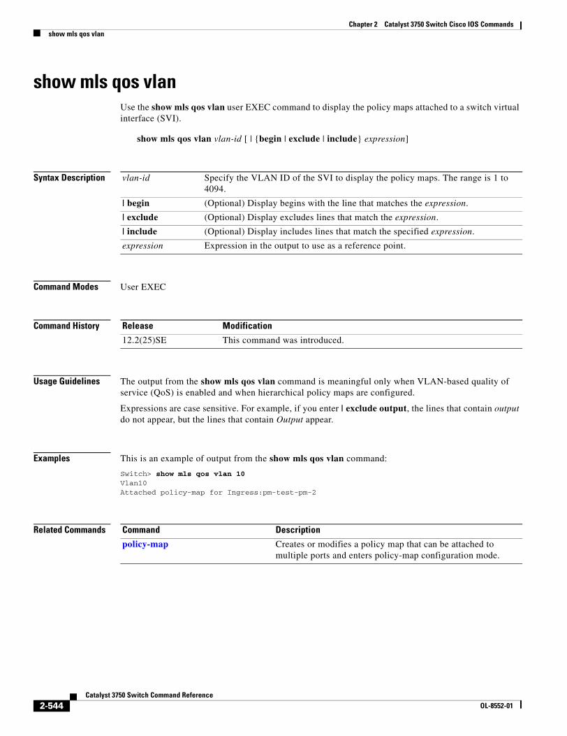
Chapter 2 Catalyst 3750 Switch Cisco IOS Commandsshow mls qos vlan
show mls qos vlanUse the show mls qos vlan user EXEC command to display the policy maps attached to a switch virtual interface (SVI).
show mls qos vlan vlan-id [ | {begin | exclude | include} expression]
Syntax Description
Command Modes User EXEC
Command History
Usage Guidelines The output from the show mls qos vlan command is meaningful only when VLAN-based quality of service (QoS) is enabled and when hierarchical policy maps are configured.
Expressions are case sensitive. For example, if you enter | exclude output, the lines that contain output do not appear, but the lines that contain Output appear.
Examples This is an example of output from the show mls qos vlan command:
Switch> show mls qos vlan 10Vlan10Attached policy-map for Ingress:pm-test-pm-2
Related Commands
vlan-id Specify the VLAN ID of the SVI to display the policy maps. The range is 1 to 4094.
| begin (Optional) Display begins with the line that matches the expression.
| exclude (Optional) Display excludes lines that match the expression.
| include (Optional) Display includes lines that match the specified expression.
expression Expression in the output to use as a reference point.
Release Modification
12.2(25)SE This command was introduced.
Command Description
policy-map Creates or modifies a policy map that can be attached to multiple ports and enters policy-map configuration mode.
2-544Catalyst 3750 Switch Command Reference
OL-8552-01
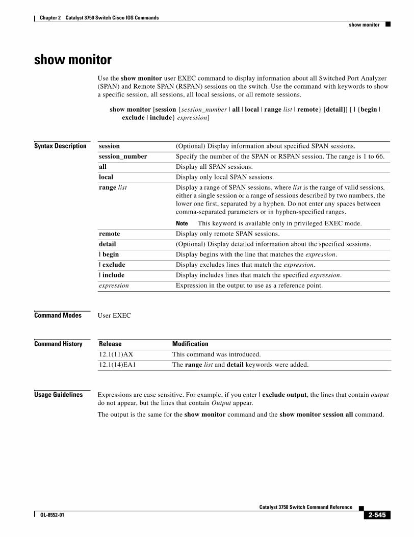
Chapter 2 Catalyst 3750 Switch Cisco IOS Commandsshow monitor
show monitorUse the show monitor user EXEC command to display information about all Switched Port Analyzer (SPAN) and Remote SPAN (RSPAN) sessions on the switch. Use the command with keywords to show a specific session, all sessions, all local sessions, or all remote sessions.
show monitor [session {session_number | all | local | range list | remote} [detail]] [ | {begin | exclude | include} expression]
Syntax Description
Command Modes User EXEC
Command History
Usage Guidelines Expressions are case sensitive. For example, if you enter | exclude output, the lines that contain output do not appear, but the lines that contain Output appear.
The output is the same for the show monitor command and the show monitor session all command.
session (Optional) Display information about specified SPAN sessions.
session_number Specify the number of the SPAN or RSPAN session. The range is 1 to 66.
all Display all SPAN sessions.
local Display only local SPAN sessions.
range list Display a range of SPAN sessions, where list is the range of valid sessions, either a single session or a range of sessions described by two numbers, the lower one first, separated by a hyphen. Do not enter any spaces between comma-separated parameters or in hyphen-specified ranges.
Note This keyword is available only in privileged EXEC mode.
remote Display only remote SPAN sessions.
detail (Optional) Display detailed information about the specified sessions.
| begin Display begins with the line that matches the expression.
| exclude Display excludes lines that match the expression.
| include Display includes lines that match the specified expression.
expression Expression in the output to use as a reference point.
Release Modification
12.1(11)AX This command was introduced.
12.1(14)EA1 The range list and detail keywords were added.
2-545Catalyst 3750 Switch Command Reference
OL-8552-01
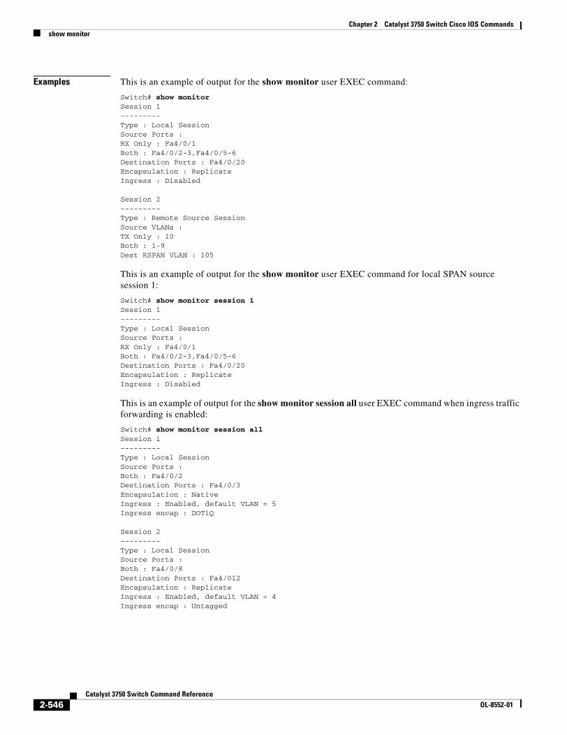
Chapter 2 Catalyst 3750 Switch Cisco IOS Commandsshow monitor
Examples This is an example of output for the show monitor user EXEC command:
Switch# show monitorSession 1---------Type : Local SessionSource Ports :RX Only : Fa4/0/1Both : Fa4/0/2-3,Fa4/0/5-6Destination Ports : Fa4/0/20Encapsulation : ReplicateIngress : Disabled
Session 2---------Type : Remote Source SessionSource VLANs :TX Only : 10Both : 1-9Dest RSPAN VLAN : 105
This is an example of output for the show monitor user EXEC command for local SPAN source session 1:
Switch# show monitor session 1Session 1---------Type : Local SessionSource Ports :RX Only : Fa4/0/1Both : Fa4/0/2-3,Fa4/0/5-6Destination Ports : Fa4/0/20Encapsulation : ReplicateIngress : Disabled
This is an example of output for the show monitor session all user EXEC command when ingress traffic forwarding is enabled:
Switch# show monitor session allSession 1---------Type : Local SessionSource Ports :Both : Fa4/0/2Destination Ports : Fa4/0/3Encapsulation : NativeIngress : Enabled, default VLAN = 5Ingress encap : DOT1Q
Session 2---------Type : Local SessionSource Ports :Both : Fa4/0/8Destination Ports : Fa4/012Encapsulation : ReplicateIngress : Enabled, default VLAN = 4Ingress encap : Untagged
2-546Catalyst 3750 Switch Command Reference
OL-8552-01

Chapter 2 Catalyst 3750 Switch Cisco IOS Commandsshow monitor
Related Commands Command Description
monitor session Starts or modifies a SPAN or RSPAN session.
2-547Catalyst 3750 Switch Command Reference
OL-8552-01
Chapter 2 Catalyst 3750 Switch Cisco IOS Commandsshow mvr
show mvrUse the show mvr privileged EXEC command without keywords to display the current Multicast VLAN Registration (MVR) global parameter values, including whether or not MVR is enabled, the MVR multicast VLAN, the maximum query response time, the number of multicast groups, and the MVR mode (dynamic or compatible).
show mvr [ | {begin | exclude | include} expression]
Syntax Description
Command Modes Privileged EXEC
Command History
Usage Guidelines Expressions are case sensitive. For example, if you enter | exclude output, the lines that contain output do not appear, but the lines that contain Output appear.
Examples This is an example of output from the show mvr command:
Switch# show mvrMVR Running: TRUEMVR multicast VLAN: 1MVR Max Multicast Groups: 256MVR Current multicast groups: 0MVR Global query response time: 5 (tenths of sec)MVR Mode: compatible
In the preceding display, the maximum number of multicast groups is fixed at 256. The MVR mode is either compatible (for interoperability with Catalyst 2900 XL and Catalyst 3500 XL switches) or dynamic (where operation is consistent with IGMP snooping operation and dynamic MVR membership on source ports is supported).
| begin (Optional) Display begins with the line that matches the expression.
| exclude (Optional) Display excludes lines that match the expression.
| include (Optional) Display includes lines that match the specified expression.
expression Expression in the output to use as a reference point.
Release Modification
12.1(11)AX This command was introduced.
2-548Catalyst 3750 Switch Command Reference
OL-8552-01
Chapter 2 Catalyst 3750 Switch Cisco IOS Commandsshow mvr
Related Commands Command Description
mvr (global configuration) Enables and configures multicast VLAN registration on the switch.
mvr (interface configuration) Configures MVR ports.
show mvr interface Displays the configured MVR interfaces, status of the specified interface, or all multicast groups to which the interface belongs when the interface and members keywords are appended to the command.
show mvr members Displays all ports that are members of an MVR multicast group or, if there are no members, means the group is inactive.
2-549Catalyst 3750 Switch Command Reference
OL-8552-01
Chapter 2 Catalyst 3750 Switch Cisco IOS Commandsshow mvr interface
show mvr interfaceUse the show mvr interface privileged EXEC command without keywords to display the Multicast VLAN Registration (MVR) receiver and source ports. Use the command with keywords to display MVR parameters for a specific receiver port.
show mvr interface [interface-id [members [vlan vlan-id]]] [ | {begin | exclude | include} expression]
Syntax Description
Command Modes Privileged EXEC
Command History
Usage Guidelines If the entered port identification is a non-MVR port or a source port, the command returns an error message. For receiver ports, it displays the port type, per port status, and Immediate-Leave setting.
If you enter the members keyword, all MVR group members on the interface appear. If you enter a VLAN ID, all MVR group members in the VLAN appear.
Expressions are case sensitive. For example, if you enter | exclude output, the lines that contain output do not appear, but the lines that contain Output appear.
Examples This is an example of output from the show mvr interface command:
Switch# show mvr interfacePort Type Status Immediate Leave---- ---- ------- ---------------Gi1/0/1 SOURCE ACTIVE/UP DISABLEDGi1/0/2 RECEIVER ACTIVE/DOWN DISABLED
interface-id (Optional) Display MVR type, status, and Immediate Leave setting for the interface.
Valid interfaces include physical ports (including type, stack member, module, and port number.
members (Optional) Display all MVR groups to which the specified interface belongs.
vlan vlan-id (Optional) Display all MVR group members on this VLAN. The range is 1 to 4094.
| begin (Optional) Display begins with the line that matches the expression.
| exclude (Optional) Display excludes lines that match the expression.
| include (Optional) Display includes lines that match the specified expression.
expression Expression in the output to use as a reference point.
Release Modification
12.1(11)AX This command was introduced.
2-550Catalyst 3750 Switch Command Reference
OL-8552-01
Chapter 2 Catalyst 3750 Switch Cisco IOS Commandsshow mvr interface
In the preceding display, Status is defined as follows:
• Active means the port is part of a VLAN.
• Up/Down means that the port is forwarding/nonforwarding.
• Inactive means that the port is not yet part of any VLAN.
This is an example of output from the show mvr interface command for a specified port:
Switch# show mvr interface gigabitethernet1/0/2Type: RECEIVER Status: ACTIVE Immediate Leave: DISABLED
This is an example of output from the show mvr interface interface-id members command:
Switch# show mvr interface gigabitethernet1/0/2 members239.255.0.0 DYNAMIC ACTIVE239.255.0.1 DYNAMIC ACTIVE239.255.0.2 DYNAMIC ACTIVE239.255.0.3 DYNAMIC ACTIVE239.255.0.4 DYNAMIC ACTIVE239.255.0.5 DYNAMIC ACTIVE239.255.0.6 DYNAMIC ACTIVE239.255.0.7 DYNAMIC ACTIVE239.255.0.8 DYNAMIC ACTIVE239.255.0.9 DYNAMIC ACTIVE
Related Commands Command Description
mvr (global configuration) Enables and configures multicast VLAN registration on the switch.
mvr (interface configuration) Configures MVR ports.
show mvr Displays the global MVR configuration on the switch.
show mvr members Displays all receiver ports that are members of an MVR multicast group.
2-551Catalyst 3750 Switch Command Reference
OL-8552-01
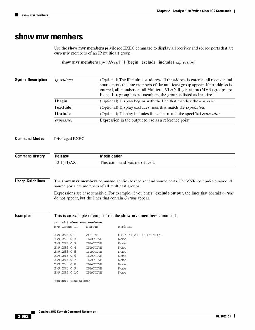
Chapter 2 Catalyst 3750 Switch Cisco IOS Commandsshow mvr members
show mvr membersUse the show mvr members privileged EXEC command to display all receiver and source ports that are currently members of an IP multicast group.
show mvr members [ip-address] [ | {begin | exclude | include} expression]
Syntax Description
Command Modes Privileged EXEC
Command History
Usage Guidelines The show mvr members command applies to receiver and source ports. For MVR-compatible mode, all source ports are members of all multicast groups.
Expressions are case sensitive. For example, if you enter | exclude output, the lines that contain output do not appear, but the lines that contain Output appear.
Examples This is an example of output from the show mvr members command:
Switch# show mvr membersMVR Group IP Status Members------------ ------ -------239.255.0.1 ACTIVE Gi1/0/1(d), Gi1/0/5(s)239.255.0.2 INACTIVE None239.255.0.3 INACTIVE None239.255.0.4 INACTIVE None239.255.0.5 INACTIVE None239.255.0.6 INACTIVE None239.255.0.7 INACTIVE None239.255.0.8 INACTIVE None239.255.0.9 INACTIVE None239.255.0.10 INACTIVE None
<output truncated>
ip-address (Optional) The IP multicast address. If the address is entered, all receiver and source ports that are members of the multicast group appear. If no address is entered, all members of all Multicast VLAN Registration (MVR) groups are listed. If a group has no members, the group is listed as Inactive.
| begin (Optional) Display begins with the line that matches the expression.
| exclude (Optional) Display excludes lines that match the expression.
| include (Optional) Display includes lines that match the specified expression.
expression Expression in the output to use as a reference point.
Release Modification
12.1(11)AX This command was introduced.
2-552Catalyst 3750 Switch Command Reference
OL-8552-01
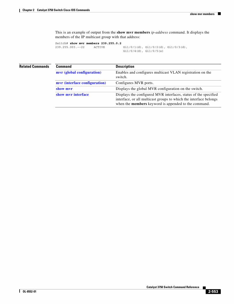
Chapter 2 Catalyst 3750 Switch Cisco IOS Commandsshow mvr members
This is an example of output from the show mvr members ip-address command. It displays the members of the IP multicast group with that address:
Switch# show mvr members 239.255.0.2239.255.003.--22 ACTIVE Gi1/0/1(d), Gi1/0/2(d), Gi1/0/3(d), Gi1/0/4(d), Gi1/0/5(s)
Related Commands Command Description
mvr (global configuration) Enables and configures multicast VLAN registration on the switch.
mvr (interface configuration) Configures MVR ports.
show mvr Displays the global MVR configuration on the switch.
show mvr interface Displays the configured MVR interfaces, status of the specified interface, or all multicast groups to which the interface belongs when the members keyword is appended to the command.
2-553Catalyst 3750 Switch Command Reference
OL-8552-01
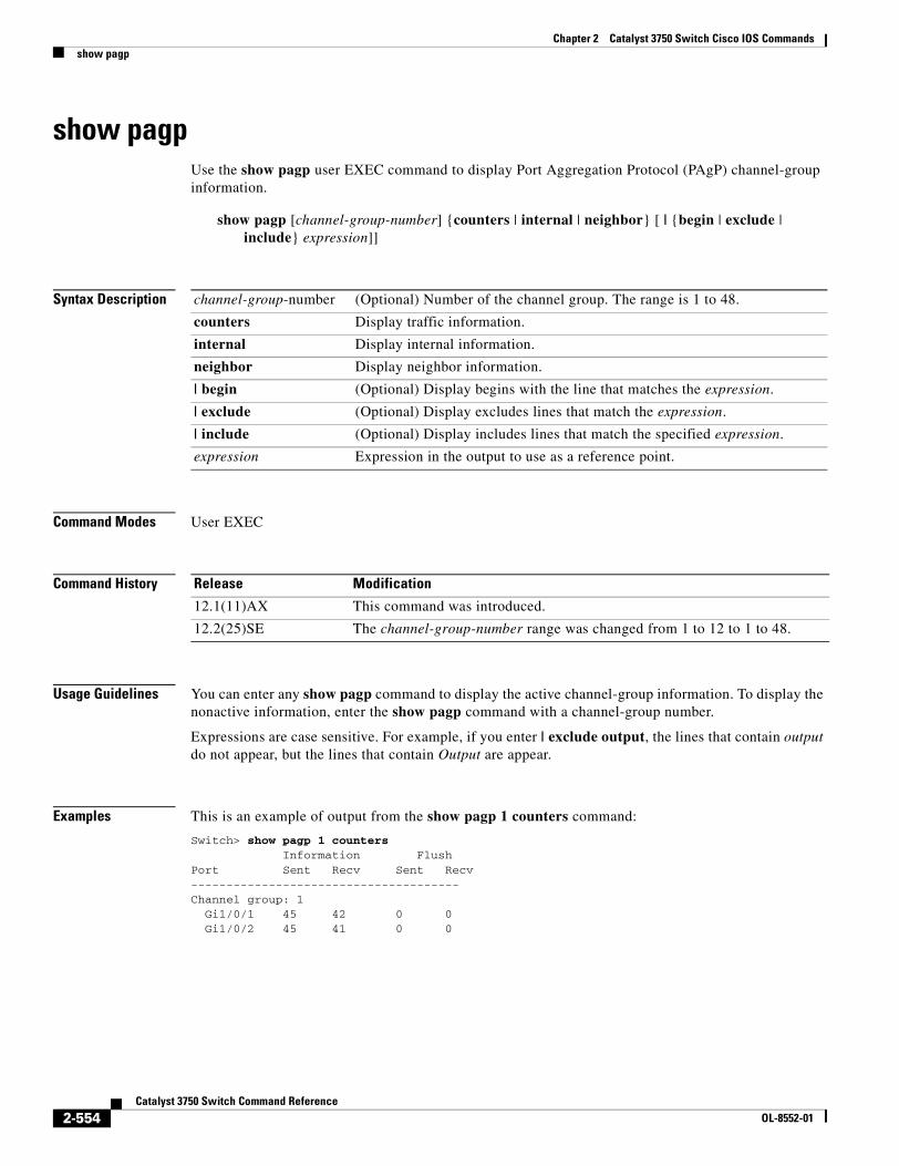
Chapter 2 Catalyst 3750 Switch Cisco IOS Commandsshow pagp
show pagpUse the show pagp user EXEC command to display Port Aggregation Protocol (PAgP) channel-group information.
show pagp [channel-group-number] {counters | internal | neighbor} [ | {begin | exclude | include} expression]]
Syntax Description
Command Modes User EXEC
Command History
Usage Guidelines You can enter any show pagp command to display the active channel-group information. To display the nonactive information, enter the show pagp command with a channel-group number.
Expressions are case sensitive. For example, if you enter | exclude output, the lines that contain output do not appear, but the lines that contain Output are appear.
Examples This is an example of output from the show pagp 1 counters command:
Switch> show pagp 1 counters Information FlushPort Sent Recv Sent Recv--------------------------------------Channel group: 1 Gi1/0/1 45 42 0 0 Gi1/0/2 45 41 0 0
channel-group-number (Optional) Number of the channel group. The range is 1 to 48.
counters Display traffic information.
internal Display internal information.
neighbor Display neighbor information.
| begin (Optional) Display begins with the line that matches the expression.
| exclude (Optional) Display excludes lines that match the expression.
| include (Optional) Display includes lines that match the specified expression.
expression Expression in the output to use as a reference point.
Release Modification
12.1(11)AX This command was introduced.
12.2(25)SE The channel-group-number range was changed from 1 to 12 to 1 to 48.
2-554Catalyst 3750 Switch Command Reference
OL-8552-01
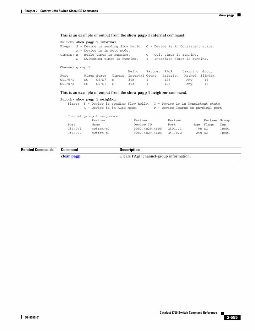
Chapter 2 Catalyst 3750 Switch Cisco IOS Commandsshow pagp
This is an example of output from the show pagp 1 internal command:
Switch> show pagp 1 internalFlags: S - Device is sending Slow hello. C - Device is in Consistent state. A - Device is in Auto mode.Timers: H - Hello timer is running. Q - Quit timer is running. S - Switching timer is running. I - Interface timer is running.
Channel group 1 Hello Partner PAgP Learning GroupPort Flags State Timers Interval Count Priority Method IfindexGi1/0/1 SC U6/S7 H 30s 1 128 Any 16Gi1/0/2 SC U6/S7 H 30s 1 128 Any 16
This is an example of output from the show pagp 1 neighbor command:
Switch> show pagp 1 neighborFlags: S - Device is sending Slow hello. C - Device is in Consistent state. A - Device is in Auto mode. P - Device learns on physical port.
Channel group 1 neighbors Partner Partner Partner Partner GroupPort Name Device ID Port Age Flags Cap.Gi1/0/1 switch-p2 0002.4b29.4600 Gi01//1 9s SC 10001 Gi1/0/2 switch-p2 0002.4b29.4600 Gi1/0/2 24s SC 10001
Related Commands Command Description
clear pagp Clears PAgP channel-group information.
2-555Catalyst 3750 Switch Command Reference
OL-8552-01
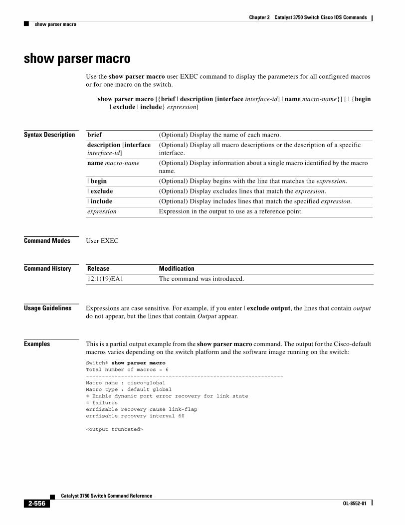
Chapter 2 Catalyst 3750 Switch Cisco IOS Commandsshow parser macro
show parser macroUse the show parser macro user EXEC command to display the parameters for all configured macros or for one macro on the switch.
show parser macro [{brief | description [interface interface-id] | name macro-name}] [ | {begin | exclude | include} expression]
Syntax Description
Command Modes User EXEC
Command History
Usage Guidelines Expressions are case sensitive. For example, if you enter | exclude output, the lines that contain output do not appear, but the lines that contain Output appear.
Examples This is a partial output example from the show parser macro command. The output for the Cisco-default macros varies depending on the switch platform and the software image running on the switch:
Switch# show parser macroTotal number of macros = 6--------------------------------------------------------------Macro name : cisco-globalMacro type : default global# Enable dynamic port error recovery for link state# failureserrdisable recovery cause link-flaperrdisable recovery interval 60
<output truncated>
brief (Optional) Display the name of each macro.
description [interface interface-id]
(Optional) Display all macro descriptions or the description of a specific interface.
name macro-name (Optional) Display information about a single macro identified by the macro name.
| begin (Optional) Display begins with the line that matches the expression.
| exclude (Optional) Display excludes lines that match the expression.
| include (Optional) Display includes lines that match the specified expression.
expression Expression in the output to use as a reference point.
Release Modification
12.1(19)EA1 The command was introduced.
2-556Catalyst 3750 Switch Command Reference
OL-8552-01
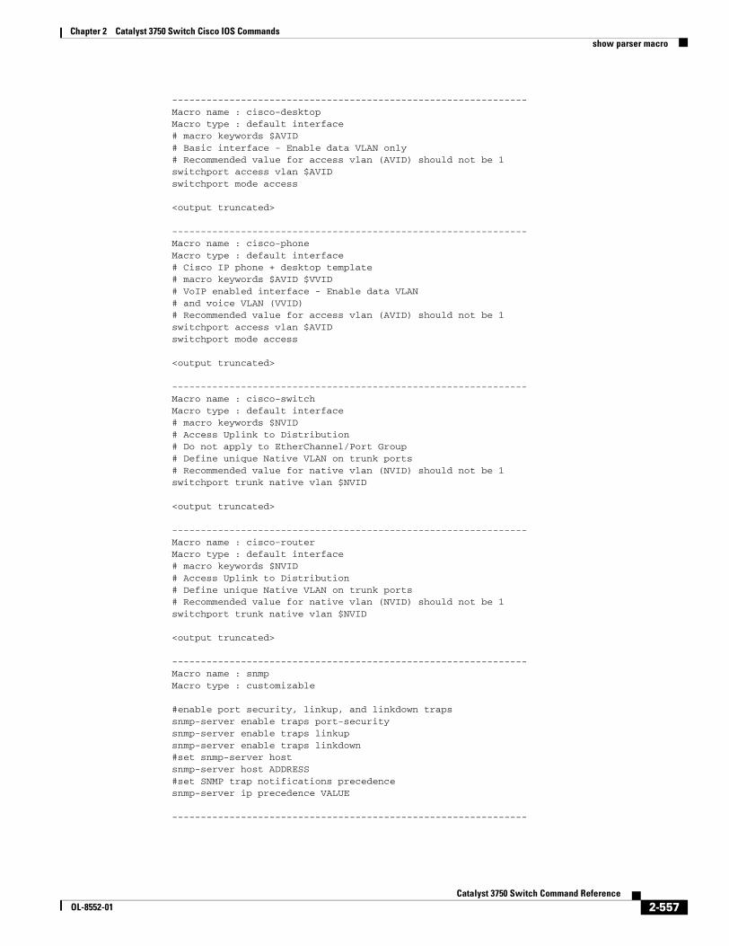
Chapter 2 Catalyst 3750 Switch Cisco IOS Commandsshow parser macro
--------------------------------------------------------------Macro name : cisco-desktopMacro type : default interface# macro keywords $AVID# Basic interface - Enable data VLAN only# Recommended value for access vlan (AVID) should not be 1switchport access vlan $AVIDswitchport mode access
<output truncated>
--------------------------------------------------------------Macro name : cisco-phoneMacro type : default interface# Cisco IP phone + desktop template# macro keywords $AVID $VVID# VoIP enabled interface - Enable data VLAN# and voice VLAN (VVID)# Recommended value for access vlan (AVID) should not be 1switchport access vlan $AVIDswitchport mode access
<output truncated>
--------------------------------------------------------------Macro name : cisco-switchMacro type : default interface# macro keywords $NVID# Access Uplink to Distribution# Do not apply to EtherChannel/Port Group# Define unique Native VLAN on trunk ports# Recommended value for native vlan (NVID) should not be 1switchport trunk native vlan $NVID
<output truncated>
--------------------------------------------------------------Macro name : cisco-routerMacro type : default interface# macro keywords $NVID# Access Uplink to Distribution# Define unique Native VLAN on trunk ports# Recommended value for native vlan (NVID) should not be 1switchport trunk native vlan $NVID
<output truncated>
--------------------------------------------------------------Macro name : snmpMacro type : customizable
#enable port security, linkup, and linkdown trapssnmp-server enable traps port-securitysnmp-server enable traps linkupsnmp-server enable traps linkdown#set snmp-server hostsnmp-server host ADDRESS#set SNMP trap notifications precedencesnmp-server ip precedence VALUE
--------------------------------------------------------------
2-557Catalyst 3750 Switch Command Reference
OL-8552-01
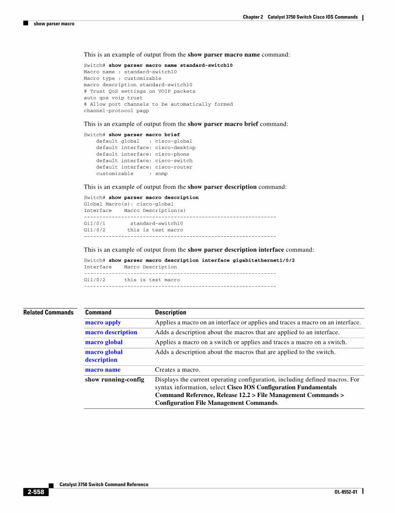
Chapter 2 Catalyst 3750 Switch Cisco IOS Commandsshow parser macro
This is an example of output from the show parser macro name command:
Switch# show parser macro name standard-switch10Macro name : standard-switch10Macro type : customizablemacro description standard-switch10# Trust QoS settings on VOIP packetsauto qos voip trust# Allow port channels to be automatically formedchannel-protocol pagp
This is an example of output from the show parser macro brief command:
Switch# show parser macro brief default global : cisco-global default interface: cisco-desktop default interface: cisco-phone default interface: cisco-switch default interface: cisco-router customizable : snmp
This is an example of output from the show parser description command:
Switch# show parser macro description Global Macro(s): cisco-globalInterface Macro Description(s)--------------------------------------------------------------Gi1/0/1 standard-switch10Gi1/0/2 this is test macro--------------------------------------------------------------
This is an example of output from the show parser description interface command:
Switch# show parser macro description interface gigabitethernet1/0/2Interface Macro Description--------------------------------------------------------------Gi1/0/2 this is test macro--------------------------------------------------------------
Related Commands Command Description
macro apply Applies a macro on an interface or applies and traces a macro on an interface.
macro description Adds a description about the macros that are applied to an interface.
macro global Applies a macro on a switch or applies and traces a macro on a switch.
macro global description
Adds a description about the macros that are applied to the switch.
macro name Creates a macro.
show running-config Displays the current operating configuration, including defined macros. For syntax information, select Cisco IOS Configuration Fundamentals Command Reference, Release 12.2 > File Management Commands > Configuration File Management Commands.
2-558Catalyst 3750 Switch Command Reference
OL-8552-01
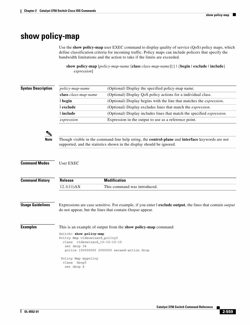
Chapter 2 Catalyst 3750 Switch Cisco IOS Commandsshow policy-map
show policy-mapUse the show policy-map user EXEC command to display quality of service (QoS) policy maps, which define classification criteria for incoming traffic. Policy maps can include policers that specify the bandwidth limitations and the action to take if the limits are exceeded.
show policy-map [policy-map-name [class class-map-name]] [ | {begin | exclude | include} expression]
Syntax Description
Note Though visible in the command-line help string, the control-plane and interface keywords are not supported, and the statistics shown in the display should be ignored.
Command Modes User EXEC
Command History
Usage Guidelines Expressions are case sensitive. For example, if you enter | exclude output, the lines that contain output do not appear, but the lines that contain Output appear.
Examples This is an example of output from the show policy-map command:
Switch> show policy-mapPolicy Map videowizard_policy2 class videowizard_10-10-10-10 set dscp 34 police 100000000 2000000 exceed-action drop
Policy Map mypolicy class dscp5 set dscp 6
policy-map-name (Optional) Display the specified policy-map name.
class class-map-name (Optional) Display QoS policy actions for a individual class.
| begin (Optional) Display begins with the line that matches the expression.
| exclude (Optional) Display excludes lines that match the expression.
| include (Optional) Display includes lines that match the specified expression.
expression Expression in the output to use as a reference point.
Release Modification
12.1(11)AX This command was introduced.
2-559Catalyst 3750 Switch Command Reference
OL-8552-01

Chapter 2 Catalyst 3750 Switch Cisco IOS Commandsshow policy-map
Related Commands Command Description
policy-map Creates or modifies a policy map that can be attached to multiple ports to specify a service policy.
2-560Catalyst 3750 Switch Command Reference
OL-8552-01
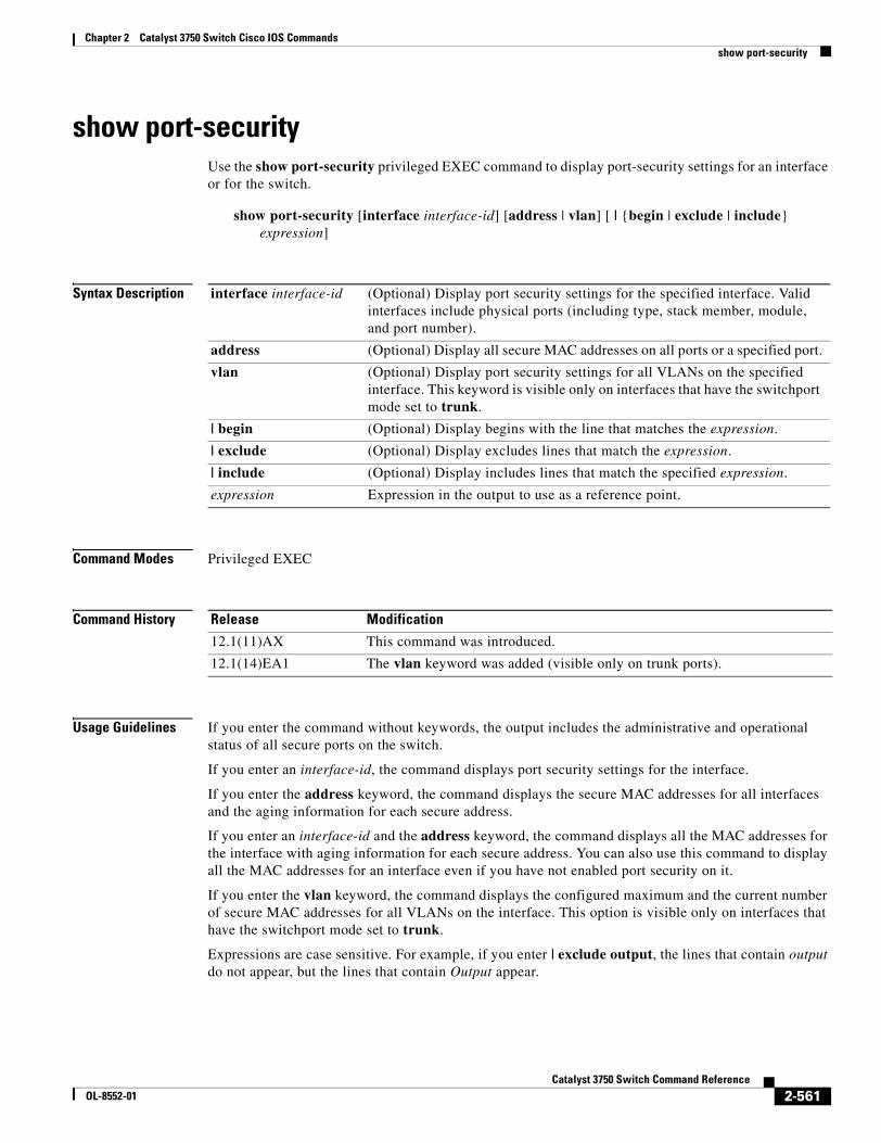
Chapter 2 Catalyst 3750 Switch Cisco IOS Commandsshow port-security
show port-securityUse the show port-security privileged EXEC command to display port-security settings for an interface or for the switch.
show port-security [interface interface-id] [address | vlan] [ | {begin | exclude | include} expression]
Syntax Description
Command Modes Privileged EXEC
Command History
Usage Guidelines If you enter the command without keywords, the output includes the administrative and operational status of all secure ports on the switch.
If you enter an interface-id, the command displays port security settings for the interface.
If you enter the address keyword, the command displays the secure MAC addresses for all interfaces and the aging information for each secure address.
If you enter an interface-id and the address keyword, the command displays all the MAC addresses for the interface with aging information for each secure address. You can also use this command to display all the MAC addresses for an interface even if you have not enabled port security on it.
If you enter the vlan keyword, the command displays the configured maximum and the current number of secure MAC addresses for all VLANs on the interface. This option is visible only on interfaces that have the switchport mode set to trunk.
Expressions are case sensitive. For example, if you enter | exclude output, the lines that contain output do not appear, but the lines that contain Output appear.
interface interface-id (Optional) Display port security settings for the specified interface. Valid interfaces include physical ports (including type, stack member, module, and port number).
address (Optional) Display all secure MAC addresses on all ports or a specified port.
vlan (Optional) Display port security settings for all VLANs on the specified interface. This keyword is visible only on interfaces that have the switchport mode set to trunk.
| begin (Optional) Display begins with the line that matches the expression.
| exclude (Optional) Display excludes lines that match the expression.
| include (Optional) Display includes lines that match the specified expression.
expression Expression in the output to use as a reference point.
Release Modification
12.1(11)AX This command was introduced.
12.1(14)EA1 The vlan keyword was added (visible only on trunk ports).
2-561Catalyst 3750 Switch Command Reference
OL-8552-01
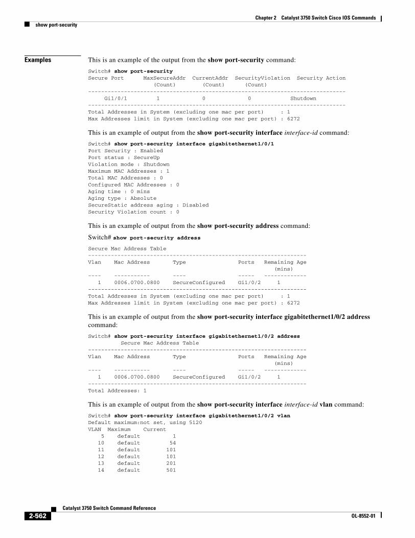
Chapter 2 Catalyst 3750 Switch Cisco IOS Commandsshow port-security
Examples This is an example of the output from the show port-security command:
Switch# show port-securitySecure Port MaxSecureAddr CurrentAddr SecurityViolation Security Action (Count) (Count) (Count)------------------------------------------------------------------------------- Gi1/0/1 1 0 0 Shutdown-------------------------------------------------------------------------------Total Addresses in System (excluding one mac per port) : 1Max Addresses limit in System (excluding one mac per port) : 6272
This is an example of output from the show port-security interface interface-id command:
Switch# show port-security interface gigabitethernet1/0/1Port Security : EnabledPort status : SecureUpViolation mode : ShutdownMaximum MAC Addresses : 1Total MAC Addresses : 0Configured MAC Addresses : 0Aging time : 0 minsAging type : AbsoluteSecureStatic address aging : DisabledSecurity Violation count : 0
This is an example of output from the show port-security address command:
Switch# show port-security address
Secure Mac Address Table-------------------------------------------------------------------Vlan Mac Address Type Ports Remaining Age (mins)---- ----------- ---- ----- ------------- 1 0006.0700.0800 SecureConfigured Gi1/0/2 1-------------------------------------------------------------------Total Addresses in System (excluding one mac per port) : 1Max Addresses limit in System (excluding one mac per port) : 6272
This is an example of output from the show port-security interface gigabitethernet1/0/2 address command:
Switch# show port-security interface gigabitethernet1/0/2 address Secure Mac Address Table-------------------------------------------------------------------Vlan Mac Address Type Ports Remaining Age (mins)---- ----------- ---- ----- ------------- 1 0006.0700.0800 SecureConfigured Gi1/0/2 1-------------------------------------------------------------------Total Addresses: 1
This is an example of output from the show port-security interface interface-id vlan command:
Switch# show port-security interface gigabitethernet1/0/2 vlan Default maximum:not set, using 5120VLAN Maximum Current 5 default 1 10 default 54 11 default 101 12 default 101 13 default 201 14 default 501
2-562Catalyst 3750 Switch Command Reference
OL-8552-01
Chapter 2 Catalyst 3750 Switch Cisco IOS Commandsshow port-security
Related Commands Command Description
clear port-security Deletes from the MAC address table a specific type of secure address or all the secure addresses on the switch or an interface.
switchport port-security Enables port security on a port, restricts the use of the port to a user-defined group of stations, and configures secure MAC addresses.
2-563Catalyst 3750 Switch Command Reference
OL-8552-01
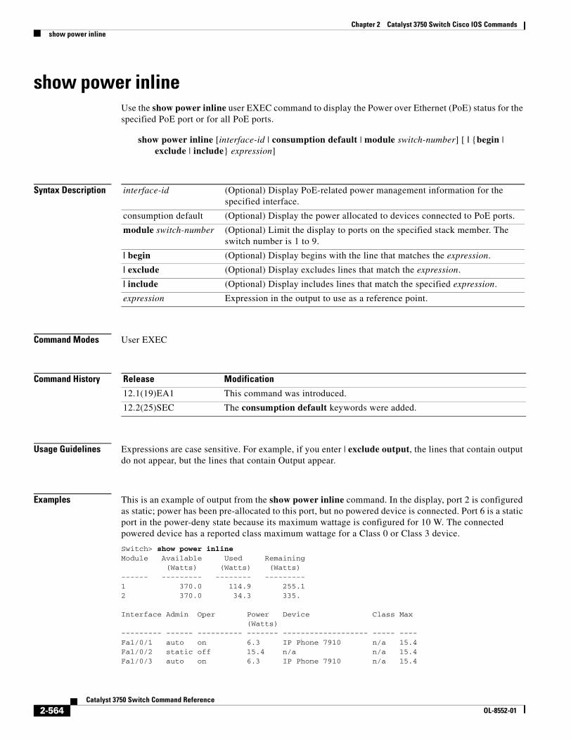
Chapter 2 Catalyst 3750 Switch Cisco IOS Commandsshow power inline
show power inlineUse the show power inline user EXEC command to display the Power over Ethernet (PoE) status for the specified PoE port or for all PoE ports.
show power inline [interface-id | consumption default | module switch-number] [ | {begin | exclude | include} expression]
Syntax Description
Command Modes User EXEC
Command History
Usage Guidelines Expressions are case sensitive. For example, if you enter | exclude output, the lines that contain output do not appear, but the lines that contain Output appear.
Examples This is an example of output from the show power inline command. In the display, port 2 is configured as static; power has been pre-allocated to this port, but no powered device is connected. Port 6 is a static port in the power-deny state because its maximum wattage is configured for 10 W. The connected powered device has a reported class maximum wattage for a Class 0 or Class 3 device.
Switch> show power inlineModule Available Used Remaining (Watts) (Watts) (Watts) ------ --------- -------- ---------1 370.0 114.9 255.12 370.0 34.3 335.
Interface Admin Oper Power Device Class Max (Watts) --------- ------ ---------- ------- ------------------- ----- ----Fa1/0/1 auto on 6.3 IP Phone 7910 n/a 15.4Fa1/0/2 static off 15.4 n/a n/a 15.4Fa1/0/3 auto on 6.3 IP Phone 7910 n/a 15.4
interface-id (Optional) Display PoE-related power management information for the specified interface.
consumption default (Optional) Display the power allocated to devices connected to PoE ports.
module switch-number (Optional) Limit the display to ports on the specified stack member. The switch number is 1 to 9.
| begin (Optional) Display begins with the line that matches the expression.
| exclude (Optional) Display excludes lines that match the expression.
| include (Optional) Display includes lines that match the specified expression.
expression Expression in the output to use as a reference point.
Release Modification
12.1(19)EA1 This command was introduced.
12.2(25)SEC The consumption default keywords were added.
2-564Catalyst 3750 Switch Command Reference
OL-8552-01
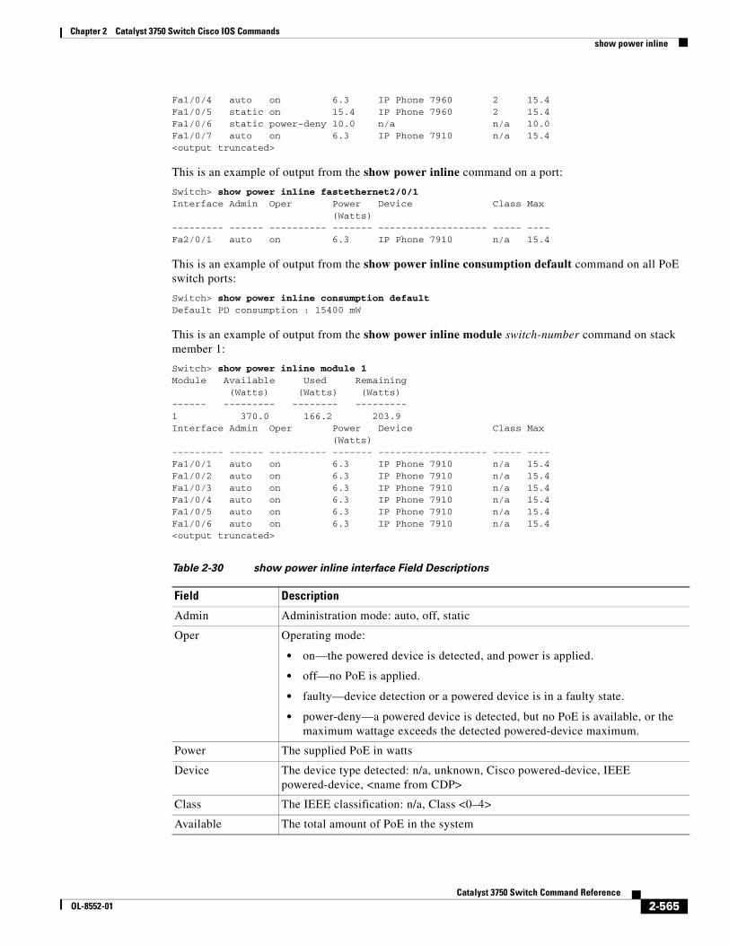
Chapter 2 Catalyst 3750 Switch Cisco IOS Commandsshow power inline
Fa1/0/4 auto on 6.3 IP Phone 7960 2 15.4Fa1/0/5 static on 15.4 IP Phone 7960 2 15.4Fa1/0/6 static power-deny 10.0 n/a n/a 10.0Fa1/0/7 auto on 6.3 IP Phone 7910 n/a 15.4<output truncated>
This is an example of output from the show power inline command on a port:
Switch> show power inline fastethernet2/0/1 Interface Admin Oper Power Device Class Max (Watts)--------- ------ ---------- ------- ------------------- ----- ----Fa2/0/1 auto on 6.3 IP Phone 7910 n/a 15.4
This is an example of output from the show power inline consumption default command on all PoE switch ports:
Switch> show power inline consumption defaultDefault PD consumption : 15400 mW
This is an example of output from the show power inline module switch-number command on stack member 1:
Switch> show power inline module 1Module Available Used Remaining (Watts) (Watts) (Watts)------ --------- -------- ---------1 370.0 166.2 203.9Interface Admin Oper Power Device Class Max (Watts)--------- ------ ---------- ------- ------------------- ----- ----Fa1/0/1 auto on 6.3 IP Phone 7910 n/a 15.4Fa1/0/2 auto on 6.3 IP Phone 7910 n/a 15.4Fa1/0/3 auto on 6.3 IP Phone 7910 n/a 15.4Fa1/0/4 auto on 6.3 IP Phone 7910 n/a 15.4Fa1/0/5 auto on 6.3 IP Phone 7910 n/a 15.4Fa1/0/6 auto on 6.3 IP Phone 7910 n/a 15.4<output truncated>
Table 2-30 show power inline interface Field Descriptions
Field Description
Admin Administration mode: auto, off, static
Oper Operating mode:
• on—the powered device is detected, and power is applied.
• off—no PoE is applied.
• faulty—device detection or a powered device is in a faulty state.
• power-deny—a powered device is detected, but no PoE is available, or the maximum wattage exceeds the detected powered-device maximum.
Power The supplied PoE in watts
Device The device type detected: n/a, unknown, Cisco powered-device, IEEE powered-device, <name from CDP>
Class The IEEE classification: n/a, Class <0–4>
Available The total amount of PoE in the system
2-565Catalyst 3750 Switch Command Reference
OL-8552-01
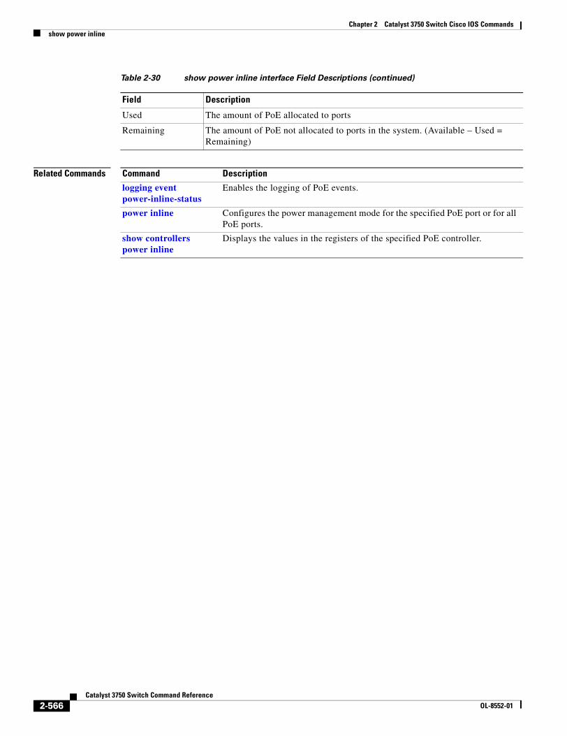
Chapter 2 Catalyst 3750 Switch Cisco IOS Commandsshow power inline
Related Commands
Used The amount of PoE allocated to ports
Remaining The amount of PoE not allocated to ports in the system. (Available – Used = Remaining)
Table 2-30 show power inline interface Field Descriptions (continued)
Field Description
Command Description
logging event power-inline-status
Enables the logging of PoE events.
power inline Configures the power management mode for the specified PoE port or for all PoE ports.
show controllers power inline
Displays the values in the registers of the specified PoE controller.
2-566Catalyst 3750 Switch Command Reference
OL-8552-01
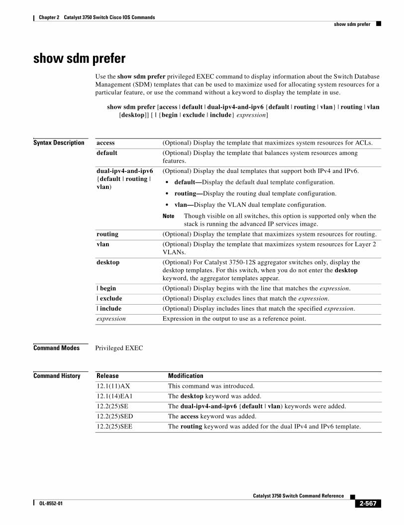
Chapter 2 Catalyst 3750 Switch Cisco IOS Commandsshow sdm prefer
show sdm preferUse the show sdm prefer privileged EXEC command to display information about the Switch Database Management (SDM) templates that can be used to maximize used for allocating system resources for a particular feature, or use the command without a keyword to display the template in use.
show sdm prefer [access | default | dual-ipv4-and-ipv6 {default | routing | vlan} | routing | vlan [desktop]] [ | {begin | exclude | include} expression]
Syntax Description
Command Modes Privileged EXEC
Command History
access (Optional) Display the template that maximizes system resources for ACLs.
default (Optional) Display the template that balances system resources among features.
dual-ipv4-and-ipv6 {default | routing | vlan)
(Optional) Display the dual templates that support both IPv4 and IPv6.
• default—Display the default dual template configuration.
• routing—Display the routing dual template configuration.
• vlan—Display the VLAN dual template configuration.
Note Though visible on all switches, this option is supported only when the stack is running the advanced IP services image.
routing (Optional) Display the template that maximizes system resources for routing.
vlan (Optional) Display the template that maximizes system resources for Layer 2 VLANs.
desktop (Optional) For Catalyst 3750-12S aggregator switches only, display the desktop templates. For this switch, when you do not enter the desktop keyword, the aggregator templates appear.
| begin (Optional) Display begins with the line that matches the expression.
| exclude (Optional) Display excludes lines that match the expression.
| include (Optional) Display includes lines that match the specified expression.
expression Expression in the output to use as a reference point.
Release Modification
12.1(11)AX This command was introduced.
12.1(14)EA1 The desktop keyword was added.
12.2(25)SE The dual-ipv4-and-ipv6 {default | vlan) keywords were added.
12.2(25)SED The access keyword was added.
12.2(25)SEE The routing keyword was added for the dual IPv4 and IPv6 template.
2-567Catalyst 3750 Switch Command Reference
OL-8552-01
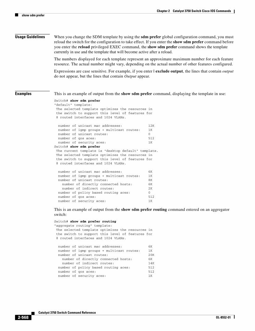
Chapter 2 Catalyst 3750 Switch Cisco IOS Commandsshow sdm prefer
Usage Guidelines When you change the SDM template by using the sdm prefer global configuration command, you must reload the switch for the configuration to take effect. If you enter the show sdm prefer command before you enter the reload privileged EXEC command, the show sdm prefer command shows the template currently in use and the template that will become active after a reload.
The numbers displayed for each template represent an approximate maximum number for each feature resource. The actual number might vary, depending on the actual number of other features configured.
Expressions are case sensitive. For example, if you enter | exclude output, the lines that contain output do not appear, but the lines that contain Output appear.
Examples This is an example of output from the show sdm prefer command, displaying the template in use:
Switch# show sdm prefer"default" template: The selected template optimizes the resources in the switch to support this level of features for 8 routed interfaces and 1024 VLANs.
number of unicast mac addresses: 12K number of igmp groups + multicast routes: 1K number of unicast routes: 0 number of qos aces: 512 number of security aces: 1KSwitch# show sdm prefer The current template is "desktop default" template. The selected template optimizes the resources in the switch to support this level of features for 8 routed interfaces and 1024 VLANs.
number of unicast mac addresses: 6K number of igmp groups + multicast routes: 1K number of unicast routes: 8K number of directly connected hosts: 6K number of indirect routes: 2K number of policy based routing aces: 0 number of qos aces: 512 number of security aces: 1K
This is an example of output from the show sdm prefer routing command entered on an aggregator switch:
Switch# show sdm prefer routing"aggregate routing" template: The selected template optimizes the resources in the switch to support this level of features for 8 routed interfaces and 1024 VLANs.
number of unicast mac addresses: 6K number of igmp groups + multicast routes: 1K number of unicast routes: 20K number of directly connected hosts: 6K number of indirect routes: 14K number of policy based routing aces: 512 number of qos aces: 512 number of security aces: 1K
2-568Catalyst 3750 Switch Command Reference
OL-8552-01
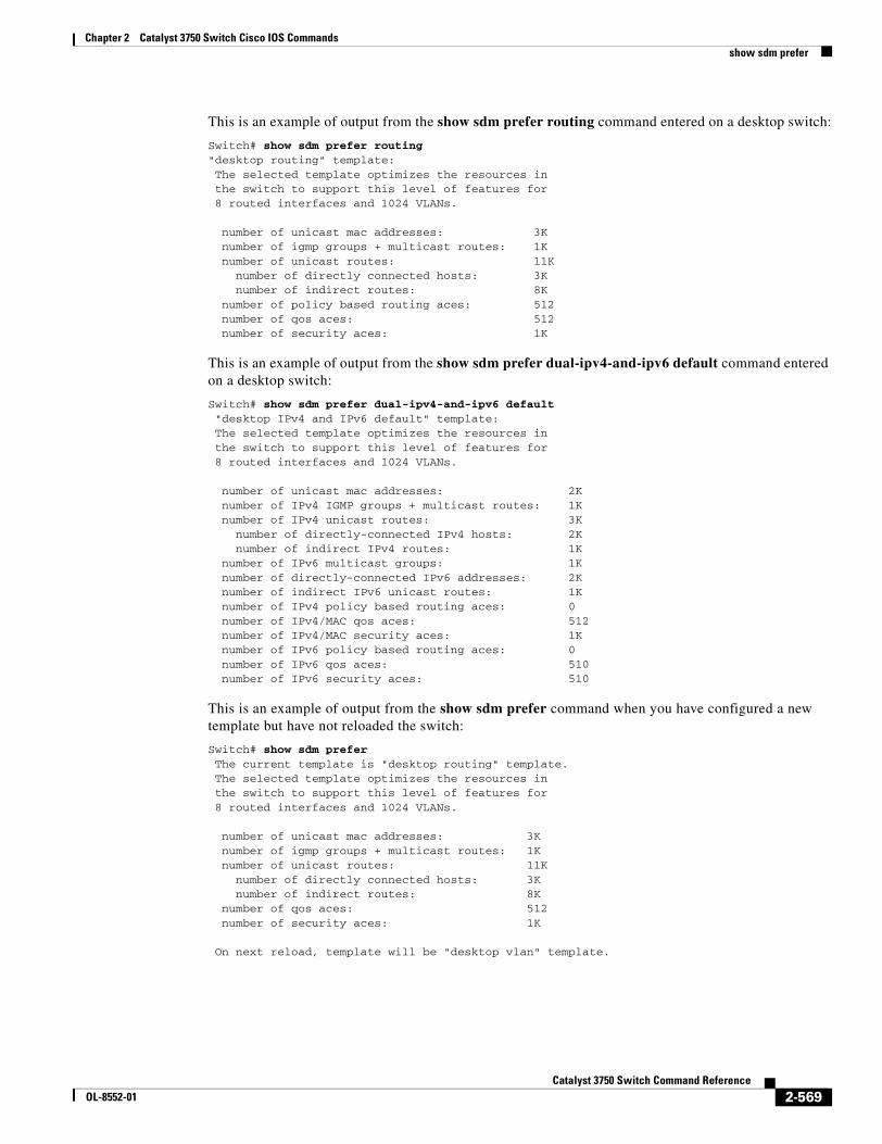
Chapter 2 Catalyst 3750 Switch Cisco IOS Commandsshow sdm prefer
This is an example of output from the show sdm prefer routing command entered on a desktop switch:
Switch# show sdm prefer routing"desktop routing" template: The selected template optimizes the resources in the switch to support this level of features for 8 routed interfaces and 1024 VLANs.
number of unicast mac addresses: 3K number of igmp groups + multicast routes: 1K number of unicast routes: 11K number of directly connected hosts: 3K number of indirect routes: 8K number of policy based routing aces: 512 number of qos aces: 512 number of security aces: 1K
This is an example of output from the show sdm prefer dual-ipv4-and-ipv6 default command entered on a desktop switch:
Switch# show sdm prefer dual-ipv4-and-ipv6 default "desktop IPv4 and IPv6 default" template: The selected template optimizes the resources in the switch to support this level of features for 8 routed interfaces and 1024 VLANs.
number of unicast mac addresses: 2K number of IPv4 IGMP groups + multicast routes: 1K number of IPv4 unicast routes: 3K number of directly-connected IPv4 hosts: 2K number of indirect IPv4 routes: 1K number of IPv6 multicast groups: 1K number of directly-connected IPv6 addresses: 2K number of indirect IPv6 unicast routes: 1K number of IPv4 policy based routing aces: 0 number of IPv4/MAC qos aces: 512 number of IPv4/MAC security aces: 1K number of IPv6 policy based routing aces: 0 number of IPv6 qos aces: 510 number of IPv6 security aces: 510
This is an example of output from the show sdm prefer command when you have configured a new template but have not reloaded the switch:
Switch# show sdm prefer The current template is "desktop routing" template. The selected template optimizes the resources in the switch to support this level of features for 8 routed interfaces and 1024 VLANs.
number of unicast mac addresses: 3K number of igmp groups + multicast routes: 1K number of unicast routes: 11K number of directly connected hosts: 3K number of indirect routes: 8K number of qos aces: 512 number of security aces: 1K On next reload, template will be "desktop vlan" template.
2-569Catalyst 3750 Switch Command Reference
OL-8552-01

Chapter 2 Catalyst 3750 Switch Cisco IOS Commandsshow sdm prefer
Related Commands Command Description
sdm prefer Sets the SDM template to maximize resources for routing or VLANs or to the default template, to select a dual IPv4 and IPv6 template, or to select the desktop or aggregator templates.
2-570Catalyst 3750 Switch Command Reference
OL-8552-01
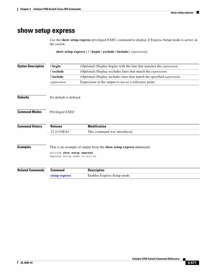
Chapter 2 Catalyst 3750 Switch Cisco IOS Commandsshow setup express
show setup expressUse the show setup express privileged EXEC command to display if Express Setup mode is active on the switch.
show setup express [ | {begin | exclude | include} expression]
Syntax Description
Defaults No default is defined.
Command Modes Privileged EXEC
Command History
Examples This is an example of output from the show setup express command:
Switch# show setup expressexpress setup mode is active
Related Commands
| begin (Optional) Display begins with the line that matches the expression.
| exclude (Optional) Display excludes lines that match the expression.
| include (Optional) Display includes lines that match the specified expression.
expression Expression in the output to use as a reference point.
Release Modification
12.1(14)EA1 This command was introduced.
Command Description
setup express Enables Express Setup mode.
2-571Catalyst 3750 Switch Command Reference
OL-8552-01
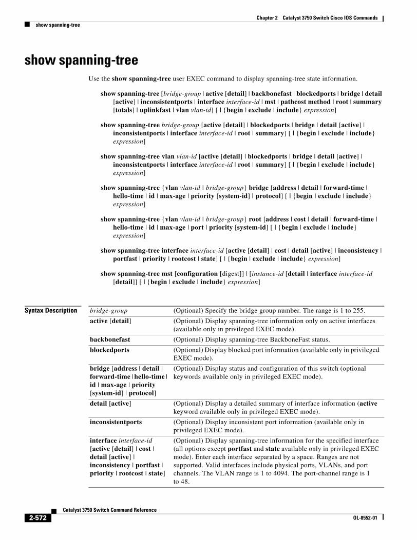
Chapter 2 Catalyst 3750 Switch Cisco IOS Commandsshow spanning-tree
show spanning-tree Use the show spanning-tree user EXEC command to display spanning-tree state information.
show spanning-tree [bridge-group | active [detail] | backbonefast | blockedports | bridge | detail [active] | inconsistentports | interface interface-id | mst | pathcost method | root | summary [totals] | uplinkfast | vlan vlan-id] [ | {begin | exclude | include} expression]
show spanning-tree bridge-group [active [detail] | blockedports | bridge | detail [active] | inconsistentports | interface interface-id | root | summary] [ | {begin | exclude | include} expression]
show spanning-tree vlan vlan-id [active [detail] | blockedports | bridge | detail [active] | inconsistentports | interface interface-id | root | summary] [ | {begin | exclude | include} expression]
show spanning-tree {vlan vlan-id | bridge-group} bridge [address | detail | forward-time | hello-time | id | max-age | priority [system-id] | protocol] [ | {begin | exclude | include} expression]
show spanning-tree {vlan vlan-id | bridge-group} root [address | cost | detail | forward-time | hello-time | id | max-age | port | priority [system-id] [ | {begin | exclude | include} expression]
show spanning-tree interface interface-id [active [detail] | cost | detail [active] | inconsistency | portfast | priority | rootcost | state] [ | {begin | exclude | include} expression]
show spanning-tree mst [configuration [digest]] | [instance-id [detail | interface interface-id [detail]] [ | {begin | exclude | include} expression]
Syntax Description bridge-group (Optional) Specify the bridge group number. The range is 1 to 255.
active [detail] (Optional) Display spanning-tree information only on active interfaces (available only in privileged EXEC mode).
backbonefast (Optional) Display spanning-tree BackboneFast status.
blockedports (Optional) Display blocked port information (available only in privileged EXEC mode).
bridge [address | detail | forward-time | hello-time | id | max-age | priority [system-id] | protocol]
(Optional) Display status and configuration of this switch (optional keywords available only in privileged EXEC mode).
detail [active] (Optional) Display a detailed summary of interface information (active keyword available only in privileged EXEC mode).
inconsistentports (Optional) Display inconsistent port information (available only in privileged EXEC mode).
interface interface-id [active [detail] | cost | detail [active] | inconsistency | portfast | priority | rootcost | state]
(Optional) Display spanning-tree information for the specified interface (all options except portfast and state available only in privileged EXEC mode). Enter each interface separated by a space. Ranges are not supported. Valid interfaces include physical ports, VLANs, and port channels. The VLAN range is 1 to 4094. The port-channel range is 1 to 48.
2-572Catalyst 3750 Switch Command Reference
OL-8552-01
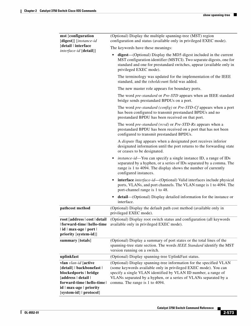
Chapter 2 Catalyst 3750 Switch Cisco IOS Commandsshow spanning-tree
mst [configuration [digest]] [instance-id [detail | interface interface-id [detail]]
(Optional) Display the multiple spanning-tree (MST) region configuration and status (available only in privileged EXEC mode).
The keywords have these meanings:
• digest—(Optional) Display the MD5 digest included in the current MST configuration identifier (MSTCI). Two separate digests, one for standard and one for prestandard switches, appear (available only in privileged EXEC mode).
The terminology was updated for the implementation of the IEEE standard, and the txholdcount field was added.
The new master role appears for boundary ports.
The word pre-standard or Pre-STD appears when an IEEE standard bridge sends prestandard BPDUs on a port.
The word pre-standard (config) or Pre-STD-Cf appears when a port has been configured to transmit prestandard BPDUs and no prestandard BPDU has been received on that port.
The word pre-standard (rcvd) or Pre-STD-Rx appears when a prestandard BPDU has been received on a port that has not been configured to transmit prestandard BPDUs.
A dispute flag appears when a designated port receives inferior designated information until the port returns to the forwarding state or ceases to be designated.
• instance-id—You can specify a single instance ID, a range of IDs separated by a hyphen, or a series of IDs separated by a comma. The range is 1 to 4094. The display shows the number of currently configured instances.
• interface interface-id—(Optional) Valid interfaces include physical ports, VLANs, and port channels. The VLAN range is 1 to 4094. The port-channel range is 1 to 48.
• detail—(Optional) Display detailed information for the instance or interface.
pathcost method (Optional) Display the default path cost method (available only in privileged EXEC mode).
root [address | cost | detail | forward-time | hello-time | id | max-age | port | priority [system-id]]
(Optional) Display root switch status and configuration (all keywords available only in privileged EXEC mode).
summary [totals] (Optional) Display a summary of port states or the total lines of the spanning-tree state section. The words IEEE Standard identify the MST version running on a switch.
uplinkfast (Optional) Display spanning-tree UplinkFast status.
vlan vlan-id [active [detail] | backbonefast | blockedports | bridge [address | detail | forward-time | hello-time | id | max-age | priority [system-id] | protocol]
(Optional) Display spanning-tree information for the specified VLAN (some keywords available only in privileged EXEC mode). You can specify a single VLAN identified by VLAN ID number, a range of VLANs separated by a hyphen, or a series of VLANs separated by a comma. The range is 1 to 4094.
2-573Catalyst 3750 Switch Command Reference
OL-8552-01
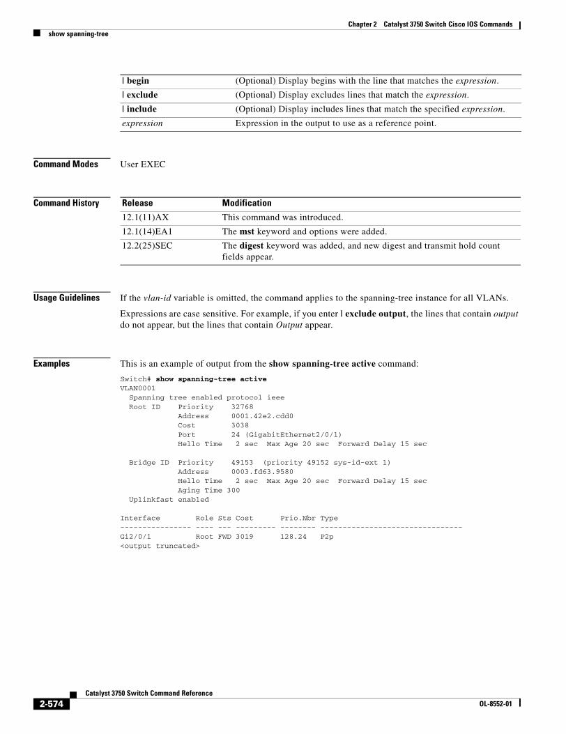
Chapter 2 Catalyst 3750 Switch Cisco IOS Commandsshow spanning-tree
Command Modes User EXEC
Command History
Usage Guidelines If the vlan-id variable is omitted, the command applies to the spanning-tree instance for all VLANs.
Expressions are case sensitive. For example, if you enter | exclude output, the lines that contain output do not appear, but the lines that contain Output appear.
Examples This is an example of output from the show spanning-tree active command:
Switch# show spanning-tree activeVLAN0001 Spanning tree enabled protocol ieee Root ID Priority 32768 Address 0001.42e2.cdd0 Cost 3038 Port 24 (GigabitEthernet2/0/1) Hello Time 2 sec Max Age 20 sec Forward Delay 15 sec
Bridge ID Priority 49153 (priority 49152 sys-id-ext 1) Address 0003.fd63.9580 Hello Time 2 sec Max Age 20 sec Forward Delay 15 sec Aging Time 300 Uplinkfast enabled
Interface Role Sts Cost Prio.Nbr Type---------------- ---- --- --------- -------- --------------------------------Gi2/0/1 Root FWD 3019 128.24 P2p<output truncated>
| begin (Optional) Display begins with the line that matches the expression.
| exclude (Optional) Display excludes lines that match the expression.
| include (Optional) Display includes lines that match the specified expression.
expression Expression in the output to use as a reference point.
Release Modification
12.1(11)AX This command was introduced.
12.1(14)EA1 The mst keyword and options were added.
12.2(25)SEC The digest keyword was added, and new digest and transmit hold count fields appear.
2-574Catalyst 3750 Switch Command Reference
OL-8552-01
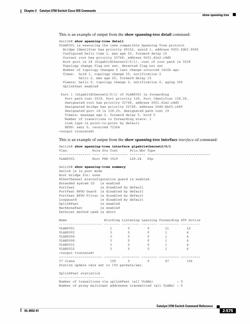
Chapter 2 Catalyst 3750 Switch Cisco IOS Commandsshow spanning-tree
This is an example of output from the show spanning-tree detail command:
Switch# show spanning-tree detailVLAN0001 is executing the ieee compatible Spanning Tree protocol Bridge Identifier has priority 49152, sysid 1, address 0003.fd63.9580 Configured hello time 2, max age 20, forward delay 15 Current root has priority 32768, address 0001.42e2.cdd0 Root port is 24 (GigabitEthernet2/0/1), cost of root path is 3038 Topology change flag not set, detected flag not set Number of topology changes 0 last change occurred 1d16h ago Times: hold 1, topology change 35, notification 2 hello 2, max age 20, forward delay 15 Timers: hello 0, topology change 0, notification 0, aging 300 Uplinkfast enabled
Port 1 (GigabitEthernet2/0/1) of VLAN0001 is forwarding Port path cost 3019, Port priority 128, Port Identifier 128.24. Designated root has priority 32768, address 0001.42e2.cdd0 Designated bridge has priority 32768, address 00d0.bbf5.c680 Designated port id is 128.25, designated path cost 19 Timers: message age 2, forward delay 0, hold 0 Number of transitions to forwarding state: 1 Link type is point-to-point by default BPDU: sent 0, received 72364<output truncated>
This is an example of output from the show spanning-tree interface interface-id command:
Switch# show spanning-tree interface gigabitethernet2/0/1Vlan Role Sts Cost Prio.Nbr Type---------------- ---- --- --------- -------- --------------------------------VLAN0001 Root FWD 3019 128.24 P2p
Switch# show spanning-tree summarySwitch is in pvst modeRoot bridge for: noneEtherChannel misconfiguration guard is enabledExtended system ID is enabledPortfast is disabled by defaultPortFast BPDU Guard is disabled by defaultPortfast BPDU Filter is disabled by defaultLoopguard is disabled by defaultUplinkFast is enabledBackboneFast is enabledPathcost method used is short
Name Blocking Listening Learning Forwarding STP Active---------------------- -------- --------- -------- ---------- ----------VLAN0001 1 0 0 11 12VLAN0002 3 0 0 1 4VLAN0004 3 0 0 1 4VLAN0006 3 0 0 1 4VLAN0031 3 0 0 1 4VLAN0032 3 0 0 1 4<output truncated>---------------------- -------- --------- -------- ---------- ----------37 vlans 109 0 0 47 156Station update rate set to 150 packets/sec.
UplinkFast statistics-----------------------Number of transitions via uplinkFast (all VLANs) : 0Number of proxy multicast addresses transmitted (all VLANs) : 0
2-575Catalyst 3750 Switch Command Reference
OL-8552-01
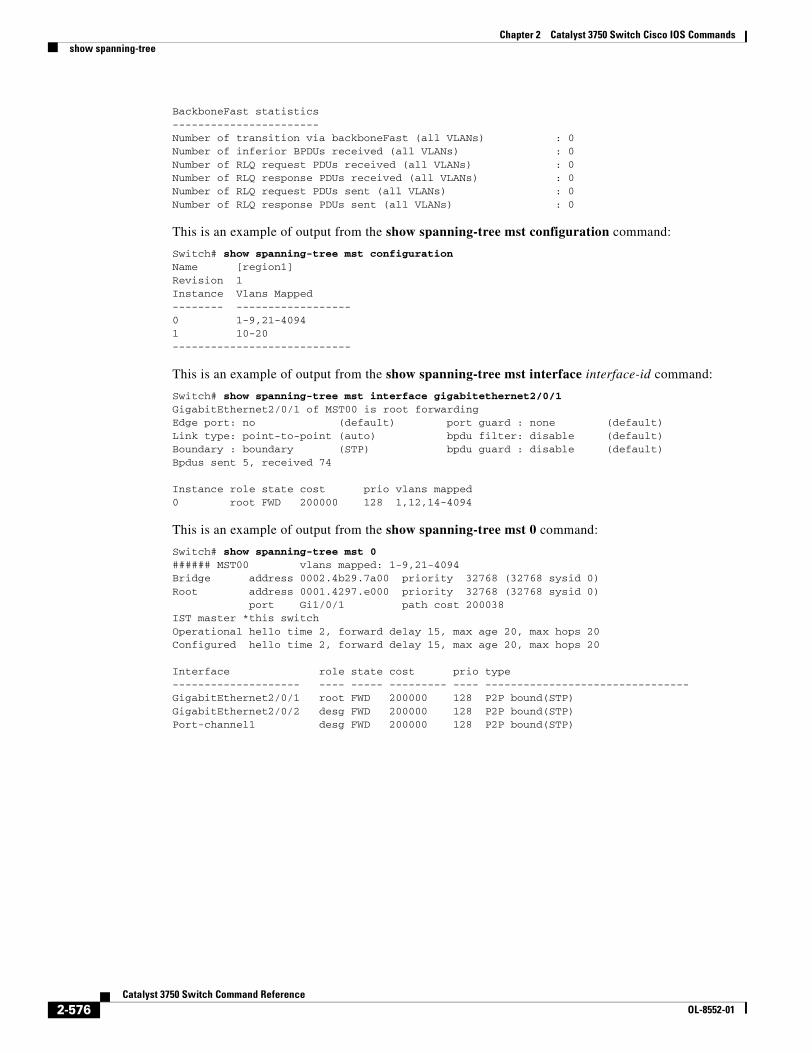
Chapter 2 Catalyst 3750 Switch Cisco IOS Commandsshow spanning-tree
BackboneFast statistics-----------------------Number of transition via backboneFast (all VLANs) : 0Number of inferior BPDUs received (all VLANs) : 0Number of RLQ request PDUs received (all VLANs) : 0Number of RLQ response PDUs received (all VLANs) : 0Number of RLQ request PDUs sent (all VLANs) : 0Number of RLQ response PDUs sent (all VLANs) : 0
This is an example of output from the show spanning-tree mst configuration command:
Switch# show spanning-tree mst configurationName [region1]Revision 1Instance Vlans Mapped-------- ------------------0 1-9,21-40941 10-20----------------------------
This is an example of output from the show spanning-tree mst interface interface-id command:
Switch# show spanning-tree mst interface gigabitethernet2/0/1GigabitEthernet2/0/1 of MST00 is root forwardingEdge port: no (default) port guard : none (default)Link type: point-to-point (auto) bpdu filter: disable (default)Boundary : boundary (STP) bpdu guard : disable (default)Bpdus sent 5, received 74
Instance role state cost prio vlans mapped0 root FWD 200000 128 1,12,14-4094
This is an example of output from the show spanning-tree mst 0 command:
Switch# show spanning-tree mst 0###### MST00 vlans mapped: 1-9,21-4094Bridge address 0002.4b29.7a00 priority 32768 (32768 sysid 0)Root address 0001.4297.e000 priority 32768 (32768 sysid 0) port Gi1/0/1 path cost 200038IST master *this switchOperational hello time 2, forward delay 15, max age 20, max hops 20Configured hello time 2, forward delay 15, max age 20, max hops 20
Interface role state cost prio type-------------------- ---- ----- --------- ---- --------------------------------GigabitEthernet2/0/1 root FWD 200000 128 P2P bound(STP)GigabitEthernet2/0/2 desg FWD 200000 128 P2P bound(STP)Port-channel1 desg FWD 200000 128 P2P bound(STP)
2-576Catalyst 3750 Switch Command Reference
OL-8552-01
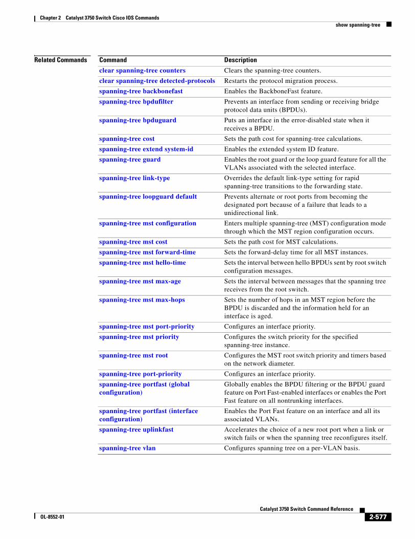
Chapter 2 Catalyst 3750 Switch Cisco IOS Commandsshow spanning-tree
Related Commands Command Description
clear spanning-tree counters Clears the spanning-tree counters.
clear spanning-tree detected-protocols Restarts the protocol migration process.
spanning-tree backbonefast Enables the BackboneFast feature.
spanning-tree bpdufilter Prevents an interface from sending or receiving bridge protocol data units (BPDUs).
spanning-tree bpduguard Puts an interface in the error-disabled state when it receives a BPDU.
spanning-tree cost Sets the path cost for spanning-tree calculations.
spanning-tree extend system-id Enables the extended system ID feature.
spanning-tree guard Enables the root guard or the loop guard feature for all the VLANs associated with the selected interface.
spanning-tree link-type Overrides the default link-type setting for rapid spanning-tree transitions to the forwarding state.
spanning-tree loopguard default Prevents alternate or root ports from becoming the designated port because of a failure that leads to a unidirectional link.
spanning-tree mst configuration Enters multiple spanning-tree (MST) configuration mode through which the MST region configuration occurs.
spanning-tree mst cost Sets the path cost for MST calculations.
spanning-tree mst forward-time Sets the forward-delay time for all MST instances.
spanning-tree mst hello-time Sets the interval between hello BPDUs sent by root switch configuration messages.
spanning-tree mst max-age Sets the interval between messages that the spanning tree receives from the root switch.
spanning-tree mst max-hops Sets the number of hops in an MST region before the BPDU is discarded and the information held for an interface is aged.
spanning-tree mst port-priority Configures an interface priority.
spanning-tree mst priority Configures the switch priority for the specified spanning-tree instance.
spanning-tree mst root Configures the MST root switch priority and timers based on the network diameter.
spanning-tree port-priority Configures an interface priority.
spanning-tree portfast (global configuration)
Globally enables the BPDU filtering or the BPDU guard feature on Port Fast-enabled interfaces or enables the Port Fast feature on all nontrunking interfaces.
spanning-tree portfast (interface configuration)
Enables the Port Fast feature on an interface and all its associated VLANs.
spanning-tree uplinkfast Accelerates the choice of a new root port when a link or switch fails or when the spanning tree reconfigures itself.
spanning-tree vlan Configures spanning tree on a per-VLAN basis.
2-577Catalyst 3750 Switch Command Reference
OL-8552-01
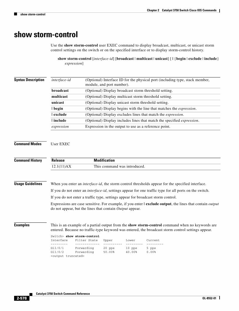
Chapter 2 Catalyst 3750 Switch Cisco IOS Commandsshow storm-control
show storm-controlUse the show storm-control user EXEC command to display broadcast, multicast, or unicast storm control settings on the switch or on the specified interface or to display storm-control history.
show storm-control [interface-id] [broadcast | multicast | unicast] [ | {begin | exclude | include} expression]
Syntax Description
Command Modes User EXEC
Command History
Usage Guidelines When you enter an interface-id, the storm control thresholds appear for the specified interface.
If you do not enter an interface-id, settings appear for one traffic type for all ports on the switch.
If you do not enter a traffic type, settings appear for broadcast storm control.
Expressions are case sensitive. For example, if you enter | exclude output, the lines that contain output do not appear, but the lines that contain Output appear.
Examples This is an example of a partial output from the show storm-control command when no keywords are entered. Because no traffic-type keyword was entered, the broadcast storm control settings appear.
Switch> show storm-controlInterface Filter State Upper Lower Current--------- ------------- ---------- --------- ---------Gi1/0/1 Forwarding 20 pps 10 pps 5 ppsGi1/0/2 Forwarding 50.00% 40.00% 0.00%<output truncated>
interface-id (Optional) Interface ID for the physical port (including type, stack member, module, and port number).
broadcast (Optional) Display broadcast storm threshold setting.
multicast (Optional) Display multicast storm threshold setting.
unicast (Optional) Display unicast storm threshold setting.
| begin (Optional) Display begins with the line that matches the expression.
| exclude (Optional) Display excludes lines that match the expression.
| include (Optional) Display includes lines that match the specified expression.
expression Expression in the output to use as a reference point.
Release Modification
12.1(11)AX This command was introduced.
2-578Catalyst 3750 Switch Command Reference
OL-8552-01
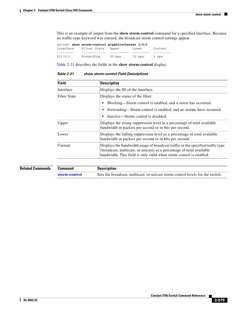
Chapter 2 Catalyst 3750 Switch Cisco IOS Commandsshow storm-control
This is an example of output from the show storm-control command for a specified interface. Because no traffic-type keyword was entered, the broadcast storm control settings appear.
Switch> show storm-control gigabitethernet 1/0/1Interface Filter State Upper Lower Current--------- ------------- ---------- --------- ---------Gi1/0/1 Forwarding 20 pps 10 pps 5 pps
Table 2-31 describes the fields in the show storm-control display.
Related Commands
Table 2-31 show storm-control Field Descriptions
Field Description
Interface Displays the ID of the interface.
Filter State Displays the status of the filter:
• Blocking—Storm control is enabled, and a storm has occurred.
• Forwarding—Storm control is enabled, and no storms have occurred.
• Inactive—Storm control is disabled.
Upper Displays the rising suppression level as a percentage of total available bandwidth in packets per second or in bits per second.
Lower Displays the falling suppression level as a percentage of total available bandwidth in packets per second or in bits per second.
Current Displays the bandwidth usage of broadcast traffic or the specified traffic type (broadcast, multicast, or unicast) as a percentage of total available bandwidth. This field is only valid when storm control is enabled.
Command Description
storm-control Sets the broadcast, multicast, or unicast storm control levels for the switch.
2-579Catalyst 3750 Switch Command Reference
OL-8552-01
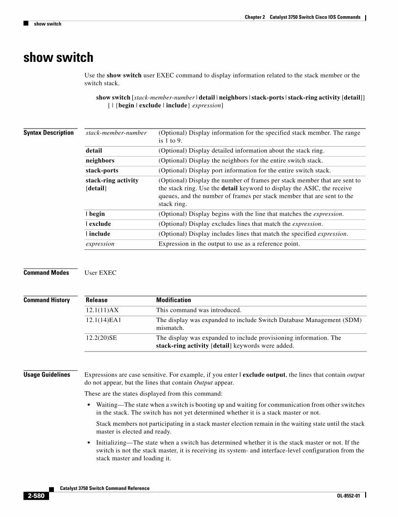
Chapter 2 Catalyst 3750 Switch Cisco IOS Commandsshow switch
show switchUse the show switch user EXEC command to display information related to the stack member or the switch stack.
show switch [stack-member-number | detail | neighbors | stack-ports | stack-ring activity [detail]] [ | {begin | exclude | include} expression]
Syntax Description
Command Modes User EXEC
Command History
Usage Guidelines Expressions are case sensitive. For example, if you enter | exclude output, the lines that contain output do not appear, but the lines that contain Output appear.
These are the states displayed from this command:
• Waiting—The state when a switch is booting up and waiting for communication from other switches in the stack. The switch has not yet determined whether it is a stack master or not.
Stack members not participating in a stack master election remain in the waiting state until the stack master is elected and ready.
• Initializing—The state when a switch has determined whether it is the stack master or not. If the switch is not the stack master, it is receiving its system- and interface-level configuration from the stack master and loading it.
stack-member-number (Optional) Display information for the specified stack member. The range is 1 to 9.
detail (Optional) Display detailed information about the stack ring.
neighbors (Optional) Display the neighbors for the entire switch stack.
stack-ports (Optional) Display port information for the entire switch stack.
stack-ring activity [detail]
(Optional) Display the number of frames per stack member that are sent to the stack ring. Use the detail keyword to display the ASIC, the receive queues, and the number of frames per stack member that are sent to the stack ring.
| begin (Optional) Display begins with the line that matches the expression.
| exclude (Optional) Display excludes lines that match the expression.
| include (Optional) Display includes lines that match the specified expression.
expression Expression in the output to use as a reference point.
Release Modification
12.1(11)AX This command was introduced.
12.1(14)EA1 The display was expanded to include Switch Database Management (SDM) mismatch.
12.2(20)SE The display was expanded to include provisioning information. The stack-ring activity [detail] keywords were added.
2-580Catalyst 3750 Switch Command Reference
OL-8552-01
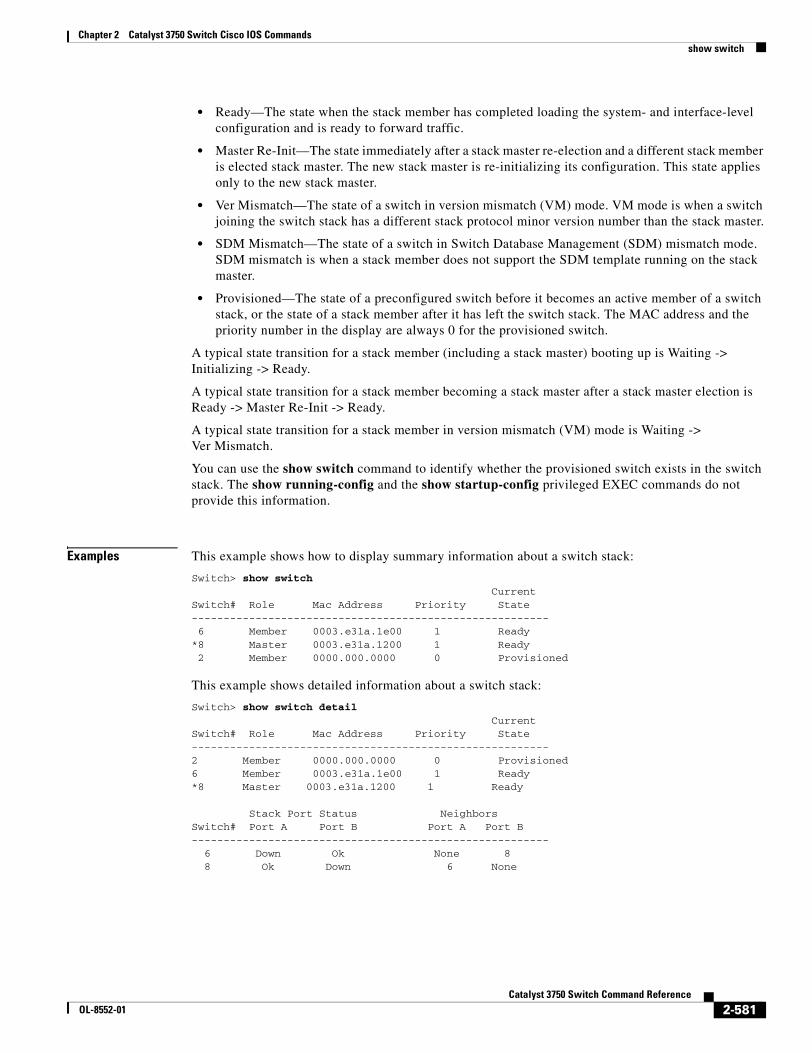
Chapter 2 Catalyst 3750 Switch Cisco IOS Commandsshow switch
• Ready—The state when the stack member has completed loading the system- and interface-level configuration and is ready to forward traffic.
• Master Re-Init—The state immediately after a stack master re-election and a different stack member is elected stack master. The new stack master is re-initializing its configuration. This state applies only to the new stack master.
• Ver Mismatch—The state of a switch in version mismatch (VM) mode. VM mode is when a switch joining the switch stack has a different stack protocol minor version number than the stack master.
• SDM Mismatch—The state of a switch in Switch Database Management (SDM) mismatch mode. SDM mismatch is when a stack member does not support the SDM template running on the stack master.
• Provisioned—The state of a preconfigured switch before it becomes an active member of a switch stack, or the state of a stack member after it has left the switch stack. The MAC address and the priority number in the display are always 0 for the provisioned switch.
A typical state transition for a stack member (including a stack master) booting up is Waiting -> Initializing -> Ready.
A typical state transition for a stack member becoming a stack master after a stack master election is Ready -> Master Re-Init -> Ready.
A typical state transition for a stack member in version mismatch (VM) mode is Waiting -> Ver Mismatch.
You can use the show switch command to identify whether the provisioned switch exists in the switch stack. The show running-config and the show startup-config privileged EXEC commands do not provide this information.
Examples This example shows how to display summary information about a switch stack:
Switch> show switch CurrentSwitch# Role Mac Address Priority State-------------------------------------------------------- 6 Member 0003.e31a.1e00 1 Ready*8 Master 0003.e31a.1200 1 Ready2 Member 0000.000.0000 0 Provisioned
This example shows detailed information about a switch stack:
Switch> show switch detail CurrentSwitch# Role Mac Address Priority State--------------------------------------------------------2 Member 0000.000.0000 0 Provisioned6 Member 0003.e31a.1e00 1 Ready*8 Master 0003.e31a.1200 1 Ready
Stack Port Status NeighborsSwitch# Port A Port B Port A Port B-------------------------------------------------------- 6 Down Ok None 8 8 Ok Down 6 None
2-581Catalyst 3750 Switch Command Reference
OL-8552-01
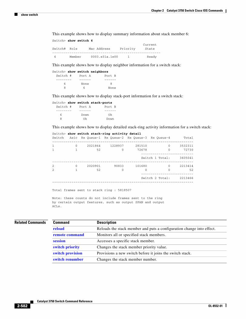
Chapter 2 Catalyst 3750 Switch Cisco IOS Commandsshow switch
This example shows how to display summary information about stack member 6:
Switch> show switch 6 CurrentSwitch# Role Mac Address Priority State-------------------------------------------------------- 6 Member 0003.e31a.1e00 1 Ready
This example shows how to display neighbor information for a switch stack:
Switch> show switch neighbors Switch # Port A Port B -------- ------ ------ 6 None 8 8 6 None
This example shows how to display stack-port information for a switch stack:
Switch> show switch stack-ports Switch # Port A Port B -------- ------ ------ 6 Down Ok 8 Ok Down
This example shows how to display detailed stack-ring activity information for a switch stack:
Switch> show switch stack-ring activity detailSwitch Asic Rx Queue-1 Rx Queue-2 Rx Queue-3 Rx Queue-4 Total-------------------------------------------------------------------------1 0 2021864 1228937 281510 0 35323111 1 52 0 72678 0 72730 --------------------------- Switch 1 Total: 3605041-------------------------------------------------------------------------2 0 2020901 90833 101680 0 22134142 1 52 0 0 0 52 --------------------------- Switch 2 Total: 2213466-------------------------------------------------------------------------
Total frames sent to stack ring : 5818507
Note: these counts do not include frames sent to the ringby certain output features, such as output SPAN and outputACLs.
Related Commands Command Description
reload Reloads the stack member and puts a configuration change into effect.
remote command Monitors all or specified stack members.
session Accesses a specific stack member.
switch priority Changes the stack member priority value.
switch provision Provisions a new switch before it joins the switch stack.
switch renumber Changes the stack member number.
2-582Catalyst 3750 Switch Command Reference
OL-8552-01
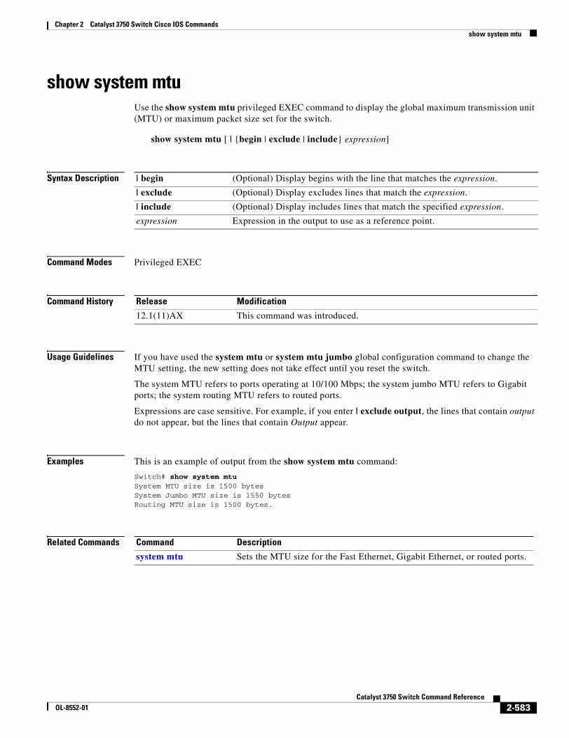
Chapter 2 Catalyst 3750 Switch Cisco IOS Commandsshow system mtu
show system mtuUse the show system mtu privileged EXEC command to display the global maximum transmission unit (MTU) or maximum packet size set for the switch.
show system mtu [ | {begin | exclude | include} expression]
Syntax Description
Command Modes Privileged EXEC
Command History
Usage Guidelines If you have used the system mtu or system mtu jumbo global configuration command to change the MTU setting, the new setting does not take effect until you reset the switch.
The system MTU refers to ports operating at 10/100 Mbps; the system jumbo MTU refers to Gigabit ports; the system routing MTU refers to routed ports.
Expressions are case sensitive. For example, if you enter | exclude output, the lines that contain output do not appear, but the lines that contain Output appear.
Examples This is an example of output from the show system mtu command:
Switch# show system mtuSystem MTU size is 1500 bytesSystem Jumbo MTU size is 1550 bytesRouting MTU size is 1500 bytes.
Related Commands
| begin (Optional) Display begins with the line that matches the expression.
| exclude (Optional) Display excludes lines that match the expression.
| include (Optional) Display includes lines that match the specified expression.
expression Expression in the output to use as a reference point.
Release Modification
12.1(11)AX This command was introduced.
Command Description
system mtu Sets the MTU size for the Fast Ethernet, Gigabit Ethernet, or routed ports.
2-583Catalyst 3750 Switch Command Reference
OL-8552-01
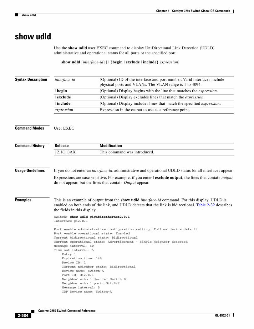
Chapter 2 Catalyst 3750 Switch Cisco IOS Commandsshow udld
show udldUse the show udld user EXEC command to display UniDirectional Link Detection (UDLD) administrative and operational status for all ports or the specified port.
show udld [interface-id] [ | {begin | exclude | include} expression]
Syntax Description
Command Modes User EXEC
Command History
Usage Guidelines If you do not enter an interface-id, administrative and operational UDLD status for all interfaces appear.
Expressions are case sensitive. For example, if you enter | exclude output, the lines that contain output do not appear, but the lines that contain Output appear.
Examples This is an example of output from the show udld interface-id command. For this display, UDLD is enabled on both ends of the link, and UDLD detects that the link is bidirectional. Table 2-32 describes the fields in this display.
Switch> show udld gigabitethernet2/0/1Interface gi2/0/1---Port enable administrative configuration setting: Follows device defaultPort enable operational state: EnabledCurrent bidirectional state: BidirectionalCurrent operational state: Advertisement - Single Neighbor detectedMessage interval: 60Time out interval: 5 Entry 1 Expiration time: 146 Device ID: 1 Current neighbor state: Bidirectional Device name: Switch-A Port ID: Gi2/0/1 Neighbor echo 1 device: Switch-B Neighbor echo 1 port: Gi2/0/2 Message interval: 5 CDP Device name: Switch-A
interface-id (Optional) ID of the interface and port number. Valid interfaces include physical ports and VLANs. The VLAN range is 1 to 4094.
| begin (Optional) Display begins with the line that matches the expression.
| exclude (Optional) Display excludes lines that match the expression.
| include (Optional) Display includes lines that match the specified expression.
expression Expression in the output to use as a reference point.
Release Modification
12.1(11)AX This command was introduced.
2-584Catalyst 3750 Switch Command Reference
OL-8552-01
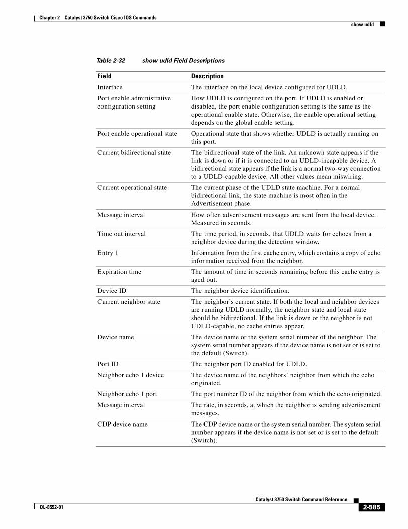
Chapter 2 Catalyst 3750 Switch Cisco IOS Commandsshow udld
Table 2-32 show udld Field Descriptions
Field Description
Interface The interface on the local device configured for UDLD.
Port enable administrative configuration setting
How UDLD is configured on the port. If UDLD is enabled or disabled, the port enable configuration setting is the same as the operational enable state. Otherwise, the enable operational setting depends on the global enable setting.
Port enable operational state Operational state that shows whether UDLD is actually running on this port.
Current bidirectional state The bidirectional state of the link. An unknown state appears if the link is down or if it is connected to an UDLD-incapable device. A bidirectional state appears if the link is a normal two-way connection to a UDLD-capable device. All other values mean miswiring.
Current operational state The current phase of the UDLD state machine. For a normal bidirectional link, the state machine is most often in the Advertisement phase.
Message interval How often advertisement messages are sent from the local device. Measured in seconds.
Time out interval The time period, in seconds, that UDLD waits for echoes from a neighbor device during the detection window.
Entry 1 Information from the first cache entry, which contains a copy of echo information received from the neighbor.
Expiration time The amount of time in seconds remaining before this cache entry is aged out.
Device ID The neighbor device identification.
Current neighbor state The neighbor’s current state. If both the local and neighbor devices are running UDLD normally, the neighbor state and local state should be bidirectional. If the link is down or the neighbor is not UDLD-capable, no cache entries appear.
Device name The device name or the system serial number of the neighbor. The system serial number appears if the device name is not set or is set to the default (Switch).
Port ID The neighbor port ID enabled for UDLD.
Neighbor echo 1 device The device name of the neighbors’ neighbor from which the echo originated.
Neighbor echo 1 port The port number ID of the neighbor from which the echo originated.
Message interval The rate, in seconds, at which the neighbor is sending advertisement messages.
CDP device name The CDP device name or the system serial number. The system serial number appears if the device name is not set or is set to the default (Switch).
2-585Catalyst 3750 Switch Command Reference
OL-8552-01
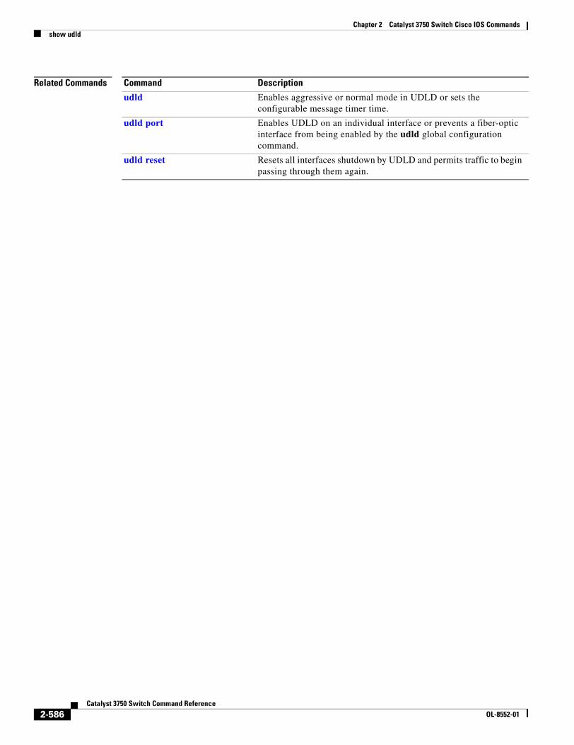
Chapter 2 Catalyst 3750 Switch Cisco IOS Commandsshow udld
Related Commands Command Description
udld Enables aggressive or normal mode in UDLD or sets the configurable message timer time.
udld port Enables UDLD on an individual interface or prevents a fiber-optic interface from being enabled by the udld global configuration command.
udld reset Resets all interfaces shutdown by UDLD and permits traffic to begin passing through them again.
2-586Catalyst 3750 Switch Command Reference
OL-8552-01
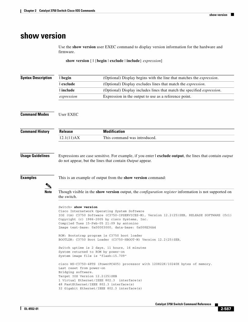
Chapter 2 Catalyst 3750 Switch Cisco IOS Commandsshow version
show versionUse the show version user EXEC command to display version information for the hardware and firmware.
show version [ | {begin | exclude | include} expression]
Syntax Description
Command Modes User EXEC
Command History
Usage Guidelines Expressions are case sensitive. For example, if you enter | exclude output, the lines that contain output do not appear, but the lines that contain Output appear.
Examples This is an example of output from the show version command:
Note Though visible in the show version output, the configuration register information is not supported on the switch.
Switch> show versionCisco Internetwork Operating System SoftwareIOS (tm) C3750 Software (C3750-IPSERVICES-M), Version 12.2(25)SEB, RELEASE SOFTWARE (fc1)Copyright (c) 1986-2005 by cisco Systems, Inc.Compiled Tues 15-Feb-05 21:09 by antoninoImage text-base: 0x00003000, data-base: 0x008E36A4
ROM: Bootstrap program is C3750 boot loaderBOOTLDR: C3750 Boot Loader (C3750-HBOOT-M) Version 12.2(25)SEB,
Switch uptime is 2 days, 11 hours, 16 minutesSystem returned to ROM by power-onSystem image file is "flash:i5.709"
cisco WS-C3750-48TS (PowerPC405) processor with 120822K/10240K bytes of memory.Last reset from power-onBridging software.Target IOS Version 12.2(25)SEB1 Virtual Ethernet/IEEE 802.3 interface(s)48 FastEthernet/IEEE 802.3 interface(s)32 Gigabit Ethernet/IEEE 802.3 interface(s)
| begin (Optional) Display begins with the line that matches the expression.
| exclude (Optional) Display excludes lines that match the expression.
| include (Optional) Display includes lines that match the specified expression.
expression Expression in the output to use as a reference point.
Release Modification
12.1(11)AX This command was introduced.
2-587Catalyst 3750 Switch Command Reference
OL-8552-01
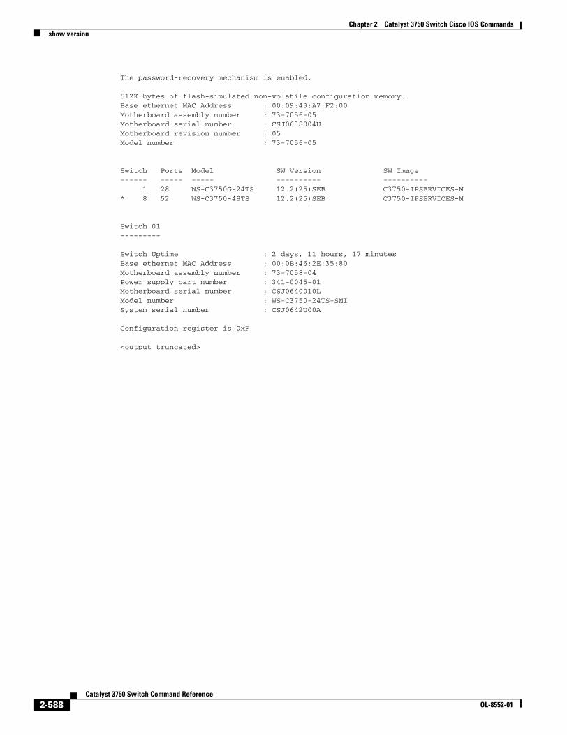
Chapter 2 Catalyst 3750 Switch Cisco IOS Commandsshow version
The password-recovery mechanism is enabled.
512K bytes of flash-simulated non-volatile configuration memory.Base ethernet MAC Address : 00:09:43:A7:F2:00Motherboard assembly number : 73-7056-05Motherboard serial number : CSJ0638004UMotherboard revision number : 05Model number : 73-7056-05
Switch Ports Model SW Version SW Image------ ----- ----- ---------- ---------- 1 28 WS-C3750G-24TS 12.2(25)SEB C3750-IPSERVICES-M* 8 52 WS-C3750-48TS 12.2(25)SEB C3750-IPSERVICES-M
Switch 01---------
Switch Uptime : 2 days, 11 hours, 17 minutesBase ethernet MAC Address : 00:0B:46:2E:35:80Motherboard assembly number : 73-7058-04Power supply part number : 341-0045-01Motherboard serial number : CSJ0640010LModel number : WS-C3750-24TS-SMISystem serial number : CSJ0642U00A
Configuration register is 0xF
<output truncated>
2-588Catalyst 3750 Switch Command Reference
OL-8552-01
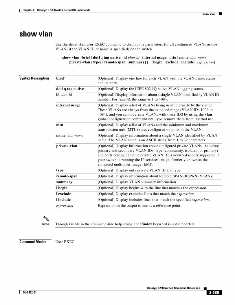
Chapter 2 Catalyst 3750 Switch Cisco IOS Commandsshow vlan
show vlanUse the show vlan user EXEC command to display the parameters for all configured VLANs or one VLAN (if the VLAN ID or name is specified) on the switch.
show vlan [brief | dot1q tag native | id vlan-id | internal usage | mtu | name vlan-name | private-vlan [type] | remote-span | summary] [ | {begin | exclude | include} expression]
Syntax Description
Note Though visible in the command-line help string, the ifindex keyword is not supported.
Command Modes User EXEC
brief (Optional) Display one line for each VLAN with the VLAN name, status, and its ports.
dot1q tag native (Optional) Display the IEEE 802.1Q native VLAN tagging status.
id vlan-id (Optional) Display information about a single VLAN identified by VLAN ID number. For vlan-id, the range is 1 to 4094.
internal usage (Optional) Display a list of VLANs being used internally by the switch. These VLANs are always from the extended range (VLAN IDs 1006 to 4094), and you cannot create VLANs with these IDS by using the vlan global configuration command until you remove them from internal use.
mtu (Optional) Display a list of VLANs and the minimum and maximum transmission unit (MTU) sizes configured on ports in the VLAN.
name vlan-name (Optional) Display information about a single VLAN identified by VLAN name. The VLAN name is an ASCII string from 1 to 32 characters.
private-vlan (Optional) Display information about configured private VLANs, including primary and secondary VLAN IDs, type (community, isolated, or primary) and ports belonging to the private VLAN. This keyword is only supported if your switch is running the IP services image, formerly known as the enhanced multilayer image (EMI).
type (Optional) Display only private VLAN ID and type.
remote-span (Optional) Display information about Remote SPAN (RSPAN) VLANs.
summary (Optional) Display VLAN summary information.
| begin (Optional) Display begins with the line that matches the expression.
| exclude (Optional) Display excludes lines that match the expression.
| include (Optional) Display includes lines that match the specified expression.
expression Expression in the output to use as a reference point.
2-589Catalyst 3750 Switch Command Reference
OL-8552-01
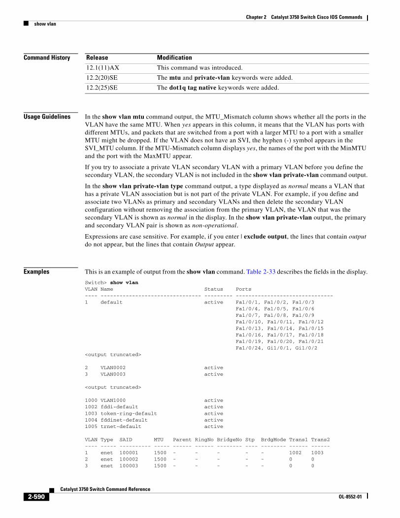
Chapter 2 Catalyst 3750 Switch Cisco IOS Commandsshow vlan
Command History
Usage Guidelines In the show vlan mtu command output, the MTU_Mismatch column shows whether all the ports in the VLAN have the same MTU. When yes appears in this column, it means that the VLAN has ports with different MTUs, and packets that are switched from a port with a larger MTU to a port with a smaller MTU might be dropped. If the VLAN does not have an SVI, the hyphen (-) symbol appears in the SVI_MTU column. If the MTU-Mismatch column displays yes, the names of the port with the MinMTU and the port with the MaxMTU appear.
If you try to associate a private VLAN secondary VLAN with a primary VLAN before you define the secondary VLAN, the secondary VLAN is not included in the show vlan private-vlan command output.
In the show vlan private-vlan type command output, a type displayed as normal means a VLAN that has a private VLAN association but is not part of the private VLAN. For example, if you define and associate two VLANs as primary and secondary VLANs and then delete the secondary VLAN configuration without removing the association from the primary VLAN, the VLAN that was the secondary VLAN is shown as normal in the display. In the show vlan private-vlan output, the primary and secondary VLAN pair is shown as non-operational.
Expressions are case sensitive. For example, if you enter | exclude output, the lines that contain output do not appear, but the lines that contain Output appear.
Examples This is an example of output from the show vlan command. Table 2-33 describes the fields in the display.
Switch> show vlanVLAN Name Status Ports---- -------------------------------- --------- -------------------------------1 default active Fa1/0/1, Fa1/0/2, Fa1/0/3 Fa1/0/4, Fa1/0/5, Fa1/0/6 Fa1/0/7, Fa1/0/8, Fa1/0/9 Fa1/0/10, Fa1/0/11, Fa1/0/12 Fa1/0/13, Fa1/0/14, Fa1/0/15 Fa1/0/16, Fa1/0/17, Fa1/0/18 Fa1/0/19, Fa1/0/20, Fa1/0/21 Fa1/0/24, Gi1/0/1, Gi1/0/2<output truncated>
2 VLAN0002 active3 VLAN0003 active
<output truncated>
1000 VLAN1000 active1002 fddi-default active1003 token-ring-default active1004 fddinet-default active1005 trnet-default active
VLAN Type SAID MTU Parent RingNo BridgeNo Stp BrdgMode Trans1 Trans2---- ----- ---------- ----- ------ ------ -------- ---- -------- ------ ------1 enet 100001 1500 - - - - - 1002 10032 enet 100002 1500 - - - - - 0 03 enet 100003 1500 - - - - - 0 0
Release Modification
12.1(11)AX This command was introduced.
12.2(20)SE The mtu and private-vlan keywords were added.
12.2(25)SE The dot1q tag native keywords were added.
2-590Catalyst 3750 Switch Command Reference
OL-8552-01
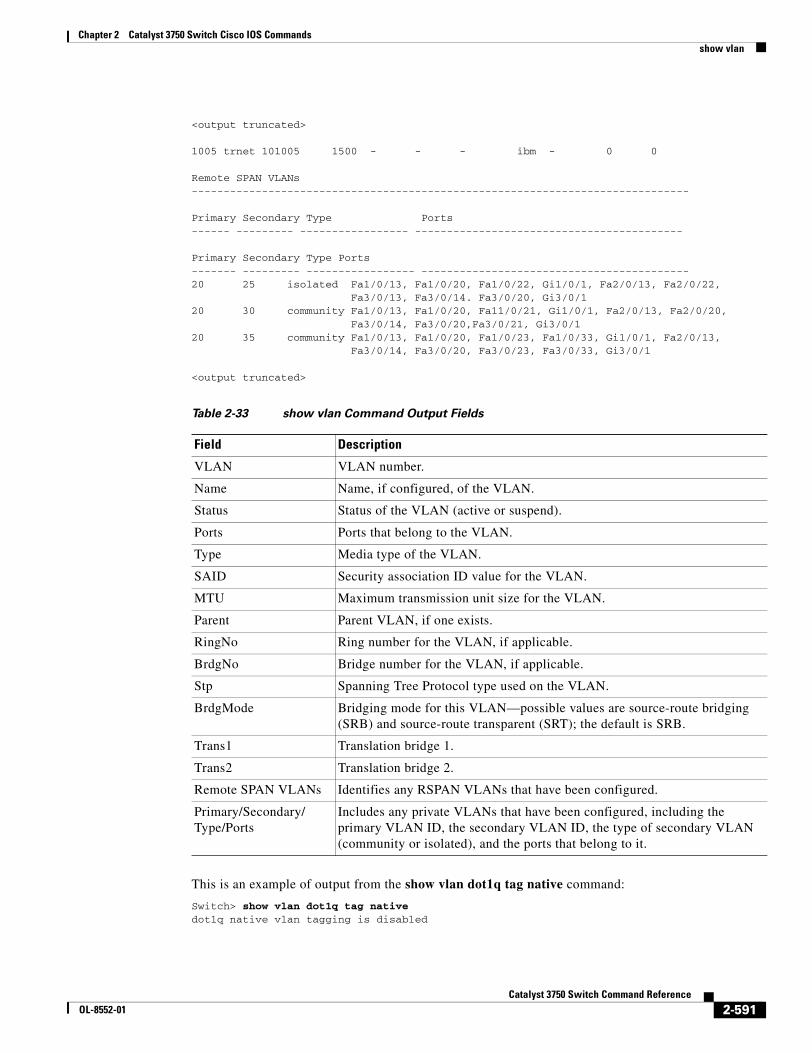
Chapter 2 Catalyst 3750 Switch Cisco IOS Commandsshow vlan
<output truncated>
1005 trnet 101005 1500 - - - ibm - 0 0
Remote SPAN VLANs------------------------------------------------------------------------------
Primary Secondary Type Ports------ --------- ----------------- ------------------------------------------
Primary Secondary Type Ports------- --------- ----------------- ------------------------------------------20 25 isolated Fa1/0/13, Fa1/0/20, Fa1/0/22, Gi1/0/1, Fa2/0/13, Fa2/0/22,
Fa3/0/13, Fa3/0/14. Fa3/0/20, Gi3/0/1 20 30 community Fa1/0/13, Fa1/0/20, Fa11/0/21, Gi1/0/1, Fa2/0/13, Fa2/0/20,
Fa3/0/14, Fa3/0/20,Fa3/0/21, Gi3/0/1 20 35 community Fa1/0/13, Fa1/0/20, Fa1/0/23, Fa1/0/33, Gi1/0/1, Fa2/0/13,
Fa3/0/14, Fa3/0/20, Fa3/0/23, Fa3/0/33, Gi3/0/1
<output truncated>
This is an example of output from the show vlan dot1q tag native command:
Switch> show vlan dot1q tag nativedot1q native vlan tagging is disabled
Table 2-33 show vlan Command Output Fields
Field Description
VLAN VLAN number.
Name Name, if configured, of the VLAN.
Status Status of the VLAN (active or suspend).
Ports Ports that belong to the VLAN.
Type Media type of the VLAN.
SAID Security association ID value for the VLAN.
MTU Maximum transmission unit size for the VLAN.
Parent Parent VLAN, if one exists.
RingNo Ring number for the VLAN, if applicable.
BrdgNo Bridge number for the VLAN, if applicable.
Stp Spanning Tree Protocol type used on the VLAN.
BrdgMode Bridging mode for this VLAN—possible values are source-route bridging (SRB) and source-route transparent (SRT); the default is SRB.
Trans1 Translation bridge 1.
Trans2 Translation bridge 2.
Remote SPAN VLANs Identifies any RSPAN VLANs that have been configured.
Primary/Secondary/Type/Ports
Includes any private VLANs that have been configured, including the primary VLAN ID, the secondary VLAN ID, the type of secondary VLAN (community or isolated), and the ports that belong to it.
2-591Catalyst 3750 Switch Command Reference
OL-8552-01
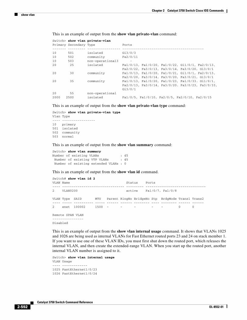
Chapter 2 Catalyst 3750 Switch Cisco IOS Commandsshow vlan
This is an example of output from the show vlan private-vlan command:
Switch> show vlan private-vlan Primary Secondary Type Ports------- --------- ----------------- ------------------------------------------10 501 isolated Gi3/0/310 502 community Fa2/0/1110 503 non-operational3 - 20 25 isolated Fa1/0/13, Fa1/0/20, Fa1/0/22, Gi1/0/1, Fa2/0/13,
Fa2/0/22, Fa3/0/13, Fa3/0/14, Fa3/0/20, Gi3/0/120 30 community Fa1/0/13, Fa1/0/20, Fa1/0/21, Gi1/0/1, Fa2/0/13,
Fa2/0/20, Fa3/0/14, Fa3/0/20, Fa3/0/21, Gi3/0/120 35 community Fa1/0/13, Fa1/0/20, Fa1/0/23, Fa1/0/33. Gi1/0/1,
Fa2/0/13, Fa3/0/14, Fa3/0/20. Fa3/0/23, Fa3/0/33, Gi3/0/1
20 55 non-operational2000 2500 isolated Fa1/0/5, Fa1/0/10, Fa2/0/5, Fa2/0/10, Fa2/0/15
This is an example of output from the show vlan private-vlan type command:
Switch> show vlan private-vlan typeVlan Type---- -----------------10 primary501 isolated502 community503 normal
This is an example of output from the show vlan summary command:
Switch> show vlan summaryNumber of existing VLANs : 45 Number of existing VTP VLANs : 45 Number of existing extended VLANs : 0
This is an example of output from the show vlan id command.
Switch# show vlan id 2VLAN Name Status Ports---- -------------------------------- --------- -------------------------------2 VLAN0200 active Fa1/0/7, Fa1/0/8
VLAN Type SAID MTU Parent RingNo BridgeNo Stp BrdgMode Trans1 Trans2---- ----- ---------- ----- ------ ------ -------- ---- -------- ------ ------2 enet 100002 1500 - - - - - 0 0
Remote SPAN VLAN----------------Disabled
This is an example of output from the show vlan internal usage command. It shows that VLANs 1025 and 1026 are being used as internal VLANs for Fast Ethernet routed ports 23 and 24 on stack member 1. If you want to use one of these VLAN IDs, you must first shut down the routed port, which releases the internal VLAN, and then create the extended-range VLAN. When you start up the routed port, another internal VLAN number is assigned to it.
Switch> show vlan internal usageVLAN Usage---- -------------1025 FastEthernet1/0/231026 FastEthernet1/0/24
2-592Catalyst 3750 Switch Command Reference
OL-8552-01
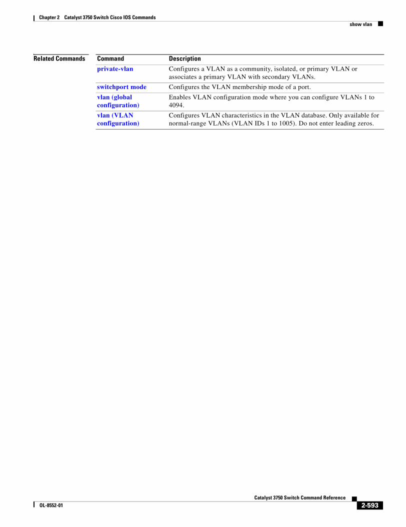
Chapter 2 Catalyst 3750 Switch Cisco IOS Commandsshow vlan
Related Commands Command Description
private-vlan Configures a VLAN as a community, isolated, or primary VLAN or associates a primary VLAN with secondary VLANs.
switchport mode Configures the VLAN membership mode of a port.
vlan (global configuration)
Enables VLAN configuration mode where you can configure VLANs 1 to 4094.
vlan (VLAN configuration)
Configures VLAN characteristics in the VLAN database. Only available for normal-range VLANs (VLAN IDs 1 to 1005). Do not enter leading zeros.
2-593Catalyst 3750 Switch Command Reference
OL-8552-01
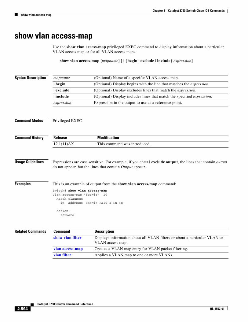
Chapter 2 Catalyst 3750 Switch Cisco IOS Commandsshow vlan access-map
show vlan access-mapUse the show vlan access-map privileged EXEC command to display information about a particular VLAN access map or for all VLAN access maps.
show vlan access-map [mapname] [ | {begin | exclude | include} expression]
Syntax Description
Command Modes Privileged EXEC
Command History
Usage Guidelines Expressions are case sensitive. For example, if you enter | exclude output, the lines that contain output do not appear, but the lines that contain Output appear.
Examples This is an example of output from the show vlan access-map command:
Switch# show vlan access-mapVlan access-map "SecWiz" 10 Match clauses:
ip address: SecWiz_Fa10_3_in_ip
Action: forward
Related Commands
mapname (Optional) Name of a specific VLAN access map.
| begin (Optional) Display begins with the line that matches the expression.
| exclude (Optional) Display excludes lines that match the expression.
| include (Optional) Display includes lines that match the specified expression.
expression Expression in the output to use as a reference point.
Release Modification
12.1(11)AX This command was introduced.
Command Description
show vlan filter Displays information about all VLAN filters or about a particular VLAN or VLAN access map.
vlan access-map Creates a VLAN map entry for VLAN packet filtering.
vlan filter Applies a VLAN map to one or more VLANs.
2-594Catalyst 3750 Switch Command Reference
OL-8552-01
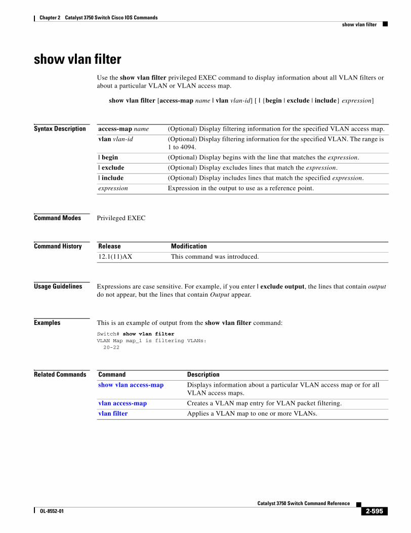
Chapter 2 Catalyst 3750 Switch Cisco IOS Commandsshow vlan filter
show vlan filterUse the show vlan filter privileged EXEC command to display information about all VLAN filters or about a particular VLAN or VLAN access map.
show vlan filter [access-map name | vlan vlan-id] [ | {begin | exclude | include} expression]
Syntax Description
Command Modes Privileged EXEC
Command History
Usage Guidelines Expressions are case sensitive. For example, if you enter | exclude output, the lines that contain output do not appear, but the lines that contain Output appear.
Examples This is an example of output from the show vlan filter command:
Switch# show vlan filter VLAN Map map_1 is filtering VLANs:
20-22
Related Commands
access-map name (Optional) Display filtering information for the specified VLAN access map.
vlan vlan-id (Optional) Display filtering information for the specified VLAN. The range is 1 to 4094.
| begin (Optional) Display begins with the line that matches the expression.
| exclude (Optional) Display excludes lines that match the expression.
| include (Optional) Display includes lines that match the specified expression.
expression Expression in the output to use as a reference point.
Release Modification
12.1(11)AX This command was introduced.
Command Description
show vlan access-map Displays information about a particular VLAN access map or for all VLAN access maps.
vlan access-map Creates a VLAN map entry for VLAN packet filtering.
vlan filter Applies a VLAN map to one or more VLANs.
2-595Catalyst 3750 Switch Command Reference
OL-8552-01
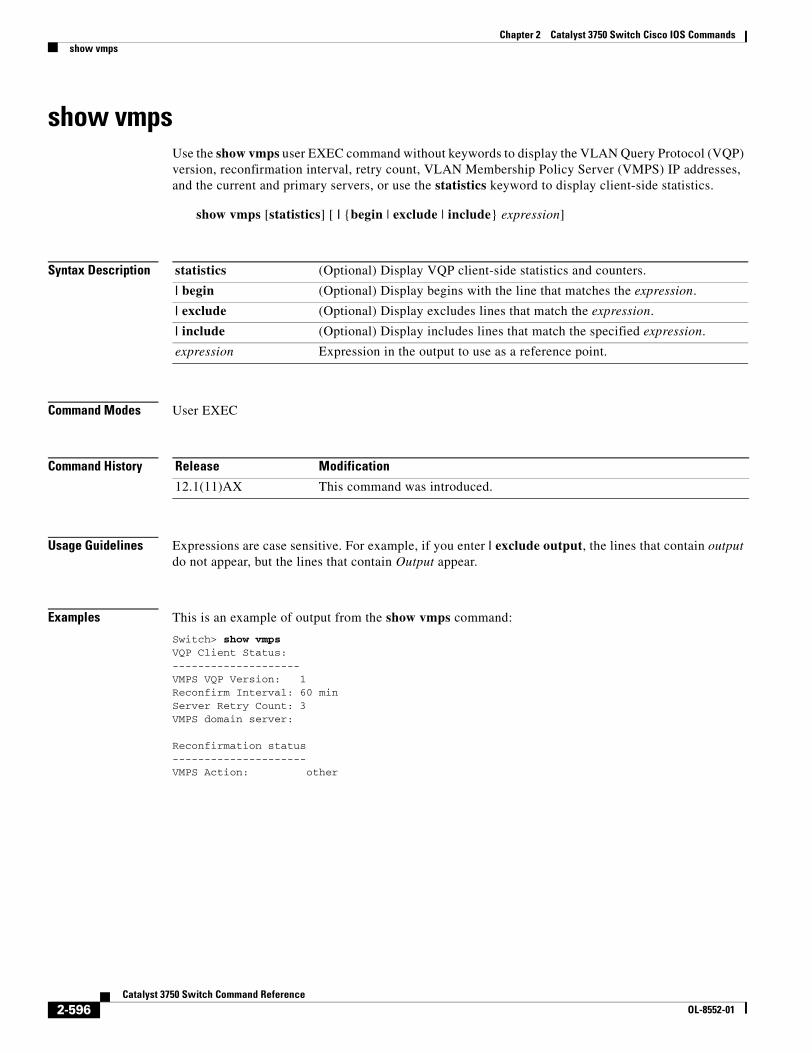
Chapter 2 Catalyst 3750 Switch Cisco IOS Commandsshow vmps
show vmpsUse the show vmps user EXEC command without keywords to display the VLAN Query Protocol (VQP) version, reconfirmation interval, retry count, VLAN Membership Policy Server (VMPS) IP addresses, and the current and primary servers, or use the statistics keyword to display client-side statistics.
show vmps [statistics] [ | {begin | exclude | include} expression]
Syntax Description
Command Modes User EXEC
Command History
Usage Guidelines Expressions are case sensitive. For example, if you enter | exclude output, the lines that contain output do not appear, but the lines that contain Output appear.
Examples This is an example of output from the show vmps command:
Switch> show vmpsVQP Client Status:--------------------VMPS VQP Version: 1Reconfirm Interval: 60 minServer Retry Count: 3VMPS domain server:
Reconfirmation status---------------------VMPS Action: other
statistics (Optional) Display VQP client-side statistics and counters.
| begin (Optional) Display begins with the line that matches the expression.
| exclude (Optional) Display excludes lines that match the expression.
| include (Optional) Display includes lines that match the specified expression.
expression Expression in the output to use as a reference point.
Release Modification
12.1(11)AX This command was introduced.
2-596Catalyst 3750 Switch Command Reference
OL-8552-01
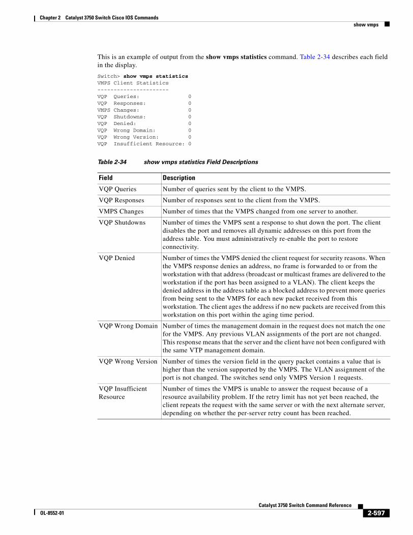
Chapter 2 Catalyst 3750 Switch Cisco IOS Commandsshow vmps
This is an example of output from the show vmps statistics command. Table 2-34 describes each field in the display.
Switch> show vmps statisticsVMPS Client Statistics----------------------VQP Queries: 0VQP Responses: 0VMPS Changes: 0VQP Shutdowns: 0VQP Denied: 0VQP Wrong Domain: 0VQP Wrong Version: 0VQP Insufficient Resource: 0
Table 2-34 show vmps statistics Field Descriptions
Field Description
VQP Queries Number of queries sent by the client to the VMPS.
VQP Responses Number of responses sent to the client from the VMPS.
VMPS Changes Number of times that the VMPS changed from one server to another.
VQP Shutdowns Number of times the VMPS sent a response to shut down the port. The client disables the port and removes all dynamic addresses on this port from the address table. You must administratively re-enable the port to restore connectivity.
VQP Denied Number of times the VMPS denied the client request for security reasons. When the VMPS response denies an address, no frame is forwarded to or from the workstation with that address (broadcast or multicast frames are delivered to the workstation if the port has been assigned to a VLAN). The client keeps the denied address in the address table as a blocked address to prevent more queries from being sent to the VMPS for each new packet received from this workstation. The client ages the address if no new packets are received from this workstation on this port within the aging time period.
VQP Wrong Domain Number of times the management domain in the request does not match the one for the VMPS. Any previous VLAN assignments of the port are not changed. This response means that the server and the client have not been configured with the same VTP management domain.
VQP Wrong Version Number of times the version field in the query packet contains a value that is higher than the version supported by the VMPS. The VLAN assignment of the port is not changed. The switches send only VMPS Version 1 requests.
VQP Insufficient Resource
Number of times the VMPS is unable to answer the request because of a resource availability problem. If the retry limit has not yet been reached, the client repeats the request with the same server or with the next alternate server, depending on whether the per-server retry count has been reached.
2-597Catalyst 3750 Switch Command Reference
OL-8552-01
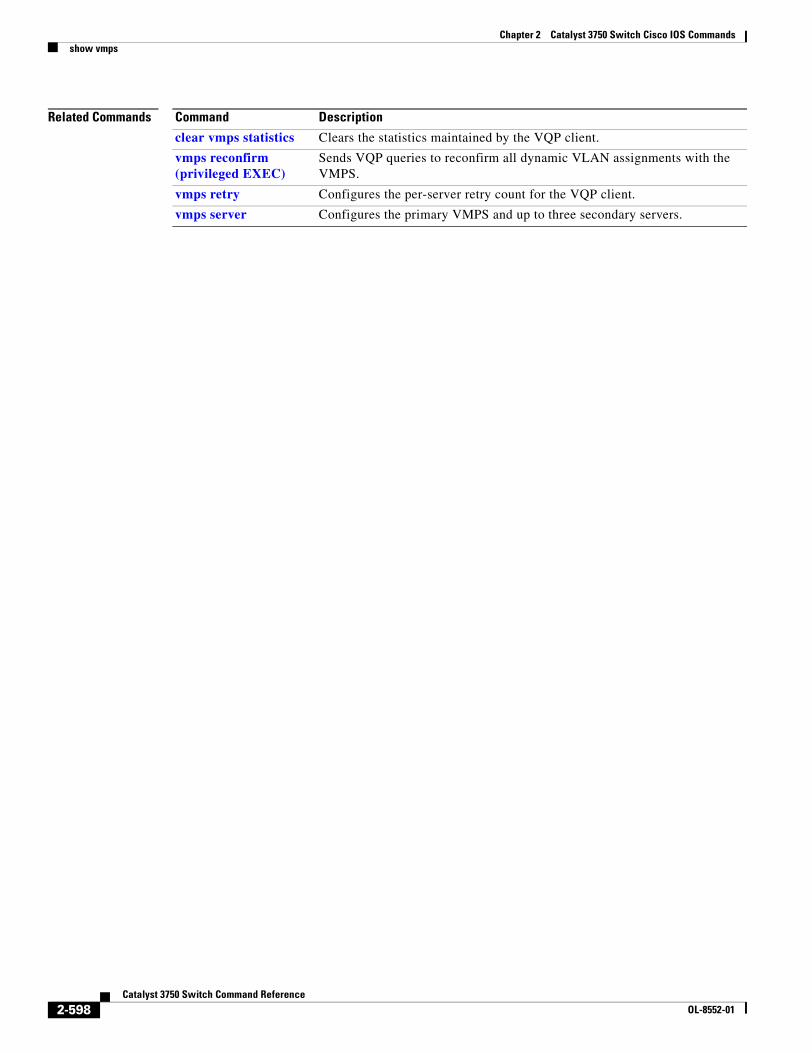
Chapter 2 Catalyst 3750 Switch Cisco IOS Commandsshow vmps
Related Commands Command Description
clear vmps statistics Clears the statistics maintained by the VQP client.
vmps reconfirm (privileged EXEC)
Sends VQP queries to reconfirm all dynamic VLAN assignments with the VMPS.
vmps retry Configures the per-server retry count for the VQP client.
vmps server Configures the primary VMPS and up to three secondary servers.
2-598Catalyst 3750 Switch Command Reference
OL-8552-01
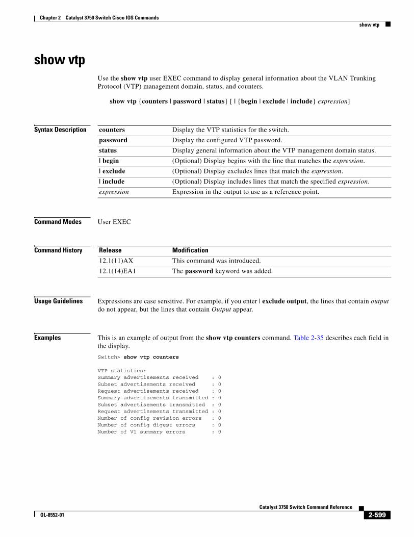
Chapter 2 Catalyst 3750 Switch Cisco IOS Commandsshow vtp
show vtpUse the show vtp user EXEC command to display general information about the VLAN Trunking Protocol (VTP) management domain, status, and counters.
show vtp {counters | password | status} [ | {begin | exclude | include} expression]
Syntax Description
Command Modes User EXEC
Command History
Usage Guidelines Expressions are case sensitive. For example, if you enter | exclude output, the lines that contain output do not appear, but the lines that contain Output appear.
Examples This is an example of output from the show vtp counters command. Table 2-35 describes each field in the display.
Switch> show vtp counters
VTP statistics:Summary advertisements received : 0Subset advertisements received : 0Request advertisements received : 0Summary advertisements transmitted : 0Subset advertisements transmitted : 0Request advertisements transmitted : 0Number of config revision errors : 0Number of config digest errors : 0Number of V1 summary errors : 0
counters Display the VTP statistics for the switch.
password Display the configured VTP password.
status Display general information about the VTP management domain status.
| begin (Optional) Display begins with the line that matches the expression.
| exclude (Optional) Display excludes lines that match the expression.
| include (Optional) Display includes lines that match the specified expression.
expression Expression in the output to use as a reference point.
Release Modification
12.1(11)AX This command was introduced.
12.1(14)EA1 The password keyword was added.
2-599Catalyst 3750 Switch Command Reference
OL-8552-01
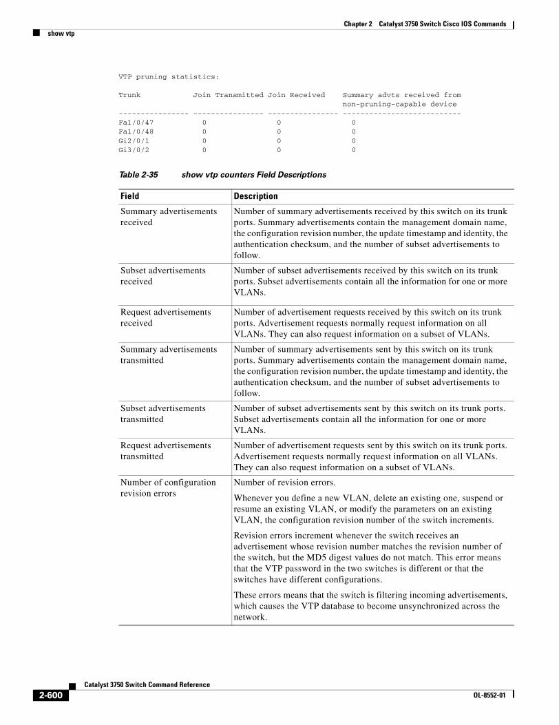
Chapter 2 Catalyst 3750 Switch Cisco IOS Commandsshow vtp
VTP pruning statistics:
Trunk Join Transmitted Join Received Summary advts received from non-pruning-capable device---------------- ---------------- ---------------- ---------------------------Fa1/0/47 0 0 0Fa1/0/48 0 0 0Gi2/0/1 0 0 0Gi3/0/2 0 0 0
Table 2-35 show vtp counters Field Descriptions
Field Description
Summary advertisements received
Number of summary advertisements received by this switch on its trunk ports. Summary advertisements contain the management domain name, the configuration revision number, the update timestamp and identity, the authentication checksum, and the number of subset advertisements to follow.
Subset advertisements received
Number of subset advertisements received by this switch on its trunk ports. Subset advertisements contain all the information for one or more VLANs.
Request advertisements received
Number of advertisement requests received by this switch on its trunk ports. Advertisement requests normally request information on all VLANs. They can also request information on a subset of VLANs.
Summary advertisements transmitted
Number of summary advertisements sent by this switch on its trunk ports. Summary advertisements contain the management domain name, the configuration revision number, the update timestamp and identity, the authentication checksum, and the number of subset advertisements to follow.
Subset advertisements transmitted
Number of subset advertisements sent by this switch on its trunk ports. Subset advertisements contain all the information for one or more VLANs.
Request advertisements transmitted
Number of advertisement requests sent by this switch on its trunk ports. Advertisement requests normally request information on all VLANs. They can also request information on a subset of VLANs.
Number of configuration revision errors
Number of revision errors.
Whenever you define a new VLAN, delete an existing one, suspend or resume an existing VLAN, or modify the parameters on an existing VLAN, the configuration revision number of the switch increments.
Revision errors increment whenever the switch receives an advertisement whose revision number matches the revision number of the switch, but the MD5 digest values do not match. This error means that the VTP password in the two switches is different or that the switches have different configurations.
These errors means that the switch is filtering incoming advertisements, which causes the VTP database to become unsynchronized across the network.
2-600Catalyst 3750 Switch Command Reference
OL-8552-01
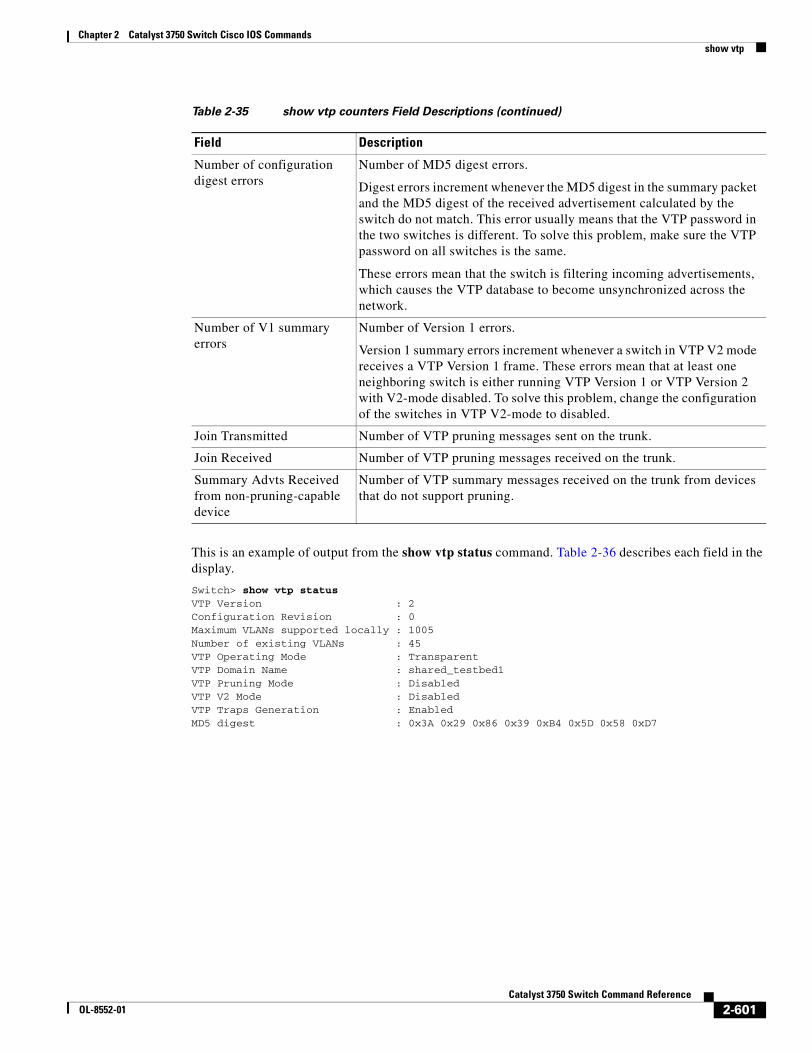
Chapter 2 Catalyst 3750 Switch Cisco IOS Commandsshow vtp
This is an example of output from the show vtp status command. Table 2-36 describes each field in the display.
Switch> show vtp statusVTP Version : 2Configuration Revision : 0Maximum VLANs supported locally : 1005Number of existing VLANs : 45VTP Operating Mode : TransparentVTP Domain Name : shared_testbed1VTP Pruning Mode : DisabledVTP V2 Mode : DisabledVTP Traps Generation : EnabledMD5 digest : 0x3A 0x29 0x86 0x39 0xB4 0x5D 0x58 0xD7
Number of configuration digest errors
Number of MD5 digest errors.
Digest errors increment whenever the MD5 digest in the summary packet and the MD5 digest of the received advertisement calculated by the switch do not match. This error usually means that the VTP password in the two switches is different. To solve this problem, make sure the VTP password on all switches is the same.
These errors mean that the switch is filtering incoming advertisements, which causes the VTP database to become unsynchronized across the network.
Number of V1 summary errors
Number of Version 1 errors.
Version 1 summary errors increment whenever a switch in VTP V2 mode receives a VTP Version 1 frame. These errors mean that at least one neighboring switch is either running VTP Version 1 or VTP Version 2 with V2-mode disabled. To solve this problem, change the configuration of the switches in VTP V2-mode to disabled.
Join Transmitted Number of VTP pruning messages sent on the trunk.
Join Received Number of VTP pruning messages received on the trunk.
Summary Advts Received from non-pruning-capable device
Number of VTP summary messages received on the trunk from devices that do not support pruning.
Table 2-35 show vtp counters Field Descriptions (continued)
Field Description
2-601Catalyst 3750 Switch Command Reference
OL-8552-01
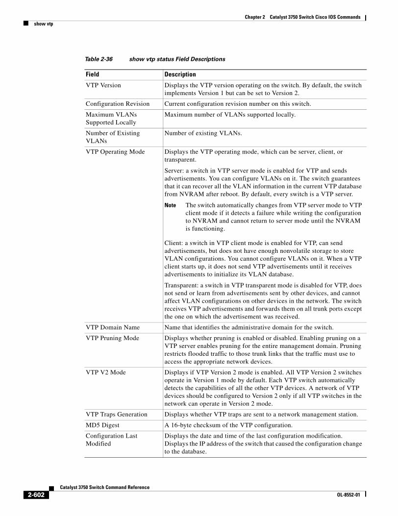
Chapter 2 Catalyst 3750 Switch Cisco IOS Commandsshow vtp
Table 2-36 show vtp status Field Descriptions
Field Description
VTP Version Displays the VTP version operating on the switch. By default, the switch implements Version 1 but can be set to Version 2.
Configuration Revision Current configuration revision number on this switch.
Maximum VLANs Supported Locally
Maximum number of VLANs supported locally.
Number of Existing VLANs
Number of existing VLANs.
VTP Operating Mode Displays the VTP operating mode, which can be server, client, or transparent.
Server: a switch in VTP server mode is enabled for VTP and sends advertisements. You can configure VLANs on it. The switch guarantees that it can recover all the VLAN information in the current VTP database from NVRAM after reboot. By default, every switch is a VTP server.
Note The switch automatically changes from VTP server mode to VTP client mode if it detects a failure while writing the configuration to NVRAM and cannot return to server mode until the NVRAM is functioning.
Client: a switch in VTP client mode is enabled for VTP, can send advertisements, but does not have enough nonvolatile storage to store VLAN configurations. You cannot configure VLANs on it. When a VTP client starts up, it does not send VTP advertisements until it receives advertisements to initialize its VLAN database.
Transparent: a switch in VTP transparent mode is disabled for VTP, does not send or learn from advertisements sent by other devices, and cannot affect VLAN configurations on other devices in the network. The switch receives VTP advertisements and forwards them on all trunk ports except the one on which the advertisement was received.
VTP Domain Name Name that identifies the administrative domain for the switch.
VTP Pruning Mode Displays whether pruning is enabled or disabled. Enabling pruning on a VTP server enables pruning for the entire management domain. Pruning restricts flooded traffic to those trunk links that the traffic must use to access the appropriate network devices.
VTP V2 Mode Displays if VTP Version 2 mode is enabled. All VTP Version 2 switches operate in Version 1 mode by default. Each VTP switch automatically detects the capabilities of all the other VTP devices. A network of VTP devices should be configured to Version 2 only if all VTP switches in the network can operate in Version 2 mode.
VTP Traps Generation Displays whether VTP traps are sent to a network management station.
MD5 Digest A 16-byte checksum of the VTP configuration.
Configuration Last Modified
Displays the date and time of the last configuration modification. Displays the IP address of the switch that caused the configuration change to the database.
2-602Catalyst 3750 Switch Command Reference
OL-8552-01

Chapter 2 Catalyst 3750 Switch Cisco IOS Commandsshow vtp
Related Commands Command Description
clear vtp counters Clears the VTP and pruning counters.
vtp (global configuration) Configures the VTP filename, interface name, domain name, and mode.
vtp (VLAN configuration) Configures the VTP domain name, password, pruning, and mode.
2-603Catalyst 3750 Switch Command Reference
OL-8552-01

Chapter 2 Catalyst 3750 Switch Cisco IOS Commandsshow vtp
2-604Catalyst 3750 Switch Command Reference
OL-8552-01
ommands
Chapter 2 Catalyst 3750 Switch Cisco IOS C2 V ]shutdown
shutdownUse the shutdown interface configuration command on the switch stack or on a standalone switch to disable an interface. Use the no form of this command to restart a disabled interface.
shutdown
no shutdown
Syntax Description This command has no arguments or keywords.
Defaults The port is enabled (not shut down).
Command Modes Interface configuration
Command History
Usage Guidelines The shutdown command causes a port to stop forwarding. You can enable the port with the no shutdown command.
The no shutdown command has no effect if the port is a static-access port assigned to a VLAN that has been deleted, suspended, or shut down. The port must first be a member of an active VLAN before it can be re-enabled.
The shutdown command disables all functions on the specified interface.
This command also marks the interface as unavailable. To see if an interface is disabled, use the show interfaces privileged EXEC command. An interface that has been shut down is shown as administratively down in the display.
Examples These examples show how to disable and re-enable a port:
Switch(config)# interface gigabitethernet1/0/2Switch(config-if)# shutdown
Switch(config)# interface gigabitethernet1/0/2Switch(config-if)# no shutdown
You can verify your settings by entering the show interfaces privileged EXEC command.
Related Commands
Release Modification
12.1(11)AX This command was introduced.
Command Description
show interfaces Displays the statistical information specific to all interfaces or to a specific interface.
2-605Catalyst 3750 Switch Command Reference
OL-8552-01
Chapter 2 Catalyst 3750 Switch Cisco IOS Commandsshutdown vlan
shutdown vlanUse the shutdown vlan global configuration command on the switch stack or on a standalone switch to shut down (suspend) local traffic on the specified VLAN. Use the no form of this command to restart local traffic on the VLAN.
shutdown vlan vlan-id
no shutdown vlan vlan-id
Syntax Description
Defaults No default is defined.
Command Modes Global configuration
Command History
Usage Guidelines The shutdown vlan command does not change the VLAN information in the VTP database. The command shuts down local traffic, but the switch still advertises VTP information.
Examples This example shows how to shut down traffic on VLAN 2:
Switch(config)# shutdown vlan 2
You can verify your setting by entering the show vlan privileged EXEC command.
Related Commands
vlan-id ID of the VLAN to be locally shut down. The range is 2 to 1001. VLANs defined as default VLANs under the VLAN Trunking Protocol (VTP), as well as extended-range VLANs (greater than 1005) cannot be shut down. The default VLANs are 1 and 1002 to 1005.
Release Modification
12.1(11)AX This command was introduced.
Command Description
shutdown (config-vlan mode)
Shuts down local traffic on the VLAN when in config-VLAN mode (accessed by the vlan vlan-id global configuration command).
vlan database Enters VLAN configuration mode.
2-606Catalyst 3750 Switch Command Reference
OL-8552-01
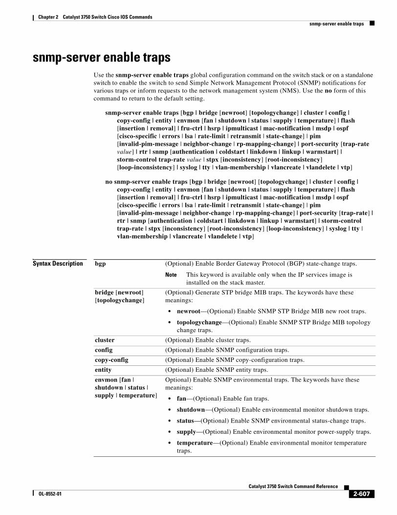
Chapter 2 Catalyst 3750 Switch Cisco IOS Commandssnmp-server enable traps
snmp-server enable trapsUse the snmp-server enable traps global configuration command on the switch stack or on a standalone switch to enable the switch to send Simple Network Management Protocol (SNMP) notifications for various traps or inform requests to the network management system (NMS). Use the no form of this command to return to the default setting.
snmp-server enable traps [bgp | bridge [newroot] [topologychange] | cluster | config | copy-config | entity | envmon [fan | shutdown | status | supply | temperature] | flash [insertion | removal] | fru-ctrl | hsrp | ipmulticast | mac-notification | msdp | ospf [cisco-specific | errors | lsa | rate-limit | retransmit | state-change] | pim [invalid-pim-message | neighbor-change | rp-mapping-change] | port-security [trap-rate value] | rtr | snmp [authentication | coldstart | linkdown | linkup | warmstart] | storm-control trap-rate value | stpx [inconsistency] [root-inconsistency] [loop-inconsistency] | syslog | tty | vlan-membership | vlancreate | vlandelete | vtp]
no snmp-server enable traps [bgp | bridge [newroot] [topologychange] | cluster | config | copy-config | entity | envmon [fan | shutdown | status | supply | temperature] | flash [insertion | removal] | fru-ctrl | hsrp | ipmulticast | mac-notification | msdp | ospf [cisco-specific | errors | lsa | rate-limit | retransmit | state-change] | pim [invalid-pim-message | neighbor-change | rp-mapping-change] | port-security [trap-rate] | rtr | snmp [authentication | coldstart | linkdown | linkup | warmstart] | storm-control trap-rate | stpx [inconsistency] [root-inconsistency] [loop-inconsistency] | syslog | tty | vlan-membership | vlancreate | vlandelete | vtp]
Syntax Description bgp (Optional) Enable Border Gateway Protocol (BGP) state-change traps.
Note This keyword is available only when the IP services image is installed on the stack master.
bridge [newroot] [topologychange]
(Optional) Generate STP bridge MIB traps. The keywords have these meanings:
• newroot—(Optional) Enable SNMP STP Bridge MIB new root traps.
• topologychange—(Optional) Enable SNMP STP Bridge MIB topology change traps.
cluster (Optional) Enable cluster traps.
config (Optional) Enable SNMP configuration traps.
copy-config (Optional) Enable SNMP copy-configuration traps.
entity (Optional) Enable SNMP entity traps.
envmon [fan | shutdown | status | supply | temperature]
Optional) Enable SNMP environmental traps. The keywords have these meanings:
• fan—(Optional) Enable fan traps.
• shutdown—(Optional) Enable environmental monitor shutdown traps.
• status—(Optional) Enable SNMP environmental status-change traps.
• supply—(Optional) Enable environmental monitor power-supply traps.
• temperature—(Optional) Enable environmental monitor temperature traps.
2-607Catalyst 3750 Switch Command Reference
OL-8552-01
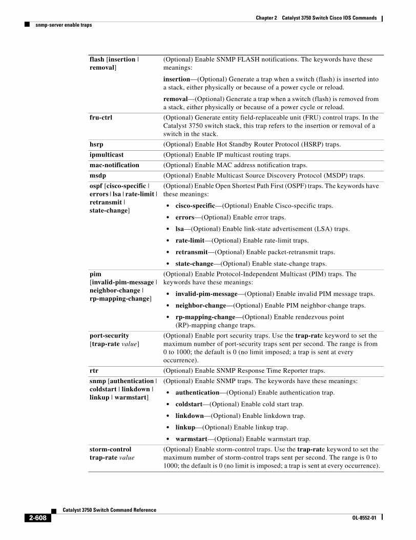
Chapter 2 Catalyst 3750 Switch Cisco IOS Commandssnmp-server enable traps
flash [insertion | removal]
(Optional) Enable SNMP FLASH notifications. The keywords have these meanings:
insertion—(Optional) Generate a trap when a switch (flash) is inserted into a stack, either physically or because of a power cycle or reload.
removal—(Optional) Generate a trap when a switch (flash) is removed from a stack, either physically or because of a power cycle or reload.
fru-ctrl (Optional) Generate entity field-replaceable unit (FRU) control traps. In the Catalyst 3750 switch stack, this trap refers to the insertion or removal of a switch in the stack.
hsrp (Optional) Enable Hot Standby Router Protocol (HSRP) traps.
ipmulticast (Optional) Enable IP multicast routing traps.
mac-notification (Optional) Enable MAC address notification traps.
msdp (Optional) Enable Multicast Source Discovery Protocol (MSDP) traps.
ospf [cisco-specific | errors | lsa | rate-limit | retransmit | state-change]
(Optional) Enable Open Shortest Path First (OSPF) traps. The keywords have these meanings:
• cisco-specific—(Optional) Enable Cisco-specific traps.
• errors—(Optional) Enable error traps.
• lsa—(Optional) Enable link-state advertisement (LSA) traps.
• rate-limit—(Optional) Enable rate-limit traps.
• retransmit—(Optional) Enable packet-retransmit traps.
• state-change—(Optional) Enable state-change traps.
pim [invalid-pim-message | neighbor-change | rp-mapping-change]
(Optional) Enable Protocol-Independent Multicast (PIM) traps. The keywords have these meanings:
• invalid-pim-message—(Optional) Enable invalid PIM message traps.
• neighbor-change—(Optional) Enable PIM neighbor-change traps.
• rp-mapping-change—(Optional) Enable rendezvous point (RP)-mapping change traps.
port-security[trap-rate value]
(Optional) Enable port security traps. Use the trap-rate keyword to set the maximum number of port-security traps sent per second. The range is from 0 to 1000; the default is 0 (no limit imposed; a trap is sent at every occurrence).
rtr (Optional) Enable SNMP Response Time Reporter traps.
snmp [authentication | coldstart | linkdown | linkup | warmstart]
(Optional) Enable SNMP traps. The keywords have these meanings:
• authentication—(Optional) Enable authentication trap.
• coldstart—(Optional) Enable cold start trap.
• linkdown—(Optional) Enable linkdown trap.
• linkup—(Optional) Enable linkup trap.
• warmstart—(Optional) Enable warmstart trap.
storm-control trap-rate value
(Optional) Enable storm-control traps. Use the trap-rate keyword to set the maximum number of storm-control traps sent per second. The range is 0 to 1000; the default is 0 (no limit is imposed; a trap is sent at every occurrence).
2-608Catalyst 3750 Switch Command Reference
OL-8552-01
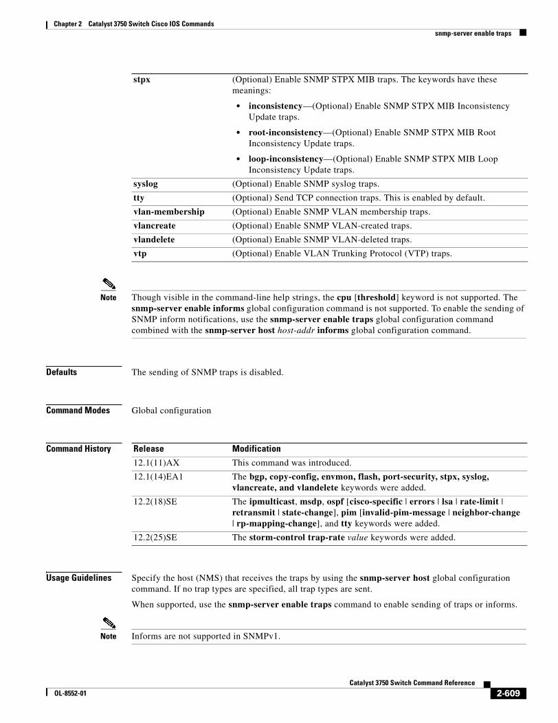
Chapter 2 Catalyst 3750 Switch Cisco IOS Commandssnmp-server enable traps
Note Though visible in the command-line help strings, the cpu [threshold] keyword is not supported. The snmp-server enable informs global configuration command is not supported. To enable the sending of SNMP inform notifications, use the snmp-server enable traps global configuration command combined with the snmp-server host host-addr informs global configuration command.
Defaults The sending of SNMP traps is disabled.
Command Modes Global configuration
Command History
Usage Guidelines Specify the host (NMS) that receives the traps by using the snmp-server host global configuration command. If no trap types are specified, all trap types are sent.
When supported, use the snmp-server enable traps command to enable sending of traps or informs.
Note Informs are not supported in SNMPv1.
stpx (Optional) Enable SNMP STPX MIB traps. The keywords have these meanings:
• inconsistency—(Optional) Enable SNMP STPX MIB Inconsistency Update traps.
• root-inconsistency—(Optional) Enable SNMP STPX MIB Root Inconsistency Update traps.
• loop-inconsistency—(Optional) Enable SNMP STPX MIB Loop Inconsistency Update traps.
syslog (Optional) Enable SNMP syslog traps.
tty (Optional) Send TCP connection traps. This is enabled by default.
vlan-membership (Optional) Enable SNMP VLAN membership traps.
vlancreate (Optional) Enable SNMP VLAN-created traps.
vlandelete (Optional) Enable SNMP VLAN-deleted traps.
vtp (Optional) Enable VLAN Trunking Protocol (VTP) traps.
Release Modification
12.1(11)AX This command was introduced.
12.1(14)EA1 The bgp, copy-config, envmon, flash, port-security, stpx, syslog, vlancreate, and vlandelete keywords were added.
12.2(18)SE The ipmulticast, msdp, ospf [cisco-specific | errors | lsa | rate-limit | retransmit | state-change], pim [invalid-pim-message | neighbor-change | rp-mapping-change], and tty keywords were added.
12.2(25)SE The storm-control trap-rate value keywords were added.
2-609Catalyst 3750 Switch Command Reference
OL-8552-01
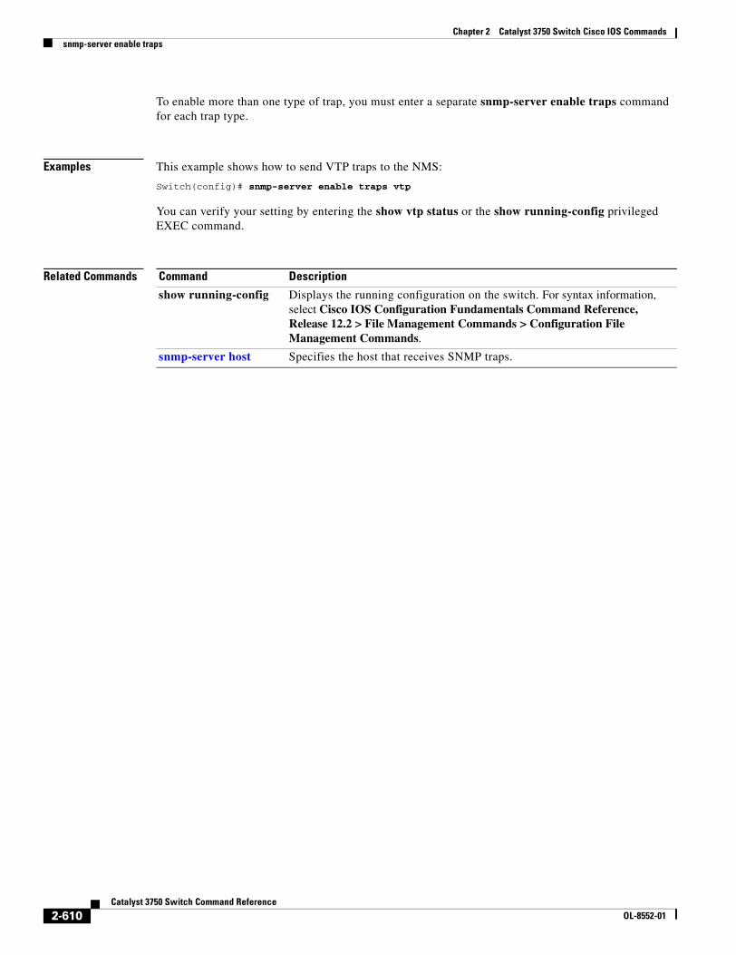
Chapter 2 Catalyst 3750 Switch Cisco IOS Commandssnmp-server enable traps
To enable more than one type of trap, you must enter a separate snmp-server enable traps command for each trap type.
Examples This example shows how to send VTP traps to the NMS:
Switch(config)# snmp-server enable traps vtp
You can verify your setting by entering the show vtp status or the show running-config privileged EXEC command.
Related Commands Command Description
show running-config Displays the running configuration on the switch. For syntax information, select Cisco IOS Configuration Fundamentals Command Reference, Release 12.2 > File Management Commands > Configuration File Management Commands.
snmp-server host Specifies the host that receives SNMP traps.
2-610Catalyst 3750 Switch Command Reference
OL-8552-01
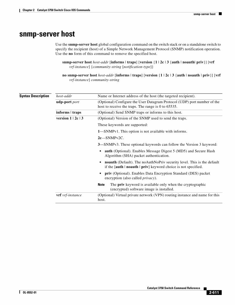
Chapter 2 Catalyst 3750 Switch Cisco IOS Commandssnmp-server host
snmp-server host Use the snmp-server host global configuration command on the switch stack or on a standalone switch to specify the recipient (host) of a Simple Network Management Protocol (SNMP) notification operation. Use the no form of this command to remove the specified host.
snmp-server host host-addr [informs | traps] [version {1 | 2c | 3 {auth | noauth| priv}] [vrf vrf-instance] {community-string [notification-type]}
no snmp-server host host-addr [informs | traps] [version {1 | 2c | 3 {auth | noauth | priv}] [vrf vrf-instance] community-string
Syntax Description host-addr Name or Internet address of the host (the targeted recipient).
udp-port port (Optional) Configure the User Datagram Protocol (UDP) port number of the host to receive the traps. The range is 0 to 65535.
informs | traps (Optional) Send SNMP traps or informs to this host.
version 1 | 2c | 3 (Optional) Version of the SNMP used to send the traps.
These keywords are supported:
1—SNMPv1. This option is not available with informs.
2c—SNMPv2C.
3—SNMPv3. These optional keywords can follow the Version 3 keyword:
• auth (Optional). Enables Message Digest 5 (MD5) and Secure Hash Algorithm (SHA) packet authentication.
• noauth (Default). The noAuthNoPriv security level. This is the default if the [auth | noauth | priv] keyword choice is not specified.
• priv (Optional). Enables Data Encryption Standard (DES) packet encryption (also called privacy).
Note The priv keyword is available only when the cryptographic (encrypted) software image is installed.
vrf vrf-instance (Optional) Virtual private network (VPN) routing instance and name for this host.
2-611Catalyst 3750 Switch Command Reference
OL-8552-01
Chapter 2 Catalyst 3750 Switch Cisco IOS Commandssnmp-server host
community-string Password-like community string sent with the notification operation. Though you can set this string by using the snmp-server host command, we recommend that you define this string by using the snmp-server community global configuration command before using the snmp-server host command.
notification-type (Optional) Type of notification to be sent to the host. If no type is specified, all notifications are sent. The notification type can be one or more of the these keywords:
• bgp—Send Border Gateway Protocol (BGP) state change traps. This keyword is available only when the IP services image is installed on the stack master.
• bridge—Send SNMP Spanning Tree Protocol (STP) bridge MIB traps.
• cluster—Send cluster member status traps.
• config—Send SNMP configuration traps.
• copy-config—Send SNMP copy configuration traps.
• entity— Send SNMP entity traps.
• envmon—Send environmental monitor traps.
• flash—Send SNMP FLASH notifications.
• fru-ctrl—Send entity FRU control traps. In the switch stack, this trap refers to the insertion or removal of a switch in the stack.
• hsrp—Send SNMP Hot Standby Router Protocol (HSRP) traps.
• ipmulticast—Send SNMP IP multicast routing traps.
• mac-notification—Send SNMP MAC notification traps.
• msdp—Send SNMP Multicast Source Discovery Protocol (MSDP) traps.
• ospf—Send Open Shortest Path First (OSPF) traps.
• pim—Send SNMP Protocol-Independent Multicast (PIM) traps.
• port-security—Send SNMP port-security traps.
• rtr—Send SNMP Response Time Reporter traps.
• snmp—Send SNMP-type traps.
• storm-control—Send SNMP storm-control traps.
• stpx—Send SNMP STP extended MIB traps.
• syslog—Send SNMP syslog traps.
• tty—Send TCP connection traps.
• udp-port port—Configure the User Datagram Protocol (UDP) port number of the host to receive the traps. The range is from 0 to 65535.
• vlan-membership— Send SNMP VLAN membership traps.
• vlancreate—Send SNMP VLAN-created traps.
• vlandelete—Send SNMP VLAN-deleted traps.
• vtp—Send SNMP VLAN Trunking Protocol (VTP) traps.
2-612Catalyst 3750 Switch Command Reference
OL-8552-01
Chapter 2 Catalyst 3750 Switch Cisco IOS Commandssnmp-server host
Note Though visible in the command-line help strings, the cpu keyword is not supported.
Defaults This command is disabled by default. No notifications are sent.
If you enter this command with no keywords, the default is to send all trap types to the host. No informs are sent to this host.
If no version keyword is present, the default is Version 1.
If Version 3 is selected and no authentication keyword is entered, the default is the noauth (noAuthNoPriv) security level.
Command Modes Global configuration
Command History
Usage Guidelines SNMP notifications can be sent as traps or inform requests. Traps are unreliable because the receiver does not send acknowledgments when it receives traps. The sender cannot determine if the traps were received. However, an SNMP entity that receives an inform request acknowledges the message with an SNMP response PDU. If the sender never receives the response, the inform request can be sent again. Thus, informs are more likely to reach their intended destinations.
However, informs consume more resources in the agent and in the network. Unlike a trap, which is discarded as soon as it is sent, an inform request must be held in memory until a response is received or the request times out. Traps are also sent only once, but an inform might be retried several times. The retries increase traffic and contribute to a higher overhead on the network.
If you do not enter an snmp-server host command, no notifications are sent. To configure the switch to send SNMP notifications, you must enter at least one snmp-server host command. If you enter the command with no keywords, all trap types are enabled for the host. To enable multiple hosts, you must enter a separate snmp-server host command for each host. You can specify multiple notification types in the command for each host.
If a local user is not associated with a remote host, the switch does not send informs for the auth (authNoPriv) and the priv (authPriv) authentication levels.
When multiple snmp-server host commands are given for the same host and kind of notification (trap or inform), each succeeding command overwrites the previous command. Only the last snmp-server host command is in effect. For example, if you enter an snmp-server host inform command for a host and then enter another snmp-server host inform command for the same host, the second command replaces the first.
Release Modification
12.1(11)AX This command was introduced.
12.1(14)EA1 The bgp, copy-config, flash, port-security, stpx, syslog, vlancreate, and vlandelete keywords were added.
12.2(18)SE The ipmulticast, msdp, ospf, and pim keywords were added. The command syntax was changed.
12.2(25)SE The storm-control and vrf vrf-instance keywords were added.
2-613Catalyst 3750 Switch Command Reference
OL-8552-01
Chapter 2 Catalyst 3750 Switch Cisco IOS Commandssnmp-server host
The snmp-server host command is used with the snmp-server enable traps global configuration command. Use the snmp-server enable traps command to specify which SNMP notifications are sent globally. For a host to receive most notifications, at least one snmp-server enable traps command and the snmp-server host command for that host must be enabled. Some notification types cannot be controlled with the snmp-server enable traps command. For example, some notification types are always enabled. Other notification types are enabled by a different command.
The no snmp-server host command with no keywords disables traps, but not informs, to the host. To disable informs, use the no snmp-server host informs command.
Examples This example shows how to configure a unique SNMP community string named comaccess for traps and prevent SNMP polling access with this string through access-list 10:
Switch(config)# snmp-server community comaccess ro 10Switch(config)# snmp-server host 172.20.2.160 comaccessSwitch(config)# access-list 10 deny any
This example shows how to send the SNMP traps to the host specified by the name myhost.cisco.com. The community string is defined as comaccess:
Switch(config)# snmp-server enable trapsSwitch(config)# snmp-server host myhost.cisco.com comaccess snmp
This example shows how to enable the switch to send all traps to the host myhost.cisco.com by using the community string public:
Switch(config)# snmp-server enable trapsSwitch(config)# snmp-server host myhost.cisco.com public
You can verify your settings by entering the show running-config privileged EXEC command.
Related Commands Command Description
show running-config Displays the running configuration on the switch. For syntax information, select Cisco IOS Configuration Fundamentals Command Reference, Release 12.2 > File Management Commands > Configuration File Management Commands.
snmp-server enable traps Enables SNMP notification for various trap types or inform requests.
2-614Catalyst 3750 Switch Command Reference
OL-8552-01
Chapter 2 Catalyst 3750 Switch Cisco IOS Commandssnmp trap mac-notification
snmp trap mac-notificationUse the snmp trap mac-notification interface configuration command on the switch stack or on a standalone switch to enable the Simple Network Management Protocol (SNMP) MAC address notification trap on a specific Layer 2 interface. Use the no form of this command to return to the default setting.
snmp trap mac-notification {added | removed}
no snmp trap mac-notification {added | removed}
Syntax Description
Defaults By default, the traps for both address addition and address removal are disabled.
Command Modes Interface configuration
Command History
Usage Guidelines Even though you enable the notification trap for a specific interface by using the snmp trap mac-notification command, the trap is generated only when you enable the snmp-server enable traps mac-notification and the mac address-table notification global configuration commands.
Examples This example shows how to enable the MAC notification trap when a MAC address is added to a port:
Switch(config)# interface gigabitethernet1/0/2Switch(config-if)# snmp trap mac-notification added
You can verify your settings by entering the show mac address-table notification interface privileged EXEC command.
added Enable the MAC notification trap whenever a MAC address is added on this interface.
removed Enable the MAC notification trap whenever a MAC address is removed from this interface.
Release Modification
12.1(11)AX This command was introduced.
2-615Catalyst 3750 Switch Command Reference
OL-8552-01
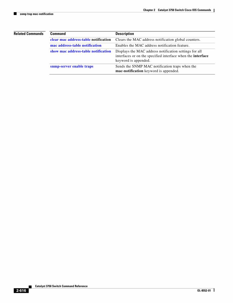
Chapter 2 Catalyst 3750 Switch Cisco IOS Commandssnmp trap mac-notification
Related Commands Command Description
clear mac address-table notification Clears the MAC address notification global counters.
mac address-table notification Enables the MAC address notification feature.
show mac address-table notification Displays the MAC address notification settings for all interfaces or on the specified interface when the interface keyword is appended.
snmp-server enable traps Sends the SNMP MAC notification traps when the mac-notification keyword is appended.
2-616Catalyst 3750 Switch Command Reference
OL-8552-01
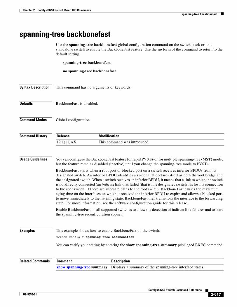
Chapter 2 Catalyst 3750 Switch Cisco IOS Commandsspanning-tree backbonefast
spanning-tree backbonefastUse the spanning-tree backbonefast global configuration command on the switch stack or on a standalone switch to enable the BackboneFast feature. Use the no form of the command to return to the default setting.
spanning-tree backbonefast
no spanning-tree backbonefast
Syntax Description This command has no arguments or keywords.
Defaults BackboneFast is disabled.
Command Modes Global configuration
Command History
Usage Guidelines You can configure the BackboneFast feature for rapid PVST+ or for multiple spanning-tree (MST) mode, but the feature remains disabled (inactive) until you change the spanning-tree mode to PVST+.
BackboneFast starts when a root port or blocked port on a switch receives inferior BPDUs from its designated switch. An inferior BPDU identifies a switch that declares itself as both the root bridge and the designated switch. When a switch receives an inferior BPDU, it means that a link to which the switch is not directly connected (an indirect link) has failed (that is, the designated switch has lost its connection to the root switch. If there are alternate paths to the root switch, BackboneFast causes the maximum aging time on the interfaces on which it received the inferior BPDU to expire and allows a blocked port to move immediately to the listening state. BackboneFast then transitions the interface to the forwarding state. For more information, see the software configuration guide for this release.
Enable BackboneFast on all supported switches to allow the detection of indirect link failures and to start the spanning-tree reconfiguration sooner.
Examples This example shows how to enable BackboneFast on the switch:
Switch(config)# spanning-tree backbonefast
You can verify your setting by entering the show spanning-tree summary privileged EXEC command.
Related Commands
Release Modification
12.1(11)AX This command was introduced.
Command Description
show spanning-tree summary Displays a summary of the spanning-tree interface states.
2-617Catalyst 3750 Switch Command Reference
OL-8552-01
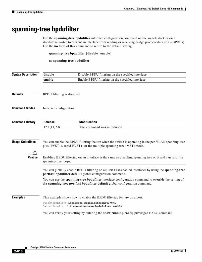
Chapter 2 Catalyst 3750 Switch Cisco IOS Commandsspanning-tree bpdufilter
spanning-tree bpdufilter Use the spanning-tree bpdufilter interface configuration command on the switch stack or on a standalone switch to prevent an interface from sending or receiving bridge protocol data units (BPDUs). Use the no form of this command to return to the default setting.
spanning-tree bpdufilter {disable | enable}
no spanning-tree bpdufilter
Syntax Description
Defaults BPDU filtering is disabled.
Command Modes Interface configuration
Command History
Usage Guidelines You can enable the BPDU filtering feature when the switch is operating in the per-VLAN spanning-tree plus (PVST+), rapid-PVST+, or the multiple spanning-tree (MST) mode.
Caution Enabling BPDU filtering on an interface is the same as disabling spanning tree on it and can result in spanning-tree loops.
You can globally enable BPDU filtering on all Port Fast-enabled interfaces by using the spanning-tree portfast bpdufilter default global configuration command.
You can use the spanning-tree bpdufilter interface configuration command to override the setting of the spanning-tree portfast bpdufilter default global configuration command.
Examples This example shows how to enable the BPDU filtering feature on a port:
Switch(config)# interface gigabitethernet2/0/1Switch(config-if)# spanning-tree bpdufilter enable
You can verify your setting by entering the show running-config privileged EXEC command.
disable Disable BPDU filtering on the specified interface.
enable Enable BPDU filtering on the specified interface.
Release Modification
12.1(11)AX This command was introduced.
2-618Catalyst 3750 Switch Command Reference
OL-8552-01
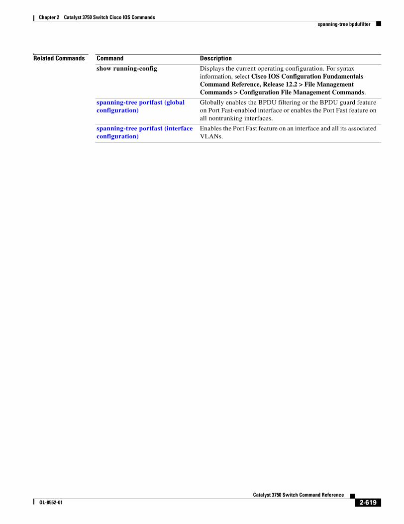
Chapter 2 Catalyst 3750 Switch Cisco IOS Commandsspanning-tree bpdufilter
Related Commands Command Description
show running-config Displays the current operating configuration. For syntax information, select Cisco IOS Configuration Fundamentals Command Reference, Release 12.2 > File Management Commands > Configuration File Management Commands.
spanning-tree portfast (global configuration)
Globally enables the BPDU filtering or the BPDU guard feature on Port Fast-enabled interface or enables the Port Fast feature on all nontrunking interfaces.
spanning-tree portfast (interface configuration)
Enables the Port Fast feature on an interface and all its associated VLANs.
2-619Catalyst 3750 Switch Command Reference
OL-8552-01
Chapter 2 Catalyst 3750 Switch Cisco IOS Commandsspanning-tree bpduguard
spanning-tree bpduguard Use the spanning-tree bpduguard interface configuration command on the switch stack or on a standalone switch to put an interface in the error-disabled state when it receives a bridge protocol data unit (BPDU). Use the no form of this command to return to the default setting.
spanning-tree bpduguard {disable | enable}
no spanning-tree bpduguard
Syntax Description
Defaults BPDU guard is disabled.
Command Modes Interface configuration
Command History
Usage Guidelines The BPDU guard feature provides a secure response to invalid configurations because you must manually put the interface back in service. Use the BPDU guard feature in a service-provider network to prevent an interface from being included in the spanning-tree topology.
You can enable the BPDU guard feature when the switch is operating in the per-VLAN spanning-tree plus (PVST+), rapid-PVST+, or the multiple spanning-tree (MST) mode.
You can globally enable BPDU guard on all Port Fast-enabled interfaces by using the spanning-tree portfast bpduguard default global configuration command.
You can use the spanning-tree bpduguard interface configuration command to override the setting of the spanning-tree portfast bpduguard default global configuration command.
Examples This example shows how to enable the BPDU guard feature on a port:
Switch(config)# interface gigabitethernet2/0/1Switch(config-if)# spanning-tree bpduguard enable
You can verify your setting by entering the show running-config privileged EXEC command.
disable Disable BPDU guard on the specified interface.
enable Enable BPDU guard on the specified interface.
Release Modification
12.1(11)AX This command was introduced.
2-620Catalyst 3750 Switch Command Reference
OL-8552-01

Chapter 2 Catalyst 3750 Switch Cisco IOS Commandsspanning-tree bpduguard
Related Commands Command Description
show running-config Displays the current operating configuration. For syntax information, select Cisco IOS Configuration Fundamentals Command Reference, Release 12.2 > File Management Commands > Configuration File Management Commands.
spanning-tree portfast (global configuration)
Globally enables the BPDU filtering or the BPDU guard feature on Port Fast-enabled interfaces or enables the Port Fast feature on all nontrunking interfaces.
spanning-tree portfast (interface configuration)
Enables the Port Fast feature on an interface and all its associated VLANs.
2-621Catalyst 3750 Switch Command Reference
OL-8552-01
Chapter 2 Catalyst 3750 Switch Cisco IOS Commandsspanning-tree cost
spanning-tree costUse the spanning-tree cost interface configuration command on the switch stack or on a standalone switch to set the path cost for spanning-tree calculations. If a loop occurs, spanning tree considers the path cost when selecting an interface to place in the forwarding state. Use the no form of this command to return to the default setting.
spanning-tree [vlan vlan-id] cost cost
no spanning-tree [vlan vlan-id] cost
Syntax Description
Defaults The default path cost is computed from the interface bandwidth setting. These are the IEEE default path cost values:
• 1000 Mbps—4
• 100 Mbps—19
• 10 Mbps—100
Command Modes Interface configuration
Command History
Usage Guidelines When you configure the cost, higher values represent higher costs.
If you configure an interface with both the spanning-tree vlan vlan-id cost cost command and the spanning-tree cost cost command, the spanning-tree vlan vlan-id cost cost command takes effect.
Examples This example shows how to set the path cost to 250 on a port:
Switch(config)# interface gigabitethernet2/0/1Switch(config-if)# spanning-tree cost 250
This example shows how to set a path cost to 300 for VLANs 10, 12 to 15, and 20:
Switch(config-if)# spanning-tree vlan 10,12-15,20 cost 300
You can verify your settings by entering the show spanning-tree interface interface-id privileged EXEC command.
vlan vlan-id (Optional) VLAN range associated with a spanning-tree instance. You can specify a single VLAN identified by VLAN ID number, a range of VLANs separated by a hyphen, or a series of VLANs separated by a comma. The range is 1 to 4094.
cost Path cost. The range is 1 to 200000000, with higher values meaning higher costs.
Release Modification
12.1(11)AX This command was introduced.
12.1(14)EA1 The value for the vlan-id variable was changed.
2-622Catalyst 3750 Switch Command Reference
OL-8552-01

Chapter 2 Catalyst 3750 Switch Cisco IOS Commandsspanning-tree cost
Related Commands Command Description
show spanning-tree interface interface-id
Displays spanning-tree information for the specified interface.
spanning-tree port-priority Configures an interface priority.
spanning-tree vlan priority Sets the switch priority for the specified spanning-tree instance.
2-623Catalyst 3750 Switch Command Reference
OL-8552-01
Chapter 2 Catalyst 3750 Switch Cisco IOS Commandsspanning-tree etherchannel guard misconfig
spanning-tree etherchannel guard misconfigUse the spanning-tree etherchannel guard misconfig global configuration command to display an error message when the switch detects an EtherChannel misconfiguration. Use the no form of this command to disable the feature.
spanning-tree etherchannel guard misconfig
no spanning-tree etherchannel guard misconfig
Syntax Description This command has no arguments or keywords.
Defaults EtherChannel guard is enabled on the switch.
Command Modes Global configuration
Command History
Usage Guidelines When the switch detects an EtherChannel misconfiguration, this error message appears:
PM-4-ERR_DISABLE: Channel-misconfig error detected on [chars], putting [chars] in err-disable state.
To show switch ports that are in the misconfigured EtherChannel, use the show interfaces status err-disabled privileged EXEC command. To verify the EtherChannel configuration on a remote device, use the show etherchannel summary privileged EXEC command on the remote device.
When a port is in the error-disabled state because of an EtherChannel misconfiguration, you can bring it out of this state by entering the errdisable recovery cause channel-misconfig global configuration command, or you can manually re-enable it by entering the shutdown and no shut down interface configuration commands.
Examples This example shows how to enable the EtherChannel guard misconfiguration feature:
Switch(config)# spanning-tree etherchannel guard misconfig
You can verify your settings by entering the show spanning-tree summary privileged EXEC command.
Release Modification
12.1(14)EA1 This command was introduced.
2-624Catalyst 3750 Switch Command Reference
OL-8552-01

Chapter 2 Catalyst 3750 Switch Cisco IOS Commandsspanning-tree etherchannel guard misconfig
Related Commands Command Description
errdisable recovery cause channel-misconfig
Enables the timer to recover from the EtherChannel misconfiguration error-disabled state.
show etherchannel summary Displays EtherChannel information for a channel as a one-line summary per channel-group.
show interfaces status err-disabled
Displays the interfaces in the error-disabled state.
2-625Catalyst 3750 Switch Command Reference
OL-8552-01
Chapter 2 Catalyst 3750 Switch Cisco IOS Commandsspanning-tree extend system-id
spanning-tree extend system-idUse the spanning-tree extend system-id global configuration command on the switch stack or on a standalone switch to enable the extended system ID feature.
spanning-tree extend system-id
Note Though visible in the command-line help strings, the no version of this command is not supported. You cannot disable the extended system ID feature.
Syntax Description This command has no arguments or keywords.
Defaults The extended system ID is enabled.
Command Modes Global configuration
Command History
Usage Guidelines The switch supports the IEEE 802.1t spanning-tree extensions. Some of the bits previously used for the switch priority are now used for the extended system ID (VLAN identifier for the per-VLAN spanning-tree plus [PVST+] and rapid PVST+ or as an instance identifier for the multiple spanning tree [MST]).
The spanning tree uses the extended system ID, the switch priority, and the allocated spanning-tree MAC address to make the bridge ID unique for each VLAN or multiple spanning-tree instance. Because the Catalyst 3750 switch stack appears as a single switch to the rest of the network, all switches in the stack use the same bridge ID for a given spanning tree. If the stack master fails, the stack members recalculate their bridge IDs of all running spanning trees based on the new MAC address of the stack master.
Support for the extended system ID affects how you manually configure the root switch, the secondary root switch, and the switch priority of a VLAN. For more information, see the “spanning-tree mst root” and the “spanning-tree vlan” sections.
If your network consists of switches that do not support the extended system ID and switches that do support it, it is unlikely that the switch with the extended system ID support will become the root switch. The extended system ID increases the switch priority value every time the VLAN number is greater than the priority of the connected switches.
Release Modification
12.1(11)AX This command was introduced.
2-626Catalyst 3750 Switch Command Reference
OL-8552-01

Chapter 2 Catalyst 3750 Switch Cisco IOS Commandsspanning-tree extend system-id
Related Commands Command Description
show spanning-tree summary Displays a summary of spanning-tree interface states.
spanning-tree mst root Configures the MST root switch priority and timers based on the network diameter.
spanning-tree vlan priority Sets the switch priority for the specified spanning-tree instance.
2-627Catalyst 3750 Switch Command Reference
OL-8552-01
Chapter 2 Catalyst 3750 Switch Cisco IOS Commandsspanning-tree guard
spanning-tree guardUse the spanning-tree guard interface configuration command on the switch stack or on a standalone switch to enable root guard or loop guard on all the VLANs associated with the selected interface. Root guard restricts which interface is allowed to be the spanning-tree root port or the path-to-the root for the switch. Loop guard prevents alternate or root ports from becoming designated ports when a failure creates a unidirectional link. Use the no form of this command to return to the default setting.
spanning-tree guard {loop | none | root}
no spanning-tree guard
Syntax Description
Defaults Root guard is disabled.
Loop guard is configured according to the spanning-tree loopguard default global configuration command (globally disabled).
Command Modes Interface configuration
Command History
Usage Guidelines You can enable root guard or loop guard when the switch is operating in the per-VLAN spanning-tree plus (PVST+), rapid-PVST+, or the multiple spanning-tree (MST) mode.
When root guard is enabled, if spanning-tree calculations cause an interface to be selected as the root port, the interface transitions to the root-inconsistent (blocked) state to prevent the customer’s switch from becoming the root switch or being in the path to the root. The root port provides the best path from the switch to the root switch.
When the no spanning-tree guard or the no spanning-tree guard none command is entered, root guard is disabled for all VLANs on the selected interface. If this interface is in the root-inconsistent (blocked) state, it automatically transitions to the listening state.
Do not enable root guard on interfaces that will be used by the UplinkFast feature. With UplinkFast, the backup interfaces (in the blocked state) replace the root port in the case of a failure. However, if root guard is also enabled, all the backup interfaces used by the UplinkFast feature are placed in the root-inconsistent state (blocked) and prevented from reaching the forwarding state. The UplinkFast feature is not available when the switch is operating in the rapid-PVST+ or MST mode.
loop Enable loop guard.
none Disable root guard or loop guard.
root Enable root guard.
Release Modification
12.1(11)AX This command was introduced.
2-628Catalyst 3750 Switch Command Reference
OL-8552-01
Chapter 2 Catalyst 3750 Switch Cisco IOS Commandsspanning-tree guard
Loop guard is most effective when it is configured on the entire switched network. When the switch is operating in PVST+ or rapid-PVST+ mode, loop guard prevents alternate and root ports from becoming designated ports, and spanning tree does not send bridge protocol data units (BPDUs) on root or alternate ports. When the switch is operating in MST mode, BPDUs are not sent on nonboundary interfaces if the interface is blocked by loop guard in all MST instances. On a boundary interface, loop guard blocks the interface in all MST instances.
To disable root guard or loop guard, use the spanning-tree guard none interface configuration command. You cannot enable both root guard and loop guard at the same time.
You can override the setting of the spanning-tree loopguard default global configuration command by using the spanning-tree guard loop interface configuration command.
Examples This example shows how to enable root guard on all the VLANs associated with the specified port:
Switch(config)# interface gigabitethernet2/0/2Switch(config-if)# spanning-tree guard root
This example shows how to enable loop guard on all the VLANs associated with the specified port:
Switch(config)# interface gigabitethernet2/0/2Switch(config-if)# spanning-tree guard loop
You can verify your settings by entering the show running-config privileged EXEC command.
Related Commands Command Description
show running-config Displays the current operating configuration. For syntax information, select Cisco IOS Configuration Fundamentals Command Reference, Release 12.2 > File Management Commands > Configuration File Management Commands.
spanning-tree cost Sets the path cost for spanning-tree calculations.
spanning-tree loopguard default Prevents alternate or root ports from becoming designated ports because of a failure that leads to a unidirectional link.
spanning-tree mst cost Configures the path cost for MST calculations.
spanning-tree mst port-priority Configures an interface priority.
spanning-tree mst root Configures the MST root switch priority and timers based on the network diameter.
spanning-tree port-priority Configures an interface priority.
spanning-tree vlan priority Sets the switch priority for the specified spanning-tree instance.
2-629Catalyst 3750 Switch Command Reference
OL-8552-01
Chapter 2 Catalyst 3750 Switch Cisco IOS Commandsspanning-tree link-type
spanning-tree link-type Use the spanning-tree link-type interface configuration command on the switch stack or on a standalone switch to override the default link-type setting, which is determined by the duplex mode of the interface, and to enable rapid spanning-tree transitions to the forwarding state. Use the no form of this command to return to the default setting.
spanning-tree link-type {point-to-point | shared}
no spanning-tree link-type
Syntax Description
Defaults The switch derives the link type of an interface from the duplex mode. A full-duplex interface is considered a point-to-point link, and a half-duplex interface is considered a shared link.
Command Modes Interface configuration
Command History
Usage Guidelines You can override the default setting of the link type by using the spanning-tree link-type command. For example, a half-duplex link can be physically connected point-to-point to a single interface on a remote switch running the Multiple Spanning Tree Protocol (MSTP) or the rapid per-VLAN spanning-tree plus (rapid-PVST+) protocol and be enabled for rapid transitions.
Examples This example shows how to specify the link type as shared (regardless of the duplex setting) and to prevent rapid transitions to the forwarding state:
Switch(config-if)# spanning-tree link-type shared
You can verify your setting by entering the show spanning-tree mst interface interface-id or the show spanning-tree interface interface-id privileged EXEC command.
point-to-point Specify that the link type of an interface is point-to-point.
shared Specify that the link type of an interface is shared.
Release Modification
12.1(14)EA1 This command was introduced.
2-630Catalyst 3750 Switch Command Reference
OL-8552-01
Chapter 2 Catalyst 3750 Switch Cisco IOS Commandsspanning-tree link-type
Related Commands Command Description
clear spanning-tree detected-protocols Restarts the protocol migration process (force the renegotiation with neighboring switches) on all interfaces or on the specified interface.
show spanning-tree interface interface-id
Displays spanning-tree state information for the specified interface.
show spanning-tree mst interface interface-id
Displays MST information for the specified interface.
2-631Catalyst 3750 Switch Command Reference
OL-8552-01
Chapter 2 Catalyst 3750 Switch Cisco IOS Commandsspanning-tree loopguard default
spanning-tree loopguard defaultUse the spanning-tree loopguard default global configuration command on the switch stack or on a standalone switch to prevent alternate or root ports from becoming designated ports because of a failure that leads to a unidirectional link. Use the no form of this command to return to the default setting.
spanning-tree loopguard default
no spanning-tree loopguard default
Syntax Description This command has no arguments or keywords.
Defaults Loop guard is disabled.
Command Modes Global configuration
Command History
Usage Guidelines You can enable the loop guard feature when the switch is operating in the per-VLAN spanning-tree plus (PVST+), rapid-PVST+, or the multiple spanning-tree (MST) mode.
Loop guard is most effective when it is configured on the entire switched network. When the switch is operating in PVST+ or rapid-PVST+ mode, loop guard prevents alternate and root ports from becoming designated ports, and spanning tree does not send bridge protocol data units (BPDUs) on root or alternate ports. When the switch is operating in MST mode, BPDUs are not sent on nonboundary interfaces if the interface is blocked by loop guard in all MST instances. On a boundary interface, loop guard blocks the interface in all MST instances.
Loop guard operates only on interfaces that the spanning tree identifies as point-to-point.
You can override the setting of the spanning-tree loopguard default global configuration command by using the spanning-tree guard loop interface configuration command.
Examples This example shows how to globally enable loop guard:
Switch(config)# spanning-tree loopguard default
You can verify your settings by entering the show running-config privileged EXEC command.
Release Modification
12.1(11)AX This command was introduced.
2-632Catalyst 3750 Switch Command Reference
OL-8552-01

Chapter 2 Catalyst 3750 Switch Cisco IOS Commandsspanning-tree loopguard default
Related Commands Command Description
show running-config Displays the current operating configuration. For syntax information, select Cisco IOS Configuration Fundamentals Command Reference, Release 12.2 > File Management Commands > Configuration File Management Commands.
spanning-tree guard loop Enables the loop guard feature on all the VLANs associated with the specified interface.
2-633Catalyst 3750 Switch Command Reference
OL-8552-01
Chapter 2 Catalyst 3750 Switch Cisco IOS Commandsspanning-tree mode
spanning-tree mode Use the spanning-tree mode global configuration command on the switch stack or on a standalone switch to enable per-VLAN spanning-tree plus (PVST+), rapid PVST+, or multiple spanning tree (MST) on your switch. Use the no form of this command to return to the default setting.
spanning-tree mode {mst | pvst | rapid-pvst}
no spanning-tree mode
Syntax Description
Defaults The default mode is PVST+.
Command Modes Global configuration
Command History
Usage Guidelines The switch supports PVST+, rapid PVST+, and MSTP, but only one version can be active at any time: All VLANs run PVST+, all VLANs run rapid PVST+, or all VLANs run MSTP. All stack members run the same version of spanning-tree.
When you enable the MST mode, RSTP is automatically enabled.
Caution Changing spanning-tree modes can disrupt traffic because all spanning-tree instances are stopped for the previous mode and restarted in the new mode.
Examples This example shows to enable MST and RSTP on the switch:
Switch(config)# spanning-tree mode mst
This example shows to enable rapid PVST+ on the switch:
Switch(config)# spanning-tree mode rapid-pvst
You can verify your setting by entering the show running-config privileged EXEC command.
mst Enable MST and Rapid Spanning Tree Protocol (RSTP) (based on IEEE 802.1s and IEEE 802.1w).
pvst Enable PVST+ (based on IEEE 802.1D).
rapid-pvst Enable rapid PVST+ (based on IEEE 802.1w).
Release Modification
12.1(11)AX This command was introduced.
12.1(14)EA1 The mst and rapid-pvst keywords were added.
2-634Catalyst 3750 Switch Command Reference
OL-8552-01

Chapter 2 Catalyst 3750 Switch Cisco IOS Commandsspanning-tree mode
Related Commands Command Description
show running-config Displays the current operating configuration. For syntax information, select Cisco IOS Configuration Fundamentals Command Reference, Release 12.2 > File Management Commands > Configuration File Management Commands.
2-635Catalyst 3750 Switch Command Reference
OL-8552-01
Chapter 2 Catalyst 3750 Switch Cisco IOS Commandsspanning-tree mst configuration
spanning-tree mst configuration Use the spanning-tree mst configuration global configuration command on the switch stack or on a standalone switch to enter multiple spanning-tree (MST) configuration mode through which you configure the MST region. Use the no form of this command to return to the default settings.
spanning-tree mst configuration
no spanning-tree mst configuration
Syntax Description This command has no arguments or keywords.
Defaults The default mapping is that all VLANs are mapped to the common and internal spanning-tree (CIST) instance (instance 0).
The default name is an empty string.
The revision number is 0.
Command Modes Global configuration
Command History
Usage Guidelines The spanning-tree mst configuration command enables the MST configuration mode. These configuration commands are available:
• abort: exits the MST region configuration mode without applying configuration changes.
• exit: exits the MST region configuration mode and applies all configuration changes.
• instance instance-id vlan vlan-range: maps VLANs to an MST instance. The range for the instance-id is 1 to 4094. The range for vlan-range is 1 to 4094. You can specify a single VLAN identified by VLAN ID number, a range of VLANs separated by a hyphen, or a series of VLANs separated by a comma.
• name name: sets the configuration name. The name string has a maximum length of 32 characters and is case sensitive.
• no: negates the instance, name, and revision commands or sets them to their defaults.
• private-vlan: Though visible in the command-line help strings, this command is not supported.
• revision version: sets the configuration revision number. The range is 0 to 65535.
• show [current | pending]: displays the current or pending MST region configuration.
In MST mode, the switch stack supports up to 65 MST instances. The number of VLANs that can be mapped to a particular MST instance is unlimited.
Release Modification
12.1(14)EA1 This command was introduced.
12.2(25)SEC The instance-id range changed to 1 to 4094.
2-636Catalyst 3750 Switch Command Reference
OL-8552-01
Chapter 2 Catalyst 3750 Switch Cisco IOS Commandsspanning-tree mst configuration
When you map VLANs to an MST instance, the mapping is incremental, and VLANs specified in the command are added to or removed from the VLANs that were previously mapped. To specify a range, use a hyphen; for example, instance 1 vlan 1-63 maps VLANs 1 to 63 to MST instance 1. To specify a series, use a comma; for example, instance 1 vlan 10, 20, 30 maps VLANs 10, 20, and 30 to MST instance 1.
All VLANs that are not explicitly mapped to an MST instance are mapped to the common and internal spanning tree (CIST) instance (instance 0) and cannot be unmapped from the CIST by using the no form of the command.
For two or more switches to be in the same MST region, they must have the same VLAN mapping, the same configuration revision number, and the same name.
Examples This example shows how to enter MST configuration mode, map VLANs 10 to 20 to MST instance 1, name the region region1, set the configuration revision to 1, display the pending configuration, apply the changes, and return to global configuration mode:
Switch# spanning-tree mst configurationSwitch(config-mst)# instance 1 vlan 10-20Switch(config-mst)# name region1Switch(config-mst)# revision 1Switch(config-mst)# show pendingPending MST configurationName [region1]Revision 1Instance Vlans Mapped-------- ---------------------0 1-9,21-40941 10-20-------------------------------
Switch(config-mst)# exitSwitch(config)#
This example shows how to add VLANs 1 to 100 to the ones already mapped (if any) to instance 2, to move VLANs 40 to 60 that were previously mapped to instance 2 to the CIST instance, to add VLAN 10 to instance 10, and to remove all the VLANs mapped to instance 2 and map them to the CIST instance:
Switch(config-mst)# instance 2 vlan 1-100Switch(config-mst)# no instance 2 vlan 40-60Switch(config-mst)# instance 10 vlan 10Switch(config-mst)# no instance 2
You can verify your settings by entering the show pending MST configuration command.
Related Commands Command Description
show spanning-tree mst configuration Displays the MST region configuration.
2-637Catalyst 3750 Switch Command Reference
OL-8552-01
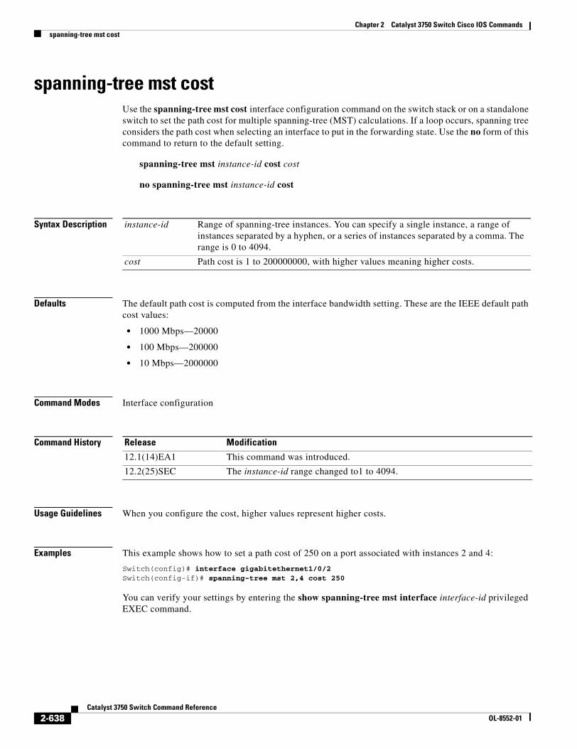
Chapter 2 Catalyst 3750 Switch Cisco IOS Commandsspanning-tree mst cost
spanning-tree mst cost Use the spanning-tree mst cost interface configuration command on the switch stack or on a standalone switch to set the path cost for multiple spanning-tree (MST) calculations. If a loop occurs, spanning tree considers the path cost when selecting an interface to put in the forwarding state. Use the no form of this command to return to the default setting.
spanning-tree mst instance-id cost cost
no spanning-tree mst instance-id cost
Syntax Description
Defaults The default path cost is computed from the interface bandwidth setting. These are the IEEE default path cost values:
• 1000 Mbps—20000
• 100 Mbps—200000
• 10 Mbps—2000000
Command Modes Interface configuration
Command History
Usage Guidelines When you configure the cost, higher values represent higher costs.
Examples This example shows how to set a path cost of 250 on a port associated with instances 2 and 4:
Switch(config)# interface gigabitethernet1/0/2Switch(config-if)# spanning-tree mst 2,4 cost 250
You can verify your settings by entering the show spanning-tree mst interface interface-id privileged EXEC command.
instance-id Range of spanning-tree instances. You can specify a single instance, a range of instances separated by a hyphen, or a series of instances separated by a comma. The range is 0 to 4094.
cost Path cost is 1 to 200000000, with higher values meaning higher costs.
Release Modification
12.1(14)EA1 This command was introduced.
12.2(25)SEC The instance-id range changed to1 to 4094.
2-638Catalyst 3750 Switch Command Reference
OL-8552-01

Chapter 2 Catalyst 3750 Switch Cisco IOS Commandsspanning-tree mst cost
Related Commands Command Description
show spanning-tree mst interface interface-id
Displays MST information for the specified interface.
spanning-tree mst port-priority
Configures an interface priority.
spanning-tree mst priority Configures the switch priority for the specified spanning-tree instance.
2-639Catalyst 3750 Switch Command Reference
OL-8552-01
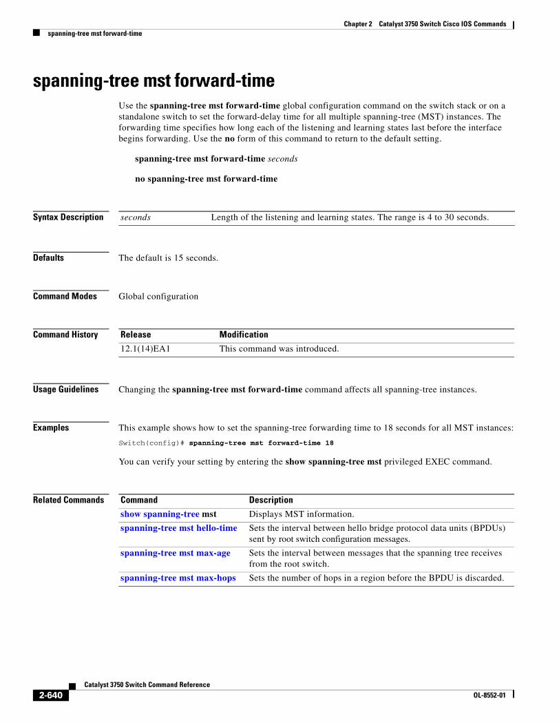
Chapter 2 Catalyst 3750 Switch Cisco IOS Commandsspanning-tree mst forward-time
spanning-tree mst forward-time Use the spanning-tree mst forward-time global configuration command on the switch stack or on a standalone switch to set the forward-delay time for all multiple spanning-tree (MST) instances. The forwarding time specifies how long each of the listening and learning states last before the interface begins forwarding. Use the no form of this command to return to the default setting.
spanning-tree mst forward-time seconds
no spanning-tree mst forward-time
Syntax Description
Defaults The default is 15 seconds.
Command Modes Global configuration
Command History
Usage Guidelines Changing the spanning-tree mst forward-time command affects all spanning-tree instances.
Examples This example shows how to set the spanning-tree forwarding time to 18 seconds for all MST instances:
Switch(config)# spanning-tree mst forward-time 18
You can verify your setting by entering the show spanning-tree mst privileged EXEC command.
Related Commands
seconds Length of the listening and learning states. The range is 4 to 30 seconds.
Release Modification
12.1(14)EA1 This command was introduced.
Command Description
show spanning-tree mst Displays MST information.
spanning-tree mst hello-time Sets the interval between hello bridge protocol data units (BPDUs) sent by root switch configuration messages.
spanning-tree mst max-age Sets the interval between messages that the spanning tree receives from the root switch.
spanning-tree mst max-hops Sets the number of hops in a region before the BPDU is discarded.
2-640Catalyst 3750 Switch Command Reference
OL-8552-01
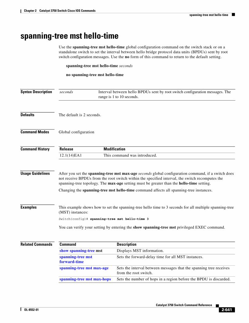
Chapter 2 Catalyst 3750 Switch Cisco IOS Commandsspanning-tree mst hello-time
spanning-tree mst hello-time Use the spanning-tree mst hello-time global configuration command on the switch stack or on a standalone switch to set the interval between hello bridge protocol data units (BPDUs) sent by root switch configuration messages. Use the no form of this command to return to the default setting.
spanning-tree mst hello-time seconds
no spanning-tree mst hello-time
Syntax Description
Defaults The default is 2 seconds.
Command Modes Global configuration
Command History
Usage Guidelines After you set the spanning-tree mst max-age seconds global configuration command, if a switch does not receive BPDUs from the root switch within the specified interval, the switch recomputes the spanning-tree topology. The max-age setting must be greater than the hello-time setting.
Changing the spanning-tree mst hello-time command affects all spanning-tree instances.
Examples This example shows how to set the spanning-tree hello time to 3 seconds for all multiple spanning-tree (MST) instances:
Switch(config)# spanning-tree mst hello-time 3
You can verify your setting by entering the show spanning-tree mst privileged EXEC command.
Related Commands
seconds Interval between hello BPDUs sent by root switch configuration messages. The range is 1 to 10 seconds.
Release Modification
12.1(14)EA1 This command was introduced.
Command Description
show spanning-tree mst Displays MST information.
spanning-tree mst forward-time
Sets the forward-delay time for all MST instances.
spanning-tree mst max-age Sets the interval between messages that the spanning tree receives from the root switch.
spanning-tree mst max-hops Sets the number of hops in a region before the BPDU is discarded.
2-641Catalyst 3750 Switch Command Reference
OL-8552-01
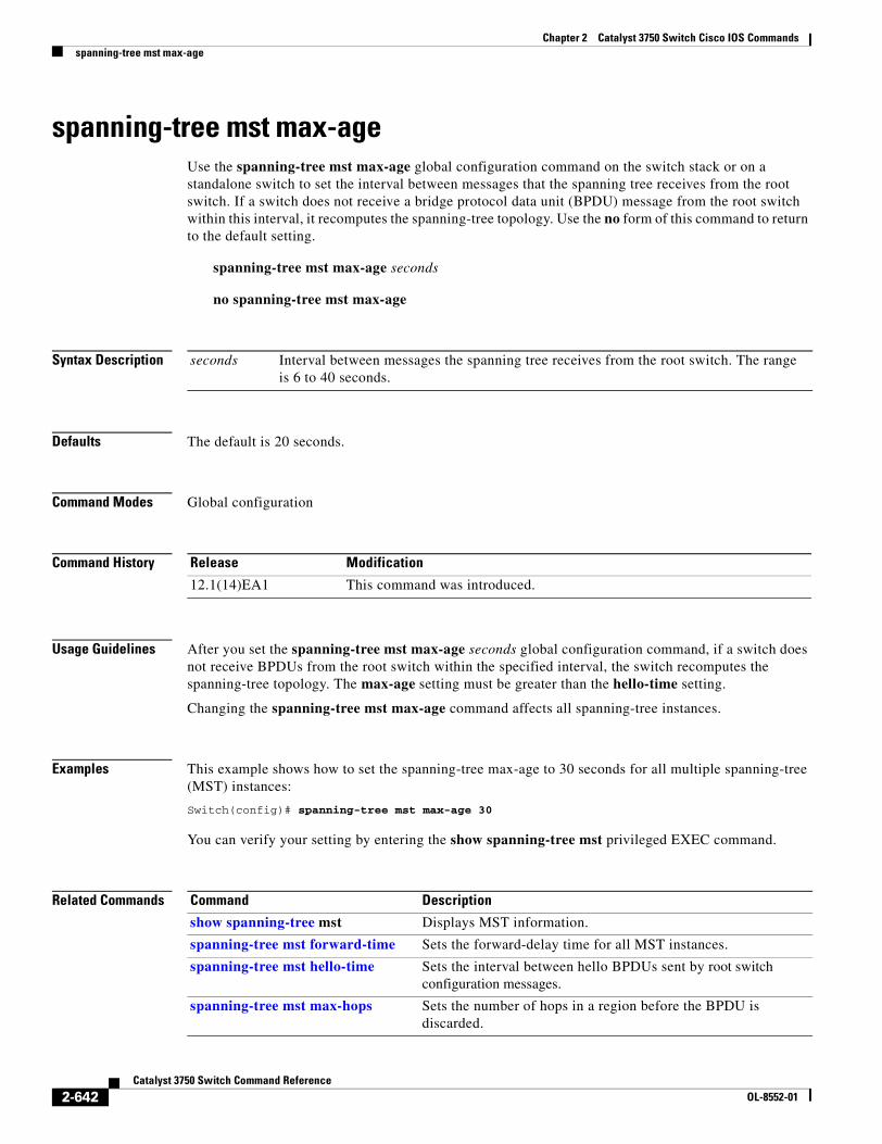
Chapter 2 Catalyst 3750 Switch Cisco IOS Commandsspanning-tree mst max-age
spanning-tree mst max-age Use the spanning-tree mst max-age global configuration command on the switch stack or on a standalone switch to set the interval between messages that the spanning tree receives from the root switch. If a switch does not receive a bridge protocol data unit (BPDU) message from the root switch within this interval, it recomputes the spanning-tree topology. Use the no form of this command to return to the default setting.
spanning-tree mst max-age seconds
no spanning-tree mst max-age
Syntax Description
Defaults The default is 20 seconds.
Command Modes Global configuration
Command History
Usage Guidelines After you set the spanning-tree mst max-age seconds global configuration command, if a switch does not receive BPDUs from the root switch within the specified interval, the switch recomputes the spanning-tree topology. The max-age setting must be greater than the hello-time setting.
Changing the spanning-tree mst max-age command affects all spanning-tree instances.
Examples This example shows how to set the spanning-tree max-age to 30 seconds for all multiple spanning-tree (MST) instances:
Switch(config)# spanning-tree mst max-age 30
You can verify your setting by entering the show spanning-tree mst privileged EXEC command.
Related Commands
seconds Interval between messages the spanning tree receives from the root switch. The range is 6 to 40 seconds.
Release Modification
12.1(14)EA1 This command was introduced.
Command Description
show spanning-tree mst Displays MST information.
spanning-tree mst forward-time Sets the forward-delay time for all MST instances.
spanning-tree mst hello-time Sets the interval between hello BPDUs sent by root switch configuration messages.
spanning-tree mst max-hops Sets the number of hops in a region before the BPDU is discarded.
2-642Catalyst 3750 Switch Command Reference
OL-8552-01
Chapter 2 Catalyst 3750 Switch Cisco IOS Commandsspanning-tree mst max-hops
spanning-tree mst max-hops Use the spanning-tree mst max-hops global configuration command on the switch stack or on a standalone switch to set the number of hops in a region before the bridge protocol data unit (BPDU) is discarded and the information held for an interface is aged. Use the no form of this command to return to the default setting.
spanning-tree mst max-hops hop-count
no spanning-tree mst max-hops
Syntax Description
Defaults The default is 20 hops.
Command Modes Global configuration
Command History
Usage Guidelines The root switch of the instance always sends a BPDU (or M-record) with a cost of 0 and the hop count set to the maximum value. When a switch receives this BPDU, it decrements the received remaining hop count by one and propagates the decremented count as the remaining hop count in the generated M-records. A switch discards the BPDU and ages the information held for the interface when the count reaches 0.
Changing the spanning-tree mst max-hops command affects all spanning-tree instances.
Examples This example shows how to set the spanning-tree max-hops to 10 for all multiple spanning-tree (MST) instances:
Switch(config)# spanning-tree mst max-hops 10
You can verify your setting by entering the show spanning-tree mst privileged EXEC command.
hop-count Number of hops in a region before the BPDU is discarded. The range is 1 to 255 hops.
Release Modification
12.1(14)EA1 This command was introduced.
12.2(25)SEC The hop-count range changed to 1 to 255.
2-643Catalyst 3750 Switch Command Reference
OL-8552-01
Chapter 2 Catalyst 3750 Switch Cisco IOS Commandsspanning-tree mst max-hops
Related Commands Command Description
show spanning-tree mst Displays MST information.
spanning-tree mst forward-time Sets the forward-delay time for all MST instances.
spanning-tree mst hello-time Sets the interval between hello BPDUs sent by root switch configuration messages.
spanning-tree mst max-age Sets the interval between messages that the spanning tree receives from the root switch.
2-644Catalyst 3750 Switch Command Reference
OL-8552-01
Chapter 2 Catalyst 3750 Switch Cisco IOS Commandsspanning-tree mst port-priority
spanning-tree mst port-priority Use the spanning-tree mst port-priority interface configuration command on the switch stack or on a standalone switch to configure an interface priority. If a loop occurs, the Multiple Spanning Tree Protocol (MSTP) can find the interface to put in the forwarding state. Use the no form of this command to return to the default setting.
spanning-tree mst instance-id port-priority priority
no spanning-tree mst instance-id port-priority
Syntax Description
Defaults The default is 128.
Command Modes Interface configuration
Command History
Usage Guidelines You can assign higher priority values (lower numerical values) to interfaces that you want selected first and lower priority values (higher numerical values) that you want selected last. If all interfaces have the same priority value, the multiple spanning tree (MST) puts the interface with the lowest interface number in the forwarding state and blocks other interfaces.
If your switch is a member of a switch stack, you must use the spanning-tree mst [instance-id] cost cost interface configuration command instead of the spanning-tree mst [instance vlan-id] port-priority priority interface configuration command to select an interface to put in the forwarding state. Assign lower cost values to interfaces that you want selected first and higher cost values to interfaces that you want selected last.
instance-id Range of spanning-tree instances. You can specify a single instance, a range of instances separated by a hyphen, or a series of instances separated by a comma. The range is 0 to 4094.
priority The range is 0 to 240 in increments of 16. Valid priority values are 0, 16, 32, 48, 64, 80, 96, 112, 128, 144, 160, 176, 192, 208, 224, and 240. All other values are rejected. The lower the number, the higher the priority.
Release Modification
12.1(14)EA1 This command was introduced.
12.2(25)SEC The instance-id range changed to 1 to 4094.
2-645Catalyst 3750 Switch Command Reference
OL-8552-01
Chapter 2 Catalyst 3750 Switch Cisco IOS Commandsspanning-tree mst port-priority
Examples This example shows how to increase the likelihood that the interface associated with spanning-tree instances 20 and 22 is placed into the forwarding state if a loop occurs:
Switch(config)# interface gigabitethernet2/0/2Switch(config-if)# spanning-tree mst 20,22 port-priority 0
You can verify your settings by entering the show spanning-tree mst interface interface-id privileged EXEC command.
Related Commands Command Description
show spanning-tree mst interface interface-id
Displays MST information for the specified interface.
spanning-tree mst cost Sets the path cost for MST calculations.
spanning-tree mst priority Sets the switch priority for the specified spanning-tree instance.
2-646Catalyst 3750 Switch Command Reference
OL-8552-01
Chapter 2 Catalyst 3750 Switch Cisco IOS Commandsspanning-tree mst pre-standard
spanning-tree mst pre-standardUse the spanning-tree mst pre-standard interface configuration command to configure a port to send only prestandard bridge protocol data units (BPDUs).
spanning-tree mst pre-standard
no spanning-tree mst pre-standard
Syntax Description This command has no arguments or keywords.
Command Default The default state is automatic detection of prestandard neighbors.
Command Modes Interface configuration
Command History
Usage Guidelines The port can accept both prestandard and standard BPDUs. If the neighbor types are mismatched, only the common and internal spanning tree (CIST) runs on this interface.
Note If a switch port is connected to a switch running prestandard Cisco IOS software, you must use the spanning-tree mst pre-standard interface configuration command on the port. If you do not configure the port to send only prestandard BPDUs, the Multiple STP (MSTP) performance might diminish.
When the port is configured to automatically detect prestandard neighbors, the prestandard flag always appears in the show spanning-tree mst commands.
Examples This example shows how to configure a port to send only prestandard BPDUs:
Switch(config-if)# spanning-tree mst pre-standard
You can verify your settings by entering the show spanning-tree mst privileged EXEC command.
Related Commands
Release Modification
12.2(25)SEC This command was introduced.
Command Description
show spanning-tree mst instance-id Displays multiple spanning-tree (MST) information, including the prestandard flag, for the specified interface.
2-647Catalyst 3750 Switch Command Reference
OL-8552-01
Chapter 2 Catalyst 3750 Switch Cisco IOS Commandsspanning-tree mst priority
spanning-tree mst priority Use the spanning-tree mst priority global configuration command on the switch stack or on a standalone switch to set the switch priority for the specified spanning-tree instance. Use the no form of this command to return to the default setting.
spanning-tree mst instance-id priority priority
no spanning-tree mst instance-id priority
Syntax Description
Defaults The default is 32768.
Command Modes Global configuration
Command History
Examples This example shows how to set the spanning-tree priority to 8192 for multiple spanning-tree instances (MST) 20 to 21:
Switch(config)# spanning-tree mst 20-21 priority 8192
You can verify your settings by entering the show spanning-tree mst instance-id privileged EXEC command.
Related Commands
instance-id Range of spanning-tree instances. You can specify a single instance, a range of instances separated by a hyphen, or a series of instances separated by a comma. The range is 0 to 4094.
priority Set the switch priority for the specified spanning-tree instance. This setting affects the likelihood that the switch is selected as the root switch. A lower value increases the probability that the switch is selected as the root switch.
The range is 0 to 61440 in increments of 4096. Valid priority values are 0, 4096, 8192, 12288, 16384, 20480, 24576, 28672, 32768, 36864, 40960, 45056, 49152, 53248, 57344, and 61440. All other values are rejected.
Release Modification
12.1(14)EA1 This command was introduced.
12.2(25)SEC The instance-id range changed to 1 to 4094.
Command Description
show spanning-tree mst instance-id Displays MST information for the specified interface.
spanning-tree mst cost Sets the path cost for MST calculations.
spanning-tree mst port-priority Configures an interface priority.
2-648Catalyst 3750 Switch Command Reference
OL-8552-01
Chapter 2 Catalyst 3750 Switch Cisco IOS Commandsspanning-tree mst root
spanning-tree mst root Use the spanning-tree mst root global configuration command on the switch stack or on a standalone switch to configure the multiple spanning-tree (MST) root switch priority and timers based on the network diameter. Use the no form of this command to return to the default settings.
spanning-tree mst instance-id root {primary | secondary} [diameter net-diameter [hello-time seconds]]
no spanning-tree mst instance-id root
Syntax Description
Defaults The primary root switch priority is 24576.
The secondary root switch priority is 28672.
The hello time is 2 seconds.
Command Modes Global configuration
Command History
Usage Guidelines Use the spanning-tree mst instance-id root command only on backbone switches.
When you enter the spanning-tree mst instance-id root command, the software tries to set a high enough priority to make this switch the root of the spanning-tree instance. Because of the extended system ID support, the switch sets the switch priority for the instance to 24576 if this value will cause this switch to become the root for the specified instance. If any root switch for the specified instance has a switch priority lower than 24576, the switch sets its own priority to 4096 less than the lowest switch priority. (4096 is the value of the least-significant bit of a 4-bit switch priority value.)
instance-id Range of spanning-tree instances. You can specify a single instance, a range of instances separated by a hyphen, or a series of instances separated by a comma. The range is 0 to 4094.
root primary Force this switch to be the root switch.
root secondary Set this switch to be the root switch should the primary root switch fail.
diameter net-diameter (Optional) Set the maximum number of switches between any two end stations. The range is 2 to 7. This keyword is available only for MST instance 0.
hello-time seconds (Optional) Set the interval between hello bridge protocol data units (BPDUs) sent by the root switch configuration messages. The range is 1 to 10 seconds. This keyword is available only for MST instance 0.
Release Modification
12.1(14)EA1 This command was introduced.
2-649Catalyst 3750 Switch Command Reference
OL-8552-01
Chapter 2 Catalyst 3750 Switch Cisco IOS Commandsspanning-tree mst root
When you enter the spanning-tree mst instance-id root secondary command, because of support for the extended system ID, the software changes the switch priority from the default value (32768) to 28672. If the root switch fails, this switch becomes the next root switch (if the other switches in the network use the default switch priority of 32768 and are therefore unlikely to become the root switch).
Examples This example shows how to configure the switch as the root switch for instance 10 with a network diameter of 4:
Switch(config)# spanning-tree mst 10 root primary diameter 4
This example shows how to configure the switch as the secondary root switch for instance 10 with a network diameter of 4:
Switch(config)# spanning-tree mst 10 root secondary diameter 4
You can verify your settings by entering the show spanning-tree mst instance-id privileged EXEC command.
Related Commands Command Description
show spanning-tree mst instance-id Displays MST information for the specified instance.
spanning-tree mst forward-time Sets the forward-delay time for all MST instances.
spanning-tree mst hello-time Sets the interval between hello BPDUs sent by root switch configuration messages.
spanning-tree mst max-age Sets the interval between messages that the spanning tree receives from the root switch.
spanning-tree mst max-hops Sets the number of hops in a region before the BPDU is discarded.
2-650Catalyst 3750 Switch Command Reference
OL-8552-01
Chapter 2 Catalyst 3750 Switch Cisco IOS Commandsspanning-tree port-priority
spanning-tree port-priorityUse the spanning-tree port-priority interface configuration command on the switch stack or on a standalone switch to configure an interface priority. If a loop occurs, spanning tree can find the interface to put in the forwarding state. Use the no form of this command to return to the default setting.
spanning-tree [vlan vlan-id] port-priority priority
no spanning-tree [vlan vlan-id] port-priority
Syntax Description
Defaults The default is 128.
Command Modes Interface configuration
Command History
Usage Guidelines If the variable vlan-id is omitted, the command applies to the spanning-tree instance associated with VLAN 1.
You can set the priority on a VLAN that has no interfaces assigned to it. The setting takes effect when you assign the interface to the VLAN.
If you configure an interface with both the spanning-tree vlan vlan-id port-priority priority command and the spanning-tree port-priority priority command, the spanning-tree vlan vlan-id port-priority priority command takes effect.
If your switch is a member of a switch stack, you must use the spanning-tree [vlan vlan-id] cost cost interface configuration command instead of the spanning-tree [vlan vlan-id] port-priority priority interface configuration command to select an interface to put in the forwarding state. Assign lower cost values to interfaces that you want selected first and higher cost values that you want selected last.
vlan vlan-id (Optional) VLAN range associated with a spanning-tree instance. You can specify a single VLAN identified by VLAN ID number, a range of VLANs separated by a hyphen, or a series of VLANs separated by a comma. The range is 1 to 4094.
priority Number from 0 to 240, in increments of 16. Valid values are 0, 16, 32, 48, 64, 80, 96, 112, 128, 144, 160, 176, 192, 208, 224, and 240. All other values are rejected. The lower the number, the higher the priority.
Release Modification
12.1(11)AX This command was introduced.
12.1(14)EA1 The value for the vlan-id variable was changed. The priority range values changed.
2-651Catalyst 3750 Switch Command Reference
OL-8552-01
Chapter 2 Catalyst 3750 Switch Cisco IOS Commandsspanning-tree port-priority
Examples This example shows how to increase the likelihood that a port will be put in the forwarding state if a loop occurs:
Switch(config)# interface gigabitethernet2/0/2Switch(config-if)# spanning-tree vlan 20 port-priority 0
This example shows how to set the port-priority value on VLANs 20 to 25:
Switch(config-if)# spanning-tree vlan 20-25 port-priority 0
You can verify your settings by entering the show spanning-tree interface interface-id privileged EXEC command.
Related Commands Command Description
show spanning-tree interface interface-id
Displays spanning-tree information for the specified interface.
spanning-tree cost Sets the path cost for spanning-tree calculations.
spanning-tree vlan priority Sets the switch priority for the specified spanning-tree instance.
2-652Catalyst 3750 Switch Command Reference
OL-8552-01
Chapter 2 Catalyst 3750 Switch Cisco IOS Commandsspanning-tree portfast (global configuration)
spanning-tree portfast (global configuration)Use the spanning-tree portfast global configuration command on the switch stack or on a standalone switch to globally enable bridge protocol data unit (BPDU) filtering on Port Fast-enabled interfaces, the BPDU guard feature on Port Fast-enabled interfaces, or the Port Fast feature on all nontrunking interfaces. The BPDU filtering feature prevents the switch interface from sending or receiving BPDUs. The BPDU guard feature puts Port Fast-enabled interfaces that receive BPDUs in an error-disabled state. Use the no form of this command to return to the default settings.
spanning-tree portfast {bpdufilter default | bpduguard default | default}
no spanning-tree portfast {bpdufilter default | bpduguard default | default}
Syntax Description
Defaults The BPDU filtering, the BPDU guard, and the Port Fast features are disabled on all interfaces unless they are individually configured.
Command Modes Global configuration
Command History
Usage Guidelines You can enable these features when the switch is operating in the per-VLAN spanning-tree plus (PVST+) rapid-PVST+, or the multiple spanning-tree (MST) mode.
Use the spanning-tree portfast bpdufilter default global configuration command to globally enable BPDU filtering on interfaces that are Port Fast-enabled (the interfaces are in a Port Fast-operational state). The interfaces still send a few BPDUs at link-up before the switch begins to filter outbound BPDUs. You should globally enable BPDU filtering on a switch so that hosts connected to switch interfaces do not receive BPDUs. If a BPDU is received on a Port Fast-enabled interface, the interface loses its Port Fast-operational status and BPDU filtering is disabled.
You can override the spanning-tree portfast bpdufilter default global configuration command by using the spanning-tree bdpufilter interface configuration command.
bpdufilter default Globally enable BPDU filtering on Port Fast-enabled interfaces and prevent the switch interface connected to end stations from sending or receiving BPDUs.
bpduguard default Globally enable the BPDU guard feature on Port Fast-enabled interfaces and place the interfaces that receive BPDUs in an error-disabled state.
default Globally enable the Port Fast feature on all nontrunking interfaces. When the Port Fast feature is enabled, the interface changes directly from a blocking state to a forwarding state without making the intermediate spanning-tree state changes.
Release Modification
12.1(11)AX This command was introduced.
2-653Catalyst 3750 Switch Command Reference
OL-8552-01
Chapter 2 Catalyst 3750 Switch Cisco IOS Commandsspanning-tree portfast (global configuration)
Caution Enabling BPDU filtering on an interface is the same as disabling spanning tree on it and can result in spanning-tree loops.
Use the spanning-tree portfast bpduguard default global configuration command to globally enable BPDU guard on interfaces that are in a Port Fast-operational state. In a valid configuration, Port Fast-enabled interfaces do not receive BPDUs. Receiving a BPDU on a Port Fast-enabled interface signals an invalid configuration, such as the connection of an unauthorized device, and the BPDU guard feature puts the interface in the error-disabled state. The BPDU guard feature provides a secure response to invalid configurations because you must manually put the interface back in service. Use the BPDU guard feature in a service-provider network to prevent an access port from participating in the spanning tree.
You can override the spanning-tree portfast bpduguard default global configuration command by using the spanning-tree bdpuguard interface configuration command.
Use the spanning-tree portfast default global configuration command to globally enable the Port Fast feature on all nontrunking interfaces. Configure Port Fast only on interfaces that connect to end stations; otherwise, an accidental topology loop could cause a data packet loop and disrupt switch and network operation. A Port Fast-enabled interface moves directly to the spanning-tree forwarding state when linkup occurs without waiting for the standard forward-delay time.
You can override the spanning-tree portfast default global configuration command by using the spanning-tree portfast interface configuration command. You can use the no spanning-tree portfast default global configuration command to disable Port Fast on all interfaces unless they are individually configured with the spanning-tree portfast interface configuration command.
Examples This example shows how to globally enable the BPDU filtering feature:
Switch(config)# spanning-tree portfast bpdufilter default
This example shows how to globally enable the BPDU guard feature:
Switch(config)# spanning-tree portfast bpduguard default
This example shows how to globally enable the Port Fast feature on all nontrunking interfaces:
Switch(config)# spanning-tree portfast default
You can verify your settings by entering the show running-config privileged EXEC command.
Related Commands Command Description
show running-config Displays the current operating configuration. For syntax information, select Cisco IOS Configuration Fundamentals Command Reference, Release 12.2 > File Management Commands > Configuration File Management Commands.
spanning-tree bpdufilter Prevents an interface from sending or receiving BPDUs.
spanning-tree bpduguard Puts an interface in the error-disabled state when it receives a BPDU.
spanning-tree portfast (interface configuration)
Enables the Port Fast feature on an interface in all its associated VLANs.
2-654Catalyst 3750 Switch Command Reference
OL-8552-01
Chapter 2 Catalyst 3750 Switch Cisco IOS Commandsspanning-tree portfast (interface configuration)
spanning-tree portfast (interface configuration)Use the spanning-tree portfast interface configuration command on the switch stack or on a standalone switch to enable the Port Fast feature on an interface in all its associated VLANs. When the Port Fast feature is enabled, the interface changes directly from a blocking state to a forwarding state without making the intermediate spanning-tree state changes. Use the no form of this command to return to the default setting.
spanning-tree portfast [disable | trunk]
no spanning-tree portfast
Syntax Description
Defaults The Port Fast feature is disabled on all interfaces; however, it is automatically enabled on dynamic-access ports.
Command Modes Interface configuration
Command History
Usage Guidelines Use this feature only on interfaces that connect to end stations; otherwise, an accidental topology loop could cause a data packet loop and disrupt switch and network operation.
To enable Port Fast on trunk ports, you must use the spanning-tree portfast trunk interface configuration command. The spanning-tree portfast command is not supported on trunk ports.
You can enable this feature when the switch is operating in the per-VLAN spanning-tree plus (PVST+), rapid-PVST+, or the multiple spanning-tree (MST) mode.
This feature affects all VLANs on the interface.
An interface with the Port Fast feature enabled is moved directly to the spanning-tree forwarding state without the standard forward-time delay.
You can use the spanning-tree portfast default global configuration command to globally enable the Port Fast feature on all nontrunking interfaces. However, the spanning-tree portfast interface configuration command can override the global setting.
If you configure the spanning-tree portfast default global configuration command, you can disable Port Fast on an interface that is not a trunk interface by using the spanning-tree portfast disable interface configuration command.
disable (Optional) Disable the Port Fast feature on the specified interface.
trunk (Optional) Enable the Port Fast feature on a trunking interface.
Release Modification
12.1(11)AX This command was introduced.
2-655Catalyst 3750 Switch Command Reference
OL-8552-01
Chapter 2 Catalyst 3750 Switch Cisco IOS Commandsspanning-tree portfast (interface configuration)
Examples This example shows how to enable the Port Fast feature on a port:
Switch(config)# interface gigabitethernet2/0/2Switch(config-if)# spanning-tree portfast
You can verify your settings by entering the show running-config privileged EXEC command.
Related Commands Command Description
show running-config Displays the current operating configuration. For syntax information, select Cisco IOS Configuration Fundamentals Command Reference, Release 12.2 > File Management Commands > Configuration File Management Commands.
spanning-tree bpdufilter Prevents an interface from sending or receiving bridge protocol data units (BPDUs).
spanning-tree bpduguard Puts an interface in the error-disabled state when it receives a BPDU.
spanning-tree portfast (global configuration)
Globally enables the BPDU filtering or the BPDU guard feature on Port Fast-enabled interfaces or enables the Port Fast feature on all nontrunking interfaces.
2-656Catalyst 3750 Switch Command Reference
OL-8552-01
Chapter 2 Catalyst 3750 Switch Cisco IOS Commandsspanning-tree transmit hold-count
spanning-tree transmit hold-countUse the spanning-tree transmit hold-count global configuration command to configure the number of bridge protocol data units (BPDUs) sent every second. Use the no form of this command to return to the default setting.
spanning-tree transmit hold-count [value]
no spanning-tree transmit hold-count [value]
Syntax Description
Defaults The default is 6.
Command Modes Global configuration
Command History
Usage Guidelines Increasing the transmit hold-count value can have a significant impact on CPU utilization when the switch is in rapid-per-VLAN spanning-tree plus (rapid-PVST+) mode. Decreasing this value might slow down convergence. We recommend using the default setting.
Examples This example shows how to set the transmit hold count to 8:
Switch(config)# spanning-tree transmit hold-count 8
You can verify your setting by entering the show spanning-tree mst privileged EXEC command.
Related Commands
value (Optional) Number of BPDUs sent every second. The range is 1 to 20.
Release Modification
12.2(25)SEC This command was introduced.
Command Description
show spanning-tree mst Displays the multiple spanning-tree (MST) region configuration and status, including the transmit hold count.
2-657Catalyst 3750 Switch Command Reference
OL-8552-01
Chapter 2 Catalyst 3750 Switch Cisco IOS Commandsspanning-tree uplinkfast
spanning-tree uplinkfast Use the spanning-tree uplinkfast global configuration command on the switch stack or on a standalone switch to accelerate the choice of a new root port when a link or switch fails or when the spanning tree reconfigures itself. Use the no form of this command to return to the default setting.
spanning-tree uplinkfast [max-update-rate pkts-per-second]
no spanning-tree uplinkfast [max-update-rate]
Syntax Description
Defaults UplinkFast is disabled.
The update rate is 150 packets per second.
Command Modes Global configuration
Command History
Usage Guidelines Use this command only on access switches.
You can configure the UplinkFast feature for rapid PVST+ or for multiple spanning-tree (MST) mode, but the feature remains disabled (inactive) until you change the spanning-tree mode to PVST+.
When you enable UplinkFast, it is enabled for the entire switch and cannot be enabled for individual VLANs.
When you enable or disable UplinkFast, cross-stack UplinkFast (CSUF) also is automatically enabled or disabled on all nonstack port interfaces. CSUF accelerates the choice of a new root port when a link or switch fails or when spanning tree reconfigures itself.
When UplinkFast is enabled, the switch priority of all VLANs is set to 49152. If you change the path cost to a value less than 3000 and you enable UplinkFast or UplinkFast is already enabled, the path cost of all interfaces and VLAN trunks is increased by 3000 (if you change the path cost to 3000 or above, the path cost is not altered). The changes to the switch priority and the path cost reduces the chance that a switch will become the root switch.
When UplinkFast is disabled, the switch priorities of all VLANs and path costs of all interfaces are set to default values if you did not modify them from their defaults.
When spanning tree detects that the root port has failed, UplinkFast immediately changes to an alternate root port, changing the new root port directly to forwarding state. During this time, a topology change notification is sent.
max-update-rate pkts-per-second (Optional) The number of packets per second at which update packets are sent. The range is 0 to 32000.
Release Modification
12.1(11)AX This command was introduced.
12.1(14)EA1 The max-update-rate keyword was added.
2-658Catalyst 3750 Switch Command Reference
OL-8552-01
Chapter 2 Catalyst 3750 Switch Cisco IOS Commandsspanning-tree uplinkfast
Do not enable the root guard on interfaces that will be used by the UplinkFast feature. With UplinkFast, the backup interfaces (in the blocked state) replace the root port in the case of a failure. However, if root guard is also enabled, all the backup interfaces used by the UplinkFast feature are placed in the root-inconsistent state (blocked) and prevented from reaching the forwarding state.
If you set the max-update-rate to 0, station-learning frames are not generated, so the spanning-tree topology converges more slowly after a loss of connectivity.
Examples This example shows how to enable UplinkFast:
Switch(config)# spanning-tree uplinkfast
You can verify your setting by entering the show spanning-tree summary privileged EXEC command.
Related Commands Command Description
show spanning-tree summary Displays a summary of the spanning-tree interface states.
spanning-tree vlan root primary Forces this switch to be the root switch.
2-659Catalyst 3750 Switch Command Reference
OL-8552-01
Chapter 2 Catalyst 3750 Switch Cisco IOS Commandsspanning-tree vlan
spanning-tree vlanUse the spanning-tree vlan global configuration command on the switch stack or on a standalone switch to configure spanning tree on a per-VLAN basis. Use the no form of this command to return to the default setting.
spanning-tree vlan vlan-id [forward-time seconds | hello-time seconds | max-age seconds | priority priority | root {primary | secondary} [diameter net-diameter [hello-time seconds]]]
no spanning-tree vlan vlan-id [forward-time | hello-time | max-age | priority | root]
Syntax Description
Defaults Spanning tree is enabled on all VLANs.
The forward-delay time is 15 seconds.
The hello time is 2 seconds.
The max-age is 20 seconds.
vlan-id VLAN range associated with a spanning-tree instance. You can specify a single VLAN identified by VLAN ID number, a range of VLANs separated by a hyphen, or a series of VLANs separated by a comma. The range is 1 to 4094.
forward-time seconds (Optional) Set the forward-delay time for the specified spanning-tree instance. The forwarding time specifies how long each of the listening and learning states last before the interface begins forwarding. The range is 4 to 30 seconds.
hello-time seconds (Optional) Set the interval between hello bridge protocol data units (BPDUs) sent by the root switch configuration messages. The range is 1 to 10 seconds.
max-age seconds (Optional) Set the interval between messages the spanning tree receives from the root switch. If a switch does not receive a BPDU message from the root switch within this interval, it recomputes the spanning-tree topology. The range is 6 to 40 seconds.
priority priority (Optional) Set the switch priority for the specified spanning-tree instance. This setting affects the likelihood that a standalone switch or a switch in the stack is selected as the root switch. A lower value increases the probability that the switch is selected as the root switch.
The range is 0 to 61440 in increments of 4096. Valid priority values are 4096, 8192, 12288, 16384, 20480, 24576, 28672, 32768, 36864, 40960, 45056, 49152, 53248, 57344, and 61440. All other values are rejected.
root primary (Optional) Force this switch to be the root switch.
root secondary (Optional) Set this switch to be the root switch should the primary root switch fail.
diameter net-diameter (Optional) Set the maximum number of switches between any two end stations. The range is 2 to 7.
2-660Catalyst 3750 Switch Command Reference
OL-8552-01
Chapter 2 Catalyst 3750 Switch Cisco IOS Commandsspanning-tree vlan
The primary root switch priority is 24576.
The secondary root switch priority is 28672.
Command Modes Global configuration
Command History
Usage Guidelines Disabling the STP causes the VLAN to stop participating in the spanning-tree topology. Interfaces that are administratively down remain down. Received BPDUs are forwarded like other multicast frames. The VLAN does not detect and prevent loops when STP is disabled.
You can disable the STP on a VLAN that is not currently active and verify the change by using the show running-config or the show spanning-tree vlan vlan-id privileged EXEC command. The setting takes effect when the VLAN is activated.
When disabling or re-enabling the STP, you can specify a range of VLANs that you want to disable or enable.
When a VLAN is disabled and then enabled, all assigned VLANs continue to be its members. However, all spanning-tree bridge parameters are returned to their previous settings (the last setting before the VLAN was disabled).
You can enable spanning-tree options on a VLAN that has no interfaces assigned to it. The setting takes effect when you assign interfaces to it.
When setting the max-age seconds, if a switch does not receive BPDUs from the root switch within the specified interval, it recomputes the spanning-tree topology. The max-age setting must be greater than the hello-time setting.
The spanning-tree vlan vlan-id root command should be used only on backbone switches.
When you enter the spanning-tree vlan vlan-id root command, the software checks the switch priority of the current root switch for each VLAN. Because of the extended system ID support, the switch sets the switch priority for the specified VLAN to 24576 if this value will cause this switch to become the root for the specified VLAN. If any root switch for the specified VLAN has a switch priority lower than 24576, the switch sets its own priority for the specified VLAN to 4096 less than the lowest switch priority. (4096 is the value of the least-significant bit of a 4-bit switch priority value.)
When you enter the spanning-tree vlan vlan-id root secondary command, because of support for the extended system ID, the software changes the switch priority from the default value (32768) to 28672. If the root switch should fail, this switch becomes the next root switch (if the other switches in the network use the default switch priority of 32768, and therefore, are unlikely to become the root switch).
Examples This example shows how to disable the STP on VLAN 5:
Switch(config)# no spanning-tree vlan 5
You can verify your setting by entering the show spanning-tree privileged EXEC command. In this instance, VLAN 5 does not appear in the list.
Release Modification
12.1(11)AX This command was introduced.
12.1(14)EA1 The value for the vlan-id variable was changed.
2-661Catalyst 3750 Switch Command Reference
OL-8552-01
Chapter 2 Catalyst 3750 Switch Cisco IOS Commandsspanning-tree vlan
This example shows how to set the spanning-tree forwarding time to 18 seconds for VLANs 20 and 25:
Switch(config)# spanning-tree vlan 20,25 forward-time 18
This example shows how to set the spanning-tree hello-delay time to 3 seconds for VLANs 20 to 24:
Switch(config)# spanning-tree vlan 20-24 hello-time 3
This example shows how to set spanning-tree max-age to 30 seconds for VLAN 20:
Switch(config)# spanning-tree vlan 20 max-age 30
This example shows how to reset the max-age parameter to the default value for spanning-tree instance 100 and 105 to 108:
Switch(config)# no spanning-tree vlan 100, 105-108 max-age
This example shows how to set the spanning-tree priority to 8192 for VLAN 20:
Switch(config)# spanning-tree vlan 20 priority 8192
This example shows how to configure the switch as the root switch for VLAN 10 with a network diameter of 4:
Switch(config)# spanning-tree vlan 10 root primary diameter 4
This example shows how to configure the switch as the secondary root switch for VLAN 10 with a network diameter of 4:
Switch(config)# spanning-tree vlan 10 root secondary diameter 4
You can verify your settings by entering the show spanning-tree vlan vlan-id privileged EXEC command.
Related Commands Command Description
show spanning-tree vlan Displays spanning-tree information.
spanning-tree cost Sets the path cost for spanning-tree calculations.
spanning-tree guard Enables the root guard or the loop guard feature for all the VLANs associated with the selected interface.
spanning-tree port-priority Sets an interface priority.
spanning-tree portfast (global configuration)
Globally enables the BPDU filtering or the BPDU guard feature on Port Fast-enabled interfaces or enables the Port Fast feature on all nontrunking interfaces.
spanning-tree portfast (interface configuration)
Enables the Port Fast feature on an interface in all its associated VLANs.
spanning-tree uplinkfast Enables the UplinkFast feature, which accelerates the choice of a new root port.
2-662Catalyst 3750 Switch Command Reference
OL-8552-01
Chapter 2 Catalyst 3750 Switch Cisco IOS Commandsspeed
speedUse the speed interface configuration command on the switch stack or on a standalone switch to specify the speed of a 10/100 Mbps or 10/100/1000 Mbps port. Use the no or default form of this command to return the port to its default value.
speed {10 | 100 | 1000 | auto [10 | 100 | 1000] | nonegotiate}
no speed
Syntax Description
Defaults The default is auto.
Command Modes Interface configuration
Command History
Usage Guidelines You cannot configure speed on the 10-Gigabit Ethernet ports.
Except for the 1000BASE-T SFP modules, if an SFP module port is connected to a device that does not support autonegotiation, you can configure the speed to not negotiate (nonegotiate).
If the speed is set to auto, the switch negotiates with the device at the other end of the link for the speed setting and then forces the speed setting to the negotiated value. The duplex setting remains as configured on each end of the link, which could result in a duplex setting mismatch.
If both ends of the line support autonegotiation, we highly recommend the default autonegotiation settings. If one interface supports autonegotiation and the other end does not, do use the auto setting on the supported side, but set the duplex and speed on the other side.
Caution Changing the interface speed and duplex mode configuration might shut down and re-enable the interface during the reconfiguration.
10 Port runs at 10 Mbps.
100 Port runs at 100 Mbps.
1000 Port runs at 1000 Mbps. This option is valid and visible only on 10/100/1000 Mbps-ports.
auto Port automatically detects the speed it should run at based on the port at the other end of the link. If you use the 10, 100, or 1000 keywords with the auto keyword, the port only autonegotiates at the specified speeds.
nonegotiate Autonegotiation is disabled, and the port runs at 1000 Mbps. (
Release Modification
12.1(11)AX This command was introduced.
12.2(20)SE1 Support for the 10, 100, and 1000 keywords with the auto keyword was added.
2-663Catalyst 3750 Switch Command Reference
OL-8552-01
Chapter 2 Catalyst 3750 Switch Cisco IOS Commandsspeed
For guidelines on setting the switch speed and duplex parameters, see the “Configuring Interface Characteristics” chapter in the software configuration guide for this release.
Examples This example shows how to set speed on a port to 100 Mbps:
Switch(config)# interface gigabitethernet1/0/1Switch(config-if)# speed 100
This example shows how to set a port to autonegotiate at only 10 Mbps:
Switch(config)# interface gigabitethernet1/0/1Switch(config-if)# speed auto 10
This example shows how to set a port to autonegotiate at only 10 or 100 Mbps:
Switch(config)# interface gigabitethernet1/0/1Switch(config-if)# speed auto 10 100
You can verify your settings by entering the show interfaces privileged EXEC command.
Related Commands Command Description
duplex Specifies the duplex mode of operation.
show interfaces Displays the statistical information specific to all interfaces or to a specific interface.
2-664Catalyst 3750 Switch Command Reference
OL-8552-01
Chapter 2 Catalyst 3750 Switch Cisco IOS Commandssrr-queue bandwidth limit
srr-queue bandwidth limitUse the srr-queue bandwidth limit interface configuration command on the switch stack or on a standalone switch to limit the maximum output on a port. Use the no form of this command to return to the default setting.
srr-queue bandwidth limit weight1
no srr-queue bandwidth limit
Syntax Description
Defaults The port is not rate limited and is set to 100 percent.
Command Modes Interface configuration
Command History
Usage Guidelines If you configure this command to 80 percent, the port is idle 20 percent of the time. The line rate drops to 80 percent of the connected speed. These values are not exact because the hardware adjusts the line rate in increments of six.
This command is not available on a 10-Gigabit Ethernet interface.
Note The egress queue default settings are suitable for most situations. You should change them only when you have a thorough understanding of the egress queues and if these settings do not meet your quality of service (QoS) solution.
Examples This example shows how to limit a port to 800 Mbps:
Switch(config)# interface gigabitethernet2/0/1Switch(config-if)# srr-queue bandwidth limit 80
You can verify your settings by entering the show mls qos interface [interface-id] queueing privileged EXEC command.
weight1 Percentage of the port speed to which the port should be limited. The range is 10 to 90.
Release Modification
12.1(11)AX This command was introduced.
2-665Catalyst 3750 Switch Command Reference
OL-8552-01
Chapter 2 Catalyst 3750 Switch Cisco IOS Commandssrr-queue bandwidth limit
Related Commands Command Description
mls qos queue-set output buffers Allocates buffers to the queue-set.
mls qos srr-queue output cos-map Maps class of service (CoS) values to egress queue or maps CoS values to a queue and to a threshold ID.
mls qos srr-queue output dscp-map Maps Differentiated Services Code Point (DSCP) values to an egress queue or maps DSCP values to a queue and to a threshold ID.
mls qos queue-set output threshold Configures the weighted tail-drop (WTD) thresholds, guarantees the availability of buffers, and configures the maximum memory allocation for the queue-set.
queue-set Maps a port to a queue-set.
show mls qos interface queueing Displays QoS information.
srr-queue bandwidth shape Assigns the shaped weights and enables bandwidth shaping on the four egress queues mapped to a port.
srr-queue bandwidth share Assigns the shared weights and enables bandwidth sharing on the four egress queues mapped to a port.
2-666Catalyst 3750 Switch Command Reference
OL-8552-01
Chapter 2 Catalyst 3750 Switch Cisco IOS Commandssrr-queue bandwidth shape
srr-queue bandwidth shapeUse the srr-queue bandwidth shape interface configuration command on the switch stack or on a standalone switch to assign the shaped weights and to enable bandwidth shaping on the four egress queues mapped to a port. Use the no form of this command to return to the default setting.
srr-queue bandwidth shape weight1 weight2 weight3 weight4
no srr-queue bandwidth shape
Syntax Description
Defaults Weight1 is set to 25. Weight2, weight3, and weight4 are set to 0, and these queues are in shared mode.
Command Modes Interface configuration
Command History
Usage Guidelines In shaped mode, the queues are guaranteed a percentage of the bandwidth, and they are rate-limited to that amount. Shaped traffic does not use more than the allocated bandwidth even if the link is idle. Use shaping to smooth bursty traffic or to provide a smoother output over time.
The shaped mode overrides the shared mode.
If you configure a shaped queue weight to 0 by using the srr-queue bandwidth shape interface configuration command, this queue participates in shared mode. The weight specified with the srr-queue bandwidth shape command is ignored, and the weights specified with the srr-queue bandwidth share interface configuration command for a queue come into effect.
When configuring queues for the same port for both shaping and sharing, make sure that you configure the lowest numbered queue for shaping.
This command is not available on a 10-Gigabit Ethernet interface.
Note The egress queue default settings are suitable for most situations. You should change them only when you have a thorough understanding of the egress queues and if these settings do not meet your QoS solution.
weight1 weight2 weight3 weight4
Specify the weights to specify the percentage of the port that is shaped. The inverse ratio (1/weight) specifies the shaping bandwidth for this queue. Separate each value with a space. The range is 0 to 65535.
Release Modification
12.1(11)AX This command was introduced.
2-667Catalyst 3750 Switch Command Reference
OL-8552-01
Chapter 2 Catalyst 3750 Switch Cisco IOS Commandssrr-queue bandwidth shape
Examples This example shows how to configure the queues for the same port for both shaping and sharing. Because the weight ratios for queues 2, 3, and 4 are set to 0, these queues operate in shared mode. The bandwidth weight for queue 1 is 1/8, which is 12.5 percent. Queue 1 is guaranteed this bandwidth and limited to it; it does not extend its slot to the other queues even if the other queues have no traffic and are idle. Queues 2, 3, and 4 are in shared mode, and the setting for queue 1 is ignored. The bandwidth ratio allocated for the queues in shared mode is 4/(4+4+4), which is 33 percent:
Switch(config)# interface gigabitethernet2/0/1Switch(config-if)# srr-queue bandwidth shape 8 0 0 0Switch(config-if)# srr-queue bandwidth share 4 4 4 4
You can verify your settings by entering the show mls qos interface [interface-id] queueing privileged EXEC command.
Related Commands Command Description
mls qos queue-set output buffers Allocates buffers to a queue-set.
mls qos srr-queue output cos-map Maps class of service (CoS) values to an egress queue or maps CoS values to a queue and to a threshold ID.
mls qos srr-queue output dscp-map Maps Differentiated Services Code Point (DSCP) values to an egress queue or maps DSCP values to a queue and to a threshold ID.
mls qos queue-set output threshold Configures the weighted tail-drop (WTD) thresholds, guarantees the availability of buffers, and configures the maximum memory allocation to a queue-set.
priority-queue Enables the egress expedite queue on a port.
queue-set Maps a port to a queue-set.
show mls qos interface queueing Displays quality of service (QoS) information.
srr-queue bandwidth share Assigns the shared weights and enables bandwidth sharing on the four egress queues mapped to a port.
2-668Catalyst 3750 Switch Command Reference
OL-8552-01
Chapter 2 Catalyst 3750 Switch Cisco IOS Commandssrr-queue bandwidth share
srr-queue bandwidth shareUse the srr-queue bandwidth share interface configuration command on the switch stack or on a standalone switch to assign the shared weights and to enable bandwidth sharing on the four egress queues mapped to a port. The ratio of the weights is the ratio of frequency in which the shaped round robin (SRR) scheduler dequeues packets from each queue. Use the no form of this command to return to the default setting.
srr-queue bandwidth share weight1 weight2 weight3 weight4
no srr-queue bandwidth share
Syntax Description
Defaults Weight1, weight2, weight3, and weight4 are 25 (1/4 of the bandwidth is allocated to each queue).
Command Modes Interface configuration
Command History
Usage Guidelines The absolute value of each weight is meaningless, and only the ratio of parameters is used.
In shared mode, the queues share the bandwidth among them according to the configured weights. The bandwidth is guaranteed at this level but not limited to it. For example, if a queue empties and does not require a share of the link, the remaining queues can expand into the unused bandwidth and share it among themselves.
If you configure a shaped queue weight to 0 by using the srr-queue bandwidth shape interface configuration command, this queue participates in SRR shared mode. The weight specified with the srr-queue bandwidth shape command is ignored, and the weights specified with the srr-queue bandwidth share interface configuration command for a queue take effect.
When configuring queues for the same port for both shaping and sharing, make sure that you configure the lowest numbered queue for shaping.
Note The egress queue default settings are suitable for most situations. You should change them only when you have a thorough understanding of the egress queues and if these settings do not meet your QoS solution.
weight1 weight2 weight3 weight4
The ratios of weight1, weight2, weight3, and weight4 specify the ratio of the frequency in which the SRR scheduler dequeues packets. Separate each value with a space. The range is 1 to 255.
Release Modification
12.1(11)AX This command was introduced.
2-669Catalyst 3750 Switch Command Reference
OL-8552-01
Chapter 2 Catalyst 3750 Switch Cisco IOS Commandssrr-queue bandwidth share
Examples This example shows how to configure the weight ratio of the SRR scheduler running on an egress port. Four queues are used. The bandwidth ratio allocated for each queue in shared mode is 1/(1+2+3+4), 2/(1+2+3+4), 3/(1+2+3+4), and 4/(1+2+3+4), which is 10 percent, 20 percent, 30 percent, and 40 percent for queues 1, 2, 3, and 4. This means that queue 4 has four times the bandwidth of queue 1, twice the bandwidth of queue 2, and one-and-a-third times the bandwidth of queue 3.
Switch(config)# interface gigabitethernet2/0/1Switch(config-if)# srr-queue bandwidth share 1 2 3 4
You can verify your settings by entering the show mls qos interface [interface-id] queueing privileged EXEC command.
Related Commands Command Description
mls qos queue-set output buffers Allocates buffers to a queue-set.
mls qos srr-queue output cos-map Maps class of service (CoS) values to an egress queue or maps CoS values to a queue and to a threshold ID.
mls qos srr-queue output dscp-map Maps Differentiated Services Code Point (DSCP) values to an egress queue or maps DSCP values to a queue and to a threshold ID.
mls qos queue-set output threshold Configures the weighted tail-drop (WTD) thresholds, guarantees the availability of buffers, and configures the maximum memory allocation to a queue-set.
priority-queue Enables the egress expedite queue on a port.
queue-set Maps a port to a queue-set.
show mls qos interface queueing Displays quality of service (QoS) information.
srr-queue bandwidth shape Assigns the shaped weights and enables bandwidth shaping on the four egress queues mapped to a port.
2-670Catalyst 3750 Switch Command Reference
OL-8552-01
Chapter 2 Catalyst 3750 Switch Cisco IOS Commandsstack-mac persistent timer
stack-mac persistent timerUse the stack-mac persistent timer global configuration command on the switch stack or on a standalone switch to enable the persistent MAC address feature. When this feature is enabled, if the stack master changes, the stack MAC address does not change for approximately four minutes. If the switch that was previously the stack master rejoins the stack during this period, the stack continues to use its MAC address as the stack MAC address, even if the switch is now a stack member. Use the no form of this command to return to the default setting.
stack-mac persistent timer
no stack-mac persistent timer
Syntax Description This command has no arguments or keywords.
Defaults Persistent MAC address is disabled. The MAC address of the stack is always that of the stack master.
Command Modes Global configuration
Command History
Usage Guidelines The MAC address of the switch stack is determined by the MAC address of the stack master. In the default state (persistent MAC address disabled), if a new switch becomes stack master, the stack MAC address changes to the MAC address of the new stack master.
When persistent MAC address is enabled, the stack MAC address does not change for approximately four minutes. During that time, if the previous stack master rejoins the stack as a stack member, the stack retains its MAC address for as long as the switch that has that MAC address is in the stack. If the previous stack master does not rejoin the stack, the switch stack takes the MAC address of the new stack master as the stack MAC address.
If the whole stack reloads, when it comes back up, the MAC address of the stack master is the stack MAC address.
Examples This examples shows how to enable persistent MAC address:
Switch(config)# stack-mac persistent timer
You can verify your settings by entering the show running-config privileged EXEC command. If enabled, stack-mac persistent timer is shown in the output.
Release Modification
12.2(25)SE This command was introduced.
2-671Catalyst 3750 Switch Command Reference
OL-8552-01

Chapter 2 Catalyst 3750 Switch Cisco IOS Commandsstack-mac persistent timer
Related Commands Command Description
show running-config Displays the current operating configuration. For syntax information, select Cisco IOS Configuration Fundamentals Command Reference, Release 12.2 > File Management Commands > Configuration File Management Commands.
2-672Catalyst 3750 Switch Command Reference
OL-8552-01
Chapter 2 Catalyst 3750 Switch Cisco IOS Commandsstorm-control
storm-controlUse the storm-control interface configuration command on the switch stack or on a standalone switch to enable broadcast, multicast, or unicast storm control and to set threshold levels on an interface. Use the no form of this command to return to the default setting.
storm-control {{broadcast | multicast | unicast} level {level [level-low] | bps bps [bps-low] | pps pps [pps-low]}} | {action {shutdown | trap}}
no storm-control {{broadcast | multicast | unicast} level} | {action {shutdown | trap}}
Syntax Description broadcast Enable broadcast storm control on the interface.
multicast Enable multicast storm control on the interface.
unicast Enable unicast storm control on the interface.
level level [level-low]
Specify the rising and falling suppression levels as a percentage of total bandwidth of the port.
• level—Rising suppression level, up to two decimal places. The range is 0.00 to 100.00. Block the flooding of storm packets when the value specified for level is reached.
• level-low—(Optional) Falling suppression level, up to two decimal places. The range is 0.00 to 100.00. This value must be less than or equal to the rising suppression value. If you do not configure a falling suppression level, it is set to the rising suppression level.
level bps bps [bps-low]
Specify the rising and falling suppression levels as a rate in bits per second at which traffic is received on the port.
• bps—Rising suppression level, up to 1 decimal place. The range is 0.0 to 10000000000.0. Block the flooding of storm packets when the value specified for bps is reached.
• bps-low—(Optional) Falling suppression level, up to 1 decimal place. The range is 0.0 to 10000000000.0. This value must be equal to or less than the rising suppression value.
You can use metric suffixes such as k, m, and g for large number thresholds.
2-673Catalyst 3750 Switch Command Reference
OL-8552-01
Chapter 2 Catalyst 3750 Switch Cisco IOS Commandsstorm-control
Defaults Broadcast, multicast, and unicast storm control are disabled.
The default action is to filter traffic and to not send an SNMP trap.
Command Modes Interface configuration
Command History
Usage Guidelines Storm control is supported only on physical interfaces. It is not supported on EtherChannel port channels, even though it is available in the command-line interface (CLI).
The storm-control suppression level can be entered as a percentage of total bandwidth of the port, as a rate in packets per second at which traffic is received, or as a rate in bits per second at which traffic is received.
When specified as a percentage of total bandwidth, a suppression value of 100 percent means that no limit is placed on the specified traffic type. A value of level 0 0 means that all broadcast, multicast, or unicast traffic on that port is blocked. Storm control is enabled only when the rising suppression level is less than 100 percent. If no other storm-control configuration is specified, the default action is to filter the traffic causing the storm and to send no SNMP traps.
Note When the storm control threshold for multicast traffic is reached, all multicast traffic except control traffic, such as bridge protocol data unit (BDPU) and Cisco Discovery Protocol (CDP) frames, are blocked. However, the switch does not differentiate between routing updates, such as Open Shortest Path First (OSPF) and regular multicast data traffic, so both types of traffic are blocked.
level pps pps [pps-low]
Specify the rising and falling suppression levels as a rate in packets per second at which traffic is received on the port.
• pps—Rising suppression level, up to 1 decimal place. The range is 0.0 to 10000000000.0. Block the flooding of storm packets when the value specified for pps is reached.
• pps-low—(Optional) Falling suppression level, up to 1 decimal place. The range is 0.0 to 10000000000.0. This value must be equal to or less than the rising suppression value.
You can use metric suffixes such as k, m, and g for large number thresholds.
action {shutdown | trap}
Action taken when a storm occurs on a port. The default action is to filter traffic and to not send an Simple Network Management Protocol (SNMP) trap.
The keywords have these meanings:
• shutdown—Disables the port during a storm.
• trap—Sends an SNMP trap when a storm occurs.
Release Modification
12.1(11)AX This command was introduced.
12.2(25)SE The level level [.level] options were replaced with the level {level [level-low] | pps pps [pps-low] | bps bps [bps-low]} action {shutdown | trap}} options.
2-674Catalyst 3750 Switch Command Reference
OL-8552-01
Chapter 2 Catalyst 3750 Switch Cisco IOS Commandsstorm-control
The trap and shutdown options are independent of each other.
If you configure the action to be taken as shutdown (the port is error-disabled during a storm) when a packet storm is detected, you must use the no shutdown interface configuration command to bring the interface out of this state. If you do not specify the shutdown action, specify the action as trap (the switch generates a trap when a storm is detected).
When a storm occurs and the action is to filter traffic, if the falling suppression level is not specified, the switch blocks all traffic until the traffic rate drops below the rising suppression level. If the falling suppression level is specified, the switch blocks traffic until the traffic rate drops below this level.
When a broadcast storm occurs and the action is to filter traffic, the switch blocks only broadcast traffic.
For more information, see the software configuration guide for this release.
Examples This example shows how to enable broadcast storm control with a 75.5-percent rising suppression level:
Switch(config-if)# storm-control broadcast level 75.5
This example shows how to enable unicast storm control on a port with a 87-percent rising suppression level and a 65-percent falling suppression level:
Switch(config-if)# storm-control unicast level 87 65
This example shows how to enable multicast storm control on a port with a 2000-packets-per-second rising suppression level and a 1000-packets-per-second falling suppression level:
Switch(config-if)# storm-control multicast level pps 2k 1k
This example shows how to enable the shutdown action on a port:
Switch(config-if)# storm-control action shutdown
You can verify your settings by entering the show storm-control privileged EXEC command.
Related Commands Command Description
show storm-control Displays broadcast, multicast, or unicast storm control settings on all interfaces or on a specified interface.
2-675Catalyst 3750 Switch Command Reference
OL-8552-01
Chapter 2 Catalyst 3750 Switch Cisco IOS Commandsswitch priority
switch priorityUse the switch priority global configuration command on the stack master to change the stack member priority value.
switch stack-member-number priority new-priority-value
Syntax Description
Defaults The default priority value is 1.
Command Modes Global configuration
Command History
Usage Guidelines The new priority value is a factor during a stack-master re-election. Therefore, changing the priority value does not change the stack master immediately.
Examples This example shows how to change the priority value of stack member 6 to 9:
Switch(config)# switch 6 priority 9Changing the Switch Priority of Switch Number 6 to 9Do you want to continue?[confirm]
Related Commands
stack-member-number Specify the current stack member number. The range is 1 to 9.
priority new-priority-value Specify the new stack member priority value. The range is 1 to 15.
Release Modification
12.1(11)AX This command was introduced.
Command Description
reload Reloads the stack member and puts a configuration change into effect.
session Accesses a specific stack member.
switch renumber Changes the stack member number.
show switch Displays information about the switch stack and its stack members.
2-676Catalyst 3750 Switch Command Reference
OL-8552-01
Chapter 2 Catalyst 3750 Switch Cisco IOS Commandsswitch provision
switch provisionUse the switch provision global configuration command on the stack master to provision (to supply a configuration to) a new switch before it joins the switch stack. Use the no form of this command to delete all configuration information associated with the removed switch (a stack member that has left the stack).
switch stack-member-number provision type
no switch stack-member-number provision
Syntax Description
Defaults The switch is not provisioned.
Command Modes Global configuration
Command History
Usage Guidelines To avoid receiving an error message, you must remove the specified switch from the switch stack before using the no form of this command to delete a provisioned configuration.
To change the switch type, you must also remove the specified switch from the switch stack. You can change the stack member number of a provisioned switch that is physically present in the switch stack if you do not also change the switch type.
If the switch type of the provisioned switch does not match the switch type in the provisioned configuration on the stack, the switch stack applies the default configuration to the provisioned switch and adds it to the stack. The switch stack displays a message when it applies the default configuration.
Provisioned information appears in the running configuration of the switch stack. When you enter the copy running-config startup-config privileged EXEC command, the provisioned configuration is saved in the startup configuration file of the switch stack.
Caution When you use this command, memory is allocated for the provisioned configuration. When a new switch type is configured, the previously allocated memory is not fully released. Therefore, do not use this command more than approximately 200 times, or the switch will run out of memory and unexpected behavior will result.
stack-member-number Specify the stack member number. The range is 1 to 9.
provision type Specify the switch type of the new switch before it joins the stack.
For type, enter the model number of a supported switch that is listed in the command-line help strings.
Release Modification
12.2(20)SE This command was introduced.
2-677Catalyst 3750 Switch Command Reference
OL-8552-01
Chapter 2 Catalyst 3750 Switch Cisco IOS Commandsswitch provision
Examples This example shows how to provision a Catalyst 3750G-12S switch with a stack member number of 2 for the switch stack. The show running-config command output shows the interfaces associated with the provisioned switch:
Switch(config)# switch 2 provision WS-C3750G-12SSwitch(config)# endSwitch# show running-config | include switch 2!interface GigabitEthernet2/0/1!interface GigabitEthernet2/0/2!interface GigabitEthernet2/0/3<output truncated>
You also can enter the show switch user EXEC command to display the provisioning status of the switch stack.
This example shows how to delete all configuration information about a stack member 5 when the switch is removed from the stack:
Switch(config)# no switch 5 provision
You can verify that the provisioned switch is added to or removed from the running configuration by entering the show running-config privileged EXEC command.
Related Commands Command Description
show running-config Displays the current operating configuration. For syntax information, select Cisco IOS Configuration Fundamentals Command Reference, Release 12.2 > File Management Commands > Configuration File Management Commands.
show switch Displays information about the switch stack and its stack members.
2-678Catalyst 3750 Switch Command Reference
OL-8552-01
Chapter 2 Catalyst 3750 Switch Cisco IOS Commandsswitch renumber
switch renumberUse the switch renumber global configuration command on the stack master to change the stack member number.
switch current-stack-member-number renumber new-stack-member-number
Syntax Description
Defaults The default stack member number is 1.
Command Modes Global configuration
Command History
Usage Guidelines If another stack member is already using the member number that you just specified, the stack master assigns the lowest available number when you reload the stack member.
Note If you change the number of a stack member, and no configuration is associated with the new stack member number, that stack member loses its current configuration and resets to its default configuration. For more information about stack member numbers and configurations, see the software configuration guide.
Do not use the switch current-stack-member-number renumber new-stack-member-number command on a provisioned switch. If you do, the command is rejected.
Use the reload slot current stack member number privileged EXEC to reload the stack member and to apply this configuration change.
Examples This example shows how to change the member number of stack member 6 to 7:
Switch(config)# switch 6 renumber 7WARNING:Changing the switch number may result in a configuration change for that switch.The interface configuration associated with the old switch number will remain as a provisioned configuration.Do you want to continue?[confirm]
current-stack-member-number Specify the current stack member number. The range is 1 to 9.
renumber new-stack-member-number
Specify the new stack member number for the stack member. The range is 1 to 9.
Release Modification
12.1(11)AX This command was introduced.
2-679Catalyst 3750 Switch Command Reference
OL-8552-01
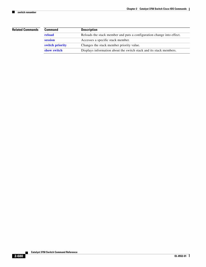
Chapter 2 Catalyst 3750 Switch Cisco IOS Commandsswitch renumber
Related Commands Command Description
reload Reloads the stack member and puts a configuration change into effect.
session Accesses a specific stack member.
switch priority Changes the stack member priority value.
show switch Displays information about the switch stack and its stack members.
2-680Catalyst 3750 Switch Command Reference
OL-8552-01
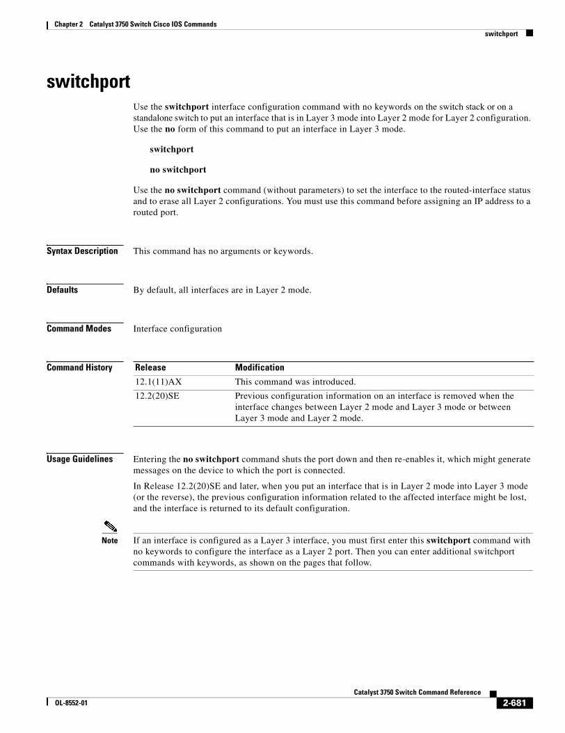
Chapter 2 Catalyst 3750 Switch Cisco IOS Commandsswitchport
switchport Use the switchport interface configuration command with no keywords on the switch stack or on a standalone switch to put an interface that is in Layer 3 mode into Layer 2 mode for Layer 2 configuration. Use the no form of this command to put an interface in Layer 3 mode.
switchport
no switchport
Use the no switchport command (without parameters) to set the interface to the routed-interface status and to erase all Layer 2 configurations. You must use this command before assigning an IP address to a routed port.
Syntax Description This command has no arguments or keywords.
Defaults By default, all interfaces are in Layer 2 mode.
Command Modes Interface configuration
Command History
Usage Guidelines Entering the no switchport command shuts the port down and then re-enables it, which might generate messages on the device to which the port is connected.
In Release 12.2(20)SE and later, when you put an interface that is in Layer 2 mode into Layer 3 mode (or the reverse), the previous configuration information related to the affected interface might be lost, and the interface is returned to its default configuration.
Note If an interface is configured as a Layer 3 interface, you must first enter this switchport command with no keywords to configure the interface as a Layer 2 port. Then you can enter additional switchport commands with keywords, as shown on the pages that follow.
Release Modification
12.1(11)AX This command was introduced.
12.2(20)SE Previous configuration information on an interface is removed when the interface changes between Layer 2 mode and Layer 3 mode or between Layer 3 mode and Layer 2 mode.
2-681Catalyst 3750 Switch Command Reference
OL-8552-01
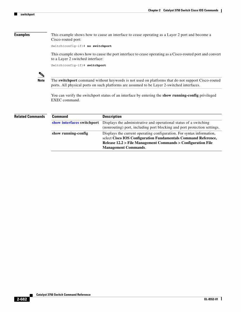
Chapter 2 Catalyst 3750 Switch Cisco IOS Commandsswitchport
Examples This example shows how to cause an interface to cease operating as a Layer 2 port and become a Cisco-routed port:
Switch(config-if)# no switchport
This example shows how to cause the port interface to cease operating as a Cisco-routed port and convert to a Layer 2 switched interface:
Switch(config-if)# switchport
Note The switchport command without keywords is not used on platforms that do not support Cisco-routed ports. All physical ports on such platforms are assumed to be Layer 2-switched interfaces.
You can verify the switchport status of an interface by entering the show running-config privileged EXEC command.
Related Commands Command Description
show interfaces switchport Displays the administrative and operational status of a switching (nonrouting) port, including port blocking and port protection settings.
show running-config Displays the current operating configuration. For syntax information, select Cisco IOS Configuration Fundamentals Command Reference, Release 12.2 > File Management Commands > Configuration File Management Commands.
2-682Catalyst 3750 Switch Command Reference
OL-8552-01
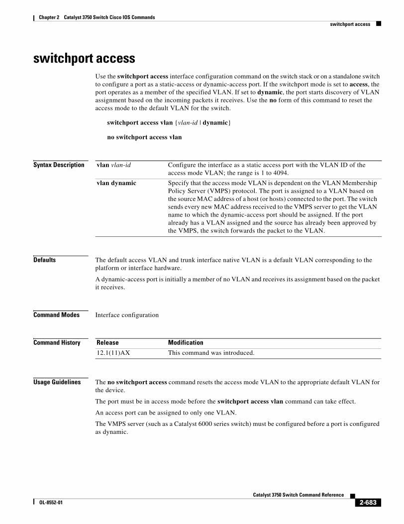
Chapter 2 Catalyst 3750 Switch Cisco IOS Commandsswitchport access
switchport accessUse the switchport access interface configuration command on the switch stack or on a standalone switch to configure a port as a static-access or dynamic-access port. If the switchport mode is set to access, the port operates as a member of the specified VLAN. If set to dynamic, the port starts discovery of VLAN assignment based on the incoming packets it receives. Use the no form of this command to reset the access mode to the default VLAN for the switch.
switchport access vlan {vlan-id | dynamic}
no switchport access vlan
Syntax Description
Defaults The default access VLAN and trunk interface native VLAN is a default VLAN corresponding to the platform or interface hardware.
A dynamic-access port is initially a member of no VLAN and receives its assignment based on the packet it receives.
Command Modes Interface configuration
Command History
Usage Guidelines The no switchport access command resets the access mode VLAN to the appropriate default VLAN for the device.
The port must be in access mode before the switchport access vlan command can take effect.
An access port can be assigned to only one VLAN.
The VMPS server (such as a Catalyst 6000 series switch) must be configured before a port is configured as dynamic.
vlan vlan-id Configure the interface as a static access port with the VLAN ID of the access mode VLAN; the range is 1 to 4094.
vlan dynamic Specify that the access mode VLAN is dependent on the VLAN Membership Policy Server (VMPS) protocol. The port is assigned to a VLAN based on the source MAC address of a host (or hosts) connected to the port. The switch sends every new MAC address received to the VMPS server to get the VLAN name to which the dynamic-access port should be assigned. If the port already has a VLAN assigned and the source has already been approved by the VMPS, the switch forwards the packet to the VLAN.
Release Modification
12.1(11)AX This command was introduced.
2-683Catalyst 3750 Switch Command Reference
OL-8552-01
Chapter 2 Catalyst 3750 Switch Cisco IOS Commandsswitchport access
These restrictions apply to dynamic-access ports:
• The software implements the VLAN Query Protocol (VQP) client, which can query a VMPS such as a Catalyst 6000 series switch. The Catalyst 3750 switches are not VMPS servers. The VMPS server must be configured before a port is configured as dynamic.
• Use dynamic-access ports only to connect end stations. Connecting them to switches or routers (that use bridging protocols) can cause a loss of connectivity.
• Configure the network so that STP does not put the dynamic-access port into an STP blocking state. The Port Fast feature is automatically enabled on dynamic-access ports.
• Dynamic-access ports can only be in one VLAN and do not use VLAN tagging.
• Dynamic-access ports cannot be configured as
– Members of an EtherChannel port group (dynamic-access ports cannot be grouped with any other port, including other dynamic ports).
– Source or destination ports in a static address entry.
– Monitor ports.
Examples This example shows how to change a switched port interface that is operating in access mode to operate in VLAN 2 instead of the default VLAN:
Switch(config-if)# switchport access vlan 2
You can verify your setting by entering the show interfaces interface-id switchport privileged EXEC command and examining information in the Administrative Mode and Operational Mode rows.
Related Commands Command Description
show interfaces switchport Displays the administrative and operational status of a switching (nonrouting) port, including port blocking and port protection settings.
switchport mode Configures the VLAN membership mode of a port.
2-684Catalyst 3750 Switch Command Reference
OL-8552-01
Chapter 2 Catalyst 3750 Switch Cisco IOS Commandsswitchport backup interface
switchport backup interfaceUse the switchport backup interface interface configuration command on a Layer 2 interface on the switch stack or on a standalone switch to configure Flex Links, a pair of interfaces that provide backup to each other. Use the no form of this command to remove the Flex Links configuration.
switchport backup interface {interface-id} mmu primary vlan vlan-id
switchport backup interface {interface-id} preemption [forced | bandwidth | off] | [delay delay-time]
no switchport backup interface {interface-id} mmu primary vlan vlan-id
no switchport backup interface {interface-id} preemption [forced | bandwidth | off] | [delay]
Syntax Description
Defaults The default is to have no Flex Links defined.
Preemption mode is off. No preemption occurs.
Preemption delay is set to 35 seconds.
Command Modes Interface configuration
Command History
interface-id Specifies the Layer 2 interface to act as a backup link to the interface being configured. The interface can be a physical interface or port channel. The port-channel range is 1 to 48.
mmu Specifies configuring the mac move update (MMU) for a backup interface pair.
primary vlan vlan-id The VLAN ID of the private-VLAN primary VLAN; valid range is 1 to 4094.
preemption Specifies configuring a preemption scheme for a backup interface pair.
forced (Optional) Specifies the interface always preempts the backup.
bandwidth (Optional) Specifies the interface with the higher available bandwidth always preempts the backup.
off (Optional) Specifies no preemption occurs from backup to active.
delay delay-time (Optional) Specifies a preemption delay; valid values are 1 to 300 seconds.
Release Modification
12.2(20)SE This command was introduced.
12.2(25)SEE Added preemption, forced, bandwidth, off, and delay keywords.
2-685Catalyst 3750 Switch Command Reference
OL-8552-01
Chapter 2 Catalyst 3750 Switch Cisco IOS Commandsswitchport backup interface
Usage Guidelines With Flex Links configured, one link acts as the primary interface and forwards traffic, while the other interface is in standby mode, ready to begin forwarding traffic if the primary link shuts down. The interface being configured is referred to as the active link; the specified interface is identified as the backup link. The feature provides an alternative to the Spanning Tree Protocol (STP), allowing users to turn off STP and still retain basic link redundancy.
• This command is available only for Layer 2 interfaces.
• You can configure only one Flex Link backup link for any active link, and it must be a different interface from the active interface.
• An interface can belong to only one Flex Link pair. An interface can be a backup link for only one active link. An active link cannot belong to another Flex Link pair.
• A backup link does not have to be the same type (Fast Ethernet or Gigabit Ethernet, for instance) as the active link. However, you should configure both Flex Links with similar characteristics so that there are no loops or changes in behavior if the standby link begins to forward traffic.
• Neither of the links can be a port that belongs to an EtherChannel. However, you can configure two port channels (EtherChannel logical interfaces) as Flex Links, and you can configure a port channel and a physical interface as Flex Links, with either the port channel or the physical interface as the active link.
• If STP is configured on the switch, Flex Links do not participate in STP in all valid VLANs. If STP is not running, be sure that there are no loops in the configured topology.
Examples This example shows how to configure two interfaces as Flex Links:
Switch# configure terminal Switch(conf)# interface fastethernet1/0/1Switch(conf-if)# switchport backup interface fastethernet1/0/2Switch(conf-if)# end
This example shows how to configure the Fast Ethernet interface to always preempt the backup:
Switch# configure terminal Switch(conf)# interface fastethernet1/0/1Switch(conf-if)# switchport backup interface fastethernet1/0/2 preemption forcedSwitch(conf-if)# end
This example shows how to configure the Fast Ethernet interface preemption delay time:
Switch# configure terminal Switch(conf)# interface fastethernet1/0/1Switch(conf-if)# switchport backup interface fastethernet1/0/2 preemption delay 150Switch(conf-if)# end
This example shows how to configure the Fast Ethernet interface as the MMU primary VLAN:
Switch# configure terminal Switch(conf)# interface fastethernet1/0/1Switch(conf-if)# switchport backup interface fastethernet1/0/2 mmu primary vlan 1021Switch(conf-if)# end
You can verify your setting by entering the show interfaces switchport backup privileged EXEC command.
2-686Catalyst 3750 Switch Command Reference
OL-8552-01

Chapter 2 Catalyst 3750 Switch Cisco IOS Commandsswitchport backup interface
Related Commands Command Description
show interfaces [interface-id] switchport backup
Displays the configured Flex Links and their status on the switch or for the specified interface.
2-687Catalyst 3750 Switch Command Reference
OL-8552-01
Chapter 2 Catalyst 3750 Switch Cisco IOS Commandsswitchport block
switchport blockUse the switchport block interface configuration command on the switch stack or on a standalone switch to prevent unknown multicast or unicast packets from being forwarded. Use the no form of this command to allow forwarding unknown multicast or unicast packets.
switchport block {multicast | unicast}
no switchport block {multicast | unicast}
Syntax Description
Defaults Unknown multicast and unicast traffic is not blocked.
Command Modes Interface configuration
Command History
Usage Guidelines By default, all traffic with unknown MAC addresses is sent to all ports. You can block unknown multicast or unicast traffic on protected or nonprotected ports. If unknown multicast or unicast traffic is not blocked on a protected port, there could be security issues.
Blocking unknown multicast or unicast traffic is not automatically enabled on protected ports; you must explicitly configure it.
For more information about blocking packets, see the software configuration guide for this release.
Examples This example shows how to block unknown multicast traffic on an interface:
Switch(config-if)# switchport block multicast
You can verify your setting by entering the show interfaces interface-id switchport privileged EXEC command.
Related Commands
multicast Specify that unknown multicast traffic should be blocked.
unicast Specify that unknown unicast traffic should be blocked.
Release Modification
12.1(11)AX This command was introduced.
Command Description
show interfaces switchport Displays the administrative and operational status of a switching (nonrouting) port, including port blocking and port protection settings.
2-688Catalyst 3750 Switch Command Reference
OL-8552-01
Chapter 2 Catalyst 3750 Switch Cisco IOS Commandsswitchport host
switchport hostUse the switchport host interface configuration command on the switch stack or on a standalone switch to optimize a Layer 2 port for a host connection. The no form of this command has no affect on the system.
switchport host
Syntax Description This command has no arguments or keywords.
Defaults The default is for the port to not be optimized for a host connection.
Command Modes Interface configuration
Command History
Usage Guidelines To optimize the port for a host connection, the switchport host command sets switch port mode to access, enables spanning tree Port Fast, and disables channel grouping. Only an end station can accept this configuration.
Because spanning tree Port Fast is enabled, you should enter the switchport host command only on ports that are connected to a single host. Connecting other switches, hubs, concentrators, or bridges to a fast-start port can cause temporary spanning-tree loops.
Enable the switchport host command to decrease the time that it takes to start up packet forwarding.
Examples This example shows how to optimize the port configuration for a host connection:
Switch(config-if)# switchport host switchport mode will be set to access spanning-tree portfast will be enabled channel group will be disabled Switch(config-if)#
You can verify your setting by entering the show interfaces interface-id switchport privileged EXEC command.
Related Commands
Release Modification
12.1(11)AX This command was introduced.
Command Description
show interfaces switchport Displays the administrative and operational status of a switching (nonrouting) port, including switchport mode.
2-689Catalyst 3750 Switch Command Reference
OL-8552-01
Chapter 2 Catalyst 3750 Switch Cisco IOS Commandsswitchport mode
switchport modeUse the switchport mode interface configuration command on the switch stack or on a standalone switch to configure the VLAN membership mode of a port. Use the no form of this command to reset the mode to the appropriate default for the device.
switchport mode {access | dot1q-tunnel | dynamic {auto | desirable} | private-vlan | trunk}
no switchport mode {access | dot1q-tunnel | dynamic | trunk}
Syntax Description
Defaults The default mode is dynamic auto.
Command Modes Interface configuration
Command History
Usage Guidelines A configuration that uses the access, dot1q-tunnel, or trunk keywords takes effect only when you configure the port in the appropriate mode by using the switchport mode command. The static-access and trunk configuration are saved, but only one configuration is active at a time.
When you enter access mode, the interface changes to permanent nontrunking mode and negotiates to convert the link into a nontrunk link even if the neighboring interface does not agree to the change.
When you enter trunk mode, the interface changes to permanent trunking mode and negotiates to convert the link into a trunk link even if the interface connecting to it does not agree to the change.
access Set the port to access mode (either static-access or dynamic-access depending on the setting of the switchport access vlan interface configuration command). The port is set to access unconditionally and operates as a nontrunking, single VLAN interface that sends and receives nonencapsulated (non-tagged) frames. An access port can be assigned to only one VLAN.
dot1q-tunnel Set the port as an IEEE 802.1Q tunnel port.
dynamic auto Set the interface trunking mode dynamic parameter to auto to specify that the interface convert the link to a trunk link. This is the default switchport mode.
dynamic desirable Set the interface trunking mode dynamic parameter to desirable to specify that the interface actively attempt to convert the link to a trunk link.
private-vlan See the switchport mode private-vlan command.
trunk Set the port to trunk unconditionally. The port is a trunking VLAN Layer 2 interface. The port sends and receives encapsulated (tagged) frames that identify the VLAN of origination. A trunk is a point-to-point link between two switches or between a switch and a router.
Release Modification
12.1(11)AX This command was introduced.
12.2(20)SE The private-vlan keyword was added.
12.2(25)SE The dot1q-tunnel keyword was added.
2-690Catalyst 3750 Switch Command Reference
OL-8552-01
Chapter 2 Catalyst 3750 Switch Cisco IOS Commandsswitchport mode
When you enter dynamic auto mode, the interface converts the link to a trunk link if the neighboring interface is set to trunk or desirable mode.
When you enter dynamic desirable mode, the interface becomes a trunk interface if the neighboring interface is set to trunk, desirable, or auto mode.
To autonegotiate trunking, the interfaces must be in the same VLAN Trunking Protocol (VTP) domain. Trunk negotiation is managed by the Dynamic Trunking Protocol (DTP), which is a point-to-point protocol. However, some internetworking devices might forward DTP frames improperly, which could cause misconfigurations. To avoid this, you should configure interfaces connected to devices that do not support DTP to not forward DTP frames, which turns off DTP.
• If you do not intend to trunk across those links, use the switchport mode access interface configuration command to disable trunking.
• To enable trunking to a device that does not support DTP, use the switchport mode trunk and switchport nonegotiate interface configuration commands to cause the interface to become a trunk but to not generate DTP frames.
When you enter dot1q-tunnel, the port is set unconditionally as an IEEE 802.1Q tunnel port.
Access ports, trunk ports, and tunnel ports are mutually exclusive.
Any IEEE 802.1Q encapsulated IP packets received on a tunnel port can be filtered by MAC access control lists (ACLs), but not by IP ACLs. This is because the switch does not recognize the protocol inside the IEEE 802.1Q header. This restriction applies to router ACLs, port ACLs, and VLAN maps.
Configuring a port as an IEEE 802.1Q tunnel port has these limitations:
• IP routing and fallback bridging are not supported on tunnel ports.
• Tunnel ports do not support IP ACLs.
• If an IP ACL is applied to a trunk port in a VLAN that includes tunnel ports, or if a VLAN map is applied to a VLAN that includes tunnel ports, packets received from the tunnel port are treated as non-IP packets and are filtered with MAC access lists.
• Layer 3 quality of service (QoS) ACLs and other QoS features related to Layer 3 information are not supported on tunnel ports.
For more information about configuring IEEE 802.1Q tunnel ports, see the software configuration guide for this release.
The IEEE 802.1x feature interacts with switchport modes in these ways:
• If you try to enable IEEE 802.1x on a trunk port, an error message appears, and IEEE 802.1x is not enabled. If you try to change the mode of an IEEE 802.1x-enabled port to trunk, the port mode is not changed.
• If you try to enable IEEE 802.1x on a port set to dynamic auto or dynamic desirable, an error message appears, and IEEE 802.1x is not enabled. If you try to change the mode of an IEEE 802.1x-enabled port to dynamic auto or dynamic desirable, the port mode is not changed.
• If you try to enable IEEE 802.1x on a dynamic-access (VLAN Query Protocol [VQP]) port, an error message appears, and IEEE 802.1x is not enabled. If you try to change an IEEE 802.1x-enabled port to dynamic VLAN assignment, an error message appears, and the VLAN configuration is not changed.
Examples This example shows how to configure a port for access mode:
Switch(config)# interface gigabitethernet2/0/1Switch(config-if)# switchport mode access
2-691Catalyst 3750 Switch Command Reference
OL-8552-01
Chapter 2 Catalyst 3750 Switch Cisco IOS Commandsswitchport mode
This example shows how set the port to dynamic desirable mode:
Switch(config)# interface gigabitethernet2/0/1Switch(config-if)# switchport mode dynamic desirable
This example shows how to configure a port for trunk mode:
Switch(config)# interface gigabitethernet2/0/1Switch(config-if)# switchport mode trunk
This example shows how to configure a port as an IEEE 802.1Q tunnel port:
Switch(config)# interface gigabitethernet2/0/1Switch(config-if)# switchport mode dot1q-tunnel
You can verify your settings by entering the show interfaces interface-id switchport privileged EXEC command and examining information in the Administrative Mode and Operational Mode rows.
Related Commands Command Description
show interfaces switchport Displays the administrative and operational status of a switching (nonrouting) port, including port blocking and port protection settings.
switchport access Configures a port as a static-access or dynamic-access port.
switchport trunk Configures the trunk characteristics when an interface is in trunking mode.
2-692Catalyst 3750 Switch Command Reference
OL-8552-01
Chapter 2 Catalyst 3750 Switch Cisco IOS Commandsswitchport mode private-vlan
switchport mode private-vlanUse the switchport mode private-vlan interface configuration command on the switch stack or on a standalone switch to configure a port as a promiscuous or host private VLAN port. Use the no form of this command to reset the mode to the appropriate default for the device.
switchport mode private-vlan {host | promiscuous}
no switchport mode private-vlan
Syntax Description
Defaults The default private-VLAN mode is neither host nor promiscuous.
The default switchport mode is dynamic auto.
Command Modes Interface configuration
Command History
Usage Guidelines A private-VLAN host or promiscuous port cannot be a Switched Port Analyzer (SPAN) destination port. If you configure a SPAN destination port as a private-VLAN host or promiscuous port, the port becomes inactive.
Do not configure private VLAN on ports with these other features:
• Dynamic-access port VLAN membership
• Dynamic Trunking Protocol (DTP)
• Port Aggregation Protocol (PAgP)
• Link Aggregation Control Protocol (LACP)
• Multicast VLAN Registration (MVR)
• Voice VLAN
A private-VLAN port cannot be a SPAN destination port.
While a port is part of the private-VLAN configuration, any EtherChannel configuration for it is inactive.
A private-VLAN port cannot be a secure port and should not be configured as a protected port.
For more information about private-VLAN interaction with other features, see the software configuration guide for this release.
host Configure the interface as a private-VLAN host port. Host ports belong to private-VLAN secondary VLANs and are either community ports or isolated ports, depending on the VLAN that they belong to.
promiscuous Configure the interface as a private-VLAN promiscuous port. Promiscuous ports are members of private-VLAN primary VLANs.
Release Modification
12.2(20)SE This command was introduced.
2-693Catalyst 3750 Switch Command Reference
OL-8552-01
Chapter 2 Catalyst 3750 Switch Cisco IOS Commandsswitchport mode private-vlan
We strongly recommend that you enable spanning tree Port Fast and bridge-protocol-data-unit (BPDU) guard on isolated and community host ports to prevent STP loops due to misconfigurations and to speed up STP convergence.
If you configure a port as a private-VLAN host port and you do not configure a valid private-VLAN association by using the switchport private-vlan host-association interface configuration command, the interface becomes inactive.
If you configure a port as a private-VLAN promiscuous port and you do not configure a valid private VLAN mapping by using the switchport private-vlan mapping interface configuration command, the interface becomes inactive.
Examples This example shows how to configure an interface as a private-VLAN host port and associate it to primary VLAN 20. The interface is a member of secondary isolated VLAN 501 and primary VLAN 20.
Note When you configure a port as a private VLAN host port, you should also enable BPDU guard and Port Fast by using the spanning-tree portfast bpduguard default global configuration command and the spanning-tree portfast interface configuration command.
Switch# configure terminal Switch(config)# interface fastethernet 1/0/1 Switch(config-if)# switchport mode private-vlan host Switch(config-if)# switchport private-vlan host-association 20 501 Switch(config-if)# end
This example shows how to configure an interface as a private VLAN promiscuous port and map it to a private VLAN. The interface is a member of primary VLAN 20 and secondary VLANs 501 to 503 are mapped to it.
Switch# configure terminal Switch(config)# interface fastethernet 1/0/2 Switch(config-if)# switchport mode private-vlan promiscuous Switch(config-if)# switchport private-vlan mapping 20 501-503 Switch(config-if)# end
You can verify private VLAN switchport mode by using the show interfaces interface-id switchport privileged EXEC command.
Related Commands Command Description
private-vlan Configures a VLAN as a community, isolated, or primary VLAN or associates a primary VLAN with secondary VLANs.
show interfaces switchport Displays the administrative and operational status of a switching (nonrouting) port, including private VLAN configuration.
switchport private-vlan Configures private VLAN associations and mappings between primary and secondary VLANs on an interface.
2-694Catalyst 3750 Switch Command Reference
OL-8552-01
Chapter 2 Catalyst 3750 Switch Cisco IOS Commandsswitchport nonegotiate
switchport nonegotiateUse the switchport nonegotiate interface configuration command on the switch stack or on a standalone switch to specify that Dynamic Trunking Protocol (DTP) negotiation packets are not sent on the Layer 2 interface. The switch does not engage in DTP negotiation on this interface. Use the no form of this command to return to the default setting.
switchport nonegotiate
no switchport nonegotiate
Syntax Description This command has no arguments or keywords.
Defaults The default is to use DTP negotiation to learn the trunking status.
Command Modes Interface configuration
Command History
Usage Guidelines The no form of the switchport nonegotiate command removes nonegotiate status.
This command is valid only when the interface switchport mode is access or trunk (configured by using the switchport mode access or the switchport mode trunk interface configuration command). This command returns an error if you attempt to execute it in dynamic (auto or desirable) mode.
Internetworking devices that do not support DTP might forward DTP frames improperly and cause misconfigurations. To avoid this, you should turn off DTP by using the switchport no negotiate command to configure the interfaces connected to devices that do not support DTP to not forward DTP frames.
When you enter the switchport nonegotiate command, DTP negotiation packets are not sent on the interface. The device does or does not trunk according to the mode parameter: access or trunk.
• If you do not intend to trunk across those links, use the switchport mode access interface configuration command to disable trunking.
• To enable trunking on a device that does not support DTP, use the switchport mode trunk and switchport nonegotiate interface configuration commands to cause the interface to become a trunk but to not generate DTP frames.
Release Modification
12.1(11)AX This command was introduced.
2-695Catalyst 3750 Switch Command Reference
OL-8552-01
Chapter 2 Catalyst 3750 Switch Cisco IOS Commandsswitchport nonegotiate
Examples This example shows how to cause a port to refrain from negotiating trunking mode and to act as a trunk or access port (depending on the mode set):
Switch(config)# interface gigabitethernet2/0/1Switch(config-if)# switchport nonegotiate
You can verify your setting by entering the show interfaces interface-id switchport privileged EXEC command.
Related Commands Command Description
show interfaces switchport Displays the administrative and operational status of a switching (nonrouting) port, including port blocking and port protection settings.
switchport mode Configures the VLAN membership mode of a port.
2-696Catalyst 3750 Switch Command Reference
OL-8552-01
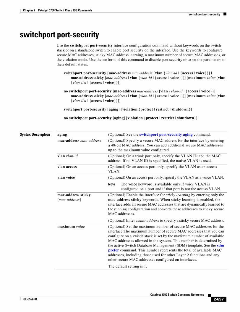
Chapter 2 Catalyst 3750 Switch Cisco IOS Commandsswitchport port-security
switchport port-securityUse the switchport port-security interface configuration command without keywords on the switch stack or on a standalone switch to enable port security on the interface. Use the keywords to configure secure MAC addresses, sticky MAC address learning, a maximum number of secure MAC addresses, or the violation mode. Use the no form of this command to disable port security or to set the parameters to their default states.
switchport port-security [mac-address mac-address [vlan {vlan-id | {access | voice}}] | mac-address sticky [mac-address | vlan {vlan-id | {access | voice}}]] [maximum value [vlan {vlan-list | {access | voice}}]]
no switchport port-security [mac-address mac-address [vlan {vlan-id | {access | voice}}] | mac-address sticky [mac-address | vlan {vlan-id | {access | voice}}]] [maximum value [vlan {vlan-list | {access | voice}}]]
switchport port-security [aging] [violation {protect | restrict | shutdown}]
no switchport port-security [aging] [violation {protect | restrict | shutdown}]
Syntax Description aging (Optional) See the switchport port-security aging command.
mac-address mac-address (Optional) Specify a secure MAC address for the interface by entering a 48-bit MAC address. You can add additional secure MAC addresses up to the maximum value configured.
vlan vlan-id (Optional) On a trunk port only, specify the VLAN ID and the MAC address. If no VLAN ID is specified, the native VLAN is used.
vlan access (Optional) On an access port only, specify the VLAN as an access VLAN.
vlan voice (Optional) On an access port only, specify the VLAN as a voice VLAN.
Note The voice keyword is available only if voice VLAN is configured on a port and if that port is not the access VLAN.
mac-address sticky [mac-address]
(Optional) Enable the interface for sticky learning by entering only the mac-address sticky keywords. When sticky learning is enabled, the interface adds all secure MAC addresses that are dynamically learned to the running configuration and converts these addresses to sticky secure MAC addresses.
(Optional) Enter a mac-address to specify a sticky secure MAC address.
maximum value (Optional) Set the maximum number of secure MAC addresses for the interface.The maximum number of secure MAC addresses that you can configure on a switch stack is set by the maximum number of available MAC addresses allowed in the system. This number is determined by the active Switch Database Management (SDM) template. See the sdm prefer command. This number represents the total of available MAC addresses, including those used for other Layer 2 functions and any other secure MAC addresses configured on interfaces.
The default setting is 1.
2-697Catalyst 3750 Switch Command Reference
OL-8552-01
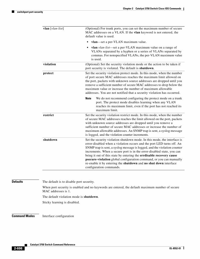
Chapter 2 Catalyst 3750 Switch Cisco IOS Commandsswitchport port-security
Defaults The default is to disable port security.
When port security is enabled and no keywords are entered, the default maximum number of secure MAC addresses is 1.
The default violation mode is shutdown.
Sticky learning is disabled.
Command Modes Interface configuration
vlan [vlan-list] (Optional) For trunk ports, you can set the maximum number of secure MAC addresses on a VLAN. If the vlan keyword is not entered, the default value is used.
• vlan—set a per-VLAN maximum value.
• vlan vlan-list—set a per-VLAN maximum value on a range of VLANs separated by a hyphen or a series of VLANs separated by commas. For nonspecified VLANs, the per-VLAN maximum value is used.
violation (Optional) Set the security violation mode or the action to be taken if port security is violated. The default is shutdown.
protect Set the security violation protect mode. In this mode, when the number of port secure MAC addresses reaches the maximum limit allowed on the port, packets with unknown source addresses are dropped until you remove a sufficient number of secure MAC addresses to drop below the maximum value or increase the number of maximum allowable addresses. You are not notified that a security violation has occurred.
Note We do not recommend configuring the protect mode on a trunk port. The protect mode disables learning when any VLAN reaches its maximum limit, even if the port has not reached its maximum limit.
restrict Set the security violation restrict mode. In this mode, when the number of secure MAC addresses reaches the limit allowed on the port, packets with unknown source addresses are dropped until you remove a sufficient number of secure MAC addresses or increase the number of maximum allowable addresses. An SNMP trap is sent, a syslog message is logged, and the violation counter increments.
shutdown Set the security violation shutdown mode. In this mode, the interface is error-disabled when a violation occurs and the port LED turns off. An SNMP trap is sent, a syslog message is logged, and the violation counter increments. When a secure port is in the error-disabled state, you can bring it out of this state by entering the errdisable recovery cause psecure-violation global configuration command, or you can manually re-enable it by entering the shutdown and no shut down interface configuration commands.
2-698Catalyst 3750 Switch Command Reference
OL-8552-01
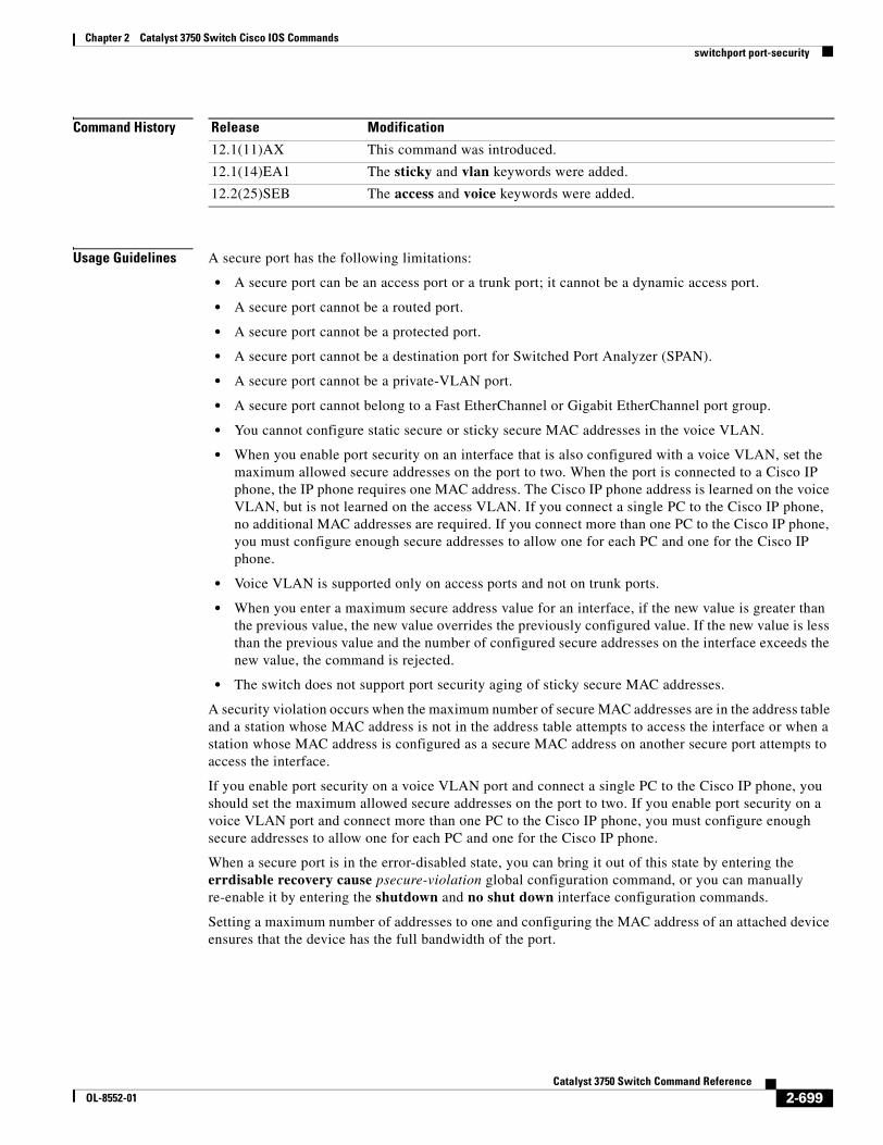
Chapter 2 Catalyst 3750 Switch Cisco IOS Commandsswitchport port-security
Command History
Usage Guidelines A secure port has the following limitations:
• A secure port can be an access port or a trunk port; it cannot be a dynamic access port.
• A secure port cannot be a routed port.
• A secure port cannot be a protected port.
• A secure port cannot be a destination port for Switched Port Analyzer (SPAN).
• A secure port cannot be a private-VLAN port.
• A secure port cannot belong to a Fast EtherChannel or Gigabit EtherChannel port group.
• You cannot configure static secure or sticky secure MAC addresses in the voice VLAN.
• When you enable port security on an interface that is also configured with a voice VLAN, set the maximum allowed secure addresses on the port to two. When the port is connected to a Cisco IP phone, the IP phone requires one MAC address. The Cisco IP phone address is learned on the voice VLAN, but is not learned on the access VLAN. If you connect a single PC to the Cisco IP phone, no additional MAC addresses are required. If you connect more than one PC to the Cisco IP phone, you must configure enough secure addresses to allow one for each PC and one for the Cisco IP phone.
• Voice VLAN is supported only on access ports and not on trunk ports.
• When you enter a maximum secure address value for an interface, if the new value is greater than the previous value, the new value overrides the previously configured value. If the new value is less than the previous value and the number of configured secure addresses on the interface exceeds the new value, the command is rejected.
• The switch does not support port security aging of sticky secure MAC addresses.
A security violation occurs when the maximum number of secure MAC addresses are in the address table and a station whose MAC address is not in the address table attempts to access the interface or when a station whose MAC address is configured as a secure MAC address on another secure port attempts to access the interface.
If you enable port security on a voice VLAN port and connect a single PC to the Cisco IP phone, you should set the maximum allowed secure addresses on the port to two. If you enable port security on a voice VLAN port and connect more than one PC to the Cisco IP phone, you must configure enough secure addresses to allow one for each PC and one for the Cisco IP phone.
When a secure port is in the error-disabled state, you can bring it out of this state by entering the errdisable recovery cause psecure-violation global configuration command, or you can manually re-enable it by entering the shutdown and no shut down interface configuration commands.
Setting a maximum number of addresses to one and configuring the MAC address of an attached device ensures that the device has the full bandwidth of the port.
Release Modification
12.1(11)AX This command was introduced.
12.1(14)EA1 The sticky and vlan keywords were added.
12.2(25)SEB The access and voice keywords were added.
2-699Catalyst 3750 Switch Command Reference
OL-8552-01
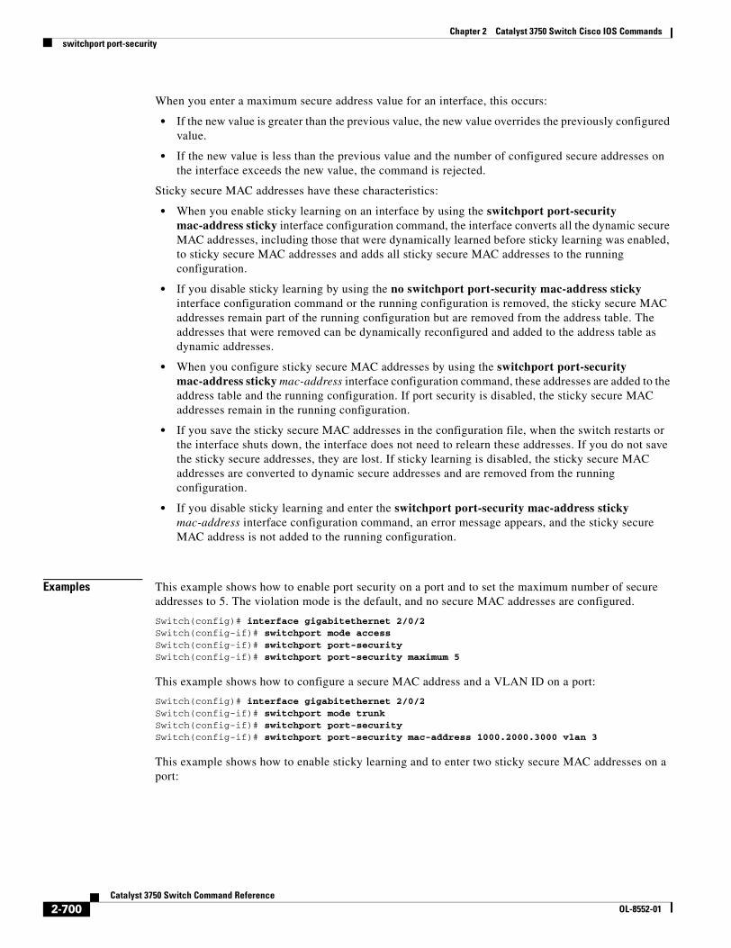
Chapter 2 Catalyst 3750 Switch Cisco IOS Commandsswitchport port-security
When you enter a maximum secure address value for an interface, this occurs:
• If the new value is greater than the previous value, the new value overrides the previously configured value.
• If the new value is less than the previous value and the number of configured secure addresses on the interface exceeds the new value, the command is rejected.
Sticky secure MAC addresses have these characteristics:
• When you enable sticky learning on an interface by using the switchport port-security mac-address sticky interface configuration command, the interface converts all the dynamic secure MAC addresses, including those that were dynamically learned before sticky learning was enabled, to sticky secure MAC addresses and adds all sticky secure MAC addresses to the running configuration.
• If you disable sticky learning by using the no switchport port-security mac-address sticky interface configuration command or the running configuration is removed, the sticky secure MAC addresses remain part of the running configuration but are removed from the address table. The addresses that were removed can be dynamically reconfigured and added to the address table as dynamic addresses.
• When you configure sticky secure MAC addresses by using the switchport port-security mac-address sticky mac-address interface configuration command, these addresses are added to the address table and the running configuration. If port security is disabled, the sticky secure MAC addresses remain in the running configuration.
• If you save the sticky secure MAC addresses in the configuration file, when the switch restarts or the interface shuts down, the interface does not need to relearn these addresses. If you do not save the sticky secure addresses, they are lost. If sticky learning is disabled, the sticky secure MAC addresses are converted to dynamic secure addresses and are removed from the running configuration.
• If you disable sticky learning and enter the switchport port-security mac-address sticky mac-address interface configuration command, an error message appears, and the sticky secure MAC address is not added to the running configuration.
Examples This example shows how to enable port security on a port and to set the maximum number of secure addresses to 5. The violation mode is the default, and no secure MAC addresses are configured.
Switch(config)# interface gigabitethernet 2/0/2Switch(config-if)# switchport mode accessSwitch(config-if)# switchport port-securitySwitch(config-if)# switchport port-security maximum 5
This example shows how to configure a secure MAC address and a VLAN ID on a port:
Switch(config)# interface gigabitethernet 2/0/2Switch(config-if)# switchport mode trunkSwitch(config-if)# switchport port-securitySwitch(config-if)# switchport port-security mac-address 1000.2000.3000 vlan 3
This example shows how to enable sticky learning and to enter two sticky secure MAC addresses on a port:
2-700Catalyst 3750 Switch Command Reference
OL-8552-01
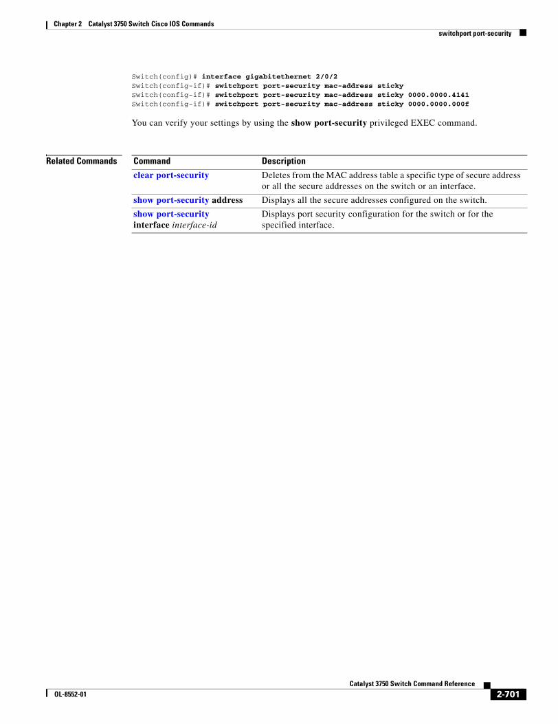
Chapter 2 Catalyst 3750 Switch Cisco IOS Commandsswitchport port-security
Switch(config)# interface gigabitethernet 2/0/2Switch(config-if)# switchport port-security mac-address sticky Switch(config-if)# switchport port-security mac-address sticky 0000.0000.4141Switch(config-if)# switchport port-security mac-address sticky 0000.0000.000f
You can verify your settings by using the show port-security privileged EXEC command.
Related Commands Command Description
clear port-security Deletes from the MAC address table a specific type of secure address or all the secure addresses on the switch or an interface.
show port-security address Displays all the secure addresses configured on the switch.
show port-security interface interface-id
Displays port security configuration for the switch or for the specified interface.
2-701Catalyst 3750 Switch Command Reference
OL-8552-01
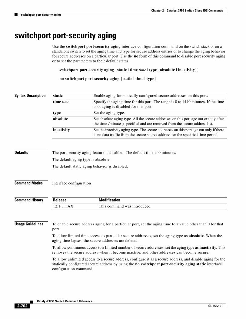
Chapter 2 Catalyst 3750 Switch Cisco IOS Commandsswitchport port-security aging
switchport port-security agingUse the switchport port-security aging interface configuration command on the switch stack or on a standalone switch to set the aging time and type for secure address entries or to change the aging behavior for secure addresses on a particular port. Use the no form of this command to disable port security aging or to set the parameters to their default states.
switchport port-security aging {static | time time | type {absolute | inactivity}}
no switchport port-security aging {static | time | type}
Syntax Description
Defaults The port security aging feature is disabled. The default time is 0 minutes.
The default aging type is absolute.
The default static aging behavior is disabled.
Command Modes Interface configuration
Command History
Usage Guidelines To enable secure address aging for a particular port, set the aging time to a value other than 0 for that port.
To allow limited time access to particular secure addresses, set the aging type as absolute. When the aging time lapses, the secure addresses are deleted.
To allow continuous access to a limited number of secure addresses, set the aging type as inactivity. This removes the secure address when it become inactive, and other addresses can become secure.
To allow unlimited access to a secure address, configure it as a secure address, and disable aging for the statically configured secure address by using the no switchport port-security aging static interface configuration command.
static Enable aging for statically configured secure addresses on this port.
time time Specify the aging time for this port. The range is 0 to 1440 minutes. If the time is 0, aging is disabled for this port.
type Set the aging type.
absolute Set absolute aging type. All the secure addresses on this port age out exactly after the time (minutes) specified and are removed from the secure address list.
inactivity Set the inactivity aging type. The secure addresses on this port age out only if there is no data traffic from the secure source address for the specified time period.
Release Modification
12.1(11)AX This command was introduced.
2-702Catalyst 3750 Switch Command Reference
OL-8552-01
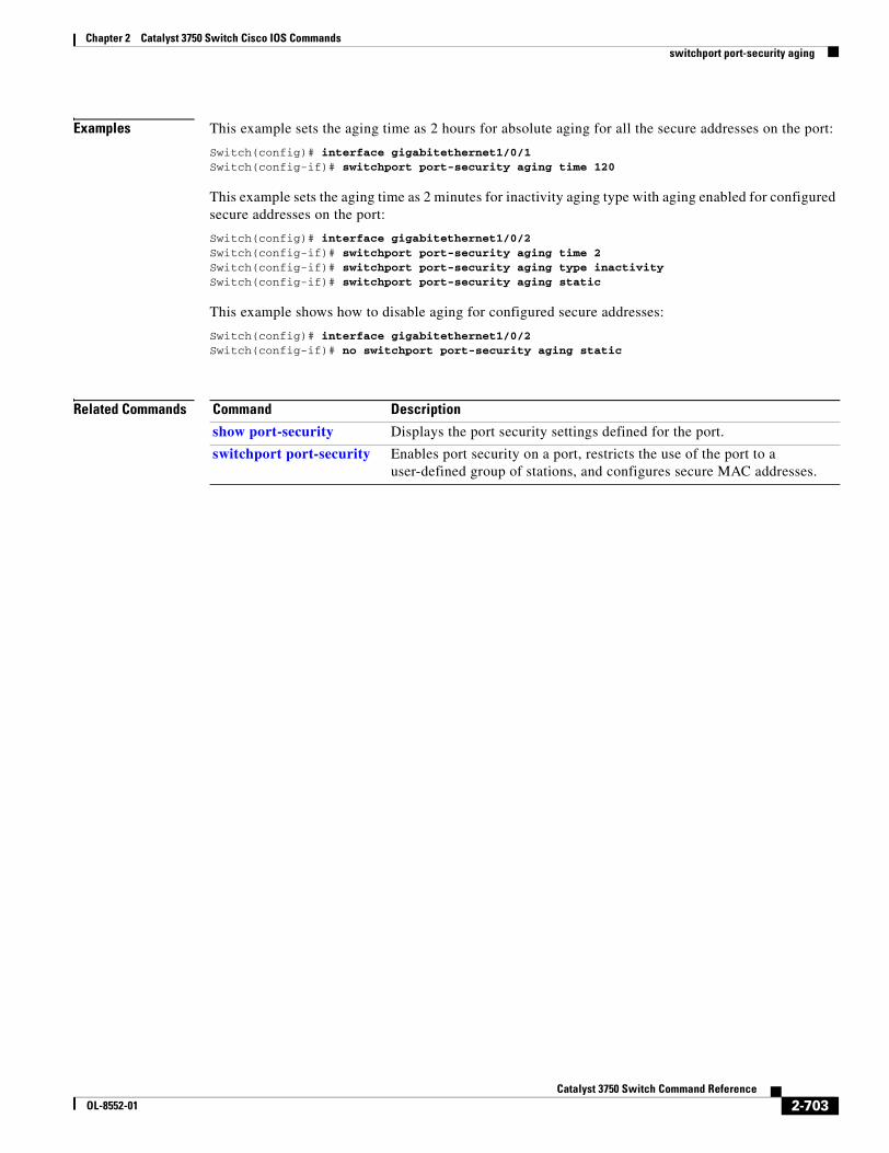
Chapter 2 Catalyst 3750 Switch Cisco IOS Commandsswitchport port-security aging
Examples This example sets the aging time as 2 hours for absolute aging for all the secure addresses on the port:
Switch(config)# interface gigabitethernet1/0/1Switch(config-if)# switchport port-security aging time 120
This example sets the aging time as 2 minutes for inactivity aging type with aging enabled for configured secure addresses on the port:
Switch(config)# interface gigabitethernet1/0/2Switch(config-if)# switchport port-security aging time 2 Switch(config-if)# switchport port-security aging type inactivity Switch(config-if)# switchport port-security aging static
This example shows how to disable aging for configured secure addresses:
Switch(config)# interface gigabitethernet1/0/2Switch(config-if)# no switchport port-security aging static
Related Commands Command Description
show port-security Displays the port security settings defined for the port.
switchport port-security Enables port security on a port, restricts the use of the port to a user-defined group of stations, and configures secure MAC addresses.
2-703Catalyst 3750 Switch Command Reference
OL-8552-01
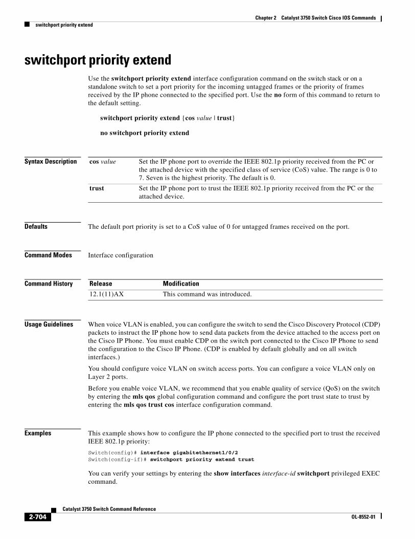
Chapter 2 Catalyst 3750 Switch Cisco IOS Commandsswitchport priority extend
switchport priority extendUse the switchport priority extend interface configuration command on the switch stack or on a standalone switch to set a port priority for the incoming untagged frames or the priority of frames received by the IP phone connected to the specified port. Use the no form of this command to return to the default setting.
switchport priority extend {cos value | trust}
no switchport priority extend
Syntax Description
Defaults The default port priority is set to a CoS value of 0 for untagged frames received on the port.
Command Modes Interface configuration
Command History
Usage Guidelines When voice VLAN is enabled, you can configure the switch to send the Cisco Discovery Protocol (CDP) packets to instruct the IP phone how to send data packets from the device attached to the access port on the Cisco IP Phone. You must enable CDP on the switch port connected to the Cisco IP Phone to send the configuration to the Cisco IP Phone. (CDP is enabled by default globally and on all switch interfaces.)
You should configure voice VLAN on switch access ports. You can configure a voice VLAN only on Layer 2 ports.
Before you enable voice VLAN, we recommend that you enable quality of service (QoS) on the switch by entering the mls qos global configuration command and configure the port trust state to trust by entering the mls qos trust cos interface configuration command.
Examples This example shows how to configure the IP phone connected to the specified port to trust the received IEEE 802.1p priority:
Switch(config)# interface gigabitethernet1/0/2Switch(config-if)# switchport priority extend trust
You can verify your settings by entering the show interfaces interface-id switchport privileged EXEC command.
cos value Set the IP phone port to override the IEEE 802.1p priority received from the PC or the attached device with the specified class of service (CoS) value. The range is 0 to 7. Seven is the highest priority. The default is 0.
trust Set the IP phone port to trust the IEEE 802.1p priority received from the PC or the attached device.
Release Modification
12.1(11)AX This command was introduced.
2-704Catalyst 3750 Switch Command Reference
OL-8552-01

Chapter 2 Catalyst 3750 Switch Cisco IOS Commandsswitchport priority extend
Related Commands Command Description
show interfaces Displays the administrative and operational status of a switching (nonrouting) port.
switchport voice vlan Configures the voice VLAN on the port.
2-705Catalyst 3750 Switch Command Reference
OL-8552-01
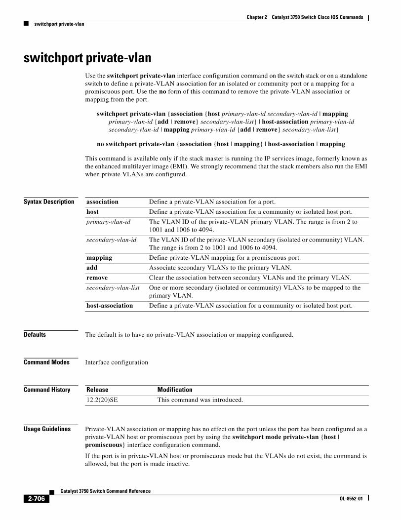
Chapter 2 Catalyst 3750 Switch Cisco IOS Commandsswitchport private-vlan
switchport private-vlanUse the switchport private-vlan interface configuration command on the switch stack or on a standalone switch to define a private-VLAN association for an isolated or community port or a mapping for a promiscuous port. Use the no form of this command to remove the private-VLAN association or mapping from the port.
switchport private-vlan {association {host primary-vlan-id secondary-vlan-id | mapping primary-vlan-id {add | remove} secondary-vlan-list} | host-association primary-vlan-id secondary-vlan-id | mapping primary-vlan-id {add | remove} secondary-vlan-list}
no switchport private-vlan {association {host | mapping} | host-association | mapping
This command is available only if the stack master is running the IP services image, formerly known as the enhanced multilayer image (EMI). We strongly recommend that the stack members also run the EMI when private VLANs are configured.
Syntax Description
Defaults The default is to have no private-VLAN association or mapping configured.
Command Modes Interface configuration
Command History
Usage Guidelines Private-VLAN association or mapping has no effect on the port unless the port has been configured as a private-VLAN host or promiscuous port by using the switchport mode private-vlan {host | promiscuous} interface configuration command.
If the port is in private-VLAN host or promiscuous mode but the VLANs do not exist, the command is allowed, but the port is made inactive.
association Define a private-VLAN association for a port.
host Define a private-VLAN association for a community or isolated host port.
primary-vlan-id The VLAN ID of the private-VLAN primary VLAN. The range is from 2 to 1001 and 1006 to 4094.
secondary-vlan-id The VLAN ID of the private-VLAN secondary (isolated or community) VLAN. The range is from 2 to 1001 and 1006 to 4094.
mapping Define private-VLAN mapping for a promiscuous port.
add Associate secondary VLANs to the primary VLAN.
remove Clear the association between secondary VLANs and the primary VLAN.
secondary-vlan-list One or more secondary (isolated or community) VLANs to be mapped to the primary VLAN.
host-association Define a private-VLAN association for a community or isolated host port.
Release Modification
12.2(20)SE This command was introduced.
2-706Catalyst 3750 Switch Command Reference
OL-8552-01
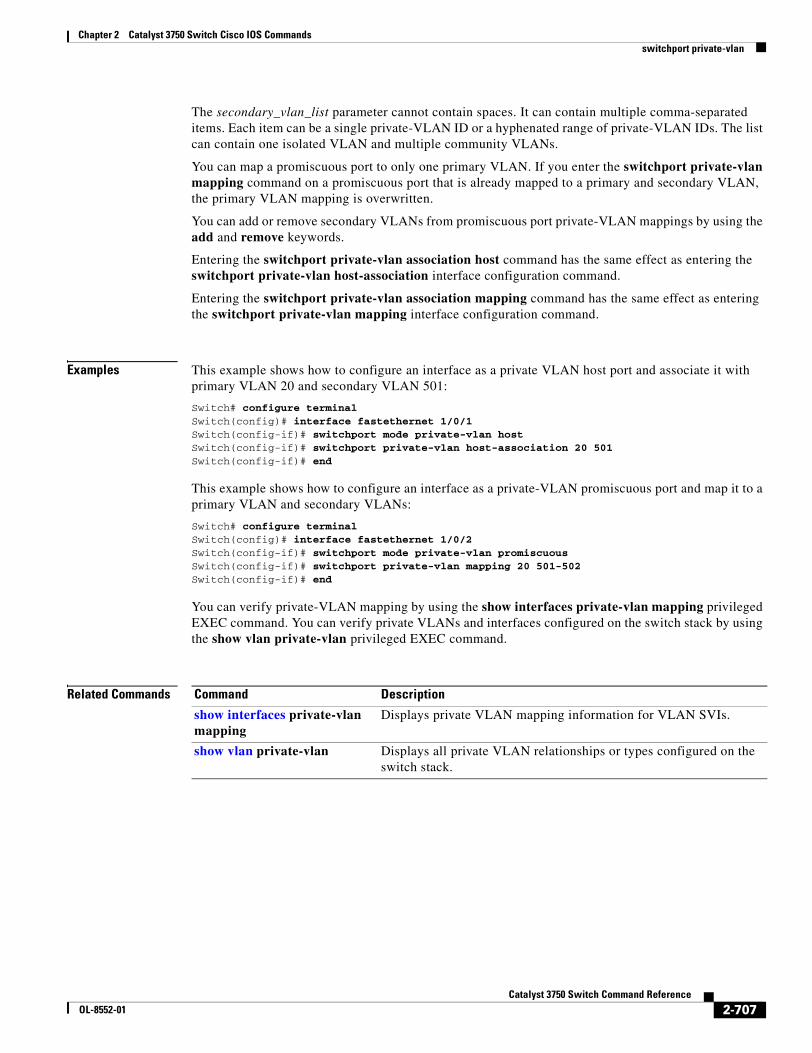
Chapter 2 Catalyst 3750 Switch Cisco IOS Commandsswitchport private-vlan
The secondary_vlan_list parameter cannot contain spaces. It can contain multiple comma-separated items. Each item can be a single private-VLAN ID or a hyphenated range of private-VLAN IDs. The list can contain one isolated VLAN and multiple community VLANs.
You can map a promiscuous port to only one primary VLAN. If you enter the switchport private-vlan mapping command on a promiscuous port that is already mapped to a primary and secondary VLAN, the primary VLAN mapping is overwritten.
You can add or remove secondary VLANs from promiscuous port private-VLAN mappings by using the add and remove keywords.
Entering the switchport private-vlan association host command has the same effect as entering the switchport private-vlan host-association interface configuration command.
Entering the switchport private-vlan association mapping command has the same effect as entering the switchport private-vlan mapping interface configuration command.
Examples This example shows how to configure an interface as a private VLAN host port and associate it with primary VLAN 20 and secondary VLAN 501:
Switch# configure terminal Switch(config)# interface fastethernet 1/0/1 Switch(config-if)# switchport mode private-vlan host Switch(config-if)# switchport private-vlan host-association 20 501 Switch(config-if)# end
This example shows how to configure an interface as a private-VLAN promiscuous port and map it to a primary VLAN and secondary VLANs:
Switch# configure terminal Switch(config)# interface fastethernet 1/0/2 Switch(config-if)# switchport mode private-vlan promiscuous Switch(config-if)# switchport private-vlan mapping 20 501-502 Switch(config-if)# end
You can verify private-VLAN mapping by using the show interfaces private-vlan mapping privileged EXEC command. You can verify private VLANs and interfaces configured on the switch stack by using the show vlan private-vlan privileged EXEC command.
Related Commands Command Description
show interfaces private-vlan mapping
Displays private VLAN mapping information for VLAN SVIs.
show vlan private-vlan Displays all private VLAN relationships or types configured on the switch stack.
2-707Catalyst 3750 Switch Command Reference
OL-8552-01
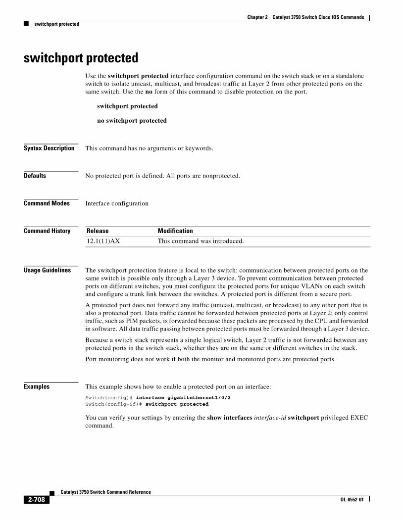
Chapter 2 Catalyst 3750 Switch Cisco IOS Commandsswitchport protected
switchport protectedUse the switchport protected interface configuration command on the switch stack or on a standalone switch to isolate unicast, multicast, and broadcast traffic at Layer 2 from other protected ports on the same switch. Use the no form of this command to disable protection on the port.
switchport protected
no switchport protected
Syntax Description This command has no arguments or keywords.
Defaults No protected port is defined. All ports are nonprotected.
Command Modes Interface configuration
Command History
Usage Guidelines The switchport protection feature is local to the switch; communication between protected ports on the same switch is possible only through a Layer 3 device. To prevent communication between protected ports on different switches, you must configure the protected ports for unique VLANs on each switch and configure a trunk link between the switches. A protected port is different from a secure port.
A protected port does not forward any traffic (unicast, multicast, or broadcast) to any other port that is also a protected port. Data traffic cannot be forwarded between protected ports at Layer 2; only control traffic, such as PIM packets, is forwarded because these packets are processed by the CPU and forwarded in software. All data traffic passing between protected ports must be forwarded through a Layer 3 device.
Because a switch stack represents a single logical switch, Layer 2 traffic is not forwarded between any protected ports in the switch stack, whether they are on the same or different switches in the stack.
Port monitoring does not work if both the monitor and monitored ports are protected ports.
Examples This example shows how to enable a protected port on an interface:
Switch(config)# interface gigabitethernet1/0/2Switch(config-if)# switchport protected
You can verify your settings by entering the show interfaces interface-id switchport privileged EXEC command.
Release Modification
12.1(11)AX This command was introduced.
2-708Catalyst 3750 Switch Command Reference
OL-8552-01

Chapter 2 Catalyst 3750 Switch Cisco IOS Commandsswitchport protected
Related Commands Command Description
show interfaces switchport
Displays the administrative and operational status of a switching (nonrouting) port, including port blocking and port protection settings.
switchport block Prevents unknown multicast or unicast traffic on the interface.
2-709Catalyst 3750 Switch Command Reference
OL-8552-01
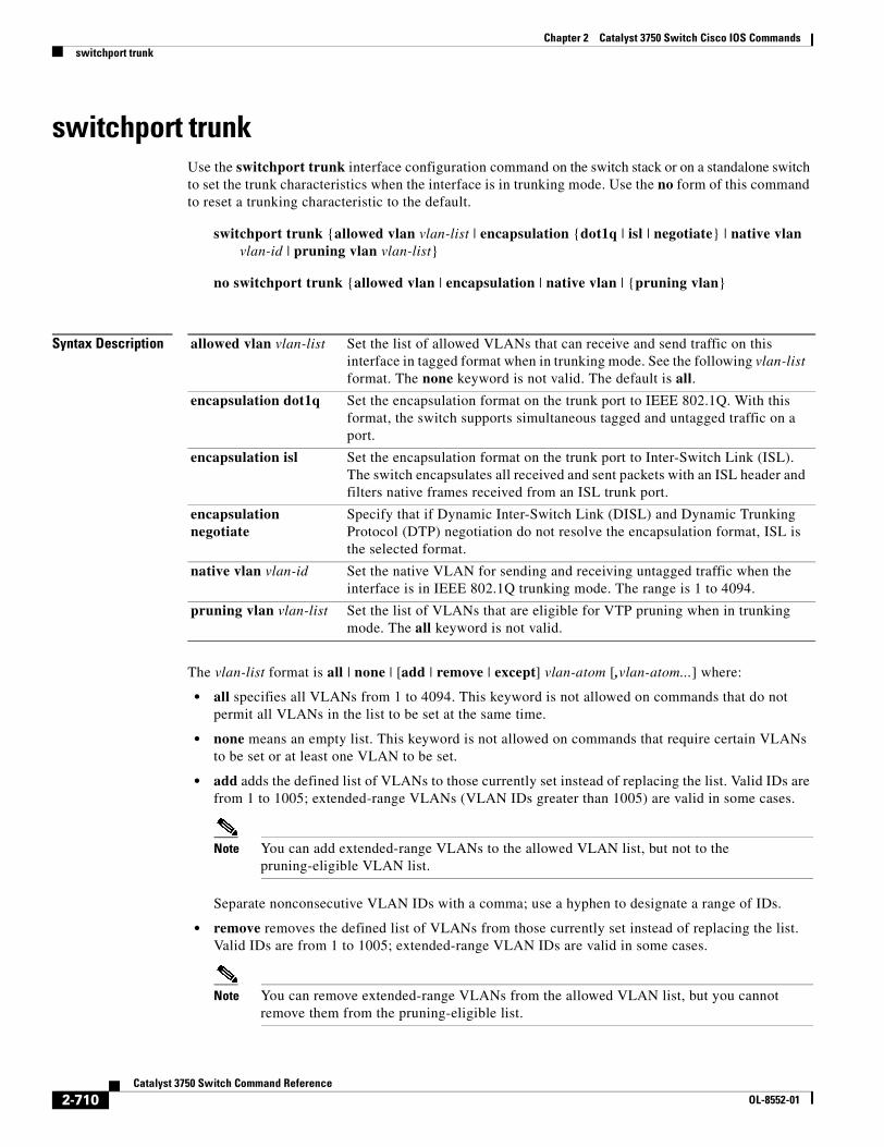
Chapter 2 Catalyst 3750 Switch Cisco IOS Commandsswitchport trunk
switchport trunkUse the switchport trunk interface configuration command on the switch stack or on a standalone switch to set the trunk characteristics when the interface is in trunking mode. Use the no form of this command to reset a trunking characteristic to the default.
switchport trunk {allowed vlan vlan-list | encapsulation {dot1q | isl | negotiate} | native vlan vlan-id | pruning vlan vlan-list}
no switchport trunk {allowed vlan | encapsulation | native vlan | {pruning vlan}
Syntax Description
The vlan-list format is all | none | [add | remove | except] vlan-atom [,vlan-atom...] where:
• all specifies all VLANs from 1 to 4094. This keyword is not allowed on commands that do not permit all VLANs in the list to be set at the same time.
• none means an empty list. This keyword is not allowed on commands that require certain VLANs to be set or at least one VLAN to be set.
• add adds the defined list of VLANs to those currently set instead of replacing the list. Valid IDs are from 1 to 1005; extended-range VLANs (VLAN IDs greater than 1005) are valid in some cases.
Note You can add extended-range VLANs to the allowed VLAN list, but not to the pruning-eligible VLAN list.
Separate nonconsecutive VLAN IDs with a comma; use a hyphen to designate a range of IDs.
• remove removes the defined list of VLANs from those currently set instead of replacing the list. Valid IDs are from 1 to 1005; extended-range VLAN IDs are valid in some cases.
Note You can remove extended-range VLANs from the allowed VLAN list, but you cannot remove them from the pruning-eligible list.
allowed vlan vlan-list Set the list of allowed VLANs that can receive and send traffic on this interface in tagged format when in trunking mode. See the following vlan-list format. The none keyword is not valid. The default is all.
encapsulation dot1q Set the encapsulation format on the trunk port to IEEE 802.1Q. With this format, the switch supports simultaneous tagged and untagged traffic on a port.
encapsulation isl Set the encapsulation format on the trunk port to Inter-Switch Link (ISL). The switch encapsulates all received and sent packets with an ISL header and filters native frames received from an ISL trunk port.
encapsulation negotiate
Specify that if Dynamic Inter-Switch Link (DISL) and Dynamic Trunking Protocol (DTP) negotiation do not resolve the encapsulation format, ISL is the selected format.
native vlan vlan-id Set the native VLAN for sending and receiving untagged traffic when the interface is in IEEE 802.1Q trunking mode. The range is 1 to 4094.
pruning vlan vlan-list Set the list of VLANs that are eligible for VTP pruning when in trunking mode. The all keyword is not valid.
2-710Catalyst 3750 Switch Command Reference
OL-8552-01
Chapter 2 Catalyst 3750 Switch Cisco IOS Commandsswitchport trunk
Separate nonconsecutive VLAN IDs with a comma; use a hyphen to designate a range of IDs.
• except lists the VLANs that should be calculated by inverting the defined list of VLANs. (VLANs are added except the ones specified.) Valid IDs are from 1 to 1005. Separate nonconsecutive VLAN IDs with a comma; use a hyphen to designate a range of IDs.
• vlan-atom is either a single VLAN number from 1 to 4094 or a continuous range of VLANs described by two VLAN numbers, the lesser one first, separated by a hyphen.
Defaults The default encapsulation is negotiate.
VLAN 1 is the default native VLAN ID on the port.
The default for all VLAN lists is to include all VLANs.
Command Modes Interface configuration
Command History
Usage Guidelines Encapsulation:
• The switchport trunk encapsulation command is supported only for platforms and interface hardware that can support both ISL and IEEE 802.1Q formats.
• You cannot configure one end of the trunk as an IEEE 802.1Q trunk and the other end as an ISL or nontrunk port. However, you can configure one port as an ISL trunk and a different port on the same switch as an IEEE 802.1Q trunk.
• If you enter the negotiate keywords and DTP negotiation does not resolve the encapsulation format, ISL is the selected format. The no form of the command resets the trunk encapsulation format to the default.
• The no form of the encapsulation command resets the encapsulation format to the default.
Native VLANs:
• All untagged traffic received on an IEEE 802.1Q trunk port is forwarded with the native VLAN configured for the port.
• If a packet has a VLAN ID that is the same as the sending-port native VLAN ID, the packet is sent without a tag; otherwise, the switch sends the packet with a tag.
• The no form of the native vlan command resets the native mode VLAN to the appropriate default VLAN for the device.
Release Modification
12.1(11)AX This command was introduced.
12.1(14)EA1 The allowed vlan vlan-list add, remove, and except keywords were modified to accept the VLAN1 and VLANs 1002 to 1005 values.
2-711Catalyst 3750 Switch Command Reference
OL-8552-01
Chapter 2 Catalyst 3750 Switch Cisco IOS Commandsswitchport trunk
Allowed VLAN:
• To reduce the risk of spanning-tree loops or storms, you can disable VLAN 1 on any individual VLAN trunk port by removing VLAN 1 from the allowed list. When you remove VLAN 1 from a trunk port, the interface continues to send and receive management traffic, for example, Cisco Discovery Protocol (CDP), Port Aggregation Protocol (PAgP), Link Aggregation Control Protocol (LACP), Dynamic Trunking Protocol (DTP), and VLAN Trunking Protocol (VTP) in VLAN 1.
• The no form of the allowed vlan command resets the list to the default list, which allows all VLANs.
Trunk pruning:
• The pruning-eligible list applies only to trunk ports.
• Each trunk port has its own eligibility list.
• If you do not want a VLAN to be pruned, remove it from the pruning-eligible list. VLANs that are pruning-ineligible receive flooded traffic.
• VLAN 1, VLANs 1002 to 1005, and extended-range VLANs (VLANs 1006 to 4094) cannot be pruned.
Examples This example shows how to cause a port configured as a switched interface to encapsulate in IEEE 802.1Q trunking format regardless of its default trunking format in trunking mode:
Switch(config)# interface gigabitethernet1/0/2Switch(config-if)# switchport trunk encapsulation dot1q
This example shows how to configure VLAN 3 as the default for the port to send all untagged traffic:
Switch(config)# interface gigabitethernet1/0/2Switch(config-if)# switchport trunk native vlan 3
This example shows how to add VLANs 1, 2, 5, and 6 to the allowed list:
Switch(config)# interface gigabitethernet1/0/2Switch(config-if)# switchport trunk allowed vlan add 1,2,5,6
This example shows how to remove VLANs 3 and 10 to 15 from the pruning-eligible list:
Switch(config)# interface gigabitethernet1/0/2Switch(config-if)# switchport trunk pruning vlan remove 3,10-15
You can verify your settings by entering the show interfaces interface-id switchport privileged EXEC command.
Related Commands Command Description
show interfaces switchport Displays the administrative and operational status of a switching (nonrouting) port, including port blocking and port protection settings.
switchport mode Configures the VLAN membership mode of a port.
2-712Catalyst 3750 Switch Command Reference
OL-8552-01
Chapter 2 Catalyst 3750 Switch Cisco IOS Commandsswitchport voice vlan
switchport voice vlanUse the switchport voice vlan interface configuration command on the switch stack or on a standalone switch to configure voice VLAN on the port. Use the no form of this command to return to the default setting.
switchport voice vlan {vlan-id | dot1p | none | untagged}
no switchport voice vlan
Syntax Description
Defaults The switch default is not to automatically configure the telephone (none).
The telephone default is not to tag frames.
Command Modes Interface configuration
Command History
Usage Guidelines You should configure voice VLAN on Layer 2 access ports.
You must enable Cisco Discovery Protocol (CDP) on the switchport connected to the Cisco IP phone for the switch to send configuration information to the phone. CDP is enabled by default globally and on the interface.
Before you enable voice VLAN, we recommend you enable quality of service (QoS) on the switch by entering the mls qos global configuration command and configure the port trust state to trust by entering the mls qos trust cos interface configuration command.
When you enter a VLAN ID, the IP phone forwards voice traffic in IEEE 802.1Q frames, tagged with the specified VLAN ID. The switch puts IEEE 802.1Q voice traffic in the voice VLAN.
When you select dot1q, none, or untagged, the switch puts the indicated voice traffic in the access VLAN.
In all configurations, the voice traffic carries a Layer 2 IP precedence value. The default is 5 for voice traffic.
vlan-id Specify the VLAN to be used for voice traffic. The range is 1 to 4094. By default, the IP phone forwards the voice traffic with an IEEE 802.1Q priority of 5.
dot1p Configure the telephone to use IEEE 802.1p priority tagging and uses VLAN 0 (the native VLAN). By default, the Cisco IP phone forwards the voice traffic with an IEEE 802.1p priority of 5.
none Do not instruct the IP telephone about the voice VLAN. The telephone uses the configuration from the telephone key pad.
untagged Configure the telephone to send untagged voice traffic. This is the default for the telephone.
Release Modification
12.1(11)AX This command was introduced.
2-713Catalyst 3750 Switch Command Reference
OL-8552-01
Chapter 2 Catalyst 3750 Switch Cisco IOS Commandsswitchport voice vlan
When you enable port security on an interface that is also configured with a voice VLAN, set the maximum allowed secure addresses on the port to two. When the port is connected to a Cisco IP phone, the IP phone requires one MAC address. The Cisco IP phone address is learned on the voice VLAN, but is not learned on the access VLAN. If you connect a single PC to the Cisco IP phone, no additional MAC addresses are required. If you connect more than one PC to the Cisco IP phone, you must configure enough secure addresses to allow one for each PC and one for the Cisco IP phone.
If any type of port security is enabled on the access VALN, dynamic port security is automatically enabled on the voice VLAN.
You cannot configure static secure MAC addresses in the voice VLAN.
A voice-VLAN port cannot be a private-VLAN port.
The Port Fast feature is automatically enabled when voice VLAN is configured. When you disable voice VLAN, the Port Fast feature is not automatically disabled.
Examples This example shows how to configure VLAN 2 as the voice VLAN for the port:
Switch(config)# interface gigabitethernet1/0/2Switch(config-if)# switchport voice vlan 2
You can verify your settings by entering the show interfaces interface-id switchport privileged EXEC command.
Related Commands Command Description
show interfaces interface-id switchport Displays the administrative and operational status of a switching (nonrouting) port.
switchport priority extend Decides how the device connected to the specified port handles priority traffic received on its incoming port.
2-714Catalyst 3750 Switch Command Reference
OL-8552-01
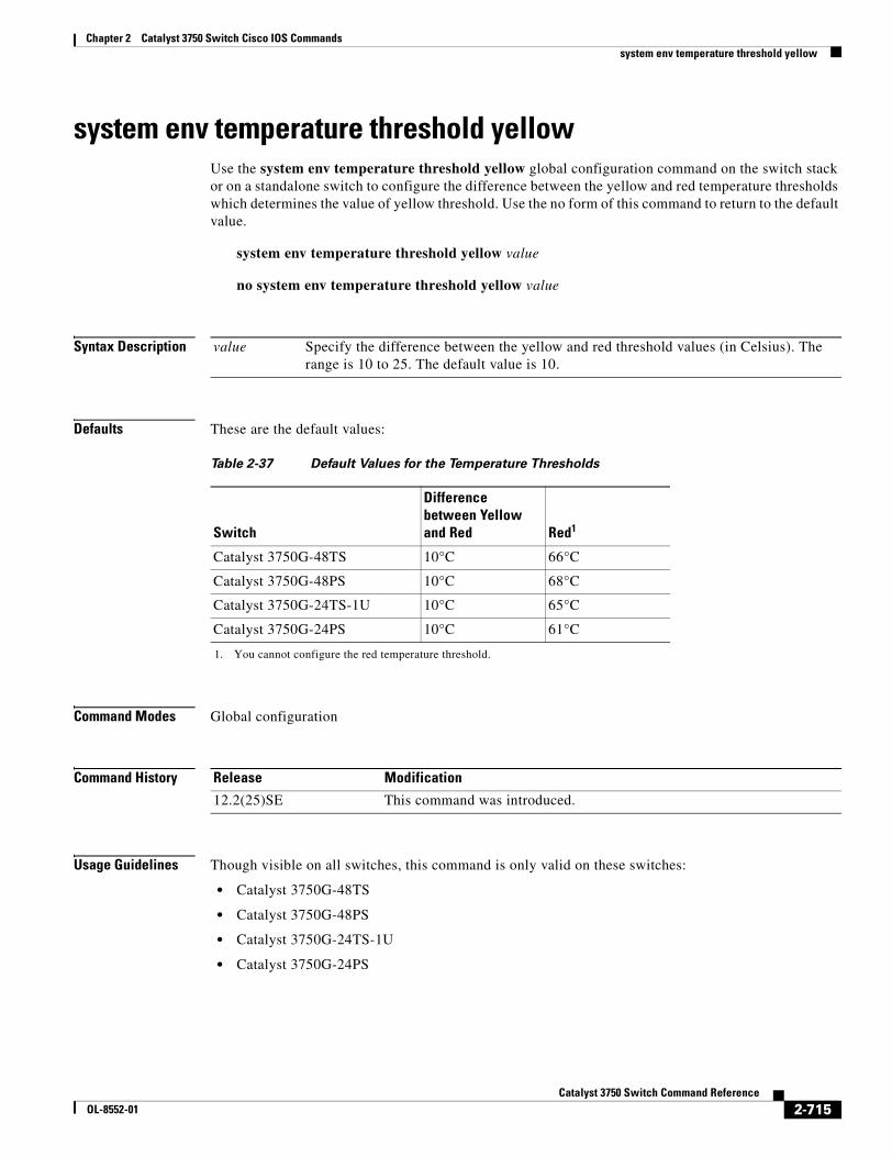
Chapter 2 Catalyst 3750 Switch Cisco IOS Commandssystem env temperature threshold yellow
system env temperature threshold yellowUse the system env temperature threshold yellow global configuration command on the switch stack or on a standalone switch to configure the difference between the yellow and red temperature thresholds which determines the value of yellow threshold. Use the no form of this command to return to the default value.
system env temperature threshold yellow value
no system env temperature threshold yellow value
Syntax Description
Defaults These are the default values:
Command Modes Global configuration
Command History
Usage Guidelines Though visible on all switches, this command is only valid on these switches:
• Catalyst 3750G-48TS
• Catalyst 3750G-48PS
• Catalyst 3750G-24TS-1U
• Catalyst 3750G-24PS
value Specify the difference between the yellow and red threshold values (in Celsius). The range is 10 to 25. The default value is 10.
Table 2-37 Default Values for the Temperature Thresholds
Switch
Difference between Yellow and Red Red1
1. You cannot configure the red temperature threshold.
Catalyst 3750G-48TS 10°C 66°C
Catalyst 3750G-48PS 10°C 68°C
Catalyst 3750G-24TS-1U 10°C 65°C
Catalyst 3750G-24PS 10°C 61°C
Release Modification
12.2(25)SE This command was introduced.
2-715Catalyst 3750 Switch Command Reference
OL-8552-01
Chapter 2 Catalyst 3750 Switch Cisco IOS Commandssystem env temperature threshold yellow
You cannot configure the green and red thresholds but can configure the yellow threshold. Use the system env temperature threshold yellow value global configuration command to specify the difference between the yellow and red thresholds and to configure the yellow threshold. For example, if the red threshold is 66 degrees C and you want to configure the yellow threshold as 51 degrees C, set the difference between the thresholds as 15 by using the system env temperature threshold yellow 15 command.
Note The internal temperature sensor in the switch measures the internal system temperature and might vary ±5 degrees C.
Examples This example sets 15 as the difference between the yellow and red thresholds:
Switch(config)# system env temperature threshold yellow 15Switch(config)#
Related Commands Command Description
show env temperature status Displays the temperature status and threshold levels.
2-716Catalyst 3750 Switch Command Reference
OL-8552-01
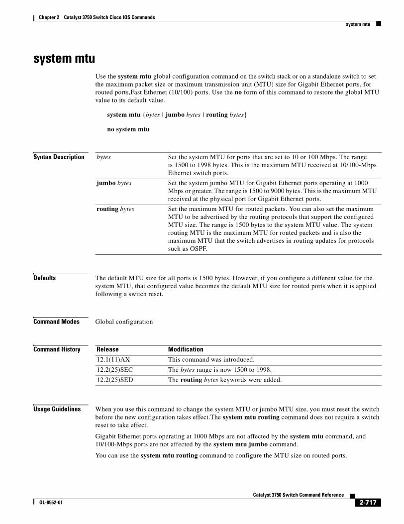
Chapter 2 Catalyst 3750 Switch Cisco IOS Commandssystem mtu
system mtuUse the system mtu global configuration command on the switch stack or on a standalone switch to set the maximum packet size or maximum transmission unit (MTU) size for Gigabit Ethernet ports, for routed ports,Fast Ethernet (10/100) ports. Use the no form of this command to restore the global MTU value to its default value.
system mtu {bytes | jumbo bytes | routing bytes}
no system mtu
Syntax Description
Defaults The default MTU size for all ports is 1500 bytes. However, if you configure a different value for the system MTU, that configured value becomes the default MTU size for routed ports when it is applied following a switch reset.
Command Modes Global configuration
Command History
Usage Guidelines When you use this command to change the system MTU or jumbo MTU size, you must reset the switch before the new configuration takes effect.The system mtu routing command does not require a switch reset to take effect.
Gigabit Ethernet ports operating at 1000 Mbps are not affected by the system mtu command, and 10/100-Mbps ports are not affected by the system mtu jumbo command.
You can use the system mtu routing command to configure the MTU size on routed ports.
bytes Set the system MTU for ports that are set to 10 or 100 Mbps. The range is 1500 to 1998 bytes. This is the maximum MTU received at 10/100-Mbps Ethernet switch ports.
jumbo bytes Set the system jumbo MTU for Gigabit Ethernet ports operating at 1000 Mbps or greater. The range is 1500 to 9000 bytes. This is the maximum MTU received at the physical port for Gigabit Ethernet ports.
routing bytes Set the maximum MTU for routed packets. You can also set the maximum MTU to be advertised by the routing protocols that support the configured MTU size. The range is 1500 bytes to the system MTU value. The system routing MTU is the maximum MTU for routed packets and is also the maximum MTU that the switch advertises in routing updates for protocols such as OSPF.
Release Modification
12.1(11)AX This command was introduced.
12.2(25)SEC The bytes range is now 1500 to 1998.
12.2(25)SED The routing bytes keywords were added.
2-717Catalyst 3750 Switch Command Reference
OL-8552-01
Chapter 2 Catalyst 3750 Switch Cisco IOS Commandssystem mtu
Note You cannot configure a routing MTU size that exceeds the system MTU size. If you change the system MTU size to a value smaller than the currently configured routing MTU size, the configuration change is accepted, but not applied until the next switch reset. When the configuration change takes effect, the routing MTU size defaults to the new system MTU size.
If you enter a value that is outside the range for the specific type of switch, the value is not accepted.
Note The switch does not support setting the MTU on a per-interface basis.
The size of frames that can be received by the switch CPU is limited to 1998 bytes, regardless of the value entered with the system mtu command. Although forwarded or routed frames are usually not received by the CPU, some packets (for example, control traffic, SNMP, Telnet, and routing protocols) are sent to the CPU.
Because the switch does not fragment packets, it drops:
• switched packets larger than the packet size supported on the egress interface
• routed packets larger than the routing MTU value
For example, if the system mtu value is 1998 bytes and the system mtu jumbo value is 5000 bytes, packets up to 5000 bytes can be received on interfaces operating at 1000 Mbps. However, although a packet larger than 1998 bytes can be received on an interface operating at 1000 Mbps, if its destination interface is operating at 10 or 100 Mbps, the packet is dropped.
Examples This example shows how to set the maximum jumbo packet size for Gigabit Ethernet ports operating at 1000 Mbps or greater to 1800 bytes:
Switch(config)# system mtu jumbo 1800Switch(config)# exitSwitch# reload
You can verify your setting by entering the show system mtu privileged EXEC command.
Related Commands Command Description
show system mtu Displays the packet size set for Fast Ethernet, Gigabit Ethernet, and routed ports.
2-718Catalyst 3750 Switch Command Reference
OL-8552-01
Chapter 2 Catalyst 3750 Switch Cisco IOS Commandstest cable-diagnostics tdr
test cable-diagnostics tdrUse the test cable-diagnostics tdr privileged EXEC command on the switch stack or on a standalone switch to run the Time Domain Reflector (TDR) feature on an interface.
test cable-diagnostics tdr interface interface-id
Syntax Description
Defaults There is no default.
Command Modes Privileged EXEC
Command History
Usage Guidelines TDR is supported only on 10/100/100 copper Ethernet ports. It is not supported on 10/100 ports, 10-Gigabit module ports, or on SFP module ports. For more information about TDR, see the software configuration guide for this release.
After you run TDR by using the test cable-diagnostics tdr interface interface-id command, use the show cable-diagnostics tdr interface interface-id privileged EXEC command to display the results.
Examples This example shows how to run TDR on an interface:
Switch# test cable-diagnostics tdr interface gigabitethernet1/0/2TDR test started on interface Gi1/0/2A TDR test can take a few seconds to run on an interfaceUse 'show cable-diagnostics tdr' to read the TDR results.
If you enter the test cable-diagnostics tdr interface interface-id command on an interface that has a link status of up and a speed of 10 or 100 Mbps, these messages appear:
Switch# test cable-diagnostics tdr interface gigabitethernet1/0/3TDR test on Gi1/0/9 will affect link state and trafficTDR test started on interface Gi1/0/3A TDR test can take a few seconds to run on an interfaceUse 'show cable-diagnostics tdr' to read the TDR results.
Related Commands
interface-id Specify the interface on which to run TDR.
Release Modification
12.1(19)EA1 This command was introduced.
Command Description
show cable-diagnostics tdr Displays the TDR results.
2-719Catalyst 3750 Switch Command Reference
OL-8552-01
Chapter 2 Catalyst 3750 Switch Cisco IOS Commandstraceroute mac
traceroute macUse the traceroute mac privileged EXEC command on the switch stack or on a standalone switch to display the Layer 2 path taken by the packets from the specified source MAC address to the specified destination MAC address.
traceroute mac [interface interface-id] {source-mac-address} [interface interface-id] {destination-mac-address} [vlan vlan-id] [detail]
Syntax Description
Defaults There is no default.
Command Modes Privileged EXEC
Command History
Usage Guidelines For Layer 2 traceroute to function properly, Cisco Discovery Protocol (CDP) must be enabled on all the switches in the network. Do not disable CDP.
When the switch detects a device in the Layer 2 path that does not support Layer 2 traceroute, the switch continues to send Layer 2 trace queries and lets them time out.
The maximum number of hops identified in the path is ten.
Layer 2 traceroute supports only unicast traffic. If you specify a multicast source or destination MAC address, the physical path is not identified, and an error message appears.
The traceroute mac command output shows the Layer 2 path when the specified source and destination addresses belong to the same VLAN. If you specify source and destination addresses that belong to different VLANs, the Layer 2 path is not identified, and an error message appears.
If the source or destination MAC address belongs to multiple VLANs, you must specify the VLAN to which both the source and destination MAC addresses belong. If the VLAN is not specified, the path is not identified, and an error message appears.
interface interface-id (Optional) Specify an interface on the source or destination switch.
source-mac-address Specify the MAC address of the source switch in hexadecimal format.
destination-mac-address Specify the MAC address of the destination switch in hexadecimal format.
vlan vlan-id (Optional) Specify the VLAN on which to trace the Layer 2 path that the packets take from the source switch to the destination switch. Valid VLAN IDs are 1 to 4094.
detail (Optional) Specify that detailed information appears.
Release Modification
12.1(14)EA1 This command was introduced.
2-720Catalyst 3750 Switch Command Reference
OL-8552-01
Chapter 2 Catalyst 3750 Switch Cisco IOS Commandstraceroute mac
The Layer 2 traceroute feature is not supported when multiple devices are attached to one port through hubs (for example, multiple CDP neighbors are detected on a port). When more than one CDP neighbor is detected on a port, the Layer 2 path is not identified, and an error message appears.
This feature is not supported in Token Ring VLANs.
Examples This example shows how to display the Layer 2 path by specifying the source and destination MAC addresses:
Switch# traceroute mac 0000.0201.0601 0000.0201.0201Source 0000.0201.0601 found on con6[WS-C3750-12T] (2.2.6.6)con6 (2.2.6.6) :Gi0/0/1 => Gi0/0/3con5 (2.2.5.5 ) : Gi0/0/3 => Gi0/0/1con1 (2.2.1.1 ) : Gi0/0/1 => Gi0/0/2con2 (2.2.2.2 ) : Gi0/0/2 => Gi0/0/1Destination 0000.0201.0201 found on con2[WS-C3550-24] (2.2.2.2)Layer 2 trace completed
This example shows how to display the Layer 2 path by using the detail keyword:
Switch# traceroute mac 0000.0201.0601 0000.0201.0201 detailSource 0000.0201.0601 found on con6[WS-C3750-12T] (2.2.6.6)con6 / WS-C3750-12T / 2.2.6.6 : Gi0/0/2 [auto, auto] => Gi0/0/3 [auto, auto]con5 / WS-C2950G-24-EI / 2.2.5.5 : Fa0/3 [auto, auto] => Gi0/1 [auto, auto]con1 / WS-C3550-12G / 2.2.1.1 : Gi0/1 [auto, auto] => Gi0/2 [auto, auto]con2 / WS-C3550-24 / 2.2.2.2 : Gi0/2 [auto, auto] => Fa0/1 [auto, auto]Destination 0000.0201.0201 found on con2[WS-C3550-24] (2.2.2.2)Layer 2 trace completed.
This example shows how to display the Layer 2 path by specifying the interfaces on the source and destination switches:
Switch# traceroute mac interface fastethernet0/1 0000.0201.0601 interface fastethernet0/3 0000.0201.0201Source 0000.0201.0601 found on con6[WS-C3750-12T] (2.2.6.6)con6 (2.2.6.6) :Gi0/0/1 => Gi0/0/3con5 (2.2.5.5 ) : Gi0/0/3 => Gi0/0/1con1 (2.2.1.1 ) : Gi0/0/1 => Gi0/0/2con2 (2.2.2.2 ) : Gi0/0/2 => Gi0/0/1Destination 0000.0201.0201 found on con2[WS-C3550-24] (2.2.2.2)Layer 2 trace completed
This example shows the Layer 2 path when the switch is not connected to the source switch:
Switch# traceroute mac 0000.0201.0501 0000.0201.0201 detailSource not directly connected, tracing source .....Source 0000.0201.0501 found on con5[WS-C3750-12T] (2.2.5.5)con5 / WS-C3750-12T / 2.2.5.5 : Gi0/0/1 [auto, auto] => Gi0/0/3 [auto, auto]con1 / WS-C3550-12G / 2.2.1.1 : Gi0/1 [auto, auto] => Gi0/2 [auto, auto]con2 / WS-C3550-24 / 2.2.2.2 : Gi0/2 [auto, auto] => Fa0/1 [auto, auto]Destination 0000.0201.0201 found on con2[WS-C3550-24] (2.2.2.2)Layer 2 trace completed.
2-721Catalyst 3750 Switch Command Reference
OL-8552-01
Chapter 2 Catalyst 3750 Switch Cisco IOS Commandstraceroute mac
This example shows the Layer 2 path when the switch cannot find the destination port for the source MAC address:
Switch# traceroute mac 0000.0011.1111 0000.0201.0201Error:Source Mac address not found. Layer2 trace aborted.
This example shows the Layer 2 path when the source and destination devices are in different VLANs:
Switch# traceroute mac 0000.0201.0601 0000.0301.0201Error:Source and destination macs are on different vlans. Layer2 trace aborted.
This example shows the Layer 2 path when the destination MAC address is a multicast address:
Switch# traceroute mac 0000.0201.0601 0100.0201.0201Invalid destination mac address
This example shows the Layer 2 path when source and destination switches belong to multiple VLANs:
Switch# traceroute mac 0000.0201.0601 0000.0201.0201Error:Mac found on multiple vlans.Layer2 trace aborted.
Related Commands Command Description
traceroute mac ip Displays the Layer 2 path taken by the packets from the specified source IP address or hostname to the specified destination IP address or hostname.
2-722Catalyst 3750 Switch Command Reference
OL-8552-01
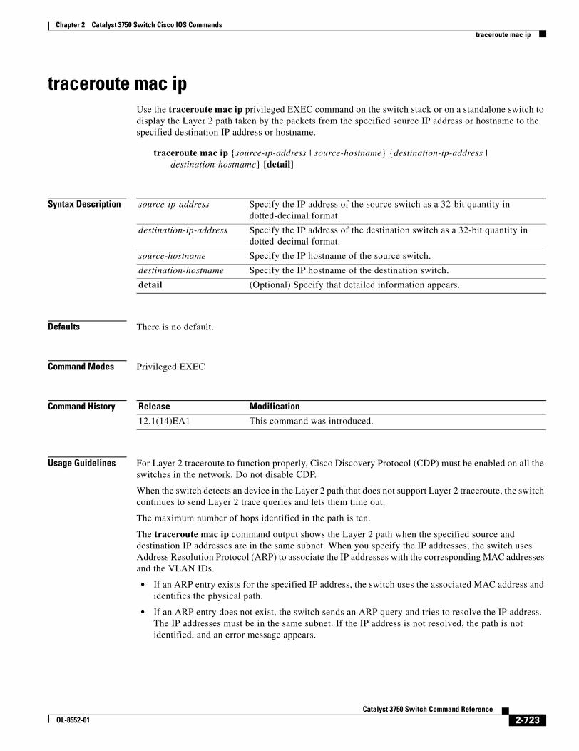
Chapter 2 Catalyst 3750 Switch Cisco IOS Commandstraceroute mac ip
traceroute mac ipUse the traceroute mac ip privileged EXEC command on the switch stack or on a standalone switch to display the Layer 2 path taken by the packets from the specified source IP address or hostname to the specified destination IP address or hostname.
traceroute mac ip {source-ip-address | source-hostname} {destination-ip-address | destination-hostname} [detail]
Syntax Description
Defaults There is no default.
Command Modes Privileged EXEC
Command History
Usage Guidelines For Layer 2 traceroute to function properly, Cisco Discovery Protocol (CDP) must be enabled on all the switches in the network. Do not disable CDP.
When the switch detects an device in the Layer 2 path that does not support Layer 2 traceroute, the switch continues to send Layer 2 trace queries and lets them time out.
The maximum number of hops identified in the path is ten.
The traceroute mac ip command output shows the Layer 2 path when the specified source and destination IP addresses are in the same subnet. When you specify the IP addresses, the switch uses Address Resolution Protocol (ARP) to associate the IP addresses with the corresponding MAC addresses and the VLAN IDs.
• If an ARP entry exists for the specified IP address, the switch uses the associated MAC address and identifies the physical path.
• If an ARP entry does not exist, the switch sends an ARP query and tries to resolve the IP address. The IP addresses must be in the same subnet. If the IP address is not resolved, the path is not identified, and an error message appears.
source-ip-address Specify the IP address of the source switch as a 32-bit quantity in dotted-decimal format.
destination-ip-address Specify the IP address of the destination switch as a 32-bit quantity in dotted-decimal format.
source-hostname Specify the IP hostname of the source switch.
destination-hostname Specify the IP hostname of the destination switch.
detail (Optional) Specify that detailed information appears.
Release Modification
12.1(14)EA1 This command was introduced.
2-723Catalyst 3750 Switch Command Reference
OL-8552-01
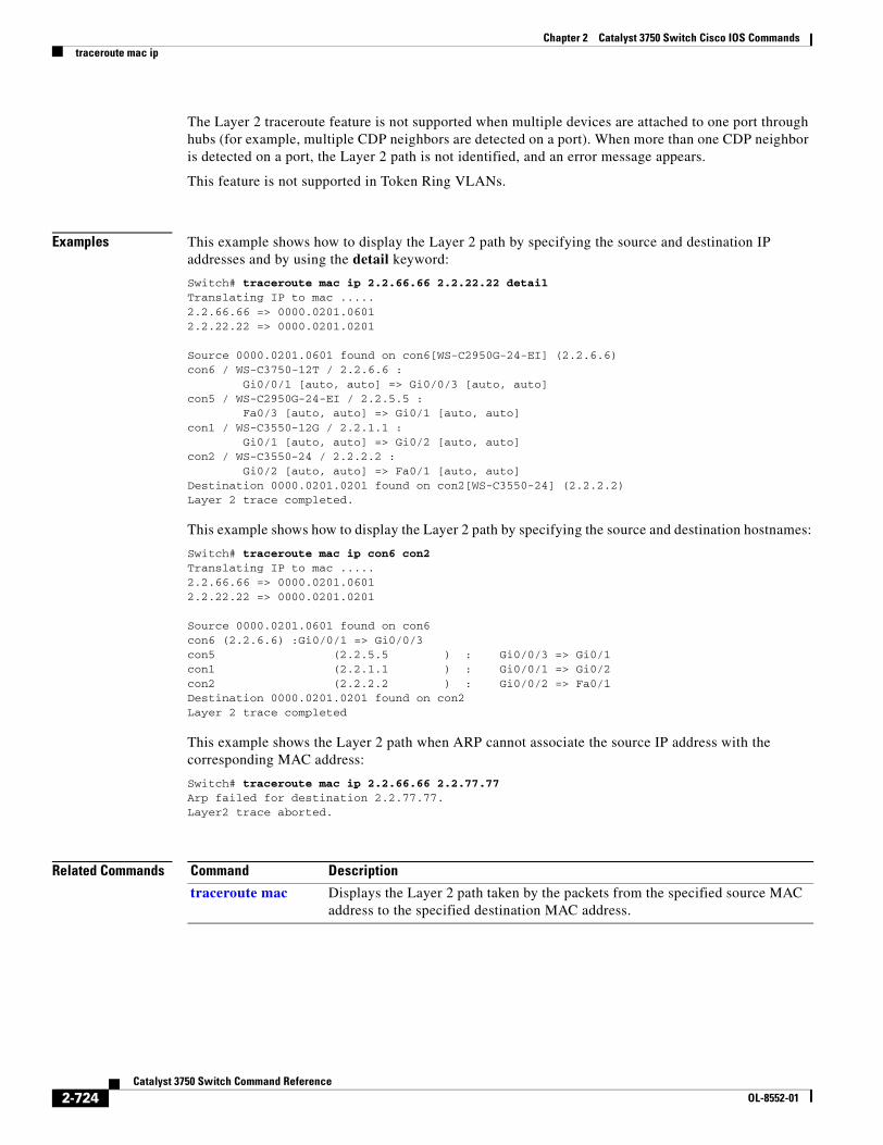
Chapter 2 Catalyst 3750 Switch Cisco IOS Commandstraceroute mac ip
The Layer 2 traceroute feature is not supported when multiple devices are attached to one port through hubs (for example, multiple CDP neighbors are detected on a port). When more than one CDP neighbor is detected on a port, the Layer 2 path is not identified, and an error message appears.
This feature is not supported in Token Ring VLANs.
Examples This example shows how to display the Layer 2 path by specifying the source and destination IP addresses and by using the detail keyword:
Switch# traceroute mac ip 2.2.66.66 2.2.22.22 detailTranslating IP to mac ..... 2.2.66.66 => 0000.0201.06012.2.22.22 => 0000.0201.0201
Source 0000.0201.0601 found on con6[WS-C2950G-24-EI] (2.2.6.6)con6 / WS-C3750-12T / 2.2.6.6 : Gi0/0/1 [auto, auto] => Gi0/0/3 [auto, auto]con5 / WS-C2950G-24-EI / 2.2.5.5 : Fa0/3 [auto, auto] => Gi0/1 [auto, auto]con1 / WS-C3550-12G / 2.2.1.1 : Gi0/1 [auto, auto] => Gi0/2 [auto, auto]con2 / WS-C3550-24 / 2.2.2.2 : Gi0/2 [auto, auto] => Fa0/1 [auto, auto]Destination 0000.0201.0201 found on con2[WS-C3550-24] (2.2.2.2)Layer 2 trace completed.
This example shows how to display the Layer 2 path by specifying the source and destination hostnames:
Switch# traceroute mac ip con6 con2Translating IP to mac ..... 2.2.66.66 => 0000.0201.06012.2.22.22 => 0000.0201.0201
Source 0000.0201.0601 found on con6con6 (2.2.6.6) :Gi0/0/1 => Gi0/0/3con5 (2.2.5.5 ) : Gi0/0/3 => Gi0/1con1 (2.2.1.1 ) : Gi0/0/1 => Gi0/2con2 (2.2.2.2 ) : Gi0/0/2 => Fa0/1Destination 0000.0201.0201 found on con2Layer 2 trace completed
This example shows the Layer 2 path when ARP cannot associate the source IP address with the corresponding MAC address:
Switch# traceroute mac ip 2.2.66.66 2.2.77.77Arp failed for destination 2.2.77.77.Layer2 trace aborted.
Related Commands Command Description
traceroute mac Displays the Layer 2 path taken by the packets from the specified source MAC address to the specified destination MAC address.
2-724Catalyst 3750 Switch Command Reference
OL-8552-01
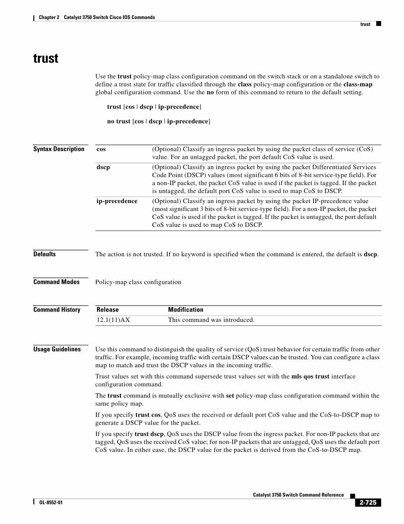
Chapter 2 Catalyst 3750 Switch Cisco IOS Commandstrust
trustUse the trust policy-map class configuration command on the switch stack or on a standalone switch to define a trust state for traffic classified through the class policy-map configuration or the class-map global configuration command. Use the no form of this command to return to the default setting.
trust [cos | dscp | ip-precedence]
no trust [cos | dscp | ip-precedence]
Syntax Description
Defaults The action is not trusted. If no keyword is specified when the command is entered, the default is dscp.
Command Modes Policy-map class configuration
Command History
Usage Guidelines Use this command to distinguish the quality of service (QoS) trust behavior for certain traffic from other traffic. For example, incoming traffic with certain DSCP values can be trusted. You can configure a class map to match and trust the DSCP values in the incoming traffic.
Trust values set with this command supersede trust values set with the mls qos trust interface configuration command.
The trust command is mutually exclusive with set policy-map class configuration command within the same policy map.
If you specify trust cos, QoS uses the received or default port CoS value and the CoS-to-DSCP map to generate a DSCP value for the packet.
If you specify trust dscp, QoS uses the DSCP value from the ingress packet. For non-IP packets that are tagged, QoS uses the received CoS value; for non-IP packets that are untagged, QoS uses the default port CoS value. In either case, the DSCP value for the packet is derived from the CoS-to-DSCP map.
cos (Optional) Classify an ingress packet by using the packet class of service (CoS) value. For an untagged packet, the port default CoS value is used.
dscp (Optional) Classify an ingress packet by using the packet Differentiated Services Code Point (DSCP) values (most significant 6 bits of 8-bit service-type field). For a non-IP packet, the packet CoS value is used if the packet is tagged. If the packet is untagged, the default port CoS value is used to map CoS to DSCP.
ip-precedence (Optional) Classify an ingress packet by using the packet IP-precedence value (most significant 3 bits of 8-bit service-type field). For a non-IP packet, the packet CoS value is used if the packet is tagged. If the packet is untagged, the port default CoS value is used to map CoS to DSCP.
Release Modification
12.1(11)AX This command was introduced.
2-725Catalyst 3750 Switch Command Reference
OL-8552-01
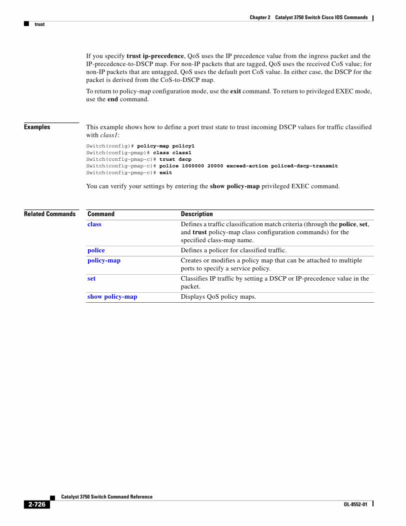
Chapter 2 Catalyst 3750 Switch Cisco IOS Commandstrust
If you specify trust ip-precedence, QoS uses the IP precedence value from the ingress packet and the IP-precedence-to-DSCP map. For non-IP packets that are tagged, QoS uses the received CoS value; for non-IP packets that are untagged, QoS uses the default port CoS value. In either case, the DSCP for the packet is derived from the CoS-to-DSCP map.
To return to policy-map configuration mode, use the exit command. To return to privileged EXEC mode, use the end command.
Examples This example shows how to define a port trust state to trust incoming DSCP values for traffic classified with class1:
Switch(config)# policy-map policy1Switch(config-pmap)# class class1Switch(config-pmap-c)# trust dscpSwitch(config-pmap-c)# police 1000000 20000 exceed-action policed-dscp-transmitSwitch(config-pmap-c)# exit
You can verify your settings by entering the show policy-map privileged EXEC command.
Related Commands Command Description
class Defines a traffic classification match criteria (through the police, set, and trust policy-map class configuration commands) for the specified class-map name.
police Defines a policer for classified traffic.
policy-map Creates or modifies a policy map that can be attached to multiple ports to specify a service policy.
set Classifies IP traffic by setting a DSCP or IP-precedence value in the packet.
show policy-map Displays QoS policy maps.
2-726Catalyst 3750 Switch Command Reference
OL-8552-01
Chapter 2 Catalyst 3750 Switch Cisco IOS Commandsudld
udld Use the udld global configuration command on the switch stack or on a standalone switch to enable aggressive or normal mode in the UniDirectional Link Detection (UDLD) and to set the configurable message timer time. Use the no form of the command to disable aggressive or normal mode UDLD on all fiber-optic ports.
udld {aggressive | enable | message time message-timer-interval}
no udld {aggressive | enable | message}
Syntax Description
Defaults UDLD is disabled on all interfaces.
The message timer is set at 60 seconds.
Command Modes Global configuration
Command History
Usage Guidelines UDLD supports two modes of operation: normal (the default) and aggressive. In normal mode, UDLD detects unidirectional links due to misconnected interfaces on fiber-optic connections. In aggressive mode, UDLD also detects unidirectional links due to one-way traffic on fiber-optic and twisted-pair links and due to misconnected interfaces on fiber-optic links. For information about normal and aggressive modes, see the “Understanding UDLD” section in the software configuration guide for this release.
If you change the message time between probe packets, you are making a trade-off between the detection speed and the CPU load. By decreasing the time, you can make the detection-response faster but increase the load on the CPU.
This command affects fiber-optic interfaces only. Use the udld interface configuration command to enable UDLD on other interface types.
aggressive Enable UDLD in aggressive mode on all fiber-optic interfaces.
enable Enable UDLD in normal mode on all fiber-optic interfaces.
message time message-timer-interval
Configure the period of time between UDLD probe messages on ports that are in the advertisement phase and are determined to be bidirectional. The range is 1 to 90 seconds.
Release Modification
12.1(11)AX This command was introduced.
12.2(25)SEC The range for the message-timer-interval was changed from 7 to 90 seconds to 1 to 90 seconds.
2-727Catalyst 3750 Switch Command Reference
OL-8552-01
Chapter 2 Catalyst 3750 Switch Cisco IOS Commandsudld
You can use these commands to reset an interface shut down by UDLD:
• The udld reset privileged EXEC command to reset all interfaces shut down by UDLD
• The shutdown and no shutdown interface configuration commands
• The no udld enable global configuration command followed by the udld {aggressive | enable} global configuration command to re-enable UDLD globally
• The no udld port interface configuration command followed by the udld port or udld port aggressive interface configuration command to re-enable UDLD on the specified interface
• The errdisable recovery cause udld and errdisable recovery interval interval global configuration commands to automatically recover from the UDLD error-disabled state
Examples This example shows how to enable UDLD on all fiber-optic interfaces:
Switch(config)# udld enable
You can verify your setting by entering the show udld privileged EXEC command.
Related Commands Command Description
show udld Displays UDLD administrative and operational status for all ports or the specified port.
udld port Enables UDLD on an individual interface or prevents a fiber-optic interface from being enabled by the udld global configuration command.
udld reset Resets all interfaces shut down by UDLD and permits traffic to again pass through.
2-728Catalyst 3750 Switch Command Reference
OL-8552-01

Chapter 2 Catalyst 3750 Switch Cisco IOS Commandsudld port
udld portUse the udld port interface configuration command on the switch stack or on a standalone switch to enable the UniDirectional Link Detection (UDLD) on an individual interface or prevent a fiber-optic interface from being enabled by the udld global configuration command. Use the no form of this command to return to the udld global configuration command setting or to disable UDLD if entered for a nonfiber-optic port.
udld port [aggressive]
no udld port [aggressive]
Syntax Description
Defaults On fiber-optic interfaces, UDLD is not enabled, not in aggressive mode, and not disabled. For this reason, fiber-optic interfaces enable UDLD according to the state of the udld enable or udld aggressive global configuration command.
On nonfiber-optic interfaces, UDLD is disabled.
Command Modes Interface configuration
Command History
Usage Guidelines A UDLD-capable port cannot detect a unidirectional link if it is connected to a UDLD-incapable port of another switch.
UDLD supports two modes of operation: normal (the default) and aggressive. In normal mode, UDLD detects unidirectional links due to misconnected interfaces on fiber-optic connections. In aggressive mode, UDLD also detects unidirectional links due to one-way traffic on fiber-optic and twisted-pair links and due to misconnected interfaces on fiber-optic links. For information about normal and aggressive modes, see the “Configuring UDLD” chapter in the software configuration guide for this release.
To enable UDLD in normal mode, use the udld port interface configuration command. To enable UDLD in aggressive mode, use the udld port aggressive interface configuration command.
Use the no udld port command on fiber-optic ports to return control of UDLD to the udld enable global configuration command or to disable UDLD on nonfiber-optic ports.
Use the udld port aggressive command on fiber-optic ports to override the setting of the udld enable or udld aggressive global configuration command. Use the no form on fiber-optic ports to remove this setting and to return control of UDLD enabling to the udld global configuration command or to disable UDLD on nonfiber-optic ports.
aggressive Enable UDLD in aggressive mode on the specified interface.
Release Modification
12.1(11)AX This command was introduced.
12.2(20)SE The disable keyword was removed.
2-729Catalyst 3750 Switch Command Reference
OL-8552-01
Chapter 2 Catalyst 3750 Switch Cisco IOS Commandsudld port
You can use these commands to reset an interface shut down by UDLD:
• The udld reset privileged EXEC command to reset all interfaces shut down by UDLD
• The shutdown and no shutdown interface configuration commands
• The no udld enable global configuration command followed by the udld {aggressive | enable} global configuration command to re-enable UDLD globally
• The no udld port interface configuration command followed by the udld port or udld port aggressive interface configuration command to re-enable UDLD on the specified interface
• The errdisable recovery cause udld and errdisable recovery interval interval global configuration commands to automatically recover from the UDLD error-disabled state
Examples This example shows how to enable UDLD on an port:
Switch(config)# interface gigabitethernet6/0/1Switch(config-if)# udld port
This example shows how to disable UDLD on a fiber-optic interface despite the setting of the udld global configuration command:
Switch(config)# interface gigabitethernet6/0/1Switch(config-if)# no udld port
You can verify your settings by entering the show running-config or the show udld interface privileged EXEC command.
Related Commands Command Description
show running-config Displays the running configuration on the switch. For syntax information, select Cisco IOS Configuration Fundamentals Command Reference, Release 12.2 > File Management Commands > Configuration File Management Commands.
show udld Displays UDLD administrative and operational status for all ports or the specified port.
udld Enables aggressive or normal mode in UDLD or sets the configurable message timer time.
udld reset Resets all interfaces shut down by UDLD and permits traffic to again pass through.
2-730Catalyst 3750 Switch Command Reference
OL-8552-01
Chapter 2 Catalyst 3750 Switch Cisco IOS Commandsudld reset
udld resetUse the udld reset privileged EXEC command to reset all interfaces disabled by the UniDirectional Link Detection (UDLD) and permit traffic to begin passing through them again (though other features, such as spanning tree, Port Aggregation Protocol (PAgP), and Dynamic Trunking Protocol (DTP) still have their normal effects, if enabled).
udld reset
Syntax Description This command has no arguments or keywords.
Command Modes Privileged EXEC
Command History
Usage Guidelines If the interface configuration is still enabled for UDLD, these ports begin to run UDLD again and are disabled for the same reason if the problem has not been corrected.
Examples This example shows how to reset all interfaces disabled by UDLD:
Switch# udld reset1 ports shutdown by UDLD were reset.
You can verify your setting by entering the show udld privileged EXEC command.
Related Commands
Release Modification
12.1(11)AX This command was introduced.
Command Description
show running-config Displays the running configuration on the switch. For syntax information, select Cisco IOS Configuration Fundamentals Command Reference, Release 12.2 > File Management Commands > Configuration File Management Commands.
show udld Displays UDLD administrative and operational status for all ports or the specified port.
udld Enables aggressive or normal mode in UDLD or sets the configurable message timer time.
udld port Enables UDLD on an individual interface or prevents a fiber-optic interface from being enabled by the udld global configuration command.
2-731Catalyst 3750 Switch Command Reference
OL-8552-01
Chapter 2 Catalyst 3750 Switch Cisco IOS Commandsvlan (global configuration)
vlan (global configuration)Use the vlan global configuration command on the switch stack or on a standalone switch to add a VLAN and to enter the config-vlan mode. Use the no form of this command to delete the VLAN. Configuration information for normal-range VLANs (VLAN IDs 1 to 1005) is always saved in the VLAN database. When VLAN Trunking Protocol (VTP) mode is transparent, you can create extended-range VLANs (VLAN IDs greater than 1005), and the VTP mode, domain name, and the VLAN configuration are saved in the switch running configuration file. You can save configurations in the switch startup configuration file by entering the copy running-config startup-config privileged EXEC command.
vlan vlan-id
no vlan vlan-id
Syntax Description
Defaults This command has no default settings.
Command Modes Global configuration
Command History
Usage Guidelines You must use the vlan vlan-id global configuration command to add extended-range VLANs (VLAN IDs 1006 to 4094). Before configuring VLANs in the extended range, you must use the vtp transparent global configuration or VLAN configuration command to put the switch in VTP transparent mode. Extended-range VLANs are not learned by VTP and are not added to the VLAN database, but when VTP mode is transparent, VTP mode and domain name and all VLAN configurations are saved in the running configuration, and you can save them in the switch startup configuration file.
When you save the VLAN and VTP configurations in the startup configuration file and reboot the switch, the configuration is selected in these ways:
• If both the VLAN database and the configuration file show the VTP mode as transparent and the VTP domain names match, the VLAN database is ignored. The VTP and VLAN configurations in the startup configuration file are used. The VLAN database revision number remains unchanged in the VLAN database.
• If the VTP mode is server, or if the startup VTP mode or domain names do not match the VLAN database, the VTP mode and the VLAN configuration for the first 1005 VLANs use the VLAN database information.
If you try to create an extended-range VLAN when the switch is not in VTP transparent mode, the VLAN is rejected, and you receive an error message.
vlan-id ID of the VLAN to be added and configured. For vlan-id, the range is 1 to 4094. You can enter a single VLAN ID, a series of VLAN IDs separated by commas, or a range of VLAN IDs separated by hyphens.
Release Modification
12.1(11)AX This command was introduced.
2-732Catalyst 3750 Switch Command Reference
OL-8552-01
Chapter 2 Catalyst 3750 Switch Cisco IOS Commandsvlan (global configuration)
If you enter an invalid VLAN ID, you receive an error message and do not enter config-vlan mode.
Entering the vlan command with a VLAN ID enables config-vlan mode. When you enter the VLAN ID of an existing VLAN, you do not create a new VLAN, but you can modify VLAN parameters for that VLAN. The specified VLANs are added or modified when you exit the config-vlan mode. Only the shutdown command (for VLANs 1 to 1005) takes effect immediately.
These configuration commands are available in config-vlan mode. The no form of each command returns the characteristic to its default state.
Note Although all commands are visible, the only VLAN configuration commands that are supported on extended-range VLANs are mtu mtu-size, private-vlan, and remote-span. For extended-range VLANs, all other characteristics must remain at the default state.
• are are-number: defines the maximum number of all-routes explorer (ARE) hops for this VLAN. This keyword applies only to TrCRF VLANs.The range is 0 to 13. The default is 7. If no value is entered, 0 is assumed to be the maximum.
• backupcrf: specifies the backup CRF mode. This keyword applies only to TrCRF VLANs.
– enable backup CRF mode for this VLAN.
– disable backup CRF mode for this VLAN (the default).
• bridge {bridge-number| type}: specifies the logical distributed source-routing bridge, the bridge that interconnects all logical rings having this VLAN as a parent VLAN in FDDI-NET, Token Ring-NET, and TrBRF VLANs. The range is 0 to 15. The default bridge number is 0 (no source-routing bridge) for FDDI-NET, TrBRF, and Token Ring-NET VLANs. The type keyword applies only to TrCRF VLANs and is one of these:
– srb (source-route bridging)
– srt (source-route transparent) bridging VLAN
• exit: applies changes, increments the VLAN database revision number (VLANs 1 to 1005 only), and exits config-vlan mode.
• media: defines the VLAN media type. See Table 2-38 for valid commands and syntax for different media types.
Note The switch supports only Ethernet ports. You configure only FDDI and Token Ring media-specific characteristics for VLAN Trunking Protocol (VTP) global advertisements to other switches. These VLANs are locally suspended.
– ethernet is Ethernet media type (the default).
– fddi is FDDI media type.
– fd-net is FDDI network entity title (NET) media type.
– tokenring is Token Ring media type if the VTP v2 mode is disabled, or TrCRF if the VTP Version 2 (v) mode is enabled.
– tr-net is Token Ring network entity title (NET) media type if the VTP v2 mode is disabled or TrBRF media type if the VTP v2 mode is enabled.
• mtu mtu-size: specifies the maximum transmission unit (MTU) (packet size in bytes). The range is 1500 to 18190. The default is 1500 bytes.
2-733Catalyst 3750 Switch Command Reference
OL-8552-01
Chapter 2 Catalyst 3750 Switch Cisco IOS Commandsvlan (global configuration)
• name vlan-name: names the VLAN with an ASCII string from 1 to 32 characters that must be unique within the administrative domain. The default is VLANxxxx where xxxx represents four numeric digits (including leading zeros) equal to the VLAN ID number.
• no: negates a command or returns it to the default setting.
• parent parent-vlan-id: specifies the parent VLAN of an existing FDDI, Token Ring, or TrCRF VLAN. This parameter identifies the TrBRF to which a TrCRF belongs and is required when defining a TrCRF. The range is 0 to 1005. The default parent VLAN ID is 0 (no parent VLAN) for FDDI and Token Ring VLANs. For both Token Ring and TrCRF VLANs, the parent VLAN ID must already exist in the database and be associated with a Token Ring-NET or TrBRF VLAN.
• private-vlan: configure the VLAN as a private VLAN community, isolated, or primary VLAN or configure the association between private-VLAN primary and secondary VLANs. For more information, see the private-vlan command.
• remote-span: configure the VLAN as a Remote SPAN (RSPAN) VLAN. When the RSPAN feature is added to an existing VLAN, the VLAN is first deleted and is then recreated with the RSPAN feature. Any access ports are deactivated until the RSPAN feature is removed. If VTP is enabled, the new RSPAN VLAN is propagated by VTP for VLAN-IDs that are lower than 1024. Learning is disabled on the VLAN. See the remote-span command for more information.
• ring ring-number: defines the logical ring for an FDDI, Token Ring, or TrCRF VLAN. The range is 1 to 4095. The default for Token Ring VLANs is 0. For FDDI VLANs, there is no default.
• said said-value: specifies the security association identifier (SAID) as documented in IEEE 802.10. The range is 1 to 4294967294, and the number must be unique within the administrative domain. The default value is 100000 plus the VLAN ID number.
• shutdown: shuts down VLAN switching on the VLAN. This command takes effect immediately. Other commands take effect when you exit config-vlan mode.
• state: specifies the VLAN state:
– active means the VLAN is operational (the default).
– suspend means the VLAN is suspended. Suspended VLANs do not pass packets.
• ste ste-number: defines the maximum number of spanning-tree explorer (STE) hops. This keyword applies only to TrCRF VLANs. The range is 0 to 13. The default is 7.
• stp type: defines the spanning-tree type for FDDI-NET, Token Ring-NET, or TrBRF VLANs. For FDDI-NET VLANs, the default STP type is ieee. For Token Ring-NET VLANs, the default STP type is ibm. For FDDI and Token Ring VLANs, the default is no type specified.
– ieee for IEEE Ethernet STP running source-route transparent (SRT) bridging.
– ibm for IBM STP running source-route bridging (SRB).
– auto for STP running a combination of source-route transparent bridging (IEEE) and source-route bridging (IBM).
• tb-vlan1 tb-vlan1-id and tb-vlan2 tb-vlan2-id: specifies the first and second VLAN to which this VLAN is translationally bridged. Translational VLANs translate FDDI or Token Ring to Ethernet, for example. The range is 0 to 1005. If no value is specified, 0 (no transitional bridging) is assumed.
2-734Catalyst 3750 Switch Command Reference
OL-8552-01
Chapter 2 Catalyst 3750 Switch Cisco IOS Commandsvlan (global configuration)
Table 2-39 describes the rules for configuring VLANs.
Table 2-38 Valid Commands and Syntax for Different Media Types
Media Type Valid Syntax
Ethernet name vlan-name, media ethernet, state {suspend | active}, said said-value, mtu mtu-size, remote-span, tb-vlan1 tb-vlan1-id, tb-vlan2 tb-vlan2-id
FDDI name vlan-name, media fddi, state {suspend | active}, said said-value, mtu mtu-size, ring ring-number, parent parent-vlan-id, tb-vlan1 tb-vlan1-id, tb-vlan2 tb-vlan2-id
FDDI-NET name vlan-name, media fd-net, state {suspend | active}, said said-value, mtu mtu-size, bridge bridge-number, stp type {ieee | ibm | auto}, tb-vlan1 tb-vlan1-id, tb-vlan2 tb-vlan2-id
If VTP v2 mode is disabled, do not set the stp type to auto.
Token Ring VTP v1 mode is enabled.
name vlan-name, media tokenring, state {suspend | active}, said said-value, mtu mtu-size, ring ring-number, parent parent-vlan-id, tb-vlan1 tb-vlan1-id, tb-vlan2 tb-vlan2-id
Token Ring concentrator relay function (TrCRF)
VTP v2 mode is enabled.
name vlan-name, media tokenring, state {suspend | active}, said said-value, mtu mtu-size, ring ring-number, parent parent-vlan-id, bridge type {srb | srt}, are are-number, ste ste-number, backupcrf {enable | disable}, tb-vlan1 tb-vlan1-id, tb-vlan2 tb-vlan2-id
Token Ring-NET VTP v1 mode is enabled.
name vlan-name, media tr-net, state {suspend | active}, said said-value, mtu mtu-size, bridge bridge-number, stp type {ieee | ibm}, tb-vlan1 tb-vlan1-id, tb-vlan2 tb-vlan2-id
Token Ring bridge relay function (TrBRF)
VTP v2 mode is enabled.
name vlan-name, media tr-net, state {suspend | active}, said said-value, mtu mtu-size, bridge bridge-number, stp type {ieee | ibm | auto}, tb-vlan1 tb-vlan1-id, tb-vlan2 tb-vlan2-id
Table 2-39 VLAN Configuration Rules
Configuration Rule
VTP v2 mode is enabled, and you are configuring a TrCRF VLAN media type.
Specify a parent VLAN ID of a TrBRF that already exists in the database.
Specify a ring number. Do not leave this field blank.
Specify unique ring numbers when TrCRF VLANs have the same parent VLAN ID. Only one backup concentrator relay function (CRF) can be enabled.
VTP v2 mode is enabled, and you are configuring VLANs other than TrCRF media type.
Do not specify a backup CRF.
2-735Catalyst 3750 Switch Command Reference
OL-8552-01
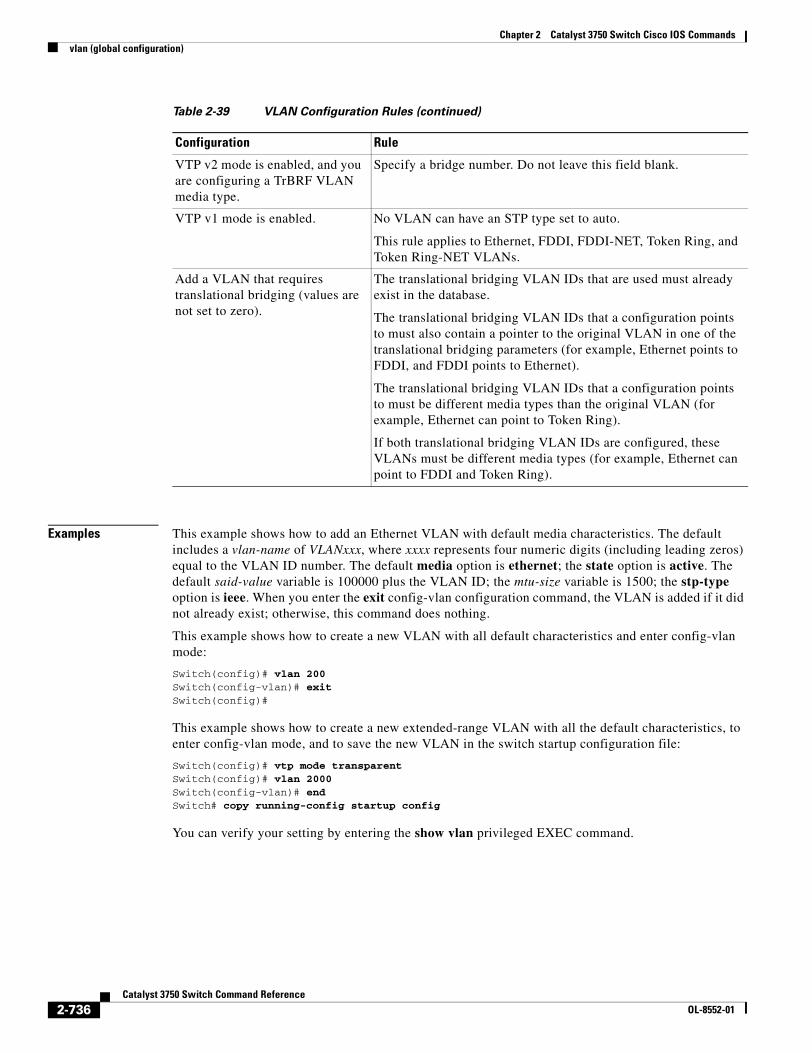
Chapter 2 Catalyst 3750 Switch Cisco IOS Commandsvlan (global configuration)
Examples This example shows how to add an Ethernet VLAN with default media characteristics. The default includes a vlan-name of VLANxxx, where xxxx represents four numeric digits (including leading zeros) equal to the VLAN ID number. The default media option is ethernet; the state option is active. The default said-value variable is 100000 plus the VLAN ID; the mtu-size variable is 1500; the stp-type option is ieee. When you enter the exit config-vlan configuration command, the VLAN is added if it did not already exist; otherwise, this command does nothing.
This example shows how to create a new VLAN with all default characteristics and enter config-vlan mode:
Switch(config)# vlan 200Switch(config-vlan)# exitSwitch(config)#
This example shows how to create a new extended-range VLAN with all the default characteristics, to enter config-vlan mode, and to save the new VLAN in the switch startup configuration file:
Switch(config)# vtp mode transparentSwitch(config)# vlan 2000Switch(config-vlan)# endSwitch# copy running-config startup config
You can verify your setting by entering the show vlan privileged EXEC command.
VTP v2 mode is enabled, and you are configuring a TrBRF VLAN media type.
Specify a bridge number. Do not leave this field blank.
VTP v1 mode is enabled. No VLAN can have an STP type set to auto.
This rule applies to Ethernet, FDDI, FDDI-NET, Token Ring, and Token Ring-NET VLANs.
Add a VLAN that requires translational bridging (values are not set to zero).
The translational bridging VLAN IDs that are used must already exist in the database.
The translational bridging VLAN IDs that a configuration points to must also contain a pointer to the original VLAN in one of the translational bridging parameters (for example, Ethernet points to FDDI, and FDDI points to Ethernet).
The translational bridging VLAN IDs that a configuration points to must be different media types than the original VLAN (for example, Ethernet can point to Token Ring).
If both translational bridging VLAN IDs are configured, these VLANs must be different media types (for example, Ethernet can point to FDDI and Token Ring).
Table 2-39 VLAN Configuration Rules (continued)
Configuration Rule
2-736Catalyst 3750 Switch Command Reference
OL-8552-01
Chapter 2 Catalyst 3750 Switch Cisco IOS Commandsvlan (global configuration)
Related Commands Command Description
show vlan Displays the parameters for all configured VLANs or one VLAN (if the VLAN ID or name is specified) in the administrative domain.
vlan (VLAN configuration)
Configures normal-range VLANs in the VLAN database.
2-737Catalyst 3750 Switch Command Reference
OL-8552-01
Chapter 2 Catalyst 3750 Switch Cisco IOS Commandsvlan (VLAN configuration)
vlan (VLAN configuration)Use the vlan VLAN configuration command on the switch stack or on a standalone switch to configure VLAN characteristics for a normal-range VLAN (VLAN IDs 1 to 1005) in the VLAN database. You access VLAN configuration mode by entering the vlan database privileged EXEC command. Use the no form of this command without additional parameters to delete a VLAN. Use the no form with parameters to change its configured characteristics.
vlan vlan-id [are are-number] [backupcrf {enable | disable}] [bridge bridge-number | type {srb | srt}] [media {ethernet | fddi | fdi-net | tokenring | tr-net}] [mtu mtu-size][name vlan-name] [parent parent-vlan-id] [ring ring-number] [said said-value] [state {suspend | active}] [ste ste-number] [stp type {ieee | ibm | auto}] [tb-vlan1 tb-vlan1-id] [tb-vlan2 tb-vlan2-id]
no vlan vlan-id [are are-number] [backupcrf {enable | disable}] [bridge bridge-number | type {srb | srt}] [media {ethernet | fddi | fdi-net | tokenring | tr-net}] [mtu mtu-size][name vlan-name] [parent parent-vlan-id] [ring ring-number] [said said-value] [state {suspend | active}] [ste ste-number] [stp type {ieee | ibm | auto}] [tb-vlan1 tb-vlan1-id] [tb-vlan2 tb-vlan2-id]
Extended-range VLANs (with VLAN IDs from 1006 to 4094) cannot be added or modified by using these commands. To add extended-range VLANs, use the vlan (global configuration) command to enter config-vlan mode.
Note The switch supports only Ethernet ports. You configure only FDDI and Token Ring media-specific characteristics for VLAN Trunking Protocol (VTP) global advertisements to other switches. These VLANs are locally suspended.
Syntax Description vlan-id ID of the configured VLAN. The range is 1 to 1005 and must be unique within the administrative domain. Do not enter leading zeros.
are are-number (Optional) Specify the maximum number of all-routes explorer (ARE) hops for this VLAN. This keyword applies only to TrCRF VLANs. The range is 0 to 13. If no value is entered, 0 is assumed to be the maximum.
backupcrf {enable | disable} (Optional) Specify the backup CRF mode. This keyword applies only to TrCRF VLANs.
• enable backup CRF mode for this VLAN.
• disable backup CRF mode for this VLAN.
bridge bridge-number| type {srb | srt}
(Optional) Specify the logical distributed source-routing bridge, the bridge that interconnects all logical rings having this VLAN as a parent VLAN in FDDI-NET, Token Ring-NET, and TrBRF VLANs.
The range is 0 to 15.
The type keyword applies only to TrCRF VLANs and is one of these:
• srb (source-route bridging)
• srt (source-route transparent) bridging VLAN
2-738Catalyst 3750 Switch Command Reference
OL-8552-01
Chapter 2 Catalyst 3750 Switch Cisco IOS Commandsvlan (VLAN configuration)
media {ethernet | fddi | fd-net | tokenring | tr-net}
(Optional) Specify the VLAN media type. Table 2-40 lists the valid syntax for each media type.
• ethernet is Ethernet media type (the default).
• fddi is FDDI media type.
• fd-net is FDDI network entity title (NET) media type.
• tokenring is Token Ring media type if the VTP v2 mode is disabled, or TrCRF if the VTP v2 mode is enabled.
• tr-net is Token Ring network entity title (NET) media type if the VTP v2 mode is disabled or TrBRF media type if the VTP v2 mode is enabled.
mtu mtu-size (Optional) Specify the maximum transmission unit (MTU) (packet size in bytes). The range is 1500 to 18190.
name vlan-name (Optional) Specify the VLAN name, an ASCII string from 1 to 32 characters that must be unique within the administrative domain.
parent parent-vlan-id (Optional) Specify the parent VLAN of an existing FDDI, Token Ring, or TrCRF VLAN. This parameter identifies the TrBRF to which a TrCRF belongs and is required when defining a TrCRF. The range is 0 to 1005.
ring ring-number (Optional) Specify the logical ring for an FDDI, Token Ring, or TrCRF VLAN. The range is 1 to 4095.
said said-value (Optional) Enter the security association identifier (SAID) as documented in IEEE 802.10. The range is 1 to 4294967294, and the number must be unique within the administrative domain.
state {suspend | active} (Optional) Specify the VLAN state:
• If active, the VLAN is operational.
• If suspend, the VLAN is suspended. Suspended VLANs do not pass packets.
ste ste-number (Optional) Specify the maximum number of spanning-tree explorer (STE) hops. This keyword applies only to TrCRF VLANs. The range is 0 to 13.
stp type {ieee | ibm | auto} (Optional) Specify the spanning-tree type for FDDI-NET, Token Ring-NET, or TrBRF VLAN.
• ieee for IEEE Ethernet STP running source-route transparent (SRT) bridging.
• ibm for IBM STP running source-route bridging (SRB).
• auto for STP running a combination of source-route transparent bridging (IEEE) and source-route bridging (IBM).
tb-vlan1 tb-vlan1-id
and tb-vlan2 tb-vlan2-id
(Optional) Specify the first and second VLAN to which this VLAN is translationally bridged. Translational VLANs translate FDDI or Token Ring to Ethernet, for example. The range is 0 to 1005. Zero is assumed if no value is specified.
2-739Catalyst 3750 Switch Command Reference
OL-8552-01
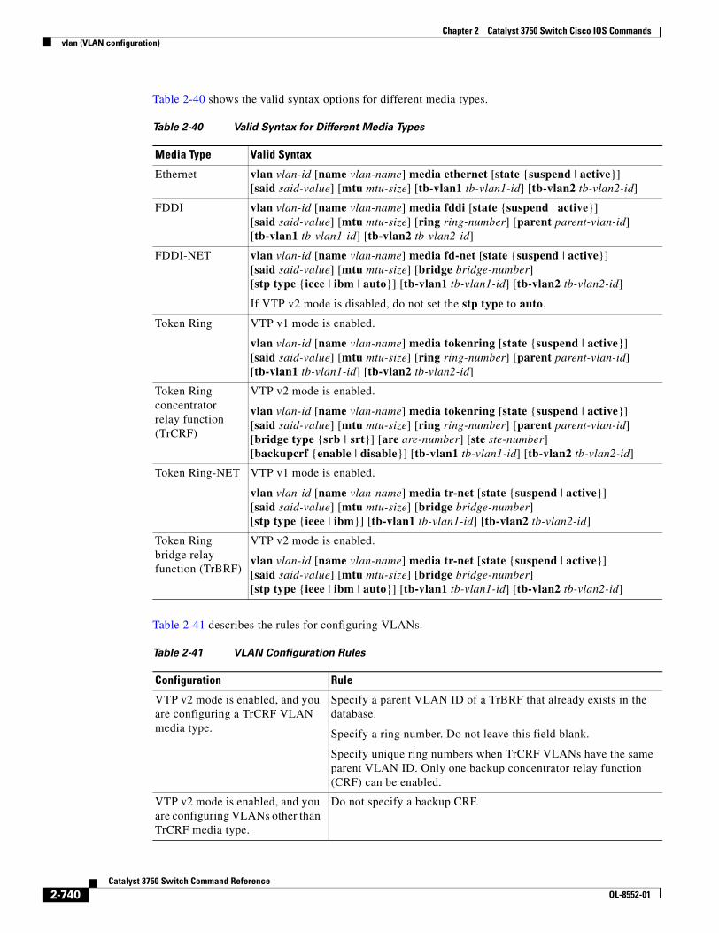
Chapter 2 Catalyst 3750 Switch Cisco IOS Commandsvlan (VLAN configuration)
Table 2-40 shows the valid syntax options for different media types.
Table 2-41 describes the rules for configuring VLANs.
Table 2-40 Valid Syntax for Different Media Types
Media Type Valid Syntax
Ethernet vlan vlan-id [name vlan-name] media ethernet [state {suspend | active}] [said said-value] [mtu mtu-size] [tb-vlan1 tb-vlan1-id] [tb-vlan2 tb-vlan2-id]
FDDI vlan vlan-id [name vlan-name] media fddi [state {suspend | active}] [said said-value] [mtu mtu-size] [ring ring-number] [parent parent-vlan-id] [tb-vlan1 tb-vlan1-id] [tb-vlan2 tb-vlan2-id]
FDDI-NET vlan vlan-id [name vlan-name] media fd-net [state {suspend | active}] [said said-value] [mtu mtu-size] [bridge bridge-number] [stp type {ieee | ibm | auto}] [tb-vlan1 tb-vlan1-id] [tb-vlan2 tb-vlan2-id]
If VTP v2 mode is disabled, do not set the stp type to auto.
Token Ring VTP v1 mode is enabled.
vlan vlan-id [name vlan-name] media tokenring [state {suspend | active}] [said said-value] [mtu mtu-size] [ring ring-number] [parent parent-vlan-id] [tb-vlan1 tb-vlan1-id] [tb-vlan2 tb-vlan2-id]
Token Ring concentrator relay function (TrCRF)
VTP v2 mode is enabled.
vlan vlan-id [name vlan-name] media tokenring [state {suspend | active}] [said said-value] [mtu mtu-size] [ring ring-number] [parent parent-vlan-id] [bridge type {srb | srt}] [are are-number] [ste ste-number] [backupcrf {enable | disable}] [tb-vlan1 tb-vlan1-id] [tb-vlan2 tb-vlan2-id]
Token Ring-NET VTP v1 mode is enabled.
vlan vlan-id [name vlan-name] media tr-net [state {suspend | active}] [said said-value] [mtu mtu-size] [bridge bridge-number] [stp type {ieee | ibm}] [tb-vlan1 tb-vlan1-id] [tb-vlan2 tb-vlan2-id]
Token Ring bridge relay function (TrBRF)
VTP v2 mode is enabled.
vlan vlan-id [name vlan-name] media tr-net [state {suspend | active}] [said said-value] [mtu mtu-size] [bridge bridge-number] [stp type {ieee | ibm | auto}] [tb-vlan1 tb-vlan1-id] [tb-vlan2 tb-vlan2-id]
Table 2-41 VLAN Configuration Rules
Configuration Rule
VTP v2 mode is enabled, and you are configuring a TrCRF VLAN media type.
Specify a parent VLAN ID of a TrBRF that already exists in the database.
Specify a ring number. Do not leave this field blank.
Specify unique ring numbers when TrCRF VLANs have the same parent VLAN ID. Only one backup concentrator relay function (CRF) can be enabled.
VTP v2 mode is enabled, and you are configuring VLANs other than TrCRF media type.
Do not specify a backup CRF.
2-740Catalyst 3750 Switch Command Reference
OL-8552-01
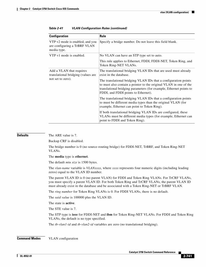
Chapter 2 Catalyst 3750 Switch Cisco IOS Commandsvlan (VLAN configuration)
Defaults The ARE value is 7.
Backup CRF is disabled.
The bridge number is 0 (no source-routing bridge) for FDDI-NET, TrBRF, and Token Ring-NET VLANs.
The media type is ethernet.
The default mtu size is 1500 bytes.
The vlan-name variable is VLANxxxx, where xxxx represents four numeric digits (including leading zeros) equal to the VLAN ID number.
The parent VLAN ID is 0 (no parent VLAN) for FDDI and Token Ring VLANs. For TrCRF VLANs, you must specify a parent VLAN ID. For both Token Ring and TrCRF VLANs, the parent VLAN ID must already exist in the database and be associated with a Token Ring-NET or TrBRF VLAN.
The ring number for Token Ring VLANs is 0. For FDDI VLANs, there is no default.
The said value is 100000 plus the VLAN ID.
The state is active.
The STE value is 7.
The STP type is ieee for FDDI-NET and ibm for Token Ring-NET VLANs. For FDDI and Token Ring VLANs, the default is no type specified.
The tb-vlan1-id and tb-vlan2-id variables are zero (no translational bridging).
Command Modes VLAN configuration
VTP v2 mode is enabled, and you are configuring a TrBRF VLAN media type.
Specify a bridge number. Do not leave this field blank.
VTP v1 mode is enabled. No VLAN can have an STP type set to auto.
This rule applies to Ethernet, FDDI, FDDI-NET, Token Ring, and Token Ring-NET VLANs.
Add a VLAN that requires translational bridging (values are not set to zero).
The translational bridging VLAN IDs that are used must already exist in the database.
The translational bridging VLAN IDs that a configuration points to must also contain a pointer to the original VLAN in one of the translational bridging parameters (for example, Ethernet points to FDDI, and FDDI points to Ethernet).
The translational bridging VLAN IDs that a configuration points to must be different media types than the original VLAN (for example, Ethernet can point to Token Ring).
If both translational bridging VLAN IDs are configured, these VLANs must be different media types (for example, Ethernet can point to FDDI and Token Ring).
Table 2-41 VLAN Configuration Rules (continued)
Configuration Rule
2-741Catalyst 3750 Switch Command Reference
OL-8552-01
Chapter 2 Catalyst 3750 Switch Cisco IOS Commandsvlan (VLAN configuration)
Command History
Usage Guidelines You can only use this command mode for configuring normal-range VLANs, that is, VLAN IDs 1 to 1005.
Note To configure extended-range VLANs (VLAN IDs 1006 to 4094), use the vlan global configuration command.
VLAN configuration is always saved in the VLAN database. If VTP mode is transparent, it is also saved in the switch running configuration file, along with the VTP mode and domain name. You can then save it in the switch startup configuration file by using the copy running-config startup-config privileged EXEC command.
When you save VLAN and VTP configuration in the startup configuration file and reboot the switch, the configuration is selected in these ways:
• If both the VLAN database and the configuration file show the VTP mode as transparent and the VTP domain names match, the VLAN database is ignored. The VTP and VLAN configurations in the startup configuration file are used. The VLAN database revision number remains unchanged in the VLAN database.
• If the VTP mode is server, or if the startup VTP mode or domain names do not match the VLAN database, the VTP mode and the VLAN configuration for the first 1005 VLANs use VLAN database information.
The following are the results of using the no vlan commands:
• When the no vlan vlan-id form is used, the VLAN is deleted. Deleting VLANs automatically resets to zero any other parent VLANs and translational bridging parameters that see the deleted VLAN.
• When the no vlan vlan-id bridge form is used, the VLAN source-routing bridge number returns to the default (0). The vlan vlan-id bridge command is used only for FDDI-NET and Token Ring-NET VLANs and is ignored in other VLAN types.
• When the no vlan vlan-id media form is used, the media type returns to the default (ethernet). Changing the VLAN media type (including the no form) resets the VLAN MTU to the default MTU for the type (unless the mtu keyword is also present in the command). It also resets the VLAN parent and translational bridging VLAN to the default (unless the parent, tb-vlan1, or tb-vlan2 are also present in the command).
• When the no vlan vlan-id mtu form is used, the VLAN MTU returns to the default for the applicable VLAN media type. You can also modify the MTU by using the media keyword.
• When the no vlan vlan-id name vlan-name form is used, the VLAN name returns to the default name (VLANxxxx, where xxxx represent four numeric digits [including leading zeros] equal to the VLAN ID number).
• When the no vlan vlan-id parent form is used, the parent VLAN returns to the default (0). The parent VLAN resets to the default if the parent VLAN is deleted or if the media keyword changes the VLAN type or the VLAN type of the parent VLAN.
• When the no vlan vlan-id ring form is used, the VLAN logical ring number returns to the default (0).
• When the no vlan vlan-id said form is used, the VLAN SAID returns to the default (100,000 plus the VLAN ID).
Release Modification
12.1(11)AX This command was introduced.
2-742Catalyst 3750 Switch Command Reference
OL-8552-01
Chapter 2 Catalyst 3750 Switch Cisco IOS Commandsvlan (VLAN configuration)
• When the no vlan vlan-id state form is used, the VLAN state returns to the default (active).
• When the no vlan vlan-id stp type form is used, the VLAN spanning-tree type returns to the default (ieee).
• When the no vlan vlan-id tb-vlan1 or no-id tb-vlan2 form is used, the VLAN translational bridge VLAN (or VLANs, if applicable) returns to the default (0). Translational bridge VLANs must be a different VLAN type than the affected VLAN, and if two are specified, the two must be different VLAN types from each other. A translational bridge VLAN resets to the default if the translational bridge VLAN is deleted, if the media keyword changes the VLAN type, or if the media keyword changes the VLAN type of the corresponding translation bridge VLAN.
Examples This example shows how to add an Ethernet VLAN with default media characteristics. The default includes a vlan-name of VLANxxx, where xxxx represents four numeric digits (including leading zeros) equal to the VLAN ID number. The default media option is ethernet; the state option is active. The default said-value variable is 100000 plus the VLAN ID; the mtu-size variable is 1500; the stp-type option is ieee. When you enter the exit or apply vlan configuration command, the VLAN is added if it did not already exist; otherwise, this command does nothing.
Switch(vlan)# vlan 2VLAN 2 added: Name: VLAN0002Switch(vlan)# exitAPPLY completed.Exiting....
This example shows how to modify an existing VLAN by changing its name and MTU size:
Switch(vlan)# no vlan name engineering mtu 1200
You can verify your settings by entering the show vlan privileged EXEC command.
Related Commands Command Description
show vlan Displays the parameters for all configured VLANs or one VLAN (if the VLAN ID or name is specified) in the administrative domain.
vlan (global configuration)
Enters config-vlan mode for configuring normal-range and extended-range VLANs.
2-743Catalyst 3750 Switch Command Reference
OL-8552-01
Chapter 2 Catalyst 3750 Switch Cisco IOS Commandsvlan access-map
vlan access-mapUse the vlan access-map global configuration command on the switch stack or on a standalone switch to create or modify a VLAN map entry for VLAN packet filtering. This entry changes the mode to the VLAN access-map configuration. Use the no form of this command to delete a VLAN map entry. Use the vlan filter interface configuration command to apply a VLAN map to one or more VLANs.
vlan access-map name [number]
no vlan access-map name [number]
Syntax Description
Defaults There are no VLAN map entries and no VLAN maps applied to a VLAN.
Command Modes Global configuration
Command History
Usage Guidelines In global configuration mode, use this command to create or modify a VLAN map. This entry changes the mode to VLAN access-map configuration, where you can use the match access-map configuration command to specify the access lists for IP or non-IP traffic to match and use the action command to set whether a match causes the packet to be forwarded or dropped.
In VLAN access-map configuration mode, these commands are available:
• action: sets the action to be taken (forward or drop).
• default: sets a command to its defaults
• exit: exits from VLAN access-map configuration mode
• match: sets the values to match (IP address or MAC address).
• no: negates a command or set its defaults
When you do not specify an entry number (sequence number), it is added to the end of the map.
There can be only one VLAN map per VLAN and it is applied as packets are received by a VLAN.
You can use the no vlan access-map name [number] command with a sequence number to delete a single entry.
name Name of the VLAN map.
number (Optional) The sequence number of the map entry that you want to create or modify (0 to 65535). If you are creating a VLAN map and the sequence number is not specified, it is automatically assigned in increments of 10, starting from 10. This number is the sequence to insert to, or delete from, a VLAN access-map entry.
Release Modification
12.1(11)AX This command was introduced.
2-744Catalyst 3750 Switch Command Reference
OL-8552-01
Chapter 2 Catalyst 3750 Switch Cisco IOS Commandsvlan access-map
In global configuration mode, use the vlan filter interface configuration command to apply the map to one or more VLANs.
For more information about VLAN map entries, see the software configuration guide for this release.
Examples This example shows how to create a VLAN map named vac1 and apply matching conditions and actions to it. If no other entries already exist in the map, this will be entry 10.
Switch(config)# vlan access-map vac1Switch(config-access-map)# match ip address acl1Switch(config-access-map)# action forward
This example shows how to delete VLAN map vac1:
Switch(config)# no vlan access-map vac1
Related Commands Command Description
action Sets the action for the VLAN access map entry.
match (access-map configuration) Sets the VLAN map to match packets against one or more access lists.
show vlan access-map Displays information about a particular VLAN access map or all VLAN access maps.
vlan filter Applies the VLAN access map to one or more VLANs.
2-745Catalyst 3750 Switch Command Reference
OL-8552-01
Chapter 2 Catalyst 3750 Switch Cisco IOS Commandsvlan database
vlan databaseUse the vlan database privileged EXEC command on the switch stack or on a standalone switch to enter VLAN configuration mode. From this mode, you can add, delete, and modify VLAN configurations for normal-range VLANs and globally propagate these changes by using the VLAN Trunking Protocol (VTP). Configuration information is saved in the VLAN database.
vlan database
Note VLAN configuration mode is only valid for VLAN IDs 1 to 1005.
Syntax Description This command has no arguments or keywords.
Defaults No default is defined.
Command Modes Privileged EXEC
Command History
Usage Guidelines You can use the VLAN database configuration commands to configure VLANs 1 to 1005. To configure extended-range VLANs (VLAN IDs 1006 to 4094), use the vlan (global configuration) command to enter config-vlan mode. You can also configure VLAN IDs 1 to 1005 by using the vlan global configuration command.
To return to the privileged EXEC mode from the VLAN configuration mode, enter the exit command.
Note This command mode is different from other modes because it is session-oriented. When you add, delete, or modify VLAN parameters, the changes are not applied until you exit the session by entering the apply or exit command. When the changes are applied, the VTP configuration version is incremented. You can also not apply the changes to the VTP database by entering abort.
When you are in VLAN configuration mode, you can access the VLAN database and make changes by using these commands:
• vlan: accesses subcommands to add, delete, or modify values associated with a single VLAN. For more information, see the vlan (VLAN configuration) command.
• vtp: accesses subcommands to perform VTP administrative functions. For more information, see the vtp (VLAN configuration) command.
Release Modification
12.1(11)AX This command was introduced.
2-746Catalyst 3750 Switch Command Reference
OL-8552-01
Chapter 2 Catalyst 3750 Switch Cisco IOS Commandsvlan database
When you have modified VLAN or VTP parameters, you can use these editing buffer manipulation commands:
• abort: exits the mode without applying the changes. The VLAN configuration that was running before you entered VLAN configuration mode continues to be used.
• apply: applies current changes to the VLAN database, increments the database configuration revision number, propagates it throughout the administrative domain, and remains in VLAN configuration mode.
Note You cannot use this command when the switch is in VTP client mode.
• exit: applies all configuration changes to the VLAN database, increments the database configuration number, propagates it throughout the administrative domain, and returns to privileged EXEC mode.
• no: negates a command or set its defaults; valid values are vlan and vtp.
• reset: abandons proposed changes to the VLAN database, resets the proposed database to the implemented VLAN database on the switch, and remains in VLAN configuration mode.
• show: displays VLAN database information.
• show changes [vlan-id]: displays the differences between the VLAN database on the switch and the proposed VLAN database for all normal-range VLAN IDs (1 to 1005) or the specified VLAN ID (1 to 1005).
• show current [vlan-id]: displays the VLAN database on the switch or on a selected VLAN (1 to 1005).
• show proposed [vlan-id]: displays the proposed VLAN database or a selected VLAN (1 to 1005) from the proposed database. The proposed VLAN database is not the running configuration until you use the exit or apply VLAN configuration command.
You can verify that VLAN database changes have been made or aborted by using the show vlan privileged EXEC command. This output is different from the show VLAN database configuration command output.
Examples This example shows how to enter the VLAN configuration mode from the privileged EXEC mode and to display VLAN database information:
Switch# vlan databaseSwitch(vlan)# show VLAN ISL Id: 1 Name: default Media Type: Ethernet VLAN 802.10 Id: 100001 State: Operational MTU: 1500 Translational Bridged VLAN: 1002 Translational Bridged VLAN: 1003
VLAN ISL Id: 2 Name: VLAN0002 Media Type: Ethernet VLAN 802.10 Id: 100002 State: Operational MTU: 1500
2-747Catalyst 3750 Switch Command Reference
OL-8552-01
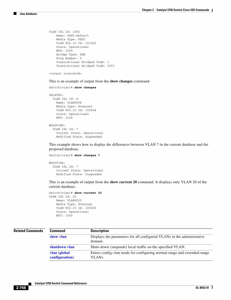
Chapter 2 Catalyst 3750 Switch Cisco IOS Commandsvlan database
VLAN ISL Id: 1002 Name: fddi-default Media Type: FDDI VLAN 802.10 Id: 101002 State: Operational MTU: 1500 Bridge Type: SRB Ring Number: 0 Translational Bridged VLAN: 1 Translational Bridged VLAN: 1003
<output truncated>
This is an example of output from the show changes command:
Switch(vlan)# show changes
DELETED: VLAN ISL Id: 4 Name: VLAN0004 Media Type: Ethernet VLAN 802.10 Id: 100004 State: Operational MTU: 1500
MODIFIED: VLAN ISL Id: 7 Current State: Operational Modified State: Suspended
This example shows how to display the differences between VLAN 7 in the current database and the proposed database.
Switch(vlan)# show changes 7
MODIFIED: VLAN ISL Id: 7 Current State: Operational Modified State: Suspended
This is an example of output from the show current 20 command. It displays only VLAN 20 of the current database.
Switch(vlan)# show current 20VLAN ISL Id: 20 Name: VLAN0020 Media Type: Ethernet VLAN 802.10 Id: 100020 State: Operational MTU: 1500
Related Commands Command Description
show vlan Displays the parameters for all configured VLANs in the administrative domain.
shutdown vlan Shuts down (suspends) local traffic on the specified VLAN.
vlan (global configuration)
Enters config-vlan mode for configuring normal-range and extended-range VLANs.
2-748Catalyst 3750 Switch Command Reference
OL-8552-01
Chapter 2 Catalyst 3750 Switch Cisco IOS Commandsvlan dot1q tag native
vlan dot1q tag nativeUse the vlan dot1q tag native global configuration command on the switch stack or on a standalone switch to enable tagging of native VLAN frames on all IEEE 802.1Q trunk ports. Use the no form of this command to return to the default setting.
vlan dot1q tag native
no vlan dot1q tag native
Syntax Description This command has no arguments or keywords.
Defaults The IEEE 802.1Q native VLAN tagging is disabled.
Command Modes Global configuration
Command History
Usage Guidelines When enabled, native VLAN packets going out all IEEE 802.1Q trunk ports are tagged.
When disabled, native VLAN packets going out all IEEE 802.1Q trunk ports are not tagged.
You can use this command with the IEEE 802.1Q tunneling feature. This feature operates on an edge switch of a service-provider network and expands VLAN space by using a VLAN-in-VLAN hierarchy and tagging the tagged packets. You must use IEEE 802.1Q trunk ports for sending packets to the service-provider network. However, packets going through the core of the service-provider network might also be carried on IEEE 802.1Q trunks. If the native VLANs of an IEEE 802.1Q trunks match the native VLAN of a tunneling port on the same switch, traffic on the native VLAN is not tagged on the sending trunk port. This command ensures that native VLAN packets on all IEEE 802.1Q trunk ports are tagged.
For more information about IEEE 802.1Q tunneling, see the software configuration guide for this release.
Examples This example shows how to enable IEEE 802.1Q tagging on native VLAN frames:
Switch# configure terminalSwitch (config)# vlan dot1q tag nativeSwitch (config)# end
You can verify your settings by entering the show vlan dot1q tag native privileged EXEC command.
Release Modification
12.2(25)EA1 This command was introduced.
2-749Catalyst 3750 Switch Command Reference
OL-8552-01

Chapter 2 Catalyst 3750 Switch Cisco IOS Commandsvlan dot1q tag native
Related Commands Command Description
show vlan dot1q tag native Displays IEEE 802.1Q native VLAN tagging status.
2-750Catalyst 3750 Switch Command Reference
OL-8552-01
Chapter 2 Catalyst 3750 Switch Cisco IOS Commandsvlan filter
vlan filterUse the vlan filter global configuration command on the switch stack or on a standalone switch to apply a VLAN map to one or more VLANs. Use the no form of this command to remove the map.
vlan filter mapname vlan-list {list | all}
no vlan filter mapname vlan-list {list | all}
Syntax Description
Defaults There are no VLAN filters.
Command Modes Global configuration
Command History
Usage Guidelines To avoid accidentally dropping too many packets and disabling connectivity in the middle of the configuration process, we recommend that you completely define the VLAN access map before applying it to a VLAN.
For more information about VLAN map entries, see the software configuration guide for this release.
Examples This example applies VLAN map entry map1 to VLANs 20 and 30:
Switch(config)# vlan filter map1 vlan-list 20, 30
This example shows how to delete VLAN map entry mac1 from VLAN 20:
Switch(config)# no vlan filter map1 vlan-list 20
You can verify your settings by entering the show vlan filter privileged EXEC command.
mapname Name of the VLAN map entry.
list The list of one or more VLANs in the form tt, uu-vv, xx, yy-zz, where spaces around commas and dashes are optional. The range is 1 to 4094.
all Remove the filter from all VLANs.
Release Modification
12.1(11)AX This command was introduced.
2-751Catalyst 3750 Switch Command Reference
OL-8552-01

Chapter 2 Catalyst 3750 Switch Cisco IOS Commandsvlan filter
Related Commands Command Description
show vlan access-map Displays information about a particular VLAN access map or all VLAN access maps.
show vlan filter Displays information about all VLAN filters or about a particular VLAN or VLAN access map.
vlan access-map Creates a VLAN map entry for VLAN packet filtering.
2-752Catalyst 3750 Switch Command Reference
OL-8552-01
Chapter 2 Catalyst 3750 Switch Cisco IOS Commandsvmps reconfirm (privileged EXEC)
vmps reconfirm (privileged EXEC)Use the vmps reconfirm privileged EXEC command on the switch stack or on a standalone switch to immediately send VLAN Query Protocol (VQP) queries to reconfirm all dynamic VLAN assignments with the VLAN Membership Policy Server (VMPS).
vmps reconfirm
Syntax Description This command has no arguments or keywords.
Defaults No default is defined.
Command Modes Privileged EXEC
Command History
Examples This example shows how to immediately send VQP queries to the VMPS:
Switch# vmps reconfirm
You can verify your setting by entering the show vmps privileged EXEC command and examining the VMPS Action row of the Reconfirmation Status section. The show vmps command shows the result of the last time the assignments were reconfirmed either because the reconfirmation timer expired or because the vmps reconfirm command was entered.
Related Commands
Release Modification
12.1(11)AX This command was introduced.
Command Description
show vmps Displays VQP and VMPS information.
vmps reconfirm (global configuration)
Changes the reconfirmation interval for the VQP client.
2-753Catalyst 3750 Switch Command Reference
OL-8552-01
Chapter 2 Catalyst 3750 Switch Cisco IOS Commandsvmps reconfirm (global configuration)
vmps reconfirm (global configuration)Use the vmps reconfirm global configuration command on the switch stack or on a standalone switch to change the reconfirmation interval for the VLAN Query Protocol (VQP) client. Use the no form of this command to return to the default setting.
vmps reconfirm interval
no vmps reconfirm
Syntax Description
Defaults The default reconfirmation interval is 60 minutes.
Command Modes Global configuration
Command History
Examples This example shows how to set the VQP client to reconfirm dynamic VLAN entries every 20 minutes:
Switch(config)# vmps reconfirm 20
You can verify your setting by entering the show vmps privileged EXEC command and examining information in the Reconfirm Interval row.
Related Commands
interval Reconfirmation interval for VQP client queries to the VLAN Membership Policy Server (VMPS) to reconfirm dynamic VLAN assignments. The range is 1 to 120 minutes.
Release Modification
12.1(11)AX This command was introduced.
Command Description
show vmps Displays VQP and VMPS information.
vmps reconfirm (privileged EXEC) Sends VQP queries to reconfirm all dynamic VLAN assignments with the VMPS.
2-754Catalyst 3750 Switch Command Reference
OL-8552-01
Chapter 2 Catalyst 3750 Switch Cisco IOS Commandsvmps retry
vmps retryUse the vmps retry global configuration command on the switch stack or on a standalone switch to configure the per-server retry count for the VLAN Query Protocol (VQP) client. Use the no form of this command to return to the default setting.
vmps retry count
no vmps retry
Syntax Description
Defaults The default retry count is 3.
Command Modes Global configuration
Command History
Examples This example shows how to set the retry count to 7:
Switch(config)# vmps retry 7
You can verify your setting by entering the show vmps privileged EXEC command and examining information in the Server Retry Count row.
Related Commands
count Number of attempts to contact the VLAN Membership Policy Server (VMPS) by the client before querying the next server in the list. The range is 1 to 10.
Release Modification
12.1(11)AX This command was introduced.
Command Description
show vmps Displays VQP and VMPS information.
2-755Catalyst 3750 Switch Command Reference
OL-8552-01
Chapter 2 Catalyst 3750 Switch Cisco IOS Commandsvmps server
vmps serverUse the vmps server global configuration command on the switch stack or on a standalone switch to configure the primary VLAN Membership Policy Server (VMPS) and up to three secondary servers. Use the no form of this command to remove a VMPS server.
vmps server ipaddress [primary]
no vmps server [ipaddress]
Syntax Description
Defaults No primary or secondary VMPS servers are defined.
Command Modes Global configuration
Command History
Usage Guidelines The first server entered is automatically selected as the primary server whether or not primary is entered. The first server address can be overridden by using primary in a subsequent command.
If a member switch in a cluster configuration does not have an IP address, the cluster does not use the VMPS server configured for that member switch. Instead, the cluster uses the VMPS server on the command switch, and the command switch proxies the VMPS requests. The VMPS server treats the cluster as a single switch and uses the IP address of the command switch to respond to requests.
When using the no form without specifying the ipaddress, all configured servers are deleted. If you delete all servers when dynamic-access ports are present, the switch cannot forward packets from new sources on these ports because it cannot query the VMPS.
Examples This example shows how to configure the server with IP address 191.10.49.20 as the primary VMPS server. The servers with IP addresses 191.10.49.21 and 191.10.49.22 are configured as secondary servers:
Switch(config)# vmps server 191.10.49.20 primarySwitch(config)# vmps server 191.10.49.21Switch(config)# vmps server 191.10.49.22
ipaddress IP address or hostname of the primary or secondary VMPS servers. If you specify a hostname, the Domain Name System (DNS) server must be configured.
primary (Optional) Decides whether primary or secondary VMPS servers are being configured.
Release Modification
12.1(11)AX This command was introduced.
2-756Catalyst 3750 Switch Command Reference
OL-8552-01
Chapter 2 Catalyst 3750 Switch Cisco IOS Commandsvmps server
This example shows how to delete the server with IP address 191.10.49.21:
Switch(config)# no vmps server 191.10.49.21
You can verify your setting by entering the show vmps privileged EXEC command and examining information in the VMPS Domain Server row.
Related Commands Command Description
show vmps Displays VQP and VMPS information.
2-757Catalyst 3750 Switch Command Reference
OL-8552-01
Chapter 2 Catalyst 3750 Switch Cisco IOS Commandsvtp (global configuration)
vtp (global configuration)Use the vtp global configuration command on the switch stack or on a standalone switch to set or modify the VLAN Trunking Protocol (VTP) configuration characteristics. Use the no form of this command to remove the settings or to return to the default settings.
vtp {domain domain-name | file filename | interface name [only] | mode {client | server | transparent} | password password | pruning | version number}
no vtp {file | interface | mode | password | pruning | version}
Syntax Description domain domain-name Specify the VTP domain name, an ASCII string from 1 to 32 characters that identifies the VTP administrative domain for the switch. The domain name is case sensitive.
file filename Specify the Cisco IOS file system file where the VTP VLAN configuration is stored.
interface name Specify the name of the interface providing the VTP ID updated for this device.
only (Optional) Use only the IP address of this interface as the VTP IP updater.
mode Specify the VTP device mode as client, server, or transparent.
client Place the switch in VTP client mode. A switch in VTP client mode is enabled for VTP, and can send advertisements, but does not have enough nonvolatile storage to store VLAN configurations. You cannot configure VLANs on the switch. When a VTP client starts up, it does not send VTP advertisements until it receives advertisements to initialize its VLAN database.
server Place the switch in VTP server mode. A switch in VTP server mode is enabled for VTP and sends advertisements. You can configure VLANs on the switch. The switch can recover all the VLAN information in the current VTP database from nonvolatile storage after reboot.
transparent Place the switch in VTP transparent mode. A switch in VTP transparent mode is disabled for VTP, does not send advertisements or learn from advertisements sent by other devices, and cannot affect VLAN configurations on other devices in the network. The switch receives VTP advertisements and forwards them on all trunk ports except the one on which the advertisement was received.
When VTP mode is transparent, the mode and domain name are saved in the switch running configuration file, and you can save them in the switch startup configuration file by entering the copy running-config startup config privileged EXEC command.
password password Set the administrative domain password for the generation of the 16-byte secret value used in MD5 digest calculation to be sent in VTP advertisements and to validate received VTP advertisements. The password can be an ASCII string from 1 to 32 characters. The password is case sensitive.
pruning Enable VTP pruning on the switch.
version number Set VTP version to Version 1 or Version 2.
2-758Catalyst 3750 Switch Command Reference
OL-8552-01
Chapter 2 Catalyst 3750 Switch Cisco IOS Commandsvtp (global configuration)
Defaults The default filename is flash:vlan.dat.
The default mode is server mode.
No domain name or password is defined.
No password is configured.
Pruning is disabled.
The default version is Version 1.
Command Modes Global configuration
Command History
Usage Guidelines When you save VTP mode, domain name, and VLAN configurations in the switch startup configuration file and reboot the switch, the VTP and VLAN configurations are selected by these conditions:
• If both the VLAN database and the configuration file show the VTP mode as transparent and the VTP domain names match, the VLAN database is ignored. The VTP and VLAN configurations in the startup configuration file are used. The VLAN database revision number remains unchanged in the VLAN database.
• If the startup VTP mode is server mode, or the startup VTP mode or domain names do not match the VLAN database, VTP mode and VLAN configuration for the first 1005 VLANs are selected by VLAN database information, and VLANs greater than 1005 are configured from the switch configuration file.
The vtp file filename cannot be used to load a new database; it renames only the file in which the existing database is stored.
Follow these guidelines when configuring a VTP domain name:
• The switch is in the no-management-domain state until you configure a domain name. While in the no-management-domain state, the switch does not send any VTP advertisements even if changes occur to the local VLAN configuration. The switch leaves the no-management-domain state after it receives the first VTP summary packet on any port that is trunking or after you configure a domain name by using the vtp domain command. If the switch receives its domain from a summary packet, it resets its configuration revision number to 0. After the switch leaves the no-management-domain state, it can no be configured to re-enter it until you clear the NVRAM and reload the software.
• Domain names are case-sensitive.
• After you configure a domain name, it cannot be removed. You can only reassign it to a different domain.
Release Modification
12.1(11)AX This command was introduced.
2-759Catalyst 3750 Switch Command Reference
OL-8552-01
Chapter 2 Catalyst 3750 Switch Cisco IOS Commandsvtp (global configuration)
Follow these guidelines when setting VTP mode:
• The no vtp mode command returns the switch to VTP server mode.
• The vtp mode server command is the same as no vtp mode except that it does not return an error if the switch is not in client or transparent mode.
• If the receiving switch is in client mode, the client switch changes its configuration to duplicate the configuration of the server. If you have switches in client mode, be sure to make all VTP or VLAN configuration changes on a switch in server mode. If the receiving switch is in server mode or transparent mode, the switch configuration is not changed.
• Switches in transparent mode do not participate in VTP. If you make VTP or VLAN configuration changes on a switch in transparent mode, the changes are not propagated to other switches in the network.
• If you change the VTP or VLAN configuration on a switch that is in server mode, that change is propagated to all the switches in the same VTP domain.
• The vtp mode transparent command disables VTP from the domain but does not remove the domain from the switch.
• The VTP mode must be transparent for you to add extended-range VLANs or for VTP and VLAN information to be saved in the running configuration file.
• If extended-range VLANs are configured on the switch and you attempt to set the VTP mode to server or client, you receive an error message, and the configuration is not allowed.
• VTP can be set to either server or client mode only when dynamic VLAN creation is disabled.
Follow these guidelines when setting a VTP password:
• Passwords are case sensitive. Passwords should match on all switches in the same domain.
• When you use the no vtp password form of the command, the switch returns to the no-password state.
Follow these guidelines when setting VTP pruning:
• VTP pruning removes information about each pruning-eligible VLAN from VTP updates if there are no stations belonging to that VLAN.
• If you enable pruning on the VTP server, it is enabled for the entire management domain for VLAN IDs 1 to 1005.
• Only VLANs in the pruning-eligible list can be pruned.
• Pruning is supported with VTP Version 1 and Version 2.
Follow these guidelines when setting the VTP version:
• Toggling the Version 2 (v2) mode state modifies parameters of certain default VLANs.
• Each VTP switch automatically detects the capabilities of all the other VTP devices. To use Version 2, all VTP switches in the network must support Version 2; otherwise, you must configure them to operate in VTP Version 1 mode.
• If all switches in a domain are VTP Version 2-capable, you need only to configure Version 2 on one switch; the version number is then propagated to the other Version-2 capable switches in the VTP domain.
• If you are using VTP in a Token Ring environment, VTP Version 2 must be enabled.
2-760Catalyst 3750 Switch Command Reference
OL-8552-01
Chapter 2 Catalyst 3750 Switch Cisco IOS Commandsvtp (global configuration)
• If you are configuring a Token Ring bridge relay function (TrBRF) or Token Ring concentrator relay function (TrCRF) VLAN media type, you must use Version 2.
• If you are configuring a Token Ring or Token Ring-NET VLAN media type, you must use Version 1.
You cannot save password, pruning, and version configurations in the switch configuration file.
Examples This example shows how to rename the filename for VTP configuration storage to vtpfilename:
Switch(config)# vtp file vtpfilename
This example shows how to clear the device storage filename:
Switch(config)# no vtp file vtpconfigClearing device storage filename.
This example shows how to specify the name of the interface providing the VTP updater ID for this device:
Switch(config)# vtp interface gigabitethernet
This example shows how to set the administrative domain for the switch:
Switch(config)# vtp domain OurDomainName
This example shows how to place the switch in VTP transparent mode:
Switch(config)# vtp mode transparent
This example shows how to configure the VTP domain password:
Switch(config)# vtp password ThisIsOurDomain’sPassword
This example shows how to enable pruning in the VLAN database:
Switch(config)# vtp pruningPruning switched ON
This example shows how to enable Version 2 mode in the VLAN database:
Switch(config)# vtp version 2
You can verify your settings by entering the show vtp status privileged EXEC command.
Related Commands Command Description
show vtp status Displays the VTP statistics for the switch and general information about the VTP management domain status.
vtp (VLAN configuration)
Configures VTP domain-name, password, pruning, version, and mode.
2-761Catalyst 3750 Switch Command Reference
OL-8552-01
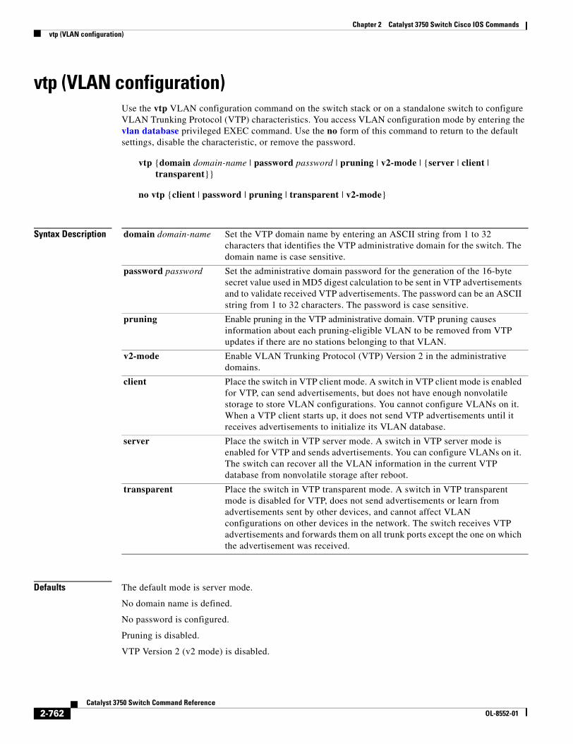
Chapter 2 Catalyst 3750 Switch Cisco IOS Commandsvtp (VLAN configuration)
vtp (VLAN configuration)Use the vtp VLAN configuration command on the switch stack or on a standalone switch to configure VLAN Trunking Protocol (VTP) characteristics. You access VLAN configuration mode by entering the vlan database privileged EXEC command. Use the no form of this command to return to the default settings, disable the characteristic, or remove the password.
vtp {domain domain-name | password password | pruning | v2-mode | {server | client | transparent}}
no vtp {client | password | pruning | transparent | v2-mode}
Syntax Description
Defaults The default mode is server mode.
No domain name is defined.
No password is configured.
Pruning is disabled.
VTP Version 2 (v2 mode) is disabled.
domain domain-name Set the VTP domain name by entering an ASCII string from 1 to 32 characters that identifies the VTP administrative domain for the switch. The domain name is case sensitive.
password password Set the administrative domain password for the generation of the 16-byte secret value used in MD5 digest calculation to be sent in VTP advertisements and to validate received VTP advertisements. The password can be an ASCII string from 1 to 32 characters. The password is case sensitive.
pruning Enable pruning in the VTP administrative domain. VTP pruning causes information about each pruning-eligible VLAN to be removed from VTP updates if there are no stations belonging to that VLAN.
v2-mode Enable VLAN Trunking Protocol (VTP) Version 2 in the administrative domains.
client Place the switch in VTP client mode. A switch in VTP client mode is enabled for VTP, can send advertisements, but does not have enough nonvolatile storage to store VLAN configurations. You cannot configure VLANs on it. When a VTP client starts up, it does not send VTP advertisements until it receives advertisements to initialize its VLAN database.
server Place the switch in VTP server mode. A switch in VTP server mode is enabled for VTP and sends advertisements. You can configure VLANs on it. The switch can recover all the VLAN information in the current VTP database from nonvolatile storage after reboot.
transparent Place the switch in VTP transparent mode. A switch in VTP transparent mode is disabled for VTP, does not send advertisements or learn from advertisements sent by other devices, and cannot affect VLAN configurations on other devices in the network. The switch receives VTP advertisements and forwards them on all trunk ports except the one on which the advertisement was received.
2-762Catalyst 3750 Switch Command Reference
OL-8552-01
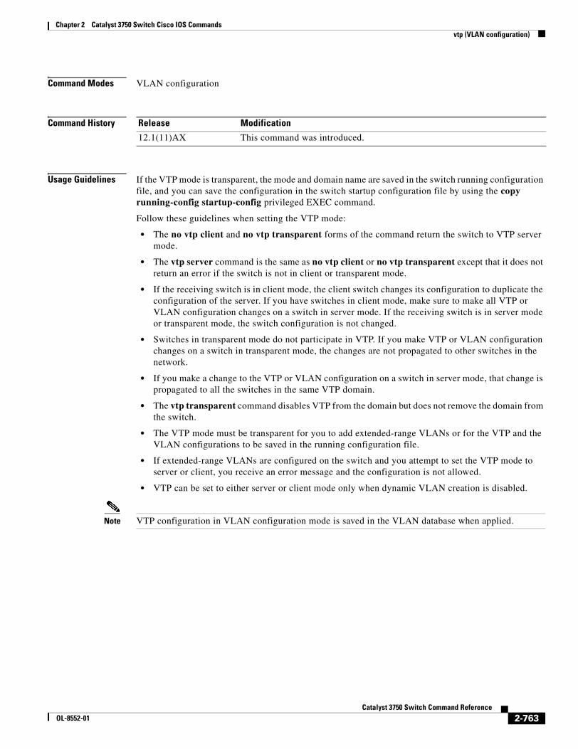
Chapter 2 Catalyst 3750 Switch Cisco IOS Commandsvtp (VLAN configuration)
Command Modes VLAN configuration
Command History
Usage Guidelines If the VTP mode is transparent, the mode and domain name are saved in the switch running configuration file, and you can save the configuration in the switch startup configuration file by using the copy running-config startup-config privileged EXEC command.
Follow these guidelines when setting the VTP mode:
• The no vtp client and no vtp transparent forms of the command return the switch to VTP server mode.
• The vtp server command is the same as no vtp client or no vtp transparent except that it does not return an error if the switch is not in client or transparent mode.
• If the receiving switch is in client mode, the client switch changes its configuration to duplicate the configuration of the server. If you have switches in client mode, make sure to make all VTP or VLAN configuration changes on a switch in server mode. If the receiving switch is in server mode or transparent mode, the switch configuration is not changed.
• Switches in transparent mode do not participate in VTP. If you make VTP or VLAN configuration changes on a switch in transparent mode, the changes are not propagated to other switches in the network.
• If you make a change to the VTP or VLAN configuration on a switch in server mode, that change is propagated to all the switches in the same VTP domain.
• The vtp transparent command disables VTP from the domain but does not remove the domain from the switch.
• The VTP mode must be transparent for you to add extended-range VLANs or for the VTP and the VLAN configurations to be saved in the running configuration file.
• If extended-range VLANs are configured on the switch and you attempt to set the VTP mode to server or client, you receive an error message and the configuration is not allowed.
• VTP can be set to either server or client mode only when dynamic VLAN creation is disabled.
Note VTP configuration in VLAN configuration mode is saved in the VLAN database when applied.
Release Modification
12.1(11)AX This command was introduced.
2-763Catalyst 3750 Switch Command Reference
OL-8552-01
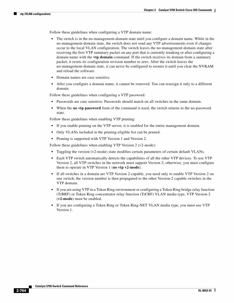
Chapter 2 Catalyst 3750 Switch Cisco IOS Commandsvtp (VLAN configuration)
Follow these guidelines when configuring a VTP domain name:
• The switch is in the no-management-domain state until you configure a domain name. While in the no-management-domain state, the switch does not send any VTP advertisements even if changes occur to the local VLAN configuration. The switch leaves the no-management-domain state after receiving the first VTP summary packet on any port that is currently trunking or after configuring a domain name with the vtp domain command. If the switch receives its domain from a summary packet, it resets its configuration revision number to zero. After the switch leaves the no-management-domain state, it can never be configured to reenter it until you clear the NVRAM and reload the software.
• Domain names are case sensitive.
• After you configure a domain name, it cannot be removed. You can reassign it only to a different domain.
Follow these guidelines when configuring a VTP password:
• Passwords are case sensitive. Passwords should match on all switches in the same domain.
• When the no vtp password form of the command is used, the switch returns to the no-password state.
Follow these guidelines when enabling VTP pruning:
• If you enable pruning on the VTP server, it is enabled for the entire management domain.
• Only VLANs included in the pruning-eligible list can be pruned.
• Pruning is supported with VTP Version 1 and Version 2.
Follow these guidelines when enabling VTP Version 2 (v2-mode):
• Toggling the version (v2-mode) state modifies certain parameters of certain default VLANs.
• Each VTP switch automatically detects the capabilities of all the other VTP devices. To use VTP Version 2, all VTP switches in the network must support Version 2; otherwise, you must configure them to operate in VTP Version 1 (no vtp v2-mode).
• If all switches in a domain are VTP Version 2-capable, you need only to enable VTP Version 2 on one switch; the version number is then propagated to the other Version-2 capable switches in the VTP domain.
• If you are using VTP in a Token Ring environment or configuring a Token Ring bridge relay function (TrBRF) or Token Ring concentrator relay function (TrCRF) VLAN media type, VTP Version 2 (v2-mode) must be enabled.
• If you are configuring a Token Ring or Token Ring-NET VLAN media type, you must use VTP Version 1.
2-764Catalyst 3750 Switch Command Reference
OL-8552-01
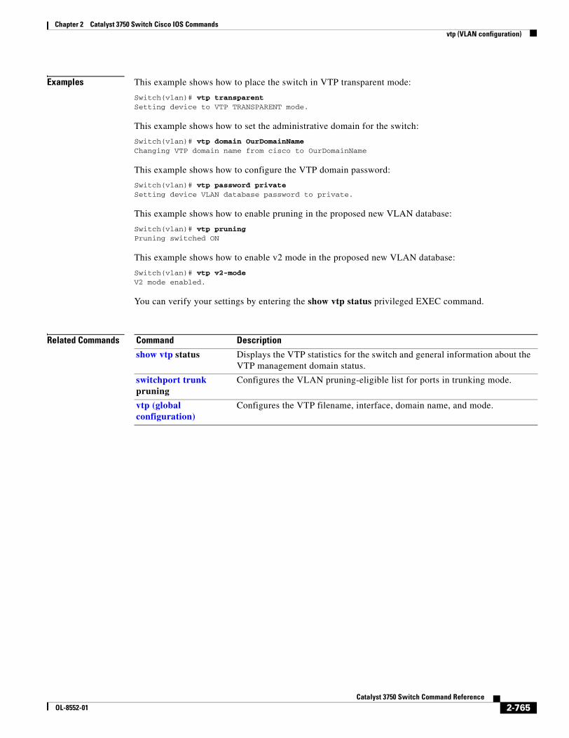
Chapter 2 Catalyst 3750 Switch Cisco IOS Commandsvtp (VLAN configuration)
Examples This example shows how to place the switch in VTP transparent mode:
Switch(vlan)# vtp transparentSetting device to VTP TRANSPARENT mode.
This example shows how to set the administrative domain for the switch:
Switch(vlan)# vtp domain OurDomainNameChanging VTP domain name from cisco to OurDomainName
This example shows how to configure the VTP domain password:
Switch(vlan)# vtp password privateSetting device VLAN database password to private.
This example shows how to enable pruning in the proposed new VLAN database:
Switch(vlan)# vtp pruningPruning switched ON
This example shows how to enable v2 mode in the proposed new VLAN database:
Switch(vlan)# vtp v2-modeV2 mode enabled.
You can verify your settings by entering the show vtp status privileged EXEC command.
Related Commands Command Description
show vtp status Displays the VTP statistics for the switch and general information about the VTP management domain status.
switchport trunk pruning
Configures the VLAN pruning-eligible list for ports in trunking mode.
vtp (global configuration)
Configures the VTP filename, interface, domain name, and mode.
2-765Catalyst 3750 Switch Command Reference
OL-8552-01

Chapter 2 Catalyst 3750 Switch Cisco IOS Commandsvtp (VLAN configuration)
2-766Catalyst 3750 Switch Command Reference
OL-8552-01
CaOL-8552-01
A P P E N D I X A
Catalyst 3750 Switch Boot Loader CommandsThis appendix describes the boot loader commands on the Catalyst 3750 switch. Unless otherwise noted, the term switch refers to a standalone switch and to a switch stack.
During normal boot loader operation, you are not presented with the boot loader command-line prompt. You gain access to the boot loader command line if the switch is set to manually boot, if an error occurs during power-on self test (POST) DRAM testing, or if an error occurs while loading the operating system (a corrupted Cisco IOS image). You can also access the boot loader if you have lost or forgotten the switch password.
Note The default switch configuration allows an end user with physical access to the switch to recover from a lost password by interrupting the boot process while the switch is powering up and then entering a new password. The password recovery disable feature allows the system administrator to protect access to the switch password by disabling part of this functionality and allowing the user to interrupt the boot process only by agreeing to set the system back to the default configuration. With password recovery disabled, the user can still interrupt the boot process and change the password, but the configuration file (config.text) and the VLAN database file (vlan.dat) are deleted. For more information, see the software configuration guide for this release.
You can access the boot loader through a switch console connection at 9600 bps. Unplug the switch power cord, and press the switch Mode button while reconnecting the power cord. You can release the Mode button a second or two after the LED above port 1X goes off. You should then see the boot loader Switch: prompt. The boot loader performs low-level CPU initialization, performs POST, and loads a default operating system image into memory.
A-1talyst 3750 Switch Command Reference
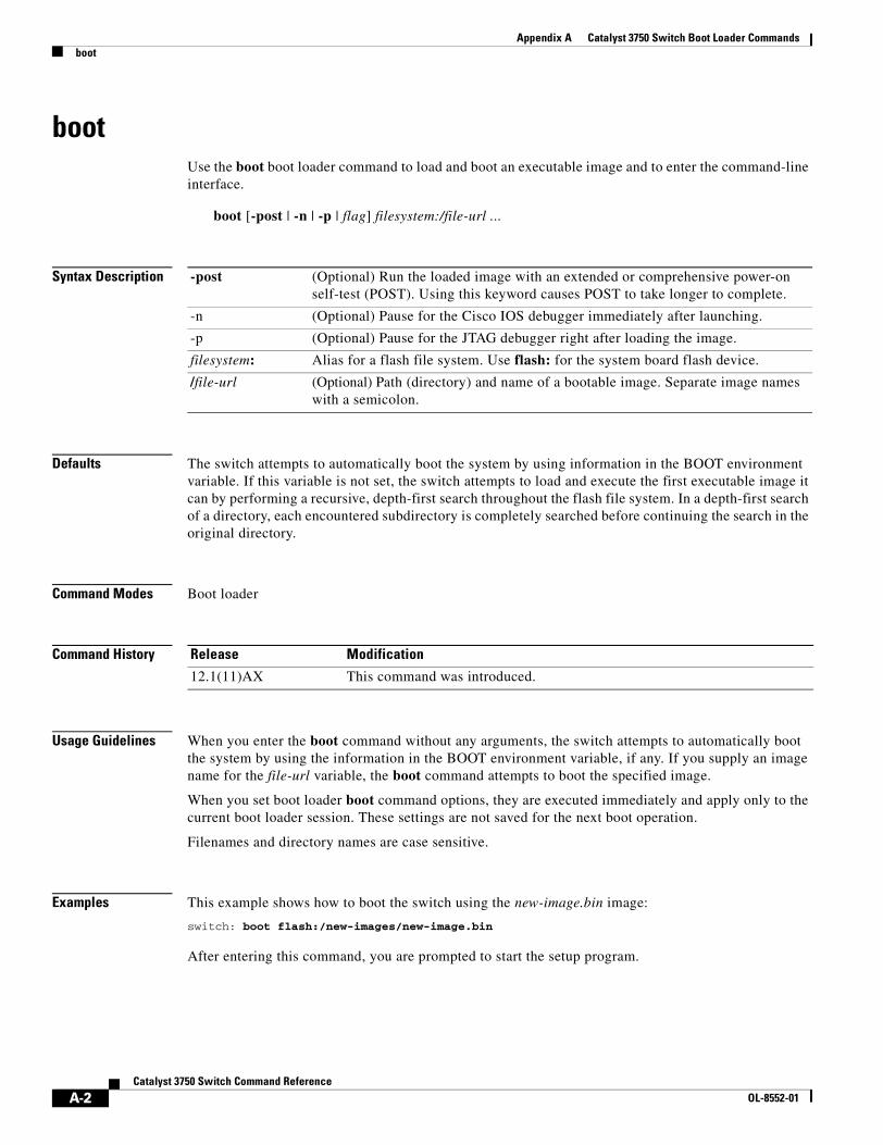
Appendix A Catalyst 3750 Switch Boot Loader Commandsboot
bootUse the boot boot loader command to load and boot an executable image and to enter the command-line interface.
boot [-post | -n | -p | flag] filesystem:/file-url ...
Syntax Description
Defaults The switch attempts to automatically boot the system by using information in the BOOT environment variable. If this variable is not set, the switch attempts to load and execute the first executable image it can by performing a recursive, depth-first search throughout the flash file system. In a depth-first search of a directory, each encountered subdirectory is completely searched before continuing the search in the original directory.
Command Modes Boot loader
Command History
Usage Guidelines When you enter the boot command without any arguments, the switch attempts to automatically boot the system by using the information in the BOOT environment variable, if any. If you supply an image name for the file-url variable, the boot command attempts to boot the specified image.
When you set boot loader boot command options, they are executed immediately and apply only to the current boot loader session. These settings are not saved for the next boot operation.
Filenames and directory names are case sensitive.
Examples This example shows how to boot the switch using the new-image.bin image:
switch: boot flash:/new-images/new-image.bin
After entering this command, you are prompted to start the setup program.
-post (Optional) Run the loaded image with an extended or comprehensive power-on self-test (POST). Using this keyword causes POST to take longer to complete.
-n (Optional) Pause for the Cisco IOS debugger immediately after launching.
-p (Optional) Pause for the JTAG debugger right after loading the image.
filesystem: Alias for a flash file system. Use flash: for the system board flash device.
/file-url (Optional) Path (directory) and name of a bootable image. Separate image names with a semicolon.
Release Modification
12.1(11)AX This command was introduced.
A-2Catalyst 3750 Switch Command Reference
OL-8552-01

Appendix A Catalyst 3750 Switch Boot Loader Commandsboot
Related Commands Command Description
set Sets the BOOT environment variable to boot a specific image when the BOOT keyword is appended to the command.
A-3Catalyst 3750 Switch Command Reference
OL-8552-01
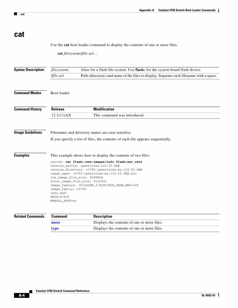
Appendix A Catalyst 3750 Switch Boot Loader Commandscat
catUse the cat boot loader command to display the contents of one or more files.
cat filesystem:/file-url ...
Syntax Description
Command Modes Boot loader
Command History
Usage Guidelines Filenames and directory names are case sensitive.
If you specify a list of files, the contents of each file appears sequentially.
Examples This example shows how to display the contents of two files:
switch: cat flash:/new-images/info flash:env_varsversion_suffix: ipservices-122-25.SEBversion_directory: c3750-ipservices-mz.122-25.SEBimage_name: c3750-ipservices-mz.122-25.SEB.binios_image_file_size: 6398464total_image_file_size: 8133632image_feature: IP|LAYER_3|PLUS|MIN_DRAM_MEG=128image_family: C3750info_end:BAUD=57600MANUAL_BOOT=no
Related Commands
filesystem: Alias for a flash file system. Use flash: for the system board flash device.
/file-url Path (directory) and name of the files to display. Separate each filename with a space.
Release Modification
12.1(11)AX This command was introduced.
Command Description
more Displays the contents of one or more files.
type Displays the contents of one or more files.
A-4Catalyst 3750 Switch Command Reference
OL-8552-01
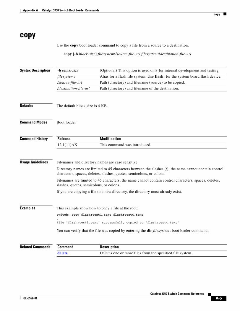
Appendix A Catalyst 3750 Switch Boot Loader Commandscopy
copyUse the copy boot loader command to copy a file from a source to a destination.
copy [-b block-size] filesystem:/source-file-url filesystem:/destination-file-url
Syntax Description
Defaults The default block size is 4 KB.
Command Modes Boot loader
Command History
Usage Guidelines Filenames and directory names are case sensitive.
Directory names are limited to 45 characters between the slashes (/); the name cannot contain control characters, spaces, deletes, slashes, quotes, semicolons, or colons.
Filenames are limited to 45 characters; the name cannot contain control characters, spaces, deletes, slashes, quotes, semicolons, or colons.
If you are copying a file to a new directory, the directory must already exist.
Examples This example show how to copy a file at the root:
switch: copy flash:test1.text flash:test4.text.File "flash:test1.text" successfully copied to "flash:test4.text"
You can verify that the file was copied by entering the dir filesystem: boot loader command.
Related Commands
-b block-size (Optional) This option is used only for internal development and testing.
filesystem: Alias for a flash file system. Use flash: for the system board flash device.
/source-file-url Path (directory) and filename (source) to be copied.
/destination-file-url Path (directory) and filename of the destination.
Release Modification
12.1(11)AX This command was introduced.
Command Description
delete Deletes one or more files from the specified file system.
A-5Catalyst 3750 Switch Command Reference
OL-8552-01
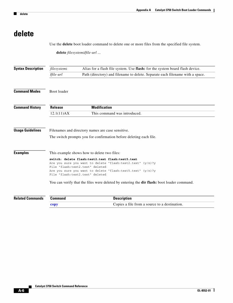
Appendix A Catalyst 3750 Switch Boot Loader Commandsdelete
deleteUse the delete boot loader command to delete one or more files from the specified file system.
delete filesystem:/file-url ...
Syntax Description
Command Modes Boot loader
Command History
Usage Guidelines Filenames and directory names are case sensitive.
The switch prompts you for confirmation before deleting each file.
Examples This example shows how to delete two files:
switch: delete flash:test2.text flash:test5.textAre you sure you want to delete "flash:test2.text" (y/n)?yFile "flash:test2.text" deletedAre you sure you want to delete "flash:test5.text" (y/n)?yFile "flash:test2.text" deleted
You can verify that the files were deleted by entering the dir flash: boot loader command.
Related Commands
filesystem: Alias for a flash file system. Use flash: for the system board flash device.
/file-url Path (directory) and filename to delete. Separate each filename with a space.
Release Modification
12.1(11)AX This command was introduced.
Command Description
copy Copies a file from a source to a destination.
A-6Catalyst 3750 Switch Command Reference
OL-8552-01
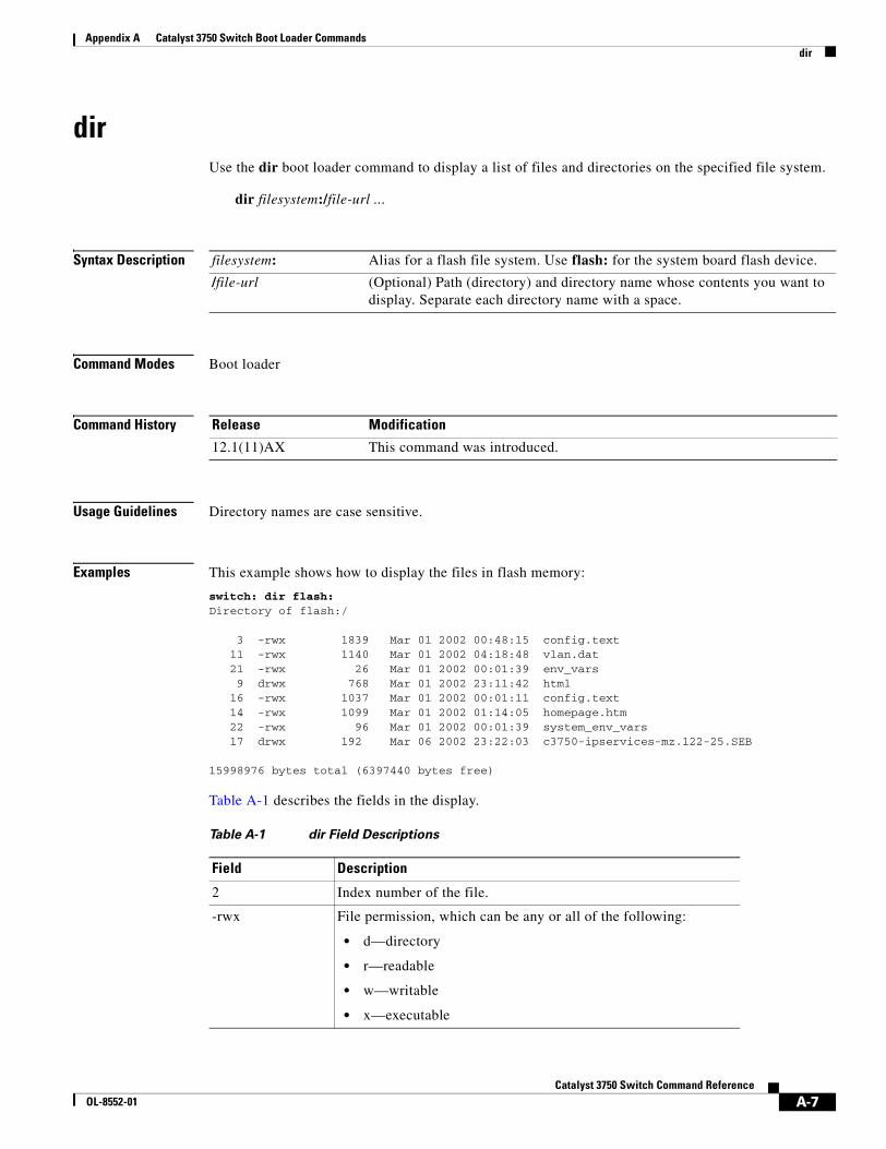
Appendix A Catalyst 3750 Switch Boot Loader Commandsdir
dirUse the dir boot loader command to display a list of files and directories on the specified file system.
dir filesystem:/file-url ...
Syntax Description
Command Modes Boot loader
Command History
Usage Guidelines Directory names are case sensitive.
Examples This example shows how to display the files in flash memory:
switch: dir flash:Directory of flash:/
3 -rwx 1839 Mar 01 2002 00:48:15 config.text 11 -rwx 1140 Mar 01 2002 04:18:48 vlan.dat 21 -rwx 26 Mar 01 2002 00:01:39 env_vars 9 drwx 768 Mar 01 2002 23:11:42 html 16 -rwx 1037 Mar 01 2002 00:01:11 config.text 14 -rwx 1099 Mar 01 2002 01:14:05 homepage.htm 22 -rwx 96 Mar 01 2002 00:01:39 system_env_vars
17 drwx 192 Mar 06 2002 23:22:03 c3750-ipservices-mz.122-25.SEB 15998976 bytes total (6397440 bytes free)
Table A-1 describes the fields in the display.
filesystem: Alias for a flash file system. Use flash: for the system board flash device.
/file-url (Optional) Path (directory) and directory name whose contents you want to display. Separate each directory name with a space.
Release Modification
12.1(11)AX This command was introduced.
Table A-1 dir Field Descriptions
Field Description
2 Index number of the file.
-rwx File permission, which can be any or all of the following:
• d—directory
• r—readable
• w—writable
• x—executable
A-7Catalyst 3750 Switch Command Reference
OL-8552-01
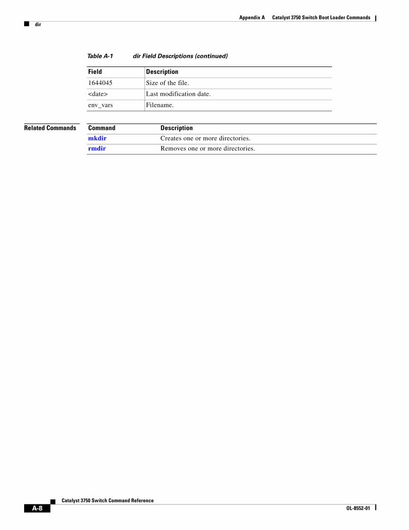
Appendix A Catalyst 3750 Switch Boot Loader Commandsdir
Related Commands
1644045 Size of the file.
<date> Last modification date.
env_vars Filename.
Table A-1 dir Field Descriptions (continued)
Field Description
Command Description
mkdir Creates one or more directories.
rmdir Removes one or more directories.
A-8Catalyst 3750 Switch Command Reference
OL-8552-01
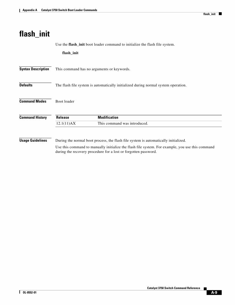
Appendix A Catalyst 3750 Switch Boot Loader Commandsflash_init
flash_initUse the flash_init boot loader command to initialize the flash file system.
flash_init
Syntax Description This command has no arguments or keywords.
Defaults The flash file system is automatically initialized during normal system operation.
Command Modes Boot loader
Command History
Usage Guidelines During the normal boot process, the flash file system is automatically initialized.
Use this command to manually initialize the flash file system. For example, you use this command during the recovery procedure for a lost or forgotten password.
Release Modification
12.1(11)AX This command was introduced.
A-9Catalyst 3750 Switch Command Reference
OL-8552-01
Appendix A Catalyst 3750 Switch Boot Loader Commandsformat
formatUse the format boot loader command to format the specified file system and destroy all data in that file system.
format filesystem:
Syntax Description
Command Modes Boot loader
Command History
Usage Guidelines
Caution Use this command with care; it destroys all data on the file system and renders your system unusable.
filesystem: Alias for a flash file system. Use flash: for the system board flash device.
Release Modification
12.1(11)AX This command was introduced.
A-10Catalyst 3750 Switch Command Reference
OL-8552-01
Appendix A Catalyst 3750 Switch Boot Loader Commandsfsck
fsckUse the fsck boot loader command to check the file system for consistency.
fsck [-test | -f] filesystem:
Syntax Description
Defaults No file system check is performed.
Command Modes Boot loader
Command History
Usage Guidelines To stop an in-progress file system consistency check, disconnect the switch power and then reconnect the power.
Examples This example shows how to perform an extensive file system check on flash memory:
switch: fsck -test flash:
-test (Optional) Initialize the file system code and perform extra POST on flash memory. An extensive, nondestructive memory test is performed on every byte that makes up the file system.
-f (Optional) Initialize the file system code and perform a fast file consistency check. Cyclic redundancy checks (CRCs) in the flashfs sectors are not checked.
filesystem: Alias for a flash file system. Use flash: for the system board flash device.
Release Modification
12.1(11)AX This command was introduced.
A-11Catalyst 3750 Switch Command Reference
OL-8552-01
Appendix A Catalyst 3750 Switch Boot Loader Commandshelp
helpUse the help boot loader command to display the available commands.
help
Syntax Description This command has no arguments or keywords.
Command Modes Boot loader
Command History
Usage Guidelines You can also use the question mark (?) to display a list of available boot loader commands.
Release Modification
12.1(11)AX This command was introduced.
A-12Catalyst 3750 Switch Command Reference
OL-8552-01
Appendix A Catalyst 3750 Switch Boot Loader Commandsload_helper
load_helperUse the load_helper boot loader command to load and initialize one or more helper images, which extend or patch the functionality of the boot loader.
load_helper filesystem:/file-url ...
Syntax Description
Defaults No helper files are loaded.
Command Modes Boot loader
Command History
Usage Guidelines The load_helper command searches for loadable files only if the HELPER environment variable is set.
Filenames and directory names are case sensitive.
filesystem: Alias for a flash file system. Use flash: for the system board flash device.
/file-url Path (directory) and a list of loadable helper files to dynamically load during loader initialization. Separate each image name with a semicolon.
Release Modification
12.1(11)AX This command was introduced.
A-13Catalyst 3750 Switch Command Reference
OL-8552-01
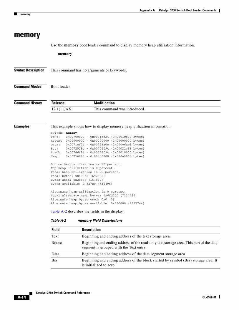
Appendix A Catalyst 3750 Switch Boot Loader Commandsmemory
memoryUse the memory boot loader command to display memory heap utilization information.
memory
Syntax Description This command has no arguments or keywords.
Command Modes Boot loader
Command History
Examples This example shows how to display memory heap utilization information:
switch: memoryText: 0x00700000 - 0x0071cf24 (0x0001cf24 bytes)Rotext: 0x00000000 - 0x00000000 (0x00000000 bytes)Data: 0x0071cf24 - 0x00723a0c (0x00006ae8 bytes)Bss: 0x0072529c - 0x00746f94 (0x00021cf8 bytes)Stack: 0x00746f94 - 0x00756f94 (0x00010000 bytes)Heap: 0x00756f98 - 0x00800000 (0x000a9068 bytes)
Bottom heap utilization is 22 percent.Top heap utilization is 0 percent.Total heap utilization is 22 percent.Total bytes: 0xa9068 (692328)Bytes used: 0x26888 (157832)Bytes available: 0x827e0 (534496)
Alternate heap utilization is 0 percent.Total alternate heap bytes: 0x6fd000 (7327744)Alternate heap bytes used: 0x0 (0)Alternate heap bytes available: 0x6fd000 (7327744)
Table A-2 describes the fields in the display.
Release Modification
12.1(11)AX This command was introduced.
Table A-2 memory Field Descriptions
Field Description
Text Beginning and ending address of the text storage area.
Rotext Beginning and ending address of the read-only text storage area. This part of the data segment is grouped with the Text entry.
Data Beginning and ending address of the data segment storage area.
Bss Beginning and ending address of the block started by symbol (Bss) storage area. It is initialized to zero.
A-14Catalyst 3750 Switch Command Reference
OL-8552-01

Appendix A Catalyst 3750 Switch Boot Loader Commandsmemory
Stack Beginning and ending address of the area in memory allocated to the software to store automatic variables, return addresses, and so forth.
Heap Beginning and ending address of the area in memory that memory is dynamically allocated to and freed from.
Table A-2 memory Field Descriptions (continued)
Field Description
A-15Catalyst 3750 Switch Command Reference
OL-8552-01
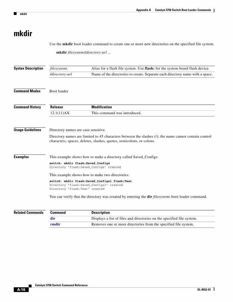
Appendix A Catalyst 3750 Switch Boot Loader Commandsmkdir
mkdirUse the mkdir boot loader command to create one or more new directories on the specified file system.
mkdir filesystem:/directory-url ...
Syntax Description
Command Modes Boot loader
Command History
Usage Guidelines Directory names are case sensitive.
Directory names are limited to 45 characters between the slashes (/); the name cannot contain control characters, spaces, deletes, slashes, quotes, semicolons, or colons.
Examples This example shows how to make a directory called Saved_Configs:
switch: mkdir flash:Saved_ConfigsDirectory "flash:Saved_Configs" created
This example shows how to make two directories:
switch: mkdir flash:Saved_Configs1 flash:TestDirectory "flash:Saved_Configs1" createdDirectory "flash:Test" created
You can verify that the directory was created by entering the dir filesystem: boot loader command.
Related Commands
filesystem: Alias for a flash file system. Use flash: for the system board flash device.
/directory-url Name of the directories to create. Separate each directory name with a space.
Release Modification
12.1(11)AX This command was introduced.
Command Description
dir Displays a list of files and directories on the specified file system.
rmdir Removes one or more directories from the specified file system.
A-16Catalyst 3750 Switch Command Reference
OL-8552-01
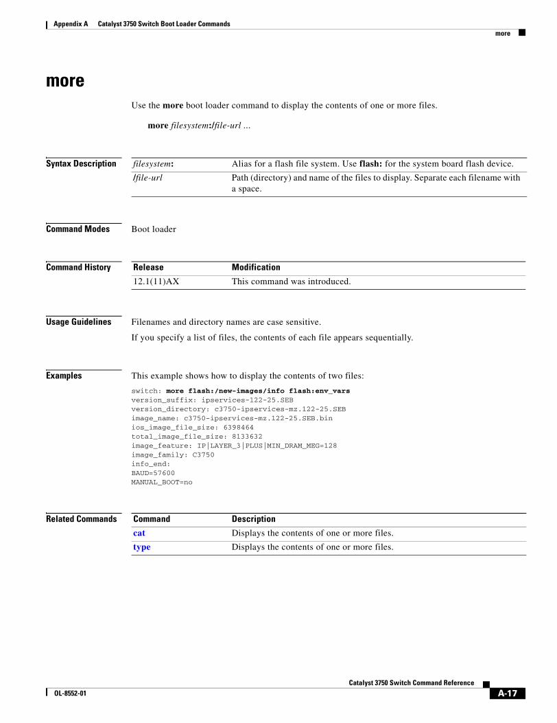
Appendix A Catalyst 3750 Switch Boot Loader Commandsmore
moreUse the more boot loader command to display the contents of one or more files.
more filesystem:/file-url ...
Syntax Description
Command Modes Boot loader
Command History
Usage Guidelines Filenames and directory names are case sensitive.
If you specify a list of files, the contents of each file appears sequentially.
Examples This example shows how to display the contents of two files:
switch: more flash:/new-images/info flash:env_varsversion_suffix: ipservices-122-25.SEBversion_directory: c3750-ipservices-mz.122-25.SEBimage_name: c3750-ipservices-mz.122-25.SEB.binios_image_file_size: 6398464total_image_file_size: 8133632image_feature: IP|LAYER_3|PLUS|MIN_DRAM_MEG=128image_family: C3750info_end:BAUD=57600MANUAL_BOOT=no
Related Commands
filesystem: Alias for a flash file system. Use flash: for the system board flash device.
/file-url Path (directory) and name of the files to display. Separate each filename with a space.
Release Modification
12.1(11)AX This command was introduced.
Command Description
cat Displays the contents of one or more files.
type Displays the contents of one or more files.
A-17Catalyst 3750 Switch Command Reference
OL-8552-01
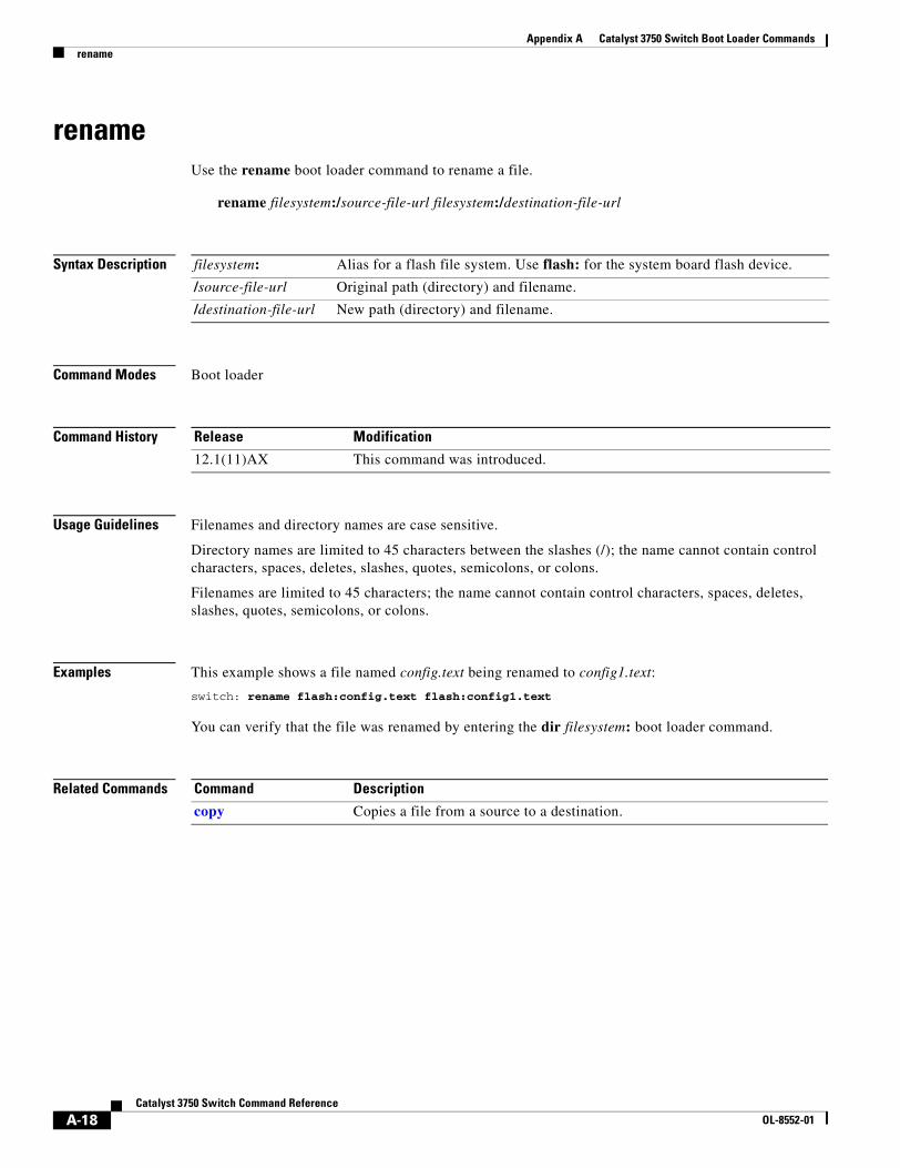
Appendix A Catalyst 3750 Switch Boot Loader Commandsrename
renameUse the rename boot loader command to rename a file.
rename filesystem:/source-file-url filesystem:/destination-file-url
Syntax Description
Command Modes Boot loader
Command History
Usage Guidelines Filenames and directory names are case sensitive.
Directory names are limited to 45 characters between the slashes (/); the name cannot contain control characters, spaces, deletes, slashes, quotes, semicolons, or colons.
Filenames are limited to 45 characters; the name cannot contain control characters, spaces, deletes, slashes, quotes, semicolons, or colons.
Examples This example shows a file named config.text being renamed to config1.text:
switch: rename flash:config.text flash:config1.text
You can verify that the file was renamed by entering the dir filesystem: boot loader command.
Related Commands
filesystem: Alias for a flash file system. Use flash: for the system board flash device.
/source-file-url Original path (directory) and filename.
/destination-file-url New path (directory) and filename.
Release Modification
12.1(11)AX This command was introduced.
Command Description
copy Copies a file from a source to a destination.
A-18Catalyst 3750 Switch Command Reference
OL-8552-01
Appendix A Catalyst 3750 Switch Boot Loader Commandsreset
resetUse the reset boot loader command to perform a hard reset on the system. A hard reset is similar to power-cycling the switch, clearing the processor, registers, and memory.
reset
Syntax Description This command has no arguments or keywords.
Command Modes Boot loader
Command History
Examples This example shows how to reset the system:
switch: resetAre you sure you want to reset the system (y/n)?ySystem resetting...
Related Commands
Release Modification
12.1(11)AX This command was introduced.
Command Description
boot Loads and boots an executable image and enters the command-line interface.
A-19Catalyst 3750 Switch Command Reference
OL-8552-01
Appendix A Catalyst 3750 Switch Boot Loader Commandsrmdir
rmdirUse the rmdir boot loader command to remove one or more empty directories from the specified file system.
rmdir filesystem:/directory-url ...
Syntax Description
Command Modes Boot loader
Command History
Usage Guidelines Directory names are case sensitive and limited to 45 characters between the slashes (/); the name cannot contain control characters, spaces, deletes, slashes, quotes, semicolons, or colons.
Before removing a directory, you must first delete all the files in the directory.
The switch prompts you for confirmation before deleting each directory.
Examples This example shows how to remove a directory:
switch: rmdir flash:Test
You can verify that the directory was deleted by entering the dir filesystem: boot loader command.
Related Commands
filesystem: Alias for a flash file system. Use flash: for the system board flash device.
/directory-url Path (directory) and name of the empty directories to remove. Separate each directory name with a space.
Release Modification
12.1(11)AX This command was introduced.
Command Description
dir Displays a list of files and directories on the specified file system.
mkdir Creates one or more new directories on the specified file system.
A-20Catalyst 3750 Switch Command Reference
OL-8552-01
Appendix A Catalyst 3750 Switch Boot Loader Commandsset
setUse the set boot loader command to set or display environment variables, which can be used to control the boot loader or any other software running on the switch.
set variable value
Syntax Description variable value Use one of these keywords for variable and value:
MANUAL_BOOT—Decides whether the switch automatically or manually boots.
Valid values are 1, yes, 0, and no. If it is set to no or 0, the boot loader attempts to automatically boot the system. If it is set to anything else, you must manually boot the switch from the boot loader mode.
BOOT filesystem:/file-url—A semicolon-separated list of executable files to try to load and execute when automatically booting.
If the BOOT environment variable is not set, the system attempts to load and execute the first executable image it can find by using a recursive, depth-first search through the flash: file system. If the BOOT variable is set but the specified images cannot be loaded, the system attempts to boot the first bootable file that it can find in the flash file system.
ENABLE_BREAK—Decides whether the automatic boot process can be interrupted by using the Break key on the console.
Valid values are 1, yes, on, 0, no, and off. If it is set to 1, yes, or on, you can interrupt the automatic boot process by pressing the Break key on the console after the flash file system has initialized.
HELPER filesystem:/file-url—A semicolon-separated list of loadable files to dynamically load during the boot loader initialization. Helper files extend or patch the functionality of the boot loader.
PS1 prompt—A string that is used as the command-line prompt in boot loader mode.
CONFIG_FILE flash:/file-url—The filename that Cisco IOS uses to read and write a nonvolatile copy of the system configuration.
BAUD rate—The rate in bits per second (bps) used for the console. The Cisco IOS software inherits the baud rate setting from the boot loader and continues to use this value unless the configuration file specifies another setting. The range is from 0 to 4294967295 bps. Valid values are 50, 75, 110, 150, 300, 600, 1200, 1800, 2000, 2400, 3600, 4800, 7200, 9600, 14400, 19200, 28800, 38400, 56000, 57600, 115200, and 128000.
The most commonly used values are 300, 1200, 2400, 9600, 19200, 57600, and 115200.
BOOTHLPR filesystem:/file-url—The name of the Cisco IOS helper image that is first loaded into memory so that it can then load a second Cisco IOS image into memory and launch it. This variable is used only for internal development and testing.
HELPER_CONFIG_FILE filesystem:/file-url—The name of the configuration file to be used by the Cisco IOS helper image. If this is not set, the file specified by the CONFIG_FILE environment variable is used by all versions of Cisco IOS that are loaded, including the helper image. This variable is used only for internal development and testing.
A-21Catalyst 3750 Switch Command Reference
OL-8552-01
Appendix A Catalyst 3750 Switch Boot Loader Commandsset
Defaults The environment variables have these default values:
MANUAL_BOOT: No (0)
BOOT: Null string
ENABLE_BREAK: No (Off or 0) (the automatic boot process cannot be interrupted by pressing the Break key on the console).
HELPER: No default value (helper files are not automatically loaded).
PS1: switch:
CONFIG_FILE: config.text
BAUD: 9600 bps
BOOTHLPR: No default value (no helper images are specified).
HELPER_CONFIG_FILE: No default value (no helper configuration file is specified).
SWITCH_NUMBER: 1
SWITCH_PRIORITY: 1
Note Environment variables that have values are stored in the flash file system in various files. The format of these files is that each line contains an environment variable name and an equal sign followed by the value of the variable. A variable has no value if it is not listed in this file; it has a value if it is listed in the file even if the value is a null string. A variable that is set to a null string (for example, “ ”) is a variable with a value. Many environment variables are predefined and have default values.
Command Modes Boot loader
Command History
Usage Guidelines Environment variables are case sensitive and must be entered as documented.
Environment variables that have values are stored in flash memory outside of the flash file system.
Under normal circumstances, it is not necessary to alter the setting of the environment variables.
The MANUAL_BOOT environment variable can also be set by using the boot manual global configuration command.
The BOOT environment variable can also be set by using the boot system filesystem:/file-url global configuration command.
The ENABLE_BREAK environment variable can also be set by using the boot enable-break global configuration command.
The HELPER environment variable can also be set by using the boot helper filesystem:/file-url global configuration command.
The CONFIG_FILE environment variable can also be set by using the boot config-file flash:/file-url global configuration command.
Release Modification
12.1(11)AX This command was introduced.
A-22Catalyst 3750 Switch Command Reference
OL-8552-01
Appendix A Catalyst 3750 Switch Boot Loader Commandsset
The BOOTHLPR environment variable can also be set by using the boot boothlpr filesystem:/file-url global configuration command.
The HELPER_CONFIG_FILE environment variable can also be set by using the boot helper-config-file filesystem:/file-url global configuration command.
The HELPER_CONFIG_FILE environment variable can also be set by using the boot helper-config-file filesystem:/file-url global configuration command.
The SWITCH_NUMBER environment variable can also be set by using the switch current-stack-member-number renumber new-stack-member-number global configuration command.
The SWITCH_PRIORITY environment variable can also be set by using the switch stack-member-number priority priority-number global configuration command.
The boot loader prompt string (PS1) can be up to 120 printable characters except the equal sign (=).
Examples This example shows how to change the boot loader prompt:
switch: set PS1 loader: loader:
You can verify your setting by using the set boot loader command.
Related Commands Command Description
unset Resets one or more environment variables to its previous setting.
A-23Catalyst 3750 Switch Command Reference
OL-8552-01
Appendix A Catalyst 3750 Switch Boot Loader Commandstype
typeUse the type boot loader command to display the contents of one or more files.
type filesystem:/file-url ...
Syntax Description
Command Modes Boot loader
Command History
Usage Guidelines Filenames and directory names are case sensitive.
If you specify a list of files, the contents of each file appears sequentially.
Examples This example shows how to display the contents of two files:
switch: type flash:/new-images/info flash:env_varsversion_suffix: ipservices-122-25.SEBversion_directory: c3750-ipservices-mz.122-25.SEBimage_name: c3750-ipservices-mz.122-25.SEB.binios_image_file_size: 6398464total_image_file_size: 8133632image_feature: IP|LAYER_3|PLUS|MIN_DRAM_MEG=128image_family: C3750info_end:BAUD=57600MANUAL_BOOT=no
Related Commands
filesystem: Alias for a flash file system. Use flash: for the system board flash device.
/file-url Path (directory) and name of the files to display. Separate each filename with a space.
Release Modification
12.1(11)AX This command was introduced.
Command Description
cat Displays the contents of one or more files.
more Displays the contents of one or more files.
A-24Catalyst 3750 Switch Command Reference
OL-8552-01
Appendix A Catalyst 3750 Switch Boot Loader Commandsunset
unsetUse the unset boot loader command to reset one or more environment variables.
unset variable ...
Syntax Description
Command Modes Boot loader
Command History
variable Use one of these keywords for variable:
MANUAL_BOOT—Decides whether the switch automatically or manually boots.
BOOT—Resets the list of executable files to try to load and execute when automatically booting. If the BOOT environment variable is not set, the system attempts to load and execute the first executable image it can find by using a recursive, depth-first search through the flash file system. If the BOOT variable is set but the specified images cannot be loaded, the system attempts to boot the first bootable file that it can find in the flash file system.
ENABLE_BREAK—Decides whether the automatic boot process can be interrupted by using the Break key on the console after the flash file system has been initialized.
HELPER—A semicolon-separated list of loadable files to dynamically load during the boot loader initialization. Helper files extend or patch the functionality of the boot loader.
PS1—A string that is used as the command-line prompt in boot loader mode.
CONFIG_FILE—Resets the filename that Cisco IOS uses to read and write a nonvolatile copy of the system configuration.
BAUD—Resets the rate in bits per second (bps) used for the console. The Cisco IOS software inherits the baud rate setting from the boot loader and continues to use this value unless the configuration file specifies another setting.
BOOTHLPR—Resets the name of the Cisco IOS helper image that is first loaded into memory so that it can then load a second Cisco IOS image into memory and launch it. This variable is used only for internal development and testing.
HELPER_CONFIG_FILE—Resets the name of the configuration file to be used by the Cisco IOS helper image. If this is not set, the file specified by the CONFIG_FILE environment variable is used by all versions of Cisco IOS that are loaded, including the helper image. This variable is used only for internal development and testing.
Release Modification
12.1(11)AX This command was introduced.
A-25Catalyst 3750 Switch Command Reference
OL-8552-01
Appendix A Catalyst 3750 Switch Boot Loader Commandsunset
Usage Guidelines Under normal circumstances, it is not necessary to alter the setting of the environment variables.
The MANUAL_BOOT environment variable can also be reset by using the no boot manual global configuration command.
The BOOT environment variable can also be reset by using the no boot system global configuration command.
The ENABLE_BREAK environment variable can also be reset by using the no boot enable-break global configuration command.
The HELPER environment variable can also be reset by using the no boot helper global configuration command.
The CONFIG_FILE environment variable can also be reset by using the no boot config-file global configuration command.
The BOOTHLPR environment variable can also be reset by using the no boot boothlpr global configuration command.
The HELPER_CONFIG_FILE environment variable can also be reset by using the no boot helper-config-file global configuration command.
Examples This example shows how to reset the prompt string to its previous setting:
switch: unset PS1switch:
Related Commands Command Description
set Sets or displays environment variables.
A-26Catalyst 3750 Switch Command Reference
OL-8552-01
Appendix A Catalyst 3750 Switch Boot Loader Commandsversion
versionUse the version boot loader command to display the boot loader version.
version
Syntax Description This command has no arguments or keywords.
Command Modes Boot loader
Command History
Examples This example shows how to display the boot loader version:
switch: versionC3750 Boot Loader (C3750-HBOOT-M) Version 12.1(11)AX
Compiled Wed 21-Feb-02 14:58 by devgoyal
switch:
Release Modification
12.1(11)AX This command was introduced.
A-27Catalyst 3750 Switch Command Reference
OL-8552-01

Appendix A Catalyst 3750 Switch Boot Loader Commandsversion
A-28Catalyst 3750 Switch Command Reference
OL-8552-01
CaOL-8552-01
A P P E N D I X B
Catalyst 3750 Switch Debug CommandsThis appendix describes the debug privileged EXEC commands that have been created or changed for use with the Catalyst 3750 switch. These commands are helpful in diagnosing and resolving internetworking problems and should be enabled only under the guidance of Cisco technical support staff.
Caution Because debugging output is assigned high priority in the CPU process, it can render the system unusable. For this reason, use the debug commands only to troubleshoot specific problems or during troubleshooting sessions with Cisco technical support staff. It is best to use the debug commands during periods of lower network traffic and fewer users. Debugging during these periods decreases the likelihood that increased debug command processing overhead will affect system use.
B-1talyst 3750 Switch Command Reference
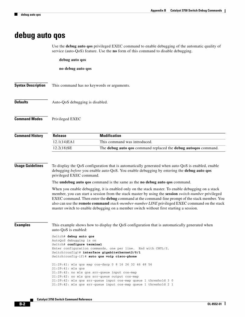
Appendix B Catalyst 3750 Switch Debug Commandsdebug auto qos
debug auto qosUse the debug auto qos privileged EXEC command to enable debugging of the automatic quality of service (auto-QoS) feature. Use the no form of this command to disable debugging.
debug auto qos
no debug auto qos
Syntax Description This command has no keywords or arguments.
Defaults Auto-QoS debugging is disabled.
Command Modes Privileged EXEC
Command History
Usage Guidelines To display the QoS configuration that is automatically generated when auto-QoS is enabled, enable debugging before you enable auto-QoS. You enable debugging by entering the debug auto qos privileged EXEC command.
The undebug auto qos command is the same as the no debug auto qos command.
When you enable debugging, it is enabled only on the stack master. To enable debugging on a stack member, you can start a session from the stack master by using the session switch-number privileged EXEC command. Then enter the debug command at the command-line prompt of the stack member. You also can use the remote command stack-member-number LINE privileged EXEC command on the stack master switch to enable debugging on a member switch without first starting a session.
Examples This example shows how to display the QoS configuration that is automatically generated when auto-QoS is enabled:
Switch# debug auto qosAutoQoS debugging is onSwitch# configure terminalEnter configuration commands, one per line. End with CNTL/Z.Switch(config)# interface gigabitethernet2/0/1Switch(config-if)# auto qos voip cisco-phone
21:29:41: mls qos map cos-dscp 0 8 16 26 32 46 48 5621:29:41: mls qos21:29:42: no mls qos srr-queue input cos-map21:29:42: no mls qos srr-queue output cos-map21:29:42: mls qos srr-queue input cos-map queue 1 threshold 3 021:29:42: mls qos srr-queue input cos-map queue 1 threshold 2 1
Release Modification
12.1(14)EA1 This command was introduced.
12.2(18)SE The debug auto qos command replaced the debug autoqos command.
B-2Catalyst 3750 Switch Command Reference
OL-8552-01
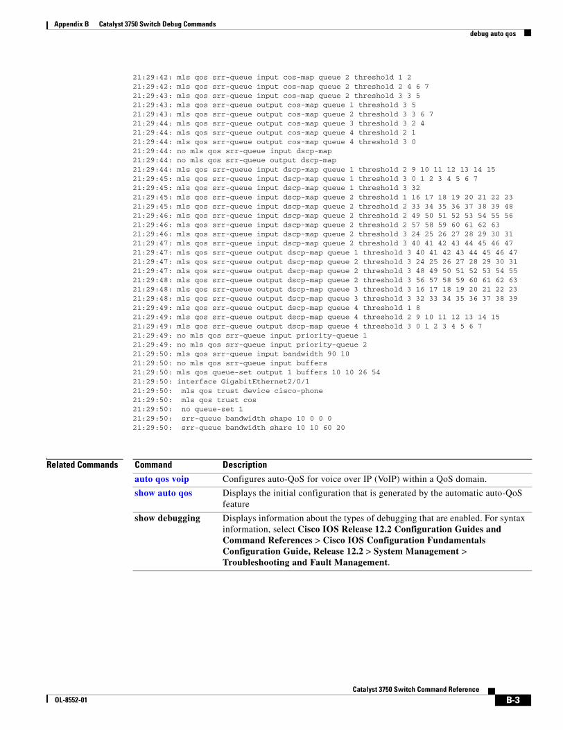
Appendix B Catalyst 3750 Switch Debug Commandsdebug auto qos
21:29:42: mls qos srr-queue input cos-map queue 2 threshold 1 221:29:42: mls qos srr-queue input cos-map queue 2 threshold 2 4 6 721:29:43: mls qos srr-queue input cos-map queue 2 threshold 3 3 521:29:43: mls qos srr-queue output cos-map queue 1 threshold 3 521:29:43: mls qos srr-queue output cos-map queue 2 threshold 3 3 6 721:29:44: mls qos srr-queue output cos-map queue 3 threshold 3 2 421:29:44: mls qos srr-queue output cos-map queue 4 threshold 2 121:29:44: mls qos srr-queue output cos-map queue 4 threshold 3 021:29:44: no mls qos srr-queue input dscp-map21:29:44: no mls qos srr-queue output dscp-map21:29:44: mls qos srr-queue input dscp-map queue 1 threshold 2 9 10 11 12 13 14 1521:29:45: mls qos srr-queue input dscp-map queue 1 threshold 3 0 1 2 3 4 5 6 721:29:45: mls qos srr-queue input dscp-map queue 1 threshold 3 3221:29:45: mls qos srr-queue input dscp-map queue 2 threshold 1 16 17 18 19 20 21 22 2321:29:45: mls qos srr-queue input dscp-map queue 2 threshold 2 33 34 35 36 37 38 39 4821:29:46: mls qos srr-queue input dscp-map queue 2 threshold 2 49 50 51 52 53 54 55 5621:29:46: mls qos srr-queue input dscp-map queue 2 threshold 2 57 58 59 60 61 62 6321:29:46: mls qos srr-queue input dscp-map queue 2 threshold 3 24 25 26 27 28 29 30 31 21:29:47: mls qos srr-queue input dscp-map queue 2 threshold 3 40 41 42 43 44 45 46 4721:29:47: mls qos srr-queue output dscp-map queue 1 threshold 3 40 41 42 43 44 45 46 4721:29:47: mls qos srr-queue output dscp-map queue 2 threshold 3 24 25 26 27 28 29 30 3121:29:47: mls qos srr-queue output dscp-map queue 2 threshold 3 48 49 50 51 52 53 54 5521:29:48: mls qos srr-queue output dscp-map queue 2 threshold 3 56 57 58 59 60 61 62 6321:29:48: mls qos srr-queue output dscp-map queue 3 threshold 3 16 17 18 19 20 21 22 2321:29:48: mls qos srr-queue output dscp-map queue 3 threshold 3 32 33 34 35 36 37 38 3921:29:49: mls qos srr-queue output dscp-map queue 4 threshold 1 821:29:49: mls qos srr-queue output dscp-map queue 4 threshold 2 9 10 11 12 13 14 1521:29:49: mls qos srr-queue output dscp-map queue 4 threshold 3 0 1 2 3 4 5 6 721:29:49: no mls qos srr-queue input priority-queue 121:29:49: no mls qos srr-queue input priority-queue 221:29:50: mls qos srr-queue input bandwidth 90 1021:29:50: no mls qos srr-queue input buffers21:29:50: mls qos queue-set output 1 buffers 10 10 26 5421:29:50: interface GigabitEthernet2/0/121:29:50: mls qos trust device cisco-phone21:29:50: mls qos trust cos21:29:50: no queue-set 121:29:50: srr-queue bandwidth shape 10 0 0 021:29:50: srr-queue bandwidth share 10 10 60 20
Related Commands Command Description
auto qos voip Configures auto-QoS for voice over IP (VoIP) within a QoS domain.
show auto qos Displays the initial configuration that is generated by the automatic auto-QoS feature
show debugging Displays information about the types of debugging that are enabled. For syntax information, select Cisco IOS Release 12.2 Configuration Guides and Command References > Cisco IOS Configuration Fundamentals Configuration Guide, Release 12.2 > System Management > Troubleshooting and Fault Management.
B-3Catalyst 3750 Switch Command Reference
OL-8552-01
Appendix B Catalyst 3750 Switch Debug Commandsdebug backup
debug backupUse the debug backup privileged EXEC command to enable debugging of the Flex Links backup interface. Use the no form of this command to disable debugging.
debug backup {all | errors | events}
no debug backup {all | errors | events}
Syntax Description
Command Default Backup interface debugging is disabled.
Command Modes Privileged EXEC
Command History
Usage Guidelines The undebug backup command is the same as the no debug backup command.
When you enable debugging, it is enabled only on the stack master. To enable debugging on a stack member, you can start a session from the stack master by using the session switch-number privileged EXEC command. Then enter the debug command at the command-line prompt of the stack member. You also can use the remote command stack-member-number LINE privileged EXEC command on the stack master switch to enable debugging on a member switch without first starting a session.
Related Commands
all Display all backup interface debug messages.
errors Display backup interface error or exception debug messages.
events Display backup interface event debug messages.
Release Modification
12.2(20)SE This command was introduced.
Command Description
show debugging Displays information about the types of debugging that are enabled. For syntax information, select Cisco IOS Release 12.2 Configuration Guides and Command References > Cisco IOS Configuration Fundamentals Configuration Guide, Release 12.2 > System Management > Troubleshooting and Fault Management.
B-4Catalyst 3750 Switch Command Reference
OL-8552-01
Appendix B Catalyst 3750 Switch Debug Commandsdebug cluster
debug clusterUse the debug cluster privileged EXEC command to enable debugging of cluster-specific events. Use the no form of this command to disable debugging.
debug cluster {discovery | events | extended | hsrp | http | ip [packet] | members | nat | neighbors | platform | snmp | vqpxy}
no debug cluster {discovery | events | extended | hsrp | http | ip [packet] | members | nat | neighbors | platform | snmp | vqpxy}
Syntax Description
Defaults Debugging is disabled.
Command Modes Privileged EXEC
Command History
Usage Guidelines This command is available only on the cluster command switch stack or cluster command switch.
The undebug cluster command is the same as the no debug cluster command.
When you enable debugging, it is enabled only on the stack master. To enable debugging on a stack member, you can start a session from the stack master by using the session switch-number privileged EXEC command. Then enter the debug command at the command-line prompt of the stack member. You also can use the remote command stack-member-number LINE privileged EXEC command on the stack master switch to enable debugging on a member switch without first starting a session.
discovery Display cluster discovery debug messages.
events Display cluster event debug messages.
extended Display extended discovery debug messages.
hsrp Display the Hot Standby Router Protocol (HSRP) debug messages.
http Display Hypertext Transfer Protocol (HTTP) debug messages.
ip [packet] Display IP or transport packet debug messages.
members Display cluster member debug messages.
nat Display Network Address Translation (NAT) debug messages.
neighbors Display cluster neighbor debug messages.
platform Display platform-specific cluster debug messages.
snmp Display Simple Network Management Protocol (SNMP) debug messages.
vqpxy Display VLAN Query Protocol (VQP) proxy debug messages.
Release Modification
12.1(11)AX This command was introduced.
B-5Catalyst 3750 Switch Command Reference
OL-8552-01
Appendix B Catalyst 3750 Switch Debug Commandsdebug cluster
Related Commands Command Description
show debugging Displays information about the types of debugging that are enabled. For syntax information, select Cisco IOS Release 12.2 Configuration Guides and Command References > Cisco IOS Configuration Fundamentals Configuration Guide, Release 12.2 > System Management > Troubleshooting and Fault Management.
show cluster Displays the cluster status and a summary of the cluster to which the switch belongs.
show cluster candidates Displays a list of candidate switches when entered on the command switch.
show cluster members Displays information about cluster members when executed on the command switch.
B-6Catalyst 3750 Switch Command Reference
OL-8552-01
Appendix B Catalyst 3750 Switch Debug Commandsdebug dot1x
debug dot1xUse the debug dot1x privileged EXEC command to enable debugging of the IEEE 802.1x authentication feature. Use the no form of this command to disable debugging.
debug dot1x {all | errors | events | feature | packets | registry | state-machine}
no debug dot1x {all | errors | events | feature | packets | registry | state-machine}
Syntax Description
Note Though visible in the command-line help strings, the redundancy keyword is not supported.
Command Default Debugging is disabled.
Command Modes Privileged EXEC
Command History
Usage Guidelines The undebug dot1x command is the same as the no debug dot1x command.
When you enable debugging, it is enabled only on the stack master. To enable debugging on a stack member, you can start a session from the stack master by using the session switch-number privileged EXEC command. Then enter the debug command at the command-line prompt of the stack member. You also can use the remote command stack-member-number LINE privileged EXEC command on the stack master switch to enable debugging on a member switch without first starting a session.
all Display all IEEE 802.1x authentication debug messages.
errors Display IEEE 802.1x error debug messages.
events Display IEEE 802.1x event debug messages.
feature Display IEEE 802.1x feature debug messages.
packets Display IEEE 802.1x packet debug messages.
registry Display IEEE 802.1x registry invocation debug messages.
state-machine Display state-machine related-events debug messages.
Release Modification
12.1(11)AX This command was introduced.
12.1(14)EA1 The authsm, backend, besm, core, and reauthsm keywords were removed. The errors, events, packets registry, and state-machine keywords were added.
12.2(25)SEE The feature keyword was added.
B-7Catalyst 3750 Switch Command Reference
OL-8552-01
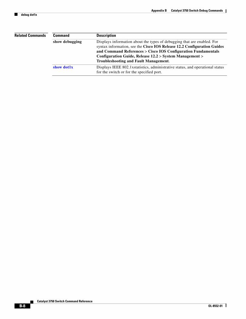
Appendix B Catalyst 3750 Switch Debug Commandsdebug dot1x
Related Commands Command Description
show debugging Displays information about the types of debugging that are enabled. For syntax information, see the Cisco IOS Release 12.2 Configuration Guides and Command References > Cisco IOS Configuration Fundamentals Configuration Guide, Release 12.2 > System Management > Troubleshooting and Fault Management.
show dot1x Displays IEEE 802.1xstatistics, administrative status, and operational status for the switch or for the specified port.
B-8Catalyst 3750 Switch Command Reference
OL-8552-01
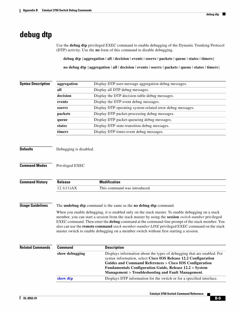
Appendix B Catalyst 3750 Switch Debug Commandsdebug dtp
debug dtpUse the debug dtp privileged EXEC command to enable debugging of the Dynamic Trunking Protocol (DTP) activity. Use the no form of this command to disable debugging.
debug dtp {aggregation | all | decision | events | oserrs | packets | queue | states | timers}
no debug dtp {aggregation | all | decision | events | oserrs | packets | queue | states | timers}
Syntax Description
Defaults Debugging is disabled.
Command Modes Privileged EXEC
Command History
Usage Guidelines The undebug dtp command is the same as the no debug dtp command.
When you enable debugging, it is enabled only on the stack master. To enable debugging on a stack member, you can start a session from the stack master by using the session switch-number privileged EXEC command. Then enter the debug command at the command-line prompt of the stack member. You also can use the remote command stack-member-number LINE privileged EXEC command on the stack master switch to enable debugging on a member switch without first starting a session.
Related Commands
aggregation Display DTP user-message aggregation debug messages.
all Display all DTP debug messages.
decision Display the DTP decision-table debug messages.
events Display the DTP event debug messages.
oserrs Display DTP operating system-related error debug messages.
packets Display DTP packet-processing debug messages.
queue Display DTP packet-queueing debug messages.
states Display DTP state-transition debug messages.
timers Display DTP timer-event debug messages.
Release Modification
12.1(11)AX This command was introduced.
Command Description
show debugging Displays information about the types of debugging that are enabled. For syntax information, select Cisco IOS Release 12.2 Configuration Guides and Command References > Cisco IOS Configuration Fundamentals Configuration Guide, Release 12.2 > System Management > Troubleshooting and Fault Management.
show dtp Displays DTP information for the switch or for a specified interface.
B-9Catalyst 3750 Switch Command Reference
OL-8552-01
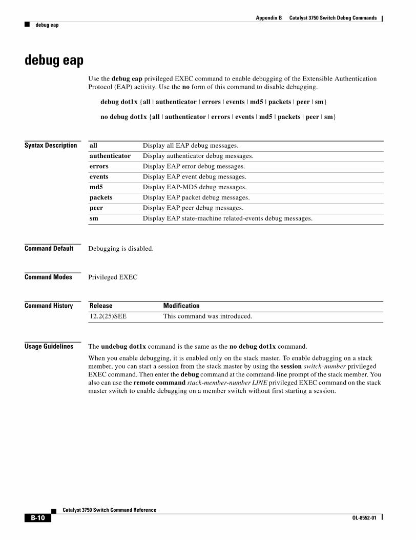
Appendix B Catalyst 3750 Switch Debug Commandsdebug eap
debug eapUse the debug eap privileged EXEC command to enable debugging of the Extensible Authentication Protocol (EAP) activity. Use the no form of this command to disable debugging.
debug dot1x {all | authenticator | errors | events | md5 | packets | peer | sm}
no debug dot1x {all | authenticator | errors | events | md5 | packets | peer | sm}
Syntax Description
Command Default Debugging is disabled.
Command Modes Privileged EXEC
Command History
Usage Guidelines The undebug dot1x command is the same as the no debug dot1x command.
When you enable debugging, it is enabled only on the stack master. To enable debugging on a stack member, you can start a session from the stack master by using the session switch-number privileged EXEC command. Then enter the debug command at the command-line prompt of the stack member. You also can use the remote command stack-member-number LINE privileged EXEC command on the stack master switch to enable debugging on a member switch without first starting a session.
all Display all EAP debug messages.
authenticator Display authenticator debug messages.
errors Display EAP error debug messages.
events Display EAP event debug messages.
md5 Display EAP-MD5 debug messages.
packets Display EAP packet debug messages.
peer Display EAP peer debug messages.
sm Display EAP state-machine related-events debug messages.
Release Modification
12.2(25)SEE This command was introduced.
B-10Catalyst 3750 Switch Command Reference
OL-8552-01
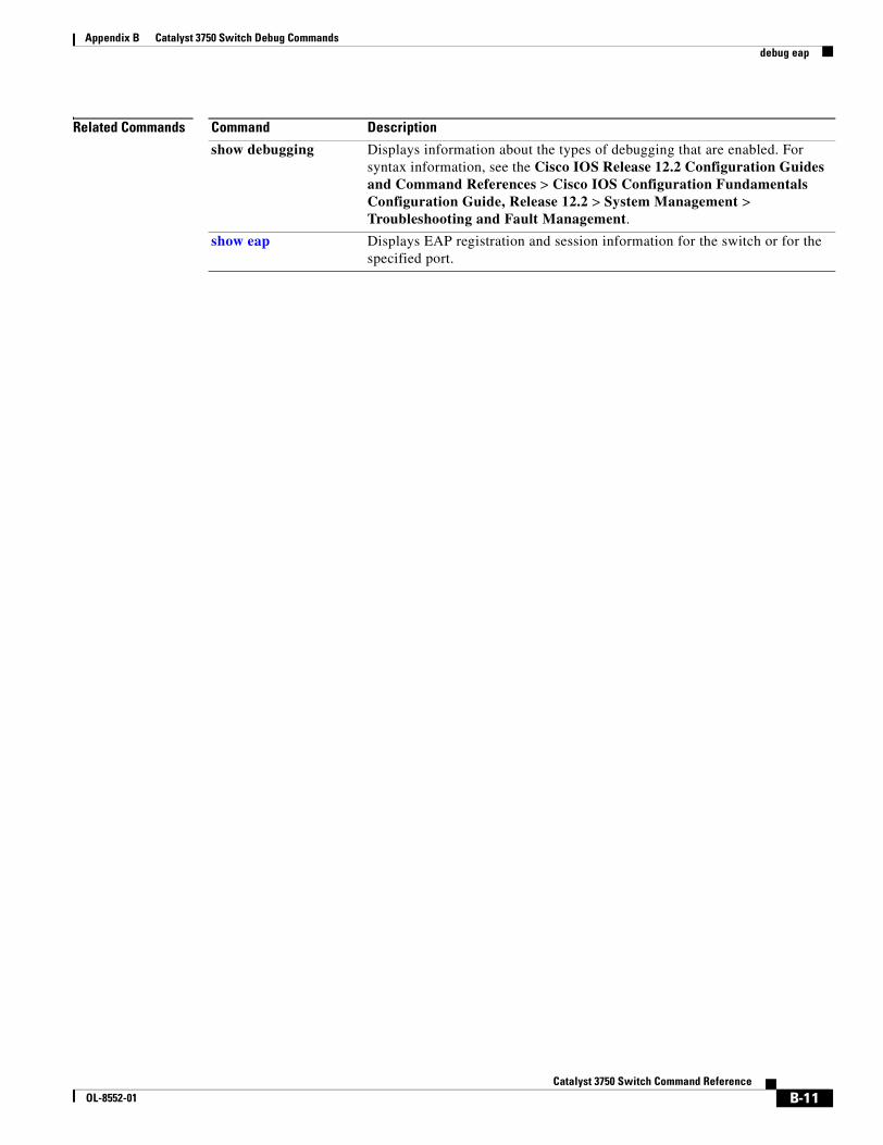
Appendix B Catalyst 3750 Switch Debug Commandsdebug eap
Related Commands Command Description
show debugging Displays information about the types of debugging that are enabled. For syntax information, see the Cisco IOS Release 12.2 Configuration Guides and Command References > Cisco IOS Configuration Fundamentals Configuration Guide, Release 12.2 > System Management > Troubleshooting and Fault Management.
show eap Displays EAP registration and session information for the switch or for the specified port.
B-11Catalyst 3750 Switch Command Reference
OL-8552-01
Appendix B Catalyst 3750 Switch Debug Commandsdebug etherchannel
debug etherchannelUse the debug etherchannel privileged EXEC command to enable debugging of the EtherChannel/PAgP shim. This shim is the software module that is the interface between the Port Aggregation Protocol (PAgP) software module and the port manager software module. Use the no form of this command to disable debugging.
debug etherchannel [all | detail | error | event | idb]
no debug etherchannel [all | detail | error | event | idb]
Syntax Description
Note Though visible in the command-line help strings, the linecard keyword is not supported.
Defaults Debugging is disabled.
Command Modes Privileged EXEC
Command History
Usage Guidelines If you do not specify a keyword, all debug messages appear.
The undebug etherchannel command is the same as the no debug etherchannel command.
When you enable debugging, it is enabled only on the stack master. To enable debugging on a stack member, you can start a session from the stack master by using the session switch-number privileged EXEC command. Then enter the debug command at the command-line prompt of the stack member. You also can use the remote command stack-member-number LINE privileged EXEC command on the stack master switch to enable debugging on a member switch without first starting a session.
all (Optional) Display all EtherChannel debug messages.
detail (Optional) Display detailed EtherChannel debug messages.
error (Optional) Display EtherChannel error debug messages.
event (Optional) Debug major EtherChannel event messages.
idb (Optional) Display PAgP interface descriptor block debug messages.
Release Modification
12.1(11)AX This command was introduced.
B-12Catalyst 3750 Switch Command Reference
OL-8552-01

Appendix B Catalyst 3750 Switch Debug Commandsdebug etherchannel
Related Commands Command Description
show debugging Displays information about the types of debugging that are enabled. For syntax information, select Cisco IOS Release 12.2 Configuration Guides and Command References > Cisco IOS Configuration Fundamentals Configuration Guide, Release 12.2 > System Management > Troubleshooting and Fault Management.
show etherchannel Displays EtherChannel information for the channel.
B-13Catalyst 3750 Switch Command Reference
OL-8552-01
Appendix B Catalyst 3750 Switch Debug Commandsdebug ilpower
debug ilpowerUse the debug ilpower privileged EXEC command to enable debugging of the power controller and Power over Ethernet (PoE) system. Use the no form of this command to disable debugging.
debug ilpower {cdp | controller | event | ha | port | powerman | registries}
no debug ilpower {cdp | controller | event | ha | port | powerman | registries}
Syntax Description
Defaults Debugging is disabled.
Command Modes Privileged EXEC
Command History
Usage Guidelines This command is supported only on PoE-capable switches.
When you enable debugging, it is enabled only on the stack master. To enable debugging on a stack member, you can start a session from the stack master by using the session switch-number privileged EXEC command. Then enter the debug command at the command-line prompt of the stack member. You also can use the remote command stack-member-number LINE privileged EXEC command on the stack master switch to enable debugging on a member switch without first starting a session.
Related Commands
cdp Display PoE Cisco Discovery Protocol (CDP) debug messages.
controller Display PoE controller debug messages.
event Display PoE event debug messages.
ha Display PoE high-availability messages.
port Display PoE port manager debug messages.
powerman Display PoE power management debug messages.
registries Display PoE registries debug messages.
Release Modification
12.1(19)EA1 This command was introduced.
12.2(25)SE The cdp, ha, and powerman keywords were added.
Command Description
show controllers power inline Displays the values in the registers of the specified PoE controller.
show power inline Displays the power status for the specified PoE port or for all PoE ports.
B-14Catalyst 3750 Switch Command Reference
OL-8552-01
Appendix B Catalyst 3750 Switch Debug Commandsdebug ip dhcp snooping
debug ip dhcp snoopingUse the debug ip dhcp snooping privileged EXEC command to enable debugging of DHCP snooping. Use the no form of this command to disable debugging.
debug ip dhcp snooping {mac-address | agent | event | packet}
no debug ip dhcp snooping {mac-address | agent | event | packet}
This command is available only if your switch is running the IP services image, formerly known as the enhanced multilayer image (EMI).
Syntax Description
Defaults Debugging is disabled.
Command Modes Privileged EXEC
Command History
Usage Guidelines The undebug ip dhcp snooping command is the same as the no debug ip dhcp snooping command.
When you enable debugging, it is enabled only on the stack master. To enable debugging on a stack member, you can start a session from the stack master by using the session switch-number privileged EXEC command. Then enter the debug command at the command-line prompt of the stack member. You also can use the remote command stack-member-number LINE privileged EXEC command on the stack master switch to enable debugging on a member switch without first starting a session.
Related Commands
mac-address Display debug messages for a DHCP packet with the specified MAC address.
agent Display debug messages for DHCP snooping agents.
event Display debug messages for DHCP snooping events.
packet Display debug messages for DHCP snooping.
Release Modification
12.2(20)SE This command was introduced.
Command Description
show debugging Displays information about the types of debugging that are enabled. For syntax information, select Cisco IOS Release 12.2 Configuration Guides and Command References > Cisco IOS Configuration Fundamentals Configuration Guide, Release 12.2 > System Management > Troubleshooting and Fault Management.
B-15Catalyst 3750 Switch Command Reference
OL-8552-01
Appendix B Catalyst 3750 Switch Debug Commandsdebug ip verify source packet
debug ip verify source packet Use the debug ip verify source packet privileged EXEC command to enable debugging of IP source guard. Use the no form of this command to disable debugging.
debug ip verify source packet
no debug ip verify source packet
Syntax Description This command has no arguments or keywords.
Defaults Debugging is disabled.
Command Modes Privileged EXEC
Command History
Usage Guidelines The undebug ip verify source packet command is the same as the no debug ip verify source packet command.
When you enable debugging, it is enabled only on the stack master. To enable debugging on a stack member, you can start a session from the stack master by using the session switch-number privileged EXEC command. Then enter the debug command at the command-line prompt of the stack member. You also can use the remote command stack-member-number LINE privileged EXEC command on the stack master switch to enable debugging on a member switch without first starting a session.
Related Commands
Release Modification
12.2(20)SE This command was introduced.
Command Description
show debugging Displays information about the types of debugging that are enabled. For syntax information, select Cisco IOS Release 12.2 Configuration Guides and Command References > Cisco IOS Configuration Fundamentals Configuration Guide, Release 12.2 > System Management > Troubleshooting and Fault Management.
B-16Catalyst 3750 Switch Command Reference
OL-8552-01
Appendix B Catalyst 3750 Switch Debug Commandsdebug interface
debug interfaceUse the debug interface privileged EXEC command to enable debugging of interface-related activities. Use the no form of this command to disable debugging.
debug interface {interface-id | null interface-number | port-channel port-channel-number | vlan vlan-id}
no debug interface {interface-id | null interface-number | port-channel port-channel-number | vlan vlan-id}
Syntax Description
Defaults Debugging is disabled.
Command Modes Privileged EXEC
Command History
Usage Guidelines If you do not specify a keyword, all debug messages appear.
The undebug interface command is the same as the no debug interface command.
When you enable debugging, it is enabled only on the stack master. To enable debugging on a stack member, you can start a session from the stack master by using the session switch-number privileged EXEC command. Then enter the debug command at the command-line prompt of the stack member. You also can use the remote command stack-member-number LINE privileged EXEC command on the stack master switch to enable debugging on a member switch without first starting a session.
interface-id Display debug messages for the specified physical port, identified by type switch number/module number/ port, for example gigabitethernet 1/0/2.
null interface-number Display debug messages for null interfaces. The interface-number is always 0.
port-channel port-channel-number
Display debug messages for the specified EtherChannel port-channel interface. The port-channel-number range is 1 to 48.
vlan vlan-id Display debug messages for the specified VLAN. The vlan-id range is 1 to 4094.
Release Modification
12.1(11)AX This command was introduced.
B-17Catalyst 3750 Switch Command Reference
OL-8552-01

Appendix B Catalyst 3750 Switch Debug Commandsdebug interface
Related Commands Command Description
show debugging Displays information about the types of debugging that are enabled. For syntax information, select Cisco IOS Release 12.2 Configuration Guides and Command References > Cisco IOS Configuration Fundamentals Configuration Guide, Release 12.2 > System Management > Troubleshooting and Fault Management.
show etherchannel Displays EtherChannel information for the channel.
B-18Catalyst 3750 Switch Command Reference
OL-8552-01
Appendix B Catalyst 3750 Switch Debug Commandsdebug ip igmp filter
debug ip igmp filterUse the debug ip igmp filter privileged EXEC command to enable debugging of Internet Group Management Protocol (IGMP) filter events. Use the no form of this command to disable debugging.
debug ip igmp filter
no debug ip igmp filter
Syntax Description This command has no arguments or keywords.
Defaults Debugging is disabled.
Command Modes Privileged EXEC
Command History
Usage Guidelines The undebug ip igmp filter command is the same as the no debug ip igmp filter command.
When you enable debugging, it is enabled only on the stack master. To enable debugging on a stack member, you can start a session from the stack master by using the session switch-number privileged EXEC command. Then enter the debug command at the command-line prompt of the stack member. You also can use the remote command stack-member-number LINE privileged EXEC command on the stack master switch to enable debugging on a member switch without first starting a session.
Related Commands
Release Modification
12.1(11)AX This command was introduced.
Command Description
show debugging Displays information about the types of debugging that are enabled. For syntax information, select Cisco IOS Release 12.2 Configuration Guides and Command References > Cisco IOS Configuration Fundamentals Configuration Guide, Release 12.2 > System Management > Troubleshooting and Fault Management.
B-19Catalyst 3750 Switch Command Reference
OL-8552-01
Appendix B Catalyst 3750 Switch Debug Commandsdebug ip igmp max-groups
debug ip igmp max-groupsUse the debug ip igmp max-groups privileged EXEC command to enable debugging of Internet Group Management Protocol (IGMP) maximum groups events. Use the no form of this command to disable debugging.
debug ip igmp max-groups
no debug ip igmp max-groups
Syntax Description This command has no arguments or keywords.
Defaults Debugging is disabled.
Command Modes Privileged EXEC
Command History
Usage Guidelines The undebug ip igmp max-groups command is the same as the no debug ip igmp max-groups command.
When you enable debugging, it is enabled only on the stack master. To enable debugging on a stack member, you can start a session from the stack master by using the session switch-number privileged EXEC command. Then enter the debug command at the command-line prompt of the stack member. You also can use the remote command stack-member-number LINE privileged EXEC command on the stack master switch to enable debugging on a member switch without first starting a session.
Related Commands
Release Modification
12.1(11)AX This command was introduced.
Command Description
show debugging Displays information about the types of debugging that are enabled. For syntax information, select Cisco IOS Release 12.2 Configuration Guides and Command References > Cisco IOS Configuration Fundamentals Configuration Guide, Release 12.2 > System Management > Troubleshooting and Fault Management.
B-20Catalyst 3750 Switch Command Reference
OL-8552-01
Appendix B Catalyst 3750 Switch Debug Commandsdebug ip igmp snooping
debug ip igmp snoopingUse the debug igmp snooping privileged EXEC command to enable debugging of Internet Group Management Protocol (IGMP) snooping activity. Use the no form of this command to disable debugging.
debug ip igmp snooping [group | management | querier | router | timer]
no debug ip igmp snooping [group | management | querier | router | timer]
Syntax Description
Defaults Debugging is disabled.
Command Modes Privileged EXEC
Command History
Usage Guidelines The undebug ip igmp snooping command is the same as the no debug ip igmp snooping command.
When you enable debugging, it is enabled only on the stack master. To enable debugging on a stack member, you can start a session from the stack master by using the session switch-number privileged EXEC command. Then enter the debug command at the command-line prompt of the stack member. You also can use the remote command stack-member-number LINE privileged EXEC command on the stack master switch to enable debugging on a member switch without first starting a session.
Related Commands
group (Optional) Display IGMP snooping group activity debug messages.
management (Optional) Display IGMP snooping management activity debug messages.
querier (Optional) Display IGMP snooping querier debug messages.
router (Optional) Display IGMP snooping router activity debug messages.
timer (Optional) Display IGMP snooping timer event debug messages.
Release Modification
12.1(11)AX This command was introduced.
12.2(25)SEA The querier keyword was added.
Command Description
debug platform ip igmp snooping
Displays information about platform-dependent IGMP snooping activity.
show debugging Displays information about the types of debugging that are enabled. For syntax information, select Cisco IOS Release 12.2 Configuration Guides and Command References > Cisco IOS Configuration Fundamentals Configuration Guide, Release 12.2 > System Management > Troubleshooting and Fault Management.
B-21Catalyst 3750 Switch Command Reference
OL-8552-01
Appendix B Catalyst 3750 Switch Debug Commandsdebug lacp
debug lacp Use the debug lacp privileged EXEC command to enable debugging of Link Aggregation Control Protocol (LACP) activity. Use the no form of this command to disable debugging.
debug lacp [all | event | fsm | misc | packet]
no debug lacp [all | event | fsm | misc | packet]
Syntax Description
Defaults Debugging is disabled.
Command Modes Privileged EXEC
Command History
Usage Guidelines The undebug lacp command is the same as the no debug lacp command.
When you enable debugging, it is enabled only on the stack master. To enable debugging on a stack member, you can start a session from the stack master by using the session switch-number privileged EXEC command. Then enter the debug command at the command-line prompt of the stack member. You also can use the remote command stack-member-number LINE privileged EXEC command on the stack master switch to enable debugging on a member switch without first starting a session.
Related Commands
all (Optional) Display all LACP debug messages.
event (Optional) Display LACP event debug messages.
fsm (Optional) Display LACP finite state-machine debug messages.
misc (Optional) Display miscellaneous LACP debug messages.
packet (Optional) Display LACP packet debug messages.
Release Modification
12.1(14)EA1 This command was introduced.
Command Description
show debugging Displays information about the types of debugging that are enabled. For syntax information, select Cisco IOS Release 12.2 Configuration Guides and Command References > Cisco IOS Configuration Fundamentals Configuration Guide, Release 12.2 > System Management > Troubleshooting and Fault Management.
show lacp Displays LACP channel-group information.
B-22Catalyst 3750 Switch Command Reference
OL-8552-01
Appendix B Catalyst 3750 Switch Debug Commandsdebug mac-notification
debug mac-notificationUse the debug mac-notification privileged EXEC command to enable debugging of MAC notification events. Use the no form of this command to disable debugging.
debug mac-notification
no debug mac-notification
Syntax Description This command has no arguments or keywords.
Defaults Debugging is disabled.
Command Modes Privileged EXEC
Command History
Usage Guidelines The undebug mac-notification command is the same as the no debug mac-notification command.
When you enable debugging, it is enabled only on the stack master. To enable debugging on a stack member, you can start a session from the stack master by using the session switch-number privileged EXEC command. Then enter the debug command at the command-line prompt of the stack member. You also can use the remote command stack-member-number LINE privileged EXEC command on the stack master switch to enable debugging on a member switch without first starting a session.
Related Commands
Release Modification
12.1(11)AX This command was introduced.
Command Description
show debugging Displays information about the types of debugging that are enabled. For syntax information, select Cisco IOS Release 12.2 Configuration Guides and Command References > Cisco IOS Configuration Fundamentals Configuration Guide, Release 12.2 > System Management > Troubleshooting and Fault Management.
show mac address-table notification
Displays the MAC address notification information for all interfaces or the specified interface.
B-23Catalyst 3750 Switch Command Reference
OL-8552-01
Appendix B Catalyst 3750 Switch Debug Commandsdebug matm
debug matmUse the debug matm privileged EXEC command to enable debugging of platform-independent MAC address management. Use the no form of this command to disable debugging.
debug matm
no debug matm
Syntax Description This command has no arguments or keywords.
Defaults Debugging is disabled.
Command Modes Privileged EXEC
Command History
Usage Guidelines The undebug matm command is the same as the no debug matm command.
When you enable debugging, it is enabled only on the stack master. To enable debugging on a stack member, you can start a session from the stack master by using the session switch-number privileged EXEC command. Then enter the debug command at the command-line prompt of the stack member. You also can use the remote command stack-member-number LINE privileged EXEC command on the stack master switch to enable debugging on a member switch without first starting a session.
Related Commands
Release Modification
12.1(11)AX This command was introduced.
Command Description
debug platform matm Displays information about platform-dependent MAC address management.
show debugging Displays information about the types of debugging that are enabled. For syntax information, select Cisco IOS Release 12.2 Configuration Guides and Command References > Cisco IOS Configuration Fundamentals Configuration Guide, Release 12.2 > System Management > Troubleshooting and Fault Management.
B-24Catalyst 3750 Switch Command Reference
OL-8552-01
Appendix B Catalyst 3750 Switch Debug Commandsdebug matm move update
debug matm move updateUse the debug matm move update privileged EXEC command to enable debugging of MAC address-table move update message processing.
debug matm move update
no debug matm move update
Syntax Description This command has no arguments or keywords.
Defaults Debugging is disabled.
Command Modes Privileged EXEC
Command History
Usage Guidelines The undebug matm move update command is the same as the no debug matm move update command.
When you enable debugging, it is enabled only on the stack master. To enable debugging on a stack member, you can start a session from the stack master by using the session switch-number privileged EXEC command. Then enter the debug command at the command-line prompt of the stack member. You canalso use the remote command stack-member-number LINE privileged EXEC command on the stack master switch to enable debugging on a member switch without first starting a session.
Related Commands
Release Modification
12.2(25)SED This command was introduced.
Command Description
mac address-table move update {receive | transmit}
Configures MAC address-table move update feature on the switch.
show debugging Displays information about the types of debugging that are enabled. For syntax information, select Cisco IOS Release 12.2 Configuration Guides and Command References > Cisco IOS Configuration Fundamentals Configuration Guide, Release 12.2 > System Management > Troubleshooting and Fault Management.
show mac address-table move update
Displays the MAC address-table move update information on the switch.
B-25Catalyst 3750 Switch Command Reference
OL-8552-01
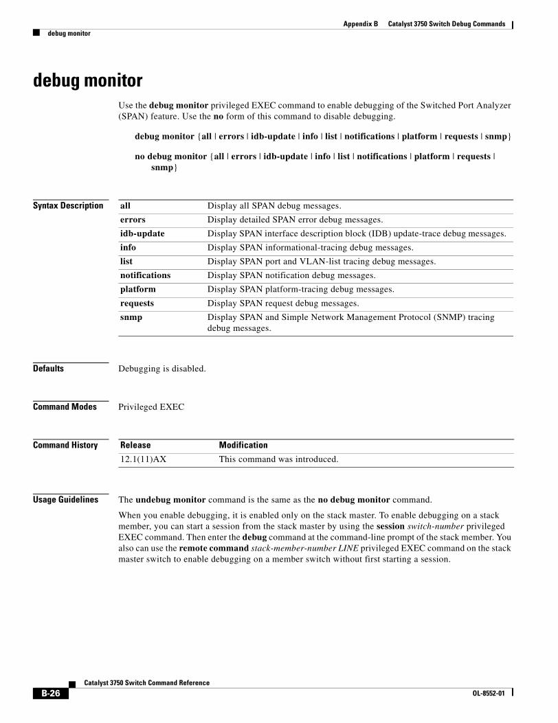
Appendix B Catalyst 3750 Switch Debug Commandsdebug monitor
debug monitorUse the debug monitor privileged EXEC command to enable debugging of the Switched Port Analyzer (SPAN) feature. Use the no form of this command to disable debugging.
debug monitor {all | errors | idb-update | info | list | notifications | platform | requests | snmp}
no debug monitor {all | errors | idb-update | info | list | notifications | platform | requests | snmp}
Syntax Description
Defaults Debugging is disabled.
Command Modes Privileged EXEC
Command History
Usage Guidelines The undebug monitor command is the same as the no debug monitor command.
When you enable debugging, it is enabled only on the stack master. To enable debugging on a stack member, you can start a session from the stack master by using the session switch-number privileged EXEC command. Then enter the debug command at the command-line prompt of the stack member. You also can use the remote command stack-member-number LINE privileged EXEC command on the stack master switch to enable debugging on a member switch without first starting a session.
all Display all SPAN debug messages.
errors Display detailed SPAN error debug messages.
idb-update Display SPAN interface description block (IDB) update-trace debug messages.
info Display SPAN informational-tracing debug messages.
list Display SPAN port and VLAN-list tracing debug messages.
notifications Display SPAN notification debug messages.
platform Display SPAN platform-tracing debug messages.
requests Display SPAN request debug messages.
snmp Display SPAN and Simple Network Management Protocol (SNMP) tracing debug messages.
Release Modification
12.1(11)AX This command was introduced.
B-26Catalyst 3750 Switch Command Reference
OL-8552-01

Appendix B Catalyst 3750 Switch Debug Commandsdebug monitor
Related Commands Command Description
show debugging Displays information about the types of debugging that are enabled. For syntax information, select Cisco IOS Release 12.2 Configuration Guides and Command References > Cisco IOS Configuration Fundamentals Configuration Guide, Release 12.2 > System Management > Troubleshooting and Fault Management.
show monitor Displays information about all SPAN and remote SPAN (RSPAN) sessions on the switch.
B-27Catalyst 3750 Switch Command Reference
OL-8552-01
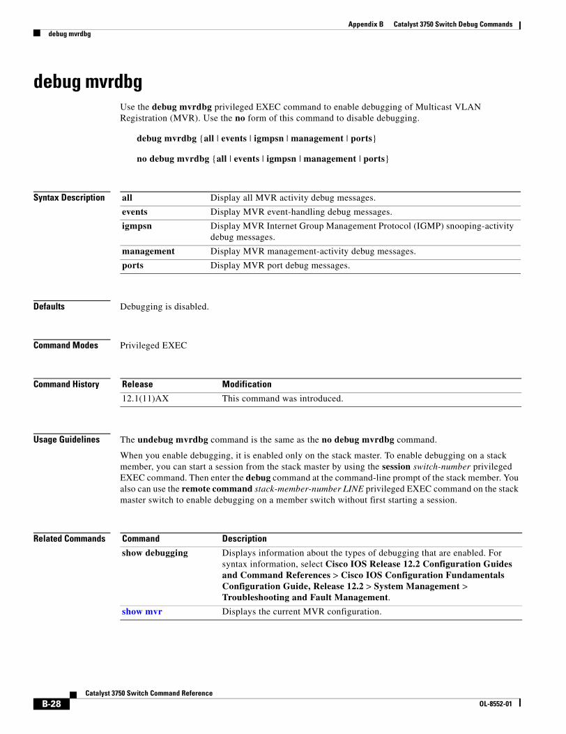
Appendix B Catalyst 3750 Switch Debug Commandsdebug mvrdbg
debug mvrdbgUse the debug mvrdbg privileged EXEC command to enable debugging of Multicast VLAN Registration (MVR). Use the no form of this command to disable debugging.
debug mvrdbg {all | events | igmpsn | management | ports}
no debug mvrdbg {all | events | igmpsn | management | ports}
Syntax Description
Defaults Debugging is disabled.
Command Modes Privileged EXEC
Command History
Usage Guidelines The undebug mvrdbg command is the same as the no debug mvrdbg command.
When you enable debugging, it is enabled only on the stack master. To enable debugging on a stack member, you can start a session from the stack master by using the session switch-number privileged EXEC command. Then enter the debug command at the command-line prompt of the stack member. You also can use the remote command stack-member-number LINE privileged EXEC command on the stack master switch to enable debugging on a member switch without first starting a session.
Related Commands
all Display all MVR activity debug messages.
events Display MVR event-handling debug messages.
igmpsn Display MVR Internet Group Management Protocol (IGMP) snooping-activity debug messages.
management Display MVR management-activity debug messages.
ports Display MVR port debug messages.
Release Modification
12.1(11)AX This command was introduced.
Command Description
show debugging Displays information about the types of debugging that are enabled. For syntax information, select Cisco IOS Release 12.2 Configuration Guides and Command References > Cisco IOS Configuration Fundamentals Configuration Guide, Release 12.2 > System Management > Troubleshooting and Fault Management.
show mvr Displays the current MVR configuration.
B-28Catalyst 3750 Switch Command Reference
OL-8552-01
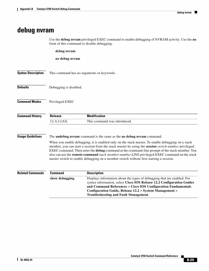
Appendix B Catalyst 3750 Switch Debug Commandsdebug nvram
debug nvramUse the debug nvram privileged EXEC command to enable debugging of NVRAM activity. Use the no form of this command to disable debugging.
debug nvram
no debug nvram
Syntax Description This command has no arguments or keywords.
Defaults Debugging is disabled.
Command Modes Privileged EXEC
Command History
Usage Guidelines The undebug nvram command is the same as the no debug nvram command.
When you enable debugging, it is enabled only on the stack master. To enable debugging on a stack member, you can start a session from the stack master by using the session switch-number privileged EXEC command. Then enter the debug command at the command-line prompt of the stack member. You also can use the remote command stack-member-number LINE privileged EXEC command on the stack master switch to enable debugging on a member switch without first starting a session.
Related Commands
Release Modification
12.1(11)AX This command was introduced.
Command Description
show debugging Displays information about the types of debugging that are enabled. For syntax information, select Cisco IOS Release 12.2 Configuration Guides and Command References > Cisco IOS Configuration Fundamentals Configuration Guide, Release 12.2 > System Management > Troubleshooting and Fault Management.
B-29Catalyst 3750 Switch Command Reference
OL-8552-01
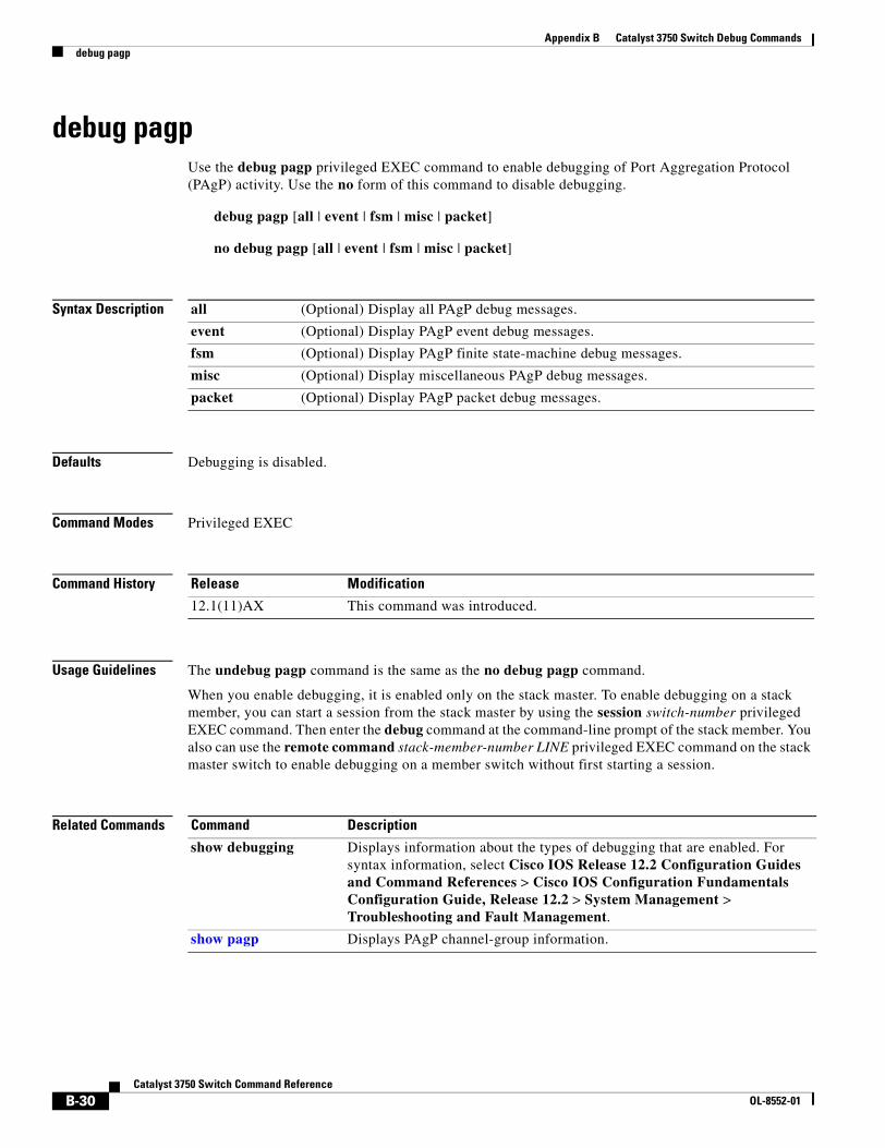
Appendix B Catalyst 3750 Switch Debug Commandsdebug pagp
debug pagpUse the debug pagp privileged EXEC command to enable debugging of Port Aggregation Protocol (PAgP) activity. Use the no form of this command to disable debugging.
debug pagp [all | event | fsm | misc | packet]
no debug pagp [all | event | fsm | misc | packet]
Syntax Description
Defaults Debugging is disabled.
Command Modes Privileged EXEC
Command History
Usage Guidelines The undebug pagp command is the same as the no debug pagp command.
When you enable debugging, it is enabled only on the stack master. To enable debugging on a stack member, you can start a session from the stack master by using the session switch-number privileged EXEC command. Then enter the debug command at the command-line prompt of the stack member. You also can use the remote command stack-member-number LINE privileged EXEC command on the stack master switch to enable debugging on a member switch without first starting a session.
Related Commands
all (Optional) Display all PAgP debug messages.
event (Optional) Display PAgP event debug messages.
fsm (Optional) Display PAgP finite state-machine debug messages.
misc (Optional) Display miscellaneous PAgP debug messages.
packet (Optional) Display PAgP packet debug messages.
Release Modification
12.1(11)AX This command was introduced.
Command Description
show debugging Displays information about the types of debugging that are enabled. For syntax information, select Cisco IOS Release 12.2 Configuration Guides and Command References > Cisco IOS Configuration Fundamentals Configuration Guide, Release 12.2 > System Management > Troubleshooting and Fault Management.
show pagp Displays PAgP channel-group information.
B-30Catalyst 3750 Switch Command Reference
OL-8552-01
Appendix B Catalyst 3750 Switch Debug Commandsdebug platform acl
debug platform aclUse the debug platform acl privileged EXEC command to enable debugging of the access control list (ACL) manager. Use the no form of this command to disable debugging.
debug platform acl {all | exit | label | main | racl | stack | vacl | vlmap | warn}
no debug platform acl {all | exit | label | main | racl | stack | vacl | vlmap | warn}
Syntax Description
Defaults Debugging is disabled.
Command Modes Privileged EXEC
Command History
Usage Guidelines The undebug platform acl command is the same as the no debug platform acl command.
When you enable debugging, it is enabled only on the stack master. To enable debugging on a stack member, you can start a session from the stack master by using the session switch-number privileged EXEC command. Then enter the debug command at the command-line prompt of the stack member. You also can use the remote command stack-member-number LINE privileged EXEC command on the stack master switch to enable debugging on a member switch without first starting a session.
Related Commands
all Display all ACL manager debug messages.
exit Display ACL exit-related debug messages.
label Display ACL label-related debug messages.
main Display the main or important ACL debug messages.
racl Display router ACL related debug messages.
stack Display ACL stack-related debug messages.
vacl Display VLAN ACL-related debug messages.
vlmap Display ACL VLAN-map-related debug messages.
warn Display ACL warning-related debug messages.
Release Modification
12.1(11)AX This command was introduced.
Command Description
show debugging Displays information about the types of debugging that are enabled. For syntax information, select Cisco IOS Release 12.2 Configuration Guides and Command References > Cisco IOS Configuration Fundamentals Configuration Guide, Release 12.2 > System Management > Troubleshooting and Fault Management.
B-31Catalyst 3750 Switch Command Reference
OL-8552-01
Appendix B Catalyst 3750 Switch Debug Commandsdebug platform backup interface
debug platform backup interfaceUse the debug platform backup interface privileged EXEC command to enable debugging of the Flex Links platform backup interface. Use the no form of this command to disable debugging.
debug platform backup interface
no debug platform backup interface
Syntax Description This command has no arguments or keywords.
Command Default Platform backup interface debugging is disabled.
Command Modes Privileged EXEC
Command History
Usage Guidelines The undebug platform backup interface command is the same as the no platform debug backup interface command.
When you enable debugging, it is enabled only on the stack master. To enable debugging on a stack member, you can start a session from the stack master by using the session switch-number privileged EXEC command. Then enter the debug command at the command-line prompt of the stack member. You also can use the remote command stack-member-number LINE privileged EXEC command on the stack master switch to enable debugging on a member switch without first starting a session.
Related Commands
Release Modification
12.2(20)SE This command was introduced.
Command Description
show debugging Displays information about the types of debugging that are enabled. For syntax information, select Cisco IOS Release 12.2 Configuration Guides and Command References > Cisco IOS Configuration Fundamentals Configuration Guide, Release 12.2 > System Management > Troubleshooting and Fault Management.
B-32Catalyst 3750 Switch Command Reference
OL-8552-01
Appendix B Catalyst 3750 Switch Debug Commandsdebug platform cli-redirection main
debug platform cli-redirection mainUse the debug platform cli-redirection main privileged EXEC command to enable debugging of the main (important) command-line interface (CLI) redirection events. Use the no form of this command to disable debugging.
debug platform cli-redirection main
no debug platform cli-redirection main
Syntax Description This command has no arguments or keywords.
Defaults Debugging is disabled.
Command Modes Privileged EXEC
Command History
Usage Guidelines The undebug platform cli-redirection main command is the same as the no debug platform cli-redirection main command.
When you enable debugging, it is enabled only on the stack master. To enable debugging on a stack member, you can start a session from the stack master by using the session switch-number privileged EXEC command. Then enter the debug command at the command-line prompt of the stack member. You also can use the remote command stack-member-number LINE privileged EXEC command on the stack master switch to enable debugging on a member switch without first starting a session.
Related Commands
Release Modification
12.1(11)AX This command was introduced.
Command Description
show debugging Displays information about the types of debugging that are enabled. For syntax information, select Cisco IOS Release 12.2 Configuration Guides and Command References > Cisco IOS Configuration Fundamentals Configuration Guide, Release 12.2 > System Management > Troubleshooting and Fault Management.
B-33Catalyst 3750 Switch Command Reference
OL-8552-01
Appendix B Catalyst 3750 Switch Debug Commandsdebug platform configuration
debug platform configurationUse the debug platform configuration privileged EXEC command to enable debugging of configuration file activity across the stack. Use the no form of this command to disable debugging.
debug platform configuration {all | reception | transmission}
no debug platform configuration {all | reception | transmission}
Syntax Description
Defaults Debugging is disabled.
Command Modes Privileged EXEC
Command History
Usage Guidelines The undebug platform configuration command is the same as the no debug platform configuration command.
When you enable debugging, it is enabled only on the stack master. To enable debugging on a stack member, you can start a session from the stack master by using the session switch-number privileged EXEC command. Then enter the debug command at the command-line prompt of the stack member. You also can use the remote command stack-member-number LINE privileged EXEC command on the stack master switch to enable debugging on a member switch without first starting a session.
Related Commands
all Display debug messages for all configuration file transmission and reception events throughout the stack.
reception Display debug messages for configuration file reception from other stack members.
transmission Display debug messages for configuration file transmission to other stack members.
Release Modification
12.1(11)AX This command was introduced.
Command Description
show debugging Displays information about the types of debugging that are enabled. For syntax information, select Cisco IOS Release 12.2 Configuration Guides and Command References > Cisco IOS Configuration Fundamentals Configuration Guide, Release 12.2 > System Management > Troubleshooting and Fault Management.
B-34Catalyst 3750 Switch Command Reference
OL-8552-01
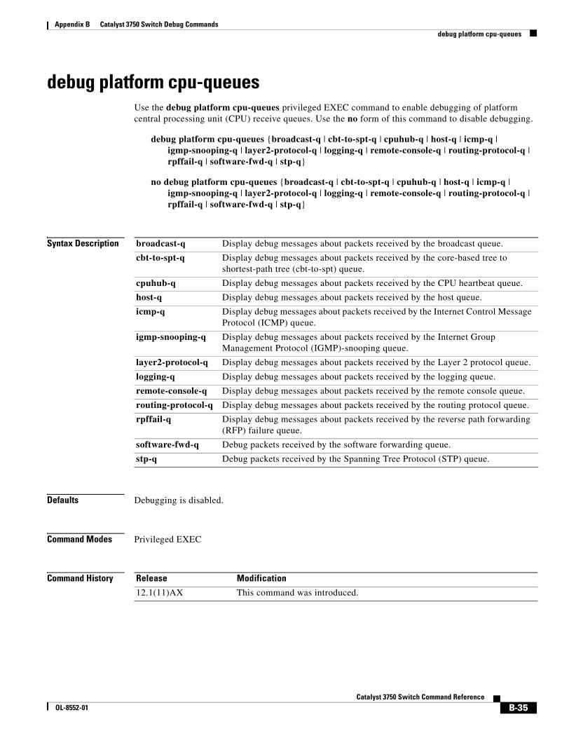
Appendix B Catalyst 3750 Switch Debug Commandsdebug platform cpu-queues
debug platform cpu-queuesUse the debug platform cpu-queues privileged EXEC command to enable debugging of platform central processing unit (CPU) receive queues. Use the no form of this command to disable debugging.
debug platform cpu-queues {broadcast-q | cbt-to-spt-q | cpuhub-q | host-q | icmp-q | igmp-snooping-q | layer2-protocol-q | logging-q | remote-console-q | routing-protocol-q | rpffail-q | software-fwd-q | stp-q}
no debug platform cpu-queues {broadcast-q | cbt-to-spt-q | cpuhub-q | host-q | icmp-q | igmp-snooping-q | layer2-protocol-q | logging-q | remote-console-q | routing-protocol-q | rpffail-q | software-fwd-q | stp-q}
Syntax Description
Defaults Debugging is disabled.
Command Modes Privileged EXEC
Command History
broadcast-q Display debug messages about packets received by the broadcast queue.
cbt-to-spt-q Display debug messages about packets received by the core-based tree to shortest-path tree (cbt-to-spt) queue.
cpuhub-q Display debug messages about packets received by the CPU heartbeat queue.
host-q Display debug messages about packets received by the host queue.
icmp-q Display debug messages about packets received by the Internet Control Message Protocol (ICMP) queue.
igmp-snooping-q Display debug messages about packets received by the Internet Group Management Protocol (IGMP)-snooping queue.
layer2-protocol-q Display debug messages about packets received by the Layer 2 protocol queue.
logging-q Display debug messages about packets received by the logging queue.
remote-console-q Display debug messages about packets received by the remote console queue.
routing-protocol-q Display debug messages about packets received by the routing protocol queue.
rpffail-q Display debug messages about packets received by the reverse path forwarding (RFP) failure queue.
software-fwd-q Debug packets received by the software forwarding queue.
stp-q Debug packets received by the Spanning Tree Protocol (STP) queue.
Release Modification
12.1(11)AX This command was introduced.
B-35Catalyst 3750 Switch Command Reference
OL-8552-01
Appendix B Catalyst 3750 Switch Debug Commandsdebug platform cpu-queues
Usage Guidelines The undebug platform cpu-queues command is the same as the no debug platform cpu-queues command.
When you enable debugging, it is enabled only on the stack master. To enable debugging on a stack member, you can start a session from the stack master by using the session switch-number privileged EXEC command. Then enter the debug command at the command-line prompt of the stack member. You also can use the remote command stack-member-number LINE privileged EXEC command on the stack master switch to enable debugging on a member switch without first starting a session.
Related Commands Command Description
show debugging Displays information about the types of debugging that are enabled. For syntax information, select Cisco IOS Release 12.2 Configuration Guides and Command References > Cisco IOS Configuration Fundamentals Configuration Guide, Release 12.2 > System Management > Troubleshooting and Fault Management.
B-36Catalyst 3750 Switch Command Reference
OL-8552-01
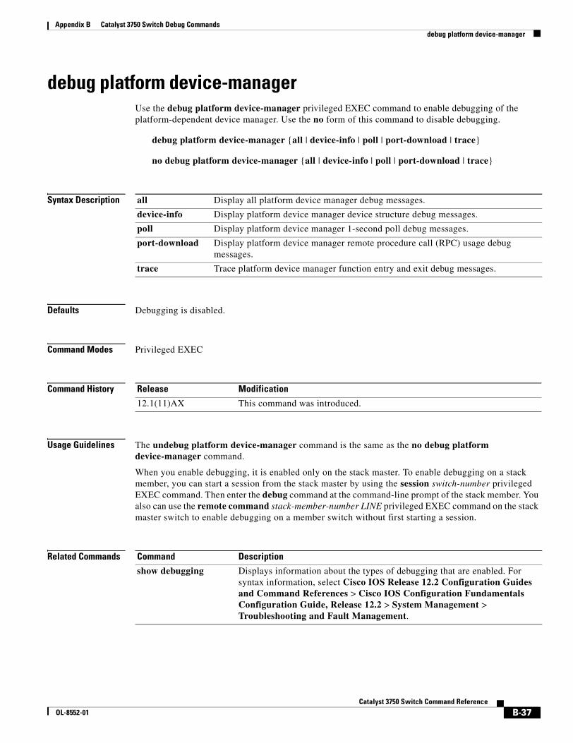
Appendix B Catalyst 3750 Switch Debug Commandsdebug platform device-manager
debug platform device-managerUse the debug platform device-manager privileged EXEC command to enable debugging of the platform-dependent device manager. Use the no form of this command to disable debugging.
debug platform device-manager {all | device-info | poll | port-download | trace}
no debug platform device-manager {all | device-info | poll | port-download | trace}
Syntax Description
Defaults Debugging is disabled.
Command Modes Privileged EXEC
Command History
Usage Guidelines The undebug platform device-manager command is the same as the no debug platform device-manager command.
When you enable debugging, it is enabled only on the stack master. To enable debugging on a stack member, you can start a session from the stack master by using the session switch-number privileged EXEC command. Then enter the debug command at the command-line prompt of the stack member. You also can use the remote command stack-member-number LINE privileged EXEC command on the stack master switch to enable debugging on a member switch without first starting a session.
Related Commands
all Display all platform device manager debug messages.
device-info Display platform device manager device structure debug messages.
poll Display platform device manager 1-second poll debug messages.
port-download Display platform device manager remote procedure call (RPC) usage debug messages.
trace Trace platform device manager function entry and exit debug messages.
Release Modification
12.1(11)AX This command was introduced.
Command Description
show debugging Displays information about the types of debugging that are enabled. For syntax information, select Cisco IOS Release 12.2 Configuration Guides and Command References > Cisco IOS Configuration Fundamentals Configuration Guide, Release 12.2 > System Management > Troubleshooting and Fault Management.
B-37Catalyst 3750 Switch Command Reference
OL-8552-01
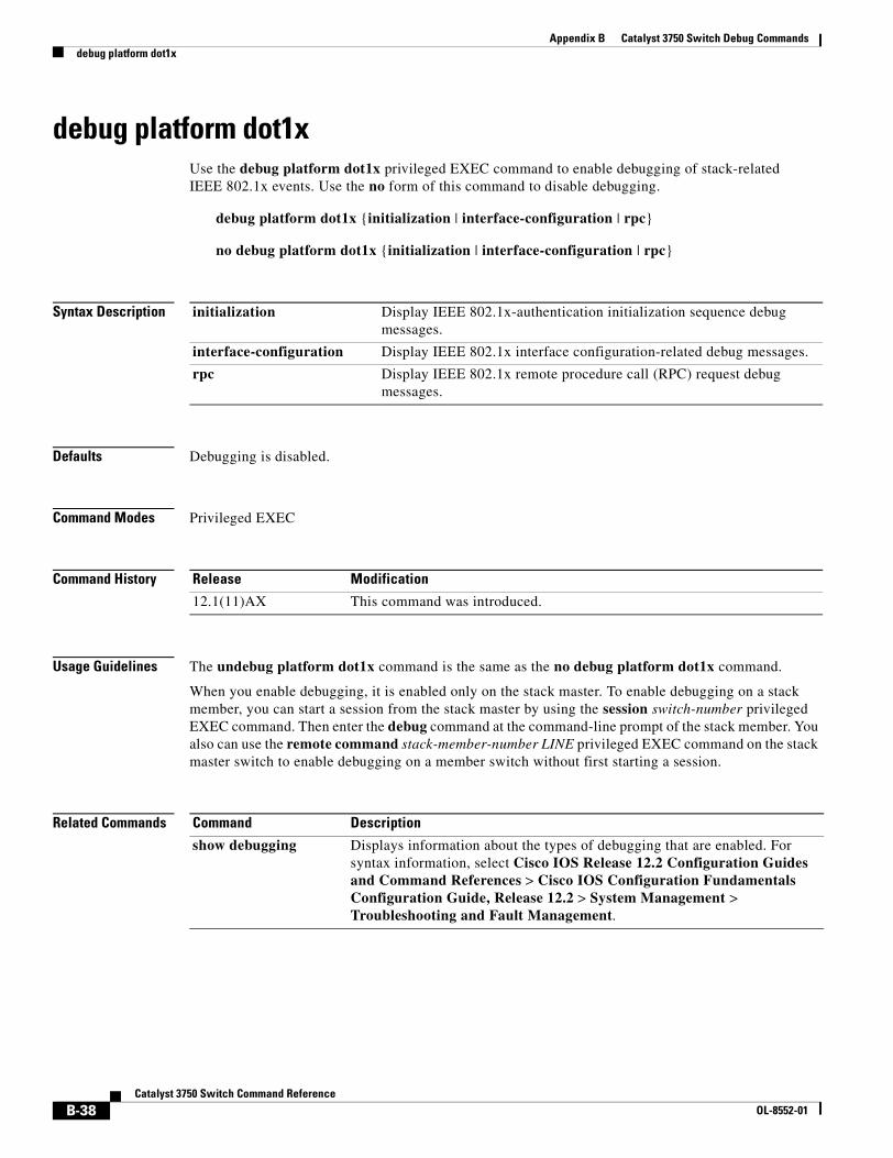
Appendix B Catalyst 3750 Switch Debug Commandsdebug platform dot1x
debug platform dot1xUse the debug platform dot1x privileged EXEC command to enable debugging of stack-related IEEE 802.1x events. Use the no form of this command to disable debugging.
debug platform dot1x {initialization | interface-configuration | rpc}
no debug platform dot1x {initialization | interface-configuration | rpc}
Syntax Description
Defaults Debugging is disabled.
Command Modes Privileged EXEC
Command History
Usage Guidelines The undebug platform dot1x command is the same as the no debug platform dot1x command.
When you enable debugging, it is enabled only on the stack master. To enable debugging on a stack member, you can start a session from the stack master by using the session switch-number privileged EXEC command. Then enter the debug command at the command-line prompt of the stack member. You also can use the remote command stack-member-number LINE privileged EXEC command on the stack master switch to enable debugging on a member switch without first starting a session.
Related Commands
initialization Display IEEE 802.1x-authentication initialization sequence debug messages.
interface-configuration Display IEEE 802.1x interface configuration-related debug messages.
rpc Display IEEE 802.1x remote procedure call (RPC) request debug messages.
Release Modification
12.1(11)AX This command was introduced.
Command Description
show debugging Displays information about the types of debugging that are enabled. For syntax information, select Cisco IOS Release 12.2 Configuration Guides and Command References > Cisco IOS Configuration Fundamentals Configuration Guide, Release 12.2 > System Management > Troubleshooting and Fault Management.
B-38Catalyst 3750 Switch Command Reference
OL-8552-01
Appendix B Catalyst 3750 Switch Debug Commandsdebug platform etherchannel
debug platform etherchannelUse the debug platform etherchannel privileged EXEC command to enable debugging of platform-dependent EtherChannel events. Use the no form of this command to disable debugging.
debug platform etherchannel {init | link-up | rpc | warnings}
no debug platform etherchannel {init | link-up | rpc | warnings}
Syntax Description
Defaults Debugging is disabled.
Command Modes Privileged EXEC
Command History
Usage Guidelines The undebug platform etherchannel command is the same as the no debug platform etherchannel command.
When you enable debugging, it is enabled only on the stack master. To enable debugging on a stack member, you can start a session from the stack master by using the session switch-number privileged EXEC command. Then enter the debug command at the command-line prompt of the stack member. You also can use the remote command stack-member-number LINE privileged EXEC command on the stack master switch to enable debugging on a member switch without first starting a session.
Related Commands
init Display EtherChannel module initialization debug messages.
link-up Display EtherChannel link-up and link-down related debug messages.
rpc Display EtherChannel remote procedure call (RPC) debug messages.
warnings Display EtherChannel warning debug messages.
Release Modification
12.1(11)AX This command was introduced.
Command Description
show debugging Displays information about the types of debugging that are enabled. For syntax information, select Cisco IOS Release 12.2 Configuration Guides and Command References > Cisco IOS Configuration Fundamentals Configuration Guide, Release 12.2 > System Management > Troubleshooting and Fault Management.
B-39Catalyst 3750 Switch Command Reference
OL-8552-01
Appendix B Catalyst 3750 Switch Debug Commandsdebug platform fallback-bridging
debug platform fallback-bridgingUse the debug platform fallback-bridging privileged EXEC command to enable debugging of the platform-dependent fallback bridging manager. Use the no form of this command to disable debugging.
debug platform fallback-bridging [error | retry | rpc {events | messages}]
no debug platform fallback-bridging [error | retry | rpc {events | messages}]
Syntax Description
Defaults Debugging is disabled.
Command Modes Privileged EXEC
Command History
Usage Guidelines If you do not specify a keyword, all fallback bridging manager debug messages appear.
The undebug platform fallback-bridging command is the same as the no debug platform fallback-bridging command.
When you enable debugging, it is enabled only on the stack master. To enable debugging on a stack member, you can start a session from the stack master by using the session switch-number privileged EXEC command. Then enter the debug command at the command-line prompt of the stack member. You also can use the remote command stack-member-number LINE privileged EXEC command on the stack master switch to enable debugging on a member switch without first starting a session.
Related Commands
error (Optional) Display fallback bridging manager error condition messages.
retry (Optional) Display fallback bridging manager retry messages.
rpc {events | messages} (Optional) Display fallback bridging debugging information. The keywords have these meanings:
• events—Display remote procedure call (RPC) events.
• messages—Display RPC messages.
Release Modification
12.1(11)AX This command was introduced.
Command Description
show debugging Displays information about the types of debugging that are enabled. For syntax information, select Cisco IOS Release 12.2 Configuration Guides and Command References > Cisco IOS Configuration Fundamentals Configuration Guide, Release 12.2 > System Management > Troubleshooting and Fault Management.
B-40Catalyst 3750 Switch Command Reference
OL-8552-01
Appendix B Catalyst 3750 Switch Debug Commandsdebug platform forw-tcam
debug platform forw-tcamUse the debug platform forw-tcam privileged EXEC command to enable debugging of the forwarding ternary content addressable memory (TCAM) manager. Use the no form of this command to disable debugging.
debug platform forw-tcam [adjustment | allocate | audit | error | move | read | write]
no debug platform forw-tcam [adjustment | allocate | audit | error | move | read | write]
Syntax Description
Defaults Debugging is disabled.
Command Modes Privileged EXEC
Command History
Usage Guidelines If you do not specify a keyword, all forwarding TCAM manager debug messages appear.
The undebug platform forw-tcam command is the same as the no debug platform forw-tcam command.
When you enable debugging, it is enabled only on the stack master. To enable debugging on a stack member, you can start a session from the stack master by using the session switch-number privileged EXEC command. Then enter the debug command at the command-line prompt of the stack member. You also can use the remote command stack-member-number LINE privileged EXEC command on the stack master switch to enable debugging on a member switch without first starting a session.
Related Commands
adjustment (Optional) Display TCAM manager adjustment debug messages.
allocate (Optional) Display TCAM manager allocation debug messages.
audit (Optional) Display TCAM manager audit messages.
error (Optional) Display TCAM manager error messages.
move (Optional) Display TCAM manager move messages.
read (Optional) Display TCAM manager read messages.
write (Optional) Display TCAM manager write messages.
Release Modification
12.1(11)AX This command was introduced.
Command Description
show debugging Displays information about the types of debugging that are enabled. For syntax information, select Cisco IOS Release 12.2 Configuration Guides and Command References > Cisco IOS Configuration Fundamentals Configuration Guide, Release 12.2 > System Management > Troubleshooting and Fault Management.
B-41Catalyst 3750 Switch Command Reference
OL-8552-01
Appendix B Catalyst 3750 Switch Debug Commandsdebug platform frontend-controller
debug platform frontend-controllerUse the debug platform frontend-controller privileged EXEC command to enable debugging of front-end controller activity. Use the no form of this command to disable debugging.
debug platform frontend-controller {all | image | led | manager | poe | register | thermal}
no debug platform frontend-controller {all | image | led | manager | poe | register | thermal}
Syntax Description
Defaults Debugging is disabled.
Command Modes Privileged EXEC
Command History
Usage Guidelines This command is only supported on Catalyst 3750G-48TS, 3750G-48PS, 3750G-24TS-1U, and 3750G-24PS switches.
The undebug platform frontend-controller command is the same as the no debug platform frontend-controller command.
When you enable debugging, it is enabled only on the stack master. To enable debugging on a stack member, start a session from the stack master by using the session switch-number privileged EXEC command. Then enter the debug command at the command-line prompt of the stack member. You can also use the remote command stack-member-number LINE privileged EXEC command on the stack master switch to enable debugging on a member switch without first starting a session.
all Display all the debug messages for front-end controller.
image Display Image Manager debug messages.
led Display LED debug messages.
manager Display front-end-controller manager debug messages.
poe Display Power over Ethernet (PoE) debug messages.
register Display Register Access debug messages.
thermal Display thermal debug messages.
Release Modification
12.2(20)SE3 This command was introduced.
B-42Catalyst 3750 Switch Command Reference
OL-8552-01
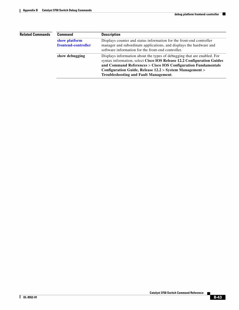
Appendix B Catalyst 3750 Switch Debug Commandsdebug platform frontend-controller
Related Commands Command Description
show platform frontend-controller
Displays counter and status information for the front-end controller manager and subordinate applications, and displays the hardware and software information for the front-end controller.
show debugging Displays information about the types of debugging that are enabled. For syntax information, select Cisco IOS Release 12.2 Configuration Guides and Command References > Cisco IOS Configuration Fundamentals Configuration Guide, Release 12.2 > System Management > Troubleshooting and Fault Management.
B-43Catalyst 3750 Switch Command Reference
OL-8552-01
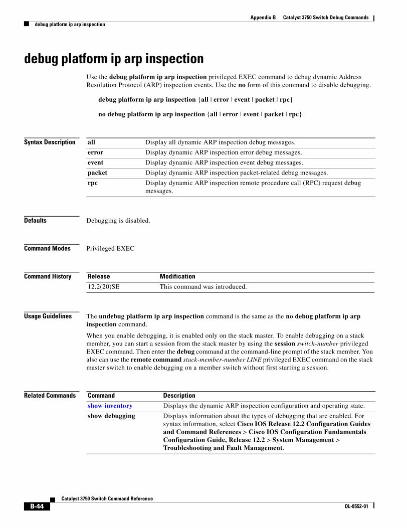
Appendix B Catalyst 3750 Switch Debug Commandsdebug platform ip arp inspection
debug platform ip arp inspectionUse the debug platform ip arp inspection privileged EXEC command to debug dynamic Address Resolution Protocol (ARP) inspection events. Use the no form of this command to disable debugging.
debug platform ip arp inspection {all | error | event | packet | rpc}
no debug platform ip arp inspection {all | error | event | packet | rpc}
Syntax Description
Defaults Debugging is disabled.
Command Modes Privileged EXEC
Command History
Usage Guidelines The undebug platform ip arp inspection command is the same as the no debug platform ip arp inspection command.
When you enable debugging, it is enabled only on the stack master. To enable debugging on a stack member, you can start a session from the stack master by using the session switch-number privileged EXEC command. Then enter the debug command at the command-line prompt of the stack member. You also can use the remote command stack-member-number LINE privileged EXEC command on the stack master switch to enable debugging on a member switch without first starting a session.
Related Commands
all Display all dynamic ARP inspection debug messages.
error Display dynamic ARP inspection error debug messages.
event Display dynamic ARP inspection event debug messages.
packet Display dynamic ARP inspection packet-related debug messages.
rpc Display dynamic ARP inspection remote procedure call (RPC) request debug messages.
Release Modification
12.2(20)SE This command was introduced.
Command Description
show inventory Displays the dynamic ARP inspection configuration and operating state.
show debugging Displays information about the types of debugging that are enabled. For syntax information, select Cisco IOS Release 12.2 Configuration Guides and Command References > Cisco IOS Configuration Fundamentals Configuration Guide, Release 12.2 > System Management > Troubleshooting and Fault Management.
B-44Catalyst 3750 Switch Command Reference
OL-8552-01
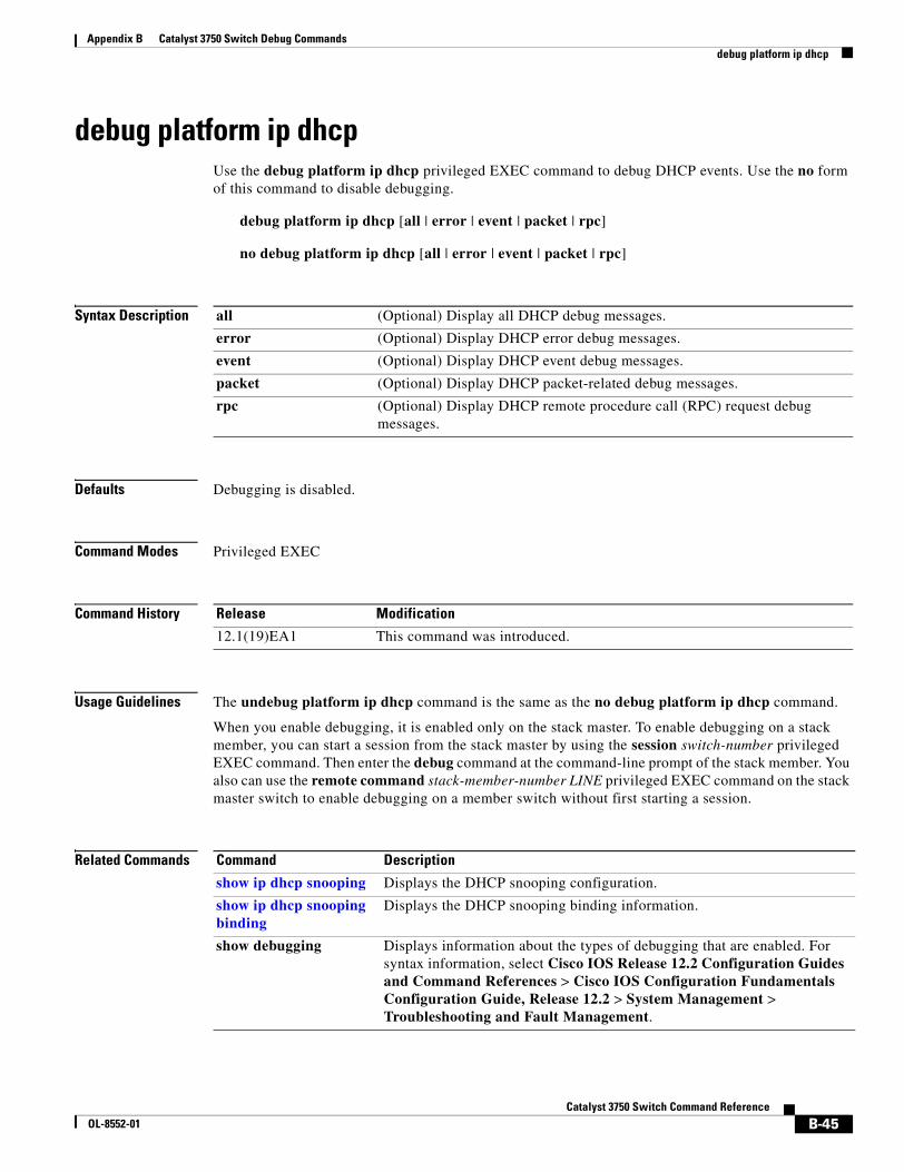
Appendix B Catalyst 3750 Switch Debug Commandsdebug platform ip dhcp
debug platform ip dhcpUse the debug platform ip dhcp privileged EXEC command to debug DHCP events. Use the no form of this command to disable debugging.
debug platform ip dhcp [all | error | event | packet | rpc]
no debug platform ip dhcp [all | error | event | packet | rpc]
Syntax Description
Defaults Debugging is disabled.
Command Modes Privileged EXEC
Command History
Usage Guidelines The undebug platform ip dhcp command is the same as the no debug platform ip dhcp command.
When you enable debugging, it is enabled only on the stack master. To enable debugging on a stack member, you can start a session from the stack master by using the session switch-number privileged EXEC command. Then enter the debug command at the command-line prompt of the stack member. You also can use the remote command stack-member-number LINE privileged EXEC command on the stack master switch to enable debugging on a member switch without first starting a session.
Related Commands
all (Optional) Display all DHCP debug messages.
error (Optional) Display DHCP error debug messages.
event (Optional) Display DHCP event debug messages.
packet (Optional) Display DHCP packet-related debug messages.
rpc (Optional) Display DHCP remote procedure call (RPC) request debug messages.
Release Modification
12.1(19)EA1 This command was introduced.
Command Description
show ip dhcp snooping Displays the DHCP snooping configuration.
show ip dhcp snooping binding
Displays the DHCP snooping binding information.
show debugging Displays information about the types of debugging that are enabled. For syntax information, select Cisco IOS Release 12.2 Configuration Guides and Command References > Cisco IOS Configuration Fundamentals Configuration Guide, Release 12.2 > System Management > Troubleshooting and Fault Management.
B-45Catalyst 3750 Switch Command Reference
OL-8552-01
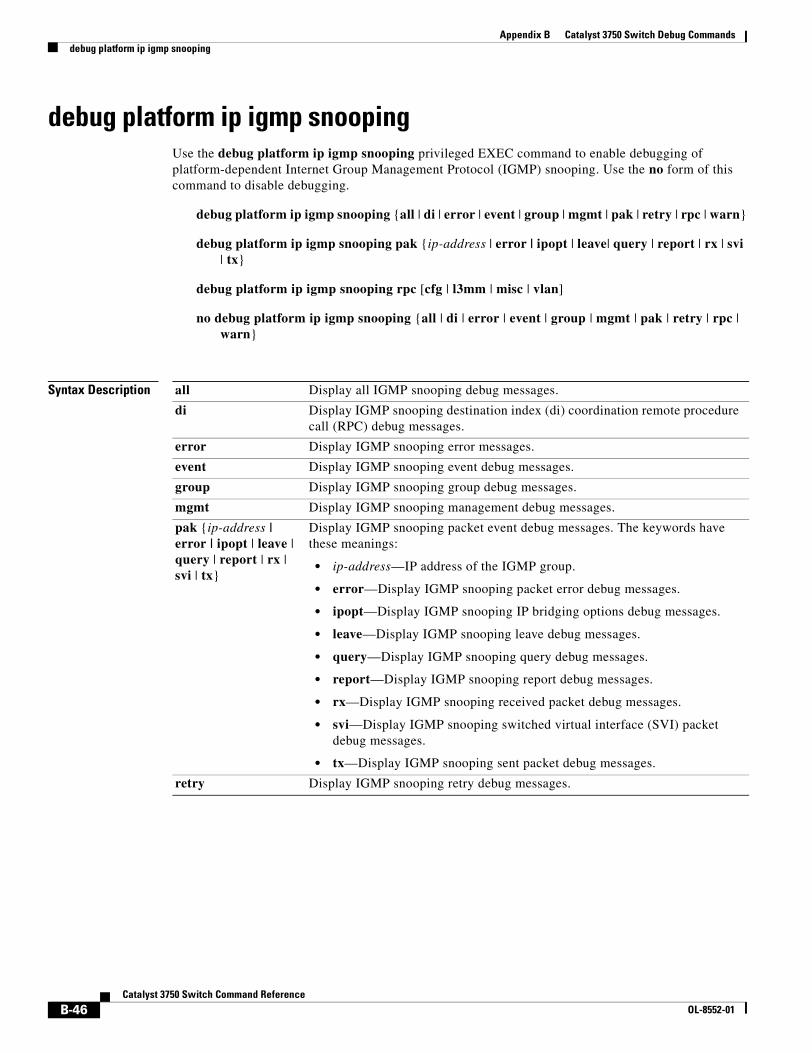
Appendix B Catalyst 3750 Switch Debug Commandsdebug platform ip igmp snooping
debug platform ip igmp snoopingUse the debug platform ip igmp snooping privileged EXEC command to enable debugging of platform-dependent Internet Group Management Protocol (IGMP) snooping. Use the no form of this command to disable debugging.
debug platform ip igmp snooping {all | di | error | event | group | mgmt | pak | retry | rpc | warn}
debug platform ip igmp snooping pak {ip-address | error | ipopt | leave| query | report | rx | svi | tx}
debug platform ip igmp snooping rpc [cfg | l3mm | misc | vlan]
no debug platform ip igmp snooping {all | di | error | event | group | mgmt | pak | retry | rpc | warn}
Syntax Description all Display all IGMP snooping debug messages.
di Display IGMP snooping destination index (di) coordination remote procedure call (RPC) debug messages.
error Display IGMP snooping error messages.
event Display IGMP snooping event debug messages.
group Display IGMP snooping group debug messages.
mgmt Display IGMP snooping management debug messages.
pak {ip-address | error | ipopt | leave | query | report | rx | svi | tx}
Display IGMP snooping packet event debug messages. The keywords have these meanings:
• ip-address—IP address of the IGMP group.
• error—Display IGMP snooping packet error debug messages.
• ipopt—Display IGMP snooping IP bridging options debug messages.
• leave—Display IGMP snooping leave debug messages.
• query—Display IGMP snooping query debug messages.
• report—Display IGMP snooping report debug messages.
• rx—Display IGMP snooping received packet debug messages.
• svi—Display IGMP snooping switched virtual interface (SVI) packet debug messages.
• tx—Display IGMP snooping sent packet debug messages.
retry Display IGMP snooping retry debug messages.
B-46Catalyst 3750 Switch Command Reference
OL-8552-01
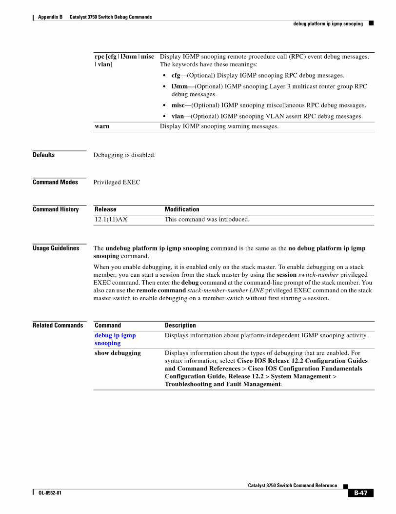
Appendix B Catalyst 3750 Switch Debug Commandsdebug platform ip igmp snooping
Defaults Debugging is disabled.
Command Modes Privileged EXEC
Command History
Usage Guidelines The undebug platform ip igmp snooping command is the same as the no debug platform ip igmp snooping command.
When you enable debugging, it is enabled only on the stack master. To enable debugging on a stack member, you can start a session from the stack master by using the session switch-number privileged EXEC command. Then enter the debug command at the command-line prompt of the stack member. You also can use the remote command stack-member-number LINE privileged EXEC command on the stack master switch to enable debugging on a member switch without first starting a session.
Related Commands
rpc [cfg | l3mm | misc | vlan]
Display IGMP snooping remote procedure call (RPC) event debug messages. The keywords have these meanings:
• cfg—(Optional) Display IGMP snooping RPC debug messages.
• l3mm—(Optional) IGMP snooping Layer 3 multicast router group RPC debug messages.
• misc—(Optional) IGMP snooping miscellaneous RPC debug messages.
• vlan—(Optional) IGMP snooping VLAN assert RPC debug messages.
warn Display IGMP snooping warning messages.
Release Modification
12.1(11)AX This command was introduced.
Command Description
debug ip igmp snooping
Displays information about platform-independent IGMP snooping activity.
show debugging Displays information about the types of debugging that are enabled. For syntax information, select Cisco IOS Release 12.2 Configuration Guides and Command References > Cisco IOS Configuration Fundamentals Configuration Guide, Release 12.2 > System Management > Troubleshooting and Fault Management.
B-47Catalyst 3750 Switch Command Reference
OL-8552-01
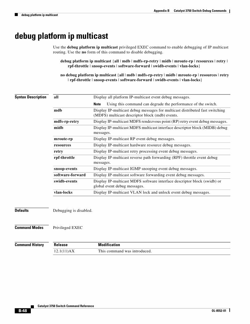
Appendix B Catalyst 3750 Switch Debug Commandsdebug platform ip multicast
debug platform ip multicastUse the debug platform ip multicast privileged EXEC command to enable debugging of IP multicast routing. Use the no form of this command to disable debugging.
debug platform ip multicast {all | mdb | mdfs-rp-retry | midb | mroute-rp | resources | retry | rpf-throttle | snoop-events | software-forward | swidb-events | vlan-locks}
no debug platform ip multicast {all | mdb | mdfs-rp-retry | midb | mroute-rp | resources | retry | rpf-throttle | snoop-events | software-forward | swidb-events | vlan-locks}
Syntax Description
Defaults Debugging is disabled.
Command Modes Privileged EXEC
Command History
all Display all platform IP-multicast event debug messages.
Note Using this command can degrade the performance of the switch.
mdb Display IP-multicast debug messages for multicast distributed fast switching (MDFS) multicast descriptor block (mdb) events.
mdfs-rp-retry Display IP-multicast MDFS rendezvous point (RP) retry event debug messages.
midb Display IP-multicast MDFS multicast interface descriptor block (MIDB) debug messages.
mroute-rp Display IP-multicast RP event debug messages.
resources Display IP-multicast hardware resource debug messages.
retry Display IP-multicast retry processing event debug messages.
rpf-throttle Display IP-multicast reverse path forwarding (RPF) throttle event debug messages.
snoop-events Display IP-multicast IGMP snooping event debug messages.
software-forward Display IP-multicast software forwarding event debug messages.
swidb-events Display IP-multicast MDFS software interface descriptor block (swidb) or global event debug messages.
vlan-locks Display IP-multicast VLAN lock and unlock event debug messages.
Release Modification
12.1(11)AX This command was introduced.
B-48Catalyst 3750 Switch Command Reference
OL-8552-01
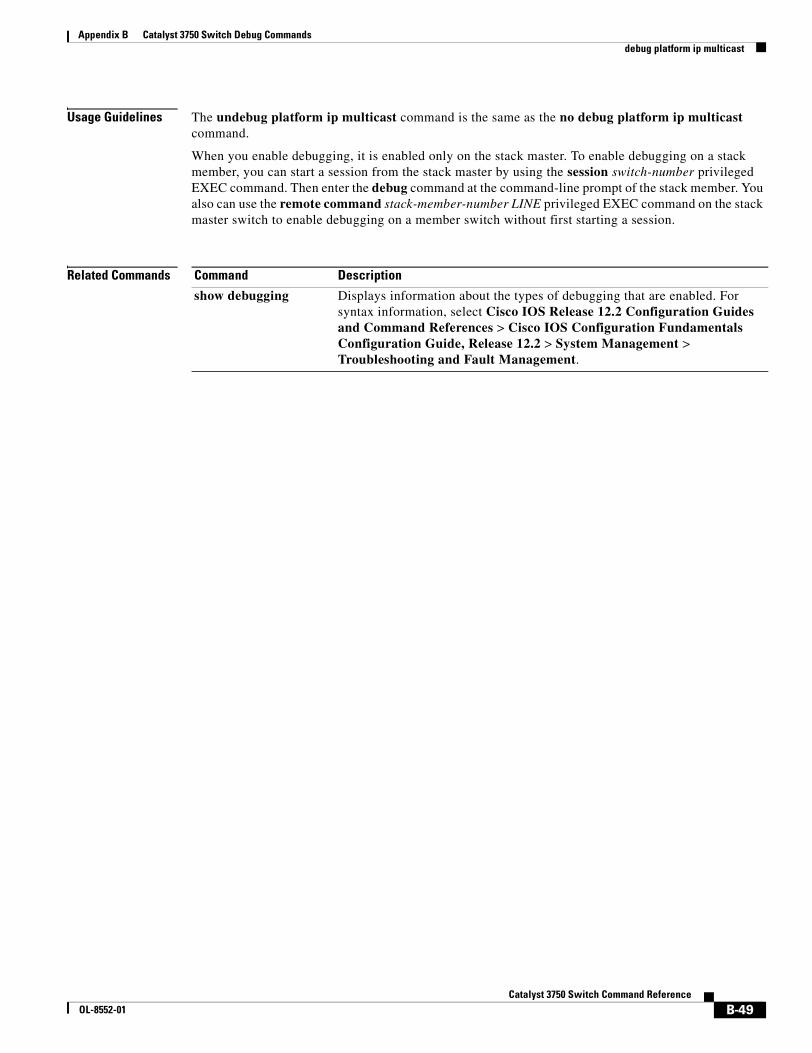
Appendix B Catalyst 3750 Switch Debug Commandsdebug platform ip multicast
Usage Guidelines The undebug platform ip multicast command is the same as the no debug platform ip multicast command.
When you enable debugging, it is enabled only on the stack master. To enable debugging on a stack member, you can start a session from the stack master by using the session switch-number privileged EXEC command. Then enter the debug command at the command-line prompt of the stack member. You also can use the remote command stack-member-number LINE privileged EXEC command on the stack master switch to enable debugging on a member switch without first starting a session.
Related Commands Command Description
show debugging Displays information about the types of debugging that are enabled. For syntax information, select Cisco IOS Release 12.2 Configuration Guides and Command References > Cisco IOS Configuration Fundamentals Configuration Guide, Release 12.2 > System Management > Troubleshooting and Fault Management.
B-49Catalyst 3750 Switch Command Reference
OL-8552-01
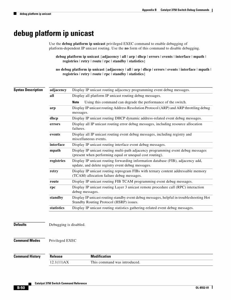
Appendix B Catalyst 3750 Switch Debug Commandsdebug platform ip unicast
debug platform ip unicastUse the debug platform ip unicast privileged EXEC command to enable debugging of platform-dependent IP unicast routing. Use the no form of this command to disable debugging.
debug platform ip unicast {adjacency | all | arp | dhcp | errors | events | interface | mpath | registries | retry | route | rpc | standby | statistics}
no debug platform ip unicast {adjacency | all | arp | dhcp | errors | events | interface | mpath | registries | retry | route | rpc | standby | statistics}
Syntax Description
Defaults Debugging is disabled.
Command Modes Privileged EXEC
Command History
adjacency Display IP unicast routing adjacency programming event debug messages.
all Display all platform IP unicast routing debug messages.
Note Using this command can degrade the performance of the switch.
arp Display IP unicast routing Address Resolution Protocol (ARP) and ARP throttling debug messages.
dhcp Display IP unicast routing DHCP dynamic address-related event debug messages.
errors Display all IP unicast routing error debug messages, including resource allocation failures.
events Display all IP unicast routing event debug messages, including registry and miscellaneous events.
interface Display IP unicast routing interface event debug messages.
mpath Display IP unicast routing multi-path adjacency programming event debug messages (present when performing equal or unequal cost routing).
registries Display IP unicast routing forwarding information database (FIB), adjacency add, update, and delete registry event debug messages.
retry Display IP unicast routing reprogram FIBs with ternary content addressable memory (TCAM) allocation failure debug messages.
route Display IP unicast routing FIB TCAM programming event debug messages.
rpc Display IP unicast routing Layer 3 unicast remote procedure call (RPC) interaction debug messages.
standby Display IP unicast routing standby event debug messages, helpful in troubleshooting Hot Standby Routing Protocol (HSRP) issues.
statistics Display IP unicast routing statistics gathering-related event debug messages.
Release Modification
12.1(11)AX This command was introduced.
B-50Catalyst 3750 Switch Command Reference
OL-8552-01
Appendix B Catalyst 3750 Switch Debug Commandsdebug platform ip unicast
Usage Guidelines The undebug platform ip unicast command is the same as the no debug platform ip unicast command.
When you enable debugging, it is enabled only on the stack master. To enable debugging on a stack member, you can start a session from the stack master by using the session switch-number privileged EXEC command. Then enter the debug command at the command-line prompt of the stack member. You also can use the remote command stack-member-number LINE privileged EXEC command on the stack master switch to enable debugging on a member switch without first starting a session.
Related Commands Command Description
show debugging Displays information about the types of debugging that are enabled. For syntax information, select Cisco IOS Release 12.2 Configuration Guides and Command References > Cisco IOS Configuration Fundamentals Configuration Guide, Release 12.2 > System Management > Troubleshooting and Fault Management.
B-51Catalyst 3750 Switch Command Reference
OL-8552-01
Appendix B Catalyst 3750 Switch Debug Commandsdebug platform ipc
debug platform ipcUse the debug platform ipc privileged EXEC command to enable debugging of the platform-dependent Interprocess Communication (IPC) Protocol. Use the no form of this command to disable debugging.
debug platform ipc {all | init | receive | send | trace}
no debug platform {all | init | receive | send | trace}
Syntax Description
Defaults Debugging is disabled.
Command Modes Privileged EXEC
Command History
Usage Guidelines The undebug platform ipc command is the same as the no debug platform ipc.
When you enable debugging, it is enabled only on the stack master. To enable debugging on a stack member, you can start a session from the stack master by using the session switch-number privileged EXEC command. Then enter the debug command at the command-line prompt of the stack member. You also can use the remote command stack-member-number LINE privileged EXEC command on the stack master switch to enable debugging on a member switch without first starting a session.
Related Commands
all Display all platform IPC debug messages.
Note Using this command can degrade the performance of the switch.
init Display debug messages related to IPC initialization.
receive Display IPC traces each time an IPC packet is received by the switch.
send Display IPC traces each time an IPC packet is sent by the switch.
trace Display IPC trace debug messages, tracing the code path as the IPC functions are executed.
Release Modification
12.1(11)AX This command was introduced.
Command Description
show debugging Displays information about the types of debugging that are enabled. For syntax information, select Cisco IOS Release 12.2 Configuration Guides and Command References > Cisco IOS Configuration Fundamentals Configuration Guide, Release 12.2 > System Management > Troubleshooting and Fault Management.
B-52Catalyst 3750 Switch Command Reference
OL-8552-01
Appendix B Catalyst 3750 Switch Debug Commandsdebug platform led
debug platform ledUse the debug platform led privileged EXEC command to enable debugging of light-emitting diode (LED) actions. Use the no form of this command to disable debugging.
debug platform led {generic | signal | stack}
no debug platform led {generic | signal | stack}
Syntax Description
Defaults Debugging is disabled.
Command Modes Privileged EXEC
Command History
Usage Guidelines The undebug platform led command is the same as the no debug platform led command.
When you enable debugging, it is enabled only on the stack master. To enable debugging on a stack member, you can start a session from the stack master by using the session switch-number privileged EXEC command. Then enter the debug command at the command-line prompt of the stack member. You also can use the remote command stack-member-number LINE privileged EXEC command on the stack master switch to enable debugging on a member switch without first starting a session.
Related Commands
generic Display LED generic action debug messages.
signal Display LED signal bit map debug messages.
stack Display LED stack action debug messages.
Release Modification
12.1(11)AX This command was introduced.
Command Description
show debugging Displays information about the types of debugging that are enabled. For syntax information, select Cisco IOS Release 12.2 Configuration Guides and Command References > Cisco IOS Configuration Fundamentals Configuration Guide, Release 12.2 > System Management > Troubleshooting and Fault Management.
B-53Catalyst 3750 Switch Command Reference
OL-8552-01
Appendix B Catalyst 3750 Switch Debug Commandsdebug platform matm
debug platform matmUse the debug platform matm privileged EXEC command to enable debugging of platform-dependent MAC address management. Use the no form of this command to disable debugging.
debug platform matm {aging | all | ec-aging | errors | learning | rpc | secure-address | warnings}
no debug platform matm {aging | all | ec-aging | errors | learning | rpc | secure-address | warnings}
Syntax Description
Defaults Debugging is disabled.
Command Modes Privileged EXEC
Command History
Usage Guidelines The undebug platform matm command is the same as the no debug platform matm command.
When you enable debugging, it is enabled only on the stack master. To enable debugging on a stack member, you can start a session from the stack master by using the session switch-number privileged EXEC command. Then enter the debug command at the command-line prompt of the stack member. You also can use the remote command stack-member-number LINE privileged EXEC command on the stack master switch to enable debugging on a member switch without first starting a session.
aging Display MAC address aging debug messages.
all Display all platform MAC address management event debug messages.
ec-aging Display EtherChannel address aging-related debug messages.
errors Display MAC address management error messages.
learning Display MAC address management address-learning debug messages.
rpc Display MAC address management remote procedure call (RPC) related debug messages.
secure-address Display MAC address management secure address learning debug messages.
warning Display MAC address management warning messages.
Release Modification
12.1(11)AX This command was introduced.
B-54Catalyst 3750 Switch Command Reference
OL-8552-01

Appendix B Catalyst 3750 Switch Debug Commandsdebug platform matm
Related Commands Command Description
debug matm Displays information about platform-independent MAC address management.
show debugging Displays information about the types of debugging that are enabled. For syntax information, select Cisco IOS Release 12.2 Configuration Guides and Command References > Cisco IOS Configuration Fundamentals Configuration Guide, Release 12.2 > System Management > Troubleshooting and Fault Management.
B-55Catalyst 3750 Switch Command Reference
OL-8552-01
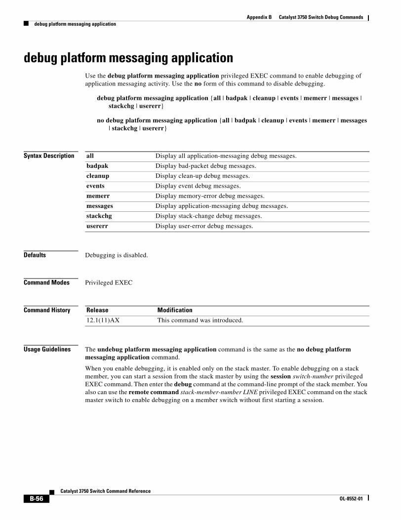
Appendix B Catalyst 3750 Switch Debug Commandsdebug platform messaging application
debug platform messaging applicationUse the debug platform messaging application privileged EXEC command to enable debugging of application messaging activity. Use the no form of this command to disable debugging.
debug platform messaging application {all | badpak | cleanup | events | memerr | messages | stackchg | usererr}
no debug platform messaging application {all | badpak | cleanup | events | memerr | messages | stackchg | usererr}
Syntax Description
Defaults Debugging is disabled.
Command Modes Privileged EXEC
Command History
Usage Guidelines The undebug platform messaging application command is the same as the no debug platform messaging application command.
When you enable debugging, it is enabled only on the stack master. To enable debugging on a stack member, you can start a session from the stack master by using the session switch-number privileged EXEC command. Then enter the debug command at the command-line prompt of the stack member. You also can use the remote command stack-member-number LINE privileged EXEC command on the stack master switch to enable debugging on a member switch without first starting a session.
all Display all application-messaging debug messages.
badpak Display bad-packet debug messages.
cleanup Display clean-up debug messages.
events Display event debug messages.
memerr Display memory-error debug messages.
messages Display application-messaging debug messages.
stackchg Display stack-change debug messages.
usererr Display user-error debug messages.
Release Modification
12.1(11)AX This command was introduced.
B-56Catalyst 3750 Switch Command Reference
OL-8552-01

Appendix B Catalyst 3750 Switch Debug Commandsdebug platform messaging application
Related Commands Command Description
show debugging Displays information about the types of debugging that are enabled. For syntax information, see the Cisco IOS Release 12.2 Configuration Guides and Command References > Cisco IOS Configuration Fundamentals Configuration Guide, Release 12.2 > System Management > Troubleshooting and Fault Management.
B-57Catalyst 3750 Switch Command Reference
OL-8552-01
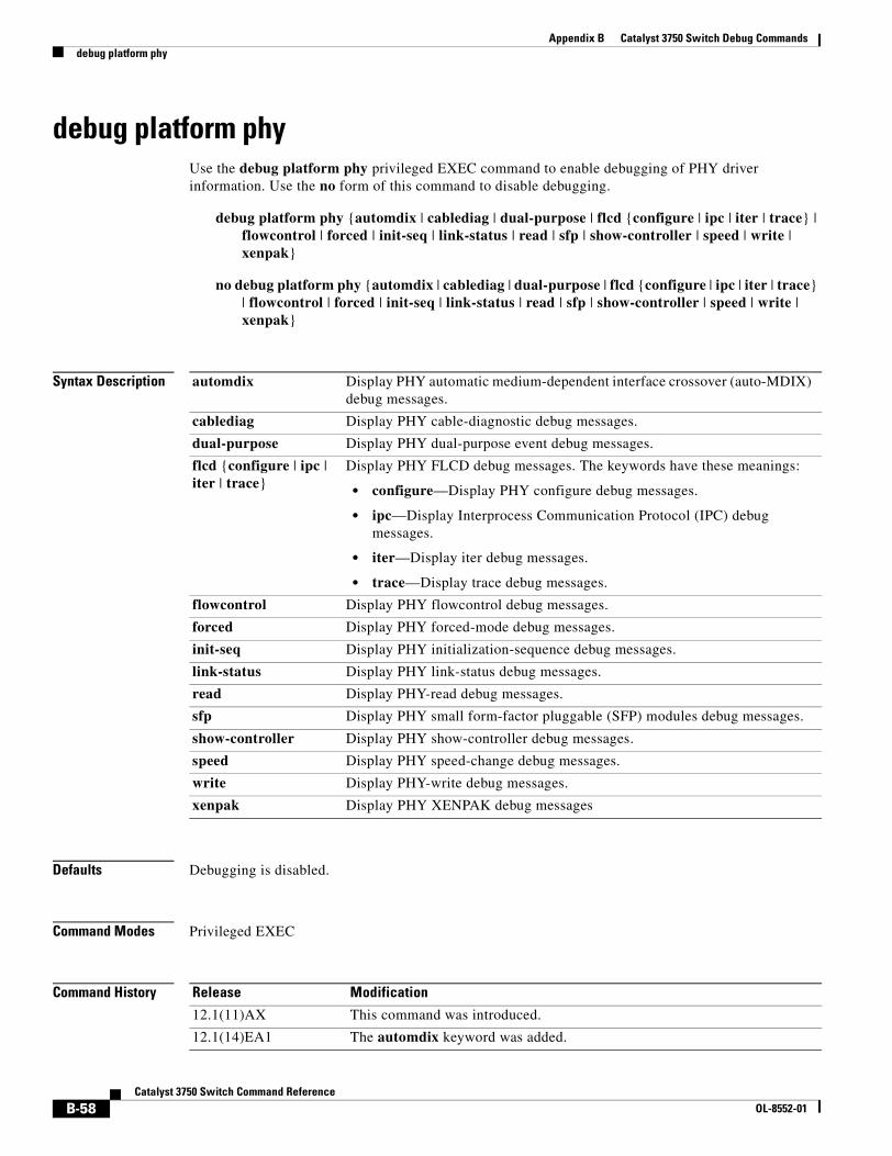
Appendix B Catalyst 3750 Switch Debug Commandsdebug platform phy
debug platform phyUse the debug platform phy privileged EXEC command to enable debugging of PHY driver information. Use the no form of this command to disable debugging.
debug platform phy {automdix | cablediag | dual-purpose | flcd {configure | ipc | iter | trace} | flowcontrol | forced | init-seq | link-status | read | sfp | show-controller | speed | write | xenpak}
no debug platform phy {automdix | cablediag | dual-purpose | flcd {configure | ipc | iter | trace} | flowcontrol | forced | init-seq | link-status | read | sfp | show-controller | speed | write | xenpak}
Syntax Description
Defaults Debugging is disabled.
Command Modes Privileged EXEC
Command History
automdix Display PHY automatic medium-dependent interface crossover (auto-MDIX) debug messages.
cablediag Display PHY cable-diagnostic debug messages.
dual-purpose Display PHY dual-purpose event debug messages.
flcd {configure | ipc | iter | trace}
Display PHY FLCD debug messages. The keywords have these meanings:
• configure—Display PHY configure debug messages.
• ipc—Display Interprocess Communication Protocol (IPC) debug messages.
• iter—Display iter debug messages.
• trace—Display trace debug messages.
flowcontrol Display PHY flowcontrol debug messages.
forced Display PHY forced-mode debug messages.
init-seq Display PHY initialization-sequence debug messages.
link-status Display PHY link-status debug messages.
read Display PHY-read debug messages.
sfp Display PHY small form-factor pluggable (SFP) modules debug messages.
show-controller Display PHY show-controller debug messages.
speed Display PHY speed-change debug messages.
write Display PHY-write debug messages.
xenpak Display PHY XENPAK debug messages
Release Modification
12.1(11)AX This command was introduced.
12.1(14)EA1 The automdix keyword was added.
B-58Catalyst 3750 Switch Command Reference
OL-8552-01
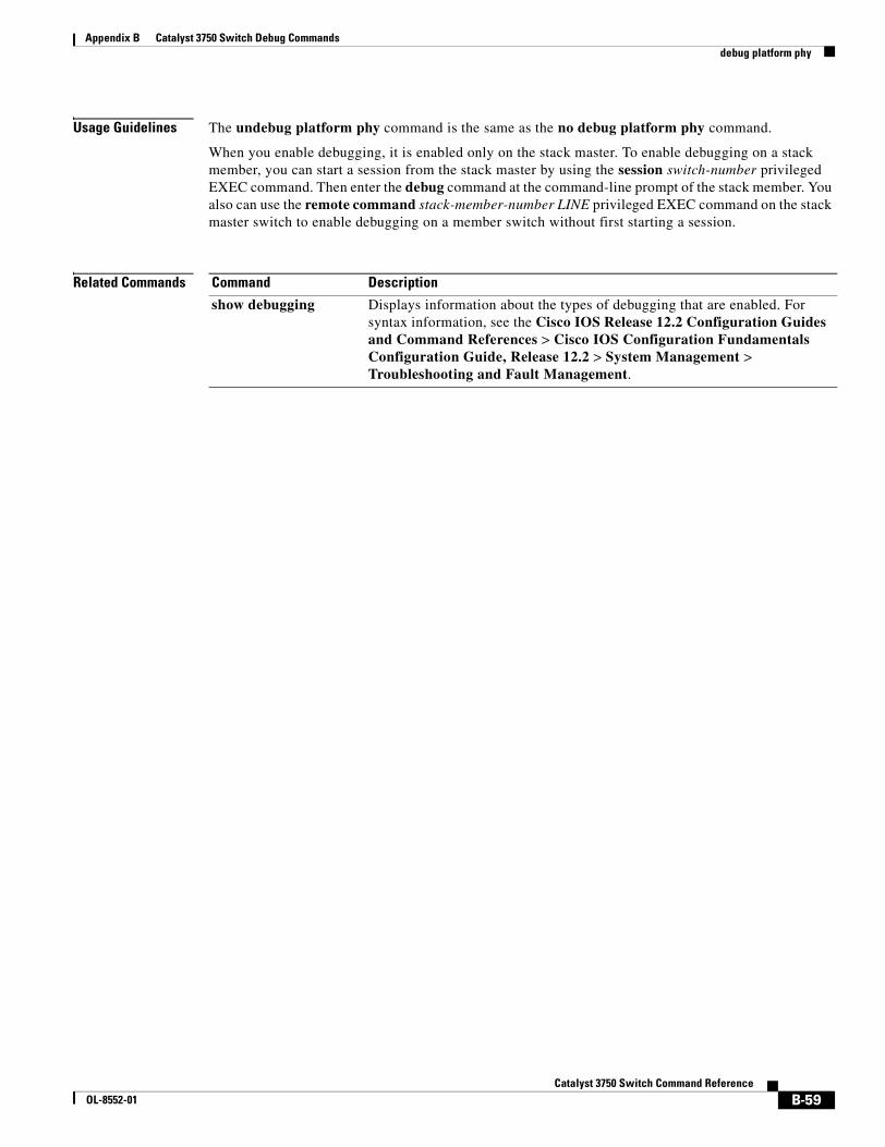
Appendix B Catalyst 3750 Switch Debug Commandsdebug platform phy
Usage Guidelines The undebug platform phy command is the same as the no debug platform phy command.
When you enable debugging, it is enabled only on the stack master. To enable debugging on a stack member, you can start a session from the stack master by using the session switch-number privileged EXEC command. Then enter the debug command at the command-line prompt of the stack member. You also can use the remote command stack-member-number LINE privileged EXEC command on the stack master switch to enable debugging on a member switch without first starting a session.
Related Commands Command Description
show debugging Displays information about the types of debugging that are enabled. For syntax information, see the Cisco IOS Release 12.2 Configuration Guides and Command References > Cisco IOS Configuration Fundamentals Configuration Guide, Release 12.2 > System Management > Troubleshooting and Fault Management.
B-59Catalyst 3750 Switch Command Reference
OL-8552-01
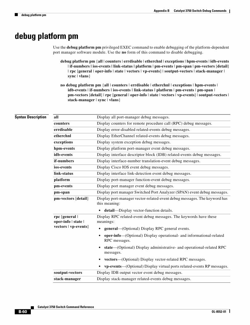
Appendix B Catalyst 3750 Switch Debug Commandsdebug platform pm
debug platform pmUse the debug platform pm privileged EXEC command to enable debugging of the platform-dependent port manager software module. Use the no form of this command to disable debugging.
debug platform pm {all | counters | errdisable | etherchnl | exceptions | hpm-events | idb-events | if-numbers | ios-events | link-status | platform | pm-events | pm-span | pm-vectors [detail] | rpc [general | oper-info | state | vectors | vp-events] | soutput-vectors | stack-manager | sync | vlans}
no debug platform pm {all | counters | errdisable | etherchnl | exceptions | hpm-events | idb-events | if-numbers | ios-events | link-status | platform | pm-events | pm-span | pm-vectors [detail] | rpc [general | oper-info | state | vectors | vp-events] | soutput-vectors | stack-manager | sync | vlans}
Syntax Description all Display all port-manager debug messages.
counters Display counters for remote procedure call (RPC) debug messages.
errdisable Display error-disabled related-events debug messages.
etherchnl Display EtherChannel related-events debug messages.
exceptions Display system exception debug messages.
hpm-events Display platform port-manager event debug messages.
idb-events Display interface descriptor block (IDB) related-events debug messages.
if-numbers Display interface-number translation-event debug messages.
ios-events Display Cisco IOS event debug messages.
link-status Display interface link-detection event debug messages.
platform Display port-manager function-event debug messages.
pm-events Display port manager event debug messages.
pm-span Display port manager Switched Port Analyzer (SPAN) event debug messages.
pm-vectors [detail] Display port-manager vector-related-event debug messages. The keyword has this meaning:
• detail—Display vector-function details.
rpc [general | oper-info | state | vectors | vp-events]
Display RPC related-event debug messages. The keywords have these meanings:
• general—(Optional) Display RPC general events.
• oper-info—(Optional) Display operational- and informational-related RPC messages.
• state—(Optional) Display administrative- and operational-related RPC messages.
• vectors—(Optional) Display vector-related RPC messages.
• vp-events—(Optional) Display virtual ports related-events RP messages.
soutput-vectors Display IDB output vector event debug messages.
stack-manager Display stack-manager related-events debug messages.
B-60Catalyst 3750 Switch Command Reference
OL-8552-01
Appendix B Catalyst 3750 Switch Debug Commandsdebug platform pm
Defaults Debugging is disabled.
Command Modes Privileged EXEC
Command History
Usage Guidelines The undebug platform pm command is the same as the no debug platform pm command.
When you enable debugging, it is enabled only on the stack master. To enable debugging on a stack member, you can start a session from the stack master by using the session switch-number privileged EXEC command. Then enter the debug command at the command-line prompt of the stack member. You also can use the remote command stack-member-number LINE privileged EXEC command on the stack master switch to enable debugging on a member switch without first starting a session.
Related Commands
sync Display operational synchronization and VLAN line-state event debug messages.
vlans Display VLAN creation and deletion event debug messages.
Release Modification
12.1(11)AX This command was introduced.
Command Description
show debugging Displays information about the types of debugging that are enabled. For syntax information, see the Cisco IOS Release 12.2 Configuration Guides and Command References > Cisco IOS Configuration Fundamentals Configuration Guide, Release 12.2 > System Management > Troubleshooting and Fault Management.
B-61Catalyst 3750 Switch Command Reference
OL-8552-01
Appendix B Catalyst 3750 Switch Debug Commandsdebug platform port-asic
debug platform port-asicUse the debug platform port-asic privileged EXEC command to enable debugging of the port application-specific integrated circuit (ASIC) driver. Use the no form of this command to disable debugging.
debug platform port-asic {interrupt | periodic | read | stack | write}
no debug platform port-asic {interrupt | periodic | read | stack | write}
Syntax Description
Defaults Debugging is disabled.
Command Modes Privileged EXEC
Command History
Usage Guidelines The undebug platform port-asic command is the same as the no debug platform port-asic command.
When you enable debugging, it is enabled only on the stack master. To enable debugging on a stack member, you can start a session from the stack master by using the session switch-number privileged EXEC command. Then enter the debug command at the command-line prompt of the stack member. You also can use the remote command stack-member-number LINE privileged EXEC command on the stack master switch to enable debugging on a member switch without first starting a session.
Related Commands
interrupt Display port-ASIC interrupt-related function debug messages.
periodic Display port-ASIC periodic-function-call debug messages.
read Display port-ASIC read debug messages.
stack Display stacking-related function debug messages.
write Display port-ASIC write debug messages.
Release Modification
12.1(11)AX This command was introduced.
Command Description
show debugging Displays information about the types of debugging that are enabled. For syntax information, see the Cisco IOS Release 12.2 Configuration Guides and Command References > Cisco IOS Configuration Fundamentals Configuration Guide, Release 12.2 > System Management > Troubleshooting and Fault Management.
B-62Catalyst 3750 Switch Command Reference
OL-8552-01
Appendix B Catalyst 3750 Switch Debug Commandsdebug platform port-security
debug platform port-securityUse the debug platform port-security privileged EXEC command to enable debugging of platform-dependent port-security information. Use the no form of this command to disable debugging.
debug platform port-security {add | aging | all | delete | errors | rpc | warnings}
no debug platform port-security {add | aging | all | delete | errors | rpc | warnings}
Syntax Description
Defaults Debugging is disabled.
Command Modes Privileged EXEC
Command History
Usage Guidelines The undebug platform port-security command is the same as the no debug platform port-security command.
When you enable debugging, it is enabled only on the stack master. To enable debugging on a stack member, you can start a session from the stack master by using the session switch-number privileged EXEC command. Then enter the debug command at the command-line prompt of the stack member. You also can use the remote command stack-member-number LINE privileged EXEC command on the stack master switch to enable debugging on a member switch without first starting a session.
Related Commands
add Display secure address addition debug messages.
aging Display secure address aging debug messages.
all Display all port-security debug messages.
delete Display secure address deletion debug messages.
errors Display port-security error debug messages.
rpc Display remote procedure call (RPC) debug messages.
warnings Display warning debug messages.
Release Modification
12.1(11)AX This command was introduced.
Command Description
show debugging Displays information about the types of debugging that are enabled. For syntax information, see the Cisco IOS Release 12.2 Configuration Guides and Command References > Cisco IOS Configuration Fundamentals Configuration Guide, Release 12.2 > System Management > Troubleshooting and Fault Management.
B-63Catalyst 3750 Switch Command Reference
OL-8552-01
Appendix B Catalyst 3750 Switch Debug Commandsdebug platform qos-acl-tcam
debug platform qos-acl-tcamUse the debug platform qos-acl-tcam privileged EXEC command to enable debugging of the quality of service (QoS) and access control list (ACL) ternary content addressable memory (TCAM) manager software. Use the no form of this command to disable debugging.
debug platform qos-acl-tcam {all | ctcam | errors | labels | mask | rpc | tcam}
no debug platform qos-acl-tcam {all | ctcam | errors | labels | mask | rpc | tcam}
Syntax Description
Defaults Debugging is disabled.
Command Modes Privileged EXEC
Command History
Usage Guidelines The undebug platform qos-acl-tcam command is the same as the no debug platform qos-acl-tcam command.
When you enable debugging, it is enabled only on the stack master. To enable debugging on a stack member, you can start a session from the stack master by using the session switch-number privileged EXEC command. Then enter the debug command at the command-line prompt of the stack member. You also can use the remote command stack-member-number LINE privileged EXEC command on the stack master switch to enable debugging on a member switch without first starting a session.
Related Commands
all Display all QoS and ACL TCAM (QATM) manager debug messages.
ctcam Display Cisco TCAM (CTCAM) related-events debug messages.
errors Display QATM error-related-events debug messages.
labels Display QATM label-related-events debug messages.
mask Display QATM mask-related-events debug messages.
rpc Display QATM remote procedure call (RPC) related-events debug messages.
tcam Display QATM TCAM-related events debug messages.
Release Modification
12.1(11)AX This command was introduced.
Command Description
show debugging Displays information about the types of debugging that are enabled. For syntax information, see the Cisco IOS Release 12.2 Configuration Guides and Command References > Cisco IOS Configuration Fundamentals Configuration Guide, Release 12.2 > System Management > Troubleshooting and Fault Management.
B-64Catalyst 3750 Switch Command Reference
OL-8552-01
Appendix B Catalyst 3750 Switch Debug Commandsdebug platform remote-commands
debug platform remote-commandsUse the debug platform remote-commands privileged EXEC command to enable debugging of remote commands. Use the no form of this command to disable debugging.
debug platform remote-commands
no debug platform remote-commands
Syntax Description This command has no arguments or keywords.
Defaults Debugging is disabled.
Command Modes Privileged EXEC
Command History
Usage Guidelines The undebug platform remote-commands command is the same as the no debug platform remote-commands command.
When you enable debugging, it is enabled only on the stack master. To enable debugging on a stack member, you can start a session from the stack master by using the session switch-number privileged EXEC command. Then enter the debug command at the command-line prompt of the stack member. You also can use the remote command stack-member-number LINE privileged EXEC command on the stack master switch to enable debugging on a member switch without first starting a session.
Related Commands
Release Modification
12.1(11)AX This command was introduced.
Command Description
show debugging Displays information about the types of debugging that are enabled. For syntax information, see the Cisco IOS Release 12.2 Configuration Guides and Command References > Cisco IOS Configuration Fundamentals Configuration Guide, Release 12.2 > System Management > Troubleshooting and Fault Management.
B-65Catalyst 3750 Switch Command Reference
OL-8552-01
Appendix B Catalyst 3750 Switch Debug Commandsdebug platform resource-manager
debug platform resource-managerUse the debug platform resource-manager privileged EXEC command to enable debugging of the resource manager software. Use the no form of this command to disable debugging.
debug platform resource-manager {all | dm | erd | errors | madmed | sd | stats | vld}
no debug platform resource-manager {all | dm | erd | errors | madmed | sd | stats | vld}
Syntax Description
Defaults Debugging is disabled.
Command Modes Privileged EXEC
Command History
Usage Guidelines The undebug platform resource-manager command is the same as the no debug platform resource-manager command.
When you enable debugging, it is enabled only on the stack master. To enable debugging on a stack member, you can start a session from the stack master by using the session switch-number privileged EXEC command. Then enter the debug command at the command-line prompt of the stack member. You also can use the remote command stack-member-number LINE privileged EXEC command on the stack master switch to enable debugging on a member switch without first starting a session.
Related Commands
all Display all resource manager debug messages.
dm Display destination-map debug messages.
erd Display equal-cost-route descriptor-table debug messages.
errors Display error debug messages.
madmed Display the MAC address descriptor table and multi-expansion descriptor table debug messages.
sd Display the station descriptor table debug messages.
stats Display statistics debug messages.
vld Display the VLAN-list descriptor debug messages.
Release Modification
12.1(11)AX This command was introduced.
Command Description
show debugging Displays information about the types of debugging that are enabled. For syntax information, see the Cisco IOS Release 12.2 Configuration Guides and Command References > Cisco IOS Configuration Fundamentals Configuration Guide, Release 12.2 > System Management > Troubleshooting and Fault Management.
B-66Catalyst 3750 Switch Command Reference
OL-8552-01
Appendix B Catalyst 3750 Switch Debug Commandsdebug platform snmp
debug platform snmpUse the debug platform snmp privileged EXEC command to enable debugging of the platform-dependent Simple Network Management Protocol (SNMP) software. Use the no form of this command to disable debugging.
debug platform snmp
no debug platform snmp
Syntax Description This command has no arguments or keywords.
Defaults Debugging is disabled.
Command Modes Privileged EXEC
Command History
Usage Guidelines The undebug platform snmp command is the same as the no debug platform snmp command.
When you enable debugging, it is enabled only on the stack master. To enable debugging on a stack member, you can start a session from the stack master by using the session switch-number privileged EXEC command. Then enter the debug command at the command-line prompt of the stack member. You also can use the remote command stack-member-number LINE privileged EXEC command on the stack master switch to enable debugging on a member switch without first starting a session.
Related Commands
Release Modification
12.1(11)AX This command was introduced.
Command Description
show debugging Displays information about the types of debugging that are enabled. For syntax information, see the Cisco IOS Release 12.2 Configuration Guides and Command References > Cisco IOS Configuration Fundamentals Configuration Guide, Release 12.2 > System Management > Troubleshooting and Fault Management.
B-67Catalyst 3750 Switch Command Reference
OL-8552-01
Appendix B Catalyst 3750 Switch Debug Commandsdebug platform span
debug platform spanUse the debug platform span privileged EXEC command to enable debugging of the platform-dependent Switched Port Analyzer (SPAN) software. Use the no form of this command to disable debugging.
debug platform span
no debug platform span
Syntax Description This command has no arguments or keywords.
Defaults Debugging is disabled.
Command Modes Privileged EXEC
Command History
Usage Guidelines The undebug platform span command is the same as the no debug platform span command.
When you enable debugging, it is enabled only on the stack master. To enable debugging on a stack member, you can start a session from the stack master by using the session switch-number privileged EXEC command. Then enter the debug command at the command-line prompt of the stack member. You also can use the remote command stack-member-number LINE privileged EXEC command on the stack master switch to enable debugging on a member switch without first starting a session.
Related Commands
Release Modification
12.1(11)AX This command was introduced.
Command Description
show debugging Displays information about the types of debugging that are enabled. For syntax information, see the Cisco IOS Release 12.2 Configuration Guides and Command References > Cisco IOS Configuration Fundamentals Configuration Guide, Release 12.2 > System Management > Troubleshooting and Fault Management.
B-68Catalyst 3750 Switch Command Reference
OL-8552-01
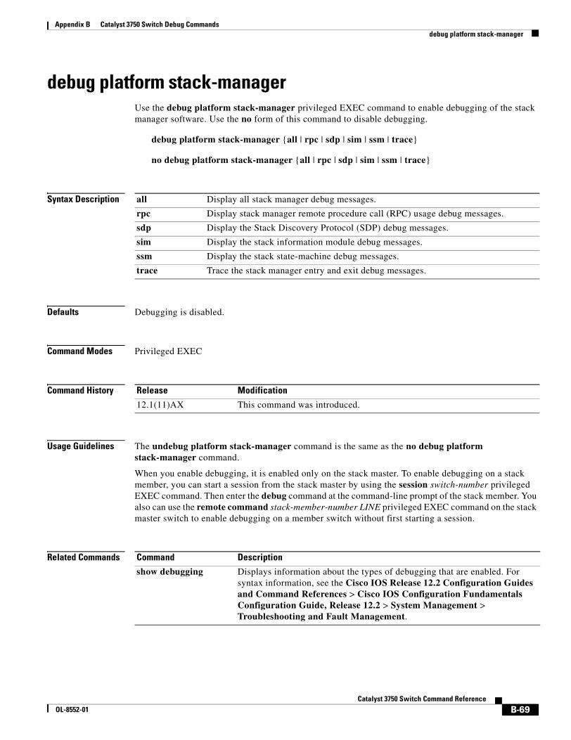
Appendix B Catalyst 3750 Switch Debug Commandsdebug platform stack-manager
debug platform stack-managerUse the debug platform stack-manager privileged EXEC command to enable debugging of the stack manager software. Use the no form of this command to disable debugging.
debug platform stack-manager {all | rpc | sdp | sim | ssm | trace}
no debug platform stack-manager {all | rpc | sdp | sim | ssm | trace}
Syntax Description
Defaults Debugging is disabled.
Command Modes Privileged EXEC
Command History
Usage Guidelines The undebug platform stack-manager command is the same as the no debug platform stack-manager command.
When you enable debugging, it is enabled only on the stack master. To enable debugging on a stack member, you can start a session from the stack master by using the session switch-number privileged EXEC command. Then enter the debug command at the command-line prompt of the stack member. You also can use the remote command stack-member-number LINE privileged EXEC command on the stack master switch to enable debugging on a member switch without first starting a session.
Related Commands
all Display all stack manager debug messages.
rpc Display stack manager remote procedure call (RPC) usage debug messages.
sdp Display the Stack Discovery Protocol (SDP) debug messages.
sim Display the stack information module debug messages.
ssm Display the stack state-machine debug messages.
trace Trace the stack manager entry and exit debug messages.
Release Modification
12.1(11)AX This command was introduced.
Command Description
show debugging Displays information about the types of debugging that are enabled. For syntax information, see the Cisco IOS Release 12.2 Configuration Guides and Command References > Cisco IOS Configuration Fundamentals Configuration Guide, Release 12.2 > System Management > Troubleshooting and Fault Management.
B-69Catalyst 3750 Switch Command Reference
OL-8552-01
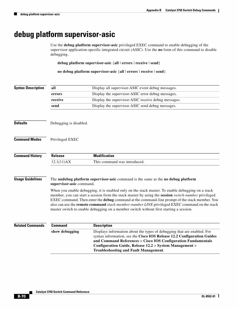
Appendix B Catalyst 3750 Switch Debug Commandsdebug platform supervisor-asic
debug platform supervisor-asicUse the debug platform supervisor-asic privileged EXEC command to enable debugging of the supervisor application-specific integrated circuit (ASIC). Use the no form of this command to disable debugging.
debug platform supervisor-asic {all | errors | receive | send}
no debug platform supervisor-asic {all | errors | receive | send}
Syntax Description
Defaults Debugging is disabled.
Command Modes Privileged EXEC
Command History
Usage Guidelines The undebug platform supervisor-asic command is the same as the no debug platform supervisor-asic command.
When you enable debugging, it is enabled only on the stack master. To enable debugging on a stack member, you can start a session from the stack master by using the session switch-number privileged EXEC command. Then enter the debug command at the command-line prompt of the stack member. You also can use the remote command stack-member-number LINE privileged EXEC command on the stack master switch to enable debugging on a member switch without first starting a session.
Related Commands
all Display all supervisor-ASIC event debug messages.
errors Display the supervisor-ASIC error debug messages.
receive Display the supervisor-ASIC receive debug messages.
send Display the supervisor-ASIC send debug messages.
Release Modification
12.1(11)AX This command was introduced.
Command Description
show debugging Displays information about the types of debugging that are enabled. For syntax information, see the Cisco IOS Release 12.2 Configuration Guides and Command References > Cisco IOS Configuration Fundamentals Configuration Guide, Release 12.2 > System Management > Troubleshooting and Fault Management.
B-70Catalyst 3750 Switch Command Reference
OL-8552-01
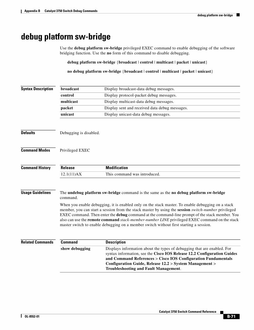
Appendix B Catalyst 3750 Switch Debug Commandsdebug platform sw-bridge
debug platform sw-bridgeUse the debug platform sw-bridge privileged EXEC command to enable debugging of the software bridging function. Use the no form of this command to disable debugging.
debug platform sw-bridge {broadcast | control | multicast | packet | unicast}
no debug platform sw-bridge {broadcast | control | multicast | packet | unicast}
Syntax Description
Defaults Debugging is disabled.
Command Modes Privileged EXEC
Command History
Usage Guidelines The undebug platform sw-bridge command is the same as the no debug platform sw-bridge command.
When you enable debugging, it is enabled only on the stack master. To enable debugging on a stack member, you can start a session from the stack master by using the session switch-number privileged EXEC command. Then enter the debug command at the command-line prompt of the stack member. You also can use the remote command stack-member-number LINE privileged EXEC command on the stack master switch to enable debugging on a member switch without first starting a session.
Related Commands
broadcast Display broadcast-data debug messages.
control Display protocol-packet debug messages.
multicast Display multicast-data debug messages.
packet Display sent and received data debug messages.
unicast Display unicast-data debug messages.
Release Modification
12.1(11)AX This command was introduced.
Command Description
show debugging Displays information about the types of debugging that are enabled. For syntax information, see the Cisco IOS Release 12.2 Configuration Guides and Command References > Cisco IOS Configuration Fundamentals Configuration Guide, Release 12.2 > System Management > Troubleshooting and Fault Management.
B-71Catalyst 3750 Switch Command Reference
OL-8552-01
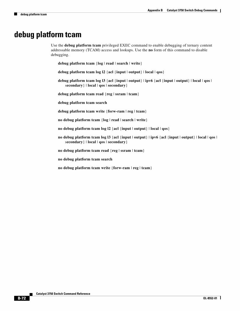
Appendix B Catalyst 3750 Switch Debug Commandsdebug platform tcam
debug platform tcam Use the debug platform tcam privileged EXEC command to enable debugging of ternary content addressable memory (TCAM) access and lookups. Use the no form of this command to disable debugging.
debug platform tcam {log | read | search | write}
debug platform tcam log l2 {acl {input | output} | local | qos}
debug platform tcam log l3 {acl {input | output} | ipv6 {acl {input | output} | local | qos | secondary} | local | qos | secondary}
debug platform tcam read {reg | ssram | tcam}
debug platform tcam search
debug platform tcam write {forw-ram | reg | tcam}
no debug platform tcam {log | read | search | write}
no debug platform tcam log l2 {acl {input | output} | local | qos}
no debug platform tcam log l3 {acl {input | output} | ipv6 {acl {input | output} | local | qos | secondary} | local | qos | secondary}
no debug platform tcam read {reg | ssram | tcam}
no debug platform tcam search
no debug platform tcam write {forw-ram | reg | tcam}
B-72Catalyst 3750 Switch Command Reference
OL-8552-01
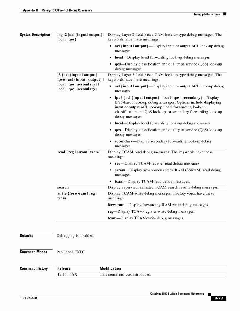
Appendix B Catalyst 3750 Switch Debug Commandsdebug platform tcam
Syntax Description
Defaults Debugging is disabled.
Command Modes Privileged EXEC
Command History
log l2 {acl {input | output} | local | qos}
Display Layer 2 field-based CAM look-up type debug messages. The keywords have these meanings:
• acl {input | output}—Display input or output ACL look-up debug messages.
• local—Display local forwarding look-up debug messages.
• qos—Display classification and quality of service (QoS) look-up debug messages.
l3 {acl {input | output} | ipv6 {acl {input | output} | local | qos | secondary} | local | qos | secondary}
Display Layer 3 field-based CAM look-up type debug messages. The keywords have these meanings:
• acl {input | output}—Display input or output ACL look-up debug messages.
• ipv6 {acl {input | output} | local | qos | secondary}—Display IPv6-based look-up debug messages. Options include displaying input or output ACL look-up, local forwarding look-up, classification and QoS look-up, or secondary forwarding look-up debug messages.
• local—Display local forwarding look-up debug messages.
• qos—Display classification and quality of service (QoS) look-up debug messages.
• secondary—Display secondary forwarding look-up debug messages.
read {reg | ssram | tcam} Display TCAM-read debug messages. The keywords have these meanings:
• reg—Display TCAM-register read debug messages.
• ssram—Display synchronous static RAM (SSRAM)-read debug messages.
• tcam—Display TCAM-read debug messages.
search Display supervisor-initiated TCAM-search results debug messages.
write {forw-ram | reg | tcam}
Display TCAM-write debug messages. The keywords have these meanings:
forw-ram—Display forwarding-RAM write debug messages.
reg—Display TCAM-register write debug messages.
tcam—Display TCAM-write debug messages.
Release Modification
12.1(11)AX This command was introduced.
B-73Catalyst 3750 Switch Command Reference
OL-8552-01
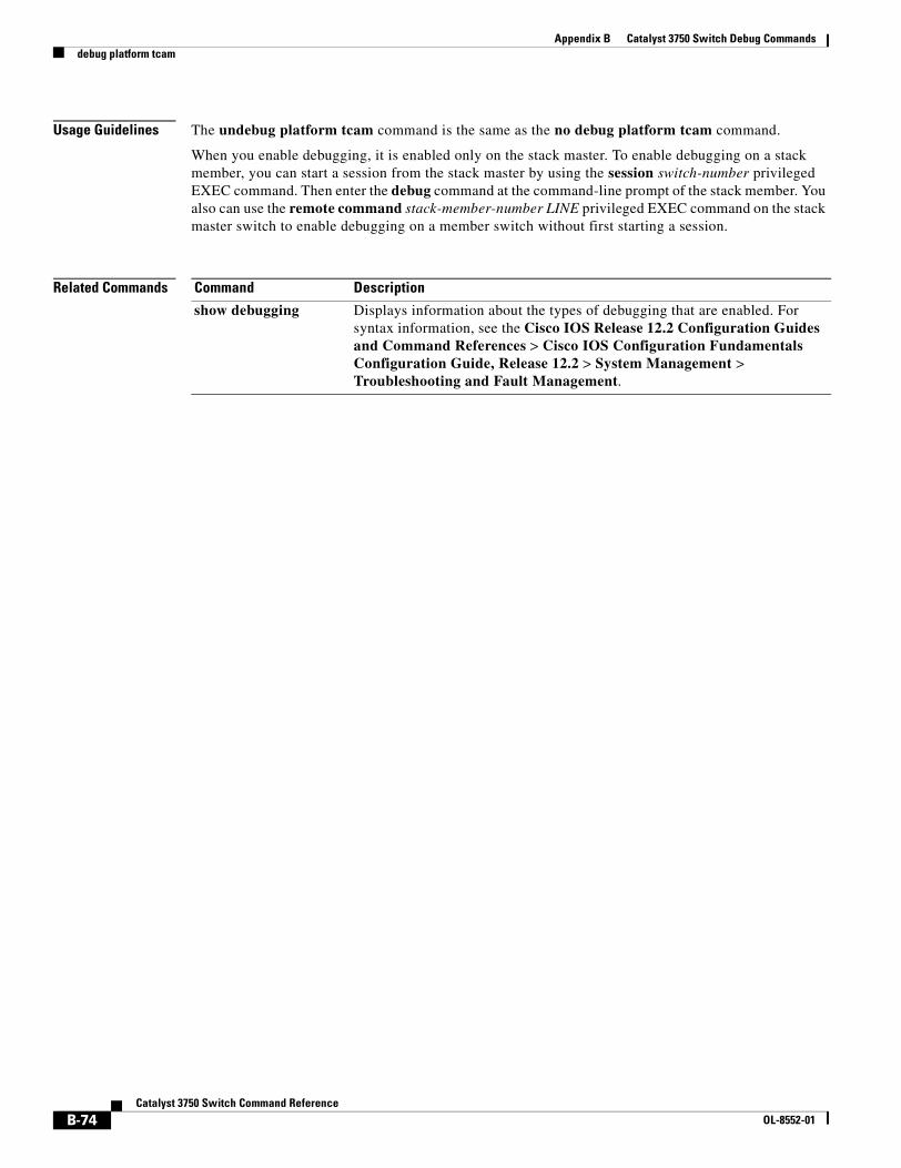
Appendix B Catalyst 3750 Switch Debug Commandsdebug platform tcam
Usage Guidelines The undebug platform tcam command is the same as the no debug platform tcam command.
When you enable debugging, it is enabled only on the stack master. To enable debugging on a stack member, you can start a session from the stack master by using the session switch-number privileged EXEC command. Then enter the debug command at the command-line prompt of the stack member. You also can use the remote command stack-member-number LINE privileged EXEC command on the stack master switch to enable debugging on a member switch without first starting a session.
Related Commands Command Description
show debugging Displays information about the types of debugging that are enabled. For syntax information, see the Cisco IOS Release 12.2 Configuration Guides and Command References > Cisco IOS Configuration Fundamentals Configuration Guide, Release 12.2 > System Management > Troubleshooting and Fault Management.
B-74Catalyst 3750 Switch Command Reference
OL-8552-01
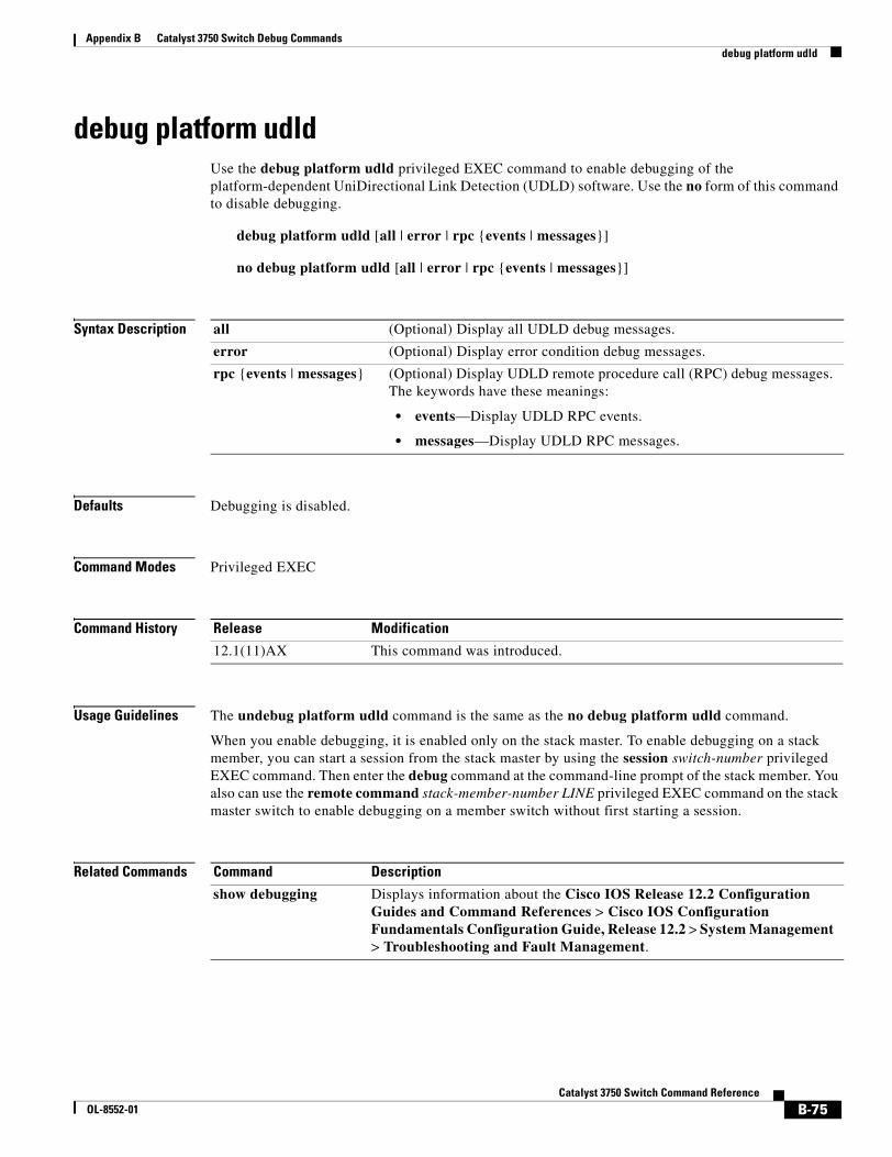
Appendix B Catalyst 3750 Switch Debug Commandsdebug platform udld
debug platform udldUse the debug platform udld privileged EXEC command to enable debugging of the platform-dependent UniDirectional Link Detection (UDLD) software. Use the no form of this command to disable debugging.
debug platform udld [all | error | rpc {events | messages}]
no debug platform udld [all | error | rpc {events | messages}]
Syntax Description
Defaults Debugging is disabled.
Command Modes Privileged EXEC
Command History
Usage Guidelines The undebug platform udld command is the same as the no debug platform udld command.
When you enable debugging, it is enabled only on the stack master. To enable debugging on a stack member, you can start a session from the stack master by using the session switch-number privileged EXEC command. Then enter the debug command at the command-line prompt of the stack member. You also can use the remote command stack-member-number LINE privileged EXEC command on the stack master switch to enable debugging on a member switch without first starting a session.
Related Commands
all (Optional) Display all UDLD debug messages.
error (Optional) Display error condition debug messages.
rpc {events | messages} (Optional) Display UDLD remote procedure call (RPC) debug messages. The keywords have these meanings:
• events—Display UDLD RPC events.
• messages—Display UDLD RPC messages.
Release Modification
12.1(11)AX This command was introduced.
Command Description
show debugging Displays information about the Cisco IOS Release 12.2 Configuration Guides and Command References > Cisco IOS Configuration Fundamentals Configuration Guide, Release 12.2 > System Management > Troubleshooting and Fault Management.
B-75Catalyst 3750 Switch Command Reference
OL-8552-01
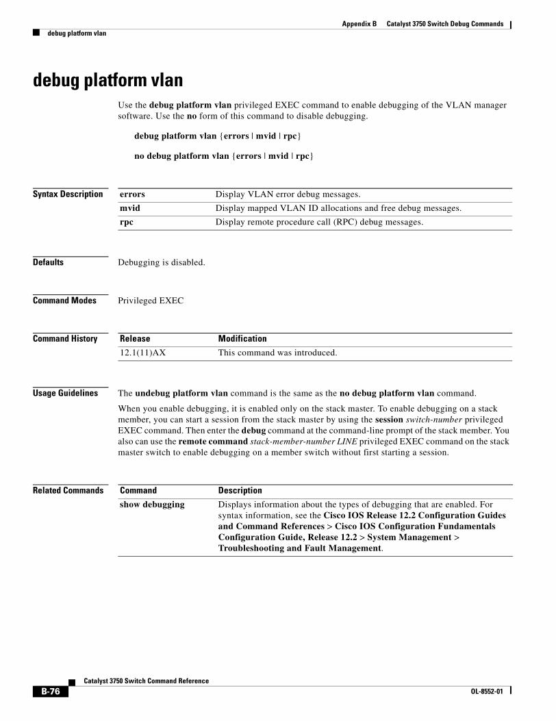
Appendix B Catalyst 3750 Switch Debug Commandsdebug platform vlan
debug platform vlanUse the debug platform vlan privileged EXEC command to enable debugging of the VLAN manager software. Use the no form of this command to disable debugging.
debug platform vlan {errors | mvid | rpc}
no debug platform vlan {errors | mvid | rpc}
Syntax Description
Defaults Debugging is disabled.
Command Modes Privileged EXEC
Command History
Usage Guidelines The undebug platform vlan command is the same as the no debug platform vlan command.
When you enable debugging, it is enabled only on the stack master. To enable debugging on a stack member, you can start a session from the stack master by using the session switch-number privileged EXEC command. Then enter the debug command at the command-line prompt of the stack member. You also can use the remote command stack-member-number LINE privileged EXEC command on the stack master switch to enable debugging on a member switch without first starting a session.
Related Commands
errors Display VLAN error debug messages.
mvid Display mapped VLAN ID allocations and free debug messages.
rpc Display remote procedure call (RPC) debug messages.
Release Modification
12.1(11)AX This command was introduced.
Command Description
show debugging Displays information about the types of debugging that are enabled. For syntax information, see the Cisco IOS Release 12.2 Configuration Guides and Command References > Cisco IOS Configuration Fundamentals Configuration Guide, Release 12.2 > System Management > Troubleshooting and Fault Management.
B-76Catalyst 3750 Switch Command Reference
OL-8552-01
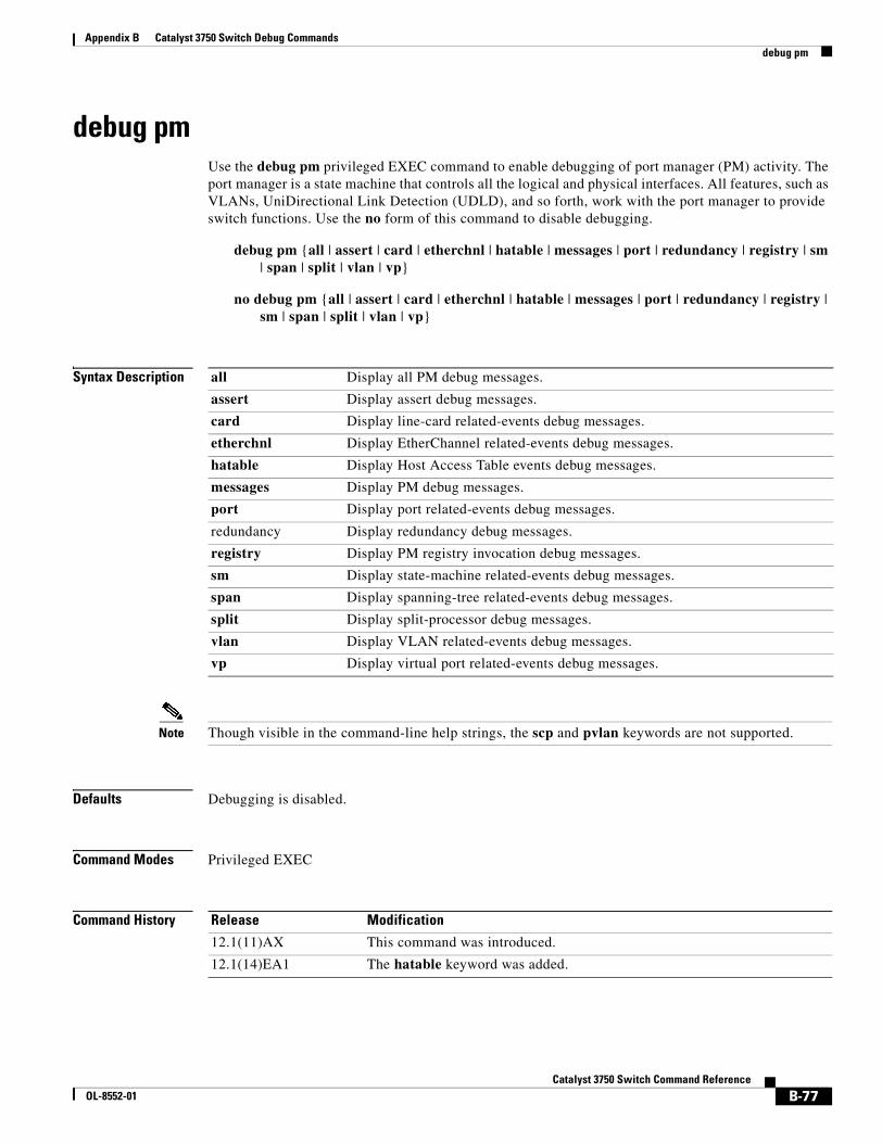
Appendix B Catalyst 3750 Switch Debug Commandsdebug pm
debug pmUse the debug pm privileged EXEC command to enable debugging of port manager (PM) activity. The port manager is a state machine that controls all the logical and physical interfaces. All features, such as VLANs, UniDirectional Link Detection (UDLD), and so forth, work with the port manager to provide switch functions. Use the no form of this command to disable debugging.
debug pm {all | assert | card | etherchnl | hatable | messages | port | redundancy | registry | sm | span | split | vlan | vp}
no debug pm {all | assert | card | etherchnl | hatable | messages | port | redundancy | registry | sm | span | split | vlan | vp}
Syntax Description
Note Though visible in the command-line help strings, the scp and pvlan keywords are not supported.
Defaults Debugging is disabled.
Command Modes Privileged EXEC
Command History
all Display all PM debug messages.
assert Display assert debug messages.
card Display line-card related-events debug messages.
etherchnl Display EtherChannel related-events debug messages.
hatable Display Host Access Table events debug messages.
messages Display PM debug messages.
port Display port related-events debug messages.
redundancy Display redundancy debug messages.
registry Display PM registry invocation debug messages.
sm Display state-machine related-events debug messages.
span Display spanning-tree related-events debug messages.
split Display split-processor debug messages.
vlan Display VLAN related-events debug messages.
vp Display virtual port related-events debug messages.
Release Modification
12.1(11)AX This command was introduced.
12.1(14)EA1 The hatable keyword was added.
B-77Catalyst 3750 Switch Command Reference
OL-8552-01
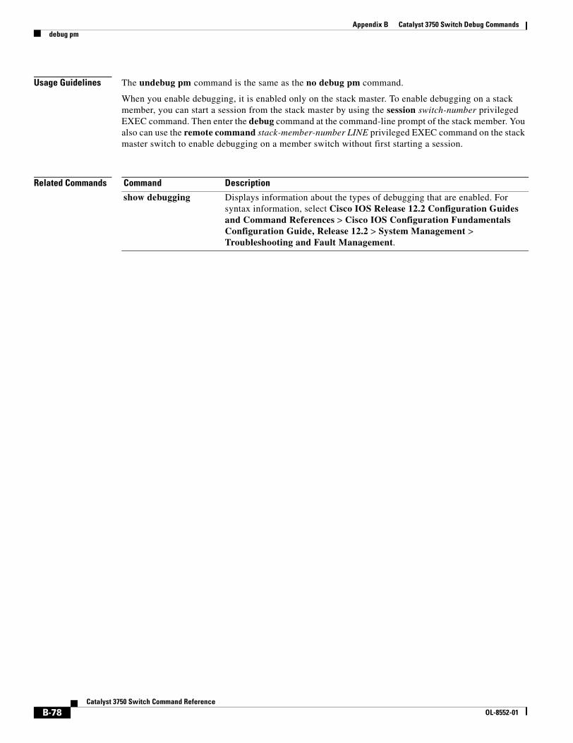
Appendix B Catalyst 3750 Switch Debug Commandsdebug pm
Usage Guidelines The undebug pm command is the same as the no debug pm command.
When you enable debugging, it is enabled only on the stack master. To enable debugging on a stack member, you can start a session from the stack master by using the session switch-number privileged EXEC command. Then enter the debug command at the command-line prompt of the stack member. You also can use the remote command stack-member-number LINE privileged EXEC command on the stack master switch to enable debugging on a member switch without first starting a session.
Related Commands Command Description
show debugging Displays information about the types of debugging that are enabled. For syntax information, select Cisco IOS Release 12.2 Configuration Guides and Command References > Cisco IOS Configuration Fundamentals Configuration Guide, Release 12.2 > System Management > Troubleshooting and Fault Management.
B-78Catalyst 3750 Switch Command Reference
OL-8552-01
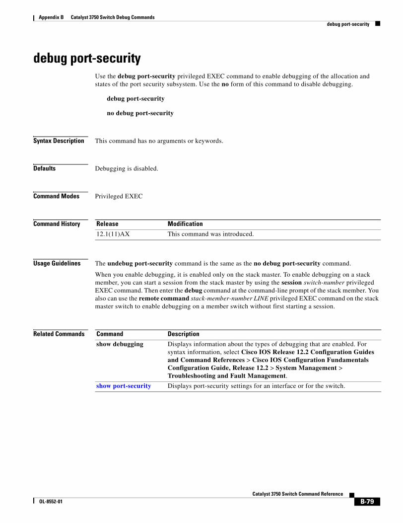
Appendix B Catalyst 3750 Switch Debug Commandsdebug port-security
debug port-securityUse the debug port-security privileged EXEC command to enable debugging of the allocation and states of the port security subsystem. Use the no form of this command to disable debugging.
debug port-security
no debug port-security
Syntax Description This command has no arguments or keywords.
Defaults Debugging is disabled.
Command Modes Privileged EXEC
Command History
Usage Guidelines The undebug port-security command is the same as the no debug port-security command.
When you enable debugging, it is enabled only on the stack master. To enable debugging on a stack member, you can start a session from the stack master by using the session switch-number privileged EXEC command. Then enter the debug command at the command-line prompt of the stack member. You also can use the remote command stack-member-number LINE privileged EXEC command on the stack master switch to enable debugging on a member switch without first starting a session.
Related Commands
Release Modification
12.1(11)AX This command was introduced.
Command Description
show debugging Displays information about the types of debugging that are enabled. For syntax information, select Cisco IOS Release 12.2 Configuration Guides and Command References > Cisco IOS Configuration Fundamentals Configuration Guide, Release 12.2 > System Management > Troubleshooting and Fault Management.
show port-security Displays port-security settings for an interface or for the switch.
B-79Catalyst 3750 Switch Command Reference
OL-8552-01
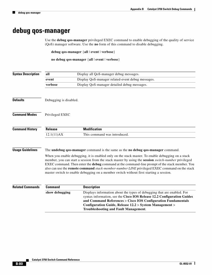
Appendix B Catalyst 3750 Switch Debug Commandsdebug qos-manager
debug qos-managerUse the debug qos-manager privileged EXEC command to enable debugging of the quality of service (QoS) manager software. Use the no form of this command to disable debugging.
debug qos-manager {all | event | verbose}
no debug qos-manager {all | event | verbose}
Syntax Description
Defaults Debugging is disabled.
Command Modes Privileged EXEC
Command History
Usage Guidelines The undebug qos-manager command is the same as the no debug qos-manager command.
When you enable debugging, it is enabled only on the stack master. To enable debugging on a stack member, you can start a session from the stack master by using the session switch-number privileged EXEC command. Then enter the debug command at the command-line prompt of the stack member. You also can use the remote command stack-member-number LINE privileged EXEC command on the stack master switch to enable debugging on a member switch without first starting a session.
Related Commands
all Display all QoS-manager debug messages.
event Display QoS-manager related-event debug messages.
verbose Display QoS-manager detailed debug messages.
Release Modification
12.1(11)AX This command was introduced.
Command Description
show debugging Displays information about the types of debugging that are enabled. For syntax information, see the Cisco IOS Release 12.2 Configuration Guides and Command References > Cisco IOS Configuration Fundamentals Configuration Guide, Release 12.2 > System Management > Troubleshooting and Fault Management.
B-80Catalyst 3750 Switch Command Reference
OL-8552-01
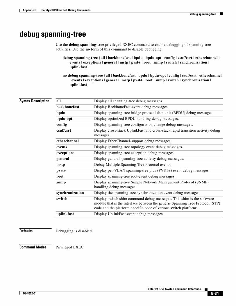
Appendix B Catalyst 3750 Switch Debug Commandsdebug spanning-tree
debug spanning-tree Use the debug spanning-tree privileged EXEC command to enable debugging of spanning-tree activities. Use the no form of this command to disable debugging.
debug spanning-tree {all | backbonefast | bpdu | bpdu-opt | config | csuf/csrt | etherchannel | events | exceptions | general | mstp | pvst+ | root | snmp | switch | synchronization | uplinkfast}
no debug spanning-tree {all | backbonefast | bpdu | bpdu-opt | config | csuf/csrt | etherchannel | events | exceptions | general | mstp | pvst+ | root | snmp | switch | synchronization | uplinkfast}
Syntax Description
Defaults Debugging is disabled.
Command Modes Privileged EXEC
all Display all spanning-tree debug messages.
backbonefast Display BackboneFast-event debug messages.
bpdu Display spanning-tree bridge protocol data unit (BPDU) debug messages.
bpdu-opt Display optimized BPDU handling debug messages.
config Display spanning-tree configuration change debug messages.
csuf/csrt Display cross-stack UplinkFast and cross-stack rapid transition activity debug messages.
etherchannel Display EtherChannel-support debug messages.
events Display spanning-tree topology event debug messages.
exceptions Display spanning-tree exception debug messages.
general Display general spanning-tree activity debug messages.
mstp Debug Multiple Spanning Tree Protocol events.
pvst+ Display per-VLAN spanning-tree plus (PVST+) event debug messages.
root Display spanning-tree root-event debug messages.
snmp Display spanning-tree Simple Network Management Protocol (SNMP) handling debug messages.
synchronization Display the spanning-tree synchronization event debug messages.
switch Display switch shim command debug messages. This shim is the software module that is the interface between the generic Spanning Tree Protocol (STP) code and the platform-specific code of various switch platforms.
uplinkfast Display UplinkFast-event debug messages.
B-81Catalyst 3750 Switch Command Reference
OL-8552-01
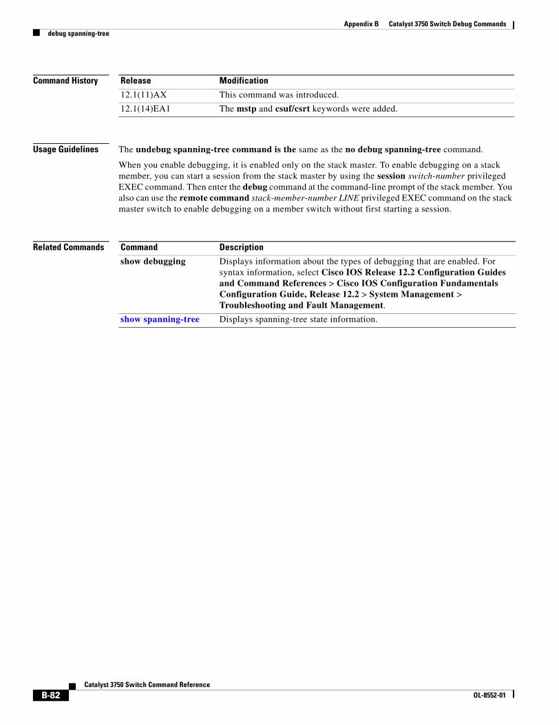
Appendix B Catalyst 3750 Switch Debug Commandsdebug spanning-tree
Command History
Usage Guidelines The undebug spanning-tree command is the same as the no debug spanning-tree command.
When you enable debugging, it is enabled only on the stack master. To enable debugging on a stack member, you can start a session from the stack master by using the session switch-number privileged EXEC command. Then enter the debug command at the command-line prompt of the stack member. You also can use the remote command stack-member-number LINE privileged EXEC command on the stack master switch to enable debugging on a member switch without first starting a session.
Related Commands
Release Modification
12.1(11)AX This command was introduced.
12.1(14)EA1 The mstp and csuf/csrt keywords were added.
Command Description
show debugging Displays information about the types of debugging that are enabled. For syntax information, select Cisco IOS Release 12.2 Configuration Guides and Command References > Cisco IOS Configuration Fundamentals Configuration Guide, Release 12.2 > System Management > Troubleshooting and Fault Management.
show spanning-tree Displays spanning-tree state information.
B-82Catalyst 3750 Switch Command Reference
OL-8552-01
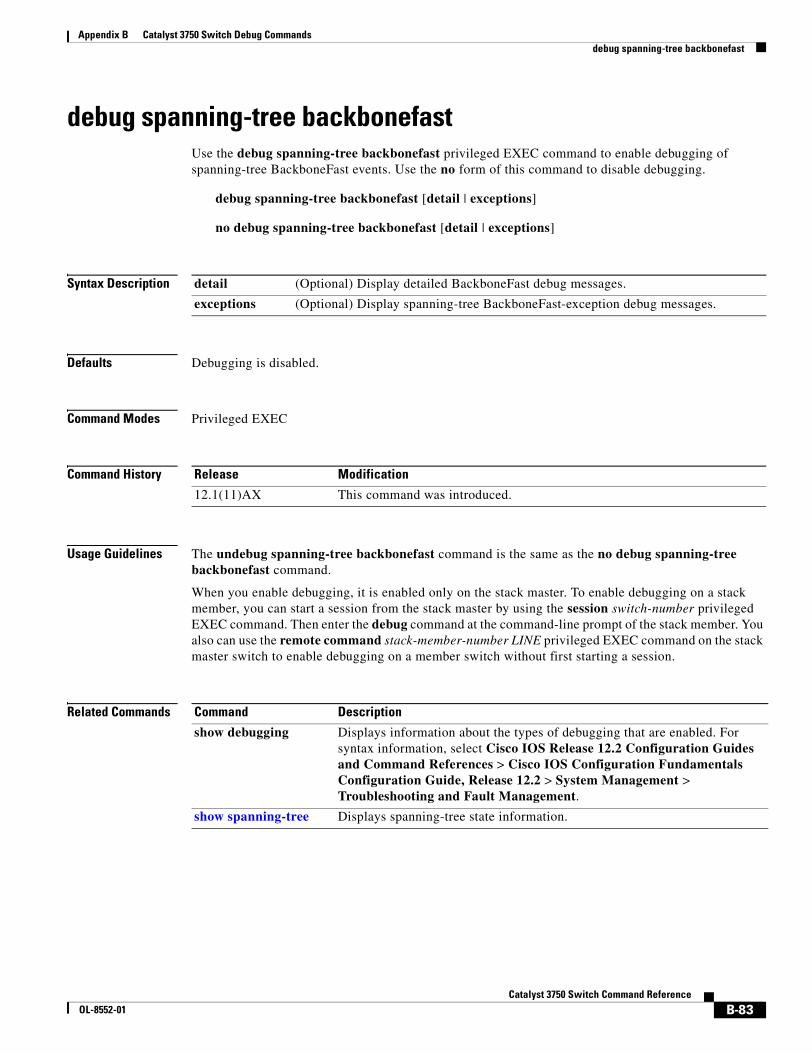
Appendix B Catalyst 3750 Switch Debug Commandsdebug spanning-tree backbonefast
debug spanning-tree backbonefastUse the debug spanning-tree backbonefast privileged EXEC command to enable debugging of spanning-tree BackboneFast events. Use the no form of this command to disable debugging.
debug spanning-tree backbonefast [detail | exceptions]
no debug spanning-tree backbonefast [detail | exceptions]
Syntax Description
Defaults Debugging is disabled.
Command Modes Privileged EXEC
Command History
Usage Guidelines The undebug spanning-tree backbonefast command is the same as the no debug spanning-tree backbonefast command.
When you enable debugging, it is enabled only on the stack master. To enable debugging on a stack member, you can start a session from the stack master by using the session switch-number privileged EXEC command. Then enter the debug command at the command-line prompt of the stack member. You also can use the remote command stack-member-number LINE privileged EXEC command on the stack master switch to enable debugging on a member switch without first starting a session.
Related Commands
detail (Optional) Display detailed BackboneFast debug messages.
exceptions (Optional) Display spanning-tree BackboneFast-exception debug messages.
Release Modification
12.1(11)AX This command was introduced.
Command Description
show debugging Displays information about the types of debugging that are enabled. For syntax information, select Cisco IOS Release 12.2 Configuration Guides and Command References > Cisco IOS Configuration Fundamentals Configuration Guide, Release 12.2 > System Management > Troubleshooting and Fault Management.
show spanning-tree Displays spanning-tree state information.
B-83Catalyst 3750 Switch Command Reference
OL-8552-01
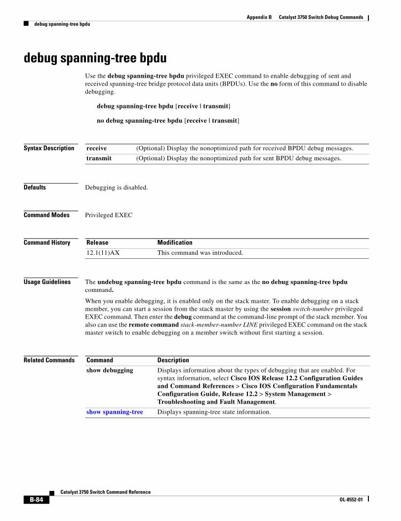
Appendix B Catalyst 3750 Switch Debug Commandsdebug spanning-tree bpdu
debug spanning-tree bpduUse the debug spanning-tree bpdu privileged EXEC command to enable debugging of sent and received spanning-tree bridge protocol data units (BPDUs). Use the no form of this command to disable debugging.
debug spanning-tree bpdu [receive | transmit]
no debug spanning-tree bpdu [receive | transmit]
Syntax Description
Defaults Debugging is disabled.
Command Modes Privileged EXEC
Command History
Usage Guidelines The undebug spanning-tree bpdu command is the same as the no debug spanning-tree bpdu command.
When you enable debugging, it is enabled only on the stack master. To enable debugging on a stack member, you can start a session from the stack master by using the session switch-number privileged EXEC command. Then enter the debug command at the command-line prompt of the stack member. You also can use the remote command stack-member-number LINE privileged EXEC command on the stack master switch to enable debugging on a member switch without first starting a session.
Related Commands
receive (Optional) Display the nonoptimized path for received BPDU debug messages.
transmit (Optional) Display the nonoptimized path for sent BPDU debug messages.
Release Modification
12.1(11)AX This command was introduced.
Command Description
show debugging Displays information about the types of debugging that are enabled. For syntax information, select Cisco IOS Release 12.2 Configuration Guides and Command References > Cisco IOS Configuration Fundamentals Configuration Guide, Release 12.2 > System Management > Troubleshooting and Fault Management.
show spanning-tree Displays spanning-tree state information.
B-84Catalyst 3750 Switch Command Reference
OL-8552-01
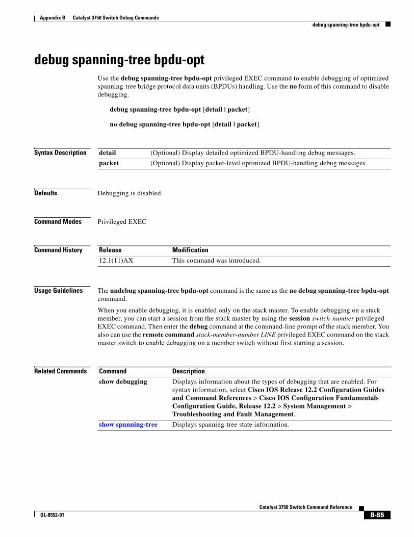
Appendix B Catalyst 3750 Switch Debug Commandsdebug spanning-tree bpdu-opt
debug spanning-tree bpdu-optUse the debug spanning-tree bpdu-opt privileged EXEC command to enable debugging of optimized spanning-tree bridge protocol data units (BPDUs) handling. Use the no form of this command to disable debugging.
debug spanning-tree bpdu-opt [detail | packet]
no debug spanning-tree bpdu-opt [detail | packet]
Syntax Description
Defaults Debugging is disabled.
Command Modes Privileged EXEC
Command History
Usage Guidelines The undebug spanning-tree bpdu-opt command is the same as the no debug spanning-tree bpdu-opt command.
When you enable debugging, it is enabled only on the stack master. To enable debugging on a stack member, you can start a session from the stack master by using the session switch-number privileged EXEC command. Then enter the debug command at the command-line prompt of the stack member. You also can use the remote command stack-member-number LINE privileged EXEC command on the stack master switch to enable debugging on a member switch without first starting a session.
Related Commands
detail (Optional) Display detailed optimized BPDU-handling debug messages.
packet (Optional) Display packet-level optimized BPDU-handling debug messages.
Release Modification
12.1(11)AX This command was introduced.
Command Description
show debugging Displays information about the types of debugging that are enabled. For syntax information, select Cisco IOS Release 12.2 Configuration Guides and Command References > Cisco IOS Configuration Fundamentals Configuration Guide, Release 12.2 > System Management > Troubleshooting and Fault Management.
show spanning-tree Displays spanning-tree state information.
B-85Catalyst 3750 Switch Command Reference
OL-8552-01
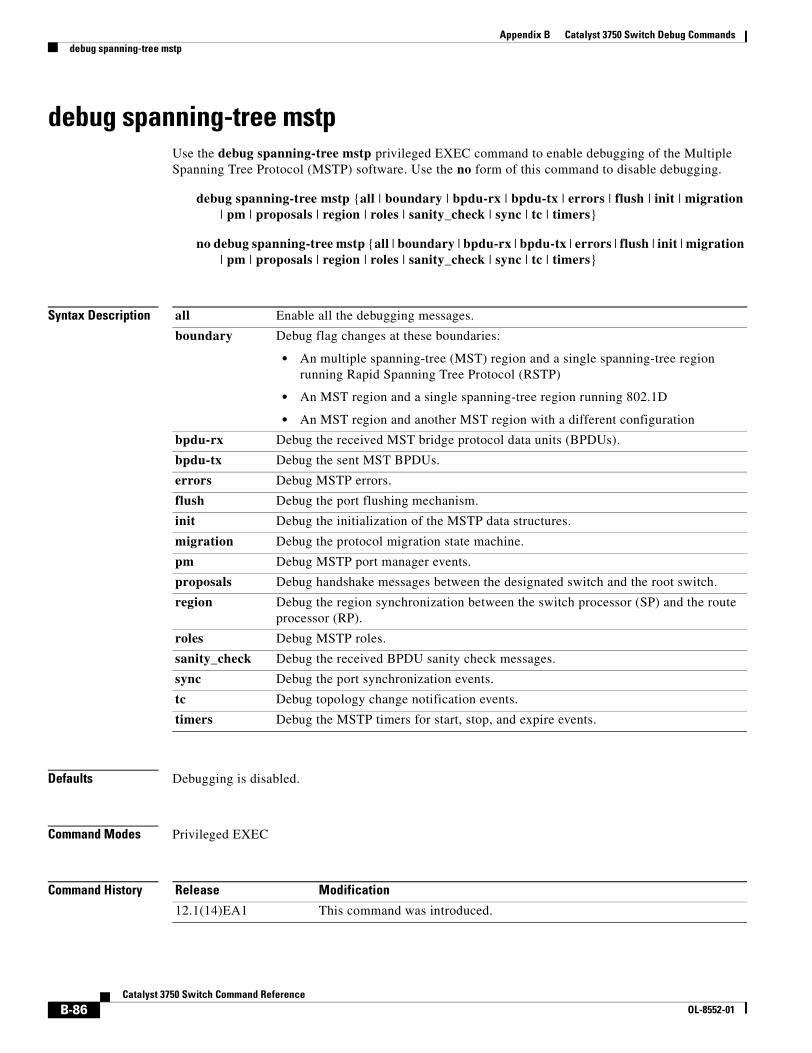
Appendix B Catalyst 3750 Switch Debug Commandsdebug spanning-tree mstp
debug spanning-tree mstp Use the debug spanning-tree mstp privileged EXEC command to enable debugging of the Multiple Spanning Tree Protocol (MSTP) software. Use the no form of this command to disable debugging.
debug spanning-tree mstp {all | boundary | bpdu-rx | bpdu-tx | errors | flush | init | migration | pm | proposals | region | roles | sanity_check | sync | tc | timers}
no debug spanning-tree mstp {all | boundary | bpdu-rx | bpdu-tx | errors | flush | init | migration | pm | proposals | region | roles | sanity_check | sync | tc | timers}
Syntax Description
Defaults Debugging is disabled.
Command Modes Privileged EXEC
Command History
all Enable all the debugging messages.
boundary Debug flag changes at these boundaries:
• An multiple spanning-tree (MST) region and a single spanning-tree region running Rapid Spanning Tree Protocol (RSTP)
• An MST region and a single spanning-tree region running 802.1D
• An MST region and another MST region with a different configuration
bpdu-rx Debug the received MST bridge protocol data units (BPDUs).
bpdu-tx Debug the sent MST BPDUs.
errors Debug MSTP errors.
flush Debug the port flushing mechanism.
init Debug the initialization of the MSTP data structures.
migration Debug the protocol migration state machine.
pm Debug MSTP port manager events.
proposals Debug handshake messages between the designated switch and the root switch.
region Debug the region synchronization between the switch processor (SP) and the route processor (RP).
roles Debug MSTP roles.
sanity_check Debug the received BPDU sanity check messages.
sync Debug the port synchronization events.
tc Debug topology change notification events.
timers Debug the MSTP timers for start, stop, and expire events.
Release Modification
12.1(14)EA1 This command was introduced.
B-86Catalyst 3750 Switch Command Reference
OL-8552-01
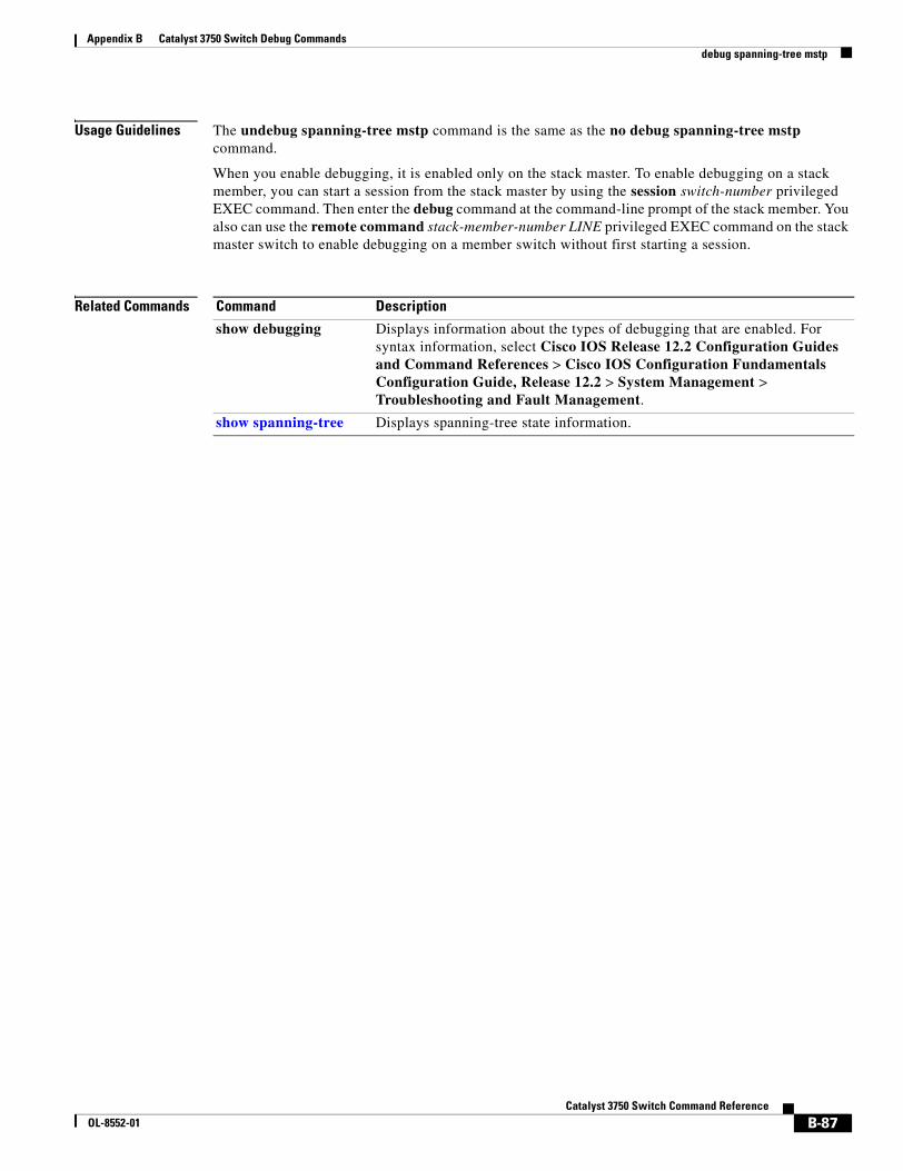
Appendix B Catalyst 3750 Switch Debug Commandsdebug spanning-tree mstp
Usage Guidelines The undebug spanning-tree mstp command is the same as the no debug spanning-tree mstp command.
When you enable debugging, it is enabled only on the stack master. To enable debugging on a stack member, you can start a session from the stack master by using the session switch-number privileged EXEC command. Then enter the debug command at the command-line prompt of the stack member. You also can use the remote command stack-member-number LINE privileged EXEC command on the stack master switch to enable debugging on a member switch without first starting a session.
Related Commands Command Description
show debugging Displays information about the types of debugging that are enabled. For syntax information, select Cisco IOS Release 12.2 Configuration Guides and Command References > Cisco IOS Configuration Fundamentals Configuration Guide, Release 12.2 > System Management > Troubleshooting and Fault Management.
show spanning-tree Displays spanning-tree state information.
B-87Catalyst 3750 Switch Command Reference
OL-8552-01
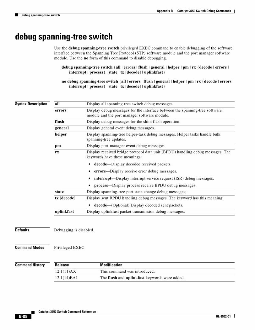
Appendix B Catalyst 3750 Switch Debug Commandsdebug spanning-tree switch
debug spanning-tree switchUse the debug spanning-tree switch privileged EXEC command to enable debugging of the software interface between the Spanning Tree Protocol (STP) software module and the port manager software module. Use the no form of this command to disable debugging.
debug spanning-tree switch {all | errors | flush | general | helper | pm | rx {decode | errors | interrupt | process} | state | tx [decode] | uplinkfast}
no debug spanning-tree switch {all | errors | flush | general | helper | pm | rx {decode | errors | interrupt | process} | state | tx [decode] | uplinkfast}
Syntax Description
Defaults Debugging is disabled.
Command Modes Privileged EXEC
Command History
all Display all spanning-tree switch debug messages.
errors Display debug messages for the interface between the spanning-tree software module and the port manager software module.
flush Display debug messages for the shim flush operation.
general Display general event debug messages.
helper Display spanning-tree helper-task debug messages. Helper tasks handle bulk spanning-tree updates.
pm Display port-manager event debug messages.
rx Display received bridge protocol data unit (BPDU) handling debug messages. The keywords have these meanings:
• decode—Display decoded received packets.
• errors—Display receive error debug messages.
• interrupt—Display interrupt service request (ISR) debug messages.
• process—Display process receive BPDU debug messages.
state Display spanning-tree port state change debug messages;
tx [decode] Display sent BPDU handling debug messages. The keyword has this meaning:
• decode—(Optional) Display decoded sent packets.
uplinkfast Display uplinkfast packet transmission debug messages.
Release Modification
12.1(11)AX This command was introduced.
12.1(14)EA1 The flush and uplinkfast keywords were added.
B-88Catalyst 3750 Switch Command Reference
OL-8552-01
Appendix B Catalyst 3750 Switch Debug Commandsdebug spanning-tree switch
Usage Guidelines The undebug spanning-tree switch command is the same as the no debug spanning-tree switch command.
When you enable debugging, it is enabled only on the stack master. To enable debugging on a stack member, you can start a session from the stack master by using the session switch-number privileged EXEC command. Then enter the debug command at the command-line prompt of the stack member. You also can use the remote command stack-member-number LINE privileged EXEC command on the stack master switch to enable debugging on a member switch without first starting a session.
Related Commands Command Description
show debugging Displays information about the types of debugging that are enabled. For syntax information, select Cisco IOS Release 12.2 Configuration Guides and Command References > Cisco IOS Configuration Fundamentals Configuration Guide, Release 12.2 > System Management > Troubleshooting and Fault Management.
show spanning-tree Displays spanning-tree state information.
B-89Catalyst 3750 Switch Command Reference
OL-8552-01
Appendix B Catalyst 3750 Switch Debug Commandsdebug spanning-tree uplinkfast
debug spanning-tree uplinkfastUse the debug spanning-tree uplinkfast privileged EXEC command to enable debugging of spanning-tree UplinkFast events. Use the no form of this command to disable debugging.
debug spanning-tree uplinkfast [exceptions]
no debug spanning-tree uplinkfast [exceptions]
Syntax Description
Defaults Debugging is disabled.
Command Modes Privileged EXEC
Command History
Usage Guidelines The undebug spanning-tree uplinkfast command is the same as the no debug spanning-tree uplinkfast command.
When you enable debugging, it is enabled only on the stack master. To enable debugging on a stack member, you can start a session from the stack master by using the session switch-number privileged EXEC command. Then enter the debug command at the command-line prompt of the stack member. You also can use the remote command stack-member-number LINE privileged EXEC command on the stack master switch to enable debugging on a member switch without first starting a session.
Related Commands
exceptions (Optional) Display spanning-tree UplinkFast-exception debug messages.
Release Modification
12.1(11)AX This command was introduced.
Command Description
show debugging Displays information about the types of debugging that are enabled. For syntax information, select Cisco IOS Release 12.2 Configuration Guides and Command References > Cisco IOS Configuration Fundamentals Configuration Guide, Release 12.2 > System Management > Troubleshooting and Fault Management.
show spanning-tree Displays spanning-tree state information.
B-90Catalyst 3750 Switch Command Reference
OL-8552-01
Appendix B Catalyst 3750 Switch Debug Commandsdebug sw-vlan
debug sw-vlanUse the debug sw-vlan privileged EXEC command to enable debugging of VLAN manager activities. Use the no form of this command to disable debugging.
debug sw-vlan {badpmcookies | cfg-vlan {bootup | cli} | events | ifs | management | mapping | notification | packets | redundancy | registries | vtp}
no debug sw-vlan {badpmcookies | cfg-vlan {bootup | cli} | events | ifs | management | mapping | notification | packets | redundancy | registries | vtp}
Syntax Description
Defaults Debugging is disabled.
Command Modes Privileged EXEC
Command History
Usage Guidelines The undebug sw-vlan command is the same as the no debug sw-vlan command.
When you enable debugging, it is enabled only on the stack master. To enable debugging on a stack member, you can start a session from the stack master by using the session switch-number privileged EXEC command. Then enter the debug command at the command-line prompt of the stack member. You also can use the remote command stack-member-number LINE privileged EXEC command on the stack master switch to enable debugging on a member switch without first starting a session.
badpmcookies Display debug messages for VLAN manager incidents of bad port manager cookies.
cfg-vlan {bootup | cli} Display config-vlan debug messages. The keywords have these meanings:
• bootup—Display messages when the switch is booting up.
• cli—Display messages when the command-line interface (CLI) is in config-vlan mode.
events Display debug messages for VLAN manager events.
ifs See the debug sw-vlan ifs command.
management Display debug messages for VLAN manager management of internal VLANs.
mapping Display debug messages for VLAN mapping.
notification See the debug sw-vlan notification command.
packets Display debug messages for packet handling and encapsulation processes.
redundancy Display debug messages for VTP VLAN redundancy.
registries Display debug messages for VLAN manager registries.
vtp See the debug sw-vlan vtp command.
Release Modification
12.1(11)AX This command was introduced.
B-91Catalyst 3750 Switch Command Reference
OL-8552-01
Appendix B Catalyst 3750 Switch Debug Commandsdebug sw-vlan
Related Commands Command Description
show debugging Displays information about the types of debugging that are enabled. For syntax information, select Cisco IOS Release 12.2 Configuration Guides and Command References > Cisco IOS Configuration Fundamentals Configuration Guide, Release 12.2 > System Management > Troubleshooting and Fault Management.
show vlan Displays the parameters for all configured VLANs or one VLAN (if the VLAN name or ID is specified) in the administrative domain.
show vtp Displays general information about VTP management domain, status, and counters.
B-92Catalyst 3750 Switch Command Reference
OL-8552-01
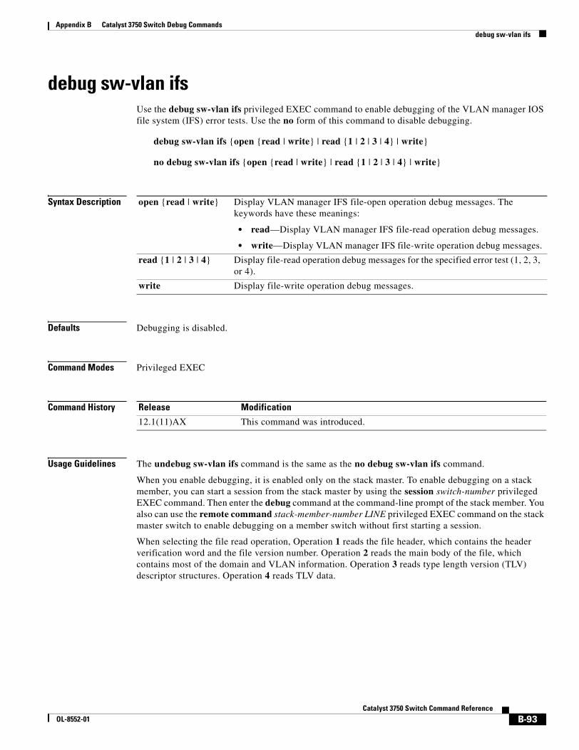
Appendix B Catalyst 3750 Switch Debug Commandsdebug sw-vlan ifs
debug sw-vlan ifsUse the debug sw-vlan ifs privileged EXEC command to enable debugging of the VLAN manager IOS file system (IFS) error tests. Use the no form of this command to disable debugging.
debug sw-vlan ifs {open {read | write} | read {1 | 2 | 3 | 4} | write}
no debug sw-vlan ifs {open {read | write} | read {1 | 2 | 3 | 4} | write}
Syntax Description
Defaults Debugging is disabled.
Command Modes Privileged EXEC
Command History
Usage Guidelines The undebug sw-vlan ifs command is the same as the no debug sw-vlan ifs command.
When you enable debugging, it is enabled only on the stack master. To enable debugging on a stack member, you can start a session from the stack master by using the session switch-number privileged EXEC command. Then enter the debug command at the command-line prompt of the stack member. You also can use the remote command stack-member-number LINE privileged EXEC command on the stack master switch to enable debugging on a member switch without first starting a session.
When selecting the file read operation, Operation 1 reads the file header, which contains the header verification word and the file version number. Operation 2 reads the main body of the file, which contains most of the domain and VLAN information. Operation 3 reads type length version (TLV) descriptor structures. Operation 4 reads TLV data.
open {read | write} Display VLAN manager IFS file-open operation debug messages. The keywords have these meanings:
• read—Display VLAN manager IFS file-read operation debug messages.
• write—Display VLAN manager IFS file-write operation debug messages.
read {1 | 2 | 3 | 4} Display file-read operation debug messages for the specified error test (1, 2, 3, or 4).
write Display file-write operation debug messages.
Release Modification
12.1(11)AX This command was introduced.
B-93Catalyst 3750 Switch Command Reference
OL-8552-01
Appendix B Catalyst 3750 Switch Debug Commandsdebug sw-vlan ifs
Related Commands Command Description
show debugging Displays information about the types of debugging that are enabled. For syntax information, select Cisco IOS Release 12.2 Configuration Guides and Command References > Cisco IOS Configuration Fundamentals Configuration Guide, Release 12.2 > System Management > Troubleshooting and Fault Management.
show vlan Displays the parameters for all configured VLANs or one VLAN (if the VLAN name or ID is specified) in the administrative domain.
B-94Catalyst 3750 Switch Command Reference
OL-8552-01
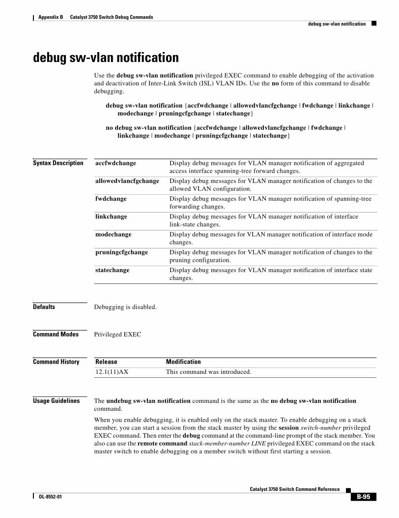
Appendix B Catalyst 3750 Switch Debug Commandsdebug sw-vlan notification
debug sw-vlan notificationUse the debug sw-vlan notification privileged EXEC command to enable debugging of the activation and deactivation of Inter-Link Switch (ISL) VLAN IDs. Use the no form of this command to disable debugging.
debug sw-vlan notification {accfwdchange | allowedvlancfgchange | fwdchange | linkchange | modechange | pruningcfgchange | statechange}
no debug sw-vlan notification {accfwdchange | allowedvlancfgchange | fwdchange | linkchange | modechange | pruningcfgchange | statechange}
Syntax Description
Defaults Debugging is disabled.
Command Modes Privileged EXEC
Command History
Usage Guidelines The undebug sw-vlan notification command is the same as the no debug sw-vlan notification command.
When you enable debugging, it is enabled only on the stack master. To enable debugging on a stack member, you can start a session from the stack master by using the session switch-number privileged EXEC command. Then enter the debug command at the command-line prompt of the stack member. You also can use the remote command stack-member-number LINE privileged EXEC command on the stack master switch to enable debugging on a member switch without first starting a session.
accfwdchange Display debug messages for VLAN manager notification of aggregated access interface spanning-tree forward changes.
allowedvlancfgchange Display debug messages for VLAN manager notification of changes to the allowed VLAN configuration.
fwdchange Display debug messages for VLAN manager notification of spanning-tree forwarding changes.
linkchange Display debug messages for VLAN manager notification of interface link-state changes.
modechange Display debug messages for VLAN manager notification of interface mode changes.
pruningcfgchange Display debug messages for VLAN manager notification of changes to the pruning configuration.
statechange Display debug messages for VLAN manager notification of interface state changes.
Release Modification
12.1(11)AX This command was introduced.
B-95Catalyst 3750 Switch Command Reference
OL-8552-01
Appendix B Catalyst 3750 Switch Debug Commandsdebug sw-vlan notification
Related Commands Command Description
show debugging Displays information about the types of debugging that are enabled. For syntax information, select Cisco IOS Release 12.2 Configuration Guides and Command References > Cisco IOS Configuration Fundamentals Configuration Guide, Release 12.2 > System Management > Troubleshooting and Fault Management.
show vlan Displays the parameters for all configured VLANs or one VLAN (if the VLAN name or ID is specified) in the administrative domain.
B-96Catalyst 3750 Switch Command Reference
OL-8552-01
Appendix B Catalyst 3750 Switch Debug Commandsdebug sw-vlan vtp
debug sw-vlan vtpUse the debug sw-vlan vtp privileged EXEC command to enable debugging of the VLAN Trunking Protocol (VTP) code. Use the no form of this command to disable debugging.
debug sw-vlan vtp {events | packets | pruning [packets | xmit] | redundancy | xmit}
no debug sw-vlan vtp {events | packets | pruning | redundancy | xmit}
Syntax Description
Defaults Debugging is disabled.
Command Modes Privileged EXEC
Command History
Usage Guidelines The undebug sw-vlan vtp command is the same as the no debug sw-vlan vtp command.
When you enable debugging, it is enabled only on the stack master. To enable debugging on a stack member, you can start a session from the stack master by using the session switch-number privileged EXEC command. Then enter the debug command at the command-line prompt of the stack member. You also can use the remote command stack-member-number LINE privileged EXEC command on the stack master switch to enable debugging on a member switch without first starting a session.
events Display debug messages for general-purpose logic flow and detailed VTP messages generated by the VTP_LOG_RUNTIME macro in the VTP code.
packets Display debug messages for the contents of all incoming VTP packets that have been passed into the VTP code from the IOS VTP platform-dependent layer, except for pruning packets.
pruning [packets | xmit] Display debug messages generated by the pruning segment of the VTP code. The keywords have these meanings:
• packets—(Optional) Display debug messages for the contents of all incoming VTP pruning packets that have been passed into the VTP code from the IOS VTP platform-dependent layer.
• xmit—(Optional) Display debug messages for the contents of all outgoing VTP packets that the VTP code requests the IOS VTP platform-dependent layer to send.
redundancy Display debug messages for VTP redundancy.
xmit Display debug messages for the contents of all outgoing VTP packets that the VTP code requests the IOS VTP platform-dependent layer to send, except for pruning packets.
Release Modification
12.1(11)AX This command was introduced.
B-97Catalyst 3750 Switch Command Reference
OL-8552-01
Appendix B Catalyst 3750 Switch Debug Commandsdebug sw-vlan vtp
If no further parameters are entered after the pruning keyword, VTP pruning debugging messages appear. They are generated by the VTP_PRUNING_LOG_NOTICE, VTP_PRUNING_LOG_INFO, VTP_PRUNING_LOG_DEBUG, VTP_PRUNING_LOG_ALERT, and VTP_PRUNING_LOG_WARNING macros in the VTP pruning code.
Related Commands Command Description
show debugging Displays information about the types of debugging that are enabled. For syntax information, select Cisco IOS Release 12.2 Configuration Guides and Command References > Cisco IOS Configuration Fundamentals Configuration Guide, Release 12.2 > System Management > Troubleshooting and Fault Management.
show vtp Displays general information about VTP management domain, status, and counters.
B-98Catalyst 3750 Switch Command Reference
OL-8552-01
Appendix B Catalyst 3750 Switch Debug Commandsdebug udld
debug udldUse the debug udld privileged EXEC command to enable debugging of the UniDirectional Link Detection (UDLD) feature. Use the no form of this command to disable UDLD debugging.
debug udld {events | packets | registries}
no debug udld {events | packets | registries}
Syntax Description
Defaults Debugging is disabled.
Command Modes Privileged EXEC
Command History
Usage Guidelines The undebug udld command is the same as the no debug udld command.
When you enable debugging, it is enabled only on the stack master. To enable debugging on a stack member, you can start a session from the stack master by using the session switch-number privileged EXEC command. Then enter the debug command at the command-line prompt of the stack member. You also can use the remote command stack-member-number LINE privileged EXEC command on the stack master switch to enable debugging on a member switch without first starting a session.
For debug udld events, these debugging messages appear:
• General UDLD program logic flow
• State machine state changes
• Program actions for the set and clear ErrDisable state
• Neighbor cache additions and deletions
• Processing of configuration commands
• Processing of link-up and link-down indications
events Display debug messages for UDLD process events as they occur.
packets Display debug messages for the UDLD process as it receives packets from the packet queue and tries to send them at the request of the UDLD protocol code.
registries Display debug messages for the UDLD process as it processes registry calls from the UDLD process-dependent module and other feature modules.
Release Modification
12.1(11)AX This command was introduced.
B-99Catalyst 3750 Switch Command Reference
OL-8552-01
Appendix B Catalyst 3750 Switch Debug Commandsdebug udld
For debug udld packets, these debugging messages appear:
• General packet processing program flow on receipt of an incoming packet
• Indications of the contents of the various pieces of packets received (such as type length versions [TLVs]) as they are examined by the packet reception code
• Packet transmission attempts and the outcome
For debug udld registries, these categories of debugging messages appear:
• Sub-block creation
• Fiber-port status changes
• State change indications from the port manager software
• MAC address registry calls
Related Commands Command Description
show debugging Displays information about the types of debugging that are enabled. For syntax information, select Cisco IOS Release 12.2 Configuration Guides and Command References > Cisco IOS Configuration Fundamentals Configuration Guide, Release 12.2 > System Management > Troubleshooting and Fault Management.
show udld Displays UDLD administrative and operational status for all ports or the specified port.
B-100Catalyst 3750 Switch Command Reference
OL-8552-01
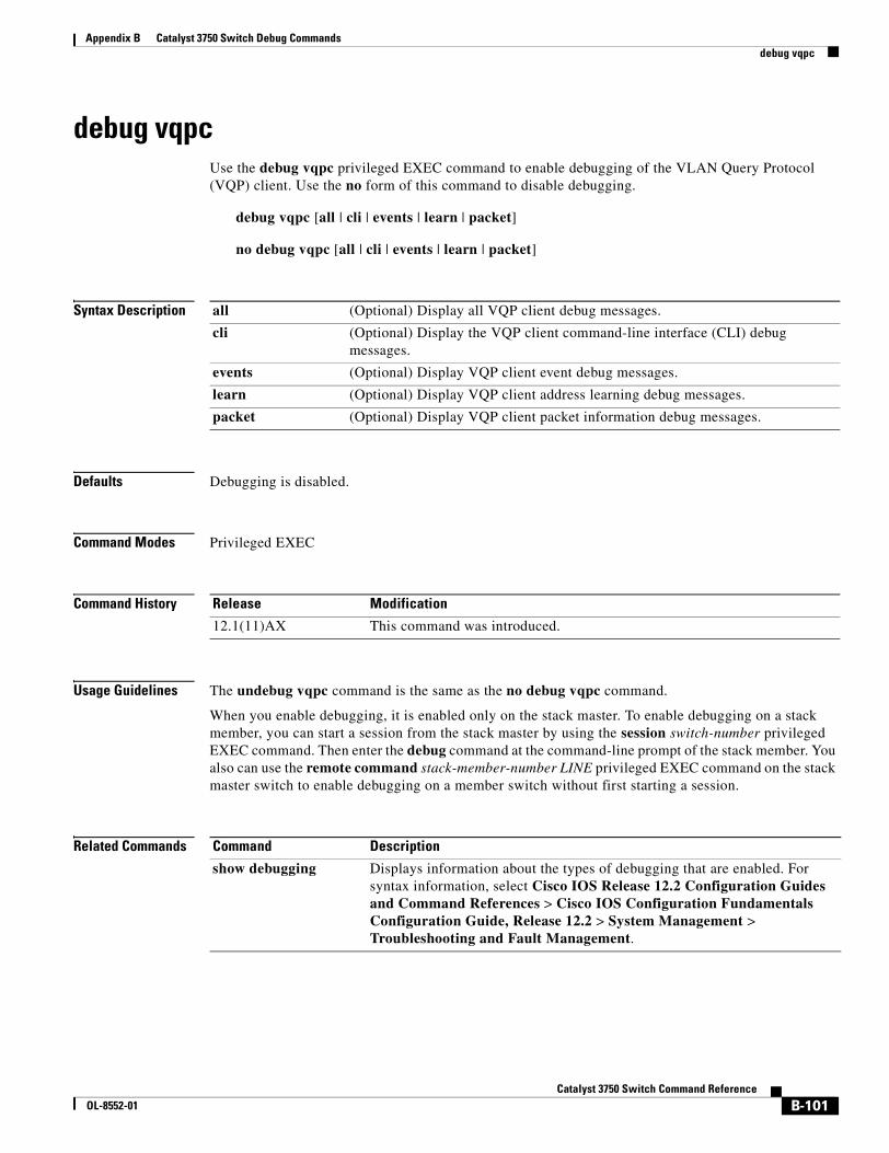
Appendix B Catalyst 3750 Switch Debug Commandsdebug vqpc
debug vqpcUse the debug vqpc privileged EXEC command to enable debugging of the VLAN Query Protocol (VQP) client. Use the no form of this command to disable debugging.
debug vqpc [all | cli | events | learn | packet]
no debug vqpc [all | cli | events | learn | packet]
Syntax Description
Defaults Debugging is disabled.
Command Modes Privileged EXEC
Command History
Usage Guidelines The undebug vqpc command is the same as the no debug vqpc command.
When you enable debugging, it is enabled only on the stack master. To enable debugging on a stack member, you can start a session from the stack master by using the session switch-number privileged EXEC command. Then enter the debug command at the command-line prompt of the stack member. You also can use the remote command stack-member-number LINE privileged EXEC command on the stack master switch to enable debugging on a member switch without first starting a session.
Related Commands
all (Optional) Display all VQP client debug messages.
cli (Optional) Display the VQP client command-line interface (CLI) debug messages.
events (Optional) Display VQP client event debug messages.
learn (Optional) Display VQP client address learning debug messages.
packet (Optional) Display VQP client packet information debug messages.
Release Modification
12.1(11)AX This command was introduced.
Command Description
show debugging Displays information about the types of debugging that are enabled. For syntax information, select Cisco IOS Release 12.2 Configuration Guides and Command References > Cisco IOS Configuration Fundamentals Configuration Guide, Release 12.2 > System Management > Troubleshooting and Fault Management.
B-101Catalyst 3750 Switch Command Reference
OL-8552-01

Appendix B Catalyst 3750 Switch Debug Commandsdebug vqpc
B-102Catalyst 3750 Switch Command Reference
OL-8552-01
CaOL-8552-01
A P P E N D I X C
Catalyst 3750 Switch Show Platform CommandsThis appendix describes the show platform privileged EXEC commands that have been created or changed for use with the Catalyst 3750 switch. These commands display information helpful in diagnosing and resolving internetworking problems and should be used only under the guidance of Cisco technical support staff.
C-1talyst 3750 Switch Command Reference
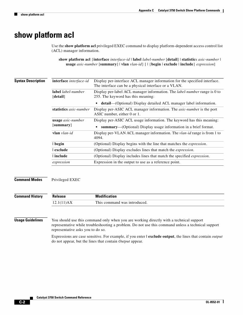
Appendix C Catalyst 3750 Switch Show Platform Commandsshow platform acl
show platform aclUse the show platform acl privileged EXEC command to display platform-dependent access control list (ACL) manager information.
show platform acl {interface interface-id | label label-number [detail] | statistics asic-number | usage asic-number [summary] | vlan vlan-id} [ | {begin | exclude | include} expression]
Syntax Description
Command Modes Privileged EXEC
Command History
Usage Guidelines You should use this command only when you are working directly with a technical support representative while troubleshooting a problem. Do not use this command unless a technical support representative asks you to do so.
Expressions are case sensitive. For example, if you enter | exclude output, the lines that contain output do not appear, but the lines that contain Output appear.
interface interface-id Display per-interface ACL manager information for the specified interface. The interface can be a physical interface or a VLAN.
label label-number [detail]
Display per-label ACL manager information. The label-number range is 0 to 255. The keyword has this meaning:
• detail—(Optional) Display detailed ACL manager label information.
statistics asic-number Display per-ASIC ACL manager information. The asic-number is the port ASIC number, either 0 or 1.
usage asic-number [summary]
Display per-ASIC ACL usage information. The keyword has this meaning:
• summary—(Optional) Display usage information in a brief format.
vlan vlan-id Display per-VLAN ACL manager information. The vlan-id range is from 1 to 4094.
| begin (Optional) Display begins with the line that matches the expression.
| exclude (Optional) Display excludes lines that match the expression.
| include (Optional) Display includes lines that match the specified expression.
expression Expression in the output to use as a reference point.
Release Modification
12.1(11)AX This command was introduced.
C-2Catalyst 3750 Switch Command Reference
OL-8552-01
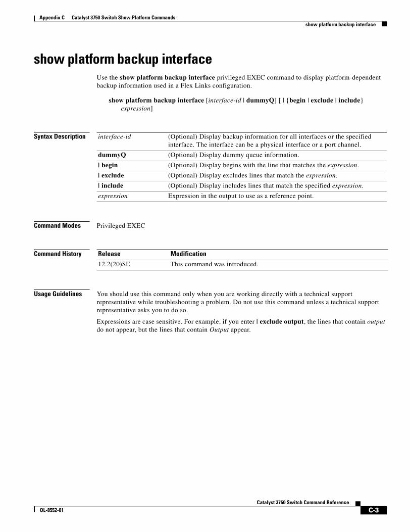
Appendix C Catalyst 3750 Switch Show Platform Commandsshow platform backup interface
show platform backup interfaceUse the show platform backup interface privileged EXEC command to display platform-dependent backup information used in a Flex Links configuration.
show platform backup interface [interface-id | dummyQ] [ | {begin | exclude | include} expression]
Syntax Description
Command Modes Privileged EXEC
Command History
Usage Guidelines You should use this command only when you are working directly with a technical support representative while troubleshooting a problem. Do not use this command unless a technical support representative asks you to do so.
Expressions are case sensitive. For example, if you enter | exclude output, the lines that contain output do not appear, but the lines that contain Output appear.
interface-id (Optional) Display backup information for all interfaces or the specified interface. The interface can be a physical interface or a port channel.
dummyQ (Optional) Display dummy queue information.
| begin (Optional) Display begins with the line that matches the expression.
| exclude (Optional) Display excludes lines that match the expression.
| include (Optional) Display includes lines that match the specified expression.
expression Expression in the output to use as a reference point.
Release Modification
12.2(20)SE This command was introduced.
C-3Catalyst 3750 Switch Command Reference
OL-8552-01
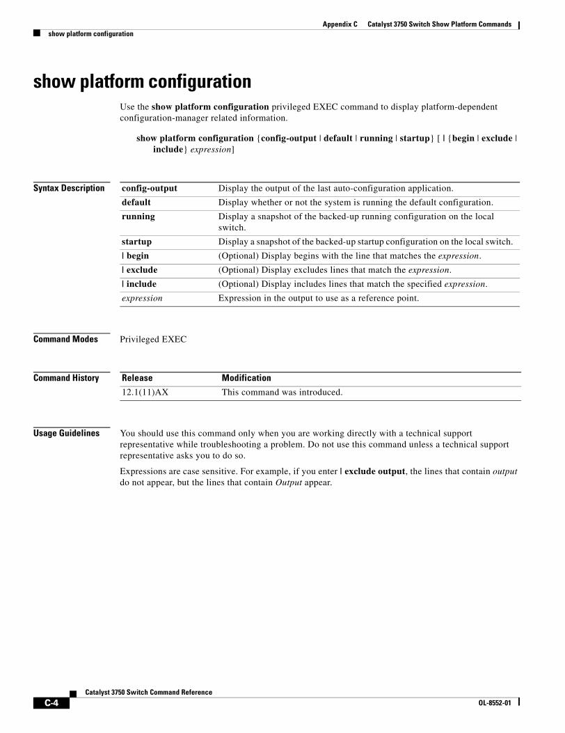
Appendix C Catalyst 3750 Switch Show Platform Commandsshow platform configuration
show platform configurationUse the show platform configuration privileged EXEC command to display platform-dependent configuration-manager related information.
show platform configuration {config-output | default | running | startup} [ | {begin | exclude | include} expression]
Syntax Description
Command Modes Privileged EXEC
Command History
Usage Guidelines You should use this command only when you are working directly with a technical support representative while troubleshooting a problem. Do not use this command unless a technical support representative asks you to do so.
Expressions are case sensitive. For example, if you enter | exclude output, the lines that contain output do not appear, but the lines that contain Output appear.
config-output Display the output of the last auto-configuration application.
default Display whether or not the system is running the default configuration.
running Display a snapshot of the backed-up running configuration on the local switch.
startup Display a snapshot of the backed-up startup configuration on the local switch.
| begin (Optional) Display begins with the line that matches the expression.
| exclude (Optional) Display excludes lines that match the expression.
| include (Optional) Display includes lines that match the specified expression.
expression Expression in the output to use as a reference point.
Release Modification
12.1(11)AX This command was introduced.
C-4Catalyst 3750 Switch Command Reference
OL-8552-01
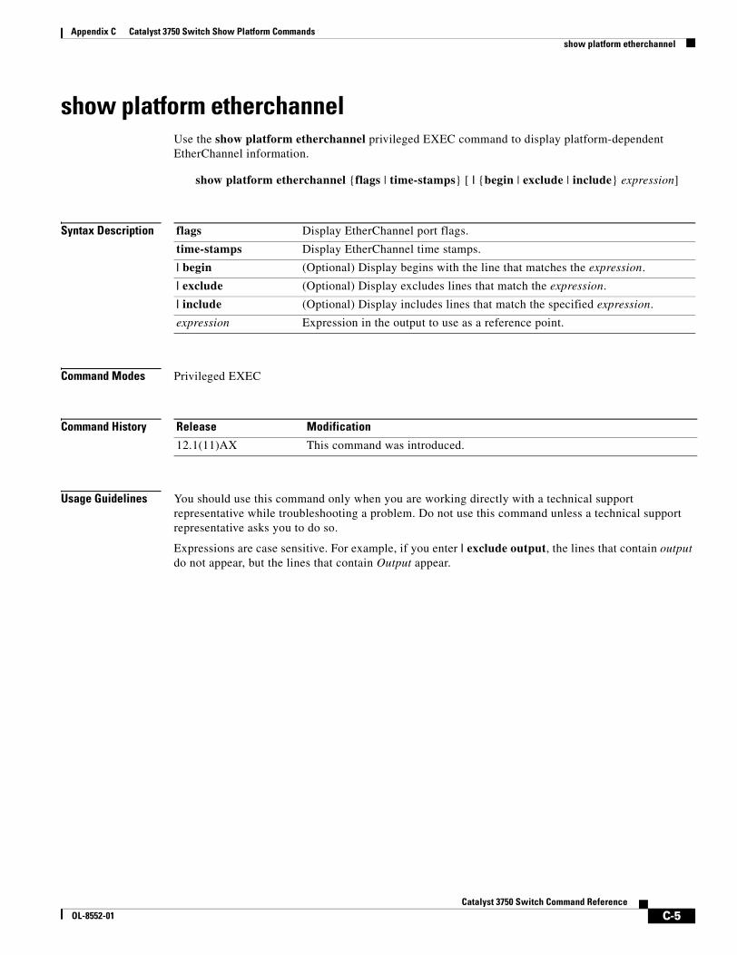
Appendix C Catalyst 3750 Switch Show Platform Commandsshow platform etherchannel
show platform etherchannelUse the show platform etherchannel privileged EXEC command to display platform-dependent EtherChannel information.
show platform etherchannel {flags | time-stamps} [ | {begin | exclude | include} expression]
Syntax Description
Command Modes Privileged EXEC
Command History
Usage Guidelines You should use this command only when you are working directly with a technical support representative while troubleshooting a problem. Do not use this command unless a technical support representative asks you to do so.
Expressions are case sensitive. For example, if you enter | exclude output, the lines that contain output do not appear, but the lines that contain Output appear.
flags Display EtherChannel port flags.
time-stamps Display EtherChannel time stamps.
| begin (Optional) Display begins with the line that matches the expression.
| exclude (Optional) Display excludes lines that match the expression.
| include (Optional) Display includes lines that match the specified expression.
expression Expression in the output to use as a reference point.
Release Modification
12.1(11)AX This command was introduced.
C-5Catalyst 3750 Switch Command Reference
OL-8552-01
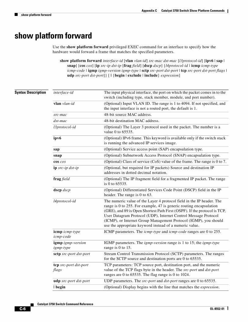
Appendix C Catalyst 3750 Switch Show Platform Commandsshow platform forward
show platform forwardUse the show platform forward privileged EXEC command for an interface to specify how the hardware would forward a frame that matches the specified parameters.
show platform forward interface-id [vlan vlan-id] src-mac dst-mac [l3protocol-id] [ipv6 | sap | snap] [cos cos] [ip src-ip dst-ip [frag field] [dscp dscp] {l4protocol-id | icmp icmp-type icmp-code | igmp igmp-version igmp-type | sctp src-port dst-port | tcp src-port dst-port flags | udp src-port dst-port]} [ | {begin | exclude | include} expression]
Syntax Description interface-id The input physical interface, the port on which the packet comes in to the switch (including type, stack member, module, and port number).
vlan vlan-id (Optional) Input VLAN ID. The range is 1 to 4094. If not specified, and the input interface is not a routed port, the default is 1.
src-mac 48-bit source MAC address.
dst-mac 48-bit destination MAC address.
l3protocol-id (Optional) The Layer 3 protocol used in the packet. The number is a value 0 to 65535.
ipv6 (Optional) IPv6 frame. This keyword is available only if the switch stack is running the advanced IP services image.
sap (Optional) Service access point (SAP) encapsulation type.
snap (Optional) Subnetwork Access Protocol (SNAP) encapsulation type.
cos cos (Optional) Class of service (CoS) value of the frame. The range is 0 to 7.
ip src-ip dst-ip (Optional, but required for IP packets) Source and destination IP addresses in dotted decimal notation.
frag field (Optional) The IP fragment field for a fragmented IP packet. The range is 0 to 65535.
dscp dscp (Optional) Differentiated Services Code Point (DSCP) field in the IP header. The range is 0 to 63.
l4protocol-id The numeric value of the Layer 4 protocol field in the IP header. The range is 0 to 255. For example, 47 is generic routing encapsulation (GRE), and 89 is Open Shortest Path First (OSPF). If the protocol is TCP, User Datagram Protocol (UDP), Internet Control Message Protocol (ICMP), or Internet Group Management Protocol (IGMP), you should use the appropriate keyword instead of a numeric value.
icmp icmp-typeicmp-code
ICMP parameters. The icmp-type and icmp-code ranges are 0 to 255.
igmp igmp-version igmp-type
IGMP parameters. The igmp-version range is 1 to 15; the igmp-type range is 0 to 15.
sctp src-port dst-port Stream Control Transmission Protocol (SCTP) parameters. The ranges for the SCTP source and destination ports are 0 to 65535.
tcp src-port dst-portflags
TCP parameters: TCP source port, destination port, and the numeric value of the TCP flags byte in the header. The src-port and dst-port ranges are 0 to 65535. The flag range is 0 to 1024.
udp src-port dst-port UDP parameters. The src-port and dst-port ranges are 0 to 65535.
| begin (Optional) Display begins with the line that matches the expression.
C-6Catalyst 3750 Switch Command Reference
OL-8552-01
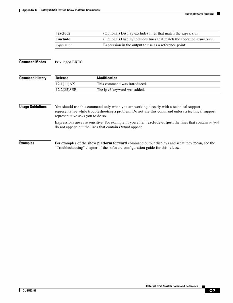
Appendix C Catalyst 3750 Switch Show Platform Commandsshow platform forward
Command Modes Privileged EXEC
Command History
Usage Guidelines You should use this command only when you are working directly with a technical support representative while troubleshooting a problem. Do not use this command unless a technical support representative asks you to do so.
Expressions are case sensitive. For example, if you enter | exclude output, the lines that contain output do not appear, but the lines that contain Output appear.
Examples For examples of the show platform forward command output displays and what they mean, see the “Troubleshooting” chapter of the software configuration guide for this release.
| exclude (Optional) Display excludes lines that match the expression.
| include (Optional) Display includes lines that match the specified expression.
expression Expression in the output to use as a reference point.
Release Modification
12.1(11)AX This command was introduced.
12.2(25)SEB The ipv6 keyword was added.
C-7Catalyst 3750 Switch Command Reference
OL-8552-01
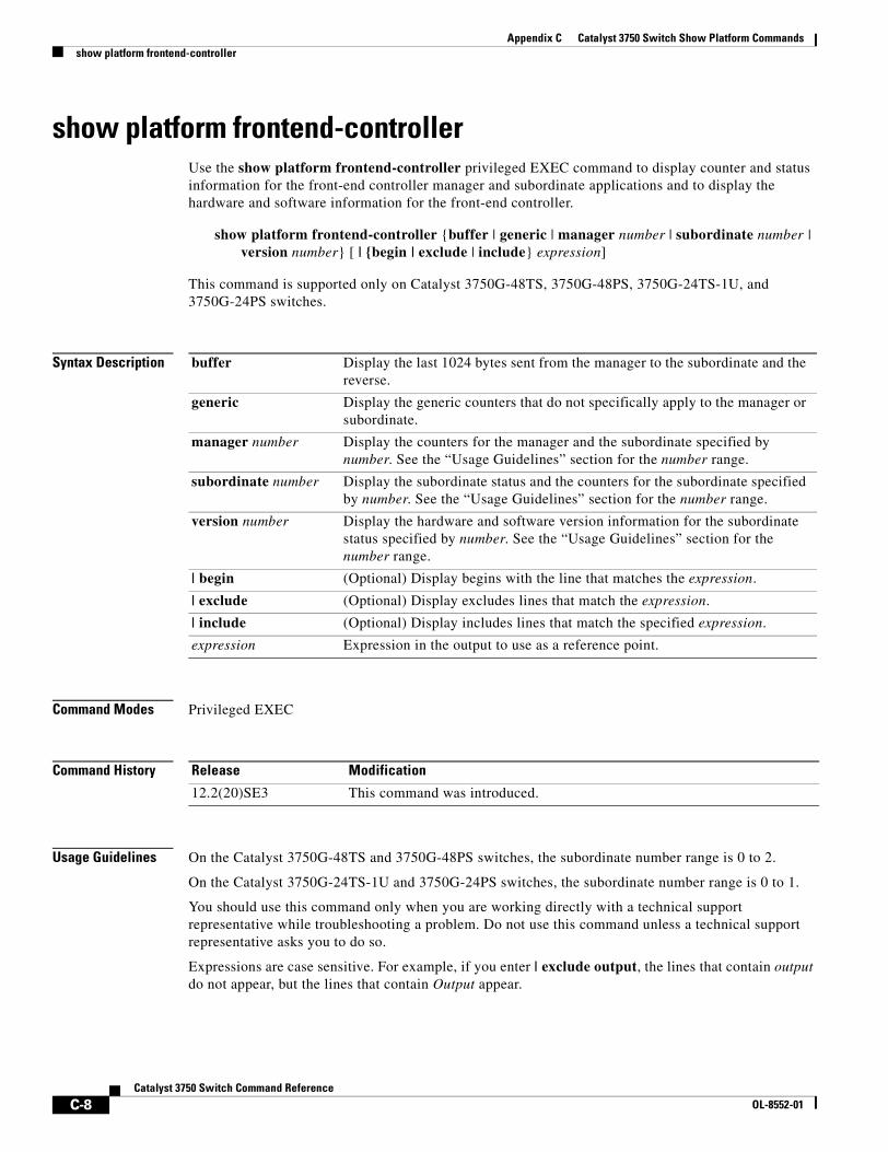
Appendix C Catalyst 3750 Switch Show Platform Commandsshow platform frontend-controller
show platform frontend-controllerUse the show platform frontend-controller privileged EXEC command to display counter and status information for the front-end controller manager and subordinate applications and to display the hardware and software information for the front-end controller.
show platform frontend-controller {buffer | generic | manager number | subordinate number | version number} [ | {begin | exclude | include} expression]
This command is supported only on Catalyst 3750G-48TS, 3750G-48PS, 3750G-24TS-1U, and 3750G-24PS switches.
Syntax Description
Command Modes Privileged EXEC
Command History
Usage Guidelines On the Catalyst 3750G-48TS and 3750G-48PS switches, the subordinate number range is 0 to 2.
On the Catalyst 3750G-24TS-1U and 3750G-24PS switches, the subordinate number range is 0 to 1.
You should use this command only when you are working directly with a technical support representative while troubleshooting a problem. Do not use this command unless a technical support representative asks you to do so.
Expressions are case sensitive. For example, if you enter | exclude output, the lines that contain output do not appear, but the lines that contain Output appear.
buffer Display the last 1024 bytes sent from the manager to the subordinate and the reverse.
generic Display the generic counters that do not specifically apply to the manager or subordinate.
manager number Display the counters for the manager and the subordinate specified by number. See the “Usage Guidelines” section for the number range.
subordinate number Display the subordinate status and the counters for the subordinate specified by number. See the “Usage Guidelines” section for the number range.
version number Display the hardware and software version information for the subordinate status specified by number. See the “Usage Guidelines” section for the number range.
| begin (Optional) Display begins with the line that matches the expression.
| exclude (Optional) Display excludes lines that match the expression.
| include (Optional) Display includes lines that match the specified expression.
expression Expression in the output to use as a reference point.
Release Modification
12.2(20)SE3 This command was introduced.
C-8Catalyst 3750 Switch Command Reference
OL-8552-01
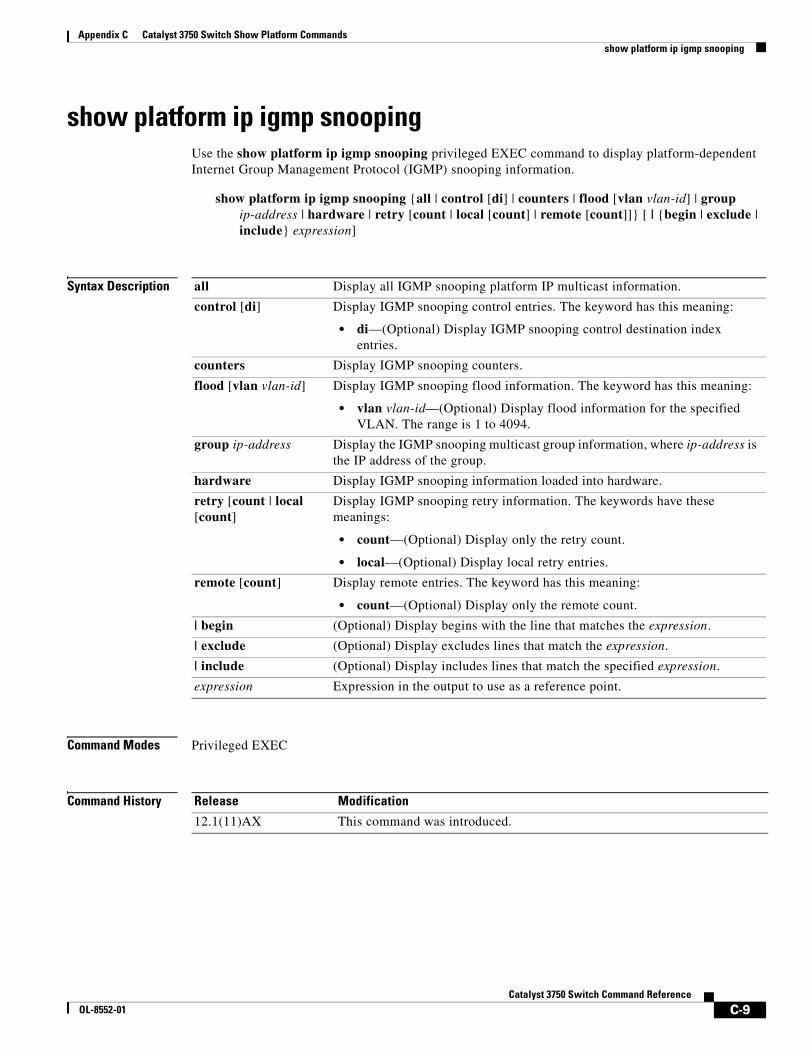
Appendix C Catalyst 3750 Switch Show Platform Commandsshow platform ip igmp snooping
show platform ip igmp snoopingUse the show platform ip igmp snooping privileged EXEC command to display platform-dependent Internet Group Management Protocol (IGMP) snooping information.
show platform ip igmp snooping {all | control [di] | counters | flood [vlan vlan-id] | group ip-address | hardware | retry [count | local [count] | remote [count]]} [ | {begin | exclude | include} expression]
Syntax Description
Command Modes Privileged EXEC
Command History
all Display all IGMP snooping platform IP multicast information.
control [di] Display IGMP snooping control entries. The keyword has this meaning:
• di—(Optional) Display IGMP snooping control destination index entries.
counters Display IGMP snooping counters.
flood [vlan vlan-id] Display IGMP snooping flood information. The keyword has this meaning:
• vlan vlan-id—(Optional) Display flood information for the specified VLAN. The range is 1 to 4094.
group ip-address Display the IGMP snooping multicast group information, where ip-address is the IP address of the group.
hardware Display IGMP snooping information loaded into hardware.
retry [count | local [count]
Display IGMP snooping retry information. The keywords have these meanings:
• count—(Optional) Display only the retry count.
• local—(Optional) Display local retry entries.
remote [count] Display remote entries. The keyword has this meaning:
• count—(Optional) Display only the remote count.
| begin (Optional) Display begins with the line that matches the expression.
| exclude (Optional) Display excludes lines that match the expression.
| include (Optional) Display includes lines that match the specified expression.
expression Expression in the output to use as a reference point.
Release Modification
12.1(11)AX This command was introduced.
C-9Catalyst 3750 Switch Command Reference
OL-8552-01

Appendix C Catalyst 3750 Switch Show Platform Commandsshow platform ip igmp snooping
Usage Guidelines You should use this command only when you are working directly with a technical support representative while troubleshooting a problem. Do not use this command unless a technical support representative asks you to do so.
Expressions are case sensitive. For example, if you enter | exclude output, the lines that contain output do not appear, but the lines that contain Output appear.
C-10Catalyst 3750 Switch Command Reference
OL-8552-01
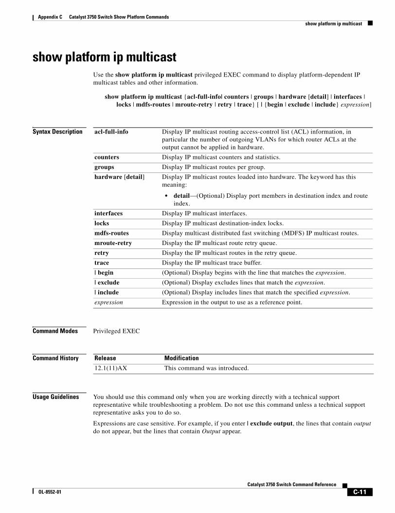
Appendix C Catalyst 3750 Switch Show Platform Commandsshow platform ip multicast
show platform ip multicastUse the show platform ip multicast privileged EXEC command to display platform-dependent IP multicast tables and other information.
show platform ip multicast {acl-full-info| counters | groups | hardware [detail] | interfaces | locks | mdfs-routes | mroute-retry | retry | trace} [ | {begin | exclude | include} expression]
Syntax Description
Command Modes Privileged EXEC
Command History
Usage Guidelines You should use this command only when you are working directly with a technical support representative while troubleshooting a problem. Do not use this command unless a technical support representative asks you to do so.
Expressions are case sensitive. For example, if you enter | exclude output, the lines that contain output do not appear, but the lines that contain Output appear.
acl-full-info Display IP multicast routing access-control list (ACL) information, in particular the number of outgoing VLANs for which router ACLs at the output cannot be applied in hardware.
counters Display IP multicast counters and statistics.
groups Display IP multicast routes per group.
hardware [detail] Display IP multicast routes loaded into hardware. The keyword has this meaning:
• detail—(Optional) Display port members in destination index and route index.
interfaces Display IP multicast interfaces.
locks Display IP multicast destination-index locks.
mdfs-routes Display multicast distributed fast switching (MDFS) IP multicast routes.
mroute-retry Display the IP multicast route retry queue.
retry Display the IP multicast routes in the retry queue.
trace Display the IP multicast trace buffer.
| begin (Optional) Display begins with the line that matches the expression.
| exclude (Optional) Display excludes lines that match the expression.
| include (Optional) Display includes lines that match the specified expression.
expression Expression in the output to use as a reference point.
Release Modification
12.1(11)AX This command was introduced.
C-11Catalyst 3750 Switch Command Reference
OL-8552-01
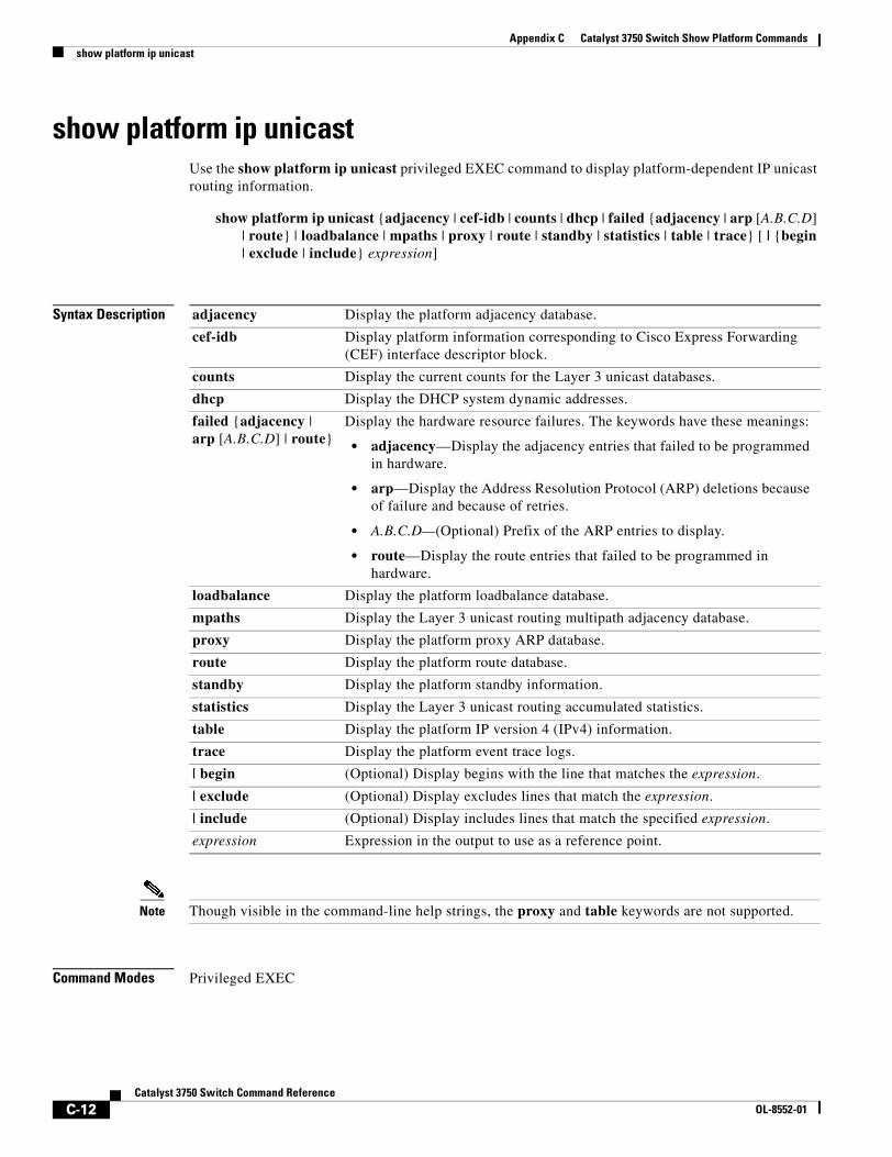
Appendix C Catalyst 3750 Switch Show Platform Commandsshow platform ip unicast
show platform ip unicastUse the show platform ip unicast privileged EXEC command to display platform-dependent IP unicast routing information.
show platform ip unicast {adjacency | cef-idb | counts | dhcp | failed {adjacency | arp [A.B.C.D] | route} | loadbalance | mpaths | proxy | route | standby | statistics | table | trace} [ | {begin | exclude | include} expression]
Syntax Description
Note Though visible in the command-line help strings, the proxy and table keywords are not supported.
Command Modes Privileged EXEC
adjacency Display the platform adjacency database.
cef-idb Display platform information corresponding to Cisco Express Forwarding (CEF) interface descriptor block.
counts Display the current counts for the Layer 3 unicast databases.
dhcp Display the DHCP system dynamic addresses.
failed {adjacency | arp [A.B.C.D] | route}
Display the hardware resource failures. The keywords have these meanings:
• adjacency—Display the adjacency entries that failed to be programmed in hardware.
• arp—Display the Address Resolution Protocol (ARP) deletions because of failure and because of retries.
• A.B.C.D—(Optional) Prefix of the ARP entries to display.
• route—Display the route entries that failed to be programmed in hardware.
loadbalance Display the platform loadbalance database.
mpaths Display the Layer 3 unicast routing multipath adjacency database.
proxy Display the platform proxy ARP database.
route Display the platform route database.
standby Display the platform standby information.
statistics Display the Layer 3 unicast routing accumulated statistics.
table Display the platform IP version 4 (IPv4) information.
trace Display the platform event trace logs.
| begin (Optional) Display begins with the line that matches the expression.
| exclude (Optional) Display excludes lines that match the expression.
| include (Optional) Display includes lines that match the specified expression.
expression Expression in the output to use as a reference point.
C-12Catalyst 3750 Switch Command Reference
OL-8552-01
Appendix C Catalyst 3750 Switch Show Platform Commandsshow platform ip unicast
Command History
Usage Guidelines You should use this command only when you are working directly with a technical support representative while troubleshooting a problem. Do not use this command unless a technical support representative asks you to do so.
Expressions are case sensitive. For example, if you enter | exclude output, the lines that contain output do not appear, but the lines that contain Output appear.
Release Modification
12.1(11)AX This command was introduced.
C-13Catalyst 3750 Switch Command Reference
OL-8552-01
Appendix C Catalyst 3750 Switch Show Platform Commandsshow platform ip unicast vrf compaction
show platform ip unicast vrf compaction Use the show platform ip unicast vrf compaction privileged EXEC command to display the compaction request queues and compaction status.
show platform ip unicast vrf compaction [ | {begin | exclude | include} expression]
Syntax Description
Command Modes Privileged EXEC
Command History
Usage Guidelines You should use this command only when you are working directly with a technical support representative while troubleshooting a problem. Do not use this command unless a technical support representative asks you to do so.
| begin (Optional) Display begins with the line that matches the expression.
| exclude (Optional) Display excludes lines that match the expression.
| include (Optional) Display includes lines that match the specified expression.
expression Expression in the output to use as a reference point.
Release Modification
12.2(25)SEC This command was introduced.
C-14Catalyst 3750 Switch Command Reference
OL-8552-01
Appendix C Catalyst 3750 Switch Show Platform Commandsshow platform ip unicast vrf tcam-label
show platform ip unicast vrf tcam-label Use the show platform ip unicast vrf tcam-label privileged EXEC command to display PBR and VRF-Lite labels and the number of labels in use by PBR.
show platform ip unicast vrf tcam-label [ | {begin | exclude | include} expression]
Syntax Description
Command Modes Privileged EXEC
Command History
Usage Guidelines You should use this command only when you are working directly with a technical support representative while troubleshooting a problem. Do not use this command unless a technical support representative asks you to do so.
| begin (Optional) Display begins with the line that matches the expression.
| exclude (Optional) Display excludes lines that match the expression.
| include (Optional) Display includes lines that match the specified expression.
expression Expression in the output to use as a reference point.
Release Modification
12.2(25)SEC This command was introduced.
C-15Catalyst 3750 Switch Command Reference
OL-8552-01
Appendix C Catalyst 3750 Switch Show Platform Commandsshow platform ipc trace
show platform ipc traceUse the show platform ipc trace privileged EXEC command to display platform-dependent Interprocess Communication (IPC) Protocol trace log information.
show platform ipc trace [ | {begin | exclude | include} expression]
Syntax Description
Command Modes Privileged EXEC
Command History
Usage Guidelines You should use this command only when you are working directly with a technical support representative while troubleshooting a problem. Do not use this command unless a technical support representative asks you to do so.
Expressions are case sensitive. For example, if you enter | exclude output, the lines that contain output do not appear, but the lines that contain Output appear.
| begin (Optional) Display begins with the line that matches the expression.
| exclude (Optional) Display excludes lines that match the expression.
| include (Optional) Display includes lines that match the specified expression.
expression Expression in the output to use as a reference point.
Release Modification
12.1(11)AX This command was introduced.
C-16Catalyst 3750 Switch Command Reference
OL-8552-01
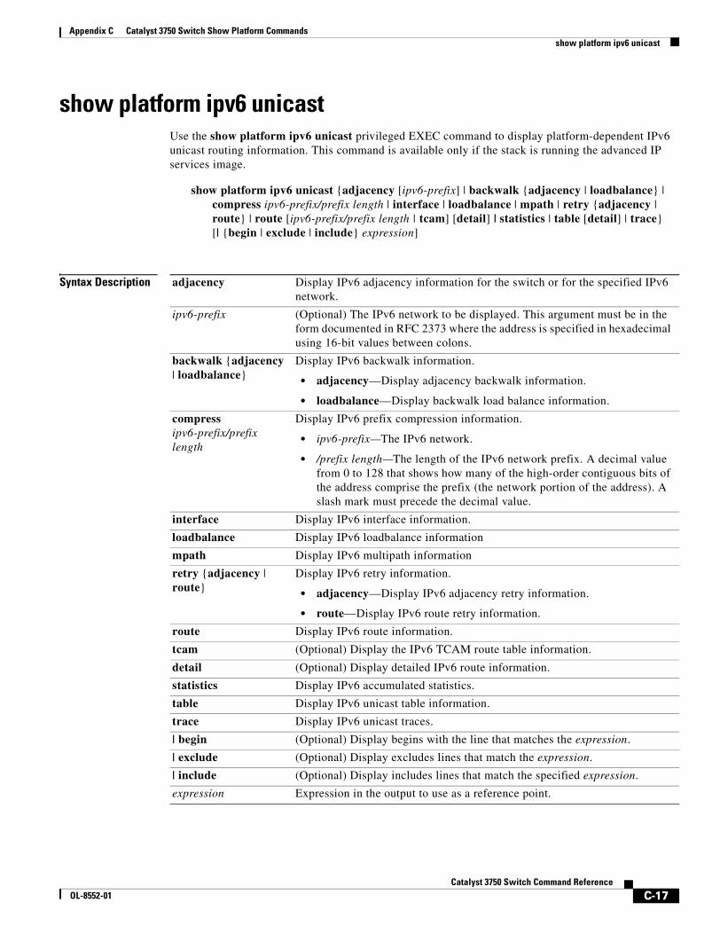
Appendix C Catalyst 3750 Switch Show Platform Commandsshow platform ipv6 unicast
show platform ipv6 unicastUse the show platform ipv6 unicast privileged EXEC command to display platform-dependent IPv6 unicast routing information. This command is available only if the stack is running the advanced IP services image.
show platform ipv6 unicast {adjacency [ipv6-prefix] | backwalk {adjacency | loadbalance} | compress ipv6-prefix/prefix length | interface | loadbalance | mpath | retry {adjacency | route} | route [ipv6-prefix/prefix length | tcam] [detail] | statistics | table [detail] | trace} [| {begin | exclude | include} expression]
Syntax Description adjacency Display IPv6 adjacency information for the switch or for the specified IPv6 network.
ipv6-prefix (Optional) The IPv6 network to be displayed. This argument must be in the form documented in RFC 2373 where the address is specified in hexadecimal using 16-bit values between colons.
backwalk {adjacency | loadbalance}
Display IPv6 backwalk information.
• adjacency—Display adjacency backwalk information.
• loadbalance—Display backwalk load balance information.
compress ipv6-prefix/prefix length
Display IPv6 prefix compression information.
• ipv6-prefix—The IPv6 network.
• /prefix length—The length of the IPv6 network prefix. A decimal value from 0 to 128 that shows how many of the high-order contiguous bits of the address comprise the prefix (the network portion of the address). A slash mark must precede the decimal value.
interface Display IPv6 interface information.
loadbalance Display IPv6 loadbalance information
mpath Display IPv6 multipath information
retry {adjacency | route}
Display IPv6 retry information.
• adjacency—Display IPv6 adjacency retry information.
• route—Display IPv6 route retry information.
route Display IPv6 route information.
tcam (Optional) Display the IPv6 TCAM route table information.
detail (Optional) Display detailed IPv6 route information.
statistics Display IPv6 accumulated statistics.
table Display IPv6 unicast table information.
trace Display IPv6 unicast traces.
| begin (Optional) Display begins with the line that matches the expression.
| exclude (Optional) Display excludes lines that match the expression.
| include (Optional) Display includes lines that match the specified expression.
expression Expression in the output to use as a reference point.
C-17Catalyst 3750 Switch Command Reference
OL-8552-01
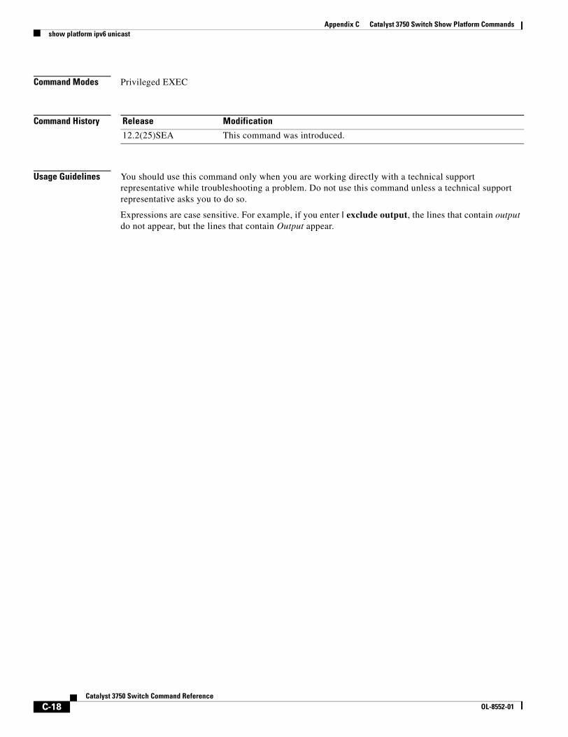
Appendix C Catalyst 3750 Switch Show Platform Commandsshow platform ipv6 unicast
Command Modes Privileged EXEC
Command History
Usage Guidelines You should use this command only when you are working directly with a technical support representative while troubleshooting a problem. Do not use this command unless a technical support representative asks you to do so.
Expressions are case sensitive. For example, if you enter | exclude output, the lines that contain output do not appear, but the lines that contain Output appear.
Release Modification
12.2(25)SEA This command was introduced.
C-18Catalyst 3750 Switch Command Reference
OL-8552-01
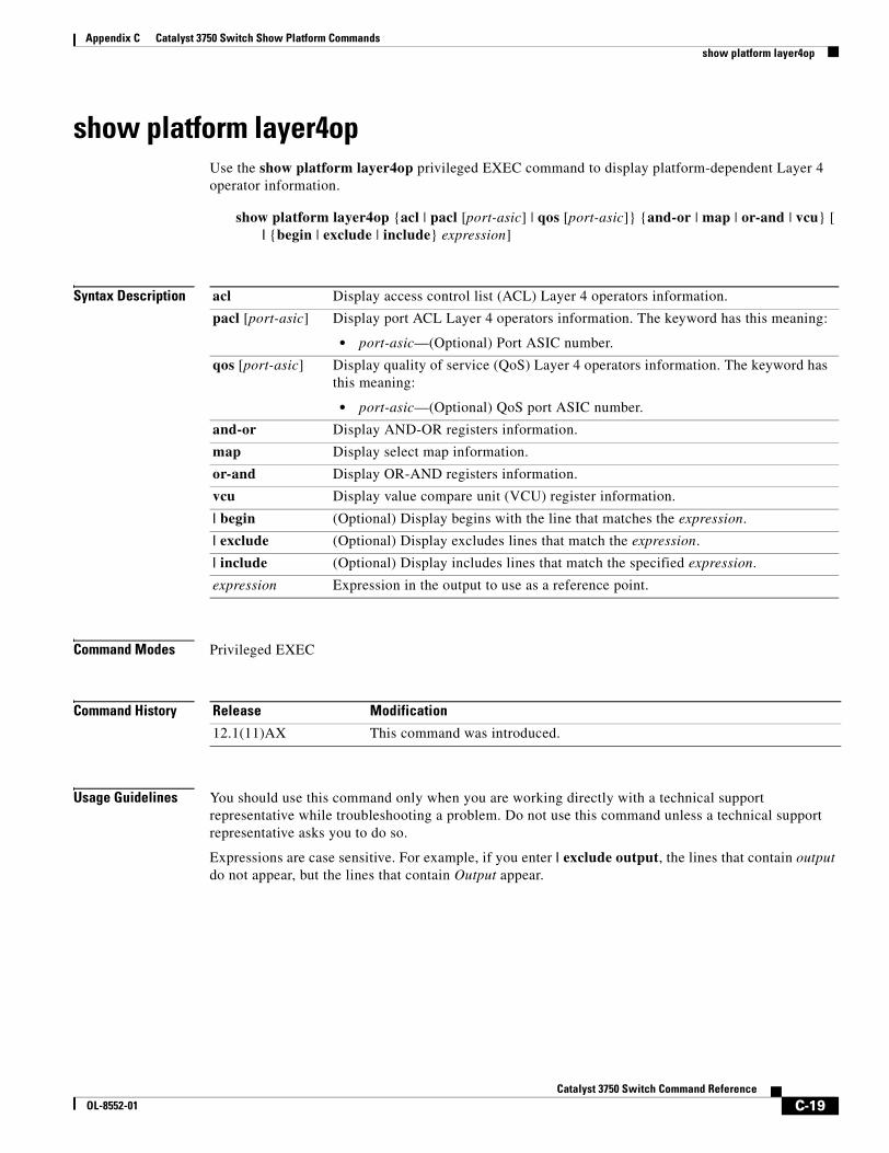
Appendix C Catalyst 3750 Switch Show Platform Commandsshow platform layer4op
show platform layer4opUse the show platform layer4op privileged EXEC command to display platform-dependent Layer 4 operator information.
show platform layer4op {acl | pacl [port-asic] | qos [port-asic]} {and-or | map | or-and | vcu} [ | {begin | exclude | include} expression]
Syntax Description
Command Modes Privileged EXEC
Command History
Usage Guidelines You should use this command only when you are working directly with a technical support representative while troubleshooting a problem. Do not use this command unless a technical support representative asks you to do so.
Expressions are case sensitive. For example, if you enter | exclude output, the lines that contain output do not appear, but the lines that contain Output appear.
acl Display access control list (ACL) Layer 4 operators information.
pacl [port-asic] Display port ACL Layer 4 operators information. The keyword has this meaning:
• port-asic—(Optional) Port ASIC number.
qos [port-asic] Display quality of service (QoS) Layer 4 operators information. The keyword has this meaning:
• port-asic—(Optional) QoS port ASIC number.
and-or Display AND-OR registers information.
map Display select map information.
or-and Display OR-AND registers information.
vcu Display value compare unit (VCU) register information.
| begin (Optional) Display begins with the line that matches the expression.
| exclude (Optional) Display excludes lines that match the expression.
| include (Optional) Display includes lines that match the specified expression.
expression Expression in the output to use as a reference point.
Release Modification
12.1(11)AX This command was introduced.
C-19Catalyst 3750 Switch Command Reference
OL-8552-01
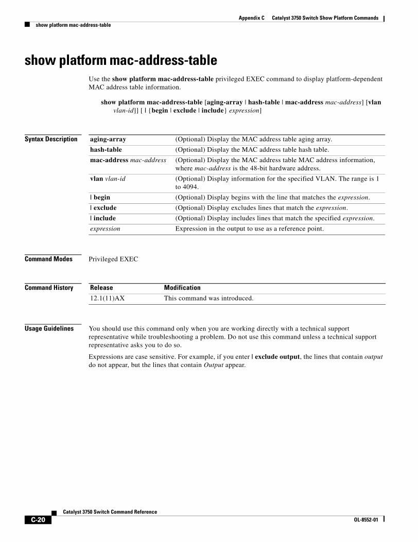
Appendix C Catalyst 3750 Switch Show Platform Commandsshow platform mac-address-table
show platform mac-address-tableUse the show platform mac-address-table privileged EXEC command to display platform-dependent MAC address table information.
show platform mac-address-table [aging-array | hash-table | mac-address mac-address] [vlan vlan-id]] [ | {begin | exclude | include} expression]
Syntax Description
Command Modes Privileged EXEC
Command History
Usage Guidelines You should use this command only when you are working directly with a technical support representative while troubleshooting a problem. Do not use this command unless a technical support representative asks you to do so.
Expressions are case sensitive. For example, if you enter | exclude output, the lines that contain output do not appear, but the lines that contain Output appear.
aging-array (Optional) Display the MAC address table aging array.
hash-table (Optional) Display the MAC address table hash table.
mac-address mac-address (Optional) Display the MAC address table MAC address information, where mac-address is the 48-bit hardware address.
vlan vlan-id (Optional) Display information for the specified VLAN. The range is 1 to 4094.
| begin (Optional) Display begins with the line that matches the expression.
| exclude (Optional) Display excludes lines that match the expression.
| include (Optional) Display includes lines that match the specified expression.
expression Expression in the output to use as a reference point.
Release Modification
12.1(11)AX This command was introduced.
C-20Catalyst 3750 Switch Command Reference
OL-8552-01
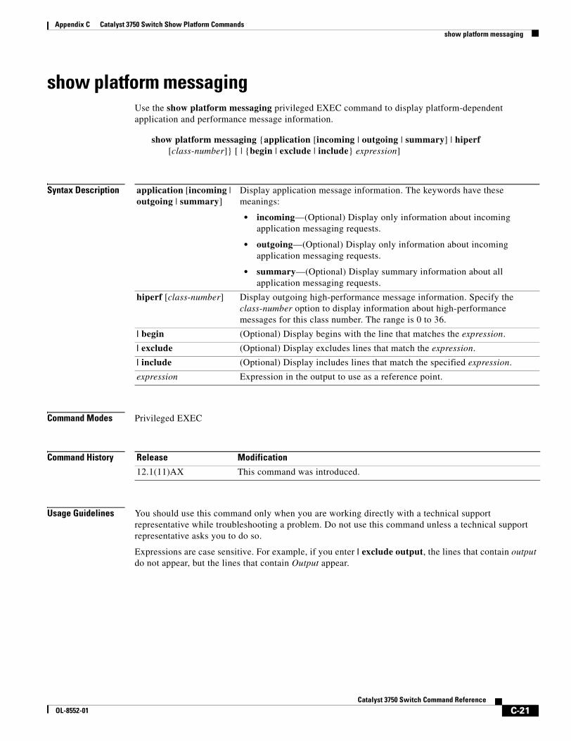
Appendix C Catalyst 3750 Switch Show Platform Commandsshow platform messaging
show platform messagingUse the show platform messaging privileged EXEC command to display platform-dependent application and performance message information.
show platform messaging {application [incoming | outgoing | summary] | hiperf [class-number]} [ | {begin | exclude | include} expression]
Syntax Description
Command Modes Privileged EXEC
Command History
Usage Guidelines You should use this command only when you are working directly with a technical support representative while troubleshooting a problem. Do not use this command unless a technical support representative asks you to do so.
Expressions are case sensitive. For example, if you enter | exclude output, the lines that contain output do not appear, but the lines that contain Output appear.
application [incoming | outgoing | summary]
Display application message information. The keywords have these meanings:
• incoming—(Optional) Display only information about incoming application messaging requests.
• outgoing—(Optional) Display only information about incoming application messaging requests.
• summary—(Optional) Display summary information about all application messaging requests.
hiperf [class-number] Display outgoing high-performance message information. Specify the class-number option to display information about high-performance messages for this class number. The range is 0 to 36.
| begin (Optional) Display begins with the line that matches the expression.
| exclude (Optional) Display excludes lines that match the expression.
| include (Optional) Display includes lines that match the specified expression.
expression Expression in the output to use as a reference point.
Release Modification
12.1(11)AX This command was introduced.
C-21Catalyst 3750 Switch Command Reference
OL-8552-01
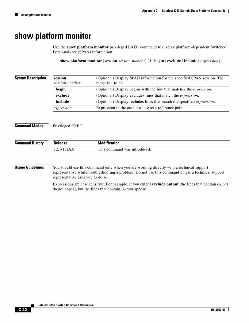
Appendix C Catalyst 3750 Switch Show Platform Commandsshow platform monitor
show platform monitorUse the show platform monitor privileged EXEC command to display platform-dependent Switched Port Analyzer (SPAN) information.
show platform monitor [session session-number] [ | {begin | exclude | include} expression]
Syntax Description
Command Modes Privileged EXEC
Command History
Usage Guidelines You should use this command only when you are working directly with a technical support representative while troubleshooting a problem. Do not use this command unless a technical support representative asks you to do so.
Expressions are case sensitive. For example, if you enter | exclude output, the lines that contain output do not appear, but the lines that contain Output appear.
session session-number
(Optional) Display SPAN information for the specified SPAN session. The range is 1 to 66.
| begin (Optional) Display begins with the line that matches the expression.
| exclude (Optional) Display excludes lines that match the expression.
| include (Optional) Display includes lines that match the specified expression.
expression Expression in the output to use as a reference point.
Release Modification
12.1(11)AX This command was introduced.
C-22Catalyst 3750 Switch Command Reference
OL-8552-01
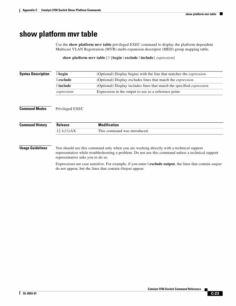
Appendix C Catalyst 3750 Switch Show Platform Commandsshow platform mvr table
show platform mvr tableUse the show platform mvr table privileged EXEC command to display the platform-dependent Multicast VLAN Registration (MVR) multi-expansion descriptor (MED) group mapping table.
show platform mvr table [ | {begin | exclude | include} expression]
Syntax Description
Command Modes Privileged EXEC
Command History
Usage Guidelines You should use this command only when you are working directly with a technical support representative while troubleshooting a problem. Do not use this command unless a technical support representative asks you to do so.
Expressions are case sensitive. For example, if you enter | exclude output, the lines that contain output do not appear, but the lines that contain Output appear.
| begin (Optional) Display begins with the line that matches the expression.
| exclude (Optional) Display excludes lines that match the expression.
| include (Optional) Display includes lines that match the specified expression.
expression Expression in the output to use as a reference point.
Release Modification
12.1(11)AX This command was introduced.
C-23Catalyst 3750 Switch Command Reference
OL-8552-01
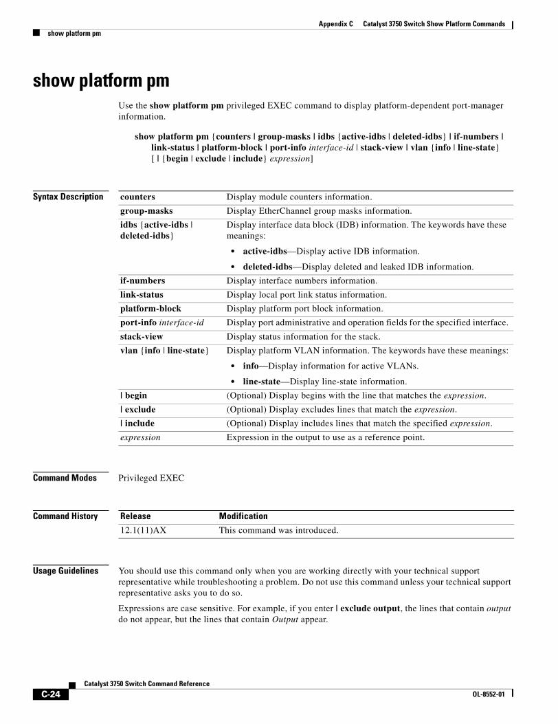
Appendix C Catalyst 3750 Switch Show Platform Commandsshow platform pm
show platform pmUse the show platform pm privileged EXEC command to display platform-dependent port-manager information.
show platform pm {counters | group-masks | idbs {active-idbs | deleted-idbs} | if-numbers | link-status | platform-block | port-info interface-id | stack-view | vlan {info | line-state} [ | {begin | exclude | include} expression]
Syntax Description
Command Modes Privileged EXEC
Command History
Usage Guidelines You should use this command only when you are working directly with your technical support representative while troubleshooting a problem. Do not use this command unless your technical support representative asks you to do so.
Expressions are case sensitive. For example, if you enter | exclude output, the lines that contain output do not appear, but the lines that contain Output appear.
counters Display module counters information.
group-masks Display EtherChannel group masks information.
idbs {active-idbs | deleted-idbs}
Display interface data block (IDB) information. The keywords have these meanings:
• active-idbs—Display active IDB information.
• deleted-idbs—Display deleted and leaked IDB information.
if-numbers Display interface numbers information.
link-status Display local port link status information.
platform-block Display platform port block information.
port-info interface-id Display port administrative and operation fields for the specified interface.
stack-view Display status information for the stack.
vlan {info | line-state} Display platform VLAN information. The keywords have these meanings:
• info—Display information for active VLANs.
• line-state—Display line-state information.
| begin (Optional) Display begins with the line that matches the expression.
| exclude (Optional) Display excludes lines that match the expression.
| include (Optional) Display includes lines that match the specified expression.
expression Expression in the output to use as a reference point.
Release Modification
12.1(11)AX This command was introduced.
C-24Catalyst 3750 Switch Command Reference
OL-8552-01
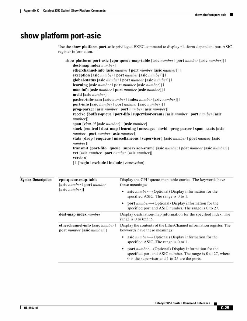
Appendix C Catalyst 3750 Switch Show Platform Commandsshow platform port-asic
show platform port-asicUse the show platform port-asic privileged EXEC command to display platform-dependent port ASIC register information.
show platform port-asic {cpu-queue-map-table [asic number | port number [asic number]] | dest-map index number | etherchannel-info [asic number | port number [asic number]] | exception [asic number | port number [asic number]] | global-status [asic number | port number [asic number]] | learning [asic number | port number [asic number]] | mac-info [asic number | port number [asic number]] | mvid [asic number] | packet-info-ram [asic number | index number [asic number]] | port-info [asic number | port number [asic number]] | prog-parser [asic number | port number [asic number]] | receive {buffer-queue | port-fifo | supervisor-sram} [asic number | port number [asic number]] | span [vlan-id [asic number] | [asic number]stack {control | dest-map | learning | messages | mvid | prog-parser | span | stats [asic number | port number [asic number]]stats {drop | enqueue | miscellaneous | supervisor} [asic number | port number [asic number]] |transmit {port-fifo | queue | supervisor-sram} [asic number | port number [asic number]] vct [asic number | port number [asic number]] version}[ | {begin | exclude | include} expression]
Syntax Description cpu-queue-map-table[asic number | port number [asic number]]
Display the CPU queue-map table entries. The keywords have these meanings:
• asic number—(Optional) Display information for the specified ASIC. The range is 0 to 1.
• port number—(Optional) Display information for the specified port and ASIC number. The range is 0 to 27.
dest-map index number Display destination-map information for the specified index. The range is 0 to 65535.
etherchannel-info [asic number | port number [asic number]]
Display the contents of the EtherChannel information register. The keywords have these meanings:
• asic number—(Optional) Display information for the specified ASIC. The range is 0 to 1.
• port number—(Optional) Display information for the specified port and ASIC number. The range is 0 to 27, where 0 is the supervisor and 1 to 25 are the ports.
C-25Catalyst 3750 Switch Command Reference
OL-8552-01
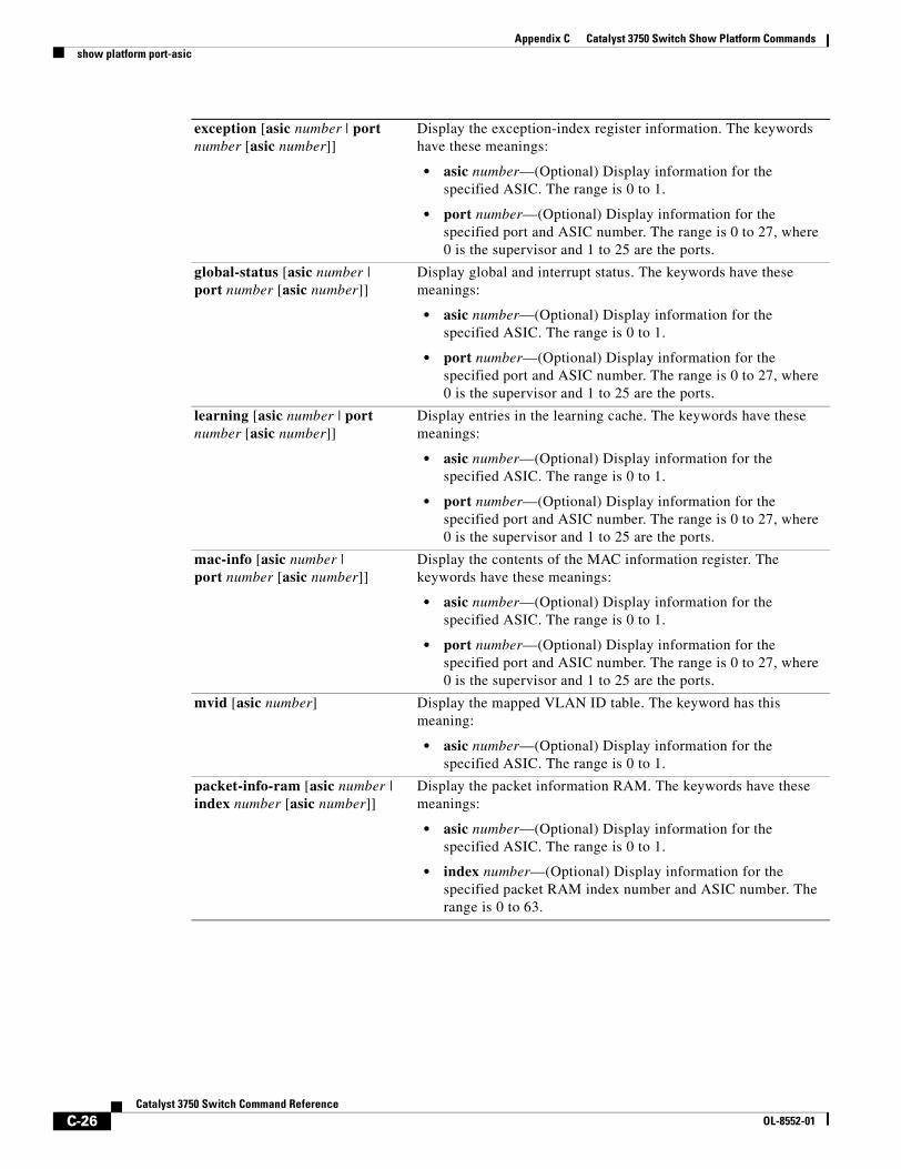
Appendix C Catalyst 3750 Switch Show Platform Commandsshow platform port-asic
exception [asic number | port number [asic number]]
Display the exception-index register information. The keywords have these meanings:
• asic number—(Optional) Display information for the specified ASIC. The range is 0 to 1.
• port number—(Optional) Display information for the specified port and ASIC number. The range is 0 to 27, where 0 is the supervisor and 1 to 25 are the ports.
global-status [asic number | port number [asic number]]
Display global and interrupt status. The keywords have these meanings:
• asic number—(Optional) Display information for the specified ASIC. The range is 0 to 1.
• port number—(Optional) Display information for the specified port and ASIC number. The range is 0 to 27, where 0 is the supervisor and 1 to 25 are the ports.
learning [asic number | port number [asic number]]
Display entries in the learning cache. The keywords have these meanings:
• asic number—(Optional) Display information for the specified ASIC. The range is 0 to 1.
• port number—(Optional) Display information for the specified port and ASIC number. The range is 0 to 27, where 0 is the supervisor and 1 to 25 are the ports.
mac-info [asic number | port number [asic number]]
Display the contents of the MAC information register. The keywords have these meanings:
• asic number—(Optional) Display information for the specified ASIC. The range is 0 to 1.
• port number—(Optional) Display information for the specified port and ASIC number. The range is 0 to 27, where 0 is the supervisor and 1 to 25 are the ports.
mvid [asic number] Display the mapped VLAN ID table. The keyword has this meaning:
• asic number—(Optional) Display information for the specified ASIC. The range is 0 to 1.
packet-info-ram [asic number | index number [asic number]]
Display the packet information RAM. The keywords have these meanings:
• asic number—(Optional) Display information for the specified ASIC. The range is 0 to 1.
• index number—(Optional) Display information for the specified packet RAM index number and ASIC number. The range is 0 to 63.
C-26Catalyst 3750 Switch Command Reference
OL-8552-01
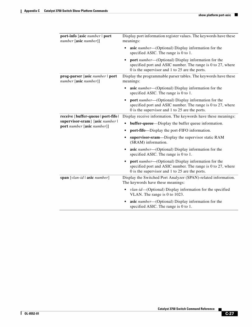
Appendix C Catalyst 3750 Switch Show Platform Commandsshow platform port-asic
port-info [asic number | port number [asic number]]
Display port information register values. The keywords have these meanings:
• asic number—(Optional) Display information for the specified ASIC. The range is 0 to 1.
• port number—(Optional) Display information for the specified port and ASIC number. The range is 0 to 27, where 0 is the supervisor and 1 to 25 are the ports.
prog-parser [asic number | port number [asic number]]
Display the programmable parser tables. The keywords have these meanings:
• asic number—(Optional) Display information for the specified ASIC. The range is 0 to 1.
• port number—(Optional) Display information for the specified port and ASIC number. The range is 0 to 27, where 0 is the supervisor and 1 to 25 are the ports.
receive {buffer-queue | port-fifo | supervisor-sram} [asic number | port number [asic number]]
Display receive information. The keywords have these meanings:
• buffer-queue—Display the buffer queue information.
• port-fifo—Display the port-FIFO information.
• supervisor-sram—Display the supervisor static RAM (SRAM) information.
• asic number—(Optional) Display information for the specified ASIC. The range is 0 to 1.
• port number—(Optional) Display information for the specified port and ASIC number. The range is 0 to 27, where 0 is the supervisor and 1 to 25 are the ports.
span [vlan-id | asic number] Display the Switched Port Analyzer (SPAN)-related information. The keywords have these meanings:
• vlan-id—(Optional) Display information for the specified VLAN. The range is 0 to 1023.
• asic number—(Optional) Display information for the specified ASIC. The range is 0 to 1.
C-27Catalyst 3750 Switch Command Reference
OL-8552-01
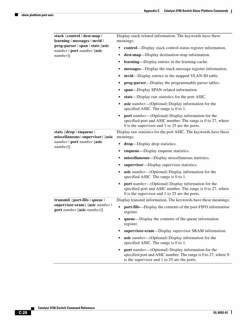
Appendix C Catalyst 3750 Switch Show Platform Commandsshow platform port-asic
stack {control | dest-map | learning | messages | mvid | prog-parser | span | stats [asic number | port number [asic number]]
Display stack-related information. The keywords have these meanings:
• control—Display stack control-status register information.
• dest-map—Display destination-map information.
• learning—Display entries in the learning-cache.
• messages—Display the stack-message register information.
• mvid—Display entries in the mapped VLAN-ID table.
• prog-parser—Display the programmable parser tables.
• span—Display SPAN-related information.
• stats—Display raw statistics for the port ASIC.
• asic number—(Optional) Display information for the specified ASIC. The range is 0 to 1.
• port number—(Optional) Display information for the specified port and ASIC number. The range is 0 to 27, where 0 is the supervisor and 1 to 25 are the ports.
stats {drop | enqueue | miscellaneous | supervisor} [asic number | port number [asic number]]
Display raw statistics for the port ASIC. The keywords have these meanings:
• drop—Display drop statistics.
• enqueue—Display enqueue statistics.
• miscellaneous—Display miscellaneous statistics.
• supervisor—Display supervisor statistics.
• asic number—(Optional) Display information for the specified ASIC. The range is 0 to 1.
• port number—(Optional) Display information for the specified port and ASIC number. The range is 0 to 27, where 0 is the supervisor and 1 to 25 are the ports.
transmit {port-fifo | queue | supervisor-sram} [asic number | port number [asic number]]
Display transmit information. The keywords have these meanings:
• port-fifo—Display the contents of the port-FIFO information register.
• queue—Display the contents of the queue information register.
• supervisor-sram—Display supervisor SRAM information.
• asic number—(Optional) Display information for the specified ASIC. The range is 0 to 1.
• port number—(Optional) Display information for the specified port and ASIC number. The range is 0 to 27, where 0 is the supervisor and 1 to 25 are the ports.
C-28Catalyst 3750 Switch Command Reference
OL-8552-01
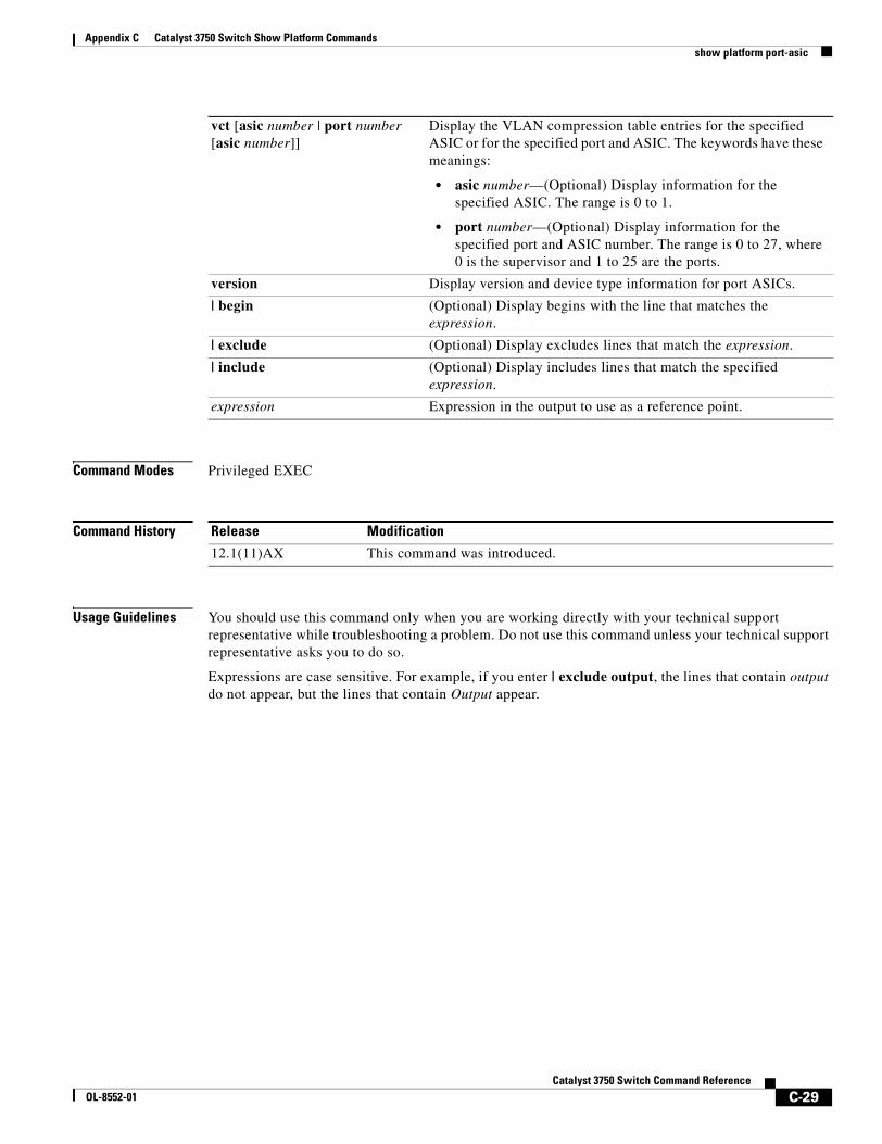
Appendix C Catalyst 3750 Switch Show Platform Commandsshow platform port-asic
Command Modes Privileged EXEC
Command History
Usage Guidelines You should use this command only when you are working directly with your technical support representative while troubleshooting a problem. Do not use this command unless your technical support representative asks you to do so.
Expressions are case sensitive. For example, if you enter | exclude output, the lines that contain output do not appear, but the lines that contain Output appear.
vct [asic number | port number [asic number]]
Display the VLAN compression table entries for the specified ASIC or for the specified port and ASIC. The keywords have these meanings:
• asic number—(Optional) Display information for the specified ASIC. The range is 0 to 1.
• port number—(Optional) Display information for the specified port and ASIC number. The range is 0 to 27, where 0 is the supervisor and 1 to 25 are the ports.
version Display version and device type information for port ASICs.
| begin (Optional) Display begins with the line that matches the expression.
| exclude (Optional) Display excludes lines that match the expression.
| include (Optional) Display includes lines that match the specified expression.
expression Expression in the output to use as a reference point.
Release Modification
12.1(11)AX This command was introduced.
C-29Catalyst 3750 Switch Command Reference
OL-8552-01
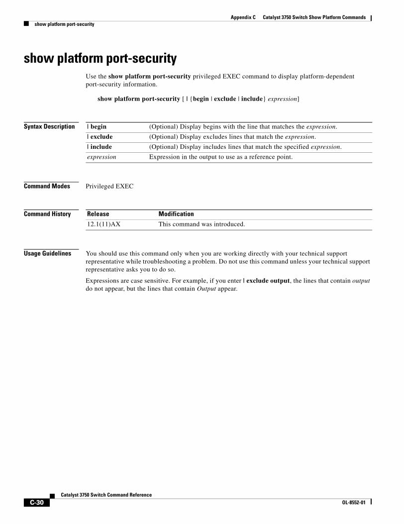
Appendix C Catalyst 3750 Switch Show Platform Commandsshow platform port-security
show platform port-securityUse the show platform port-security privileged EXEC command to display platform-dependent port-security information.
show platform port-security [ | {begin | exclude | include} expression]
Syntax Description
Command Modes Privileged EXEC
Command History
Usage Guidelines You should use this command only when you are working directly with your technical support representative while troubleshooting a problem. Do not use this command unless your technical support representative asks you to do so.
Expressions are case sensitive. For example, if you enter | exclude output, the lines that contain output do not appear, but the lines that contain Output appear.
| begin (Optional) Display begins with the line that matches the expression.
| exclude (Optional) Display excludes lines that match the expression.
| include (Optional) Display includes lines that match the specified expression.
expression Expression in the output to use as a reference point.
Release Modification
12.1(11)AX This command was introduced.
C-30Catalyst 3750 Switch Command Reference
OL-8552-01
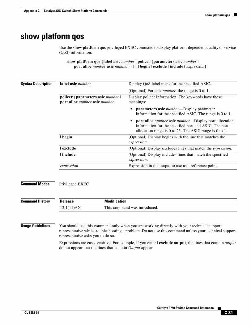
Appendix C Catalyst 3750 Switch Show Platform Commandsshow platform qos
show platform qosUse the show platform qos privileged EXEC command to display platform-dependent quality of service (QoS) information.
show platform qos {label asic number | policer {parameters asic number | port alloc number asic number}} [ | {begin | exclude | include} expression]
Syntax Description
Command Modes Privileged EXEC
Command History
Usage Guidelines You should use this command only when you are working directly with your technical support representative while troubleshooting a problem. Do not use this command unless your technical support representative asks you to do so.
Expressions are case sensitive. For example, if you enter | exclude output, the lines that contain output do not appear, but the lines that contain Output appear.
label asic number Display QoS label maps for the specified ASIC.
(Optional) For asic number, the range is 0 to 1.
policer {parameters asic number | port alloc number asic number}
Display policer information. The keywords have these meanings:
• parameters asic number—Display parameter information for the specified ASIC. The range is 0 to 1.
• port alloc number asic number—Display port allocation information for the specified port and ASIC. The port allocation range is 0 to 25. The ASIC range is 0 to 1.
| begin (Optional) Display begins with the line that matches the expression.
| exclude (Optional) Display excludes lines that match the expression.
| include (Optional) Display includes lines that match the specified expression.
expression Expression in the output to use as a reference point.
Release Modification
12.1(11)AX This command was introduced.
C-31Catalyst 3750 Switch Command Reference
OL-8552-01
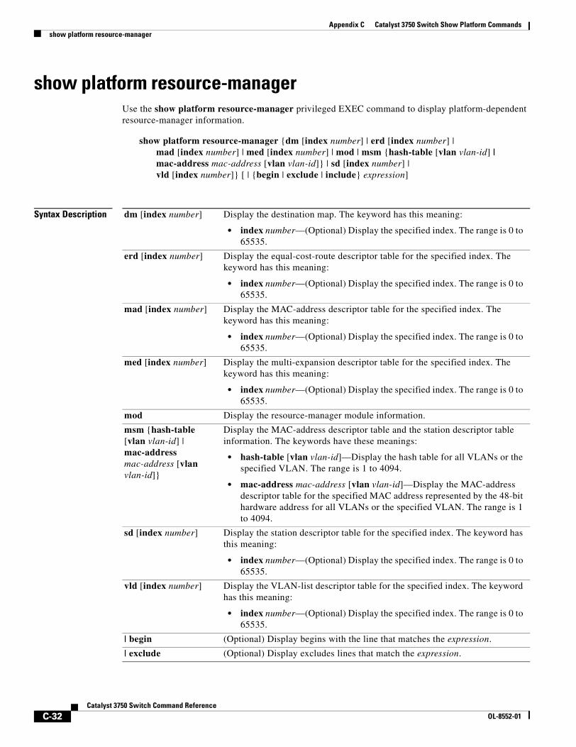
Appendix C Catalyst 3750 Switch Show Platform Commandsshow platform resource-manager
show platform resource-managerUse the show platform resource-manager privileged EXEC command to display platform-dependent resource-manager information.
show platform resource-manager {dm [index number] | erd [index number] | mad [index number] | med [index number] | mod | msm {hash-table [vlan vlan-id] | mac-address mac-address [vlan vlan-id]} | sd [index number] | vld [index number]} [ | {begin | exclude | include} expression]
Syntax Description dm [index number] Display the destination map. The keyword has this meaning:
• index number—(Optional) Display the specified index. The range is 0 to 65535.
erd [index number] Display the equal-cost-route descriptor table for the specified index. The keyword has this meaning:
• index number—(Optional) Display the specified index. The range is 0 to 65535.
mad [index number] Display the MAC-address descriptor table for the specified index. The keyword has this meaning:
• index number—(Optional) Display the specified index. The range is 0 to 65535.
med [index number] Display the multi-expansion descriptor table for the specified index. The keyword has this meaning:
• index number—(Optional) Display the specified index. The range is 0 to 65535.
mod Display the resource-manager module information.
msm {hash-table [vlan vlan-id] | mac-address mac-address [vlan vlan-id]}
Display the MAC-address descriptor table and the station descriptor table information. The keywords have these meanings:
• hash-table [vlan vlan-id]—Display the hash table for all VLANs or the specified VLAN. The range is 1 to 4094.
• mac-address mac-address [vlan vlan-id]—Display the MAC-address descriptor table for the specified MAC address represented by the 48-bit hardware address for all VLANs or the specified VLAN. The range is 1 to 4094.
sd [index number] Display the station descriptor table for the specified index. The keyword has this meaning:
• index number—(Optional) Display the specified index. The range is 0 to 65535.
vld [index number] Display the VLAN-list descriptor table for the specified index. The keyword has this meaning:
• index number—(Optional) Display the specified index. The range is 0 to 65535.
| begin (Optional) Display begins with the line that matches the expression.
| exclude (Optional) Display excludes lines that match the expression.
C-32Catalyst 3750 Switch Command Reference
OL-8552-01
Appendix C Catalyst 3750 Switch Show Platform Commandsshow platform resource-manager
Command Modes Privileged EXEC
Command History
Usage Guidelines You should use this command only when you are working directly with your technical support representative while troubleshooting a problem. Do not use this command unless your technical support representative asks you to do so.
Expressions are case sensitive. For example, if you enter | exclude output, the lines that contain output do not appear, but the lines that contain Output appear.
| include (Optional) Display includes lines that match the specified expression.
expression Expression in the output to use as a reference point.
Release Modification
12.1(11)AX This command was introduced.
C-33Catalyst 3750 Switch Command Reference
OL-8552-01
Appendix C Catalyst 3750 Switch Show Platform Commandsshow platform snmp counters
show platform snmp countersUse the show platform snmp counters privileged EXEC command to display platform-dependent Simple Network Management Protocol (SNMP) counter information.
show platform snmp counters [ | {begin | exclude | include} expression]
Syntax Description
Command Modes Privileged EXEC
Command History
Usage Guidelines You should use this command only when you are working directly with your technical support representative while troubleshooting a problem. Do not use this command unless your technical support representative asks you to do so.
Expressions are case sensitive. For example, if you enter | exclude output, the lines that contain output do not appear, but the lines that contain Output appear.
| begin (Optional) Display begins with the line that matches the expression.
| exclude (Optional) Display excludes lines that match the expression.
| include (Optional) Display includes lines that match the specified expression.
expression Expression in the output to use as a reference point.
Release Modification
12.1(11)AX This command was introduced.
C-34Catalyst 3750 Switch Command Reference
OL-8552-01
Appendix C Catalyst 3750 Switch Show Platform Commandsshow platform spanning-tree
show platform spanning-treeUse the show platform spanning-tree privileged EXEC command to display platform-dependent spanning-tree information.
show platform spanning-tree synchronization [detail | vlan vlan-id] [ | {begin | exclude | include} expression]
Syntax Description
Command Modes Privileged EXEC
Command History
Usage Guidelines You should use this command only when you are working directly with your technical support representative while troubleshooting a problem. Do not use this command unless your technical support representative asks you to do so.
Expressions are case sensitive. For example, if you enter | exclude output, the lines that contain output do not appear, but the lines that contain Output appear.
synchronization [detail | vlan vlan-id]
Display spanning-tree state synchronization information. The keywords have these meanings:
• detail—(Optional) Display detailed spanning-tree information.
• vlan vlan-id—(Optional) Display VLAN switch spanning-tree information for the specified VLAN. The range is 1 to 4094.
| begin (Optional) Display begins with the line that matches the expression.
| exclude (Optional) Display excludes lines that match the expression.
| include (Optional) Display includes lines that match the specified expression.
expression Expression in the output to use as a reference point.
Release Modification
12.1(11)AX This command was introduced.
C-35Catalyst 3750 Switch Command Reference
OL-8552-01
Appendix C Catalyst 3750 Switch Show Platform Commandsshow platform stp-instance
show platform stp-instanceUse the show platform stp-instance privileged EXEC command to display platform-dependent spanning-tree instance information.
show platform stp-instance vlan-id [ | {begin | exclude | include} expression]
Syntax Description
Command Modes Privileged EXEC
Command History
Usage Guidelines You should use this command only when you are working directly with your technical support representative while troubleshooting a problem. Do not use this command unless your technical support representative asks you to do so.
Expressions are case sensitive. For example, if you enter | exclude output, the lines that contain output do not appear, but the lines that contain Output appear.
vlan-id Display spanning-tree instance information for the specified VLAN. The range is 1 to 4094.
| begin (Optional) Display begins with the line that matches the expression.
| exclude (Optional) Display excludes lines that match the expression.
| include (Optional) Display includes lines that match the specified expression.
expression Expression in the output to use as a reference point.
Release Modification
12.1(14)EA1 This command was introduced.
C-36Catalyst 3750 Switch Command Reference
OL-8552-01
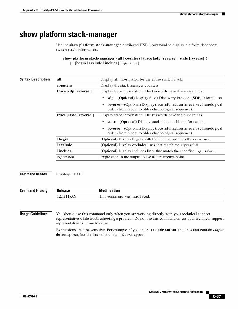
Appendix C Catalyst 3750 Switch Show Platform Commandsshow platform stack-manager
show platform stack-managerUse the show platform stack-manager privileged EXEC command to display platform-dependent switch-stack information.
show platform stack-manager {all | counters | trace [sdp [reverse] | state [reverse]]} [ | {begin | exclude | include} expression]
Syntax Description
Command Modes Privileged EXEC
Command History
Usage Guidelines You should use this command only when you are working directly with your technical support representative while troubleshooting a problem. Do not use this command unless your technical support representative asks you to do so.
Expressions are case sensitive. For example, if you enter | exclude output, the lines that contain output do not appear, but the lines that contain Output appear.
all Display all information for the entire switch stack.
counters Display the stack manager counters.
trace [sdp [reverse]] Display trace information. The keywords have these meanings:
• sdp—(Optional) Display Stack Discovery Protocol (SDP) information.
• reverse—(Optional) Display trace information in reverse chronological order (from recent to older chronological sequence).
trace [state [reverse]] Display trace information. The keywords have these meanings:
• state—(Optional) Display stack state machine information.
• reverse—(Optional) Display trace information in reverse chronological order (from recent to older chronological sequence).
| begin (Optional) Display begins with the line that matches the expression.
| exclude (Optional) Display excludes lines that match the expression.
| include (Optional) Display includes lines that match the specified expression.
expression Expression in the output to use as a reference point.
Release Modification
12.1(11)AX This command was introduced.
C-37Catalyst 3750 Switch Command Reference
OL-8552-01
Appendix C Catalyst 3750 Switch Show Platform Commandsshow platform stack-manager
These are the states displayed in the summary information about the switch stack:
• Waiting—The stage when a switch is booting up and waiting for communication from other switches in the stack. The switch has not yet determined whether it is a stack master or not.
Stack members not participating in a stack master election remain in the waiting state until the stack master is elected and ready.
• Initializing—The stage when a switch has determined whether it is the stack master or not. If the switch is not the stack master, it is receiving its system- and interface-level configuration from the stack master and loading it.
• Ready—The stage when the stack member has completed loading the system- and interface-level configuration and is ready to forward traffic.
• Master Re-Init—The stage immediately after a stack master re-election and a different stack member is elected stack master. The new stack master is re-initializing its configuration. This state applies only to the new stack master.
• Ver Mismatch—The stage of a switch in version mismatch (VM) mode. VM mode is when a switch joining the switch stack has a different stack protocol minor version number from the stack master.
A typical state transition for a stack member (including a stack master) booting up is Waiting -> Initializing -> Ready.
A typical state transition for a stack member becoming a stack master after a stack master election is Ready -> Master Re-Init -> Ready.
A typical state transition for a stack member in version mismatch (VM) mode is Waiting -> Ver Mismatch.
C-38Catalyst 3750 Switch Command Reference
OL-8552-01
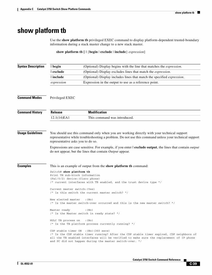
Appendix C Catalyst 3750 Switch Show Platform Commandsshow platform tb
show platform tbUse the show platform tb privileged EXEC command to display platform-dependent trusted-boundary information during a stack master change to a new stack master.
show platform tb [ | {begin | exclude | include} expression]
Syntax Description
Command Modes Privileged EXEC
Command History
Usage Guidelines You should use this command only when you are working directly with your technical support representative while troubleshooting a problem. Do not use this command unless your technical support representative asks you to do so.
Expressions are case sensitive. For example, if you enter | exclude output, the lines that contain output do not appear, but the lines that contain Output appear.
Examples This is an example of output from the show platform tb command:
Switch# show platform tbPrint TB sub-block information (Fa1/0/2) device:(Cisco phone)/* current interfaces with TB enabled, and the trust device type */
Current master switch:(Yes)/* Is this switch the current master switch? */
New elected master :(No)/* Is the master switch-over occurred and this is the new master switch? */
Master ready :(No)/* Is the Master switch in ready state? */
HULC TB process on :(No)/* Is the TB platform process currently running? */
CDP stable timer ON :(No)(360 secs)/* Is the CDP stable timer running? After the CDP stable timer expired, CDP neighbors of all the TB enabled interfaces will be verified to make sure the replacement of IP phone and PC did not happen during the master switch-over. */
| begin (Optional) Display begins with the line that matches the expression.
| exclude (Optional) Display excludes lines that match the expression.
| include (Optional) Display includes lines that match the specified expression.
expression Expression in the output to use as a reference point.
Release Modification
12.1(14)EA1 This command was introduced.
C-39Catalyst 3750 Switch Command Reference
OL-8552-01

Appendix C Catalyst 3750 Switch Show Platform Commandsshow platform tb
Print TB residue trust ports information/* The interfaces with TB enabled right before master switch-over. */
Print port CDP neighbor information/* Is the CDP message still received after switch-over? */
HULC TB is not detecting CDP events/* Currently, this switch is not detecting any CDP event. */
C-40Catalyst 3750 Switch Command Reference
OL-8552-01
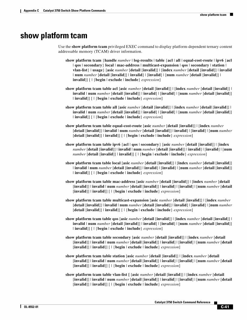
Appendix C Catalyst 3750 Switch Show Platform Commandsshow platform tcam
show platform tcamUse the show platform tcam privileged EXEC command to display platform-dependent ternary content addressable memory (TCAM) driver information.
show platform tcam {handle number | log-results | table {acl | all | equal-cost-route | ipv6 {acl | qos | secondary} local | mac-address | multicast-expansion | qos | secondary | station | vlan-list} | usage} [asic number [detail [invalid]] | [index number [detail [invalid]] | invalid | num number [detail [invalid]] | invalid] | [invalid] | [num number [detail [invalid]] | invalid]] [ | {begin | exclude | include} expression]
show platform tcam table acl [asic number [detail [invalid]] | [index number [detail [invalid]] | invalid | num number [detail [invalid]] | invalid] | [invalid] | [num number [detail [invalid]] | invalid]] [ | {begin | exclude | include} expression]
show platform tcam table all [asic number [detail [invalid]] | [index number [detail [invalid]] | invalid | num number [detail [invalid]] | invalid] | [invalid] | [num number [detail [invalid]] | invalid]] [ | {begin | exclude | include} expression]
show platform tcam table equal-cost-route [asic number [detail [invalid]] | [index number [detail [invalid]] | invalid | num number [detail [invalid]] | invalid] | [invalid] | [num number [detail [invalid]] | invalid]] [ | {begin | exclude | include} expression]
show platform tcam table ipv6 {acl | qos | secondary} [asic number [detail [invalid]] | [index number [detail [invalid]] | invalid | num number [detail [invalid]] | invalid] | [invalid] | [num number [detail [invalid]] | invalid]] [ | {begin | exclude | include} expression]
show platform tcam table local [asic number [detail [invalid]] | [index number [detail [invalid]] | invalid | num number [detail [invalid]] | invalid] | [invalid] | [num number [detail [invalid]] | invalid]] [ | {begin | exclude | include} expression]
show platform tcam table mac-address [asic number [detail [invalid]] | [index number [detail [invalid]] | invalid | num number [detail [invalid]] | invalid] | [invalid] | [num number [detail [invalid]] | invalid]] [ | {begin | exclude | include} expression]
show platform tcam table multicast-expansion [asic number [detail [invalid]] | [index number [detail [invalid]] | invalid | num number [detail [invalid]] | invalid] | [invalid] | [num number [detail [invalid]] | invalid]] [ | {begin | exclude | include} expression]
show platform tcam table qos [asic number [detail [invalid]] | [index number [detail [invalid]] | invalid | num number [detail [invalid]] | invalid] | [invalid] | [num number [detail [invalid]] | invalid]] [ | {begin | exclude | include} expression]
show platform tcam table secondary [asic number [detail [invalid]] | [index number [detail [invalid]] | invalid | num number [detail [invalid]] | invalid] | [invalid] | [num number [detail [invalid]] | invalid]] [ | {begin | exclude | include} expression]
show platform tcam table station [asic number [detail [invalid]] | [index number [detail [invalid]] | invalid | num number [detail [invalid]] | invalid] | [invalid] | [num number [detail [invalid]] | invalid]] [ | {begin | exclude | include} expression]
show platform tcam table vlan-list [ [asic number [detail [invalid]] | [index number [detail [invalid]] | invalid | num number [detail [invalid]] | invalid] | [invalid] | [num number [detail [invalid]] | invalid]] [ | {begin | exclude | include} expression]
C-41Catalyst 3750 Switch Command Reference
OL-8552-01
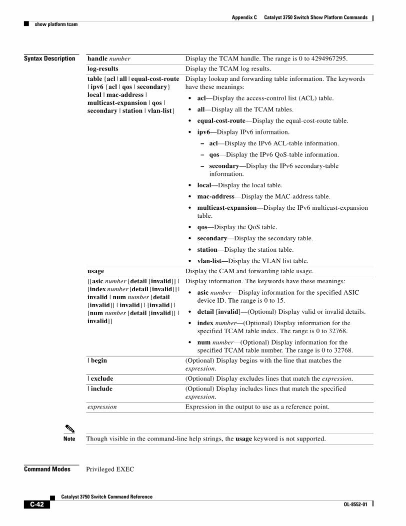
Appendix C Catalyst 3750 Switch Show Platform Commandsshow platform tcam
Syntax Description
Note Though visible in the command-line help strings, the usage keyword is not supported.
Command Modes Privileged EXEC
handle number Display the TCAM handle. The range is 0 to 4294967295.
log-results Display the TCAM log results.
table {acl | all | equal-cost-route | ipv6 {acl | qos | secondary} local | mac-address | multicast-expansion | qos | secondary | station | vlan-list}
Display lookup and forwarding table information. The keywords have these meanings:
• acl—Display the access-control list (ACL) table.
• all—Display all the TCAM tables.
• equal-cost-route—Display the equal-cost-route table.
• ipv6—Display IPv6 information.
– acl—Display the IPv6 ACL-table information.
– qos—Display the IPv6 QoS-table information.
– secondary—Display the IPv6 secondary-table information.
• local—Display the local table.
• mac-address—Display the MAC-address table.
• multicast-expansion—Display the IPv6 multicast-expansion table.
• qos—Display the QoS table.
• secondary—Display the secondary table.
• station—Display the station table.
• vlan-list—Display the VLAN list table.
usage Display the CAM and forwarding table usage.
[[asic number [detail [invalid]] | [index number [detail [invalid]] | invalid | num number [detail [invalid]] | invalid] | [invalid] | [num number [detail [invalid]] | invalid]]
Display information. The keywords have these meanings:
• asic number—Display information for the specified ASIC device ID. The range is 0 to 15.
• detail [invalid]—(Optional) Display valid or invalid details.
• index number—(Optional) Display information for the specified TCAM table index. The range is 0 to 32768.
• num number—(Optional) Display information for the specified TCAM table number. The range is 0 to 32768.
| begin (Optional) Display begins with the line that matches the expression.
| exclude (Optional) Display excludes lines that match the expression.
| include (Optional) Display includes lines that match the specified expression.
expression Expression in the output to use as a reference point.
C-42Catalyst 3750 Switch Command Reference
OL-8552-01
Appendix C Catalyst 3750 Switch Show Platform Commandsshow platform tcam
Command History
Usage Guidelines You should use this command only when you are working directly with your technical support representative while troubleshooting a problem. Do not use this command unless your technical support representative asks you to do so.
Expressions are case sensitive. For example, if you enter | exclude output, the lines that contain output do not appear, but the lines that contain Output appear.
Release Modification
12.1(11)AX This command was introduced.
C-43Catalyst 3750 Switch Command Reference
OL-8552-01
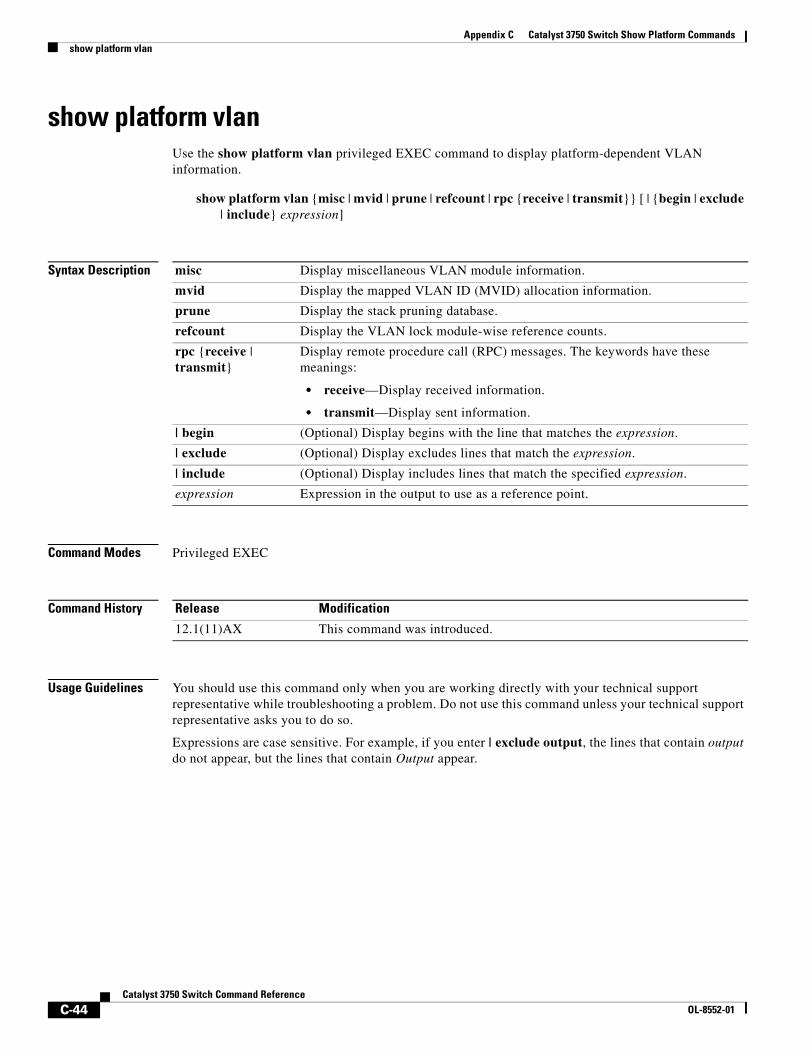
Appendix C Catalyst 3750 Switch Show Platform Commandsshow platform vlan
show platform vlanUse the show platform vlan privileged EXEC command to display platform-dependent VLAN information.
show platform vlan {misc | mvid | prune | refcount | rpc {receive | transmit}} [ | {begin | exclude | include} expression]
Syntax Description
Command Modes Privileged EXEC
Command History
Usage Guidelines You should use this command only when you are working directly with your technical support representative while troubleshooting a problem. Do not use this command unless your technical support representative asks you to do so.
Expressions are case sensitive. For example, if you enter | exclude output, the lines that contain output do not appear, but the lines that contain Output appear.
misc Display miscellaneous VLAN module information.
mvid Display the mapped VLAN ID (MVID) allocation information.
prune Display the stack pruning database.
refcount Display the VLAN lock module-wise reference counts.
rpc {receive | transmit}
Display remote procedure call (RPC) messages. The keywords have these meanings:
• receive—Display received information.
• transmit—Display sent information.
| begin (Optional) Display begins with the line that matches the expression.
| exclude (Optional) Display excludes lines that match the expression.
| include (Optional) Display includes lines that match the specified expression.
expression Expression in the output to use as a reference point.
Release Modification
12.1(11)AX This command was introduced.
C-44Catalyst 3750 Switch Command Reference
OL-8552-01
CatalyOL-8552-01
I N D E X
A
aaa accounting dot1x command 2-1
aaa authentication dot1x command 2-3
aaa authorization network command 2-5
AAA methods 2-3
abort command 2-747
access control entries
See ACEs
access control lists
See ACLs
access groups
IP 2-146
MAC, displaying 2-509
access list, IPv6 2-207
access map configuration mode 2-261
access mode 2-690
access ports 2-690
ACEs 2-89, 2-329
ACLs
deny 2-87
displaying 2-384
for non-IP protocols 2-241
IP 2-146
matching 2-261
on Layer 2 interfaces 2-146
permit 2-327
action command 2-6
address aliasing 2-310
aggregate-port learner 2-315
allowed VLANs 2-710
apply command 2-747
archive copy-sw command 2-8
archive download-sw command 2-11
archive tar command 2-15
archive upload-sw command 2-18
arp access-list command 2-20
audience xix
authentication failed VLAN
See dot1x auth-fail vlan
auth-fail max-attempts
See dot1x auth-fail max-attempts
auth-fail vlan
See dot1x auth-fail vlan
authorization state of controlled port 2-122
autonegotiation of duplex mode 2-131
auto qos voip command 2-22
B
BackboneFast, for STP 2-617
backup interfaces
configuring 2-685
displaying 2-451
boot (boot loader) command A-2
boot auto-copy-sw command 2-27
boot boothlpr command 2-28
boot config-file command 2-29
boot enable-break command 2-30
boot helper command 2-31
boot helper-config file command 2-32
booting
Cisco IOS image 2-35
displaying environment variables 2-394
interrupting 2-30
manually 2-33
IN-1st 3750 Switch Command Reference
Index
boot loader
accessing A-1
booting
Cisco IOS image A-2
helper image 2-31
directories
creating A-16
displaying a list of A-7
removing A-20
displaying
available commands A-12
memory heap utilization A-14
version A-27
environment variables
described A-21
displaying settings A-21
location of A-22
setting A-21
unsetting A-25
files
copying A-5
deleting A-6
displaying a list of A-7
displaying the contents of A-4, A-17, A-24
renaming A-18
file system
formatting A-10
initializing flash A-9
running a consistency check A-11
loading helper images A-13
prompt A-1
resetting the system A-19
boot manual command 2-33
boot private-config-file command 2-34
boot system command 2-35
BPDU filtering, for spanning tree 2-618, 2-653
BPDU guard, for spanning tree 2-620, 2-653
broadcast storm control 2-673
IN-2Catalyst 3750 Switch Command Reference
C
candidate switches
See clusters
cat (boot loader) command A-4
caution, description xx
CDP, enabling protocol tunneling for 2-225
channel-group command 2-37
channel-protocol command 2-41
Cisco Network Assistant
See Network Assistant xx
Cisco SoftPhone
auto-QoS configuration 2-22
trusting packets sent from 2-301
class command 2-42
class-map command 2-44
class maps
creating 2-44
defining the match criteria 2-263
displaying 2-398
class of service
See CoS
clear dot1x command 2-46
clear eap command 2-47
clear ip arp inspection log command 2-48
clear ip arp inspection statistics command 2-49
clear ipc command 2-51
clear ip dhcp snooping database command 2-50
clear l2protocol-tunnel counters command 2-52
clear lacp command 2-53
clear mac address-table command 2-54, 2-56
clear pagp command 2-57
clear port-security command 2-58
clear spanning-tree counters command 2-60
clear spanning-tree detected-protocols command 2-61
clear vmps statistics command 2-62
clear vtp counters command 2-63
cluster commander-address command 2-64
cluster discovery hop-count command 2-66
OL-8552-01
Index
cluster enable command 2-67
cluster holdtime command 2-69
cluster member command 2-70
cluster outside-interface command 2-72
cluster requirements xxi
cluster run command 2-73
clusters
adding candidates 2-70
binding to HSRP group 2-74
building manually 2-70
communicating with
devices outside the cluster 2-72
members by using Telnet 2-356
debug messages, display B-5
displaying
candidate switches 2-401
debug messages B-5
member switches 2-403
status 2-399
hop-count limit for extended discovery 2-66
HSRP standby groups 2-74
redundancy 2-74
SNMP trap 2-607
cluster standby-group command 2-74
cluster timer command 2-76
command modes defined 1-2
commands changed in Cisco IOS Release 12.2(18)SE 1-6
command switch
See clusters
configuration, initial
See getting started guide and hardware installation guide
configuration files
password recovery disable considerations A-1
specifying the name 2-29, 2-34
configuring multiple interfaces 2-142
OL-8552-01
config-vlan mode
commands 2-733
description 1-4
entering 2-732
summary 1-2
conventions
command xx
for examples xx
publication xx
text xx
copy (boot loader) command A-5
CoS
assigning default value to incoming packets 2-271
assigning to Layer 2 protocol packets 2-228
overriding the incoming value 2-271
CoS-to-DSCP map 2-275
CPU ASIC statistics, displaying 2-405
crashinfo files 2-137
D
debug auto qos command B-2
debug backup command B-4
debug cluster command B-5
debug dot1x command B-7
debug dtp command B-9
debug eap command B-10
debug etherchannel command B-12
debug ilpower command B-14
debug interface command B-17
debug ip dhcp snooping command B-15
debug ip igmp filter command B-19
debug ip igmp max-groups command B-20
debug ip igmp snooping command B-21
debug ip verify source packet command B-16
debug lacp command B-22
debug mac-notification command B-23
debug matm command B-24
debug matm move update command B-25
IN-3Catalyst 3750 Switch Command Reference
Index
debug monitor command B-26
debug mvrdbg command B-28
debug nvram command B-29
debug pagp command B-30
debug platform acl command B-31
debug platform backup interface command B-32
debug platform cli-redirection main command B-33
debug platform configuration command B-34, B-42
debug platform cpu-queues command B-35
debug platform device-manager command B-37
debug platform dot1x command B-38
debug platform etherchannel command B-39
debug platform fallback-bridging command B-40
debug platform forw-tcam command B-41
debug platform ip arp inspection command B-44
debug platform ipc command B-52
debug platform ip dhcp command B-45
debug platform ip igmp snooping command B-46
debug platform ip multicast command B-48
debug platform ip unicast command B-50
debug platform led command B-53
debug platform matm command B-54
debug platform messaging application command B-56
debug platform phy command B-58
debug platform pm command B-60
debug platform port-asic command B-62
debug platform port-security command B-63
debug platform qos-acl-tcam command B-64
debug platform remote-commands command B-65
debug platform resource-manager command B-66
debug platform snmp command B-67
debug platform span command B-68
debug platform stack-manager command B-69
debug platform supervisor-asic command B-70
debug platform sw-bridge command B-71
debug platform tcam command B-72
debug platform udld command B-75
debug platform vlan command B-76
debug pm command B-77
IN-4Catalyst 3750 Switch Command Reference
debug port-security command B-79
debug qos-manager command B-80
debug spanning-tree backbonefast command B-83
debug spanning-tree bpdu command B-84
debug spanning-tree bpdu-opt command B-85
debug spanning-tree command B-81
debug spanning-tree mstp command B-86
debug spanning-tree switch command B-88
debug spanning-tree uplinkfast command B-90
debug sw-vlan command B-91
debug sw-vlan ifs command B-93
debug sw-vlan notification command B-95
debug sw-vlan vtp command B-97
debug udld command B-99
debug vqpc command B-101
define interface-range command 2-77
delete (boot loader) command A-6
delete command 2-79
deny (ARP access-list configuration) command 2-80
deny (IPv6) command 2-82
deny command 2-87
detect mechanism, causes 2-132
device manager requirements xx
DHCP snooping
accepting untrusted packets from edge switch 2-171
enabling
on a VLAN 2-177
option 82 2-169, 2-171
trust on an interface 2-175
error recovery timer 2-134
rate limiting 2-174
DHCP snooping binding database
binding file, configuring 2-167
bindings
adding 2-165
deleting 2-165
displaying 2-468
clearing database agent statistics 2-50
database agent, configuring 2-167
OL-8552-01
Index
displaying
binding entries 2-468
database agent status 2-470
renewing 2-363
dir (boot loader) command A-7
directories, deleting 2-79
documentation, related xx
document conventions xx
domain name, VTP 2-758, 2-762
dot1x auth-fail max-attempts 2-99
dot1x auth-fail vlan 2-101
dot1x command 2-97
dot1x control-direction command 2-103
dot1x critical global configuration command 2-105
dot1x critical interface configuration command 2-107
dot1x default command 2-109
dot1x guest-vlan command 2-110
dot1x host-mode command 2-113
dot1x initialize command 2-115
dot1x mac-auth-bypass command 2-116
dot1x max-reauth-req command 2-118
dot1x max-req command 2-119
dot1x multiple-hosts command 2-120
dot1x pae command 2-121
dot1x port-control command 2-122
dot1x re-authenticate command 2-124
dot1x re-authentication command 2-125
dot1x reauthentication command 2-126
dot1x timeout command 2-127
dropping packets, with ACL matches 2-6
drop threshold, Layer 2 protocol tunneling 2-225
DSCP-to-CoS map 2-275
DSCP-to-DSCP-mutation map 2-275
DTP 2-691
DTP flap
error detection for 2-132
error recovery timer 2-134
OL-8552-01
DTP negotiation 2-695
dual IPv4 and IPv6 templates 2-321
duplex command 2-130
dynamic-access ports
configuring 2-683
restrictions 2-684
dynamic ARP inspection
ARP ACLs
apply to a VLAN 2-151
define 2-20
deny packets 2-80
display 2-389
permit packets 2-319
clear
log buffer 2-48
statistics 2-49
display
ARP ACLs 2-389
configuration and operating state 2-464
log buffer 2-464
statistics 2-464
trust state and rate limit 2-464
enable per VLAN 2-161
error detection for 2-132
error recovery timer 2-134
log buffer
clear 2-48
configure 2-155
display 2-464
rate-limit incoming ARP packets 2-153
statistics
clear 2-49
display 2-464
trusted interface state 2-157
type of packet logged 2-162
validation checks 2-159
dynamic auto VLAN membership mode 2-690
dynamic desirable VLAN membership mode 2-690
IN-5Catalyst 3750 Switch Command Reference
Index
Dynamic Host Configuration Protocol (DHCP)
See DHCP snooping
Dynamic Trunking Protocol
See DTP
E
EAP-request/identity frame
maximum number to send 2-119
response time before retransmitting 2-127
encapsulation methods 2-710
environment variables, displaying 2-394
errdisable detect cause command 2-132
errdisable recovery command 2-134
error conditions, displaying 2-439
error disable detection 2-132
error-disabled interfaces, displaying 2-451
EtherChannel
assigning Ethernet interface to channel group 2-37
creating port-channel logical interface 2-140
debug EtherChannel/PAgP, display B-12
debug platform-specific events, display B-39
displaying 2-443
enabling Layer 2 protocol tunneling for
LACP 2-226
PAgP 2-226
UDLD 2-226
interface information, displaying 2-451
LACP
clearing channel-group information 2-53
debug messages, display B-22
displaying 2-503
modes 2-37
port priority for hot-standby ports 2-229
restricting a protocol 2-41
system priority 2-231
load-distribution methods 2-337
IN-6Catalyst 3750 Switch Command Reference
PAgP
aggregate-port learner 2-315
clearing channel-group information 2-57
debug messages, display B-30
displaying 2-554
error detection for 2-132
error recovery timer 2-134
learn method 2-315
modes 2-37
physical-port learner 2-315
priority of interface for transmitted traffic 2-317
Ethernet controller, internal register display 2-407
Ethernet statistics, collecting 2-365
examples, conventions for xx
exception crashinfo command 2-137
exit command 2-747
extended discovery of candidate switches 2-66
extended-range VLANs
and allowed VLAN list 2-710
and pruning-eligible list 2-710
configuring 2-732
extended system ID for STP 2-626
F
fan information, displaying 2-434
file name, VTP 2-758
files, deleting 2-79
flash_init (boot loader) command A-9
Flex Links
configuring 2-685
displaying 2-451
flowcontrol command 2-138
format (boot loader) command A-10
forwarding packets, with ACL matches 2-6
forwarding results, display C-6
OL-8552-01
Index
frame forwarding information, displaying C-6
front-end controller
counter and status information C-8
fsck (boot loader) command A-11
G
global configuration mode 1-2, 1-4
H
hardware ACL statistics 2-384
health monitoring diagnostic tests
configuring 2-90
help (boot loader) command A-12
hierarchical policy maps 2-335
hop-count limit for clusters 2-66
host connection, port configuration 2-689
host ports, private VLANs 2-693
Hot Standby Router Protocol
See HSRP
HSRP
binding HSRP group to cluster 2-74
standby group 2-74
I
IEEE 802.1Q trunk ports and native VLANs 2-749
IEEE 802.1Q tunnel ports
configuring 2-690
displaying 2-424
limitations 2-691
IEEE 802.1x
and switchport modes 2-691
violation error recovery 2-134
See also port-based authentication
IEEE 802.1X Port Based Authentication
enabling guest VLAN supplicant 2-100
OL-8552-01
IGMP filters
applying 2-180
debug messages, display B-19
IGMP groups, setting maximum 2-181
IGMP maximum groups, debugging B-20
IGMP profiles
creating 2-183
displaying 2-472
IGMP snooping
adding ports as a static member of a group 2-199
displaying 2-473, 2-478, 2-480
enabling 2-185
enabling the configurable-leave timer 2-187
enabling the Immediate-Leave feature 2-196
flooding query count 2-193
interface topology change notification behavior 2-195
multicast table 1-6, 2-476
querier 2-189
query solicitation 2-193
report suppression 2-191
switch topology change notification behavior 2-193
images
See software images
Immediate-Leave feature, MVR 2-312
Immediate-Leave processing
IPv6 2-221
immediate-leave processing 2-196
initial configuration
See getting started guide and hardware installation guide
interface configuration mode 1-2, 1-4
interface port-channel command 2-140
interface range command 2-142
interface-range macros 2-77
interfaces
assigning Ethernet interface to channel group 2-37
configuring 2-130
configuring multiple 2-142
creating port-channel logical 2-140
debug messages, display B-17
IN-7Catalyst 3750 Switch Command Reference
Index
disabling 2-605
displaying the MAC address table 2-521
restarting 2-605
interface speed, configuring 2-663
interface vlan command 2-144
internal registers, displaying 2-407, 2-417
Internet Group Management Protocol
See IGMP
invalid GBIC
error detection for 2-132
error recovery timer 2-134
ip access-group command 2-146
ip address command 2-149
IP addresses, setting 2-149
IP address matching 2-261
ip arp inspection filter vlan command 2-151
ip arp inspection limit command 2-153
ip arp inspection log-buffer command 2-155
ip arp inspection trust command 2-157
ip arp inspection validate command 2-159
ip arp inspection vlan command 2-161
ip arp inspection vlan logging command 2-162
IP DHCP snooping
See DHCP snooping
ip dhcp snooping binding command 2-165
ip dhcp snooping command 2-164
ip dhcp snooping database command 2-167
ip dhcp snooping information option allow-untrusted command 2-171
ip dhcp snooping information option command 2-169
ip dhcp snooping information option format remote-id command 2-173
ip dhcp snooping limit rate command 2-174
ip dhcp snooping trust command 2-175
ip dhcp snooping verify command 2-176
ip dhcp snooping vlan command 2-177
ip dhcp snooping vlan information option format-type circuit-id string command 2-178
ip igmp filter command 2-180
ip igmp max-groups command 2-181
IN-8Catalyst 3750 Switch Command Reference
ip igmp profile command 2-183
ip igmp snooping command 2-185
ip igmp snooping last-member-query-interval command 2-187
ip igmp snooping querier command 2-189
ip igmp snooping report-suppression command 2-191
ip igmp snooping tcn command 2-193
ip igmp snooping tcn flood command 2-195
ip igmp snooping vlan immediate-leave command 2-196
ip igmp snooping vlan mrouter command 2-197
ip igmp snooping vlan static command 2-199
IP multicast addresses 2-309
IP phones
auto-QoS configuration 2-22
trusting packets sent from 2-301
IP-precedence-to-DSCP map 2-275
ip snap forwarding command 2-201
ip source binding command 2-202
IP source guard
disabling 2-206
displaying
binding entries 2-482
configuration 2-484
dynamic binding entries only 2-468
enabling 2-206
static IP source bindings 2-202
ip ssh command 2-204
IPv6 access list
deny conditions 2-82
ipv6 access-list command 2-207
ipv6 mld snooping command 2-209
ipv6 mld snooping last-listener-query count command 2-211
ipv6 mld snooping last-listener-query-interval command 2-213
ipv6 mld snooping listener-message-suppression command 2-215
ipv6 mld snooping robustness-variable command 2-217
ipv6 mld snooping tcn command 2-219
ipv6 mld snooping vlan command 2-221
OL-8552-01
Index
IPv6 SDM template 2-366
ipv6 traffic-filter command 2-223
ip verify source command 2-206
J
jumbo frames
See MTU
L
l2protocol-tunnel command 2-225
l2protocol-tunnel cos command 2-228
LACP
See EtherChannel
lacp port-priority command 2-229
lacp system-priority command 2-231
Layer 2 mode, enabling 2-681
Layer 2 protocol ports, displaying 2-500
Layer 2 protocol-tunnel
error detection for 2-132
error recovery timer 2-134
Layer 2 protocol tunnel counters 2-52
Layer 2 protocol tunneling error recovery 2-226
Layer 2 traceroute
IP addresses 2-723
MAC addresses 2-720
Layer 3 mode, enabling 2-681
line configuration mode 1-3, 1-5
Link Aggregation Control Protocol
See EtherChannel
link flap
error detection for 2-132
error recovery timer 2-134
link state group command 2-233
link state track command 2-235
load_helper (boot loader) command A-13
load-distribution methods for EtherChannel 2-337
OL-8552-01
logging event power-inline-status command 2-236
logging file command 2-237
logical interface 2-140
loopback error
detection for 2-132
recovery timer 2-134
loop guard, for spanning tree 2-628, 2-632
M
mac access-group command 2-239
MAC access-groups, displaying 2-509
MAC access list configuration mode 2-241
mac access-list extended command 2-241
MAC access lists 2-87
MAC addresses
displaying
aging time 2-515
all 2-513
dynamic 2-519
MAC address-table move updates 2-523
notification settings 2-525
number of addresses in a VLAN 2-517
per interface 2-521
per VLAN 2-529
static 2-527
static and dynamic entries 2-511
dynamic
aging time 2-243
deleting 2-54
displaying 2-519
enabling MAC address notification 2-246
enabling MAC address-table move update 2-244
matching 2-261
persistent stack 2-671
static
adding and removing 2-248
IN-9Catalyst 3750 Switch Command Reference
Index
displaying 2-527
dropping on an interface 2-249
tables 2-513
MAC address notification, debugging B-23
mac address-table aging-time 2-239, 2-261
mac address-table aging-time command 2-243
mac address-table move update command 2-244
mac address-table notification command 2-246
mac address-table static command 2-248
mac address-table static drop command 2-249
macro apply command 2-251
macro description command 2-254
macro global command 2-255
macro global description command 2-258
macro name command 2-259
macros
adding a description 2-254
adding a global description 2-258
applying 2-255
creating 2-259
displaying 2-556
interface range 2-77, 2-142
specifying parameter values 2-255
tracing 2-255
manual
audience xix
purpose of xix
maps
QoS
defining 2-275
displaying 2-539
VLAN
creating 2-744
defining 2-261
displaying 2-595
match (access-map configuration) command 2-261
match (class-map configuration) command 2-263
IN-10Catalyst 3750 Switch Command Reference
maximum transmission unit
See MTU
mdix auto command 2-265
MDL snooping
displaying 2-494
member switches
See clusters
memory (boot loader) command A-14
mkdir (boot loader) command A-16
MLD snooping
configuring 2-215, 2-217
configuring queries 2-211, 2-213
configuring topology change notification 2-219
displaying 2-492, 2-496, 2-498
enabling 2-209
MLD snooping on a VLAN
enabling 2-221
mls qos aggregate-policer command 2-269
mls qos command 2-267
mls qos cos command 2-271
mls qos dscp-mutation command 2-273
mls qos map command 2-275
mls qos queue-set output buffers command 2-279
mls qos queue-set output threshold command 2-281
mls qos rewrite ip dscp command 2-283
mls qos srr-queue input bandwidth command 2-285
mls qos srr-queue input buffers command 2-287
mls qos-srr-queue input cos-map command 2-289
mls qos srr-queue input dscp-map command 2-291
mls qos srr-queue input priority-queue command 2-293
mls qos srr-queue input threshold command 2-295
mls qos-srr-queue output cos-map command 2-297
mls qos srr-queue output dscp-map command 2-299
mls qos trust command 2-301
mls qos vlan-based command 2-303
mode, MVR 2-309
Mode button, and password recovery 2-371
modes, commands 1-2
monitor session command 2-304
OL-8552-01
Index
more (boot loader) command A-17
MSTP
displaying 2-573, 2-574
interoperability 2-61
link type 2-630
MST region
aborting changes 2-636
applying changes 2-636
configuration name 2-636
configuration revision number 2-636
current or pending display 2-636
displaying 2-573, 2-574
MST configuration mode 2-636
VLANs-to-instance mapping 2-636
path cost 2-638
protocol mode 2-634
restart protocol migration process 2-61
root port
loop guard 2-628
preventing from becoming designated 2-628
restricting which can be root 2-628
root guard 2-628
root switch
affects of extended system ID 2-626
hello-time 2-641, 2-649
interval between BDPU messages 2-642
interval between hello BPDU messages 2-641, 2-649
max-age 2-642
maximum hop count before discarding BPDU 2-643
port priority for selection of 2-645
primary or secondary 2-649
switch priority 2-648
state changes
blocking to forwarding state 2-655
enabling BPDU filtering 2-618, 2-653
enabling BPDU guard 2-620, 2-653
enabling Port Fast 2-653, 2-655
forward-delay time 2-640
OL-8552-01
length of listening and learning states 2-640
rapid transition to forwarding 2-630
shutting down Port Fast-enabled ports 2-653
state information display 2-572
MTU
configuring size 2-717
displaying global setting 2-584
Multicase Listener Discovery
See MLD
multicast group address, MVR 2-312
multicast groups, MVR 2-310
Multicast Listener Discovery
See MLD
multicast router learning method 2-197
multicast router ports
IPv6 2-221
multicast router ports, configuring 2-197
multicast storm control 2-673
multicast VLAN, MVR 2-309
multicast VLAN registration
See MVR
multiple hosts on authorized port 2-113
Multiple Spanning Tree Protocol
See MSTP
MVR
and address aliasing 2-310
configuring 2-309
configuring interfaces 2-312
debug messages, display B-28
displaying 2-548
displaying interface information 2-550
members, displaying 2-552
mvr (global configuration) command 2-309
mvr (interface configuration) command 2-312
mvr vlan group command 2-313
IN-11Catalyst 3750 Switch Command Reference
Index
N
native VLANs 2-710
native VLAN tagging 2-749
Network Assistant requirements xx
nonegotiate
DTP messaging 2-695
nonegotiate, speed 2-663
non-IP protocols
denying 2-87
forwarding 2-327
non-IP traffic access lists 2-241
non-IP traffic forwarding
denying 2-87
permitting 2-327
normal-range VLANs 2-732, 2-738
note, description xx
no vlan command 2-732, 2-742
O
online diagnostics
configuring
health monitoring diagnostic tests 2-90
displaying
configured boot-up coverage level 2-421
current scheduled tasks 2-421
event logs 2-421
supported test suites 2-421
test ID 2-421
test results 2-421
test statistics 2-421
enabling
scheduling 2-93
syslog messages 2-90
global configuration mode
clearing health monitoring diagnostic test schedule 2-90
clearing test-based testing schedule 2-93
IN-12Catalyst 3750 Switch Command Reference
setting health monitoring diagnostic testing 2-90
setting test-based testing 2-93
setting up health monitoring diagnostic test schedule 2-90
setting up test-based testing 2-93
removing
scheduling 2-93
scheduled switchover
disabling 2-93
enabling 2-93
setting
test interval 2-93
specifying
health monitoring diagnostic tests 2-90
starting testing 2-95
P
PAgP
See EtherChannel
pagp learn-method command 2-315
pagp port-priority command 2-317
password, VTP 2-758, 2-762
password-recovery mechanism, enabling and disabling 2-371
permit (ARP access-list configuration) command 2-319
permit (IPv6) command 2-321
permit (MAC access-list configuration) command 2-327
per-VLAN spanning-tree plus
See STP
physical-port learner 2-315
PID, displaying 2-463
PIM-DVMRP, as multicast router learning method 2-197
PoE
configuring the power budget 2-342
configuring the power management mode 2-339
displaying controller register values 2-415
displaying power management information 2-564
logging of status 2-236
OL-8552-01
Index
police aggregate command 2-332
police command 2-330
policed-DSCP map 2-275
policy-map command 2-334
policy maps
applying to an interface 2-373, 2-379
creating 2-334
displaying 2-559
hierarchical 2-335
policers
displaying 2-532
for a single class 2-330
for multiple classes 2-269, 2-332
policed-DSCP map 2-275
traffic classification
defining the class 2-42
defining trust states 2-725
setting DSCP or IP precedence values 2-377
Port Aggregation Protocol
See EtherChannel
port-based authentication
AAA method list 2-3
debug messages, display B-7
enabling IEEE 802.1x
globally 2-97
per interface 2-122
guest VLAN 2-110
host modes 2-113
IEEE 802.1x AAA accounting methods 2-1
initialize an interface 2-115
MAC authentication bypass 2-116
manual control of authorization state 2-122
multiple hosts on authorized port 2-113
PAE as authenticator 2-121
periodic re-authentication
enabling 2-126
time between attempts 2-127
quiet period between failed authentication exchanges 2-127
OL-8552-01
re-authenticating IEEE 802.1x-enabled ports 2-124
resetting configurable IEEE 802.1x parameters 2-109
switch-to-authentication server retransmission time 2-127
switch-to-client frame-retransmission number 2-118 to 2-119
switch-to-client retransmission time 2-127
port-channel load-balance command 2-337
Port Fast, for spanning tree 2-655
port ranges, defining 2-77
ports, debugging B-77
ports, protected 2-708
port security
aging 2-702
debug messages, display B-79
enabling 2-697
violation error recovery 2-134
port trust states for QoS 2-301
port types, MVR 2-312
power information, displaying 2-434
power inline command 2-339
power inline consumption command 2-342
Power over Ethernet
See PoE
priority-queue command 2-344
priority value, stack member 2-581, 2-676
private-vlan command 2-346
private-vlan mapping command 2-349
private VLANs
association 2-706
configuring 2-346
configuring ports 2-693
displaying 2-590
host ports 2-693
mapping
configuring 2-706
displaying 2-451
promiscuous ports 2-693
privileged EXEC mode 1-2, 1-3
IN-13Catalyst 3750 Switch Command Reference
Index
product identification information, displaying 2-463
promiscuous ports, private VLANs 2-693
protected ports, displaying 2-457
pruning
VLANs 2-710
VTP
displaying interface information 2-451
enabling 2-758, 2-762
pruning-eligible VLAN list 2-712
PVST+
See STP
Q
QoS
auto-QoS
configuring 2-22
debug messages, display 1-6, B-2
displaying 2-390
class maps
creating 2-44
defining the match criteria 2-263
displaying 2-398
defining the CoS value for an incoming packet 2-271
displaying configuration information 2-390, 2-531
DSCP transparency 2-283
DSCP trusted ports
applying DSCP-to-DSCP-mutation map to 2-273
defining DSCP-to-DSCP-mutation map 2-275
egress queues
allocating buffers 2-279
defining the CoS output queue threshold map 2-297
defining the DSCP output queue threshold map 2-299
displaying buffer allocations 2-535
displaying CoS output queue threshold map 2-539
displaying DSCP output queue threshold map 2-539
displaying queueing strategy 2-535
displaying queue-set settings 2-542
enabling bandwidth shaping and scheduling 2-667
IN-14Catalyst 3750 Switch Command Reference
enabling bandwidth sharing and scheduling 2-669
limiting the maximum output on a port 2-665
mapping a port to a queue-set 2-351
mapping CoS values to a queue and threshold 2-297
mapping DSCP values to a queue and threshold 2-299
setting maximum and reserved memory allocations 2-281
setting WTD thresholds 2-281
enabling 2-267
ingress queues
allocating buffers 2-287
assigning SRR scheduling weights 2-285
defining the CoS input queue threshold map 2-289
defining the DSCP input queue threshold map 2-291
displaying buffer allocations 2-535
displaying CoS input queue threshold map 2-539
displaying DSCP input queue threshold map 2-539
displaying queueing strategy 2-535
displaying settings for 2-533
enabling the priority queue 2-293
mapping CoS values to a queue and threshold 2-289
mapping DSCP values to a queue and threshold 2-291
setting WTD thresholds 2-295
maps
defining 2-275, 2-289, 2-291, 2-297, 2-299
displaying 2-539
policy maps
applying an aggregate policer 2-332
applying to an interface 2-373, 2-379
creating 2-334
defining policers 2-269, 2-330
displaying policers 2-532
displaying policy maps 2-559
hierarchical 2-335
policed-DSCP map 2-275
setting DSCP or IP precedence values 2-377
traffic classifications 2-42
trust states 2-725
port trust states 2-301
OL-8552-01
Index
queues, enabling the expedite 2-344
statistics
in-profile and out-of-profile packets 2-535
packets enqueued or dropped 2-535
sent and received CoS values 2-535
sent and received DSCP values 2-535
trusted boundary for IP phones 2-301
VLAN-based 2-303
quality of service
See QoS
querytime, MVR 2-309
queue-set command 2-351
R
radius-server dead-criteria command 2-352
radius-server host command 2-354
rapid per-VLAN spanning-tree plus
See STP
rapid PVST+
See STP
rcommand command 2-356
re-authenticating IEEE 802.1x-enabled ports 2-124
re-authentication
periodic 2-126
time between attempts 2-127
receiver ports, MVR 2-312
receiving flow-control packets 2-138
recovery mechanism
causes 2-134
display 2-396, 2-437, 2-441
timer interval 2-135
redundancy for cluster switches 2-74
reload command 2-358
remote command 2-360
remote-span command 2-361
Remote Switched Port Analyzer
See RSPAN
rename (boot loader) command A-18
OL-8552-01
renew ip dhcp snooping database command 2-363
requirements
cluster xxi
device manager xx
Network Assistant xx
reset (boot loader) command A-19
reset command 2-747
resource templates, displaying 2-567
restricted VLAN
See dot1x auth-fail vlan
rmdir (boot loader) command A-20
rmon collection stats command 2-365
root guard, for spanning tree 2-628
routed ports
IP addresses on 2-150
number supported 2-150
RSPAN
configuring 2-304
displaying 2-545
filter RSPAN traffic 2-304
remote-span command 2-361
sessions
add interfaces to 2-304
displaying 2-545
start new 2-304
S
scheduled switchover
disabling 2-93, 2-94
enabling 2-93, 2-94
SDM mismatch mode 2-367, 2-582
sdm prefer command 2-366
SDM templates
allowed resources 2-368
and stacking 2-367
displaying 2-567
dual IPv4 and IPv6 2-366
secure ports, limitations 2-699
IN-15Catalyst 3750 Switch Command Reference
Index
sending flow-control packets 2-138
service password-recovery command 2-371
service-policy command 2-373
session command 2-376
set (boot loader) command A-21
set command 2-377
setup command 2-379
setup express command 2-382
show access-lists command 2-384
show archive status command 2-387
show arp access-list command 2-389
show auto qos command 2-390
show boot command 2-394
show cable-diagnostics tdr command 2-396
show changes command 2-747
show class-map command 2-398
show cluster candidates command 2-401
show cluster command 2-399
show cluster members command 2-403
show controllers cpu-interface command 2-405
show controllers ethernet-controller command 2-407
show controllers power inline command 2-415
show controllers tcam command 2-417
show controller utilization command 2-419
show current command 2-747
show dot1q-tunnel command 2-424
show dot1x command 2-425
show dtp 2-429
show eap command 2-431
show env command 2-434
show errdisable detect command 2-437
show errdisable flap-values command 2-439
show errdisable recovery command 2-441
show etherchannel command 2-443
show flowcontrol command 2-446
show idprom command 2-448
show interfaces command 2-451
show interfaces counters command 2-460
show inventory command 2-463
IN-16Catalyst 3750 Switch Command Reference
show ip arp inspection command 2-464
show ipc command 2-486
show ip dhcp snooping binding command 2-468
show ip dhcp snooping command 2-467
show ip dhcp snooping database command 2-470
show ip igmp profile command 2-472
show ip igmp snooping address command 2-494
show ip igmp snooping command 2-473, 2-492
show ip igmp snooping groups command 2-476
show ip igmp snooping mrouter command 2-478, 2-496
show ip igmp snooping querier command 2-480, 2-498
show ip source binding command 2-482
show ipv6 access-list command 2-490
show ip verify source command 2-484
show l2protocol-tunnel command 2-500
show lacp command 2-503
show link state group command 2-507
show mac access-group command 2-509
show mac address-table address command 2-513
show mac address-table aging time command 2-515
show mac address-table command 2-511
show mac address-table count command 2-517
show mac address-table dynamic command 2-519
show mac address-table interface command 2-521
show mac address-table move update command 2-523
show mac address-table notification command 2-56, 2-525, B-25
show mac address-table static command 2-527
show mac address-table vlan command 2-529
show mls qos aggregate-policer command 2-532
show mls qos command 2-531
show mls qos input-queue command 2-533
show mls qos interface command 2-535
show mls qos maps command 2-539
show mls qos queue-set command 2-542
show mls qos vlan command 2-544
show monitor command 2-545
show mvr command 2-548
show mvr interface command 2-550
OL-8552-01
Index
show mvr members command 2-552
show pagp command 2-554
show parser macro command 2-556
show platform acl command C-2
show platform backup interface command C-3
show platform configuration command C-4
show platform etherchannel command C-5
show platform forward command C-6
show platform frontend-controller command C-8
show platform igmp snooping command C-9
show platform ipc trace command C-16
show platform ip multicast command C-11
show platform ip unicast command C-12
show platform ipv6 unicast command C-17
show platform layer4op command C-19
show platform mac-address-table command C-20
show platform messaging command C-21
show platform monitor command C-22
show platform mvr table command C-23
show platform pm command C-24
show platform port-asic command C-25
show platform port-security command C-30
show platform qos command C-31
show platform resource-manager command C-32
show platform snmp counters command C-34
show platform spanning-tree command C-35
show platform stack-manager command C-37
show platform stp-instance command C-36
show platform tb command C-39
show platform tcam command C-41
show platform vlan command C-44
show policy-map command 2-559
show port security command 2-561
show power inline command 2-564
show proposed command 2-747
show sdm prefer command 2-567
show setup express command 2-571
show spanning-tree command 2-572
show storm-control command 2-579
OL-8552-01
show switch command 2-581
show system mtu command 2-584
show trust command 2-725
show udld command 2-585
show version command 2-588
show vlan access-map command 2-595
show vlan command 2-590
show vlan command, fields 2-592
show vlan filter command 2-596
show vmps command 2-597
show vtp command 2-600
shutdown command 2-605
shutdown threshold, Layer 2 protocol tunneling 2-225
shutdown vlan command 2-606
Smartports macros
See macros
SNMP host, specifying 2-611
SNMP informs, enabling the sending of 2-607
snmp-server enable traps command 2-607
snmp-server host command 2-611
snmp trap mac-notification command 2-615
SNMP traps
enabling MAC address notification trap 2-615
enabling the MAC address notification feature 2-246
enabling the sending of 2-607
SoftPhone
See Cisco SoftPhone
software images
copying 2-8
deleting 2-79
downloading 2-11
upgrading 2-8, 2-11
uploading 2-18
software version, displaying 2-588
source ports, MVR 2-312
SPAN
configuring 2-304
debug messages, display B-26
displaying 2-545
IN-17Catalyst 3750 Switch Command Reference
Index
filter SPAN traffic 2-304
sessions
add interfaces to 2-304
displaying 2-545
start new 2-304
spanning 2-657
spanning-tree backbonefast command 2-617
spanning-tree bpdufilter command 2-618
spanning-tree bpduguard command 2-620
spanning-tree cost command 2-622
spanning-tree etherchannel command 2-624
spanning-tree extend system-id command 2-626
spanning-tree guard command 2-628
spanning-tree link-type command 2-630
spanning-tree loopguard default command 2-632
spanning-tree mode command 2-634
spanning-tree mst configuration command 2-636
spanning-tree mst cost command 2-638
spanning-tree mst forward-time command 2-640
spanning-tree mst hello-time command 2-641
spanning-tree mst max-age command 2-642
spanning-tree mst max-hops command 2-643
spanning-tree mst port-priority command 2-645
spanning-tree mst pre-standard command 2-647
spanning-tree mst priority command 2-648
spanning-tree mst root command 2-649
spanning-tree portfast (global configuration) command 2-653
spanning-tree portfast (interface configuration) command 2-655
spanning-tree port-priority command 2-651
Spanning Tree Protocol
See STP
spanning-tree transmit hold-count command 2-657
spanning-tree uplinkfast command 2-658
spanning-tree vlan command 2-660
speed command 2-663
IN-18Catalyst 3750 Switch Command Reference
srr-queue bandwidth limit command 2-665
srr-queue bandwidth shape command 2-667
srr-queue bandwidth share command 2-669
SSH, configuring version 2-204
stack-mac persistent timer command 2-671
stack member
access 2-376
number 2-581, 2-679
priority value 2-676
provisioning 2-677
reloading 2-358
stacks, switch
MAC address 2-671
provisioning a new member 2-677
reloading 2-358
stack member access 2-376
stack member number 2-581, 2-679
stack member priority value 2-581, 2-676
static-access ports, configuring 2-683
statistics, Ethernet group 2-365
sticky learning, enabling 2-697
storm-control command 2-673
STP
BackboneFast 2-617
counters, clearing 2-60
debug messages, display
BackboneFast events B-83
MSTP B-86
optimized BPDUs handling B-85
spanning-tree activity B-81
switch shim B-88
transmitted and received BPDUs B-84
UplinkFast B-90
detection of indirect link failures 2-617
enabling protocol tunneling for 2-225
EtherChannel misconfiguration 2-624
extended system ID 2-626
path cost 2-622
protocol modes 2-634
OL-8552-01
Index
root port
accelerating choice of new 2-658
loop guard 2-628
preventing from becoming designated 2-628
restricting which can be root 2-628
root guard 2-628
UplinkFast 2-658
root switch
affects of extended system ID 2-626, 2-661
hello-time 2-660
interval between BDPU messages 2-660
interval between hello BPDU messages 2-660
max-age 2-660
port priority for selection of 2-651
primary or secondary 2-660
switch priority 2-660
state changes
blocking to forwarding state 2-655
enabling BPDU filtering 2-618, 2-653
enabling BPDU guard 2-620, 2-653
enabling Port Fast 2-653, 2-655
enabling timer to recover from error state 2-134
forward-delay time 2-660
length of listening and learning states 2-660
shutting down Port Fast-enabled ports 2-653
state information display 2-572
VLAN options 2-648, 2-660
SVIs, creating 2-144
Switched Port Analyzer
See SPAN
switching characteristics
modifying 2-681
returning to interfaces 2-681
switchport access command 2-683
switchport backup interface command 2-685
switchport block command 2-688
switchport command 2-681
switchport host command 2-689
switchport mode command 2-690
OL-8552-01
switchport mode private-vlan command 2-693
switchport nonegotiate command 2-695
switchport port-security aging command 2-702
switchport port-security command 2-697
switchport priority extend command 2-704
switchport private-vlan command 2-706
switchport protected command 2-708
switchports, displaying 2-451
switchport trunk command 2-710
switchport voice vlan command 2-713
switch priority command 2-676
switch provision command 2-677
switch renumber command 2-679
system env temperature threshold yellow command 2-715
system message logging 2-236
system message logging, save message to flash 2-237
system mtu command 2-717
system resource templates 2-366
T
tar files, creating, listing, and extracting 2-15
TDR, running 2-719
Telnet, using to communicate to cluster switches 2-356
temperature information, displaying 2-434
templates, system resources 2-366
test cable-diagnostics tdr command 2-719
traceroute mac command 2-720
traceroute mac ip command 2-723
trunking, VLAN mode 2-690
trunk mode 2-690
trunk ports 2-690
trunks, to non-DTP device 2-691
trusted boundary for QoS 2-301
trusted port states for QoS 2-301
tunnel ports, Layer 2 protocol, displaying 2-500
type (boot loader) command A-24
IN-19Catalyst 3750 Switch Command Reference
Index
U
UDLD
aggressive mode 2-727, 2-729
debug messages, display B-99
enable globally 2-727
enable per interface 2-729
error recovery timer 2-134
message timer 2-727
normal mode 2-727, 2-729
reset a shutdown interface 2-731
status 2-585
udld command 2-727
udld port command 2-729
udld reset command 2-731
unicast storm control 2-673
UniDirectional Link Detection
See UDLD
unknown multicast traffic, preventing 2-688
unknown unicast traffic, preventing 2-688
unset (boot loader) command A-25
upgrading
software images 2-8, 2-11
monitoring status of 2-387
upgrading information
See release notes
UplinkFast, for STP 2-658
user EXEC mode 1-2, 1-3
V
version (boot loader) command A-27
version mismatch mode 2-582
VLAN
enabling guest VLAN supplicant 2-100
vlan (global configuration) command 2-732
vlan (VLAN configuration) command 2-738
vlan access-map command 2-744
VLAN access map configuration mode 2-744
IN-20Catalyst 3750 Switch Command Reference
VLAN access maps
actions 2-6
displaying 2-595
VLAN-based QoS 2-303
VLAN configuration
rules 2-735, 2-740
saving 2-732, 2-742
VLAN configuration mode
commands
VLAN 2-738
VTP 2-762
description 1-5
entering 2-746
summary 1-3
vlan database command 2-746
vlan dot1q tag native command 2-749
vlan filter command 2-751
VLAN filters, displaying 2-596
VLAN ID range 2-732, 2-738
VLAN maps
applying 2-751
creating 2-744
defining 2-261
displaying 2-595
VLAN Query Protocol
See VQP
VLANs
adding 2-732
configuring 2-732, 2-738
debug messages, display
ISL B-95
VLAN IOS file system error tests B-93
VLAN manager activity B-91
VTP B-97
displaying configurations 2-590
extended-range 2-732
MAC addresses
displaying 2-529
number of 2-517
OL-8552-01
Index
media types 2-735, 2-740
normal-range 2-732, 2-738
private 2-693
configuring 2-346
displaying 2-590
See also private VLANs
restarting 2-606
saving the configuration 2-732
shutting down 2-606
SNMP traps for VTP 2-609, 2-612
suspending 2-606
variables 2-738
VLAN Trunking Protocol
See VTP
VM mode 2-582
VMPS
configuring servers 2-756
displaying 2-597
error recovery timer 2-135
reconfirming dynamic VLAN assignments 2-753
vmps reconfirm (global configuration) command 2-754
vmps reconfirm (privileged EXEC) command 2-753
vmps retry command 2-755
vmps server command 2-756
voice VLAN
configuring 2-713
setting port priority 2-704
VQP
and dynamic-access ports 2-684
clearing client statistics 2-62
displaying information 2-597
per-server retry count 2-755
reconfirmation interval 2-754
reconfirming dynamic VLAN assignments 2-753
VTP
changing characteristics 2-758
clearing pruning counters 2-63
configuring
domain name 2-758, 2-762
OL-8552-01
file name 2-758
mode 2-758, 2-762
password 2-758, 2-762
counters display fields 2-601
displaying information 2-600
enabling
pruning 2-758, 2-762
tunneling for 2-225
Version 2 2-758, 2-762
mode 2-758, 2-762
pruning 2-758, 2-762
saving the configuration 2-732, 2-742
statistics 2-600
status 2-600
status display fields 2-603
vtp (global configuration) command 2-758
vtp (VLAN configuration) command 2-762
X
XENPAK module serial EERPOM information 2-411, 2-448
IN-21Catalyst 3750 Switch Command Reference

Index
IN-22Catalyst 3750 Switch Command Reference
OL-8552-01


![Catalyst 3750 Switch Cisco IOS Commands - shutdown … · Chapter 2 Catalyst 3750 Switch Cisco IOS Commands shutdown 0-709 Catalyst 3750 Switch Command Reference OL-8552-09 0V] shutdown](https://img.pdfslide.net/doc/110x75/5b90f2e009d3f22c258cf6a1/catalyst-3750-switch-cisco-ios-commands-shutdown-chapter-2-catalyst-3750-switch.jpg)