Embed Size (px)
Citation preview

Caterpillar Digital Voltage RegulatorCaterpillar Digital Voltage Regulator(CDVR) (CDVR)
Introduction and SpecificationsIntroduction and Specifications
Prepared by Service Traininghttps://psmktg.cat.com/srvtrng/
ForewordForewordThis presentation was prepared by Caterpillar Service Training to be a training overview of the CDVR for Caterpillar generator set service personnel. This presentation provides comparisons to the previous design, DVR, and includes information pertaining to the removal of a DVR and replacement with a new CDVR. As always, the proper service information for the regulators in SIS should be used for the latest specific details for operation, adjustments, programming and troubleshooting. Please E-mail comments about this overview presentation to Todd Roth at [email protected]. Thank You!
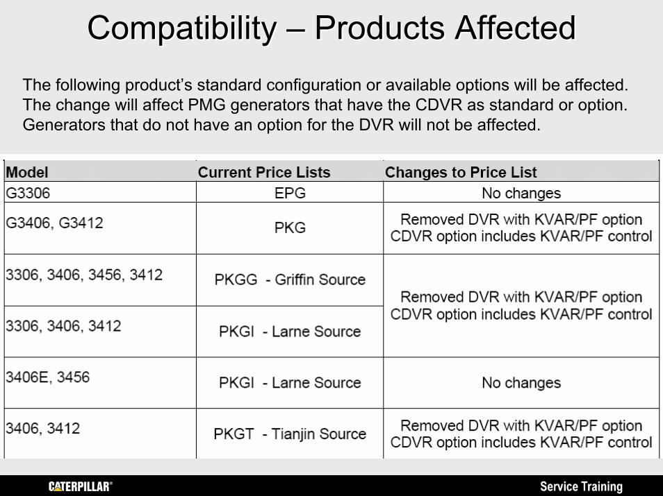
Compatibility Compatibility –– Products AffectedProducts AffectedThe following product’s standard configuration or available options will be affected. The change will affect PMG generators that have the CDVR as standard or option. Generators that do not have an option for the DVR will not be affected.
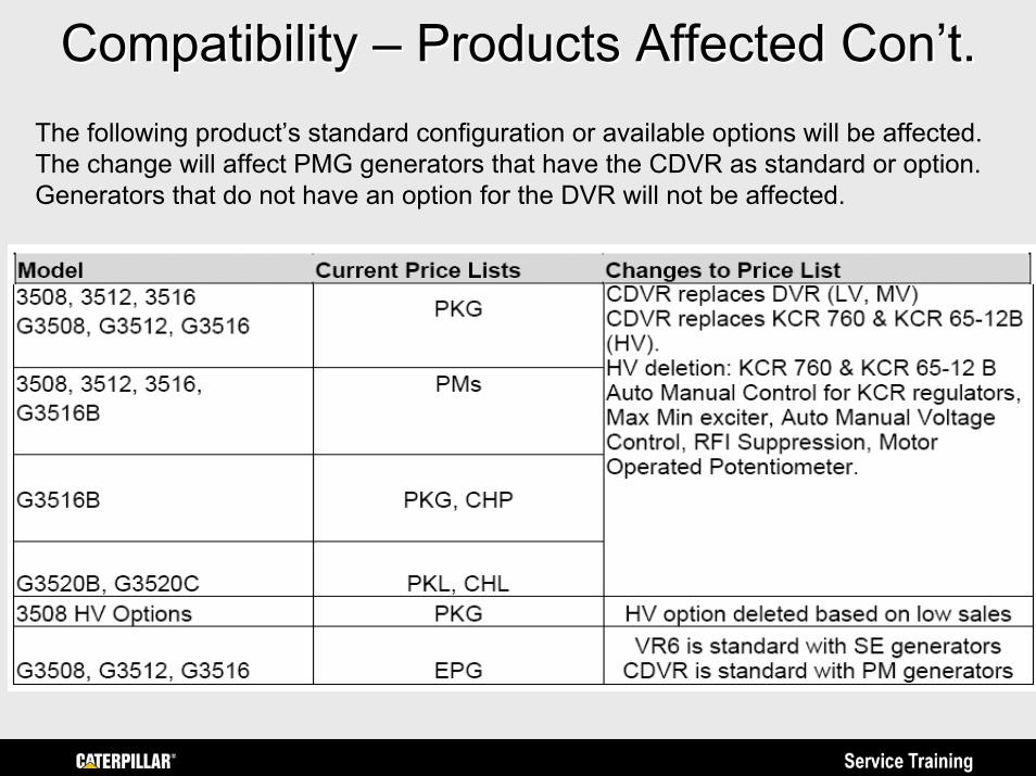
Compatibility Compatibility –– Products Affected Products Affected Con’tCon’t..The following product’s standard configuration or available options will be affected. The change will affect PMG generators that have the CDVR as standard or option. Generators that do not have an option for the DVR will not be affected.
Other CDVR Production InformationOther CDVR Production Information• The CDVR will replace DVR for low and medium
voltage generators and will also replace KCR 760 & KCR 65-12B for high voltage generators. A follow-up announcement will be sent that details product changeover on all affected products.
• The CDVR will be used in all EPG products currently available with a standard or optional CDVR and with high voltage applications where analog regulators are standard with current product.
• 3500 SE Generators will be shipped with a VR-6• 3500 PM Generators will be shipped with a CDVR
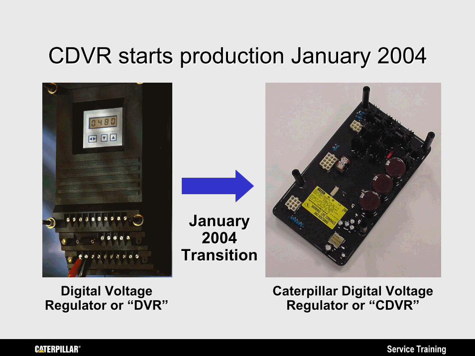
CDVR starts production January 2004CDVR starts production January 2004
JanuaryJanuary20042004
TransitionTransition
Digital Voltage Digital Voltage Regulator or “DVR”
Caterpillar Digital Voltage Caterpillar Digital Voltage Regulator or “CDVR”Regulator or “DVR” Regulator or “CDVR”
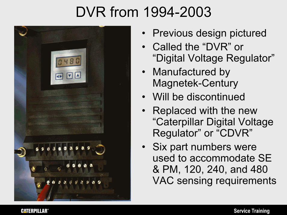
DVR from 1994DVR from 1994--20032003• Previous design pictured• Called the “DVR” or
“Digital Voltage Regulator”• Manufactured by
Magnetek-Century• Will be discontinued• Replaced with the new
“Caterpillar Digital Voltage Regulator” or “CDVR”
• Six part numbers were used to accommodate SE & PM, 120, 240, and 480 VAC sensing requirements
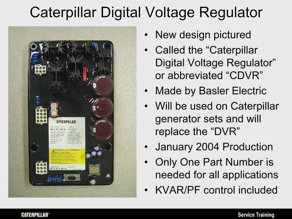
Caterpillar Digital Voltage RegulatorCaterpillar Digital Voltage Regulator• New design pictured• Called the “Caterpillar
Digital Voltage Regulator” or abbreviated “CDVR”
• Made by Basler Electric• Will be used on Caterpillar
generator sets and will replace the “DVR”
• January 2004 Production• Only One Part Number is
needed for all applications• KVAR/PF control included
CDVR PublicationsCDVR Publications• Available on Service Information System (SIS)
– RENR7941 Specifications System OperationTesting & Adjusting Guide
– “CDVR PC Software” is available on SISweb in the Flash File download section or on the monthly SIS subscription Flash File CD ROM.
• Available on Electronic Media Center– LEHE3225 Specifications Sheet– LEXE3226 November 2003 Product News
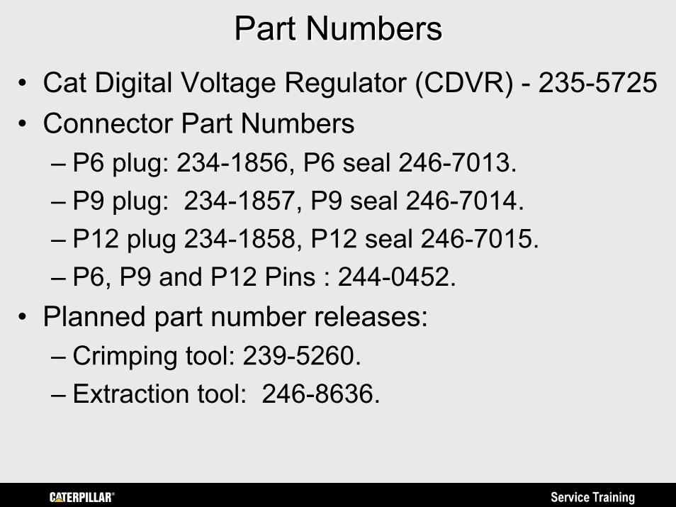
Part NumbersPart Numbers• Cat Digital Voltage Regulator (CDVR) - 235-5725 • Connector Part Numbers
– P6 plug: 234-1856, P6 seal 246-7013. – P9 plug: 234-1857, P9 seal 246-7014. – P12 plug 234-1858, P12 seal 246-7015.– P6, P9 and P12 Pins : 244-0452.
• Planned part number releases:– Crimping tool: 239-5260. – Extraction tool: 246-8636.
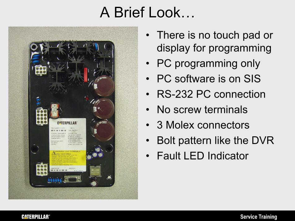
A Brief Look…A Brief Look…• There is no touch pad or
display for programming• PC programming only• PC software is on SIS• RS-232 PC connection• No screw terminals• 3 Molex connectors• Bolt pattern like the DVR• Fault LED Indicator
Why a new Caterpillar Regulator?Why a new Caterpillar Regulator?• DVR was designed in early 1990’s…
– 1990’s technology has fewer features– Internal components are becoming obsolete– DVR designed for fewer applications– Not cost effective to improve present design
• The CDVR has improved transient performance, added standard features such as VAR & PF control, and expanded flexibility for optimizing performance to individual customer applications.
FeaturesFeatures• Microprocessor control of three standard modes
– Automatic Voltage Regulation (AVR)– Power Factor Regulation (PF)– Reactive Power Regulation (VAR)
• Programmable stability settings• Soft start control with an adjustable time setting
in AVR control mode• Dual Slope Under Frequency (volts/Hertz)
regulation
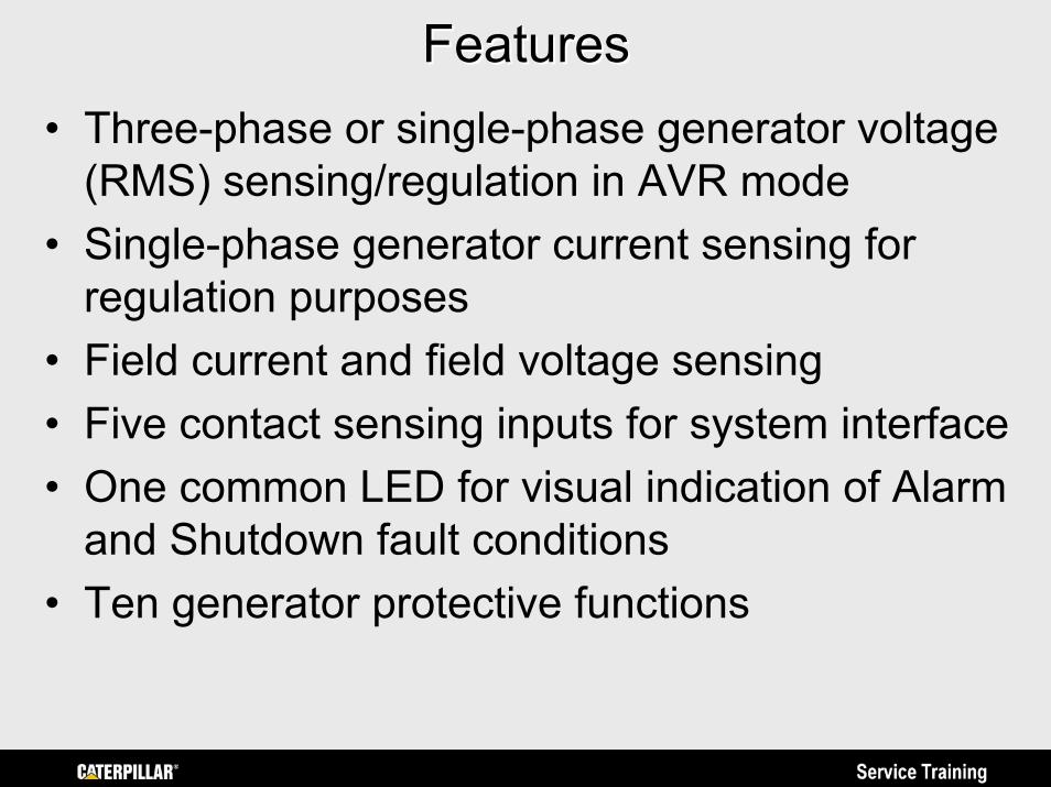
FeaturesFeatures• Three-phase or single-phase generator voltage
(RMS) sensing/regulation in AVR mode• Single-phase generator current sensing for
regulation purposes• Field current and field voltage sensing• Five contact sensing inputs for system interface• One common LED for visual indication of Alarm
and Shutdown fault conditions• Ten generator protective functions
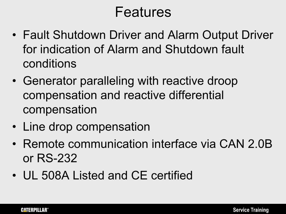
FeaturesFeatures• Fault Shutdown Driver and Alarm Output Driver
for indication of Alarm and Shutdown fault conditions
• Generator paralleling with reactive droop compensation and reactive differential compensation
• Line drop compensation • Remote communication interface via CAN 2.0B
or RS-232• UL 508A Listed and CE certified
Modes of Operation DefinedModes of Operation Defined
•Automatic Voltage Regulation (AVR)•Reactive Power (VAR) Regulation•Power Factor (PF) Regulation
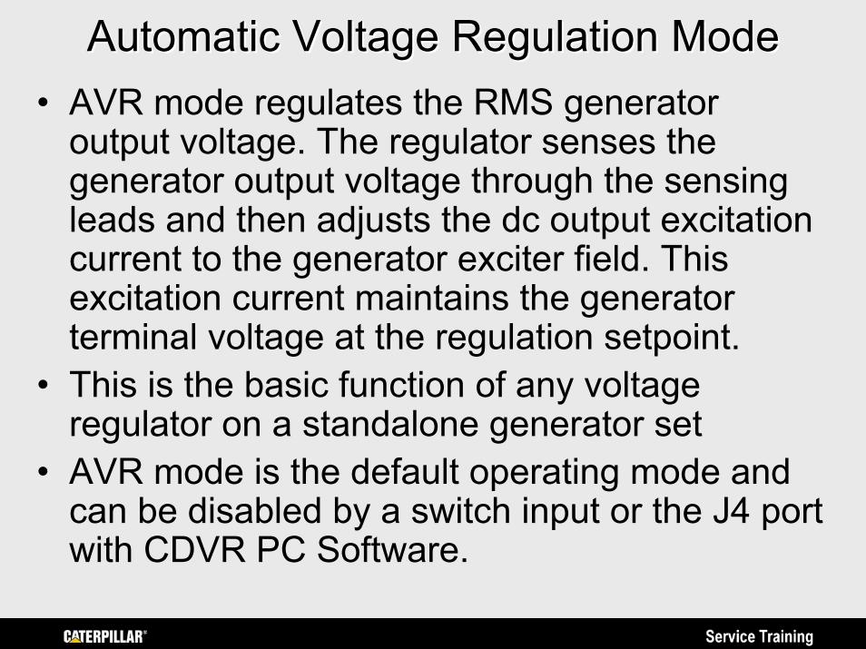
Automatic Voltage Regulation ModeAutomatic Voltage Regulation Mode• AVR mode regulates the RMS generator
output voltage. The regulator senses the generator output voltage through the sensing leads and then adjusts the dc output excitation current to the generator exciter field. This excitation current maintains the generator terminal voltage at the regulation setpoint.
• This is the basic function of any voltage regulator on a standalone generator set
• AVR mode is the default operating mode and can be disabled by a switch input or the J4 port with CDVR PC Software.
VAR Control ModeVAR Control Mode• Reactive or VAR mode regulates “Volt-Amps
Reactive” when paralleling with an infinite bus. The CDVR calculates generator VARs from output voltage and droop CT current quantities and adjusts the excitation current to maintain VARs at the programmed setpoint. VAR mode and PF mode are mutually exclusive modes that both work in conjunction with AVR mode.
• VAR mode is enabled by a switch input or the CDVR PC Software. VAR is adjustable from 100 percent absorb to 100 percent generate.
• Typically used when paralleled with utility.
Power Factor Control ModePower Factor Control Mode• PF mode regulates Power Factor when
paralleling with an infinite bus. The CDVR calculates PF using the sensed output voltage and current and then adjusts the dc excitation current to maintain PF at the programmedsetpoint. Again, VAR mode and Power Factor mode are mutually exclusive modes that both work in conjunction with AVR mode.
• PF mode is enabled by a switch input or the J4 port with CDVR PC Software. PF setpoint is adjustable from 0.6 lag and 0.6 lead. .
• Typically used when paralleled with utility.
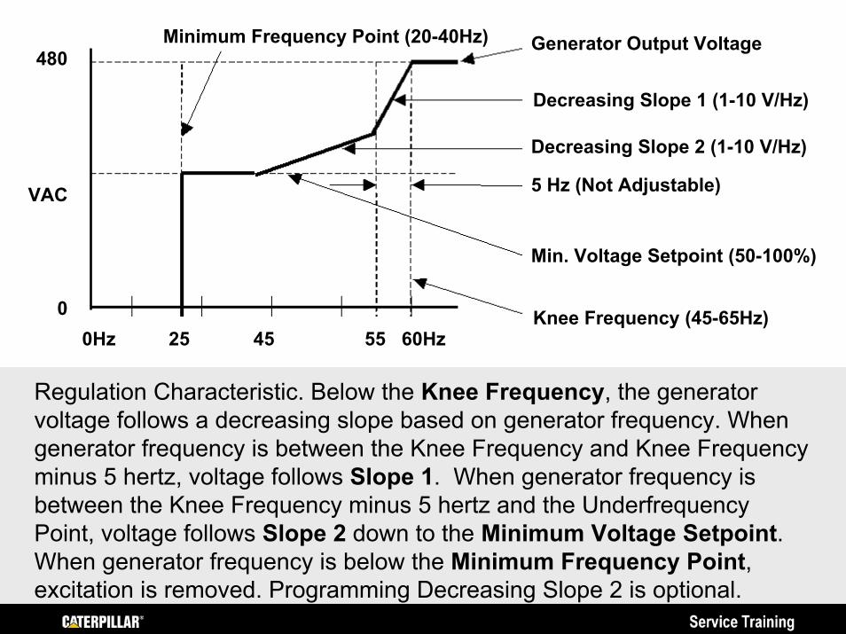
0Hz 25 45 55 60Hz
480
VAC
0 Knee Frequency (45-65Hz)
Min. Voltage Setpoint (50-100%)
5 Hz (Not Adjustable)
Decreasing Slope 1 (1-10 V/Hz)
Decreasing Slope 2 (1-10 V/Hz)
Generator Output VoltageMinimum Frequency Point (20-40Hz)
Regulation Characteristic. Below the Knee Frequency, the generator voltage follows a decreasing slope based on generator frequency. When generator frequency is between the Knee Frequency and Knee Frequency minus 5 hertz, voltage follows Slope 1. When generator frequency is between the Knee Frequency minus 5 hertz and the UnderfrequencyPoint, voltage follows Slope 2 down to the Minimum Voltage Setpoint. When generator frequency is below the Minimum Frequency Point, excitation is removed. Programming Decreasing Slope 2 is optional.
10 CDVR Protective Functions10 CDVR Protective Functions• Generator Overvoltage• Generator Undervoltage• Loss of Excitation• Instantaneous Field Overcurrent• Over Excitation• Loss of Sensing Voltage• Diode Fault Monitor• Internal CDVR Processor Watchdog Failure• Internal CDVR Memory Failure• Fault Reset Switch Closed Too Long
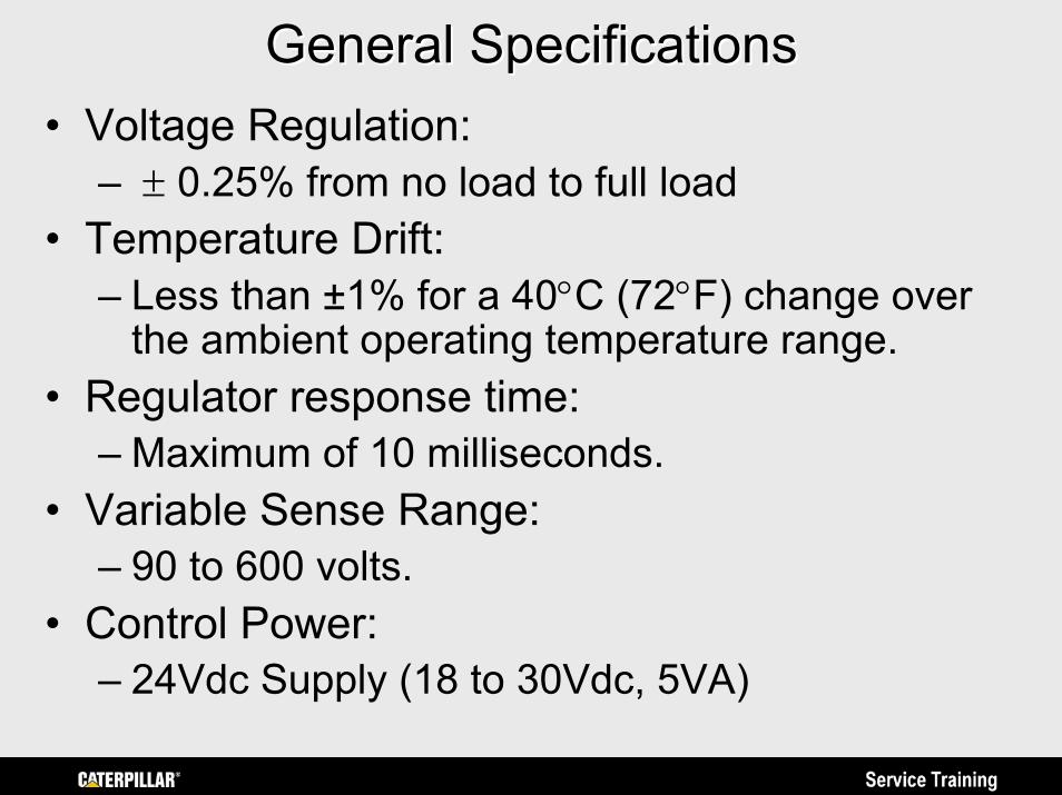
General SpecificationsGeneral Specifications• Voltage Regulation:
– ± 0.25% from no load to full load• Temperature Drift:
– Less than ±1% for a 40°C (72°F) change over the ambient operating temperature range.
• Regulator response time:– Maximum of 10 milliseconds.
• Variable Sense Range:– 90 to 600 volts.
• Control Power:– 24Vdc Supply (18 to 30Vdc, 5VA)
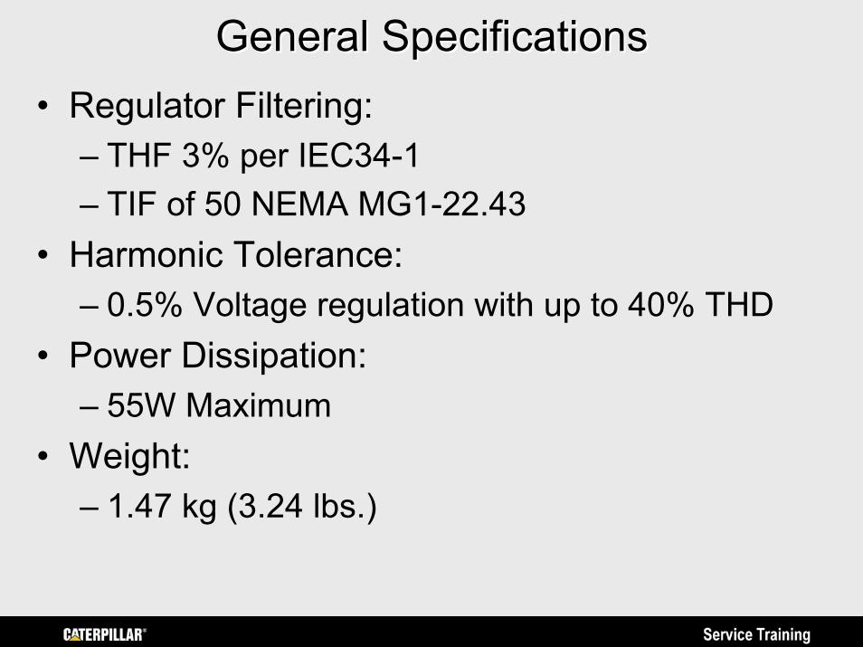
General SpecificationsGeneral Specifications• Regulator Filtering:
– THF 3% per IEC34-1– TIF of 50 NEMA MG1-22.43
• Harmonic Tolerance:– 0.5% Voltage regulation with up to 40% THD
• Power Dissipation:– 55W Maximum
• Weight:– 1.47 kg (3.24 lbs.)
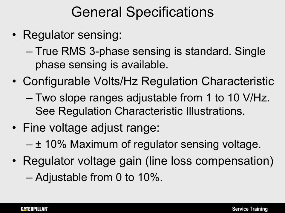
General SpecificationsGeneral Specifications• Regulator sensing:
– True RMS 3-phase sensing is standard. Single phase sensing is available.
• Configurable Volts/Hz Regulation Characteristic– Two slope ranges adjustable from 1 to 10 V/Hz.
See Regulation Characteristic Illustrations.• Fine voltage adjust range:
– ± 10% Maximum of regulator sensing voltage.• Regulator voltage gain (line loss compensation)
– Adjustable from 0 to 10%.
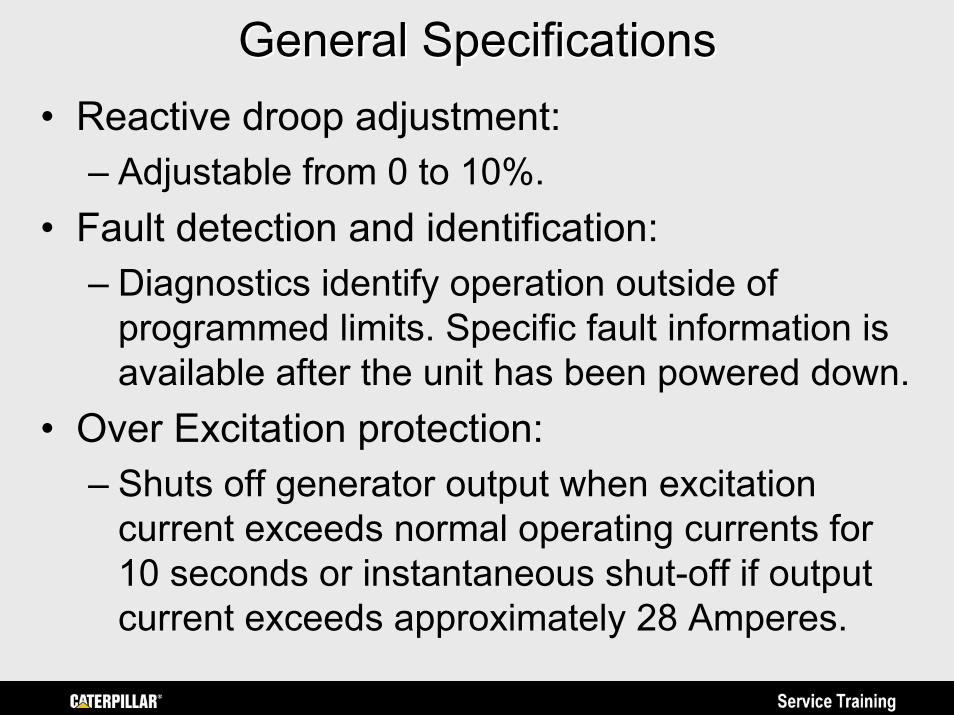
General SpecificationsGeneral Specifications• Reactive droop adjustment:
– Adjustable from 0 to 10%.• Fault detection and identification:
– Diagnostics identify operation outside of programmed limits. Specific fault information is available after the unit has been powered down.
• Over Excitation protection:– Shuts off generator output when excitation
current exceeds normal operating currents for 10 seconds or instantaneous shut-off if output current exceeds approximately 28 Amperes.
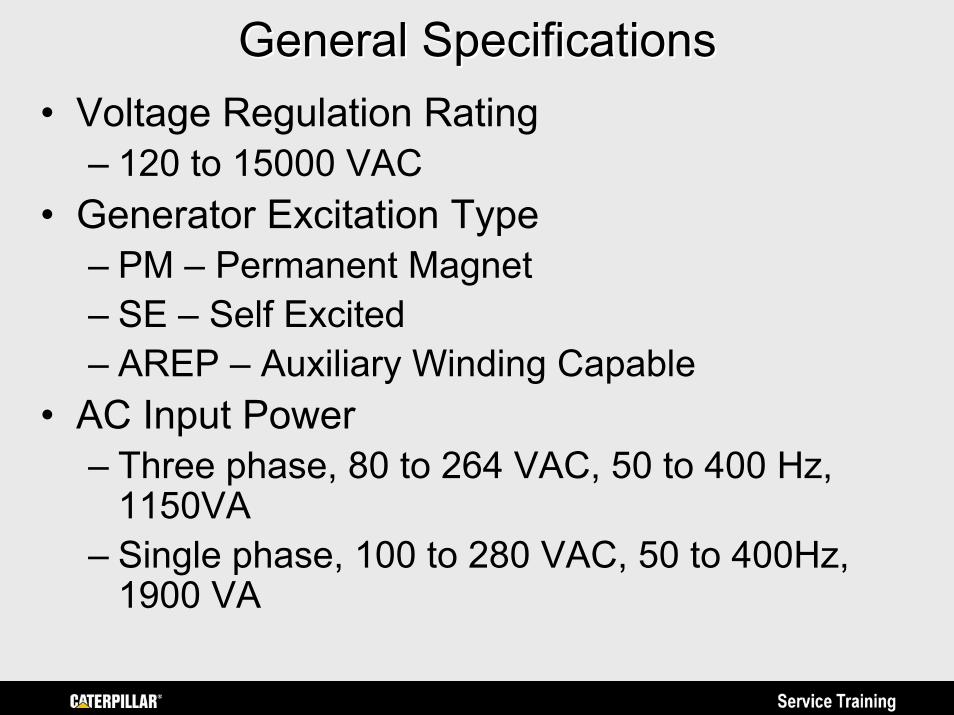
General SpecificationsGeneral Specifications• Voltage Regulation Rating
– 120 to 15000 VAC• Generator Excitation Type
– PM – Permanent Magnet– SE – Self Excited– AREP – Auxiliary Winding Capable
• AC Input Power– Three phase, 80 to 264 VAC, 50 to 400 Hz,
1150VA– Single phase, 100 to 280 VAC, 50 to 400Hz,
1900 VA
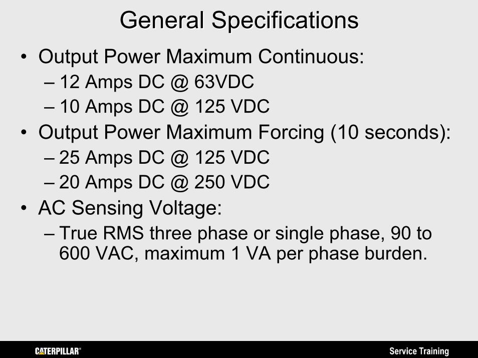
General SpecificationsGeneral Specifications• Output Power Maximum Continuous:
– 12 Amps DC @ 63VDC – 10 Amps DC @ 125 VDC
• Output Power Maximum Forcing (10 seconds):– 25 Amps DC @ 125 VDC– 20 Amps DC @ 250 VDC
• AC Sensing Voltage:– True RMS three phase or single phase, 90 to
600 VAC, maximum 1 VA per phase burden.
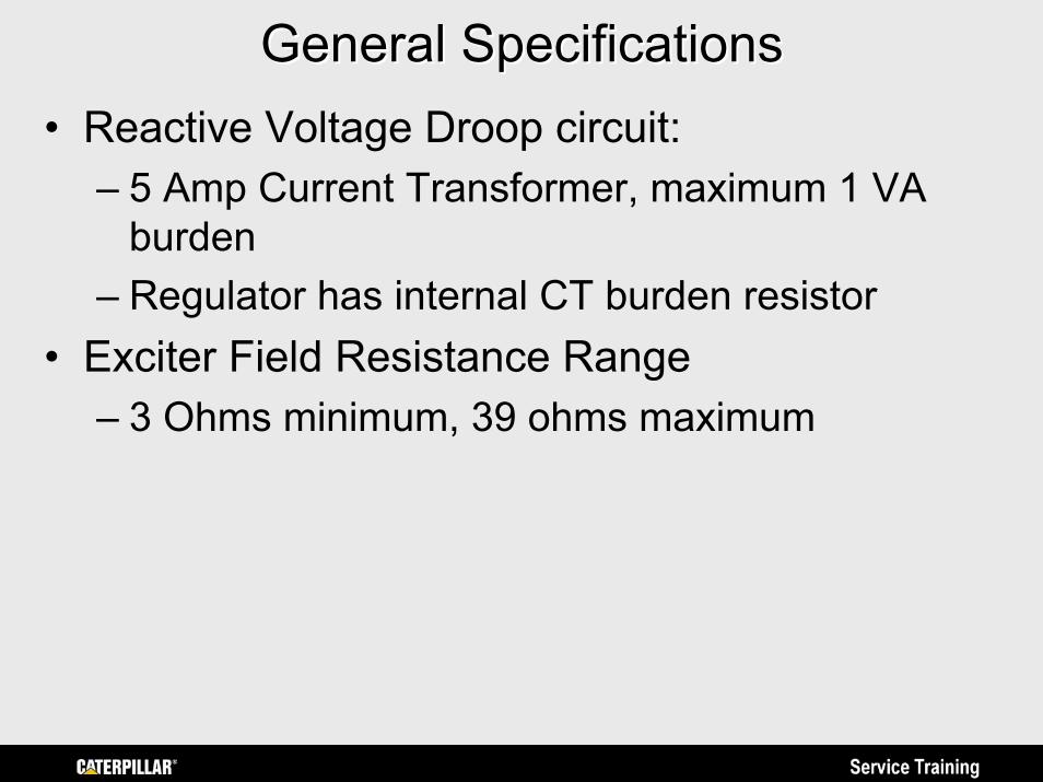
General SpecificationsGeneral Specifications• Reactive Voltage Droop circuit:
– 5 Amp Current Transformer, maximum 1 VA burden
– Regulator has internal CT burden resistor• Exciter Field Resistance Range
– 3 Ohms minimum, 39 ohms maximum
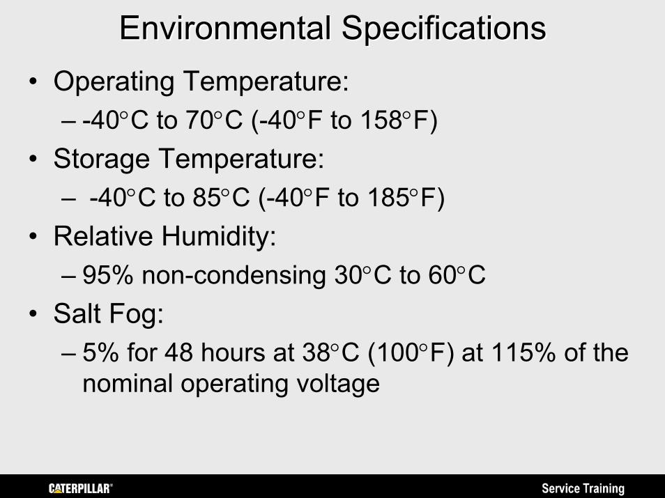
Environmental SpecificationsEnvironmental Specifications• Operating Temperature:
– -40°C to 70°C (-40°F to 158°F)• Storage Temperature:
– -40°C to 85°C (-40°F to 185°F)• Relative Humidity:
– 95% non-condensing 30°C to 60°C• Salt Fog:
– 5% for 48 hours at 38°C (100°F) at 115% of the nominal operating voltage
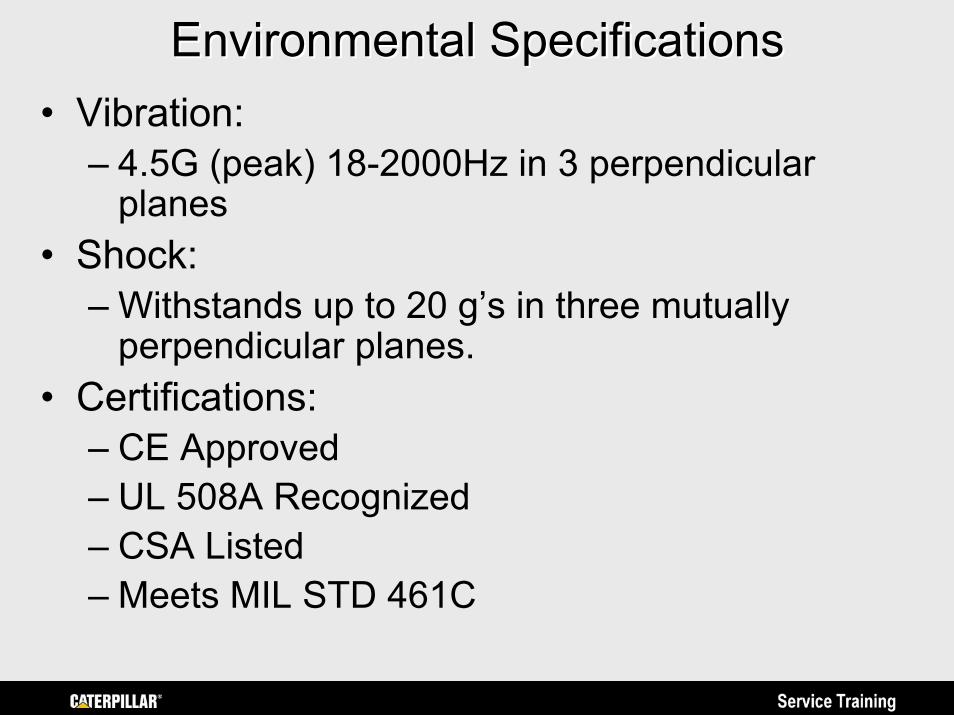
Environmental SpecificationsEnvironmental Specifications• Vibration:
– 4.5G (peak) 18-2000Hz in 3 perpendicular planes
• Shock:– Withstands up to 20 g’s in three mutually
perpendicular planes.• Certifications:
– CE Approved– UL 508A Recognized– CSA Listed– Meets MIL STD 461C
Caterpillar Digital Voltage RegulatorCaterpillar Digital Voltage Regulator(CDVR) (CDVR)
Wiring ConnectionsWiring Connections
Prepared by Service Traininghttps://psmktg.cat.com/srvtrng/
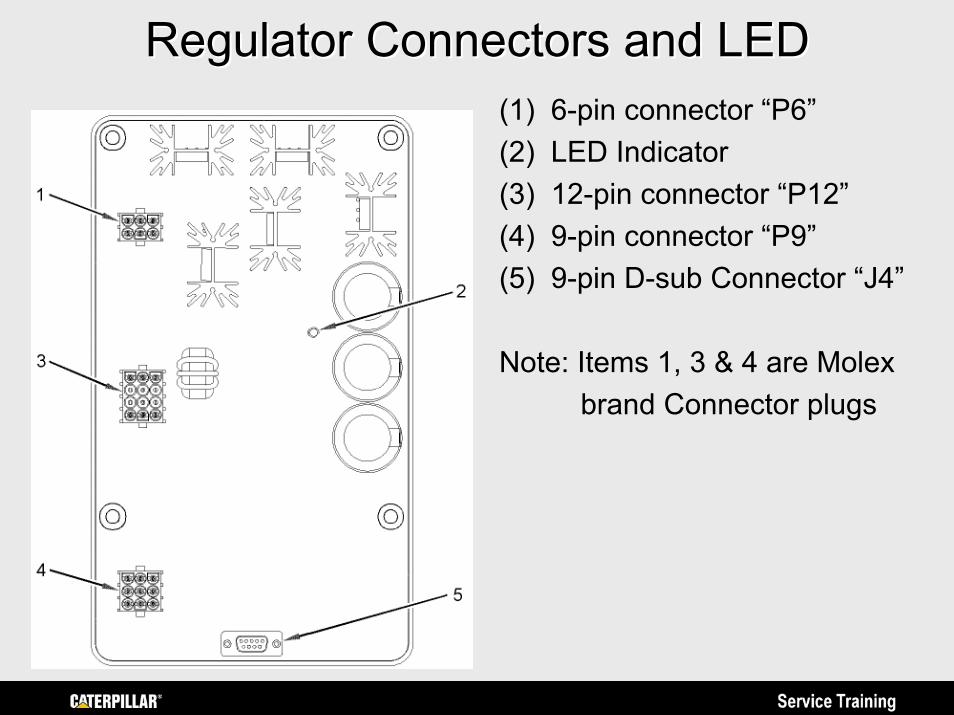
Regulator Connectors and LEDRegulator Connectors and LED(1) 6-pin connector “P6”(2) LED Indicator(3) 12-pin connector “P12”(4) 9-pin connector “P9”(5) 9-pin D-sub Connector “J4”
Note: Items 1, 3 & 4 are Molexbrand Connector plugs
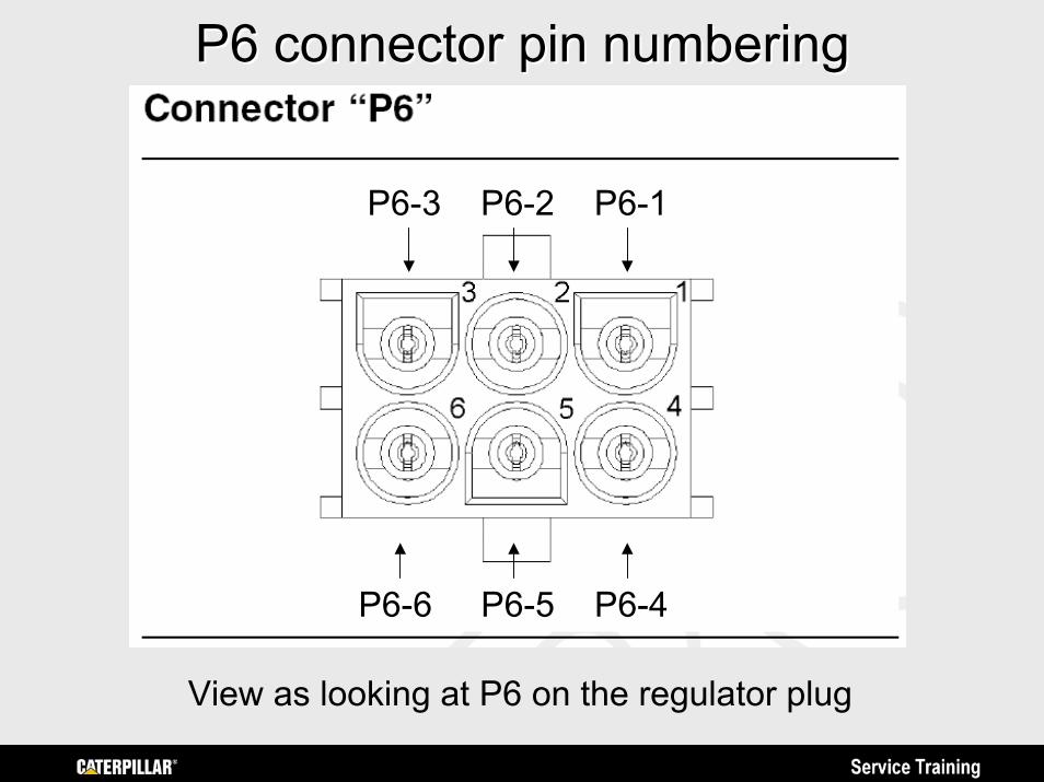
P6 connector pin numberingP6 connector pin numbering
P6-6 P6-5 P6-4
P6-1P6-2P6-3
View as looking at P6 on the regulator plug
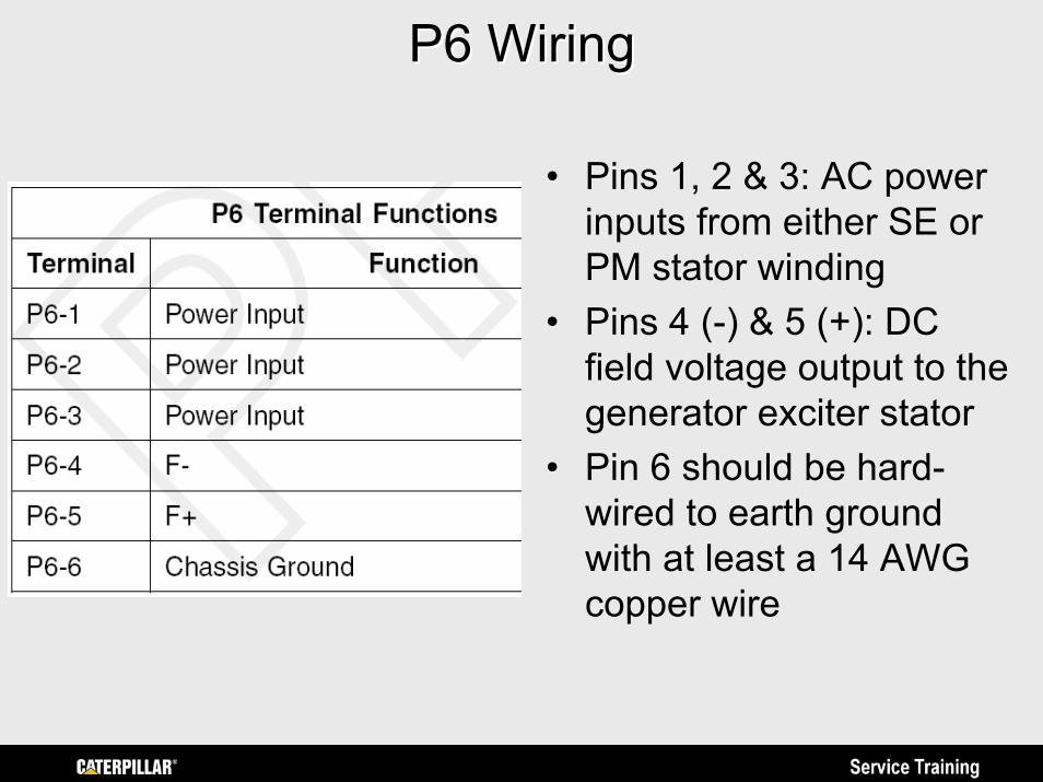
P6 WiringP6 Wiring
• Pins 1, 2 & 3: AC power inputs from either SE or PM stator winding
• Pins 4 (-) & 5 (+): DC field voltage output to the generator exciter stator
• Pin 6 should be hard-wired to earth ground with at least a 14 AWG copper wire
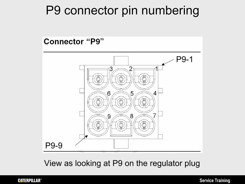
P9 connector pin numberingP9 connector pin numbering
P9-1
P9-9
View as looking at P9 on the regulator plug
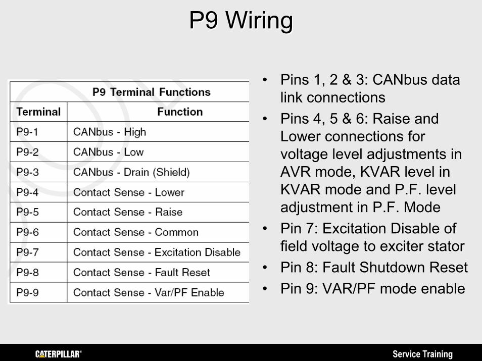
P9 WiringP9 Wiring
• Pins 1, 2 & 3: CANbus data link connections
• Pins 4, 5 & 6: Raise and Lower connections for voltage level adjustments in AVR mode, KVAR level in KVAR mode and P.F. level adjustment in P.F. Mode
• Pin 7: Excitation Disable of field voltage to exciter stator
• Pin 8: Fault Shutdown Reset• Pin 9: VAR/PF mode enable
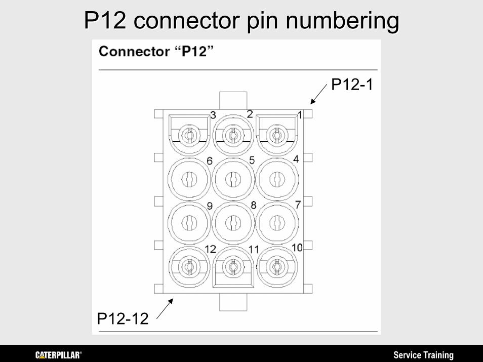
P12 connector pin numberingP12 connector pin numbering
P12-1
P12-12
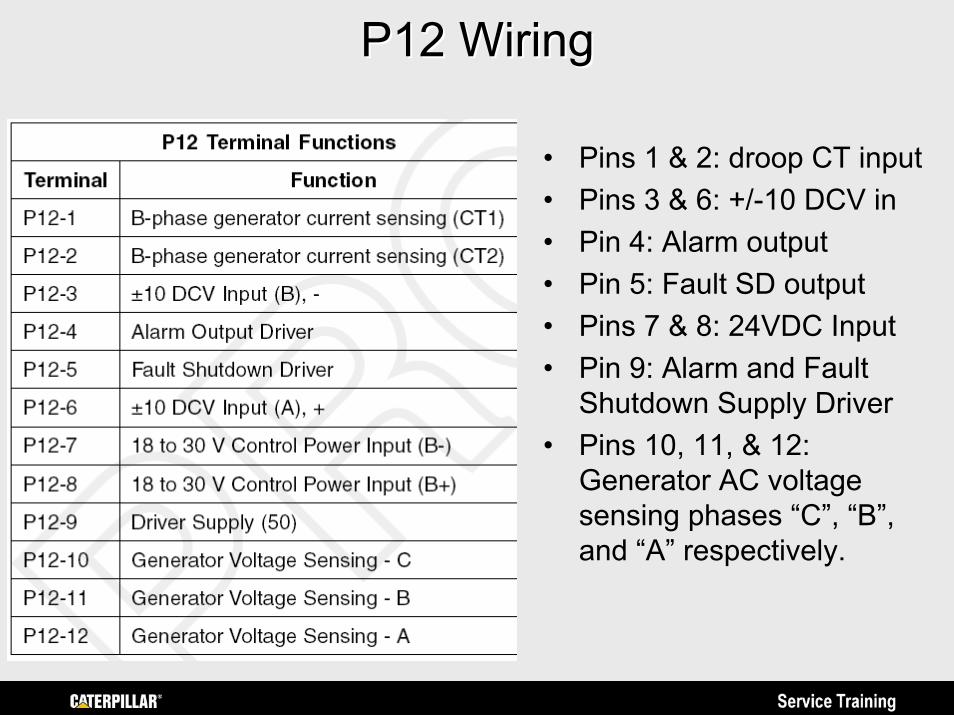
P12 WiringP12 Wiring
• Pins 1 & 2: droop CT input• Pins 3 & 6: +/-10 DCV in• Pin 4: Alarm output• Pin 5: Fault SD output• Pins 7 & 8: 24VDC Input• Pin 9: Alarm and Fault
Shutdown Supply Driver• Pins 10, 11, & 12:
Generator AC voltage sensing phases “C”, “B”, and “A” respectively.
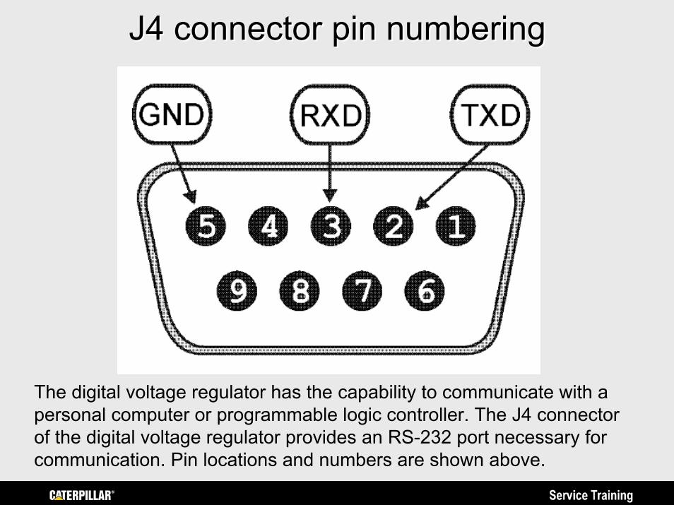
J4 connector pin numberingJ4 connector pin numbering
The digital voltage regulator has the capability to communicate with a personal computer or programmable logic controller. The J4 connector of the digital voltage regulator provides an RS-232 port necessary for communication. Pin locations and numbers are shown above.
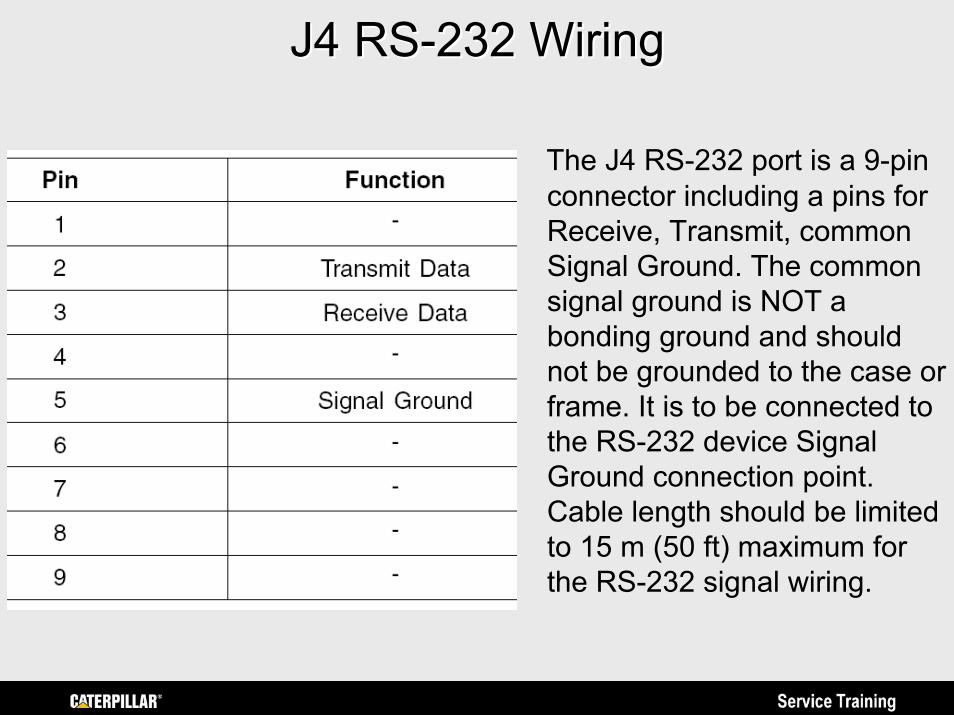
J4 RSJ4 RS--232 Wiring232 Wiring
The J4 RS-232 port is a 9-pin connector including a pins for Receive, Transmit, common Signal Ground. The common signal ground is NOT a bonding ground and should not be grounded to the case or frame. It is to be connected to the RS-232 device Signal Ground connection point. Cable length should be limited to 15 m (50 ft) maximum for the RS-232 signal wiring.
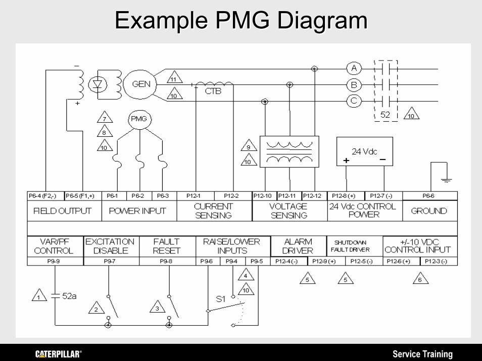
Example PMG DiagramExample PMG Diagram
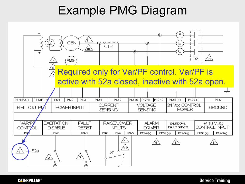
Example PMG DiagramExample PMG Diagram
Required only for Var/PF control. Var/PF is active with 52a closed, inactive with 52a open.
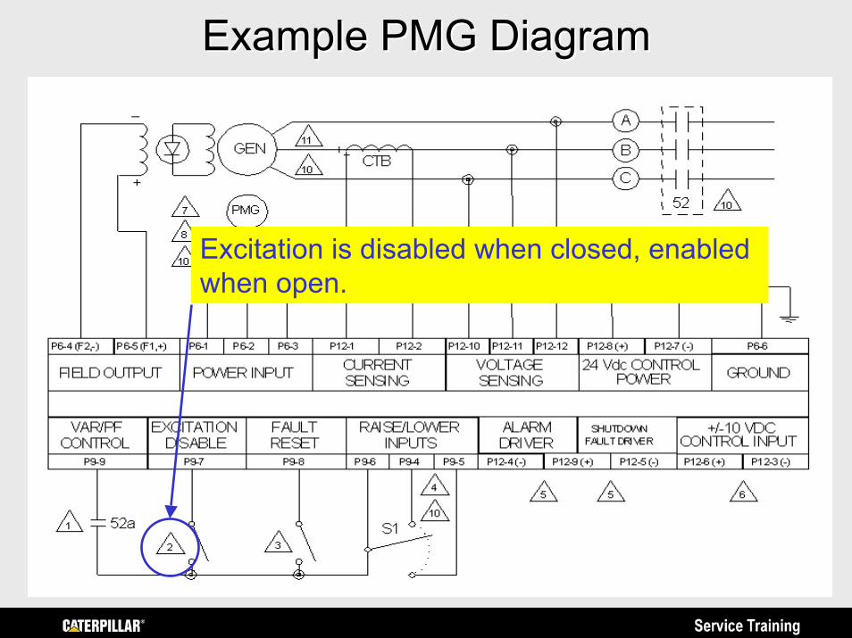
Example PMG DiagramExample PMG Diagram
Excitation is disabled when closed, enabled when open.
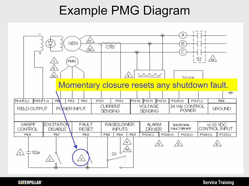
Example PMG DiagramExample PMG Diagram
Momentary closure resets any shutdown fault.
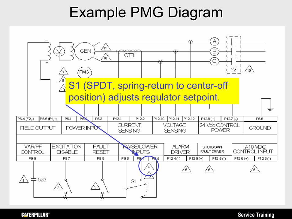
Example PMG DiagramExample PMG Diagram
S1 (SPDT, spring-return to center-off position) adjusts regulator setpoint.
Example PMG DiagramExample PMG Diagram
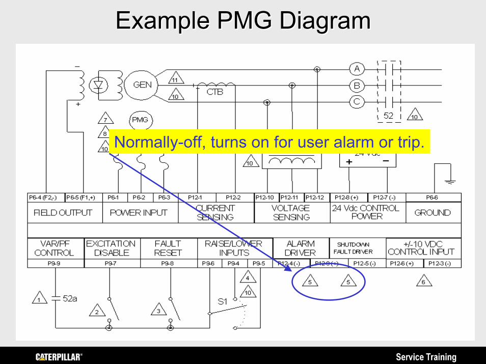
Normally-off, turns on for user alarm or trip.
Example PMG DiagramExample PMG Diagram
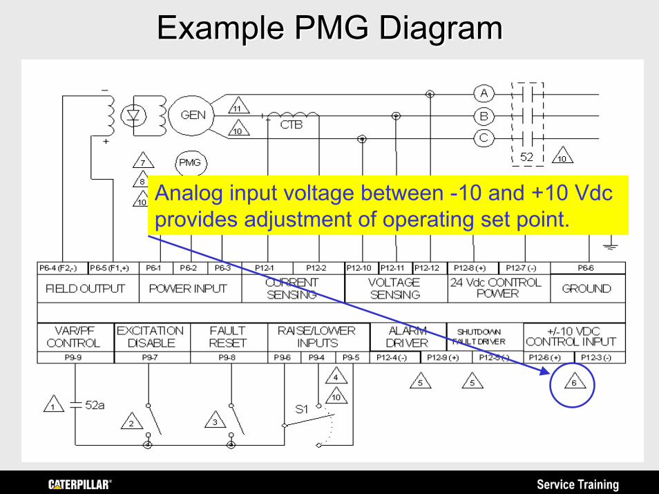
Analog input voltage between -10 and +10 Vdcprovides adjustment of operating set point.
Example PMG DiagramExample PMG Diagram
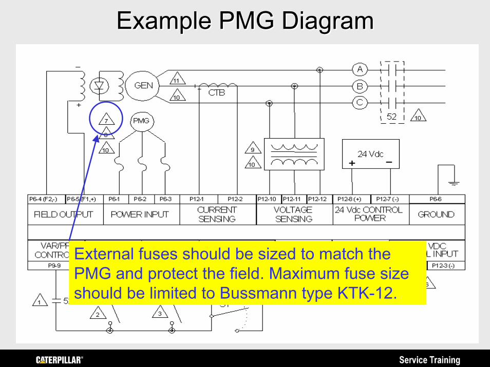
External fuses should be sized to match the PMG and protect the field. Maximum fuse size should be limited to Bussmann type KTK-12.
Example PMG DiagramExample PMG Diagram
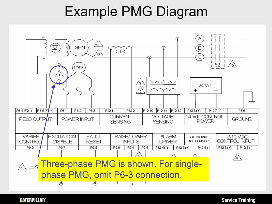
Three-phase PMG is shown. For single-phase PMG, omit P6-3 connection.
Example PMG DiagramExample PMG Diagram
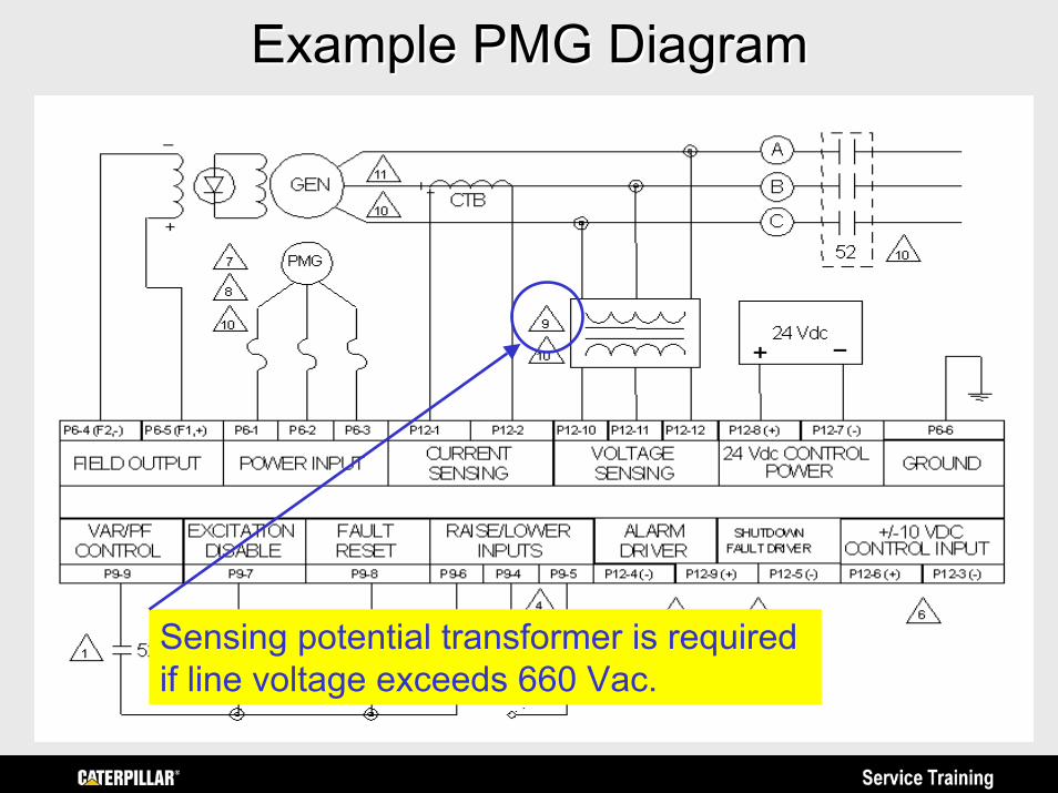
Sensing potential transformer is required if line voltage exceeds 660 Vac.
Example PMG DiagramExample PMG Diagram
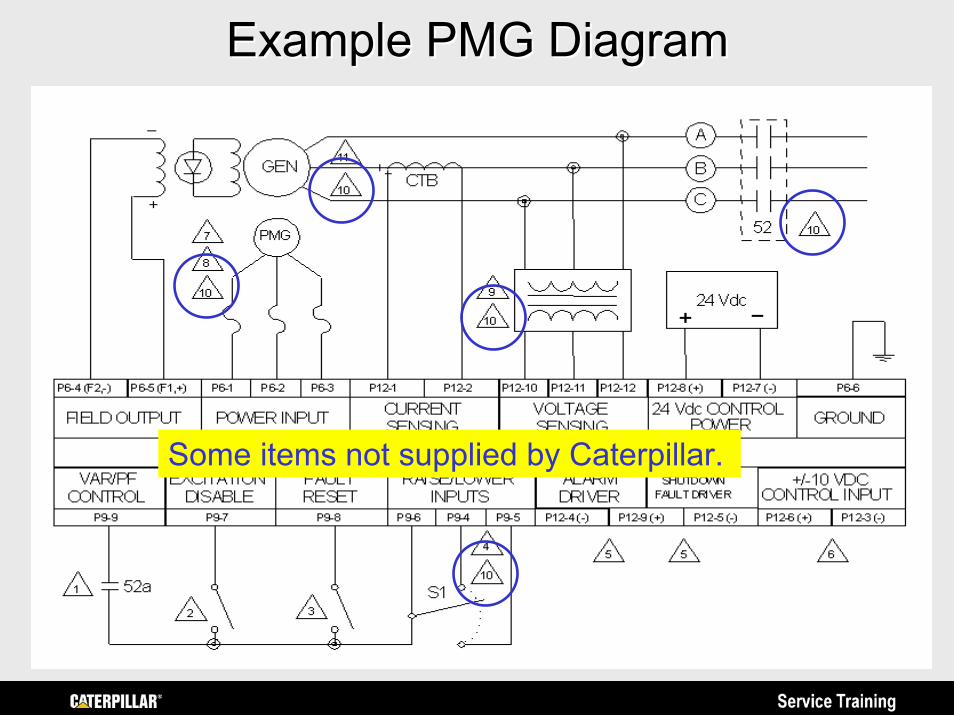
Some items not supplied by Caterpillar.
Example PMG DiagramExample PMG Diagram
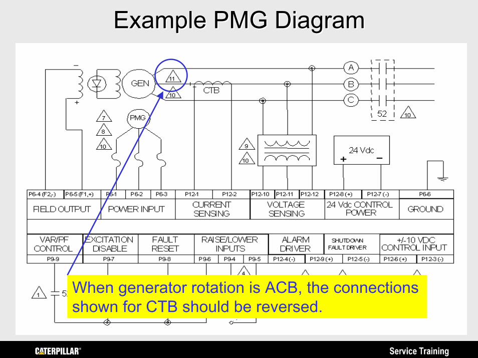
When generator rotation is ACB, the connections shown for CTB should be reversed.
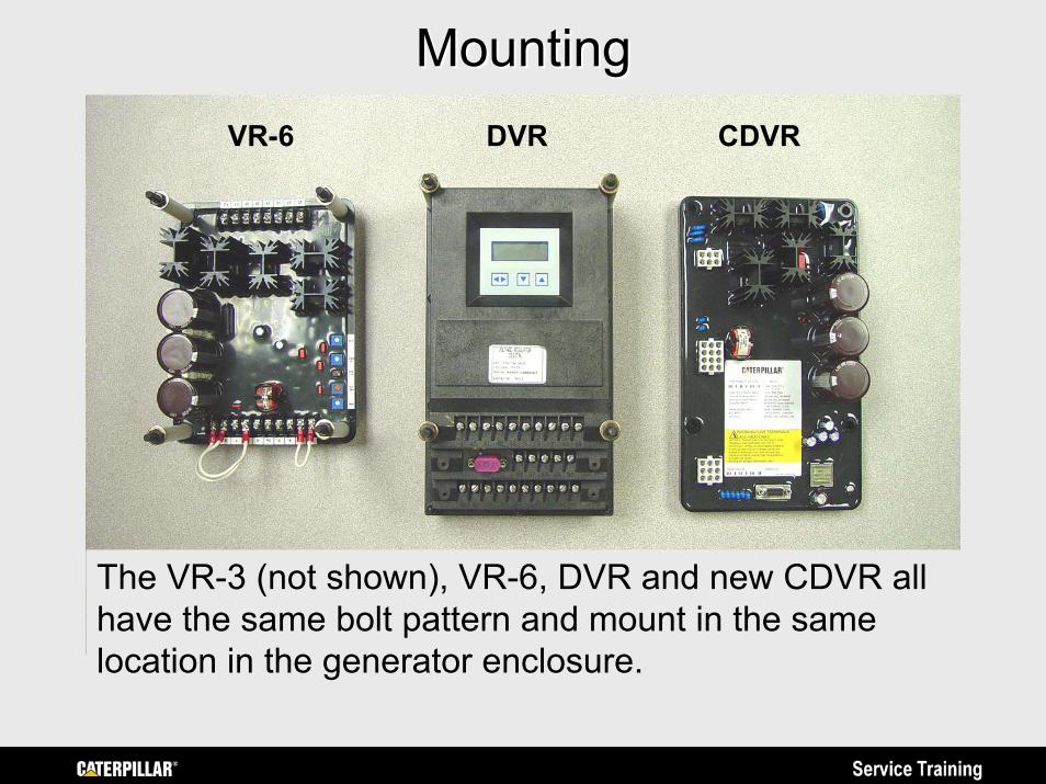
The VR-3 (not shown), VR-6, DVR and new CDVR all have the same bolt pattern and mount in the same location in the generator enclosure.
MountingMountingVR-6 DVR CDVR
VR-6 CDVR
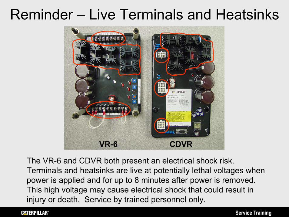
Reminder Reminder –– Live Terminals and Live Terminals and HeatsinksHeatsinks
The VR-6 and CDVR both present an electrical shock risk. Terminals and heatsinks are live at potentially lethal voltages when power is applied and for up to 8 minutes after power is removed.This high voltage may cause electrical shock that could result in injury or death. Service by trained personnel only.
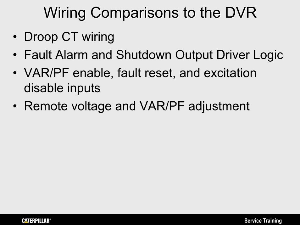
Wiring Comparisons to the DVRWiring Comparisons to the DVR• Droop CT wiring• Fault Alarm and Shutdown Output Driver Logic• VAR/PF enable, fault reset, and excitation
disable inputs• Remote voltage and VAR/PF adjustment
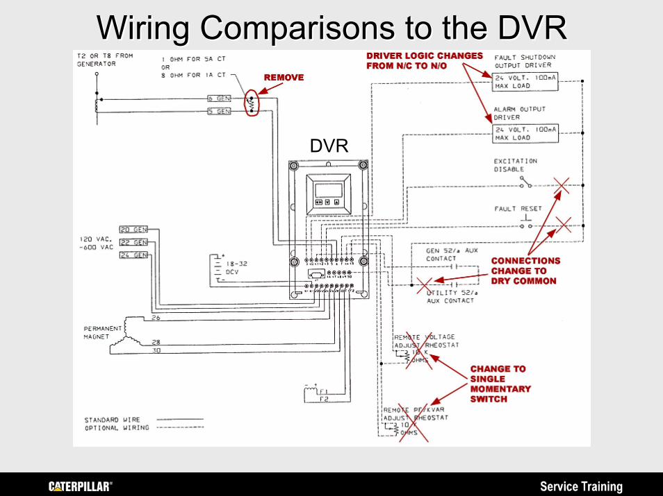
Wiring Comparisons to the DVRWiring Comparisons to the DVR
DVR
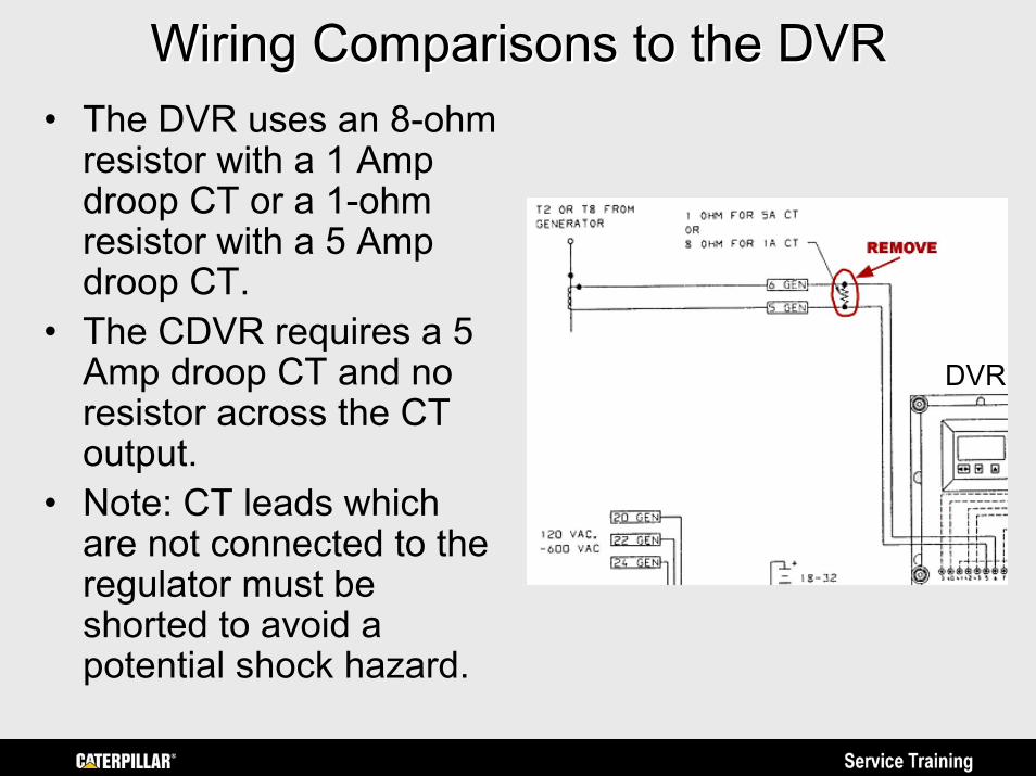
Wiring Comparisons to the DVRWiring Comparisons to the DVR• The DVR uses an 8-ohm
resistor with a 1 Amp droop CT or a 1-ohm resistor with a 5 Amp droop CT.
• The CDVR requires a 5 Amp droop CT and no resistor across the CT output.
• Note: CT leads which are not connected to the regulator must be shorted to avoid a potential shock hazard.
DVR
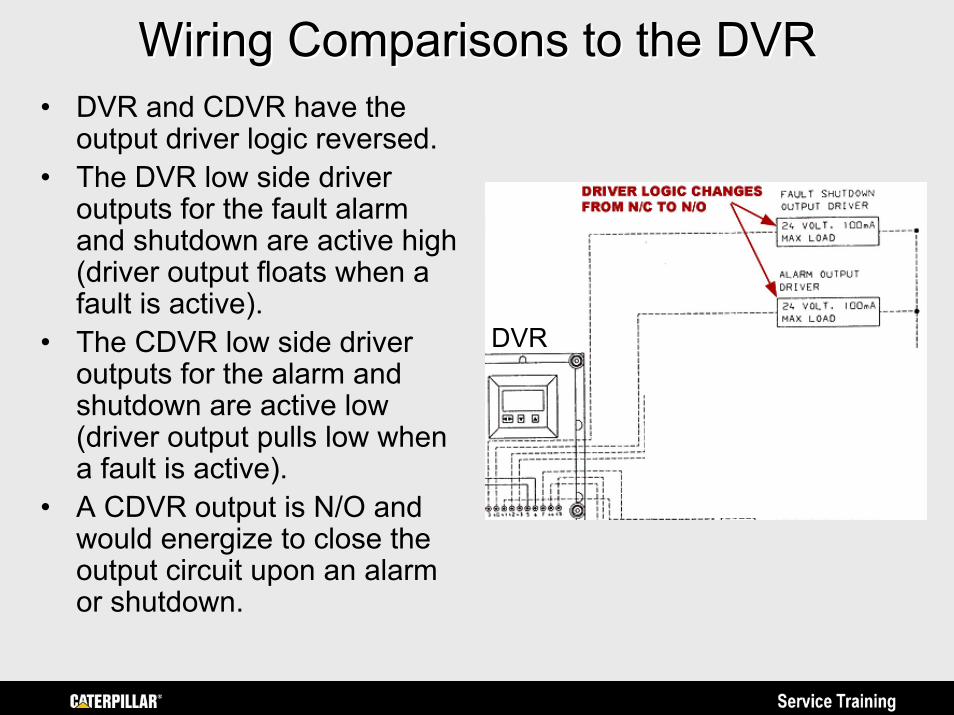
Wiring Comparisons to the DVRWiring Comparisons to the DVR• DVR and CDVR have the
output driver logic reversed.• The DVR low side driver
outputs for the fault alarm and shutdown are active high (driver output floats when a fault is active).
• The CDVR low side driver outputs for the alarm and shutdown are active low (driver output pulls low when a fault is active).
• A CDVR output is N/O and would energize to close the output circuit upon an alarm or shutdown.
DVR
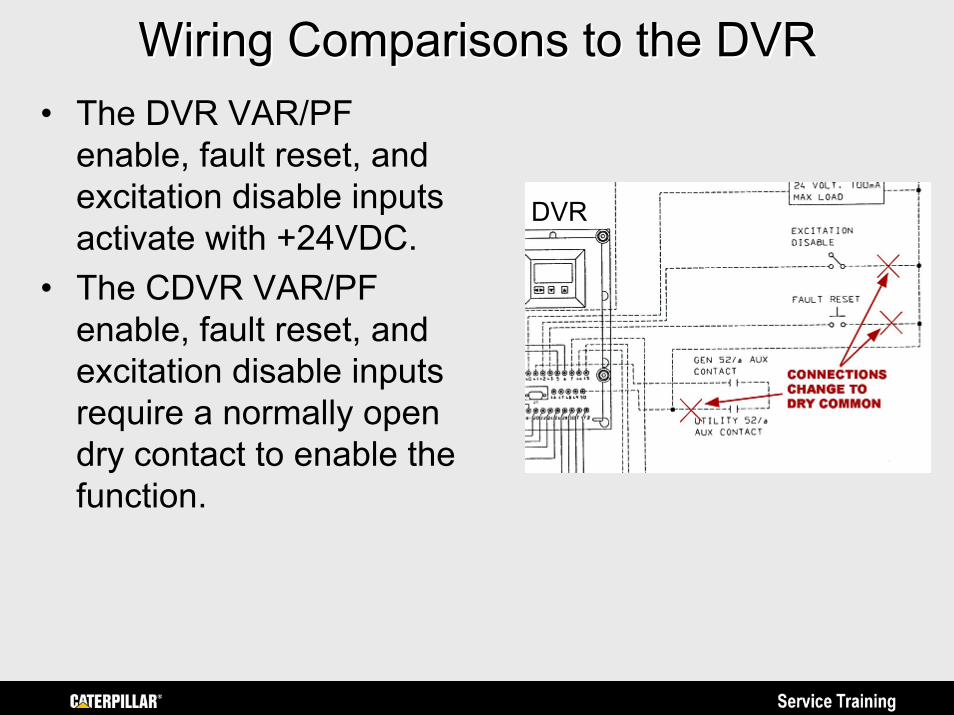
Wiring Comparisons to the DVRWiring Comparisons to the DVR• The DVR VAR/PF
enable, fault reset, and excitation disable inputs activate with +24VDC.
• The CDVR VAR/PF enable, fault reset, and excitation disable inputs require a normally open dry contact to enable the function.
DVR
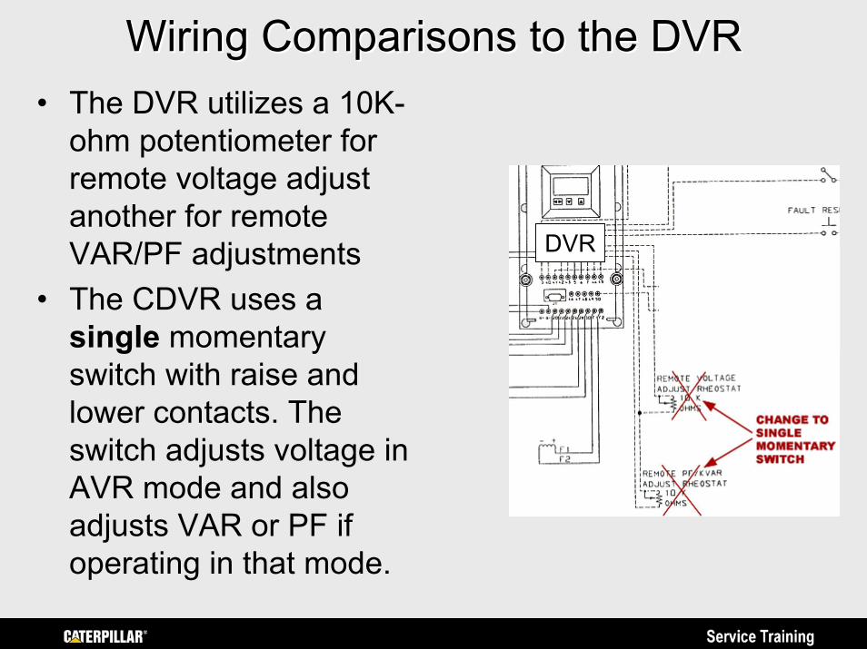
Wiring Comparisons to the DVRWiring Comparisons to the DVR• The DVR utilizes a 10K-
ohm potentiometer for remote voltage adjust another for remote VAR/PF adjustments
• The CDVR uses a single momentary switch with raise and lower contacts. The switch adjusts voltage in AVR mode and also adjusts VAR or PF if operating in that mode.
DVR
Caterpillar Digital Voltage RegulatorCaterpillar Digital Voltage Regulator(CDVR) (CDVR)
PC Software InstallationPC Software InstallationPrepared by Service Training
https://psmktg.cat.com/srvtrng/
CDVR PC Software DownloadCDVR PC Software Download• The CDVR PC software and an IBM
Compatible Personal Computer or Laptop is required for the service technician to program CDVR set points and parameters and to access status indicators and regulator metering functions.
• This Presentation has detailed steps for downloading the PC Software from SIS (Service Information System), establishing communications and programming the CDVR.
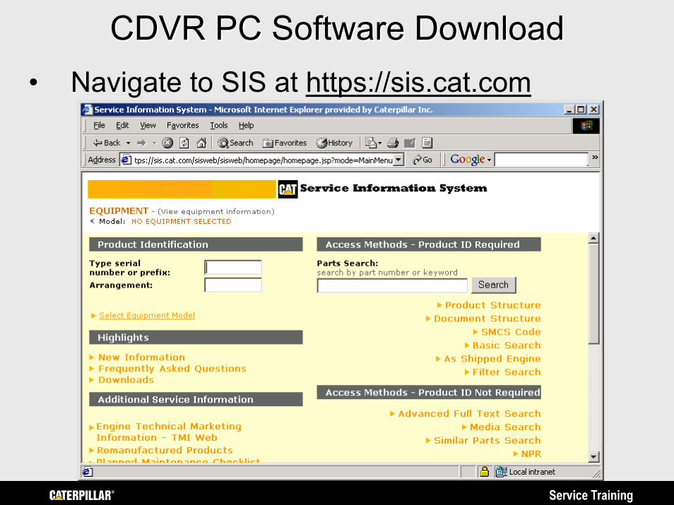
CDVR PC Software DownloadCDVR PC Software Download• Navigate to SIS at https://sis.cat.com
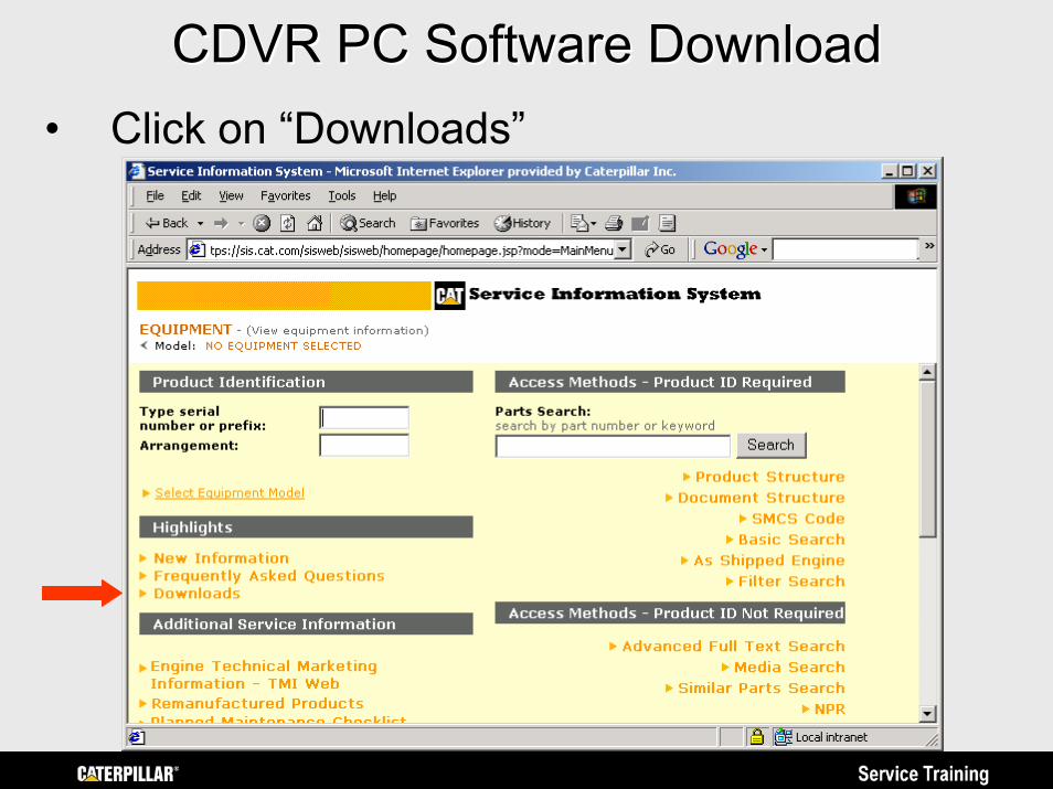
CDVR PC Software DownloadCDVR PC Software Download• Click on “Downloads”
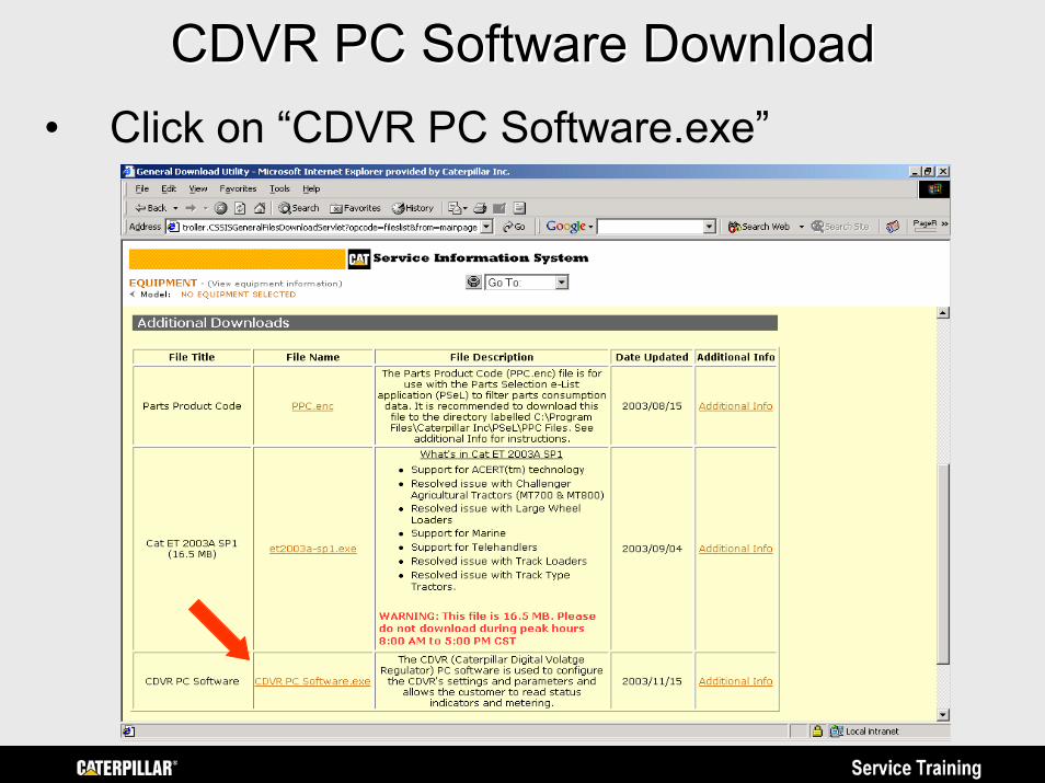
CDVR PC Software DownloadCDVR PC Software Download• Click on “CDVR PC Software.exe”
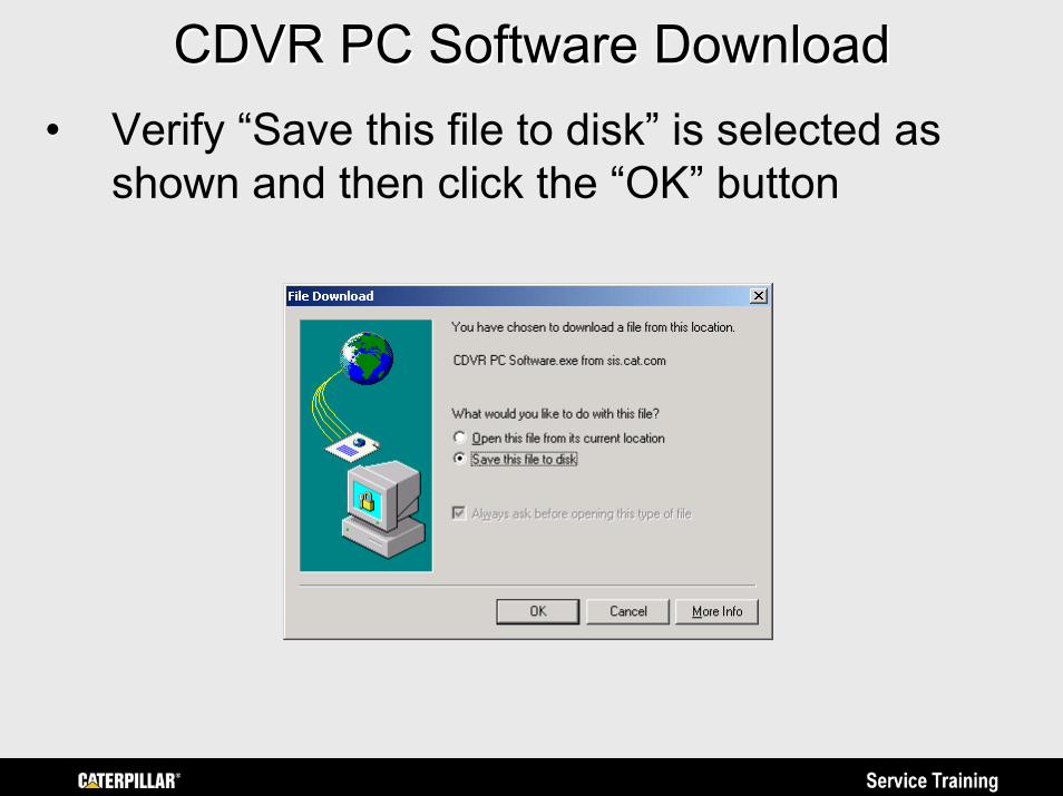
CDVR PC Software DownloadCDVR PC Software Download• Verify “Save this file to disk” is selected as
shown and then click the “OK” button
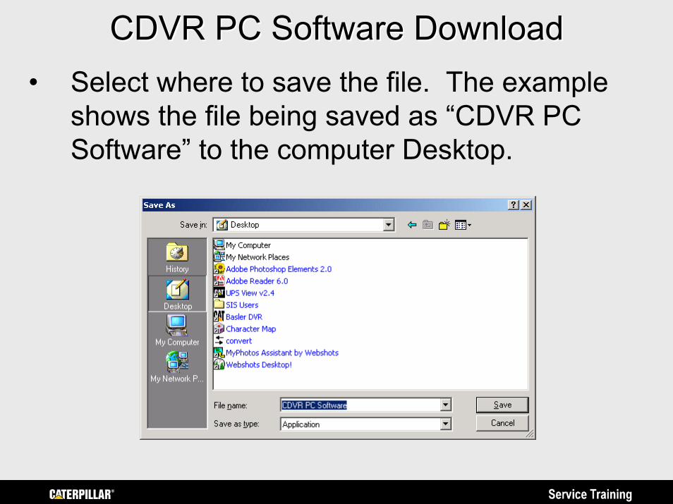
CDVR PC Software DownloadCDVR PC Software Download• Select where to save the file. The example
shows the file being saved as “CDVR PC Software” to the computer Desktop.
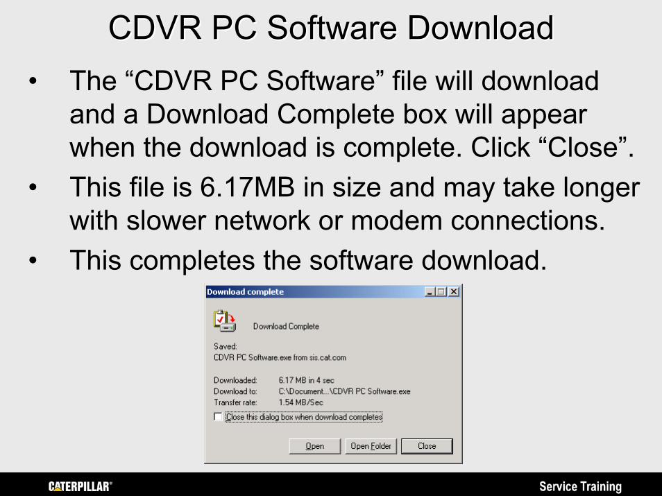
CDVR PC Software DownloadCDVR PC Software Download• The “CDVR PC Software” file will download
and a Download Complete box will appear when the download is complete. Click “Close”.
• This file is 6.17MB in size and may take longer with slower network or modem connections.
• This completes the software download.
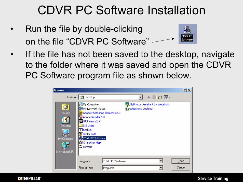
CDVR PC Software InstallationCDVR PC Software Installation• Run the file by double-clicking
on the file “CDVR PC Software”• If the file has not been saved to the desktop, navigate
to the folder where it was saved and open the CDVR PC Software program file as shown below.
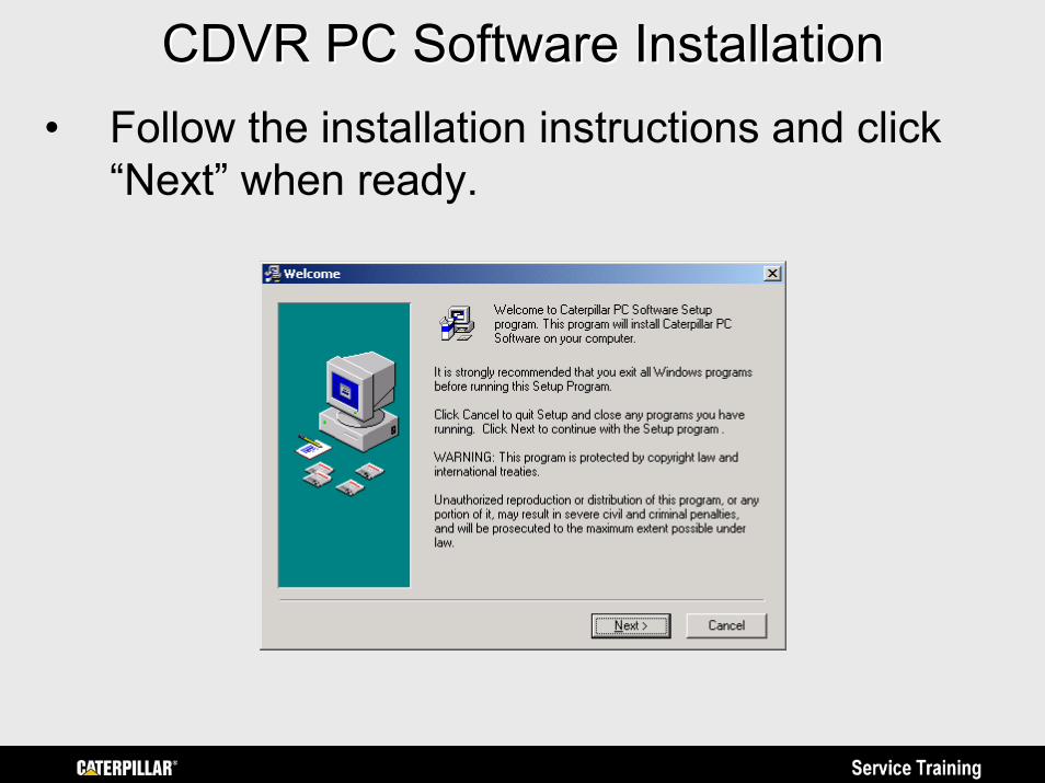
CDVR PC Software InstallationCDVR PC Software Installation• Follow the installation instructions and click
“Next” when ready.
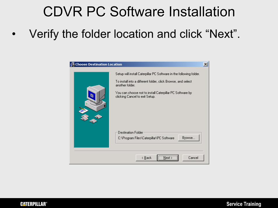
CDVR PC Software InstallationCDVR PC Software Installation• Verify the folder location and click “Next”.
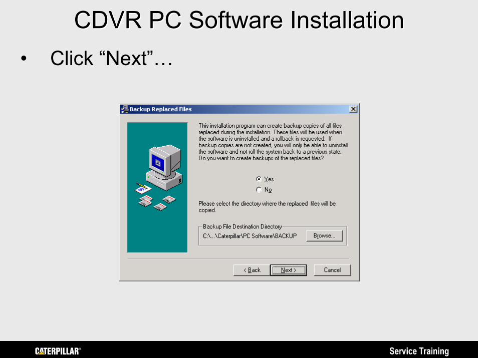
CDVR PC Software InstallationCDVR PC Software Installation• Click “Next”…
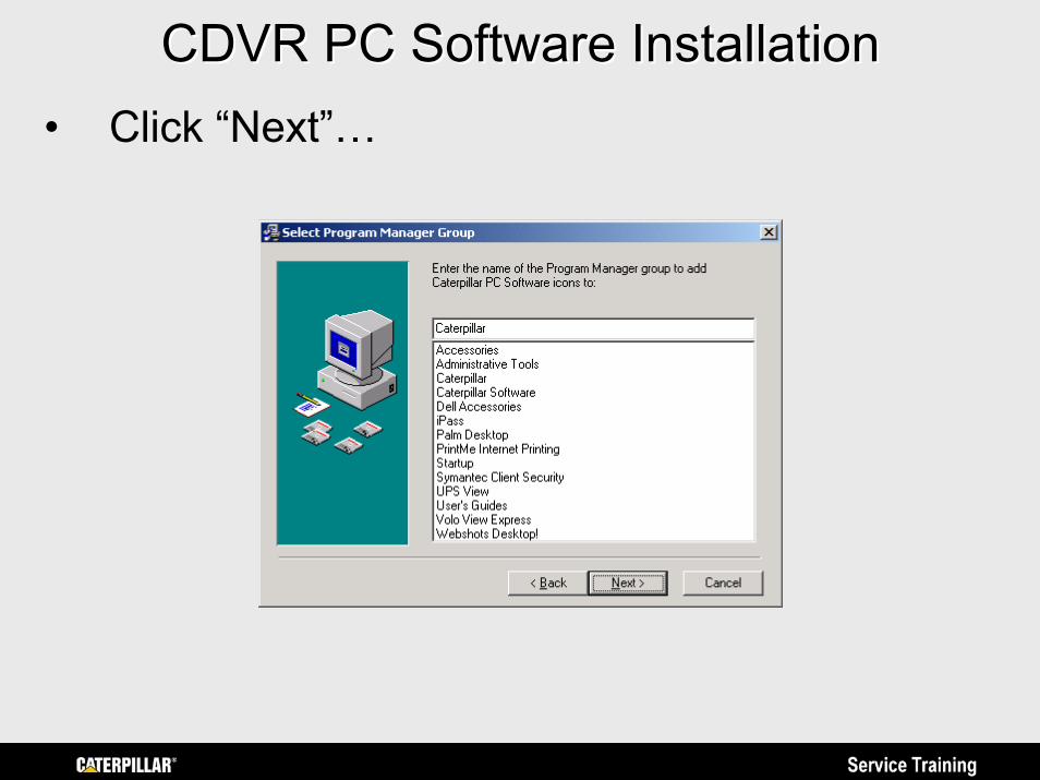
CDVR PC Software InstallationCDVR PC Software Installation• Click “Next”…
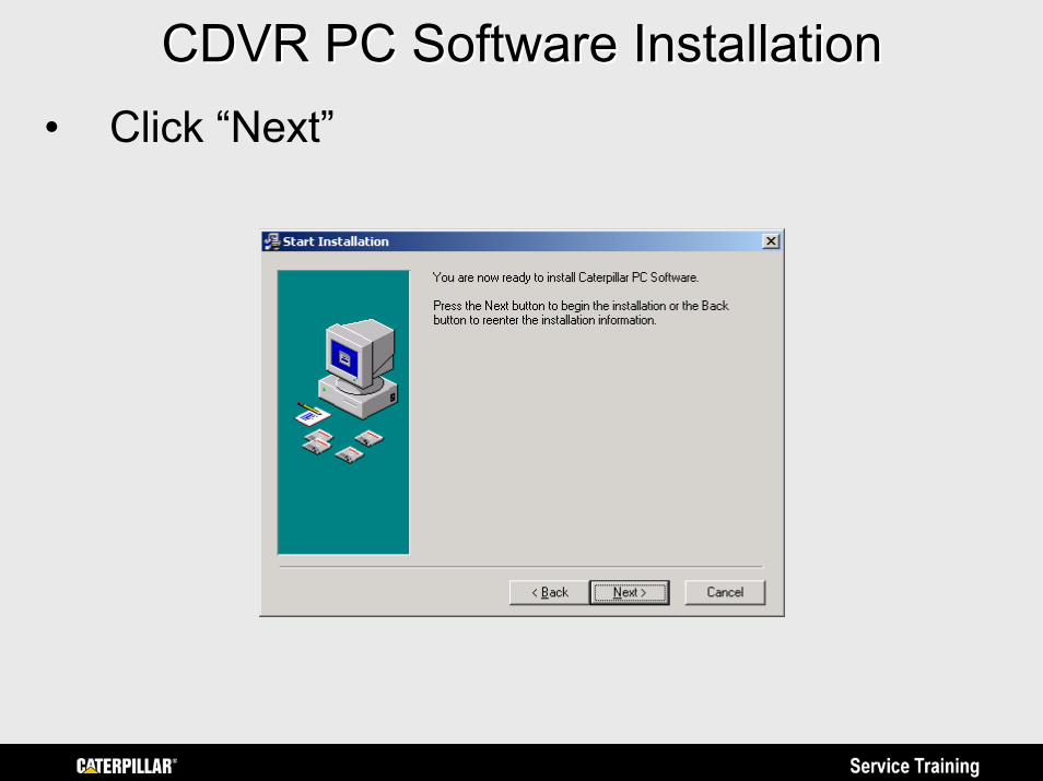
CDVR PC Software InstallationCDVR PC Software Installation• Click “Next”
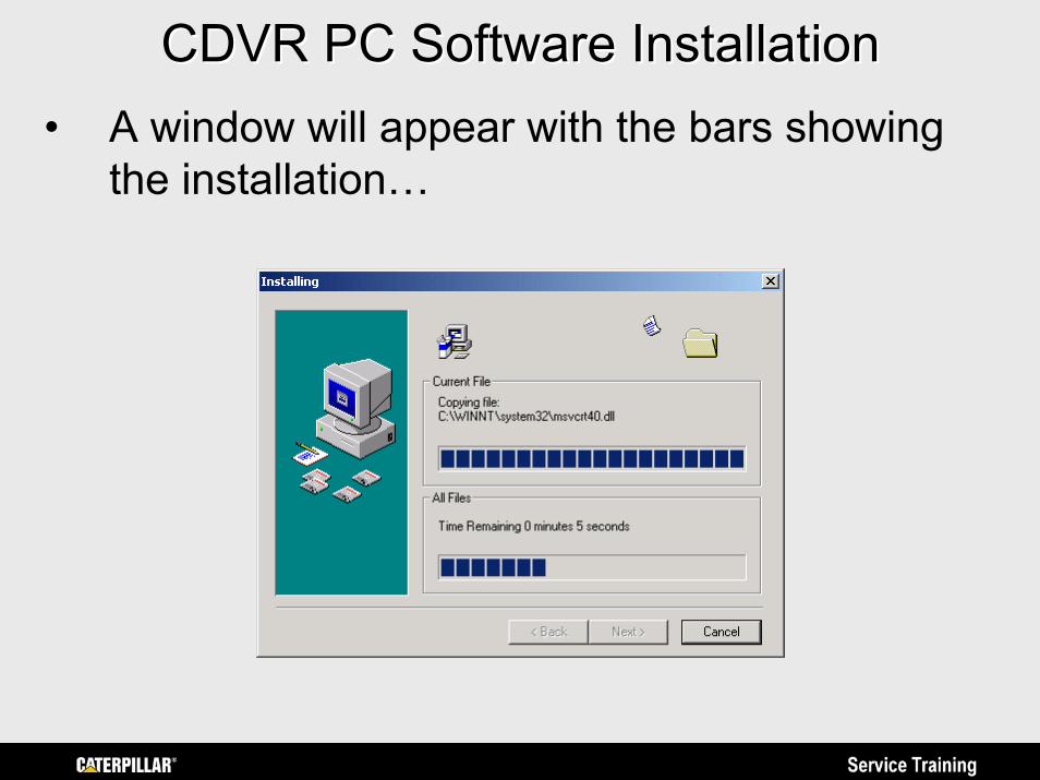
CDVR PC Software InstallationCDVR PC Software Installation• A window will appear with the bars showing
the installation…
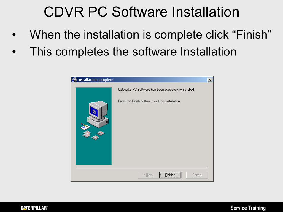
CDVR PC Software InstallationCDVR PC Software Installation• When the installation is complete click “Finish”• This completes the software Installation
CDVR PC SoftwareCDVR PC Software
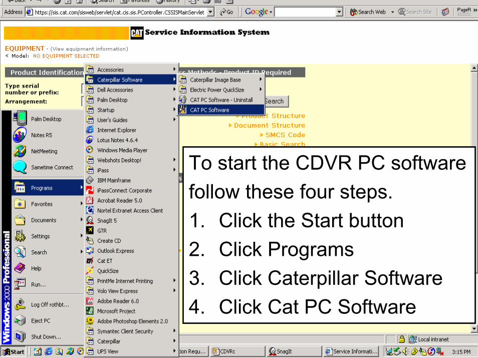
To start the CDVR PC softwarefollow these four steps. 1. Click the Start button2. Click Programs3. Click Caterpillar Software4. Click Cat PC Software
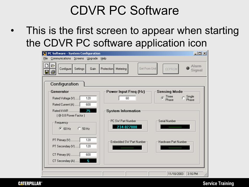
CDVR PC SoftwareCDVR PC Software• This is the first screen to appear when starting
the CDVR PC software application icon
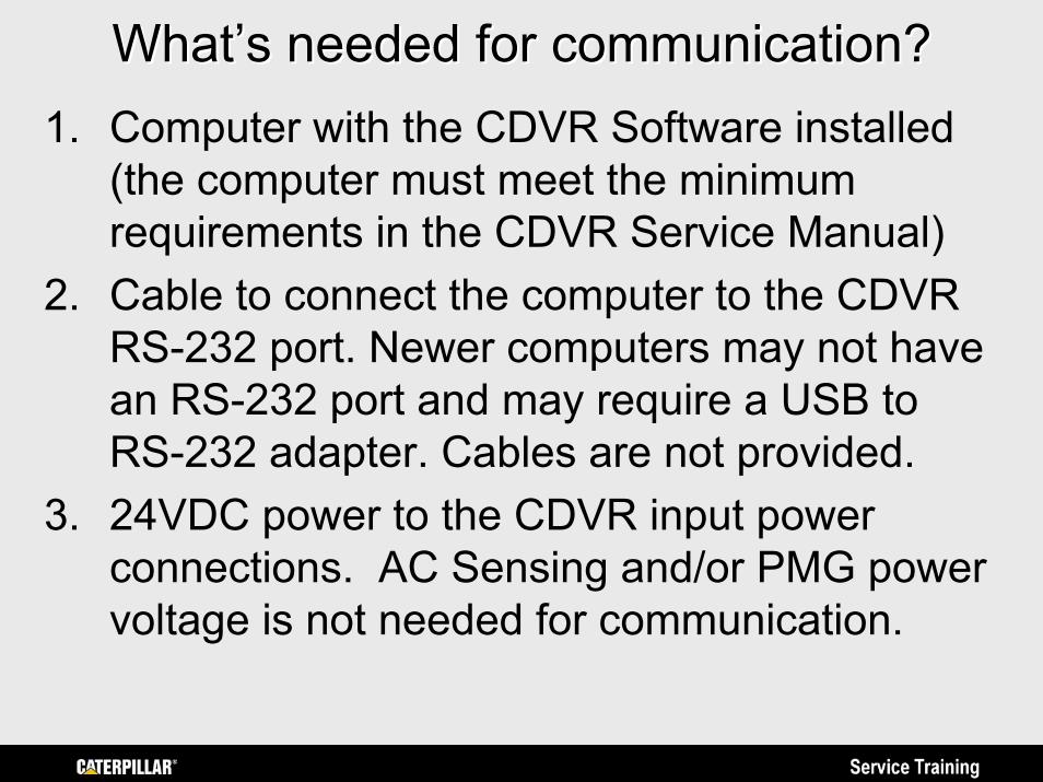
What’s needed for communication?What’s needed for communication?1. Computer with the CDVR Software installed
(the computer must meet the minimum requirements in the CDVR Service Manual)
2. Cable to connect the computer to the CDVR RS-232 port. Newer computers may not have an RS-232 port and may require a USB to RS-232 adapter. Cables are not provided.
3. 24VDC power to the CDVR input power connections. AC Sensing and/or PMG power voltage is not needed for communication.
Caterpillar Digital Voltage RegulatorCaterpillar Digital Voltage Regulator(CDVR) (CDVR)
PC Software OverviewPC Software OverviewPrepared by Service Training
https://psmktg.cat.com/srvtrng/
CDVR Programming OverviewCDVR Programming Overview• The next few slides provide only a brief
explanation of the CDVR PC Software screens and parameters. The CDVR Service Manual, RENR7941, should be referenced for more detail on the parameters and functions not covered in this overview.
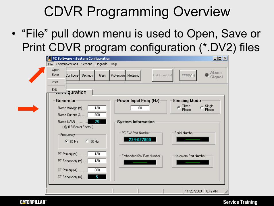
CDVR Programming OverviewCDVR Programming Overview• “File” pull down menu is used to Open, Save or
Print CDVR program configuration (*.DV2) files
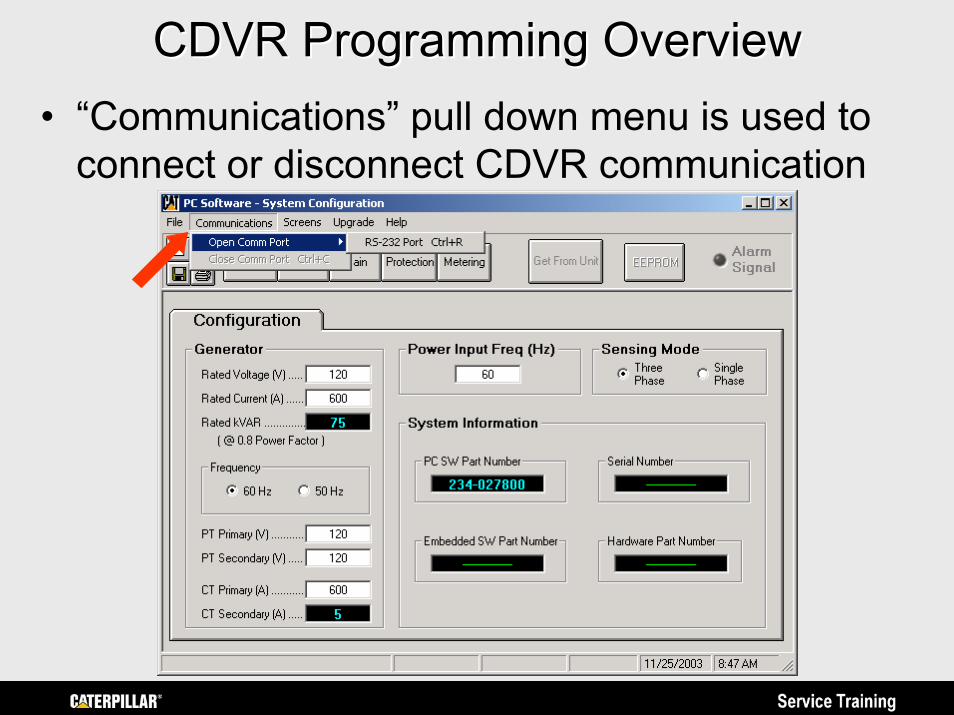
CDVR Programming OverviewCDVR Programming Overview• “Communications” pull down menu is used to
connect or disconnect CDVR communication
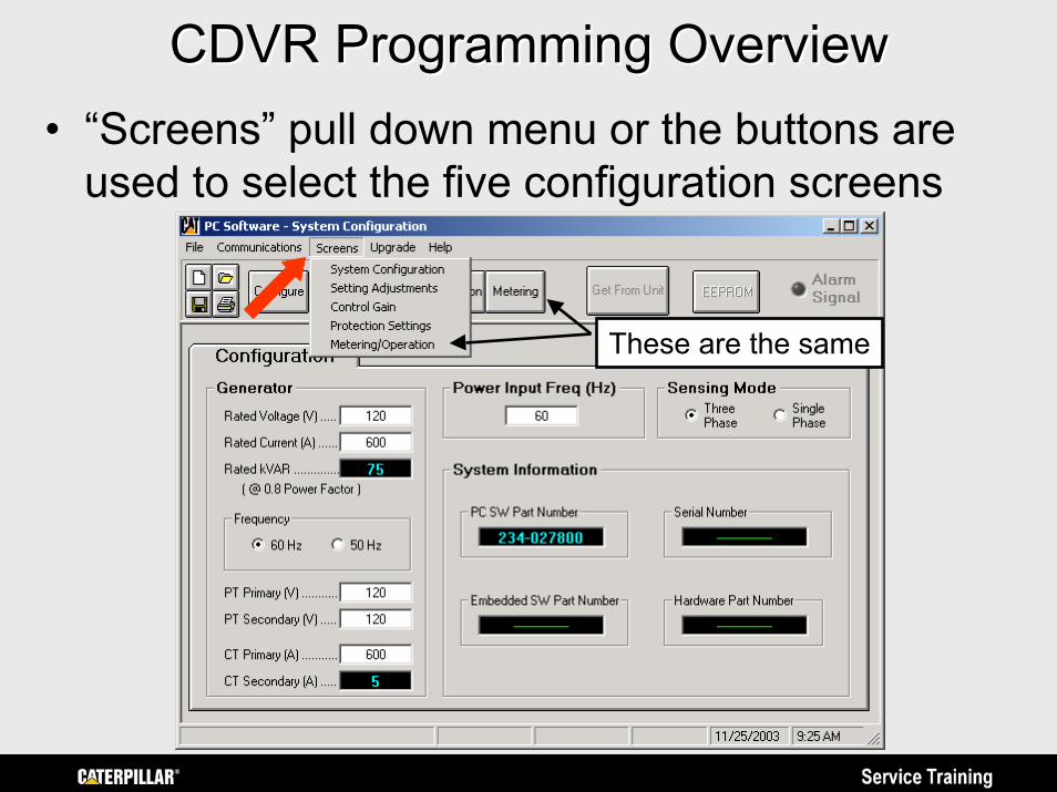
CDVR Programming OverviewCDVR Programming Overview• “Screens” pull down menu or the buttons are
used to select the five configuration screens
These are the same
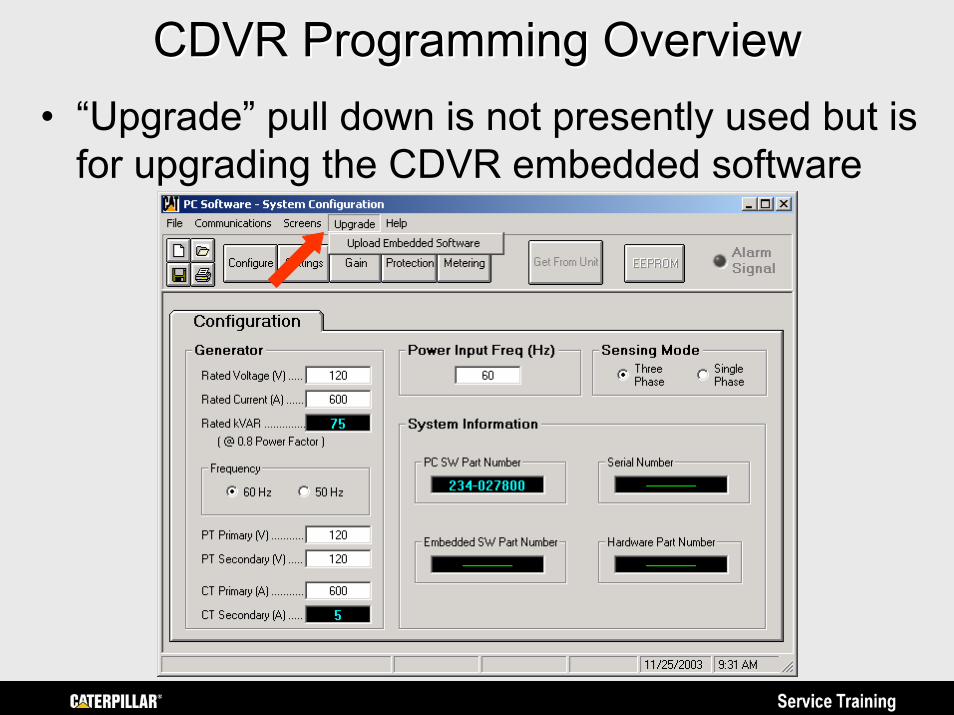
CDVR Programming OverviewCDVR Programming Overview• “Upgrade” pull down is not presently used but is
for upgrading the CDVR embedded software
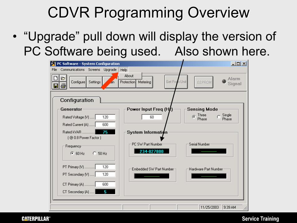
CDVR Programming OverviewCDVR Programming Overview• “Upgrade” pull down will display the version of
PC Software being used. Also shown here.
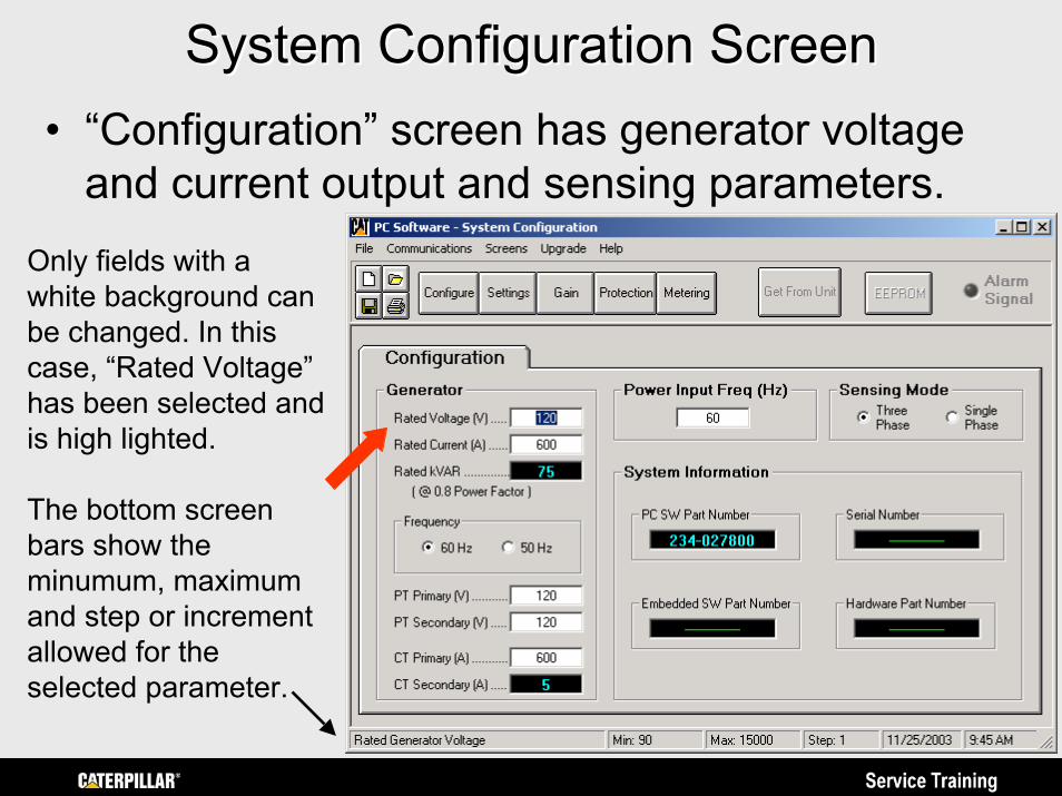
System Configuration ScreenSystem Configuration Screen• “Configuration” screen has generator voltage
and current output and sensing parameters.Only fields with a white background can be changed. In this case, “Rated Voltage” has been selected and is high lighted.
The bottom screen bars show the minumum, maximum and step or increment allowed for the selected parameter.
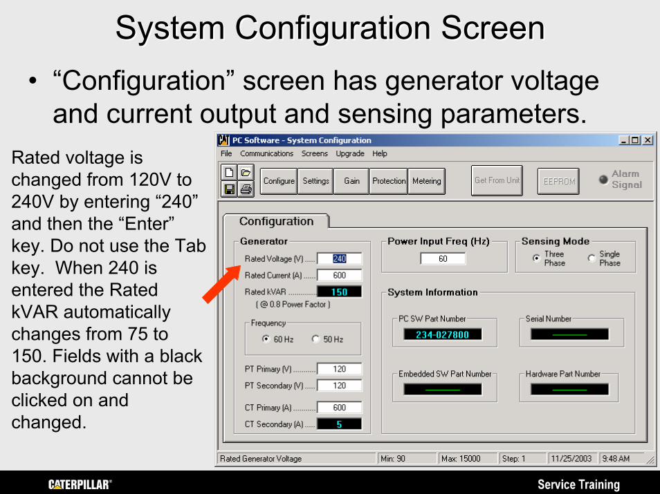
System Configuration ScreenSystem Configuration Screen• “Configuration” screen has generator voltage
and current output and sensing parameters.Rated voltage is changed from 120V to 240V by entering “240” and then the “Enter” key. Do not use the Tab key. When 240 is entered the Rated kVAR automatically changes from 75 to 150. Fields with a black background cannot be clicked on and changed.
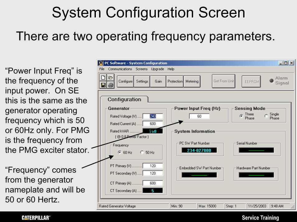
System Configuration ScreenSystem Configuration ScreenThere are two operating frequency parameters.
“Power Input Freq” is the frequency of the input power. On SE this is the same as the generator operating frequency which is 50 or 60Hz only. For PMG is the frequency from the PMG exciter stator.
“Frequency” comes from the generator nameplate and will be 50 or 60 Hertz.
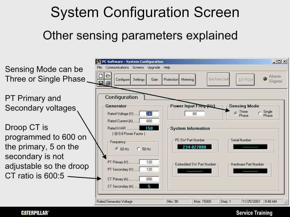
System Configuration ScreenSystem Configuration ScreenOther sensing parameters explained
Sensing Mode can be Three or Single Phase
PT Primary and Secondary voltages
Droop CT is programmed to 600 on the primary, 5 on the secondary is not adjustable so the droop CT ratio is 600:5
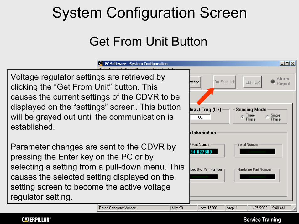
System Configuration ScreenSystem Configuration Screen
Get From Unit Button
Voltage regulator settings are retrieved by clicking the “Get From Unit” button. This causes the current settings of the CDVR to be displayed on the “settings” screen. This button will be grayed out until the communication is established.
Parameter changes are sent to the CDVR by pressing the Enter key on the PC or by selecting a setting from a pull-down menu. This causes the selected setting displayed on the setting screen to become the active voltage regulator setting.
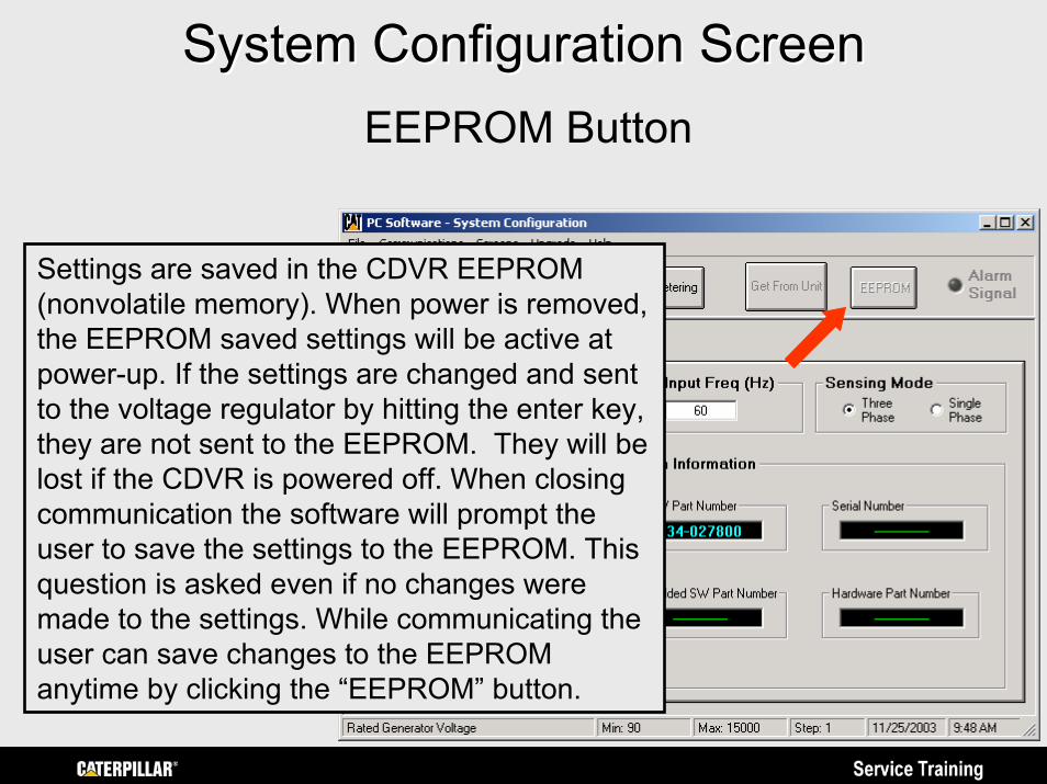
System Configuration ScreenSystem Configuration ScreenEEPROM Button
Settings are saved in the CDVR EEPROM (nonvolatile memory). When power is removed, the EEPROM saved settings will be active at power-up. If the settings are changed and sent to the voltage regulator by hitting the enter key, they are not sent to the EEPROM. They will be lost if the CDVR is powered off. When closing communication the software will prompt the user to save the settings to the EEPROM. This question is asked even if no changes were made to the settings. While communicating the user can save changes to the EEPROM anytime by clicking the “EEPROM” button.
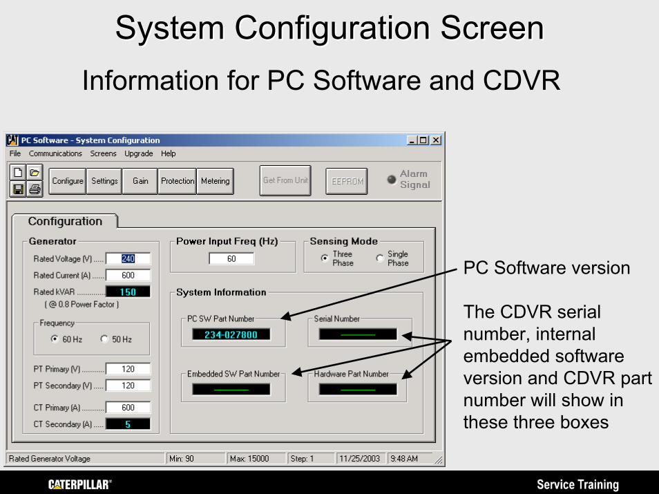
System Configuration ScreenSystem Configuration ScreenInformation for PC Software and CDVR
PC Software version
The CDVR serial number, internal embedded software version and CDVR part number will show in these three boxes
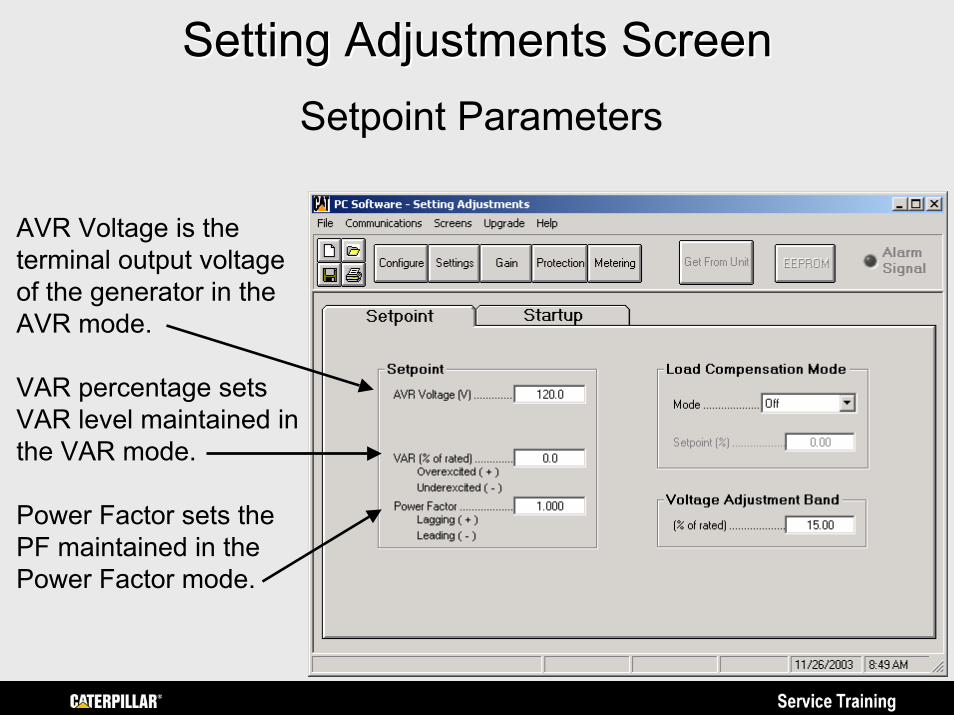
Setting Adjustments ScreenSetting Adjustments ScreenSetpoint Parameters
AVR Voltage is the terminal output voltage of the generator in the AVR mode.
VAR percentage sets VAR level maintained in the VAR mode.
Power Factor sets the PF maintained in the Power Factor mode.
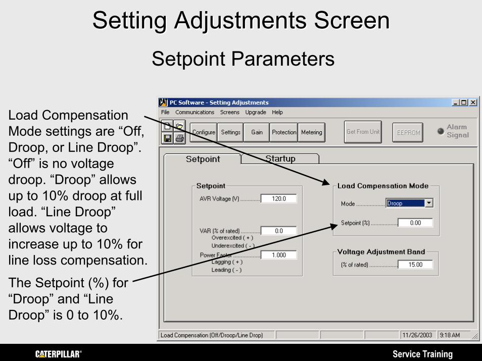
Setting Adjustments ScreenSetting Adjustments ScreenSetpoint Parameters
Load Compensation Mode settings are “Off, Droop, or Line Droop”. “Off” is no voltage droop. “Droop” allows up to 10% droop at full load. “Line Droop” allows voltage to increase up to 10% for line loss compensation.The Setpoint (%) for “Droop” and “Line Droop” is 0 to 10%.
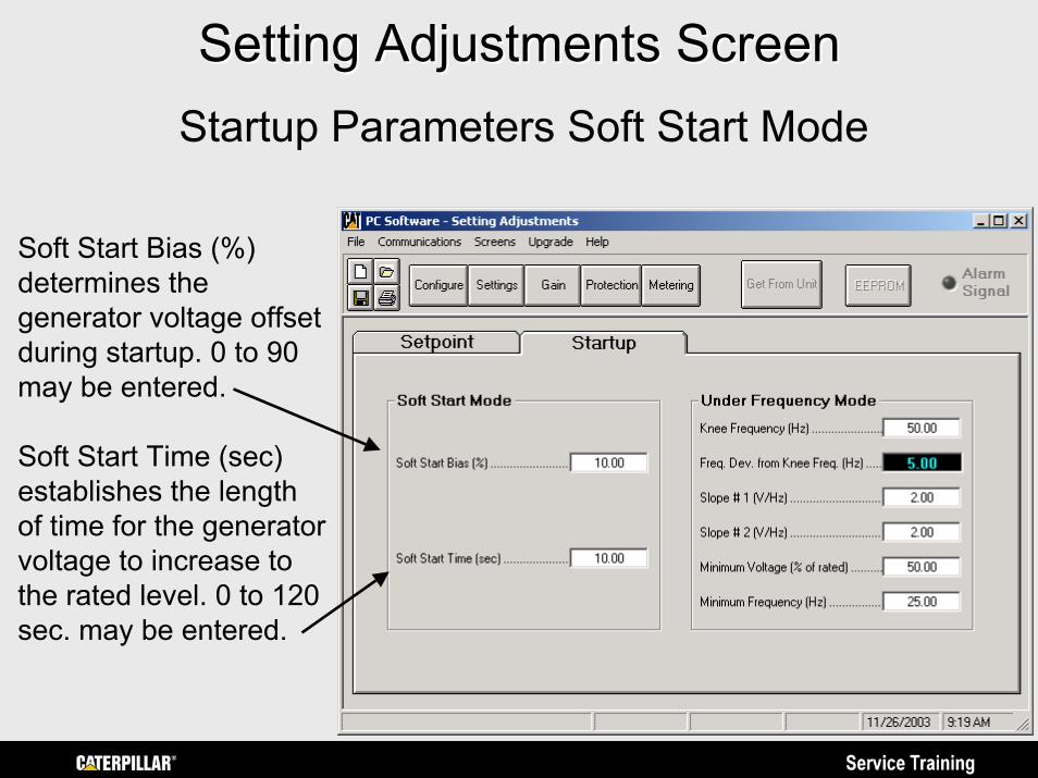
Setting Adjustments ScreenSetting Adjustments ScreenStartup Parameters Soft Start Mode
Soft Start Bias (%) determines the generator voltage offset during startup. 0 to 90 may be entered.
Soft Start Time (sec) establishes the length of time for the generatorvoltage to increase to the rated level. 0 to 120 sec. may be entered.
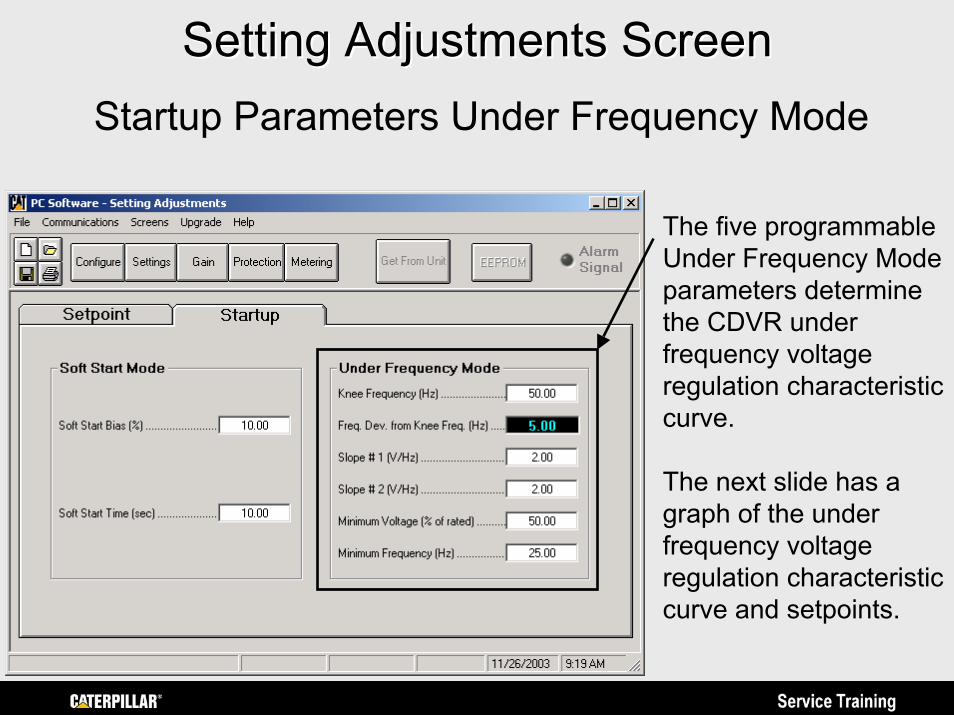
Setting Adjustments ScreenSetting Adjustments ScreenStartup Parameters Under Frequency Mode
The five programmable Under Frequency Mode parameters determine the CDVR under frequency voltage regulation characteristic curve.
The next slide has a graph of the under frequency voltage regulation characteristic curve and setpoints.

0Hz 25 45 55 60Hz
480
VAC
0 Knee Frequency (45-65Hz)
Min. Voltage Setpoint (50-100%)
5 Hz (Not Adjustable)
Decreasing Slope 1 (1-10 V/Hz)
Decreasing Slope 2 (1-10 V/Hz)
Generator Output VoltageMinimum Frequency Point (20-40Hz)
Regulation Characteristic. Below the Knee Frequency, the generator voltage follows a decreasing slope based on generator frequency. When generator frequency is between the Knee Frequency and Knee Frequency minus 5 hertz, voltage follows Slope 1. When generator frequency is between the Knee Frequency minus 5 hertz and the UnderfrequencyPoint, voltage follows Slope 2 down to the Minimum Voltage Setpoint. When generator frequency is below the Minimum Frequency Point, excitation is removed. Programming Decreasing Slope 2 is optional.
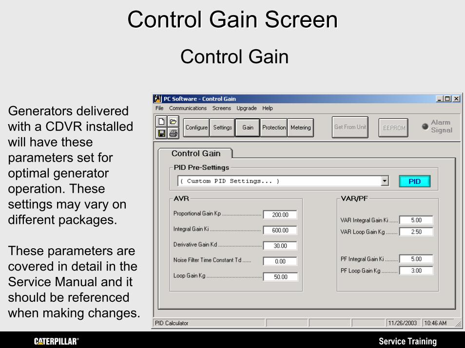
Control Gain ScreenControl Gain ScreenControl Gain
Generators delivered with a CDVR installed will have these parameters set for optimal generator operation. These settings may vary on different packages.
These parameters are covered in detail in the Service Manual and it should be referenced when making changes.
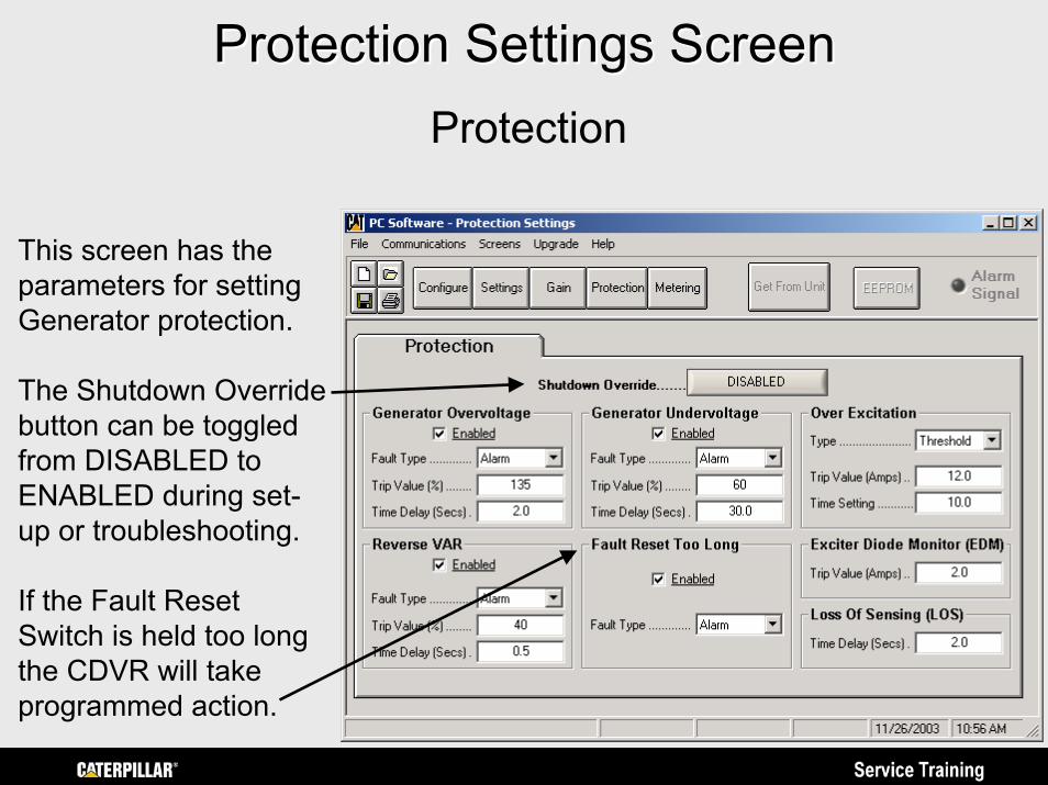
Protection Settings ScreenProtection Settings ScreenProtection
This screen has the parameters for setting Generator protection.
The Shutdown Override button can be toggled from DISABLED to ENABLED during set-up or troubleshooting.
If the Fault Reset Switch is held too long the CDVR will take programmed action.
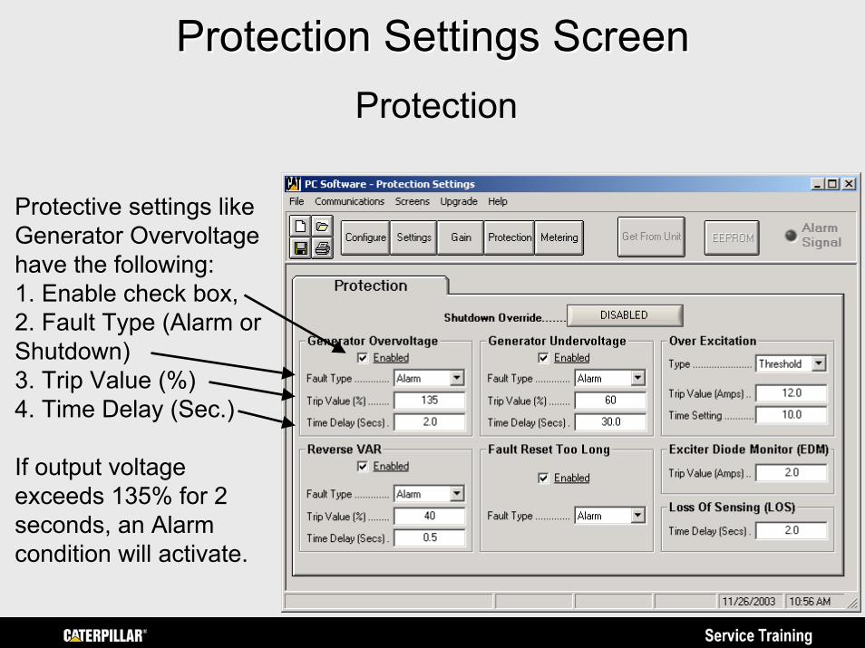
Protection Settings ScreenProtection Settings ScreenProtection
Protective settings like Generator Overvoltagehave the following:1. Enable check box,2. Fault Type (Alarm or Shutdown)3. Trip Value (%)4. Time Delay (Sec.)
If output voltage exceeds 135% for 2 seconds, an Alarm condition will activate.
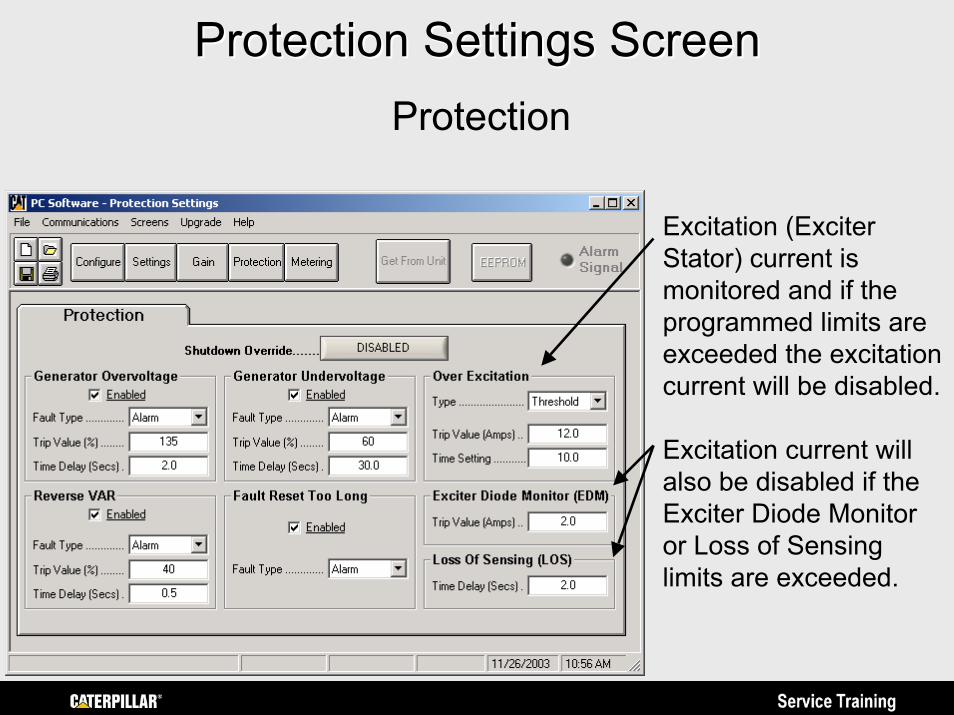
Protection Settings ScreenProtection Settings ScreenProtection
Excitation (Exciter Stator) current is monitored and if the programmed limits are exceeded the excitation current will be disabled.
Excitation current will also be disabled if the Exciter Diode Monitor or Loss of Sensing limits are exceeded.
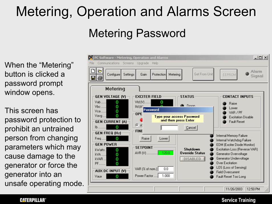
Metering, Operation and Alarms ScreenMetering, Operation and Alarms ScreenMetering Password
When the “Metering” button is clicked a password prompt window opens.
This screen has password protection to prohibit an untrained person from changing parameters which may cause damage to the generator or force the generator into an unsafe operating mode.
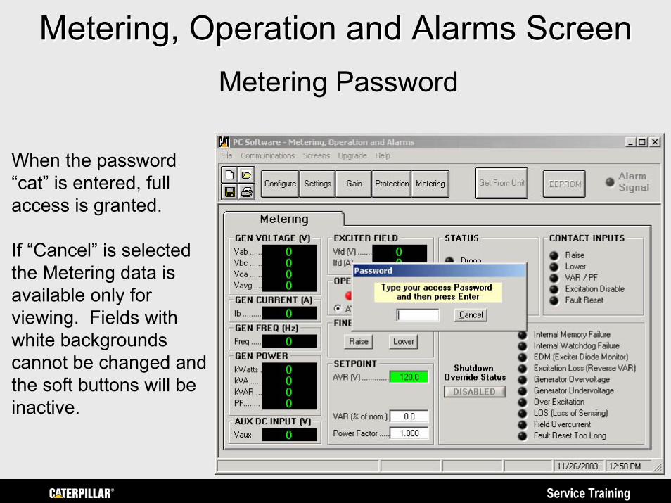
Metering, Operation and Alarms ScreenMetering, Operation and Alarms ScreenMetering Password
When the password “cat” is entered, full access is granted.
If “Cancel” is selected the Metering data is available only for viewing. Fields with white backgrounds cannot be changed and the soft buttons will be inactive.
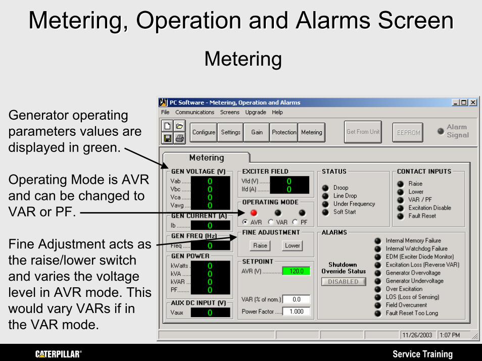
Metering, Operation and Alarms ScreenMetering, Operation and Alarms ScreenMetering
Generator operating parameters values are displayed in green.
Operating Mode is AVR and can be changed to VAR or PF.
Fine Adjustment acts as the raise/lower switch and varies the voltage level in AVR mode. This would vary VARs if in the VAR mode.
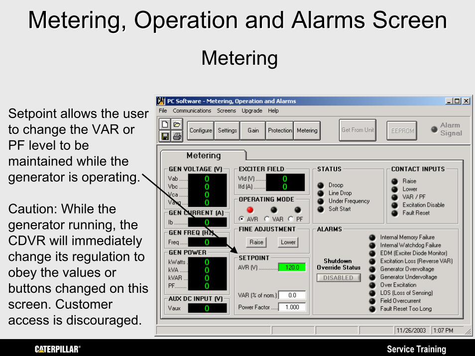
Metering, Operation and Alarms ScreenMetering, Operation and Alarms ScreenMetering
Setpoint allows the user to change the VAR or PF level to be maintained while the generator is operating.
Caution: While the generator running, the CDVR will immediately change its regulation to obey the values or buttons changed on this screen. Customer access is discouraged.
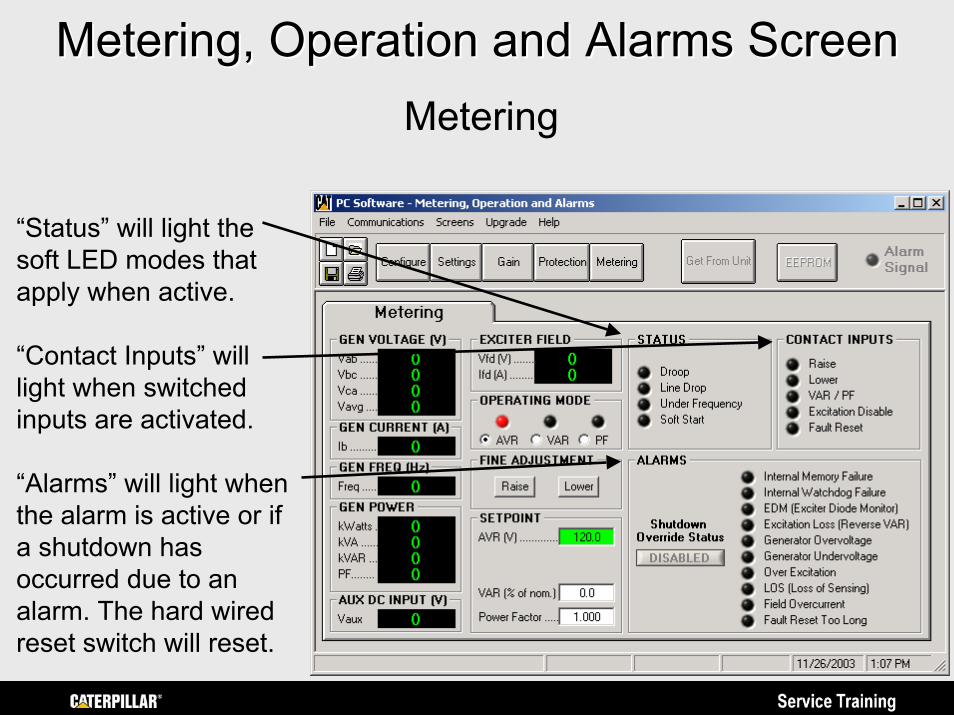
Metering, Operation and Alarms ScreenMetering, Operation and Alarms ScreenMetering
“Status” will light the soft LED modes that apply when active.
“Contact Inputs” will light when switched inputs are activated.
“Alarms” will light when the alarm is active or if a shutdown has occurred due to an alarm. The hard wired reset switch will reset.
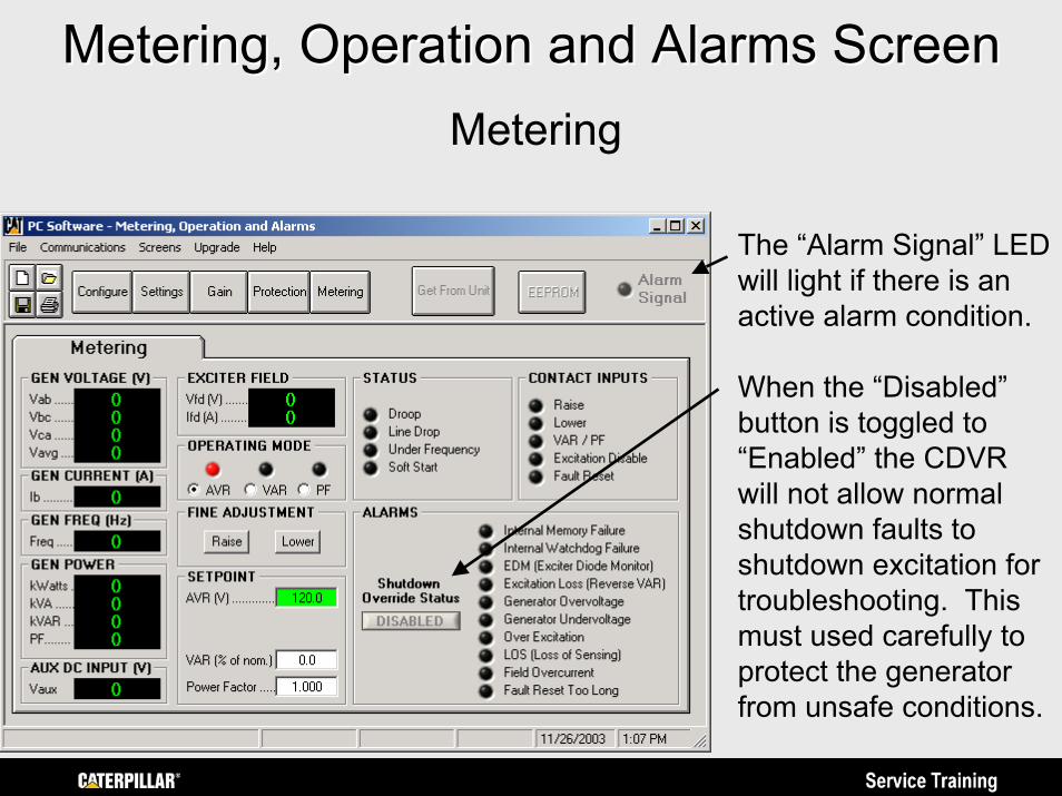
Metering, Operation and Alarms ScreenMetering, Operation and Alarms ScreenMetering
The “Alarm Signal” LED will light if there is an active alarm condition.
When the “Disabled” button is toggled to “Enabled” the CDVR will not allow normal shutdown faults to shutdown excitation for troubleshooting. This must used carefully to protect the generator from unsafe conditions.
SummarySummaryThis concludes the training overview of the CDVR. This presentation will be updated as needed and available on the Caterpillar Service Training Website at: https://psmktg.cat.com/srvtrng/
Again, the proper service information for the regulators in SIS should be used for the latest specific details for operation, adjustments, programming and troubleshooting. Please E-mail comments about this overview presentation to Todd Roth at [email protected]. Thank You!