Embed Size (px)
Citation preview
CC-Link IE Field NetworkWaterproof/Dustproof Remote I/O ModuleUser's Manual
-NZ2GF12A4-16D-NZ2GF12A4-16DE-NZ2GF12A2-16T-NZ2GF12A2-16TE-NZ2GF12A42-16DT-NZ2GF12A42-16DTE

COPYRIGHTThis document is protected by the law of copyright, whereby all rights established therein remain with the company Mitsubishi
Electric Corporation. Reproduction of this document or parts of this document is only permissible within the limits of the legal
determination of Copyright Law. Alteration or abridgement of the document is not permitted without the explicit written
approval of the company Mitsubishi Electric Corporation.
PRECAUTIONS REGARDING WARRANTYThis product is jointly developed and manufactured with Molex. Thus, warranty information is different from that of other
MELSEC products. Please confirm the following restrictions before purchase.
Gratis Warranty Term
Warranty period is one year after delivery.(Maximum of 18 months after produced)
Repair and Analysis
Please note that repairs and failure analysis are refused due to the structure of this product. Therefore, free replacement is
arranged for the failure of our responsibility during the warranty period.
1
2
SAFETY PRECAUTIONS(Read these precautions before using this product.)
Before using this product, please read this manual and the relevant manuals carefully and pay full attention to safety to handle
the product correctly.
The precautions given in this manual are concerned with this product only. For the safety precautions of the programmable
controller system, refer to the user's manual for the CPU module used.
In this manual, the safety precautions are classified into two levels: " WARNING" and " CAUTION".
Under some circumstances, failure to observe the precautions given under " CAUTION" may lead to serious
consequences.
Observe the precautions of both levels because they are important for personal and system safety.
Make sure that the end users read this manual and then keep the manual in a safe place for future reference.
[Design Precautions]
[Design Precautions]
WARNING● When a communication failure occurs in the network, data in the master module are held. Check Data
link status (each station) (SW00B0 to SW00B7) and configure an interlock circuit in the program to
ensure that the entire system will operate safely.
● When the module is disconnected due to a communication failure in the network or the CPU module is
in the STOP status, all outputs are held or turned off according to the parameter setting.
Configure an interlock circuit in the program to ensure that the entire system will always operate
safely even in such a case. If not, an accident may occur due to an incorrect output or malfunction.
● Outputs may remain on or off due to a failure of the module. Configure an external circuit for
monitoring output signals that could cause a serious accident.
● Do not use any "use prohibited" signals as a remote input or output signal. These signals are reserved
for system use. Do not write any data to the "use prohibited" areas in the remote register. If these
operations are performed, an accident may occur due to an incorrect output or malfunction.
CAUTION● Do not install the control lines or communication cables together with the main circuit lines or power
cables. Keep a distance of 100mm or more between them. Failure to do so may result in malfunction
due to noise.
● During control of an inductive load such as a lamp, heater, or solenoid valve, a large current
(approximately ten times greater than normal) may flow when the output is turned from off to on.
Therefore, use a module that has a sufficient current rating.
WARNING Indicates that incorrect handling may cause hazardous conditions, resulting in death or severe injury.
CAUTION Indicates that incorrect handling may cause hazardous conditions, resulting in minor or moderate injury or property damage.
[Installation Precautions]
[Installation Precautions]
WARNING● Shut off the load power supply (all phases) used in the system before mounting or removing a
module. Failure to do so may result in electric shock or cause the module to fail or malfunction.
CAUTION● Use the module in an environment that meets the general specifications in this manual. Failure to do
so may result in electric shock, fire, malfunction, or damage to or deterioration of the product.
● Do not directly touch any conductive parts and electronic components of the module. Doing so can
cause malfunction or failure of the module.
● Securely fix the module with mounting screws. Failure to do so may cause the module to fail due to
increasing effects of vibrations.
● Securely connect the cable connectors. Poor contact may cause malfunction.
● After the first use of the product, do not connect/remove the connector more than 50 times (IEC
61131-2 compliant). Exceeding the limit may cause malfunction.
3
4
[Wiring Precautions]
[Wiring Precautions]
WARNING● Shut off the load power supply (all phases) used in the system before wiring. Failure to do so may
result in electric shock or cause the module to fail or malfunction.
CAUTION● Individually ground the FG metal fitting of the programmable controller with a ground resistance of 100
ohms or less. Failure to do so may result in electric shock or malfunction.
● Check the rated voltage and terminal layout before wiring to the module, and connect the cables
correctly. Connecting a power supply with a different voltage rating or incorrect wiring may cause a fire
or failure.
● Tighten the waterproof caps within the specified torque range. Undertightening can cause short
circuit, fire, or malfunction. Overtightening can damage the waterproof cap, resulting in short circuit or
malfunction.
● The module meets IP67 only when all of the waterproof plugs and waterproof caps are attached and
the cover of the station number setting switch is securely fixed with a screw.
● Do not connect a communication cable to an I/O connector instead of to a communication connector.
Both connectors are the same in form. Connecting the cable to a wrong connector may cause the
module to fail or malfunction.
● Prevent foreign matter such as dust or wire chips from entering the module. Such foreign matter can
cause a fire, failure, or malfunction.
● Place the cables in a duct or clamp them. If not, dangling cable may swing or inadvertently be pulled,
resulting in damage to the module or cables or malfunction due to poor contact.
● Do not install the control lines or communication cables together with the main circuit lines or power
cables. Keep a distance of 100mm or more between them. Failure to do so may result in malfunction
due to noise.
● When disconnecting the cable from the module, do not pull the cable by the cable part. For the cable
with connector, hold the connector part of the cable. Pulling the cable connected to the module may
result in malfunction or damage to the module or cable.
● When an overcurrent caused by an error of an external device or a failure of the programmable
controller flows for a long time, it may cause smoke and fire. To prevent this, configure an external
safety circuit, such as a fuse.
● Wiring and replacement of a module must be performed by qualified maintenance personnel with
knowledge of protection against electric shock. For wiring methods, refer to "INSTALLATION AND
WIRING" in this manual.
[Startup and Maintenance Precautions]
[Startup and Maintenance Precautions]
[Disposal Precautions]
WARNING● Do not touch any connector while power is on. Doing so will cause electric shock or malfunction.
● Shut off the load power supply (all phases) used in the system before cleaning the module or
retightening screws or connector screws. Failure to do so may cause the module to fail or malfunction.
CAUTION● Do not disassemble or modify the module. Doing so may cause failure, malfunction, injury, or a fire.
● Do not drop or apply strong shock to the module. Doing so may damage the module.
● Shut off the load power supply (all phases) used in the system before mounting or removing a
module. Failure to do so may cause the module to fail or malfunction.
● After the first use of the product, do not connect/remove the connectors more than 50 times (IEC
61131-2 compliant). Exceeding the limit may cause malfunction.
● Before handling the module or connection cables, touch a conducting object such as a grounded
metal to discharge the static electricity from the human body. Failure to do so may cause the module
to fail or malfunction.
● Startup and maintenance of a control panel must be performed by qualified maintenance personnel
with knowledge of protection against electric shock. Lock the control panel so that only qualified
maintenance personnel can operate it.
CAUTION● When disposing of this product, treat it as industrial waste.
5
6
CONDITIONS OF USE FOR THE PRODUCT(1) Mitsubishi programmable controller ("the PRODUCT") shall be used in conditions;
i) where any problem, fault or failure occurring in the PRODUCT, if any, shall not lead to any major or serious accident; and ii) where the backup and fail-safe function are systematically or automatically provided outside of the PRODUCT for the case of any problem, fault or failure occurring in the PRODUCT.
(2) The PRODUCT has been designed and manufactured for the purpose of being used in general industries.MITSUBISHI SHALL HAVE NO RESPONSIBILITY OR LIABILITY (INCLUDING, BUT NOT LIMITED TO ANY AND ALL RESPONSIBILITY OR LIABILITY BASED ON CONTRACT, WARRANTY, TORT, PRODUCT LIABILITY) FOR ANY INJURY OR DEATH TO PERSONS OR LOSS OR DAMAGE TO PROPERTY CAUSED BY the PRODUCT THAT ARE OPERATED OR USED IN APPLICATION NOT INTENDED OR EXCLUDED BY INSTRUCTIONS, PRECAUTIONS, OR WARNING CONTAINED IN MITSUBISHI'S USER, INSTRUCTION AND/OR SAFETY MANUALS, TECHNICAL BULLETINS AND GUIDELINES FOR the PRODUCT. ("Prohibited Application")Prohibited Applications include, but not limited to, the use of the PRODUCT in;• Nuclear Power Plants and any other power plants operated by Power companies, and/or any other cases in which the
public could be affected if any problem or fault occurs in the PRODUCT.• Railway companies or Public service purposes, and/or any other cases in which establishment of a special quality
assurance system is required by the Purchaser or End User.• Aircraft or Aerospace, Medical applications, Train equipment, transport equipment such as Elevator and Escalator,
Incineration and Fuel devices, Vehicles, Manned transportation, Equipment for Recreation and Amusement, and Safety devices, handling of Nuclear or Hazardous Materials or Chemicals, Mining and Drilling, and/or other applications where there is a significant risk of injury to the public or property.
Notwithstanding the above, restrictions Mitsubishi may in its sole discretion, authorize use of the PRODUCT in one or more of the Prohibited Applications, provided that the usage of the PRODUCT is limited only for the specific applications agreed to by Mitsubishi and provided further that no special quality assurance or fail-safe, redundant or other safety features which exceed the general specifications of the PRODUCTs are required. For details, please contact the Mitsubishi representative in your region.
INTRODUCTIONThank you for purchasing the CC-Link IE Field Network waterproof/dustproof remote I/O module (hereafter abbreviated as I/O
module).
This manual describes the procedures, system configuration, parameter settings, functions, and troubleshooting of the I/O
module.
Before using this product, please read this manual and the relevant manuals carefully and develop familiarity with the
functions and performance of the I/O module to handle the product correctly.
When applying the program examples introduced in this manual to an actual system, ensure the applicability and confirm that
it will not cause system control problems.
Relevant products
NZ2GF12A4-16D, NZ2GF12A4-16DE, NZ2GF12A2-16T, NZ2GF12A2-16TE, NZ2GF12A42-16DT, NZ2GF12A42-16DTE
Unless otherwise specified, this manual describes the program examples in which the remote I/O signals and
remote registers are assigned for an I/O combined module as follows.
• Remote input signal: RX0 to RX7
• Remote output signal: RY8 to RYF
• Remote register: RWr0 to RWrB, RWw0 to RWwB
For the assignment of remote I/O signals and remote registers, refer to the following.
User's manual for the master/local module used
7
8
RELEVANT MANUALS
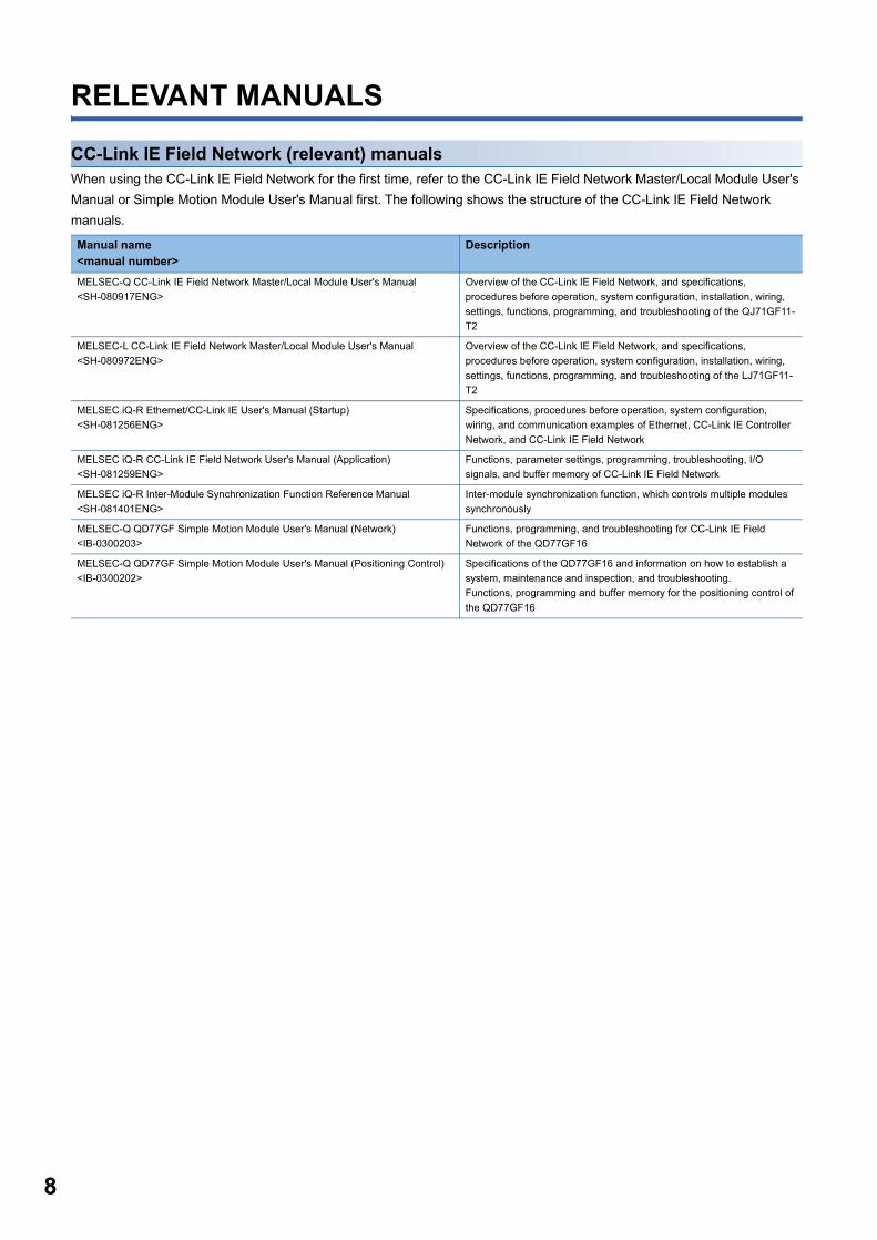
CC-Link IE Field Network (relevant) manualsWhen using the CC-Link IE Field Network for the first time, refer to the CC-Link IE Field Network Master/Local Module User's
Manual or Simple Motion Module User's Manual first. The following shows the structure of the CC-Link IE Field Network
manuals.
Manual name<manual number>
Description
MELSEC-Q CC-Link IE Field Network Master/Local Module User's Manual
<SH-080917ENG>
Overview of the CC-Link IE Field Network, and specifications,
procedures before operation, system configuration, installation, wiring,
settings, functions, programming, and troubleshooting of the QJ71GF11-
T2
MELSEC-L CC-Link IE Field Network Master/Local Module User's Manual
<SH-080972ENG>
Overview of the CC-Link IE Field Network, and specifications,
procedures before operation, system configuration, installation, wiring,
settings, functions, programming, and troubleshooting of the LJ71GF11-
T2
MELSEC iQ-R Ethernet/CC-Link IE User's Manual (Startup)
<SH-081256ENG>
Specifications, procedures before operation, system configuration,
wiring, and communication examples of Ethernet, CC-Link IE Controller
Network, and CC-Link IE Field Network
MELSEC iQ-R CC-Link IE Field Network User's Manual (Application)
<SH-081259ENG>
Functions, parameter settings, programming, troubleshooting, I/O
signals, and buffer memory of CC-Link IE Field Network
MELSEC iQ-R Inter-Module Synchronization Function Reference Manual
<SH-081401ENG>
Inter-module synchronization function, which controls multiple modules
synchronously
MELSEC-Q QD77GF Simple Motion Module User's Manual (Network)
<IB-0300203>
Functions, programming, and troubleshooting for CC-Link IE Field
Network of the QD77GF16
MELSEC-Q QD77GF Simple Motion Module User's Manual (Positioning Control)
<IB-0300202>
Specifications of the QD77GF16 and information on how to establish a
system, maintenance and inspection, and troubleshooting.
Functions, programming and buffer memory for the positioning control of
the QD77GF16
CO
NT
EN
TS
CONTENTSCOPYRIGHT . . . . . . . . . . . . . . . . . . . . . . . . . . . . . . . . . . . . . . . . . . . . . . . . . . . . . . . . . . . . . . . . . . . . . . . . . . . . . .1
PRECAUTIONS REGARDING WARRANTY . . . . . . . . . . . . . . . . . . . . . . . . . . . . . . . . . . . . . . . . . . . . . . . . . . . . .1
SAFETY PRECAUTIONS . . . . . . . . . . . . . . . . . . . . . . . . . . . . . . . . . . . . . . . . . . . . . . . . . . . . . . . . . . . . . . . . . . . .2
CONDITIONS OF USE FOR THE PRODUCT . . . . . . . . . . . . . . . . . . . . . . . . . . . . . . . . . . . . . . . . . . . . . . . . . . . .6
INTRODUCTION. . . . . . . . . . . . . . . . . . . . . . . . . . . . . . . . . . . . . . . . . . . . . . . . . . . . . . . . . . . . . . . . . . . . . . . . . . .7
RELEVANT MANUALS . . . . . . . . . . . . . . . . . . . . . . . . . . . . . . . . . . . . . . . . . . . . . . . . . . . . . . . . . . . . . . . . . . . . . .8
TERMS . . . . . . . . . . . . . . . . . . . . . . . . . . . . . . . . . . . . . . . . . . . . . . . . . . . . . . . . . . . . . . . . . . . . . . . . . . . . . . . . .12
CHAPTER 1 PRODUCT LINEUP 13
1.1 I/O Module . . . . . . . . . . . . . . . . . . . . . . . . . . . . . . . . . . . . . . . . . . . . . . . . . . . . . . . . . . . . . . . . . . . . . . . . . . . . . 13
1.2 Recommended Connector List . . . . . . . . . . . . . . . . . . . . . . . . . . . . . . . . . . . . . . . . . . . . . . . . . . . . . . . . . . . . 14
CHAPTER 2 PART NAMES 16
CHAPTER 3 SPECIFICATIONS 19
3.1 General Specifications . . . . . . . . . . . . . . . . . . . . . . . . . . . . . . . . . . . . . . . . . . . . . . . . . . . . . . . . . . . . . . . . . . . 19
3.2 I/O Module Specifications. . . . . . . . . . . . . . . . . . . . . . . . . . . . . . . . . . . . . . . . . . . . . . . . . . . . . . . . . . . . . . . . . 20
Input module . . . . . . . . . . . . . . . . . . . . . . . . . . . . . . . . . . . . . . . . . . . . . . . . . . . . . . . . . . . . . . . . . . . . . . . . . . . . 20
Output module . . . . . . . . . . . . . . . . . . . . . . . . . . . . . . . . . . . . . . . . . . . . . . . . . . . . . . . . . . . . . . . . . . . . . . . . . . . 26
I/O combined module . . . . . . . . . . . . . . . . . . . . . . . . . . . . . . . . . . . . . . . . . . . . . . . . . . . . . . . . . . . . . . . . . . . . . 34
3.3 Function List . . . . . . . . . . . . . . . . . . . . . . . . . . . . . . . . . . . . . . . . . . . . . . . . . . . . . . . . . . . . . . . . . . . . . . . . . . . 44
3.4 List of Remote I/O Signals . . . . . . . . . . . . . . . . . . . . . . . . . . . . . . . . . . . . . . . . . . . . . . . . . . . . . . . . . . . . . . . . 46
3.5 List of Remote Register . . . . . . . . . . . . . . . . . . . . . . . . . . . . . . . . . . . . . . . . . . . . . . . . . . . . . . . . . . . . . . . . . . 48
3.6 List of Remote Buffer Memory . . . . . . . . . . . . . . . . . . . . . . . . . . . . . . . . . . . . . . . . . . . . . . . . . . . . . . . . . . . . . 50
CHAPTER 4 PROCEDURES BEFORE OPERATION 60
CHAPTER 5 SYSTEM CONFIGURATION 62
5.1 Applicable Systems. . . . . . . . . . . . . . . . . . . . . . . . . . . . . . . . . . . . . . . . . . . . . . . . . . . . . . . . . . . . . . . . . . . . . . 62
CHAPTER 6 INSTALLATION AND WIRING 64
6.1 Setting Switch . . . . . . . . . . . . . . . . . . . . . . . . . . . . . . . . . . . . . . . . . . . . . . . . . . . . . . . . . . . . . . . . . . . . . . . . . . 64
Station number setting with the station number setting switch . . . . . . . . . . . . . . . . . . . . . . . . . . . . . . . . . . . . . . 64
6.2 Installation Environment and Installation Position . . . . . . . . . . . . . . . . . . . . . . . . . . . . . . . . . . . . . . . . . . . . 66
Installation environment. . . . . . . . . . . . . . . . . . . . . . . . . . . . . . . . . . . . . . . . . . . . . . . . . . . . . . . . . . . . . . . . . . . . 66
Installation position . . . . . . . . . . . . . . . . . . . . . . . . . . . . . . . . . . . . . . . . . . . . . . . . . . . . . . . . . . . . . . . . . . . . . . . 67
Installation direction. . . . . . . . . . . . . . . . . . . . . . . . . . . . . . . . . . . . . . . . . . . . . . . . . . . . . . . . . . . . . . . . . . . . . . . 67
6.3 Installation . . . . . . . . . . . . . . . . . . . . . . . . . . . . . . . . . . . . . . . . . . . . . . . . . . . . . . . . . . . . . . . . . . . . . . . . . . . . . 68
Fixing the I/O module . . . . . . . . . . . . . . . . . . . . . . . . . . . . . . . . . . . . . . . . . . . . . . . . . . . . . . . . . . . . . . . . . . . . . 68
6.4 Wiring the Power Supply . . . . . . . . . . . . . . . . . . . . . . . . . . . . . . . . . . . . . . . . . . . . . . . . . . . . . . . . . . . . . . . . . 68
6.5 Wiring of Ethernet Cable. . . . . . . . . . . . . . . . . . . . . . . . . . . . . . . . . . . . . . . . . . . . . . . . . . . . . . . . . . . . . . . . . . 69
6.6 Attaching Waterproof Caps . . . . . . . . . . . . . . . . . . . . . . . . . . . . . . . . . . . . . . . . . . . . . . . . . . . . . . . . . . . . . . . 71
CHAPTER 7 VARIOUS SETTINGS 72
7.1 Parameter Setting . . . . . . . . . . . . . . . . . . . . . . . . . . . . . . . . . . . . . . . . . . . . . . . . . . . . . . . . . . . . . . . . . . . . . . . 72
7.2 Changing the Parameter . . . . . . . . . . . . . . . . . . . . . . . . . . . . . . . . . . . . . . . . . . . . . . . . . . . . . . . . . . . . . . . . . . 77
Changing the network configuration . . . . . . . . . . . . . . . . . . . . . . . . . . . . . . . . . . . . . . . . . . . . . . . . . . . . . . . . . . 77
Changing the parameter without changing the network configuration. . . . . . . . . . . . . . . . . . . . . . . . . . . . . . . . . 79
9
10
CHAPTER 8 FUNCTIONS 81
8.1 Error Notification Function. . . . . . . . . . . . . . . . . . . . . . . . . . . . . . . . . . . . . . . . . . . . . . . . . . . . . . . . . . . . . . . . 81
8.2 Input OFF Delay Function. . . . . . . . . . . . . . . . . . . . . . . . . . . . . . . . . . . . . . . . . . . . . . . . . . . . . . . . . . . . . . . . . 84
8.3 Input Response Time Setting Function. . . . . . . . . . . . . . . . . . . . . . . . . . . . . . . . . . . . . . . . . . . . . . . . . . . . . . 86
8.4 Output HOLD/CLEAR Setting Function. . . . . . . . . . . . . . . . . . . . . . . . . . . . . . . . . . . . . . . . . . . . . . . . . . . . . . 87
8.5 Cyclic Data Update Watch Function . . . . . . . . . . . . . . . . . . . . . . . . . . . . . . . . . . . . . . . . . . . . . . . . . . . . . . . . 88
8.6 Number of ON Times Integration Function . . . . . . . . . . . . . . . . . . . . . . . . . . . . . . . . . . . . . . . . . . . . . . . . . . . 89
8.7 Output ON/OFF Information Hold Function . . . . . . . . . . . . . . . . . . . . . . . . . . . . . . . . . . . . . . . . . . . . . . . . . . 91
8.8 Power Supply Monitoring Function . . . . . . . . . . . . . . . . . . . . . . . . . . . . . . . . . . . . . . . . . . . . . . . . . . . . . . . . . 92
8.9 Short-Circuit Detection Function . . . . . . . . . . . . . . . . . . . . . . . . . . . . . . . . . . . . . . . . . . . . . . . . . . . . . . . . . . . 93
8.10 Fast Logic Function . . . . . . . . . . . . . . . . . . . . . . . . . . . . . . . . . . . . . . . . . . . . . . . . . . . . . . . . . . . . . . . . . . . . . 95
8.11 Initial Operation Setting Function . . . . . . . . . . . . . . . . . . . . . . . . . . . . . . . . . . . . . . . . . . . . . . . . . . . . . . . . . . 98
8.12 Protection Function. . . . . . . . . . . . . . . . . . . . . . . . . . . . . . . . . . . . . . . . . . . . . . . . . . . . . . . . . . . . . . . . . . . . . 100
8.13 CC-Link IE Field Network Diagnostic Function . . . . . . . . . . . . . . . . . . . . . . . . . . . . . . . . . . . . . . . . . . . . . . 100
CHAPTER 9 PROGRAMMING 103
9.1 Precautions for Programming . . . . . . . . . . . . . . . . . . . . . . . . . . . . . . . . . . . . . . . . . . . . . . . . . . . . . . . . . . . . 103
9.2 Procedure for Programming. . . . . . . . . . . . . . . . . . . . . . . . . . . . . . . . . . . . . . . . . . . . . . . . . . . . . . . . . . . . . . 104
9.3 Program Example . . . . . . . . . . . . . . . . . . . . . . . . . . . . . . . . . . . . . . . . . . . . . . . . . . . . . . . . . . . . . . . . . . . . . . 104
9.4 Program Example for the Number of ON Times Integration Function . . . . . . . . . . . . . . . . . . . . . . . . . . . . 111
Program example for checking the number of ON times. . . . . . . . . . . . . . . . . . . . . . . . . . . . . . . . . . . . . . . . . . 111
Program example for clearing the number of ON times . . . . . . . . . . . . . . . . . . . . . . . . . . . . . . . . . . . . . . . . . . 111
9.5 Program Example for the Fast Logic Function. . . . . . . . . . . . . . . . . . . . . . . . . . . . . . . . . . . . . . . . . . . . . . . 114
Program example for the fast logic function . . . . . . . . . . . . . . . . . . . . . . . . . . . . . . . . . . . . . . . . . . . . . . . . . . . 114
Program example for checking the fast logic enable or disable status . . . . . . . . . . . . . . . . . . . . . . . . . . . . . . . 117
CHAPTER 10 MAINTENANCE AND INSPECTION 119
CHAPTER 11 TROUBLESHOOTING 121
11.1 Checking for the Error Codes and the Warning Codes . . . . . . . . . . . . . . . . . . . . . . . . . . . . . . . . . . . . . . . . 121
11.2 Error Code List . . . . . . . . . . . . . . . . . . . . . . . . . . . . . . . . . . . . . . . . . . . . . . . . . . . . . . . . . . . . . . . . . . . . . . . . 124
11.3 Checking the LEDs . . . . . . . . . . . . . . . . . . . . . . . . . . . . . . . . . . . . . . . . . . . . . . . . . . . . . . . . . . . . . . . . . . . . . 128
11.4 Unit Test . . . . . . . . . . . . . . . . . . . . . . . . . . . . . . . . . . . . . . . . . . . . . . . . . . . . . . . . . . . . . . . . . . . . . . . . . . . . . . 131
11.5 Troubleshooting for Each Phenomenon . . . . . . . . . . . . . . . . . . . . . . . . . . . . . . . . . . . . . . . . . . . . . . . . . . . . 132
11.6 Examples of Troubles with the I/O Module . . . . . . . . . . . . . . . . . . . . . . . . . . . . . . . . . . . . . . . . . . . . . . . . . . 134
Troubleshooting for input circuit . . . . . . . . . . . . . . . . . . . . . . . . . . . . . . . . . . . . . . . . . . . . . . . . . . . . . . . . . . . . 134
Troubleshooting for output circuit . . . . . . . . . . . . . . . . . . . . . . . . . . . . . . . . . . . . . . . . . . . . . . . . . . . . . . . . . . . 137
APPENDICES 143
Appendix 1 Details of Remote I/O Signals . . . . . . . . . . . . . . . . . . . . . . . . . . . . . . . . . . . . . . . . . . . . . . . . . . . . . . . . 143
Remote input signal. . . . . . . . . . . . . . . . . . . . . . . . . . . . . . . . . . . . . . . . . . . . . . . . . . . . . . . . . . . . . . . . . . . . . . 143
Remote output signal. . . . . . . . . . . . . . . . . . . . . . . . . . . . . . . . . . . . . . . . . . . . . . . . . . . . . . . . . . . . . . . . . . . . . 143
Appendix 2 Details of Remote Registers . . . . . . . . . . . . . . . . . . . . . . . . . . . . . . . . . . . . . . . . . . . . . . . . . . . . . . . . . 144
Appendix 3 Details of Remote Buffer Memory Addresses . . . . . . . . . . . . . . . . . . . . . . . . . . . . . . . . . . . . . . . . . . . 154
Appendix 4 EMC and Low Voltage Directives . . . . . . . . . . . . . . . . . . . . . . . . . . . . . . . . . . . . . . . . . . . . . . . . . . . . . 166
Measures to comply with the EMC Directive . . . . . . . . . . . . . . . . . . . . . . . . . . . . . . . . . . . . . . . . . . . . . . . . . . . 166
Requirements to compliance with the Low Voltage Directive . . . . . . . . . . . . . . . . . . . . . . . . . . . . . . . . . . . . . . 168
Appendix 5 How to Check Serial Number and Function Version . . . . . . . . . . . . . . . . . . . . . . . . . . . . . . . . . . . . . 169
Appendix 6 External Dimensions . . . . . . . . . . . . . . . . . . . . . . . . . . . . . . . . . . . . . . . . . . . . . . . . . . . . . . . . . . . . . . . 170

CO
NT
EN
TS
INDEX 172
REVISIONS. . . . . . . . . . . . . . . . . . . . . . . . . . . . . . . . . . . . . . . . . . . . . . . . . . . . . . . . . . . . . . . . . . . . . . . . . . . . .174
WARRANTY . . . . . . . . . . . . . . . . . . . . . . . . . . . . . . . . . . . . . . . . . . . . . . . . . . . . . . . . . . . . . . . . . . . . . . . . . . . .175
TRADEMARKS . . . . . . . . . . . . . . . . . . . . . . . . . . . . . . . . . . . . . . . . . . . . . . . . . . . . . . . . . . . . . . . . . . . . . . . . . .176
11
12
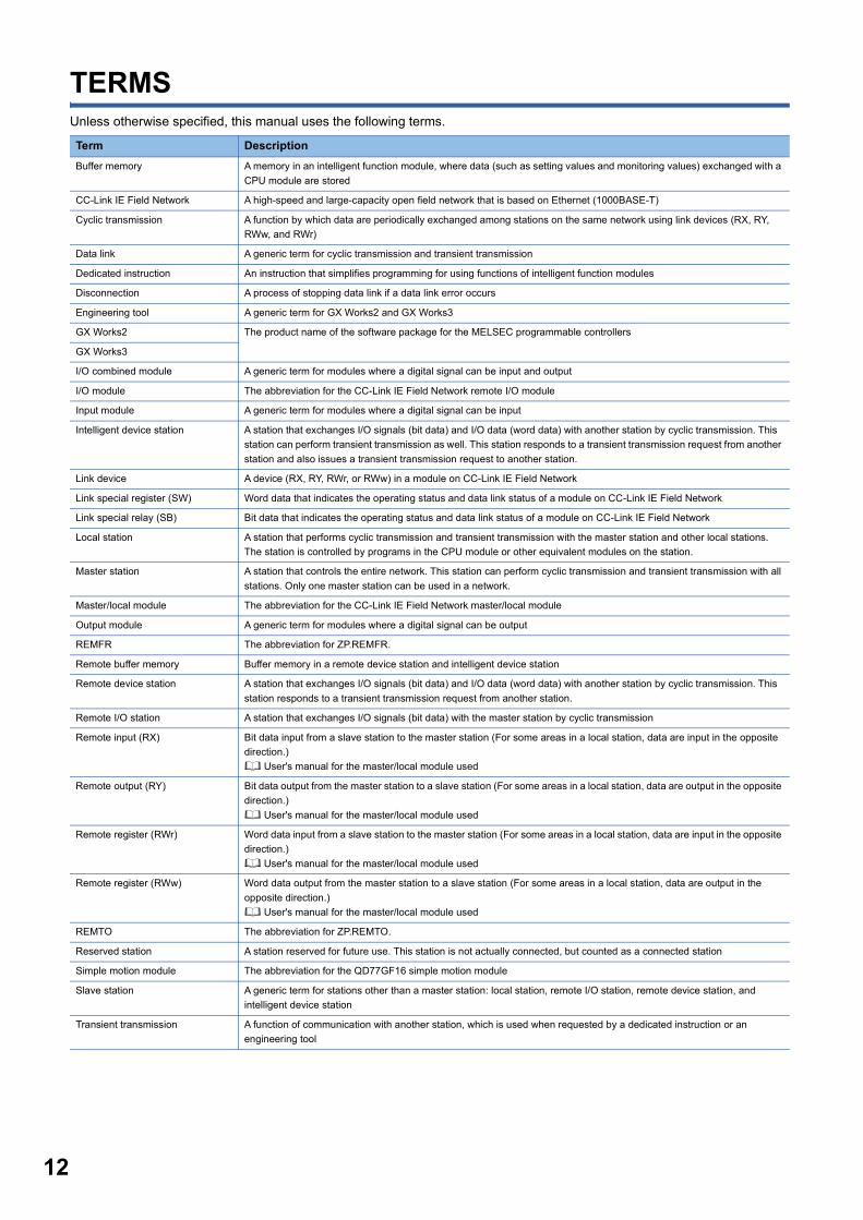
TERMSUnless otherwise specified, this manual uses the following terms.
Term Description
Buffer memory A memory in an intelligent function module, where data (such as setting values and monitoring values) exchanged with a
CPU module are stored
CC-Link IE Field Network A high-speed and large-capacity open field network that is based on Ethernet (1000BASE-T)
Cyclic transmission A function by which data are periodically exchanged among stations on the same network using link devices (RX, RY,
RWw, and RWr)
Data link A generic term for cyclic transmission and transient transmission
Dedicated instruction An instruction that simplifies programming for using functions of intelligent function modules
Disconnection A process of stopping data link if a data link error occurs
Engineering tool A generic term for GX Works2 and GX Works3
GX Works2 The product name of the software package for the MELSEC programmable controllers
GX Works3
I/O combined module A generic term for modules where a digital signal can be input and output
I/O module The abbreviation for the CC-Link IE Field Network remote I/O module
Input module A generic term for modules where a digital signal can be input
Intelligent device station A station that exchanges I/O signals (bit data) and I/O data (word data) with another station by cyclic transmission. This
station can perform transient transmission as well. This station responds to a transient transmission request from another
station and also issues a transient transmission request to another station.
Link device A device (RX, RY, RWr, or RWw) in a module on CC-Link IE Field Network
Link special register (SW) Word data that indicates the operating status and data link status of a module on CC-Link IE Field Network
Link special relay (SB) Bit data that indicates the operating status and data link status of a module on CC-Link IE Field Network
Local station A station that performs cyclic transmission and transient transmission with the master station and other local stations.
The station is controlled by programs in the CPU module or other equivalent modules on the station.
Master station A station that controls the entire network. This station can perform cyclic transmission and transient transmission with all
stations. Only one master station can be used in a network.
Master/local module The abbreviation for the CC-Link IE Field Network master/local module
Output module A generic term for modules where a digital signal can be output
REMFR The abbreviation for ZP.REMFR.
Remote buffer memory Buffer memory in a remote device station and intelligent device station
Remote device station A station that exchanges I/O signals (bit data) and I/O data (word data) with another station by cyclic transmission. This
station responds to a transient transmission request from another station.
Remote I/O station A station that exchanges I/O signals (bit data) with the master station by cyclic transmission
Remote input (RX) Bit data input from a slave station to the master station (For some areas in a local station, data are input in the opposite
direction.)
User's manual for the master/local module used
Remote output (RY) Bit data output from the master station to a slave station (For some areas in a local station, data are output in the opposite
direction.)
User's manual for the master/local module used
Remote register (RWr) Word data input from a slave station to the master station (For some areas in a local station, data are input in the opposite
direction.)
User's manual for the master/local module used
Remote register (RWw) Word data output from the master station to a slave station (For some areas in a local station, data are output in the
opposite direction.)
User's manual for the master/local module used
REMTO The abbreviation for ZP.REMTO.
Reserved station A station reserved for future use. This station is not actually connected, but counted as a connected station
Simple motion module The abbreviation for the QD77GF16 simple motion module
Slave station A generic term for stations other than a master station: local station, remote I/O station, remote device station, and
intelligent device station
Transient transmission A function of communication with another station, which is used when requested by a dedicated instruction or an
engineering tool
1
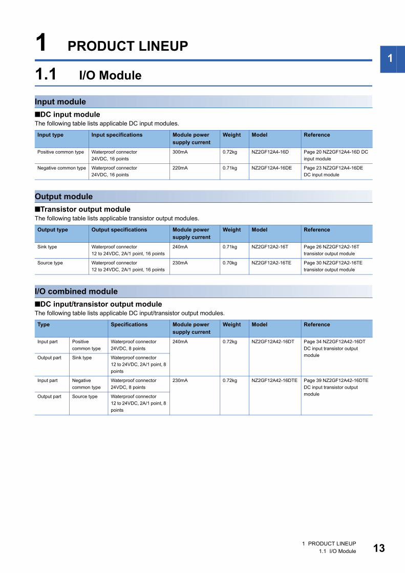
1 PRODUCT LINEUP1.1 I/O Module
Input module
■DC input moduleThe following table lists applicable DC input modules.
Output module
■Transistor output moduleThe following table lists applicable transistor output modules.
I/O combined module
■DC input/transistor output moduleThe following table lists applicable DC input/transistor output modules.
Input type Input specifications Module power supply current
Weight Model Reference
Positive common type Waterproof connector
24VDC, 16 points
300mA 0.72kg NZ2GF12A4-16D Page 20 NZ2GF12A4-16D DC
input module
Negative common type Waterproof connector
24VDC, 16 points
220mA 0.71kg NZ2GF12A4-16DE Page 23 NZ2GF12A4-16DE
DC input module
Output type Output specifications Module power supply current
Weight Model Reference
Sink type Waterproof connector
12 to 24VDC, 2A/1 point, 16 points
240mA 0.71kg NZ2GF12A2-16T Page 26 NZ2GF12A2-16T
transistor output module
Source type Waterproof connector
12 to 24VDC, 2A/1 point, 16 points
230mA 0.70kg NZ2GF12A2-16TE Page 30 NZ2GF12A2-16TE
transistor output module
Type Specifications Module power supply current
Weight Model Reference
Input part Positive
common type
Waterproof connector
24VDC, 8 points
240mA 0.72kg NZ2GF12A42-16DT Page 34 NZ2GF12A42-16DT
DC input transistor output
moduleOutput part Sink type Waterproof connector
12 to 24VDC, 2A/1 point, 8
points
Input part Negative
common type
Waterproof connector
24VDC, 8 points
230mA 0.72kg NZ2GF12A42-16DTE Page 39 NZ2GF12A42-16DTE
DC input transistor output
moduleOutput part Source type Waterproof connector
12 to 24VDC, 2A/1 point, 8
points
1 PRODUCT LINEUP1.1 I/O Module 13
14
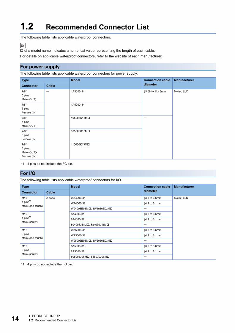
1.2 Recommended Connector ListThe following table lists applicable waterproof connectors.
Ex.
of a model name indicates a numerical value representing the length of each cable.
For details on applicable waterproof connectors, refer to the website of each manufacturer.
For power supplyThe following table lists applicable waterproof connectors for power supply.
*1 4 pins do not include the FG pin.
For I/OThe following table lists applicable waterproof connectors for I/O.
*1 4 pins do not include the FG pin.
Type Model Connection cable diameter
Manufacturer
Connector Cable
7/8"
5 pins
Male (OUT)
1A5006-34 5.08 to 11.43mm Molex, LLC
7/8"
5 pins
Female (IN)
1A5000-34
7/8"
5 pins
Male (OUT)
105006K13M
7/8"
5 pins
Female (IN)
105000K13M
7/8"
5 pins
Male (OUT)-
Female (IN)
115030K13M
Type Model Connection cable diameter
Manufacturer
Connector Cable
M12
4 pins*1
Male (one-touch)
A code WA4006-31 3.3 to 6.6mm Molex, LLC
WA4006-32 4.1 to 8.1mm
W04006E03M, 8W4030E03M
M12
4 pins*1
Male (screw)
8A4006-31 3.3 to 6.6mm
8A4006-32 4.1 to 8.1mm
804006J11M, 884030J11M
M12
5 pins
Male (one-touch)
WA5006-31 3.3 to 6.6mm
WA5006-32 4.1 to 8.1mm
W05006E03M, 8W5030E03M
M12
5 pins
Male (screw)
8A5006-31 3.3 to 6.6mm
8A5006-32 4.1 to 8.1mm
805006J06M, 885030J06M
1 PRODUCT LINEUP1.2 Recommended Connector List
1
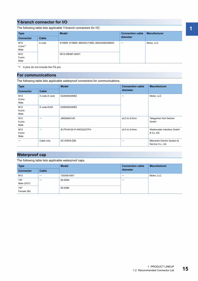
Y-branch connector for I/OThe following table lists applicable Y-branch connectors for I/O.*1 4 pins do not include the FG pin.
For communicationsThe following table lists applicable waterproof connectors for communications.
Waterproof capThe following table lists applicable waterproof caps.
Type Model Connection cable diameter
Manufacturer
Connector Cable
M12
4 pins*1
Male
A code 81590R, 81589R, 884045J11M, 8W4A30E03M003 Molex, LLC
M12
5 pins
Male
0812-05EMF-00001
Type Model Connection cable diameter
Manufacturer
Connector Cable
M12
8 pins
Male
X code-X code E22E06020M Molex, LLC
M12
8 pins
Male
X code-RJ45 E26E06020M
M12
8 pins
Male
J80026A0100 5.5 to 9.0mm Telegartner Karl Gartner
GmbH
M12
8 pins
Male
IE-PS-M12X-P-AWG22/27FH 5.5 to 9.0mm Weidmueller Interface GmbH
& Co. KG
Cable only SC-E5EW-M Mitsubishi Electric System &
Service Co., Ltd.
Type Model Connection cable diameter
Manufacturer
Connector Cable
M12 120358-0007 Molex, LLC
7/8"
Male (OUT)
65-0085
7/8"
Female (IN)
65-0086
1 PRODUCT LINEUP1.2 Recommended Connector List 15
16
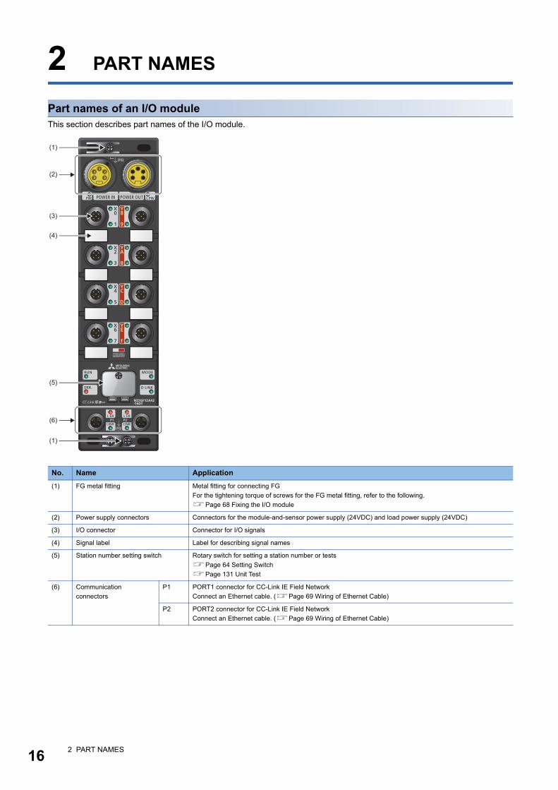
2 PART NAMES
Part names of an I/O moduleThis section describes part names of the I/O module.
No. Name Application
(1) FG metal fitting Metal fitting for connecting FG
For the tightening torque of screws for the FG metal fitting, refer to the following.
Page 68 Fixing the I/O module
(2) Power supply connectors Connectors for the module-and-sensor power supply (24VDC) and load power supply (24VDC)
(3) I/O connector Connector for I/O signals
(4) Signal label Label for describing signal names
(5) Station number setting switch Rotary switch for setting a station number or tests
Page 64 Setting Switch
Page 131 Unit Test
(6) Communication
connectors
P1 PORT1 connector for CC-Link IE Field Network
Connect an Ethernet cable. (Page 69 Wiring of Ethernet Cable)
P2 PORT2 connector for CC-Link IE Field Network
Connect an Ethernet cable. (Page 69 Wiring of Ethernet Cable)
(1)
(3)
(4)
(5)
(6)
(1)
(2)
2 PART NAMES
2
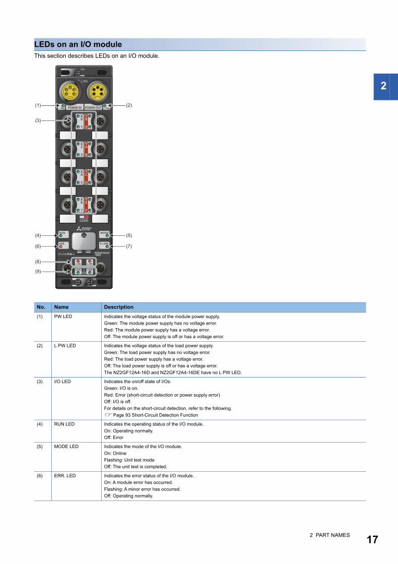
LEDs on an I/O moduleThis section describes LEDs on an I/O module.
No. Name Description
(1) PW LED Indicates the voltage status of the module power supply.
Green: The module power supply has no voltage error.
Red: The module power supply has a voltage error.
Off: The module power supply is off or has a voltage error.
(2) L PW LED Indicates the voltage status of the load power supply.
Green: The load power supply has no voltage error.
Red: The load power supply has a voltage error.
Off: The load power supply is off or has a voltage error.
The NZ2GF12A4-16D and NZ2GF12A4-16DE have no L PW LED.
(3) I/O LED Indicates the on/off state of I/Os.
Green: I/O is on.
Red: Error (short-circuit detection or power supply error)
Off: I/O is off.
For details on the short-circuit detection, refer to the following.
Page 93 Short-Circuit Detection Function
(4) RUN LED Indicates the operating status of the I/O module.
On: Operating normally.
Off: Error
(5) MODE LED Indicates the mode of the I/O module.
On: Online
Flashing: Unit test mode
Off: The unit test is completed.
(6) ERR. LED Indicates the error status of the I/O module.
On: A module error has occurred.
Flashing: A minor error has occurred.
Off: Operating normally.
(1) (2)
(4) (5)
(6) (7)
(3)
(8)
(9)
2 PART NAMES 17
18
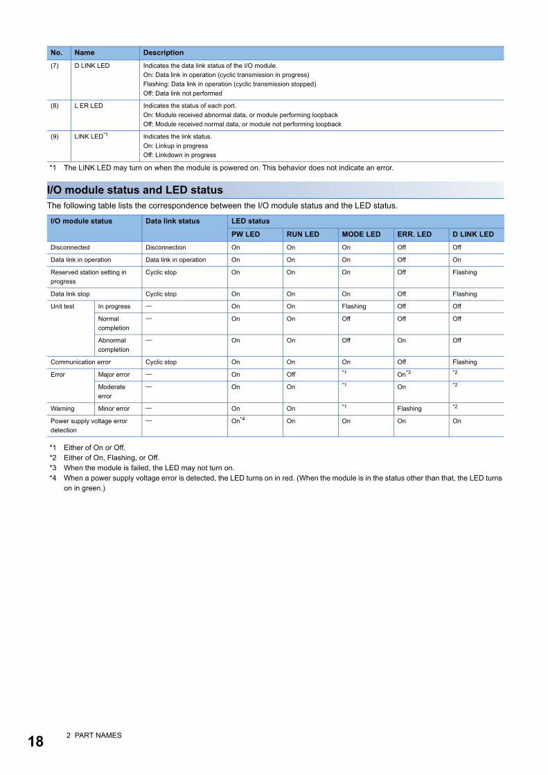
*1 The LINK LED may turn on when the module is powered on. This behavior does not indicate an error.
I/O module status and LED statusThe following table lists the correspondence between the I/O module status and the LED status.
*1 Either of On or Off.*2 Either of On, Flashing, or Off.*3 When the module is failed, the LED may not turn on.*4 When a power supply voltage error is detected, the LED turns on in red. (When the module is in the status other than that, the LED turns
on in green.)
(7) D LINK LED Indicates the data link status of the I/O module.
On: Data link in operation (cyclic transmission in progress)
Flashing: Data link in operation (cyclic transmission stopped)
Off: Data link not performed
(8) L ER LED Indicates the status of each port.
On: Module received abnormal data, or module performing loopback
Off: Module received normal data, or module not performing loopback
(9) LINK LED*1 Indicates the link status.
On: Linkup in progress
Off: Linkdown in progress
I/O module status Data link status LED status
PW LED RUN LED MODE LED ERR. LED D LINK LED
Disconnected Disconnection On On On Off Off
Data link in operation Data link in operation On On On Off On
Reserved station setting in
progress
Cyclic stop On On On Off Flashing
Data link stop Cyclic stop On On On Off Flashing
Unit test In progress On On Flashing Off Off
Normal
completion
On On Off Off Off
Abnormal
completion
On On Off On Off
Communication error Cyclic stop On On On Off Flashing
Error Major error On Off *1 On*3 *2
Moderate
error
On On *1 On *2
Warning Minor error On On *1 Flashing *2
Power supply voltage error
detection
On*4 On On On On
No. Name Description
2 PART NAMES
3
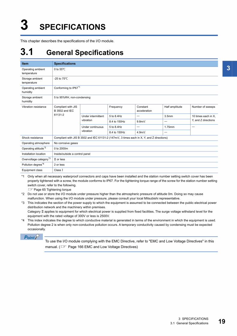
3 SPECIFICATIONS
This chapter describes the specifications of the I/O module.
3.1 General Specifications
*1 Only when all necessary waterproof connectors and caps have been installed and the station number setting switch cover has been properly tightened with a screw, the module conforms to IP67. For the tightening torque range of the screw for the station number setting switch cover, refer to the following.Page 65 Tightening torque
*2 Do not use or store the I/O module under pressure higher than the atmospheric pressure of altitude 0m. Doing so may cause malfunction. When using the I/O module under pressure, please consult your local Mitsubishi representative.
*3 This indicates the section of the power supply to which the equipment is assumed to be connected between the public electrical power distribution network and the machinery within premises.Category applies to equipment for which electrical power is supplied from fixed facilities. The surge voltage withstand level for the equipment with the rated voltage of 300V or less is 2500V.
*4 This index indicates the degree to which conductive material is generated in terms of the environment in which the equipment is used.Pollution degree 2 is when only non-conductive pollution occurs. A temporary conductivity caused by condensing must be expected occasionally.
To use the I/O module complying with the EMC Directive, refer to "EMC and Low Voltage Directives" in this
manual. ( Page 166 EMC and Low Voltage Directives)
Item Specifications
Operating ambient
temperature
0 to 55
Storage ambient
temperature
-25 to 75
Operating ambient
humidity
Conforming to IP67*1
Storage ambient
humidity
5 to 95%RH, non-condensing
Vibration resistance Compliant with JIS
B 3502 and IEC
61131-2
Frequency Constant
acceleration
Half amplitude Number of sweeps
Under intermittent
vibration
5 to 8.4Hz 3.5mm 10 times each in X,
Y, and Z directions8.4 to 150Hz 9.8m/
Under continuous
vibration
5 to 8.4Hz 1.75mm
8.4 to 150Hz 4.9m/
Shock resistance Compliant with JIS B 3502 and IEC 61131-2 (147m/, 3 times each in X, Y, and Z directions)
Operating atmosphere No corrosive gases
Operating altitude*2 0 to 2000m
Installation location Inside/outside a control panel
Overvoltage category*3 or less
Pollution degree*4 2 or less
Equipment class Class
3 SPECIFICATIONS3.1 General Specifications 19
20
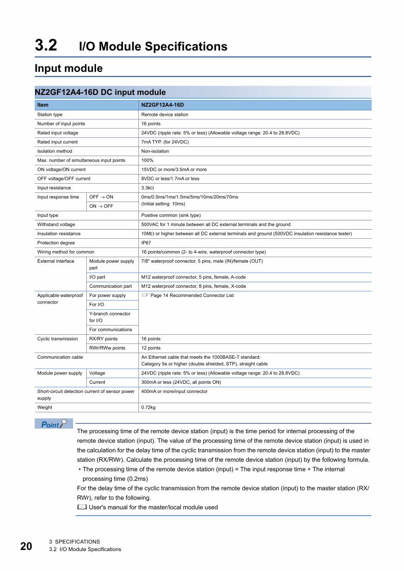
3.2 I/O Module Specifications
Input module
NZ2GF12A4-16D DC input module
The processing time of the remote device station (input) is the time period for internal processing of the
remote device station (input). The value of the processing time of the remote device station (input) is used in
the calculation for the delay time of the cyclic transmission from the remote device station (input) to the master
station (RX/RWr). Calculate the processing time of the remote device station (input) by the following formula.
• The processing time of the remote device station (input) = The input response time + The internal
processing time (0.2ms)
For the delay time of the cyclic transmission from the remote device station (input) to the master station (RX/
RWr), refer to the following.
User's manual for the master/local module used
Item NZ2GF12A4-16D
Station type Remote device station
Number of input points 16 points
Rated input voltage 24VDC (ripple rate: 5% or less) (Allowable voltage range: 20.4 to 28.8VDC)
Rated input current 7mA TYP. (for 24VDC)
Isolation method Non-isolation
Max. number of simultaneous input points 100%
ON voltage/ON current 15VDC or more/3.5mA or more
OFF voltage/OFF current 8VDC or less/1.7mA or less
Input resistance 3.3k
Input response time OFF ON 0ms/0.5ms/1ms/1.5ms/5ms/10ms/20ms/70ms
(Initial setting: 10ms)ON OFF
Input type Positive common (sink type)
Withstand voltage 500VAC for 1 minute between all DC external terminals and the ground
Insulation resistance 10M or higher between all DC external terminals and ground (500VDC insulation resistance tester)
Protection degree IP67
Wiring method for common 16 points/common (2- to 4-wire, waterproof connector type)
External interface Module power supply
part
7/8" waterproof connector, 5 pins, male (IN)/female (OUT)
I/O part M12 waterproof connector, 5 pins, female, A-code
Communication part M12 waterproof connector, 8 pins, female, X-code
Applicable waterproof
connector
For power supply Page 14 Recommended Connector List
For I/O
Y-branch connector
for I/O
For communications
Cyclic transmission RX/RY points 16 points
RWr/RWw points 12 points
Communication cable An Ethernet cable that meets the 1000BASE-T standard:
Category 5e or higher (double shielded, STP), straight cable
Module power supply Voltage 24VDC (ripple rate: 5% or less) (Allowable voltage range: 20.4 to 28.8VDC)
Current 300mA or less (24VDC, all points ON)
Short-circuit detection current of sensor power
supply
400mA or more/input connector
Weight 0.72kg
3 SPECIFICATIONS3.2 I/O Module Specifications
3
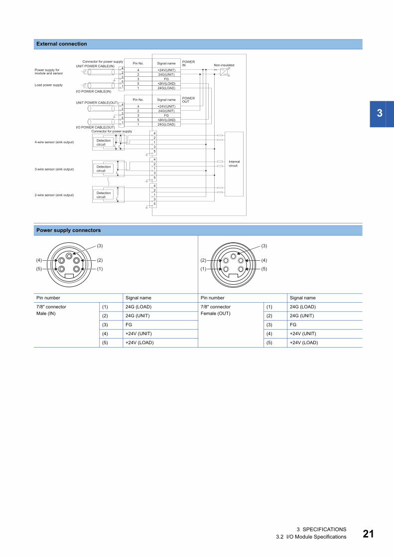
External connection
Power supply connectors
Pin number Signal name Pin number Signal name
7/8" connector
Male (IN)
(1) 24G (LOAD) 7/8" connector
Female (OUT)
(1) 24G (LOAD)
(2) 24G (UNIT) (2) 24G (UNIT)
(3) FG (3) FG
(4) +24V (UNIT) (4) +24V (UNIT)
(5) +24V (LOAD) (5) +24V (LOAD)
I/O POWER CABLE(IN)
UNIT POWER CABLE(IN)POWER IN
POWER OUT
42135
I/O POWER CABLE(OUT)
UNIT POWER CABLE(OUT)+24V(UNIT)24G(UNIT)
FG+24V(LOAD)24G(LOAD)
42351
42351
+24V(UNIT)24G(UNIT)
FG+24V(LOAD)24G(LOAD)
42351
42351
42135
42135
Internal circuit
Load power supply
Non-insulatedConnector for power supply
Power supply for module and sensor
Signal namePin No.
Connector for power supply
Signal namePin No.
4-wire sensor (sink output)
3-wire sensor (sink output)
2-wire sensor (sink output)
Detection circuit
Detection circuit
Detection circuit
(2)
(3)
(1)
(4)
(5)
(4)
(3)
(5)
(2)
(1)
3 SPECIFICATIONS3.2 I/O Module Specifications 21
22
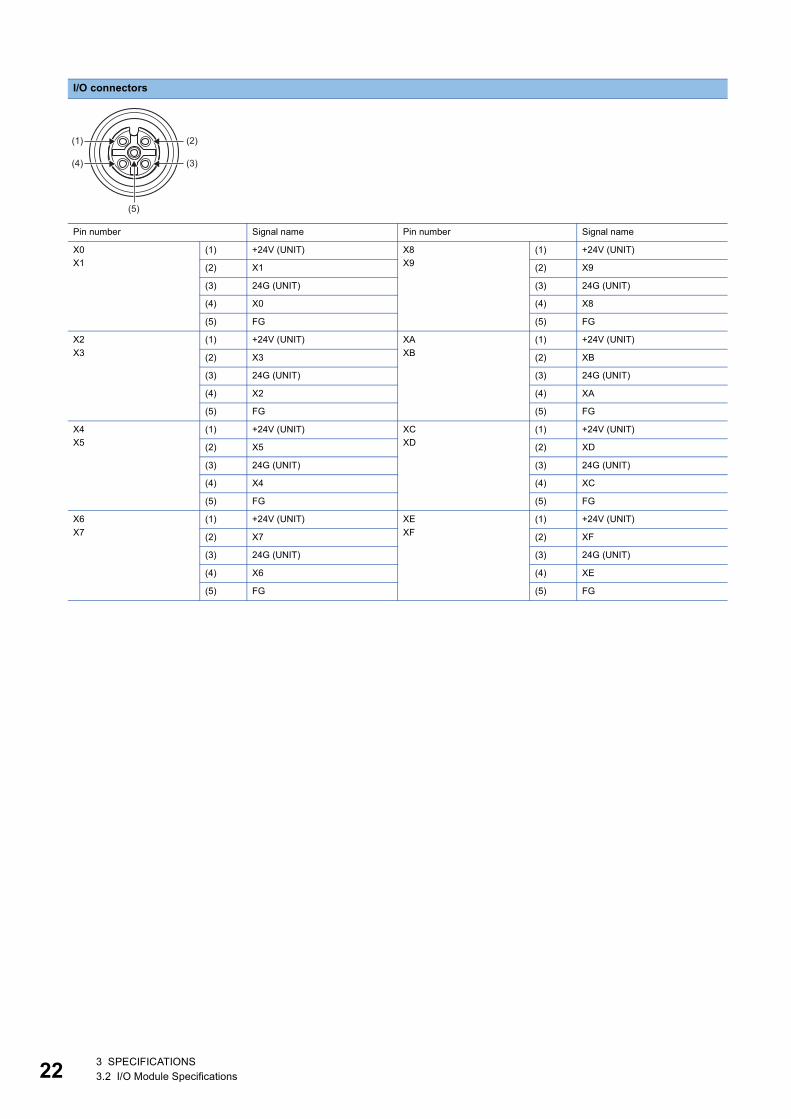
I/O connectors
Pin number Signal name Pin number Signal name
X0
X1
(1) +24V (UNIT) X8
X9
(1) +24V (UNIT)
(2) X1 (2) X9
(3) 24G (UNIT) (3) 24G (UNIT)
(4) X0 (4) X8
(5) FG (5) FG
X2
X3
(1) +24V (UNIT) XA
XB
(1) +24V (UNIT)
(2) X3 (2) XB
(3) 24G (UNIT) (3) 24G (UNIT)
(4) X2 (4) XA
(5) FG (5) FG
X4
X5
(1) +24V (UNIT) XC
XD
(1) +24V (UNIT)
(2) X5 (2) XD
(3) 24G (UNIT) (3) 24G (UNIT)
(4) X4 (4) XC
(5) FG (5) FG
X6
X7
(1) +24V (UNIT) XE
XF
(1) +24V (UNIT)
(2) X7 (2) XF
(3) 24G (UNIT) (3) 24G (UNIT)
(4) X6 (4) XE
(5) FG (5) FG
(2)
(3)
(5)
(1)
(4)
3 SPECIFICATIONS3.2 I/O Module Specifications
3
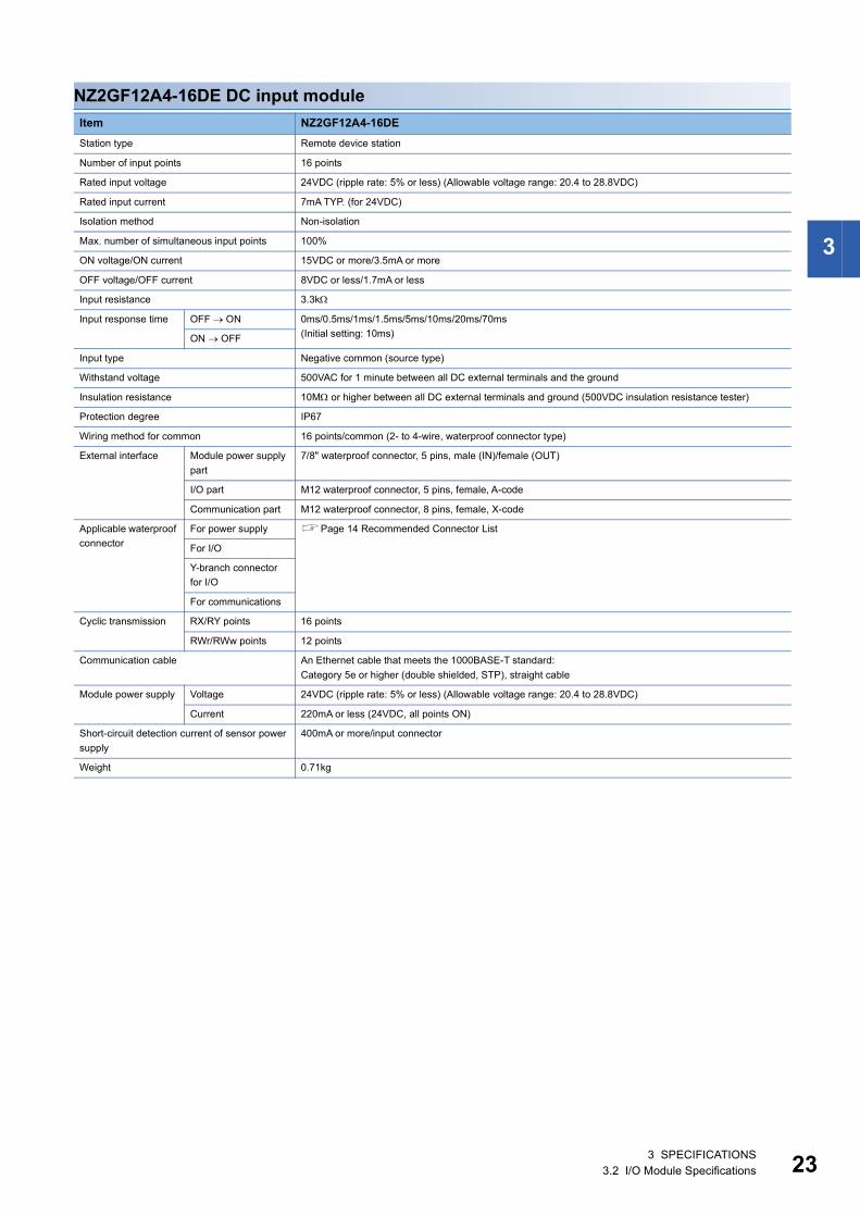
NZ2GF12A4-16DE DC input module
Item NZ2GF12A4-16DE
Station type Remote device station
Number of input points 16 points
Rated input voltage 24VDC (ripple rate: 5% or less) (Allowable voltage range: 20.4 to 28.8VDC)
Rated input current 7mA TYP. (for 24VDC)
Isolation method Non-isolation
Max. number of simultaneous input points 100%
ON voltage/ON current 15VDC or more/3.5mA or more
OFF voltage/OFF current 8VDC or less/1.7mA or less
Input resistance 3.3k
Input response time OFF ON 0ms/0.5ms/1ms/1.5ms/5ms/10ms/20ms/70ms
(Initial setting: 10ms)ON OFF
Input type Negative common (source type)
Withstand voltage 500VAC for 1 minute between all DC external terminals and the ground
Insulation resistance 10M or higher between all DC external terminals and ground (500VDC insulation resistance tester)
Protection degree IP67
Wiring method for common 16 points/common (2- to 4-wire, waterproof connector type)
External interface Module power supply
part
7/8" waterproof connector, 5 pins, male (IN)/female (OUT)
I/O part M12 waterproof connector, 5 pins, female, A-code
Communication part M12 waterproof connector, 8 pins, female, X-code
Applicable waterproof
connector
For power supply Page 14 Recommended Connector List
For I/O
Y-branch connector
for I/O
For communications
Cyclic transmission RX/RY points 16 points
RWr/RWw points 12 points
Communication cable An Ethernet cable that meets the 1000BASE-T standard:
Category 5e or higher (double shielded, STP), straight cable
Module power supply Voltage 24VDC (ripple rate: 5% or less) (Allowable voltage range: 20.4 to 28.8VDC)
Current 220mA or less (24VDC, all points ON)
Short-circuit detection current of sensor power
supply
400mA or more/input connector
Weight 0.71kg
3 SPECIFICATIONS3.2 I/O Module Specifications 23
24
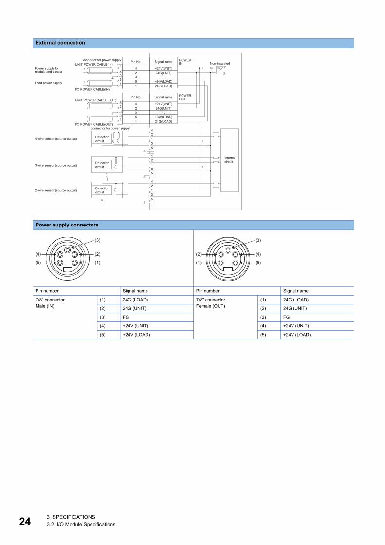
External connection
Power supply connectors
Pin number Signal name Pin number Signal name
7/8" connector
Male (IN)
(1) 24G (LOAD) 7/8" connector
Female (OUT)
(1) 24G (LOAD)
(2) 24G (UNIT) (2) 24G (UNIT)
(3) FG (3) FG
(4) +24V (UNIT) (4) +24V (UNIT)
(5) +24V (LOAD) (5) +24V (LOAD)
I/O POWER CABLE(IN)
UNIT POWER CABLE(IN)POWER IN
POWER OUT
42135
I/O POWER CABLE(OUT)
UNIT POWER CABLE(OUT)+24V(UNIT)24G(UNIT)
FG+24V(LOAD)24G(LOAD)
42351
42351
+24V(UNIT)24G(UNIT)
FG+24V(LOAD)24G(LOAD)
42351
42351
42135
42135
Internal circuit
Load power supply
Non-insulatedConnector for power supply
Power supply for module and sensor
Signal namePin No.
Connector for power supply
Signal namePin No.
4-wire sensor (source output)
3-wire sensor (source output)
2-wire sensor (source output)
Detection circuit
Detection circuit
Detection circuit
(2)
(3)
(1)
(4)
(5)
(4)
(3)
(5)
(2)
(1)
3 SPECIFICATIONS3.2 I/O Module Specifications

3
I/O connectors
Pin number Signal name Pin number Signal name
X0
X1
(1) +24V (UNIT) X8
X9
(1) +24V (UNIT)
(2) X1 (2) X9
(3) 24G (UNIT) (3) 24G (UNIT)
(4) X0 (4) X8
(5) FG (5) FG
X2
X3
(1) +24V (UNIT) XA
XB
(1) +24V (UNIT)
(2) X3 (2) XB
(3) 24G (UNIT) (3) 24G (UNIT)
(4) X2 (4) XA
(5) FG (5) FG
X4
X5
(1) +24V (UNIT) XC
XD
(1) +24V (UNIT)
(2) X5 (2) XD
(3) 24G (UNIT) (3) 24G (UNIT)
(4) X4 (4) XC
(5) FG (5) FG
X6
X7
(1) +24V (UNIT) XE
XF
(1) +24V (UNIT)
(2) X7 (2) XF
(3) 24G (UNIT) (3) 24G (UNIT)
(4) X6 (4) XE
(5) FG (5) FG
(2)
(3)
(5)
(1)
(4)
3 SPECIFICATIONS3.2 I/O Module Specifications 25
26
Output module
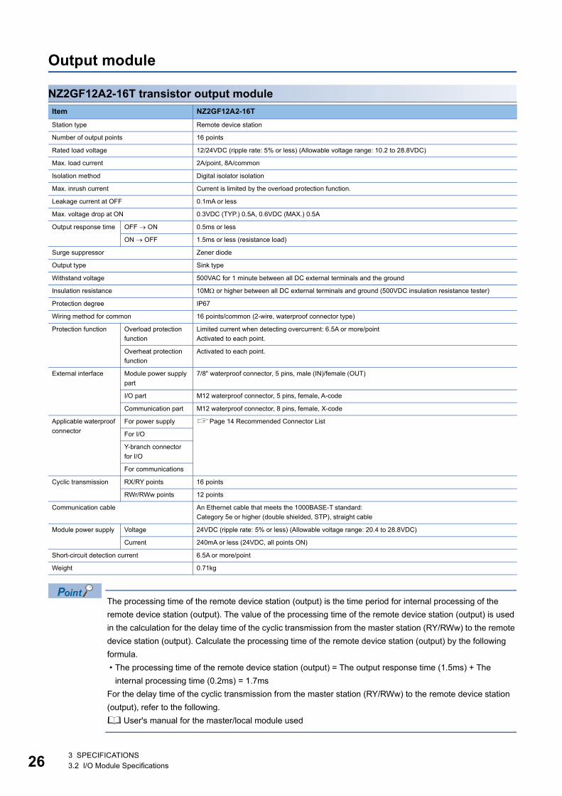
NZ2GF12A2-16T transistor output module
The processing time of the remote device station (output) is the time period for internal processing of the
remote device station (output). The value of the processing time of the remote device station (output) is used
in the calculation for the delay time of the cyclic transmission from the master station (RY/RWw) to the remote
device station (output). Calculate the processing time of the remote device station (output) by the following
formula.
• The processing time of the remote device station (output) = The output response time (1.5ms) + The
internal processing time (0.2ms) = 1.7ms
For the delay time of the cyclic transmission from the master station (RY/RWw) to the remote device station
(output), refer to the following.
User's manual for the master/local module used
Item NZ2GF12A2-16T
Station type Remote device station
Number of output points 16 points
Rated load voltage 12/24VDC (ripple rate: 5% or less) (Allowable voltage range: 10.2 to 28.8VDC)
Max. load current 2A/point, 8A/common
Isolation method Digital isolator isolation
Max. inrush current Current is limited by the overload protection function.
Leakage current at OFF 0.1mA or less
Max. voltage drop at ON 0.3VDC (TYP.) 0.5A, 0.6VDC (MAX.) 0.5A
Output response time OFF ON 0.5ms or less
ON OFF 1.5ms or less (resistance load)
Surge suppressor Zener diode
Output type Sink type
Withstand voltage 500VAC for 1 minute between all DC external terminals and the ground
Insulation resistance 10M or higher between all DC external terminals and ground (500VDC insulation resistance tester)
Protection degree IP67
Wiring method for common 16 points/common (2-wire, waterproof connector type)
Protection function Overload protection
function
Limited current when detecting overcurrent: 6.5A or more/point
Activated to each point.
Overheat protection
function
Activated to each point.
External interface Module power supply
part
7/8" waterproof connector, 5 pins, male (IN)/female (OUT)
I/O part M12 waterproof connector, 5 pins, female, A-code
Communication part M12 waterproof connector, 8 pins, female, X-code
Applicable waterproof
connector
For power supply Page 14 Recommended Connector List
For I/O
Y-branch connector
for I/O
For communications
Cyclic transmission RX/RY points 16 points
RWr/RWw points 12 points
Communication cable An Ethernet cable that meets the 1000BASE-T standard:
Category 5e or higher (double shielded, STP), straight cable
Module power supply Voltage 24VDC (ripple rate: 5% or less) (Allowable voltage range: 20.4 to 28.8VDC)
Current 240mA or less (24VDC, all points ON)
Short-circuit detection current 6.5A or more/point
Weight 0.71kg
3 SPECIFICATIONS3.2 I/O Module Specifications
3
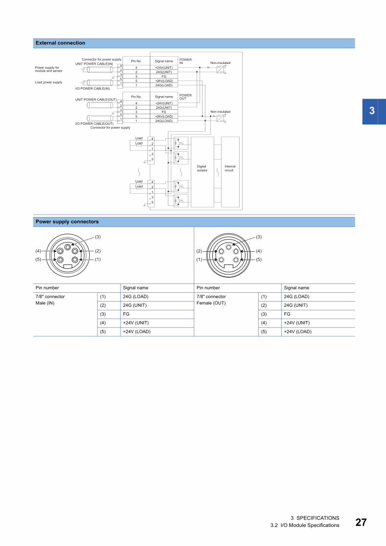
External connection
Power supply connectors
Pin number Signal name Pin number Signal name
7/8" connector
Male (IN)
(1) 24G (LOAD) 7/8" connector
Female (OUT)
(1) 24G (LOAD)
(2) 24G (UNIT) (2) 24G (UNIT)
(3) FG (3) FG
(4) +24V (UNIT) (4) +24V (UNIT)
(5) +24V (LOAD) (5) +24V (LOAD)
I/O POWER CABLE(IN)
UNIT POWER CABLE(IN)POWER IN
POWER OUT
I/O POWER CABLE(OUT)
UNIT POWER CABLE(OUT)+24V(UNIT)24G(UNIT)
FG+24V(LOAD)24G(LOAD)
42351
42351
+24V(UNIT)24G(UNIT)
FG+24V(LOAD)24G(LOAD)
42351
42351
42135
42135
Load power supply
Non-insulated
Non-insulated
Connector for power supply
Power supply for module and sensor
Signal namePin No.
Connector for power supply
Signal namePin No.
Internal circuit
Digital isolator
LoadLoad
LoadLoad
(2)
(3)
(1)
(4)
(5)
(4)
(3)
(5)
(2)
(1)
3 SPECIFICATIONS3.2 I/O Module Specifications 27
28
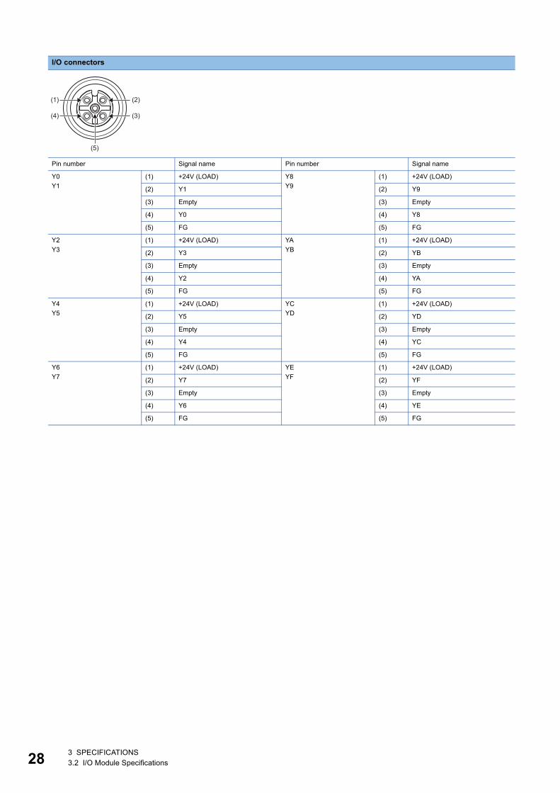
I/O connectors
Pin number Signal name Pin number Signal name
Y0
Y1
(1) +24V (LOAD) Y8
Y9
(1) +24V (LOAD)
(2) Y1 (2) Y9
(3) Empty (3) Empty
(4) Y0 (4) Y8
(5) FG (5) FG
Y2
Y3
(1) +24V (LOAD) YA
YB
(1) +24V (LOAD)
(2) Y3 (2) YB
(3) Empty (3) Empty
(4) Y2 (4) YA
(5) FG (5) FG
Y4
Y5
(1) +24V (LOAD) YC
YD
(1) +24V (LOAD)
(2) Y5 (2) YD
(3) Empty (3) Empty
(4) Y4 (4) YC
(5) FG (5) FG
Y6
Y7
(1) +24V (LOAD) YE
YF
(1) +24V (LOAD)
(2) Y7 (2) YF
(3) Empty (3) Empty
(4) Y6 (4) YE
(5) FG (5) FG
(2)
(3)
(5)
(1)
(4)
3 SPECIFICATIONS3.2 I/O Module Specifications

3
Derating chart
X: Ambient temperature ()
Y: Output current (A)
●: Output current per point
: Output current per common
Y
(55,4)
9
8
7
6
5
4
3
2
1
00 10 20 30 40 50 55
X
(55,1)
(35, 2)
(35, 8)
3 SPECIFICATIONS3.2 I/O Module Specifications 29
30
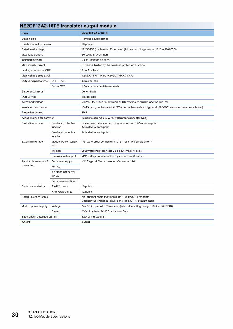
NZ2GF12A2-16TE transistor output module
Item NZ2GF12A2-16TE
Station type Remote device station
Number of output points 16 points
Rated load voltage 12/24VDC (ripple rate: 5% or less) (Allowable voltage range: 10.2 to 28.8VDC)
Max. load current 2A/point, 8A/common
Isolation method Digital isolator isolation
Max. inrush current Current is limited by the overload protection function.
Leakage current at OFF 0.1mA or less
Max. voltage drop at ON 0.5VDC (TYP.) 0.5A, 0.8VDC (MAX.) 0.5A
Output response time OFF ON 0.5ms or less
ON OFF 1.5ms or less (resistance load)
Surge suppressor Zener diode
Output type Source type
Withstand voltage 500VAC for 1 minute between all DC external terminals and the ground
Insulation resistance 10M or higher between all DC external terminals and ground (500VDC insulation resistance tester)
Protection degree IP67
Wiring method for common 16 points/common (2-wire, waterproof connector type)
Protection function Overload protection
function
Limited current when detecting overcurrent: 6.5A or more/point
Activated to each point.
Overheat protection
function
Activated to each point.
External interface Module power supply
part
7/8" waterproof connector, 5 pins, male (IN)/female (OUT)
I/O part M12 waterproof connector, 5 pins, female, A-code
Communication part M12 waterproof connector, 8 pins, female, X-code
Applicable waterproof
connector
For power supply Page 14 Recommended Connector List
For I/O
Y-branch connector
for I/O
For communications
Cyclic transmission RX/RY points 16 points
RWr/RWw points 12 points
Communication cable An Ethernet cable that meets the 1000BASE-T standard:
Category 5e or higher (double shielded, STP), straight cable
Module power supply Voltage 24VDC (ripple rate: 5% or less) (Allowable voltage range: 20.4 to 28.8VDC)
Current 230mA or less (24VDC, all points ON)
Short-circuit detection current 6.5A or more/point
Weight 0.70kg
3 SPECIFICATIONS3.2 I/O Module Specifications
3
External connection
Power supply connectors
Pin number Signal name Pin number Signal name
7/8" connector
Male (IN)
(1) 24G (LOAD) 7/8" connector
Female (OUT)
(1) 24G (LOAD)
(2) 24G (UNIT) (2) 24G (UNIT)
(3) FG (3) FG
(4) +24V (UNIT) (4) +24V (UNIT)
(5) +24V (LOAD) (5) +24V (LOAD)
I/O POWER CABLE(IN)
UNIT POWER CABLE(IN)POWER IN
POWER OUT
I/O POWER CABLE(OUT)
UNIT POWER CABLE(OUT)+24V(UNIT)24G(UNIT)
FG+24V(LOAD)24G(LOAD)
42351
42351
+24V(UNIT)24G(UNIT)
FG+24V(LOAD)24G(LOAD)
42351
42351
42135
42135
Load power supply
Non-insulated
Non-insulated
Connector for power supply
Power supply for module and sensor
Signal namePin No.
Connector for power supply
Signal namePin No.
Internal circuit
Digital isolator
LoadLoad
LoadLoad
(2)
(3)
(1)
(4)
(5)
(4)
(3)
(5)
(2)
(1)
3 SPECIFICATIONS3.2 I/O Module Specifications 31
32
I/O connectors
Pin number Signal name Pin number Signal name
Y0
Y1
(1) Empty Y8
Y9
(1) Empty
(2) Y1 (2) Y9
(3) 24G (LOAD) (3) 24G (LOAD)
(4) Y0 (4) Y8
(5) FG (5) FG
Y2
Y3
(1) Empty YA
YB
(1) Empty
(2) Y3 (2) YB
(3) 24G (LOAD) (3) 24G (LOAD)
(4) Y2 (4) YA
(5) FG (5) FG
Y4
Y5
(1) Empty YC
YD
(1) Empty
(2) Y5 (2) YD
(3) 24G (LOAD) (3) 24G (LOAD)
(4) Y4 (4) YC
(5) FG (5) FG
Y6
Y7
(1) Empty YE
YF
(1) Empty
(2) Y7 (2) YF
(3) 24G (LOAD) (3) 24G (LOAD)
(4) Y6 (4) YE
(5) FG (5) FG
(2)
(3)
(5)
(1)
(4)
3 SPECIFICATIONS3.2 I/O Module Specifications

3
Derating chart
X: Ambient temperature ()
Y: Output current (A)
●: Output current per point
: Output current per common
Y
(55,4)
9
8
7
6
5
4
3
2
1
00 10 20 30 40 50 55
X
(55,1)
(35, 2)
(35, 8)
3 SPECIFICATIONS3.2 I/O Module Specifications 33
34
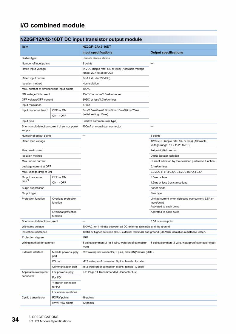
I/O combined module
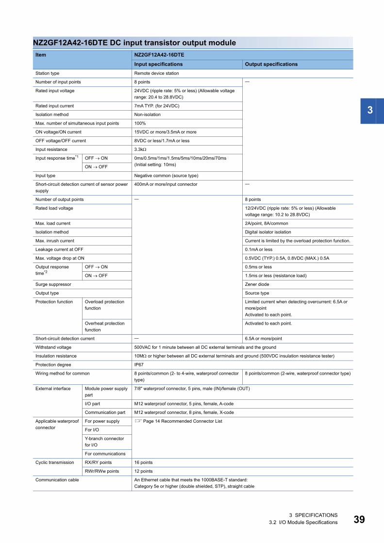
NZ2GF12A42-16DT DC input transistor output module
Item NZ2GF12A42-16DT
Input specifications Output specifications
Station type Remote device station
Number of input points 8 points
Rated input voltage 24VDC (ripple rate: 5% or less) (Allowable voltage
range: 20.4 to 28.8VDC)
Rated input current 7mA TYP. (for 24VDC)
Isolation method Non-isolation
Max. number of simultaneous input points 100%
ON voltage/ON current 15VDC or more/3.5mA or more
OFF voltage/OFF current 8VDC or less/1.7mA or less
Input resistance 3.3k
Input response time*1 OFF ON 0ms/0.5ms/1ms/1.5ms/5ms/10ms/20ms/70ms
(Initial setting: 10ms)ON OFF
Input type Positive common (sink type)
Short-circuit detection current of sensor power
supply
400mA or more/input connector
Number of output points 8 points
Rated load voltage 12/24VDC (ripple rate: 5% or less) (Allowable
voltage range: 10.2 to 28.8VDC)
Max. load current 2A/point, 8A/common
Isolation method Digital isolator isolation
Max. inrush current Current is limited by the overload protection function.
Leakage current at OFF 0.1mA or less
Max. voltage drop at ON 0.3VDC (TYP.) 0.5A, 0.6VDC (MAX.) 0.5A
Output response
time*2OFF ON 0.5ms or less
ON OFF 1.5ms or less (resistance load)
Surge suppressor Zener diode
Output type Sink type
Protection function Overload protection
function
Limited current when detecting overcurrent: 6.5A or
more/point
Activated to each point.
Overheat protection
function
Activated to each point.
Short-circuit detection current 6.5A or more/point
Withstand voltage 500VAC for 1 minute between all DC external terminals and the ground
Insulation resistance 10M or higher between all DC external terminals and ground (500VDC insulation resistance tester)
Protection degree IP67
Wiring method for common 8 points/common (2- to 4-wire, waterproof connector
type)
8 points/common (2-wire, waterproof connector type)
External interface Module power supply
part
7/8" waterproof connector, 5 pins, male (IN)/female (OUT)
I/O part M12 waterproof connector, 5 pins, female, A-code
Communication part M12 waterproof connector, 8 pins, female, X-code
Applicable waterproof
connector
For power supply Page 14 Recommended Connector List
For I/O
Y-branch connector
for I/O
For communications
Cyclic transmission RX/RY points 16 points
RWr/RWw points 12 points
3 SPECIFICATIONS3.2 I/O Module Specifications
3
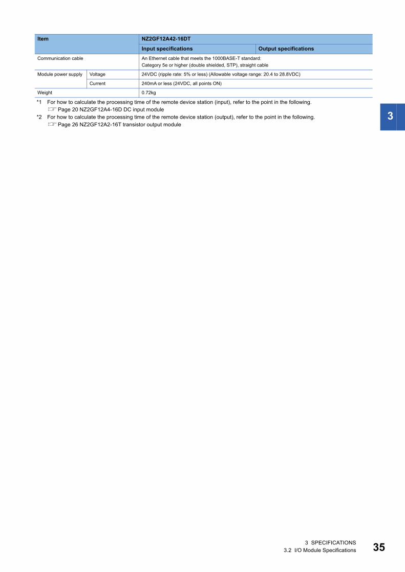
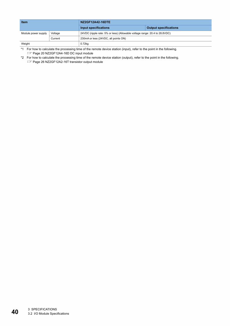
*1 For how to calculate the processing time of the remote device station (input), refer to the point in the following.Page 20 NZ2GF12A4-16D DC input module
*2 For how to calculate the processing time of the remote device station (output), refer to the point in the following.Page 26 NZ2GF12A2-16T transistor output module
Communication cable An Ethernet cable that meets the 1000BASE-T standard:
Category 5e or higher (double shielded, STP), straight cable
Module power supply Voltage 24VDC (ripple rate: 5% or less) (Allowable voltage range: 20.4 to 28.8VDC)
Current 240mA or less (24VDC, all points ON)
Weight 0.72kg
Item NZ2GF12A42-16DT
Input specifications Output specifications
3 SPECIFICATIONS3.2 I/O Module Specifications 35
36
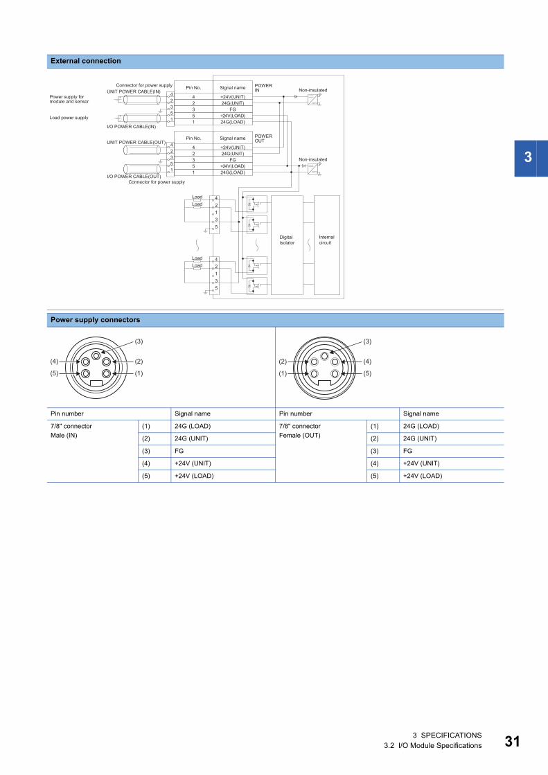
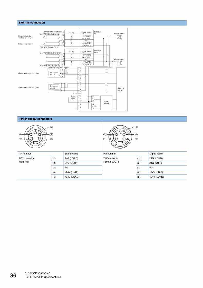
External connection
Power supply connectors
Pin number Signal name Pin number Signal name
7/8" connector
Male (IN)
(1) 24G (LOAD) 7/8" connector
Female (OUT)
(1) 24G (LOAD)
(2) 24G (UNIT) (2) 24G (UNIT)
(3) FG (3) FG
(4) +24V (UNIT) (4) +24V (UNIT)
(5) +24V (LOAD) (5) +24V (LOAD)
42135
42135
I/O POWER CABLE(IN)
UNIT POWER CABLE(IN)POWER IN
POWER OUT
I/O POWER CABLE(OUT)
UNIT POWER CABLE(OUT)+24V(UNIT)24G(UNIT)
FG+24V(LOAD)24G(LOAD)
42351
42351
+24V(UNIT)24G(UNIT)
FG+24V(LOAD)24G(LOAD)
42351
42351
42135
Load power supply
Non-insulated
Non-insulated
Connector for power supply
Power supply for module and sensor
Signal namePin No.
Connector for power supply
Signal namePin No.
Internal circuit
Digital isolator
LoadLoad
Detection circuit
Detection circuit
4-wire sensor (sink output)
3-wire sensor (sink output)
(2)
(3)
(1)
(4)
(5)
(4)
(3)
(5)
(2)
(1)
3 SPECIFICATIONS3.2 I/O Module Specifications
3
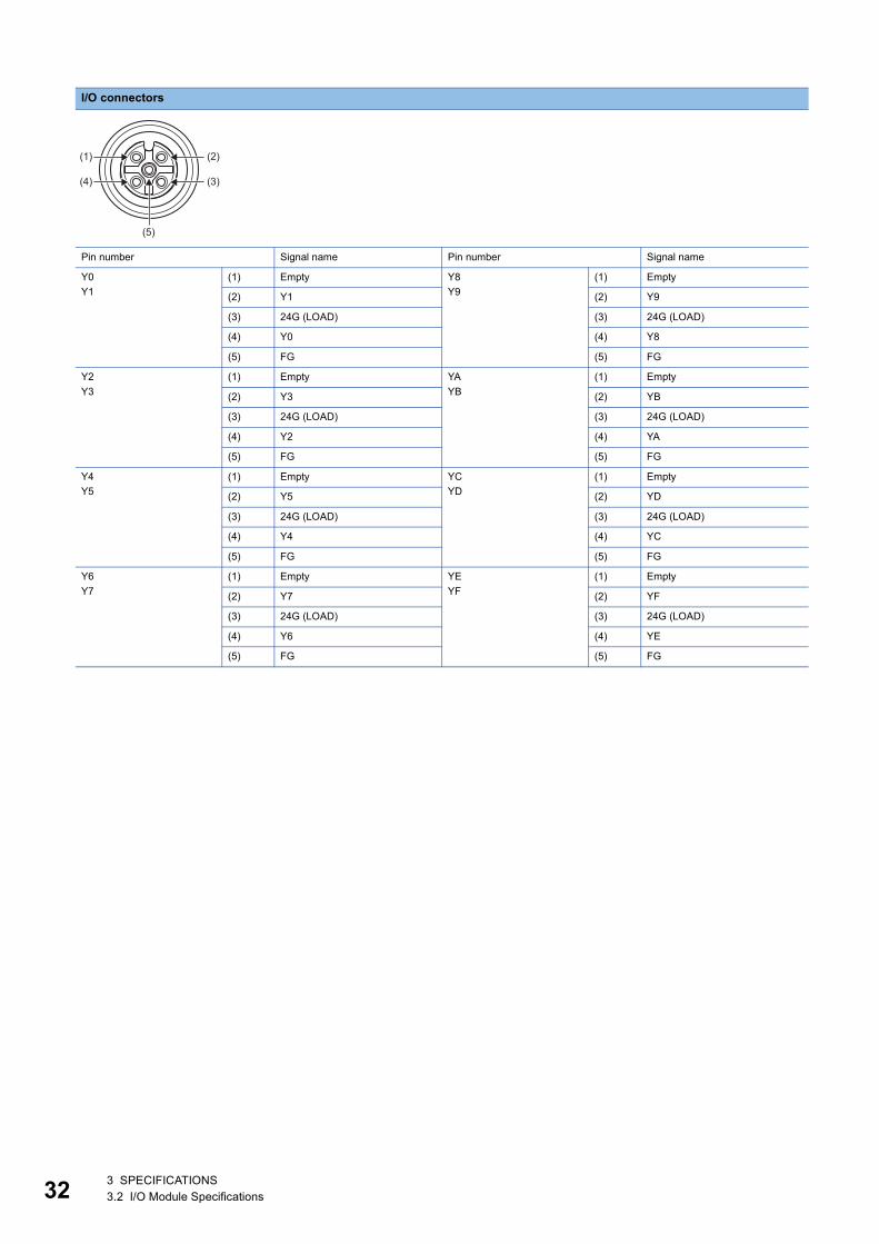
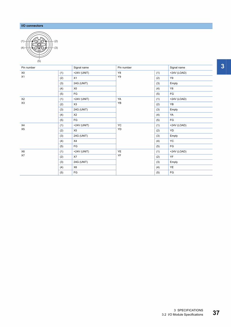
I/O connectors
Pin number Signal name Pin number Signal name
X0
X1
(1) +24V (UNIT) Y8
Y9
(1) +24V (LOAD)
(2) X1 (2) Y9
(3) 24G (UNIT) (3) Empty
(4) X0 (4) Y8
(5) FG (5) FG
X2
X3
(1) +24V (UNIT) YA
YB
(1) +24V (LOAD)
(2) X3 (2) YB
(3) 24G (UNIT) (3) Empty
(4) X2 (4) YA
(5) FG (5) FG
X4
X5
(1) +24V (UNIT) YC
YD
(1) +24V (LOAD)
(2) X5 (2) YD
(3) 24G (UNIT) (3) Empty
(4) X4 (4) YC
(5) FG (5) FG
X6
X7
(1) +24V (UNIT) YE
YF
(1) +24V (LOAD)
(2) X7 (2) YF
(3) 24G (UNIT) (3) Empty
(4) X6 (4) YE
(5) FG (5) FG
(2)
(3)
(5)
(1)
(4)
3 SPECIFICATIONS3.2 I/O Module Specifications 37
38
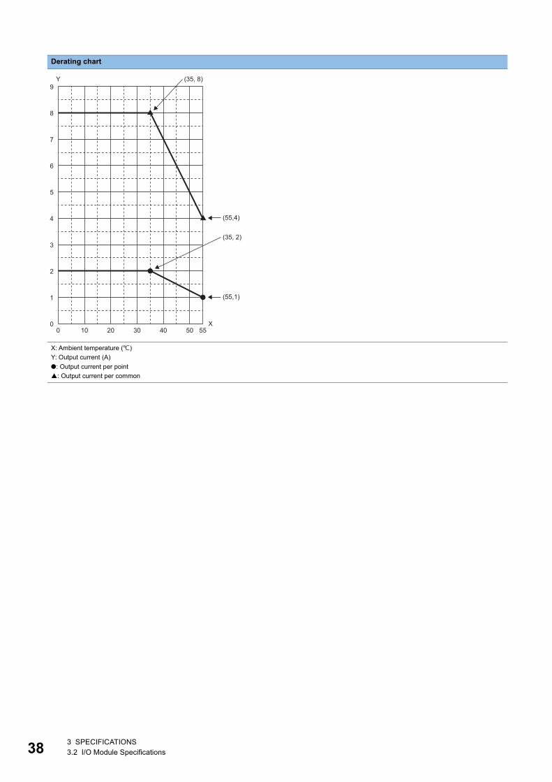
Derating chart
X: Ambient temperature ()
Y: Output current (A)
●: Output current per point
: Output current per common
Y
(55,4)
9
8
7
6
5
4
3
2
1
00 10 20 30 40 50 55
X
(55,1)
(35, 2)
(35, 8)
3 SPECIFICATIONS3.2 I/O Module Specifications
3
NZ2GF12A42-16DTE DC input transistor output module
Item NZ2GF12A42-16DTE
Input specifications Output specifications
Station type Remote device station
Number of input points 8 points
Rated input voltage 24VDC (ripple rate: 5% or less) (Allowable voltage
range: 20.4 to 28.8VDC)
Rated input current 7mA TYP. (for 24VDC)
Isolation method Non-isolation
Max. number of simultaneous input points 100%
ON voltage/ON current 15VDC or more/3.5mA or more
OFF voltage/OFF current 8VDC or less/1.7mA or less
Input resistance 3.3k
Input response time*1 OFF ON 0ms/0.5ms/1ms/1.5ms/5ms/10ms/20ms/70ms
(Initial setting: 10ms)ON OFF
Input type Negative common (source type)
Short-circuit detection current of sensor power
supply
400mA or more/input connector
Number of output points 8 points
Rated load voltage 12/24VDC (ripple rate: 5% or less) (Allowable
voltage range: 10.2 to 28.8VDC)
Max. load current 2A/point, 8A/common
Isolation method Digital isolator isolation
Max. inrush current Current is limited by the overload protection function.
Leakage current at OFF 0.1mA or less
Max. voltage drop at ON 0.5VDC (TYP.) 0.5A, 0.8VDC (MAX.) 0.5A
Output response
time*2OFF ON 0.5ms or less
ON OFF 1.5ms or less (resistance load)
Surge suppressor Zener diode
Output type Source type
Protection function Overload protection
function
Limited current when detecting overcurrent: 6.5A or
more/point
Activated to each point.
Overheat protection
function
Activated to each point.
Short-circuit detection current 6.5A or more/point
Withstand voltage 500VAC for 1 minute between all DC external terminals and the ground
Insulation resistance 10M or higher between all DC external terminals and ground (500VDC insulation resistance tester)
Protection degree IP67
Wiring method for common 8 points/common (2- to 4-wire, waterproof connector
type)
8 points/common (2-wire, waterproof connector type)
External interface Module power supply
part
7/8" waterproof connector, 5 pins, male (IN)/female (OUT)
I/O part M12 waterproof connector, 5 pins, female, A-code
Communication part M12 waterproof connector, 8 pins, female, X-code
Applicable waterproof
connector
For power supply Page 14 Recommended Connector List
For I/O
Y-branch connector
for I/O
For communications
Cyclic transmission RX/RY points 16 points
RWr/RWw points 12 points
Communication cable An Ethernet cable that meets the 1000BASE-T standard:
Category 5e or higher (double shielded, STP), straight cable
3 SPECIFICATIONS3.2 I/O Module Specifications 39
40
*1 For how to calculate the processing time of the remote device station (input), refer to the point in the following.Page 20 NZ2GF12A4-16D DC input module
*2 For how to calculate the processing time of the remote device station (output), refer to the point in the following.Page 26 NZ2GF12A2-16T transistor output module
Module power supply Voltage 24VDC (ripple rate: 5% or less) (Allowable voltage range: 20.4 to 28.8VDC)
Current 230mA or less (24VDC, all points ON)
Weight 0.72kg
Item NZ2GF12A42-16DTE
Input specifications Output specifications
3 SPECIFICATIONS3.2 I/O Module Specifications
3
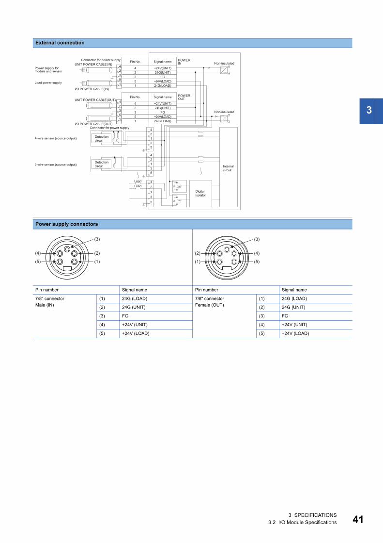
External connection
Power supply connectors
Pin number Signal name Pin number Signal name
7/8" connector
Male (IN)
(1) 24G (LOAD) 7/8" connector
Female (OUT)
(1) 24G (LOAD)
(2) 24G (UNIT) (2) 24G (UNIT)
(3) FG (3) FG
(4) +24V (UNIT) (4) +24V (UNIT)
(5) +24V (LOAD) (5) +24V (LOAD)
42135
42135
I/O POWER CABLE(IN)
UNIT POWER CABLE(IN)POWER IN
POWER OUT
I/O POWER CABLE(OUT)
UNIT POWER CABLE(OUT)+24V(UNIT)24G(UNIT)
FG+24V(LOAD)24G(LOAD)
42351
42351
+24V(UNIT)24G(UNIT)
FG+24V(LOAD)24G(LOAD)
42351
42351
42135
Load power supply
Non-insulated
Non-insulated
Connector for power supply
Power supply for module and sensor
Signal namePin No.
Connector for power supply
Signal namePin No.
Internal circuit
Digital isolator
LoadLoad
Detection circuit
Detection circuit
4-wire sensor (source output)
3-wire sensor (source output)
(2)
(3)
(1)
(4)
(5)
(4)
(3)
(5)
(2)
(1)
3 SPECIFICATIONS3.2 I/O Module Specifications 41

42
I/O connectors
Pin number Signal name Pin number Signal name
X0
X1
(1) +24V (UNIT) Y8
Y9
(1) Empty
(2) X1 (2) Y9
(3) 24G (UNIT) (3) 24G (LOAD)
(4) X0 (4) Y8
(5) FG (5) FG
X2
X3
(1) +24V (UNIT) YA
YB
(1) Empty
(2) X3 (2) YB
(3) 24G (UNIT) (3) 24G (LOAD)
(4) X2 (4) YA
(5) FG (5) FG
X4
X5
(1) +24V (UNIT) YC
YD
(1) Empty
(2) X5 (2) YD
(3) 24G (UNIT) (3) 24G (LOAD)
(4) X4 (4) YC
(5) FG (5) FG
X6
X7
(1) +24V (UNIT) YE
YF
(1) Empty
(2) X7 (2) YF
(3) 24G (UNIT) (3) 24G (LOAD)
(4) X6 (4) YE
(5) FG (5) FG
(2)
(3)
(5)
(1)
(4)
3 SPECIFICATIONS3.2 I/O Module Specifications
3
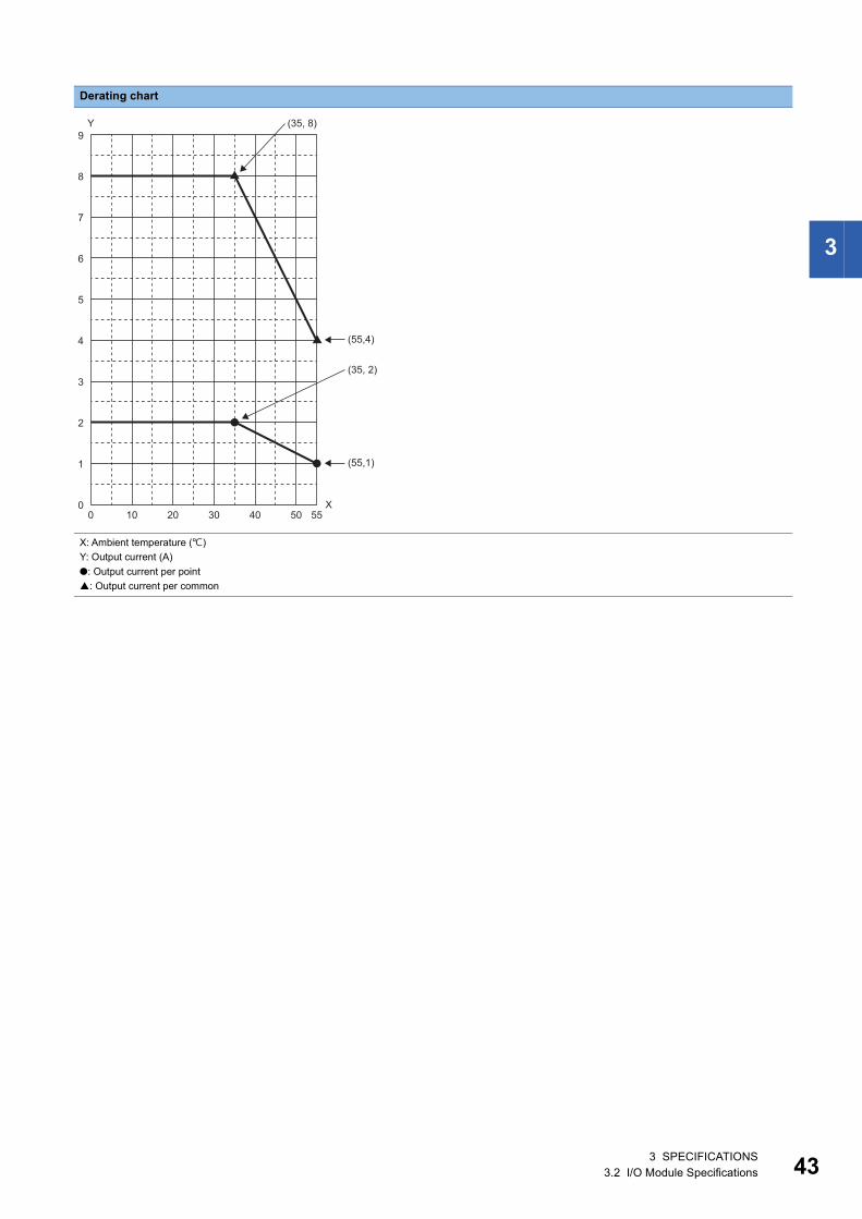
Derating chart
X: Ambient temperature ()
Y: Output current (A)
●: Output current per point
: Output current per common
Y
(55,4)
9
8
7
6
5
4
3
2
1
00 10 20 30 40 50 55
X
(55,1)
(35, 2)
(35, 8)
3 SPECIFICATIONS3.2 I/O Module Specifications 43
44
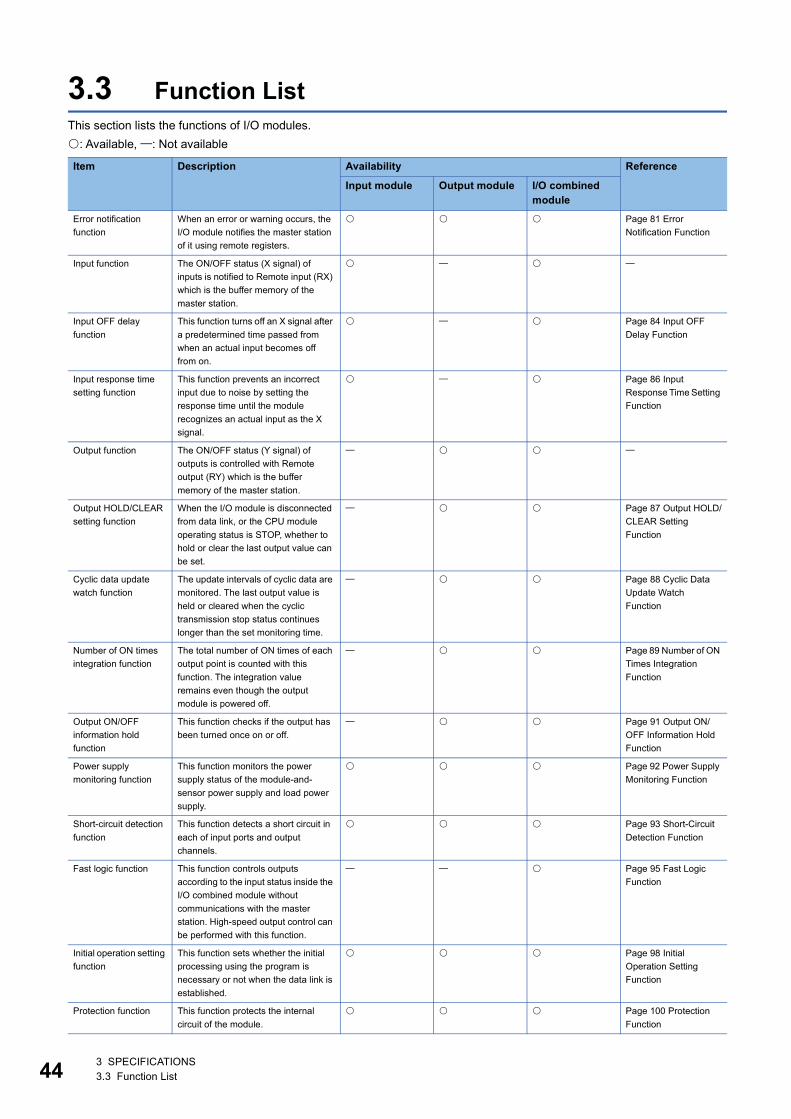
3.3 Function ListThis section lists the functions of I/O modules.
: Available, : Not available
Item Description Availability Reference
Input module Output module I/O combined module
Error notification
function
When an error or warning occurs, the
I/O module notifies the master station
of it using remote registers.
Page 81 Error
Notification Function
Input function The ON/OFF status (X signal) of
inputs is notified to Remote input (RX)
which is the buffer memory of the
master station.
Input OFF delay
function
This function turns off an X signal after
a predetermined time passed from
when an actual input becomes off
from on.
Page 84 Input OFF
Delay Function
Input response time
setting function
This function prevents an incorrect
input due to noise by setting the
response time until the module
recognizes an actual input as the X
signal.
Page 86 Input
Response Time Setting
Function
Output function The ON/OFF status (Y signal) of
outputs is controlled with Remote
output (RY) which is the buffer
memory of the master station.
Output HOLD/CLEAR
setting function
When the I/O module is disconnected
from data link, or the CPU module
operating status is STOP, whether to
hold or clear the last output value can
be set.
Page 87 Output HOLD/
CLEAR Setting
Function
Cyclic data update
watch function
The update intervals of cyclic data are
monitored. The last output value is
held or cleared when the cyclic
transmission stop status continues
longer than the set monitoring time.
Page 88 Cyclic Data
Update Watch
Function
Number of ON times
integration function
The total number of ON times of each
output point is counted with this
function. The integration value
remains even though the output
module is powered off.
Page 89 Number of ON
Times Integration
Function
Output ON/OFF
information hold
function
This function checks if the output has
been turned once on or off.
Page 91 Output ON/
OFF Information Hold
Function
Power supply
monitoring function
This function monitors the power
supply status of the module-and-
sensor power supply and load power
supply.
Page 92 Power Supply
Monitoring Function
Short-circuit detection
function
This function detects a short circuit in
each of input ports and output
channels.
Page 93 Short-Circuit
Detection Function
Fast logic function This function controls outputs
according to the input status inside the
I/O combined module without
communications with the master
station. High-speed output control can
be performed with this function.
Page 95 Fast Logic
Function
Initial operation setting
function
This function sets whether the initial
processing using the program is
necessary or not when the data link is
established.
Page 98 Initial
Operation Setting
Function
Protection function This function protects the internal
circuit of the module.
Page 100 Protection
Function
3 SPECIFICATIONS3.3 Function List
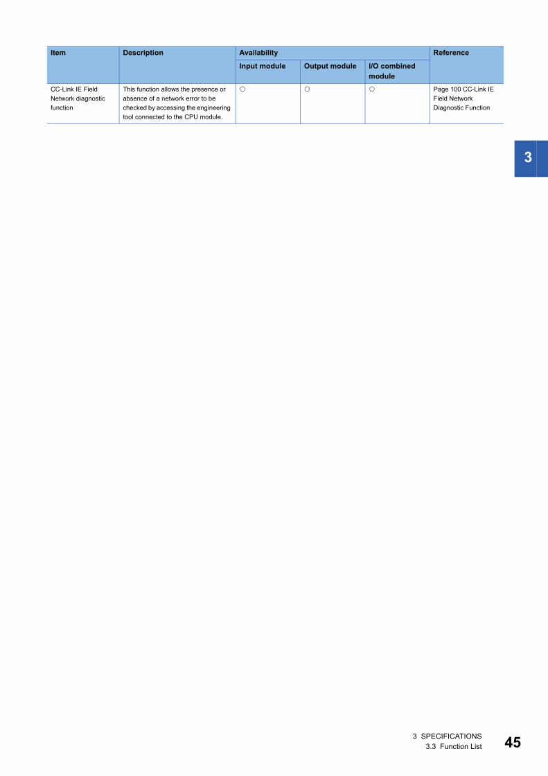
3
CC-Link IE Field
Network diagnostic
function
This function allows the presence or
absence of a network error to be
checked by accessing the engineering
tool connected to the CPU module.
Page 100 CC-Link IE
Field Network
Diagnostic Function
Item Description Availability Reference
Input module Output module I/O combined module
3 SPECIFICATIONS3.3 Function List 45
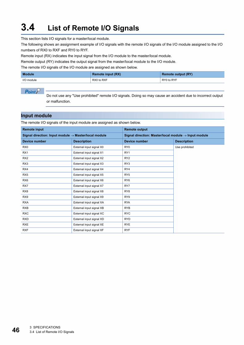
46
3.4 List of Remote I/O SignalsThis section lists I/O signals for a master/local module.
The following shows an assignment example of I/O signals with the remote I/O signals of the I/O module assigned to the I/O
numbers of RX0 to RXF and RY0 to RYF.
Remote input (RX) indicates the input signal from the I/O module to the master/local module.
Remote output (RY) indicates the output signal from the master/local module to the I/O module.
The remote I/O signals of the I/O module are assigned as shown below.
Do not use any "Use prohibited" remote I/O signals. Doing so may cause an accident due to incorrect output
or malfunction.
Input moduleThe remote I/O signals of the input module are assigned as shown below.
Module Remote input (RX) Remote output (RY)
I/O module RX0 to RXF RY0 to RYF
Remote input Remote output
Signal direction: Input module Master/local module Signal direction: Master/local module Input module
Device number Description Device number Description
RX0 External input signal X0 RY0 Use prohibited
RX1 External input signal X1 RY1
RX2 External input signal X2 RY2
RX3 External input signal X3 RY3
RX4 External input signal X4 RY4
RX5 External input signal X5 RY5
RX6 External input signal X6 RY6
RX7 External input signal X7 RY7
RX8 External input signal X8 RY8
RX9 External input signal X9 RY9
RXA External input signal XA RYA
RXB External input signal XB RYB
RXC External input signal XC RYC
RXD External input signal XD RYD
RXE External input signal XE RYE
RXF External input signal XF RYF
3 SPECIFICATIONS3.4 List of Remote I/O Signals
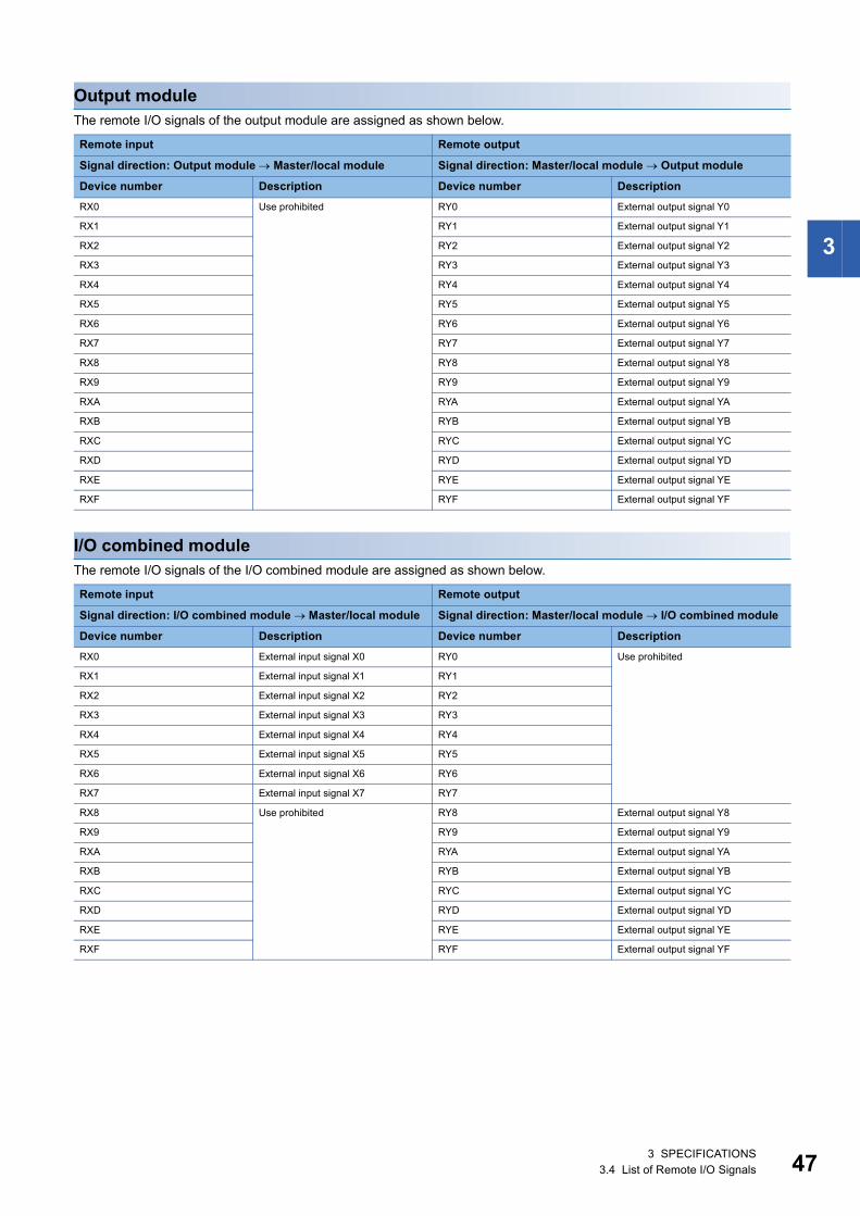
3
Output moduleThe remote I/O signals of the output module are assigned as shown below.
I/O combined moduleThe remote I/O signals of the I/O combined module are assigned as shown below.
Remote input Remote output
Signal direction: Output module Master/local module Signal direction: Master/local module Output module
Device number Description Device number Description
RX0 Use prohibited RY0 External output signal Y0
RX1 RY1 External output signal Y1
RX2 RY2 External output signal Y2
RX3 RY3 External output signal Y3
RX4 RY4 External output signal Y4
RX5 RY5 External output signal Y5
RX6 RY6 External output signal Y6
RX7 RY7 External output signal Y7
RX8 RY8 External output signal Y8
RX9 RY9 External output signal Y9
RXA RYA External output signal YA
RXB RYB External output signal YB
RXC RYC External output signal YC
RXD RYD External output signal YD
RXE RYE External output signal YE
RXF RYF External output signal YF
Remote input Remote output
Signal direction: I/O combined module Master/local module Signal direction: Master/local module I/O combined module
Device number Description Device number Description
RX0 External input signal X0 RY0 Use prohibited
RX1 External input signal X1 RY1
RX2 External input signal X2 RY2
RX3 External input signal X3 RY3
RX4 External input signal X4 RY4
RX5 External input signal X5 RY5
RX6 External input signal X6 RY6
RX7 External input signal X7 RY7
RX8 Use prohibited RY8 External output signal Y8
RX9 RY9 External output signal Y9
RXA RYA External output signal YA
RXB RYB External output signal YB
RXC RYC External output signal YC
RXD RYD External output signal YD
RXE RYE External output signal YE
RXF RYF External output signal YF
3 SPECIFICATIONS3.4 List of Remote I/O Signals 47
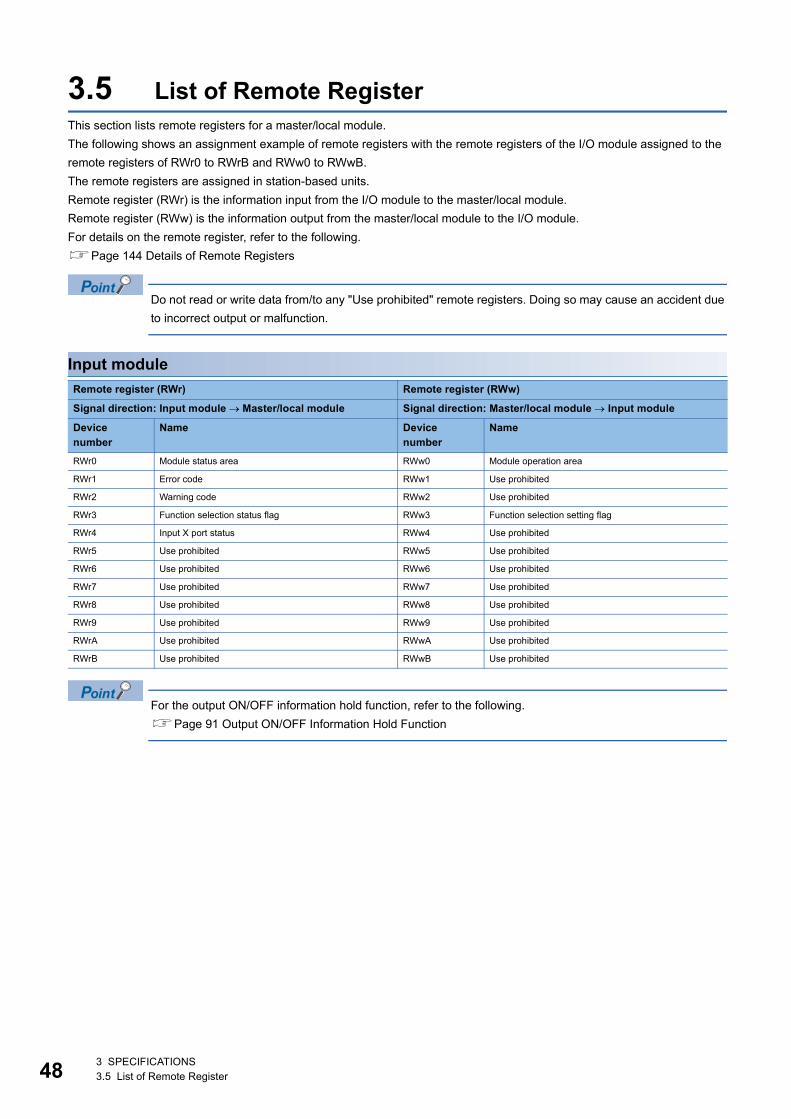
48
3.5 List of Remote RegisterThis section lists remote registers for a master/local module.
The following shows an assignment example of remote registers with the remote registers of the I/O module assigned to the
remote registers of RWr0 to RWrB and RWw0 to RWwB.
The remote registers are assigned in station-based units.
Remote register (RWr) is the information input from the I/O module to the master/local module.
Remote register (RWw) is the information output from the master/local module to the I/O module.
For details on the remote register, refer to the following.
Page 144 Details of Remote Registers
Do not read or write data from/to any "Use prohibited" remote registers. Doing so may cause an accident due
to incorrect output or malfunction.
Input module
For the output ON/OFF information hold function, refer to the following.
Page 91 Output ON/OFF Information Hold Function
Remote register (RWr) Remote register (RWw)
Signal direction: Input module Master/local module Signal direction: Master/local module Input module
Device number
Name Device number
Name
RWr0 Module status area RWw0 Module operation area
RWr1 Error code RWw1 Use prohibited
RWr2 Warning code RWw2 Use prohibited
RWr3 Function selection status flag RWw3 Function selection setting flag
RWr4 Input X port status RWw4 Use prohibited
RWr5 Use prohibited RWw5 Use prohibited
RWr6 Use prohibited RWw6 Use prohibited
RWr7 Use prohibited RWw7 Use prohibited
RWr8 Use prohibited RWw8 Use prohibited
RWr9 Use prohibited RWw9 Use prohibited
RWrA Use prohibited RWwA Use prohibited
RWrB Use prohibited RWwB Use prohibited
3 SPECIFICATIONS3.5 List of Remote Register
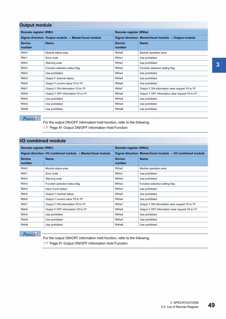
3
Output module
For the output ON/OFF information hold function, refer to the following.
Page 91 Output ON/OFF Information Hold Function
I/O combined module
For the output ON/OFF information hold function, refer to the following.
Page 91 Output ON/OFF Information Hold Function
Remote register (RWr) Remote register (RWw)
Signal direction: Output module Master/local module Signal direction: Master/local module Output module
Device number
Name Device number
Name
RWr0 Module status area RWw0 Module operation area
RWr1 Error code RWw1 Use prohibited
RWr2 Warning code RWw2 Use prohibited
RWr3 Function selection status flag RWw3 Function selection setting flag
RWr4 Use prohibited RWw4 Use prohibited
RWr5 Output Y channel status RWw5 Use prohibited
RWr6 Output Y current value Y0 to YF RWw6 Use prohibited
RWr7 Output Y ON information Y0 to YF RWw7 Output Y ON information clear request Y0 to YF
RWr8 Output Y OFF information Y0 to YF RWw8 Output Y OFF information clear request Y0 to YF
RWr9 Use prohibited RWw9 Use prohibited
RWrA Use prohibited RWwA Use prohibited
RWrB Use prohibited RWwB Use prohibited
Remote register (RWr) Remote register (RWw)
Signal direction: I/O combined module Master/local module Signal direction: Master/local module I/O combined module
Device number
Name Device number
Name
RWr0 Module status area RWw0 Module operation area
RWr1 Error code RWw1 Use prohibited
RWr2 Warning code RWw2 Use prohibited
RWr3 Function selection status flag RWw3 Function selection setting flag
RWr4 Input X port status RWw4 Use prohibited
RWr5 Output Y channel status RWw5 Use prohibited
RWr6 Output Y current value Y8 to YF RWw6 Use prohibited
RWr7 Output Y ON information Y8 to YF RWw7 Output Y ON information clear request Y8 to YF
RWr8 Output Y OFF information Y8 to YF RWw8 Output Y OFF information clear request Y8 to YF
RWr9 Use prohibited RWw9 Use prohibited
RWrA Use prohibited RWwA Use prohibited
RWrB Use prohibited RWwB Use prohibited
3 SPECIFICATIONS3.5 List of Remote Register 49
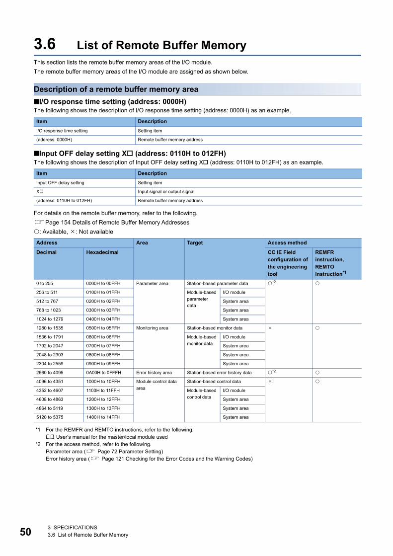
50
3.6 List of Remote Buffer MemoryThis section lists the remote buffer memory areas of the I/O module.
The remote buffer memory areas of the I/O module are assigned as shown below.
Description of a remote buffer memory area
■I/O response time setting (address: 0000H)The following shows the description of I/O response time setting (address: 0000H) as an example.
■Input OFF delay setting X (address: 0110H to 012FH)The following shows the description of Input OFF delay setting X (address: 0110H to 012FH) as an example.
For details on the remote buffer memory, refer to the following.
Page 154 Details of Remote Buffer Memory Addresses
: Available, : Not available
*1 For the REMFR and REMTO instructions, refer to the following. User's manual for the master/local module used
*2 For the access method, refer to the following.Parameter area ( Page 72 Parameter Setting)Error history area ( Page 121 Checking for the Error Codes and the Warning Codes)
Item Description
I/O response time setting Setting item
(address: 0000H) Remote buffer memory address
Item Description
Input OFF delay setting Setting item
X Input signal or output signal
(address: 0110H to 012FH) Remote buffer memory address
Address Area Target Access method
Decimal Hexadecimal CC IE Field configuration of the engineering tool
REMFR instruction, REMTO instruction*1
0 to 255 0000H to 00FFH Parameter area Station-based parameter data *2
256 to 511 0100H to 01FFH Module-based
parameter
data
I/O module
512 to 767 0200H to 02FFH System area
768 to 1023 0300H to 03FFH System area
1024 to 1279 0400H to 04FFH System area
1280 to 1535 0500H to 05FFH Monitoring area Station-based monitor data
1536 to 1791 0600H to 06FFH Module-based
monitor data
I/O module
1792 to 2047 0700H to 07FFH System area
2048 to 2303 0800H to 08FFH System area
2304 to 2559 0900H to 09FFH System area
2560 to 4095 0A00H to 0FFFH Error history area Station-based error history data *2
4096 to 4351 1000H to 10FFH Module control data
area
Station-based control data
4352 to 4607 1100H to 11FFH Module-based
control data
I/O module
4608 to 4863 1200H to 12FFH System area
4864 to 5119 1300H to 13FFH System area
5120 to 5375 1400H to 14FFH System area
3 SPECIFICATIONS3.6 List of Remote Buffer Memory
3
• Do not access the system area using the REMFR or REMTO instruction. Doing so may lead the module to
malfunction.
• Do not use the dedicated instruction of the REMFR and REMTO instructions to the areas later than the
above areas. If these instructions are used, the error code (0202H) is stored in Warning code (RWr2),
Warning status flag (RWr0.b12) turns on, and the ERR. LED flashes.
Parameter area (address: 0000H to 04FFH)For the parameter area, parameters can be set by means of the CC IE Field configuration of the engineering tool, or the
REMTO instruction.
The parameter in the parameter area is backed up to the nonvolatile memory.
However, Fast logic setting Y (address: 0120H to 0127H) is not backed up. The parameter backed up to the nonvolatile
memory is read to the parameter area when the module power supply is turned off and on or the module returns from remote
reset.
For the parameters written from the parameter settings of the CC IE Field configuration of the engineering tool, the write to the
non-volatile memory is also completed at the same time. When the parameter is written using the REMTO instruction, it is
written to the nonvolatile memory when Operation condition setting request flag (RWw0.b9) is turned on. At this time, the
parameter is written to the nonvolatile memory even though it is incorrect. When the power supply is turned off and on with an
incorrect parameter written, the incorrect parameter is read from the nonvolatile memory and an error code is stored to Error
code (RWr1). Take corrective action according to the error code list. (Page 124 Error Code List)
3 SPECIFICATIONS3.6 List of Remote Buffer Memory 51
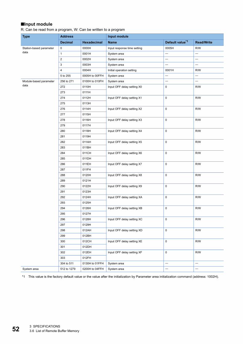
52
■Input moduleR: Can be read from a program, W: Can be written to a program
*1 This value is the factory default value or the value after the initialization by Parameter area initialization command (address: 1002H).
Type Address Input module
Decimal Hexadecimal Name Default value*1 Read/Write
Station-based parameter
data
0 0000H Input response time setting 0005H R/W
1 0001H System area
2 0002H System area
3 0003H System area
4 0004H Initial operation setting 0001H R/W
5 to 255 0005H to 00FFH System area
Module-based parameter
data
256 to 271 0100H to 010FH System area
272 0110H Input OFF delay setting X0 0 R/W
273 0111H
274 0112H Input OFF delay setting X1 0 R/W
275 0113H
276 0114H Input OFF delay setting X2 0 R/W
277 0115H
278 0116H Input OFF delay setting X3 0 R/W
279 0117H
280 0118H Input OFF delay setting X4 0 R/W
281 0119H
282 011AH Input OFF delay setting X5 0 R/W
283 011BH
284 011CH Input OFF delay setting X6 0 R/W
285 011DH
286 011EH Input OFF delay setting X7 0 R/W
287 011FH
288 0120H Input OFF delay setting X8 0 R/W
289 0121H
290 0122H Input OFF delay setting X9 0 R/W
291 0123H
292 0124H Input OFF delay setting XA 0 R/W
293 0125H
294 0126H Input OFF delay setting XB 0 R/W
295 0127H
296 0128H Input OFF delay setting XC 0 R/W
297 0129H
298 012AH Input OFF delay setting XD 0 R/W
299 012BH
300 012CH Input OFF delay setting XE 0 R/W
301 012DH
302 012EH Input OFF delay setting XF 0 R/W
303 012FH
304 to 511 0130H to 01FFH System area
System area 512 to 1279 0200H to 04FFH System area
3 SPECIFICATIONS3.6 List of Remote Buffer Memory
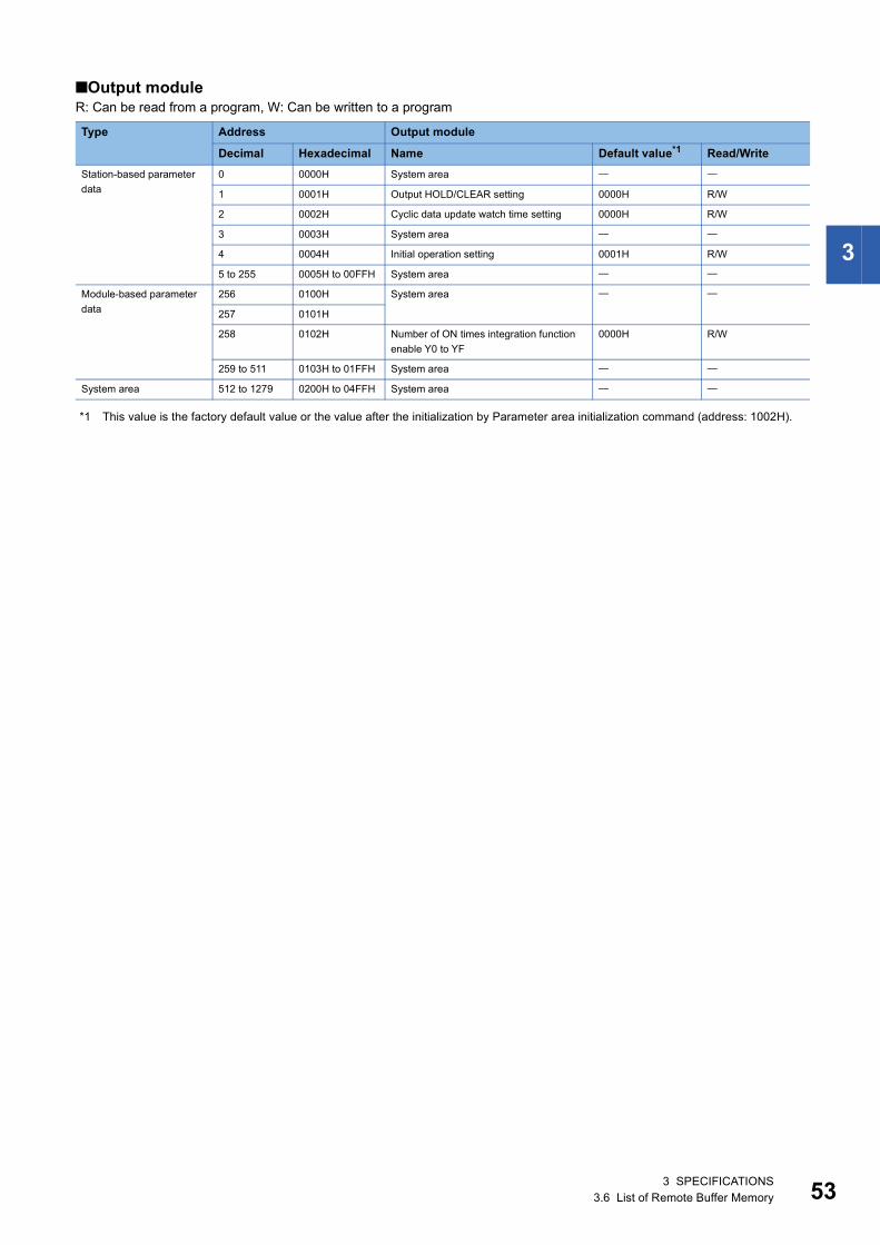
3
■Output moduleR: Can be read from a program, W: Can be written to a program
*1 This value is the factory default value or the value after the initialization by Parameter area initialization command (address: 1002H).
Type Address Output module
Decimal Hexadecimal Name Default value*1 Read/Write
Station-based parameter
data
0 0000H System area
1 0001H Output HOLD/CLEAR setting 0000H R/W
2 0002H Cyclic data update watch time setting 0000H R/W
3 0003H System area
4 0004H Initial operation setting 0001H R/W
5 to 255 0005H to 00FFH System area
Module-based parameter
data
256 0100H System area
257 0101H
258 0102H Number of ON times integration function
enable Y0 to YF
0000H R/W
259 to 511 0103H to 01FFH System area
System area 512 to 1279 0200H to 04FFH System area
3 SPECIFICATIONS3.6 List of Remote Buffer Memory 53
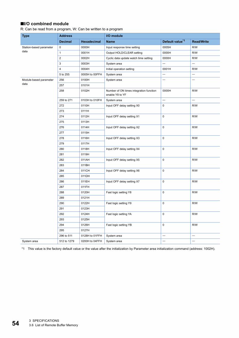
54
■I/O combined moduleR: Can be read from a program, W: Can be written to a program
*1 This value is the factory default value or the value after the initialization by Parameter area initialization command (address: 1002H).
Type Address I/O module
Decimal Hexadecimal Name Default value*1 Read/Write
Station-based parameter
data
0 0000H Input response time setting 0005H R/W
1 0001H Output HOLD/CLEAR setting 0000H R/W
2 0002H Cyclic data update watch time setting 0000H R/W
3 0003H System area
4 0004H Initial operation setting 0001H R/W
5 to 255 0005H to 00FFH System area
Module-based parameter
data
256 0100H System area
257 0101H
258 0102H Number of ON times integration function
enable Y8 to YF
0000H R/W
259 to 271 0103H to 010FH System area
272 0110H Input OFF delay setting X0 0 R/W
273 0111H
274 0112H Input OFF delay setting X1 0 R/W
275 0113H
276 0114H Input OFF delay setting X2 0 R/W
277 0115H
278 0116H Input OFF delay setting X3 0 R/W
279 0117H
280 0118H Input OFF delay setting X4 0 R/W
281 0119H
282 011AH Input OFF delay setting X5 0 R/W
283 011BH
284 011CH Input OFF delay setting X6 0 R/W
285 011DH
286 011EH Input OFF delay setting X7 0 R/W
287 011FH
288 0120H Fast logic setting Y8 0 R/W
289 0121H
290 0122H Fast logic setting Y9 0 R/W
291 0123H
292 0124H Fast logic setting YA 0 R/W
293 0125H
294 0126H Fast logic setting YB 0 R/W
295 0127H
296 to 511 0128H to 01FFH System area
System area 512 to 1279 0200H to 04FFH System area
3 SPECIFICATIONS3.6 List of Remote Buffer Memory
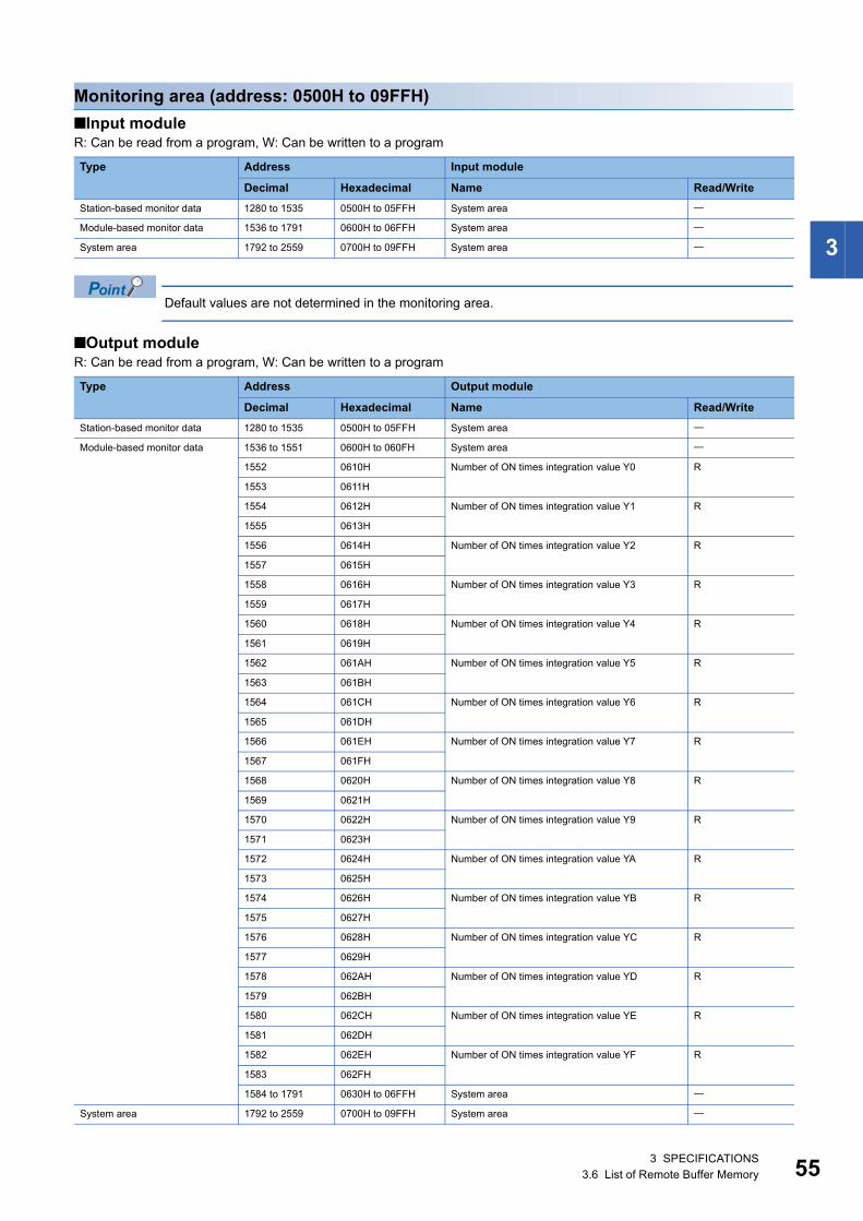
3
Monitoring area (address: 0500H to 09FFH)
■Input moduleR: Can be read from a program, W: Can be written to a program
Default values are not determined in the monitoring area.
■Output moduleR: Can be read from a program, W: Can be written to a program
Type Address Input module
Decimal Hexadecimal Name Read/Write
Station-based monitor data 1280 to 1535 0500H to 05FFH System area
Module-based monitor data 1536 to 1791 0600H to 06FFH System area
System area 1792 to 2559 0700H to 09FFH System area
Type Address Output module
Decimal Hexadecimal Name Read/Write
Station-based monitor data 1280 to 1535 0500H to 05FFH System area
Module-based monitor data 1536 to 1551 0600H to 060FH System area
1552 0610H Number of ON times integration value Y0 R
1553 0611H
1554 0612H Number of ON times integration value Y1 R
1555 0613H
1556 0614H Number of ON times integration value Y2 R
1557 0615H
1558 0616H Number of ON times integration value Y3 R
1559 0617H
1560 0618H Number of ON times integration value Y4 R
1561 0619H
1562 061AH Number of ON times integration value Y5 R
1563 061BH
1564 061CH Number of ON times integration value Y6 R
1565 061DH
1566 061EH Number of ON times integration value Y7 R
1567 061FH
1568 0620H Number of ON times integration value Y8 R
1569 0621H
1570 0622H Number of ON times integration value Y9 R
1571 0623H
1572 0624H Number of ON times integration value YA R
1573 0625H
1574 0626H Number of ON times integration value YB R
1575 0627H
1576 0628H Number of ON times integration value YC R
1577 0629H
1578 062AH Number of ON times integration value YD R
1579 062BH
1580 062CH Number of ON times integration value YE R
1581 062DH
1582 062EH Number of ON times integration value YF R
1583 062FH
1584 to 1791 0630H to 06FFH System area
System area 1792 to 2559 0700H to 09FFH System area
3 SPECIFICATIONS3.6 List of Remote Buffer Memory 55
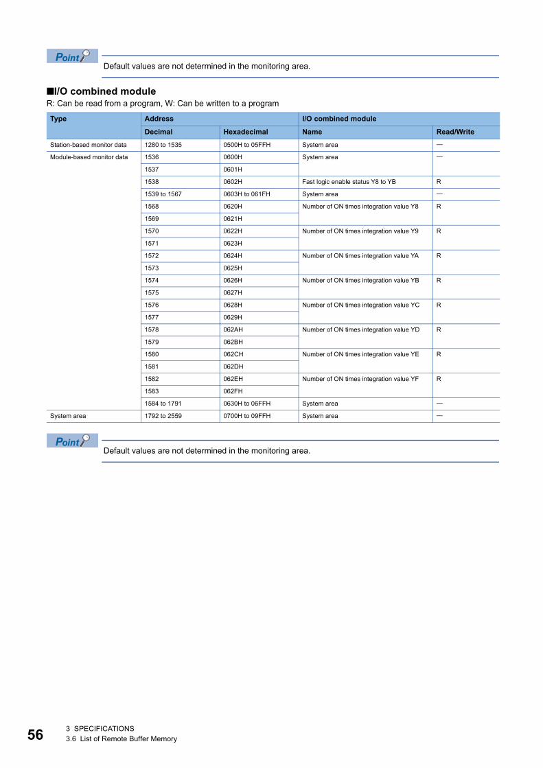
56
Default values are not determined in the monitoring area.
■I/O combined moduleR: Can be read from a program, W: Can be written to a program
Default values are not determined in the monitoring area.
Type Address I/O combined module
Decimal Hexadecimal Name Read/Write
Station-based monitor data 1280 to 1535 0500H to 05FFH System area
Module-based monitor data 1536 0600H System area
1537 0601H
1538 0602H Fast logic enable status Y8 to YB R
1539 to 1567 0603H to 061FH System area
1568 0620H Number of ON times integration value Y8 R
1569 0621H
1570 0622H Number of ON times integration value Y9 R
1571 0623H
1572 0624H Number of ON times integration value YA R
1573 0625H
1574 0626H Number of ON times integration value YB R
1575 0627H
1576 0628H Number of ON times integration value YC R
1577 0629H
1578 062AH Number of ON times integration value YD R
1579 062BH
1580 062CH Number of ON times integration value YE R
1581 062DH
1582 062EH Number of ON times integration value YF R
1583 062FH
1584 to 1791 0630H to 06FFH System area
System area 1792 to 2559 0700H to 09FFH System area
3 SPECIFICATIONS3.6 List of Remote Buffer Memory
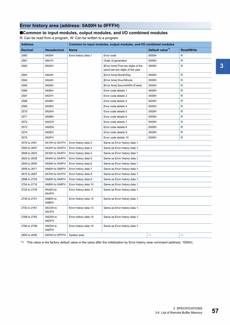
3
Error history area (address: 0A00H to 0FFFH)
■Common to input modules, output modules, and I/O combined modulesR: Can be read from a program, W: Can be written to a program
*1 This value is the factory default value or the value after the initialization by Error history clear command (address: 1000H).
Address Common to input modules, output modules, and I/O combined modules
Decimal Hexadecimal Name Default value*1 Read/Write
2560 0A00H Error history data 1 Error code 0000H R
2561 0A01H Order of generation 0000H R
2562 0A02H [Error time] First two digits of the
year/Last two digits of the year
0000H R
2563 0A03H [Error time] Month/Day 0000H R
2564 0A04H [Error time] Hour/Minute 0000H R
2565 0A05H [Error time] Second/00H (Fixed) 0000H R
2566 0A06H Error code details 1 0000H R
2567 0A07H Error code details 2 0000H R
2568 0A08H Error code details 3 0000H R
2569 0A09H Error code details 4 0000H R
2570 0A0AH Error code details 5 0000H R
2571 0A0BH Error code details 6 0000H R
2572 0A0CH Error code details 7 0000H R
2573 0A0DH Error code details 8 0000H R
2574 0A0EH Error code details 9 0000H R
2575 0A0FH Error code details 10 0000H R
2576 to 2591 0A10H to 0A1FH Error history data 2 Same as Error history data 1.
2592 to 2607 0A20H to 0A2FH Error history data 3 Same as Error history data 1.
2608 to 2623 0A30H to 0A3FH Error history data 4 Same as Error history data 1.
2624 to 2639 0A40H to 0A4FH Error history data 5 Same as Error history data 1.
2640 to 2655 0A50H to 0A5FH Error history data 6 Same as Error history data 1.
2656 to 2671 0A60H to 0A6FH Error history data 7 Same as Error history data 1.
2672 to 2687 0A70H to 0A7FH Error history data 8 Same as Error history data 1.
2688 to 2703 0A80H to 0A8FH Error history data 9 Same as Error history data 1.
2704 to 2719 0A90H to 0A9FH Error history data 10 Same as Error history data 1.
2720 to 2735 0AA0H to
0AAFH
Error history data 11 Same as Error history data 1.
2736 to 2751 0AB0H to
0ABFH
Error history data 12 Same as Error history data 1.
2752 to 2767 0AC0H to
0ACFH
Error history data 13 Same as Error history data 1.
2768 to 2783 0AD0H to
0ADFH
Error history data 14 Same as Error history data 1.
2784 to 2799 0AE0H to
0AEFH
Error history data 15 Same as Error history data 1.
2800 to 4095 0AF0H to 0FFFH System area
3 SPECIFICATIONS3.6 List of Remote Buffer Memory 57
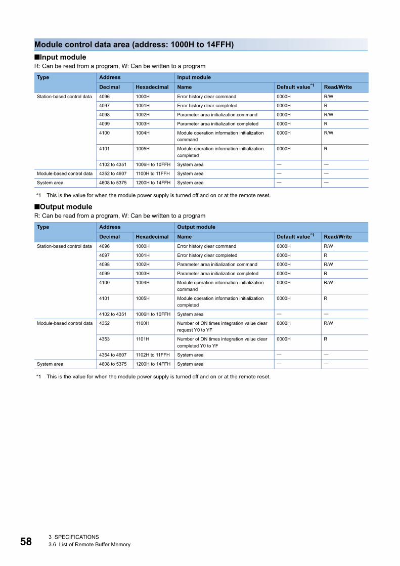
58
Module control data area (address: 1000H to 14FFH)
■Input moduleR: Can be read from a program, W: Can be written to a program
*1 This is the value for when the module power supply is turned off and on or at the remote reset.
■Output moduleR: Can be read from a program, W: Can be written to a program
*1 This is the value for when the module power supply is turned off and on or at the remote reset.
Type Address Input module
Decimal Hexadecimal Name Default value*1 Read/Write
Station-based control data 4096 1000H Error history clear command 0000H R/W
4097 1001H Error history clear completed 0000H R
4098 1002H Parameter area initialization command 0000H R/W
4099 1003H Parameter area initialization completed 0000H R
4100 1004H Module operation information initialization
command
0000H R/W
4101 1005H Module operation information initialization
completed
0000H R
4102 to 4351 1006H to 10FFH System area
Module-based control data 4352 to 4607 1100H to 11FFH System area
System area 4608 to 5375 1200H to 14FFH System area
Type Address Output module
Decimal Hexadecimal Name Default value*1 Read/Write
Station-based control data 4096 1000H Error history clear command 0000H R/W
4097 1001H Error history clear completed 0000H R
4098 1002H Parameter area initialization command 0000H R/W
4099 1003H Parameter area initialization completed 0000H R
4100 1004H Module operation information initialization
command
0000H R/W
4101 1005H Module operation information initialization
completed
0000H R
4102 to 4351 1006H to 10FFH System area
Module-based control data 4352 1100H Number of ON times integration value clear
request Y0 to YF
0000H R/W
4353 1101H Number of ON times integration value clear
completed Y0 to YF
0000H R
4354 to 4607 1102H to 11FFH System area
System area 4608 to 5375 1200H to 14FFH System area
3 SPECIFICATIONS3.6 List of Remote Buffer Memory
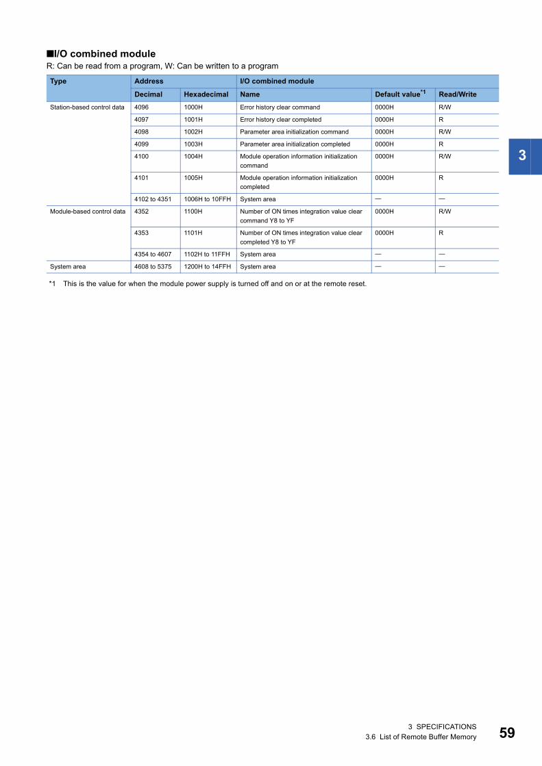
3
■I/O combined moduleR: Can be read from a program, W: Can be written to a program
*1 This is the value for when the module power supply is turned off and on or at the remote reset.
Type Address I/O combined module
Decimal Hexadecimal Name Default value*1 Read/Write
Station-based control data 4096 1000H Error history clear command 0000H R/W
4097 1001H Error history clear completed 0000H R
4098 1002H Parameter area initialization command 0000H R/W
4099 1003H Parameter area initialization completed 0000H R
4100 1004H Module operation information initialization
command
0000H R/W
4101 1005H Module operation information initialization
completed
0000H R
4102 to 4351 1006H to 10FFH System area
Module-based control data 4352 1100H Number of ON times integration value clear
command Y8 to YF
0000H R/W
4353 1101H Number of ON times integration value clear
completed Y8 to YF
0000H R
4354 to 4607 1102H to 11FFH System area
System area 4608 to 5375 1200H to 14FFH System area
3 SPECIFICATIONS3.6 List of Remote Buffer Memory 59
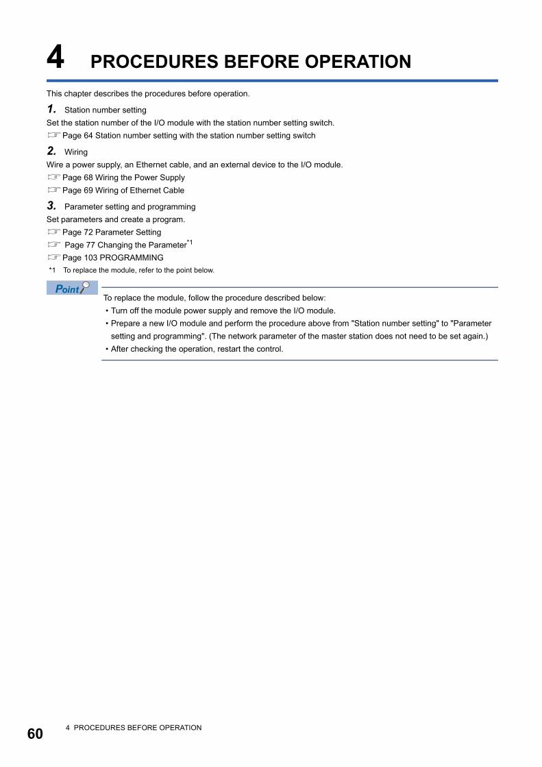
60
4 PROCEDURES BEFORE OPERATION
This chapter describes the procedures before operation.
1. Station number setting
Set the station number of the I/O module with the station number setting switch.
Page 64 Station number setting with the station number setting switch
2. Wiring
Wire a power supply, an Ethernet cable, and an external device to the I/O module.
Page 68 Wiring the Power Supply
Page 69 Wiring of Ethernet Cable
3. Parameter setting and programming
Set parameters and create a program.
Page 72 Parameter Setting
Page 77 Changing the Parameter*1
Page 103 PROGRAMMING
*1 To replace the module, refer to the point below.
To replace the module, follow the procedure described below:
• Turn off the module power supply and remove the I/O module.
• Prepare a new I/O module and perform the procedure above from "Station number setting" to "Parameter
setting and programming". (The network parameter of the master station does not need to be set again.)
• After checking the operation, restart the control.
4 PROCEDURES BEFORE OPERATION

4
MEMO
4 PROCEDURES BEFORE OPERATION 61
62
5 SYSTEM CONFIGURATION
This chapter describes system configuration using an I/O module.
For CC-Link IE Field Network configuration, refer to the following.
User's manual for the master/local module used
5.1 Applicable Systems
Applicable master stationWhen using an I/O module, use the following products as a master station.
Information on "Applicable master station" described above is the ones at the point when this manual was issued.
For latest information, please visit the website of CC-Link Partner Association.
www.cc-link.org
Ethernet cableUse a general-purpose Ethernet cable that meets the 1000BASE-T standard.
Consider the operating environment when selecting available cables that satisfy the product specifications.
Available softwareThe following software is available for settings and diagnostics of the I/O module. ( Manuals of each software)
Applicable profileTo use the parameter setting function of an I/O module, the profile is required.
When the latest profile of the remote I/O module is necessary, please consult your local Mitsubishi representative.
The profile is a setting file that stores information required for the start-up, operation, and maintenance of devices supporting
the CC-Link family.
A module is added to "Module List" of "CC IE Field Configuration" window by profile registration to an engineering tool. For the
profile registration, refer to the operating manual for the engineering tool used.
Model First five digits of serial number
RJ71GF11-T2 (no restriction)
RJ71EN71
QJ71GF11-T2 "14102" or later
LJ71GF11-T2
QD77GF16 "14111" or later
Product name Function and application
GX Works2 Software for system design, programming, debugging, and maintenance of the programmable controller.
GX Works3
5 SYSTEM CONFIGURATION5.1 Applicable Systems

5
MEMO
5 SYSTEM CONFIGURATION5.1 Applicable Systems 63
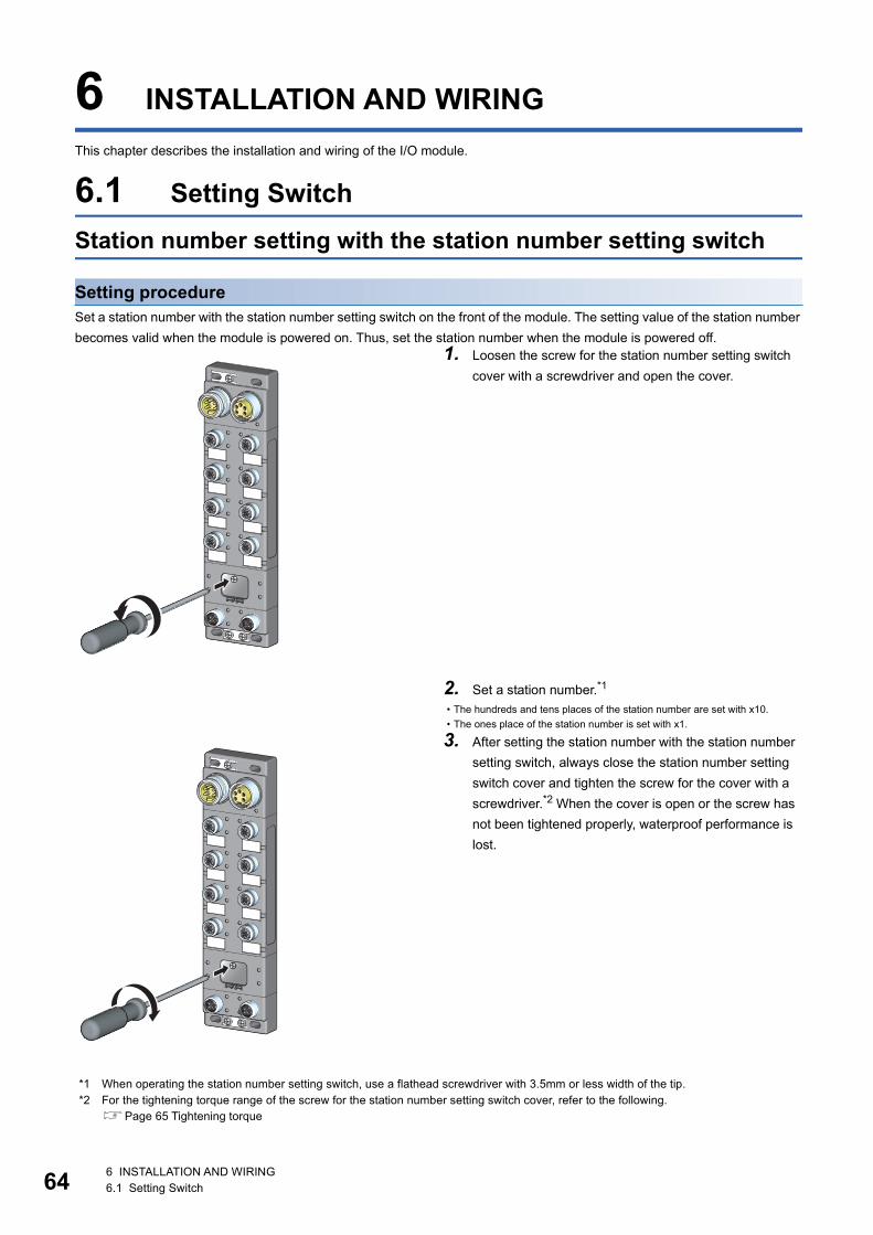
64
6 INSTALLATION AND WIRING
This chapter describes the installation and wiring of the I/O module.
6.1 Setting Switch
Station number setting with the station number setting switch
Setting procedureSet a station number with the station number setting switch on the front of the module. The setting value of the station number
becomes valid when the module is powered on. Thus, set the station number when the module is powered off.
*1 When operating the station number setting switch, use a flathead screwdriver with 3.5mm or less width of the tip.*2 For the tightening torque range of the screw for the station number setting switch cover, refer to the following.
Page 65 Tightening torque
1. Loosen the screw for the station number setting switch
cover with a screwdriver and open the cover.
2. Set a station number.*1
• The hundreds and tens places of the station number are set with x10.
• The ones place of the station number is set with x1.
3. After setting the station number with the station number
setting switch, always close the station number setting
switch cover and tighten the screw for the cover with a
screwdriver.*2 When the cover is open or the screw has
not been tightened properly, waterproof performance is
lost.
6 INSTALLATION AND WIRING6.1 Setting Switch
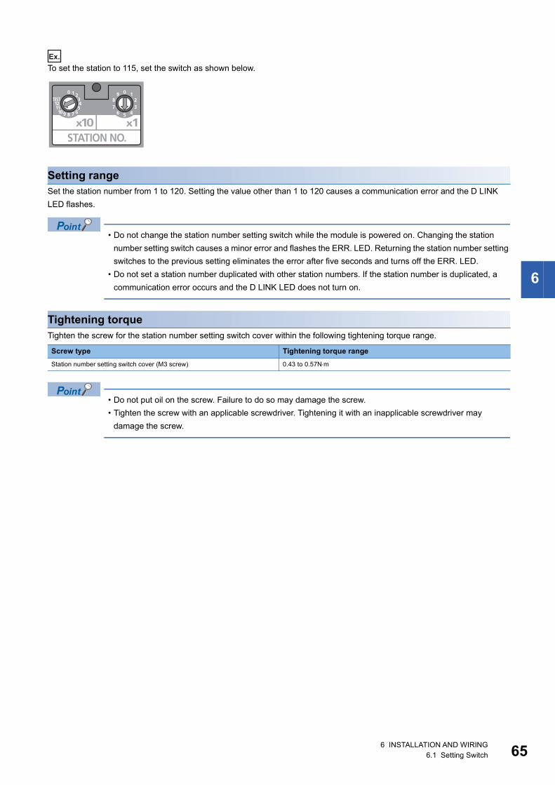
6
Ex.
To set the station to 115, set the switch as shown below.
Setting rangeSet the station number from 1 to 120. Setting the value other than 1 to 120 causes a communication error and the D LINK
LED flashes.
• Do not change the station number setting switch while the module is powered on. Changing the station
number setting switch causes a minor error and flashes the ERR. LED. Returning the station number setting
switches to the previous setting eliminates the error after five seconds and turns off the ERR. LED.
• Do not set a station number duplicated with other station numbers. If the station number is duplicated, a
communication error occurs and the D LINK LED does not turn on.
Tightening torqueTighten the screw for the station number setting switch cover within the following tightening torque range.
• Do not put oil on the screw. Failure to do so may damage the screw.
• Tighten the screw with an applicable screwdriver. Tightening it with an inapplicable screwdriver may
damage the screw.
Screw type Tightening torque range
Station number setting switch cover (M3 screw) 0.43 to 0.57Nm
6 INSTALLATION AND WIRING6.1 Setting Switch 65
66
6.2 Installation Environment and Installation Position
Installation environment
Installation locationDo not install the I/O module to the place where:
• Ambient temperature is outside the range of 0 to 55;
• IP67 is not satisfied;
• Condensation occurs due to rapid temperature change;
• Corrosive gas or combustible gas is present;
• Conductive powder such as iron powder, oil mist, salinity, or organic solvent is filled;
• The I/O module is exposed to direct sunlight;
• A strong electric field or strong magnetic field is generated; and
• The I/O module is subject to vibration and shock.
Installation surfaceInstall the I/O module on the flat surface. When the installation surface is uneven, excessive force is applied to the printed-
circuit board and may cause a defect.
6 INSTALLATION AND WIRING6.2 Installation Environment and Installation Position
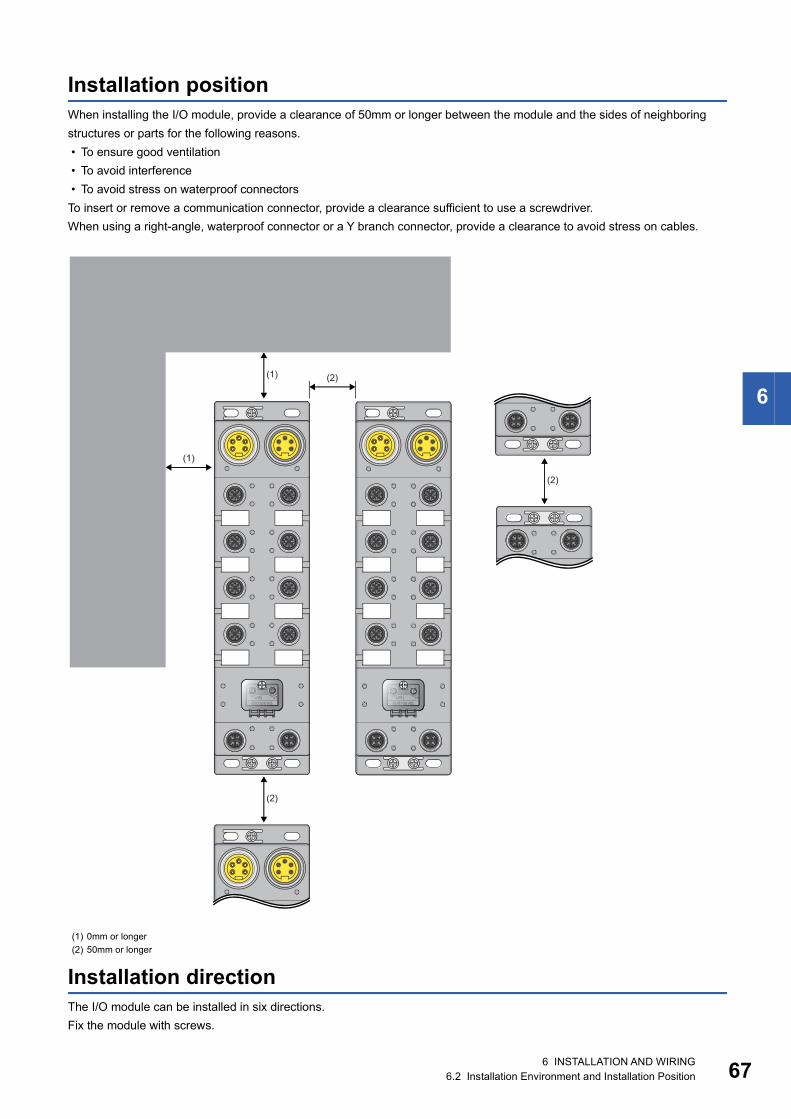
6
Installation positionWhen installing the I/O module, provide a clearance of 50mm or longer between the module and the sides of neighboring
structures or parts for the following reasons.
• To ensure good ventilation
• To avoid interference
• To avoid stress on waterproof connectors
To insert or remove a communication connector, provide a clearance sufficient to use a screwdriver.
When using a right-angle, waterproof connector or a Y branch connector, provide a clearance to avoid stress on cables.
Installation directionThe I/O module can be installed in six directions.
Fix the module with screws.
(1) 0mm or longer
(2) 50mm or longer
(2)
(1)
(2)
(1)
(2)
6 INSTALLATION AND WIRING6.2 Installation Environment and Installation Position 67
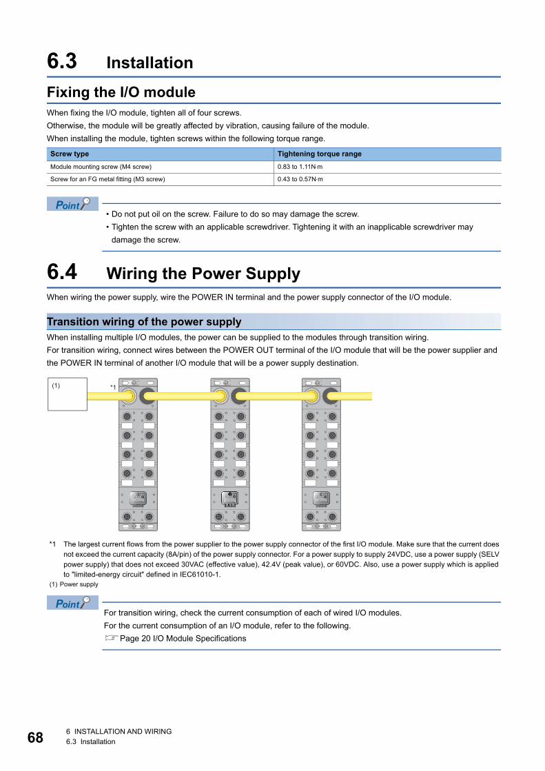
68
6.3 Installation
Fixing the I/O moduleWhen fixing the I/O module, tighten all of four screws.
Otherwise, the module will be greatly affected by vibration, causing failure of the module.
When installing the module, tighten screws within the following torque range.
• Do not put oil on the screw. Failure to do so may damage the screw.
• Tighten the screw with an applicable screwdriver. Tightening it with an inapplicable screwdriver may
damage the screw.
6.4 Wiring the Power SupplyWhen wiring the power supply, wire the POWER IN terminal and the power supply connector of the I/O module.
Transition wiring of the power supplyWhen installing multiple I/O modules, the power can be supplied to the modules through transition wiring.
For transition wiring, connect wires between the POWER OUT terminal of the I/O module that will be the power supplier and
the POWER IN terminal of another I/O module that will be a power supply destination.
*1 The largest current flows from the power supplier to the power supply connector of the first I/O module. Make sure that the current does not exceed the current capacity (8A/pin) of the power supply connector. For a power supply to supply 24VDC, use a power supply (SELV power supply) that does not exceed 30VAC (effective value), 42.4V (peak value), or 60VDC. Also, use a power supply which is applied to "limited-energy circuit" defined in IEC61010-1.
For transition wiring, check the current consumption of each of wired I/O modules.
For the current consumption of an I/O module, refer to the following.
Page 20 I/O Module Specifications
Screw type Tightening torque range
Module mounting screw (M4 screw) 0.83 to 1.11Nm
Screw for an FG metal fitting (M3 screw) 0.43 to 0.57Nm
(1) Power supply
*1(1)
6 INSTALLATION AND WIRING6.3 Installation
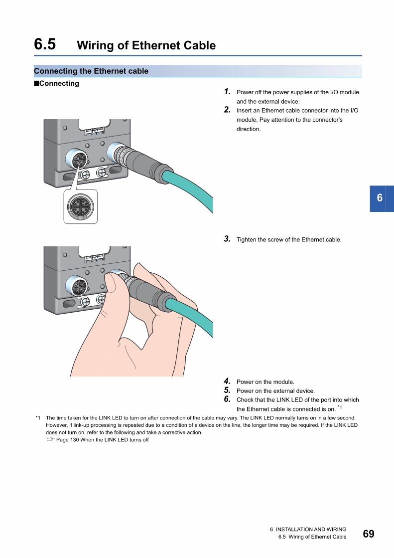
6
6.5 Wiring of Ethernet Cable
Connecting the Ethernet cable
■Connecting
*1 The time taken for the LINK LED to turn on after connection of the cable may vary. The LINK LED normally turns on in a few second. However, if link-up processing is repeated due to a condition of a device on the line, the longer time may be required. If the LINK LED does not turn on, refer to the following and take a corrective action.Page 130 When the LINK LED turns off
1. Power off the power supplies of the I/O module
and the external device.
2. Insert an Ethernet cable connector into the I/O
module. Pay attention to the connector's
direction.
3. Tighten the screw of the Ethernet cable.
4. Power on the module.
5. Power on the external device.
6. Check that the LINK LED of the port into which
the Ethernet cable is connected is on. *1
6 INSTALLATION AND WIRING6.5 Wiring of Ethernet Cable 69
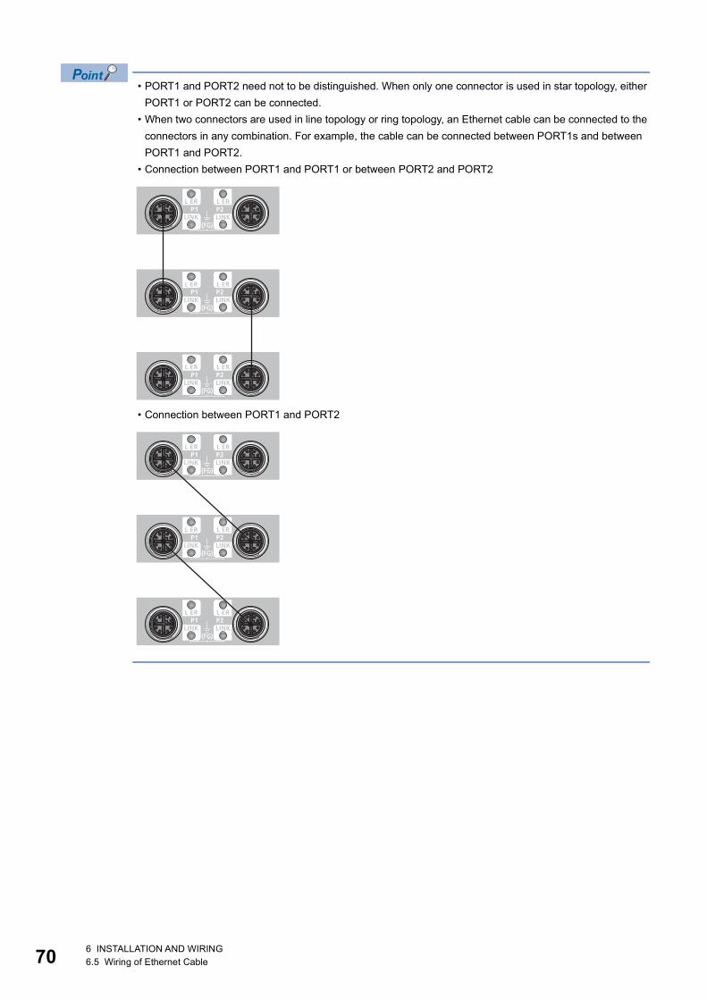
70
• PORT1 and PORT2 need not to be distinguished. When only one connector is used in star topology, either
PORT1 or PORT2 can be connected.
• When two connectors are used in line topology or ring topology, an Ethernet cable can be connected to the
connectors in any combination. For example, the cable can be connected between PORT1s and between
PORT1 and PORT2.
• Connection between PORT1 and PORT1 or between PORT2 and PORT2
• Connection between PORT1 and PORT2
6 INSTALLATION AND WIRING6.5 Wiring of Ethernet Cable
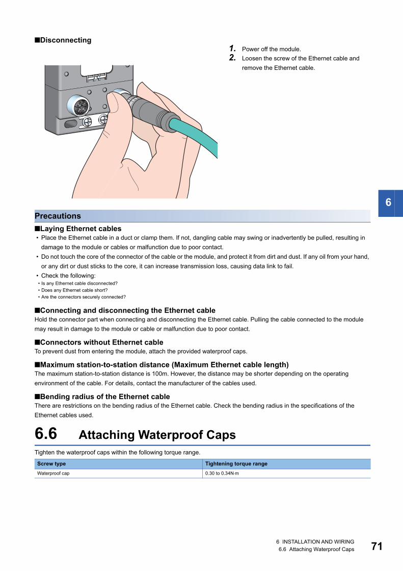
6
■Disconnecting
Precautions
■Laying Ethernet cables • Place the Ethernet cable in a duct or clamp them. If not, dangling cable may swing or inadvertently be pulled, resulting in
damage to the module or cables or malfunction due to poor contact.
• Do not touch the core of the connector of the cable or the module, and protect it from dirt and dust. If any oil from your hand,
or any dirt or dust sticks to the core, it can increase transmission loss, causing data link to fail.
• Check the following:
■Connecting and disconnecting the Ethernet cableHold the connector part when connecting and disconnecting the Ethernet cable. Pulling the cable connected to the module
may result in damage to the module or cable or malfunction due to poor contact.
■Connectors without Ethernet cableTo prevent dust from entering the module, attach the provided waterproof caps.
■Maximum station-to-station distance (Maximum Ethernet cable length)The maximum station-to-station distance is 100m. However, the distance may be shorter depending on the operating
environment of the cable. For details, contact the manufacturer of the cables used.
■Bending radius of the Ethernet cableThere are restrictions on the bending radius of the Ethernet cable. Check the bending radius in the specifications of the
Ethernet cables used.
6.6 Attaching Waterproof CapsTighten the waterproof caps within the following torque range.
1. Power off the module.
2. Loosen the screw of the Ethernet cable and
remove the Ethernet cable.
• Is any Ethernet cable disconnected?
• Does any Ethernet cable short?
• Are the connectors securely connected?
Screw type Tightening torque range
Waterproof cap 0.30 to 0.34Nm
6 INSTALLATION AND WIRING6.6 Attaching Waterproof Caps 71
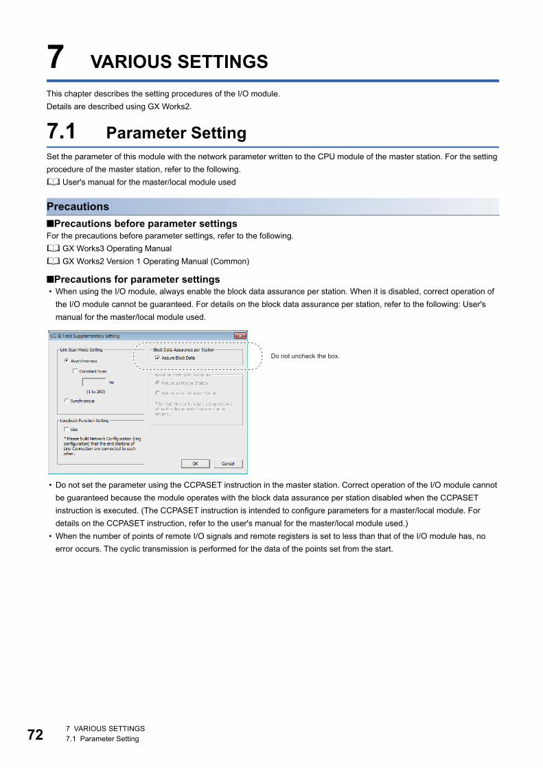
72
7 VARIOUS SETTINGS
This chapter describes the setting procedures of the I/O module.
Details are described using GX Works2.
7.1 Parameter SettingSet the parameter of this module with the network parameter written to the CPU module of the master station. For the setting
procedure of the master station, refer to the following.
User's manual for the master/local module used
Precautions
■Precautions before parameter settingsFor the precautions before parameter settings, refer to the following.
GX Works3 Operating Manual
GX Works2 Version 1 Operating Manual (Common)
■Precautions for parameter settings • When using the I/O module, always enable the block data assurance per station. When it is disabled, correct operation of
the I/O module cannot be guaranteed. For details on the block data assurance per station, refer to the following: User's
manual for the master/local module used.
• Do not set the parameter using the CCPASET instruction in the master station. Correct operation of the I/O module cannot
be guaranteed because the module operates with the block data assurance per station disabled when the CCPASET
instruction is executed. (The CCPASET instruction is intended to configure parameters for a master/local module. For
details on the CCPASET instruction, refer to the user's manual for the master/local module used.)
• When the number of points of remote I/O signals and remote registers is set to less than that of the I/O module has, no
error occurs. The cyclic transmission is performed for the data of the points set from the start.
Do not uncheck the box.
7 VARIOUS SETTINGS7.1 Parameter Setting
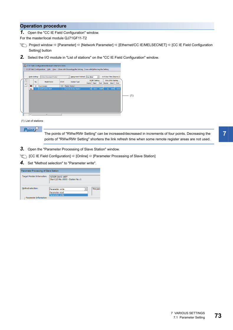
7
Operation procedure1. Open the "CC IE Field Configuration" window.
For the master/local module QJ71GF11-T2
Project window [Parameter] [Network Parameter] [Ethernet/CC IE/MELSECNET] [CC IE Field Configuration
Setting] button
2. Select the I/O module in "List of stations" on the "CC IE Field Configuration" window.
The points of "RWw/RWr Setting" can be increased/decreased in increments of four points. Decreasing the
points of "RWw/RWr Setting" shortens the link refresh time when some remote register areas are not used.
3. Open the "Parameter Processing of Slave Station" window.
[CC IE Field Configuration] [Online] [Parameter Processing of Slave Station]
4. Set "Method selection" to "Parameter write".
(1) List of stations
(1)
7 VARIOUS SETTINGS7.1 Parameter Setting 73
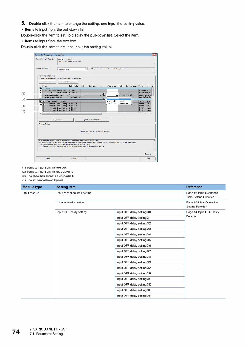
74
5. Double-click the item to change the setting, and input the setting value.
• Items to input from the pull-down list
Double-click the item to set, to display the pull-down list. Select the item.
• Items to input from the text box
Double-click the item to set, and input the setting value.
(1) Items to input from the text box
(2) Items to input from the drop-down list
(3) The checkbox cannot be unchecked.
(4) The list cannot be collapsed.
Module type Setting item Reference
Input module Input response time setting Page 86 Input Response
Time Setting Function
Initial operation setting Page 98 Initial Operation
Setting Function
Input OFF delay setting Input OFF delay setting X0 Page 84 Input OFF Delay
FunctionInput OFF delay setting X1
Input OFF delay setting X2
Input OFF delay setting X3
Input OFF delay setting X4
Input OFF delay setting X5
Input OFF delay setting X6
Input OFF delay setting X7
Input OFF delay setting X8
Input OFF delay setting X9
Input OFF delay setting XA
Input OFF delay setting XB
Input OFF delay setting XC
Input OFF delay setting XD
Input OFF delay setting XE
Input OFF delay setting XF
(1)
(4)
(2)
(3)
7 VARIOUS SETTINGS7.1 Parameter Setting
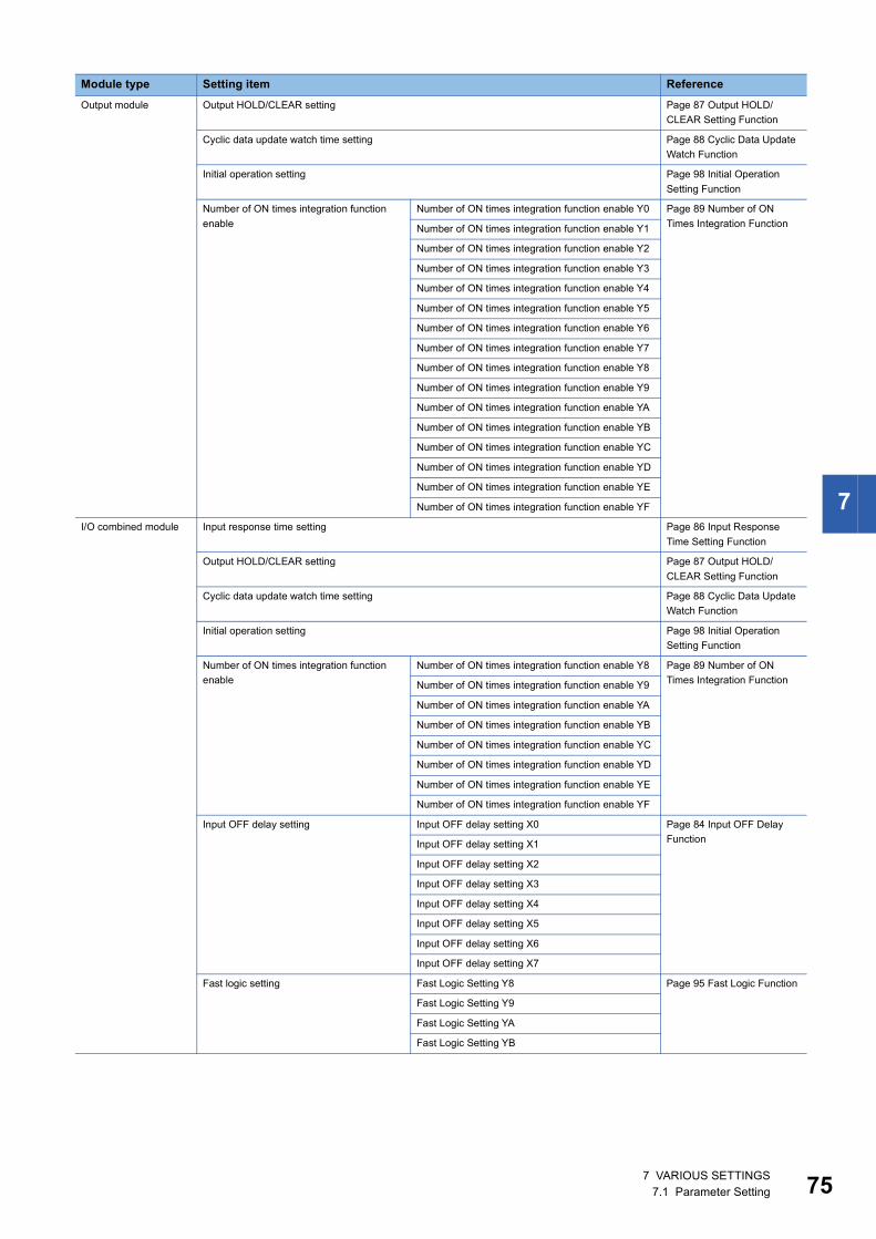
7
Output module Output HOLD/CLEAR setting Page 87 Output HOLD/
CLEAR Setting Function
Cyclic data update watch time setting Page 88 Cyclic Data Update
Watch Function
Initial operation setting Page 98 Initial Operation
Setting Function
Number of ON times integration function
enable
Number of ON times integration function enable Y0 Page 89 Number of ON
Times Integration FunctionNumber of ON times integration function enable Y1
Number of ON times integration function enable Y2
Number of ON times integration function enable Y3
Number of ON times integration function enable Y4
Number of ON times integration function enable Y5
Number of ON times integration function enable Y6
Number of ON times integration function enable Y7
Number of ON times integration function enable Y8
Number of ON times integration function enable Y9
Number of ON times integration function enable YA
Number of ON times integration function enable YB
Number of ON times integration function enable YC
Number of ON times integration function enable YD
Number of ON times integration function enable YE
Number of ON times integration function enable YF
I/O combined module Input response time setting Page 86 Input Response
Time Setting Function
Output HOLD/CLEAR setting Page 87 Output HOLD/
CLEAR Setting Function
Cyclic data update watch time setting Page 88 Cyclic Data Update
Watch Function
Initial operation setting Page 98 Initial Operation
Setting Function
Number of ON times integration function
enable
Number of ON times integration function enable Y8 Page 89 Number of ON
Times Integration FunctionNumber of ON times integration function enable Y9
Number of ON times integration function enable YA
Number of ON times integration function enable YB
Number of ON times integration function enable YC
Number of ON times integration function enable YD
Number of ON times integration function enable YE
Number of ON times integration function enable YF
Input OFF delay setting Input OFF delay setting X0 Page 84 Input OFF Delay
FunctionInput OFF delay setting X1
Input OFF delay setting X2
Input OFF delay setting X3
Input OFF delay setting X4
Input OFF delay setting X5
Input OFF delay setting X6
Input OFF delay setting X7
Fast logic setting Fast Logic Setting Y8 Page 95 Fast Logic Function
Fast Logic Setting Y9
Fast Logic Setting YA
Fast Logic Setting YB
Module type Setting item Reference
7 VARIOUS SETTINGS7.1 Parameter Setting 75
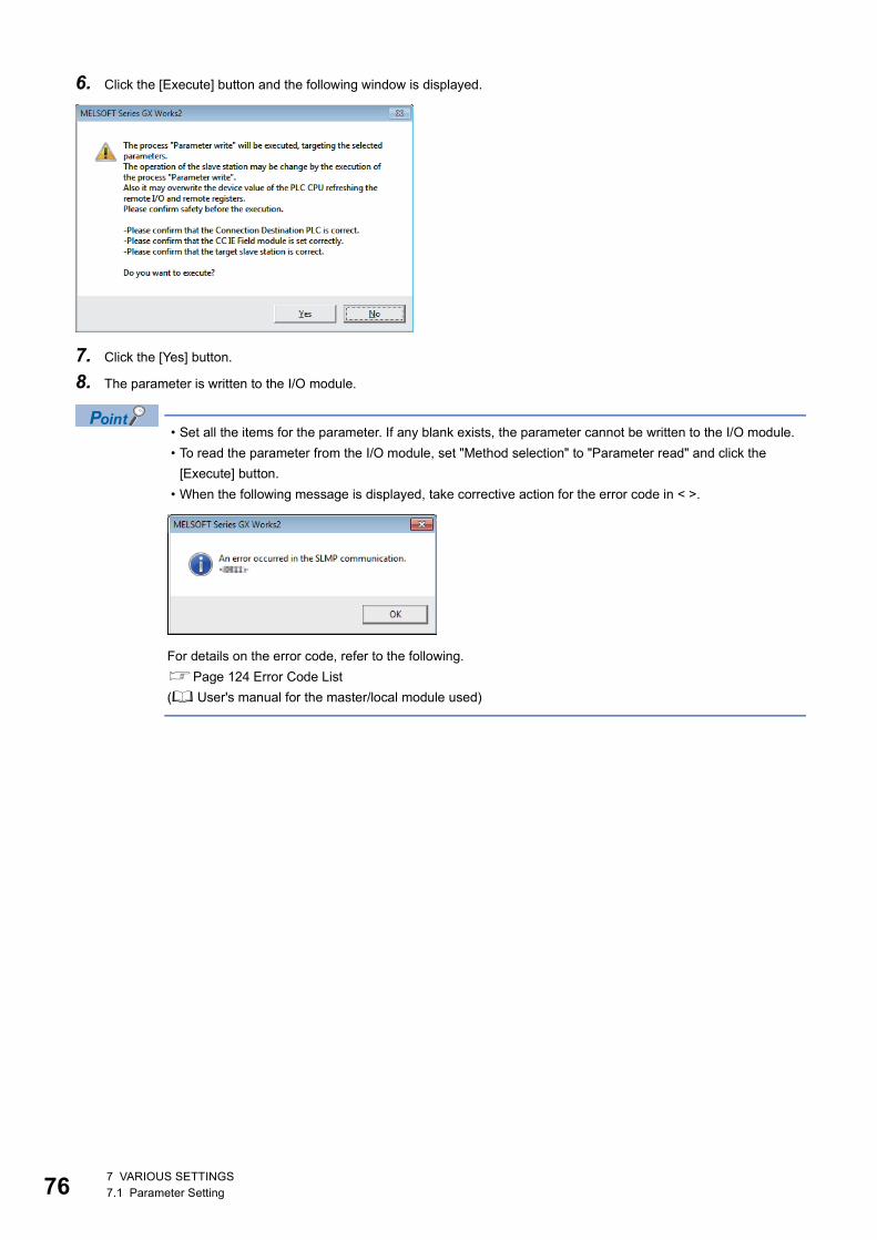
76
6. Click the [Execute] button and the following window is displayed.
7. Click the [Yes] button.
8. The parameter is written to the I/O module.
• Set all the items for the parameter. If any blank exists, the parameter cannot be written to the I/O module.
• To read the parameter from the I/O module, set "Method selection" to "Parameter read" and click the
[Execute] button.
• When the following message is displayed, take corrective action for the error code in < >.
For details on the error code, refer to the following.
Page 124 Error Code List
( User's manual for the master/local module used)
7 VARIOUS SETTINGS7.1 Parameter Setting
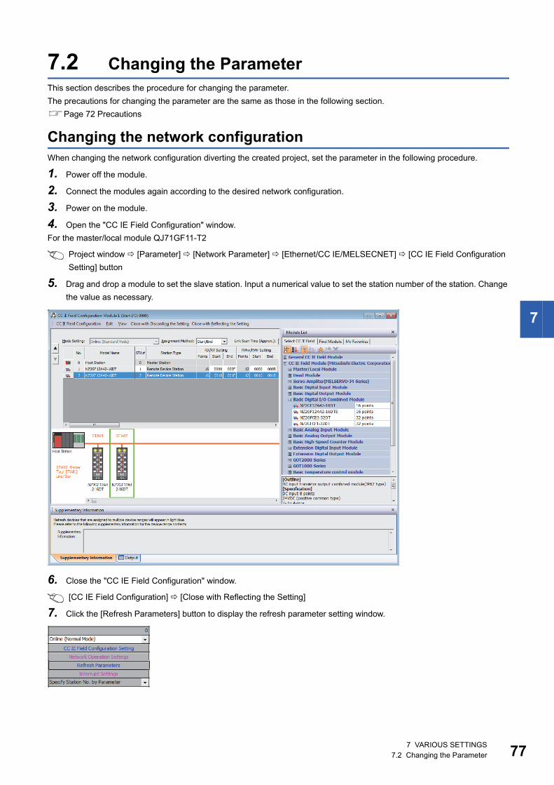
7
7.2 Changing the ParameterThis section describes the procedure for changing the parameter.
The precautions for changing the parameter are the same as those in the following section.
Page 72 Precautions
Changing the network configurationWhen changing the network configuration diverting the created project, set the parameter in the following procedure.
1. Power off the module.
2. Connect the modules again according to the desired network configuration.
3. Power on the module.
4. Open the "CC IE Field Configuration" window.
For the master/local module QJ71GF11-T2
Project window [Parameter] [Network Parameter] [Ethernet/CC IE/MELSECNET] [CC IE Field Configuration
Setting] button
5. Drag and drop a module to set the slave station. Input a numerical value to set the station number of the station. Change
the value as necessary.
6. Close the "CC IE Field Configuration" window.
[CC IE Field Configuration] [Close with Reflecting the Setting]
7. Click the [Refresh Parameters] button to display the refresh parameter setting window.
7 VARIOUS SETTINGS7.2 Changing the Parameter 77
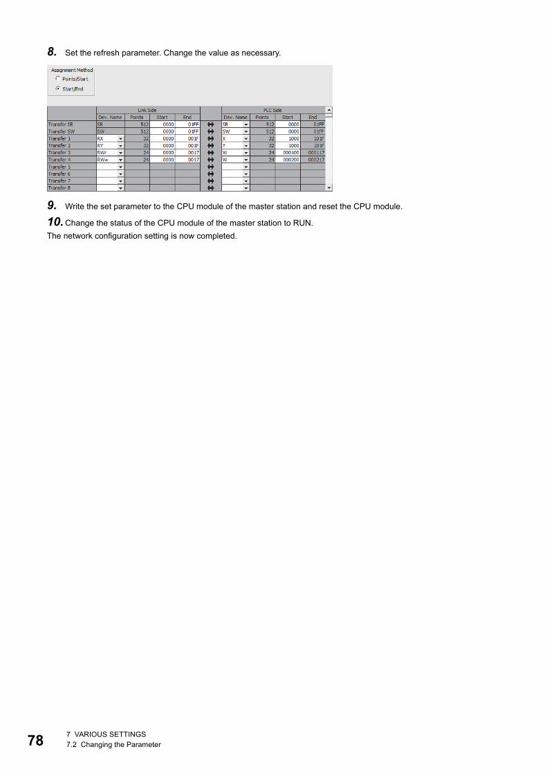
78
8. Set the refresh parameter. Change the value as necessary.
9. Write the set parameter to the CPU module of the master station and reset the CPU module.
10.Change the status of the CPU module of the master station to RUN.
The network configuration setting is now completed.
7 VARIOUS SETTINGS7.2 Changing the Parameter
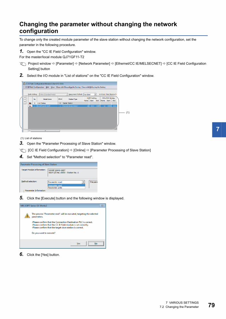
7
Changing the parameter without changing the network configurationTo change only the created module parameter of the slave station without changing the network configuration, set the
parameter in the following procedure.
1. Open the "CC IE Field Configuration" window.
For the master/local module QJ71GF11-T2
Project window [Parameter] [Network Parameter] [Ethernet/CC IE/MELSECNET] [CC IE Field Configuration
Setting] button
2. Select the I/O module in "List of stations" on the "CC IE Field Configuration" window.
3. Open the "Parameter Processing of Slave Station" window.
[CC IE Field Configuration] [Online] [Parameter Processing of Slave Station]
4. Set "Method selection" to "Parameter read".
5. Click the [Execute] button and the following window is displayed.
6. Click the [Yes] button.
(1) List of stations
(1)
7 VARIOUS SETTINGS7.2 Changing the Parameter 79
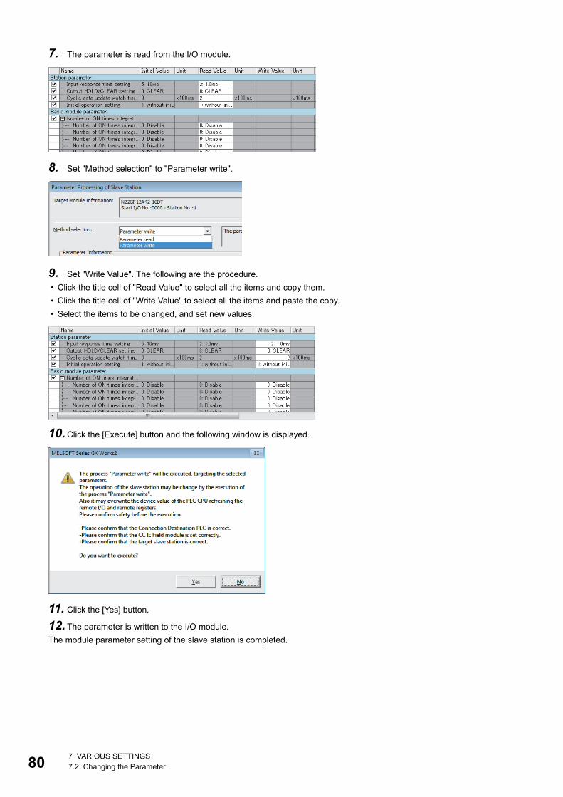
80
7. The parameter is read from the I/O module.
8. Set "Method selection" to "Parameter write".
9. Set "Write Value". The following are the procedure.
• Click the title cell of "Read Value" to select all the items and copy them.
• Click the title cell of "Write Value" to select all the items and paste the copy.
• Select the items to be changed, and set new values.
10.Click the [Execute] button and the following window is displayed.
11. Click the [Yes] button.
12. The parameter is written to the I/O module.
The module parameter setting of the slave station is completed.
7 VARIOUS SETTINGS7.2 Changing the Parameter
8
8 FUNCTIONS
This chapter describes the details of the functions available in the I/O module, and the setting procedures for those functions.
For details on remote I/O signals, remote registers, and remote buffer memory, refer to the following.
Page 143 Details of Remote I/O Signals
Page 144 Details of Remote Registers
Page 154 Details of Remote Buffer Memory Addresses
8.1 Error Notification FunctionWhen an error or warning occurs, the I/O module notifies the master station of it using remote registers.
The notification of the error or warning can be checked on the LED on the front of the module.
For details, refer to the following.
Page 17 LEDs on an I/O module
Notification of an errorThe I/O module notifies the master station of an error in the following method.
Depending on the major error status such as a hardware failure of the module, Error status flag (RWr0.b10)
may not be turned on, or an error code may not be stored in Error code (RWr1). When the above error occurs,
check the error occurrence with the LED indication on the front of the module, and please consult your local
Mitsubishi representative.
■Method for clearing an errorThe method for clearing an error depends on the error type.
Item Description Reference
Error status flag (RWr0.b10) Turns on when a moderate error or major error occurs. Page 147 Error status flag
(RWr0.b10)
Error clear request flag (RWw0.b10) Some errors can be cleared by turning on and off Error clear request flag
(RWw0.b10).
Page 152 Error clear request
flag (RWw0.b10)
Error code (RWr1) An error code is stored when a moderate error or major error occurs. Page 148 Error code
Error type Clearing an error
Major error The error cannot be cleared.
Moderate error Turn on Error clear request flag (RWw0.b10) or Operation condition setting request flag (RWw0.b9) after
removing the error cause.
8 FUNCTIONS8.1 Error Notification Function 81
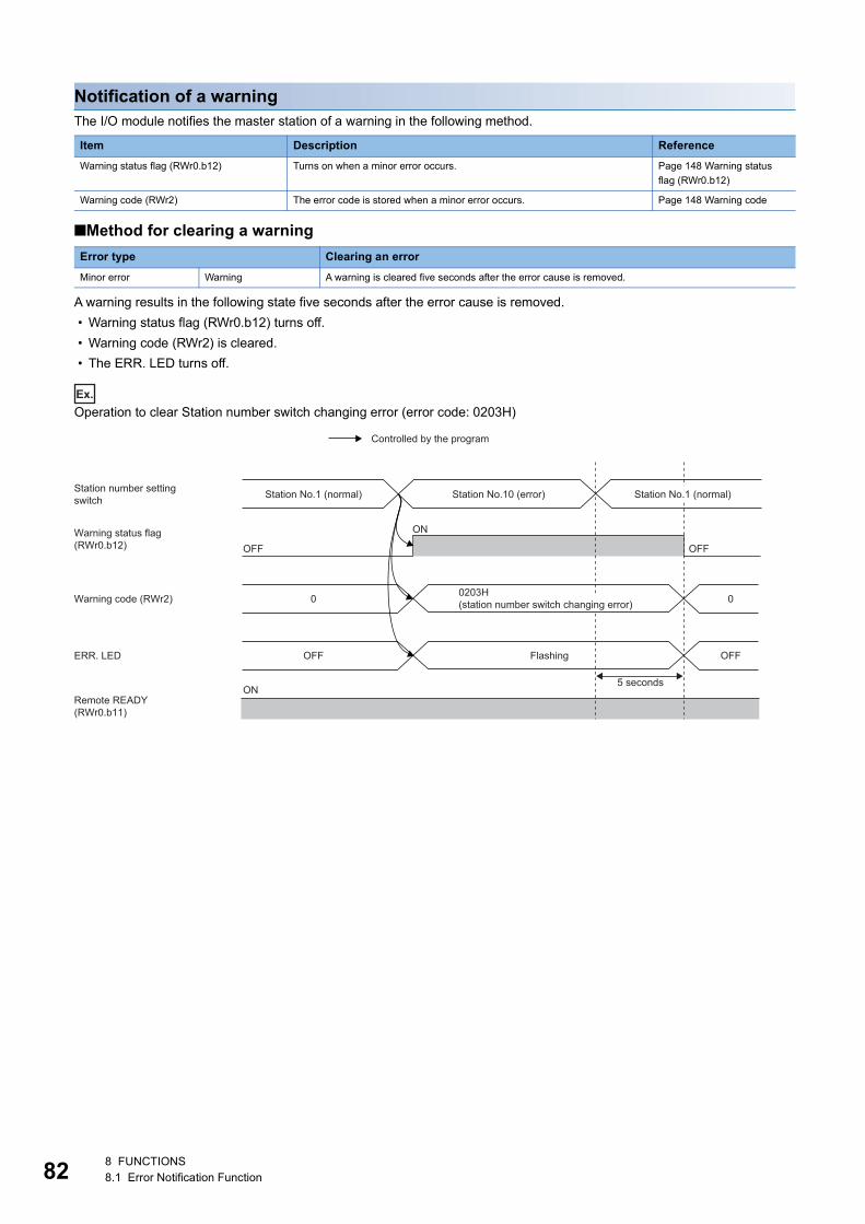
82
Notification of a warningThe I/O module notifies the master station of a warning in the following method.
■Method for clearing a warning
A warning results in the following state five seconds after the error cause is removed.
• Warning status flag (RWr0.b12) turns off.
• Warning code (RWr2) is cleared.
• The ERR. LED turns off.
Ex.
Operation to clear Station number switch changing error (error code: 0203H)
Item Description Reference
Warning status flag (RWr0.b12) Turns on when a minor error occurs. Page 148 Warning status
flag (RWr0.b12)
Warning code (RWr2) The error code is stored when a minor error occurs. Page 148 Warning code
Error type Clearing an error
Minor error Warning A warning is cleared five seconds after the error cause is removed.
ON
ON
OFFOFF
0 0
ERR. LED
Controlled by the program
Station No.1 (normal) Station No.1 (normal)
Warning status flag(RWr0.b12)
Station number setting switch
Warning code (RWr2)
Remote READY(RWr0.b11)
OFF
Station No.10 (error)
OFF Flashing
5 seconds
0203H(station number switch changing error)
8 FUNCTIONS8.1 Error Notification Function
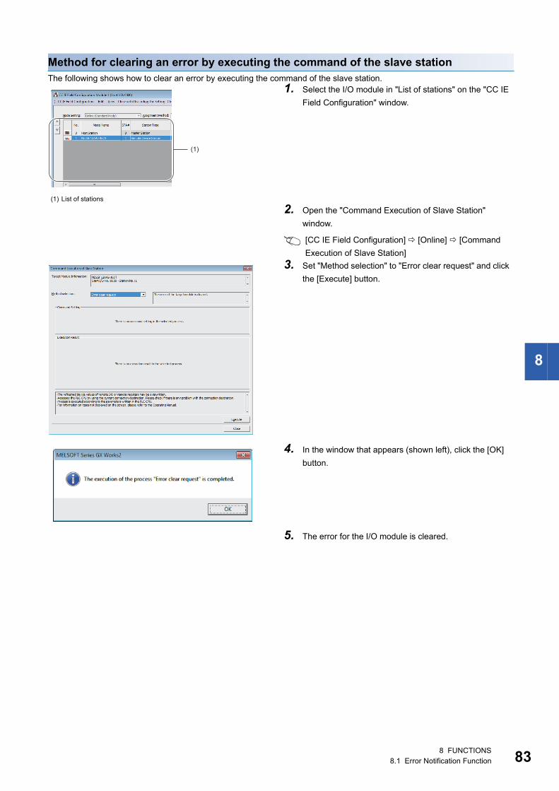
8
Method for clearing an error by executing the command of the slave stationThe following shows how to clear an error by executing the command of the slave station.
(1) List of stations
1. Select the I/O module in "List of stations" on the "CC IE
Field Configuration" window.
2. Open the "Command Execution of Slave Station"
window.
[CC IE Field Configuration] [Online] [Command
Execution of Slave Station]
3. Set "Method selection" to "Error clear request" and click
the [Execute] button.
4. In the window that appears (shown left), click the [OK]
button.
5. The error for the I/O module is cleared.
(1)
8 FUNCTIONS8.1 Error Notification Function 83
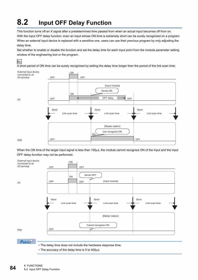
84
8.2 Input OFF Delay FunctionThis function turns off an X signal after a predetermined time passed from when an actual input becomes off from on.
With the input OFF delay function, even an input whose ON time is extremely short can be surely recognized on a program.
When an external input device is replaced with a sensitive one, users can use their previous program by only adjusting the
delay time.
Set whether to enable or disable the function and set the delay time for each input point from the module parameter setting
window of the engineering tool or the program.
Ex.
A short period of ON time can be surely recognized by setting the delay time longer than the period of the link scan time.
When the ON time of the target input signal is less than 100s, the module cannot recognize ON of the input and the input
OFF delay function may not be performed.
• The delay time does not include the hardware response time.
• The accuracy of the delay time is 0 to 400s.
X0
RX0 OFF OFF
OFF OFF
OFF OFF
ON
ON
ON
Can recognize ON.
Sends ON.
[Input module]
[Master station]
Link scan timeSend
Link scan timeSend
Link scan timeSend
External input deviceconnected to anX0 terminal
OFF delay
X0
RX0 OFF
OFF
OFF OFF
OFF
ON
ON
Cannot recognize ON.
Sends OFF.
[Input module]
[Master station]
Link scan timeSend
Link scan timeSend
Link scan timeSend
External input deviceconnected to anX0 terminal
8 FUNCTIONS8.2 Input OFF Delay Function
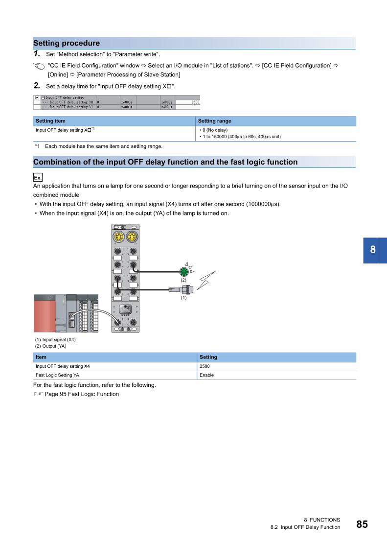
8
Setting procedure1. Set "Method selection" to "Parameter write".
"CC IE Field Configuration" window Select an I/O module in "List of stations". [CC IE Field Configuration]
[Online] [Parameter Processing of Slave Station]
2. Set a delay time for "Input OFF delay setting X".
*1 Each module has the same item and setting range.
Combination of the input OFF delay function and the fast logic function
Ex.
An application that turns on a lamp for one second or longer responding to a brief turning on of the sensor input on the I/O
combined module
• With the input OFF delay setting, an input signal (X4) turns off after one second (1000000s).
• When the input signal (X4) is on, the output (YA) of the lamp is turned on.
For the fast logic function, refer to the following.
Page 95 Fast Logic Function
Setting item Setting range
Input OFF delay setting X*1 • 0 (No delay)
• 1 to 150000 (400s to 60s, 400s unit)
(1) Input signal (X4)
(2) Output (YA)
Item Setting
Input OFF delay setting X4 2500
Fast Logic Setting YA Enable
(2)
(1)
8 FUNCTIONS8.2 Input OFF Delay Function 85
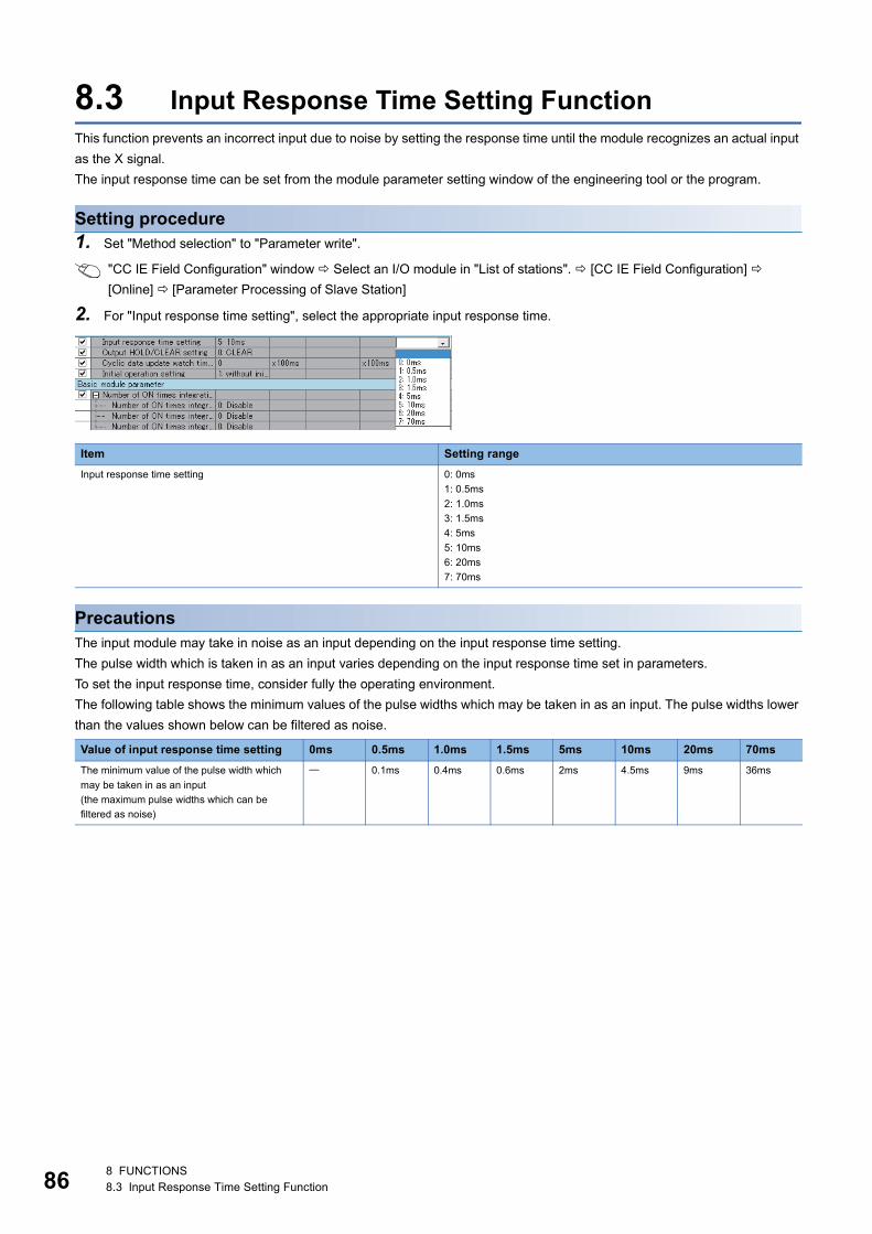
86
8.3 Input Response Time Setting FunctionThis function prevents an incorrect input due to noise by setting the response time until the module recognizes an actual input
as the X signal.
The input response time can be set from the module parameter setting window of the engineering tool or the program.
Setting procedure1. Set "Method selection" to "Parameter write".
"CC IE Field Configuration" window Select an I/O module in "List of stations". [CC IE Field Configuration]
[Online] [Parameter Processing of Slave Station]
2. For "Input response time setting", select the appropriate input response time.
PrecautionsThe input module may take in noise as an input depending on the input response time setting.
The pulse width which is taken in as an input varies depending on the input response time set in parameters.
To set the input response time, consider fully the operating environment.
The following table shows the minimum values of the pulse widths which may be taken in as an input. The pulse widths lower
than the values shown below can be filtered as noise.
Item Setting range
Input response time setting 0: 0ms
1: 0.5ms
2: 1.0ms
3: 1.5ms
4: 5ms
5: 10ms
6: 20ms
7: 70ms
Value of input response time setting 0ms 0.5ms 1.0ms 1.5ms 5ms 10ms 20ms 70ms
The minimum value of the pulse width which
may be taken in as an input
(the maximum pulse widths which can be
filtered as noise)
0.1ms 0.4ms 0.6ms 2ms 4.5ms 9ms 36ms
8 FUNCTIONS8.3 Input Response Time Setting Function
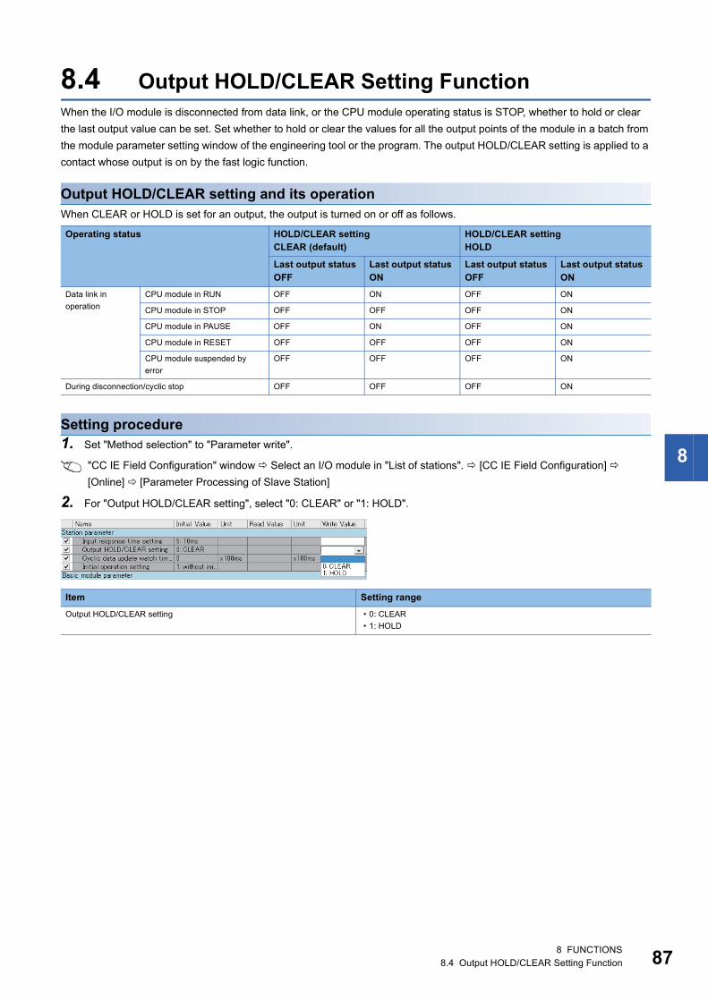
8
8.4 Output HOLD/CLEAR Setting FunctionWhen the I/O module is disconnected from data link, or the CPU module operating status is STOP, whether to hold or clear
the last output value can be set. Set whether to hold or clear the values for all the output points of the module in a batch from
the module parameter setting window of the engineering tool or the program. The output HOLD/CLEAR setting is applied to a
contact whose output is on by the fast logic function.
Output HOLD/CLEAR setting and its operationWhen CLEAR or HOLD is set for an output, the output is turned on or off as follows.
Setting procedure1. Set "Method selection" to "Parameter write".
"CC IE Field Configuration" window Select an I/O module in "List of stations". [CC IE Field Configuration]
[Online] [Parameter Processing of Slave Station]
2. For "Output HOLD/CLEAR setting", select "0: CLEAR" or "1: HOLD".
Operating status HOLD/CLEAR settingCLEAR (default)
HOLD/CLEAR settingHOLD
Last output status OFF
Last output status ON
Last output status OFF
Last output status ON
Data link in
operation
CPU module in RUN OFF ON OFF ON
CPU module in STOP OFF OFF OFF ON
CPU module in PAUSE OFF ON OFF ON
CPU module in RESET OFF OFF OFF ON
CPU module suspended by
error
OFF OFF OFF ON
During disconnection/cyclic stop OFF OFF OFF ON
Item Setting range
Output HOLD/CLEAR setting • 0: CLEAR
• 1: HOLD
8 FUNCTIONS8.4 Output HOLD/CLEAR Setting Function 87
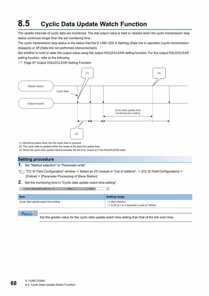
88
8.5 Cyclic Data Update Watch FunctionThe update intervals of cyclic data are monitored. The last output value is held or cleared when the cyclic transmission stop
status continues longer than the set monitoring time.
The cyclic transmission stop status is the status that the D LINK LED is flashing (Data link in operation (cyclic transmission
stopped)) or off (Data link not performed (disconnected)).
Set whether to hold or clear the output value using the output HOLD/CLEAR setting function. For the output HOLD/CLEAR
setting function, refer to the following.
Page 87 Output HOLD/CLEAR Setting Function
Setting procedure1. Set "Method selection" to "Parameter write".
"CC IE Field Configuration" window Select an I/O module in "List of stations". [CC IE Field Configuration]
[Online] [Parameter Processing of Slave Station]
2. Set the monitoring time in "Cyclic data update watch time setting".
Set the greater value for the cyclic data update watch time setting than that of the link scan time.
(1) Monitoring starts when the first cyclic data is received.
(2) The cyclic data is updated within the range of the data link update time.
(3) When the cyclic data update interval exceeds the set time, output is in the HOLD/CLEAR state.
Item Setting range
Cyclic data update watch time setting • 0 (Not monitor)
• 1 to 20 (0.1 to 2 seconds in units of 100ms)
(2)
(3)(1)
Master station
Output module
Cyclic data
Cyclic data update timemonitoring time setting
8 FUNCTIONS8.5 Cyclic Data Update Watch Function
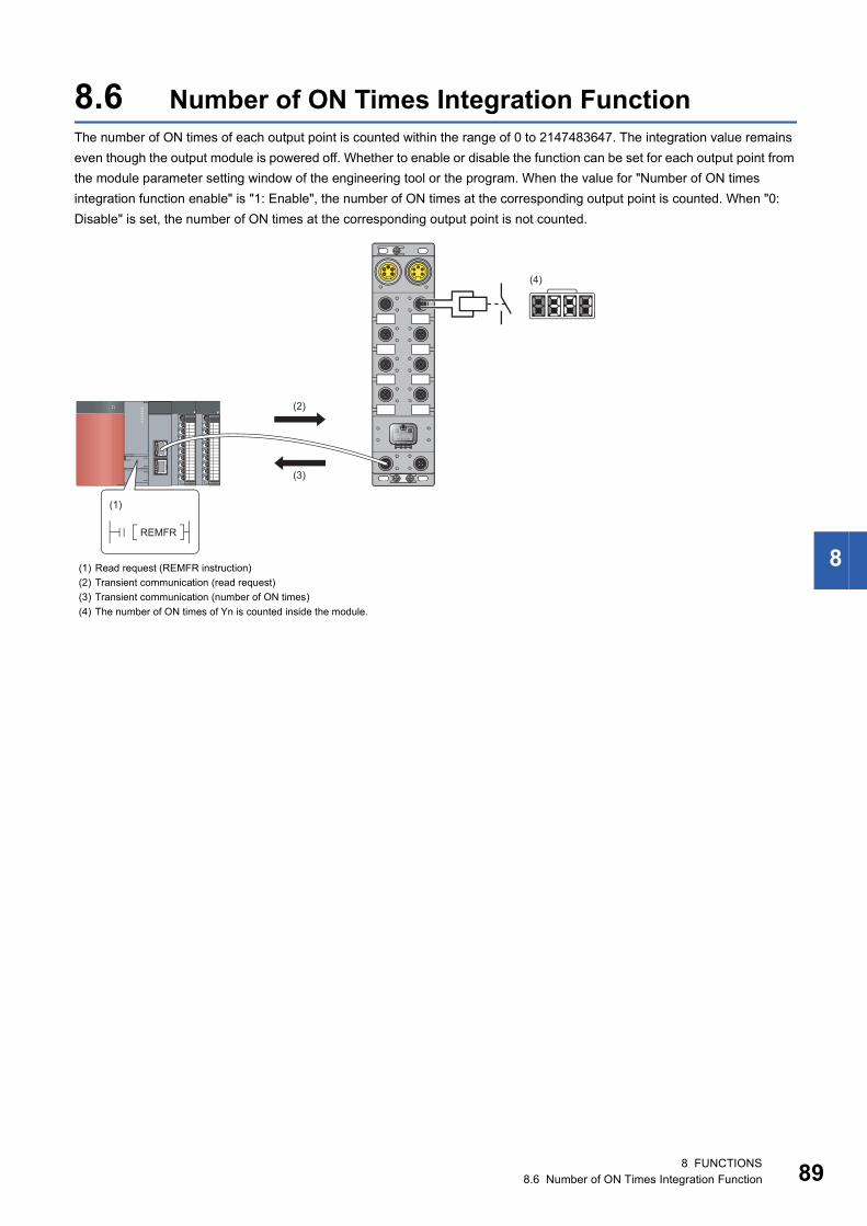
8
8.6 Number of ON Times Integration FunctionThe number of ON times of each output point is counted within the range of 0 to 2147483647. The integration value remains
even though the output module is powered off. Whether to enable or disable the function can be set for each output point from
the module parameter setting window of the engineering tool or the program. When the value for "Number of ON times
integration function enable" is "1: Enable", the number of ON times at the corresponding output point is counted. When "0:
Disable" is set, the number of ON times at the corresponding output point is not counted.
(1) Read request (REMFR instruction)
(2) Transient communication (read request)
(3) Transient communication (number of ON times)
(4) The number of ON times of Yn is counted inside the module.
(2)
(3)
(4)
(1)
REMFR
8 FUNCTIONS8.6 Number of ON Times Integration Function 89
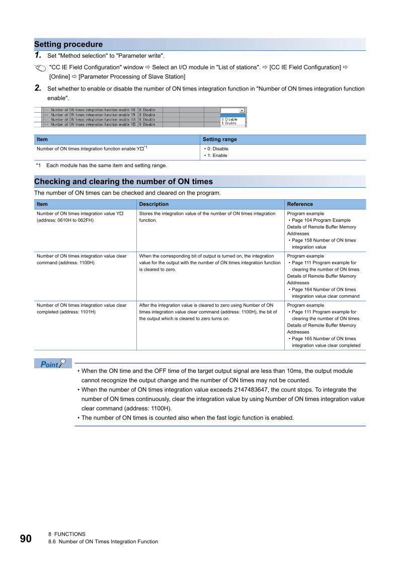
90
Setting procedure1. Set "Method selection" to "Parameter write".
"CC IE Field Configuration" window Select an I/O module in "List of stations". [CC IE Field Configuration]
[Online] [Parameter Processing of Slave Station]
2. Set whether to enable or disable the number of ON times integration function in "Number of ON times integration function
enable".
*1 Each module has the same item and setting range.
Checking and clearing the number of ON timesThe number of ON times can be checked and cleared on the program.
• When the ON time and the OFF time of the target output signal are less than 10ms, the output module
cannot recognize the output change and the number of ON times may not be counted.
• When the number of ON times integration value exceeds 2147483647, the count stops. To integrate the
number of ON times continuously, clear the integration value by using Number of ON times integration value
clear command (address: 1100H).
• The number of ON times is counted also when the fast logic function is enabled.
Item Setting range
Number of ON times integration function enable Y*1 • 0: Disable
• 1: Enable
Item Description Reference
Number of ON times integration value Y
(address: 0610H to 062FH)
Stores the integration value of the number of ON times integration
function.
Program example
• Page 104 Program Example
Details of Remote Buffer Memory
Addresses
• Page 158 Number of ON times
integration value
Number of ON times integration value clear
command (address: 1100H)
When the corresponding bit of output is turned on, the integration
value for the output with the number of ON times integration function
is cleared to zero.
Program example
• Page 111 Program example for
clearing the number of ON times
Details of Remote Buffer Memory
Addresses
• Page 164 Number of ON times
integration value clear command
Number of ON times integration value clear
completed (address: 1101H)
After the integration value is cleared to zero using Number of ON
times integration value clear command (address: 1100H), the bit of
the output which is cleared to zero turns on.
Program example
• Page 111 Program example for
clearing the number of ON times
Details of Remote Buffer Memory
Addresses
• Page 165 Number of ON times
integration value clear completed
8 FUNCTIONS8.6 Number of ON Times Integration Function
8
8.7 Output ON/OFF Information Hold FunctionThis function checks if the output has been turned once on or off.
Output ON informationOutput ON information is stored in Output Y ON information (RWr7).
Whether the output has been turned on or not can be checked with Output Y ON information (RWr7).
Output Y ON information (RWr7) can be cleared using Output Y ON information clear request (RWw7).
For the on and off timing, refer to the following.
Page 150 Output Y ON information
Output OFF informationOutput OFF information is stored in Output Y OFF information (RWr8).
Whether the output has been turned off or not can be checked with Output Y OFF information (RWr8).
Output Y OFF information (RWr8) can be cleared using Output Y OFF information clear request (RWw8).
For the on and off timing, refer to the following.
Page 151 Output Y OFF information
8 FUNCTIONS8.7 Output ON/OFF Information Hold Function 91
92
8.8 Power Supply Monitoring FunctionThis function monitors the voltage status of each of the module-and-sensor power supply and load power supply and notifies
users of the status with the PW LED and L PW LED.
By using Power supply monitor request flag (RWw3.b0), a moderate error is generated when the power supply is off. Thus,
the on/off state of the power supply is notified and the output module can be stopped.
Enabling the power supply monitoring function is recommended because operating the module with the power
supply voltage unstable may cause incorrect input or output.
Operation of the power supply monitoring functionWhen an error occurs on the module-and-sensor power supply or load power supply while the Power supply monitor request
flag (RWw3.b0) is on, a moderate error occurs. The following table lists errors of each power supply and bits to be turned on.
When using this function, check that the load power supply stabilizes before turning on Power supply monitor request flag
(RWw3.b0). When turning off the load power supply, turn off Power supply monitor request flag (RWw3.b0) in advance.
Setting and checking the power supply monitoring function
Error cause Error code
Abnormal power supply Description
Module-and-sensor power supply Low voltage 0103H Bit 0 of Error code details 1 turns on.
Overvoltage Bit 1 of Error code details 1 turns on.
Load power supply Low voltage Bit 2 of Error code details 1 turns on.
Overvoltage Bit 3 of Error code details 1 turns on.
Item Description Reference
Power supply monitor request flag (RWw3.b0) Sets whether to enable or disable the power supply monitoring function. Page 152 Power supply
monitor request flag
(RWw3.b0)
Power supply monitor state flag (RWr3.b0) Indicates whether the power supply monitoring function is enabled or
disabled.
Page 149 Power supply
monitor state flag (RWr3.b0)
8 FUNCTIONS8.8 Power Supply Monitoring Function
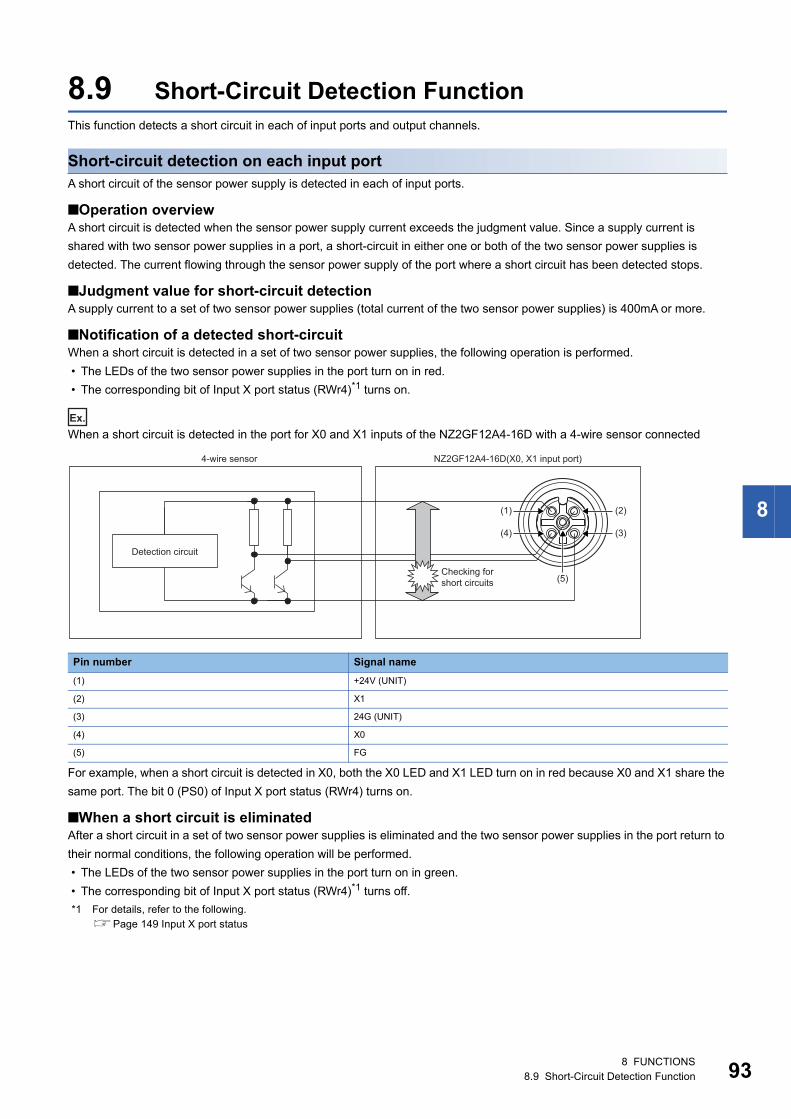
8
8.9 Short-Circuit Detection FunctionThis function detects a short circuit in each of input ports and output channels.
Short-circuit detection on each input portA short circuit of the sensor power supply is detected in each of input ports.
■Operation overviewA short circuit is detected when the sensor power supply current exceeds the judgment value. Since a supply current is
shared with two sensor power supplies in a port, a short-circuit in either one or both of the two sensor power supplies is
detected. The current flowing through the sensor power supply of the port where a short circuit has been detected stops.
■Judgment value for short-circuit detectionA supply current to a set of two sensor power supplies (total current of the two sensor power supplies) is 400mA or more.
■Notification of a detected short-circuitWhen a short circuit is detected in a set of two sensor power supplies, the following operation is performed.
• The LEDs of the two sensor power supplies in the port turn on in red.
• The corresponding bit of Input X port status (RWr4)*1 turns on.
Ex.
When a short circuit is detected in the port for X0 and X1 inputs of the NZ2GF12A4-16D with a 4-wire sensor connected
For example, when a short circuit is detected in X0, both the X0 LED and X1 LED turn on in red because X0 and X1 share the
same port. The bit 0 (PS0) of Input X port status (RWr4) turns on.
■When a short circuit is eliminatedAfter a short circuit in a set of two sensor power supplies is eliminated and the two sensor power supplies in the port return to
their normal conditions, the following operation will be performed.
• The LEDs of the two sensor power supplies in the port turn on in green.
• The corresponding bit of Input X port status (RWr4)*1 turns off.
*1 For details, refer to the following.Page 149 Input X port status
Pin number Signal name
(1) +24V (UNIT)
(2) X1
(3) 24G (UNIT)
(4) X0
(5) FG
(2)
(3)
(5)
(1)
(4)
Detection circuit
4-wire sensor NZ2GF12A4-16D(X0, X1 input port)
Checking for short circuits
8 FUNCTIONS8.9 Short-Circuit Detection Function 93
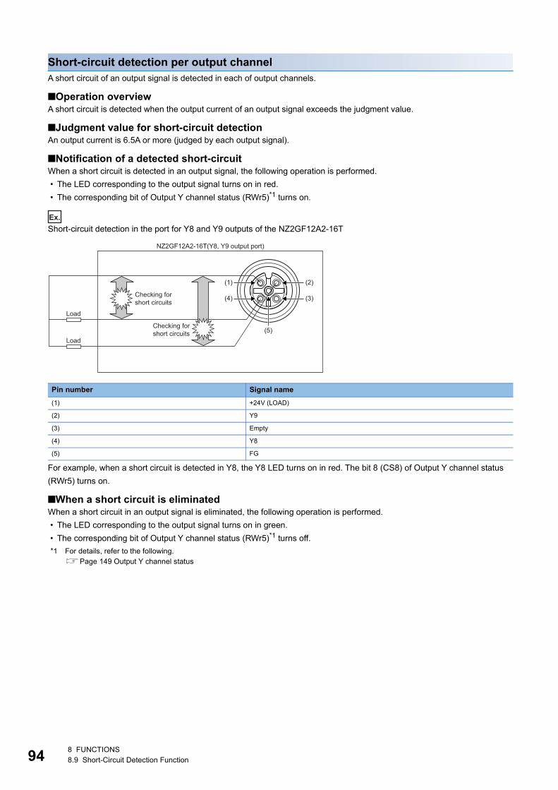
94
Short-circuit detection per output channelA short circuit of an output signal is detected in each of output channels.
■Operation overviewA short circuit is detected when the output current of an output signal exceeds the judgment value.
■Judgment value for short-circuit detectionAn output current is 6.5A or more (judged by each output signal).
■Notification of a detected short-circuitWhen a short circuit is detected in an output signal, the following operation is performed.
• The LED corresponding to the output signal turns on in red.
• The corresponding bit of Output Y channel status (RWr5)*1 turns on.
Ex.
Short-circuit detection in the port for Y8 and Y9 outputs of the NZ2GF12A2-16T
For example, when a short circuit is detected in Y8, the Y8 LED turns on in red. The bit 8 (CS8) of Output Y channel status
(RWr5) turns on.
■When a short circuit is eliminatedWhen a short circuit in an output signal is eliminated, the following operation is performed.
• The LED corresponding to the output signal turns on in green.
• The corresponding bit of Output Y channel status (RWr5)*1 turns off.
*1 For details, refer to the following.Page 149 Output Y channel status
Pin number Signal name
(1) +24V (LOAD)
(2) Y9
(3) Empty
(4) Y8
(5) FG
(2)
(3)
(5)
(1)
(4)
Checking for short circuits
Checking for short circuits
Load
Load
NZ2GF12A2-16T(Y8, Y9 output port)
8 FUNCTIONS8.9 Short-Circuit Detection Function
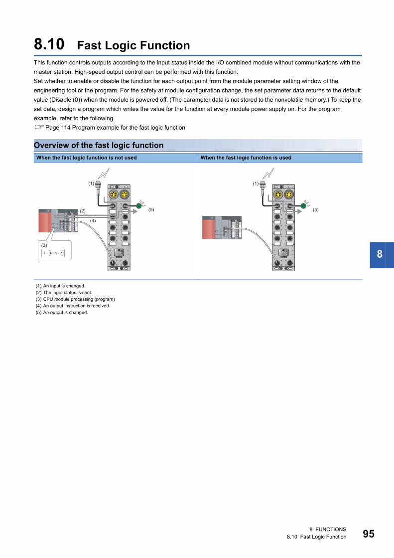
8
8.10 Fast Logic FunctionThis function controls outputs according to the input status inside the I/O combined module without communications with the
master station. High-speed output control can be performed with this function.
Set whether to enable or disable the function for each output point from the module parameter setting window of the
engineering tool or the program. For the safety at module configuration change, the set parameter data returns to the default
value (Disable (0)) when the module is powered off. (The parameter data is not stored to the nonvolatile memory.) To keep the
set data, design a program which writes the value for the function at every module power supply on. For the program
example, refer to the following.
Page 114 Program example for the fast logic function
Overview of the fast logic function
When the fast logic function is not used When the fast logic function is used
(1) An input is changed.
(2) The input status is sent.
(3) CPU module processing (program)
(4) An output instruction is received.
(5) An output is changed.
(1)
(5) (2)
(4)
(3) REMFR
(1)
(5)
8 FUNCTIONS8.10 Fast Logic Function 95
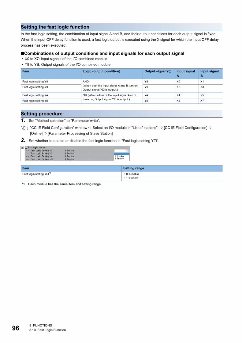
96
Setting the fast logic functionIn the fast logic setting, the combination of input signal A and B, and their output conditions for each output signal is fixed.
When the input OFF delay function is used, a fast logic output is executed using the X signal for which the input OFF delay
process has been executed.
■Combinations of output conditions and input signals for each output signal • X0 to X7: Input signals of the I/O combined module
• Y8 to YB: Output signals of the I/O combined module
Setting procedure1. Set "Method selection" to "Parameter write".
"CC IE Field Configuration" window Select an I/O module in "List of stations". [CC IE Field Configuration]
[Online] [Parameter Processing of Slave Station]
2. Set whether to enable or disable the fast logic function in "Fast logic setting Y".
*1 Each module has the same item and setting range.
Item Logic (output condition) Output signal Y Input signal A
Input signal B
Fast logic setting Y8 AND
(When both the input signal A and B turn on,
Output signal Y is output.)
Y8 X0 X1
Fast logic setting Y9 Y9 X2 X3
Fast logic setting YA OR (When either of the input signal A or B
turns on, Output signal Y is output.)
YA X4 X5
Fast logic setting YB YB X6 X7
Item Setting range
Fast logic setting Y*1 • 0: Disable
• 1: Enable
8 FUNCTIONS8.10 Fast Logic Function
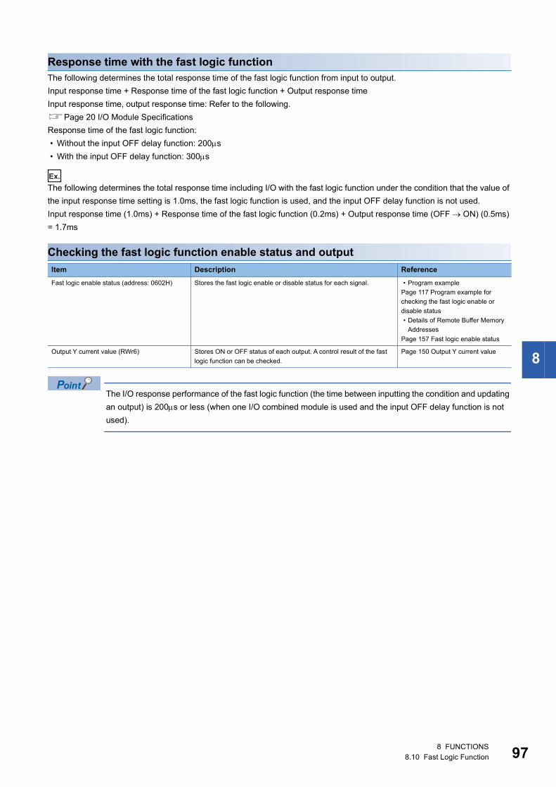
8
Response time with the fast logic functionThe following determines the total response time of the fast logic function from input to output.
Input response time + Response time of the fast logic function + Output response time
Input response time, output response time: Refer to the following.
Page 20 I/O Module Specifications
Response time of the fast logic function:
• Without the input OFF delay function: 200s
• With the input OFF delay function: 300s
Ex.
The following determines the total response time including I/O with the fast logic function under the condition that the value of
the input response time setting is 1.0ms, the fast logic function is used, and the input OFF delay function is not used.
Input response time (1.0ms) + Response time of the fast logic function (0.2ms) + Output response time (OFF ON) (0.5ms)
= 1.7ms
Checking the fast logic function enable status and output
The I/O response performance of the fast logic function (the time between inputting the condition and updating
an output) is 200s or less (when one I/O combined module is used and the input OFF delay function is not
used).
Item Description Reference
Fast logic enable status (address: 0602H) Stores the fast logic enable or disable status for each signal. • Program example
Page 117 Program example for
checking the fast logic enable or
disable status
• Details of Remote Buffer Memory
Addresses
Page 157 Fast logic enable status
Output Y current value (RWr6) Stores ON or OFF status of each output. A control result of the fast
logic function can be checked.
Page 150 Output Y current value
8 FUNCTIONS8.10 Fast Logic Function 97
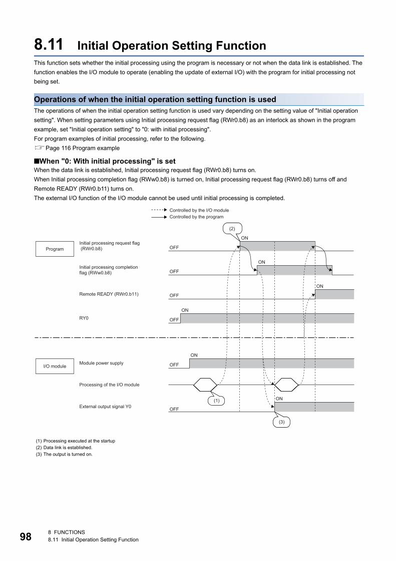
98
8.11 Initial Operation Setting FunctionThis function sets whether the initial processing using the program is necessary or not when the data link is established. The
function enables the I/O module to operate (enabling the update of external I/O) with the program for initial processing not
being set.
Operations of when the initial operation setting function is usedThe operations of when the initial operation setting function is used vary depending on the setting value of "Initial operation
setting". When setting parameters using Initial processing request flag (RWr0.b8) as an interlock as shown in the program
example, set "Initial operation setting" to "0: with initial processing".
For program examples of initial processing, refer to the following.
Page 116 Program example
■When "0: With initial processing" is setWhen the data link is established, Initial processing request flag (RWr0.b8) turns on.
When Initial processing completion flag (RWw0.b8) is turned on, Initial processing request flag (RWr0.b8) turns off and
Remote READY (RWr0.b11) turns on.
The external I/O function of the I/O module cannot be used until initial processing is completed.
(1) Processing executed at the startup
(2) Data link is established.
(3) The output is turned on.
OFF
OFF
OFF
ON
ON
ON
OFF
ON
OFF
ON
OFF
ON
(2)
(1)
(3)
RY0
Controlled by the I/O moduleControlled by the program
Initial processing request flag (RWr0.b8)
Module power supply
Processing of the I/O module
External output signal Y0
Initial processing completion flag (RWw0.b8)
Remote READY (RWr0.b11)
Program
I/O module
8 FUNCTIONS8.11 Initial Operation Setting Function
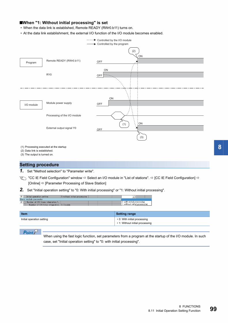
8
■When "1: Without initial processing" is set • When the data link is established, Remote READY (RWr0.b11) turns on.
• At the data link establishment, the external I/O function of the I/O module becomes enabled.
Setting procedure1. Set "Method selection" to "Parameter write".
"CC IE Field Configuration" window Select an I/O module in "List of stations". [CC IE Field Configuration]
[Online] [Parameter Processing of Slave Station]
2. Set "Initial operation setting" to "0: With initial processing" or "1: Without initial processing".
When using the fast logic function, set parameters from a program at the startup of the I/O module. In such
case, set "Initial operation setting" to "0: with initial processing".
(1) Processing executed at the startup
(2) Data link is established.
(3) The output is turned on.
Item Setting range
Initial operation setting • 0: With initial processing
• 1: Without initial processing
OFF
ON
OFF
OFF
ON
OFF
ON
ON
(2)
(1)
(3)
RY0
Controlled by the I/O moduleControlled by the program
Remote READY (RWr0.b11)
Module power supply
Processing of the I/O module
External output signal Y0
Program
I/O module
8 FUNCTIONS8.11 Initial Operation Setting Function 99
10
8.12 Protection FunctionThe I/O module has the following protection functions.
: Available, : Not available
The protection functions do not protect external devices but protect the internal circuit of the module.
A problem on a load may raise the internal temperature of the module, causing deterioration in output
elements and discoloration on the case and the printed-circuit board. Turn off the corresponding output as
soon as a problem on a load is found, and remove the cause.
The following describes the operation of each protection function.
Overload protection functionIf the output module and I/O combined module detect overcurrent, the module performs the current limiting operation (that
imposes a limit on the output current to a constant value and keeps the output).
For the overcurrent detection value and the limited current, refer to "Overload protection function" in the specifications table
for each module.
Page 26 Output module
Page 34 I/O combined module
If the load current becomes equal to the overcurrent detection value or lower, the module returns to normal operation.
Overheat protection functionIf the output module and I/O combined module keep outputting the overcurrent caused by an overload, heat is generated
inside the module. If the module detects a high heat in its inside, it turns off the output.
The multiple points at which the overheat protection function operates simultaneously depend on the module. Refer to
"Overheat protection function" in the specifications table for each module.
Page 26 Output module
Page 34 I/O combined module
If the heat descends, the module automatically returns to normal operation.
Power supply overvoltage protection functionIf the module power supply of the I/O module becomes the overvoltage state, the module stops the operation.
If the voltage of the module power supply descends, the module automatically returns to normal operation.
8.13 CC-Link IE Field Network Diagnostic FunctionThis function allows the presence or absence of a network error to be checked by accessing the engineering tool connected to
the CPU module.
How to useThe following instructions assume the use of GX Works2 as the engineering tool.
1. Connect GX Works2 to the CPU module.
Protection function Input module Output module I/O combined module
Overload protection function
Overheat protection function
Power supply overvoltage protection
function
08 FUNCTIONS8.12 Protection Function
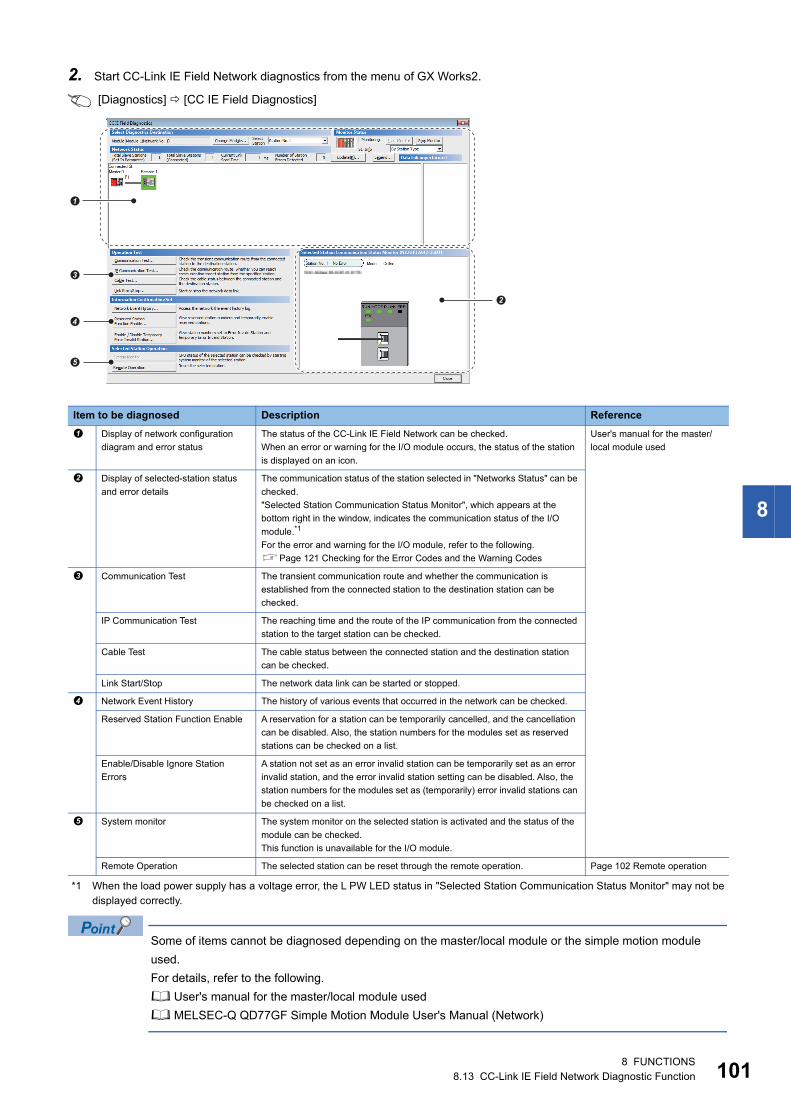
8
2. Start CC-Link IE Field Network diagnostics from the menu of GX Works2.
[Diagnostics] [CC IE Field Diagnostics]
*1 When the load power supply has a voltage error, the L PW LED status in "Selected Station Communication Status Monitor" may not be displayed correctly.
Some of items cannot be diagnosed depending on the master/local module or the simple motion module
used.
For details, refer to the following.
User's manual for the master/local module used
MELSEC-Q QD77GF Simple Motion Module User's Manual (Network)
Item to be diagnosed Description Reference
Display of network configuration
diagram and error status
The status of the CC-Link IE Field Network can be checked.
When an error or warning for the I/O module occurs, the status of the station
is displayed on an icon.
User's manual for the master/
local module used
Display of selected-station status
and error details
The communication status of the station selected in "Networks Status" can be
checked.
"Selected Station Communication Status Monitor", which appears at the
bottom right in the window, indicates the communication status of the I/O
module.*1
For the error and warning for the I/O module, refer to the following.
Page 121 Checking for the Error Codes and the Warning Codes
Communication Test The transient communication route and whether the communication is
established from the connected station to the destination station can be
checked.
IP Communication Test The reaching time and the route of the IP communication from the connected
station to the target station can be checked.
Cable Test The cable status between the connected station and the destination station
can be checked.
Link Start/Stop The network data link can be started or stopped.
Network Event History The history of various events that occurred in the network can be checked.
Reserved Station Function Enable A reservation for a station can be temporarily cancelled, and the cancellation
can be disabled. Also, the station numbers for the modules set as reserved
stations can be checked on a list.
Enable/Disable Ignore Station
Errors
A station not set as an error invalid station can be temporarily set as an error
invalid station, and the error invalid station setting can be disabled. Also, the
station numbers for the modules set as (temporarily) error invalid stations can
be checked on a list.
System monitor The system monitor on the selected station is activated and the status of the
module can be checked.
This function is unavailable for the I/O module.
Remote Operation The selected station can be reset through the remote operation. Page 102 Remote operation
�
�
�
�
�
8 FUNCTIONS8.13 CC-Link IE Field Network Diagnostic Function 101
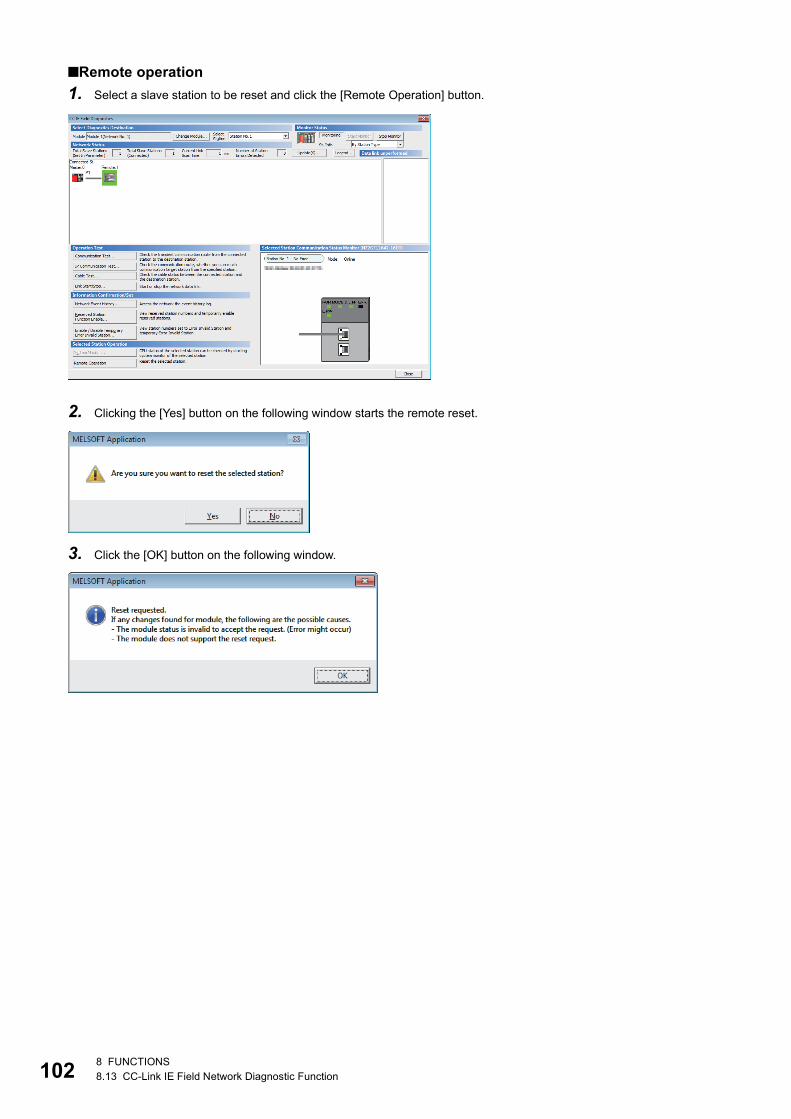
10
■Remote operation
1. Select a slave station to be reset and click the [Remote Operation] button.
2. Clicking the [Yes] button on the following window starts the remote reset.
3. Click the [OK] button on the following window.
28 FUNCTIONS8.13 CC-Link IE Field Network Diagnostic Function
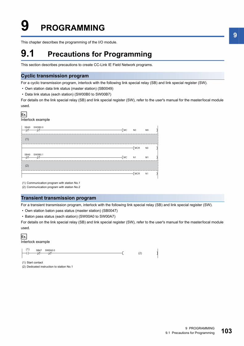
9
9 PROGRAMMINGThis chapter describes the programming of the I/O module.
9.1 Precautions for ProgrammingThis section describes precautions to create CC-Link IE Field Network programs.
Cyclic transmission programFor a cyclic transmission program, interlock with the following link special relay (SB) and link special register (SW).
• Own station data link status (master station) (SB0049)
• Data link status (each station) (SW00B0 to SW00B7)
For details on the link special relay (SB) and link special register (SW), refer to the user's manual for the master/local module
used.
Ex.
Interlock example
Transient transmission programFor a transient transmission program, interlock with the following link special relay (SB) and link special register (SW).
• Own station baton pass status (master station) (SB0047)
• Baton pass status (each station) (SW00A0 to SW00A7)
For details on the link special relay (SB) and link special register (SW), refer to the user's manual for the master/local module
used.
Ex.
Interlock example
(1) Communication program with station No.1
(2) Communication program with station No.2
(1) Start contact
(2) Dedicated instruction to station No.1
(1)
(2)
(1)(2)
9 PROGRAMMING9.1 Precautions for Programming 103
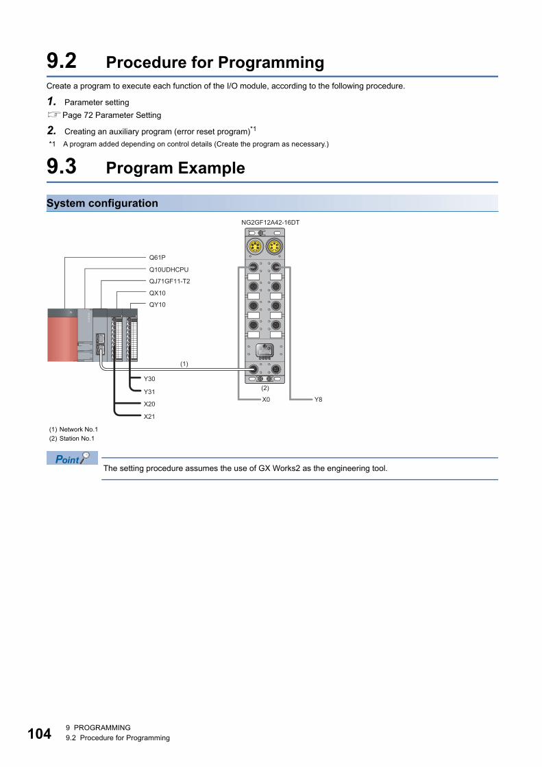
10
9.2 Procedure for ProgrammingCreate a program to execute each function of the I/O module, according to the following procedure.
1. Parameter setting
Page 72 Parameter Setting
2. Creating an auxiliary program (error reset program)*1
*1 A program added depending on control details (Create the program as necessary.)
9.3 Program Example
System configuration
The setting procedure assumes the use of GX Works2 as the engineering tool.
(1) Network No.1
(2) Station No.1
Y8X0
QX10
QY10
Q61P
Q10UDHCPU
NG2GF12A42-16DT
QJ71GF11-T2
Y30
(1)
(2)Y31
X20
X21
49 PROGRAMMING9.2 Procedure for Programming
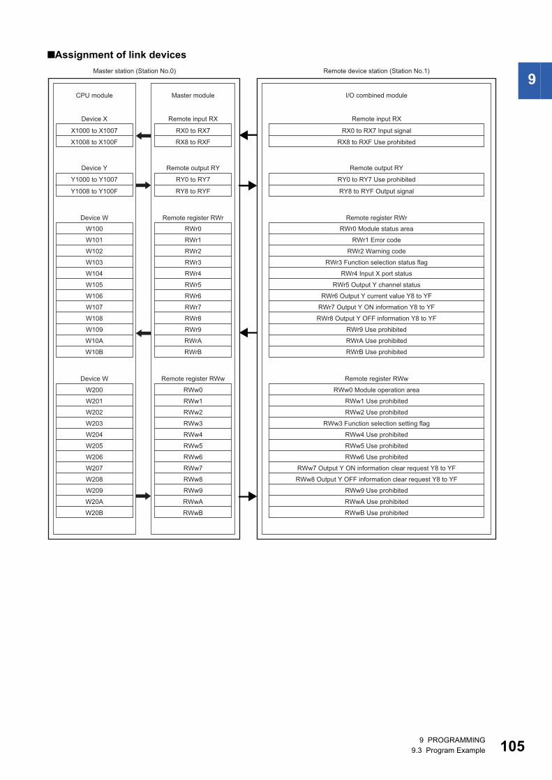
9
■Assignment of link devices
W100
W101
W102
W103
W104
W105
W106
W107
W108
W109
W10A
W10B
W200
W201
W202
W203
W204
W205
W206
W207
W208
W209
W20A
W20B
RWr8
RWr9
RWrA
RWrB
RWw7
RWw8
RWw9
RWwA
RWwB
RWr0
RWr1
RWr2
RWr3
RWr4
RWr5
RWr6
RWr7
RWw0
RWw1
RWw2
RWw3
RWw4
RWw5
RWw6
CPU module
Device X
Device Y
Device W
Master module
Remote input RX
Remote output RY
Device W
Remote register RWr
Remote register RWw
Remote input RX
Remote output RY
Remote register RWr
RWr0 Module status area
RWr1 Error code
RWr2 Warning code
RWr3 Function selection status flag
Remote register RWw
RWw0 Module operation area
RWw1 Use prohibited
RWw2 Use prohibited
RWw3 Function selection setting flag
RWw4 Use prohibited
RWw5 Use prohibited
RWw6 Use prohibited
Master station (Station No.0) Remote device station (Station No.1)
X1000 to X1007
X1008 to X100F
Y1000 to Y1007
Y1008 to Y100F
RY0 to RY7
RY8 to RYF
RX0 to RX7
RX8 to RXF
RWr8 Output Y OFF information Y8 to YF
RWr9 Use prohibited
RWrA Use prohibited
RWrB Use prohibited
RWw8 Output Y OFF information clear request Y8 to YF
RWw9 Use prohibited
RWwA Use prohibited
RWwB Use prohibited
RY0 to RY7 Use prohibited
RY8 to RYF Output signal
RX0 to RX7 Input signal
RX8 to RXF Use prohibited
RWr4 Input X port status
RWr5 Output Y channel status
RWr6 Output Y current value Y8 to YF
RWr7 Output Y ON information Y8 to YF
RWw7 Output Y ON information clear request Y8 to YF
I/O combined module
9 PROGRAMMING9.3 Program Example 105
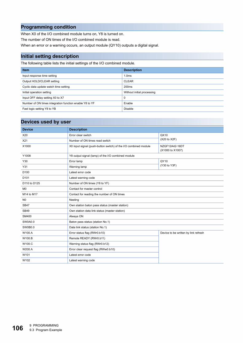
10
Programming conditionWhen X0 of the I/O combined module turns on, Y8 is turned on.
The number of ON times of the I/O combined module is read.
When an error or a warning occurs, an output module (QY10) outputs a digital signal.
Initial setting descriptionThe following table lists the initial settings of the I/O combined module.
Devices used by user
Item Description
Input response time setting 1.0ms
Output HOLD/CLEAR setting CLEAR
Cyclic data update watch time setting 200ms
Initial operation setting Without initial processing
Input OFF delay setting X0 to X7 0
Number of ON times integration function enable Y8 to YF Enable
Fast logic setting Y8 to YB Disable
Device Description
X20 Error clear switch QX10
(X20 to X2F)X21 Number of ON times read switch
X1000 X0 input signal (push-button switch) of the I/O combined module NZGF12A42-16DT
(X1000 to X1007)
Y1008 Y8 output signal (lamp) of the I/O combined module
Y30 Error lamp QY10
(Y30 to Y3F)Y31 Warning lamp
D100 Latest error code
D101 Latest warning code
D110 to D125 Number of ON times (Y8 to YF)
M0 Contact for master control
M14 to M17 Contact for reading the number of ON times
N0 Nesting
SB47 Own station baton pass status (master station)
SB49 Own station data link status (master station)
SM400 Always ON
SW0A0.0 Baton pass status (station No.1)
SW0B0.0 Data link status (station No.1)
W100.A Error status flag (RWr0.b10) Device to be written by link refresh
W100.B Remote READY (RWr0.b11)
W100.C Warning status flag (RWr0.b12)
W200.A Error clear request flag (RWw0.b10)
W101 Latest error code
W102 Latest warning code
69 PROGRAMMING9.3 Program Example
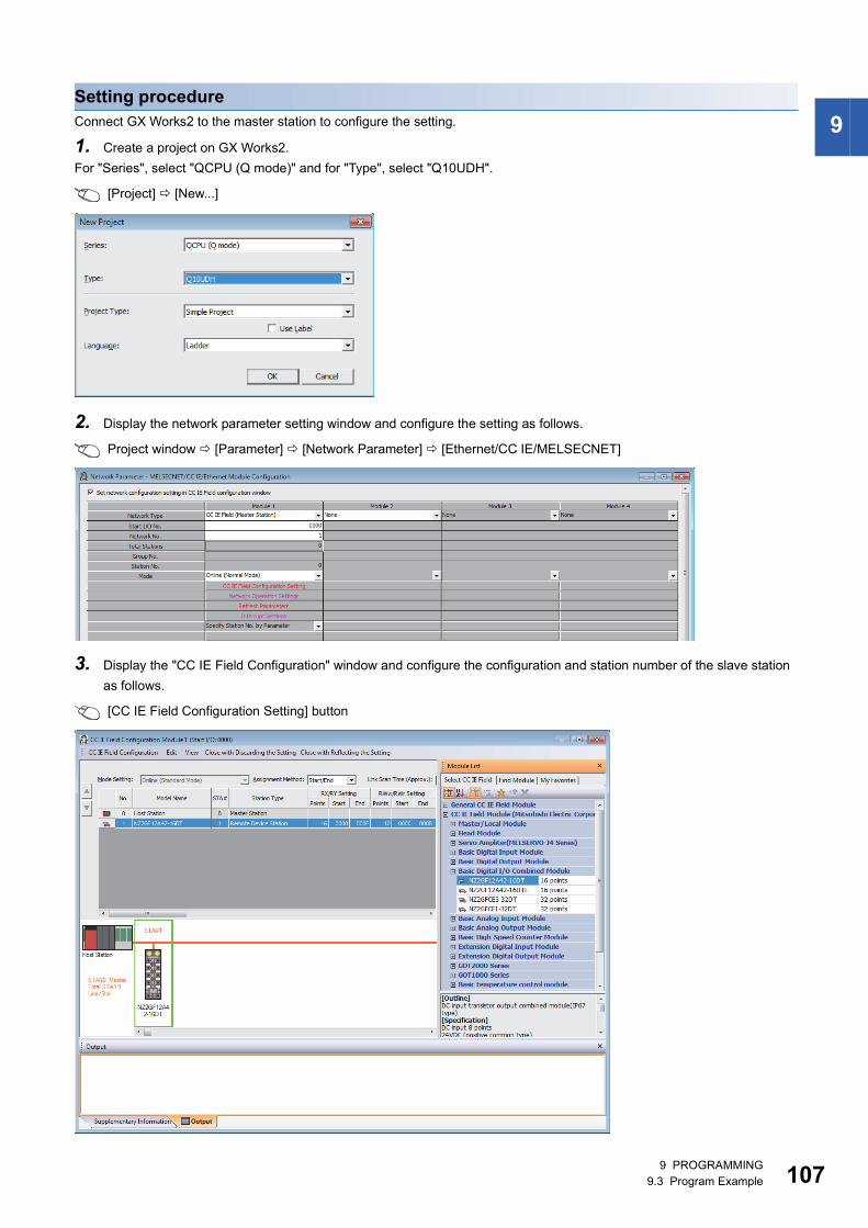
9
Setting procedureConnect GX Works2 to the master station to configure the setting.1. Create a project on GX Works2.
For "Series", select "QCPU (Q mode)" and for "Type", select "Q10UDH".
[Project] [New...]
2. Display the network parameter setting window and configure the setting as follows.
Project window [Parameter] [Network Parameter] [Ethernet/CC IE/MELSECNET]
3. Display the "CC IE Field Configuration" window and configure the configuration and station number of the slave station
as follows.
[CC IE Field Configuration Setting] button
9 PROGRAMMING9.3 Program Example 107
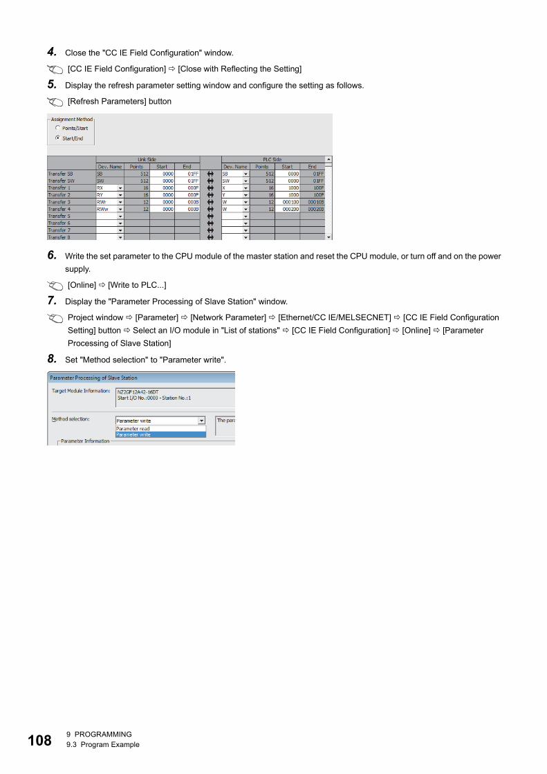
10
4. Close the "CC IE Field Configuration" window.
[CC IE Field Configuration] [Close with Reflecting the Setting]
5. Display the refresh parameter setting window and configure the setting as follows.
[Refresh Parameters] button
6. Write the set parameter to the CPU module of the master station and reset the CPU module, or turn off and on the power
supply.
[Online] [Write to PLC...]
7. Display the "Parameter Processing of Slave Station" window.
Project window [Parameter] [Network Parameter] [Ethernet/CC IE/MELSECNET] [CC IE Field Configuration
Setting] button Select an I/O module in "List of stations" [CC IE Field Configuration] [Online] [Parameter
Processing of Slave Station]
8. Set "Method selection" to "Parameter write".
89 PROGRAMMING9.3 Program Example
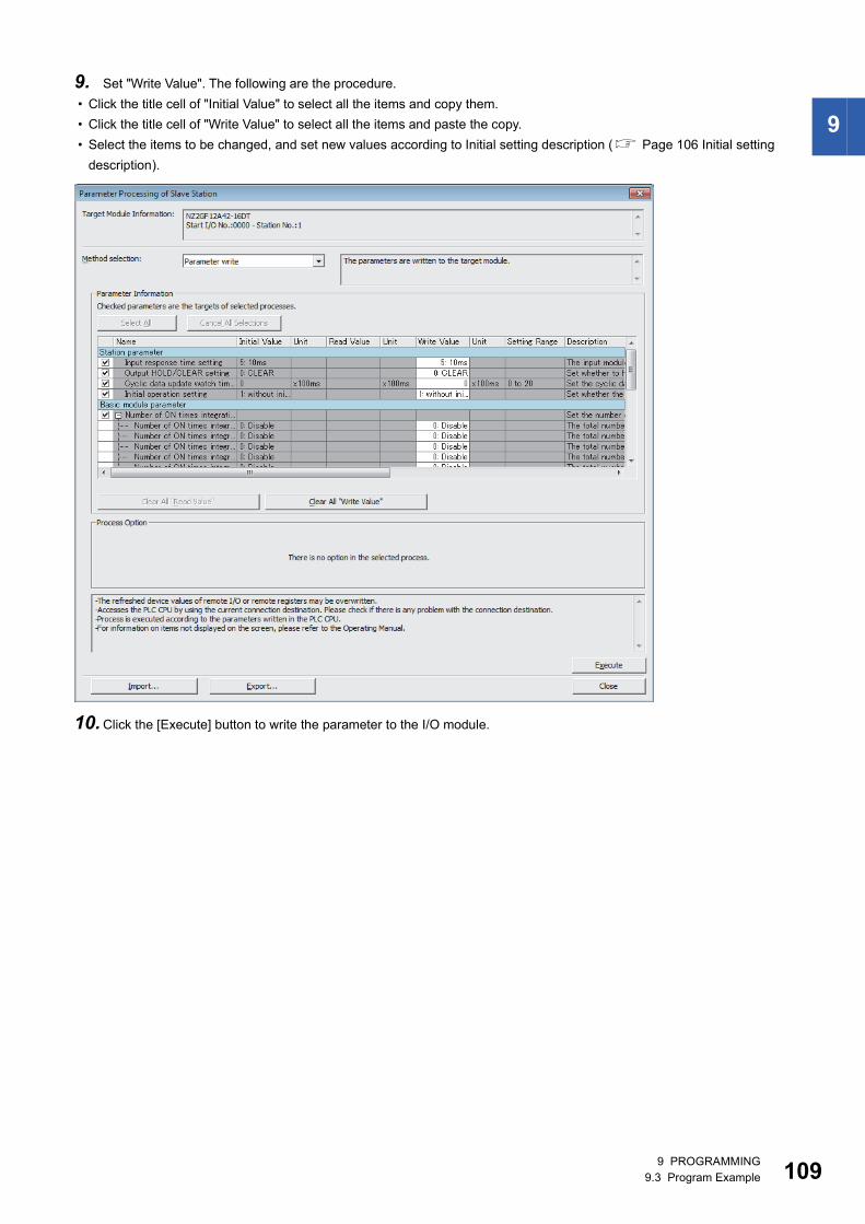
9
9. Set "Write Value". The following are the procedure.
• Click the title cell of "Initial Value" to select all the items and copy them.
• Click the title cell of "Write Value" to select all the items and paste the copy.
• Select the items to be changed, and set new values according to Initial setting description ( Page 106 Initial setting
description).
10.Click the [Execute] button to write the parameter to the I/O module.
9 PROGRAMMING9.3 Program Example 109
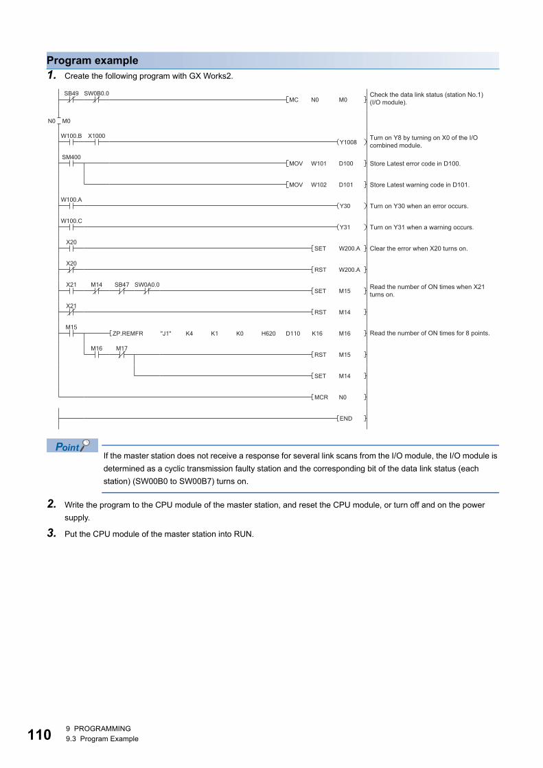
11
Program example1. Create the following program with GX Works2.
If the master station does not receive a response for several link scans from the I/O module, the I/O module is
determined as a cyclic transmission faulty station and the corresponding bit of the data link status (each
station) (SW00B0 to SW00B7) turns on.
2. Write the program to the CPU module of the master station, and reset the CPU module, or turn off and on the power
supply.
3. Put the CPU module of the master station into RUN.
Check the data link status (station No.1) (I/O module).
Turn on Y8 by turning on X0 of the I/O combined module.
Store Latest error code in D100.
Store Latest warning code in D101.
Turn on Y30 when an error occurs.
Turn on Y31 when a warning occurs.
Clear the error when X20 turns on.
Read the number of ON times when X21 turns on.
Read the number of ON times for 8 points.
09 PROGRAMMING9.3 Program Example
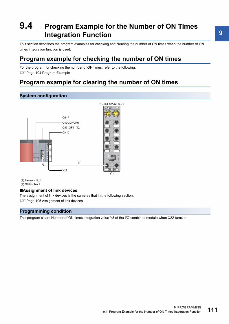
9
9.4 Program Example for the Number of ON TimesIntegration FunctionThis section describes the program examples for checking and clearing the number of ON times when the number of ON
times integration function is used.
Program example for checking the number of ON timesFor the program for checking the number of ON times, refer to the following.
Page 104 Program Example
Program example for clearing the number of ON times
System configuration
■Assignment of link devicesThe assignment of link devices is the same as that in the following section.
Page 105 Assignment of link devices
Programming conditionThis program clears Number of ON times integration value Y8 of the I/O combined module when X22 turns on.
(1) Network No.1
(2) Station No.1
QX10
Q61P
Q10UDHCPU
NG2GF12A42-16DT
QJ71GF11-T2
X22
(1)
(2)
9 PROGRAMMING9.4 Program Example for the Number of ON Times Integration Function 111
11
Initial setting descriptionThe following table lists the initial settings of the I/O combined module.
Devices used by user
Setting procedureSet the same contents from procedures 1 to 6 in the following section.
Page 107 Setting procedure
Item Description
Input response time setting 1.0ms
Output HOLD/CLEAR setting CLEAR
Cyclic data update watch time setting 200ms
Initial operation setting Without initial processing
Input OFF delay setting X0 to X7 0
Number of ON times integration function enable Y8 to YF Enable
Fast logic setting Y8 to YB Disable
Device Description
X22 Number of ON times clear switch QX10 (X20 to X2F)
D145 Number of ON times clear target device specification
D146 Number of ON times integration value clear completed confirmation
D147 Number of ON times clear target device specification clear
M30 to M41 Contact for clearing the number of ON times
SB47 Own station baton pass status (master station)
SW0A0.0 Baton pass status (station No.1)
29 PROGRAMMING9.4 Program Example for the Number of ON Times Integration Function
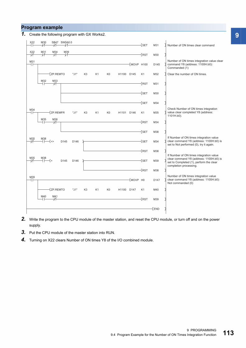
9
Program example1. Create the following program with GX Works2.2. Write the program to the CPU module of the master station, and reset the CPU module, or turn off and on the power
supply.
3. Put the CPU module of the master station into RUN.
4. Turning on X22 clears Number of ON times Y8 of the I/O combined module.
Clear the number of ON times.
Number of ON times integration value clear command Y8 (address: 1100H.b0): Commanded (1)
Number of ON times clear command
Check Number of ON times integration value clear completed Y8 (address: 1101H.b0).
If Number of ON times integration value clear command Y8 (address: 1100H.b0) is set to Not performed (0), try it again.
If Number of ON times integration value clear command Y8 (address: 1100H.b0) is set to Completed (1), perform the clear completion processing.
Number of ON times integration value clear command Y8 (address: 1100H.b0): Not commanded (0)
9 PROGRAMMING9.4 Program Example for the Number of ON Times Integration Function 113
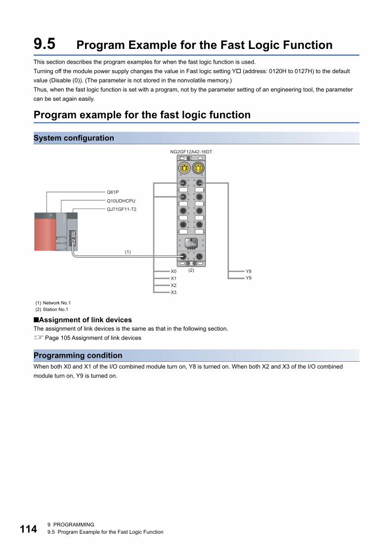
11
9.5 Program Example for the Fast Logic FunctionThis section describes the program examples for when the fast logic function is used.
Turning off the module power supply changes the value in Fast logic setting Y (address: 0120H to 0127H) to the default
value (Disable (0)). (The parameter is not stored in the nonvolatile memory.)
Thus, when the fast logic function is set with a program, not by the parameter setting of an engineering tool, the parameter
can be set again easily.
Program example for the fast logic function
System configuration
■Assignment of link devicesThe assignment of link devices is the same as that in the following section.
Page 105 Assignment of link devices
Programming conditionWhen both X0 and X1 of the I/O combined module turn on, Y8 is turned on. When both X2 and X3 of the I/O combined
module turn on, Y9 is turned on.
(1) Network No.1
(2) Station No.1
NG2GF12A42-16DT
Y8X0Y9X1
X2X3
Q61P
Q10UDHCPU
QJ71GF11-T2
(1)
(2)
49 PROGRAMMING9.5 Program Example for the Fast Logic Function
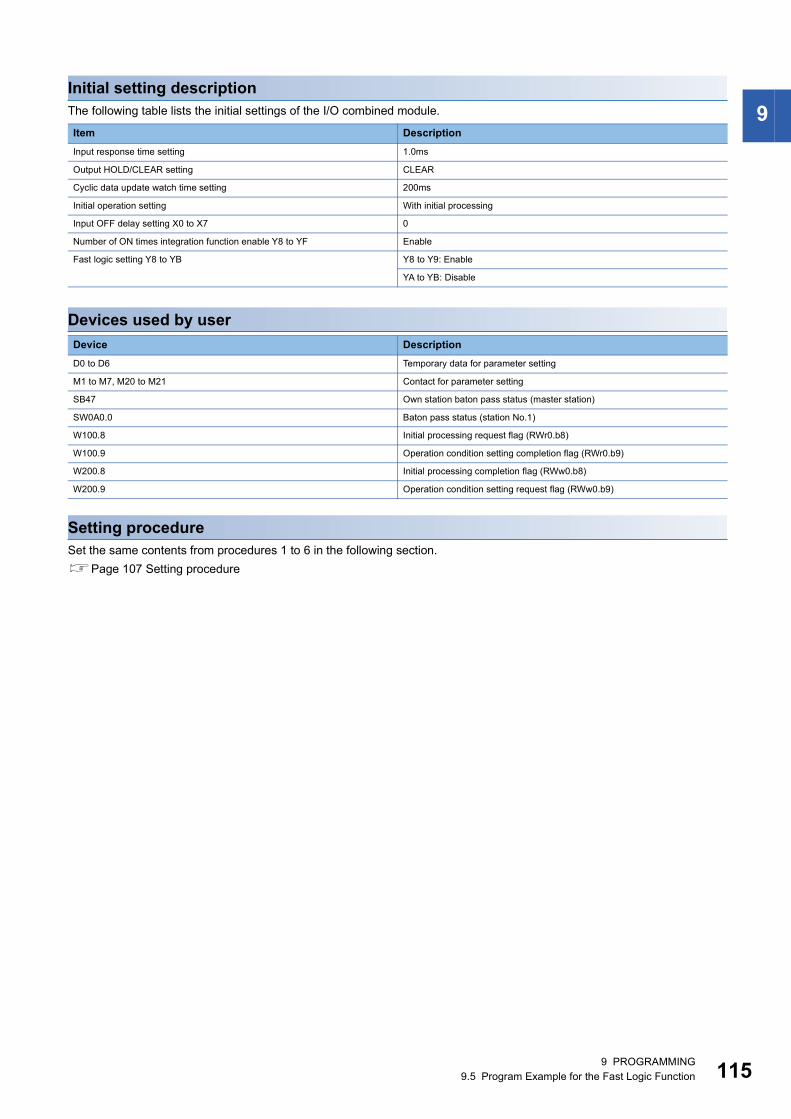
9
Initial setting descriptionThe following table lists the initial settings of the I/O combined module.Devices used by user
Setting procedureSet the same contents from procedures 1 to 6 in the following section.
Page 107 Setting procedure
Item Description
Input response time setting 1.0ms
Output HOLD/CLEAR setting CLEAR
Cyclic data update watch time setting 200ms
Initial operation setting With initial processing
Input OFF delay setting X0 to X7 0
Number of ON times integration function enable Y8 to YF Enable
Fast logic setting Y8 to YB Y8 to Y9: Enable
YA to YB: Disable
Device Description
D0 to D6 Temporary data for parameter setting
M1 to M7, M20 to M21 Contact for parameter setting
SB47 Own station baton pass status (master station)
SW0A0.0 Baton pass status (station No.1)
W100.8 Initial processing request flag (RWr0.b8)
W100.9 Operation condition setting completion flag (RWr0.b9)
W200.8 Initial processing completion flag (RWw0.b8)
W200.9 Operation condition setting request flag (RWw0.b9)
9 PROGRAMMING9.5 Program Example for the Fast Logic Function 115
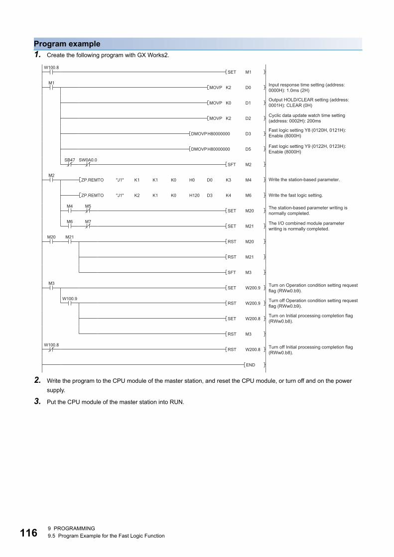
11
Program example1. Create the following program with GX Works2.
2. Write the program to the CPU module of the master station, and reset the CPU module, or turn off and on the power
supply.
3. Put the CPU module of the master station into RUN.
Cyclic data update watch time setting (address: 0002H): 200ms
Output HOLD/CLEAR setting (address: 0001H): CLEAR (0H)
Input response time setting (address: 0000H): 1.0ms (2H)
Fast logic setting Y8 (0120H, 0121H): Enable (8000H)
Fast logic setting Y9 (0122H, 0123H): Enable (8000H)
Write the station-based parameter.
Write the fast logic setting.
The station-based parameter writing is normally completed.
The I/O combined module parameter writing is normally completed.
Turn on Operation condition setting request flag (RWw0.b9).
Turn off Operation condition setting request flag (RWw0.b9).
Turn on Initial processing completion flag (RWw0.b8).
Turn off Initial processing completion flag (RWw0.b8).
69 PROGRAMMING9.5 Program Example for the Fast Logic Function
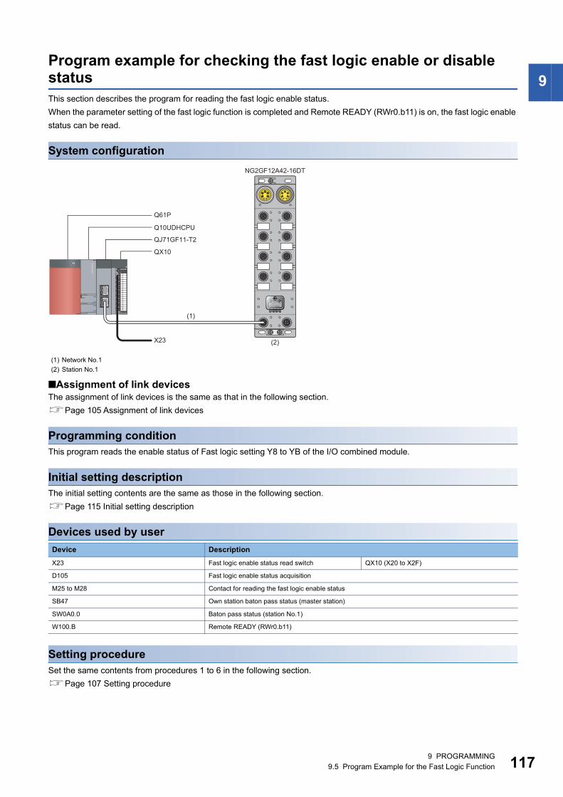
9
Program example for checking the fast logic enable or disable statusThis section describes the program for reading the fast logic enable status.When the parameter setting of the fast logic function is completed and Remote READY (RWr0.b11) is on, the fast logic enable
status can be read.
System configuration
■Assignment of link devicesThe assignment of link devices is the same as that in the following section.
Page 105 Assignment of link devices
Programming conditionThis program reads the enable status of Fast logic setting Y8 to YB of the I/O combined module.
Initial setting descriptionThe initial setting contents are the same as those in the following section.
Page 115 Initial setting description
Devices used by user
Setting procedureSet the same contents from procedures 1 to 6 in the following section.
Page 107 Setting procedure
(1) Network No.1
(2) Station No.1
Device Description
X23 Fast logic enable status read switch QX10 (X20 to X2F)
D105 Fast logic enable status acquisition
M25 to M28 Contact for reading the fast logic enable status
SB47 Own station baton pass status (master station)
SW0A0.0 Baton pass status (station No.1)
W100.B Remote READY (RWr0.b11)
NG2GF12A42-16DT
QX10
Q61P
Q10UDHCPU
QJ71GF11-T2
X23
(1)
(2)
9 PROGRAMMING9.5 Program Example for the Fast Logic Function 117
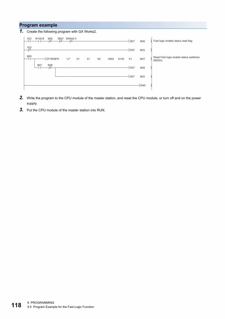
11
Program example1. Create the following program with GX Works2.
2. Write the program to the CPU module of the master station, and reset the CPU module, or turn off and on the power
supply.
3. Put the CPU module of the master station into RUN.
Read Fast logic enable status (address: 0602H).
Fast logic enable status read flag
89 PROGRAMMING9.5 Program Example for the Fast Logic Function

10
10 MAINTENANCE AND INSPECTION
The I/O module has no special item to be inspected. However, to maintain the best condition of the system, perform the
inspection in accordance with the items described in the user's manual of the CPU module used.
10 MAINTENANCE AND INSPECTION 119

12
MEMO
010 MAINTENANCE AND INSPECTION
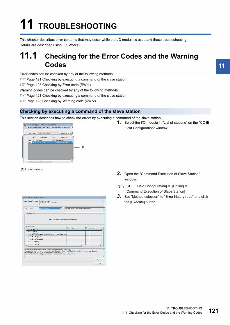
11
11 TROUBLESHOOTING
This chapter describes error contents that may occur while the I/O module is used and those troubleshooting.
Details are described using GX Works2.
11.1 Checking for the Error Codes and the Warning Codes
Error codes can be checked by any of the following methods:
Page 121 Checking by executing a command of the slave station
Page 123 Checking by Error code (RWr1)
Warning codes can be checked by any of the following methods:
Page 121 Checking by executing a command of the slave station
Page 123 Checking by Warning code (RWr2)
Checking by executing a command of the slave stationThis section describes how to check the errors by executing a command of the slave station.
(1) List of stations
1. Select the I/O module in "List of stations" on the "CC IE
Field Configuration" window.
2. Open the "Command Execution of Slave Station"
window.
[CC IE Field Configuration] [Online]
[Command Execution of Slave Station]
3. Set "Method selection" to "Error history read" and click
the [Execute] button.
(1)
11 TROUBLESHOOTING11.1 Checking for the Error Codes and the Warning Codes 121
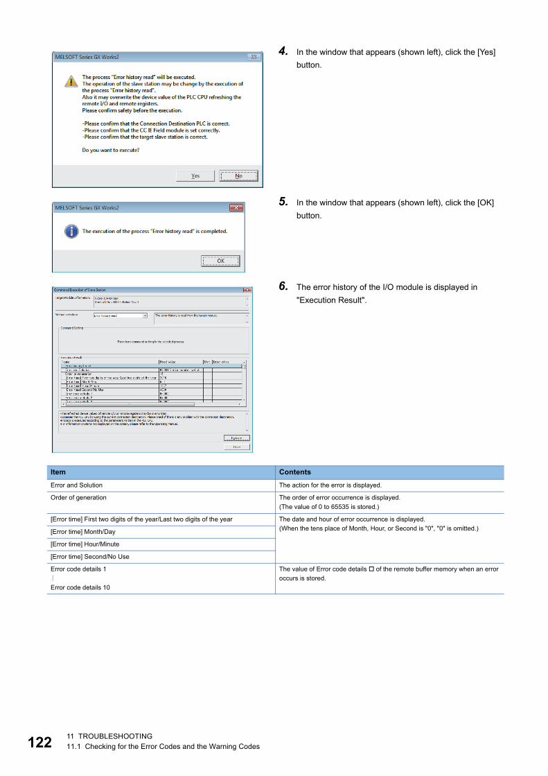
12
4. In the window that appears (shown left), click the [Yes]
button.
5. In the window that appears (shown left), click the [OK]
button.
6. The error history of the I/O module is displayed in
"Execution Result".
Item Contents
Error and Solution The action for the error is displayed.
Order of generation The order of error occurrence is displayed.
(The value of 0 to 65535 is stored.)
[Error time] First two digits of the year/Last two digits of the year The date and hour of error occurrence is displayed.
(When the tens place of Month, Hour, or Second is "0", "0" is omitted.)[Error time] Month/Day
[Error time] Hour/Minute
[Error time] Second/No Use
Error code details 1
Error code details 10
The value of Error code details of the remote buffer memory when an error
occurs is stored.
211 TROUBLESHOOTING11.1 Checking for the Error Codes and the Warning Codes
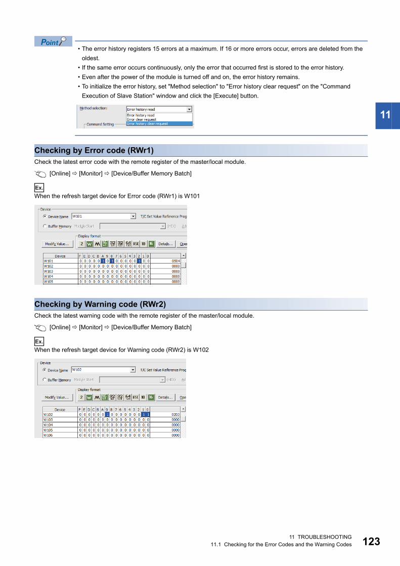
11
• The error history registers 15 errors at a maximum. If 16 or more errors occur, errors are deleted from the
oldest.
• If the same error occurs continuously, only the error that occurred first is stored to the error history.
• Even after the power of the module is turned off and on, the error history remains.
• To initialize the error history, set "Method selection" to "Error history clear request" on the "Command
Execution of Slave Station" window and click the [Execute] button.
Checking by Error code (RWr1)Check the latest error code with the remote register of the master/local module.
[Online] [Monitor] [Device/Buffer Memory Batch]
Ex.
When the refresh target device for Error code (RWr1) is W101
Checking by Warning code (RWr2)Check the latest warning code with the remote register of the master/local module.
[Online] [Monitor] [Device/Buffer Memory Batch]
Ex.
When the refresh target device for Warning code (RWr2) is W102
11 TROUBLESHOOTING11.1 Checking for the Error Codes and the Warning Codes 123
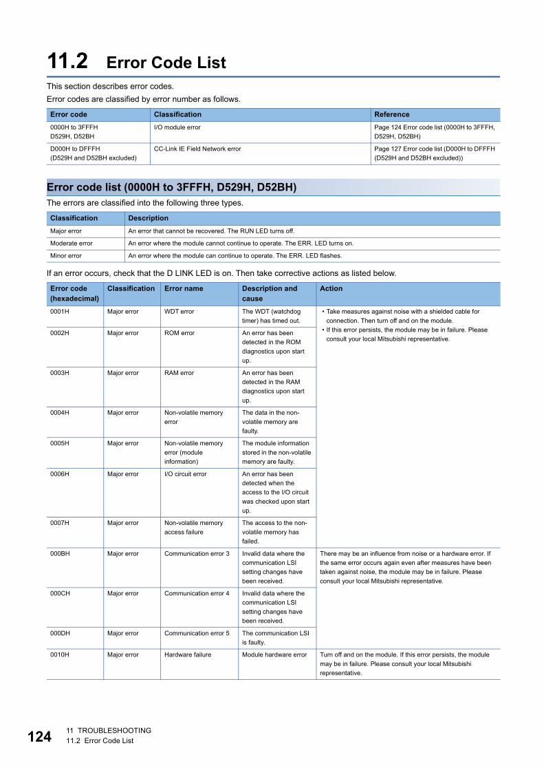
12
11.2 Error Code ListThis section describes error codes.
Error codes are classified by error number as follows.
Error code list (0000H to 3FFFH, D529H, D52BH)The errors are classified into the following three types.
If an error occurs, check that the D LINK LED is on. Then take corrective actions as listed below.
Error code Classification Reference
0000H to 3FFFH
D529H, D52BH
I/O module error Page 124 Error code list (0000H to 3FFFH,
D529H, D52BH)
D000H to DFFFH
(D529H and D52BH excluded)
CC-Link IE Field Network error Page 127 Error code list (D000H to DFFFH
(D529H and D52BH excluded))
Classification Description
Major error An error that cannot be recovered. The RUN LED turns off.
Moderate error An error where the module cannot continue to operate. The ERR. LED turns on.
Minor error An error where the module can continue to operate. The ERR. LED flashes.
Error code (hexadecimal)
Classification Error name Description and cause
Action
0001H Major error WDT error The WDT (watchdog
timer) has timed out.
• Take measures against noise with a shielded cable for
connection. Then turn off and on the module.
• If this error persists, the module may be in failure. Please
consult your local Mitsubishi representative.0002H Major error ROM error An error has been
detected in the ROM
diagnostics upon start
up.
0003H Major error RAM error An error has been
detected in the RAM
diagnostics upon start
up.
0004H Major error Non-volatile memory
error
The data in the non-
volatile memory are
faulty.
0005H Major error Non-volatile memory
error (module
information)
The module information
stored in the non-volatile
memory are faulty.
0006H Major error I/O circuit error An error has been
detected when the
access to the I/O circuit
was checked upon start
up.
0007H Major error Non-volatile memory
access failure
The access to the non-
volatile memory has
failed.
000BH Major error Communication error 3 Invalid data where the
communication LSI
setting changes have
been received.
There may be an influence from noise or a hardware error. If
the same error occurs again even after measures have been
taken against noise, the module may be in failure. Please
consult your local Mitsubishi representative.
000CH Major error Communication error 4 Invalid data where the
communication LSI
setting changes have
been received.
000DH Major error Communication error 5 The communication LSI
is faulty.
0010H Major error Hardware failure Module hardware error Turn off and on the module. If this error persists, the module
may be in failure. Please consult your local Mitsubishi
representative.
411 TROUBLESHOOTING11.2 Error Code List
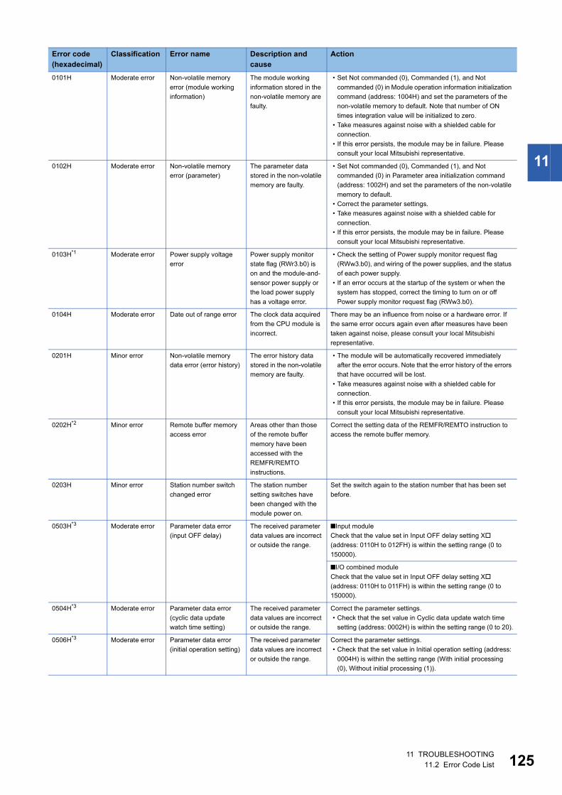
11
0101H Moderate error Non-volatile memory
error (module working
information)
The module working
information stored in the
non-volatile memory are
faulty.
• Set Not commanded (0), Commanded (1), and Not
commanded (0) in Module operation information initialization
command (address: 1004H) and set the parameters of the
non-volatile memory to default. Note that number of ON
times integration value will be initialized to zero.
• Take measures against noise with a shielded cable for
connection.
• If this error persists, the module may be in failure. Please
consult your local Mitsubishi representative.
0102H Moderate error Non-volatile memory
error (parameter)
The parameter data
stored in the non-volatile
memory are faulty.
• Set Not commanded (0), Commanded (1), and Not
commanded (0) in Parameter area initialization command
(address: 1002H) and set the parameters of the non-volatile
memory to default.
• Correct the parameter settings.
• Take measures against noise with a shielded cable for
connection.
• If this error persists, the module may be in failure. Please
consult your local Mitsubishi representative.
0103H*1 Moderate error Power supply voltage
error
Power supply monitor
state flag (RWr3.b0) is
on and the module-and-
sensor power supply or
the load power supply
has a voltage error.
• Check the setting of Power supply monitor request flag
(RWw3.b0), and wiring of the power supplies, and the status
of each power supply.
• If an error occurs at the startup of the system or when the
system has stopped, correct the timing to turn on or off
Power supply monitor request flag (RWw3.b0).
0104H Moderate error Date out of range error The clock data acquired
from the CPU module is
incorrect.
There may be an influence from noise or a hardware error. If
the same error occurs again even after measures have been
taken against noise, please consult your local Mitsubishi
representative.
0201H Minor error Non-volatile memory
data error (error history)
The error history data
stored in the non-volatile
memory are faulty.
• The module will be automatically recovered immediately
after the error occurs. Note that the error history of the errors
that have occurred will be lost.
• Take measures against noise with a shielded cable for
connection.
• If this error persists, the module may be in failure. Please
consult your local Mitsubishi representative.
0202H*2 Minor error Remote buffer memory
access error
Areas other than those
of the remote buffer
memory have been
accessed with the
REMFR/REMTO
instructions.
Correct the setting data of the REMFR/REMTO instruction to
access the remote buffer memory.
0203H Minor error Station number switch
changed error
The station number
setting switches have
been changed with the
module power on.
Set the switch again to the station number that has been set
before.
0503H*3 Moderate error Parameter data error
(input OFF delay)
The received parameter
data values are incorrect
or outside the range.
■Input module
Check that the value set in Input OFF delay setting X
(address: 0110H to 012FH) is within the setting range (0 to
150000).
■I/O combined module
Check that the value set in Input OFF delay setting X
(address: 0110H to 011FH) is within the setting range (0 to
150000).
0504H*3 Moderate error Parameter data error
(cyclic data update
watch time setting)
The received parameter
data values are incorrect
or outside the range.
Correct the parameter settings.
• Check that the set value in Cyclic data update watch time
setting (address: 0002H) is within the setting range (0 to 20).
0506H*3 Moderate error Parameter data error
(initial operation setting)
The received parameter
data values are incorrect
or outside the range.
Correct the parameter settings.
• Check that the set value in Initial operation setting (address:
0004H) is within the setting range (With initial processing
(0), Without initial processing (1)).
Error code (hexadecimal)
Classification Error name Description and cause
Action
11 TROUBLESHOOTING11.2 Error Code List 125
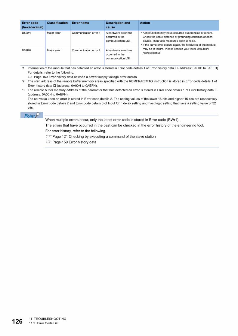
12
*1 Information of the module that has detected an error is stored in Error code details 1 of Error history data (address: 0A00H to 0AEFH).For details, refer to the following.Page 160 Error history data of when a power supply voltage error occurs
*2 The start address of the remote buffer memory areas specified with the REMFR/REMTO instruction is stored in Error code details 1 of Error history data (address: 0A00H to 0AEFH).
*3 The remote buffer memory address of the parameter that has detected an error is stored in Error code details 1 of Error history data (address: 0A00H to 0AEFH).The set value upon an error is stored in Error code details 2. The setting values of the lower 16 bits and higher 16 bits are respectively stored in Error code details 2 and Error code details 3 of Input OFF delay setting and Fast logic setting that have a setting value of 32 bits.
When multiple errors occur, only the latest error code is stored in Error code (RWr1).
The errors that have occurred in the past can be checked in the error history of the engineering tool.
For error history, refer to the following.
Page 121 Checking by executing a command of the slave station
Page 159 Error history data
D529H Major error Communication error 1 A hardware error has
occurred in the
communication LSI.
• A malfunction may have occurred due to noise or others.
Check the cable distance or grounding condition of each
device. Then take measures against noise.
• If the same error occurs again, the hardware of the module
may be in failure. Please consult your local Mitsubishi
representative.D52BH Major error Communication error 2 A hardware error has
occurred in the
communication LSI.
Error code (hexadecimal)
Classification Error name Description and cause
Action
611 TROUBLESHOOTING11.2 Error Code List
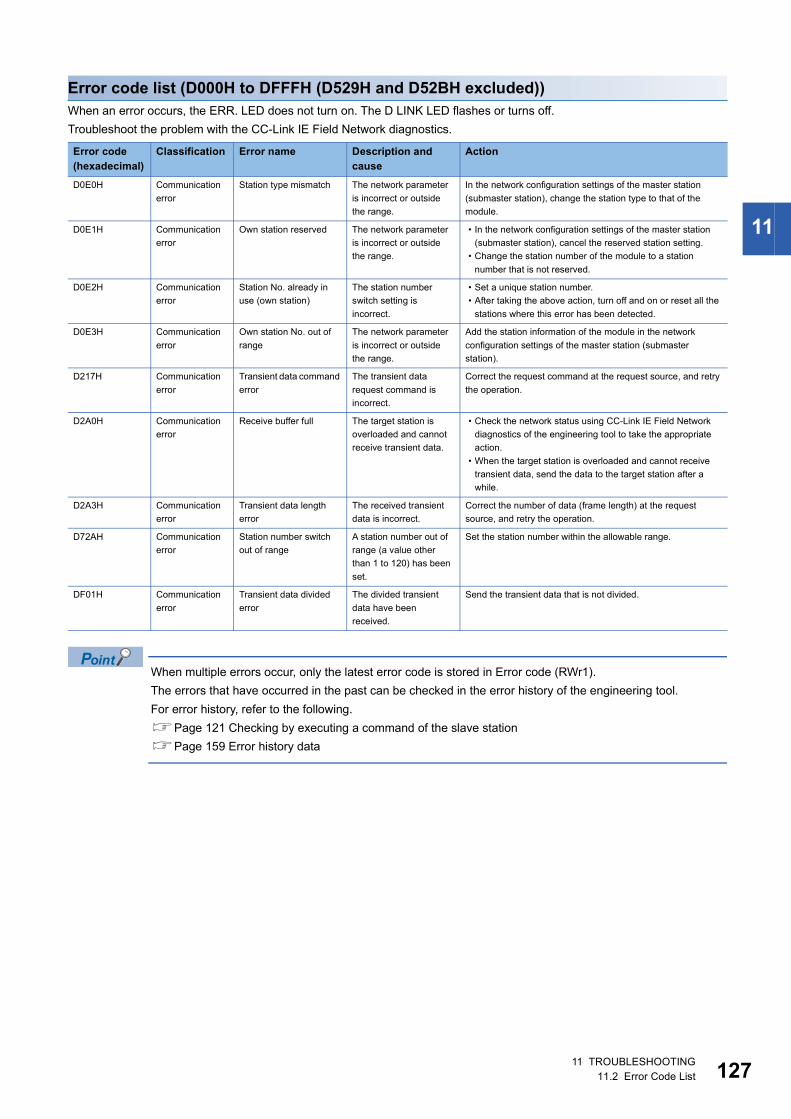
11
Error code list (D000H to DFFFH (D529H and D52BH excluded))When an error occurs, the ERR. LED does not turn on. The D LINK LED flashes or turns off.
Troubleshoot the problem with the CC-Link IE Field Network diagnostics.
When multiple errors occur, only the latest error code is stored in Error code (RWr1).
The errors that have occurred in the past can be checked in the error history of the engineering tool.
For error history, refer to the following.
Page 121 Checking by executing a command of the slave station
Page 159 Error history data
Error code(hexadecimal)
Classification Error name Description and cause
Action
D0E0H Communication
error
Station type mismatch The network parameter
is incorrect or outside
the range.
In the network configuration settings of the master station
(submaster station), change the station type to that of the
module.
D0E1H Communication
error
Own station reserved The network parameter
is incorrect or outside
the range.
• In the network configuration settings of the master station
(submaster station), cancel the reserved station setting.
• Change the station number of the module to a station
number that is not reserved.
D0E2H Communication
error
Station No. already in
use (own station)
The station number
switch setting is
incorrect.
• Set a unique station number.
• After taking the above action, turn off and on or reset all the
stations where this error has been detected.
D0E3H Communication
error
Own station No. out of
range
The network parameter
is incorrect or outside
the range.
Add the station information of the module in the network
configuration settings of the master station (submaster
station).
D217H Communication
error
Transient data command
error
The transient data
request command is
incorrect.
Correct the request command at the request source, and retry
the operation.
D2A0H Communication
error
Receive buffer full The target station is
overloaded and cannot
receive transient data.
• Check the network status using CC-Link IE Field Network
diagnostics of the engineering tool to take the appropriate
action.
• When the target station is overloaded and cannot receive
transient data, send the data to the target station after a
while.
D2A3H Communication
error
Transient data length
error
The received transient
data is incorrect.
Correct the number of data (frame length) at the request
source, and retry the operation.
D72AH Communication
error
Station number switch
out of range
A station number out of
range (a value other
than 1 to 120) has been
set.
Set the station number within the allowable range.
DF01H Communication
error
Transient data divided
error
The divided transient
data have been
received.
Send the transient data that is not divided.
11 TROUBLESHOOTING11.2 Error Code List 127
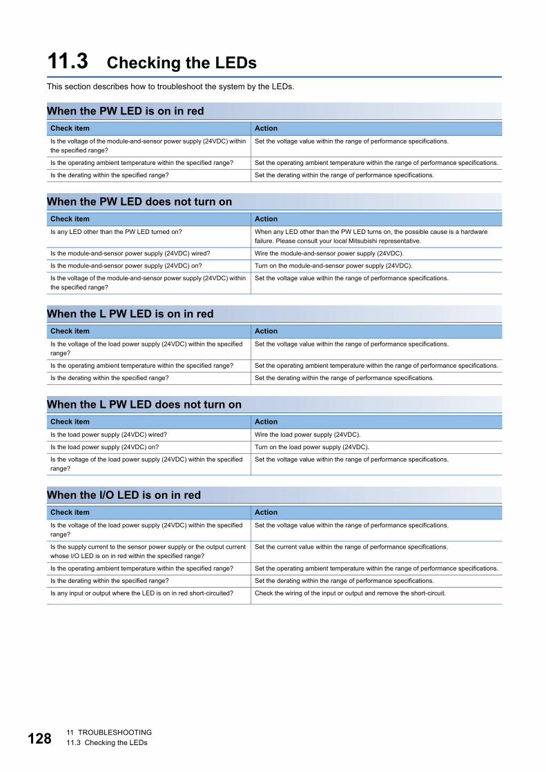
12
11.3 Checking the LEDsThis section describes how to troubleshoot the system by the LEDs.
When the PW LED is on in red
When the PW LED does not turn on
When the L PW LED is on in red
When the L PW LED does not turn on
When the I/O LED is on in red
Check item Action
Is the voltage of the module-and-sensor power supply (24VDC) within
the specified range?
Set the voltage value within the range of performance specifications.
Is the operating ambient temperature within the specified range? Set the operating ambient temperature within the range of performance specifications.
Is the derating within the specified range? Set the derating within the range of performance specifications.
Check item Action
Is any LED other than the PW LED turned on? When any LED other than the PW LED turns on, the possible cause is a hardware
failure. Please consult your local Mitsubishi representative.
Is the module-and-sensor power supply (24VDC) wired? Wire the module-and-sensor power supply (24VDC).
Is the module-and-sensor power supply (24VDC) on? Turn on the module-and-sensor power supply (24VDC).
Is the voltage of the module-and-sensor power supply (24VDC) within
the specified range?
Set the voltage value within the range of performance specifications.
Check item Action
Is the voltage of the load power supply (24VDC) within the specified
range?
Set the voltage value within the range of performance specifications.
Is the operating ambient temperature within the specified range? Set the operating ambient temperature within the range of performance specifications.
Is the derating within the specified range? Set the derating within the range of performance specifications.
Check item Action
Is the load power supply (24VDC) wired? Wire the load power supply (24VDC).
Is the load power supply (24VDC) on? Turn on the load power supply (24VDC).
Is the voltage of the load power supply (24VDC) within the specified
range?
Set the voltage value within the range of performance specifications.
Check item Action
Is the voltage of the load power supply (24VDC) within the specified
range?
Set the voltage value within the range of performance specifications.
Is the supply current to the sensor power supply or the output current
whose I/O LED is on in red within the specified range?
Set the current value within the range of performance specifications.
Is the operating ambient temperature within the specified range? Set the operating ambient temperature within the range of performance specifications.
Is the derating within the specified range? Set the derating within the range of performance specifications.
Is any input or output where the LED is on in red short-circuited? Check the wiring of the input or output and remove the short-circuit.
811 TROUBLESHOOTING11.3 Checking the LEDs
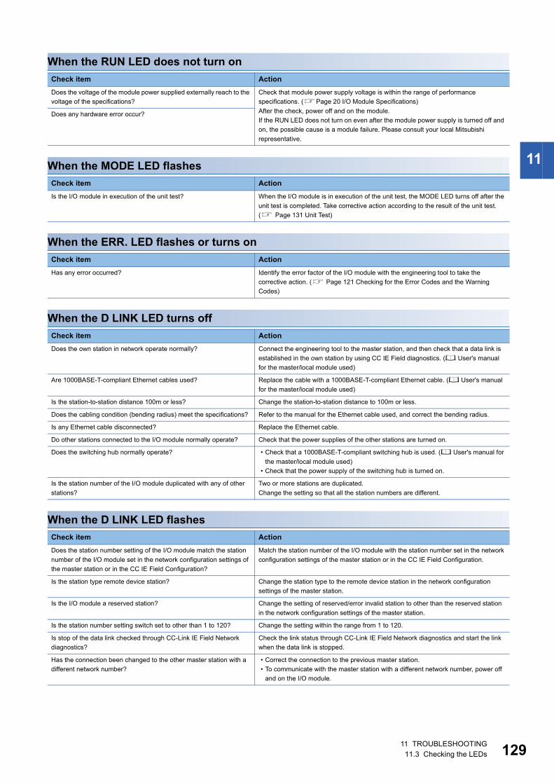
11
When the RUN LED does not turn on
When the MODE LED flashes
When the ERR. LED flashes or turns on
When the D LINK LED turns off
When the D LINK LED flashes
Check item Action
Does the voltage of the module power supplied externally reach to the
voltage of the specifications?
Check that module power supply voltage is within the range of performance
specifications. (Page 20 I/O Module Specifications)
After the check, power off and on the module.
If the RUN LED does not turn on even after the module power supply is turned off and
on, the possible cause is a module failure. Please consult your local Mitsubishi
representative.
Does any hardware error occur?
Check item Action
Is the I/O module in execution of the unit test? When the I/O module is in execution of the unit test, the MODE LED turns off after the
unit test is completed. Take corrective action according to the result of the unit test.
( Page 131 Unit Test)
Check item Action
Has any error occurred? Identify the error factor of the I/O module with the engineering tool to take the
corrective action. ( Page 121 Checking for the Error Codes and the Warning
Codes)
Check item Action
Does the own station in network operate normally? Connect the engineering tool to the master station, and then check that a data link is
established in the own station by using CC IE Field diagnostics. ( User's manual
for the master/local module used)
Are 1000BASE-T-compliant Ethernet cables used? Replace the cable with a 1000BASE-T-compliant Ethernet cable. ( User's manual
for the master/local module used)
Is the station-to-station distance 100m or less? Change the station-to-station distance to 100m or less.
Does the cabling condition (bending radius) meet the specifications? Refer to the manual for the Ethernet cable used, and correct the bending radius.
Is any Ethernet cable disconnected? Replace the Ethernet cable.
Do other stations connected to the I/O module normally operate? Check that the power supplies of the other stations are turned on.
Does the switching hub normally operate? • Check that a 1000BASE-T-compliant switching hub is used. ( User's manual for
the master/local module used)
• Check that the power supply of the switching hub is turned on.
Is the station number of the I/O module duplicated with any of other
stations?
Two or more stations are duplicated.
Change the setting so that all the station numbers are different.
Check item Action
Does the station number setting of the I/O module match the station
number of the I/O module set in the network configuration settings of
the master station or in the CC IE Field Configuration?
Match the station number of the I/O module with the station number set in the network
configuration settings of the master station or in the CC IE Field Configuration.
Is the station type remote device station? Change the station type to the remote device station in the network configuration
settings of the master station.
Is the I/O module a reserved station? Change the setting of reserved/error invalid station to other than the reserved station
in the network configuration settings of the master station.
Is the station number setting switch set to other than 1 to 120? Change the setting within the range from 1 to 120.
Is stop of the data link checked through CC-Link IE Field Network
diagnostics?
Check the link status through CC-Link IE Field Network diagnostics and start the link
when the data link is stopped.
Has the connection been changed to the other master station with a
different network number?
• Correct the connection to the previous master station.
• To communicate with the master station with a different network number, power off
and on the I/O module.
11 TROUBLESHOOTING11.3 Checking the LEDs 129
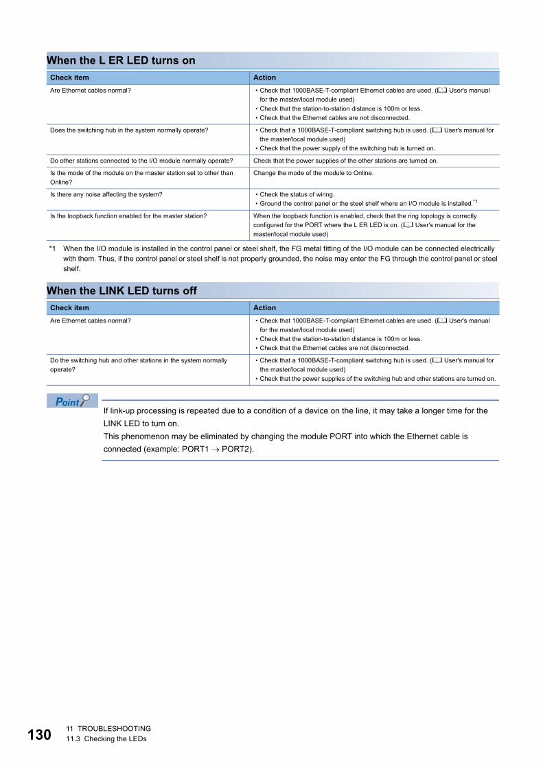
13
When the L ER LED turns on
*1 When the I/O module is installed in the control panel or steel shelf, the FG metal fitting of the I/O module can be connected electrically with them. Thus, if the control panel or steel shelf is not properly grounded, the noise may enter the FG through the control panel or steel shelf.
When the LINK LED turns off
If link-up processing is repeated due to a condition of a device on the line, it may take a longer time for the
LINK LED to turn on.
This phenomenon may be eliminated by changing the module PORT into which the Ethernet cable is
connected (example: PORT1 PORT2).
Check item Action
Are Ethernet cables normal? • Check that 1000BASE-T-compliant Ethernet cables are used. ( User's manual
for the master/local module used)
• Check that the station-to-station distance is 100m or less.
• Check that the Ethernet cables are not disconnected.
Does the switching hub in the system normally operate? • Check that a 1000BASE-T-compliant switching hub is used. ( User's manual for
the master/local module used)
• Check that the power supply of the switching hub is turned on.
Do other stations connected to the I/O module normally operate? Check that the power supplies of the other stations are turned on.
Is the mode of the module on the master station set to other than
Online?
Change the mode of the module to Online.
Is there any noise affecting the system? • Check the status of wiring.
• Ground the control panel or the steel shelf where an I/O module is installed.*1
Is the loopback function enabled for the master station? When the loopback function is enabled, check that the ring topology is correctly
configured for the PORT where the L ER LED is on. ( User's manual for the
master/local module used)
Check item Action
Are Ethernet cables normal? • Check that 1000BASE-T-compliant Ethernet cables are used. ( User's manual
for the master/local module used)
• Check that the station-to-station distance is 100m or less.
• Check that the Ethernet cables are not disconnected.
Do the switching hub and other stations in the system normally
operate?
• Check that a 1000BASE-T-compliant switching hub is used. ( User's manual for
the master/local module used)
• Check that the power supplies of the switching hub and other stations are turned on.
011 TROUBLESHOOTING11.3 Checking the LEDs
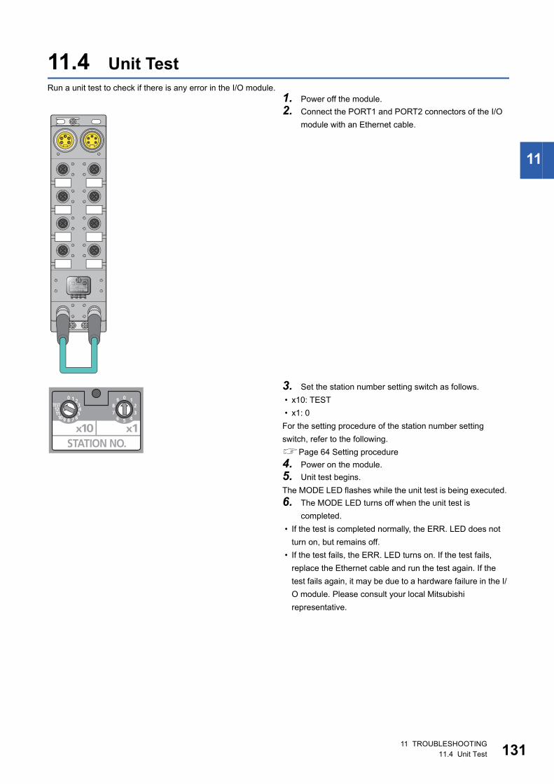
11
11.4 Unit TestRun a unit test to check if there is any error in the I/O module.
1. Power off the module.
2. Connect the PORT1 and PORT2 connectors of the I/O
module with an Ethernet cable.
3. Set the station number setting switch as follows.
• x10: TEST
• x1: 0
For the setting procedure of the station number setting
switch, refer to the following.
Page 64 Setting procedure
4. Power on the module.
5. Unit test begins.
The MODE LED flashes while the unit test is being executed.
6. The MODE LED turns off when the unit test is
completed.
• If the test is completed normally, the ERR. LED does not
turn on, but remains off.
• If the test fails, the ERR. LED turns on. If the test fails,
replace the Ethernet cable and run the test again. If the
test fails again, it may be due to a hardware failure in the I/
O module. Please consult your local Mitsubishi
representative.
11 TROUBLESHOOTING11.4 Unit Test 131
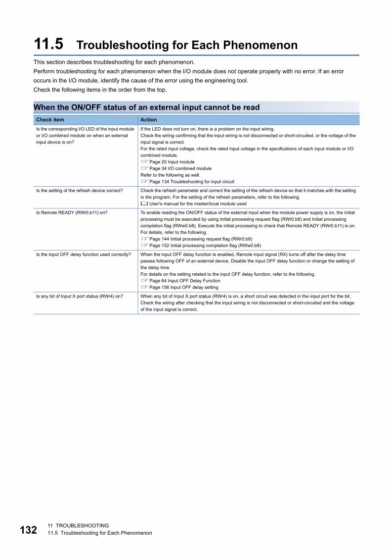
13
11.5 Troubleshooting for Each PhenomenonThis section describes troubleshooting for each phenomenon.
Perform troubleshooting for each phenomenon when the I/O module does not operate properly with no error. If an error
occurs in the I/O module, identify the cause of the error using the engineering tool.
Check the following items in the order from the top.
When the ON/OFF status of an external input cannot be read
Check item Action
Is the corresponding I/O LED of the input module
or I/O combined module on when an external
input device is on?
If the LED does not turn on, there is a problem on the input wiring.
Check the wiring confirming that the input wiring is not disconnected or short-circuited, or the voltage of the
input signal is correct.
For the rated input voltage, check the rated input voltage in the specifications of each input module or I/O
combined module.
Page 20 Input module
Page 34 I/O combined module
Refer to the following as well.
Page 134 Troubleshooting for input circuit
Is the setting of the refresh device correct? Check the refresh parameter and correct the setting of the refresh device so that it matches with the setting
in the program. For the setting of the refresh parameters, refer to the following.
User's manual for the master/local module used
Is Remote READY (RWr0.b11) on? To enable reading the ON/OFF status of the external input when the module power supply is on, the initial
processing must be executed by using Initial processing request flag (RWr0.b8) and Initial processing
completion flag (RWw0.b8). Execute the initial processing to check that Remote READY (RWr0.b11) is on.
For details, refer to the following.
Page 144 Initial processing request flag (RWr0.b8)
Page 152 Initial processing completion flag (RWw0.b8)
Is the input OFF delay function used correctly? When the input OFF delay function is enabled, Remote input signal (RX) turns off after the delay time
passes following OFF of an external device. Disable the input OFF delay function or change the setting of
the delay time.
For details on the setting related to the input OFF delay function, refer to the following.
Page 84 Input OFF Delay Function
Page 156 Input OFF delay setting
Is any bit of Input X port status (RWr4) on? When any bit of Input X port status (RWr4) is on, a short circuit was detected in the input port for the bit.
Check the wiring after checking that the input wiring is not disconnected or short-circuited and the voltage
of the input signal is correct.
211 TROUBLESHOOTING11.5 Troubleshooting for Each Phenomenon
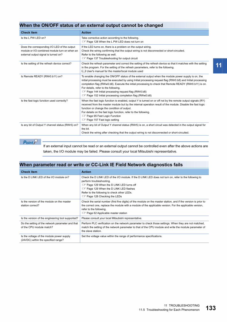
11
When the ON/OFF status of an external output cannot be changed
If an external input cannot be read or an external output cannot be controlled even after the above actions are
taken, the I/O module may be failed. Please consult your local Mitsubishi representative.
When parameter read or write or CC-Link IE Field Network diagnostics fails
Check item Action
Is the L PW LED on? Take corrective action according to the following.
Page 128 When the L PW LED does not turn on
Does the corresponding I/O LED of the output
module or I/O combined module turn on when an
external output signal is turned on?
If the LED turns on, there is a problem on the output wiring.
Check the wiring confirming that the output wiring is not disconnected or short-circuited.
Refer to the following as well.
Page 137 Troubleshooting for output circuit
Is the setting of the refresh device correct? Check the refresh parameter and correct the setting of the refresh device so that it matches with the setting
in the program. For the setting of the refresh parameters, refer to the following.
User's manual for the master/local module used
Is Remote READY (RWr0.b11) on? To enable changing the ON/OFF status of the external output when the module power supply is on, the
initial processing must be executed by using Initial processing request flag (RWr0.b8) and Initial processing
completion flag (RWw0.b8). Execute the initial processing to check that Remote READY (RWr0.b11) is on.
For details, refer to the following.
Page 144 Initial processing request flag (RWr0.b8)
Page 152 Initial processing completion flag (RWw0.b8)
Is the fast logic function used correctly? When the fast logic function is enabled, output Y is turned on or off not by the remote output signals (RY)
received from the master module but by the internal operation result of the module. Disable the fast logic
function or change the condition of output.
For details on the fast logic function, refer to the following.
Page 95 Fast Logic Function
Page 157 Fast logic setting
Is any bit of Output Y channel status (RWr5) on? When any bit of Output Y channel status (RWr5) is on, a short circuit was detected in the output signal for
the bit.
Check the wiring after checking that the output wiring is not disconnected or short-circuited.
Check item Action
Is the D LINK LED of the I/O module on? Check the D LINK LED of the I/O module. If the D LINK LED does not turn on, refer to the following to
perform troubleshooting.
Page 129 When the D LINK LED turns off
Page 129 When the D LINK LED flashes
Refer to the following to check other LEDs.
Page 128 Checking the LEDs
Is the version of the module on the master
station correct?
Check the serial number (first five digits) of the module on the master station, and if the version is prior to
the correct one, replace the module with a module of the applicable version. For the applicable version,
refer to the following.
Page 62 Applicable master station
Is the version of the engineering tool supported? Please consult your local Mitsubishi representative.
Do the setting of the network parameter and that
of the CPU module match?
Perform PLC verification on the network parameter to check those settings. When they are not matched,
match the setting of the network parameter to that of the CPU module and write the module parameter of
the slave station.
Is the voltage of the module power supply
(24VDC) within the specified range?
Set the voltage value within the range of performance specifications.
11 TROUBLESHOOTING11.5 Troubleshooting for Each Phenomenon 133
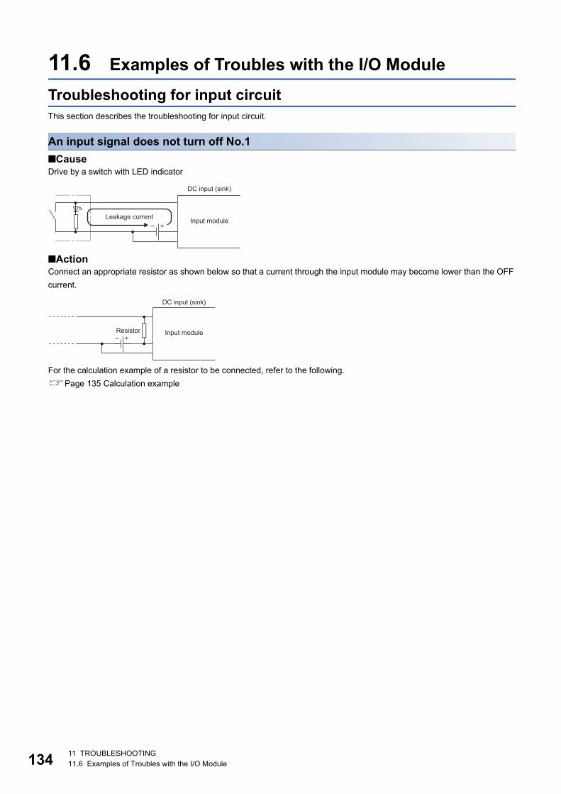
13
11.6 Examples of Troubles with the I/O Module
Troubleshooting for input circuitThis section describes the troubleshooting for input circuit.
An input signal does not turn off No.1
■CauseDrive by a switch with LED indicator
■ActionConnect an appropriate resistor as shown below so that a current through the input module may become lower than the OFF
current.
For the calculation example of a resistor to be connected, refer to the following.
Page 135 Calculation example
DC input (sink)
Input moduleLeakage current
DC input (sink)
Input moduleResistor
411 TROUBLESHOOTING11.6 Examples of Troubles with the I/O Module
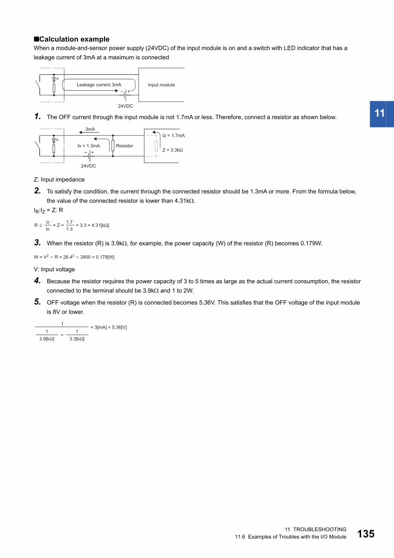
11
■Calculation exampleWhen a module-and-sensor power supply (24VDC) of the input module is on and a switch with LED indicator that has a
leakage current of 3mA at a maximum is connected
1. The OFF current through the input module is not 1.7mA or less. Therefore, connect a resistor as shown below.
Z: Input impedance
2. To satisfy the condition, the current through the connected resistor should be 1.3mA or more. From the formula below,
the value of the connected resistor is lower than 4.31k.
IR:IZ = Z: R
3. When the resistor (R) is 3.9k, for example, the power capacity (W) of the resistor (R) becomes 0.179W.
V: Input voltage
4. Because the resistor requires the power capacity of 3 to 5 times as large as the actual current consumption, the resistor
connected to the terminal should be 3.9k and 1 to 2W.
5. OFF voltage when the resistor (R) is connected becomes 5.36V. This satisfies that the OFF voltage of the input module
is 8V or lower.
Input moduleLeakage current 3mA
24VDC
Z = 3.3kΩIR = 1.3mA
3mAIz = 1.7mA
24VDC
Resistor
R ≤IRIZ
1.31.7
× Z = × 3.3 = 4.31[kΩ]
W = V2 R = 26.42÷ 3900 = 0.179[W]÷
× 3[mA] = 5.36[V]
3.9[kΩ]1
3.3[kΩ]1
+
1
11 TROUBLESHOOTING11.6 Examples of Troubles with the I/O Module 135
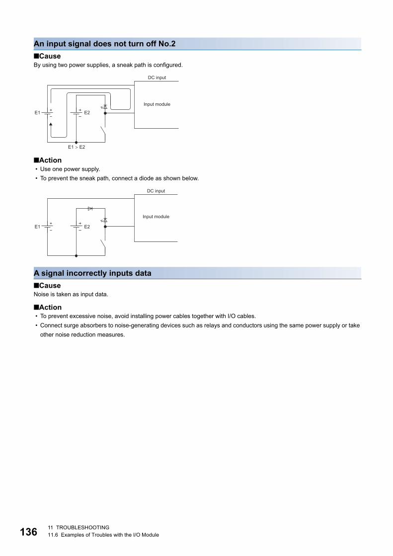
13
An input signal does not turn off No.2
■CauseBy using two power supplies, a sneak path is configured.
■Action • Use one power supply.
• To prevent the sneak path, connect a diode as shown below.
A signal incorrectly inputs data
■CauseNoise is taken as input data.
■Action • To prevent excessive noise, avoid installing power cables together with I/O cables.
• Connect surge absorbers to noise-generating devices such as relays and conductors using the same power supply or take
other noise reduction measures.
E1 E2
E1 > E2
DC input
Input module
E1 E2
DC input
Input module
611 TROUBLESHOOTING11.6 Examples of Troubles with the I/O Module
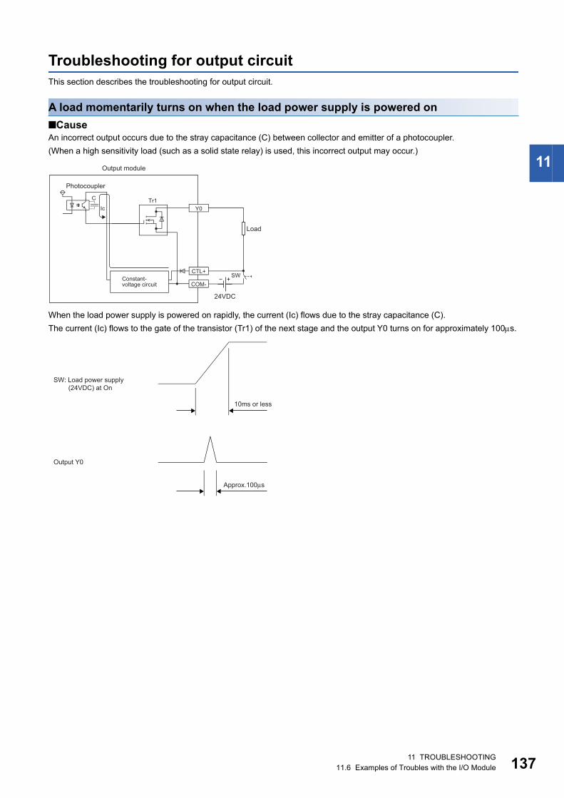
11
Troubleshooting for output circuitThis section describes the troubleshooting for output circuit.
A load momentarily turns on when the load power supply is powered on
■CauseAn incorrect output occurs due to the stray capacitance (C) between collector and emitter of a photocoupler.
(When a high sensitivity load (such as a solid state relay) is used, this incorrect output may occur.)
When the load power supply is powered on rapidly, the current (Ic) flows due to the stray capacitance (C).
The current (Ic) flows to the gate of the transistor (Tr1) of the next stage and the output Y0 turns on for approximately 100s.
Y0
C
SW
IcTr1
COM-
CTL+
24VDC
Output module
Photocoupler
Constant-voltage circuit
Load
SW: Load power supply (24VDC) at On
10ms or less
Output Y0
Approx.100μs
11 TROUBLESHOOTING11.6 Examples of Troubles with the I/O Module 137
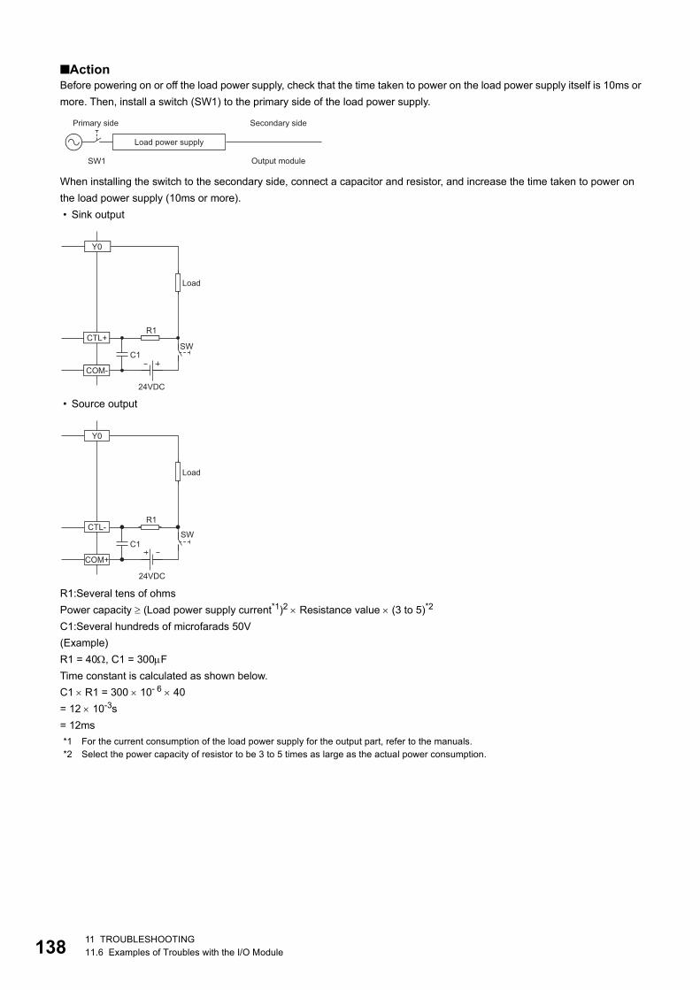
13
■ActionBefore powering on or off the load power supply, check that the time taken to power on the load power supply itself is 10ms or
more. Then, install a switch (SW1) to the primary side of the load power supply.
When installing the switch to the secondary side, connect a capacitor and resistor, and increase the time taken to power on
the load power supply (10ms or more).
• Sink output
• Source output
R1:Several tens of ohms
Power capacity (Load power supply current*1)2 Resistance value (3 to 5)*2
C1:Several hundreds of microfarads 50V
(Example)
R1 = 40, C1 = 300F
Time constant is calculated as shown below.
C1 R1 = 300 10- 6 40
= 12 10-3s
= 12ms
*1 For the current consumption of the load power supply for the output part, refer to the manuals.*2 Select the power capacity of resistor to be 3 to 5 times as large as the actual power consumption.
SW1 Output module
Secondary sidePrimary side
Load power supply
Y0
SW
R1
C1
CTL+
COM-
Load
24VDC
Y0
SW
R1
C1
CTL-
COM+
Load
24VDC
811 TROUBLESHOOTING11.6 Examples of Troubles with the I/O Module
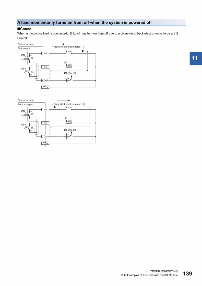
11
A load momentarily turns on from off when the system is powered off
■CauseWhen an inductive load is connected, [2] Load may turn on from off due to a diversion of back electromotive force at [1]
Shutoff.
ON
OFF
ON
OFF
Y0
Y1
COM+
CTL-
Y0
Y1
COM-
CTL+
[2]
[2]
Load
Load
Load
Load
Output module- Back electromotive force + [3]
+ Back electromotive force - [3]Output module
Sink output
[1] Shut off
[1] Shut off
Source output
11 TROUBLESHOOTING11.6 Examples of Troubles with the I/O Module 139
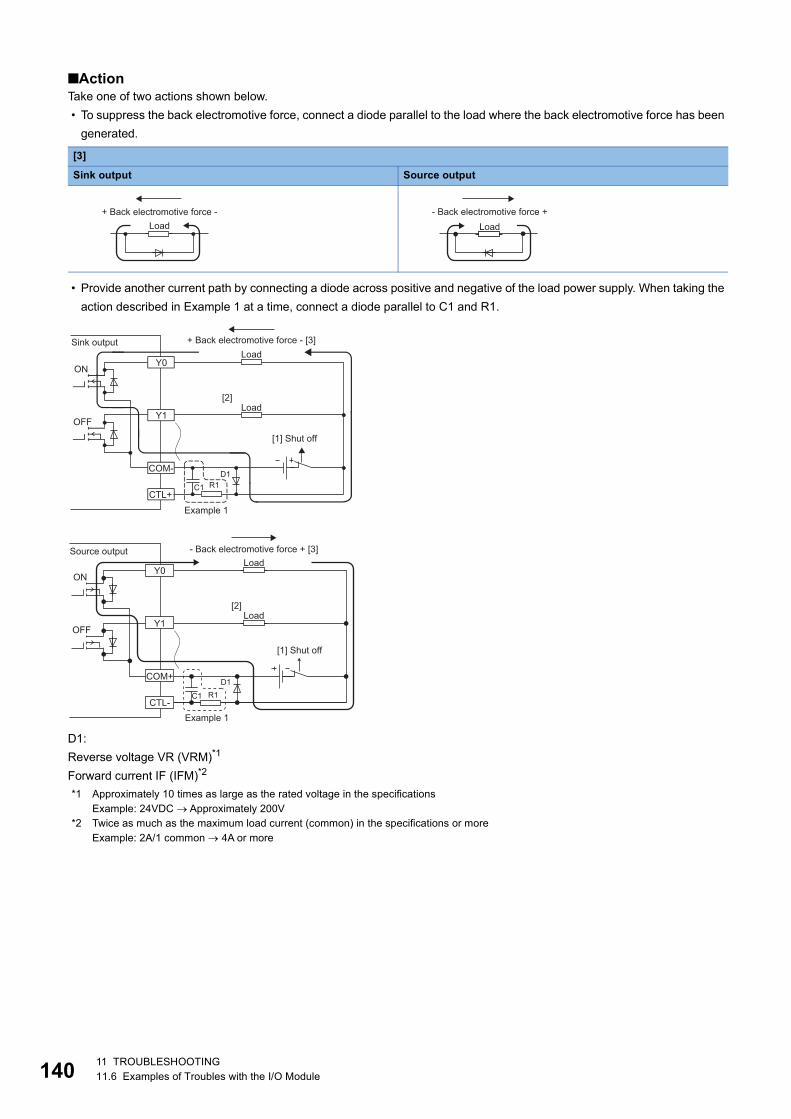
14
■ActionTake one of two actions shown below.
• To suppress the back electromotive force, connect a diode parallel to the load where the back electromotive force has been
generated.
• Provide another current path by connecting a diode across positive and negative of the load power supply. When taking the
action described in Example 1 at a time, connect a diode parallel to C1 and R1.
D1:
Reverse voltage VR (VRM)*1
Forward current IF (IFM)*2
*1 Approximately 10 times as large as the rated voltage in the specificationsExample: 24VDC Approximately 200V
*2 Twice as much as the maximum load current (common) in the specifications or moreExample: 2A/1 common 4A or more
[3]
Sink output Source output
+ Back electromotive force -Load Load
- Back electromotive force +
ON
OFF
[2]
Y0
Y1
COM-
CTL+
D1
C1 R1
Example 1
Load
Load
[1] Shut off
+ Back electromotive force - [3]Sink output
ON
OFF
[2]
Y0
Y1
COM+
CTL-
D1
C1 R1
Example 1
Load
Load
Source output - Back electromotive force + [3]
[1] Shut off
011 TROUBLESHOOTING11.6 Examples of Troubles with the I/O Module
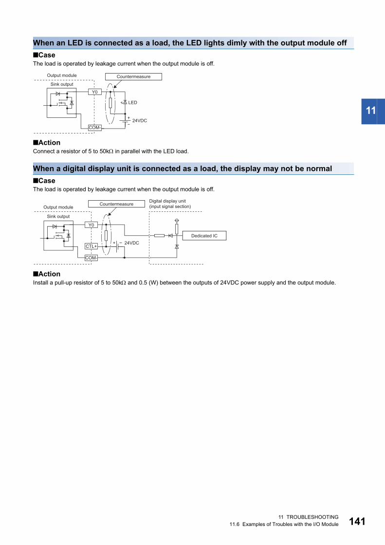
11
When an LED is connected as a load, the LED lights dimly with the output module off
■CaseThe load is operated by leakage current when the output module is off.
■ActionConnect a resistor of 5 to 50k in parallel with the LED load.
When a digital display unit is connected as a load, the display may not be normal
■CaseThe load is operated by leakage current when the output module is off.
■ActionInstall a pull-up resistor of 5 to 50k and 0.5 (W) between the outputs of 24VDC power supply and the output module.
LED
COM-
Y0
Output module
24VDC
Countermeasure
Sink output
Y0
CTL+
COM-
Digital display unit (input signal section)Countermeasure
24VDC
Output module
Dedicated IC
Sink output
11 TROUBLESHOOTING11.6 Examples of Troubles with the I/O Module 141
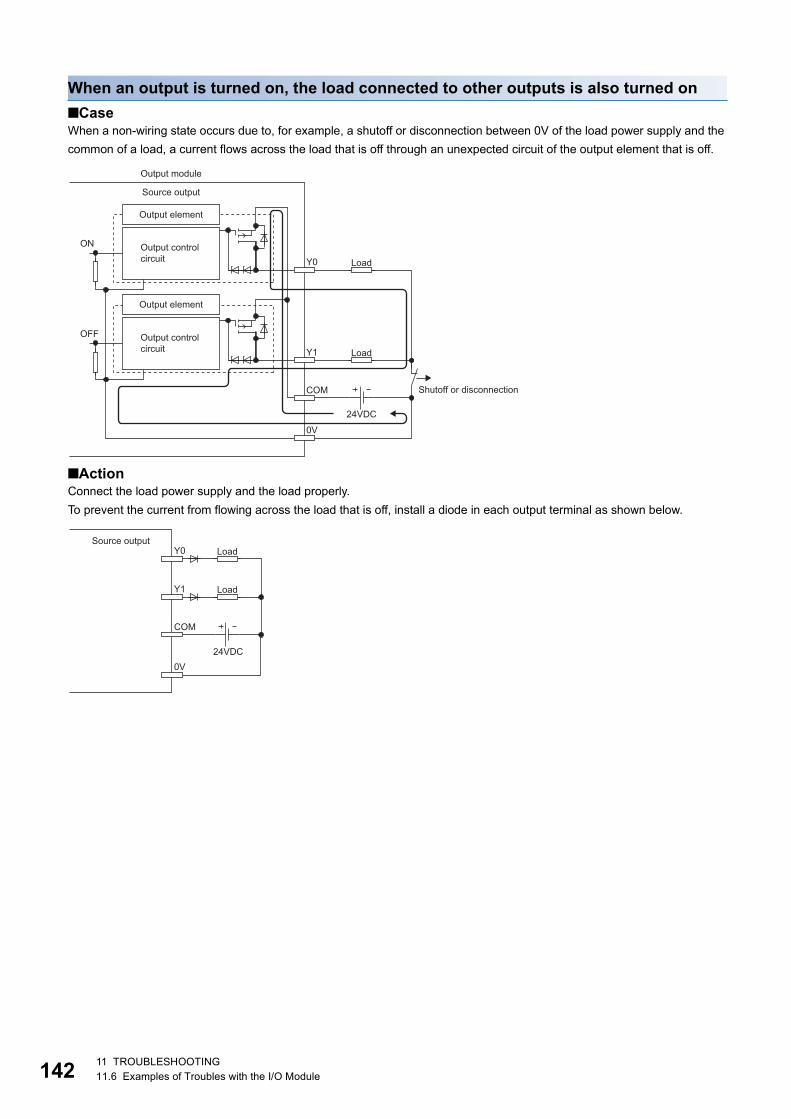
14
When an output is turned on, the load connected to other outputs is also turned on
■CaseWhen a non-wiring state occurs due to, for example, a shutoff or disconnection between 0V of the load power supply and the
common of a load, a current flows across the load that is off through an unexpected circuit of the output element that is off.
■ActionConnect the load power supply and the load properly.
To prevent the current from flowing across the load that is off, install a diode in each output terminal as shown below.
Y0
Y1
COM
0V
ON
OFF
Load
Load
24VDC
Shutoff or disconnection
Source output
Output control circuit
Output control circuit
Output element
Output element
Output module
Y0
Y1
COM
0V
Load
Load
24VDC
Source output
211 TROUBLESHOOTING11.6 Examples of Troubles with the I/O Module
APPENDICESAppendix 1 Details of Remote I/O Signals 143
A
APPENDICESAppendix 1 Details of Remote I/O SignalsThe following describes the details of the remote I/O signals assigned to the master/local module.
The assignment of each device number is for the case when the remote I/O signals of the I/O module are assigned as follows.
Remote input signal
External input signalThis signal shows the on/off state of each of external inputs (X0 to XF) of the input module. However, when the input OFF
delay function is enabled, the on/off state of each of the actual external inputs (X0 to XF) and that of External input signal X
(RX0 to RXF) may not match. For details on the input OFF delay function, refer to the following.
Page 84 Input OFF Delay Function
Remote output signal
External output signalThis signal turns on or off each of external outputs (Y0 to YF) of the output module. However, when the fast logic function is
enabled, the on/off state of External output signal Y (RY0 to RYF) and that of each of the actual external outputs (Y0 to YF)
may not match. For details on the fast logic function, refer to the following.
Page 95 Fast Logic Function
Item I/O module
Remote input signal RX0 to RXF
Remote output signal RY0 to RYF
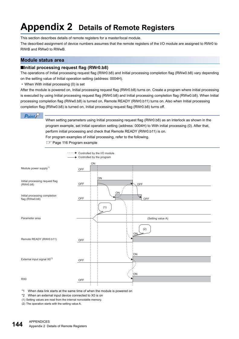
14
Appendix 2 Details of Remote RegistersThis section describes details of remote registers for a master/local module.
The described assignment of device numbers assumes that the remote registers of the I/O module are assigned to RWr0 to
RWrB and RWw0 to RWwB.
Module status area
■Initial processing request flag (RWr0.b8)The operations of Initial processing request flag (RWr0.b8) and Initial processing completion flag (RWw0.b8) vary depending
on the setting value of Initial operation setting (address: 0004H).
• When With initial processing (0) is set
After the module is powered on, Initial processing request flag (RWr0.b8) turns on. Create a program where initial processing
is executed by using Initial processing request flag (RWr0.b8) and Initial processing completion flag (RWw0.b8). When Initial
processing completion flag (RWw0.b8) is turned on, Remote READY (RWr0.b11) turns on. Also when Initial processing
completion flag (RWw0.b8) is turned on, Initial processing request flag (RWr0.b8) turns off.
When setting parameters using Initial processing request flag (RWr0.b8) as an interlock as shown in the
program example, set Initial operation setting (address: 0004H) to With initial processing (0). After that,
perform initial processing and check that Remote READY (RWr0.b11) is on.
For program examples of initial processing, refer to the following.
Page 116 Program example
*1 When data link starts at the same time of when the module is powered on*2 When an external input device connected to X0 is on(1) Setting values are read from the internal nonvolatile memory.
(2) The operation starts with the setting value A.
ON
ON
ON
ON
OFF
ON
OFF
OFF
OFF
OFF
OFF
OFF
OFF
ON
(2)
(1)
RX0
Initial processing request flag(RWr0.b8)
(Setting value A)
Module power supply*1
External input signal X0*2
Controlled by the I/O moduleControlled by the program
Initial processing completion flag (RWw0.b8)
Remote READY (RWr0.b11)
Parameter area
4APPENDICESAppendix 2 Details of Remote Registers
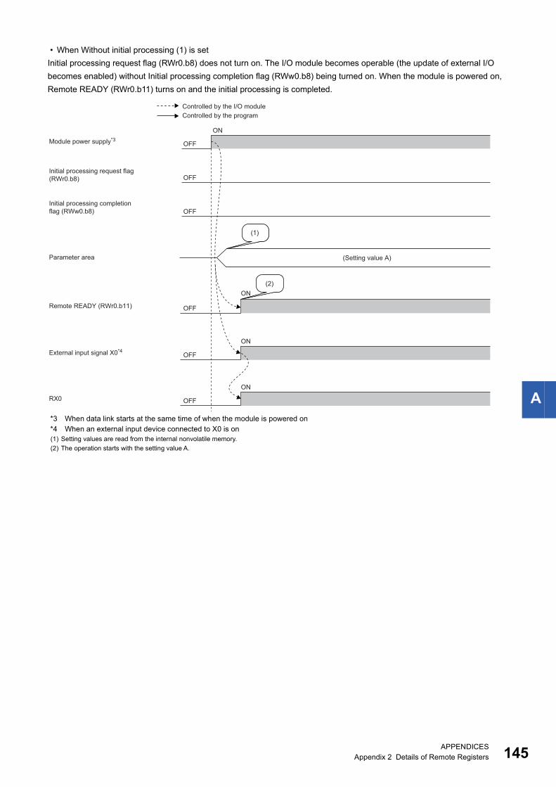
A
• When Without initial processing (1) is set
Initial processing request flag (RWr0.b8) does not turn on. The I/O module becomes operable (the update of external I/O
becomes enabled) without Initial processing completion flag (RWw0.b8) being turned on. When the module is powered on,
Remote READY (RWr0.b11) turns on and the initial processing is completed.
*3 When data link starts at the same time of when the module is powered on*4 When an external input device connected to X0 is on(1) Setting values are read from the internal nonvolatile memory.
(2) The operation starts with the setting value A.
ON(2)
(1)
ON
OFF
ON
OFF
OFF
OFF
OFF
OFF
ON
RX0
Initial processing request flag(RWr0.b8)
(Setting value A)
Module power supply*3
External input signal X0*4
Controlled by the I/O moduleControlled by the program
Initial processing completion flag (RWw0.b8)
Remote READY (RWr0.b11)
Parameter area
APPENDICESAppendix 2 Details of Remote Registers 145
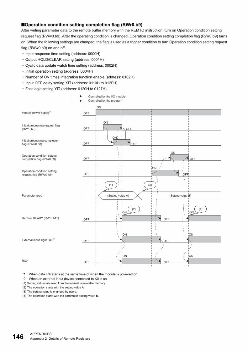
14
■Operation condition setting completion flag (RWr0.b9)After writing parameter data to the remote buffer memory with the REMTO instruction, turn on Operation condition setting
request flag (RWw0.b9). After the operating condition is changed, Operation condition setting completion flag (RWr0.b9) turns
on. When the following settings are changed, the flag is used as a trigger condition to turn Operation condition setting request
flag (RWw0.b9) on and off.
• Input response time setting (address: 0000H)
• Output HOLD/CLEAR setting (address: 0001H)
• Cyclic data update watch time setting (address: 0002H)
• Initial operation setting (address: 0004H)
• Number of ON times integration function enable (address: 0102H)
• Input OFF delay setting X (address: 0110H to 012FH)
• Fast logic setting Y (address: 0120H to 0127H)
*1 When data link starts at the same time of when the module is powered on*2 When an external input device connected to X0 is on(1) Setting values are read from the internal nonvolatile memory.
(2) The operation starts with the setting value A.
(3) The setting value is changed by users.
(4) The operation starts with the parameter setting value B.
ON
ON ON
ON
(1) (3)
(2) (4)
ON
OFF
ON ON
ON
OFF
OFF
OFF
OFF
OFF
OFF
OFF
ON
OFF OFF
OFF
ON
OFF
ON
OFF
OFF
OFFRX0
Initial processing request flag(RWr0.b8)
(Setting value A) (Setting value B)
Module power supply*1
External input signal X0*2
Controlled by the I/O moduleControlled by the program
Initial processing completion flag (RWw0.b8)
Remote READY (RWr0.b11)
Parameter area
Operation condition settingcompletion flag (RWr0.b9)
Operation condition settingrequest flag (RWw0.b9)
6APPENDICESAppendix 2 Details of Remote Registers
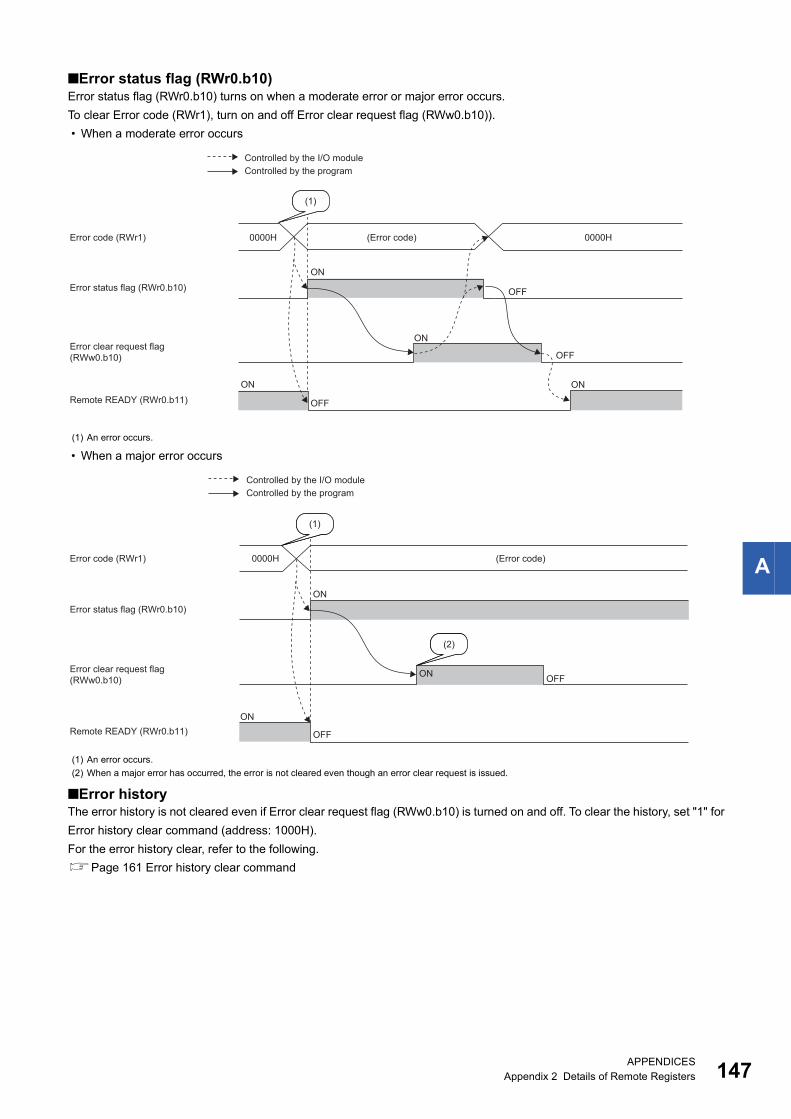
A
■Error status flag (RWr0.b10)Error status flag (RWr0.b10) turns on when a moderate error or major error occurs.
To clear Error code (RWr1), turn on and off Error clear request flag (RWw0.b10)).
• When a moderate error occurs
• When a major error occurs
■Error historyThe error history is not cleared even if Error clear request flag (RWw0.b10) is turned on and off. To clear the history, set "1" for
Error history clear command (address: 1000H).
For the error history clear, refer to the following.
Page 161 Error history clear command
(1) An error occurs.
(1) An error occurs.
(2) When a major error has occurred, the error is not cleared even though an error clear request is issued.
0000H 0000H
ON
OFF
OFF
OFF
ON
ONON
(1)
Error status flag (RWr0.b10)
Error code (RWr1) (Error code)
Error clear request flag(RWw0.b10)
Remote READY (RWr0.b11)
Controlled by the I/O moduleControlled by the program
(1)
(2)
0000H
ON
OFF
OFF
ON
ON
Error status flag (RWr0.b10)
Error code (RWr1) (Error code)
Error clear request flag(RWw0.b10)
Remote READY (RWr0.b11)
Controlled by the I/O moduleControlled by the program
APPENDICESAppendix 2 Details of Remote Registers 147
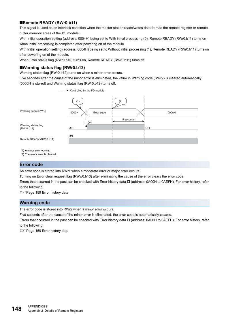
14
■Remote READY (RWr0.b11)This signal is used as an interlock condition when the master station reads/writes data from/to the remote register or remote
buffer memory areas of the I/O module.
With Initial operation setting (address: 0004H) being set to With initial processing (0), Remote READY (RWr0.b11) turns on
when initial processing is completed after powering on of the module.
With Initial operation setting (address: 0004H) being set to Without initial processing (1), Remote READY (RWr0.b11) turns on
after powering on of the module.
When Error status flag (RWr0.b10) turns on, Remote READY (RWr0.b11) turns off.
■Warning status flag (RWr0.b12)Warning status flag (RWr0.b12) turns on when a minor error occurs.
Five seconds after the cause of the minor error is eliminated, the value in Warning code (RWr2) is cleared automatically
(0000H is stored) and Warning status flag (RWr0.b12) turns off.
Error codeAn error code is stored into RWr1 when a moderate error or major error occurs.
Turning on Error clear request flag (RWw0.b10) after eliminating the cause of the error clears the error code.
Errors that occurred in the past can be checked with Error history data (address: 0A00H to 0AEFH). For error history, refer
to the following.
Page 159 Error history data
Warning codeThe error code is stored into RWr2 when a minor error occurs.
Five seconds after the cause of the minor error is eliminated, the error code is automatically cleared.
Errors that occurred in the past can be checked with Error history data (address: 0A00H to 0AEFH). For error history, refer
to the following.
Page 159 Error history data
(1) A minor error occurs.
(2) The minor error is cleared.
(2)
OFF
ON
ON
OFF
0000H
(1)
0000H
Warning status flag(RWr0.b12)
Warning code (RWr2) Error code
Controlled by the I/O module
Remote READY (RWr0.b11)
5 seconds
8APPENDICESAppendix 2 Details of Remote Registers
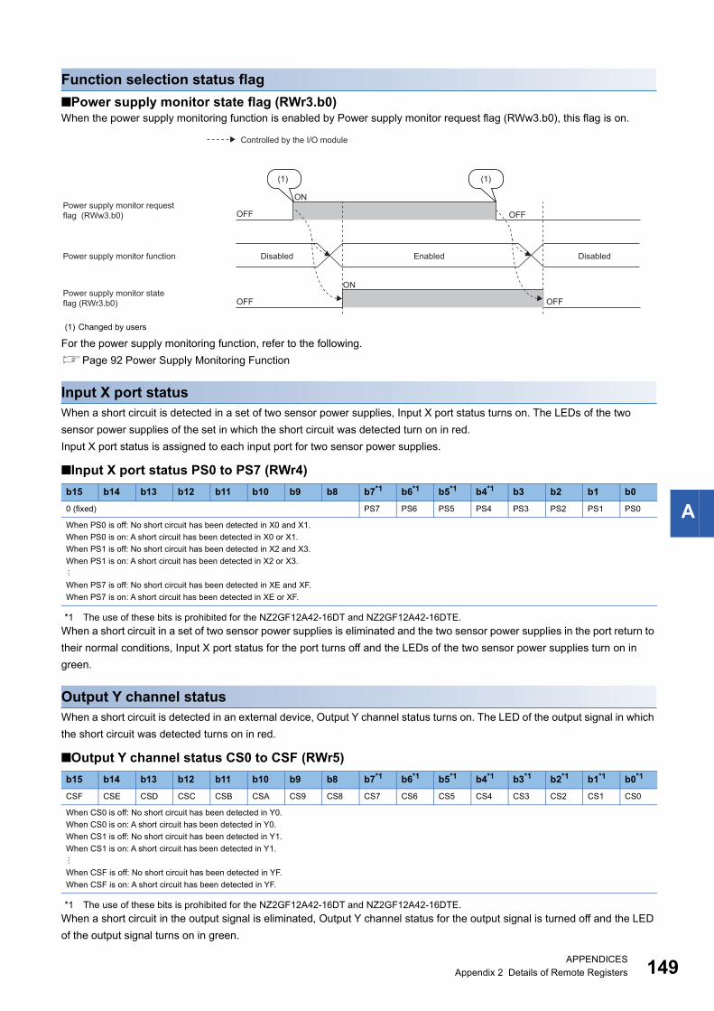
A
Function selection status flag
■Power supply monitor state flag (RWr3.b0)When the power supply monitoring function is enabled by Power supply monitor request flag (RWw3.b0), this flag is on.
For the power supply monitoring function, refer to the following.
Page 92 Power Supply Monitoring Function
Input X port statusWhen a short circuit is detected in a set of two sensor power supplies, Input X port status turns on. The LEDs of the two
sensor power supplies of the set in which the short circuit was detected turn on in red.
Input X port status is assigned to each input port for two sensor power supplies.
■Input X port status PS0 to PS7 (RWr4)
*1 The use of these bits is prohibited for the NZ2GF12A42-16DT and NZ2GF12A42-16DTE.
When a short circuit in a set of two sensor power supplies is eliminated and the two sensor power supplies in the port return to
their normal conditions, Input X port status for the port turns off and the LEDs of the two sensor power supplies turn on in
green.
Output Y channel statusWhen a short circuit is detected in an external device, Output Y channel status turns on. The LED of the output signal in which
the short circuit was detected turns on in red.
■Output Y channel status CS0 to CSF (RWr5)
*1 The use of these bits is prohibited for the NZ2GF12A42-16DT and NZ2GF12A42-16DTE.
When a short circuit in the output signal is eliminated, Output Y channel status for the output signal is turned off and the LED
of the output signal turns on in green.
(1) Changed by users
b15 b14 b13 b12 b11 b10 b9 b8 b7*1 b6*1 b5*1 b4*1 b3 b2 b1 b0
0 (fixed) PS7 PS6 PS5 PS4 PS3 PS2 PS1 PS0
When PS0 is off: No short circuit has been detected in X0 and X1.
When PS0 is on: A short circuit has been detected in X0 or X1.
When PS1 is off: No short circuit has been detected in X2 and X3.
When PS1 is on: A short circuit has been detected in X2 or X3.
When PS7 is off: No short circuit has been detected in XE and XF.
When PS7 is on: A short circuit has been detected in XE or XF.
b15 b14 b13 b12 b11 b10 b9 b8 b7*1 b6*1 b5*1 b4*1 b3*1 b2*1 b1*1 b0*1
CSF CSE CSD CSC CSB CSA CS9 CS8 CS7 CS6 CS5 CS4 CS3 CS2 CS1 CS0
When CS0 is off: No short circuit has been detected in Y0.
When CS0 is on: A short circuit has been detected in Y0.
When CS1 is off: No short circuit has been detected in Y1.
When CS1 is on: A short circuit has been detected in Y1.
When CSF is off: No short circuit has been detected in YF.
When CSF is on: A short circuit has been detected in YF.
OFF
OFF
ON
ON
OFF
OFF
(1)(1)
Controlled by the I/O module
Disabled Enabled Disabled Power supply monitor function
Power supply monitor request flag (RWw3.b0)
Power supply monitor state flag (RWr3.b0)
APPENDICESAppendix 2 Details of Remote Registers 149
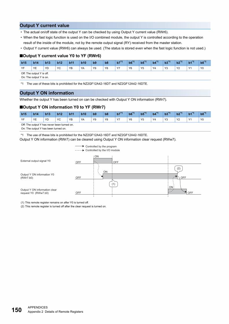
15
Output Y current value • The actual on/off state of the output Y can be checked by using Output Y current value (RWr6).
• When the fast logic function is used on the I/O combined module, the output Y is controlled according to the operation
result of the inside of the module, not by the remote output signal (RY) received from the master station.
• Output Y current value (RWr6) can always be used. (The status is stored even when the fast logic function is not used.)
■Output Y current value Y0 to YF (RWr6)
*1 The use of these bits is prohibited for the NZ2GF12A42-16DT and NZ2GF12A42-16DTE.
Output Y ON informationWhether the output Y has been turned on can be checked with Output Y ON information (RWr7).
■Output Y ON information Y0 to YF (RWr7)
*1 The use of these bits is prohibited for the NZ2GF12A42-16DT and NZ2GF12A42-16DTE.
Output Y ON information (RWr7) can be cleared using Output Y ON information clear request (RWw7).
b15 b14 b13 b12 b11 b10 b9 b8 b7*1 b6*1 b5*1 b4*1 b3*1 b2*1 b1*1 b0*1
YF YE YD YC YB YA Y9 Y8 Y7 Y6 Y5 Y4 Y3 Y2 Y1 Y0
Off: The output Y is off.
On: The output Y is on.
b15 b14 b13 b12 b11 b10 b9 b8 b7*1 b6*1 b5*1 b4*1 b3*1 b2*1 b1*1 b0*1
YF YE YD YC YB YA Y9 Y8 Y7 Y6 Y5 Y4 Y3 Y2 Y1 Y0
Off: The output Y has never been turned on.
On: The output Y has been turned on.
(1) This remote register remains on after Y0 is turned off.
(2) This remote register is turned off after the clear request is turned on.
OFF OFF
OFF
OFF
OFF
ON
ON
ON
OFF
(1)
(2)
External output signal Y0
Output Y ON information Y0(RWr7.b0)
Output Y ON information clear request Y0 (RWw7.b0)
Controlled by the programControlled by the I/O module
0APPENDICESAppendix 2 Details of Remote Registers
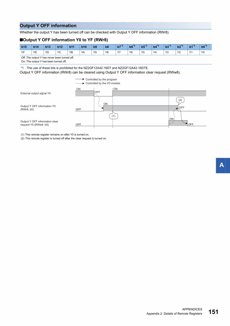
A
Output Y OFF informationWhether the output Y has been turned off can be checked with Output Y OFF information (RWr8).
■Output Y OFF information Y0 to YF (RWr8)
*1 The use of these bits is prohibited for the NZ2GF12A42-16DT and NZ2GF12A42-16DTE.
Output Y OFF information (RWr8) can be cleared using Output Y OFF information clear request (RWw8).
b15 b14 b13 b12 b11 b10 b9 b8 b7*1 b6*1 b5*1 b4*1 b3*1 b2*1 b1*1 b0*1
YF YE YD YC YB YA Y9 Y8 Y7 Y6 Y5 Y4 Y3 Y2 Y1 Y0
Off: The output Y has never been turned off.
On: The output Y has been turned off.
(1) This remote register remains on after Y0 is turned on.
(2) This remote register is turned off after the clear request is turned on.
OFF
OFF
OFF
OFF
ON ON
ON
ON
(2)
(1)
OFF
External output signal Y0
Controlled by the programControlled by the I/O module
Output Y OFF information Y0(RWr8. b0)
Output Y OFF information clear request Y0 (RWw8. b0)
APPENDICESAppendix 2 Details of Remote Registers 151
15
Module operation area
■Initial processing completion flag (RWw0.b8)Turning on this flag completes the initial processing and turns on Remote READY (RWr0.b11).
For the timing of turning the flag on and off, refer to the following.
Page 144 Initial processing request flag (RWr0.b8)
■Operation condition setting request flag (RWw0.b9)After writing parameter data to the remote buffer memory, turn on Operation condition setting request flag (RWw0.b9). After
the operating condition is changed, Operation condition setting completion flag (RWr0.b9) turns on.
For the timing of turning the flag on and off, refer to the following.
Page 146 Operation condition setting completion flag (RWr0.b9)
• Turning on Operation condition setting request flag (RWw0.b9) stores zero in Warning code (RWr2) and
turns off Warning status flag (RWr0.b12).
• When a major error or a moderate error occurs and the error cause is eliminated, turning on Operation
condition setting request flag (RWw0.b9) stores zero in Error code (RWr1) and turns off Error status flag
(RWr0.b10).
■Error clear request flag (RWw0.b10)Use this flag to clear Error status flag (RWr0.b10) and Error code (RWr1).
• When a moderate error occurs
When Error clear request flag (RWw0.b10) is turned on after the cause of the error is eliminated, the error status is cleared
and Error status flag (RWr0.b10) turns off.
If Error clear request flag (RWw0.b10) is turned off before Error status flag (RWr0.b10) turns off, Error status flag (RWr0.b10)
does not turn off.
For the timing of turning the flag on and off, refer to the following.
Error status flag (RWr0.b10) ( Page 147 Error status flag (RWr0.b10))
• When a major error occurs
Error status flag (RWr0.b10) does not turn off even if Error clear request flag (RWw0.b10) is turned on and off.
For the timing of turning the flag on and off, refer to the following.
Error status flag (RWr0.b10) ( Page 147 Error status flag (RWr0.b10))
Function selection setting flag
■Power supply monitor request flag (RWw3.b0)To enable the power supply monitoring function, turn on this flag. For the timing of turning the flag on and off, refer to the
following.
Page 149 Power supply monitor state flag (RWr3.b0)
Output Y ON information clear requestThis remote register is used to clear Output Y ON information (RWr7).
Clear processing continues while the bit of Output Y ON information clear request (RWw7) is on.
■Output Y ON information clear request Y0 to YF (RWw7)
*1 The use of these bits is prohibited for the NZ2GF12A42-16DT and NZ2GF12A42-16DTE.
For the timing of turning the register on and off, refer to the following.
Page 150 Output Y ON information
b15 b14 b13 b12 b11 b10 b9 b8 b7*1 b6*1 b5*1 b4*1 b3*1 b2*1 b1*1 b0*1
YF YE YD YC YB YA Y9 Y8 Y7 Y6 Y5 Y4 Y3 Y2 Y1 Y0
Off: Output Y ON information is not cleared.
On: Output Y ON information is cleared.
2APPENDICESAppendix 2 Details of Remote Registers
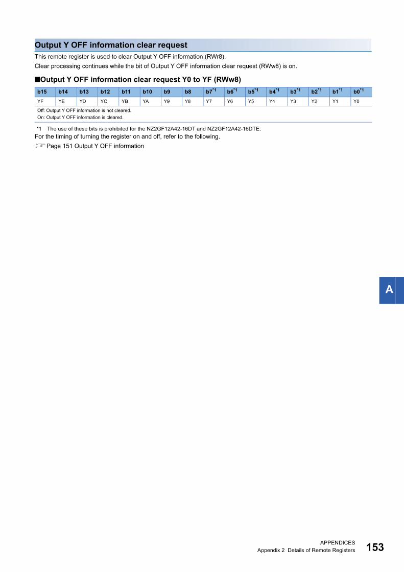
A
Output Y OFF information clear requestThis remote register is used to clear Output Y OFF information (RWr8).
Clear processing continues while the bit of Output Y OFF information clear request (RWw8) is on.
■Output Y OFF information clear request Y0 to YF (RWw8)
*1 The use of these bits is prohibited for the NZ2GF12A42-16DT and NZ2GF12A42-16DTE.
For the timing of turning the register on and off, refer to the following.
Page 151 Output Y OFF information
b15 b14 b13 b12 b11 b10 b9 b8 b7*1 b6*1 b5*1 b4*1 b3*1 b2*1 b1*1 b0*1
YF YE YD YC YB YA Y9 Y8 Y7 Y6 Y5 Y4 Y3 Y2 Y1 Y0
Off: Output Y OFF information is not cleared.
On: Output Y OFF information is cleared.
APPENDICESAppendix 2 Details of Remote Registers 153
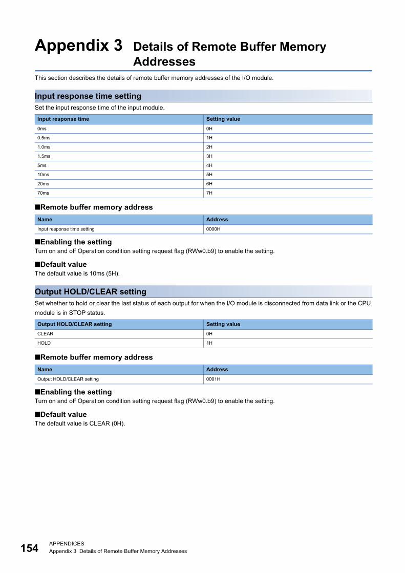
15
Appendix 3 Details of Remote Buffer Memory Addresses
This section describes the details of remote buffer memory addresses of the I/O module.
Input response time settingSet the input response time of the input module.
■Remote buffer memory address
■Enabling the settingTurn on and off Operation condition setting request flag (RWw0.b9) to enable the setting.
■Default valueThe default value is 10ms (5H).
Output HOLD/CLEAR settingSet whether to hold or clear the last status of each output for when the I/O module is disconnected from data link or the CPU
module is in STOP status.
■Remote buffer memory address
■Enabling the settingTurn on and off Operation condition setting request flag (RWw0.b9) to enable the setting.
■Default valueThe default value is CLEAR (0H).
Input response time Setting value
0ms 0H
0.5ms 1H
1.0ms 2H
1.5ms 3H
5ms 4H
10ms 5H
20ms 6H
70ms 7H
Name Address
Input response time setting 0000H
Output HOLD/CLEAR setting Setting value
CLEAR 0H
HOLD 1H
Name Address
Output HOLD/CLEAR setting 0001H
4APPENDICESAppendix 3 Details of Remote Buffer Memory Addresses
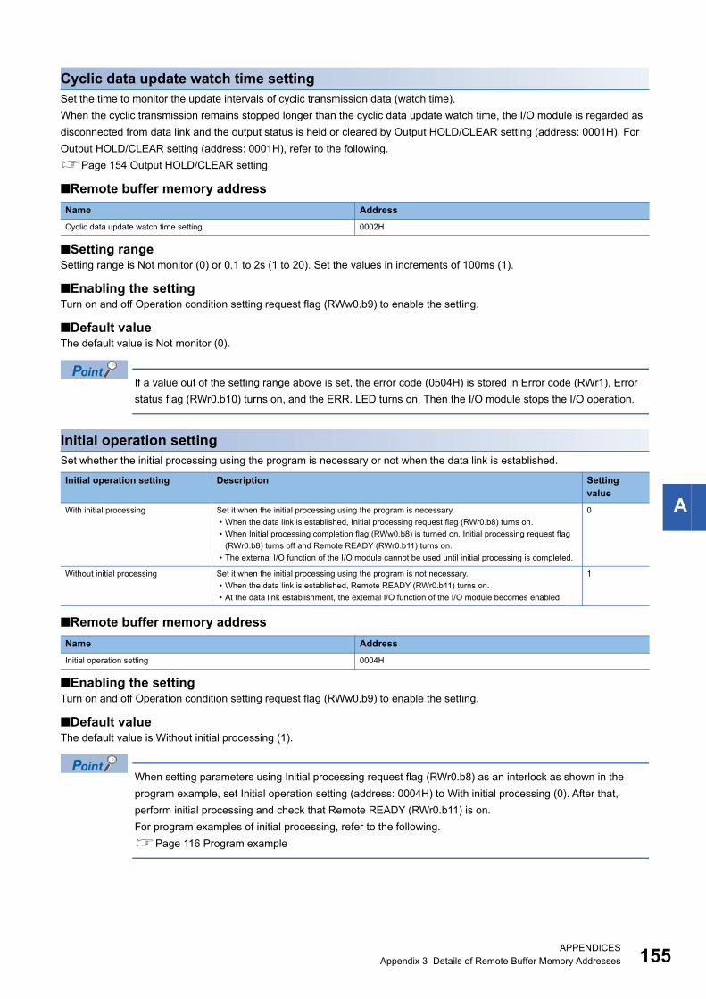
A
Cyclic data update watch time settingSet the time to monitor the update intervals of cyclic transmission data (watch time).
When the cyclic transmission remains stopped longer than the cyclic data update watch time, the I/O module is regarded as
disconnected from data link and the output status is held or cleared by Output HOLD/CLEAR setting (address: 0001H). For
Output HOLD/CLEAR setting (address: 0001H), refer to the following.
Page 154 Output HOLD/CLEAR setting
■Remote buffer memory address
■Setting rangeSetting range is Not monitor (0) or 0.1 to 2s (1 to 20). Set the values in increments of 100ms (1).
■Enabling the settingTurn on and off Operation condition setting request flag (RWw0.b9) to enable the setting.
■Default valueThe default value is Not monitor (0).
If a value out of the setting range above is set, the error code (0504H) is stored in Error code (RWr1), Error
status flag (RWr0.b10) turns on, and the ERR. LED turns on. Then the I/O module stops the I/O operation.
Initial operation settingSet whether the initial processing using the program is necessary or not when the data link is established.
■Remote buffer memory address
■Enabling the settingTurn on and off Operation condition setting request flag (RWw0.b9) to enable the setting.
■Default valueThe default value is Without initial processing (1).
When setting parameters using Initial processing request flag (RWr0.b8) as an interlock as shown in the
program example, set Initial operation setting (address: 0004H) to With initial processing (0). After that,
perform initial processing and check that Remote READY (RWr0.b11) is on.
For program examples of initial processing, refer to the following.
Page 116 Program example
Name Address
Cyclic data update watch time setting 0002H
Initial operation setting Description Setting value
With initial processing Set it when the initial processing using the program is necessary.
• When the data link is established, Initial processing request flag (RWr0.b8) turns on.
• When Initial processing completion flag (RWw0.b8) is turned on, Initial processing request flag
(RWr0.b8) turns off and Remote READY (RWr0.b11) turns on.
• The external I/O function of the I/O module cannot be used until initial processing is completed.
0
Without initial processing Set it when the initial processing using the program is not necessary.
• When the data link is established, Remote READY (RWr0.b11) turns on.
• At the data link establishment, the external I/O function of the I/O module becomes enabled.
1
Name Address
Initial operation setting 0004H
APPENDICESAppendix 3 Details of Remote Buffer Memory Addresses 155
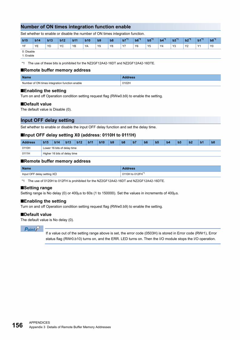
15
Number of ON times integration function enableSet whether to enable or disable the number of ON times integration function.
*1 The use of these bits is prohibited for the NZ2GF12A42-16DT and NZ2GF12A42-16DTE.
■Remote buffer memory address
■Enabling the settingTurn on and off Operation condition setting request flag (RWw0.b9) to enable the setting.
■Default valueThe default value is Disable (0).
Input OFF delay settingSet whether to enable or disable the input OFF delay function and set the delay time.
■Input OFF delay setting X0 (address: 0110H to 0111H)
■Remote buffer memory address
*1 The use of 0120H to 012FH is prohibited for the NZ2GF12A42-16DT and NZ2GF12A42-16DTE.
■Setting rangeSetting range is No delay (0) or 400s to 60s (1 to 150000). Set the values in increments of 400s.
■Enabling the settingTurn on and off Operation condition setting request flag (RWw0.b9) to enable the setting.
■Default valueThe default value is No delay (0).
If a value out of the setting range above is set, the error code (0503H) is stored in Error code (RWr1), Error
status flag (RWr0.b10) turns on, and the ERR. LED turns on. Then the I/O module stops the I/O operation.
b15 b14 b13 b12 b11 b10 b9 b8 b7*1 b6*1 b5*1 b4*1 b3*1 b2*1 b1*1 b0*1
YF YE YD YC YB YA Y9 Y8 Y7 Y6 Y5 Y4 Y3 Y2 Y1 Y0
0: Disable
1: Enable
Name Address
Number of ON times integration function enable 0102H
Address b15 b14 b13 b12 b11 b10 b9 b8 b7 b6 b5 b4 b3 b2 b1 b0
0110H Lower 16 bits of delay time
0111H Higher 16 bits of delay time
Name Address
Input OFF delay setting X 0110H to 012FH*1
6APPENDICESAppendix 3 Details of Remote Buffer Memory Addresses
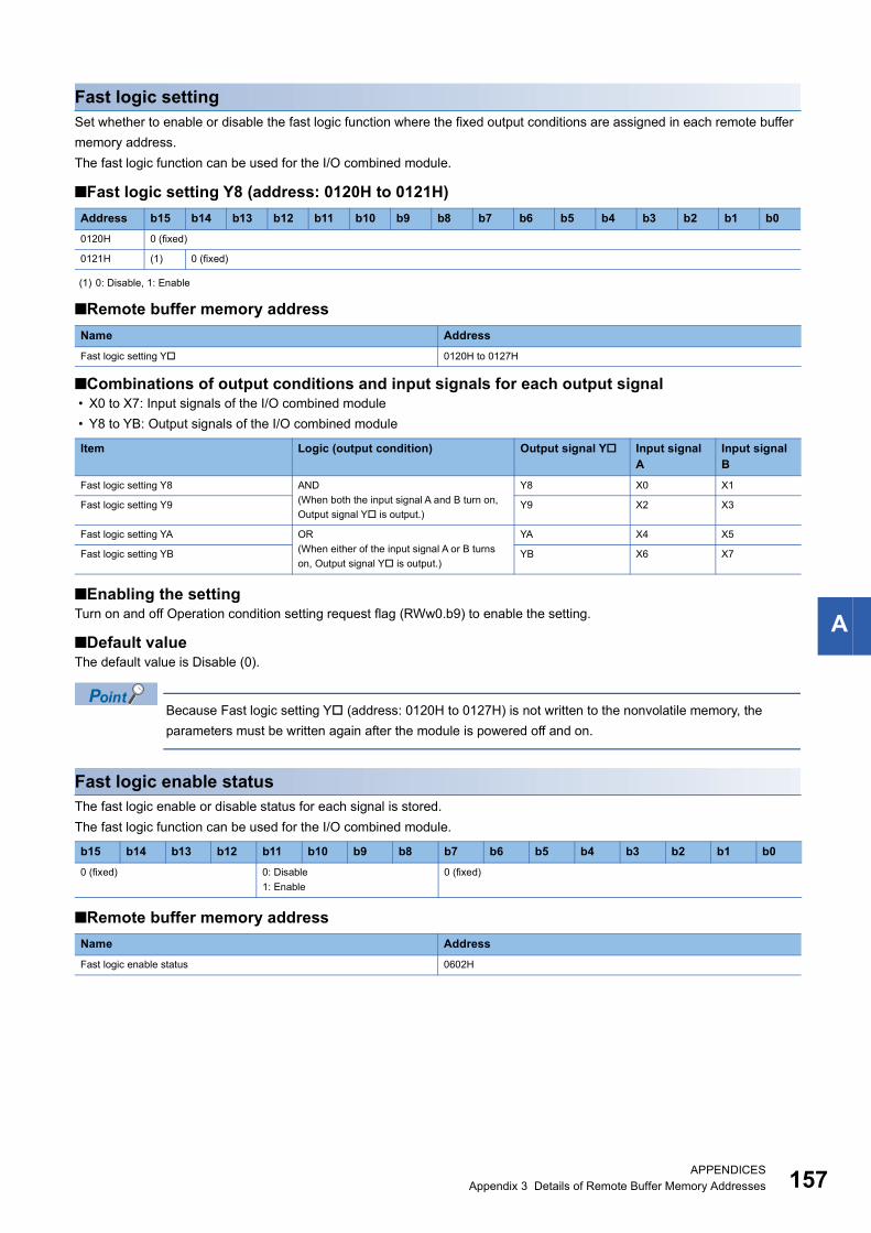
A
Fast logic settingSet whether to enable or disable the fast logic function where the fixed output conditions are assigned in each remote buffer
memory address.
The fast logic function can be used for the I/O combined module.
■Fast logic setting Y8 (address: 0120H to 0121H)
■Remote buffer memory address
■Combinations of output conditions and input signals for each output signal • X0 to X7: Input signals of the I/O combined module
• Y8 to YB: Output signals of the I/O combined module
■Enabling the settingTurn on and off Operation condition setting request flag (RWw0.b9) to enable the setting.
■Default valueThe default value is Disable (0).
Because Fast logic setting Y (address: 0120H to 0127H) is not written to the nonvolatile memory, the
parameters must be written again after the module is powered off and on.
Fast logic enable statusThe fast logic enable or disable status for each signal is stored.
The fast logic function can be used for the I/O combined module.
■Remote buffer memory address
Address b15 b14 b13 b12 b11 b10 b9 b8 b7 b6 b5 b4 b3 b2 b1 b0
0120H 0 (fixed)
0121H (1) 0 (fixed)
(1) 0: Disable, 1: Enable
Name Address
Fast logic setting Y 0120H to 0127H
Item Logic (output condition) Output signal Y Input signal A
Input signal B
Fast logic setting Y8 AND
(When both the input signal A and B turn on,
Output signal Y is output.)
Y8 X0 X1
Fast logic setting Y9 Y9 X2 X3
Fast logic setting YA OR
(When either of the input signal A or B turns
on, Output signal Y is output.)
YA X4 X5
Fast logic setting YB YB X6 X7
b15 b14 b13 b12 b11 b10 b9 b8 b7 b6 b5 b4 b3 b2 b1 b0
0 (fixed) 0: Disable
1: Enable
0 (fixed)
Name Address
Fast logic enable status 0602H
APPENDICESAppendix 3 Details of Remote Buffer Memory Addresses 157
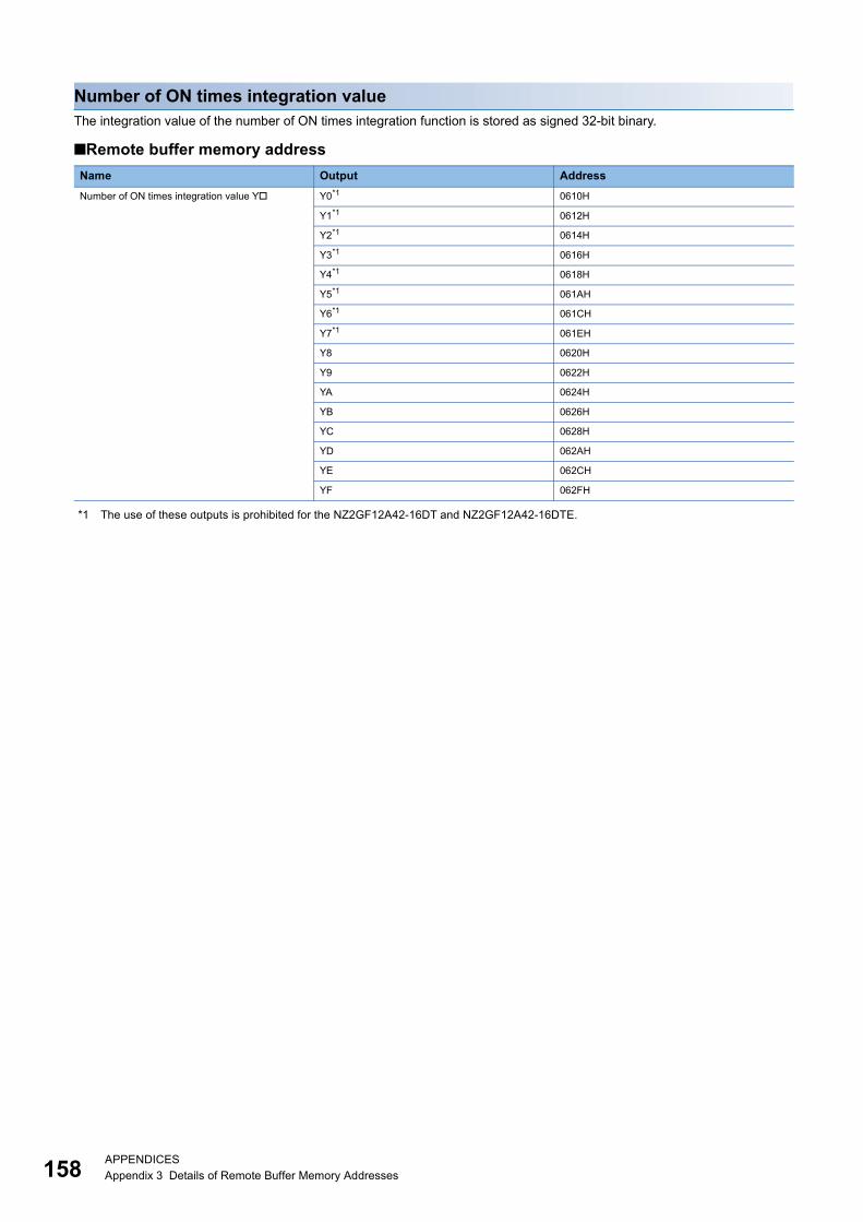
15
Number of ON times integration valueThe integration value of the number of ON times integration function is stored as signed 32-bit binary.
■Remote buffer memory address
*1 The use of these outputs is prohibited for the NZ2GF12A42-16DT and NZ2GF12A42-16DTE.
Name Output Address
Number of ON times integration value Y Y0*1 0610H
Y1*1 0612H
Y2*1 0614H
Y3*1 0616H
Y4*1 0618H
Y5*1 061AH
Y6*1 061CH
Y7*1 061EH
Y8 0620H
Y9 0622H
YA 0624H
YB 0626H
YC 0628H
YD 062AH
YE 062CH
YF 062FH
8APPENDICESAppendix 3 Details of Remote Buffer Memory Addresses
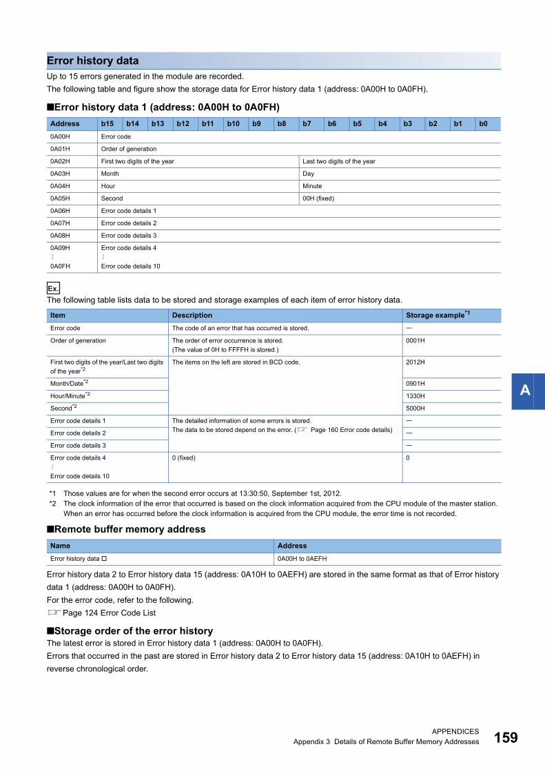
A
Error history dataUp to 15 errors generated in the module are recorded.
The following table and figure show the storage data for Error history data 1 (address: 0A00H to 0A0FH).
■Error history data 1 (address: 0A00H to 0A0FH)
Ex.
The following table lists data to be stored and storage examples of each item of error history data.
*1 Those values are for when the second error occurs at 13:30:50, September 1st, 2012.*2 The clock information of the error that occurred is based on the clock information acquired from the CPU module of the master station.
When an error has occurred before the clock information is acquired from the CPU module, the error time is not recorded.
■Remote buffer memory address
Error history data 2 to Error history data 15 (address: 0A10H to 0AEFH) are stored in the same format as that of Error history
data 1 (address: 0A00H to 0A0FH).
For the error code, refer to the following.
Page 124 Error Code List
■Storage order of the error historyThe latest error is stored in Error history data 1 (address: 0A00H to 0A0FH).
Errors that occurred in the past are stored in Error history data 2 to Error history data 15 (address: 0A10H to 0AEFH) in
reverse chronological order.
Address b15 b14 b13 b12 b11 b10 b9 b8 b7 b6 b5 b4 b3 b2 b1 b0
0A00H Error code
0A01H Order of generation
0A02H First two digits of the year Last two digits of the year
0A03H Month Day
0A04H Hour Minute
0A05H Second 00H (fixed)
0A06H Error code details 1
0A07H Error code details 2
0A08H Error code details 3
0A09H
0A0FH
Error code details 4
Error code details 10
Item Description Storage example*1
Error code The code of an error that has occurred is stored.
Order of generation The order of error occurrence is stored.
(The value of 0H to FFFFH is stored.)
0001H
First two digits of the year/Last two digits
of the year*2The items on the left are stored in BCD code. 2012H
Month/Date*2 0901H
Hour/Minute*2 1330H
Second*2 5000H
Error code details 1 The detailed information of some errors is stored.
The data to be stored depend on the error. ( Page 160 Error code details)
Error code details 2
Error code details 3
Error code details 4
Error code details 10
0 (fixed) 0
Name Address
Error history data 0A00H to 0AEFH
APPENDICESAppendix 3 Details of Remote Buffer Memory Addresses 159
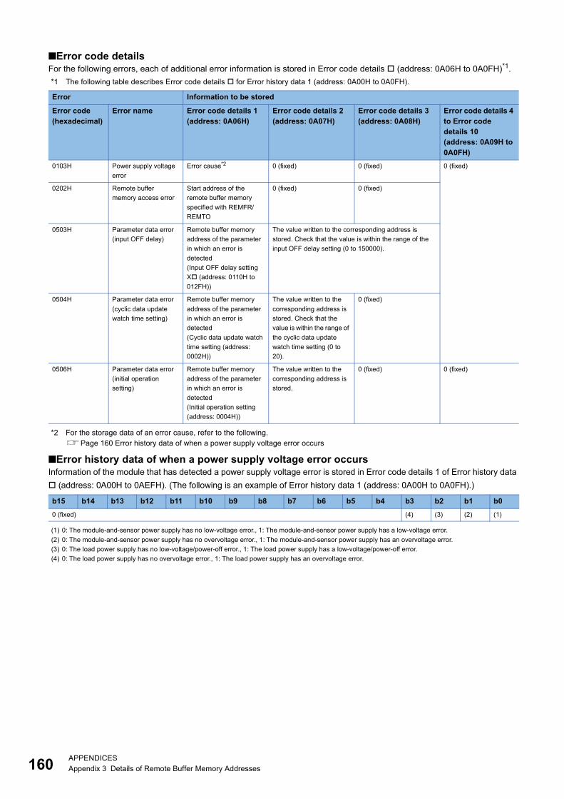
16
■Error code detailsFor the following errors, each of additional error information is stored in Error code details (address: 0A06H to 0A0FH)*1.
*1 The following table describes Error code details for Error history data 1 (address: 0A00H to 0A0FH).
*2 For the storage data of an error cause, refer to the following.Page 160 Error history data of when a power supply voltage error occurs
■Error history data of when a power supply voltage error occursInformation of the module that has detected a power supply voltage error is stored in Error code details 1 of Error history data
(address: 0A00H to 0AEFH). (The following is an example of Error history data 1 (address: 0A00H to 0A0FH).)
Error Information to be stored
Error code(hexadecimal)
Error name Error code details 1(address: 0A06H)
Error code details 2(address: 0A07H)
Error code details 3(address: 0A08H)
Error code details 4 to Error code details 10(address: 0A09H to 0A0FH)
0103H Power supply voltage
error
Error cause*2 0 (fixed) 0 (fixed) 0 (fixed)
0202H Remote buffer
memory access error
Start address of the
remote buffer memory
specified with REMFR/
REMTO
0 (fixed) 0 (fixed)
0503H Parameter data error
(input OFF delay)
Remote buffer memory
address of the parameter
in which an error is
detected
(Input OFF delay setting
X (address: 0110H to
012FH))
The value written to the corresponding address is
stored. Check that the value is within the range of the
input OFF delay setting (0 to 150000).
0504H Parameter data error
(cyclic data update
watch time setting)
Remote buffer memory
address of the parameter
in which an error is
detected
(Cyclic data update watch
time setting (address:
0002H))
The value written to the
corresponding address is
stored. Check that the
value is within the range of
the cyclic data update
watch time setting (0 to
20).
0 (fixed)
0506H Parameter data error
(initial operation
setting)
Remote buffer memory
address of the parameter
in which an error is
detected
(Initial operation setting
(address: 0004H))
The value written to the
corresponding address is
stored.
0 (fixed) 0 (fixed)
b15 b14 b13 b12 b11 b10 b9 b8 b7 b6 b5 b4 b3 b2 b1 b0
0 (fixed) (4) (3) (2) (1)
(1) 0: The module-and-sensor power supply has no low-voltage error., 1: The module-and-sensor power supply has a low-voltage error.
(2) 0: The module-and-sensor power supply has no overvoltage error., 1: The module-and-sensor power supply has an overvoltage error.
(3) 0: The load power supply has no low-voltage/power-off error., 1: The load power supply has a low-voltage/power-off error.
(4) 0: The load power supply has no overvoltage error., 1: The load power supply has an overvoltage error.
0APPENDICESAppendix 3 Details of Remote Buffer Memory Addresses

A
Error history clear commandThe error history stored in the module is cleared.
■Remote buffer memory address
■Operation of error history clearWhen Error history clear command (address: 1000H) is set to Commanded (1), an error history is cleared.
■Default valueThe default value is Not commanded (0).
Error history clear completedThis remote buffer memory area shows whether the error history stored in the module is cleared or not.
■Remote buffer memory address
■Operation of error history clearWhen the error history clear is completed, Error history clear completed (address: 1001H) is turned to Completed (1).
For the timing of turning the bit to Not performed (0) Completed (1) Not performed (0), refer to the following.
Page 161 Error history clear command
■Default valueThe default value is Not performed (0).
b15 b14 b13 b12 b11 b10 b9 b8 b7 b6 b5 b4 b3 b2 b1 b0
0 (fixed) (1)
(1) 0: Not commanded, 1: Commanded
Name Address
Error history clear command 1000H
b15 b14 b13 b12 b11 b10 b9 b8 b7 b6 b5 b4 b3 b2 b1 b0
0 (fixed) (1)
(1) 0: Not performed, 1: Completed
Name Address
Error history clear completed 1001H
Controlled by the I/O module
Stored condition of an error history
Error history clear request(address: 1000H)
Error history clear completed(address: 1001H)
Controlled by the program
An error history is stored. An error history is not stored.
Notcommanded (0) Not commanded (0)Commanded (1)
Not performed (0)Not performed (0) Completed (1)
APPENDICESAppendix 3 Details of Remote Buffer Memory Addresses 161
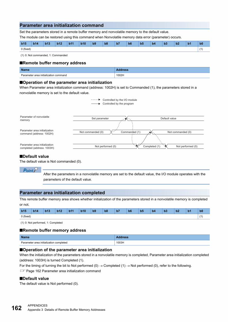
16
Parameter area initialization commandSet the parameters stored in a remote buffer memory and nonvolatile memory to the default value.
The module can be restored using this command when Nonvolatile memory data error (parameter) occurs.
■Remote buffer memory address
■Operation of the parameter area initializationWhen Parameter area initialization command (address: 1002H) is set to Commanded (1), the parameters stored in a
nonvolatile memory is set to the default value.
■Default valueThe default value is Not commanded (0).
After the parameters in a nonvolatile memory are set to the default value, the I/O module operates with the
parameters of the default value.
Parameter area initialization completedThis remote buffer memory area shows whether initialization of the parameters stored in a nonvolatile memory is completed
or not.
■Remote buffer memory address
■Operation of the parameter area initializationWhen the initialization of the parameters stored in a nonvolatile memory is completed, Parameter area initialization completed
(address: 1003H) is turned Completed (1).
For the timing of turning the bit to Not performed (0) Completed (1) Not performed (0), refer to the following.
Page 162 Parameter area initialization command
■Default valueThe default value is Not performed (0).
b15 b14 b13 b12 b11 b10 b9 b8 b7 b6 b5 b4 b3 b2 b1 b0
0 (fixed) (1)
(1) 0: Not commanded, 1: Commanded
Name Address
Parameter area initialization command 1002H
b15 b14 b13 b12 b11 b10 b9 b8 b7 b6 b5 b4 b3 b2 b1 b0
0 (fixed) (1)
(1) 0: Not performed, 1: Completed
Name Address
Parameter area initialization completed 1003H
Controlled by the I/O module
Parameter of nonvolatile memory
Parameter area initialization command (address: 1002H)
Parameter area initialization completed (address: 1003H)
Controlled by the program
Set parameter Default value
Not commanded (0) Not commanded (0)Commanded (1)
Not performed (0)Not performed (0) Completed (1)
2APPENDICESAppendix 3 Details of Remote Buffer Memory Addresses
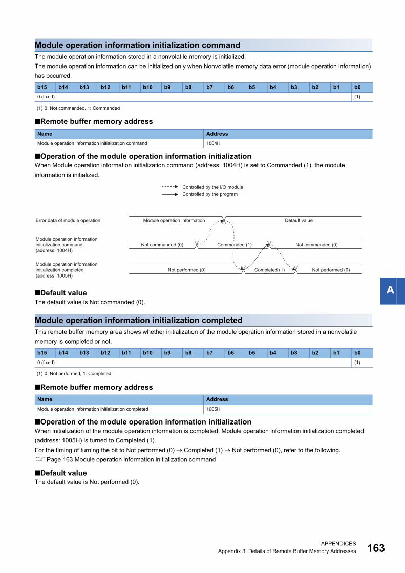
A
Module operation information initialization commandThe module operation information stored in a nonvolatile memory is initialized.
The module operation information can be initialized only when Nonvolatile memory data error (module operation information)
has occurred.
■Remote buffer memory address
■Operation of the module operation information initializationWhen Module operation information initialization command (address: 1004H) is set to Commanded (1), the module
information is initialized.
■Default valueThe default value is Not commanded (0).
Module operation information initialization completedThis remote buffer memory area shows whether initialization of the module operation information stored in a nonvolatile
memory is completed or not.
■Remote buffer memory address
■Operation of the module operation information initializationWhen initialization of the module operation information is completed, Module operation information initialization completed
(address: 1005H) is turned to Completed (1).
For the timing of turning the bit to Not performed (0) Completed (1) Not performed (0), refer to the following.
Page 163 Module operation information initialization command
■Default valueThe default value is Not performed (0).
b15 b14 b13 b12 b11 b10 b9 b8 b7 b6 b5 b4 b3 b2 b1 b0
0 (fixed) (1)
(1) 0: Not commanded, 1: Commanded
Name Address
Module operation information initialization command 1004H
b15 b14 b13 b12 b11 b10 b9 b8 b7 b6 b5 b4 b3 b2 b1 b0
0 (fixed) (1)
(1) 0: Not performed, 1: Completed
Name Address
Module operation information initialization completed 1005H
Controlled by the I/O module
Error data of module operation
Module operation informationinitialization command(address: 1004H)
Module operation informationinitialization completed(address: 1005H)
Controlled by the program
Module operation information Default value
Not commanded (0) Not commanded (0)Commanded (1)
Not performed (0)Not performed (0) Completed (1)
APPENDICESAppendix 3 Details of Remote Buffer Memory Addresses 163
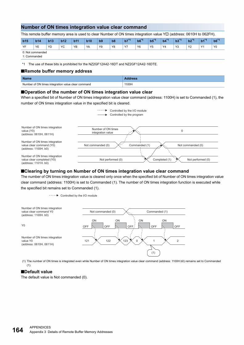
16
Number of ON times integration value clear commandThis remote buffer memory area is used to clear Number of ON times integration value Y (address: 0610H to 062FH).
*1 The use of these bits is prohibited for the NZ2GF12A42-16DT and NZ2GF12A42-16DTE.
■Remote buffer memory address
■Operation of the number of ON times integration value clearWhen a specified bit of Number of ON times integration value clear command (address: 1100H) is set to Commanded (1), the
number of ON times integration value in the specified bit is cleared.
■Clearing by turning on Number of ON times integration value clear commandThe number of ON times integration value is cleared only once when the specified bit of Number of ON times integration value
clear command (address: 1100H) is set to Commanded (1). The number of ON times integration function is executed while
the specified bit remains set to Commanded (1).
■Default valueThe default value is Not commanded (0).
b15 b14 b13 b12 b11 b10 b9 b8 b7*1 b6*1 b5*1 b4*1 b3*1 b2*1 b1*1 b0*1
YF YE YD YC YB YA Y9 Y8 Y7 Y6 Y5 Y4 Y3 Y2 Y1 Y0
0: Not commanded
1: Commanded
Name Address
Number of ON times integration value clear command 1100H
(1) The number of ON times is integrated even while Number of ON times integration value clear command (address: 1100H.b0) remains set to Commanded
(1).
0
Controlled by the I/O module
Number of ON times integrationvalue (Y0)(address: 0610H, 0611H)
Number of ON times integrationvalue clear command (Y0)(address: 1100H. b0)
Number of ON times integrationvalue clear completed (Y0)(address: 1101H. b0)
Controlled by the program
Number of ON times integration value
Not commanded (0)Commanded (1)
Not performed (0) Completed (1) Not performed (0)
Not commanded (0)
121 122 123 0 1 2
OFF OFF
ON
OFF
ON
OFF
ON
OFF
ON
(1)
Y0
Controlled by the I/O module
Number of ON times integration value clear command Y0(address: 1100H. b0)
Number of ON times integration value Y0(address: 0610H, 0611H)
Not commanded (0) Commanded (1)
4APPENDICESAppendix 3 Details of Remote Buffer Memory Addresses
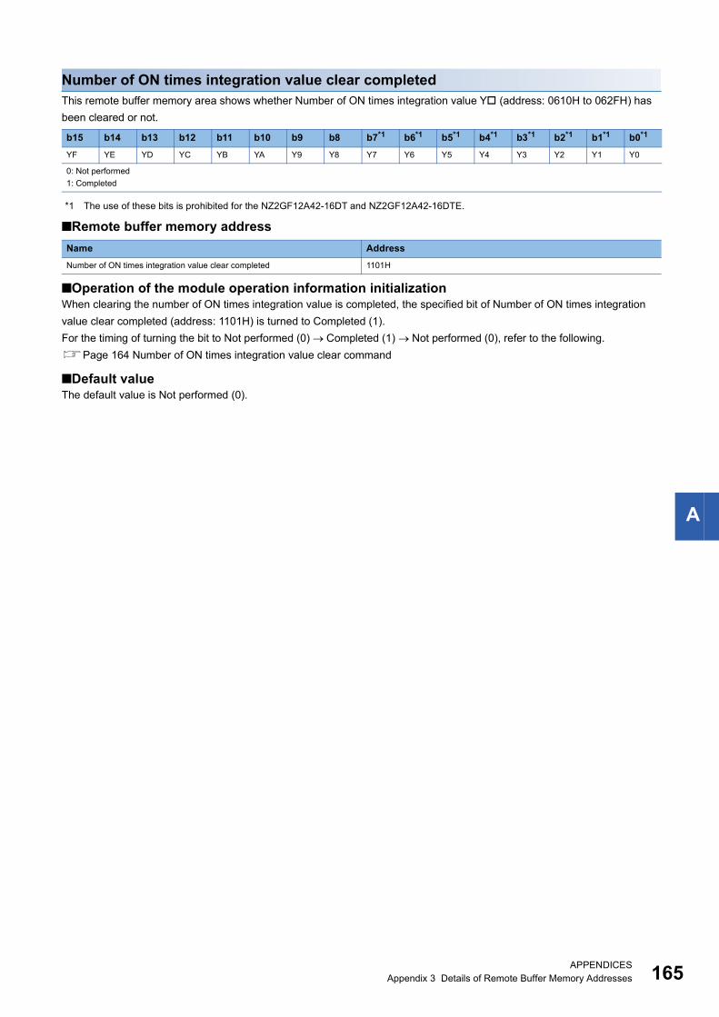
A
Number of ON times integration value clear completedThis remote buffer memory area shows whether Number of ON times integration value Y (address: 0610H to 062FH) has
been cleared or not.
*1 The use of these bits is prohibited for the NZ2GF12A42-16DT and NZ2GF12A42-16DTE.
■Remote buffer memory address
■Operation of the module operation information initializationWhen clearing the number of ON times integration value is completed, the specified bit of Number of ON times integration
value clear completed (address: 1101H) is turned to Completed (1).
For the timing of turning the bit to Not performed (0) Completed (1) Not performed (0), refer to the following.
Page 164 Number of ON times integration value clear command
■Default valueThe default value is Not performed (0).
b15 b14 b13 b12 b11 b10 b9 b8 b7*1 b6*1 b5*1 b4*1 b3*1 b2*1 b1*1 b0*1
YF YE YD YC YB YA Y9 Y8 Y7 Y6 Y5 Y4 Y3 Y2 Y1 Y0
0: Not performed
1: Completed
Name Address
Number of ON times integration value clear completed 1101H
APPENDICESAppendix 3 Details of Remote Buffer Memory Addresses 165
16
Appendix 4 EMC and Low Voltage DirectivesCompliance to the EMC Directive, which is one of the EU Directives, has been a legal obligation for the products sold in
European countries since 1996 as well as the Low Voltage Directive since 1997.
Manufacturers who recognize their products are compliant to the EMC and Low Voltage Directives are required to attach a
"CE mark" on their products.
Sales representative in EU member statesAuthorized representative in EU member states is shown below.
Name: MITSUBISHI ELECTRIC EUROPE B.V.
Address: Mitsubishi-Electric-Platz 1, 40882 Ratingen, Germany
Measures to comply with the EMC DirectiveThe EMC Directive specifies that "products placed on the market must be so constructed that they do not cause excessive
electromagnetic interference (emissions) and are not unduly affected by electromagnetic interference (immunity)".
This section summarizes the precautions on compliance with the EMC Directive of the machinery constructed with the
module.
These precautions are based on the requirements and the standards of the regulation, however, it does not guarantee that the
entire machinery constructed according to the descriptions will comply with abovementioned directives.
The method and judgment for complying with the EMC Directive must be determined by the person who constructs the entire
machinery.
6APPENDICESAppendix 4 EMC and Low Voltage Directives
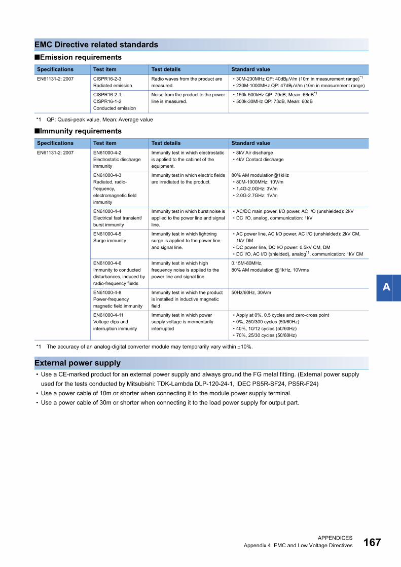
A
EMC Directive related standards
■Emission requirements
*1 QP: Quasi-peak value, Mean: Average value
■Immunity requirements
*1 The accuracy of an analog-digital converter module may temporarily vary within 10%.
External power supply • Use a CE-marked product for an external power supply and always ground the FG metal fitting. (External power supply
used for the tests conducted by Mitsubishi: TDK-Lambda DLP-120-24-1, IDEC PS5R-SF24, PS5R-F24)
• Use a power cable of 10m or shorter when connecting it to the module power supply terminal.
• Use a power cable of 30m or shorter when connecting it to the load power supply for output part.
Specifications Test item Test details Standard value
EN61131-2: 2007 CISPR16-2-3
Radiated emission
Radio waves from the product are
measured.
• 30M-230MHz QP: 40dBV/m (10m in measurement range)*1
• 230M-1000MHz QP: 47dBV/m (10m in measurement range)
CISPR16-2-1,
CISPR16-1-2
Conducted emission
Noise from the product to the power
line is measured.
• 150k-500kHz QP: 79dB, Mean: 66dB*1
• 500k-30MHz QP: 73dB, Mean: 60dB
Specifications Test item Test details Standard value
EN61131-2: 2007 EN61000-4-2
Electrostatic discharge
immunity
Immunity test in which electrostatic
is applied to the cabinet of the
equipment.
• 8kV Air discharge
• 4kV Contact discharge
EN61000-4-3
Radiated, radio-
frequency,
electromagnetic field
immunity
Immunity test in which electric fields
are irradiated to the product.
80% AM modulation@1kHz
• 80M-1000MHz: 10V/m
• 1.4G-2.0GHz: 3V/m
• 2.0G-2.7GHz: 1V/m
EN61000-4-4
Electrical fast transient/
burst immunity
Immunity test in which burst noise is
applied to the power line and signal
line.
• AC/DC main power, I/O power, AC I/O (unshielded): 2kV
• DC I/O, analog, communication: 1kV
EN61000-4-5
Surge immunity
Immunity test in which lightning
surge is applied to the power line
and signal line.
• AC power line, AC I/O power, AC I/O (unshielded): 2kV CM,
1kV DM
• DC power line, DC I/O power: 0.5kV CM, DM
• DC I/O, AC I/O (shielded), analog*1, communication: 1kV CM
EN61000-4-6
Immunity to conducted
disturbances, induced by
radio-frequency fields
Immunity test in which high
frequency noise is applied to the
power line and signal line
0.15M-80MHz,
80% AM modulation @1kHz, 10Vrms
EN61000-4-8
Power-frequency
magnetic field immunity
Immunity test in which the product
is installed in inductive magnetic
field
50Hz/60Hz, 30A/m
EN61000-4-11
Voltage dips and
interruption immunity
Immunity test in which power
supply voltage is momentarily
interrupted
• Apply at 0%, 0.5 cycles and zero-cross point
• 0%, 250/300 cycles (50/60Hz)
• 40%, 10/12 cycles (50/60Hz)
• 70%, 25/30 cycles (50/60Hz)
APPENDICESAppendix 4 EMC and Low Voltage Directives 167
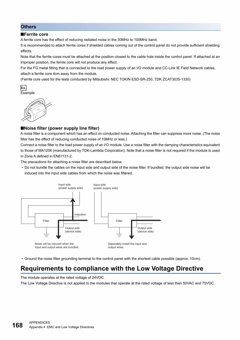
16
Others
■Ferrite coreA ferrite core has the effect of reducing radiated noise in the 30MHz to 100MHz band.
It is recommended to attach ferrite cores if shielded cables coming out of the control panel do not provide sufficient shielding
effects.
Note that the ferrite cores must be attached at the position closest to the cable hole inside the control panel. If attached at an
improper position, the ferrite core will not produce any effect.
For the FG metal fitting that is connected to the load power supply of an I/O module and CC-Link IE Field Network cables,
attach a ferrite core 4cm away from the module.
(Ferrite core used for the tests conducted by Mitsubishi: NEC TOKIN ESD-SR-250, TDK ZCAT3035-1330)
Ex.
Example
■Noise filter (power supply line filter)A noise filter is a component which has an effect on conducted noise. Attaching the filter can suppress more noise. (The noise
filter has the effect of reducing conducted noise of 10MHz or less.)
Connect a noise filter to the load power supply of an I/O module. Use a noise filter with the damping characteristics equivalent
to those of MA1206 (manufactured by TDK-Lambda Corporation). Note that a noise filter is not required if the module is used
in Zone A defined in EN61131-2.
The precautions for attaching a noise filter are described below.
• Do not bundle the cables on the input side and output side of the noise filter. If bundled, the output side noise will be
induced into the input side cables from which the noise was filtered.
• Ground the noise filter grounding terminal to the control panel with the shortest cable possible (approx. 10cm).
Requirements to compliance with the Low Voltage DirectiveThe module operates at the rated voltage of 24VDC.
The Low Voltage Directive is not applied to the modules that operate at the rated voltage of less than 50VAC and 75VDC.
Filter
Induction
Filter
Input side (power supply side)
Input side (power supply side)
Output side (device side)
Output side (device side)
Noise will be induced when the input and output wires are bundled.
Separately install the input and output wires.
8APPENDICESAppendix 4 EMC and Low Voltage Directives
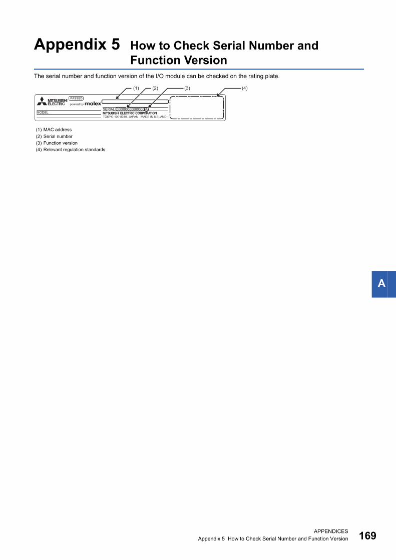
APPENDICESAppendix 5 How to Check Serial Number and Function Version 169
A
Appendix 5 How to Check Serial Number and Function Version
The serial number and function version of the I/O module can be checked on the rating plate.
(1) MAC address
(2) Serial number
(3) Function version
(4) Relevant regulation standards
TOKYO 100-8310. JAPAN MADE IN ILELAND
PASSED
powerd by
MODEL000000000000000-ASERIAL
(4)(3)(2)(1)
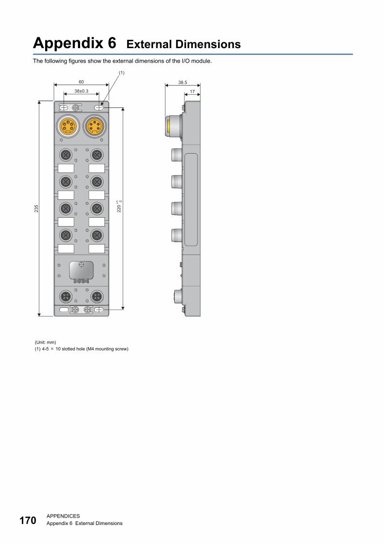
17
Appendix 6 External DimensionsThe following figures show the external dimensions of the I/O module.
(Unit: mm)
(1) 4-5 10 slotted hole (M4 mounting screw)
235
220
60
(1)
38±0.3
+1 0
38.5
17
0APPENDICESAppendix 6 External Dimensions

MEMO
171
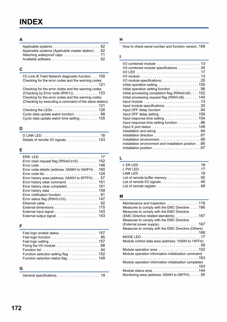
17
INDEX
A
Applicable systems . . . . . . . . . . . . . . . . . . . . . . 62Applicable systems (Applicable master station) . . 62Attaching waterproof caps . . . . . . . . . . . . . . . . . 71Available software. . . . . . . . . . . . . . . . . . . . . . . 62
C
CC-Link IE Field Network diagnostic function . . . 100Checking for the error codes and the warning codes. . . . . . . . . . . . . . . . . . . . . . . . . . . . . . . . . . . 121Checking for the error codes and the warning codes (Checking by Error code (RWr1)) . . . . . . . . . . . 123Checking for the error codes and the warning codes (Checking by executing a command of the slave station). . . . . . . . . . . . . . . . . . . . . . . . . . . . . . . . . . . 121Checking the LEDs . . . . . . . . . . . . . . . . . . . . . 128Cyclic data update watch function. . . . . . . . . . . . 88Cyclic data update watch time setting . . . . . . . . 155
D
D LINK LED . . . . . . . . . . . . . . . . . . . . . . . . . . . 18Details of remote I/O signals . . . . . . . . . . . . . . 143
E
ERR. LED . . . . . . . . . . . . . . . . . . . . . . . . . . . . 17Error clear request flag (RWw0.b10) . . . . . . . . . 152Error code . . . . . . . . . . . . . . . . . . . . . . . . . . . 148Error code details (address: 0A06H to 0A0FH) . . 160Error code list . . . . . . . . . . . . . . . . . . . . . . . . . 124Error history area (address: 0A00H to 0FFFH) . . . 57Error history clear command . . . . . . . . . . . . . . 161Error history clear completed . . . . . . . . . . . . . . 161Error history data . . . . . . . . . . . . . . . . . . . . . . 159Error notification function . . . . . . . . . . . . . . . . . . 81Error status flag (RWr0.b10). . . . . . . . . . . . . . . 147Ethernet cable . . . . . . . . . . . . . . . . . . . . . . . . . 62External dimensions . . . . . . . . . . . . . . . . . . . . 170External input signal . . . . . . . . . . . . . . . . . . . . 143External output signal . . . . . . . . . . . . . . . . . . . 143
F
Fast logic enable status . . . . . . . . . . . . . . . . . . 157Fast logic function . . . . . . . . . . . . . . . . . . . . . . . 95Fast logic setting. . . . . . . . . . . . . . . . . . . . . . . 157Fixing the I/O module . . . . . . . . . . . . . . . . . . . . 68Function list . . . . . . . . . . . . . . . . . . . . . . . . . . . 44Function selection setting flag . . . . . . . . . . . . . 152Function selection status flag . . . . . . . . . . . . . . 149
G
General specifications . . . . . . . . . . . . . . . . . . . . 19
H
How to check serial number and function version .169
I
I/O combined module . . . . . . . . . . . . . . . . . . . . .13I/O combined module specifications . . . . . . . . . . .34I/O LED . . . . . . . . . . . . . . . . . . . . . . . . . . . . . . .17I/O module. . . . . . . . . . . . . . . . . . . . . . . . . . . . .13I/O module specifications. . . . . . . . . . . . . . . . . . .20Initial operation setting . . . . . . . . . . . . . . . . . . .155Initial operation setting function . . . . . . . . . . . . . .98Initial processing completion flag (RWw0.b8) . . . .152Initial processing request flag (RWr0.b8) . . . . . . .144Input module . . . . . . . . . . . . . . . . . . . . . . . . . . .13Input module specifications . . . . . . . . . . . . . . . . .20Input OFF delay function . . . . . . . . . . . . . . . . . . .84Input OFF delay setting . . . . . . . . . . . . . . . . . . .156Input response time setting . . . . . . . . . . . . . . . .154Input response time setting function . . . . . . . . . . .86Input X port status . . . . . . . . . . . . . . . . . . . . . .149Installation and wiring . . . . . . . . . . . . . . . . . . . . .64Installation direction . . . . . . . . . . . . . . . . . . . . . .67Installation environment. . . . . . . . . . . . . . . . . . . .66Installation environment and installation position . .66Installation position . . . . . . . . . . . . . . . . . . . . . . .67
L
L ER LED . . . . . . . . . . . . . . . . . . . . . . . . . . . . .18L PW LED . . . . . . . . . . . . . . . . . . . . . . . . . . . . .17LINK LED . . . . . . . . . . . . . . . . . . . . . . . . . . . . .18List of remote buffer memory . . . . . . . . . . . . . . . .50List of remote I/O signals . . . . . . . . . . . . . . . . . . .46List of remote register . . . . . . . . . . . . . . . . . . . . .48
M
Maintenance and inspection . . . . . . . . . . . . . . .119Measures to comply with the EMC Directive . . . .166Measures to comply with the EMC Directive (EMC Directive related standards) . . . . . . . . . . .167Measures to comply with the EMC Directive (External power supply). . . . . . . . . . . . . . . . . . .167Measures to comply with the EMC Directive (Others). . . . . . . . . . . . . . . . . . . . . . . . . . . . . . . . . . . .168MODE LED . . . . . . . . . . . . . . . . . . . . . . . . . . . .17Module control data area (address: 1000H to 14FFH). . . . . . . . . . . . . . . . . . . . . . . . . . . . . . . . . . . . .58Module operation area . . . . . . . . . . . . . . . . . . .152Module operation information initialization command. . . . . . . . . . . . . . . . . . . . . . . . . . . . . . . . . . . .163Module operation information initialization completed. . . . . . . . . . . . . . . . . . . . . . . . . . . . . . . . . . . .163Module status area . . . . . . . . . . . . . . . . . . . . . .144Monitoring area (address: 0500H to 09FFH) . . . . .55
2
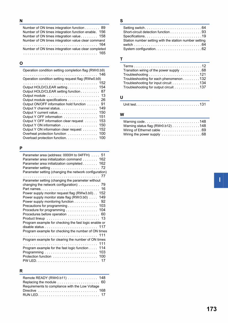
I
N
Number of ON times integration function . . . . . . . 89Number of ON times integration function enable. 156Number of ON times integration value . . . . . . . . 158Number of ON times integration value clear command. . . . . . . . . . . . . . . . . . . . . . . . . . . . . . . . . . . 164Number of ON times integration value clear completed. . . . . . . . . . . . . . . . . . . . . . . . . . . . . . . . . . . 165
O
Operation condition setting completion flag (RWr0.b9). . . . . . . . . . . . . . . . . . . . . . . . . . . . . . . . . . . 146Operation condition setting request flag (RWw0.b9). . . . . . . . . . . . . . . . . . . . . . . . . . . . . . . . . . . 152Output HOLD/CLEAR setting . . . . . . . . . . . . . . 154Output HOLD/CLEAR setting function . . . . . . . . . 87Output module . . . . . . . . . . . . . . . . . . . . . . . . . 13Output module specifications . . . . . . . . . . . . . . . 26Output ON/OFF information hold function . . . . . . 91Output Y channel status. . . . . . . . . . . . . . . . . . 149Output Y current value. . . . . . . . . . . . . . . . . . . 150Output Y OFF information . . . . . . . . . . . . . . . . 151Output Y OFF information clear request . . . . . . 153Output Y ON information . . . . . . . . . . . . . . . . . 150Output Y ON information clear request . . . . . . . 152Overheat protection function . . . . . . . . . . . . . . 100Overload protection function. . . . . . . . . . . . . . . 100
P
Parameter area (address: 0000H to 04FFH) . . . . 51Parameter area initialization command . . . . . . . 162Parameter area initialization completed . . . . . . . 162Parameter setting . . . . . . . . . . . . . . . . . . . . . . . 72Parameter setting (changing the network configuration). . . . . . . . . . . . . . . . . . . . . . . . . . . . . . . . . . . . 77Parameter setting (changing the parameter without changing the network configuration) . . . . . . . . . . 79Part names. . . . . . . . . . . . . . . . . . . . . . . . . . . . 16Power supply monitor request flag (RWw3.b0) . . 152Power supply monitor state flag (RWr3.b0) . . . . 149Power supply monitoring function . . . . . . . . . . . . 92Precautions for programming . . . . . . . . . . . . . . 103Procedure for programming . . . . . . . . . . . . . . . 104Procedures before operation . . . . . . . . . . . . . . . 60Product lineup . . . . . . . . . . . . . . . . . . . . . . . . . 13Program example for checking the fast logic enable or disable status . . . . . . . . . . . . . . . . . . . . . . . . . 117Program example for checking the number of ON times. . . . . . . . . . . . . . . . . . . . . . . . . . . . . . . . . . . 111Program example for clearing the number of ON times. . . . . . . . . . . . . . . . . . . . . . . . . . . . . . . . . . . 111Program example for the fast logic function . . . . 114Programming . . . . . . . . . . . . . . . . . . . . . . . . . 103Protection function . . . . . . . . . . . . . . . . . . . . . 100PW LED. . . . . . . . . . . . . . . . . . . . . . . . . . . . . . 17
R
Remote READY (RWr0.b11) . . . . . . . . . . . . . . 148Replacing the module . . . . . . . . . . . . . . . . . . . . 60Requirements to compliance with the Low Voltage Directive . . . . . . . . . . . . . . . . . . . . . . . . . . . . 168RUN LED. . . . . . . . . . . . . . . . . . . . . . . . . . . . . 17
S
Setting switch. . . . . . . . . . . . . . . . . . . . . . . . . . .64Short-circuit detection function . . . . . . . . . . . . . . .93Specifications. . . . . . . . . . . . . . . . . . . . . . . . . . .19Station number setting with the station number setting switch . . . . . . . . . . . . . . . . . . . . . . . . . . . . . . . .64System configuration. . . . . . . . . . . . . . . . . . . . . .62
T
Terms . . . . . . . . . . . . . . . . . . . . . . . . . . . . . . . .12Transition wiring of the power supply . . . . . . . . . .68Troubleshooting . . . . . . . . . . . . . . . . . . . . . . . .121Troubleshooting for each phenomenon . . . . . . . .132Troubleshooting for input circuit . . . . . . . . . . . . .134Troubleshooting for output circuit . . . . . . . . . . . .137
U
Unit test. . . . . . . . . . . . . . . . . . . . . . . . . . . . . .131
W
Warning code. . . . . . . . . . . . . . . . . . . . . . . . . .148Warning status flag (RWr0.b12) . . . . . . . . . . . . .148Wiring of Ethernet cable . . . . . . . . . . . . . . . . . . .69Wiring the power supply . . . . . . . . . . . . . . . . . . .68
173
174
REVISIONS*The manual number is given on the bottom left of the back cover.
Japanese manual number: SH-081636-B
2017 MITSUBISHI ELECTRIC CORPORATION
Print date *Manual number Revision
February 2017 SH(NA)-081637ENG-A First edition
July 2017 SH(NA)-081637ENG-B Added or modified part
Chapter 2
This manual confers no industrial property rights or any rights of any other kind, nor does it confer any patent licenses. Mitsubishi Electric Corporation cannot
be held responsible for any problems involving industrial property rights which may occur as a result of using the contents noted in this manual.
175
WARRANTY
Please confirm the following product warranty details before using this product.
1. Gratis Warranty Term and Gratis Warranty RangeIf any faults or defects (hereinafter "Failure") found to be the responsibility of Mitsubishi occurs during use of the product within the gratis warranty term, the product shall be replaced at no cost via the sales representative.However, if on-site service are required at domestic or overseas location, expenses to send an engineer will be solely at the customer's discretion. Mitsubishi shall not be held responsible for any re-commissioning, maintenance, or testing on-site that involves replacement of the failed module.[Gratis Warranty Term]The gratis warranty term of the product shall be for one year after the date of purchase or delivery to a designated place.Note that after manufacture and shipment from Mitsubishi, the maximum distribution period shall be six (6) months, and the longest gratis warranty term after manufacturing shall be eighteen (18) months. The gratis warranty term of replacement shall not exceed the gratis warranty term before product exchange.[Gratis Warranty Range](1) The range shall be limited to normal use within the usage state, usage methods and usage environment, etc., which
follow the conditions and precautions, etc., given in the instruction manual, user's manual and caution labels on the product.
(2) Even within the gratis warranty term, replacement shall be charged for in the following cases.1. Failure occurring from inappropriate storage or handling, carelessness or negligence by the user. Failure caused
by the user's hardware or software design.2. Failure caused by unapproved modifications, etc., to the product by the user.3. When the Mitsubishi product is assembled into a user's device, Failure that could have been avoided if functions
or structures, judged as necessary in the legal safety measures the user's device is subject to or as necessary by industry standards, had been provided.
4. Failure that could have been avoided if consumable parts (battery, backlight, fuse, etc.) designated in the instruction manual had been correctly serviced or replaced.
5. Failure caused by external irresistible forces such as fires or abnormal voltages, and Failure caused by force majeure such as earthquakes, lightning, wind and water damage.
6. Failure caused by reasons unpredictable by scientific technology standards at time of shipment from Mitsubishi.7. Any other failure found not to be the responsibility of Mitsubishi or that admitted not to be so by the user.
2. Repair and AnalysisPlease note that repairs and failure analysis are refused due to the structure of this product.
3. Discontinuation of production(1) Discontinuation of production shall be notified with Mitsubishi Technical Bulletins, etc.(2) Product supply (including repair parts) is not available after production is discontinued.
4. Overseas serviceOverseas, please contact Mitsubishi's local overseas FA Center.
5. Exclusion of loss in opportunity and secondary loss from warranty liabilityRegardless of the gratis warranty term, Mitsubishi shall not be liable for compensation to:(1) Damages caused by any cause found not to be the responsibility of Mitsubishi.(2) Loss in opportunity, lost profits incurred to the user by Failures of Mitsubishi products.(3) Special damages and secondary damages whether foreseeable or not, compensation for accidents, and
compensation for damages to products other than Mitsubishi products.(4) Replacement by the user, maintenance of on-site equipment, start-up test run and other tasks.
6. Changes in product specificationsThe specifications given in the catalogs, manuals or technical documents are subject to change without prior notice.

176
TRADEMARKSEthernet is a registered trademark of Fuji Xerox Co., Ltd. in Japan.
The company names, system names and product names mentioned in this manual are either registered trademarks or
trademarks of their respective companies.
In some cases, trademark symbols such as '' or '' are not specified in this manual.
SH(NA)-081637ENG-B


SH(NA)-081637ENG-B(1707)MEE
MODEL: CCIEF-WD-IO-U-E
MODEL CODE: 13JX54
Molex, LLC www.molex.com
Specifications subject to change without notice.
When exported from Japan, this manual does not require application to theMinistry of Economy, Trade and Industry for service transaction permission.
HEAD OFFICE : TOKYO BUILDING, 2-7-3 MARUNOUCHI, CHIYODA-KU, TOKYO 100-8310, JAPANNAGOYA WORKS : 1-14 , YADA-MINAMI 5-CHOME , HIGASHI-KU, NAGOYA , JAPAN