Embed Size (px)
Citation preview
Crownhill Associates
smart electronic solut ions
Cell MONITOR
MK III
Firmware Revision 1.5
Cell Monitor MK III
2 of 19 Copyright Crownhill Associates 2005 All rights reserved
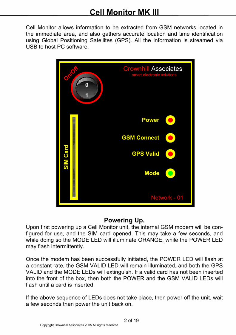
Cell Monitor allows information to be extracted from GSM networks located in the immediate area, and also gathers accurate location and time identification using Global Positioning Satellites (GPS). All the information is streamed via USB to host PC software.
Powering Up. Upon first powering up a Cell Monitor unit, the internal GSM modem will be con-figured for use, and the SIM card opened. This may take a few seconds, and while doing so the MODE LED will illuminate ORANGE, while the POWER LED may flash intermittently. Once the modem has been successfully initiated, the POWER LED will flash at a constant rate, the GSM VALID LED will remain illuminated, and both the GPS VALID and the MODE LEDs will extinguish. If a valid card has not been inserted into the front of the box, then both the POWER and the GSM VALID LEDs will flash until a card is inserted. If the above sequence of LEDs does not take place, then power off the unit, wait a few seconds than power the unit back on.
On/Off
0
1
Power
GSM Connect
GPS Valid
Mode
SIM
Car
dCrownhill Associates
smart electronic solutions
Network - 01
Cell Monitor MK III
3 of 19 Copyright Crownhill Associates 2005 All rights reserved
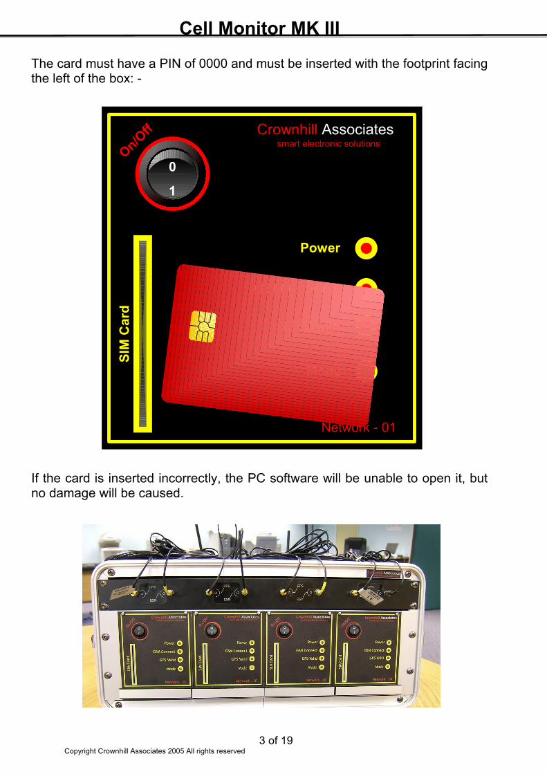
The card must have a PIN of 0000 and must be inserted with the footprint facing the left of the box: - If the card is inserted incorrectly, the PC software will be unable to open it, but no damage will be caused.
On/Off
0
1
Power
GSM Connect
GPS Valid
Mode
SIM
Car
dCrownhill Associates
smart electronic solutions
Network - 01
Cell Monitor MK III
4 of 19 Copyright Crownhill Associates 2005 All rights reserved
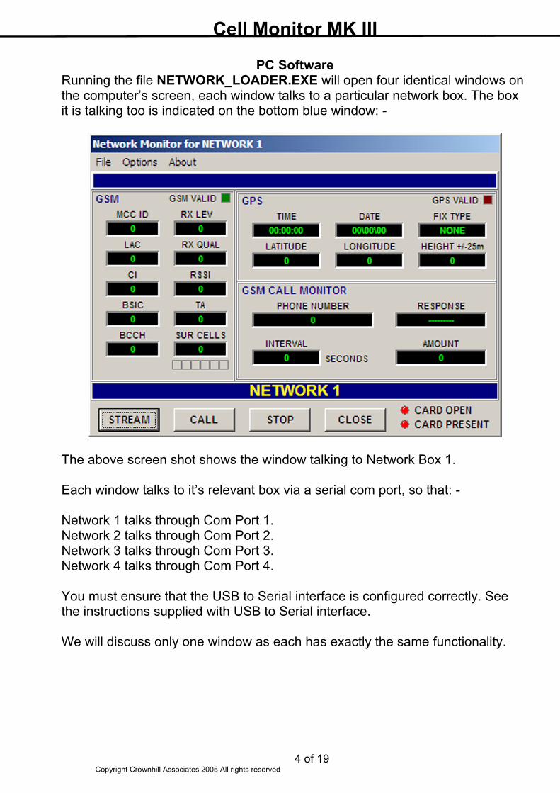
PC Software Running the file NETWORK_LOADER.EXE will open four identical windows on the computer’s screen, each window talks to a particular network box. The box it is talking too is indicated on the bottom blue window: - The above screen shot shows the window talking to Network Box 1. Each window talks to it’s relevant box via a serial com port, so that: - Network 1 talks through Com Port 1. Network 2 talks through Com Port 2. Network 3 talks through Com Port 3. Network 4 talks through Com Port 4. You must ensure that the USB to Serial interface is configured correctly. See the instructions supplied with USB to Serial interface. We will discuss only one window as each has exactly the same functionality.
Cell Monitor MK III
5 of 19 Copyright Crownhill Associates 2005 All rights reserved
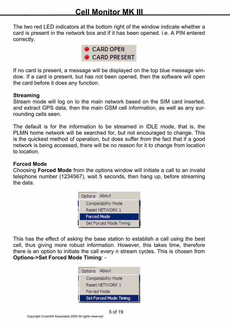
The two red LED indicators at the bottom right of the window indicate whether a card is present in the network box and if it has been opened. i.e. A PIN entered correctly. If no card is present, a message will be displayed on the top blue message win-dow. If a card is present, but has not been opened, then the software will open the card before it does any function. Streaming Stream mode will log on to the main network based on the SIM card inserted, and extract GPS data, then the main GSM cell information, as well as any sur-rounding cells seen. The default is for the information to be streamed in IDLE mode, that is, the PLMN home network will be searched for, but not encouraged to change. This is the quickest method of operation, but does suffer from the fact that if a good network is being accessed, there will be no reason for it to change from location to location. Forced Mode Choosing Forced Mode from the options window will initiate a call to an invalid telephone number (1234567), wait 5 seconds, then hang up, before streaming the data. This has the effect of asking the base station to establish a call using the best cell, thus giving more robust information. However, this takes time, therefore there is an option to initiate the call every n stream cycles. This is chosen from Options->Set Forced Mode Timing: -
Cell Monitor MK III
6 of 19 Copyright Crownhill Associates 2005 All rights reserved
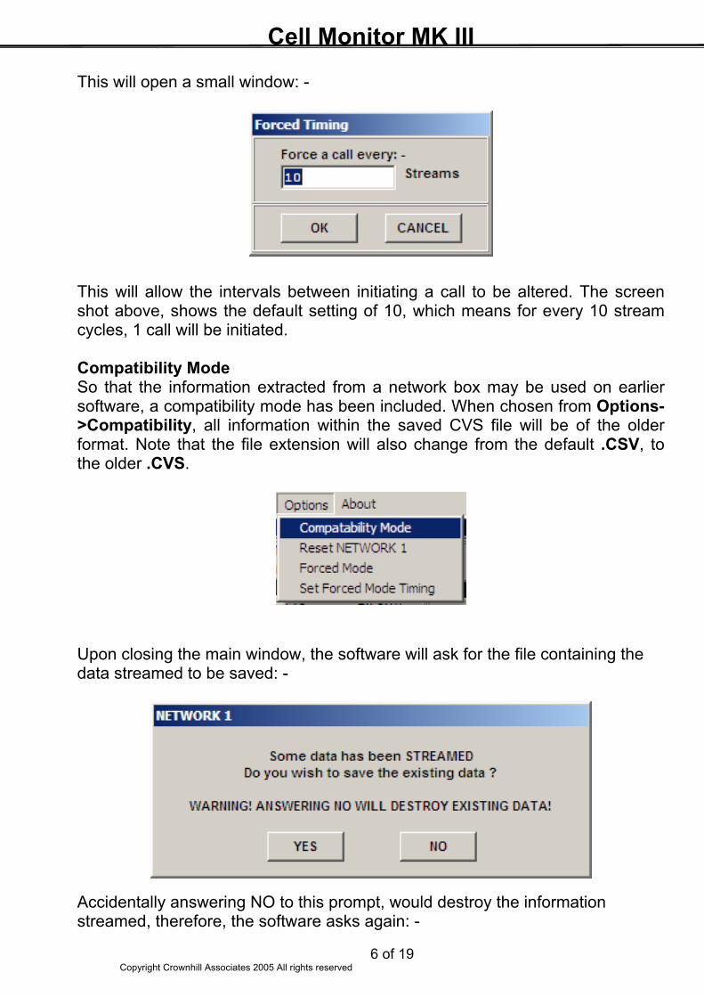
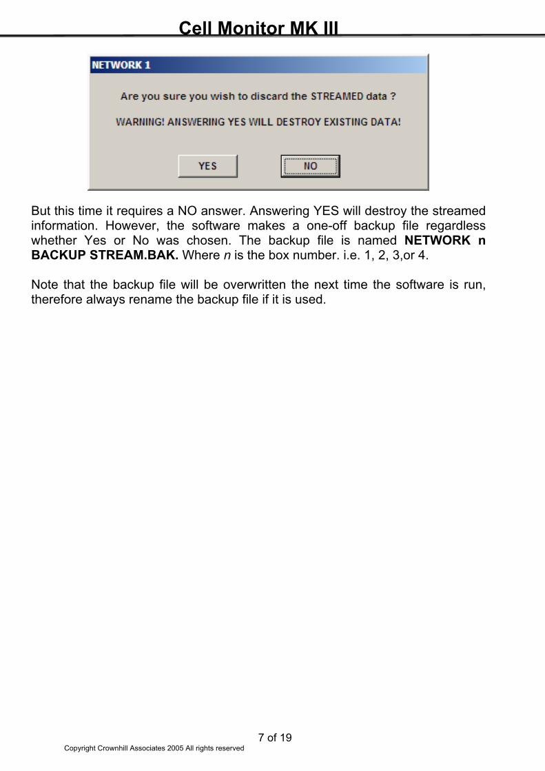
This will open a small window: - This will allow the intervals between initiating a call to be altered. The screen shot above, shows the default setting of 10, which means for every 10 stream cycles, 1 call will be initiated. Compatibility Mode So that the information extracted from a network box may be used on earlier software, a compatibility mode has been included. When chosen from Options->Compatibility, all information within the saved CVS file will be of the older format. Note that the file extension will also change from the default .CSV, to the older .CVS. Upon closing the main window, the software will ask for the file containing the data streamed to be saved: - Accidentally answering NO to this prompt, would destroy the information streamed, therefore, the software asks again: -
Cell Monitor MK III
7 of 19 Copyright Crownhill Associates 2005 All rights reserved
But this time it requires a NO answer. Answering YES will destroy the streamed information. However, the software makes a one-off backup file regardless whether Yes or No was chosen. The backup file is named NETWORK n BACKUP STREAM.BAK. Where n is the box number. i.e. 1, 2, 3,or 4. Note that the backup file will be overwritten the next time the software is run, therefore always rename the backup file if it is used.
Cell Monitor MK III
8 of 19 Copyright Crownhill Associates 2005 All rights reserved
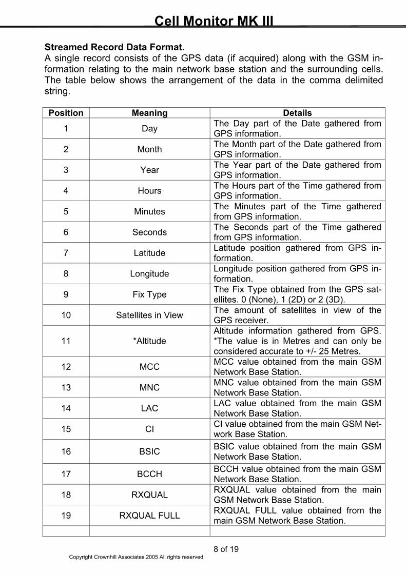
Streamed Record Data Format. A single record consists of the GPS data (if acquired) along with the GSM in-formation relating to the main network base station and the surrounding cells. The table below shows the arrangement of the data in the comma delimited string. Position Meaning Details
1 Day The Day part of the Date gathered from GPS information.
2 Month The Month part of the Date gathered from GPS information.
3 Year The Year part of the Date gathered from GPS information.
4 Hours The Hours part of the Time gathered from GPS information.
5 Minutes The Minutes part of the Time gathered from GPS information.
6 Seconds The Seconds part of the Time gathered from GPS information.
7 Latitude Latitude position gathered from GPS in-formation.
8 Longitude Longitude position gathered from GPS in-formation.
9 Fix Type The Fix Type obtained from the GPS sat-ellites. 0 (None), 1 (2D) or 2 (3D).
10 Satellites in View The amount of satellites in view of the GPS receiver.
11 *Altitude Altitude information gathered from GPS. *The value is in Metres and can only be considered accurate to +/- 25 Metres.
12 MCC MCC value obtained from the main GSM Network Base Station.
13 MNC MNC value obtained from the main GSM Network Base Station.
14 LAC LAC value obtained from the main GSM Network Base Station.
15 CI CI value obtained from the main GSM Net-work Base Station.
16 BSIC BSIC value obtained from the main GSM Network Base Station.
17 BCCH BCCH value obtained from the main GSM Network Base Station.
18 RXQUAL RXQUAL value obtained from the main GSM Network Base Station.
19 RXQUAL FULL RXQUAL FULL value obtained from the main GSM Network Base Station.
Cell Monitor MK III
9 of 19 Copyright Crownhill Associates 2005 All rights reserved
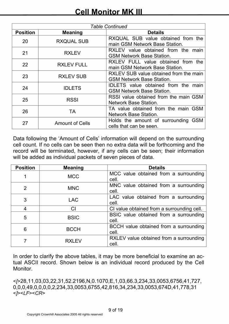
Table Continued Position Meaning Details
20 RXQUAL SUB RXQUAL SUB value obtained from the main GSM Network Base Station.
21 RXLEV RXLEV value obtained from the main GSM Network Base Station.
22 RXLEV FULL RXLEV FULL value obtained from the main GSM Network Base Station.
23 RXLEV SUB RXLEV SUB value obtained from the main GSM Network Base Station.
24 IDLETS IDLETS value obtained from the main GSM Network Base Station.
25 RSSI RSSI value obtained from the main GSM Network Base Station.
26 TA TA value obtained from the main GSM Network Base Station.
27 Amount of Cells Holds the amount of surrounding GSM cells that can be seen.
Data following the ‘Amount of Cells’ information will depend on the surrounding cell count. If no cells can be seen then no extra data will be forthcoming and the record will be terminated, however, if any cells can be seen; their information will be added as individual packets of seven pieces of data. Position Meaning Details
1 MCC MCC value obtained from a surrounding cell.
2 MNC MNC value obtained from a surrounding cell.
3 LAC LAC value obtained from a surrounding cell.
4 CI CI value obtained from a surrounding cell.
5 BSIC BSIC value obtained from a surrounding cell.
6 BCCH BCCH value obtained from a surrounding cell.
7 RXLEV RXLEV value obtained from a surrounding cell.
In order to clarify the above tables, it may be more beneficial to examine an ac-tual ASCII record. Shown below is an individual record produced by the Cell Monitor. <[>28,11,03,03,22,31,52.2196,N,0.1070,E,1,03,66.3,234,33,0053,6756,41,727,0,0,0,49,0,0,0,0,2,234,33,0053,6755,42,816,34,234,33,0053,674D,41,778,31 <]><LF><CR>
Cell Monitor MK III
10 of 19 Copyright Crownhill Associates 2005 All rights reserved
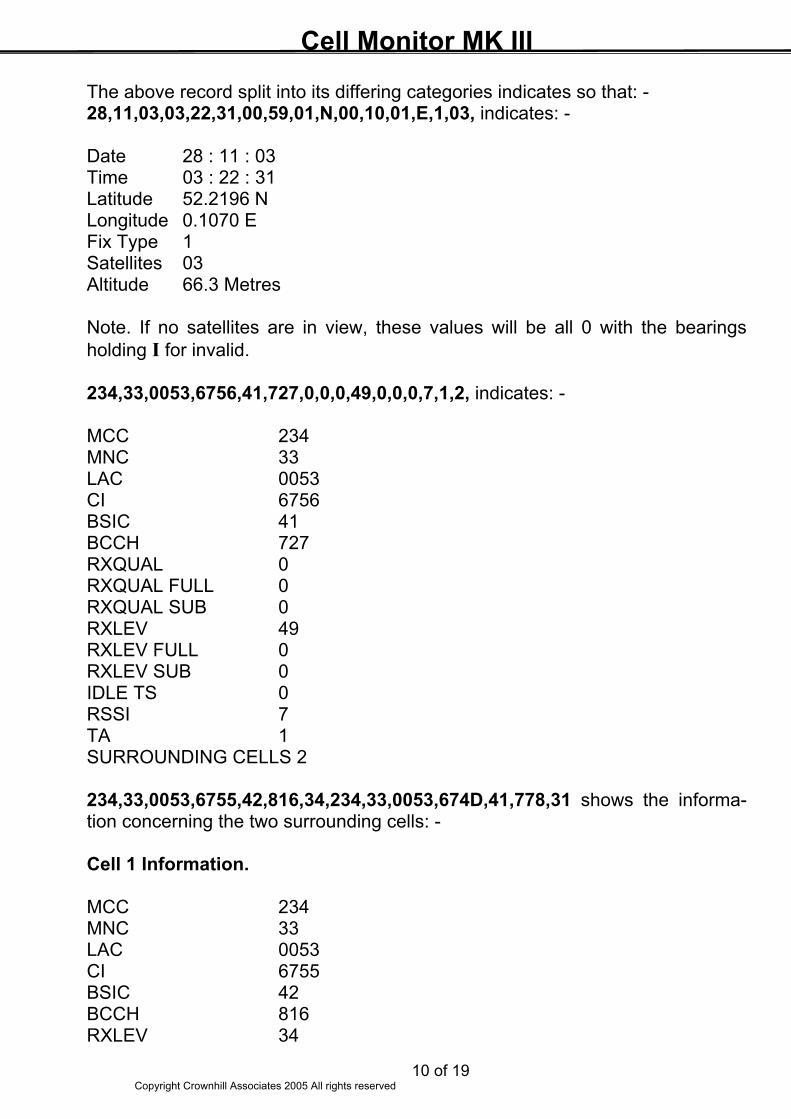
The above record split into its differing categories indicates so that: - 28,11,03,03,22,31,00,59,01,N,00,10,01,E,1,03, indicates: - Date 28 : 11 : 03 Time 03 : 22 : 31 Latitude 52.2196 N Longitude 0.1070 E Fix Type 1 Satellites 03 Altitude 66.3 Metres Note. If no satellites are in view, these values will be all 0 with the bearings holding I for invalid. 234,33,0053,6756,41,727,0,0,0,49,0,0,0,7,1,2, indicates: - MCC 234 MNC 33 LAC 0053 CI 6756 BSIC 41 BCCH 727 RXQUAL 0 RXQUAL FULL 0 RXQUAL SUB 0 RXLEV 49 RXLEV FULL 0 RXLEV SUB 0 IDLE TS 0 RSSI 7 TA 1 SURROUNDING CELLS 2 234,33,0053,6755,42,816,34,234,33,0053,674D,41,778,31 shows the informa-tion concerning the two surrounding cells: - Cell 1 Information. MCC 234 MNC 33 LAC 0053 CI 6755 BSIC 42 BCCH 816 RXLEV 34
Cell Monitor MK III
11 of 19 Copyright Crownhill Associates 2005 All rights reserved
Cell 2 Information. MCC 234 MNC 33 LAC 0053 CI 674D BSIC 41 BCCH 778 RXLEV 31
Cell Monitor MK III
12 of 19 Copyright Crownhill Associates 2005 All rights reserved
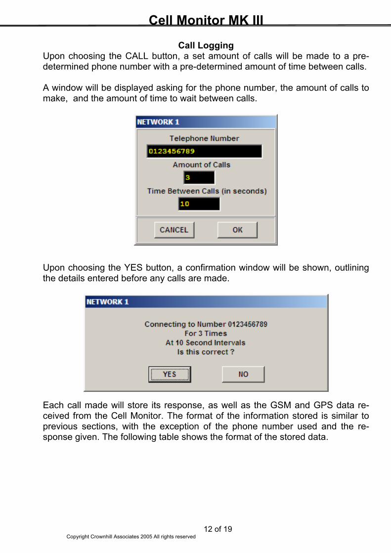
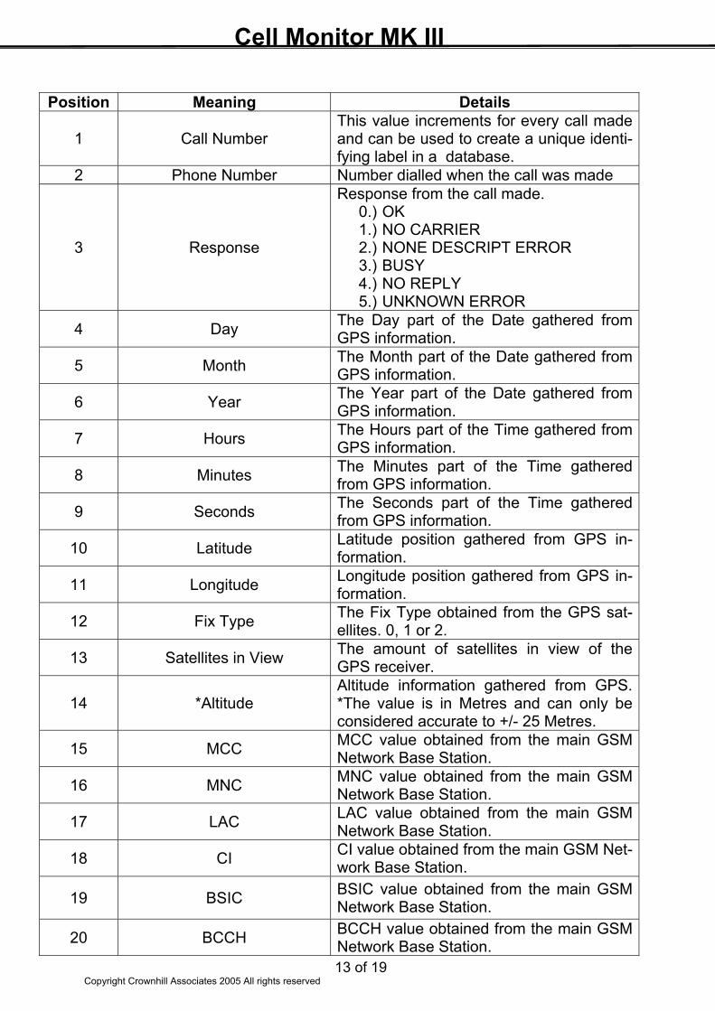
Call Logging Upon choosing the CALL button, a set amount of calls will be made to a pre-determined phone number with a pre-determined amount of time between calls. A window will be displayed asking for the phone number, the amount of calls to make, and the amount of time to wait between calls. Upon choosing the YES button, a confirmation window will be shown, outlining the details entered before any calls are made. Each call made will store its response, as well as the GSM and GPS data re-ceived from the Cell Monitor. The format of the information stored is similar to previous sections, with the exception of the phone number used and the re-sponse given. The following table shows the format of the stored data.
Cell Monitor MK III
13 of 19 Copyright Crownhill Associates 2005 All rights reserved
Position Meaning Details
1 Call Number This value increments for every call made and can be used to create a unique identi-fying label in a database.
2 Phone Number Number dialled when the call was made
3 Response
Response from the call made. 0.) OK 1.) NO CARRIER 2.) NONE DESCRIPT ERROR 3.) BUSY 4.) NO REPLY 5.) UNKNOWN ERROR
4 Day The Day part of the Date gathered from GPS information.
5 Month The Month part of the Date gathered from GPS information.
6 Year The Year part of the Date gathered from GPS information.
7 Hours The Hours part of the Time gathered from GPS information.
8 Minutes The Minutes part of the Time gathered from GPS information.
9 Seconds The Seconds part of the Time gathered from GPS information.
10 Latitude Latitude position gathered from GPS in-formation.
11 Longitude Longitude position gathered from GPS in-formation.
12 Fix Type The Fix Type obtained from the GPS sat-ellites. 0, 1 or 2.
13 Satellites in View The amount of satellites in view of the GPS receiver.
14 *Altitude Altitude information gathered from GPS. *The value is in Metres and can only be considered accurate to +/- 25 Metres.
15 MCC MCC value obtained from the main GSM Network Base Station.
16 MNC MNC value obtained from the main GSM Network Base Station.
17 LAC LAC value obtained from the main GSM Network Base Station.
18 CI CI value obtained from the main GSM Net-work Base Station.
19 BSIC BSIC value obtained from the main GSM Network Base Station.
20 BCCH BCCH value obtained from the main GSM Network Base Station.
Cell Monitor MK III
14 of 19 Copyright Crownhill Associates 2005 All rights reserved
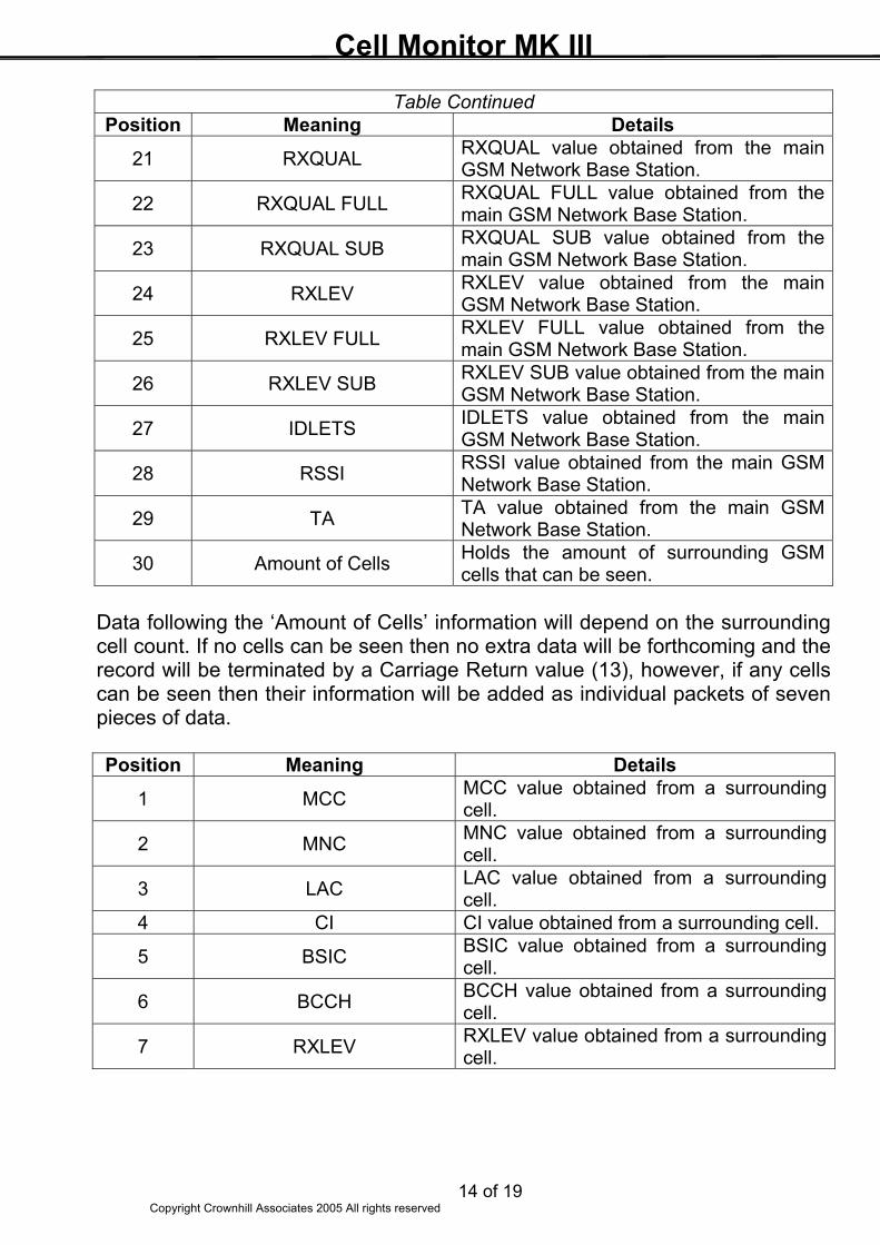
Table Continued Position Meaning Details
21 RXQUAL RXQUAL value obtained from the main GSM Network Base Station.
22 RXQUAL FULL RXQUAL FULL value obtained from the main GSM Network Base Station.
23 RXQUAL SUB RXQUAL SUB value obtained from the main GSM Network Base Station.
24 RXLEV RXLEV value obtained from the main GSM Network Base Station.
25 RXLEV FULL RXLEV FULL value obtained from the main GSM Network Base Station.
26 RXLEV SUB RXLEV SUB value obtained from the main GSM Network Base Station.
27 IDLETS IDLETS value obtained from the main GSM Network Base Station.
28 RSSI RSSI value obtained from the main GSM Network Base Station.
29 TA TA value obtained from the main GSM Network Base Station.
30 Amount of Cells Holds the amount of surrounding GSM cells that can be seen.
Data following the ‘Amount of Cells’ information will depend on the surrounding cell count. If no cells can be seen then no extra data will be forthcoming and the record will be terminated by a Carriage Return value (13), however, if any cells can be seen then their information will be added as individual packets of seven pieces of data. Position Meaning Details
1 MCC MCC value obtained from a surrounding cell.
2 MNC MNC value obtained from a surrounding cell.
3 LAC LAC value obtained from a surrounding cell.
4 CI CI value obtained from a surrounding cell.
5 BSIC BSIC value obtained from a surrounding cell.
6 BCCH BCCH value obtained from a surrounding cell.
7 RXLEV RXLEV value obtained from a surrounding cell.
Cell Monitor MK III
15 of 19 Copyright Crownhill Associates 2005 All rights reserved
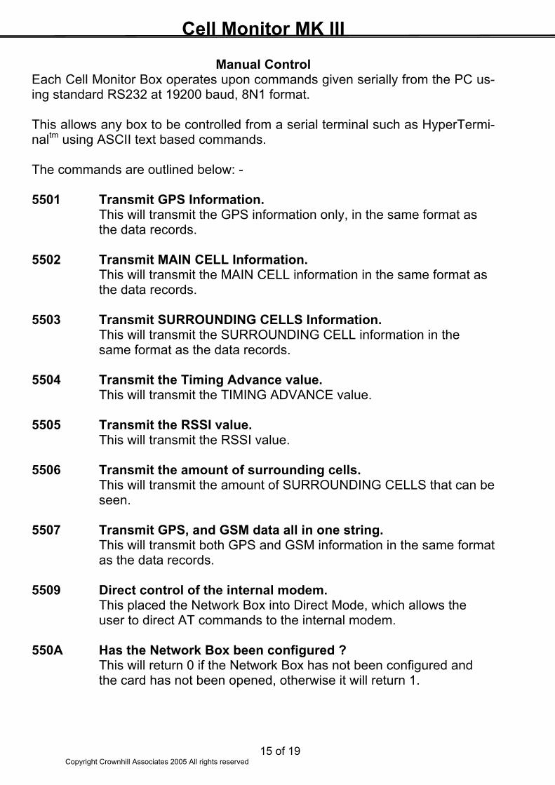
Manual Control Each Cell Monitor Box operates upon commands given serially from the PC us-ing standard RS232 at 19200 baud, 8N1 format. This allows any box to be controlled from a serial terminal such as HyperTermi-naltm using ASCII text based commands. The commands are outlined below: - 5501 Transmit GPS Information. This will transmit the GPS information only, in the same format as the data records. 5502 Transmit MAIN CELL Information. This will transmit the MAIN CELL information in the same format as the data records. 5503 Transmit SURROUNDING CELLS Information. This will transmit the SURROUNDING CELL information in the same format as the data records. 5504 Transmit the Timing Advance value. This will transmit the TIMING ADVANCE value. 5505 Transmit the RSSI value. This will transmit the RSSI value. 5506 Transmit the amount of surrounding cells. This will transmit the amount of SURROUNDING CELLS that can be seen. 5507 Transmit GPS, and GSM data all in one string. This will transmit both GPS and GSM information in the same format
as the data records. 5509 Direct control of the internal modem. This placed the Network Box into Direct Mode, which allows the user to direct AT commands to the internal modem. 550A Has the Network Box been configured ? This will return 0 if the Network Box has not been configured and the card has not been opened, otherwise it will return 1.
Cell Monitor MK III
16 of 19 Copyright Crownhill Associates 2005 All rights reserved
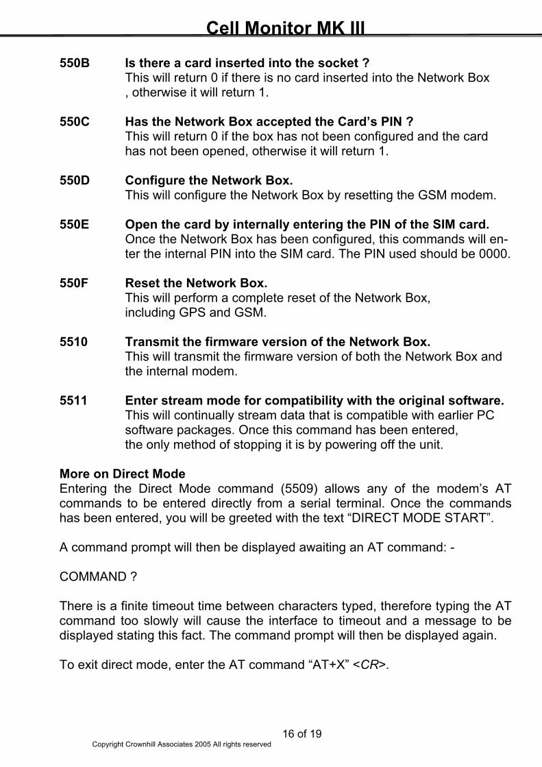
550B Is there a card inserted into the socket ? This will return 0 if there is no card inserted into the Network Box , otherwise it will return 1. 550C Has the Network Box accepted the Card’s PIN ? This will return 0 if the box has not been configured and the card has not been opened, otherwise it will return 1. 550D Configure the Network Box. This will configure the Network Box by resetting the GSM modem. 550E Open the card by internally entering the PIN of the SIM card. Once the Network Box has been configured, this commands will en-
ter the internal PIN into the SIM card. The PIN used should be 0000. 550F Reset the Network Box. This will perform a complete reset of the Network Box,
including GPS and GSM. 5510 Transmit the firmware version of the Network Box. This will transmit the firmware version of both the Network Box and the internal modem. 5511 Enter stream mode for compatibility with the original software. This will continually stream data that is compatible with earlier PC software packages. Once this command has been entered,
the only method of stopping it is by powering off the unit. More on Direct Mode Entering the Direct Mode command (5509) allows any of the modem’s AT commands to be entered directly from a serial terminal. Once the commands has been entered, you will be greeted with the text “DIRECT MODE START”. A command prompt will then be displayed awaiting an AT command: - COMMAND ? There is a finite timeout time between characters typed, therefore typing the AT command too slowly will cause the interface to timeout and a message to be displayed stating this fact. The command prompt will then be displayed again. To exit direct mode, enter the AT command “AT+X” <CR>.
Cell Monitor MK III
17 of 19 Copyright Crownhill Associates 2005 All rights reserved
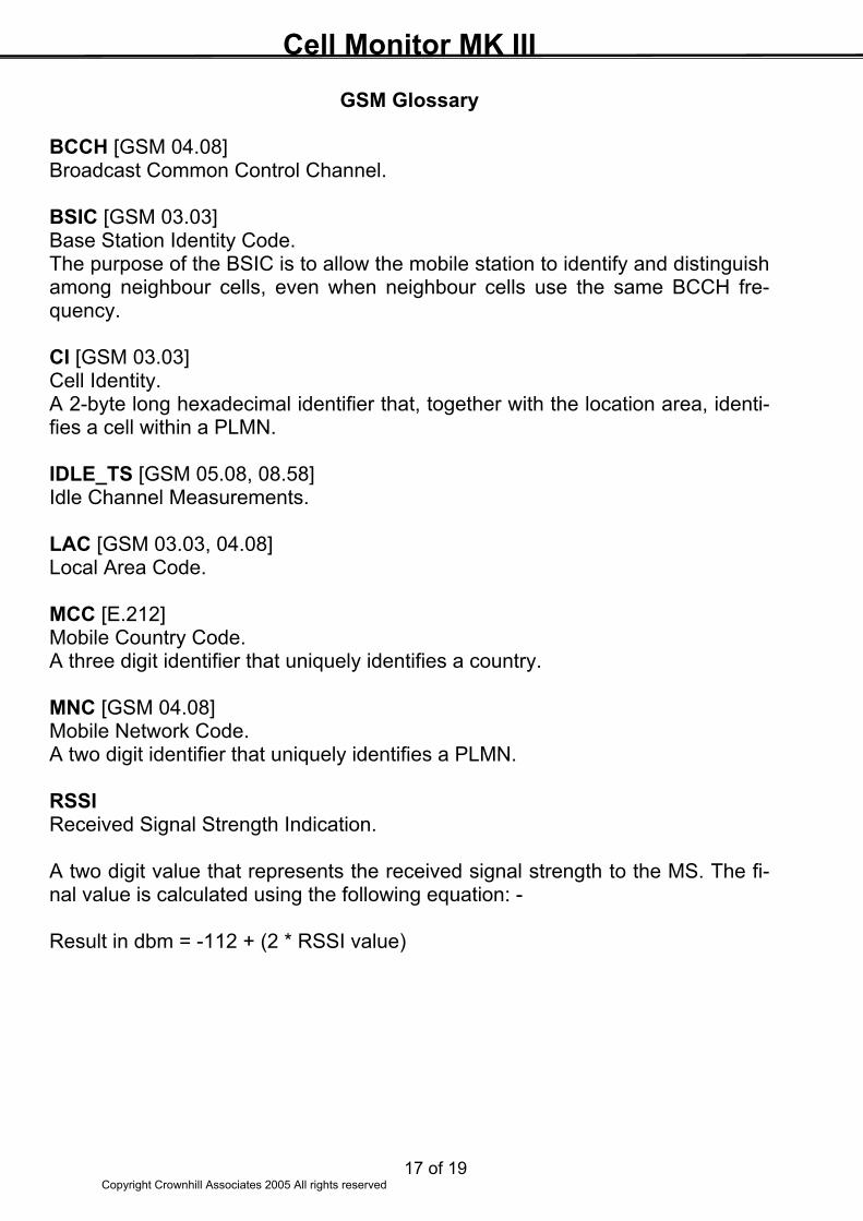
GSM Glossary BCCH [GSM 04.08] Broadcast Common Control Channel. BSIC [GSM 03.03] Base Station Identity Code. The purpose of the BSIC is to allow the mobile station to identify and distinguish among neighbour cells, even when neighbour cells use the same BCCH fre-quency. CI [GSM 03.03] Cell Identity. A 2-byte long hexadecimal identifier that, together with the location area, identi-fies a cell within a PLMN. IDLE_TS [GSM 05.08, 08.58] Idle Channel Measurements. LAC [GSM 03.03, 04.08] Local Area Code. MCC [E.212] Mobile Country Code. A three digit identifier that uniquely identifies a country. MNC [GSM 04.08] Mobile Network Code. A two digit identifier that uniquely identifies a PLMN. RSSI Received Signal Strength Indication. A two digit value that represents the received signal strength to the MS. The fi-nal value is calculated using the following equation: - Result in dbm = -112 + (2 * RSSI value)
Cell Monitor MK III
18 of 19 Copyright Crownhill Associates 2005 All rights reserved
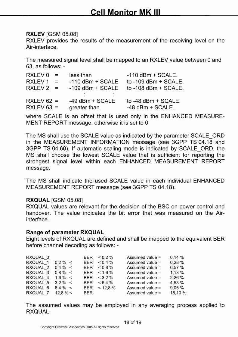
RXLEV [GSM 05.08] RXLEV provides the results of the measurement of the receiving level on the Air-interface. The measured signal level shall be mapped to an RXLEV value between 0 and 63, as follows: - RXLEV 0 = less than -110 dBm + SCALE. RXLEV 1 = -110 dBm + SCALE to -109 dBm + SCALE. RXLEV 2 = -109 dBm + SCALE to -108 dBm + SCALE. : : RXLEV 62 = -49 dBm + SCALE to -48 dBm + SCALE. RXLEV 63 = greater than -48 dBm + SCALE. where SCALE is an offset that is used only in the ENHANCED MEASURE-MENT REPORT message, otherwise it is set to 0. The MS shall use the SCALE value as indicated by the parameter SCALE_ORD in the MEASUREMENT INFORMATION message (see 3GPP TS 04.18 and 3GPP TS 04.60). If automatic scaling mode is indicated by SCALE_ORD, the MS shall choose the lowest SCALE value that is sufficient for reporting the strongest signal level within each ENHANCED MEASUREMENT REPORT message. The MS shall indicate the used SCALE value in each individual ENHANCED MEASUREMENT REPORT message (see 3GPP TS 04.18). RXQUAL [GSM 05.08] RXQUAL values are relevant for the decision of the BSC on power control and handover. The value indicates the bit error that was measured on the Air-interface. Range of parameter RXQUAL Eight levels of RXQUAL are defined and shall be mapped to the equivalent BER before channel decoding as follows: - RXQUAL_0 BER < 0,2 % Assumed value = 0,14 % RXQUAL_1 0,2 % < BER < 0,4 % Assumed value = 0,28 % RXQUAL_2 0,4 % < BER < 0,8 % Assumed value = 0,57 % RXQUAL_3 0,8 % < BER < 1,6 % Assumed value = 1,13 % RXQUAL_4 1,6 % < BER < 3,2 % Assumed value = 2,26 % RXQUAL_5 3,2 % < BER < 6,4 % Assumed value = 4,53 % RXQUAL_6 6,4 % < BER < 12,8 % Assumed value = 9,05 % RXQUAL_7 12,8 % < BER Assumed value = 18,10 % The assumed values may be employed in any averaging process applied to RXQUAL.
Cell Monitor MK III
19 of 19 Copyright Crownhill Associates 2005 All rights reserved
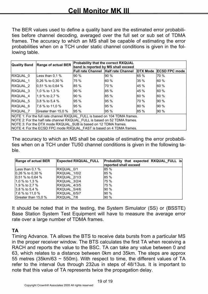
The BER values used to define a quality band are the estimated error probabili-ties before channel decoding, averaged over the full set or sub set of TDMA frames. The accuracy to which an MS shall be capable of estimating the error probabilities when on a TCH under static channel conditions is given in the fol-lowing table. Quality Band Range of actual BER Probability that the correct RXQUAL
band is reported by MS shall exceed Full rate Channel Half rate Channel DTX Mode ECSD FPC modeRXQUAL_0 Less than 0,1 % 90 % 90 % 65 % 70 % RXQUAL_1 0,26 % to 0,30 % 75 % 60 % 35 % 60 % RXQUAL_2 0,51 % to 0,64 % 85 % 70 % 45 % 60 % RXQUAL_3 1,0 % to 1,3 % 90 % 85 % 45 % 60 % RXQUAL_4 1,9 % to 2,7 % 90 % 85 % 60 % 60 % RXQUAL_5 3,8 % to 5,4 % 95 % 95 % 70 % 90 % RXQUAL_6 7,6 % to 11,0 % 95 % 95 % 80 % 90 % RXQUAL_7 Greater than 15,0 % 95 % 95 % 85 % 90 % NOTE 1: For the full rate channel RXQUAL_FULL is based on 104 TDMA frames. NOTE 2: For the half rate channel RXQUAL_FULL is based on 52 TDMA frames. NOTE 3: For the DTX mode RXQUAL_SUB is based on 12 TDMA frames. NOTE 4: For the ECSD FPC mode RXQUAL_FAST is based on 4 TDMA frames. The accuracy to which an MS shall be capable of estimating the error probabili-ties when on a TCH under TU50 channel conditions is given in the following ta-ble.
Range of actual BER Expected RXQUAL_FULL Probability that expected RXQUAL_FULL is reported shall exceed
Less than 0,1 % RXQUAL_0/1 85 % 0,26 % to 0,30 % RXQUAL_1/0/2 85 % 0,51 % to 0,64 % RXQUAL_2/1/3 85 % 1,0 % to 1,3 % RXQUAL_3/2/4 75 % 1,9 % to 2,7 % RXQUAL_4/3/5 75 % 3,8 % to 5,4 % RXQUAL_5/4/6 90 % 7,6 % to 11,0 % RXQUAL_6/5/7 90 % Greater than 15,0 % RXQUAL_7/6 90 %
It should be noted that in the testing, the System Simulator (SS) or (BSSTE) Base Station System Test Equipment will have to measure the average error rate over a large number of TDMA frames. TA Timing Advance. TA allows the BTS to receive data bursts from a particular MS in the proper receiver window. The BTS calculates the first TA when receiving a RACH and reports the value to the BSC. TA can take any value between 0 and 63, which relates to a distance between 0km and 35km. The steps are approx 55 metres (35km/63 ~ 550m). With respect to time, the different values of TA refer to the interval 0us through 232us in steps of 48/13us. It is important to note that this value of TA represents twice the propagation delay.