Embed Size (px)
Citation preview
Tender Document: C-2(b)/RC/0700/4485/2018
FORMAT NO. : CEL/FR/MMD/03(01)
CENTRAL ELECTRONICS LIMITED
(A Public Sector Enterprise)
TENDER DOCUMENT
for the
“Design, Engineering, Supply, Construction, Erection, Testing, Commissioning and
Warranty of Thirteen months of Sub-Stations (Power Evacuation of Solar Power
Plants) ranging from 630 KVA, 750 KVA, 1 MVA & 1.2 MVA, 1.5 MVA at Nashik
district in the State of Maharashtra”
Tender notice no. C-2(b)/RC/0700/4485/2018 dated February 26, 2018
Assistant General Manager (Materials) Materials Management Division Central Electronics Limited, 4, Industrial Area, Saur Urja Marg, Sahibabad – 201 010 (UP) INDIA Tel. No. 0091-120-2895145 Fax No. 0091-120-2895148
Tender Document: C-2(b)/RC/0700/4485/2018
Email: [email protected] Website: www.celindia.co.in
FORMAT NO. : CEL/FR/MMD/03(01)
CENTRAL ELECTRONICS LIMITED (A Public Sector Enterprise) 4, Industrial Area, Saur Urja Marg, Sahibabad – 201 010 (UP) INDIA
Tel. No. 0091-120-2895145 Fax No. 0091-120-2895148 Email: [email protected] Website: www.celindia.co.in
TENDER NOTICE
Tender notice no. C-2(b)/RC/0700/4485/2018 February 26, 2018
Central Electronics Limited invites sealed bids (Technical & Financial) from eligible bidders which are valid for a minimum period of 90 days from the date of opening (i.e., 09-03-2018) for “Design, Engineering, Supply, Construction, Erection, Testing, Commissioning and Warranty of Thirteen months of Sub-Stations (Power Evacuation of Solar Power Plants) ranging from 630 KVA, 750 KVA, 1 MVA & 1.2 MVA, 1.5 MVA at Nashik district in the State of Maharashtra”
Scope of Work Design, Engineering, Supply, Construction, Erection, Testing, Commissioning and Warranty of Thirteen months of Sub-Stations (Power Evacuation of Solar Power Plants) ranging from 630 KVA, 750 KVA, 1 MVA & 1.2 MVA, 1.5 MVA at Nashik district in the State of Maharashtra
Earnest Money
Deposit
Rs. 1,16,000 (Rupees One Lakhs Sixteen Thousand Only)
Interested parties may view and download the tender document containing the
detailed terms & conditions, free of cost from the website http://eprocure.gov.in/ or http://www.celindia.co.in
Please see important dates and Eligibility Criteria.
For CENTRAL ELECTRONICS LIMITED
Sd-
Assistant General Manager (Materials)
Materials Management Division

Tender Document: C-2(b)/RC/0700/4485/2018
Annexure-1
Important Dates
Tender Reference No. C-2(b)/RC/0700/4485/2018 Name of Organization Central Electronics Limited
Tender Type (Open/Limited/EOI/Auction/Single)
LIMITED
Packet System TWO PACKET SYSTEM
Tender Category (Services/Goods/works) Goods/ Works
Type/Form of Contract (Work/Supply/
Auction/Service/Buy/Empanelment/Sell)
Supply/ Works
Payment Mode (Online/Offline) Offline
Date of Issue/Publishing 26-02-2018 (12:00 Hours IST)
Document Download/Sale Start Date 26-02-2018 (12:00 Hours IST)
Document Download/Sale End Date 09-03-2018 (15:00 Hours IST)
Bid submission Start Date 26-02-2018 (12:00 Hours IST)
Last Date and Time for Submission of Bids 09-03-2018 (15:00 Hours IST)
Date and Time of Opening of Bids 09-03-2018 (15:30 Hours IST)
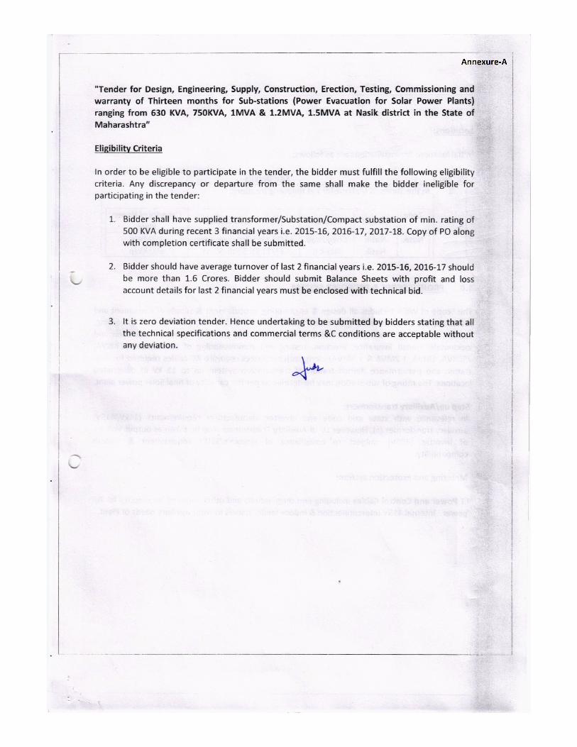
Pre-Qualification/Eligibility Criteria:
Pre-Qualification Criteria:
1. Detailed criteria as per Annexure-A.
2. This is a limited tender and in case, a new vendor wishes to participate in the similar type of
tender, they can enrol themselves by submitting their credentials and relevant documents
through Vendor Registration Process mentioned on our website at www.celindia.co.in
Pre-Qualification is a must and only suppliers/bidders meeting them shall be technically evaluated
Note:
No Deviation from Specification, Terms & Condition of Tender allowed. Quotations having
deviation from our specification, terms & condition would be rejected.
1. Vendors who have successfully supplied to CEL in past are eligible to quote in this tender.
2. All new/unapproved bidders who wish to quote and supply must meet the following criteria:
a) Agree to supply the materials as per CEL Purchase Specification and terms & conditions.
Submit Tender acceptance letter as format at page no. 14 of tender document.
b) Submit data sheet / catalogue.
Tender Document: C-2(b)/RC/0700/4485/2018
c) manufacturers. Documentary proof of supply (i.e. any of the document types like copy of bill d) TENDER DOCUMENT for Tender notice no. C-2(b)/RC/0700/4485/2018
Important Instructions: - 1. The following documents/Annexure are part of tender document:
i. Tender notice along with Annexures
ii. Details of item, BOM, specifications, etc. Annexure A
iii. Standard terms & conditions (GCC) Annexure B
iv. Special Terms & Conditions Annexure C
v. Format for submission of Vendor Data Annexure D
vi. Tender acceptance letter Annexure E
vii. BOQ format for submission of price bid Annexure F
2. Quotations shall be liable to be rejected if there is/are any deviation(s) from the specifications.
3. Escalation in price, deviation from delivery schedule, terms and conditions will not be permitted in your quotation. Statutory Taxes & Duties should be shown separately from the price.
4. Bidder who is Micro & Small Enterprise should enclose copy of valid Certificate of Registration with DIC or KVIC or KVIB or Coir Board or NSIC or DHH or any other body specified by Ministry of Micro, Small and Medium Enterprises, Govt. of India to avail benefits under the “Public Procurement Policy for Micro & Small Enterprises (MSEs) Order 2012”.
5. Catalogue, literature, specification details should accompany the quotation. Incomplete quotations are liable to be rejected.
6. Quotation should be submitted offline as per instructions given in tender.
7. Any deviations whether technical or commercial stated anywhere in the bid shall not be taken into account and may render the bid non-responsible and liable to be rejected.
8. Vendor Data should be submitted in the Format for submission of Vendor Data as per Annexure D.
9. Quotation should be submitted in TWO PACKET SYSTEM as per instructions in Annexure-C.
10. In case of any ambiguity between any terms given in Standard Terms & Conditions (GCC) at Annexure B and Special Terms and Conditions at Annexure C, the terms given in Special Terms & Conditions at Annexure C will prevail and override those at Annexure B.
11. Deviations from specifications, terms and conditions are not allowed. The bid of that bidder who mentions deviations anywhere in the technical bid would not be considered for price bid opening. The bid of bidder who mentions deviation in price bid would be rejected and such bidder may be barred/blacklisted for participation in future tenders.
12. Tender/Quotation/Bid should be submitted in sealed cover super-scribing the tender notice no., name of the item and due date should be delivered at the Office of the Asstt. General Manager, Materials Management Division, Central Electronics Limited, 4, Industrial Area, Saur Urja Marg, Sahibabad – 201010 (U.P), INDIA. Last date of receiving of tenders/quotations is 09-03-2018 up to 15:00 hrs IST. The following are to be submitted in your quotation duly signed and stamped on all pages:
Part A and inline to Pre-Qualification Criteria
i. Filled up Format for Submission of Vendor Data as per format at Annexure D. ii. Data sheet/catalogue clearly showing that the offered material is meeting the specifications given in
the tender. iii. Tender acceptance letter as per format at Annexure E. iv. Original Signed and stamped tender document (photocopy document is liable to be rejected).
v. Eligibility criteria as per Annexure-A Part B: (Financial Bid) and inline to Annexure ‘F’ :
� Price Bid as per As per Annexure ‘F’ as asked in the relevant columns. Note: The rates should be quoted in figures (typed or printed) and cutting should be avoided. The final amount should be in figures as well as in words. Changing of heading or title or modification to any part of the price bid may render the bid as invalid and such bids are liable to be rejected.
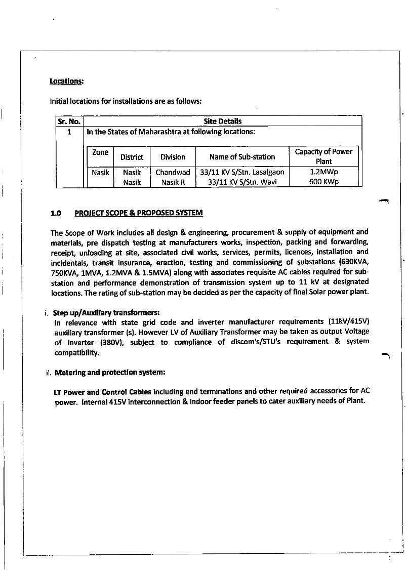
Locatlons:
lnftial locations for installations are as follows:
Sr. No. Sfte Detalls7 ln the States of Maharashtra at following locations:
ZoneDistrict DMsion Name of Sub-station
Capacity of PowerPIant
Nasik Nasik
Nasik
ChandwadNasik R
33/11 KV S/Stn. Lasalgaon
33/11 KV S/stn. Wavi1.2MWp600 KWp
1.0 PROJECTSCOPE&PROPOSEDSYSTEM
The Scope of Work includes all design & engineering, procurement & supply of equipment and
materials, pre dispatch testing at manufacturers works, inspection, packing and fonivarding
receipt, unloading at site, associated civil work, services, permits, licences, installation and
incidentals, transit insurance, erection, testing and commissioning of substations (630KVA,
75OKVA 1MVA, 1.2MVA & 1.5MVA) along with associates requisite AC cables required for sub-
station and performance demonstration of transmission system up to 11 kV at desigrated
locatlons. The rating of sub-station may be decided as per the capacity offinal Solar power plant.
i. Step up/Aurdllary transformerc:ln relevance with state grid code and inverter manufacturer requirements (11kV/415V)
auxiliary transformer (s). However LV of Auxiliary Transformer may be taken as output Voltage
of lnverter (380V), subJea to compliance of discom's/STU's requirement & system
compatibility.
ii. Meterlng and protectlon system:
LT power and Control Cabt6 including end terminations and other required accessories for AC
power. lntemal 415V interconnection & lndoor feeder panels to cater auxiliary needs of Plant.
_-J
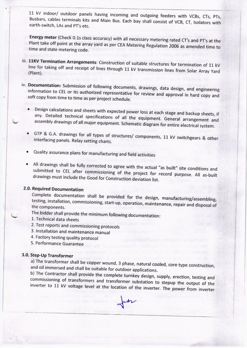
11 kv indoorl outdoor paners having incoming and outgoing feeders with VCBs, crs, prs,Busbars, cables terminars kits and Main Bus. Each bay shal consist of vcB, cr, rsorators withearth-switch, LAs and pT,s etc.
Energy meter (check 0.1s crass accuracy) with a[ necessary metering rated cr,s and pr,s at thePlant take off point at the array yard as per cEA MeterinS Regulation 2006 as amended tame totime and state metering code.
iii' ul(v rermination Arrangements: construction of suitable structures for termination of 11 kVline for taking off and receipt of lines through 11 kv transmission lines from solar Array yard(Plant).
iv' Documentation: submission of folowing documents, drawings, data design, and engineeringinformation to cEL or its authorized repiesentative for review and approvar in hard copy andsoft copy from time to time as per project schedule.
Design calcurations and sheets with expected power ross at each stage and backup sheets, ifany' Detaired technicar specifications of a[ the equipment. Generar arrangement andassembly drawings of all major equipment. schematic diagram for entire electrical system.
GTP & G'A' drawings for ar.types of structures/ components, 11 kV switchgears & otherinterfacing panels. Relay setting charts.
Quality assurance plans for manufacturing and field activities
All drawings shafl be fuly corrected to agree with the actuar ,,as buirt,, site conditions andsubmitted to cEL after commissioning of the projea ior record purpose. A, as-buirtdrawings must include the Good for ConstruAion devltion tist.
a
a
n
a
2.0. Required Documentation
3.0. Step-Up Transformer
Comprete documentation sha, be provided for the design, manufacturing/assembringtestin& insta'ation, commissioning, start-up, operation, ,.in,"n.na", repair and disposar ofthe components.The bidder shall provide the minimum following documentation:1. Technical data sheets2. Test reports and commissioning protocols3. lnstallation and maintenance manual4. Factory testing quality protocol5. Performance Guarantee
a) The transformer shall be copper wound, 3 phase, natural cooled, core type construction,and oil immersed and shall be suitable for outdoor applications.b) The Contractor shall provide the complete trrnt"i a"rign, supply, erection, testing andcommissioning of transformers and transformer substation to stepup the output of theinverter to 11 kV vortage revel at the rocation of ttre inverter. The power from inverter
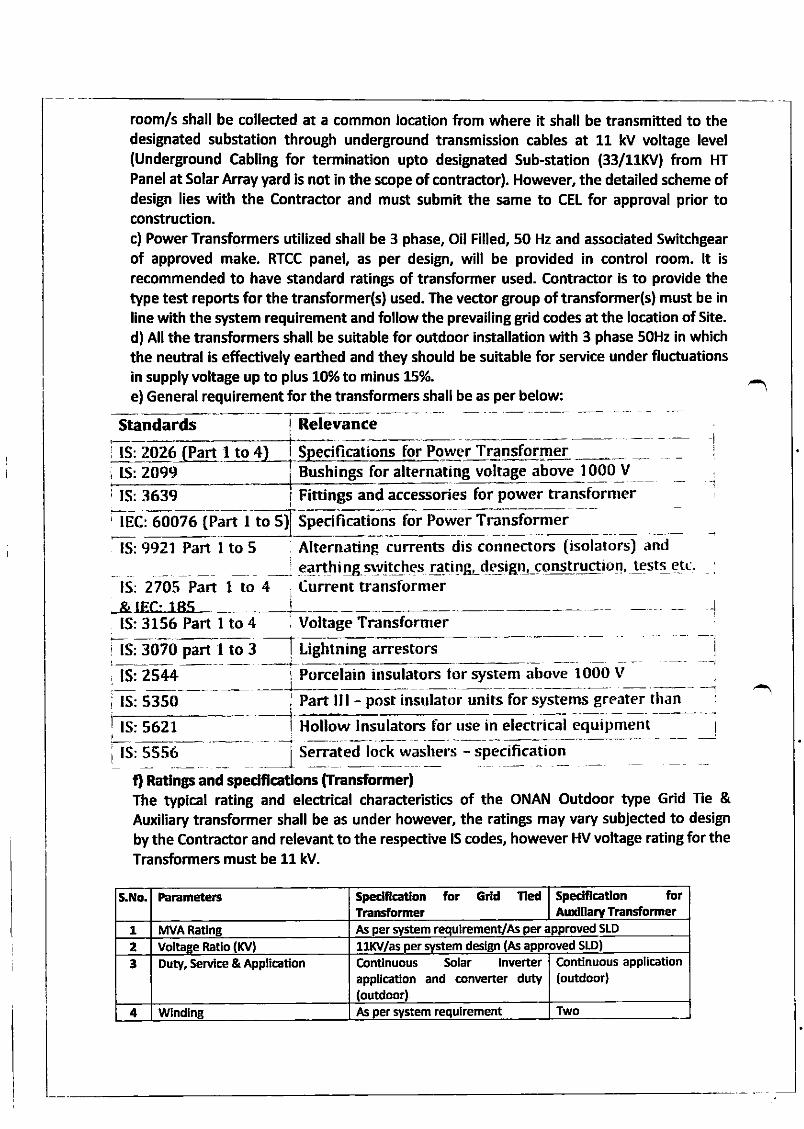
room/s shall be collected at a common location from where it shall be transmitted to thedesignated substation through underground transmission cables at 11 kV voltage level(Underground Cabllng for termination upto designated Sub-station (33/111(V) from HT
Panel at Solar Array yard is not in the scope of contractor). However, the detailed scheme ofdesign lies with the Contractor and must submit the same to CEL for approval prior toconstruction.c) Power Transformers utilized shall be 3 phase, Oil Filled,50 Hz and associated Switchgearof approved make. RTCC panel, as per desigr, will be provided in control room. lt is
recommended to have standard ratings of transformer used. Contractor is to provide thetype test reports for the transformer(s) used. The vector group of tritnsformer(s) must be inline with the system requirement and follow the prevailing grid codes at the location of Site.
d) All the transformers shall be suitable for outdoor installation with 3 phase 50Hz in whichthe neutral is effectively earthed and they should be suhable for service under fluctuationsin supply voltage up to plus 10% to mlnus 15%.
e) General requirement for the transformers shall be as per below:
Standards lRelevance
i Is._z!lQ[ar! to4 Specifications for Power Transformeri lS:2099 Bushings for alternating voltage above 1000 V
i IS:3639 Fittings and accesories for power transformer, tEc :6O076 (Part I to 5) Specifications for Power Transformer
1I
i
lS:9921 Part I to 5 Alternating currents dis connectors (isolators) andi earthi 4g ryvllghCs ftr-tilg-dq,sigtL_qq_15gUqqio4, !qst! e-tt::
:
lS: 2705 Part I to 4 , Current transt-ormer&tE& 185lS:3156 Part I to 4 i voltage Transformer
i lS:3070 part I to 3 Lightning arrestors
lS: 25,14 Porcelain insulators lbr system above 1000 L'
lS: 5350 Part lll - post insulator units for systems greater than
lS: 5621 Hollow lnsulators for use in electrical equipment
lS: 5556 Serrated lock washers - specification
fl Ratlngs and spedf,cafons ffransformer)The typical rating and electrical characteristics of the oNAN Outdoor type Grid Tie &Auxiliary transformer shall be as under however, the ratings may vary subjected to design
by the Contractor and relevant to the respective lS codeq however HV voltage rating for theTransformers must be 11 kV.
S.No. Parametens spedftcatlon for Grld rledTransfurmer
Sp€dfetlon forArodllary Tr"nsformer
1 lvlvA Ratln8 As per system requlremenvAr per approved s[D
2 VoltaEe Ratlo (Kv) 11Mas per system design (As approved StD)
3 Duty, seMce & Applicadon Contlnuous Solar lnverterappllcation and converter duty(outdoor)
C.ontinuous application(outdoor,
4 Wndlng As per system requlrement Two
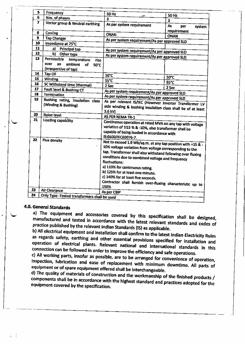
5 Hz 50 HzNos. of 3 3
67 Vector group & Neutral earthing As per system requirement As per system
8 ONAN ONAN9 Ta chuiremenVAs stDAs
10 edance at 75"CI
tl Prina ta As stDerx2 Other tabuirem roved SIDAs a13 ble temperature
oyer an ambiem ofPermissi
ectlve of ta
rlse50"c
t4 Ta oil 50"c 50"c,li55"C 5s'c16 SC Withstand time 2 Sec 2 Sect7 Fault level & Bush CT As storemenvAs er18 Termination
roved sLDAs m per aulrem enVAs
1!, n& lnsulation class(Windlng & Bushtng)
Bushing rati As relevantper ECrs/r Howexrer lnverter Transformer LVdeSI & bushwlndlng latllnsu onln8 dass shal ofbe at least.63a Noise level A5 PER NEMA TR.t
2L Loading capabllityMVAusContinuo atoperation rated on a wfthny tap voltage
ofvarladon 1115 % & alsoto%, transformer shall bee ofcapab oadedbelng aln ccordance ti,ith
ts t66OOllEC60076-722 Flux density
al 110"2 for continuous raung.bl 125% for at least one minute-c) 140% for at least five seconds.Contractor shall fumlsh over-flurdng characterlsuc up toL5@/"
Not to erceed L9 m at awb/sq. ny +taP withposltion 15 &wo voltage homyarlatlon voltage to thecorrespondingTtap. ransformer shal wlalso thsta nd fol overowlng flurdng
condidons du toe edaombln and uvoltage enfreq cfonsfluctuafl
a Air OearanceCBIPAt
24 On -Tested transfo er5rm sha be used
4.0. General Standardsa) The equipment and accessodes covered by this specrflcation sha, be des@ed,manufactured and tested in accordance with th; htest relevant standards and codes ofpractice published by the relevant lndian Standards (E[s appticable.b) All electricar equipment and instaration ,h"[ c;#; ; the ratest rndian Electricity Ruresas regards safety, earthing and other essential prwisions specilted for installation andoperation of erectricar prants. Rere\rant nationar and rnternatronal standards rn thisconnection can be followed in order to improve the efficiency and safe operations.c) All working parts, insofar as possibre, are to b"
"n ngea for convenrence of operaron,inspection, rubrication and ease of repracement *iti 'iiinir*
downtime. A, parts of:lTl-""1,:r .f.spare equipment offered shaI be lnterchangeabte.o' r ne quarity of materiars of construction and the workmanshrp of the finished products /components sha, be in accordance with the highest standard rnu pra.tt.", aoopiJi"r,r,"equipment covered by the specffication.
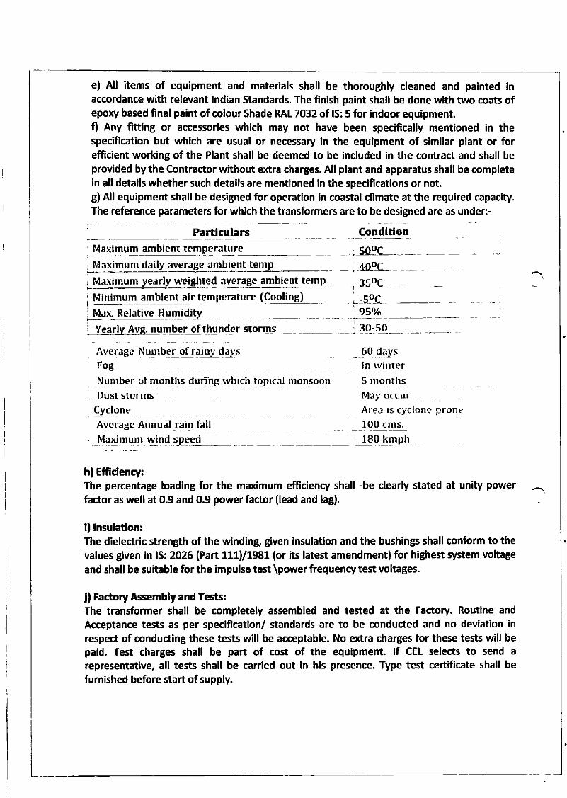
e) All items of equipment and materials shall be thoroughly cleaned and painted inaccordance with relevant lndian Standards. The finish paint shall be done with two coats ofepory based final paint of colour Shade RAL 7032 of lS: 5 for indoor equipment.fl Any fifting or accessories which may not have been specifically mentioned in thespecification but which are usual or necessary in the equipment of similar plant or forefficient working of the Plant shall be deemed to be included in the contract and shall beprovided by the Contractor without extra charges. All plant and apparatus shall be completein all details whether such details are mentioned in the specifications or not.g) All equipment shall be designed for operation in coastal climate at the required capacity.The reference parameters for which the transformers are to be designed are as under:-
Partlculars CondltlonMaximum ambient temperature ;109L-
,40(Jc____,-35L
, Maximum daily average ambient temp
, Maximum yearly rveighted average ambient temp
Minimum ambient air tenperarure (Cooling) t.5oC' 950/o). Relative HumiditvMa
iYearl A number of thunder storms 30-50
Averagc Number of raiuy days _ Q0 daysln winterFoE
\,!Eb"I ot !!on-t!g !!ur!lg.wl'rict to_p_rcaI monsoon
Dust storms
!yc!9neAverage Annual rain fallMaximum wind speed 180 knrph
hl Efftdency:The percentage loading for the maximum efficiency shall -be clearly stated at unity power
factor as well at 0.9 and 0.9 power factor (lead and lag).
ll lnsulatlon:The dielectric strength of the winding, given insulation and the bushings shall conform to thevalues given in lS: 2026 (Part 111)/1981 (or its latest amendment) for highest sYstem vohage
and shall be suitable for the impulse test \power fiequency test voltages.
ll Factory Assembly and Tests:The transformer shall be completely assembled and tested at the Factory. Routine and
Acceptance tests as per specification/ standards are to be conducted and no deviation inrespect of conducting these tests will be acceptable. No extra charges for these tests will bepaid. Test charges shall be part of cost of the equipment. lf CEL selects to send arepresentative, all tests shall be carried out in his presence. Type test certificate shall be
fumished before start ofsupply.
5_ mo,Ir_ths
\'!av ggqurAre:r rs cyclone pronc100 cms-
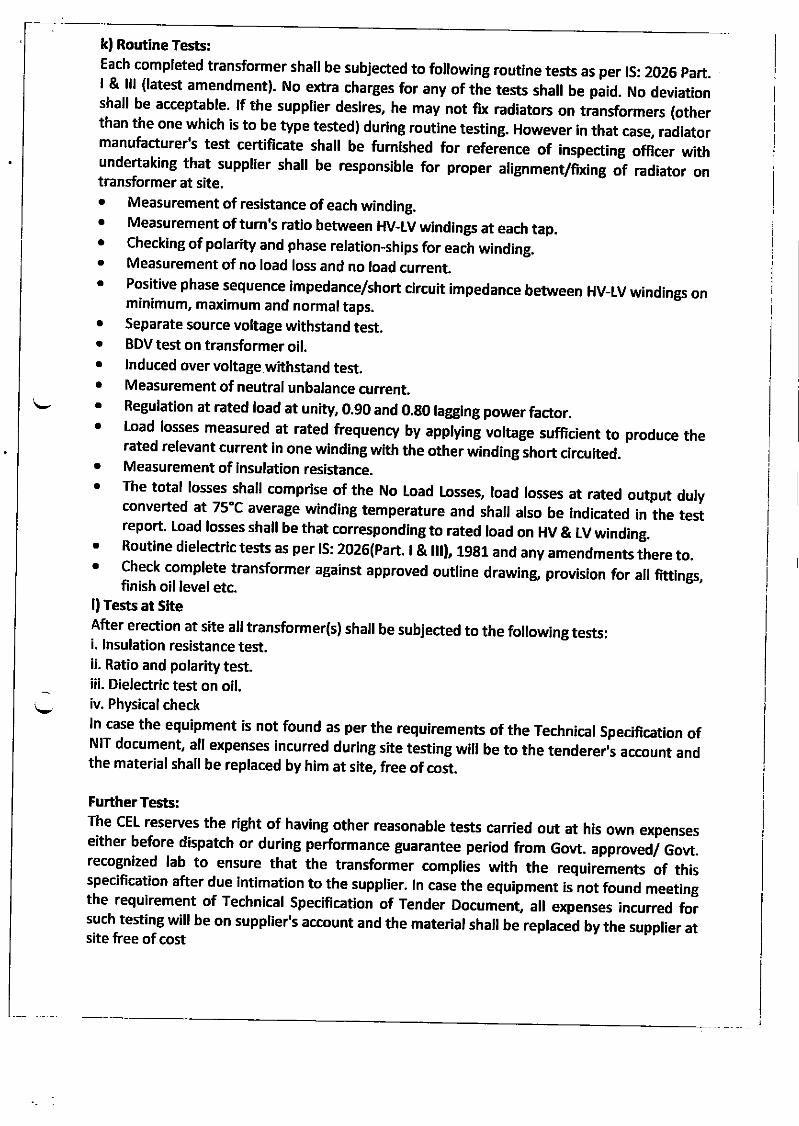
kl Routine Tests:Each completed transformer shall be subjected to following routine tests as per lS: 2O2E part.I & lll (latest amendment). No extra charges for any of the tests shall ue piio. No deviationshall be acceptable. lf the supplier desires, he may not ffx radiators on transformers (otherthan the one which is to be type tested) during routine testing. However in that case, radiatormanufacturer's test certificate shall be fumished for reference of inspecting officer withundertaking that supprier shal be responsibre for proper arigrrment/fixing o] radiator ontransformer at site,. Measurement of resistance of each winding.r Measurement of tum,s ratio between HV_LV windings at each tap.o Checking of polarity and phase relation-ships for each winding.o Measurement of no load loss and no load current.
' Positive phase sequence-impedance/short circuit impedance between HV-LV windings onminimum, maximum and normal taps.
. Separate source voltage withstand test.
. BDV test on transformer oil.o Induced over voltage withstand test.. Measurement of neutral unbalance current,r Regulation at rated load at unity, 0.90 and 0.g0 lagging power factor.o Load losses measured at rated frequency by applying vortage sufficient to produce the
rated relevant current in one winding with the other winding short circuhed.o Measurement of insulation resistance.o The total losses shall comprise of the No load losseg load losses at rated output duly
converted at 75'C average winding temperature and shall also be indicated in the testreport. Load losses shal be that corresponding to rated road on HV & LV winding.o Routine dielectric tests as per rs: 2026(part. I & l[], 19g1 and any amendments ihere to.o check complete transformer against approved outline drawing provision for all fitflngs,finish oil level etc.
l) Tests at SheAfter erection at site all transformer(s) shall be subjected to the following tests:i. lnsulation resistance test.ii. Ratio and polarity test.iii. Dielectric test on oil.iv. Physical checkln case the equipment is not found as per the requirements of the Technical specification ofNlr document, all expenses incurred during she testing will be to the tenderert account andthe material shall be replaced by him at site, free of cost.
Further Tests:The cEL reserves the right of having other reasonabre tests carried out at his own expenseseither before dispatch or during performance guarantee period from Govt. approved/ Govt.recognized lab to ensure that the transformer complies with the requirements of thisspecification after due intimation to the supplier. ln case the equipment is not found meetingthe requirement of Technical specification of Tender Document, all expenses incurred forsuch testing will be on supplier's account and the material shall be replaced by the supplier atsite free of cost
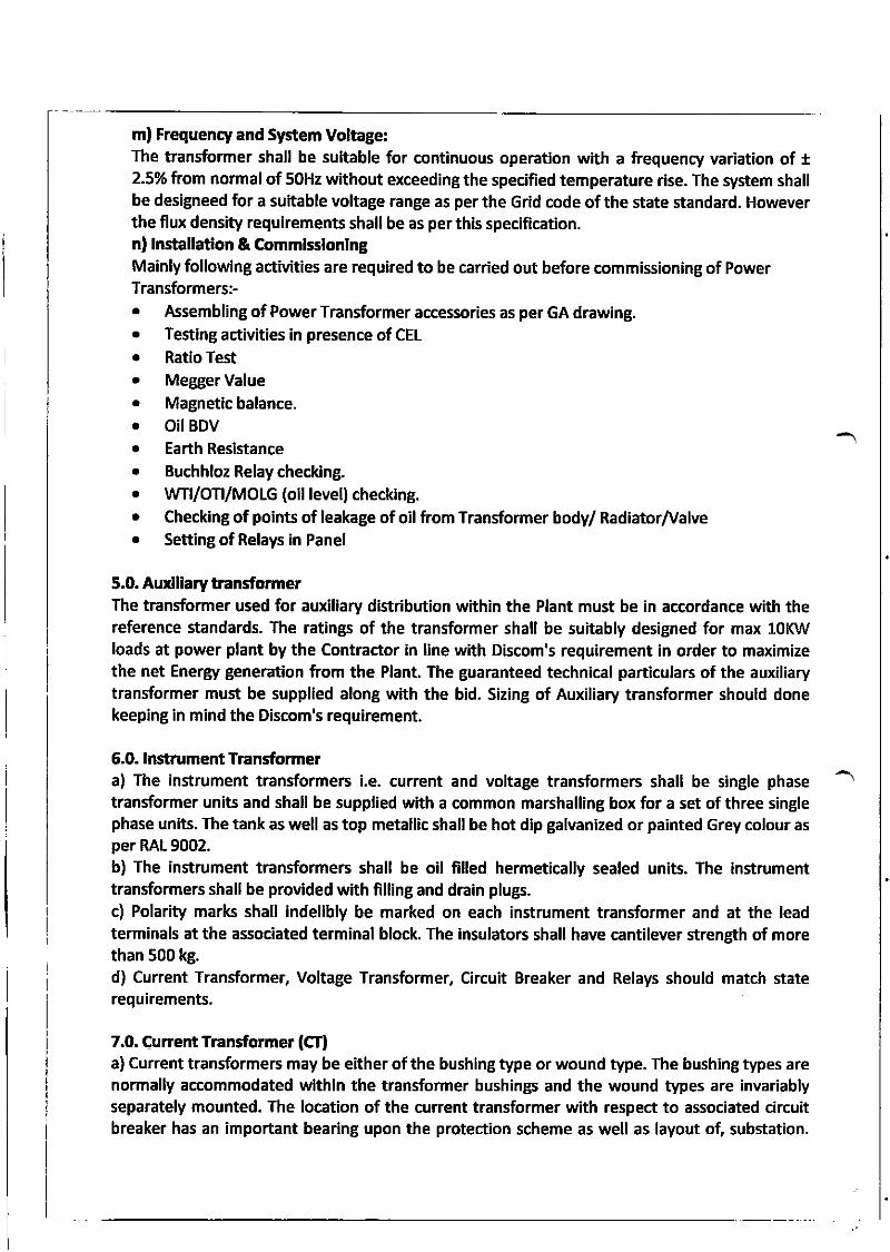
m) Frequency and System Voltage:The transformer shall be suitable for continuous operation with a frequency variation of +2.5o/o from normal of 50Hz without exceeding the specified temperature rise. The system shallbe designeed for a suitable voltage range as perthe Grid code ofthe state standard. Howeverthe flux density requirements shall be as per this specification.n) lnstallatlon & C.ommlsslonlngMainly following activities are required to be carried out before commissioning of power
Transformersi. Assembling of Power Transformer accessories as per GA drawing.. Testing activities in presence of CEL
. Ratio Test
. Megger valuer Magnetic balance.r Oil BDV
o Earth Resistancer Buchhloz Relay checklng.o WTI/OTI/MOLG (oil level) checking.o Checking of points of leakage of oilfiom Transformer body/ RadiatorTValve. Setting of Relays in Panel
5.0. Aurdllary transformerThe transformer used for auxiliary distribution within the Plant must be in accordance with thereference standards. The ratings of the transformer shall be suitably designed for max 10KWloads at power plant by the Contractor in line with Discom's requirement in order to maximizethe net Enerry generation from the Plant. The guaranteed technical particulars of the auxiliarytransformer must be supplied along with the bid. Sizing of Auxiliary transformer should donekeeping in mind the Discom's requirement.
6.0. lnstrument Transformera) The instrument transformers i.e. current and voltage transformers shall be single phase
transformer units and shall be supplied with a common marshalling box for a set of three singlephase units. The tank as well as top metallic shall be hot dip galvanized or painted Grey colour asper RAL 9002.b) The instrument transformers shall be oil filled hermetically sealed units. The instrumenttransformers shall be provided with filling and drain plugs.c) Polarity mark shall indelibly be marked on each instrument transformer and at the leadterminals at the associated terminal block. The insulators shall have cantilever strength of morethan 500 kg.
d) Current Transformer, Voltage Transformer, Circuit Breaker and Relays should match staterequirements.
7.0. Current Transformer (CTl
a) Current transformers may be either of the bushing type or wound type. The bushing types arenormally accommodated within the transformer bushings and the wound Wpes are invariablyseparately mounted. The location of the current transformer with respect to associated circuitbreaker has an important bearing upon the protection scheme as well as layout of, substation.
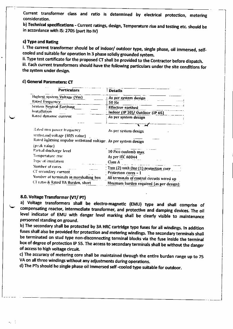
and ratio is determined by electrical protection, metering
b) Technlcal spedffcatlons - current ratings, design, Temperature rise and testing etc. should bein accordance with lS: 2705 (part lto lV)
cl Type and Ratlngi. The current tran#ormer should be of indoor/ outdoor type, single phase, oil immersed, self_cooled and suitable for operation in 3 phase solidly grounded system.ii. Type test certificate for the proposed CT shall be provided to the contractor before dispatch.iii. Each current transformers should have the following particulars under the site condftlons forthe system under design.
Current transformer classconsideration.
d) General Parameters: CT
panicutars -Detalls
HrAhest syste f/oltage (VmJ As pcrs!.st-efi design50 Hzlltnq fr.qgqn_L_
Svst!,m Neutral,EarthlnEll|stJllationn.teit' ivnont,c iuirent
P,rrtral drsch.rrgt, levelTernpt,rature nsc.lrpr
ol insul; xtnNumber o[ ctrrtsl:l {FaundJr} rurrentNunrber ot term-inals in marshalltng boxC l lrtto & Ratetl VA 8urdl.n, short
j lndoor (lP Z0)/ Qutdo0[As per system design
EffeL-tive earthed
l0 Pico coulomb max.As perrld ooo++ -Class A
(tP 55
qM!!! $1Ie4 qp ,
r-qd Elper qej!Fr):
j _ __-
Il,rtol rlrrr porrler lrc(lur.nci- rls per syst(,u d;iBnrt rt lrsr.rnd v')ltJHp (R MS tnlu(,.)R.rrcd ltghtntnp irnpulse rvrlhstand vollagt, As per systpm d(TiRnIpe.rl.i r,.rlue]
' t1q l-2) rtrrh One ( l) pryrqgigq coreProtection cores - IAll terminals of cortrolNtinimum burden lll
8.0. Voltage Transformer (fl pT)
a) voltage transformers shall be electrc.magnetic (EMU) type and shall comprise ofcompensating reactor, intermediate transformer, and protectfue and damping devices. The oillevel indicator of EMU wfth danger level marking shall be clearly visille-to malntenancepersonnel standing on ground.b) The secondary shall be protected by 3A HRC carHdge type fuses for all windings. ln additionfuses shall also be proMded for protection and metering windings. The secondary iermlnals shallbe terminated on stud type non-disconnecting terminal blocks via the fuse lnslde the terminalbox of degree of protection lP 55' The access to secondary terminals shall be without the dangerof access to high voltage circuit.c) The accuracy of metering core shall be maintained through the entire burden range up to 75VA on all three windings wfthout any adjustments during operations.d) The PTs should be single phase oil immersed self -cooled type suitable for outdoor.
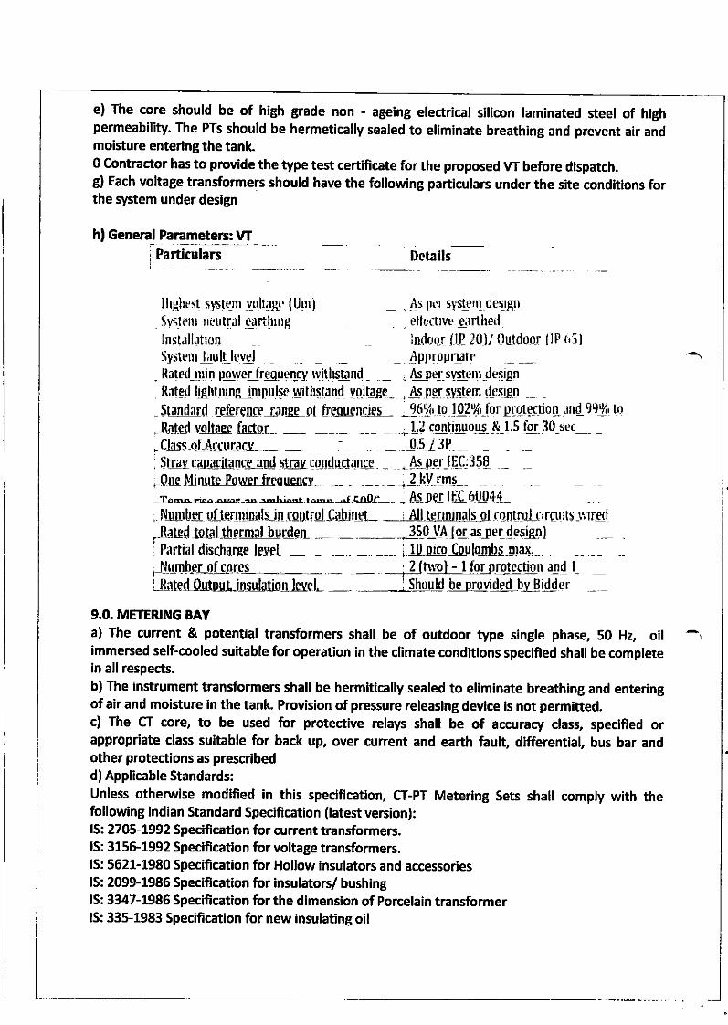
e) The core should be of high grade non - ageing electrical silicon laminated steel of highpermeability' The PTs should be hermetically sealed to eliminate breathing and prevent air andmoisture entering the tank.0 contractor has to provide the type test certmcate for the proposed w before dispatch.g) Each voltage transformerc should have the following particulars under the site conditions forthe system under design
hf General Parametets: VIrParticulars Details
lllghest slstem volt4_qc [Um1Svstenr neutlll ejrtlrngInstallatron
. As pr,r s1s1en1.de1gn
_ rtleefrvc qartherl
indoor [E 20)/ tlutdoor llP t'5)Systenr laulilovel Appropnate
. Raled_utrt pqve1-tresgenry titltlstrnd _ , fu pe1-sy5lemdesigrl
Ritgd lAhtning timpulge.qltl6gSnd yA.ltlSe_ , A p_et syslsn dtqgn
- Stadard Leflremc-r;rnse 0l hesucnoer -.16% tq ) 02% -l or BIqtSFo I d nd- 99 9{, to
-Rnt.d vdtase ftdor- -
, Ll conhruo.us &,1.5 fu30-ser- -"C]as-qlArctrraey-- -SEau cap,lritanccad sttay cordLctanee tu er IEC:358
; OneMinulelorver fre{uelcy- -- - -- - , 2-kV Lms
:Iemn;!- n..-r- r -mki6Ft I
filuubcr sltemunals-inrout
As pel i[l61]04!_
_ 0.s l3P
.nardiPr"ti,
toultternalfurienrol[abrrcf- i All-termrnals olrantlalt.lreruts -lrlred_ _ _-_* 310_Vi Ioraslerdqsiffrl_ __ _ __i 10prep Jculsrnbq-44r.,I disrharpp lpvel
Number of co
,R;lt€d,0trtpil.tnsuiationfuel -9.0. METERING BAYa) The current & potential transformers shall be of outdoor type single phase, 50 Hz, oilimmersed self-cooled suitable for operation in the climate conditions specified shall be completein all respects.b) The instrument transformers shall be hermltically sealed to eliminate breathing and enteringof air and moisture in the tank. Provision of pressure releasing device is not permitted.c) The CT core, to be used for protective relays shall be of accuracy class, specified orappropriate class suitable for back up, over current and earth fault, differential, bus bar andother protections as prescribedd) Applicable Standards:Unless othenuise modlfied in this specification, cr-PT Metering Sets shall comply with thefollowing lndian Standard Specification (latest version):lS: 2705-1992 Specfficatlon for current ransformers.IS: 315G1992 Speciffcatlon for voltage transformers.lS: 5621-1980 Specification for Hollow insulators and accessorieslS: 20991986 Speciffcatlon for insulatory bushinglS: 3347-1986 Specffication for the dimenslon of Porcelain transformerlS: 33$1983 Specification for new insulating oil
I
e) The core of instrumsaturation factor, lowshort circuit current.
ent transformers to be used for metering and instrumentations shall haveenough to avoid damage to the instruirertr, ii ti" "r*t of maximum
0 Nuts and borts (or screws used for fixation of interfacing porcerain bushings for takint outterminals) sha, be provided on flanges, ."r"n*o ii ii" bushing and not on the porcerain i.e.Flange type bushing for CTlpT, shall be provided.-- -- -"
g) For gasket joints, wherever used, Nitrire Butyr rubber gaskets sha[ be used. The gasket shafibe fitted properry with adequate space for accommodating the gasket under compression.h) The meterins sets shafl b,e suipried ;'ilil ffi;; of insurating oir conforming to rs: sas(including latest amendment).i) The outer surface of metar tank sha, be Hot Dip Garvanised, whereas, the inner portion sharl::ffi::,i,,:!.l,H,:',$ffi)#i+: -; ","t";"'erves
right ror stage i,,pJJon a,,ingi) The externar surhces d ,iif of cr-pr sets sha, be painted with one coat of primer and twocoats of svnthetic enamer erl.ol:h.ade nt*iilrlir!, the intemal surfaces of the tank sha,be painted with two coats of suitable heat resistant oiii#otrOte p.int.
[J[Jllt'"nt transformers shalt be rrrtrb[;;';;;ntins on steer structures or concrete
l) For load shading single oh3sins is adopted in the system. The offered cr-pr set sha, besuitable for working under such abnormat operauoi.i#ition.m) The cr - pr sets sha, three nos. of singre ptrrr" prr.'rn" primary windlng of 3 singre phase prsharr be connected in star formation in the tank ritt iorron neutrar of brought outside thetank through 3 KV bushing for earthing,n) The secondary terminal box shall have cable gland/ flange suitable to recelve two Nos. controlcable of size 6x4 sq.mm and.4x2.s rq.n-.t'ti";#; of the secondary box for meteringconnections to secondary winding of CT_pT circuitrr".p"Air"ly.o) The CT - pr set sha' have 3 Nos. incoming .nJi *o, o-utsgrng outdoor type bushingcomplete with 6 Nos' bimetaric terminar conneaiolrn"al ,.. oog/panther conductor
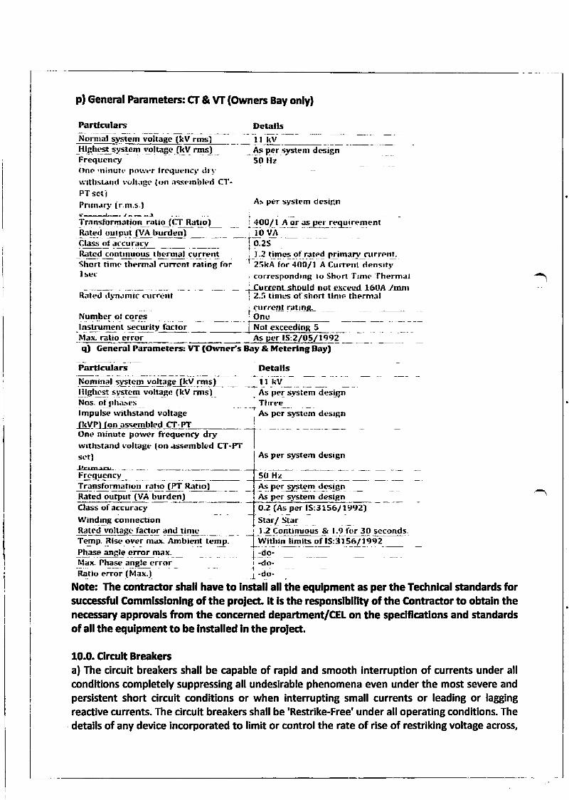
p) General Parameters: CT & vT (Ourners Bay only)
PardEulars DetallsNorEraI system voltage [kV rms) ll kvHlEhest sysrcm soltagc [kV rms)Frequenryt nc 'ttitrut(,porter frcquencl' dr1.rvrurstand r.oltngr. (ofl ir$emttlpd C'l'-PT setiPnrn.rr-v (r-m.s.l
Tra nsfonnation ratiq_[CT RxllD)8a!-.! o!]put IVA lrurdenlCla.is ot J[cuR.rLcd contruuous thcrr'lal currentShorr time themlJ .urieDt ratioB forI sec
Raled d!.n.tmir curra.nl
N.umler glrqrql *_I nstrum€nt securlty factor
_As peJ sl.stem d€5ign50 Hz
As per s].stem design
I 4o0/l A-!r dsi_pfTeq ur rerBent, lo vAIozi -. L2 time5 of rated primaly surrpnt-tlsti i"i+oolt A currenl densrr-y, correspondrng to Short Trme lhermal-Iurtent should net ex!-eed l6tlA /mnr! 2.4 trnrl.s .if sho llRrF lherhrilfirrrenl rat tI!I+
lOnr:Not erceedlnE5
MalL ratio crror As per lS:2/O5,/1992q) General Paiameters! l/T (Owner's Biy & Mcterlng Bay)
Grdculars DetallsNominal system eoltaBe (tV rms) t! kvHlghcst ststcm vDllage (kV rms)Nos. of ph.r-reslmpslsE withsta[d eoltagc
As per syslem desiBnTlrreEet pei systcm aesrsn
I As per system desiBn
ftYP-ll-s!,e!s@lcdOne mirurte porver frequsncy drywrtlrstand !'oltaBe lon .r5:s+rnbled CT-PTset)
ryggys".r-Transformanon ratro lFI Rg!!o-J- , -tleled oulput (VAClass of accuracyWindEE corrnectiooRdted voltagc factor and timc
-Temp Rise over rnar( nmblent temp-
!h+s !!gl! eEqI !x!axfitari- Phsse alEle cr.orRatio error (Max-)
As ft des02 (As pqr 1513156/ 1992)Star/ Star
burden)
--r,!a-qosqn!p!!-& t'Z!-qjq!9!9!9..I Wi rn hmlts of lS:31S5,r19e2
| !e--do-
1-r"'Note: The contractor shall have to Install all the equlpment as per the Technlcal standards forsuccssful C.ommlsslonlng of the prolect. lt ls the rGponslblltty of the Contractor to obtaln thenecessary approvals from the concemed department/CEl on the spedffcations and standardsof all the equlpment to be lnstalled ln the prolect.
10.0. Clrcult Breakerca) The circuh breakers shall be capable of rapid and smooth interruption of currents under allconditions completely suppressing all undesirable phenomena even under the most severe andperslstent short circuft conditions or when interrupting small currents or leading or laggingreactlve currents. The circuh breakers shall be 'Restrike.Free' under all operating conditions. Thedetails of any device incorporated to limit or control the rate of rlse of restriking voltage across,
the circuit breaker contacts shall be stated. The over voltage across, the circuit breaker contactsshall be stated. The over vortage caused by circuit breaker whire switching inductive orcapacitive loads shall not exceed 2.5 times the highest phase to neutral voltage. The actual makeand break times for the circuit breakers throughout ttre ranges of their operaling duties shall bestated in the offer and guaranteedbl Applicable standards: The materials shall mnform in all respects to the relevant rndian
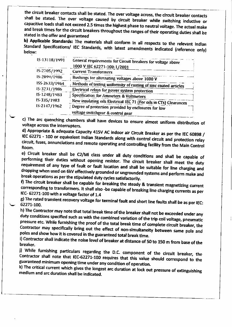
;:ili:' specifications/ rEC standards, with ratest amendments indicated (reierence onlv)
ls-l:1118/1991 General requirements for Clrcuit Ureaten toivottage ,b.v" - - i
.-_ _ _{!qo,vtEq6227l__!g!:v?j!_l__ l1S.2705/1.')SZ CurrentTransformersrs-2ogq/1986
rss-zt,r:7iuo+rs-323 I /_1986ls.1248/1ea3ls-33511983ts-2147 /7562
Bush lgs lor alternatinE voItages above 1000 V
coated articles
New insulating oils Electrical IEC 71 (Fgr oils in CTs) ClearancesDegre e of protection provided by enclos ures for low
& contml gear
-1I
c)vo
The arc quenching chambers shalr have deMces to ensure armost uniform distribution ofItage across the interrupters.d) Appropriate & adequate capacity 415v AC indoor air circuit Breaker as per the tEC 60g9g /lEc 62277 - 100 or equivalent lndian standards along with control circuit and protection relaycircuit, fuset annunciations and remote operating anJ controlling facility from the Main controlRoom.
e) Grcuit breaker sha, be .c2rMr crass under ail duty conditions and shail be capabre ofperforming their duties without opening resistor. The circuit breaker shalr meet the dutyrequirement of any type of fauh or fault location and shall be suitable for line ciarging anadropping when used on Gkv effectivery grounded or ungrounded systems and perform make andbreak operations as per the stipulated duty cycles satisictorily.
f) The circuit breaker shall be capable foi uieaking the steady & transient magnetizing currentcorresponding to transformers. rt shal arso -be capibte ot breaking tine chargii-;.ri.",io ".
p".IEC- 62277-tOO with a voltage hct or ol t.4g) The rated transient recovery voltage for terminal fauh and short line faults shall be as per tEC:62277-700.h) The contractor may note that total break time ofthe breaker shalt not be exceeded under anyduty conditions specified such as with the combined variation of the trip -il ,oltrg", pn"rrrti.pressure etc. while furnishrng the proof of the totar break time of comptete circuit breaker, thecontractor may specifically bring out the effect of non-simuhaneity betrreen ,arne-pore
"napoles and show how it is covered in the guaranteed totat break time.i) contractor shall indicate the nolse level of breaker at distance of 50 to 150 m from base of thebreaker.j) while furnishing particulars
_regarding the D,c. component of the clrcuit breaker, thecontractor shal note that rEc-6227r-100 requires that ihis ,rtre ,t outJ'.or."r-po-nl to tt "guaranteed minimum opening time under any condftion of operation.
k) The critical current which gives the rongest arc duration at rock out pressure of exrnguishingmedium and arc duration shall be indicated.
l) Contractor has to provide the type test reports for the CB before the dispatch.m) All the duty requirements specified above shall be provided with the support of adequatetest reports.
11.0. Operatlng Mechanlsm of Clrorlt Breakersa) Circuit shall be vacuum type whh electrically spring charged mechanism.b) The operating mechanism shall be anti-pumping and trip free (as per IEC definition)electrically under every method of closing. The mechanism ofthe breaker shall be such that theposition ofthe breaker is maintained even after the leakage of operating media and / or gas. Thecircuit breaker shall be able to perform the duty cycle without any interruption.c) Electrical tripping shall be performed by shunt trip coil. Provision shall also be made for localelectrical control. 'Local / remote' selector switch and close & trip push buttons shall beprovided in the breaker central control cabinet. Remote located push buttons and indicatinglamps shall also be provided. The VCB coil DC supply through appropriately rated battery bankand charger to be supplied by the Contractor.d) Operating mechanism and all accessories shall be in local control cabinet. A central controlcabinet for the three poles of the breaker shall be provided along with supply of necessarytubing, cables, etc.e) Mounting and supporting structure for Circuit Breaker: The circuit breakers should be self-supporting type. However, ff necessary for the purpose of minimum ground clearance the circuitbreakers should be mounted on raised steel structures which should be included in the scope ofsupply of circuit breaker. Bidder/Contractor to obtain the necessary information and datarequired for design offoundations ofthe circuit breaker be obtained from the CB supplier.f) Max. lmpact loading in terms of equivalent static load both compression and upward due toopening/closing of the breakers. lt shall be clearly stated whether these forces shall actsimultaneously or at different timing.g) Necessary connecting materials such as clamps, bolts, nuts, washers etc. and fixing bolts formounting the equipment on the supporting structures wherever required should be obtainedfrom the circuit breaker supplier.h) General parameters: Vacuum type Circuit Breaker:i) Co-ordination of rated voltages, short circuit breaking curent and rated normal current forguidance as per lS 13118 for rated voltage 33 kV and above Circuit Breaker Protection againstx Over Currentx Earth faultx Under voltage & over voltage protectionx Under frequency & over frequencyx SF6 gas pressure low (where applicable)x DC supply failure
12.0. lsolatorsa) The isolators and accessories shall conform in general to IEC 62277-1.02 (or equivalent lndianstandard) except to the extent explicitly modified in specification.b) Each isolating switch should have the following particulars under the site conditions for thesystem under design (typical values for 36 kV system are given).
c) General Parameters: lsolators
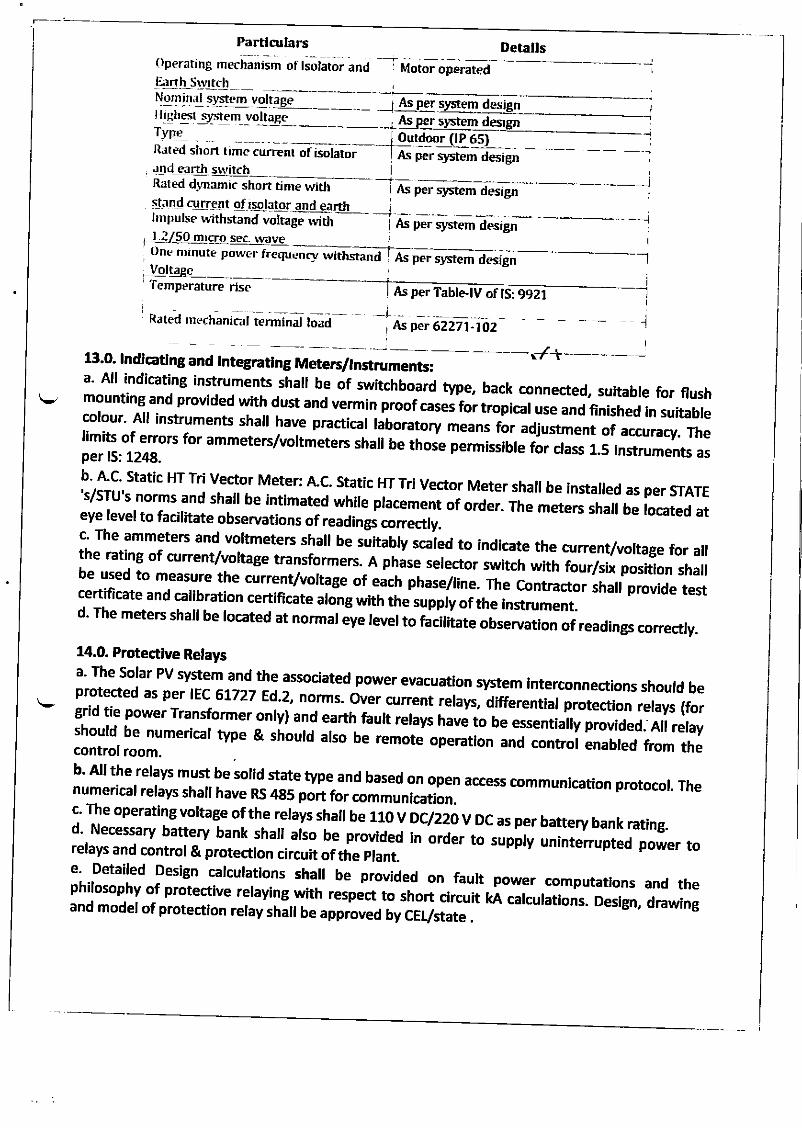
PartlgllarsOperating mechanism of lsolator anJ I Motor operatedFrnh Stl'ttch
Detalls
Nomin.rl system vol--.tAP-gI md
l{!Ehss!_.ylt(: m voltage As per systemTypc Ouq&"r(l6s)Raled short time curent of isolator As per sJstem d€sign!nd earth switchRated dlrnamic short time witi i As per sl/stem designstJnd curren t q[ rsolatq!: and eaLlmpulse withstand voltage rvith As per system design1-?150 mrcro sea- \vitveOne nrinute powcr frequtn withstand As per slrstem design
_Vol!4Bc___Temperature tu per Table-lV of lS: 9921
Rated rnechanical termlnal load , As p€r 62271-102
13.O. tndlcatlng and tntegEtlng MeteB/tnstruments:
14.0. Protecttve Retays
a. All indicating instruments shafl be of switchboard type, back connecte4 suitabre for flushmounting and provided with dust and vermin proof case; fortropical use and finished in suitablecolour. All instruments sha, have practrcar t"to,"tory i".ns for adjustment of accum"y. *relimits of errors for ammeters/voltmeters rrtarl ue ir,ose p"rmissible for class 1.s lnstruments asper lS: 12218.
b' A"c' static llr rri vector Meter: A"c. static HT Tri vector Meter shall be installed as per srATE'slsrU's norms and shall be intimated while pracemeniii oro"r. The meters shall be located ateye level to facilitate observations of readings correaly. -'
c' The ammeters and vortmeters shal be rrit"uty ,."i"a to indicate the current/vohage for a1the rating of current/vohage transformers. a pr,.r" t"i""tor switch with four6ix position shallbe used to measure the currenvvoltage of each il;;"/1i"". The contractor shall provide testcertificate and caribration certificate arong wrtn *re suppiv of the instrument.d' The meters shafl be rocated at normar eye tevel to natitate ooservation of readings correctry.
ti8g____
I
t
--1
i--.1
rlse
.l
a' The Solar PV system and the associated power evacuation system interconnections should beprotected as per rEC 61727 Ed,2, norms. over current rerays, differential p.ot"aion ,"r.v, (to,grid tie power Transformer onry) and earth tautt retays t L ,o u" essentialry provided.. AIr rerayshould be numericar type & shourd atso ue remoil opl,,tion and contror enabred fiom thecontrol room.b' All the relays must be solid. state type-and based on open access communication protocol. Thenumerical relays shall have RS ll85 port for communication.c' The operating vortage ofthe rerays shalr a" nov iciiioV DC as per battery bank rating.d' Necessary battery bank sha, arso be provided ;;;r to suppry uninterrupted power torelays and control & protection circuit ofthe plant.e' Detailed Design carcuratrons shafl be provided on faurt power computarons and thephilosophy of protective reraying with respect to shoi circurt kA carcurations. Design, drawingand model of protection relay shall be approved tvir-Viri" .
f. The contractor must submit the relay setting chart as a part of design documents incoordination with the connecting substation.
15.0. Earthllng for Transformer yarda. The earthing system shall be designed with consideration ofthe earth resistivity ofthe projectarea. The earth resistivity values shall be measured prior to designing the earthing system.Unless othenvise specified, earthing system shall be in accordance with lS:3043 and IEEE 80,lndian Electricity Rules, Codes of practice and regulations existing in the location where thesystem is being installed.b. The permissible system fault power level also shall be kept in consideration while designingthe earthing system. Each LT power system, earthing grid for switchyard ,all electrical equipmentshall be grounded properly as per lS 3043 - 1987. Alt metal casing / shielding shall be thoroughlygrounded in accordance with lndian electricity act / lE Rules.c. The earthing for LT power system shall be made of 3.0 in long 40 mm diameler perforated Glpipe / chemical compound filled, double walled earthing electrodes including accessories, andproviding masonry enclosure with cast iron cover plate having pad-locking arrangement,watering pipe using charcoal or coke and salt as required as per provisions of lS: 3043.d. Necessary provision shall be made for bolted isolating joints of each earthing pit for periodicchecking of earth resistance.e. For each earth pit, a necessary test point shall be provided.f. Necessary provision shall be made for bolted isolating joints of each earthing pit for periodicchecking of earth resistance.g. ln compliance to Rule 11 and 61 of lndian Electricity Rules, 1956 (as amended up to date), allnon-current carrying metal parts shall be earthed with two sepaGte and distinct earth continuityconductors to an efficient earth electrode.h. The Contractor should submit the earthing system design calculations along with the system
layout for Owner approval. Prior to the installation ofthe system n. Unless otherwise specified,the earthing system primary and secondary grid conductors, equipment connections shall beconstructed with galvanized iron flat However the earthing of transformer neutrals andelectronic earthing shall be provided using copper earthing conductor only.
15.0. Control & Relay Panela. General Requirement:i. The control & relay panel shall be free standing simplex type, floor mounting type, fabricatedfiom 2 mm thick MS sheet for main enclosure and 1.6 mm thick MS sheet for intemals andpartitionS. The main enclosure shall be mounted on a base frame fabricated out of 100x50 ISMC
mild steel section.ii. The enclosuri external finish colour shade shall be decided by the CELJhe intemal surface
shall have a glossy white finish all over.iii. The control & relay panel shall contain the following metering and protection devices:. Metering; lndications & Controls. Ammeter:r Ammeter selector switch. Voltmeter:. Voltmeter selector swltch. Load manager to display the following parameters: MW, MVA, MVArh, MVAr Cos0, Hz,
Ilndication lamps for R, Y, B phases, Breake r 'ON' (R), Breaker 'OFF' (G), Breaker ,TRtp,Spring charged (W), Trip Circuit Healthy (B). TNC switch, spring return to neutral pos ition shall be provided for clrcuit breaker operation.
. Local / Remote selection switch for ctrcuit breaker operatlon. Semaphore indifor the systems with
cators (LED typel foraluminiCB and
um $rips and ,ON"OFF, indications for isolators
,solator 'Open' & ,Close, positionso Mimic diagram
18.0. C.ontrot Or@it
17:. Lo:l HlCh Vottage Swttchgear panetsa' The [T/ HT switchgear panets.sharl re Jesigneo as per the. retevant rs codes and as per the;:,H:"[,f 'ff fi :'J;:i'"t
Arr.th; ;;;;il" o,i J, -,o *teo as pe, *re .elvant ftredthe panets. Howevei, ,h;t'u* have multitunction meters (M FM) filil; ff;" surface ofaccountins. '- outsoins feeder can have Tri ,"a"r ;";;;'wili'io'l',n"
"r".*b. The power Controt Centre (pCC)/ SwitchCear shalt besupply transformer reeainetie'J;:;H:'ff::'::]:.1" T.:"d for the maximum output of the
"r,h"#;;;;;;;iiff"'lli"L'liT;ff ,:HX":,;TSh"""d;;;il;'.t"ji.a,ort.g"c. The configuration ofthe pai"-"i"i il=--=ilt]ng erecrical system short circuit ratinEs.
l; l:-1:':r",.:r c"nt.* iilc,.,?$ll b"
's re' the singte Line D"*;';rih" ;;"r:tt, stngte fiont / compartmeextension on both sides.
ntalized modular design, degree of protection lp52 with provision of(ii) lncomer feeders: mains .
tecs-orv".,,;;;il';H:::ilil;,,:::Hf_,Eoperated draw out type Air circuit Breakers
liii) o:tcoinc feeders: Moutded i*"
"r.rt[rJt"i. r,tvpe Air circuit srear.e.s (Aies)t v..,,,ii..,i'a';;#'ir:Tli,:f$1i,,"*operated draw out(iv) The corour finish shade. of r*it.h';; ;;;r"rrr.ri.",.nor shart be grossv white & forl+ii:r'rl,'fl.f,lfilff:r,
semi grossv ,h,d;-A; oi y, ,. ir a dirrereni "o",i- shade isi*. r*ii:r#ii:iI::!'qiH$d:,nil;;,;;:;;;,,,.",,,
(vi) The gtand ptates shati be 3to;sjhall be of 1'6 mm thlck cRGo sheet rt""i
- ---' -"'" '
(A),
a.
b.
,c.d.e-
Control suppty for breaker closing / tripping _ llOV DC
il:flli+jf #,Id;.###ff;ff;;;*"Space heater, sockets, etc. _ 240 V Ag 1 phase
19.0. Bus Bar & Cabte Caviw
i;{[,{ :ffi Iil l,}i fi ff 11,',ffi[: * ba rs sha, be erectrorvrc grade aru m in u m with
2. Bus.bar shall be suitable for short circ;it r;;g and currt3' cable entry for incomine and outgoing ca6;sffi';"[:H;:["t* for all connected road.
It,lrT'" grand prate srr-'rr ue sufr rie'a ;;;#;;'1, oo*"r, contror and instrumentation
5. Whenever feeders are horsheet metal Orr".. -,.
,,t,!rs€d in multi_tier configuration, these tiers sha be segregated by
6. Earthing: Earthing bus bar shall be terminated at both ends of the switchgear to suit theconnections to outside earthing conductor. All components inside the module are required to beearthed individually and are to be looped and connected to the horizontat earth bus. All the non-current carrying parts of the panels, e.g., enclosure, must be connected to earth as per theregulations.
2O.0. Termlnals:1. CT circuit - lsolating link type terminals with shorting facility2. PT circuit - clip on type terminals3. Spare contacts shall be wired up to terminal block. 1O% spare terminals shall be provided foreach module
21.0. Speciff c Requlrement1. All ACBs/ VCBs, as applicable, shall be 4 pole, etectrically-operated, draw-our type, withclosing coil, spring charge motor, trip coil, TNC switch for close and trip, manual closing andtripping push buttons, door lX test and service position micro switches, emergency P.B., safetyshutters, etc. The circuit breaker shall be provided with anti-pumping feature.2. ACBsI VCBs, as applicablq shall be complete with microprocessor release and shall beprovided with over current, short circuit and earth fault protections.3. Minimuml(F/o spare feeders of each rating shall be provided in the switchgear.4. All current transformers shall have 5/lA secondary and all meters shall be suitable for 5/lAoperation.5. All indicating lamps shall be of LED cluster type. ACB feeders shall be provided with ON, OFF,
AUTOTRIP, SPRING CHARGED, TEST, SERVICE, TRIP CIRCUIT HEALTHY indications6. Al! indicating instruments, including MFM, shall be flush mountin& Digital type and ofstandard size.7. Window annunciator with hooter and accept, test, reset button shall be provided. Necessaryauxiliary relays for contact multlplication shall be provided in the panel.8. The maximum temperature of the bus bars, droppers and contacts at continuous currentrating under site reference ambient temperature of 50" C shall not exceed 105" C.
9. lnstrumentation: Switchgear instrumentation shall be provided as follows:i. Mains lncomer - Voltmeter with selector switchii. Ammeter with selector switchiii. Power Factor meteriv. Frequency meterv. TVM + MD metervi. Potential indicating lampsvii. Outgoing Feeders
viii. Ammeter with selector switch on all feeders
22.0. Genenl Technlcal Spedffcatlons (LTl llT Swftch gear Panel)1. The panel shall be self-supporting free standing floor mounted, modular type withconstruction having degree of protection of lP 54 as per lS 2147.2. The panel shall be fabricated from 14 SWG CRCA sheet steel for frame & load bearingsurfaces. Partitions may be fabricated from 16 SWG CRCA if no components are mounted onthem.
3. The panel shall be painted with 2 coats of primer after pre-treatment and 2 coats ofPolyurethane / epory paint with shade as decided by the Owner4. stiffeners shall be provided at corners & between modules to make panel rugged. Thestiffeners will necessarily be required for relay compartments or doors where heavy componentsare mounted.5. The openable covers will be provided with lift off type hinges, quarter tum door lock andflexible copper wire for earth connection.6' The panel shall be dust and vermin proof. Synthetlc or neoprene gaskets shall be provided atall openings.7. The panel shall be of dead front construction suitable for front operated and back maintainedfunctioning.8. Panel shall be provided with fluorescent lamp of 20w capacity operated by door operatedlimit switch. Panel shall also have space heaters and thermostat arrangement.9. Panel shall be provided with 3 pin switch socket combined unit of 5 Amp capacity.10. Lifting hooks shall be provided at the top ofthe panel.11. The hardware components used in the panel shall be hot dipped galvanized.12. The control components shall be fixed on mounting plate by drilling & tapping.13. Aluminium anodized legend plates shall be provided for all the components. For componentsmounted on front fuce, legend plate from lnside shall also be provided.14. Pre-treatment process shall be done before painting / powder coatlng the panel.15. Panel shall have provision of drawing pocket.16. The panel shall be designed to ensure maximum safety during operation inspection,connection of cables and maintenance. lnside panel, checking and removal of components shallbe possible without disturbing other units.17. Cable entries will be from bottom. The opening of cable entry shall be coveredby 3 mm thick gland plates.18. The panel shall be provided with all necessary components / devices and instruments as perthe recommended schematic diagram and functional requirements.19. The components such as protective relays, auxiliary relays, push buttons, sraritches,instruments shall be flush mounted on the front side of a panet.20. The control wiring shall be done with pvc insulated flexible copper wire. For cr secondarycircuits 2.5 sq.mm wire shall be used. For control wiring 1.5 sq.mm wire will be used.21. Earthing bus bar of suitable cross section shall be provided throughout the len$h of panel.22. The panel shall be fully wired all the terminals shall be brought out for cable connections.10% spare terminals shall be provlded on each terminal block Separate terminal block shall beprovided for different voltages. All wire shall have p.V.c. ferrules as per wiring diagnm.23. Proper shrouding to incoming and outgoing terminals shall be provided to ensure safetyduring operation, inspection and maintenance.24. indicating lamps shall be with multiple LEDS & shall be suitable for the voltage specified.25. All the components in the panel shall be properly labelled. The labels shall be made of non-rusting metal or engraved PVC material properly fixed by screws.26. The panel layout shall be made in such a way that it will always facilitate easy removal andreconnection of control cables without disturbing other wiring.27. Centre lines of control switches, push buttons and lndicatlng lamps shall be matched so astogive neat appearance. Similarly top lines of indicating instruments and relays shall also bematched.
28. The panel shall be provided with electrolytic grade aluminium bus bar of suitable crosssection so as to maintain max current density of 0.8 AMp/Sq.mm.29. Bus bars shall be provided with colour coded heat shrinkable insulating sleeves.30. Bus bars shall be supported by high quality epoxy insulators provided at specified distancesso as to withstand to the given fault level.31. The bus bar chambers shall be provided with suitable ventilation arrangements so as to limitthe maximum temperature of 85'C while carrying rated current.32. Proper clearance of minimum 25 mm shall be maintained between phase bus bars andbetween bus bars.33. The panel shall be inspected at manufactures works before dispatch to site at the discretionof CEL
34. All routine tests shall be carried out on the panel in presence of CEL or their representativeor its representative. These tests shall include following:i. Verification of components ratings and operation.iL High voltage measurement test.iii. lnsulation Resistance measurement.iv. Control testing35. Approval on following drawlngs shall be obtained before manufacturing the panelsi. General arrangement dnlwingii. Wiring Diagram.iii. Detail bill of materialiv. 33 kV Transmission Unev. Contractor shall provide 33 kV underground transmission cables and metering on Turnkeybasis as per State 's requirement.ln case, the Contractor ls using bus duct at the incoming/ outgoing terminals, appropriatearrangement has to be made in the LT/HT panel for the incorporation. Construction of bus ductsshall be as per relevant lS standards. Bus ducts must be provided with the space heaters andsilica gel as recommended36.0. Technical specffication for 11 kV shall be followed as per relevant standards existing insefting up of interconnection network with Grid/'s substation.
23.0. Meterlng System1. Energy meter shall be provided as approved by state under the metering scheme, to measurethe delivered quantum of energy to the grid for sale. The responsibility of arranging for themeter, tts inspection/calibration/testing charges etc. rests with the Contractor. Alt chargesincurred on Meter testin& shall be bome by the Contractor.2. Meter must be provided wfth the necessary data cables.3. lnterface metering shall conform to the Central Electricity Authority (lnstallation andOperation Meters) Regulation 2006 and amendment thereof Commercial settlement of solarPhotovoltaic Grid lnteractive based power project.5. All charges for testing and passing of the meter with relevant govemment agency shall beborne by Contractor, the CEL will assist Contractor for necessary document as and whenrequired. Contractor has to intimate the required documents at least 7 days prior of suchrequirements.6. Meters shall have an accuracy of energy measurement of at least Class 0.2 for active energyand at least Class 0.5 for reactive energy according to IEC 60687, and shall be connected to Class
t0.2 CT cores and Class 0.2 VT windings or as per state gdd regulations. The actlve and reactiveenergy shall be directly computed in CT & W primary ratlngs.7. Meters shall compute the net MWh and MVArh during each successive 1S-minute blockmetering interval along with a plus/minus sign, instantaneous net MWh, instantaneous netMVARh, average frequency of each 15 minutes, net active energy at midnigh! net reactiveenergy for voltage low and high conditions at each midnight.8. Each energy meter shall have a display unit wfth a seven digft display unit. lt shall display thenet MWh and MVARh with a plus/minus sign and average frequency during the previousmetering interval; peak MW demand since the last demand rese! accumulated total(instantaneous) MWh and MVARh with a plus/minus sign, date and time; and instantaneouscurrent and voltage on each phases.
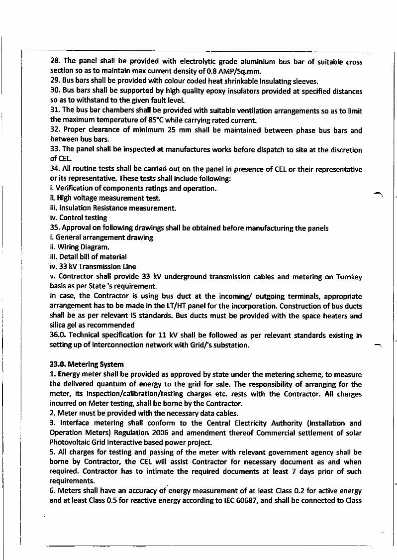
9. All the registers shall be stored in a non-volatile memory. Meter registers for each meteringinterval, as well as accumulated totals, shall be downloadable. All the net active/reactive energyvalues displayed or stored shall be with a plus/minus sign for exportfmport.10. At least the following data shall be stored before being over-written for the followingparameters.
sl.No Parameters Deralls _ . Mln No ol4aJsNt't,l'lWh 15 min. block 90 d;r in meteri
t'
I
'|
_ \!'eragc Frequenc1'
Net MvARh lt)r > l03yo
tiuntulatiur- ner MWh
'i (.urnuliltive npr MVARh for >103@,o
l)ate & timr, blorks for lIT fallureon any phase
l5 mrn. block ' 90 da ,n meter
, l! minblock l9_0Cays iLmgEr_ -. _jAt every i 3O days in nterer/ 90mid nreht davs rn PC
At every 30 days rn meter/ 90 l
. mid nithl. . days in PC
11. Shall have a built in clock and calendar with an accuracy of less than 5 seconds per monthdrift without assistance of extemal time synchronizing pulse.12. Date/time shall be displayed on demand. The clock shall be synchronlzed by Gps timesynchronization equipment existing at the station provided by Contractor13. The meter shall be suitable to operate wfth power drawn from the w supplies. The burdenof the meters shall be less than maximum 2VA14. The power supply to the meter shall be healthy even with a single. phase VT supply. Anautomatic backup, in the event of non-arrailability of voltage in all the phases, shall be provldedby a built in long life battery and shall not need replacement for at least 10 years with acontinuous VT interruption of at least 2 yeaB. Date and Ume of vT interruption and restoratlonshall be automatically stored in a non-volatile memory.15. Even under the absence of VT input, energy meter display shall be available and it shall bepossible to download data from the energy meters.16. Meters shall have an optical port on the front of the meter for data collection from either ahand held meter reading instrument (MRl) having a display for energy readings or from anotebook computer with suhable software.17. The meter shall have means to test MWh and MVARh accuracy and calibration at sfte in-situand test terminal blocks shall be provided for the same.18. The CEU Owner shall have the right to carry out surprise inspections of the MeteringSystems from time to time to check their accuracy.
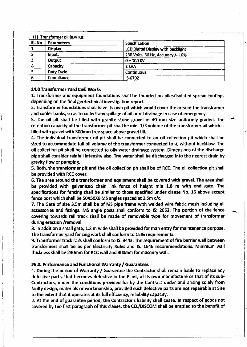
Sl. No Paremetens Speclficadon1 Display tCD Digital Display with backlight2 lnput: 230 Volts, 50 Hz, Accuncll l- 1O%
3 o 0-100 r(v4 capacity l kvA
Duty Cycle
6 Compliance
L Transformer oil BDV Kit:
Continuous1s.6792
24.0 Transformer Yard Clvll WorksL. Transformer and equipment foundations shall be founded on piles/isolated spread footingsdepending on the final geotechnical investigation report.2. Transformer foundations shall have its own pit which would cover the area ofthe transformerand cooler bank, so as to collect any spillage of oil or oil drainage in case of emergency.3. The oil pit shall be filled with granite stone gravel of 40 mm size uniformly graded. Theretention capacity of the transformer pit shall be min. {3 volume of the transformer oil which is
filled with gravel with 300mm fiee space above gravel fill.4. The indMdual transformer oil pit shall be connected to an oil collection pit which shall besized to accommodate full oil volume of the transformer connected to 'O without backflow. The
oil collection pit shall be connected to oily water drainage system. Dimensions of the dischargepipe shall consider rainfall intensity also. The water shall be discharged into the nearest drain bygravity flow or pumping.5. Both, the transformer pit and the oil collection pit shall be of RCC. The oil collection pit shall
be provided with RCC cover.6. The area around the transformer and equipment shall be covered with gravel. The area shallbe provided with galvanized chain link fence of height min 1.8 m with and gate. The
specifications for fenclng shall be similar to those specified under clause No. 15 above except
fence post whlch shall be 50)60X6 MS angles spaced at 2.5m c/c.7. The Gate of size 3.5m shall be of MS pipe frame with welded wire fabric mesh including all
accessories and fittings. MS angle posts shall conform to lS: 2062. The portion of the fencecovering towards rail track shall be made of removable type for movement of transformerduring erection /removal.8. ln addition a small gate, 1.2 m wide shall he provided for man entry for maintenance purpose.
The transformer yard fencing work shall conform to CEIG requirements.9. Transformer track rails shall conform to lS: 3443. The requirement of fire barrier wall betweentransformers shall be as per Electricity Rules and lS: 1il6 recommendations. Minimum wallthickness shall be 230mm for RCC wall and 300mm for masonry wall.
25.0. Performance and Functlona! Warranty / GuaEntees1. During the period of Warranty / Guarantee the Contractor shall remain liable to replace any
defective parts, that becomes defective in the Plant, of its own manuhcture or that of its sub-Contractors, under the conditions provided for by the Contract under and arising solely fromfaulty design, materials or workmanship, provided such defuctive parts are not repairable at Site
to the extent that it operates at its full efficienry, reliability capacity.2. At the end of guarantee period, the Contractor's liability shall cease. ln respect of goods notcovered bythe first paragrdph of this clause, the CEUDISCOM shall be entitled to the benefit of
5
such guarantee given to the Contractor by the original Contractor or manufacturer of such
goods.
3. During the first year of assured performance demonstratlon, the Conractor shall be
responsibte for any defects in the work due to faulty workmanship or due to use of sub-standard
materials in the worlc Any defects in the work during the guarantee period shall therefore, be
rectified by the Contractor without any extra cost to the CEL within a reasonable time as may be
considered from the date of receipt of such intimation from the CEt failing which the CEL shall
take up rectification work at the risk and cost ofthe Contractor.
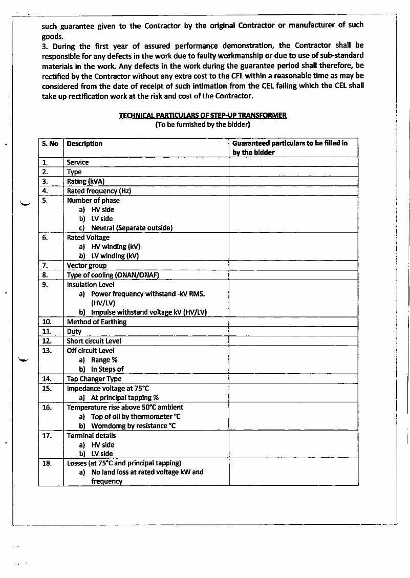
TEq{NICAL PARNCULARS OF SIEP.UP TRANSFORMER
firo be fumished by the bidder)
S. No Descrlpdon Guaranteed pardculars to be f,lled lnby the bldder
t. Service
2. Type3. Rating (kvA)
4 Rated frequency (Hz)
5. Number of phase
a) HV sideb) Lv sidec) Neutral (Separate outside)
6_ Rated Voltagea) Hv winding (kV)
b) w windlne (kv)7 Vector group
8. Type of cooling (ONAN/ONAF)
9 lnsulation Level
a) Power fiequency withstand -kV RMS.(Hv/Lv)
b) lmpulse withstand voltage kV (HV/IV)
10. Method of Earthingrt Dutyt2 Short circuit Level
13 Off circuit Level
a) Range %
b) ln Steps of14. Tap changer Type
15 lmpedance voltage at 75"Ca) At principaltapping %
L6. Temperature rise above strC ambienta) Top of oil by thermometer "C
b) Womdomg by resistance "C
t7. Terminal detailsa) HV sideb) LV side
18. Iosses (at 75"C and principal tapping)a) No land loss at rated voltage kW and
frequency
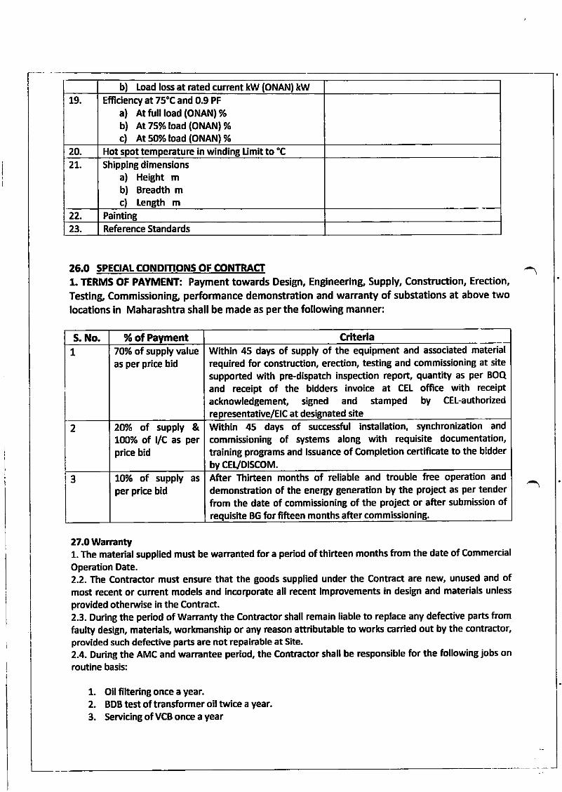
L
b) Load loss at rated current kW (ONAN) kW19 Efffciency at 75"C and 0.9 PF
a) At tull load (Ol,lAN) %b) At 7s% load (oNAN) %
c) At gYo load (ONAN) %20. Hot spot temperature in windinB Limit to "C21.. shipping dimenslons
a) Height mb) Breadth mc) length m
22. Painting23. Reference Standards
26.0 SPECIALCONDInONS OF CONTRACT
1. TERMS OF PAYMENT: Payment towards Design, Engineerin& Supply, Construction, Erection,
Testln& Commissioning, performance demonstration and warranty of substations at above twolocatlons in Maharashtra shall be made as per the following manner:
27.0 War."nty1. The material supplled must be warEnted for a period of thirteen months from the date of Commercial
Operation Date.2.2. The Contractor must ensure that the goods supplied under the contract are new, unused and ofmost recent or current models and incorporate all recent improvements in des@ and materials unless
provided otherwise in the Contract.2.3. During the period of Warranty the Contractor shall remain liable to replace any defective parts from
faulty design, materlals, workmanship or any reason attributable to works canied out by the contractor,provided such dekive parts are not repairable at Site.
2.4. During the AMC and warrantee period, the Contractor shall be responsible for the following jobs on
routine basis:
1. Oilfiltering once a year.2. BDB test of transformer oil twice a year.
3. Servicing of VCB once a year
S. No. % of Payment Crfterla70% of supply valueas per price bid
Within 45 days of supply of the equipment and associated material
required for construction, erection, testing and commissioning at site
supported with pre-dlspatch inspection report, quantity as per BoQ
and receipt of the bidders invoice at CEL office with receipt
acknowledgement, siBned and stamped by CEl-authorized
re p resentative/E lc at designated site
2 2elo of supply &1@% ol /c as perprice bid
Within 45 days of successful installation, synchronization and
commissioning of slstems along with requisite documentation,
training programs and lssuance of Completion certificate to the bidder
cEvDrscoM.3 10% of supply as
per pdce bidAfter Thirteen months of reliable and trouble free operation and
demonstration of the energy generation by the project as per tenderfiom the date of commissioning of the project or after submission ofre uisfte BG for ffieen months after commissioning.
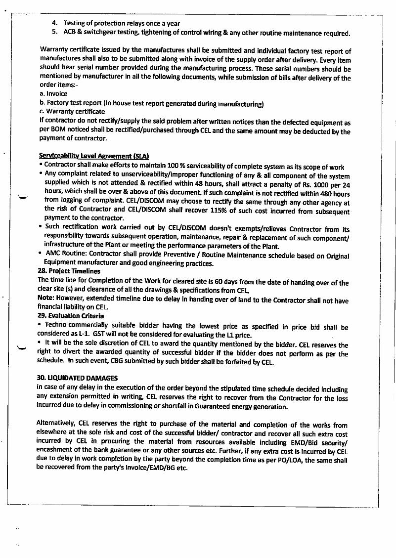
t'4. Testing of protection relays once a year5. AcB & switchgear testin& ti8htening of control wlring & any other routine maintenance required.
warranty certificate issued by the manufactures shall be submltted and indMdual factory test report ofmanufactures shall also to be submitted along with invoice of the supply order after delivery. Every itemshould bear serial number provided during the manufacturing process. These serial numbers should bementioned by manufacturer in all the following documents, whlle submlssion of bills after delivery of theorder items:-a. lnvoiceb. Factory test report (ln house test report generated during manufacturing)c. Warranty certificatelf contractor do not rectify/supply the said problem after written notices than the defected equipment asper BOM noticed shall be rectified/purchased through CEL and the same amount may be deducted by thepayment of contmctor.
Servtceabillty tevel Asreement (StAl
' contractor shall make efforts to malntaln 100 % seMceability of complete system as its scope of work' Any complaint related to unserviceability/improper functioning of any & all component oi the
"yrtemsupplied which is not attended & rectified within 48 hours, shall attGct a penalty of Rs. 1O0O per 24hours, which shall be over & above of this document lf such complaint is noi rectided within 48o hoursfrom logging of complaint. cEuDrscoM may choose to rectify the same through any other agency atthe risk of Contractor and cEVDlScoM shall recover L75yo ot such cost incJned ftom subsequentpayment to the contractor.
. Such rectification work carried out by CEUDISCTOM doesn"t erempts/relieves Contractor ftom itsresponsibility towards subsequent opeftttion, maintenance, repair & replacement of such component/infrastructure ofthe Plant or meeting the performance panmeters of the plant.
' AMc Routine: contractor shall provide Preventive / Routine Maintenance schedule based on o.iginalEquipment manufacturer and good engineering practices.
28. Project TimellnesThe time line for completion ofthe Work for cleared site ls 60 days ftom the date of handing over of theclear site (s) and clearance of all the drawings & specifications ftom CELNote: However, extended timeline due to delay in handing over of land to the Contractor shall not havefinancial liability on CEL29. Eyaluadon Crlterla
' Techno-commercially suitable bidder having the lowest price as specified ln price bid shall beconsidered as L-1. GST will not be considered for eyaluating the L1 price
' lt will be the sole discretion of CEt to award the quantity mentioned by the bidder. CEt reseryes theright to divert the awarded quantity of successful bidder if the bidder does not perform as per theschedule. ln such event, CBG submitted by such bidder shall be forfuited by CEL
30. UQUIDATED DAMAGESln case of any delay in the execution of the order beyond the stipulated time schedule decided includingany extension permitted in writing, CEL reserves the right to recover from the Contractor for the lossincurred due to delay in commissioning or shorthll in Guaranteed energy generation.
Alternatively, cEL reserves the right to purchase of the material and comptetion of the work fromelsewhere at the sole risk and cost of the successful bidder/ contractor and recover all such extra costincurred by CEL in procuring the material from resources available lncluding EMD/Bid security/encashment of the bank guarantee or any other sources etc. Further, lf any extra cost is incurred by CELdue to delay in work completion by the party beyond the completion tlme as per PO/LOA, the same shallbe recovered from the party's lnvoice/EMD/BG etc.
Altematively cEL may cancel the order completely or partly without preiudice to his right under the
altematives mentioned above.
3'- CONTRACT PERFORMANCE GUARANIEE
Within thirty (30) days of the receipt of notification of award ftom CEl, the successful bidder shallfumish
the security deposit in the form of Demand Dnft/ Pay Order or Bank Guarantee for 10olo of the total
contract value. The security must be valid to cover completion Period' Any delay in submission of SD shall
be deemed as accruing of financial benefit to the supplier and cEL may take necessary interest penalty
rEcovery action (interest @ sBl's McLR + 2 %l ftom the payments due to the supplier for the period of
detay. However, this provision does not bind CEL in any way ftom proceeding against the supplier
(including forfeiture of EMD, cancellation of the empanelmenvloA, etc.) for non-compliance towards
non-submission of the sD.
Bank guarantee shall be ftom any Nationalized Banks/other scheduled private banks. cEL shall at his
discreiion have recourse to the said Bank Guarantee for the recovery of any or all amount due from the
bidder in connection with the contract including of guarantee obliBations'
Failure of the successful Bidder to mmply with the requirements of tender shall constitute sufficient
grounds for the annulment of the award and forfeiture ofthe contract Performance Guarantee'
32. Thlrd Party lnsPecton Agency
32.1. A thlrd party lnspection aBency ('Third Party lnspectoE' or 'TPl") may be appointed by
cEvDlScoM, at its sole discretion, to conduct any kind of inspection regarding but not limited to
protrr"rant, fabrication, installation, hook-up and commissioning during the execution of the Proiect'
The Contractor shall provide necessi!ry access and coordination to conduct such inspections' The extent
ofthlrd party inspectorc' involvement shall be ffnalized after mutual discussions between the Contractor
and CEL/DISCOM.
32.2. CEVDISCOM or its authorised representatives, reserve the right to inspect the project components,
as per project schedule to ensure compliance of the quality of Componens/ material as per the
,p"tm62uon and data sheet, before dispatch to site. cEVDlscoM at its own discretion will visit the
premises for inspection with prior intimation to the contractor. lt is the responsibility of the contractor to
inform 6EUDI5COM at least 14 days prior to the despatch of the project equipment. All administrative
expenses for cEuDlscoM or its authorised representatives, will be bome by cEvDlscoM for above
inipections. However, all the expenses retated to testing and inspection at manufucturer/ supplier
premises or at project site shall be borne by the contractor only. ln case contractor fails to show the
compliance for the component under inspection as per Technical specification & approved drawing
/design & same is not approved for mass production or dispatch, in such cases contractor shall bear the
expe;ses towards visit of CE{DISCOM'5 team for subsequent visit/s for inspection of same component'
33. INSURANCE. During the contract period, i.e., during construction, all insurance related expenses shall be bome by
the contractor. The goods supplied (including the solar Pv modules & lnverters) under the contract
shall be fully insured against the toss or damage incidental to manufacture or acquisition,
transportation, storage and delivery in such a manner that CEVDTSCOM shall not incur any financial
loss, as long as the ptant continues to remain under the custody ofthe Contractor'
. The contractor should arrange for providing insurance coverage to its workmen under workmen's
Compensation Act or similar-Rules, ind Acts as appticable during execution of work for covering risk
against any mishap to its workmen. The contractor shall also undertake a Third Party lnsurance' The
CEUDISCOM will not be responslble for any such loss or mishap'
a
All other insurance like ln - transit insurance (Marine/ cargo/ otherc as applicable), contractor AIIRisk, Erection All Risk, workmen compensation, third party liability, insurance against theft and actsof coD and others as required for the construction and to indemnifu the cEuDiscoM/ equipmenvmaterial and resources shall be bome by the Contrilctor.
cEUDlscoM shall be named as co - Insured under all-insurance policies taken out by the contractor,except for the workmen compensation, third - party liabllity and cEvDtscoM's ri.uiritv inrrin."..AIso, contGctors' sub - contractor shall be named as co - insured under all insurances taken out bythe contractor pursuant to except for cargo insurance, workmen compensation inrror,a" -ocEvDlscoM's liability insurance. All insurerc' rights of iubrogation against such co _ insured forlosses or claims arising out ofthe performance ofthe contract siall be waived under such policies.
!I4. TR'INSPORTANON, DEIIIIURRAGE, WHARFAGE, ETCcontractor is required under the crntract to transport the Goods to place of destination defined as site.Transport to such place of destination in India including lnsurance, as shall be specified in the contract,shall be arranged by the contractor, and the retated coishall be Incruded ln the contract price.successful bidder, on whom retter of award is praced, is to ensure a[ safety guiderines, rures andregulations, labour raws etc. Successfur bidder indemnifies cEL for any accid*t i'"irrv ,"i tv its rabour,employee or any other person wo*ing for him. Any compensation sought by its ratour. erftly"" or rnyother person working for him shall be paid by succersnrltiooer as per setuement solely. cEL has no roleto play in this matter.35. Pedod of valldlty of Bid:Bids shall remain valid for a period of 180 days after the closing date pressibed by the cEL for the receiptof bids. A bid varid for a shorter period may be releaed-by the cEL as ueing non-responsive. tnexceptional circumstances, the cEL may solicit the bidde/s consent to an extension of the bio validityperiod' The request and response thereto shall be made in writing thro' letters/ e-mails. lf the bidderaccepts to prolong the period of vatidity, the bid securfty/EMD shali also be suitably exteia"a. a uiua.,may retuse the request for Bid validity Extension wfthout forhfting its nia secuaty. a iiJJ", eint1ns tt "request will not be required nor permitted to modify its bid.
SPECUU. CONDMONS:L,
2.
3.
Prices quoted shall be on FoR cEL sites in Nasik dlstrict of Maharashtra which includes freigh!loading unloading at site etc Actuarsfte address shafl be intimated at the time ofdispatch.Ll ofeach category shall be declared separately.Depending upon the design of power system approved by customer, one or two types of system (outof 5 types) shall be procured.
4. Based upon the type of system approved by client, order shall be placed accordingly.5. cEL reserves the right to split the item/order and place order on more than one vendor.6' subsequent to an order being praced against youi quotation, received in respons€ to this ,enquiry,, ifit is found that the materiars suppried are not orthe right quarity or not in accordance with ourspecifications (required by us) or received in damageo or oroten conoitions, not satishaory oring toany reason of which we shall be the sole judgg we shall be entitled to r"j".i thu .rt"ri.ir, Lnculthucontract and buy our requirement ftom the open market / other sourcei and recover the ioss, if any,ftom the supprier reservinB to ourserves the right to forfeit the security deposit, fumished by thesupplier against the contract. The supplier will make his own anirngements to remove the re1ectedmaterial within a fortnight of instruction to do so. Thereafter material will lie entirely at the supplier,srisk and responsibirity and storage charBes, arong with any other charges applcabre, wifl berecoverable from the supplier.7' Successful bidder is to ensure interchangeabllity of its product supplled for replacement duringwarranty period and even yhen it is purchased from open market rn or" ir" to change intechnology, the supplied product is not available durint warranty perlod than the lmproved vercion
of product can be used in warranty period with same or improved technical parameters or thecombination thereof after written communication of Project in Charge at same cost & terms andconditions. Successful Bidder, on whom letter of award has been placed, has also to confirm that theprices of improved vercion of product is not lesser than the original product or its parts incomparison.
8. CEL reserve the right for guantity variation up to +/-50% irrespective of project capacity. Further cELreserve the right to place a repeat order in case of urgency for part quantity in the Letter of Awardfor similar work on same prices, terms and conditions. Also, CEL reserve the right to ask thesuccessful bidder to deliver the part quantity placed on them anywhere in territory of lndia on sameprices, terms and conditions.
9. CEL have the rights to accept or reject any bid or part without assigning any reason. The biddershould not have been black-listed by-Central Govemment or Centrill Public-sector Undertakings. lf atany sta8e of tendering process or during the currency of the contract, any suppression / falsificationof such information is brought to the knowledge, CEI -shall have the right to reject the proposal orterminate the contract, as the case may be, wfthout any compensation to the tenderer & forfeitureof bid secufty/EMD/CPG.
10. The contractor/bidder shall not display the photographs & content of the work and also will not takeadvantage through publicity of the work without written permission of CEL Non-compliance to thismay result in removal ftom the EPC list and the contractor will be blacklisted.
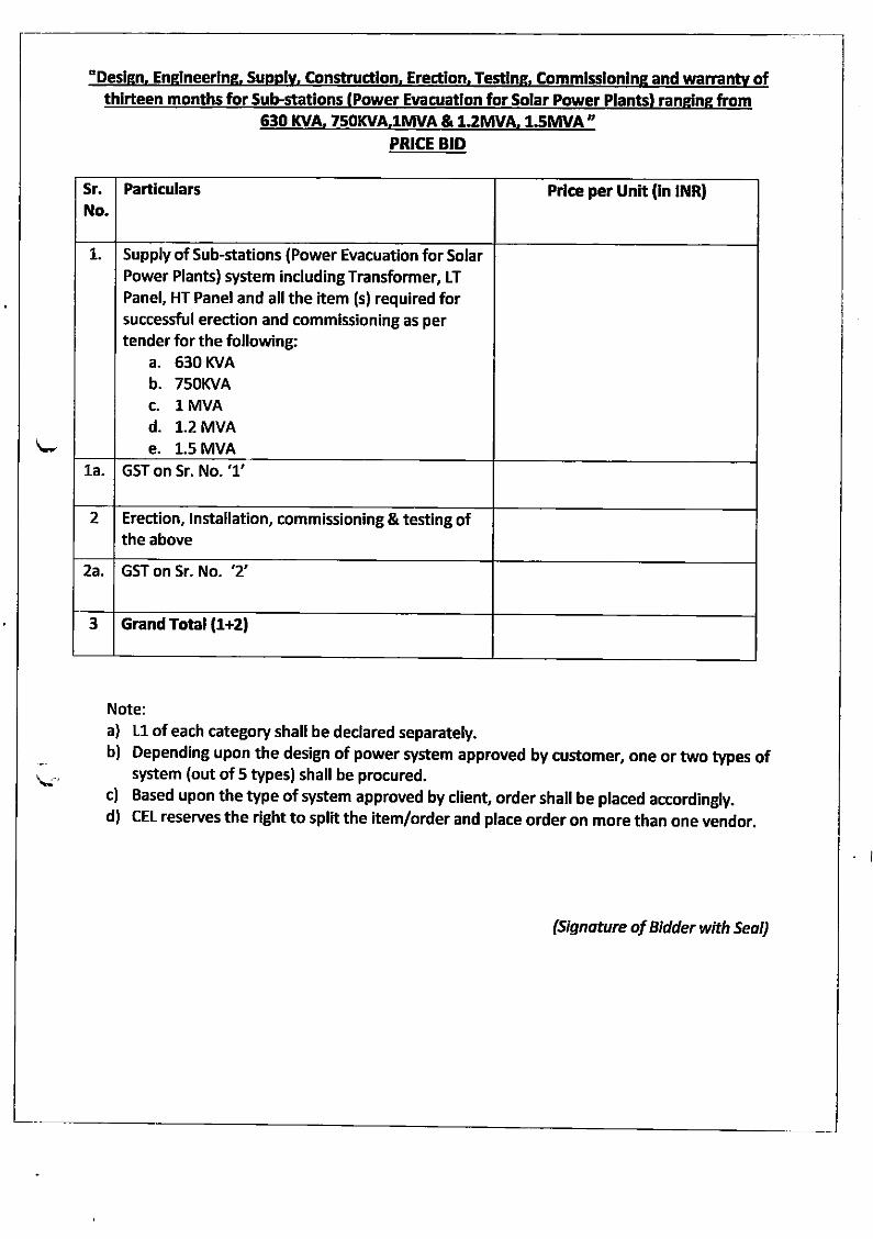
"Deslsn. Enelneerine. SuoDlv, Constructlon, Erectlon. Testlns. Commlsslonlne and trvarmnty ofhirteen months for Sub-statlons Power lar Power Plants ra
630 KVA. 7 & 1.2fi,M. 1.5MVA ,,
PRICE BID
Note:a) L1 of each category shall be declared separately.b) Depending upon the design of power system approved by customer, one or two types of
system (out of 5 types) shall be procured.c) Based upon the type of system approved by client, order shall be placed accordingly.d) cEL reserves the right to split the item/order and place order on more than one vendor.
(Signoture of Bidder with Seo,,)
Sr
No.Partlculars Prlce per Unlt (ln tNR)
7. Supply of Sub-stations (Power Evacuatlon for SolarPower Plants) system including Transformer, LT
Panel, HT Panel and all the item (s) required forsuccessful erection and commissioning as pertender for the following:
a. 630 KVA
b. 750KVA
c. l MVAd. 1.2 MVAe. 1.5 MvA
1a GST on Sr. No. '1'
2 Erection, lnstallation, commissioning & testing ofthe above
2a. GST on Sr. No. '2'
3 Grand Total {1+21
Tender Document: C-2(b)/RC/0700/4485/2018
Annexure- B
Standard terms and conditions:
(Terms and conditions mentioned in Annexure C will supersede these Standard Terms and Conditions
wherever there is any difference. Hence please see Annexure C carefully)
1. CEL will prefers to get offers directly from the original manufacturers and prefer to deal directly with manufacturer.
2. Terms of Price: The terms of Price would be FOR CEL, Sahibabad unless specified otherwise in special
terms & conditions of Annexure C.
3. No Deviation from Specifications, Terms & Conditions of the tender is allowed. Quotations having deviation from our specifications, standard terms & conditions would be rejected.
4. All requirements of export licensing, Govt. permissions or any other statutory clearance from the country of export as per regulations existing in the supplier’s country shall be the responsibility of supplier, if required as per the terms of the purchase order.
5. In a tender either the Indian agent on behalf of the foreign Principal/OEM or foreign Principal/OEM itself can bid but both cannot bid simultaneously in the same tender. If an agent submit bid on behalf of the Principal/OEM, the same agent shall not submit a bid on behalf of another Principal/OEM in the same tender. Agent quoting on behalf of OEM /Principal shall submit valid authorization certificate along with their offer.
6. Taxes and duties: The taxes and duties are to be clearly mentioned, if any.
7. Delivery schedule: As per Special Terms and conditions of Annexure C.
8. Payment terms:
Option 1: Within 45 days from the consignment note/LWB.
Option 2: Letter of credit with 45 days usance from the consignment note/LWB. LC charges of opener’s
bank would be borne by opener and LC charges of beneficiary’s bank would be borne by the beneficiary. A loading of 1% on the total amount will be done for comparison of landing cost to CEL, if option 2 is
ticked/accepted by the bidder
Please tick √ either option 1 or option 2. If no option is selected then option 1 would be considered.
Quotation with payment terms other than these 2 options will be rejected.
9. Inspection: Inspection will be done by CEL representative. CEL shall have free access to the supplier’s
works during testing and final inspection. Vendor shall inform the purchase not less than one week in advance. All testing arrangements shall be the responsibility of the vendor. CEL reserves the right to inspect the material during manufacturing and/or before dispatch as per specifications and test protocols. Internal inspection report and inspection certificate must accompany the supply. (This clause will be superseded by Inspection clause, if any, in Annexure C).
10. Price variation Clause: Price variation will not be permitted and quotations having Price variation clause will be rejected. (This clause will be superseded by Price Variation Clause, if any, in Annexure C).
11. Price reduction for delayed delivery: In the event of delay in affecting the delivery within agreed period, a reduction in the price shall be levied @ 0.5% of the total order value per week or part thereof subject to maximum of 5% of the total order value.
12. Validity of offer: The quotation/tender/bid submitted by the bidder/supplier shall be valid for a minimum period of 90 days from date of opening.
13. Determination of Lowest quoting bidder: The lowest quoting bidder would be decided on the basis of lowest landing cost of items to CEL.
14. Splitting of tender quantity in two or more bidders: CEL reserve the right to split the quantity and
award on two or more vendors as per the production / project requirement. The following norms would be adopted in case of spilt of quantity: If the lowest quoting vendor is an approved vendor and the second lowest and third lowest bidders are
Tender Document: C-2(b)/RC/0700/4485/2018
also approved vendors to CEL 100% of tender quantity would be split amongst the approved vendors only. In case of split of quantity in two approved vendors, the same shall be applicable for lowest (L1) & second lowest (L2) in the ratio of 70:30 at the rate & terms applicable to L1 approved vendor, keeping in view the objective that the per unit landed cost to CEL in case of purchase from L1 or L2 approved vendor remains same. In case of split of quantity in three approved vendors 60% quantity would be awarded to L1 approved vendor and balance 40% quantity will be awarded to the L2 approved vendor and L3 approved vendors in the ratio of L2’s quantity > L3’s quantity subject to acceptance of L1 rate by L2 and L3 vendor. If the L2 vendor does not accept the L1 approved vendor’s rate and terms then the quantity will be split between L1 approved vendors and L3 approved vendors. Micro & Small Enterprises quoting price within price band of L1+15 per cent shall also be allowed to supply a portion upto 20% of requirement by bringing down their price to L1 price where L1 is non MSEs (as per “Public Procurement Policy for Micro & Small Enterprises (MSEs) Order 2012”). If price quoted by a MSE is within L1+15% and such MSE is L4 or higher (provided L1, L2 and L3 are not the MSEs) and agrees to the rates & terms quoted/agreed by L1 bidder, then the splitting of quantities may be done as: MSE bidder: 20%, other bidders: 80% of tender quantity as given in above paragraph.
15. NEW / UNAPPROVED VENDOR POLICY: Bidders who are not in the approved vendor list of CEL and
are unapproved in CEL would be allowed to participate in open tenders. However, the quotation of such
bidders would be evaluated based on the eligibility criteria defined in the tenders. If the bidders
satisfies the eligibility criteria and meets the specifications and terms and conditions given in the tender
then that bidder may be awarded with purchase order/work order of maximum 10% of the tendered
quantity in order to develop that bidder as a vendor to CEL for participation in future tenders subject to
the following conditions:-
a) The bidder should be either the 1st lowest quoting bidder or 2nd lowest quoting or 3rd lowest
quoting bidder.
b) The bidder should agree to supply the tendered material at the lowest quoting bidder’s rate if the
bidder is unapproved and is L2 or L3 bidder.
c) The bidder must fill up the vendor registration form and follows the vendor approval procedure.
d) The maximum quantity to be divided between the unapproved bidders would be 10% of the total
tendered quantity.
e) Supply from unapproved bidders who are awarded purchase/work order would be taken only after
approval of samples, wherever applicable.
f) In case of Capital items/Projects/EPC/Works Contract or even regular procurement for production
where splitting of tender is not possible, purchase/work order would be placed on lowest eligible &
technically qualified vendor only.
However to develop new vendors, a perpetually open EOI No. C-2(b)/EOI/707/68/2015 is also uploaded
on our website and CPP with detailed specifications.
16. Any corrections/alterations in the tender/quotation/bid should be duly signed by the bidder. CEL does not take any responsibility for delay in receipt or non-receipt or loss of tender(s).
17. Earnest money deposit (EMD): EMD amount of 1,16,000/- (and also in tender notice) must be submitted through demand draft/RTGS/NEFT/TT/SWIFT favoring Central Electronics Limited. The demand draft must be valid for three months and should be payable at Delhi. The EMD amount must be submitted on or before the due date of opening of quotations. No interest shall be payable on the EMD. The details of CEL’s bank account for RTGS/NEFT of EMD amount are as below:
Beneficiary Name: Central Electronics Limited Beneficiary Account Number/IBAN: 87761250000014 Beneficiary Bank SWIFT Address/BIC: SYNBINBB161 Beneficiary Bank Name: Syndicate Bank Beneficiary Bank Address: Sahibabad Branch, CEL Complex, Plot No. 1, Site 4, Sahibabad 201010, U.P., INDIA
The EMD (after deduction of bank charges, if any) of unsuccessful bidder will be refunded within one
Tender Document: C-2(b)/RC/0700/4485/2018
month of finalization of tender. The earnest money of successful bidder would be converted into security deposit and would be returned (after deduction of bank charges, if any) to the bidder after two months of successful completion of order. Exemption from submission of EMD: The following type of bidders are exempted from submission of EMD subject to submission of relevant documents mentioned herein: a) Micro & Small Enterprise registered with DIC or KVIC or KVIB or Coir Board or NSIC or DHH or any other body specified by Ministry of Micro, Small and Medium Enterprises, Govt. of India. A copy of valid registration certificate should be submitted with technical bid of quotation. b) Approved vendors of CEL or vendors who have supplied stores to CEL in the last 3 years (attach a copy of Purchase Orders received from CEL with the technical bid).
18. Tender/Quotation/Bid should be submitted in sealed cover super-scribing the tender notice no.,
name of the item and due date should be delivered at the Office of the Asstt. General Manager,
Materials Management Division, Central Electronics Limited, 4, Industrial Area, Saur Urja Marg,
Sahibabad – 201010 (U.P), INDIA. Last date of receiving of tenders/quotations is 09-03-2018
up to 15:00 hrs IST. The following are to be submitted in your quotation duly signed and stamped on all
pages:
Part A and inline to Pre-Qualification Criteria
i. Filled up Format for Submission of Vendor Data as per format at Annexure D. ii. Data sheet/catalogue clearly showing that the offered material is meeting the specifications given in
the tender. iii. Tender acceptance letter as per format at Annexure E. iv. Original Signed and stamped tender document (photocopy document is liable to be rejected).
v. Eligibility criteria as per Annexure-A
Part B: (Financial Bid) and inline to Annexure ‘F’ :
Price Bid as per As per Annexure ‘F’ as asked in the relevant columns.
Note: The rates should be quoted in figures (typed or printed) and cutting should be avoided. The final
amount should be in figures as well as in words. Changing of heading or title or modification to any part
of the price bid may render the bid as invalid and such bids are liable to be rejected.
Submission of Tender Documents
All tender documents (Technical and Financial) should have to be received in Materials Management Division, Central Electronics Limited on/before 09-03-2018 up to 15:00 Hrs IST and through reputed couriers, speed post or registered post only. All tender documents received after the specified date and time shall not be considered. Each individual sealed envelope i.e Cover - 1: (Technical) and Cover - 2 (Financial) as well as the outer envelope should be marked with the following reference as below:
a. Tender notice no. C-2(b)/RC/0700/4485/2018 b. Name of the item: Design, Engineering, Supply, Construction, Erection, Testing, Commissioning and Warranty of Thirteen months of Sub-Stations (Power Evacuation of Solar Power Plants) ranging from 630 KVA, 750 KVA, 1 MVA & 1.2 MVA, 1.5 MVA at Nashik district in the State of Maharashtra c. Due Date: 09-03-2018 d. Nature of Bid (To be mention on Cover 1 and Cover 2 only): Technical / Commercial.
The postal address for submitting the tender is
Office of the Assistant General Manager,
Materials Management Division
Tender Document: C-2(b)/RC/0700/4485/2018
Central Electronics Limited,
4, Industrial Area, Saur Urja Marg,
Sahibabad – 201010 (U.P) INDIA
19. Opening of Tenders: Technical bid will be opened on 09-03-2018 at 15:30 Hrs (IST).
Note 1: The bidders or their authorized representatives may also be present during the opening of the
Technical Bid, if they desire so, at their own expenses.
Note 2: The technical bids will be opened and evaluated by a duly constituted committee. After
evaluation of the technical bid, Price bids of only those bidders will be opened whose technical bids are
found suitable. Date and time of opening of price bids will be decided after technical bids have been
evaluated by the committee
20. CEL reserves the right to reject any or all tenders/quotations/bids received or accept any or all tenders/quotation/bids wholly or in part. Further, CEL reserves the right to order a lesser quantity without assigning any reason(s) thereof. CEL also reserves the right to cancel any order placed on basis of this tender in case of strike, accident or any other unforeseen contingencies causing stoppage of production at CEL or to modify the order without liability for any compensation and or claim of any description.
21. In case an order placed by the CEL based on the quotation/bid/tender submitted by the bidder/supplier is not executed by the supplier/bidder, CEL may buy the ordered goods from elsewhere and recover the additional amount that CEL may have to spend in procuring the stores plus 10% to cover the overhead & incidental expenses.
22. Quantity Enhancement: CEL Reserves the right to enhance the quantity of material ordered by up to
50% by amending the purchase order(s) within a year, if any, awarded on the basis of this tender at the rate and terms and conditions mentioned in such purchase order(s).
23. Replacement of Rejected Material: Any material supplied against order place on basis of this tender and found to be defective on inspection or differing from approved samples or make or specifications will be replaced by the supplier free of cost or full refund made for the amount paid by Central Electronics Limited including freight and insurance and other incidental charges at our discretion.
24. Termination for Default :
CEL may, without prejudice to any other remedy for breach of contract, by written notice of
default sent to the Supplier, terminate the Contract in whole or in part:
9.1 If the Supplier fails to deliver any or all of the Goods within the period(s) specified in the Contract,
or within any extension thereof granted by the Purchaser; or
9.2 If the Supplier fails to perform any other obligation(s) under the Contract.
9.3 If the supplier, in the judgment of the purchaser, has engaged in corrupt or fraudulent practices in
competing for or in executing the contract.
For the purpose of this clause:
“Corrupt practice” means the offering, giving, receiving, or soliciting of anything of value to
influence the action of a public official in the procurement process or in contract execution.
“fraudulent practice” means a misrepresentation of facts in order to influence a procurement
process or the execution or a contract to the detriment of the borrower, and includes collusive
practice among bidders (prior to or after bid submission) designed to establish bid prices at
artificial non-competitive levels and to deprive the borrower of the benefits of free and open
competition.
In the event the Purchaser terminates the Contract in whole or in part, the Purchaser may
procure, upon such terms and in such manner as it deems appropriate, Goods or services similar
to those undelivered, and the Supplier shall be liable to the Purchaser for any excess costs for
such similar Goods or services. However, the Supplier shall continue the performance of the
Contract to the extent not terminated.
Tender Document: C-2(b)/RC/0700/4485/2018
The contractor/bidder shall not display the photographs & content of the work and also will not
take advantage through publicity of the work without written permission of CEL. Noncompliance
to this may result in the blacklisted of firm.
25. Force Majeure: In no event shall either Party have any liability for failure to comply with this Agreement, if such failure results directly from the occurrence of any contingency beyond the reasonable control of the Party, including, without limitation, strike or other labor disturbance, riot, major power failure, war, natural calamities including but not limited to floods, earthquakes, fire, volcanic eruptions, epidemics, National Emergency, interference by any government or governmental agency, embargo, seizure, or enactment or abolition of any law, statute, ordinance, rule, or regulation (each a " Force Majeure Event"). In the event that either Party is unable to perform any of its obligations under this Agreement because of a Force Majeure Event, the Party who has been so affected shall as soon as may be, after coming to know of the Force Majeure Event, inform the other Party and shall take reasonable steps to resume performance as soon as may be after the cessation of the Force Majeure Event. If the period of nonperformance due to a Force Majeure Event exceeds thirty (30) days, the Party whose ability to perform has been so affected may, by giving written notice, terminate this Agreement.
26. Arbitration: Any disputes, difference controversies/ difference of opinions, breach and violation arising
from or related to this agreement/contract/work order etc. between the parties shall be resolved by
mutual discussion/reconciliation in good faith. If disputes, difference controversies/difference of opinions,
breach and violation arising from or related to this agreement/contract/work order etc. cannot be resolved
within 30 days of commencement of reconciliations/ discussions then the matter shall be referred to the
Sole arbitrator, nominated by CMD, CEL for this purpose and his decision shall be final and binding on
both the parties. There will be no objection to any such appointment on the grounds that the Arbitrator is
an employee of CEL and no appeal on any order passed by the Arbitrator for this purpose shall be filed in
any Court of Law on such ground.
Tender Document: C-2(b)/RC/0700/4485/2018
Annexure-C
SPECIAL TERMS & CONDITIONS
1. All the Standard Terms and conditions of the tender will be applicable unless mentioned in Annexure-A. All the terms of Annexure A will supersede the Standard Terms and conditions, if applicable.
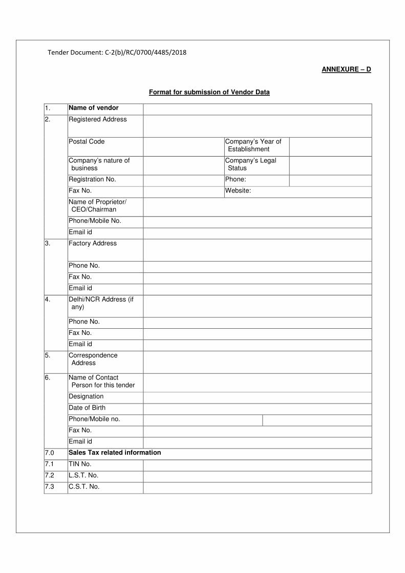
Tender Document: C-2(b)/RC/0700/4485/2018
ANNEXURE – D
Format for submission of Vendor Data
1. Name of vendor
2. Registered Address
Postal Code Company’s Year of Establishment
Company’s nature of business
Company’s Legal Status
Registration No. Phone:
Fax No. Website:
Name of Proprietor/ CEO/Chairman
Phone/Mobile No.
Email id
3. Factory Address
Phone No.
Fax No.
Email id
4. Delhi/NCR Address (if any)
Phone No.
Fax No.
Email id
5. Correspondence Address
6.
Name of Contact Person for this tender
Designation
Date of Birth
Phone/Mobile no.
Fax No.
Email id
7.0 Sales Tax related information
7.1 TIN No.
7.2 L.S.T. No.
7.3 C.S.T. No.
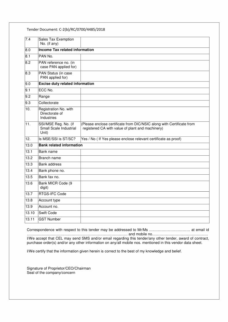
Tender Document: C-2(b)/RC/0700/4485/2018
Correspondence with respect to this tender may be addressed to Mr/Ms …………………………… at email id ……………………………………………………………………… and mobile no……………………………………… I/We accept that CEL may send SMS and/or email regarding this tender/any other tender, award of contract, purchase order(s) and/or any other information on any/all mobile nos. mentioned in this vendor data sheet. I/We certify that the information given herein is correct to the best of my knowledge and belief. Signature of Proprietor/CEO/Chairman Seal of the company/concern
7.4 Sales Tax Exemption No. (if any)
8.0 Income Tax related information
8.1 PAN No.
8.2 PAN reference no. (in case PAN applied for)
8.3 PAN Status (in case PAN applied for)
9.0 Excise duty related information
9.1 ECC No.
9.2 Range
9.3 Collectorate
10. Registration No. with Directorate of Industries
11. SSI/MSE Reg. No. (if Small Scale Industrial Unit)
(Please enclose certificate from DIC/NSIC along with Certificate from registered CA with value of plant and machinery)
12. Is MSE/SSI is ST/SC? Yes / No ( If Yes please enclose relevant certificate as proof)
13.0 Bank related information
13.1 Bank name
13.2 Branch name
13.3 Bank address
13.4 Bank phone no.
13.5 Bank fax no.
13.6 Bank MICR Code (9 digit)
13.7 RTGS-IFC Code
13.8 Account type
13.9 Account no.
13.10 Swift Code
13.11 GST Number
Tender Document: C-2(b)/RC/0700/4485/2018
Annexure – E TENDER ACCEPTANCE LETTER
(To be given on Company Letter Head) The Assistant General Manager Materials Management Division Central Electronics Limited 4, Industrial Area SAHIBABAD – 201010 (UP) INDIA Reference: Tender No: C-2(b)/RC/0700/4485/2018 dated 26-02-2018 Name of Tender / Work: Design, Engineering, Supply, Construction, Erection, Testing, Commissioning and Warranty of Thirteen months of Sub-Stations (Power Evacuation of Solar Power Plants) ranging from 630 KVA, 750 KVA, 1 MVA & 1.2 MVA, 1.5 MVA at Nashik district in the State of Maharashtra Subject: Acceptance of Terms & Conditions of Tender. Dear Sir, 1. I/ We have downloaded / obtained the tender document(s) for the above mentioned ‘Tender/Work’ from the web site(s) namely: Supply of Multi-crystalline Solar Cells, Size: 156mm x 156mm (4 Bus Bar) Wattage: Minimum 4.43 Watt as per your advertisement, given in the above mentioned website(s). 2. I / We hereby certify that I / we have read the entire terms and conditions of the tender documents from
Page No. to (including all documents like annexure(s), schedule(s), etc .,), which form part of the contract agreement and I / we shall abide hereby by the terms / conditions / clauses contained therein.
3. The corrigendum(s) issued from time to time by your department/ organization too have also been taken
into consideration, while submitting this acceptance letter. 4. I / We hereby unconditionally accept the tender conditions of above mentioned tender document(s)
/corrigendum(s) in its totality / entirety. 5. In case any provisions of this tender are found violated , then your department/ organisation shall without
prejudice to any other right or remedy be at liberty to reject this tender/bid including the forfeiture of the full said earnest money deposit absolutely.
Yours Faithfully, Signature of the Bidder Name of Authorized Signatory: Designation: Official Seal:
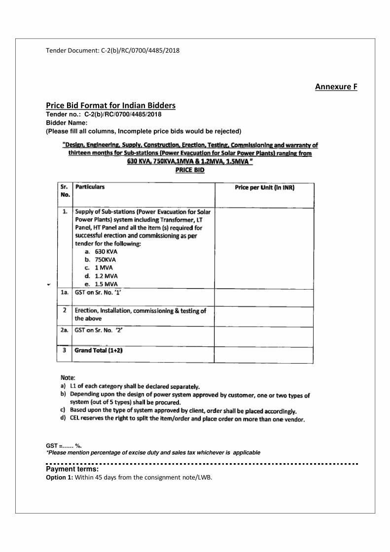
Tender Document: C-2(b)/RC/0700/4485/2018
Annexure F
Price Bid Format for Indian Bidders
Tender no.: C-2(b)/RC/0700/4485/2018
Bidder Name: (Please fill all columns, Incomplete price bids would be rejected)
GST =…… %. *Please mention percentage of excise duty and sales tax whichever is applicable
Payment terms: Option 1: Within 45 days from the consignment note/LWB.
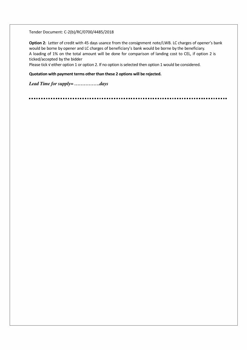
Tender Document: C-2(b)/RC/0700/4485/2018
Option 2: Letter of credit with 45 days usance from the consignment note/LWB. LC charges of opener’s bank
would be borne by opener and LC charges of beneficiary’s bank would be borne by the beneficiary. A loading of 1% on the total amount will be done for comparison of landing cost to CEL, if option 2 is
ticked/accepted by the bidder
Please tick √ either option 1 or option 2. If no option is selected then option 1 would be considered.
Quotation with payment terms other than these 2 options will be rejected.
Lead Time for supply= …………….days
![CENTRAL ELECTRONICS LIMITED (A Public Sector … for...Tender Document: C-2(b)/WC/0907/150/2016 [1] FORMAT NO. : CEL/FR/MMD/03(01) CENTRAL ELECTRONICS LIMITED (A Public Sector Enterprise)](https://img.pdfslide.net/doc/110x75/5aa74f6e7f8b9a294b8bebb1/central-electronics-limited-a-public-sector-fortender-document-c-2bwc09071502016.jpg)


![Asian Electronics Limited[1]](https://img.pdfslide.net/doc/110x75/577d29861a28ab4e1ea70b34/asian-electronics-limited1.jpg)