Embed Size (px)
DESCRIPTION
led heat sink techniques
Citation preview
www.led-professional.com
Review
ISSN 1993-890X
The technology of tomorrow for general lighting applications. Mar/Apr 2009 | Issue 12
LpR
Ceramic Simplifies Heat Dissipation
Spe
cial E
dition
LED professional Review | Mar/Apr 2009 | pagewww.led-professional.com 2
Copyright © 2009 Luger Research & LED-professional. All rights reserved.
Thermal Management
Ceramic Simplifies Heat Dissipation> Dr. Armin Veitl, Dir. of Design - Europe, Altair Engineering GmbH
LEDs suffer heat problems limiting their success as a light source. Much attention is given to the heatsink, less to the layers and barriers between LED and the heat dissipating surface. A change of concept and material allows significant gains in thermal management and reliability as well as a simplified system. Using ceramics as heatsink, circuit carrier and part of the product design needs some fresh thinking and the willingness to overcome traditional patterns. A simulation method based on Computational Fluid Dynamics supports thermal optimization and technical product design. Besides the theoretical approach, the proof of concept shows what and how improvements with ceramic heatsinks can be achieved.
The Impact of HeatLEDs are known to be efficient and are loved for being tiny. But they are only really tiny as long as heat management is not involved. Incandescent light sources work with temperatures up to 2.500°C. LEDs are much colder and many people stumble upon the fact that heat is such an issue. Being relatively cold LEDs still do produce heat which is not yet a problem. But they are based on semiconductors which, roughly speaking, simply allow temperatures below 100°C. According to the law of energy
conservation the thermal energy must be transferred to the surrounding area. The LED can only use a small temperature gap between 100°C of the hot spot and 25°C ambience temperature; offering just 75 Kelvin. Consequently a larger surface and powerful thermal management are needed.
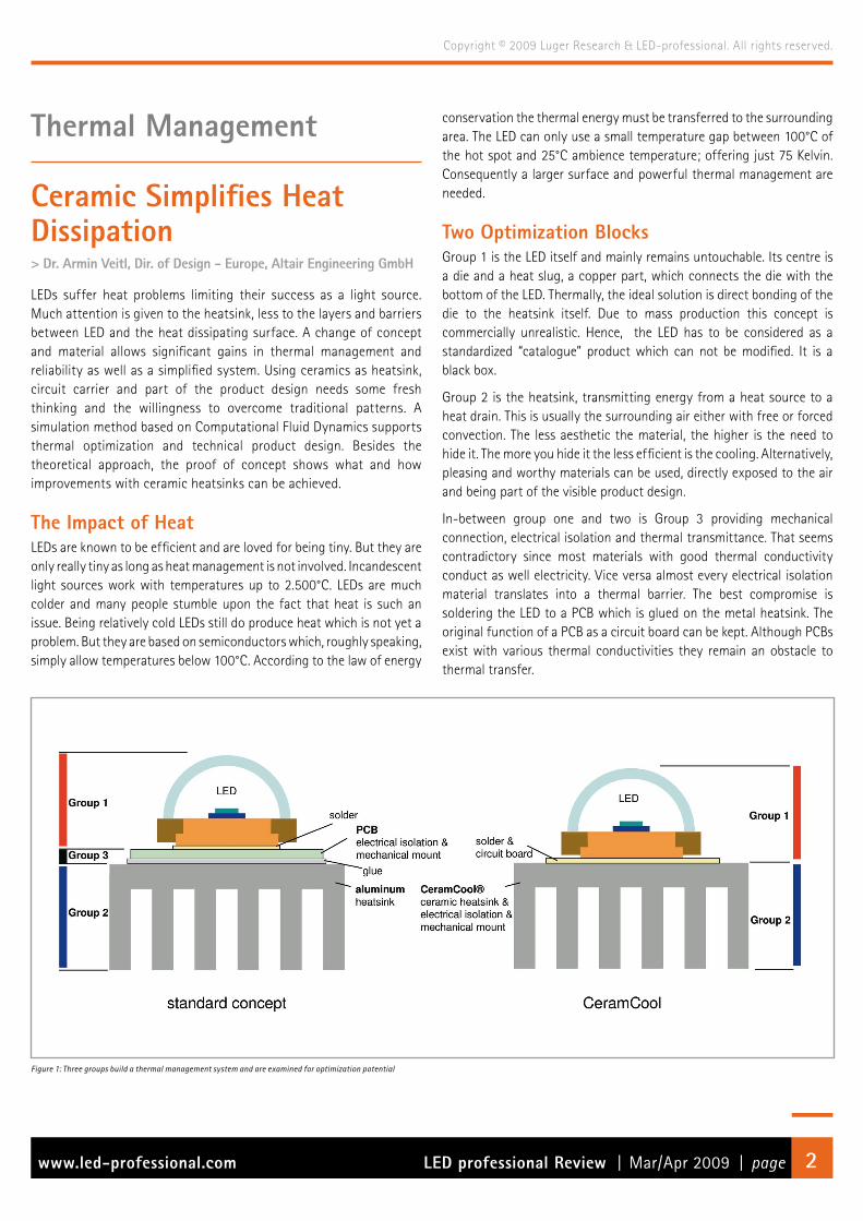
Two Optimization Blocks Group 1 is the LED itself and mainly remains untouchable. Its centre is a die and a heat slug, a copper part, which connects the die with the bottom of the LED. Thermally, the ideal solution is direct bonding of the die to the heatsink itself. Due to mass production this concept is commercially unrealistic. Hence, the LED has to be considered as a standardized “catalogue” product which can not be modified. It is a black box.
Group 2 is the heatsink, transmitting energy from a heat source to a heat drain. This is usually the surrounding air either with free or forced convection. The less aesthetic the material, the higher is the need to hide it. The more you hide it the less efficient is the cooling. Alternatively, pleasing and worthy materials can be used, directly exposed to the air and being part of the visible product design.
In-between group one and two is Group 3 providing mechanical connection, electrical isolation and thermal transmittance. That seems contradictory since most materials with good thermal conductivity conduct as well electricity. Vice versa almost every electrical isolation material translates into a thermal barrier. The best compromise is soldering the LED to a PCB which is glued on the metal heatsink. The original function of a PCB as a circuit board can be kept. Although PCBs exist with various thermal conductivities they remain an obstacle to thermal transfer.
Figure 1: Three groups build a thermal management system and are examined for optimization potential
LED professional Review | Mar/Apr 2009 | pagewww.led-professional.com 3
Copyright © 2009 Luger Research & LED-professional. All rights reserved.
Rtt for Valid System Comparison The thermal resistance of LEDs (die to heat slug pad) and heatsinks is available from the manufacturer. But there is little focus on group 3 and its significant influence on the total thermal performance.
Adding all thermal resistances but the LED (group 1), the total thermal resistance Rtt is born. The Rtt allows a real comparison of heat management concepts.
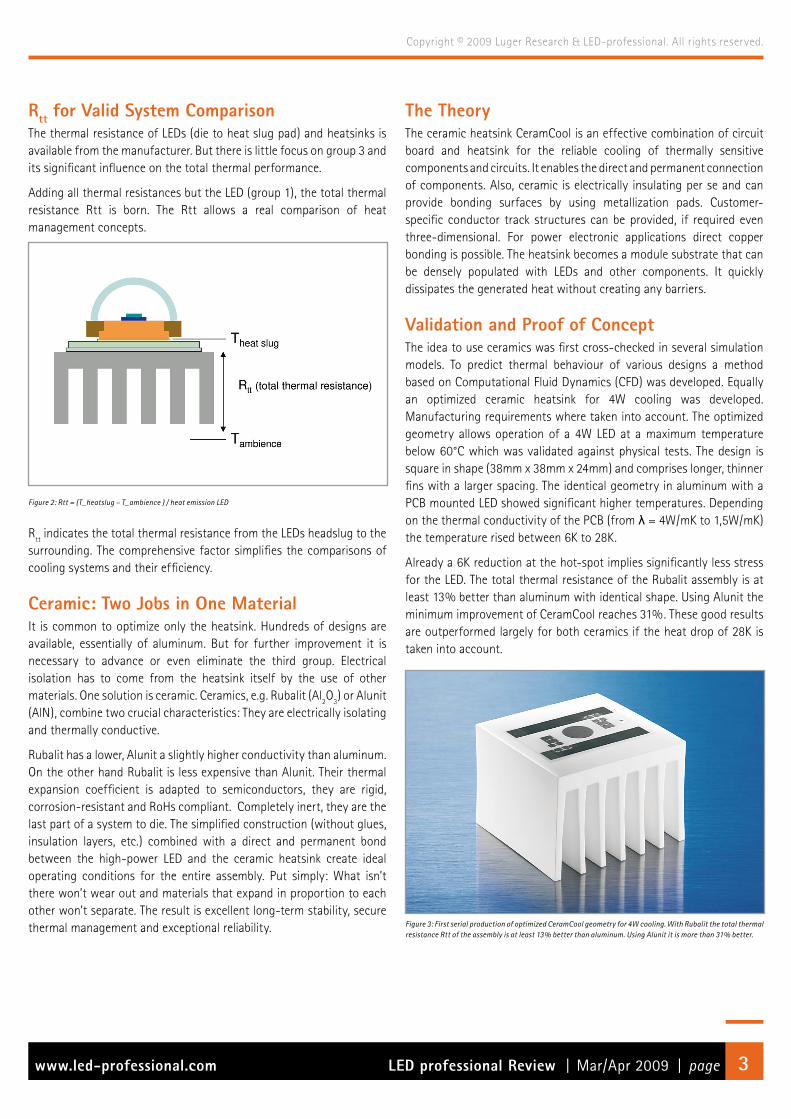
Figure 2: Rtt = (T_heatslug – T_ambience ) / heat emission LED
Rtt indicates the total thermal resistance from the LEDs headslug to the surrounding. The comprehensive factor simplifies the comparisons of cooling systems and their efficiency.
Ceramic: Two Jobs in One MaterialIt is common to optimize only the heatsink. Hundreds of designs are available, essentially of aluminum. But for further improvement it is necessary to advance or even eliminate the third group. Electrical isolation has to come from the heatsink itself by the use of other materials. One solution is ceramic. Ceramics, e.g. Rubalit (Al2O3) or Alunit (AlN), combine two crucial characteristics: They are electrically isolating and thermally conductive.
Rubalit has a lower, Alunit a slightly higher conductivity than aluminum. On the other hand Rubalit is less expensive than Alunit. Their thermal expansion coefficient is adapted to semiconductors, they are rigid, corrosion-resistant and RoHs compliant. Completely inert, they are the last part of a system to die. The simplified construction (without glues, insulation layers, etc.) combined with a direct and permanent bond between the high-power LED and the ceramic heatsink create ideal operating conditions for the entire assembly. Put simply: What isn’t there won’t wear out and materials that expand in proportion to each other won’t separate. The result is excellent long-term stability, secure thermal management and exceptional reliability.
The TheoryThe ceramic heatsink CeramCool is an effective combination of circuit board and heatsink for the reliable cooling of thermally sensitive components and circuits. It enables the direct and permanent connection of components. Also, ceramic is electrically insulating per se and can provide bonding surfaces by using metallization pads. Customer-specific conductor track structures can be provided, if required even three-dimensional. For power electronic applications direct copper bonding is possible. The heatsink becomes a module substrate that can be densely populated with LEDs and other components. It quickly dissipates the generated heat without creating any barriers.
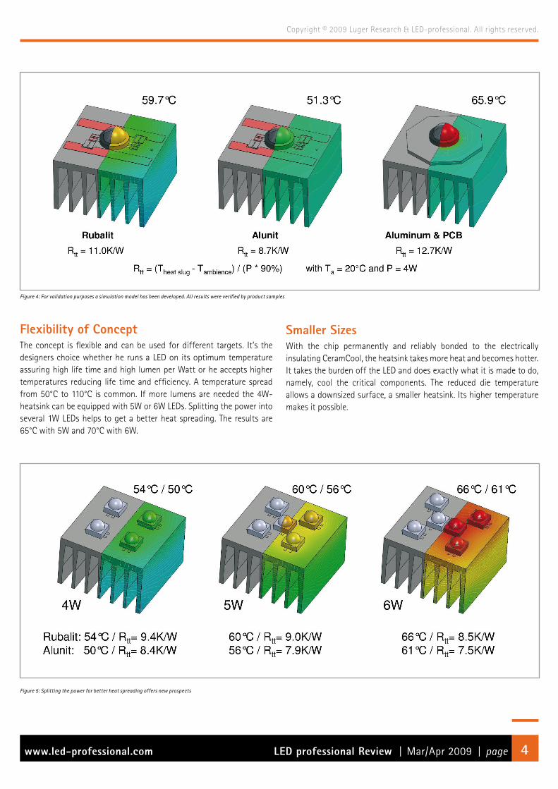
Validation and Proof of ConceptThe idea to use ceramics was first cross-checked in several simulation models. To predict thermal behaviour of various designs a method based on Computational Fluid Dynamics (CFD) was developed. Equally an optimized ceramic heatsink for 4W cooling was developed. Manufacturing requirements where taken into account. The optimized geometry allows operation of a 4W LED at a maximum temperature below 60°C which was validated against physical tests. The design is square in shape (38mm x 38mm x 24mm) and comprises longer, thinner fins with a larger spacing. The identical geometry in aluminum with a PCB mounted LED showed significant higher temperatures. Depending on the thermal conductivity of the PCB (from λ = 4W/mK to 1,5W/mK) the temperature rised between 6K to 28K.
Already a 6K reduction at the hot-spot implies significantly less stress for the LED. The total thermal resistance of the Rubalit assembly is at least 13% better than aluminum with identical shape. Using Alunit the minimum improvement of CeramCool reaches 31%. These good results are outperformed largely for both ceramics if the heat drop of 28K is taken into account.
Figure 3: First serial production of optimized CeramCool geometry for 4W cooling. With Rubalit the total thermal resistance Rtt of the assembly is at least 13% better than aluminum. Using Alunit it is more than 31% better.
LED professional Review | Mar/Apr 2009 | pagewww.led-professional.com 4
Copyright © 2009 Luger Research & LED-professional. All rights reserved.
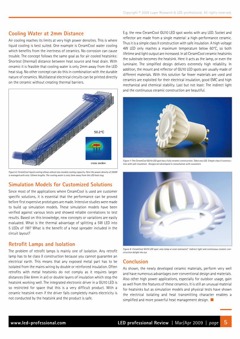
Figure 4: For validation purposes a simulation model has been developed. All results were verified by product samples
Smaller SizesWith the chip permanently and reliably bonded to the electrically insulating CeramCool, the heatsink takes more heat and becomes hotter. It takes the burden off the LED and does exactly what it is made to do, namely, cool the critical components. The reduced die temperature allows a downsized surface, a smaller heatsink. Its higher temperature makes it possible.
Flexibility of Concept The concept is flexible and can be used for different targets. It’s the designers choice whether he runs a LED on its optimum temperature assuring high life time and high lumen per Watt or he accepts higher temperatures reducing life time and efficiency. A temperature spread from 50°C to 110°C is common. If more lumens are needed the 4W-heatsink can be equipped with 5W or 6W LEDs. Splitting the power into several 1W LEDs helps to get a better heat spreading. The results are 65°C with 5W and 70°C with 6W.
Figure 5: Splitting the power for better heat spreading offers new prospects
LED professional Review | Mar/Apr 2009 | pagewww.led-professional.com 5
Copyright © 2009 Luger Research & LED-professional. All rights reserved.
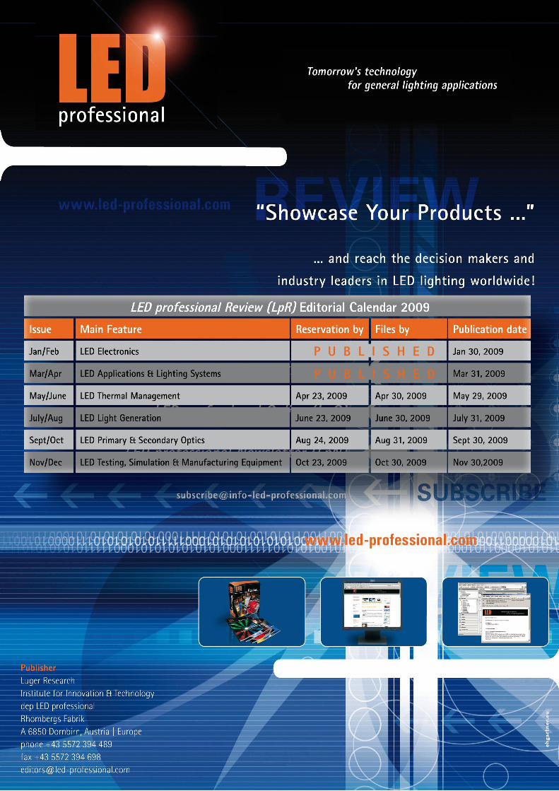
Cooling Water at 2mm DistanceAir cooling reaches its limits at very high power densities. This is where liquid cooling is best suited. One example is CeramCool water cooling which benefits from the inertness of ceramics. No corrosion can cause trouble. The concept follows the same goal as for air cooled heatsinks: Shortest (thermal) distance between heat source and heat drain. With ceramic it is feasible that cooling water is only 2mm away from the LED heat slug. No other concept can do this in combination with the durable nature of ceramics. Multilateral electrical circuits can be printed directly on the ceramic without creating thermal barriers.
Figure 6: CeramCool liquid cooling allows almost any needed cooling capacity. Here the power density of 290W is managed with only 120mm lengths. The cooling water is only 2mm away from the LED heat slug
Simulation Models for Customized SolutionsSince most of the applications where CeramCool is used are customer specific solutions, it is essential that the performance can be proved before first expensive prototypes are made. Intensive studies were made to build up simulation models. These simulation models have been verified against various tests and showed reliable correlations to test results. Based on this knowledge, new concepts or variations are easily evaluated. What is the thermal advantage of splitting a 5W LED into 5 LEDs of 1W? What is the benefit of a heat spreader included in the circuit layout?
Retrofit Lamps and IsolationThe problem of retrofit lamps is mainly one of isolation. Any retrofit lamp has to be class II construction because you cannot guarantee an electrical earth. This means that any exposed metal part has to be isolated from the mains wiring by double or reinforced insulation. Often retrofits with metal heatsinks do not comply as it requires larger distances (like 6mm in air) or double layers of insulation which stop the heatsink working well. The integrated electronic driver in a GU10 LED is so restricted for space that this is a very difficult product. With a ceramic heatsink even if the driver fails completely mains electricity is not conducted by the heatsink and the product is safe.
E.g. the new CeramCool GU10 LED spot works with any LED. Socket and reflector are made from a single material: a high-performance ceramic. Thus it is a simple class II construction with safe insulation. A high voltage 4W LED only reaches a maximum temperature below 60°C, so both lifetime and light output are increased. In all CeramCool ceramic heatsinks the substrate becomes the heatsink. Here it acts as the lamp, or even the luminaire. The simplified design delivers extremely high reliability. In addition, the mount and reflector of GU10 LED spots are usually made of different materials. With this solution far fewer materials are used and ceramics are exploited for their electrical insulation, good EMC and high mechanical and chemical stability. Last but not least: The indirect light and the continuous ceramic construction are beautiful.
Figure 7: The CeramCool GU10 LED spot has a fully ceramic construction. Takes any LED. Simple class II construc-tion with safe insulation. Designs are developed in consultation with customers
Figure 8: CeramCool GU10 LED spot: only lamp or even luminaire? Indirect light and continuous ceramic con-struction delight the eye
ConclusionAs shown, the newly developed ceramic materials, perform very well and have numerous advantages over conventional design and materials. Also other high power applications, especially for outdoor usage, gain as well from the features of these ceramics. It is still an unusual material for heatsinks but as simulation models and physical tests have shown the electrical isolating and heat transmitting character enables a simplified and more powerful heat management design.
P U B L I S H E D
P U B L I S H E D
![Investigation of Heat Sink Efficiency for Electronic ...2013/01/26 · of heat sink, (mm) Number of fins Natural convection, Power dissipation [W], 60 ºC rise heat sink to ambient](https://img.pdfslide.net/doc/110x75/5f0eacc47e708231d44061ee/investigation-of-heat-sink-efficiency-for-electronic-20130126-of-heat-sink.jpg)