Embed Size (px)
Citation preview
1 15 JAN 15
APPROVED FOR PUBLIC RELEASE
APPROVED FOR PUBLIC RELEASE
APPROVED FOR PUBLIC RELEASE
APPROVED FOR PUBLIC RELEASE
CERDEC C4ISR/EW Hardware/Software
Convergence
15 JAN 15
Benjamin Peddicord
Chief, Intel Technology and Architecture Branch
CERDEC I2WD
DISTRIBUTION STATEMENT A. Approved for public release, distribution is unlimited.
2 15 JAN 15
APPROVED FOR PUBLIC RELEASE
APPROVED FOR PUBLIC RELEASE
Problem Statement
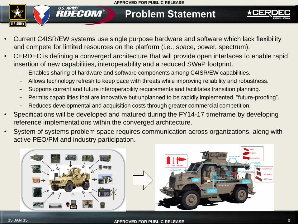
• Current C4ISR/EW systems use single purpose hardware and software which lack flexibility
and compete for limited resources on the platform (i.e., space, power, spectrum).
• CERDEC is defining a converged architecture that will provide open interfaces to enable rapid
insertion of new capabilities, interoperability and a reduced SWaP footprint.
Enables sharing of hardware and software components among C4ISR/EW capabilities.
Allows technology refresh to keep pace with threats while improving reliability and robustness.
Supports current and future interoperability requirements and facilitates transition planning.
Permits capabilities that are innovative but unplanned to be rapidly implemented, “future-proofing”.
Reduces developmental and acquisition costs through greater commercial competition.
• Specifications will be developed and matured during the FY14-17 timeframe by developing
reference implementations within the converged architecture.
• System of systems problem space requires communication across organizations, along with
active PEO/PM and industry participation.
3 15 JAN 15
APPROVED FOR PUBLIC RELEASE
APPROVED FOR PUBLIC RELEASE
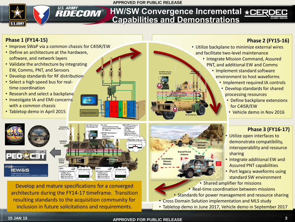
Phase 1 (FY14-15) • Improve SWaP via a common chassis for C4ISR/EW • Define an architecture at the hardware,
software, and network layers • Validate the architecture by integrating
EW, Comms, PNT, and Sensors • Develop standards for RF distribution • Select a high speed bus for real-
time coordination • Research and select a backplane • Investigate IA and EMI concerns
with a common chassis • Tabletop demo in April 2015
HW/SW Convergence Incremental Capabilities and Demonstrations
Phase 2 (FY15-16) • Utilize backplane to minimize external wires
and facilitate two-level maintenance • Integrate Mission Command, Assured
PNT, and additional EW and Comms • Implement standard software
environment to host waveforms • Implement required IA controls • Develop standards for shared
processing resources • Define backplane extensions
for C4ISR/EW • Vehicle demo in Nov 2016
Phase 3 (FY16-17) • Utilize open interfaces to
demonstrate compatibility, interoperability and resource sharing
• Integrate additional EW and Assured PNT capabilities
• Port legacy waveforms using standard SW environment
• Shared amplifier for missions • Real-time coordination between missions
• Standards for power management and resource sharing • Cross Domain Solution implementation and MLS study • Tabletop demo in June 2017, Vehicle demo in September 2017
Develop and mature specifications for a converged architecture during the FY14-17 timeframe. Transition resulting standards to the acquisition community for
inclusion in future solicitations and requirements.
4 15 JAN 15
APPROVED FOR PUBLIC RELEASE
APPROVED FOR PUBLIC RELEASE
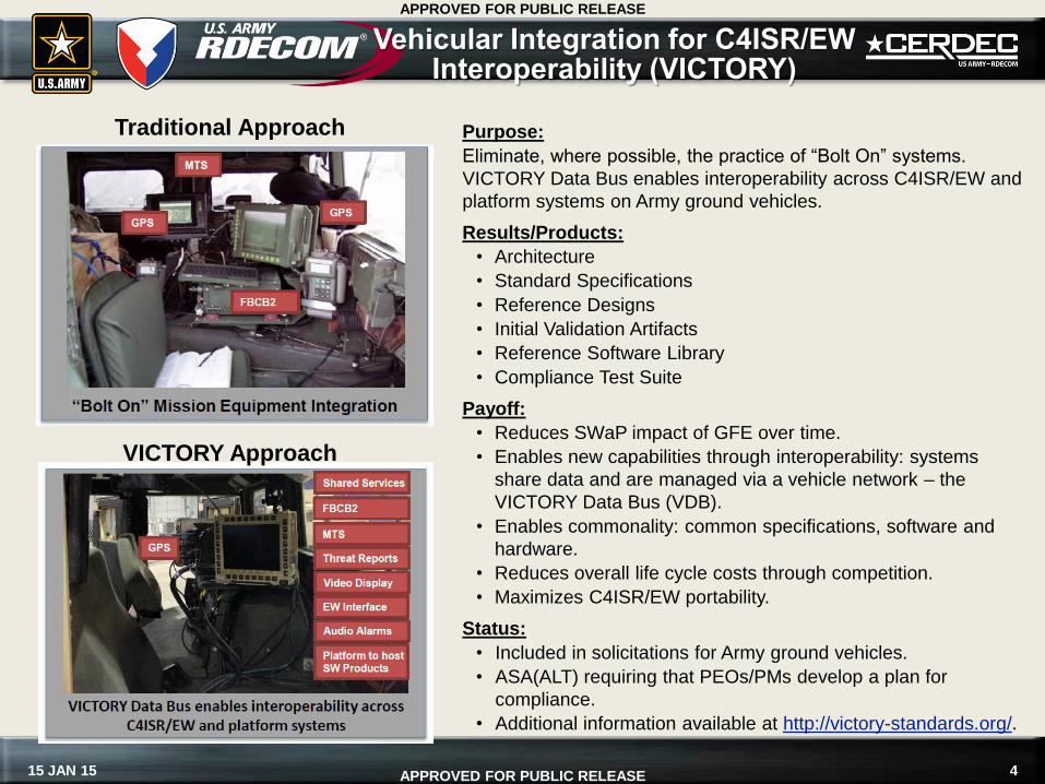
Vehicular Integration for C4ISR/EW Interoperability (VICTORY)
Purpose:
Eliminate, where possible, the practice of “Bolt On” systems.
VICTORY Data Bus enables interoperability across C4ISR/EW and
platform systems on Army ground vehicles.
Results/Products:
• Architecture
• Standard Specifications
• Reference Designs
• Initial Validation Artifacts
• Reference Software Library
• Compliance Test Suite
Payoff:
• Reduces SWaP impact of GFE over time.
• Enables new capabilities through interoperability: systems
share data and are managed via a vehicle network – the
VICTORY Data Bus (VDB).
• Enables commonality: common specifications, software and
hardware.
• Reduces overall life cycle costs through competition.
• Maximizes C4ISR/EW portability.
Status:
• Included in solicitations for Army ground vehicles.
• ASA(ALT) requiring that PEOs/PMs develop a plan for
compliance.
• Additional information available at http://victory-standards.org/.
Traditional Approach
VICTORY Approach
5 15 JAN 15
APPROVED FOR PUBLIC RELEASE
APPROVED FOR PUBLIC RELEASE
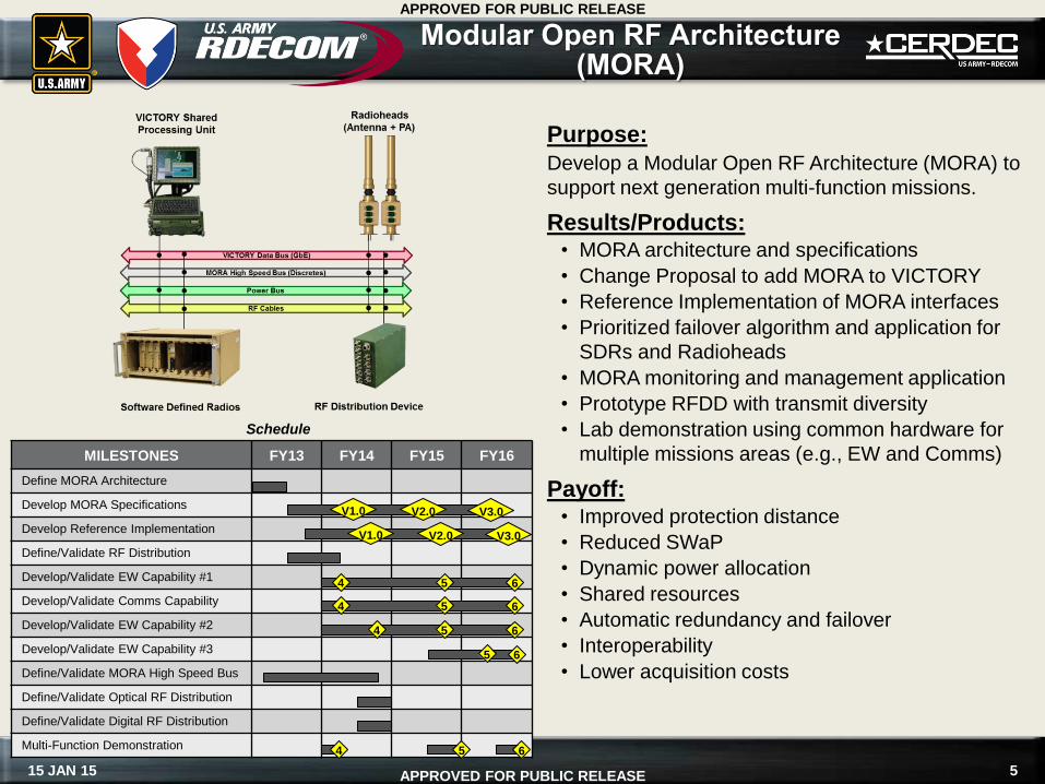
Modular Open RF Architecture (MORA)
Purpose:
Develop a Modular Open RF Architecture (MORA) to
support next generation multi-function missions.
Results/Products: • MORA architecture and specifications
• Change Proposal to add MORA to VICTORY
• Reference Implementation of MORA interfaces
• Prioritized failover algorithm and application for
SDRs and Radioheads
• MORA monitoring and management application
• Prototype RFDD with transmit diversity
• Lab demonstration using common hardware for
multiple missions areas (e.g., EW and Comms)
Payoff: • Improved protection distance
• Reduced SWaP
• Dynamic power allocation
• Shared resources
• Automatic redundancy and failover
• Interoperability
• Lower acquisition costs
Schedule
MILESTONES FY13 FY14 FY15 FY16
Define MORA Architecture
Develop MORA Specifications
Develop Reference Implementation
Define/Validate RF Distribution
Develop/Validate EW Capability #1
Develop/Validate Comms Capability
Develop/Validate EW Capability #2
Develop/Validate EW Capability #3
Define/Validate MORA High Speed Bus
Define/Validate Optical RF Distribution
Define/Validate Digital RF Distribution
Multi-Function Demonstration
V1.0
4
V2.0 V3.0
V1.0 V2.0 V3.0
5 6
4 5 6
4 5 6
5 6
4 5 6
6 15 JAN 15
APPROVED FOR PUBLIC RELEASE
APPROVED FOR PUBLIC RELEASE
REDHAWK
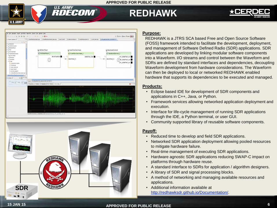
Purpose:
REDHAWK is a JTRS SCA based Free and Open Source Software
(FOSS) framework intended to facilitate the development, deployment,
and management of Software Defined Radio (SDR) applications. SDR
applications are developed by linking modular software components
into a Waveform. I/O streams and control between the Waveform and
SDRs are defined by standard interfaces and dependencies, decoupling
Waveform development from hardware considerations. The Waveform
can then be deployed to local or networked REDHAWK enabled
hardware that supports its dependencies to be executed and managed.
Products:
• Eclipse based IDE for development of SDR components and
applications in C++, Java, or Python.
• Framework services allowing networked application deployment and
execution.
• Interface for life-cycle management of running SDR applications
through the IDE, a Python terminal, or user GUI.
• Community supported library of reusable software components.
Payoff:
• Reduced time to develop and field SDR applications.
• Networked SDR application deployment allowing pooled resources
to mitigate hardware failure.
• Real-time management of executing SDR applications.
• Hardware agnostic SDR applications reducing SWAP-C impact on
platforms through hardware reuse.
• A standard interface to SDRs for application / algorithm designers.
• A library of SDR and signal processing blocks.
• A method of networking and managing available resources and
applications.
• Additional information available at
http://redhawksdr.github.io/Documentation/. SDR
7 15 JAN 15
APPROVED FOR PUBLIC RELEASE
APPROVED FOR PUBLIC RELEASE
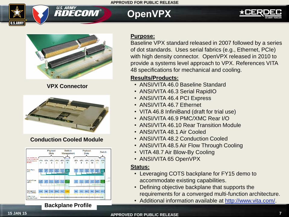
OpenVPX
Purpose:
Baseline VPX standard released in 2007 followed by a series
of dot standards. Uses serial fabrics (e.g., Ethernet, PCIe)
with high density connector. OpenVPX released in 2010 to
provide a systems level approach to VPX. References VITA
48 specifications for mechanical and cooling.
Results/Products:
• ANSI/VITA 46.0 Baseline Standard
• ANSI/VITA 46.3 Serial RapidIO
• ANSI/VITA 46.4 PCI Express
• ANSI/VITA 46.7 Ethernet
• VITA 46.8 InfiniBand (draft for trial use)
• ANSI/VITA 46.9 PMC/XMC Rear I/O
• ANSI/VITA 46.10 Rear Transition Module
• ANSI/VITA 48.1 Air Cooled
• ANSI/VITA 48.2 Conduction Cooled
• ANSI/VITA 48.5 Air Flow Through Cooling
• VITA 48.7 Air Blow-By Cooling
• ANSI/VITA 65 OpenVPX
Status:
• Leveraging COTS backplane for FY15 demo to
accommodate existing capabilities.
• Defining objective backplane that supports the
requirements for a converged multi-function architecture.
• Additional information available at http://www.vita.com/.
VPX Connector
Conduction Cooled Module
Backplane Profile
8 15 JAN 15
APPROVED FOR PUBLIC RELEASE
APPROVED FOR PUBLIC RELEASE
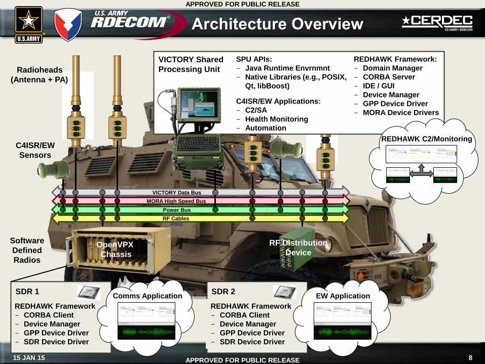
REDHAWK Framework
CORBA Client
Device Manager
GPP Device Driver
SDR Device Driver
Architecture Overview
VICTORY Data Bus
MORA High Speed Bus
Power Bus
RF Cables
Radioheads
(Antenna + PA)
C4ISR/EW
Sensors
SDR 1 Comms Application
REDHAWK Framework
CORBA Client
Device Manager
GPP Device Driver
SDR Device Driver
SDR 2 EW Application
OpenVPX
Chassis
Software
Defined
Radios
RF Distribution
Device
REDHAWK Framework:
Domain Manager
CORBA Server
IDE / GUI
Device Manager
GPP Device Driver
MORA Device Drivers
REDHAWK C2/Monitoring
SPU APIs:
Java Runtime Envrnmnt
Native Libraries (e.g., POSIX,
Qt, libBoost)
C4ISR/EW Applications:
C2/SA
Health Monitoring
Automation
VICTORY Shared
Processing Unit
9 15 JAN 15
APPROVED FOR PUBLIC RELEASE
APPROVED FOR PUBLIC RELEASE
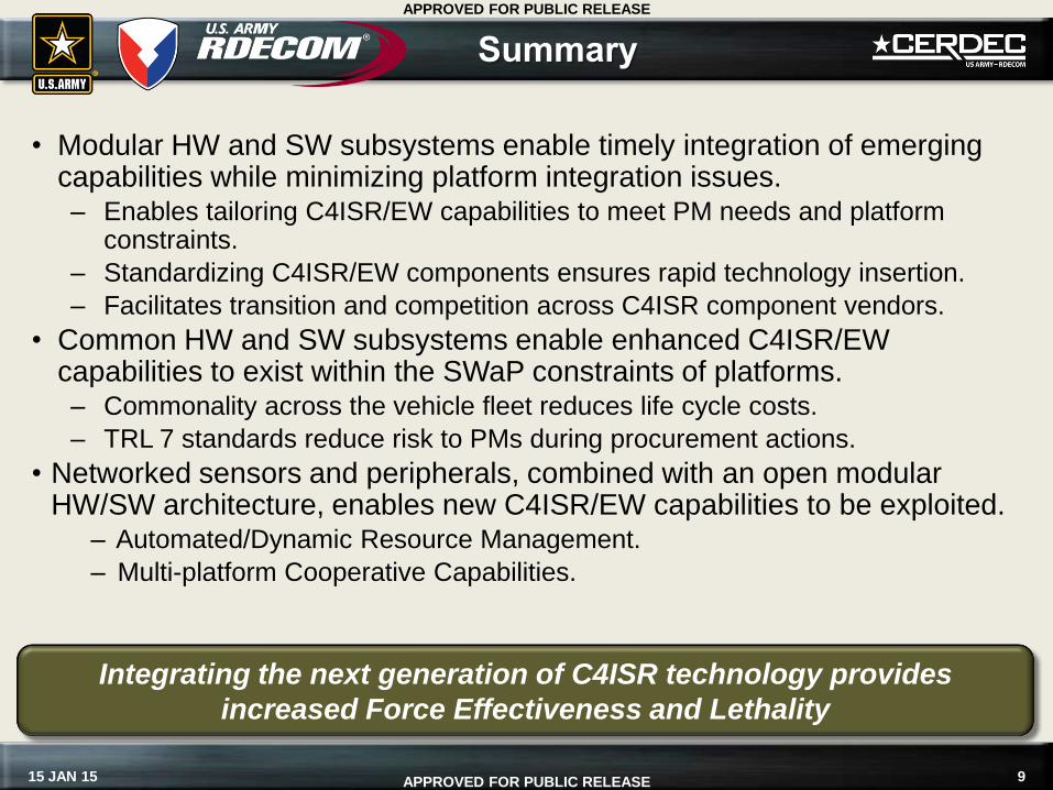
Summary
• Modular HW and SW subsystems enable timely integration of emerging capabilities while minimizing platform integration issues. – Enables tailoring C4ISR/EW capabilities to meet PM needs and platform
constraints.
– Standardizing C4ISR/EW components ensures rapid technology insertion.
– Facilitates transition and competition across C4ISR component vendors.
• Common HW and SW subsystems enable enhanced C4ISR/EW capabilities to exist within the SWaP constraints of platforms. – Commonality across the vehicle fleet reduces life cycle costs.
– TRL 7 standards reduce risk to PMs during procurement actions.
• Networked sensors and peripherals, combined with an open modular HW/SW architecture, enables new C4ISR/EW capabilities to be exploited.
– Automated/Dynamic Resource Management.
– Multi-platform Cooperative Capabilities.
Integrating the next generation of C4ISR technology provides
increased Force Effectiveness and Lethality
10 15 JAN 15
APPROVED FOR PUBLIC RELEASE
APPROVED FOR PUBLIC RELEASE
MORA Overview
11 15 JAN 15
APPROVED FOR PUBLIC RELEASE
APPROVED FOR PUBLIC RELEASE
What is MORA?
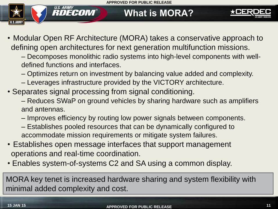
• Modular Open RF Architecture (MORA) takes a conservative approach to
defining open architectures for next generation multifunction missions. – Decomposes monolithic radio systems into high-level components with well-
defined functions and interfaces.
– Optimizes return on investment by balancing value added and complexity.
– Leverages infrastructure provided by the VICTORY architecture.
• Separates signal processing from signal conditioning. – Reduces SWaP on ground vehicles by sharing hardware such as amplifiers
and antennas.
– Improves efficiency by routing low power signals between components.
– Establishes pooled resources that can be dynamically configured to
accommodate mission requirements or mitigate system failures.
• Establishes open message interfaces that support management
operations and real-time coordination.
• Enables system-of-systems C2 and SA using a common display.
MORA key tenet is increased hardware sharing and system flexibility with
minimal added complexity and cost.
12 15 JAN 15
APPROVED FOR PUBLIC RELEASE
APPROVED FOR PUBLIC RELEASE
What is MORA?
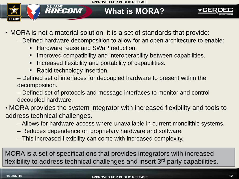
• MORA is not a material solution, it is a set of standards that provide: – Defined hardware decomposition to allow for an open architecture to enable:
Hardware reuse and SWaP reduction.
Improved compatibility and interoperability between capabilities.
Increased flexibility and portability of capabilities.
Rapid technology insertion.
– Defined set of interfaces for decoupled hardware to present within the
decomposition.
– Defined set of protocols and message interfaces to monitor and control
decoupled hardware.
• MORA provides the system integrator with increased flexibility and tools to
address technical challenges. – Allows for hardware access where unavailable in current monolithic systems.
– Reduces dependence on proprietary hardware and software.
– This increased flexibility can come with increased complexity.
MORA is a set of specifications that provides integrators with increased
flexibility to address technical challenges and insert 3rd party capabilities.
13 15 JAN 15
APPROVED FOR PUBLIC RELEASE
APPROVED FOR PUBLIC RELEASE
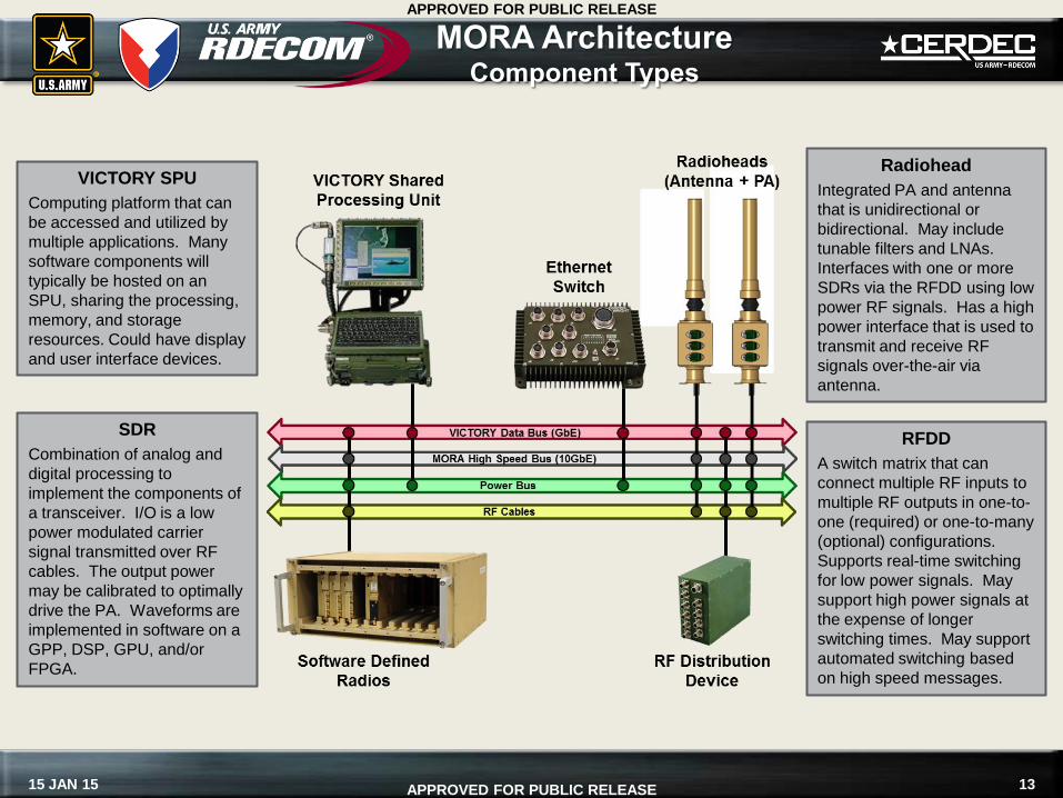
MORA Architecture Component Types
SDR
Combination of analog and
digital processing to
implement the components of
a transceiver. I/O is a low
power modulated carrier
signal transmitted over RF
cables. The output power
may be calibrated to optimally
drive the PA. Waveforms are
implemented in software on a
GPP, DSP, GPU, and/or
FPGA.
RFDD
A switch matrix that can
connect multiple RF inputs to
multiple RF outputs in one-to-
one (required) or one-to-many
(optional) configurations.
Supports real-time switching
for low power signals. May
support high power signals at
the expense of longer
switching times. May support
automated switching based
on high speed messages.
Radiohead
Integrated PA and antenna
that is unidirectional or
bidirectional. May include
tunable filters and LNAs.
Interfaces with one or more
SDRs via the RFDD using low
power RF signals. Has a high
power interface that is used to
transmit and receive RF
signals over-the-air via
antenna.
VICTORY SPU
Computing platform that can
be accessed and utilized by
multiple applications. Many
software components will
typically be hosted on an
SPU, sharing the processing,
memory, and storage
resources. Could have display
and user interface devices.
14 15 JAN 15
APPROVED FOR PUBLIC RELEASE
APPROVED FOR PUBLIC RELEASE
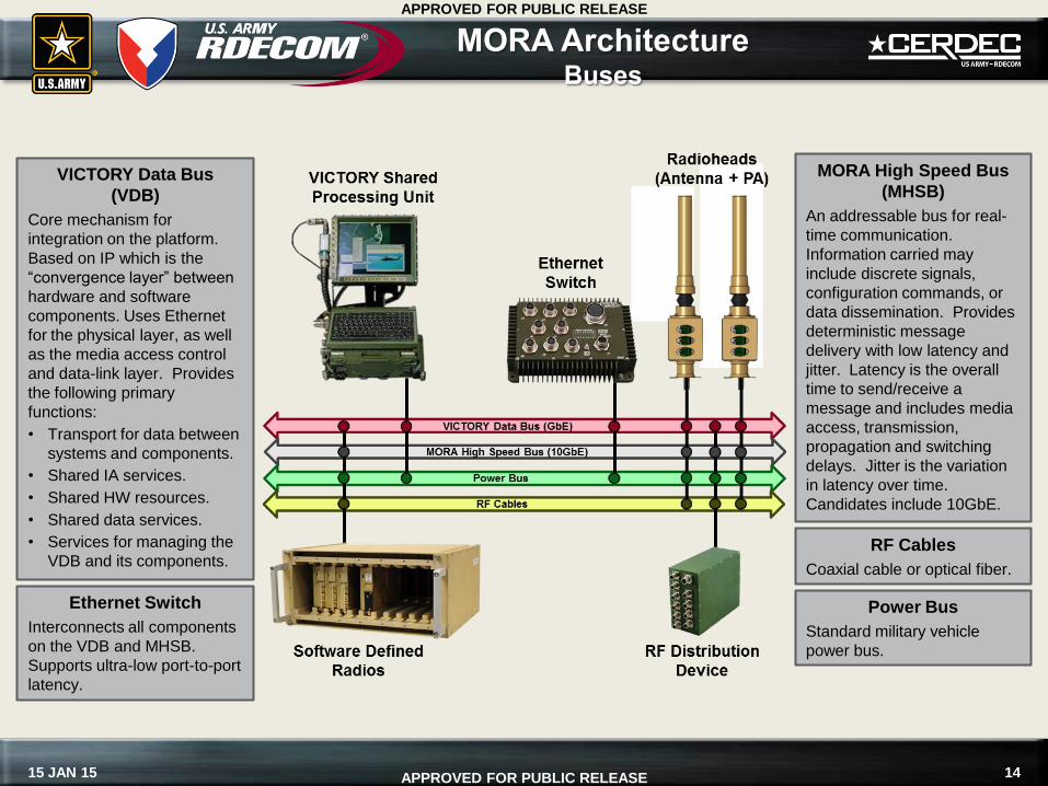
MORA Architecture Buses
Power Bus
Standard military vehicle
power bus.
Ethernet Switch
Interconnects all components
on the VDB and MHSB.
Supports ultra-low port-to-port
latency.
MORA High Speed Bus
(MHSB)
An addressable bus for real-
time communication.
Information carried may
include discrete signals,
configuration commands, or
data dissemination. Provides
deterministic message
delivery with low latency and
jitter. Latency is the overall
time to send/receive a
message and includes media
access, transmission,
propagation and switching
delays. Jitter is the variation
in latency over time.
Candidates include 10GbE.
VICTORY Data Bus
(VDB)
Core mechanism for
integration on the platform.
Based on IP which is the
“convergence layer” between
hardware and software
components. Uses Ethernet
for the physical layer, as well
as the media access control
and data-link layer. Provides
the following primary
functions:
• Transport for data between
systems and components.
• Shared IA services.
• Shared HW resources.
• Shared data services.
• Services for managing the
VDB and its components. RF Cables
Coaxial cable or optical fiber.
15 15 JAN 15
APPROVED FOR PUBLIC RELEASE
APPROVED FOR PUBLIC RELEASE
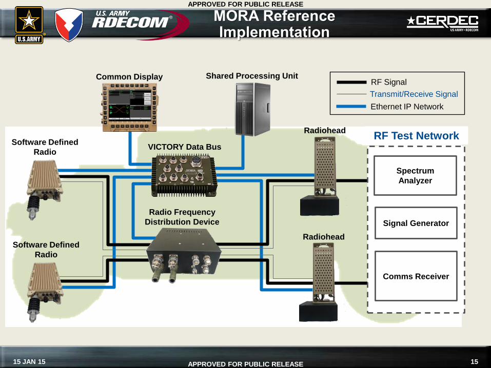
MORA Reference Implementation
Radiohead
Radiohead
Radio Frequency
Distribution Device Signal Generator
Spectrum
Analyzer
Comms Receiver
RF Test Network Software Defined
Radio
Software Defined
Radio
RF Signal
Transmit/Receive Signal
Ethernet IP Network
VICTORY Data Bus
Common Display Shared Processing Unit
16 15 JAN 15
APPROVED FOR PUBLIC RELEASE
APPROVED FOR PUBLIC RELEASE
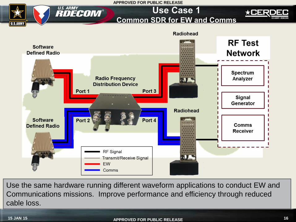
Use Case 1 Common SDR for EW and Comms
Use the same hardware running different waveform applications to conduct EW and
Communications missions. Improve performance and efficiency through reduced
cable loss.
17 15 JAN 15
APPROVED FOR PUBLIC RELEASE
APPROVED FOR PUBLIC RELEASE
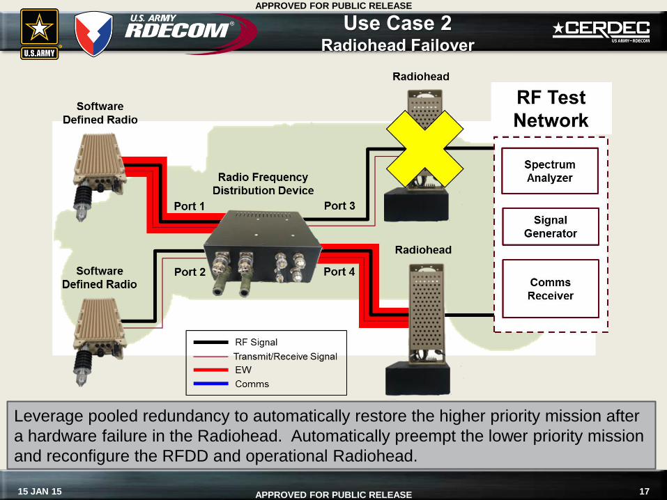
Leverage pooled redundancy to automatically restore the higher priority mission after
a hardware failure in the Radiohead. Automatically preempt the lower priority mission
and reconfigure the RFDD and operational Radiohead.
Use Case 2 Radiohead Failover
18 15 JAN 15
APPROVED FOR PUBLIC RELEASE
APPROVED FOR PUBLIC RELEASE
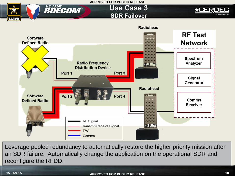
Leverage pooled redundancy to automatically restore the higher priority mission after
an SDR failure. Automatically change the application on the operational SDR and
reconfigure the RFDD.
Use Case 3 SDR Failover
19 15 JAN 15
APPROVED FOR PUBLIC RELEASE
APPROVED FOR PUBLIC RELEASE
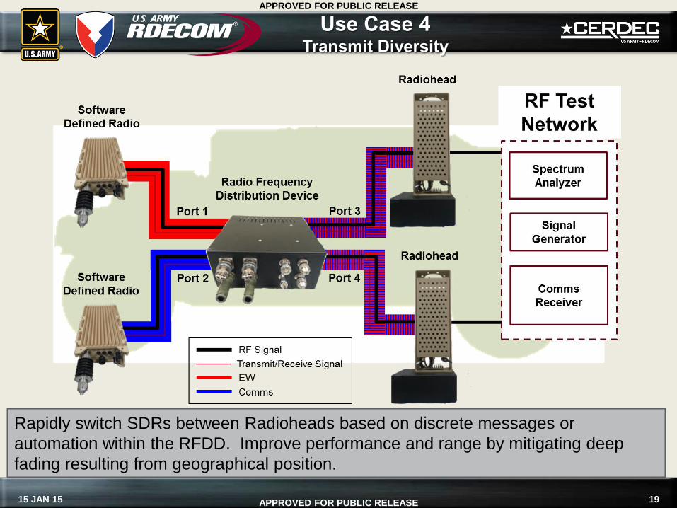
Rapidly switch SDRs between Radioheads based on discrete messages or
automation within the RFDD. Improve performance and range by mitigating deep
fading resulting from geographical position.
Use Case 4 Transmit Diversity
20 15 JAN 15
APPROVED FOR PUBLIC RELEASE
APPROVED FOR PUBLIC RELEASE
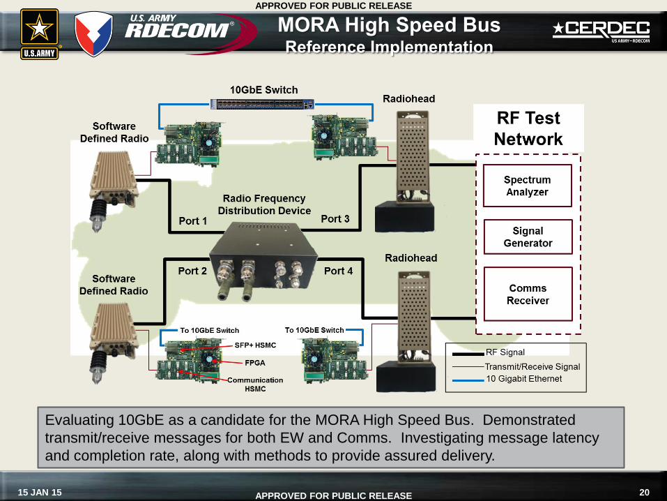
MORA High Speed Bus Reference Implementation
Evaluating 10GbE as a candidate for the MORA High Speed Bus. Demonstrated
transmit/receive messages for both EW and Comms. Investigating message latency
and completion rate, along with methods to provide assured delivery.
21 15 JAN 15
APPROVED FOR PUBLIC RELEASE
APPROVED FOR PUBLIC RELEASE
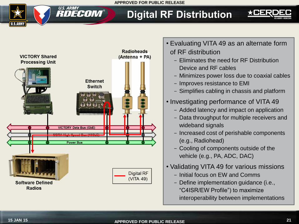
Digital RF Distribution
• Evaluating VITA 49 as an alternate form
of RF distribution
Eliminates the need for RF Distribution
Device and RF cables
Minimizes power loss due to coaxial cables
Improves resistance to EMI
Simplifies cabling in chassis and platform
• Investigating performance of VITA 49
Added latency and impact on application
Data throughput for multiple receivers and
wideband signals
Increased cost of perishable components
(e.g., Radiohead)
Cooling of components outside of the
vehicle (e.g., PA, ADC, DAC)
• Validating VITA 49 for various missions
Initial focus on EW and Comms
Define implementation guidance (i.e.,
“C4ISR/EW Profile”) to maximize
interoperability between implementations
22 15 JAN 15
APPROVED FOR PUBLIC RELEASE
APPROVED FOR PUBLIC RELEASE
Backplane Proposal
23 15 JAN 15
APPROVED FOR PUBLIC RELEASE
APPROVED FOR PUBLIC RELEASE
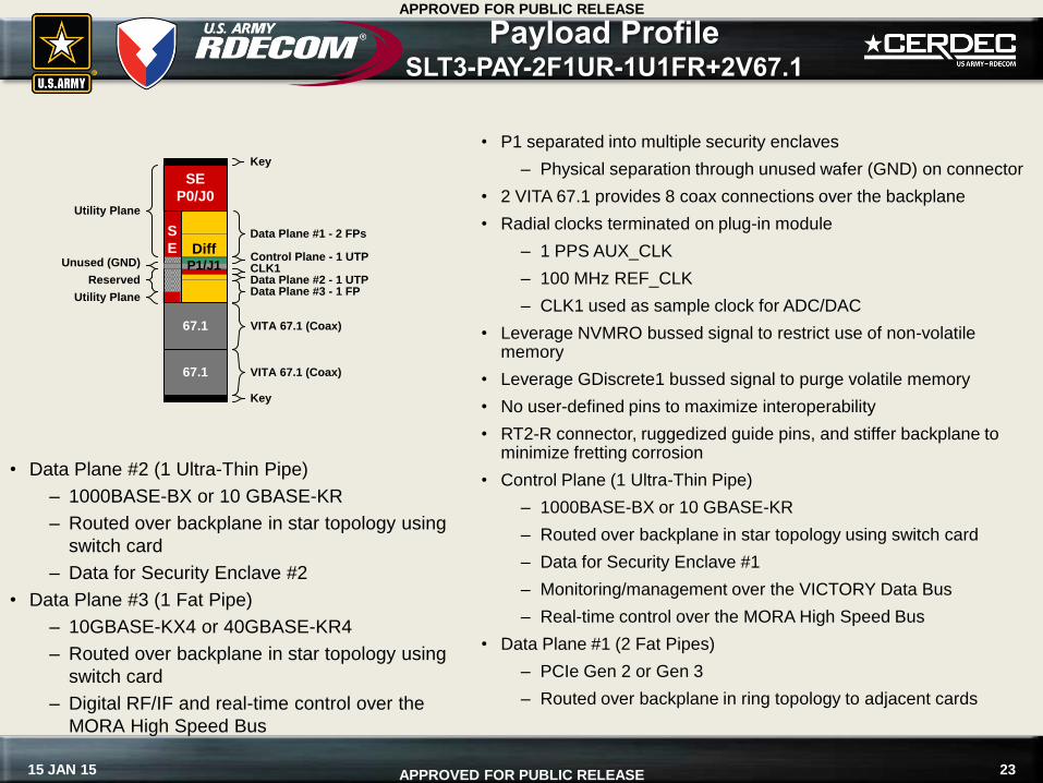
• P1 separated into multiple security enclaves
– Physical separation through unused wafer (GND) on connector
• 2 VITA 67.1 provides 8 coax connections over the backplane
• Radial clocks terminated on plug-in module
– 1 PPS AUX_CLK
– 100 MHz REF_CLK
– CLK1 used as sample clock for ADC/DAC
• Leverage NVMRO bussed signal to restrict use of non-volatile memory
• Leverage GDiscrete1 bussed signal to purge volatile memory
• No user-defined pins to maximize interoperability
• RT2-R connector, ruggedized guide pins, and stiffer backplane to minimize fretting corrosion
• Control Plane (1 Ultra-Thin Pipe)
– 1000BASE-BX or 10 GBASE-KR
– Routed over backplane in star topology using switch card
– Data for Security Enclave #1
– Monitoring/management over the VICTORY Data Bus
– Real-time control over the MORA High Speed Bus
• Data Plane #1 (2 Fat Pipes)
– PCIe Gen 2 or Gen 3
– Routed over backplane in ring topology to adjacent cards
Control Plane - 1 UTP
Utility Plane
Reserved
Utility Plane
Key
Key
S
E
SE
P0/J0
Data Plane #1 - 2 FPs
CLK1
Data Plane #3 - 1 FPData Plane #2 - 1 UTP
Unused (GND)Diff
P1/J1
67.1
67.1
VITA 67.1 (Coax)
VITA 67.1 (Coax)
• Data Plane #2 (1 Ultra-Thin Pipe)
– 1000BASE-BX or 10 GBASE-KR
– Routed over backplane in star topology using
switch card
– Data for Security Enclave #2
• Data Plane #3 (1 Fat Pipe)
– 10GBASE-KX4 or 40GBASE-KR4
– Routed over backplane in star topology using
switch card
– Digital RF/IF and real-time control over the
MORA High Speed Bus
Payload Profile SLT3-PAY-2F1UR-1U1FR+2V67.1
24 15 JAN 15
APPROVED FOR PUBLIC RELEASE
APPROVED FOR PUBLIC RELEASE
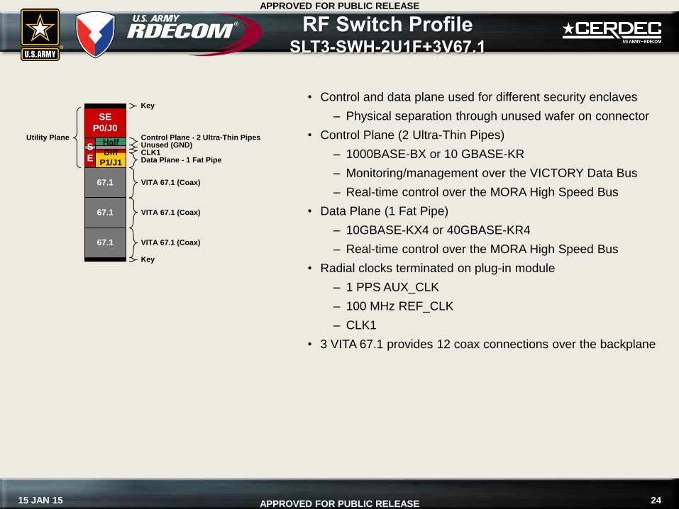
• Control and data plane used for different security enclaves
– Physical separation through unused wafer on connector
• Control Plane (2 Ultra-Thin Pipes)
– 1000BASE-BX or 10 GBASE-KR
– Monitoring/management over the VICTORY Data Bus
– Real-time control over the MORA High Speed Bus
• Data Plane (1 Fat Pipe)
– 10GBASE-KX4 or 40GBASE-KR4
– Real-time control over the MORA High Speed Bus
• Radial clocks terminated on plug-in module
– 1 PPS AUX_CLK
– 100 MHz REF_CLK
– CLK1
• 3 VITA 67.1 provides 12 coax connections over the backplane
Control Plane - 2 Ultra-Thin PipesUtility Plane
Key
Key
SE
P0/J0
67.1 VITA 67.1 (Coax)
67.1 VITA 67.1 (Coax)
Data Plane - 1 Fat Pipe
67.1 VITA 67.1 (Coax)
S
E
Unused (GND)Half
Diff
P1/J1
CLK1
RF Switch Profile SLT3-SWH-2U1F+3V67.1
25 15 JAN 15
APPROVED FOR PUBLIC RELEASE
APPROVED FOR PUBLIC RELEASE
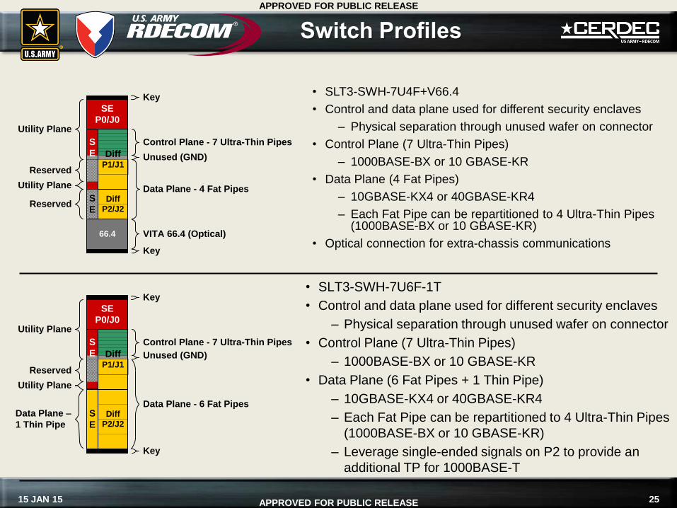
Switch Profiles
Control Plane - 7 Ultra-Thin Pipes
Utility Plane
Reserved
Utility Plane
Key
Key
S
E
Diff
P2/J2
S
E
SE
P0/J0
66.4 VITA 66.4 (Optical)
DiffP1/J1
Data Plane - 4 Fat Pipes
Unused (GND)
Reserved
• SLT3-SWH-7U4F+V66.4
• Control and data plane used for different security enclaves
– Physical separation through unused wafer on connector
• Control Plane (7 Ultra-Thin Pipes)
– 1000BASE-BX or 10 GBASE-KR
• Data Plane (4 Fat Pipes)
– 10GBASE-KX4 or 40GBASE-KR4
– Each Fat Pipe can be repartitioned to 4 Ultra-Thin Pipes (1000BASE-BX or 10 GBASE-KR)
• Optical connection for extra-chassis communications
Control Plane - 7 Ultra-Thin Pipes
Utility Plane
Reserved
Utility Plane
Key
Key
S
E
Diff
P2/J2
S
E
SE
P0/J0
DiffP1/J1
Data Plane - 6 Fat Pipes
Unused (GND)
Data Plane –
1 Thin Pipe
• SLT3-SWH-7U6F-1T
• Control and data plane used for different security enclaves
– Physical separation through unused wafer on connector
• Control Plane (7 Ultra-Thin Pipes)
– 1000BASE-BX or 10 GBASE-KR
• Data Plane (6 Fat Pipes + 1 Thin Pipe)
– 10GBASE-KX4 or 40GBASE-KR4
– Each Fat Pipe can be repartitioned to 4 Ultra-Thin Pipes
(1000BASE-BX or 10 GBASE-KR)
– Leverage single-ended signals on P2 to provide an
additional TP for 1000BASE-T
26 15 JAN 15
APPROVED FOR PUBLIC RELEASE
APPROVED FOR PUBLIC RELEASE
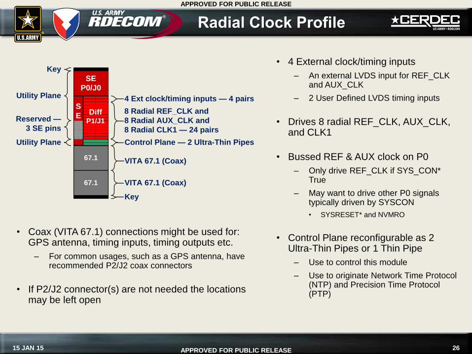
Radial Clock Profile
• Coax (VITA 67.1) connections might be used for: GPS antenna, timing inputs, timing outputs etc.
– For common usages, such as a GPS antenna, have recommended P2/J2 coax connectors
• If P2/J2 connector(s) are not needed the locations may be left open
• 4 External clock/timing inputs
– An external LVDS input for REF_CLK and AUX_CLK
– 2 User Defined LVDS timing inputs
• Drives 8 radial REF_CLK, AUX_CLK, and CLK1
• Bussed REF & AUX clock on P0
– Only drive REF_CLK if SYS_CON* True
– May want to drive other P0 signals typically driven by SYSCON
• SYSRESET* and NVMRO
• Control Plane reconfigurable as 2 Ultra-Thin Pipes or 1 Thin Pipe
– Use to control this module
– Use to originate Network Time Protocol (NTP) and Precision Time Protocol (PTP)
Utility Plane
Reserved —
3 SE pins
Utility Plane
SE
P0/J0
4 Ext clock/timing inputs — 4 pairs
Key
8 Radial REF_CLK and
8 Radial AUX_CLK and
8 Radial CLK1 — 24 pairs
Control Plane — 2 Ultra-Thin Pipes
Key
67.1 VITA 67.1 (Coax)
67.1 VITA 67.1 (Coax)
DiffP1/J1
S
E
27 15 JAN 15
APPROVED FOR PUBLIC RELEASE
APPROVED FOR PUBLIC RELEASE
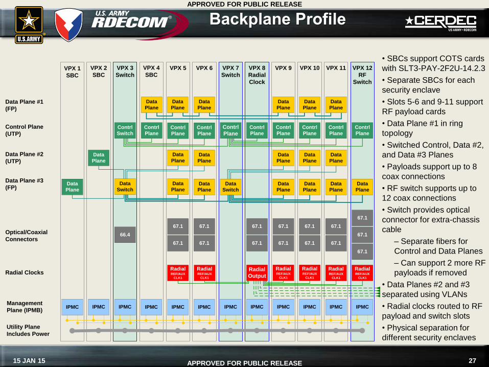
Backplane Profile
RadialREF/AUX
CLK1
RadialREF/AUX
CLK1
IPMC IPMC IPMC IPMC IPMC
Contrl
Plane
Contrl
Plane
Utility Plane
Includes Power
Management
Plane (IPMB)
Radial Clocks
Control Plane
(UTP)
Data
PlaneData Plane #1
(FP)
VPX 10
Radial
Output
VPX 2
SBC
IPMC
Contrl
Plane
Data
Plane
Contrl
Plane
Contrl
Switch
Data
Plane
67.1
67.1
VPX 9
RadialREF/AUX
CLK1
VPX 8
Radial
Clock
VPX 5
RadialREF/AUX
CLK1
IPMC
Contrl
Plane
Data
Plane
RadialREF/AUX
CLK1
IPMCIPMC
Data
Plane
Data
Plane
Data
PlaneData
Plane
Data Plane #2
(UTP)
Contrl
Plane
Optical/Coaxial
Connectors66.4
VPX 1
SBC
VPX 7
Switch
VPX 6
Data
Plane
Data
Plane
Data
SwitchData
Plane
Data Plane #3
(FP)Data
Switch
Contrl
Plane
Data
Plane
VPX 11
IPMC
Contrl
Plane
VPX 12
RF
Switch
IPMC
Contrl
Plane
Data
Plane
VPX 4
SBC
Data
Plane
Data
Plane
Data
Plane
Data
Plane
Data
Plane
Data
Plane
IPMC
VPX 3
Switch
67.1
67.1
67.1
RadialREF/AUX
CLK1
67.1
67.1
67.1
67.1
67.1
67.1
67.1
67.1
67.1
67.1
• SBCs support COTS cards
with SLT3-PAY-2F2U-14.2.3
• Separate SBCs for each
security enclave
• Slots 5-6 and 9-11 support
RF payload cards
• Data Plane #1 in ring
topology
• Switched Control, Data #2,
and Data #3 Planes
• Payloads support up to 8
coax connections
• RF switch supports up to
12 coax connections
• Switch provides optical
connector for extra-chassis
cable
– Separate fibers for
Control and Data Planes
– Can support 2 more RF
payloads if removed
• Data Planes #2 and #3
separated using VLANs
• Radial clocks routed to RF
payload and switch slots
• Physical separation for
different security enclaves