Embed Size (px)
Citation preview
CERNY & IVEY ENGINEERS, INC. CONSULTING ENGINEERS - TESTING LABORATORY
5650 PEACHTREE PARKWAY, NORCROSS (ATLANTA), GA. 30092 770-449-6936 • FAX 770-368-1148
EMAIL: [email protected]
June 28, 2001
Engineering Report 21117
Uniform Load Testing E. Dillon & Company
Nova Brik
SUMMARY
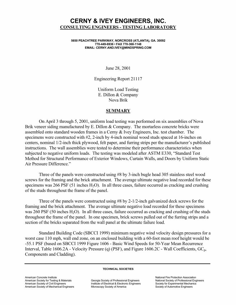
On April 3 through 5, 2001, uniform load testing was performed on six assemblies of Nova Brik veneer siding manufactured by E. Dillon & Company. The mortarless concrete bricks were assembled onto standard wooden frames in a Cerny & Ivey Engineers, Inc. test chamber. The specimens were constructed with #2, 2-inch by 4-inch nominal wood studs spaced at 16-inches on centers, nominal 1/2-inch thick plywood, felt paper, and furring strips per the manufacturer’s published instructions. The wall assemblies were tested to determine their performance characteristics when subjected to negative uniform loads. The testing was modeled after ASTM E330, “Standard Test Method for Structural Performance of Exterior Windows, Curtain Walls, and Doors by Uniform Static Air Pressure Difference.”
Three of the panels were constructed using #8 by 3-inch bugle head 305 stainless steel wood
screws for the framing and the brick attachment. The average ultimate negative load recorded for these specimens was 266 PSF (51 inches H2O). In all three cases, failure occurred as cracking and crushing of the studs throughout the frame of the panel.
Three of the panels were constructed using #8 by 2-1/2-inch galvanized deck screws for the
framing and the brick attachment. The average ultimate negative load recorded for these specimens was 260 PSF (50 inches H2O). In all three cases, failure occurred as cracking and crushing of the studs throughout the frame of the panel. In one specimen, brick screws pulled out of the furring strips and a section of the bricks separated from the wall panel at the ultimate failure load.
Standard Building Code (SBCCI 1999) minimum negative wind velocity design pressures for a
worst case 110 mph, wall end zone, on an enclosed building with a 60-foot mean roof height would be -55.1 PSF (based on SBCCI 1999 Figure 1606 - Basic Wind Speeds for 50-Year Mean Recurrence Interval, Table 1606.2A - Velocity Pressure (q) (PSF), and Figure 1606.2C - Wall Coefficients, GCp, Components and Cladding).
TECHNICAL SOCIETIES
American Concrete Institute National Fire Protection Association American Society for Testing & Materials Georgia Society of Professional Engineers National Society of Professional Engineers American Society of Civil Engineers Institute of Electrical & Electronic Engineers Society for Experimental Mechanics American Society of Mechanical Engineers Microscopy Society of America Society of Automotive Engineers
Engineering Report 21117 Page 2 June 28, 2001
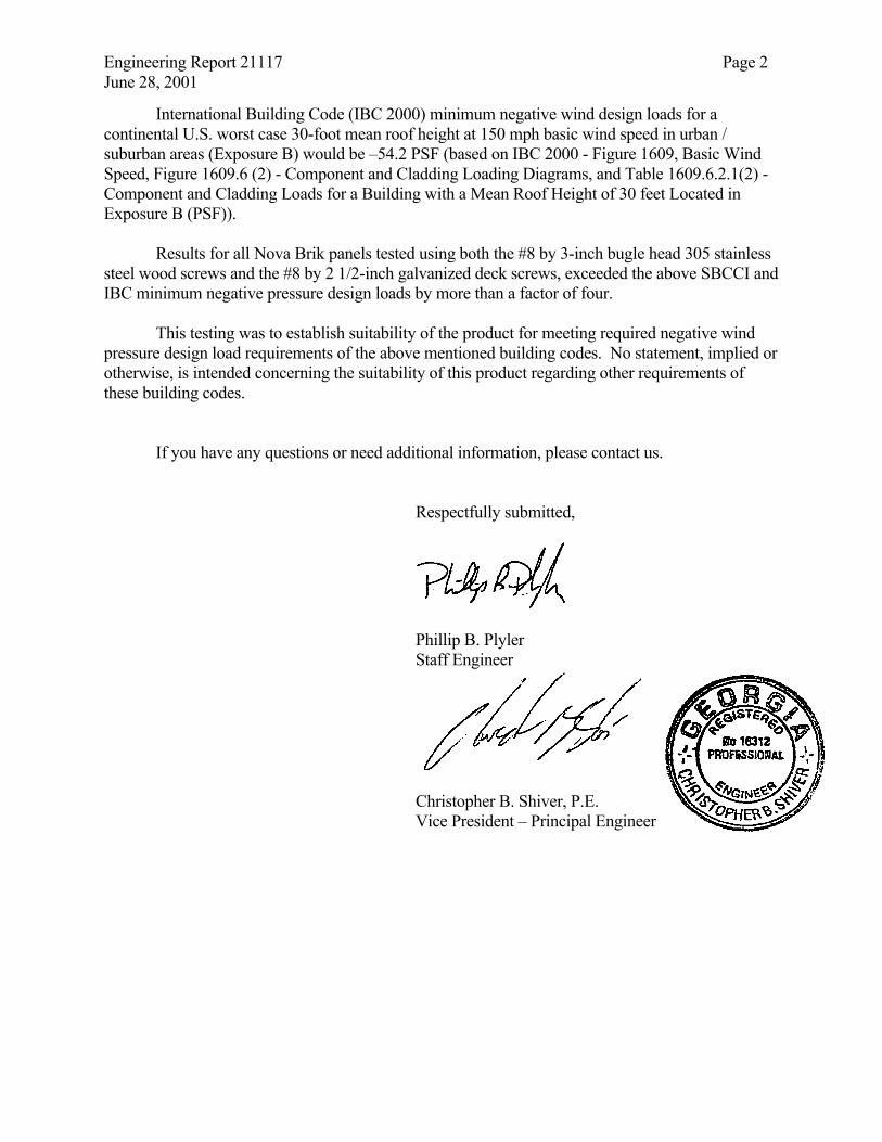
International Building Code (IBC 2000) minimum negative wind design loads for a continental U.S. worst case 30-foot mean roof height at 150 mph basic wind speed in urban / suburban areas (Exposure B) would be –54.2 PSF (based on IBC 2000 - Figure 1609, Basic Wind Speed, Figure 1609.6 (2) - Component and Cladding Loading Diagrams, and Table 1609.6.2.1(2) - Component and Cladding Loads for a Building with a Mean Roof Height of 30 feet Located in Exposure B (PSF)).
Results for all Nova Brik panels tested using both the #8 by 3-inch bugle head 305 stainless
steel wood screws and the #8 by 2 1/2-inch galvanized deck screws, exceeded the above SBCCI and IBC minimum negative pressure design loads by more than a factor of four.
This testing was to establish suitability of the product for meeting required negative wind
pressure design load requirements of the above mentioned building codes. No statement, implied or otherwise, is intended concerning the suitability of this product regarding other requirements of these building codes.
If you have any questions or need additional information, please contact us.
Respectfully submitted,
Phillip B. Plyler Staff Engineer
Christopher B. Shiver, P.E. Vice President – Principal Engineer
Engineering Report 21117 Page 3 June 28, 2001 INTRODUCTION
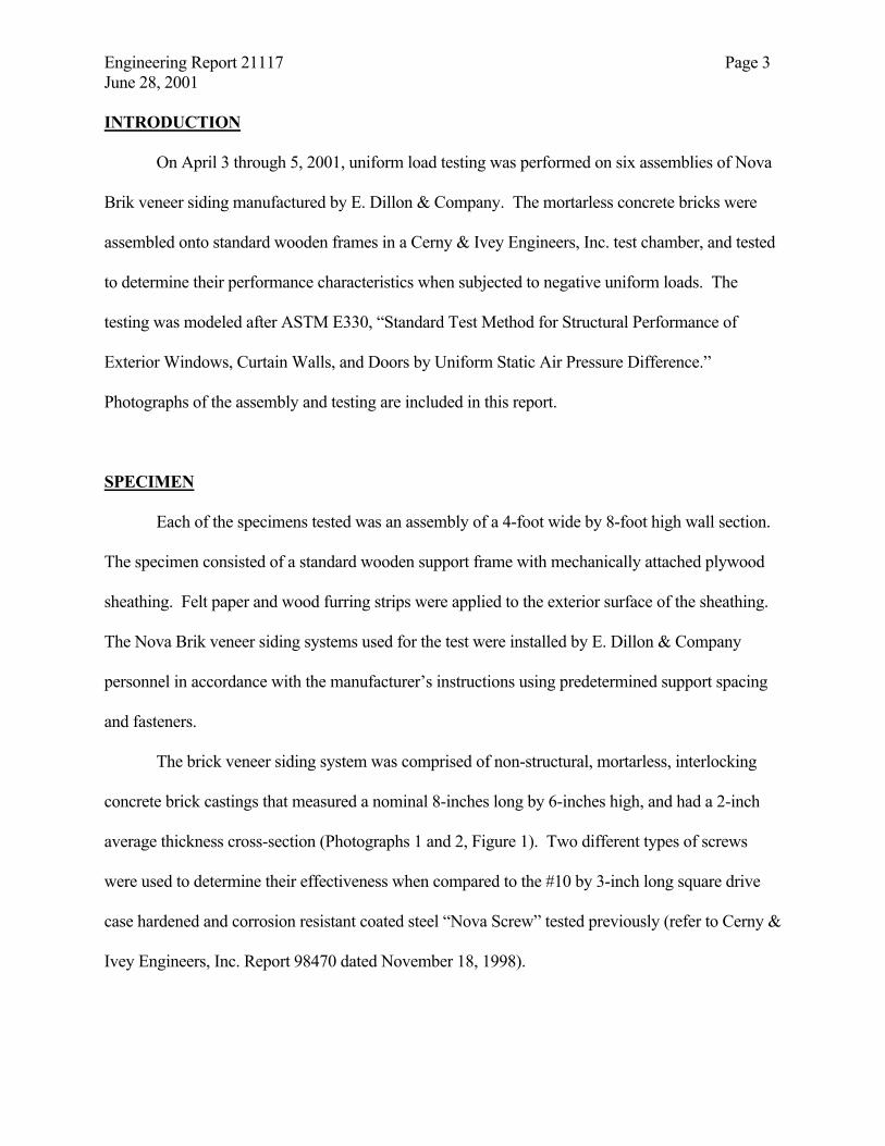
On April 3 through 5, 2001, uniform load testing was performed on six assemblies of Nova
Brik veneer siding manufactured by E. Dillon & Company. The mortarless concrete bricks were
assembled onto standard wooden frames in a Cerny & Ivey Engineers, Inc. test chamber, and tested
to determine their performance characteristics when subjected to negative uniform loads. The
testing was modeled after ASTM E330, “Standard Test Method for Structural Performance of
Exterior Windows, Curtain Walls, and Doors by Uniform Static Air Pressure Difference.”
Photographs of the assembly and testing are included in this report.
SPECIMEN
Each of the specimens tested was an assembly of a 4-foot wide by 8-foot high wall section.
The specimen consisted of a standard wooden support frame with mechanically attached plywood
sheathing. Felt paper and wood furring strips were applied to the exterior surface of the sheathing.
The Nova Brik veneer siding systems used for the test were installed by E. Dillon & Company
personnel in accordance with the manufacturer’s instructions using predetermined support spacing
and fasteners.
The brick veneer siding system was comprised of non-structural, mortarless, interlocking
concrete brick castings that measured a nominal 8-inches long by 6-inches high, and had a 2-inch
average thickness cross-section (Photographs 1 and 2, Figure 1). Two different types of screws
were used to determine their effectiveness when compared to the #10 by 3-inch long square drive
case hardened and corrosion resistant coated steel “Nova Screw” tested previously (refer to Cerny &
Ivey Engineers, Inc. Report 98470 dated November 18, 1998).
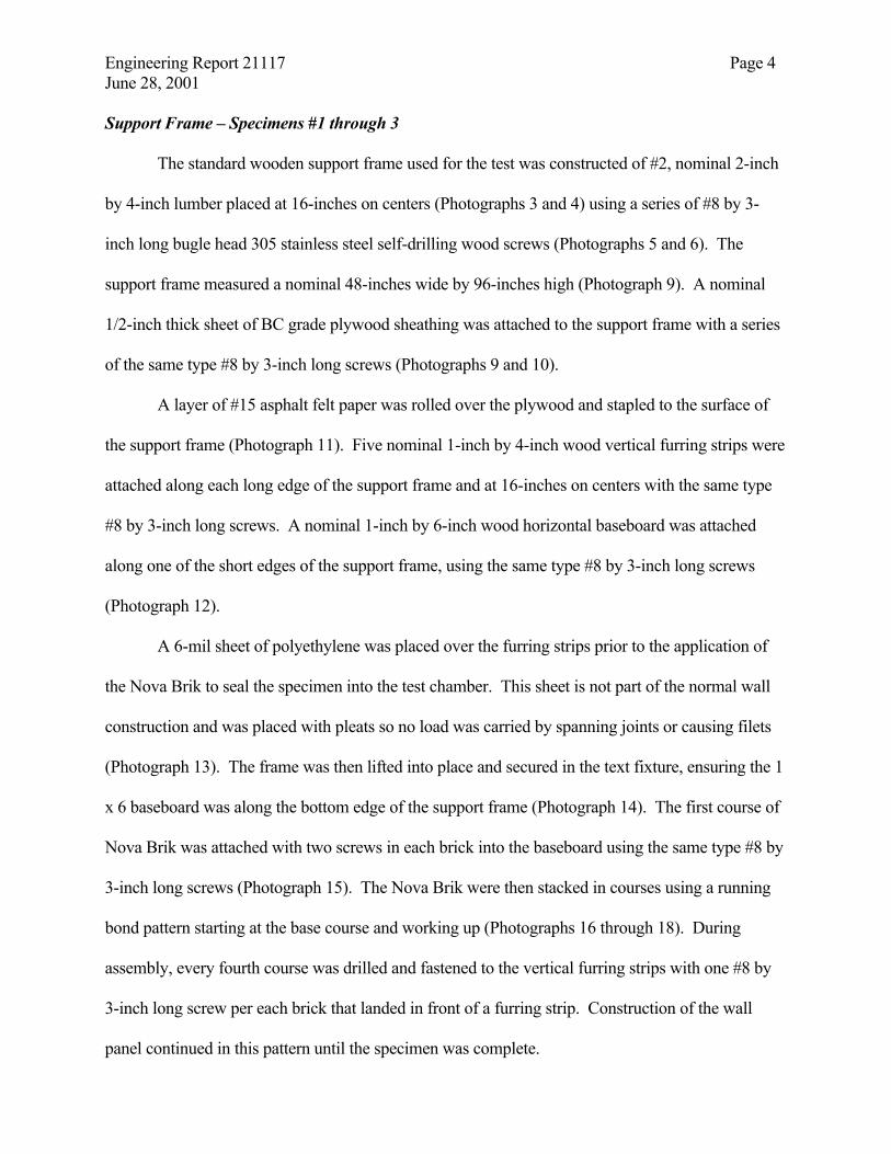
Engineering Report 21117 Page 4 June 28, 2001 Support Frame – Specimens #1 through 3
The standard wooden support frame used for the test was constructed of #2, nominal 2-inch
by 4-inch lumber placed at 16-inches on centers (Photographs 3 and 4) using a series of #8 by 3-
inch long bugle head 305 stainless steel self-drilling wood screws (Photographs 5 and 6). The
support frame measured a nominal 48-inches wide by 96-inches high (Photograph 9). A nominal
1/2-inch thick sheet of BC grade plywood sheathing was attached to the support frame with a series
of the same type #8 by 3-inch long screws (Photographs 9 and 10).
A layer of #15 asphalt felt paper was rolled over the plywood and stapled to the surface of
the support frame (Photograph 11). Five nominal 1-inch by 4-inch wood vertical furring strips were
attached along each long edge of the support frame and at 16-inches on centers with the same type
#8 by 3-inch long screws. A nominal 1-inch by 6-inch wood horizontal baseboard was attached
along one of the short edges of the support frame, using the same type #8 by 3-inch long screws
(Photograph 12).
A 6-mil sheet of polyethylene was placed over the furring strips prior to the application of
the Nova Brik to seal the specimen into the test chamber. This sheet is not part of the normal wall
construction and was placed with pleats so no load was carried by spanning joints or causing filets
(Photograph 13). The frame was then lifted into place and secured in the text fixture, ensuring the 1
x 6 baseboard was along the bottom edge of the support frame (Photograph 14). The first course of
Nova Brik was attached with two screws in each brick into the baseboard using the same type #8 by
3-inch long screws (Photograph 15). The Nova Brik were then stacked in courses using a running
bond pattern starting at the base course and working up (Photographs 16 through 18). During
assembly, every fourth course was drilled and fastened to the vertical furring strips with one #8 by
3-inch long screw per each brick that landed in front of a furring strip. Construction of the wall
panel continued in this pattern until the specimen was complete.
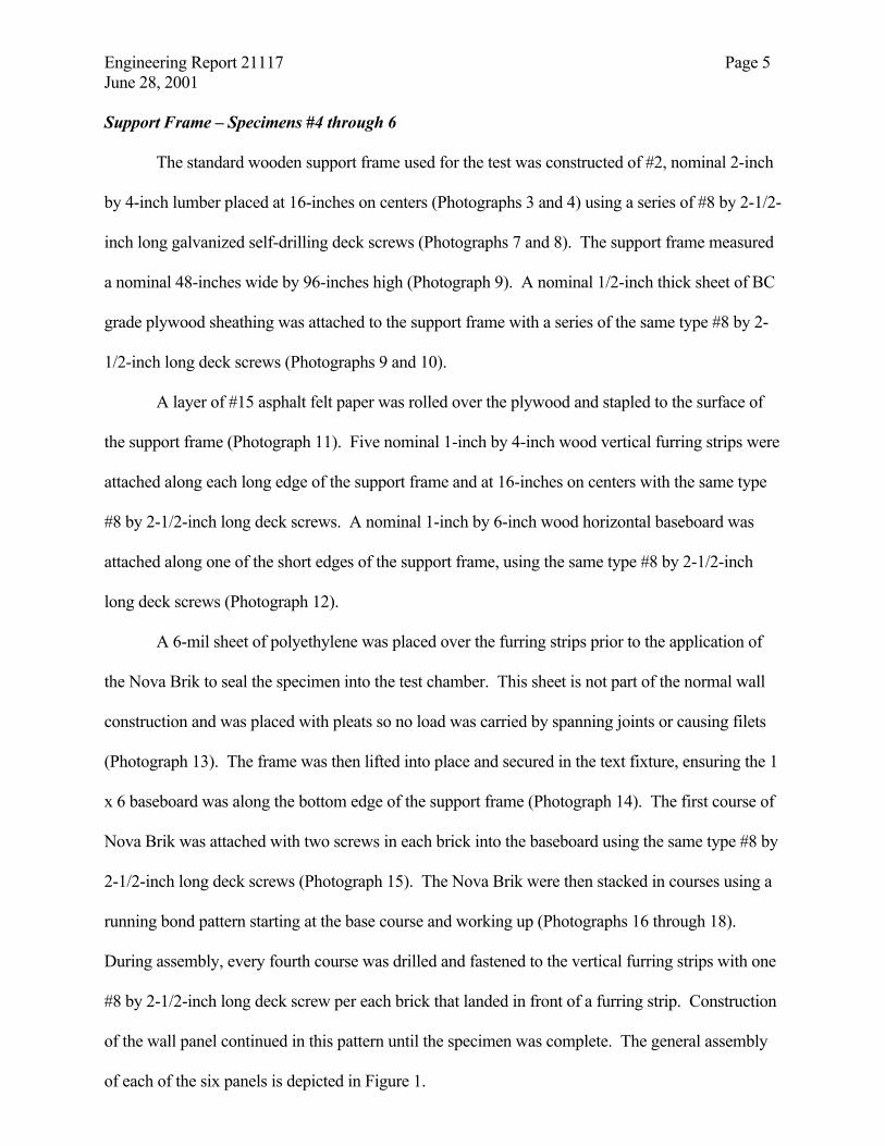
Engineering Report 21117 Page 5 June 28, 2001 Support Frame – Specimens #4 through 6
The standard wooden support frame used for the test was constructed of #2, nominal 2-inch
by 4-inch lumber placed at 16-inches on centers (Photographs 3 and 4) using a series of #8 by 2-1/2-
inch long galvanized self-drilling deck screws (Photographs 7 and 8). The support frame measured
a nominal 48-inches wide by 96-inches high (Photograph 9). A nominal 1/2-inch thick sheet of BC
grade plywood sheathing was attached to the support frame with a series of the same type #8 by 2-
1/2-inch long deck screws (Photographs 9 and 10).
A layer of #15 asphalt felt paper was rolled over the plywood and stapled to the surface of
the support frame (Photograph 11). Five nominal 1-inch by 4-inch wood vertical furring strips were
attached along each long edge of the support frame and at 16-inches on centers with the same type
#8 by 2-1/2-inch long deck screws. A nominal 1-inch by 6-inch wood horizontal baseboard was
attached along one of the short edges of the support frame, using the same type #8 by 2-1/2-inch
long deck screws (Photograph 12).
A 6-mil sheet of polyethylene was placed over the furring strips prior to the application of
the Nova Brik to seal the specimen into the test chamber. This sheet is not part of the normal wall
construction and was placed with pleats so no load was carried by spanning joints or causing filets
(Photograph 13). The frame was then lifted into place and secured in the text fixture, ensuring the 1
x 6 baseboard was along the bottom edge of the support frame (Photograph 14). The first course of
Nova Brik was attached with two screws in each brick into the baseboard using the same type #8 by
2-1/2-inch long deck screws (Photograph 15). The Nova Brik were then stacked in courses using a
running bond pattern starting at the base course and working up (Photographs 16 through 18).
During assembly, every fourth course was drilled and fastened to the vertical furring strips with one
#8 by 2-1/2-inch long deck screw per each brick that landed in front of a furring strip. Construction
of the wall panel continued in this pattern until the specimen was complete. The general assembly
of each of the six panels is depicted in Figure 1.
Engineering Report 21117 Page 6 June 28, 2001
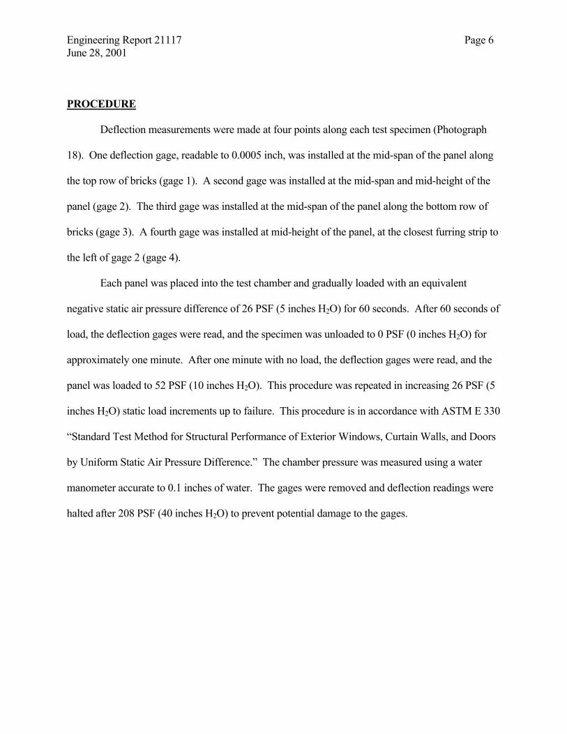
PROCEDURE
Deflection measurements were made at four points along each test specimen (Photograph
18). One deflection gage, readable to 0.0005 inch, was installed at the mid-span of the panel along
the top row of bricks (gage 1). A second gage was installed at the mid-span and mid-height of the
panel (gage 2). The third gage was installed at the mid-span of the panel along the bottom row of
bricks (gage 3). A fourth gage was installed at mid-height of the panel, at the closest furring strip to
the left of gage 2 (gage 4).
Each panel was placed into the test chamber and gradually loaded with an equivalent
negative static air pressure difference of 26 PSF (5 inches H2O) for 60 seconds. After 60 seconds of
load, the deflection gages were read, and the specimen was unloaded to 0 PSF (0 inches H2O) for
approximately one minute. After one minute with no load, the deflection gages were read, and the
panel was loaded to 52 PSF (10 inches H2O). This procedure was repeated in increasing 26 PSF (5
inches H2O) static load increments up to failure. This procedure is in accordance with ASTM E 330
“Standard Test Method for Structural Performance of Exterior Windows, Curtain Walls, and Doors
by Uniform Static Air Pressure Difference.” The chamber pressure was measured using a water
manometer accurate to 0.1 inches of water. The gages were removed and deflection readings were
halted after 208 PSF (40 inches H2O) to prevent potential damage to the gages.
Engineering Report 21117 Page 7 June 28, 2001 RESULTS
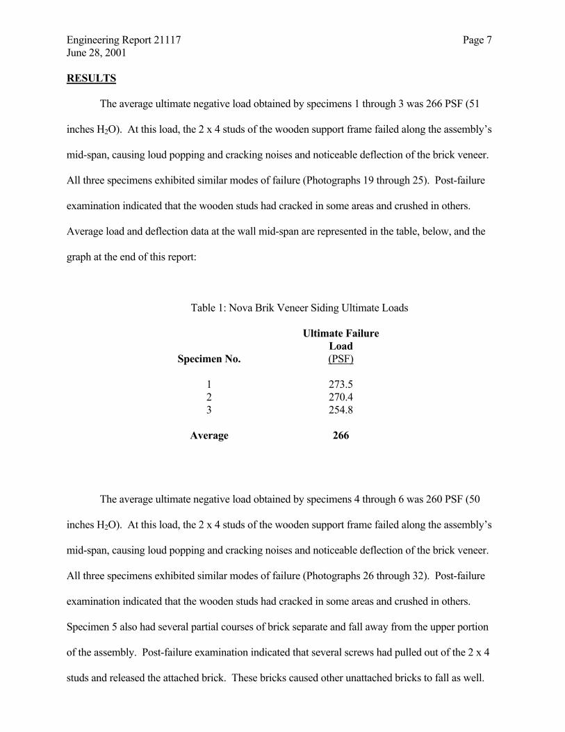
The average ultimate negative load obtained by specimens 1 through 3 was 266 PSF (51
inches H2O). At this load, the 2 x 4 studs of the wooden support frame failed along the assembly’s
mid-span, causing loud popping and cracking noises and noticeable deflection of the brick veneer.
All three specimens exhibited similar modes of failure (Photographs 19 through 25). Post-failure
examination indicated that the wooden studs had cracked in some areas and crushed in others.
Average load and deflection data at the wall mid-span are represented in the table, below, and the
graph at the end of this report:
Table 1: Nova Brik Veneer Siding Ultimate Loads
Ultimate Failure Load
Specimen No. (PSF)
1 273.5 2 270.4 3 254.8
Average 266
The average ultimate negative load obtained by specimens 4 through 6 was 260 PSF (50
inches H2O). At this load, the 2 x 4 studs of the wooden support frame failed along the assembly’s
mid-span, causing loud popping and cracking noises and noticeable deflection of the brick veneer.
All three specimens exhibited similar modes of failure (Photographs 26 through 32). Post-failure
examination indicated that the wooden studs had cracked in some areas and crushed in others.
Specimen 5 also had several partial courses of brick separate and fall away from the upper portion
of the assembly. Post-failure examination indicated that several screws had pulled out of the 2 x 4
studs and released the attached brick. These bricks caused other unattached bricks to fall as well.
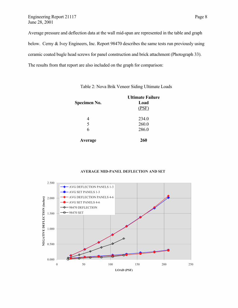
Engineering Report 21117 Page 8 June 28, 2001 Average pressure and deflection data at the wall mid-span are represented in the table and graph
below. Cerny & Ivey Engineers, Inc. Report 98470 describes the same tests run previously using
ceramic coated bugle head screws for panel construction and brick attachment (Photograph 33).
The results from that report are also included on the graph for comparison:
Table 2: Nova Brik Veneer Siding Ultimate Loads
Ultimate Failure Specimen No. Load
(PSF)
4 234.0 5 260.0 6 286.0
Average 260
AVERAGE MID-PANEL DEFLECTION AND SET
0.000
0.500
1.000
1.500
2.000
2.500
0 50 100 150 200 250
LOAD (PSF)
NE
GA
TIV
E D
EFL
EC
TIO
N (i
nche
s)
AVG DEFLECTION PANELS 1-3AVG SET PANELS 1-3AVG DEFLECTION PANELS 4-6AVG SET PANELS 4-698470 DEFLECTION98470 SET
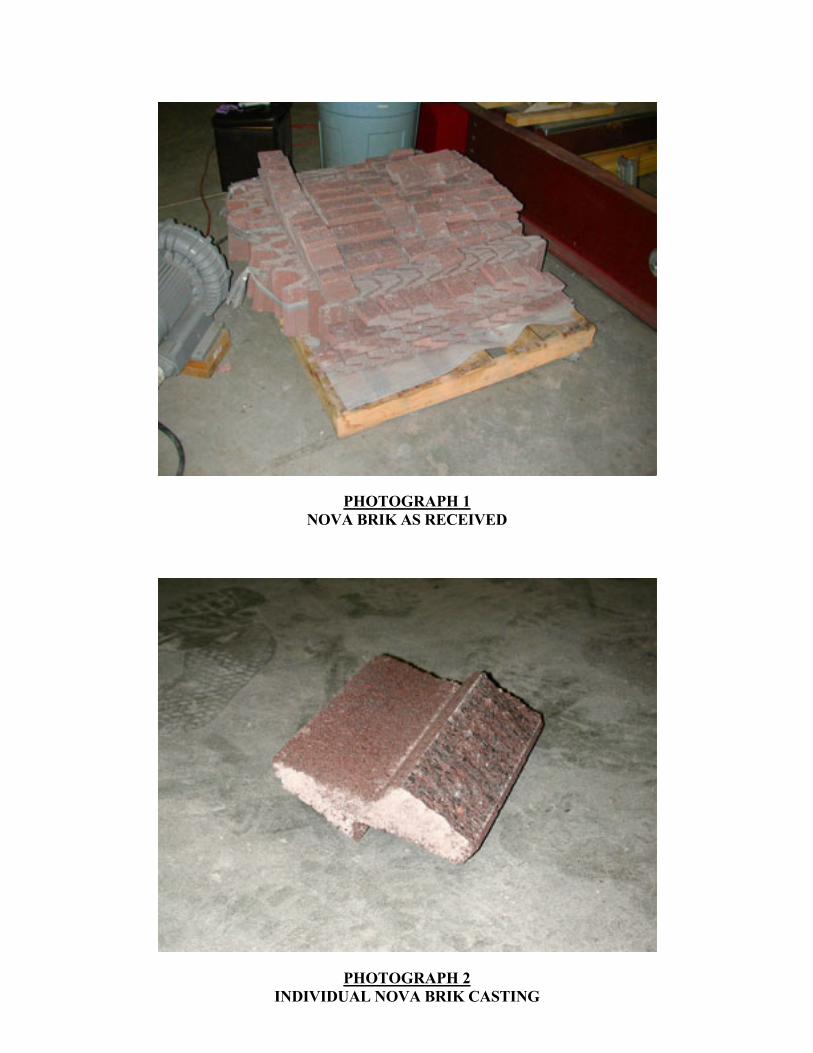
PHOTOGRAPH 1 NOVA BRIK AS RECEIVED
PHOTOGRAPH 2 INDIVIDUAL NOVA BRIK CASTING
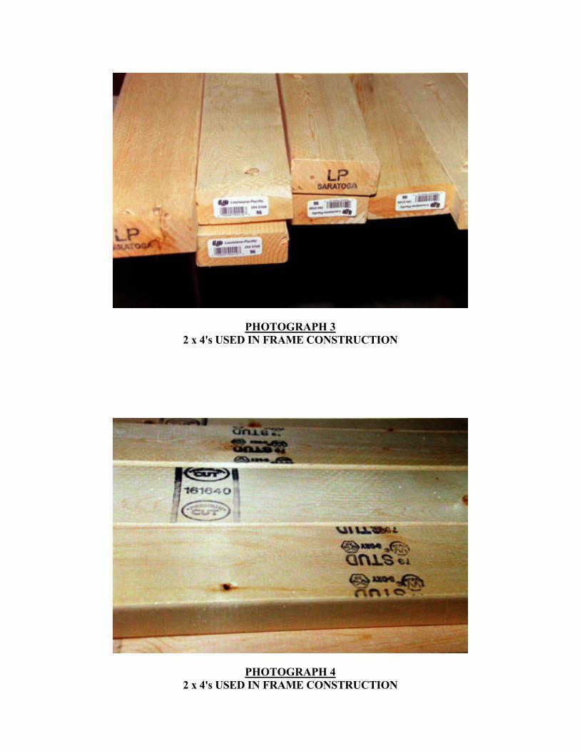
PHOTOGRAPH 3 2 x 4's USED IN FRAME CONSTRUCTION
PHOTOGRAPH 4 2 x 4's USED IN FRAME CONSTRUCTION
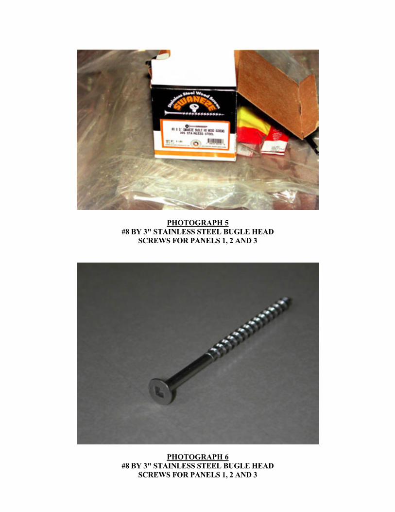
PHOTOGRAPH 5 #8 BY 3" STAINLESS STEEL BUGLE HEAD
SCREWS FOR PANELS 1, 2 AND 3
PHOTOGRAPH 6 #8 BY 3" STAINLESS STEEL BUGLE HEAD
SCREWS FOR PANELS 1, 2 AND 3
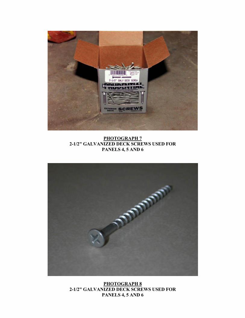
PHOTOGRAPH 7 2-1/2" GALVANIZED DECK SCREWS USED FOR
PANELS 4, 5 AND 6
PHOTOGRAPH 8 2-1/2" GALVANIZED DECK SCREWS USED FOR
PANELS 4, 5 AND 6
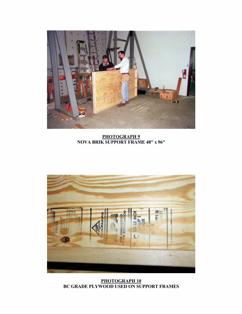
PHOTOGRAPH 9 NOVA BRIK SUPPORT FRAME 48" x 96"
PHOTOGRAPH 10 BC GRADE PLYWOOD USED ON SUPPORT FRAMES
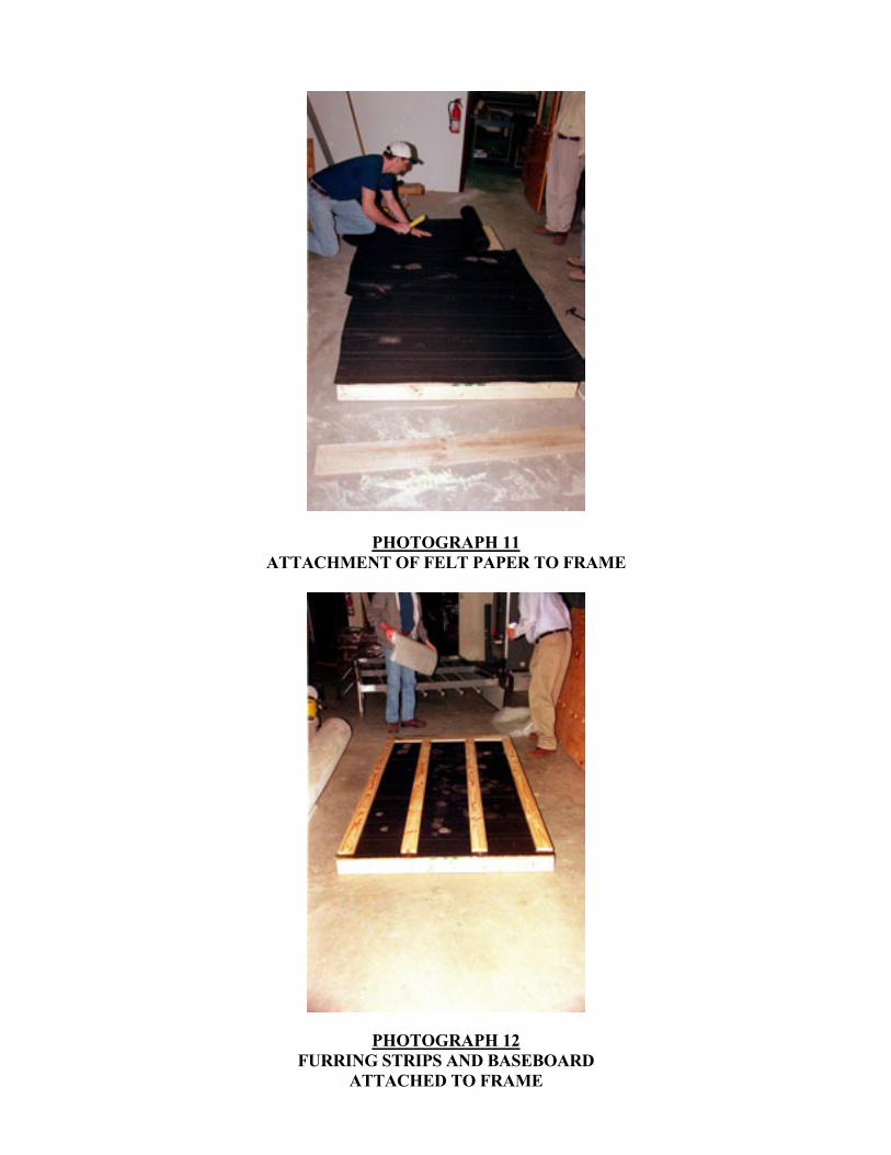
PHOTOGRAPH 11 ATTACHMENT OF FELT PAPER TO FRAME
PHOTOGRAPH 12 FURRING STRIPS AND BASEBOARD
ATTACHED TO FRAME
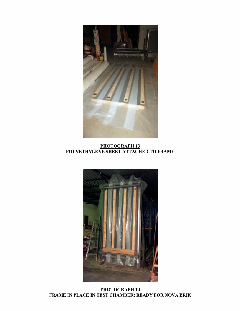
PHOTOGRAPH 13 POLYETHYLENE SHEET ATTACHED TO FRAME
PHOTOGRAPH 14 FRAME IN PLACE IN TEST CHAMBER; READY FOR NOVA BRIK
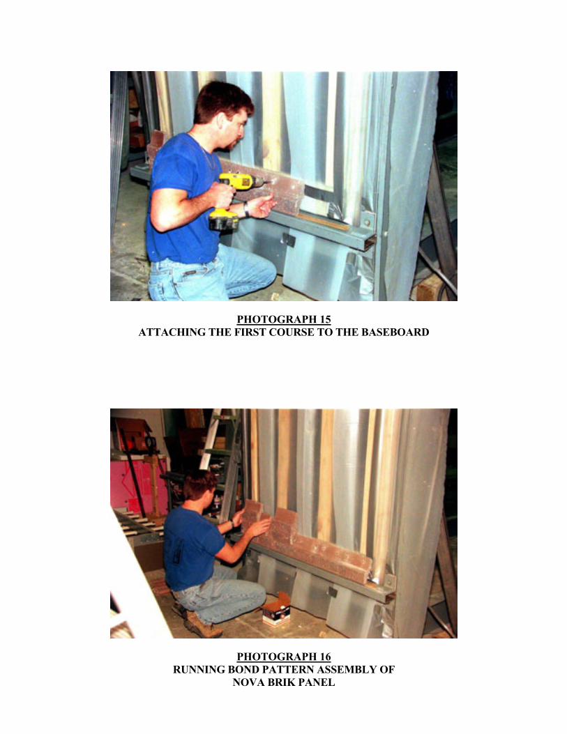
PHOTOGRAPH 15 ATTACHING THE FIRST COURSE TO THE BASEBOARD
PHOTOGRAPH 16 RUNNING BOND PATTERN ASSEMBLY OF
NOVA BRIK PANEL
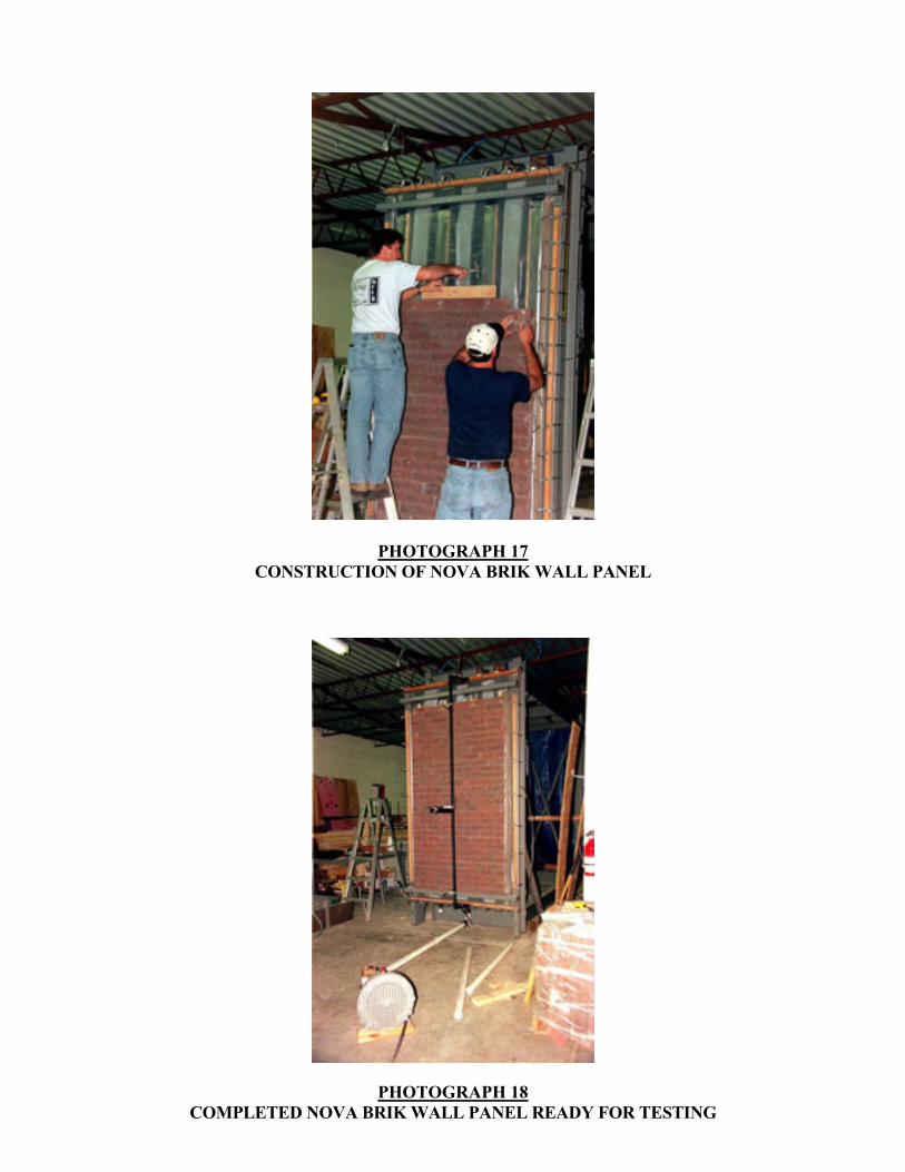
PHOTOGRAPH 17 CONSTRUCTION OF NOVA BRIK WALL PANEL
PHOTOGRAPH 18 COMPLETED NOVA BRIK WALL PANEL READY FOR TESTING
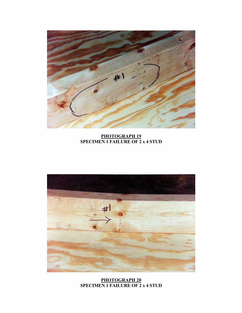
PHOTOGRAPH 19 SPECIMEN 1 FAILURE OF 2 x 4 STUD
PHOTOGRAPH 20 SPECIMEN 1 FAILURE OF 2 x 4 STUD
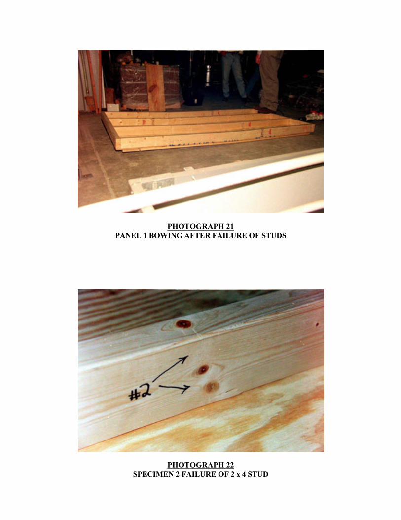
PHOTOGRAPH 21 PANEL 1 BOWING AFTER FAILURE OF STUDS
PHOTOGRAPH 22 SPECIMEN 2 FAILURE OF 2 x 4 STUD
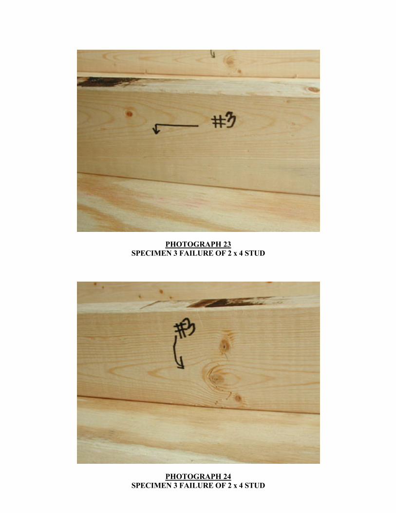
PHOTOGRAPH 23 SPECIMEN 3 FAILURE OF 2 x 4 STUD
PHOTOGRAPH 24 SPECIMEN 3 FAILURE OF 2 x 4 STUD
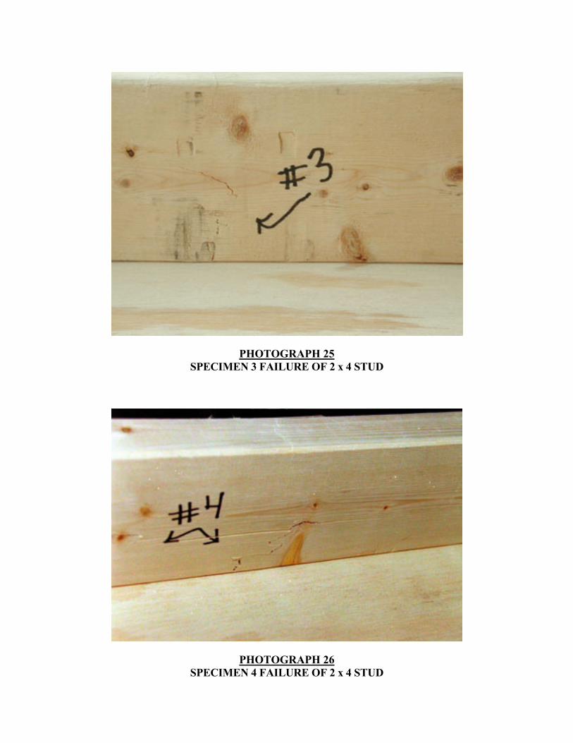
PHOTOGRAPH 25 SPECIMEN 3 FAILURE OF 2 x 4 STUD
PHOTOGRAPH 26 SPECIMEN 4 FAILURE OF 2 x 4 STUD
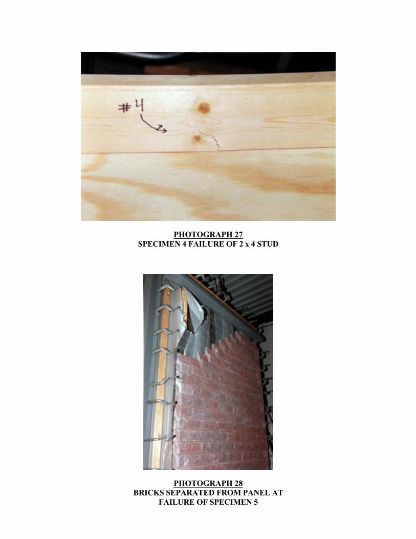
PHOTOGRAPH 27 SPECIMEN 4 FAILURE OF 2 x 4 STUD
PHOTOGRAPH 28 BRICKS SEPARATED FROM PANEL AT
FAILURE OF SPECIMEN 5
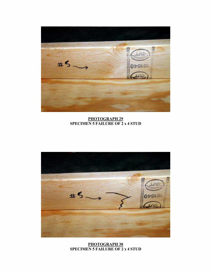
PHOTOGRAPH 29 SPECIMEN 5 FAILURE OF 2 x 4 STUD
PHOTOGRAPH 30 SPECIMEN 5 FAILURE OF 2 x 4 STUD
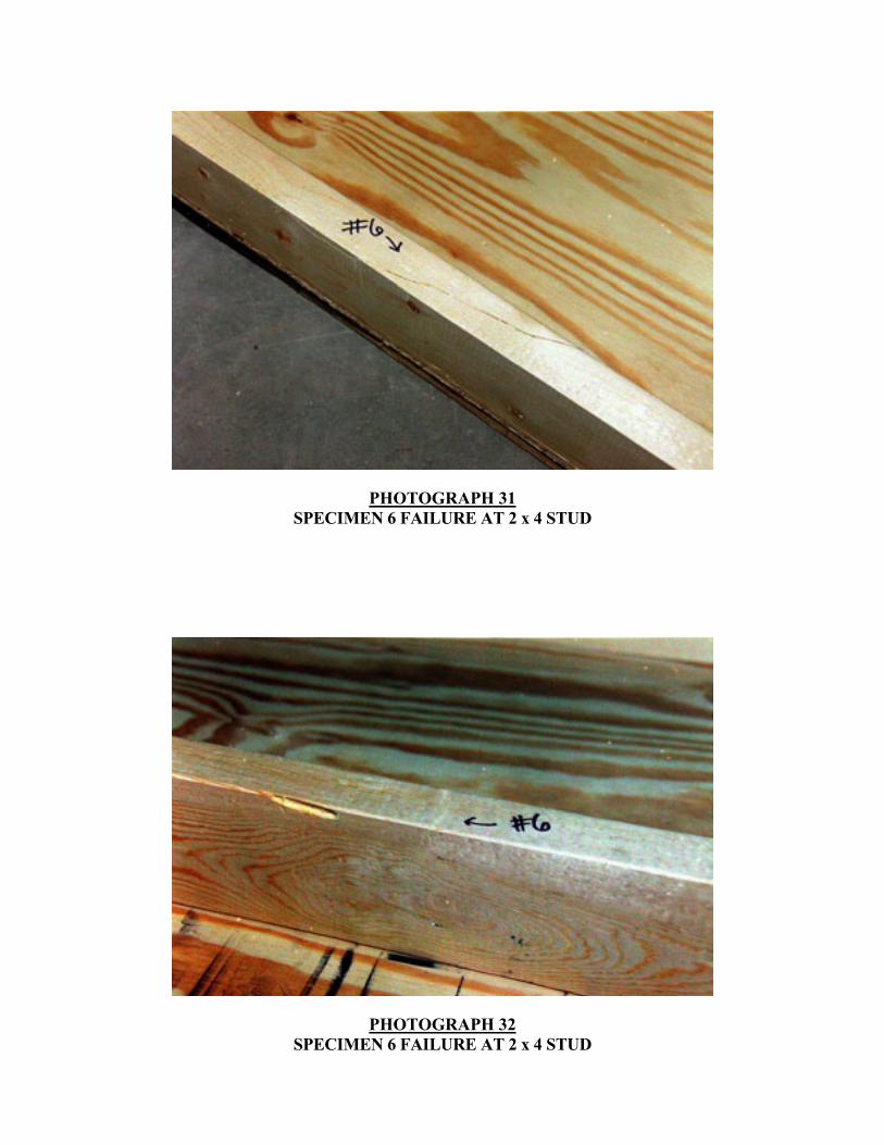
PHOTOGRAPH 31 SPECIMEN 6 FAILURE AT 2 x 4 STUD
PHOTOGRAPH 32 SPECIMEN 6 FAILURE AT 2 x 4 STUD
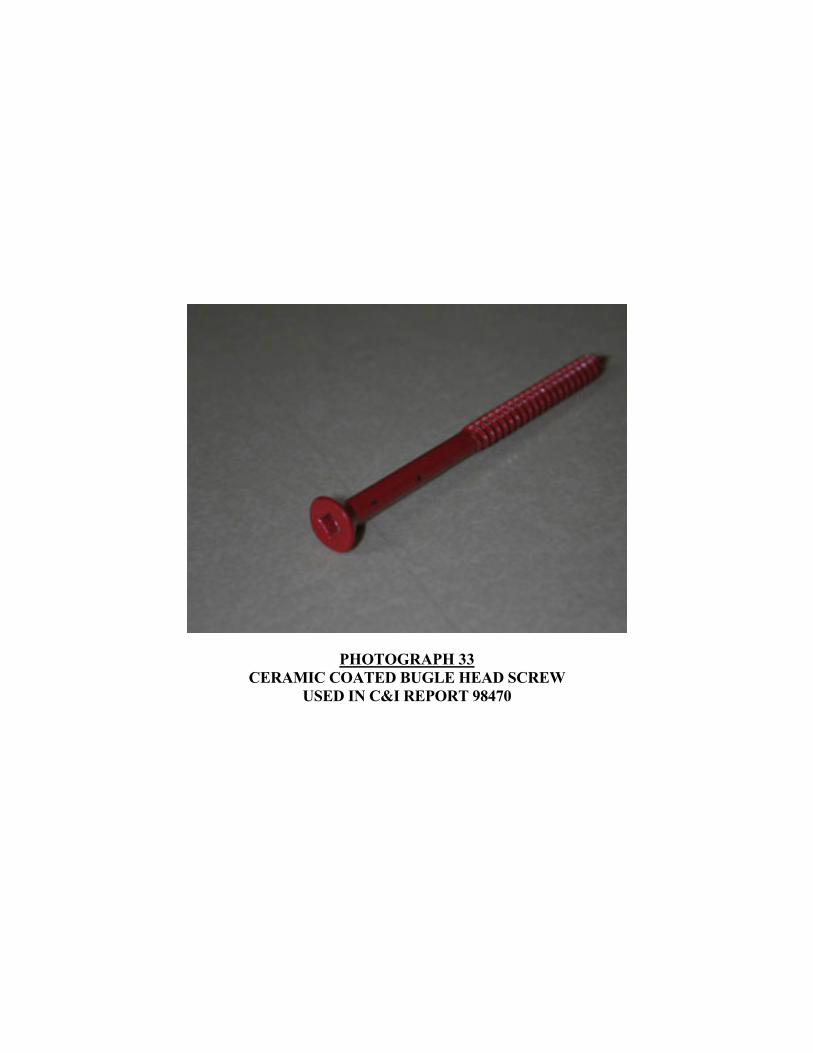
PHOTOGRAPH 33 CERAMIC COATED BUGLE HEAD SCREW
USED IN C&I REPORT 98470