Embed Size (px)
Citation preview
CFD study of using a tube insert and an air blowing system to prevent tube failure in the Bisotoun Power Plant boiler
MASOUD RAHIMI, SEYED MEHDI SHARIATI, ABBAS KHOSHHAL
Chemical Engineering Department, Faculty of Engineering Razi University
Kermanshah, Taghe bostan IRAN
Abstract In this study attempts to find a theoretical solution to prevent tube explosion of the tubes placed in the superheater region of the Bisotoun Power Plant boiler, Iran. The boiler has three types of tube and the tube failure was occurred in the long length type of these tubes. A three dimensional Computational Fluid Dynamics (CFD) modeling was carried out for this purpose. The result of modeling of the boiler shows that the long tubes are working in a temperature higher than the designed value. In the present work in order to solve this problem, two different ways was proposed and theoretically investigated. Using of a tube insert in the tube for heat transfer enhancement which increases the cooling performance of the steam inside the tube was the first one. The ability of the tube insert to increasing the heat transfer coefficient and reducing the tube wall temperature was observed from the CFD modeling. However, this way was not accepted due to probability of separating a part of the welded parts and the consequent danger of the steam turbine placed after the boiler in the plant layout. Using the air blowing system which locally cools the tube in the placed of explosion was also studied. The results show that by this method it is possible to reduce the tube wall temperature to a safe value for the tube. The relation between the air mass flow rate and the temperature at place of damage is also predicted in this study. Key words: CFD; Combustion; Tube insert; Boiler; Modeling; Air blowing 1 Introduction The use of CFD codes for modeling of combustion, heat and fluid flow is a useful tool to predict the performance of boilers among the scientific and industrial communities. The CFD helps engineers to optimize the operating conditions and also improve the design of new boilers. The development of the models depends on the availability of accurate and approximate experimental data in order to compare with the predicted results. However, because of the expensive cost measurements of the combustion and heat transfer characteristics and the limitation of measurements in this type of process a few experimental works were reported in the literature. A numerical simulation of the flow and combustion process in the furnace of a pulverized coal fired 350 MW utility boiler was presented by Xu et al [1]. In that study the boiler contains 24 swirl burners installed at the furnace front wall. The predicted results were compared with the plant data. A reasonable agreement between the site data and simulation results was reported by the authors. A CFD analysis of a 33 MW straw-fired grate boiler was performed by Søren and Kaer [2]. He studied the
combustion of biomass in the boiler with focused on emission level and the amount of unburned carbon. The overall heat transfer predictions were in reasonable agreement with process data from the boiler except at the secondary superheater. Based on the CFD analysis, it was suggested that poor mixing in the furnace is a key issue leading to high level of unburned carbon in the fly ash. In investigation for using the CFD in the boilers modeling, a model was developed on the base of CFD technique for a waste heat recovery boiler by Manickam et al [3]. The boiler fuel was a typical plant off gas consisting of both gaseous and particulate combustibles. The model allowed the calculation of temperatures of gas and particles within the boiler. Combustion stability was also studied using the Eddy Break-up model and the results were compared with the Mixed-is-burnt model. In the present work, the 320 MW natural gas fired boiler was modeled using CFD technique. The main aim of this research is to find a way to prevent the superheater tube explosion. This study more focused on the heat transfer to the boiler’s tubes and the temperature field inside the boiler which demanding
Proceedings of the 5th WSEAS Int. Conf. on SIMULATION, MODELING AND OPTIMIZATION, Corfu, Greece, August 17-19, 2005 (pp413-418)
combustion modeling besides other transport phenomena calculations. 2 Theory Industrial combustion simulations typically involve the solution of the turbulent flows with heat transfer, species transport and chemical reactions. It is common to use the Reynolds-averaged from of the governing equation in conjunction with a suitable turbulence model. Addition equations, such as for radative transport or for specialized combustion models, are also used. Typical Reynolds-averaged governing equations for combustion flows are given below. 2.1 Continuity equation The Reynolds-averaged mixture continuity equation for the gas phase is:
( ) ( ) mSVt
=⋅∇+∂∂ ρρ (1)
Where t is time, ρ is the Reynolds-averaged mixture density, V is the Reynolds-averaged velocity vector and mS represents external mass source. 2.2 Momentum equation The Reynolds-averaged gas-phase momentum equation is given by:
( ) ( ) ( )( ) FVVVVt t +∇+⋅∇=⋅∇+∂∂ µµρρ (2)
where tµ is the turbulent viscosity, obtained from a turbulence model. F contains those parts of the stress term not shown explicitly as well as other momentum sources, such as drag from the dispersed phase. 2.3 Energy equation Heat transfer is governed by the energy conservation equation:
( ) ( ) ( )( ) ( )
( ) hr
t
SSpV
VTkkVEEt
++⋅∇−
⋅⋅∇+∇+⋅∇=⋅∇+∂∂ τρρ
where k is the thermal conductivity, rk is the turbulent thermal conductivity resulting from the
turbulence model, τ is the stress tensor, p is the pressure and E is the total energy defined as:
( )2VVTeE ⋅
+= (4)
and e is the internal energy per unit mass. rS is the radiative heat source. In the present form of the energy equation, reaction source terms are included in hS , which also contains all other volumetric heat sources, including those form any dispersed phase. 2.4 Radiative transfer In the absence of the radiation-turbulence interaction, one can write the radiative transfer equation (RTE) for a gray absorbing, emitting and scattering medium in the direction s as [4]:
( )( ) ( ) ( ) ( )sBsIssI s ++−=⋅∇ σκ (5) Where
( ) ( ) ( ) Ω′′Φ′+= ∫ dsssIIsB sB ,
4 4ππσ
κ (6)
Here, ( )sI is the radiant intensity in the direction s , κ is the absorption coefficient, sσ is the scattering coefficient, BI is the blackbody intensity and Φ is the scattering function. The radiative source term rS in the Eq. (3) is given by:
( )[ ] Ω−= ∫ dIsIS Brπ
κ4
(7)
In this research, the Rosseland model [5] was used for solving the RTE. 2.5 Turbulence modeling A turbulence model is a computational procedure to close the system of mean flow Eqs. (1) and (2) and solve them, so that a more or less wide variety of flow problems can be calculated. There are some well known classical turbulence models. In the present work, the standard ε−k turbulence model [6] was used, which involves solution of the following transport equations for the turbulent kinetic energy k and its dissipationε .
(3)
Proceedings of the 5th WSEAS Int. Conf. on SIMULATION, MODELING AND OPTIMIZATION, Corfu, Greece, August 17-19, 2005 (pp413-418)
( ) ( ) ( )
ρεσµµ
ρρ
−+
⎟⎟⎠
⎞⎜⎜⎝
⎛∇
+⋅∇=⋅∇+
∂∂
k
k
t
G
kVkkt
( ) ( ) ( )
kCG
kC
Vt
k
t
2
21ερε
εσµµ
ερρε
εε
ε
−+
⎟⎟⎠
⎞⎜⎜⎝
⎛∇
+⋅∇=⋅∇+
∂∂
where kG is the turbulence production term, kσ and
εσ are the turbulence Prandtl numbers and ε1C and
ε2C are model constants. In order to solve the PDE equations, the second-order schemes and the segregated solution method and the simple pressure velocity coupling algorithm were used. The standard version of the ε−k model using the following coefficients was employed in the modeling:
314.1;1;92.1;44.1 21 ==== εεε σσ kCC 2.6 Species transport Under the dilute approximation, the Reynolds-averaged conservation equations for the mass fraction,
lm , of species l can written as:
( ) ( )
l
lm
tll
R
mDVmmt
+
⎟⎟⎠
⎞⎜⎜⎝
⎛∇⎟⎟⎠
⎞⎜⎜⎝
⎛+⋅∇=⋅∇+
∂∂
σµ
ρρρ
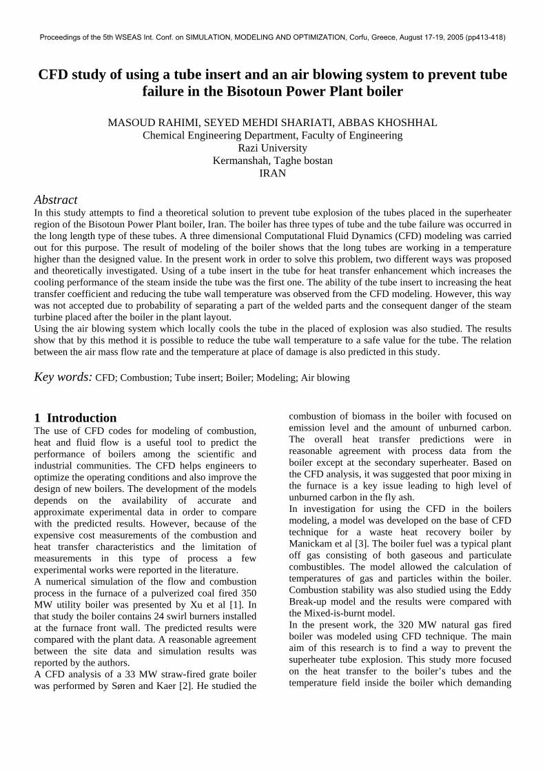
where D is the diffusion coefficient of species l in the mixture and mσ is the turbulent Schmidt number. In this work, for turbulent reacting flows, the eddy dissipation model [7] was used. 3 The boiler description Fig.1 shows the Bisotoun Power Plant boiler with dimensions of 10.5×39.8×11.7 m . The boiler contains 16 gas burners placed in four stages horizontally separated by 10 cm. The four burners in each stage are distributed at an angle of 90o around the boiler. The boiler has six banks of the superheater tubes in three categories in the boiler Platen region including; two long, two medium and two short length tubes with a length of 38.12m, 23.95m and 20.89m respectively. The tubes were made from 14Cr5Mo stainless steel with an outer diameter of 38mm and an inner diameter
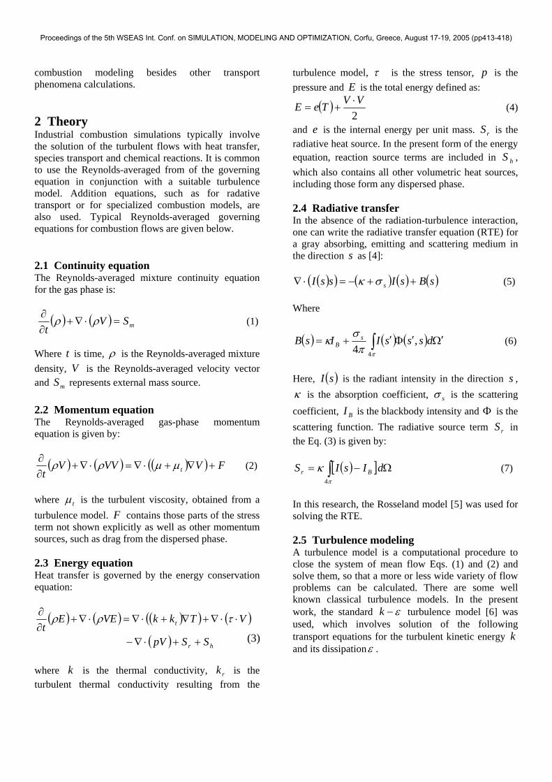
of 28mm. A saturated steam with a pressure of 18.9 Mpa enters the boiler steam header box and after being distributed in the tubes, it is heated inside the boiler by all modes of heat transfer. Finally the steam is diverted into the boiler steam junction header and collected at 17.8 Mpa. The power plant process unit reported that the long length tubes occasionally exploded at the last elbows close to the junction header. Fig.2 shows the exploded tube. As can be seen in the figure, there is no a considerable reduction in the tube wall thickness. Therefore it is not expected that the corrosion or erosion is the reason of this damage. 4 Results and Discussion In the present work, in order to find the reason for the tube damage in the Platen long superheater tubes the predicted operating condition in the long and short tubes were analyzed. The short tube has been chosen to illustrate the maximum differences in the
Fig.1. The Bisotoun power plant’s boiler.
Fig.2. A view of damaged superheater tube.
(8)
(9)
(10)
Proceedings of the 5th WSEAS Int. Conf. on SIMULATION, MODELING AND OPTIMIZATION, Corfu, Greece, August 17-19, 2005 (pp413-418)
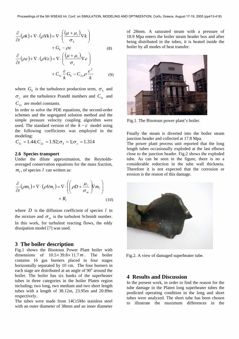
operational conditions. An in-house CFD code with ability of simultaneous solving of continuity, the Reynolds-Averaged Navier-Stokes (RANS) equations and employing various types of turbulence and radiation models was used in the present work. The code is written specially for this modeling and it is not the general purpose code. In the first step, the fluid flow hydrodynamics and temperature fields inside the boiler were studied. Fig.3 shows the modeled boiler. The boiler volume was meshed into 2,000,0000- 2,500,000 triangular type of mesh. The gas with a velocity of 116 m/s enters the burner nozzle and burns with 7% air in excess. The steam with a temperature of 368 0C and a pressure of 187.5 atm enters the superheater tubes with a mass flow rate of 1056 ton/hr. The steam exits at a temperature of 385 0C and pressure of 175.5 atm. These values were applied as boundary conditions to the code. The temperature fields are predicted in the whole boiler. In this work, the results show that the temperature inside the boiler in most regions is more than 2000 0C. In addition, the steam and
tube wall temperatures were predicted by the CFD. Fig.4 shows the result of the tube wall temperature along the short and long tubes. As can be seen in the figure, the long tube which exploded at the last elbow close to the exit section has a temperature almost 60 oC higher than the exit temperature of the short one. This temperature is more than the temperature that already designed for the boiler’s tubes. This difference can be seen in the tube metal temperatures at the end part of the two tubes. This over-design temperature is sufficient to reduce the strength of the metal. This condition causes the metal microstructure to reform and the metal loses its strength and becomes more ductile and soft. On the other hand, the power plant process unit reports that the explosion was happened only at the elbow region. This can be explained by the structural fatigue tension exists on the tube’s elbow. Therefore, it is expected that the metal at the elbow section with high level of internal energy is more suitable for microstructure deformation and consequent metal damage compare to other parts. In order to bring the tube wall temperature to the designed temperature, two ways of using the tube insert for heat transfer enhancement and locally cooling the superheater tube were studied. In this work, a wire coil type of the tube inert and a simple air blowing system was proposed in order to achieve this aim. A tube inserts is a device which make heat transfer enhancements by increasing the turbulency, reduction of the hydraulic diameter and extending the heat surface. Tube insert devises such as twisted tape
Fig.3. The modeled boiler and its sizing.
Fig.4. The tube wall temperature for the short and long tube inside the boiler.
Proceedings of the 5th WSEAS Int. Conf. on SIMULATION, MODELING AND OPTIMIZATION, Corfu, Greece, August 17-19, 2005 (pp413-418)
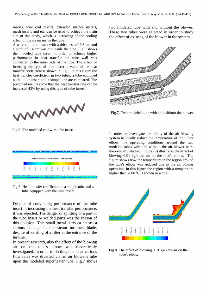
inserts, wire coil inserts, extended surface inserts, mesh inserts and etc. can be used to achieve the main aim of this study, which is increasing of the cooling effect of the steam inside the tube. A wire coil tube insert with a thickness of 0.3 cm and a pitch of 1.4 cm was put inside the tube. Fig.5 shows the modeled tube inset. In order to achieve higher performance in heat transfer the wire wall was connected to the inner side of the tube. The effect of inserting this type of tube insert in value of the heat transfer coefficient is shown in Fig.6. In this figure the heat transfer coefficient in two tubes, a tube equipped with a tube insert and a simple one are compared. The predicted results show that the heat transfer rate can be increased 43% by using this type of tube insert. Despite of convincing performance of the tube insert in increasing the heat transfer performance, it was rejected. The danger of splitting of a part of the tube insert or welded parts was the reason of this decision. This small metal parts ca causes a serious damage in the steam turbine's blade, despite of existing of a filter at the entrance of the turbine. In present research, also the effect of the blowing air on the tube's elbow was theoretically investigated. In order to do this, the air at various flow rates was diverted via an air blower's tube upon the modeled superheater tube. Fig.7 shows
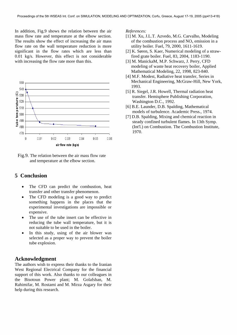
two modeled tube with and without the blower. These two tubes were selected in order to study the effect of existing of the blower in the system. In order to investigate the ability of the air blowing system to locally reduce the temperature of the tube's elbow, the operating conditions around the two modeled tubes with and without the air blower were theoretically studied. Figure (8) illustrates the effect of blowing 0.01 kg/s the air on the tube's elbow. The figure shows how the temperature in the region around the tube's elbow was reduced due to the air blower operation. In this figure the region with a temperature higher than 2000 oC is shown in white.
Fig.7. Two modeled tube with and without the blower.
Fig.5. The modeled coil wire tube insert.
Fig.6. Heat transfer coefficient in a simple tube and a tube equipped with the tube insert.
Fig.8. The effect of blowing 0.01 kg/s the air on the tube's elbow.
Proceedings of the 5th WSEAS Int. Conf. on SIMULATION, MODELING AND OPTIMIZATION, Corfu, Greece, August 17-19, 2005 (pp413-418)
In addition, Fig.9 shows the relation between the air mass flow rate and temperature at the elbow section. The results show the effect of increasing the air mass flow rate on the wall temperature reduction is more significant in the flow rates which are less than 0.01 kg/s. However, this effect is not considerable with increasing the flow rate more than this. 5 Conclusion
• The CFD can predict the combustion, heat transfer and other transfer phenomenon.
• The CFD modeling is a good way to predict something happens in the places that the experimental investigations are impossible or expensive.
• The use of the tube insert can be effective in reducing the tube wall temperature, but it is not suitable to be used in the boiler.
• In this study, using of the air blower was selected as a proper way to prevent the boiler tube explosion.
Acknowledgment The authors wish to express their thanks to the Iranian West Regional Electrical Company for the financial support of this work. Also thanks to our colleagues in the Bisotoun Power plant; M. Golafshan, M. Rahimifar, M. Rostami and M. Mirza Asgary for their help during this research.
References: [1] M. Xu, J.L.T. Azvedo, M.G. Carvalho, Modeling of the combustion process and NOx emission in a utility boiler. Fuel, 79, 2000, 1611-1619. [2] K. Søren, S. Kaer, Numerical modeling of a straw- fired grate boiler. Fuel, 83, 2004, 1183-1190. [3] M. ManickaM, M.P. Schwarz, J. Perry, CFD modeling of waste heat recovery boiler, Applied Mathematical Modeling, 22, 1998, 823-840. [4] M.F. Modest, Radiative heat transfer, Series in Mechanical Engineering, McGraw-Hill, New York, 1993. [5] R. Siegel, J.R. Howell, Thermal radiation heat transfer. Hemisphere Publishing Corporation, Washington D.C., 1992. [6] B.E. Launder, D.B. Spalding, Mathematical models of turbulence. Academic Press., 1974. [7] D.B. Spalding, Mixing and chemical reaction in steady confined turbulent flames. In 13th Symp. (Int'l.) on Combustion. The Combustion Institute, 1970.
Fig.9. The relation between the air mass flow rate and temperature at the elbow section.
Proceedings of the 5th WSEAS Int. Conf. on SIMULATION, MODELING AND OPTIMIZATION, Corfu, Greece, August 17-19, 2005 (pp413-418)


![Experimental and CFD Study of the Tube Configuration ... · work, Salimpour [12] studied heat transfer characteristics of temperature dependent- ... the shell and coiled tube heat](https://img.pdfslide.net/doc/110x75/5b08b5457f8b9a404d8cc124/experimental-and-cfd-study-of-the-tube-configuration-salimpour-12-studied.jpg)