Embed Size (px)
Citation preview
© 2010 Eaton Corporation. All rights reserved.
NEC Mandated Selective CoordinationChallenges and Solutions
IEEE IAS MeetingMay 16, 2011
© 2010 Eaton Corporation. All rights reserved.
Background and Definitions
3 3© 2009 Eaton Corporation. All rights reserved.
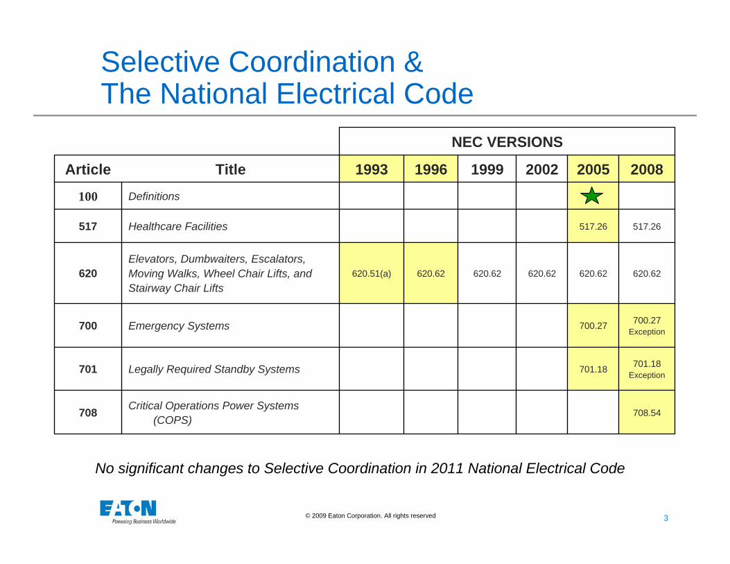
Selective Coordination & The National Electrical Code
708.54Critical Operations Power Systems
(COPS)708
701.18 Exception
701.18Legally Required Standby Systems701
700.27 Exception
700.27Emergency Systems700
620.62620.62620.62620.62620.62620.51(a)Elevators, Dumbwaiters, Escalators, Moving Walks, Wheel Chair Lifts, and Stairway Chair Lifts
620
517.26517.26Healthcare Facilities517
Definitions100
200820052002199919961993TitleArticle
NEC VERSIONS
No significant changes to Selective Coordination in 2011 National Electrical Code
4 4© 2009 Eaton Corporation. All rights reserved.
Selective Coordination -Background
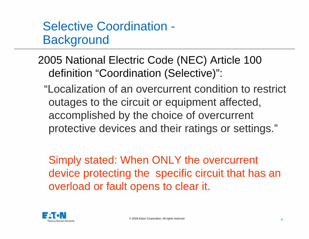
2005 National Electric Code (NEC) Article 100 definition “Coordination (Selective)”:
“Localization of an overcurrent condition to restrict outages to the circuit or equipment affected, accomplished by the choice of overcurrent protective devices and their ratings or settings.”
Simply stated: When ONLY the overcurrent device protecting the specific circuit that has an overload or fault opens to clear it.
5 5© 2009 Eaton Corporation. All rights reserved.
Selective Coordination - Background
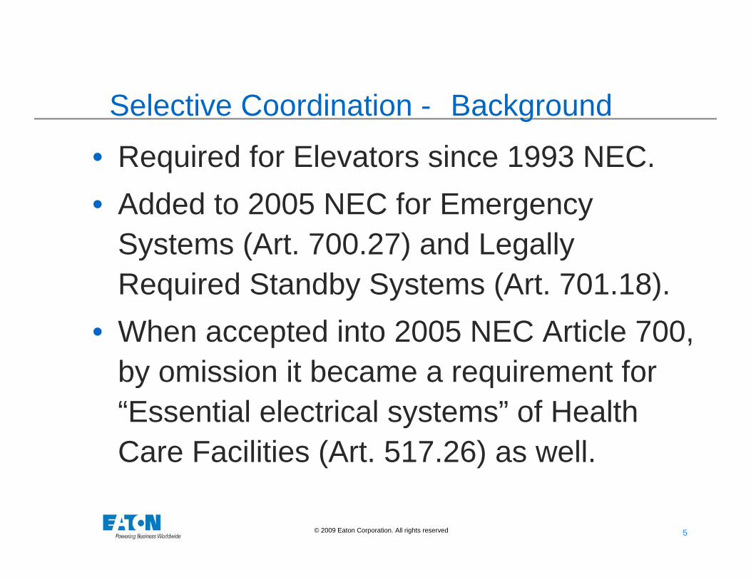
• Required for Elevators since 1993 NEC. • Added to 2005 NEC for Emergency
Systems (Art. 700.27) and Legally Required Standby Systems (Art. 701.18).
• When accepted into 2005 NEC Article 700, by omission it became a requirement for “Essential electrical systems” of Health Care Facilities (Art. 517.26) as well.
6 6© 2009 Eaton Corporation. All rights reserved.
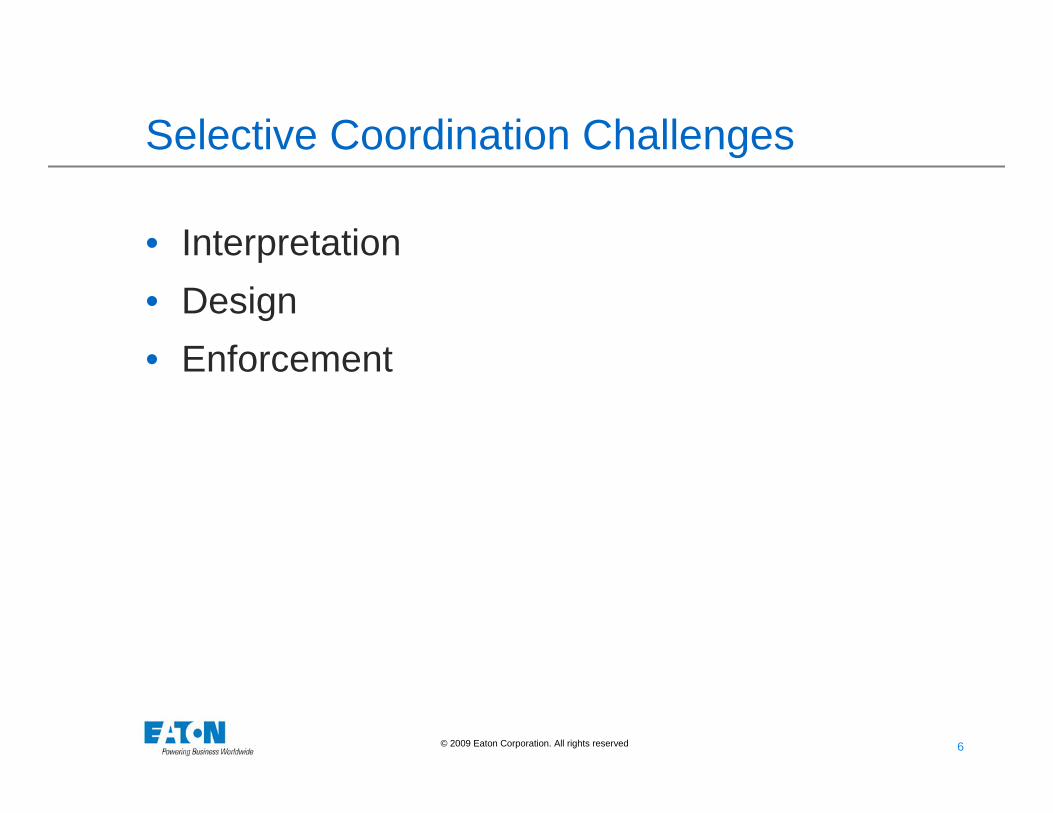
Selective Coordination Challenges
• Interpretation• Design• Enforcement
7 7© 2009 Eaton Corporation. All rights reserved.
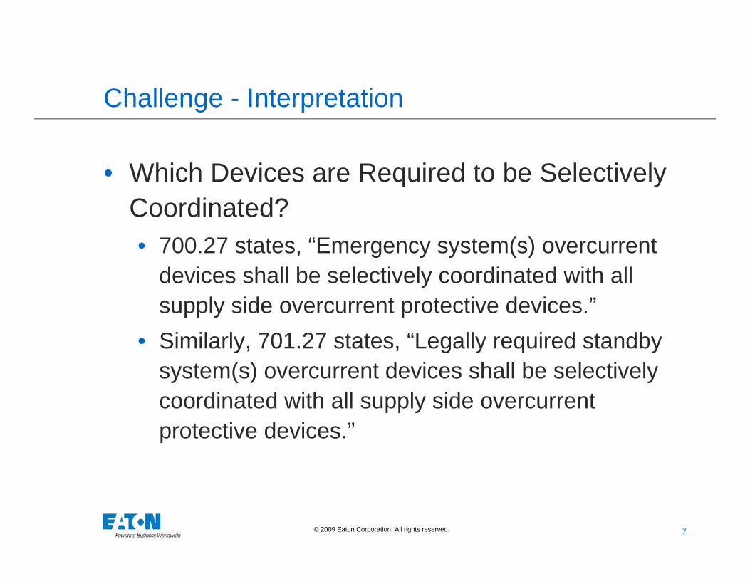
Challenge - Interpretation
• Which Devices are Required to be Selectively Coordinated?• 700.27 states, “Emergency system(s) overcurrent
devices shall be selectively coordinated with all supply side overcurrent protective devices.”
• Similarly, 701.27 states, “Legally required standby system(s) overcurrent devices shall be selectively coordinated with all supply side overcurrentprotective devices.”
8 8© 2009 Eaton Corporation. All rights reserved.
Which devices are required to be Selectively Coordinated?
U TIL IT Y A
M A I N A
M SG -A
M S G -TI E
U TI L IT Y B
M A IN B
M S G -B
A TS -E Q N O RM A T S-C R N O RM A T S- L S N O R MC H ILL E R F D R
G E N # 1 M A I N
G E N S W G R
A T S- EQ E M ER A TS -C R E M E R A TS -L S E M E R
G E N # 1
G E N # 2 M A I N
G E N # 2
EN
A T S- E Q
EN
A TS -C R
EN
A TS -L S
C B L-A T S EQ N C BL -A TS C R N C BL -A TS L S N C BL -0 00 5 C B L-0 0 06 C BL- 00 0 7
C B L -E Q 4 80 V P N L C BL -C R 4 8 0V PN L C BL -LS 4 80 V P N L
E Q 4 80 V P N L
E Q X F M R P R I
C B L -E Q X F M R P R I
S
PE Q X F M R
C B L -E Q 2 08 V P N L
E Q 2 0 8V P N L M A IN
E Q 2 08 V P N L
E Q 2 0 8V B R A N CH
C R 4 8 0V PN L
C R X FM R P R I
C BL -C R X F M R P R I
S
PC R X FM R
C BL -C R 2 0 8V PN L
C R 20 8 V P N L M AIN
C R 2 0 8V PN L
C R 20 8 V BR A N C H
LS 4 80 V P N L
L S X FM R P R I
C BL -LS X F M R PR I
S
PLS X F M R
C BL -LS 2 08 V P N L
L S 2 0 8V PN L M A IN
LS 2 08 V P N L
L S 2 0 8V BR A N C H
C H ILL E R
C BL- C H IL LER
D IS T R P N L FD R
C BL - D IST R P N L
D IS T R P N L
4 80 V L T G P N L F D R
C BL- 48 0V LT G P N L
48 0 V LT G P N L
LT G BR A N C H
4 80 V LR G S T
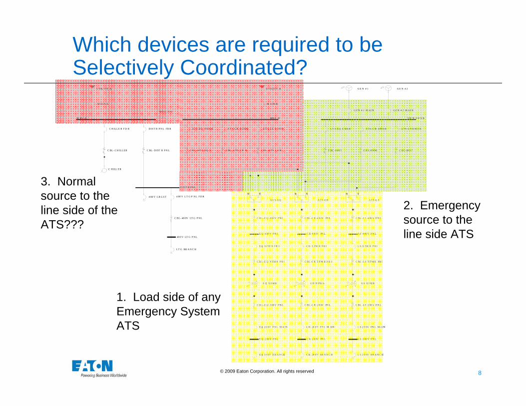
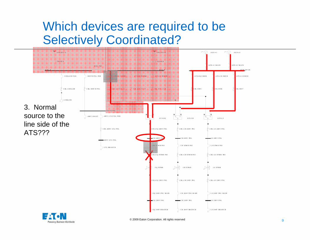
1. Load side of any Emergency System ATS
2. Emergency source to the line side ATS
3. Normal source to the line side of the ATS???
9 9© 2009 Eaton Corporation. All rights reserved.
U TIL IT Y A
M A I N A
M SG -A
M S G -TI E
U TI L IT Y B
M A IN B
M S G -B
A TS -E Q N O RM A T S-C R N O RM A T S- L S N O R MC H ILL E R F D R
G E N # 1 M A I N
G E N S W G R
A T S- EQ E M ER A TS -C R E M E R A TS -L S E M E R
G E N # 1
G E N # 2 M A I N
G E N # 2
EN
A T S- E Q
EN
A TS -C R
EN
A TS -L S
C B L-A T S EQ N C BL -A TS C R N C BL -A TS L S N C BL -0 00 5 C B L-0 0 06 C BL- 00 0 7
C B L -E Q 4 80 V P N L C BL -C R 4 8 0V PN L C BL -LS 4 80 V P N L
E Q 4 80 V P N L
E Q X F M R P R I
C B L -E Q X F M R P R I
S
PE Q X F M R
C B L -E Q 2 08 V P N L
E Q 2 0 8V P N L M A IN
E Q 2 08 V P N L
E Q 2 0 8V B R A N CH
C R 4 8 0V PN L
C R X FM R P R I
C BL -C R X F M R P R I
S
PC R X FM R
C BL -C R 2 0 8V PN L
C R 20 8 V P N L M AIN
C R 2 0 8V PN L
C R 20 8 V BR A N C H
LS 4 80 V P N L
L S X FM R P R I
C BL -LS X F M R PR I
S
PLS X F M R
C BL -LS 2 08 V P N L
L S 2 0 8V PN L M A IN
LS 2 08 V P N L
L S 2 0 8V BR A N C H
C H ILL E R
C BL- C H IL LER
D IS T R P N L FD R
C BL - D IST R P N L
D IS T R P N L
4 80 V L T G P N L F D R
C BL- 48 0V LT G P N L
48 0 V LT G P N L
LT G BR A N C H
4 80 V LR G S T
Which devices are required to be Selectively Coordinated?
3. Normal source to the line side of the ATS???
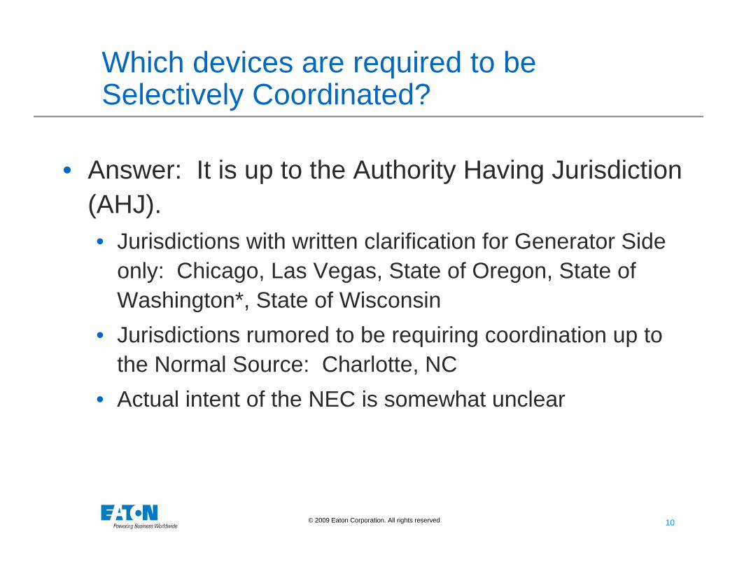
10 10© 2009 Eaton Corporation. All rights reserved.
Which devices are required to be Selectively Coordinated?
• Answer: It is up to the Authority Having Jurisdiction (AHJ).• Jurisdictions with written clarification for Generator Side
only: Chicago, Las Vegas, State of Oregon, State of Washington*, State of Wisconsin
• Jurisdictions rumored to be requiring coordination up to the Normal Source: Charlotte, NC
• Actual intent of the NEC is somewhat unclear
11 11© 2009 Eaton Corporation. All rights reserved.
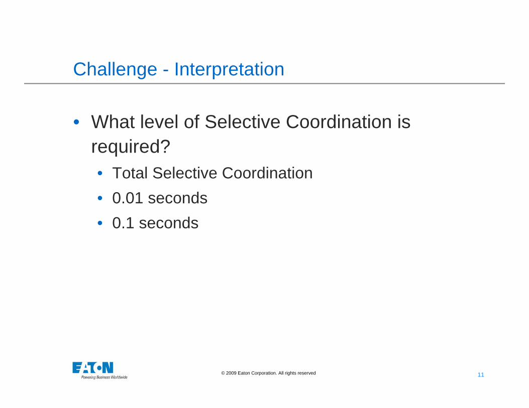
Challenge - Interpretation
• What level of Selective Coordination is required?• Total Selective Coordination• 0.01 seconds• 0.1 seconds
12 12© 2009 Eaton Corporation. All rights reserved.
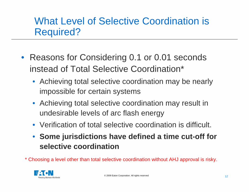
What Level of Selective Coordination is Required?
• Reasons for Considering 0.1 or 0.01 seconds instead of Total Selective Coordination*• Achieving total selective coordination may be nearly
impossible for certain systems• Achieving total selective coordination may result in
undesirable levels of arc flash energy• Verification of total selective coordination is difficult.• Some jurisdictions have defined a time cut-off for
selective coordination* Choosing a level other than total selective coordination without AHJ approval is risky.
13 13© 2009 Eaton Corporation. All rights reserved.
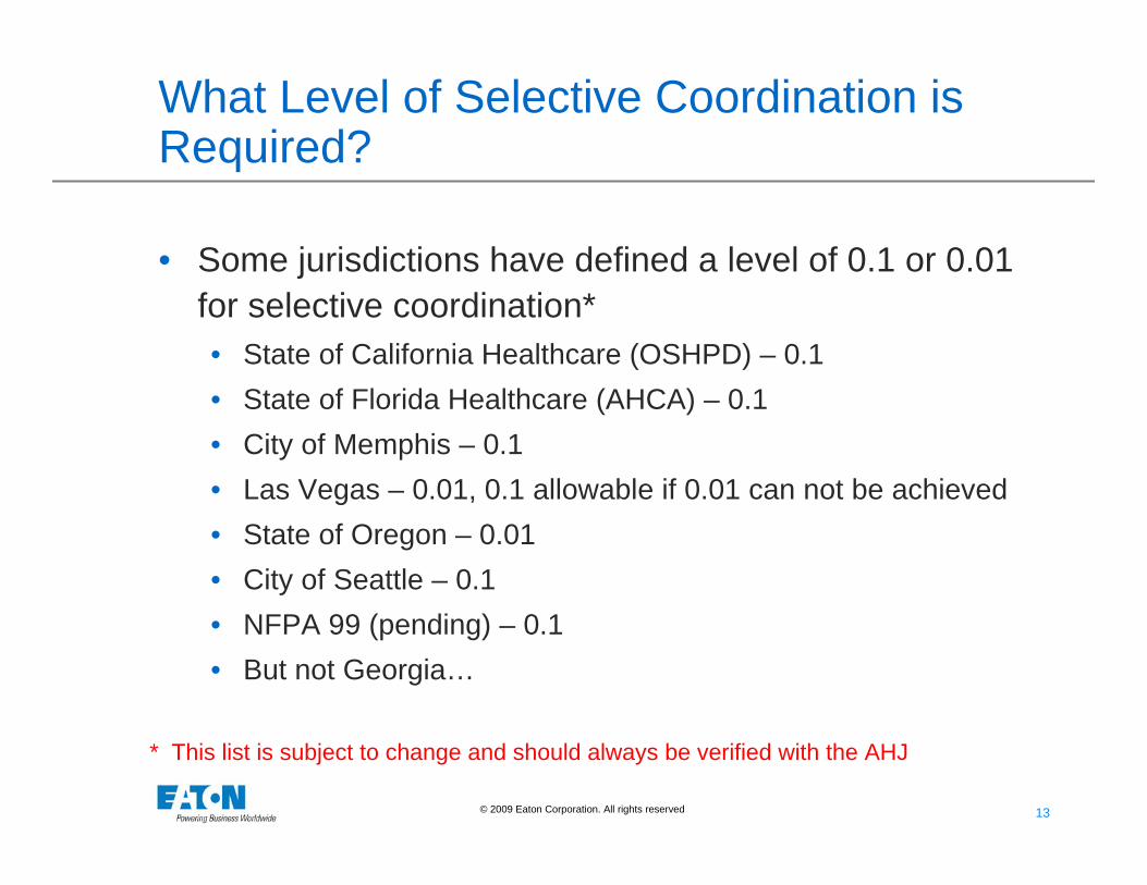
What Level of Selective Coordination is Required?
• Some jurisdictions have defined a level of 0.1 or 0.01 for selective coordination*• State of California Healthcare (OSHPD) – 0.1• State of Florida Healthcare (AHCA) – 0.1• City of Memphis – 0.1• Las Vegas – 0.01, 0.1 allowable if 0.01 can not be achieved• State of Oregon – 0.01• City of Seattle – 0.1• NFPA 99 (pending) – 0.1• But not Georgia…
* This list is subject to change and should always be verified with the AHJ
14 14© 2009 Eaton Corporation. All rights reserved.
What Level of Selective Coordination is Required?
• What do these time limits mean in the real world?• Design to worst case fault currents – bolted fault• Most real world faults are lower level arcing faults
or ground faults• Coordination down to 0.01 seconds allows
coordination for all but the highest levels of fault current
• Coordination down to 0.1 seconds allows coordination for overloads and typical arcing fault levels
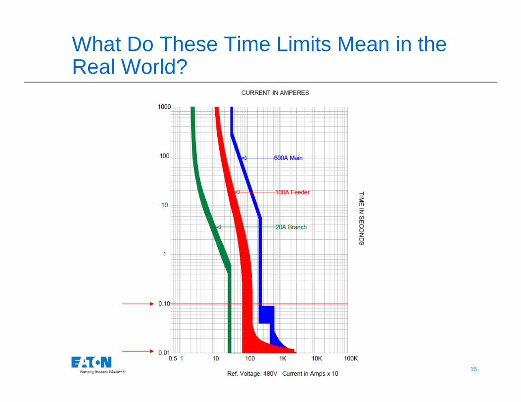
15 15© 2009 Eaton Corporation. All rights reserved.
What Do These Time Limits Mean in the Real World?
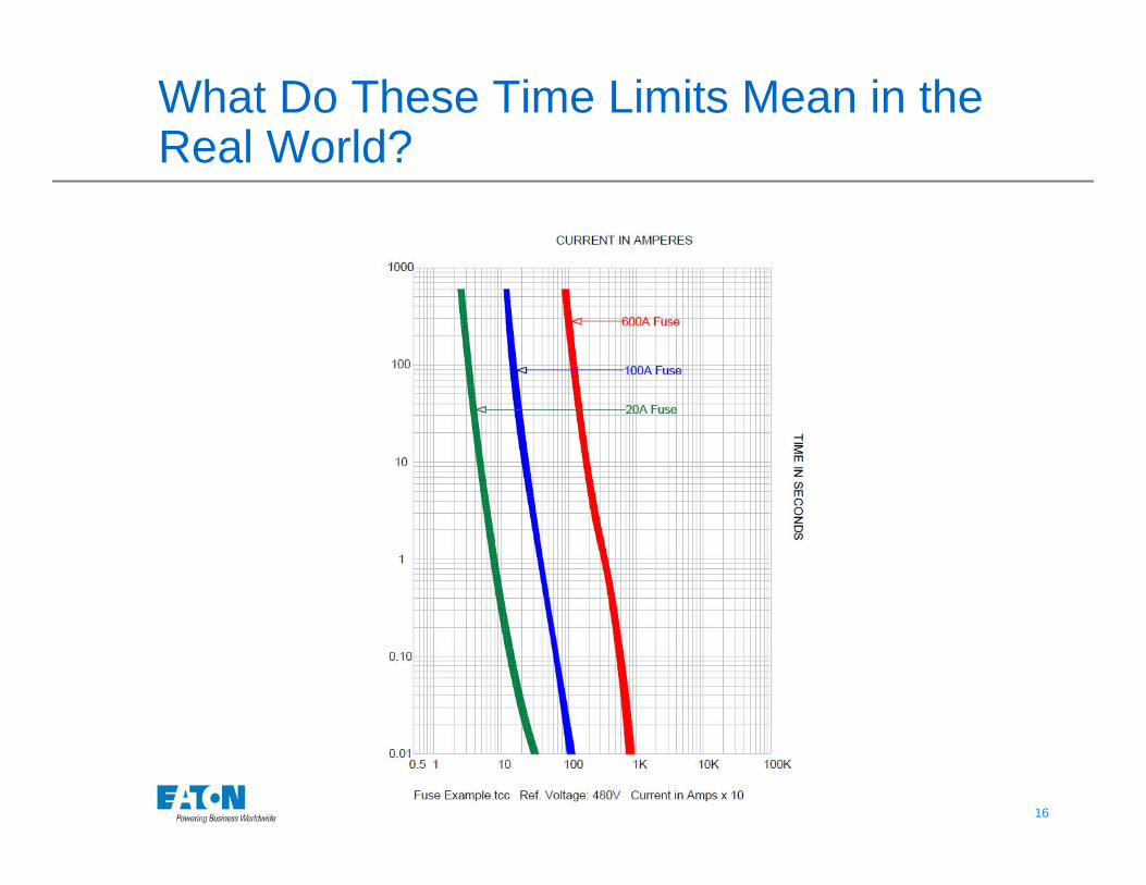
16 16© 2009 Eaton Corporation. All rights reserved.
What Do These Time Limits Mean in the Real World?
17 17© 2009 Eaton Corporation. All rights reserved.
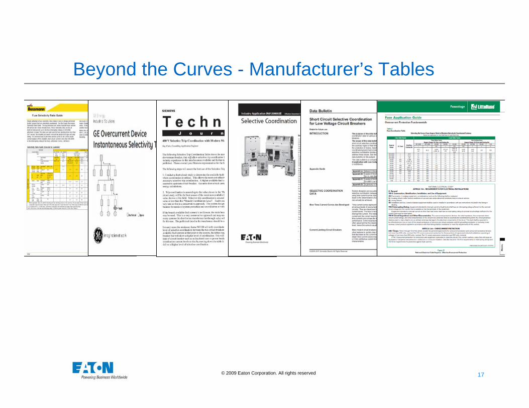
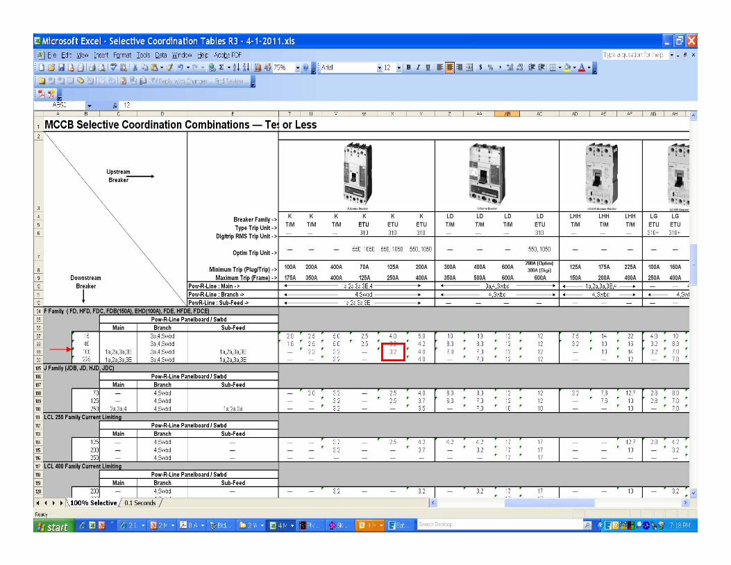
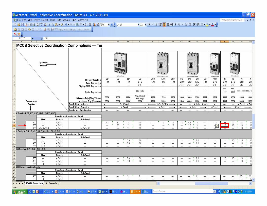
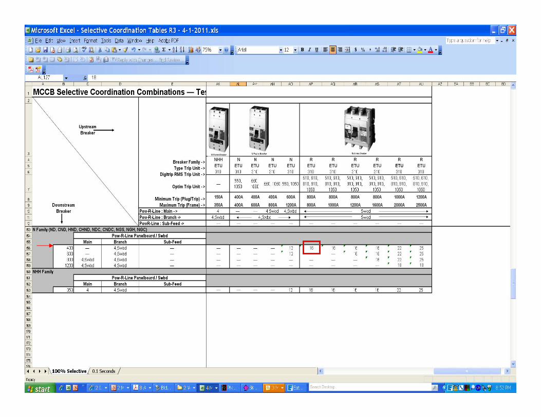
Beyond the Curves - Manufacturer’s Tables
18 18© 2009 Eaton Corporation. All rights reserved.
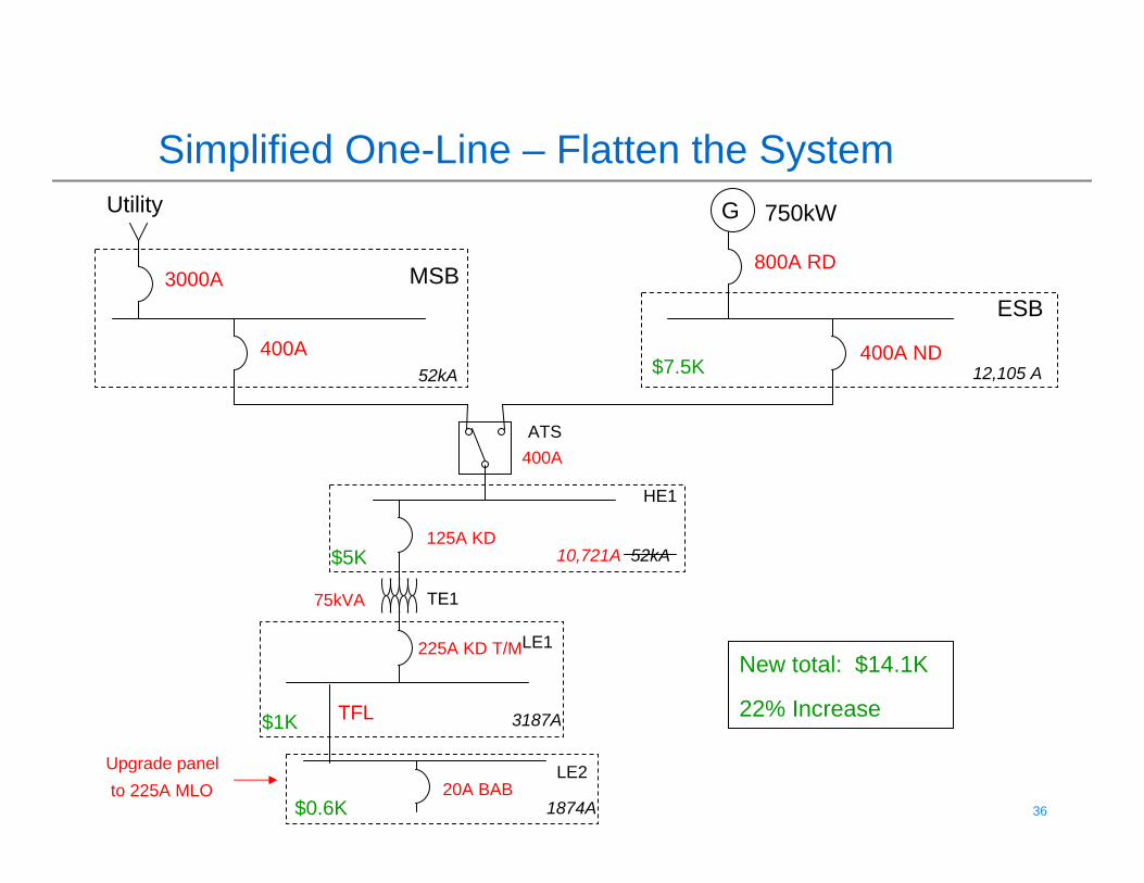
Challenge - Design
• How Do I Design a System that can be Coordinated?
19 19© 2009 Eaton Corporation. All rights reserved.
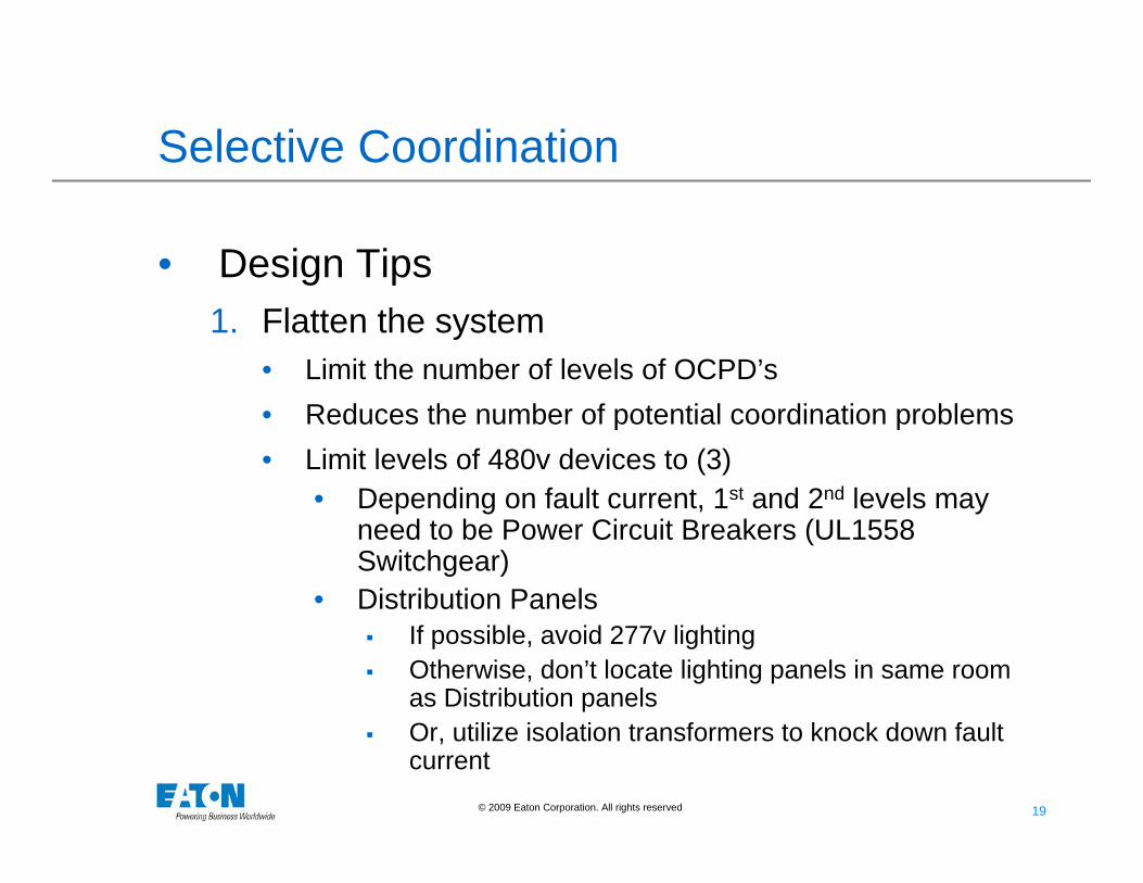
Selective Coordination
• Design Tips1. Flatten the system
• Limit the number of levels of OCPD’s• Reduces the number of potential coordination problems• Limit levels of 480v devices to (3)
• Depending on fault current, 1st and 2nd levels may need to be Power Circuit Breakers (UL1558 Switchgear)
• Distribution Panels If possible, avoid 277v lighting Otherwise, don’t locate lighting panels in same room
as Distribution panels Or, utilize isolation transformers to knock down fault
current
20 20© 2009 Eaton Corporation. All rights reserved.
Selective Coordination
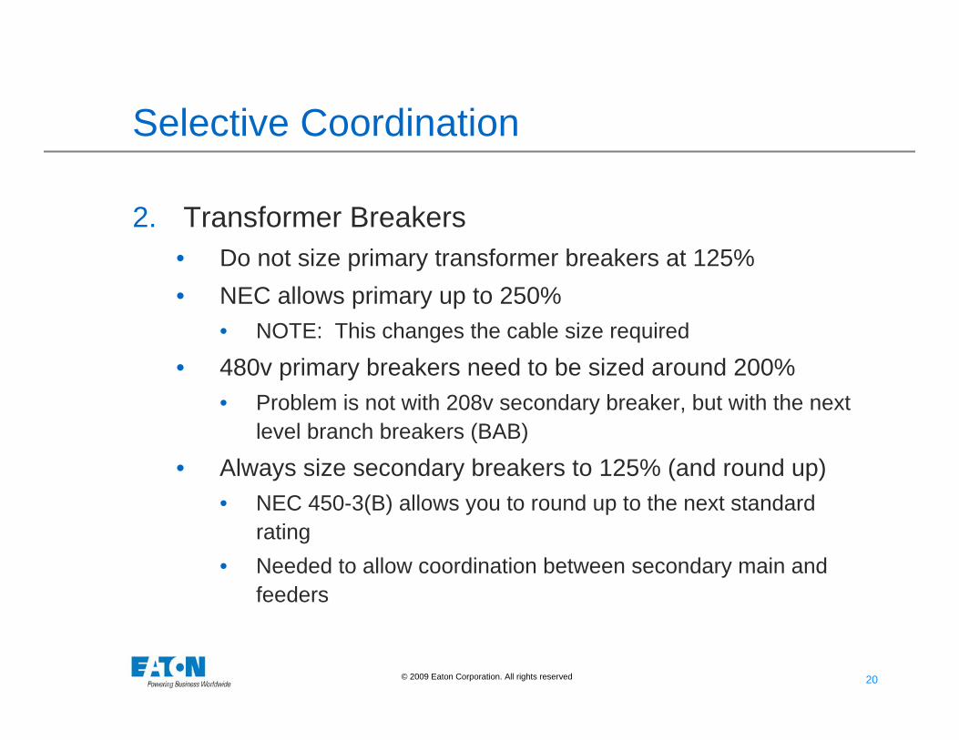
2. Transformer Breakers• Do not size primary transformer breakers at 125%• NEC allows primary up to 250%
• NOTE: This changes the cable size required
• 480v primary breakers need to be sized around 200%• Problem is not with 208v secondary breaker, but with the next
level branch breakers (BAB)
• Always size secondary breakers to 125% (and round up)• NEC 450-3(B) allows you to round up to the next standard
rating• Needed to allow coordination between secondary main and
feeders
21 21© 2009 Eaton Corporation. All rights reserved.
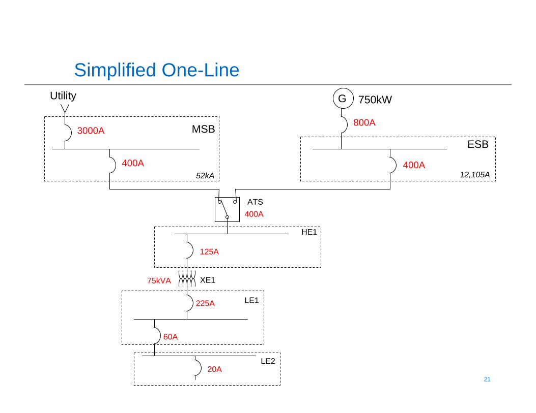
Simplified One-LineGUtility
MSBESB
ATS
HE1
LE1
LE2
XE1
3000A
52kA400A
750kW
800A
400A
400A
125A
225A
60A
20A
75kVA
12,105A
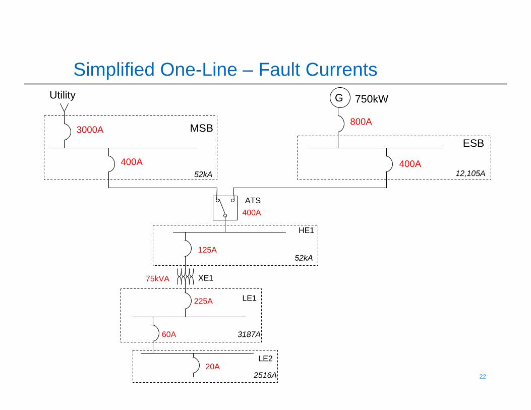
22 22© 2009 Eaton Corporation. All rights reserved.
Simplified One-Line – Fault CurrentsGUtility
MSBESB
ATS
HE1
LE1
LE2
XE1
3000A
52kA400A
750kW
800A
400A
400A
125A
225A
60A
20A
75kVA
12,105A
52kA
3187A
2516A
23 23© 2009 Eaton Corporation. All rights reserved.
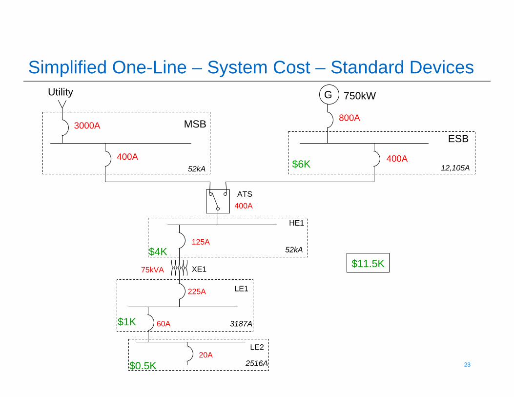
Simplified One-Line – System Cost – Standard DevicesGUtility
MSBESB
ATS
HE1
LE1
LE2
XE1
3000A
52kA400A
750kW
800A
400A
400A
125A
225A
60A
20A
75kVA
12,105A
52kA
3187A
2516A
$6K
$4K
$1K
$0.5K
$11.5K
24 24© 2009 Eaton Corporation. All rights reserved.
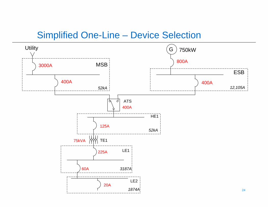
Simplified One-Line – Device SelectionGUtility
MSBESB
ATS
HE1
LE1
LE2
TE1
3000A
52kA400A
750kW
800A
400A
400A
125A
225A
60A
20A
75kVA
12,105A
52kA
3187A
1874A
25 25© 2009 Eaton Corporation. All rights reserved.
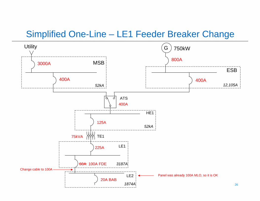
26 26© 2009 Eaton Corporation. All rights reserved.
Simplified One-Line – LE1 Feeder Breaker ChangeGUtility
MSBESB
ATS
HE1
LE1
LE2
TE1
3000A
52kA400A
750kW
800A
400A
400A
125A
225A
60A 100A FDE
20A BAB
75kVA
12,105A
52kA
3187A
1874A
Change cable to 100A
Panel was already 100A MLO, so it is OK
27 27© 2009 Eaton Corporation. All rights reserved.
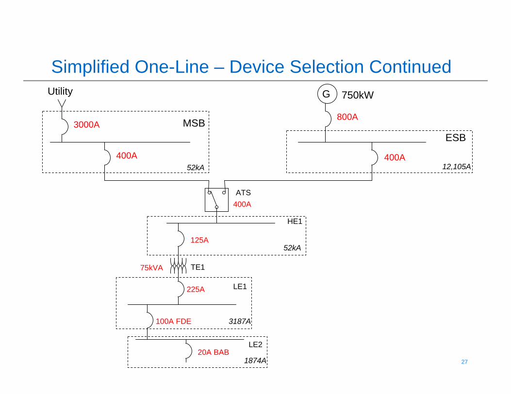
Simplified One-Line – Device Selection ContinuedGUtility
MSBESB
ATS
HE1
LE1
LE2
TE1
3000A
52kA400A
750kW
800A
400A
400A
125A
225A
100A FDE
20A BAB
75kVA
12,105A
52kA
3187A
1874A
28 28© 2009 Eaton Corporation. All rights reserved.
29 29© 2009 Eaton Corporation. All rights reserved.
Simplified One-Line – Device Selection ContinuedGUtility
MSBESB
ATS
HE1
LE1
LE2
TE1
3000A
52kA400A
750kW
800A
400A
400A
125A KD
225A KD
100A FDE
20A BAB
75kVA
12,105A
52kA
3187A
1874A
30 30© 2009 Eaton Corporation. All rights reserved.
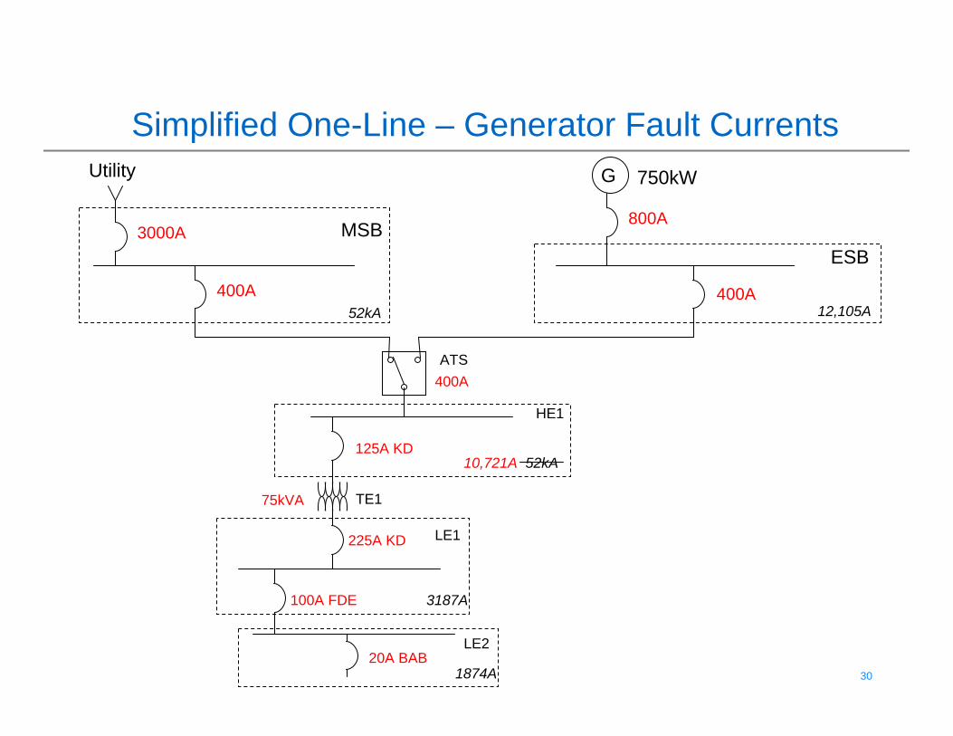
Simplified One-Line – Generator Fault CurrentsGUtility
MSBESB
ATS
HE1
LE1
LE2
TE1
3000A
52kA400A
750kW
800A
400A
400A
125A KD
225A KD
100A FDE
20A BAB
75kVA
12,105A
10,721A 52kA
3187A
1874A
31 31© 2009 Eaton Corporation. All rights reserved.
32 32© 2009 Eaton Corporation. All rights reserved.
Simplified One-Line – Device Selection ContinuedGUtility
MSBESB
ATS
HE1
LE1
LE2
TE1
3000A
52kA400A
750kW
800A
400A
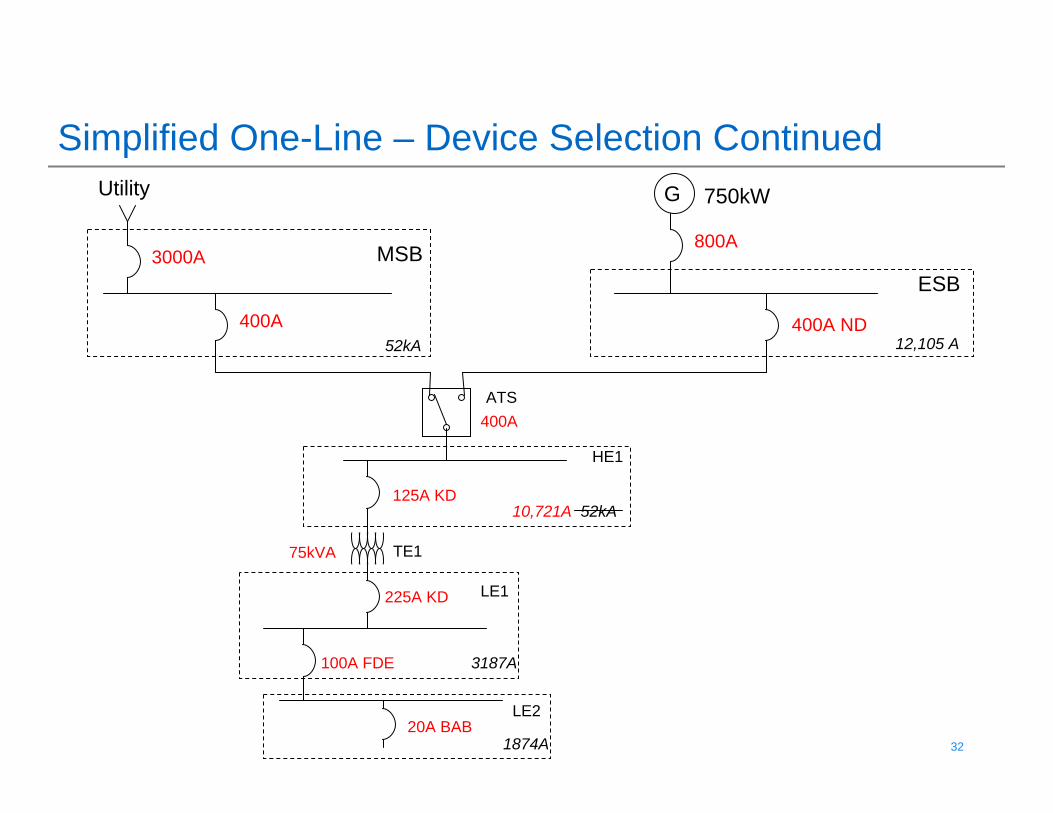
400A ND
125A KD
225A KD
100A FDE
20A BAB
75kVA
12,105 A
10,721A 52kA
3187A
1874A
33 33© 2009 Eaton Corporation. All rights reserved.
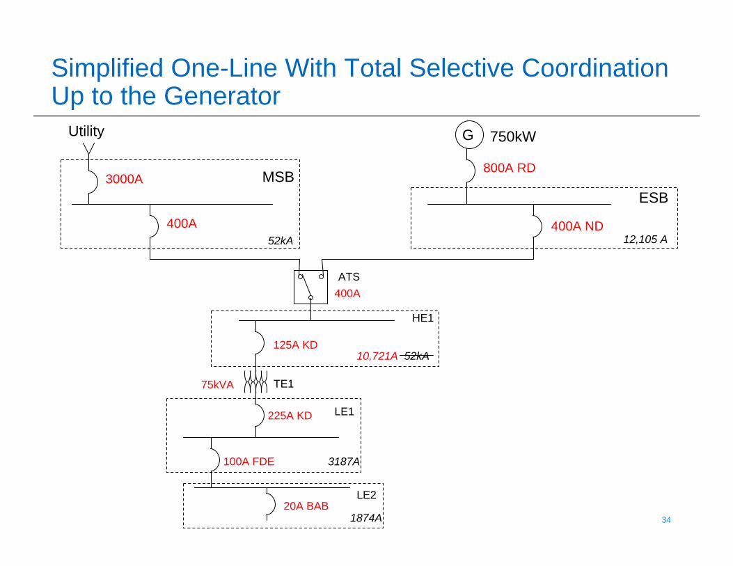
34 34© 2009 Eaton Corporation. All rights reserved.
Simplified One-Line With Total Selective Coordination Up to the Generator
GUtility
MSBESB
ATS
HE1
LE1
LE2
TE1
3000A
52kA400A
750kW
800A RD
400A
400A ND
125A KD
225A KD
100A FDE
20A BAB
75kVA
12,105 A
10,721A 52kA
3187A
1874A
35 35© 2009 Eaton Corporation. All rights reserved.
Simplified One-Line – Equipment Costs –Selectively Coordinated System
GUtility
MSBESB
ATS
HE1
LE1
LE2
TE1
3000A
52kA400A
750kW
800A RD
400A
400A ND
125A KD
225A KD
100A FDE
20A BAB
75kVA
12,105 A
10,721A 52kA
3187A
1874A$0.5K
New total: $15K
30% Increase
$7.5K
$5K
$2K
36 36© 2009 Eaton Corporation. All rights reserved.
Simplified One-Line – Flatten the SystemGUtility
MSBESB
ATS
HE1
LE1
LE2
TE1
3000A
52kA400A
750kW
800A RD
400A
400A ND
125A KD
225A KD T/M
20A BAB
75kVA
12,105 A
10,721A 52kA
3187A
1874A$0.6K
New total: $14.1K
22% Increase
$7.5K
$5K
$1K TFL
Upgrade panelto 225A MLO
37 37© 2009 Eaton Corporation. All rights reserved.
Total Selective Coordination Summary
• Flatten the system• Broaden your ideas on transformer protection• Check ATS withstand ratings with chosen
breakers• Tables represent a single manufacturer’s
equipment
38 38© 2009 Eaton Corporation. All rights reserved.
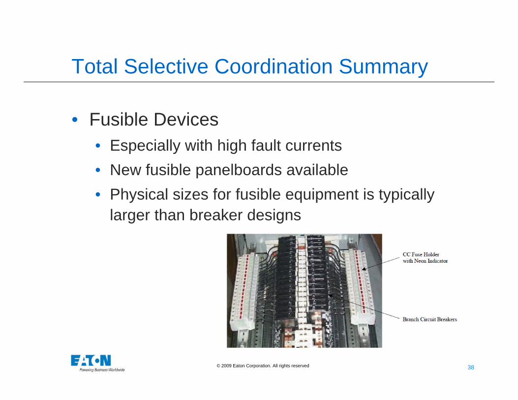
Total Selective Coordination Summary
• Fusible Devices • Especially with high fault currents• New fusible panelboards available• Physical sizes for fusible equipment is typically
larger than breaker designs
39 39© 2009 Eaton Corporation. All rights reserved.
Total Selective Coordination Summary
• Can’t I just put in my specs that the switchgear manufacturer must provide a selectively coordinated system?
• Yes, but please don’t!• Our salesmen won’t necessarily know which circuits need to
be coordinated• Cable sizes may need to be increased, depending on which
breakers are required• ATS sizes may need to be increased – not in our package• Generator breaker sizes may need to increase – not in our
package• Distribution equipment size may increase and no longer fit in
the room• Who pays for all of the above?
40 40© 2009 Eaton Corporation. All rights reserved.
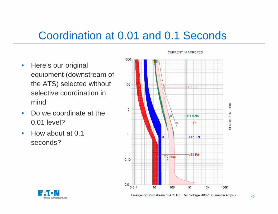
Coordination at 0.01 and 0.1 Seconds
• Here’s our original equipment (downstream of the ATS) selected without selective coordination in mind
• Do we coordinate at the 0.01 level?
• How about at 0.1 seconds?
41 41© 2009 Eaton Corporation. All rights reserved.
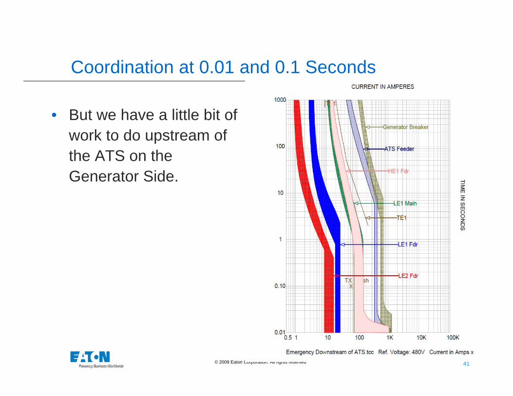
Coordination at 0.01 and 0.1 Seconds
• But we have a little bit of work to do upstream of the ATS on the Generator Side.
42 42© 2009 Eaton Corporation. All rights reserved.
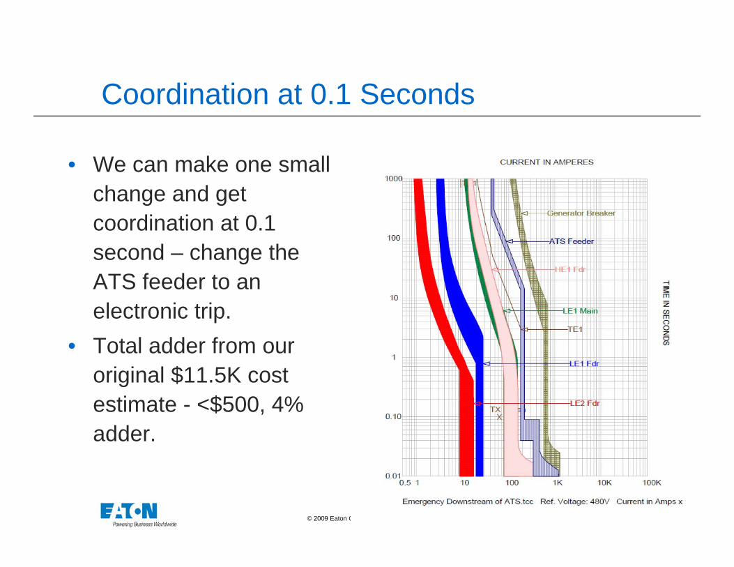
Coordination at 0.1 Seconds
• We can make one small change and get coordination at 0.1 second – change the ATS feeder to an electronic trip.
• Total adder from our original $11.5K cost estimate - <$500, 4% adder.
43 43© 2009 Eaton Corporation. All rights reserved.
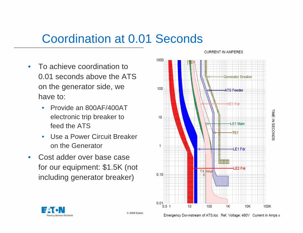
Coordination at 0.01 Seconds
• To achieve coordination to 0.01 seconds above the ATS on the generator side, we have to:• Provide an 800AF/400AT
electronic trip breaker to feed the ATS
• Use a Power Circuit Breaker on the Generator
• Cost adder over base case for our equipment: $1.5K (not including generator breaker)
44 44© 2009 Eaton Corporation. All rights reserved.
Challenge - Enforcement
• How is Selective Coordination Evaluated?• Some jurisdictions are looking at curves• Some jurisdictions require a stamped letter from the
engineer of record• In some jurisdictions, it has yet to be defined
45 45© 2009 Eaton Corporation. All rights reserved.
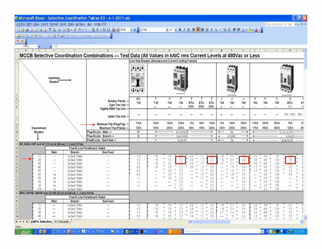
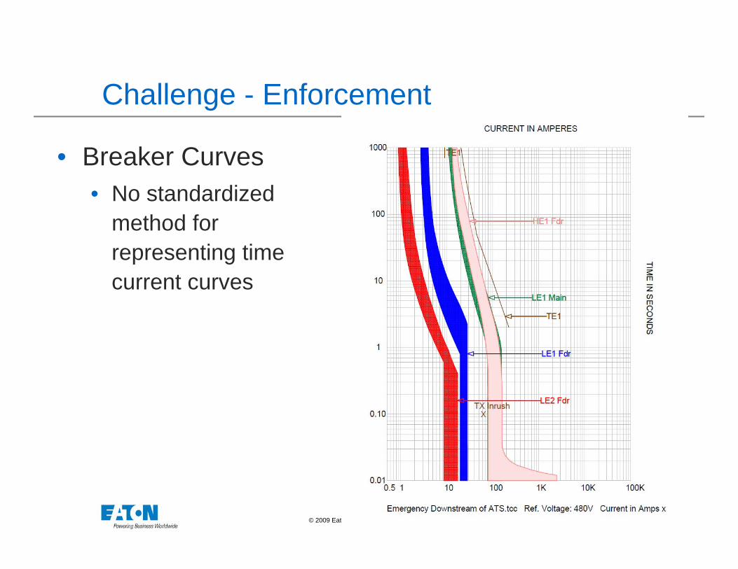
Challenge - Enforcement
• Breaker Curves• No standardized
method for representing time current curves
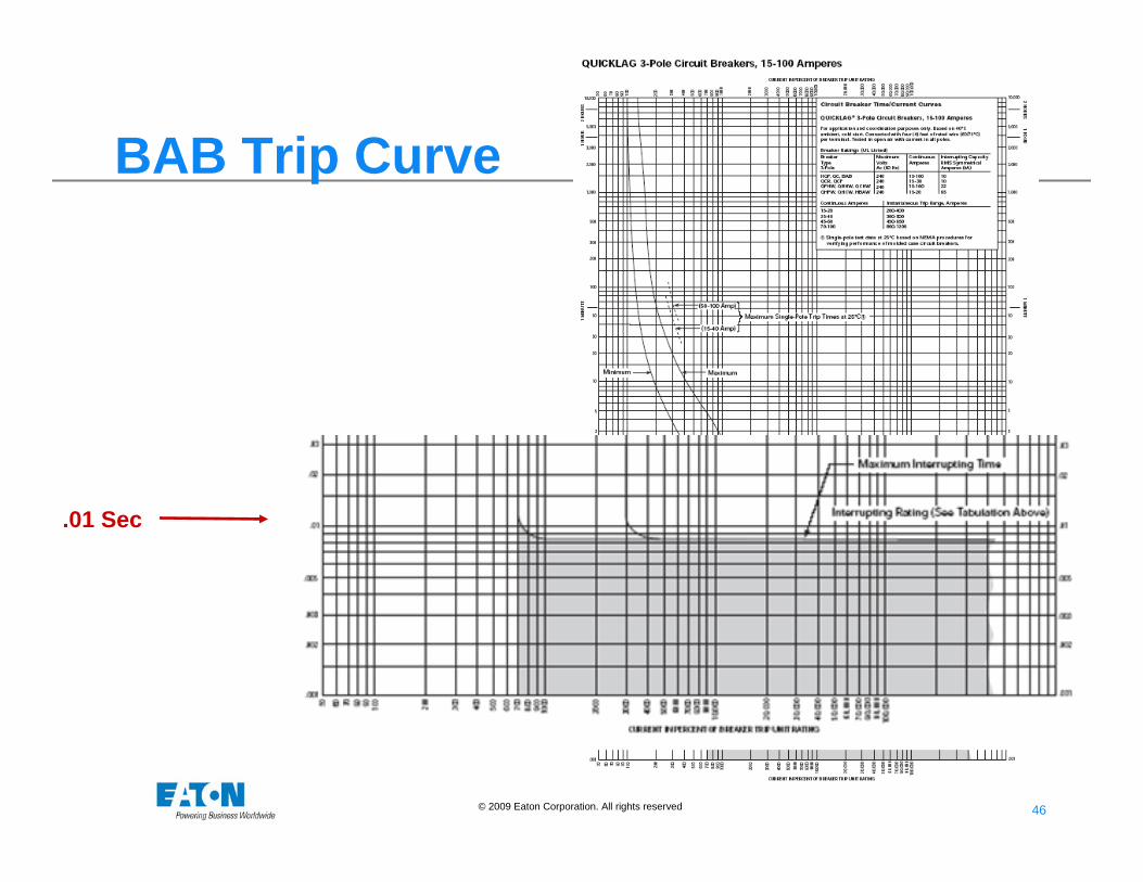
46 46© 2009 Eaton Corporation. All rights reserved.
.01 Sec
BAB Trip Curve
47 47© 2009 Eaton Corporation. All rights reserved.
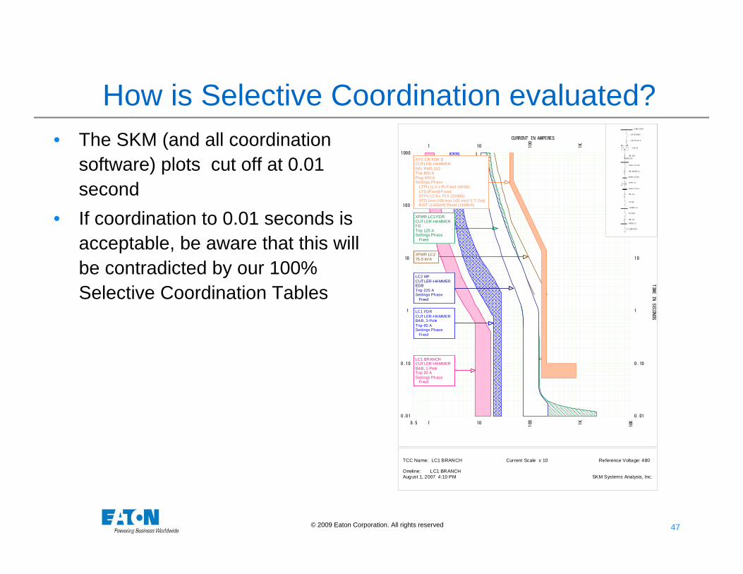
How is Selective Coordination evaluated?• The SKM (and all coordination
software) plots cut off at 0.01 second
• If coordination to 0.01 seconds is acceptable, be aware that this will be contradicted by our 100% Selective Coordination Tables
TX Inrush
0.5 1
1
10
10
100
100
1K1K
10K
10K
0.01 0.01
0.10 0.10
1 1
10 10
100 100
1000 1000
CURRENT IN AMPERES
TIME IN SECONDS
LC1 FDR CUT LER-HAMMER BAB, 3-Pole Trip 60 ASettings Phase Fixed
XFMR LC2 FDR CUT LER-HAMMER FD Trip 125 ASettings Phase Fixed
XFMR LC2 75.0 kVA
LC2 MF CUT LER-HAMMER EDB Trip 225 ASettings Phase Fixed
LC1 BRANCH CUT LER-HAMMER BAB, 1-Pole Trip 20 ASettings Phase Fixed
ATS CR FDR E CUT LER-HAMMER ND, RMS 310 Trip 800 APlug 400 ASettings Phase LTPU (1.0 x P) Fixed (400A) LTD (Fixed) Fixed STPU (2-8 x P) 5 (2000A) STD (Inst-300 ms) 100 ms(I^2 T Out) INST (14000A) Fixed (14000A)
CBL -HC2
LC1 FDR
XFMR LC2 FDR
CBL -XFMR LC2
S
P XFMR LC2
CBL -LC2
LC2 MF
CBL -LC1
L C1 BRANCH
PANEL HC2
XFMR LC2 PRI
XFMR LC2 SE C
PANEL L C2
PANEL LC1
ENATS CR
ATS CR FDR E
CBL-ATS CR E
P ANE L ESDP
TCC Name: LC1 BRANCH Current Scale x 10 Reference Voltage: 480 Oneline: LC1 BRANCH August 1, 2007 4:10 PM SKM Systems Analysis, Inc.
48 48© 2009 Eaton Corporation. All rights reserved.
Challenge - Design
What about Arc Flash?• Arc Flash Energy is dependent upon:
• Actual magnitude of the fault energy• Time that the arc is allowed to propagate
When we select devices to selectively coordinate, we are purposefully introducing time delays by selecting larger and/or more adjustable devices upstream.
49 49© 2009 Eaton Corporation. All rights reserved.
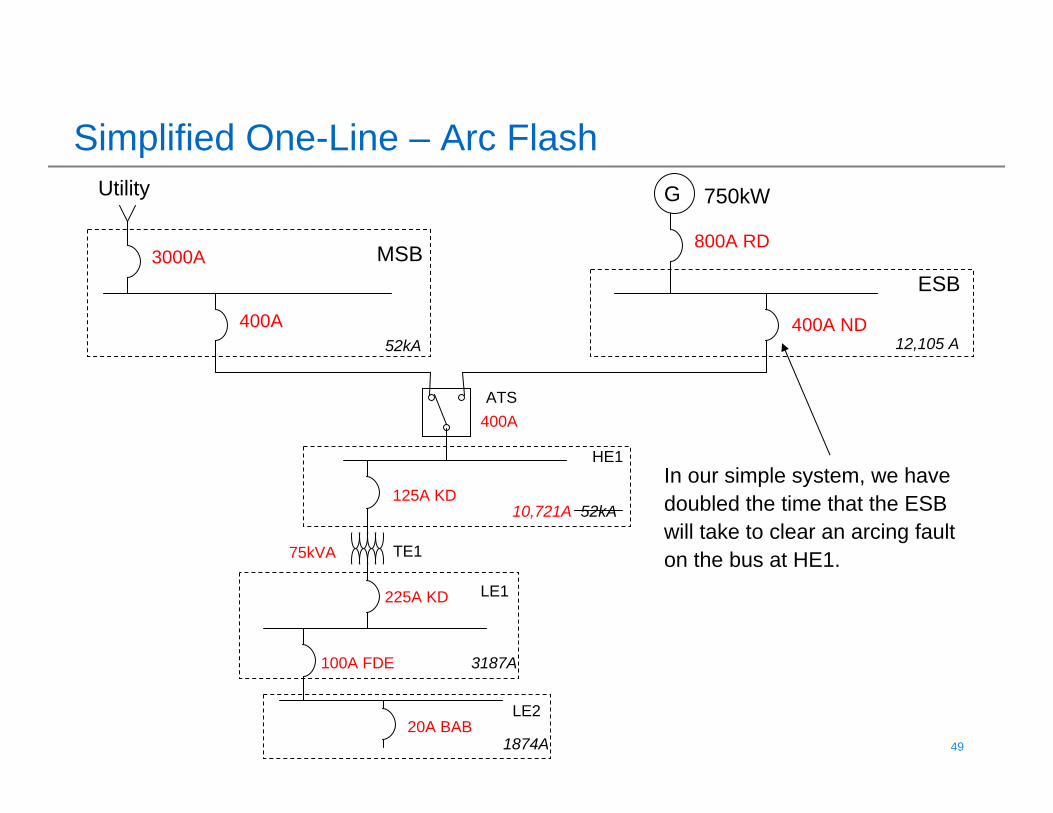
Simplified One-Line – Arc FlashGUtility
MSBESB
ATS
HE1
LE1
LE2
TE1
3000A
52kA400A
750kW
800A RD
400A
400A ND
125A KD
225A KD
100A FDE
20A BAB
75kVA
12,105 A
10,721A 52kA
3187A
1874A
In our simple system, we have doubled the time that the ESB will take to clear an arcing fault on the bus at HE1.
50 50© 2009 Eaton Corporation. All rights reserved.
Challenge – Arc Flash
Techniques for dealing with the Arc Flash Challenge:• Zone Selective Interlocking• Arc Flash Reduction Maintenance Switches
Note: 2011 NEC 240.87 mandates one of the above or differential protection when circuit breakers are used without instantaneous protection.
© 2010 Eaton Corporation. All rights reserved.
Questions?