Embed Size (px)
Citation preview
Chaotic Responses on Vortex Induced Vibration Systems Supported by Bi-stable Springs
B. H . Huynh1, T. Tjahjowidodo2, Z. Zhong2, Y. Wang3, N. Srikanth4 1 Interdisciplinary Graduate School, Nanyang Technological University, Singapore 639798, Singapore 2 School of Mechanical & Aerospace Engineering, Nanyang Technological University, Singapore 639798, Singapore e-mail: [email protected] 3 School of Electrical & Electronic Engineering, Nanyang Technological University, Singapore 639798, Singapore 4 Energy Research Institute at NTU, Nanyang Technological University, Singapore 639798, Singapore
Abstract In this study, chaotic responses of a vortex induced vibration (VIV) energy converter enhanced by a bi-stable stiffness element are quantified based on the largest Lyapunov exponent. The analysis is performed on simulated data obtained through a wake oscillator model via the construction of its time delay phase space. Chaotic responses on a VIV energy converter deteriorate the efficiency of the energy harvested. From the analysis results, it is noticed that the chaotic responses in the system is governed by the structural parameters including bi-stable gap, damping value and effective mass. The results obtained from the simulated data are subsequently verified experimentally on a computer-based force-feedback testing platform.
1 Introduction
Harvesting energy from water flows based on the vortex induced vibration (VIV) principle has received much attention in last few years as a promising alternative to aquatic renewable energy. When a blunt structure, typically a cylinder, is submerged into a water flow in the cross-flow direction, vortices will be formed in the wake region due to the flow separation. These vortices alternately shed to two sides of the wake region and induce periodic drag and lift forces imposing to the structure. If the cylinder is mounted to a spring so that its translational motion is constrained only to a direction that is perpendicular to the cross-flow, the periodic lift force will cause vibrations of the cylinder. This phenomenon is referred to as vortex induced vibrations. Knowledge and studies on vortex induced vibrations of an elastically supported structure are thoroughly reviewed in [1-3]. By connecting the structure to an energy conversion mechanism, e.g. a generator, vibrational energy from the vortex induced vibrations can be converted to generate electricity. The merit that makes this source of energy prominent is that the VIV energy converter can operate well in low-speed water flows [4], when the structure is designed so that its natural frequency coincides to the frequency of the vortex shedding, which is determined by the water flow velocity.
As the basic principle is based on the resonance phenomenon, the efficiency will drop significantly when the water flow velocity deviates from the designated velocity that correlates to the resonant frequency. This situation might occur since the water flow velocity in natural water flow fluctuates severely. To overcome this adversity, [5] and [6] suggested applying hardening stiffness on the supporting structure to broaden the resonance range. Further studies show that bi-stable stiffness is also potential to improve its performance and its operating flow range. However, it is also noted that the introduction of the bi-stable spring element might ignite chaotic responses, which are hardly predictable [7].
695
Due to the nature of chaotic responses, which is hardly predictable, the dynamics of the system needs to be properly characterized before the VIV energy converter is designed with a bi-stable stiffness element. However, based on the authors’ knowledge, there is hardly any evidence on the study of chaotic behaviour on VIV system. Some papers (e.g. [8-10]) presented the existence of chaotic response in a VIV system. However, parametric analysis and quantification on the chaotic vibrations of the VIV structure are not discussed intensively.
This paper focuses on the quantification of the chaotic responses in a VIV energy converter enhanced by a bi-stable spring in its operating range (water flow velocity). The quantification is based on the Lyapunov exponent that is commonly used to measure the chaotic degree in a system [11]. A wake oscillator model is utilized to simulate the vibrations on a VIV energy converter. The quantification is then carried out on the simulated data after the reconstruction of its time delay phase space ([12-14]). The technique is similar to that presented in [15] and [16], where the chaotic responses in mechanical systems with nonlinear elements were quantified. In our particular case, the quantified results are subsequently correlated to the estimated harvested power to evaluate the effect of chaotic responses on the VIV energy converter performance. The effects of the structural parameters that include the effective mass, damping, and bi-stable gap, on the chaotic degree of the system response are also analysed. Finally, an experimental qualitative validation of the results is performed on a testing platform that is specifically design to represent the system.
The paper is organized as follows. Section 2 presents the numerical study including the discussion on the wake oscillator model used to simulate the vibrations of the VIV structure, the expression of the bi-stable stiffness and the quantification of the chaotic responses based on the Lyapunov exponent. Following the numerical study, the experimental study based on the computer-based force-feedback testing platform to verify the observations from the numerical study is discussed in Section 3. Some conclusions are drawn in Section 4.
2 Numerical study
2.1 Wake oscillator model
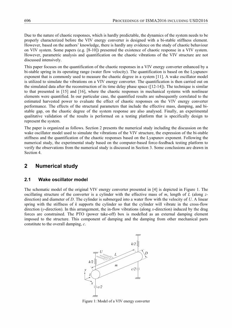
The schematic model of the original VIV energy converter presented in [4] is depicted in Figure 1. The oscillating structure of the converter is a cylinder with the effective mass of m, length of L (along z-direction) and diameter of D. The cylinder is submerged into a water flow with the velocity of U. A linear spring with the stiffness of k supports the cylinder so that the cylinder will vibrate in the cross-flow direction (y-direction). In this arrangement, the in-flow vibrations (along x-direction) induced by the drag forces are constrained. The PTO (power take-off) box is modelled as an external damping element imposed to the structure. This component of damping and the damping from other mechanical parts constitute to the overall damping, c.
Figure 1: Model of a VIV energy converter
696 PROCEEDINGS OF ISMA2016 INCLUDING USD2016
The cross-flow vibrations or the displacement of the cylinder, y(t), can be simulated by the Direct Numerical Simulation (DNS) to solve the Navier-Stokes equations for the flow around the structure. However, this approach is rather time and computationally expensive. Moreover, later on when the bi-stable spring is introduced to the structure, it will complicate the calculation. Therefore, in this study, the oscillating structure is modelled as an externally excited oscillator. The dynamics equation of the oscillator (Eq. 1) is coupled with the forcing term to a wake oscillator equation (Eq. 2) that models the waking effect of the vortex shedding on the cylinder. This wake oscillator model [17], which was originated from the model proposed in [18], is widely used for theoretical analysis on the VIV phenomenon.
)(qSkyycym (1)
)()/(2)1()/(2 242 yFqDUStqqqDUStq (2)
where:
‐ F(q): vortex shedding force ‐ q: wake variable ‐ St: Strouhal number ‐ U: water flow velocity ‐ D: diameter of cylinder ‐ F(y): effect from vibrations of the structure on the wake ‐ ε, β, λ: coefficients of nonlinearity
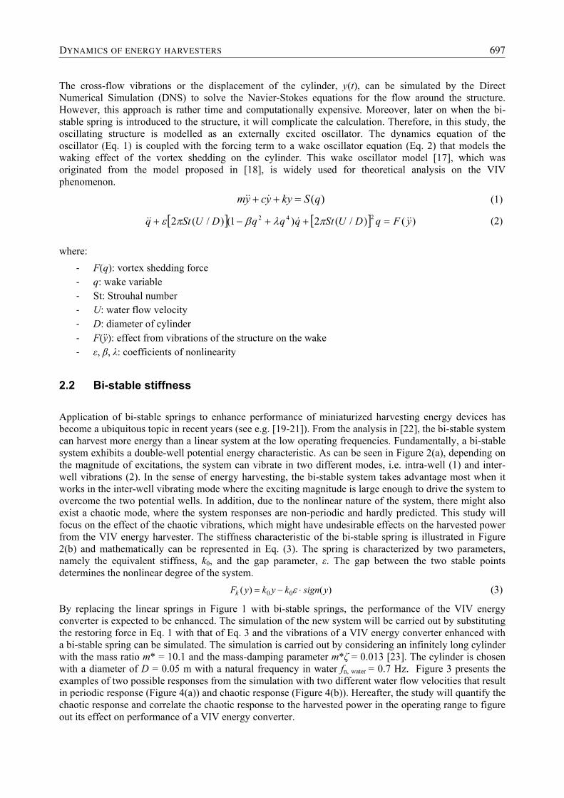
2.2 Bi-stable stiffness
Application of bi-stable springs to enhance performance of miniaturized harvesting energy devices has become a ubiquitous topic in recent years (see e.g. [19-21]). From the analysis in [22], the bi-stable system can harvest more energy than a linear system at the low operating frequencies. Fundamentally, a bi-stable system exhibits a double-well potential energy characteristic. As can be seen in Figure 2(a), depending on the magnitude of excitations, the system can vibrate in two different modes, i.e. intra-well (1) and inter-well vibrations (2). In the sense of energy harvesting, the bi-stable system takes advantage most when it works in the inter-well vibrating mode where the exciting magnitude is large enough to drive the system to overcome the two potential wells. In addition, due to the nonlinear nature of the system, there might also exist a chaotic mode, where the system responses are non-periodic and hardly predicted. This study will focus on the effect of the chaotic vibrations, which might have undesirable effects on the harvested power from the VIV energy harvester. The stiffness characteristic of the bi-stable spring is illustrated in Figure 2(b) and mathematically can be represented in Eq. (3). The spring is characterized by two parameters, namely the equivalent stiffness, k0, and the gap parameter, ε. The gap between the two stable points determines the nonlinear degree of the system.
)()( 00 ysignkykyFk (3)
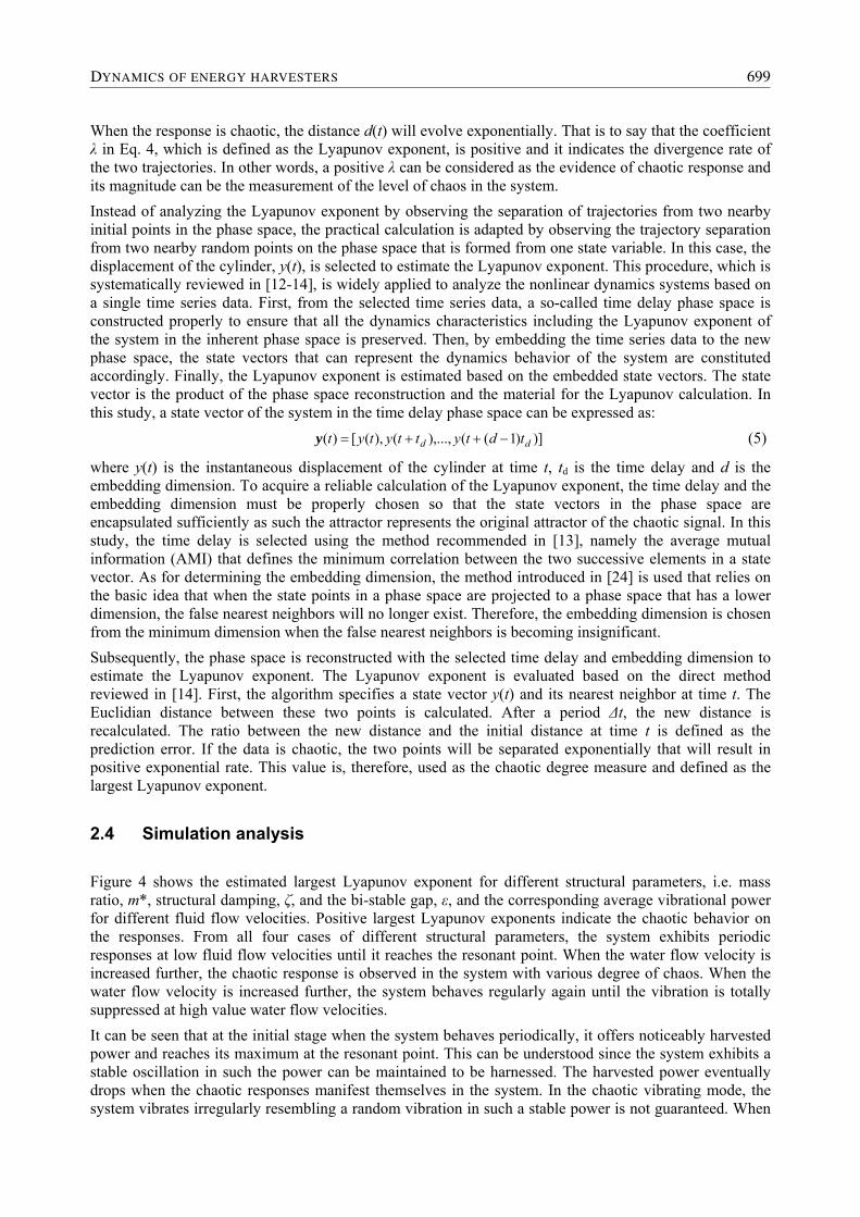
By replacing the linear springs in Figure 1 with bi-stable springs, the performance of the VIV energy converter is expected to be enhanced. The simulation of the new system will be carried out by substituting the restoring force in Eq. 1 with that of Eq. 3 and the vibrations of a VIV energy converter enhanced with a bi-stable spring can be simulated. The simulation is carried out by considering an infinitely long cylinder with the mass ratio m* = 10.1 and the mass-damping parameter m*ζ = 0.013 [23]. The cylinder is chosen with a diameter of D = 0.05 m with a natural frequency in water fn, water = 0.7 Hz. Figure 3 presents the examples of two possible responses from the simulation with two different water flow velocities that result in periodic response (Figure 4(a)) and chaotic response (Figure 4(b)). Hereafter, the study will quantify the chaotic response and correlate the chaotic response to the harvested power in the operating range to figure out its effect on performance of a VIV energy converter.
DYNAMICS OF ENERGY HARVESTERS 697
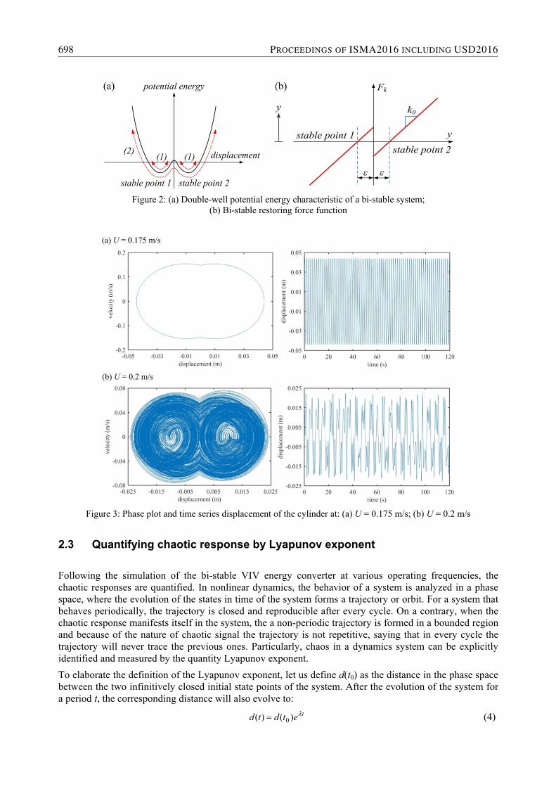
Figure 2: (a) Double-well potential energy characteristic of a bi-stable system;
(b) Bi-stable restoring force function
Figure 3: Phase plot and time series displacement of the cylinder at: (a) U = 0.175 m/s; (b) U = 0.2 m/s
2.3 Quantifying chaotic response by Lyapunov exponent
Following the simulation of the bi-stable VIV energy converter at various operating frequencies, the chaotic responses are quantified. In nonlinear dynamics, the behavior of a system is analyzed in a phase space, where the evolution of the states in time of the system forms a trajectory or orbit. For a system that behaves periodically, the trajectory is closed and reproducible after every cycle. On a contrary, when the chaotic response manifests itself in the system, the a non-periodic trajectory is formed in a bounded region and because of the nature of chaotic signal the trajectory is not repetitive, saying that in every cycle the trajectory will never trace the previous ones. Particularly, chaos in a dynamics system can be explicitly identified and measured by the quantity Lyapunov exponent.
To elaborate the definition of the Lyapunov exponent, let us define d(t0) as the distance in the phase space between the two infinitively closed initial state points of the system. After the evolution of the system for a period t, the corresponding distance will also evolve to:
tetdtd )()( 0 (4)
698 PROCEEDINGS OF ISMA2016 INCLUDING USD2016
When the response is chaotic, the distance d(t) will evolve exponentially. That is to say that the coefficient λ in Eq. 4, which is defined as the Lyapunov exponent, is positive and it indicates the divergence rate of the two trajectories. In other words, a positive λ can be considered as the evidence of chaotic response and its magnitude can be the measurement of the level of chaos in the system.
Instead of analyzing the Lyapunov exponent by observing the separation of trajectories from two nearby initial points in the phase space, the practical calculation is adapted by observing the trajectory separation from two nearby random points on the phase space that is formed from one state variable. In this case, the displacement of the cylinder, y(t), is selected to estimate the Lyapunov exponent. This procedure, which is systematically reviewed in [12-14], is widely applied to analyze the nonlinear dynamics systems based on a single time series data. First, from the selected time series data, a so-called time delay phase space is constructed properly to ensure that all the dynamics characteristics including the Lyapunov exponent of the system in the inherent phase space is preserved. Then, by embedding the time series data to the new phase space, the state vectors that can represent the dynamics behavior of the system are constituted accordingly. Finally, the Lyapunov exponent is estimated based on the embedded state vectors. The state vector is the product of the phase space reconstruction and the material for the Lyapunov calculation. In this study, a state vector of the system in the time delay phase space can be expressed as:
)])1((),...,(),([)( dd tdtyttytyt y (5)
where y(t) is the instantaneous displacement of the cylinder at time t, td is the time delay and d is the embedding dimension. To acquire a reliable calculation of the Lyapunov exponent, the time delay and the embedding dimension must be properly chosen so that the state vectors in the phase space are encapsulated sufficiently as such the attractor represents the original attractor of the chaotic signal. In this study, the time delay is selected using the method recommended in [13], namely the average mutual information (AMI) that defines the minimum correlation between the two successive elements in a state vector. As for determining the embedding dimension, the method introduced in [24] is used that relies on the basic idea that when the state points in a phase space are projected to a phase space that has a lower dimension, the false nearest neighbors will no longer exist. Therefore, the embedding dimension is chosen from the minimum dimension when the false nearest neighbors is becoming insignificant.
Subsequently, the phase space is reconstructed with the selected time delay and embedding dimension to estimate the Lyapunov exponent. The Lyapunov exponent is evaluated based on the direct method reviewed in [14]. First, the algorithm specifies a state vector y(t) and its nearest neighbor at time t. The Euclidian distance between these two points is calculated. After a period Δt, the new distance is recalculated. The ratio between the new distance and the initial distance at time t is defined as the prediction error. If the data is chaotic, the two points will be separated exponentially that will result in positive exponential rate. This value is, therefore, used as the chaotic degree measure and defined as the largest Lyapunov exponent.
2.4 Simulation analysis
Figure 4 shows the estimated largest Lyapunov exponent for different structural parameters, i.e. mass ratio, m*, structural damping, ζ, and the bi-stable gap, ε, and the corresponding average vibrational power for different fluid flow velocities. Positive largest Lyapunov exponents indicate the chaotic behavior on the responses. From all four cases of different structural parameters, the system exhibits periodic responses at low fluid flow velocities until it reaches the resonant point. When the water flow velocity is increased further, the chaotic response is observed in the system with various degree of chaos. When the water flow velocity is increased further, the system behaves regularly again until the vibration is totally suppressed at high value water flow velocities.
It can be seen that at the initial stage when the system behaves periodically, it offers noticeably harvested power and reaches its maximum at the resonant point. This can be understood since the system exhibits a stable oscillation in such the power can be maintained to be harnessed. The harvested power eventually drops when the chaotic responses manifest themselves in the system. In the chaotic vibrating mode, the system vibrates irregularly resembling a random vibration in such a stable power is not guaranteed. When
DYNAMICS OF ENERGY HARVESTERS 699
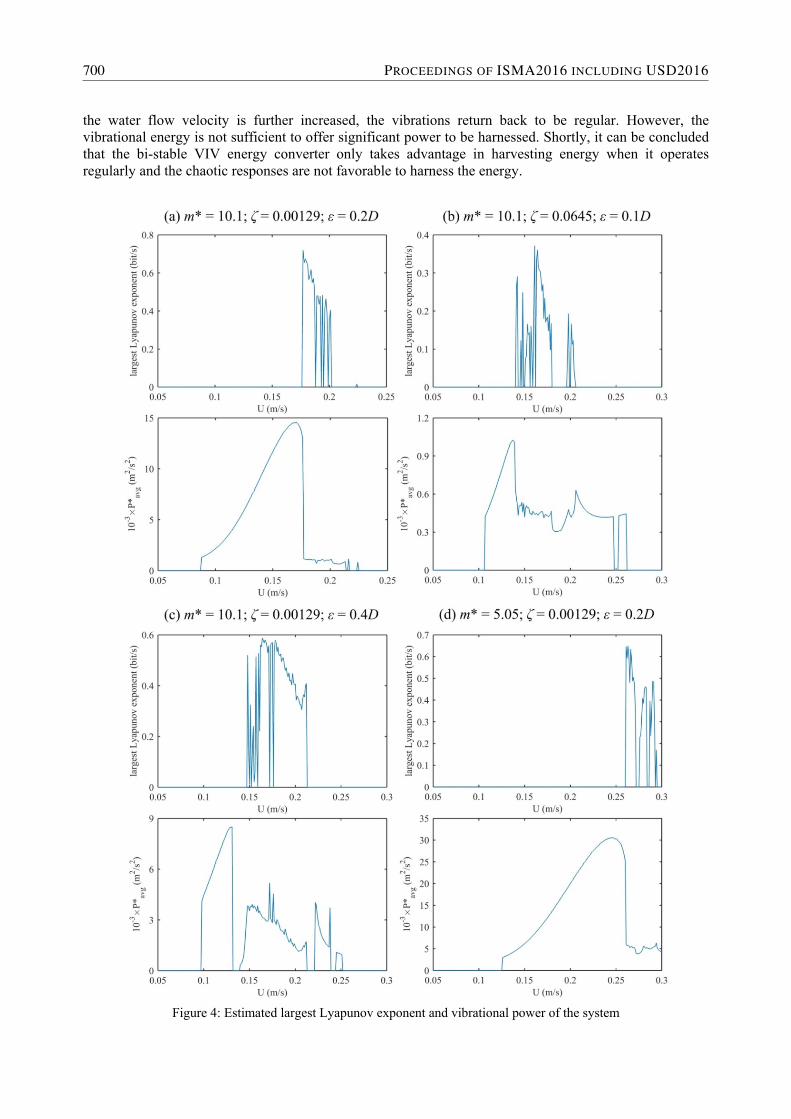
the water flow velocity is further increased, the vibrations return back to be regular. However, the vibrational energy is not sufficient to offer significant power to be harnessed. Shortly, it can be concluded that the bi-stable VIV energy converter only takes advantage in harvesting energy when it operates regularly and the chaotic responses are not favorable to harness the energy.
Figure 4: Estimated largest Lyapunov exponent and vibrational power of the system
700 PROCEEDINGS OF ISMA2016 INCLUDING USD2016
From the nature of the bi-stable VIV system, it is observed that the effect of bi-stable stiffness with a small bi-stable gap, , is minor to improve the converter performance and it is nearly the same to the linear system. When the bi-stable gap is increased, chaotic response is observed. However, the chaotic degree in the system tends to reduce when the bi-stable gap is further increased. For example, it can be seen from the Figure 5(a) for the system with the bi-stable gap of 0.2D, the Lyapunov exponent reaches its maximum of 0.7194 bit/s. When the bi-stable gap is increased to 0.4D, the maximum Lyapunov exponent drops to 0.5874 bit/s (see Figure 5(c)). The chaotic degree can also be reduced by introducing a high value of structural damping. Figure 5(b) depicts the chaotic response of the system with a high value of structural damping (ζ = 0.0645). The maximum value of the Lyapunov exponent is only 0.3718 bit/s in this case.
The influence of the effective mass of the oscillating structure is also observed. In comparison to the chaotic responses in the Figure 5(a) and Figure 5(d), when the mass ratio is reduced by one half, the Lyapunov exponent is slightly decreased. In particular, for the system with the mass ratio of 10.1 (see Figure 5(a)), the maximum Lyapunov exponent is 0.7194 bit/s. While for the system with the mass ratio of 5.05 (see Figure 5(d)), the maximum Lyapunov exponent is 0.6495 bit/s. However, since the effective mass determines the natural frequency of the system, the reduction in effective mass essentially shifts the resonance range toward high speed water flow and the effectiveness at low speed water flow will drop.
3 Experimental study
3.1 Testing platform
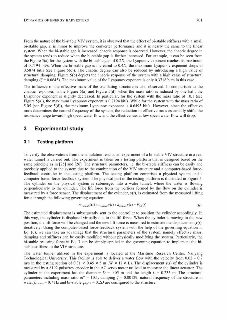
To verify the observations from the simulation results, an experiment of a bi-stable VIV structure in a real water tunnel is carried out. The experiment is taken on a testing platform that is designed based on the same principle as in [25] and [26]. The structural parameters, i.e. the bi-stable stiffness can be easily and precisely applied to the system due to the combination of the VIV structure and a computer-based force-feedback controller in the testing platform. The testing platform comprises a physical system and a computer-based force-feedback system. The physical part of the testing platform is illustrated in Figure 5. The cylinder on the physical system is submerged into a water tunnel, where the water is flowing perpendicularly to the cylinder. The lift force from the vortices formed by the flow on the cylinder is measured by a force sensor. The displacement of the cylinder, y(t), is estimated from the measured lifting force through the following governing equation:
)()()()( tFtyktyctym liftvirtualvirtualvirtual (6)
The estimated displacement is subsequently sent to the controller to position the cylinder accordingly. In this way, the cylinder is displaced virtually due to the lift force. When the cylinder is moving to the new position, the lift force will be changed and the new lift force is measured to estimate the displacement y(t), iteratively. Using the computer-based force-feedback system with the help of the governing equation in Eq. (6), we can take an advantage that the structural parameters of the system, namely effective mass, damping and stiffness can be easily modified without physically modifying the system. Particularly, the bi-stable restoring force in Eq. 3 can be simply applied in the governing equation to implement the bi-stable stiffness to the VIV structure.
The water tunnel utilized in the experiment is located at the Maritime Research Center, Nanyang Technological University. This facility is able to deliver a water flow with the velocity from 0.02 – 0.7 m/s in the testing section of 0.31 0.45 5 m (W H L). The displacement y(t) of the cylinder is measured by a 8192 pulse/rev encoder in the AC servo motor utilized to motorize the linear actuator. The cylinder in the experiment has the diameter D = 0.05 m and the length L = 0.235 m. The structural parameters including mass ratio m* = 10.1, damping ζ = 0.00129, natural frequency of the structure in water fn, water = 0.7 Hz and bi-stable gap ε = 0.2D are configured to the structure.
DYNAMICS OF ENERGY HARVESTERS 701
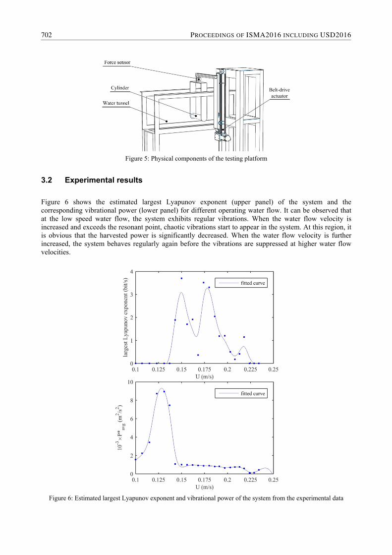
Figure 5: Physical components of the testing platform
3.2 Experimental results
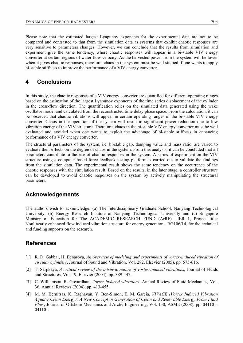
Figure 6 shows the estimated largest Lyapunov exponent (upper panel) of the system and the corresponding vibrational power (lower panel) for different operating water flow. It can be observed that at the low speed water flow, the system exhibits regular vibrations. When the water flow velocity is increased and exceeds the resonant point, chaotic vibrations start to appear in the system. At this region, it is obvious that the harvested power is significantly decreased. When the water flow velocity is further increased, the system behaves regularly again before the vibrations are suppressed at higher water flow velocities.
Figure 6: Estimated largest Lyapunov exponent and vibrational power of the system from the experimental data
702 PROCEEDINGS OF ISMA2016 INCLUDING USD2016
Please note that the estimated largest Lyapunov exponents for the experimental data are not to be compared and contrasted to that from the simulation data as systems that exhibit chaotic responses are very sensitive to parameters changes. However, we can conclude that the results from simulation and experiment give the same tendency, where chaotic responses will appear in a bi-stable VIV energy converter at certain regions of water flow velocity. As the harvested power from the system will be lower when it gives chaotic responses, therefore, chaos in the system must be well studied if one wants to apply bi-stable stiffness to improve the performance of a VIV energy converter.
4 Conclusions
In this study, the chaotic responses of a VIV energy converter are quantified for different operating ranges based on the estimation of the largest Lyapunov exponents of the time series displacement of the cylinder in the cross-flow direction. The quantification relies on the simulated data generated using the wake oscillator model and calculated from the reconstructed time delay phase space. From the calculation, it can be observed that chaotic vibrations will appear in certain operating ranges of the bi-stable VIV energy converter. Chaos in the operation of the system will result in significant power reduction due to low vibration energy of the VIV structure. Therefore, chaos in the bi-stable VIV energy converter must be well evaluated and avoided when one wants to exploit the advantage of bi-stable stiffness in enhancing performance of a VIV energy converter.
The structural parameters of the system, i.e. bi-stable gap, damping value and mass ratio, are varied to evaluate their effects on the degree of chaos in the system. From this analysis, it can be concluded that all parameters contribute to the rise of chaotic responses in the system. A series of experiment on the VIV structure using a computer-based force-feedback testing platform is carried out to validate the findings from the simulation data. The experimental result shows the same tendency on the occurrence of the chaotic responses with the simulation result. Based on the results, in the later stage, a controller structure can be developed to avoid chaotic responses on the system by actively manipulating the structural parameters.
Acknowledgements
The authors wish to acknowledge: (a) The Interdisciplinary Graduate School, Nanyang Technological University, (b) Energy Research Institute at Nanyang Technological University and (c) Singapore Ministry of Education for The ACADEMIC RESEARCH FUND (ArRF) TIER 1, Project title: Nonlinearly enhanced flow induced vibration structure for energy generator – RG106/14, for the technical and funding supports on the research.
References
[1] R. D. Gabbai, H. Benaroya, An overview of modeling and experiments of vortex-induced vibration of circular cylinders, Journal of Sound and Vibration, Vol. 282, Elsevier (2005), pp. 575-616.
[2] T. Sarpkaya, A critical review of the intrinsic nature of vortex-induced vibrations, Journal of Fluids and Structures, Vol. 19, Elsevier (2004), pp. 389-447.
[3] C. Williamson, R. Govardhan, Vortex-induced vibrations, Annual Review of Fluid Mechanics, Vol. 36, Annual Reviews (2004), pp. 413-455.
[4] M. M. Bernitsas, K. Raghavan, Y. Ben-Simon, E. M. Garcia, VIVACE (Vortex Induced Vibration Aquatic Clean Energy): A New Concept in Generation of Clean and Renewable Energy From Fluid Flow, Journal of Offshore Mechanics and Arctic Engineering, Vol. 130, ASME (2008), pp. 041101-041101.
DYNAMICS OF ENERGY HARVESTERS 703
[5] A. W. Mackowski, C. H. K. Williamson, An experimental investigation of vortex-induced vibration with nonlinear restoring forces, Physics of Fluids, Vol. 25, AIP (2013), pp. 087101.
[6] B. Huynh, T. Tjahjowidodo, Z. Zhong, Y. Wang, N. Srikanth, Nonlinearly enhanced vortex induced vibrations for energy harvesting, Proceedings of The 2015 IEEE International Conference on Advanced Intelligent Mechatronics (AIM), Busan, Korea, 2015 July 07-11, Busan (2015), pp. 91-96.
[7] R. C. Hilborn, Chaos and nonlinear dynamics: an introduction for scientists and engineers, Oxford University Press (2000).
[8] J. Zhao, J. S. Leontini, D. Lo Jacono, J. Sheridan, Chaotic vortex induced vibrations, Physics of Fluids, Vol. 26, AIP (2014), pp. 121702.
[9] P. G. Perdikaris, L. Kaiktsis, G. S. Triantafyllou, Chaos in a cylinder wake due to forcing at the Strouhal frequency, Physics of Fluids, Vol. 21, AIP (2009), pp. 101705.
[10] H. Blackburn, R. Henderson, Lock-in behavior in simulated vortex-induced vibration, Experimental Thermal and Fluid Science, Vol. 12, Elsevier (1996), pp. 184-189.
[11] S. H. Strogatz, Nonlinear dynamics and chaos: with applications to physics, biology, chemistry, and engineering, Westview press (2014).
[12] H. Kantz, T. Schreiber, Nonlinear time series analysis, Vol. 7, Cambridge university press (2004).
[13] H. Abarbanel, Analysis of observed chaotic data, Springer Science & Business Media (2012).
[14] U. Parlitz, Nonlinear time-series analysis, Nonlinear Modeling, Springer (1998), pp. 209-239.
[15] I. Trendafilova, H. Van Brussel, Non-linear dynamics tools for the motion analysis and condition monitoring of robot joints, Mechanical Systems and Signal Processing, Vol. 15, Elsevier (2001), pp. 1141-1164.
[16] T. Tjahjowidodo, F. Al-Bender, H. Van Brussel, Quantifying chaotic responses of mechanical systems with backlash component, Mechanical Systems and Signal Processing, Vol. 21, Elsevier (2007), pp. 973-993.
[17] A. Farshidianfar, N. Dolatabadi, Modified higher-order wake oscillator model for vortex-induced vibration of circular cylinders, Acta Mechanica, Vol. 224, Springer (2013), pp. 1441-1456.
[18] M. L. Facchinetti, E. de Langre, F. Biolley, Coupling of structure and wake oscillators in vortex-induced vibrations, Journal of Fluids and Structures, Vol. 19, Elsevier (2004), pp. 123-140.
[19] L. Tang, Y. Yang, C. K. Soh, Broadband Vibration Energy Harvesting Techniques, Advances in Energy Harvesting Methods, Springer New York (2013), pp. 17-61.
[20] R. L. Harne, K. W. Wang, A review of the recent research on vibration energy harvesting via bistable systems, Smart Materials and Structures, Vol. 22, IOPscience (2013), pp. 023001.
[21] S. P. Pellegrini, N. Tolou, M. Schenk, J. L. Herder, Bistable vibration energy harvesters: A review, Journal of Intelligent Material Systems and Structures, SAGE (2012).
[22] R. Ramlan, M. J. Brennan, B. R. Mace, I. Kovacic, Potential benefits of a non-linear stiffness in an energy harvesting device, Nonlinear Dynamics, Vol. 59, Springer (2009), pp. 545-558.
[23] A. Khalak, C. H. K. Williamson, Motions, forces and mode transitions in vortex-induced vibrations at low mass-damping, Journal of Fluids and Structures, Vol. 13, Elsevier (1999), pp. 813-851.
[24] L. Cao, Practical method for determining the minimum embedding dimension of a scalar time series, Physica D: Nonlinear Phenomena, Vol. 110, Elsevier (1997), pp. 43-50.
[25] F. S. Hover, M. S. Triantafyllou, Combined Simulation with Real-Time Force Feedback: A New Tool for Experimental Fluid Mechanics, System Theory: Modeling, Analysis and Control, Springer US (2000), pp. 463-474.
[26] A. W. Mackowski, C. H. K. Williamson, Developing a cyber-physical fluid dynamics facility for fluid–structure interaction studies, Journal of Fluids and Structures, Vol. 27, Elsevier (2011), pp. 748-757.
704 PROCEEDINGS OF ISMA2016 INCLUDING USD2016