Embed Size (px)
Citation preview
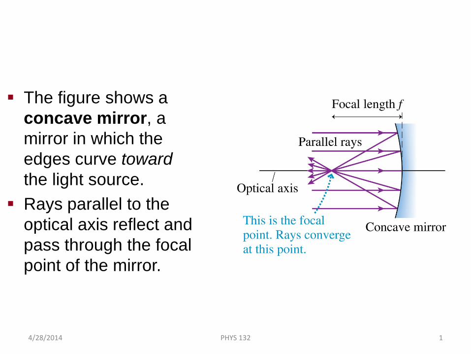
The figure shows a concave mirror, a mirror in which the edges curve toward the light source.
Rays parallel to the optical axis reflect and pass through the focal point of the mirror.
Image Formation with Concave Spherical Mirrors
4/28/2014 PHYS 132 1
A Spherical Mirror: Central Rays
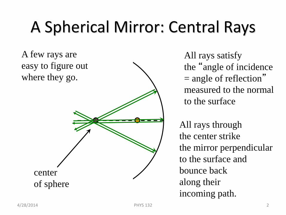
centerof sphere
All rays satisfythe “angle of incidence= angle of reflection”measured to the normalto the surface
All rays through the center strike the mirror perpendicularto the surface and bounce back along theirincoming path.
A few rays areeasy to figure outwhere they go.
4/28/2014 PHYS 132 2
A Spherical Mirror: Central Ray
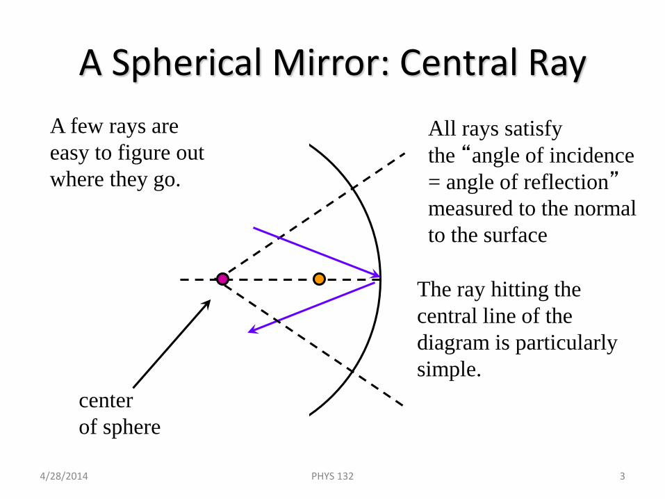
centerof sphere
All rays satisfythe “angle of incidence= angle of reflection”measured to the normalto the surface
The ray hitting the central line of the diagram is particularlysimple.
A few rays areeasy to figure outwhere they go.
4/28/2014 PHYS 132 3
A Spherical Mirror: Parallel Rays
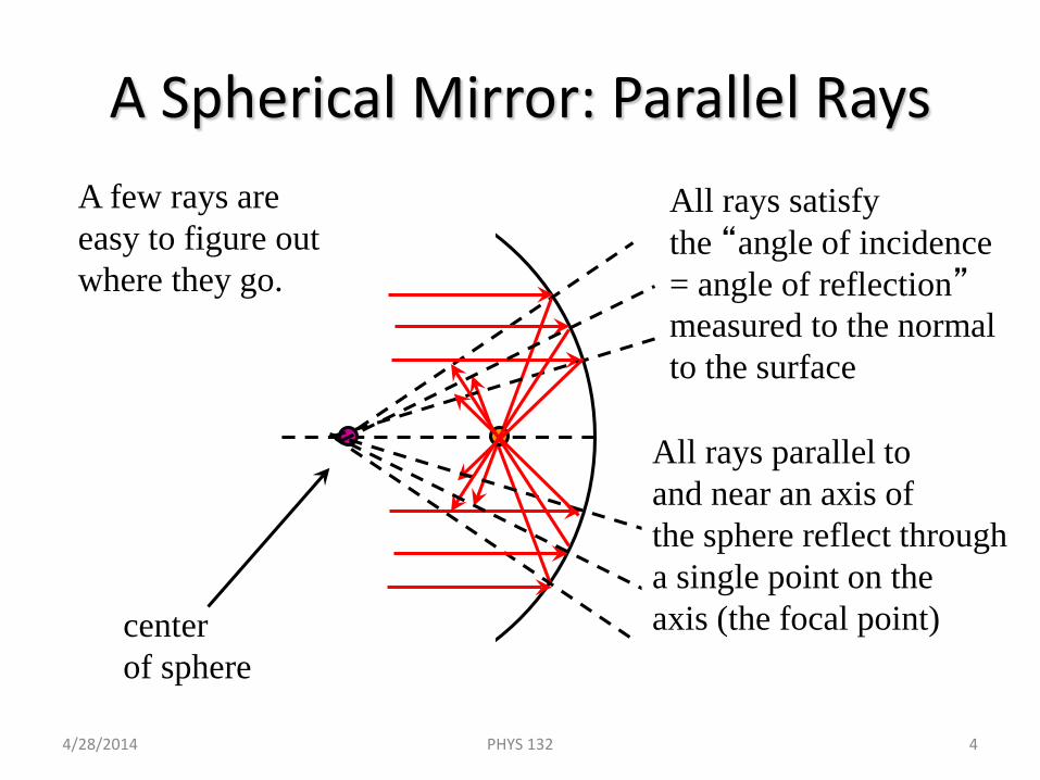
centerof sphere
A few rays areeasy to figure outwhere they go.
All rays parallel to and near an axis of the sphere reflect througha single point on the axis (the focal point)
All rays satisfythe “angle of incidence= angle of reflection”measured to the normalto the surface
4/28/2014 PHYS 132 4
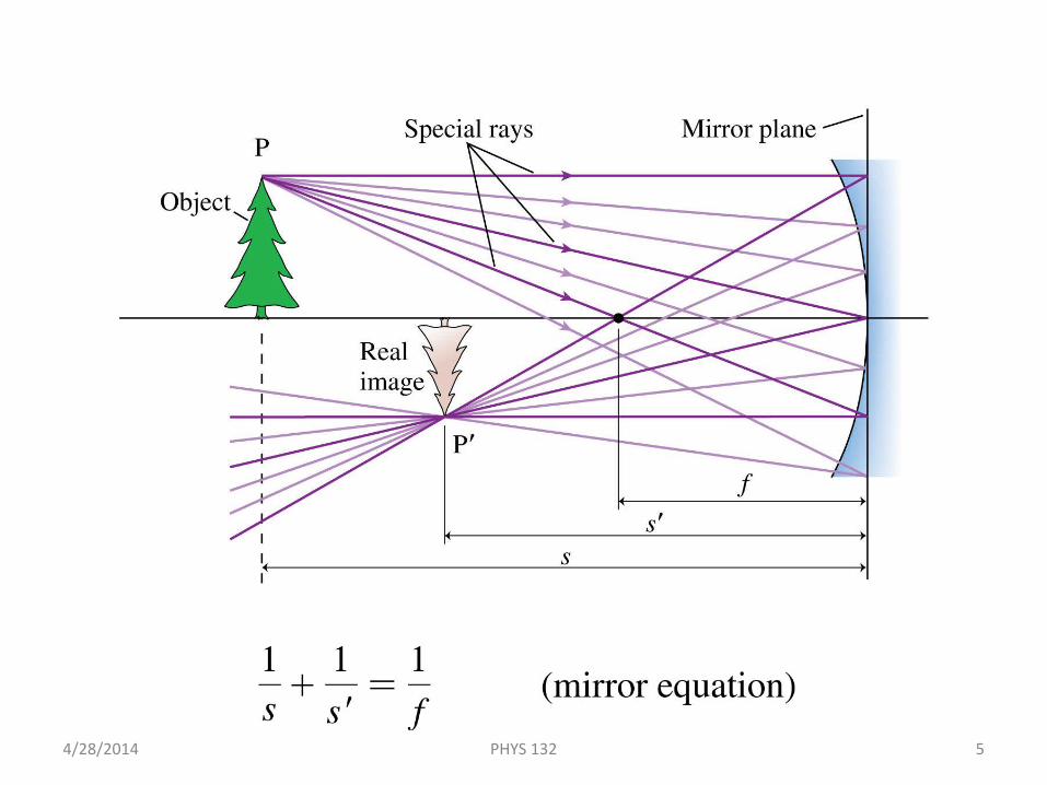
A Real Image Formed by a Concave Mirror
4/28/2014 PHYS 132 5
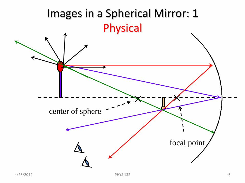
Images in a Spherical Mirror: 1Physical
center of sphere
focal point
4/28/2014 PHYS 132 6
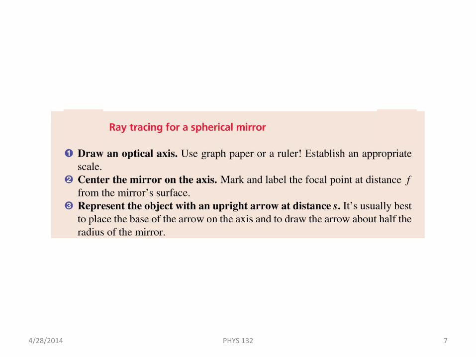
Tactics: Ray Tracing for a Spherical Mirror
4/28/2014 PHYS 132 7
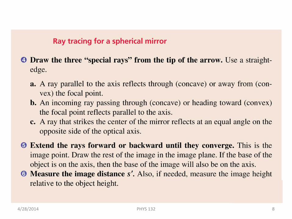
4/28/2014 PHYS 132 8
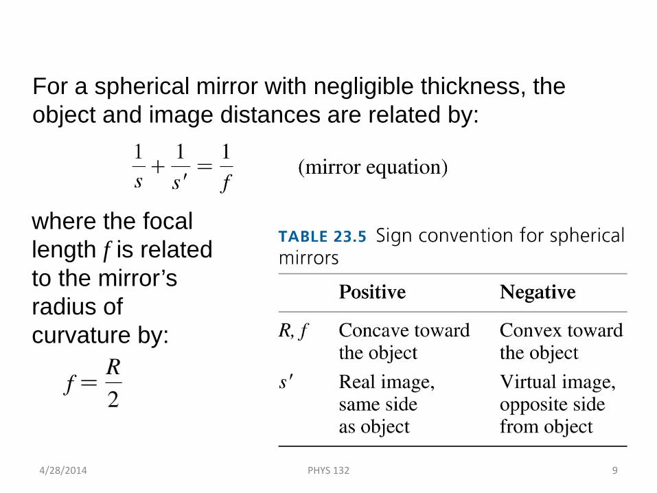
For a spherical mirror with negligible thickness, the object and image distances are related by:
where the focal length f is related to the mirror’s radius of curvature by:
The Mirror Equation
4/28/2014 PHYS 132 9
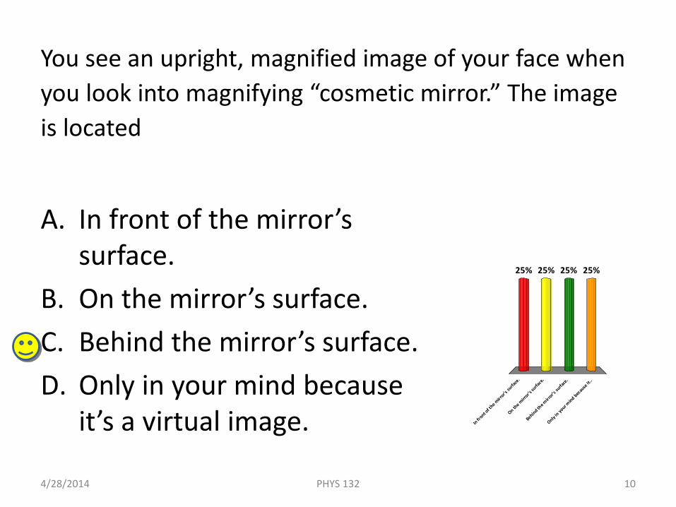
You see an upright, magnified image of your face when you look into magnifying “cosmetic mirror.” The image is located
A. In front of the mirror’s surface.
B. On the mirror’s surface.C. Behind the mirror’s surface.D. Only in your mind because
it’s a virtual image.
4/28/2014 10PHYS 132
In front o
f the m
irror’s
surfa
ce.
On the m
irror’s
surfa
ce.
Behind the m
irror’s
surfa
ce.
Only in yo
ur mind bec
ause
it..
25% 25%25%25%
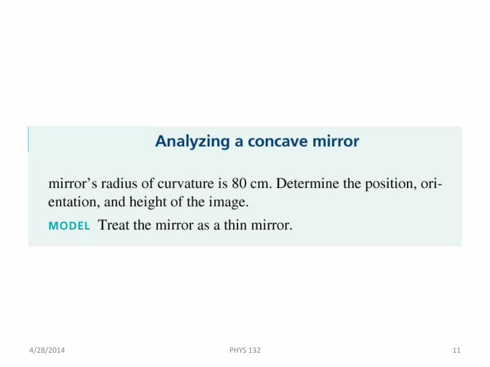
Example 23.17 Analyzing a Concave Mirror
4/28/2014 PHYS 132 11
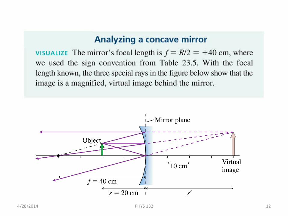
Example 23.17 Analyzing a Concave Mirror
4/28/2014 PHYS 132 12
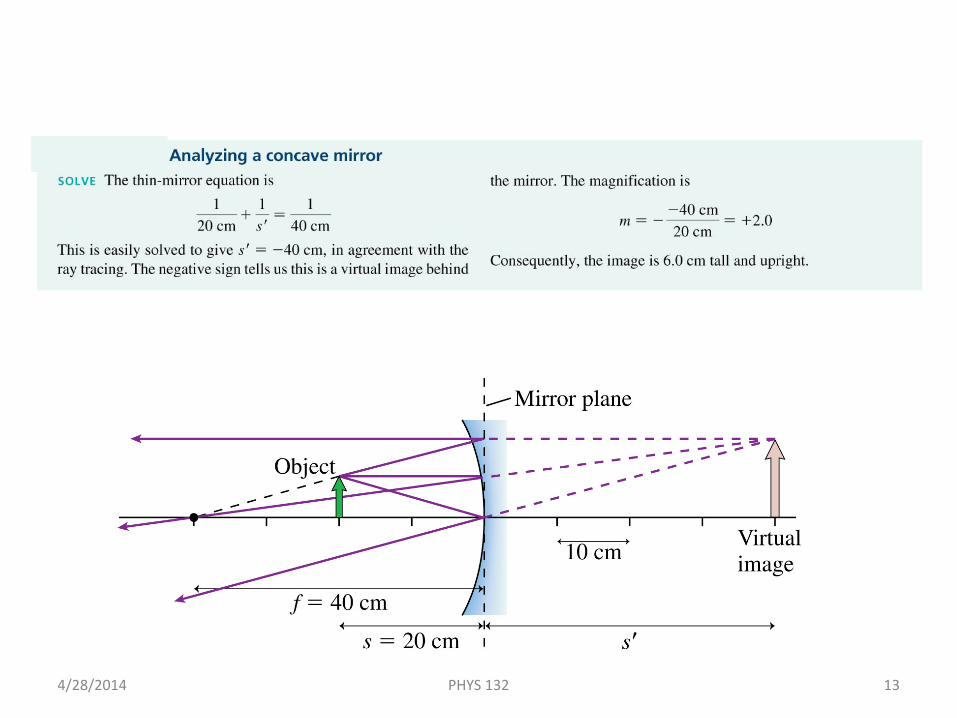
Example 23.17 Analyzing a Concave Mirror
4/28/2014 PHYS 132 13
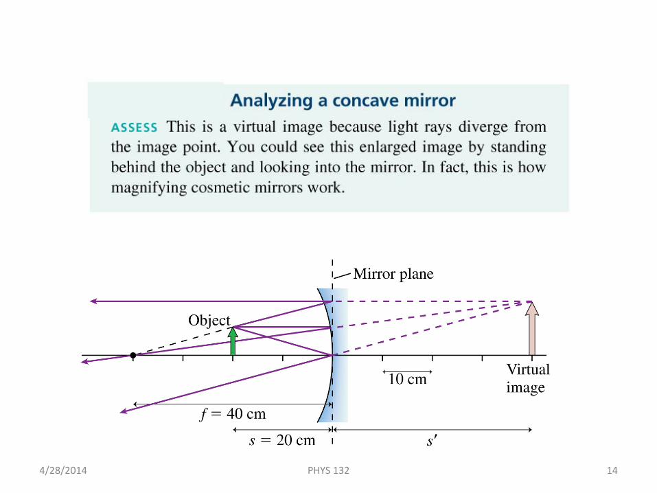
Example 23.17 Analyzing a Concave Mirror
4/28/2014 PHYS 132 14

A city skyline is reflected in this polished sphere.
Image Formation with Spherical Mirrors
4/28/2014 PHYS 132 15
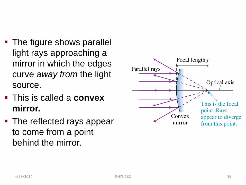
The figure shows parallel light rays approaching a mirror in which the edges curve away from the light source.
This is called a convex mirror.
The reflected rays appear to come from a point behind the mirror.
Image Formation with Convex Spherical Mirrors
4/28/2014 PHYS 132 16
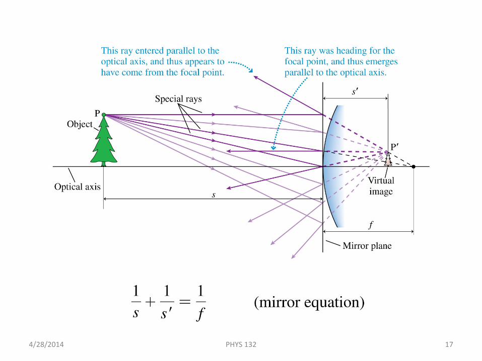
A Real Image Formed by a Convex Mirror
4/28/2014 PHYS 132 17
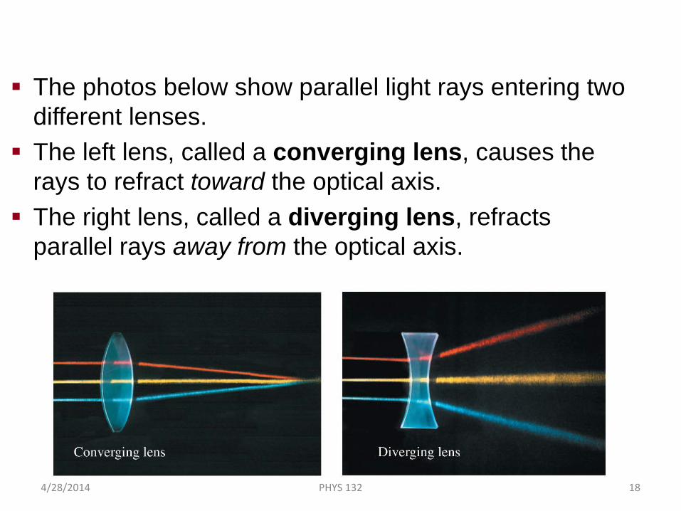
The photos below show parallel light rays entering two different lenses.
The left lens, called a converging lens, causes the rays to refract toward the optical axis.
The right lens, called a diverging lens, refracts parallel rays away from the optical axis.
Lenses
4/28/2014 PHYS 132 18
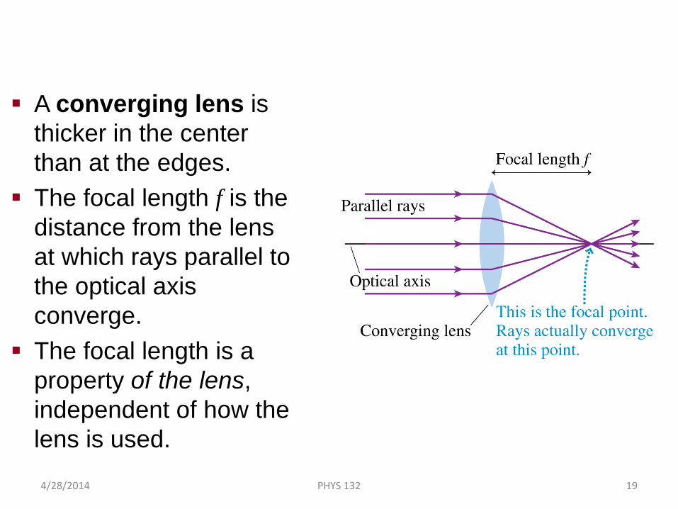
A converging lens is thicker in the center than at the edges.
The focal length f is the distance from the lens at which rays parallel to the optical axis converge.
The focal length is a property of the lens, independent of how the lens is used.
Converging Lenses
4/28/2014 PHYS 132 19
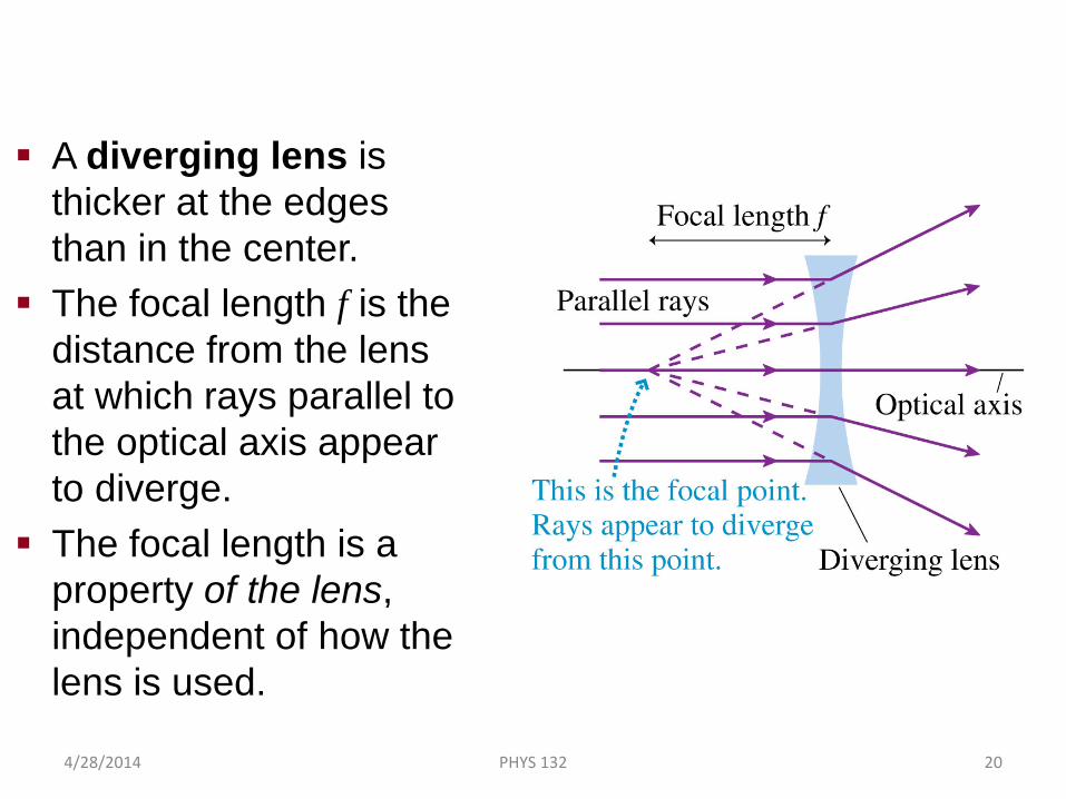
A diverging lens is thicker at the edges than in the center.
The focal length f is the distance from the lens at which rays parallel to the optical axis appear to diverge.
The focal length is a property of the lens, independent of how the lens is used.
Diverging Lenses
4/28/2014 PHYS 132 20
You can use the sun’s rays and a lens to start a fire. To do so, you should use
A. A converging lens.B. A diverging lens.C. Either a converging
or a diverging lens will work if you use it correctly.
4/28/2014 21PHYS 132
A conve
rging l
ens.
A divergi
ng lens.
Either a
conve
rging o
r a div.
..
33%33%33%
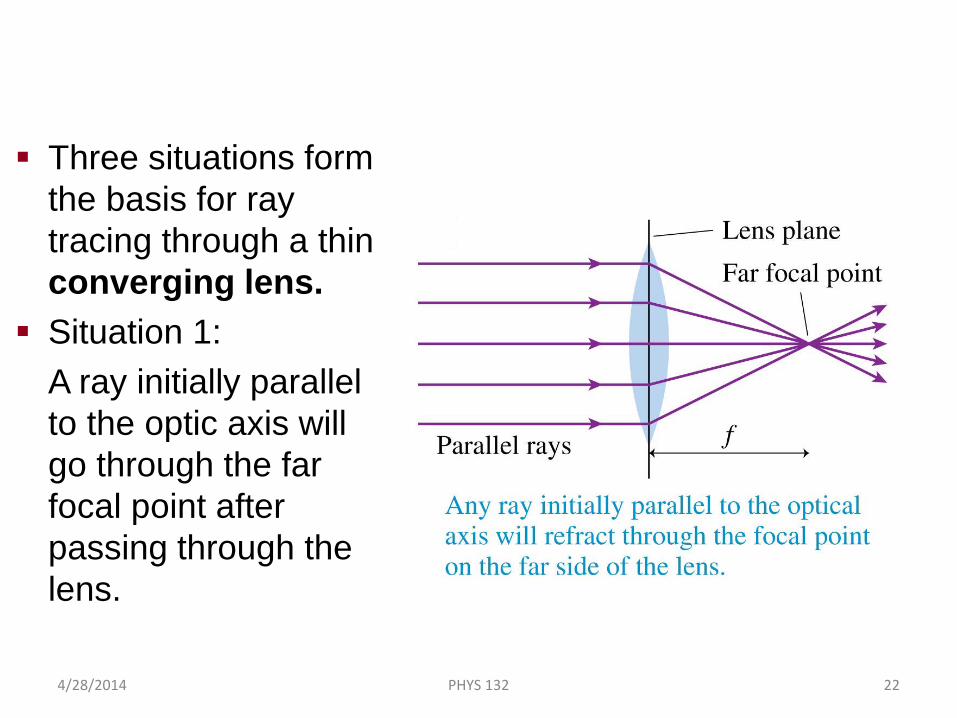
Three situations form the basis for ray tracing through a thin converging lens.
Situation 1:A ray initially parallel to the optic axis will go through the far focal point after passing through the lens.
Thin Lenses: Ray Tracing
4/28/2014 PHYS 132 22
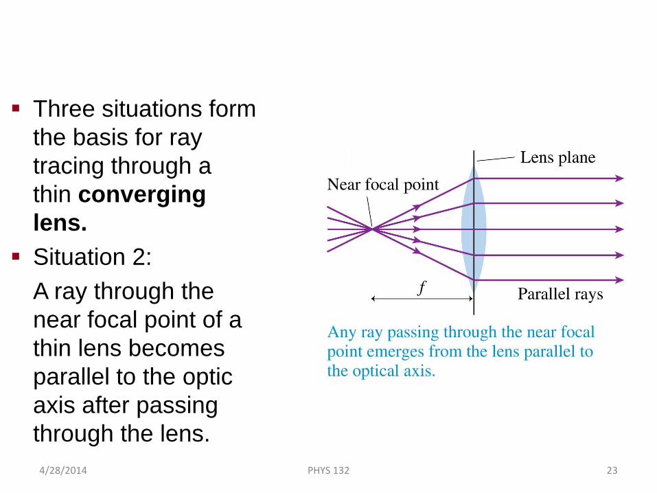
Three situations form the basis for ray tracing through a thin converging lens.
Situation 2:A ray through the near focal point of a thin lens becomes parallel to the optic axis after passing through the lens.
Thin Lenses: Ray Tracing
4/28/2014 PHYS 132 23
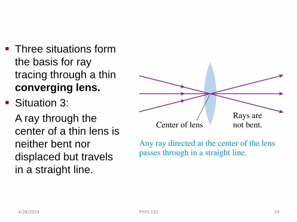
Three situations form the basis for ray tracing through a thin converging lens.
Situation 3:A ray through the center of a thin lens is neither bent nor displaced but travels in a straight line.
Thin Lenses: Ray Tracing
4/28/2014 PHYS 132 24
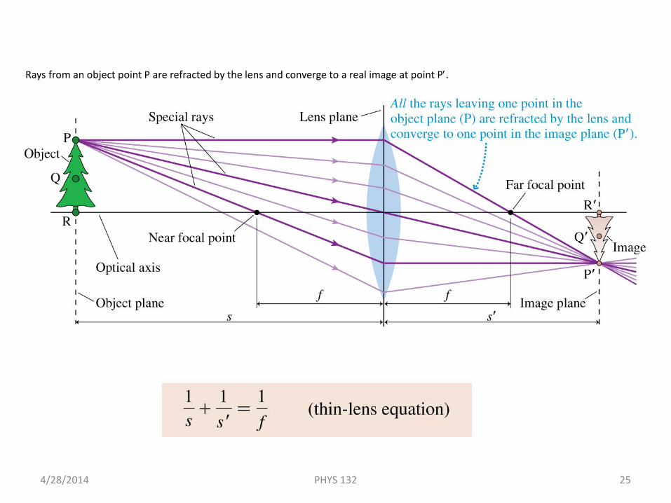
Thin Lenses: Ray TracingRays from an object point P are refracted by the lens and converge to a real image at point P′.
4/28/2014 PHYS 132 25
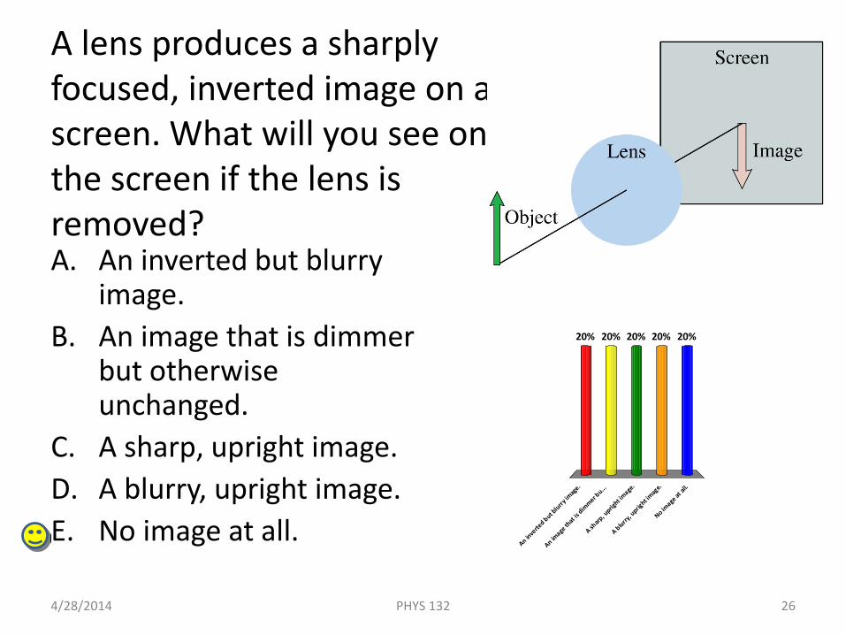
A lens produces a sharply focused, inverted image on a screen. What will you see on the screen if the lens is removed?A. An inverted but blurry
image.B. An image that is dimmer
but otherwise unchanged.
C. A sharp, upright image.D. A blurry, upright image.E. No image at all.
4/28/2014 26PHYS 132
An inve
rted but b
lurry im
age.
An image
that
is dim
mer bu...
A sharp
, uprig
ht image
.
A blurry, u
pright im
age.
No image
at al
l.
20% 20%20%20%20%
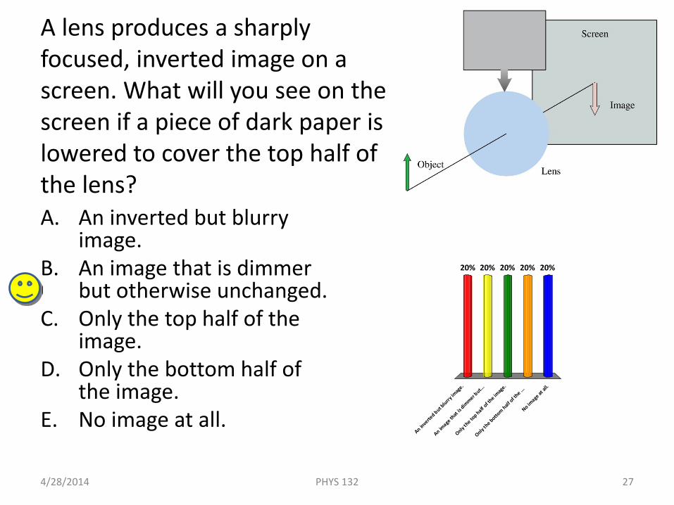
A lens produces a sharply focused, inverted image on a screen. What will you see on the screen if a piece of dark paper is lowered to cover the top half of the lens?A. An inverted but blurry
image.B. An image that is dimmer
but otherwise unchanged.C. Only the top half of the
image.D. Only the bottom half of
the image.E. No image at all.
4/28/2014 27PHYS 132
An inve
rted but b
lurry im
age.
An image
that
is dim
mer but...
Only th
e top half o
f the im
age.
Only th
e botto
m half of th
e ...
No image
at al
l.
20% 20%20%20%20%
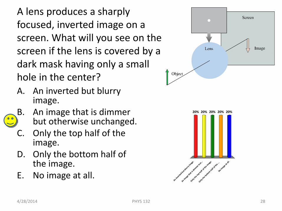
A lens produces a sharply focused, inverted image on a screen. What will you see on the screen if the lens is covered by a dark mask having only a small hole in the center?A. An inverted but blurry
image.B. An image that is dimmer
but otherwise unchanged.C. Only the top half of the
image.D. Only the bottom half of
the image.E. No image at all.
4/28/2014 28PHYS 132
An inve
rted but b
lurry im
age.
An image
that
is dim
mer but...
Only th
e top half o
f the im
age.
Only th
e botto
m half of th
e ...
No image
at al
l.
20% 20%20%20%20%
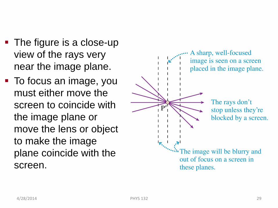
The figure is a close-up view of the rays very near the image plane.
To focus an image, you must either move the screen to coincide with the image plane or move the lens or object to make the image plane coincide with the screen.
Image Formation
4/28/2014 PHYS 132 29
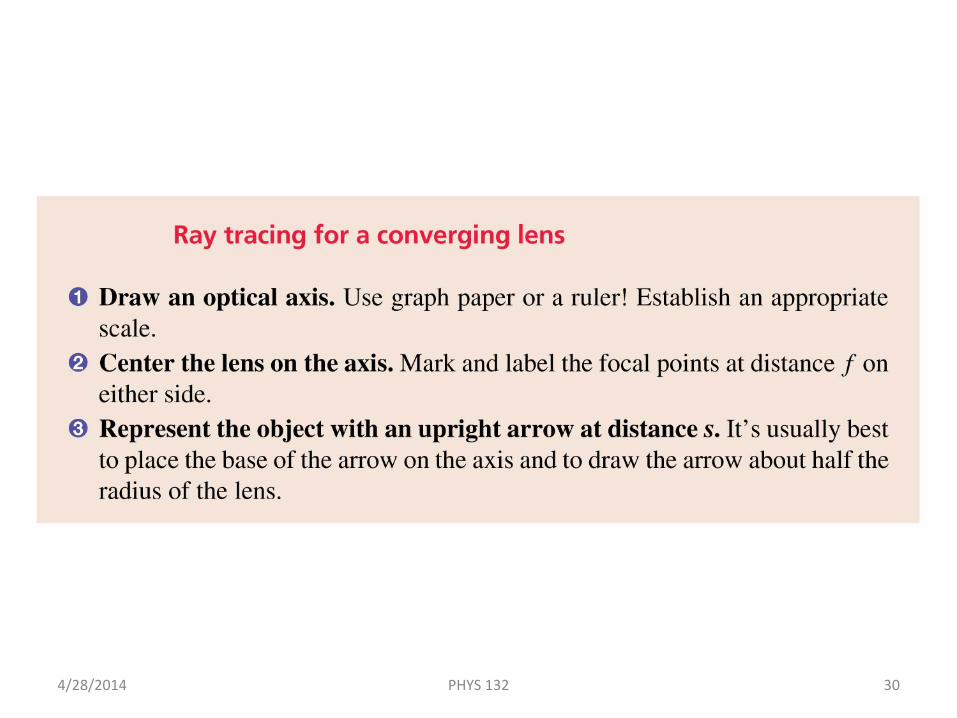
Tactics: Ray Tracing for a Converging Lens
4/28/2014 PHYS 132 30
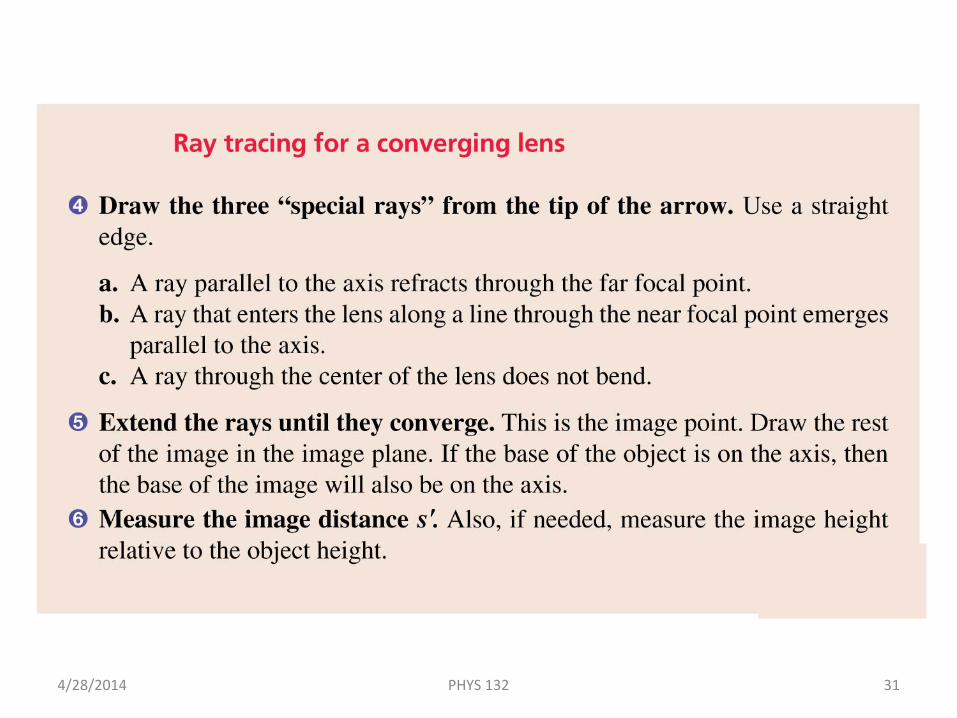
Tactics: Ray Tracing for a Converging Lens
4/28/2014 PHYS 132 31

A lens creates an image as shown. In this situation, the object distance s is
A. Larger than the focal length f.B. Equal to the focal length f.C. Shorter than the focal length f.
4/28/2014 32PHYS 132
Large
r than
the f
ocal le
ngth f.
Equal to
the f
ocal le
ngth f.
Shorte
r than th
e foca
l length
f.
33%33%33%
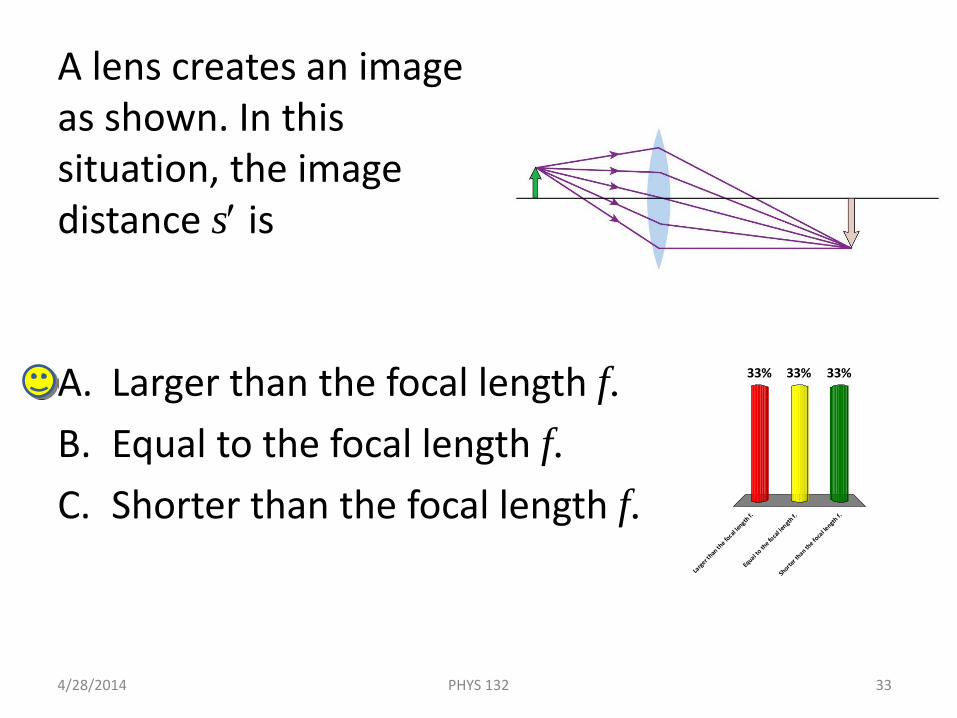
A lens creates an image as shown. In this situation, the image distance s′ is
A. Larger than the focal length f.B. Equal to the focal length f.C. Shorter than the focal length f.
4/28/2014 33PHYS 132
Large
r than
the f
ocal le
ngth f.
Equal to
the f
ocal le
ngth f.
Shorte
r than th
e foca
l length
f.
33%33%33%
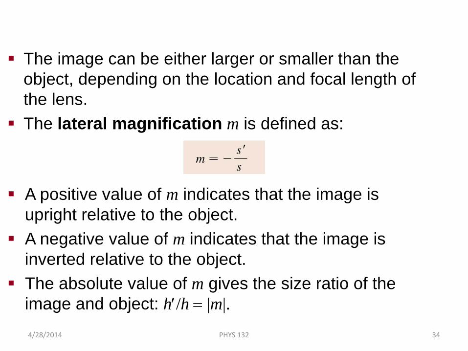
The image can be either larger or smaller than the object, depending on the location and focal length of the lens.
The lateral magnification m is defined as:
A positive value of m indicates that the image is upright relative to the object.
A negative value of m indicates that the image is inverted relative to the object.
The absolute value of m gives the size ratio of the image and object: h′/h = |m|.
Lateral Magnification
4/28/2014 PHYS 132 34
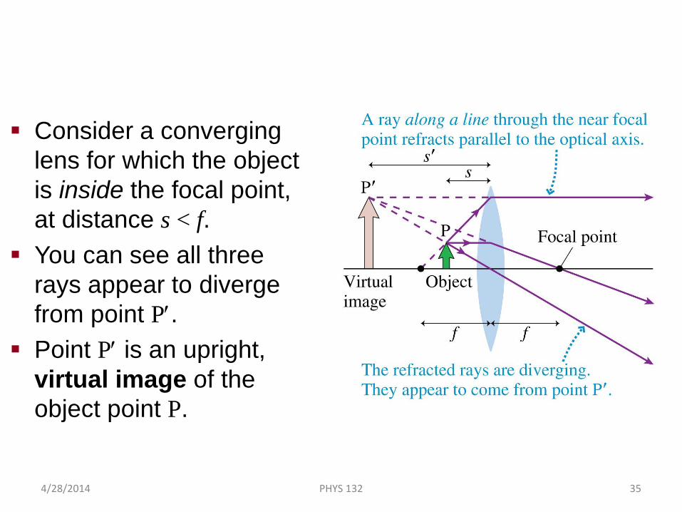
Consider a converging lens for which the object is inside the focal point, at distance s < f.
You can see all three rays appear to diverge from point P′.
Point P′ is an upright, virtual image of the object point P.
Virtual Images
4/28/2014 PHYS 132 35
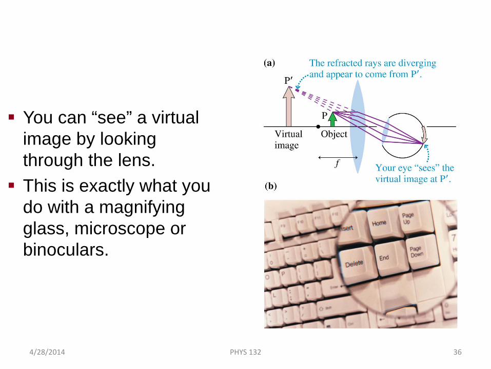
You can “see” a virtual image by looking through the lens. This is exactly what you
do with a magnifying glass, microscope or binoculars.
Virtual Images
4/28/2014 PHYS 132 36

Example 23.9 Magnifying a Flower
4/28/2014 PHYS 132 37
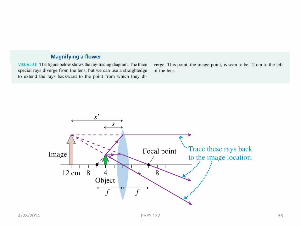
Example 23.9 Magnifying a Flower
4/28/2014 PHYS 132 38
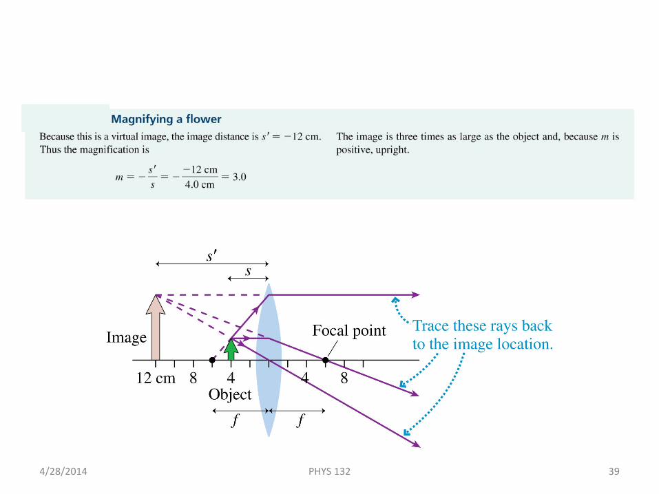
Example 23.9 Magnifying a Flower
4/28/2014 PHYS 132 39
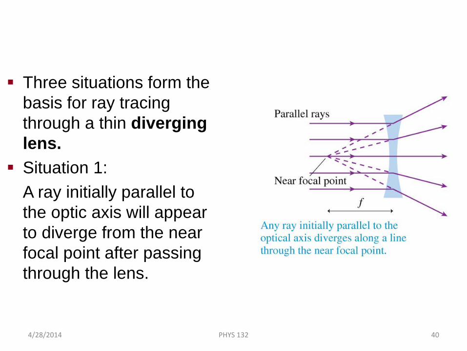
Three situations form the basis for ray tracing through a thin diverging lens.
Situation 1:A ray initially parallel to the optic axis will appear to diverge from the near focal point after passing through the lens.
Thin Lenses: Ray Tracing
4/28/2014 PHYS 132 40
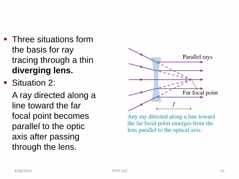
Three situations form the basis for ray tracing through a thin diverging lens.
Situation 2:A ray directed along a line toward the far focal point becomes parallel to the optic axis after passing through the lens.
Thin Lenses: Ray Tracing
4/28/2014 PHYS 132 41
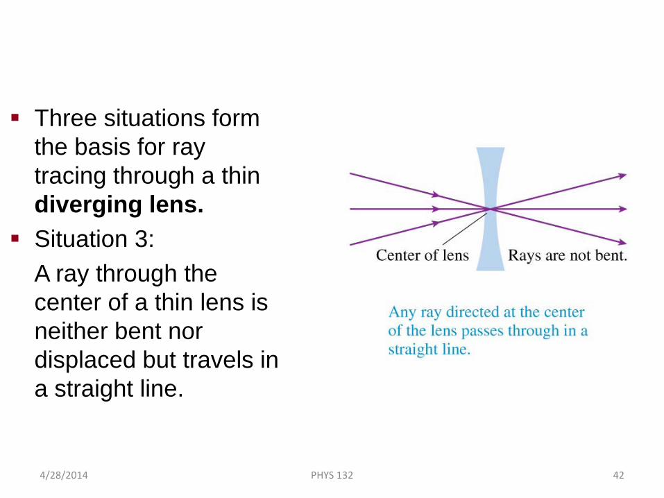
Three situations form the basis for ray tracing through a thin diverging lens.
Situation 3:A ray through the center of a thin lens is neither bent nor displaced but travels in a straight line.
Thin Lenses: Ray Tracing
4/28/2014 PHYS 132 42
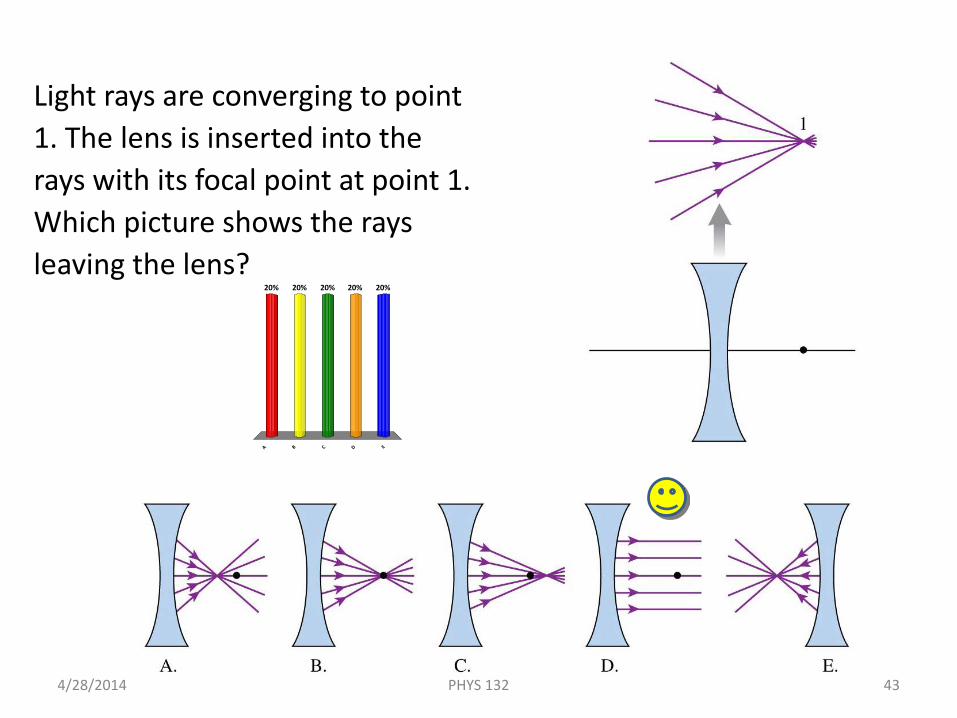
Light rays are converging to point 1. The lens is inserted into the rays with its focal point at point 1. Which picture shows the rays leaving the lens?
4/28/2014 43PHYS 132
A B C D E
20% 20%20%20%20%
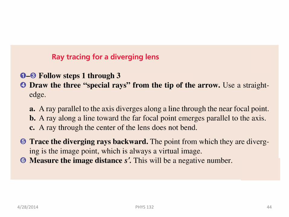
Tactics: Ray Tracing for a Diverging Lens
4/28/2014 PHYS 132 44
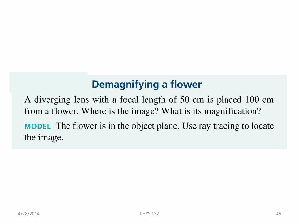
Example 23.10 Demagnifying a Flower
4/28/2014 PHYS 132 45
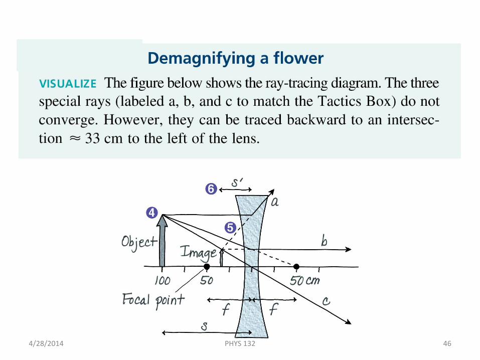
Example 23.10 Demagnifying a Flower
4/28/2014 PHYS 132 46
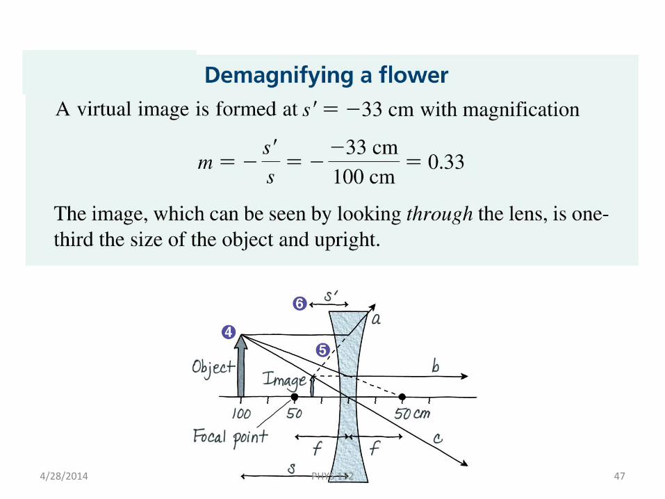
Example 23.10 Demagnifying a Flower
4/28/2014 PHYS 132 47
Wave Model
4/28/2014 PHYS 132 48
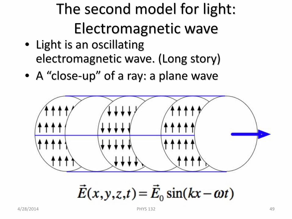
The second model for light: Electromagnetic wave
• Light is an oscillating electromagnetic wave. (Long story)
• A “close-up” of a ray: a plane wave
4/28/2014 PHYS 132 49
It’s hard to picture EM waves in 3D
• Let’s build some intuition by working through a simpler example.
Waves on the surface of water
(treating the height of the surface only –that moves up and down – transvers to the wave motion: the actual bits of water move in small circles)
4/28/2014 PHYS 132 50
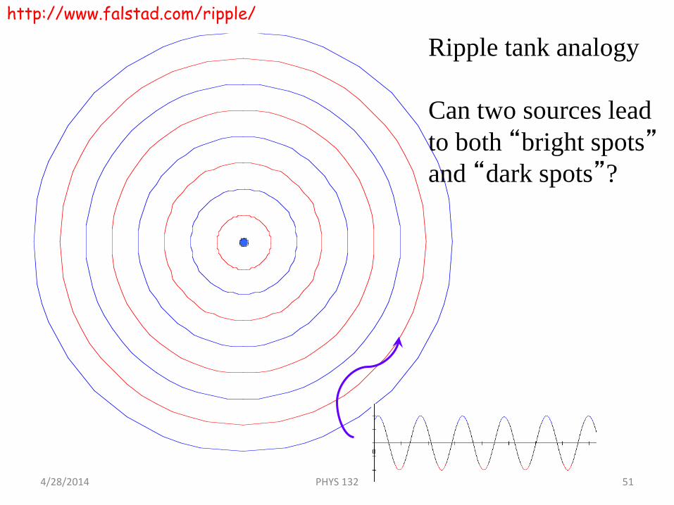
Ripple tank analogy
Can two sources lead to both “bright spots”and “dark spots”?
http://www.falstad.com/ripple/
4/28/2014 PHYS 132 51
Chapter 22 Preview
4/28/2014 PHYS 132 52
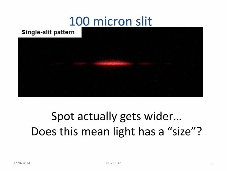
Spot actually gets wider…Does this mean light has a “size”?
100 micron slit
4/28/2014 PHYS 132 53
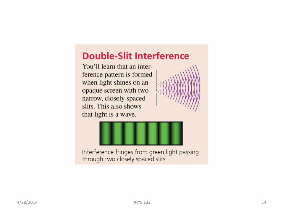
Chapter 22 Preview
4/28/2014 PHYS 132 54
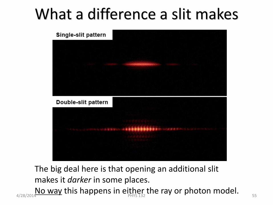
What a difference a slit makes
The big deal here is that opening an additional slitmakes it darker in some places. No way this happens in either the ray or photon model.
4/28/2014 PHYS 132 55
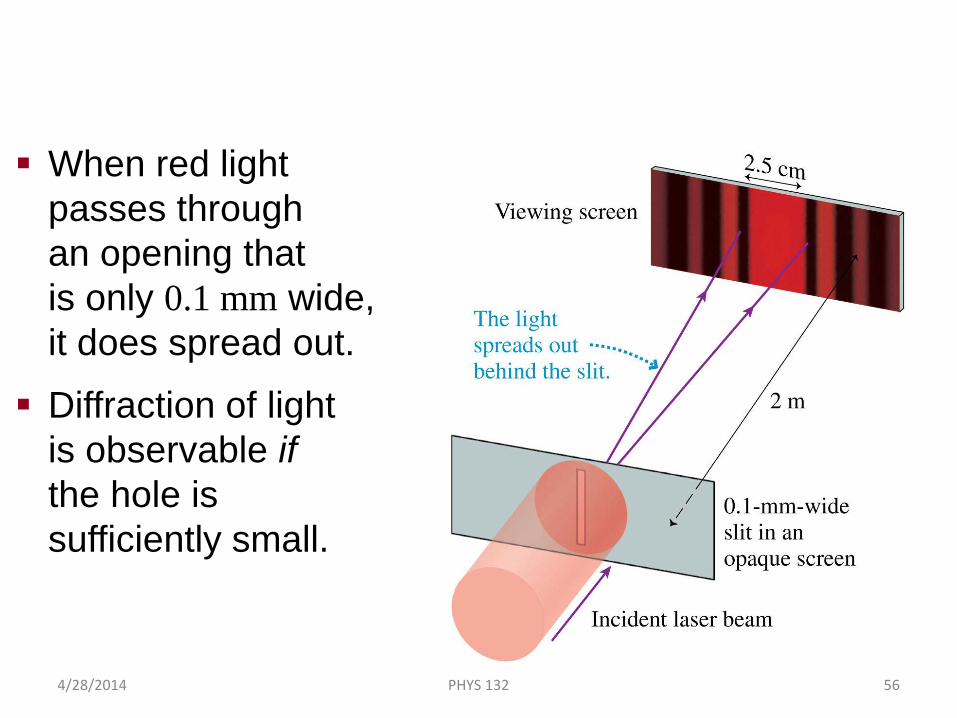
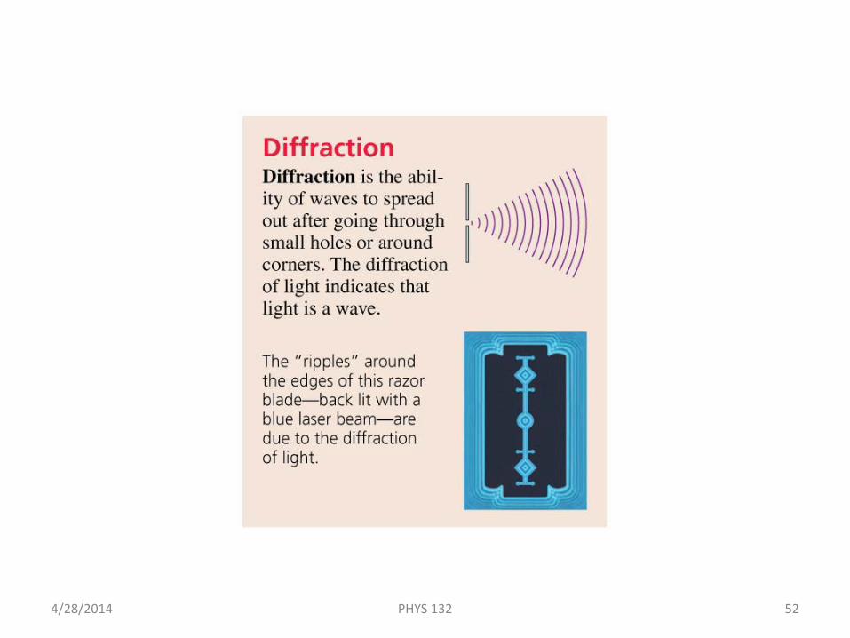
Diffraction of Light
When red light passes through an opening that is only 0.1 mm wide, it does spread out.
Diffraction of light is observable if the hole is sufficiently small.
4/28/2014 PHYS 132 56
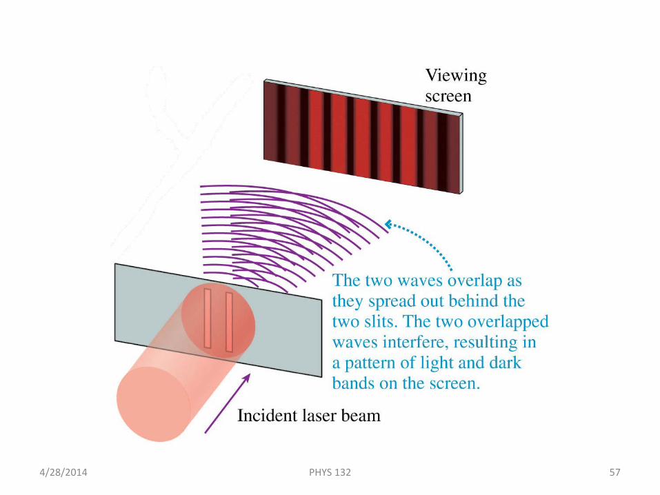
Young’s Double-Slit Experiment
4/28/2014 PHYS 132 57
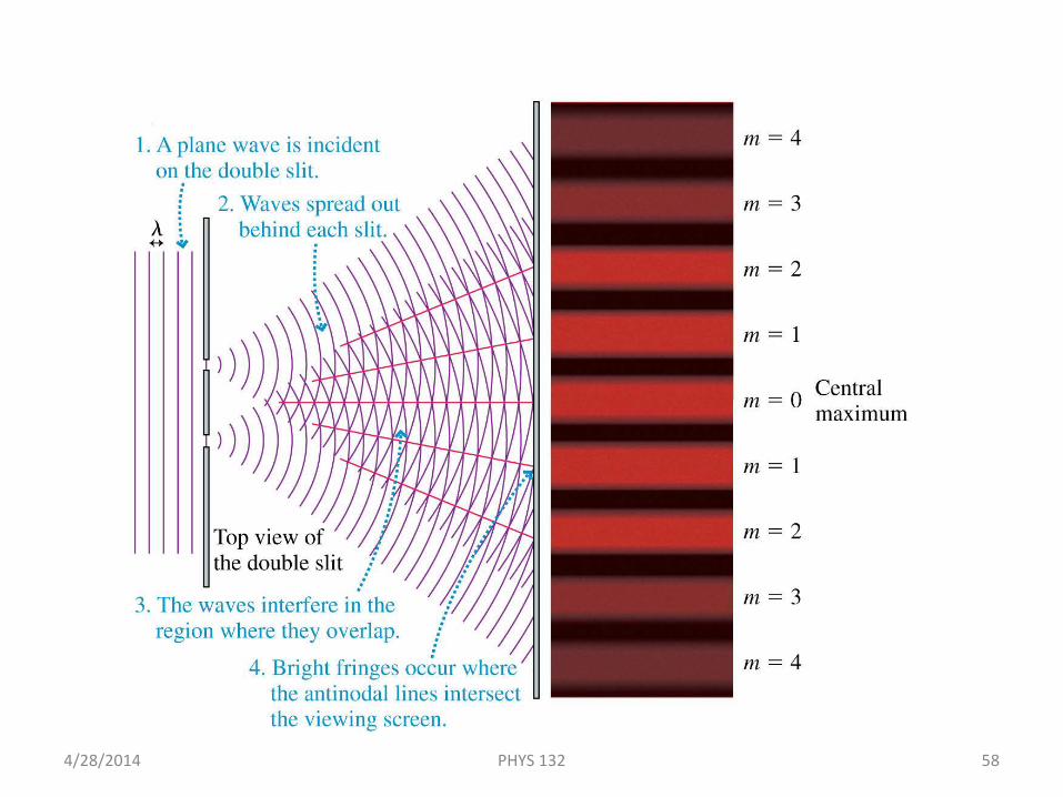
Young’s Double-Slit Experiment
4/28/2014 PHYS 132 58
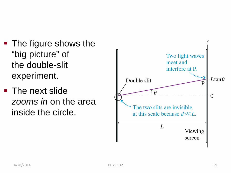
Analyzing Double-Slit Interference
The figure shows the “big picture” of the double-slit experiment.
The next slide zooms in on the area inside the circle.
4/28/2014 PHYS 132 59
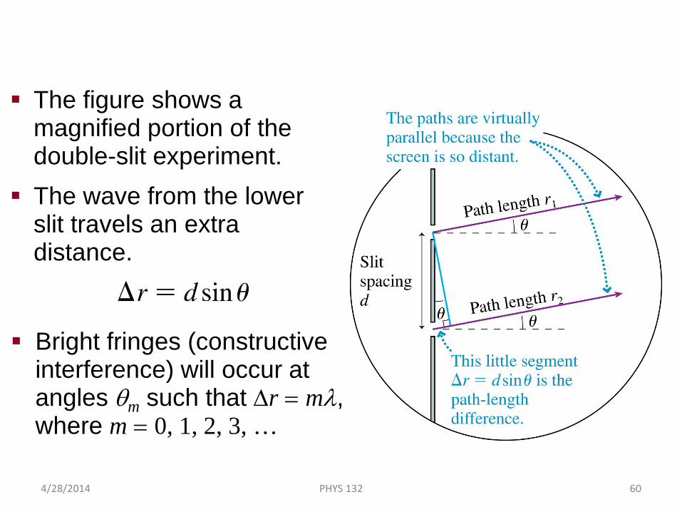
Analyzing Double-Slit Interference
The figure shows a magnified portion of the double-slit experiment.
The wave from the lower slit travels an extra distance.
Bright fringes (constructive interference) will occur at angles θm such that ∆r = mλ, where m = 0, 1, 2, 3, …
4/28/2014 PHYS 132 60
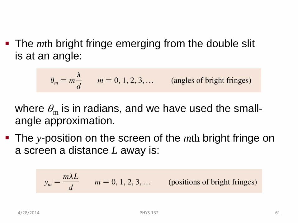
Analyzing Double-Slit Interference
The mth bright fringe emerging from the double slit is at an angle:
where θm is in radians, and we have used the small-angle approximation.
The y-position on the screen of the mth bright fringe on a screen a distance L away is:
4/28/2014 PHYS 132 61
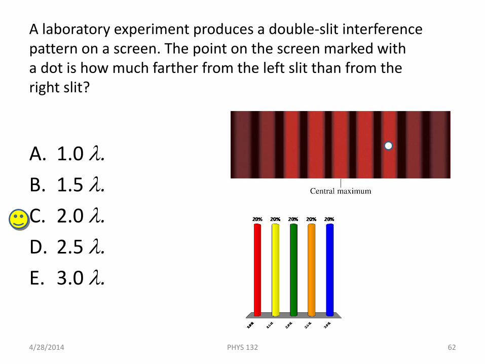
A laboratory experiment produces a double-slit interference pattern on a screen. The point on the screen marked with a dot is how much farther from the left slit than from the right slit?
A. 1.0 λ.B. 1.5 λ.C. 2.0 λ.D. 2.5 λ.E. 3.0 λ.
4/28/2014 62PHYS 132
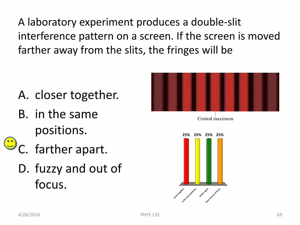
A laboratory experiment produces a double-slit interference pattern on a screen. If the screen is moved farther away from the slits, the fringes will be
A. closer together.B. in the same
positions.C. farther apart.D. fuzzy and out of
focus.
4/28/2014 63PHYS 132
close
r toge
ther.
in the sa
me posit
ions.
farth
er ap
art.
fuzzy and out o
f focu
s.
25% 25%25%25%

A laboratory experiment produces a double-slit interference pattern on a screen. If green light is used, with everything else the same, the bright fringes will be
A. closer together.B. in the same positions.C. farther apart.D. There will be no
fringes because the conditions for interference won’t be satisfied.
4/28/2014 64PHYS 132
close
r toge
ther.
in the sa
me posit
ions.
farth
er ap
art.
There
will
be no fringe
s bec..
.
25% 25%25%25%
d∆y = λL and green light has a shorter wavelength.
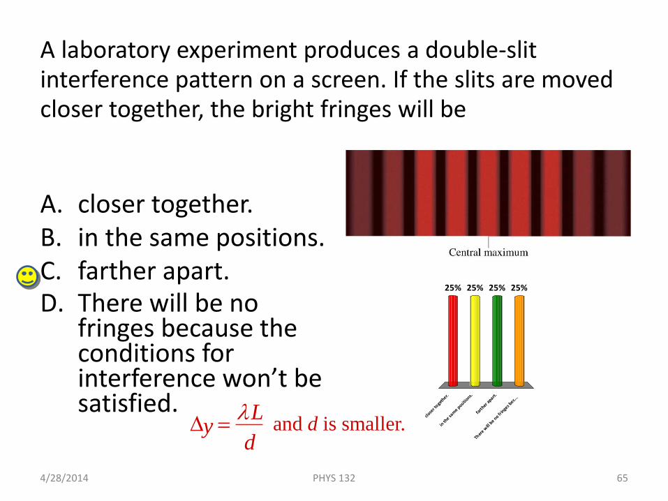
A laboratory experiment produces a double-slit interference pattern on a screen. If the slits are moved closer together, the bright fringes will be
A. closer together.B. in the same positions.C. farther apart.D. There will be no
fringes because the conditions for interference won’t be satisfied.
4/28/2014 65PHYS 132
close
r toge
ther.
in the sa
me posit
ions.
farth
er ap
art.
There
will
be no fringe
s bec..
.
25% 25%25%25%
∆y = λLd
and d is smaller.
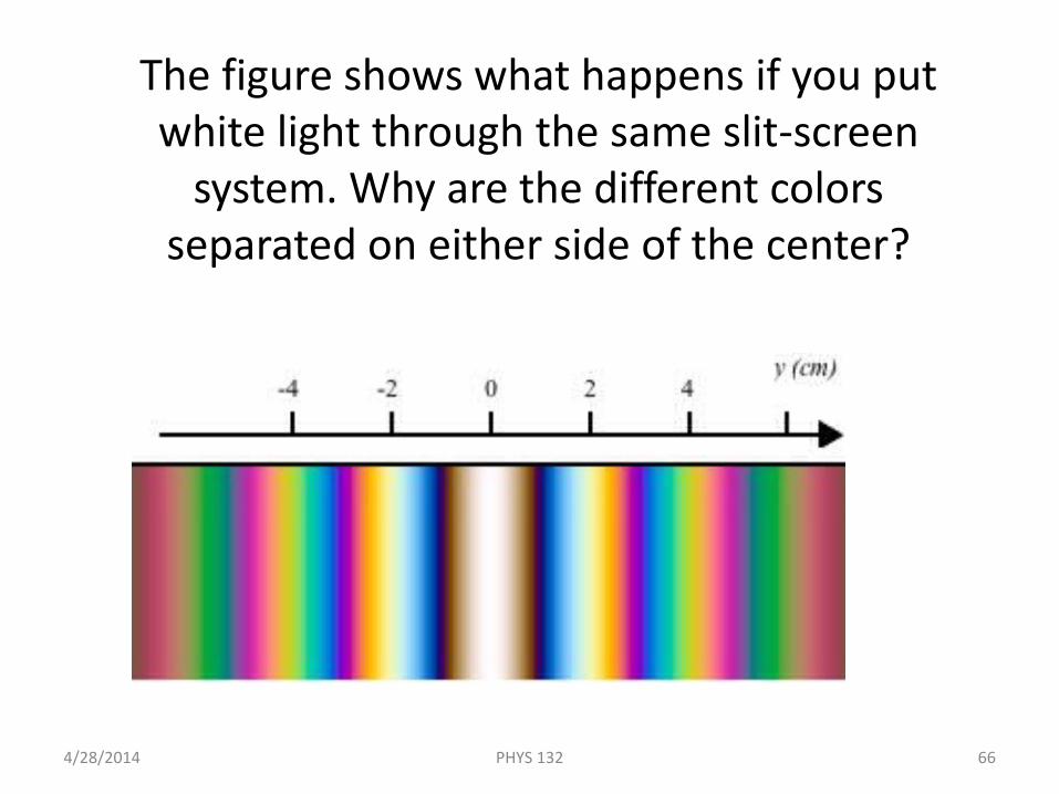
The figure shows what happens if you put white light through the same slit-screen
system. Why are the different colors separated on either side of the center?
4/28/2014 PHYS 132 66
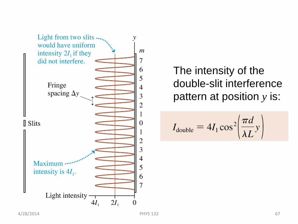
Intensity of the Double-Slit Interference Pattern
The intensity of the double-slit interference pattern at position y is:
4/28/2014 PHYS 132 67
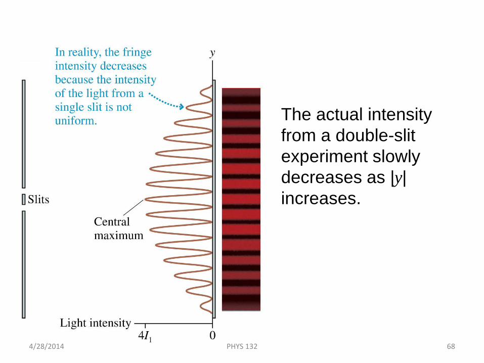
Intensity of the Double-Slit Interference Pattern
The actual intensity from a double-slit experiment slowly decreases as |y| increases.
4/28/2014 PHYS 132 68
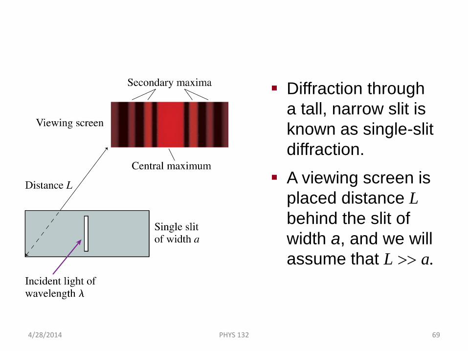
Single-Slit Diffraction
Diffraction through a tall, narrow slit is known as single-slit diffraction.
A viewing screen is placed distance Lbehind the slit of width a, and we will assume that L >> a.
4/28/2014 PHYS 132 69
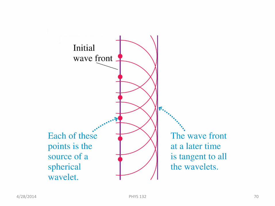
Huygens’ Principle: Plane Waves
4/28/2014 PHYS 132 70
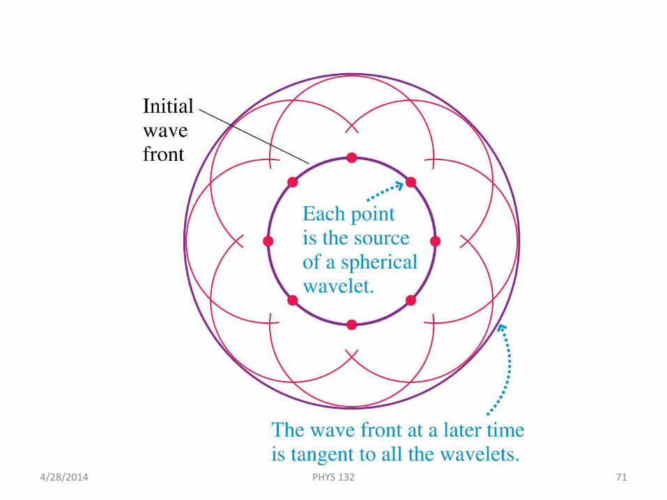
Huygens’ Principle: Spherical Waves
4/28/2014 PHYS 132 71
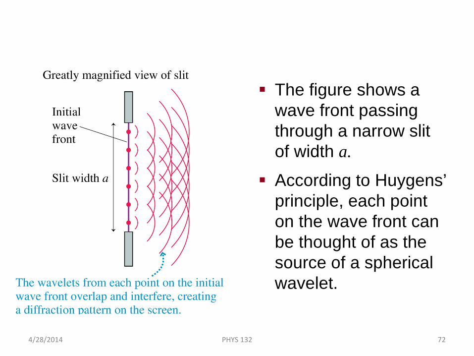
Analyzing Single-Slit Diffraction
The figure shows a wave front passing through a narrow slit of width a.
According to Huygens’ principle, each point on the wave front can be thought of as the source of a spherical wavelet.
4/28/2014 PHYS 132 72
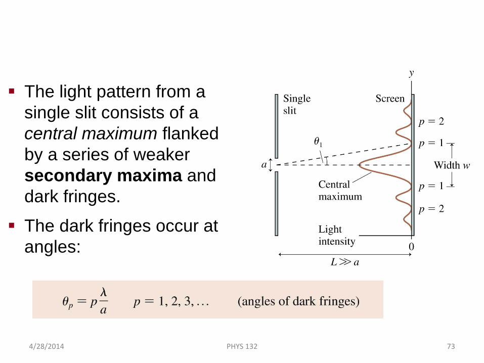
Single-Slit Diffraction
The light pattern from a single slit consists of a central maximum flanked by a series of weaker secondary maxima and dark fringes.
The dark fringes occur at angles:
4/28/2014 PHYS 132 73
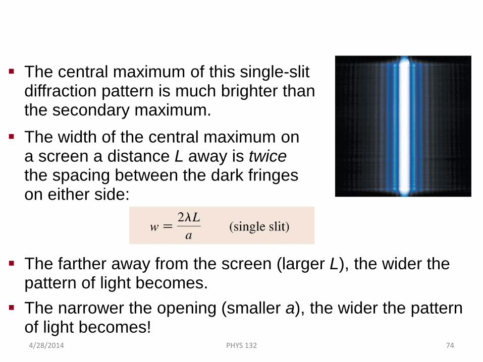
The Width of a Single-Slit Diffraction Pattern
The central maximum of this single-slit diffraction pattern is much brighter than the secondary maximum.
The width of the central maximum on a screen a distance L away is twice the spacing between the dark fringes on either side:
The farther away from the screen (larger L), the wider the pattern of light becomes.
The narrower the opening (smaller a), the wider the pattern of light becomes!
4/28/2014 PHYS 132 74
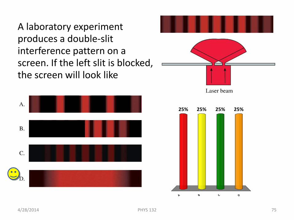
A laboratory experiment produces a double-slit interference pattern on a screen. If the left slit is blocked, the screen will look like
4/28/2014 75PHYS 132
A B C D
25% 25%25%25%