Embed Size (px)
Citation preview
XIV. STANDARD WATER SPECIFICATIONS AND DETAILS DESCRIPTION: All materials, equipment, and labor for water main construction shall be furnished in accordance with these specifications and in accordance with the Plans prepared by a Registered Professional Engineer licensed to practice in the state of North Carolina. MATERIAL SPECIFICATIONS Unless superseded or modified in the Detailed Specifications, all materials, apparatus, supplies, methods of manufacture, or construction shall conform to the specifications contained in this Section. National material standards (ASTM, ANSI, AWWA, etc.) referred to herein shall be considered to be the latest revisions only. A. PIPE 1. Ductile Iron Pipe: Ductile iron pipe shall conform to the requirements of AWWA
Standard C-151 and shall have a cement-mortar lining of standard thickness in accordance with AWWA C-104. Unless otherwise shown on the construction plans, all ductile iron pipe shall be furnished with push on joints in accordance with AWWA C-111.
Sixteen (16) inch and larger diameter pipe shall be minimum Pressure Class 250.
Also, the pipe class selection for 16-inch and larger pipe shall be based on the installation conditions. This pipe class shall be as shown on the plans and/or elsewhere in these specifications.
Twelve-inch (12") and smaller diameter pipe shall be Pressure Class 350. a. Mechanical Joint Accessories: Bolts and gaskets for mechanical joint pipe and
fittings shall be furnished by the pipe/fitting manufacturer and shall conform to ANSI Specifications A21.11 (AWWA C-111).
b. Push-On Joint Material: Gaskets for push-on pipe shall be furnished by the
pipe manufacturer. Gaskets and gasket lubricant shall meet the requirements of ANSI Specification A21.11 (AWWA C-111).
c. Flange Joints And Accessories: Flange joints shall be in accordance with ANSI
A21.10 of either Class 125 or Class 250, as required. Flanges, flange bolts and nuts, and gaskets shall conform to the dimensional requirements of ANSI B16.1 for Class 125 or ANSI B16.2 for Class 250. Bolts shall have standard Hexagonal heads and shall be provided with standard hexagonal cold pressed nuts unless otherwise specified. Bolts and nuts shall be made of the best quality refined iron or mill steel and shall have sound, well fitting threads.
d. Restrained Joint Pipe: Flexible restrained joints shall be supplied by the pipe
manufacturer. Gaskets with vulcanized internal stainless steel locking segments may be used for 6-inch through 12-inch Ductile Iron Pipe. The following manufacturers are approved, U. S. Pipe and Field Lok Gasket. Only
July 27, 1995 Water Specifications/Details (MS) XIV - 1
designs using a welded retainer ring on the spigot will be allowed for 16-inch and larger diameter pipe. Push-on or mechanical joint designs may be used for the pipe and associated fittings. The following manufacturer's products are approved, American Lok Ring, American Lok Fast, Griffin Snap Lok, Griffin Bolt Lok, and U.S. Pipe TR Flex.
2. Polyvinyl Chloride (PVC) Pipe: Unless amended on the Construction Drawings or
elsewhere in these specifications, all six, eight and twelve-inch water main pipe may be PVC 1120, in accordance with AWWA C-900. All 1-1/2" and 2" water main pipe shall be PVC 1120 in accordance with ASTM D-2241. The pipe shall be minimum Pressure Class 200 with a SDR of 14 or less for C-900 pipe and a SDR of 21 or less for ASTM 2241 pipe. PVC Pressure Pipe shall be made from white or blue pigmented virgin materials and shall be furnished in lengths of 20 feet. Lesser lengths will be accepted to allow the proper placement of fittings, valves, etc. All PVC Water Pipe will be shipped, stored, and strung at the project in such a manner as to be protected from total accumulated exposure to sunlight and possible ultraviolet radiation of no more than four (4) weeks.
a. Push on Joint: Pipe jointing will be by elastomeric joints only. Joints shall
conform to ASTM D-3139 for two inch pipe and to AWWA C-900 for six, eight and twelve inch pipe.
Pipe bells, with gasket seats, shall be formed as the pipe is extruded. Sleeve
couplings are not permitted except as specified in the DS Section for connections to existing mains or as necessary for repairs during pressure/leakage tests.
3. Reinforced Concrete Cylinder Pipe: All reinforced concrete water pipe furnished shall
be either prestressed concrete cylinder type with rubber and steel joint, or prestressed concrete embedded cylinder type with rubber and steel joints all in compliance with AWWA C-301. The pipe shall be designed and furnished to fit the profile and head conditions shown on the Plans and hydrostatic tests herein specified, plus the standard allowance for water hammer. All connections for main line valves will be mechanical joint unless otherwise shown on the construction plans. Connections for side outlets will be flanged or mechanical joint as indicated on the Construction Plans.
4. Galvanized Steel Pipe: All steel pipe specified shall conform to the requirements of
ASTM A-120. The pipe and fittings shall be Schedule 80 (extra strong) galvanized steel, with wall thickness as specified for each size in Table III of ASTM A-120, shall be furnished butt welded, and shall be of the standard length for such materials but not specifically of an exact length. Both ends of the pipe shall be furnished threaded with a coupling on one end. The pipe shall be marked as specified in ASTM A-120. The pipe, couplings, and fittings shall be manufactured in the United States.
5. Copper Tubing: Copper tubing shall be Type K, per ASTM B-88. End connections
may be flared or compression. Copper services shall conform to AWWA C-800.
July 27, 1995 Water Specifications/Details (MS) XIV - 2
6. Polyethylene Tubing: Polyethylene water service tubing shall be manufactured in
accordance with ASTM D-2737, using PE 3408 resin (ASTM D-1248, Type III, Class 5, Grade P34). Polyethylene water service tubing shall be SDR-9, 200 psi pressure rating and shall comply with AWWA C-901 and NSF 14.
B. FITTINGS 1. Cast Fittings: Cast fittings furnished for ductile iron or PVC pipe may be pressure
Class 250, cast from ductile iron or gray iron, in accordance with AWWA C-110 or pressure Class 350 compact fittings, cast from ductile iron, in accordance with AWWA C-153. Fittings shall be furnished with mechanical or flanged joints as indicated on the construction plans. All mechanical joint fittings will be Bell and Bell unless otherwise indicated on the plans. All cast fittings shall have a cement mortar lining of standard thickness in accordance with AWWA C-104. All fittings, including glands and bolts, shall be manufactured in domestic foundries.
2. Restrained Mechanical Joint Fittings: Mechanical joint restraints may be through the use of a follower gland with restraining
device that imparts a wedging action against the pipe. The restraining device shall have twist off nuts to ensure proper contact with the pipe. Glands and restraining devices shall be manufactured of Ductile Iron. The restraining devices shall be heat treated to a hardness of 370BHN. Gland dimensions shall be compatible with the MJ fittings hereinbefore specified. The restrained joint shall be rated for a minimum 250 PSI working pressure with a 2:1 safety factor.
Mechanical joint restraints may be through the use of a specially machined ductile iron
ring and follower gland that is used with standard mechanical joint gaskets and T-bolts.
Retainer glands will not be permitted. Restrained mechanical joints will not be allowed
on C-900 PVC pipe. Restrained mechanical joints shall be Megalug as manufactured by Ebaa Iron, Inc.,
GripRing as manufactured by Romac Industries, Inc., or approved equal. Restrained joints may be used where shown on the plan, standard details or as approved by the Engineer.
3. Copper Fittings: Fittings for copper tubing and polyethylene tubing shall be red brass
containing 85% copper, 5% lead, 5% tin, and 5% zinc in conformance with ASTM B-62. Fittings may be flared or compression as applicable, in accordance with AWWA C-800. Compression fittings shall utilize a compression nut and/or split clamp with tightening screw. Stab type fittings are not approved.
4. PVC Fittings: All fittings for six, eight and twelve inch PVC pipe shall be cast iron or
ductile iron as specified below. Fittings for two inch PVC pipe shall be push on joint PVC or threaded malleable iron. Malleable iron fittings shall be furnished with threaded PVC adapters to connect the fittings to the push on joint pipe. Elastomeric joints for PVC adapters and PVC fittings with push on joints shall conform to ASTM D-
July 27, 1995 Water Specifications/Details (MS) XIV - 3
3139. PVC adapters and fittings shall have a minimum pressure rating of 200 PSI and shall, except for threaded areas on adapters, have a SDR of 13.5.
C. FIRE HYDRANTS Fire hydrants shall conform to AWWA C-502, and shall be constructed for 3'-0" minimum
depth of trench. All fire hydrants shall be constructed with a bronze main valve seat which screws into a threaded bronze connection at the base of the hydrant. All fire hydrants shall be equipped with two 2�-inch hose nozzles with National Standard Threads, and one 4" (minimum opening) pumper nozzle with Charlotte Fire Department Standard Threads. Charlotte Fire Department Standard
Threads are essentially: 1. 6 Threads Per Inch 2. O.D.: 4.875" 3. Pitch Diameter.: 4.777" 4. Root: 4.653" 5. Gauge: 2C All hydrants shall open by turning to the right or clockwise, shall have a minimum valve
opening size of 4�" and shall be furnished with a 6" mechanical joint inlet. The operating nut shall be 1�" pentagon. Any extensions required shall be as recommended and supplied by the hydrant manufacturer.
All fire hydrants and any portions of the hydrant assembly exposed to view (above adjacent
ground elevation) shall be painted with two (2) or more evenly applied coats of yellow hydrant enamel paint. Hydrants will be retouched/repainted as necessary after installation and prior to acceptance.
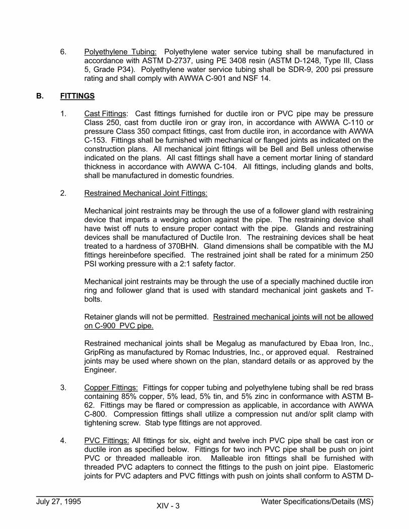
1. All fire hydrants shall be one of the following models:
MANUFACTURER MODEL
Mueller Company Super Centurion 200 No. 421
Kennedy Valve Manufacturing Company Guardian No. K81-A
American Darling Company Mark 73-1
Waterous Company Trend WB-77
2. Fire hydrant tees will be Griffin Swivel Hydrant tee, Tyler 5-125 swivel hydrant tee or
approved equal. Swivel 90� bends will be Tyler 5-197 or approved equal. 3. Piping extensions for hydrant installations may be made with 6-inch ductile iron
nipples with Tyler long swivel hydrant adapters, Megalug MJ Restraint, U. S. Pipe Field Lok Gaskets, Romac GripRing, or other approved method.
July 27, 1995 Water Specifications/Details (MS) XIV - 4
D. VALVES 1. Gate valves on water mains smaller than 16-inch in diameter shall be direct bury gate
valves and shall be furnished with Charlotte Standard Valve boxes set in concrete pads as specified. Gate valves shall be furnished with non rising stems only, and stem seals shall be of the "0" ring type only. Valves six (6") inches and larger shall be furnished with two inch square operating nuts and shall open by turning to the right or clockwise. Gate valves three (3") inches and smaller shall be furnished with T-Head operating nuts. Valve ends shall normally be mechanical joint with necessary glands, gaskets and bolts furnished with the valve. Flange ends shall be furnished for special installations as shown on the construction plans. Flange by mechanical joint ends shall be furnished for tapping sleeve & valve installations.
Gate valves may be of the double disc parallel seat type in accordance with AWWA C-
500 or of the resilient seat type in accordance with AWWA C-509 with a working pressure of 200 PSI. Resilient seated gate valves must be furnished with durable opaque end shields to prevent ultra violet damage to the rubber discs.
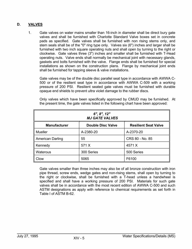
Only valves which have been specifically approved by CMUD may be furnished. At
the present time, the gate valves listed in the following chart have been approved:
6", 8", 12" MJ GATE VALVES
Manufacturer Double Disc Valve Resilient Seat Valve
Mueller A-2380-20 A-2370-20
American Darling 55 CRS 80 - No. 85
Kennedy 571 X 4571 X
Waterous 300 Series 500 Series
Clow 5065 F6100 Gate valves smaller than three inches may also be of all bronze construction with iron
pipe thread, screw ends, wedge gates and non-rising stems, shall open by turning to the right or clockwise, shall be furnished with a T-head unless a handwheel is specified and shall have a working pressure of 200 PSI. Materials for such gate valves shall be in accordance with the most recent edition of AWWA C-500 and such ASTM designations as apply with reference to chemical requirements as set forth in Table I of ASTM B-62.
July 27, 1995 Water Specifications/Details (MS) XIV - 5
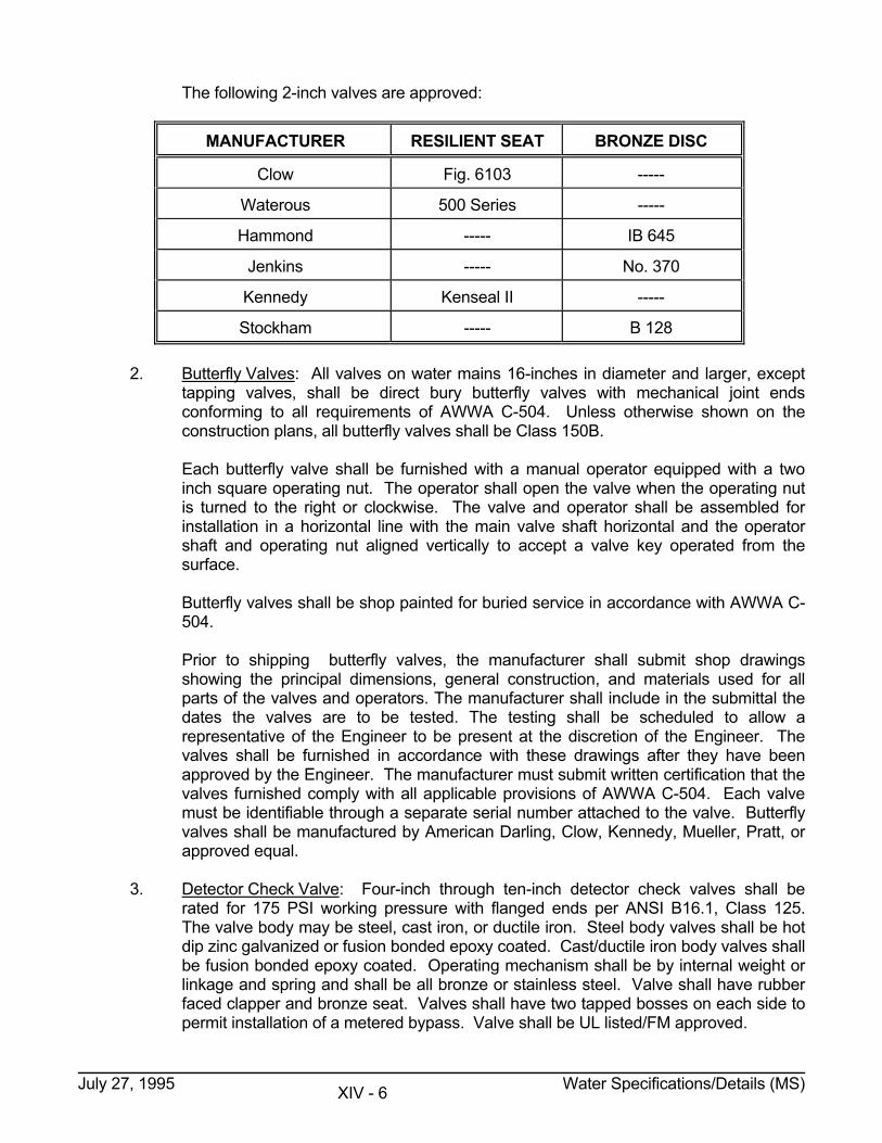
The following 2-inch valves are approved:
MANUFACTURER RESILIENT SEAT BRONZE DISC
Clow Fig. 6103 -----
Waterous 500 Series -----
Hammond ----- IB 645
Jenkins ----- No. 370
Kennedy Kenseal II -----
Stockham ----- B 128 2. Butterfly Valves: All valves on water mains 16-inches in diameter and larger, except
tapping valves, shall be direct bury butterfly valves with mechanical joint ends conforming to all requirements of AWWA C-504. Unless otherwise shown on the construction plans, all butterfly valves shall be Class 150B.
Each butterfly valve shall be furnished with a manual operator equipped with a two
inch square operating nut. The operator shall open the valve when the operating nut is turned to the right or clockwise. The valve and operator shall be assembled for installation in a horizontal line with the main valve shaft horizontal and the operator shaft and operating nut aligned vertically to accept a valve key operated from the surface.
Butterfly valves shall be shop painted for buried service in accordance with AWWA C-
504. Prior to shipping butterfly valves, the manufacturer shall submit shop drawings
showing the principal dimensions, general construction, and materials used for all parts of the valves and operators. The manufacturer shall include in the submittal the dates the valves are to be tested. The testing shall be scheduled to allow a representative of the Engineer to be present at the discretion of the Engineer. The valves shall be furnished in accordance with these drawings after they have been approved by the Engineer. The manufacturer must submit written certification that the valves furnished comply with all applicable provisions of AWWA C-504. Each valve must be identifiable through a separate serial number attached to the valve. Butterfly valves shall be manufactured by American Darling, Clow, Kennedy, Mueller, Pratt, or approved equal.
3. Detector Check Valve: Four-inch through ten-inch detector check valves shall be
rated for 175 PSI working pressure with flanged ends per ANSI B16.1, Class 125. The valve body may be steel, cast iron, or ductile iron. Steel body valves shall be hot dip zinc galvanized or fusion bonded epoxy coated. Cast/ductile iron body valves shall be fusion bonded epoxy coated. Operating mechanism shall be by internal weight or linkage and spring and shall be all bronze or stainless steel. Valve shall have rubber faced clapper and bronze seat. Valves shall have two tapped bosses on each side to permit installation of a metered bypass. Valve shall be UL listed/FM approved.
July 27, 1995 Water Specifications/Details (MS) XIV - 6
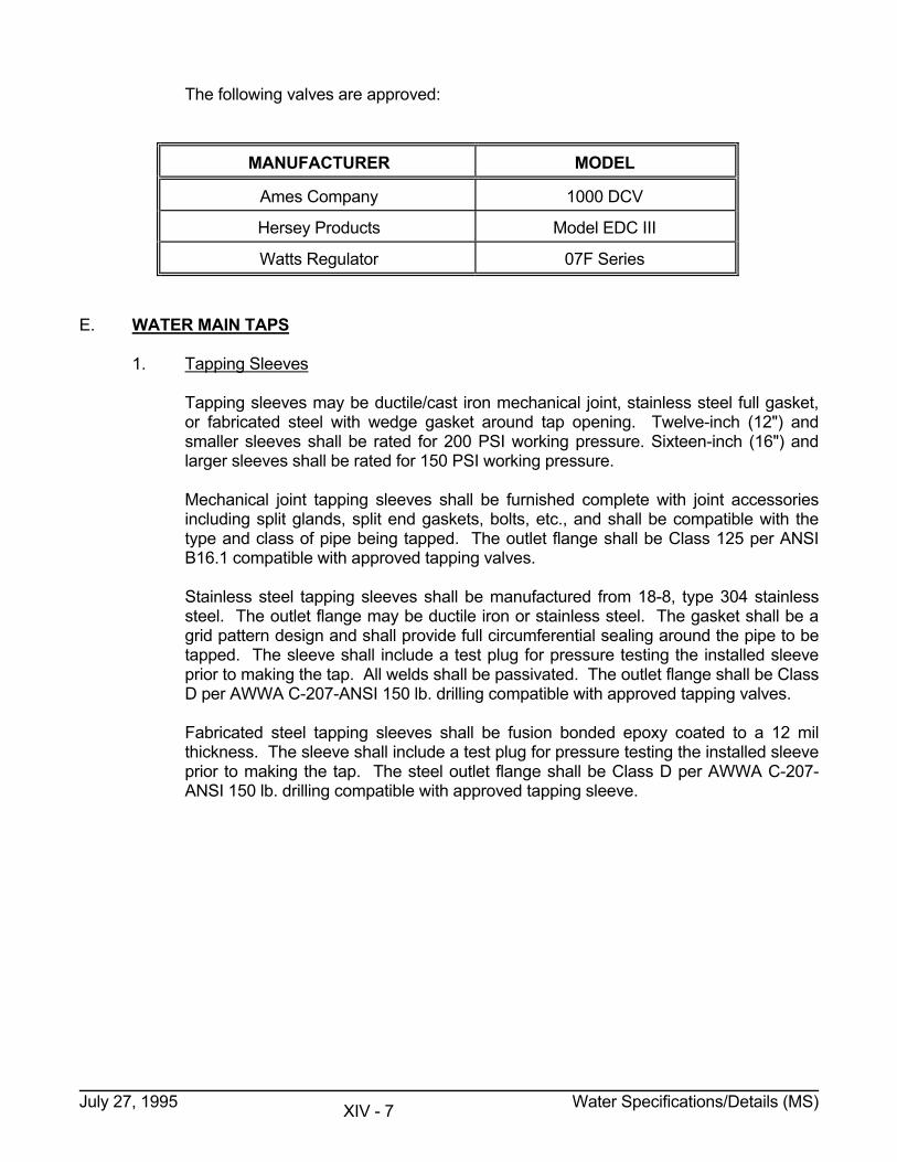
The following valves are approved:
MANUFACTURER MODEL
Ames Company 1000 DCV
Hersey Products Model EDC III
Watts Regulator 07F Series E. WATER MAIN TAPS 1. Tapping Sleeves Tapping sleeves may be ductile/cast iron mechanical joint, stainless steel full gasket,
or fabricated steel with wedge gasket around tap opening. Twelve-inch (12") and smaller sleeves shall be rated for 200 PSI working pressure. Sixteen-inch (16") and larger sleeves shall be rated for 150 PSI working pressure.
Mechanical joint tapping sleeves shall be furnished complete with joint accessories
including split glands, split end gaskets, bolts, etc., and shall be compatible with the type and class of pipe being tapped. The outlet flange shall be Class 125 per ANSI B16.1 compatible with approved tapping valves.
Stainless steel tapping sleeves shall be manufactured from 18-8, type 304 stainless
steel. The outlet flange may be ductile iron or stainless steel. The gasket shall be a grid pattern design and shall provide full circumferential sealing around the pipe to be tapped. The sleeve shall include a test plug for pressure testing the installed sleeve prior to making the tap. All welds shall be passivated. The outlet flange shall be Class D per AWWA C-207-ANSI 150 lb. drilling compatible with approved tapping valves.
Fabricated steel tapping sleeves shall be fusion bonded epoxy coated to a 12 mil
thickness. The sleeve shall include a test plug for pressure testing the installed sleeve prior to making the tap. The steel outlet flange shall be Class D per AWWA C-207-ANSI 150 lb. drilling compatible with approved tapping sleeve.
July 27, 1995 Water Specifications/Details (MS) XIV - 7
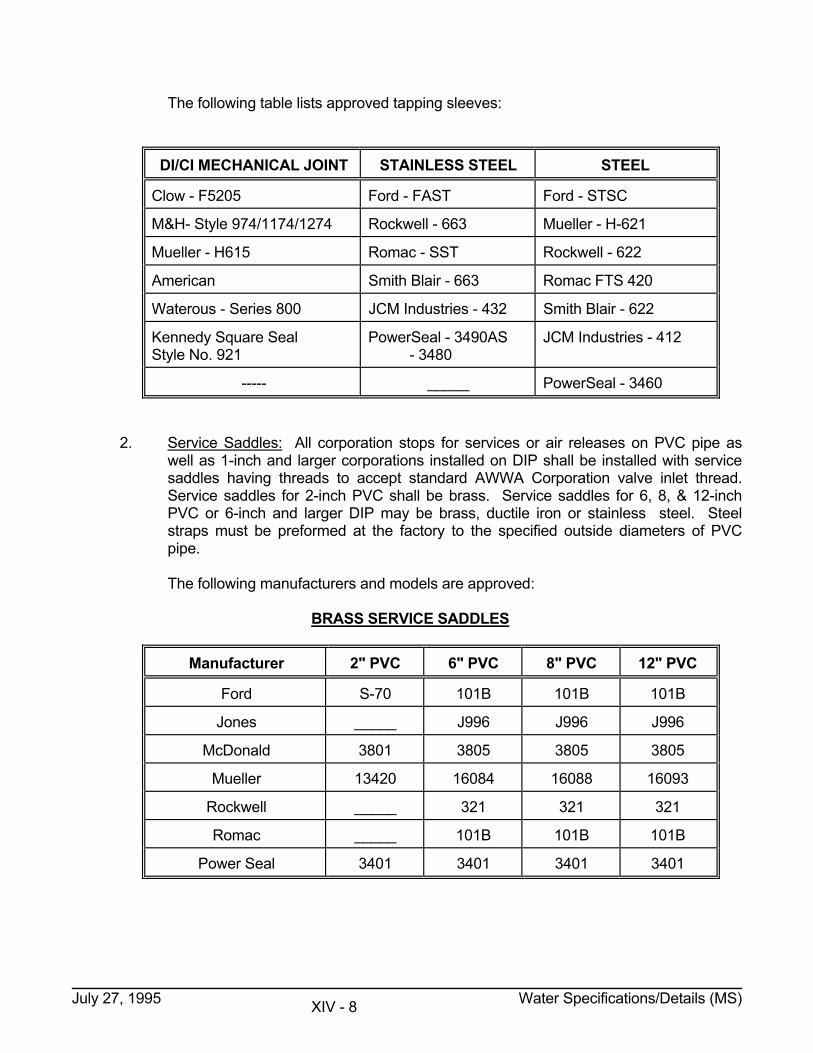
The following table lists approved tapping sleeves:
DI/CI MECHANICAL JOINT STAINLESS STEEL STEEL
Clow - F5205 Ford - FAST Ford - STSC
M&H- Style 974/1174/1274 Rockwell - 663 Mueller - H-621
Mueller - H615 Romac - SST Rockwell - 622
American Smith Blair - 663 Romac FTS 420
Waterous - Series 800 JCM Industries - 432 Smith Blair - 622
Kennedy Square Seal Style No. 921
PowerSeal - 3490AS - 3480
JCM Industries - 412
----- _____ PowerSeal - 3460
2. Service Saddles: All corporation stops for services or air releases on PVC pipe as
well as 1-inch and larger corporations installed on DIP shall be installed with service saddles having threads to accept standard AWWA Corporation valve inlet thread. Service saddles for 2-inch PVC shall be brass. Service saddles for 6, 8, & 12-inch PVC or 6-inch and larger DIP may be brass, ductile iron or stainless steel. Steel straps must be preformed at the factory to the specified outside diameters of PVC pipe.
The following manufacturers and models are approved: BRASS SERVICE SADDLES
Manufacturer 2" PVC 6" PVC 8" PVC 12" PVC
Ford S-70 101B 101B 101B
Jones _____ J996 J996 J996
McDonald 3801 3805 3805 3805
Mueller 13420 16084 16088 16093
Rockwell _____ 321 321 321
Romac _____ 101B 101B 101B
Power Seal 3401 3401 3401 3401
July 27, 1995 Water Specifications/Details (MS) XIV - 8
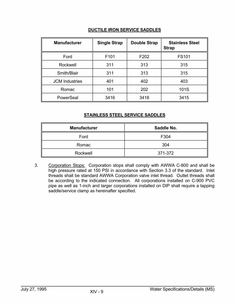
DUCTILE IRON SERVICE SADDLES
Manufacturer Single Strap Double Strap Stainless Steel Strap
Ford F101 F202 FS101
Rockwell 311 313 315
Smith/Blair 311 313 315
JCM Industries 401 402 403
Romac 101 202 101S
PowerSeal 3416 3418 3415 STAINLESS STEEL SERVICE SADDLES
Manufacturer Saddle No.
Ford F304
Romac 304
Rockwell 371-372 3. Corporation Stops: Corporation stops shall comply with AWWA C-800 and shall be
high pressure rated at 150 PSI in accordance with Section 3.3 of the standard. Inlet threads shall be standard AWWA Corporation valve inlet thread. Outlet threads shall be according to the indicated connection. All corporations installed on C-900 PVC pipe as well as 1-inch and larger corporations installed on DIP shall require a tapping saddle/service clamp as hereinafter specified.
July 27, 1995 Water Specifications/Details (MS) XIV - 9
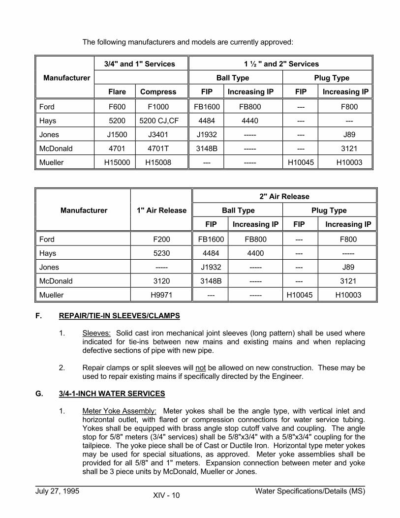
The following manufacturers and models are currently approved:
3/4" and 1" Services 1 ½ " and 2" Services
Manufacturer Ball Type Plug Type
Flare Compress FIP Increasing IP FIP Increasing IP
Ford F600 F1000 FB1600 FB800 --- F800
Hays 5200 5200 CJ,CF 4484 4440 --- ---
Jones J1500 J3401 J1932 ----- --- J89
McDonald 4701 4701T 3148B ----- --- 3121
Mueller H15000 H15008 --- ----- H10045 H10003
2" Air Release
Manufacturer 1" Air Release Ball Type Plug Type
FIP Increasing IP FIP Increasing IP
Ford F200 FB1600 FB800 --- F800
Hays 5230 4484 4400 --- -----
Jones ----- J1932 ----- --- J89
McDonald 3120 3148B ----- --- 3121
Mueller H9971 --- ----- H10045 H10003 F. REPAIR/TIE-IN SLEEVES/CLAMPS 1. Sleeves: Solid cast iron mechanical joint sleeves (long pattern) shall be used where
indicated for tie-ins between new mains and existing mains and when replacing defective sections of pipe with new pipe.
2. Repair clamps or split sleeves will not be allowed on new construction. These may be
used to repair existing mains if specifically directed by the Engineer. G. 3/4-1-INCH WATER SERVICES 1. Meter Yoke Assembly: Meter yokes shall be the angle type, with vertical inlet and
horizontal outlet, with flared or compression connections for water service tubing. Yokes shall be equipped with brass angle stop cutoff valve and coupling. The angle stop for 5/8" meters (3/4" services) shall be 5/8"x3/4" with a 5/8"x3/4" coupling for the tailpiece. The yoke piece shall be of Cast or Ductile Iron. Horizontal type meter yokes may be used for special situations, as approved. Meter yoke assemblies shall be provided for all 5/8" and 1" meters. Expansion connection between meter and yoke shall be 3 piece units by McDonald, Mueller or Jones.
July 27, 1995 Water Specifications/Details (MS) XIV - 10
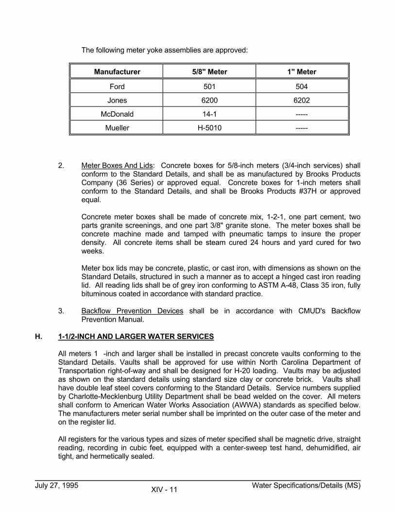
The following meter yoke assemblies are approved:
Manufacturer 5/8" Meter 1" Meter
Ford 501 504
Jones 6200 6202
McDonald 14-1 -----
Mueller H-5010 -----
2. Meter Boxes And Lids: Concrete boxes for 5/8-inch meters (3/4-inch services) shall
conform to the Standard Details, and shall be as manufactured by Brooks Products Company (36 Series) or approved equal. Concrete boxes for 1-inch meters shall conform to the Standard Details, and shall be Brooks Products #37H or approved equal.
Concrete meter boxes shall be made of concrete mix, 1-2-1, one part cement, two
parts granite screenings, and one part 3/8" granite stone. The meter boxes shall be concrete machine made and tamped with pneumatic tamps to insure the proper density. All concrete items shall be steam cured 24 hours and yard cured for two weeks.
Meter box lids may be concrete, plastic, or cast iron, with dimensions as shown on the
Standard Details, structured in such a manner as to accept a hinged cast iron reading lid. All reading lids shall be of grey iron conforming to ASTM A-48, Class 35 iron, fully bituminous coated in accordance with standard practice.
3. Backflow Prevention Devices shall be in accordance with CMUD's Backflow
Prevention Manual. H. 1-1/2-INCH AND LARGER WATER SERVICES All meters 1�-inch and larger shall be installed in precast concrete vaults conforming to the
Standard Details. Vaults shall be approved for use within North Carolina Department of Transportation right-of-way and shall be designed for H-20 loading. Vaults may be adjusted as shown on the standard details using standard size clay or concrete brick. Vaults shall have double leaf steel covers conforming to the Standard Details. Service numbers supplied by Charlotte-Mecklenburg Utility Department shall be bead welded on the cover. All meters shall conform to American Water Works Association (AWWA) standards as specified below. The manufacturers meter serial number shall be imprinted on the outer case of the meter and on the register lid.
All registers for the various types and sizes of meter specified shall be magnetic drive, straight
reading, recording in cubic feet, equipped with a center-sweep test hand, dehumidified, air tight, and hermetically sealed.
July 27, 1995 Water Specifications/Details (MS) XIV - 11
All meters where the register is separate or removable from the main case, and held in place by screws must have the head of each screw drilled two ways, and sealed with a copper wire and lead seal before delivery. The security of such registers must be guaranteed non-removable except by destruction of seal wire, or seal.
The manufacturer must furnish with each meter a certificate of accuracy which references the
particular meter serial number. The certificate of accuracy must be furnished to the Engineer before the meter is activated. The certificate must reference the job name or number. The number can be added by the supplier or contractor.
The manufacturer shall guarantee that all meters furnished under this specification will meet
the required new meter accuracy standards in accordance with AWWA standards. 1. Displacement Meters - Sizes 1�" and 2": a. Meters in these sizes shall be positive displacement type conforming to AWWA
C-700. b. All 1�" and 2" meters shall be furnished with spuds and brass end
connections. c. Meters may be furnished with either nutating or oscillating type of piston or
disc. d. Main casings and bottom plate shall be of a copper alloy containing not less
then 75% copper. e. Measuring chambers for 1�" and 2" meters shall be of a copper alloy
containing not less than 85% copper. f. All meters are to have strainers. g. Registers shall be permanently hermetically sealed and shall have standard
trial gear combinations. The manufacturer shall furnish the City with a certificate which unconditionally guarantees the registers for a minimum period of 25 years against defects in material or workmanship.
h. In the interest of standardization, only the following makes and models will be
acceptable: Rockwell Model SR Neptune Model 8 Hersey Model 562-1�", 572-2" Badger Recordall Bronze 25 i. Check valves shall be located as shown on the Standard Details. Check
valves shall be Grinnell #3310 or approved equal.
July 27, 1995 Water Specifications/Details (MS) XIV - 12
2. Turbine Meters - Sizes 1�" 2", 3", 4": a. These meters shall conform to AWWA C-701. b. Main casings shall be of a copper alloy containing not less than 75% copper. c. Measuring cages or chambers shall be made of a copper alloy containing not
less than 85% copper or of a suitable synthetic polymer. d. Meters are to have strainers. e. All 1�" and 2" meters shall be furnished with spuds and brass end
connections. Laying length shall be same as standards for displacement meter.
f. Meters size 1�" and 2" shall meet the performance specifications of AWWA C-
700 for displacement meters. g. Meters 3" and 4" shall test 100% + 1.5% at the following flow in GPM and size: 3" - 5 to 350 4" - 5 to 650 h. The following turbine meters are presently approved as meeting the above
performance specifications: 1�" Hersey MVR100 2" Hersey MVR160 3" Hersey MVR350 4" Hersey MVR650 Other makes and models may be added to this approved list when they are
certified as meeting the above performance standard and when appropriate test data are submitted.
i. Checks valves shall be located as shown on the Standard Details. 1�" and 2"
check valves shall be Grinnell #3310 or approved equal. 3" and 4" check valves shall be Mueller A-2600-6, Kennedy 106, or approved equal. The blank flange on the 3" and 4" check valve shall be replaced with a flange tapped 2-inch as shown on the Standard Details.
3. Combined Fire And Domestic Service Meters - Sizes 6", 8", 10", and 12": a. Meters shall comply with AWWA C-703. b. Meters must be approved for use for fireline service by Underwriters
Laboratories or National Fire Protection Association. c. Companion flanges, gaskets, bolts and nuts shall not be provided. d. Meters must have stop and check valves on bypass meter.
July 27, 1995 Water Specifications/Details (MS) XIV - 13
e. Measuring cages or chambers shall be made of a copper alloy containing not
less than 85% copper. f. Main casing for bypass meters shall be of a copper alloy containing not less
than 75% copper. g. Casing for main line meters shall be of copper alloy containing not less than
75% copper or galvanized zinc treated cast iron. h. Only Hersey Model MFM #2 - MVR as manufactured by Hersey Products, Inc.,
or approved equal combined Fire and Domestic service type meter will be accepted.
4. Backflow Prevention devices shall be in accordance with CMUD's Backflow
Prevention Manual. I. FERROUS CASTINGS 1. Valve Boxes: All valve boxes shall conform to the dimensions shown on the Standard
Details. Valve boxes shall be of cast iron conforming to ASTM A-48, Class 30 and shall be manufactured in domestic foundries.
2. Manhole Frames and Covers: All manhole frames and covers shall conform to the
dimensions shown on the Standard Details. Manhole frames and covers shall be of cast iron conforming to ASTM-A-48, Class 30 and shall be manufactured in domestic foundries.
J. MISCELLANEOUS STEEL 1. Steel Encasement Pipe: Steel pipe shall be welded or seamless, consisting of Grade
"B" steel as specified in ASTM A-139. Minimum yield strength shall be 35,000 PSI; and pipe thickness shall be as specified
for each individual job. All pipe shall be furnished with beveled ends prepared for field welding of
circumferential joints. All burrs at pipe ends shall be removed. Encasement pipe must be approved by the appropriate controlling agency (D.O.T.,
R.R., etc.) and the Engineer prior to ordering. 2. Structural Steel Tunnel Liner Plates: The tunnel liner plates shall be either the four (4)
flange type (as approved for use within D.O.T. right-of-way) or the lap seam type (as approved for use within railroad right-of-way) fabricated to permit assembly of a continuous steel support system as the tunnel is excavated. Tunnel liner plates shall be fabricated from hot rolled, carbon steel sheets or plates conforming to the specifications of ASTM A-569.
July 27, 1995 Water Specifications/Details (MS) XIV - 14
The tunnel liner shall be designed in accordance with the requirements of Section 16-Division I and constructed to conform to Section 25-Division II or the current or interim AASHTO Standard Specifications For Highway Bridges.
Liner plates shall be galvanized in accordance with AASHTO M167 and fully
bituminously coated in accordance with AASHTO M190. All hardware necessary to the tunneling operation shall be hot-dip galvanized in accordance with ASTM A-153 prior to bituminous coating application. Hardware shall conform to ASTM Specification A-307, Grade A.
The minimum mechanical properties of the flat steel plate before cold forming used for
the design of the tunnel liner shall be: A. Minimum Tensile Strength of Liner Plates: 42,000 P.S.I. B. Minimum Yield Strength of Liner Plates: 28,000 P.S.I. C. Steel Liner Plates must be approved by the appropriate controlling agency
(DOT, Railroad, etc.) and the Engineer prior to ordering. Gauge or thickness of liner plates will be as noted on the plans or elsewhere in these specifications.
D. Elongation in 2-inches: 30 percent E. The moment of inertia shall be .042 inches to the 4th power per inch of width
for four flange 12 gage liner plate. 3. Steel Reinforcing For Concrete: a. Bars: All reinforcement bars shall conform to the Standard Specifications for
BILLET-STEEL BARS FOR CONCRETE, REINFORCEMENT, ASTM A-615. All bars shall be deformed and of structural Grade 60.
b. Wire: All reinforcement wire fabric shall conform to the Standard Specifications
for WELDED STEEL WIRE FABRIC FOR CONCRETE REINFORCEMENT, ASTM A-185.
K. CONCRETE 1. Portland Cement: All concrete shall conform to the Standard Specifications for
READY MIXED CONCRETE, ASTM C-94. An air-entraining admixture, conforming to ASTM C-260, shall be added to either Type I, Type II, or Type III Portland Cement.
Fly Ash conforming to ASTM C-618 for Class C Fly Ash may be added to the concrete
mix but shall not be considered as replacement for more than 10% of the cement therein (strengths shall not be less than hereinafter required).
Types I, IA, III and IIIA Portland Cement shall only be used for manhole inverts,
concrete encasement, concrete blocking, and/or as directed by the Engineer, and shall conform to ASTM C-150.
July 27, 1995 Water Specifications/Details (MS) XIV - 15
Types II and IIA Portland Cement shall be used in precast manholes, reinforced concrete pipe, reinforced concrete piers and concrete or reinforced concrete rip-rap as directed by the Engineer, and shall conform to ASTM C-150 except that Tricalcium Aluminate (3CaOAl2O3) content shall not exceed 8%.
2. Aggregates: All aggregates used for concreting shall conform to ASTM C-33 and shall
be checked daily for any variances in moisture content. Said variances shall be corrected and/or taken into consideration for each batch.
a. Coarse Aggregates: Shall be uniformly and evenly graded for each application
in accordance with A.C.I. Standard 318. Unless otherwise approved, aggregate shall be sound, crushed, angular granitic stone. Smooth or rounded stone (river rock) shall not be acceptable.
b. Fine Aggregates: Shall consist of natural sand, manufactured sand or a
combination thereof. Fine aggregates shall conform to the sieve analysis as specified in paragraph 4.1 of the standard except that the percent passing a No. 50 sieve shall not exceed 5% and the percent passing a No. 100 sieve shall be 0% as provided for in paragraph 4.2 of the standard.
3. Mix Design: Concrete shall be watertight, resistant to freeze-thaw cycles and
moderate sulfate attack, abrasion resistant, workable, and/or finishable. These qualities may be met through the use of admixtures (if and only if approved in the mix design as hereinafter specified) conforming to the appropriate ASTM with the exception of the use of calcium chloride, which shall be limited to no more than 1% by cement weight - thoroughly mixed to insure uniform distribution within the mix. If the concrete is used with reinforcing steel, no calcium chloride will be allowed.
The Contractor shall assume responsibility for concrete mixture. The concrete shall
be proportioned to meet the following requirements: (Note: This mix does not apply "in total" to precast manhole or reinforced concrete pipe).
A. Compressive Strength Minimum 3600 PSI B. Water-Cement Ratio By Weight Maximum-0.50 C. Slump Min. 3" Max. 5" D. Air Content (Entrained & Entrapped) Min. 4% Max. 6% E. Coarse Aggregate 3/4"-1/2 (as required by the application) When required by the Engineer, and prior to beginning construction, the Contractor, at
his expense, shall obtain from an approved commercial testing laboratory a design for a suitable concrete mix and submit same with his list of materials and material suppliers for approval.
4. Curing Compound: All concrete curing compounds shall conform to the standard
specifications for LIQUID MEMBRANE - FORMING COMPOUNDS FOR CURING CONCRETE, ASTM C-309, Type 2.
July 27, 1995 Water Specifications/Details (MS) XIV - 16
Curing compounds shall be applied as forms are stripped. 5. Grouts: All grouts shall be of a non-shrink nature (as may be achieved through
additives or proportioning) and depending upon application range from plastic to flowable cement water paste. Testing as specified above for concrete may be required for acceptance of grouts to include frequent checks for consistency by a time-of-flow measurement.
Expansion grouts shall be either Gilco pre-mixed or Supreme non-metallic grout as
manufactured by Gifford-Hill and Company, Incorporated, or Embeco 636 grout as manufactured by Master Builders or equal.
Acceptable range of testing requirements: Compressive Strength...... .........10,500 to 12,500 PSI Bond Strength ........ ......... ......... ......... 1,350 to 1,700 PSI % Expansion. ......... ......... .........+.025% to +0.75% Expansion grouts shall be used only as directed by the Engineer. Grouts shall be mixed (if applicable) and placed in accordance with the manufacturer's
current recommendations, for each specific application. 6. Mortar: Mortar used in sanitary sewer manholes shall be hydraulic cement mortar in
accordance with ASTM C-398. Mortar used in water meter vaults and water valve vaults shall be Type M mortar in accordance with ASTM C-270.
L. STONE AND BRICK 1. Granular Bedding Material: All bedding material shall be angular, clean washed
crushed stone graded in accordance with Size #67 in ASTM D-448 for "Standard Sizes of Coarse Aggregate" (NCDOT Standard Size #67).
Bedding material will be used only as instructed in the Specifications and/or as
specifically directed by the Engineer. 2. Stone Stabilization Material: All stone stabilization material shall be angular, clean
washed crushed stone graded in accordance with standard sizes #467 in ASTM D-448 (NCDOT Standard Size #467M).
Stabilization material will be used only as instructed in the specifications and/or as
specifically directed by the Engineer. 3. Silt Check Dam Material: Shall be coarse angular, clean washed crushed stone,
gravel, or rock, well graded, and ranging in size from 2-inch through 6-inch, (NCDOT stone for erosion control Class A).
July 27, 1995 Water Specifications/Details (MS) XIV - 17
4. Rip Rap: All rip rap shall consist of clean field stone or rough unhewn quarry stone,
resistant to the action of air and water, varying in weight from 25 to 250 pounds with 60% weighing a minimum of 100 pounds each and no more than 5% weighing less than 50 pounds each, (NCDOT Class 2 Rip Rap). Rip Rap will be placed from a minimum of 4.0 feet below the toe of the bank to top of the bank in areas determined by field conditions. Rip rap thickness shall be 1� times the diameter of the largest stones used, or 2.0 feet, whichever is greater.
5. Brick: Brick shall be clay or shale brick meeting the requirements of ASTM C-62 for
Grade SW, except as otherwise provided below. Brick shall be of uniform standard commercial size, with straight and parallel edges
and square corners. They shall be burned hard and entirely true, free from injurious cracks and flaws, tough, strong, and shall have a clear ring when struck together. The sides, ends and faces of all brick shall be plane surfaces at right angles and parallel one to the other.
Concrete brick may be used in lieu of clay or shale brick for adjustment of water meter
vaults and/or water valve vaults. Concrete brick shall meet the requirements of ASTM C-55 for Grade S-II except that the absorption of brick used in minor drainage structures shall not exceed 10 lbs./ft.3
M. TRAFFIC CONTROL DEVICES All traffic control signs, barrels, barricades, pavement markings, etc., shall conform to the
"Manual on Uniform Traffic Control Devices" (MUTCD) published by the U.S.D.O.T. and any supplements to the MUTCD adopted by N.C.D.O.T.
N. EROSION CONTROL 1. Seed: All seed shall be labeled to show that it meets the current requirements of the
North Carolina Seed Law. Seed shall have been tested within the six (6) months immediately preceding its use.
Further specifications for each seed item are given below: a. Kentucky Fescue #31: Minimum 98% pure live seed; maximum 1% weed
seed; minimum 90% germination. b. Sericea Lespedeza (Scarified and Unscarified): Minimum 98% pure live seed;
maximum .50% weed seed; minimum 85% germination. Scarified may include 20% hard seed.
c. Rye Grass (Annual): Minimum 98% pure live seed; maximum .10% weed
seed; minimum 85% germination. d. Sudangrass: Minimum 98% pure live seed; maximum .25% weed seed;
minimum 85% germination.
July 27, 1995 Water Specifications/Details (MS) XIV - 18
e. Certification/Supplier: The contractor shall furnish the State's Landscape Supervisor in Albemarle, North Carolina (for work in Department of Transportation rights-of-ways) and the City's Construction Engineer (for all work) the name of the supplier of seed, the seed type and the total amount (not seed rate) to be used in restoring disturbed groundcover. This information shall be furnished at least four (4) weeks prior to reseeding operations so that quality tests can be made by the appropriate controlling agency.
Seed containing prohibited noxious weed seed shall not be accepted. Seed
shall conform to the state law restrictions for restricted noxious weeds. 2. Fertilizer: All fertilizer for undeveloped areas shall have minimum 5-10-10 analysis or
a comparable 1-2-2 ratio. All fertilizer for established lawn areas shall have a minimum 10-10-10 analysis or a comparable 1-1-1 ratio.
All fertilizer shall be uniform in composition, dry and free flowing and shall be delivered
to the job site in the original unopened containers, each bearing the manufacturer's guaranteed analysis.
Any fertilizer which becomes caked or otherwise damaged will not be accepted. The
quality of all fertilizer and all operations in connection with furnishing same, shall comply with the current requirements of the North Carolina Fertilizer Law and with the current applicable Rules and Regulations adopted by the North Carolina Board of Agriculture.
3. Lime: All lime shall be finely ground limestone (Dolomite) containing not less than
85% total carbonates. Lime shall conform to the specifications of the North Carolina Department of Agriculture for Agricultural Grade.
4. Superphosphate: All superphosphates shall be composed of finely ground phosphate
rock, as commonly used for agricultural purposes, containing not less than 20% available phosphoric acid.
5. Mulch: All mulch shall be small grain or tame hay. Small grain or tame hay shall be
furnished undamaged, air dried, threshed and free of undesirable weed seed. 6. Erosion Control Fabric: Material shall be as specified in the Environmental Protection
Section of these specifications per Erosion Control Standard Detail 16.62. 7. Jute Netting Or Thatching: All jute shall be of a uniform open plain weave of single
jute yarn, 18-inches in width (1"). The yarn shall be of loosely twisted construction and shall not vary in thickness by more than one-half (�) its normal diameter. There shall be 78 warp ends (2), per width of netting; 41 weft ends (1), per linear yard; and the weight shall average 1.22 pounds (5%) per linear yard of netting. Jute shall be anchored into place in accordance with the manufacturer's requirements. Installation shall only be at the direction of the Engineer.
July 27, 1995 Water Specifications/Details (MS) XIV - 19
8. Erosion Control Blanket: Erosion control blankets shall be manufactured from wood
fiber, straw, coconut fiber or other degradable material woven into a mat and secured with photodegradable plastic mesh or biodegradable thread.
Blankets shall be installed according to manufacturers recommendations where
directed by the Engineer. The following manufacturers are approved, AMXCO-Curlex Blanket, North American Green-SC150, HV Excelsior or approved equal.
9. Gabions: Gabions shall be manufactured from zinc coated steel wire mesh (minimum
gauge) to form rectangular units. The front, base, back and lid shall be woven into a single unit and the ends and diaphragms shall be factory connected to the base. The individual units shall be installed per the manufacturers instructions and filled with hard durable, clean stone from 4-8 inches inside, or as approved by the Engineer.
July 27, 1995 Water Specifications/Details (MS) XIV - 20
DETAILED SPECIFICATIONS FOR WATER MAIN CONSTRUCTION A. HANDLING AND STORAGE OF MATERIALS The Contractor shall be responsible for the safe storage of materials furnished by or to him,
and accepted by him and intended for the work, until they have been incorporated in the completed project. The interior of all pipe, fittings and other accessories shall be kept free from dirt and foreign materials at all times. Valves and hydrants shall be drained and stored in a manner that will protect them from damage by freezing.
1. Transportation of Materials and Equipment: The Contractor and his Suppliers are
directed to contact the North Carolina Department of Transportation to verify axle load limits on State maintained roads (and bridges) which are to be used for hauling equipment and materials for this project. The Contractor and his Suppliers shall do all that is necessary to satisfy the Department of Transportation requirements and will be responsible for any damage to roads which may be attributed to this project.
All materials required to construct this project shall be furnished by the contractor and
shall be delivered and distributed at the site by the Contractor or his material supplier. 2. Loading/Unloading Materials: All pipe, fittings, valves, hydrants and accessories shall
be loaded and unloaded by lifting with hoists or skidding so as to avoid shock or damage. Under no circumstances shall such materials be dropped. Pipe handled on skidways shall not be skidded or rolled against pipe already on the ground.
3. Responsibility for Materials on Site: In distributing the material at the site of the work,
each piece shall be unloaded opposite or near the place where it is to be laid in the trench. Pedestrian or vehicular traffic shall not be unduly inconvenienced by material placed along the street right-of-way.
The Contractor will string in advance no more than the amount of pipe and material
that can be installed within two (2) weeks unless approved by the Engineer. Other material may be placed in storage yards as specified below. All materials shall be placed in such a manner as not to impede any traffic. Materials strung through residential areas (or any area with maintained lawns) shall be placed in such a manner that normal lawn maintenance is not restricted and must either be installed within two (2) weeks or removed to an approved storage yard, as required by the Engineer.
4. Material and Equipment Storage: The Contractor will be responsible for locating and
providing any required offsite storage areas for construction materials and equipment. Unless prior written consent from the owner of the proposed storage area is received by this Department, the Contractor will be required to store all equipment and materials within the project site or the limits of the right-of-way provided. The materials and equipment storage shall comply with all state and local ordinances throughout the construction period. Material and equipment may only be stored within road right-of-way if approved by the controlling agency.
July 27, 1995 Water Specifications/Details (DS) XIV - 21
The Contractor shall be responsible for safeguarding materials and equipment against fire, theft, and vandalism and shall not hold the City responsible in any way for the occurrence of the same.
5. Care of Coatings and Linings: Pipe and fittings, including hydrants, shall be so
handled that the coating and lining will not be damaged. If, however, any part of the coating or lining is damaged, the repair shall be made by the Contractor at his expense in a manner satisfactory to the Engineer.
B. CONNECTION TO EXISTING MAINS Connections to the existing system shall be made in the presence of CMUD Inspection
personnel. Valves, hydrants, blow offs, etc. will be operated by CMUD personnel and/or the Contractor if specifically directed by CMUD to do so. The Contractor shall provide all labor, materials, and equipment required for connection to the existing system. Only one (1) connection between the existing system and the new extension will be allowed until testing, chlorination, and successful sampling of the new extension is complete.
If connection to existing mains will necessitate an interruption of service, the Contractor will
schedule the connection for a time that is most convenient to the affected customers as determined by the Engineer. Adequate notice will be provided to those customers who will be put out of service by the connection. When such interruption of service is approved, the Contractor will have all required labor, material and equipment at the site before beginning any work and the service interruption will be kept to an absolute minimum.
The Contractor shall verify blocking at existing valves prior to making connections and will be
required to block, rod, or restrain existing and new pipe, fittings and valves as necessary. C. EXISTING UTILITIES The Contractor will be required to excavate to determine the precise location of utilities, or
other underground obstructions, which are shown on the Construction Plans. Such location and excavation shall be at least 500 feet ahead of construction or as noted in the Special Provision Section of this document.
All utility owners will be notified prior to excavation as required by the 1985 Underground
Damage Prevention Act. Owners who are members of ULOCO may be notified in accordance with current ULOCO procedures. The Charlotte-Mecklenburg Utility Department is not a ULOCO member. The Contractor will be fully responsible for damage to any utilities if the owners have not been properly notified as required by the Underground Damage Prevention Act.
Utility owners may, at their option, have representatives present to supervise excavation in
the vicinity of their utilities. The cost of such supervision, if any, shall be borne by the Contractor.
Conflicts with underground utilities may necessitate changes in alignment and/or grade of this
construction. All such changes will be approved by the Engineer before construction proceeds.
July 27, 1995 Water Specifications/Details (DS) XIV - 22
When underground obstructions not shown on the Construction Plans are encountered, the Contractor shall promptly report the conflict to the Engineer and shall not proceed with construction until the conflict is resolved by the Engineer.
When a PVC water main crosses other buried pipeline utilities (storm drain, gas, encased or
capped telephone conduit, etc.) 12-inches clearance must be maintained between the water line and utility and the water main shall receive Type III stone bedding. If this clearance requires the water main to be deeper than 5 feet, the Contractor may install a DIP (galvanized steel pipe for 2-inch mains) water main over the utility with less than 12-inches clearance provided there is 3 feet cover over the water main.
D. WATER LINE/SEWER LINE CLEARANCE When a water main crosses or is parallel to an existing sewer main, the Contractor shall
install ductile iron pipe for the water main and sewer main as described below. 1. Vertical Separation Of Water Lines & Sewer Lines: Whenever it is necessary for a
water main to cross over a sewer main with less than 18-inches of vertical separation, the water main and sewer main shall be constructed of ductile iron pipe, for a distance of 10 feet on each side of the point of crossing.
Whenever it is necessary for a water main to cross under a sewer main, the water
main and sewer main shall be constructed of ductile iron pipe, for a distance of 10 feet on each side of the point of crossing.
2. Horizontal Separation Of Water Lines And Sewer Lines: Water mains shall be laid at
least 10 feet horizontally from existing or proposed sewer mains unless local conditions or barriers prevent a 10-foot horizontal separation. In that case, the water main will be laid in a separate trench, with the elevation of the bottom of the water main at least 18-inches above the top of the sewer. When these conditions are not met, the water main and sewer main shall be constructed of Ductile Iron Pipe.
E. EXCAVATION All excavations shall be as specified below. Excavation within street rights-of-way shall be
backfilled when left unattended for more than 1 hour unless otherwise approved by the controlling agency.
1. Trench Excavation: No more than 100 LF of trench shall be opened in advance of the
pipe laying unless prior approval is given by the Engineer. Ground conditions and/or location will be considered by the Engineer in making this determination.
(a) Trench Width: Maximum trench width for pipe shall be equal to the outside
diameter (as measured at the pipe barrel) of the pipe plus sixteen (16) inches. Trench width shall be measured between faces of cut at the top of the pipe
bell. If the Contractor varies from this requirement without approval of the Inspector, he shall at his own expense install Type II or Type III bedding defined in this specification.
July 27, 1995 Water Specifications/Details (DS) XIV - 23
(b) Trench Bottom Conformation: The excavation shall be made to the elevations, grades, and lines shown on the Construction Plans. The trench bottom shall be excavated slightly above grade and cut down to the pipe grade by hand in the fine grading operation. The trench bottom shall be true and even with bell holes at each joint to provide the barrel of the pipe with soil or granular bedding support for its full length.
This should prevent point loading at the bells. If the trench bottom is
inadvertently cut below grade, the Contractor shall (at his own expense) fill it to grade with approved material thoroughly tamped, or with #67 bedding stone.
Pipe depth and/or soil conditions may require Type II or Type III granular embedment. This bedding shall also be shaped to allow adequate support of the pipe.
If the trench passes either under or over another pipeline or previous
excavation, the trench bottom in this area shall be tamped, if necessary, so the disturbed soil has approximately the same supportive strength as the native soil.
2. Excavation For Structures: The excavation shall be made to the lines, grades and
elevations shown on the Plans and the Standard Details. The area excavated shall be limited to no more than is necessary to allow the proper installation of the structure as determined by the Engineer. The excavation shall remain open no longer than is necessary to allow the proper and complete installation of the structure.
a. Structure Pit Bottom Conformation: The pit bottom shall be true and even, and
capable of supporting the structure as determined by the Engineer. If the pit bottom is inadvertently cut below grade, the Contractor shall fill it to the proper elevation with approved material capable of continually maintaining adequate supportive strength.
3. Excavation for Bore Pits: The excavation shall be controlled by the limits of the
existing rights-of-way and shall not exceed these without prior written approval of the current property owner. The excavation shall be made to the proper elevation, line and grade to install the casing pipe as shown on the construction plans.
The pit bottom shall be true and even with adequate stabilization to maintain proper
elevation and grade on the boring rig for the duration of the bore. The walls of the pit shall be shored or sloped to comply with OSHA requirements.
The bore pit shall not be left open overnight on NCDOT maintained roadways without
specific approval from the NCDOT. If approval is obtained, concrete median barriers are required to be placed around the bore pit within the road right-of-way.
4. Rock Excavation: Rock excavation shall be defined as solid ledge rock that requires
drilling and blasting, sledging, or barring for its removal. Soft, disintegrated rock that can be removed with a pick shall not be classified as solid rock.
July 27, 1995 Water Specifications/Details (DS) XIV - 24
Boulders greater than one cubic yard in volume will also be considered rock excavation. Smaller boulders and soft rock which in the opinion of the Engineer can be excavated by the use of a power shovel, without undue delay, shall not be classified as rock.
Rock shall be removed to the following limits as measured between vertical planes -
twelve-inches (12") outside the pipe bell - parallel to the water line and for a depth of six (6) inches below the pipe bell. Rock around structures shall be removed to the same 12-inch limit as measured between vertical planes around the structure to a depth necessary to allow proper installation of the structure. Over excavation of rock due to removal methods, or for safety considerations, shall be the Contractors responsibility.
When rock removal is necessary for pipeline installation, either Type II or Type III
bedding shall be installed as specified and directed by the Engineer. All blasting shall be conducted in the manner as described elsewhere in these
Specifications. 5. Piling Excavated Material: All excavated material shall be piled in a manner that will
not endanger the work. Excavated material will be piled a safe distance away from the edge of the excavation allowing room for an adequate angle of repose and if shoring, sheeting, and bracing is used to protect the excavation, no material will be piled within three (3) feet of the nearest edge.
Sidewalks, driveways, hydrants, valve pit covers, valve boxes, curb stop boxes,
existing manholes, fire and police call boxes, or other utility controls shall be unobstructed and accessible until the work is completed. Gutters, catch basins, and natural watercourses shall not be obstructed or silted.
6. Dewatering: The Contractor shall at all times provide and maintain ample means and
equipment with which to remove and properly dispose of water entering the excavation or other parts of the work and shall keep all excavations dry until such time as pipe laying and grading is completed.
Water shall not be allowed to rise around the pipe in unbackfilled trenches nor shall it
be allowed to rise over masonry until the concrete or mortar has set (minimum 24 hours). All water pumped or drained from the work shall be disposed of in such a manner as to minimize siltation and erosion on adjacent property or other construction.
7. Shoring And Shielding: The Contractor shall comply with OSHA trenching and
excavation regulations as revised in Subpart P of Part 1926 in the Federal Register. Shoring and/or shielding systems shall be used as specified in Subpart P to prevent caving of trench banks and to provide a safe excavation.
The Contractor will be responsible for excavation safety and shall designate his
"competent person" (as defined in Subpart P) for the determination of proper shielding/shoring systems.
July 27, 1995 Water Specifications/Details (DS) XIV - 25
If, in the opinion of the Engineer, the trench/excavation is not in compliance with OSHA regulations, the Contractor may be directed to stop work. Continued unsafe conditions will be reported to the appropriate regulatory agency. The Contractor will be responsible for paying all fines resulting from safety violations.
F. PIPE LAYING In all instances, pipe shall be installed in a workmanlike manner and true to line and grade.
The various pipes specified shall be handled and installed in accordance with the manufacturer's recommendations and good engineering practices. The following requirements and/or standards of the Charlotte-Mecklenburg Utility Department shall govern this construction.
1. Pipe Bedding: Unless otherwise specified or noted on the Plans the following bedding
classes are as commonly required by this Department. When granular material embedment is required, the Contractor will backfill above the
granular bedding as specified for Type I bedding to an elevation one (1) foot above the top of the pipe bell.
(a) Type I - Shaped Bottom Bedding: Shaped bottom bedding shall be such that
the pipe bears uniformly upon undisturbed native earth. Soil is then backfilled by hand around the pipe and completely under the pipe haunches in uniform layers not exceeding six (6) inches in depth to an elevation one (1) foot above the top of the pipe bell.
Each layer shall be placed; then carefully and uniformly tamped so that the
pipe is not damaged nor the alignment disturbed. (b) Type II - Granular Material Embedment: For Type II bedding, the trench
bottom shall be undercut a minimum of six (6) inches below the pipe barrel grade and filled with an approved stone to an elevation such that the pipe will be completely and uniformly bedded to a vertical height of one-third the outside diameter of the pipe for the pipe's entire length and the entire width of the ditch. Type II embedment shall be used as directed by the Engineer.
(c) Type III - Granular Material Embedment: For Type III bedding, the trench
bottom shall be undercut a minimum of six (6) inches below the pipe barrel grade and filled with an approved stone to an elevation such that the pipe will be completely and uniformly bedded to vertical height of one-half the outside diameter of the pipe for the pipe's entire length and width of the ditch. Type III Granular material embedment shall be used as directed by the Engineer.
(d) Concrete Encasement and Cradles: Concrete encasement or cradles will be
used only as designed for individual cases or as directed by the Engineer and will be noted on the plans and in the Special Provisions when applicable.
July 27, 1995 Water Specifications/Details (DS) XIV - 26
(e) Stone Stabilization: Stabilization stone shall be used when the trench must be undercut in excess of the six (6) inches required for Type II or Type III bedding, either due to excessive ground water or the existence of unsuitable material incapable of adequately supporting the pipe.
The Contractor shall undercut the trench as necessary and shall place and
compact the stone stabilization material required to establish a stable bottom to receive either the Type II or Type III granular bedding and pipe.
2. Depth of Pipe Installation: Unless otherwise indicated on Plans, or required by
existing utility location, all pipe will be installed with the top of the pipe at least 3.0' below the edge of adjacent roadway pavement or 3.0' below the ground at the pipe, whichever is greatest. The Contractor is instructed to check the construction plans and blow-up views for additional requirements.
The maximum depth of cover for the previously specified pressure classifications shall
be as follows: Type I Bedding...... .........10 feet Type II Bedding..... .........15 feet Type III Bedding.... .........20 feet The Contractor may be required to vary the depth of pipe to achieve minimum
clearance from existing utilities while maintaining the minimum cover specified whether or not the existing pipelines, conduits, cables, mains, etc. are shown on the Plans.
3. Alignment and Grade: a. New Subdivision Streets: The water main shall be laid and maintained to the
required lines and grades with fittings, valves and hydrants at the required locations; spigots centered in bells; and all valves and hydrant stems plumb. The curb must be in place and backfilled, and the area between the curb and the street right-of-way line graded smooth and to finished grade before water mains are installed. The water main shall be installed behind the curb as shown on approved plans or directed by the Engineer.
In special circumstances, the Engineer may approve installation of water mains
before the curb is installed. In such cases, the street must be graded according to approved grading plans for the entire width of the street right-of-way, the water main staked five feet behind the proposed curb line with 90� offset stakes every 50 feet, and "cut sheets" provided showing the vertical distance between each offset stake and the trench bottom at that point. Such staking will be done only by a surveyor registered in the State of North Carolina.
After the curb and gutter has been installed, the location and depth of the main,
valves, fire hydrants, etc., will be checked for conformance with CMUD standards. Any deficiencies will be corrected to the satisfaction of the Engineer prior to testing, disinfection and activation of the mains.
July 27, 1995 Water Specifications/Details (DS) XIV - 27
b. Existing Streets: The water mains shall be installed as shown on the plans
unless an obstruction prevents such alignment or grade. The Contractor will be required to adjust the location of the water main where possible to avoid such conflicts as specified and as directed by the Engineer.
All construction layout and surveying which may be required for construction
shall be provided by the Contractor and any costs associated shall be included in the various pay items of the proposal. The Contractor is responsible for determining the amount of construction layout and surveying that may be required to complete construction.
G. INSTALLATION AND ASSEMBLY Proper implements, tools, and facilities satisfactory to the Engineer shall be provided and
used by the Contractor for the safe and convenient prosecution of the work. All pipe, fittings, valves and hydrants shall be carefully lowered into the trench piece by piece by means of a backhoe or other suitable means, in such a manner as to prevent damage to protective coatings and linings. Under no circumstances shall water main materials be dropped or dumped into the trench.
1. Inspection of Material: The pipe and fittings shall be inspected for defects. 2. Cleaning Pipe and Fittings: All lumps, blisters and excess coatings shall be removed
from the bell and spigot ends of each pipe, and the outside of the spigot and the inside of the bell shall be wire- brushed and wiped clean and dry and free from oil and grease before the pipe is laid.
3. Laying Pipe: Pipe shall be laid with bell ends facing in the direction of laying, unless
otherwise approved by the Engineer. Every precaution shall be taken to prevent foreign material from entering the pipe while it is being placed.
If the pipe laying crew cannot put the pipe into the trench and in place without getting
earth into it, the Engineer may require that before lowering the pipe into the trench, a heavy, tightly woven canvas bag of suitable size shall be placed over each end and left there until the connection is to be made to the adjacent pipe. During laying operations, no debris, tools, clothing or other materials shall be placed in the pipe.
After placing a length of pipe in the trench, the spigot end shall be centered in the bell
and the pipe forced home and brought to correct line and grade. The pipe shall be secured in place with approved backfill material tamped under it except at the bells. Precautions shall be taken to prevent dirt from entering the joint space.
At times when pipe laying is not in progress, the open ends of pipe shall be closed by
a watertight plug or other means approved by the Engineer. This provision shall apply during the noon hours as well as overnight. If water is in the trench, the seal shall remain in place until the trench is pumped completely dry.
July 27, 1995 Water Specifications/Details (DS) XIV - 28
4. Permissible Deflection of Joints: Wherever it is necessary to deflect pressure pipe from a straight line, either in the vertical or horizontal plane, to avoid obstruction or plumb valve stems, or where long radius curves are permitted, the amount of deflection allowed shall not exceed that required for satisfactory sealing of the joint as recommended by the manufacturer, and shall be approved by the Engineer.
5. Installation of Push-On Joint Pipe: The gasket groove and bell socket shall be cleaned
and lubricated, and the gasket inserted as specified by the pipe manufacturer. Sterile lubricant, as furnished or specified by the manufacturer shall be applied to the gasket and beveled spigot end of the pipe. The beveled spigot end of pipe shall be pushed straight into bell using either a bar, jack, lever puller, or backhoe. A timber header will be placed between the jack or backhoe bucket and the pipe to prevent damage to the pipe. At no time will the joint be made by swinging the pipe. The pipe will be deflected, if required, after the joint is made.
6. Installing Mechanical Joint Pipe and Fittings: All spigots shall be centrally located in
the bell and adequate anchorage shall be provided where abrupt change in direction and dead ends occur. All pipe surfaces with which the rubber gasket seals come into contact will be brushed with a wire brush just prior to assembly in order to remove all loose rust or foreign material and to provide a clean surface for the installation of the gasket. The pipe surface with which the gasket comes into contact and the gasket will be brushed with soapy water just prior to the installation of the gasket and the making up of the joint. Torque loads shall be applied to the standard cast iron bolts used in making the joint as follows:
BOLT SIZE, INCHES RANGE OF TORQUE, FT. POUNDS 5/8 40-60 3/4 60-90 1 70-100 1-1/4 90-120 The above torque loads may be applied with torque measuring or indicating wrenches.
Torque wrenches may be used to check the application of approximate torque loads applied by men trained to give an average pull on a definite length of regular socket wrench. The following lengths of wrenches should satisfactorily produce the above ranges of torques when used by the average man:
BOLT SIZE, INCHES LENGTH OF WRENCH, INCHES 5/8 8 3/4 10 1 12 1-1/4 14 When tightening bolts, the gland will be brought up toward the pipe flange evenly,
maintaining approximately the same distance between the gland and the face of the flange at all points around the socket.
July 27, 1995 Water Specifications/Details (DS) XIV - 29
7. Bend and Fitting Location: The Contractor is advised that the bends and fittings indicated on the plans are for a guide only. The Contractor will be required to furnish additional bends and fittings as needed to complete all installations.
8. Cutting Pipe: The cutting of pipe for inserting valves, fittings, or closure pieces shall be
done in a neat and workmanlike manner without damage to the pipe or cement lining and so as to leave a smooth end at right angles to the axis of the pipe. Cut ends of a pipe shall be beveled before installation in a push-on joint bell.
When making connections to existing mains which require water mains to be removed
from service, automatic traveling pipe cutting machines will be required on pipe 16-inch and larger. At other times, hand-held pipe saws may be used provided the pipe is marked, prior to cutting, such as to provide a cut at right angles to the axis of the pipe. Handheld pipe saws may be used in all applications for cutting pipe smaller than 16-inch.
Flame cutting of pipe with an acetylene torch will not be allowed. 9. PVC Pipe Installation: PVC water main shall be installed in accordance with the
Recommended Practice for the Installation of PVC Pressure Pipe UNI-B-3 and AWWA C-900. Backfill shall be as specified elsewhere in these specifications. Tracer wire or locator tape shall be installed as outlined below:
a. Tracer Wire: A 14-gauge solid copper wire shall be laid on top of the PVC pipe
to aid in locating the pipe for maintenance purposes. This wire shall be secured to the pipe with duct tape near every bell and at the center of each pipe joint. The wire shall be fastened securely to a cast iron fitting at each main line valve and fire hydrant and/or to copper service lines as directed by the Engineer.
b. Locator Tape: in lieu of copper tracer wire specified above, PVC water mains
may be installed with blue plastic detachable locator tape made specifically for this purpose. The tape shall be marked with black lettering clearly identifying the pipeline as water. The tape shall be Type III Detachable Marking Tape as manufactured by Lineguard Inc., Terra Tape Sentry Line as manufactured by Reef Industries, or approved equal.
Unless otherwise indicated on the Plans, or required by existing utility locations, all
PVC water pipe will be installed with a minimum cover of 3.0 feet. The maximum cover shall be as previously specified. Ductile Iron Pipe shall be installed when the minimum cover is less than 3.0 feet and in all crossings of other pipelines (storm drainage, gas, etc.) when the vertical distance between the water main and the other pipeline is less than 12-inches.
H. INSTALLING VALVES, HYDRANTS, AND FITTINGS Valves, hydrants and fittings shall be installed in the manner specified for installation and
assembly of pipe. Valves and hydrants shall be installed at locations shown on the plans and/or as directed by the Engineer.
July 27, 1995 Water Specifications/Details (DS) XIV - 30
1. Valve Boxes: A valve box conforming to the Standard Details shall be installed for every gate valve. The valve box shall not transmit shock or stress to the valve and shall be centered and plumb over the operating nut, with the box cover flush with the surface of the pavement or other existing surface.
Where the box is not set in pavement, the top section shall be anchored by an 18" x
18" x 6" concrete pad, or an approved pre-cast concrete pad, set flush with the existing terrain. The top section will be grouted into the pre-cast concrete pad. The location of valves will be identified by the letter "V" imprinted into the curb adjacent to mainline or hydrant valve.
All butterfly valves shall be installed with operating nuts plumb and centered beneath a
manhole frame and cover, valve box top section and riser pipe as shown in the Standard Details. Extension stems as shown on the standard detail will be required on valves where the operating nut is more than 4.0 feet below the top of the frame and cover.
2. Valve Blocking: All end of line valves 12-inch and smaller installed on PVC or DIP
water mains and all 12-inch valves installed along PVC water mains shall be securely wedge blocked with concrete bearing against, and cut into the excavated sides of the trench. Care shall be taken in forming and pouring the "wedge" blocking so the fitting joints will be accessible for repair and/or valve extraction.
3. Fire Hydrants: Hydrants shall be set with no less than three (3) foot bury on water
mains 12" and smaller and with four (4) foot or more for water mains 16" and larger. Because of varying topography, extensions, and/or hydrants with greater bury may be required. Extensions will be made by the hydrant manufacturer.
All hydrants and hydrant guard valves will be installed plumb and in accordance with
the Standard Details. The appropriate plan view will be noted on the Plans or in the Special Provisions. Each hydrant installation will include a drainage bed of clean washed stone approximately 1 cubic foot in size at the "weep hole". Piping from the main to the hydrant shall be 6-inch DIP.
4. Blocking Fittings: All plugs, caps, tees, and bends deflecting 11-1/4 degree or more
on pressure mains 6" in diameter or larger shall be provided with thrust blocking, placed as shown on the Plans and/or as directed by the Engineer, and consisting of ready mix concrete having a compressive strength of not less than 3,600 lbs per square inch at 28 days.
Bagged mix concrete may be used for blocking, anchorage, concrete valve pads, etc.
on water mains and valves 12-inches and smaller, when less than 1/2 yard is required. Blocking shall be placed between solid ground and the fittings to be anchored. The
area of bearing on the pipe and on the ground in each instance shall be that shown or directed by the Engineer. The blocking shall be so placed that the pipe and fittings will be accessible for repair.
July 27, 1995 Water Specifications/Details (DS) XIV - 31
5. Restrained joints shall be installed where shown on the plans, standard details or when approved by the Engineer, and may be installed in lieu of blocking. Installation shall be per manufacturer's recommendations, as shown on the plans, special provisions, and/or as directed by the Engineer. Restrained joints will not be allowed on PVC pipe.
I. WATER MAIN TAPS 1. Installation Of Tapping Sleeves And Valves: Tapping sleeves and valves will be
installed only under inspection by the Engineering Division of the Charlotte-Mecklenburg Utility Department and as recommended by the Manufacturer. No work will be done (including excavation of the existing main) except when Charlotte-Mecklenburg Utility Department Engineering personnel are present.
Tapping valves shall be supported at all times to prevent the tapping sleeve from
slipping on the main. Tapping sleeves and valves will be field pressure tested after installation on the pipe but before the tap is made.
First, the tapping valve will be opened and the sleeve and valve filled with water and
placed under the rated pressure of the sleeve (200 PSI for 12-inch and smaller, 150 PSI for 16-inch and larger). The pressure gauge shall be observed for five minutes with no loss of pressure. Then the pressure shall be released, the valve closed and procedure repeated with test pressure against the outside of the valve gate or wedge.
When tapping sleeves are furnished with test plugs, the test may be made in a single
step with the valve closed and pressure applied through the test plug. 2. 3/4" And 1" Water Service Connections: Applications shall be made to the Public
Service Section of the Charlotte-Mecklenburg Utility Department and will pay current fees for 3/4-inch and 1-inch meters prior to construction and installation of water service connections. Only those connections which have been applied for and approved will be made.
Service lines will be made perpendicular to the water main and shall, unless otherwise
approved, terminate in the middle of the lot served. All taps will be made substantially as shown on the Standard Details. Services lines will be installed with a minimum depth of cover of 20-inches and a maximum depth of cover of 30-inches. Service connections must be installed prior to pressure testing and sterilization. Allowance for the joints in service connections will be included when computing the allowable leakage. The Contractor shall flush each connection after testing and sterilization is complete.
Meter box locations shall be as shown on the standard details. Meter boxes shall be
concrete as previously specified. In areas with sidewalks or proposed sidewalks, the meter boxes are to be set either totally in or totally out of the sidewalk. Meter boxes set in sidewalks shall have concrete lids. Meter boxes will not be set in driveway locations.
July 27, 1995 Water Specifications/Details (DS) XIV - 32
Meters will be obtained through the Utility Department and will be installed by the Utility Department personnel after the lines are approved by the Engineer, subject to receipt of turn-on order. The location of services will be identified by the letter "W" imprinted into the curb adjacent to the service. Where a service is moved or removed, the "W" will be removed from the curb or grouted over.
On projects without curb, the Contractor will paint a "W" on the edge of pavement
adjacent to the service. Markings will be made with blue paint conforming to the uniform color code established by the Utility Location And Coordination Council of the American Public Works Association.
3/4-inch service connections to Ductile Iron Pipe shall be made by tapping the main
directly with a corporation stop. Service connections to PVC pipe as well as 1-inch and larger service connections to DIP shall be made by using tapping saddles threaded to accept corporation stops.
In new streets, piping beneath pavement on "long side" taps will be installed prior to
paving. Backfill shall be compacted as specified with extreme care taken to prevent damage to the copper piping. Piping beneath paved areas will be one continuous piece.
3. 1-1/2 Inch And Larger Services: Master meters 1�-inch and larger and fire lines with
detector checks may be installed by the Contractor. Such installation shall conform to the Standard Details, as applicable for the meter installations and to the applicable MS and DS sections for service line piping. All portions of the installation, including property line valves, shall be contained within the street right-of-way. Where this is not feasible because of vault size or limited right-of-way width, the required additional right-of-way shall be transferred to the City in accordance with the General Conditions section of this document. The Contractor shall consult with the project inspector to determine location of meter vaults before installation begins.
4. Backflow Prevention devices shall be installed in accordance with CMUD's Backflow
Prevention Manual. J. BACKFILL All backfill shall be of a non-plastic nature free from roots, vegetative matter, waste,
construction material, or other objectionable material, including but not limited to rock larger than 2/3 cubic foot. Rock shall not exceed 10% of the fill material, and shall not be placed within 2-feet of the pipeline or within 2-feet of finish grade. Backfill material shall be capable of being tamped by mechanical tamps using relatively low velocity and heavy blows. The material shall have no tendency to flow or behave in a plastic manner under the tamping blows. Material deemed by the Engineer as unsuitable for backfill shall be removed from the job site before backfilling operations begin.
1. Replacement of Wet Or Unsuitable Material: When the Engineer determines that the
material excavated from the trench is unsuitable for backfill because of the material type or because it contains excessive debris, rock or organics, it shall be removed from the project and replaced with a backfill material approved by the Engineer. When the moisture content of an otherwise suitable material is too high to achieve specified
July 27, 1995 Water Specifications/Details (DS) XIV - 33
compaction, as determined by a moisture content and density test, the Contractor shall replace the material as necessary to meet backfill requirements. The wet material may be dried to optimum moisture content and used for backfill in subsequent phases of the project. Should an otherwise suitable material be found too dry to achieve compaction requirements, water may be added to the material to raise the moisture content to optimum. Borrow material placed at the direction of the Engineer shall be clean earth at optimum moisture content, concord (pit) gravel or ABC stone.
2. Backfilling of Trenches: Trenches shall be backfilled immediately after the pipe is laid.
Backfill around pipe and to an elevation of one (1) foot above the pipe bell shall be done only by hand and in layers not exceeding six (6) inches with every layer thoroughly tamped. Successive layers of backfill shall be compacted in place as specified below.
Should water rise in an unbackfilled ditch after the pipe has been placed, the Engineer
may require the Contractor to remove the pipe, muck the trench and relay the pipe using Type II or Type III granular bedding.
a. Backfill of trenches within water main rights-of-way: Trenches excavated
outside existing roadway and railway right-of-way may be backfilled, above the initial one (1) foot, by mechanical means in layers up to twelve (12) inches thick, unless otherwise approved by the Engineer.
b. Backfill of trenches within road and railway rights-of-way: Trenches excavated
within existing road and railway rights-of-way shall be backfilled in layers not to exceed six (6) inches and each layer shall be thoroughly tamped.
K. COMPACTION REQUIREMENTS Compaction for pipeline and structure excavations shall be attained by the use of mechanical
tamps. Each layer of backfill shall be placed loose and thoroughly compacted in place. Heavy rollers, vehicles or other equipment shall not be used for compacting backfill nor allowed to cross over completed work except at points adjudged capable of adequately protecting the pipeline. Pneumatic tamps, ram type tamps or vibrating tamps with sheepsfoot rollers will be required to meet the specifications of "Mechanical Tamp".
1. Pipeline Compaction: Trenches excavated outside existing road and railway rights-of-
way shall be backfilled as specified above and tamped thoroughly: a. All material shall have an in-place density of at least 95% of maximum density
or as directed by the Engineer. b. Should any public or private roadways, service road, drive, etc. be encountered
during this construction, the Contractor shall at the Engineer's direction comply with the compaction requirements specified below for work within road and railway rights-of- way.
July 27, 1995 Water Specifications/Details (DS) XIV - 34
2. Compaction Within Road and Railway Rights-of-Way: Trenches excavated within existing road and railway rights-of-way, and all structure excavation regardless of location, shall be backfilled as previously specified and thoroughly tamped:
a. Unless otherwise required by the controlling agency, all material from the
bottom of trench to within six (6) inches of the subgrade shall have an in-place density of 95% of the maximum dry density as defined by a standard proctor curve for the material.
b. All material within six (6) inches of the subgrade level shall have an in place
density of 100% of the maximum dry density. c. On roadway shoulders, all material shall have an in place density of 95% of
maximum dry density. 3. Compaction Testing: Moisture content and density testing of backfill will be performed
by CMUD soils technicians. Tests will be performed within all street, highway and railway rights-of-way to insure that the specified compaction requirements are met. The Contractor will cooperate fully with the soils technicians in providing access to backfill at any requested depth for the purpose of performing moisture content/density testing. When requested, the Contractor shall excavate a backfilled ditch to any specified depth for a compaction test and shall insure that the ditch meets all OSHA safety standards before the technician enters to perform the test.
A "standard proctor curve" which establishes the relationship between moisture
content and dry density for soil will be determined by the method described in ASTM D-698 or by AASHTO Method T-99. Field density tests will be performed using either the sand cone method or a nuclear moisture/density gauge. Any backfill which does not meet the specified compaction will be re-tamped, or removed and replaced as approved by the Engineer.
L. REMOVAL AND RESTORATION OF PAVEMENT AND ROAD SURFACES All removal and restoration of pavement and road surfaces will be in accordance with the
specifications approved by the Superintendent of Streets of the City of Charlotte or of the North Carolina Department of Transportation and Safety, Division of Highways, whichever applies.
All restored bituminous and concrete pavements shall be placed to existing cross-section and
ride quality. Restored pavement will in all instances be flush and level with existing pavement at the sawed edges, and at existing gutter lines where applicable unless otherwise approved by the Engineer. When pavement repairs do not meet the above criteria or are not performed in a workmanship manner as determined by the Engineer, Superintendent of Streets of the City of Charlotte, or North Carolina Department of Transportation, whichever applies, the contractor will remove and re-perform the restoration as specified.
When cuts are to be made in street rights-of-way under maintenance by the City of Charlotte,
the Contractor shall contact the Superintendent of Streets or his designated representative before each separate pavement cut is made and secure a permit.
July 27, 1995 Water Specifications/Details (DS) XIV - 35
Pavement will be replaced as follows. In all pavement cuts either the permanent pavement or a temporary pavement consisting of 1"-l�" of black asphaltic concrete (later to be replaced permanently) will be placed immediately upon completion of the subgrade unless otherwise approved by the Engineer.
1. Specifications for Cutting Pavement: Unless otherwise approved or required, concrete
pavement shall be removed to the nearest expansion or contraction joint. The Contractor will contact the Superintendent of Streets and/or D.O.T.'s District Engineer for a determination of the limits of concrete replacement and location of joints. Where sawed joints are allowed, the depth of the sawed cut shall be at least one (1) inch and shall extend at least 1/5 of the depth of the concrete. More depth may be required if necessary to prevent damage to surrounding pavement.
Bituminous pavement shall be cut in a smooth and straight line. Sawing is required on
asphaltic concrete. The width of pavement left between the edge of the ditch and the existing edge of the pavement or the front line of the gutter, shall be at least 2 feet. Residual strips of pavement less than 2 feet in width must be removed and replaced. Existing pavement shall be removed on each side of the trench for at least 12 inches beyond top of trench.
The Contractor shall remove and replace pavement which, in the opinion of the
Engineer, has been cracked or displaced by the operation of the Contractor. 2. Specification For Restoring Concrete Pavement: The concrete used to restore
pavement shall have a minimum 28 day compressive strength of 3600 P.S.I. The concrete as placed shall conform to the shape, grade, and finish of the existing pavement and will be one (1) inch deeper than the original pavement including base, but in no instance less than six (6) inches.
3. Specification For Restoring Asphalt Pavement: All material above the sub-base level
shall be hot-mix bituminous concrete conforming to North Carolina Department of Transportation Standard Specifications for Roads and Structures for both mix design and placement.
The asphalt pavement as placed shall be one (1) inch deeper than the original
pavement including base, but in no instance less than six (6) inches within City maintained roadways or eight (8) inches within state maintained roadways. The asphalt shall be placed in lifts not greater than 4 inches and shall be hot mix bituminous concrete binder Type H. The last two (2) inches in either instance shall be bituminous plant mix (I-2) suitable to the appropriate controlling agency. I-2 asphalt pavement resurfacing will be placed with paving machines and/or rollers of a size and type currently approved by the North Carolina Department of Transportation for use on resurfacing contracts.
If a bituminous surfacing overlays a concrete base, the Contractor, at the option of the
Engineer, shall replace the concrete to its original thickness, or to a level 2 inches below the finished surface. The Engineer may direct the Contractor to omit all concrete and to replace the pavement with bituminous materials.
July 27, 1995 Water Specifications/Details (DS) XIV - 36
Tack coats shall be employed with each lift. Tack coats shall be placed on both horizontal and vertical surfaces (pavement cuts or face of concrete gutters).
Under normal conditions, asphalt binder will be placed in pavement cuts at the end of
each work day. I-2 shall be replaced weekly or within five days following completion of pipeline construction along a continuous section of pavement. During inclement weather, the Engineer may permit the use of temporary asphalt (cold mix) to seal the trench until permanent asphalt can be placed.
M. CONCRETE CONSTRUCTION 1. Acceptance of Concrete: Concrete shall be accepted on the basis of its meeting the
requirements listed under the Material Specifications and Detail Specifications Section of this contract. The Inspector will accept no ready mix concrete without the plant dispatch ticket.
The Engineer shall make or require any tests as he deems necessary to insure that
the concrete meets specifications. Such tests may be performed by CMUD materials technicians or the Engineer may require the test to be performed by an independent testing laboratory at the Contractor's expense.
2. Placement: Concrete will not be accepted if it cannot be placed within ninety (90)
minutes of the dispatch time. Time requirements may fluctuate marginally due to temperature. Concrete shall be deposited in such a manner so as to prevent contamination by foreign material and segregation due to rehandling or flowing. Segregated concrete and/or concrete containing foreign material will not be accepted. Depositing will not be permitted when temperature has not exceeded 35� and rising by 10:00 A.M. Depositing shall cease when the descending air temperature in the shade falls below 40� F. It shall not resume until the ascending air temperature rises to 35� F. All concrete shall be kept from freezing by the Contractor. Frozen concrete shall be replaced at the Contractor's expense. Free fall shall not exceed 3 feet in any case.
3. Forms: Forms may be made of wood, plywood, metal, or any other material approved
by the Engineer. Forms shall be mortar tight, of material strong enough to resist noticeable deflection or bulging between supports, and the interior dimensions of the forms shall be such that the finished concrete shall be of the form and dimensions shown on the Plans. The design of the forms shall take into account the effect of vibration of concrete as it is placed and also the rate of speed at which the forms will be filled. Forms shall be coated with a lubricant as approved by the Engineer.
Mechanical vibrators, of an approved type, and continuous spading and/or rodding of
concrete shall be used to produce proper contact of concrete with forms and reinforcing steel in piers and with forms and pipe in monolithic inverts insuring a compact, dense and impervious artificial stone of uniform texture.
4. Curing: All concrete will be cured for a seven (7) day period after placement according
to the following procedure.
July 27, 1995 Water Specifications/Details (DS) XIV - 37
a. Forms will normally be left in place for the entire seven (7) day period. Exposed surfaces not covered by forms will be kept moist continuously for the entire seven day period or will be cured through use of an approved curing compound which will be applied after all surface water has disappeared.
b. At the discretion of the Engineer, forms may be removed after the initial set and
before the end of the seven day period. In such cases, the areas previously covered by forms shall be cured as described above.
c. The Engineer may permit backfill of certain structures (e.g. concrete piers)
before the end of the curing period. In such cases, the forms shall be stripped and the surfaces that remain exposed after backfill shall be cured as described in (a) above. Curing compound shall not be required for backfilled surfaces except where specified by the plans or Special Provisions.
5. Finishing: The structure shall have a uniform and textured surface. All form marks
exposed to view shall be rubbed off with a stone. 6. Testing: The following tests will be performed by CMUD technicians to ensure the
concrete quality: a. Compressive strength in accordance with ASTM C-31 and ASTM C-39. Test
cylinders which are formed in the field will be left in the field until compression testing (7 day, 14 day, 28 day) is completed thereby more closely approximately the curing conditions of the field placed concrete.
b. Slump Test in accordance with ASTM C-143. c. Air Content Test in accordance with either ASTM C-173 or ASTM C-231. N. DRY BORE WITH STEEL ENCASEMENT Unless otherwise shown on the construction plans, casing pipe installed under State and/or
City maintained roadways shall not require a protective coating. Casing pipe installed within Railroad rights-of-way may require a coal-tar primer coat, followed by a single application of hot coal-tar enamel 3/32 inches thick 1/32 inch plus a bonded 15 lb. asbestos felt wrap or an approved equal coating.
Unless prohibited by the railroad, uncoated pipe may be used if and only if the wall thickness
specified is increased to the next thicker standard size, or a minimum of .0063 inches thicker than standard.
1. Bore Pits (or Tunnel Pits): Bore or tunnel pits shall be safed-up, shored, well marked,
lighted, and not left unattended except as approved by the Engineer. Requirements for stabilization and dewatering of bore pits shall be as hereinbefore specified. The angle of repose method (sloping pit walls) for creating a safe working area shall not be used unless specifically allowed or approved by the Engineer.
July 27, 1995 Water Specifications/Details (DS) XIV - 38
2. Installation: Smooth wall or spiral weld steel pipe may be jacked through dry bores slightly larger than the pipe, bored progressively ahead of the leading edge of the advancing pipe as spoil is mucked by the auger back through the pipe. As the dry boring operation progresses, each new section of encasement pipe shall be butt-welded to the section previously jacked into place. Continuous checks shall be made as to the elevation, grade and alignment of each successive section of encasement as well as the tracks (rails) upon which the boring rig travels.
If voids are encountered or occur outside the encasement pipe, grout holes shall be
installed in the top section of the encasement pipe at ten (10) foot centers and the voids filled with 1:3 Portland Cement grout at sufficient pressure to prevent settlement in the roadway/railway.
Boring operations shall be continuous to their completion, and unnecessary or
prolonged stoppages shall not be allowed. In the event an obstruction is encountered during the boring and jacking operations,
the auger is to be withdrawn and the excess pipe is to be cut off, capped, and filled with 1:3 Portland Cement Grout at sufficient pressure to fill all voids before reapplying to the Controlling Agency for permission to open cut, bore at an alternate location, or install a tunnel.
Installation shall be to the limits specified by the Controlling Agency and/or as
delineated in their encroachment issued to the City. (Copy of the encroachment agreement must be kept at the site throughout boring operations).
The completed casing installation shall be such as to prevent the formation of a
waterway under the road or railbed. The Controlling Agency shall have full authority to require remedial measures and/or
to stop all work if, in its opinion, said work will cause any damage to the roadway/railway section or endanger traffic. In all instances the Controlling Agencies reserve the right to sample, test, and approve all materials and methods used.
The Contractor shall notify the Controlling Agency through the Construction Engineer
and acknowledgement shall be received a minimum of five (5) working days prior to beginning any work within roadway or railway rights-of-way. If required, 24-hours notice will be given prior to completion.
O. GUARANTEED CASING INSTALLATION The casing shall be installed by jacking, with simultaneous removal of spoil. The spoil
removal shall not proceed more than 18-inches ahead of the casing. The diameter of the excavated hole shall be no larger than necessary to keep the casing moving freely and lubricant may be used to reduce the jacking forces. Casing sections shall be joined by butt weld.
July 27, 1995 Water Specifications/Details (DS) XIV - 39
After the casing is jacked in place, 2-inch grout holes shall be used to pump a 1:3 portland cement grout to fill the void outside the casing. Sufficient pressure should be applied to force grout out of the adjacent grout hole. Grout holes shall be a maximum of ten feet apart at the top of the casing.
The casing size and thickness shall be as shown on the Plans or Special Provisions. P. TUNNELLING OPERATIONS USING STRUCTURAL STEEL LINER PLATES All plates shall be formed to provide circumferential flanged joints. Longitudinal joints may be
flanged or offset lap seam type. All plates shall be punched for bolting on both longitudinal and circumferential seam or joints. Bolt spacing in circumferential flanges shall be in accordance with the manufacturer's standard spacing and shall be multiples of the plate length so that plates having the same curvature shall be interchangeable to permit staggering of the longitudinal seam. Bolt spacing at flanged longitudinal seams shall be in accordance with the manufacturer's standard spacing. For lapped longitudinal seams, bolt size and spacing shall be in accordance with the manufacturer's standard but not less than that required to meet the longitudinal seam strength requirements of the design specifications. All liner plates for the full length of a specified tunnel shall be either the flanged or the lapped seam type. The two types shall not be mixed in the same tunnel.
Liner plates shall be assembled in accordance with the manufacturer's instructions.
Galvanized and coated plates shall be handled in such a manner as to prevent bruising, scaling, or breaking of the coating. Any plates that are damaged during handling or placing shall be replaced, except that small areas with minor damage may be repaired to the satisfaction of the Construction Engineer or his representative.
Galvanized surfaces shall be repaired by thoroughly wire brushing the damaged areas and
removing all loose cracked coating, after which the cleaned areas shall be painted with two (2) coats of zinc rich paint as approved, and an acceptable bituminous coating restored.
When tunnelling has proceeded a distance sufficient for placing one section of the tunnel
liner, that section of liner will be placed before excavating further. Excavation shall be controlled so that the space outside the liner plate shall be held to a minimum. All voids between the liner plate and the tunnel wall shall be filled with 1:3 portland cement grout, containing no more water than necessary, placed under sufficient pressure to fill all voids.
Grout shall be placed through the grout holes provided in the top of the tunnel liner plates.
Grout holes 2" in diameter shall be provided at not more than 4.5 foot centers or every third ring of plates to permit grouting as the erection of the tunnel liner progresses. At no time will the grouting operations be further than 10' from the front end or head of the tunnel construction. At the end of each day's operations, the voids outside installed liner plates shall be grouted whether 10' or less. Grout will be forced into each grout hole. If the grout from one hole should flow along the liner plates so as to plug the next hole, the plug shall be opened by punching through the grout so that each hole may be used for grouting. The grouting operation will be continued at each hole until all spaces outside the liner plates are filled and no grout will flow.
July 27, 1995 Water Specifications/Details (DS) XIV - 40
The tunnel shall be constructed to the limits, grade and alignment shown on the Construction Plans. Excavation, without the use of jetting, shall be done in such a manner as to protect public and/or private property from damage. Prior to beginning any construction, the Contractor shall submit pit shoring and tunnel liner details for approval, and no tunneling may begin prior to approval of these details by the appropriate Controlling Agency. After approval of tunnel liner and pit shoring details, a five (5) day notice to the Controlling Agency, through the Construction Engineer, shall be provided as previously specified.
No blasting will be done without prior written approval of the controlling agency and then only
in strict accordance with all Federal, State, and Local laws, ordinances, rules, or regulations governing the storage and use of explosives. Where blasting is required, only small controlled charges of 40% dynamite or plastic explosives shall be used. The depths of the holes for these charges shall not exceed the depth necessary to clear an area sufficient to place one section of tunnel liner.
The charges for the initial series of blasts should be placed in the triangle method. The second series should be placed in the radial method a minimum distance from the desired diameter of the tunnel. The triangular charges shall be set to go of first, with the radial charges to go off following a short interval or using the time-lag method.
Where rock is encountered before approaching the shoulder or pavement, the first four series
of charges will be used in determining the amount of controlled blasting to be used before beginning any blasting beneath the railway or shoulders or pavement of the highway as applicable. If rock is encountered after tunneling progresses beneath the pavement or railway, the charges will initially be set at very low levels and increased in small increments until the proper amount of charge is determined. In no case will an overshoot be permitted. If a boulder is encountered and removed by blasting or by other methods, a bulkhead will be formed immediately after removal of the boulder and the area filled with grout before proceeding with the tunneling operations.
If there is any indication of a vertical split in the rock formation, or any indication of settlement
of the roadway or railway fill, all operations shall be stopped and the Controlling Agency notified immediately. If the vertical split is not determined to be of too great a magnitude or too close to the rails/pavement, the split shall be filled with grout at a pressure specified by the Controlling Agency, allowed to set and tunneling operations may be continued. If it is determined that the vertical split is too great of a magnitude or too close to the pavement or railway, the Controlling Agency shall determine the method to be used to correct the split. If settlement of the roadway or railway occurs, the Controlling Agency will determine the proper steps to be taken to correct the settlement. If deemed necessary by the Controlling Agency, adequate warning devices (signs, flashers, etc.) accompanied by responsible flagmen shall be placed at a distance allowing any and all traffic time to stop safely before reaching the questionable area. At the option of the Controlling Agency, it may provide the necessary flagmen, warning devices, etc., at the Contractor's expense. Traffic shall be allowed over the questionable area only as directed by the Controlling Agency.
The Controlling Agency shall have full authority to inspect entire tunnel operation, require
disposition of remedial measures, and to stop all work if, in its opinion, the work will cause any damage to the roadway/railway section or endanger traffic. In all instances the Controlling Agencies reserve the right to sample, test, and approve all materials used.
July 27, 1995 Water Specifications/Details (DS) XIV - 41
The completed liner shall consist of a series of structural steel liner plates assembled with staggered longitudinal joints. Liner plates shall have been fabricated to fit the cross section of the tunnel. All plates shall be connected by bolts on both longitudinal and circumferential seams or joints.
After tunnelling operations have been completed the Contractor will install the carrier pipe in a
manner approved by the Engineer. Concrete fill (1:3 portland cement grout) will then be placed after completing installation of the water pipe within the tunnel liner as directed by the Engineer and end enclosure walls installed as shown on the Construction Plans or Standard Details. Ends of the tunnel liner will be sealed with an eight-inch (8") masonry wall on the lower end and a twelve-inch (12") masonry wall on the higher end. Weep holes will be provided on the downstream end for drainage - see Standard Detail #16. The Contractor shall then remove the vertical shoring for pits (if ground conditions allow), surplus spoils, and material from the site.
The site shall then be returned to its original condition, seeded, mulched, or restored as
specified and left in a neat and satisfactory condition. Shoring material shall be removed in such a manner so as to avoid collapse and to allow proper backfill. The backfill shall be placed in accordance with these Specifications or the requirements of the Controlling Agency.
The Contractor will notify the Utility Department, in writing, upon completion of the tunnel liner
installation. Notification of completion of the tunnel operation will then be forwarded to the Division Engineer, in writing, by letter with a copy to the attention of the State Design Services Engineer, North Carolina Department of Transportation, Division of Highways, Raleigh, North Carolina 27611 by the Utility Department.
The Contractor shall reimburse the Utility Department (Owner) and the Utility Department
(Owner) shall reimburse the Division of Highways should any settlement or damage result to the roadway within a period of one (1) year after completion of the tunneling operations.
The Contractor and any of his subcontractors performing work on the State's (NCDOT) right-
of-way in connection with tunneling operations shall furnish for approval, through the Construction Engineer, to the Department of Transportation, attention State Design Services Engineer, North Carolina Department of Transportation, Division of Highways, Raleigh, North Carolina, 27611, a certificate of insurance. An original and one copy of the certificate in the minimum amounts of $500,000 Bodily Injury and $250,000/$500,000 Property Damage shall be submitted for approval as evidence of proper coverage before beginning any work at the site. The Certificate is to show explosion, collapse, and underground insurance coverage is provided. The Certificate will also reference the project, county and the Design Services Unit's file number.
Insurance requirements for work performed on Railroad (CSX, Norfolk-Southern, etc.)
property will be as outlined in the Special Provision Section of this contract. The Contractor shall furnish for approval a certificate of Insurance to this office. All required submittals will be sent to the Utility Department for review and this office will then forward the documentation on to the railroad.
July 27, 1995 Water Specifications/Details (DS) XIV - 42
Insurance will remain in full force and effect for one (1) year after acceptance by the owner and the Controlling Agency. The Certificate is to be countersigned by an authorized North Carolina Resident Agent with the name and address of the agent denoted thereon.
Q. BLASTING Prior to commencing any blasting operations the Contractor shall notify either the City Fire
Department - Fire Prevention Section or the County Fire Administrator as applicable, and obtain blasting permits as required. The Contractor must furnish certification of Insurance specifically covering any and all obligations assumed pursuant to the use of explosives.
All blasting operations shall be conducted in strict accordance with any and all decrees, rules,
regulations, ordinances, and laws as may be imposed by any regulatory body and/or agency having jurisdiction over the work relative to handling, transporting, use and storage of explosives. Blasting shall be done only by competent, sober and experienced personnel whose activities shall be conducted in a workmanlike manner. Satisfactory information must be provided to the Engineer that the blaster meets or exceeds the qualifications enumerated in OSHA Regulations Part 1926, Subpart U, Section 1926.901 - Blaster Qualifications.
All rock, dirt and debris from blasting shall be contained within the excavation by use of
weighted mats or undisturbed overburden. The Contractor's blaster shall be fully responsible for determining the method of containment and the weight, size and placement of material required to contain the charge he is using.
Charges shall be sized such that no damage to houses, structures, roadways etc., outside the
limits of the excavation will occur. Where there is a possibility of such damage, the charge will initially be set at a very low level and increased in small increments until the proper charge is determined. The Contractor shall be held responsible for any and all injury to persons or damage to public or private property.
1. Permission to Blast: The Contractor shall not be allowed to blast within any rights-of-
way maintained by any agency (D.O.T., R.R., Gas, etc.) other than the City without specific approval of the controlling agency and only in accordance with their respective requirements.
R. TESTING AND INSPECTION Required testing of pipelines and valves shall be done under the direct supervision of the
Project Inspector. Field testing shall not negate the requirements for material certifications as contained in the material specification section of this contract. Unless otherwise directed by the Engineer, all testing and disinfection will be completed prior to connection to any existing line. The Contractor shall provide open ventilation of confined spaces. The Contractor shall be responsible for providing all equipment and personnel necessary to comply with OSHA confined spaces regulations.
1. Hydrostatic and Leakage Tests: On completion of the line or sections of the lines,
connections and appurtenances, the line shall be filled and hydrostatically tested. The water for this purpose can be taken from existing lines under the supervision of the Engineer's Inspector and leakage will be measured by the Inspector with a meter furnished by the Charlotte-Mecklenburg Utility Department. All leaks and any defective
July 27, 1995 Water Specifications/Details (DS) XIV - 43
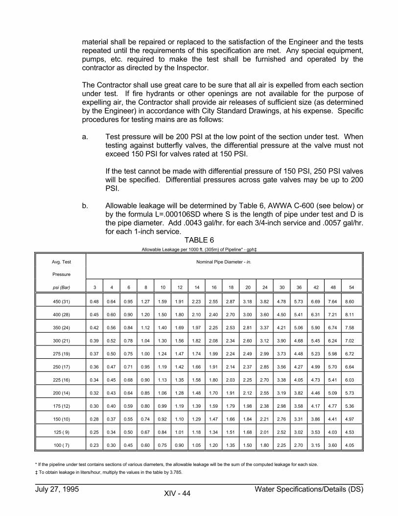
material shall be repaired or replaced to the satisfaction of the Engineer and the tests repeated until the requirements of this specification are met. Any special equipment, pumps, etc. required to make the test shall be furnished and operated by the contractor as directed by the Inspector.
The Contractor shall use great care to be sure that all air is expelled from each section
under test. If fire hydrants or other openings are not available for the purpose of expelling air, the Contractor shall provide air releases of sufficient size (as determined by the Engineer) in accordance with City Standard Drawings, at his expense. Specific procedures for testing mains are as follows:
a. Test pressure will be 200 PSI at the low point of the section under test. When
testing against butterfly valves, the differential pressure at the valve must not exceed 150 PSI for valves rated at 150 PSI.
If the test cannot be made with differential pressure of 150 PSI, 250 PSI valves
will be specified. Differential pressures across gate valves may be up to 200 PSI.
b. Allowable leakage will be determined by Table 6, AWWA C-600 (see below) or
by the formula L=.000106SD where S is the length of pipe under test and D is the pipe diameter. Add .0043 gal/hr. for each 3/4-inch service and .0057 gal/hr. for each 1-inch service.
TABLE 6 Allowable Leakage per 1000 ft. (305m) of Pipeline* - gph‡
Avg. Test Nominal Pipe Diameter - in.
Pressure
psi (Bar) 3 4 6 8 10 12 14 16 18 20 24 30 36 42 48 54
450 (31) 0.48 0.64 0.95 1.27 1.59 1.91 2.23 2.55 2.87 3.18 3.82 4.78 5.73 6.69 7.64 8.60
400 (28) 0.45 0.60 0.90 1.20 1.50 1.80 2.10 2.40 2.70 3.00 3.60 4.50 5.41 6.31 7.21 8.11
350 (24) 0.42 0.56 0.84 1.12 1.40 1.69 1.97 2.25 2.53 2.81 3.37 4.21 5.06 5.90 6.74 7.58
300 (21) 0.39 0.52 0.78 1.04 1.30 1.56 1.82 2.08 2.34 2.60 3.12 3.90 4.68 5.45 6.24 7.02
275 (19) 0.37 0.50 0.75 1.00 1.24 1.47 1.74 1.99 2.24 2.49 2.99 3.73 4.48 5.23 5.98 6.72
250 (17) 0.36 0.47 0.71 0.95 1.19 1.42 1.66 1.91 2.14 2.37 2.85 3.56 4.27 4.99 5.70 6.64
225 (16) 0.34 0.45 0.68 0.90 1.13 1.35 1.58 1.80 2.03 2.25 2.70 3.38 4.05 4.73 5.41 6.03
200 (14) 0.32 0.43 0.64 0.85 1.06 1.28 1.48 1.70 1.91 2.12 2.55 3.19 3.82 4.46 5.09 5.73
175 (12) 0.30 0.40 0.59 0.80 0.99 1.19 1.39 1.59 1.79 1.98 2.38 2.98 3.58 4.17 4.77 5.36
150 (10) 0.28 0.37 0.55 0.74 0.92 1.10 1.29 1.47 1.66 1.84 2.21 2.76 3.31 3.86 4.41 4.97
125 ( 9) 0.25 0.34 0.50 0.67 0.84 1.01 1.18 1.34 1.51 1.68 2.01 2.52 3.02 3.53 4.03 4.53
100 ( 7) 0.23 0.30 0.45 0.60 0.75 0.90 1.05 1.20 1.35 1.50 1.80 2.25 2.70 3.15 3.60 4.05
* If the pipeline under test contains sections of various diameters, the allowable leakage will be the sum of the computed leakage for each size.
‡ To obtain leakage in liters/hour, multiply the values in the table by 3.785.
July 27, 1995 Water Specifications/Details (DS) XIV - 44
c. Pressure and leakage tests will be run concurrently and for a duration of four
hours except as modified below. d. The Contractor will pressurize the line and verify that it is within allowable
leakage before the official test is started. e. The Inspector will begin the test and remain at the job for the first hour, making
sure that the test pressure is maintained within 5 PSI. The Contractor is to maintain the pressure within 5 PSI for the duration of the test period. At the end of the first hour, with the line pumped to full test pressure, he will read the meter and record the first hour leakage. If the first hour leakage is within allowable, he will return at the end of the fourth hour and again read the meter. If the total leakage for the four hour period does not exceed four times the first hour leakage, the test will be terminated. If the total leakage exceeds four times the first hour leakage, but is still within allowable, the test will be held an additional hour. If the fifth hour leakage does not exceed the average hourly leakage for the first four hours, the test will be terminated at the end of the fifth hour. Otherwise, the test will be held until the leakage is non-increasing and within allowable for two consecutive hours.
f. If leakage exceeds allowable for the four hour test, the test will be terminated
and re-scheduled after the Contractor has verified that actual leakage is within the allowable leakage, but no earlier than the next work day.
g. If the first hour leakage does not exceed 10% of the allowable, or if the
allowable leakage rate does not exceed .4 gal/hr., the test may be terminated at the end of two hours provided the second hour leakage does not exceed the first hour leakage. If the second hour leakage exceeds the first hour leakage, the test will be held for an additional period as described in Paragraph (e) above.
h. The maximum length of pipe tested in one test shall be 5,000 feet or as close
to 5,000 feet as possible depending on valve spacing. i. During the last stages of the test and without any reduction in pressure, first the
hydrant guard valves will be closed, then progressing in an orderly manner from the end opposite the test pump, each main line valve will be closed and pressure released to determine if it is holding pressure (minimum 10 minutes per valve closing).
j. Unless otherwise directed by the Engineer, each Butterfly Valve will be tested
to 150 PSI for a minimum of 10 minutes after the pipeline has been successfully tested.
July 27, 1995 Water Specifications/Details (DS) XIV - 45
k. When testing mains with Contractor installed water services, the Engineer may on a random basis require jumpers in selected meter yokes with full test pressure applied to the property line valve. Such jumpers will be furnished by the Engineer and installed by the Contractor.
2. Disinfection of Mains: All of the water mains installed shall be thoroughly flushed and
disinfected before being placed in service. This work shall be done under the direct supervision of the Engineer's Inspector. The Contractor shall supply all labor, equipment and materials necessary for carrying out this work. After a thorough flushing and cleaning out, sufficient chlorine compounds shall be introduced in the lines to produce a chlorine concentration of at least 50 parts per million. The chlorine solution shall be retained in the lines for at least twenty-four (24) hours. At the end of this period, the chlorine residual shall be at least 20 parts per million. The lines will then be flushed sufficiently to clear them of chlorine exceeding one part per million. Samples of water from the mains will then be taken and analyzed for bacteriological purity. If the mains fail to meet the bacteriological standard for purity, disinfecting and flushing will be repeated until such standards have been met. All analysis for chlorine and bacteriological purity will be by City Personnel.
3. Drainage of Mains: Drainage of mains and disposal of chlorinated water shall be in
accordance with all Federal, State and local laws, ordinances and regulations. Mains shall be drained to sanitary sewers, where available. Drainage directly to surface waters (creeks, rivers, streams, lakes, ponds, etc.) will not be allowed. Drainage branches, blowoffs, air vents and appurtenances shall be provided with valves and shall be located and installed as shown on the Plans and Standard Details. Drainage of mains will be accomplished in such a manner as to minimize erosion and siltation to adjoining properties. Water velocity from drainage and/or blow-off will be dissipated as necessary to prevent erosion.
Drainage branches or blowoffs shall not be connected to any sewer, submerged in
any streams, or installed in any other manner that will permit back siphonage into the distribution system.
S. REPAIRS The Contractor shall make any needed repairs to newly installed unactivated mains. Repairs
to existing and/or activated mains will be made by the Charlotte-Mecklenburg Utility Department unless the Contractor is otherwise directed by the Engineer.
1. Repairs to New mains: Repairs shall be made by cutting out and removing the
damaged/defective section and replacing those with new pipe using long pattern solid sleeves to connect plain ends. Bell clamps will not be allowed to repair newly installed
2. Repairs to Existing Mains: The Contractor will not be required to repair existing mains
unless specifically directed by the Engineer, or specified elsewhere in these specifications. Repair methods will be considered on a case by case basis.
July 27, 1995 Water Specifications/Details (DS) XIV - 46
T. RESTORATION All surfaces and structures (both public and private) within and adjacent to the construction
operations shall be restored to a condition comparable to that existing prior to construction or as specified in the special provisions.
All surplus materials shall be disposed of in a manner acceptable to the Engineer, and the
construction area shall be left in a neat condition, with special attention called to proper drainage, smoothness of surface, and general clean up. No machinery or equipment shall be left or stored on the job site after the project is completed.
Unless otherwise specified, complete restoration to include fertilizing, seeding, and mulching
of any and all areas disturbed during construction shall be completed within thirty (30) working days following the initial ground disturbing activity.
1. Water meters, valve boxes, drain pipes, and other structures encountered shall be
reset or relaid to match or clear surface grade and/or water main pipe grade as applicable.
2. All shoulder areas shall be restored, stabilized, and maintained to their original condition. Concrete, asphalt, gravel, and dirt walks, drives and roadways are to be replaced to their original shape and serviceability. Unless otherwise approved by the Engineer all areas (shoulders, side streets, drive, parking areas, etc.) which exhibit a gravel surface at the time of construction will be re-graveled with a minimum depth of six (6) inches of C.A.B.C stone compacted-in-place for the width and length of the disturbed area and then feathered gradually into the existing cross section. When a driveway is finished with other than C.A.B.C stone, a one inch finish coating to match existing gravel gradation and appearance shall be placed.
The Contractor should note that all existing side streets and drives which are either dirt
or gravel will be restored as specified for graveled areas. 3. Refuse Burial: The Contractor shall not bury rock, broken concrete/asphalt,
construction material, timber, etc. within the street or water main right-of-way. 4. Rip-Rap: The Contractor shall place stone rip-rap as specified in those areas subject
to severe water action where directed by the Engineer. Placement of rip-rap as shown on the Construction Plans shall be considered a guide
only, with final determination made at the time of construction by the Engineer. Either the addition or deletion of quantities may be required.
Stone rip-rap will be placed as indicated on the Standard Details immediately following
pipe installation and will be installed no steeper than a 2:1 slope except when specifically approved by the Engineer. Grading will be required as necessary to insure continuous even flow.
The rip-rap installation shall include all earthwork necessary to stabilize the creek bank
and to provide cover for the water line.
July 27, 1995 Water Specifications/Details (DS) XIV - 47
5. Jute Netting/Erosion Blanket: The Contractor shall install jute netting or Erosion Control Blanket in areas subject to high runoff velocities, areas subject to concentrated runoff and on steep slopes as shown on the plans and/or as directed by the Engineer.
6. Fertilizing, Seeding, and Mulching: Established lawns and landscaped areas
damaged by construction shall be restored to their former condition by seeding, unless the type and condition of the existing sod warrants it being cut, removed, preserved, and replaced. All areas, regardless of previous condition, damaged by construction shall be fertilized, seeded, and mulched as outlined below:
a. Seed Bed Preparation: The seed bed shall be prepared by pulverizing the soil
in an approved manner to a depth of three (3) inches for field conditions or slopes that are 3:1 or flatter and to a depth of one (1) to three (3) inches, as determined on site for slopes steeper than 3:1. The soil shall be tilled until a well pulverized, firm, reasonably uniform seed bed is prepared conforming substantially to ground elevations as shown on the Plans and/or as existed prior to construction. The disturbed area shall blend uniformly into adjacent topography. Good surface drainage must be provided, allowances for settlement made and ground elevations adjusted accordingly. Visible ponding will not be allowed. All stones, roots, sticks, rubbish, and other objectionable material shall be removed.
b. Soil Improvements: Soil additives shall be incorporated in an approved
manner into the top soil at the following rates: (1) ...... Fertilizer - 20 pounds per 1000 square feet of 5-10-10 fertilizer generally
and 30 pounds per 1000 square feet of 10-10-10 fertilizer for established lawn areas.
(2) ...... Lime - 100 pounds per 1000 square feet. (3) ...... Superphosphate (0-20-0) - 12 pounds per 1000 square feet. c. Seeding: Seeding must be done within thirty (30) calendar days after the initial
ground disturbing activity. (1) ...... The seed bed must be in good, friable condition and not muddy or hard
at the time seeding is performed. (2) ...... Seed shall be applied at the rate specified and raked or tilled into the
topsoil with the resulting furroughs running across the natural slope of the ground. Under no circumstances will any tilling activity be allowed parallel with said slope. Slopes steeper than 3:1 shall require the use of hydraulic seeding unless otherwise specifically approved by the Engineer.
d. Mulching: After fertilizing, seeding and raking, dried straw shall be spread
uniformly over the area at a rate of 90 pounds per 1000 square feet. Approximately 1/4 of the ground should remain visible to avoid smothering seedlings. The straw shall be sprayed with liquid asphalt to bond it together and anchor it in place within road right-of-way and areas subject to erosion.
July 27, 1995 Water Specifications/Details (DS) XIV - 48
(1) ...... Liquid asphalt, thinned with kerosene, shall be used during freezing
weather and shall be either rapid or medium curing. It shall be applied at a rate of 200 gallons per ton of straw or approximately 9 gallons per 1000 square feet.
(2) ...... Emulsified asphalt, thinned with water shall be used when temperatures
are less severe, shall be rapid curing only, and shall be applied at a rate of 150 gallons per ton of straw or approximately 7 gallons per 1000 square feet.
e. Maintenance: The Contractor shall maintain the seeded areas until there is a
uniform growth three (3) inches high. Maintenance shall consist of watering, weed and pest control within established lawns, fertilization, erosion repair, reseeding and all else necessary to establish a vigorous healthy and uniform stand of grass. All areas and spots which do not show a uniform stand of grass, for any reason, shall be treated repeatedly until a uniform stand is attained.
Seasonal seeding mixtures and rates of application shall be as follows. All rates are in
pounds per 1000 square feet and any rates listed below may be cut by 1/2 for temporary erosion control measures only.
SEPTEMBER 15 - MARCH 1 Maintained/Established Lawns or road rights-of-way ........... 6# Kentucky Fescue No. 31 ........... 2# Rye Grain ........... 30# Fertilizer (10-10-10) ........... 100# Lime ........... 12# Superphosphate Open-Field (Anything other than an established lawn) ........... 4# Kentucky Fescue No. 31 ........... 2# Rye Grain ........... 20# Fertilizer (5-10-10) ........... 100# Lime ........... 12# Superphosphate Open-Field For Slopes 2:1 or greater or areas subject to erosion 2# Kentucky Fescue No. 31 4# Sericea Lespedeza (Unscarified) 2# Rye Grain 30# Fertilizer (5-10-10) 100# Lime 12# Superphosphate
July 27, 1995 Water Specifications/Details (DS) XIV - 49
FEBRUARY 1 - OCTOBER 15 Maintained/Established Lawns or road rights-of-way 8# Kentucky Fescue No. 31 30# Fertilizer (10-10-10) 100# Lime 12# Superphosphate Open-Field (Anything other than an established lawn) 6# Kentucky Fescue No. 31 2# Sudangrass (May, June, and July only) 20# Fertilizer (5-10-10) 100# Lime 12# Superphosphate Open-Field For Slopes 2:1 or greater or areas subject to erosion 2# Kentucky Fescue No. 31 4# Sericea Lespedeza (Scarified) 2# Sudangrass (May, June, and July only) 20# Fertilizer (5-10-10) 100# Lime 12# Superphosphate The Engineer will be consulted prior to seeding for a determination of appropriate seed
mixture. Unless otherwise required by the North Carolina Department of Transportation or the
Engineer seeding within road rights-of-way will be as specified for established lawns. U. WORK WITHIN NORTH CAROLINA DEPARTMENT OF TRANSPORTATION RIGHTS-OF-
WAY Construction is permitted within the rights-of-way of the North Carolina Department of
Transportation (DOT), Division of Highways in accordance with their Policies And Procedures For Accommodating Utilities On Highway Rights-Of-Way as amended. The Charlotte-Mecklenburg Utility Department (CMUD) is required to enforce this entire document as it relates to this work. All bidders are required to become familiar with the document and any amendments which are available from the Manager of Right-of-Way, North Carolina Department of Transportation, Division of Highways, Raleigh, North Carolina.
1. Charlotte-Mecklenburg Utility Department has entered into an encroachment
agreement with the North Carolina Department of Transportation (DOT) which grants the right for any work within the Department of Transportation's rights-of-way. The encroachment agreement for any work within DOT rights-of-way under this project is included as a special provision in this contract. A copy of the approved encroachment has been attached to this contract or will be supplied to the Contractor prior to
July 27, 1995 Water Specifications/Details (DS) XIV - 50
construction. A copy of the encroachment agreement must be kept at the construction site at all times.
2. Certain notices are required in writing before any work can proceed within the
Department of Transportation's rights-of-way. Upon ample notice by the Contractor, the Engineer will make this notification.
3. Proper signing before, during, and after construction in conformance with the manual
on Uniform Traffic Control Devices for Streets and Highways will be required. In addition, warning signs as related to soft and/or low shoulders and broken pavement may be required by the Engineer.
4. Piling and/or storage of excavated material upon the pavement and on some types of
shoulders is prohibited unless special permission is granted by the Department of Transportation's Division Engineer. Any material spilled, tracked or placed on the pavement is to be cleaned and damaged pavement repaired subject to stoppage of all work by Charlotte-Mecklenburg Utility Department. Drainage ditches are to be protected from siltation as specified in the EP Section and must be opened at the end of each work day or as weather conditions require.
5. Open trenches are prohibited between dusk and dawn and at designated peak traffic
hours unless special permission is received from the Department of Transportation's Division Engineer.
6. When cutting of pavement is permitted, only one-half of the road width shall be
opened at any time. Full traffic flow is to be maintained between dusk and dawn and at other peak hours of traffic as required by the encroachment agreement or other Special Provision.
7. The Contractor and his suppliers are directed to contact the North Carolina
Department of Transportation to verify axle load limits on State maintained roads and bridges which will be used for hauling of equipment or materials for this project. The Contractor and his suppliers shall do all that is necessary to satisfy the Department of Transportation requirements and will be responsible for any damage to roads and bridges resulting from this project.
July 27, 1995 Water Specifications/Details (DS) XIV - 51
This page intentionally left blank.
July 27, 1995 Water Specifications/Details (SD) XIV - 52
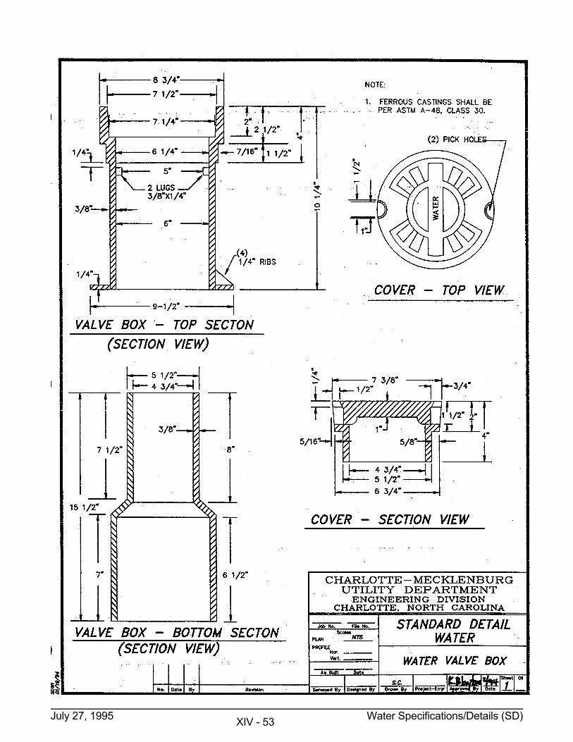
July 27, 1995 Water Specifications/Details (SD) XIV - 53
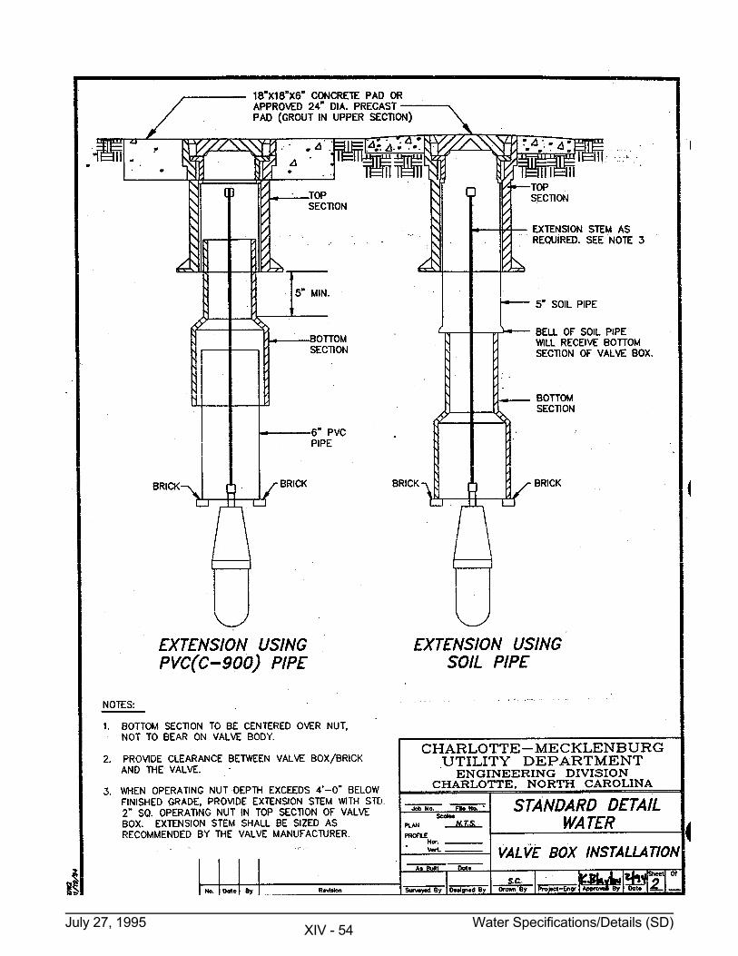
July 27, 1995 Water Specifications/Details (SD) XIV - 54
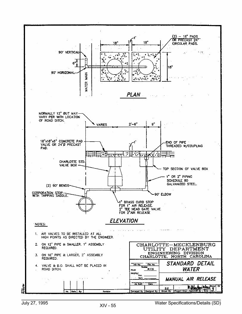
July 27, 1995 Water Specifications/Details (SD) XIV - 55
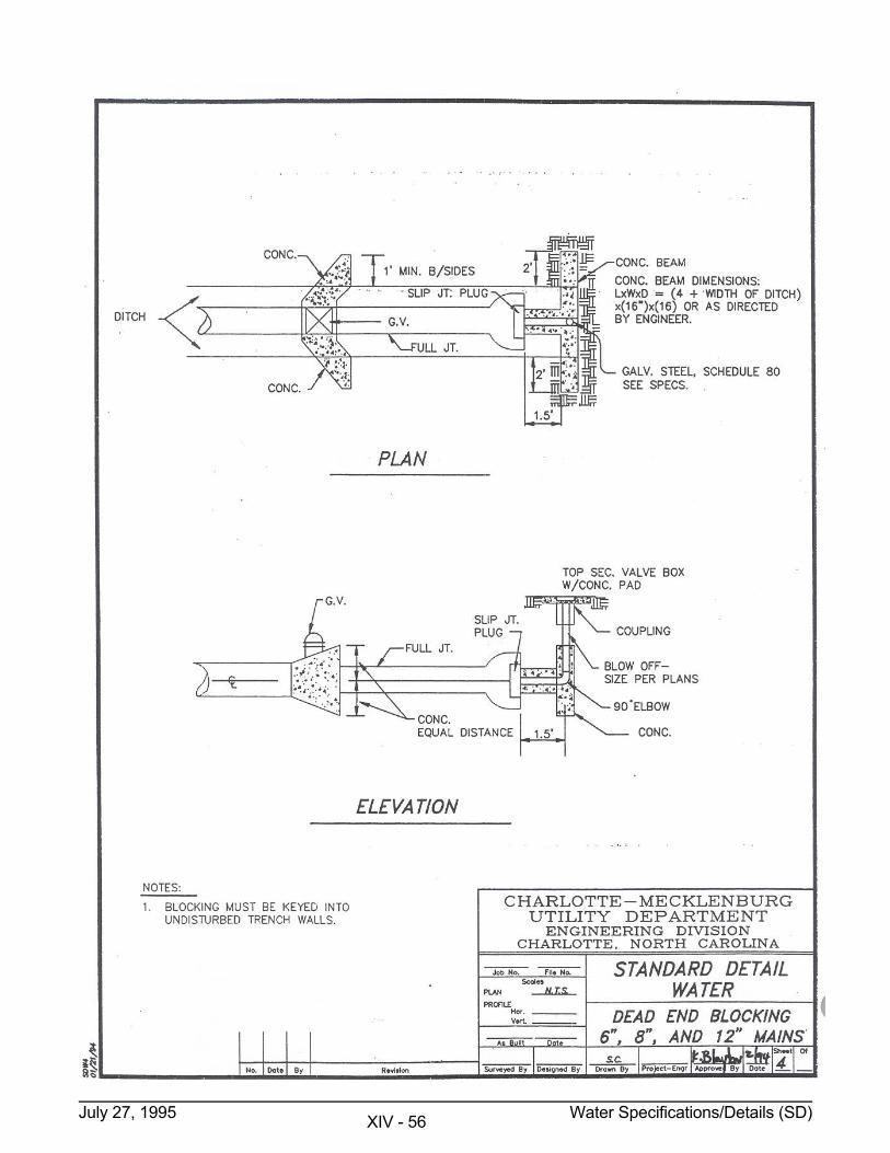
July 27, 1995 Water Specifications/Details (SD) XIV - 56
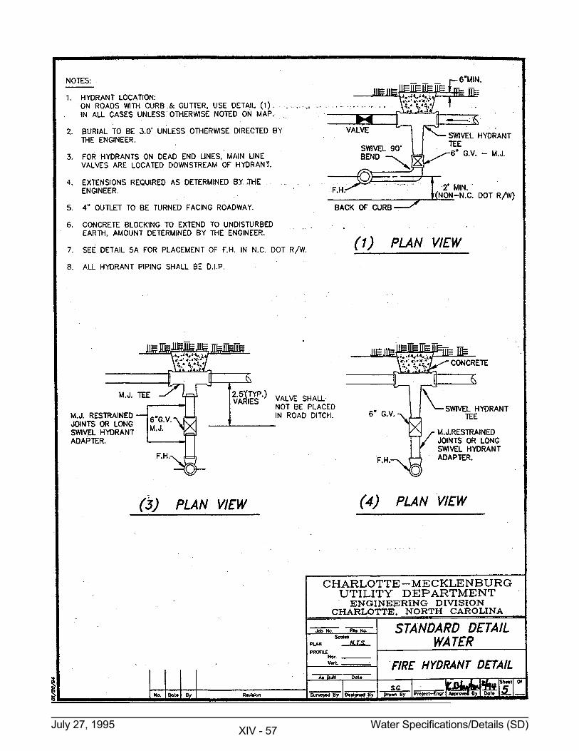
July 27, 1995 Water Specifications/Details (SD) XIV - 57
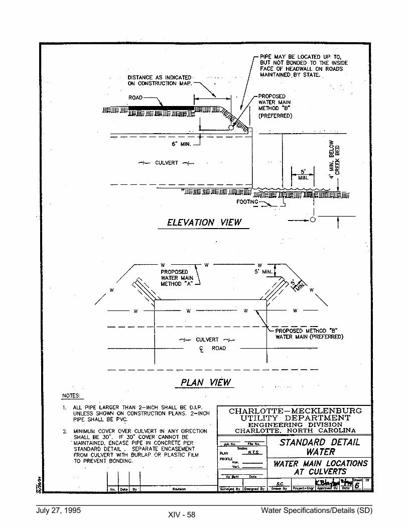
July 27, 1995 Water Specifications/Details (SD) XIV - 58
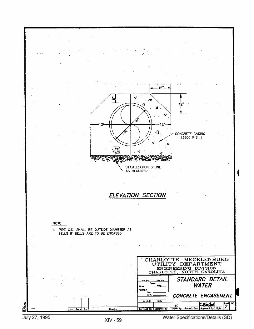
July 27, 1995 Water Specifications/Details (SD) XIV - 59
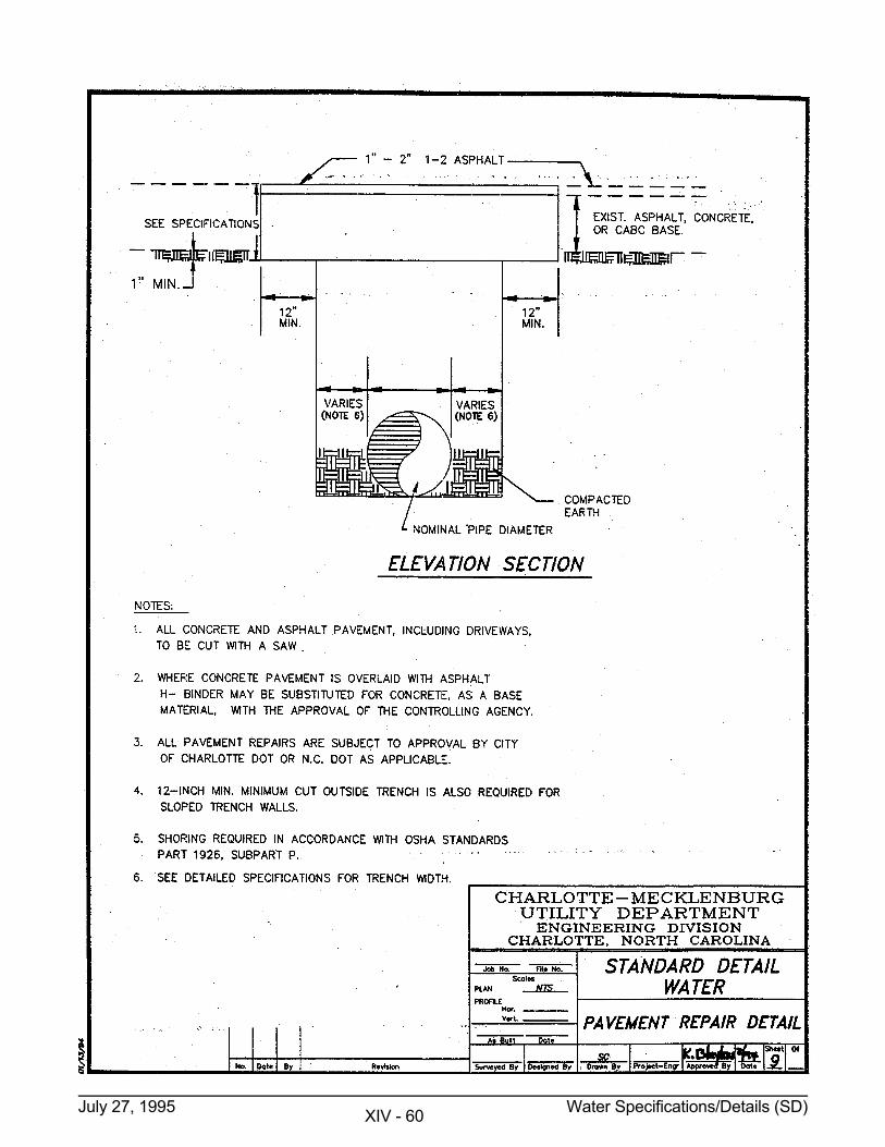
July 27, 1995 Water Specifications/Details (SD) XIV - 60
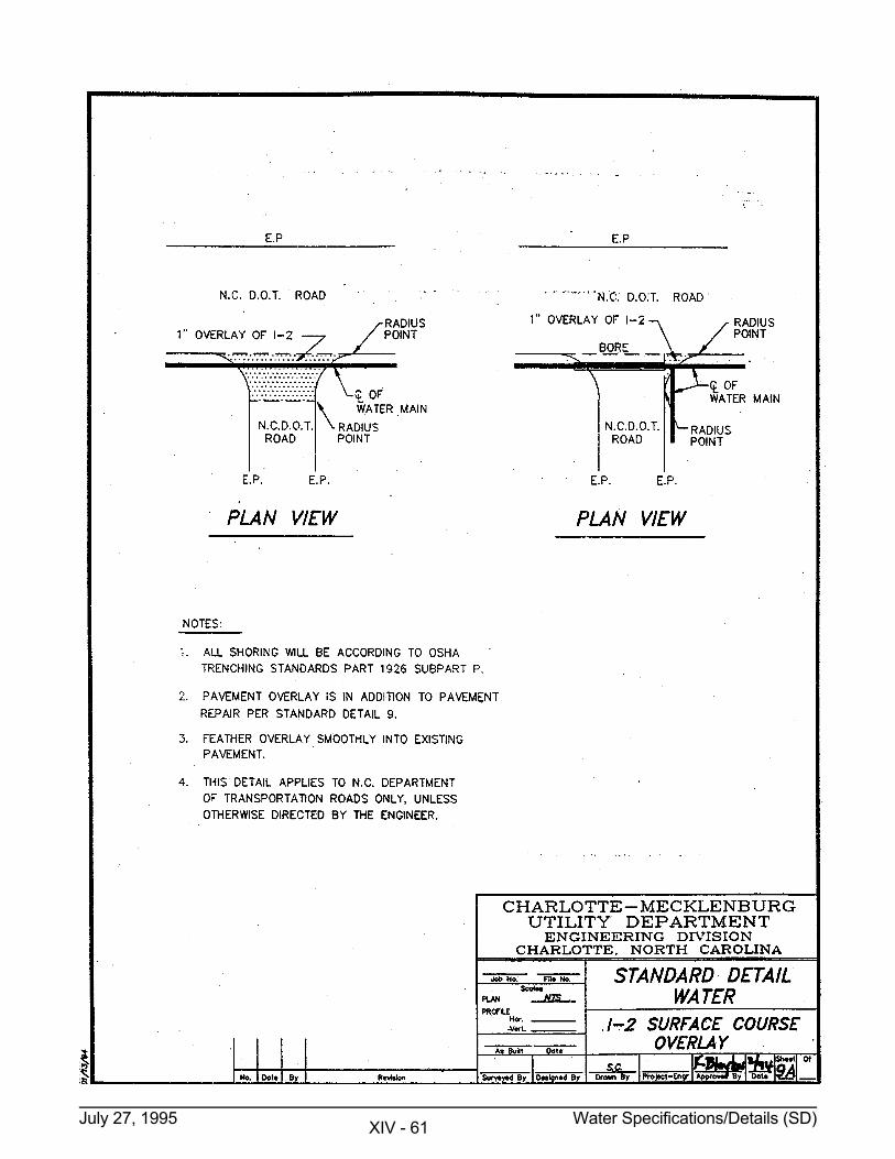
July 27, 1995 Water Specifications/Details (SD) XIV - 61
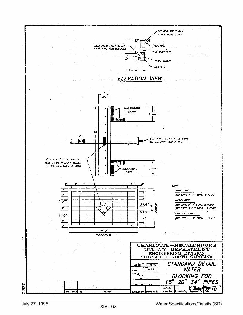
July 27, 1995 Water Specifications/Details (SD) XIV - 62
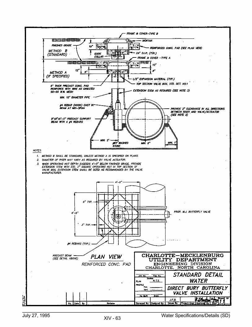
July 27, 1995 Water Specifications/Details (SD) XIV - 63
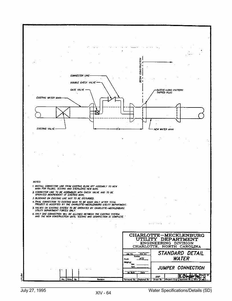
July 27, 1995 Water Specifications/Details (SD) XIV - 64
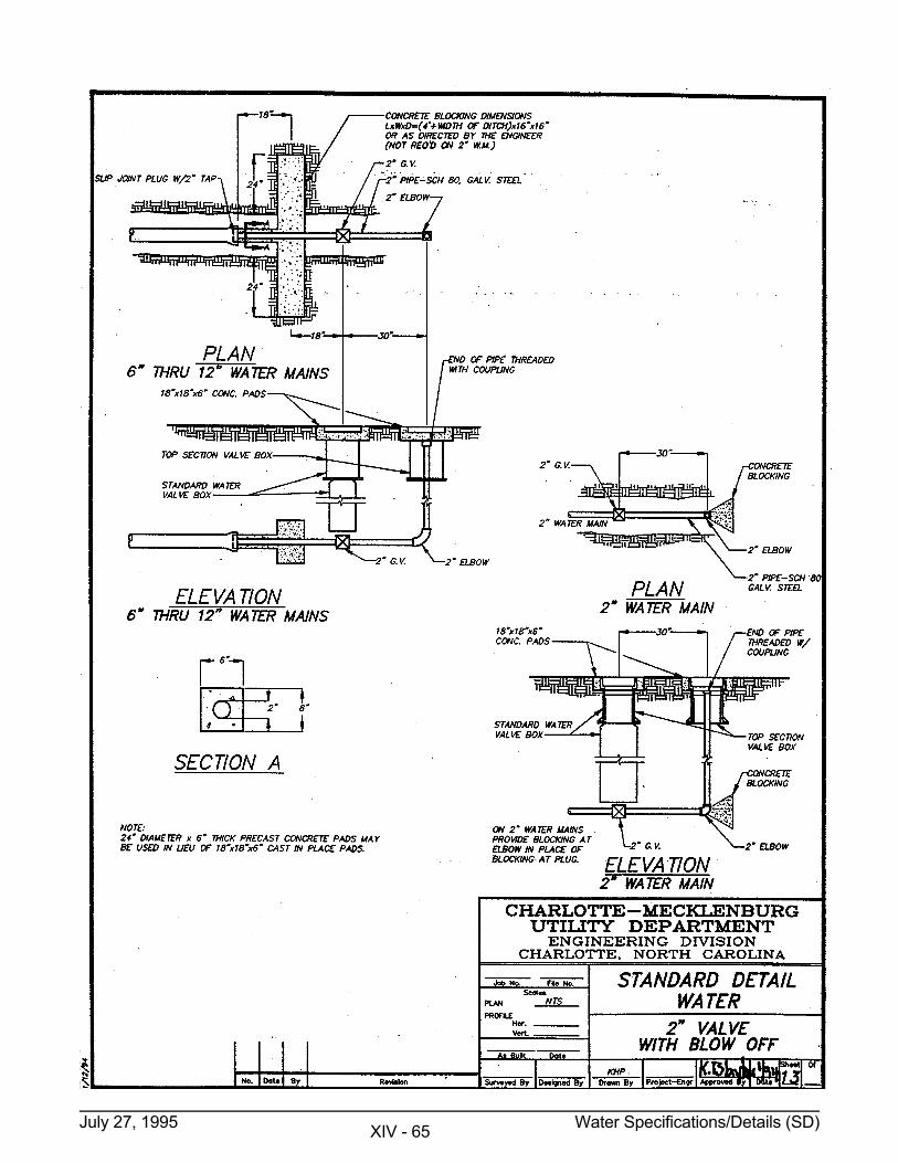
July 27, 1995 Water Specifications/Details (SD) XIV - 65
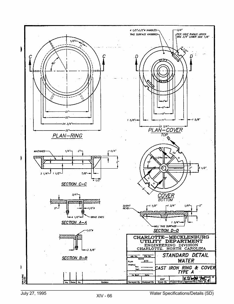
July 27, 1995 Water Specifications/Details (SD) XIV - 66
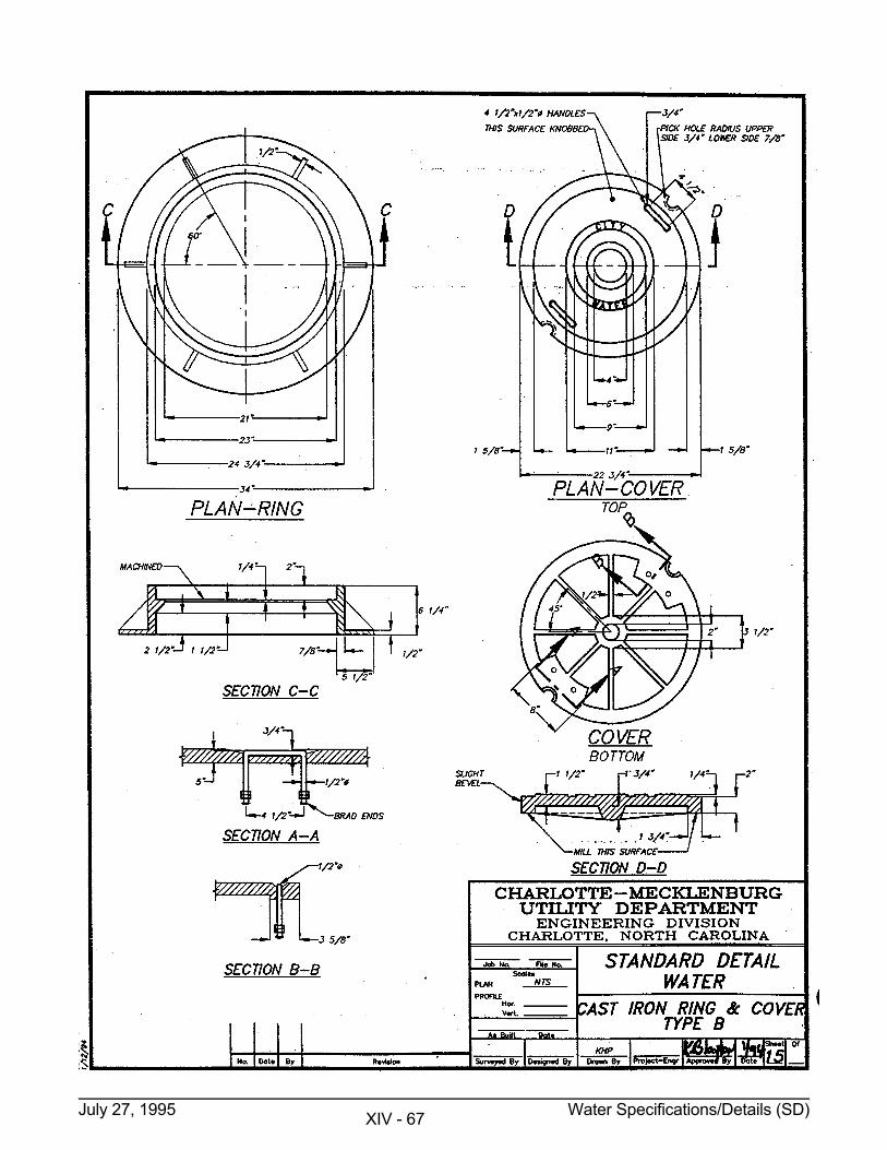
July 27, 1995 Water Specifications/Details (SD) XIV - 67
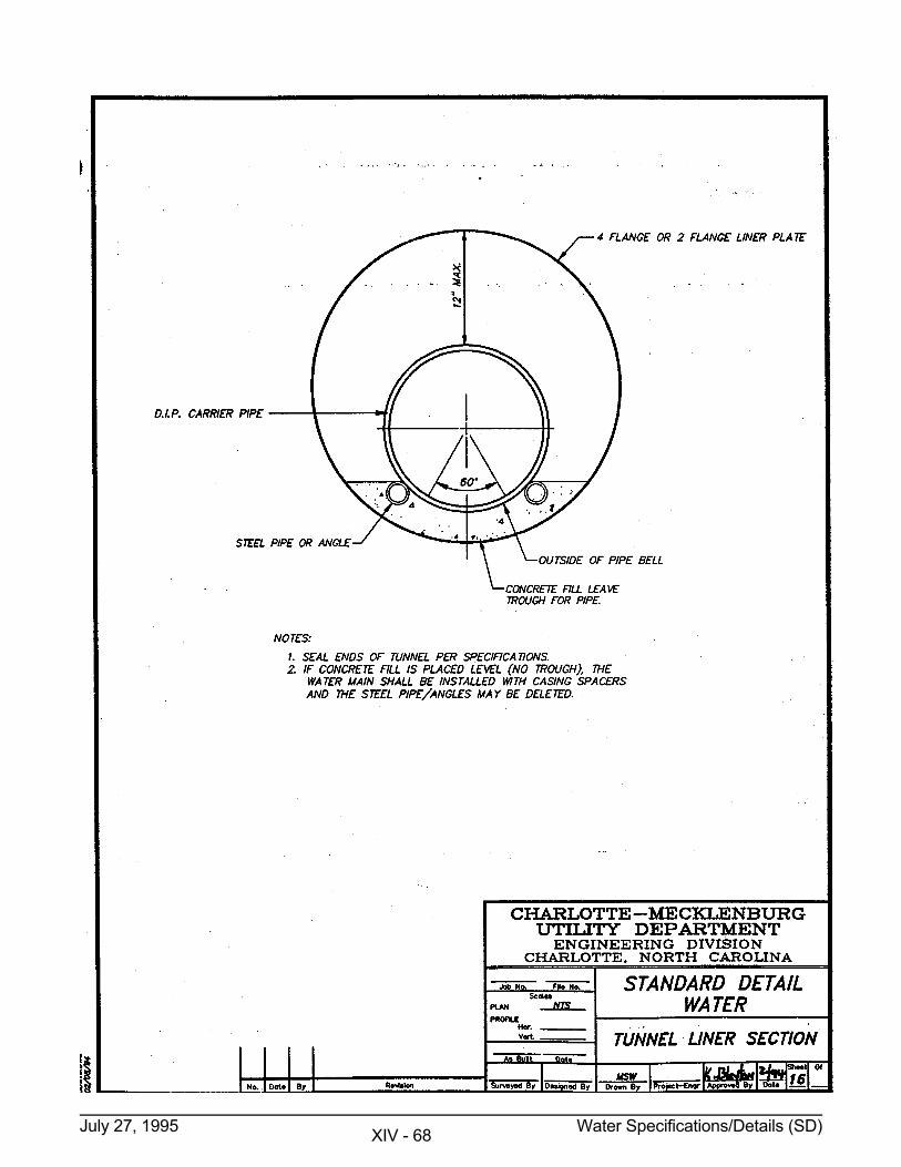
July 27, 1995 Water Specifications/Details (SD) XIV - 68
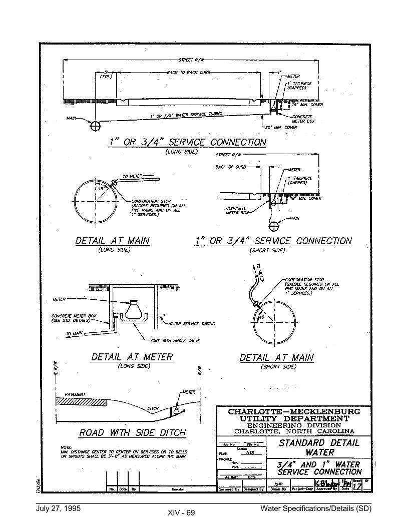
July 27, 1995 Water Specifications/Details (SD) XIV - 69
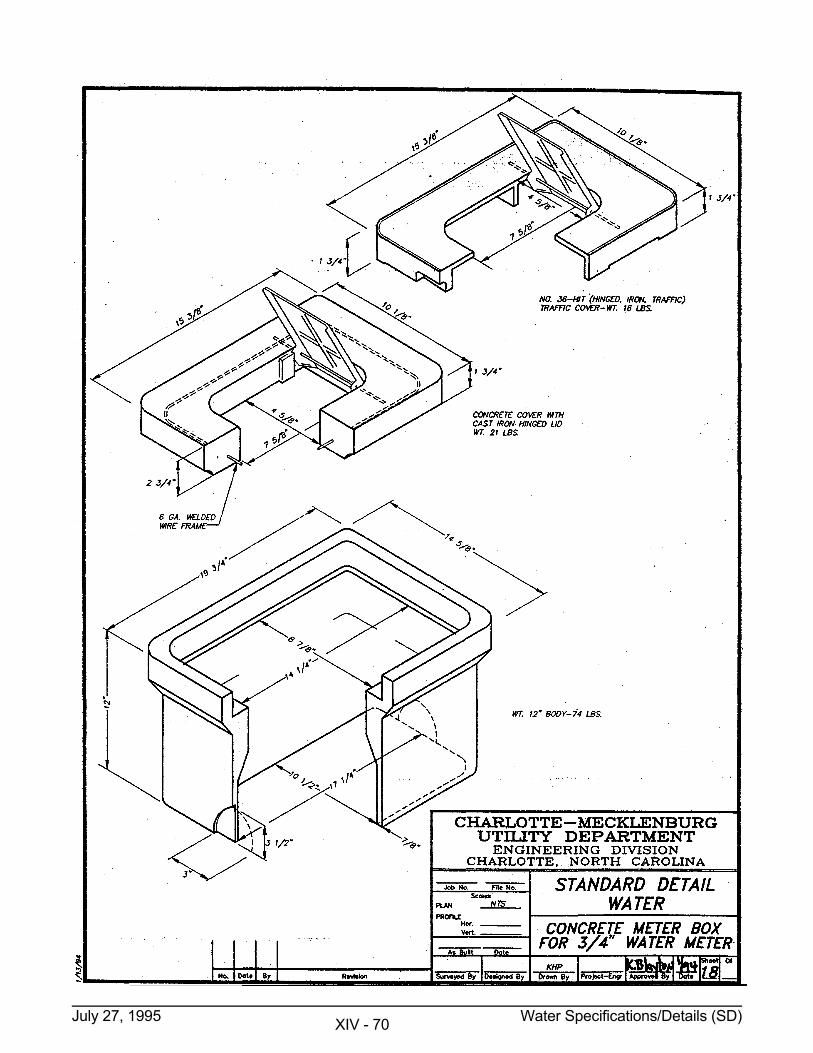
July 27, 1995 Water Specifications/Details (SD) XIV - 70
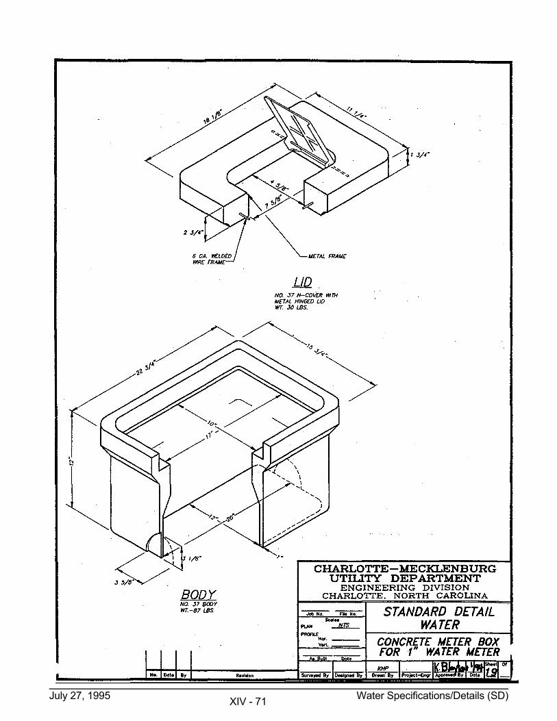
July 27, 1995 Water Specifications/Details (SD) XIV - 71
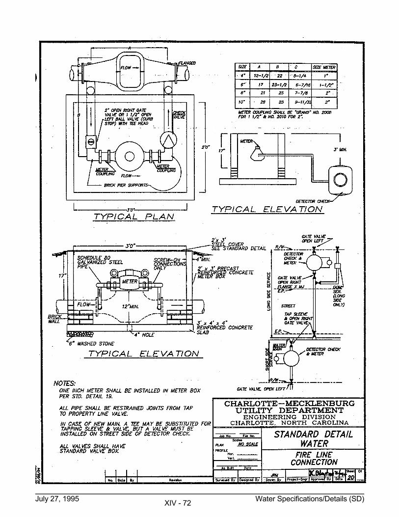
July 27, 1995 Water Specifications/Details (SD) XIV - 72
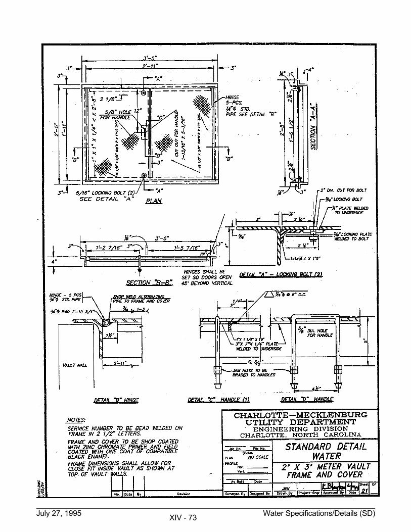
July 27, 1995 Water Specifications/Details (SD) XIV - 73
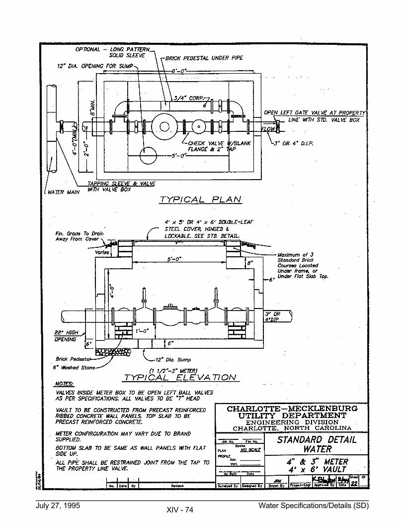
July 27, 1995 Water Specifications/Details (SD) XIV - 74
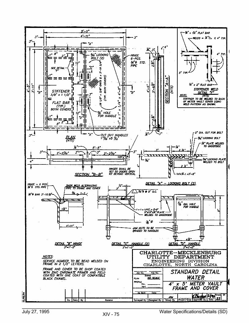
July 27, 1995 Water Specifications/Details (SD) XIV - 75
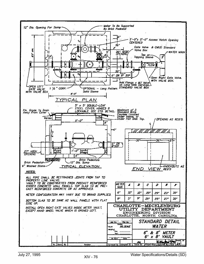
July 27, 1995 Water Specifications/Details (SD) XIV - 76
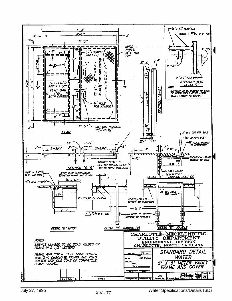
July 27, 1995 Water Specifications/Details (SD) XIV - 77
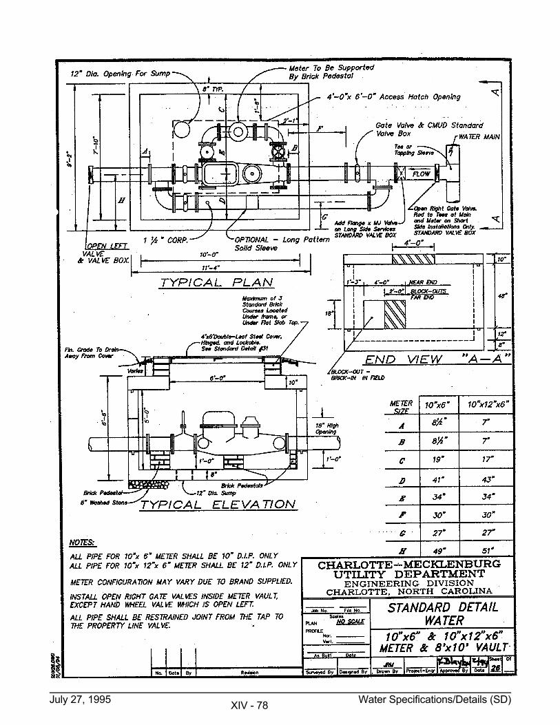
July 27, 1995 Water Specifications/Details (SD) XIV - 78
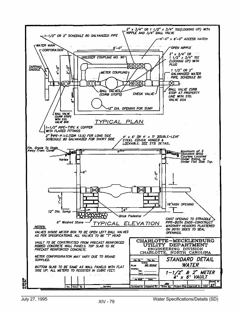
July 27, 1995 Water Specifications/Details (SD) XIV - 79
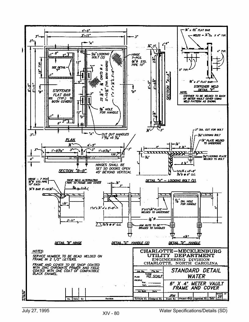
July 27, 1995 Water Specifications/Details (SD) XIV - 80