Embed Size (px)
Citation preview

CHAPTER 15
BANK PROTECTION

Bank Protection 15 - 1
Chapter Table of Contents 15.1 Introduction ....................................................................................................................... 5
15.2 Policy .................................................................................................................................. 5
15.3 Erosion Potential ............................................................................................................... 6
15.4 Design Considerations ...................................................................................................... 7
15.4.1 Stream Stability ................................................................................................... 7
15.4.2 Fish Habitat and Mitigation ................................................................................. 8
15.4.3 Design Event Discharge ...................................................................................... 8
15.4.4 Scour in Channel Bends and Straight Sections ................................................... 9
15.4.5 Extent of Protection ........................................................................................... 12
15.4.5.1 Longitudinal Extent ......................................................................... 12
15.4.5.2 Vertical Extent ................................................................................. 13
15.4.5.2.1 Lower Limit ................................................................... 13
15.4.5.2.2 Upper Limit ................................................................... 14
15.5 Design Guidelines ............................................................................................................ 15
15.5.1 Rock Riprap ....................................................................................................... 15
15.5.1.1 Bank Slope ...................................................................................... 15
15.5.1.2 Rock Properties ............................................................................... 16
15.5.1.3 Layer Thickness “T” ....................................................................... 21
15.5.1.4 Riprap Backing ................................................................................ 21
15.5.1.5 Standard and Modified Riprap Sections .......................................... 22
15.5.1.6 Flank Treatment .............................................................................. 27
15.5.1.7 Calculating Riprap Size ................................................................... 27
15.5.1.7.1 Parol Evidence, History & Site Investigation Method .. 27
15.5.1.7.2 Tractive Force Design Relationship .............................. 30
15.5.1.7.3 ODOT Velocity Based Design Procedure ..................... 34
15.5.1.7.4 Hudson Relationship for Wave Erosion Protection ...... 36
15.5.1.7.5 Modified Isbash Relationship to Size Riprap at Bridge Piers and Abutments ........................................................................ 37
15.5.2 Stream Barbs ..................................................................................................... 41
April 2014 ODOT Hydraulics Manual
15 - 2 Bank Protection
15.5.2.1 Height .............................................................................................. 45
15.5.2.2 Angle of Projection ......................................................................... 45
15.5.2.3 Barb Length ..................................................................................... 47
15.5.2.4 Barb Location and Spacing ............................................................. 47
15.5.2.5 Length of Bank Key ........................................................................ 48
15.5.2.6 Top Width ....................................................................................... 48
15.5.2.7 Riprap Backing ................................................................................ 48
15.5.2.8 Number of Barbs ............................................................................. 49
15.5.2.9 Riprap Sizing ................................................................................... 49
15.5.3 Grouted Rock .................................................................................................... 50
15.5.3.1 Bank Slope ...................................................................................... 51
15.5.3.2 Rock Size and Grout Penetration .................................................... 51
15.5.3.3 Hydrostatic Pressure Relief ............................................................. 51
15.5.3.4 Riprap Backing ................................................................................ 51
15.5.3.5 Typical Grouted Rock Section ........................................................ 51
15.5.4 Keyed Riprap ..................................................................................................... 52
15.5.5 Impermeable Deflector Spurs ............................................................................ 53
15.5.5.1 Spur Length ..................................................................................... 55
15.5.5.2 Spur Spacing ................................................................................... 55
15.5.5.3 Spur Height and Crest Profile ......................................................... 58
15.5.5.4 Bed and Bank Contact ..................................................................... 58
15.5.5.5 Spur Orientation .............................................................................. 58
15.5.5.6 Riprap Sizing ................................................................................... 59
15.5.5.7 Typical Rock Spur Details .............................................................. 60
15.5.6 Proprietary Products .......................................................................................... 60
15.5.6.1 Gabions ............................................................................................ 60
15.5.6.2 Pre-Cast Concrete Blocks ................................................................ 66
15.5.6.3 Grout Filled Mattresses ................................................................... 68
15.5.7 Biotechnical Stabilization ................................................................................. 69
15.5.7.1 Use of Vegetation ............................................................................ 70
15.5.7.2 Toe Protection ................................................................................. 72
15.5.7.3 Selection of Erosion Control Mat .................................................... 72
15.5.7.4 Typical Designs ............................................................................... 73
ODOT Hydraulics Manual April 2014
Bank Protection 15 - 3
15.5.7.5 Stability of Large Woody Debris .................................................... 79
15.5.7.5.1 Example 1 ...................................................................... 82
15.5.7.5.2 Example 2 ...................................................................... 84
15.6 References ........................................................................................................................ 87 Figures Figure 15-1 Channel Bend Scour ................................................................................................. 10
Figure 15-2 Extent of Protection at a Channel Bend ................................................................... 13
Figure 15-3 Marine Basalt ........................................................................................................... 20
Figure 15-4 Standard Riprap Section ........................................................................................... 23
Figure 15-5 Launching of Riprap Toe Stone ............................................................................... 24
Figure 15-6 Alternate Toe Protection Details .............................................................................. 26
Figure 15-7 Typical Flank Protection Details .............................................................................. 28
Figure 15-8 Definition Sketch of Channel Flow Distribution ..................................................... 32
Figure 15-9 Velocity Based Riprap Design Chart ....................................................................... 35
Figure 15-10 Pier Scour Riprap Chart ......................................................................................... 39
Figure 15-11 Characteristic Average Velocity for SBR is less than 5 ........................................ 42
Figure 15-12 Characteristic Average Velocity for SBR is more than 5 ...................................... 43
Figure 15-13 Characteristic Average Velocity for SBR is more than 5 and SBR is less than 5 44
Figure 15-14 Stream Barbs .......................................................................................................... 46
Figure 15-15 Length of Bank Key for Mild Bends (R is more than 5W) .................................... 49
Figure 15-16 Spur Spacing in a Channel Bend ............................................................................ 56
Figure 15-17 Definition Sketch for Spur Orientation .................................................................. 59
Figure 15-18 Typical Rock Spur Details ..................................................................................... 61
Figure 15-19 Typical Rock Spur Details ..................................................................................... 62
Figure 15-20 Rock Spurs ............................................................................................................. 63
Figure 15-21 Typical Gabion Configurations .............................................................................. 65
Figure 15-22 Articulating Block Mat .......................................................................................... 68
Figure 15-23 Grout Filled Mattress ............................................................................................. 69
Figure 15-24 Live Stakes with Riprap Toe Details ..................................................................... 73
Figure 15-25 Vegetated Geogrid Details ..................................................................................... 74
April 2014 ODOT Hydraulics Manual
15 - 4 Bank Protection
Figure 15-26 Live Cribwall Detail ............................................................................................... 75
Figure 15-27 Riprap with Rootwad Details ................................................................................. 76
Figure 15-28 Boulder Toe Details ............................................................................................... 77
Figure 15-29 Coconut (Coir) Fiber Roll Details .......................................................................... 78
Figure 15-30 Definition Sketch for Example 1 ............................................................................ 82
Figure 15-31 Definition Sketch for Example 2 ............................................................................ 85
Tables Table 15-1 Specific Gravities of Typical Oregon Riprap Stone .................................................. 17
Table 15-2 Gradation of Standard Riprap Classes ....................................................................... 18
Table 15-3 D50, W50, D100, and W100 for Standard Riprap Classes .............................................. 18
Table 15-4 Riprap Gradation Limits ............................................................................................ 19
Table 15-5 Riprap Layer Thickness “T” for Standard Riprap Classes ........................................ 21
Table 15-6 Riprap Backing for Standard Riprap Classes ............................................................ 22
Table 15-8 K1 Values ................................................................................................................... 31
Table 15-9 Guidelines for the Selection of Stability Factors ....................................................... 33
Table 15-10 Bank Slope vs. Maximum Wave Height ................................................................. 37
Table 15-11 Grouted Rock ........................................................................................................... 52
Table 15-12 Standard Keyed Riprap Gradations ......................................................................... 53
Table 15-13 Criteria for Gabion Mattress Thickness .................................................................. 66
Table 15-14 Standard Gabion Basket Sizes ................................................................................. 67
Table 15-15 Wood Properties ...................................................................................................... 81
ODOT Hydraulics Manual April 2014
Bank Protection 15 - 5 15.1 Introduction One of the hazards of placing a highway near a river or other water body is the potential for erosion of the highway embankment by moving water. If erosion of the highway embankment is to be prevented, bank protection must be anticipated and the proper type and amount of protec-tion must be provided in the right locations. Embankment stabilization may be designed and constructed during the initial roadway project where the need is obvious or the risk of damage is high. There will be other locations where economic considerations, the availability of materials, and the probability of damage are such that construction of embankment stabilization measures can be delayed until a problem actually develops.
Five methods of protecting a highway embankment from bank erosion are available to the designer. These are:
• locate the highway away from the stream or water body initially, • relocate the highway away from the stream or water body, • move the river or stream channel away from the highway (channel change), • change the direction of the current with training works, or • protect the highway embankment from erosion.
This chapter provides procedures for the design of revetments to be used as channel bank protection and channel linings on larger streams and rivers (i.e., having design discharges gen-erally greater than 50 cubic feet per second). In addition to revetments, design procedures are also presented for stream barbs, impermeable deflector spurs, and riprap protection at bridge piers and abutments. This chapter also provides guidance on biotechnical bank protection. For discharges less than 50 cubic feet per second, procedures presented in Chapter 8 should be used. 15.2 Policy Bank protection should satisfy the policies that are listed in Chapter 3.
April 2014 ODOT Hydraulics Manual
15 - 6 Bank Protection 15.3 Erosion Potential Channel and bank stabilization is essential to the design of any highway affected by the water environment. The identification of the potential for bank erosion, and the subsequent need for channel stabilization or highway embankment protection, is best accomplished through observa-tion. Observations are usually based on current site conditions supplemented with historic information. Documentation of channel movement or bank instability can be obtained from aerial photographs, old maps, surveying notes, bridge maintenance files, river survey data that are available at State and Federal agencies, gage station records and interviews of long-time resi-dents. Additional discussion about data collection is presented in Chapter 6. Even when historic information indicates that a bank has been relatively stable in the past, local conditions may indicate more recent instabilities. Local site conditions that are indicative of instabilities may include:
• tipping and falling of vegetation along the bank, • cracks along the bank surface, • the presence of slumped material due to an instability condition at or near the bank
surface that causes transverse movement of a soil mass down the stream bank, • fresh vegetation laying in the channel near the channel banks, • deflection of channel flows in the direction of the bank due to some recently deposited
obstruction or channel course change, • fresh vertical face cuts along the bank, • locally high velocities along the bank, • new bar formation downstream from an eroding bank, • local headcuts (refer to Chapter 9 for headcut description), • landslides, • toe erosion, and • pending or recent cutoffs. A cutoff is a channel formed naturally or artificially that
shortens the length of a stream; typically occurs across the neck of a meander loop or across a point bar.
It is also important to recognize that the presence of any one of these conditions does not in itself indicate an erosion problem; some bank erosion is common in all channels even when the channel is stable.
ODOT Hydraulics Manual April 2014
Bank Protection 15 - 7 15.4 Design Considerations This section presents factors that need to be considered for the bank protection techniques presented in this chapter. 15.4.1 Stream Stability Stream stability can affect the stability of the method chosen to provide bank protection. Therefore, it is important to evaluate the stream’s stability as part of the design process for bank protection. A stable channel or graded stream exists when a stream has achieved a bed slope and cross-section that allows its channel to transport water and sediment delivered from the upstream watershed without aggradation, degradation, or bank erosion. Factors that affect stream stability can be classified as geomorphic factors and hydraulic factors. Geomorphic factors include stream size, flow habit (i.e., ephemeral or perennial), composition and erodibility of bed and bank materials, geologic controls, floodplain characteristics (i.e., narrow or wide), planform characteristics (i.e., straight, meandering, braided, or anabranched), and other features such as natural levies, channel incision, and riparian vegetation. Hydraulic factors include flow resistance, bank and bed shear stresses, flow velocities, flow depths, magnitude and frequency of floods, and flow classification (e.g., unsteady, nonuniform, turbulent, supercritical or subcritical). Geomorphic characteristics of particular interest are the alignment, geometry, and form of the stream channel. The behavior of the stream at the site of bank instability depends not only on the local conditions at the site, but also on the behavior of the overall stream system. Upstream and downstream changes may affect future stability at the site. These changes can be reflected in aggradation, degradation, or lateral migration of the stream channel. Changes can occur in streams in response to human activities in the watershed and/or natural disturbances of the fluvial system. For example human-induced changes in the watershed such as changes in land use (i.e., increase in impervious area), gravel mining, streamside levees and dikes, reservoirs, and channel straightening can have major effects on the hydrology and sediment yield and transport, which can effect the channel geometry and planform characteristics. Natural disturbances such as floods, drought, landslides, forest fires, etc., may also result in large changes in sediment load in a stream and major changes in the stream channel. Either a qualitative or quantitative analysis can be used to evaluate stream stability. As an example, a qualitative study would describe critical areas and the problems encountered while a quantitative study would provide specific numeric data such as rate of erosion, etc. As a minimum, a qualitative analysis should be performed. The qualitative analysis should include a April 2014 ODOT Hydraulics Manual
15 - 8 Bank Protection site visit and evaluation of historic information described in Section 15.3. The conclusions of the qualitative analysis, along with the risk to highway safety associated with the stream instability, will determine whether a more detailed quantitative analysis is necessary. For a more detailed discussion of stream stability and analysis techniques, the reader is referred to References 1 and 2. The effect of the proposed bank protection on the stream’s stability also needs to be evaluated and the design should be modified as necessary to minimize the negative impacts. For example spurs that project too far into the channel may deflect the flow to the opposite bank and cause the bank to erode, or a design that constricts the channel may cause excessive scour that can destroy spawning beds or result in aggradation downstream. The outcome of the stream stability analysis is that it will allow the designer to select a design that is the most compatible with overall stream instability and that provides the required bank protection. The goal of the project will be to protect the highway facility and will usually not include a solution to the identified stream instability; however, in some cases the stream instability may need to be addressed in order for the bank protection to be successful. The project should be monitored after construction to ensure that the design is performing as intended and also to identify any unexpected impacts caused by the project. The project limits will usually be confined to highway right-of-way. 15.4.2 Fish Habitat and Mitigation Impact on fish habitat is an important consideration in the design of bank protection. The first priority of natural resource agencies in reviewing a stream bank project is to avoid habitat impacts. The second priority is minimizing habitat impacts. If negative impacts to habitat cannot be avoided, then the third priority is mitigation of impacts. Therefore, prior to the design, the Region Environmental Coordinator should be contacted. They will name the environmental personnel working on the project. The environmental personnel will contact the appropriate natural resource agencies, which are usually Oregon Department of Fish and Wildlife and the National Oceanic and Atmospheric Administration Fisheries Service. These agencies may require special design features, such as burying logs with rootwads in the toe of riprap revetments, minimizing the use of riprap, or maximizing the use of vegetation in the design. 15.4.3 Design Event Discharge The appropriate recurrence intervals discussed in Chapter 3 should be used for design. There may be instances where a lower discharge than the design event discharge might produce hydraulically worse conditions with respect to bank stability. Therefore, it is suggested that the
ODOT Hydraulics Manual April 2014
Bank Protection 15 - 9 design be evaluated for a range of event discharges to ensure that the proposed design will provide adequate protection. 15.4.4 Scour in Channel Bends and Straight Sections A large percentage of bank erosion problems occur at channel bends because they are naturally unstable. Flow conditions in channel bends are complicated by the distortion of flow patterns that develop in the vicinity of the bend. In long, relatively straight channels, flow conditions are uniform and symmetrical about the centerline of the channel. In channel bends the centrifugal forces and secondary currents produced cause non-uniform and non-symmetrical flow conditions. The increased velocities and shear stresses that are generated as a result of non-uniform flow conditions in bends are difficult to assess quantitatively, but need to be considered when designing bank protection. When designing riprap using the equations developed from tractive force theory presented in Subsection 15.5.1.7.2, an increased riprap stability factor is used to account for the increased shear stress in a bend. For the velocity based riprap design procedure presented in Subsection 15.5.1.7.3, the velocity is increased 33 percent to account for the uncertainties associated with channel bends. Chapter 8 presents a method to calculate the shear stress in straight channels as well as channel bends. It is the method used to estimate the shear stress when selecting an erosion control fabric for biotechnical stabilization discussed in Subsection 15.5.7.3. Superelevation of flow in channel bends can sometimes be an important consideration in the design of revetments. Although the magnitude of superelevation is generally small, it should be considered when establishing freeboard limits for bank protection designs on sharp bends, particularly when the design event is contained within the channel. Chapter 8 presents an equation for estimating superelevation for subcritical flow in channel bends. Superelevation does not need to be considered at sites where design event exceeds the top of bank elevation. Scour that occurs at the toe of the outer bank of a channel bend also needs to be considered in the design of revetments. Estimates of the potential scour depth are needed to determine how deep to extend the toe protection to prevent undermining. Experience is usually the most reliable means of estimating scour depth when designing a bank protection project for a particular stream. Lacking experience on a particular stream, scour depths may be estimated using physically based analytical models or empirical methods. Empirical methods generally provide better agreement with observed data. Maynord developed an empirical method for estimating scour depth in a channel bend. The following equation is adopted from his procedure. The reader is referred to Reference 3. April 2014 ODOT Hydraulics Manual
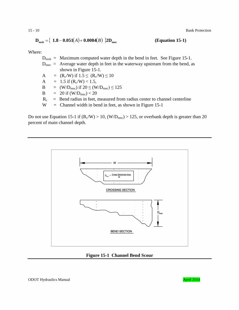
15 - 10 Bank Protection { ( ) ( ) } mncmxb 2D0.00840.0511.8D BA +−= (Equation 15-1) Where:
Dmxb = Maximum computed water depth in the bend in feet. See Figure 15-1. Dmnc = Average water depth in feet in the waterway upstream from the bend, as
shown in Figure 15-1. A = (Rc/W) if 1.5 ≤ (Rc/W) ≤ 10 A = 1.5 if (Rc/W) < 1.5, B = (W/Dmnc) if 20 ≤ (W/Dmnc) ≤ 125 B = 20 if (W/Dmnc) < 20
Rc = Bend radius in feet, measured from radius center to channel centerline W = Channel width in bend in feet, as shown in Figure 15-1
Do not use Equation 15-1 if (Rc/W) > 10, (W/Dmnc) > 125, or overbank depth is greater than 20 percent of main channel depth.
Figure 15-1 Channel Bend Scour
ODOT Hydraulics Manual April 2014
Bank Protection 15 - 11 The equation is valid for sand and gravel streams with naturally developed widths and depths. It is not valid for channels with artificially confined widths less than a natural channel. The equation can be applied to overbank conditions, where the overbank depth is less than 20 percent of the main channel depth. The main channel depth is defined as the average depth within the bed and banks that confine the flow of surface water during the design event. The overbank depth is defined as the average depth of the overbank area beyond the top of the main channel bank during the design event. An alternate method of calculating scour in mild bends (i.e., curve radius/channel width > 30) and straight channels has been developed by Blodgett(4) and the following equations are adopted from his procedure. The reader is referred to reference 4 for more information.
0.11550s(max) 6.5Dd −= for D50 > 0.005 feet (Equation 15-2)
Where:
ds(max) = estimated probable maximum scour depth in feet D50 = median diameter of bed material in feet
If D50 is less than 0.005 feet, ds equals 12 feet. The D50 used in Equation 15-2 is the gradation of the underlying materials at scour depth. It is not the D50 for the coarser armoring layer. Use geological exploration as needed to look at deeper materials below armor layer. Blodgett(4) developed Equation 15-3 for estimating the mean scour depth, ds(mean). The following equation is adopted from his procedure. 0.115
50s(mean) 1.42Dd −= (Equation 15-3) Equations 15-2 and 15-3 calculate the scour depth below the lowest surveyed point in the cross-section. It should be assumed that the low point in the cross-section might eventually migrate adjacent to the bank protection, even if this is not the case in the current channel survey. The depth of scour predicted by equations 15-2 and 15-3 must be added to the magnitude of predicted degradation and local scour, if any, to arrive at the total scour depth. When equations 15-2 and 15-3 are used to design the toe protection, the toe protection should at least be designed to tolerate a scour depth that corresponds to ds(mean). Equation 15-2 represents an enveloping curve for the upper limit of observed scour and consequently may over predict the scour depth, therefore, judgment should be used to determine if the toe protection should be designed to tolerate a scour depth that corresponds to ds(max). April 2014 ODOT Hydraulics Manual
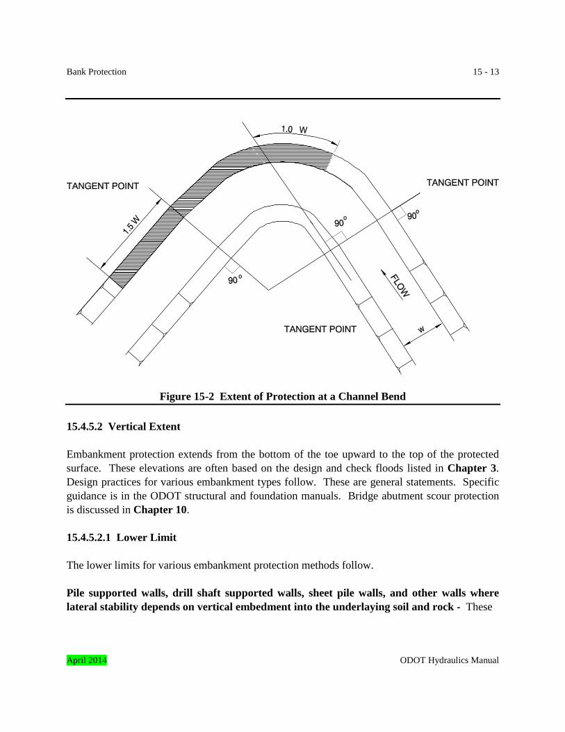
15 - 12 Bank Protection 15.4.5 Extent of Protection Extent of protection refers to the longitudinal and vertical extent of protection required to adequately protect the channel bank. It is also important for the stability of the selected bank protection scheme. 15.4.5.1 Longitudinal Extent The longitudinal extent of protection required for a particular bank protection scheme is highly dependent on local site conditions. In general, the bank protection scheme should be able to protect the bank for a distance greater than the length that is impacted by channel-flow forces severe enough to cause dislodging and/or transport of bank material. Investigators of field installations of bank protection have found that bank protection commonly extends farther upstream than necessary and not far enough downstream. Figure 15-2 was developed from U.S. Army Corps of Engineers studies of the extent of protection required at meander bends, and it can be used as a guide when determining the length of bank to be protected. The minimum length of bank that should be protected is the length of bank that is observed to be actively eroding. A longer bank length may need to be protected if it is judged that additional bank is vulnerable to erosion if left unprotected based on local site conditions, particularly on the downstream side of the active erosion. The limit of protection on the downstream end should depend on where the flow crosses to the opposite bank, and should consider future bar building on the opposite bank, resulting in channel constriction and increased velocities. A review of aerial photographs along with the site inspection can provide some insight on where the crossover flow occurs. Geomorphic studies to determine the limits of protection should be considered. Environmental concerns may play a role in determining the limits of protection, particularly when the design proposes disturbing portions of the bank that are beyond the limits of the observed active erosion. Wherever possible, the bank protection should tie into stable anchorage points, such as bridge abutments, rock outcrops, or well-vegetated, stable channel sections. When a stable feature does not exist, flank protection as described in Subsection 15.5.1.6 should be considered. Note: Eroding streambanks frequently affect both the agency and neighboring landowners. ODOT funds are used only to protect ODOT facilities. Often the training structures or embankment protection needed to do this extends, or is built, on neighboring properties. This is done after obtaining the properties, drainage easements, cooperative agreements, or other suitable means.
ODOT Hydraulics Manual April 2014
Bank Protection 15 - 13
Figure 15-2 Extent of Protection at a Channel Bend 15.4.5.2 Vertical Extent Embankment protection extends from the bottom of the toe upward to the top of the protected surface. These elevations are often based on the design and check floods listed in Chapter 3. Design practices for various embankment types follow. These are general statements. Specific guidance is in the ODOT structural and foundation manuals. Bridge abutment scour protection is discussed in Chapter 10. 15.4.5.2.1 Lower Limit The lower limits for various embankment protection methods follow. Pile supported walls, drill shaft supported walls, sheet pile walls, and other walls where lateral stability depends on vertical embedment into the underlaying soil and rock - These
April 2014 ODOT Hydraulics Manual
15 - 14 Bank Protection walls are at a minimum, designed to withstand hydraulic forces and scour that occurs during the design event, and they are verified to be stable during the check flood. Other stability issues also need to be addressed, such as seismic loading. The pile or shaft tips may extend down well below the check flood elevation to provide stability. The lower edges of the wall faces extend at least down to the check flood scour elevation. This protects the embankment toe during large floods. Riprap, articulated concrete block mats, jacks, or other suitable means can be used to reduce scour depths. The protection methods are designed using the design event and checked for stability during the check flood. Gabion walls and other gravity walls, footing supported walls, and reinforced earth walls – These walls, at a minimum, are designed to withstand the hydraulic forces and scour depth associated with the design event, and it is verified they will be stable during the check flood. The bases of the wall or the bottoms of the footings are at or below the check flood elevation. The tops of the footings, if footings are used, are at or below the design event elevation. At a minimum, the bottoms of the footings or wall base are to be at least 6 feet below the channel bottom elevation unless they are keyed into non-erodible rock. Potential scour depths can be reduced by use of riprap, blocks, or other means as mentioned for pile supported walls. Riprap revetment and riprap toes for other wall types – The lower limits of riprap embankment protection are discussed in Subsection 15.5.1.5. 15.4.5.2.2 Upper Limit The upper limit for embankment protection is typically the design event elevation plus 1 foot for freeboard. Freeboard should be increased at sites subject to wave action generated from boat traffic or wind. Freeboard should also include the superelevation in channel bends. Superelevation can be estimated by methods in Chapter 8. Bank protection should extend to the top of the bank at sites where the design event elevation exceeds the top of bank elevation. The embankment protection design should also be analyzed using the check flood. A higher top of protection elevation may be warranted in critical areas where damage cannot be tolerated. ODOT Hydraulics Manual April 2014
Bank Protection 15 - 15 15.5 Design Guidelines The following sections present design guidelines for various techniques that are used for bank protection. 15.5.1 Rock Riprap This subsection contains design guidelines for the design of rock riprap revetment embankment protection, and bridge abutment and pier protection. Guidelines are provided for bank slope, rock size, rock gradation, durability, riprap layer thickness, filter design, and edge treatment. In addition, typical construction details are illustrated and examples are provided. Additional information on structure revetment, including details, is in Chapter 10, Bridges. 15.5.1.1 Bank Slope A primary consideration in the design of stable riprap bank protection is the slope of the channel bank. Two items need to be considered. First is the stability of the riprap face. The second is the stability of the embankment behind the riprap. Normally, the maximum recommended riprap face slope on an engineered embankment is 1V: 1½H. Engineered embankments are typically bridge abutments and roadway embankments made from materials complying with ODOT requirements and constructed according to practices in ODOT specifications. This includes placing the fill in layers, compaction in layers, etc. Slopes made of natural materials placed by geologic processes are a different situation. Examples are hillsides and streambanks. The steepest slopes these materials may withstand may be greater or less than 1V: 1½H. It is recommended that an engineer or other qualified person familiar with slope stability determine the stability of non-engineered slopes. This is especially important if the slope supports a structure or roadway. It is important to determine the cause of the bank failure prior to design, and to address the problem in the design. Experience has shown that streamside embankment failures are often caused by factors other than riverine scour. An example is a failure of a cross-culvert under the roadway. Water percolating into the embankment from a plugged or perforated culvert can weaken the embankment and cause failure. The stability of the riprap itself limits the maximum recommended embankment face slope to 1V: 1½H. Although not recommended, riprap slopes as steep as 1V: 1H have been successfully constructed. These were done on maintenance repairs, and these steep slopes are strongly April 2014 ODOT Hydraulics Manual
15 - 16 Bank Protection discouraged on new designs. The successful riprap installations on overly steep slopes almost always:
• used larger rocks and greater layer thicknesses than an embankments with flatter slopes would need to withstand identical wave attacks or lateral velocities,
• were founded on a deep and stable toes (this is especially critical), • were placed by methods other than dumping, such as carefully fitting the individual rocks
into the revetment layer, one-at-a-time, with an excavator, and • used extremely angular rock such as basalt blasted from a quarry face.
15.5.1.2 Rock Properties The properties of the riprap rock are important if the installation is to perform as designed. The riprap must be stable when subjected to hydraulic forces. Riprap particle stability is a function of its density, its size expressed either in terms of its weight or equivalent spherical diameter, and its shape. The rock must be durable. The requirements in the ODOT Standard Specifications for Construction are adequate for most installations. Occasionally a special specification will be needed, and it is included in the project supplemental specifications. Density – Rock to be used for revetment must be dense enough to resist displacement due to hydraulic forces. The most commonly used stone in Oregon is crushed basalt from quarries. Occasionally other rocks are used. The specific gravities for various rock types are listed in Table 15-1. A density of 165 pounds per cubic foot and a specific gravity of 2.65 are almost always used in design. These values represent the typical riprap rock. The actual rock density should be used in the design if it is known and it is significantly different than 2.65. Most of the revetment design procedures have adjustment methods to accommodate different rock densities. The minimum allowable specific gravity for riprap is 2.50. Equivalent Spherical Diameter - Revetment riprap stones are rarely round in shape. The properties of a hypothetical round stone are used to simplify calculations. The diameter of these rocks is called the “equivalent spherical diameter.” The following equation can be used to calculate the stone weight for rock that weights 165 pounds per cubic foot:
3
2D691.15W
= (Equation 15-4)
ODOT Hydraulics Manual April 2014
Bank Protection 15 - 17
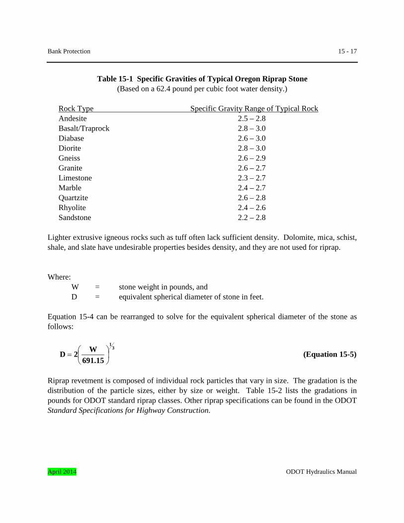
Table 15-1 Specific Gravities of Typical Oregon Riprap Stone
(Based on a 62.4 pound per cubic foot water density.) Rock Type Specific Gravity Range of Typical Rock Andesite 2.5 – 2.8 Basalt/Traprock 2.8 – 3.0 Diabase 2.6 – 3.0 Diorite 2.8 – 3.0 Gneiss 2.6 – 2.9 Granite 2.6 – 2.7 Limestone 2.3 – 2.7 Marble 2.4 – 2.7 Quartzite 2.6 – 2.8 Rhyolite 2.4 – 2.6 Sandstone 2.2 – 2.8 Lighter extrusive igneous rocks such as tuff often lack sufficient density. Dolomite, mica, schist, shale, and slate have undesirable properties besides density, and they are not used for riprap. Where: W = stone weight in pounds, and D = equivalent spherical diameter of stone in feet. Equation 15-4 can be rearranged to solve for the equivalent spherical diameter of the stone as follows:
3
1
691.15W2D
= (Equation 15-5)
Riprap revetment is composed of individual rock particles that vary in size. The gradation is the distribution of the particle sizes, either by size or weight. Table 15-2 lists the gradations in pounds for ODOT standard riprap classes. Other riprap specifications can be found in the ODOT Standard Specifications for Highway Construction.
April 2014 ODOT Hydraulics Manual
15 - 18 Bank Protection
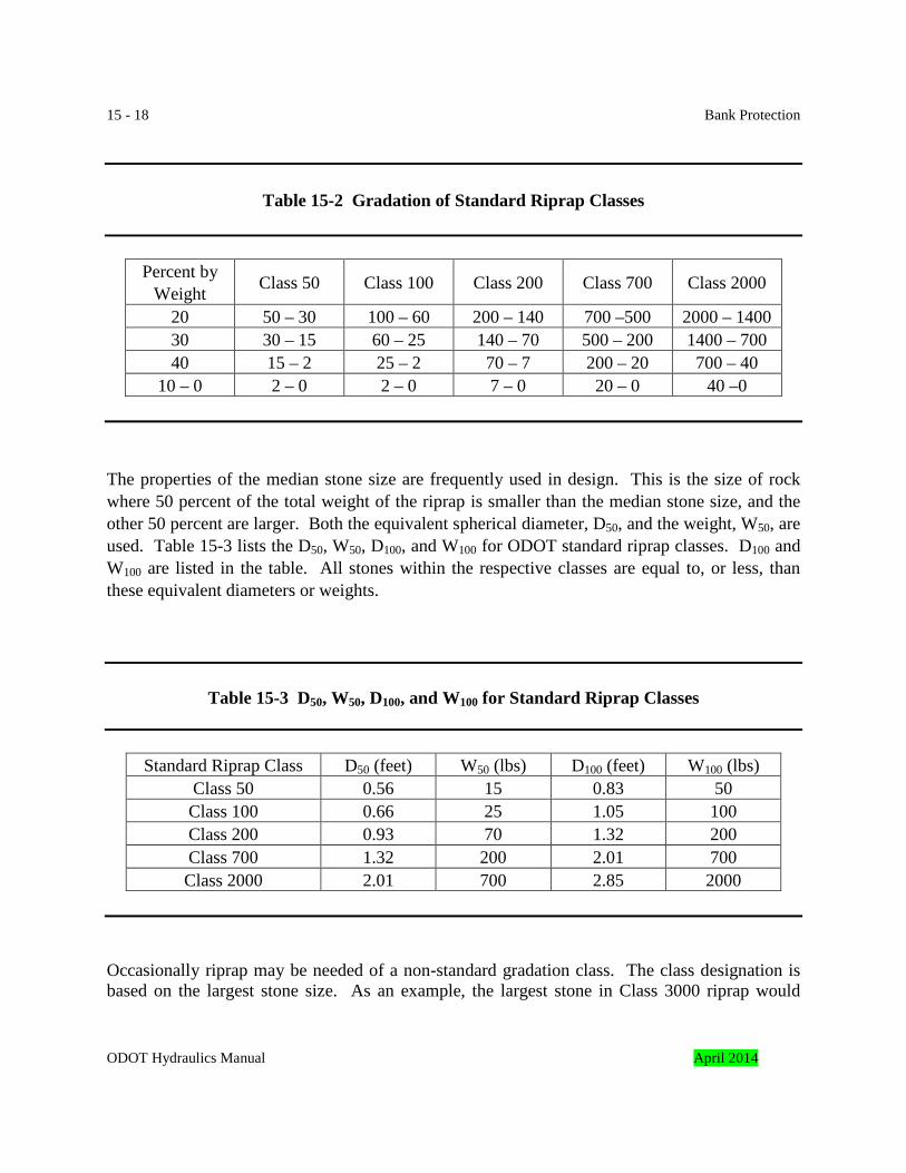
Table 15-2 Gradation of Standard Riprap Classes
Percent by Weight Class 50 Class 100 Class 200 Class 700 Class 2000
20 50 – 30 100 – 60 200 – 140 700 –500 2000 – 1400 30 30 – 15 60 – 25 140 – 70 500 – 200 1400 – 700 40 15 – 2 25 – 2 70 – 7 200 – 20 700 – 40
10 – 0 2 – 0 2 – 0 7 – 0 20 – 0 40 –0 The properties of the median stone size are frequently used in design. This is the size of rock where 50 percent of the total weight of the riprap is smaller than the median stone size, and the other 50 percent are larger. Both the equivalent spherical diameter, D50, and the weight, W50, are used. Table 15-3 lists the D50, W50, D100, and W100 for ODOT standard riprap classes. D100 and W100 are listed in the table. All stones within the respective classes are equal to, or less, than these equivalent diameters or weights.
Table 15-3 D50, W50, D100, and W100 for Standard Riprap Classes
Standard Riprap Class D50 (feet) W50 (lbs) D100 (feet) W100 (lbs) Class 50 0.56 15 0.83 50 Class 100 0.66 25 1.05 100 Class 200 0.93 70 1.32 200 Class 700 1.32 200 2.01 700 Class 2000 2.01 700 2.85 2000
Occasionally riprap may be needed of a non-standard gradation class. The class designation is based on the largest stone size. As an example, the largest stone in Class 3000 riprap would
ODOT Hydraulics Manual April 2014
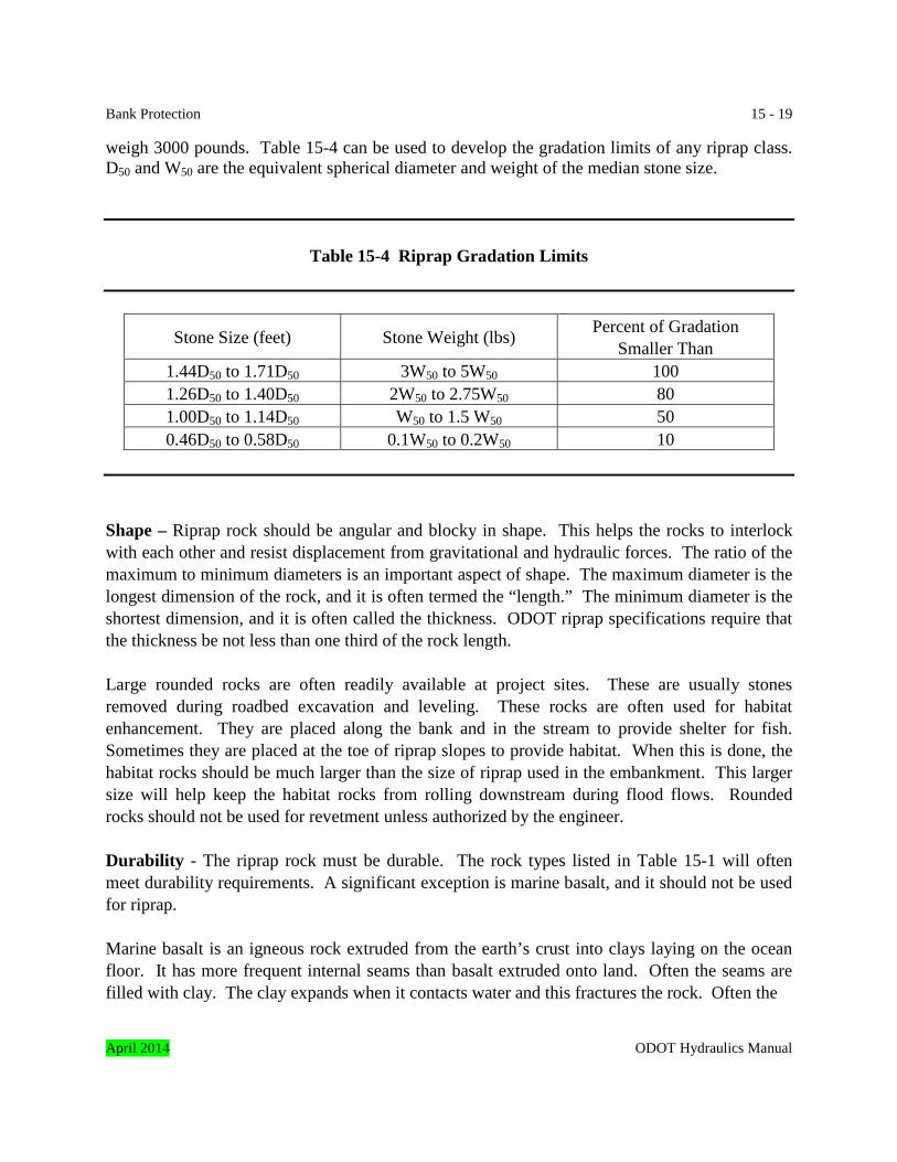
Bank Protection 15 - 19 weigh 3000 pounds. Table 15-4 can be used to develop the gradation limits of any riprap class. D50 and W50 are the equivalent spherical diameter and weight of the median stone size.
Table 15-4 Riprap Gradation Limits
Stone Size (feet) Stone Weight (lbs) Percent of Gradation Smaller Than
1.44D50 to 1.71D50 3W50 to 5W50 100 1.26D50 to 1.40D50 2W50 to 2.75W50 80 1.00D50 to 1.14D50 W50 to 1.5 W50 50 0.46D50 to 0.58D50 0.1W50 to 0.2W50 10
Shape – Riprap rock should be angular and blocky in shape. This helps the rocks to interlock with each other and resist displacement from gravitational and hydraulic forces. The ratio of the maximum to minimum diameters is an important aspect of shape. The maximum diameter is the longest dimension of the rock, and it is often termed the “length.” The minimum diameter is the shortest dimension, and it is often called the thickness. ODOT riprap specifications require that the thickness be not less than one third of the rock length. Large rounded rocks are often readily available at project sites. These are usually stones removed during roadbed excavation and leveling. These rocks are often used for habitat enhancement. They are placed along the bank and in the stream to provide shelter for fish. Sometimes they are placed at the toe of riprap slopes to provide habitat. When this is done, the habitat rocks should be much larger than the size of riprap used in the embankment. This larger size will help keep the habitat rocks from rolling downstream during flood flows. Rounded rocks should not be used for revetment unless authorized by the engineer. Durability - The riprap rock must be durable. The rock types listed in Table 15-1 will often meet durability requirements. A significant exception is marine basalt, and it should not be used for riprap. Marine basalt is an igneous rock extruded from the earth’s crust into clays laying on the ocean floor. It has more frequent internal seams than basalt extruded onto land. Often the seams are filled with clay. The clay expands when it contacts water and this fractures the rock. Often the April 2014 ODOT Hydraulics Manual
15 - 20 Bank Protection
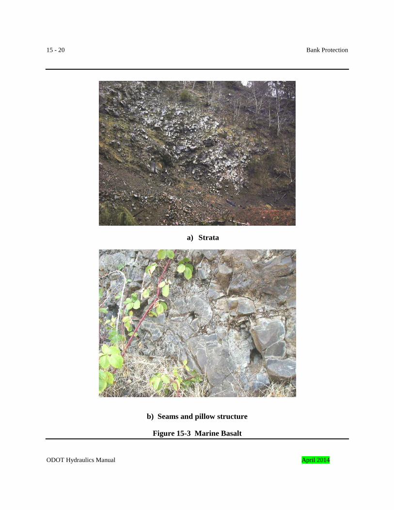
a) Strata
b) Seams and pillow structure
Figure 15-3 Marine Basalt
ODOT Hydraulics Manual April 2014
Bank Protection 15 - 21 rock fractures into pieces of only a few inches in size. The damaged rock no longer has the desired gradation and it is susceptible to displacement by hydraulic forces. Marine basalts occur more frequently in western Oregon than the rest of the state. They can be identified by the many clay filled seams within the rock. Occasionally the “pillow” structure is evident from the underwater extrusion. Figure 15-3a shows marine basalt strata. Figure 15-3b shows a closer view. The pillow structure and seams are evident.
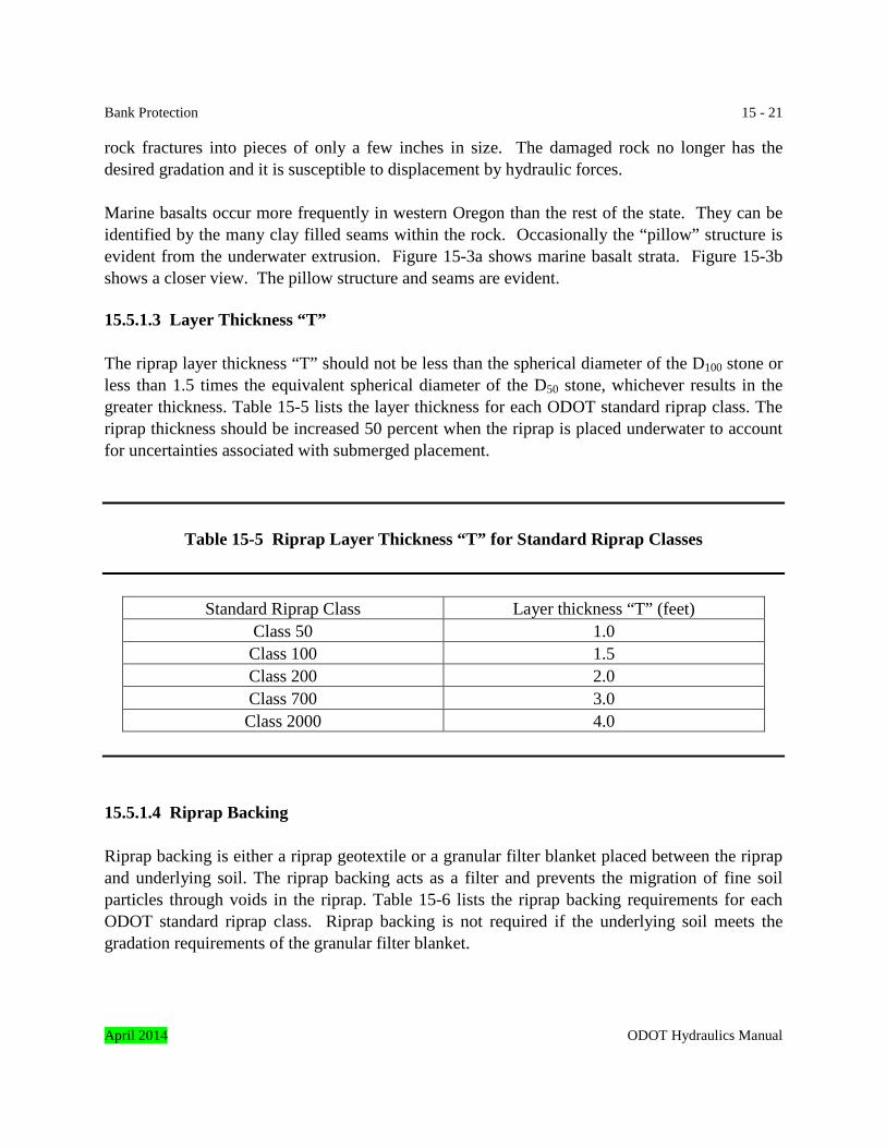
15.5.1.3 Layer Thickness “T” The riprap layer thickness “T” should not be less than the spherical diameter of the D100 stone or less than 1.5 times the equivalent spherical diameter of the D50 stone, whichever results in the greater thickness. Table 15-5 lists the layer thickness for each ODOT standard riprap class. The riprap thickness should be increased 50 percent when the riprap is placed underwater to account for uncertainties associated with submerged placement.
Table 15-5 Riprap Layer Thickness “T” for Standard Riprap Classes
Standard Riprap Class Layer thickness “T” (feet) Class 50 1.0 Class 100 1.5 Class 200 2.0 Class 700 3.0 Class 2000 4.0
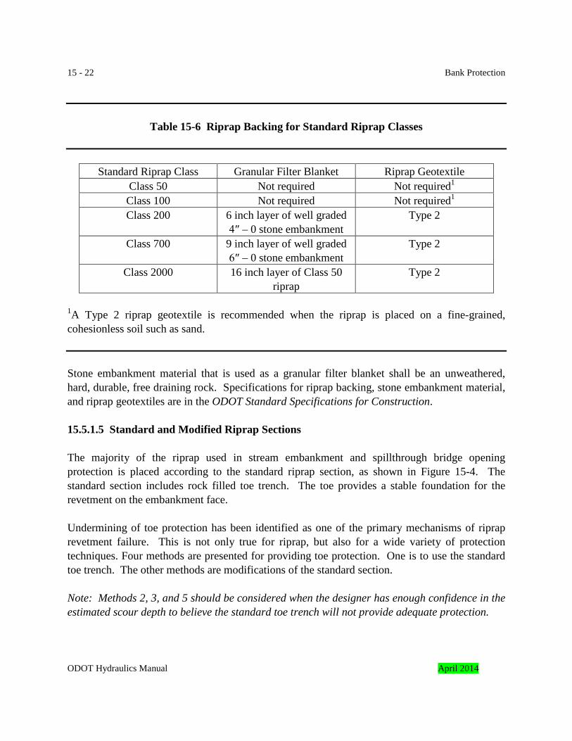
15.5.1.4 Riprap Backing Riprap backing is either a riprap geotextile or a granular filter blanket placed between the riprap and underlying soil. The riprap backing acts as a filter and prevents the migration of fine soil particles through voids in the riprap. Table 15-6 lists the riprap backing requirements for each ODOT standard riprap class. Riprap backing is not required if the underlying soil meets the gradation requirements of the granular filter blanket.
April 2014 ODOT Hydraulics Manual
15 - 22 Bank Protection
Table 15-6 Riprap Backing for Standard Riprap Classes
Standard Riprap Class Granular Filter Blanket Riprap Geotextile Class 50 Not required Not required1
Class 100 Not required Not required1
Class 200 6 inch layer of well graded 4″ – 0 stone embankment
Type 2
Class 700 9 inch layer of well graded 6″ – 0 stone embankment
Type 2
Class 2000 16 inch layer of Class 50 riprap
Type 2
1A Type 2 riprap geotextile is recommended when the riprap is placed on a fine-grained, cohesionless soil such as sand.
Stone embankment material that is used as a granular filter blanket shall be an unweathered, hard, durable, free draining rock. Specifications for riprap backing, stone embankment material, and riprap geotextiles are in the ODOT Standard Specifications for Construction.
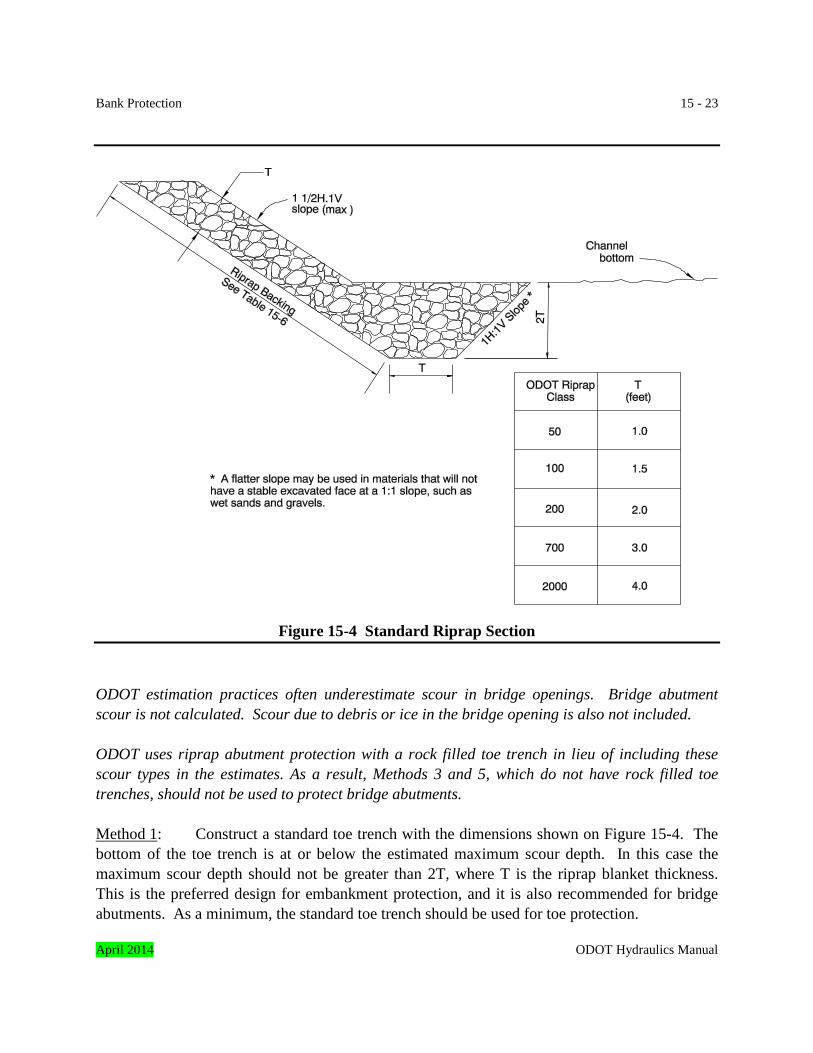
15.5.1.5 Standard and Modified Riprap Sections The majority of the riprap used in stream embankment and spillthrough bridge opening protection is placed according to the standard riprap section, as shown in Figure 15-4. The standard section includes rock filled toe trench. The toe provides a stable foundation for the revetment on the embankment face. Undermining of toe protection has been identified as one of the primary mechanisms of riprap revetment failure. This is not only true for riprap, but also for a wide variety of protection techniques. Four methods are presented for providing toe protection. One is to use the standard toe trench. The other methods are modifications of the standard section. Note: Methods 2, 3, and 5 should be considered when the designer has enough confidence in the estimated scour depth to believe the standard toe trench will not provide adequate protection.
ODOT Hydraulics Manual April 2014
Bank Protection 15 - 23
Figure 15-4 Standard Riprap Section ODOT estimation practices often underestimate scour in bridge openings. Bridge abutment scour is not calculated. Scour due to debris or ice in the bridge opening is also not included. ODOT uses riprap abutment protection with a rock filled toe trench in lieu of including these scour types in the estimates. As a result, Methods 3 and 5, which do not have rock filled toe trenches, should not be used to protect bridge abutments. Method 1: Construct a standard toe trench with the dimensions shown on Figure 15-4. The bottom of the toe trench is at or below the estimated maximum scour depth. In this case the maximum scour depth should not be greater than 2T, where T is the riprap blanket thickness. This is the preferred design for embankment protection, and it is also recommended for bridge abutments. As a minimum, the standard toe trench should be used for toe protection. April 2014 ODOT Hydraulics Manual
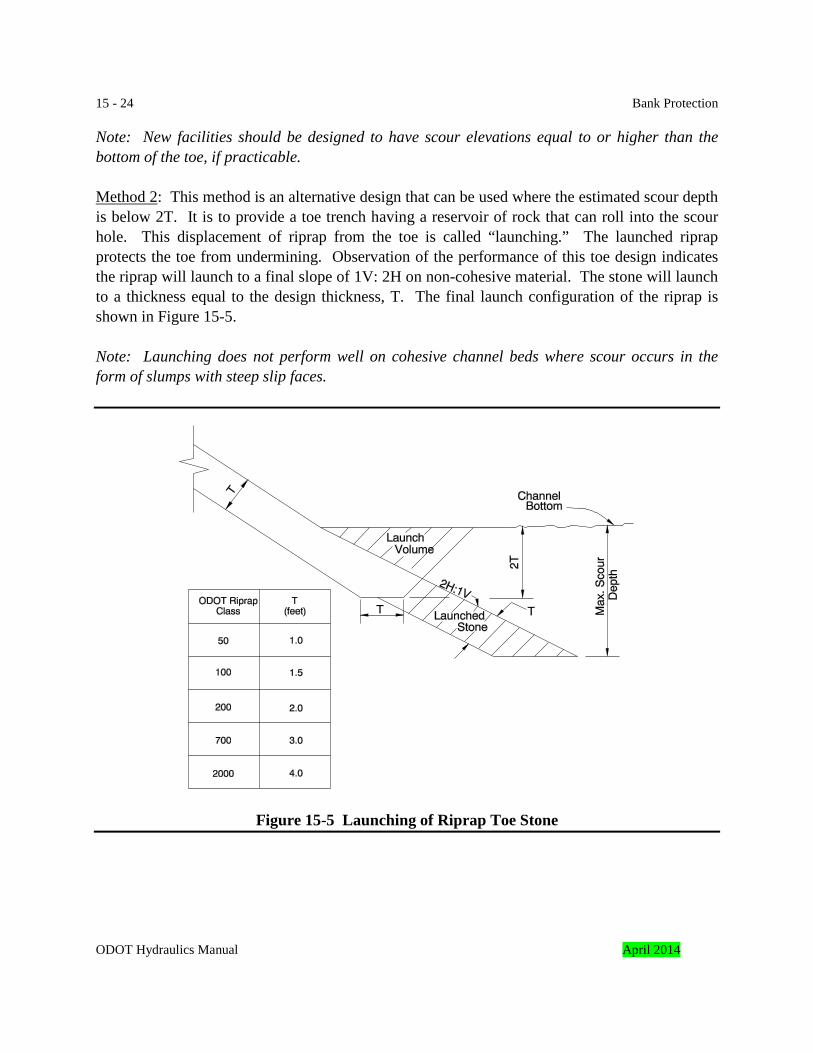
15 - 24 Bank Protection Note: New facilities should be designed to have scour elevations equal to or higher than the bottom of the toe, if practicable. Method 2: This method is an alternative design that can be used where the estimated scour depth is below 2T. It is to provide a toe trench having a reservoir of rock that can roll into the scour hole. This displacement of riprap from the toe is called “launching.” The launched riprap protects the toe from undermining. Observation of the performance of this toe design indicates the riprap will launch to a final slope of 1V: 2H on non-cohesive material. The stone will launch to a thickness equal to the design thickness, T. The final launch configuration of the riprap is shown in Figure 15-5. Note: Launching does not perform well on cohesive channel beds where scour occurs in the form of slumps with steep slip faces.
Figure 15-5 Launching of Riprap Toe Stone
ODOT Hydraulics Manual April 2014
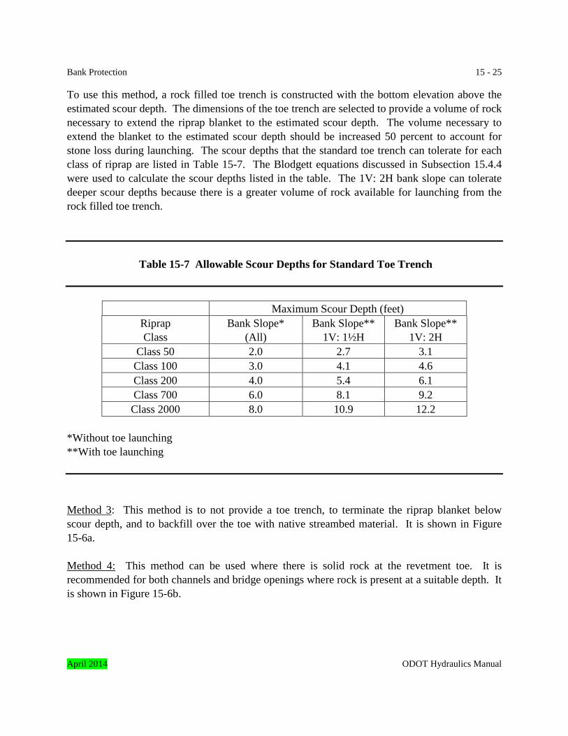
Bank Protection 15 - 25 To use this method, a rock filled toe trench is constructed with the bottom elevation above the estimated scour depth. The dimensions of the toe trench are selected to provide a volume of rock necessary to extend the riprap blanket to the estimated scour depth. The volume necessary to extend the blanket to the estimated scour depth should be increased 50 percent to account for stone loss during launching. The scour depths that the standard toe trench can tolerate for each class of riprap are listed in Table 15-7. The Blodgett equations discussed in Subsection 15.4.4 were used to calculate the scour depths listed in the table. The 1V: 2H bank slope can tolerate deeper scour depths because there is a greater volume of rock available for launching from the rock filled toe trench.
Table 15-7 Allowable Scour Depths for Standard Toe Trench
Maximum Scour Depth (feet) Riprap Class
Bank Slope* (All)
Bank Slope** 1V: 1½H
Bank Slope** 1V: 2H
Class 50 2.0 2.7 3.1 Class 100 3.0 4.1 4.6 Class 200 4.0 5.4 6.1 Class 700 6.0 8.1 9.2 Class 2000 8.0 10.9 12.2
*Without toe launching **With toe launching Method 3: This method is to not provide a toe trench, to terminate the riprap blanket below scour depth, and to backfill over the toe with native streambed material. It is shown in Figure 15-6a. Method 4: This method can be used where there is solid rock at the revetment toe. It is recommended for both channels and bridge openings where rock is present at a suitable depth. It is shown in Figure 15-6b.
April 2014 ODOT Hydraulics Manual
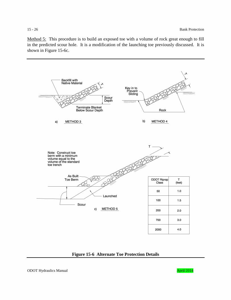
15 - 26 Bank Protection Method 5: This procedure is to build an exposed toe with a volume of rock great enough to fill in the predicted scour hole. It is a modification of the launching toe previously discussed. It is shown in Figure 15-6c.
Figure 15-6 Alternate Toe Protection Details
ODOT Hydraulics Manual April 2014
Bank Protection 15 - 27 15.5.1.6 Flank Treatment
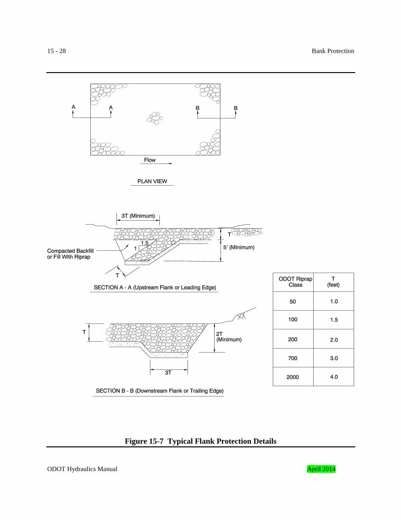
Flank treatment includes special design features to prevent flanking of the ends of the revetment. Wherever possible, the bank protection should tie into stable anchorage points, such as bridge abutments, rock outcrops, or well-vegetated, stable channel sections. When a stable feature does not exist, flank protection as shown in Figure 15-7 should be considered. 15.5.1.7 Calculating Riprap Size The following subsections present methods to calculate the riprap size required to resist streamflow and wave hydraulic forces. All applicable methods are to be used at each site. The selected rock size is equal to or larger than the most appropriate calculated value, unless:
• historical performance of riprap at or near the site, or the size of bed material moved by the stream indicates a different size rock is needed, or
• a suitable hydraulic model cannot be developed to calculate riprap size. In this case, the size is based on parol evidence, the history of the site, and a site investigation.
Riprap size is calculated using a design and a check discharge. It is sized to be stable during the design discharge. The size is checked to verify it will be stable during the check discharge. Occasionally the riprap size adequate for the design discharge will need to be increased to be stable during the check discharge. Design and check discharges are listed in Chapter 3. These methods can also be used to size rock for lining large channels (discharge is greater than 50 cubic feet per second). Riprap sizing methods for smaller channels are in Chapter 8. 15.5.1.7.1 Parol Evidence, History & Site Investigation Method The parol evidence, history, and site investigation method consists of a thorough evaluation of historic riprap stability at the site and similar nearby sites. This method is recommended for:
• all locations where data is available.
The results of this method should not be used at all sites, although its results should be considered. The results should be compared to the calculated values from the other procedures if they are used. This method is often the only practicable procedure at locations with complex interactions of oceanic, riverine, and estuarine hydraulics, or sites with complex river/floodplain hydraulic relationships. It is often very difficult at these locations to construct the numerical hydraulic models needed for the other procedures. April 2014 ODOT Hydraulics Manual
15 - 28 Bank Protection
Figure 15-7 Typical Flank Protection Details ODOT Hydraulics Manual April 2014
Bank Protection 15 - 29 The primary sources of information this procedure are:
• records of historic revetment installation and repairs, • eyewitness accounts by people familiar with the structure, and • field inspection.
Historic documentation often mentions the size of riprap installed in the past. Records of historic repairs and scour problems for structures are documented in the bridge inspection and bridge maintenance files. Copies are available from the ODOT Bridge Section. Records of many repairs to both structures and roadways are documented in the ODOT vertical “V” files. Copies are available from the ODOT Roadway Section. Scour problems and repairs are also documented in the ODOT hydraulics files. Copies are available from the ODOT Geo-Environmental Section. Additional guidance on information collection is in Chapter 6. Eyewitness accounts from people familiar with the structure can also be helpful when sizing riprap. Structure and roadway maintenance personnel are good sources. Nearby residents can also be helpful. Photographs are also valuable. They can be used to estimate riprap size. Field inspection often gives insight on adequate riprap size. Particular attention should be given to the size of the riprap that is in place at or near the site. The designer should also note the predominant hydraulic forces at the site: i.e. tractive forces due to streamflow, tidal action, wind driven waves, boat wakes, etc. Careful attention is needed during a field inspection to locate existing riprap that is in hydraulically similar conditions. As an example, a bridge abutment is proposed in very shallow water at the edge of a bay. During severe winter storms the abutment is on the leeward shore. The predominant hydraulic forces are due to wave action. The ability of a wave to displace riprap is proportional to the wave height. Waves are highest in deeper water on the windward side of bays. Riprap adequate to withstand waves in deep water on the windward side may be overly large for the proposed abutment. The performance of existing riprap on the leeward side of the bay or nearby bays in shallow water would be a better indicator of site conditions. The size of bed material transported by the stream at the specific location of the proposed riprap is determined by both the field inspection and geological exploration. This information is critical when sizing riprap. Many experienced designers do not select riprap with a D50 less than two or three times the maximum diameter of the moving bed material at the location where the riprap will be placed. This practice is recommended. April 2014 ODOT Hydraulics Manual
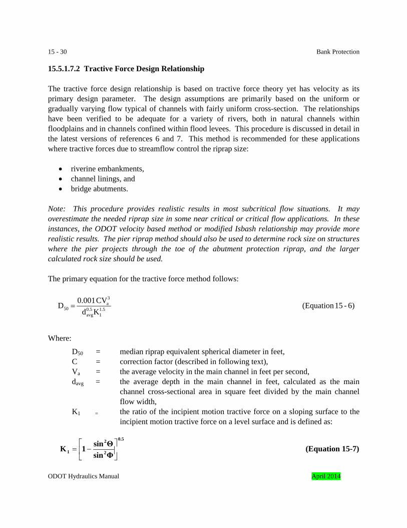
15 - 30 Bank Protection 15.5.1.7.2 Tractive Force Design Relationship The tractive force design relationship is based on tractive force theory yet has velocity as its primary design parameter. The design assumptions are primarily based on the uniform or gradually varying flow typical of channels with fairly uniform cross-section. The relationships have been verified to be adequate for a variety of rivers, both in natural channels within floodplains and in channels confined within flood levees. This procedure is discussed in detail in the latest versions of references 6 and 7. This method is recommended for these applications where tractive forces due to streamflow control the riprap size:
• riverine embankments, • channel linings, and • bridge abutments.
Note: This procedure provides realistic results in most subcritical flow situations. It may overestimate the needed riprap size in some near critical or critical flow applications. In these instances, the ODOT velocity based method or modified Isbash relationship may provide more realistic results. The pier riprap method should also be used to determine rock size on structures where the pier projects through the toe of the abutment protection riprap, and the larger calculated rock size should be used. The primary equation for the tractive force method follows:
Where:
D50 = median riprap equivalent spherical diameter in feet, C = correction factor (described in following text), Va = the average velocity in the main channel in feet per second,
davg = the average depth in the main channel in feet, calculated as the main channel cross-sectional area in square feet divided by the main channel flow width,
K1 = the ratio of the incipient motion tractive force on a sloping surface to the incipient motion tractive force on a level surface and is defined as:
0.5
2
2
1 ΦsinΘsin1K
−= (Equation 15-7)
6)-15(Equation KdCV 0.001 D 1.5
10.5avg
3a
50 =
ODOT Hydraulics Manual April 2014
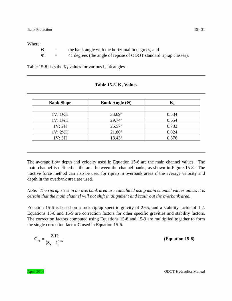
Bank Protection 15 - 31 Where: Θ = the bank angle with the horizontal in degrees, and Φ = 41 degrees (the angle of repose of ODOT standard riprap classes). Table 15-8 lists the K1 values for various bank angles.
Table 15-8 K1 Values
Bank Slope Bank Angle (Θ) K1
1V: 1½H 33.69º 0.534 1V: 1¾H 29.74º 0.654 1V: 2H 26.57º 0.732
1V: 2½H 21.80º 0.824 1V: 3H 18.43º 0.876
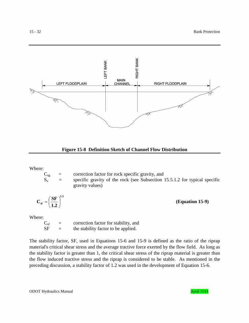
The average flow depth and velocity used in Equation 15-6 are the main channel values. The main channel is defined as the area between the channel banks, as shown in Figure 15-8. The tractive force method can also be used for riprap in overbank areas if the average velocity and depth in the overbank area are used. Note: The riprap sizes in an overbank area are calculated using main channel values unless it is certain that the main channel will not shift in alignment and scour out the overbank area. Equation 15-6 is based on a rock riprap specific gravity of 2.65, and a stability factor of 1.2. Equations 15-8 and 15-9 are correction factors for other specific gravities and stability factors. The correction factors computed using Equations 15-8 and 15-9 are multiplied together to form the single correction factor C used in Equation 15-6.
( )1.5
ssg 1S
2.12C−
= (Equation 15-8)
April 2014 ODOT Hydraulics Manual
15 - 32 Bank Protection
Figure 15-8 Definition Sketch of Channel Flow Distribution Where: Csg = correction factor for rock specific gravity, and
Ss = specific gravity of the rock (see Subsection 15.5.1.2 for typical specific gravity values)
1.5
sf 1.2SFC
= (Equation 15-9)
Where: Csf = correction factor for stability, and
SF = the stability factor to be applied. The stability factor, SF, used in Equations 15-6 and 15-9 is defined as the ratio of the riprap material's critical shear stress and the average tractive force exerted by the flow field. As long as the stability factor is greater than 1, the critical shear stress of the riprap material is greater than the flow induced tractive stress and the riprap is considered to be stable. As mentioned in the preceding discussion, a stability factor of 1.2 was used in the development of Equation 15-6.
ODOT Hydraulics Manual April 2014
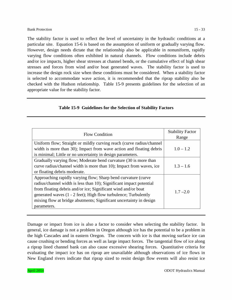
Bank Protection 15 - 33 The stability factor is used to reflect the level of uncertainty in the hydraulic conditions at a particular site. Equation 15-6 is based on the assumption of uniform or gradually varying flow. However, design needs dictate that the relationship also be applicable in nonuniform, rapidly varying flow conditions often exhibited in natural channels. Flow conditions include debris and/or ice impacts, higher shear stresses at channel bends, or the cumulative effect of high shear stresses and forces from wind and/or boat generated waves. The stability factor is used to increase the design rock size when these conditions must be considered. When a stability factor is selected to accommodate wave action, it is recommended that the riprap stability also be checked with the Hudson relationship. Table 15-9 presents guidelines for the selection of an appropriate value for the stability factor.
Table 15-9 Guidelines for the Selection of Stability Factors
Flow Condition Stability Factor Range
Uniform flow; Straight or mildly curving reach (curve radius/channel width is more than 30); Impact from wave action and floating debris is minimal; Little or no uncertainty in design parameters.
1.0 – 1.2
Gradually varying flow; Moderate bend curvature (30 is more than curve radius/channel width is more than 10); Impact from waves, ice or floating debris moderate.
1.3 – 1.6
Approaching rapidly varying flow; Sharp bend curvature (curve radius/channel width is less than 10); Significant impact potential from floating debris and/or ice; Significant wind and/or boat generated waves (1 - 2 feet); High flow turbulence; Turbulently mixing flow at bridge abutments; Significant uncertainty in design parameters.
1.7 –2.0
Damage or impact from ice is also a factor to consider when selecting the stability factor. In general, ice damage is not a problem in Oregon although ice has the potential to be a problem in the high Cascades and in eastern Oregon. The concern with ice is that moving surface ice can cause crushing or bending forces as well as large impact forces. The tangential flow of ice along a riprap lined channel bank can also cause excessive shearing forces. Quantitative criteria for evaluating the impact ice has on riprap are unavailable although observations of ice flows in New England rivers indicate that riprap sized to resist design flow events will also resist ice
April 2014 ODOT Hydraulics Manual
15 - 34 Bank Protection forces. Maintenance personnel should be contacted to determine if a site or watershed is subject to ice and if so, get their advice as to what size riprap has historically provided adequate performance when subjected to ice. Observations and experience of maintenance personnel can also be used to select an appropriate stability factor. Where ice flows have historically caused problems, a stability factor of 1.2 to 1.5 is usually adequate to increase the design rock size. 15.5.1.7.3 ODOT Velocity Based Design Procedure This design method is based on the average channel velocity in the channel bank side slope. It was adapted from a U.S. Bureau of Public Roads (USBPR) procedure, and it has been used by ODOT for over thirty years. The original USBPR procedure was developed for channel linings and bank protection revetment on straight waterways. ODOT has adapted the procedure to be used on curved waterways and bridge abutments by use of a correction factor. This method is suitable for the following situations where tractive forces due to streamflow predominate:
• riverine embankments or channel linings in straight to moderately curving reaches (curve radius/channel width more than 10), or
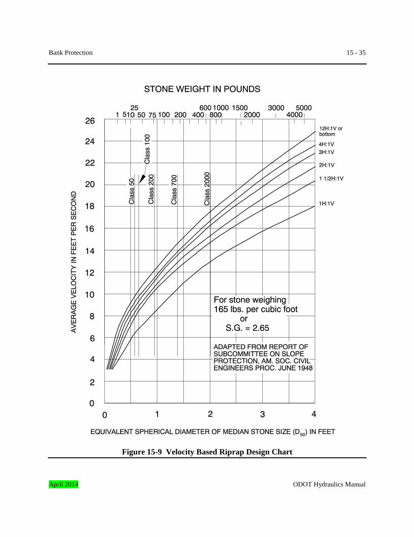
• bridge abutments with no to moderate flow contraction through the bridge opening. Note: The tractive force design method is recommended for channels with sharp bend curvature. The modified Isbash relationship is recommended for abutments in locations with significant flow contraction. The pier riprap method should also be used to determine rock size on structures where the pier projects through the toe of the abutment protection riprap, and the larger calculated rock size should be used. The velocity/side slope/riprap size relationship is shown in Figure 15-9. To use the figure, enter the average channel velocity and side slope of the riprap and then select the appropriate ODOT standard riprap class. The D50 values of ODOT standard riprap classes are plotted on Figure 15-9 and they represent the upper stability limits for the particular riprap classes. The next larger riprap class should be used when the required size of stone exceeds the D50 of a particular riprap class. For example, for a velocity of 9 feet per second and a 1V: 1½H side slope, the embankment should be protected with Class 200 riprap. These average velocities are used:
• the average channel velocity for a straight channel or a slightly curved channel (curve radius/channel width more than 30), or riprap on the inside of a bend on a moderately curved channel,
• 1.33 times the average channel velocity for riprap on the outside of a bend on a moderately curved channel (curve radius /channel width more than 10), or
• 1.33 times the average bridge opening velocity for bridge abutments. ODOT Hydraulics Manual April 2014
Bank Protection 15 - 35
Figure 15-9 Velocity Based Riprap Design Chart April 2014 ODOT Hydraulics Manual

15 - 36 Bank Protection The stone size determined from Figure 15-9 should be corrected with Creager’s equation when the unit weight of stone is other than 165 pounds per cubic foot, as follows.
62.5γ
102.5DD
w
sw −= (Equation 15-10)
Where: Dw = stone size in feet for stone of unit weight γw in pounds per cubic foot, and Ds = stone size in feet from Figure 15-9. 15.5.1.7.4 Hudson Relationship for Wave Erosion Protection Waves generated by wind or boat traffic can cause bank erosion on inland waterways. The most widely used measure of riprap wave resistance is that developed by R. Y. Hudson. The so-called Hudson relationship is given by the following equation:
( ) cotΘ1S2.20
HγW 3
s
3s
50−
= (Equation 15-11)
Where: W50 = median rock weight in pounds, γs = riprap rock unit weight (solid material) in pounds per cubic foot, H = the wave height in feet, Ss = specific gravity of riprap material, and Θ = bank angle with the horizontal in degrees. Assuming Ss = 2.65 and γs = 165 pounds per cubic foot, Equation 15-11 can be reduced to:
cotΘ
16.7HW3
50 = (Equation 15-12)
In terms of an equivalent diameter Equation 15-12 can be reduced to:
350 cotΘ0.75HD = (Equation 15-13)
Where: D50 = median riprap size in feet.
ODOT Hydraulics Manual April 2014
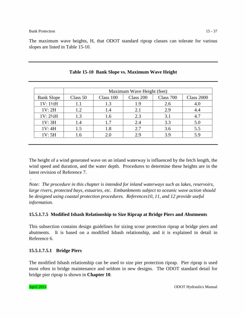
Bank Protection 15 - 37 The maximum wave heights, H, that ODOT standard riprap classes can tolerate for various slopes are listed in Table 15-10.
Table 15-10 Bank Slope vs. Maximum Wave Height
Maximum Wave Height (feet) Bank Slope Class 50 Class 100 Class 200 Class 700 Class 2000 1V: 1½H 1.1 1.3 1.9 2.6 4.0 1V: 2H 1.2 1.4 2.1 2.9 4.4
1V: 2½H 1.3 1.6 2.3 3.1 4.7 1V: 3H 1.4 1.7 2.4 3.3 5.0 1V: 4H 1.5 1.8 2.7 3.6 5.5 1V: 5H 1.6 2.0 2.9 3.9 5.9
The height of a wind generated wave on an inland waterway is influenced by the fetch length, the wind speed and duration, and the water depth. Procedures to determine these heights are in the latest revision of Reference 7. . Note: The procedure in this chapter is intended for inland waterways such as lakes, reservoirs, large rivers, protected bays, estuaries, etc. Embankments subject to oceanic wave action should be designed using coastal protection procedures. References10, 11, and 12 provide useful information. 15.5.1.7.5 Modified Isbash Relationship to Size Riprap at Bridge Piers and Abutments This subsection contains design guidelines for sizing scour protection riprap at bridge piers and abutments. It is based on a modified Isbash relationship, and it is explained in detail in Reference 6. 15.5.1.7.5.1 Bridge Piers The modified Isbash relationship can be used to size pier protection riprap. Pier riprap is used most often in bridge maintenance and seldom in new designs. The ODOT standard detail for bridge pier riprap is shown in Chapter 10. April 2014 ODOT Hydraulics Manual
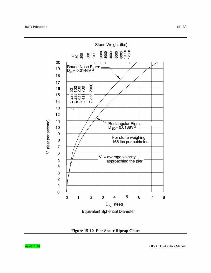
15 - 38 Bank Protection Note: Spillthrough opening bridge piers are sometimes surrounded by the revetment protecting the abutment toe. This procedure should be used in addition to the abutment revetment sizing methods to calculate the needed rock size. The larger calculated rock size should be used. Determine the D50 size of riprap using the rearranged Isbash equation:
( )( )2g1S
KV0.692Ds
2
50 −= (Equation 15-14)
Where: D50 = median stone diameter in feet,
K = pier shape coefficient (K = 1.5 for round-nose piers, K = 1.7 for rectangular piers),
V = average velocity approaching the pier in feet per second, Ss = specific gravity of riprap (normally 2.65), g = acceleration of gravity (32.2 feet per second per second).
The velocity, V, should be the same velocity that was used to calculate local pier scour. Figure 15-10 can be used to determine the D50 size of the riprap necessary to provide scour protection. The upper stability limits for ODOT riprap classes are plotted on Figure 15-10. The next larger riprap class should be used when the required size of stone exceeds the D50 of a particular riprap class. For example, for a round-nose pier subjected to a velocity of 9.0 feet per second, the pier should be protected with Class 700 riprap. ODOT standard riprap classes can be used for a velocities up to 11.7 and 10.3 feet per second for round-nose and rectangular piers, respectively. 15.5.1.7.5.2 Bridge Abutments The following equations for sizing riprap for abutments are based on research conducted by the FHWA in a hydraulic flume. This method determines rock size. Abutment protection details are in Chapter 10, Bridges. This method is applicable to applications where tractive forces due to streamflow predominate, including:
• all bridge abutment types, including those with significant flow contraction into the bridge opening.
Note: The pier riprap method should also be used to determine rock size on structures where the pier projects through the toe of the abutment protection riprap, and the larger calculated rock size should be used.
ODOT Hydraulics Manual April 2014
Bank Protection 15 - 39
Figure 15-10 Pier Scour Riprap Chart April 2014 ODOT Hydraulics Manual
15 - 40 Bank Protection The research was conducted using 1V: 2H slopes for spillthrough abutments. The riprap size should be compared against the riprap size obtained from the other procedures when applying the equations to spillthrough abutments with 1V: 1½H slopes. Engineering judgment should then be used to select the final riprap size. The same procedure is recommended for all spillthrough abutments and vertical abutments – compare the riprap size obtained with following equations to the riprap size obtained from all other applicable methods, and then apply engineering judgment to select the final riprap size.
This form of the Isbash relationship is recommended for Froude numbers, gyV less than or
equal to 0.80, with either spill through or vertical abutments:
(Equation 15-15)
Where: D50 = median stone diameter in feet,
V = characteristic average velocity in the contracted section (explained in the remainder of this subsection), in feet per second,
Ss = specific gravity of rock riprap, g = gravitational acceleration, 32.2 feet/second2 y = depth of flow in the contracted bridge opening in feet, K = 0.89 for spillthrough abutments, and K = 1.02 for vertical abutments. Equation 15-16 is recommended for Froude numbers more than 0.80, (Equation 15-16)
Where: K = 0.61 for spillthrough abutments, and K = 0.69 for vertical abutments.
=
gyy
2
5 V 1 - S
K Ds
0
14.0
s
0 V 1 - S
K D
=
gyy
2
5
ODOT Hydraulics Manual April 2014
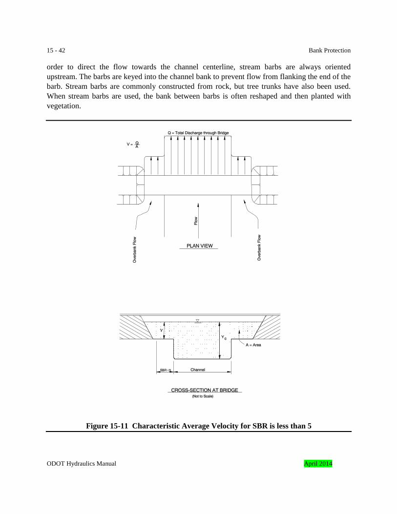
Bank Protection 15 - 41 In both equations, the coefficient K is a velocity multiplier to account for the apparent local acceleration of flow at the point of rock riprap failure. Both of the equations are envelope relationships that were forced to over predict 90 percent of the laboratory data. The first step to determine the characteristic average velocity is to determine the set-back ratio, SBR, of each abutment. SBR is the ratio of the set-back length to average channel flow depth. The set-back length is the distance from the near edge of the main channel to the toe of the abutment. The average channel flow depth is the area of the main channel divided by the top width of the main channel.
depthflow channel Average
lengthback-SetSBR =
The characteristic average velocity depends on the set-back ratio, using the following guidelines.
1. Compute a characteristic average velocity, Q/A, based on the entire contracted area through the bridge opening, if SBR is less than 5 for both abutments (Figure 15-11). This includes the entire upstream flow, exclusive of that which overtops the roadway.
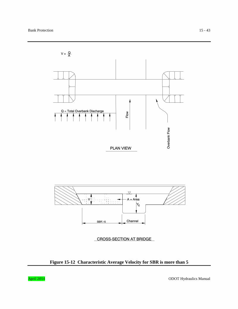
2. Compute a characteristic average velocity, Q/A, for the respective overbank flow only, if
SBR is more than 5 for an abutment (Figure 15-12). Assume that the entire respective overbank flow stays in the overbank section through the bridge opening.
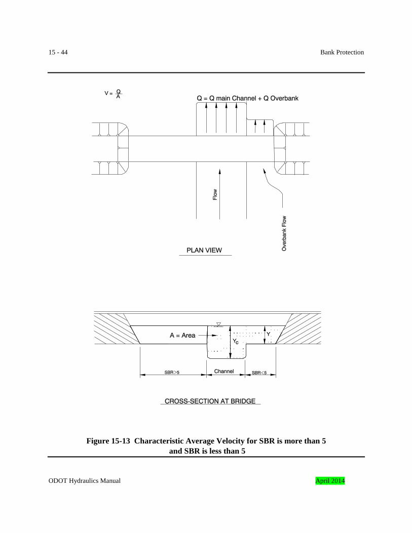
3. A characteristic average velocity determined in Step 1a for the abutment with SBR less
than 5 may be unrealistically low if SBR for one abutment is less than 5 and SBR for the other abutment is more than 5 (Figure 15-13). This would depend upon the opposite overbank discharge as well as how far the other abutment is set back. For this case, the characteristic average velocity for the abutment with SBR less than 5 should be based on the flow area limited by the boundary of that abutment and an imaginary wall located on the opposite channel bank. The appropriate discharge is bounded by this imaginary wall and the outer edge of the floodplain associated with that abutment.
15.5.2 Stream Barbs This section contains design guidelines for designing stream barbs. Stream barbs, also referred to as bendway weirs or bank barbs, are low sills projecting out from a stream bank and across the stream’s thalweg to redirect the stream flow away from an eroding bank towards the channel centerline. Stream barbs are normally not visible, especially at stages above low water and are intended to redirect flow by utilizing weir hydraulics over the stream barb. Flow passing over the barb is redirected so that flow leaving the barb is perpendicular to the barb centerline axis. In April 2014 ODOT Hydraulics Manual
15 - 42 Bank Protection order to direct the flow towards the channel centerline, stream barbs are always oriented upstream. The barbs are keyed into the channel bank to prevent flow from flanking the end of the barb. Stream barbs are commonly constructed from rock, but tree trunks have also been used. When stream barbs are used, the bank between barbs is often reshaped and then planted with vegetation.
Figure 15-11 Characteristic Average Velocity for SBR is less than 5
ODOT Hydraulics Manual April 2014
Bank Protection 15 - 43
Figure 15-12 Characteristic Average Velocity for SBR is more than 5 April 2014 ODOT Hydraulics Manual
15 - 44 Bank Protection
Figure 15-13 Characteristic Average Velocity for SBR is more than 5 and SBR is less than 5
ODOT Hydraulics Manual April 2014
Bank Protection 15 - 45 The channel stability needs to be evaluated before selecting barbs to protect the bank. Barbs should not be used in degrading channels. In degrading channels, the barbs are likely to be undermined and will fail. The approach channel also needs to be laterally stable in order to ensure long-term performance of the barbs. The best sites for stream barbs are long, uniform channel bends where the approach flow pattern will remain relatively constant over time. 15.5.2.1 Height The height of the barb, H, is determined by analyzing various flow depths at the project site as shown in Figure 15-14. The stream barb height should be between 30 to 50 percent of the depth at the mean annual high water elevation. The height of the barb should also be below the normal or seasonal mean water elevation (ordinary high water) and should be equal to or above the mean low water elevation. The barb must be high enough to intercept a large enough percentage of the flow to produce the desired results. If barbs are placed in channels used for boat traffic, the barbs must be low enough to allow boats to safely pass over the barbs. The barb should be keyed a minimum depth of D100 into the channel bottom. 15.5.2.2 Angle of Projection The angle of projection, Θ, between the stream barb axis and the upstream bankline tangent typically ranges from 50 to 85 degrees as shown in Figure 15-14. Rather than measure the angle from the bankline tangent, the angle of projection is often easier to measure from the centerline of the barb to the chord between two adjacent barbs. The chord is drawn from the points of intersection of the barbs and the bankline. The flow pattern entering the area of the proposed barb field should be analyzed and drawn in plan view for low and high flow conditions. The angle of projection,Θ, of the barb into the stream is based on the location of the barb in the bend and the direction of the flow lines of the approach flow. Ideally, the angle of attack of the flow lines at high-water flow should be no greater than 30 degrees and, at low flow, the angle of attack of the flow lines should be no less than 15 degrees to the normal of the centerline of the first few barbs. If the low-flow angle of approach is head-on (parallel to the barb) or close to head-on, the barb will be ineffective and serve to divide the flow. Bank scalloping and erosion will result. Also, the barbs downstream will be less effective due to turbulence and incorrect flow patterns entering their section of the barb field. If the angle of the approach flow line of high-water flow is too large, the weir will not be able to effectively redirect the flow to the desired direction. The upstream edge of the weir should be a well-defined straight line.
April 2014 ODOT Hydraulics Manual
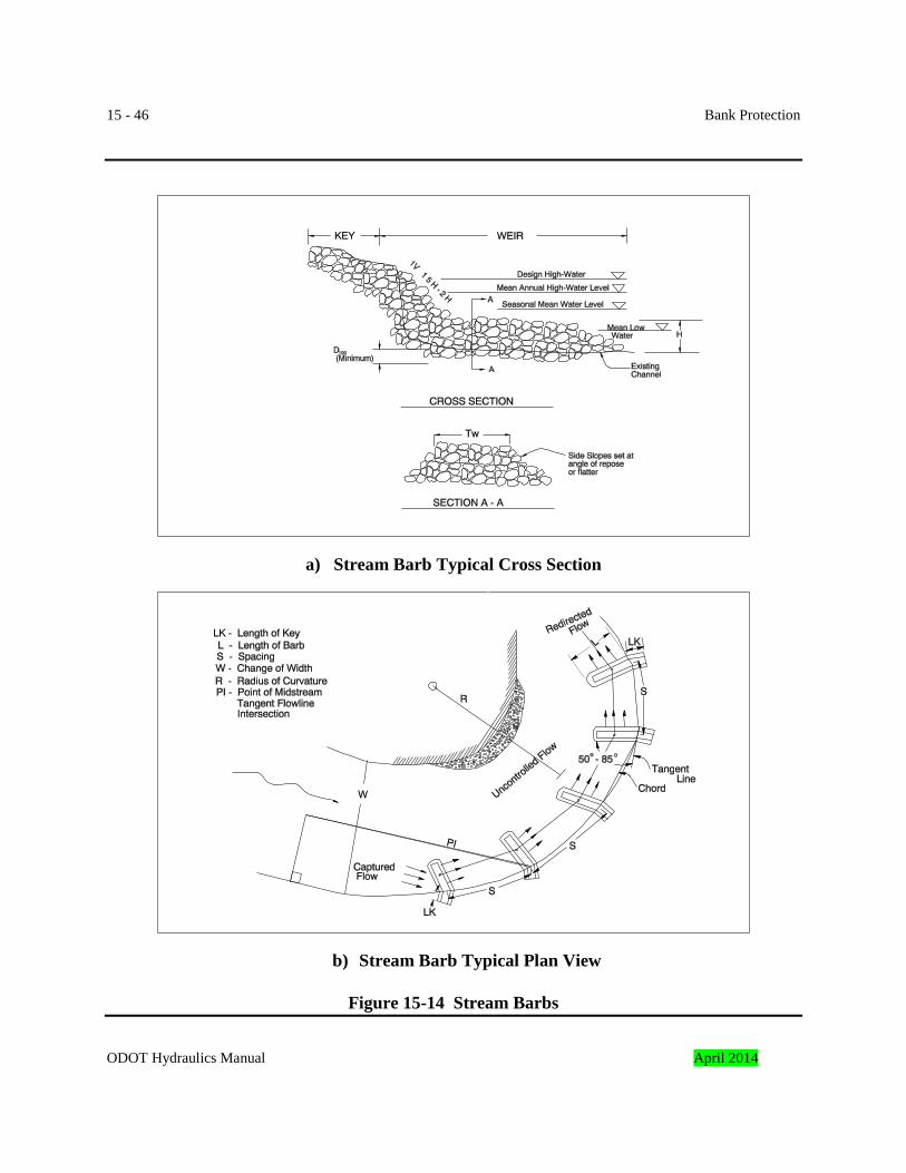
15 - 46 Bank Protection
a) Stream Barb Typical Cross Section
b) Stream Barb Typical Plan View
Figure 15-14 Stream Barbs
ODOT Hydraulics Manual April 2014
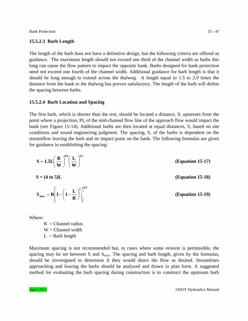
Bank Protection 15 - 47 15.5.2.3 Barb Length The length of the barb does not have a definitive design, but the following criteria are offered as guidance. The maximum length should not exceed one third of the channel width as barbs this long can cause the flow pattern to impact the opposite bank. Barbs designed for bank protection need not exceed one fourth of the channel width. Additional guidance for barb length is that it should be long enough to extend across the thalweg. A length equal to 1.5 to 2.0 times the distance from the bank to the thalweg has proven satisfactory. The length of the barb will define the spacing between barbs. 15.5.2.4 Barb Location and Spacing The first barb, which is shorter than the rest, should be located a distance, S, upstream from the point where a projection, PI, of the mid-channel flow line of the approach flow would impact the bank (see Figure 15-14). Additional barbs are then located at equal distances, S, based on site conditions and sound engineering judgment. The spacing, S, of the barbs is dependent on the streamflow leaving the barb and its impact point on the bank. The following formulas are given for guidance in establishing the spacing:
0.30.8
WL
WR1.5LS
= (Equation 15-17)
S = (4 to 5)L (Equation 15-18)
0.52
max RL11RS
−−= (Equation 15-19)
Where: R = Channel radius W = Channel width L = Barb length Maximum spacing is not recommended but, in cases where some erosion is permissible, the spacing may be set between S and Smax. The spacing and barb length, given by the formulas, should be investigated to determine if they would direct the flow as desired. Streamlines approaching and leaving the barbs should be analyzed and drawn in plan form. A suggested method for evaluating the barb spacing during construction is to construct the upstream barb
April 2014 ODOT Hydraulics Manual
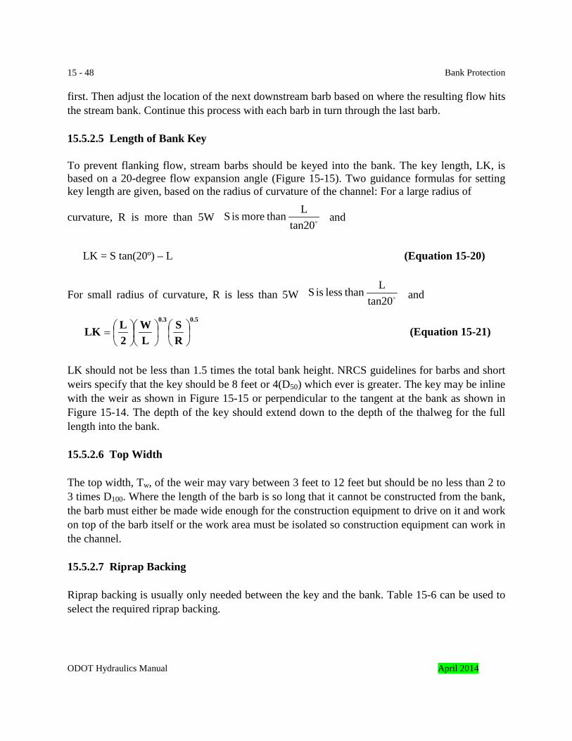
15 - 48 Bank Protection first. Then adjust the location of the next downstream barb based on where the resulting flow hits the stream bank. Continue this process with each barb in turn through the last barb. 15.5.2.5 Length of Bank Key To prevent flanking flow, stream barbs should be keyed into the bank. The key length, LK, is based on a 20-degree flow expansion angle (Figure 15-15). Two guidance formulas for setting key length are given, based on the radius of curvature of the channel: For a large radius of curvature, R is more than 5W and LK = S tan(20º) – L (Equation 15-20) For small radius of curvature, R is less than 5W and
0.50.3
RS
LW
2LLK
= (Equation 15-21)
LK should not be less than 1.5 times the total bank height. NRCS guidelines for barbs and short weirs specify that the key should be 8 feet or 4(D50) which ever is greater. The key may be inline with the weir as shown in Figure 15-15 or perpendicular to the tangent at the bank as shown in Figure 15-14. The depth of the key should extend down to the depth of the thalweg for the full length into the bank.
15.5.2.6 Top Width The top width, Tw, of the weir may vary between 3 feet to 12 feet but should be no less than 2 to 3 times D100. Where the length of the barb is so long that it cannot be constructed from the bank, the barb must either be made wide enough for the construction equipment to drive on it and work on top of the barb itself or the work area must be isolated so construction equipment can work in the channel. 15.5.2.7 Riprap Backing Riprap backing is usually only needed between the key and the bank. Table 15-6 can be used to select the required riprap backing.
tan20L than more is S
tan20L than less is S
ODOT Hydraulics Manual April 2014
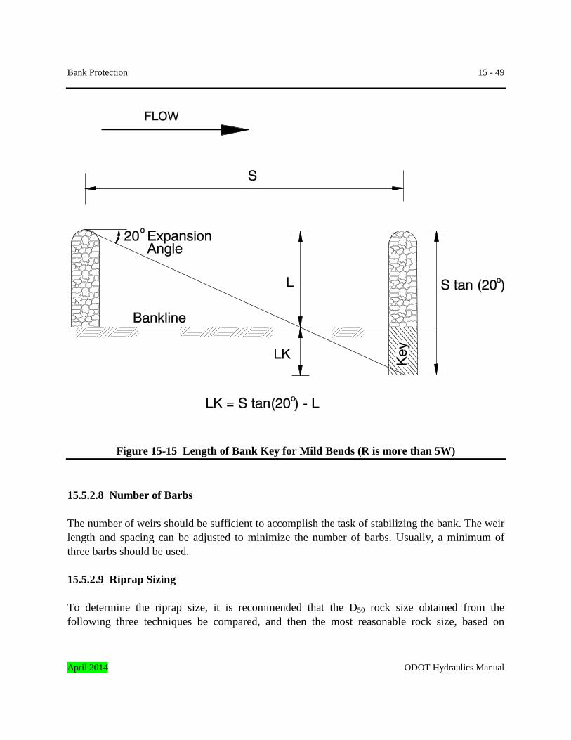
Bank Protection 15 - 49
Figure 15-15 Length of Bank Key for Mild Bends (R is more than 5W) 15.5.2.8 Number of Barbs The number of weirs should be sufficient to accomplish the task of stabilizing the bank. The weir length and spacing can be adjusted to minimize the number of barbs. Usually, a minimum of three barbs should be used. 15.5.2.9 Riprap Sizing To determine the riprap size, it is recommended that the D50 rock size obtained from the following three techniques be compared, and then the most reasonable rock size, based on
April 2014 ODOT Hydraulics Manual
15 - 50 Bank Protection judgment and experience, should be selected. When applying the techniques listed below, use the bankfull velocity and bankfull flow depth.
1. Equation 15-6 with a stability factor of 2.0. 2. Double the rock size obtained with Figure 15-9. 3. Use the appropriate rearranged Isbash equation for sizing riprap for bridge abutment
protection discussed in Subsection 15.5.1.7.5.2. It is recommended that the K factor for vertical abutments be used when applying the equations in Section 15.5.1.7.5.2.
Natural Resources Conservation Service (NCRS) recommends that the D100 rock size should be 1.5 to 2 times the D50 rock size, while the guidance Reference 6, recommends that the D100 should be 3 times the D50 rock size. Using a D100 rock size equal to 2 times the D50 rock size seems like a reasonable criterion. Rock should be well graded but with only a limited amount of material less than half the median stone size. The minimum rock size should not be less than the D100 of the streambed material. 15.5.3 Grouted Rock Grouted rock revetment consists of rock slope protection having voids filled with concrete grout to form a monolithic armor. Relative to loose riprap, grouted rock allows the use of smaller rock to provide the same level of protection. Since grouted rock is a rigid revetment, it will not conform to changes in the bank geometry due to settlement. As with other monolithic revetments, grouted rock is particularly susceptible to failure from undermining and the subsequent loss of the supporting bank material. Although it is rigid, grouted rock is not extremely strong and the loss of even a small area of bank support can cause failure of large portions of the revetment. Consequently, the stability of the underlying soil is critical to the long-term performance of grouted rock. If long-term stability problems are likely with the underlying soil, then grouted rock should not be used. Experience has shown that grouted riprap will crack, cracking will be irregular, and cracks will likely extend within the grout matrix and around the periphery of larger stones. Cracking may cause enhanced weathering, including aggressive chemical reactions, but should not significantly diminish the effectiveness of the revetment if the underlying granular filter is properly designed and constructed to provide adequate drainage without loss of filter materials through cracks. Grouted rock should not be used at sites where frost heave or ice in the underlying native soil can be expected to cause a significant uplift force.
ODOT Hydraulics Manual April 2014
Bank Protection 15 - 51 The most common application of grouted rock is to protect spillthrough abutments for bridges at sites where the velocity is too high to use loose riprap. Other applications include linings for steep gradient drainage ditches and scour protection for culvert and storm sewer outfalls. Grouted rock is also an option when a source of the required loose riprap size is unavailable. 15.5.3.1 Bank Slope Bank slopes for grouted riprap revetments should typically not exceed 1V: 1½H. Banks slopes as steep as 1V: 1H may be possible if no stability problems are expected with the supporting soil mass. 15.5.3.2 Rock Size and Grout Penetration Table 15-11 lists the maximum velocity that ODOT’s standard riprap classes can withstand after being grouted to the penetration depth shown. Reference 7 was used to determine the maximum design velocity listed in the table. 15.5.3.3 Hydrostatic Pressure Relief Proper drainage is critical to the long-term performance of grouted rock. Therefore, weep holes should be provided in the revetment to relieve hydrostatic pressure buildup behind the grout surface. Weeps should extend through the grout surface to the interface with the granular filter blanket. Weeps should consist of 3-inch diameter pipes having a maximum horizontal spacing of 6-feet and a maximum vertical spacing of 10-feet. The buried end of the weep should be covered with wire screening or a fabric filter of a gage that will prevent the granular filter blanket from migrating into the weep. The minimum grout penetration equals one-half the blanket thickness. 15.5.3.4 Riprap Backing Riprap backing should be a granular filter blanket that conforms to the requirements listed in Table 15-6. For Class 50 and Class 100 riprap use the granular filter shown for Class 200 riprap. A riprap geotextile should not be used in lieu of the granular filter blanket, but can be used as backing for the granular filter. 15.5.3.5 Typical Grouted Rock Section The typical section for grouted rock is the same as for loose riprap and is shown in Figure 15-4. The grouted rock layer should extend to the bottom of the toe trench. For example, if a 3-foot thick layer of Class 700 loose riprap is being grouted, the outer 18-inches of the 3-foot layer April 2014 ODOT Hydraulics Manual
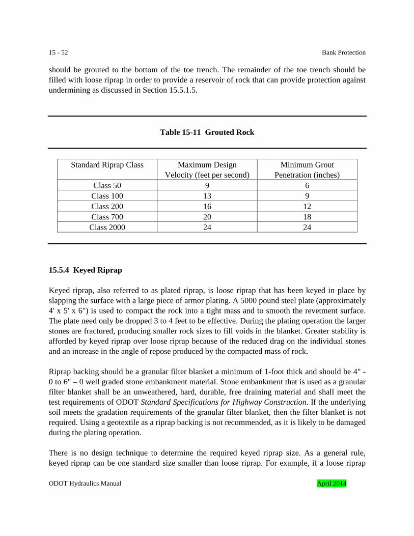
15 - 52 Bank Protection should be grouted to the bottom of the toe trench. The remainder of the toe trench should be filled with loose riprap in order to provide a reservoir of rock that can provide protection against undermining as discussed in Section 15.5.1.5.
Table 15-11 Grouted Rock
Standard Riprap Class Maximum Design Velocity (feet per second)
Minimum Grout Penetration (inches)
Class 50 9 6 Class 100 13 9 Class 200 16 12 Class 700 20 18 Class 2000 24 24
15.5.4 Keyed Riprap Keyed riprap, also referred to as plated riprap, is loose riprap that has been keyed in place by slapping the surface with a large piece of armor plating. A 5000 pound steel plate (approximately 4' x 5' x 6") is used to compact the rock into a tight mass and to smooth the revetment surface. The plate need only be dropped 3 to 4 feet to be effective. During the plating operation the larger stones are fractured, producing smaller rock sizes to fill voids in the blanket. Greater stability is afforded by keyed riprap over loose riprap because of the reduced drag on the individual stones and an increase in the angle of repose produced by the compacted mass of rock. Riprap backing should be a granular filter blanket a minimum of 1-foot thick and should be 4" - 0 to 6" – 0 well graded stone embankment material. Stone embankment that is used as a granular filter blanket shall be an unweathered, hard, durable, free draining material and shall meet the test requirements of ODOT Standard Specifications for Highway Construction. If the underlying soil meets the gradation requirements of the granular filter blanket, then the filter blanket is not required. Using a geotextile as a riprap backing is not recommended, as it is likely to be damaged during the plating operation. There is no design technique to determine the required keyed riprap size. As a general rule, keyed riprap can be one standard size smaller than loose riprap. For example, if a loose riprap ODOT Hydraulics Manual April 2014
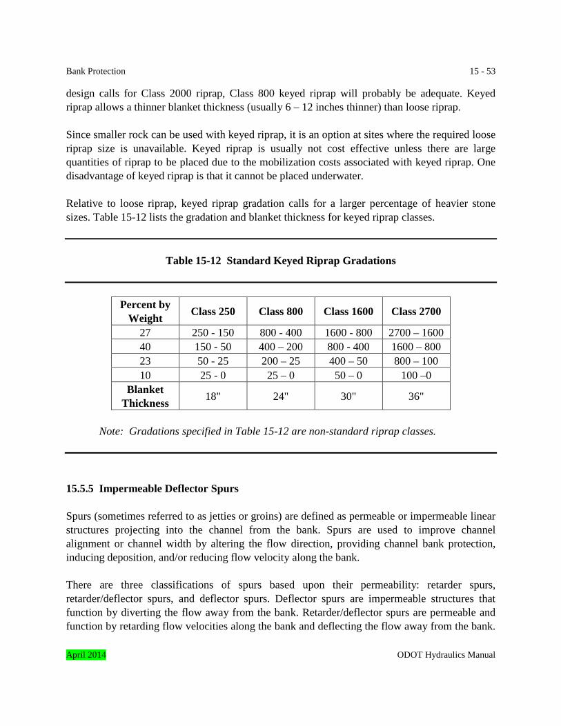
Bank Protection 15 - 53 design calls for Class 2000 riprap, Class 800 keyed riprap will probably be adequate. Keyed riprap allows a thinner blanket thickness (usually 6 – 12 inches thinner) than loose riprap. Since smaller rock can be used with keyed riprap, it is an option at sites where the required loose riprap size is unavailable. Keyed riprap is usually not cost effective unless there are large quantities of riprap to be placed due to the mobilization costs associated with keyed riprap. One disadvantage of keyed riprap is that it cannot be placed underwater. Relative to loose riprap, keyed riprap gradation calls for a larger percentage of heavier stone sizes. Table 15-12 lists the gradation and blanket thickness for keyed riprap classes.
Table 15-12 Standard Keyed Riprap Gradations
Percent by Weight Class 250 Class 800 Class 1600 Class 2700
27 250 - 150 800 - 400 1600 - 800 2700 – 1600 40 150 - 50 400 – 200 800 - 400 1600 – 800 23 50 - 25 200 – 25 400 – 50 800 – 100 10 25 - 0 25 – 0 50 – 0 100 –0
Blanket Thickness 18" 24" 30" 36"
Note: Gradations specified in Table 15-12 are non-standard riprap classes.
15.5.5 Impermeable Deflector Spurs Spurs (sometimes referred to as jetties or groins) are defined as permeable or impermeable linear structures projecting into the channel from the bank. Spurs are used to improve channel alignment or channel width by altering the flow direction, providing channel bank protection, inducing deposition, and/or reducing flow velocity along the bank. There are three classifications of spurs based upon their permeability: retarder spurs, retarder/deflector spurs, and deflector spurs. Deflector spurs are impermeable structures that function by diverting the flow away from the bank. Retarder/deflector spurs are permeable and function by retarding flow velocities along the bank and deflecting the flow away from the bank. April 2014 ODOT Hydraulics Manual
15 - 54 Bank Protection Retarder spurs are the most permeable spur type and function by retarding flow velocities near the bank. Retarder spurs rely on flow retardance and sediment deposition as their primary bank protection mechanism. General guidance on site conditions best suited for spurs are as follows.
• Spur-type structures are typically not suited for channels less than 150 feet wide. Potential impacts when used on narrow channels are flow deflection towards the opposite bank that can initiate an erosion problem and excessive channel bed scour caused by constricting the flow. Spurs can be used effectively on small channels where their function is to shift the location of the channel.
• The use of spurs on channel bends with a radius less than 350 feet may not be cost
effective when compared to other countermeasures. This is due to the short spur spacing that would be required.
• Spurs are best suited for protecting low (less than 10 feet) to medium-height (from 10 to
20 feet) banks. Higher banks may be protected, but may require special designs using construction materials other than riprap in order to limit the size (footprint) of the spur.
This section will present design guidelines for deflector spurs as they are generally best suited for the stream types and hydraulic conditions encountered in Oregon. The reader is referred to References 5 and 6 for design guidelines for permeable, as well as impermeable, spurs. Spurs are generally used to halt meander migration at a channel bend. They are also used to channelize wide, poorly defined streams into well-defined channels. Where spurs project from highway embankments to decrease flow along the embankment, they are called embankment spurs. These may project into the floodplain rather than the channel, and thus function as spurs only during overbank flow. A common application is to better align the flow through bridge openings at sites where the channel has migrated and is misaligned with the bridge. The usual consequence of a misaligned channel relative to the bridge opening is erosion of the approach embankment and increased abutment scour. Diverter spurs are classified as either hardpoints or transverse-dike spurs. The primary difference between the two types of spurs is the length of the spur. Hardpoints are short structures used to protect an existing bank line and are not long enough to be used for flow control or improved channel alignment. Transverse-dike spurs are longer than hardpoints and are used to move the thalweg in order to improve the channel alignment.
ODOT Hydraulics Manual April 2014
Bank Protection 15 - 55 The most common construction material for diverter spurs is loose riprap. Other designs have been used such steel sheetpile, gabions, and rectangular or triangular timber cribs filled with rock. Abrasion of the gabion baskets is a concern and are not recommended at sites with an abrasive bed load Spurs and stream barbs are sometimes mistaken for one another because they look similar and have similar functions. Spurs are typically bank height or near bank height structures and are significantly larger structures than stream barbs. Spurs also provide better flow control than stream barbs and are used at sites where an improved or previous flow alignment as well as bank protection is desired. Since spurs constrict/obstruct the channel more than stream barbs, deeper scour holes will develop at the tip of spurs and is a more critical design issue. 15.5.5.1 Spur Length The spur should be long enough to produce the desired effect; however, the projected length of the spur should be held to less than 20 percent of the channel width at bank full stage. The projected spur length and channel width are measured from the desired channel bank alignment. The projected spur length is the length normal to the channel. When spurs are being used to shift the channel thalweg or to improve the channel alignment at sites with eroded, irregular channel banks, the actual spur length will be greater than the projected spur length. As the projected spur length increases, the scour depth and velocity at the spur tip will also increase. 15.5.5.2 Spur Spacing Spur spacing is established by first drawing an arc representing the desired flow alignment as shown in Figure 15-16. This arc will represent the desired extreme location of the thalweg nearest the outside bank in the bend. This is shown as the low flow thalweg in the figure. The desired flow alignment may or may not differ from existing conditions, depending on whether there is a need to arrest erosion of the bank at its current location or improve the flow alignment. If the goal is to arrest the bank erosion at its current location, then hardpoints may be the proper treatment. If improving the flow alignment is the goal, then transverse-dike spurs should be used. The arc representing the desired flow alignment should provide a smooth transition between the upstream and downstream flow alignment. The next step is to draw an arc that represents the desired bank line. This may approximately describe the existing bank alignment or a new desired bank line that protects the existing bank line from further erosion. Also, draw an arc connecting the crest of the nose or tip of the spur field. This arc should encroach no more than 20 percent of the desired channel width as discussed in Subsection 15.5.5.1. The distance from this arc to the arc describing the desired bank line, along with the flow expansion angle, fixes the spacing between spurs. The arc April 2014 ODOT Hydraulics Manual
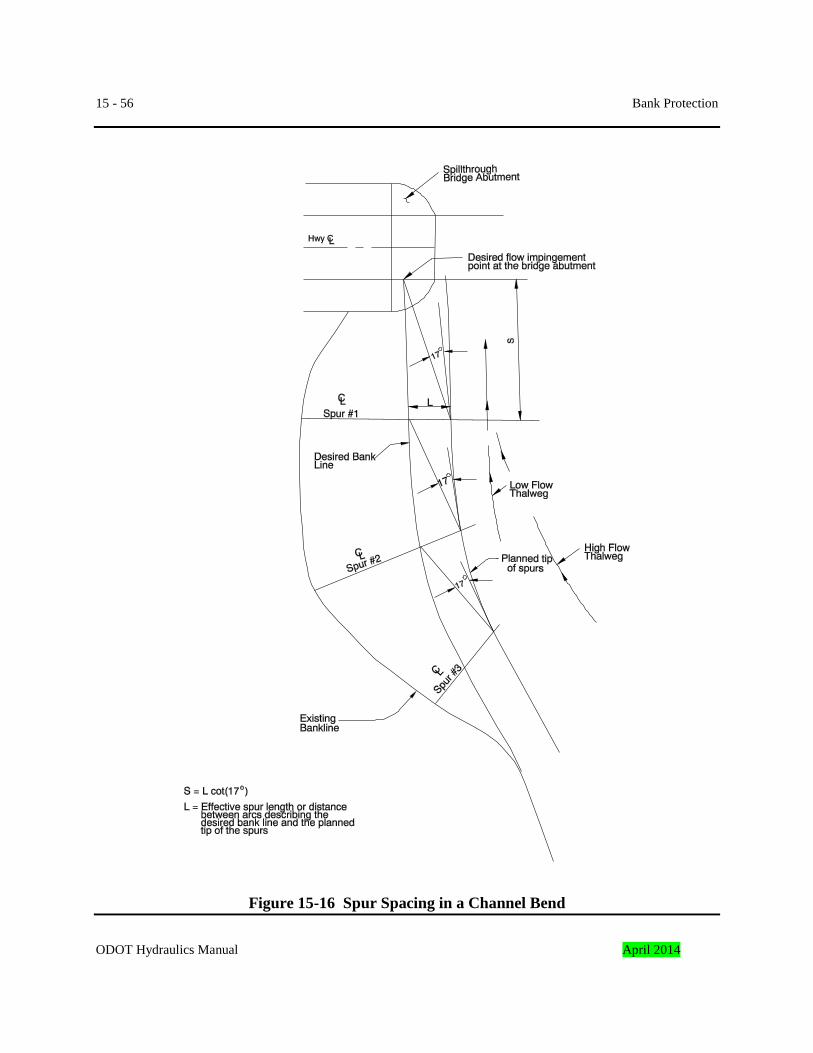
15 - 56 Bank Protection
Figure 15-16 Spur Spacing in a Channel Bend
ODOT Hydraulics Manual April 2014
Bank Protection 15 - 57 describing the tip of the spurs will be essentially concentric with the arc describing the desired flow alignment. The next step is to establish the location of the spur at the downstream end of the spur field. The first step is to determine the desired flow impingement point downstream of the first spur. As previously mentioned a common application for spurs is to better align the flow at bridge sites were the channel has migrated and is misaligned with the bridge. For bridges with vertical abutments the desired impingement point will usually be the upstream corner of the abutment, but it may be any point within the width of the bridge or possibly a point downstream of bridge. For bridges with spillthrough abutments the desired impingement point will usually be a point along the abutment slope equal in elevation to the top of bank elevation at the upstream face of the bridge. As with vertical abutment bridges, the desired impingement point may be located within the width of the bridge or possibly along the bank downstream of the bridge. There may be cases that do not involve a bridge where a channel bend has migrated and is flowing adjacent to or impinging on the highway embankment. For this case the desired impingement point will be a point along the downstream channel bank judged to be stable. Note: The potential scour elevations within the waterway opening should be analyzed where spurs are used adjacent to structures. It should be verified that the spurs do not cause scour or revetment retention problems. For impermeable spurs the flow will expand at an angle of approximately 17 degrees from the tangent of the flow path at the tip of the spur. Therefore, it is important to determine the flow path at the tip of the spur. The flow path or thalweg needs to be estimated for low flow as well as high flow conditions because the thalweg has a tendency to shift during high flows as shown in Figure 15-16. The spacing between spurs and the distance to the first spur from the desired impingement point is determined with the following equation: ( ) 3.27Lcot17LS == (Equation 15-22) Where: S = Spacing between spurs at the crest of the spur tip, feet L = Effective length of the spur or the distance between arcs describing the planned tip of the spur and the desired bank line, feet ODOT experience with this spacing technique is that it is conservative and can sometimes result in very close spacing with the consequence that more spurs will be specified than are actually needed. Therefore, when determining the spacing, the designer may want to consider an impingement point between spurs that lies somewhere between the existing bank line and the desired bank line. The final spacing will be determined by the judgment of the designer. To assist April 2014 ODOT Hydraulics Manual
15 - 58 Bank Protection the designer in determining the final spacing of the spurs, it is recommended that the footprint of the proposed spurs be drawn on a plan view of the site. 15.5.5.3 Spur Height and Crest Profile Impermeable spurs are generally designed not to exceed the bank height in order to protect against flanking of the spur by flow concentration and erosion behind the spur at high river stages. Where river stages are more than or equal to the bank height, the spurs should be equal to the bank height. If flood stages are lower than bank height, the spur should be high enough to prevent overtopping of the spur. Overtopping of spurs by as much as 3 feet does not affect the spurs’ effectiveness. The crest of impermeable spurs should slope slightly downward away from the bank line mainly because it is difficult to construct and maintain a level spur profile constructed with rock. 15.5.5.4 Bed and Bank Contact The spur should be keyed a minimum of 6 feet into the channel bank to protect the spur from being flanked when flood stages overtop the spur. The nose or tip of the spur is vulnerable to being undermined by the scour hole that will develop due to the flow contraction that occurs at the spur tip. Therefore, the spur tip needs to be protected against undermining from scour. Two methods are used to provide scour protection. The preferred method is to key the spur tip into the channel bottom with a toe trench. A 4 – 6 foot deep toe trench will usually provide adequate protection. The alternate method is to place excess stone at the spur tip. As scour occurs the rock will self-launch or roll into the scour hole and protect the spur tip from being undermined. Adequate bed and bank contact is particularly important for the leading spur because it is subjected to the most intense hydraulic conditions. 15.5.5.5 Spur Orientation Spur orientation refers to spur alignment with respect to the direction of the main flow current in the channel. Figure 15-17 defines the spur angle such that an acute angle means that the spur is angled in a downstream direction and an angle greater than 90 degrees means that the spur is oriented in an upstream direction. There is no consensus regarding the orientation of impermeable deflector spurs. Spurs oriented at approximately 90 degrees have been found to force the thalweg farther from the bank than spurs oriented in an upstream or downstream direction. Therefore, more positive flow control is achieved with spurs oriented normal to the channel bank. Scour at the tip of a spur oriented in an upstream direction is greater than if oriented normal to the bank while spurs oriented in a ODOT Hydraulics Manual April 2014
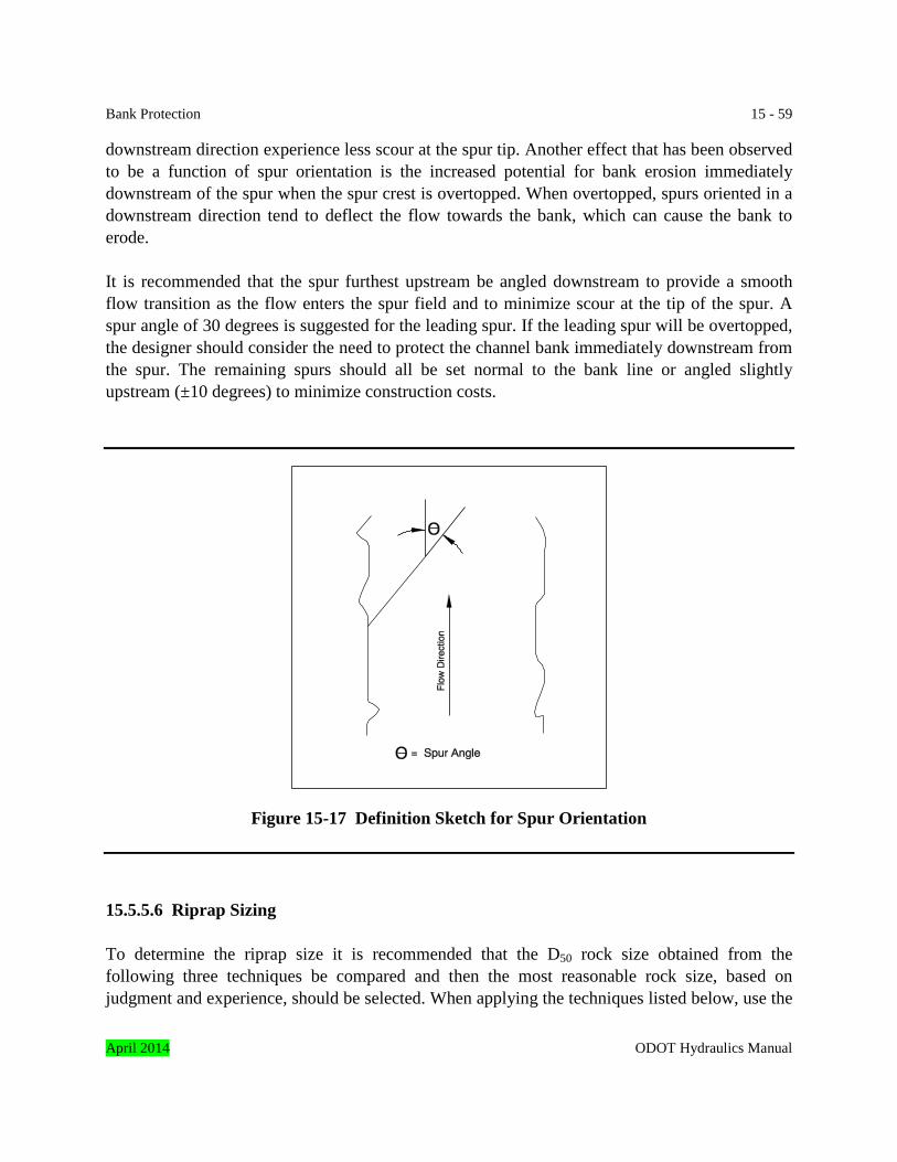
Bank Protection 15 - 59 downstream direction experience less scour at the spur tip. Another effect that has been observed to be a function of spur orientation is the increased potential for bank erosion immediately downstream of the spur when the spur crest is overtopped. When overtopped, spurs oriented in a downstream direction tend to deflect the flow towards the bank, which can cause the bank to erode. It is recommended that the spur furthest upstream be angled downstream to provide a smooth flow transition as the flow enters the spur field and to minimize scour at the tip of the spur. A spur angle of 30 degrees is suggested for the leading spur. If the leading spur will be overtopped, the designer should consider the need to protect the channel bank immediately downstream from the spur. The remaining spurs should all be set normal to the bank line or angled slightly upstream (±10 degrees) to minimize construction costs.
Figure 15-17 Definition Sketch for Spur Orientation
15.5.5.6 Riprap Sizing To determine the riprap size it is recommended that the D50 rock size obtained from the following three techniques be compared and then the most reasonable rock size, based on judgment and experience, should be selected. When applying the techniques listed below, use the
April 2014 ODOT Hydraulics Manual
15 - 60 Bank Protection bankfull velocity and bankfull flow depth at the constricted channel cross-section at the tip of the spur.
Method 1: Equation 15-6 with a stability factor of 2.0. Method 2: Double the rock size obtained with Figure 15-9. Method 3: Use the appropriate equation for sizing riprap for bridge abutment protection
discussed in Subsection 15.5.1.7.5.2. It is recommended that the K factor for spillthrough abutments be used when applying the equations in Subsection 15.5.1.7.5.2.
Use a standard riprap class if the D50 is within the range of D50 values shown in Table 15-3 otherwise design a special riprap gradation that meets the gradation requirements shown in Table 15-4. 15.5.5.7 Typical Rock Spur Details Figures 15-18 and 15-19 show typical spur details. The side slopes of the spur should be no steeper than 1V: 1½H. The top of the spur should be a minimum of 4 feet wide. For cases where the top of the spur is used for construction access, the spur will need to be wide enough to accommodate the construction equipment. For construction access the spur may need the top to be 10 – 12 feet wide. Figure 15-20 shows rock spurs that were constructed to better align the flow with a bridge opening. 15.5.6 Proprietary Products Several proprietary products are available for bank protection. This section will briefly discuss several of the products available. The reader is referred to the various manufacturers for more detailed information on the products discussed. 15.5.6.1 Gabions Gabions are rectangular wire mesh baskets filled with rock. The gabion baskets are commercially available from several manufacturers. Wire enclosed riprap is similar to gabions, but differs in that it is a continuous framework rather than individual interconnected baskets. When used for bank protection, gabions are either placed as a mattress on a prepared slope or they are constructed as a retaining wall with a stepped block configuration as shown in Figure 15-21. To construction a gabion revetment empty gabions are placed in position, wired to adjoining gabions, filled with rock, and then folded shut and wired at the ends and sides. ODOT Hydraulics Manual April 2014
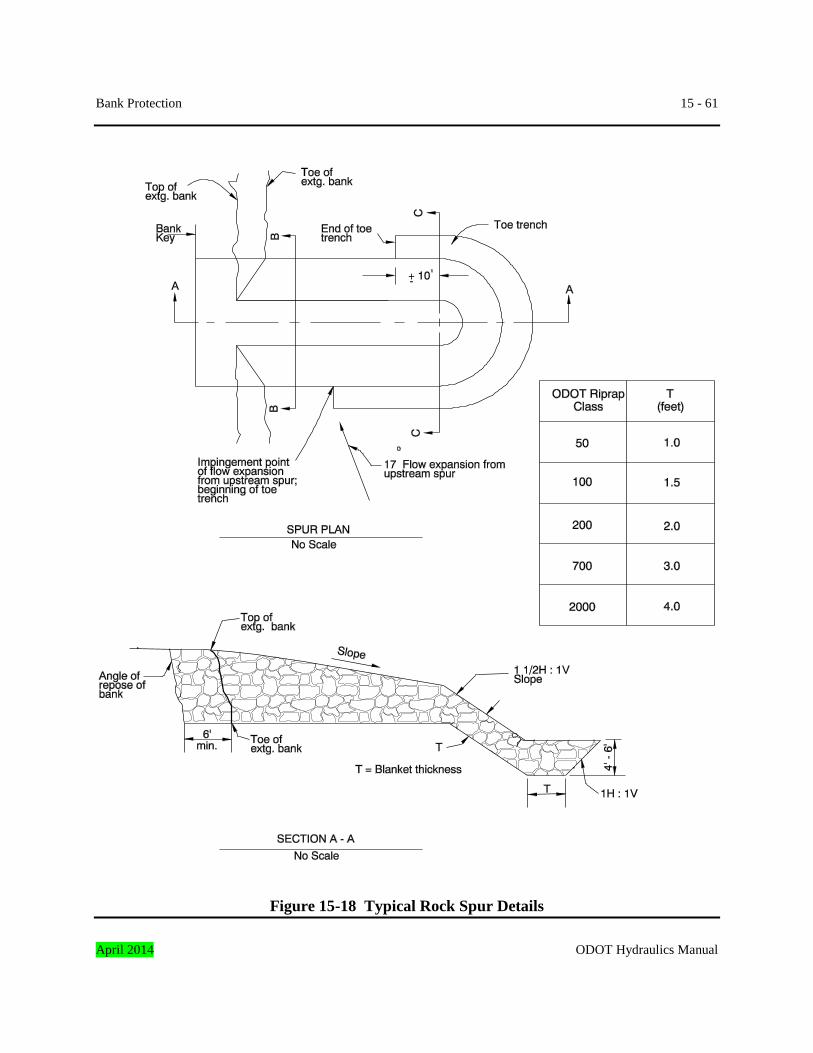
Bank Protection 15 - 61
Figure 15-18 Typical Rock Spur Details
April 2014 ODOT Hydraulics Manual
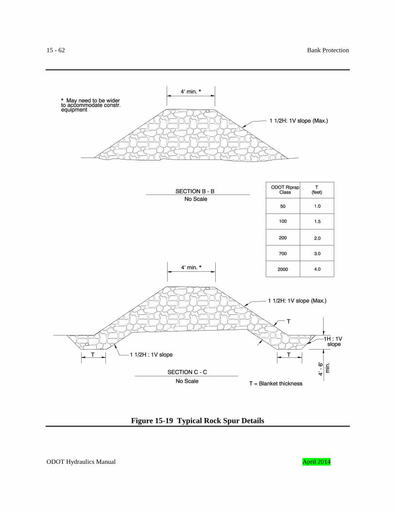
15 - 62 Bank Protection
Figure 15-19 Typical Rock Spur Details
ODOT Hydraulics Manual April 2014
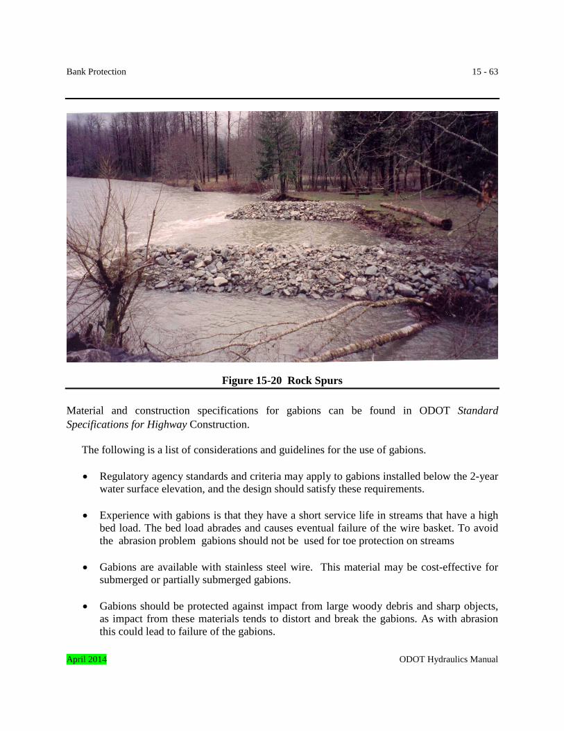
Bank Protection 15 - 63
Figure 15-20 Rock Spurs Material and construction specifications for gabions can be found in ODOT Standard Specifications for Highway Construction.
The following is a list of considerations and guidelines for the use of gabions.
• Regulatory agency standards and criteria may apply to gabions installed below the 2-year
water surface elevation, and the design should satisfy these requirements.
• Experience with gabions is that they have a short service life in streams that have a high bed load. The bed load abrades and causes eventual failure of the wire basket. To avoid the abrasion problem gabions should not be used for toe protection on streams
• Gabions are available with stainless steel wire. This material may be cost-effective for
submerged or partially submerged gabions.
• Gabions should be protected against impact from large woody debris and sharp objects, as impact from these materials tends to distort and break the gabions. As with abrasion this could lead to failure of the gabions.
April 2014 ODOT Hydraulics Manual
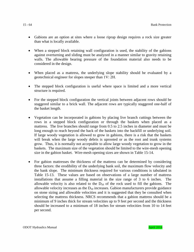
15 - 64 Bank Protection
• Gabions are an option at sites where a loose riprap design requires a rock size greater
than what is locally available.
• When a stepped block retaining wall configuration is used, the stability of the gabions against overturning and sliding must be analyzed in a manner similar to gravity retaining walls. The allowable bearing pressure of the foundation material also needs to be considered in the design.
• When placed as a mattress, the underlying slope stability should be evaluated by a
geotechnical engineer for slopes steeper than 1V: 2H.
• The stepped block configuration is useful where space is limited and a more vertical structure is required.
• For the stepped block configuration the vertical joints between adjacent rows should be
staggered similar to a brick wall. The adjacent rows are typically staggered one-half of the basket length.
• Vegetation can be incorporated in gabions by placing live branch cuttings between the
rows in a stepped block configuration or through the baskets when placed as a mattress. The live branches should range from 0.5 to 2.5 inches in diameter and must be long enough to reach beyond the back of the baskets into the backfill or underlying soil. If large woody vegetation is allowed to grow in gabions, there is a risk that the baskets will break when the large woody debris is uprooted or as the root and trunk systems grow. Thus, it is normally not acceptable to allow large woody vegetation to grow in the baskets. The maximum size of the vegetation should be limited to the wire-mesh opening size in the gabion basket. Wire-mesh opening sizes are shown in Table 15-14.
• For gabion mattresses the thickness of the mattress can be determined by considering
three factors: the erodibility of the underlying bank soil, the maximum flow velocity and the bank slope. The minimum thickness required for various conditions is tabulated in Table 15-13. These values are based on observations of a large number of mattress installations that assume a filling material in the size range of 3 to 6 inches. The allowable velocity is also related to the D50 of the rock used to fill the gabions. The allowable velocity increases as the D50 increases. Gabion manufacturers provide guidance on stone sizing and allowable velocities and it is suggested that they be consulted when selecting the mattress thickness. NRCS recommends that a gabion mattress should be a minimum of 9 inches thick for stream velocities up to 9 feet per second and the thickness should be increased to a minimum of 18 inches for stream velocities from 10 to 14 feet per second.
ODOT Hydraulics Manual April 2014
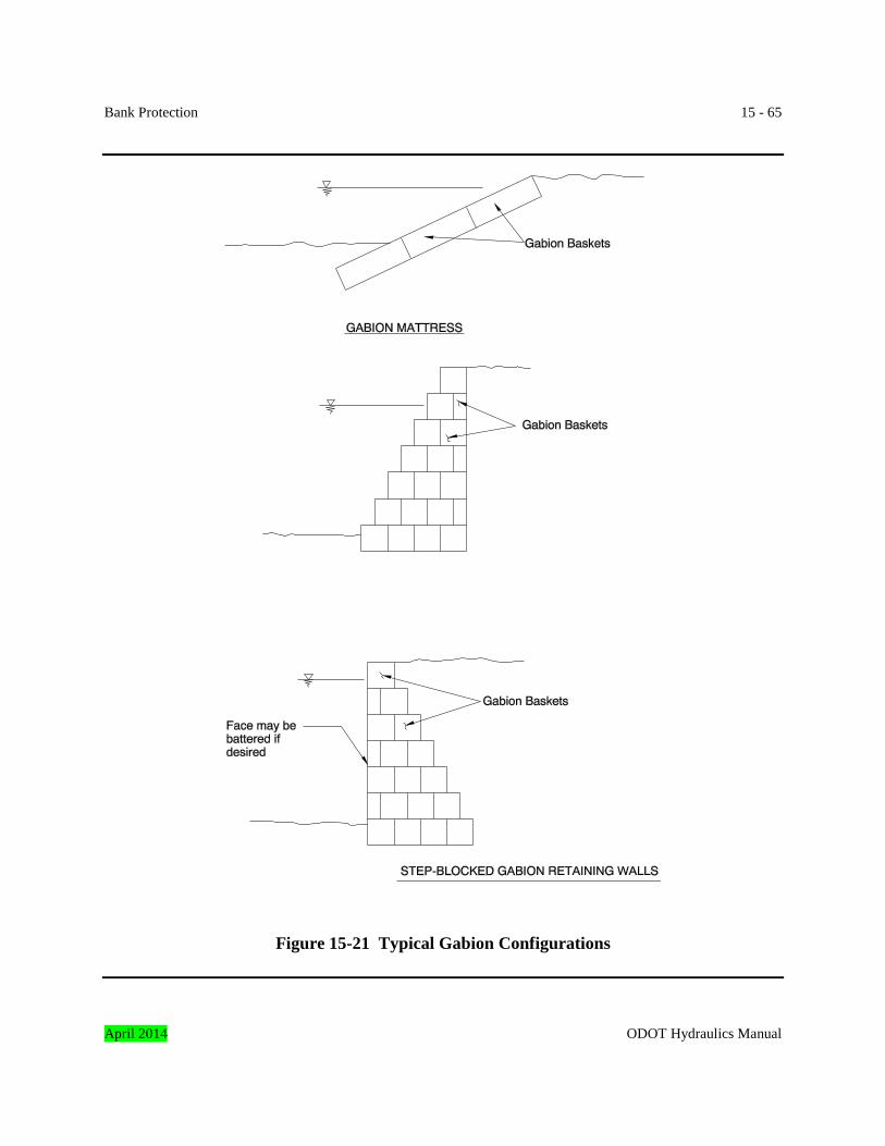
Bank Protection 15 - 65
Figure 15-21 Typical Gabion Configurations
April 2014 ODOT Hydraulics Manual
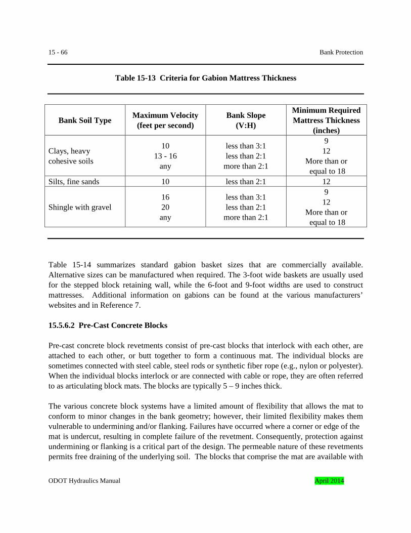
15 - 66 Bank Protection
Table 15-13 Criteria for Gabion Mattress Thickness
Bank Soil Type Maximum Velocity (feet per second)
Bank Slope (V:H)
Minimum Required Mattress Thickness
(inches)
Clays, heavy cohesive soils
10 13 - 16
any
less than 3:1 less than 2:1
more than 2:1
9 12
More than or equal to 18
Silts, fine sands 10 less than 2:1 12
Shingle with gravel 16 20 any
less than 3:1 less than 2:1
more than 2:1
9 12
More than or equal to 18
Table 15-14 summarizes standard gabion basket sizes that are commercially available. Alternative sizes can be manufactured when required. The 3-foot wide baskets are usually used for the stepped block retaining wall, while the 6-foot and 9-foot widths are used to construct mattresses. Additional information on gabions can be found at the various manufacturers’ websites and in Reference 7. 15.5.6.2 Pre-Cast Concrete Blocks Pre-cast concrete block revetments consist of pre-cast blocks that interlock with each other, are attached to each other, or butt together to form a continuous mat. The individual blocks are sometimes connected with steel cable, steel rods or synthetic fiber rope (e.g., nylon or polyester). When the individual blocks interlock or are connected with cable or rope, they are often referred to as articulating block mats. The blocks are typically 5 – 9 inches thick. The various concrete block systems have a limited amount of flexibility that allows the mat to conform to minor changes in the bank geometry; however, their limited flexibility makes them vulnerable to undermining and/or flanking. Failures have occurred where a corner or edge of the mat is undercut, resulting in complete failure of the revetment. Consequently, protection against undermining or flanking is a critical part of the design. The permeable nature of these revetments permits free draining of the underlying soil. The blocks that comprise the mat are available with
ODOT Hydraulics Manual April 2014
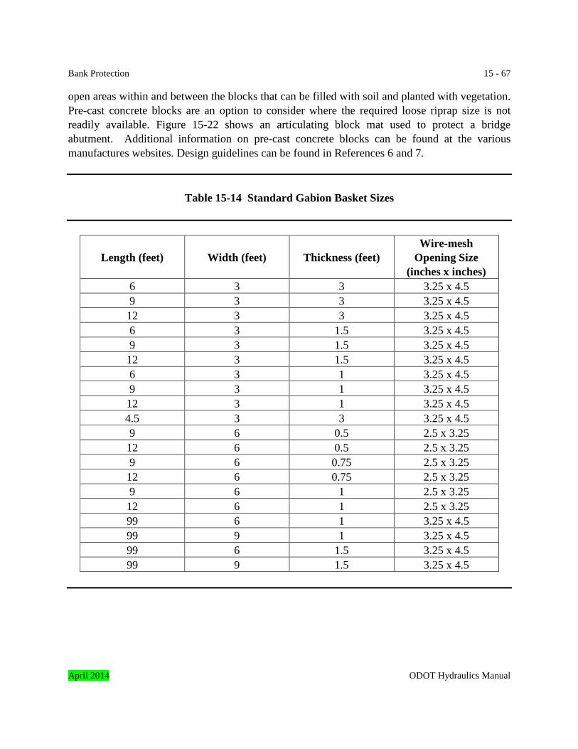
Bank Protection 15 - 67 open areas within and between the blocks that can be filled with soil and planted with vegetation. Pre-cast concrete blocks are an option to consider where the required loose riprap size is not readily available. Figure 15-22 shows an articulating block mat used to protect a bridge abutment. Additional information on pre-cast concrete blocks can be found at the various manufactures websites. Design guidelines can be found in References 6 and 7.
Table 15-14 Standard Gabion Basket Sizes
Length (feet) Width (feet) Thickness (feet) Wire-mesh
Opening Size (inches x inches)
6 3 3 3.25 x 4.5 9 3 3 3.25 x 4.5 12 3 3 3.25 x 4.5 6 3 1.5 3.25 x 4.5 9 3 1.5 3.25 x 4.5 12 3 1.5 3.25 x 4.5 6 3 1 3.25 x 4.5 9 3 1 3.25 x 4.5 12 3 1 3.25 x 4.5 4.5 3 3 3.25 x 4.5 9 6 0.5 2.5 x 3.25 12 6 0.5 2.5 x 3.25 9 6 0.75 2.5 x 3.25 12 6 0.75 2.5 x 3.25 9 6 1 2.5 x 3.25 12 6 1 2.5 x 3.25 99 6 1 3.25 x 4.5 99 9 1 3.25 x 4.5 99 6 1.5 3.25 x 4.5 99 9 1.5 3.25 x 4.5
April 2014 ODOT Hydraulics Manual
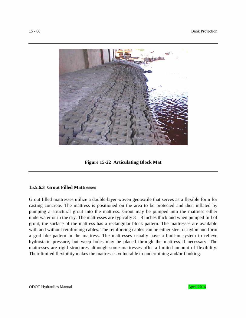
15 - 68 Bank Protection
Figure 15-22 Articulating Block Mat 15.5.6.3 Grout Filled Mattresses Grout filled mattresses utilize a double-layer woven geotextile that serves as a flexible form for casting concrete. The mattress is positioned on the area to be protected and then inflated by pumping a structural grout into the mattress. Grout may be pumped into the mattress either underwater or in the dry. The mattresses are typically 3 – 8 inches thick and when pumped full of grout, the surface of the mattress has a rectangular block pattern. The mattresses are available with and without reinforcing cables. The reinforcing cables can be either steel or nylon and form a grid like pattern in the mattress. The mattresses usually have a built-in system to relieve hydrostatic pressure, but weep holes may be placed through the mattress if necessary. The mattresses are rigid structures although some mattresses offer a limited amount of flexibility. Their limited flexibility makes the mattresses vulnerable to undermining and/or flanking.
ODOT Hydraulics Manual April 2014
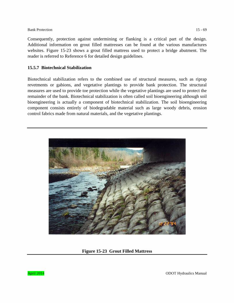
Bank Protection 15 - 69 Consequently, protection against undermining or flanking is a critical part of the design. Additional information on grout filled mattresses can be found at the various manufactures websites. Figure 15-23 shows a grout filled mattress used to protect a bridge abutment. The reader is referred to Reference 6 for detailed design guidelines. 15.5.7 Biotechnical Stabilization Biotechnical stabilization refers to the combined use of structural measures, such as riprap revetments or gabions, and vegetative plantings to provide bank protection. The structural measures are used to provide toe protection while the vegetative plantings are used to protect the remainder of the bank. Biotechnical stabilization is often called soil bioengineering although soil bioengineering is actually a component of biotechnical stabilization. The soil bioengineering component consists entirely of biodegradable material such as large woody debris, erosion control fabrics made from natural materials, and the vegetative plantings.
Figure 15-23 Grout Filled Mattress
April 2014 ODOT Hydraulics Manual

15 - 70 Bank Protection This section addresses the design of biotechnical bank stabilization and discusses the various components of biotechnical stabilization including the stability of large woody debris, selecting an adequate erosion control mat, toe protection and the various vegetative techniques that are used. Typical designs are also presented. Note: Biotechnical methods will require routine maintenance and repairs. Access and maintenance should be evaluated and addressed during project development. The design should assure that proper easements, right-of-way acquisition, agreements, or other means are obtained to allow for access and maintenance activities and adequate area is allocated for these activities. The facilities required for access should also be incorporated into the project design. This could include turnouts, access roads, removable fences, etc. 15.5.7.1 Use of Vegetation Vegetation is an important component of biotechnical stabilization. Vegetation can effectively control erosion while providing environmental benefits. Environmental benefits include diverse and productive riparian habitats, shade to help maintain suitable water temperature for fish, cover for fish, source of nutrients for aquatic life, and improved water quality. Vegetation, if dense enough, can control erosion and provide bank protection by performing the following functions.
• The root system binds the soil together and increases the overall stability and shear strength of the bank.
• The exposed vegetation increases surface roughness and reduces local flow velocities,
causing the flow to dissipate energy against the deforming plant rather than the soil. This also reduces the transport capacity and shear stress near the bank, thereby inducing sediment deposition.
• Vegetation deflects the high-velocity flow away from the bank and acts as a buffer
against the abrasive effect of transported material. Vegetative methods normally use un-rooted plant parts in the form of cut branches, although containerized plants and bare-root stock are also commonly used. Vegetative techniques often referred to as soil bioengineering include live stakes, live fascines (also called wattles), brush layering (also called branch packing), and brush mattresses. These techniques are most successful when constructed during the dormant season, which is typically mid-October to mid-March. Many of the vegetative techniques incorporate a natural or synthetic erosion control mat (see Subsection 15.5.7.3) to reinforce the stream bank and to provide protection until the vegetation is established. The reader is referred to References 8 and 9 for more detailed design guidance on vegetative techniques: ODOT Hydraulics Manual April 2014
Bank Protection 15 - 71 Live stakes are live, rootable vegetative cuttings that are inserted into the ground. The live stakes are typically 0.5 – 1.5 inches in diameter, 2 – 3 feet long, and are installed 2 –3 feet apart. When live stakes are driven through a layer of riprap, the planting technique is known as “joint planting”. Live fascines are long, cylindrical bundles of branch cuttings that are bound together and placed in a shallow trench parallel to the bank. The bundles are typically 6 – 8 inches in diameter and secured to the bank with live and dead stakes. Brush layering consists of dense layers of live cuttings, branches, and/or rooted stock between layers of compacted soil. Cuttings extend back into the bank and protrude slightly from the bank. They are particularly applicable in bank protection projects that require fill. A brush mattress is a thick layer of overlapping live cuttings or branches placed on the surface of a graded stream bank and secured with a combination of twine, wire and live and dead stakes. The bottom edge of the mattress is often anchored with a live fascine. ODOT’s landscape architect should be consulted for guidance on plant selection. The plant materials should be native species that are suited to the soil, moisture, available sunlight and climatic conditions of the site. As an example, biotechnical methods may not be suitable under bridges because of the lack of sunlight that is needed for sustained growth. Flood tolerant plant species need to be used when planted in areas that may be partially or totally submerged for several weeks of the year. Species that root easily such as willow are required for measures such as live stakes and live fascines. As a general rule, the most successful planting plan is one that mimics the type and distribution of vegetation that is growing on adjacent channel banks that are stable. Note: The designer should visit the site and evaluate the pattern of plant growth on the adjacent channel banks. This pattern will reveal horizontal dividing line along the channel bank where and where not vegetation growth occurs. For successful application of biotechnical methods; biotechnical methods should be applied above this line and non-biotechnical methods should be applied below this line. Following the recommendation of planting during the dormant season will likely conflict with the in-water work period. Therefore, the required toe protection will probably need to be constructed during the in-water work period with the vegetative component constructed outside of the in-water work window unless irrigation or other means is provided to sustain the plants until the rainy season. Measures to isolate the work area from the stream channel will need to be in place prior to construction.
April 2014 ODOT Hydraulics Manual
15 - 72 Bank Protection The performance of bank protection methods that use vegetation depends upon the ability of the plant’s root system to reinforce the underlying soil. The current state-of-the-art, however, lacks a practical design method to quantify the performance or evaluate the safety factor of bank protection methods that use vegetation. Therefore, vegetation should be used only at sites that can tolerate a failure without endangering the public or causing extensive damage to the highway, structures, or other developed property. Vegetation will usually provide inadequate protection at sites subject to high velocities such as bridge abutments and the outside bank of channel bends. Where establishment of the vegetation is critical to the long-term stability of the bank, a commitment needs to be made to maintain the site until the vegetation gets established. 15.5.7.2 Toe Protection As with other bank protection techniques, a stable toe is the most critical component of a biotechnical design as failure of the toe can lead to total failure of the bank protection. Riprap is the most common material used for toe protection. The riprap size can be determined as discussed in Subsection 15.5.1.7. The top of the riprap will typically extend slightly higher than the water surface elevation present during construction or up to the natural vegetation line of the adjacent bank. As a minimum the top of riprap should extend up to the vegetation line of the adjacent bank. Limited ODOT experience with biotechnical protection indicated that a dense stand of plants on a channel bank will concentrate flow velocities at the toe. This occurs where biotechnical slope protection is used on the outside of bends. Larger riprap than the sizes calculated by methods in Subsection 15.5.1.7 may be needed. 15.5.7.3 Selection of Erosion Control Mat Erosion control mats, in conjunction with vegetation, are often used in biotechnical bank protection schemes. The role of the erosion control mat is to provide bank protection while the vegetation is becoming established. The mats are proprietary products and can be broadly classified as either degradable or non-degradable. Degradable mats are made from natural materials such as coir and photodegradable synthetic products and typically provide protection from 1 – 5 years. Non-degradable mats are made from synthetic materials and will typically provide protection for at least ten years after installation. Since the erosion control mats have a limited life, it is important that the vegetation becomes well established, particularly for the degradable mats. At some sites the erodibility of the underlying soil may be a concern in which case a mat should be selected that can essentially act as a filter and prevent the underlying soil from migrating through the erosion control mat.
ODOT Hydraulics Manual April 2014
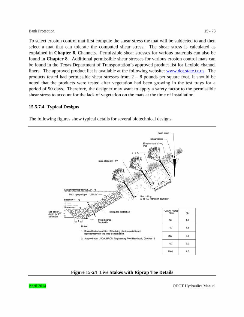
Bank Protection 15 - 73 To select erosion control mat first compute the shear stress the mat will be subjected to and then select a mat that can tolerate the computed shear stress. The shear stress is calculated as explained in Chapter 8, Channels. Permissible shear stresses for various materials can also be found in Chapter 8. Additional permissible shear stresses for various erosion control mats can be found in the Texas Department of Transportation’s approved product list for flexible channel liners. The approved product list is available at the following website: www.dot.state.tx.us. The products tested had permissible shear stresses from 2 – 8 pounds per square foot. It should be noted that the products were tested after vegetation had been growing in the test trays for a period of 90 days. Therefore, the designer may want to apply a safety factor to the permissible shear stress to account for the lack of vegetation on the mats at the time of installation. 15.5.7.4 Typical Designs The following figures show typical details for several biotechnical designs.
Figure 15-24 Live Stakes with Riprap Toe Details
April 2014 ODOT Hydraulics Manual
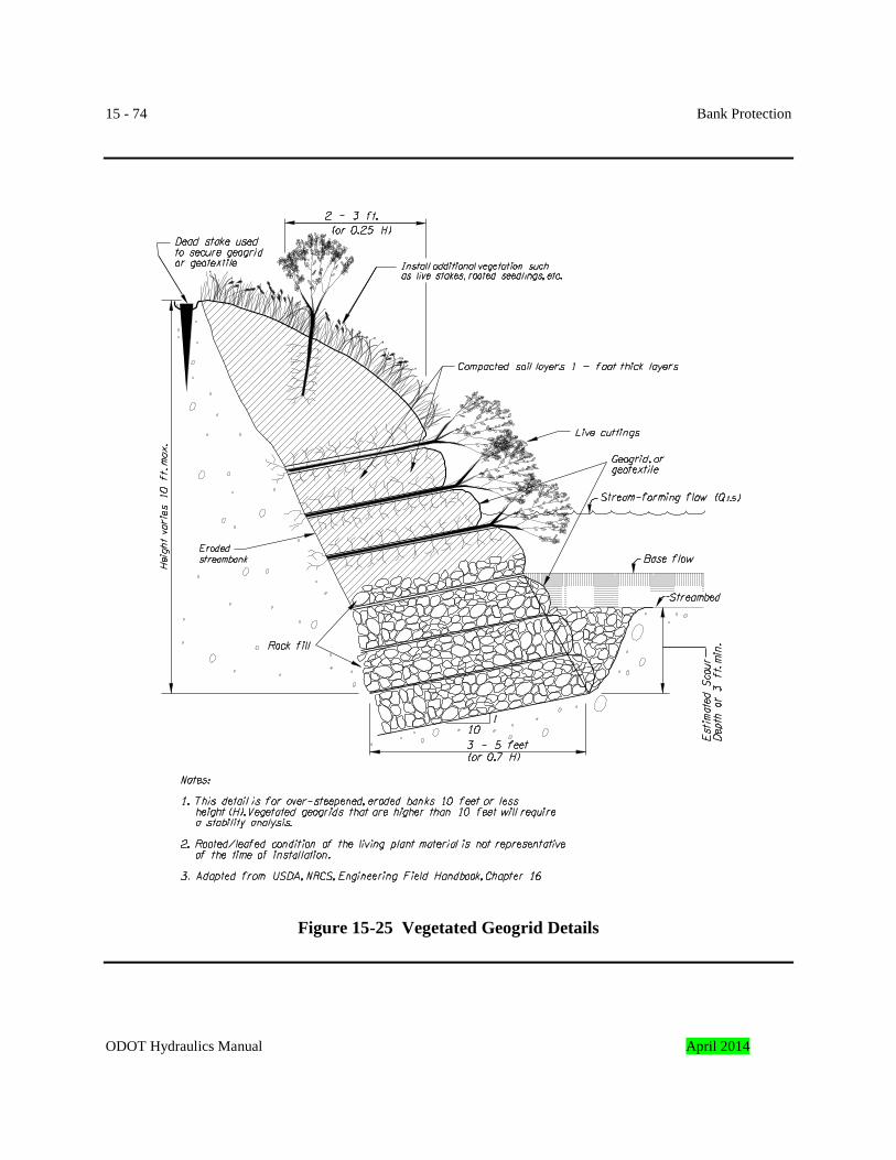
15 - 74 Bank Protection
Figure 15-25 Vegetated Geogrid Details
ODOT Hydraulics Manual April 2014
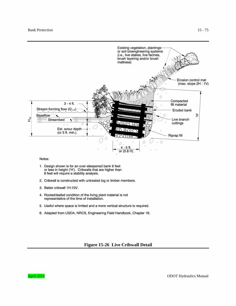
Bank Protection 15 - 75
Figure 15-26 Live Cribwall Detail
April 2014 ODOT Hydraulics Manual
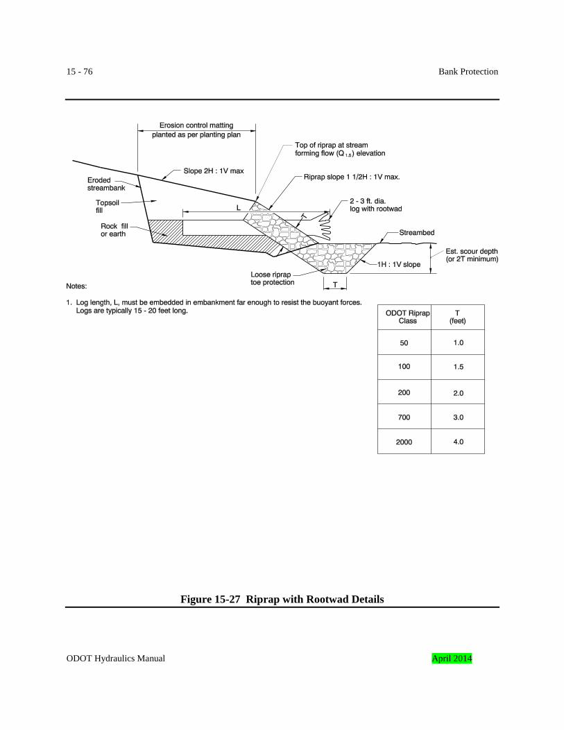
15 - 76 Bank Protection
Figure 15-27 Riprap with Rootwad Details
ODOT Hydraulics Manual April 2014
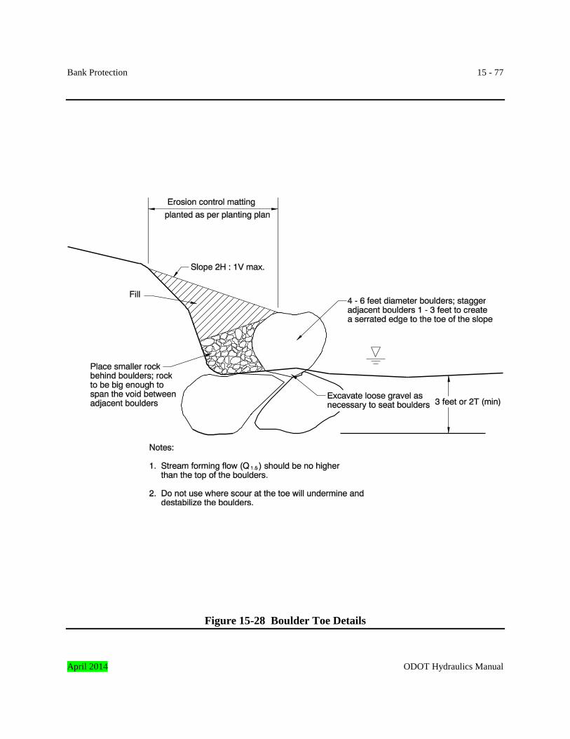
Bank Protection 15 - 77
Figure 15-28 Boulder Toe Details
April 2014 ODOT Hydraulics Manual
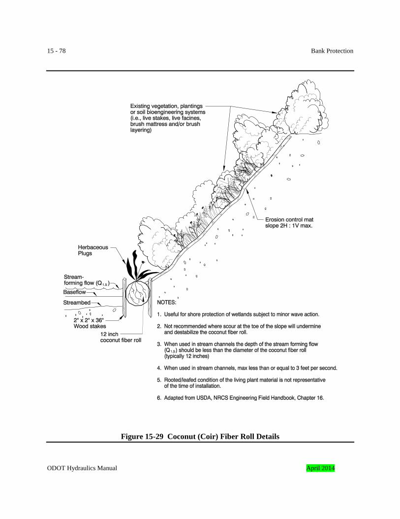
15 - 78 Bank Protection
Figure 15-29 Coconut (Coir) Fiber Roll Details ODOT Hydraulics Manual April 2014
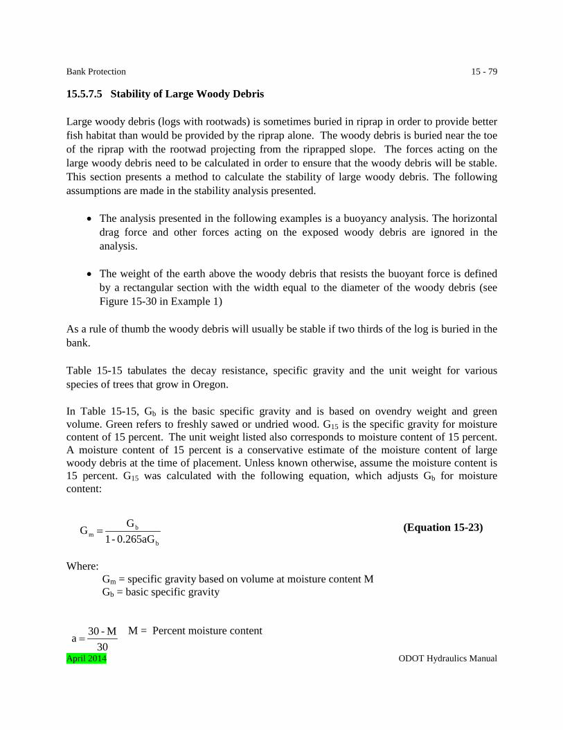
Bank Protection 15 - 79 15.5.7.5 Stability of Large Woody Debris Large woody debris (logs with rootwads) is sometimes buried in riprap in order to provide better fish habitat than would be provided by the riprap alone. The woody debris is buried near the toe of the riprap with the rootwad projecting from the riprapped slope. The forces acting on the large woody debris need to be calculated in order to ensure that the woody debris will be stable. This section presents a method to calculate the stability of large woody debris. The following assumptions are made in the stability analysis presented.
• The analysis presented in the following examples is a buoyancy analysis. The horizontal drag force and other forces acting on the exposed woody debris are ignored in the analysis.
• The weight of the earth above the woody debris that resists the buoyant force is defined
by a rectangular section with the width equal to the diameter of the woody debris (see Figure 15-30 in Example 1)
As a rule of thumb the woody debris will usually be stable if two thirds of the log is buried in the bank. Table 15-15 tabulates the decay resistance, specific gravity and the unit weight for various species of trees that grow in Oregon. In Table 15-15, Gb is the basic specific gravity and is based on ovendry weight and green volume. Green refers to freshly sawed or undried wood. G15 is the specific gravity for moisture content of 15 percent. The unit weight listed also corresponds to moisture content of 15 percent. A moisture content of 15 percent is a conservative estimate of the moisture content of large woody debris at the time of placement. Unless known otherwise, assume the moisture content is 15 percent. G15 was calculated with the following equation, which adjusts Gb for moisture content:
(Equation 15-23)
Where: Gm = specific gravity based on volume at moisture content M Gb = basic specific gravity
M = Percent moisture content
b
bm 0.265aG -1
G G =
30M - 30 a =
April 2014 ODOT Hydraulics Manual
15 - 80 Bank Protection When M ≥ 30 percent, Gm = Gb. The unit weight, γ, shown in Table 15-15 is calculated with the following equation:
(Equation 15-24)
Equations 15-23 and 15-24 can be used to calculate the unit weight of the various species of wood for any moisture content. The source of the information in Table 15-15 and the equations used to calculate Gm and γ is Reference 10. This Reference can be viewed at the following website: www.fpl.fs.fed.us. The maximum decay rate of wood occurs with alternate wetting and drying, or consistently damp conditions, which is the environment most large woody debris will be subjected to. If, however, the wood is kept continuously submerged, it does not decay significantly by the common decay fungi regardless of the wood species. Therefore, for maximum longevity, particularly at sites subject to wetting and drying, it is best to select a species with a decay resistance of “resistant or very resistant” or “moderately resistant”. At sites where the wood will be continuously submerged, any of the species listed in Table 15-15 can be used. When incorporating large woody debris in bank protection designs, it is recommended that the woody debris be placed normal to the bank or angled slightly upstream (15 - 20 degrees) in order to prevent overtopping flows from being deflected towards and possibly eroding the channel bank. The following soil parameters are suggested for the analysis:
• Unit weight of soil, γsoil = 120 pounds per cubic foot • Submerged unit weight of soil, γ'
soil = γsoil – γwater = 120 – 62.4 = 57.6 pounds per cubic foot
• Unit weight of riprap, γriprap = 165(0.7) = 115.5 pounds per cubic foot (assumes riprap weighing 165 pounds per cubic foot has 30 percent voids)
• Submerged unit weight of riprap, γ'riprap = (165 –62.4) 0.7 = 71.8 pounds per cubic foot
(assumes riprap weighing 165 pounds per cubic foot has 30 percent voids) For site-specific soil parameters, contact either the project geologist or the project geotechnical engineer.
+=
100M 1 62.4G γ m
ODOT Hydraulics Manual April 2014
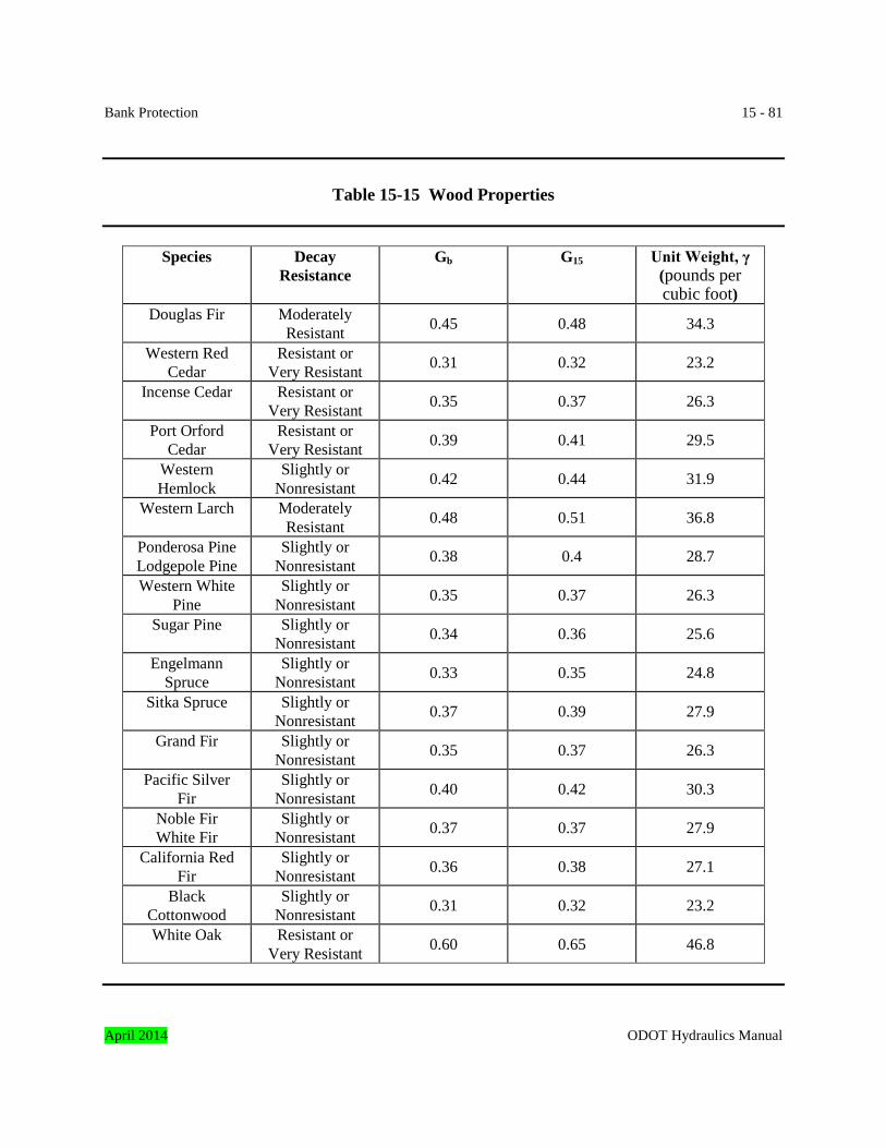
Bank Protection 15 - 81
Table 15-15 Wood Properties
Species Decay
Resistance Gb G15 Unit Weight, γ
(pounds per cubic foot)
Douglas Fir Moderately Resistant 0.45 0.48 34.3
Western Red Cedar
Resistant or Very Resistant 0.31 0.32 23.2
Incense Cedar Resistant or Very Resistant 0.35 0.37 26.3
Port Orford Cedar
Resistant or Very Resistant 0.39 0.41 29.5
Western Hemlock
Slightly or Nonresistant 0.42 0.44 31.9
Western Larch Moderately Resistant 0.48 0.51 36.8
Ponderosa Pine Lodgepole Pine
Slightly or Nonresistant 0.38 0.4 28.7
Western White Pine
Slightly or Nonresistant 0.35 0.37 26.3
Sugar Pine Slightly or Nonresistant 0.34 0.36 25.6
Engelmann Spruce
Slightly or Nonresistant 0.33 0.35 24.8
Sitka Spruce Slightly or Nonresistant 0.37 0.39 27.9
Grand Fir Slightly or Nonresistant 0.35 0.37 26.3
Pacific Silver Fir
Slightly or Nonresistant 0.40 0.42 30.3
Noble Fir White Fir
Slightly or Nonresistant 0.37 0.37 27.9
California Red Fir
Slightly or Nonresistant 0.36 0.38 27.1
Black Cottonwood
Slightly or Nonresistant 0.31 0.32 23.2
White Oak Resistant or Very Resistant 0.60 0.65 46.8
April 2014 ODOT Hydraulics Manual
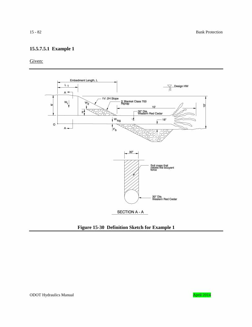
15 - 82 Bank Protection 15.5.7.5.1 Example 1 Given:
Figure 15-30 Definition Sketch for Example 1
ODOT Hydraulics Manual April 2014
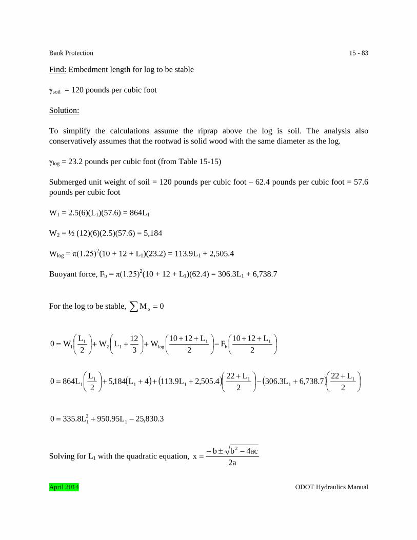
Bank Protection 15 - 83 Find: Embedment length for log to be stable γsoil = 120 pounds per cubic foot
Solution: To simplify the calculations assume the riprap above the log is soil. The analysis also conservatively assumes that the rootwad is solid wood with the same diameter as the log. γlog = 23.2 pounds per cubic foot (from Table 15-15) Submerged unit weight of soil = 120 pounds per cubic foot – 62.4 pounds per cubic foot = 57.6 pounds per cubic foot W1 = 2.5(6)(L1)(57.6) = 864L1 W2 = ½ (12)(6)(2.5)(57.6) = 5,184 Wlog = π(1.25)2(10 + 12 + L1)(23.2) = 113.9L1 + 2,505.4 Buoyant force, Fb = π(1.25)2(10 + 12 + L1)(62.4) = 306.3L1 + 6,738.7
For the log to be stable, ∑ = 0Mo
++
−
++
+
++
=
2L1210F
2L1210W
312LW
2LW0 1
b1
log121
1
( ) ( ) ( )
+
+−
+
++++
=
2L227.738,6L3.306
2L224.505,2L9.1134L184,5
2LL8640 1
11
111
1
3.830,25L95.950L8.3350 121 −+=
Solving for L1 with the quadratic equation, a2
ac4bbx2 −±−
=
April 2014 ODOT Hydraulics Manual
15 - 84 Bank Protection
( )( )( )8.3352
3.830,258.335495.95095.950L
2
1−−±−
=
L1 = 7.47 feet Minimum embedment length, L = L1 + 12 = 7.47 + 12 = 19.47 ≈ 20 feet Use embedment length, L = 24 feet to provide factor of safety against overturning; recheck stability with L = 24 feet.
( )
−
+
++
=∑ 2
344.414,102
34872,33
1212184,52
1212864Mo
0lbsft931,33045,177824,65944,82208,62M0 >−=−++=∑ … log will not overturn
19.1045,177976,210
045,177824,65944,82208,62FactorSafety ==
++=
Example 1 Summary: Example 1 demonstrates cumbersome design process to determine embedment length as shown in Figure 15-30. It results in a 2:1 ratio of embedment to exposure. This should be a rule of thumb with 6-feet of cover on a 30 inch diameter log with rootwad. 15.5.7.5.2 Example 2 At some sites it may not practical or environmentally acceptable to disturb the stream bank the amount necessary to provide the embedment length as calculated in Example 1. Cabling concrete blocks or large rocks to the log can reduce the embedment length as shown in this example. This example is the same as Example 1 except that two concrete blocks have been added to provide additional ballast. ODOT Hydraulics Manual April 2014
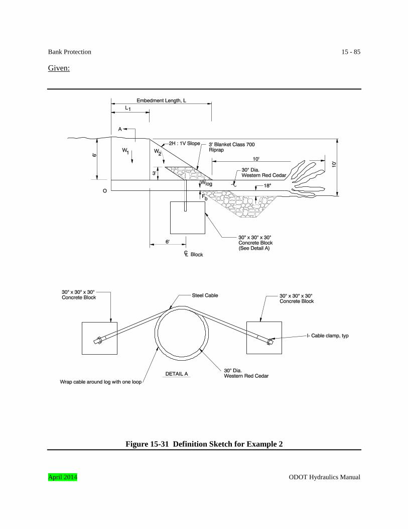
Bank Protection 15 - 85 Given:
Figure 15-31 Definition Sketch for Example 2
April 2014 ODOT Hydraulics Manual

15 - 86 Bank Protection Find: Embedment length for log to be stable. Solution: To simplify the calculations assume the riprap above the log is soil. The analysis also assumes that the rootwad is solid wood with the same diameter as the log. γsoil = 120 pounds per cubic foot γlog = 23.2 pounds per cubic foot (from Table 15-15) γconcrete = 145 pounds per cubic foot Submerged unit weight of soil = 120 pounds per cubic foot – 62.4 pounds per cubic foot = 57.6 pounds per cubic foot
Submerged unit weight of concrete = 145 – 62.4 = 82.6 pounds per cubic foot W1 = 2.5(6)(L1)(57.6) = 864L1 W2 = ½ (12)(6)(2.5)(57.6) = 5,184 Wb = 2(2.5)3(82.6) = 2,581 Wlog = π(1.25)2(10 + 12 + L1)(23.2) = 113.9L1 + 2,505.4 Buoyant force, Fb = π(1.25)2(10 + 12 + L1)(62.4) = 306.3L1 + 6,738.7
For the log to be stable, ∑ = 0Mo
( )
++
−
++
+++
++
=
2L1210F
2L1210W6LW
312LW
2LW0 1
b1
log1b121
1
ODOT Hydraulics Manual April 2014
Bank Protection 15 - 87
( ) ( ) ( )
+
++++++
=
2L224.505,2L9.1136L581,24L184,5
2LL8640 1
1111
1
Minimum embedment length, L = L1 + 12 = 2.39 + 12 = 14.39 ≈ 15 feet Adding the concrete blocks reduced the embedment length calculated in Example 1 by 5 feet. In general cabling concrete blocks or large rocks to woody debris is most effective and often necessary at sites with a shallow layer of soil over the woody debris. Example 2 summary: Example 2 demonstrates a cumbersome design process to determine a reduced embedment length as shown in Figure 15-31 where two concrete blocks provide ballast to offset buoyant forces on the log. It results in a 1.5:1 ratio of embedment to exposure. This should be a rule of thumb with 2 concrete blocks and 6 feet of cover on a 30 inch diameter log with rootwad. 15.6 References 1. U.S. Department of Agriculture, Forest Service, Forest Products Laboratory, “Wood Handbook – Wood as an Engineering Material”, General Technical Report FPL-GTR-113, Madison, Wisconsin, 1999.
+
+2
L 22 6,738.7) (306.3L - 11
feet 2.39 L
(335.8) 2)0,344.3(335.8)(-1 4 -3,531.95 3,531.95 -
L
equation quadratic with theLfor Solving
10,344.3 - 3,531.95L 335.8L 0
1
2
1
1
121
=
±=
+=
April 2014 ODOT Hydraulics Manual
15 - 88 Bank Protection 2. Lagasse, P.F., J.D. Schall, and E.V. Richardson, 2001, “Stream Stability at Highway Structures”, Third Edition, Publication No. FHWA NHI 01-002, Hydraulic Engineering Circular No. 20, Federal Highway Administration, Washington, D.C. 3. Richardson, E.V., D.B. Simons, and P.F. Lagasse, 2001, “Highways in the River Environment”, Publication No. FHWA NHI 01-004, Hydraulic Design Series No. 6, Federal Highway Administration, Washington, D.C. 4. Maynord, S.T., 1996, “Toe-Scour Estimation in Stabilized Bendways”, ASCE Journal of Hydraulic Engineering, Vol. 122, No. 8, pp. 460-464. 5. Blodgett, J.C., 1986, “Hydraulic Characteristics of Natural Open Channels”, Volume 1 of “Rock Riprap Design for Protection of Stream Channels Near Highway Structures”, U.S. Geological Survey, Water-Resources Investigation Report 86-4127. 6. Brown, S.A., 1985, “Design of Spur-Type Streambank Stabilization Structures”, Report No. FHWA/RD-84/101, Federal Highway Administration, Washington, D.C. 7. Lagasse, P.F., L.W. Zevenbergen, J.D. Schall, and P.E. Clopper, 2001, “Bridge Scour and Stream Instability Countermeasures, Experience, Selection, and Design Guidance”, Second Edition, Publication No. FHWA NHI 01-003, Hydraulic Engineering Circular No. 23, Federal Highway Administration, Washington, D.C. 8. Brown, S.A., and E.S. Clyde, 1989, “Design of Riprap Revetment”, Report No. FHWA-IP-89-016, Hydraulic Engineering Circular No. 11, Federal Highway Administration, Washington, D.C. 9. U.S. Department of Agriculture, “Field Engineering Handbook”, Chapter 16, Streambank and Shoreline Protection, Natural Resources Conservation Service, December 1996. 10. Washington Department of Fish and Wildlife, Integrated Streambank Protection Guidelines, 2002. 11. U.S. Department of the Army, Corps of Engineers “Coastal Engineering Manual,” 12. Corps of Engineers Engineering Manual EM-1110-2-1614 “Design of Coastal Revetments, Seawalls, and Bulkheads” 13. California Department of Transportation, Report FHWA-CA-TL-95-10, “California Bank and Shore Rock Slope Protection Design: Practitioner’s Guide and Field Evaluations of Riprap Methods”
ODOT Hydraulics Manual April 2014