Embed Size (px)
Citation preview
Karnataka State Highways Improvement Project - II Detailed Project Report
Consultancy Services for Preparation of DPR, Bid Documents Volume IV – Part 1: EIA Report
and Associated Safeguard Instruments – EPC Packages Funded by World Bank
Chapter 2: Project Description i Scott Wilson
CHAPTER 2: PROJECT DESCRIPTION
TABLE OF CONTENTS
2. PROJECT DESCRIPTION......................................................................................................................... 1
2.1 PROJECT LOCATION................................................................................................................................. 1
2.2 DETAILS OF PROJECT CORRIDOR: ............................................................................................................ 1
2.3 CORRIDOR OF IMPACT (COI) AND RIGHT OF WAY (ROW) ..................................................................... 1
2.4 SCOPE OF WORKS .................................................................................................................................... 3
2.5 TRAFFIC DETAILS PER ROUTE ................................................................................................................. 3
2.6 DESIGN SPEED: ........................................................................................................................................ 3
2.7 IMPROVEMENT PROPOSAL........................................................................................................................ 3
2.8 ROAD CONSTRUCTION MATERIALS ......................................................................................................... 4
2.5.1 Rocks............................................................................................................................................... 4
2.5.2 Gravel ............................................................................................................................................. 4
2.5.3 Sand ................................................................................................................................................ 4
2.5.4 Fly Ash............................................................................................................................................ 4
2.5.5 Embankment Fill............................................................................................................................. 5
2.5.6 Asphalt ............................................................................................................................................ 5
2.8 MAJOR AND MINOR JUNCTIONS................................................................................................................ 5
2.9 BUS LAY-BAYS, TRUCK LAY-BYES AND PARKING AREAS....................................................................... 5
2.10 STREET FURNITURE ................................................................................................................................. 5
2.9 REALIGNMENTS AND BYPASSES .............................................................................................................. 5
2.11 CONSTRUCTIONS AND REPLACEMENT OF BRIDGES AND CULVERTS.......................................................... 6
2.12 ECONOMIC INTERNAL RATE OF RETURN (EIRR)..................................................................................... 6
2.13 DESIGN CROSS SECTIONS & ROAD WIDENING AND IMPROVEMENTS: ...................................................... 6
LIST OF TABLESTABLE 2-1: DISTRICTS TRAVERSED BY THE PROJECT ROADS.................................................................................. 1
TABLE 2-2: RIGHT OF WAY IN THE PROJECT AREA ................................................................................................... 1
TABLE 2-3: PRESENT & PROJECTED TRAFFIC BY VEHICLE TYPES ALONG THE PROJECT ROADS ............................. 3
TABLE 2-4: DETAILS OF MINOR REALIGNMENTS ..................................................................................................... 6
TABLE 2-5: ECONOMIC ANALYSIS RESULTS............................................................................................................. 6
TABLE 2-6: GUIDING PARAMETERS FOR UP GRADATION OF ROAD IN PROJECT AREA .............................................. 7
TABLE 2-7: DETAILS OF TYPICAL WIDTH ELEMENTS.............................................................................................. 7
LIST OF FIGURESFIGURE 2-1: GEOGRAPHICAL LOCATION OF THE PROJECT ROADS ............................................................................ 2
FIGURE 2-2: THE RURAL AND URBAN CROSS SECTION OF THE ROADS IN THE PROJECT AREA ................................. 8
Karnataka State Highways Improvement Project - II Detailed Project Report
Consultancy Services for Preparation of DPR, Bid Documents Volume IV – Part 1: EIA Report
and Associated Safeguard Instruments – EPC Packages Funded by World Bank
Chapter 2: Project Description 1 Scott Wilson
2. PROJECT DESCRIPTION
2.1 Project Location
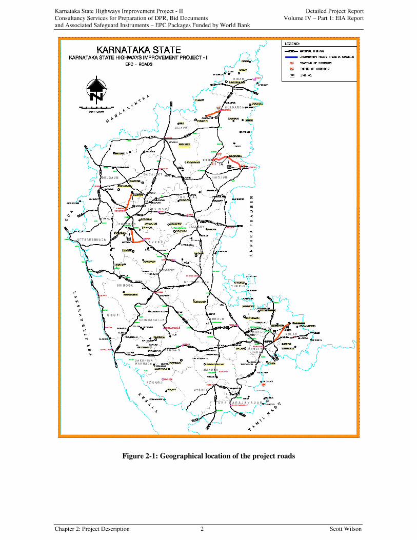
The proposed KSHIP II EPC Project Roads have been divided into 5 contract packages. The project
roads are distributed in 7 districts of Karnataka state. Table-2.1 shows the link numbers and various
districts through which the roads pass. Figure-2.1 shows the geographical location of the project
roads.
2.2 Details of project Corridor:
Table 2-1: Districts Traversed by the Project Roads
Contract
PackageLink ID Description of Links Districts
67A Hoskote - H (Hindgnala) Cross Bangalore Rural & KolarWEP 1
67B H Cross - Chinatmani Bypass (cor 65 F –Jn) Kolar
M7D Hangal - Tadasa HaveriWEP 2
T8 Haveri (NH-4) – Hangal Haveri
WEP 3 21B Dharwad – Saundatti Belgaum & Dharwad
13A Thinthini – Chinchodi – Jalhalli – Karegud – Devadurga RaichurWEP 4
13B Devadurga – Masarkal – Gabbur – Kalmala Raichur
WEP 5 6C Chowdapur – Gulbarga Gulbarga
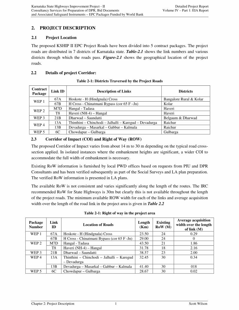
2.3 Corridor of Impact (COI) and Right of Way (ROW)
The proposed Corridor of Impact varies from about 14 m to 30 m depending on the typical road cross-
section applied. In isolated instances where the embankment heights are significant, a wider COI to
accommodate the full width of embankment is necessary.
Existing RoW information is furnished by local PWD offices based on requests from PIU and DPR
Consultants and has been verified subsequently as part of the Social Surveys and LA plan preparation.
The verified RoW information is presented in LA plans.
The available RoW is not consistent and varies significantly along the length of the routes. The IRC
recommended RoW for State Highways is 30m but clearly this is not available throughout the length
of the project roads. The minimum available ROW width for each of the links and average acquisition
width over the length of the road link in the project area is given in Table 2.2
Table 2-1: Right of way in the project area
Package
Number
Link
IDLocation of Roads
Length
(Km)
Existing
RoW (M)
Average acquisition
width over the length
of link (M)
67A Hoskote - H (Hindgnala) Cross 23.50 24 0.29WEP 1
67B H Cross - Chinatmani Bypass (cor 65 F -Jn) 29.00 24 0
M7D Hangal - Tadasa 43.50 21 1.86WEP 2
T8 Haveri (NH-4) – Hangal 31.78 18 2.16
WEP 3 21B Dharwad – Saundatti 38.57 23 2.00
13A Thinthini – Chinchodi – Jalhalli – Karegud
– Devadurga
32.45 30 0.34WEP 4
13B Devadurga – Masarkal – Gabbur – Kalmala 41.40 30 018
WEP 5 6C Chowdapur – Gulbarga 28.67 30 0.02
Karnataka State Highways Improvement Project - II Detailed Project Report
Consultancy Services for Preparation of DPR, Bid Documents Volume IV – Part 1: EIA Report
and Associated Safeguard Instruments – EPC Packages Funded by World Bank
Chapter 2: Project Description 2 Scott Wilson
Figure 2-1: Geographical location of the project roads

Karnataka State Highways Improvement Project - II Detailed Project Report
Consultancy Services for Preparation of DPR, Bid Documents Volume IV – Part 1: EIA Report
and Associated Safeguard Instruments – EPC Packages Funded by World Bank
Chapter 2: Project Description 3 Scott Wilson
2.4 Scope of Works
The PWD, GoK reviewed the various routes selected for up-gradation decided to award the work
based on contract packages under International Competitive Bidding (ICB).
2.5 Traffic Details per Route
The volume of vehicular traffic as of year 2006 is presented in Table-2.3 along with the projection for
year 2012. The reason for not preparing any projection beyond year 2012 is that any EIA report is not
considered valid by the MoEF beyond five years without further review.
Table 2-1: Present & Projected Traffic by Vehicle Types along the Project Roads
Route/
LinksYear
Two
wheelerCar
Three
wheelerLCV BUS TRUCKS Total
2006 4,423 1,945 903 555 632 1,664 10,12167A
2012 7,619 3,862 1,242 868 1,010 2,538 17,138
2006 1,078 711 74 473 421 543 3,30067B
2012 1,826 1,412 99 720 672 815 5,545
2006 472 98 49 73 111 61 864M7D
2012 832 221 66 115 179 86 1500
2006 2,471 919 679 993 379 371 5,812T-8
2012 4,186 2,119 939 1,513 616 534 9,907
2006 668 666 92 219 560 705 2,91021B
2012 1,182 1,448 129 360 949 1,137 5,206
2006 426 285 122 273 58 148 1,31213A
2012 785 645 174 425 95 235 2,358
2006 232 232 11 236 98 346 1,15513B
2012 427 500 16 370 166 553 2,033
2006 785 400 261 132 298 260 2,1376C
2012 1,329 817 353 198 478 386 3,561
2.6 Design Speed:
The design speed of different locations of the corridor has been calculated depending on the IRC
recommended design speed for State Highways and the location of the road with respect to,
topography, sight distance, road geometry, accident zones, silent zones such as schools, hospitals and
other safety aspects. The designed speeds for the proposed road links are presented in Appendix - 1.
2.7 Improvement proposal
The main elements of the construction processes are given below.
Upgradation: Widening & Strengthening (including raising of embankment): The elements are:
• Remove high shoulders & grub out bushes (some trees may get removed);
• Remove existing pavement;
• Widen road formation to 12-m width;
• Construct new wider pavement with paved or unpaved shoulder, including surfacing
and providing ditches and drains, wherever necessary; and
Raising of Embankment & New Pavement: The elements are:
• Remove high shoulders & grub out bushes (some trees may get removed);
• Remove existing pavement and widening;
• Widen roadway to 12-m and construct side ditch, if required;
• Raise existing embankment if required;
Karnataka State Highways Improvement Project - II Detailed Project Report
Consultancy Services for Preparation of DPR, Bid Documents Volume IV – Part 1: EIA Report
and Associated Safeguard Instruments – EPC Packages Funded by World Bank
Chapter 2: Project Description 4 Scott Wilson
• Construct new wider pavement and paved shoulder, including surfacing and pavement
edge drain; and
• Construct shoulder filling.
The sections identified for raising were selected on the basis of a number of criteria including
• Relative height of the existing road formation level (top of subgrade) to the surrounding
ground and likely maximum water table conditions;
• Possibility of seepage across the road line;
• Presence or likelihood of field irrigation close to the road;
• Nature of local soil; and
• Possibility or otherwise of improving drainage by means of side drains.
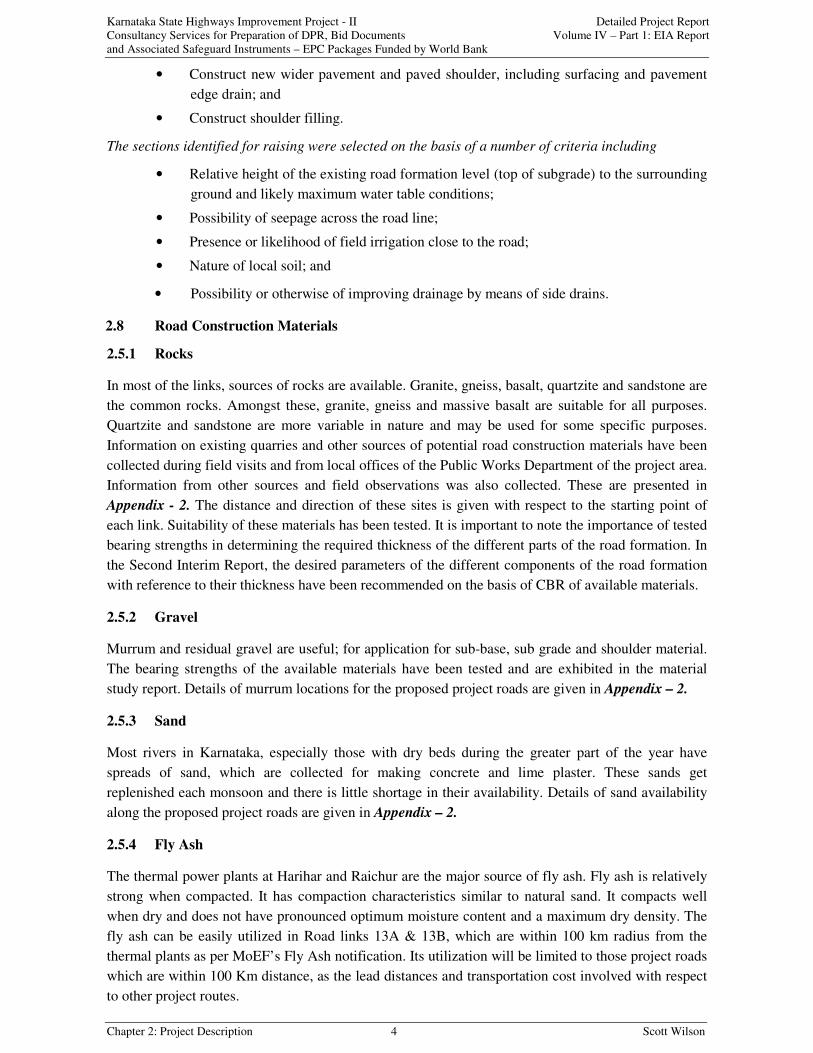
2.8 Road Construction Materials
2.5.1 Rocks
In most of the links, sources of rocks are available. Granite, gneiss, basalt, quartzite and sandstone are
the common rocks. Amongst these, granite, gneiss and massive basalt are suitable for all purposes.
Quartzite and sandstone are more variable in nature and may be used for some specific purposes.
Information on existing quarries and other sources of potential road construction materials have been
collected during field visits and from local offices of the Public Works Department of the project area.
Information from other sources and field observations was also collected. These are presented in
Appendix - 2. The distance and direction of these sites is given with respect to the starting point of
each link. Suitability of these materials has been tested. It is important to note the importance of tested
bearing strengths in determining the required thickness of the different parts of the road formation. In
the Second Interim Report, the desired parameters of the different components of the road formation
with reference to their thickness have been recommended on the basis of CBR of available materials.
2.5.2 Gravel
Murrum and residual gravel are useful; for application for sub-base, sub grade and shoulder material.
The bearing strengths of the available materials have been tested and are exhibited in the material
study report. Details of murrum locations for the proposed project roads are given in Appendix – 2.
2.5.3 Sand
Most rivers in Karnataka, especially those with dry beds during the greater part of the year have
spreads of sand, which are collected for making concrete and lime plaster. These sands get
replenished each monsoon and there is little shortage in their availability. Details of sand availability
along the proposed project roads are given in Appendix – 2.
2.5.4 Fly Ash
The thermal power plants at Harihar and Raichur are the major source of fly ash. Fly ash is relatively
strong when compacted. It has compaction characteristics similar to natural sand. It compacts well
when dry and does not have pronounced optimum moisture content and a maximum dry density. The
fly ash can be easily utilized in Road links 13A & 13B, which are within 100 km radius from the
thermal plants as per MoEF’s Fly Ash notification. Its utilization will be limited to those project roads
which are within 100 Km distance, as the lead distances and transportation cost involved with respect
to other project routes.
Karnataka State Highways Improvement Project - II Detailed Project Report
Consultancy Services for Preparation of DPR, Bid Documents Volume IV – Part 1: EIA Report
and Associated Safeguard Instruments – EPC Packages Funded by World Bank
Chapter 2: Project Description 5 Scott Wilson
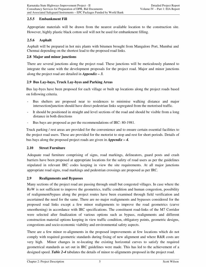
2.5.5 Embankment Fill
Appropriate materials will be drawn from the nearest available location to the construction site.
However, highly plastic black cotton soil will not be used for embankment filling.
2.5.6 Asphalt
Asphalt will be prepared in hot mix plants with bitumen brought from Mangalore Port, Mumbai and
Chennai depending on the shortest lead to the proposed road links.
2.8 Major and minor junctions
There are several junctions along the project road. These junctions will be meticulously planned to
integrate the same with the development proposals for the project road. Major and minor junctions
along the project road are detailed in Appendix – 3.
2.9 Bus Lay-bays, Truck Lay-byes and Parking Areas
Bus lay-byes have been proposed for each village or built up locations along the project roads based
on following criteria.
- Bus shelters are proposed near to residences to minimise walking distance and major
intersection/junction should have direct pedestrian links segregated from the motorised traffic.
- It should be positioned in straight and level sections of the road and should be visible from a long
distance in both directions
- Bus bays are proposed as per the recommendations of IRC: 80-1981.
Truck parking / rest areas are provided for the convenience and to ensure certain essential facilities to
the project road users. These are provided for the motorist to stop and rest for short periods. Details of
bus bays along the proposed project roads are given in Appendix – 4.
2.10 Street Furniture
Adequate road furniture comprising of signs, road markings, delineators, guard posts and crash
barriers have been proposed at appropriate locations for the safety of road users as per the guidelines
stipulated in relevant IRC codes keeping in view the site requirements. At all major junctions
appropriate road signs, road markings and pedestrian crossings are proposed as per IRC.
2.9 Realignments and Bypasses
Many sections of the project road are passing through small but congested villages. In case where the
RoW is not sufficient to improve the geometrics, traffic condition and human congestion, possibility
of realignment/bypass along the project routes have been examined through field verification and
ascertained the need for the same. There are no major realignments and bypasses considered for the
proposed road links except a few minor realignments to improve the road geometrics (curve
smoothening) in accordance with IRC specifications. The constituent road-links of the M7 Corridor
were selected after finalization of various options such as bypass, realignments and different
construction material options keeping in view traffic condition, obligatory points, geometric designs,
congestions and socio-economic viability and environmental safety aspects.
There are a few minor re-alignments in the proposed improvements at few locations which do not
comply with required geometric standards during fixing of new alignment and where R&R costs are
very high. Minor changes in re-locating the existing horizontal curves to satisfy the required
geometrical standards as set out in IRC guidelines were made. This has led to the achievement of a
designed speed. Table 2-4 tabulates the details of minor re-alignments proposed in the project road.
Karnataka State Highways Improvement Project - II Detailed Project Report
Consultancy Services for Preparation of DPR, Bid Documents Volume IV – Part 1: EIA Report
and Associated Safeguard Instruments – EPC Packages Funded by World Bank
Chapter 2: Project Description 6 Scott Wilson
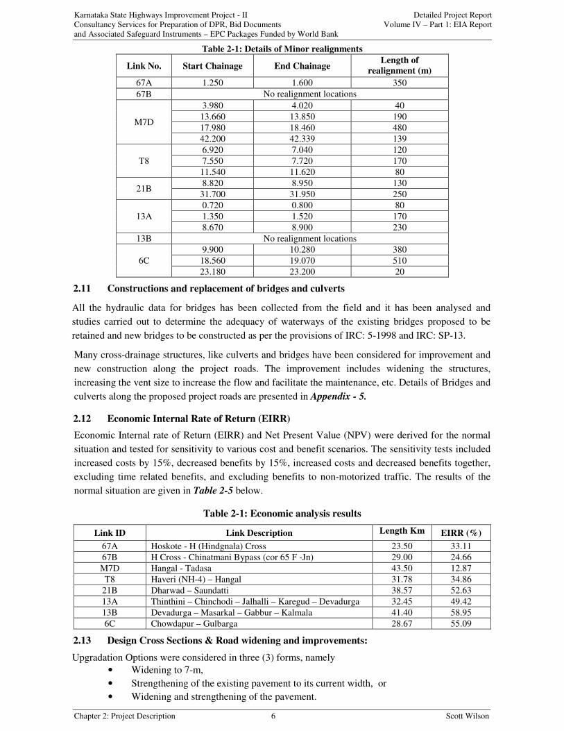
Table 2-1: Details of Minor realignments
Link No. Start Chainage End ChainageLength of
realignment (m)
67A 1.250 1.600 350
67B No realignment locations
3.980 4.020 40
13.660 13.850 190
17.980 18.460 480M7D
42.200 42.339 139
6.920 7.040 120
7.550 7.720 170T8
11.540 11.620 80
8.820 8.950 13021B
31.700 31.950 250
0.720 0.800 80
1.350 1.520 17013A
8.670 8.900 230
13B No realignment locations
9.900 10.280 380
18.560 19.070 5106C
23.180 23.200 20
2.11 Constructions and replacement of bridges and culverts
All the hydraulic data for bridges has been collected from the field and it has been analysed and
studies carried out to determine the adequacy of waterways of the existing bridges proposed to be
retained and new bridges to be constructed as per the provisions of IRC: 5-1998 and IRC: SP-13.
Many cross-drainage structures, like culverts and bridges have been considered for improvement and
new construction along the project roads. The improvement includes widening the structures,
increasing the vent size to increase the flow and facilitate the maintenance, etc. Details of Bridges and
culverts along the proposed project roads are presented in Appendix - 5.
2.12 Economic Internal Rate of Return (EIRR)
Economic Internal rate of Return (EIRR) and Net Present Value (NPV) were derived for the normal
situation and tested for sensitivity to various cost and benefit scenarios. The sensitivity tests included
increased costs by 15%, decreased benefits by 15%, increased costs and decreased benefits together,
excluding time related benefits, and excluding benefits to non-motorized traffic. The results of the
normal situation are given in Table 2-5 below.
Table 2-1: Economic analysis results
Link ID Link Description Length Km EIRR (%)
67A Hoskote - H (Hindgnala) Cross 23.50 33.11
67B H Cross - Chinatmani Bypass (cor 65 F -Jn) 29.00 24.66
M7D Hangal - Tadasa 43.50 12.87
T8 Haveri (NH-4) – Hangal 31.78 34.86
21B Dharwad – Saundatti 38.57 52.63
13A Thinthini – Chinchodi – Jalhalli – Karegud – Devadurga 32.45 49.42
13B Devadurga – Masarkal – Gabbur – Kalmala 41.40 58.95
6C Chowdapur – Gulbarga 28.67 55.09
2.13 Design Cross Sections & Road widening and improvements:
Upgradation Options were considered in three (3) forms, namely
• Widening to 7-m,
• Strengthening of the existing pavement to its current width, or
• Widening and strengthening of the pavement.
Karnataka State Highways Improvement Project - II Detailed Project Report
Consultancy Services for Preparation of DPR, Bid Documents Volume IV – Part 1: EIA Report
and Associated Safeguard Instruments – EPC Packages Funded by World Bank
Chapter 2: Project Description 7 Scott Wilson
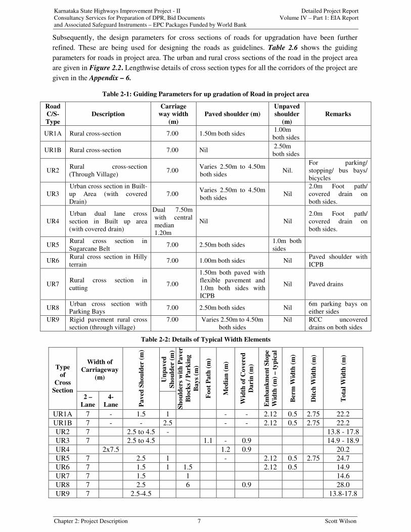
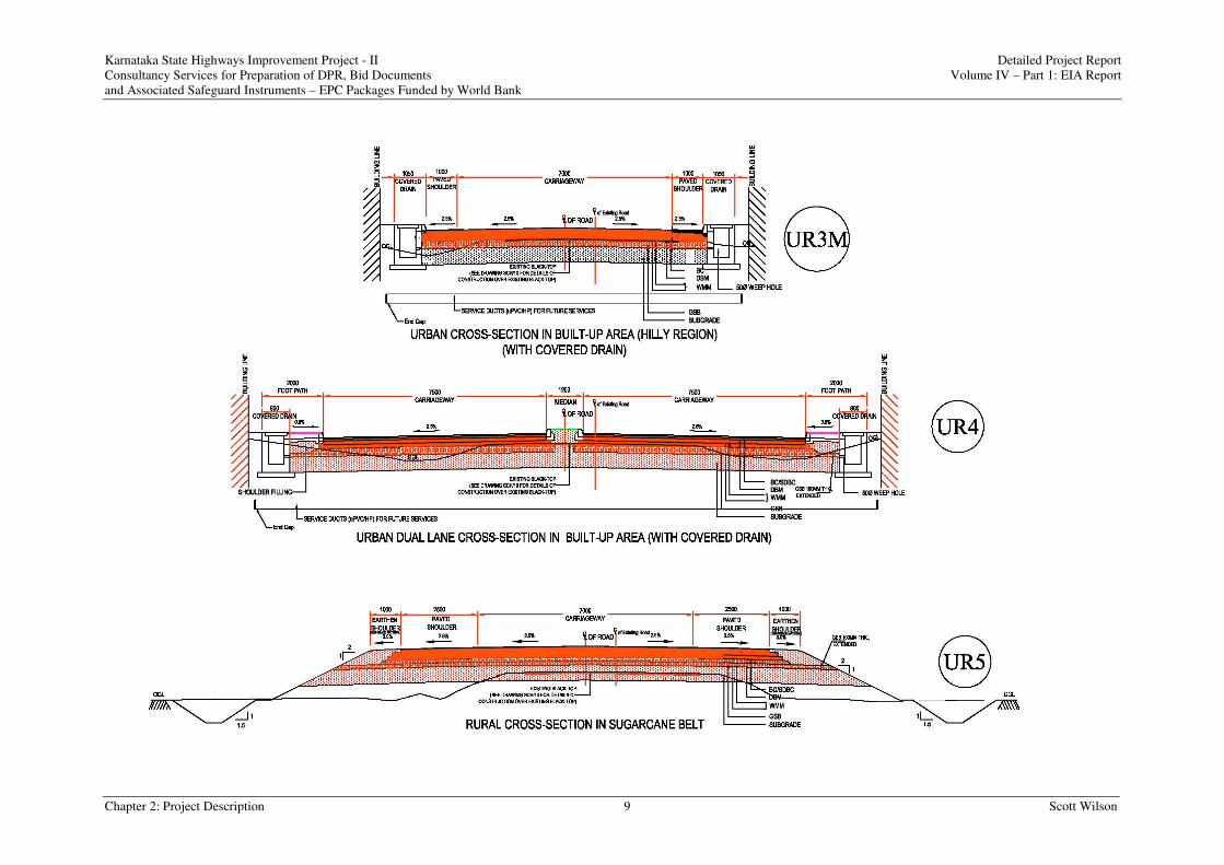
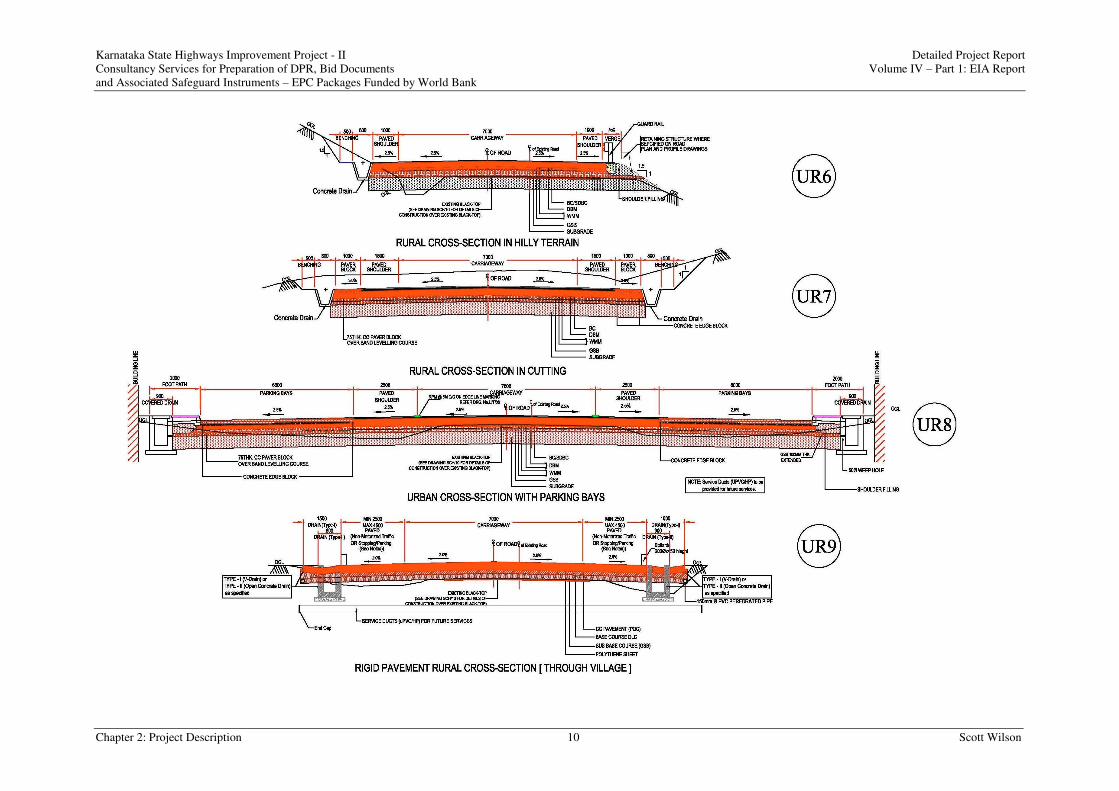
Subsequently, the design parameters for cross sections of roads for upgradation have been further
refined. These are being used for designing the roads as guidelines. Table 2.6 shows the guiding
parameters for roads in project area. The urban and rural cross sections of the road in the project area
are given in Figure 2.2. Lengthwise details of cross section types for all the corridors of the project are
given in the Appendix – 6.
Table 2-1: Guiding Parameters for up gradation of Road in project area
Road
C/S-
Type
Description
Carriage
way width
(m)
Paved shoulder (m)
Unpaved
shoulder
(m)
Remarks
UR1A Rural cross-section 7.00 1.50m both sides1.00m
both sides
UR1B Rural cross-section 7.00 Nil2.50m
both sides
UR2Rural cross-section
(Through Village)7.00
Varies 2.50m to 4.50m
both sidesNil.
For parking/
stopping/ bus bays/
bicycles
UR3
Urban cross section in Built-
up Area (with covered
Drain)
7.00Varies 2.50m to 4.50m
both sidesNil
2.0m Foot path/
covered drain on
both sides.
UR4
Urban dual lane cross
section in Built up area
(with covered drain)
Dual 7.50m
with central
median
1.20m
Nil Nil
2.0m Foot path/
covered drain on
both sides.
UR5Rural cross section in
Sugarcane Belt7.00 2.50m both sides
1.0m both
sides
UR6Rural cross section in Hilly
terrain7.00 1.00m both sides Nil
Paved shoulder with
ICPB
UR7Rural cross section in
cutting7.00
1.50m both paved with
flexible pavement and
1.0m both sides with
ICPB
Nil Paved drains
UR8Urban cross section with
Parking Bays7.00 2.50m both sides Nil
6m parking bays on
either sides
UR9 Rigid pavement rural cross
section (through village)
7.00 Varies 2.50m to 4.50m
both sides
Nil RCC uncovered
drains on both sides
Table 2-2: Details of Typical Width Elements
Width of
Carriageway
(m) Un
pa
ved
Sh
ou
lder
(m
)
Type
of
Cross
Section2 –
Lane
4-
Lane Pa
ved
Sh
ou
lder
(m
)
Sh
ou
lder
s w
ith
Pa
ver
Blo
cks
/ P
ark
ing
Ba
ys
(m)
Fo
ot
Pa
th (
m)
Med
ian
(m
)
Wid
th o
f C
ov
ered
Da
rin
(m
)
Em
ba
nk
men
t S
lop
e
Wid
th (
m)
– t
yp
ica
l
Ber
m W
idth
(m
)
Dit
ch W
idth
(m
)
To
tal
Wid
th (
m)
UR1A 7 - 1.5 1 - - 2.12 0.5 2.75 22.2
UR1B 7 - - 2.5 - - 2.12 0.5 2.75 22.2
UR2 7 2.5 to 4.5 - 13.8 - 17.8
UR3 7 2.5 to 4.5 1.1 - 0.9 14.9 - 18.9
UR4 2x7.5 1.2 0.9 20.2
UR5 7 2.5 1 - 2.12 0.5 2.75 24.7
UR6 7 1.5 1 1.5 2.12 0.5 14.9
UR7 7 1.5 1 14.6
UR8 7 2.5 6 0.9 28.0
UR9 7 2.5-4.5 13.8-17.8

Karnataka State Highways Improvement Project - II Detailed Project Report
Consultancy Services for Preparation of DPR, Bid Documents Volume IV – Part 1: EIA Report
and Associated Safeguard Instruments – EPC Packages Funded by World Bank
Chapter 2: Project Description 8 Scott Wilson
Figure 2-1: The Rural and Urban cross section of the Roads in the project area
Karnataka State Highways Improvement Project - II Detailed Project Report
Consultancy Services for Preparation of DPR, Bid Documents Volume IV – Part 1: EIA Report
and Associated Safeguard Instruments – EPC Packages Funded by World Bank
Chapter 2: Project Description 9 Scott Wilson
Karnataka State Highways Improvement Project - II Detailed Project Report
Consultancy Services for Preparation of DPR, Bid Documents Volume IV – Part 1: EIA Report
and Associated Safeguard Instruments – EPC Packages Funded by World Bank
Chapter 2: Project Description 10 Scott Wilson