Embed Size (px)
Citation preview
Chapter 23
The Reflection of Light: Mirrors

Wave Fronts and Rays
Defining wave fronts and rays. Consider a sound wave since it is easier to visualize. Shown is a hemispherical view of a sound wave emitted by a pulsating sphere. The rays are perpendicular to the wave fronts (e.g. crests) which are separated from each other by the wavelength of the wave, λ.
Wave Fronts and Rays
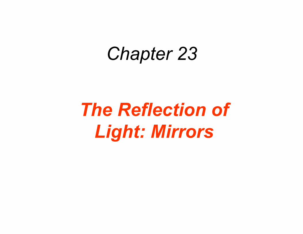
The positions of two spherical wave fronts are shown in (a) with their diverging rays. At large distances from the source, the wave fronts become less and less curved and approach the limiting case of a plane wave shown in (b). A plane wave has flat wave fronts and rays parallel to each other. We will consider light waves as plane waves and will represent them by their rays.
The Reflection of Light
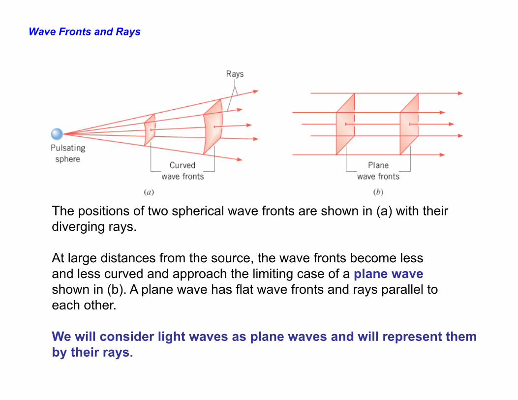
LAW OF REFLECTION FROM FLAT MIRRORS. The incident ray, the reflected ray, and the normal to the surface all lie in the same plane, and the angle of incidence, θi, equals the angle of reflection, θr.
θi = θr
The Reflection of Light
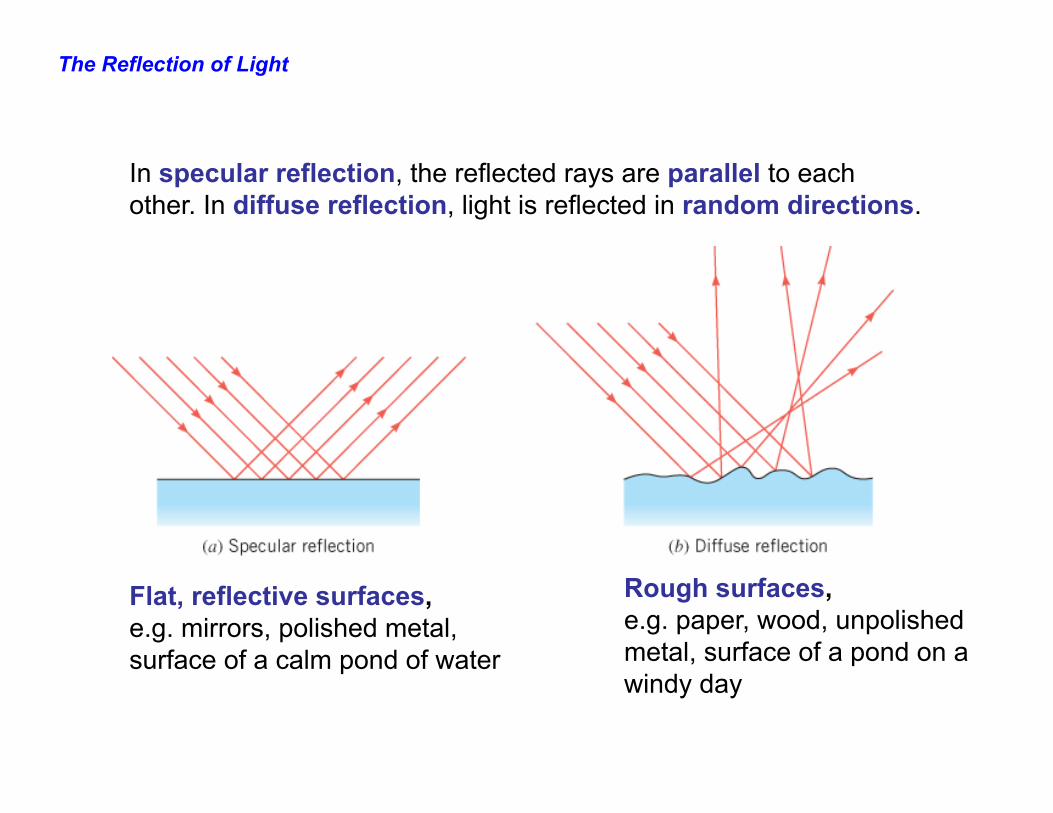
In specular reflection, the reflected rays are parallel to each other. In diffuse reflection, light is reflected in random directions.
Flat, reflective surfaces, e.g. mirrors, polished metal, surface of a calm pond of water
Rough surfaces, e.g. paper, wood, unpolished metal, surface of a pond on a windy day
The Formation of Images by a Plane Mirror
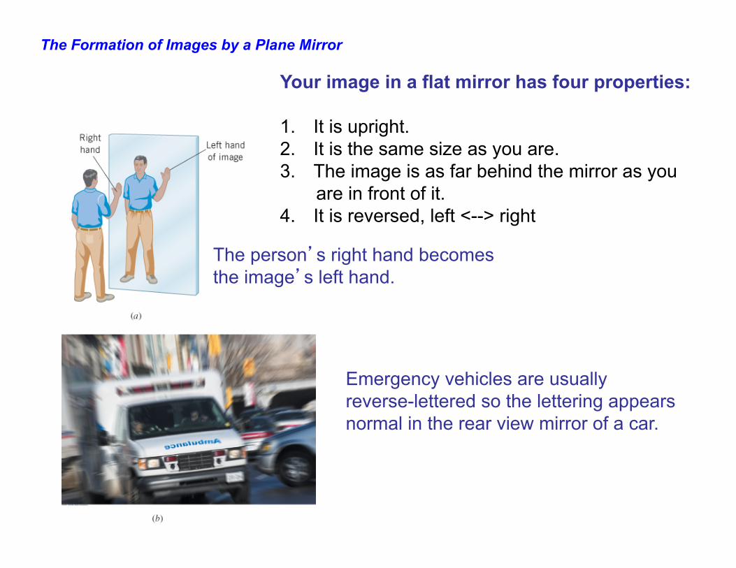
Your image in a flat mirror has four properties: 1. It is upright. 2. It is the same size as you are. 3. The image is as far behind the mirror as you are in front of it. 4. It is reversed, left <--> right
The person’s right hand becomes the image’s left hand.
Emergency vehicles are usually reverse-lettered so the lettering appears normal in the rear view mirror of a car.
The Formation of Images by a Plane Mirror
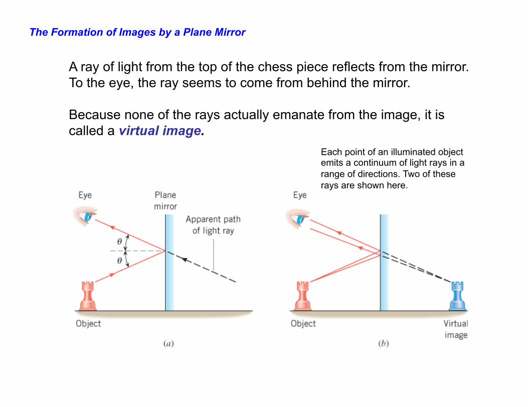
A ray of light from the top of the chess piece reflects from the mirror. To the eye, the ray seems to come from behind the mirror. Because none of the rays actually emanate from the image, it is called a virtual image.
Each point of an illuminated object emits a continuum of light rays in a range of directions. Two of these rays are shown here.
The Formation of Images by a Plane Mirror
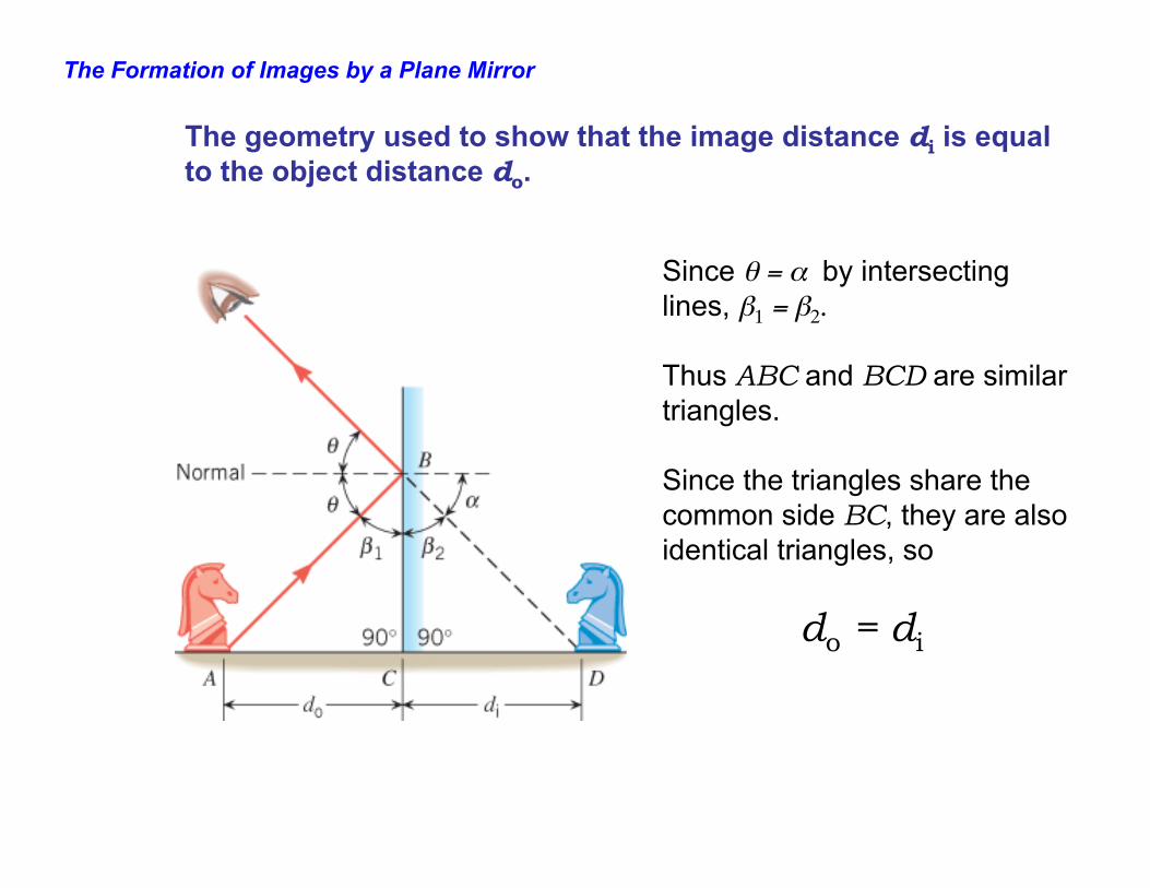
The geometry used to show that the image distance di is equal to the object distance do.
Since θ = α by intersecting lines, β1 = β2. Thus ABC and BCD are similar triangles. Since the triangles share the common side BC, they are also identical triangles, so do = di
The Formation of Images by a Plane Mirror
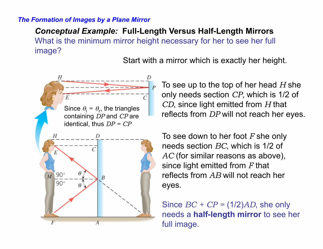
Conceptual Example: Full-Length Versus Half-Length Mirrors What is the minimum mirror height necessary for her to see her full image?
To see up to the top of her head H she only needs section CP, which is 1/2 of CD, since light emitted from H that reflects from DP will not reach her eyes.
Since θi = θr, the triangles containing DP and CP are identical, thus DP = CP
To see down to her foot F she only needs section BC, which is 1/2 of AC (for similar reasons as above), since light emitted from F that reflects from AB will not reach her eyes. Since BC + CP = (1/2)AD, she only needs a half-length mirror to see her full image.
Start with a mirror which is exactly her height.
The Formation of Images by a Plane Mirror
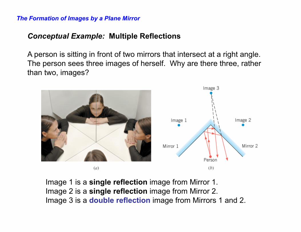
Conceptual Example: Multiple Reflections A person is sitting in front of two mirrors that intersect at a right angle. The person sees three images of herself. Why are there three, rather than two, images?
Image 1 is a single reflection image from Mirror 1. Image 2 is a single reflection image from Mirror 2. Image 3 is a double reflection image from Mirrors 1 and 2.
Spherical Mirrors
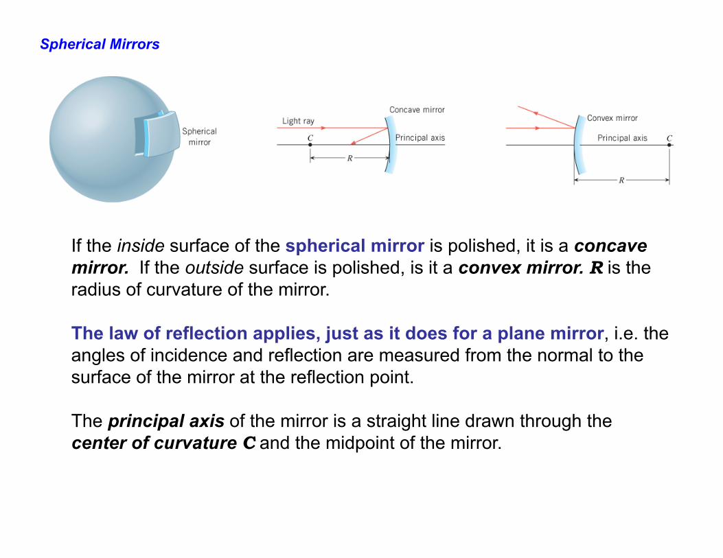
If the inside surface of the spherical mirror is polished, it is a concave mirror. If the outside surface is polished, is it a convex mirror. R is the radius of curvature of the mirror. The law of reflection applies, just as it does for a plane mirror, i.e. the angles of incidence and reflection are measured from the normal to the surface of the mirror at the reflection point. The principal axis of the mirror is a straight line drawn through the center of curvature C and the midpoint of the mirror.
Spherical Mirrors
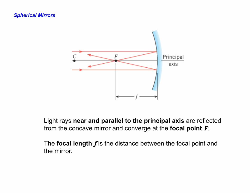
Light rays near and parallel to the principal axis are reflected from the concave mirror and converge at the focal point F. The focal length f is the distance between the focal point and the mirror.
Spherical Mirrors
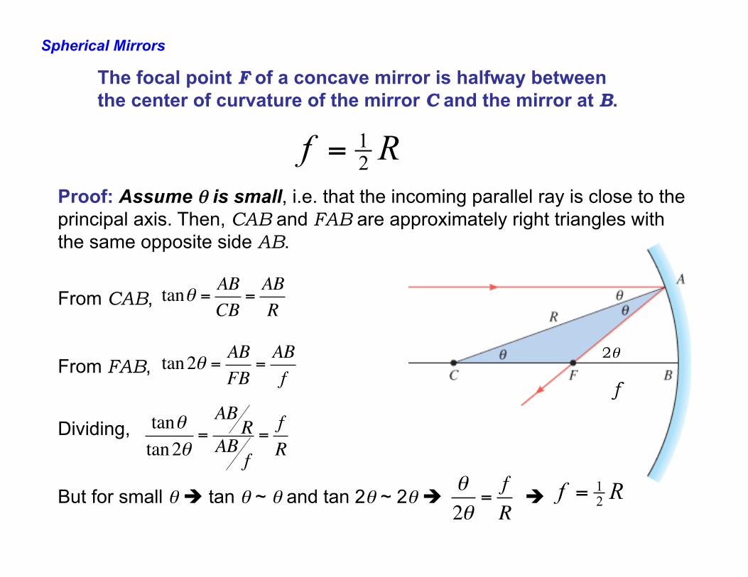
The focal point F of a concave mirror is halfway between the center of curvature of the mirror C and the mirror at B.
Rf 21=
Proof: Assume θ is small, i.e. that the incoming parallel ray is close to the principal axis. Then, CAB and FAB are approximately right triangles with the same opposite side AB.
From CAB, From FAB,
2θ
f
Dividing, But for small θ è tan θ ~ θ and tan 2θ ~ 2θ è è Rf 2
1=θ2θ
=fR
tanθtan2θ
=AB
RAB
f=fR
tanθ = ABCB
=ABR
tan2θ = ABFB
=ABf
Spherical Mirrors
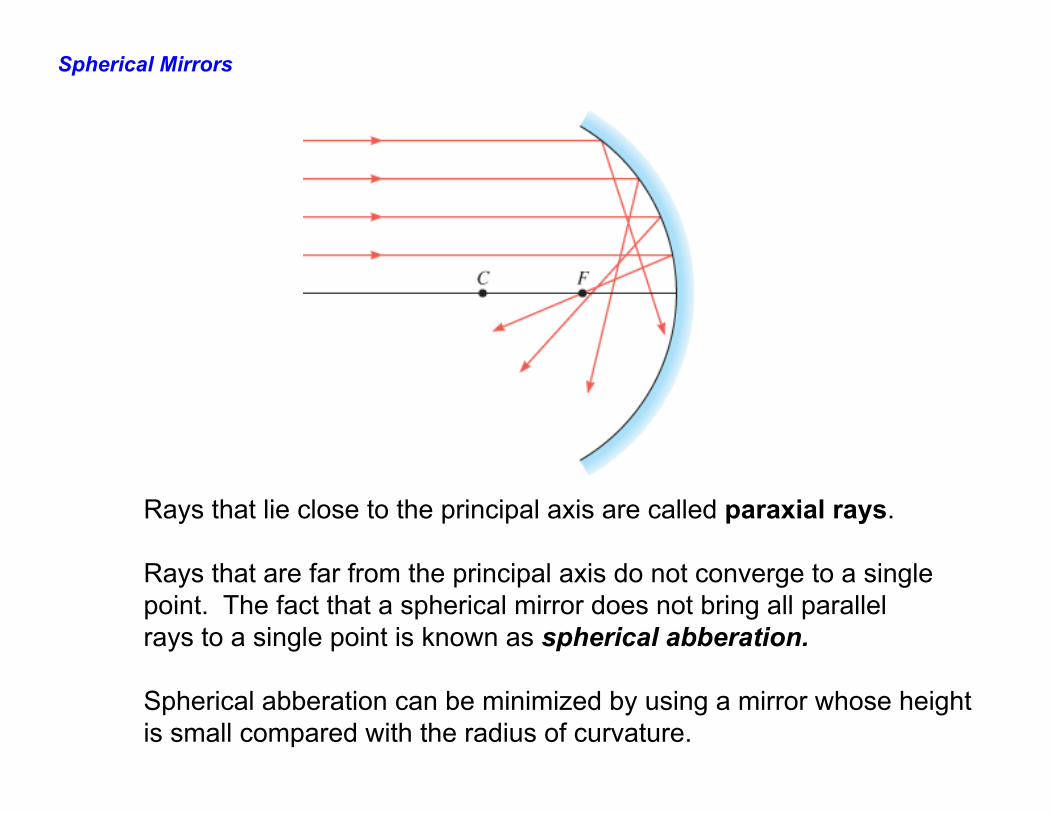
Rays that lie close to the principal axis are called paraxial rays. Rays that are far from the principal axis do not converge to a single point. The fact that a spherical mirror does not bring all parallel rays to a single point is known as spherical abberation. Spherical abberation can be minimized by using a mirror whose height is small compared with the radius of curvature.
Spherical Mirrors
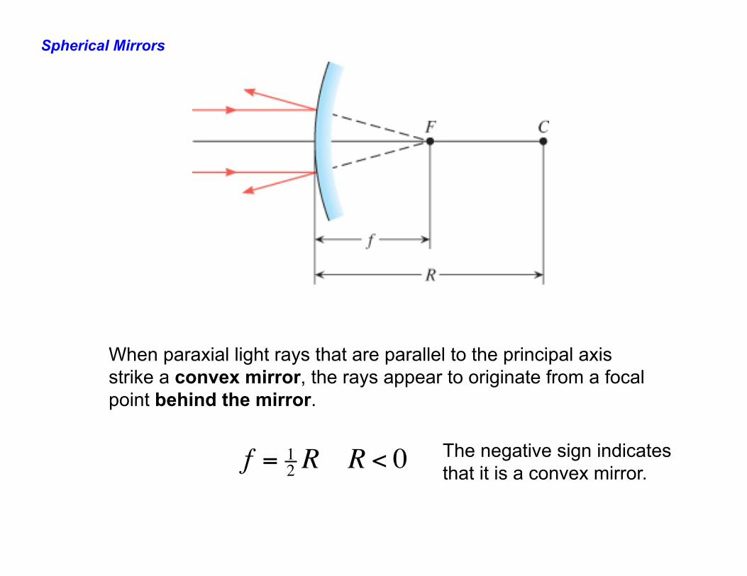
f = 12 R R < 0
When paraxial light rays that are parallel to the principal axis strike a convex mirror, the rays appear to originate from a focal point behind the mirror.
The negative sign indicates that it is a convex mirror.
The Formation of Images by Spherical Mirrors
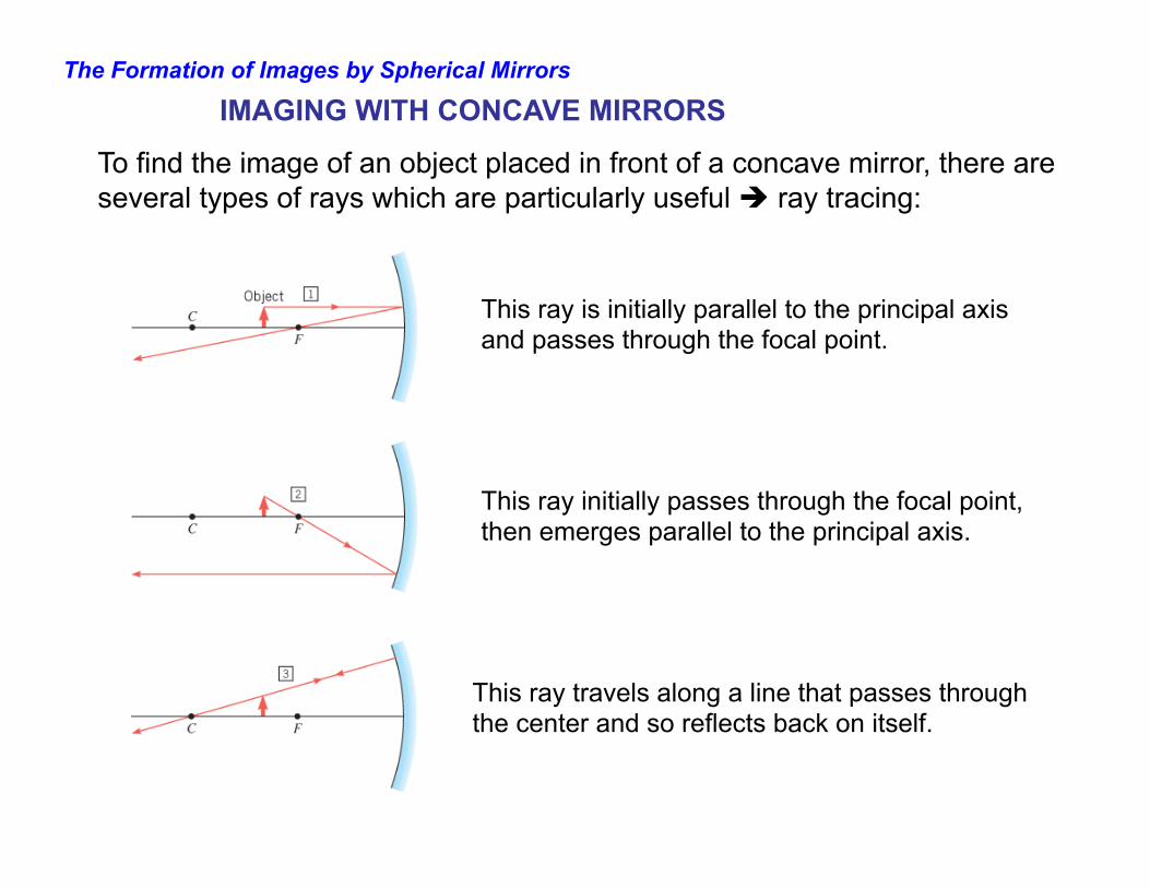
IMAGING WITH CONCAVE MIRRORS
This ray is initially parallel to the principal axis and passes through the focal point.
This ray initially passes through the focal point, then emerges parallel to the principal axis.
This ray travels along a line that passes through the center and so reflects back on itself.
To find the image of an object placed in front of a concave mirror, there are several types of rays which are particularly useful è ray tracing:
The Formation of Images by Spherical Mirrors
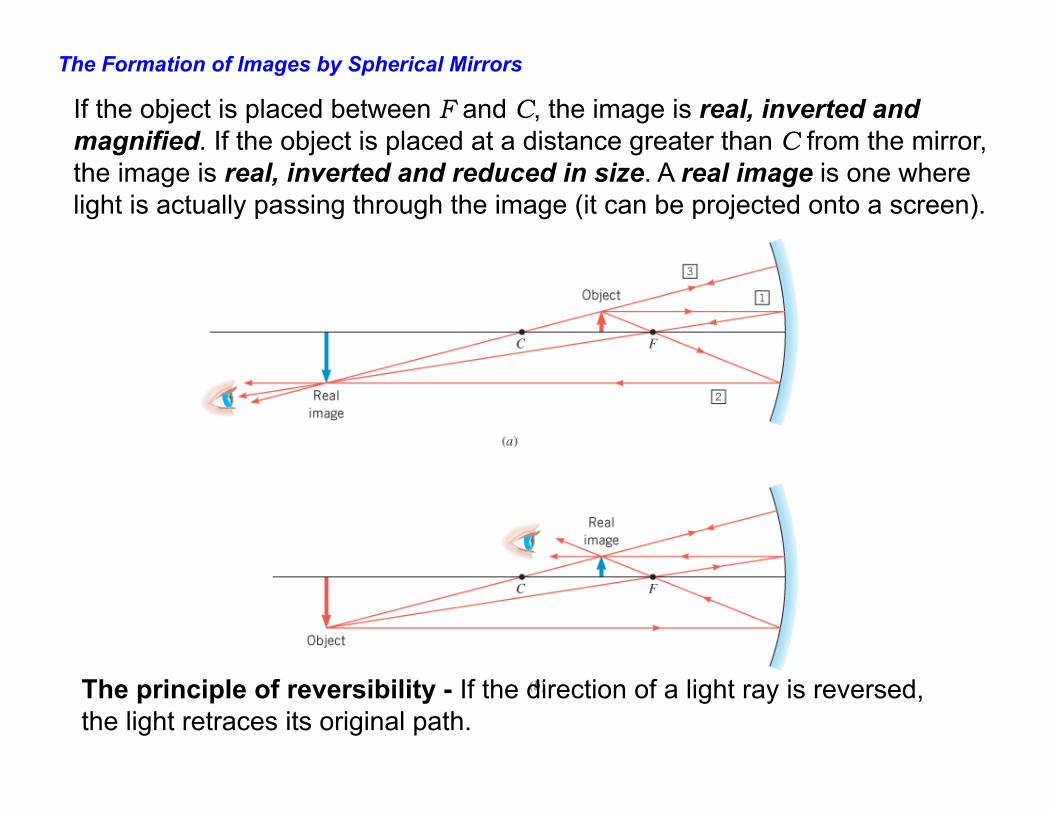
The principle of reversibility - If the direction of a light ray is reversed, the light retraces its original path.
If the object is placed between F and C, the image is real, inverted and magnified. If the object is placed at a distance greater than C from the mirror, the image is real, inverted and reduced in size. A real image is one where light is actually passing through the image (it can be projected onto a screen).
The Formation of Images by Spherical Mirrors
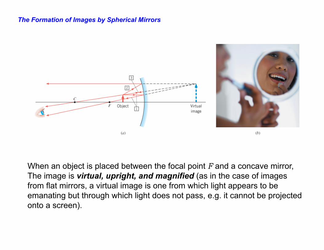
When an object is placed between the focal point F and a concave mirror, The image is virtual, upright, and magnified (as in the case of images from flat mirrors, a virtual image is one from which light appears to be emanating but through which light does not pass, e.g. it cannot be projected onto a screen).
The Formation of Images by Spherical Mirrors
IMAGING WITH CONVEX MIRRORS
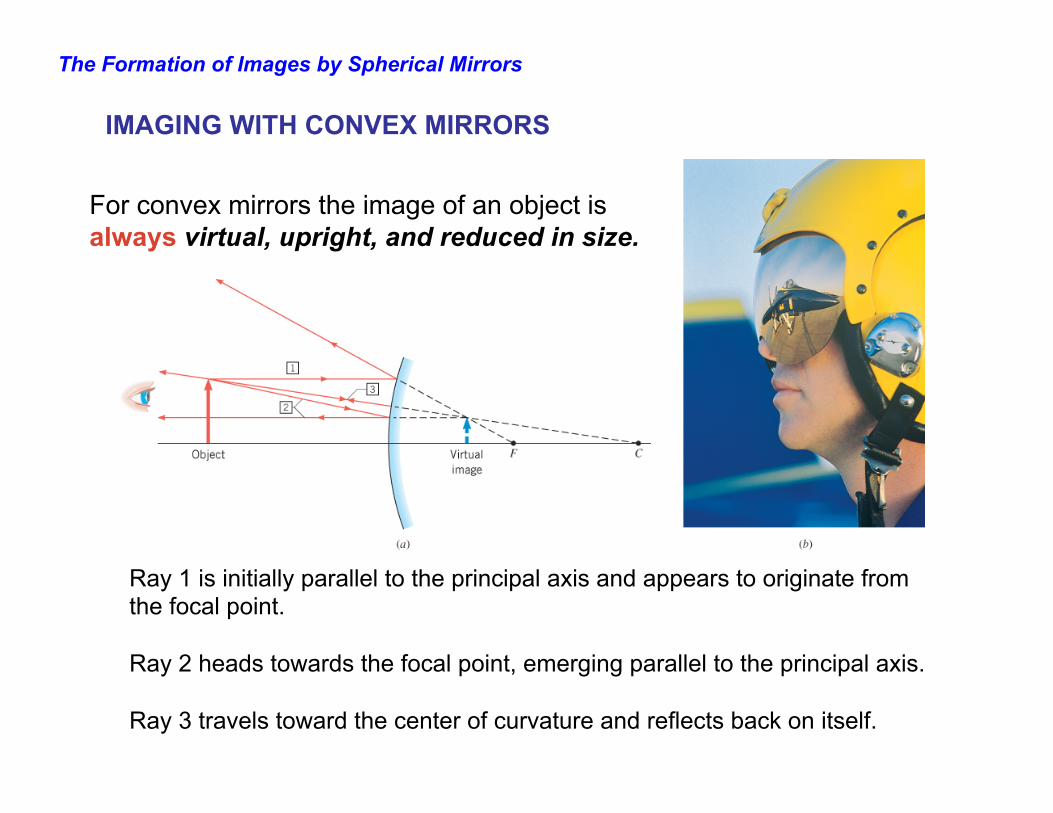
Ray 1 is initially parallel to the principal axis and appears to originate from the focal point. Ray 2 heads towards the focal point, emerging parallel to the principal axis. Ray 3 travels toward the center of curvature and reflects back on itself.
For convex mirrors the image of an object is always virtual, upright, and reduced in size.
The Mirror Equation and Magnification
length focal=f
distanceobject =od
distance image=id
ionmagnificat=m
So far we have discussed concave and convex mirrors qualitatively and graphically. We now want to derive two simple equations which provide quantitative relationships among the quantities we have defined to describe mirrors, i.e.,
The Mirror Equation and Magnification
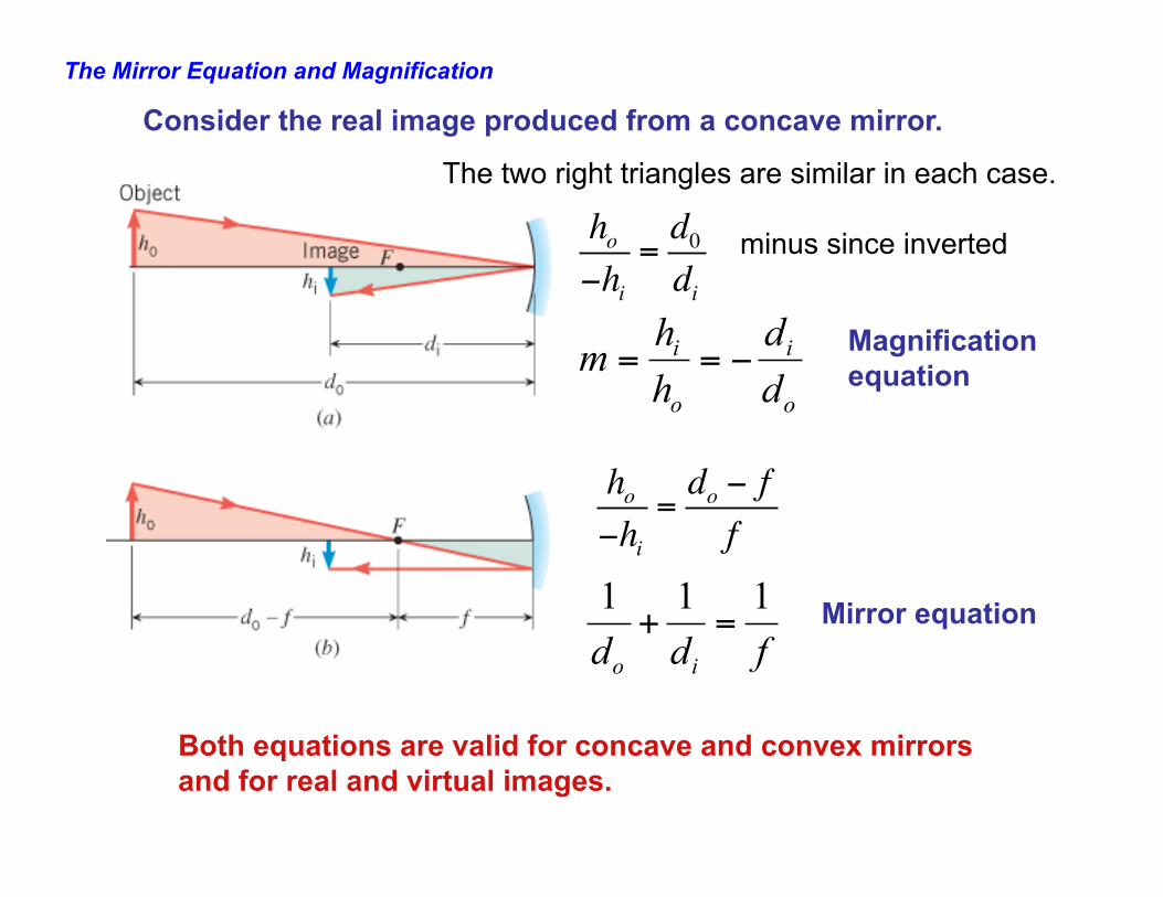
The two right triangles are similar in each case.
fdd io
111=+
o
i
o
i
dd
hh
m −==
Both equations are valid for concave and convex mirrors and for real and virtual images.
Mirror equation
minus since inverted
Magnification equation
Consider the real image produced from a concave mirror.
ho−hi
=d0di
ho−hi
=do − ff
The Mirror Equation and Magnification
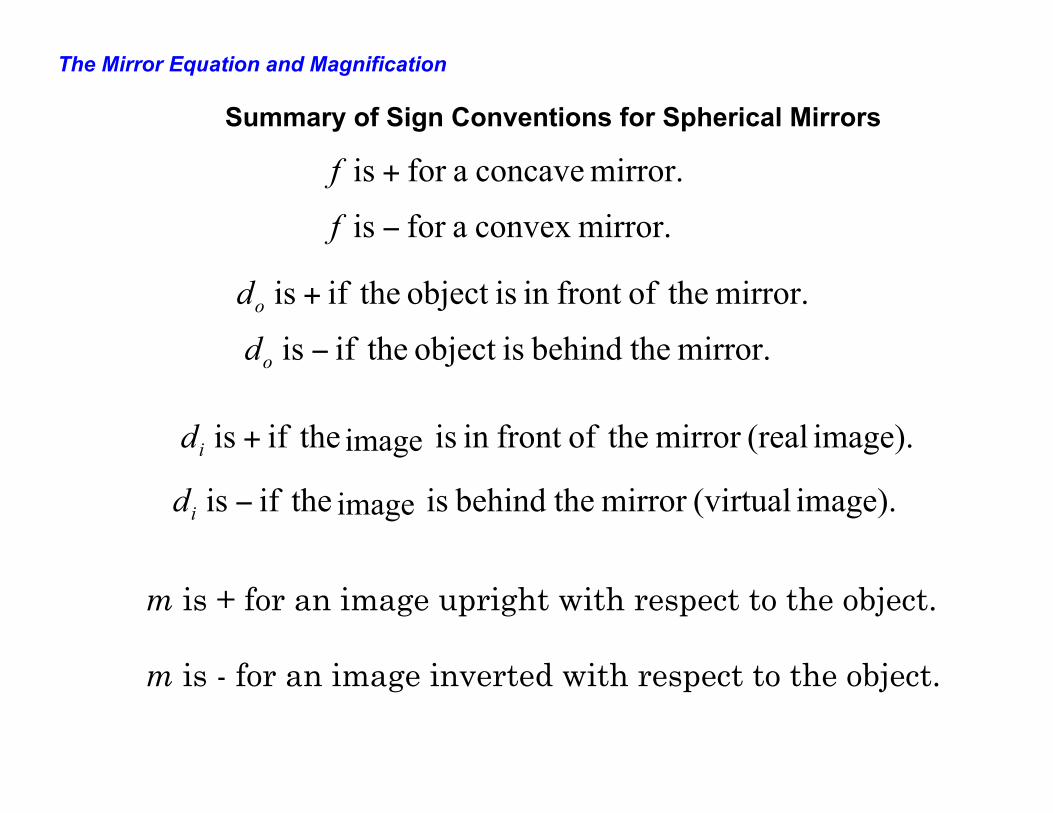
Summary of Sign Conventions for Spherical Mirrors
mirror. concave afor is +f
mirror.convex afor is −f
mirror. theoffront in isobject theif is +od
mirror. thebehind isobject theif is −od
image). (realmirror theoffront in isobject theif is +id
image). (virtualmirror thebehind isobject theif is −id
m is + for an image upright with respect to the object. m is - for an image inverted with respect to the object.
image
image
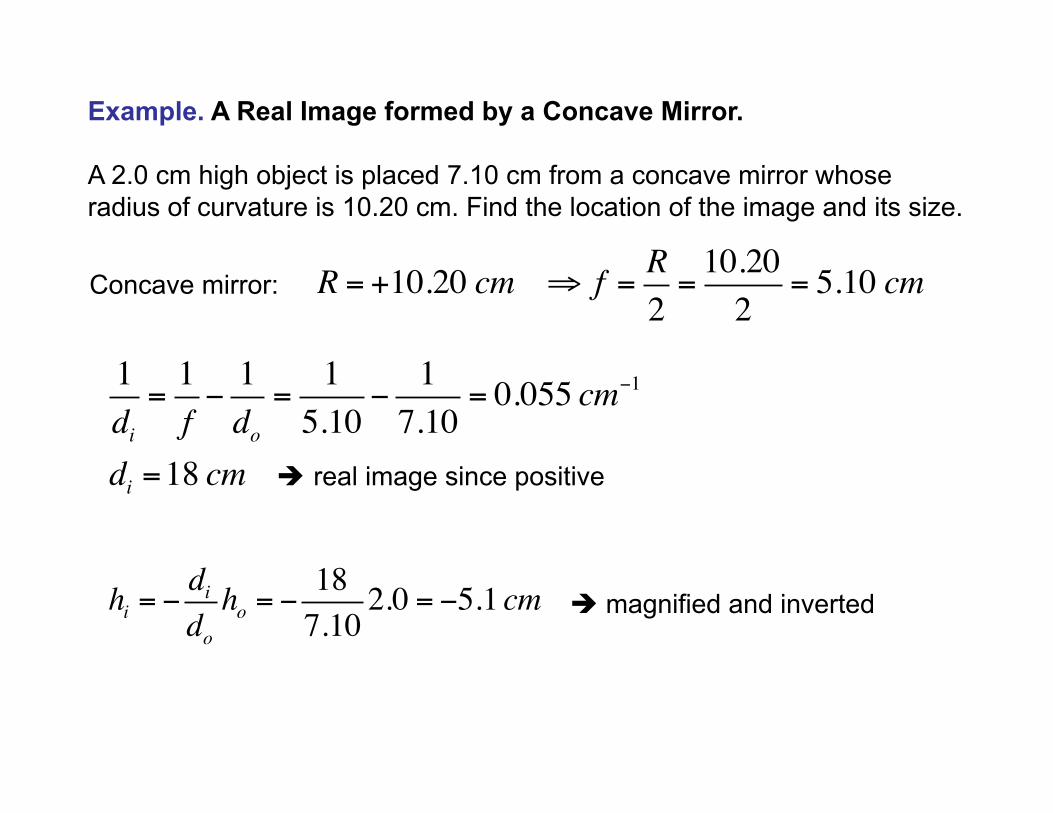
Example. A Real Image formed by a Concave Mirror. A 2.0 cm high object is placed 7.10 cm from a concave mirror whose radius of curvature is 10.20 cm. Find the location of the image and its size.
Concave mirror: è real image since positive è magnified and inverted
R = +10.20 cm ⇒ f = R2=10.202
= 5.10 cm
1di=1f−1do=
15.10
−17.10
= 0.055 cm−1
di =18 cm
hi = −didoho = −
187.10
2.0 = −5.1 cm
The Mirror Equation and Magnification
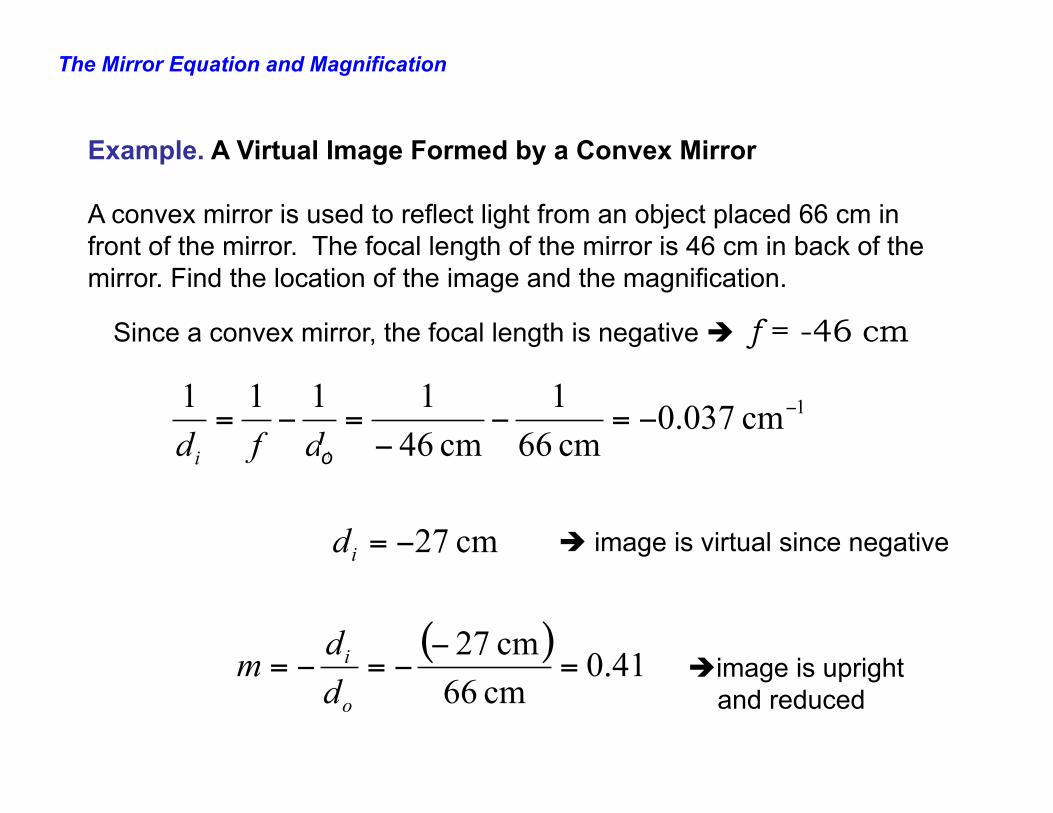
Example. A Virtual Image Formed by a Convex Mirror A convex mirror is used to reflect light from an object placed 66 cm in front of the mirror. The focal length of the mirror is 46 cm in back of the mirror. Find the location of the image and the magnification.
1cm 037.0cm 661
cm 461111 −−=−
−=−=
ii dfd
cm 27−=id
( ) 41.0cm 66cm 27
=−
−=−=o
i
dd
m
Since a convex mirror, the focal length is negative è f = -46 cm
è image is virtual since negative
è image is upright and reduced
o