Embed Size (px)
Citation preview
1
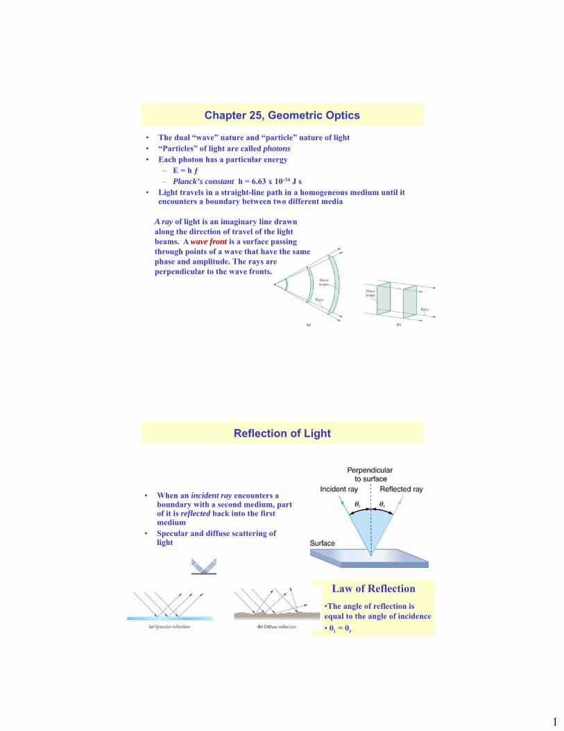
Chapter 25, Geometric Optics
• The dual “wave” nature and “particle” nature of light• “Particles” of light are called photons• Each photon has a particular energy
– E = h ƒ– Planck’s constant h = 6.63 x 10⁻³⁴ J s
• Light travels in a straight-line path in a homogeneous medium until it encounters a boundary between two different media
A ray of light is an imaginary line drawn along the direction of travel of the light beams. A wave front is a surface passing through points of a wave that have the same phase and amplitude. The rays are perpendicular to the wave fronts.
Law of Reflection
Reflection of Light
• When an incident ray encounters a boundary with a second medium, part of it is reflected back into the first medium
• Specular and diffuse scattering of light
•The angle of reflection is equal to the angle of incidence
• θi = θr
2
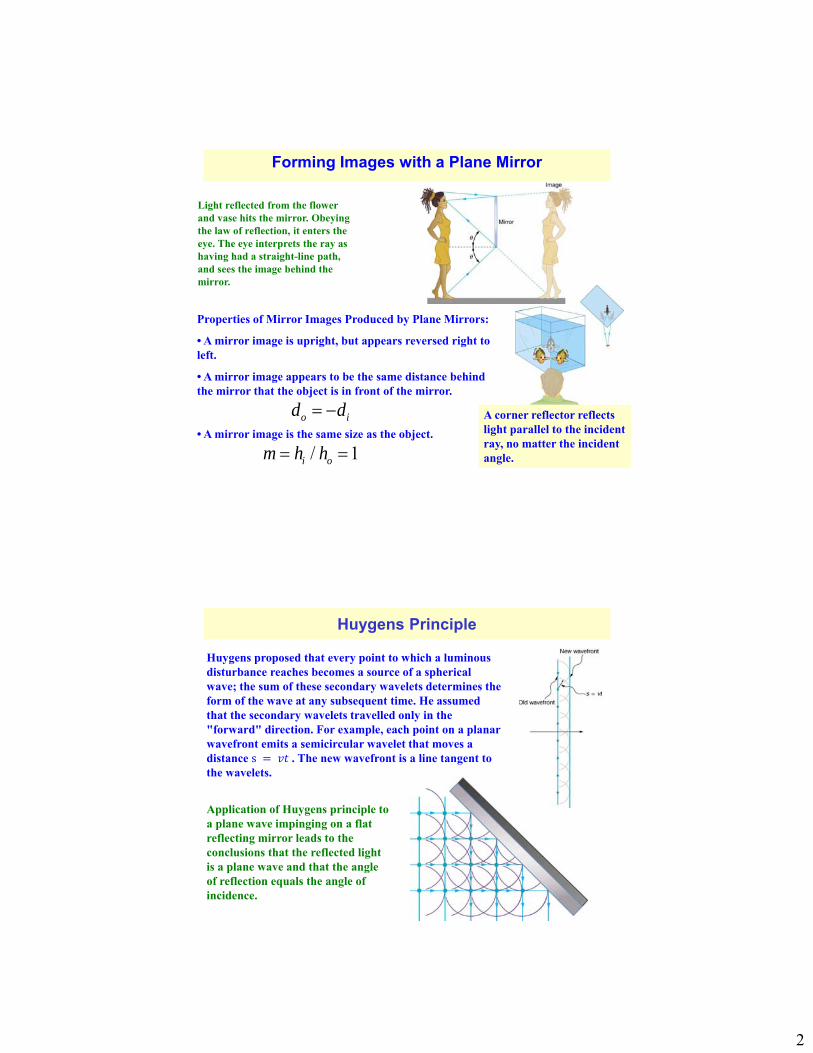
Light reflected from the flower and vase hits the mirror. Obeying the law of reflection, it enters the eye. The eye interprets the ray as having had a straight-line path, and sees the image behind the mirror.
Forming Images with a Plane Mirror
Properties of Mirror Images Produced by Plane Mirrors:
• A mirror image is upright, but appears reversed right to left.
• A mirror image appears to be the same distance behind the mirror that the object is in front of the mirror.
• A mirror image is the same size as the object.
A corner reflector reflects light parallel to the incident ray, no matter the incident angle.
o id d
/ 1i om h h
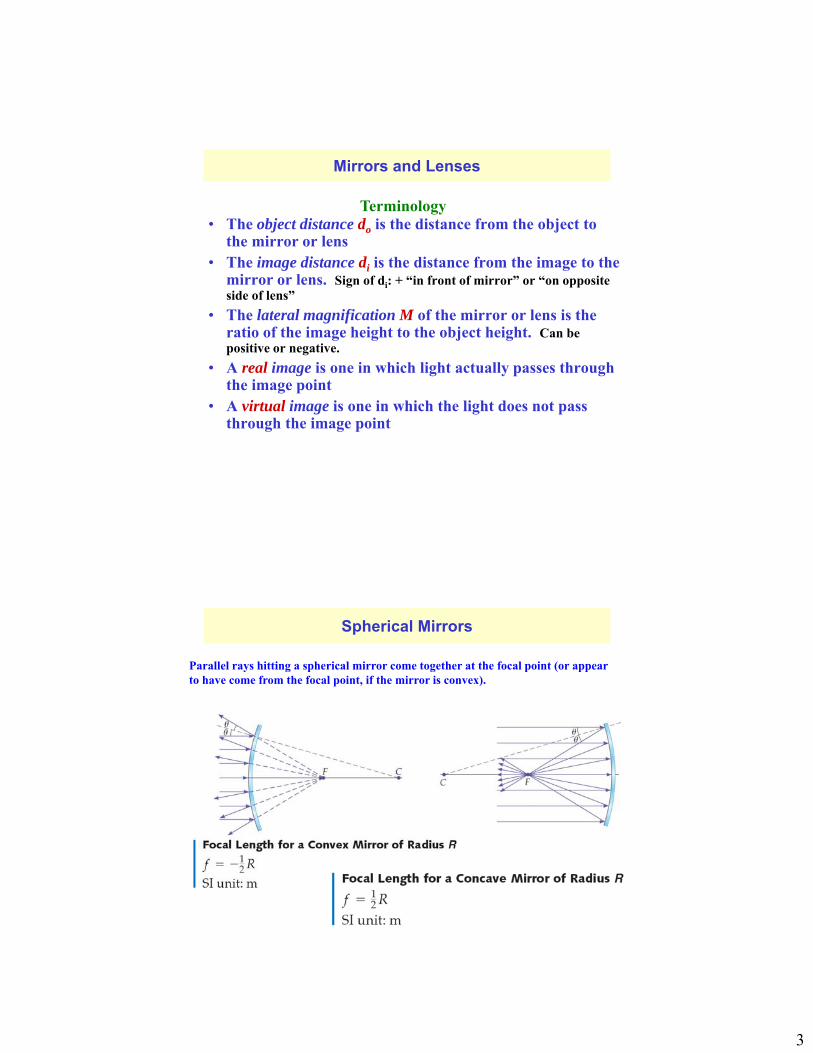
Huygens Principle
Huygens proposed that every point to which a luminous disturbance reaches becomes a source of a spherical wave; the sum of these secondary wavelets determines the form of the wave at any subsequent time. He assumed that the secondary wavelets travelled only in the "forward" direction. For example, each point on a planar wavefront emits a semicircular wavelet that moves a distance s 𝑣𝑡 . The new wavefront is a line tangent to the wavelets.
Application of Huygens principle to a plane wave impinging on a flat reflecting mirror leads to the conclusions that the reflected light is a plane wave and that the angle of reflection equals the angle of incidence.
3
Mirrors and Lenses
• The object distance do is the distance from the object to the mirror or lens
• The image distance di is the distance from the image to the mirror or lens. Sign of di: + “in front of mirror” or “on opposite side of lens”
• The lateral magnification M of the mirror or lens is the ratio of the image height to the object height. Can be positive or negative.
• A real image is one in which light actually passes through the image point
• A virtual image is one in which the light does not pass through the image point
Terminology
Spherical Mirrors
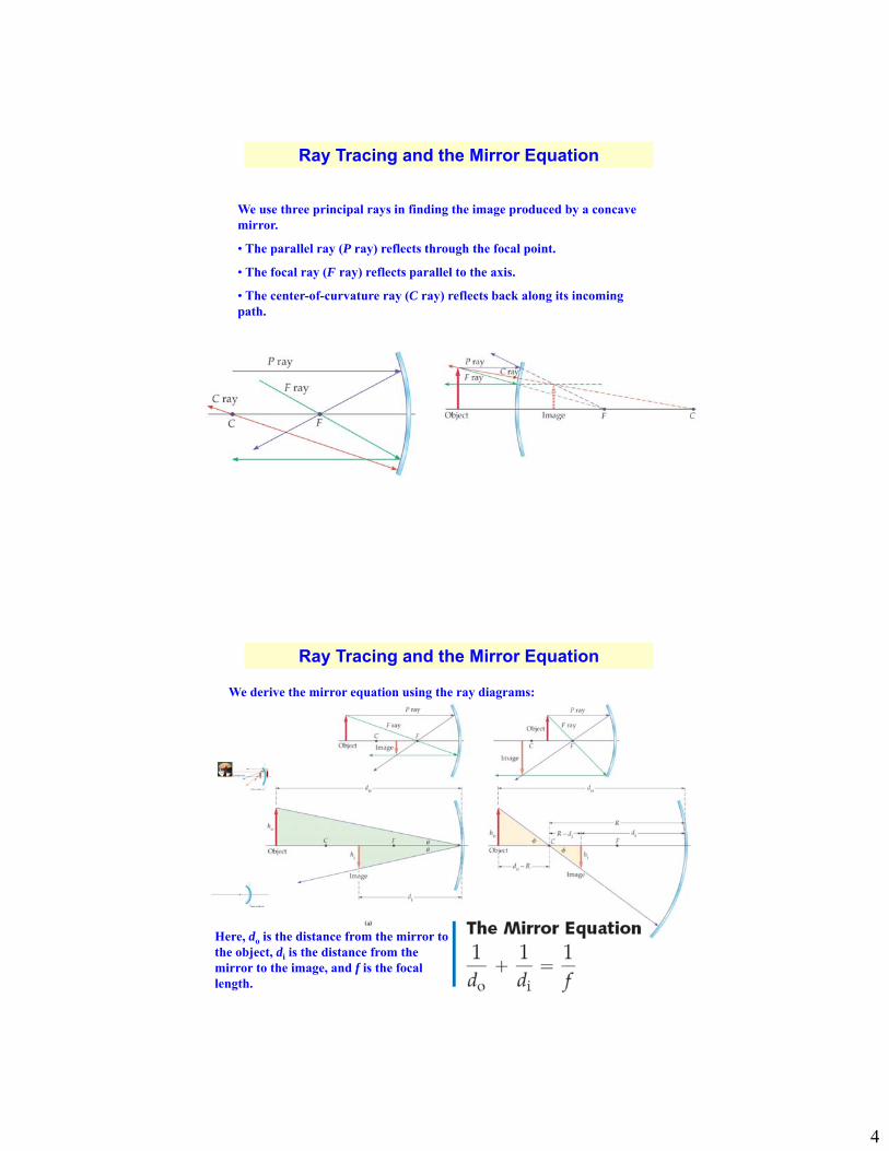
Parallel rays hitting a spherical mirror come together at the focal point (or appear to have come from the focal point, if the mirror is convex).
4
Ray Tracing and the Mirror Equation
We use three principal rays in finding the image produced by a concave mirror.
• The parallel ray (P ray) reflects through the focal point.
• The focal ray (F ray) reflects parallel to the axis.
• The center-of-curvature ray (C ray) reflects back along its incoming path.
We derive the mirror equation using the ray diagrams:
Ray Tracing and the Mirror Equation
Here, do is the distance from the mirror to the object, di is the distance from the mirror to the image, and f is the focal length.
5
Ray Tracing and the Mirror Equation
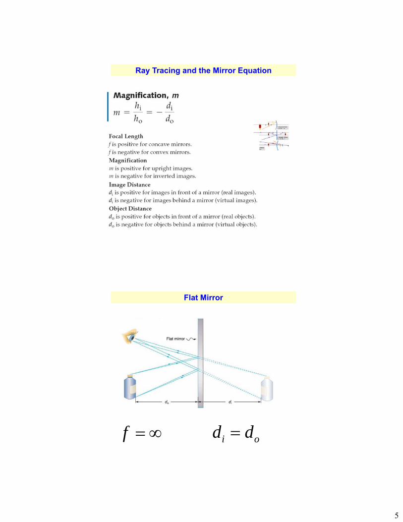
Flat Mirror
f i od d
6
Example
59. An object 1.50 cm high is held 3.00 cm from a person’s cornea, and its reflected image is measured to be 0.167 cm high. (a) What is the magnification? (b) Where is the image? (c) Find the radius of curvature of the convex mirror formed by the cornea.
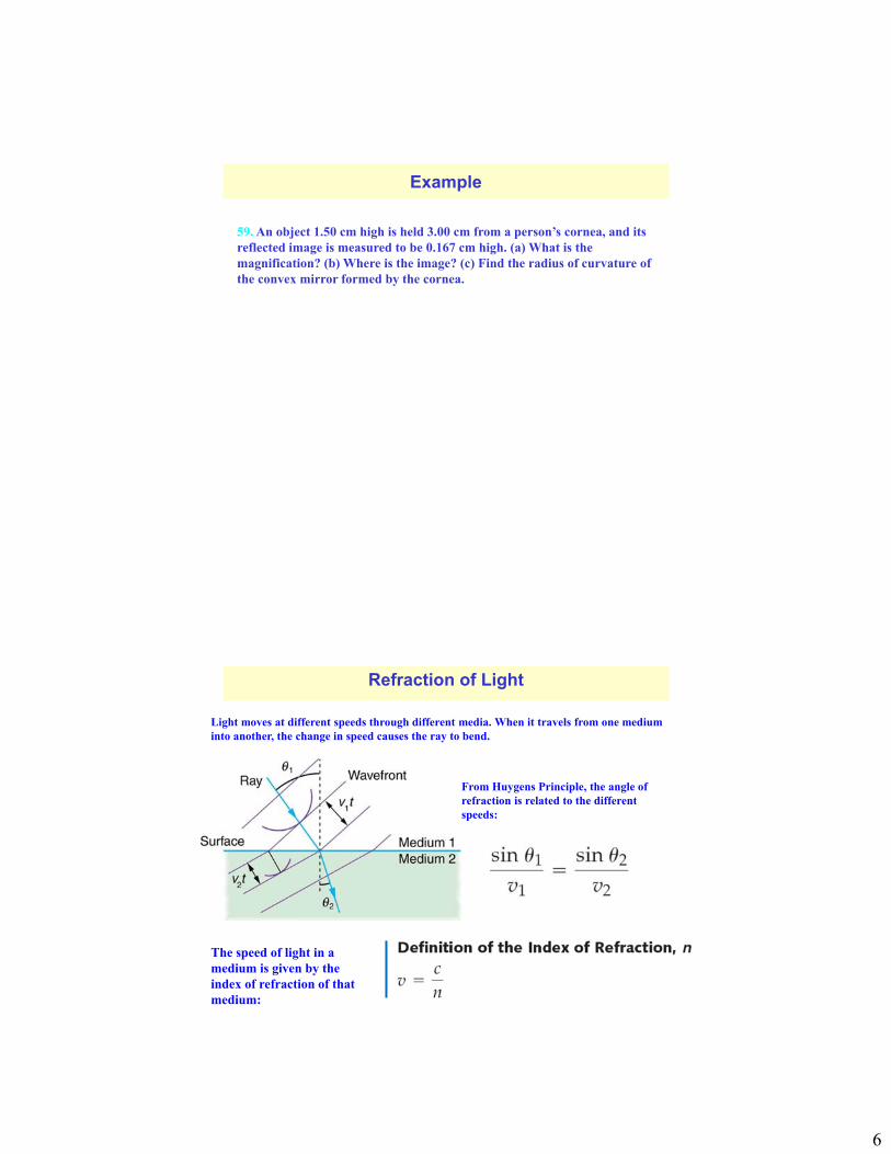
Light moves at different speeds through different media. When it travels from one medium into another, the change in speed causes the ray to bend.
Refraction of Light
From Huygens Principle, the angle of refraction is related to the different speeds:
The speed of light in a medium is given by the index of refraction of that medium:
7
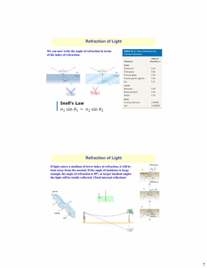
We can now write the angle of refraction in terms of the index of refraction:
Refraction of Light
If light enters a medium of lower index of refraction, it will be bent away from the normal. If the angle of incidence is large enough, the angle of refraction is 90°; at larger incident angles the light will be totally reflected. (Total internal reflection)
Refraction of Light
8
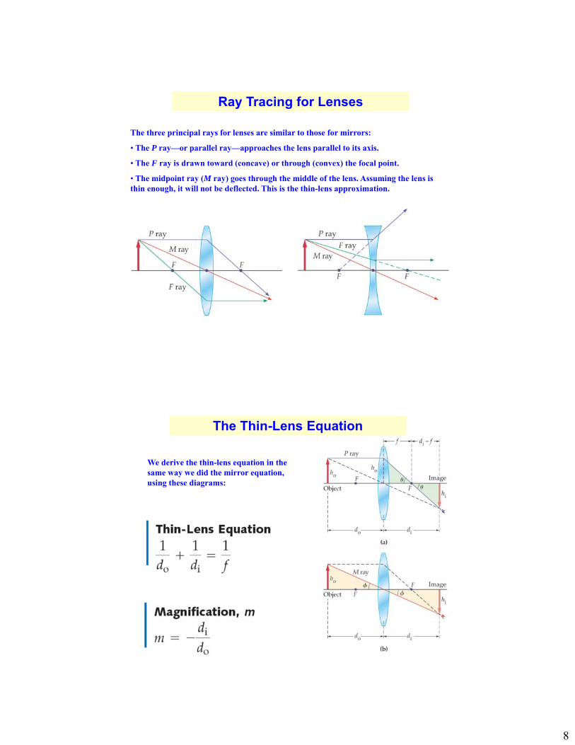
Ray Tracing for Lenses
The three principal rays for lenses are similar to those for mirrors:
• The P ray—or parallel ray—approaches the lens parallel to its axis.
• The F ray is drawn toward (concave) or through (convex) the focal point.
• The midpoint ray (M ray) goes through the middle of the lens. Assuming the lens is thin enough, it will not be deflected. This is the thin-lens approximation.
The Thin-Lens Equation
We derive the thin-lens equation in the same way we did the mirror equation, using these diagrams:
9
Sign conventions for thin lenses:
The Thin-Lens Equation
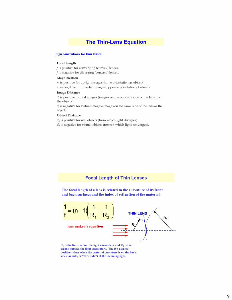
Focal Length of Thin Lenses
21 R
1
R
1)1n(
f
1
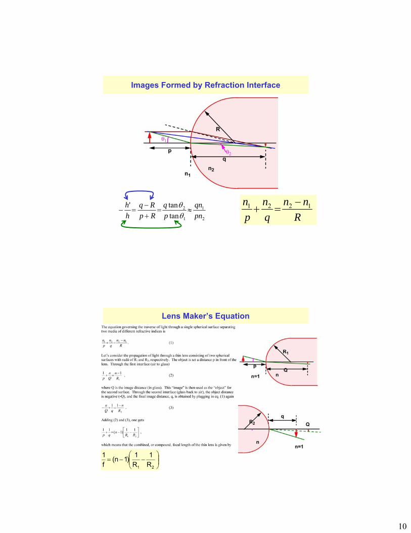
The focal length of a lens is related to the curvature of its front and back surfaces and the index of refraction of the material.
R1 is the first surface the light encounters and R2 is the second surface the light encounters. The R’s assume positive values when the center of curvature is on the back side (far side, or “thru side”) of the incoming light.
lens maker’s equation
10
Images Formed by Refraction Interface
R
nn
q
n
p
n 1221
2
1
1
2
tan
tan'
pn
qn
p
q
Rp
Rq
h
h
Lens Maker’s Equation
21 R
1
R
1)1n(
f
1
11
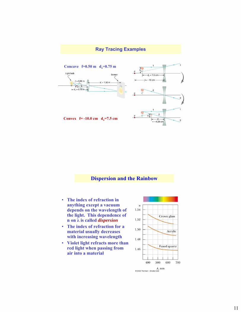
Ray Tracing Examples
Concave f=0.50 m do=0.75 m
Convex f= -10.0 cm do=7.5 cm
Dispersion and the Rainbow
• The index of refraction in anything except a vacuum depends on the wavelength of the light. This dependence of n on λ is called dispersion
• The index of refraction for a material usually decreases with increasing wavelength
• Violet light refracts more than red light when passing from air into a material
12
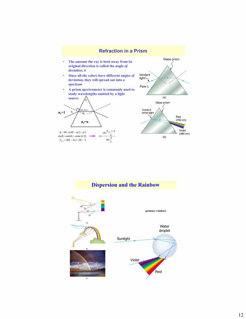
Refraction in a Prism
• The amount the ray is bent away from its original direction is called the angle of deviation, δ
• Since all the colors have different angles of deviation, they will spread out into a spectrum
• A prism spectrometer is commonly used to study wavelengths emitted by a light source
n2=n
n1=1
Dispersion and the Rainbow
primary rainbow
13
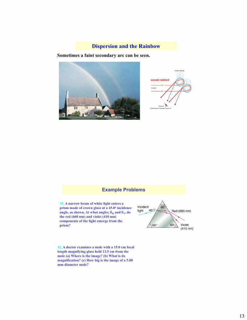
Dispersion and the Rainbow
Sometimes a faint secondary arc can be seen.
second rainbow
Example Problems
35. A narrow beam of white light enters a prism made of crown glass at a 45.0o incidence angle, as shown. At what angles, R and V, do the red (660 nm) and violet (410 nm) components of the light emerge from the prism?
42. A doctor examines a mole with a 15.0 cm focal length magnifying glass held 13.5 cm from the mole (a) Where is the image? (b) What is its magnification? (c) How big is the image of a 5.00 mm diameter mole?
14
Chapter 25, Summary
1. Law of reflection, index of reflection
2. Law of refraction, Snell’s law.
3. Huygens’s principle.
4. Total internal reflection and critical angle.
5. Magnification and focal length of mirrors and lenses
6. Mirror equation, thin lens equation
7. Refracting surface