Embed Size (px)
Citation preview
Chapter 26 Geometrical OpticsChapter 26 Geometrical Optics
Outline
26-1 The Reflection of Light
26-2 Forming Images with a Plane Mirror
26-3 Spherical Mirrorp
26-4 Ray Tracing and the Mirror Equation
26 5 The Refraction of Light26-5 The Refraction of Light
26-6 Ray Tracing for Lens
26 7 Thi L E ti26-7 Thin Lens Equation
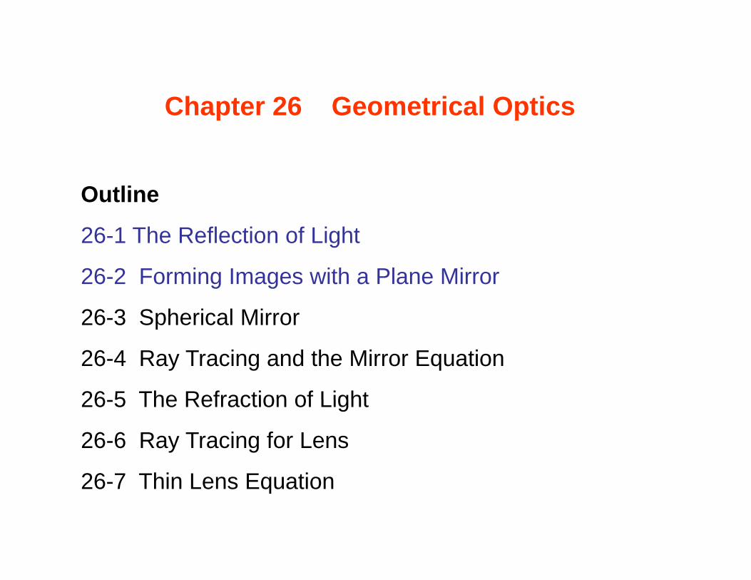
26-1 The Reflection of Light
Light propagation can be described in terms of “wave front” and “rays”.
Wave front is mostly associated with physical optics (difficult to understand), while rays are mostly associated with geometrical optics (easy to understand).
Wave front: Think about water wave!
Figure 26-1Wave Fronts and Rays of
a point light source
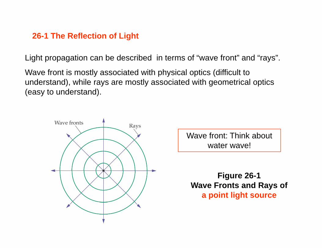
• The rays are always traveling in straight line and they indicate the
traveling direction of the light--- in Geometrical Optics!
• Rays are always at right angle to the wave fronts.
More wave fronts
Figure 26-2Spherical (point source light) and Planar (sun light) Wave Fronts
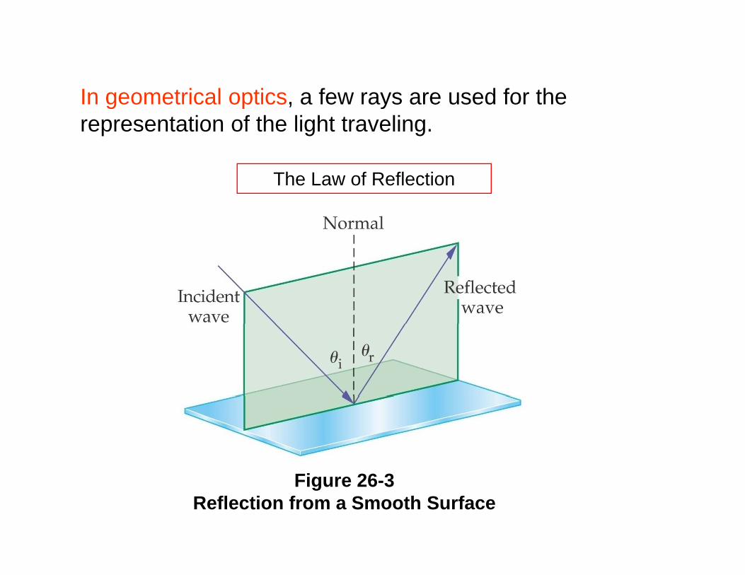
In geometrical optics, a few rays are used for the g p , yrepresentation of the light traveling.
The Law of ReflectionThe Law of Reflection
Figure 26-3Reflection from a Smooth Surface
The Law of Reflection
ir θθ =
The angle of reflection is equal to the angle of incidence (Fig 26-3).
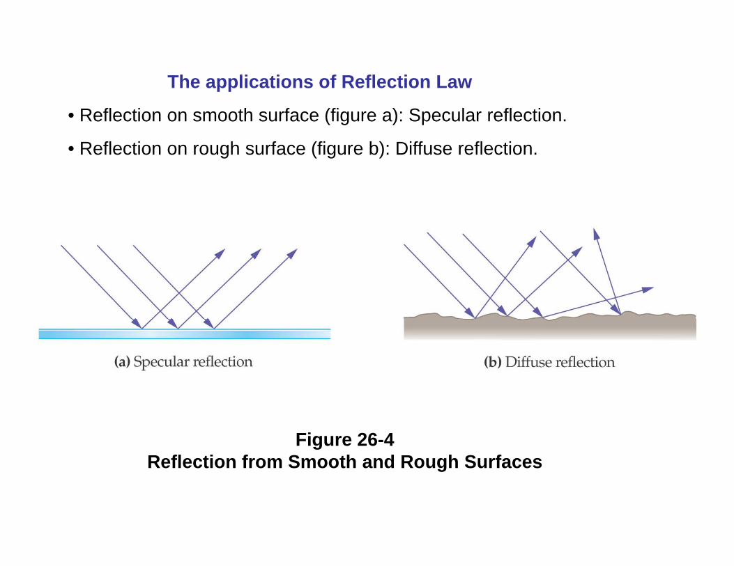
The applications of Reflection Law
• Reflection on smooth surface (figure a): Specular reflection.
• Reflection on rough surface (figure b): Diffuse reflection.
Figure 26-4Reflection from Smooth and Rough SurfacesReflection from Smooth and Rough Surfaces
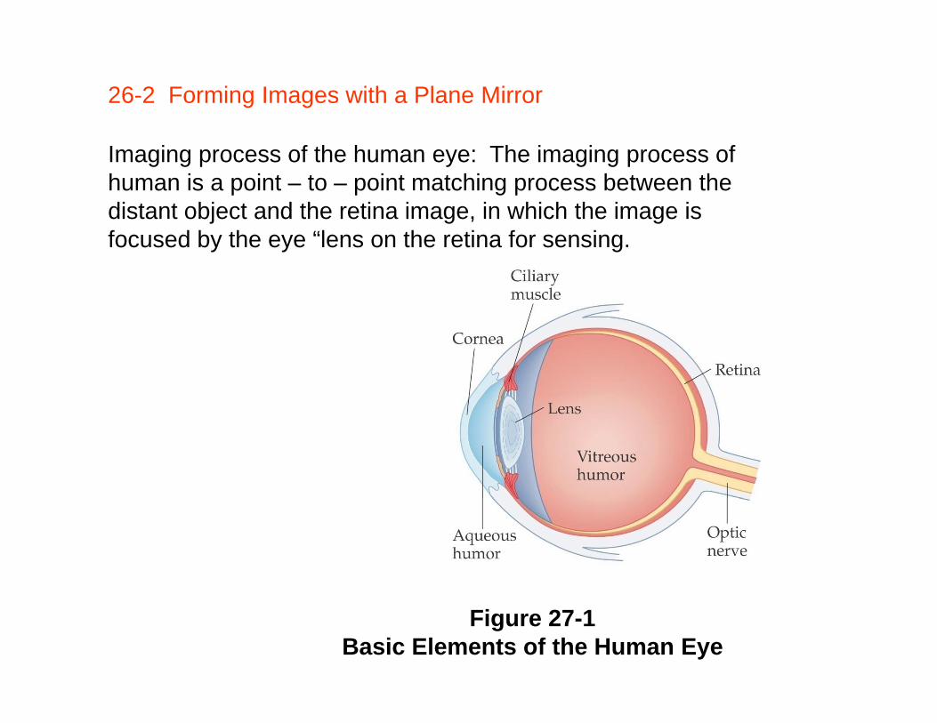
26-2 Forming Images with a Plane Mirror
Imaging process of the human eye: The imaging process of human is a point – to – point matching process between the distant object and the retina image, in which the image is focused by the eye “lens on the retina for sensing.
Figure 27-1Basic Elements of the Human Eye
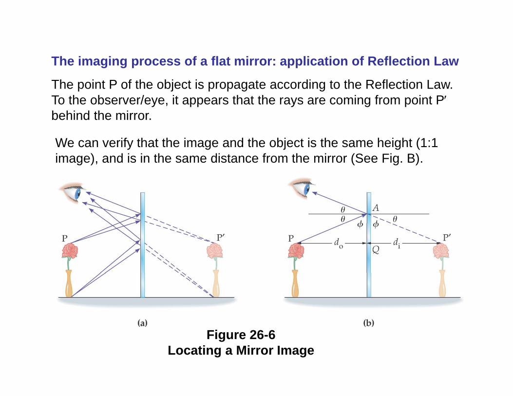
The imaging process of a flat mirror: application of Reflection Law
The point P of the object is propagate according to the Reflection Law. To the observer/eye, it appears that the rays are coming from point P′behind the mirror.
We can verify that the image and the object is the same height (1:1 image), and is in the same distance from the mirror (See Fig. B).
Figure 26-6Locating a Mirror Image
Summary of Flat/Plane Mirror imagingy g g
• 1:1 object-to-image upright• 1:1 object-to-image, upright.
• Left and right is inversed to the observer.
Th / b i t l i b hi d th i• The eye/observer see a virtual image behind the mirror.
A flat mirror has no optical power, and it only changes the direction of light traveling !
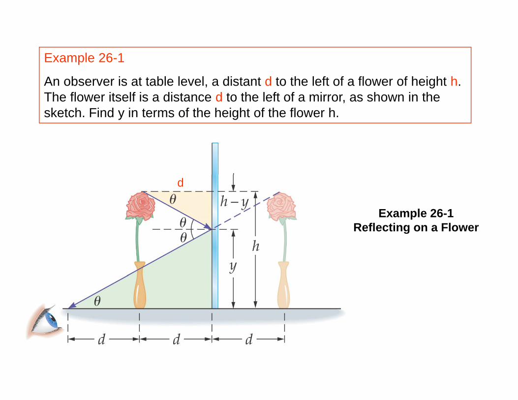
Example 26-1
An observer is at table level, a distant d to the left of a flower of height h. The flower itself is a distance d to the left of a mirror, as shown in the sketch. Find y in terms of the height of the flower h.
Example 26-1Reflecting on a Flower
d
Reflecting on a Flower
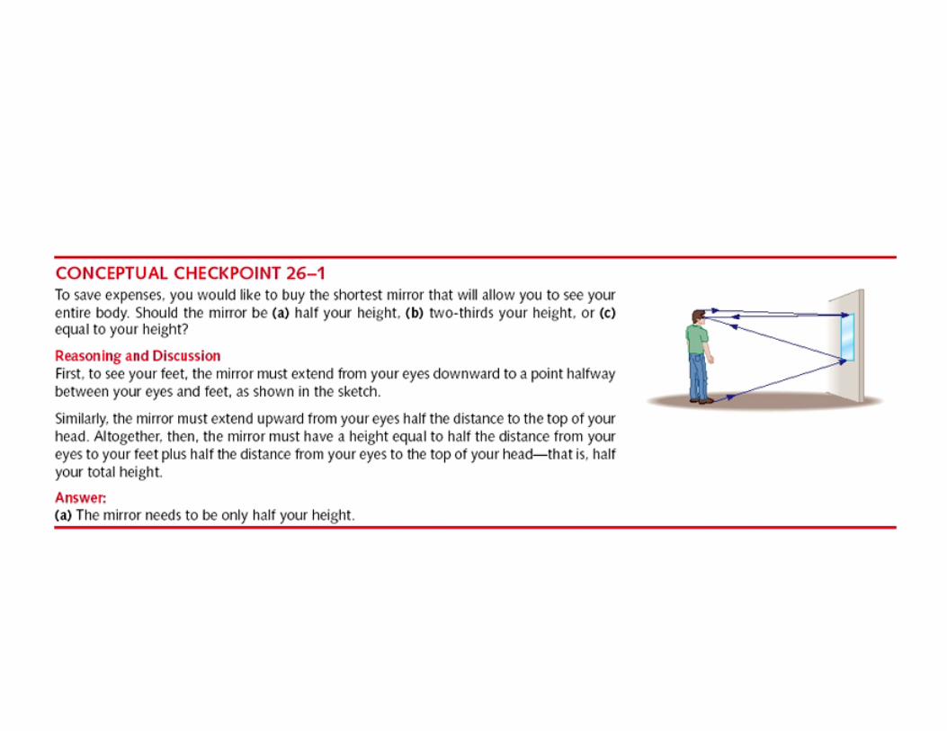
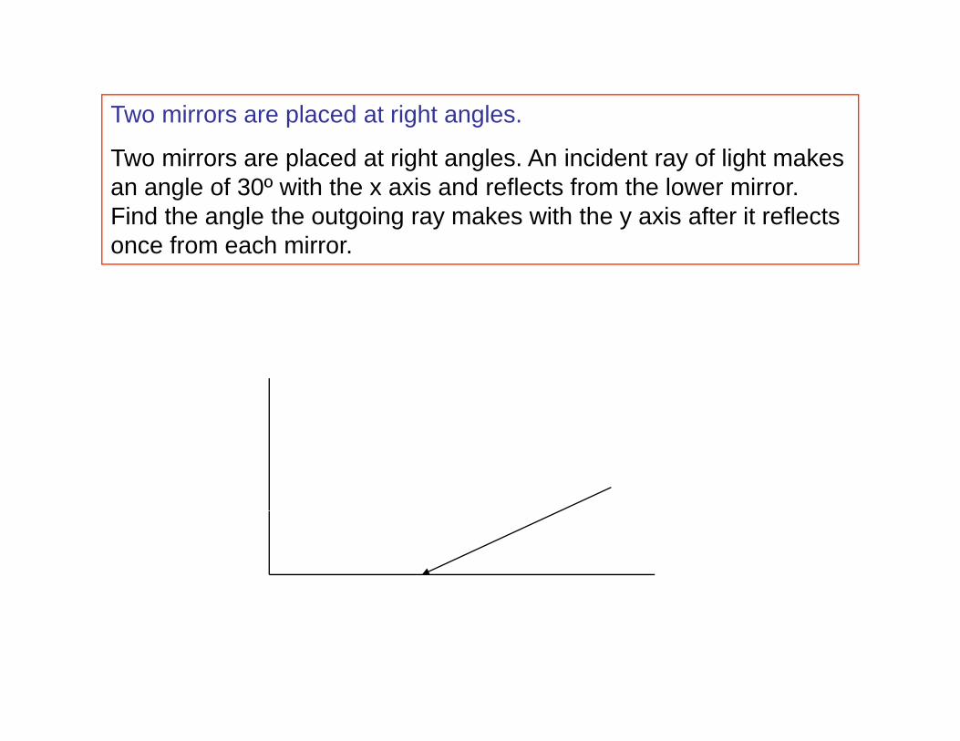
Two mirrors are placed at right angles.
Two mirrors are placed at right angles. An incident ray of light makes an angle of 30º with the x axis and reflects from the lower mirror. Find the angle the outgoing ray makes with the y axis after it reflects once from each mirror.
Summary
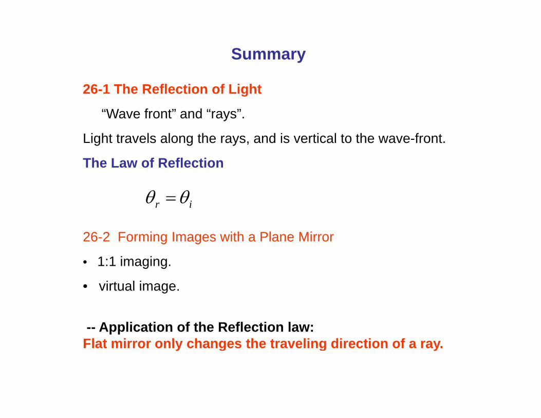
26-1 The Reflection of Light
“Wave front” and “rays”.
Light travels along the rays, and is vertical to the wave-front.
The Law of Reflection
26 2 Forming Images with a Plane Mirror
ir θθ =
26-2 Forming Images with a Plane Mirror
• 1:1 imaging.
• virtual imagevirtual image.
-- Application of the Reflection law: Flat mirror onl changes the tra eling direction of a raFlat mirror only changes the traveling direction of a ray.