Embed Size (px)
Citation preview
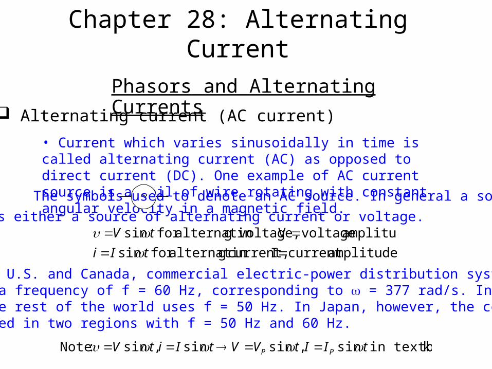
Chapter 28: Alternating Current
Phasors and Alternating Currents Alternating current (AC current)
• Current which varies sinusoidally in time is called alternating current (AC) as opposed to direct current (DC). One example of AC current source is a coil of wire rotating with constant angular velocity in a magnetic field.
The symbol ~ is used to denote an AC source. In general a source
means either a source of alternating current or voltage.
• In the U.S. and Canada, commercial electric-power distribution system uses a frequency of f = 60 Hz, corresponding to = 377 rad/s. In much of the rest of the world uses f = 50 Hz. In Japan, however, the country is divided in two regions with f = 50 Hz and 60 Hz.
amplitudecurrent I current, galternatinfor sin
amplitude voltageV voltage,galternatinfor sin
tIi
tV
kin textboo sin,sinsin,sin :Note tIItVVtIitV PP
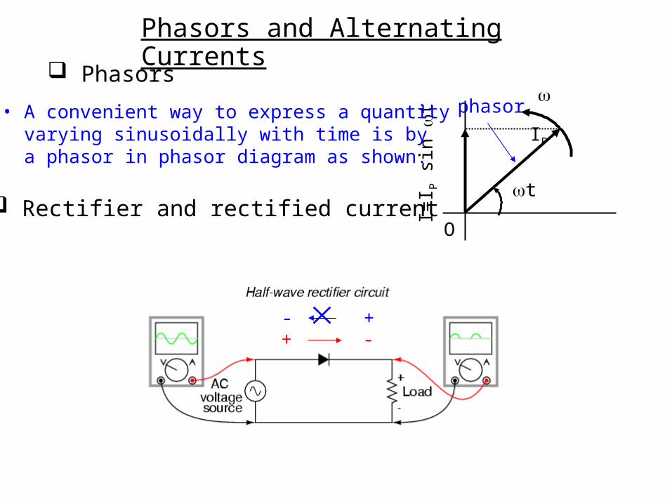
Phasors and Alternating Currents
Phasors
O
t
IP
I=I P
sin
t
• A convenient way to express a quantity varying sinusoidally with time is by a phasor in phasor diagram as shown.
phasor
Rectifier and rectified current
+ -- +
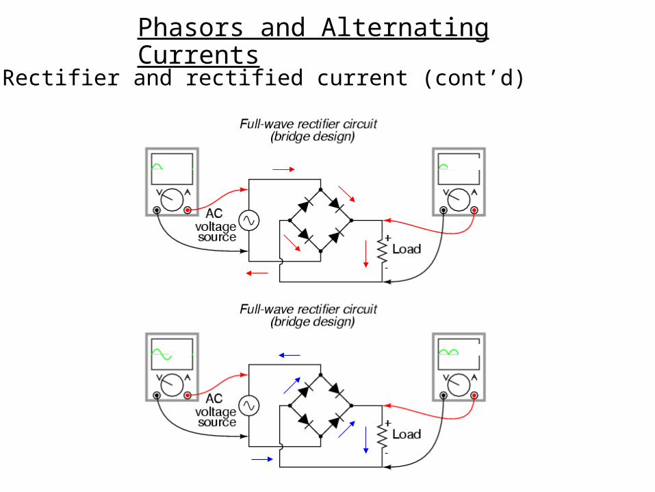
Phasors and Alternating Currents
Rectifier and rectified current (cont’d)
Phasors and Alternating Currents
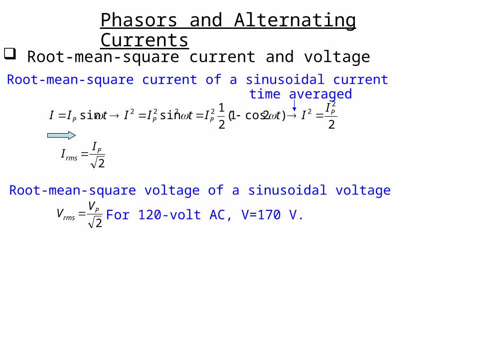
Root-mean-square current and voltage• Root-mean-square current of a sinusoidal current
2)2cos1(
2
1sinsin
222222 P
PPP
IItItIItII
time averaged
2P
rms
II
• Root-mean-square voltage of a sinusoidal voltage
2P
rms
VV For 120-volt AC, V=170 V.
Reluctance
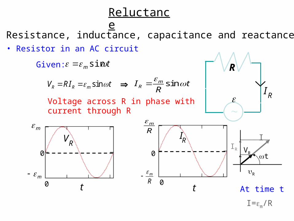
Resistance, inductance, capacitance and reactance• Resistor in an AC circuit
IR
R
s inR R mV RI t
0
0t
IRRm
Rm
0
0
VR
t
m
m
Voltage across R in phase with current through R
sinmRI t
R
I
VR
R
IR
t
tm sinGiven:
At time t
I=m/R
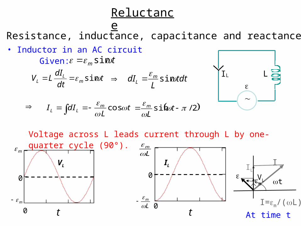
Resistance, inductance, capacitance and reactance• Inductor in an AC circuit
Voltage across L leads current through L by one-quarter cycle (90°).
I L
L
cosmL LI dI t
L
2/sin
tLm
t
0
0
m
m
VL
t
0
0
Lm
Lm
IL I
VL
IL
t
tm sinGiven:
Reluctance
At time t
I=m/(L)
m
tdt
dILV m
LL sin tdt
LdI m
L sin
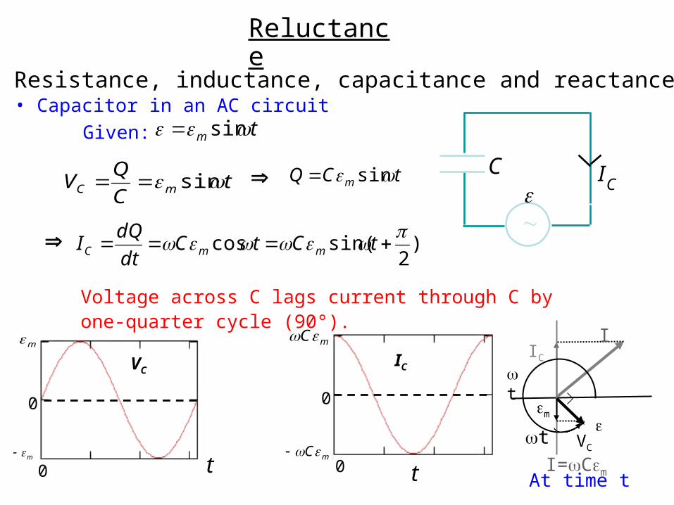
Resistance, inductance, capacitance and reactance• Capacitor in an AC circuit
C IC
Voltage across C lags current through C by one-quarter cycle (90°).
tC
QV mC sin tCQ m sin
0
0 t
m
m
VC
t
0
0
mC
mC
IC
I
VC
m
IC
t
tm sinGiven:
Reluctance
At time t
)2
sin(cos tCtC
dt
dQI mmC
t
I=Cm
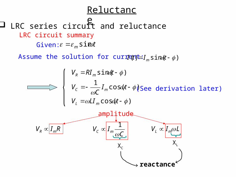
LRC series circuit and reluctance
R mV I R 1C mV I
C L mV I L
XCXL
reactance
tm sinGiven:
Assume the solution for current: )sin()( tItI m
LRC circuit summary
)cos(
)cos(1
)sin(
tLIV
tIC
V
tRIV
mL
mC
mR
amplitude
Reluctance
(See derivation later)
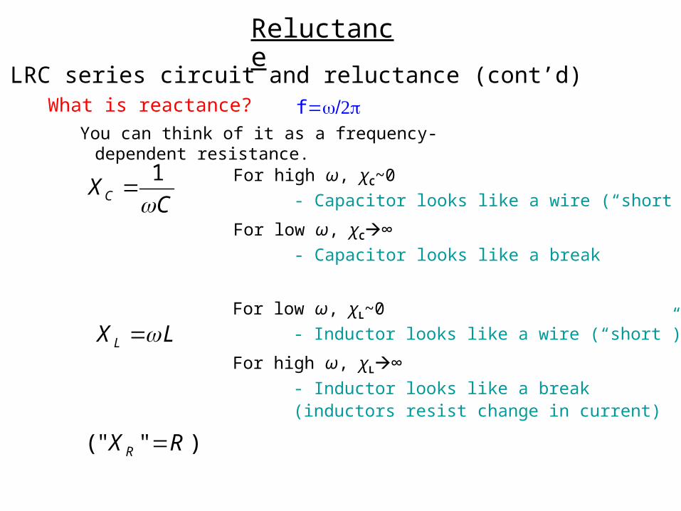
For high ω, χC~0
- Capacitor looks like a wire (“short”)
For low ω, χC∞
- Capacitor looks like a break
1CX
C
For low ω, χL~0
- Inductor looks like a wire (“short”)
For high ω, χL∞
- Inductor looks like a break(inductors resist change in current)
LX L
( " " )RX R
You can think of it as a frequency-dependent resistance.
What is reactance?
LRC series circuit and reluctance (cont’d)
Reluctance
f
LC
R
ImR
Im L
ImC
m
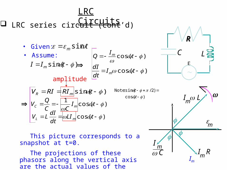
)sin( tRIRIV mR
)cos( tLIdt
dILV mL
)cos(1
tI
CC
QV mC
• Assume:
• Given: tm sin
)sin( tII m )cos(
t
IQ m
)cos( tIdt
dIm
This picture corresponds to a snapshot at t=0.
The projections of these phasors along the vertical axis are the actual values of the voltages at the given time.
LRC series circuit (cont’d)
amplitude
LRC Circuits
Im
)cos(
)2/sin( : Note
t
t
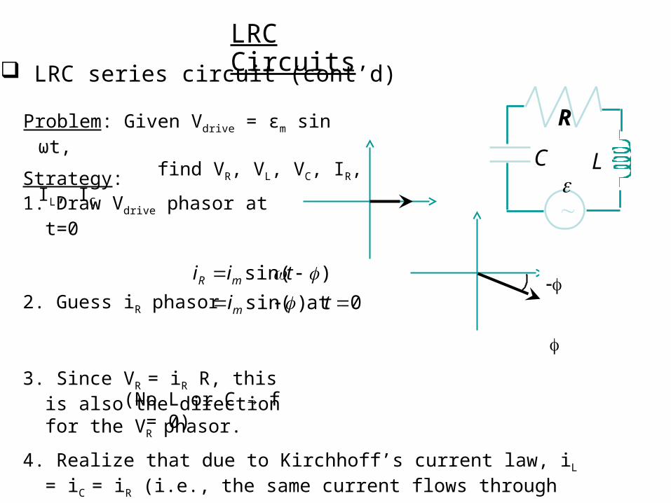
Problem: Given Vdrive = εm sin ωt,find VR, VL, VC, IR, IL, IC
Strategy:1. Draw Vdrive phasor at t=0
2. Guess iR phasor
3. Since VR = iR R, this is also the direction for the VR phasor.
-φ
4. Realize that due to Kirchhoff’s current law, iL = iC = iR (i.e., the same current flows through each).
(No L or C → f = 0)
LC
R
LRC series circuit (cont’d)
0at )sin(
)sin(
ti
tii
m
mR
LRC Circuits
-φ
VR = I R
VL= I XL
VC = I XC
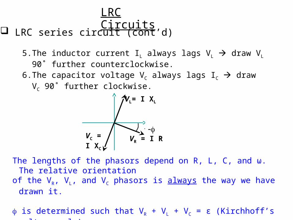
5. The inductor current IL always lags VL draw VL 90˚ further counterclockwise.
6. The capacitor voltage VC always lags IC draw VC 90˚ further clockwise.
The lengths of the phasors depend on R, L, C, and ω. The relative orientation of the VR, VL, and VC phasors is always the way we have drawn it.
is determined such that VR + VL + VC = ε (Kirchhoff’s voltage rule)These are added like vectors.
LRC series circuit (cont’d)
LRC Circuits
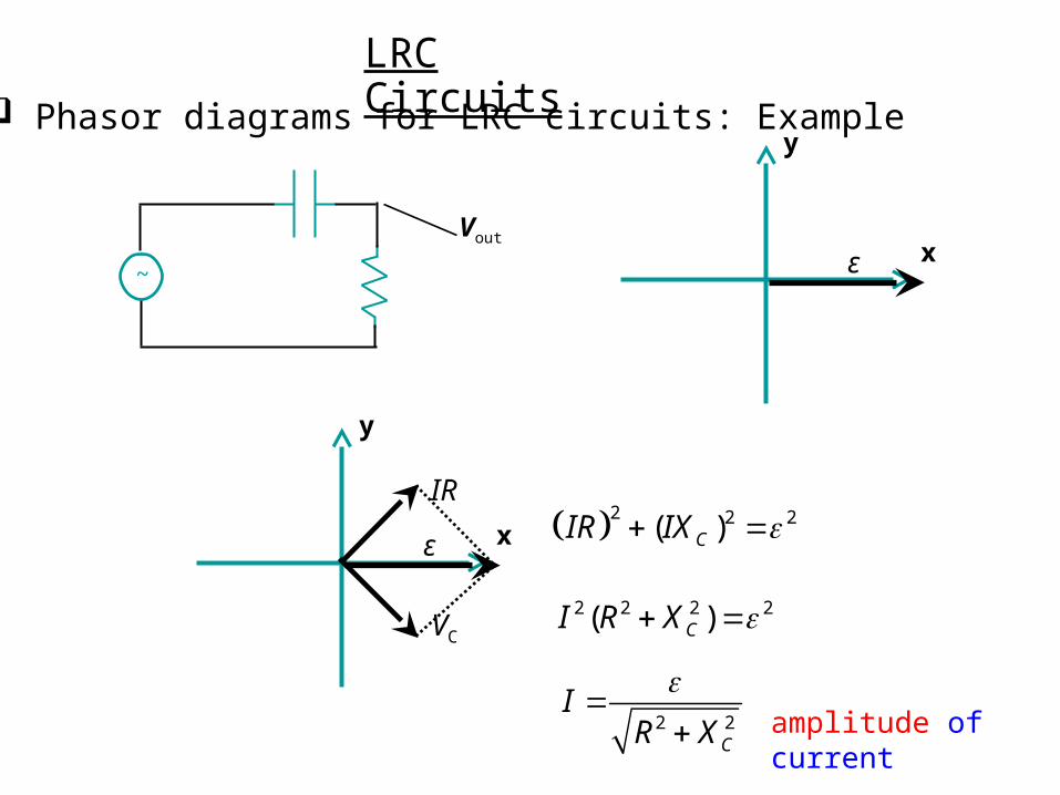
Phasor diagrams for LRC circuits: Example
y
xε
VC
IR 2 2 2( )CIR IX
2 2 2 2( )CI R X
2 2C
IR X
~
Vout
y
xε
LRC Circuits
amplitude of current
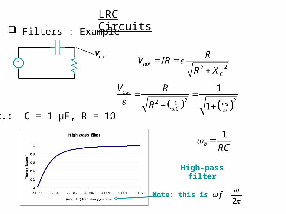
Filters : Example
22out
C
RV IR
R X
02 22 1
1
1
out
C
V R
R
0
1
RC
Ex.: C = 1 μF, R = 1Ω
High-pass filter
High-pass filter
0
0.2
0.4
0.6
0.8
1
0.E+00 1.E+06 2.E+06 3.E+06 4.E+06 5.E+06 6.E+06
(Angular) frequency, omega
"tra
nsm
issi
on"
Note: this is ω,2
f
~Vout
LRC Circuits
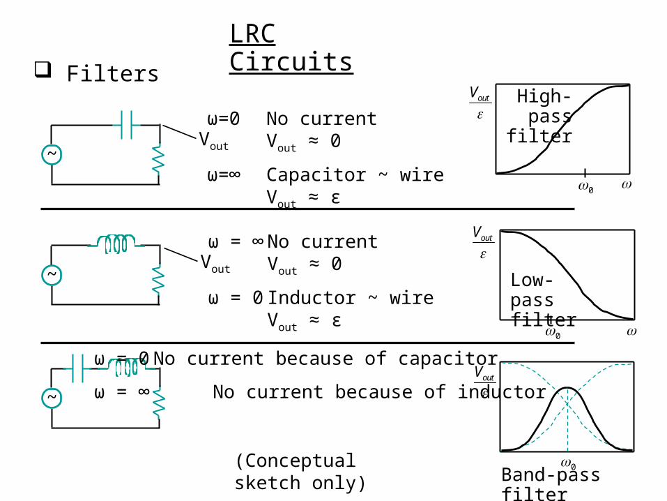
Filters
~Vout
~
ω=0 No currentVout ≈ 0
ω=∞ Capacitor ~ wireVout ≈ ε
~Vout
ω = ∞ No currentVout ≈ 0
ω = 0 Inductor ~ wireVout ≈ ε
ω = 0 No current because of capacitor
ω = ∞ No current because of inductor
outV
0
outV
0
(Conceptual sketch only)
High-pass filter
Low-pass filter
Band-pass filter
outV
0
LRC Circuits
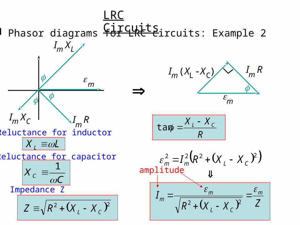
Phasor diagrams for LRC circuits: Example 2
ImR
m
Im(XL -XC)
ImR
m
ImXC
ImXL
LX L
CXC
1
22CL XXRZ
R
XX CL tan
2222CLmm XXRI
ZXXRI m
CL
mm
22
Impedance Z
amplitude
LRC Circuits
Reluctance for inductor
Reluctance for capacitor
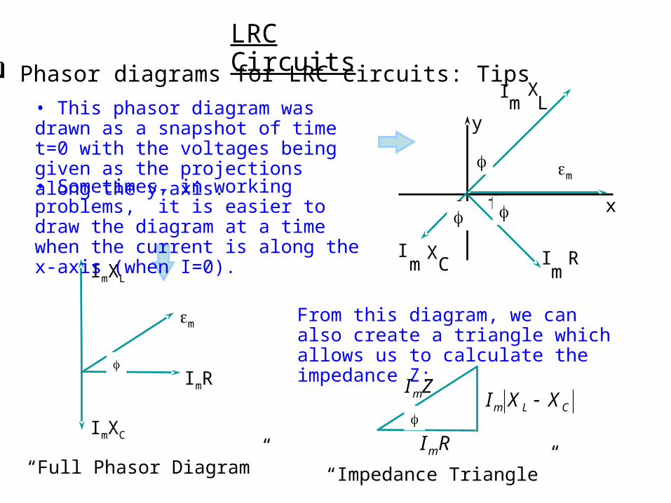
LRC Circuits Phasor diagrams for LRC circuits: Tips
• This phasor diagram was drawn as a snapshot of time t=0 with the voltages being given as the projections along the y-axis.
From this diagram, we can also create a triangle which allows us to calculate the impedance Z:f
ImR
ImXL
ImXC
m
“Full Phasor Diagram”
• Sometimes, in working problems, it is easier to draw the diagram at a time when the current is along the x-axis (when I=0).
Im
R
m
Im
XC
Im
XL
y
xf f
f
CLm XXI ZIm
RIm“Impedance Triangle”
f| |
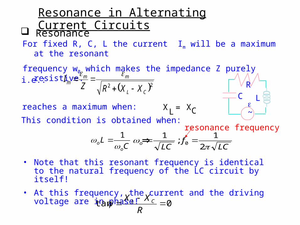
Resonance in Alternating Current Circuits
Resonance For fixed R, C, L the current Im will be a maximum at the resonant
frequency w0 which makes the impedance Z purely resistive.
• Note that this resonant frequency is identical to the natural frequency of the LC circuit by itself!
• At this frequency, the current and the driving voltage are in phase!
0tan
R
XX CL
22CL
mmm
XXRZI
i.e.:
reaches a maximum when: X XC=LThis condition is obtained when:
C
Lo
o 1
LC
fLC
o
2
1;
10
LC
~
R
resonance frequency
Resonance in Alternating Current Circuits
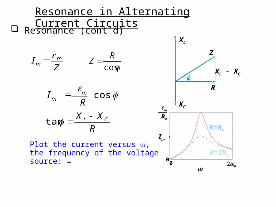
Resonance (cont’d)
Im
00
o
0Rm
R=Ro
R=2Ro
R
XL
XC
Z
XL - XC
Plot the current versus , the frequency of the voltage source: →
R
XX CL tan
cos R
I mm
ZI mm
cos
RZ
Resonance in Alternating Current Circuits
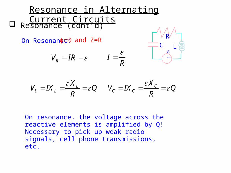
Resonance (cont’d)
On Resonance:LC
~
R
RV IR IR
LL L
XV IX Q
R
CC C
XV IX Q
R
On resonance, the voltage across the reactive elements is amplified by Q!Necessary to pick up weak radio signals, cell phone transmissions, etc.
and Z=R
Power in Alternating Current Circuits
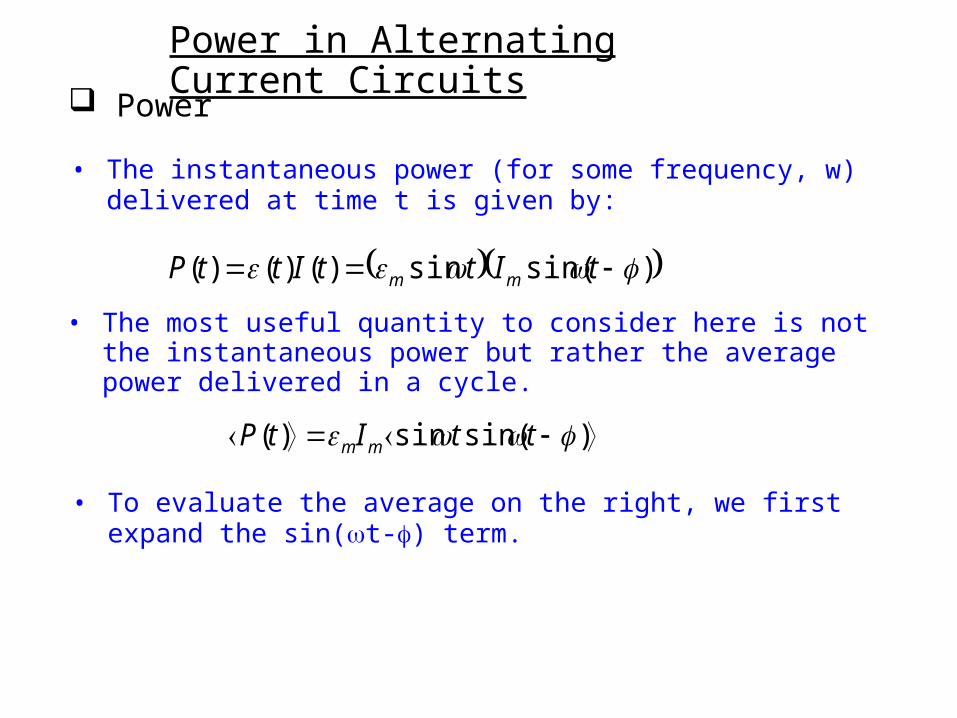
Power
• The instantaneous power (for some frequency, w) delivered at time t is given by:
• The most useful quantity to consider here is not the instantaneous power but rather the average power delivered in a cycle.
• To evaluate the average on the right, we first expand the sin(t-) term.
)sin(sin)()()( tIttIttP mm
)sin(sin)( ttItP mm
Power in Alternating Current Circuits
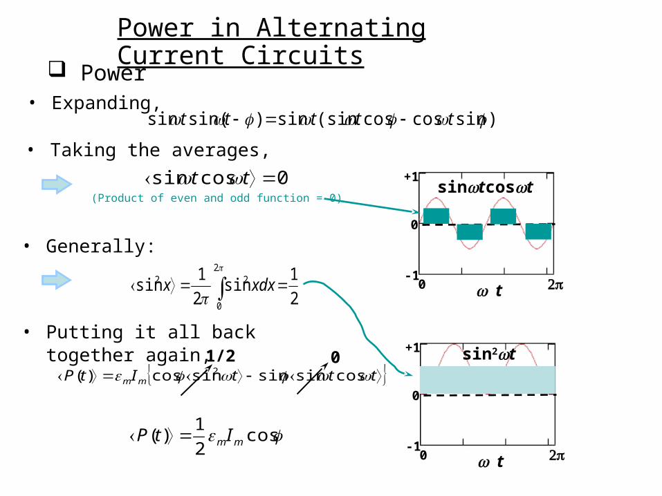
Power
sintcost
t0
0
+1
-1
(Product of even and odd function = 0)
sin2t
t0
0
+1
-1
tttItP mm cossinsinsincos)( 2
cos2
1)( mmItP
01/2
• Expanding,
• Taking the averages,
)sincoscos(sinsin)sin(sin ttttt
0cossin tt
• Generally:
2
0
22
2
1sin
2
1sin xdxx
• Putting it all back together again,
Power in Alternating Current Circuits
Power
mrms 2
1 mrms II
2
1 cos)( rmsrmsItP
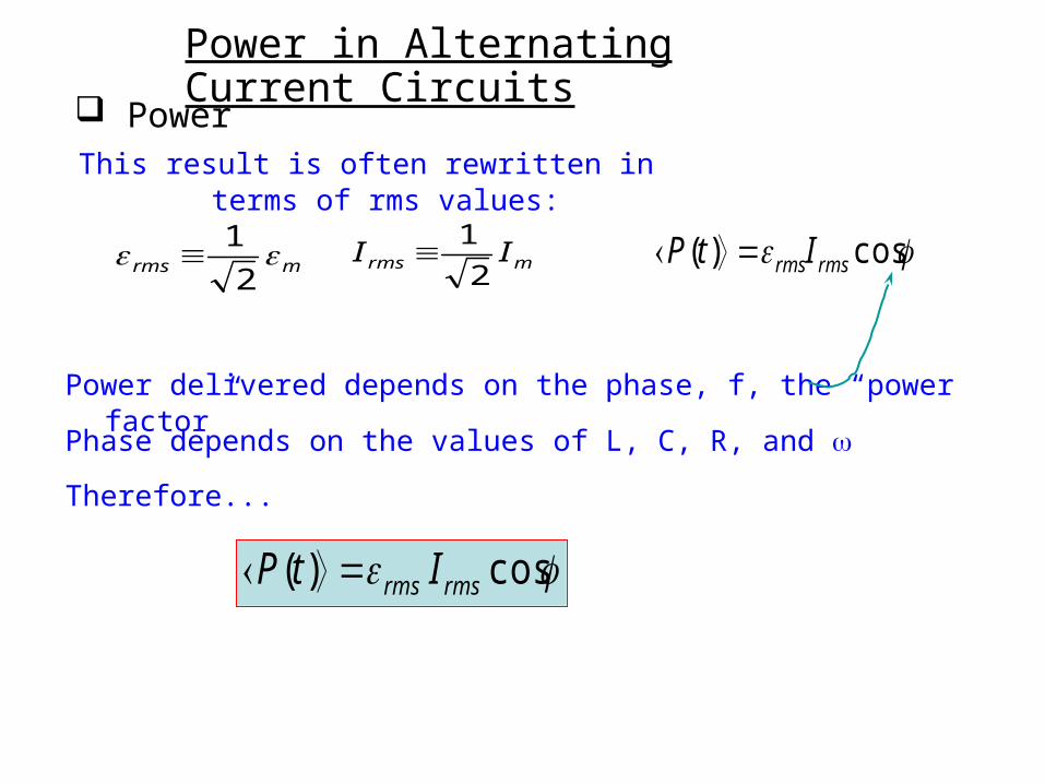
Power delivered depends on the phase, f, the “power factor”
Phase depends on the values of L, C, R, and
Therefore...
This result is often rewritten in terms of rms values:
cos)( rmsrms ItP
Power in Alternating Current Circuits
Power
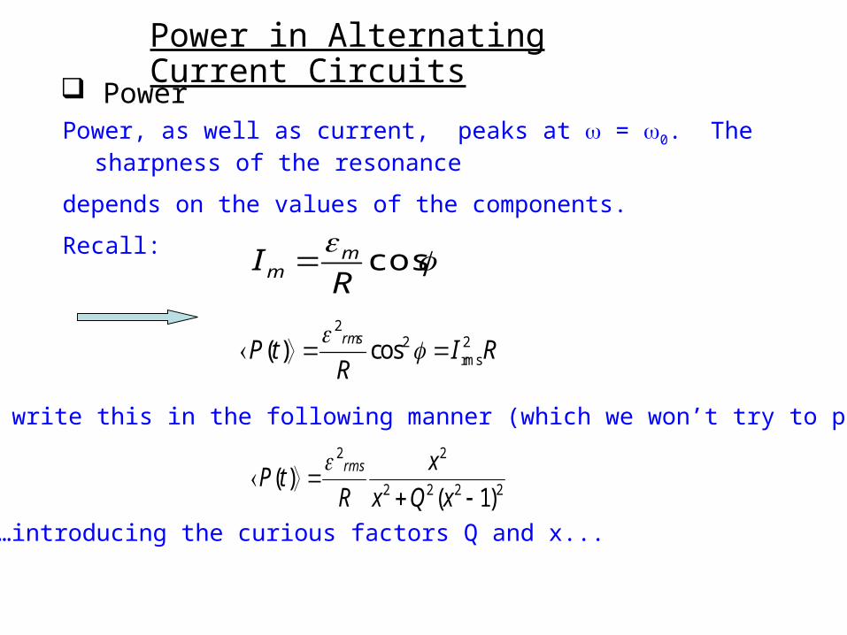
cos
RI mm
22 2
rms( ) cosrms
P t I RR
We can write this in the following manner (which we won’t try to prove):
2222
22
)1()(
xQx
x
RtP
rms
…introducing the curious factors Q and x...
Power, as well as current, peaks at = 0. The sharpness of the resonance
depends on the values of the components.
Recall:
Resonance in Alternating Current Circuits
Power and resonance
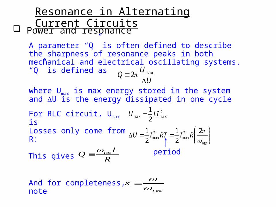
where Umax is max energy stored in the system and U is the energy dissipated in one cycle
A parameter “Q” is often defined to describe the sharpness of resonance peaks in both mechanical and electrical oscillating systems. “Q” is defined as
U
UQ
max2
For RLC circuit, Umax is 2maxmax 2
1LIU
Losses only come from R:
res
RIRTIU
2
2
1
2
1 2max
2max
This gives R
LQ res
And for completeness, note res
x
period
Resonance in Alternating Current Circuits
Power and resonance
<P>
00
o
0
2
Rrms
R=Ro
R=2Ro
Q=3
FWHM
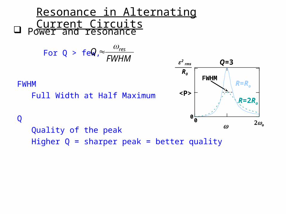
For Q > few, FWHM
Q res
FWHM
Full Width at Half Maximum
Q
Quality of the peak
Higher Q = sharper peak = better quality
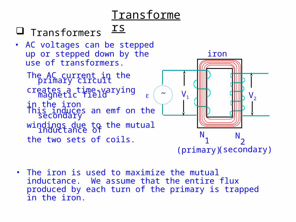
Transformers Transformers
• AC voltages can be stepped up or stepped down by the use of transformers.
The AC current in the primary circuitcreates a time-varying magnetic field in the iron
• The iron is used to maximize the mutual inductance. We assume that the entire flux produced by each turn of the primary is trapped in the iron.
21(primary) (secondary)
~
NN
iron
V2V1
This induces an emf on the secondarywindings due to the mutual inductance ofthe two sets of coils.
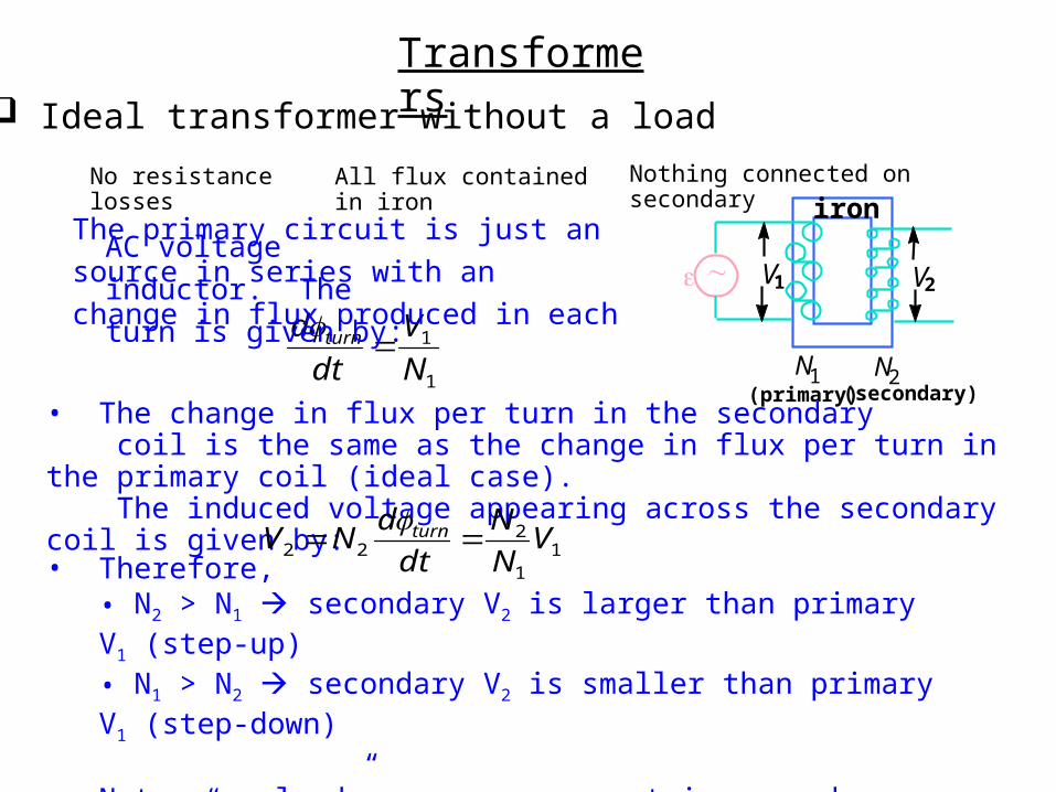
Transformers Ideal transformer without a load
1
1
N
V
dt
d turn
No resistance losses All flux contained in iron Nothing connected on secondary
N2N1(primary) (secondary)
iron
V2V1
The primary circuit is just an AC voltagesource in series with an inductor. Thechange in flux produced in each turn is given by:
• The change in flux per turn in the secondary coil is the same as the change in flux per turn in the primary coil (ideal case). The induced voltage appearing across the secondary coil is given by:
11
222 V
N
N
dt
dNV turn
• Therefore,
• N2 > N1 secondary V2 is larger than primary V1 (step-up) • N1 > N2 secondary V2 is smaller than primary V1 (step-down)
• Note: “no load” means no current in secondary. The primary current, termed “the magnetizing current” is small!
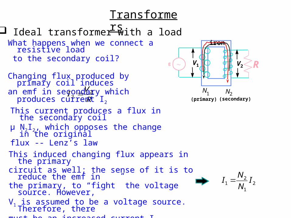
Transformers Ideal transformer with a load
R
VI 2
2
21
21 I
N
NI
N2N1
(primary) (secondary)
iron
V2V1 R
What happens when we connect a resistive load to the secondary coil?
Changing flux produced by primary coil inducesan emf in secondary which produces current I2
This current produces a flux in the secondary coilµ N2I2, which opposes the change in the originalflux -- Lenz’s law
This induced changing flux appears in the primarycircuit as well; the sense of it is to reduce the emf inthe primary, to “fight” the voltage source. However, V1 is assumed to be a voltage source. Therefore, theremust be an increased current I1 (supplied by the voltagesource) in the primary which produces a flux µ N1I1 which exactly cancels the flux produced by I2.
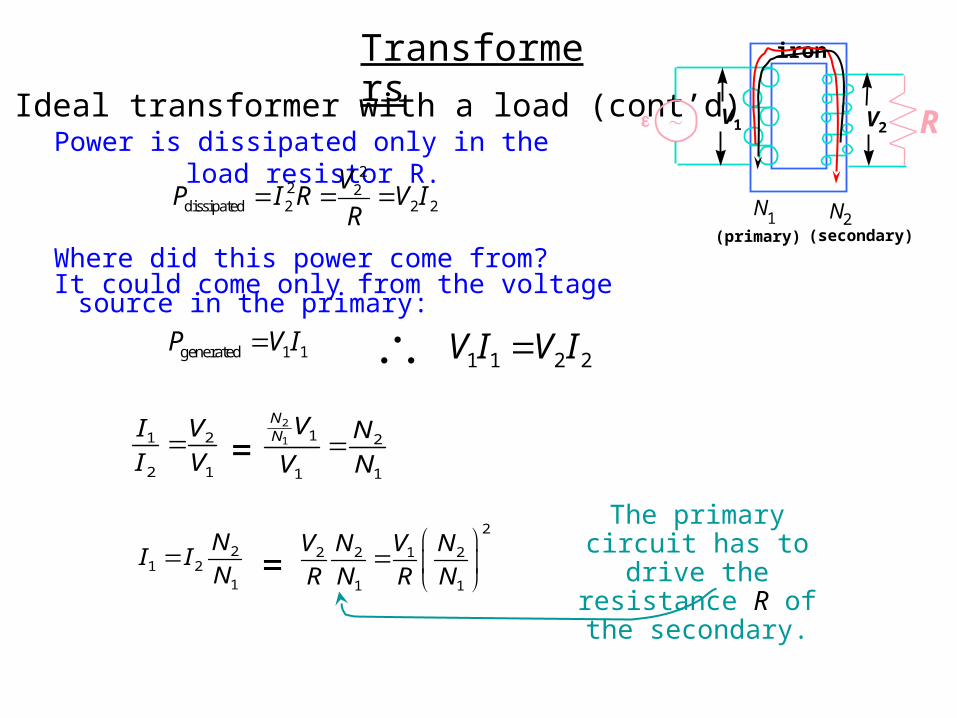
Transformers Ideal transformer with a load (cont’d)
Power is dissipated only in the load resistor R.
N2N1
(primary) (secondary)
iron
V2V1 R
22 2
dissipated 2 2 2
VP I R V I
R
generated 1 1P V I 1 1 2 2V I V I
1 2
2 1
I V
I V
2
1 1 2
1 1
NN V N
V N=
21 2
1
NI I
N
2
2 2 1 2
1 1
V N V N
R N R N
=
The primary circuit has to drive the resistance R
of the secondary.
Where did this power come from?It could come only from the voltage source in the
primary:
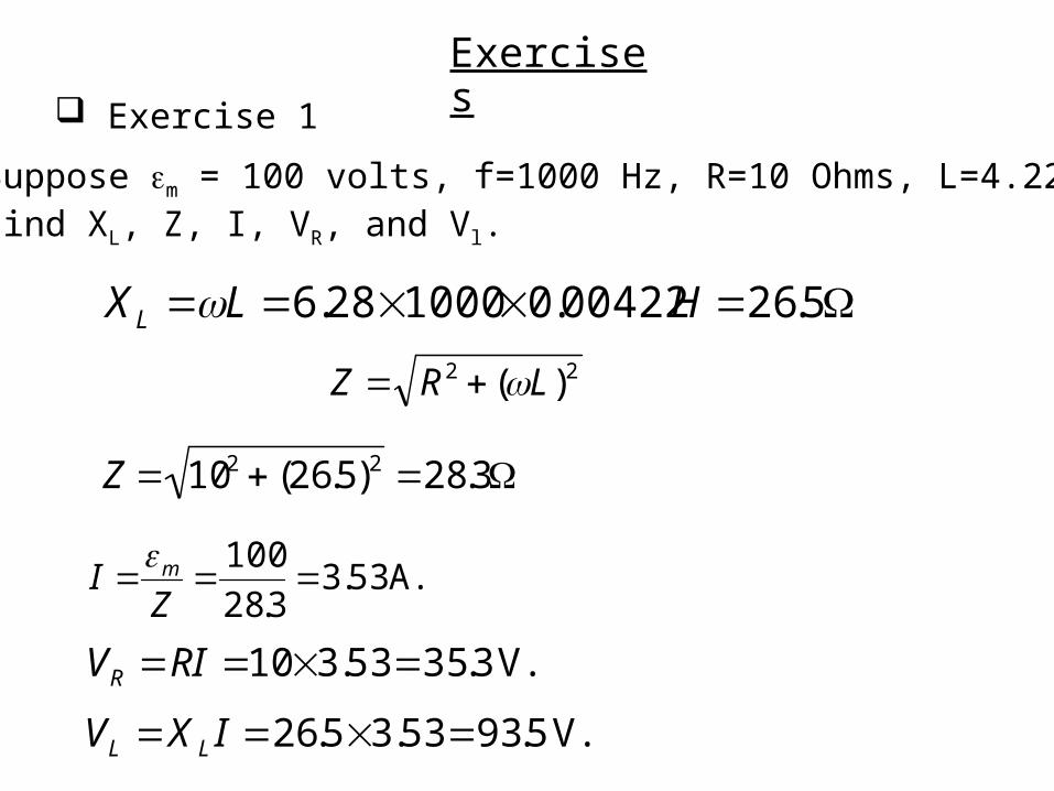
Exercises Exercise 1
Suppose m = 100 volts, f=1000 Hz, R=10 Ohms, L=4.22 mH,Find XL, Z, I, VR, and Vl.
XL L 6.28 10000.00422H 26.5
Z 102 (26.5)2 28.3
A. 53.33.28
100
ZI m
V. 3.3553.310 RIVR
V. 5.9353.35.26 IXV LL
22 )( LRZ
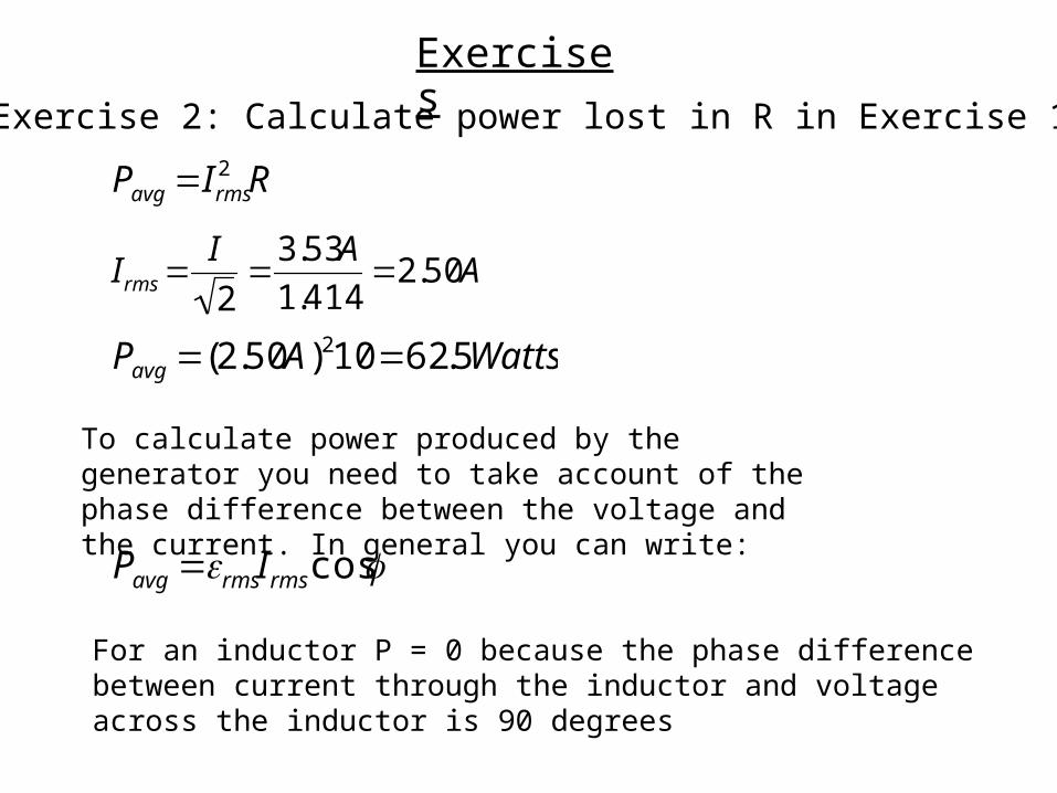
Exercises Exercise 2: Calculate power lost in R in Exercise 1
Pavg Irms2 R
Irms I
2
3.53A
1.4142.50A
Pavg (2.50A)210 62.5Watts
To calculate power produced by the generator you need to take account of the phase difference between the voltage and the current. In general you can write:
Pavg rmsIrms cos
For an inductor P = 0 because the phase difference between current through the inductor and voltage across the inductor is 90 degrees