Embed Size (px)
Citation preview
CHAPTER 6
BRIDGES AND MAJOR DRAINAGE STRUCTURES
CHAPTER 6 BRIDGES AND MAJOR DRAINAGE STRUCTURES
INDEX
Section Topic
6.1 General
6.2 Structure Design Loadings
6.3 Certification of Design
6.4 Waterway Opening Design Criteria
6.5 Concrete Structure Testing and Inspections
. ,..
Page
6.1
6.1
6.1
6.1
6.1
1 .. ...
.. i
I
'.i.
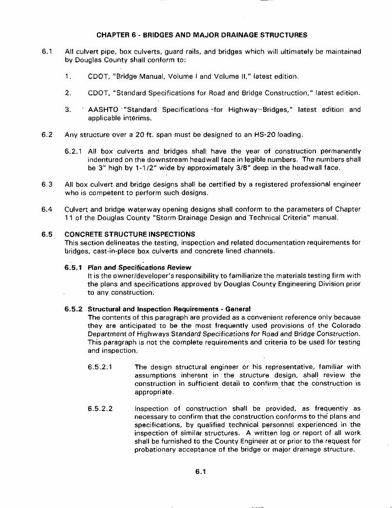
CHAPTER 6 - BRIDGES AND MAJOR DRAINAGE STRUCTURES
6.1 All culvert pipe, box culverts, guard rails, and bridges which will ultimately be maintained by Douglas County shall conform to:
1 .
2.
CDOT, "Bridge Manual, Volume I and Volume 11," latest edition.
CDOT, "Standard Specifications for Road and Bridge Construction," latest edition.
3. . AASHTO '"Standard Specifications &for Highway-Bridges," latest edition and applicable interims.
6.2 Any structure over a 20 ft. span must be designed to an HS-20 loading.
6.2.1 All box culverts and bridges shall have the year of construction permanently indentured on the downstream headwall face in legible numbers. The numbers shall be 3" high by 1-1/2" wide by approximately 3/8" deep in the headwall face.
All box culvert and bridge designs shall be certified by a registered professional engineer who is competent to perform such designs.
Culvert and bridge waterway opening designs shall conform to the parameters of Chapter 11 of the Douglas County "Storm Drainage Design and Technical Criteria" manual.
6.3
6.4
6.5 CONCRETE STRUCTURE INSPECTIONS This section delineates the testing, inspection and related documentation requirements for bridges, cast-in-place box culverts and concrete lined channels.
6.'5.1 Plan and Specifications Review It is the ownerldeveloper's responsibility to familiarize the materials testing firm with the plans and specifications approved by Douglas County Engineering Division prior to any construction.
6.5.2 Structural and Inspection Requirements - General The contents of this paragraph are provided as a convenient reference only because they are anticipated to be the most frequently used provisions of the Colorado Department of Highways Standard Specifications for Road and Bridge Construction. This paragraph is not the complete requirements and criteria to be used.for testing and inspection.
6.5.2.1 The design structural engineer or his representative, familiar with assumptions inherent in the structure design, shall review the construction in sufficient detail to confirm that the construction is appropriate.
6.5.2.2 Inspection of construction shall be provided, as frequently as necessary to confirm that the construction conforms to the plans and specifications, by qualified technical personnel experienced in the inspection of similar structures. A written log or report of all work shall be furnished to the County Engineer at or prior to the request for probationary acceptance of the bridge or major drainage structure.
6.1
6.5.3 Material Testing Requirements - General Testing of materials shall conform to the requirements of AASHTO "Standard Specifications for Highway Bridges," latest edition, and applicable interims, and applicable CDOT standards.
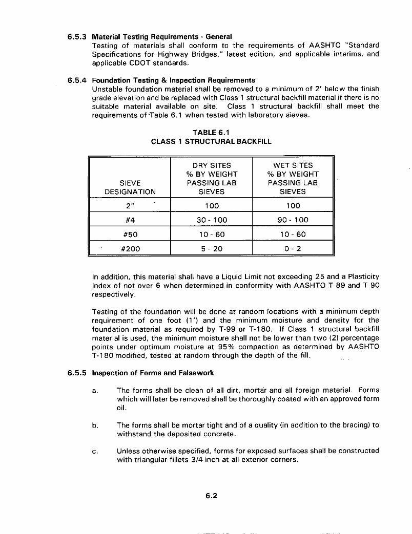
6.5.4 Foundation Testing & Inspection Requirements Unstable foundation material shall be removed to a minimum of 2' below the finish grade elevation and be replaced with Class 1 structural backfill material if there is no suitable material available on site. Class 1 structural backfill shall meet the requirements of 'Table 6.1 when tested with laboratory sieves.
TABLE 6.1 CLASS 1 STRUCTURAL BACKFILL
DRY SITES Yo BY WEIGHT
SIEVE PASSING LAB DESIGNATION SIEVES
2" 100
WET SITES
PASSING LAB SIEVES
100
Yo BY WEIGHT
II #4 I 3 0 - 100 I 9 0 - 100
#50 1 0 - 60 1 0 - 60
#200
In addition, this material shall have a Liquid Limit not exceeding 25 and a Plasticity Index of not over 6 when determined in conformity with AASHTO T 89 and T 90 respectively.
Testing of the foundation will be done at random locations with a minimum depth requirement of one foot (1') and the minimum moisture and density for the foundation material as required by T-99 or T-180. If Class 1 structural backfill material is used, the minimum moisture shall not be lower than two ( 2 ) percentage points under optimum moisture at 95% compaction as determined by AASHTO T-180 modified, tested at random through the depth of the fill. .. .
6.5.5 Inspection of Forms and Falsework
a. The forms shall be clean of all dirt, mortar and all foreign material. Forms which will later be removed shall be thoroughly coated with'an approved form oil.
The forms shall be mortar tight and of a quality (in addition to the bracing) to withstand the deposited concrete.
Unless otherwise specified, forms for exposed surfaces shall be constructed with triangular fillets 3/4 inch at all exterior corners.
b.
C.
5 - 20 0 - 2
6.2
6.5.6 Inspection of Reinforcing Steel
a. The material grade and size shall be as specified by the design engineer on the certified construction drawings.
b. Tying.
1.
, . and at spacingsbaccording to bar sizes. .. .
- 5'0" to 6'0" - 0'0" to 10'0"
Slab bars should be tied sufficiently, at least three times in any bar length, to prevent shifting at every intersection around the periphery
#5 and smaller staggered #6 to #9 # 1 0 a n d # l l - 10'0" to 12'0"
Wall bars should be tied sufficiently to prevent shifting, at least three times in any bar length at every third or fourth intersection and at spaces according to bar sizes, staggered:
#5 and smaller - 3'0" #6 to #9 # 1 0 t o # l l - 6'0" to 0'0"
2.
- 4'0" to 5'0"
Upper and lower mats shall be tied or otherwise fastened at 4 ft. maximum spacing in each direction. Minimum splice length shall be 24 bar diameters.
3. Supports for reinforcing steel shall be: slabs on grade or footings, concrete blocking or approved blocking material. All other reinforcing steel shall be supported with steel chair or precast mortar.
Reinforcing steel shall be clean and free of all foreign material before concrete is placed.
4.
5. All clearances shall be in compliance with approved plans and specifications.
A daily log of all work shall be kept by a resident project observer. A copy of this log shall be furnished to the Douglas County Engineer at or prior to the request for probationary acceptance.
6.
6.5.7 Concrete Testing and Inspections
6.5.7.1 Materials Specifications
a. Class A, E, or D concrete shall be used on structures as listed on the following tables.
Table 6.2 Concrete Materials Specifications Table 6.3 Concrete Aggregate Gradation Table
6.3
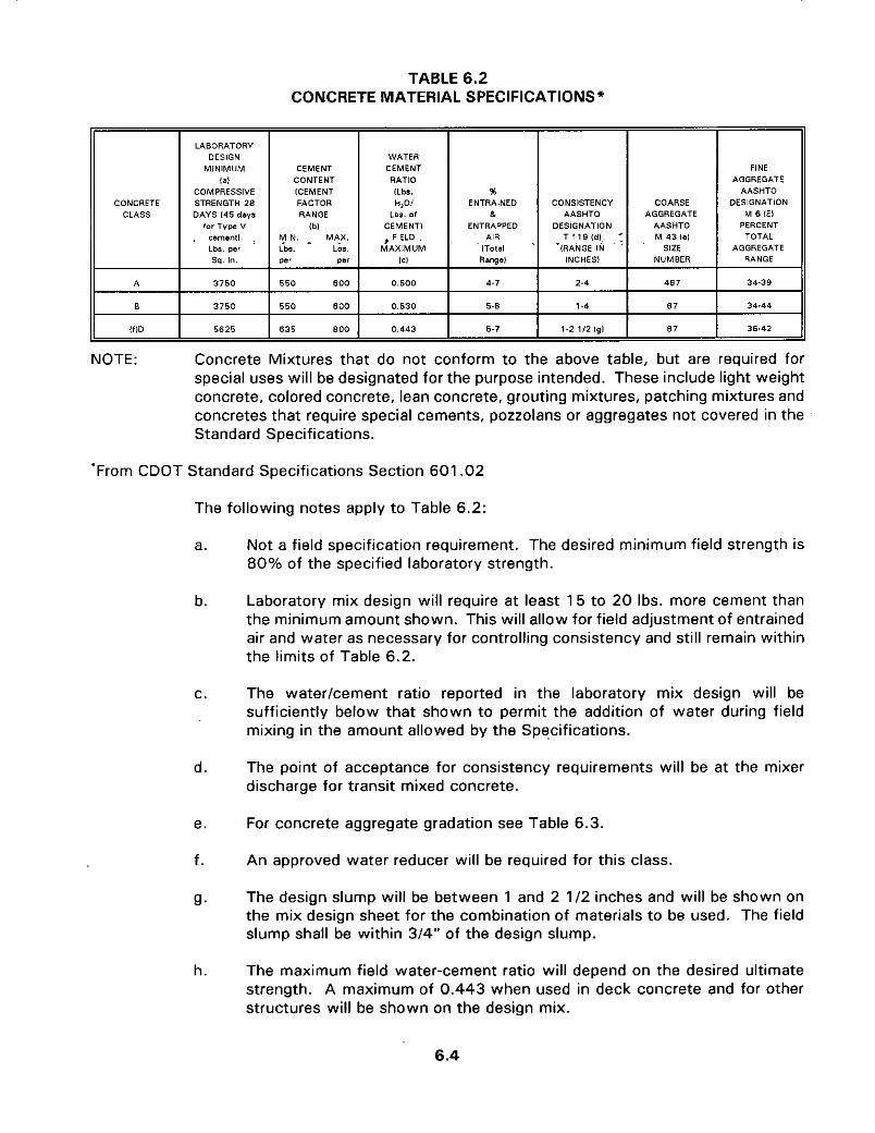
TABLE 6.2 CONCRETE MATERIAL SPECIFICATIONS*
FACTOR RANGE
lbl MIN. . MAX. LbS. Lbs. oer W'
550 GOO
550 800
635 GOO
LABORATORY DESIGN
MINIMUM
COMPRESSIVE CONCRETE STRENGTH 28
CLASS DAYS 145 days tor Type Y
LbS. per sq. I".
3750
l f lD 5625
H,OI Lb.. of
CEMENT1 I FIELD
MAXIMUM IC1
0 .500
0 . 5 3 0
0.443
WATER CEMENT CEMENT
CONTENT RATIO [CEMENT ILbs.
AIR 1Tma1 '
Rangol
TOTAL T 1 18 Id! M 43 IO1
AGGREGATE INCHES1 NUMBER RANGE
*(RANGE IN ' SIZE
FINE I AGGREGATE % I I I AASHTO
DESIGNATION M G IEl I DESIGNATION I AASHTO I PERCENT
COARSE AGGREGATE
CONSISTENCY AASHTD
ENTRAINED h
ENTRAPPED
34-38 * 34.44
5.1 1.2 112 191 36.42
NOTE: Concrete Mixtures that do not conform to the above table, but are required for special uses will be designated for the purpose intended. These include light weight concrete, colored concrete, lean concrete, grouting mixtures, patching mixtures and concretes that require special cements, pozzolans or aggregates not covered in the Standard Specifications.
'From CDOT Standard Specifications Section 601.02
The following notes apply to Table 6.2:
a.
b.
C.
d.
e.
f.
9.
h.
Not a field specification requirement. The desired minimum field strength is 80% of the specified laboratory strength.
Laboratory mix design will require at least 15 to 20 Ibs. more cement than the minimum amount shown. This will allow for field adjustment of entrained air and water as necessary for controlling consistency and still remain within the limits of Table 6.2.
The waterlcement ratio reported in the laboratory mix design will be sufficiently below that shown to permit the addition of water during field mixing in the amount allowed by the Specifications.
The point of acceptance for consistency requirements will be at the mixer discharge for transit mixed concrete.
For concrete aggregate gradation see Table 6.3.
An approved water reducer will be required for this class.
The design slump will be between 1 and 2 1/2 inches and will be shown on the mix design sheet for the combination of materials to be used. The field slump shall be within 3/4" of the design slump.
The maximum field water-cement ratio will depend on the desired ultimate strength. A maximum of 0.443 when used in deck concrete and for other structures will be shown on the design mix.
6.4
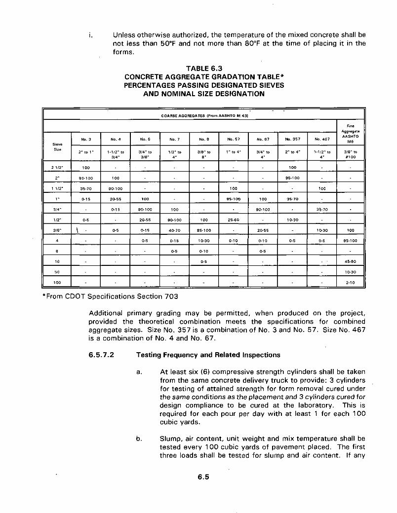
I. Unless otherwise authorized, the temperature of the mixed concrete shall be not less than 50°F and not more than 80°F at the time of placing it in the forms.
TABLE 6.3 CONCRETE AGGREGATE GRADATION TABLE* PERCENTAGES PASSING DESIGNATED SIEVES
AND NOMINAL SIZE DESIGNATION
*From CDOT Specifications Section 703
Additional primary grading may be permitted, when produced on the project, provided the theoretical combination meets the specifications for combined aggregate sizes. Size No. 357 is a combination of No. 3 and No. 57. Size No. 467 is a combination of No. 4 and No. 67.
6.5.7.2 Testing Frequency and Related Inspections
a. At least six (6) compressive strength cylinders shall be taken from the same concrete delivery truck to provide: 3 cylinders for testing of attained strength for form removal cured under the same conditions as the placement and 3 cylinders cured for design compliance to be cured at the laboratory. This is required for each pour per day with at least 1 for each 100 cubic yards.
Slump, air content, unit weight and mix temperature shall be tested every 100 cubic yards of pavement placed. The first three loads shall be tested for slump and air content. If any
b.
6.5
one test fails to meet requirements, slump and air content tests shall continue until three continuous loads meet requirements. Thereafter, slump shall be tested at least every fifth load.
6.5.7.3 Placement (Inspection)
a. Concrete placement shall be done in a manner so that the concrete is not segregated or altered before placing. It shall not be allowed to free falbmore than five feet. Concrete shall be placed in lifts not to exceed eighteen (1 8 ) inches.
A sufficient number of vibrators shall be used to properly consolidate the concrete as required.
,. "
b.
SIEVE SIZE OR DESIGNATION
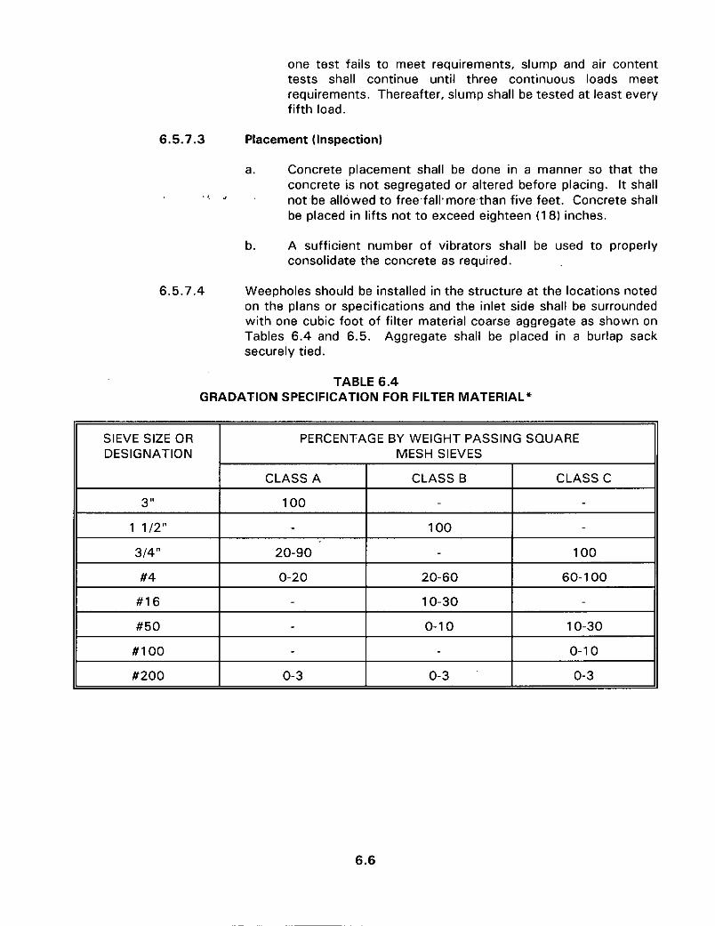
6.5.7.4
PERCENTAGE BY WEIGHT PASSING SQUARE MESH SIEVES
Weepholes should be installed in the structure at the locations noted on the plans or specifications and the inlet side shall be surrounded with one cubic foot of filter material coarse aggregate as shown on Tables 6.4 and 6.5. Aggregate shall be placed in a burlap sack securely tied.
CLASS A CLASS B CLASS C
3"
1 112"
II 314" I 20-90 I I 100 II
100
100
II #4 I 0-20 I 20-60 I 60-1 00 II #16
#50
# I 00
10-30
0-1 0 10-30
0-1 0
#200
6.6
0-3 0-3 0-3

SIEVE SIZE
DESIGNATION OR
# l o
#40
6.5.7.9
PERCENTAGE OF SOIL PASSING DESIGNATED SIEVES’
USE CLASS A, B OR C2 USE CLASS B OR C2 USE CLASS C
Less than 85, and Less than 85 More than 85
less than 25
6.5.7.8 Curing concrete other than Bridge Decks when the ambient temperature is below 35°F: the contractor shall maintain the concrete surface temperature above 50”Fduring the curing period. A time clock shall be used to monitor temperature. The minimum curing period shall be seven days. Methods of curing are t o be in conformance with Colorado Department of Highways Specifications. Curing of Bridge Decks shall also follow current CDOT Specifications.
Finishing of Hardened Concrete Surfaces
a. All formed surfaces shall be given a Class 1 finish immediately following curing, as defined by CDOT specification 601.14.
Culvert headwall and wingwall surfaces above ground, where visible from a traveled way, shall receive a Class 2 or Class 5 finish at the contractor’s option.
b.
6.5.8 Riprap Rock used for riprap or wire enclosed riprap shall be hard, durable, angular in shape, and be free from cracks, overburden, shale and organic matter. Neither breadth nor thickness of a single stone shall be less than 1.3 its length and rounded stone shall not be used. The rock shall sustain a loss of not more than 40% after 500 revolutions in an abrasion test (Los Angeles machine - ASTM C-535) and shall sustain a loss of not more than 10% after 12 cycles of freezing and thawing (AASHTO T-103 for ledge rock procedure A). Rock having a minimum specific gravity of 2.65 is preferred; however, in no case should rock have a specific gravity less than 2.50. Classification and gradation for riprap are shown in Table 6.6 and Figure 6-1 and are based on minimum specific gravity of 2.50for the rock. Because of its relatively small size and weight, riprap types VL and L must be buried with native soil and revegetated to protect the rock from vandalism.
6.7
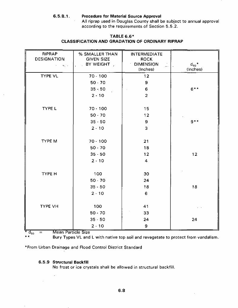
6.5.8.1. Procedure for Material Source Approval All riprap used in Douglas County shall be subject t o annual approval according to the requirements of Section 5.5.2.
TABLE 6.6' CLASSIFICATION AND GRADATION OF ORDINARY RIPRAP
RIPRAP DESIGNATION
., TYPE VL
TYPE L
TYPE M
TYPE H
TYPE VH
Mean Par - dw -
Yo SMALLER THAN GIVEN SIZE BY WEIGHT
70 - 100 5 0 - 70 35 -. 50 2 - 10
70 - 100 50 - 70 35 - 50 2 - 10
7 0 - 100 50 - 70 35 - 50 2 - 10
100 50 - 70 35 - 50 2 - 10
100 5 0 - 70 35 - 50 2 - 10
3e Size
~~
INTERMEDIATE ROCK
(Inches) DIMENSION ,
12 9 6 L
15 12 9 3
21 18 12 4
30 24 18 6
41 33 24 9
6 * *
9"'
12
18
24
-. * I
*From Urban Drainage and Flood Control District Standard
Bury Types VL and L with native top soil and revegetate to protect from vandalism.
6.5.9 Structural Backfill No frost or ice crystals shall be allowed in structural backfill.
6.8
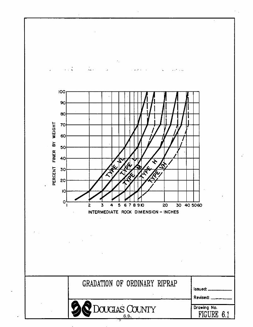
Issued I GRADATION OF ORDINARY RIPRAP I
Revised:
Drawing No.