Embed Size (px)
Citation preview
WSF Terminal Design Manual M 3082.05 Page 650-1 April 2016
Chapter 650 Floating Dolphins
650.01 General650.02 References650.03 Design Considerations650.04 Design Criteria650.05 Stability
650.06 Anchor System650.07 Fender System650.08 Towing System650.09 Miscellaneous Design
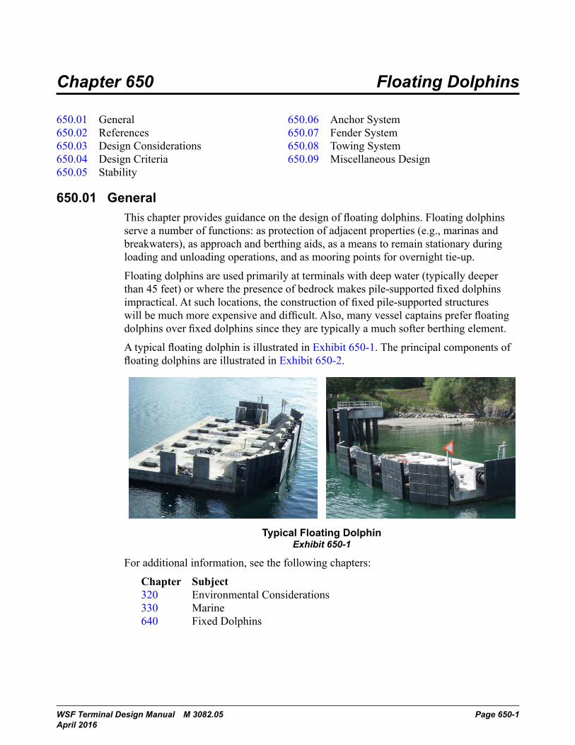
650.01 GeneralThis chapter provides guidance on the design of floating dolphins. Floating dolphins serve a number of functions: as protection of adjacent properties (e.g., marinas and breakwaters), as approach and berthing aids, as a means to remain stationary during loading and unloading operations, and as mooring points for overnight tie-up.
Floating dolphins are used primarily at terminals with deep water (typically deeper than 45 feet) or where the presence of bedrock makes pile-supported fixed dolphins impractical. At such locations, the construction of fixed pile-supported structures will be much more expensive and difficult. Also, many vessel captains prefer floating dolphins over fixed dolphins since they are typically a much softer berthing element.
A typical floating dolphin is illustrated in Exhibit 650-1. The principal components of floating dolphins are illustrated in Exhibit 650-2.
Chapter 650 Floating Dolphins
650.01 General650.02 References650.03 Design Considerations650.04 Design Criteria650.05 Stability650.06 Anchor System650.07 Fender System650.08 Towing System650.09 Miscellaneous Design
650.01 GeneralThis chapter provides guidance on the design of floating dolphins. Floating dolphins serve a number of functions: as protection of adjacent properties (e.g., marinas and breakwaters), asapproach and berthing aids, as a means to remain stationary during loading and unloading operations, and as mooring points for overnight tie-up.
Floating dolphins are used primarily at terminals with deep water (typically deeper than 45 feet) or where the presence of bedrock makes pile-supported fixed dolphins impractical. At such locations, the construction of fixed pile-supported structures will be much more expensive and difficult. Also, many vessel captains prefer floating dolphins over fixed dolphins since they are typically a much softer berthing element.
A typical floating dolphin is illustrated in Exhibit 650-1. The principal components of floating dolphins are illustrated in Exhibit 650-2.
Typical Floating DolphinExhibit 650-1
For additional information, see the following chapters:
Chapter Subject320 Environmental Considerations330 Marine640 Fixed Dolphins
Terminal Design Manual M 3082 Page 650-1January 2014
Typical Floating DolphinExhibit 650-1
For additional information, see the following chapters:
Chapter Subject 320 Environmental Considerations 330 Marine 640 Fixed Dolphins
Floating Dolphins Chapter 650
Page 650-2 WSF Terminal Design Manual M 3082.05 April 2016
Floating Dolphins Chapter 650
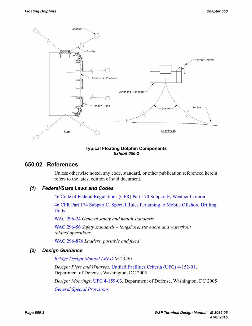
Typical Floating Dolphin ComponentsExhibit 650-2
650.02 ReferencesUnless otherwise noted, any code, standard, or other publication referenced herein refers to the latest edition of said document.
(1) Federal/State Laws and Codes
46 Code of Federal Regulations (CFR) Part 170 Subpart E, Weather Criteria
46 CFR Part 174 Subpart C, Special Rules Pertaining to Mobile Offshore Drilling Units
Washington Administrative Code (WAC) Chapter 296-24, General safety and health standards
WAC Chapter 296-56, Safety standards – longshore, stevedore and waterfront related operations
WAC Chapter 296-876, Ladders, portable and fixed
(2) Design Guidance
Bridge Design Manual LRFD, M 23-50, WSDOT
Design: Piers and Wharves, Unified Facilities Criteria (UFC) 4-152-01, Department of Defense, Washington, DC 2005
Design: Moorings, UFC 4-159-03, Department of Defense, Washington, DC 2005
Page 650-2 Terminal Design Manual M 3082January 2014
Typical Floating Dolphin ComponentsExhibit 650-2
650.02 ReferencesUnless otherwise noted, any code, standard, or other publication referenced herein refers to the latest edition of said document.
(1) Federal/State Laws and Codes46 Code of Federal Regulations (CFR) Part 170 Subpart E, Weather Criteria
46 CFR Part 174 Subpart C, Special Rules Pertaining to Mobile Offshore Drilling Units
WAC 296-24 General safety and health standards
WAC 296-56 Safety standards – longshore, stevedore and waterfront related operations
WAC 296-876 Ladders, portable and fixed
(2) Design GuidanceBridge Design Manual LRFD M 23-50
Design: Piers and Wharves, Unified Facilities Criteria (UFC) 4-152-01, Department of Defense, Washington, DC 2005
Design: Moorings, UFC 4-159-03, Department of Defense, Washington, DC 2005
General Special Provisions
Chapter 650 Floating Dolphins
WSF Terminal Design Manual M 3082.05 Page 650-3 April 2016
Geotechnical Design Manual M 46-03
Guidelines for the Design of Fender Systems: 2002, The World Association for Waterborne Transport Infrastructure (PIANC), 2002
AASHTO LRFD Bridge Design Specifications, American Association of State Highway and Transportation Officials, Washington DC
Region General Special Provisions, WSF
Specification for Aluminum Structure, Aluminum Association
Specification for Structural Steel Buildings (ANSI/AISC 360), American Institute of Steel Construction
Structural Welding Code – Steel (AWS D1.1), American Welding Society
Structural Welding Code – Reinforcing Steel (AWS D1.4), American Welding Society
Structural Welding Code – Aluminum (AWS D1.2), American Welding Society
Control of Cracking in Structural Concrete, ACI 224R, American Concrete Institute
Standard Plans for Road, Bridge, and Municipal Construction M 21-01
Standard Specifications for Road, Bridge, and Municipal Construction M 41-10
Standard Specifications for Structural Supports for Highway Signs, Luminaires and Traffic Signals, 5th ed. with Interim Revision, AASHTO, Washington, DC 2009
Velocity Pattern Generated by Propulsion of Four Ferries, Pacific International Engineering Draft Technical Memorandum, 2001
650.03 Design Considerations(1) Location
Consult with WSF Operations staff to determine the location of floating dolphins. Chapter 330 provides design guidelines on WSF dolphin configurations.
Tune the translational response of the dolphin as much as practical to the current operational norm of 5 to 10 feet in the typical berthing contact. Accomplish this by adjusting the catenary shape of the anchor lines. Within limits, adjustment to the plan locations of the dolphins can be made if the vessel captains request a location adjustment at the time of installation, or after installation. The position of the dolphin can be adjusted by plus or minus 10 feet by changing the length of the anchor chains.
(2) EnvironmentalRefer to Chapter 320 for general environmental requirements and design guidance. Refer to the project NEPA/SEPA documentation for project-specific environmental impacts and mitigation.
Floating Dolphins Chapter 650
Page 650-4 WSF Terminal Design Manual M 3082.05 April 2016
(3) MarineRefer to Chapter 330 for general marine design criteria pertaining to floating dolphins. Below are links to relevant sections by topic.• Operations and Maintenance: 330.04(4)• Proprietary Items: 330.04(6)• Long Lead Time Items: 330.04(7)• Design Life: 330.04(8)• Corrosion Mitigation: 330.04(9)• Scour and Mudline Elevations: 330.04(10)• Material Specifications: 330.04(12)• Tidal Information: 330.06• Slips: 330.07• Berthing and Mooring Criteria: 330.08
(4) Geotechnical RequirementsDesign anchors in accordance with the Geotechnical Recommendations provided by the WSDOT Geotechnical Branch. Do not include seismic effects including liquefaction in the design. The Geotechnical Recommendations will typically include:• Type of anchors to be used• Resistance and safety factors to be used for the given anchors• Capacity charts or values for the given anchors
650.04 Design Criteria(1) General
Floating dolphins are moored concrete pontoons with standard dimensions as shown in Exhibit 650-3 below. Two standard sizes are used depending on whether the dolphin is single-sided or double-sided. Design the float to consist of the number of individual cells tabulated below, each capable of being independently ballasted to attain level trim. Moor each dolphin with the number of chain mooring lines tabulated below and secure the chains to the sea bed with anchors. Locate one or more sinkers along the length of each mooring line as required to control the mooring line response and help meet energy design levels. Sinkers can also provide more vertical clearance between the vessel and the mooring lines. Typically for single-sided dolphins sinkers are provided only on the slip-side mooring lines.
Characteristic Single-sided Double-sidedPontoon Length 80 feet 80 feetPontoon Width 40 feet 48 feetPontoon Depth 14 feet 14 feetNumber of Cells 21 24
Number of Mooring Lines 6 8
Standard Floating Dolphin CharacteristicsExhibit 650-3
Chapter 650 Floating Dolphins
WSF Terminal Design Manual M 3082.05 Page 650-5 April 2016
(2) Design VesselRefer to Chapter 330 for design vessel information and Appendix O for vessel particulars. Consider WSF’s future plans for vessel assignment to the subject terminal and slip. The design vessel is determined in consultation with WSF Operations staff.
(3) Design LifeDesign lives for the following components of the floating dolphins are based on deterioration due to corrosion and/or fatigue in accordance with the LCCM.• Pontoon: 50 years• Mooring chain and anchors: 25 years• Marine fenders: 30 years• UHMW polyethylene rub panels: 20 years• Fender chain and hardware: 20 years
(4) Design LoadsDesign floating dolphins for dead loads, live loads, berthing, overnight mooring, wind, wave, current, and tidal conditions. Berthing loads are due to the ferries laying into the dolphins as they enter the slip. Wind, wave, current, and tide are important in designing the mooring lines for the berthing loads as well as float motions. Float motions, resulting from wind, wave and current environmental loads, are important to berthing vessels because excessive movement may result in the dolphin impacting nearby structures, damage to the ferries, or overload of the mooring system.
(a) Load DesignationsDC = dead load of structural components and nonstructural attachments
DW = dead load of wearing surfaces and utilities
LL = live load
EQ = seismic force
WA = static water loads and current pressure
BY = buoyant force
WS = wind force on structure
WV = wave force on structure
CV = vessel collision force
TU = uniform temperature
SH = shrinkage
EL = locked-in force effects
Floating Dolphins Chapter 650
Page 650-6 WSF Terminal Design Manual M 3082.05 April 2016
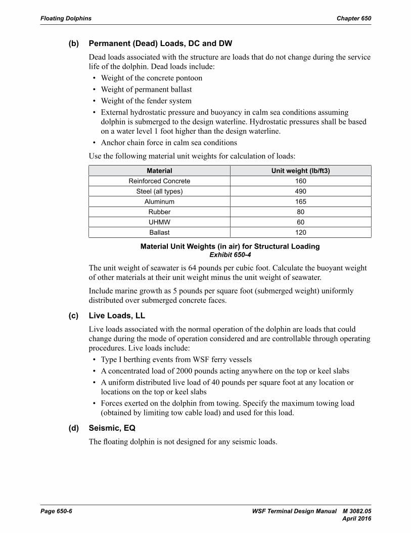
(b) Permanent (Dead) Loads, DC and DWDead loads associated with the structure are loads that do not change during the service life of the dolphin. Dead loads include:• Weight of the concrete pontoon• Weight of permanent ballast• Weight of the fender system• External hydrostatic pressure and buoyancy in calm sea conditions assuming
dolphin is submerged to the design waterline. Hydrostatic pressures shall be based on a water level 1 foot higher than the design waterline.
• Anchor chain force in calm sea conditions
Use the following material unit weights for calculation of loads:
Material Unit weight (lb/ft3)Reinforced Concrete 160
Steel (all types) 490Aluminum 165
Rubber 80UHMW 60Ballast 120
Material Unit Weights (in air) for Structural LoadingExhibit 650-4
The unit weight of seawater is 64 pounds per cubic foot. Calculate the buoyant weight of other materials at their unit weight minus the unit weight of seawater.
Include marine growth as 5 pounds per square foot (submerged weight) uniformly distributed over submerged concrete faces.
(c) Live Loads, LLLive loads associated with the normal operation of the dolphin are loads that could change during the mode of operation considered and are controllable through operating procedures. Live loads include:• Type I berthing events from WSF ferry vessels• A concentrated load of 2000 pounds acting anywhere on the top or keel slabs• A uniform distributed live load of 40 pounds per square foot at any location or
locations on the top or keel slabs• Forces exerted on the dolphin from towing. Specify the maximum towing load
(obtained by limiting tow cable load) and used for this load.
(d) Seismic, EQThe floating dolphin is not designed for any seismic loads.
Chapter 650 Floating Dolphins
WSF Terminal Design Manual M 3082.05 Page 650-7 April 2016
(e) Water Load, WA and BYWater loads include the buoyant uplift force as well as horizontal fluid pressure. This includes the current generated by a maximum propeller wash velocity of 19 feet per second. This does not include loads due to waves.
When determining hydrostatic pressures, assume a water level 1.0 foot above design freeboard.
(f) Wind and Wave Loads, WS and WVIncludes both wind and wave loads on the structure. Design wind speed is site-specific.
(g) Vessel Collision Load, CVConsider vessel collisions beyond the Type I berthing event.
(h) Temperature and Shrinkage, TU and SHUse a load factor of 1.20 for temperature and shrinkage when deformations are being calculated. For all other effects use the load factor from Exhibit 650-5.
(i) Locked-in Force Effects, ELAccumulated locked-in force effects resulting from construction process, including the secondary forces from post-tensioning.
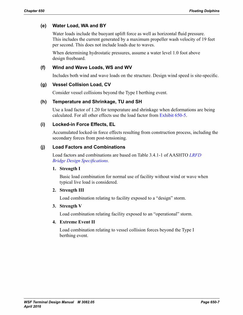
(j) Load Factors and CombinationsLoad factors and combinations are based on Table 3.4.1-1 of AASHTO LRFD Bridge Design Specifications.
1. Strength I
Basic load combination for normal use of facility without wind or wave when typical live load is considered.
2. Strength III
Load combination relating to facility exposed to a “design” storm.
3. Strength V
Load combination relating facility exposed to an “operational” storm.
4. Extreme Event II
Load combination relating to vessel collision forces beyond the Type I berthing event.
Floating Dolphins Chapter 650
Page 650-8 WSF Terminal Design Manual M 3082.05 April 2016
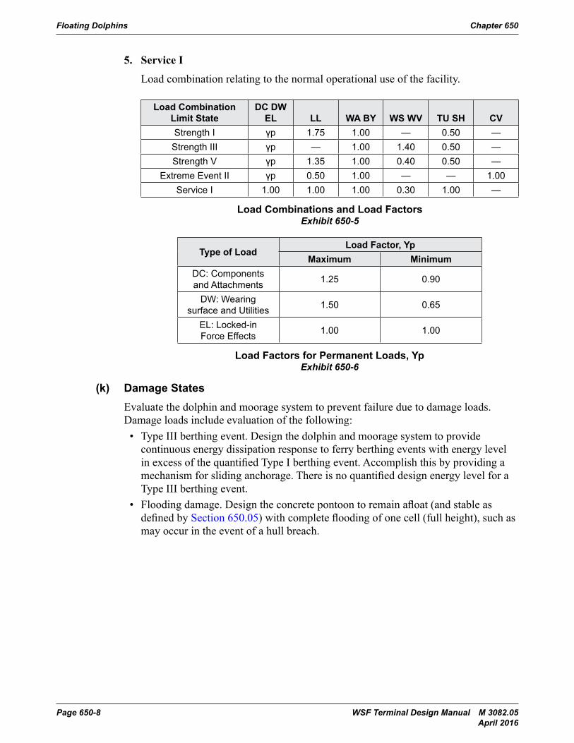
5. Service I
Load combination relating to the normal operational use of the facility.
Load Combination Limit State
DC DW EL LL WA BY WS WV TU SH CV
Strength I γp 1.75 1.00 — 0.50 —Strength III γp — 1.00 1.40 0.50 —Strength V γp 1.35 1.00 0.40 0.50 —
Extreme Event II γp 0.50 1.00 — — 1.00Service I 1.00 1.00 1.00 0.30 1.00 —
Load Combinations and Load FactorsExhibit 650-5
Type of LoadLoad Factor, Yp
Maximum MinimumDC: Components and Attachments 1.25 0.90
DW: Wearing surface and Utilities 1.50 0.65
EL: Locked-in Force Effects 1.00 1.00
Load Factors for Permanent Loads, YpExhibit 650-6
(k) Damage StatesEvaluate the dolphin and moorage system to prevent failure due to damage loads. Damage loads include evaluation of the following:• Type III berthing event. Design the dolphin and moorage system to provide
continuous energy dissipation response to ferry berthing events with energy level in excess of the quantified Type I berthing event. Accomplish this by providing a mechanism for sliding anchorage. There is no quantified design energy level for a Type III berthing event.
• Flooding damage. Design the concrete pontoon to remain afloat (and stable as defined by Section 650.05) with complete flooding of one cell (full height), such as may occur in the event of a hull breach.
Chapter 650 Floating Dolphins
WSF Terminal Design Manual M 3082.05 Page 650-9 April 2016
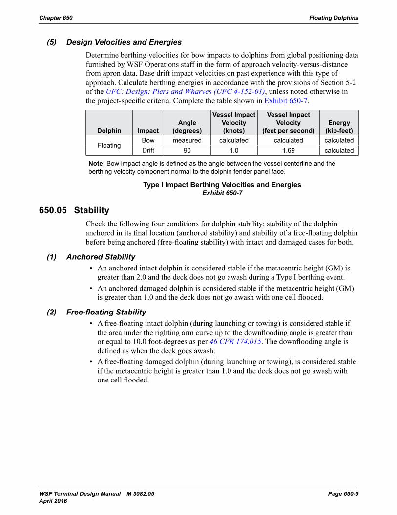
(5) Design Velocities and EnergiesDetermine berthing velocities for bow impacts to dolphins from global positioning data furnished by WSF Operations staff in the form of approach velocity-versus-distance from apron data. Base drift impact velocities on past experience with this type of approach. Calculate berthing energies in accordance with the provisions of Section 5-2 of the UFC: Design: Piers and Wharves (UFC 4-152-01), unless noted otherwise in the project-specific criteria. Complete the table shown in Exhibit 650-7.
Dolphin ImpactAngle
(degrees)
Vessel Impact Velocity (knots)
Vessel Impact Velocity
(feet per second)Energy
(kip-feet)
FloatingBowDrift
measured calculated calculated calculated90 1.0 1.69 calculated
Note: Bow impact angle is defined as the angle between the vessel centerline and the berthing velocity component normal to the dolphin fender panel face.
Type I Impact Berthing Velocities and EnergiesExhibit 650-7
650.05 StabilityCheck the following four conditions for dolphin stability: stability of the dolphin anchored in its final location (anchored stability) and stability of a free-floating dolphin before being anchored (free-floating stability) with intact and damaged cases for both.
(1) Anchored Stability• An anchored intact dolphin is considered stable if the metacentric height (GM) is
greater than 2.0 and the deck does not go awash during a Type I berthing event.• An anchored damaged dolphin is considered stable if the metacentric height (GM)
is greater than 1.0 and the deck does not go awash with one cell flooded.
(2) Free-floatingStability• A free-floating intact dolphin (during launching or towing) is considered stable if
the area under the righting arm curve up to the downflooding angle is greater than or equal to 10.0 foot-degrees as per 46 CFR 174.015. The downflooding angle is defined as when the deck goes awash.
• A free-floating damaged dolphin (during launching or towing), is considered stable if the metacentric height is greater than 1.0 and the deck does not go awash with one cell flooded.
Floating Dolphins Chapter 650
Page 650-10 WSF Terminal Design Manual M 3082.05 April 2016
650.06 Anchor SystemAnalyze and design the anchor system using the OPTIMOOR computer program or other suitable mooring software at multiple tide levels using the controlling design vessel parameters and the design impact energy parameters. Use the following criteria to determine the capacity of the anchor system:• The anchors have a factor of safety of 1.5. The applied anchor force
(horizontal and uplift) is less than the ultimate resistance provided by the Geotechnical Recommendations.
• The tension in the mooring chain reaches 40 percent of its breaking capacity (this correlates to a factor of safety of 2.5 and is typical of the industry).
650.07 Fender SystemDesign the fender system to meet the following performance requirements (per fender panel):• Energy Absorbed, minimum = 150 kip-feet• Reaction at Rated Energy = 150 kips (± 10 percent)• Deflection at Rated Energy = 50 percent (± 10 percent)
650.08 Towing SystemMaximum towing load is the minimum of manufacturer’s stated cleat capacity or the capacity of the cleat connection to the floating dolphin.
650.09 Miscellaneous Design(1) Vessel Tie-up and Navigational Aids
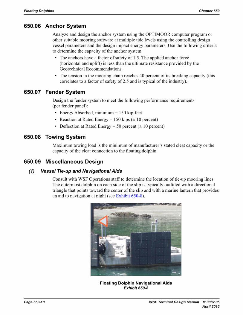
Consult with WSF Operations staff to determine the location of tie-up mooring lines. The outermost dolphin on each side of the slip is typically outfitted with a directional triangle that points toward the center of the slip and with a marine lantern that provides an aid to navigation at night (see Exhibit 650-8).
Floating Dolphins Chapter 650
• The anchors have a factor of safety of 1.5. The applied anchor force (horizontal and uplift) is less than the ultimate resistance provided by the Geotechnical Recommendations.
• The tension in the mooring chain reaches 40% of its breaking capacity (this correlates to a factor of safety of 2.5 and is typical of the industry).
650.07 Fender SystemDesign the fender system to meet the following performance requirements (per fender panel):
• Energy Absorbed, minimum = 150 kip-feet
• Reaction at Rated Energy = 150 kips (± 10%)
• Deflection at Rated Energy = 50 percent (± 10%)
650.08 Towing SystemMaximum towing load is the minimum of manufacturer’s stated cleat capacity or the capacity of the cleat connection to the floating dolphin.
650.09 Miscellaneous Design
(1) Vessel Tie-up and Navigational Aids
Consult with WSF Operations staff to determine the location of tie-up mooring lines. The outermost dolphin on each side of the slip is typically outfitted with a directional triangle that points toward the center of the slip and with a marine lantern that provides an aid to navigation at night (see Exhibit 650-8).
Floating Dolphin Navigational AidsExhibit 650-8
(2) Hatches
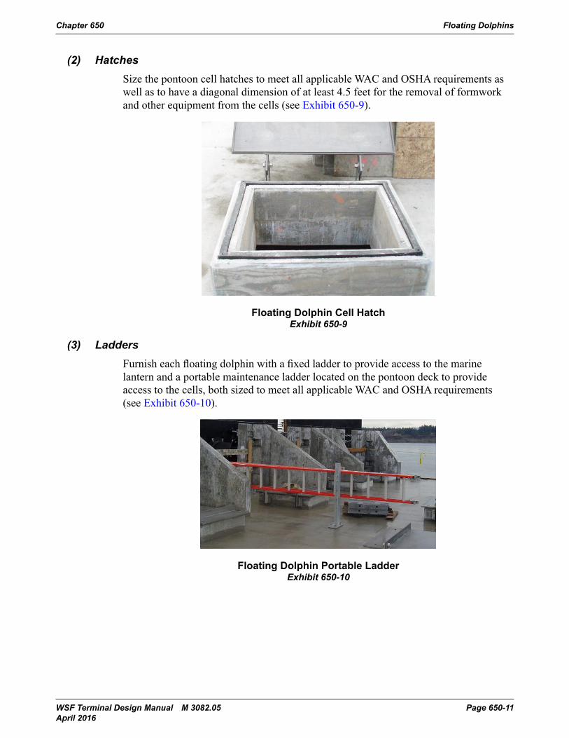
Size the pontoon cell hatches to meet all applicable WAC and OSHA requirements as well as tohave a diagonal dimension of at least 4.5 feet for the removal of formwork and other equipment from the cells (see Exhibit 650-9).
Page 650-10 Terminal Design Manual M 3082January 2014
Floating Dolphin Navigational AidsExhibit 650-8
Chapter 650 Floating Dolphins
WSF Terminal Design Manual M 3082.05 Page 650-11 April 2016
(2) HatchesSize the pontoon cell hatches to meet all applicable WAC and OSHA requirements as well as to have a diagonal dimension of at least 4.5 feet for the removal of formwork and other equipment from the cells (see Exhibit 650-9).Chapter 650 Floating Dolphins
Floating Dolphin Cell HatchExhibit 650-9
(3) Ladders
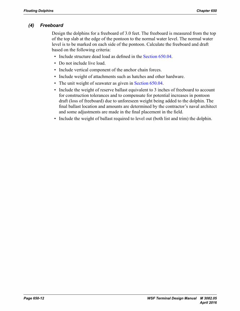
Furnish each floating dolphin with a fixed ladder to provide access to the marine lantern and aportable maintenance ladder located on the pontoon deck to provide access to the cells, both sized to meet all applicable WAC and OSHA requirements (see Exhibit 650-10).
Floating Dolphin Portable LadderExhibit 650-10
(4) Freeboard
Design the dolphins for a freeboard of 3.0 feet. The freeboard is measured from the top of the top slab at the edge of the pontoon to the normal water level. The normal water level is to be marked on each side of the pontoon. Calculate the freeboard and draft based on the following criteria:
• Include structure dead load as defined in the Section 650.04.
• Do not include live load.
• Include vertical component of the anchor chain forces.
• Include weight of attachments such as hatches and other hardware.
Terminal Design Manual M 3082 Page 650-11January 2014
Floating Dolphin Cell HatchExhibit 650-9
(3) LaddersFurnish each floating dolphin with a fixed ladder to provide access to the marine lantern and a portable maintenance ladder located on the pontoon deck to provide access to the cells, both sized to meet all applicable WAC and OSHA requirements (see Exhibit 650-10).
Chapter 650 Floating Dolphins
Floating Dolphin Cell HatchExhibit 650-9
(3) Ladders
Furnish each floating dolphin with a fixed ladder to provide access to the marine lantern and aportable maintenance ladder located on the pontoon deck to provide access to the cells, both sized to meet all applicable WAC and OSHA requirements (see Exhibit 650-10).
Floating Dolphin Portable LadderExhibit 650-10
(4) Freeboard
Design the dolphins for a freeboard of 3.0 feet. The freeboard is measured from the top of the top slab at the edge of the pontoon to the normal water level. The normal water level is to be marked on each side of the pontoon. Calculate the freeboard and draft based on the following criteria:
• Include structure dead load as defined in the Section 650.04.
• Do not include live load.
• Include vertical component of the anchor chain forces.
• Include weight of attachments such as hatches and other hardware.
Terminal Design Manual M 3082 Page 650-11January 2014
Floating Dolphin Portable LadderExhibit 650-10
Floating Dolphins Chapter 650
Page 650-12 WSF Terminal Design Manual M 3082.05 April 2016
(4) FreeboardDesign the dolphins for a freeboard of 3.0 feet. The freeboard is measured from the top of the top slab at the edge of the pontoon to the normal water level. The normal water level is to be marked on each side of the pontoon. Calculate the freeboard and draft based on the following criteria:• Include structure dead load as defined in the Section 650.04.• Do not include live load.• Include vertical component of the anchor chain forces.• Include weight of attachments such as hatches and other hardware.• The unit weight of seawater as given in Section 650.04.• Include the weight of reserve ballast equivalent to 3 inches of freeboard to account
for construction tolerances and to compensate for potential increases in pontoon draft (loss of freeboard) due to unforeseen weight being added to the dolphin. The final ballast location and amounts are determined by the contractor’s naval architect and some adjustments are made in the final placement in the field.
• Include the weight of ballast required to level out (both list and trim) the dolphin.