Embed Size (px)
Citation preview
Chapter 8—Construction Details provides technical information concerning the design and installation ofconstruction details for quality SPF roof systems. This introduction is intended to supplement the special notes on the individual construction details.
Construction details are provided for the following SPFroof system types:
• SPF roof systems with protective coatings
• SPF re-cover roof systems with protective coatings
Construction details applicable to SPF roof systems withprotective coatings are denoted as “SPF-” followed by anumber and possibly a letter (e.g., SPF-2, SPF-2A).
Construction details applicable to SPF re-cover roof sys-tems with protective coatings are denoted as “SPF(R)-”followed by a number and possibly a letter (e.g., SPF(R)-1, SPF(R)-1A).
The letter designation after an SPF roof system type des-ignation and number identifies NRCA’s order of preferencefor addressing a specific detail condition. For example,
Construction Detail SPF-3—Base Flashing With Coun-terflashing depicts NRCA’s preferred method of address-ing a base flashing with counterflashing detail for SPFroof systems with protective coatings. Construction De-tail SPF-3A—Base Flashing depicts an alternative detailNRCA also considers acceptable based on any limitationsdescribed on the alternative construction details.
8.1 Information Applicable to All Construction Details
The construction details in this manual provide a genericconcept for each specific detail type shown. NRCA’s construction details likely will require modification tomeet a project’s specific requirements. It is a designer’s responsibility to adapt the construction details to a project’s requirements.
NRCA makes these construction details available in acomputer-aided design (CAD) format to allow users tocustomize these construction details using their own CADsoftware applications to suit their specific project needs.
The information contained in this manual is intended
CHAPTER 8CONSTRUCTION DETAILS
The NRCA Roofing Manual: Metal Panel and SPF Roof Systems—2012
333The NRCA Roofing Manual: Metal Panel and SPF Roof Systems—2012SPF Roof Systems | Chapter 8—Construction Details
primarily to address construction details applicable tonew construction. When considering reroofing projects,the Reroofing Manual section of The NRCA RoofingManual: Architectural Metal Flashing, CondensationControl and Reroofing should be consulted regarding thedecision to re-cover or remove existing roof systems andfor general information applicable to reroofing low- andsteep-slope roof systems. Once this decision is made,most information contained within this chapter can alsoapply to reroofing.
NRCA suggests this chapter be used in the design of roofsystems only after a number of criteria have been carefullyconsidered, including:
• Climate and geographic location
• A building’s intended use and design life expectancy
• Exterior and interior temperature and humidityconditions
• Code requirements
• Type of roof deck
• Slope and drainage
• A roof ’s configuration
• Building movement
• Fire, wind and impact resistance
• Type and amount of insulation needed
• Need for ventilation
• Maintenance, repair and reroofing
• Compatibility with adjacent components, in-cluding potential material discharge onto a roof
• Construction sequencing
• Worker safety
• Potential building additions
• Odors, noise and dust generated by certain system application methods
• Rooftop traffic
• Reflectivity or emissivity
These criteria play important roles in the success or fail-ure of every roof assembly and must be considered by a
designer to determine the appropriate components of aroof assembly, applicable specifications and constructiondetails to be used.
In addition, NRCA recommends designers consider thefollowing factors for SPF roof systems.
Other Components: Components that may be pro-vided or installed by other trades that are integrated intoroof systems can be critical to the weathertight integrity ofcompleted roof systems. These components may include:
• Metal counterflashings at curbs and other penetrations
• Lead flashings, drains and plumbing vent stacks
• Drain heads, clamps and strainers
• Sheet-metal vents
• Sheet-metal pitch pans
• Through-wall flashings
• Skylight components and flashings
• Smoke hatch components and flashings
• Expansion joints and related components
• Wood blocking and attachment
• Pipe or conduit supports
• Crickets and saddles
• Siding or cladding
• Chimney caps
• Wall cladding
• Permanent safety anchors or guardrails
• Microwave or satellite dish components
• Lightning protection arresters and cables
• Photovoltaic systems
Definition of responsibility for the above componentsshould be determined prior to job initiation.
Roof Assembly Components—Deck, Insulation and SPF: In all the construction details, unless otherwise noted, the primary compo-nents of each construction detail are illustrated as generic components.
334 The NRCA Roofing Manual: Metal Panel and SPF Roof Systems—2012SPF Roof Systems | Chapter 8—Construction Details
335The NRCA Roofing Manual: Metal Panel and SPF Roof Systems—2012SPF Roof Systems | Chapter 8—Construction Details
Wood Nailers and Blocking: Many of the con-struction details illustrated in this manual depict woodnailers and blocking at roof edges and other points ofroof termination. Wood nailers must be adequately fas-tened to the substrate below to resist uplift loads. This especially is true at parapet walls and copings and roofedges where edge-metal shapes are fastened to woodblocking.
Among other advantages, the nailers provide protection forthe edges of rigid board insulation and provide a substratefor anchoring flashing materials. Wood nailers should bea minimum of 2 x 6 nominal-dimension lumber.
To provide an adequate base, nailers should be securelyattached to a roof deck, wall and/or structural framing. In the design of specific details for a project, a designershould describe and clearly indicate the manner in whichwood nailers and/or blocking should be incorporated intoconstruction details. A designer should specify the meansof attachment, as well as the fastening schedule for allwood nailers and blocking.
Preservative-treated Wood: Preservative-treatedwood available for consumer use no longer is treated withchromate copper arsenate (CCA). Some commercial usesof CCA are still available. The new treatment processesuse alkaline copper quat (ACQ), copper azole (CBA),sodium borates (SBX), ammoniocal copper zinc arsenate(ACZA) or variations of these compounds. Most treat-ments except SBX are more corrosive than CCA and re-quire fasteners, anchors and connectors of specific com-position to resist corrosion.
NRCA suggests the following guidelines when encounter-ing the current generation of treated wood:
• Carbon steel, aluminum and electroplated gal-vanized steel fasteners and connectors shouldnot be used in contact with treated wood. Hotdipped galvanized fasteners complying withASTM A153, “Standard Specification for ZincCoating (Hot-Dip) on Iron and Steel Hard-ware,” and connectors complying with ASTMA653, “Standard Specification for Steel Sheet,Zinc-coated (Galvanized) or Zinc-Iron Alloy-Coated (Galvannealed) by the Hot-Dip Process,”Class G185, generally are acceptable. Type 304 orType 316 stainless-steel fasteners and connectors
are recommended for maximum corrosion resistance.
• Fasteners with proprietary anti-corrosion coat-ings may be acceptable for use with treated wood.
When the use of such proprietary coated fasteners andconnectors is being considered, fastener manufacturersshould be consulted for specific information regard-ing the performance of their products in treated woodand any precautions or special instructions that may be applicable.
• Aluminum fasteners, flashings and accessoryproducts should not be used in direct contactwith any treated wood. ACQ-treated wood isnot compatible with aluminum.
• Uncoated metal and painted metal flashings andaccessories except for 300-series stainless steelshould not be used in direct contact with treatedwood. Metal products except stainless steel maybe used if separated from treated wood by aspacer or barrier, such as a single-ply membraneor self-adhering polymer-modified bitumenmembrane.
• SPF will not bond well to treated wood andmay need primers or mechanical means to ensure adhesion.
NRCA is of the opinion the corrosion-related concernsregarding the use of the current generation of treatedwood possibly outweigh the benefits that treated woodprovides as a component in roof assemblies. In many in-stances, the use of nontreated, construction-grade wood issuitable for use in roof assemblies as blocking or nailersprovided reasonable measures are taken to ensure thenontreated wood remains reasonably dry when in service.
Where a specific construction detail provides for a sec-ondary means of waterproofing, NRCA now considersthe use of nontreated, construction-grade wood to be anacceptable substitute for treated wood.
Job-site-fabricated Components: A majority ofthe construction details illustrated in this manual depictjob-site-fabricated construction. Many roof system manu-facturers offer prefabricated flashing components or haveguidelines that permit the use of materials other thanthose indicated in these details. Flashing materials may
vary greatly; individual manufacturer’s requirements shouldbe examined and evaluated for construction compatibility.
Penetrations and Clearance: Roof drains, penetrationpockets and vertical sides of curbs often have particularinstallation or attachment requirements, which follow:
• Interior roof drain bowls and under-deck clampstypically are furnished and installed by others.Clamping rings and dome strainers generally arefurnished by others and installed by a roofingcontractor.
• Prefabricated flashing, metal sleeves and curbswith premolded pipe flashings are preferred forsealing pipes or irregularly shaped support legs.Penetration pockets or pitch pans are acceptableas a last alternative. Pourable sealer is the recom-mended top fill material for penetration pockets.
• Vertical wood curb nailers may be secured to astructural member or the roof deck using addi-tional wood blocking, metal angle supports, or a
combination of wood and metal. Curbs mayconsist of prefabricated (insulated where appro-priate) metal curbs and, when securing flashingis necessary, should have nailers at the top edge.
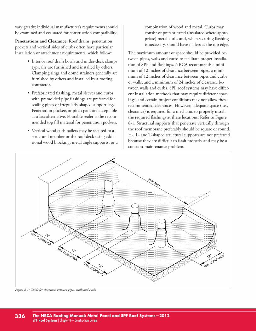
The maximum amount of space should be provided be-tween pipes, walls and curbs to facilitate proper installa-tion of SPF and flashings. NRCA recommends a mini-mum of 12 inches of clearance between pipes, a mini-mum of 12 inches of clearance between pipes and curbsor walls, and a minimum of 24 inches of clearance be-tween walls and curbs. SPF roof systems may have differ-ent installation methods that may require different spac-ings, and certain project conditions may not allow theserecommended clearances. However, adequate space (i.e.,clearance) is required for a mechanic to properly installthe required flashings at these locations. Refer to Figure8-1. Structural supports that penetrate vertically throughthe roof membrane preferably should be square or round.H-, L- and T-shaped structural supports are not preferredbecause they are difficult to flash properly and may be aconstant maintenance problem.
336 The NRCA Roofing Manual: Metal Panel and SPF Roof Systems—2012SPF Roof Systems | Chapter 8—Construction Details
Figure 8-1: Guide for clearances between pipes, walls and curbs
Fastener Spacing: Fastener spacing for gasketed fas-teners depicted in the construction details generally is be-tween 8 inches and 24 inches. Fastener spacings providedin the details are nominal dimensions.
Metal Flashing Components: Because metalshave thermal expansion and contraction characteristicsthat differ from most other roof covering materials, it isadvisable to isolate metal flashings from the primary roofcovering and flashing when possible. NRCA suggestsavoiding, where possible, flashing details that requirerigid metal flanges to be embedded or sandwiched intoSPF coatings.
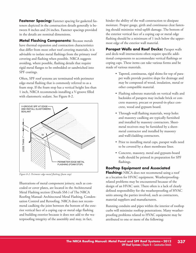
Often, SPF roof systems are terminated with perimeteredge-metal flashing that is commonly referred to as afoam stop. If the foam stop has a vertical height less than1 inch, NRCA recommends installing a V-groove filledwith elastomeric sealant. See Figure 8-2.
Illustrations of metal component joinery, such as con-cealed or cover plates, are located in the ArchitecturalMetal Flashing section (Details SM-) of The NRCARoofing Manual: Architectural Metal Flashing, Conden-sation Control and Reroofing. NRCA does not recom-mend caulking the joint between the bottom of the exte-rior vertical face of a coping cap or metal edge flashingand building exterior because it does not add to the wa-terproofing integrity of the assembly and may, in fact,
hinder the ability of the wall construction to dissipatemoisture. Proper gauge, girth and continuous cleat fasten-ing should minimize wind-uplift damage. The bottom ofthe exterior vertical face of a coping cap or metal edgeflashing should be a minimum of 1 inch below the upper-most edge of the exterior wall material.
Parapet Walls and Roof Decks: Parapet wallsand deck-wall intersections often require specific addi-tional components to accommodate vertical flashings orcoping caps. These items can take various forms and bemade of various materials.
• Tapered, continuous, rigid shims for top of para-pet walls provide positive slope for drainage andmay be composed of wood, insulation, metal orother compatible material.
• Flashing substrate materials on vertical walls andbacksides of parapets may include brick or con-crete masonry, precast or poured-in-place con-crete, wood and gypsum board.
• Through-wall flashing materials, weep holes and masonry caulking are typically furnishedand installed by masonry contractors. Sheet-metal receivers may be furnished by a sheet-metal contractor and installed by masonry and wall/cladding contractors.
• Prior to installing metal caps, parapet walls needto be covered by a sheet membrane liner.
• Concrete, masonry, metal and gypsum-boardwalls should be primed in preparation for SPFflashings.
Rooftop Equipment and Associated Flashing: NRCA does not recommend using a roof as a location for HVAC equipment. Weatherproofing-related problems may be encountered because of the design of an HVAC unit. There often is a lack of clearlydefined responsibility for the weatherproofing of HVACunits among the parties involved, such as contractors,material suppliers and manufacturers.
Running conduits and pipes within the interior of rooftopcurbs will minimize rooftop penetrations. Many weather-proofing problems related to HVAC equipment may beattributed to one or more of the following:
337The NRCA Roofing Manual: Metal Panel and SPF Roof Systems—2012SPF Roof Systems | Chapter 8—Construction Details
PERIMETER EDGE METALFLASHING (FOAM STOP)
V-GROOVE SPF AT EDGEAND INSTALL ELASTOMERICSEALANT
Figure 8-2: Perimeter edge-metal flashing (foam stop)
• Improper design of the equipment’s exteriorshell or housing. This may allow water to enterthe building directly through the unit.
• Improper design or penetration of condensatepans or drainage lines. This may allow water toenter the building below the HVAC equipment.
• Improper design of pre-manufactured HVACequipment curbs. There are often no means toproperly terminate base flashings.
• Inadequate design of the structural framing orroof deck intended to support the weight ofHVAC units. This may result in excessive roofdeflection and subsequent ponding water.
• Improper flashing of the penetration(s), such as pipes, conduits and drain lines, that extendthrough the roof to service the HVAC equipment.
• Lack of service walkways to and around mechan-ical equipment for rooftop traffic.
Expansion Joints: The expansion joints depictedgenerally provide movement capability in longitudinaland transverse directions and must be designed to accom-modate the amount of expected movement. It is the de-signer’s responsibility to determine the amount and direc-tion of expected movement at expansion joints. The ex-pansion joints depicted generally will not accommodateseismic movement. Where seismic movement is expected,alternative details likely are needed.
Skylights: Skylights incorporated into SPF roof sys-tems and structural metal panel roof assemblies should beinstalled on curbs so they are out of the drainage plane—that is, above the plane of roof panels. Skylight framesshould overlap the curb a minimum of 3 inches to act as counterflashing, or separate counterflashing should be installed.
Skylights require fall protection. NRCA suggests perma-nent internal or external fall-protection devices be includ-ed at all skylights.
Drains and Drain Sumps: NRCA recommendsthe use of cast-iron drain bowls, clamping rings and strain-ers at internal drain locations. Cast iron is the only mate-rial that will meet building code requirements for drain
materials. Drain sumps are recommended at all internaldrain locations.
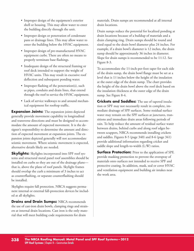
Drain sumps reduce the potential for localized ponding atdrain locations because of a buildup of materials and adrain clamping ring. Drain sumps should be round andsized equal to the drain bowl diameter plus 24 inches. Forexample, if a drain bowl’s diameter is 12 inches, the drainsump should be approximately 36 inches in diameter.Slope for drain sumps is recommended to be 11⁄2:12. SeeFigure 8-3.
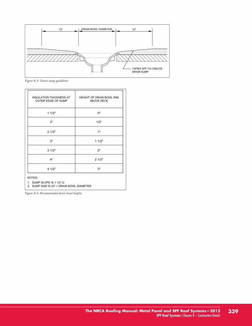
To accommodate the 11⁄2-inch-per-foot taper for each sideof the drain sump, the drain bowl flange must be set at alevel that is 11⁄2 inches below the height of the insulationat the outer edge of the drain sump. The chart providesthe height of the drain bowl above the roof deck based onthe insulation thickness at the outer edge of the drainsump. See Figure 8-4.
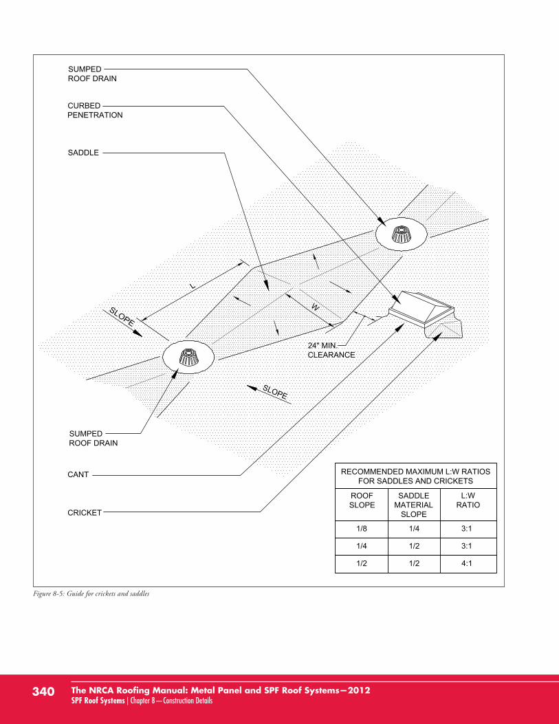
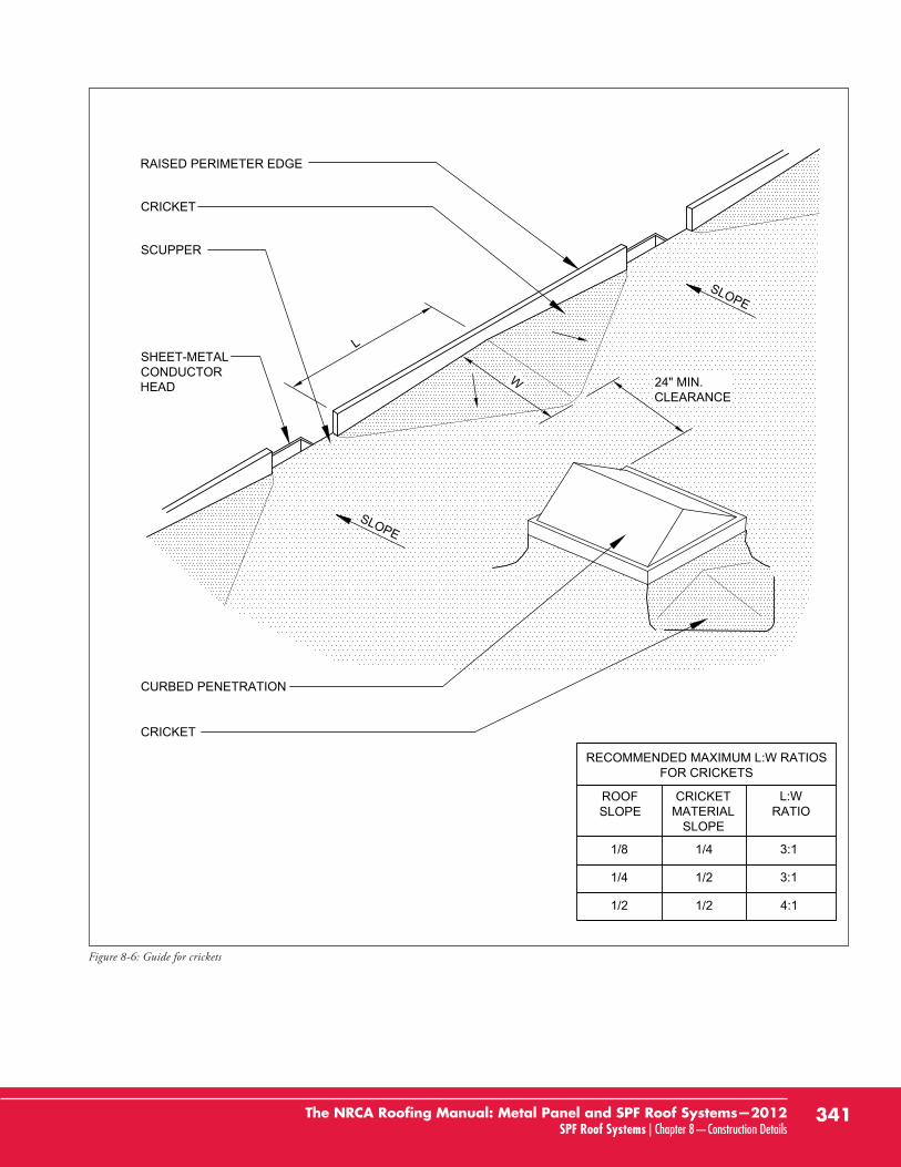
Crickets and Saddles: The use of tapered insula-tion or SPF may not necessarily result in complete, im-mediate drainage of SPF surfaces. Some residual surfacewater may remain on the SPF surfaces at junctures, tran-sitions and immediate drain areas following periods ofrain. To help reduce the amount of residual surface waterbetween drains, behind curbs and along roof edges be-tween scuppers, NRCA recommends installing cricketsand saddles. Figures 8-5 (page 340) and 8-6 (page 341)provide additional information regarding cricket and saddle slope and length-to-width (L:W) ratios.
Surface Protection: Prior to the application of SPF,provide masking protection to prevent the overspray ofmaterials onto surfaces not intended to receive SPF andprotective coating. In addition, mask, seal or cover HVACand ventilation equipment and building air intakes nearthe work area.
338 The NRCA Roofing Manual: Metal Panel and SPF Roof Systems—2012SPF Roof Systems | Chapter 8—Construction Details
339The NRCA Roofing Manual: Metal Panel and SPF Roof Systems—2012SPF Roof Systems | Chapter 8—Construction Details
Figure 8-3: Drain sump guidelines
Figure 8-4: Recommended drain bowl heights
340 The NRCA Roofing Manual: Metal Panel and SPF Roof Systems—2012SPF Roof Systems | Chapter 8—Construction Details
SLOPE
SUMPEDROOF DRAIN
CRICKET
CANT
CURBEDPENETRATION
SUMPEDROOF DRAIN
SADDLE
L
W
24" MIN.CLEARANCE
RECOMMENDED MAXIMUM L:W RATIOSFOR SADDLES AND CRICKETS
1/2
1/4
1/8
ROOFSLOPE
SADDLEMATERIAL
SLOPE
1/2
1/2
1/4 3:1
3:1
4:1
L:WRATIO
Figure 8-5: Guide for crickets and saddles
341The NRCA Roofing Manual: Metal Panel and SPF Roof Systems—2012SPF Roof Systems | Chapter 8—Construction Details
CRICKET
SLOPE
SHEET-METALCONDUCTORHEAD
SCUPPER
CURBED PENETRATION
RAISED PERIMETER EDGE
CRICKET
SLOPE
24" MIN.CLEARANCE
W
L
RECOMMENDED MAXIMUM L:W RATIOSFOR CRICKETS
1/8
1/4
1/2
ROOFSLOPE
CRICKETMATERIAL
SLOPE
1/4
1/2
1/2
3:1
3:1
4:1
L:WRATIO
Figure 8-6: Guide for crickets
8.2 Index of Drawings
SPF Construction Details
SPF-1 Base Flashing at Parapet Wall with Metal Coping ................................................................344
SPF-2 Perimeter Edge-metal Flashing With Sealant (Foam Stop)....................................................345
SPF-2A Perimeter Edge-metal Flashing (Foam Stop) ........................................................................346
SPF-3 Base Flashing With Counterflashing ....................................................................................347
SPF-3A Base Flashing........................................................................................................................348
SPF-4 Base Flashing at Roof-to-wall Expansion Joint......................................................................349
SPF-5 Base Flashing at Expansion Joint With Metal Cover ............................................................350
SPF-6 Base Flashing at Roof System Divider ..................................................................................351
SPF-7 Base Flashing at Equipment Support Curb ..........................................................................352
SPF-7A Base Flashing at Equipment Support Curb ..........................................................................353
SPF-8 Equipment Support Stand Leg ............................................................................................354
SPF-8A Equipment Support Stand Leg ............................................................................................355
SPF-9 Base Flashing at Prefabricated Metal Curb............................................................................356
SPF-10 Base Flashing at Wood Curb ................................................................................................357
SPF-11 Base Flashing at Structural Member Through Roof Deck ....................................................358
SPF-11A Base Flashing at Structural Member Through Roof Deck ....................................................359
SPF-12 Base Flashing at Sheet-metal Enclosure for Piping Through Roof Deck................................360
SPF-13 Base Flashing at Isolated Stack Flashing................................................................................361
SPF-14 Base Flashing at Stack Vent [Hot or Cold]............................................................................362
SPF-15 Pipe Penetration ..................................................................................................................363
SPF-16 Cable Penetration ................................................................................................................364
SPF-17 Lightning Protection Terminal ............................................................................................365
SPF-18 Roof Drain ..........................................................................................................................366
SPF-19 Through-wall Scupper..........................................................................................................367
SPF-20 Overflow Scupper ................................................................................................................368
SPF-21 Gutter With Perimeter Edge Metal ......................................................................................369
342 The NRCA Roofing Manual: Metal Panel and SPF Roof Systems—2012SPF Roof Systems | Chapter 8—Construction Details
SPF Re-cover Construction Details
SPF(R)-1 Base Flashing at Parapet Wall With New Metal Coping for SPF Re-cover ............................370
SPF(R)-1A Base Flashing at Parapet Wall With Existing Metal Coping and New Counterflashing for SPF Re-cover ..............................................................................371
SPF(R)-2 Perimeter Edge With Existing Embedded Edge Metal (Gravel Stop) for SPF Re-cover ........372
SPF(R)-3 Base Flashing With New Counterflashing for SPF Re-cover ................................................373
SPF(R)-3A Base Flashing for SPF Re-cover ............................................................................................374
SPF(R)-4 Base Flashing at Roof-to-wall Expansion Joint for SPF Re-cover ..........................................375
SPF(R)-5 Base Flashing at Expansion Joint With New Sheet-metal Cover for SPF Re-cover ................376
SPF(R)-6 Base Flashing at Equipment Support Curb With Existing Sheet-metal Cover and New Counterflashing for SPF Re-cover ............................................................377
SPF(R)-6A Base Flashing at Equipment Support Curb for SPF Re-cover................................................378
SPF(R)-7 Base Flashing at Equipment Support Stand and Rain Collar Penetration for SPF Re-cover ................................................................................................................379
SPF(R)-8 Base Flashing at Curb With Existing Sheet-metal Cover and New Counterflashingfor SPF Re-cover ................................................................................................................380
SPF(R)-9 Base Flashing at Isolated Stack Flashing for SPF Re-cover ....................................................381
SPF(R)-10 Plumbing Vent for SPF Re-cover..........................................................................................382
SPF(R)-11 Roof Drain for SPF Re-cover................................................................................................383
343The NRCA Roofing Manual: Metal Panel and SPF Roof Systems—2012SPF Roof Systems | Chapter 8—Construction Details
344 The NRCA Roofing Manual: Metal Panel and SPF Roof Systems—2012SPF Roof Systems | Chapter 8—Construction Details
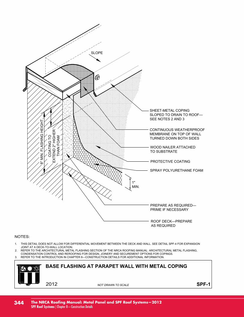
BASE FLASHING AT PARAPET WALL WITH METAL COPING
SPF-1
SHEET-METAL COPING
SEE NOTES 2 AND 3
CONTINUOUS WEATHERPROOFMEMBRANE ON TOP OF WALLTURNED DOWN BOTH SIDES
PROTECTIVE COATING
SPRAY POLYURETHANE FOAM
PRIME IF NECESSARY
AS REQUIRED
WOOD NAILER ATTACHEDTO SUBSTRATE
SLOPE
1"MIN.
1. THIS DETAIL DOES NOT ALLOW FOR DIFFERENTIAL MOVEMENT BETWEEN THE DECK AND WALL. SEE DETAIL SPF-4 FOR EXPANSIONJOINT AT A DECK-TO-WALL LOCATION.
2. REFER TO THE ARCHITECTURAL METAL FLASHING SECTION OF THE NRCA ROOFING MANUAL: ARCHITECTURAL METAL FLASHING,CONDENSATION CONTROL AND REROOFING FOR DESIGN, JOINERY AND SECUREMENT OPTIONS FOR COPINGS.
3.
8'' M
IN. F
LAS
HIN
G H
EIG
HT
CO
ATI
NG
TO
EX
TEN
D 2
" HIG
HE
RTH
AN
FO
AM
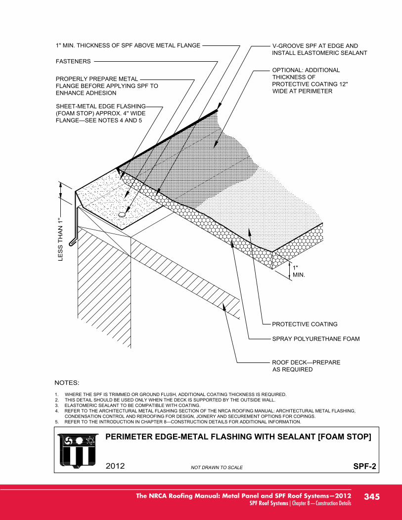
PERIMETER EDGE-METAL FLASHING WITH SEALANT [FOAM STOP]
SPF-2
SHEET-METAL EDGE FLASHING(FOAM STOP) APPROX. 4'' WIDE
PROPERLY PREPARE METALFLANGE BEFORE APPLYING SPF TOENHANCE ADHESION
FASTENERS
1'' MIN. THICKNESS OF SPF ABOVE METAL FLANGE
AS REQUIRED
SPRAY POLYURETHANE FOAM
PROTECTIVE COATING
OPTIONAL: ADDITIONALTHICKNESS OFPROTECTIVE COATING 12''WIDE AT PERIMETER
V-GROOVE SPF AT EDGE ANDINSTALL ELASTOMERIC SEALANT
1. WHERE THE SPF IS TRIMMED OR GROUND FLUSH, ADDITIONAL COATING THICKNESS IS REQUIRED.2. THIS DETAIL SHOULD BE USED ONLY WHEN THE DECK IS SUPPORTED BY THE OUTSIDE WALL.3. ELASTOMERIC SEALANT TO BE COMPATIBLE WITH COATING.4. REFER TO THE ARCHITECTURAL METAL FLASHING SECTION OF THE NRCA ROOFING MANUAL: ARCHITECTURAL METAL FLASHING,
CONDENSATION CONTROL AND REROOFING FOR DESIGN, JOINERY AND SECUREMENT OPTIONS FOR COPINGS.5.
1"MIN.
345The NRCA Roofing Manual: Metal Panel and SPF Roof Systems—2012SPF Roof Systems | Chapter 8—Construction Details
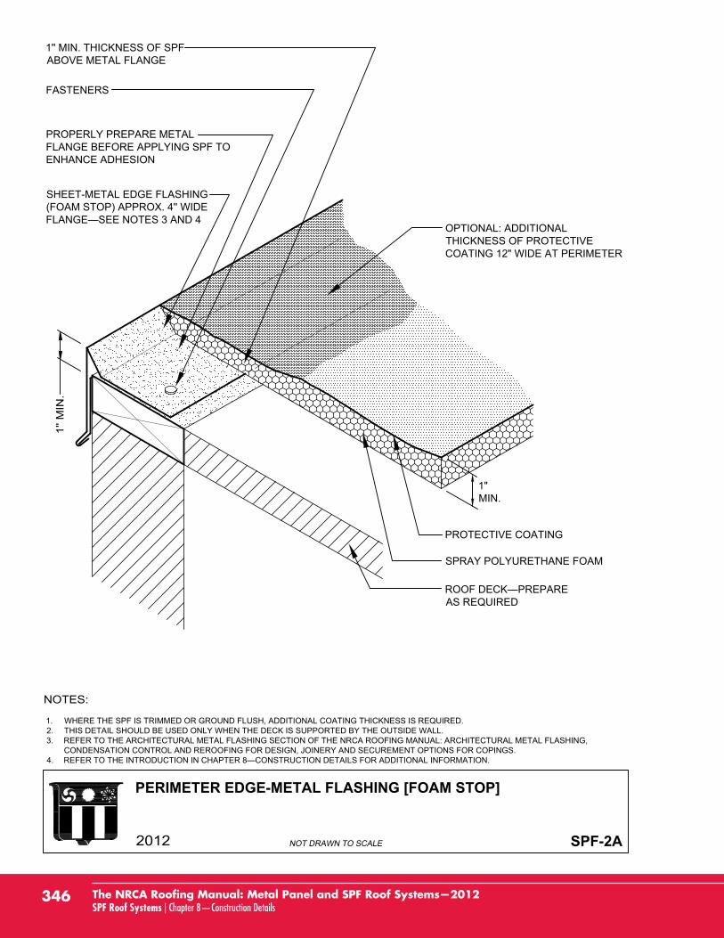
PERIMETER EDGE-METAL FLASHING [FOAM STOP]
SPF-2A
SHEET-METAL EDGE FLASHING(FOAM STOP) APPROX. 4'' WIDEFLANGE—SEE NOTES 3 AND 4
PROPERLY PREPARE METALFLANGE BEFORE APPLYING SPF TOENHANCE ADHESION
FASTENERS
1'' MIN. THICKNESS OF SPFABOVE METAL FLANGE
ROOF DECK—PREPAREAS REQUIRED
SPRAY POLYURETHANE FOAM
PROTECTIVE COATING
1. WHERE THE SPF IS TRIMMED OR GROUND FLUSH, ADDITIONAL COATING THICKNESS IS REQUIRED.2. THIS DETAIL SHOULD BE USED ONLY WHEN THE DECK IS SUPPORTED BY THE OUTSIDE WALL.3. REFER TO THE ARCHITECTURAL METAL FLASHING SECTION OF THE NRCA ROOFING MANUAL: ARCHITECTURAL METAL FLASHING,
CONDENSATION CONTROL AND REROOFING FOR DESIGN, JOINERY AND SECUREMENT OPTIONS FOR COPINGS.4. REFER TO THE INTRODUCTION IN CHAPTER 8—CONSTRUCTION DETAILS FOR ADDITIONAL INFORMATION.
1"MIN.
OPTIONAL: ADDITIONALTHICKNESS OF PROTECTIVECOATING 12" WIDE AT PERIMETER
346 The NRCA Roofing Manual: Metal Panel and SPF Roof Systems—2012SPF Roof Systems | Chapter 8—Construction Details
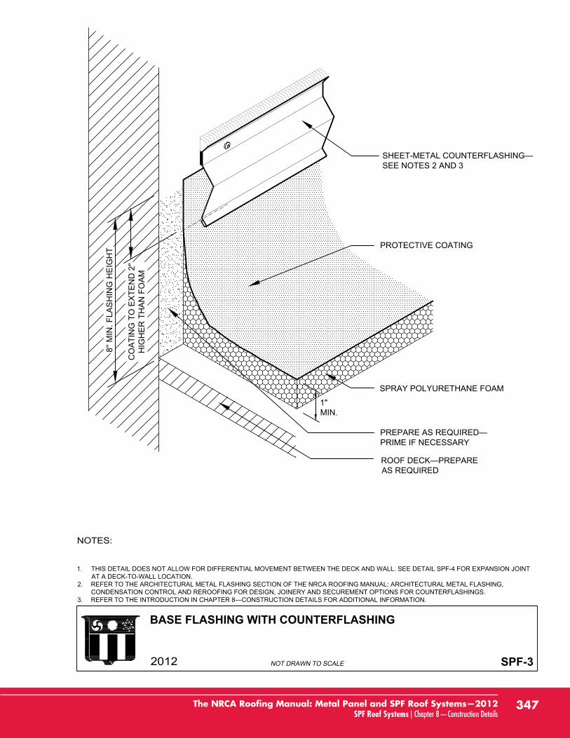
BASE FLASHING WITH COUNTERFLASHING
SPF-3
1. THIS DETAIL DOES NOT ALLOW FOR DIFFERENTIAL MOVEMENT BETWEEN THE DECK AND WALL. SEE DETAIL SPF-4 FOR EXPANSION JOINTAT A DECK-TO-WALL LOCATION.
2. REFER TO THE ARCHITECTURAL METAL FLASHING SECTION OF THE NRCA ROOFING MANUAL: ARCHITECTURAL METAL FLASHING,CONDENSATION CONTROL AND REROOFING FOR DESIGN, JOINERY AND SECUREMENT OPTIONS FOR COUNTERFLASHINGS.
3.
AS REQUIRED
PRIME IF NECESSARY
SPRAY POLYURETHANE FOAM
PROTECTIVE COATING
SEE NOTES 2 AND 3
1"MIN.
8'' M
IN. F
LAS
HIN
G H
EIG
HT
CO
ATI
NG
TO
EX
TEN
D 2
"H
IGH
ER
TH
AN
FO
AM
347The NRCA Roofing Manual: Metal Panel and SPF Roof Systems—2012SPF Roof Systems | Chapter 8—Construction Details
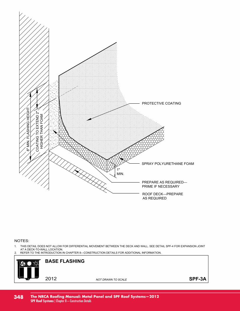
BASE FLASHING
SPF-3A
1. THIS DETAIL DOES NOT ALLOW FOR DIFFERENTIAL MOVEMENT BETWEEN THE DECK AND WALL. SEE DETAIL SPF-4 FOR EXPANSION JOINTAT A DECK-TO-WALL LOCATION.
2.
AS REQUIRED
PRIME IF NECESSARY
SPRAY POLYURETHANE FOAM
PROTECTIVE COATING
1"MIN.
8'' M
IN. F
LAS
HIN
G H
EIG
HT
CO
ATI
NG
TO
EX
TEN
D 2
"H
IGH
ER
TH
AN
FO
AM
348 The NRCA Roofing Manual: Metal Panel and SPF Roof Systems—2012SPF Roof Systems | Chapter 8—Construction Details
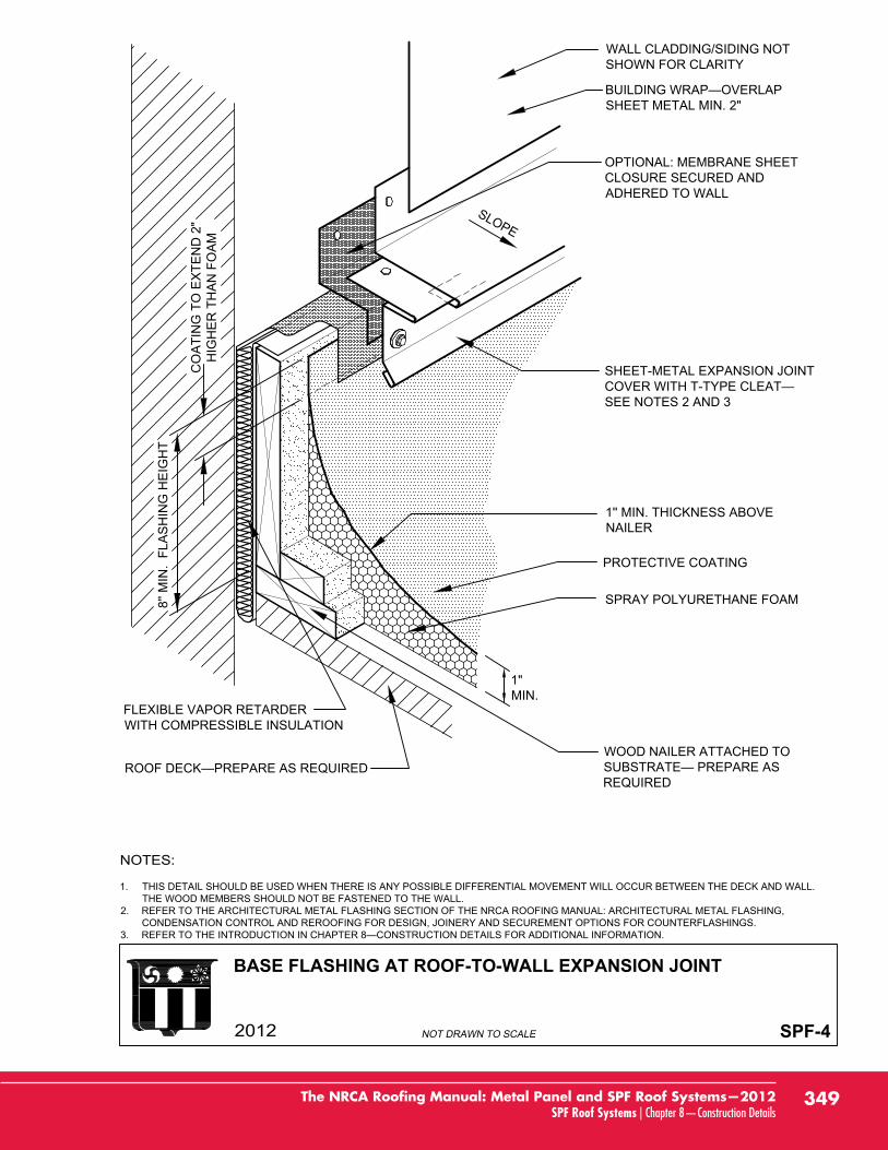
BASE FLASHING AT ROOF-TO-WALL EXPANSION JOINT
SPF-4
1. THIS DETAIL SHOULD BE USED WHEN THERE IS ANY POSSIBLE DIFFERENTIAL MOVEMENT WILL OCCUR BETWEEN THE DECK AND WALL.THE WOOD MEMBERS SHOULD NOT BE FASTENED TO THE WALL.
2. REFER TO THE ARCHITECTURAL METAL FLASHING SECTION OF THE NRCA ROOFING MANUAL: ARCHITECTURAL METAL FLASHING,CONDENSATION CONTROL AND REROOFING FOR DESIGN, JOINERY AND SECUREMENT OPTIONS FOR COUNTERFLASHINGS.
3.
SPRAY POLYURETHANE FOAM
WOOD NAILER ATTACHED TO
REQUIRED
PROTECTIVE COATING
1'' MIN. THICKNESS ABOVENAILER
FLEXIBLE VAPOR RETARDERWITH COMPRESSIBLE INSULATION
OPTIONAL: MEMBRANE SHEETCLOSURE SECURED ANDADHERED TO WALL
WALL CLADDING/SIDING NOTSHOWN FOR CLARITY
SHEET METAL MIN. 2"
SHEET-METAL EXPANSION JOINT
SEE NOTES 2 AND 3
SLOPE
1"MIN.
8'' M
IN.
FLA
SH
ING
HE
IGH
T
CO
ATI
NG
TO
EX
TEN
D 2
"H
IGH
ER
TH
AN
FO
AM
349The NRCA Roofing Manual: Metal Panel and SPF Roof Systems—2012SPF Roof Systems | Chapter 8—Construction Details
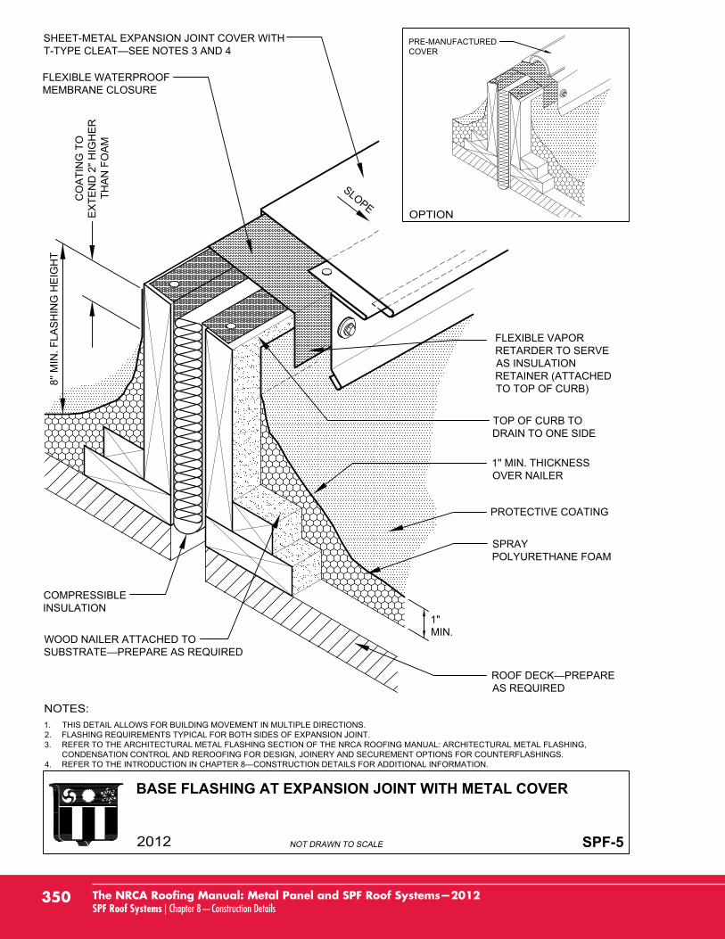
BASE FLASHING AT EXPANSION JOINT WITH METAL COVER
SPF-5
1. THIS DETAIL ALLOWS FOR BUILDING MOVEMENT IN MULTIPLE DIRECTIONS.2. FLASHING REQUIREMENTS TYPICAL FOR BOTH SIDES OF EXPANSION JOINT.3. REFER TO THE ARCHITECTURAL METAL FLASHING SECTION OF THE NRCA ROOFING MANUAL: ARCHITECTURAL METAL FLASHING,
CONDENSATION CONTROL AND REROOFING FOR DESIGN, JOINERY AND SECUREMENT OPTIONS FOR COUNTERFLASHINGS.4.
WOOD NAILER ATTACHED TO
COMPRESSIBLEINSULATION
FLEXIBLE VAPORRETARDER TO SERVEAS INSULATIONRETAINER (ATTACHEDTO TOP OF CURB)
FLEXIBLE WATERPROOFMEMBRANE CLOSURE
AS REQUIRED
SPRAYPOLYURETHANE FOAM
1'' MIN. THICKNESSOVER NAILER
PROTECTIVE COATING
TOP OF CURB TODRAIN TO ONE SIDE
8'' M
IN. F
LAS
HIN
G H
EIG
HT
CO
ATI
NG
TO
EX
TEN
D 2
" HIG
HE
RTH
AN
FO
AM
SHEET-METAL EXPANSION JOINT COVER WITH
SLOPE
PRE-MANUFACTUREDCOVER
1"MIN.
350 The NRCA Roofing Manual: Metal Panel and SPF Roof Systems—2012SPF Roof Systems | Chapter 8—Construction Details
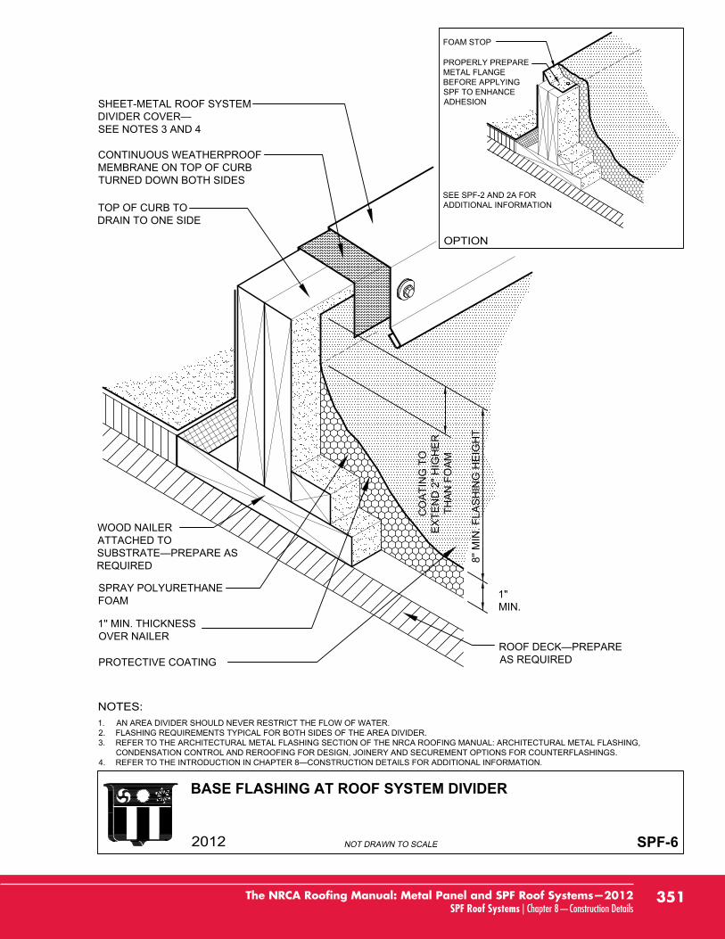
BASE FLASHING AT ROOF SYSTEM DIVIDER
SPF-6
1. AN AREA DIVIDER SHOULD NEVER RESTRICT THE FLOW OF WATER.2. FLASHING REQUIREMENTS TYPICAL FOR BOTH SIDES OF THE AREA DIVIDER.3. REFER TO THE ARCHITECTURAL METAL FLASHING SECTION OF THE NRCA ROOFING MANUAL: ARCHITECTURAL METAL FLASHING,
CONDENSATION CONTROL AND REROOFING FOR DESIGN, JOINERY AND SECUREMENT OPTIONS FOR COUNTERFLASHINGS.4.
WOOD NAILERATTACHED TO
REQUIRED
CONTINUOUS WEATHERPROOFMEMBRANE ON TOP OF CURBTURNED DOWN BOTH SIDES
SHEET-METAL ROOF SYSTEM
SEE NOTES 3 AND 4
AS REQUIRED
SPRAY POLYURETHANEFOAM
1'' MIN. THICKNESSOVER NAILER
PROTECTIVE COATING
TOP OF CURB TODRAIN TO ONE SIDE
FOAM STOP
PROPERLY PREPAREMETAL FLANGEBEFORE APPLYINGSPF TO ENHANCEADHESION
SEE SPF-2 AND 2A FORADDITIONAL INFORMATION
1"MIN.
8'' M
IN. F
LAS
HIN
G H
EIG
HT
CO
ATI
NG
TO
EX
TEN
D 2
" HIG
HE
RTH
AN
FO
AM
351The NRCA Roofing Manual: Metal Panel and SPF Roof Systems—2012SPF Roof Systems | Chapter 8—Construction Details
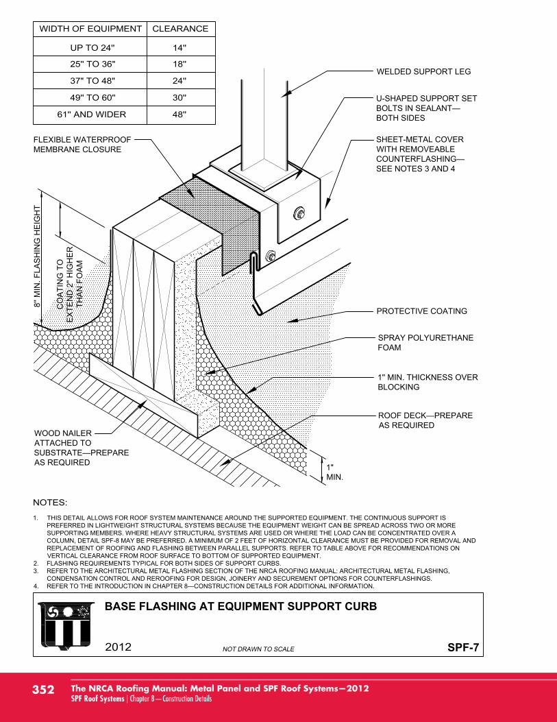
BASE FLASHING AT EQUIPMENT SUPPORT CURB
SPF-7
1. THIS DETAIL ALLOWS FOR ROOF SYSTEM MAINTENANCE AROUND THE SUPPORTED EQUIPMENT. THE CONTINUOUS SUPPORT ISPREFERRED IN LIGHTWEIGHT STRUCTURAL SYSTEMS BECAUSE THE EQUIPMENT WEIGHT CAN BE SPREAD ACROSS TWO OR MORESUPPORTING MEMBERS. WHERE HEAVY STRUCTURAL SYSTEMS ARE USED OR WHERE THE LOAD CAN BE CONCENTRATED OVER ACOLUMN, DETAIL SPF-8 MAY BE PREFERRED. A MINIMUM OF 2 FEET OF HORIZONTAL CLEARANCE MUST BE PROVIDED FOR REMOVAL ANDREPLACEMENT OF ROOFING AND FLASHING BETWEEN PARALLEL SUPPORTS. REFER TO TABLE ABOVE FOR RECOMMENDATIONS ONVERTICAL CLEARANCE FROM ROOF SURFACE TO BOTTOM OF SUPPORTED EQUIPMENT.
2. FLASHING REQUIREMENTS TYPICAL FOR BOTH SIDES OF SUPPORT CURBS.3. REFER TO THE ARCHITECTURAL METAL FLASHING SECTION OF THE NRCA ROOFING MANUAL: ARCHITECTURAL METAL FLASHING,
CONDENSATION CONTROL AND REROOFING FOR DESIGN, JOINERY AND SECUREMENT OPTIONS FOR COUNTERFLASHINGS.4.
WOOD NAILERATTACHED TO
AS REQUIRED
AS REQUIRED
SPRAY POLYURETHANEFOAM
1'' MIN. THICKNESS OVERBLOCKING
PROTECTIVE COATING
8'' M
IN. F
LAS
HIN
G H
EIG
HT
CO
ATI
NG
TO
EX
TEN
D 2
" HIG
HE
RTH
AN
FO
AM
SHEET-METAL COVERWITH REMOVEABLE
SEE NOTES 3 AND 4
U-SHAPED SUPPORT SET
BOTH SIDES
WELDED SUPPORT LEG
1"MIN.
FLEXIBLE WATERPROOFMEMBRANE CLOSURE
352 The NRCA Roofing Manual: Metal Panel and SPF Roof Systems—2012SPF Roof Systems | Chapter 8—Construction Details

BASE FLASHING AT EQUIPMENT SUPPORT CURB
SPF-7A
1. THIS DETAIL ALLOWS FOR ROOF SYSTEM MAINTENANCE AROUND THE SUPPORTED EQUIPMENT. THE CONTINUOUS SUPPORT ISPREFERRED IN LIGHTWEIGHT STRUCTURAL SYSTEMS BECAUSE THE EQUIPMENT WEIGHT CAN BE SPREAD ACROSS TWO OR MORESUPPORTING MEMBERS. WHERE HEAVY STRUCTURAL SYSTEMS ARE USED OR WHERE THE LOAD CAN BE CONCENTRATED OVER ACOLUMN, DETAIL SPF-8 MAY BE PREFERRED. A MINIMUM OF 2 FEET OF HORIZONTAL CLEARANCE MUST BE PROVIDED FOR REMOVAL ANDREPLACEMENT OF ROOFING AND FLASHING BETWEEN PARALLEL SUPPORTS. REFER TO TABLE ABOVE FOR RECOMMENDATIONS ONVERTICAL CLEARANCE FROM ROOF SURFACE TO BOTTOM OF SUPPORTED EQUIPMENT.
2. FLASHING REQUIREMENTS TYPICAL FOR BOTH SIDES OF SUPPORT CURBS.3. REFER TO THE ARCHITECTURAL METAL FLASHING SECTION OF THE NRCA ROOFING MANUAL: ARCHITECTURAL METAL FLASHING,
CONDENSATION CONTROL AND REROOFING FOR DESIGN, JOINERY AND SECUREMENT OPTIONS FOR COUNTERFLASHINGS.4.
WOOD NAILER ATTACHED
AS REQUIRED
AS REQUIRED
SPRAY POLYURETHANE FOAM
1'' MIN. THICKNESS OVERBLOCKING
PROTECTIVE COATING
EQUIPMENT LEG (INSTALLED
8'' M
IN. F
LAS
HIN
G H
EIG
HT
CO
ATI
NG
TO
EX
TEN
D 2
"H
IGH
ER
TH
AN
FO
AM
1"MIN.
353The NRCA Roofing Manual: Metal Panel and SPF Roof Systems—2012SPF Roof Systems | Chapter 8—Construction Details
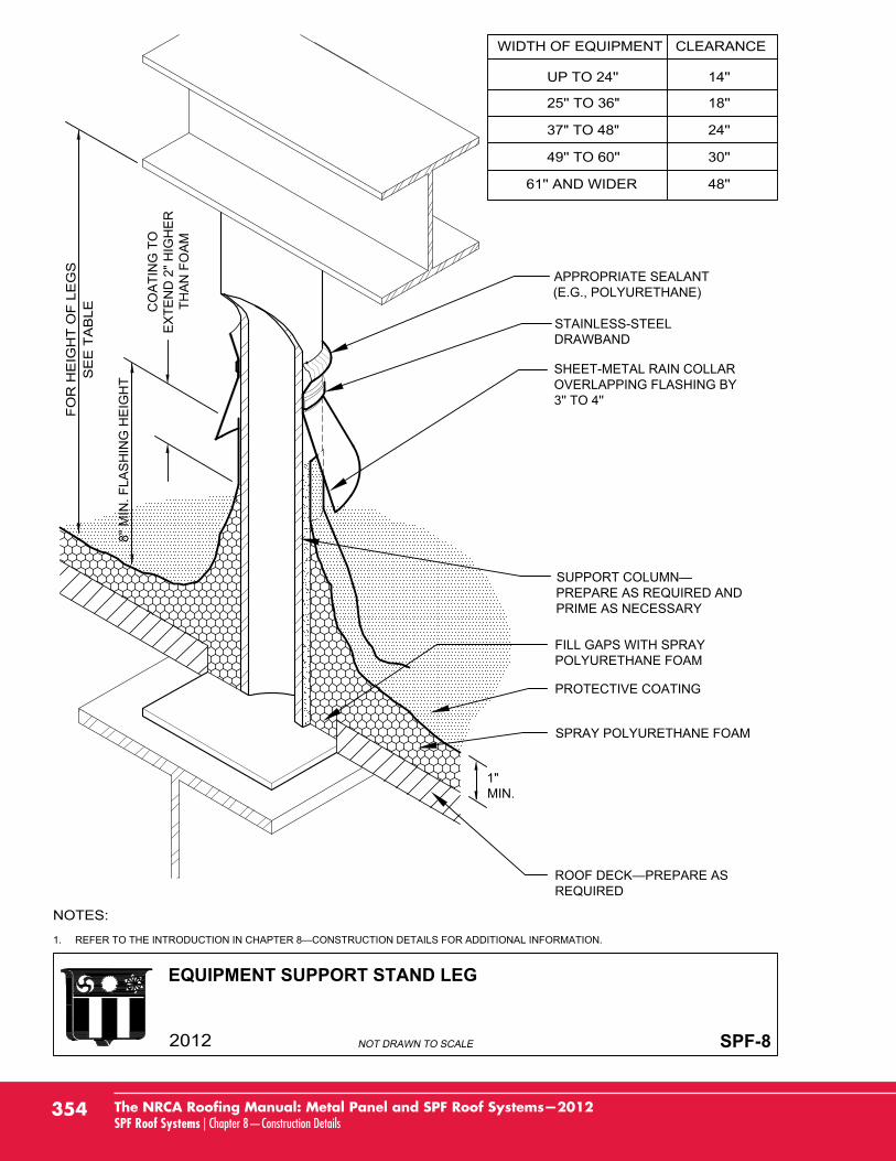
EQUIPMENT SUPPORT STAND LEG
SPF-8
1.
PREPARE AS REQUIRED ANDPRIME AS NECESSARY
PROTECTIVE COATING
FILL GAPS WITH SPRAYPOLYURETHANE FOAM
SPRAY POLYURETHANE FOAM
REQUIRED
1"MIN.
8'' M
IN. F
LAS
HIN
G H
EIG
HT
CO
ATI
NG
TO
EX
TEN
D 2
" HIG
HE
RTH
AN
FO
AM
APPROPRIATE SEALANT(E.G., POLYURETHANE)
STAINLESS-STEELDRAWBAND
SHEET-METAL RAIN COLLAROVERLAPPING FLASHING BY3'' TO 4''
354 The NRCA Roofing Manual: Metal Panel and SPF Roof Systems—2012SPF Roof Systems | Chapter 8—Construction Details
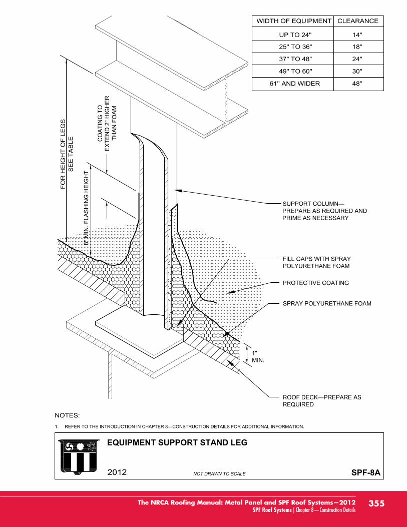
EQUIPMENT SUPPORT STAND LEG
SPF-8A
1.
PREPARE AS REQUIRED ANDPRIME AS NECESSARY
PROTECTIVE COATING
FILL GAPS WITH SPRAYPOLYURETHANE FOAM
SPRAY POLYURETHANE FOAM
REQUIRED
1"MIN.
8'' M
IN. F
LAS
HIN
G H
EIG
HT
CO
ATI
NG
TO
EX
TEN
D 2
" HIG
HE
RTH
AN
FO
AM
355The NRCA Roofing Manual: Metal Panel and SPF Roof Systems—2012SPF Roof Systems | Chapter 8—Construction Details
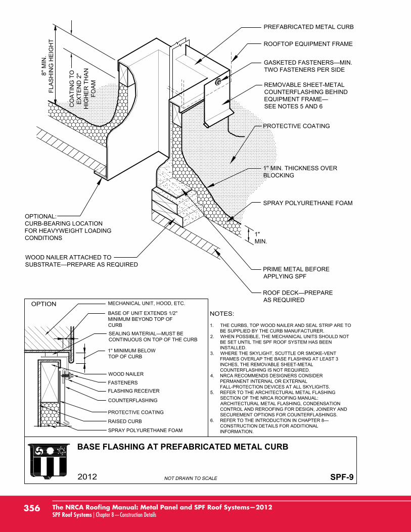
BASE FLASHING AT PREFABRICATED METAL CURB
SPF-9
OPTIONAL:CURB-BEARING LOCATIONFOR HEAVYWEIGHT LOADINGCONDITIONS
SPRAY POLYURETHANE FOAM
PRIME METAL BEFOREAPPLYING SPF
AS REQUIRED
WOOD NAILER ATTACHED TO
PREFABRICATED METAL CURB
REMOVABLE SHEET-METALCOUNTERFLASHING BEHIND
SEE NOTES 5 AND 6
ROOFTOP EQUIPMENT FRAME
PROTECTIVE COATING
8'' M
IN.
FLA
SH
ING
HE
IGH
T
CO
ATI
NG
TO
EX
TEN
D 2
"H
IGH
ER
TH
AN
FOA
M
1. THE CURBS, TOP WOOD NAILER AND SEAL STRIP ARE TOBE SUPPLIED BY THE CURB MANUFACTURER.
2. WHEN POSSIBLE, THE MECHANICAL UNITS SHOULD NOTBE SET UNTIL THE SPF ROOF SYSTEM HAS BEENINSTALLED.
3. WHERE THE SKYLIGHT, SCUTTLE OR SMOKE-VENTFRAMES OVERLAP THE BASE FLASHING AT LEAST 3INCHES, THE REMOVABLE SHEET-METALCOUNTERFLASHING IS NOT REQUIRED.
4. NRCA RECOMMENDS DESIGNERS CONSIDERPERMANENT INTERNAL OR EXTERNALFALL-PROTECTION DEVICES AT ALL SKYLIGHTS.
5. REFER TO THE ARCHITECTURAL METAL FLASHINGSECTION OF THE NRCA ROOFING MANUAL:ARCHITECTURAL METAL FLASHING, CONDENSATIONCONTROL AND REROOFING FOR DESIGN, JOINERY ANDSECUREMENT OPTIONS FOR COUNTERFLASHINGS.
6.CONSTRUCTION DETAILS FOR ADDITIONALINFORMATION.
1'' MIN. THICKNESS OVERBLOCKING
TWO FASTENERS PER SIDE
PROTECTIVE COATING
RAISED CURB
SPRAY POLYURETHANE FOAM
MECHANICAL UNIT, HOOD, ETC.
CONTINUOUS ON TOP OF THE CURB
1'' MINIMUM BELOWTOP OF CURB
FLASHING RECEIVER
WOOD NAILER
COUNTERFLASHING
FASTENERS
BASE OF UNIT EXTENDS 1/2''MINIMUM BEYOND TOP OFCURB
1"MIN.
356 The NRCA Roofing Manual: Metal Panel and SPF Roof Systems—2012SPF Roof Systems | Chapter 8—Construction Details
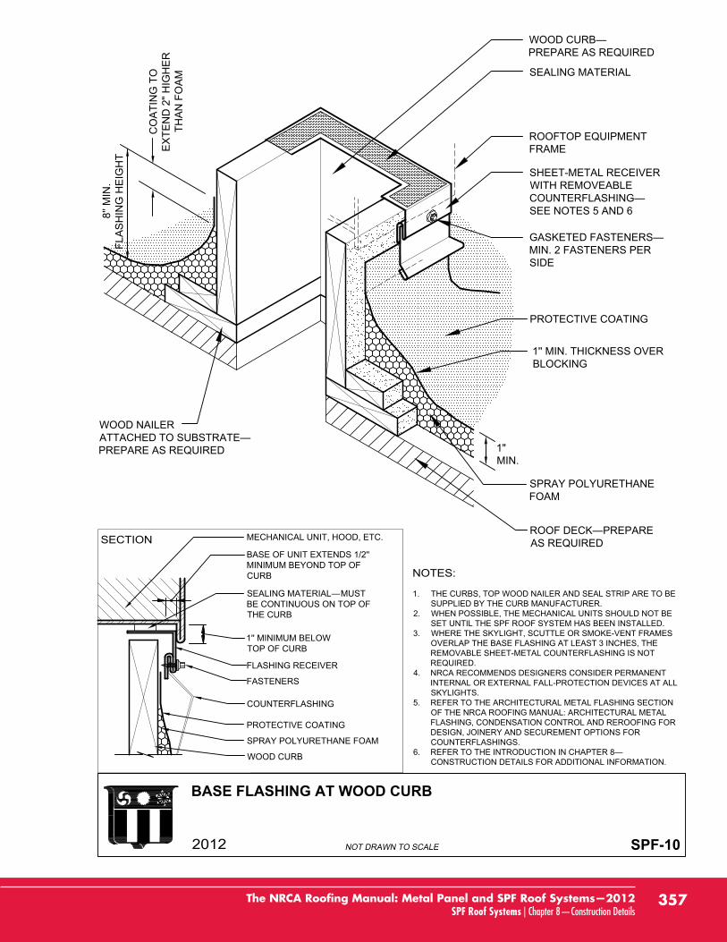
BASE FLASHING AT WOOD CURB
SPF-10
WOOD CURB—PREPARE AS REQUIRED
PROTECTIVE COATING
SPRAY POLYURETHANEFOAM
ROOF DECK—PREPAREAS REQUIRED
SEALING MATERIAL
ROOFTOP EQUIPMENTFRAME
GASKETED FASTENERS—MIN. 2 FASTENERS PERSIDE
WOOD NAILERATTACHED TO SUBSTRATE—PREPARE AS REQUIRED
SHEET-METAL RECEIVERWITH REMOVEABLECOUNTERFLASHING—SEE NOTES 5 AND 6
1'' MIN. THICKNESS OVERBLOCKING
MECHANICAL UNIT, HOOD, ETC.
BASE OF UNIT EXTENDS 1/2''MINIMUM BEYOND TOP OFCURB
COUNTERFLASHING
PROTECTIVE COATING
WOOD CURB
FASTENERS
SEALING MATERIAL—MUSTBE CONTINUOUS ON TOP OFTHE CURB
1'' MINIMUM BELOWTOP OF CURB
FLASHING RECEIVER
1. THE CURBS, TOP WOOD NAILER AND SEAL STRIP ARE TO BESUPPLIED BY THE CURB MANUFACTURER.
2. WHEN POSSIBLE, THE MECHANICAL UNITS SHOULD NOT BESET UNTIL THE SPF ROOF SYSTEM HAS BEEN INSTALLED.
3. WHERE THE SKYLIGHT, SCUTTLE OR SMOKE-VENT FRAMESOVERLAP THE BASE FLASHING AT LEAST 3 INCHES, THEREMOVABLE SHEET-METAL COUNTERFLASHING IS NOTREQUIRED.
4. NRCA RECOMMENDS DESIGNERS CONSIDER PERMANENTINTERNAL OR EXTERNAL FALL-PROTECTION DEVICES AT ALLSKYLIGHTS.
5. REFER TO THE ARCHITECTURAL METAL FLASHING SECTIONOF THE NRCA ROOFING MANUAL: ARCHITECTURAL METALFLASHING, CONDENSATION CONTROL AND REROOFING FORDESIGN, JOINERY AND SECUREMENT OPTIONS FORCOUNTERFLASHINGS.
6. REFER TO THE INTRODUCTION IN CHAPTER 8—CONSTRUCTION DETAILS FOR ADDITIONAL INFORMATION.
8'' M
IN.
FLA
SH
ING
HE
IGH
T
CO
ATI
NG
TO
EX
TEN
D 2
" HIG
HE
RTH
AN
FO
AM
1"MIN.
SPRAY POLYURETHANE FOAM
357The NRCA Roofing Manual: Metal Panel and SPF Roof Systems—2012SPF Roof Systems | Chapter 8—Construction Details
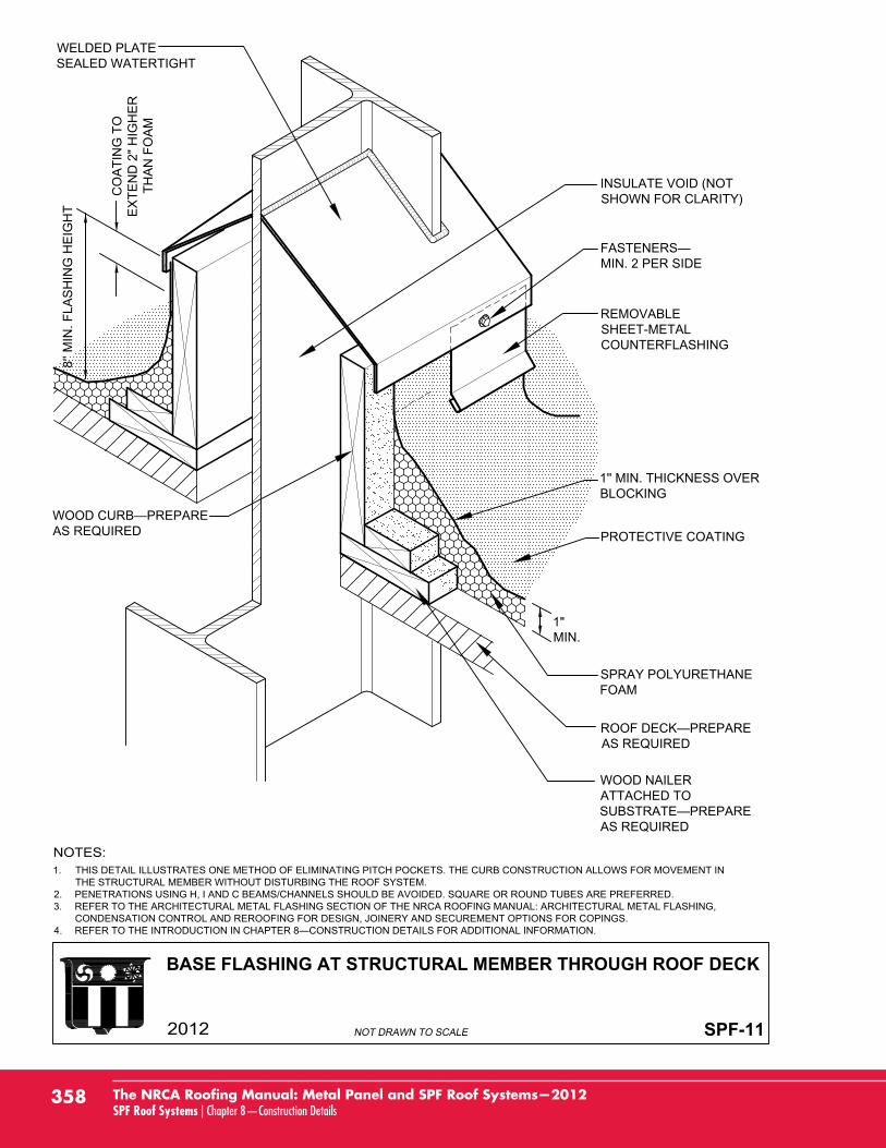
BASE FLASHING AT STRUCTURAL MEMBER THROUGH ROOF DECK
SPF-11
1. THIS DETAIL ILLUSTRATES ONE METHOD OF ELIMINATING PITCH POCKETS. THE CURB CONSTRUCTION ALLOWS FOR MOVEMENT INTHE STRUCTURAL MEMBER WITHOUT DISTURBING THE ROOF SYSTEM.
2. PENETRATIONS USING H, I AND C BEAMS/CHANNELS SHOULD BE AVOIDED. SQUARE OR ROUND TUBES ARE PREFERRED.3. REFER TO THE ARCHITECTURAL METAL FLASHING SECTION OF THE NRCA ROOFING MANUAL: ARCHITECTURAL METAL FLASHING,
CONDENSATION CONTROL AND REROOFING FOR DESIGN, JOINERY AND SECUREMENT OPTIONS FOR COPINGS.4. REFER TO THE INTRODUCTION IN CHAPTER 8—CONSTRUCTION DETAILS FOR ADDITIONAL INFORMATION.
WELDED PLATESEALED WATERTIGHT
WOOD CURB—PREPAREAS REQUIRED
ROOF DECK—PREPAREAS REQUIRED
SPRAY POLYURETHANEFOAM
PROTECTIVE COATING
REMOVABLESHEET-METALCOUNTERFLASHING
FASTENERS—MIN. 2 PER SIDE
INSULATE VOID (NOTSHOWN FOR CLARITY)
WOOD NAILERATTACHED TOSUBSTRATE—PREPAREAS REQUIRED
1'' MIN. THICKNESS OVERBLOCKING
8'' M
IN. F
LAS
HIN
G H
EIG
HT
CO
AT
ING
TO
EX
TE
ND
2"
HIG
HE
RT
HA
N F
OA
M
1"MIN.
358 The NRCA Roofing Manual: Metal Panel and SPF Roof Systems—2012SPF Roof Systems | Chapter 8—Construction Details
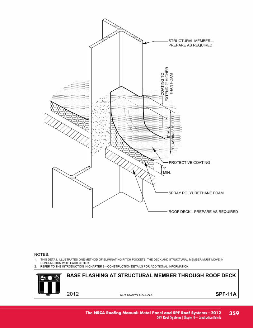
BASE FLASHING AT STRUCTURAL MEMBER THROUGH ROOF DECK
SPF-11A
1. THIS DETAIL ILLUSTRATES ONE METHOD OF ELIMINATING PITCH POCKETS. THE DECK AND STRUCTURAL MEMBER MUST MOVE INCONJUNCTION WITH EACH OTHER.
2.
PREPARE AS REQUIRED
SPRAY POLYURETHANE FOAM
PROTECTIVE COATING1"MIN.
8'' M
IN.
FLA
SH
ING
HE
IGH
T
CO
ATI
NG
TO
EX
TEN
D 2
" HIG
HE
RTH
AN
FO
AM
359The NRCA Roofing Manual: Metal Panel and SPF Roof Systems—2012SPF Roof Systems | Chapter 8—Construction Details
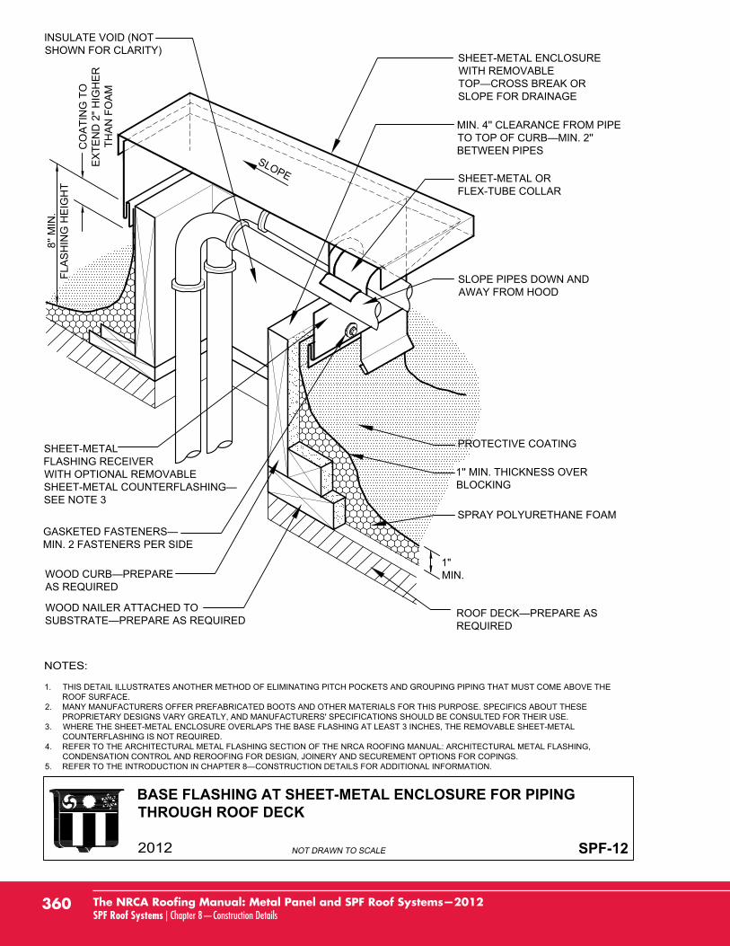
BASE FLASHING AT SHEET-METAL ENCLOSURE FOR PIPINGTHROUGH ROOF DECK
SPF-12
INSULATE VOID (NOTSHOWN FOR CLARITY)
MIN. 4'' CLEARANCE FROM PIPE
BETWEEN PIPES
AS REQUIRED
REQUIRED
SPRAY POLYURETHANE FOAM
PROTECTIVE COATING
MIN. 2 FASTENERS PER SIDE
SHEET-METALFLASHING RECEIVERWITH OPTIONAL REMOVABLE
SEE NOTE 3
SLOPE PIPES DOWN ANDAWAY FROM HOOD
SHEET-METAL ORFLEX-TUBE COLLAR
SHEET-METAL ENCLOSUREWITH REMOVABLE
SLOPE FOR DRAINAGE
SLOPE
WOOD NAILER ATTACHED TO
1. THIS DETAIL ILLUSTRATES ANOTHER METHOD OF ELIMINATING PITCH POCKETS AND GROUPING PIPING THAT MUST COME ABOVE THEROOF SURFACE.
2. MANY MANUFACTURERS OFFER PREFABRICATED BOOTS AND OTHER MATERIALS FOR THIS PURPOSE. SPECIFICS ABOUT THESEPROPRIETARY DESIGNS VARY GREATLY, AND MANUFACTURERS' SPECIFICATIONS SHOULD BE CONSULTED FOR THEIR USE.
3. WHERE THE SHEET-METAL ENCLOSURE OVERLAPS THE BASE FLASHING AT LEAST 3 INCHES, THE REMOVABLE SHEET-METALCOUNTERFLASHING IS NOT REQUIRED.
4. REFER TO THE ARCHITECTURAL METAL FLASHING SECTION OF THE NRCA ROOFING MANUAL: ARCHITECTURAL METAL FLASHING,CONDENSATION CONTROL AND REROOFING FOR DESIGN, JOINERY AND SECUREMENT OPTIONS FOR COPINGS.
5.
1'' MIN. THICKNESS OVERBLOCKING
8'' M
IN.
FLA
SH
ING
HE
IGH
T
CO
ATI
NG
TO
EX
TEN
D 2
" HIG
HE
RTH
AN
FO
AM
1"MIN.
360 The NRCA Roofing Manual: Metal Panel and SPF Roof Systems—2012SPF Roof Systems | Chapter 8—Construction Details
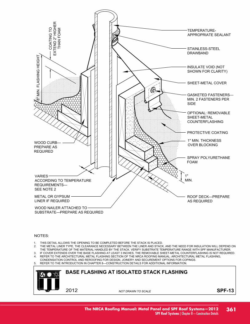
BASE FLASHING AT ISOLATED STACK FLASHING
SPF-13
METAL OR GYPSUMLINER IF REQUIRED
VARIESACCORDING TO TEMPERATURE
SEE NOTE 2
MIN. 2 FASTENERS PERSIDE
AS REQUIRED
SPRAY POLYURETHANEFOAM
PREPARE ASREQUIRED
PROTECTIVE COATING
OPTIONAL: REMOVABLESHEET-METALCOUNTERFLASHING
SHEET-METAL COVER
INSULATE VOID (NOTSHOWN FOR CLARITY)
STAINLESS-STEELDRAWBAND
TEMPERATURE-APPROPRIATE SEALANT
WOOD NAILER ATTACHED TO
1. THIS DETAIL ALLOWS THE OPENING TO BE COMPLETED BEFORE THE STACK IS PLACED.2. THE METAL LINER TYPE, THE CLEARANCE NECESSARY BETWEEN THE LINER AND STACK, AND THE NEED FOR INSULATION WILL DEPEND ON
THE TEMPERATURE OF THE MATERIAL HANDLED BY THE STACK. VERIFY SUBSTRATE TEMPERATURE RANGE WITH SPF MANUFACTURER.3. IF COVER EXTENDS OVER THE BASE FLASHING AT LEAST 3 INCHES, THE REMOVABLE SHEET-METAL COUNTERFLASHING IS NOT REQUIRED.4. REFER TO THE ARCHITECTURAL METAL FLASHING SECTION OF THE NRCA ROOFING MANUAL: ARCHITECTURAL METAL FLASHING,
CONDENSATION CONTROL AND REROOFING FOR DESIGN, JOINERY AND SECUREMENT OPTIONS FOR COPINGS.5.
1'' MIN. THICKNESSOVER BLOCKING
8'' M
IN. F
LAS
HIN
G H
EIG
HT
CO
ATI
NG
TO
EX
TEN
D 2
" HIG
HE
RTH
AN
FO
AM
1"MIN.
361The NRCA Roofing Manual: Metal Panel and SPF Roof Systems—2012SPF Roof Systems | Chapter 8—Construction Details
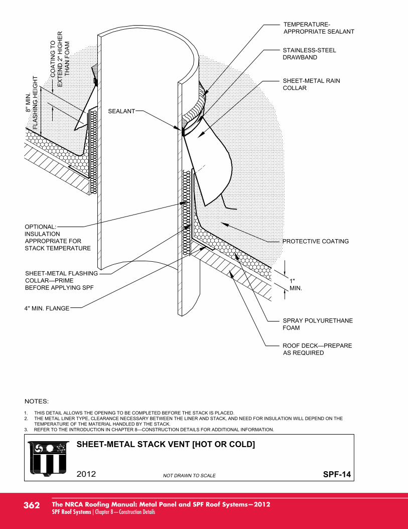
SHEET-METAL STACK VENT [HOT OR COLD]
SPF-14
1. THIS DETAIL ALLOWS THE OPENING TO BE COMPLETED BEFORE THE STACK IS PLACED.2. THE METAL LINER TYPE, CLEARANCE NECESSARY BETWEEN THE LINER AND STACK, AND NEED FOR INSULATION WILL DEPEND ON THE
TEMPERATURE OF THE MATERIAL HANDLED BY THE STACK.3.
OPTIONAL:INSULATIONAPPROPRIATE FORSTACK TEMPERATURE
4'' MIN. FLANGE
SHEET-METAL RAINCOLLAR
TEMPERATURE-APPROPRIATE SEALANT
STAINLESS-STEELDRAWBAND
SEALANT
SHEET-METAL FLASHING
BEFORE APPLYING SPF
PROTECTIVE COATING
SPRAY POLYURETHANEFOAM
1"MIN.
AS REQUIRED
8'' M
IN.
FLA
SH
ING
HE
IGH
T CO
ATI
NG
TO
EX
TEN
D 2
" HIG
HE
RTH
AN
FO
AM
362 The NRCA Roofing Manual: Metal Panel and SPF Roof Systems—2012SPF Roof Systems | Chapter 8—Construction Details
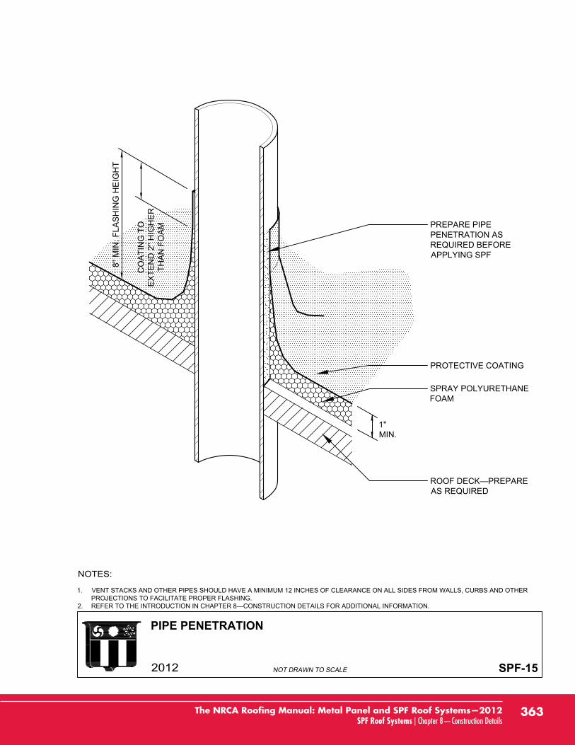
PIPE PENETRATION
SPF-15
1. VENT STACKS AND OTHER PIPES SHOULD HAVE A MINIMUM 12 INCHES OF CLEARANCE ON ALL SIDES FROM WALLS, CURBS AND OTHERPROJECTIONS TO FACILITATE PROPER FLASHING.
2.
PREPARE PIPEPENETRATION ASREQUIRED BEFOREAPPLYING SPF
PROTECTIVE COATING
SPRAY POLYURETHANEFOAM
AS REQUIRED
1"MIN.
8'' M
IN. F
LAS
HIN
G H
EIG
HT
CO
ATI
NG
TO
EX
TEN
D 2
" HIG
HE
RTH
AN
FO
AM
363The NRCA Roofing Manual: Metal Panel and SPF Roof Systems—2012SPF Roof Systems | Chapter 8—Construction Details
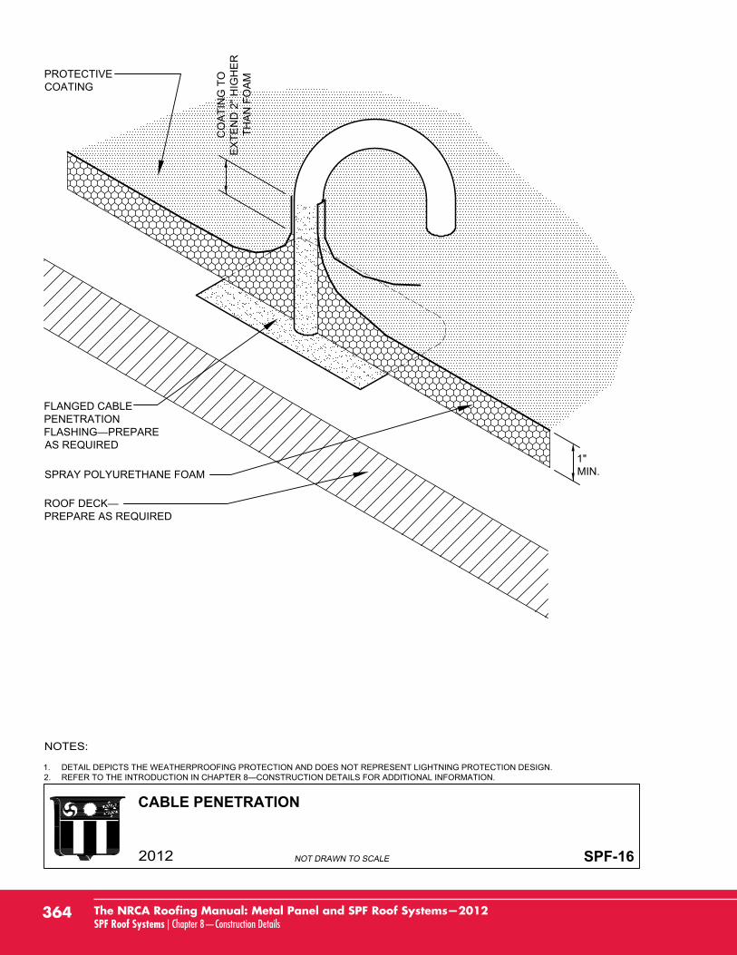
CABLE PENETRATION
SPF-16
1. DETAIL DEPICTS THE WEATHERPROOFING PROTECTION AND DOES NOT REPRESENT LIGHTNING PROTECTION DESIGN.2.
FLANGED CABLEPENETRATION
AS REQUIRED
PROTECTIVECOATING
1"MIN.
PREPARE AS REQUIRED
SPRAY POLYURETHANE FOAM
CO
ATI
NG
TO
EX
TEN
D 2
" HIG
HE
RTH
AN
FO
AM
364 The NRCA Roofing Manual: Metal Panel and SPF Roof Systems—2012SPF Roof Systems | Chapter 8—Construction Details
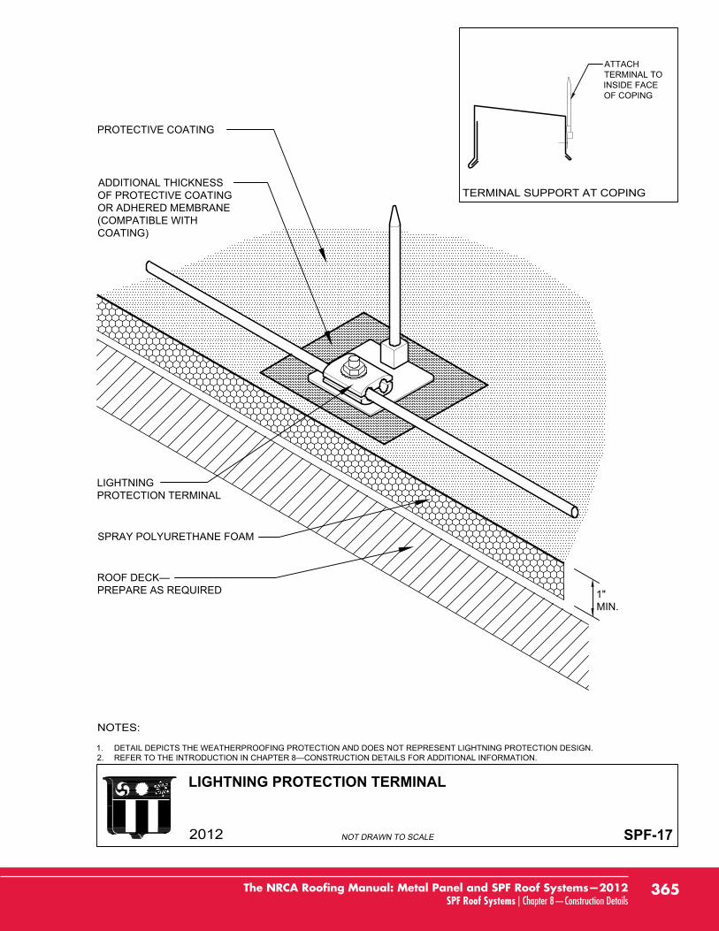
LIGHTNING PROTECTION TERMINAL
SPF-17
1. DETAIL DEPICTS THE WEATHERPROOFING PROTECTION AND DOES NOT REPRESENT LIGHTNING PROTECTION DESIGN.2.
LIGHTNINGPROTECTION TERMINAL
ADDITIONAL THICKNESSOF PROTECTIVE COATINGOR ADHERED MEMBRANE(COMPATIBLE WITHCOATING)
1"MIN.
PREPARE AS REQUIRED
SPRAY POLYURETHANE FOAM
ATTACHTERMINAL TOINSIDE FACEOF COPING
PROTECTIVE COATING
365The NRCA Roofing Manual: Metal Panel and SPF Roof Systems—2012SPF Roof Systems | Chapter 8—Construction Details
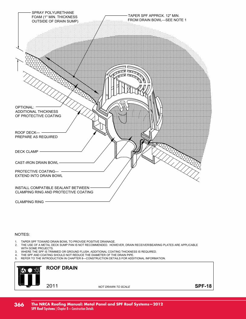
ROOF DRAIN
SPF-18
1. TAPER SPF TOWARD DRAIN BOWL TO PROVIDE POSITIVE DRAINAGE.2. THE USE OF A METAL DECK SUMP PAN IS NOT RECOMMENDED. HOWEVER, DRAIN RECEIVER/BEARING PLATES ARE APPLICABLE
WITH SOME PROJECTS.3. WHERE THE SPF IS TRIMMED OR GROUND FLUSH, ADDITIONAL COATING THICKNESS IS REQUIRED.4. THE SPF AND COATING SHOULD NOT REDUCE THE DIAMETER OF THE DRAIN PIPE.5.
SPRAY POLYURETHANEFOAM (1'' MIN. THICKNESSOUTSIDE OF DRAIN SUMP)
EXTEND INTO DRAIN BOWL
CAST-IRON DRAIN BOWL
DECK CLAMP
PREPARE AS REQUIRED
TAPER SPF APPROX. 12" MIN.
INSTALL COMPATIBLE SEALANT BETWEENCLAMPING RING AND PROTECTIVE COATING
CLAMPING RING
OPTIONAL:ADDITIONAL THICKNESSOF PROTECTIVE COATING
366 The NRCA Roofing Manual: Metal Panel and SPF Roof Systems—2012SPF Roof Systems | Chapter 8—Construction Details
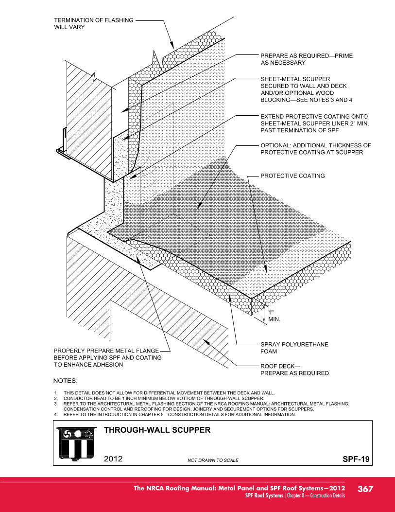
THROUGH-WALL SCUPPER
SPF-19
1''MIN.
PREPARE AS REQUIRED
SHEET-METAL SCUPPERSECURED TO WALL AND DECKAND/OR OPTIONAL WOODBLOCKING SEE NOTES 3 AND 4
TERMINATION OF FLASHINGWILL VARY
1. THIS DETAIL DOES NOT ALLOW FOR DIFFERENTIAL MOVEMENT BETWEEN THE DECK AND WALL.2. CONDUCTOR HEAD TO BE 1 INCH MINIMUM BELOW BOTTOM OF THROUGH-WALL SCUPPER.3. REFER TO THE ARCHITECTURAL METAL FLASHING SECTION OF THE NRCA ROOFING MANUAL: ARCHITECTURAL METAL FLASHING,
CONDENSATION CONTROL AND REROOFING FOR DESIGN, JOINERY AND SECUREMENT OPTIONS FOR SCUPPERS.4.
AS NECESSARY
PROPERLY PREPARE METAL FLANGEBEFORE APPLYING SPF AND COATINGTO ENHANCE ADHESION
EXTEND PROTECTIVE COATING ONTOSHEET-METAL SCUPPER LINER 2" MIN.PAST TERMINATION OF SPF
SPRAY POLYURETHANEFOAM
PROTECTIVE COATING
OPTIONAL: ADDITIONAL THICKNESS OFPROTECTIVE COATING AT SCUPPER
367The NRCA Roofing Manual: Metal Panel and SPF Roof Systems—2012SPF Roof Systems | Chapter 8—Construction Details
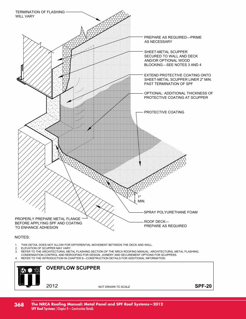
OVERFLOW SCUPPER
SPF-20
PREPARE AS REQUIRED
1. THIS DETAIL DOES NOT ALLOW FOR DIFFERENTIAL MOVEMENT BETWEEN THE DECK AND WALL.2. ELEVATION OF SCUPPER MAY VARY.3. REFER TO THE ARCHITECTURAL METAL FLASHING SECTION OF THE NRCA ROOFING MANUAL: ARCHITECTURAL METAL FLASHING,
CONDENSATION CONTROL AND REROOFING FOR DESIGN, JOINERY AND SECUREMENT OPTIONS FOR SCUPPERS.4.
TERMINATION OF FLASHINGWILL VARY
1''MIN.
SHEET-METAL SCUPPERSECURED TO WALL AND DECKAND/OR OPTIONAL WOODBLOCKING SEE NOTES 3 AND 4
AS NECESSARY
PROPERLY PREPARE METAL FLANGEBEFORE APPLYING SPF AND COATINGTO ENHANCE ADHESION
EXTEND PROTECTIVE COATING ONTOSHEET-METAL SCUPPER LINER 2" MIN.PAST TERMINATION OF SPF
SPRAY POLYURETHANE FOAM
PROTECTIVE COATING
OPTIONAL: ADDITIONAL THICKNESS OFPROTECTIVE COATING AT SCUPPER
368 The NRCA Roofing Manual: Metal Panel and SPF Roof Systems—2012SPF Roof Systems | Chapter 8—Construction Details

GUTTER WITH PERIMETER EDGE METAL
SPF-21
1. IN CLIMATES WHERE THE WINTER TEMPERATURE REMAINS BELOW FREEZING FOR EXTENDED PERIODS OF TIME, NRCA SUGGESTS USINGINTERIOR DRAINS TO DRAIN THE ROOF.
2. REFER TO THE ARCHITECTURAL METAL FLASHING SECTION OF THE NRCA ROOFING MANUAL: ARCHITECTURAL METAL FLASHING,CONDENSATION CONTROL AND REROOFING FOR MORE INFORMATION ON GUTTERS.
3. REFER TO THE INTRODUCTION IN CHAPTER 8—CONSTRUCTION DETAILS FOR ADDITIONAL INFORMATION.
SHEET-METALGUTTER—SEE NOTE 3
SEPARATIONMEMBRANE SHEETEXTENDED BELOWBLOCKING
ROOF DECK—PREPARE AS REQUIRED
SPRAYPOLYURETHANE FOAM
PROTECTIVE COATING
OPTIONAL: ADDITIONAL THICKNESSOF PROTECTIVE COATING AT EDGE
GUTTER SPACERSINSTALLED BETWEENGUTTER BRACKETS
PROPERLY PREPAREMETAL FLANGE BEFOREAPPLYING SPF TOENHANCE ADHESION
V-GROOVE SPF ANDINSTALL ELASTOMERICSEALANT
FASTENERS
WOODNAILERATTACHED TOSUBSTRATE
OPTIONAL:STIFFENING BAR
OPTIONAL: GUTTERBRACKET SUPPORT
SHEET-METAL EDGEFLASHING (FOAM STOP)APPROX. 4'' WIDE FLANGE
1" MIN.
APPROX. 12"
369The NRCA Roofing Manual: Metal Panel and SPF Roof Systems—2012SPF Roof Systems | Chapter 8—Construction Details

BASE FLASHING AT PARAPET WALL WITH NEW METAL COPINGFOR SPF RE-COVER
SPF(R)-1
1.RE-COVERING FOR ADDITIONAL INFORMATION.
2. REFER TO THE ARCHITECTURAL METAL FLASHING SECTION OF THE NRCA ROOFING MANUAL: ARCHITECTURAL METAL FLASHING,CONDENSATION CONTROL AND REROOFING FOR DESIGN, JOINERY AND SECUREMENT OPTIONS FOR COPINGS.
3.
EXISTING ROOF SYSTEMPREPARE AS REQUIRED
EXISTING ROOF DECK
NEW PROTECTIVE COATING
NEW SPRAY POLYURETHANE
NEW WEATHERPROOFMEMBRANE ON TOP OF WALLTURNED DOWN BOTH SIDES
NEW GASKETED FASTENERS
EXISTING LOOSE MEMBRANEFLASHINGS TO BE SECURED ORREMOVED
EXISTING SHIM AND WOODNAILER
SHEET-METAL COPING SLOPEDTO DRAIN TO ROOF
1"MIN.
1'' MIN. THICKNESS OVERCANT
8'' M
IN. F
LAS
HIN
G H
EIG
HT
CO
ATI
NG
TO
EX
TEN
D 2
" HIG
HE
RTH
AN
FO
AM
370 The NRCA Roofing Manual: Metal Panel and SPF Roof Systems—2012SPF Roof Systems | Chapter 8—Construction Details
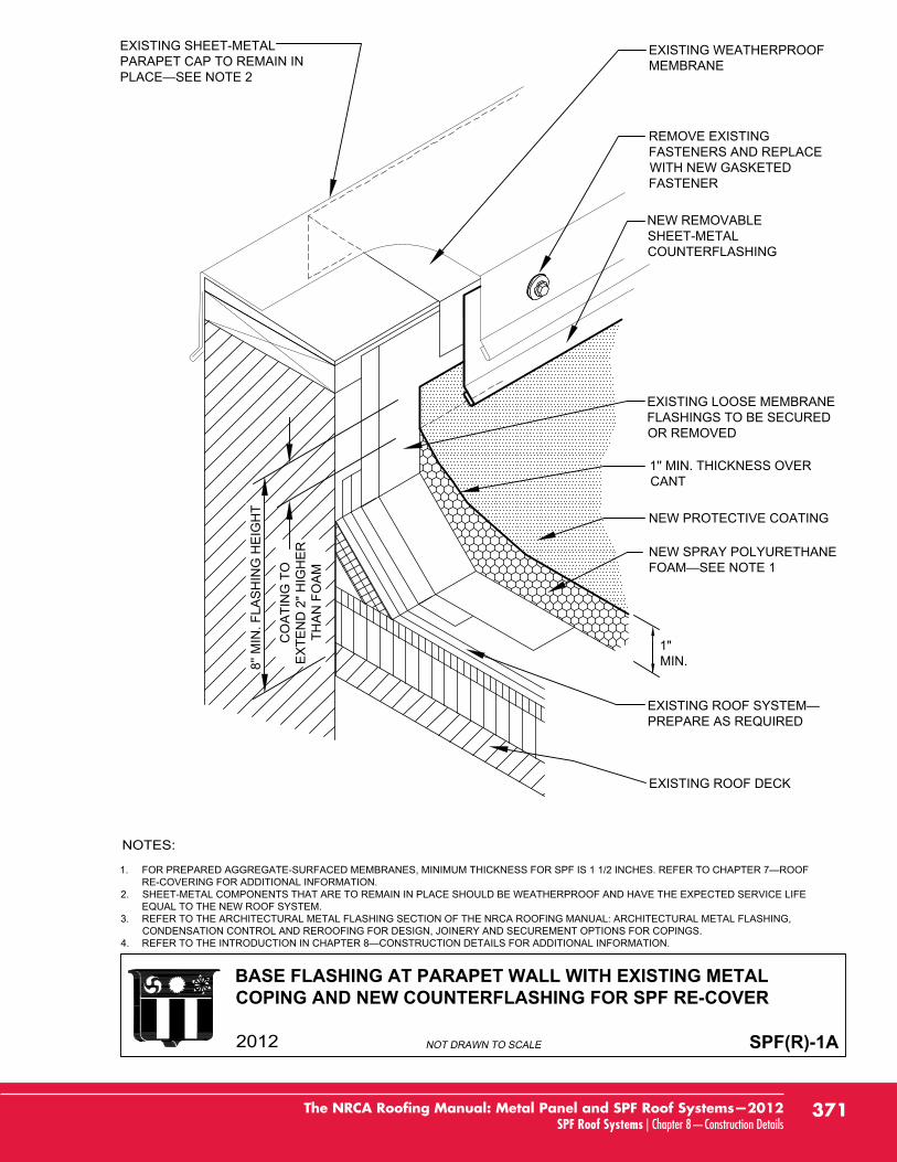
BASE FLASHING AT PARAPET WALL WITH EXISTING METALCOPING AND NEW COUNTERFLASHING FOR SPF RE-COVER
SPF(R)-1A
1.RE-COVERING FOR ADDITIONAL INFORMATION.
2. SHEET-METAL COMPONENTS THAT ARE TO REMAIN IN PLACE SHOULD BE WEATHERPROOF AND HAVE THE EXPECTED SERVICE LIFEEQUAL TO THE NEW ROOF SYSTEM.
3. REFER TO THE ARCHITECTURAL METAL FLASHING SECTION OF THE NRCA ROOFING MANUAL: ARCHITECTURAL METAL FLASHING,CONDENSATION CONTROL AND REROOFING FOR DESIGN, JOINERY AND SECUREMENT OPTIONS FOR COPINGS.
4.
PREPARE AS REQUIRED
EXISTING ROOF DECK
EXISTING SHEET-METALPARAPET CAP TO REMAIN IN
NEW PROTECTIVE COATING
NEW SPRAY POLYURETHANE
NEW REMOVABLESHEET-METALCOUNTERFLASHING
REMOVE EXISTINGFASTENERS AND REPLACEWITH NEW GASKETEDFASTENER
EXISTING LOOSE MEMBRANEFLASHINGS TO BE SECUREDOR REMOVED
EXISTING WEATHERPROOFMEMBRANE
1"MIN.
1'' MIN. THICKNESS OVERCANT
8'' M
IN. F
LAS
HIN
G H
EIG
HT
CO
ATI
NG
TO
EX
TEN
D 2
" HIG
HE
RTH
AN
FO
AM
371The NRCA Roofing Manual: Metal Panel and SPF Roof Systems—2012SPF Roof Systems | Chapter 8—Construction Details
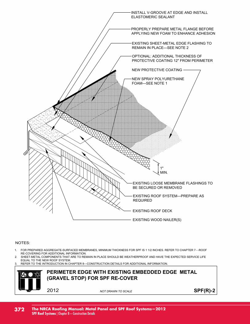
PERIMETER EDGE WITH EXISTING EMBEDDED EDGE METAL(GRAVEL STOP) FOR SPF RE-COVER
SPF(R)-2
EXISTING LOOSE MEMBRANE FLASHINGS TOBE SECURED OR REMOVED
EXISTING ROOF DECK
EXISTING SHEET-METAL EDGE FLASHING TO
PROPERLY PREPARE METAL FLANGE BEFOREAPPLYING NEW FOAM TO ENHANCE ADHESION
NEW PROTECTIVE COATING
NEW SPRAY POLYURETHANE
INSTALL V-GROOVE AT EDGE AND INSTALLELASTOMERIC SEALANT
EXISTING WOOD NAILER(S)
REQUIRED
OPTIONAL: ADDITIONAL THICKNESS OFPROTECTIVE COATING 12" FROM PERIMETER
1"MIN.
1. FOR PREPARED AGGREGATE-SURFACED MEMBRANES, MINIMUM THICKNESS FOR SPF IS 1 1/2 INCHES. REFER TO CHAPTER 7 ROOFRE-COVERING FOR ADDITIONAL INFORMATION.
2. SHEET-METAL COMPONENTS THAT ARE TO REMAIN IN PLACE SHOULD BE WEATHERPROOF AND HAVE THE EXPECTED SERVICE LIFEEQUAL TO THE NEW ROOF SYSTEM.
3.
372 The NRCA Roofing Manual: Metal Panel and SPF Roof Systems—2012SPF Roof Systems | Chapter 8—Construction Details
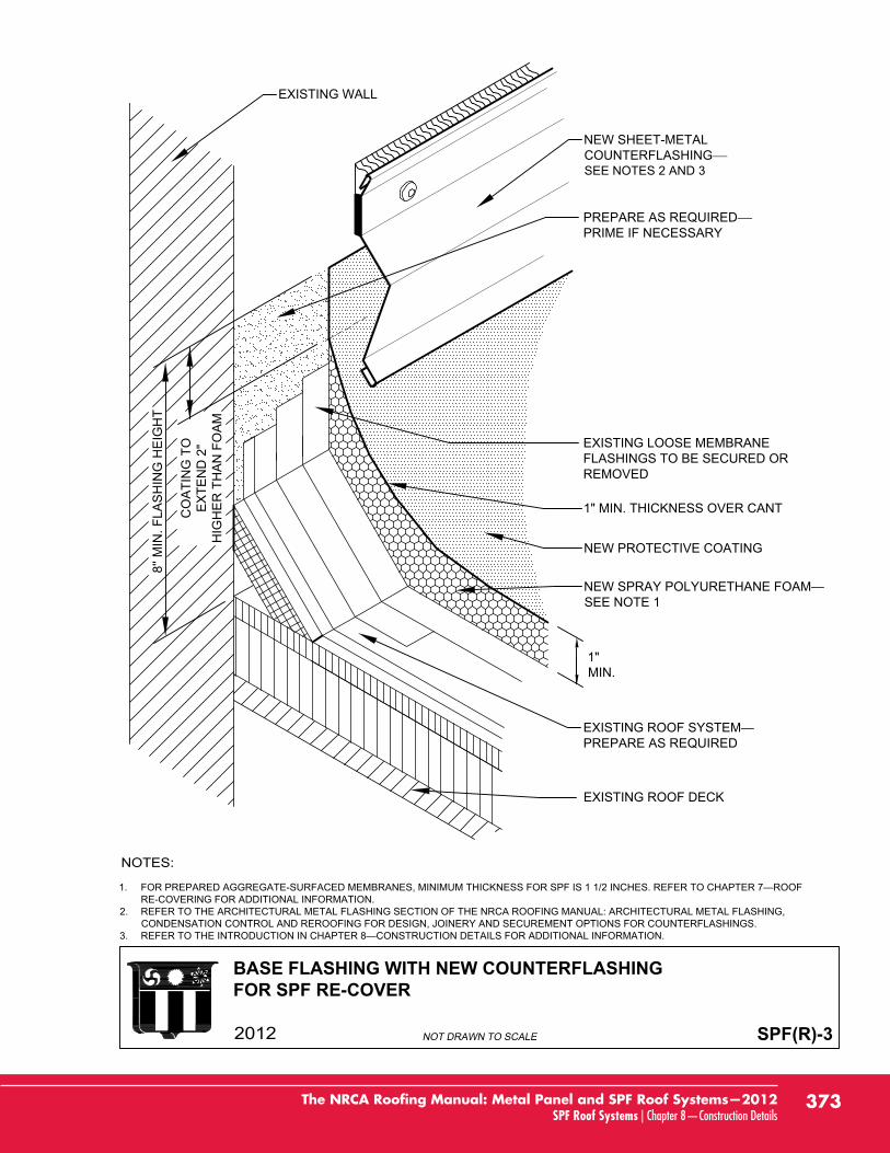
BASE FLASHING WITH NEW COUNTERFLASHINGFOR SPF RE-COVER
SPF(R)-3
EXISTING LOOSE MEMBRANEFLASHINGS TO BE SECURED ORREMOVED
EXISTING ROOF DECK
NEW SHEET-METALCOUNTERFLASHINGSEE NOTES 2 AND 3
NEW PROTECTIVE COATING
SEE NOTE 1
PREPARE AS REQUIRED
1"MIN.
8'' M
IN. F
LAS
HIN
G H
EIG
HT
CO
ATI
NG
TO
EX
TEN
D 2
"H
IGH
ER
TH
AN
FO
AM
1" MIN. THICKNESS OVER CANT
EXISTING WALL
PREPARE AS REQUIREDPRIME IF NECESSARY
1.RE-COVERING FOR ADDITIONAL INFORMATION.
2. REFER TO THE ARCHITECTURAL METAL FLASHING SECTION OF THE NRCA ROOFING MANUAL: ARCHITECTURAL METAL FLASHING,CONDENSATION CONTROL AND REROOFING FOR DESIGN, JOINERY AND SECUREMENT OPTIONS FOR COUNTERFLASHINGS.
3.
373The NRCA Roofing Manual: Metal Panel and SPF Roof Systems—2012SPF Roof Systems | Chapter 8—Construction Details
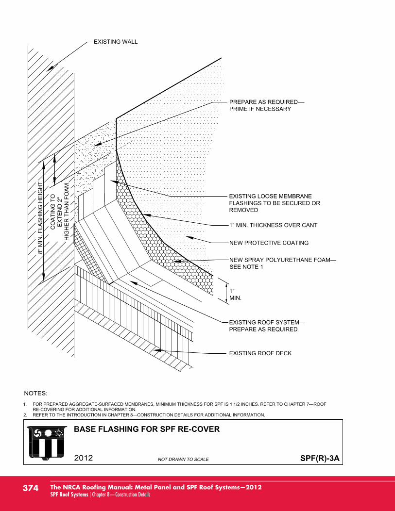
BASE FLASHING FOR SPF RE-COVER
SPF(R)-3A
EXISTING LOOSE MEMBRANEFLASHINGS TO BE SECURED ORREMOVED
EXISTING ROOF DECK
NEW PROTECTIVE COATING
SEE NOTE 1
PREPARE AS REQUIRED
1"MIN.
8'' M
IN. F
LAS
HIN
G H
EIG
HT
CO
ATI
NG
TO
EX
TEN
D 2
"H
IGH
ER
TH
AN
FO
AM
1" MIN. THICKNESS OVER CANT
EXISTING WALL
PREPARE AS REQUIREDPRIME IF NECESSARY
1.RE-COVERING FOR ADDITIONAL INFORMATION.
2.
374 The NRCA Roofing Manual: Metal Panel and SPF Roof Systems—2012SPF Roof Systems | Chapter 8—Construction Details
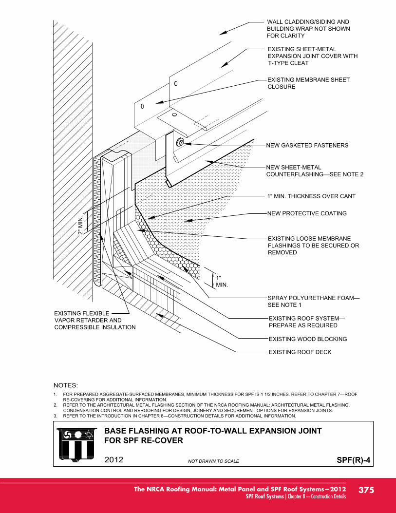
BASE FLASHING AT ROOF-TO-WALL EXPANSION JOINTFOR SPF RE-COVER
SPF(R)-4
1.RE-COVERING FOR ADDITIONAL INFORMATION.
2. REFER TO THE ARCHITECTURAL METAL FLASHING SECTION OF THE NRCA ROOFING MANUAL: ARCHITECTURAL METAL FLASHING,CONDENSATION CONTROL AND REROOFING FOR DESIGN, JOINERY AND SECUREMENT OPTIONS FOR EXPANSION JOINTS.
3.
WALL CLADDING/SIDING ANDBUILDING WRAP NOT SHOWNFOR CLARITY
EXISTING SHEET-METALEXPANSION JOINT COVER WITHT-TYPE CLEAT
1"MIN.
EXISTING LOOSE MEMBRANEFLASHINGS TO BE SECURED ORREMOVED
EXISTING ROOF DECK
NEW PROTECTIVE COATING
SEE NOTE 1
EXISTING MEMBRANE SHEETCLOSURE
EXISTING WOOD BLOCKING
EXISTING FLEXIBLEVAPOR RETARDER ANDCOMPRESSIBLE INSULATION PREPARE AS REQUIRED
2" M
IN.
1" MIN. THICKNESS OVER CANT
NEW SHEET-METALCOUNTERFLASHING SEE NOTE 2
NEW GASKETED FASTENERS
375The NRCA Roofing Manual: Metal Panel and SPF Roof Systems—2012SPF Roof Systems | Chapter 8—Construction Details
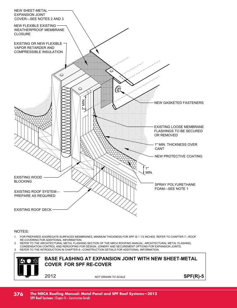
BASE FLASHING AT EXPANSION JOINT WITH NEW SHEET-METALCOVER FOR SPF RE-COVER
SPF(R)-5
1"MIN.
1.RE-COVERING FOR ADDITIONAL INFORMATION.
2. REFER TO THE ARCHITECTURAL METAL FLASHING SECTION OF THE NRCA ROOFING MANUAL: ARCHITECTURAL METAL FLASHING,CONDENSATION CONTROL AND REROOFING FOR DESIGN, JOINERY AND SECUREMENT OPTIONS FOR EXPANSION JOINTS.
3.
PREPARE AS REQUIRED
EXISTING ROOF DECK
NEW FLEXIBLE EXISTINGWEATHERPROOF MEMBRANECLOSURE
NEW PROTECTIVE COATING
SPRAY POLYURETHANE
EXISTING WOODBLOCKING
NEW GASKETED FASTENERS
EXISTING LOOSE MEMBRANEFLASHINGS TO BE SECUREDOR REMOVED
EXISTING OR NEW FLEXIBLEVAPOR RETARDER ANDCOMPRESSIBLE INSULATION
NEW SHEET-METALEXPANSION JOINT
2" M
IN.
1" MIN. THICKNESS OVERCANT
376 The NRCA Roofing Manual: Metal Panel and SPF Roof Systems—2012SPF Roof Systems | Chapter 8—Construction Details
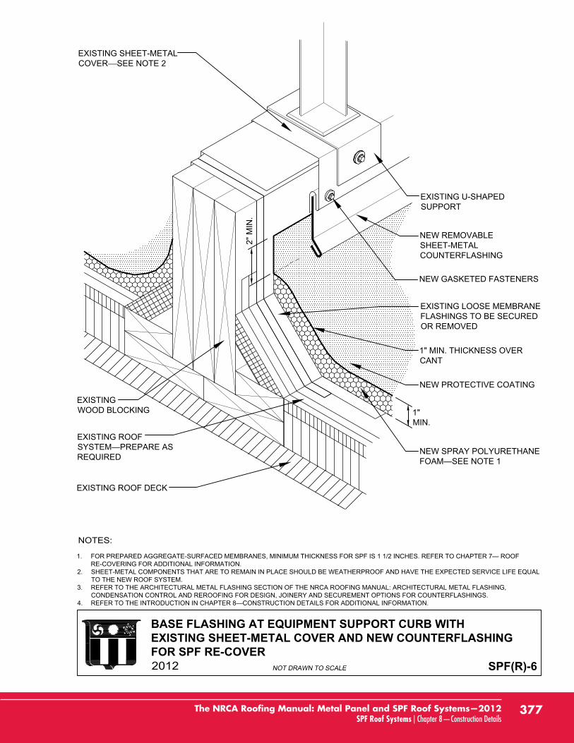
BASE FLASHING AT EQUIPMENT SUPPORT CURB WITHEXISTING SHEET-METAL COVER AND NEW COUNTERFLASHINGFOR SPF RE-COVER
SPF(R)-6
1.RE-COVERING FOR ADDITIONAL INFORMATION.
2. SHEET-METAL COMPONENTS THAT ARE TO REMAIN IN PLACE SHOULD BE WEATHERPROOF AND HAVE THE EXPECTED SERVICE LIFE EQUALTO THE NEW ROOF SYSTEM.
3. REFER TO THE ARCHITECTURAL METAL FLASHING SECTION OF THE NRCA ROOFING MANUAL: ARCHITECTURAL METAL FLASHING,CONDENSATION CONTROL AND REROOFING FOR DESIGN, JOINERY AND SECUREMENT OPTIONS FOR COUNTERFLASHINGS.
4.
1"MIN.
EXISTING ROOF
REQUIRED
EXISTING ROOF DECK
NEW PROTECTIVE COATING
NEW SPRAY POLYURETHANE
EXISTING SHEET-METALCOVER SEE NOTE 2
EXISTINGWOOD BLOCKING
EXISTING LOOSE MEMBRANEFLASHINGS TO BE SECUREDOR REMOVED
NEW GASKETED FASTENERS
EXISTING U-SHAPEDSUPPORT
NEW REMOVABLESHEET-METALCOUNTERFLASHING
2" M
IN.
1" MIN. THICKNESS OVERCANT
377The NRCA Roofing Manual: Metal Panel and SPF Roof Systems—2012SPF Roof Systems | Chapter 8—Construction Details
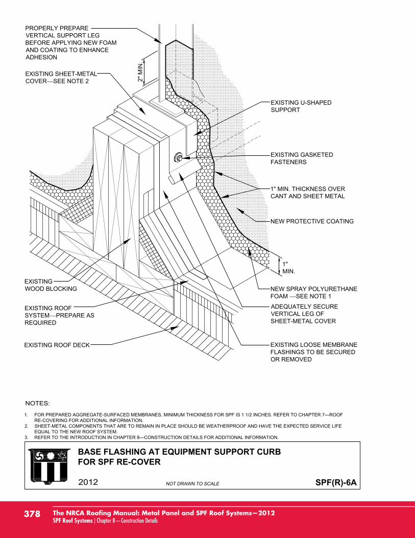
BASE FLASHING AT EQUIPMENT SUPPORT CURBFOR SPF RE-COVER
SPF(R)-6A
EXISTING ROOFSYSTEM PREPARE ASREQUIRED
EXISTING ROOF DECK
NEW PROTECTIVE COATING
1" MIN. THICKNESS OVERCANT AND SHEET METAL
EXISTING SHEET-METALCOVER SEE NOTE 2
EXISTINGWOOD BLOCKING
EXISTING LOOSE MEMBRANEFLASHINGS TO BE SECUREDOR REMOVED
EXISTING GASKETEDFASTENERS
EXISTING U-SHAPEDSUPPORT
PROPERLY PREPAREVERTICAL SUPPORT LEGBEFORE APPLYING NEW FOAMAND COATING TO ENHANCEADHESION
ADEQUATELY SECUREVERTICAL LEG OFSHEET-METAL COVER
1.RE-COVERING FOR ADDITIONAL INFORMATION.
2. SHEET-METAL COMPONENTS THAT ARE TO REMAIN IN PLACE SHOULD BE WEATHERPROOF AND HAVE THE EXPECTED SERVICE LIFEEQUAL TO THE NEW ROOF SYSTEM.
3.
NEW SPRAY POLYURETHANEFOAM SEE NOTE 1
1"MIN.
2" M
IN.
378 The NRCA Roofing Manual: Metal Panel and SPF Roof Systems—2012SPF Roof Systems | Chapter 8—Construction Details

BASE FLASHING AT EQUIPMENT SUPPORT STAND AND RAINCOLLAR PENETRATION FOR SPF RE-COVER
SPF(R)-7
PREPARE AS REQUIRED
EXISTING ROOF DECK
PROPERLY PREPARE METALSLEEVE BEFORE APPLYING FOAMTO ENHANCE ADHESION
NEW PROTECTIVE COATING
SEE NOTE 1
EXISTING SHEET-METAL
EXISTING LOOSE MEMBRANEFLASHINGS TO BE SECURED ORREMOVED
2" MIN.
1.RE-COVERING FOR ADDITIONAL INFORMATION.
2. SHEET-METAL COMPONENTS THAT ARE TO REMAIN IN PLACE SHOULD BE WEATHERPROOF AND HAVE THE EXPECTED SERVICE LIFEEQUAL TO THE NEW ROOF SYSTEM.
3.
1"MIN.
NEW OR EXISTING SHEET-METAL
379The NRCA Roofing Manual: Metal Panel and SPF Roof Systems—2012SPF Roof Systems | Chapter 8—Construction Details
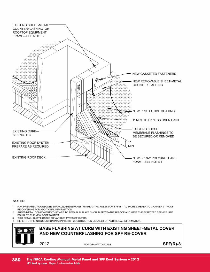
BASE FLASHING AT CURB WITH EXISTING SHEET-METAL COVERAND NEW COUNTERFLASHING FOR SPF RE-COVER
SPF(R)-8
1.RE-COVERING FOR ADDITIONAL INFORMATION.
2. SHEET-METAL COMPONENTS THAT ARE TO REMAIN IN PLACE SHOULD BE WEATHERPROOF AND HAVE THE EXPECTED SERVICE LIFEEQUAL TO THE NEW ROOF SYSTEM.
3. THIS DETAIL IS APPLICABLE TO VARIOUS TYPES OF CURBS.4.
PREPARE AS REQUIRED
EXISTING ROOF DECK
EXISTING SHEET-METALCOUNTERFLASHING ORROOFTOP EQUIPMENT
NEW REMOVABLE SHEET-METALCOUNTERFLASHING
NEW PROTECTIVE COATING
NEW SPRAY POLYURETHANE
NEW GASKETED FASTENERS
SEE NOTE 3
EXISTING LOOSEMEMBRANE FLASHINGS TOBE SECURED OR REMOVED
1"MIN.
1" MIN. THICKNESS OVER CANT
2" M
IN.
380 The NRCA Roofing Manual: Metal Panel and SPF Roof Systems—2012SPF Roof Systems | Chapter 8—Construction Details
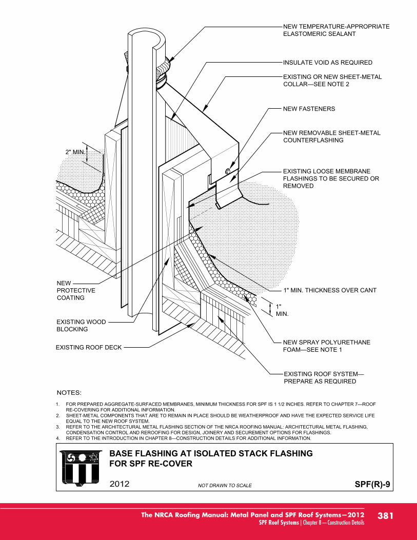
BASE FLASHING AT ISOLATED STACK FLASHINGFOR SPF RE-COVER
SPF(R)-9
1.RE-COVERING FOR ADDITIONAL INFORMATION.
2. SHEET-METAL COMPONENTS THAT ARE TO REMAIN IN PLACE SHOULD BE WEATHERPROOF AND HAVE THE EXPECTED SERVICE LIFEEQUAL TO THE NEW ROOF SYSTEM.
3. REFER TO THE ARCHITECTURAL METAL FLASHING SECTION OF THE NRCA ROOFING MANUAL: ARCHITECTURAL METAL FLASHING,CONDENSATION CONTROL AND REROOFING FOR DESIGN, JOINERY AND SECUREMENT OPTIONS FOR FLASHINGS.
4.
PREPARE AS REQUIRED
EXISTING ROOF DECK
NEW REMOVABLE SHEET-METALCOUNTERFLASHING
1" MIN. THICKNESS OVER CANT
NEW SPRAY POLYURETHANE
EXISTING WOODBLOCKING
NEW FASTENERS
EXISTING LOOSE MEMBRANEFLASHINGS TO BE SECURED ORREMOVED
EXISTING OR NEW SHEET-METAL
INSULATE VOID AS REQUIRED
NEW TEMPERATURE-APPROPRIATEELASTOMERIC SEALANT
1"MIN.
2" MIN.
NEWPROTECTIVECOATING
381The NRCA Roofing Manual: Metal Panel and SPF Roof Systems—2012SPF Roof Systems | Chapter 8—Construction Details
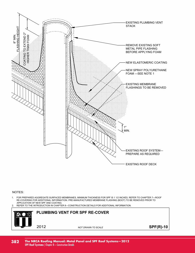
PLUMBING VENT FOR SPF RE-COVER
SPF(R)-10
1.RE-COVERING FOR ADDITIONAL INFORMATION. PRE-MANUFACTURED MEMBRANE FLASHING (BOOT) TO BE REMOVED PRIOR TOAPPLICATION OF NEW SPF AND COATING.
2.
EXISTING PLUMBING VENTSTACK
NEW SPRAY POLYURETHANE
NEW ELASTOMERIC COATING
PREPARE AS REQUIRED
EXISTING ROOF DECK
REMOVE EXISTING SOFTMETAL PIPE FLASHINGBEFORE APPLYING FOAM
EXISTING MEMBRANEFLASHINGS TO BE REMOVED
1"MIN.
8'' M
IN.
FLA
SH
ING
HE
IGH
T
CO
ATI
NG
TO
EX
TEN
D 2
"H
IGH
ER
TH
AN
FO
AM
382 The NRCA Roofing Manual: Metal Panel and SPF Roof Systems—2012SPF Roof Systems | Chapter 8—Construction Details
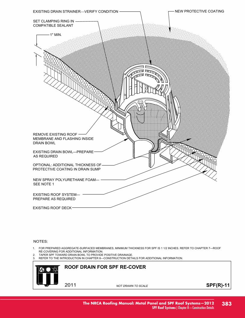
ROOF DRAIN FOR SPF RE-COVER
SPF(R)-11
1'' MIN.
1.RE-COVERING FOR ADDITIONAL INFORMATION.
2. TAPER SPF TOWARD DRAIN BOWL TO PROVIDE POSITIVE DRAINAGE.3.
AS REQUIRED
SET CLAMPING RING INCOMPATIBLE SEALANT
NEW PROTECTIVE COATING
SEE NOTE 1
PREPARE AS REQUIRED
EXISTING ROOF DECK
REMOVE EXISTING ROOFMEMBRANE AND FLASHING INSIDEDRAIN BOWL
OPTIONAL: ADDITIONAL THICKNESS OFPROTECTIVE COATING IN DRAIN SUMP
EXISTING DRAIN STRAINER VERIFY CONDITION
383The NRCA Roofing Manual: Metal Panel and SPF Roof Systems—2012SPF Roof Systems | Chapter 8—Construction Details

This page is intentionally left blank.