Embed Size (px)
Citation preview
CHAPTER 9
STORMWATER BEST MANAGEMENT PRACTICES (BMPs)
NOTE: All questions and comments should be directed to the Drainage Specialist, Design Support Area.
Revised January 2006
Stormwater Best Management Practices (BMPs) 9-2
Chapter Table of Contents 9.1 Introduction/Purpose 9-3
9.1.1 Non-Point Source Pollution Overview 9-3
9.1.2 Soil Erosion and Sedimentation Control 9-4
9.2 Definitions 9-6
9.3 Policy and Design Criteria 9-7
9.3.1 Federal Policy 9-7
9.3.2 AASHTO Policy 9-7
9.3.3 MDOT Policy 9-7
9.4 Design Guidance and Procedure 9-9
9.4.1 BMP Selection Process 9-9
9.4.1.1 MDOT Goals 9-10
9.4.1.2 Project Delivery Steps 9-11
9.4.1.3 Location Issues 9-12
9.4.1.4 Excluded Projects 9-12
9.4.2 MDOT-Approved BMPs 9-13
9.4.2.1 Summary List for BMP Selection 9-13
9.4.2.2 BMP Descriptions and Applications 9-18
References 9-35
Weblinks 9-36
Appendices 9-A Symbols and Acronyms 9-A-1
9-B Cost List for MDOT-Approved BMPs 9-B-1
Tables 9-1 List of MDOT-Approved BMPs 9-14

Stormwater Best Management Practices (BMPs) 9-3
9.1 INTRODUCTION/PURPOSE The purpose of this chapter is to introduce Stormwater Best Management Practices (BMPs) for use in MDOT operations, and to give a brief overview of how they can be used to improve water quality. Some MDOT publications call out for BMP elements to be "Designed by the Engineer." This chapter will give additional design information for references made to "the engineer" within MDOT’s Soil Erosion and Sedimentation Control (SESC) Manual. It is not the intent of this chapter to provide an all-encompassing list of potential BMPs to be used by MDOT. BMPs in other MDOT publications can and should be referenced by the engineer. Note the numbers (E&S-#) of standard plan R-96-Series following titles of BMPs discussed in this chapter are numbers used in the SESC Manual. The chapter will also direct the designer to other resources available within the manual and elsewhere. Operational BMPs are not discussed with great detail in this manual. The Stormwater Management Plan (SWMP) should be consulted for guidance on operational BMPs. The SWMP will be completed in 2006. 9.1.1 Non-Point Source Pollution Overview The Michigan Department of Environmental Quality (MDEQ) issues National Pollutant Discharge Elimination System (NPDES) permits to MDOT. The permits require MDOT to implement a Stormwater Management Plan (SWMP), which will include a description of plans to accomplish illicit discharge elimination, public education, and stormwater pollution prevention. This chapter helps to fulfill these requirements by giving guidance on how to use BMPs to prevent soil erosion and sedimentation which contribute to stormwater pollution. A link to the MDOT SWMP can be found at:
http://www.michigan.gov/stormwater
Stormwater Best Management Practices (BMPs) 9-4
9.1.2 Soil Erosion and Sedimentation Control The MDOT SESC Manual describes how MDOT, as an Authorized Public Agency (APA) under Part 91 of Public Act 451, NREPA of 1994 as amended, will conduct earth change activities on construction and maintenance projects with a minimum of erosion and off-site sedimentation. The SESC Manual can be referenced when utility work or driveway work under an MDOT-issued permit has the potential to generate off-site sediment. However, the permit applicant must still obtain a Part 91 permit from the County or Municipal Enforcing Agencies (CEA or MEA). Soil erosion and sedimentation control procedures have been established which, when properly used, will minimize soil erosion and sedimentation problems associated with construction, operation, and maintenance of MDOT roads. This chapter uses information from the SESC Manual, but for more details on soil erosion policy, the SESC Manual should be consulted. Soil erosion and sedimentation are natural or geologic processes whereby soil materials are detached and transported from one location and deposited in another, primarily due to rainfall, runoff, and wind. Accelerated erosion and sedimentation can sometimes occur in conjunction with highway and transportation facility construction. This accelerated process can result in significant impacts such as safety hazards, expensive maintenance problems, unsightly conditions, instability of slopes, and disruption of ecosystems. Furthermore, pollutants readily attach to and are carried by sediments. For these reasons, the design process must be done with consideration given to the minimization of soil erosion. Since modern highway construction may involve the disturbance of large land areas, control of soil erosion and sedimentation is a major concern. A commitment to soil erosion and sedimentation prevention during all phases of highway design, construction, and maintenance is essential. While much of the effort for control of soil erosion and sedimentation is expended during the construction phase of a highway project, a successful program must address soil erosion and sedimentation during location planning, design, operation, and future maintenance phases. Designers should refer to the SESC Manual for additional guidance in these subjects. The inherent erosion potential of any area is determined by four principal factors: soil characteristics, vegetative cover, topography, and climate. Although each of these factors is discussed separately herein, they are interrelated in determining erosion potential. Soil Characteristics The properties of soil which influence erosion by rainfall and runoff are ones which affect the infiltration capacity of a soil and those which affect the resistance of a soil to detachment and being carried away by falling or flowing water. Soils containing high percentages of fine sands and silt are normally the most erodible. As the clay and organic matter content of these soils increase, the erodibility decreases. The cohesive nature of clay acts as a binder to soil particles, thus reducing erodibility. However, while clays have a
Stormwater Best Management Practices (BMPs) 9-5
tendency to resist erosion, once eroded they are easily transported by water. Soils high in organic matter have a more stable structure which improves their permeability. Such soils resist raindrop detachment and infiltrate more rainwater. Clean, well-drained, and well-graded gravels and gravel-sand mixtures are usually the least erodible soils. Soils with high infiltration rates and permeabilities reduce the amount of runoff. Vegetative Cover Vegetative cover plays an important role in controlling erosion in the following ways:
• slows the velocity of runoff,
• shields the soil surface from the impact of falling rain,
• holds soil particles in place,
• maintains the soil's capacity to absorb water, and
• removes subsurface water between rainfalls through the process of evapotranspiration.
Limiting and staging the removal of existing vegetation and decreasing the area and duration of exposure can significantly reduce soil erosion and sedimentation. Special consideration should be given to the maintenance of existing vegetative cover on areas of high erosion potential such as erodible soils, steep slopes, drainageways, and the banks of streams. Topography The size, shape, and slope characteristics of a watershed influence the amount and rate of runoff. As both slope length and gradient increase, the rate of runoff increases and the potential for erosion is magnified. Slope orientation can also be a factor in determining erosion potential. Climate The frequency, intensity, and duration of rainfall are fundamental factors in determining the amounts of runoff produced in a given area. As both the volume and velocity of runoff increase, the capacity of runoff to detach and transport soil particles also increases. Where storms are frequent, intense, or of long duration, erosion risks are high. Seasonal changes in temperature, as well as variations in rainfall, help to define the high erosion risk period of the year. When precipitation falls as snow, no erosion will take place. However, in the spring the melting snow adds to the runoff and erosion hazards are high. Frozen soils have a reduced ability to absorb but are relatively erosion resistant. However, soils with high moisture content are subject to uplift during freezing and are usually very easily eroded upon thawing.
Stormwater Best Management Practices (BMPs) 9-6
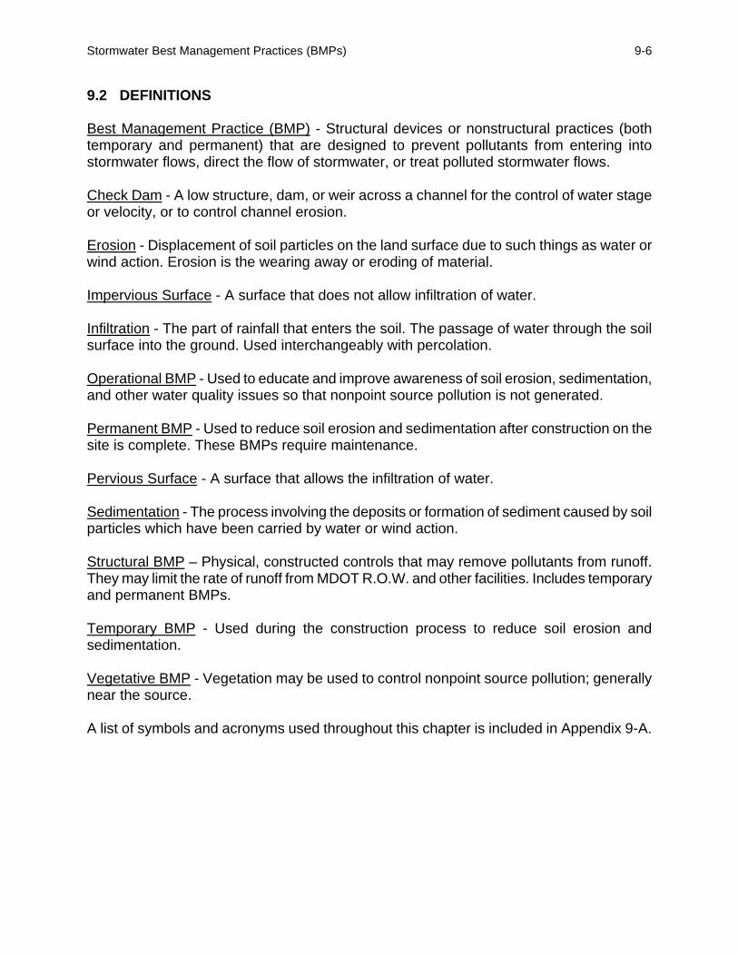
9.2 DEFINITIONS Best Management Practice (BMP) - Structural devices or nonstructural practices (both temporary and permanent) that are designed to prevent pollutants from entering into stormwater flows, direct the flow of stormwater, or treat polluted stormwater flows. Check Dam - A low structure, dam, or weir across a channel for the control of water stage or velocity, or to control channel erosion. Erosion - Displacement of soil particles on the land surface due to such things as water or wind action. Erosion is the wearing away or eroding of material. Impervious Surface - A surface that does not allow infiltration of water. Infiltration - The part of rainfall that enters the soil. The passage of water through the soil surface into the ground. Used interchangeably with percolation. Operational BMP - Used to educate and improve awareness of soil erosion, sedimentation, and other water quality issues so that nonpoint source pollution is not generated. Permanent BMP - Used to reduce soil erosion and sedimentation after construction on the site is complete. These BMPs require maintenance. Pervious Surface - A surface that allows the infiltration of water. Sedimentation - The process involving the deposits or formation of sediment caused by soil particles which have been carried by water or wind action. Structural BMP – Physical, constructed controls that may remove pollutants from runoff. They may limit the rate of runoff from MDOT R.O.W. and other facilities. Includes temporary and permanent BMPs. Temporary BMP - Used during the construction process to reduce soil erosion and sedimentation. Vegetative BMP - Vegetation may be used to control nonpoint source pollution; generally near the source. A list of symbols and acronyms used throughout this chapter is included in Appendix 9-A.
Stormwater Best Management Practices (BMPs) 9-7
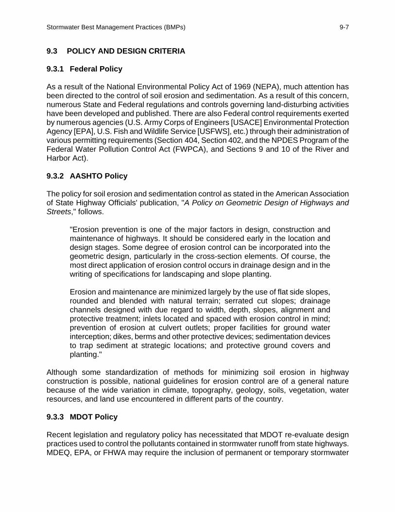
9.3 POLICY AND DESIGN CRITERIA 9.3.1 Federal Policy As a result of the National Environmental Policy Act of 1969 (NEPA), much attention has been directed to the control of soil erosion and sedimentation. As a result of this concern, numerous State and Federal regulations and controls governing land-disturbing activities have been developed and published. There are also Federal control requirements exerted by numerous agencies (U.S. Army Corps of Engineers [USACE] Environmental Protection Agency [EPA], U.S. Fish and Wildlife Service [USFWS], etc.) through their administration of various permitting requirements (Section 404, Section 402, and the NPDES Program of the Federal Water Pollution Control Act (FWPCA), and Sections 9 and 10 of the River and Harbor Act). 9.3.2 AASHTO Policy The policy for soil erosion and sedimentation control as stated in the American Association of State Highway Officials' publication, "A Policy on Geometric Design of Highways and Streets," follows.
"Erosion prevention is one of the major factors in design, construction and maintenance of highways. It should be considered early in the location and design stages. Some degree of erosion control can be incorporated into the geometric design, particularly in the cross-section elements. Of course, the most direct application of erosion control occurs in drainage design and in the writing of specifications for landscaping and slope planting. Erosion and maintenance are minimized largely by the use of flat side slopes, rounded and blended with natural terrain; serrated cut slopes; drainage channels designed with due regard to width, depth, slopes, alignment and protective treatment; inlets located and spaced with erosion control in mind; prevention of erosion at culvert outlets; proper facilities for ground water interception; dikes, berms and other protective devices; sedimentation devices to trap sediment at strategic locations; and protective ground covers and planting."
Although some standardization of methods for minimizing soil erosion in highway construction is possible, national guidelines for erosion control are of a general nature because of the wide variation in climate, topography, geology, soils, vegetation, water resources, and land use encountered in different parts of the country. 9.3.3 MDOT Policy Recent legislation and regulatory policy has necessitated that MDOT re-evaluate design practices used to control the pollutants contained in stormwater runoff from state highways. MDEQ, EPA, or FHWA may require the inclusion of permanent or temporary stormwater
Stormwater Best Management Practices (BMPs) 9-8
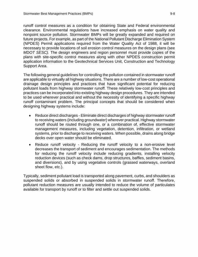
runoff control measures as a condition for obtaining State and Federal environmental clearance. Environmental regulations have increased emphasis on water quality and nonpoint source pollution. Stormwater BMPs will be greatly expanded and required on future projects. For example, as part of the National Pollutant Discharge Elimination System (NPDES) Permit applications required from the Water Quality Act of 1988, it will be necessary to provide locations of soil erosion control measures on the design plans (see MDOT SESC). The design engineers and region personnel must provide copies of the plans with site-specific control measures along with other NPDES construction permit application information to the Geotechnical Services Unit, Construction and Technology Support Area. The following general guidelines for controlling the pollution contained in stormwater runoff are applicable to virtually all highway situations. There are a number of low-cost operational drainage design principles and practices that have significant potential for reducing pollutant loads from highway stormwater runoff. These relatively low-cost principles and practices can be incorporated into existing highway design procedures. They are intended to be used wherever practical and without the necessity of identifying a specific highway runoff contaminant problem. The principal concepts that should be considered when designing highway systems include:
• Reduce direct discharges - Eliminate direct discharges of highway stormwater runoff to receiving waters (including groundwater) wherever practical. Highway stormwater runoff should be routed through one, or a combination of, effective stormwater management measures, including vegetation, detention, infiltration, or wetland systems, prior to discharge to receiving waters. When possible, drains along bridge decks over open water should be eliminated.
• Reduce runoff velocity - Reducing the runoff velocity to a non-erosive level decreases the transport of sediment and encourages sedimentation. The methods for reducing the runoff velocity include reducing gradients, installing velocity reduction devices (such as check dams, drop structures, baffles, sediment basins, and diversions), and by using vegetative controls (grassed waterways, overland sheet flow, etc.).
Typically, sediment pollutant load is transported along pavement, curbs, and shoulders as suspended solids or absorbed in suspended solids in stormwater runoff. Therefore, pollutant reduction measures are usually intended to reduce the volume of particulates available for transport by runoff or to filter and settle out suspended solids.

Stormwater Best Management Practices (BMPs) 9-9
9.4 DESIGN GUIDANCE AND PROCEDURE This section offers design guidance in choosing the correct BMP application. Designers may also consult SWMP; a link is located on the MDOT stormwater website:
www.michigan.gov/stormwater
9.4.1 BMP Selection Process Stormwater BMPs should be used when feasible. The following paragraphs outline the MDOT structural BMP identification/selection process. The MDOT SWMP gives a listing of MDOT-approved BMPs and their effectiveness. A link to SWMP can be found at the website given above. The Environmental Section of Project Planning Division will provide, in its environmental documentation, a review of a project for potential need of structural BMP(s) for stormwater. Environmental documentation, in the form of Environmental Impact Statement (EIS), Environmental Assessment (EA), or Form 1775 for Categorical Exclusions (CE), will be provided to the Project Manager and will alert them of the potential need for structural BMPs for stormwater runoff control, to the maximum extent practicable, for the project. Structural BMP selection will be identified as needed for a project based on the following considerations:
• Type of project, i.e., only if drainage patterns are modified or altered.
• Average daily traffic is greater than 30,000 vehicles.
• Drainage area ratio from the highway to receiving waters.
• Environmental permit mitigation requirements.
• Request to meet local agency stormwater ordinances.
• Local agency’s NPDES MS4 permit requirements. The Environmental Section of Project Planning Division, upon request of the Project Manager, will organize a project meeting, appropriate design (development) staff and consultants, operation (delivery) staff, and regional stormwater coordinator to review stormwater recommendations for structural BMPs to be implemented within project limitations. The following BMPs may be required:
• Vegetative Controls.
• Detention Basins (see Chapter 8, Stormwater Storage Facilities, Section 8.4.1).
• Infiltration Facilities (see Chapter 8, Stormwater Storage Facilities, Section 8.4.4).
• Retention Basins (see Chapter 8, Stormwater Storage Facilities, Section 8.4.2).

Stormwater Best Management Practices (BMPs) 9-10
9.4.1.1 MDOT Goals To make a stormwater management program effective, it must be considered during the project development stage. Planned measures, if conscientiously and expeditiously applied during construction, result in orderly development without environmental degradation. From the previous discussion (Section 9.3.3) about soil erosion and sedimentation processes and the factors affecting erosion, basic MDOT BMP goals can assist the designer in choosing effective erosion and sedimentation control. The following goals should be achieved to the maximum extent practical on all projects:
• Maximize vegetated surfaces (for nonpoint source control).
• Stabilize disturbed soil areas. Minimize the extent and duration of exposure. Keep runoff velocities low and retain runoff on the site.
• Control downstream erosion and sedimentation.
• Minimize adverse downstream effects (quality/quantity issues). Post-development runoff equal to or less than pre-development runoff.
• Coordinate with local needs.
• Maintain BMPs to keep them working properly.
• Manage first flush (as defined in Chapter 8, Stormwater Storage Facilities, Sections 8.2 and 8.3.3).
Usually, these goals are achieved by using a system of vegetative and structural BMPs along with management techniques to develop a plan to prevent erosion and control sedimentation. In most cases, a combination of limited time of exposure, a sensible selection of erosion control practices, and sedimentation trapping facilities will prove to be the most practical method of controlling erosion and the associated transport of sediment.
Stormwater Best Management Practices (BMPs) 9-11
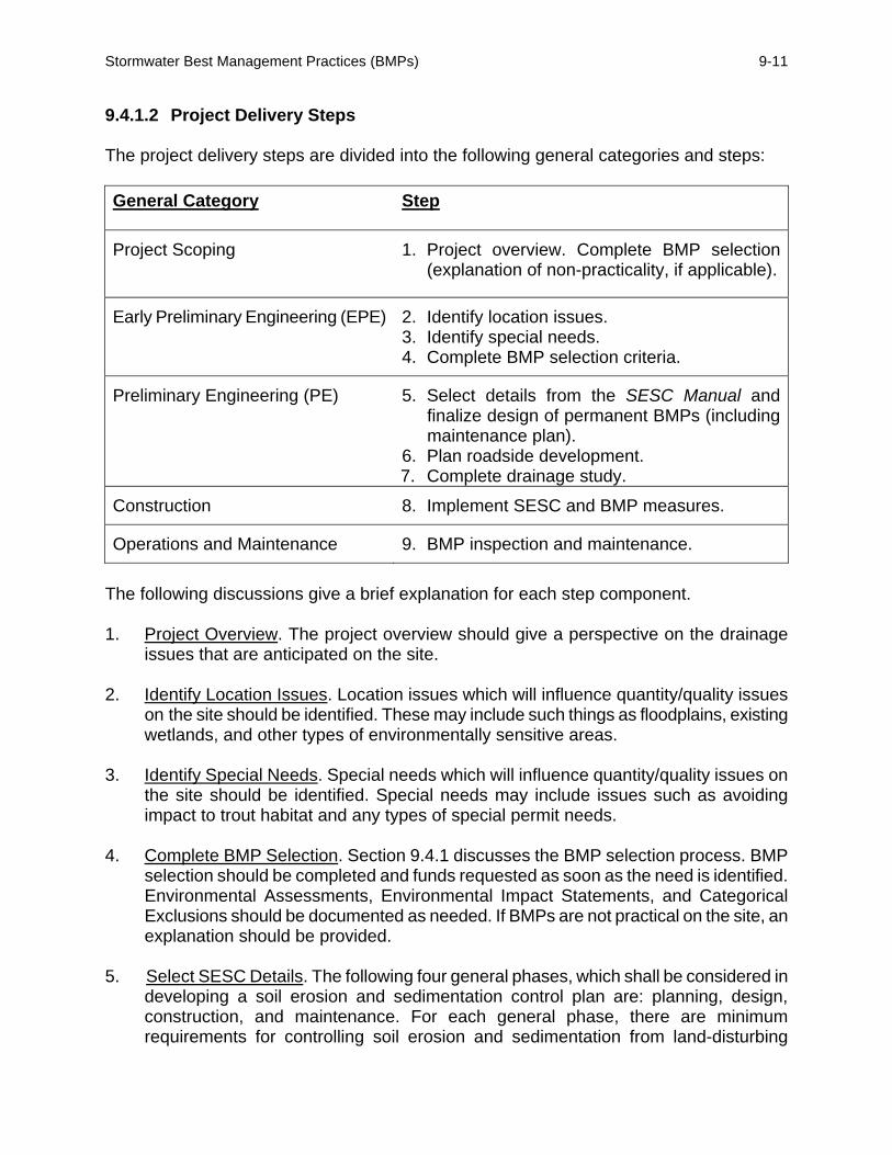
9.4.1.2 Project Delivery Steps The project delivery steps are divided into the following general categories and steps: General Category Step
Project Scoping
1. Project overview. Complete BMP selection (explanation of non-practicality, if applicable).
Early Preliminary Engineering (EPE)
2. Identify location issues. 3. Identify special needs. 4. Complete BMP selection criteria.
Preliminary Engineering (PE)
5. Select details from the SESC Manual and finalize design of permanent BMPs (including maintenance plan).
6. Plan roadside development. 7. Complete drainage study.
Construction 8. Implement SESC and BMP measures.
Operations and Maintenance 9. BMP inspection and maintenance.
The following discussions give a brief explanation for each step component. 1. Project Overview. The project overview should give a perspective on the drainage
issues that are anticipated on the site. 2. Identify Location Issues. Location issues which will influence quantity/quality issues
on the site should be identified. These may include such things as floodplains, existing wetlands, and other types of environmentally sensitive areas.
3. Identify Special Needs. Special needs which will influence quantity/quality issues on
the site should be identified. Special needs may include issues such as avoiding impact to trout habitat and any types of special permit needs.
4. Complete BMP Selection. Section 9.4.1 discusses the BMP selection process. BMP
selection should be completed and funds requested as soon as the need is identified. Environmental Assessments, Environmental Impact Statements, and Categorical Exclusions should be documented as needed. If BMPs are not practical on the site, an explanation should be provided.
5. Select SESC Details. The following four general phases, which shall be considered in
developing a soil erosion and sedimentation control plan are: planning, design, construction, and maintenance. For each general phase, there are minimum requirements for controlling soil erosion and sedimentation from land-disturbing
Stormwater Best Management Practices (BMPs) 9-12
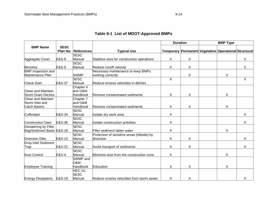
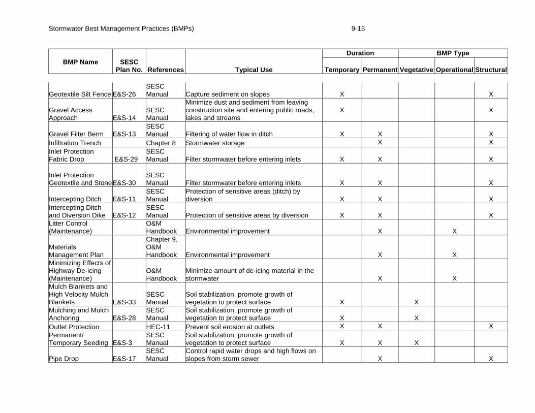
activities. These general requirements work in concert with individually developed soil erosion and sedimentation control details (by special provision). They establish minimum standards of soil conservation practice which apply to all land disturbing projects. For details on the specific required controls for each phase, see the SESC Manual. Table 9-1, gives an overview of MDOT approved BMPs, typical use, and where design details can be found. BMPs, which have reference to "the engineer," are covered more specifically in the following sections (as noted in Table 9-1).
6. Plan Roadside Development. A vegetation management plan should be developed to
ensure vegetation is able to survive after the project is completed. The vegetation management plan should include plans to maintain existing vegetation and develop new vegetation on the site, if feasible.
7. Drainage Study. An analysis must be performed to anticipate any downstream affects
the project may induce. The MDOT hydraulic report may be required for the project. A copy of the report can be found in Chapter 6, Bridges, Appendix 6-C.
8. Implement SESC and BMP measures. Implemented by contractor and verified by
construction engineer. Contractor may be required to maintain SESCs during construction.
9. BMP Inspection and Maintenance (where applicable). As described in this chapter or
in the BMP plan developed for the project. 9.4.1.3 Location Issues Location of construction projects has a direct impact on the types of BMPs that will be necessary. When considering the location of a project, be aware of environmentally sensitive areas. This information will come from:
• 305(b) - Water Quality and Pollution Control. • Form 1775 - Environmental Clearance, Categorical Exclusions.
• MDOT MS4 Permit.
• MDOT Regional Stormwater Management Plan. 9.4.1.4 Excluded Projects Some types of projects may not require use of BMPs. Exempted projects would not change any existing stormwater discharge quality or quantity. Check with your Regional Stormwater Coordinator.
Stormwater Best Management Practices (BMPs) 9-13
9.4.2 MDOT-Approved BMPs The following two sections describe MDOT-approved BMPs. Section 9.4.2.1 lists approved BMPs in a table format, and Section 9.4.2.2 lists the BMPs in alphabetical order along with their definition and applications. 9.4.2.1 Summary List for BMP Selection Table 9-1 gives an alphabetized listing of BMPs, which can be used on MDOT projects. These BMPs are taken from the SESC Manual and the MDOT SWMP. BMPs which need more explanation than is provided in the SESC Manual are discussed in Section 9.4.2.2; otherwise, for design details, see the references given in Table 9-1. Copies of details identified can be found in the SESC Manual. Estimated costs are provided in Appendix 9-B. When selecting BMPs, use those given in Table 9-1. Additionally, there are some BMPs selection guidelines, listed below, which should always be used to help accomplish MDOT goals. 1. Preserve the natural drainage system. 2. Control source pollutants by:
• Maximizing green space.
• Protecting riparian buffer.
• Stabilizing disturbed areas.
• Identifying proper use of fertilizers and pesticides.
• Identifying proper use of snow and ice control operations. 3. Evaluate site according to project delivery steps outlined in Section 9.4.1.2. 4. Use SESC details, outlined in the SESC Manual, for evaluation during construction. 5. Prepare a plan for proper operation, inspection, and maintenance to keep BMPs
working as intended. A proper plan may include the following items:
• Schedule for maintenance.
• Necessary actions.
• Responsibility chart for actions.
• Equipment required.
• Cost opinions.
Stormwater Best Management Practices (BMPs) 9-14
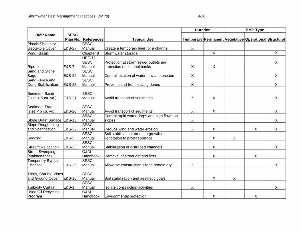
Table 9-1 List of MDOT-Approved BMPs
Duration BMP Type BMP Name
SESC
Plan No. References Typical Use
Temporary
Permanent
Vegetative
Operational
Structural
Aggregate Cover E&S-8 SESC Manual Stabilize area for construction operations X X X
Benches E&S-9 SESC Manual Reduce runoff velocity X X X
BMP Inspection and Maintenance Plan SWMP
Necessary maintenance to keep BMPs working correctly
X
X
Check Dam E&S-37 SESC Manual Reduce erosive velocities in ditches
X X
Clean and Maintain Storm Drain Ditches
Chapter 4 and O&M Handbook Remove contaminated sediments
X
X
X
Clean and Maintain Storm Inlet and Catch Basins
Chapter 7 and O&M Handbook Remove contaminated sediments
X
X
X
Cofferdam E&S-34 SESC Manual Isolate dry work area
X
X
Construction Dam E&S-36 SESC Manual Isolate construction activities
X
X
Dewatering by Filter Bag/Sediment Basin E&S-18
SESC Manual Filter sediment laden water X X
Diversion Dike E&S-10 SESC Manual
Protection of sensitive areas (hillside) by diversion X X X
Drop Inlet Sediment Trap E&S-31
SESC Manual Avoid transport of sediments X X X
Dust Control E&S-4 SESC Manual Minimize dust from the construction zone X X
Employee Training
SWMP and O&M Handbook Education
X
X
X
Energy Dissipators E&S-19
HEC-14, SESC Manual Reduce erosive velocities from storm sewer
X
X
X
Stormwater Best Management Practices (BMPs) 9-15
Duration BMP Type BMP Name
SESC
Plan No. References Typical Use
Temporary
Permanent
Vegetative
Operational
Structural
Geotextile Silt Fence E&S-26 SESC Manual Capture sediment on slopes
X
X
Gravel Access Approach E&S-14
SESC Manual
Minimize dust and sediment from leaving construction site and entering public roads, lakes and streams
X
X
Gravel Filter Berm E&S-13 SESC Manual Filtering of water flow in ditch X X X
Infiltration Trench Chapter 8 Stormwater storage X X Inlet Protection Fabric Drop E&S-29
SESC Manual Filter stormwater before entering inlets X X X
Inlet Protection Geotextile and Stone E&S-30
SESC Manual Filter stormwater before entering inlets
X
X
X
Intercepting Ditch E&S-11 SESC Manual
Protection of sensitive areas (ditch) by diversion X X X
Intercepting Ditch and Diversion Dike E&S-12
SESC Manual Protection of sensitive areas by diversion X X X
Litter Control (Maintenance)
O&M Handbook Environmental improvement
X
X
Materials Management Plan
Chapter 9, O&M Handbook Environmental improvement
X
X
Minimizing Effects of Highway De-icing (Maintenance)
O&M Handbook
Minimize amount of de-icing material in the stormwater
X
X
Mulch Blankets and High Velocity Mulch Blankets E&S-33
SESC Manual
Soil stabilization, promote growth of vegetation to protect surface
X
X
Mulching and Mulch Anchoring E&S-28
SESC Manual
Soil stabilization, promote growth of vegetation to protect surface
X
X
Outlet Protection HEC-11 Prevent soil erosion at outlets X X X Permanent/ Temporary Seeding E&S-3
SESC Manual
Soil stabilization, promote growth of vegetation to protect surface
X
X
X
Pipe Drop E&S-17 SESC Manual
Control rapid water drops and high flows on slopes from storm sewer
X
X
Stormwater Best Management Practices (BMPs) 9-16
Duration BMP Type BMP Name
SESC
Plan No. References Typical Use
Temporary
Permanent
Vegetative
Operational
Structural Plastic Sheets or Geotextile Cover E&S-27
SESC Manual Create a temporary liner for a channel
X
Pond (Basin) Chapter 8 Stormwater storage X X
Riprap E&S-7
HEC-11, SESC Manual
Protection at storm sewer outlets and protection of channel banks
X
X
X
Sand and Stone Bags E&S-24
SESC Manual Control location of water flow and erosion
X
X
Sand Fence and Dune Stabilization E&S-25
SESC Manual Prevent sand from leaving dunes
X
X
Sediment Basin ( size > 5 cu. yd.) E&S-21
SESC Manual Avoid transport of sediments
X
X
X
Sediment Trap (size < 5 cu. yd.) E&S-20
SESC Manual Avoid transport of sediments
X
X
X
Slope Drain Surface E&S-15 SESC Manual
Control rapid water drops and high flows on slopes
X
X
Slope Roughening and Scarification E&S-32
SESC Manual Reduce wind and water erosion
X
X
X
X
Sodding E&S-5 SESC Manual
Soil stabilization, promote growth of vegetation to protect surface
X
X
Stream Relocation E&S-23 SESC Manual Stabilization of disturbed channels
X
X
Street Sweeping (Maintenance)
O&M Handbook Removal of street dirt and litter.
X
X
Temporary Bypass Channel E&S-35
SESC Manual Allow the construction site to remain dry
X
X
Trees, Shrubs, Vines and Ground Cover E&S-16
SESC Manual Soil stabilization and aesthetic goals
X
X
Turbidity Curtain E&S-1 SESC Manual Isolate construction activities
X
X
Used Oil Recycling Program
O&M Handbook Environmental protection
X
X

Stormwater Best Management Practices (BMPs) 9-17
Duration BMP Type BMP Name
SESC
Plan No. References Typical Use
Temporary
Permanent
Vegetative
Operational
Structural Vegetated Buffer at Watercourse E&S-22
SESC Manual
Sediment and pollutant filtering and reduction of sheet flow velocities
X
X
Vegetative Buffer Strips E&S-6
SESC Manual
Reduction of sheet flow velocities and prevent rilling and gulling
X
X
Note: References in “References” column refer to: SWMP = MDOT Stormwater Management Plan O&M Handbook = MDOT Operations and Maintenance Handbook SESC Manual = MDOT Soil Erosion and Sedimentation Control Manual HEC = Hydraulic Engineering Circular 9.4.2.2 = Section within this chapter Chapter 8 = Chapter within this manual
Stormwater Best Management Practices (BMPs) 9-18
9.4.2.2 BMP Descriptions and Applications This section will give additional design information for references made to "the engineer" within MDOT’s SESC Manual. Specifically, additional design information is provided for the following BMPs: check dam, diversion dike, energy dissipators, gravel filter berm, intercepting ditch, intercepting ditch and diversion dike, pipe drop, riprap, slope drain surface, stream relocation, temporary bypass channel, and turbidity curtain. Aggregate Cover – Details can be found in the SESC Manual (E&S-8). This BMP can be used as either a temporary or permanent BMP and is classified as structural. Applications – Used to stabilize soils in high traffic areas, equipment storage areas, or
areas which would develop into a soil erosion problem as a result of intensive activities and loss of vegetative cover.
Benches – Details can be found in the SESC Manual (E&S-9). This BMP can be used as either a temporary or permanent BMP and is classified as structural. Applications – Creative grading technique used on long slopes to prevent sheet flow
from gaining velocity which may result in soil erosion and sedimentation problems. BMP Inspection and Maintenance Plan – Plans to regularly inspect and maintain BMPs to assure their effectiveness and structural integrity. Details can be found in the MDOT SWMP. This BMP should be used permanently and is classified as operational. Applications – All BMPs should be regularly inspected and maintained. Check Dam – A device constructed across ditch lines used to reduce velocity of concentrated flows in the ditch and to protect vegetation. Details can be found in the SESC Manual (E&S-37). This BMP is temporary and is classified as structural.
Applications – Check dams are constructed to reduce the velocity of concentrated flows and protect vegetation. Although check dams also collect sediment, and hence act as filters, their primary purpose is to reduce erosive velocities. Check dams should be used when it is not practical to divert flow to a stabilized outlet or where weather conditions prevent the timely installation of vegetation or non-erosive liners. Factors Affecting Preliminary Design – Consideration should be given to slope and depth of the ditch, design flow, and design velocity. These items will dictate stone size and other physical features. Implementation – Check dams should be applied during the construction of ditches and diversions and before vegetation is established. Stone should be placed in the ditch banks and extended a minimum of 18 inches above the anticipated flow to avoid washouts from overflow around the dam. The area downstream of the last check dam should be stabilized or the flow diverted to a stabilized outlet.

Stormwater Best Management Practices (BMPs) 9-19
Design Example – See HEC-14 for examples of check dam design. Maintenance Requirements – A Certified Stormwater Operator should inspect check dams after each precipitation event that results in a discharge to ensure there is no piping under the structure or around its banks during construction. All damage should be corrected immediately. If banks are severely eroded, consider other stabilization options. Sedimentation should be removed when it accumulates to one-half the height of the dam to ensure water can flow through the dam and to prevent large flows from carrying sediment over the dam. Add stones as needed to maintain design height and cross section. Also, be sure that culverts and other structures below the check dam are not damaged or blocked due to any displaced stone.
Clean and Maintain Storm Drain Ditches – Plans to regularly clean and maintain channels to assure their effectiveness. Details can be found in MDOT’s O&M Handbook. This BMP should be used permanently and is classified as operational. Applications – All storm drainage channels should be regularly cleaned and
maintained. Clean and Maintain Storm Inlet and Catch Basins – Plans to regularly clean and maintain inlets and catch basins to assure their effectiveness. Details can be found in MDOT’s O&M Handbook. This BMP should be used permanently and is classified as operational. Applications – All storm inlets and catch basins should be regularly cleaned and
maintained. Cofferdam – A temporary dam placed to prevent flow from entering the project site area. Details can be found in the SESC Manual (E&S-34). This BMP should be used temporarily and is classified as structural. Applications – Use where a dry construction site within the streambed is required. Construction Dam – A temporary dam placed to prevent from entering the project site area. Details can be found in the SESC Manual (E&S-36). This BMP should be used temporarily and is classified as structural. Applications – Construction dams should be used when a dry or slack water area
is necessary to isolate construction activities from the watercourse. A construction dam can be used for a shorter duration than a cofferdam.
Dewatering by Filter Bag/Sediment Basin – A method of releasing water and cleaning from a depressed area. Details can be found in the SESC Manual (E&S-18). This BMP is temporary and classified as operational.
Stormwater Best Management Practices (BMPs) 9-20
Applications – Dewatering with a filter bag should be used on retained water (cofferdam, sediment basin) being discharged to surface waters. It may be used in conjunction with a sediment basin.
Diversion Dike – A temporary or permanent ridge of compacted earth constructed across sloping land to protect work or sensitive areas from upslope runoff by diverting flow away. Details can be found in the SESC Manual (E&S-10). This BMP can be used as either a permanent or temporary BMP and is classified as structural.
Applications – Diversion dikes are best utilized in construction areas where runoff can be diverted and properly outletted to control erosion, sedimentation, or flood damage. Specific locations are listed on the SESC Manual detail sheet. Design Criteria – It is important that engineers design diversion dikes; too steep a slope can result in erosive velocity behind the diversion dike or at the outlet. The design example given in MDEQ’s Guidebook of BMPs for Michigan Watersheds gives designer’s guidance on proper design velocities. Factors Affecting Preliminary Design – Changes in slope from steep to flat may cause unwanted deposition to occur. The deposition can reduce the carrying capacity and may cause overtopping and failure. Designers should also consider the type of soil and vegetation that will be used in the dike. Implementation – Diversion dikes should be stabilized with topsoil, seed, and mulch or mulch blankets immediately after completion. Any excavated or surplus soil shall be disposed of in an upland area outside any floodplain or wetland areas Maintenance Requirements – Frequent inspection and timely maintenance are essential to the proper functioning of a diversion dike. Diversion dikes should be inspected after each storm to ensure there is no piping under the dike. Damage should be repaired immediately.
Drop Inlet Sediment Trap – A temporary device used to trap sediment from stormwater before it enters the storm sewer system. Details can be found in the SESC Manual (E&S-31). This BMP can be used as either a temporary or permanent BMP and is classified as structural. Applications – Should be used on construction sites with sediment-laden runoff where
minimal flows are expected to enter a catch basin and settling of large particles is desired.
Dust Control – Means of limiting dust generated during construction by grade watering or other methods. Details can be found in the SESC Manual (E&S-4). This BMP should be used temporarily and is classified as operational.
Stormwater Best Management Practices (BMPs) 9-21
Applications – Should be used during construction to minimize amount of dust leaving the site.
Employee Training – Training MDOT employees to be aware of BMPs and their importance. Details can be found in the MDOT SWMP and the O&M Handbook. This BMP is permanent and classified as operational. Applications – All appropriate MDOT staff should be trained. Energy Dissipators – Structures used to control erosion in a channel or conduit. Details can be found in the SESC Manual (E&S-19) and HEC-14. This BMP can be used as either a temporary or permanent BMP and is classified as structural. Applications – Use energy dissipators to reduce velocity of flow and dissipate energy
at outlets of channels or conduits which will, in turn, reduce erosion. Design Criteria – Design criteria for energy dissipators is given in FHWA’s publication HEC-14, Hydraulic Design of Energy Dissipators for Culverts and Channels. Factors Affecting Preliminary Design – Factors to be considered include peak flow, velocity of flow, slope of the channel, and shape of the channel. Implementation – For guidance on how to implement energy dissipators, see HEC-14. Maintenance Requirements – Frequent inspection and timely maintenance are essential to the proper functioning of energy dissipators. Energy dissipators should be inspected after large storm events to ensure there is no piping or damage to the dissipator. Damage should be repaired immediately.
Geotextile Silt Fence – A permeable barrier used to capture sediment from sheet flow. Details can be found in the SESC Manual (E&S-26). This BMP should be used temporarily and is classified as structural. Applications – Use adjacent to disturbed areas to capture sediment from sheet flow. Gravel Access Approach – A temporary construction access road which helps minimize dust and tracking of loose materials from the work site to public roadways. Details can be found in the SESC Manual (E&S-14). This BMP should be used temporarily and is classified as structural. Applications – Use as a transition roadway between public roads and the construction
site. Gravel Filter Berm – A gravel filter used to clean water as it flows through. Details can be found in the SESC Manual (E&S-13). This BMP should be used temporarily and is classified as structural.
Stormwater Best Management Practices (BMPs) 9-22
Applications – Gravel filter berms are to be placed wherever a concentrated water flow requires filtering before leaving the construction site. Design Criteria – In profile, standard dimensions as indicated on SESC detail sheets should be used. In cross section, berm dimensions (e.g., bottom width and side slope) should be sized such that peak velocity is less than or equal to 2 feet per second. The water surface in the ditch downstream of the berm should be 6 to 12 inches below the crest of the berm. Factors Affecting Preliminary Design – The factors that affect preliminary design include peak flow rate and slope of the ditch. Implementation – Gravel filter berms are temporary in nature and shall be installed during times of active construction before water is released from dewatering area. Design Example – Given the following: Qpeak = 16 cfs Ditch Slope = 0.2 % Ditch Bottom Width = 4 feet Side slopes = 1V:4H Manning’s n = 0.025 y, Normal Depth (from Manning’s equation) = 1 foot Q = (1.486/n)(A)(R)^(2/3)(S)^(1/2) Where: A = 4y + y(4y) R = A/P P = 4 + 2y(17)^(1/2) S = 0.002 feet/feet Area in the channel at normal depth = 8 sf Velocity in the channel = 2 feet per second (16 cfs/8 sf) The velocity is 2 feet per second at the downstream face; therefore, installing 24 inches of stone will provide 1 foot of freeboard. Maintenance Requirements – A Certified Stormwater Operator should inspect gravel filter berms after each precipitation event that results in a discharge to ensure there is no piping under the structures or around banks during construction. All damage should be corrected immediately. Sedimentation should be removed when it accumulates to one-half the height of the berm to ensure water can flow through the berm and to prevent large flows from carrying sediment over the berm. Add/replace stones as needed to maintain design height, cross section, and filtering ability. Also, be sure that culverts and other structures below the berm are not damaged or blocked due to any displaced stone.
Stormwater Best Management Practices (BMPs) 9-23
Infiltration Trench – An excavated trench, backfilled with stone aggregate and lined with filter fabric. Used to treat small areas of runoff by detaining stormwater for short periods until it infiltrates down into the groundwater table. Details can be found in Chapter 8, Stormwater Storage Facilities. This BMP should be used permanently and is classified as structural. Applications – The use of an infiltration trench requires the following conditions:
• Permeable native soil. • Small drainage areas. • No convenient surface water outlet available or surface water is sensitive to the
discharge. • Location is available to facilitate maintenance.
Inlet Protection Fabric Drop – Geotextile fabric barrier built up around storm sewer inlets to prevent sediment and debris from entering the storm sewer system. Details can be found in the SESC Manual (E&S-29). This BMP should be used temporarily and is classified as structural. Applications – Use to capture sediment runoff during construction at the approach to
storm drain inlets where sediment-laden runoff is expected. Use in nonpaved areas. Inlet Protection Geotextile and Stone – Geotextile fabric placed over curb openings then covered with stone to prevent sediment and debris from entering the storm sewer system. Details can be found in the SESC Manual (E&S-30). This BMP should be used temporarily and is classified as structural. Applications – Use in paved areas on storm inlets at curb openings where flows are
expected to be minimal but filtration is desired. Intercepting Ditch – An intercepting ditch is a long, narrow ditch excavated into the earth on the upslope or downslope of a drainage area. It is used to intercept storm runoff and divert it to a safe outlet location where sediment can be removed by slowing down water velocities. Details can be found in the SESC Manual (E&S-11). This BMP can be used as either a permanent or temporary BMP and is classified as structural.
Applications – Intercepting ditches are best utilized in construction areas where runoff can be diverted to control erosion, sedimentation, or flood damage. Specific locations are listed in the SESC Manual details. Design Criteria – It is important that engineers design intercepting ditches; too steep a slope can result in erosive velocity behind the diversion dike or at the outlet. The design example given in MDEQ’s Guidebook of BMPs for Michigan Watersheds gives designer’s guidance on proper design velocities.

Stormwater Best Management Practices (BMPs) 9-24
Factors Affecting Preliminary Design – Factors include: type of soil, type of vegetation, profile and cross section, size of the drainage area, and peak runoff. Changes in slope from steep to flat may cause unwanted deposition to occur. The deposition can reduce carrying capacity and may cause overtopping and failure. Implementation – Any excavated or surplus soils shall be disposed of in an upland area outside any floodplain or wetland areas. Excavated soils must be adequately stabilized by the use of seed, mulch, or mulch blankets in sufficient quantities to prevent erosion and subsequent siltation to any off-site areas, floodplains, wetlands, lakes, or streams. If the intercepting ditch remains a permanent BMP, seed and high velocity mulch blankets must be placed and anchored throughout the limits of the ditch. Maintenance Requirements – Frequent inspection and timely maintenance are essential to the proper function of an intercepting ditch. Damages should be repaired immediately.
Intercepting Ditch and Diversion Dike – Combination of using both an intercepting ditch and dike as described above. Details can be found in the SESC Manual (E&S-12). This BMP can be used as either a permanent or temporary BMP and is classified as structural.
Applications – Use to intercept sediment-laden storm runoff by diverting it to safe outlet areas where sediments can be removed by slowing down the water velocity, or divert water away from disturbed areas. Design Criteria – It is important that engineers design intercepting ditches and diversion dikes; too steep a slope can result in erosive velocity behind the diversion dike, within the ditch, or at the outlet. The design example given in MDEQ’s Guidebook of BMPs for Michigan Watersheds gives designers guidance on design velocities. Factors Affecting Preliminary Design – Changes in slope from steep to flat may cause unwanted deposition to occur. The deposits can reduce the carrying capacity of the ditch and may cause overtopping and failure. Designers should also consider the type of soil and vegetation that will be used. Implementation – See practices listed for diversion dike or intercepting ditch. Maintenance Requirements – See maintenance requirements listed for diversion dike or intercepting ditch.
Litter Control (Maintenance) – Controlling litter to reduce potential clogging, and properly disposing of paper, plastic, and glass. Details can be found in the MDOT O&M Handbook. This BMP should be used permanently and is classified as operational.
Stormwater Best Management Practices (BMPs) 9-25
Applications – Litter control should be applied during MDOT activities such as:
• Prior to mowing. • Construction. • Reconstruction. • Rest area maintenance/construction. • Operations and maintenance activities.
Materials Management Plan – Identify hazardous and non-hazardous materials in the storage locations that require special handling, storage, and disposal. Details can be found in MDOT’s O&M Handbook. This BMP should be used permanently and is classified as operational. Applications – Should be used in handling and cleaning of equipment. Minimizing Effects of Highway De-icing (Maintenance) – Reducing effects caused by using salt and other de-icing materials on roadways (i.e., calibration of salt trucks). Details can be found in MDOT’s O&M Handbook. This BMP should be used permanently and is classified as operational. Applications – Effects of highway deicing material should be minimized whenever they
are applied. Mulch Blankets and High Velocity Mulch Blankets – Placement of degradable cloth type blankets to provide immediate and effective cover over raw erodible slopes. Details can be found in the SESC Manual (E&S-33). This BMP should be used temporarily and is classified as vegetative. Applications – Use when immediate erosion protection over raw erodible slopes or
ditch bottoms is needed to protect against rain and runoff. This BMP generally is used for more challenging applications (steep slopes and ditches) than conventional mulch. Guidelines for permanent stabilization treatments for various ditch grades are listed in Chapter 4, Natural Channels and Roadside Ditches, Section 4.4.3.2.3, Table 4-5.
Mulching and Mulch Anchoring – Covering exposed soil areas with straw mulch, mulch blankets, or high velocity mulch blankets. Details can be found in the SESC Manual (E&S-28). This BMP should be used temporarily and is classified as vegetative. Applications – Use to provide immediate erosion protection and promote vegetative
growth. Outlet Protection – Methods of preventing soil erosion at structure outlets. Methods of outlet protection are discussed in FHWA, HEC-14. Details can be found in HEC-11. This BMP can be used as either a temporary or permanent BMP and is classified as structural. Applications – Use whenever erosive velocities are expected at outfalls/outlets.
Stormwater Best Management Practices (BMPs) 9-26
Permanent/Temporary Seeding – An inexpensive, yet effective, method of stabilizing flat areas and slopes. Details can be found in the SESC Manual (E&S-3). This BMP can be used as either a temporary or permanent BMP and is classified as vegetative. Applications – Use to establish protective cover on flat areas and slopes by
encouraging vegetation. Pipe Drop – A pipe installed which allows water to drop in elevation very rapidly without causing erosive conditions. Details can be found in the SESC Manual (E&S-17). This BMP should be used permanently and is classified as structural.
Applications – Applications include areas where the concentration and velocity of water are such that head cutting or gully erosion will occur, where beds of intersecting channels are at different elevation, and where a flatter grade is needed for stability in a proposed channel. The inlet can be designed to promote sedimentation. Design Criteria – This BMP requires consultation with the Design Engineer - Hydraulics/Hydrology prior to specification on the plans. Pipe drops located in or adjacent to streams or other watercourses may require a permit from MDEQ. Factors Affecting Preliminary Design – Soils should be stable and able to support the planned structure with no piping. The drainage area above the structure should be protected against erosion. The channel below the selected site must be stable for the design flow. Designers should also consider the effect the pipe drop may have on the water table. Implementation – Implementation of this BMP should occur early in the construction sequence. A common failure of the pipe drop is caused by water saturating the soil and seeping (piping) along the pipe. This creates voids and washouts. Proper backfilling around and under the pipe haunches with stable soil will eliminate this type of failure by creating firm contact between the pipe and the soil. Design Example – Design of a slope drain subsurface is similar to design of a storm sewer. An example of storm sewer design is given in Chapter 7, Road Storm Drainage Systems. The following general steps can be followed:
1. Once a preliminary pipe size is determined, the designer should calculate the hydraulic grade line through the pipe. There will be some losses associated with the friction of the pipe, a 90-degree bend, entrance and exit losses, and a loss to overcome the grate and/or inlet safety guards.
2. If the water surface elevation at the upstream end is unacceptable or causes harmful interference, a larger pipe size should be considered.
3. Once the water surface elevation at the inlet has been determined, the size/height of the diversion dike can be determined.
Stormwater Best Management Practices (BMPs) 9-27
Maintenance Requirements – The pipe drop should be inspected regularly for seeping (piping) near the pipe. The pipe should also be inspected for any blockage/clogging material. Any damage or failing parts should be repaired or replaced immediately. If the pool at the upstream end becomes more than one-half filled with sedimentation, it should be cleaned. Any vegetation or erosion problems should be addressed as soon as possible.
Plastic Sheets – A liner used to prevent soil erosion. Details can be found in the SESC Manual (E&S-27). This BMP should be used temporarily and is classified as structural. Applications – Use in temporary channels or as a temporary cover of stockpiled
materials to prevent soil erosion. Pond (Basin) – Method of holding stormwater temporarily with a controlled release rate. Details can be found in Chapter 8, Stormwater Storage Facilities. This BMP should be used permanently and is classified as structural. Applications – Use where detention of stormwater is necessary to limit the peak rate
released from the site into downstream conveyance systems. Can be designed to promote sedimentation in the basin.
Riprap – Placement of large rocks and cobbles. Details can be found in the SESC Manual (E&S-7) or in HEC-11. This BMP should be used permanently and is classified as structural. Applications – Use to dissipate energy or stabilize channel beds and banks where
vegetative measures will not be stable. Use on steep slopes, as channel liners, at inlets and outlets for culverts, and as shoreline protection. Design Criteria – This BMP is used to stabilize stream banks and line channels, and provide stable outlets. All work conducted below the ordinary high water mark of a lake or stream, or in a floodplain or wetland will require permits from MDEQ. Riprap is generally designed to be stable, with appropriate factors of safety, for the 1 percent chance (100-year) storm. MDOT generally recommends the layer thickness be increased by 50 percent if installed underwater. Generally, MDOT uses heavy riprap as protection for bridges. A geotextile or aggregate filter placement is recommended below the riprap. Factors Affecting Preliminary Design – Riprap structures should be designed by licensed professional engineers or other persons qualified in the design of such structures. Water velocity, water depth, stone density, stone shape, steepness of side slope, type of watercourse, application (piers, abutments, channels, etc.), and flow condition should all be considered in the preliminary design.
Stormwater Best Management Practices (BMPs) 9-28
Implementation – Riprap should consist of stones 8-inch diameter or more. The stone should be hard, angular, and of such quality that it will not disintegrate on exposure to water or weathering. Guidance on implementation of riprap can be found in the MDEQ’s Guidebook of BMPs for Michigan Watersheds and HEC-11. Design Example – For a design example see HEC-11. Maintenance Requirements – Inspections should be done at all sites immediately after the first storm following installation or riprap. This is particularly important in areas where riprap displaced during the storm would impact culverts. Thereafter riprap sites should be checked following large storms, especially those that are near or exceed the storm frequency used in the design. Displaced riprap should be removed from its downstream location and new riprap placed.
Sand and Stone Bags – Sand and stone bags are a useful tool in prevention of erosion. Used to prevent stormwater access to a site. Details can be found in the SESC Manual (E&S-24). This BMP should be used temporarily and is classified as structural. Applications – Use to create check dams and for headwalls on temporary culvert
crossings. Sand Fence and Dune Stabilization – Traps blowing sand by reducing wind velocities. Details can be found in the SESC Manual (E&S-25). This BMP should be used temporarily and is classified as structural. Applications – Use to prevent sand from blowing onto roads or offsite areas. Works
well for building up areas of sand where blowouts have occurred. Sediment Basin (Size greater than 5 cubic yards) – Used to trap sediments from an upstream construction site. Provides a pool for velocities to slow down and sediment to drop out of traveling water. Details can be found in the SESC Manual (E&S-21). This BMP can be used as either a temporary or permanent BMP and is classified as structural. Applications – Use as a last effort to collect sediments from an upstream construction
site. Use to settle out sediment and large debris in rivers, streams, or large watercourses. Use if filter fences, turbidity curtains, cofferdams, and other practices will not be able to keep soil from moving downstream. Design Criteria – A permit from MDEQ will be required for any in-stream sediment basin. The sediment basin should be used to reduce the water velocity to a level that will promote sedimentation in the basin and provide an area for the sediment to accumulate. Factors Affecting Preliminary Design – Sediment basins are often converted to stormwater detention basins after the completion of the construction project. It is, therefore, important to determine from the onset what the ultimate fate of the basin
Stormwater Best Management Practices (BMPs) 9-29
will be and design accordingly. Factors that influence the design of the sediment basin include the amount of tributary drainage area, the permeability of the drainage area, the type of soils on the construction site, and location. Implementation – Locate sediment basins where the largest storage capacity can be obtained with the least amount of earthwork, such as in natural depressions and drainage ways. Design Example – For a design example, see MDEQ’s Guidebook of BMPs for Michigan Watersheds. Maintenance Requirements – Maintenance should be done following every storm. If the depth of sediment deposit has exceeded 50 percent of the total depth, the basin should be cleaned. Sediment removed should be placed at an upland area and stabilized so that it does not re-enter the drainage course. The basin should be checked for piping or seepage. Any damage discovered during maintenance should be corrected immediately.
Sediment Trap (Size less than 5 cubic yards) – Used to intercept concentrated flows and prevent sediments from being transported offsite or into a watercourse or wetland. Provides a pool for velocities to slow down and sediment to drop out of traveling water. Details can be found in the SESC Manual (E&S-20). This BMP can be used as either a temporary or permanent BMP and is classified as structural. Applications – Use in any area where concentrated flow would result in the transport
of sediments offsite into a water body or wetland area. Use to settle out sediment and large debris in ditches or small watercourses. Use if filter fences, turbidity curtains, cofferdams, and other practices will not be able to keep soil from moving downstream. Design Criteria – A permit from MDEQ will be required for any in-stream sediment trap. The sediment trap should be used to reduce the water velocity to a level that will promote sedimentation in the trap and provide an area for the sediment to accumulate. Factors Affecting Preliminary Design – Factors that influence the design of the sediment trap include the amount of tributary drainage area, the permeability of the drainage area, the type of soils on the construction site (clays have more erosion potential than sands), and location. Implementation – Locate sediment basins where the largest storage capacity can be obtained with the least amount of earthwork, such as in natural depressions and drainage ways. Do not place sediment basins in or immediately adjacent to wetlands. Design Example – For a design example see MDEQ’s Guidebook of BMPs for Michigan Watersheds.
Stormwater Best Management Practices (BMPs) 9-30
Maintenance Requirements – Observations should be made as necessary to ensure satisfactory trapping of sediment. Maintenance should be done following every storm. If the depth of sediment deposit has exceeded 50 percent of the total depth, the basin should be cleaned. Sediment removed should be placed at an upland area and stabilized so that it does not re-enter the drainage course. The basin should be checked for piping or seepage. Any damage discovered during maintenance should be corrected immediately.
Slope Drain Surface – A pipe used to carry water down slopes without causing erosive conditions. Details can be found in the SESC Manual (E&S-15). This BMP should be used temporarily and is classified as structural.
Applications – The slope drain surface pipe is intended to carry water down slope within a conduit, in a controlled manner, to prevent slope erosion and subsequent siltation. Applications include areas where the concentration and velocity of water are such that head cutting or gully erosion will occur, where beds of intersecting channels are at different elevation, and where a flatter glade is needed for stability in a proposed channel. This should be used only as a temporary device during construction. Factors Effecting Preliminary Design – The amount of flow expected through the culvert, the gradient of the slope, and the type of material used for the slope drain surface will effect the preliminary design. The drainage area above the structure should be protected against erosion. The channel below the selected site must be stable for the design flow. Designers should also consider the effect the slope drain surface may have on the water table. Implementation – The slope drain surface should be placed on undisturbed soil or well-compacted fill. Design Example – The design example given in Chapter 7, Road Storm Drainage Systems, is very similar to the problem of designing a slope drain surface. For additional guidance, in addition to the general steps listed below, see the example problem in Chapter 7.
1. Once a preliminary pipe size has been chosen, the designer should calculate a hydraulic grade line for the pipe. Techniques for calculating losses through the pipe are given in Chapter 7, Road Storm Drainage Systems. It should be noted that the control for the upstream portion of pipe will be the critical depth elevation at the downhill bend.
2. If the water surface elevation determined at the upstream end is determined unacceptable, a larger pipe should be considered.
3. It is very important to place riprap to protect the outlets of these structures because of the high velocities that are expected from the steep slope.

Stormwater Best Management Practices (BMPs) 9-31
Maintenance Requirements – See maintenance requirement for sewers as discussed in Chapter 7, Road Storm Drainage Systems, Section 7.5.
Slope Roughening and Scarification – Use of construction equipment to create grooves or tracks perpendicular to slope direction which reduces soil erosion. Details can be found in the SESC Manual (E&S-32). This BMP can be used as either a temporary or permanent BMP and is classified as structural or operational. Applications – Use to catch rainwater and retain seed, mulch, and fertilizer.
Scarification can also be used to minimize runoff velocities. Sodding – Provides an immediate vegetative cover at locations allowed in Standard Plan R-100 Series, such as spillways and grassed waterways. Details can be found in the SESC Manual (E&S-5). This BMP should be used permanently and is classified as vegetative. Applications – Use to provide immediate vegetative cover at locations allowed in
Standard Plan R-100 Series. Sod should only be used in areas where seeding or mulch blankets will not work.
Stream Relocation – Relocation of the natural channel by moving its location while maintaining the same width, depth, and flow velocity. Details can be found in the SESC Manual (E&S-23). This BMP should be used permanently and is classified as structural.
Applications – This BMP may be required if the stream is in danger of becoming contaminated in its current location, or if the stream has an erosive high gradient, in which case relocation would add some length to the stream, lower shear stresses, and lower erosive potential. Other reasons would be if the stream is passing through unacceptably erosive soils. Design Criteria – Certain habitat structures must be incorporated into its design to mitigate for habitat impacts. These structures include, but are not limited to, rock weirs, plumbs, and others as specified by MDEQ Permit Provisions. Factors Affecting Preliminary Design – The following factors would affect preliminary design:
• High and low water elevations. • Peak flows. • Soil conditions in the existing and proposed locations. • Slope of banks and longitudinal slope. • Location within the 1 percent chance (100-year) flood plain. • Easements and R.O.W. for relocation. • Permits.
Implementation – Sequence of events are outlined in the SESC Manual detail sheet.
Stormwater Best Management Practices (BMPs) 9-32
Design Example – A sample of the construction sequence and controls are given in the SESC detail sheet. The fundamentals of open channel flow are discussed in Chapter 4, Natural Channels and Roadside Ditches, Appendix 4-C. The following must be verified for stream relocation.
• Post-construction velocity must be non-erosive. • Post-construction channel must not create harmful interference. • The channel depth must be adequate to facilitate maintenance. A shelved
channel should be considered if a deep channel is needed. Maintenance Requirements – See Chapter 4, Natural Channels and Roadside Ditches, Section 4.5, for guidance on channel maintenance.
Street Sweeping (Maintenance) – Street sweeping prevents soils from entering stormwater. Details on scheduling/frequency of street sweeping can be found in MDOT’s Operation and Maintenance Manual. This BMP should be used permanently and is classified as operational. Applications – Street sweeping should be done on a regular basis to prevent street
dirt from entering the conveyance system. Temporary Bypass Channel – A temporary bypass channel moves location of channel flow when dry construction sites are necessary. Details can be found in the SESC Manual (E&S-35). This BMP should be used temporarily and is classified as structural.
Applications – Temporary bypass channels should be used when a dry construction site is needed in the natural streambed. Factors Affecting Preliminary Design – The following factors would affect preliminary design:
• High and low water elevations. • Peak flows. • Soil conditions in the existing and proposed locations. • Slope of banks and longitudinal slope. • Location within the 1 percent chance (100-year) floodplain. • Easements and R.O.W. for relocation. • Permits.
Implementation – The construction sequence for a temporary bypass channel is given in the SESC Manual detail sheet.
Stormwater Best Management Practices (BMPs) 9-33
Design Example – Sample construction sequence and controls are listed on E&S-35 detail sheet. The fundamentals of open channel flow are discussed in Chapter 4, Natural Channels and Roadside Ditches, Appendix 4-C. The following must be verified for stream relocation.
• Post-construction velocity must be non-erosive. • Post-construction channel must not create harmful interference. • The channel depth must be adequate to facilitate maintenance. A shelved
channel should be considered if a deep channel is needed. Maintenance Requirements – See Chapter 4, Natural Channels and Roadside Ditches, Section 4.5, for guidance on channel maintenance.
Trees, Shrubs, Vines, and Groundcover – Details can be found in the SESC Manual (E&S-16). This BMP should be used permanently and is classified as vegetative. Applications – Use to provide low maintenance, permanent erosion protection in the
buffer. Turbidity Curtain – A turbidity curtain is used when slack water area is necessary to isolate construction activities from the watercourse. Details can be found in the SESC Manual (E&S-1). This BMP should be used temporarily and is classified as structural.
Applications – Turbidity curtains should be used in streams where work will be performed along the banks of the stream and a dry work area is not required. Use turbidity curtains to prevent sediment from entering the watercourse. Implementation – The turbidity curtain shall be selected based on depth, velocity, and flow of water in the stream. Re-directional barriers (i.e., temporary concrete or steel sheet pile barriers) may be needed at the upstream end of the turbidity curtain in high flow situations. Maintenance Requirements – Turbidity curtains should be inspected after each rain to ensure there is no piping under the structure or around its banks. Correct all damage immediately.
Used Oil Recycling Program – Recycling oil programs prevent used oil from being illegally dumped. Details can be found in MDOT’s O&M Handbook. This BMP should be used permanently and is classified as operational. Applications – Used oil recycling programs should be used to handle all used oil. Vegetated Buffers at Watercourse – A specified width of buffer between construction sites and adjacent watercourses. The buffer helps acts as a filter to reduce soil erosion and sedimentation from entering the watercourse. Details can be found in the SESC Manual (E&S-22). This BMP should be used temporarily and is classified as vegetative.

Stormwater Best Management Practices (BMPs) 9-34
Applications – Use along the toe of slopes or during ditch clean out operations to control sediments from migrating into the watercourse or wetland.
Vegetative Buffer Strips – A method to reduce sheet flow velocities which may create rilling and gullying. Details can be found in the SESC Manual (E&S-6). This BMP should be used permanently and is classified as vegetative. Applications – Use to reduce sheet flow velocities and prevent rilling and gullying.
Also useful to establish permanent vegetative cover and prevent sloughing and loss of seed and mulch.
Stormwater Best Management Practices (BMPs) 9-35
References American Association of State Highway and Transportation Officials, A Policy on Geometric Design of Highways and Streets. 1994. American Association of State Highway and Transportation Officials, Guideline Volume III, Erosion and Sediment Control in Highway Construction. American Association of State Highway and Transportation Officials, Model Drainage Manual Metric. 1999. Cullen, Sherwood W., and David C. Wyant. Virginia Highway and Transportation Research Council, Report No. VHTRC 77-R18. Installation of Straw and Fabric Filter Barriers for Sediment Control. 1976. Division of Soil and Water Conservation, Virginia Department of Conservation and Historic Resources. Virginia Erosion & Sediment Control Handbook, Second Edition. 1980. King County Department of Natural Resources, Surface Water Design Manual. September 1998. MDEQ, Guidebook of Best Management Practices for Michigan Watersheds. October 1998. MDEQ, Guidelines for Vegetative Erosion Control. November 2000. MDOT, Soil Erosion and Sedimentation Control Manual. 2000. MDOT, Operations and Maintenance Handbook. April 1999. North Carolina Sedimentation Control Commission. North Carolina Department of Natural Resources and Community Development, Erosion and Sediment Control Planning and Design Manual. 1988. NRCS, Critical Area Planting Guide. 1999. U.S. Department of Transportation, Federal Highway Administration, Design of Riprap Revetment, HEC-11. November 1989. U.S. Department of Transportation, Federal Highway Administration, Hydraulic Design of Energy Dissipators for Culverts & Channels, HEC-14. November 1983. Note: References in bold are recommended for the engineer’s library.
Stormwater Best Management Practices (BMPs) 9-36
Weblinks ASCE National Stormwater BMP Database www.bmpdatabase.org/ Tool for evaluating BMP effectiveness. Center for Watershed Protection www.cwp.org Provides technical tools for protecting streams, lakes, and rivers. MDEQ Guidebook of BMPs for Michigan Watersheds www.deq.state.mi.us/documents/deq-swq-nps-wholeGuidebook.pdf MDOT www.michigan.gov/mdot MDOT Stormwater Management www.michigan.gov/stormwater Washington Department of Fish and Wildlife www.wa.gov/wdfw/hab/ahg/ispgdoc Integrated stream protection guidelines.