Embed Size (px)
Citation preview
Chapter C: Conductive PolymersLEVEL 2: CONCLUSIONS AND GUIDELINES
2.1 DESIGN AND PRODUCTION ISSUES
Figure C1 Production flow chart
*Not all electrically conductive adhesives provide sufficient mechanical strength so this can be achieved byadditional use of a non-conductive adhesive positioned under the centre of the component. This is especiallyappropriate for the first generation of electrically conductive adhesives.
**This step is only appropriate if the adhesive is not fully cured in the first curing process. This may beadvantageous in order to facilitate rework [C14b].
When compared to the process for assembly using solder it can be seen that removal of flux residuals andalso prebake may be eliminated by use of adhesives instead of solder. Furthermore, the board shall not besolder plated, and pre-tinned component are not needed. In fact, this last mentioned aspect may be aproblem because the supply of components, which are not pre-tinned is limited on the market today.
Screen print ofadhesive to board
* Dispense dot ofnon-conductive adhesive
Pick and place mountingof components
Curing
Test/rework
** Postcure
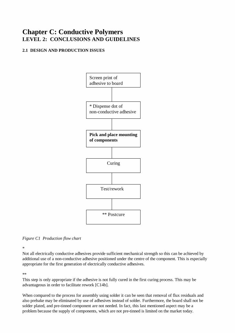
2.1.1 Applying the adhesive to the board
It seems that the most frequently used method for applying the adhesive is by screen printing or stencil.
The layer thickness of the adhesive may be dependent on the rype of components used [C17] but lies, ingeneral, between 20-50 AM [C18]. In [C17] the redommended pad thickness is higher, i.e. between 140and 180 lam in order to take into account the high tolerance of the different components. By evaluation ofdata sheets it seem that the normal recommended thickness most closely equals that reported in [18]. Foranisotropic adhesives a thinner layer may be optimal for use. An example is given in [C3] where a 15-20AM layer is applied.
2.1.2 The pick and place operation
The components can be placed by normal pick and place operations but component alignment must be veryprecise. This is necessary because adhesives do not have the self-aligning feature that solder provides [C3].In [C10] it is said that “pick and place machines provide sufficiently precise placement. Smallermanufacturing operations which may use manual or semiautomatic placement could have epoxy smearingproblems”.
2.1.3 The curing operation
Electrically conductive adhesives can be cured in conventional IR ovens, in hot belt ovens or in vapourphase equipment 2,3). Thermoplastic adhesives must not be cured in vapour phase ovens: “The organicvapours used in these ovens not only will prevent evaporation of the contained solvent but will attack theorganic solder and dramatically change its properties for the worse” [C1].
The curing time and temperature are very dependent on the material and the properties required. Normallycuring temperature lies between room temperature and 180°C (16,1). For anisotropy adhesives pressure isalso needed during curing and values from 0.2 kg/cm2 [C49] to 2-50 kg/cm2 [C49] are reported. Curingtime may be from seconds to about half an hour or more (C18,3). Posture is typically one hour at 80°C[C3].
2.1.4 Bleed out
“Bleed-out” is a phenomenon where the resin is not stable enough to stay positioned on the footprints on theboard. According to [C26] this is especially a problem with thermosetting materials where it is said that:“during the curing process, the bulk viscosity of the material is initially reduced due to the temperature rise.Then the viscosity will slowly build up because of the molecular weight increase. Conductimer*P-86 is afully reacted high molecular weight thermoplastic. The viscosity of this thermoplastic adhesivecontinuously increases as solvent is lost”.
In [C43] it is said that bleed-out especially is a problem, if the substrate surface is rough or contaminatedwith organic material.
2.2 BASIC FACTS ABOUT ELECTRICALLY CONDUCTIVE ADHESIVES
As the name indicates electrically conductive adhesives are adhesives which are made electricallyconductive in one way or another. Most often this is done by incorporation electrically conductiveparticles (metal or plated particles) into the adhesive – a polymer structure. There are severalbasically different ECAs, different in the way they conduct or in the construction of the polymerstructure. In addition to these main types there are variants within each group due to choice ofmaterial, modifications in particle size and shape, curing conditions etc.
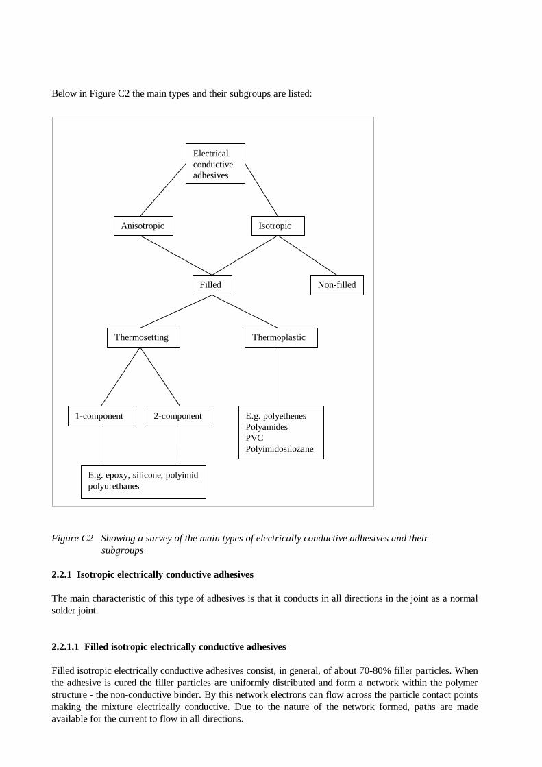
Below in Figure C2 the main types and their subgroups are listed:
Figure C2 Showing a survey of the main types of electrically conductive adhesives and their subgroups
2.2.1 Isotropic electrically conductive adhesives
The main characteristic of this type of adhesives is that it conducts in all directions in the joint as a normalsolder joint.
2.2.1.1 Filled isotropic electrically conductive adhesives
Filled isotropic electrically conductive adhesives consist, in general, of about 70-80% filler particles. Whenthe adhesive is cured the filler particles are uniformly distributed and form a network within the polymerstructure - the non-conductive binder. By this network electrons can flow across the particle contact pointsmaking the mixture electrically conductive. Due to the nature of the network formed, paths are madeavailable for the current to flow in all directions.
Electricalconductiveadhesives
Anisotropic Isotropic
Filled
Thermosetting
Non-filled
Thermoplastic
1-component 2-component E.g. polyethenesPolyamidesPVCPolyimidosilozane
E.g. epoxy, silicone, polyimidpolyurethanes
Filled isotropic electrically conductive adhesives are available both as thermosetting and thermoplasticmaterials.2.2.2 Non-filled isotropic electrically conductive adhesives
This kind of adhesives are based on polymers that are inherently electrically conductive (also called doped).Most of the inherently conductive polymer materials are polymerised aromatic compounds that derive theirelectrical properties from their molecular structure. The carbon structure has very long arrays ofalternating double and single bonds resembling the structure in graphite. Examples of such materials arePolyacetyline, polypyrrole, polyparaphenylene, polyaniline and many others [C28].
In [C28] it is said that "Emerson & Cuming's senior scientist, Dr. Justin C. Bolger, decribes inherentlyconductive polymer technology as "very long range". He characterises these materials as extremely brittleand sensitive to oxidation. He also suggests, "They will become useful for thin film deposition but never asa replacement for solder"."
Non-filled electrically conductive adhesives will not be further discussed in this project.
2.2.3 Anisotropic electrically conductive adhesives
The special characteristics for this type of adhesives are their ability to conduct in only one direction -along the Z-axis. This special effect is achieved by the formulation of the adhesive and the curingconditions.
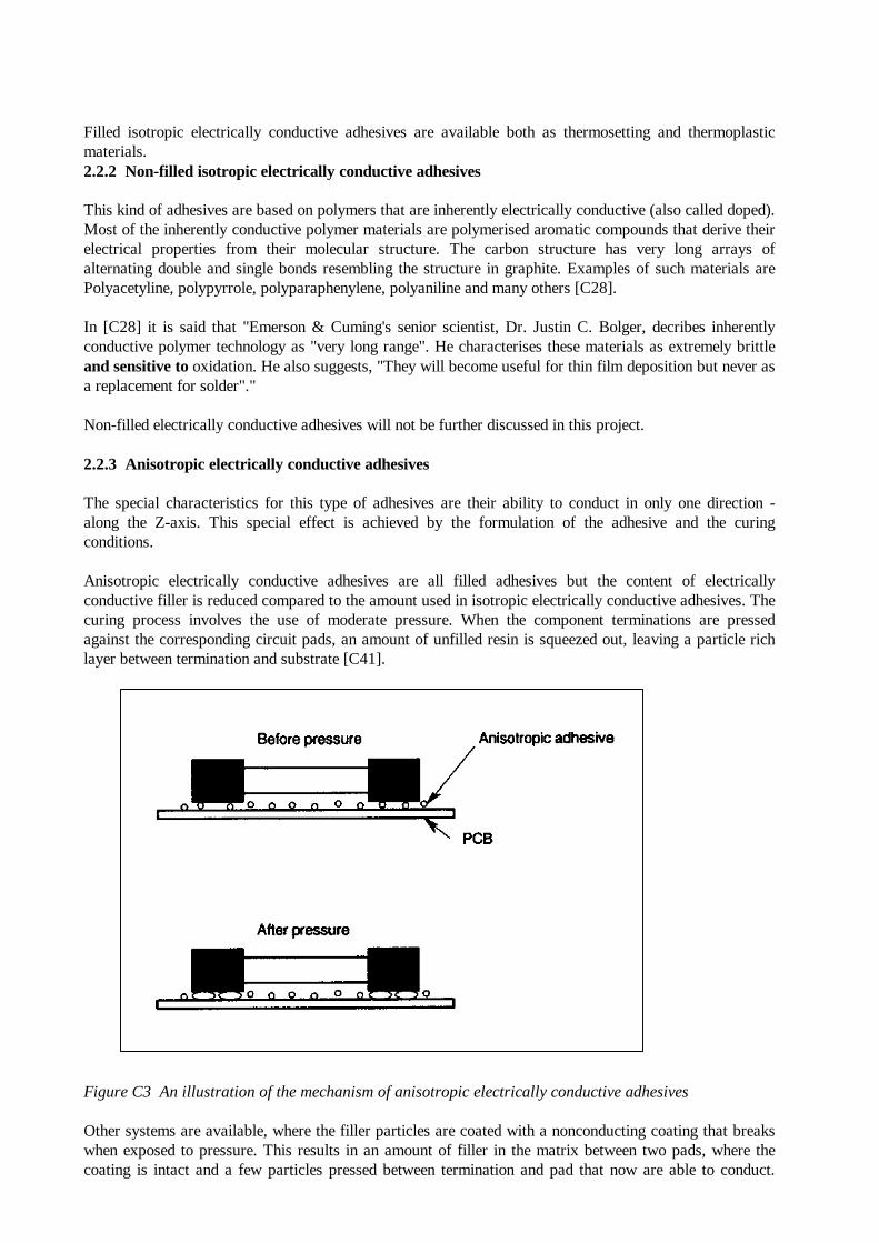
Anisotropic electrically conductive adhesives are all filled adhesives but the content of electricallyconductive filler is reduced compared to the amount used in isotropic electrically conductive adhesives. Thecuring process involves the use of moderate pressure. When the component terminations are pressedagainst the corresponding circuit pads, an amount of unfilled resin is squeezed out, leaving a particle richlayer between termination and substrate [C41].
Figure C3 An illustration of the mechanism of anisotropic electrically conductive adhesives
Other systems are available, where the filler particles are coated with a nonconducting coating that breakswhen exposed to pressure. This results in an amount of filler in the matrix between two pads, where thecoating is intact and a few particles pressed between termination and pad that now are able to conduct.
This means that the adhesive cannot conduct in either X or Y directions, although filler particles touch eachother.
As for filled isotropic electrically conductive adhesives the anisotropic adhesives exist both asthermosetting and thermoplastic materials.
Anisotropic conductive adhesives are available in liquid form for screen printing and as an adhesive film,especially suitable for connecting flex circuits to LCDs or to PCBs.
The electrically conductive particles used in anisotropic conductive adhesives are often deformable spherescoated with e.g. gold or silver, also nickel is used. The advantages of deformable spheres are theavailability of a larger contact area when pressure is applied.
Clearly, one great advantage of these adhesives that only conduct in one direction is the fact that their use isnot restricted to bonding areas, this is particularly advantageous with narrow pitched conductor patterns.However, the necessity of applied pressure during curing can very well be a limiting factor for the use ofthese, in many ways, ideal adhesives.
Anyhow, some anisotropic adhesives are developed which cure at low pressure, and that means that theycan be cured during the pick- and place operation [C49].
2.2.4 Thermosetting adhesives
The phrase "thermosetting" is related to the curing mechanism of the resin. The adhesive consists of apolymer resin (epoxy, polyamide or silicone are the most frequently used), curing agent, additives and, ofcourse, the conductive filler particles. The thermosetting adhesives are characterised by the fact that achemical reaction between polymer resin and curing agent occurs during curing. By this reaction the resinand the curing agent (or the resin itself) are bonded together resulting in a three dimensional polymericnetwork.
In chemical terms "thermosetting" is only used for adhesives that cure involving a chemical reaction atelevated temperatures. In most literature concerning electrically conductive adhesives the phrase is used forall adhesives that cure involving a chemical reaction, also when it takes place at room temperature, thephrase will be used in that meaning in the following.
When cured the thermosetting adhesives do not melt under heating. When the temperature exceeds the glasstransition temperature (Tg) the material becomes rubbery and leathery and has great flexibility andtoughness. Below Tg the material is hard and often also brittle.
The thermosetting adhesives can be divided into two subgroups named one-component and two-componentthermosetting adhesives. The general differences of these two types are described in the following.
2.2.4.1 One component thermosetting adhesives
As the name indicates this kind of adhesives is based on one component (i.e. it is delivered as one mixture).The curing agent is either incorporated in the mixture in an inactive state or "delivered" from theenvironment. The curing is initiated for example by heat, humidity from the air, by use of UV-light orvisible light. It is possible to get adhesives that cure at room temperature as well as at higher temperature[C22]. Pot life is often a little longer than for two-component adhesives, while shelf life is reduced.
2.2.4.2 Two component thermosetting adhesives
The resin and the curing agent are here delivered separately. Just before use the two components are mixedand the curing reaction is initiated - normally accelerated by heating. Also in this group of adhesives, thereare adhesives available which can be cured at room temperature.
A disadvantage of the two-component adhesives is the handling of the chemicals, complicated by the factthat it is important to obtain the right ratio of the two components in the final mixture. Also a very shortpot life is normal for these adhesives, while a long shelf life can be achieved.
2.2.4.3 The polymer matrix in thermosetting adhesives
The resin most frequently used for thermosetting adhesives - one-component as well as two-componentadhesives - are epoxy-based, polyamide based or silicone based. In the following typical curing agents andchemical reactions are discussed for each resin type.
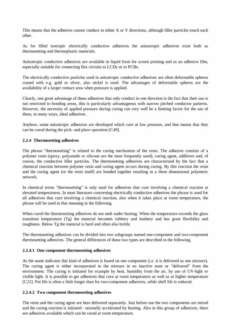
2.2.4.4 The epoxy-based polymeric matrix
All epoxy resins are characterised by one chemical group very likely to react with other chemicals:
Figure C4 Typical steps of the synthesis of a Bisphenol-A.resin [C37]
Examples of curing agents are Amines, acrylic (no rings) or cyclic (ring structure connected to nitrogen), asone of the most frequently used curing agents. The amino group reacts with the epoxy group formingn-hydroxyamino group’s [C18]. If tertiary amines or halogenamincomplexes are used it is possible toachieve an adhesive containing a high degree of cross-linking resulting in stability towards chemicals butalso in low flexibility.
Anhydrides are another example of curing agents used. Here the result is a diester structure, which meansthat the cured adhesive becomes very sensitive towards moisture. The temperature needed for the curingreaction is higher than for amine [C18].
2.2.4.5 The silicone based polymeric matrix
Silicone (polyorganosiloxane) based adhesives contain a network of the following chemical group:
R R
Si __ O __ Si
R R
where R and R' often are a mixture of methyl- and phenyl groups in addition to groups that makecross-linking possible.
Curing takes place in the presence of humidity in the case of one-component adhesives. Curing time ismeasured in hours or days. When two-component adhesives are used instead, the curing is very fast andcan take place at room temperature.
The resulting adhesive is very elastic, has good stability towards chemicals and heat but its adhesion abilityis relatively poor compared to the epoxy adhesives [C43].
2.2.4.6 The polyamide based polymeric matrix
The chemical structure in polyamide based adhesives consists of a high degree of ring structure, whichmakes its flexibility very limited. But good stability under heat is achieved. The inherent amount ofchlorides and other ionic compounds in the polyamide resin is less than in epoxy resin (C6, C18).
The curing temperature is above 200°C (in [C18] the minimum temperature is stated to be 230°C) andoften pressure is applied (0.8 - 1 MPa). This high curing temperature is a limiting factor in relation to theuse of this adhesive as substitution for solder, because one of the required properties of the adhesives is thelow temperature curing - reducing the risk of terminal stress.
Furthermore, the handling of the raw m. materials must be carried out at reduced temperatures and it mustbe stored at -20°C [C43].
2.2.5 Thermoplastic adhesives
Thermoplastic adhesives are characterised by their ability to melt after curing when exposed to heat.Thermoplastic adhesives are based on a polymer dispersed in a solvent. The curing is a drying process,where heating evaporates the content of solvent; thus no chemical reaction takes place. Examples ofpolymers used are Polyamides (nylon), polythene’s, PVC and polyimidosilozane.
Examples of solvents are Butylcellosolvacetate, N-methyl-2-pyrrolidone.
Thermoplastic adhesives have virtually unlimited shelf life at room temperature. The special elastifyingeffect of heating makes this type of adhesive advantageous in relation to its ability to reduce thermal stressin the joint. Furthermore, rework can be easily carried out (C26, C1). A disadvantage is a relatively longercuring time compared with most thermosetting adhesives.
2.2.6 Electrically conductive filler particles
As described in section 1.8.1.1 filler particles are incorporated into the polymer structure in order to makethe adhesive electrically conductive? These filler particles vary in shape and size as well as in materialcomposition. These factors influence the properties of the adhesive and are continually refined by the
development of new products. In the following some basic information regarding the filler articles used ispresented.
2.2.6.1 Material
Basically all metals can be used as electrically conductive filler materials. However, each of the metals ischaracterised by different factors that make them more or less suitable as filler material in electricallyconductive adhesives.
Some relevant factors are electrical conductivity, ageing mechanisms, health risk and, of course, costs.
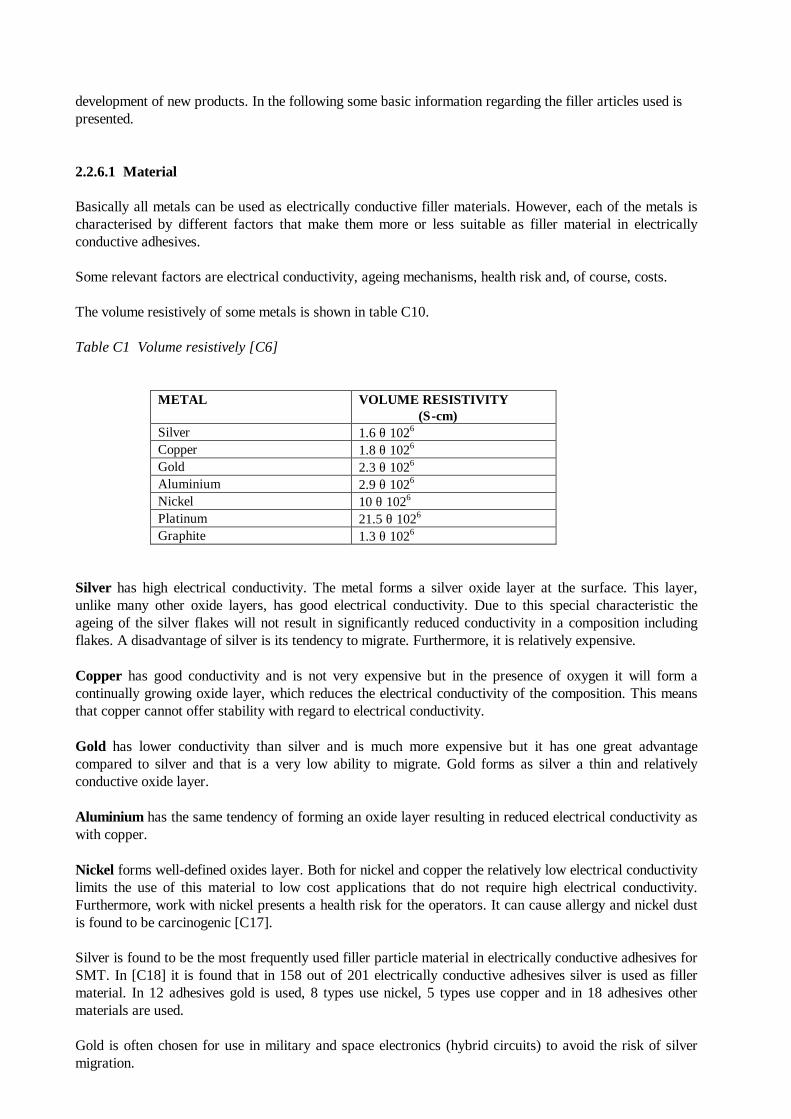
The volume resistively of some metals is shown in table C10.
Table C1 Volume resistively [C6]
METAL VOLUME RESISTIVITY (Σ-cm)
Silver 1.6 θ 1026
Copper 1.8 θ 1026
Gold 2.3 θ 1026
Aluminium 2.9 θ 1026
Nickel 10 θ 1026
Platinum 21.5 θ 1026
Graphite 1.3 θ 1026
Silver has high electrical conductivity. The metal forms a silver oxide layer at the surface. This layer,unlike many other oxide layers, has good electrical conductivity. Due to this special characteristic theageing of the silver flakes will not result in significantly reduced conductivity in a composition includingflakes. A disadvantage of silver is its tendency to migrate. Furthermore, it is relatively expensive.
Copper has good conductivity and is not very expensive but in the presence of oxygen it will form acontinually growing oxide layer, which reduces the electrical conductivity of the composition. This meansthat copper cannot offer stability with regard to electrical conductivity.
Gold has lower conductivity than silver and is much more expensive but it has one great advantagecompared to silver and that is a very low ability to migrate. Gold forms as silver a thin and relativelyconductive oxide layer.
Aluminium has the same tendency of forming an oxide layer resulting in reduced electrical conductivity aswith copper.
Nickel forms well-defined oxides layer. Both for nickel and copper the relatively low electrical conductivitylimits the use of this material to low cost applications that do not require high electrical conductivity.Furthermore, work with nickel presents a health risk for the operators. It can cause allergy and nickel dustis found to be carcinogenic [C17].
Silver is found to be the most frequently used filler particle material in electrically conductive adhesives forSMT. In [C18] it is found that in 158 out of 201 electrically conductive adhesives silver is used as fillermaterial. In 12 adhesives gold is used, 8 types use nickel, 5 types use copper and in 18 adhesives othermaterials are used.
Gold is often chosen for use in military and space electronics (hybrid circuits) to avoid the risk of silvermigration.
In addition to the pure metals attempts have been made to develop composites for use as filler material.Examples are copper and glass plated with silver, and coated Reformative.
2.2.6.2 Particle shape and size
It is not only the choice of filler material but also its size and shapes that influence the properties of thefinal adhesive. Some of the properties that can be influenced by particle size and shape are electricalconductivity, thermal conductivity, tensile strength, viscosity, weight loss and rheology.
The productions of silver flakes are often based on silver powder, which is mechanically worked using fluidenergy milling or ball milling. The latter is the most frequently used [C32].
Fluid energy milling is a method in which a mixture of silver powder and surfactant is accelerated in astream of compressed air or superheated steam. When the particles collide under the turbulent flow, thedensification takes place (particle size decreases but density increases).
In ball milling the silver powder mixed with solvent and surfactant is tumbled in a rotary mill loaded withballs. When collision occurs the powder is flaked. The chosen solvent must have high flash point and lowvapour pressure because of heat generation. The surfactant used must be soluble in the solvent to ensureeven distribution. Often fatty acids are used as surfactant [C32].
In both milling methods a surfactant is used either to prevent agglomeration (fluid energy milling) or toprevent cold welding (ball milling). A part of this surfactant is absorbed at the surface of the flakesproduced resulting in a coating that can affect the properties of the final flake. It is very important for theresulting conductivity of the adhesive that the surfactant shows compatibility with the resin.
The size of the resulting flakes, after cleaning and drying is reported to be 2-30 ~m. [C32] states: 2-20 ~m,after 50 hours, where most is in the interval of 2-12 ~m. [C43] states 5-30 Am no milling time is specified.
Three other manufacturing processes for silver filler particles are mentioned in [C43], these are:
• Chemical reduction of an alkaline silver nitrate solution - the resulting flake size being 0.5 - 10: m.
• Electrochemical cathodic precipitation in nitrate or sulphate solution - the resulting flake size
being 1.2 - 50 :m.
• Atomisation. Melted silver is induced into a high speed water- or gas flow -resulting in flakes that is 5 - 100 :m.
The electrical conductivity of an isotropic adhesive is dependent on the amount of contact points betweenthe filler particles. This means that the conductivity will increase with increased amount of filler particles.However, as the amount of filler increases the amount of polymer must obviously decrease and this meansthat there is a limit for the amount of filler that can be used without too much decrease in the properties ofthe polymer matrix (adhesion and tensile strength) [C12]. 80 wt% silver is found to be the limit in epoxyadhesives [C43].
The achieved particle size influences the amount of filler material that provides the optimum balancebetween electrical conductivity and tensile strength. In [C9] it is found that "the larger the flake particles,the greater the number of contacts. " This means that larger particles, when formed as flakes, should bepreferred to smaller ones (tap density, packing ability of flakes, increase with increased particle size).
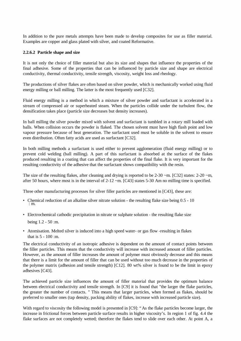
With regard to viscosity the following model is presented in [C9]: “As the flake particles become larger, theincrease in frictional forces between particle surface results in higher viscosity’s. In region 1 of fig. 4.4 theflake surfaces are not completely wetted; therefore the flakes tend to slide over each other. At point A, a
maximum viscosity is achieved where the flake surfaces are completely wetted. At this point, the flakesstop sliding over each other and start forming agglomerates. Therefore, in region 2 there is a decrease inviscosity because the result of agglomeration is a net decrease in the number of free moving particles”. (Itseems from results in the article that flake size above 2.4 :m results in region 2 behaviour)
Figure C5 Describes the relationship between flake size and viscosity [C9]
With regard to filler particle shape some influence on rheology, conductivity and tensile strength is alsoobserved. The use of spherical filler particles decreases the viscosity while flakes, needles and fibres offerideal overlapping conditions for isotropic adhesives (C28, C12). The manufacturer therefore can optimisethe adhesive to a specific use by mixing filler particles with different shapes.
In addition, the tensile strength of the final adhesive is found to be influenced by the properties of thesurface of the filler particles/coatings. In [C42] it is found that when nickel is used as filler, the strengthincreases until 40 wt% is added, whereas for silver it only increases up to 10 wt%. This is explained by therough surface of nickel compared to a smoother surface of silver. This must only be taken as an example ofthe relationship between surface conditions and strength and not as a general rule in comparing nickel withsilver.
2.2.7 Additives
In addition to the previously described substances some additives are also added to the formulation of mostadhesives. The most important additives are substances used for optimising flexibility and rheology(workability).
2.2.7.1 Reactive solvents
In order to optimise the rheology of an adhesive, for example for achieving good dispensing properties itmay be desirable to dilute the resin in order to reduce the viscosity. For thermoplastic adhesives this is doneby simple physical dissolution. However, this is not the solution for thermosetting adhesives because simplephysical dissolution will ruin the curing process and voids in the joint will be the result. Alternatively,reactive solvents can be added. Reactive solvents are substances that contain epoxy groups the viscosity ofwhich is very low. These substances react with the resin and are incorporated in the polymer matrix, whichmeans that they also influence the properties of the cured adhesive [C12].
Depending on the reaction rate of different reactive solvents a small or larger amount of the substances willevaporate during the curing process. This phenomenon affects the weight loss and the risk of weakness inthe final joint. Furthermore, it will damage the environment, especially with regard to the workingenvironment.
The optimal choice of reactive solvents is one that has low viscosity (a smaller amount of the substance isneeded for lowering the viscosity of the total resin), the boiling point of which is as high as possible -reducing the rate of evaporation and with optimal reaction rate related to curing conditions chosen. Finallythe effect on the cured polymer matrix of the reactive solvents chosen must be taken into consideration.
In [C43] it seems that an amount of about 3 wt% of the adhesives is reactive solvent. Information givenfrom Degussa indicates an amount of reactive solvents at 1-7 wt% of the adhesive.As reactive solvent glycidylether is often used [C53] (not specified for electrically conductive adhesives butrelated to general epoxy technology).2.2.7.2 Flexibility compounds
In order to minimise defects caused by mechanical or thermal stress a flexible joint is preferable. In aflexible joint it is possible for example to absorb movements of the substrate with reference to thecomponent the result being reduction of stresses in the joint and in the component.
Joints based on thermoplastic adhesives are flexible due to the fact that no true and irreversible chemicalreaction has taken place; hence reversible movement/displacement in the joint material is possible.
However, thermosetting adhesives are inflexible in themselves due to the three-dimensional network formedwhen the adhesive is cured. Molecules bonded in this network cannot move much unless the polymericstructure is broken. For flexibility of these joints it is possible to add some flexible compounds.
Additives that can increase the flexibility of the adhesive are flexible compounds often containing an epoxygroup that is able to react with the epoxy resin or the curing agent the result being incorporation in the finalpolymer structure. The effect of the compounds is explained by the fact that the resulting polymer structurecontains larger meshes than without flexible compounds incorporated, making the molecules more able tomove [C12].
In [C12] polyglycoldiepoxides, epoxydized polybutadines, butadienacrylicnitrilrubber-epoxide andpolyurethane modified epoxides are mentioned as examples of flexible compounds.
2.3 DISCUSSION OF PARAMETERS RELEVANT TO THE EVALUATION OF THE PROPERTIES OF AN ADHESIVE
In this section parameters are discussed relating to the evaluation electrically conductive adhesives as asubstitute for solder for SMT on rigid PCB. Furthermore, the influence of different aspects such asmaterial composition, curing conditions etc. at these parameters are evaluated.
2.3.1 Electrical conductivity
Electrical conductivity is often evaluated by measurements of specific volume resistivity (Σ-cm) of thematerial. Volume resistivity can be measured for example in accordance with the method described in(C44). In (C44) the general requirements for electrically conductive adhesives for use in hybridmicrocircuits are stated to be # 5 Ρ 10-4 Σ-cm for silver-filled and # 1.5 Ρ 10-3 Σ-cm for gold-filledadhesives at the following temperatures: 25°C, 60°C, 150°C after 1000 h at 150°C in a nitrogen ambient(current density of 139.5 amps/cm2 shall be applied during the 1000 h).
The volume resistivity of solder (63 tin/37 lead) is 1.5 Ρ 10-5 Σ-cm (C4).
The specific volume resistivity is determined according to the following formula:
P = R (W Ρ t) / l
P = resistivity in Σ-cmR = measured resistance, ohmsW = width in cmT = thickness in cmL = length between inner pair of probes in cm (C44)
By this formula it can be seen that if P for the adhesive is a factor ten higher than for solder, the measuredresistance of the adhesive relative to the resistance of the solder (R-adh/R-sold) will be even higher,because the thickness of the adhesive needed compared to the thickness of the solder is less. This is incontrast to the statement in (C18), where it is said that for:
P-sold = 1.7 Ρ 10-5 Σ-cm and P-adh = 16.7 Ρ 10-5 Σ-cmt-sold = 120 :m and t-adh = t-adh = 20 :m
Then R-adh/ R-sold = 1.63
This is explained by the fact that the formula in [C44] is developed for resistance measurements in thehorizontal direction, whereas in [C18] the adhesive is used as joint material and the relevant resistance is inthe vertical direction. This means that I in the formula here is the thickness of the adhesive layer.
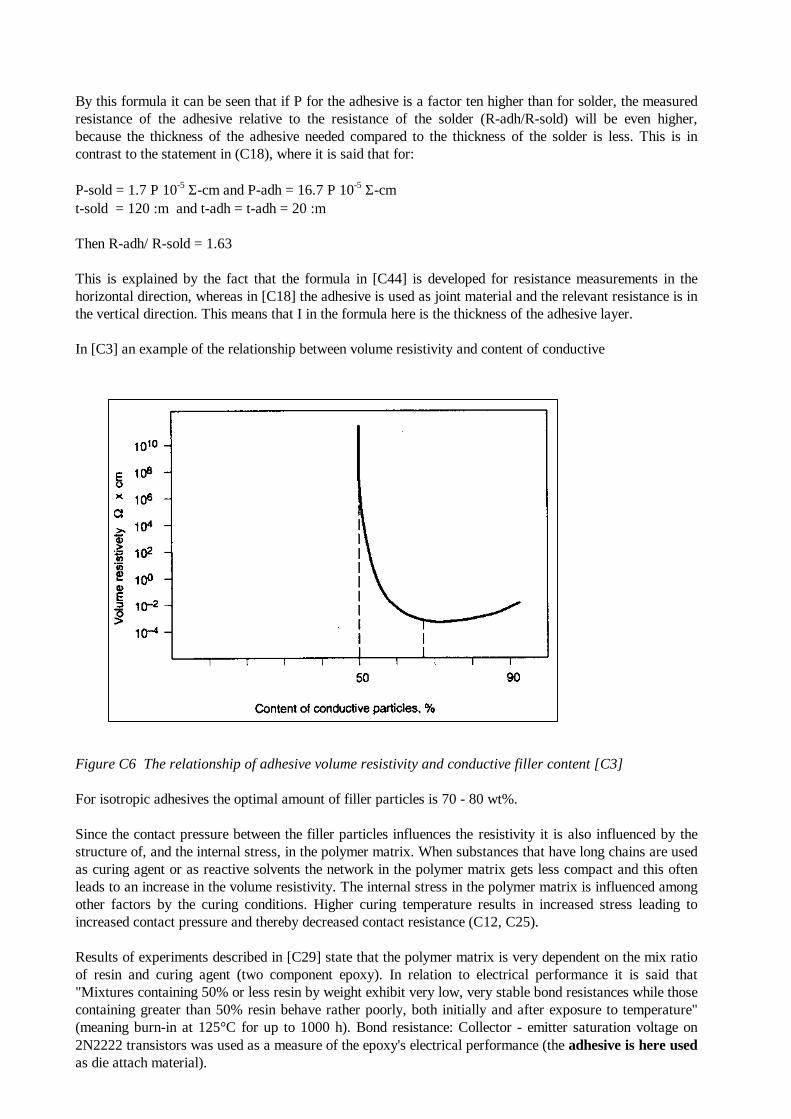
In [C3] an example of the relationship between volume resistivity and content of conductive
Figure C6 The relationship of adhesive volume resistivity and conductive filler content [C3]
For isotropic adhesives the optimal amount of filler particles is 70 - 80 wt%.
Since the contact pressure between the filler particles influences the resistivity it is also influenced by thestructure of, and the internal stress, in the polymer matrix. When substances that have long chains are usedas curing agent or as reactive solvents the network in the polymer matrix gets less compact and this oftenleads to an increase in the volume resistivity. The internal stress in the polymer matrix is influenced amongother factors by the curing conditions. Higher curing temperature results in increased stress leading toincreased contact pressure and thereby decreased contact resistance (C12, C25).
Results of experiments described in [C29] state that the polymer matrix is very dependent on the mix ratioof resin and curing agent (two component epoxy). In relation to electrical performance it is said that"Mixtures containing 50% or less resin by weight exhibit very low, very stable bond resistances while thosecontaining greater than 50% resin behave rather poorly, both initially and after exposure to temperature"(meaning burn-in at 125°C for up to 1000 h). Bond resistance: Collector - emitter saturation voltage on2N2222 transistors was used as a measure of the epoxy's electrical performance (the adhesive is here usedas die attach material).
<LINK TO 2.3.13.1>
2.3.2 Thermal conductivity
Thermal conductivity is measured directly and may be expressed in W/mK or Cal/cm-sec-°C.
High thermal conductivity is desirable because increased thermal conductivity results in decreased risk ofbuild up of thermal stress in the component and in the joint.
In [C44] the general required value for adhesives for hybrid circuits is stated to be > 1.5 W/mK [C18]. Thevalue for solder is about 51 W/mK and is normally between 1-5 W/mK for adhesives, although highervalues can be achieved [C18]. As for the electrical conductivity the thinner layer of adhesive compared tothat of solder results in a decreased difference between the solder and the adhesive in the vertical direction,the adhesive has generally a factor 2-5 lower value compared to solder in this direction [C18].
The heat is as for the electric current primarily transported through the metal particles. This means that theaspects that can influence the thermal conductivity are the same as described for electrical conductivity.
2.3.3 Coefficient of thermal expansion (CTE)
The coefficient of thermal expansion is expressed in ppm/ °C. It is a factor that is of great importance inrelation to the risk of failures occurring due to thermal mismatch. The failure mechanism is related to theoccurrence of stress in the materials such as those due to differences in the expansion of die and packagewhen exposed to elevated temperatures or changes in temperatures [see section 3.2].
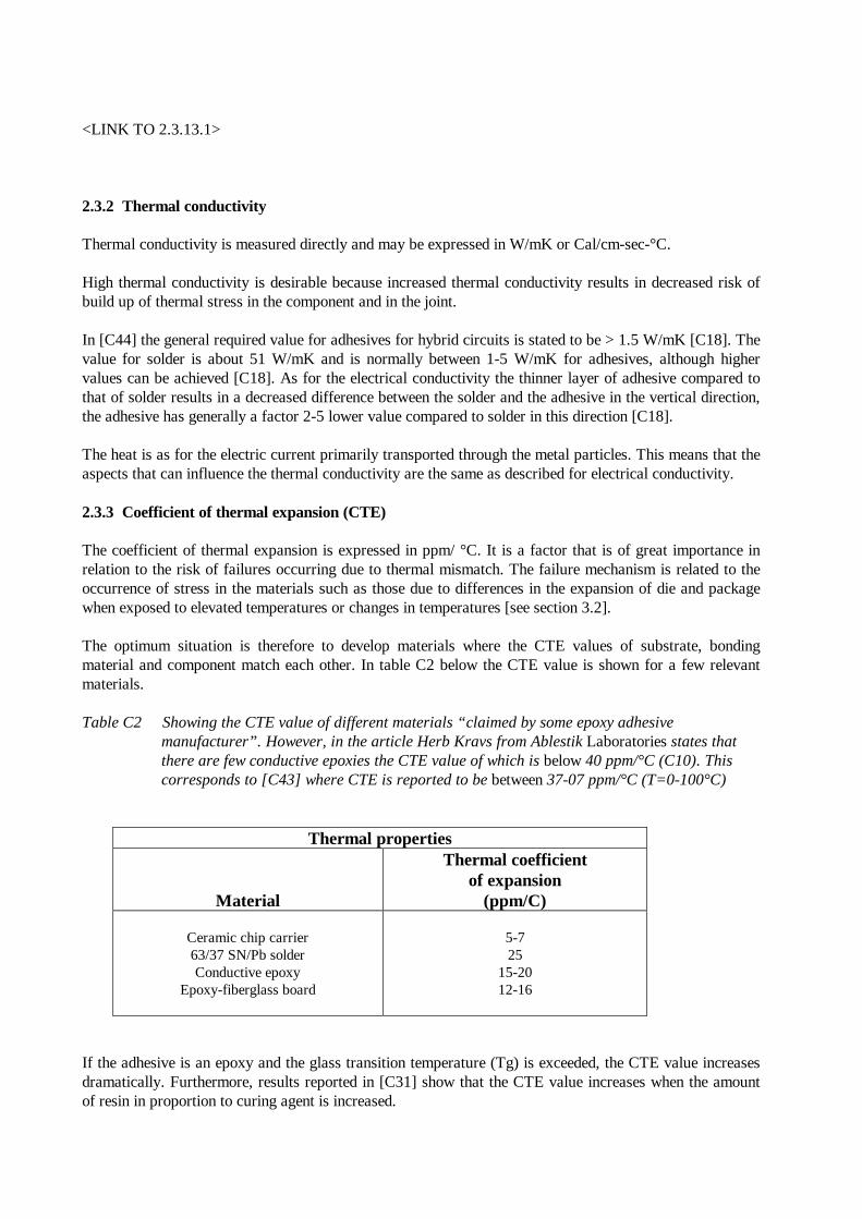
The optimum situation is therefore to develop materials where the CTE values of substrate, bondingmaterial and component match each other. In table C2 below the CTE value is shown for a few relevantmaterials.
Table C2 Showing the CTE value of different materials “claimed by some epoxy adhesive manufacturer”. However, in the article Herb Kravs from Ablestik Laboratories states that there are few conductive epoxies the CTE value of which is below 40 ppm/°C (C10). This corresponds to [C43] where CTE is reported to be between 37-07 ppm/°C (T=0-100°C)
Thermal properties
Material
Thermal coefficientof expansion
(ppm/C)
Ceramic chip carrier63/37 SN/Pb solderConductive epoxy
Epoxy-fiberglass board
5-725
15-2012-16
If the adhesive is an epoxy and the glass transition temperature (Tg) is exceeded, the CTE value increasesdramatically. Furthermore, results reported in [C31] show that the CTE value increases when the amountof resin in proportion to curing agent is increased.
The filler particles influence the CTE value of conductive adhesives. Increased amount of particles result ina decreased CTE [C42]. Furthermore, it is also stated in [C42] that "particle size has been reported toaffect indirectly the thermal expansion through adhesion quality. The particle properties, such as theparticle shape, surface energy, etc. also play a role."
2.3.4 Reworkability
The possibility for rework is essential if conductive adhesives are to be declared suitable for SMTassembling. It must be possible to remove one failed or misplaced component and replace it with a newdevice even under field service conditions. Furthermore, it would be desirable if solder could also be usedfor repair in an assembly where adhesives are used for mounting.
There is a great difference between the possibility for repair of thermoplastic and thermosetting adhesives,respectively. Thermoplastic adhesives become by their nature flexible when heated and the componentshould easily be removed. However, this is not the case for thermosetting materials. When studying theliterature it seems that experience about reworkability of thermosetting, especially epoxy-based adhesives,is very different.
Local heating to above the glass transition temperature makes it possible to remove the component. Auseful indicator of reparability is a plot of die shear strength vs. temperature.
There seems to be agreement about the fact that it is possible to remove a component from the PCB evenafter the adhesive is fully cured. However, the question is how easy it is to remove residual adhesive fromthe board, if necessary.
In [C8] it is said that "adhesive residues on the board may hinder position and reinstallation ofcomponents", in [C14] it is stated that "most of the adhesive remains on the circuit and it must be removedor flattened," whereas in [C39/2] this is not considered to be a problem. In [C39] it is said that "Conductiveepoxy can be easily heated above its glass transition temperature... The defective components can beremoved and new components attached - with no additional steps. This rework technique is usedsuccessfully in the hybrid industry to manufacture military screened devices. " One reservation related tothe statement in [C39] should be noted, the article is from 1984 and the discussions are based on thesupplementary use of a non-conductive adhesive for mechanical strength.
Removal of residual resin by plasma, solvent or abrasion is suggested in [C14B] for anisotropic adhesives.Furthermore, testing and rework prior to post curing is suggested to facilitate repair.
However, there is a difference between the substrates used, ceramic, polyester or epoxy, and it can verywell be that rework is easily carried out on hybrid circuits (ceramic substrates) but not on PCBs.Methylenechloride is often used as a solvent for epoxy and one should therefore be able to remove residualsfrom ceramic substrates by this solvent but when methylenechloride is used on PCBs the boards can easilybe damaged.
At a seminar at EC concerning electrically conductive adhesives (1992.03.19) repair was discussed. Therewas a general agreement not to use chemicals for removal of residuals from the PCB. If residuals should beremoved mechanical methods must be applied. Hence, if residuals are not removed it is important that it isnot degenerated, which means that Tg must not be exceeded by more than about 20-30°C.
Furthermore, the Tg of the substrate has also to be taken into consideration.
A manufacturer stated that smear of the residue should not be a problem but the failed devices shall beremoved by, for example, the use of vacuum.
2.3.5 Rheology
Rheology is a way to describe the workability of an adhesive. In some situations the rheology can bedescribed by the viscosity of an adhesive, in other situations the thixotropy of an adhesive is used. It ismeaningless to talk about viscosity if the adhesive is thixotropic. Thixotropic materials are characterised bythe fact that when not stirred they are form stable but when they are mechanically worked, stirred, theybecome more or less viscous [C11].By optimisation of the amount and the properties of filler particles and by use of different additives itshould be possible to achieve a suitable rheology for either screen printing, stencil and syringe [C13].
In most applications the adhesive is screen printed to the substrate. For screen-printing a viscosity of about100,000 centipoises is required [C10].
2.3.6 Ionic impurities
Ionic impurities are of interest because the presence of Cl-, F-, Na+, K+, NH4+, acetate or other anions oforganic acids increases the risk of corrosion and migration in the presence of moisture.
Often the amount of ionic impurities is stated as a total amount expressed in ppm NaCI and afterwardssplit up into ppm Cl- etc.
The amount of ionic impurities is influenced by the cleanliness of the resin used and of the substancechosen as curing agent and other additives. In continuation of this the mix ratio between resin and curingagent may also be of concern. In [C31] an example is given, where the content of chloride ions increasesdramactically if the weight % of resin is below 40%. Below this mix ratio the excess of curing agent iseasily hydrolisable which explains the high ionic impurity.
In [C44] the general requirements for adhesives for hybrid circuits are stated to be:
Total ionic contentpHChlorideSodiumPotassium
6.7
< 1000 ppm (as NaCI)4.0 to 9.0' 300 ppm~ 50 ppm< 5 ppm (in (18) this value is 50 ppm)
2.3.7 Weight loss
Curing of the adhesive, both thermosetting and thermoplastic, results in a slight decrease in the weight ofthe adhesive. This weight loss is caused by the evaporation of solvent, or reactive solvents. In general, theweight loss is highest for thermoplastic adhesives, where the total amount of solvent must evaporate inorder for the adhesive to cure.
It is desirable to minimise the weight loss both in consideration of technical and environmental aspects.When substances evaporate from the joint it becomes porous, which affects both mechanical and electricalproperties. In relation to the environment organic solvents or reactive solvents may cause health risk and/orpollution if present in larger amounts [C12].
The weight loss is dependent on the amount of organic solvents or reactive solvents that evaporates duringcuring; this leads to the obvious conclusion that the amount of these substances in the adhesive should beminimised. For the reactive solvents it means that its own viscosity should be as low as possible.
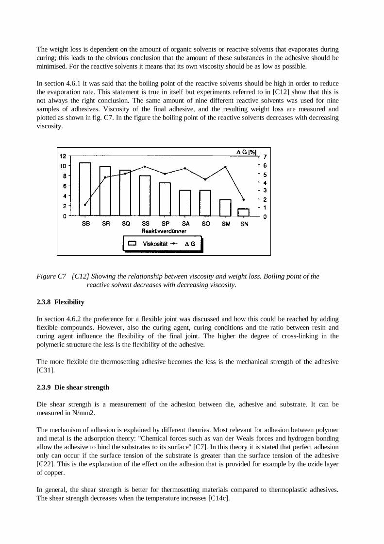
In section 4.6.1 it was said that the boiling point of the reactive solvents should be high in order to reducethe evaporation rate. This statement is true in itself but experiments referred to in [C12] show that this isnot always the right conclusion. The same amount of nine different reactive solvents was used for ninesamples of adhesives. Viscosity of the final adhesive, and the resulting weight loss are measured andplotted as shown in fig. C7. In the figure the boiling point of the reactive solvents decreases with decreasingviscosity.
Figure C7 [C12] Showing the relationship between viscosity and weight loss. Boiling point of the reactive solvent decreases with decreasing viscosity.
2.3.8 Flexibility
In section 4.6.2 the preference for a flexible joint was discussed and how this could be reached by addingflexible compounds. However, also the curing agent, curing conditions and the ratio between resin andcuring agent influence the flexibility of the final joint. The higher the degree of cross-linking in thepolymeric structure the less is the flexibility of the adhesive.
The more flexible the thermosetting adhesive becomes the less is the mechanical strength of the adhesive[C31].
2.3.9 Die shear strength
Die shear strength is a measurement of the adhesion between die, adhesive and substrate. It can bemeasured in N/mm2.
The mechanism of adhesion is explained by different theories. Most relevant for adhesion between polymerand metal is the adsorption theory: "Chemical forces such as van der Weals forces and hydrogen bondingallow the adhesive to bind the substrates to its surface" [C7]. In this theory it is stated that perfect adhesiononly can occur if the surface tension of the substrate is greater than the surface tension of the adhesive[C22]. This is the explanation of the effect on the adhesion that is provided for example by the ozide layerof copper.
In general, the shear strength is better for thermosetting materials compared to thermoplastic adhesives.The shear strength decreases when the temperature increases [C14c].
For epoxy-based adhesives it is reported that the shear strength increases when the resin ratio is increased[C29, C12]. This also leads to the conclusion that the most rigid epoxy exhibits the highest shear strength.
Die shear strength for solder (Sn60Pb) is about 35 N/mm2 [C18] values reported for adhesives are up to25 N/mrn2, in general, between 7 - 14 N/mm2 [C18].
2.3.10 Substrate
This project is concerned with SMD mounting on rigid PCBs. The rigid boards are most frequently glassepoxy laminates. The conductor elements are normally made of copper, coated with solder at the pads inorder to prevent oxidation of the copper before mounting of the components.
Soldered surfaces may result in poor adhesive bonding although reports stating that this problem is solvedare given. Conductive epoxy will work with lightly oxidised surfaces, this may lead to the conclusion thatanother material is needed as a protection layer at the copper to prevent the formation of a thicker oxidelayer, such as when exposed to temperature ageing. Silver plating is recommended for this purpose [C10].
Ageing of the substrate as well as component terminations has therefore to be considered.
2.3.11 Glass transition temperature
The glass transition temperature (Tg) is the temperature, where the material changes from a hard "glassey"form to a "rubbery" form. At Tg a change in the segmental mobility of the polymer chains occurs. AboveTg there is sufficient mobility enabling large-scale reorganisation of chains to occur in response to anapplied stress (e.g. a change of temperature). Whereas below Tg the chains are "frozen" in position. Tg ismaterial dependent but it is influenced by the curing conditions [C11].
The higher the degree of cross-linking in the polymer structure the higher is Tg. This means that reactivesolvent and flexibility compounds consisting of small chains and high viscosity of the total adhesive resultin high Tg values.
Shear strength decreases when Tg is exceeded while flexibility increases [C11].
Typical values of Tg lie between 45°C and 180°C (C4). On account of the reworkability it is advisable tochoose an adhesive with a Tg below the Tg of the board material but still, of course, above the operatingtemperature (C4).
2.3.12 Cost
The cost of electrically conductive adhesives is very dependent on the filler material used. Silver, the mostfrequently used filler material is expensive compared to solder. In [C45] from 1991 the cost of solder isstated to be 8C10C/g, whereas the conductive adhesive is 20C-50C/g.
The production cost should be reduced due to a reduced number of production steps required. Furthermore,the density of adhesives versus solder is much less and adhesives require a thinner layer. In [C45] it is saidthat "on a consistent set of assumptions for fine pitch the material for solder, ICAs and ACAs wascalculated to be 0.8 10-3, 0.4 10-3C and 1 · 10-3C, respectively ...not including the cost of cleaningmaterials that solder might require" (ICA: Isotropic conductive adhesives, ACA: Anisotropic conductiveadhesives). In [C45] costs like 5C/cm2 for ACAs and 8C/cm- for ICAs are mentioned.
Furthermore, the price of components that are not pre-tinned and possibly a new plating material for thePCBs must be taken into consideration.
2.3.13 Reliability
The reliability of an assembly must be evaluated in each specific case because the reliability of a joint canbe influenced by many factors and can therefore vary from one case to another.
Where reliability is concerned factors such as electrical and thermal conductivity, shear strength andmigration/corrosion are of interest.
The reliability can be evaluated by carrying out different environmental tests such as thermal ageing,thermal cycling/shock, humidity ageing and HAST test.
2.3.13.1 Electrical conductivity
Electrical conductivity is influenced by ageing mechanisms altering the surface of the electricallyconductive filler particles, or mechanisms occurring in the interface between adhesive and componentterminal or substrate. Furthermore, the conductivity may be influenced by alterations occurring in thepolymer matrix.
The ageing mechanism of the surface of the filler particle is an oxidation, which leads to a more or lessthick oxide layer that may result in decreased conductivity. This is especially relevant for filler particles ofcopper or materials coated with copper (see section 4.5.1). Furthermore, there may be a problem of theadhesion between the layers, if particles such as silver plated copper are used.
With regard to substrate and component terminal, oxidation can also occur causing an increase in theresistivity. Furthermore, if the substrate or component terminal is pre-tinned certain investigations [C47]indicate that an amorphous layer of tin/lead is formed in the interface between adhesive and terminalleading to reduced conductivity, and this is further discussed under “shear strength”.
The polymer matrix may be influenced by exposure to humidity during pressure cooker test, which resultsin swelling reducing the contact between filler particles and therefore reducing the conductivity [C25].Furthermore, in [C10] it is said that “the epoxy resin tends to selectively form a resin-rich, insulation layeraround a wire. An electrical joint could exhibit high resistance, either immediately or eventually. Thisproblem can be expected with silver epoxy attached leads”.
2.3.13.2 Shear strength
The shear strength may, as for the conductivity, be influenced by reactions occurring in the interfacebetween adhesive and substrate or component terminal.
2.3.13.3 Ageing of substrate or component
Ageing of the substrate or the component before assembly leading to build up of an oxide layer reduces theresulting shear strength because of alteration in surface tension and thereby of the wetting conditions of theadhesive to the substrate. In [C35] nickel-plated chip capacitors have been aged under different conditions.The resulting Ni-oxide layer is determined in comparison to one week old components by use ofAugerspectroscopy. Fig. C8 shows the results obtained.
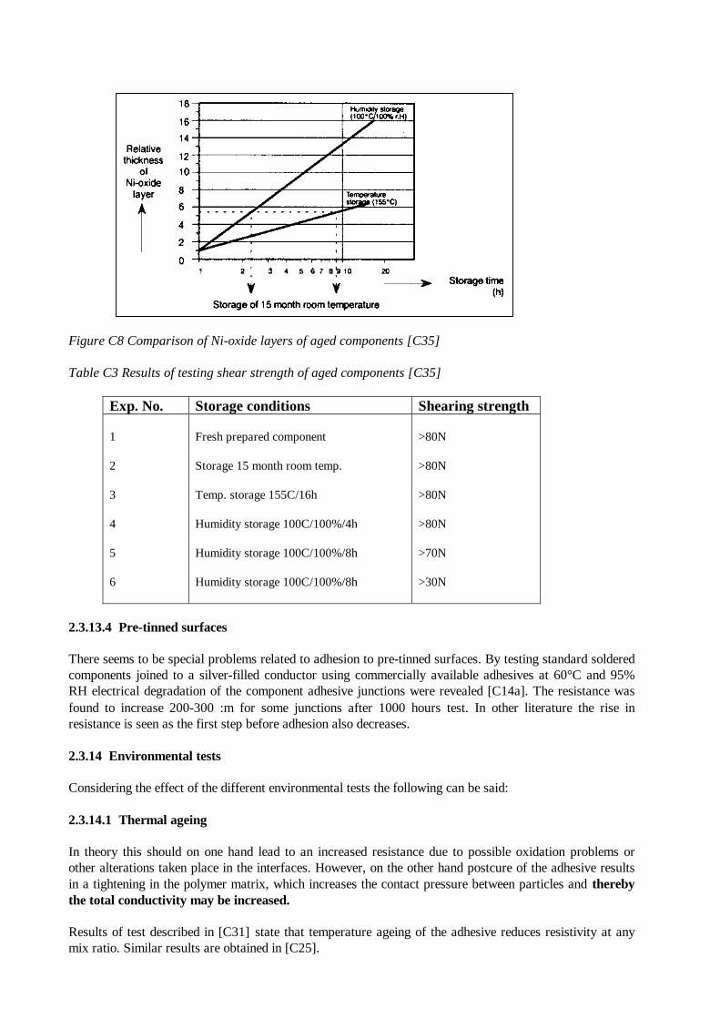
Figure C8 Comparison of Ni-oxide layers of aged components [C35]
Table C3 Results of testing shear strength of aged components [C35]
Exp. No. Storage conditions Shearing strength
1
2
3
4
5
6
Fresh prepared component
Storage 15 month room temp.
Temp. storage 155C/16h
Humidity storage 100C/100%/4h
Humidity storage 100C/100%/8h
Humidity storage 100C/100%/8h
>80N
>80N
>80N
>80N
>70N
>30N
2.3.13.4 Pre-tinned surfaces
There seems to be special problems related to adhesion to pre-tinned surfaces. By testing standard solderedcomponents joined to a silver-filled conductor using commercially available adhesives at 60°C and 95%RH electrical degradation of the component adhesive junctions were revealed [C14a]. The resistance wasfound to increase 200-300 :m for some junctions after 1000 hours test. In other literature the rise inresistance is seen as the first step before adhesion also decreases.
2.3.14 Environmental tests
Considering the effect of the different environmental tests the following can be said:
2.3.14.1 Thermal ageing
In theory this should on one hand lead to an increased resistance due to possible oxidation problems orother alterations taken place in the interfaces. However, on the other hand postcure of the adhesive resultsin a tightening in the polymer matrix, which increases the contact pressure between particles and therebythe total conductivity may be increased.
Results of test described in [C31] state that temperature ageing of the adhesive reduces resistivity at anymix ratio. Similar results are obtained in [C25].
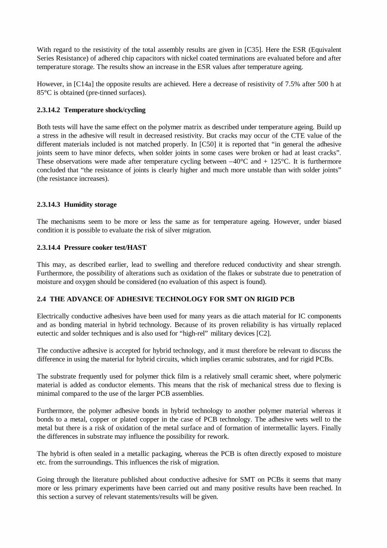
With regard to the resistivity of the total assembly results are given in [C35]. Here the ESR (EquivalentSeries Resistance) of adhered chip capacitors with nickel coated terminations are evaluated before and aftertemperature storage. The results show an increase in the ESR values after temperature ageing.
However, in [C14a] the opposite results are achieved. Here a decrease of resistivity of 7.5% after 500 h at85°C is obtained (pre-tinned surfaces).
2.3.14.2 Temperature shock/cycling
Both tests will have the same effect on the polymer matrix as described under temperature ageing. Build upa stress in the adhesive will result in decreased resistivity. But cracks may occur of the CTE value of thedifferent materials included is not matched properly. In [C50] it is reported that “in general the adhesivejoints seem to have minor defects, when solder joints in some cases were broken or had at least cracks”.These observations were made after temperature cycling between –40°C and + 125°C. It is furthermoreconcluded that “the resistance of joints is clearly higher and much more unstable than with solder joints”(the resistance increases).
2.3.14.3 Humidity storage
The mechanisms seem to be more or less the same as for temperature ageing. However, under biasedcondition it is possible to evaluate the risk of silver migration.
2.3.14.4 Pressure cooker test/HAST
This may, as described earlier, lead to swelling and therefore reduced conductivity and shear strength.Furthermore, the possibility of alterations such as oxidation of the flakes or substrate due to penetration ofmoisture and oxygen should be considered (no evaluation of this aspect is found).
2.4 THE ADVANCE OF ADHESIVE TECHNOLOGY FOR SMT ON RIGID PCB
Electrically conductive adhesives have been used for many years as die attach material for IC componentsand as bonding material in hybrid technology. Because of its proven reliability is has virtually replacedeutectic and solder techniques and is also used for “high-rel” military devices [C2].
The conductive adhesive is accepted for hybrid technology, and it must therefore be relevant to discuss thedifference in using the material for hybrid circuits, which implies ceramic substrates, and for rigid PCBs.
The substrate frequently used for polymer thick film is a relatively small ceramic sheet, where polymericmaterial is added as conductor elements. This means that the risk of mechanical stress due to flexing isminimal compared to the use of the larger PCB assemblies.
Furthermore, the polymer adhesive bonds in hybrid technology to another polymer material whereas itbonds to a metal, copper or plated copper in the case of PCB technology. The adhesive wets well to themetal but there is a risk of oxidation of the metal surface and of formation of intermetallic layers. Finallythe differences in substrate may influence the possibility for rework.
The hybrid is often sealed in a metallic packaging, whereas the PCB is often directly exposed to moistureetc. from the surroundings. This influences the risk of migration.
Going through the literature published about conductive adhesive for SMT on PCBs it seems that manymore or less primary experiments have been carried out and many positive results have been reached. Inthis section a survey of relevant statements/results will be given.
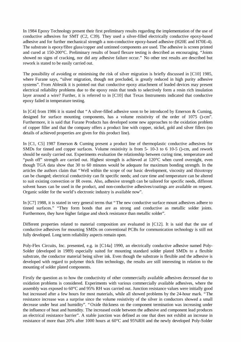
In 1984 Epoxy Technology present their first preliminary results regarding the implementation of the use ofconductive adhesives for SMT (C2, C39). They used a silver-filled electrically conductive epoxy-basedadhesive and for further mechanical strength a non-conductive epoxy-based adhesive (H20E and H70E-4).The substrate is epoxy/fibre glass/copper and untinned components are used. The adhesive is screen printedand cured at 150-200°C. Preliminary results of board flexure testing is described as encouraging. “Jointsshowed no signs of cracking, nor did any adhesive failure occur.” No other test results are described butrework is stated to be easily carried out.
The possibility of avoiding or minimising the risk of silver migration is briefly discussed in [C10] 1985,where Furane says, “silver migration, though not precluded, is greatly reduced in high purity adhesivesystems”. From Ablestik it is pointed out that conductive epoxy attachment of leaded devices may presentelectrical reliability problems due to the epoxy resin that tends to selectively form a resin rich insulationlayer around a wire? Further, it is referred to in [C10] that Texas Instruments indicated that conductiveepoxy failed in temperature testing.
In [C4] from 1986 it is stated that “A silver-filled adhesive soon to be introduced by Emerson & Cuming,designed for surface mounting components, has a volume resistivity of the order of 1075 ()-cm”.Furthermore, it is said that Furane Products has developed some new approaches to the oxidation problemof copper filler and that the company offers a product line with copper, nickel, gold and silver fillers (nodetails of achieved properties are given for this product line).
In [C1, C5] 1987 Emerson & Cuming present a product line of thermoplastic conductive adhesives forSMDs for tinned and copper surfaces. Volume resistivity is from 5- 10-3 to 6 10-5 ()-cm, and reworkshould be easily carried out. Experiments evaluation the relationship between curing time, temperature and“push off” strength are carried out. Highest strength is achieved at 120°C when cured overnight, eventhough TGA data show that 30 to 60 minutes would be adequate for maximum bonding strength. In thearticles the authors claim that “Well within the scope of our basic development, viscosity and thixotropycan be changed; electrical conductivity can fit specific needs; and cure time and temperature can be alteredto suit existing convection or IR ovens. Also, adhesive strength can be tailored for specific needs, differentsolvent bases can be used in the product, and non-conductive adhesives/coatings are available on request.Organic solder for the world’s electronic industry is available now”.
In [C7] 1988, it is stated in very general terms that “The new conductive surface mount adhesives adhere totinned surfaces.” “They form bonds that are as strong and conductive as metallic solder joints.Furthermore, they have higher fatigue and shock resistance than metallic solder”.
Different properties related to material composition are evaluated in [C12]. It is said that the use ofconductive adhesives for mounting SMDs on conventional PCBs for communication technology is still notfully developed. Long term reliability aspects remain open.
Poly-Flex Circuits, Inc. presented, e.g. in [C14a] 1990, an electrically conductive adhesive named Poly-Solder (developed in 1989) especially suited for mounting standard solder plated SMDs to a flexiblesubstrate, the conductor material being silver ink. Even though the substrate is flexible and the adhesive isdeveloped with regard to polymer thick film technology, the results are still interesting in relation to themounting of solder plated components.
Firstly the question as to how the conductivity of other commercially available adhesives decreased due tooxidation problems is considered. Experiments with various commercially available adhesives, where theassembly was exposed to 60°C and 95% RH was carried out. Junction resistance values were initially goodbut increased after a few hours for most materials, while all showed problems by the 24-hour mark. “Theresistance increase was a surprise since the volume resistivity of the silver in conductors showed a smalldecrease under heat and humidity”. “Oxide thickness on the component termination was increasing underthe influence of heat and humidity. The increased oxide between the adhesive and component lead producesan electrical resistance barrier”. A stable junction was defined as one that does not exhibit an increase inresistance of more than 20% after 1000 hours at 60°C and 95%RH and the newly developed Poly-Solder
was tested given the following results: “ Testing of the new adhesive against this criterion showed reliableconnections using ordinary solder plated or solder coated components. Gold and silver plated versions, aswould be expected, tested favourably. Even components that were steam aged to simulate shelf life ageingand therefore had much more oxide showed stable junctions during heat humidity tests. In fact, the junctionresistance decreased during virtually every test condition”. (Other tests must have been carried out?).
In [C28] 1991 a representative from Poly-Flex Circuits is quoted as saying, “Although Poly-Solder appearsto work with PCB substrates other than polyester film, most particularly FRY, what we are offering todayis one conductive adhesive with one substrate and one set of assembly rules”.
Experiments and discussions about anisotropy adhesives are referred to in [C14b and C14c] 1990. In[C14b] results for silver terminated components under modest temperature cycling and 85°C/85%RH arestated as encouraging. Devices with solder coated leads subjected to more severe temperature cycling (-65°C to 150°C) failed after 100 cycles due to adhesion loss. These results are not related to PCBs. In[C14c] anisotropy adhesives have been used for making connections for LCD cells. Results of variousenvironmental tests showed that “the connection of 5 lam thickness and large contact area remainedunchanged through increased substantially. This is believed to indicate unstable contact that occurs whenthe connection thickness is too large. From these observations we may conclude that an ACE withdeformable particles for the conductive material will develop high enough connection reliability, providedthat the bonding process greatly flattens the particles between the electrodes, thereby developing asufficiently large contact area. “Finally in [C36] it is seen that test of flexible circuits bonded to FR-4boards using an anisotropy adhesive results in increased resistance during temperature storage. Noliterature is found concerning anisotropy adhesives tested for SMDs mounted on PCBs.
Examples of users and their experiences with conductive adhesives for SMT are presented in [C45]. Ford,AC/DELCO and Philips are mentioned. All are very optimistic but not quite satisfied with the experienceof the adhesives for SMT available now. Ford mentions the brittleness at low temperature as the mostdifficult characteristic.
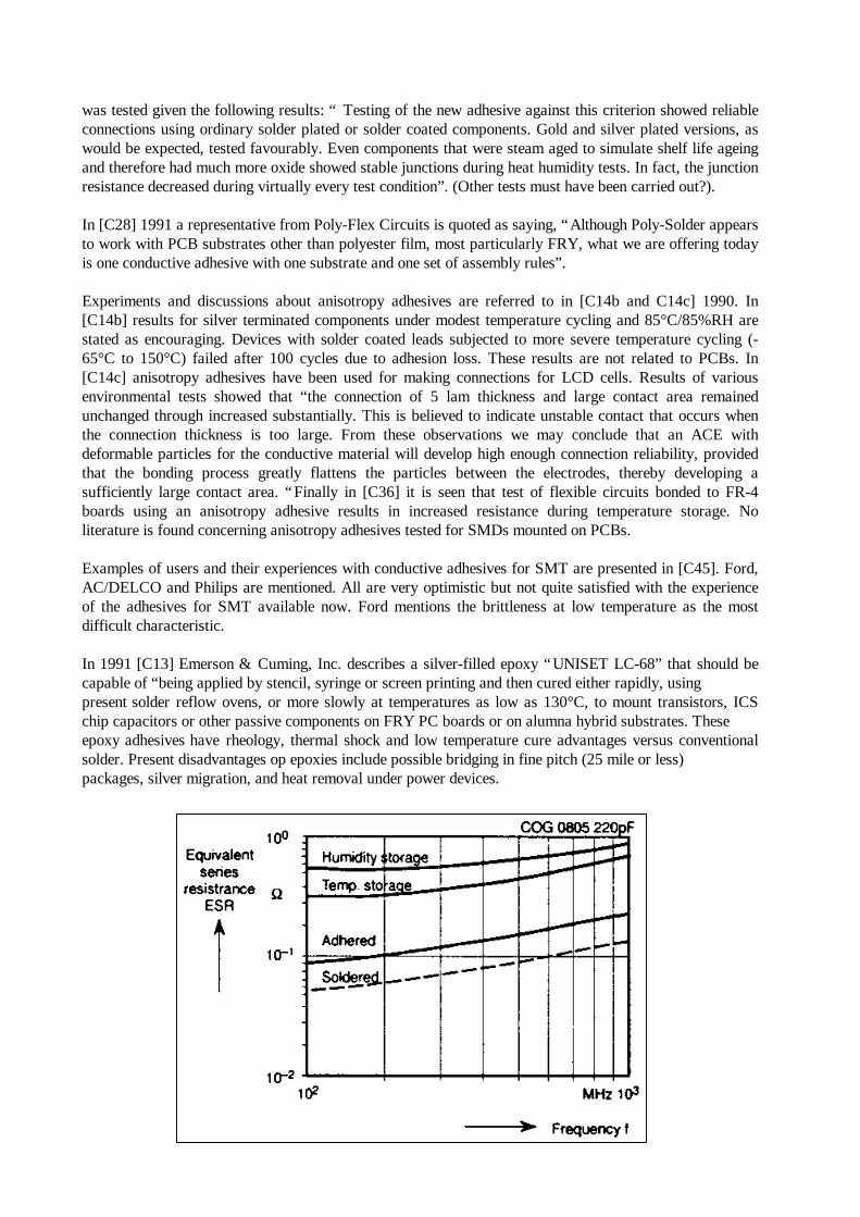
In 1991 [C13] Emerson & Cuming, Inc. describes a silver-filled epoxy “UNISET LC-68” that should becapable of “being applied by stencil, syringe or screen printing and then cured either rapidly, usingpresent solder reflow ovens, or more slowly at temperatures as low as 130°C, to mount transistors, ICSchip capacitors or other passive components on FRY PC boards or on alumna hybrid substrates. Theseepoxy adhesives have rheology, thermal shock and low temperature cure advantages versus conventionalsolder. Present disadvantages op epoxies include possible bridging in fine pitch (25 mile or less)packages, silver migration, and heat removal under power devices.
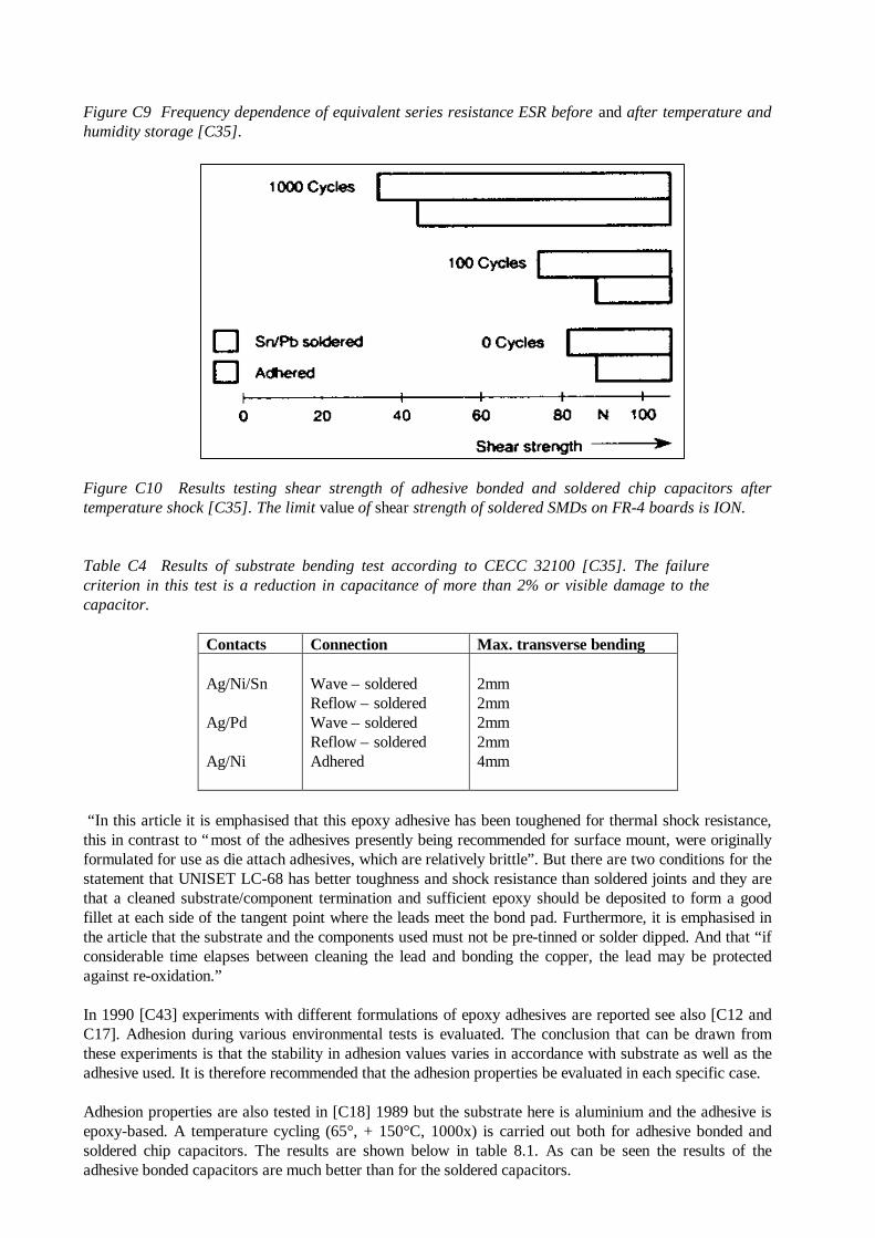
Figure C9 Frequency dependence of equivalent series resistance ESR before and after temperature andhumidity storage [C35].
Figure C10 Results testing shear strength of adhesive bonded and soldered chip capacitors aftertemperature shock [C35]. The limit value of shear strength of soldered SMDs on FR-4 boards is ION.
Table C4 Results of substrate bending test according to CECC 32100 [C35]. The failurecriterion in this test is a reduction in capacitance of more than 2% or visible damage to thecapacitor.
Contacts Connection Max. transverse bending
Ag/Ni/Sn
Ag/Pd
Ag/Ni
Wave – solderedReflow – solderedWave – solderedReflow – solderedAdhered
2mm2mm2mm2mm4mm
“In this article it is emphasised that this epoxy adhesive has been toughened for thermal shock resistance,this in contrast to “most of the adhesives presently being recommended for surface mount, were originallyformulated for use as die attach adhesives, which are relatively brittle”. But there are two conditions for thestatement that UNISET LC-68 has better toughness and shock resistance than soldered joints and they arethat a cleaned substrate/component termination and sufficient epoxy should be deposited to form a goodfillet at each side of the tangent point where the leads meet the bond pad. Furthermore, it is emphasised inthe article that the substrate and the components used must not be pre-tinned or solder dipped. And that “ifconsiderable time elapses between cleaning the lead and bonding the copper, the lead may be protectedagainst re-oxidation.”
In 1990 [C43] experiments with different formulations of epoxy adhesives are reported see also [C12 andC17]. Adhesion during various environmental tests is evaluated. The conclusion that can be drawn fromthese experiments is that the stability in adhesion values varies in accordance with substrate as well as theadhesive used. It is therefore recommended that the adhesion properties be evaluated in each specific case.
Adhesion properties are also tested in [C18] 1989 but the substrate here is aluminium and the adhesive isepoxy-based. A temperature cycling (65°, + 150°C, 1000x) is carried out both for adhesive bonded andsoldered chip capacitors. The results are shown below in table 8.1. As can be seen the results of theadhesive bonded capacitors are much better than for the soldered capacitors.
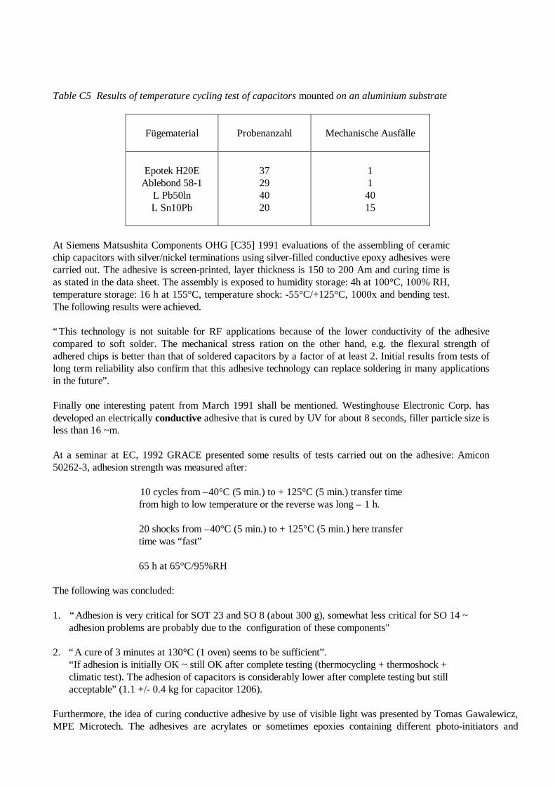
Table C5 Results of temperature cycling test of capacitors mounted on an aluminium substrate
Fügematerial Probenanzahl Mechanische Ausfälle
Epotek H20EAblebond 58-1
L Pb50lnL Sn10Pb
37294020
114015
At Siemens Matsushita Components OHG [C35] 1991 evaluations of the assembling of ceramicchip capacitors with silver/nickel terminations using silver-filled conductive epoxy adhesives werecarried out. The adhesive is screen-printed, layer thickness is 150 to 200 Am and curing time isas stated in the data sheet. The assembly is exposed to humidity storage: 4h at 100°C, 100% RH,temperature storage: 16 h at 155°C, temperature shock: -55°C/+125°C, 1000x and bending test.The following results were achieved.
“This technology is not suitable for RF applications because of the lower conductivity of the adhesivecompared to soft solder. The mechanical stress ration on the other hand, e.g. the flexural strength ofadhered chips is better than that of soldered capacitors by a factor of at least 2. Initial results from tests oflong term reliability also confirm that this adhesive technology can replace soldering in many applicationsin the future”.
Finally one interesting patent from March 1991 shall be mentioned. Westinghouse Electronic Corp. hasdeveloped an electrically conductive adhesive that is cured by UV for about 8 seconds, filler particle size isless than 16 ~m.
At a seminar at EC, 1992 GRACE presented some results of tests carried out on the adhesive: Amicon50262-3, adhesion strength was measured after:
10 cycles from –40°C (5 min.) to + 125°C (5 min.) transfer time from high to low temperature or the reverse was long – 1 h.
20 shocks from –40°C (5 min.) to + 125°C (5 min.) here transfer time was “fast”
65 h at 65°C/95%RH
The following was concluded:
1. “Adhesion is very critical for SOT 23 and SO 8 (about 300 g), somewhat less critical for SO 14 ~ adhesion problems are probably due to the configuration of these components"
2. “A cure of 3 minutes at 130°C (1 oven) seems to be sufficient”. “If adhesion is initially OK ~ still OK after complete testing (thermocycling + thermoshock + climatic test). The adhesion of capacitors is considerably lower after complete testing but still acceptable” (1.1 +/- 0.4 kg for capacitor 1206).
Furthermore, the idea of curing conductive adhesive by use of visible light was presented by Tomas Gawalewicz,MPE Microtech. The adhesives are acrylates or sometimes epoxies containing different photo-initiators and
optional thermal initiators. They cure at light (450-500 nm) and can be cured through the PCB. Cure depth is 10-mm [C51].
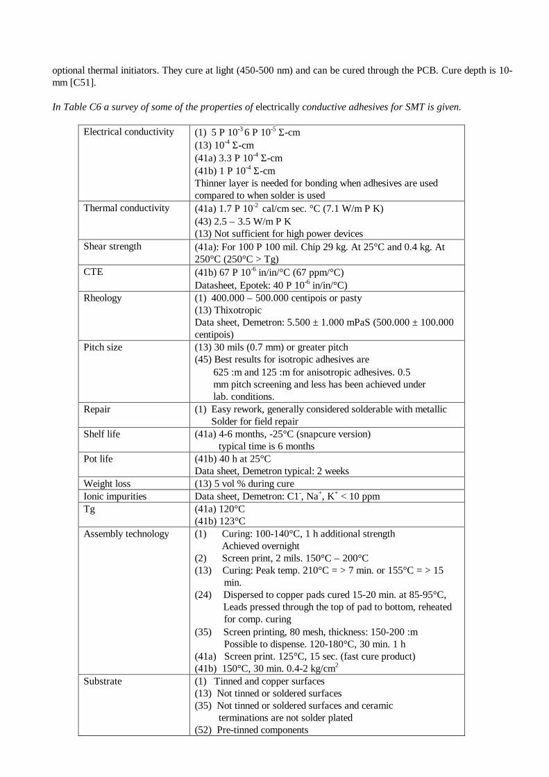
In Table C6 a survey of some of the properties of electrically conductive adhesives for SMT is given.
Electrical conductivity (1) 5 Ρ 10-3 6 Ρ 10-5 Σ-cm(13) 10-4 Σ-cm(41a) 3.3 Ρ 10-4 Σ-cm(41b) 1 Ρ 10-4 Σ-cmThinner layer is needed for bonding when adhesives are usedcompared to when solder is used
Thermal conductivity (41a) 1.7 Ρ 10-2 cal/cm sec. °C (7.1 W/m Ρ K)(43) 2.5 – 3.5 W/m Ρ K(13) Not sufficient for high power devices
Shear strength (41a): For 100 Ρ 100 mil. Chip 29 kg. At 25°C and 0.4 kg. At250°C (250°C > Tg)
CTE (41b) 67 Ρ 10-6 in/in/°C (67 ppm/°C)Datasheet, Epotek: 40 Ρ 10-6 in/in/°C)
Rheology (1) 400.000 – 500.000 centipois or pasty(13) ThixotropicData sheet, Demetron: 5.500 ± 1.000 mPaS (500.000 ± 100.000centipois)
Pitch size (13) 30 mils (0.7 mm) or greater pitch(45) Best results for isotropic adhesives are 625 :m and 125 :m for anisotropic adhesives. 0.5 mm pitch screening and less has been achieved under lab. conditions.
Repair (1) Easy rework, generally considered solderable with metallicSolder for field repair
Shelf life (41a) 4-6 months, -25°C (snapcure version) typical time is 6 months
Pot life (41b) 40 h at 25°CData sheet, Demetron typical: 2 weeks
Weight loss (13) 5 vol % during cureIonic impurities Data sheet, Demetron: C1-, Na+, K+ < 10 ppmTg (41a) 120°C
(41b) 123°CAssembly technology (1) Curing: 100-140°C, 1 h additional strength
Achieved overnight(2) Screen print, 2 mils. 150°C – 200°C(13) Curing: Peak temp. 210°C = > 7 min. or 155°C = > 15 min.(24) Dispersed to copper pads cured 15-20 min. at 85-95°C,
Leads pressed through the top of pad to bottom, reheated for comp. curing(35) Screen printing, 80 mesh, thickness: 150-200 :m Possible to dispense. 120-180°C, 30 min. 1 h(41a) Screen print. 125°C, 15 sec. (fast cure product)(41b) 150°C, 30 min. 0.4-2 kg/cm2
Substrate (1) Tinned and copper surfaces(13) Not tinned or soldered surfaces(35) Not tinned or soldered surfaces and ceramic terminations are not solder plated(52) Pre-tinned components
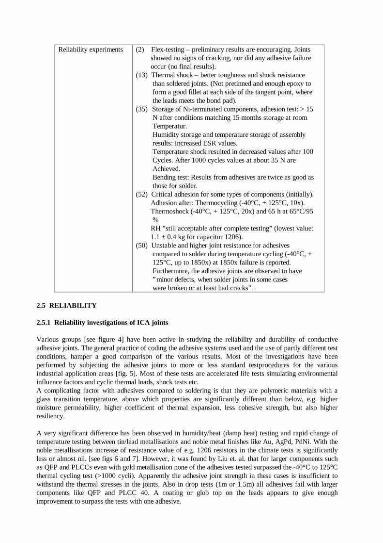
Reliability experiments (2) Flex-testing – preliminary results are encouraging. Joints showed no signs of cracking, nor did any adhesive failure occur (no final results).(13) Thermal shock – better toughness and shock resistance than soldered joints. (Not pretinned and enough epoxy to form a good fillet at each side of the tangent point, where the leads meets the bond pad).(35) Storage of Ni-terminated components, adhesion test: > 15 N after conditions matching 15 months storage at room Temperatur. Humidity storage and temperature storage of assembly results: Increased ESR values. Temperature shock resulted in decreased values after 100 Cycles. After 1000 cycles values at about 35 N are Achieved. Bending test: Results from adhesives are twice as good as those for solder.(52) Critical adhesion for some types of components (initially). Adhesion after: Thermocycling (-40°C, + 125°C, 10x). Thermoshock (-40°C, + 125°C, 20x) and 65 h at 65°C/95 % RH ”still acceptable after complete testing” (lowest value: 1.1 ± 0.4 kg for capacitor 1206).(50) Unstable and higher joint resistance for adhesives compared to solder during temperature cycling (-40°C, + 125°C, up to 1850x) at 1850x failure is reported. Furthermore, the adhesive joints are observed to have ”minor defects, when solder joints in some cases were broken or at least had cracks”.
2.5 RELIABILITY
2.5.1 Reliability investigations of ICA joints
Various groups [see figure 4] have been active in studying the reliability and durability of conductiveadhesive joints. The general practice of coding the adhesive systems used and the use of partly different testconditions, hamper a good comparison of the various results. Most of the investigations have beenperformed by subjecting the adhesive joints to more or less standard testprocedures for the variousindustrial application areas [fig. 5]. Most of these tests are accelerated life tests simulating environmentalinfluence factors and cyclic thermal loads, shock tests etc.A complicating factor with adhesives compared to soldering is that they are polymeric materials with aglass transition temperature, above which properties are significantly different than below, e.g. highermoisture permeability, higher coefficient of thermal expansion, less cohesive strength, but also higherresiliency.
A very significant difference has been observed in humidity/heat (damp heat) testing and rapid change oftemperature testing between tin/lead metallisations and noble metal finishes like Au, AgPd, PdNi. With thenoble metallisations increase of resistance value of e.g. 1206 resistors in the climate tests is significantlyless or almost nil. [see figs 6 and 7]. However, it was found by Liu et. al. that for larger components suchas QFP and PLCCs even with gold metallisation none of the adhesives tested surpassed the -40°C to 125°Cthermal cycling test (>1000 cycli). Apparently the adhesive joint strength in these cases is insufficient towithstand the thermal stresses in the joints. Also in drop tests (1m or 1.5m) all adhesives fail with largercomponents like QFP and PLCC 40. A coating or glob top on the leads appears to give enoughimprovement to surpass the tests with one adhesive.
On the contrary conductive adhesive joints of capacitors appear to have better performance in harshthermal cycling tests (-65° to 150°C) than solder.
Most of the adhesives show unacceptable increase in contact resistance using SnPb finishes [see figs. 8 and9].
Increases in resistance after TC (-40 to 125°C) and TH (85°C/85%RH) in many cases are larger thanseveral ohms. Only for some adhesives, specially developed for SnPb, the behaviour in 85°C/85%RH andTH is quite good [fig. 10]. The results in TC tests however still need improvement.It has been reported that under the test conditions chosen no Ag-migration is observed and good SIR valuesare obtained.
The mechanical shear strength of the adhesive joints generally decreases in the temperature/humidity andthermal cycling tests, but in general no direct correlation with the electrical properties is observed.
2.5.2 Reliability of Anisotropic Conductive Adhesives
Only a few studies have been reported about the reliability of anisotropic conductive adhesive joints ofSMD components to printed circuit boards. One of the limitations of the ACA(F) adhesives is the need tocure under a contact pressure.In an investigation by Lijten and van Noort it was found that contrary to the observations for ICAs,anisotropic joints (e.g. with Au coated plastic spheres) of QFP80s on FR-4 (Au) [fig. 11] showedsignificant increase in resistance values after 85°C/85%RH testing and RCT (-25 to 100°C). Surprisinglywith components finished with SnPb [figs 11 and 12], far better results were obtained. It was shown thatunder the conditions used solder bridges were formed across the Au particles in the ACA, with showed verylow and stable resistance values. Recently SnBi filled anisotropic adhesives have become commerciallyavailable, that can form micro-solder joints within the adhesive matrix, showing low and stable resistancevalues. An example from the work of Kivilahti et. Al. of Sn58Bi bonding of flex to flex with NiAu, Cu andSn finishs is given in figure 13. Results for the SnBi filled adhesive after 60°C/95%RH are quite good incase of Cu and Sn, but worse for Au/Ni due to gold dissolution and Ni corrosion. Neither in TC (-40°C/100°C) a significant resistance increase observed. For flip chip similar results were reported(85°C/85%RH).
2.6 FAILURE CAUSES
Several failure causes have been suggested to explain the resistance increases sometimes observed withconductive adhesives i.e. oxidation of SnPb and Cu, crack formation, a silver depleted surface layer in theadhesive, creep of the adhesive, the formation of intermetallics, and processing failures. In some cases(with water condensation), also silver migration could be a failure cause.
2.6.1 Oxidation and corrosion (SnPb, Cu)
Oxidation of SnPb can be uniform or local. The formation of a > 100 nm thick oxide layer has beenreported. Several investigators have also observed local oxidation. In some cases traces of CI, have beendetected at the oxidised/corroded places [see fig. 15]. Is has been suggested that the mechanism of SnPbcorrosion is by electrochemical cell formation. Resistance increases appear to be more severe for Snfinished products than for SnPb and even less for Pb. The oxidation is also stronger underneath theadhesives than on unprotected SnPb.
It is also claimed that combinations of noble/less-noble metallisations suffer more severely ofoxidation/corrosion than combinations of non-noble metals only. This could be due to the electrochemicalcell formation.Oxidation of SnPb may be the direct cause of the sometimes huge resistance increases, or indirectly byinducing crack formation.
In addition, in the case of bare Cu substrates also oxidation of Cu has been observed and considered as acause of resistance increase.
2.6.2 Crack formation/delamination
The occurrence of cracks in electrically bad performing joints has been observed by many differentinvestigators, after constant temperature/humidity as well as cyclic temperature/humidity testing, andthermal cycling. Some examples for R1206 (SnPb) are given in figure 14-16, for 85°C/85%RH testing,and also in figure 17 after RCT testing. Despite crack formation, the shear strength of the joint may still beconsiderable [fig. 17]. Figure 18 (Botter) shows that during humidity cycling sudden increases in resistancevalues may occur in some joints, possibly due to crack formation, while in similar joints the increase israther smooth.With AgPd finished resistors, not showing significant resistance increase in the indicated tests, no crackswere observed [fig. 19].
2.6.3 Silver depleted layer
In one case it has been reported that a thin silver depleted layer (> 50 nm) has been observed in theadhesive at the component side after temperature/humidity testing, by Auger analyses in combination withAr-ion sputtering. The observation was made after cleavage of the joint at the component side. It is alsopossible that crack formation and some creep of the adhesive occurred.
2.6.4 Creep of the adhesive
Some authors have suggested the possibility of adhesive creep leading to resistance increase during TCtesting. This could be due to cyclic shear motion of the component and viscoplastic deformation of theadhesive. The fact however that with a gold finish on component and board no large resistance increase isobserved, indicated that it is unlikely that creep is a main cause of the R-increase with SnPb. It has alsobeen observed by several workers that the bulk resistance of the adhesive does not increase significantly inclimate tests, but in these no cyclic mechanical load is exerted on the adhesive as in case of bondedcomponents.
2.6.5 Formation of an intermetallic layer
Formation of AgSn Intermediate layers of lower conductivity was suggested by Orthmann et. Al. as thecause of R-increase during hot storage tests at 150°. Other investigators, however, have not observed AgSnduring TC and pressure cooker testing.
2.6.6 Ag migration
Several investigators have reported that they did not observe signs of Ag migration during climate testing.It is clear however that silver migration can easily occur if a liquid waterfilm can be formed on theadhesive. If any danger exists for water condensation it is advisable to avoid the risk for silver migration byapplying a protective coating or glob top on the joints.
2.6.7 Processing defects
Undercure of the adhesive may lead to resistance increase during reliability testing. Also bad wetting, voidsin the adhesive, a very thin bondline, and misalignment can lead to R-increase possibly by crack formationin the adhesive joints [fig. 20].
2.7 THE INFLUENCE ON INTERNAL AND EXTERNAL ENVIRONMENTS
By implementing new technologies there is always the risk of introducing new and possible unknownenvironmental problems. In this section possible problems and precautions that must be taken, in general,
when electrically conductive adhesives are used for SMT is discussed, in general. Note that it is importantto further evaluate risks related to a specific chosen adhesive. Variants that will be chosen for thesubsequent part of the project will be individually evaluated.
2.7.1 External environmental aspects
Possible sources for pollution from the production process using adhesives as a substitution for solder andsolder paste are organic solvents (thermoplastic adhesive) and reactive solvents/curing agent that mayevaporate during curing. Furthermore, in some cases it may be necessary to use solvents for rework and forcleaning of the stencil/screening mask. From this cleaning process residuals of the adhesives are also apossible source of pollution. Finally, residuals in the packing and adhesive beyond shelf life must beeliminated.
In relation to the external environment the amount of organic solvent or reactive solvents/curing agentsfrom the adhesive it is negligible, when thermosetting materials are applied. Especially, because forthermosetting adhesives it is also for technical reasons desirable to reduce the evaporation of thosesubstances from the adhesive. The amount of solvents from thermoplastic adhesives, however, must betaken into consideration.
Today when solder paste is used new paste may be added at the stencil without previous cleaning. Thisprocess may continue for about 10 days. Old paste can be removed mechanically. If this process can alsobe used for adhesives the amount of solvents necessary for cleaning will not increase by substitution fromsolder to electrically conductive adhesives. The pot life, however, is less for adhesives compared to solderpaste and therefore further cleaning may be necessary. However, it was said by one manufacturer that ifmetal screens were used the amount of waste was limited. Any waste containing organic solder or uncuredadhesive must be disposed in accordance with the legislation (in Denmark it has to be sent toKommunekemi, which is a public waste plant for chemicals). If the amount of adhesive residuals from thestencils is sufficiently high it is for some adhesives, and particularly thermoplastic adhesives, possible toreuse the adhesive, when the bulk of the solvent has evaporated (information from Multicore SoldersLimited, about the adhesive HTECA- 1000).
Residuals from packing and adhesives beyond shelf life must be minimised by optimal planning of purchaseof the adhesives related to production (as for solder paste). The residues must be sent to Kommunekemi asis also done today for solder paste and used solder baths.
It may be possible to reuse the adhesive or parts of it (the pure metals). Information from METALORScandinavia A/S, who are concerned about the reprocessing of metals from materials used in theelectronics industry, indicates that it is technically possible to reuse silver. However, a test is necessary inorder to evaluate if it is sufficiently profitable and does not by itself give rise to more pollution. Due tohandling and transport it may be advisable to cure the adhesive, even though this may make thereprocessing more difficult.
At Degussa AG the silver from adhesives beyond their shelf life is reused. The adhesive is burned and fromthe ash the silver is regained.
As can be seen the substitution of solder with adhesive, and thereby eliminating the use of lead and CRCs,will be an advantage for the external environment, especially if thermoseKing adhesives containing nosolvents are used. The possible advantages by reuse or reprocessing of the adhesive or parts of it must befurther investigated.
2.7.2 Internal environmental aspects
Evaluation of the working environment is very dependent on the adhesive chosen. If a thermoplasticadhesive is used, it is organic solvents evaporating from the uncured adhesive that is of concern. Thismeans that ventilation and/or masks together with gloves must be used.
Especially the risk of allergic eczema is present and skin contact must be avoided, if an epoxy adhesive isused. The special regulations for use of epoxy must be followed. In Denmark: The departmental order No.199 of 26th March, 1985 from the Danish Working Environment Services concerning epoxy resins andisocyanates. This order gives the basis for instruction No. 3.01.3, June 1988. Both resin, curing agent andpossible reactive solvents or other additives can influence the working environment.
In [C53] a general evaluation of the above mentioned substances is presented.
In general, resins consisting of mostly low molecular substances, e.g Bisphenol-A-epichlorhydrin, are veryreactive and by contact they can cause irritation of the skin, eyes or the respiratory passages. Allergy maybe the result of repeated skin contact (for some one week is enough while others may be exposed to epoxyfor several years before the allergy is developed). An allergy will often last for the rest of one's life. Longterm exposure may cause damage to the testicles or bloodforming organs. The vapour pressure of thesesubstances is low which means that exposure by inhalation is very limited.
High molecular resins are less reactive and therefore less harmful. Notice, there will always be a smallamount of low molecular resins present.
The curing agent can consist of many different substances. Acrylic amines and cyclic amines are often used(general knowledge about adhesives, no specific information about electrically conductive adhesives).Acrylic amines evaporate very easily and can cause allergy and further increase the risk of epoxy allergy.Some cyclic amines can cause damage of the kidney, allergy and can alter the genes of bacteria.Amineepoxyadduct and polyaminoamide as curing agents are recommended instead of pure acrylic amines.
The reactive solvents are low molecular substances with the same disadvantages as the low molecularresins and furthermore they are often very easily evaporated. Proper ventilation must be used in order toavoid inhalation. The use of these substances must be avoided, if possible. Furthermore, if volatile reactivesolvents are present it must be indicated in the safety data sheet.
Both for thermoplastic and thermosetting adhesives the handling of the uncured adhesive is where exposureof some of the above mentioned substances may occur. It is therefore appropriate to evaluate theproduction process.
When a conductive adhesive is screen printed or stencilled to the PCB the adhesive is normally manuallyplaced onto the stencil/screening mask. The adhesive is then cured in the oven and postcure may take placeafterwards. From the oven vapours must be removed by proper air ventilation. After cure the boards arethen removed from the oven, often automatically and postcure can take place. There should be proper airventilation provided also for the postcure.
This means that the operator is in contact with the uncured adhesive when it shall be mixed (iftwo-component types are used), when placed on the stencil/screening mask and during cleaning of thestencil/screening mask. Furthermore, operators may be in contact with organic solvents and uncuredadhesives during rework.
Sufficient precautions must be taken both when handling epoxy and organic solvents. Ventilation mustprovide a descending air stream because the substance that has to be removed is heavier than air [53].Furthermore, if contact cannot be avoided (e.g. by use of a dispenser) suitable disposable gloves andspecial working clothes must be used. Protective cream must not be used under the gloves or instead ofgloves. Further: "persons suffering from eczema and persons suffering from a previously diagnosed allergyto epoxy are not allowed to work with epoxy resins". Neither are persons with excessive perspiration of thehands (hyperhedrosis manuum).
In Denmark only persons trained at a special course are allowed to work with epoxies.

As can be seen there are several aspects that must be considered with regard to the internal environment.With regard to the internal environment wave soldering technology seems to be favourable but this is notthe case when external environment is of concern due to the residue from the solder baths.


![Conductive polymers: Towards a smart biomaterial for ... · electrochemical and electromechanical stimulation to cells [1–4]. The family of electroactive biomaterials includes conductive](https://img.pdfslide.net/doc/110x75/5ae925f27f8b9ad73f8b7bcd/conductive-polymers-towards-a-smart-biomaterial-for-and-electromechanical-stimulation.jpg)