1
Characterisation of a Quiet Wind Tunnel Author: Declan Walsh Supervisor: Con Doolan Research Theme: Fundamental and Enabling Research Results: Free Field Environment Background and Motivation Flow noise is a loud and obtrusive phenomena in modern society. Increasingly, the leading causes of aircraft noise are due to flow unsteadiness and acoustic resonance. An understanding of these complex processes will lead to better designed aircraft, quieter propellers, wind turbines and automobiles. The newly installed anechoic wind tunnel has been designed to provide a reflection free, quiet environment in which flow noise can be studied. Before it can be used in research, the tunnel must have its flow and acoustic characteristics determined. In order to be suitable for acoustic measurements the chamber must be anechoic. That is, it must not reflect any significant sound in the frequencies of interest (250Hz to 20kHz) and be a free field. As seen in Figure 2 below the sound power level (SPL) follows a logarithmic reduction as the microphone moves away from the speaker. This indicates a free field environment with a 6dB decrease in SPL per doubling of distance. Conclusion The wind tunnel has a very strong core that maintains itself over a large length allowing for reliable testing conditions in the tunnel’s flow A free field environment is present over most of the chamber allowing accurate acoustic measurements to be made These characteristics make the new quiet wind tunnel ideal for aeroacoustic testing Further research into flow noise is enabled with the tunnel Method Jet Potential Core (Figure 1): A traverse mounted 3D printed pitot rake recorded pressure and flow measurements along the span of the tunnel at 15m/s. Free Field Environment: A white noise speaker set in the corner of the room was recorded by a microphone at various distances away from it moving along the room diagonal. Results: Jet Potential Core A stable flow at constant speed is required from the inlet to the chamber to provide reliable conditions for testing. This region is called the jet potential core of the tunnel. In the horizontal velocity profile in Figure 3 several features are visible: Broad flat region is the jet core As distance from the outlet increase the core shrinks slightly Very strong, stable core at all measured distances These measurements were repeated for several different directions and evaluated over a range of frequency bands with all results strongly indicating a free field environment with no significant reflections. All values measured lay within the accepted limits, except for some results caused by interference near the traverse in one of the chamber corners. These areas are out of the region of measurement and can be ignored. Figure 2: Logarithmic Decrease in SPL with Distance Figure 4: 3D Jet Potential Core Mapping at various Downstream Distances (15 m/s flow) Future Work To further improve the flow quality of the tunnel a collector is being developed to increase the effective size of the outlet. Once completed, repeating the flow quality measurements to determine the level of improvement would provide valuable insight into collector design and effectiveness. Figure 1: Photograph of Flow Measurement Setup in Anechoic Wind Tunnel Chamber Aims To determine the suitability of the anechoic wind tunnel for aeroacoustic testing by: Measuring flow quality in the jet potential core Determining if the chamber is a free field environment with no reflections Figure 3: Horizontal Decay of Potential Core (3 m/s offset) These results are supported for the 3D velocity profile seen in figure 4: Yellow plateau is the jet core from inlet Blue edges are the surrounding air As distance downstream increases the surroundings become more disturbed Core maintains its shape and velocity, ideal for testing

Characterisation of a Quiet Wind Tunnel - Engineering · Characterisation of a Quiet Wind Tunnel Author: Declan Walsh ... The newly installed anechoic wind tunnel has been designed

Embed Size (px)

Citation preview

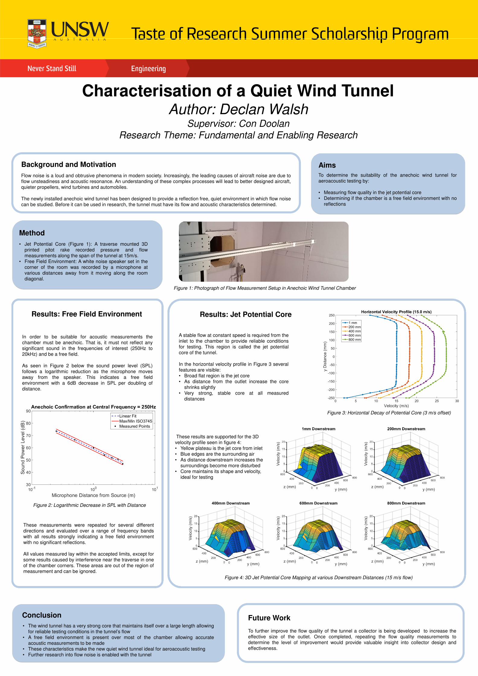
Characterisation of a Quiet Wind TunnelAuthor: Declan Walsh

Supervisor: Con Doolan

Research Theme: Fundamental and Enabling Research

Results: Free Field Environment

Background and Motivation

Flow noise is a loud and obtrusive phenomena in modern society. Increasingly, the leading causes of aircraft noise are due to

flow unsteadiness and acoustic resonance. An understanding of these complex processes will lead to better designed aircraft,

quieter propellers, wind turbines and automobiles.

The newly installed anechoic wind tunnel has been designed to provide a reflection free, quiet environment in which flow noise

can be studied. Before it can be used in research, the tunnel must have its flow and acoustic characteristics determined.

In order to be suitable for acoustic measurements the

chamber must be anechoic. That is, it must not reflect any

significant sound in the frequencies of interest (250Hz to

20kHz) and be a free field.

As seen in Figure 2 below the sound power level (SPL)

follows a logarithmic reduction as the microphone moves

away from the speaker. This indicates a free field

environment with a 6dB decrease in SPL per doubling of

distance.

Conclusion

• The wind tunnel has a very strong core that maintains itself over a large length allowing

for reliable testing conditions in the tunnel’s flow

• A free field environment is present over most of the chamber allowing accurate

acoustic measurements to be made

• These characteristics make the new quiet wind tunnel ideal for aeroacoustic testing

• Further research into flow noise is enabled with the tunnel

Method

• Jet Potential Core (Figure 1): A traverse mounted 3D

printed pitot rake recorded pressure and flow

measurements along the span of the tunnel at 15m/s.

• Free Field Environment: A white noise speaker set in the

corner of the room was recorded by a microphone at

various distances away from it moving along the room

diagonal.

Results: Jet Potential Core

A stable flow at constant speed is required from the

inlet to the chamber to provide reliable conditions

for testing. This region is called the jet potential

core of the tunnel.

In the horizontal velocity profile in Figure 3 several

features are visible:

• Broad flat region is the jet core

• As distance from the outlet increase the core

shrinks slightly

• Very strong, stable core at all measured

distances

These measurements were repeated for several different

directions and evaluated over a range of frequency bands

with all results strongly indicating a free field environment

with no significant reflections.

All values measured lay within the accepted limits, except for

some results caused by interference near the traverse in one

of the chamber corners. These areas are out of the region of

measurement and can be ignored.

Figure 2: Logarithmic Decrease in SPL with Distance

Figure 4: 3D Jet Potential Core Mapping at various Downstream Distances (15 m/s flow)

Future Work

To further improve the flow quality of the tunnel a collector is being developed to increase the

effective size of the outlet. Once completed, repeating the flow quality measurements to

determine the level of improvement would provide valuable insight into collector design and

effectiveness.

Figure 1: Photograph of Flow Measurement Setup in Anechoic Wind Tunnel Chamber

Aims

To determine the suitability of the anechoic wind tunnel for

aeroacoustic testing by:

• Measuring flow quality in the jet potential core

• Determining if the chamber is a free field environment with no

reflections

Figure 3: Horizontal Decay of Potential Core (3 m/s offset)

These results are supported for the 3D

velocity profile seen in figure 4:

• Yellow plateau is the jet core from inlet

• Blue edges are the surrounding air

• As distance downstream increases the

surroundings become more disturbed

• Core maintains its shape and velocity,

ideal for testing