Embed Size (px)
Citation preview
Part No. N450000888 Rev 001
Published March 2009
Title Page
Check Point IP390 Security Platform
Installation Guide

2 Check Point IP390 Security Platform Installation Guide
© 2003-2009 Check Point Software Technologies Ltd.
All rights reserved. This product and related documentation are protected by copyright and distributed under licensing restricting their use, copying, distribution, and decompilation. No part of this product or related documentation may be reproduced in any form or by any means without prior written authorization of Check Point. While every precaution has been taken in the preparation of this book, Check Point assumes no responsibility for errors or omissions. This publication and features described herein are subject to change without notice.
RESTRICTED RIGHTS LEGEND: Use, duplication, or disclosure by the government is subject to restrictions as set forth in subparagraph (c)(1)(ii) of the Rights in Technical Data and Computer Software clause at DFARS 252.227-7013 and FAR 52.227-19.
TRADEMARKS:Please refer to http://www.checkpoint.com/copyright.html for a list of our trademarks.For third party notices, see http://www.checkpoint.com/3rd_party_copyright.html.
Check Point Contact InformationFor additional technical information about Check Point products, and for the latest version of this document, see the Check Point Support Center at http://support.checkpoint.com/.Check Point is engaged in a continuous effort to improve its documentation. Please help us by sending your comments to:
Contents
Check Point Contact Information. . . . . . . . . . . . . . . . . . . . . . . . . . . . . . . . . . . . . . . 2
About This Guide . . . . . . . . . . . . . . . . . . . . . . . . . . . . . . . . . . . . . . . . . . . . . . . . . 11In this Guide . . . . . . . . . . . . . . . . . . . . . . . . . . . . . . . . . . . . . . . . . . . . . . . . . . . . . . . 11Conventions this Guide Uses . . . . . . . . . . . . . . . . . . . . . . . . . . . . . . . . . . . . . . . . . . 12
Notices . . . . . . . . . . . . . . . . . . . . . . . . . . . . . . . . . . . . . . . . . . . . . . . . . . . . . . . . . 12Command-Line Conventions. . . . . . . . . . . . . . . . . . . . . . . . . . . . . . . . . . . . . . . . . 12Text Conventions . . . . . . . . . . . . . . . . . . . . . . . . . . . . . . . . . . . . . . . . . . . . . . . . . 13
1 Overview . . . . . . . . . . . . . . . . . . . . . . . . . . . . . . . . . . . . . . . . . . . . . . . . . . . . . . . . 15About the Check Point IP390 Appliance . . . . . . . . . . . . . . . . . . . . . . . . . . . . . . . . . 15
Built-In Gigabit Ethernet Ports. . . . . . . . . . . . . . . . . . . . . . . . . . . . . . . . . . . . . . . . 16PMC Expansion Slots . . . . . . . . . . . . . . . . . . . . . . . . . . . . . . . . . . . . . . . . . . . . . . 17
Managing the IP390 Appliance . . . . . . . . . . . . . . . . . . . . . . . . . . . . . . . . . . . . . . . . 18Site Requirements, Warnings, and Cautions . . . . . . . . . . . . . . . . . . . . . . . . . . . . . . 19Software Requirements . . . . . . . . . . . . . . . . . . . . . . . . . . . . . . . . . . . . . . . . . . . . . . 20Product Disposal . . . . . . . . . . . . . . . . . . . . . . . . . . . . . . . . . . . . . . . . . . . . . . . . . . . 20
2 Installing the Check Point IP390 Appliance . . . . . . . . . . . . . . . . . . . . . . . . . . . . 21Before You Begin . . . . . . . . . . . . . . . . . . . . . . . . . . . . . . . . . . . . . . . . . . . . . . . . . . . 21Rack Mounting the Appliance. . . . . . . . . . . . . . . . . . . . . . . . . . . . . . . . . . . . . . . . . . 21Connecting Power . . . . . . . . . . . . . . . . . . . . . . . . . . . . . . . . . . . . . . . . . . . . . . . . . . 22Connecting to the Console or Auxiliary Port. . . . . . . . . . . . . . . . . . . . . . . . . . . . . . . 23
Console Port . . . . . . . . . . . . . . . . . . . . . . . . . . . . . . . . . . . . . . . . . . . . . . . . . . . . . 25Auxiliary Port . . . . . . . . . . . . . . . . . . . . . . . . . . . . . . . . . . . . . . . . . . . . . . . . . . . . . 26
Connecting to Network Interfaces . . . . . . . . . . . . . . . . . . . . . . . . . . . . . . . . . . . . . . 27
3 Performing the Initial Configuration . . . . . . . . . . . . . . . . . . . . . . . . . . . . . . . . . . 29Using a Console Connection . . . . . . . . . . . . . . . . . . . . . . . . . . . . . . . . . . . . . . . . . . 29Using Check Point Network Voyager . . . . . . . . . . . . . . . . . . . . . . . . . . . . . . . . . . . . 31
Viewing Check Point IPSO Documentation by Using Check Point Network Voyager . . . . . . . . . . . . . . . . . . . . . . . . . . . . . . . . . . . . . . 32
Using the Command-Line Interface . . . . . . . . . . . . . . . . . . . . . . . . . . . . . . . . . . . . . 33Using Check Point Horizon Manager . . . . . . . . . . . . . . . . . . . . . . . . . . . . . . . . . . . . 33
Check Point IP390 Security Platform Installation Guide 3
4 About IP390 Appliance Network Interface Cards . . . . . . . . . . . . . . . . . . . . . . . . 35Four-Port 10/100 Mbps Ethernet Network Interface Card. . . . . . . . . . . . . . . . . . . . 35
Ethernet NIC Features . . . . . . . . . . . . . . . . . . . . . . . . . . . . . . . . . . . . . . . . . . . . . 35Ethernet NIC Connectors and Cables . . . . . . . . . . . . . . . . . . . . . . . . . . . . . . . . . 36
Two-Port Copper Gigabit Ethernet Network Interface Card . . . . . . . . . . . . . . . . . . 38Copper Gigabit Ethernet NIC Features . . . . . . . . . . . . . . . . . . . . . . . . . . . . . . . . 38Copper Gigabit Ethernet Connectors and Cables . . . . . . . . . . . . . . . . . . . . . . . . 39
Two-Port Fiber-Optic Gigabit Ethernet Network Interface Card . . . . . . . . . . . . . . . 40Fiber-Optic Gigabit Ethernet NIC Features . . . . . . . . . . . . . . . . . . . . . . . . . . . . . 41Fiber-Optic Gigabit Ethernet NIC Connectors and Cables. . . . . . . . . . . . . . . . . . 42Fiber-Optic Gigabit Ethernet NIC SFP Modules. . . . . . . . . . . . . . . . . . . . . . . . . . 42
Four-Port T1 Network Interface Card . . . . . . . . . . . . . . . . . . . . . . . . . . . . . . . . . . . 43T1 NIC Features. . . . . . . . . . . . . . . . . . . . . . . . . . . . . . . . . . . . . . . . . . . . . . . . . . 43T1 Connectors and Cables . . . . . . . . . . . . . . . . . . . . . . . . . . . . . . . . . . . . . . . . . 43
5 Installing and Replacing Network Interface Cards . . . . . . . . . . . . . . . . . . . . . . . 47Deactivating Configured Interfaces . . . . . . . . . . . . . . . . . . . . . . . . . . . . . . . . . . . . . 47Removing, Installing, and Replacing NICs . . . . . . . . . . . . . . . . . . . . . . . . . . . . . . . 48
Before You Start. . . . . . . . . . . . . . . . . . . . . . . . . . . . . . . . . . . . . . . . . . . . . . . . . . 48Configuring and Activating Interfaces . . . . . . . . . . . . . . . . . . . . . . . . . . . . . . . . . . . 53Monitoring Network Interface Cards . . . . . . . . . . . . . . . . . . . . . . . . . . . . . . . . . . . . 53
6 Installing and Replacing Components Other than Network Interface Cards . . 55Replacing the Compact Flash Memory Card . . . . . . . . . . . . . . . . . . . . . . . . . . . . . 55Installing a Flash-Memory PC Card . . . . . . . . . . . . . . . . . . . . . . . . . . . . . . . . . . . . 58
Before You Begin . . . . . . . . . . . . . . . . . . . . . . . . . . . . . . . . . . . . . . . . . . . . . . . . . 58Transferring Files with the Flash-Memory PC Card . . . . . . . . . . . . . . . . . . . . . . . 59
Installing or Replacing a Hard-Disk Drive . . . . . . . . . . . . . . . . . . . . . . . . . . . . . . . . 59Before You Start. . . . . . . . . . . . . . . . . . . . . . . . . . . . . . . . . . . . . . . . . . . . . . . . . . 60Configuring a Hard-Disk Drive for Logging . . . . . . . . . . . . . . . . . . . . . . . . . . . . . 63
Replacing or Upgrading Memory . . . . . . . . . . . . . . . . . . . . . . . . . . . . . . . . . . . . . . 64Before You Start. . . . . . . . . . . . . . . . . . . . . . . . . . . . . . . . . . . . . . . . . . . . . . . . . . 65
Replacing the Battery . . . . . . . . . . . . . . . . . . . . . . . . . . . . . . . . . . . . . . . . . . . . . . . 68
7 Troubleshooting . . . . . . . . . . . . . . . . . . . . . . . . . . . . . . . . . . . . . . . . . . . . . . . . . . . 73General Troubleshooting Information . . . . . . . . . . . . . . . . . . . . . . . . . . . . . . . . . . . 73Troubleshooting Routing Problems . . . . . . . . . . . . . . . . . . . . . . . . . . . . . . . . . . . . 79
A Technical Specifications . . . . . . . . . . . . . . . . . . . . . . . . . . . . . . . . . . . . . . . . . . . . 83Physical Dimensions . . . . . . . . . . . . . . . . . . . . . . . . . . . . . . . . . . . . . . . . . . . . . . . . 83Space Requirements. . . . . . . . . . . . . . . . . . . . . . . . . . . . . . . . . . . . . . . . . . . . . . . . 83Operating Temperature. . . . . . . . . . . . . . . . . . . . . . . . . . . . . . . . . . . . . . . . . . . . . . 83NIC Interfaces . . . . . . . . . . . . . . . . . . . . . . . . . . . . . . . . . . . . . . . . . . . . . . . . . . . . 84
4 Check Point IP390 Security Platform Installation Guide
B Compliance Information . . . . . . . . . . . . . . . . . . . . . . . . . . . . . . . . . . . . . . . . . . . . 85Declaration of Conformity. . . . . . . . . . . . . . . . . . . . . . . . . . . . . . . . . . . . . . . . . . . . . 85Compliance Statements . . . . . . . . . . . . . . . . . . . . . . . . . . . . . . . . . . . . . . . . . . . . . . 86FCC Requirements (US) . . . . . . . . . . . . . . . . . . . . . . . . . . . . . . . . . . . . . . . . . . . . . 87FCC Notice (US) . . . . . . . . . . . . . . . . . . . . . . . . . . . . . . . . . . . . . . . . . . . . . . . . . . . 87
Index . . . . . . . . . . . . . . . . . . . . . . . . . . . . . . . . . . . . . . . . . . . . . . . . . . . . . . . . . . . . 89
Check Point IP390 Security Platform Installation Guide 5

6 Check Point IP390 Security Platform Installation Guide
Tables
Table 1 Command-Line Conventions . . . . . . . . . . . . . . . . . . . . . . . . . . . . . . . . . . 12Table 2 Text Conventions . . . . . . . . . . . . . . . . . . . . . . . . . . . . . . . . . . . . . . . . . . . 13Table 3 Specifications for the IP390 Platform . . . . . . . . . . . . . . . . . . . . . . . . . . . . 15Table 4 PMC Network Interface Card Slots . . . . . . . . . . . . . . . . . . . . . . . . . . . . . 17Table 5 System Status LEDs . . . . . . . . . . . . . . . . . . . . . . . . . . . . . . . . . . . . . . . . 18Table 6 Pin Assignments Console Connector and Cable . . . . . . . . . . . . . . . . . . . 26Table 7 Pin Assignments for AUX Connector and Modem Cable . . . . . . . . . . . . . 26
Check Point IP390 Security Platform Installation Guide 7

8 Check Point IP390 Security Platform Installation Guide

Figures
Figure 1 Component Locations Front View . . . . . . . . . . . . . . . . . . . . . . . . . . . . . . 16Figure 2 Component Locations Rear View . . . . . . . . . . . . . . . . . . . . . . . . . . . . . . 16Figure 3 Built-In Gigabit Ethernet Ports Details . . . . . . . . . . . . . . . . . . . . . . . . . . . 16Figure 4 Appliance Status LEDs . . . . . . . . . . . . . . . . . . . . . . . . . . . . . . . . . . . . . . 18Figure 5 Mounting Screws Location . . . . . . . . . . . . . . . . . . . . . . . . . . . . . . . . . . . 22Figure 6 Adjustable Mounting Brackets . . . . . . . . . . . . . . . . . . . . . . . . . . . . . . . . . 22Figure 7 Back Panel Power Switch and Socket . . . . . . . . . . . . . . . . . . . . . . . . . . 23Figure 8 Check Point Network Voyager Reference Access Points . . . . . . . . . . . . 32Figure 9 Four-Port Ethernet NIC Front Panel Details . . . . . . . . . . . . . . . . . . . . . . 36Figure 10 Ethernet Cable Connector Pin Assignments . . . . . . . . . . . . . . . . . . . . . 37Figure 11 Ethernet Crossover-Cable Pin Connections . . . . . . . . . . . . . . . . . . . . . 37Figure 12 Gigabit Ethernet Crossover Cable Pin Connections . . . . . . . . . . . . . . . 38Figure 13 Two-Port Copper Gigabit Ethernet NIC . . . . . . . . . . . . . . . . . . . . . . . . . 39Figure 14 Copper Gigabit Ethernet Cable Connector Pin Assignments . . . . . . . . 40Figure 15 Gigabit Ethernet Crossover Cable Pin Connections . . . . . . . . . . . . . . . 40Figure 16 PMC Two-Port Short-Range Gigabit Ethernet NIC . . . . . . . . . . . . . . . . 41Figure 17 PMC Two-Port Long-Range Gigabit Ethernet NIC . . . . . . . . . . . . . . . . 42Figure 18 Four-port T1 NIC front-panel details . . . . . . . . . . . . . . . . . . . . . . . . . . . 43Figure 19 T1 Network Interface Card Receptacle and Pin Assignments . . . . . . . 44Figure 20 T1 Crossover Cable Pin Connections . . . . . . . . . . . . . . . . . . . . . . . . . . 44Figure 21 Compact Flash Memory Card Slot . . . . . . . . . . . . . . . . . . . . . . . . . . . . 56Figure 22 Hard-Disk Drive Location . . . . . . . . . . . . . . . . . . . . . . . . . . . . . . . . . . . 60Figure 23 DIMM Socket Locations . . . . . . . . . . . . . . . . . . . . . . . . . . . . . . . . . . . . 65
Check Point IP390 Security Platform Installation Guide 9

10 Check Point IP390 Security Platform Installation Guide
About This Guide
This guide describes how to install and use Check Point IP390 security appliances. Installation and maintenance should be performed by experienced technicians or Check Point-approved service providers only. This preface provides the following information:
In this GuideConventions this Guide Uses
In this GuideThis guide is organized into the following chapters and appendixes:
Chapter 1, “Overview” presents a general overview of the IP390 appliance.Chapter 2, “Installing the Check Point IP390 Appliance” describes how to rack-mount the appliance and how to physically connect it to a network and power.Chapter 3, “Performing the Initial Configuration” describes how to make the appliance available on the network.Chapter 4, “About IP390 Appliance Network Interface Cards” describes how to connect to and use each of the supported NICs.Chapter 5, “Installing and Replacing Network Interface Cards” describes how to install, monitor, and replace network interface cards (NICs).Chapter 6, “Installing and Replacing Components Other than Network Interface Cards” describes how to install or replace compact flash memory cards, flash-memory PC cards, RAM memory, and a hard-disk drive.Chapter 7, “Troubleshooting” describes problems you might encounter and proposes solutions to these problems.Appendix A, “Technical Specifications” provides technical specifications such as interface characteristics.Appendix B, “Compliance Information” provides compliance and regulatory information.
Check Point IP390 Security Platform Installation Guide 11
Conventions this Guide UsesThe following sections describe the conventions this guide uses, including notices, text conventions, and command-line conventions.
Notices
WarningWarnings advise the user that bodily injury might occur because of a physical hazard.
CautionCautions indicate potential equipment damage, equipment malfunction, loss of performance, loss of data, or interruption of service.
NoteNotes provide information of special interest or recommendations.
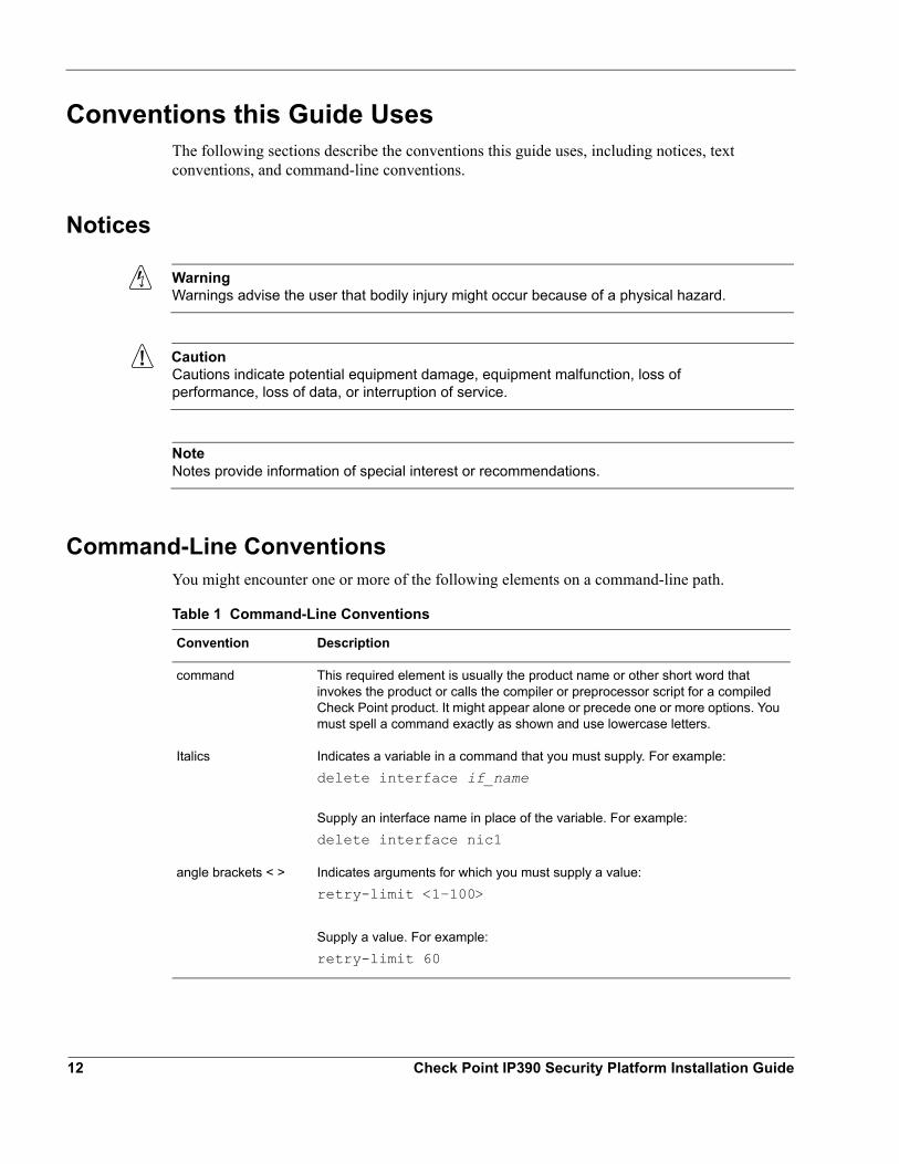
Command-Line ConventionsYou might encounter one or more of the following elements on a command-line path.
Table 1 Command-Line Conventions
Convention Description
command This required element is usually the product name or other short word that invokes the product or calls the compiler or preprocessor script for a compiled Check Point product. It might appear alone or precede one or more options. You must spell a command exactly as shown and use lowercase letters.
Italics Indicates a variable in a command that you must supply. For example:delete interface if_name
Supply an interface name in place of the variable. For example:delete interface nic1
angle brackets < > Indicates arguments for which you must supply a value:retry-limit <1–100>
Supply a value. For example:retry-limit 60
12 Check Point IP390 Security Platform Installation Guide
Conventions this Guide Uses
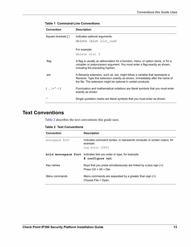
Text ConventionsTable 2 describes the text conventions this guide uses.
Square brackets [ ] Indicates optional arguments.delete [slot slot_num]
For example:delete slot 3
-flag A flag is usually an abbreviation for a function, menu, or option name, or for a compiler or preprocessor argument. You must enter a flag exactly as shown, including the preceding hyphen.
.ext A filename extension, such as .ext, might follow a variable that represents a filename. Type this extension exactly as shown, immediately after the name of the file. The extension might be optional in certain products.
( . , ; + * - / ) Punctuation and mathematical notations are literal symbols that you must enter exactly as shown.
' ' Single quotation marks are literal symbols that you must enter as shown.
Table 1 Command-Line Conventions
Convention Description
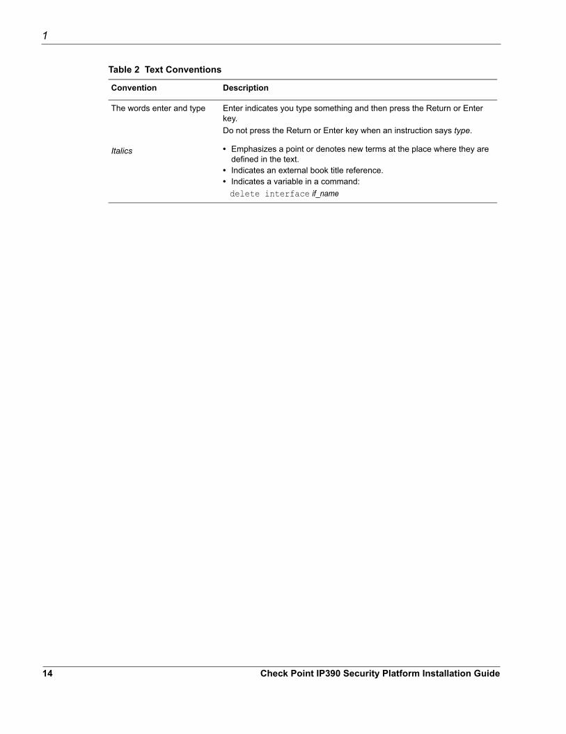
Table 2 Text Conventions
Convention Description
monospace font Indicates command syntax, or represents computer or screen output, for example:Log error 12453
bold monospace font Indicates text you enter or type, for example:# configure nat
Key names Keys that you press simultaneously are linked by a plus sign (+):Press Ctrl + Alt + Del.
Menu commands Menu commands are separated by a greater than sign (>):Choose File > Open.
Check Point IP390 Security Platform Installation Guide 13
1
The words enter and type Enter indicates you type something and then press the Return or Enter key.Do not press the Return or Enter key when an instruction says type.
Italics • Emphasizes a point or denotes new terms at the place where they are defined in the text.
• Indicates an external book title reference.• Indicates a variable in a command: delete interface if_name
Table 2 Text Conventions
Convention Description
14 Check Point IP390 Security Platform Installation Guide
1 Overview
The Check Point IP390 appliance combines the power of Check Point IPSO software with your choice of firewall and VPN applications. These appliances are ideally suited for growing companies and satellite offices that want high-performance IP routing combined with the industry-leading Check Point VPN-1 enterprise applications. The small size of the IP390 appliance makes it ideal for installations that need to conserve space.As network devices, these appliances support a comprehensive suite of IP-routing functions and protocols, including RIPv1/RIPv2, IGRP, OSPF and BGP4 for unicast traffic, and DVMRP for multicast traffic.
This chapter provides an overview of the IP390 appliance and the requirements for using it. The following topics are covered:
About the Check Point IP390 ApplianceManaging the IP390 ApplianceSite Requirements, Warnings, and CautionsSoftware RequirementsProduct Disposal
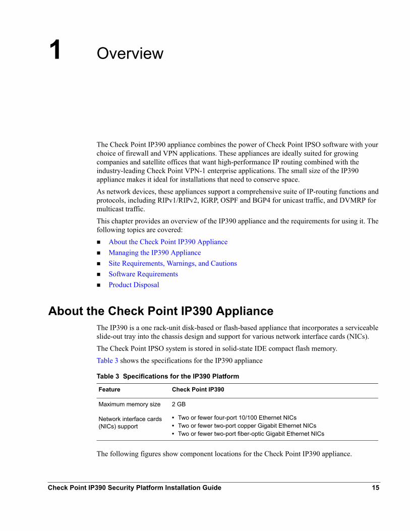
Table 3 Specifications for the IP390 Platform
Feature Check Point IP390
Maximum memory size 2 GB
Network interface cards (NICs) support
• Two or fewer four-port 10/100 Ethernet NICs• Two or fewer two-port copper Gigabit Ethernet NICs• Two or fewer two-port fiber-optic Gigabit Ethernet NICs
About the Check Point IP390 ApplianceThe IP390 is a one rack-unit disk-based or flash-based appliance that incorporates a serviceable slide-out tray into the chassis design and support for various network interface cards (NICs). The Check Point IPSO system is stored in solid-state IDE compact flash memory.Table 3 shows the specifications for the IP390 appliance
The following figures show component locations for the Check Point IP390 appliance.
Check Point IP390 Security Platform Installation Guide 15
1 Overview
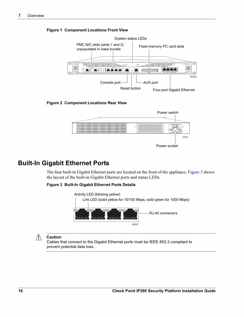
Figure 1 Component Locations Front View
00525
IP390
System status LEDs
AUX portConsole port
Four-port Gigabit Ethernet
Flash-memory PC card slots PMC NIC slots (slots 1 and 2) unpopulated in base bundle
Reset button
Figure 2 Component Locations Rear View
00527
Power socket
Power switch
Built-In Gigabit Ethernet PortsThe four built-in Gigabit Ethernet ports are located on the front of the appliance. Figure 3 shows the layout of the built-in Gigabit Ethernet ports and status LEDs.
Figure 3 Built-In Gigabit Ethernet Ports Details
00547
Activity LED (blinking yellow)Link LED (solid yellow for 10/100 Mbps, solid green for 1000 Mbps)
RJ-45 connectors
CautionCables that connect to the Gigabit Ethernet ports must be IEEE 802.3 compliant to prevent potential data loss.
16 Check Point IP390 Security Platform Installation Guide
About the Check Point IP390 Appliance
NoteCheck Point recommends the use of shielded twisted-pair cables and connectors for best Electromagnetic Interference and Immunity performance.
PMC Expansion Slots
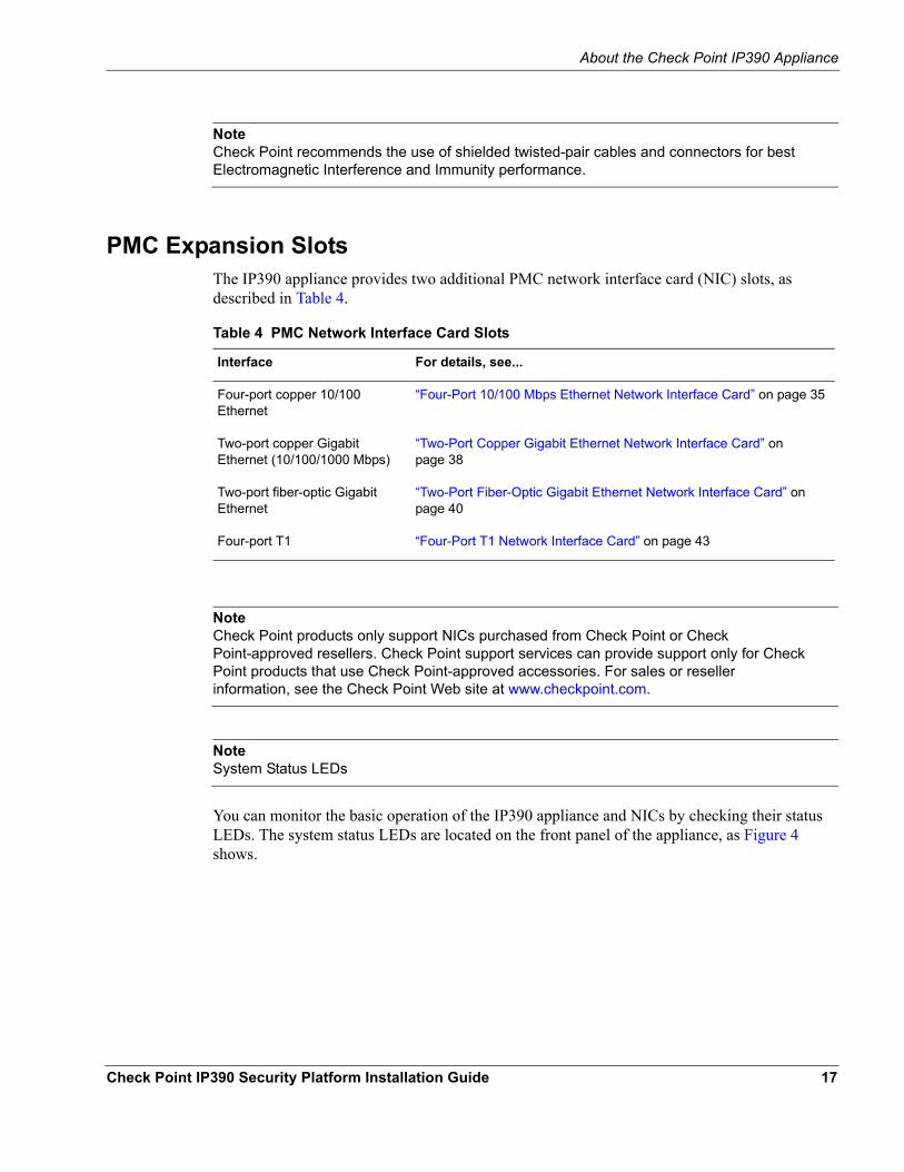
Table 4 PMC Network Interface Card Slots
Interface For details, see...
Four-port copper 10/100 Ethernet
“Four-Port 10/100 Mbps Ethernet Network Interface Card” on page 35
Two-port copper Gigabit Ethernet (10/100/1000 Mbps)
“Two-Port Copper Gigabit Ethernet Network Interface Card” on page 38
Two-port fiber-optic Gigabit Ethernet
“Two-Port Fiber-Optic Gigabit Ethernet Network Interface Card” on page 40
Four-port T1 “Four-Port T1 Network Interface Card” on page 43
The IP390 appliance provides two additional PMC network interface card (NIC) slots, as described in Table 4.
NoteCheck Point products only support NICs purchased from Check Point or Check Point-approved resellers. Check Point support services can provide support only for Check Point products that use Check Point-approved accessories. For sales or reseller information, see the Check Point Web site at www.checkpoint.com.
NoteSystem Status LEDs
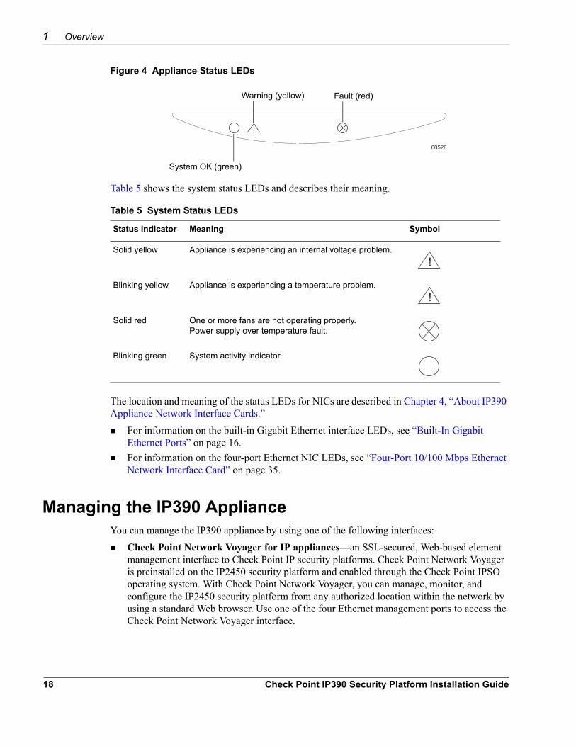
You can monitor the basic operation of the IP390 appliance and NICs by checking their status LEDs. The system status LEDs are located on the front panel of the appliance, as Figure 4 shows.
Check Point IP390 Security Platform Installation Guide 17
1 Overview
Figure 4 Appliance Status LEDs
00526
!
Fault (red)Warning (yellow)
System OK (green)
Table 5 System Status LEDs
Status Indicator Meaning Symbol
Solid yellow Appliance is experiencing an internal voltage problem.!
Blinking yellow Appliance is experiencing a temperature problem.!
Solid red One or more fans are not operating properly. Power supply over temperature fault.
Blinking green System activity indicator
Table 5 shows the system status LEDs and describes their meaning.
The location and meaning of the status LEDs for NICs are described in Chapter 4, “About IP390 Appliance Network Interface Cards.”
For information on the built-in Gigabit Ethernet interface LEDs, see “Built-In Gigabit Ethernet Ports” on page 16.For information on the four-port Ethernet NIC LEDs, see “Four-Port 10/100 Mbps Ethernet Network Interface Card” on page 35.
Managing the IP390 ApplianceYou can manage the IP390 appliance by using one of the following interfaces:
Check Point Network Voyager for IP appliances—an SSL-secured, Web-based element management interface to Check Point IP security platforms. Check Point Network Voyager is preinstalled on the IP2450 security platform and enabled through the Check Point IPSO operating system. With Check Point Network Voyager, you can manage, monitor, and configure the IP2450 security platform from any authorized location within the network by using a standard Web browser. Use one of the four Ethernet management ports to access the Check Point Network Voyager interface.
18 Check Point IP390 Security Platform Installation Guide
Site Requirements, Warnings, and Cautions
For information about how to access Check Point Network Voyager and the related reference materials, see “Using Check Point Network Voyager” on page 31.The Check Point IPSO command-line interface (CLI)—an SSHv2-secured interface that enables you to easily configure Check Point IP security platforms from the command line. Everything that you can accomplish with Check Point Network Voyager—manage, monitor, and configure the IP2450 security platform —you can also do with the CLI. For information about how to access the CLI, see the CLI Reference Guide for the version of Check Point IPSO you are using.Check Point Horizon Manager for IP appliances—a secure GUI-based software image management application. With Check Point Horizon Manager, you can securely install and upgrade the Check Point IPSO operating system and applications such as Check Point VPN-1. Check Point Horizon Manager can perform installations and upgrades on up to 2,500 Check Point IP security platforms, offering administrators the most rapid and dependable method to perform Check Point application upgrades.For information about how to obtain Check Point Horizon Manager, see the Check Point Web site at www.checkpoint.com.
Site Requirements, Warnings, and CautionsBefore you install a Check Point IP390 appliance, ensure that your computer room or wiring closet conforms to the environmental specifications listed in Chapter A, “Technical Specifications.”
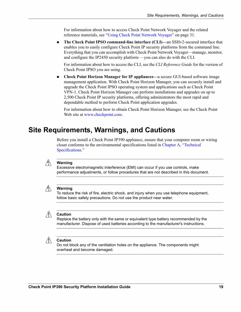
WarningExcessive electromagnetic interference (EMI) can occur if you use controls, make performance adjustments, or follow procedures that are not described in this document.
WarningTo reduce the risk of fire, electric shock, and injury when you use telephone equipment, follow basic safety precautions. Do not use the product near water.
CautionReplace the battery only with the same or equivalent type battery recommended by the manufacturer. Dispose of used batteries according to the manufacturer's instructions.
CautionDo not block any of the ventilation holes on the appliance. The components might overheat and become damaged.
Check Point IP390 Security Platform Installation Guide 19
1 Overview
WarningHazardous radiation exposure can occur if you use controls, make performance adjustments, or follow procedures that are not described in this document.
CautionFor IP390 appliances intended for shipment outside of the United States, the cord might be optional. If a cord is not provided, use a power cord rated at 6A, 250V, maximum 15 feet long, made of HAR cordage and IEC fittings approved by the country of end use.
Software RequirementsThe Check Point IP390 appliance supports the following operating system and applications:
Check Point operating system software requirements—Check Point IPSO v4.1 or laterCheck Point VPN-1 versions compatible with the version of Check Point IPSO you are using
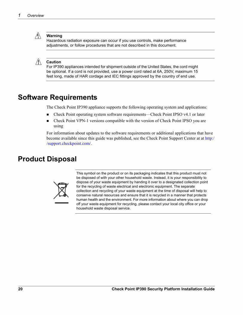
This symbol on the product or on its packaging indicates that this product must not be disposed of with your other household waste. Instead, it is your responsibility to dispose of your waste equipment by handing it over to a designated collection point for the recycling of waste electrical and electronic equipment. The separate collection and recycling of your waste equipment at the time of disposal will help to conserve natural resources and ensure that it is recycled in a manner that protects human health and the environment. For more information about where you can drop off your waste equipment for recycling, please contact your local city office or your household waste disposal service.
For information about updates to the software requirements or additional applications that have become available since this guide was published, see the Check Point Support Center at at http://support.checkpoint.com/.
Product Disposal
20 Check Point IP390 Security Platform Installation Guide
2 Installing the Check Point IP390 Appliance
This chapter describes how to install the Check Point IP390 appliance. The following topics are covered:
Before You BeginRack Mounting the ApplianceConnecting PowerConnecting to the Console or Auxiliary PortConnecting to Network Interfaces
Before You BeginTo rack-mount the appliance, you need:
Phillips-head screwdriverGrounding wrist strapSuitable, grounded work surface on which to place the chassis tray assembly
CautionTo help guard against electrostatic discharge damage, make sure you are properly grounded by using a grounding wrist strap and following the instructions provided with the wrist strap before you handle the components or open the appliance.
Rack Mounting the ApplianceThe IP390 appliance mounts in a standard 19-inch rack with four mounting screws as Figure 5 shows.
Check Point IP390 Security Platform Installation Guide 21
2 Installing the Check Point IP390 Appliance
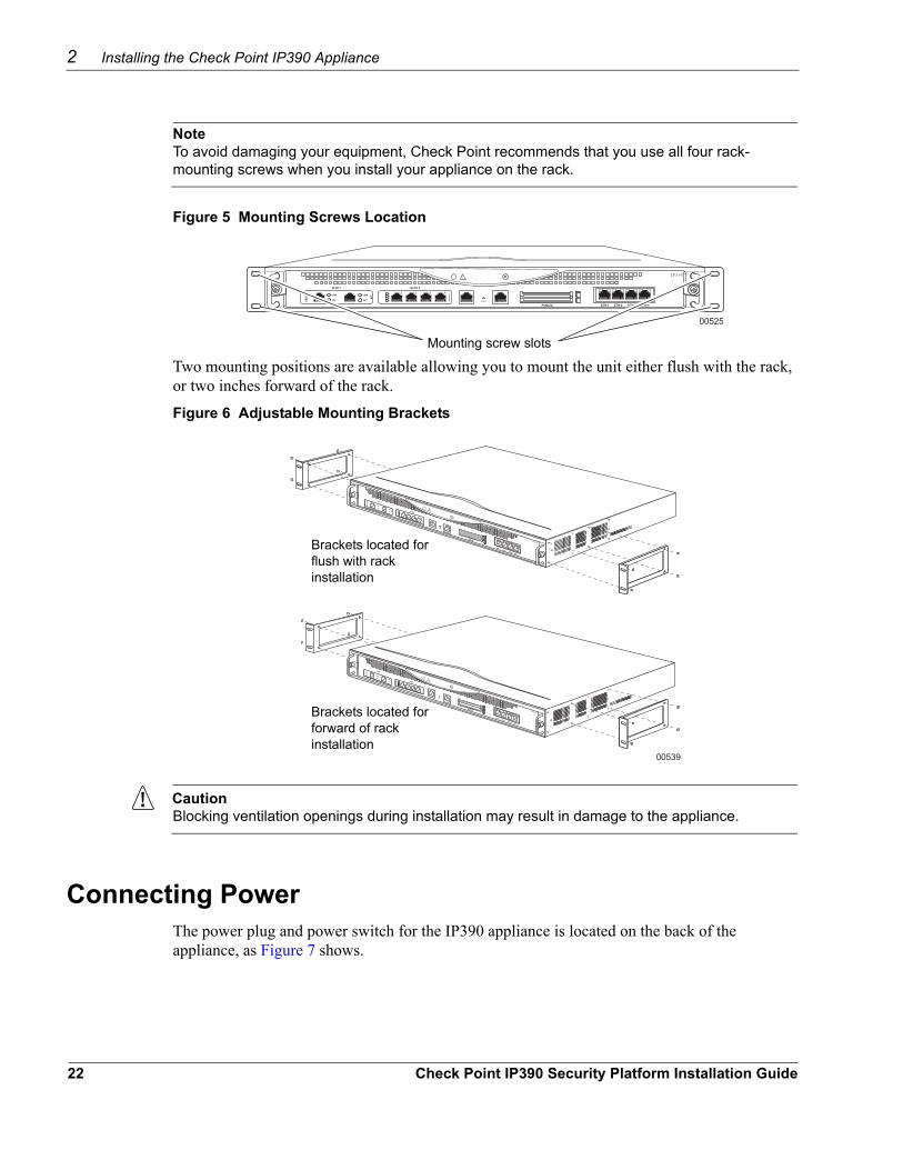
NoteTo avoid damaging your equipment, Check Point recommends that you use all four rack-mounting screws when you install your appliance on the rack.
Figure 5 Mounting Screws Location
00525
IP390
Mounting screw slots
Two mounting positions are available allowing you to mount the unit either flush with the rack, or two inches forward of the rack.
Figure 6 Adjustable Mounting Brackets
00539
IP390
IP390Brackets located for flush with rack installation
Brackets located for forward of rack installation
CautionBlocking ventilation openings during installation may result in damage to the appliance.
Connecting PowerThe power plug and power switch for the IP390 appliance is located on the back of the appliance, as Figure 7 shows.
22 Check Point IP390 Security Platform Installation Guide
Connecting to the Console or Auxiliary Port
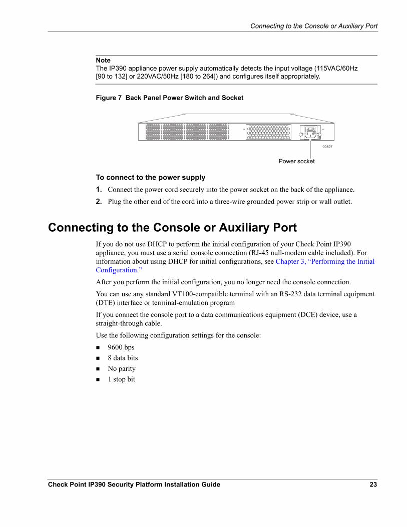
NoteThe IP390 appliance power supply automatically detects the input voltage (115VAC/60Hz [90 to 132] or 220VAC/50Hz [180 to 264]) and configures itself appropriately.
Figure 7 Back Panel Power Switch and Socket
00527
Power socket
To connect to the power supply1. Connect the power cord securely into the power socket on the back of the appliance.
2. Plug the other end of the cord into a three-wire grounded power strip or wall outlet.
Connecting to the Console or Auxiliary PortIf you do not use DHCP to perform the initial configuration of your Check Point IP390 appliance, you must use a serial console connection (RJ-45 null-modem cable included). For information about using DHCP for initial configurations, see Chapter 3, “Performing the Initial Configuration.”After you perform the initial configuration, you no longer need the console connection.You can use any standard VT100-compatible terminal with an RS-232 data terminal equipment (DTE) interface or terminal-emulation program If you connect the console port to a data communications equipment (DCE) device, use a straight-through cable.Use the following configuration settings for the console:
9600 bps8 data bitsNo parity1 stop bit
Check Point IP390 Security Platform Installation Guide 23
2 Installing the Check Point IP390 Appliance
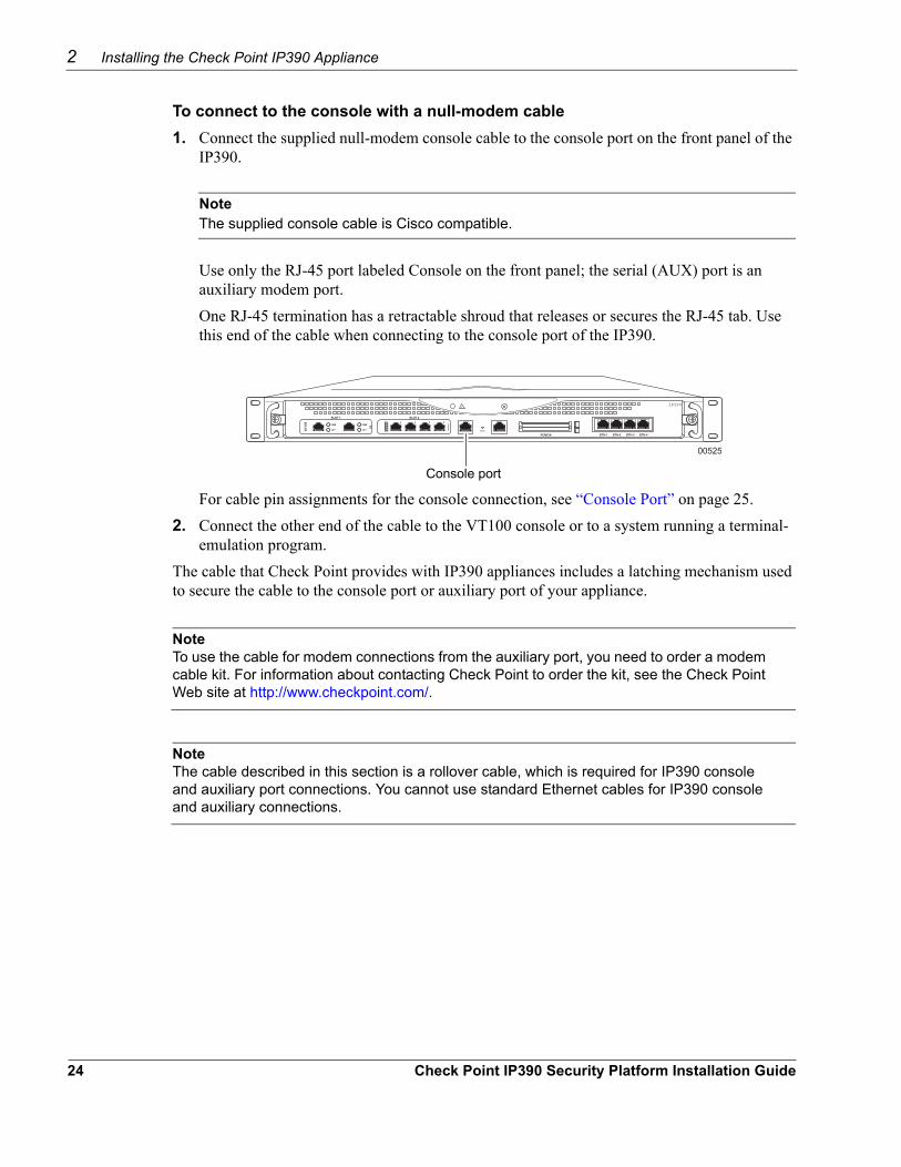
To connect to the console with a null-modem cable1. Connect the supplied null-modem console cable to the console port on the front panel of the
IP390.
NoteThe supplied console cable is Cisco compatible.
Use only the RJ-45 port labeled Console on the front panel; the serial (AUX) port is an auxiliary modem port.One RJ-45 termination has a retractable shroud that releases or secures the RJ-45 tab. Use this end of the cable when connecting to the console port of the IP390.
00525
IP390
Console port
For cable pin assignments for the console connection, see “Console Port” on page 25.2. Connect the other end of the cable to the VT100 console or to a system running a terminal-
emulation program.The cable that Check Point provides with IP390 appliances includes a latching mechanism used to secure the cable to the console port or auxiliary port of your appliance.
NoteTo use the cable for modem connections from the auxiliary port, you need to order a modem cable kit. For information about contacting Check Point to order the kit, see the Check Point Web site at http://www.checkpoint.com/.
NoteThe cable described in this section is a rollover cable, which is required for IP390 console and auxiliary port connections. You cannot use standard Ethernet cables for IP390 console and auxiliary connections.
24 Check Point IP390 Security Platform Installation Guide
Connecting to the Console or Auxiliary Port
1 + 2 =
2
1
00548a
Push cable
Pull boot
To connect the cable
To disconnect the cable
00552
DB-9 female adapter DB-25 male adapter
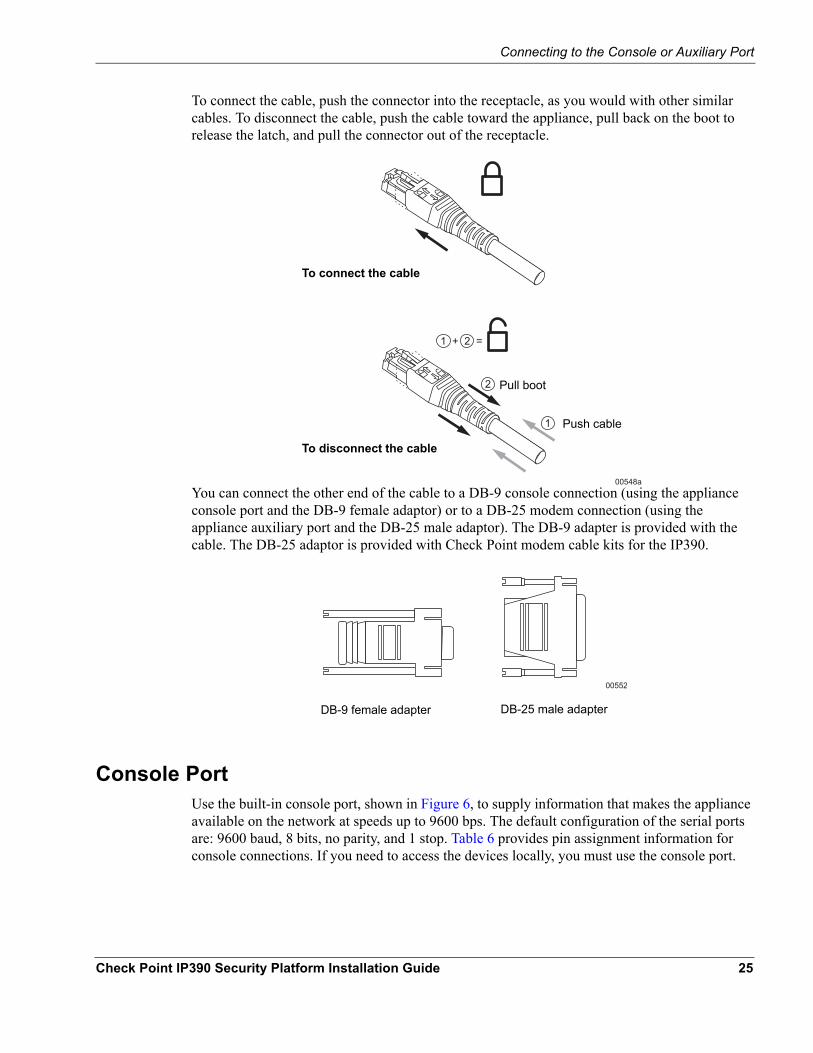
To connect the cable, push the connector into the receptacle, as you would with other similar cables. To disconnect the cable, push the cable toward the appliance, pull back on the boot to release the latch, and pull the connector out of the receptacle.
You can connect the other end of the cable to a DB-9 console connection (using the appliance console port and the DB-9 female adaptor) or to a DB-25 modem connection (using the appliance auxiliary port and the DB-25 male adaptor). The DB-9 adapter is provided with the cable. The DB-25 adaptor is provided with Check Point modem cable kits for the IP390.
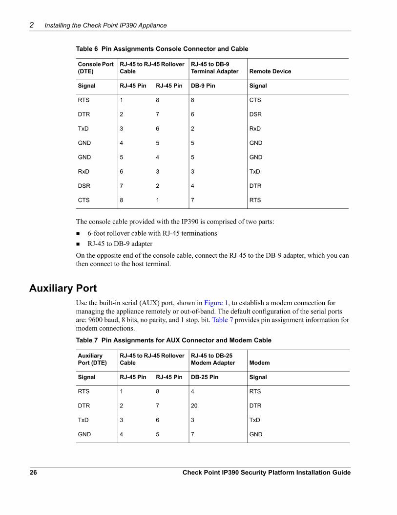
Console PortUse the built-in console port, shown in Figure 6, to supply information that makes the appliance available on the network at speeds up to 9600 bps. The default configuration of the serial ports are: 9600 baud, 8 bits, no parity, and 1 stop. Table 6 provides pin assignment information for console connections. If you need to access the devices locally, you must use the console port.
Check Point IP390 Security Platform Installation Guide 25
2 Installing the Check Point IP390 Appliance
Table 6 Pin Assignments Console Connector and Cable
Console Port (DTE)
RJ-45 to RJ-45 Rollover Cable
RJ-45 to DB-9 Terminal Adapter Remote Device
Signal RJ-45 Pin RJ-45 Pin DB-9 Pin Signal
RTS 1 8 8 CTS
DTR 2 7 6 DSR
TxD 3 6 2 RxD
GND 4 5 5 GND
GND 5 4 5 GND
RxD 6 3 3 TxD
DSR 7 2 4 DTR
CTS 8 1 7 RTS
The console cable provided with the IP390 is comprised of two parts:6-foot rollover cable with RJ-45 terminationsRJ-45 to DB-9 adapter
On the opposite end of the console cable, connect the RJ-45 to the DB-9 adapter, which you can then connect to the host terminal.
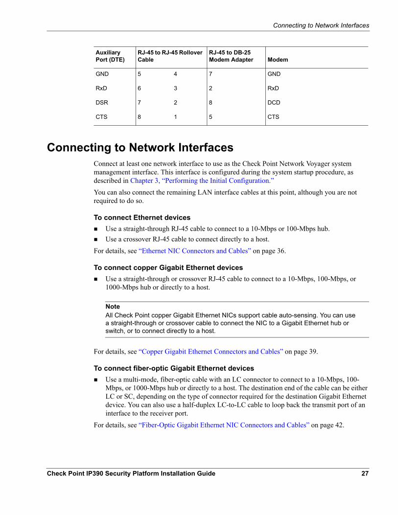
Auxiliary PortUse the built-in serial (AUX) port, shown in Figure 1, to establish a modem connection for managing the appliance remotely or out-of-band. The default configuration of the serial ports are: 9600 baud, 8 bits, no parity, and 1 stop. bit. Table 7 provides pin assignment information for modem connections.
Table 7 Pin Assignments for AUX Connector and Modem Cable
Auxiliary Port (DTE)
RJ-45 to RJ-45 Rollover Cable
RJ-45 to DB-25 Modem Adapter Modem
Signal RJ-45 Pin RJ-45 Pin DB-25 Pin Signal
RTS 1 8 4 RTS
DTR 2 7 20 DTR
TxD 3 6 3 TxD
GND 4 5 7 GND
26 Check Point IP390 Security Platform Installation Guide
Connecting to Network Interfaces
Connecting to Network InterfacesConnect at least one network interface to use as the Check Point Network Voyager system management interface. This interface is configured during the system startup procedure, as described in Chapter 3, “Performing the Initial Configuration.”You can also connect the remaining LAN interface cables at this point, although you are not required to do so.
To connect Ethernet devicesUse a straight-through RJ-45 cable to connect to a 10-Mbps or 100-Mbps hub.Use a crossover RJ-45 cable to connect directly to a host.
For details, see “Ethernet NIC Connectors and Cables” on page 36.
To connect copper Gigabit Ethernet devicesUse a straight-through or crossover RJ-45 cable to connect to a 10-Mbps, 100-Mbps, or 1000-Mbps hub or directly to a host.
NoteAll Check Point copper Gigabit Ethernet NICs support cable auto-sensing. You can use a straight-through or crossover cable to connect the NIC to a Gigabit Ethernet hub or switch, or to connect directly to a host.
For details, see “Copper Gigabit Ethernet Connectors and Cables” on page 39.
To connect fiber-optic Gigabit Ethernet devicesUse a multi-mode, fiber-optic cable with an LC connector to connect to a 10-Mbps, 100-Mbps, or 1000-Mbps hub or directly to a host. The destination end of the cable can be either LC or SC, depending on the type of connector required for the destination Gigabit Ethernet device. You can also use a half-duplex LC-to-LC cable to loop back the transmit port of an interface to the receiver port.
For details, see “Fiber-Optic Gigabit Ethernet NIC Connectors and Cables” on page 42.
GND 5 4 7 GND
RxD 6 3 2 RxD
DSR 7 2 8 DCD
CTS 8 1 5 CTS
Auxiliary Port (DTE)
RJ-45 to RJ-45 Rollover Cable
RJ-45 to DB-25 Modem Adapter Modem
Check Point IP390 Security Platform Installation Guide 27
2 Installing the Check Point IP390 Appliance
After you connect the network interfaces, continue with Chapter 3, “Performing the Initial Configuration.”
28 Check Point IP390 Security Platform Installation Guide
3 Performing the Initial Configuration
The first time you turn power on to a Check Point IP390 appliance, the initial configuration process begins. This process enables you to configure the network settings and provides access to the admin account. You can perform the initial configuration in two ways.
You can configure a DHCP server to provide the initial configuration information the first time the appliance is started. You can perform the initial configuration manually by using a console connection.
This chapter describes how to perform the initial configuration manually by using a console connection. It includes the following sections:
Using a Console ConnectionUsing Check Point Network VoyagerUsing the Command-Line InterfaceUsing Check Point Horizon Manager
For information about how to use the DHCP client for initial configuration, see the Read Me First document.
Using a Console ConnectionIf you have not already done so, you need to connect to the console port to complete the initial configuration. For information about console connections, see “Connecting to the Console or Auxiliary Port” on page 23.Before you perform the initial configuration, you might gather the following information, which can be useful during the configuration process:
What is the hostname?What is the admin password?Will you use Check Point Network Voyager for subsequent configuration?Which interface will you use?What is the assigned IP address and mask length?What is the default router?What is the interface speed?
Check Point IP390 Security Platform Installation Guide 29
3 Performing the Initial Configuration
NoteThe default interface speed for the IP390 is 1000 Mbps.
You can make VLAN, SNMP community string, and remote logging configuration choices at this time, although you can change them later.
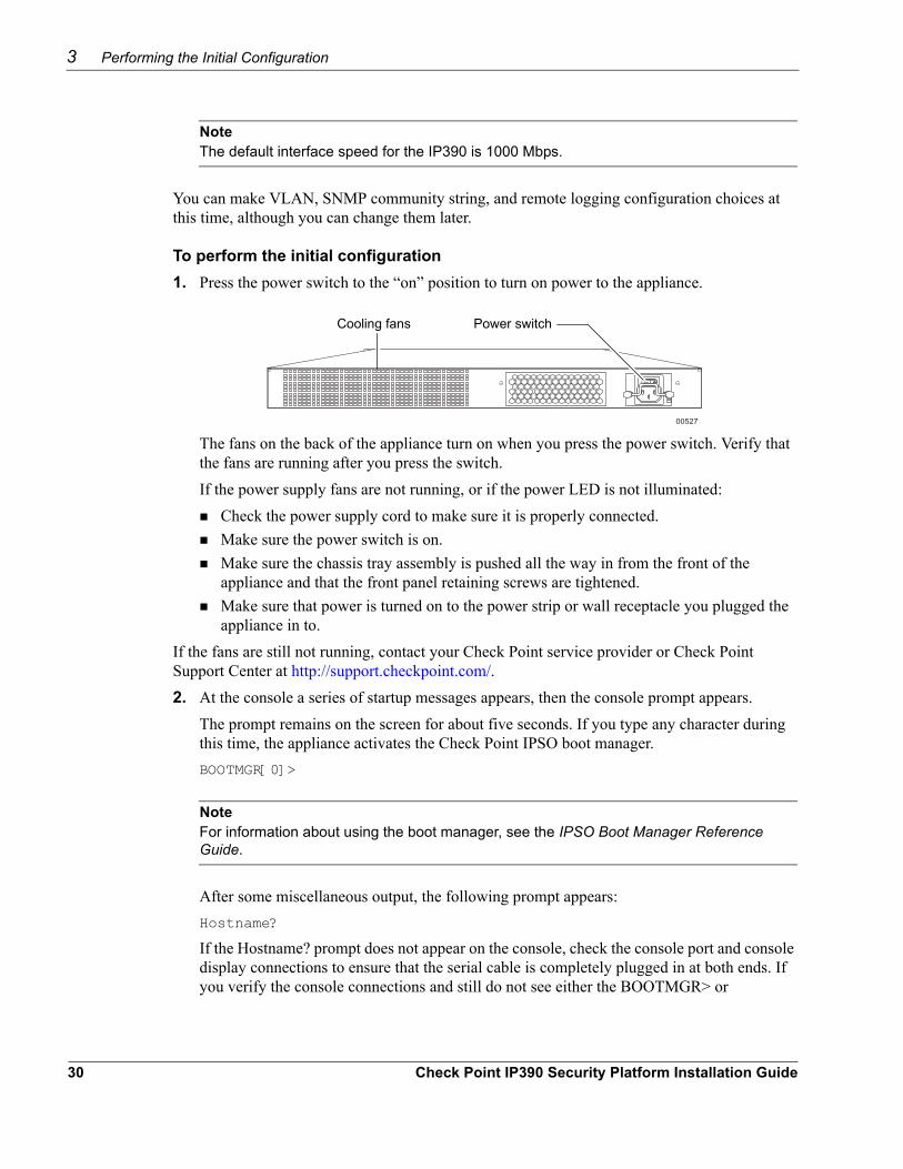
To perform the initial configuration1. Press the power switch to the “on” position to turn on power to the appliance.
00527
Power switchCooling fans
The fans on the back of the appliance turn on when you press the power switch. Verify that the fans are running after you press the switch.If the power supply fans are not running, or if the power LED is not illuminated:
Check the power supply cord to make sure it is properly connected.Make sure the power switch is on.Make sure the chassis tray assembly is pushed all the way in from the front of the appliance and that the front panel retaining screws are tightened.Make sure that power is turned on to the power strip or wall receptacle you plugged the appliance in to.
If the fans are still not running, contact your Check Point service provider or Check Point Support Center at http://support.checkpoint.com/.2. At the console a series of startup messages appears, then the console prompt appears.
The prompt remains on the screen for about five seconds. If you type any character during this time, the appliance activates the Check Point IPSO boot manager.BOOTMGR[0]>
NoteFor information about using the boot manager, see the IPSO Boot Manager Reference Guide.
After some miscellaneous output, the following prompt appears:Hostname?
If the Hostname? prompt does not appear on the console, check the console port and console display connections to ensure that the serial cable is completely plugged in at both ends. If you verify the console connections and still do not see either the BOOTMGR> or
30 Check Point IP390 Security Platform Installation Guide
Using Check Point Network Voyager
Hostname? prompts, verify that the terminal or terminal emulator program settings are correct. If the settings are correct, contact your Check Point service provider or Check Point Support Center at http://support.checkpoint.com/.
3. Respond to the Hostname? prompt within 30 seconds to prevent the DHCP client from starting.If the DHCP client starts, it might configure the appliance with an incorrect host name and IP address (this could happen if a DHCP server on your network is configured to respond to any request). To reset the incorrect host name and IP address:a. Establish a console connection to the appliance.b. Log into the system using the user name admin and the password password.c. Enter the following:
rm /config/active
ormv /config/active /config/active.old
d. Reboot the appliance.e. Respond to the Hostname? prompt within 30 seconds to prevent the DHCP client from
restarting.4. At each subsequent prompt, type the requested configuration information and then press
Enter.For more information about how to respond to the prompts during the initial configuration process, see the Getting Started Guide and Release Notes for the version of Check Point IPSO you are using.
5. After you complete the initial configuration, you can use Network Voyager to configure the remaining network ports.
Using Check Point Network VoyagerUse Check Point Network Voyager to configure and monitor your appliance.
To open Check Point Network Voyager1. Open a Web browser on the host you plan to use to configure or monitor your appliance.2. In the Location or Address field, enter the IP address of the initial interface you configured
for the appliance.You are prompted to enter the admin username and the password you entered when you performed the initial configuration.
NoteIf the username login screen does not open, you might not have a physical network connection between the host and your appliance, or you might have a network routing
Check Point IP390 Security Platform Installation Guide 31
3 Performing the Initial Configuration
problem. Confirm the information you entered during the initial configuration and check that all cables are firmly connected. For more information, see the troubleshooting section in the installation guide for your appliance.
Viewing Check Point IPSO Documentation by Using Check Point Network Voyager
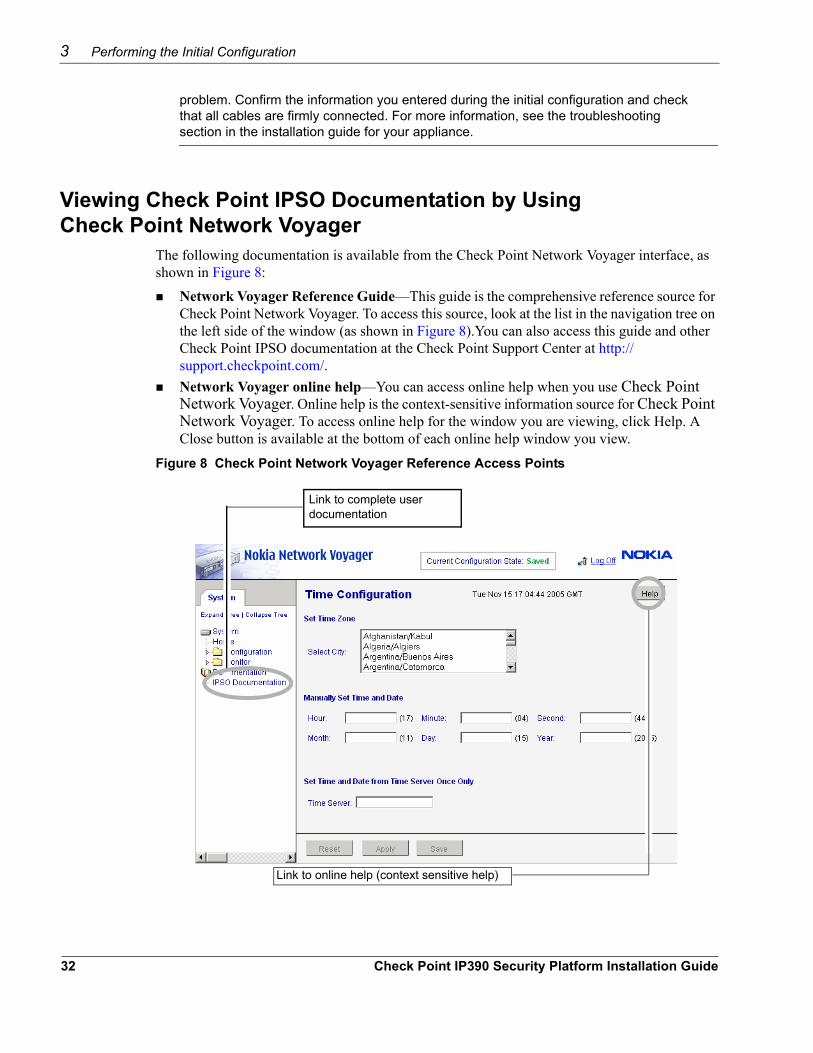
The following documentation is available from the Check Point Network Voyager interface, as shown in Figure 8:
Network Voyager Reference Guide—This guide is the comprehensive reference source for Check Point Network Voyager. To access this source, look at the list in the navigation tree on the left side of the window (as shown in Figure 8).You can also access this guide and other Check Point IPSO documentation at the Check Point Support Center at http://support.checkpoint.com/. Network Voyager online help—You can access online help when you use Check Point Network Voyager. Online help is the context-sensitive information source for Check Point Network Voyager. To access online help for the window you are viewing, click Help. A Close button is available at the bottom of each online help window you view.
Figure 8 Check Point Network Voyager Reference Access Points
Link to complete user documentation
Link to online help (context sensitive help)
32 Check Point IP390 Security Platform Installation Guide
Using the Command-Line Interface
Using the Command-Line Interface You can also use the Check Point IPSO command-line interface (CLI) to manage and configure Check Point IP security appliances from the command line. Nearly everything that you can accomplish with Check Point Network Voyager you can also do with the CLI.
To access the command-line interface1. Log on to the appliance by using a command-line connection (SSH, console, or Telnet) over
a TCP/IP network as an admin, cadmin, or monitor user:If you log in as a cadmin (cluster administrator) user, you can change and view configuration settings on all the cluster nodes. For information about how to administer a cluster, see the traffic management commands section in the CLI Reference Guide for the version of Check Point IPSO you are using.
2. If you log in as a monitor user, you can execute only the show form of commands. That is, you can view configuration settings, but you cannot change them.
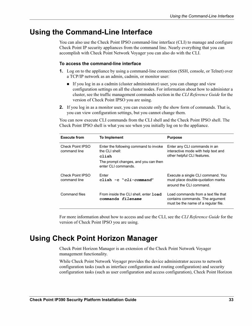
Execute from To Implement Purpose
Check Point IPSO command line
Enter the following command to invoke the CLI shell:clishThe prompt changes, and you can then enter CLI commands.
Enter any CLI commands in an interactive mode with help text and other helpful CLI features.
Check Point IPSO command line
Enter clish -c “cli-command”
Execute a single CLI command. You must place double-quotation marks around the CLI command.
Command files From inside the CLI shell, enter load commands filename
Load commands from a text file that contains commands. The argument must be the name of a regular file.
You can now execute CLI commands from the CLI shell and the Check Point IPSO shell. The Check Point IPSO shell is what you see when you initially log on to the appliance.
For more information about how to access and use the CLI, see the CLI Reference Guide for the version of Check Point IPSO you are using.
Using Check Point Horizon ManagerCheck Point Horizon Manager is an extension of the Check Point Network Voyager management functionality.While Check Point Network Voyager provides the device administrator access to network configuration tasks (such as interface configuration and routing configuration) and security configuration tasks (such as user configuration and access configuration), Check Point Horizon
Check Point IP390 Security Platform Installation Guide 33

3 Performing the Initial Configuration
Manager concentrates on secure software image, inventory, and platform management of Check Point IP security platforms.Using Check Point Horizon Manager, an administrator can obtain configuration information, upgrade (or downgrade) the operating system, perform application installations, and distribute necessary licensing to multiple platforms simultaneously, thereby reducing potential human error and improving productivity.Using Check Point Horizon Manager, a network security professional can manage multiple devices simultaneously, perform parallel software upgrades, device verifications, device configuration, file backups, and more.Check Point Horizon Manager is designed to manage and configure a large number of Check Point IP security appliances that reside on a corporate enterprise, managed service provider (MSP), or hosted applications service provider network (ASP).For information about how to obtain Check Point Horizon Manager or to learn more about the Check Point Horizon Manager, see the Check Point Web site at www.checkpoint.com.
34 Check Point IP390 Security Platform Installation Guide
4 About IP390 Appliance Network Interface Cards
This chapter describes the PMC network interface cards (NICs) available for the IP390 appliance and describes how to connect those NICs to your network. The following NICs are covered:
Four-Port 10/100 Mbps Ethernet Network Interface CardTwo-Port Copper Gigabit Ethernet Network Interface CardTwo-Port Fiber-Optic Gigabit Ethernet Network Interface CardFour-Port T1 Network Interface Card
For instructions on adding or replacing NICs, see Chapter 5, “Installing and Replacing Network Interface Cards.”
CautionProtect your IP390 appliance and other electronic equipment from electrostatic discharge (ESD) damage by making sure you are properly grounded before you touch any electronic component.
Four-Port 10/100 Mbps Ethernet Network Interface CardThe IP390 appliance supports Check Point-approved, four-port UTP5 dual-mode 10-Mbps and 100-Mbps Ethernet NICs.When you purchase an Ethernet NIC with your IP390 appliance, the NIC is installed before the appliance is delivered to you. For information on how to add or replace a NIC later, see Chapter 5, “Installing and Replacing Network Interface Cards.”
Ethernet NIC FeaturesThe Ethernet PMC NIC supports the following features:
Supports traffic at 10 and 100 MbpsPacket tracing for analysis through tcpdump
Check Point IP390 Security Platform Installation Guide 35
4 About IP390 Appliance Network Interface Cards
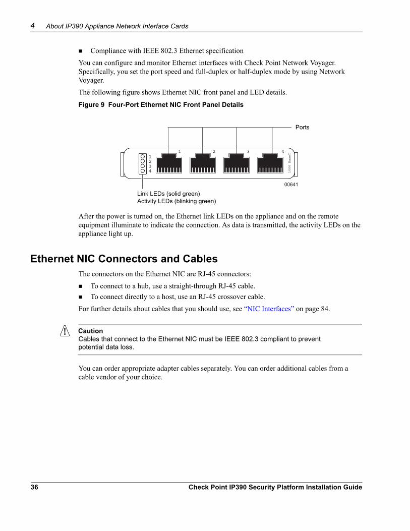
Compliance with IEEE 802.3 Ethernet specificationYou can configure and monitor Ethernet interfaces with Check Point Network Voyager. Specifically, you set the port speed and full-duplex or half-duplex mode by using Network Voyager.The following figure shows Ethernet NIC front panel and LED details.
Figure 9 Four-Port Ethernet NIC Front Panel Details
00641
3211234
4
1000 BaseT
Link LEDs (solid green) Activity LEDs (blinking green)
Ports
After the power is turned on, the Ethernet link LEDs on the appliance and on the remote equipment illuminate to indicate the connection. As data is transmitted, the activity LEDs on the appliance light up.
Ethernet NIC Connectors and CablesThe connectors on the Ethernet NIC are RJ-45 connectors:
To connect to a hub, use a straight-through RJ-45 cable.To connect directly to a host, use an RJ-45 crossover cable.
For further details about cables that you should use, see “NIC Interfaces” on page 84.
CautionCables that connect to the Ethernet NIC must be IEEE 802.3 compliant to prevent potential data loss.
You can order appropriate adapter cables separately. You can order additional cables from a cable vendor of your choice.
36 Check Point IP390 Security Platform Installation Guide
Four-Port 10/100 Mbps Ethernet Network Interface Card
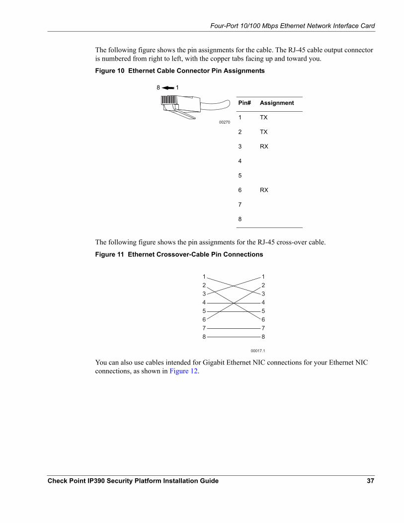
The following figure shows the pin assignments for the cable. The RJ-45 cable output connector is numbered from right to left, with the copper tabs facing up and toward you.
Figure 10 Ethernet Cable Connector Pin Assignments
Pin# Assignment
1 TX
2 TX
3 RX
4
5
6 RX
7
8
00270
8 1
The following figure shows the pin assignments for the RJ-45 cross-over cable.
Figure 11 Ethernet Crossover-Cable Pin Connections
00017.1
12345678
12345678
You can also use cables intended for Gigabit Ethernet NIC connections for your Ethernet NIC connections, as shown in Figure 12.
Check Point IP390 Security Platform Installation Guide 37
4 About IP390 Appliance Network Interface Cards
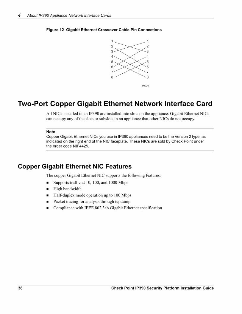
Figure 12 Gigabit Ethernet Crossover Cable Pin Connections
00020
12345678
12345678
Two-Port Copper Gigabit Ethernet Network Interface CardAll NICs installed in an IP390 are installed into slots on the appliance. Gigabit Ethernet NICs can occupy any of the slots or subslots in an appliance that other NICs do not occupy.
NoteCopper Gigabit Ethernet NICs you use in IP390 appliances need to be the Version 2 type, as indicated on the right end of the NIC faceplate. These NICs are sold by Check Point under the order code NIF4425.
Copper Gigabit Ethernet NIC FeaturesThe copper Gigabit Ethernet NIC supports the following features:
Supports traffic at 10, 100, and 1000 MbpsHigh bandwidthHalf-duplex mode operation up to 100 MbpsPacket tracing for analysis through tcpdumpCompliance with IEEE 802.3ab Gigabit Ethernet specification
38 Check Point IP390 Security Platform Installation Guide
Two-Port Copper Gigabit Ethernet Network Interface Card
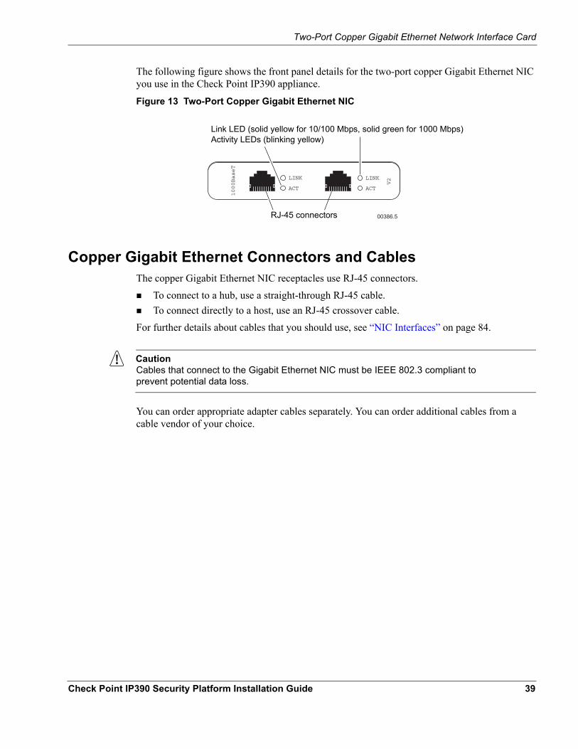
The following figure shows the front panel details for the two-port copper Gigabit Ethernet NIC you use in the Check Point IP390 appliance.
Figure 13 Two-Port Copper Gigabit Ethernet NIC
00386.5
LINK
ACT
V2LINK
ACT
1000BaseT
Link LED (solid yellow for 10/100 Mbps, solid green for 1000 Mbps) Activity LEDs (blinking yellow)
RJ-45 connectors
Copper Gigabit Ethernet Connectors and CablesThe copper Gigabit Ethernet NIC receptacles use RJ-45 connectors.
To connect to a hub, use a straight-through RJ-45 cable.To connect directly to a host, use an RJ-45 crossover cable.
For further details about cables that you should use, see “NIC Interfaces” on page 84.
CautionCables that connect to the Gigabit Ethernet NIC must be IEEE 802.3 compliant to prevent potential data loss.
You can order appropriate adapter cables separately. You can order additional cables from a cable vendor of your choice.
Check Point IP390 Security Platform Installation Guide 39

4 About IP390 Appliance Network Interface Cards
In the following figure, the RJ-45 cable output connector is numbered from right to left, with the copper pins facing up and toward you.
Figure 14 Copper Gigabit Ethernet Cable Connector Pin Assignments
00270
Pin#
Gigabit Ethernet Assignment
10/100 Mbps Assignment
1 BI_DA+ TX
2 BI_DA- TX
3 BI_DB+ RX
4 BI_DC+
5 BI_DC-
6 BI_DB- RX
7 BI_DD+
8 BI_DD-
8 1
To connect directly to a host, use an RJ-45 crossover cable wired as the following figure shows.
Figure 15 Gigabit Ethernet Crossover Cable Pin Connections
00020
12345678
12345678
To connect the IP390 appliance to other network components, you can order appropriate adapter cables separately from a cable vendor of your choice.
Two-Port Fiber-Optic Gigabit Ethernet Network Interface Card
All NICs installed in an IP390 are installed into slots on the appliance. Gigabit Ethernet NICs can occupy any of the slots or subslots in an appliance that other NICs do not occupy.
40 Check Point IP390 Security Platform Installation Guide
Two-Port Fiber-Optic Gigabit Ethernet Network Interface Card
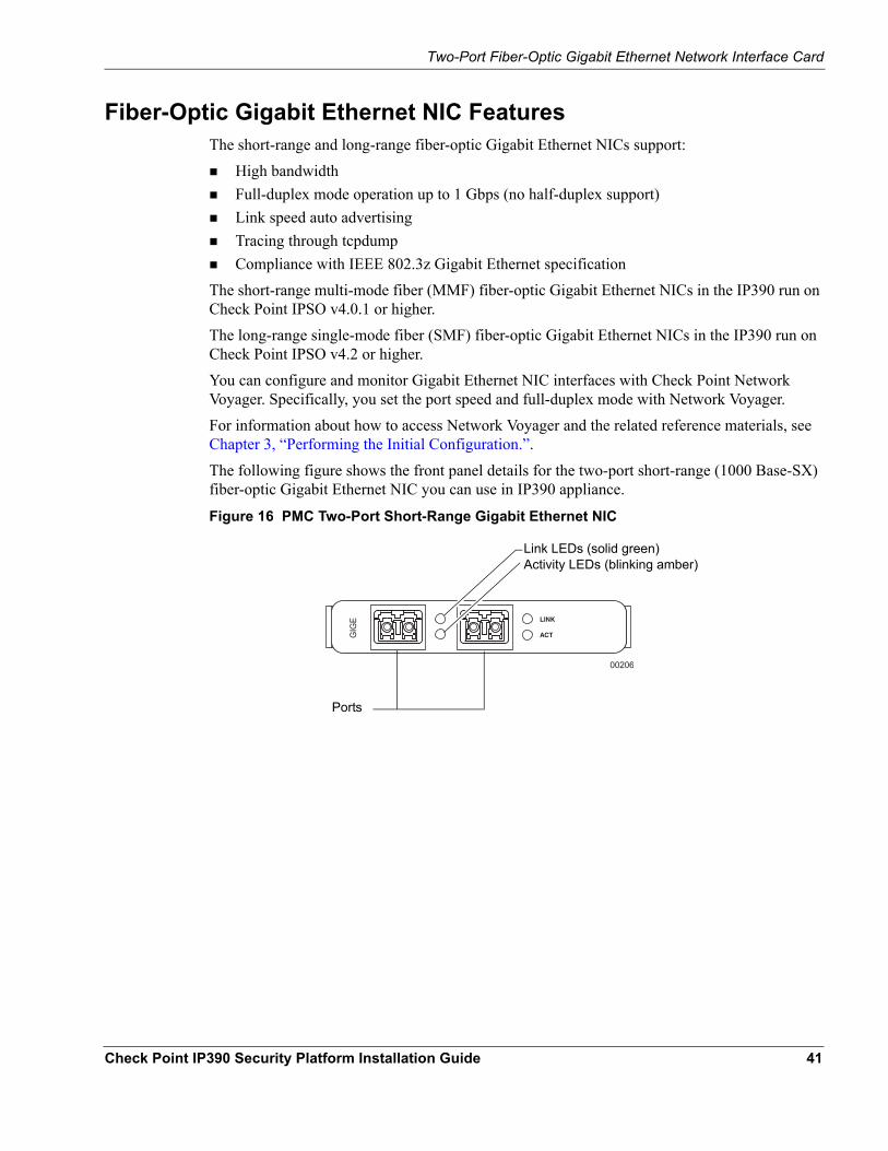
Fiber-Optic Gigabit Ethernet NIC FeaturesThe short-range and long-range fiber-optic Gigabit Ethernet NICs support:
High bandwidthFull-duplex mode operation up to 1 Gbps (no half-duplex support)Link speed auto advertisingTracing through tcpdumpCompliance with IEEE 802.3z Gigabit Ethernet specification
The short-range multi-mode fiber (MMF) fiber-optic Gigabit Ethernet NICs in the IP390 run on Check Point IPSO v4.0.1 or higher.The long-range single-mode fiber (SMF) fiber-optic Gigabit Ethernet NICs in the IP390 run on Check Point IPSO v4.2 or higher.You can configure and monitor Gigabit Ethernet NIC interfaces with Check Point Network Voyager. Specifically, you set the port speed and full-duplex mode with Network Voyager. For information about how to access Network Voyager and the related reference materials, see Chapter 3, “Performing the Initial Configuration.”.
The following figure shows the front panel details for the two-port short-range (1000 Base-SX) fiber-optic Gigabit Ethernet NIC you can use in IP390 appliance.
Figure 16 PMC Two-Port Short-Range Gigabit Ethernet NIC
00206
GIG
E
Link LEDs (solid green) Activity LEDs (blinking amber)
Ports
Check Point IP390 Security Platform Installation Guide 41
4 About IP390 Appliance Network Interface Cards
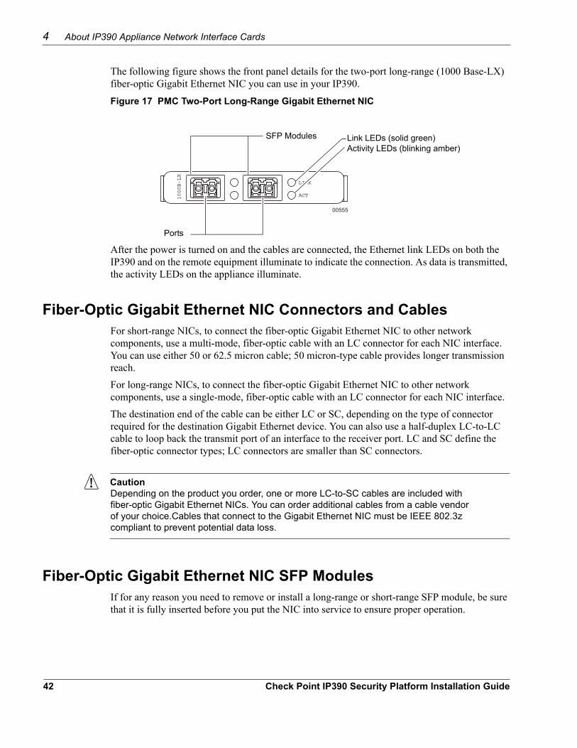
The following figure shows the front panel details for the two-port long-range (1000 Base-LX) fiber-optic Gigabit Ethernet NIC you can use in your IP390.
Figure 17 PMC Two-Port Long-Range Gigabit Ethernet NIC
00555
LINK
ACT1000B-LX
Link LEDs (solid green) Activity LEDs (blinking amber)
Ports
SFP Modules
After the power is turned on and the cables are connected, the Ethernet link LEDs on both the IP390 and on the remote equipment illuminate to indicate the connection. As data is transmitted, the activity LEDs on the appliance illuminate.
Fiber-Optic Gigabit Ethernet NIC Connectors and CablesFor short-range NICs, to connect the fiber-optic Gigabit Ethernet NIC to other network components, use a multi-mode, fiber-optic cable with an LC connector for each NIC interface. You can use either 50 or 62.5 micron cable; 50 micron-type cable provides longer transmission reach. For long-range NICs, to connect the fiber-optic Gigabit Ethernet NIC to other network components, use a single-mode, fiber-optic cable with an LC connector for each NIC interface.The destination end of the cable can be either LC or SC, depending on the type of connector required for the destination Gigabit Ethernet device. You can also use a half-duplex LC-to-LC cable to loop back the transmit port of an interface to the receiver port. LC and SC define the fiber-optic connector types; LC connectors are smaller than SC connectors.
CautionDepending on the product you order, one or more LC-to-SC cables are included with fiber-optic Gigabit Ethernet NICs. You can order additional cables from a cable vendor of your choice.Cables that connect to the Gigabit Ethernet NIC must be IEEE 802.3z compliant to prevent potential data loss.
Fiber-Optic Gigabit Ethernet NIC SFP ModulesIf for any reason you need to remove or install a long-range or short-range SFP module, be sure that it is fully inserted before you put the NIC into service to ensure proper operation.
42 Check Point IP390 Security Platform Installation Guide
Four-Port T1 Network Interface Card
Four-Port T1 Network Interface CardAll NICs installed in an IP390 are installed into slots on the appliance. T1 NICs can occupy any of the slots or subslots in an appliance that other NICs do not occupy.
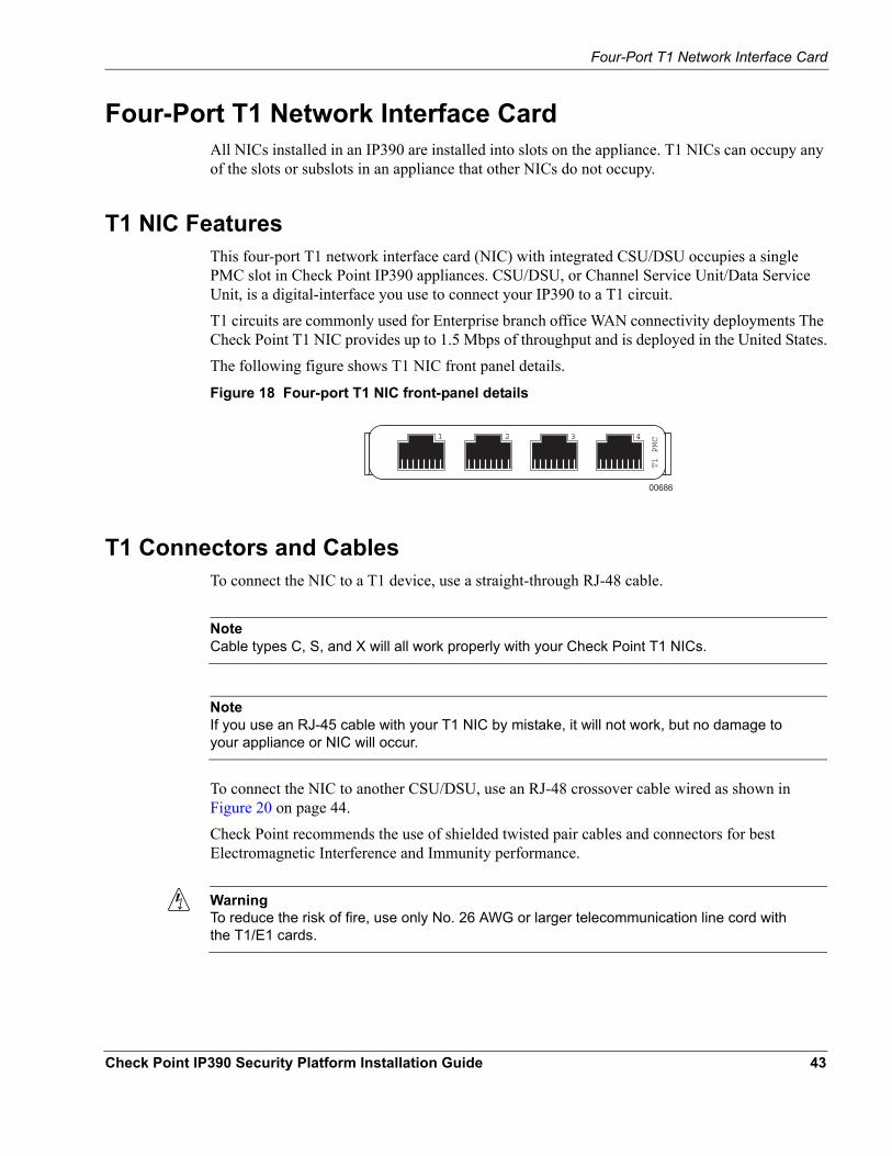
T1 NIC FeaturesThis four-port T1 network interface card (NIC) with integrated CSU/DSU occupies a single PMC slot in Check Point IP390 appliances. CSU/DSU, or Channel Service Unit/Data Service Unit, is a digital-interface you use to connect your IP390 to a T1 circuit.T1 circuits are commonly used for Enterprise branch office WAN connectivity deployments The Check Point T1 NIC provides up to 1.5 Mbps of throughput and is deployed in the United States.The following figure shows T1 NIC front panel details.
Figure 18 Four-port T1 NIC front-panel details
00686
321 4
T1 PMC
T1 Connectors and CablesTo connect the NIC to a T1 device, use a straight-through RJ-48 cable.
NoteCable types C, S, and X will all work properly with your Check Point T1 NICs.
NoteIf you use an RJ-45 cable with your T1 NIC by mistake, it will not work, but no damage to your appliance or NIC will occur.
To connect the NIC to another CSU/DSU, use an RJ-48 crossover cable wired as shown in Figure 20 on page 44.Check Point recommends the use of shielded twisted pair cables and connectors for best Electromagnetic Interference and Immunity performance.
WarningTo reduce the risk of fire, use only No. 26 AWG or larger telecommunication line cord with the T1/E1 cards.
Check Point IP390 Security Platform Installation Guide 43
4 About IP390 Appliance Network Interface Cards
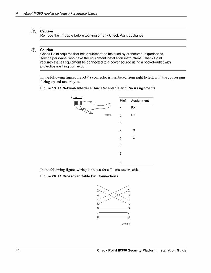
CautionRemove the T1 cable before working on any Check Point appliance.
CautionCheck Point requires that this equipment be installed by authorized, experienced service personnel who have the equipment installation instructions. Check Point requires that all equipment be connected to a power source using a socket-outlet with protective earthing connection.
In the following figure, the RJ-48 connector is numbered from right to left, with the copper pins facing up and toward you.
Figure 19 T1 Network Interface Card Receptacle and Pin Assignments
Pin# Assignment
1 RX
2 RX
3
4 TX
5 TX
6
7
8
8 1
00270
In the following figure, wiring is shown for a T1 crossover cable.
Figure 20 T1 Crossover Cable Pin Connections
12345678
12345678
00018.1
44 Check Point IP390 Security Platform Installation Guide
Four-Port T1 Network Interface Card
NoteYour T1 cable might not include straight-through wiring for pins 3, 6, 7, and 8. It will, however, work properly with your Check Point T1 NICs.
Check Point IP390 Security Platform Installation Guide 45

4 About IP390 Appliance Network Interface Cards
46 Check Point IP390 Security Platform Installation Guide
5 Installing and Replacing Network Interface Cards
Your IP390 appliance comes with any network interface cards (NICs) you ordered already installed. This chapter describes how to remove, add, or replace NICs later if it becomes necessary. The following topics are covered:
Deactivating Configured InterfacesRemoving, Installing, and Replacing NICsConfiguring and Activating InterfacesMonitoring Network Interface Cards
For detailed information on specific NICs, see Chapter 4, “About IP390 Appliance Network Interface Cards.”
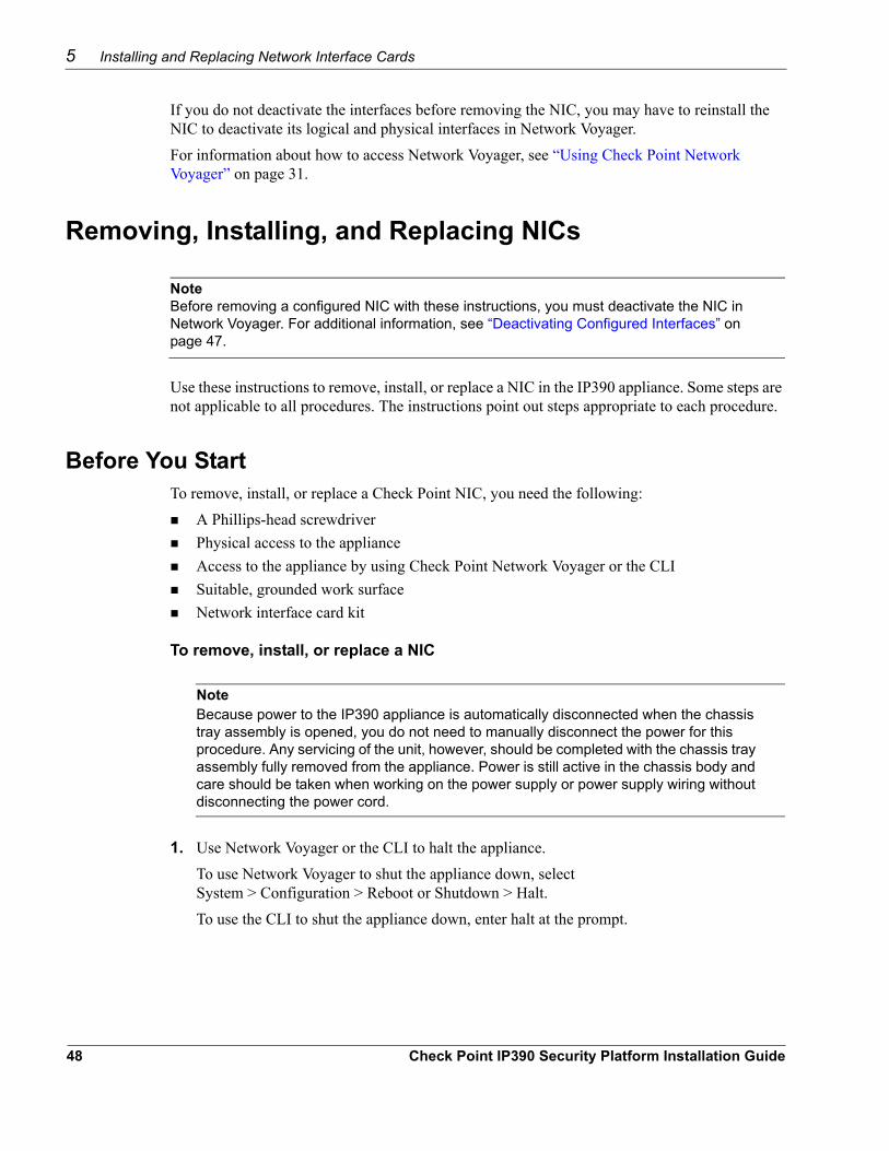
CautionYou should have a working knowledge of networking equipment before attempting to service an IP390 appliance. Limit service of the unit to the procedures described in this chapter.
CautionProtect your IP390 appliance and other electronic equipment from electrostatic discharge (ESD) by making sure you are properly grounded before touching any electronic components.
Deactivating Configured InterfacesIf you are removing or replacing an installed NIC, use Check Point Network Voyager to deactivate any configured ports on the NIC before removing it.
Deactivate all of the logical interfaces on the NIC.Deactivate all of the physical interfaces on the NIC.
Check Point IP390 Security Platform Installation Guide 47
5 Installing and Replacing Network Interface Cards
If you do not deactivate the interfaces before removing the NIC, you may have to reinstall the NIC to deactivate its logical and physical interfaces in Network Voyager.For information about how to access Network Voyager, see “Using Check Point Network Voyager” on page 31.
Removing, Installing, and Replacing NICs
NoteBefore removing a configured NIC with these instructions, you must deactivate the NIC in Network Voyager. For additional information, see “Deactivating Configured Interfaces” on page 47.
Use these instructions to remove, install, or replace a NIC in the IP390 appliance. Some steps are not applicable to all procedures. The instructions point out steps appropriate to each procedure.
Before You StartTo remove, install, or replace a Check Point NIC, you need the following:
A Phillips-head screwdriverPhysical access to the applianceAccess to the appliance by using Check Point Network Voyager or the CLISuitable, grounded work surface Network interface card kit
To remove, install, or replace a NIC
NoteBecause power to the IP390 appliance is automatically disconnected when the chassis tray assembly is opened, you do not need to manually disconnect the power for this procedure. Any servicing of the unit, however, should be completed with the chassis tray assembly fully removed from the appliance. Power is still active in the chassis body and care should be taken when working on the power supply or power supply wiring without disconnecting the power cord.
1. Use Network Voyager or the CLI to halt the appliance. To use Network Voyager to shut the appliance down, select System > Configuration > Reboot or Shutdown > Halt.To use the CLI to shut the appliance down, enter halt at the prompt.
48 Check Point IP390 Security Platform Installation Guide
Removing, Installing, and Replacing NICs
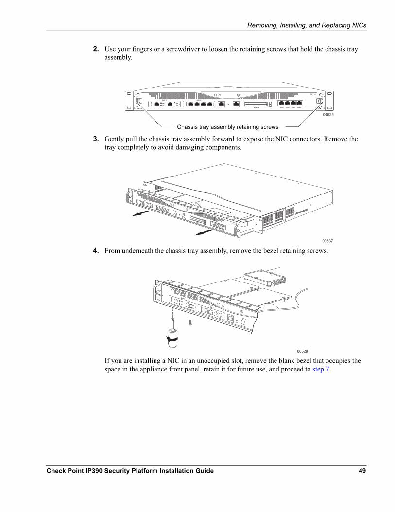
2. Use your fingers or a screwdriver to loosen the retaining screws that hold the chassis tray assembly.
00525
IP390
Chassis tray assembly retaining screws
3. Gently pull the chassis tray assembly forward to expose the NIC connectors. Remove the tray completely to avoid damaging components.
00537
IP390
4. From underneath the chassis tray assembly, remove the bezel retaining screws.
00529
If you are installing a NIC in an unoccupied slot, remove the blank bezel that occupies the space in the appliance front panel, retain it for future use, and proceed to step 7.
Check Point IP390 Security Platform Installation Guide 49
5 Installing and Replacing Network Interface Cards
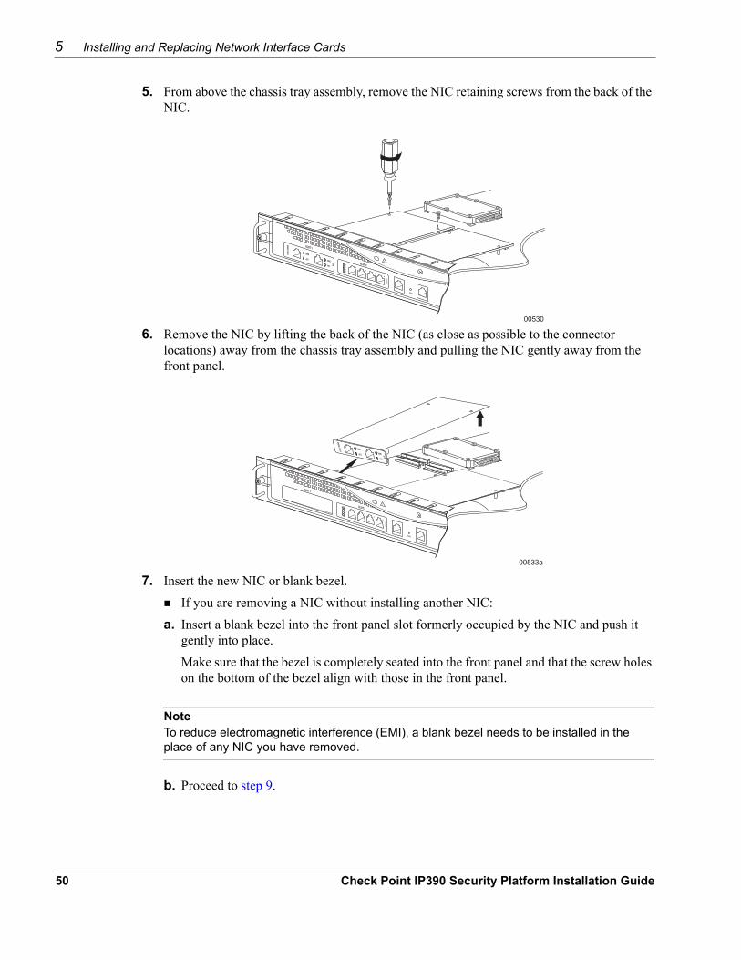
5. From above the chassis tray assembly, remove the NIC retaining screws from the back of the NIC.
00530
6. Remove the NIC by lifting the back of the NIC (as close as possible to the connector locations) away from the chassis tray assembly and pulling the NIC gently away from the front panel.
00533a
7. Insert the new NIC or blank bezel.If you are removing a NIC without installing another NIC:
a. Insert a blank bezel into the front panel slot formerly occupied by the NIC and push it gently into place. Make sure that the bezel is completely seated into the front panel and that the screw holes on the bottom of the bezel align with those in the front panel.
NoteTo reduce electromagnetic interference (EMI), a blank bezel needs to be installed in the place of any NIC you have removed.
b. Proceed to step 9.
50 Check Point IP390 Security Platform Installation Guide
Removing, Installing, and Replacing NICs
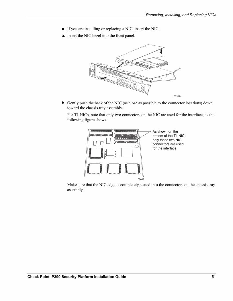
If you are installing or replacing a NIC, insert the NIC.a. Insert the NIC bezel into the front panel.
00532a
b. Gently push the back of the NIC (as close as possible to the connector locations) down toward the chassis tray assembly.For T1 NICs, note that only two connectors on the NIC are used for the interface, as the following figure shows.
00689
As shown on the bottom of the T1 NIC, only these two NIC connectors are used for the interface
Make sure that the NIC edge is completely seated into the connectors on the chassis tray assembly.
Check Point IP390 Security Platform Installation Guide 51
5 Installing and Replacing Network Interface Cards
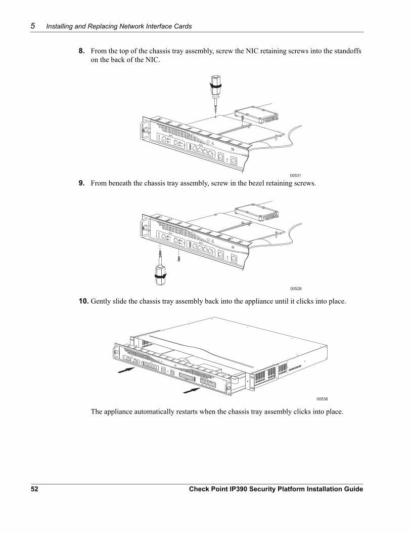
8. From the top of the chassis tray assembly, screw the NIC retaining screws into the standoffs on the back of the NIC.
00531
9. From beneath the chassis tray assembly, screw in the bezel retaining screws.
00528
10. Gently slide the chassis tray assembly back into the appliance until it clicks into place.
00538
IP390
The appliance automatically restarts when the chassis tray assembly clicks into place.
52 Check Point IP390 Security Platform Installation Guide
Configuring and Activating Interfaces
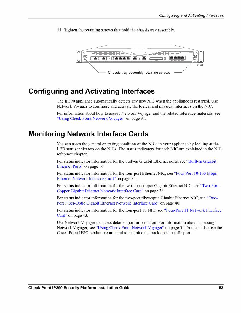
11. Tighten the retaining screws that hold the chassis tray assembly.
00525
IP390
Chassis tray assembly retaining screws
Configuring and Activating InterfacesThe IP390 appliance automatically detects any new NIC when the appliance is restarted. Use Network Voyager to configure and activate the logical and physical interfaces on the NIC.For information about how to access Network Voyager and the related reference materials, see “Using Check Point Network Voyager” on page 31.
Monitoring Network Interface CardsYou can asses the general operating condition of the NICs in your appliance by looking at the LED status indicators on the NICs. The status indicators for each NIC are explained in the NIC reference chapter.For status indicator information for the built-in Gigabit Ethernet ports, see “Built-In Gigabit Ethernet Ports” on page 16.For status indicator information for the four-port Ethernet NIC, see “Four-Port 10/100 Mbps Ethernet Network Interface Card” on page 35.For status indicator information for the two-port copper Gigabit Ethernet NIC, see “Two-Port Copper Gigabit Ethernet Network Interface Card” on page 38.For status indicator information for the two-port fiber-optic Gigabit Ethernet NIC, see “Two-Port Fiber-Optic Gigabit Ethernet Network Interface Card” on page 40.For status indicator information for the four-port T1 NIC, see “Four-Port T1 Network Interface Card” on page 43.Use Network Voyager to access detailed port information. For information about accessing Network Voyager, see “Using Check Point Network Voyager” on page 31. You can also use the Check Point IPSO tcpdump command to examine the track on a specific port.
Check Point IP390 Security Platform Installation Guide 53

5 Installing and Replacing Network Interface Cards
54 Check Point IP390 Security Platform Installation Guide
6 Installing and Replacing Components Other than Network Interface Cards
This chapter provides information on how to install or replace user serviceable items other than network interface cards (NICs) in your IP390 appliance. The following topics are covered:
Replacing the Compact Flash Memory CardInstalling a Flash-Memory PC CardInstalling or Replacing a Hard-Disk DriveReplacing or Upgrading MemoryReplacing the Battery
For instructions on adding or replacing interface cards, see Chapter 5, “Installing and Replacing Network Interface Cards”.
CautionYou should have a working knowledge of networking equipment before attempting to service an IP390 appliance. Limit service of the appliance to the procedures described in this chapter.
CautionProtect your IP390 appliance and other electronic equipment from electrostatic discharge (ESD) damage by making sure you are properly grounded before you touch any component.
Replacing the Compact Flash Memory CardIn flash-based IP390 appliances, the compact flash memory card stores the Check Point IPSO operating system, Check Point application, and boot manager. In disk-based IP390 appliances, the compact flash memory card stores only the boot manager, and the Check Point IPSO operating system and Check Point application are stored on the hard-disk drive. Use the internal compact flash to boot the system and install the Check Point IPSO operating system on the disk. The compact flash memory card is located on the motherboard in a slot behind the hard-disk drive location.
Check Point IP390 Security Platform Installation Guide 55
6 Installing and Replacing Components Other than Network Interface Cards
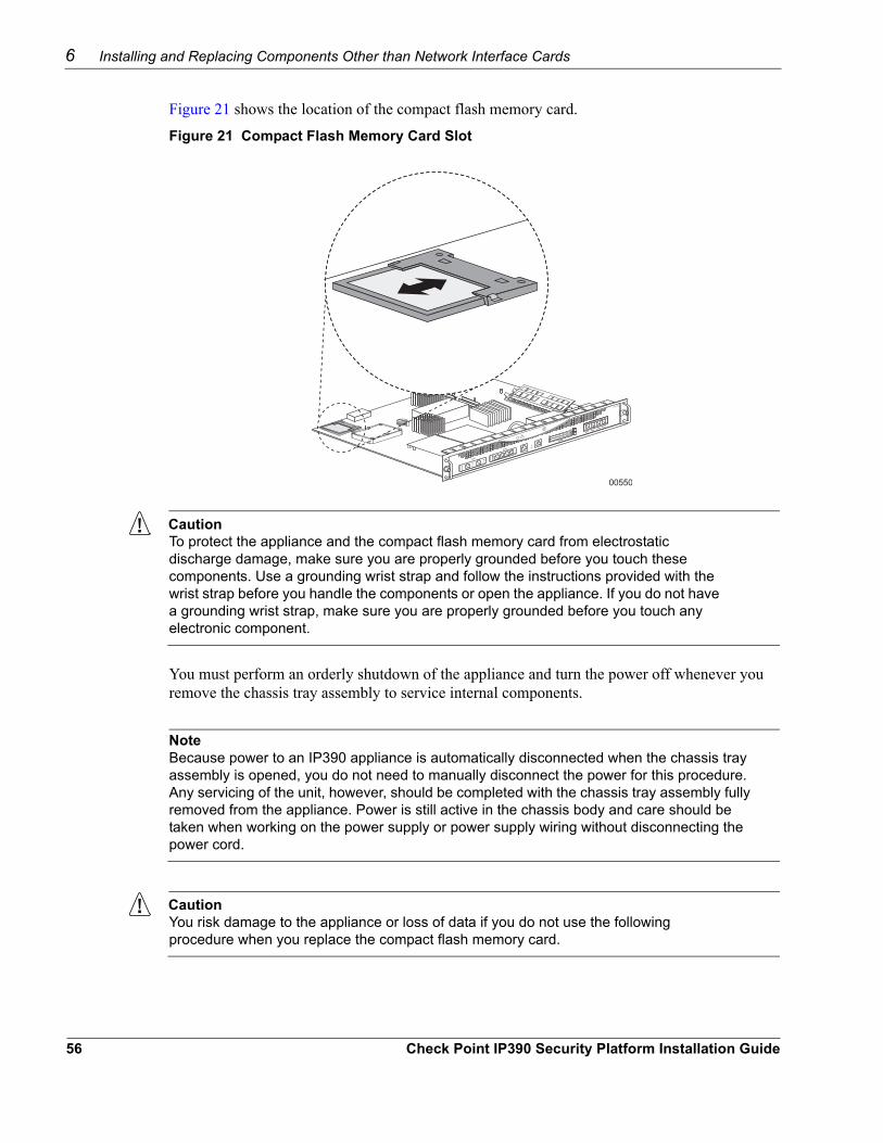
Figure 21 shows the location of the compact flash memory card.
Figure 21 Compact Flash Memory Card Slot
00550
IP390
CautionTo protect the appliance and the compact flash memory card from electrostatic discharge damage, make sure you are properly grounded before you touch these components. Use a grounding wrist strap and follow the instructions provided with the wrist strap before you handle the components or open the appliance. If you do not have a grounding wrist strap, make sure you are properly grounded before you touch any electronic component.
You must perform an orderly shutdown of the appliance and turn the power off whenever you remove the chassis tray assembly to service internal components.
NoteBecause power to an IP390 appliance is automatically disconnected when the chassis tray assembly is opened, you do not need to manually disconnect the power for this procedure. Any servicing of the unit, however, should be completed with the chassis tray assembly fully removed from the appliance. Power is still active in the chassis body and care should be taken when working on the power supply or power supply wiring without disconnecting the power cord.
CautionYou risk damage to the appliance or loss of data if you do not use the following procedure when you replace the compact flash memory card.
56 Check Point IP390 Security Platform Installation Guide
Replacing the Compact Flash Memory Card
To replace compact flash memory card in your appliance1. Use Check Point Network Voyager or the CLI to halt the appliance.
To use Network Voyager to shut the appliance down, select System > Configuration > Reboot or Shutdown > Halt.To use the CLI to shut the appliance down, enter halt at the prompt.
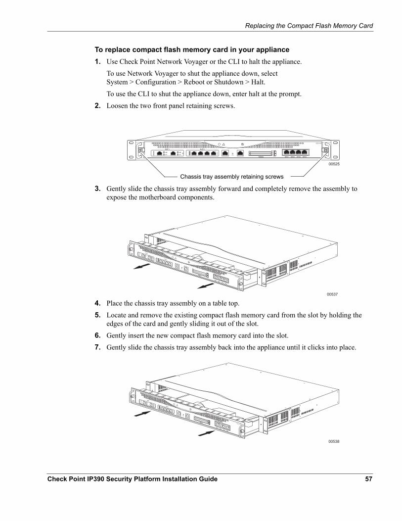
2. Loosen the two front panel retaining screws.
00525
IP390
Chassis tray assembly retaining screws
3. Gently slide the chassis tray assembly forward and completely remove the assembly to expose the motherboard components.
00537
IP390
4. Place the chassis tray assembly on a table top.5. Locate and remove the existing compact flash memory card from the slot by holding the
edges of the card and gently sliding it out of the slot.6. Gently insert the new compact flash memory card into the slot. 7. Gently slide the chassis tray assembly back into the appliance until it clicks into place.
00538
IP390
Check Point IP390 Security Platform Installation Guide 57
6 Installing and Replacing Components Other than Network Interface Cards
The appliance automatically restarts when the chassis tray assembly clicks into place.8. Resecure the two chassis tray assembly retaining screws.9. Turn on the power supply at the back of the appliance.
Installing a Flash-Memory PC CardYou can use the flash-memory PC card to store local system logs, Check Point IPSO images, and configuration files.The IP390 appliance has two PCMCIA slots that can support a flash-memory PC card having a capacity of 1 GB or higher.
Before You BeginTo install a flash-memory PC card, you need:
Physical access to the applianceAccess to the appliance by using Check Point Network Voyager or the command-line interface (CLI)Compact flash-memory PC card and accompanying documentation
CautionTo avoid potential equipment malfunction, Check Point recommends that you obtain flash-memory PC cards only from Check Point or authorized resellers. For further information, see the Check Point Web site at http://www.checkpoint.com.
CautionYou risk damage to the appliance or loss of data if you do not use the following procedure when you replace the flash-memory PC card.
NoteThe flash-memory PC card comes formatted from the factory.
To install the flash-memory PC card1. Insert the flash-memory PC card into PC-card slot 1 or slot 2.2. Press gently on the card until it is firmly seated in the slot.
The eject button to the left of the slot should be flush with the card.The card is automatically detected by your appliance, and you are notified through your console connection.
58 Check Point IP390 Security Platform Installation Guide
Installing or Replacing a Hard-Disk Drive
Transferring Files with the Flash-Memory PC CardYou can copy configuration files between the internal compact flash memory and the flash-memory PC card. If you do not use Check Point Network Voyager to configure the flash-memory PC card as an optional disk, you must mount the flash-memory PC card when you insert it in the PC-card slot, and you must unmount the flash-memory PC card before you remove it. You do not need to reboot or shut down the system if you manually mount and unmount the flash-memory PC card.
To transfer Check Point IPSO images or configuration files to the flash-memory PC card:1. Insert the flash-memory PC card into the IP390 appliance.2. Connect to the IP390 appliance by using a console or terminal connection.3. Mount the flash-memory PC card by using the following command if you do not have a
hard-disk drive installed in your appliance:mount /dev/wd1 /cdrom
Or, if you do have a hard-disk drive installed in your appliance:mount /dev/wd2 /cdrom
The /cdrom directory is a default directory in Check Point IPSO for mounting media.4. Use the cp command to transfer Check Point IPSO images or configuration files to and from
the flash-memory PC card.For example, to copy the current Check Point IPSO image from the compact flash memory to the flash-memory PC card, use the following command:cp /image/current/ipso.tgz /cdrom/
5. Use the following command to unmount the flash-memory PC card before you eject it:umount /cdrom
6. To remove the card, slowly push the eject button located to the left of the card.Hold the flash-memory PC card while you push the eject button to prevent the card from ejecting too quickly.
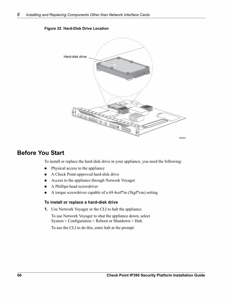
Installing or Replacing a Hard-Disk DriveYou can add a single hard-disk drive to your flash-based IP390 appliance. The following figure shows the location of the hard-disk drive on the motherboard.
NoteBack up your files to a remote system on a regular basis. For back up and restore procedures, see the Network Voyager Reference Guide for the version of Check Point IPSO you are using.
Check Point IP390 Security Platform Installation Guide 59
6 Installing and Replacing Components Other than Network Interface Cards
Figure 22 Hard-Disk Drive Location
00542
IP390
Hard-disk drive
Before You StartTo install or replace the hard-disk drive in your appliance, you need the following:
Physical access to the applianceA Check Point-approved hard-disk driveAccess to the appliance through Network VoyagerA Phillips-head screwdriverA torque screwdriver capable of a 69.4ozf*in (5kgf*cm) setting
To install or replace a hard-disk drive1. Use Network Voyager or the CLI to halt the appliance.
To use Network Voyager to shut the appliance down, select System > Configuration > Reboot or Shutdown > Halt.To use the CLI to do this, enter halt at the prompt.
60 Check Point IP390 Security Platform Installation Guide
Installing or Replacing a Hard-Disk Drive
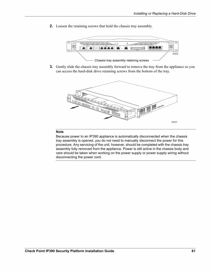
2. Loosen the retaining screws that hold the chassis tray assembly.
00525
IP390
Chassis tray assembly retaining screws
3. Gently slide the chassis tray assembly forward to remove the tray from the appliance so you can access the hard-disk drive retaining screws from the bottom of the tray.
00537
IP390
NoteBecause power to an IP390 appliance is automatically disconnected when the chassis tray assembly is opened, you do not need to manually disconnect the power for this procedure. Any servicing of the unit, however, should be completed with the chassis tray assembly fully removed from the appliance. Power is still active in the chassis body and care should be taken when working on the power supply or power supply wiring without disconnecting the power cord.
Check Point IP390 Security Platform Installation Guide 61
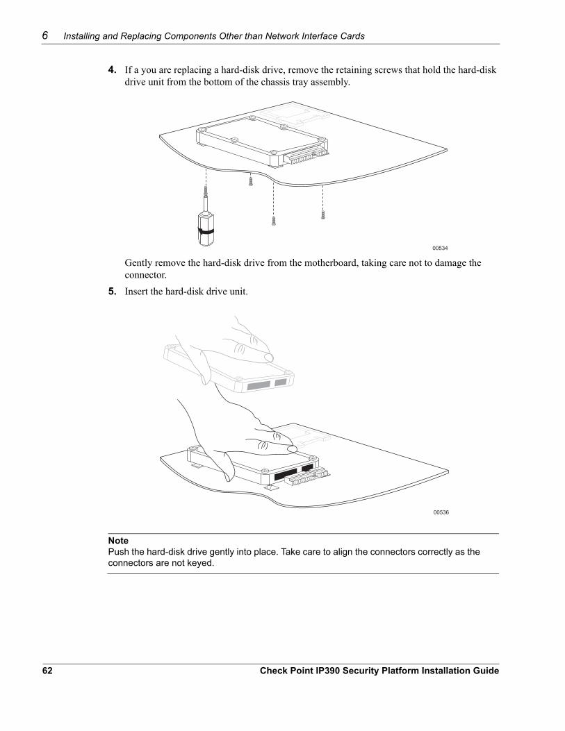
6 Installing and Replacing Components Other than Network Interface Cards
4. If a you are replacing a hard-disk drive, remove the retaining screws that hold the hard-disk drive unit from the bottom of the chassis tray assembly.
00534
Gently remove the hard-disk drive from the motherboard, taking care not to damage the connector.
5. Insert the hard-disk drive unit.
00536
NotePush the hard-disk drive gently into place. Take care to align the connectors correctly as the connectors are not keyed.
62 Check Point IP390 Security Platform Installation Guide
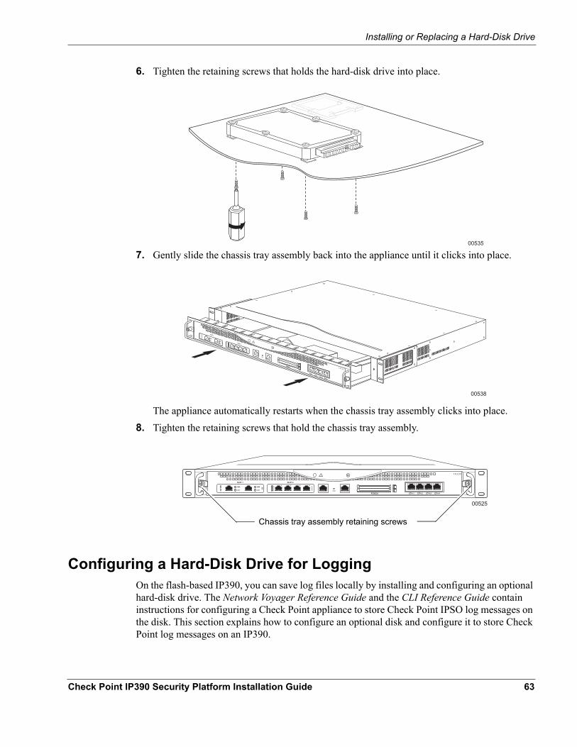
Installing or Replacing a Hard-Disk Drive
6. Tighten the retaining screws that holds the hard-disk drive into place.
00535
7. Gently slide the chassis tray assembly back into the appliance until it clicks into place.
00538
IP390
The appliance automatically restarts when the chassis tray assembly clicks into place. 8. Tighten the retaining screws that hold the chassis tray assembly.
00525
IP390
Chassis tray assembly retaining screws
Configuring a Hard-Disk Drive for LoggingOn the flash-based IP390, you can save log files locally by installing and configuring an optional hard-disk drive. The Network Voyager Reference Guide and the CLI Reference Guide contain instructions for configuring a Check Point appliance to store Check Point IPSO log messages on the disk. This section explains how to configure an optional disk and configure it to store Check Point log messages on an IP390.
Check Point IP390 Security Platform Installation Guide 63
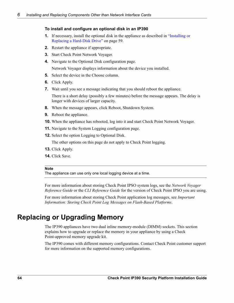
6 Installing and Replacing Components Other than Network Interface Cards
To install and configure an optional disk in an IP3901. If necessary, install the optional disk in the appliance as described in “Installing or
Replacing a Hard-Disk Drive” on page 59.2. Restart the appliance if appropriate.3. Start Check Point Network Voyager.4. Navigate to the Optional Disk configuration page.
Network Voyager displays information about the device you installed.5. Select the device in the Choose column.6. Click Apply.7. Wait until you see a message indicating that you should reboot the appliance.
There is a short delay (possibly a few minutes) before the message appears. The delay is longer with devices of larger capacity.
8. When the message appears, click Reboot, Shutdown System. 9. Reboot the appliance.10. When the appliance has rebooted, log into it and start Check Point Network Voyager.
11. Navigate to the System Logging configuration page.12. Select the option Logging to Optional Disk.
The other options on this page do not apply to Check Point logging.13. Click Apply.14. Click Save.
NoteThe appliance can use only one local logging device at a time.
For more information about storing Check Point IPSO system logs, see the Network Voyager Reference Guide or the CLI Reference Guide for the version of Check Point IPSO you are using.For more information about storing Check Point application log messages, see Important Information: Storing Check Point Log Messages on Flash-Based Platforms.
Replacing or Upgrading MemoryThe IP390 appliances have two dual inline memory-module (DIMM) sockets. This section explains how to upgrade or replace the memory in your appliance by using a Check Point-approved memory upgrade kit.The IP390 comes with different memory configurations. Contact Check Point customer support for more information on the supported memory configurations.
64 Check Point IP390 Security Platform Installation Guide
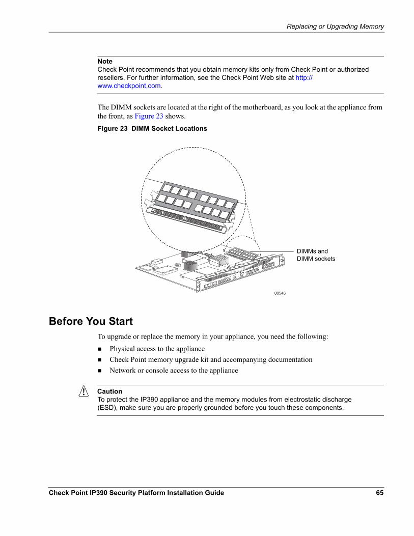
Replacing or Upgrading Memory
NoteCheck Point recommends that you obtain memory kits only from Check Point or authorized resellers. For further information, see the Check Point Web site at http://www.checkpoint.com.
The DIMM sockets are located at the right of the motherboard, as you look at the appliance from the front, as Figure 23 shows.
Figure 23 DIMM Socket Locations
00546
IP390
DIMMs and DIMM sockets
Before You StartTo upgrade or replace the memory in your appliance, you need the following:
Physical access to the applianceCheck Point memory upgrade kit and accompanying documentationNetwork or console access to the appliance
CautionTo protect the IP390 appliance and the memory modules from electrostatic discharge (ESD), make sure you are properly grounded before you touch these components.
Check Point IP390 Security Platform Installation Guide 65
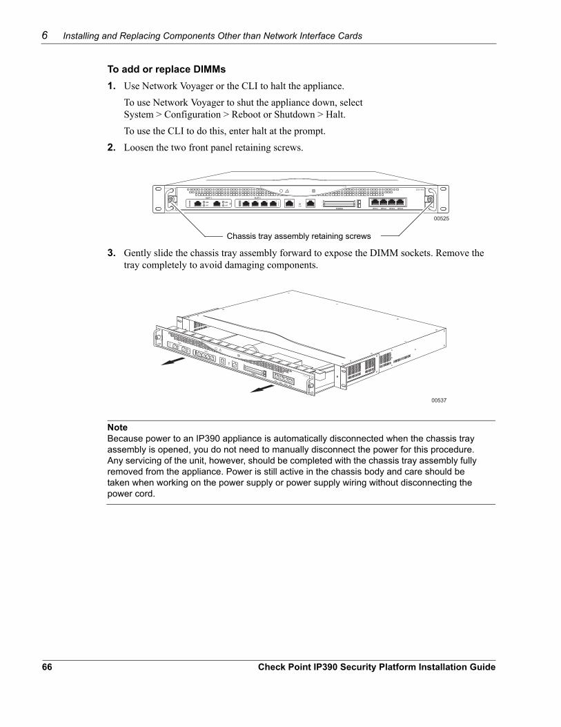
6 Installing and Replacing Components Other than Network Interface Cards
To add or replace DIMMs1. Use Network Voyager or the CLI to halt the appliance.
To use Network Voyager to shut the appliance down, select System > Configuration > Reboot or Shutdown > Halt.To use the CLI to do this, enter halt at the prompt.
2. Loosen the two front panel retaining screws.
00525
IP390
Chassis tray assembly retaining screws
3. Gently slide the chassis tray assembly forward to expose the DIMM sockets. Remove the tray completely to avoid damaging components.
00537
IP390
NoteBecause power to an IP390 appliance is automatically disconnected when the chassis tray assembly is opened, you do not need to manually disconnect the power for this procedure. Any servicing of the unit, however, should be completed with the chassis tray assembly fully removed from the appliance. Power is still active in the chassis body and care should be taken when working on the power supply or power supply wiring without disconnecting the power cord.
66 Check Point IP390 Security Platform Installation Guide
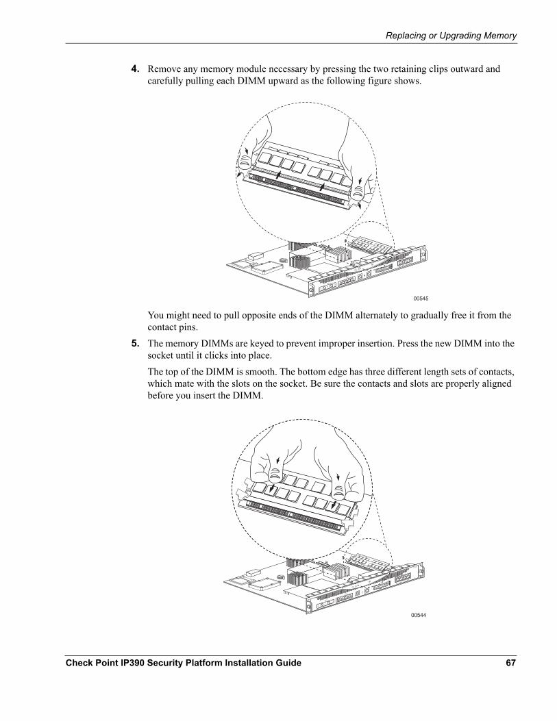
Replacing or Upgrading Memory
4. Remove any memory module necessary by pressing the two retaining clips outward and carefully pulling each DIMM upward as the following figure shows.
00545
IP390
You might need to pull opposite ends of the DIMM alternately to gradually free it from the contact pins.
5. The memory DIMMs are keyed to prevent improper insertion. Press the new DIMM into the socket until it clicks into place. The top of the DIMM is smooth. The bottom edge has three different length sets of contacts, which mate with the slots on the socket. Be sure the contacts and slots are properly aligned before you insert the DIMM.
00544
IP390
Check Point IP390 Security Platform Installation Guide 67
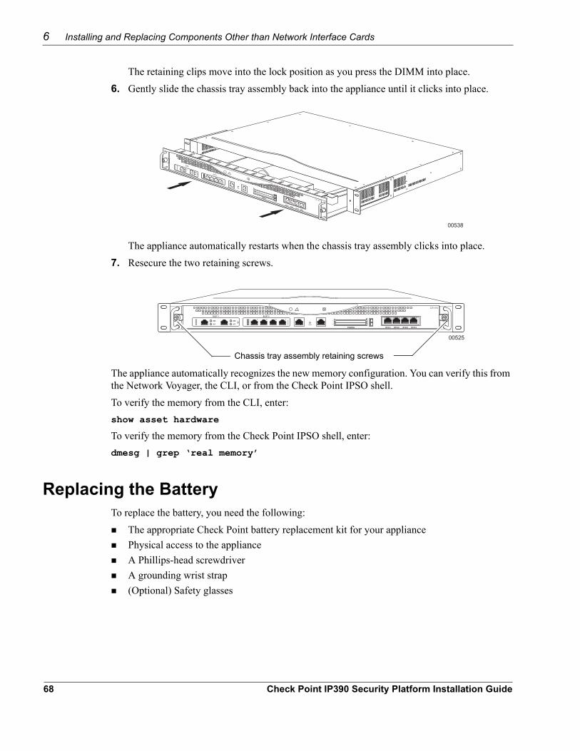
6 Installing and Replacing Components Other than Network Interface Cards
The retaining clips move into the lock position as you press the DIMM into place.6. Gently slide the chassis tray assembly back into the appliance until it clicks into place.
00538
IP390
The appliance automatically restarts when the chassis tray assembly clicks into place. 7. Resecure the two retaining screws.
00525
IP390
Chassis tray assembly retaining screws
The appliance automatically recognizes the new memory configuration. You can verify this from the Network Voyager, the CLI, or from the Check Point IPSO shell.To verify the memory from the CLI, enter:show asset hardware
To verify the memory from the Check Point IPSO shell, enter:dmesg | grep ‘real memory’
Replacing the BatteryTo replace the battery, you need the following:
The appropriate Check Point battery replacement kit for your appliancePhysical access to the applianceA Phillips-head screwdriverA grounding wrist strap(Optional) Safety glasses
68 Check Point IP390 Security Platform Installation Guide
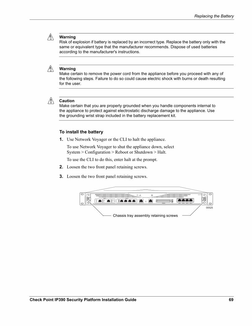
Replacing the Battery
WarningRisk of explosion if battery is replaced by an incorrect type. Replace the battery only with the same or equivalent type that the manufacturer recommends. Dispose of used batteries according to the manufacturer's instructions.
WarningMake certain to remove the power cord from the appliance before you proceed with any of the following steps. Failure to do so could cause electric shock with burns or death resulting for the user.
CautionMake certain that you are properly grounded when you handle components internal to the appliance to protect against electrostatic discharge damage to the appliance. Use the grounding wrist strap included in the battery replacement kit.
To install the battery1. Use Network Voyager or the CLI to halt the appliance.
To use Network Voyager to shut the appliance down, select System > Configuration > Reboot or Shutdown > Halt.To use the CLI to do this, enter halt at the prompt.
2. Loosen the two front panel retaining screws.
3. Loosen the two front panel retaining screws.
00525
IP390
Chassis tray assembly retaining screws
Check Point IP390 Security Platform Installation Guide 69
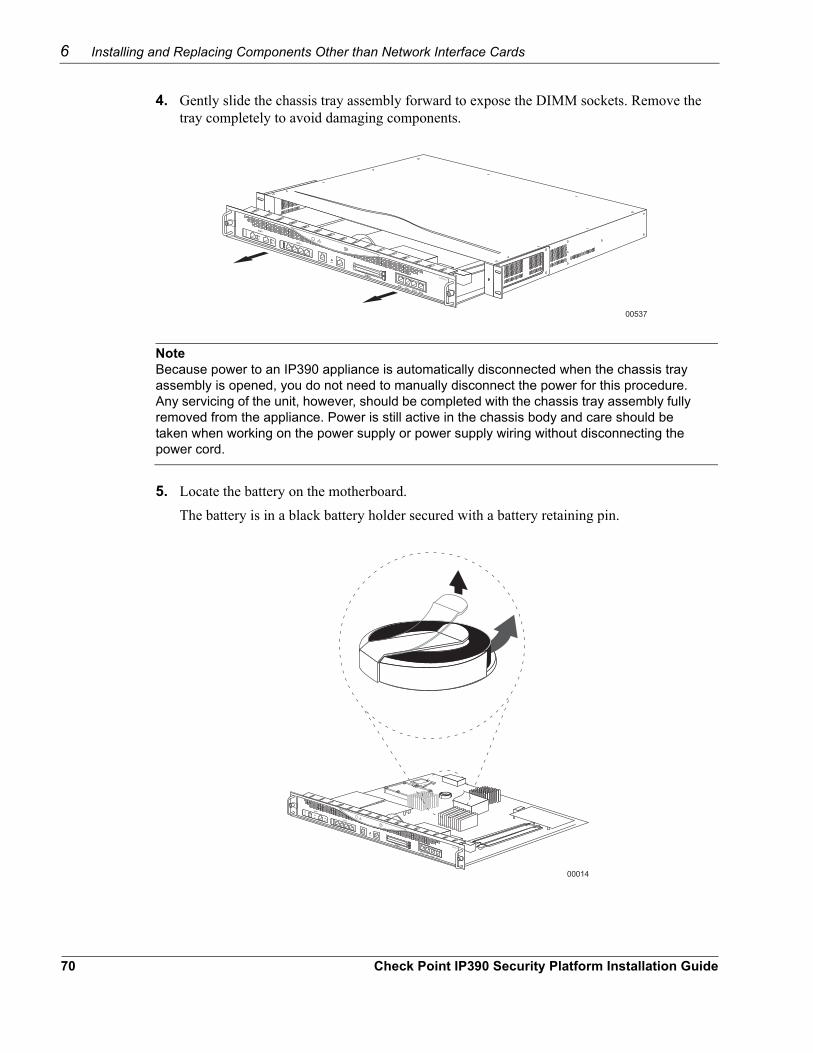
6 Installing and Replacing Components Other than Network Interface Cards
4. Gently slide the chassis tray assembly forward to expose the DIMM sockets. Remove the tray completely to avoid damaging components.
00537
IP390
NoteBecause power to an IP390 appliance is automatically disconnected when the chassis tray assembly is opened, you do not need to manually disconnect the power for this procedure. Any servicing of the unit, however, should be completed with the chassis tray assembly fully removed from the appliance. Power is still active in the chassis body and care should be taken when working on the power supply or power supply wiring without disconnecting the power cord.
5. Locate the battery on the motherboard. The battery is in a black battery holder secured with a battery retaining pin.
00014
IP390
70 Check Point IP390 Security Platform Installation Guide
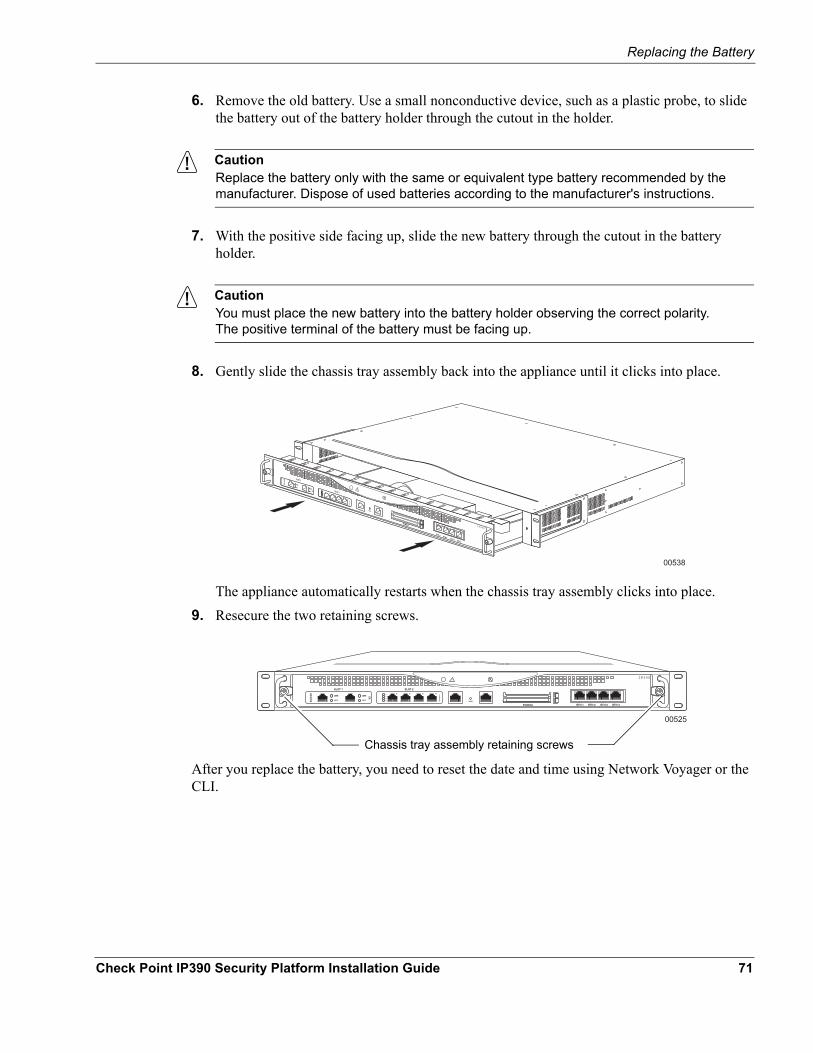
Replacing the Battery
6. Remove the old battery. Use a small nonconductive device, such as a plastic probe, to slide the battery out of the battery holder through the cutout in the holder.
CautionReplace the battery only with the same or equivalent type battery recommended by the manufacturer. Dispose of used batteries according to the manufacturer's instructions.
7. With the positive side facing up, slide the new battery through the cutout in the battery holder.
CautionYou must place the new battery into the battery holder observing the correct polarity. The positive terminal of the battery must be facing up.
8. Gently slide the chassis tray assembly back into the appliance until it clicks into place.
00538
IP390
The appliance automatically restarts when the chassis tray assembly clicks into place. 9. Resecure the two retaining screws.
00525
IP390
Chassis tray assembly retaining screws
After you replace the battery, you need to reset the date and time using Network Voyager or the CLI.
Check Point IP390 Security Platform Installation Guide 71

6 Installing and Replacing Components Other than Network Interface Cards
72 Check Point IP390 Security Platform Installation Guide
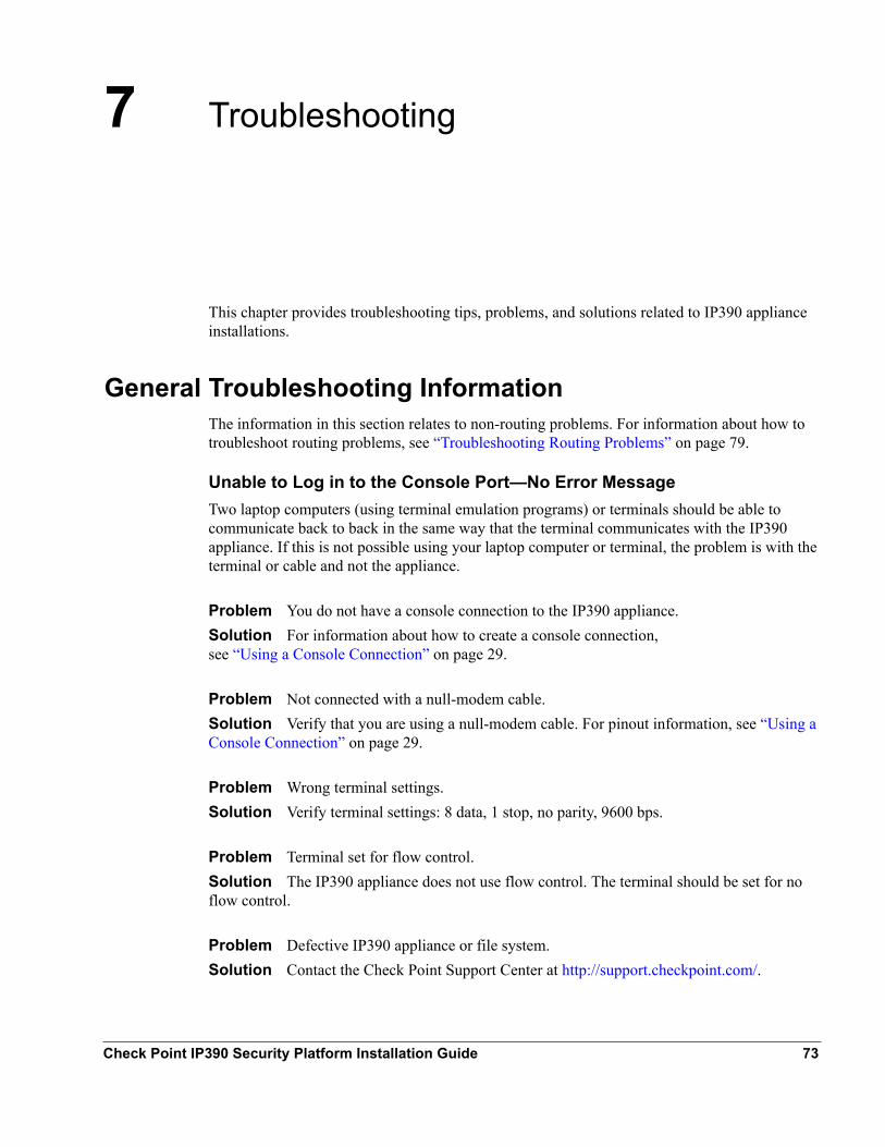
7 Troubleshooting
This chapter provides troubleshooting tips, problems, and solutions related to IP390 appliance installations.
General Troubleshooting InformationThe information in this section relates to non-routing problems. For information about how to troubleshoot routing problems, see “Troubleshooting Routing Problems” on page 79.
Unable to Log in to the Console Port—No Error MessageTwo laptop computers (using terminal emulation programs) or terminals should be able to communicate back to back in the same way that the terminal communicates with the IP390 appliance. If this is not possible using your laptop computer or terminal, the problem is with the terminal or cable and not the appliance.
Problem You do not have a console connection to the IP390 appliance.Solution For information about how to create a console connection, see “Using a Console Connection” on page 29.
Problem Not connected with a null-modem cable. Solution Verify that you are using a null-modem cable. For pinout information, see “Using a Console Connection” on page 29.
Problem Wrong terminal settings.Solution Verify terminal settings: 8 data, 1 stop, no parity, 9600 bps.
Problem Terminal set for flow control.Solution The IP390 appliance does not use flow control. The terminal should be set for no flow control.
Problem Defective IP390 appliance or file system.Solution Contact the Check Point Support Center at http://support.checkpoint.com/.
Check Point IP390 Security Platform Installation Guide 73
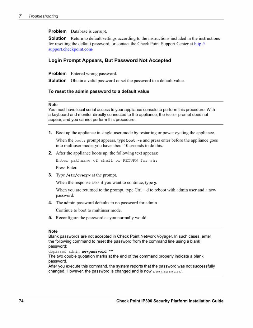
7 Troubleshooting
Problem Database is corrupt.Solution Return to default settings according to the instructions included in the instructions for resetting the default password, or contact the Check Point Support Center at http://support.checkpoint.com/.
Login Prompt Appears, But Password Not Accepted
Problem Entered wrong password.Solution Obtain a valid password or set the password to a default value.
To reset the admin password to a default value
NoteYou must have local serial access to your appliance console to perform this procedure. With a keyboard and monitor directly connected to the appliance, the boot: prompt does not appear, and you cannot perform this procedure.
1. Boot up the appliance in single-user mode by restarting or power cycling the appliance.When the boot: prompt appears, type boot -s and press enter before the appliance goes into multiuser mode; you have about 10 seconds to do this.
2. After the appliance boots up, the following text appears:Enter pathname of shell or RETURN for sh:
Press Enter.3. Type /etc/overpw at the prompt.
When the response asks if you want to continue, type y.When you are returned to the prompt, type Ctrl + d to reboot with admin user and a new password.
4. The admin password defaults to no password for admin.Continue to boot to multiuser mode.
5. Reconfigure the password as you normally would.
NoteBlank passwords are not accepted in Check Point Network Voyager. In such cases, enter the following command to reset the password from the command line using a blank password: dbpasswd admin newpassword "" The two double quotation marks at the end of the command properly indicate a blank password. After you execute this command, the system reports that the password was not successfully changed. However, the password is changed and is now newpassword.
74 Check Point IP390 Security Platform Installation Guide
General Troubleshooting Information
Finally, return the entire database to its default settings and bring up the new system-startup procedure. The new system-startup procedure is described in Chapter 3, “Performing the Initial Configuration”.
To reset the default database settings1. Log in to the IP390 appliance as admin by using Network Voyager.
For information about how to access Network Voyager and the related reference materials, see “Using Check Point Network Voyager” on page 31.
2. Under Configuration Database Management (Config > System Configuration > Manage Configuration Sets), choose the option to create a new factory default configuration.
3. Create the new default configuration.
Do Not Get a Login Prompt—Error Messages Appear
Problem The IP390 appliance is defective, or the file system on the IP390 appliance is defective.Solution Contact the Check Point Support Center at http://support.checkpoint.com/.
NoteUse the full installation procedure to install a new system. The new system completely replaces the contents of the drive and might be needed to restore or reload an IP390 appliance. This procedure erases any configuration database on the appliance. For information about how to complete the full installation procedure, see the current release notes. The release notes are located on the Check Point Support Center aat http://support.checkpoint.com/.
Unable to Connect to Network Voyager Using the Ethernet Port, But Console Access Works
Problem Using the wrong Ethernet cable.Solution Use a crossover Ethernet cable if you are connecting directly to the computer. Use a straight-through cable if you are connecting to a hub. For cabling information, see “Four-Port 10/100 Mbps Ethernet Network Interface Card” on page 35.
Problem Port is not configured as active. Solution Use the CLI over the console connection to verify the interface configuration and fix it if necessary.
Problem Host port configuration is incorrect.Solution Use the CLI over the console connection to verify the interface configuration and fix it if necessary.
Check Point IP390 Security Platform Installation Guide 75
7 Troubleshooting
Problem Wrong link speed.Solution Use the CLI over the console connection to verify the interface configuration and fix it if necessary.
Do Not See Interfaces that Should be Present
Problem Local IP390 appliance ports do not appear. Solution Your NIC might be defective. Contact the Check Point Support Center at http://support.checkpoint.com/.
NoteThe problem could be with the slot on the PMC card carrier. Try installing the NIC in another slot.
Common Ethernet Problems—Connectivity with Attached Device
Problem No link light. Solution You might have used the wrong cable. Use a crossover cable between an IP390 appliance and a host, and a straight-through cable between an appliance and a hub.
Problem Solid data and activity LED. Solution You might have set the wrong speed. Verify that the speeds match on each end of the Ethernet connection (10 Mbps or 100Mbps).
Problem Port not enabled.Solution Verify from the Interface page in Network Voyager that the interface port is configured as active.
Problem High collision rate on the hub. Solution Disconnect connections one at a time until the problem is localized to one computer and troubleshoot further.
Unable to Ping Through Appliance—No Connectivity Between Ports This section covers connectivity issues that are isolated within an IP390 appliance or network.Localize the problem by issuing pings to various network interfaces. Use tcpdump to help isolate the problem. Use tcpdump to verify that a packet is leaving or entering a port.
Problem Interfaces not up. Solution Ensure that all interfaces are up and active, as described in Chapter 3, “Performing the Initial Configuration.”
76 Check Point IP390 Security Platform Installation Guide
General Troubleshooting Information
Problem No route to network. Solution Check the routing table to see if a route exists to the network where the interface is located. If no route exists, see “Troubleshooting Routing Problems” on page 79.
Problem Attached device does not have proper default route or routing information. Solution If a local computer is unable to ping through an attached appliance, the computer might contain either an invalid default route or invalid routing information.If you are using default routes from a computer, ensure that the local interface is the default route for that computer.
Problem The ARP table has old information. Solution If the ARP table has an old or invalid entry for the device associated with the IP address you are attempting to ping, use Network Voyager to delete the invalid entry.For information about how to access Network Voyager and the related reference materials, see “Using Check Point Network Voyager” on page 31.
To delete the invalid entry1. Click Config.2. Click ARP in the Interfaces section.3. Click Display or Remove Dynamic ARP Entries.4. Click Delete for the entry you want to delete.5. Click Apply.
Problems with MulticastUse tcpdump to view packets. To display packets for a specific interface, use the following command: tcpdump -i interface proto igmp. For more information about how to use the tcpdump command, see the Network Voyager Reference Guide.Under Routing Options in the Routing Configuration section in Network Voyager, you can also enable several types of trace options for DVMRP. These traces are logged into /var/tmp/ipsrd.log.For information about how to access Network Voyager and the related reference materials, see “Using Check Point Network Voyager” on page 31.
Problem No IP connectivity. Solution Verify that you have IP connectivity; ping various hosts on each network.
Problem DVMRP is not enabled on the interfaces.Solution Verify that DVMRP is enabled on the interfaces in use.
Check Point IP390 Security Platform Installation Guide 77
7 Troubleshooting
Problem Exceeding TTL on clients.Solution Verify that the client is set up for the proper TTL number. Many clients are set to receive local traffic only one hop away.
Problems Interfacing to 1483 Devices
Problem Remote and local devices are not configured for the same VC and VP value.Solution Set remote and local devices to the same VC and VP values. Consult your 1483 device documentation.
Problem Remote and local devices are not in the supported VC range of the NIC.Solution Use ipsctl to determine the VC range. Enter the following command:ipsctl ifphys:logical interface:max_rxlabel
Problem Encapsulation is not set to LLC/SNAP.Solution Set encapsulation to LLC/SNAP. Consult your 1483 device documentation.
Problem The MTU size is not 1500 (for Ethernet interfaces) or 16018 (for Gigabit Ethernet interfaces).Solution The MTU size must be 1500 (for Ethernet interfaces) or 16018 (for Gigabit Ethernet interfaces). Check Point does not support larger MTU sizes.
Appliance Not Receiving Power
Problem Power cord is not properly plugged in.Solution Check cord. Make sure it is properly seated at both ends.
Problem Power supply not providing power.Solution Check power source. If there is no power at the source, take appropriate action such as inserting a new fuse or resetting circuit breaker.
Appliance Does Not Recognize New Memory Configuration
Problem DIMMs are not properly seated in DIMM sockets.Solution Repeat memory installation procedures. Make sure DIMMs are fully seated in sockets. Be sure DIMMs click into place.
78 Check Point IP390 Security Platform Installation Guide
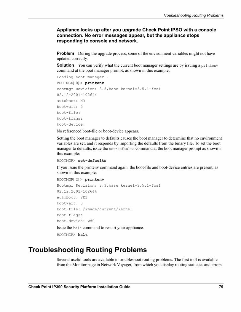
Troubleshooting Routing Problems
Appliance locks up after you upgrade Check Point IPSO with a console connection. No error messages appear, but the appliance stops responding to console and network.
Problem During the upgrade process, some of the environment variables might not have updated correctly.Solution You can verify what the current boot manager settings are by issuing a printenv command at the boot manager prompt, as shown in this example:Loading boot manager ..
BOOTMGR[0]> printenv
Bootmgr Revision: 3.3,base kernel=3.5.1-fcs1
02.12-2001-102644
autoboot: NO
bootwait: 5
boot-file:
boot-flags:
boot-device:
No referenced boot-file or boot-device appears.Setting the boot manager to defaults causes the boot manager to determine that no environment variables are set, and it responds by importing the defaults from the binary file. To set the boot manager to defaults, issue the set-defaults command at the boot manager prompt as shown in this example:BOOTMGR> set-defaults
If you issue the printenv command again, the boot-file and boot-device entries are present, as shown in this example:BOOTMGR[2]> printenv
Bootmgr Revision: 3.3,base kernel=3.5.1-fcs1
02.12.2001-102644
autoboot: YES
bootwait: 5
boot-file: /image/current/kernel
boot-flags:
boot-device: wd0
Issue the halt command to restart your appliance.BOOTMGR> halt
Troubleshooting Routing Problems Several useful tools are available to troubleshoot routing problems. The first tool is available from the Monitor page in Network Voyager, from which you display routing statistics and errors.
Check Point IP390 Security Platform Installation Guide 79
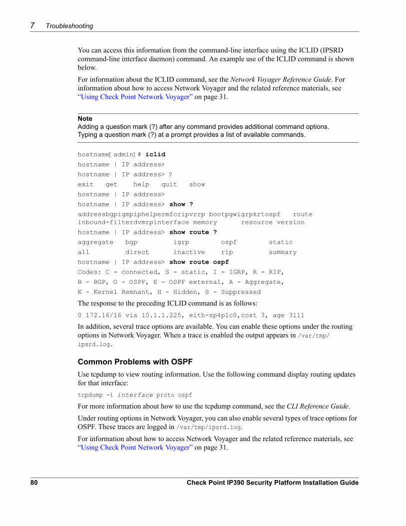
7 Troubleshooting
You can access this information from the command-line interface using the ICLID (IPSRD command-line interface daemon) command. An example use of the ICLID command is shown below. For information about the ICLID command, see the Network Voyager Reference Guide. For information about how to access Network Voyager and the related reference materials, see “Using Check Point Network Voyager” on page 31.
NoteAdding a question mark (?) after any command provides additional command options. Typing a question mark (?) at a prompt provides a list of available commands.
hostname[admin]# iclid
hostname | IP address>
hostname | IP address> ?
exit get help quit show
hostname | IP address>
hostname | IP address> show ?
addressbgpigmpiphelpermfcripvrrp bootpgwigrpkrtospf route inbound-filterdvmrpinterface memory resource version
hostname | IP address> show route ?
aggregate bgp igrp ospf static
all direct inactive rip summary
hostname | IP address> show route ospf
Codes: C - connected, S - static, I - IGRP, R - RIP,
B - BGP, O - OSPF, E - OSPF external, A - Aggregate,
K - Kernel Remnant, H - Hidden, S - Suppressed
The response to the preceding ICLID command is as follows:0 172.16/16 via 10.1.1.225, eith-sp4p1c0,cost 3, age 3111
In addition, several trace options are available. You can enable these options under the routing options in Network Voyager. When a trace is enabled the output appears in /var/tmp/ipsrd.log.
Common Problems with OSPF Use tcpdump to view routing information. Use the following command display routing updates for that interface:tcpdump -i interface proto ospf
For more information about how to use the tcpdump command, see the CLI Reference Guide.Under routing options in Network Voyager, you can also enable several types of trace options for OSPF. These traces are logged in /var/tmp/ipsrd.log.For information about how to access Network Voyager and the related reference materials, see “Using Check Point Network Voyager” on page 31.
80 Check Point IP390 Security Platform Installation Guide
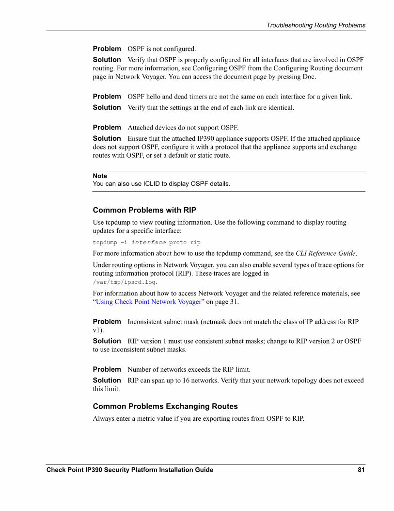
Troubleshooting Routing Problems
Problem OSPF is not configured. Solution Verify that OSPF is properly configured for all interfaces that are involved in OSPF routing. For more information, see Configuring OSPF from the Configuring Routing document page in Network Voyager. You can access the document page by pressing Doc.
Problem OSPF hello and dead timers are not the same on each interface for a given link.Solution Verify that the settings at the end of each link are identical.
Problem Attached devices do not support OSPF.Solution Ensure that the attached IP390 appliance supports OSPF. If the attached appliance does not support OSPF, configure it with a protocol that the appliance supports and exchange routes with OSPF, or set a default or static route.
NoteYou can also use ICLID to display OSPF details.
Common Problems with RIP Use tcpdump to view routing information. Use the following command to display routing updates for a specific interface:tcpdump -i interface proto rip
For more information about how to use the tcpdump command, see the CLI Reference Guide.Under routing options in Network Voyager, you can also enable several types of trace options for routing information protocol (RIP). These traces are logged in /var/tmp/ipsrd.log.For information about how to access Network Voyager and the related reference materials, see “Using Check Point Network Voyager” on page 31.
Problem Inconsistent subnet mask (netmask does not match the class of IP address for RIP v1).Solution RIP version 1 must use consistent subnet masks; change to RIP version 2 or OSPF to use inconsistent subnet masks.
Problem Number of networks exceeds the RIP limit.Solution RIP can span up to 16 networks. Verify that your network topology does not exceed this limit.
Common Problems Exchanging Routes Always enter a metric value if you are exporting routes from OSPF to RIP.
Check Point IP390 Security Platform Installation Guide 81
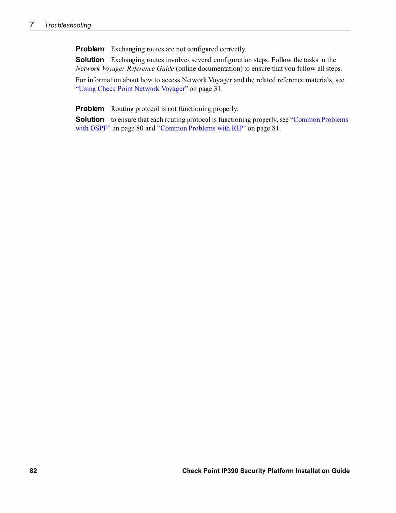
7 Troubleshooting
Problem Exchanging routes are not configured correctly.Solution Exchanging routes involves several configuration steps. Follow the tasks in the Network Voyager Reference Guide (online documentation) to ensure that you follow all steps. For information about how to access Network Voyager and the related reference materials, see “Using Check Point Network Voyager” on page 31.
Problem Routing protocol is not functioning properly.Solution to ensure that each routing protocol is functioning properly, see “Common Problems with OSPF” on page 80 and “Common Problems with RIP” on page 81.
82 Check Point IP390 Security Platform Installation Guide
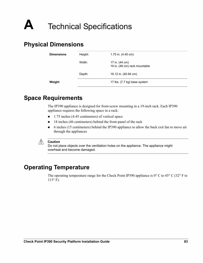
A Technical Specifications
Physical Dimensions
Space RequirementsThe IP390 appliance is designed for front-screw mounting in a 19-inch rack. Each IP390 appliance requires the following space in a rack:
1.75 inches (4.45 centimeters) of vertical space 18 inches (46 centimeters) behind the front-panel of the rack 6 inches (15 centimeters) behind the IP390 appliance to allow the back exit fan to move air through the appliances
CautionDo not place objects over the ventilation holes on the appliance. The appliance might overheat and become damaged.
Operating TemperatureThe operating temperature range for the Check Point IP390 appliance is 0° C to 45° C (32° F to 113° F).
Dimensions Height: 1.75 in. (4.45 cm)
Width: 17 in. (44 cm) 19 in. (48 cm) rack mountable
Depth: 16.12 in. (40.94 cm)
Weight 17 lbs. (7.7 kg) base system
Check Point IP390 Security Platform Installation Guide 83
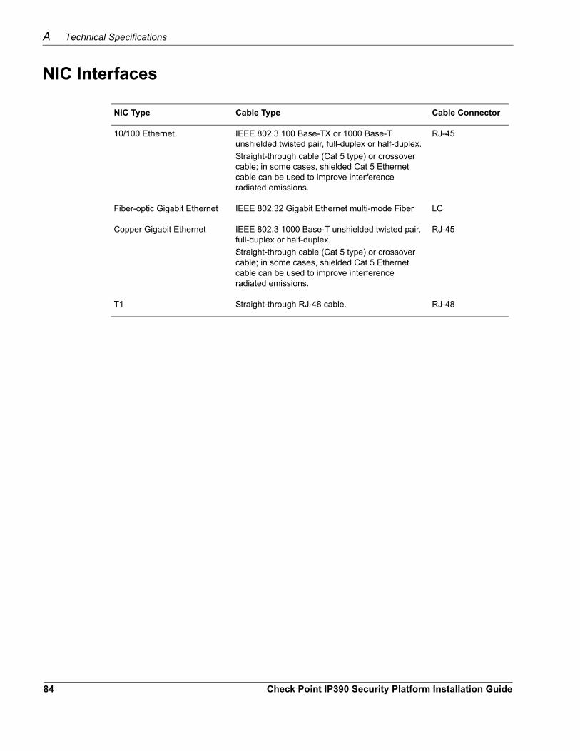
A Technical Specifications
NIC Type Cable Type Cable Connector
10/100 Ethernet IEEE 802.3 100 Base-TX or 1000 Base-T unshielded twisted pair, full-duplex or half-duplex.Straight-through cable (Cat 5 type) or crossover cable; in some cases, shielded Cat 5 Ethernet cable can be used to improve interference radiated emissions.
RJ-45
Fiber-optic Gigabit Ethernet IEEE 802.32 Gigabit Ethernet multi-mode Fiber LC
Copper Gigabit Ethernet IEEE 802.3 1000 Base-T unshielded twisted pair, full-duplex or half-duplex.Straight-through cable (Cat 5 type) or crossover cable; in some cases, shielded Cat 5 Ethernet cable can be used to improve interference radiated emissions.
RJ-45
T1 Straight-through RJ-48 cable. RJ-48
NIC Interfaces
84 Check Point IP390 Security Platform Installation Guide
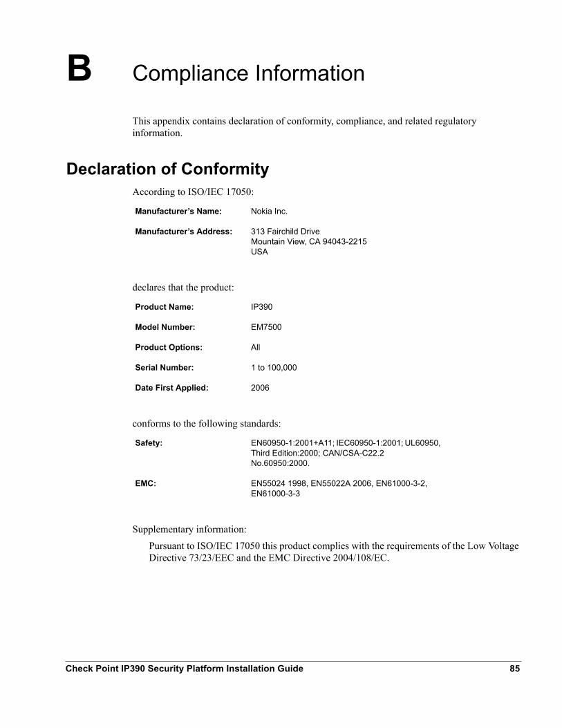
B Compliance Information
This appendix contains declaration of conformity, compliance, and related regulatory information.
Declaration of ConformityAccording to ISO/IEC 17050:
declares that the product:
conforms to the following standards:
Supplementary information:Pursuant to ISO/IEC 17050 this product complies with the requirements of the Low Voltage Directive 73/23/EEC and the EMC Directive 2004/108/EC.
Manufacturer’s Name: Nokia Inc.
Manufacturer’s Address: 313 Fairchild Drive Mountain View, CA 94043-2215 USA
Product Name: IP390
Model Number: EM7500
Product Options: All
Serial Number: 1 to 100,000
Date First Applied: 2006
Safety: EN60950-1:2001+A11; IEC60950-1:2001; UL60950, Third Edition:2000; CAN/CSA-C22.2 No.60950:2000.
EMC: EN55024 1998, EN55022A 2006, EN61000-3-2, EN61000-3-3
Check Point IP390 Security Platform Installation Guide 85
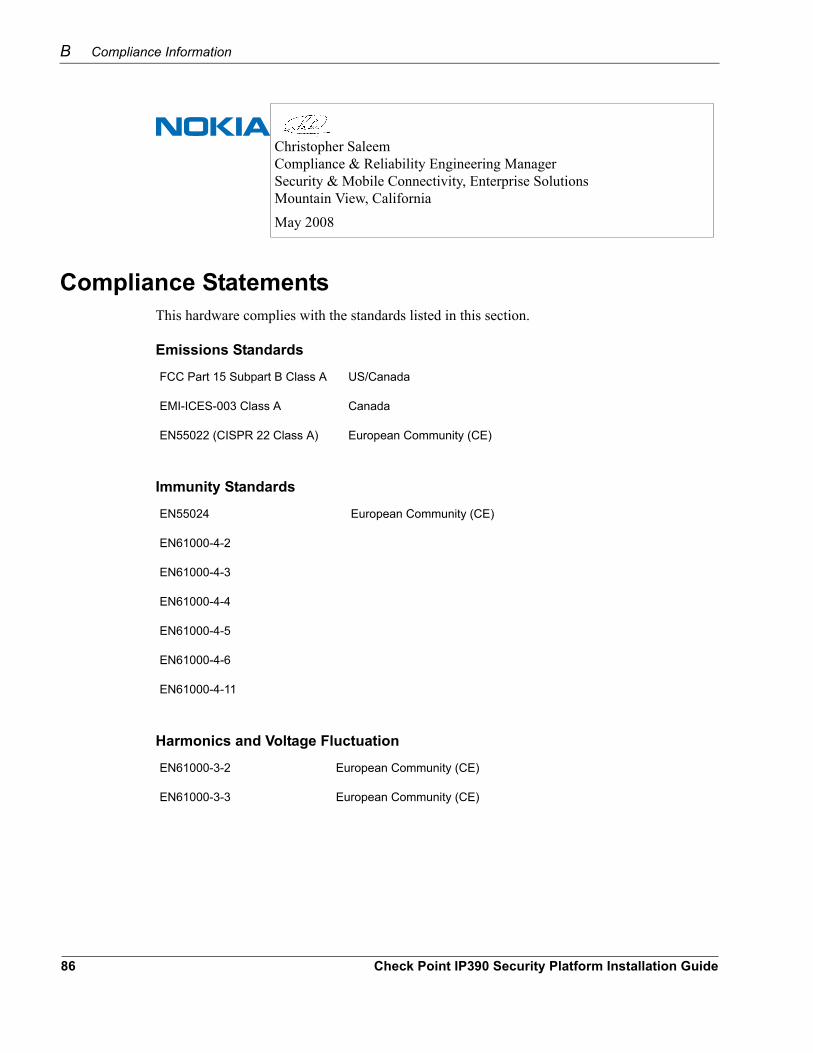
B Compliance Information
Compliance StatementsThis hardware complies with the standards listed in this section.
Emissions Standards
FCC Part 15 Subpart B Class A US/Canada
EMI-ICES-003 Class A Canada
EN55022 (CISPR 22 Class A) European Community (CE)
Immunity Standards
EN55024 European Community (CE)
EN61000-4-2
EN61000-4-3
EN61000-4-4
EN61000-4-5
EN61000-4-6
EN61000-4-11
Harmonics and Voltage Fluctuation
EN61000-3-2 European Community (CE)
EN61000-3-3 European Community (CE)
Christopher Saleem Compliance & Reliability Engineering Manager Security & Mobile Connectivity, Enterprise Solutions Mountain View, CaliforniaMay 2008
86 Check Point IP390 Security Platform Installation Guide
FCC Requirements (US)
Safety Standards
UL60950/EN60950 US/European Community(CE)
CAN/CSA-C22.2 No.60950 Canada
Telecom
T1 FCC Part 68, CS-03
FCC Requirements (US)This equipment complies with FCC rules, Part 68. On the bottom of this equipment is a label that contains, among other things, the FCC Registration Number. When you are ready to install this unit, contact your local telephone company and supply them with the following information:
Standard Jack(s) for connection to the network: RJ48Universal Service Order Code (USOC): 6.0Facility Interface Code (FIC): All are applicable; 04DU9-BN,04DU9-DN, 04DU9-1KN, 04DU9-1SNFCC registration number: 6NV-USA-46001-DE-N
Should this equipment cause harm to the telephone network, the telephone company shall, where practicable, notify the customer that temporary discontinuance of service may be required; however, where prior written notice is not practicable, the telephone company may discontinue service forthwith, if such action is reasonable in the circumstances. You will be informed of your right to file a complaint with the FCC.The telephone company may make changes in its communications facilities, equipment, and operation procedures, where such action is reasonably required in the operation of its business and is not inconsistent with the rules and regulations of the Federal Communications Commission. If they do, you will be notified in advance to give you an opportunity to maintain uninterrupted telephone service. Do not attempt to repair or modify this equipment. If defective, return it to the person from whom it was purchased who will in turn arrange to return it or to have it repaired by the manufacturer. The telephone company may ask that you disconnect this equipment from the network until the problem has been corrected or until you are sure that the equipment is not malfunctioning. If trouble is experienced, disconnect this equipment from the telephone line to determine if it is causing the malfunction. If equipment is determined to be malfunctioning, its use shall be discontinued until the problem has been corrected.
FCC Notice (US)This equipment has been tested and found to comply with the limits for a Class A digital device, pursuant to part 15 of the FCC Rules. These limits are designed to provide reasonable protection
Check Point IP390 Security Platform Installation Guide 87
B Compliance Information
against harmful interference when the equipment is operated in a commercial environment. This equipment generates, uses, and can radiate radio frequency energy and, if not installed and used in accordance with the instruction manual, may cause harmful interference to radio communications. Operation of this equipment in a residential area is likely to cause harmful interference in which case the user will be required to correct the interference at his own expense.
CautionAny changes or modifications not expressly approved by the grantee of this device could void the user’s authority to operate the equipment.
060425
88 Check Point IP390 Security Platform Installation Guide
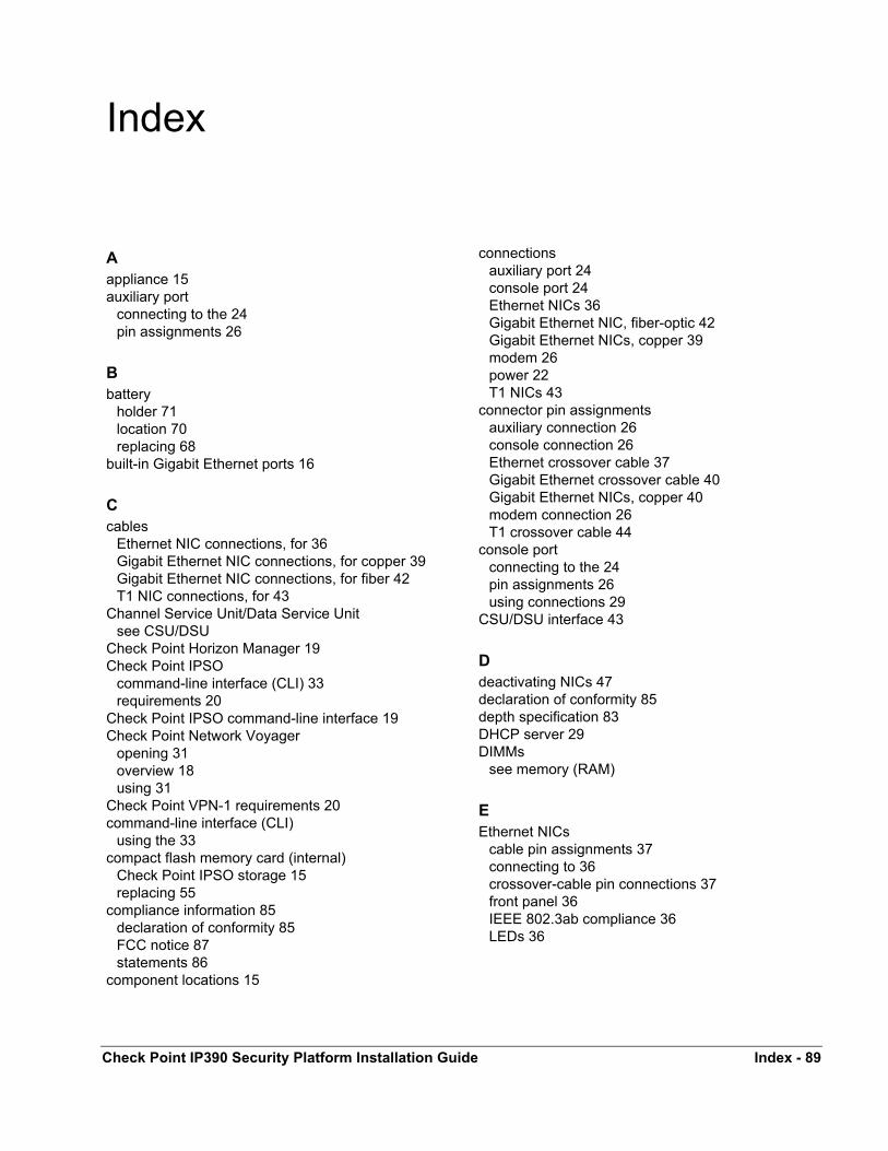
Index
Aappliance 15auxiliary port
connecting to the 24pin assignments 26
Bbattery
holder 71location 70replacing 68
built-in Gigabit Ethernet ports 16
Ccables
Ethernet NIC connections, for 36Gigabit Ethernet NIC connections, for copper 39Gigabit Ethernet NIC connections, for fiber 42T1 NIC connections, for 43
Channel Service Unit/Data Service Unitsee CSU/DSU
Check Point Horizon Manager 19Check Point IPSO
command-line interface (CLI) 33requirements 20
Check Point IPSO command-line interface 19Check Point Network Voyager
opening 31overview 18using 31
Check Point VPN-1 requirements 20command-line interface (CLI)
using the 33compact flash memory card (internal)
Check Point IPSO storage 15replacing 55
compliance information 85declaration of conformity 85FCC notice 87statements 86
component locations 15
Check Point IP390 Security Platform Installation Guid
connectionsauxiliary port 24console port 24Ethernet NICs 36Gigabit Ethernet NIC, fiber-optic 42Gigabit Ethernet NICs, copper 39modem 26power 22T1 NICs 43
connector pin assignmentsauxiliary connection 26console connection 26Ethernet crossover cable 37Gigabit Ethernet crossover cable 40Gigabit Ethernet NICs, copper 40modem connection 26T1 crossover cable 44
console portconnecting to the 24pin assignments 26using connections 29
CSU/DSU interface 43
Ddeactivating NICs 47declaration of conformity 85depth specification 83DHCP server 29DIMMs
see memory (RAM)
EEthernet NICs
cable pin assignments 37connecting to 36crossover-cable pin connections 37front panel 36IEEE 802.3ab compliance 36LEDs 36
e Index - 89
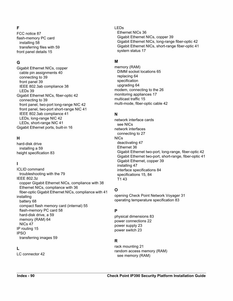
FFCC notice 87flash-memory PC card
installing 58transferring files with 59
front panel details 15
GGigabit Ethernet NICs, copper
cable pin assignments 40connecting to 39front panel 39IEEE 802.3ab compliance 38LEDs 39
Gigabit Ethernet NICs, fiber-optic 42connecting to 39front panel, two-port long-range NIC 42front panel, two-port short-range NIC 41IEEE 802.3ab compliance 41LEDs, long-range NIC 42LEDs, short-range NIC 41
Gigabit Ethernet ports, built-in 16
Hhard-disk drive
installing a 59height specification 83
IICLID command
troubleshooting with the 79IEEE 802.3z
copper Gigabit Ethernet NICs, compliance with 38Ethernet NICs, compliance with 36fiber-optic Gigabit Ethernet NICs, compliance with 41
installingbattery 68compact flash memory card (internal) 55flash-memory PC card 58hard-disk drive, a 59memory (RAM) 64NICs 47
IP routing 15IPSO
transferring images 59
LLC connector 42
LEDsEthernet NICs 36Gigabit Ethernet NICs, copper 39Gigabit Ethernet NICs, long-range fiber-optic 42Gigabit Ethernet NICs, short-range fiber-optic 41system status 17
Mmemory (RAM)
DIMM socket locations 65replacing 64specificationupgrading 64
modem, connecting to the 26monitoring appliances 17multicast traffic 15multi-mode, fiber-optic cable 42
Nnetwork interface cards
see NICsnetwork interfaces
connecting to 27NICs
deactivating 47Ethernet 36Gigabit Ethernet two-port, long-range, fiber-optic 42Gigabit Ethernet two-port, short-range, fiber-optic 41Gigabit Ethernet, copper 39installing 47interface specifications 84specifications 15, 84T1 43
Oopening Check Point Network Voyager 31operating temperature specification 83
Pphysical dimensions 83power connections 22power supply 23power switch 23
Rrack mounting 21random access memory (RAM)
see memory (RAM)
Index - 90 Check Point IP390 Security Platform Installation Guide
Sserial port 26SFP modules 42single-mode, fiber-optic cable 42space requirements 83specifications
depth 83height 83network interfaces 84operating temperature 83physical dimensions 83space requirements 83technical 83weight 83width 83
system logging with hard-disk drive 63system status LEDs 17
TT1 NICs
cable pin assignments 44connecting to 43front panel 43
tcpdumpEthernet connections, for 35Gigabit Ethernet connections, for copper 38Gigabit Ethernet connections, for fiber-optic 41
technical specifications 83transferring Check Point IPSO images 59transferring files with flash-memory PC cards 59troubleshooting 73
Vventilation requirements 19
Wweight specification 83width specification 83
Check Point IP390 Security Platform Installation Guide Index - 91

Index - 92 Check Point IP390 Security Platform Installation Guide