Embed Size (px)
Citation preview
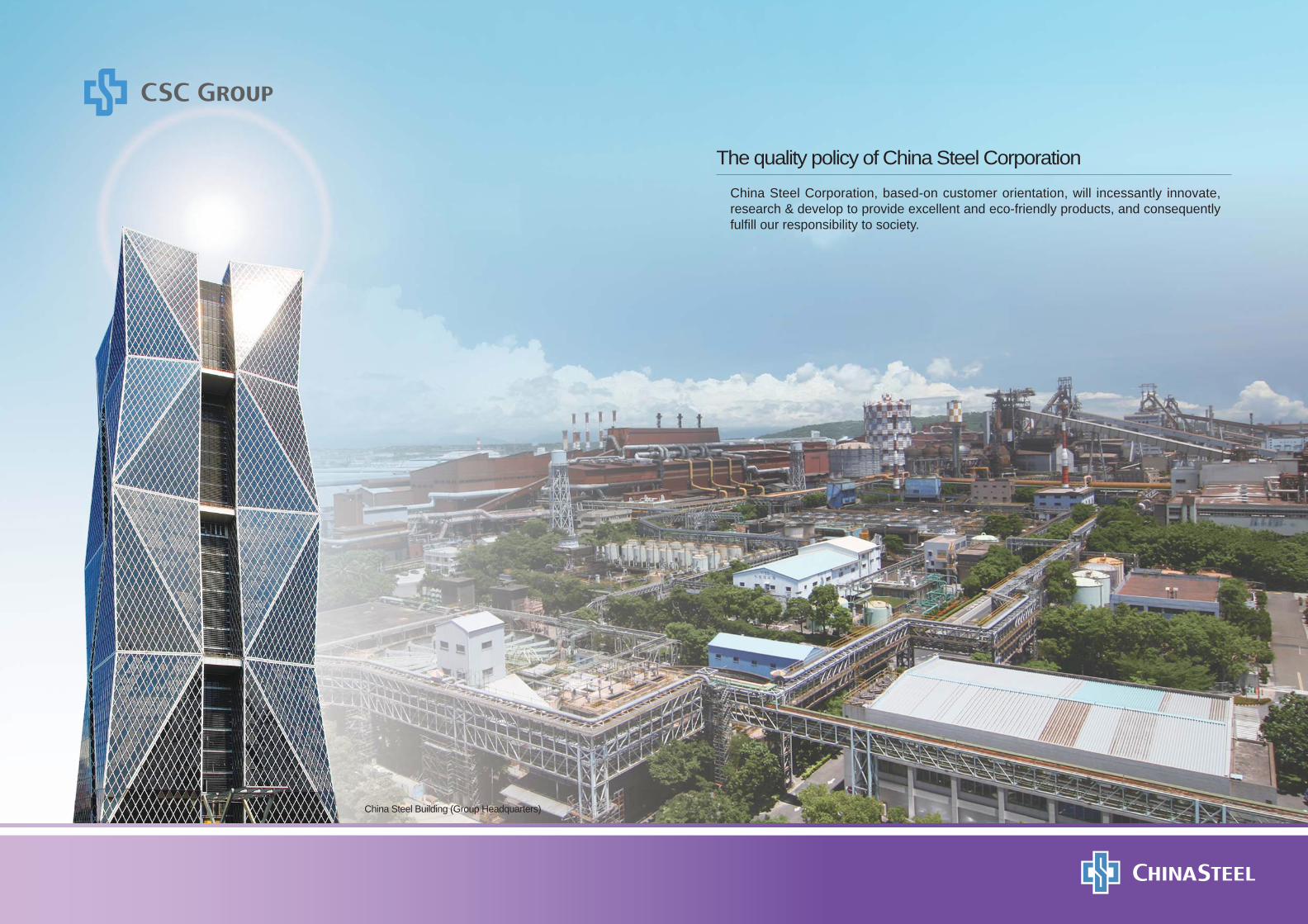
China Steel Building (Group Headquarters)
The quality policy of China Steel Corporation
China Steel Corporation, based-on customer orientation, will incessantly innovate, research & develop to provide excellent and eco-friendly products, and consequently fulfi ll our responsibility to society.
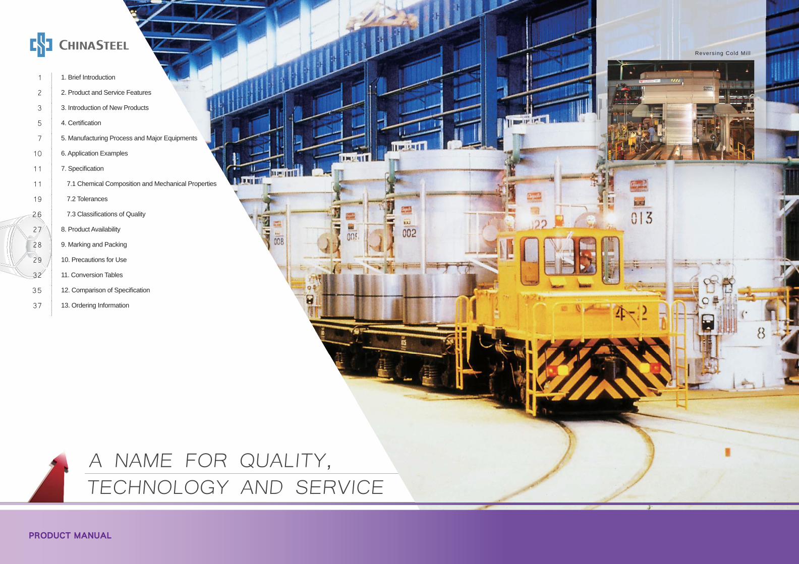
Reversing Cold Mi l l
A NAME FOR QUALITY, TECHNOLOGY AND SERVICE
PRODUCT MANUAL
1 1. Brief Introduction
2 2. Product and Service Features
3 3. Introduction of New Products
5 4. Certifi cation
7 5. Manufacturing Process and Major Equipments
10 6. Application Examples
11 7. Specifi cation
11 7.1 Chemical Composition and Mechanical Properties
19 7.2 Tolerances
26 7.3 Classifi cations of Quality
27 8. Product Availability
28 9. Marking and Packing
29 10. Precautions for Use
32 11. Conversion Tables
35 12. Comparison of Specifi cation
37 13. Ordering Information
1
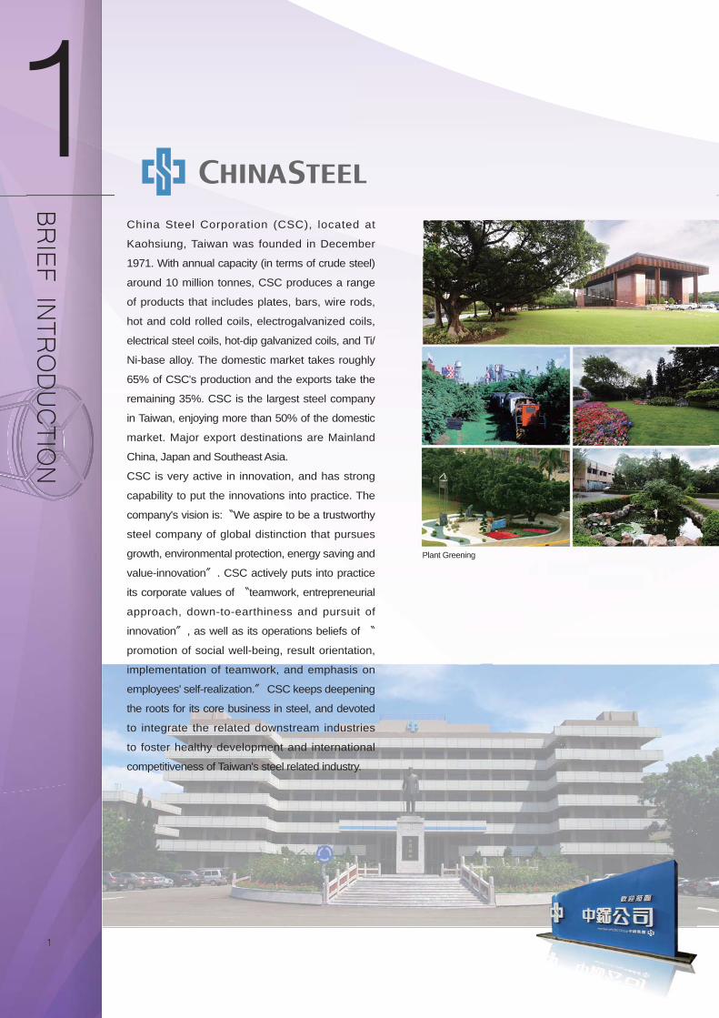
Plant Greening
BRIEF IN
TRODUCTIO
N
China Steel Corporation (CSC), located at
Kaohsiung, Taiwan was founded in December
1971. With annual capacity (in terms of crude steel)
around 10 million tonnes, CSC produces a range
of products that includes plates, bars, wire rods,
hot and cold rolled coils, electrogalvanized coils,
electrical steel coils, hot-dip galvanized coils, and Ti/
Ni-base alloy. The domestic market takes roughly
65% of CSC's production and the exports take the
remaining 35%. CSC is the largest steel company
in Taiwan, enjoying more than 50% of the domestic
market. Major export destinations are Mainland
China, Japan and Southeast Asia.
CSC is very active in innovation, and has strong
capability to put the innovations into practice. The
company's vision is:〝We aspire to be a trustworthy
steel company of global distinction that pursues
growth, environmental protection, energy saving and
value-innovation〞. CSC actively puts into practice
its corporate values of 〝teamwork, entrepreneurial
approach, down-to-earthiness and pursuit of
innovation〞, as well as its operations beliefs of 〝
promotion of social well-being, result orientation,
implementation of teamwork, and emphasis on
employees' self-realization.〞 CSC keeps deepening
the roots for its core business in steel, and devoted
to integrate the related downstream industries
to foster healthy development and international
competitiveness of Taiwan's steel related industry.
2
the regulations of RoHS (Restriction of Hazardous
Substances Directive) and REACH(Registration,
Evaluation, Authorization and Restriction of Chemical
substances), and are verified through Certification
of high-strength grades by the well-known carmakers.
The quality is good enough to meet customers' needs.
The vision of CSC's customer services is to gain
customers' appreciation and trust and help them
be successful, and the aim of that is to promote
customers' technology and upgrade the steel industry.
In order to enhance the customer services, CSC
adopts multi-step and multi-level service pattern which
is characterized by emphasizing on (1) the pre-sale
services for helping customers to choose suitable
materials and improve their production processes; (2)
handling complains and claims from customers with
proper and rapid manner, and conducting customers
the corresponding improvements to the root-causes;
(3) providing customers with the developed high-grade
materials to meet the upgrade policy for domestic
industries.
The stable and reliable quality of CSC's steel
products have gained the acceptance of domestic
industries widely, and CSC has also been selected
as the first priority provider to purchase their needed
steel materials owing to CSC's quick and efficient
technical services. CSC will continue to improve
customer services and the technical technologies both
for customers and CSC itself to promote steel-use
industries' international competitiveness.
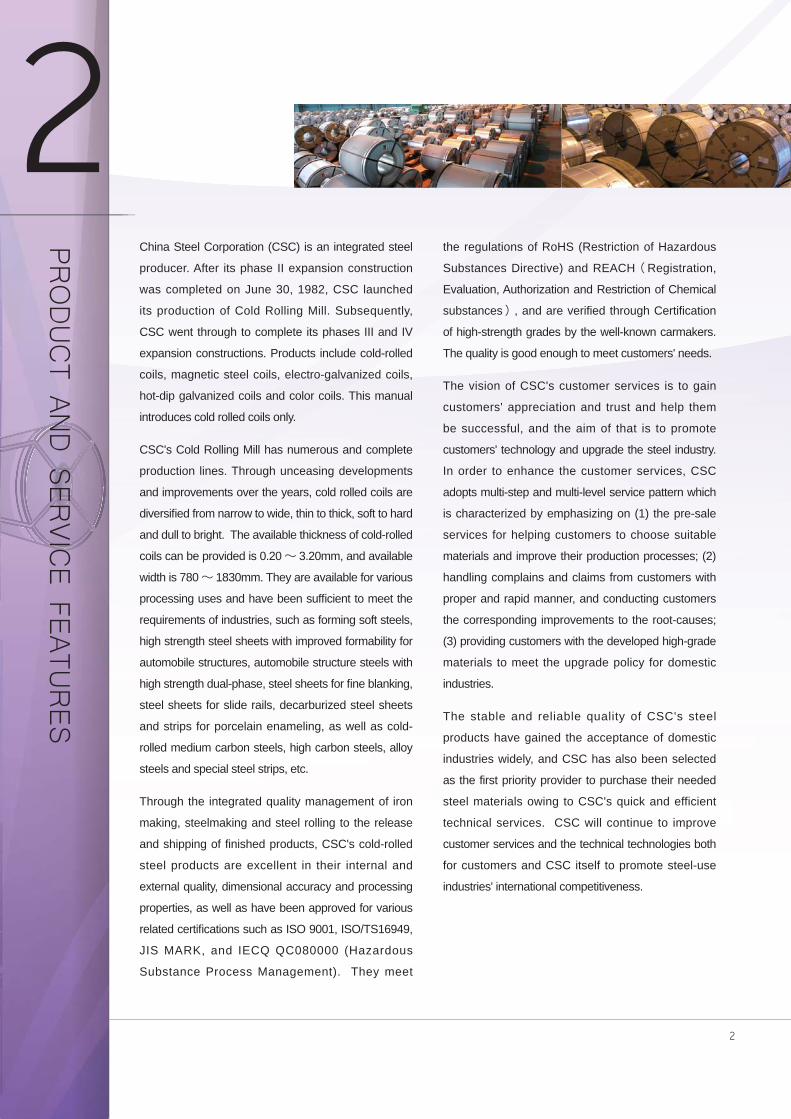
China Steel Corporation (CSC) is an integrated steel
producer. After its phase II expansion construction
was completed on June 30, 1982, CSC launched
its production of Cold Rolling Mill. Subsequently,
CSC went through to complete its phases III and IV
expansion constructions. Products include cold-rolled
coils, magnetic steel coils, electro-galvanized coils,
hot-dip galvanized coils and color coils. This manual
introduces cold rolled coils only.
CSC's Cold Rolling Mill has numerous and complete
production lines. Through unceasing developments
and improvements over the years, cold rolled coils are
diversifi ed from narrow to wide, thin to thick, soft to hard
and dull to bright. The available thickness of cold-rolled
coils can be provided is 0.20∼ 3.20mm, and available
width is 780∼ 1830mm. They are available for various
processing uses and have been suffi cient to meet the
requirements of industries, such as forming soft steels,
high strength steel sheets with improved formability for
automobile structures, automobile structure steels with
high strength dual-phase, steel sheets for fi ne blanking,
steel sheets for slide rails, decarburized steel sheets
and strips for porcelain enameling, as well as cold-
rolled medium carbon steels, high carbon steels, alloy
steels and special steel strips, etc.
Through the integrated quality management of iron
making, steelmaking and steel rolling to the release
and shipping of finished products, CSC's cold-rolled
steel products are excellent in their internal and
external quality, dimensional accuracy and processing
properties, as well as have been approved for various
related certifi cations such as ISO 9001, ISO/TS16949,
JIS MARK, and IECQ QC080000 (Hazardous
Substance Process Management). They meet
PRODUCT AN
D SER
VICE FEATU
RES
3
JFS JSC980Y Ultra-high strength structural steelfor automobile The tensile strength of this grade could reach 980 MPa above by formation of dual phase structure
which combines the ductile ferrite and high strength martensite. By characteristics with high strength
and superior ductility, this is an important material for light-weighted energy saving automobile design
including application for safety structural parts, bumper, seat skid parts,etc.
EN HC420LA High strength low alloy (HSLA) structural steel The yield strength of this grade could reach 420 MPa above in adoption of HSLA type steel structure
which shows the high yield ratio, fi ne work formation and weldability. This is also an important material for
light-weighted energy saving automobile design.
JFS JSC340H High strength baked-hardening (BH) steel The tensile strength of this grade could reach 340 MPa above which processes the character of fi ne
stamping formation and baked hardening. The material could be served as light-weighted energy saving
automobile part such as outer panel or body construction which is strengthened after coating baked
treatment.
INTR
ODUCTIO
N O
F NEW
PRODUCTS
4
SAE 1552SAE1552 belongs to high manganese carbon steel with excellent cleanness and high strength after suitable
heat treatment. The characteristics of this product fit in with requirements of manufacturing timing chain of
automobile engine.
JIS G3311 SKS51MSKS51M belongs to alloy tool steel with high hardness, high strength, great fl atness and suitable for application
of saw blade.
CSC CC8660CSC CC8860 belongs to nickle chrome molybdenum steel with excellent anti-abrasion, anti-impact, anti-
deformation and can be applied to chain saw for lumbering.
JIS G3125 SPA-CJIS G3125 SPA-C is superior atmospheric corrosion resisting cold rolled steel and can be used in environment
containing sulfuric waste gas.
5
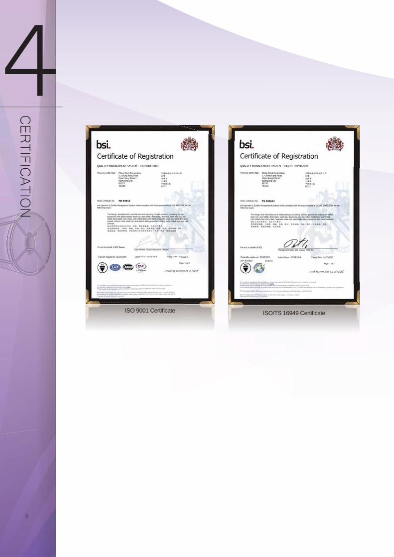
ISO 9001 Certifi cate ISO/TS 16949 Certifi cate
CER
TIFICATIO
N
6
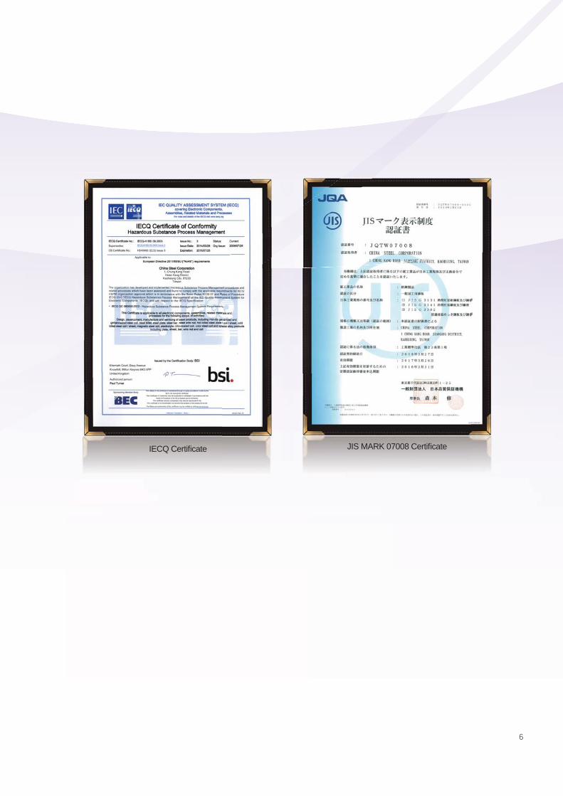
IECQ Certifi cate JIS MARK 07008 Certifi cate
7 87 8
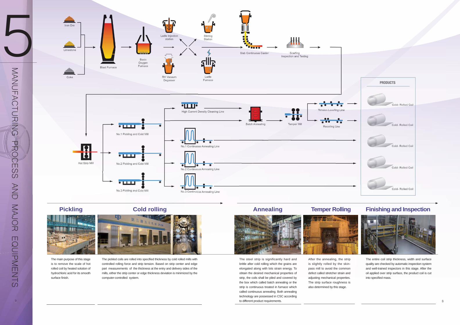
The main purpose of this stage is to remove the scale of hot rolled coil by heated solution of hydrochloric acid for its smooth surface fi nish.
The pickled coils are rolled into specifi ed thickness by cold rolled mills with controlled rolling force and strip tension. Based on strip center and edge part measurements of the thickness at the entry and delivery sides of the mills, either the strip center or edge thickness deviation is minimized by the computer-controlled system.
The steel strip is significantly hard and brittle after cold rolling which the grains are elongated along with lots strain energy. To obtain the desired mechanical properties of strip, the coils shall be piled and covered by the box which called batch annealing or the strip is continuous treated in furnace which called continuous annealing. Both annealing technology are possessed in CSC according to different product requirements.
After the annealing, the strip is slightly rolled by the skin-pass mill to avoid the common defect called stretcher strain and adjusting mechanical properties. The strip surface roughness is also determined by this stage.
The entire coil strip thickness, width and surface quality are checked by automatic inspection system and well-trained inspectors in this stage. After the oil applied over strip surface, the product coil is cut into specifi ed mass.
Pickling Cold rolling Annealing Temper Rolling Finishing and Inspection
MAN
UFAC
TURING PR
OCESS AN
D M
AJOR EQ
UIPM
ENTS
9
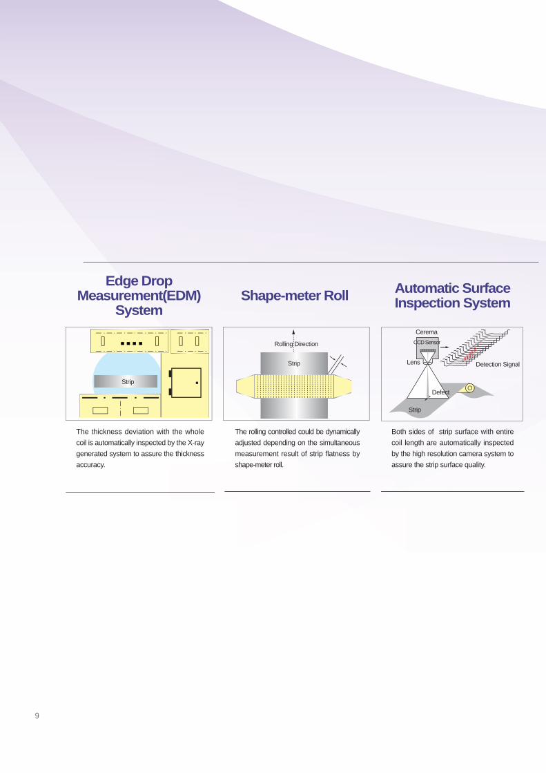
The thickness deviation with the whole coil is automatically inspected by the X-ray generated system to assure the thickness accuracy.
The rolling controlled could be dynamically adjusted depending on the simultaneous measurement result of strip flatness by shape-meter roll.
Both sides of strip surface with entire coil length are automatically inspected by the high resolution camera system to assure the strip surface quality.
Edge Drop Measurement(EDM)
SystemShape-meter Roll Automatic Surface
Inspection System
Strip
Rolling Direction
Detection SignalLens
Defect
CCD Sensor
Cerema
Strip
Strip
10
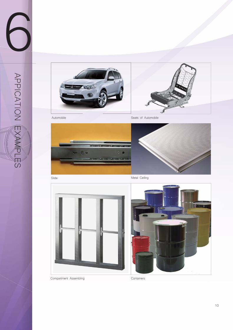
Automobile Seats of Automobile
Containers
Metal Ceiling
Compartment Assembling
Slide
APPICATIO
N EXAM
PLES
11
SPECIFIC
ATION
The contents of this catalog are for reference only. Custom
ers are urged to consult the specifi cations published by the corresponding associations. Inform
ations of the available CSC
steel grades, as shown herein m
ay be updated w
ithout notice to comply w
ith actual production situations.
7.1 Chemical Compositions and Mechanical Properties
7.1.1 Carbon Steel Sheet for of Forming Fabrication
Notes:1. Alloying elements other than those in the above table can be added as necessary.2. For SPCC that guarantees tensile strength and elongation.
Remarks:1. For those less than 0.60 mm in thickness, as a rule, the tension test shall be omitted.2. SPCF and SPCG shall be guarantees for non-ageing property for six months after shipment from the manufacturer's factory.3. The upper limit of yield point or proof stress in parenthesis is informative and can be applied when agreed upon between the
purchaser and the supplier.
(1) JIS G3141-2011 SPCC/SPCD/SPCE/SPCF/SPCG(-SD, Standard temper)
Specification JIS G3141
Symbol of Grade SPCC SPCCT(NOTE 2) SPCD SPCE SPCF SPCG
ChemicalComposition
%
C max. 0.15 0.10 0.08 0.06 0.02
Mn max. 0.60 0.50 0.45 0.45 0.25
P max. 0.100 0.040 0.030 0.030 0.020
S max. 0.035 0.035 0.030 0.030 0.020
Si max. - ─ ─ ─ ─
Tension Test
No.5 test piece
rolling direction
Thickness(t)mm
Tensile StrengthN/mm2 min. 0.25 ≦ t ─ 270 270 270 270 270
Yield PointN/mm2 max. 0.25 ≦ t ─ ─ (240) (220) (210) (190)
Elongation % min.
0.25 ≦ t< 0.30 ─ 28 30 32 ─ ─
0.30 ≦ t< 0.40 ─ 31 33 35 ─ ─
0.40 ≦ t< 0.60 ─ 34 36 38 40 42
0.60 ≦ t< 1.00 ─ 36 38 40 42 44
1.00 ≦ t< 1.60 ─ 37 39 41 43 45
1.60 ≦ t< 2.50 ─ 38 40 42 44 46
2.50 ≦ t ─ 39 41 43 45 ─
The average ratio of plastic strain
0.50 ≦ t≦ 1.00 ─ ─ ─ ─ ─ 1.5min.
1.00 <t≦ 1.60 ─ ─ ─ ─ ─ 1.4min.
Bend TestNo.3
test piece rolling direction
Bend Angle ( 180o )
Inside Clearance Flat on Itself
r
12
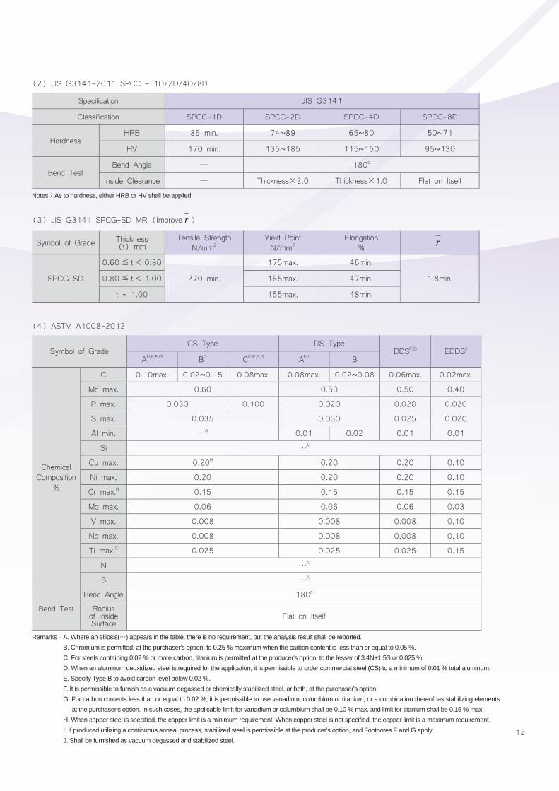
Notes:As to hardness, either HRB or HV shall be applied.
Remarks:A. Where an ellipsis(⋯) appears in the table, there is no requirement, but the analysis result shall be reported. B. Chromium is permitted, at the purchaser's option, to 0.25 % maximum when the carbon content is less than or equal to 0.05 %. C. For steels containing 0.02 % or more carbon, titanium is permitted at the producer's option, to the lesser of 3.4N+1.5S or 0.025 %.D. When an aluminum deoxidized steel is required for the application, it is permissible to order commercial steel (CS) to a minimum of 0.01 % total aluminum. E. Specify Type B to avoid carbon level below 0.02 %.F. It is permissible to furnish as a vacuum degassed or chemically stabilized steel, or both, at the purchaser's option.G. For carbon contents less than or equal to 0.02 %, it is permissible to use vanadium, columbium or titanium, or a combination thereof, as stabilizing elements
at the purchaser's option. In such cases, the applicable limit for vanadium or columbium shall be 0.10 % max. and limit for titanium shall be 0.15 % max. H. When copper steel is specifi ed, the copper limit is a minimum requirement. When copper steel is not specifi ed, the copper limit is a maximum requirement.I. If produced utilizing a continuous anneal process, stabilized steel is permissible at the producer's option, and Footnotes F and G apply.J. Shall be furnished as vacuum degassed and stabilized steel.
(2) JIS G3141-2011 SPCC - 1D/2D/4D/8D
(4) ASTM A1008-2012
Specification JIS G3141
Classification SPCC-1D SPCC-2D SPCC-4D SPCC-8D
HardnessHRB 85 min. 74~89 65~80 50~71
HV 170 min. 135~185 115~150 95~130
Bend TestBend Angle ─ 180o
Inside Clearance ─ Thickness×2.0 Thickness×1.0 Flat on Itself
Symbol of GradeCS Type DS Type
DDSF,G EDDSJ
AD,E,F,G BD CD,E,F,G AE,I B
ChemicalComposition
%
C 0.10max. 0.02~0.15 0.08max. 0.08max. 0.02~0.08 0.06max. 0.02max.
Mn max. 0.60 0.50 0.50 0.40
P max. 0.030 0.100 0.020 0.020 0.020
S max. 0.035 0.030 0.025 0.020
Al min. ⋯A 0.01 0.02 0.01 0.01
Si ⋯A
Cu max. 0.20H 0.20 0.20 0.10
Ni max. 0.20 0.20 0.20 0.10
Cr max.B 0.15 0.15 0.15 0.15
Mo max. 0.06 0.06 0.06 0.03
V max. 0.008 0.008 0.008 0.10
Nb max. 0.008 0.008 0.008 0.10
Ti max.C 0.025 0.025 0.025 0.15
N ⋯A
B ⋯A
Bend Test
Bend Angle 180o
Radius of Inside Surface
Flat on Itself
Symbol of Grade Thickness (t) mm
Tensile StrengthN/mm2
Yield PointN/mm2
Elongation%
SPCG-SD
0.60≦ t< 0.80
270 min.
175max. 46min.
1.8min.0.80≦ t< 1.00 165max. 47min.
t = 1.00 155max. 48min.
r
(3) JIS G3141 SPCG-SD MR (Improve )r
13
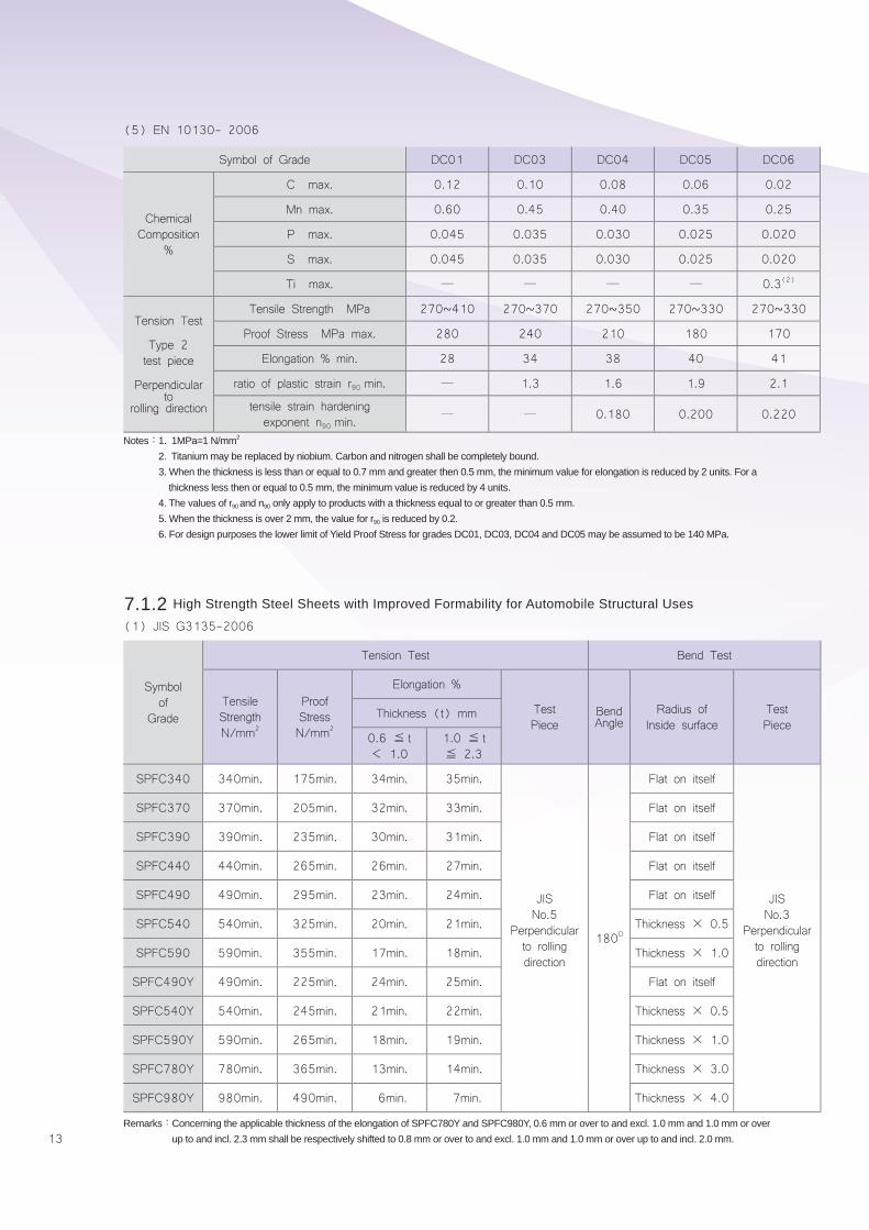
(5) EN 10130- 2006
Symbol of Grade DC01 DC03 DC04 DC05 DC06
ChemicalComposition
%
C max. 0.12 0.10 0.08 0.06 0.02
Mn max. 0.60 0.45 0.40 0.35 0.25
P max. 0.045 0.035 0.030 0.025 0.020
S max. 0.045 0.035 0.030 0.025 0.020
Ti max. ─ ─ ─ ─ 0.3(2)
Tension Test
Type 2 test piece
Perpendicular to
rolling direction
Tensile Strength MPa 270~410 270~370 270~350 270~330 270~330
Proof Stress MPa max. 280 240 210 180 170
Elongation % min. 28 34 38 40 41
ratio of plastic strain r90 min. ─ 1.3 1.6 1.9 2.1
tensile strain hardening exponent n90 min.
─ ─ 0.180 0.200 0.220
Notes:1. 1MPa=1 N/mm2
2. Titanium may be replaced by niobium. Carbon and nitrogen shall be completely bound.3. When the thickness is less than or equal to 0.7 mm and greater then 0.5 mm, the minimum value for elongation is reduced by 2 units. For a
thickness less then or equal to 0.5 mm, the minimum value is reduced by 4 units.4. The values of r90 and n90 only apply to products with a thickness equal to or greater than 0.5 mm.5. When the thickness is over 2 mm, the value for r90 is reduced by 0.2.6. For design purposes the lower limit of Yield Proof Stress for grades DC01, DC03, DC04 and DC05 may be assumed to be 140 MPa.
Remarks:Concerning the applicable thickness of the elongation of SPFC780Y and SPFC980Y, 0.6 mm or over to and excl. 1.0 mm and 1.0 mm or over up to and incl. 2.3 mm shall be respectively shifted to 0.8 mm or over to and excl. 1.0 mm and 1.0 mm or over up to and incl. 2.0 mm.
7.1.2 High Strength Steel Sheets with Improved Formability for Automobile Structural Uses
(1) JIS G3135-2006
Symbol of
Grade
Tension Test Bend Test
TensileStrengthN/mm2
ProofStressN/mm2
Elongation %
Test Piece
Bend Angle
Radius ofInside surface
TestPiece
Thickness (t) mm
0.6 ≦ t< 1.0
1.0 ≦ t≦ 2.3
SPFC340 340min. 175min. 34min. 35min.
JIS No.5
Perpendicular to rolling direction
180O
Flat on itself
JIS No.3
Perpendicular to rolling direction
SPFC370 370min. 205min. 32min. 33min. Flat on itself
SPFC390 390min. 235min. 30min. 31min. Flat on itself
SPFC440 440min. 265min. 26min. 27min. Flat on itself
SPFC490 490min. 295min. 23min. 24min. Flat on itself
SPFC540 540min. 325min. 20min. 21min. Thickness × 0.5
SPFC590 590min. 355min. 17min. 18min. Thickness × 1.0
SPFC490Y 490min. 225min. 24min. 25min. Flat on itself
SPFC540Y 540min. 245min. 21min. 22min. Thickness × 0.5
SPFC590Y 590min. 265min. 18min. 19min. Thickness × 1.0
SPFC780Y 780min. 365min. 13min. 14min. Thickness × 3.0
SPFC980Y 980min. 490min. 6min. 7min. Thickness × 4.0
14
SP
EC
IFICATIO
N
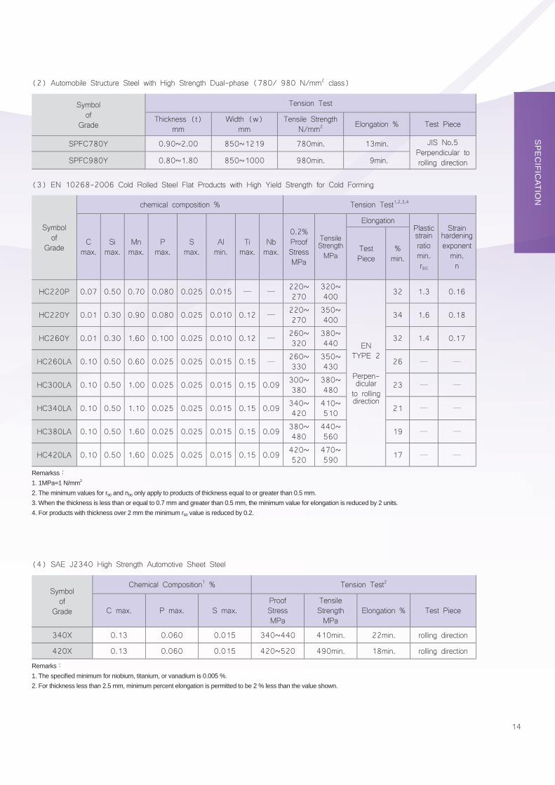
(2) Automobile Structure Steel with High Strength Dual-phase (780/ 980 N/mm2 class)
(3) EN 10268-2006 Cold Rolled Steel Flat Products with High Yield Strength for Cold Forming
Symbol of
Grade
Tension Test
Thickness (t)mm
Width (w)mm
Tensile StrengthN/mm2 Elongation % Test Piece
SPFC780Y 0.90~2.00 850~1219 780min. 13min. JIS No.5Perpendicular to rolling directionSPFC980Y 0.80~1.80 850~1000 980min. 9min.
Symbol of
Grade
chemical composition % Tension Test1,2,3,4
Cmax.
Simax.
Mnmax.
Pmax.
Smax.
Almin.
Timax.
Nbmax.
0.2% ProofStressMPa
Tensile StrengthMPa
ElongationPlastic strain ratiomin.r90
Strain hardening exponentmin.n
TestPiece
%min.
HC220P 0.07 0.50 0.70 0.080 0.025 0.015 ─ ─220~270
320~400
ENTYPE 2
Perpen- dicularto rolling direction
32 1.3 0.16
HC220Y 0.01 0.30 0.90 0.080 0.025 0.010 0.12 ─220~270
350~400 34 1.6 0.18
HC260Y 0.01 0.30 1.60 0.100 0.025 0.010 0.12 ─260~320
380~440 32 1.4 0.17
HC260LA 0.10 0.50 0.60 0.025 0.025 0.015 0.15 ─260~330
350~430 26 ─ ─
HC300LA 0.10 0.50 1.00 0.025 0.025 0.015 0.15 0.09 300~380
380~480 23 ─ ─
HC340LA 0.10 0.50 1.10 0.025 0.025 0.015 0.15 0.09 340~420
410~510 21 ─ ─
HC380LA 0.10 0.50 1.60 0.025 0.025 0.015 0.15 0.09 380~480
440~560 19 ─ ─
HC420LA 0.10 0.50 1.60 0.025 0.025 0.015 0.15 0.09 420~520
470~590 17 ─ ─
Remarkss:1. 1MPa=1 N/mm2
2. The minimum values for r90 and n90 only apply to products of thickness equal to or greater than 0.5 mm.3. When the thickness is less than or equal to 0.7 mm and greater than 0.5 mm, the minimum value for elongation is reduced by 2 units.4. For products with thickness over 2 mm the minimum r90 value is reduced by 0.2.
(4) SAE J2340 High Strength Automotive Sheet Steel
Symbol of
Grade
Chemical Composition1 % Tension Test2
C max. P max. S max.ProofStressMPa
TensileStrengthMPa
Elongation % Test Piece
340X 0.13 0.060 0.015 340~440 410min. 22min. rolling direction
420X 0.13 0.060 0.015 420~520 490min. 18min. rolling direction
Remarks:1. The specifi ed minimum for niobium, titanium, or vanadium is 0.005 %.2. For thickness less than 2.5 mm, minimum percent elongation is permitted to be 2 % less than the value shown.
15
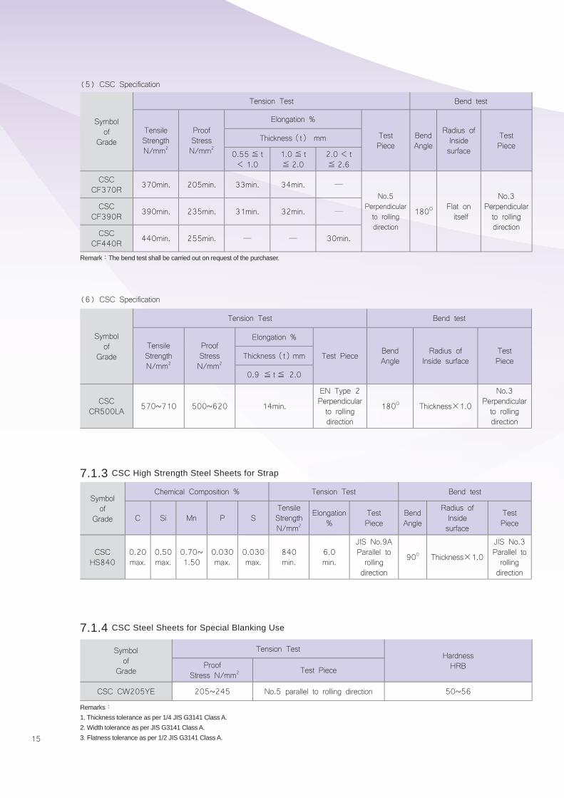
Remark:The bend test shall be carried out on request of the purchaser.
Remarks:1. Thickness tolerance as per 1/4 JIS G3141 Class A.2. Width tolerance as per JIS G3141 Class A.3. Flatness tolerance as per 1/2 JIS G3141 Class A.
(5) CSC Specification
(6) CSC Specification
Symbol of
Grade
Tension Test Bend test
TensileStrengthN/mm2
ProofStressN/mm2
Elongation %
Test Piece
BendAngle
Radius ofInsidesurface
Test Piece
Thickness(t) mm
0.55≦ t< 1.0
1.0≦ t≦ 2.0
2.0< t≦ 2.6
CSCCF370R 370min. 205min. 33min. 34min. ─
No.5Perpendicularto rollingdirection
180O Flat on itself
No.3Perpendicular to rolling direction
CSCCF390R 390min. 235min. 31min. 32min. ─
CSCCF440R 440min. 255min. ─ ─ 30min.
Symbol of
Grade
Tension Test Bend test
TensileStrengthN/mm2
ProofStressN/mm2
Elongation %
Test Piece BendAngle
Radius ofInside surface
TestPieceThickness(t)mm
0.9 ≦ t≦ 2.0
CSCCR500LA 570~710 500~620 14min.
EN Type 2 Perpendicular to rolling direction
180O Thickness×1.0
No.3Perpendicular to rolling direction
7.1.3 CSC High Strength Steel Sheets for Strap
7.1.4 CSC Steel Sheets for Special Blanking Use
Symbol of
Grade
Chemical Composition % Tension Test Bend test
C Si Mn P STensileStrengthN/mm2
Elongation%
TestPiece
BendAngle
Radius ofInside surface
TestPiece
CSCHS840
0.20max.
0.50max.
0.70~1.50
0.030max.
0.030max.
840min.
6.0min.
JIS No.9AParallel torolling direction
90 0 Thickness×1.0
JIS No.3Parallel to rolling direction
Symbol of
Grade
Tension TestHardnessHRBProof
Stress N/mm2 Test Piece
CSC CW205YE 205~245 No.5 parallel to rolling direction 50~56
16
SP
EC
IFICATIO
N
Remarkss:1. Thickness tolerance as per 1/4 JIS G3141 Class A.2. Width tolerance as per JIS G3141 Class A.3. Flatness tolerance as per 1/2 JIS G3141 Class A.
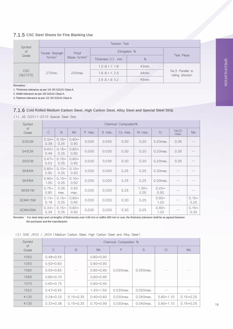
Remarks: For steel strips and cut-lengths of thicknesses over 4.00 mm or widths 600 mm or over, the thickness tolerance shall be as agreed between the purchaser and the manufacturer.
(1) JIS G3311-2010 Special Steel Strip
(2) SAE J403 / J404(Medium Carbon Steel, High Carbon Steel and Alloy Steel)
Symbol of
Grade
Tension Test
Tensile StrengthN/mm2
Proof Stress N/mm2
Elongation % Test Piece
Thickness(t) mm %
CSCCB270TE 270min. 200max.
1.0≦ t< 1.6 43min.No.5 Parallel to rolling direction1.6≦ t< 2.5 44min.
2.5≦ t≦ 3.2 45min.
7.1.5 CSC Steel Sheets for Fine Blanking Use
7.1.6 Cold Rolled Medium Carbon Steel, High Carbon Steel, Alloy Steel and Special Steel Strip
Symbol of
Grade
Chemical Composition%
C Si Mn P max. S max. Cu max. Ni max. Cr Ni+Cr max. Mo
S35CM 0.32~0.38
0.15~0.35
0.60~0.90 0.030 0.035 0.30 0.20 0.20max. 0.35 ─
S45CM 0.42~0.48
0.15~0.35
0.60~0.90 0.030 0.035 0.30 0.20 0.20max. 0.35 ─
S50CM 0.47~0.53
0.15~0.35
0.60~0.90 0.030 0.035 0.30 0.20 0.20max. 0.35 ─
SK85M 0.80~0.90
0.10~0.35
0.10~0.50 0.030 0.030 0.25 0.25 0.30max. ─ ─
SK95M 0.90~1.00
0.10~0.35
0.10~0.50 0.030 0.030 0.25 0.25 0.30max. ─ ─
SKS51M 0.75~0.85
0.35max.
0.50max. 0.030 0.030 0.25 1.30~
2.000.20~0.50 ─ ─
SCM415M 0.13~0.18
0.15~0.35
0.60~0.90 0.030 0.030 0.30 0.25 0.90~
1.20 ─0.15~0.25
SCM435M 0.33~0.38
0.15~0.35
0.60~0.90 0.030 0.030 0.30 0.25 0.90~
1.20 ─0.15~0.30
Symbol of
Grade
Chemical Composition %
C Si Mn P S Cr Mo
1050 0.48~0.55
─
0.60~0.90
0.030max. 0.050max. ─ ─
1055 0.50~0.60 0.60~0.90
1060 0.55~0.65 0.60~0.90
1065 0.60~0.70 0.60~0.90
1070 0.65~0.75 0.60~0.90
1552 0.47~0.55 ─ 1.20~1.50 0.030max. 0.050max. ─ ─
4130 0.28~0.33 0.15~0.35 0.40~0.60 0.030max. 0.040max. 0.80~1.10 0.15~0.25
4135 0.33~0.38 0.15~0.35 0.70~0.90 0.030max. 0.040max. 0.80~1.10 0.15~0.25
17
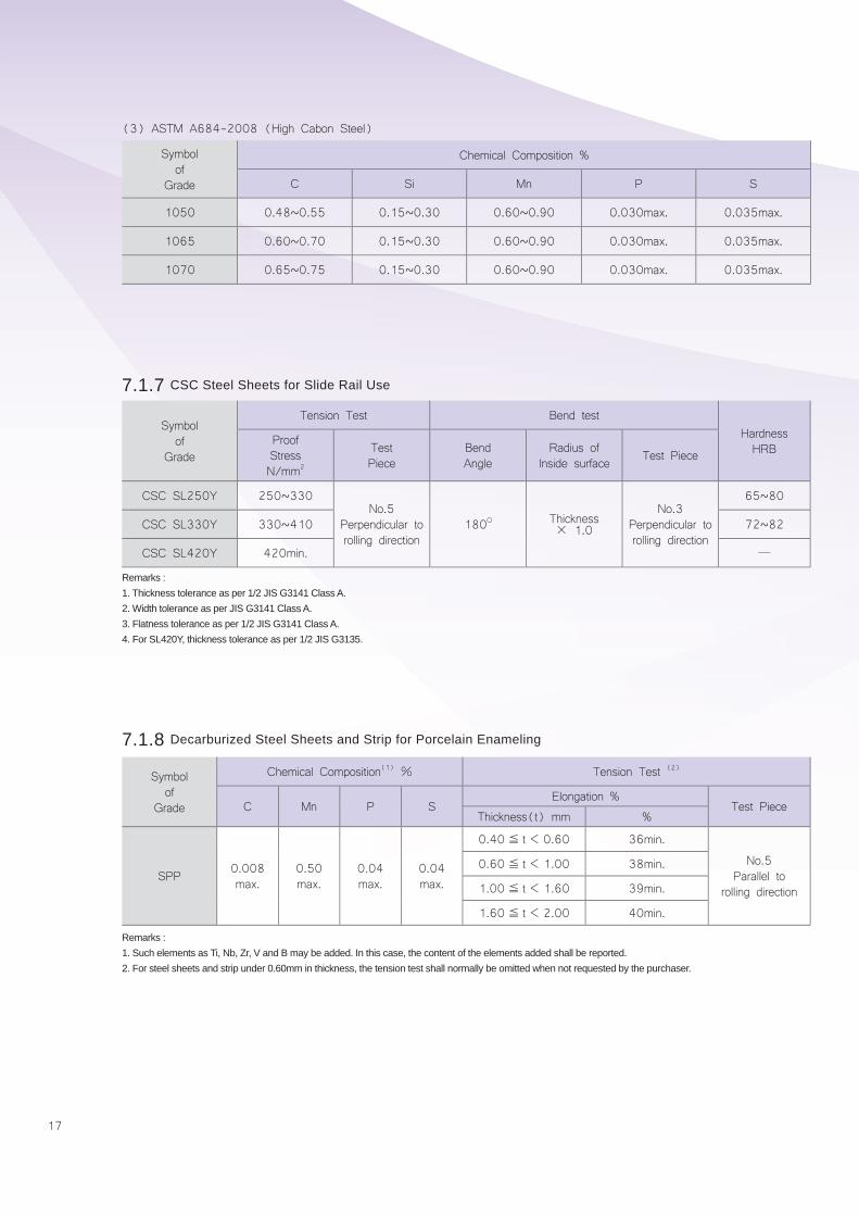
(3) ASTM A684-2008 (High Cabon Steel)
Symbol of
Grade
Chemical Composition %
C Si Mn P S
1050 0.48~0.55 0.15~0.30 0.60~0.90 0.030max. 0.035max.
1065 0.60~0.70 0.15~0.30 0.60~0.90 0.030max. 0.035max.
1070 0.65~0.75 0.15~0.30 0.60~0.90 0.030max. 0.035max.
Symbol of
Grade
Tension Test Bend testHardnessHRB
ProofStressN/mm2
Test Piece
BendAngle
Radius ofInside surface Test Piece
CSC SL250Y 250~330No.5
Perpendicular to rolling direction
180O Thickness × 1.0
No.3Perpendicular torolling direction
65~80
CSC SL330Y 330~410 72~82
CSC SL420Y 420min. ─
7.1.7 CSC Steel Sheets for Slide Rail Use
7.1.8 Decarburized Steel Sheets and Strip for Porcelain Enameling
Remarks :1. Thickness tolerance as per 1/2 JIS G3141 Class A.2. Width tolerance as per JIS G3141 Class A.3. Flatness tolerance as per 1/2 JIS G3141 Class A.4. For SL420Y, thickness tolerance as per 1/2 JIS G3135.
Remarks :1. Such elements as Ti, Nb, Zr, V and B may be added. In this case, the content of the elements added shall be reported.2. For steel sheets and strip under 0.60mm in thickness, the tension test shall normally be omitted when not requested by the purchaser.
Symbol of
Grade
Chemical Composition(1) % Tension Test (2)
C Mn P SElongation %
Test PieceThickness(t) mm %
SPP 0.008max.
0.50max.
0.04max.
0.04max.
0.40≦ t< 0.60 36min.
No.5 Parallel to
rolling direction
0.60≦ t< 1.00 38min.
1.00≦ t< 1.60 39min.
1.60≦ t< 2.00 40min.
18
SP
EC
IFICATIO
N
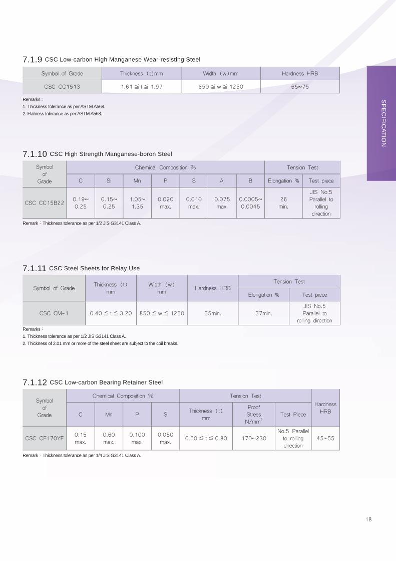
7.1.9 CSC Low-carbon High Manganese Wear-resisting Steel
7.1.10 CSC High Strength Manganese-boron Steel
7.1.11 CSC Steel Sheets for Relay Use
7.1.12 CSC Low-carbon Bearing Retainer Steel
Remarks :1. Thickness tolerance as per ASTM A568.2. Flatness tolerance as per ASTM A568.
Remark:Thickness tolerance as per 1/2 JIS G3141 Class A.
Remarks:1. Thickness tolerance as per 1/2 JIS G3141 Class A.2. Thickness of 2.01 mm or more of the steel sheet are subject to the coil breaks.
Remark:Thickness tolerance as per 1/4 JIS G3141 Class A.
Symbol of
Grade
Chemical Composition % Tension TestHardness HRBC Mn P S Thickness (t)
mm
Proof Stress N/mm2
Test Piece
CSC CF170YF 0.15max.
0.60max.
0.100max.
0.050max. 0.50≦ t≦ 0.80 170~230
No.5 Parallel to rolling direction
45~55
Symbol of Grade Thickness (t)mm Width (w)mm Hardness HRB
CSC CC1513 1.61≦ t≦ 1.97 850≦ w≦ 1250 65~75
Symbol of
Grade
Chemical Composition % Tension Test
C Si Mn P S Al B Elongation % Test piece
CSC CC15B22 0.19~0.25
0.15~0.25
1.05~1.35
0.020max.
0.010max.
0.075max.
0.0005~0.0045
26min.
JIS No.5Parallel to rolling direction
Symbol of Grade Thickness (t)mm
Width (w)mm Hardness HRB
Tension Test
Elongation % Test piece
CSC CM-1 0.40≦ t≦ 3.20 850≦ w≦ 1250 35min. 37min.JIS No.5Parallel to
rolling direction
19
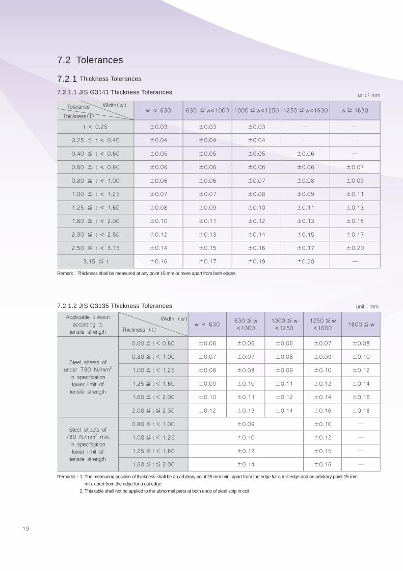
7.2 Tolerances
7.2.1 Thickness Tolerances
7.2.1.1 JIS G3141 Thickness Tolerances
7.2.1.2 JIS G3135 Thickness Tolerances
unit:mm
unit:mm
w < 630 630 ≦ w<1000 1000≦w<1250 1250≦w<1630 w≧ 1630
t < 0.25 ±0.03 ±0.03 ±0.03 ─ ─
0.25 ≦ t < 0.40 ±0.04 ±0.04 ±0.04 ─ ─
0.40 ≦ t < 0.60 ±0.05 ±0.05 ±0.05 ±0.06 ─
0.60 ≦ t < 0.80 ±0.06 ±0.06 ±0.06 ±0.06 ±0.07
0.80 ≦ t < 1.00 ±0.06 ±0.06 ±0.07 ±0.08 ±0.09
1.00 ≦ t < 1.25 ±0.07 ±0.07 ±0.08 ±0.09 ±0.11
1.25 ≦ t < 1.60 ±0.08 ±0.09 ±0.10 ±0.11 ±0.13
1.60 ≦ t < 2.00 ±0.10 ±0.11 ±0.12 ±0.13 ±0.15
2.00 ≦ t < 2.50 ±0.12 ±0.13 ±0.14 ±0.15 ±0.17
2.50 ≦ t < 3.15 ±0.14 ±0.15 ±0.16 ±0.17 ±0.20
3.15 ≦ t ±0.16 ±0.17 ±0.19 ±0.20 ─
Thickness(t)Tolerance Width(w)
Applicable divisionaccording to
tensile strengthw < 630 630≦ w
<10001000≦ w<1250
1250≦ w<1600 1600≦ w
Steel sheets ofunder 780 N/mm2
in specificationlower limit oftensile strength
0.60≦ t< 0.80 ±0.06 ±0.06 ±0.06 ±0.07 ±0.08
0.80≦ t< 1.00 ±0.07 ±0.07 ±0.08 ±0.09 ±0.10
1.00≦ t< 1.25 ±0.08 ±0.08 ±0.09 ±0.10 ±0.12
1.25≦ t< 1.60 ±0.09 ±0.10 ±0.11 ±0.12 ±0.14
1.60≦ t< 2.00 ±0.10 ±0.11 ±0.12 ±0.14 ±0.16
2.00≦ t≦ 2.30 ±0.12 ±0.13 ±0.14 ±0.16 ±0.18
Steel sheets of780 N/mm2 min.in specificationlower limit oftensile strength
0.80≦ t< 1.00 ±0.09 ±0.10 ─
1.00≦ t< 1.25 ±0.10 ±0.12 ─
1.25≦ t< 1.60 ±0.12 ±0.15 ─
1.60≦ t≦ 2.00 ±0.14 ±0.16 ─
Thickness (t)
Width (w)
Remark:Thickness shall be measured at any point 15 mm or more apart from both edges.
Remarks:1. The measuring position of thickness shall be an arbitrary point 25 mm min. apart from the edge for a mill edge and an arbitrary point 15 mm min. apart from the edge for a cut edge.
2. This table shall not be applied to the abnormal parts at both ends of steel strip in coil.
20
SP
EC
IFICATIO
N
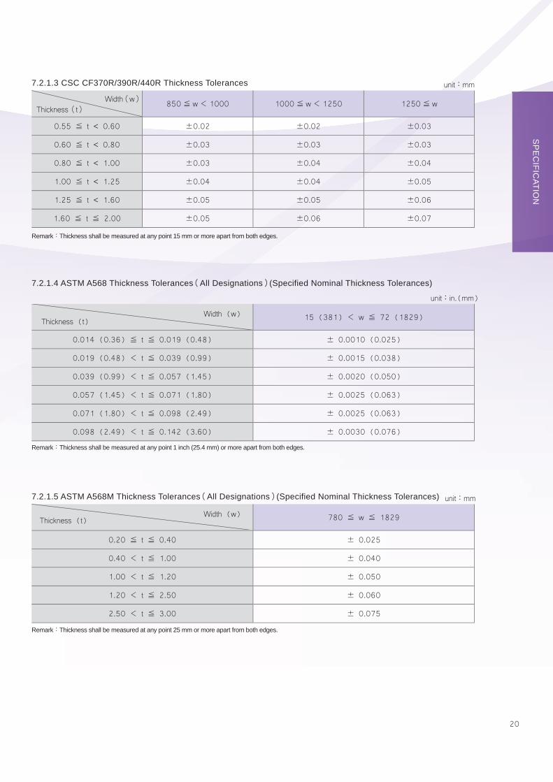
7.2.1.3 CSC CF370R/390R/440R Thickness Tolerances
7.2.1.4 ASTM A568 Thickness Tolerances(All Designations)(Specified Nominal Thickness Tolerances)
7.2.1.5 ASTM A568M Thickness Tolerances(All Designations)(Specified Nominal Thickness Tolerances)
unit:mm
unit:in.(mm)
unit:mm
850≦ w< 1000 1000≦ w< 1250 1250≦ w
0.55 ≦ t < 0.60 ±0.02 ±0.02 ±0.03
0.60 ≦ t < 0.80 ±0.03 ±0.03 ±0.03
0.80 ≦ t < 1.00 ±0.03 ±0.04 ±0.04
1.00 ≦ t < 1.25 ±0.04 ±0.04 ±0.05
1.25 ≦ t < 1.60 ±0.05 ±0.05 ±0.06
1.60 ≦ t ≦ 2.00 ±0.05 ±0.06 ±0.07
Thickness(t)Width(w)
15 (381) < w ≦ 72 (1829)
0.014 (0.36) ≦ t ≦ 0.019 (0.48) ± 0.0010 (0.025)
0.019 (0.48) < t ≦ 0.039 (0.99) ± 0.0015 (0.038)
0.039 (0.99) < t ≦ 0.057 (1.45) ± 0.0020 (0.050)
0.057 (1.45) < t ≦ 0.071 (1.80) ± 0.0025 (0.063)
0.071 (1.80) < t ≦ 0.098 (2.49) ± 0.0025 (0.063)
0.098 (2.49) < t ≦ 0.142 (3.60) ± 0.0030 (0.076)
Thickness (t)Width (w)
780 ≦ w ≦ 1829
0.20 ≦ t ≦ 0.40 ± 0.025
0.40 < t ≦ 1.00 ± 0.040
1.00 < t ≦ 1.20 ± 0.050
1.20 < t ≦ 2.50 ± 0.060
2.50 < t ≦ 3.00 ± 0.075
Thickness (t)Width (w)
Remark:Thickness shall be measured at any point 15 mm or more apart from both edges.
Remark:Thickness shall be measured at any point 1 inch (25.4 mm) or more apart from both edges.
Remark:Thickness shall be measured at any point 25 mm or more apart from both edges.
21
w ≦ 1200 1200 < w ≦ 1500 1500 < w
0.35 ≦ t ≦ 0.40 ± 0.03 ± 0.04 ± 0.05
0.40 < t ≦ 0.60 ± 0.03 ± 0.04 ± 0.05
0.60 < t ≦ 0.80 ± 0.04 ± 0.05 ± 0.06
0.80 < t ≦ 1.00 ± 0.05 ± 0.06 ± 0.07
1.00 < t ≦ 1.20 ± 0.06 ± 0.07 ± 0.08
1.20 < t ≦ 1.60 ± 0.08 ± 0.09 ± 0.10
1.60 < t ≦ 2.00 ± 0.10 ± 0.11 ± 0.12
2.00 < t ≦ 2.50 ± 0.12 ± 0.13 ± 0.14
2.50 < t ≦ 3.00 ± 0.15 ± 0.15 ± 0.16
Thickness(t)Tolerance Width(w)
w ≦ 1200 1200 < w ≦ 1500 1500 < w
0.35 ≦ t ≦ 0.40 ± 0.04 ± 0.05 ± 0.06
0.40 < t ≦ 0.60 ± 0.04 ± 0.05 ± 0.06
0.60 < t ≦ 0.80 ± 0.05 ± 0.06 ± 0.07
0.80 < t ≦ 1.00 ± 0.06 ± 0.07 ± 0.08
1.00 < t ≦ 1.20 ± 0.07 ± 0.08 ± 0.10
1.20 < t ≦ 1.60 ± 0.09 ± 0.11 ± 0.12
1.60 < t ≦ 2.00 ± 0.12 ± 0.13 ± 0.14
2.00 < t ≦ 2.50 ± 0.14 ± 0.15 ± 0.16
2.50 < t ≦ 3.00 ± 0.17 ± 0.18 ± 0.18
Thickness(t)Tolerance Width(w)
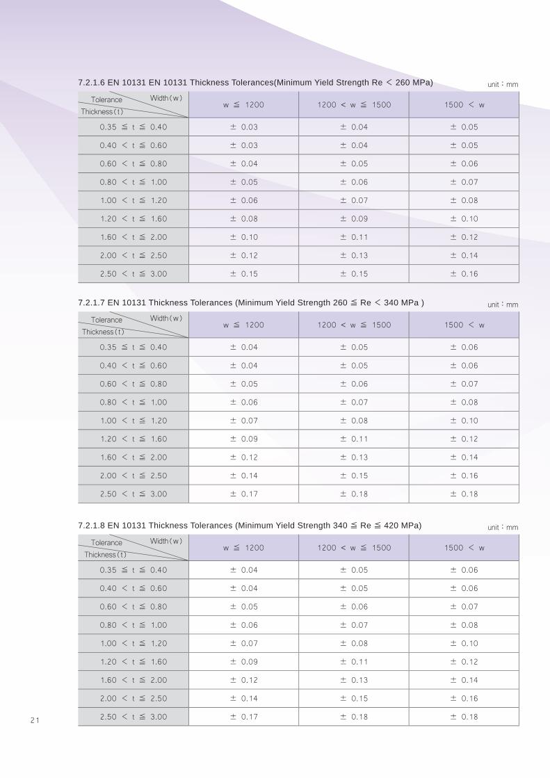
7.2.1.6 EN 10131 EN 10131 Thickness Tolerances(Minimum Yield Strength Re< 260 MPa)
7.2.1.7 EN 10131 Thickness Tolerances (Minimum Yield Strength 260≦ Re< 340 MPa )
7.2.1.8 EN 10131 Thickness Tolerances (Minimum Yield Strength 340≦ Re≦ 420 MPa)
unit:mm
unit:mm
unit:mm
22
SP
EC
IFICATIO
N
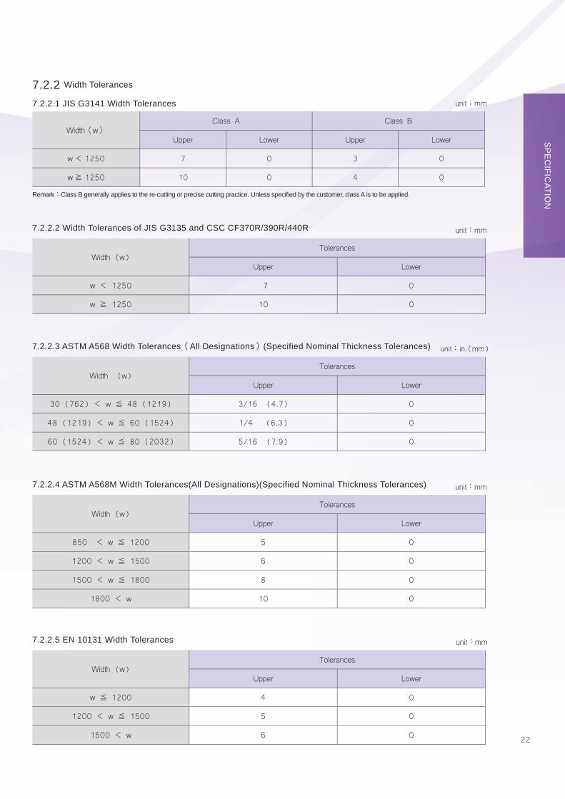
7.2.2 Width Tolerances
7.2.2.1 JIS G3141 Width Tolerances
7.2.2.2 Width Tolerances of JIS G3135 and CSC CF370R/390R/440R
7.2.2.3 ASTM A568 Width Tolerances(All Designations)(Specified Nominal Thickness Tolerances)
7.2.2.4 ASTM A568M Width Tolerances(All Designations)(Specified Nominal Thickness Tolerances)
7.2.2.5 EN 10131 Width Tolerances
unit:mm
unit:mm
unit:in.(mm)
unit:mm
unit:mm
Width(w)Class A Class B
Upper Lower Upper Lower
w< 1250 7 0 3 0
w≧ 1250 10 0 4 0
Width (w)Tolerances
Upper Lower
w < 1250 7 0
w ≧ 1250 10 0
Width (w)Tolerances
Upper Lower
30 (762) < w ≦ 48 (1219) 3/16 (4.7) 0
48 (1219) < w ≦ 60 (1524) 1/4 (6.3) 0
60 (1524) < w ≦ 80 (2032) 5/16 (7.9) 0
Width (w)Tolerances
Upper Lower
850 < w ≦ 1200 5 0
1200 < w ≦ 1500 6 0
1500 < w ≦ 1800 8 0
1800 < w 10 0
Width (w)Tolerances
Upper Lower
w ≦ 1200 4 0
1200 < w ≦ 1500 5 0
1500 < w 6 0
Remark:Class B generally applies to the re-cutting or precise cutting practice. Unless specifi ed by the customer, class A is to be applied.

23
7.2.3 Flatness Tolerances
7.2.3.1 JIS G3141 Flatness Tolerances
7.2.3.2 JIS G3135 Flatness Tolerances
7.2.3.3 Flatness Tolerances for CSC CF370R/390R/440R
Remarks:1. Class B generally applies to the steel sheets of stretcher-leveled steel sheet.2. Class A applies to the normally refi ned steel sheets.
Remarks:1. Grade 1 to 3 shall respectively be applied to the steel sheet of which the lower limit specifi cation value of tensile strength is under 780 N/ mm2, 780 N/mm2 and 980 N/mm2.
2. The value of fl atness shall, as a rule, be measured by placing the steel sheet on a surface plate. It shall be obtained by subtracting nominal thickness of steel sheet from the maximum value of strain and be applied to the upper side surface of steel sheet.
Class A Class B
BowWave
EdgeWave
CenterBuckle
BowWave
EdgeWave
CenterBuckle
w< 1000 12 8 6 2 2 2
1000≦ w< 1250 15 9 8 3 2 2
1250≦ w< 1600 15 11 8 4 3 2
1600≦ w 20 13 9 5 4 2
Width (w)
Flatness(max.)Classification
Bow Wave Edge Wave Center Buckle
1 2 3 1 2 3 1 2 3
w < 1000 12 16 18 8 11 12 6 8 9
1000 ≦ w < 1250 15 19 21 10 12 13 8 10 11
1250 ≦ w < 1600 15 19 21 12 14 15 9 11 12
1600 ≦ w 20 - - 14 - - 10 - -
Width(w)
Flatness (max.) Classification
unit:mm
unit:mm
The fl atness tolerances for 0.79mm and under in thickness shall conform to table A of JIS G3141, and for 0.80mm and
over in thickness shall conform to 1/2 of table A of JIS G3141.
24
SP
EC
IFICATIO
N
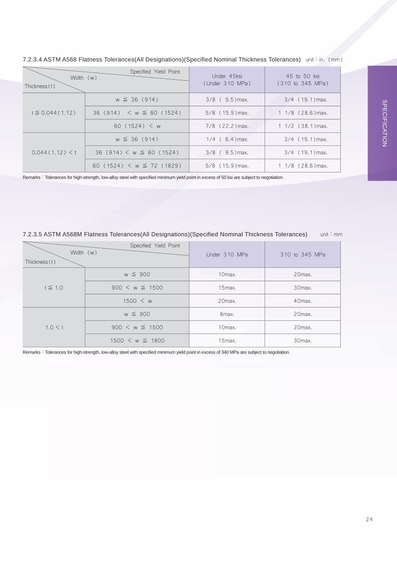
7.2.3.4 ASTM A568 Flatness Tolerances(All Designations)(Specified Nominal Thickness Tolerances)
7.2.3.5 ASTM A568M Flatness Tolerances(All Designations)(Specified Nominal Thickness Tolerances)
Under 45ksi(Under 310 MPa)
45 to 50 ksi(310 to 345 MPa)
t≦ 0.044(1.12)
w ≦ 36 (914) 3/8 ( 9.5)max. 3/4 (19.1)max.
36 (914) < w ≦ 60 (1524) 5/8 (15.9)max. 1 1/8 (28.6)max.
60 (1524) < w 7/8 (22.2)max. 1 1/2 (38.1)max.
0.044(1.12)< t
w ≦ 36 (914) 1/4 ( 6.4)max. 3/4 (19.1)max.
36 (914)< w ≦ 60 (1524) 3/8 ( 9.5)max. 3/4 (19.1)max.
60 (1524) < w ≦ 72 (1829) 5/8 (15.9)max. 1 1/8 (28.6)max.
Thickness(t) Width (w)
Specified Yield Point
Under 310 MPa 310 to 345 MPa
t≦ 1.0
w ≦ 900 10max. 20max.
900 < w ≦ 1500 15max. 30max.
1500 < w 20max. 40max.
1.0< t
w ≦ 900 8max. 20max.
900 < w ≦ 1500 10max. 20max.
1500 < w ≦ 1800 15max. 30max.
Thickness(t) Width (w)
Specified Yield Point
unit:in. (mm)
unit:mm
Remarks:Tolerances for high-strength, low-alloy steel with specifi ed minimum yield point in excess of 50 ksi are subject to negotiation.
Remarks:Tolerances for high-strength, low-alloy steel with specifi ed minimum yield point in excess of 340 MPa are subject to negotiation.
25
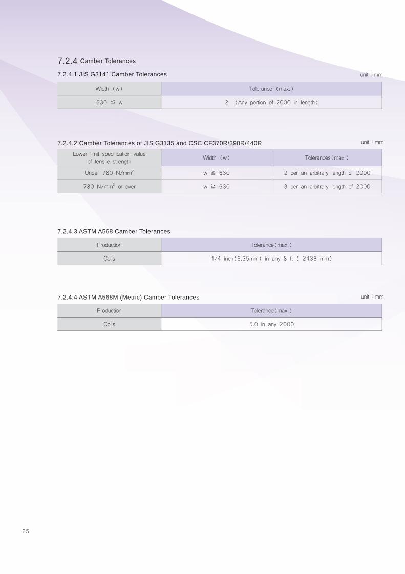
7.2.4 Camber Tolerances
7.2.4.1 JIS G3141 Camber Tolerances
7.2.4.3 ASTM A568 Camber Tolerances
7.2.4.4 ASTM A568M (Metric) Camber Tolerances
7.2.4.2 Camber Tolerances of JIS G3135 and CSC CF370R/390R/440R
Width (w) Tolerance (max.)
630 ≦ w 2 (Any portion of 2000 in length)
Production Tolerance(max.)
Coils 1/4 inch(6.35mm) in any 8 ft ( 2438 mm)
Production Tolerance(max.)
Coils 5.0 in any 2000
Lower limit specification value of tensile strength Width (w) Tolerances(max.)
Under 780 N/mm2 w ≧ 630 2 per an arbitrary length of 2000
780 N/mm2 or over w ≧ 630 3 per an arbitrary length of 2000
unit:mm
unit:mm
unit:mm
26
SP
EC
IFICATIO
N
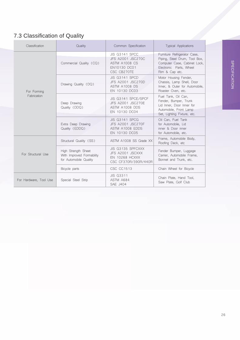
7.3 Classifi cation of QualityClassification Quality Common Specification Typical Applications
For FormingFabrication
Commercial Quality (CQ)
JIS G3141 SPCCJFS A2001 JSC270CASTM A1008 CSEN10130 DC01CSC CB270TE
Furniture Refrigerator Case, Piping, Steel Drum, Tool Box, Computer Case, Cabinet Lock, Electronic Parts, Wheel Rim & Cap etc.
Drawing Quality (DQ)
JIS G3141 SPCDJFS A2001 JSC270DASTM A1008 DSEN 10130 DC03
Motor Housing Fender, Chassis, Lamp Shell, Door Inner, & Outer for Automobile,Roaster Oven, etc.
Deep Drawing Quality (DDQ)
JIS G3141 SPCE/SPCFJFS A2001 JSC270EASTM A1008 DDSEN 10130 DC04
Fuel Tank, Oil Can, Fender, Bumper, Trunk Lid Inner, Door Inner for Automobile, Front Lamp Set, Lighting Fixture, etc.
Extra Deep Drawing Quality (EDDQ)
JIS G3141 SPCGJFS A2001 JSC270FASTM A1008 EDDSEN 10130 DC05
Oil Can, Fuel Tank for Automobile, Lid inner & Door innerfor Automobile, etc.
For Structural Use
Structural Quality (SS) ASTM A1008 SS Grade XX Frame, Automobile Body, Roofing Deck, etc
High Strength Sheet With Improved Formability for Automobile Quality
JIS G3135 SPFCXXXJFS A2001 JSCXXXEN 10268 HCXXXCSC CF370R/390R/440R
Fender Bumper, Luggage Carrier, Automobile Frame, Bonnet and Trunk, etc.
Bicycle parts CSC CC1513 Chain Wheel for Bicycle
For Hardware, Tool Use Special Steel StripJIS G3311ASTM A684SAE J404
Chain Plate, Hand Tool, Saw Plate, Golf Club
27
PRODUCT AVAILABILITY
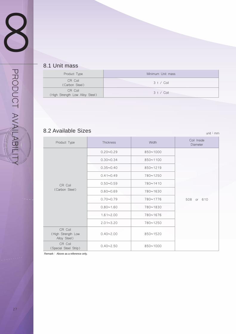
8.1 Unit mass
8.2 Available Sizes
Product Type Minimum Unit mass
CR Coil(Carbon Steel) 3 t / Coil
CR Coil(High Strength Low Alloy Steel) 3 t / Coil
Product Type Thickness Width Coil InsideDiameter
CR Coil(Carbon Steel)
0.20~0.29 850~1000
508 or 610
0.30~0.34 850~1100
0.35~0.40 850~1219
0.41~0.49 780~1250
0.50~0.59 780~1410
0.60~0.69 780~1630
0.70~0.79 780~1776
0.80~1.60 780~1830
1.61~2.00 780~1676
2.01~3.20 780~1250
CR Coil(High Strength Low
Alloy Steel)0.40~2.00 850~1520
CR Coil(Special Steel Strip) 0.40~2.50 850~1000
Remark: Above as a reference only.
unit:mm
28
MAR
KING AN
D PAC
KING
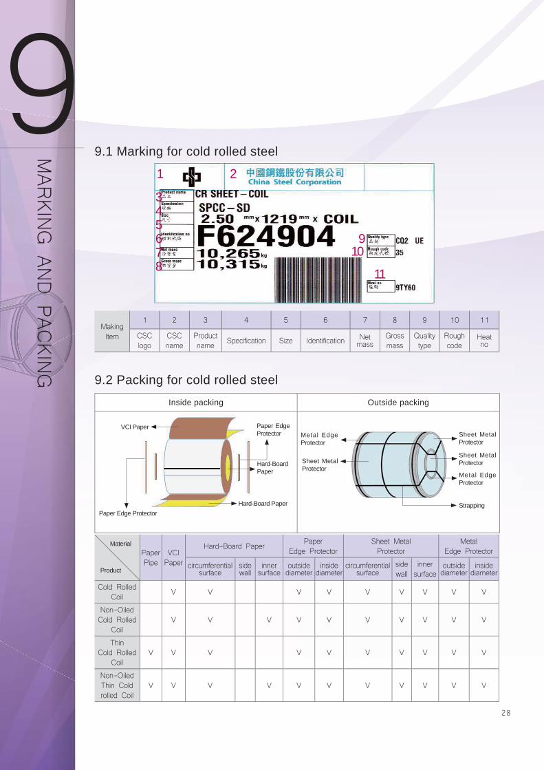
9.1 Marking for cold rolled steel
Inside packing Outside packing
9.2 Packing for cold rolled steel
Paper Pipe
VCIPaper
Hard-Board Paper PaperEdge Protector
Sheet Metal Protector
MetalEdge Protector
circumferential surface
side wall
inner surface
outside diameter
inside diameter
circumferential surface
side wall
inner surface
outside diameter
inside diameter
Cold RolledCoil V V V V V V V V V
Non-OiledCold Rolled
CoilV V V V V V V V V V
ThinCold Rolled
CoilV V V V V V V V V V
Non-OiledThin Cold rolled Coil
V V V V V V V V V V V
Material
Product
VCI Paper
Hard-Board Paper
Hard-Board Paper
Metal Edge Protector
Sheet Metal Protector
Sheet Metal Protector
Sheet Metal Protector
Metal Edge Protector
StrappingPaper Edge Protector
Paper Edge Protector
1 2
345678
910
11
MakingItem
1 2 3 4 5 6 7 8 9 10 11
CSClogo
CSCname
Productname Specification Size Identification Net
massGrossmass
Qualitytype
Roughcode
Heat no
2929
10.1 Rust Prevention
If antirust treatment is not properly performed for the cold-rolled steel coils and sheets, it will be easy to rust the steel
surface. Therefore, the coils have to be spread with proper rust preventive oil, and the coils are packed completely
to protect them before shipping. However, the steel sheets and coils are easy to rust owing to the environmental
factors during their storage and use. Especially the condensation problems are easy to occur when the coil storage is
in an environment of high humidity and high/low temperature with rapid changes. Therefore, it should particularly pay
attention to the prevention of condensation and drain water in advance. Besides, since the dust or acidic substance in
the atmosphere are also easy to rust the surface of steel coils or sheets, such problems in the storage or processing
must be eliminated for keeping good surface quality.
10.2 Stretcher strain and Aging
There are solid solution Carbon and Nitrogen in the low carbon steels. If they are not treated properly, the stretcher
strain marks will be occurred in the process. Therefore, the temper rolling process will be carried out appropriately on
these products to eliminate the extension of yield point. However, the extension of yield point may appear again with
the longer period of storage as we called the aging problem. Aging is mainly related to solid solution Carbon、storing
temperature and time. The “fi rst in, fi rst out (FIFO)” management to use these grades of steel is recommended as
soon as possible in order to avoid the aging problems
10.3 Painting
The painting is one of the common ways to apply for further protecting the cold-rolled products, or enhancing their
beauty and function. Not only the paint itself but also the painting pre-treatment is important factor to infl uence the
coating performance. The main factors resulting in poor painting are:
(a) Insuffi cient clean: The residual oil and contaminant are often seen on the steel surfaces. These foreign matters
may cause the paint to be unable to bond to the substrate surfaces, and may result in declining to fail the adhesion
of film. It is better to understand the rust preventive oil, lubricants and other characteristics, proper choosing
the way of cleaning and cleaning agents, paying more attention to storage conditions and painting operation
environment for helping to improve the insuffi cient clean.
(b) Unsuitable chemical treatment: If the passivation film of chemical treatment is not sufficient or uneven, once
outside corrosion factors are contacted with metal, the reactive metal is very easy to oxidize. Then oxide will
thoroughly destroy the adhesion of primer paint to the steel surface. Moreover, if there are loose passivation fi lms
and coarse crystals or the residue contamination on the chemical treatment liquid, it will also cause the defi ciency
of the fi lm adhesion. It is better to understand the reaction properties of the chemical treatment liquid, paying more
attention on the differences between different cold-rolled steel sheet surfaces, properly adjusting the treatment
PREC
AUTIO
NS FO
R U
SE
3030
liquid concentration, temperature and time, as well as emphasizing on the clean of the treated surface.
(c) Improper paint:The environment and the end-use of products should be considered in the selection of paint, and
the appropriate painting procedure should be adopted to ensure that the treated substrate surfaces are suffi ciently
wetted, are compatible with the paint, and have the ability to resist the environmental corrosion factors.
10.4 Electroplating
Electroplating is covering the cold-rolled steel sheets with a layer of metal or alloy by the principle of electrolysis,
and the fi nishing products will have decorative metallic color and property. After electroplated, the appearance of the
electroplated object is related to the current density. In the operational current density range, when the current density
is smaller, the electroplated object will be more beautiful. Oppositely, there will be some uneven shapes. Generally,
the electroplating bath is acidic that can dissolve the coating layer of Cathode. When the current density is too small,
as a result of the dissolution of the acidic bath, the metal of coating layer will show the appearance of loose and
matt. The contaminated water generated by electroplating process is an important source of water pollution, which
is needed to concentrate on sewage treatment. The common electroplating is zinc-coated、copper-coated、nickel-
coated、chrome-coated. The main factors resulting in poor electroplating are:
(a) Uneven coated layer: To obtain a uniform coated method is the well composition of coating bath. The reasonable
operation makes the surface activity to be uniform. The reasonable hanging of the coated pieces makes the best
current to be distributed uniformly. The current distribution can be improved by the distance and height between
the anode and cathode, and by adding to auxiliary electrode、transmission device、insulation barrier etc.
(b) Coated layer with slag: Since it is due to impurity contamination, and impurity accumulation of long operation, it
must always purify the coating bath. The main methods are:To use the fi lter material to remove solid impurities,
to use activated carbon to remove organic matter, and to remove the metallic impurities by the electrolysis.
Furthermore, the impurities can be removed by using the chemical methods of replacement、precipitation、pH
adjustment and others.
(c) Coated layer with poor adhesion: It is due to the poor surface pre-treatment and oil contamination that the coated
layer is unable to combine with the substrate. Therefore, it must execute the proper degreasing clean suffi ciently.
10.5 Welding
(a) To compare with galvanized steel sheets, there are higher resistance values on cold-rolled steel sheets that only
need a small welding current or shorter welding time to obtain suffi cient resistance welding heat.
(b) Because the cold-rolled steel does not have the galvanized layer, there will be no phenomenon of the foreign
31
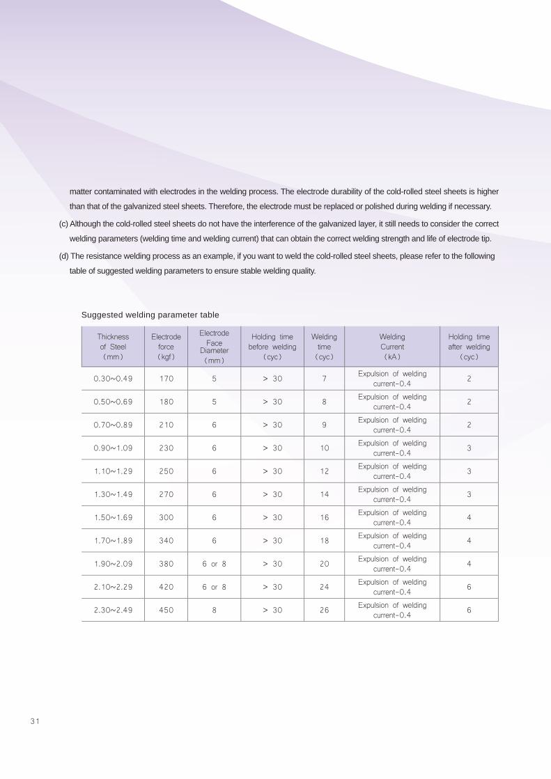
Suggested welding parameter table
Thickness of Steel (mm)
Electrode force (kgf)
Electrode Face
Diameter (mm)
Holding time before welding
(cyc)
Welding time (cyc)
Welding Current (kA)
Holding time after welding
(cyc)
0.30~0.49 170 5 > 30 7 Expulsion of welding current-0.4 2
0.50~0.69 180 5 > 30 8 Expulsion of welding current-0.4 2
0.70~0.89 210 6 > 30 9 Expulsion of welding current-0.4 2
0.90~1.09 230 6 > 30 10 Expulsion of welding current-0.4 3
1.10~1.29 250 6 > 30 12 Expulsion of welding current-0.4 3
1.30~1.49 270 6 > 30 14 Expulsion of welding current-0.4 3
1.50~1.69 300 6 > 30 16 Expulsion of welding current-0.4 4
1.70~1.89 340 6 > 30 18 Expulsion of welding current-0.4 4
1.90~2.09 380 6 or 8 > 30 20 Expulsion of welding current-0.4 4
2.10~2.29 420 6 or 8 > 30 24 Expulsion of welding current-0.4 6
2.30~2.49 450 8 > 30 26 Expulsion of welding current-0.4 6
matter contaminated with electrodes in the welding process. The electrode durability of the cold-rolled steel sheets is higher
than that of the galvanized steel sheets. Therefore, the electrode must be replaced or polished during welding if necessary.
(c) Although the cold-rolled steel sheets do not have the interference of the galvanized layer, it still needs to consider the correct
welding parameters (welding time and welding current) that can obtain the correct welding strength and life of electrode tip.
(d) The resistance welding process as an example, if you want to weld the cold-rolled steel sheets, please refer to the following
table of suggested welding parameters to ensure stable welding quality.
32
CONVER
SION TABLES
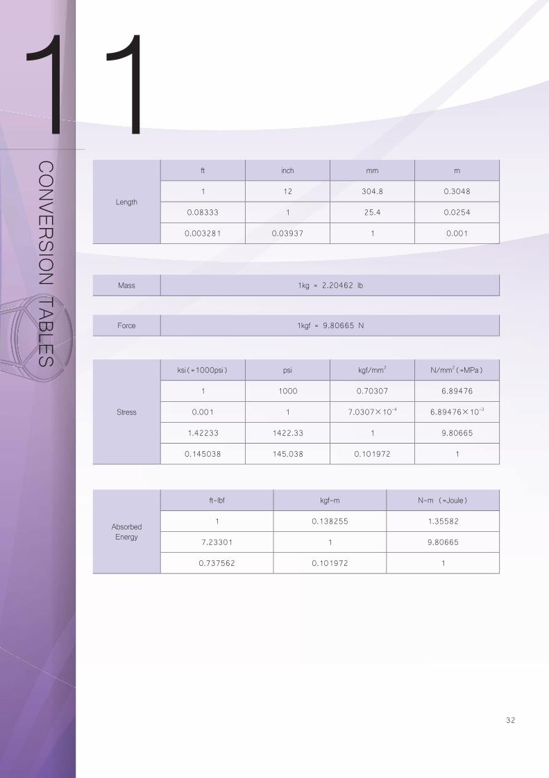
Length
ft inch mm m
1 12 304.8 0.3048
0.08333 1 25.4 0.0254
0.003281 0.03937 1 0.001
Stress
ksi(=1000psi) psi kgf/mm2 N/mm2(=MPa)
1 1000 0.70307 6.89476
0.001 1 7.0307×10⁻⁴ 6.89476×10⁻³
1.42233 1422.33 1 9.80665
0.145038 145.038 0.101972 1
AbsorbedEnergy
ft-lbf kgf-m N-m (=Joule)
1 0.138255 1.35582
7.23301 1 9.80665
0.737562 0.101972 1
Mass 1kg = 2.20462 lb
Force 1kgf = 9.80665 N
333333
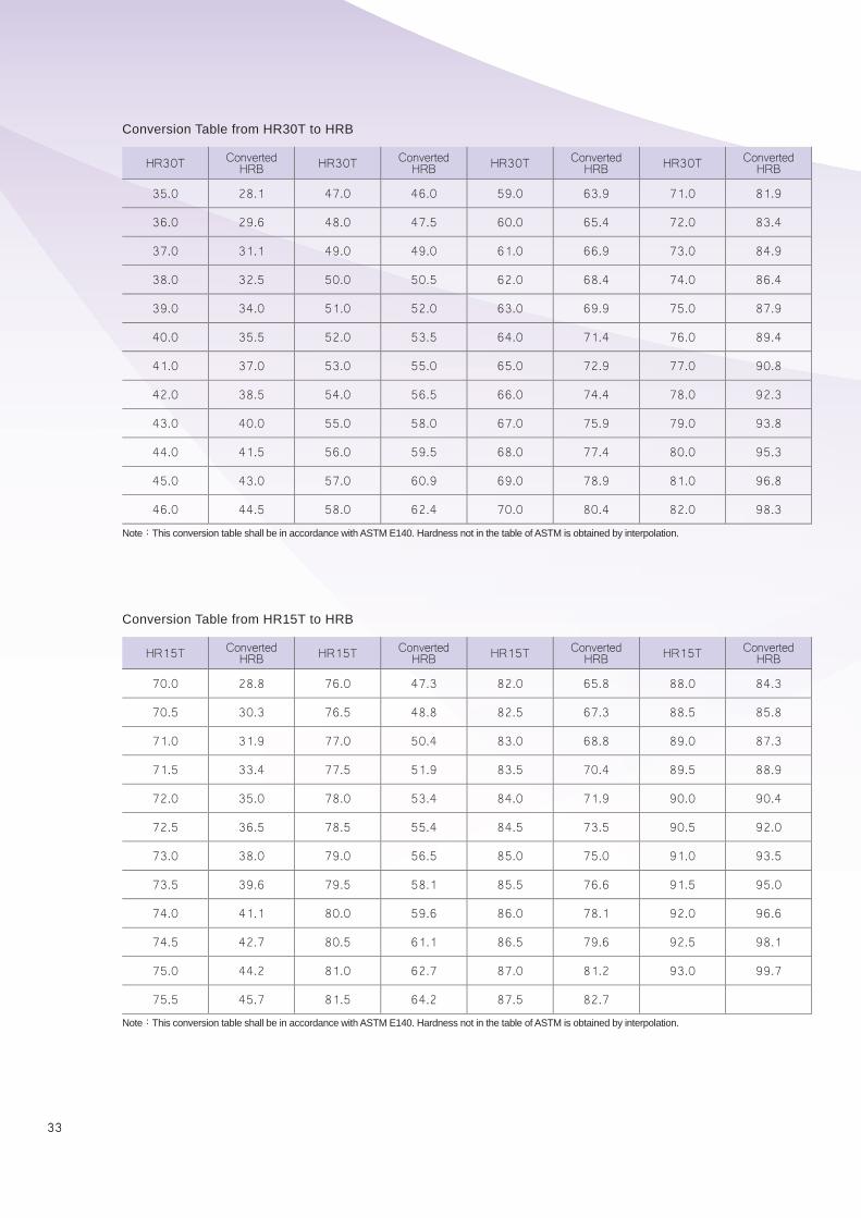
Conversion Table from HR30T to HRB
Conversion Table from HR15T to HRB
HR30T Converted HRB HR30T Converted
HRB HR30T Converted HRB HR30T Converted
HRB
35.0 28.1 47.0 46.0 59.0 63.9 71.0 81.9
36.0 29.6 48.0 47.5 60.0 65.4 72.0 83.4
37.0 31.1 49.0 49.0 61.0 66.9 73.0 84.9
38.0 32.5 50.0 50.5 62.0 68.4 74.0 86.4
39.0 34.0 51.0 52.0 63.0 69.9 75.0 87.9
40.0 35.5 52.0 53.5 64.0 71.4 76.0 89.4
41.0 37.0 53.0 55.0 65.0 72.9 77.0 90.8
42.0 38.5 54.0 56.5 66.0 74.4 78.0 92.3
43.0 40.0 55.0 58.0 67.0 75.9 79.0 93.8
44.0 41.5 56.0 59.5 68.0 77.4 80.0 95.3
45.0 43.0 57.0 60.9 69.0 78.9 81.0 96.8
46.0 44.5 58.0 62.4 70.0 80.4 82.0 98.3
HR15T Converted HRB HR15T Converted
HRB HR15T Converted HRB HR15T Converted
HRB
70.0 28.8 76.0 47.3 82.0 65.8 88.0 84.3
70.5 30.3 76.5 48.8 82.5 67.3 88.5 85.8
71.0 31.9 77.0 50.4 83.0 68.8 89.0 87.3
71.5 33.4 77.5 51.9 83.5 70.4 89.5 88.9
72.0 35.0 78.0 53.4 84.0 71.9 90.0 90.4
72.5 36.5 78.5 55.4 84.5 73.5 90.5 92.0
73.0 38.0 79.0 56.5 85.0 75.0 91.0 93.5
73.5 39.6 79.5 58.1 85.5 76.6 91.5 95.0
74.0 41.1 80.0 59.6 86.0 78.1 92.0 96.6
74.5 42.7 80.5 61.1 86.5 79.6 92.5 98.1
75.0 44.2 81.0 62.7 87.0 81.2 93.0 99.7
75.5 45.7 81.5 64.2 87.5 82.7
Note:This conversion table shall be in accordance with ASTM E140. Hardness not in the table of ASTM is obtained by interpolation.
Note:This conversion table shall be in accordance with ASTM E140. Hardness not in the table of ASTM is obtained by interpolation.
34
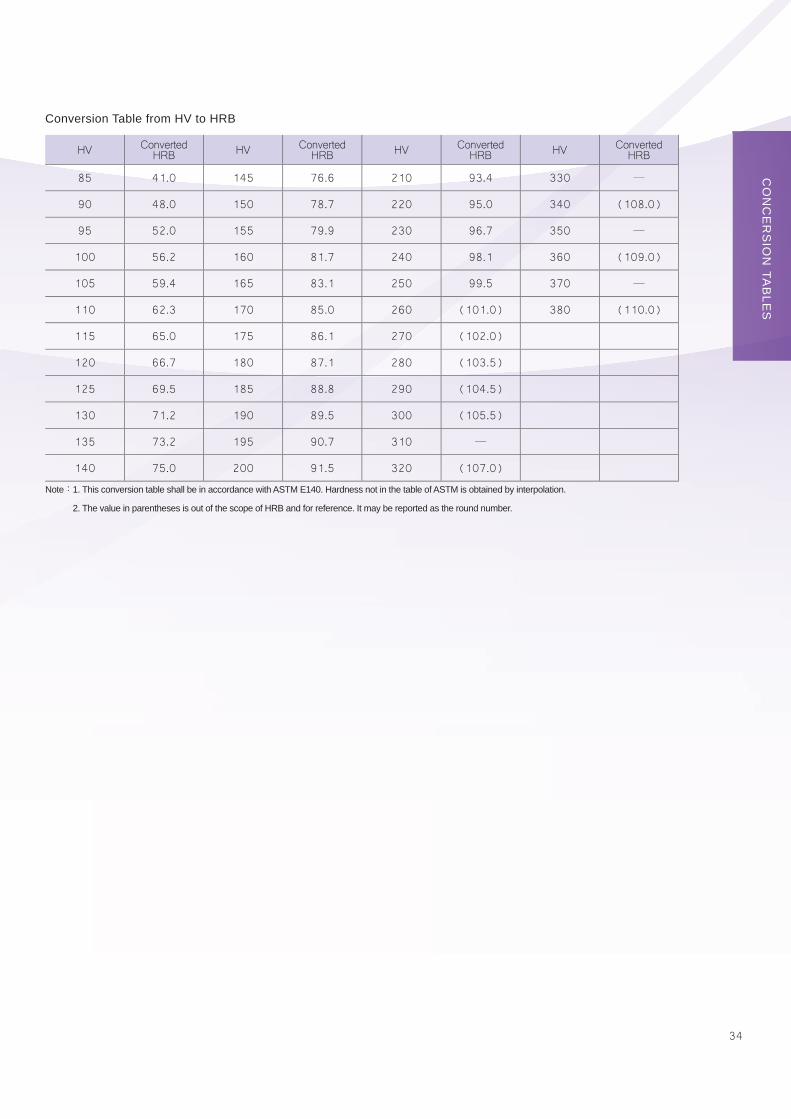
Conversion Table from HV to HRB
HV Converted HRB HV Converted
HRB HV Converted HRB HV Converted
HRB
85 41.0 145 76.6 210 93.4 330 ─
90 48.0 150 78.7 220 95.0 340 (108.0)
95 52.0 155 79.9 230 96.7 350 ─
100 56.2 160 81.7 240 98.1 360 (109.0)
105 59.4 165 83.1 250 99.5 370 ─
110 62.3 170 85.0 260 (101.0) 380 (110.0)
115 65.0 175 86.1 270 (102.0)
120 66.7 180 87.1 280 (103.5)
125 69.5 185 88.8 290 (104.5)
130 71.2 190 89.5 300 (105.5)
135 73.2 195 90.7 310 ─
140 75.0 200 91.5 320 (107.0)
Note:1. This conversion table shall be in accordance with ASTM E140. Hardness not in the table of ASTM is obtained by interpolation.
2. The value in parentheses is out of the scope of HRB and for reference. It may be reported as the round number.
CO
NC
ER
SIO
N TA
BLE
S
35
COMPAR
ISON O
F SPECIFIC
ATION
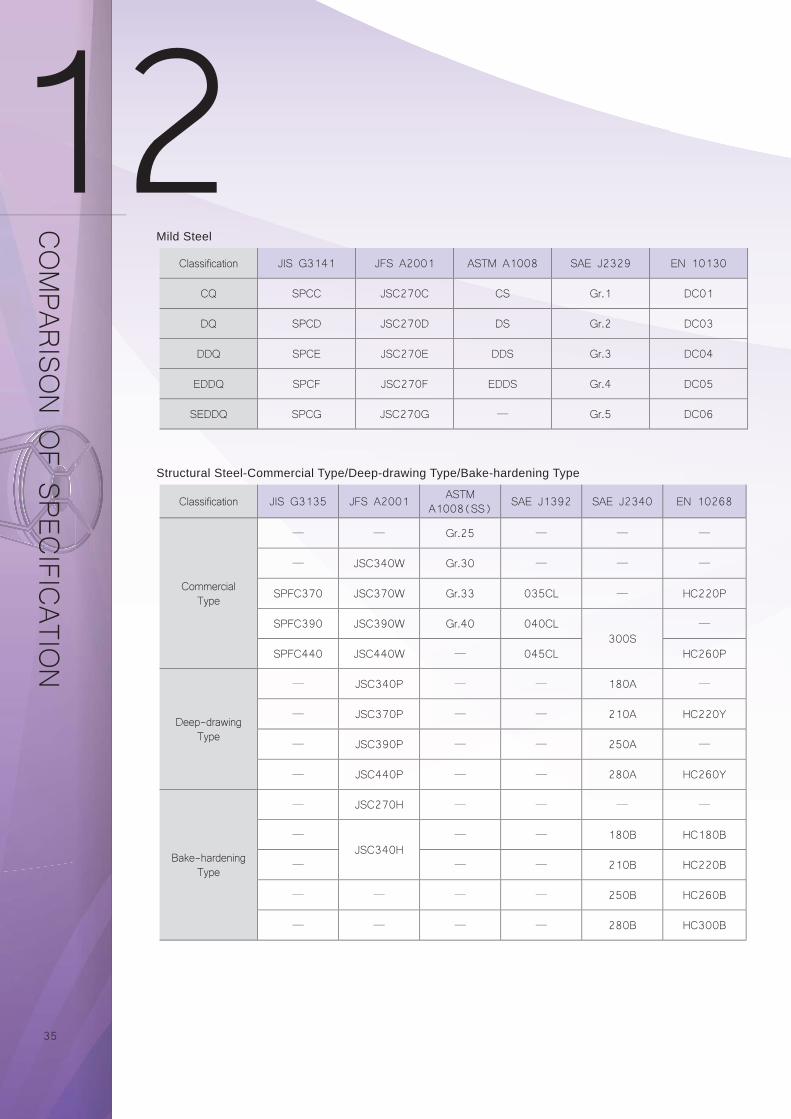
Classification JIS G3141 JFS A2001 ASTM A1008 SAE J2329 EN 10130
CQ SPCC JSC270C CS Gr.1 DC01
DQ SPCD JSC270D DS Gr.2 DC03
DDQ SPCE JSC270E DDS Gr.3 DC04
EDDQ SPCF JSC270F EDDS Gr.4 DC05
SEDDQ SPCG JSC270G ─ Gr.5 DC06
Classification JIS G3135 JFS A2001 ASTM A1008(SS) SAE J1392 SAE J2340 EN 10268
CommercialType
─ ─ Gr.25 ─ ─ ─
─ JSC340W Gr.30 ─ ─ ─
SPFC370 JSC370W Gr.33 035CL ─ HC220P
SPFC390 JSC390W Gr.40 040CL300S
─
SPFC440 JSC440W ─ 045CL HC260P
Deep-drawingType
─ JSC340P ─ ─ 180A ─
─ JSC370P ─ ─ 210A HC220Y
─ JSC390P ─ ─ 250A ─
─ JSC440P ─ ─ 280A HC260Y
Bake-hardeningType
─ JSC270H ─ ─ ─ ─
─
JSC340H─ ─ 180B HC180B
─ ─ ─ 210B HC220B
─ ─ ─ ─ 250B HC260B
─ ─ ─ ─ 280B HC300B
Mild Steel
Structural Steel-Commercial Type/Deep-drawing Type/Bake-hardening Type
36
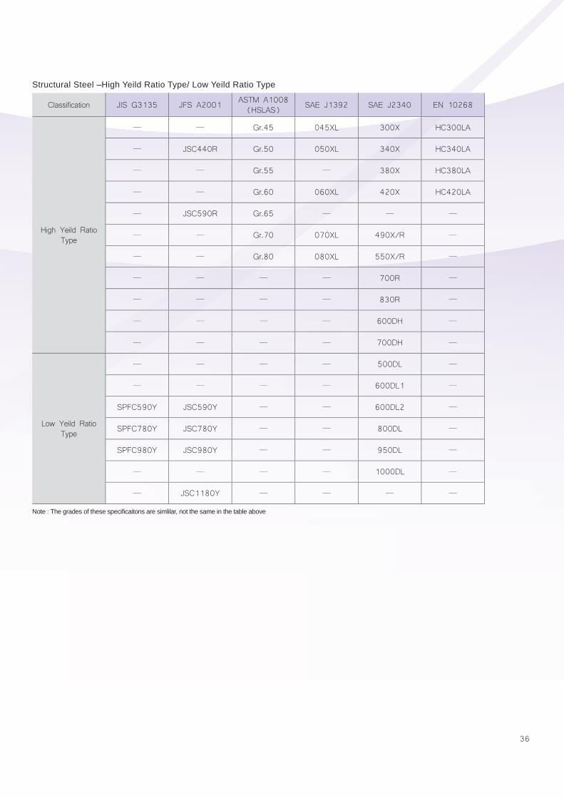
Classification JIS G3135 JFS A2001 ASTM A1008(HSLAS) SAE J1392 SAE J2340 EN 10268
High Yeild Ratio Type
─ ─ Gr.45 045XL 300X HC300LA
─ JSC440R Gr.50 050XL 340X HC340LA
─ ─ Gr.55 ─ 380X HC380LA
─ ─ Gr.60 060XL 420X HC420LA
─ JSC590R Gr.65 ─ ─ ─
─ ─ Gr.70 070XL 490X/R ─
─ ─ Gr.80 080XL 550X/R ─
─ ─ ─ ─ 700R ─
─ ─ ─ ─ 830R ─
─ ─ ─ ─ 600DH ─
─ ─ ─ ─ 700DH ─
Low Yeild Ratio Type
─ ─ ─ ─ 500DL ─
─ ─ ─ ─ 600DL1 ─
SPFC590Y JSC590Y ─ ─ 600DL2 ─
SPFC780Y JSC780Y ─ ─ 800DL ─
SPFC980Y JSC980Y ─ ─ 950DL ─
─ ─ ─ ─ 1000DL ─
─ JSC1180Y ─ ─ ─ ─
Structural Steel –High Yeild Ratio Type/ Low Yeild Ratio Type
Note : The grades of these specifi caitons are simlilar, not the same in the table above
37
Phone number are listed below for your convenience. Numbers of our international Offi ces are shown on the back cover.
1.Sales servicesCHINA STEEL GLOBAL TRADING CORPORATION Address: 10F, NO.88, Cheng gong 2nd Rd, Qian zhen, Kaohsiung 80661 TAIWAN
Tel:886-7-3322168 Fax:886-7-3356411 E-mail:[email protected]
CSGT JAPAN CO., LTD. Address:2F, Osaka U2 Bldg., 4-7 Uchihonmachi 2-Chome,Chuoku, Osaka 540-0026, Japan
Tel:002-81-6-69100850 Fax:002-81-6-69100851 E-mail:[email protected]
CSGT HONG KONG LIMITED Address:ROOM 1407,14/F, WORLD WIDE HOUSE, 19 DES VOEUX ROAD, CENTRAL, HONG KONG
Tel:852-25231488 Fax:852-25234748 E-mail:[email protected]
CSGT (SHANGHAI) CO.,LTD.Address:21F, NO.1468 NAN JING WEST RD., SHANGHAI 200040
Tel:86-21-62896898 Fax:86-21-62896678 E-mail:[email protected]
CSGT (SINGAPORE) PTE, LTD.Address:#14-01, MAS BUILDING, 10 SHENTON WAY SINGAPORE 079117
Tel:65-62238777~8 Fax:65-62256054 E-mail:[email protected]
2.Metallurgical DepartmentTechnical Service Section-Metallurgy: 886-7-8021335
Metallurgical Specification and Testing Section: 886-7-8021111 Ext. 2207
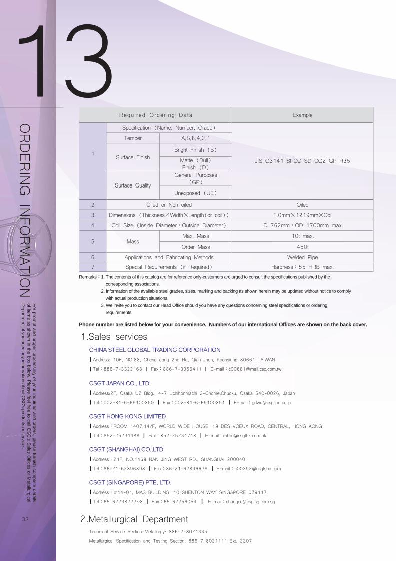
ORDER
ING IN
FORMATIO
N
Required Order ing Data Example
1
Specification (Name, Number, Grade)
JIS G3141 SPCC-SD CQ2 GP R35
Temper A,S,8,4,2,1
Surface FinishBright Finish (B)
Matte (Dull) Finish (D)
Surface Quality
General Purposes (GP)
Unexposed (UE)
2 Oiled or Non-oiled Oiled
3 Dimensions (Thickness×Width×Length(or coil)) 1.0mm×1219mm×Coil
4 Coil Size (Inside Diameter,Outside Diameter) ID 762mm,OD 1700mm max.
5 MassMax. Mass 10t max.
Order Mass 450t
6 Applications and Fabricating Methods Welded Pipe
7 Special Requirements (if Required) Hardness:55 HRB max.
Remarks:1. The contents of this catalog are for reference only-customers are urged to consult the specifi cations published by the corresponding associations.
2. Information of the available steel grades, sizes, marking and packing as shown herein may be updated without notice to comply with actual production situations.
3. We invite you to contact our Head Offi ce should you have any questions concerning steel specifi cations or ordering requirements.
For prompt and proper processing of your inquiries and orders, please furnish com
plete details of item
s as shown in the box below. Please feel free to call C
SC's Sales O
ffices or Metallurgical
Departm
ent, if you need any information about C
SC's products or services.