Embed Size (px)
Citation preview
CHIP MULTIPROCESSOR GENERATOR:
AUTOMATIC GENERATION OF CUSTOM AND HETEROGENEOUS
COMPUTE PLATFORMS
A DISSERTATION
SUBMITTED TO THE DEPARTMENT OF ELECTRICAL ENGINEERING
AND THE COMMITTEE ON GRADUATE STUDIES
OF STANFORD UNIVERSITY
IN PARTIAL FULFILLMENT OF THE REQUIREMENTS
FOR THE DEGREE OF
DOCTOR OF PHILOSOPHY
Ofer Shacham
May 2011

http://creativecommons.org/licenses/by-nc/3.0/us/
This dissertation is online at: http://purl.stanford.edu/wv793rg3775
© 2011 by Ofer Shacham. All Rights Reserved.
Re-distributed by Stanford University under license with the author.
This work is licensed under a Creative Commons Attribution-Noncommercial 3.0 United States License.
ii

I certify that I have read this dissertation and that, in my opinion, it is fully adequatein scope and quality as a dissertation for the degree of Doctor of Philosophy.
Mark Horowitz, Primary Adviser
I certify that I have read this dissertation and that, in my opinion, it is fully adequatein scope and quality as a dissertation for the degree of Doctor of Philosophy.
Christoforos Kozyrakis
I certify that I have read this dissertation and that, in my opinion, it is fully adequatein scope and quality as a dissertation for the degree of Doctor of Philosophy.
Subhasish Mitra
I certify that I have read this dissertation and that, in my opinion, it is fully adequatein scope and quality as a dissertation for the degree of Doctor of Philosophy.
Stephen Richardson
Approved for the Stanford University Committee on Graduate Studies.
Patricia J. Gumport, Vice Provost Graduate Education
This signature page was generated electronically upon submission of this dissertation in electronic format. An original signed hard copy of the signature page is on file inUniversity Archives.
iii

iv
Abstract
Recent changes in technology scaling have made power dissipation today’s major perfor-
mance limiter. As a result, designers struggle to meet performance requirements under
stringent power budgets. At the same time, the traditional solution to power efficiency,
application specific designs, has become prohibitively expensive due to increasing non-
recurring engineering (NRE) costs. Most concerning are the development costs for design,
validation, and software for new systems.
One direction that industry has attempted, with the goal of mitigating the rising costs of
per-application designs, is to add a layer of programmability that specifies how the hardware
operates. Example of this approach include baseband processors for software-defined-radio
(SDR) wireless devices [28, 100, 51]. Similarly, our previous study, Stanford Smart Memo-
ries (SSM), showed that it is possible to build a reconfigurable chip multiprocessor memory
system that can be customized for specific application needs [71, 41, 92, 89]. These pro-
grammable, or reconfigurable, hardware solutions enable per-application customization and
amortization of NRE costs—to a limited extent. However, reconfigurability introduces over-
heads at the circuit level, and customization is limited to those resources that were decided
upon, and verified, upfront.
In this thesis, we argue that one can harness the ideas of reconfigurable designs to build
a design framework that can generate semi-custom chips—a Chip Generator. A domain-
specific chip generator codifies the designer knowledge and design trade-offs into a template
that can be used to create many different chips. Like reconfigurable designs, these systems
fix the top level system architecture, amortizing software and validation and design costs,
and enabling a rich system simulation environment for application developers. Meanwhile,
below the top level, the developer can “program” the individual inner components of the
architecture. Unlike reconfigurable chips, a generator “compiles” the program to create a
customized chip. This compilation process occurs at elaboration time—long before silicon
v
is fabricated. The result is a framework that enables more customization of the generated
chip at the architectural level, because additional components and logic can be added if
the customization process requires it. At the same time this framework does not introduce
inefficiency at the circuit level because unneeded circuit overheads are not taped out.
The design of a chip generator is significantly different than the design of a single chip
instance since one must account for a much larger design and verification space. Thus
we propose a new tool, Genesis2, that can serve as a design framework for generators.
Using Genesis2, designers write elaboration programs, or “recipes,” for how the hardware
blocks need to be constructed given a set of constraints, rather than hard code a particular
solution. Genesis2 enables a standardized method for creation of module generators and for
aggregating unit level generators together into a full chip generator. Ultimately, Genesis2
enables users to design an entire family of chips at once, so that producing custom chips
becomes a simple matter of adjusting a system configuration file.
While logic validation of a generator may at first seem like an infeasible or very expen-
sive task, we show that this is in fact not the case. The first key insight that enables efficient
validation is that one only needs to validate generated instances—not the generator. This
means that we can even leverage the generator to generate many of the validation com-
ponents such as drivers, monitors and assertions, alongside the design itself. The second
insight is that the validation approach can be oblivious to low level customizations details,
and instead thoroughly check correctness at the higher, system level. The result, as we
show, is that testing multiple hardware configurations does not become harder than testing
only one. Moreover, we show that a chip generator may even improve validation quality
and reduce validation time, because by testing multiple closely related configurations one
increases the probability of exposing corner case bugs.
Using Chip Generators, we argue, will enable design houses to design a wide family of
chips using a cost structure similar to that of designing a single chip—potentially saving
tens of millions of dollars—while enabling per-application customization and optimization.
vi
Acknowledgments
Dedicated with love to my grandfather Simcha.
As much, and perhaps more than this thesis represents my personal abilities, it represents
how lucky I was to be surrounded by incredible people who guided me, mentored me, taught
me, provided a shoulder to lean on, and examples to live by. First and foremost, I would
like to thank Professor Mark Horowitz, my advisor. When I just started at Stanford, Mark
needed someone to help wrap-up a project, and hired me with the promise that this is “not
research, just grant work for a couple of quarters,” and I was happy to take it. But I stuck
around, closing on my sixth year now. Throughout these years, from being my teacher (and
my boss), Mark became my advisor, my mentor, and my role model. I learned so much
about circuit and chip design from Mark, but even more than Mark taught me academically,
he taught me how to think.
I would also like to thank my co-advisor, Professor Subhasish Mitra. I got to meet
Subhasish for the first time through an independent study project I performed under his
supervision on my first year. I quickly realized what an endless source of information he
is, and that his door was always open for me to just wander in with any random question.
Subasish always accepted me with a big smile, with great patience, (with chocolates from
his most recent trip) and with a clear answer to whatever I was puzzled about.
Many thanks are extended to Professor Christos Kozyrakis for serving in my reading and
defense committee, and for teaching me so much, whether in his classes, a random corridor
talk, or during the Stanford Smart Memories project. A special thank you is extended to
Professor Dan Boneh, for being the chair of my defense committee and for all the wonderful
things I learned in his classes. Somehow, Dan was able to take the arguably most difficult
topics—cryptography and computer security—and make it understandable to mere humans
like myself.
vii

A great and special thanks is extended to Consulting Professor Stephen Richardson,
who also served on my defense and reading committee. When I met Steve for the first time,
he manifested his goal as to “help students understand what they are doing and what they
need to do to achieve their PhD goals.” I took Steve on his word, and we had numerous
meeting in which he always provided good, useful, advice. Over the years, and even more
important than any academic advice, co-authoring of papers and research collaborations,
Steve and I became good friends.
Stanford is a wonderful place with many wonderful people, many of whom became my
friends. An enormous thank you is sent to Megan Wachs and Zain Asgar. Without my
good friend Megan, much of the research presented here would not have existed. Many
thanks are also extended to Amin Firoozshahian, Alex Solomatnikov and Francois Labonte
who took me in to the group and helped, taught, and mentored me in my early days at
Stanford. Finally I would like to thank the rest of the Stanford VLSI research group who
have been such a fertile ground for thoughts and research.
This thesis, and my entire career at Stanford for that matter, would not have existed if
it was not for the kindness and generosity of Mr. and Ms. Irving and Harriet Sands who
not only supported me financially, but also supported me morally and mentally throughout
these years. In fact, as I was considering my options before going to Stanford, Harriet and
Irving, who at that point had last seen me as a little kid, called me to explain why I must
not miss out on this great opportunity, and even offered to help. They were indeed very
right.
Finally, I would like to thank my family who supported me through all these years of
living abroad. I would like to thank my parents, Itzhak and Lea Shacham, who always
encouraged me to strive higher and be better, and have gave me the foundations I needed
to complete this task. I would also like to thank my wife’s parents, Rafi and Chaya Taterka,
who supported our decision to live on the other side of the world for this adventure even
though I know how tough this is for them, and for making constant trips to visit us.
My greatest thanks are for my daughters, Ori and Alma, who joined us along the way
and made our lives so wonderful, and made it practically impossible to work too hard!
And to top it all up, Neta my love, there are not enough words to express my love and
gratitude—this PhD is as much yours as it is mine!
viii
Contents
Abstract v
Acknowledgments vii
1 Introduction 1
2 What Is A Chip Generator? 7
2.1 Technology Scaling and the Cause of the Power Crisis . . . . . . . . . . . . 8
2.2 Design in a Power Constrained World . . . . . . . . . . . . . . . . . . . . . 11
2.3 Build Chip-Generators, Not Chips . . . . . . . . . . . . . . . . . . . . . . . 16
2.4 Challenges . . . . . . . . . . . . . . . . . . . . . . . . . . . . . . . . . . . . . 20
3 Creating A Generator 27
3.1 Templates and Parameters . . . . . . . . . . . . . . . . . . . . . . . . . . . . 29
3.2 Hardware Descriptive Languages . . . . . . . . . . . . . . . . . . . . . . . . 37
3.3 Genesis2 . . . . . . . . . . . . . . . . . . . . . . . . . . . . . . . . . . . . . . 40
3.3.1 Genesis2 Elaboration Order And Scope . . . . . . . . . . . . . . . . 43
3.3.2 Genesis2 Parametrization Levels . . . . . . . . . . . . . . . . . . . . 46
3.3.3 Interfacing With Genesis2 . . . . . . . . . . . . . . . . . . . . . . . . 51
3.3.4 Small Design Example . . . . . . . . . . . . . . . . . . . . . . . . . . 53
3.3.5 Using Genesis2 to Capture More of The Designers’ Knowledge . . . 57
3.4 Genesis2 Backend . . . . . . . . . . . . . . . . . . . . . . . . . . . . . . . . . 58
3.5 Future Improvements To Genesis2 . . . . . . . . . . . . . . . . . . . . . . . 63
4 Verification of A Flexible Architecture 69
4.1 Smart Memories Background . . . . . . . . . . . . . . . . . . . . . . . . . . 71
ix
4.2 Verification Challenges and Approach . . . . . . . . . . . . . . . . . . . . . 74
4.3 Creating A Reference Model . . . . . . . . . . . . . . . . . . . . . . . . . . . 80
4.4 Verification Results . . . . . . . . . . . . . . . . . . . . . . . . . . . . . . . . 87
4.5 Flexibility And Bug Discovery . . . . . . . . . . . . . . . . . . . . . . . . . . 92
4.6 Putting It All Together . . . . . . . . . . . . . . . . . . . . . . . . . . . . . 98
5 Conclusion 101
A Genesis2 User Guide 107
A.1 Setting Your Environment For Genesis2 . . . . . . . . . . . . . . . . . . . . 107
A.2 Genesis2 File Types . . . . . . . . . . . . . . . . . . . . . . . . . . . . . . . 109
A.2.1 Main File Types . . . . . . . . . . . . . . . . . . . . . . . . . . . . . 109
A.2.2 Additional (Output) File Types . . . . . . . . . . . . . . . . . . . . . 112
A.2.3 Extending Genesis2 . . . . . . . . . . . . . . . . . . . . . . . . . . . 115
A.3 Genesis2 Command Line Arguments . . . . . . . . . . . . . . . . . . . . . . 118
A.3.1 Parsing Mode . . . . . . . . . . . . . . . . . . . . . . . . . . . . . . . 118
A.3.2 Generation Mode . . . . . . . . . . . . . . . . . . . . . . . . . . . . . 119
A.3.3 Help and Debugging . . . . . . . . . . . . . . . . . . . . . . . . . . . 119
A.4 Genesis2 Source Code & Built-in Methods . . . . . . . . . . . . . . . . . . . 120
A.4.1 Genesis2 Source Code Structure . . . . . . . . . . . . . . . . . . . . 120
A.4.2 Genesis2 Special Built-in Methods . . . . . . . . . . . . . . . . . . . 121
A.5 Useful Debugging Hints . . . . . . . . . . . . . . . . . . . . . . . . . . . . . 126
A.6 Genesis2 Design Example . . . . . . . . . . . . . . . . . . . . . . . . . . . . 127
A.6.1 Basic Flip-Flop Template . . . . . . . . . . . . . . . . . . . . . . . . 128
A.6.2 Config and Debug Interface . . . . . . . . . . . . . . . . . . . . . . . 139
A.6.3 Config and Debug Register File Template . . . . . . . . . . . . . . . 141
Bibliography 167
x
List of Tables
3.1 Sources and Impact of Parameters On A Cache . . . . . . . . . . . . . . . . 33
3.2 Genesis2’s Jargon . . . . . . . . . . . . . . . . . . . . . . . . . . . . . . . . . 43
4.1 Reference Models Qualitative Comparison . . . . . . . . . . . . . . . . . . . 87
4.2 Impact Of Architectural Configuration And Seed On SSM’s Bug 458 . . . . 94
xi
List of Figures
2.1 Processors Power Consumption Graph . . . . . . . . . . . . . . . . . . . . . 9
2.2 Processors Clock Frequency Graph . . . . . . . . . . . . . . . . . . . . . . . 10
2.3 Processors Power Density Graph . . . . . . . . . . . . . . . . . . . . . . . . 11
2.4 The Energy-Performance Space Illustration . . . . . . . . . . . . . . . . . . 12
2.5 Processors Power Vs. Performance Graph . . . . . . . . . . . . . . . . . . . 13
2.6 Performance Dependency On The Software Stack and Tool-Chain . . . . . . 16
2.7 Using a Chip Generator . . . . . . . . . . . . . . . . . . . . . . . . . . . . . 18
2.8 Exploration Of Energy-Performance Trade-offs . . . . . . . . . . . . . . . . 25
3.1 Example of An Architectural Template and Chip Program . . . . . . . . . . 30
3.2 From Architectural Template To Elaborated Design . . . . . . . . . . . . . 32
3.3 Sources and Impact of Parameters On A Cache . . . . . . . . . . . . . . . . 34
3.4 Implications of Late Binding and Uniquification . . . . . . . . . . . . . . . . 36
3.5 Conceptual Hardware Generator . . . . . . . . . . . . . . . . . . . . . . . . 41
3.6 XML to Genesis2 to XML . . . . . . . . . . . . . . . . . . . . . . . . . . . . 53
3.7 Genesis2 Parsing . . . . . . . . . . . . . . . . . . . . . . . . . . . . . . . . . 62
3.8 unique inst :Pseudo Code . . . . . . . . . . . . . . . . . . . . . . . . . . . . . 67
3.9 Genesis2 Target-Language Generation . . . . . . . . . . . . . . . . . . . . . 68
4.1 Stanford Smart Memories’ Architecture . . . . . . . . . . . . . . . . . . . . 72
4.2 SSM’s Configurable Local Memory . . . . . . . . . . . . . . . . . . . . . . . 73
4.3 SSM Configuration Encoding Scheme . . . . . . . . . . . . . . . . . . . . . . 76
4.4 Race Condition In A CMP Trace . . . . . . . . . . . . . . . . . . . . . . . . 82
4.5 Relaxed Scoreboard Uncertainty Window . . . . . . . . . . . . . . . . . . . 84
4.6 Pie Breakdown Of Bugs Found In SSM . . . . . . . . . . . . . . . . . . . . 88
4.7 Over-Time Accumulation Of Bugs Found In SSM . . . . . . . . . . . . . . . 88
xii
4.8 SSM’s Bug Distribution By Configuration In Cache Coherence Mode . . . . 91
4.9 SSM’s Bug Distribution By Configuration In Transactional Mode . . . . . . 92
4.10 Impact Of Architectural Configuration On SSM’s Bug 458 . . . . . . . . . . 93
4.11 Impact Of Architectural Configuration On SSM’s Bug 395 . . . . . . . . . . 96
4.12 Impact Of Architectural Configuration On SSM’s Bug 538 . . . . . . . . . . 96
4.13 Impact Of Architectural Configuration On SSM’s Bug 511 . . . . . . . . . . 97
4.14 Leveraging Generators For Validation . . . . . . . . . . . . . . . . . . . . . 99
xiii

xiv
Chapter 1
Introduction
Power constraints are changing how chips are being designed today. Changes to technology
scaling, post-90nm, have severely compromised our ability to keep power in check, which
means almost all systems designed today, from high performance servers to wireless sensors,
are becoming energy constrained. Years of research has taught us that the best—and
perhaps only—way to save energy is to cut waste. Clock and power gating, now common
techniques, reduce direct energy waste in unused circuits. Power is also wasted indirectly
when we waste performance. As is well known, and recently quantified for processors by
Azizi [23], higher performance requirements lead to higher energy operations, so removing
performance waste also reduces energy per operation. Using multiple simpler units rather
than a single aggressive one, therefore, saves energy when processing parallel tasks. At the
system level, this observation is driving the recent push for parallel computing.
Ultimately, the best tool in our power-saving arsenal is customization, because the most
effective way to improve energy efficiency is to find a solution that accomplishes the same
task with less work. Doing less work directly saves energy. Better still, since less work is
needed, performance improves, allowing even greater reduction of the required energy. For
many applications, adding a few specialized hardware units greatly reduces the required
work, making application specific integrated circuits (ASICs) orders of magnitude more
energy efficient than a CPU for that application.
Yet, despite the clear energy efficiency advantage of ASICs, the number of new ASICs
built today is not skyrocketing, but actually decreasing. The reason is simple: non-recurring
engineering (NRE) costs for ASIC design have become extremely expensive, and very few
applications have markets big enough to justify these costs. This uneasy status quo is
1
2 CHAPTER 1. INTRODUCTION
reminiscent of chip design problems in the early 1980s, when all chips were designed by
full custom techniques. At that time, few companies had the skills or the dollars to create
chips. The invention of synthesis and place-and-route tools dramatically reduced design
costs and enabled cost effective ASICs. Over the past 25 years, however, complexity has
grown, creating the need for another design innovation.
To enable this innovation, we first need to face the main issue: building a completely
new complex system is expensive. The cost of design and verification has long exceeded
tens of millions of dollars. Moreover, hardware is only half the story. New architectures
require expensive new software ecosystems to be useful. Developing these tools and code is
also expensive. Providing a designer with complex IP blocks does not solve this problem:
the assembled system is still complex and still requires custom verification and software.
Furthermore, verification costs still trend with system complexity and not with the number
of individual blocks used. To address some of these design costs, the industry has been
moving toward platform-based designs [99], where the system architecture has been fixed,
to provide an interface, an abstraction layer, for the design space exploration, validation and
software efforts. A platform in this ([99]) sense is an architecture that, rather than being
assembled from a collection of independently developed blocks of silicon, is derived from
a specific “family” of micro-architectures, oriented toward a particular class of problems.
Most often, to make these platforms serve a wide class of problems, design houses rely on
hardware programmability and/or reconfigurability [71, 64, 51, 61].
While such strategies address some of the design costs, these general, programmable
platforms still do not provide the desired ASIC-like performance and power efficiency. The
amount of resources in a programmable platform (e.g., compute engines, instruction and
data caches, processor width, memory bandwidth, etc.) is never optimal for any particular
application. Since the power and area of the chip are limited, a compromise among the
expected use-cases is typically implemented. Similarly, adding configuration registers to a
design also implies adding circuit inefficiencies, such as muxes in data paths or table look-ups
for control, impeding both performance and energy. Furthermore, while a reconfigurable
chip is likely to work in the modes for which it was designed and tested, and perhaps for
some closely related configurations, it is doubtful if a completely new use-case would work
efficiently the first time.
It therefore seems that on one hand, a reconfigurable platform based approach does
not provide the required performance and power efficiency, and on the other, ASIC based
3
solutions are too expensive for most applications. The key to solving this impasse is to
understand that while we cannot afford to build a customized chip for every application,
we can reuse one application’s design process to generate multiple new chips. For example,
many applications within a domain may require similar systems with small variations in
hardware units, or the same application may be used in multiple target devices with different
power and performance constraints.
While a configurable chip cannot be as efficient as its set of application specific counter-
parts, suppose we could introduce the one piece of “secret sauce” that makes that application
work, and then generate (rather than program) a system configuration that meets the power
and performance constraints, and only then fabricate the chip; we would certainly end up
with a much more efficient chip.
Furthermore, every time a chip is built, we inherently evaluate different design decisions,
either implicitly using micro-architectural and domain knowledge, or explicitly through cus-
tom evaluation tools. While this process could help create other, similar chips, today these
trade-offs are often not recorded—we either settle on a particular target implementation
and record our solution, or we create a chip that is a super-set or a compromise among
design choices (and is thus less than optimal).
We argue that this implicit and explicit knowledge should be embedded in the modules
we construct, allowing others, with different goals or constraints, to create different chip
instances. Rather than building a custom chip, designers should create a module that
can generate the specialized chip—a chip generator. As presented in Chapter 2 of this
thesis, the chip generator approach uses a fixed system architecture, or “template,” to
simplify both software development and hardware verification. This template is composed
of highly parametrized modules, to enable pervasive customization of the hardware. The
user, an application developer, tunes the parameters to meet a desired specification. The
chip generator compiles this information and deploys optimization procedures to produce
the final chip. This process results in customized function units and memories that increase
compute efficiency.
Since this approach is different than traditional ASIC, SoC or other current chip design
strategies, the first steps in realizing it are to create a design tool chain that can easily
embed designers knowledge into the modules they create, and allow hierarchical assembly
of these modules into a generator. To better understand the requirements for this tool, we
begin Chapter 3 by discussing a few design examples. However, rather than describing the
4 CHAPTER 1. INTRODUCTION
hardware architecture, we emphasize the designer thought process: where design choices
come from, which design choice should be set by the generator user (i.e., the application
engineer), and which should be inferred from a previously made choice or calculated by
optimization scripts. From this analysis, we learn that the problem in embedding designer
knowledge and design process into the generator is that it requires more designer control over
the elaboration process, than is currently available in standard hardware descriptive lan-
guages. Therefore the first step in realizing a chip generator must be to create a framework
for making generators. Chapter 3 goes on to describes one such tool–Genesis2. Genesis2
embeds designer knowledge into modules by enabling the interleaving of a software scripting
language (Perl) and a hardware descriptive language (Verilog). While the idea of interleav-
ing a pre-processing language with an HDL is not new [95, 18, 94, 10, 40, 43], Genesis2 has
a collection of features that make it powerful for creating generators: (a) Genesis2 pulls all
the parametrization from the hardware language scope to the hardware generator scope. (b)
Genesis2 has hierarchical scope (rather than the file based scope of all other pre-processors).
This also enables generation of heterogeneous systems by doing automatic uniquification of
generated modules and instances. (c) Genesis2 constructs/uses a hierarchical XML repre-
sentation of the entire design data base, which lays down the API for application engineers
to program the generator, or for optimization tools to search the design space. (d) Finally,
Genesis2’s foundation in a complete and known software language (Perl) enables the de-
signer to embed his thoughts by explicitly controlling the hardware elaboration. Moreover,
it enables the design modules to generate some of the collateral files needed for validation,
physical implementation and/or software development.
Genesis2 makes it easy for a designer to create an elaboration program that can generate
custom, heterogeneous hardware based on a user’s input. However, design is just part of the
problem. As important is the verification problem, accounting for 30%-70% of today’s chip
design NRE costs. Chapter 4 delves into the difficulties that a chip generator may inflict
on RTL verification. Since one design is hard to verify, one might expect the verification
problem to only get (exponentially) worse with a chip generator approach, because flexible
designs increase the validation space. However, our validation goal is not to validate the
generator, but the particular design that it generates. This means that the validation space
for each instance is in fact constrained, and is no worse than an equivalent instance that was
not auto-generated. The key challenge is to ensure that the generator validation collateral
can be reused to generate the test environment needed for each instance.
5
The chapter uses a case study of a very flexible chip multiprocessor, Stanford Smart
Memories, that was actually implemented, verified, taped out and proved to be working
in the lab, to better exemplify the impact of flexibility in a design on its validation. We
demonstrate how a configuration-agnostic validation environment was created for SSM, and
in particular we focus on how the environment was connected to the design to enable efficient
abstraction of low level details. Abstracting low level details also yielded the creation of
a Relaxed Scoreboard [90]—a configuration-agnostic reference model. Traditional reference
models (known as gold models or scoreboards), predict a single “correct” answer for every
output, which requires that the model and design implement the same timing, arbitrations,
and priorities on a cycle accurate basis. In contrast, a relaxed scoreboard keeps a set of
possibly correct outputs, and update this set as more of the actual outputs are seen.
In perhaps the most interesting aspect of validation with respect to chip generators,
we further show in Chapter 4 that our ability to quickly and effortlessly generate multiple
different versions from one template architecture can even be beneficial for verification. In-
tuitively, a small change in the generated machine would cause its cycle-by-cycle behavior
to change, thus adding another random factor into the existing simulation infrastructure,
potentially making a rare corner case scenario in one generated configuration become a
frequent event in another. Empirically we show that randomly generating machine config-
urations can significantly improve our chances of exposing a given bug, thus we are making
the verification effort both better and more efficient.

6 CHAPTER 1. INTRODUCTION
Chapter 2
Why And What Is A Chip
Multiprocessor Generator
The integrated circuit (IC) industry has been designing and manufacturing chips for five
decades. During this time, chips got better at an exponential rate, with each generation
providing increased compute performance for a decreasing dollar cost. The enabler for this
incredible improvement in the industry was our ability to shrink the most basic components
of the circuits—the transistor and wires. As transistors dimensions scaled down, architects
placed more of them on each chip, thus providing more compute power. Moreover, with each
shrink of the technology feature size, these smaller transistors also got faster and required
less energy to switch.
In the early years of the millennium however, this paradigm started to break and power
became a key limiting factor. Currently, it is not yet clear if a return to that exponential
trend will ever be possible again. First and foremost, the MOS technology scaling rules
that have set the pace since 1974 are now changing. No longer can we “simply” scale
down the technology feature sizes to gain an improvement in speed, area and energy. A
second destructive force to join the technology scaling difficulties is the incredible increase
in non-recurring engineering (NRE) costs due to an increase in our chips’ logic complexity.
While this complexity is attributed to an industry achievement—the integration of more
transistors on a die of silicon—design and verification costs rose so high over the decades,
that today only a few application markets can justify a designated chip to be built for them.
In this chapter, we suggest a new approach to digital chip design and describe the concept
of a chip generator. In essence, a generator is a framework that is capable of embedding
7
8 CHAPTER 2. WHAT IS A CHIP GENERATOR?
the design team’s knowledge such that it can then be easily re-configured to produce many
different chips.
The chapter starts by stating the background facts of technology scaling and the rea-
sons for the current power crisis (Section 2.1). It then moves on to describe the obvious
solutions—customization and optimization—and how increasing NRE costs prevent the in-
dustry from implementing those solutions in most cases (Section 2.2). Section 2.3 describes
in detail our proposed chip generator solution to this impasse, and Section 2.4 then describes
some of the challenges one must face when constructing such a framework. As the focus of
this thesis is on the design and verification aspects of the chip generator, Chapters 3 and 4
discuss these challenges in detail.
2.1 Technology Scaling and the Cause of the Power Crisis
When considering technology scaling and the growth of the semiconductor industry over
the past few decades, it is almost impossible not to begin with Moore’s Law. Introduced
by Gordon Moore in 1965, Moore’s Law stated that the number of transistors which could
economically be placed on an integrated circuit would increase exponentially with time [78].
While this “law” was an empirical observation, history has shown Moore’s prediction to have
been very accurate, to the point that, today, Moore’s Law has become synonymous with
technology scaling.
Moore successfully predicted the exponential growth of the number of transistors on a
chip, but explaining how device characteristics would be affected by scaling took another
decade, and was described by Robert Dennard in his seminal paper on MOS device scaling
published in 1974 [37]. In the paper, Dennard showed that by scaling voltages along with all
dimensions, the electric fields in a device remained constant, and most device characteristics
were preserved.
Following Dennard scaling, chip makers achieved a triple benefit: First, devices became
smaller in both x and y dimensions (scaled by α < 1), allowing for 1α2 more transistors in
the same area. Second, capacitance scaled down by α (since C = εLWt ), so the charge that
needed to be removed to change a node’s state scaled by α2 (since Q = CV ); as current also
scaled by α, this meant gate delays decreased by α (because D = Q/I). Finally, because
energy is equal to CV 2, energy decreased by α3.
Thus, following constant field scaling, each generation supplied more gates per mm2,
2.1. TECHNOLOGY SCALING AND THE CAUSE OF THE POWER CRISIS 9
1
10
100
1000
85 86 87 88 89 90 91 92 93 94 95 96 97 98 99 00 01 02 03 04 05 06 07 08 09 10 11
Pow
er [W
att]
Year
Intel 80386 Intel 80486 Intel Pentium Intel Pentium IIIntel Pentium III Intel Pentium IV Intel Itanium Intel Pentium DIntel Core 2 Intel Xeon Intel Atom Intel Core i7Alpha 21064 Alpha 21164 Alpha 21264 MipsHP PA Power PC IBM-Power AMD K6AMD K7 AMD Turion AMD Athlon AMD OpteronAMD Phenom Sun SuperSparc Sun UltraSparc Sun Niagara
Intel Core i7: 130W
AMD Phenom: 125WIBM Power-6: 100W
Intel Atom
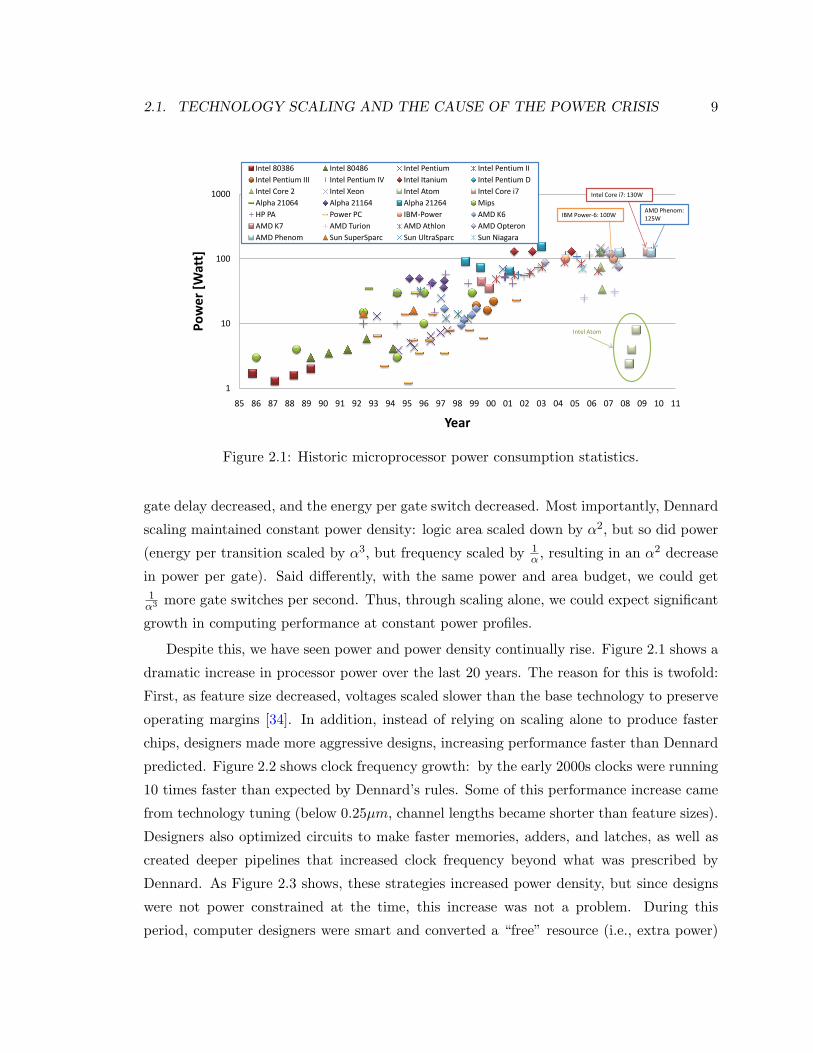
Figure 2.1: Historic microprocessor power consumption statistics.
gate delay decreased, and the energy per gate switch decreased. Most importantly, Dennard
scaling maintained constant power density: logic area scaled down by α2, but so did power
(energy per transition scaled by α3, but frequency scaled by 1α , resulting in an α2 decrease
in power per gate). Said differently, with the same power and area budget, we could get1
α3 more gate switches per second. Thus, through scaling alone, we could expect significant
growth in computing performance at constant power profiles.
Despite this, we have seen power and power density continually rise. Figure 2.1 shows a
dramatic increase in processor power over the last 20 years. The reason for this is twofold:
First, as feature size decreased, voltages scaled slower than the base technology to preserve
operating margins [34]. In addition, instead of relying on scaling alone to produce faster
chips, designers made more aggressive designs, increasing performance faster than Dennard
predicted. Figure 2.2 shows clock frequency growth: by the early 2000s clocks were running
10 times faster than expected by Dennard’s rules. Some of this performance increase came
from technology tuning (below 0.25µm, channel lengths became shorter than feature sizes).
Designers also optimized circuits to make faster memories, adders, and latches, as well as
created deeper pipelines that increased clock frequency beyond what was prescribed by
Dennard. As Figure 2.3 shows, these strategies increased power density, but since designs
were not power constrained at the time, this increase was not a problem. During this
period, computer designers were smart and converted a “free” resource (i.e., extra power)
10 CHAPTER 2. WHAT IS A CHIP GENERATOR?
10
100
1000
10000
85 86 87 88 89 90 91 92 93 94 95 96 97 98 99 00 01 02 03 04 05 06 07 08 09 10 11
Clk
freq
uenc
y [M
Hz]
Year
Intel 80386 Intel 80486 Intel PentiumIntel Pentium II Intel Pentium III Intel Pentium IVIntel Itanium Intel Pentium D Intel Core 2 Intel Xeon Intel Atom Intel Core i7Alpha 21064 Alpha 21164 Alpha 21264Mips HP PA Power PCIBM-Power AMD K6 AMD K7AMD Turion AMD Athlon AMD Opteron
IBM Power-6: 4.7GHz
Intel Core i7: 3.3GHz
AMD Phenom: 3.2GHz
45nm tech:533MHz
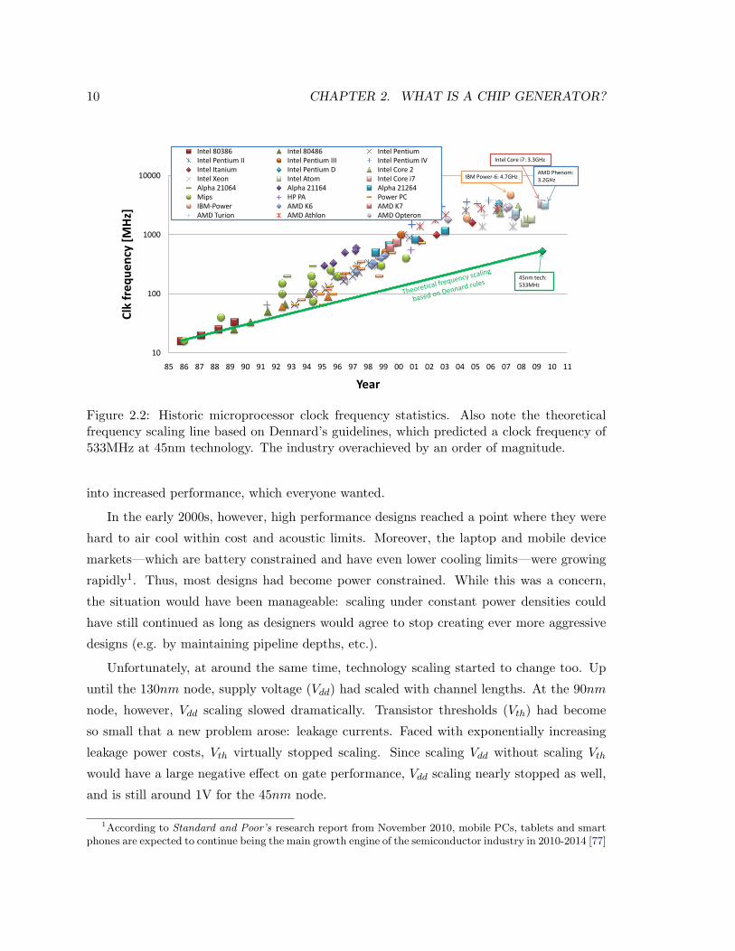
Figure 2.2: Historic microprocessor clock frequency statistics. Also note the theoreticalfrequency scaling line based on Dennard’s guidelines, which predicted a clock frequency of533MHz at 45nm technology. The industry overachieved by an order of magnitude.
into increased performance, which everyone wanted.
In the early 2000s, however, high performance designs reached a point where they were
hard to air cool within cost and acoustic limits. Moreover, the laptop and mobile device
markets—which are battery constrained and have even lower cooling limits—were growing
rapidly1. Thus, most designs had become power constrained. While this was a concern,
the situation would have been manageable: scaling under constant power densities could
have still continued as long as designers would agree to stop creating ever more aggressive
designs (e.g. by maintaining pipeline depths, etc.).
Unfortunately, at around the same time, technology scaling started to change too. Up
until the 130nm node, supply voltage (Vdd) had scaled with channel lengths. At the 90nm
node, however, Vdd scaling slowed dramatically. Transistor thresholds (Vth) had become
so small that a new problem arose: leakage currents. Faced with exponentially increasing
leakage power costs, Vth virtually stopped scaling. Since scaling Vdd without scaling Vth
would have a large negative effect on gate performance, Vdd scaling nearly stopped as well,
and is still around 1V for the 45nm node.
1According to Standard and Poor’s research report from November 2010, mobile PCs, tablets and smartphones are expected to continue being the main growth engine of the semiconductor industry in 2010-2014 [77]
2.2. DESIGN IN A POWER CONSTRAINED WORLD 11
0.01
0.10
1.00
10.00
85 86 87 88 89 90 91 92 93 94 95 96 97 98 99 00 01 02 03 04 05 06 07 08 09 10 11
Pow
er D
ensi
ty [W
att/
mm
^2]
Year
Intel 80386 Intel 80486 Intel Pentium Intel Pentium IIIntel Pentium III Intel Pentium IV Intel Itanium Intel Pentium DIntel Core 2 Intel Xeon Intel Atom Intel Core i7Alpha 21064 Alpha 21164 Alpha 21264 MipsHP PA Power PC IBM-Power AMD K6AMD K7 AMD Turion AMD Athlon AMD OpteronAMD Phenom Sun SuperSparc Sun UltraSparc Sun Niagara
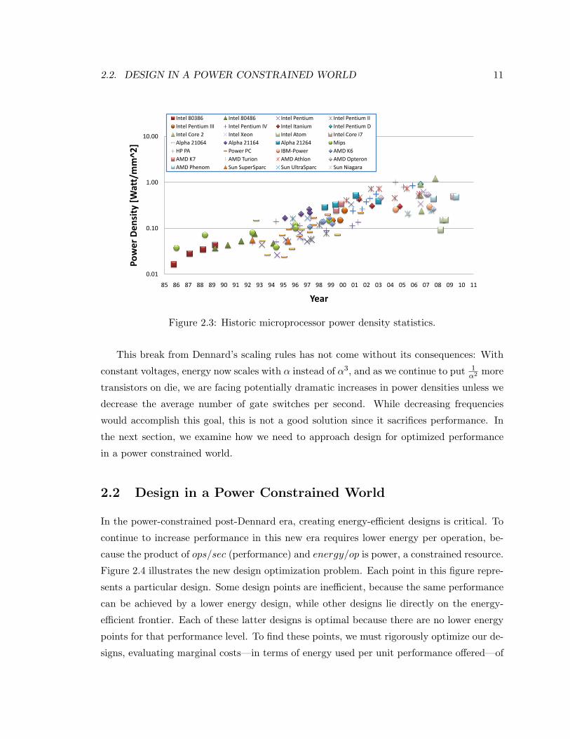
Figure 2.3: Historic microprocessor power density statistics.
This break from Dennard’s scaling rules has not come without its consequences: With
constant voltages, energy now scales with α instead of α3, and as we continue to put 1α2 more
transistors on die, we are facing potentially dramatic increases in power densities unless we
decrease the average number of gate switches per second. While decreasing frequencies
would accomplish this goal, this is not a good solution since it sacrifices performance. In
the next section, we examine how we need to approach design for optimized performance
in a power constrained world.
2.2 Design in a Power Constrained World
In the power-constrained post-Dennard era, creating energy-efficient designs is critical. To
continue to increase performance in this new era requires lower energy per operation, be-
cause the product of ops/sec (performance) and energy/op is power, a constrained resource.
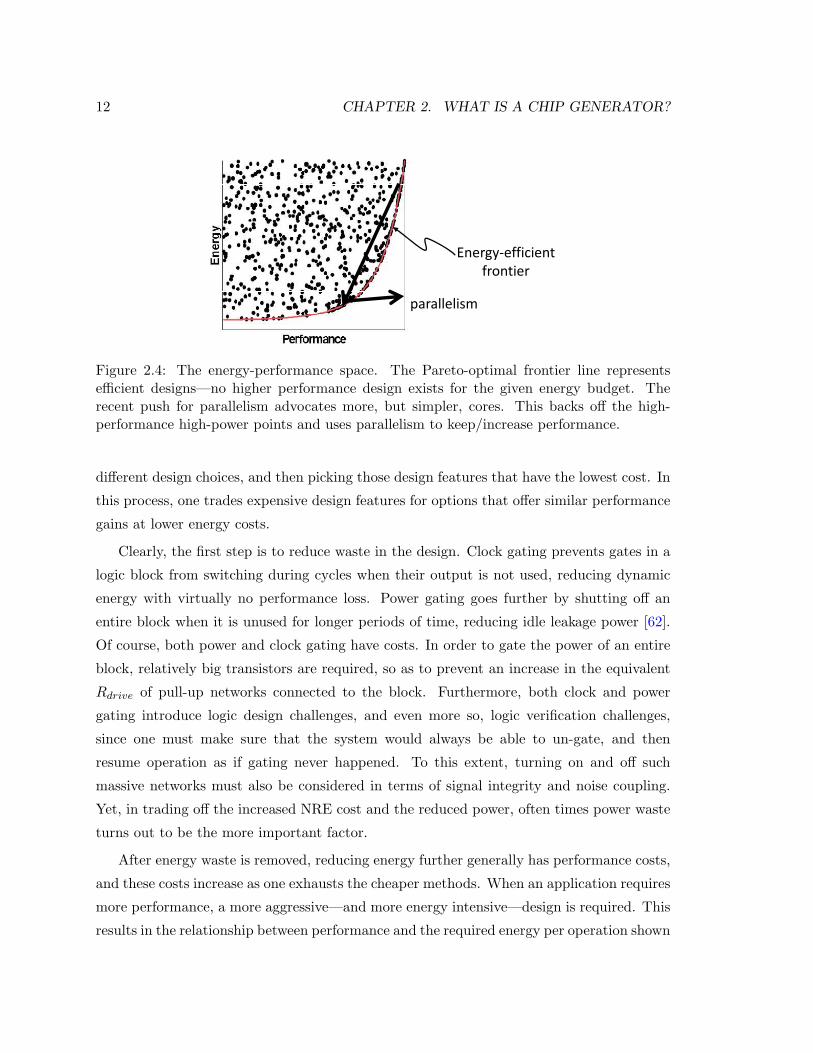
Figure 2.4 illustrates the new design optimization problem. Each point in this figure repre-
sents a particular design. Some design points are inefficient, because the same performance
can be achieved by a lower energy design, while other designs lie directly on the energy-
efficient frontier. Each of these latter designs is optimal because there are no lower energy
points for that performance level. To find these points, we must rigorously optimize our de-
signs, evaluating marginal costs—in terms of energy used per unit performance offered—of
12 CHAPTER 2. WHAT IS A CHIP GENERATOR?
�������������
� � ������
�������������
�������
Figure 2.4: The energy-performance space. The Pareto-optimal frontier line representsefficient designs—no higher performance design exists for the given energy budget. Therecent push for parallelism advocates more, but simpler, cores. This backs off the high-performance high-power points and uses parallelism to keep/increase performance.
different design choices, and then picking those design features that have the lowest cost. In
this process, one trades expensive design features for options that offer similar performance
gains at lower energy costs.
Clearly, the first step is to reduce waste in the design. Clock gating prevents gates in a
logic block from switching during cycles when their output is not used, reducing dynamic
energy with virtually no performance loss. Power gating goes further by shutting off an
entire block when it is unused for longer periods of time, reducing idle leakage power [62].
Of course, both power and clock gating have costs. In order to gate the power of an entire
block, relatively big transistors are required, so as to prevent an increase in the equivalent
Rdrive of pull-up networks connected to the block. Furthermore, both clock and power
gating introduce logic design challenges, and even more so, logic verification challenges,
since one must make sure that the system would always be able to un-gate, and then
resume operation as if gating never happened. To this extent, turning on and off such
massive networks must also be considered in terms of signal integrity and noise coupling.
Yet, in trading off the increased NRE cost and the reduced power, often times power waste
turns out to be the more important factor.
After energy waste is removed, reducing energy further generally has performance costs,
and these costs increase as one exhausts the cheaper methods. When an application requires
more performance, a more aggressive—and more energy intensive—design is required. This
results in the relationship between performance and the required energy per operation shown
2.2. DESIGN IN A POWER CONSTRAINED WORLD 13
in Figure 2.4 and the same trade-off is shown with historical processor data in Figure 2.5.
1
10
100
0.00 0.01 0.10 1.00Wat
ts /
(#Co
res*
Spec
06*L
*Vdd
^2)
Spec 2006 (Avg) * L
Intel 80386 Intel 80486 Intel Pentium Intel Pentium IIIntel Pentium III Intel Pentium IV Intel Itanium Intel Pentium DIntel Core 2 Intel Xeon Intel Atom Intel Core i7Alpha 21064 Alpha 21164 Alpha 21264 MipsHP PA Power PC IBM-Power AMD K6AMD K7 AMD Turion AMD Athlon AMD OpteronAMD Phenom Sun SuperSparc Sun UltraSparc
Intel Itanium: Single core
Intel Core 2 Duo: 2-4 cores
AMD Opteron: From1 to 2 to 4 cores
Intel Core i7: 4 cores
Intel Pentium IV: Single core
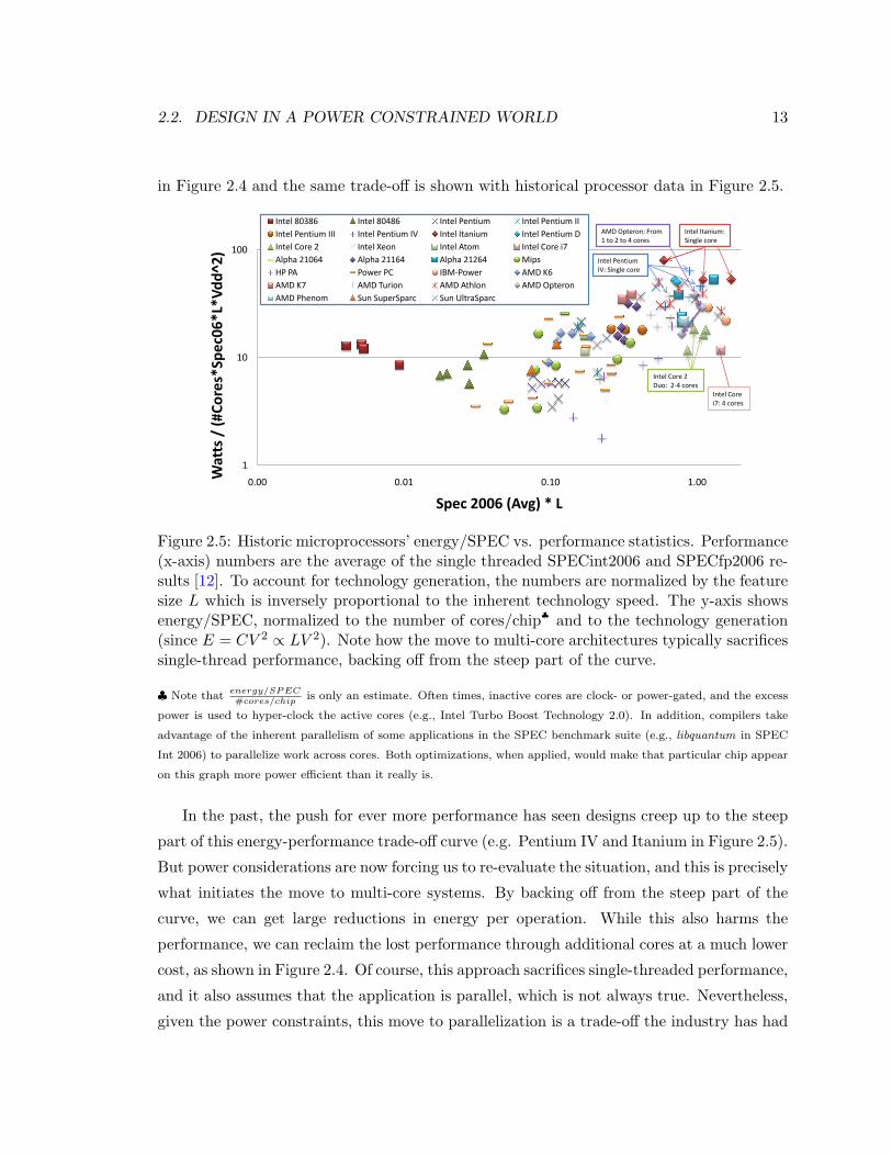
Figure 2.5: Historic microprocessors’ energy/SPEC vs. performance statistics. Performance(x-axis) numbers are the average of the single threaded SPECint2006 and SPECfp2006 re-sults [12]. To account for technology generation, the numbers are normalized by the featuresize L which is inversely proportional to the inherent technology speed. The y-axis showsenergy/SPEC, normalized to the number of cores/chip♣ and to the technology generation(since E = CV 2 ∝ LV 2). Note how the move to multi-core architectures typically sacrificessingle-thread performance, backing off from the steep part of the curve.
♣ Note thatenergy/SPEC#cores/chip
is only an estimate. Often times, inactive cores are clock- or power-gated, and the excess
power is used to hyper-clock the active cores (e.g., Intel Turbo Boost Technology 2.0). In addition, compilers take
advantage of the inherent parallelism of some applications in the SPEC benchmark suite (e.g., libquantum in SPEC
Int 2006) to parallelize work across cores. Both optimizations, when applied, would make that particular chip appear
on this graph more power efficient than it really is.
In the past, the push for ever more performance has seen designs creep up to the steep
part of this energy-performance trade-off curve (e.g. Pentium IV and Itanium in Figure 2.5).
But power considerations are now forcing us to re-evaluate the situation, and this is precisely
what initiates the move to multi-core systems. By backing off from the steep part of the
curve, we can get large reductions in energy per operation. While this also harms the
performance, we can reclaim the lost performance through additional cores at a much lower
cost, as shown in Figure 2.4. Of course, this approach sacrifices single-threaded performance,
and it also assumes that the application is parallel, which is not always true. Nevertheless,
given the power constraints, this move to parallelization is a trade-off the industry has had
14 CHAPTER 2. WHAT IS A CHIP GENERATOR?
to make [83].
Unfortunately, there are two reasons why we cannot rely on parallelism to save us in
the long term. First, as Amdahl noted in 1965, with extensive parallelization, serial code
and communication bottlenecks rapidly begin to dominate execution time [21, 39]. Thus,
the marginal energy cost of increasing performance through parallelism increases with the
number of processors, and will start increasing the overall energy per operation. The second
issue is that parallelism itself does not intrinsically lower the energy per operation; lower
energy is achieved only if backing off the performance yields a lower energy point in the
energy-performance space of Figure 2.4. Unfortunately, this follows the law of diminishing
returns. After initially backing away from high power designs, the remaining savings are
modest.
To improve energy efficiency further, we must consider another class of techniques:
hardware customization. By specializing compute platforms for the specific tasks they
perform, customization can result not only in significant energy savings, but can also reduce
the time to perform the task. The idea of specialization is well known, and is already applied
in varying degrees today. The use of SIMD units (e.g. SSE), vector machines and GPUs as
accelerators are all examples in which higher performance and lower energy can be achieved
through special-purpose units [53]. To get an idea of how much potential gain we can
achieve through customization, we only need to look at ASIC solutions, which often use
orders of magnitude less power than general purpose CPU-based solutions while achieving
the same or even greater levels of performance.
One way to achieve customization is through programmable chips. Examples include
polymorphic chip multiprocessor memory systems [71, 88], polymorphic on-chip networks [64],
configurable data paths [61] and baseband processors for software-defined-radio (SDR) wire-
less devices [28, 100, 51]. The premise of programmable chips is that the software layer can
configure the hardware for its needs. Doing that achieves multiple goals: first, it can deliver
a cost effective and flexible solution since multiple protocols can be supported on the same
hardware. Second, the hardware becomes a better fit for the application running on it.
For example, Intel’s reconfigurable SIMD engine ([61]) can be used as either 4-way 16bit
multiply, single 32 bit multiply, 4-way 16bit addition, 2-way 32bit addition or 72bit addition
to achieve maximum utilization. The third benefit of reconfigurability is that a significant
portion of the design cost is amortized. That means that building one machine with two
functional modes is not twice as difficult as building a machine with only one functional
2.2. DESIGN IN A POWER CONSTRAINED WORLD 15
mode.
Unfortunately, reconfigurability also carries a price. Devices with coarse-grain pro-
grammability, such as SDR baseband processors, must find compromises in the mix of
hardware resources that are put on the die. As a result, some applications may be less effi-
cient or lower in performance because they lack some resource they need. At the same time,
other resources on the die may be under utilized. Similarly, fine grain configurability, such
as configurable data paths or protocols, introduce circuit level overheads: first, every bit of
configuration has to be registered in hardware. In addition, each such bit implies some inef-
ficiency in the circuit’s logic, because it adds logic to the function being implemented (e.g.,
an extra mux in a data path, or an extra CAM look-up in a configurable state machine).
Therefore had we built separate ASIC chips, one for each use case, or “configuration,” of
the programmable chip, the resulting product would have been a much better match for
the application and much more power-efficient.
ASICs are more efficient because they eliminate the overheads that come with general
purpose computing and/or configurability. Many computing tasks, for example, need only
simple 8 or 16-bit operations, which typically take on the order of a picojoule or less at
90nm technology. This is in contrast to the energy consumed in the rest of a general
purpose processor pipeline which is on the order of hundreds of picojoules [26]. To efficiently
execute these simple operations in a processor, we need to perform hundreds of operations
per processor instruction, so the functional unit energy becomes a significant fraction of the
total energy.
While we would prefer to build customized chips for their efficiency, they are expensive to
design. The design and verification cost for a state-of-the-art ASIC today is well over $20M,
and the total non-recurring engineering (NRE) costs are more than twice that, due to the
custom software required for these custom chips [44, 16, 36, 48, 63]. Interestingly, fabrication
costs, while very high, only account for roughly 10% of the total cost today [36, 63]. This
means high design, verification and software costs are the primary reason the number of
ASICs being produced is actually decreasing [85, 48], despite the fact that they are the
most energy-efficient solution.
To summarize this impasse, in order to provide better, higher performance, chips, one
must create more power efficient chips. In order to create chips that are more power efficient,
one must find a way to make custom chip design cheaper. The next section proposes an
approach to energy efficiency by making customized solutions much less expensive. In our
16 CHAPTER 2. WHAT IS A CHIP GENERATOR?
Chip Generator approach, a chip template replaces the chip instance, and customization be-
comes a matter of setting parameter knobs in that template, thus moving the customization
process to a higher level of abstraction.
2.3 Build Chip-Generators, Not Chips
Chip design today is not an isolated task but a process. Creating new hardware involves the
creation of a new set of simulation and software tools, including a system level architecture
simulator and, often times, additional design-space exploration tools for internal blocks.
Only after the architectural and micro-architectural design trade-offs are well understood,
do designers create optimized instances and ultimately the final chip. In addition, new
hardware typically requires new software support such as drivers, or if it is programmable,
compilers, linkers and runtime environments. An optimized software stack is as important
as optimized hardware since one can easily lose an order of magnitude in performance from
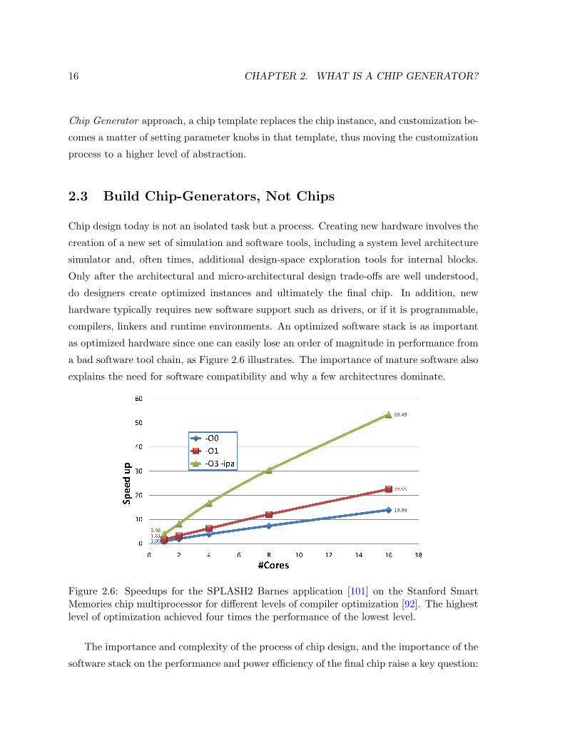
a bad software tool chain, as Figure 2.6 illustrates. The importance of mature software also
explains the need for software compatibility and why a few architectures dominate.
Figure 2.6: Speedups for the SPLASH2 Barnes application [101] on the Stanford SmartMemories chip multiprocessor for different levels of compiler optimization [92]. The highestlevel of optimization achieved four times the performance of the lowest level.
The importance and complexity of the process of chip design, and the importance of the
software stack on the performance and power efficiency of the final chip raise a key question:
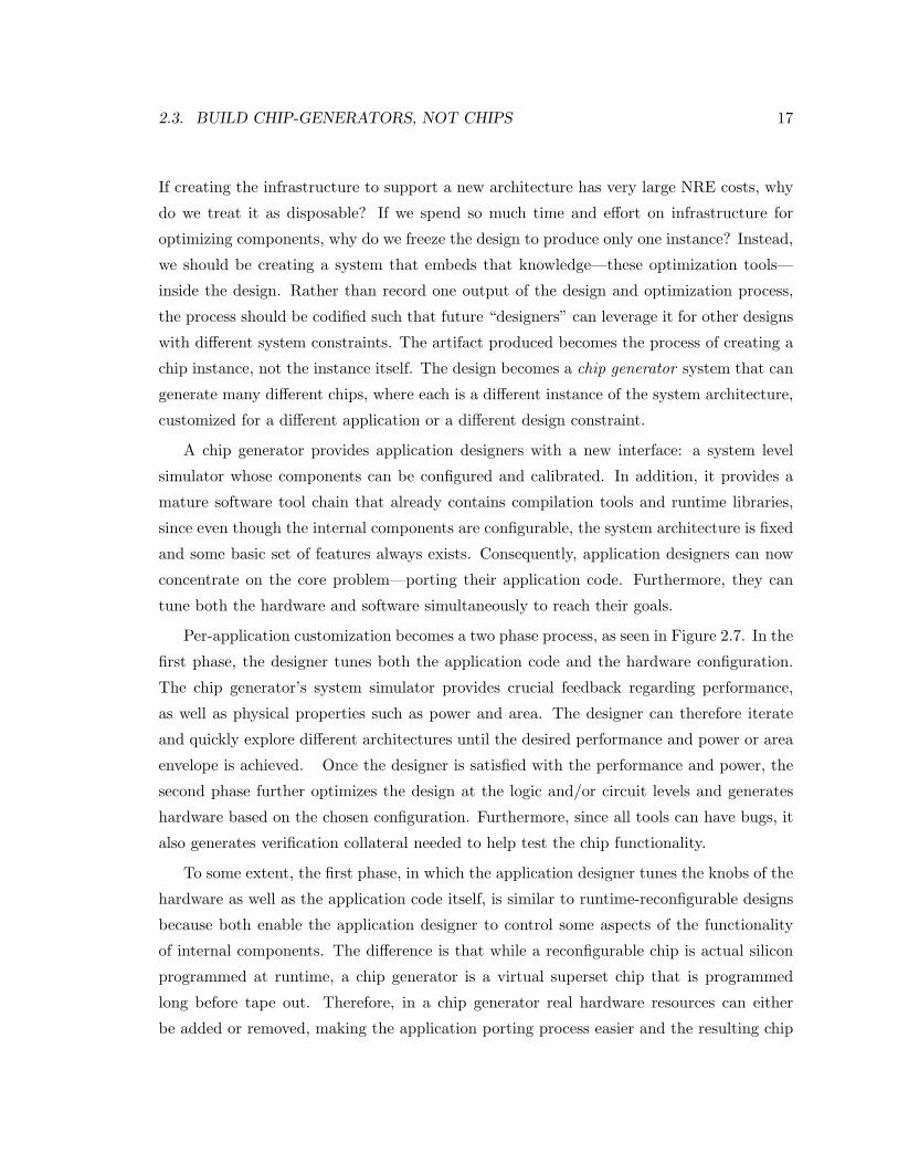
2.3. BUILD CHIP-GENERATORS, NOT CHIPS 17
If creating the infrastructure to support a new architecture has very large NRE costs, why
do we treat it as disposable? If we spend so much time and effort on infrastructure for
optimizing components, why do we freeze the design to produce only one instance? Instead,
we should be creating a system that embeds that knowledge—these optimization tools—
inside the design. Rather than record one output of the design and optimization process,
the process should be codified such that future “designers” can leverage it for other designs
with different system constraints. The artifact produced becomes the process of creating a
chip instance, not the instance itself. The design becomes a chip generator system that can
generate many different chips, where each is a different instance of the system architecture,
customized for a different application or a different design constraint.
A chip generator provides application designers with a new interface: a system level
simulator whose components can be configured and calibrated. In addition, it provides a
mature software tool chain that already contains compilation tools and runtime libraries,
since even though the internal components are configurable, the system architecture is fixed
and some basic set of features always exists. Consequently, application designers can now
concentrate on the core problem—porting their application code. Furthermore, they can
tune both the hardware and software simultaneously to reach their goals.
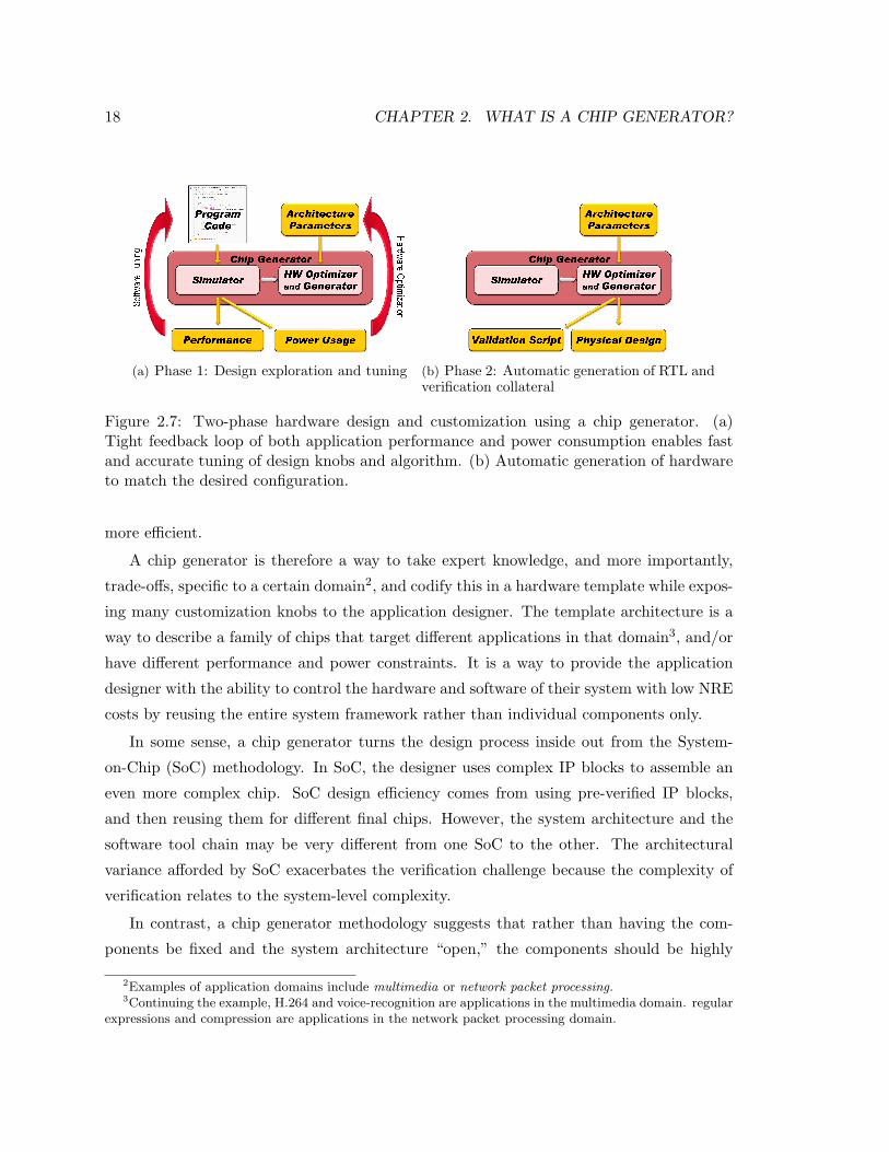
Per-application customization becomes a two phase process, as seen in Figure 2.7. In the
first phase, the designer tunes both the application code and the hardware configuration.
The chip generator’s system simulator provides crucial feedback regarding performance,
as well as physical properties such as power and area. The designer can therefore iterate
and quickly explore different architectures until the desired performance and power or area
envelope is achieved. Once the designer is satisfied with the performance and power, the
second phase further optimizes the design at the logic and/or circuit levels and generates
hardware based on the chosen configuration. Furthermore, since all tools can have bugs, it
also generates verification collateral needed to help test the chip functionality.
To some extent, the first phase, in which the application designer tunes the knobs of the
hardware as well as the application code itself, is similar to runtime-reconfigurable designs
because both enable the application designer to control some aspects of the functionality
of internal components. The difference is that while a reconfigurable chip is actual silicon
programmed at runtime, a chip generator is a virtual superset chip that is programmed
long before tape out. Therefore, in a chip generator real hardware resources can either
be added or removed, making the application porting process easier and the resulting chip
18 CHAPTER 2. WHAT IS A CHIP GENERATOR?
(a) Phase 1: Design exploration and tuning (b) Phase 2: Automatic generation of RTL andverification collateral
Figure 2.7: Two-phase hardware design and customization using a chip generator. (a)Tight feedback loop of both application performance and power consumption enables fastand accurate tuning of design knobs and algorithm. (b) Automatic generation of hardwareto match the desired configuration.
more efficient.
A chip generator is therefore a way to take expert knowledge, and more importantly,
trade-offs, specific to a certain domain2, and codify this in a hardware template while expos-
ing many customization knobs to the application designer. The template architecture is a
way to describe a family of chips that target different applications in that domain3, and/or
have different performance and power constraints. It is a way to provide the application
designer with the ability to control the hardware and software of their system with low NRE
costs by reusing the entire system framework rather than individual components only.
In some sense, a chip generator turns the design process inside out from the System-
on-Chip (SoC) methodology. In SoC, the designer uses complex IP blocks to assemble an
even more complex chip. SoC design efficiency comes from using pre-verified IP blocks,
and then reusing them for different final chips. However, the system architecture and the
software tool chain may be very different from one SoC to the other. The architectural
variance afforded by SoC exacerbates the verification challenge because the complexity of
verification relates to the system-level complexity.
In contrast, a chip generator methodology suggests that rather than having the com-
ponents be fixed and the system architecture “open,” the components should be highly
2Examples of application domains include multimedia or network packet processing.3Continuing the example, H.264 and voice-recognition are applications in the multimedia domain. regular
expressions and compression are applications in the network packet processing domain.
2.3. BUILD CHIP-GENERATORS, NOT CHIPS 19
parametrized and the system architecture “fixed.” Moreover, the flexible components should
(as explained above) codify the trade-offs, such that the actual value for each knob can be
set at a later time and the rest of the design would adjust. The result is that the architec-
tural variance is constrained at the system level, so that the difficult verification problem
can be amortized over many designs. Acknowledging that all tools can be faulty and thus
one cannot guarantee bug-free hardware, we argue that a fixed system architecture allows
a generator to find bugs efficiently by either reusing or generating system level verification
collateral (more on validation issues in Chapter 4).
At the same time, the additional flexibility adds two more benefits: Adding flexibility at
lower levels (i.e., inside the IP blocks) enables us to do fine grain optimizations. For example,
if the processor in the generator has much flexibility in it (i.e., number and type of functional
units, pipe depth, number of ways etc) than one can use that processor for many different
instances of generated systems, and always push the processor power/performance tradeoff
to the right area of the Pareto optimal curve. Adding flexibility at the higher level (i.e.,
for the “plumbing” between the IP blocks) helps with system reuse for more applications,
since these knobs are likely to be set by architects to create different systems in that domain
(e.g., in an SoC generator, these knobs may include number of USB ports, number/type of
processors, number Ethernet ports etc.).
In general, one can think about chip generators as improving (or even fixing) the method-
ology move from RTL to IP blocks as the next design abstraction layer: When the IC indus-
try moved from transistors to gates, the new abstraction left the transistor sizing “free” for
optimization at place-and-route (PNR) stage, and the tool vendors “taught” PNR tools how
to run the logical effort calculations to create an efficient implementation of the required
gate (either by choosing from a predefined set of gates of discrete sizes, or by creating trees of
gates and buffers). Similarly, when the industry moved from gates (structural) to RTL (be-
havioral), in the improved hardware descriptive languages (HDLs) the actual combinational
implementation of the combinational logic was left as a free knob, and design automation
engineers “taught” the synthesis tool to do Boolean conversions and optimizations. They
also built knowledge into the synthesis tool, such that it “knows” how to implement an
adder or a multiplier or even a reduction tree. However, in the move from RTL to IP blocks
something went “wrong,” some of the engineers’ knowledge was not recorded: First, IP
blocks are generally fixed, with almost no free knobs. Second, we did not create a tool
that contains knowledge on how to translate a complete system from the abstraction to a
20 CHAPTER 2. WHAT IS A CHIP GENERATOR?
functional and correct implementation. This is where a chip generator comes to play — A
chip generator in this sense is a high level, domain specific, synthesis and optimization tool.
The next section sheds some light on the challenges that one will need to face in order to
realize a chip generator. These challenges range from layout and physical design automation,
through better design tools for embedding designers knowledge, better and more automated
exploration of design space, and challenges in the already notorious RTL verification process,
and up to software and application tuning and customization.
2.4 Challenges
Unlike designing a single chip instance or family, even a reconfigurable one, the making of
a generator is significantly different. Most critical in this differentiation is the fact that the
generator designer, writing the hardware, does not know exactly what hardware is going to
actually be generated at the end of the process. In the generator concept, it is up to the
application designer to make that final configuration decision based on the application she
is implementing. For example, some parts may not be required by the application and thus
not taped out to silicon.
In order to create customized, heterogeneous designs, we believe it is better to start
with a flexible, yet well defined, architecture, to make verification and software easier.
This means that when we come to think about an architecture, we don’t immediately
dive into the resolution of how each individual instance of a component is configured, but
instead we generalize it as best we can, abstract it to its key architectural traits. This
would be the template of this architecture. For example, the design may have one or
more processing cores, but we leave it to a later phase to determine exactly how many
cores, and for each core its particular internal micro-architectural decisions such as out-
of-order vs. in-order, VLIW and/or SIMD and so on. What we need to code is where
(logically and physically) these processing elements will reside once the decision is made,
and what other implication on the system they might have (e.g., a SIMD processor requires
wider bandwidth for its data port). Similarly, we need to mark where storage components
logically are, but we can leave their exact semantics (FIFO vs. scratch-pads vs. caches)
to the system configuration phase. Of course, once template parameters are bound at the
top level, for example deciding that storage element A is a FIFO and B is a cache, at the
next level there are more decisions to be made, such as that FIFO’s size or that cache’s
2.4. CHALLENGES 21
associativity (in a processor these internal decision might include the size of the reorder
buffer or whether the floating point unit implements multiply-accumulate). This means
that “templating” of the components should be done hierarchically, so that each level of the
hierarchy provides a few local design decisions—knobs for customization by an application
designer or architect—while not breaking from the general formation so the change to the
verification and software layers is minimal.
Enabling these pervasive customizations, however, would mean that the internals of the
architecture need to be built from highly parametrized and extensible modules, so one can
then easily shape the components, creating heterogeneous modules tailored to specific ap-
plication needs. In this process, the application designer, architect, optimization framework
or perhaps even a high-level compiler, hierarchically cast values into the architectural tem-
plates. The challenge is both in creating these flexible modules and then in enabling late
binding of the parameters.These issues are discussed in more detail in Chapter 3.
The idea of creating flexible modules is, of course, not new. Both VHDL and Verilog
(post 2001) use elaboration time parameters and generate blocks to enable more code reuse.
Generate blocks enable the designer to write (simple) elaboration programs, for which
parameters are the input and hardware components are the output. Bluespec [1] extended
this concept, enhancing and merging the programmability into the main code (rather than
limiting it to generate blocks). At the block level, commercially available products such as
Tensilica’s processors [9, 47], Sonics’s on-chip interconnects [6], or Synfora’s PICO system [8]
generate complete IP blocks for SoCs. However, while good for creating individual blocks,
these methods are not designed to produce full systems. There are many inter-dependencies
between modules, and one still needs a program to configure the parameters such that the
entire system is consistent (for example, the cache matches the processor’s word size).
Moreover, even when using these high level blocks, what about the generation of the rest
of the system? The missing piece is how to compose these building blocks in larger and
larger blocks until you reach the system level. In the next chapter, we discuss how Genesis2
solves this problem.
In creating a hierarchical generator, there are various types of design parameters that
need to be determined. At the top level, the application designer specifies the high-level
design architecture. Beyond these directly controlled parameters, however, many other
parameters still need to be determined. First, design parameters in different blocks are
often linked. Thus, each flexible module needs to incorporate an “elaboration program”
22 CHAPTER 2. WHAT IS A CHIP GENERATOR?
to specify how parameters in one block are computed from the parameters of another,
be it higher or lower in the design hierarchy. This requires that the elaboration engine
have significant software capabilities. Furthermore, many lower-level design parameters
exist whose impact on the system is not functional, but a matter of performance and cost
(sizing of caches, queues, etc.). These should automatically be determined by optimization
procedures. To this end, after the designer provides the chip program and the design
objective and constraints (e.g. maximize performance under some power and area budget),
an optimization framework should evaluate the different potential design configurations, to
select the best one.
One challenge in creating the optimization framework lies in the huge space that needs
to be explored. With even as few as twenty parameters, the design space can easily exceed
billions of distinct design configurations. This is a problem since architects traditionally rely
on long-running simulations for performance evaluation; searching the entire space would
take far too long. To make this problem more tractable, one powerful technique is to gener-
ate predictive models from samples of the design space [67, 59, 38]. With only a relatively
small number of design simulations, one can analyze the performance numbers and use data
fitting to produce an analytical model. Using these techniques, Azizi et. al. have created
a hierarchical system trade-off optimization framework [25, 24]. Leveraging sample-and-fit
methods, they have shown that one can dramatically reduce the number of simulations re-
quired; with only 500 simulation runs, they were able to accurately characterize large design
spaces for processor systems that had billions of possible design configurations. Moreover,
by encapsulating energy-performance trade-off information into libraries, they created a hi-
erarchical framework that could evaluate both higher level micro-architectural design knobs
and lower level circuit trade-offs.
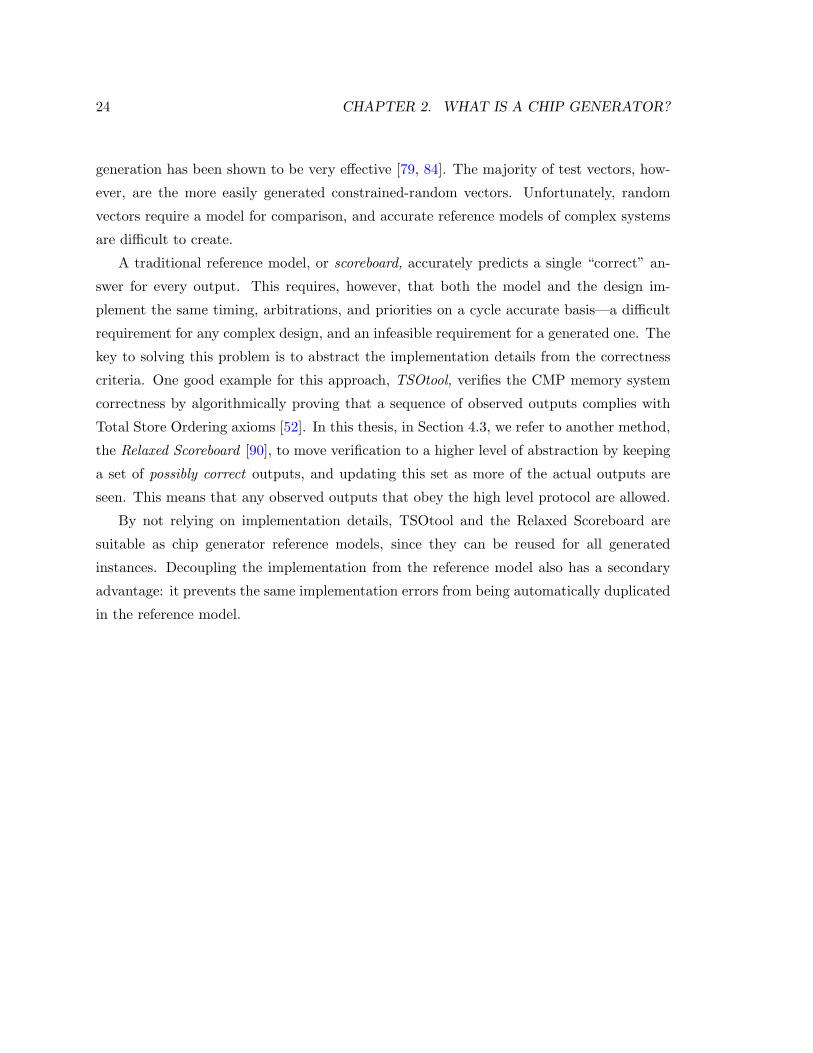
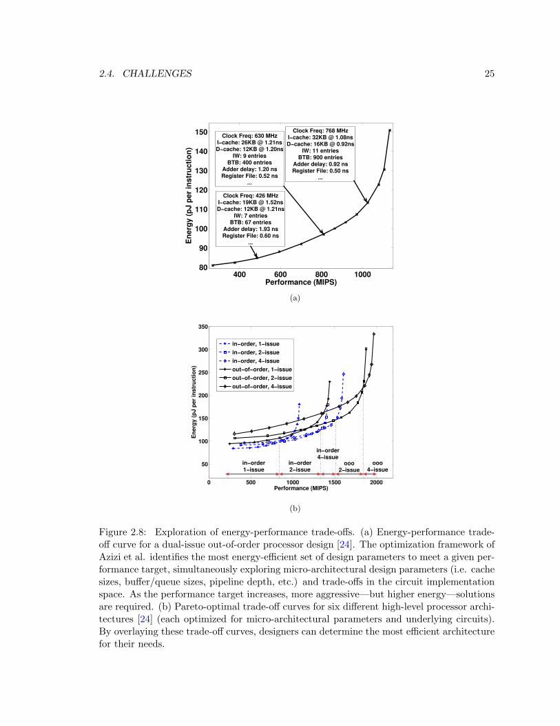
Figure 2.8 shows the results of using this framework to optimize a processor architecture.
Each curve represents a particular high-level architecture with various underlying design
knobs. As the performance requirement increases, more resources are introduced into each
design, resulting in higher performance, but also higher cost. Figure 2.8(a) shows some of
the lower level design parameters throughout the design space for one high-level architecture,
while Figure 2.8(b) compares various higher level architectures.
This optimization method is a great tool for handling the tuning of many low-level
parameters, but it further emphasizes the need to leave “free parameters” in the design,
whose values will be determined in a late binding stage—something that the existing tools
2.4. CHALLENGES 23
today don’t do very well. Our tool, Genesis2, solves this problem by providing a standard
XML based interface for optimization tools.
Even if we can successfully generate an optimized design, we still need to address the
validation problem, since no design and no tool is bug free. This is a significant issue because
design verification is one of the largest hurdles in ASIC design, estimated to account for
35%-70% of the total design cost [44]. Therefore for a chip generator to be a valid solution
to today’s chip design hurdles, it must reduce, or at least amortize across multiple chips the
high verification costs.
It is essential to understand that in a chip generator scheme, the validation efforts
are directed at verifying the resulting instance of the generator—not the generator itself.
Moreover, it is common practice for verification engineers to “tweak” components of a design
to induce “interesting” corner cases (e.g., reducing the size of a producer-consumer FIFO
to introduce more back-pressure scenarios). A generator can be applied to quickly produce
even more variations, introduce more randomness, and expose more corner cases. When
verifying instances produced by our SSM prototype generator, we found that this technique
resulted in design instances that were verified better and faster, because one generated
instance would often expose a given bug faster than other instances. This work is discussed
in Chapter 4.
While the ability to “shake” the architecture (i.e., test various configurations of the
design) does seem to be helpful for verification, there is a real challenge in creating a ver-
ification environment flexible enough to account for all the different design instances that
the generator can produce. Our solution is for the chip generator to automatically produce
significant portions of the verification collateral. The main components of verification col-
lateral include a test bench, design assertions, test vectors and a reference model. The use
of a fixed system architecture with flexible components is advantageous here: because the
system architecture is fixed, and the interfaces are known, the same test bench and scripts
can be used for multiple different generated instances. This is similar to the verification
of runtime-reconfigurable designs. In addition, we show in Section 3.3.5 how the same pa-
rameters that are used for the generator’s inner components can be applied to create the
verification monitors, drivers and the local assertions.
Once a test bench is in place, a generated design would require a set of directed and
constrained-random vectors. Generating directed test vectors is conceptually more diffi-
cult, since they depend on the target application, although automatic directed test vector
24 CHAPTER 2. WHAT IS A CHIP GENERATOR?
generation has been shown to be very effective [79, 84]. The majority of test vectors, how-
ever, are the more easily generated constrained-random vectors. Unfortunately, random
vectors require a model for comparison, and accurate reference models of complex systems
are difficult to create.
A traditional reference model, or scoreboard, accurately predicts a single “correct” an-
swer for every output. This requires, however, that both the model and the design im-
plement the same timing, arbitrations, and priorities on a cycle accurate basis—a difficult
requirement for any complex design, and an infeasible requirement for a generated one. The
key to solving this problem is to abstract the implementation details from the correctness
criteria. One good example for this approach, TSOtool, verifies the CMP memory system
correctness by algorithmically proving that a sequence of observed outputs complies with
Total Store Ordering axioms [52]. In this thesis, in Section 4.3, we refer to another method,
the Relaxed Scoreboard [90], to move verification to a higher level of abstraction by keeping
a set of possibly correct outputs, and updating this set as more of the actual outputs are
seen. This means that any observed outputs that obey the high level protocol are allowed.
By not relying on implementation details, TSOtool and the Relaxed Scoreboard are
suitable as chip generator reference models, since they can be reused for all generated
instances. Decoupling the implementation from the reference model also has a secondary
advantage: it prevents the same implementation errors from being automatically duplicated
in the reference model.
2.4. CHALLENGES 25
400 600 800 100080
90
100
110
120
130
140
150
Performance (MIPS)
Ener
gy (p
J pe
r ins
truct
ion)
Clock Freq: 426 MHzI−cache: 19KB @ 1.52nsD−cache: 12KB @ 1.21ns
IW: 7 entriesBTB: 67 entries
Adder delay: 1.93 nsRegister File: 0.60 ns
...
Clock Freq: 768 MHzI−cache: 32KB @ 1.08nsD−cache: 16KB @ 0.92ns
IW: 11 entriesBTB: 900 entries
Adder delay: 0.92 nsRegister File: 0.50 ns
...
Clock Freq: 630 MHzI−cache: 26KB @ 1.21nsD−cache: 12KB @ 1.20ns
IW: 9 entriesBTB: 400 entries
Adder delay: 1.20 nsRegister File: 0.52 ns
...
(a)
0 500 1000 1500 2000
50
100
150
200
250
300
350
Performance (MIPS)
Ener
gy (p
J pe
r ins
truct
ion)
in−order, 1−issuein−order, 2−issuein−order, 4−issueout−of−order, 1−issueout−of−order, 2−issueout−of−order, 4−issue
in−order4−issue
ooo4−issue
ooo2−issue
in−order2−issue
in−order1−issue
(b)
Figure 2.8: Exploration of energy-performance trade-offs. (a) Energy-performance trade-off curve for a dual-issue out-of-order processor design [24]. The optimization framework ofAzizi et al. identifies the most energy-efficient set of design parameters to meet a given per-formance target, simultaneously exploring micro-architectural design parameters (i.e. cachesizes, buffer/queue sizes, pipeline depth, etc.) and trade-offs in the circuit implementationspace. As the performance target increases, more aggressive—but higher energy—solutionsare required. (b) Pareto-optimal trade-off curves for six different high-level processor archi-tectures [24] (each optimized for micro-architectural parameters and underlying circuits).By overlaying these trade-off curves, designers can determine the most efficient architecturefor their needs.

26 CHAPTER 2. WHAT IS A CHIP GENERATOR?
Chapter 3
Creating A Generator:
Embedding The Hardware
Designer’s Knowledge
In Chapter 2 we introduced the concept of a chip generator hardware design framework.
In its essence, the chip generator provides an application designer the ability to control
the hardware substrate on which his/her application is going to be computed. As a simple
example, an application designer may decide that one storage element in the architecture
template is to be used as a private cache, another as a shared cache and a third as local
scratch pad. Similarly, the application designer may decide to add some custom functional
unit to a processing element to improve the efficiency of a calculation. In addition, after
higher level architectural knobs have been set, an optimization script may be used to au-
tomatically make some of the lower level design decisions. For example, these lower level
decisions might include size and associativity of the aforementioned caches or the width of
that functional unit. Notably, an implicit assumption here is that the system can accept
such late, high level changes, and generate the appropriate hardware with minimal or no
manual intervention.
This chapter talks about how one should approach the hardware generation phase. We
start by discussing the previously mentioned “architectural template” approach, in which
the skeleton is set but the components are flexible—subject to the application designer and
optimization tools creativity (Section 3.1).
27
28 CHAPTER 3. CREATING A GENERATOR
It is important to note that in this approach many of the design decisions must be left
unassigned or parametrized until a later stage in the process where the application engineers
set them. This process, which we call “late binding” of design decisions and parameters,
comes in contrast to current approaches where the design exploration and optimization has
been fixed and hard-coded up front by the hardware architects and hardware designers.
Late binding of design parameters implies that at design time the hardware designer
does not know the exact value of parameters, and therefore must embed instructions—an
“elaboration program”—that encode the impact of each parameter on the construction of
the system. To give a concrete example of the level of parametrization required, Section 3.1
examines the architecture of a couple of typical structures in a chip multiprocessor. We
show how parameters can be classified into three main groups: architectural parameters,
free/optimization parameters, and constrained/inherited parameters. We then examine the
implication of these parameter classes on making a late-bindable, optimizable generator,
that can take a homogeneous flexible component and create a heterogeneous result.
Unfortunately however, our attempt to build a chip generator using existing Hardware
Descriptive Languages (HDLs) either resulted in cumbersome code, or else these HDLs (or
the tools parsing them) could not handle the extreme parametrization and the embedding
of complicated elaboration programs (Section 3.2). Therefore, in Section 3.3 we introduce
Genesis2—a tool that facilitates the construction of generators by enabling hardware de-
signers to encode elaboration instructions with complete software-like capabilities. Genesis2
enables designers to code in two languages simultaneously and interleaved. One language
describes the hardware proper (Verilog; synthesizable), and the other one decides what
hardware to generate (Perl; evaluated at elaboration). C++ programmers might recognize
this as being similar to the use of the main C language to describe an algorithm, interleaved
with C++ constructors and templates meta-programming to describe the structure of the
system and to do late binding of types, constants or functions to specific parameters within
the algorithm.
The premise of Genesis2 is that during elaboration time everything is allowed and every-
thing is possible. Genesis2 pulls out all parametrization functionality from the underlying
language (typically Verilog). It then takes charge of the construction of the entire hierarchy
and of module uniquification, which will be discussed later. Thus by using Genesis2, instead
of coding specific modules, hardware designers are coding instructions for how these mod-
ules need to be generated given a set of (external) application specific input parameters. At
3.1. TEMPLATES AND PARAMETERS 29
elaboration time, whenever a module is instantiated, the interleaved elaboration program
constructs the required hardware module.
Section 3.4 provides the lower level technical details of how Genesis2 was implemented,
and Section 3.5 discusses improvements one may consider if one wants to make Genesis2
into a commercial tool (instead of a research one).
3.1 Architectural Templates and Design Parameters
Section 2.3 introduced the term architectural template as a venue for the codification of
expert knowledge and trade-offs in a certain domain. Therefore, a templated architecture
describes a family of chips that target different applications and/or have different perfor-
mance and power constraints. In many ways, for the user of the generator—that is, the
application designer—programming this template is similar to configuring an architectural
simulator such as M5 [27] or SimpleScalar [22], because in both cases, the underlying frame-
work defines a set of knobs for the user to configure. Figure 3.1 shows an example template
for what could be a tile in a chip multiprocessor generator. The left side of the diagram
illustrates that components are placed and interconnected to form a rigid structure for that
architecture. Yet, it also shows how at each level of the template hierarchy, certain knobs
or parameters have been left for the application designer to determine. In the diagram
shown here, the tile level parameters include, for example, the number of processors to be
included in the tile. It also shows that once that number is set, each processor can be con-
figured at the next lower level of the hierarchy, according to predefined knobs that impact
the architecture of that processor. Furthermore each processor configuration may result in
completely different processor hardware.
The right side of Figure 3.1 shows how configuring the generator is to be done. In its
essence, the configuration is done by the user hierarchically specifying the value for the
architectural knobs1. In some cases, the application designer may not desire to specify the
exact value of a knob but may instead leave it to an optimization procedure to determine
(e.g., an application designer may desire a cache, but may want to leave the cache size for
the optimizer to determine). In these cases O. Azizi et. al. has shown how optimization
1While there are many ways for a user to specify hierarchical input, we chose to use an XML [29]configuration file as the delivery media, for its simplicity on one hand, along with the rich library supportfor creating, manipulating and parsing XML documents in all software languages. This guarantees easy andstandardized interfacing with other tools as we show later.
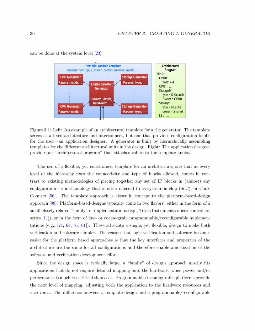
30 CHAPTER 3. CREATING A GENERATOR
can be done at the system level [23].
Application Designer Sees A “Simulator-like” Framework
Application Designer Sees A “Simulator-like” Framework
Fixed interconnection of flexible modules A d i t l t / bl i t A design template / blueprintNot a flexible configuration of fixed modules
Architectural CMP Tile: Module Template Architectural Program
Tile 0:CPU0:
width = 4
CMP Tile: Module Template
CPU GeneratorParams: width
Params: num_cpus, shared_caches, memory_model, …
Storage GeneratorParams: type width = 4
CPU1: …Storage0:
type = D-Scratch
Params: width, … Load-Store-Unit Generator
Params: type, …
Owner = CPU0Storage1:
type = I-Cacheowner = Shared
CPU GeneratorParams: width
Params: depth, bandwidth…
Storage GeneratorParams: type
September 14, 2010 [email protected]
owner = SharedLSU: …
Params: width, … Params: type, …
16
Figure 3.1: Left: An example of an architectural template for a tile generator. The templateserves as a fixed architecture and interconnect, but one that provides configuration knobsfor the user—an application designer. A generator is built by hierarchically assemblingtemplates for the different architectural units in the design. Right: The application designerprovides an “architectural program” that attaches values to the template knobs.
The use of a flexible, yet constrained template for an architecture, one that at every
level of the hierarchy fixes the connectivity and type of blocks allowed, comes in con-
trast to existing methodologies of piecing together any set of IP blocks in (almost) any
configuration—a methodology that is often referred to as system-on-chip (SoC), or Core-
Connect [56]. The template approach is closer in concept to the platform-based-design
approach [99]. Platform-based-designs typically come in two flavors: either in the form of a
small closely related “family” of implementations (e.g., Texas Instruments micro-controllers
series [11]), or in the form of fine- or coarse-grain programmable/reconfigurable implemen-
tations (e.g., [71, 64, 51, 61]). These advocate a single, yet flexible, design to make both
verification and software simpler. The reason that logic verification and software becomes
easier for the platform based approaches is that the key interfaces and properties of the
architecture are the same for all configurations and therefore enable amortization of the
software and verification development effort.
Since the design space is typically large, a “family” of designs approach mostly fits
applications that do not require detailed mapping onto the hardware, when power and/or
performance is much less critical than cost. Programmable/reconfigurable platforms provide
the next level of mapping, adjusting both the application to the hardware resources and
vice versa. The difference between a template design and a programmable/reconfigurable
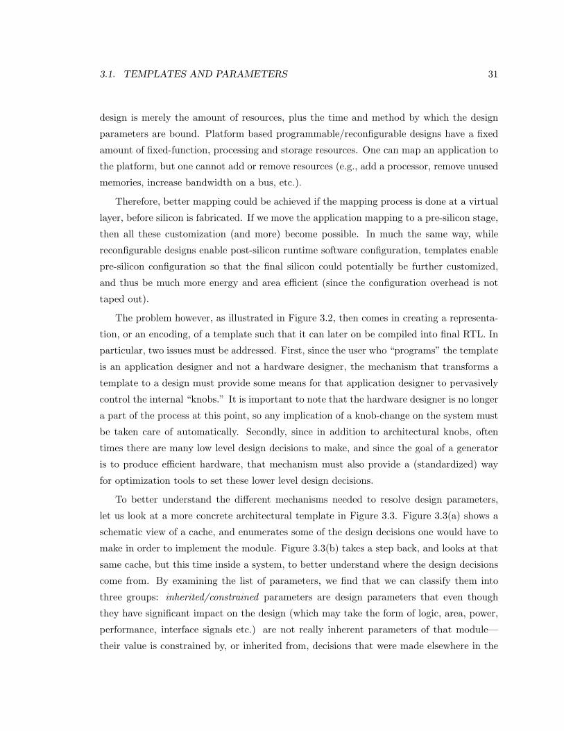
3.1. TEMPLATES AND PARAMETERS 31
design is merely the amount of resources, plus the time and method by which the design
parameters are bound. Platform based programmable/reconfigurable designs have a fixed
amount of fixed-function, processing and storage resources. One can map an application to
the platform, but one cannot add or remove resources (e.g., add a processor, remove unused
memories, increase bandwidth on a bus, etc.).
Therefore, better mapping could be achieved if the mapping process is done at a virtual
layer, before silicon is fabricated. If we move the application mapping to a pre-silicon stage,
then all these customization (and more) become possible. In much the same way, while
reconfigurable designs enable post-silicon runtime software configuration, templates enable
pre-silicon configuration so that the final silicon could potentially be further customized,
and thus be much more energy and area efficient (since the configuration overhead is not
taped out).
The problem however, as illustrated in Figure 3.2, then comes in creating a representa-
tion, or an encoding, of a template such that it can later on be compiled into final RTL. In
particular, two issues must be addressed. First, since the user who “programs” the template
is an application designer and not a hardware designer, the mechanism that transforms a
template to a design must provide some means for that application designer to pervasively
control the internal “knobs.” It is important to note that the hardware designer is no longer
a part of the process at this point, so any implication of a knob-change on the system must
be taken care of automatically. Secondly, since in addition to architectural knobs, often
times there are many low level design decisions to make, and since the goal of a generator
is to produce efficient hardware, that mechanism must also provide a (standardized) way
for optimization tools to set these lower level design decisions.
To better understand the different mechanisms needed to resolve design parameters,
let us look at a more concrete architectural template in Figure 3.3. Figure 3.3(a) shows a
schematic view of a cache, and enumerates some of the design decisions one would have to
make in order to implement the module. Figure 3.3(b) takes a step back, and looks at that
same cache, but this time inside a system, to better understand where the design decisions
come from. By examining the list of parameters, we find that we can classify them into
three groups: inherited/constrained parameters are design parameters that even though
they have significant impact on the design (which may take the form of logic, area, power,
performance, interface signals etc.) are not really inherent parameters of that module—
their value is constrained by, or inherited from, decisions that were made elsewhere in the
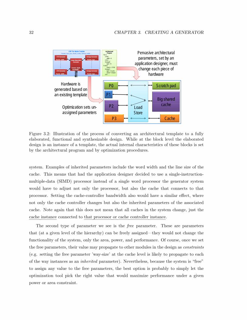
32 CHAPTER 3. CREATING A GENERATORHow Do We Turn
This into That?How Do We Turn
This into That?Pervasive architectural parameters, set by an
Architectural Program
Tile 0:CPU0:
width = 4CPU1:
CMP Tile: Module Template
CPU Generator
Params: width, …
Params: num_cpus, shared_caches, memory_model, …
Load-Store-Unit
Storage Generator
Params: type, … p yapplication designer, must
change each piece of hardware
CPU1: …Storage0:
type = D-Scratch
Owner = CPU0Storage1:
type = I-Cacheowner = Shared
LSU:
,,
,
CPU Generator
Params: width, …
Load-Store-Unit Generator
Params: depth, bandwidth…
yp ,yp ,
yp ,
Storage Generator
Params: type, …
P0 Scratch pad
hardware
Hardware is generated based on
LSU: …
P1Big shared
h
generated based on an existing template
P2
P3
cache
Cache
Load Store
Optimization sets un-assigned parameters
September 14, 2010 [email protected]
P3 Cache
18
Figure 3.2: Illustration of the process of converting an architectural template to a fullyelaborated, functional and synthesizable design. While at the block level the elaborateddesign is an instance of a template, the actual internal characteristics of these blocks is setby the architectural program and by optimization procedures.
system. Examples of inherited parameters include the word width and the line size of the
cache. This means that had the application designer decided to use a single-instruction-
multiple-data (SIMD) processor instead of a single word processor the generator system
would have to adjust not only the processor, but also the cache that connects to that
processor. Setting the cache-controller bandwidth also would have a similar effect, where
not only the cache controller changes but also the inherited parameters of the associated
cache. Note again that this does not mean that all caches in the system change, just the
cache instance connected to that processor or cache controller instance.
The second type of parameter we see is the free parameter. These are parameters
that (at a given level of the hierarchy) can be freely assigned—they would not change the
functionality of the system, only the area, power, and performance. Of course, once we set
the free parameters, their value may propagate to other modules in the design as constraints
(e.g. setting the free parameter ’way-size’ at the cache level is likely to propagate to each
of the way instances as an inherited parameter). Nevertheless, because the system is “free”
to assign any value to the free parameters, the best option is probably to simply let the
optimization tool pick the right value that would maximize performance under a given
power or area constraint.
3.1. TEMPLATES AND PARAMETERS 33
The third type of parameter is the architectural parameter. These are decisions that
once made, are going to impact the functionality of the module. As an example, in Fig-
ure 3.3 we consider the meta-data bits that are often associated with cache structures, to
keep the state of the line (e.g., Valid and Dirty bits in a simple single processor system,
Modified/Exclusive/Shared/Invalid in a chip-multiprocessor that implements a MESI pro-
tocol for coherence, Speculatively Read/Speculatively Written in a chip-multiprocessor that
implements transactional memory model, etc.) By setting the number and functionality of
these meta-data bits, one changes the architecture of the system. Table 3.1 summarize the
type of parameters, their impact and the source of their assigned value.
Table 3.1: Sources and impact of parameters on a cache microarchitecture designParameter Name Impacts Parameter SourceWord-size Memory block width, decoding
of address vector, processor sideinterface width
Constrained / inherited (re-quires information from the rel-evant CPU instance)
Line-size Number of memory blocks, de-coding of address vector, cachecontroller interface width
Constrained / inherited (re-quires information from the rel-evant cache controller instance)
Way-size Size of memory blocks Free (optimization → requireslate binding)
Associativity Number of memory blocks Free (optimization → requireslate binding)
Meta-data bits Line state, cache protocol (e.g.,coherence)
Architectural (set-by-user → re-quires late binding)
In examining the cache design example presented in Figure 3.3, we first notice that
often times, design parameters of various blocks are closely related and thus constrained
or inherited. Naturally, any single module (like in the example above) may need to inherit
parameters from multiple various modules. The constraining parameters may come from
modules which are at the same branch and level of the design hierarchy, like the module
holding the constrained parameters in the cache example. However, the constraining pa-
rameters may also be in a module higher in the hierarchy (e.g., way-size at the cache level
would constrain parameters inside each cache-way instance). Similarly, the constraining
parameters may come from a module lower in the hierarchy (e.g., a processor may or may
not need to implement a configuration bus interface, depending on whether a register file
module inside it requires such an interface). Finally, there may even be cases for which the
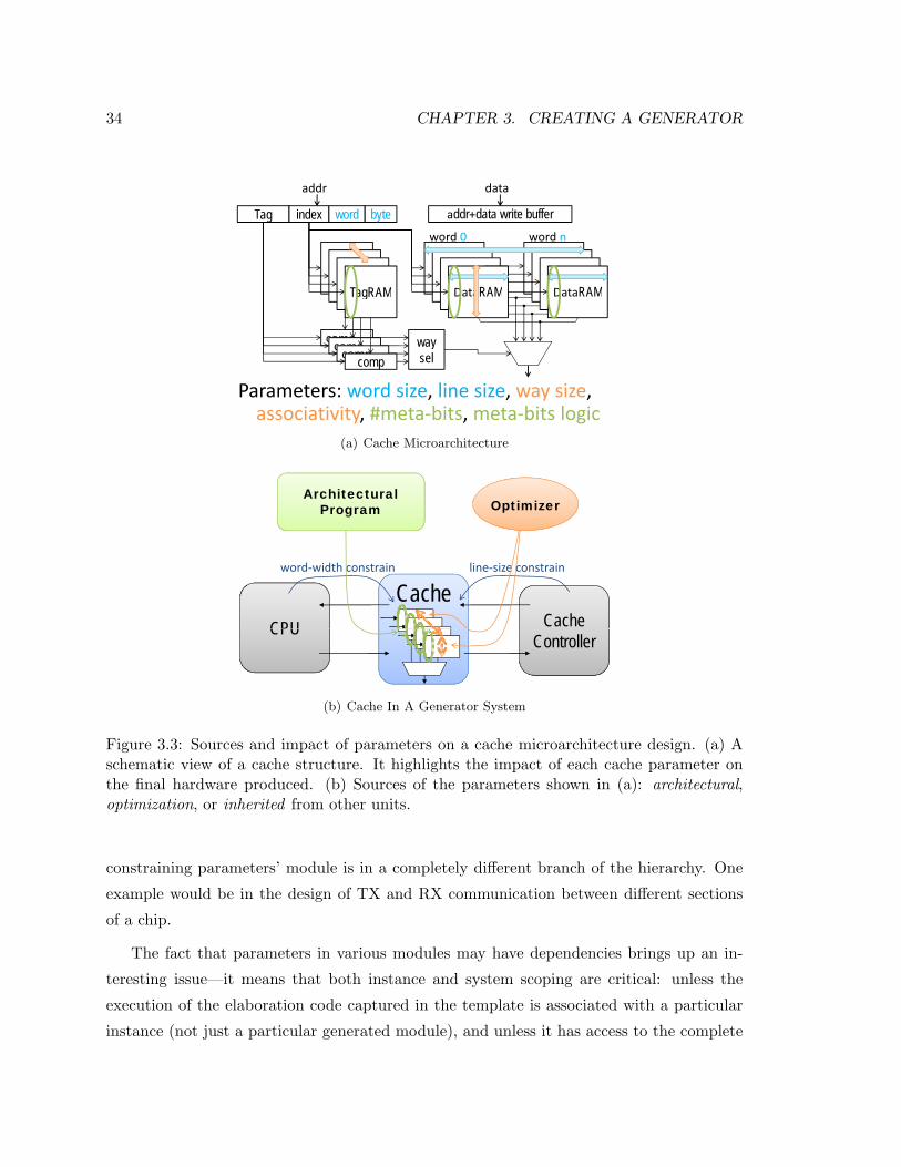
34 CHAPTER 3. CREATING A GENERATOR
dd d t
Tag index word byte
addr
addr+data write buffer
data
word 0 word n
D RAMD RAMT RAM
word 0 word n
DataRAMDataRAM
comp
TagRAM
Parameters: word size line size way size
compcompcompcompway sel
Parameters: word size, line size, way size, associativity, #meta‐bits, meta‐bits logic
(a) Cache Microarchitecture
Architectural Program Optimizerg
line‐size constrainword‐width constrain
CPU Cache Cache
CPUController
(b) Cache In A Generator System
Figure 3.3: Sources and impact of parameters on a cache microarchitecture design. (a) Aschematic view of a cache structure. It highlights the impact of each cache parameter onthe final hardware produced. (b) Sources of the parameters shown in (a): architectural,optimization, or inherited from other units.
constraining parameters’ module is in a completely different branch of the hierarchy. One
example would be in the design of TX and RX communication between different sections
of a chip.
The fact that parameters in various modules may have dependencies brings up an in-
teresting issue—it means that both instance and system scoping are critical: unless the
execution of the elaboration code captured in the template is associated with a particular
instance (not just a particular generated module), and unless it has access to the complete
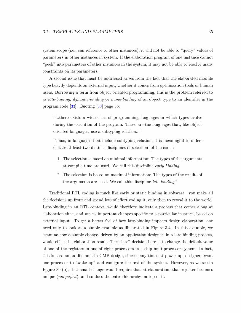
3.1. TEMPLATES AND PARAMETERS 35
system scope (i.e., can reference to other instances), it will not be able to “query” values of
parameters in other instances in system. If the elaboration program of one instance cannot
“peek” into parameters of other instances in the system, it may not be able to resolve many
constraints on its parameters.
A second issue that must be addressed arises from the fact that the elaborated module
type heavily depends on external input, whether it comes from optimization tools or human
users. Borrowing a term from object oriented programming, this is the problem referred to
as late-binding, dynamic-binding or name-binding of an object type to an identifier in the
program code [33]. Quoting [33] page 36:
“...there exists a wide class of programming languages in which types evolve
during the execution of the program. These are the languages that, like object
oriented languages, use a subtyping relation...”
“Thus, in languages that include subtyping relation, it is meaningful to differ-
entiate at least two distinct disciplines of selection [of the code]:
1. The selection is based on minimal information: The types of the arguments
at compile time are used. We call this discipline early binding.
2. The selection is based on maximal information: The types of the results of
the arguments are used. We call this discipline late binding.”
Traditional RTL coding is much like early or static binding in software—you make all
the decisions up front and spend lots of effort coding it, only then to reveal it to the world.
Late-binding in an RTL context, would therefore indicate a process that comes along at
elaboration time, and makes important changes specific to a particular instance, based on
external input. To get a better feel of how late-binding impacts design elaboration, one
need only to look at a simple example as illustrated in Figure 3.4. In this example, we
examine how a simple change, driven by an application designer, in a late binding process,
would effect the elaboration result. The “late” decision here is to change the default value
of one of the registers in one of eight processors in a chip multiprocessor system. In fact,
this is a common dilemma in CMP design, since many times at power-up, designers want
one processor to “wake up” and configure the rest of the system. However, as we see in
Figure 3.4(b), that small change would require that at elaboration, that register becomes
unique (uniquified), and so does the entire hierarchy on top of it.
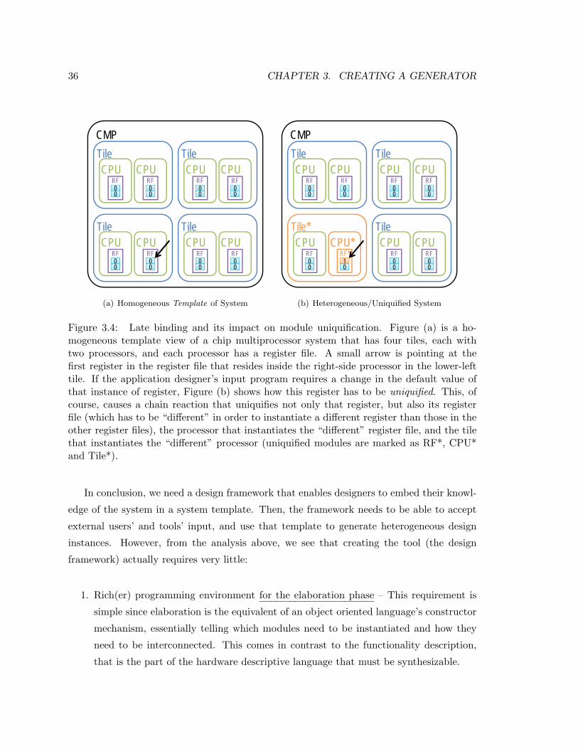
36 CHAPTER 3. CREATING A GENERATORProblem 2:Late Binding Requires Auto-UniquificationProblem 2:Late Binding Requires Auto-Uniquificationg q qg q q
CMPTile TileCPU CPU CPU CPU
CMP
CPU CPU CPU CPURF0000
RF0000
RF0000
RF0000
Tile TileCPU CPU CPU CPUCPU CPU CPU CPU
RF0000
RF0000
RF0000
RF0000
September 20, 2010 [email protected] 1(a) Homogeneous Template of System
Problem 2:Late Binding Requires Auto-UniquificationProblem 2:Late Binding Requires Auto-Uniquificationg q qg q q
CMPTile TileCPU CPU CPU CPU
CMP
CPU CPU CPU CPURF0000
RF0000
RF0000
RF0000
Tile* TileCPU CPU* CPU CPUCPU CPU CPU CPU
RF0000
RF*1100
RF0000
RF0000
September 20, 2010 [email protected] 2(b) Heterogeneous/Uniquified System
Figure 3.4: Late binding and its impact on module uniquification. Figure (a) is a ho-mogeneous template view of a chip multiprocessor system that has four tiles, each withtwo processors, and each processor has a register file. A small arrow is pointing at thefirst register in the register file that resides inside the right-side processor in the lower-lefttile. If the application designer’s input program requires a change in the default value ofthat instance of register, Figure (b) shows how this register has to be uniquified. This, ofcourse, causes a chain reaction that uniquifies not only that register, but also its registerfile (which has to be “different” in order to instantiate a different register than those in theother register files), the processor that instantiates the “different” register file, and the tilethat instantiates the “different” processor (uniquified modules are marked as RF*, CPU*and Tile*).
In conclusion, we need a design framework that enables designers to embed their knowl-
edge of the system in a system template. Then, the framework needs to be able to accept
external users’ and tools’ input, and use that template to generate heterogeneous design
instances. However, from the analysis above, we see that creating the tool (the design
framework) actually requires very little:
1. Rich(er) programming environment for the elaboration phase – This requirement is
simple since elaboration is the equivalent of an object oriented language’s constructor
mechanism, essentially telling which modules need to be instantiated and how they
need to be interconnected. This comes in contrast to the functionality description,
that is the part of the hardware descriptive language that must be synthesizable.
3.2. HARDWARE DESCRIPTIVE LANGUAGES 37
2. Instance and system based scopes – In its essence this requirement is the same as
the default scoping used in object oriented languages. It means that the run of the
elaboration program generates an instance of a module, not a module. Moreover,
that instance, during its construction, is “aware” of its position in the system, and
can obtain pointers or references to other instances (in order to satisfy parameters’
constraints for example).
3. Elaboration with I/O – This requires some standardized way of external input/output
interaction with the embedded elaboration program, while any aspect of late binding
and uniquification need to be handled automatically. Without compliance to this
requirement, the separation of hardware designer (embedding design instructions for
the system) vs. application designer / tools (providing application specific input),
cannot be achieved.
3.2 Common Approaches To Hardware Descriptive Languages
In our search for an existing language or tool that would enable coding of a generator, we
found no single tool that met our requirements as laid out at the end of the previous section.
For example, VHDL [15] and Verilog [13] are great languages for describing hardware—once
a designer knows exactly how the module they create needs to perform, it is easily described.
However, this process does not adequately embed the designer knowledge into the design,
and any slight deviation requires significant recoding. To ease this problem, both VHDL,
Verilog (post 2001) and SystemVerilog [14] use elaboration time parameters and generate
blocks to enable more code reuse. Generate blocks enable the designer to write (extremely)
simple elaboration programs for which parameters are the input and hardware components
are the output. These programs however, are limited to if, case and for -loop statements.
No variables are allowed except for the very restricted genvar2, and needless to say that
no advanced programming techniques such as classes or even IO reads/writes are possible
during elaboration3.
To enrich a hardware descriptive language’s programming capabilities for elaboration,
many companies use pre-processors to generate RTL code. Naming just a few examples,
2genvar declares a variable that can only be used as the iterator of a for-loop in a generate block. It cannot be assigned to a value by user code or in any other way but the for-loop declaration.
3IO reads and writes are allowed in RTL simulation, but not at the time of elaboration.
38 CHAPTER 3. CREATING A GENERATOR
these include the native Verilog pre-processor, C/C++ pre-processor, EP3 [94], deper-
lify [40], EmPy [43], Tensilica TIE pre-processor [10], etc., as well as in-house scripts de-
veloped by individuals in many industrial design teams. While the programming language
and the mechanism of implementation vary from one tool to the other, the concept is the
same: Regular Verilog or VHDL are coded, but are also instrumented with pre-processor
directives, marked with special escape characters. Upon compile time of the code, each file
is first pre-processed and all the embedded pre-processor directives are evaluated to create
a new text file. The new text file is the input to the HDL compiler. Pre-processing is a
simple solution to a very big problem since it artificially adds an explicit elaboration phase,
and then significantly enriches the elaboration language. In the requirement list at the end
of the previous section, it solves req#1 and could potentially be used to solve req#3. How-
ever, pre-processors have a file-based in-compilation-order scope. Moreover, the elaboration
program does not generate instances but modules, because it is text-based and unaware of
the hierarchical, object-oriented structure of the hardware that it is being used to describe.
Bluespec [80, 1], which is a recent HDL, takes a completely different approach. For
once, it changes the HDL software paradigm to a functional one—initial releases of the
Bluespec compiler essentially provided a front end for a Haskell back end [80, 57]. However,
the aspect of Bluespec that provides an advantage over languages like SystemVerilog or
VHDL, is in the higher level description of the hardware, which is then translated via Term
Rewriting System (TRS) to either Verilog for synthesis or C++ for simulation [65]. While
one may or may not like the different approach of Bluespec to describing hardware and
the resulting quality of hardware (in terms of power, area or performance), Bluespec does
provides many benefits in the ability of designers to describe the hardware. Notably its
ability to parametrize modules by value or type, or even by function or module (meaning
that if module X internally uses function F or instantiates module Y, then module X can
be parametrized such that F and/or Y are its parameters) constitutes a great advance
in comparison to VHDL and SystemVerilog parametrization. The use of variables during
elaboration (while trivial) is another advantage over the aforementioned restricted genvars.
Unfortunately, there are still barriers that currently keep Bluespec from becoming the
best method for making a generator. One subtle but important such barrier is that numer-
ical values can only flow from the type domain to the value domain, but not vice versa. For
example, the number 5 can be declared as a size type using typedef 5 my five t; and if
one wants to get a value that corresponds to that size type, there is a special pseudo-function,
3.2. HARDWARE DESCRIPTIVE LANGUAGES 39
valueof, that takes a size type and gives the corresponding Integer value. The other way
around is not possible however, meaning that if we defined an integer Integer width = 5;
width cannot be used for making new types (e.g. creating a register of Bit#(width) would
produce an error). This limitation, though seemingly subtle, is important to our goal of
embedding hardware designers’ knowledge of how an instance of a module needs to be
constructed—knowledge that often includes how internal types need to be defined. Our
goal in the generator is for the application designer to assign values to high level architec-
tural knobs, and have the system underneath compile that into both types and values as
needed. For example, if a user (or optimization tool) specifies that a cache must have four
ways, it would change not only the number of ways (i.e. using the value of 4) but also
the controlling signal widths (i.e. using the type 4). Similarly, it turns out that describing
even a flip-flop based register file template, with N (N is a parameter) registers of widths
{W1,W2, ...,WN} is not as trivial as one may initially think. Note that, by contrast, writing
a short Perl script to generate such a module actually is simple4.
A key issue that Bluespec does not yet solve over the older and more prevalent HDL’s
is that the elaboration code is still restricted by synthesizability rules. However, in reality,
there is no actual reason why during elaboration one would not be able to unleash full
software capabilities (e.g. dynamically allocating a structure, or spanning a process to
determine the optimal architecture for a particular multiplier, or dynamic/late construction
of types). As we show in the next sections, decoupling the elaboration part of the HDL
from the functional part actually provides many benefits.
Finally, there have also been a number of tools that take the opposite approach. In
these cases, native software languages such as Java [35, 58], Python [3], C++ [69, 4] or
Ruby [5], are used to describe the structure of hardware. Unfortunately, while these tools
provide good means for structural description, the behavioral part is often lacking5. This
is of course the exact opposite problem of the one just described for classic HDLs such as
Verilog and VHDL. Once again the problem is that the same semantics are used for both
4Bluespec users often work around type vs. value issues by adding dummy type variables to interfacearguments. One way to code the register file mentioned above is to add dummy type variables for each ofthe register widths. Unfortunately since these types are completely unrestricted the compiler needs provisosto impose meaning onto them. This, in turn, often leads to complex proviso statements, as the Bluespeccompiler cannot prove complex arithmetic (for example that K ∗3 = K +K +K). Another way to overcometype vs. value limitations is to use pre-processor directives, since these textual-based replacements can serveas both type and value. Unfortunately, this puts us back to the compilation unit and scope issues describedfor other pre-processors above.
5Attributed, in part, to the lack of time as an integral part of the language
40 CHAPTER 3. CREATING A GENERATOR
the elaboration (i.e., resolving the hardware structure), and the functional (i.e., resolving
the hardware behavior). In addition, there is a huge code base which is already in Verilog
or VHDL that would have to be re-written.
Since SystemVerilog is a commonly used and a widely supported HDL, with well defined
methodologies for verification and synthesis, in the work presented here, we chose the path
of modestly enriching the “elaboration” portion of SystemVerilog, replacing the severely
limited “generate” block concept, with a strong software meta-language, as described next.
3.3 Genesis2—Embedding Designers Knowledge
In Section 3.1, we saw what a tool for encoding a chip-generator—one that encapsulates the
hardware designer’s knowledge—would have to support. Figure 3.5 illustrates a conceptual
view of a tool that meets these requirements. Rather than coding a specific module, hard-
ware designers would use a rich, software-like language to write instructions for how modules
are to be generated, given a set of input parameters that come from multiple sources. This
code constitutes a template for creating the module. When the elaboration code evaluates,
some of the parameter values are extracted from the hierarchical architectural description,
while others are forced by the instantiating parent template (like in SystemVerilog) or read
from any of the other objects (i.e., instances of templates) in the system, and a third group
is simply calculated (i.e., locally optimized). The elaboration program may also hierarchi-
cally instantiate other templates, or recursively instantiate a different instance of the same
template. When sub-instances are created, the elaboration program can force parameter
values into those instances (like in SystemVerilog) and/or read out any of these instances’
parameters after they were generated. In other words, designers write how each particular
block in the system is to be constructed, with respect to all the other blocks in the system.
Aggregated together, these elaboration programs describe how the system is constructed
based on application designers’ input.
After templates are hierarchically put together, the top of this system becomes the
system generator. Its input is the architectural configuration description that sets values
for the architectural knobs throughout the system. The output is an elaborated system (not
module), as well as architectural feedback to the application designer and design exploration
tools.
Unfortunately, as previously mentioned in Section 3.2, at this time no tool is capable of
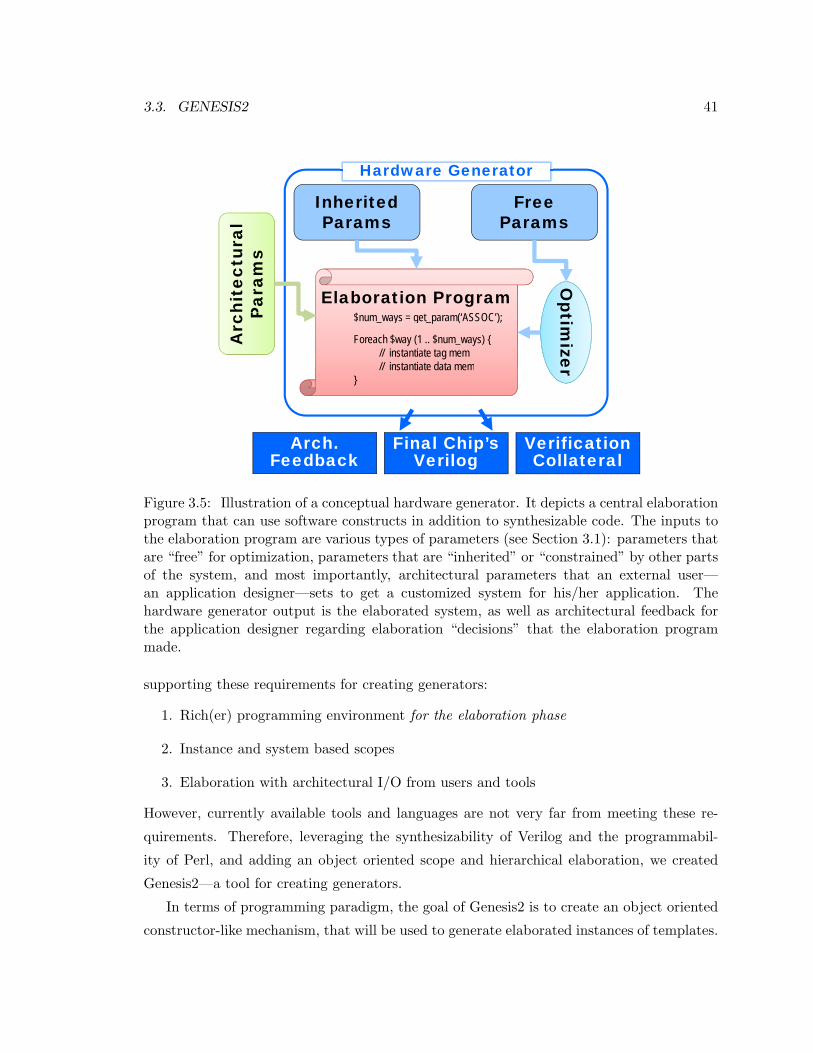
3.3. GENESIS2 41
What I WantedWhat I WantedHardware Generator
Free Inherited Free Params
Inherited Params
ural
s
hite
ctP
aram
s
Elaboration Program$ ( SSOC )
Op
Arc
P $num_ways = get_param(‘ASSOC’);
Foreach $way (1 .. $num_ways) {// instantiate tag mem// instantiate data mem
timize
// instantiate data mem}
er
Final Chip’s Verilog
Verification Collateral
Arch. Feedback
Figure 3.5: Illustration of a conceptual hardware generator. It depicts a central elaborationprogram that can use software constructs in addition to synthesizable code. The inputs tothe elaboration program are various types of parameters (see Section 3.1): parameters thatare “free” for optimization, parameters that are “inherited” or “constrained” by other partsof the system, and most importantly, architectural parameters that an external user—an application designer—sets to get a customized system for his/her application. Thehardware generator output is the elaborated system, as well as architectural feedback forthe application designer regarding elaboration “decisions” that the elaboration programmade.
supporting these requirements for creating generators:
1. Rich(er) programming environment for the elaboration phase
2. Instance and system based scopes
3. Elaboration with architectural I/O from users and tools
However, currently available tools and languages are not very far from meeting these re-
quirements. Therefore, leveraging the synthesizability of Verilog and the programmabil-
ity of Perl, and adding an object oriented scope and hierarchical elaboration, we created
Genesis2—a tool for creating generators.
In terms of programming paradigm, the goal of Genesis2 is to create an object oriented
constructor-like mechanism, that will be used to generate elaborated instances of templates.
42 CHAPTER 3. CREATING A GENERATOR
One difficulty is that in software coding, there is no difference between the coding of con-
structors and instantiators of classes, and the coding of the class functionality. In hardware
on the other hand, the description of the functionality of a module must obey strict rules of
synthesizability. As a result, design languages also enforce strict rules on the construction
and instantiation program—the elaboration step. Genesis2 aims to break this artificial lim-
itation. It does that by enabling a designer to code in two languages simultaneously and
interleaved: One that describes the hardware proper, and one that decides what hardware to
use for a given instance. The premise of Genesis2 is that during elaboration time everything
is allowed and everything is possible. As an extreme example, given that the parameters
for an instruction cache specify a 16KB capacity, say, one can even embed a small program
to figure out what is the optimal associativity for a particular target application.
Unfortunately, a solution that simply uses software constructors for hardware modules
is also problematic because once created, a hardware module is a static entity, whereas a
software class is dynamic—it can have members and pointers, and those could be assigned
with different values and objects for every instance of that class. Therefore to enable
this constructor-like mechanism in hardware, we leverage another known concept from the
software world—meta-programming using templates [17]. In C++, instead of coding classes,
programmers can code templates for those classes, leaving the binding of types to a later,
compilation time, stage. Quoting Abrahams [17]:
A meta-program is a program that generates or manipulates program code. Ever
since generic programming was introduced to C++, programmers have discov-
ered myriad “template tricks” for manipulating programs as they are compiled,
effectively eliminating the barrier between program and meta-program.
Genesis2 takes a similar approach by enabling designers to create module templates rather
than modules6. Conceptually, by coding templates (whether in C++ or Genesis2) a meta-
language is used to generate an elaborated instance of a target-language. Put differently,
the output of a program-run of the meta-language is valid code for the target-language.
To make the following discussions clearer, Table 3.2 defines the jargon that will be used to
describe the operation of Genesis2.
Next we discuss the high level programming concepts of Genesis2. A full user guide for
Genesis2 is also appended to this thesis as Appendix A.6I suspect that behind the scenes, commercial tools handle parameters using templates as well, but to a
limited extent as described in Section 3.2
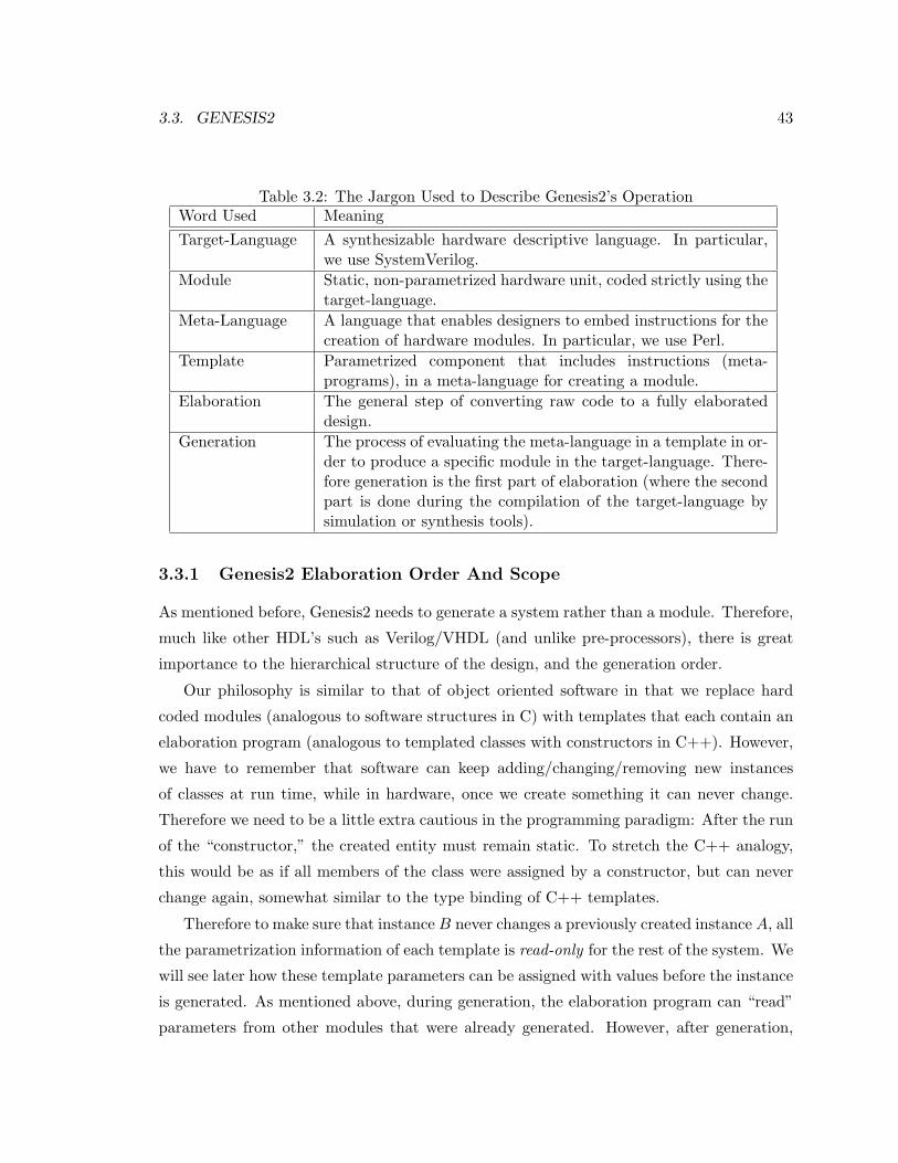
3.3. GENESIS2 43
Table 3.2: The Jargon Used to Describe Genesis2’s OperationWord Used MeaningTarget-Language A synthesizable hardware descriptive language. In particular,
we use SystemVerilog.Module Static, non-parametrized hardware unit, coded strictly using the
target-language.Meta-Language A language that enables designers to embed instructions for the
creation of hardware modules. In particular, we use Perl.Template Parametrized component that includes instructions (meta-
programs), in a meta-language for creating a module.Elaboration The general step of converting raw code to a fully elaborated
design.Generation The process of evaluating the meta-language in a template in or-
der to produce a specific module in the target-language. There-fore generation is the first part of elaboration (where the secondpart is done during the compilation of the target-language bysimulation or synthesis tools).
3.3.1 Genesis2 Elaboration Order And Scope
As mentioned before, Genesis2 needs to generate a system rather than a module. Therefore,
much like other HDL’s such as Verilog/VHDL (and unlike pre-processors), there is great
importance to the hierarchical structure of the design, and the generation order.
Our philosophy is similar to that of object oriented software in that we replace hard
coded modules (analogous to software structures in C) with templates that each contain an
elaboration program (analogous to templated classes with constructors in C++). However,
we have to remember that software can keep adding/changing/removing new instances
of classes at run time, while in hardware, once we create something it can never change.
Therefore we need to be a little extra cautious in the programming paradigm: After the run
of the “constructor,” the created entity must remain static. To stretch the C++ analogy,
this would be as if all members of the class were assigned by a constructor, but can never
change again, somewhat similar to the type binding of C++ templates.
Therefore to make sure that instance B never changes a previously created instance A, all
the parametrization information of each template is read-only for the rest of the system. We
will see later how these template parameters can be assigned with values before the instance
is generated. As mentioned above, during generation, the elaboration program can “read”
parameters from other modules that were already generated. However, after generation,

44 CHAPTER 3. CREATING A GENERATOR
that instance cannot be modified again. This paradigm gives all the decision-making power
for how a particular instance needs to be generated, given the external input and given
the surrounding system, to the designer of a template. However, it gives absolutely no
power to any other template’s meta-program to tweak that instance. This hard separation
of one template’s elaboration program from all others is crucial for enabling designers and
elaboration tools to reason about what hardware needs to be generated. For example, we’ll
see in Section 3.3.2 that because this separation does not exist in the SystemVerilog IEEE
Standard [14], it has been suggested that the elaboration feature defparam be deprecated.
This approach therefore requires that there should be a deterministic order for gen-
eration, so that designers can reason about the flow of design decisions (i.e., if module
A’s parameters are constrained by module B’s parameters, then B must be generated
first, and the designer must have the ability to specify that). Therefore, Genesis2 always
starts generation from the top module’s template, and then generates the entire design be-
low it. Generation is done as a depth-first search of the hierarchy, which means that the
meta-program in the top module’s template would be first to be processed, until the first
unique inst instantiation function call is encountered7. Then Genesis2 recursively turns to
processing the template of the sub-instance which is being instantiated, before continuing
the generation of the current template. This process repeats recursively, until the complete
hierarchy is generated.
Behind the scenes, this depth-first-search (DFS) strategy also makes it easy to handle
uniquification and therefore late binding. Let us assume that we are now processing the
template T1 NAME because of an instance at level N of the hierarchy.
1. If during this generation we encounter no sub-instances (i.e., this is a leaf in the
hierarchy graph), then uniquification is simple because all one needs to do is compare
the module which was just now generated to all the other k − 1 modules that were
previously generated from this template.
(a) If it is different from all of them, then we name the new module T1 NAME k.
(b) Otherwise, if it is identical to the ith (previously generated) module, then we
discard the newly generated module and inform the system that the generated
module is T1 NAME i.
7See Appendix A for more details about the built-in method call unique inst
3.3. GENESIS2 45
2. If during this generation we encounter sub-instances (i.e., instances of level N + 1),
then going depth-first means that we first generate and uniquify these sub instances,
before making uniquification decisions about the generated module for this instance.
Therefore, by the time we are done processing T1 NAME, we already resolved all
the sub-instances’ types, so uniquifying the newly generated module only requires a
shallow comparison to all the other k−1 modules that were previously generated from
this template.
(a) If it is different from all of them, then we name the new module T1 NAME k.
(b) Otherwise, if it is identical to the ith (previously generated) module, then we
discard the newly generated module and inform the system that the generated
module is T1 NAME i.
During the depth-first-scan of the code, scoping rules are very similar to other ob-
ject oriented languages. A new scope is opened every time a new instance of a tem-
plate is being instantiated. This is done using the $NewObject = $self->unique inst(-
SomeTemplateName, prmName=>prmValue); method call. Note that this is essentially the
equivalent of the NewObject = new SomeClassName<SomeType>; template+constructor call
in C++ template meta-programming. This means that in addition to having class members,
a Genesis2 template uses parameters, which serve as input to the meta-program (construc-
tor) run. Just like C++ templates, where this call would create a new class based on the
SomeType argument, Genesis2 would create a new module based on that meta-program run
on the parameters input.
On the other hand, when module types are dynamically generated, a hardware designer
who simply wants to instantiate an identical module/interface to one that already exists
elsewhere in the design, might find him/herself going through the trouble of trying to
generate an exact clone. Experience in SystemVerilog parameters shows that this can
become quite a cumbersome task. It is especially difficult for code maintenance, since
often more parameters are added to a template as the design matures, which may then
require manual updating of some instantiations. For example, consider a parametrized
configuration bus interface that repeats in multiple places in the design (“daisy chain”),
and say initially this interface is parametrized by data width only. Then, if one wants
to also parametrize it by addr width, all instantiations of that interface would have to
be manually modified (or all occurrences of that interface in the XML configuration file
46 CHAPTER 3. CREATING A GENERATOR
would have to be modified). Therefore a better solution would be to declare that interface
once, with all its relevant parameters, and then declare all other instantiations as “clones”
of the original. In this case, when the original changes, all other instances change as
well. To handle such situations, in addition to unique inst, we provide the $NewObject =
$self->clone inst(OtherObject); mechanism for Genesis2, which is somewhat similar
to typeof(OtherObject) NewObject = OtherObject->deepCopy(); in some versions of
C++8. NewObject is going to be an object of the exact same module type as OtherObject.
Regardless of how an object was generated, a handle to any previously generated (in DFS
order) instance can always be obtained by using the built-in methods get parent, get subinst,
get instance path and get instance obj. In addition, because generated module types are
late-bound, template designers may occasionally need to query the resulting type of their
meta-program run. Therefore Genesis2 provides for every object the built-in methods
$module name = $self->get module name(); and $inst name = $self->get instance name();
(get module name is a somewhat similar mechanism to the C++ typeid).
Finally, in terms of the template coding style, unlike object oriented programs, the entire
meta-program is considered as part of the new module’s “constructor” unless explicitly spec-
ified otherwise (for example using the Perl sub keyword one can declare subroutines/methods
for that template). This deviation from the classic class, constructor and methods decla-
rations style, is important for giving hardware designers the feeling (or illusion) that they
are still coding Verilog, and simply enhancing it with some meta-language constructs. In
addition, for simplicity of implementation Genesis2 always assumes that the template for
TemplateName will always reside in the file TemplateName.vp. Furthermore, we assume
that all statements in that file belong to that template scope. These simplifications and
assumptions are closer in nature to object oriented Perl than to Verilog. Yet, since it is
common practice in Verilog coding to put one module per file and to give the file the exact
same name as the module, this simplification seems reasonable.
3.3.2 Genesis2 Parametrization Levels
In Section 3.1, we greatly emphasized that one major benefit of a chip generator is that
the template for the architecture is coded first, only to receive final binding of architectural
8Note however, that typeof is a function call, while clone inst is a method call. The reason for thisdifference is that Genesis2 is not just compiling a program—behind the scenes it also keeps informationabout the hardware structure, source and generated files, and design hierarchy.
3.3. GENESIS2 47
and optimization parameters later. We have also seen in Section 3.3.1 that parameters are
the key input to the generation meta-language program. However, current HDL languages
generally don’t accept external input during the elaboration phase9. Moreover, there is no
standardized way of interfacing design parameters with other tools such as design explo-
ration/optimization or GUI’s.
First, let us look at the levels and mechanisms of parametrization in SystemVerilog, to
understand the current state of the art. As we see later, Genesis2 builds on these concepts
and attempts to improve them. A quick analysis of parametrization in SystemVerilog reveals
that it has three levels of priorities or strengths for elaboration parameters’ assignments [14]:
1. A localparam or parameter must be declared and initialized with a default value inside
the module to which it belongs. The initial value can be assigned directly, or it can
be derived from other parameter/localparams, or it can be assigned using a constant
function.
2. The value of parameters (but not the value of localparams) can then be overruled
during the instantiation of the module.
3. The value of parameters (but not the value of localparams) may also be altered by a
defparam statement, from anywhere in the code. Note however, that the IEEE Std
1800–2009 definition of the defparam is considered as a cause for both design and tool
errors, and is therefore put on the deprecation list by the standard itself (see section
C.4.1 of the IEEE Std 1800–2009 [14]).
Obviously, this list is missing a way to control internal parameters (free and architectural
parameters) from external input (e.g. to change a particular cache’s associativity). One
solution—propagating all low level parameters to the top module—is bad and cumbersome:
First, in a chip generator there are going to be MANY knobs. Second, it is not even possible
to explicitly propagate the knobs since the existence of some of them depend on the value
of others (for example, the existence of the parameter for the number of ALUs in processor
#3 depends on the value of the parameter for number-of-processors).
Another direction that we initially considered was to use defparams: In this scheme,
external tools would create a list of defparams to “configure” the system10. Unfortunately,9Some tools, like Synopsis’s VCS, do accept some changes to some parameter types as a command line
switch. However, these cases are limited to simple, integer value changes.10This direction was considered before we realized that SystemVerilog does not have a rich enough elabo-
ration language anyhow
48 CHAPTER 3. CREATING A GENERATOR
defparams are in fact the Achilles heel of SystemVerilog’s parametrization. As explained in
Section C.4.1 of the standard [14]:
“The defparam method of specifying the value of a parameter can be a source of
design errors and can be an impediment to tool implementation due to its usage
of hierarchical paths. The defparam statement does not provide a capability
that cannot be done by another method that avoids these problems. Therefore,
the defparam statement is on a deprecation list. In other words, a future revision
of IEEE Std 1800 might not require support for this feature.
A defparam statement can precede the instance to be modified, can follow the
instance to be modified, can be at the end of the file that contains the instance
to be modified, can be in a separate file from the instance to be modified, can
modify parameters hierarchically that are in turn passed to other defparam
statements to modify, and can modify the same parameter from two different
defparam statements (with undefined results). Due to the many ways that
a defparam can modify parameters, a SystemVerilog compiler cannot resolve
the final parameter values for an instance until after all of the design files are
compiled.
Prior to IEEE Std 1364-2001, the only other method available to change the
values of parameters on instantiated modules was to use implicit in-line param-
eter redefinition. This method uses #(parameter value) as part of the module
instantiation. Implicit in-line parameter redefinition syntax requires that all pa-
rameters up to and including the parameter to be changed shall be placed in
the correct order and shall be assigned values.
IEEE Std 1364-2001 introduced explicit in-line parameter redefinition, in the
form #(.parameter name(value)), as part of the module instantiation. This
method gives the capability to pass parameters by name in the instantiation,
which supplies all of the necessary parameter information to the model in the
instantiation itself.
The practice of using defparam statements is highly discouraged. Engineers
are encouraged to take advantage of the explicit in-line parameter redefinition
capability.”
The problem as stated by the IEEE Standard, can be summarized as lack of definite and
3.3. GENESIS2 49
deterministic way to perform elaboration, a shortcoming that hurts both the the hardware
designers and the tool implementation. Genesis2 solves this issue by defining a clear and
definite order of generation, as explained in Section 3.3.1. The DFS scan is also intuitive
because it is in serial program order, much like software objects construction.
However, there is also a second issue, that the IEEE Standard had not identified, but
we consider as error-prone. Because the defparam statement is “stronger” than the instan-
tiation assignment of parameters, an overriding of a parameter value inside a module can
cause conflicts with its parent (the module that instantiated it) or with modules that inter-
face with it. For example, consider a simple module that implements a hardware register
and uses width=8 as a parameter. Let us also assume that this module is instantiated and
width=8 is overridden with some new width=16 (i.e., the signal to be registered is of width
16). If an external definition, using the defparam construct, overrides width=16 with a
width=12, then suddenly a lint error is created. While this is a trivial example, it illus-
trates a significant problem: Inherited or constrained parameters (as defined in Section 3.1)
must not be overridden by external statements. Put differently, assignments of parame-
ters at instantiation should be at a higher priority than external assignment, because the
template designer consciously chose to bind these parameters to a specific value.
Therefore to enable better parametrization, Genesis2 pulls all parameters to the meta-
language level and redefines the assignment priorities. First, and much like SystemVerilog,
Genesis2 enables designers to define and give default values to parameters. Then, it pro-
vides a simple mechanism for overwriting these values from external configuration files (for
example, this enables finding the best parameter values using an optimizer). Note that since
generation is on an instance-by-instance basis, the configuration file specifies the overridden
parameter and its value on an instance-by-instance basis, as shown next in Section 3.3.3.
However, changing values from a configuration file is only possible if that parameter’s
value is not already tied inside the system, for example, when compatibility is required for
interface bit-widths. In this case we should not use external input for these parameters.
Instead we expect that the instantiating template’s elaboration program would calculate
these values, and force them as input of the instantiated template’s elaboration program.
Therefore we allow parameters to be assigned during instantiation (again, much like de-
scribed above for SystemVerilog), and put this assignment at a higher priority than both
the local definition and the external input.
As mentioned in Section 3.3.1, except for during instantiation, and unlike the defparam
50 CHAPTER 3. CREATING A GENERATOR
statements in SystemVerilog, one template instance cannot change the parameters of an-
other. However we provide extra means for passive communication between template in-
stances. We add a highest priority parameter assignment, force param, as a way for a
module to declare and export a value/message to the world. The other side of that coin,
$someVar = $anyObj->get param(prm name) enables any instance’s meta-program to read
parameters from any other instance that was previously generated anywhere in the system.
Put together, we redefined the priorities of parameter assignments as follows:
1. Parameters can be declared and defined in the template to which they belong using
the notation: $someVar = $self->define param(prm name=>prm val)
where someVar is initially set to the value that was hashed by the name prm name.
This value, by default, is prm val, or if prm val was a pointer, then someVar is a deep
copy of the structure pointed by prm val.
2. Parameter values which where defined using method 1, can be overruled by external
input (provided in XML format as explained in Section 3.3.3).
3. Parameter values which were defined using methods 1 or 2 can be overruled by the
instantiation call to the unique inst method.
4. Parameters can alternatively be declared and defined in the template for which they
belong using the notation: $someVar = $self->force param(prm name=>prm val).
In these cases, the parameter is non-mutable by any other technique. In fact, an
attempt to override its value will result in an error.
More than anything else, force param is used for instances to inform the system about
some property they possess. For example, a memory block instance may declare its
required address-bus width based on its size, which may have been set for a particular
application by an optimization tool.
Complete syntax and code examples for all parametrization methods is described in Ap-
pendix A.
The introduction of design parameters into a module’s template essentially defines an
API for that module. In SystemVerilog for example, this API can be used by the instan-
tiator of that module. In a chip generator framework, we want parts of this API to be
driven externally—free parameters by an optimization tool, architectural parameters by an
3.3. GENESIS2 51
architect or application designer. For the API to be better defined, it is better if it also con-
tains type information, that is, if each parameter has a clearly defined type. For example,
in SystemVerilog the default type for parameters is integer, but one can explicitly declare
parameters with other types. Type information can also assist other automatic tools that
connect through the configuration file. For example, a design space exploration tool would
certainly need to “understand” what is the legal range of values for each parameter it can
change.
Unfortunately, Genesis2’s parametrization is typeless, at least for now. Having no types
for parameters is an implementation by-product of using Perl as the meta-language, and
is certainly a shortcoming, since type checking is now delayed until generation is done
and the resultant modules are compiled for simulation or synthesis. In practice, since
parameters serve as the input to the system and to the templates’ meta-programs, it is
highly recommended that each parameter value is tested in the template’s meta-code, and
that a $self->error("error message") is thrown if the value is found to be illegal, much
like in good software programming practice. Yet, Perl as a dynamic language, also offer
some benefits because on top of supporting typical structures such as scalars, strings, arrays,
hashes, instance references, etc., it also allows for types of parameters that are traditionally
difficult in strict typed languages, such as subroutine names, template names, and module
names.
Finally, Genesis2 treats parameters as constants; if a re-definition of a parameter is
attempted, the Genesis2 compiler signals it as an error. Combined with the DFS order of
generation and the methods and priorities of declaring and assigning values to parameters,
this makes parameter value assignment a fully deterministic process (lesson learned from
the Verilog defparam statement). However, because Genesis2 enables the use of compound
structures as parameters (e.g., a hash), there could still be a flaw if the internal values of
these compound parameters could be modified by user code—it would break the read-only
paradigm. Genesis2 solves this issue by making any of the methods that return a parameter
value or pointer, actually return a deep-copy of that parameter.
3.3.3 Interfacing With Genesis2
A key requirement for a generator is that hardware should be generated based on external
input from an application designer, without the intervention of the hardware designer.
While there can be many ways (e.g., comma-separated-values, binary files, etc.) and many
52 CHAPTER 3. CREATING A GENERATOR
formats for a configuration file containing the external input, we chose to standardize the
configuration of the entire system to one data structure using XML format and a pre-defined
schema.
The benefit of a standardized interface is obvious—it removes the burden of parsing the
input files from the template designer. Instead, parsing is done by Genesis2 so that the
configuration file is read, parsed and its information binned to the appropriate instances’
parameters, before the first line of the designer code is processed. However, rather than just
reading the input configuration file, Genesis2 goes one more step and generates a complete
description of the generated design, in much the same format as the input configuration
file. In this feedback-XML description, parameters which are bound at instantiation or
forced by the elaboration program (see Section 3.3.2) are put on a separate category of
ImmutableParameters11. On input-XML files on the other hand, the entire ImmutablePa-
rameters element is not required and is in fact ignored. If a user wrongfully attempts
to modify a bound or forced parameter by specifying it as a regular parameter, it is also
ignored since external input has a lower priority than bound or forced priority.
Figure 3.6 illustrates the process of iteratively customizing a system: The user/external
tools assign values to internal “knobs” via XML→ Genesis2 generates hardware accordingly
→ Genesis2 generates an XML description of the hardware → User/tools refine the values
of the internal knobs to meet the specification. Therefore a second, but as important,
advantage is that because the interface is well defined, Genesis2 can work with other tools
such as GUIs or optimization frameworks.
For example, to implement a graphical user interface (GUI) for a generator, we start
with all parameters in their default state. Genesis2 generates the design database but
also a configuration file that represents that state. Once the user changes some parameter
of some instance in the configuration file—for example change number of processors in a
chip multiprocessor (CMP) from 2 to 3—Genesis2 re-generates the new design and the
configuration file. Since we added a new processor, our new configuration file now contains
the entire parametrization of that instance and its sub-hierarchy. Our user can now modify
that processor (e.g. change it to a VLIW processor), and once again, Genesis2 will generate
this, now heterogeneous, CMP. Manual customization by way of GUI can continue in this
manner until the user is happy with the resultant CMP.
This example also illustrates the benefits of using XML for the representation of the
11See Appendix A for the complete XML schema
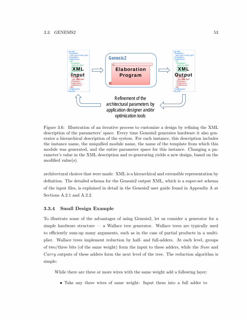
3.3. GENESIS2 53Standardized Parameter I/O Through XMLStandardized Parameter I/O Through XMLgg
Genesis2<cg_cmp>
<Parameters><num_cpus>2</num_cpus>
</Parameters><SubInstances>
<p1><Parameters>
<type>risc</type>
<cg_cmp><Parameters>
<num_cpus>2</num_cpus></Parameters><SubInstances>
<p1><Parameters>
<type>risc</type>
Elaboration Program
yp yp</Parameters><SubInstances> …</SubInstances>
</p1><p2>
<Parameters><type>vliw</type>
</Parameters>
yp yp</Parameters><SubInstances> …</SubInstances>
</p1><p2>
<Parameters><type>vliw</type>
</Parameters>
XML Input
XML Output
/Parameters<SubInstances> …</SubInstances>
</p2></SubInstances>
</cg_cmp>
/Parameters<SubInstances> …</SubInstances>
</p2></SubInstances>
</cg_cmp>
R fi t f th Refinement of the architectural parameters by application designer and/or
October 21, 2010 [email protected] 44
optimization tools
Figure 3.6: Illustration of an iterative process to customize a design by refining the XMLdescription of the parameters’ space. Every time Genesis2 generates hardware it also gen-erates a hierarchical description of the system. For each instance, this description includesthe instance name, the uniquified module name, the name of the template from which thismodule was generated, and the entire parameter space for this instance. Changing a pa-rameter’s value in the XML description and re-generating yields a new design, based on themodified value(s).
architectural choices that were made: XML is a hierarchical and extensible representation by
definition. The detailed schema for the Genesis2 output XML, which is a super-set schema
of the input files, is explained in detail in the Genesis2 user guide found in Appendix A at
Sections A.2.1 and A.2.2.
3.3.4 Small Design Example
To illustrate some of the advantages of using Genesis2, let us consider a generator for a
simple hardware structure — a Wallace tree generator. Wallace trees are typically used
to efficiently sum-up many arguments, such as in the case of partial products in a multi-
plier. Wallace trees implement reduction by half- and full-adders. At each level, groups
of two/three bits (of the same weight) form the input to these adders, while the Sum and
Carry outputs of these adders form the next level of the tree. The reduction algorithm is
simple:
While there are three or more wires with the same weight add a following layer:
• Take any three wires of same weight: Input them into a full adder to
54 CHAPTER 3. CREATING A GENERATOR
produce sum and carry.
• If there are two wires of the same weight left: Input them into a half adder
to produce sum and carry. (Alternatively, as shown below, one can pad
with a constant zero and use a full-adder. The synthesis tool propagates
these constants and reduces these full-adders into half-adders.)
• If there is just one wire left: No logic needed. Connect it to the next layer.
In this example, we show a Wallace tree generator for N partial products in a multi-
plier, each of N bits. Because this hardware is generated for a multiplier, we also add an
initialization step of logically shifting the weight of each partial product, by padding with
zeros according to its index. The synthesis tool will get rid of these zero-padding. Despite
the algorithm simplicity, it is an irregular structure, and therefore encoding a parametrized
Wallace tree in SystemVerilog or VHDL is difficult. Of course, in software, this would have
been a simple task. Therefore, because Genesis2 “married” the Perl software language to
SystemVerilog, Wallace trees are easy to encode using Genesis2. Note that as expected, it
is just a simple ’while’ loop that at each level of the tree instantiate the required wires and
full-adders, until the tree height is two.
At first sight, it may not be clear why this cannot be done using just a text pre-processor.
The problem, as noted before, is that a text pre-processor only creates module types, unlike
constructor and template mechanisms in an object oriented language, that bind a handle
to a particular class and/or template instance. To illustrate how this is done in Genesis2,
below is a second code snippet of a testbench that instantiate multiple Wallace trees of
various bit widths. More code examples can be found in Appendix A.
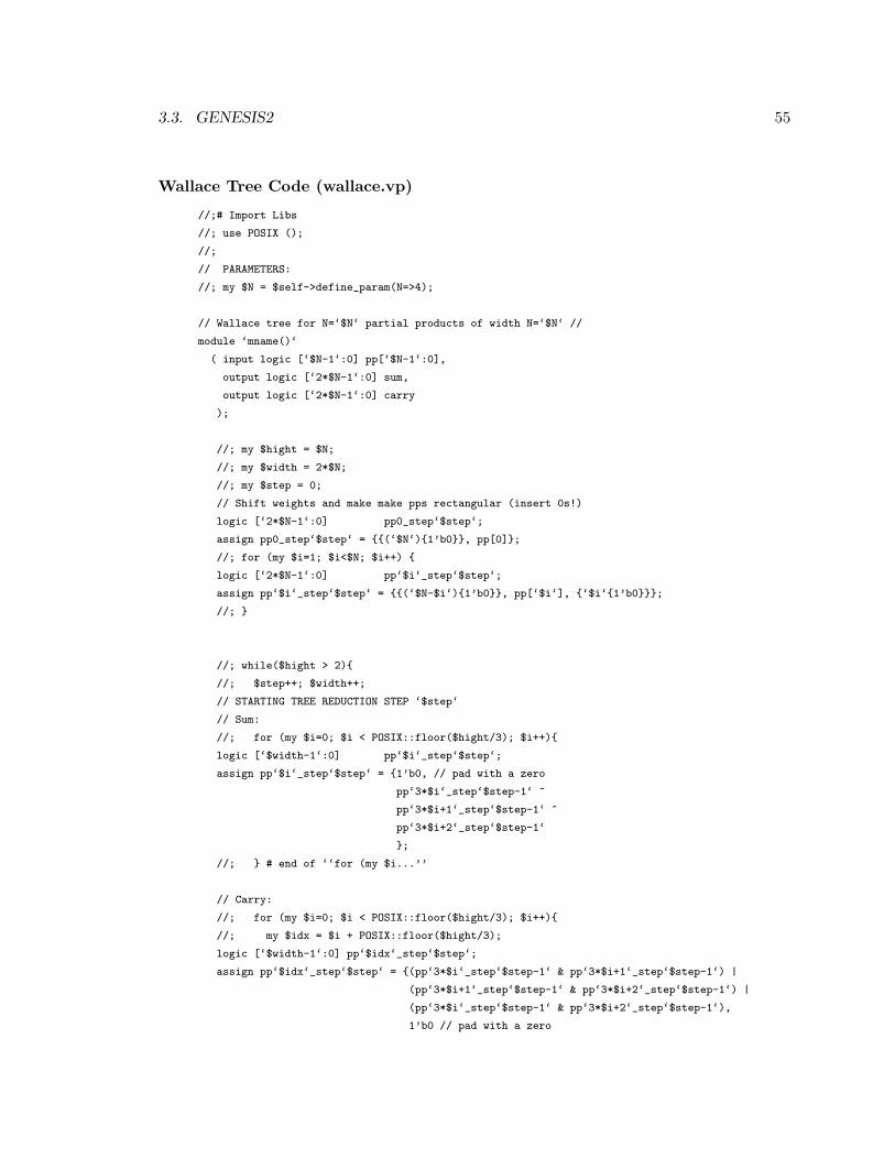
3.3. GENESIS2 55
Wallace Tree Code (wallace.vp)
//;# Import Libs
//; use POSIX ();
//;
// PARAMETERS:
//; my $N = $self->define_param(N=>4);
// Wallace tree for N=‘$N‘ partial products of width N=‘$N‘ //
module ‘mname()‘
( input logic [‘$N-1‘:0] pp[‘$N-1‘:0],
output logic [‘2*$N-1‘:0] sum,
output logic [‘2*$N-1‘:0] carry
);
//; my $hight = $N;
//; my $width = 2*$N;
//; my $step = 0;
// Shift weights and make make pps rectangular (insert 0s!)
logic [‘2*$N-1‘:0] pp0_step‘$step‘;
assign pp0_step‘$step‘ = {{(‘$N‘){1’b0}}, pp[0]};
//; for (my $i=1; $i<$N; $i++) {
logic [‘2*$N-1‘:0] pp‘$i‘_step‘$step‘;
assign pp‘$i‘_step‘$step‘ = {{(‘$N-$i‘){1’b0}}, pp[‘$i‘], {‘$i‘{1’b0}}};
//; }
//; while($hight > 2){
//; $step++; $width++;
// STARTING TREE REDUCTION STEP ‘$step‘
// Sum:
//; for (my $i=0; $i < POSIX::floor($hight/3); $i++){
logic [‘$width-1‘:0] pp‘$i‘_step‘$step‘;
assign pp‘$i‘_step‘$step‘ = {1’b0, // pad with a zero
pp‘3*$i‘_step‘$step-1‘ ^
pp‘3*$i+1‘_step‘$step-1‘ ^
pp‘3*$i+2‘_step‘$step-1‘
};
//; } # end of ‘‘for (my $i...’’
// Carry:
//; for (my $i=0; $i < POSIX::floor($hight/3); $i++){
//; my $idx = $i + POSIX::floor($hight/3);
logic [‘$width-1‘:0] pp‘$idx‘_step‘$step‘;
assign pp‘$idx‘_step‘$step‘ = {(pp‘3*$i‘_step‘$step-1‘ & pp‘3*$i+1‘_step‘$step-1‘) |
(pp‘3*$i+1‘_step‘$step-1‘ & pp‘3*$i+2‘_step‘$step-1‘) |
(pp‘3*$i‘_step‘$step-1‘ & pp‘3*$i+2‘_step‘$step-1‘),
1’b0 // pad with a zero
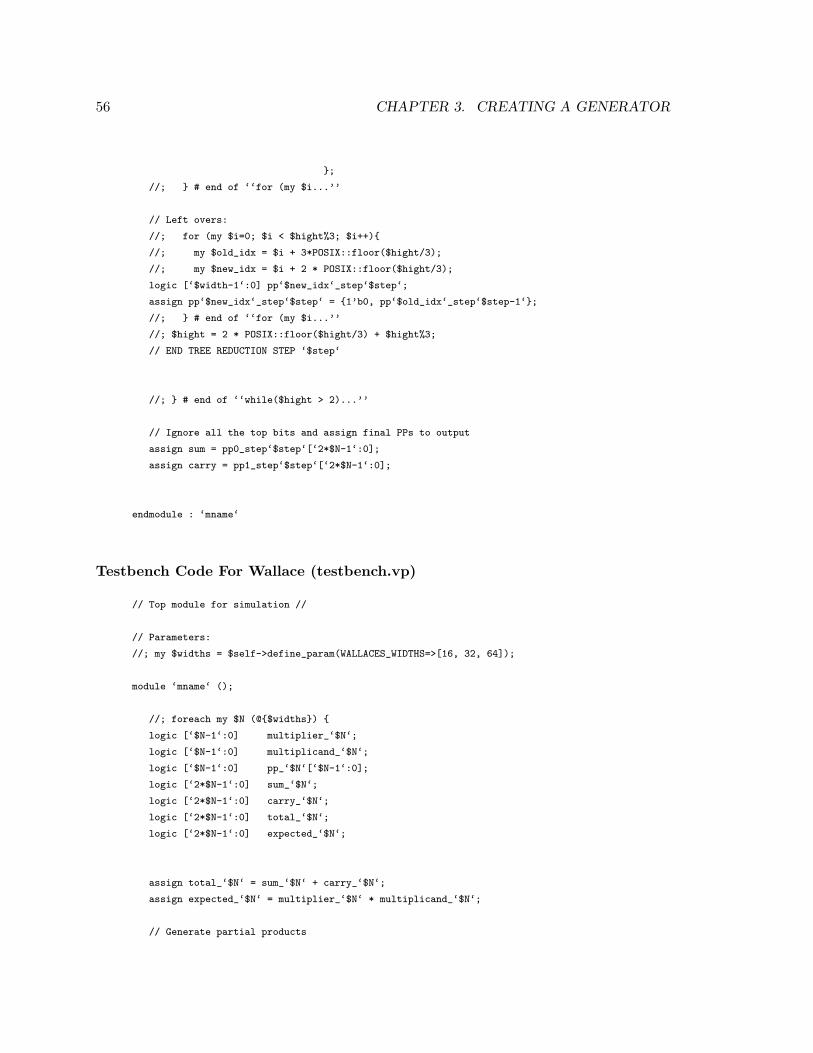
56 CHAPTER 3. CREATING A GENERATOR
};
//; } # end of ‘‘for (my $i...’’
// Left overs:
//; for (my $i=0; $i < $hight%3; $i++){
//; my $old_idx = $i + 3*POSIX::floor($hight/3);
//; my $new_idx = $i + 2 * POSIX::floor($hight/3);
logic [‘$width-1‘:0] pp‘$new_idx‘_step‘$step‘;
assign pp‘$new_idx‘_step‘$step‘ = {1’b0, pp‘$old_idx‘_step‘$step-1‘};
//; } # end of ‘‘for (my $i...’’
//; $hight = 2 * POSIX::floor($hight/3) + $hight%3;
// END TREE REDUCTION STEP ‘$step‘
//; } # end of ‘‘while($hight > 2)...’’
// Ignore all the top bits and assign final PPs to output
assign sum = pp0_step‘$step‘[‘2*$N-1‘:0];
assign carry = pp1_step‘$step‘[‘2*$N-1‘:0];
endmodule : ‘mname‘
Testbench Code For Wallace (testbench.vp)
// Top module for simulation //
// Parameters:
//; my $widths = $self->define_param(WALLACES_WIDTHS=>[16, 32, 64]);
module ‘mname‘ ();
//; foreach my $N (@{$widths}) {
logic [‘$N-1‘:0] multiplier_‘$N‘;
logic [‘$N-1‘:0] multiplicand_‘$N‘;
logic [‘$N-1‘:0] pp_‘$N‘[‘$N-1‘:0];
logic [‘2*$N-1‘:0] sum_‘$N‘;
logic [‘2*$N-1‘:0] carry_‘$N‘;
logic [‘2*$N-1‘:0] total_‘$N‘;
logic [‘2*$N-1‘:0] expected_‘$N‘;
assign total_‘$N‘ = sum_‘$N‘ + carry_‘$N‘;
assign expected_‘$N‘ = multiplier_‘$N‘ * multiplicand_‘$N‘;
// Generate partial products
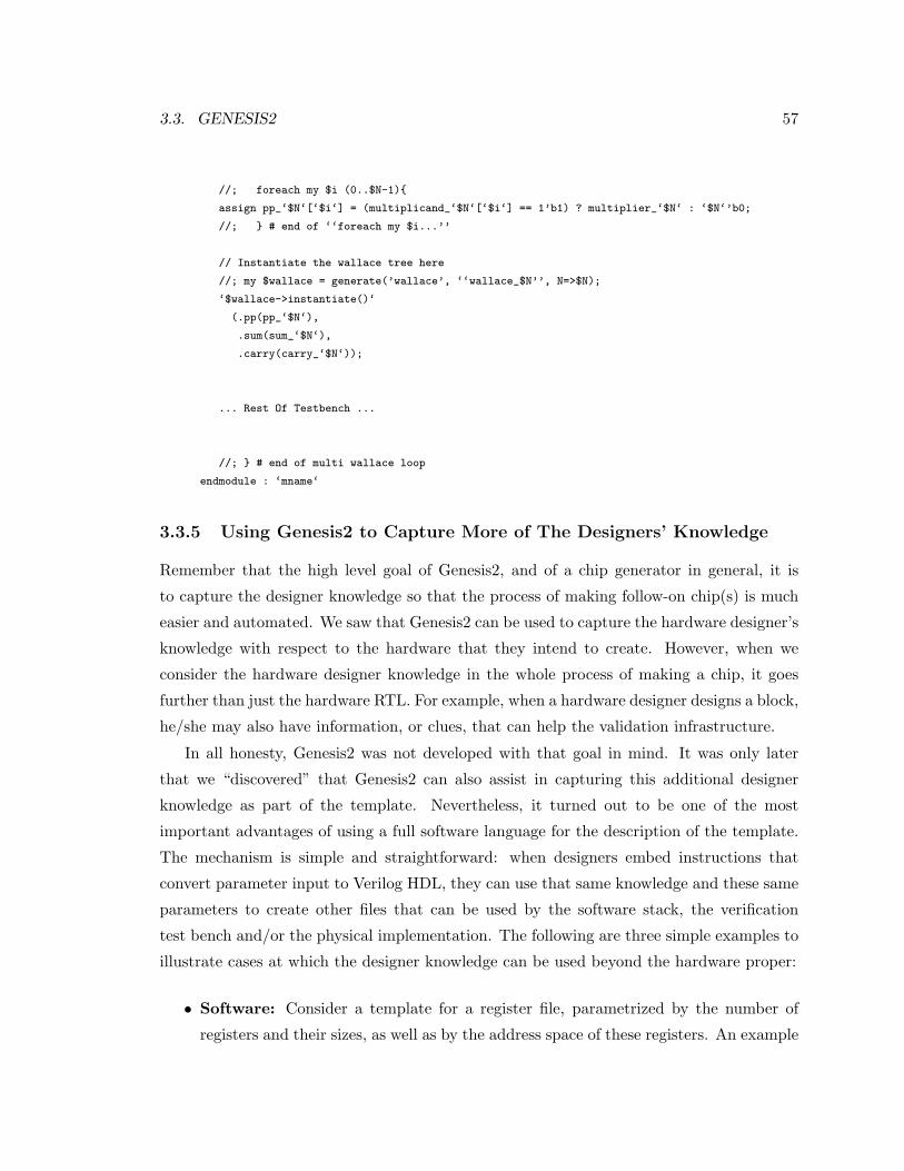
3.3. GENESIS2 57
//; foreach my $i (0..$N-1){
assign pp_‘$N‘[‘$i‘] = (multiplicand_‘$N‘[‘$i‘] == 1’b1) ? multiplier_‘$N‘ : ‘$N‘’b0;
//; } # end of ‘‘foreach my $i...’’
// Instantiate the wallace tree here
//; my $wallace = generate(’wallace’, ‘‘wallace_$N’’, N=>$N);
‘$wallace->instantiate()‘
(.pp(pp_‘$N‘),
.sum(sum_‘$N‘),
.carry(carry_‘$N‘));
... Rest Of Testbench ...
//; } # end of multi wallace loop
endmodule : ‘mname‘
3.3.5 Using Genesis2 to Capture More of The Designers’ Knowledge
Remember that the high level goal of Genesis2, and of a chip generator in general, it is
to capture the designer knowledge so that the process of making follow-on chip(s) is much
easier and automated. We saw that Genesis2 can be used to capture the hardware designer’s
knowledge with respect to the hardware that they intend to create. However, when we
consider the hardware designer knowledge in the whole process of making a chip, it goes
further than just the hardware RTL. For example, when a hardware designer designs a block,
he/she may also have information, or clues, that can help the validation infrastructure.
In all honesty, Genesis2 was not developed with that goal in mind. It was only later
that we “discovered” that Genesis2 can also assist in capturing this additional designer
knowledge as part of the template. Nevertheless, it turned out to be one of the most
important advantages of using a full software language for the description of the template.
The mechanism is simple and straightforward: when designers embed instructions that
convert parameter input to Verilog HDL, they can use that same knowledge and these same
parameters to create other files that can be used by the software stack, the verification
test bench and/or the physical implementation. The following are three simple examples to
illustrate cases at which the designer knowledge can be used beyond the hardware proper:
• Software: Consider a template for a register file, parametrized by the number of
registers and their sizes, as well as by the address space of these registers. An example
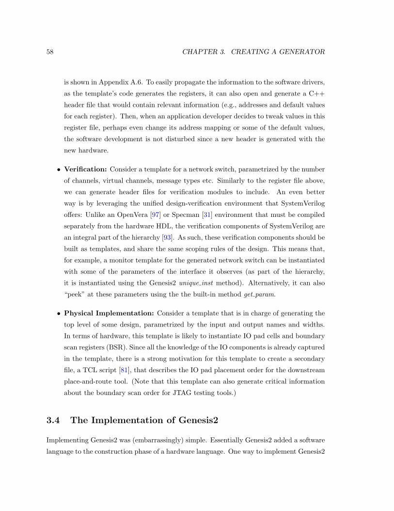
58 CHAPTER 3. CREATING A GENERATOR
is shown in Appendix A.6. To easily propagate the information to the software drivers,
as the template’s code generates the registers, it can also open and generate a C++
header file that would contain relevant information (e.g., addresses and default values
for each register). Then, when an application developer decides to tweak values in this
register file, perhaps even change its address mapping or some of the default values,
the software development is not disturbed since a new header is generated with the
new hardware.
• Verification: Consider a template for a network switch, parametrized by the number
of channels, virtual channels, message types etc. Similarly to the register file above,
we can generate header files for verification modules to include. An even better
way is by leveraging the unified design-verification environment that SystemVerilog
offers: Unlike an OpenVera [97] or Specman [31] environment that must be compiled
separately from the hardware HDL, the verification components of SystemVerilog are
an integral part of the hierarchy [93]. As such, these verification components should be
built as templates, and share the same scoping rules of the design. This means that,
for example, a monitor template for the generated network switch can be instantiated
with some of the parameters of the interface it observes (as part of the hierarchy,
it is instantiated using the Genesis2 unique inst method). Alternatively, it can also
“peek” at these parameters using the the built-in method get param.
• Physical Implementation: Consider a template that is in charge of generating the
top level of some design, parametrized by the input and output names and widths.
In terms of hardware, this template is likely to instantiate IO pad cells and boundary
scan registers (BSR). Since all the knowledge of the IO components is already captured
in the template, there is a strong motivation for this template to create a secondary
file, a TCL script [81], that describes the IO pad placement order for the downstream
place-and-route tool. (Note that this template can also generate critical information
about the boundary scan order for JTAG testing tools.)
3.4 The Implementation of Genesis2
Implementing Genesis2 was (embarrassingly) simple. Essentially Genesis2 added a software
language to the construction phase of a hardware language. One way to implement Genesis2
3.4. GENESIS2 BACKEND 59
could have been to pick a known HDL such as Verilog or VHDL and extend it. However, this
would have required re-implementing a full software compiler in addition to the hardware
compiler. We noticed however, that a simpler way would be to use an already existing
software tool and have it handle the software extensions of the HDL code. In the case of
Genesis2, this would be the Perl interpreter.
Enabling users to code in a target language annotated with a second, full fledged software
capable meta-language, is of course not a new idea. It is done by numerous pre-processors,
including EP3 [94] and deperlify [40] which enable stubs of Perl code and EmPy [43],
which enables stubs of Python code. However, as mentioned before, these tools lack the
per-instance and hierarchical system scopes required for a generator.
Nevertheless, the starting point for making the first version of the Genesis2 tool (Gen-
esis1) was based on modifying EP3. In a nutshell, EP3 provides three main mechanisms
for programmability: pre-defined directives such as @define or @macro; toggling between
meta- (Perl) and target- (Verilog) language using the @perl begin/end directives; and ex-
tending/defining new directives. In this first version, we added a new directive @unique inst
to the existing list of EP3 directives. The purpose of the unique inst directive was to make
a recursive call to the EP3 pre-processing engine for an instantiated object. This recursive
mechanism was enough for creating a per-instance scope since each new instance of the pre-
processor could have its own parameter definition data structure. This therefore enabled the
generation of modules from templates on the fly, plus uniquification where needed. We also
kept a globals list—a list of global scope parameter definitions—for inter-instance message
passing. To provide an XML based intermediate form, we augmented the EP3 data struc-
ture with pointers to parent and child instances, and had the unique inst function extract
information from an XML file if one was provided. The only piece that was completely
missing was the ability of user code in an instance A to get a handle to a second instance
B or to instance B’s parameters.
While Genesis1 did work and was useful for first attempts in creating a generator,
we quickly learned that it also had significant limitations. The first was in the limited
amount of directives that were implemented and in the complexity of adding more. In
EP3, directives such as @define are not native Perl calls but actually calls to Perl functions
that must implement that functionality (for example, the @define directive is a call to a
function that puts a definition of name and value in the EP3 data structure). In order
to support even the most common software construct, we had to implement directives for
60 CHAPTER 3. CREATING A GENERATOR
@for/@foreach/@endfor, @while/@endwhile, @next, @break, and more. In addition, we had
to create a “math” library of directives such as @add, @sub, @mul, @div, @log2 etc. Adding
more and more software mechanisms as directives proved to be a tedious and endless task.
A second problem was that the EP3 engine is based on text replacements and not
on terms evaluation like actual software languages, which made it close to impossible to
compound function calls. E.g., assume we set “@define A 1”, “@define B 2” and “@define
C 3”. To implement D=A+B*C we first need to calculate “@mul B B C” and only then
“@add D A B”. An attempt to call “@define D A+B*C” instead, would have resulted in
the definition of D as the string “1+2*3”. Similarly an attempt to call “@add D A (@mul
B C)” would have resulted in an error.
Finally, we concluded that Genesis1, which was based on the parsing engine of EP3,
could be used to make chip generators—but it was a very cumbersome solution.
A better solution is therefore to use the Perl interpreter directly on the meta-language.
One other tool that does that is the Tensilica TIE pre-processor (TPP) [10]. Like EP3,
TPP enables the user to easily and quickly toggle between target-language mode and meta-
language mode. In TPP, this is done either on a line basis (using an escape character) or
on an expression basis (using two escape characters as delimiters)However, TPP is different
from EP3 in the sense that rather then generating the target-language directly as the meta-
language is processed, TPP creates an intermediate form. TPP first parses the target and
meta-language into an intermediate file as a Perl script. Then, this generated Perl script is
executed to generate the final text. This approach eliminates the need for directives, except
those that toggle between meta and target language—any statement or expression that is
in the “Perl mode” area will be interpreted by the Perl interpreter.
Therefore, to create Genesis2, we used a mechanism much like that of TPP: a “ //; ”
(two forward-slashes followed by a semi-colon) indicates the start of a full meta-language
(Perl) line, and “ ‘expression‘ ” (an expression placed between two grave accent signs)
indicates an in-line toggling between meta- and target-language. The key however is in the
intermediate form that was generated. Had we generated an executable script like TPP
does, then each template would have been processed on its own—no instance or system
scope. Instead, we take a page from the C compiler, which first creates object files and
only then links them together. Our parsing engine first creates Perl classes, or packages,
and the generation of target-language code is done only after all said packages have been
made. This means that Genesis2 first parses all templates to create Perl packages. This
3.4. GENESIS2 BACKEND 61
parsing phase essentially creates the complete code for a fully object oriented program that
generates hardware. To make this program “link” together, all generated classes/packages
inherit from one base class/package called UniqueModule.pm.
Figure 3.7 shows how a template, which contains both Verilog and Perl code interleaved,
is parsed and transformed into a Perl package. The Perl package is attached with a header to
import relevant libraries, and most importantly, to inherit the UniqueModule.pm package.
UniqueModule.pm holds critical code that constructs the system: a data-structure to hold
parent and child instances, a data-structure to hold parameters’ names, values and priorities,
and API methods to handle and manipulate these data structures (see API methods in
Appendix A).
The most important API call that all templates inherit from the base template (i.e.,
inherit from the base package UniqueModule.pm), is the method unique inst. A call to
$self->unique inst(SomeTemplateName, NewInstName, PrmName=>PrmVal), returns a han-
dle to a new object instance. This method call is in fact a call to template SomeTemplateName’s
constructor, since after parsing, it is translated into a call to the generated Perl package
SomeTemplateName.pm’s constructor.
Interestingly enough, the result is that each Perl object (returned by the unique inst
method) is uniquely tied to a Verilog object. Therefore, even though Perl and Verilog are
on two different layers, the hardware designer has the illusion that they (the Verilog and
the Perl layers) are one and the same.
A key to achieving system and instance scopes, rather than just pre-processing files, is
that we first create the intermediate representation for all templates, and then assemble
them into a full object oriented program with a centralized database of instances and types.
This facilitates our ability to acquire handles from one instance to the other, for example,
for querying of parameters. Each such package also has a to verilog method, and it is the
activation of these methods throughout the hierarchy that generates the final Verilog code.
Note that unlike typical pre-processors, since to verilog is a method (not a function), it is
called on an instance basis, generating a unique module when needed. This means that a
single template that is instantiated in multiple places and whose parameters get different
values for each of these instances, would in fact have its to verilog method called multiple
times, once per instance, potentially generating multiple unique modules in multiple output
files.
To better understand how the method call to unique inst orchestrates the different
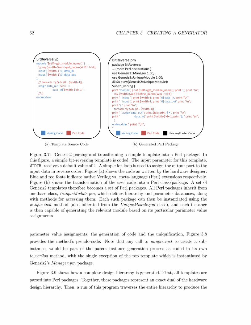
62 CHAPTER 3. CREATING A GENERATOR
BitReverse.vpmodule `$self‐>get_module_name()` (\\; my $width=$self‐>get param(WIDTH=>4);\\; y $ $ g _p ( );input [`$width‐1`:0] data_in,input [`$width‐1`:0] data_out
);//; foreach my $idx (0 .. $width‐1){assign data out[`$idx`] =assign data_out[ $idx ] =
data_in[`$width‐$idx‐1`];//; }
endmodule
Perl CodeVerilog Code
(a) Template Source Code
BitReverse.pmpackage BitReverse;(more Perl declarations )… (more Perl declarations )
use Genesis2::Manager 1.00;use Genesis2::UniqueModule 1.00;@ISA = qw(Genesis2::UniqueModule);Sub to verilog {Sub to_verilog {print ‘module’; print $self‐>get_module_name(); print ’(‘; print “\n”;my $width=$self‐>define_param(WIDTH=>4);
print ‘ input [‘; print $width‐1; print ‘:0] data_in,’ print “\n”;print ‘ input [‘; print $width‐1; print ‘:0] data_out’ print “\n”;print ‘); ’ print “\n”;foreach my $idx (0 .. $width‐1){
print ‘ assign data_out[‘; print $idx; print ‘] = ,’ print “\n”;print ‘ data_in[‘; print $width‐$idx‐1; print ‘]; ,’ print “\n”;}}
endmodule ,’ print “\n”;}
Perl CodeVerilog Code Header/Footer Code
(b) Generated Perl Package
Figure 3.7: Genesis2 parsing and transforming a simple template into a Perl package. Inthis figure, a simple bit-reversing template is coded. The input parameter for this template,WIDTH, receives a default value of 4. A simple for-loop is used to assign the output port to theinput data in reverse order. Figure (a) shows the code as written by the hardware designer.Blue and red fonts indicate native Verilog vs. meta-language (Perl) extensions respectively.Figure (b) shows the transformation of the user code into a Perl class/package. A set ofGenesis2 templates therefore becomes a set of Perl packages. All Perl packages inherit fromone base class, UniqueModule.pm, which defines hierarchy and parameter databases, alongwith methods for accessing them. Each such package can then be instantiated using theunique inst method (also inherited from the UniqueModule.pm class), and each instanceis then capable of generating the relevant module based on its particular parameter valueassignments.
parameter value assignments, the generation of code and the uniquification, Figure 3.8
provides the method’s pseudo-code. Note that any call to unique inst to create a sub-
instance, would be part of the parent instance generation process as coded in its own
to verilog method, with the single exception of the top template which is instantiated by
Genesis2’s Manager.pm package.
Figure 3.9 shows how a complete design hierarchy is generated. First, all templates are
parsed into Perl packages. Together, these packages represent an exact dual of the hardware
design hierarchy. Then, a run of this program traverses the entire hierarchy to produce the
3.5. FUTURE IMPROVEMENTS TO GENESIS2 63
Verilog modules.
3.5 Future Improvements To Genesis2
Genesis2 was built as part of an exploration process, trying to figure out “what would it
take to build a chip generator?” At the time these pages are written, Genesis2 is fully
functional, and is being used for the design of a number of digital and mixed signal chips
by the Stanford VLSI group, as well as being integrated into the design flow of Stanford’s
EE272—Design Projects in VLSI Systems digital and mixed signal design class. Looking
forward, there are a number of possible implementation changes that should be considered
so that a mature version of Genesis2 can be deployed for industrial use (as a commercial
tool).
The most basic foundation of Genesis2 was the premise that there should be a clear
distinction between the functional description of the hardware and the decision what hard-
ware to place. While the former had to be synthesizable, for the latter we argued that
there should be a rich software-like environment. To achieve this separation, we added a
layer of meta-language to a commonly used hardware descriptive language: Genesis2 uses
Perl as the meta-language and Verilog or SystemVerilog as the target-language. While this
choice made complete sense from a research perspective, allowing the Genesis2 developers
to easily figure out what features the tool needed to support and to quickly iterate through
versions, this decision has a lot of impact on the use model for the hardware designer.
First, we can see that many meta-languages are actually tied to their target-language, and
share some (though typically not all) syntactic rules. Examples include C++ templates
and even SystemVerilog’s generate blocks. the downside of our approach, is that since the
meta- and target-languages are completely separated, the evaluation of the meta-language
program can produce syntax errors in the generated code of the target-language. However,
the benefit of our approach is that it provides much more coding flexibility to the hardware
designer—flexibility that C++ templates traditionally achieve through an additional layer
of C or M4 pre-processors, for example.
In addition, layered meta- and target-languages can become a source of frustration for
programmers (in our case hardware designers). Whether a functional bug or even a Verilog
compilation error, the errors that the programmer sees during the debugging process do
not point back all the way to the source code. Instead they point back to the intermediate
64 CHAPTER 3. CREATING A GENERATOR
form. For example, the design compiler may report a Verilog syntax error in the generated
Verilog (.v) file, but to fix the error the designer would have to trace it back to the Genesis2
code (.vp file) that generated that Verilog, and fix it there. We try to provide the user with
tools to do the mapping between the Verilog and the Genesis2 files more easily: First, all
files—Genesis2 (.vp) files, intermediate Perl (.pm) files and generated Verilog (.v) files—
are available to the user for debugging. We argue subjectively that this is already a huge
improvement over C++ templates or SystemVerilog generate blocks that result in code that
is hidden from the user. We also provide a sync statements annotation mechanism, using
the debug switch, that creates comments on the generated files, specifying the respective
location (name of .vp file and line number) that created the relevant Verilog. Having said
that, this is far from being enough. The right way to solve this problem is to make the
synthesizer/simulator/debugger point directly to the source, much like GDB does not point
to the assembly but to the C/C++ code.
A second and less crucial consideration is that of which meta-language to use. Genesis2
uses Perl, a decision that works well due to the fact that the author knew it well and
that it is a very flexible and adaptable language. Another advantage of Perl is that it is
one of the most commonly used scripting languages in hardware design houses. However,
assuming that the meta-language is kept separated from the target-language, a variety of
new languages, in particular Python [68], have emerged as potentially more concise and
more easily maintained languages. As we expect the use of chip generators to grow, and the
relative portion of the “generating” code to rise while the relative portion of static target-
language code goes down, maintainability and ease of use are likely to gradually become
significant issues for generators.
A key motivation for Genesis2 was to enable users and tools a standardized way of pro-
viding high level input to customize the generated design without actually writing Verilog.
This input comes as a hierarchical set of parameter assignments to the design knobs de-
fined by the designer, so it can pervasively impact the various elaboration programs. It is
therefore important that this interface is clear and formal. Even though our current imple-
mentation using Perl is typeless, we have forced a simple mechanism to at least convey the
structure of each parameter to the external world: Genesis2’s XML schema unambiguously
annotates whether a parameter is a scalar/string, hash, array or instance-path12. We are
12Scalar/string, hash and array are the native Perl data-types; Instance path represents a pointer toanother instance in the system.
3.5. FUTURE IMPROVEMENTS TO GENESIS2 65
also working on a “range” mechanism, such that in addition to simply defining a knob, de-
signers could also determine, and more importantly, convey to other tools and users, what
are valid values for those knobs.
As work that uses Genesis2 continues, we see that another improvement on the way
parameters are handled in Genesis2 may be to add yet another priority level. As described
in Section 3.3.2, there are four ways to assign a value to a parameter in Genesis2, associated
with four priority levels:
1. In the template body using define param (weakest assignment type)
2. Via the XML configuration file
3. During the instantiation of one template in another template
4. In the template body using force param (immutable assignment type)
Yet, it may be the case that for additional convenience, it may be useful to add another
priority—a “weak-instantiation” priority. This priority would be even weaker than assign-
ments via XML, even though it is to be used at instantiation. The use case for this priority
is for when a designer wishes to instantiate a template (e.g., a FIFO) and give some pa-
rameter (e.g., DEPTH) a new default value instead of this parameter’s original value (e.g., if
DEPTH was coded to have a default of 4 but for this design reasonable values are around 64).
Since this parameter belongs to the free or to the architectural parameter categories, the
designer may still wish to allow an application designer or even tools to tweak this value
again through the XML interface (e.g., refine DEPTH to be 72 entries to avoid a performance
bottleneck). In this case, even though the designer wants a different default, he/she does
not want this default to be strongly bound just yet.
Finally, parameters are also used to communicate between meta-programs of templates.
For example, a cache may want to “check” the word width of the processor it is to be
connected to. This implementation did not concentrate on strong encapsulation or object
privacy issues. Therefore templates in Genesis2 do not have any restrictions on information
sharing. Any template is allowed to “peek” into the parameters and sub-hierarchy of any
other template. The only restriction is that all parameters are immutable once assigned,
and that all objects are immutable once created. Essentially each elaboration program has
its own scope and the rest of the system is read-only for it. The problem is that this scheme
relies on “good coding practices”—a “bad” designer might write code for template A that
66 CHAPTER 3. CREATING A GENERATOR
accesses the internal data of template B. This action breaks the module abstraction and
encapsulation, and results in brittle code. In analogy, most object oriented languages put
different/more restrictions on information sharing (e.g. using the public, protected and
private constructs in C++) for the purpose of providing better encapsulation of a class’s
functionality. In future work, it may be worthwhile to consider adding some restrictions,
potentially in the form of private by default with an export construct—a template’s internal
information would be private unless explicitly exported.
Whether implemented as a meta-language or inherent to the target-language, the key to
enabling the creation of a generator is the ability to embed the designer’s knowledge of how
the entire system needs to be constructed under different conditions, rather than just the
functional behavior of each hardware component. In our experience, this (unfortunately)
cannot be done with existing HDLs. The missing piece is the rich expressibility that exists
in software languages. Therefore to create Genesis2 we took an approach of merging the
good of both worlds: use software language to describe the system and each component’s
elaboration; use SystemVerilog to describe the functionality/behavior of the hardware. Our
experience had shown that Genesis2 can adequately describe generators, and is useful for
embedding the designer’s knowledge into the design. The second, and not less important
requirement, is to enable external users’ and tools’ input to control those elaboration pro-
grams. Genesis2’s inherent ability to automatically extract the parametrization space in a
standardized and formal media, and to later accept that same format as pervasive input to
all elaboration programs, enables quick and automatic integration with GUI’s and optimiz-
ers. While improvements such as the ones described in this section will definitely enhance
the user’s experience and potentially even productivity, as these lines are written, Genesis2
is already in use by Stanford students implementing a chip-multiprocessor generator, Stan-
ford students implementing a number of mixed signal chips, and Carnegie Mellon students
implementing digital signal processing components.
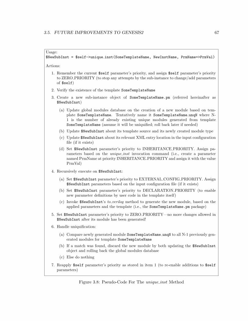
3.5. FUTURE IMPROVEMENTS TO GENESIS2 67
Usage:$NewSubInst = $self->unique inst(SomeTemplateName, NewInstName, PrmName=>PrmVal)
Actions:
1. Remember the current $self parameter’s priority, and assign $self parameter’s priorityto ZERO PRIORITY (to stop any attempts by the sub-instance to change/add parametersof $self)
2. Verify the existence of the template SomeTemplateName
3. Create a new sub-instance object of SomeTemplateName.pm (referred hereinafter as$NewSubInst)
(a) Update global modules database on the creation of a new module based on tem-plate SomeTemplateName. Tentatively name it SomeTemplateName unqN where N-1 is the number of already existing unique modules generated from templateSomeTemplateName (assume it will be uniquified; roll back later if needed)
(b) Update $NewSubInst about its template source and its newly created module type
(c) Update $NewSubInst about its relevant XML entry location in the input configurationfile (if it exists)
(d) Set $NewSubInst parameter’s priority to INHERITANCE PRIORITY. Assign pa-rameters based on the unique inst invocation command (i.e., create a parameternamed PrmName at priority INHERITANCE PRIORITY and assign it with the valuePrmVal)
4. Recursively execute on $NewSubInst:
(a) Set $NewSubInst parameter’s priority to EXTERNAL CONFIG PRIORITY. Assign$NewSubInst parameters based on the input configuration file (if it exists)
(b) Set $NewSubInst parameter’s priority to DECLARATION PRIORITY (to enablenew parameter definitions by user code in the template itself)
(c) Invoke $NewSubInst’s to verilog method to generate the new module, based on theapplied parameters and the template (i.e., the SomeTemplateName.pm package)
5. Set $NewSubInst parameter’s priority to ZERO PRIORITY—no more changes allowed in$NewSubInst after its module has been generated!
6. Handle uniquification:
(a) Compare newly generated module SomeTemplateName unqN to all N-1 previously gen-erated modules for template SomeTemplateName
(b) If a match was found, discard the new module by both updating the $NewSubInstobject and rolling back the global modules database
(c) Else do nothing
7. Reapply $self parameter’s priority as stored in item 1 (to re-enable additions to $selfparameters)
Figure 3.8: Pseudo-Code For The unique inst Method
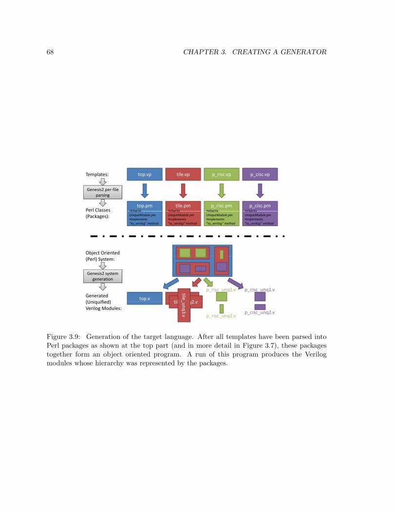
68 CHAPTER 3. CREATING A GENERATOR
top.vp tile.vp p_risc.vp p_cisc.vpTemplates:
Genesis2 per file
top.pm•Inherits
tile.pm•InheritsPerl Classes
p_risc.pm•Inherits
p_cisc.pm•Inherits
Genesis2 per‐file parsing
Inherits UniqueModule.pm•Implements “to_verilog” method
Inherits UniqueModule.pm•Implements “to_verilog” method
Perl Classes (Packages):
Inherits UniqueModule.pm•Implements “to_verilog” method
Inherits UniqueModule.pm•Implements “to_verilog” method
Object Oriented (Perl) System:
Genesis2 system generation
top.vtile nq2
tile_Generated (U i ifi d)
p_risc_unq1.v p_cisc_unq1.v
generation
tile_unq2.v
_unq3.v
(Uniquified) Verilog Modules:
p_risc_unq2.vp_cisc_unq2.v
Figure 3.9: Generation of the target language. After all templates have been parsed intoPerl packages as shown at the top part (and in more detail in Figure 3.7), these packagestogether form an object oriented program. A run of this program produces the Verilogmodules whose hierarchy was represented by the packages.
Chapter 4
Verification of A Flexible
Architecture
In Chapters 2 and 3, we discussed the concepts surrounding chip generators and suggested
a framework for creating them. Unfortunately, as Chapter 2 already suggests, designing
new chips is only half the problem. In this chapter we start the discussion of the other half:
design validation.
In particular, in the context of chip generators, because many chips need to be pro-
duced, validation may get very difficult if not handled carefully. Furthermore, we don’t
consider “correct by construction” as a valid assertion, even though a generator generates
the hardware automatically, because every tool can have errors. On the other hand, we
do pose (and answer) the question, “What is it that we are verifying?” Is it the generator
itself or is it the generated instance? Obviously, a bullet-proof generator is best, but since
we don’t know how to produce such an artifact, we argue that we really should be verifying
the instances that the generator produces. Unfortunately, this validation task could render
the whole chip generator concept useless unless we automate much of the process, thus
amortizing verification costs over the many chip instances that the generator produces.
To this extent, runtime-configurable architectures resemble chip generators: both have
embedded flexibility in their architecture and micro-architecture, both can be programmed,
and for both, the program fixes the flexible architecture to a particular mode of operation.
The difference, of course, is the time at which this binding process happens—runtime or
pre-silicon. Therefore, from a validation perspective, one can serve as proxy for the other.
For example, the previously posed question, if formulated for a runtime configurable design
69
70 CHAPTER 4. VERIFICATION OF A FLEXIBLE ARCHITECTURE
would become: are we verifying the chip (under any and all random configurations) or are
we verifying a set of particular configurations?
Therefore this chapter uses the case study of a very flexible chip multiprocessor, Stan-
ford Smart Memories, that was actually implemented, verified, taped out and proved to be
working in the lab, to better understand the impact of flexibility in the design on validation.
As Section 4.1 describes in detail, Stanford’s Smart Memories (SSM) is a scalable 8-core
chip multiprocessor with a completely configurable memory system that can support cache
coherent, stream or transactional memory models. Today, the completed chip(s) run appli-
cations in the lab, in all modes and with up to 32 active processors (the largest configuration
our test platform supports). While there is no guarantee that our silicon is completely bug
free, so far no functional bug has yet been found. We were pleasantly surprised by this
result, given the complexity and flexibility of the design.
Sections 4.2 and 4.3 describe how we approached the validation of our configurable
CMP system, especially focusing on how we approached testing our highly configurable
components. When SSM’s validation work started we thought that, at best, these configu-
rations would be orthogonal to each other, with a linear increase in required validation. Of
course, we feared the worst: that the verification work would be proportional to verifying
a cross-product of all possible modes of operation, or an n-factorial explosion in potential
verification effort. Careful planning was therefore critical, as we could not afford to have
each system configuration require a separate testing environment. In the end, we created
a validation flow that required some up-front work, but greatly reduced the complexity
caused by added flexibility. This was the first signal that validating a generator would also
be feasible—a modest amount of additional up-front work that can be amortized across
multiple chip instances would be a good trade-off.
In Section 4.4 we explore how SSM’s flexibility impacted the validation results, as cap-
tured in our bug database. We analyze some of the most difficult bugs we dealt with in
each mode and explain what architectural decisions caused each one or what architectural
assumptions had to be altered to fix them. Of particular interest is the analysis regarding
which configuration found which bug. For example, is there a particular configuration that
would find all bugs? (no); if we need the generator to produce only a single particular config-
uration, would it be useful to test a few more closely related ones? (yes). Section 4.5 reports
our hindsight investigation results. We find that by randomly changing the configuration
of particular modules (e.g. making an I-cache bigger or smaller), we not only tested that
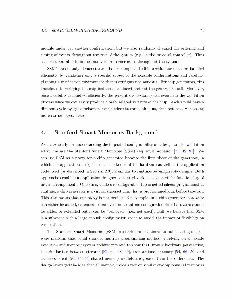
4.1. SMART MEMORIES BACKGROUND 71
module under yet another configuration, but we also randomly changed the ordering and
timing of events throughout the rest of the system (e.g. in the protocol controller). Thus
each test was able to induce many more corner cases throughout the system.
SSM’s case study demonstrates that a complex flexible architecture can be handled
efficiently by validating only a specific subset of the possible configurations and carefully
planning a verification environment that is configuration agnostic. For chip generators, this
translates to verifying the chip instances produced and not the generator itself. Moreover,
once flexibility is handled efficiently, the generator’s flexibility can even help the validation
process since we can easily produce closely related variants of the chip—each would have a
different cycle by cycle behavior, even under the same stimulus, thus potentially exposing
more corner cases, faster.
4.1 Stanford Smart Memories Background
As a case study for understanding the impact of configurability of a design on the validation
effort, we use the Stanford Smart Memories (SSM) chip multiprocessor [71, 42, 91]. We
can use SSM as a proxy for a chip generator because the first phase of the generator, in
which the application designer tunes the knobs of the hardware as well as the application
code itself (as described in Section 2.3), is similar to runtime-reconfigurable designs. Both
approaches enable an application designer to control various aspects of the functionality of
internal components. Of course, while a reconfigurable chip is actual silicon programmed at
runtime, a chip generator is a virtual superset chip that is programmed long before tape out.
This also means that our proxy is not perfect—for example, in a chip generator, hardware
can either be added, extended or removed; in a runtime-configurable chip, hardware cannot
be added or extended but it can be “removed” (i.e., not used). Still, we believe that SSM
is a subspace with a large enough configuration space to model the impact of flexibility on
verification.
The Stanford Smart Memories (SSM) research project aimed to build a single hard-
ware platform that could support multiple programming models by relying on a flexible
execution and memory system architecture and to show that, from a hardware perspective,
the similarities between streams [82, 60, 98, 49], transactional memory [54, 66, 50] and
cache coherent [20, 75, 55] shared memory models are greater than the differences. The
design leveraged the idea that all memory models rely on similar on-chip physical memories
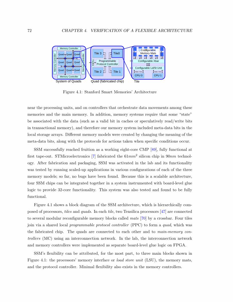
72 CHAPTER 4. VERIFICATION OF A FLEXIBLE ARCHITECTURE
Quad
Configurable Xbar
TileQuad (fabricated chip)
Configurable Ld/St Unit
CPU 1Memory Controller
Mem
ory
Con
trolle
r
Memory Controller
System of Quads
ConfigurableMemory Mats
Data / Inst’
CPU 0Data / Inst’
Tile0Tile 3
Tile 1Tile 2
Programmable Protocol Controller
QuadQuad
QuadQuadQuad
QuadQuadQuad Mem
ory
Con
trolle
r
TX/R
X
Figure 4.1: Stanford Smart Memories’ Architecture
near the processing units, and on controllers that orchestrate data movements among these
memories and the main memory. In addition, memory systems require that some “state”
be associated with the data (such as a valid bit in caches or speculatively read/write bits
in transactional memory), and therefore our memory system included meta-data bits in the
local storage arrays. Different memory models were created by changing the meaning of the
meta-data bits, along with the protocols for actions taken when specific conditions occur.
SSM successfully reached fruition as a working eight-core CMP [89], fully functional at
first tape-out. STMicroelectronics [7] fabricated the 61mm2 silicon chip in 90nm technol-
ogy. After fabrication and packaging, SSM was activated in the lab and its functionality
was tested by running scaled-up applications in various configurations of each of the three
memory models; so far, no bugs have been found. Because this is a scalable architecture,
four SSM chips can be integrated together in a system instrumented with board-level glue
logic to provide 32-core functionality. This system was also tested and found to be fully
functional.
Figure 4.1 shows a block diagram of the SSM architecture, which is hierarchically com-
posed of processors, tiles and quads. In each tile, two Tensilica processors [47] are connected
to several modular reconfigurable memory blocks called mats [70] by a crossbar. Four tiles
join via a shared local programmable protocol controller (PPC) to form a quad, which was
the fabricated chip. The quads are connected to each other and to main-memory con-
trollers (MC) using an interconnection network. In the lab, the interconnection network
and memory controllers were implemented as separate board-level glue logic on FPGA.
SSM’s flexibility can be attributed, for the most part, to three main blocks shown in
Figure 4.1: the processors’ memory interface or load store unit (LSU), the memory mats,
and the protocol controller. Minimal flexibility also exists in the memory controllers.
4.1. SMART MEMORIES BACKGROUND 73
Data ArrayMetadataArray
RMWLogic
Pointer LogicHead
Tail
Cmp
Meta-Data inAddress in Data in
Meta-Data out
TotalMatch
Data out
Cmp
(a)
Word 4Word 0Tag
M6 M7 M8
Tag
M11 M12 M13
Tag MatsM9 M10
M14 M15
IMCN
Match Guard
Word 4Word 0 Word 4
Word 0Word 5Word 1 Word 4
Word 0Word 6Word 2 Word 4
Word 0Word 7Word 3
Data Mats
(b)
Figure 4.2: Configurable local memory. (a) Block diagram of the memory mat. (b) Ex-ample mat organization for a 2-way cache.
The first reconfigurable block, the LSU, adapts the Tensilica cores to our memory sys-
tem. It performs virtual to physical address mapping, and translates the Tensilica op-codes
into accesses to the appropriate memory mats. The LSU can be configured to generate
multicast requests for set associative cache configurations, and can generate parallel unique
accesses to different mats.
The memory mats constitute the second reconfigurable block; Figure 4.2(a) shows a
block diagram of a single mat. Each mat is an array of data words and associated meta-
data bits. The meta-data bits store the status of each data word and their state is considered
(and updated) with every memory access—each access to the word can be either completed
or discarded based on the status of these bits. The meta-data’s update function is set by
each mat’s internal programmable-logic-array (PLA) configuration. In addition, a built-in
comparator and a set of pointers allow the mat to be used as tag storage (for cache) or even
as a FIFO. Mats connect to each other through a reconfigurable inter-mat communication
network (IMCN) that communicates control information when the mats are accessed as a
group.
The final part of our reconfigurable memory system is the programmable protocol con-
troller (PPC). This reconfigurable engine executes sequences of basic micro-coded opera-
tions, composed according to the memory model, to service protocol requests [41]. These
requests include moving data and updating memory state. Each PPC is connected to a
network interface port, and can send and receive (programmable) requests to/from other
quads or memory controllers.
Mapping a programming model to the SSM architecture involves configuring the LSU,
mats, tile interconnect and PPC. For example, when implementing a shared-memory model,
74 CHAPTER 4. VERIFICATION OF A FLEXIBLE ARCHITECTURE
multiple memory mats can be joined to form the caches (Figure 4.2(b)), and the tile crossbar
is configured to route the processors’ access information appropriately. Meta-data bits in
tag mats are configured to serve as line state bits (e.g. Modified, Shared and Exclusive),
while the PPC acts as a cache coherence engine to refill the caches and enforce coherence.
To enable operation in stream, cache coherence or transaction modes, SSM’s software
layer includes a C/C++ Tensilica compiler instrumented with special SSM TIE instruc-
tions [47], and dedicated runtime environments for each programming model. The number
of possible SSM configurations is quite large, and so a simple configuration coding scheme
was developed, from which configuration scripts are automatically generated.
As the key concept of the SSM chip was reconfigurability (which is also what makes it a
good proxy for a generator), a main concern when making it was whether quality functional
validation would even be possible. Validation in conventional non-configurable architectures
accounts for over 50% of the cost of digital design [44, 86]. Therefore, next we describe how
SSM’s validation was approached to minimize the additional validation overhead. These
same techniques, we argue, also apply to chip generators.
4.2 Verification Challenges and Approach
A chip generator is a template of an architecture, a vessel into which the application de-
signer and the architect pour configuration content. The first verification question to ask is
therefore, “What is it that we must verify?” Are we verifying the generator for any and all
configurations, or should verification concentrate on particular generated instances? In an
ideal world, of course the former is better since this would mean that any derived chip would
then be correct (by construction). This is hardly ever feasible however, except for (maybe)
very small blocks. In bigger systems, not every system configuration has an architectural
meaning. Furthermore, it would be inconceivable that we could prepare for all various con-
figurations since no one can predict the future. Finally, even if we could foresee all possible
meaningful configurations, every tool has bugs, so validating generated chip instances would
still be required, just like equivalence checking is required in today’s RTL-to-gate synthesis
flow. Therefore, a more pragmatic approach is to validate each generated chip instance.
Of course, this requires careful planning so that we don’t need to do much more work (in
comparison to making just one non-generated chip).
We need to consider the two parts of an RTL validation framework. The first is the
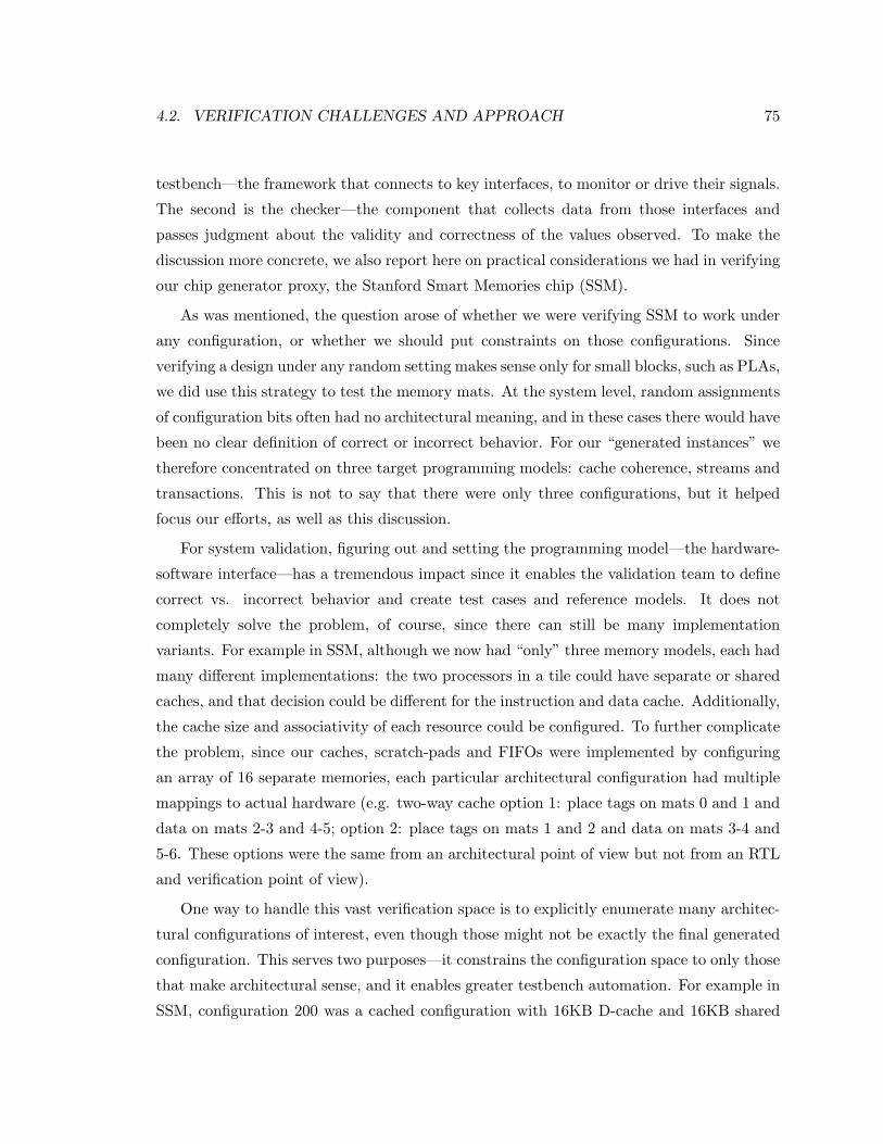
4.2. VERIFICATION CHALLENGES AND APPROACH 75
testbench—the framework that connects to key interfaces, to monitor or drive their signals.
The second is the checker—the component that collects data from those interfaces and
passes judgment about the validity and correctness of the values observed. To make the
discussion more concrete, we also report here on practical considerations we had in verifying
our chip generator proxy, the Stanford Smart Memories chip (SSM).
As was mentioned, the question arose of whether we were verifying SSM to work under
any configuration, or whether we should put constraints on those configurations. Since
verifying a design under any random setting makes sense only for small blocks, such as PLAs,
we did use this strategy to test the memory mats. At the system level, random assignments
of configuration bits often had no architectural meaning, and in these cases there would have
been no clear definition of correct or incorrect behavior. For our “generated instances” we
therefore concentrated on three target programming models: cache coherence, streams and
transactions. This is not to say that there were only three configurations, but it helped
focus our efforts, as well as this discussion.
For system validation, figuring out and setting the programming model—the hardware-
software interface—has a tremendous impact since it enables the validation team to define
correct vs. incorrect behavior and create test cases and reference models. It does not
completely solve the problem, of course, since there can still be many implementation
variants. For example in SSM, although we now had “only” three memory models, each had
many different implementations: the two processors in a tile could have separate or shared
caches, and that decision could be different for the instruction and data cache. Additionally,
the cache size and associativity of each resource could be configured. To further complicate
the problem, since our caches, scratch-pads and FIFOs were implemented by configuring
an array of 16 separate memories, each particular architectural configuration had multiple
mappings to actual hardware (e.g. two-way cache option 1: place tags on mats 0 and 1 and
data on mats 2-3 and 4-5; option 2: place tags on mats 1 and 2 and data on mats 3-4 and
5-6. These options were the same from an architectural point of view but not from an RTL
and verification point of view).
One way to handle this vast verification space is to explicitly enumerate many architec-
tural configurations of interest, even though those might not be exactly the final generated
configuration. This serves two purposes—it constrains the configuration space to only those
that make architectural sense, and it enables greater testbench automation. For example in
SSM, configuration 200 was a cached configuration with 16KB D-cache and 16KB shared
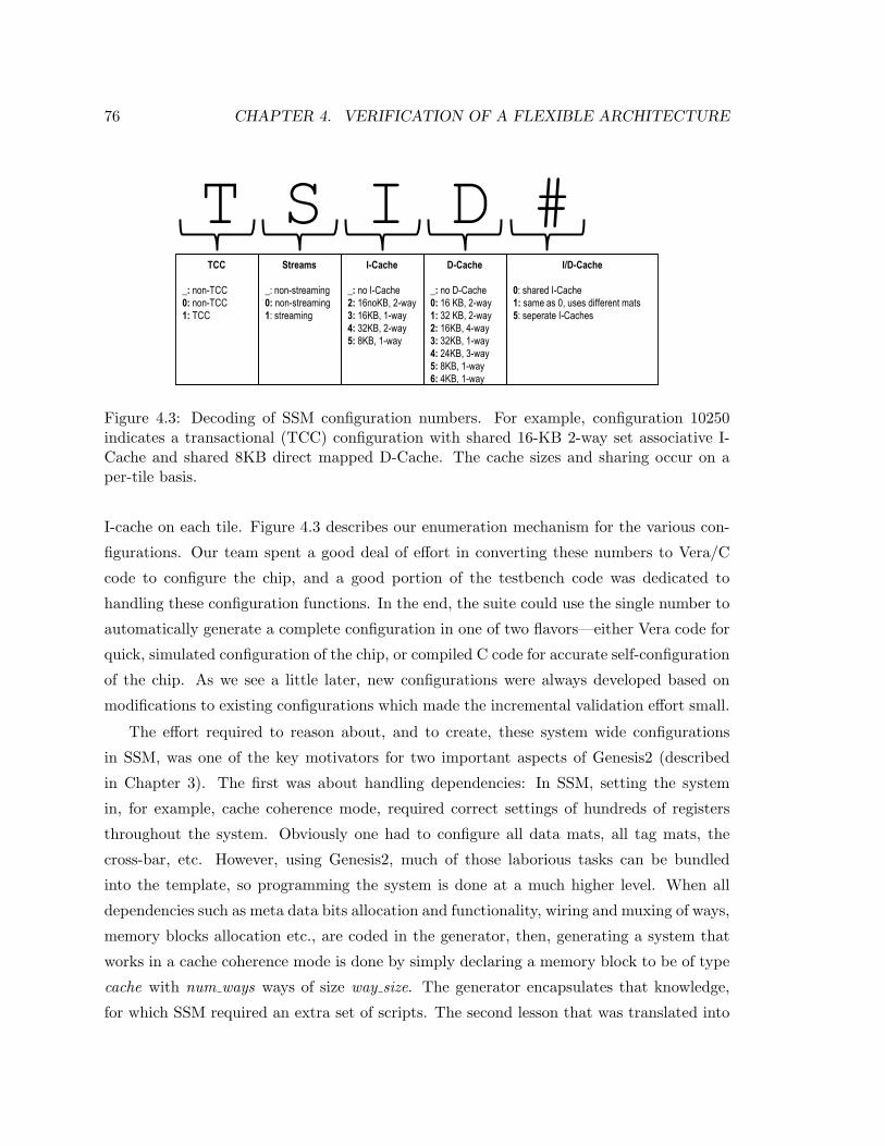
76 CHAPTER 4. VERIFICATION OF A FLEXIBLE ARCHITECTURE
T S I D #I-Cache
_: no I-Cache2: 16noKB, 2-way3: 16KB, 1-way4: 32KB, 2-way5: 8KB, 1-way
D-Cache
_: no D-Cache0: 16 KB, 2-way1: 32 KB, 2-way2: 16KB, 4-way3: 32KB, 1-way4: 24KB, 3-way5: 8KB, 1-way6: 4KB, 1-way
I/D-Cache
0: shared I-Cache1: same as 0, uses different mats5: seperate I-Caches
Streams
_: non-streaming0: non-streaming1: streaming
TCC
_: non-TCC0: non-TCC1: TCC
Figure 4.3: Decoding of SSM configuration numbers. For example, configuration 10250indicates a transactional (TCC) configuration with shared 16-KB 2-way set associative I-Cache and shared 8KB direct mapped D-Cache. The cache sizes and sharing occur on aper-tile basis.
I-cache on each tile. Figure 4.3 describes our enumeration mechanism for the various con-
figurations. Our team spent a good deal of effort in converting these numbers to Vera/C
code to configure the chip, and a good portion of the testbench code was dedicated to
handling these configuration functions. In the end, the suite could use the single number to
automatically generate a complete configuration in one of two flavors—either Vera code for
quick, simulated configuration of the chip, or compiled C code for accurate self-configuration
of the chip. As we see a little later, new configurations were always developed based on
modifications to existing configurations which made the incremental validation effort small.
The effort required to reason about, and to create, these system wide configurations
in SSM, was one of the key motivators for two important aspects of Genesis2 (described
in Chapter 3). The first was about handling dependencies: In SSM, setting the system
in, for example, cache coherence mode, required correct settings of hundreds of registers
throughout the system. Obviously one had to configure all data mats, all tag mats, the
cross-bar, etc. However, using Genesis2, much of those laborious tasks can be bundled
into the template, so programming the system is done at a much higher level. When all
dependencies such as meta data bits allocation and functionality, wiring and muxing of ways,
memory blocks allocation etc., are coded in the generator, then, generating a system that
works in a cache coherence mode is done by simply declaring a memory block to be of type
cache with num ways ways of size way size. The generator encapsulates that knowledge,
for which SSM required an extra set of scripts. The second lesson that was translated into
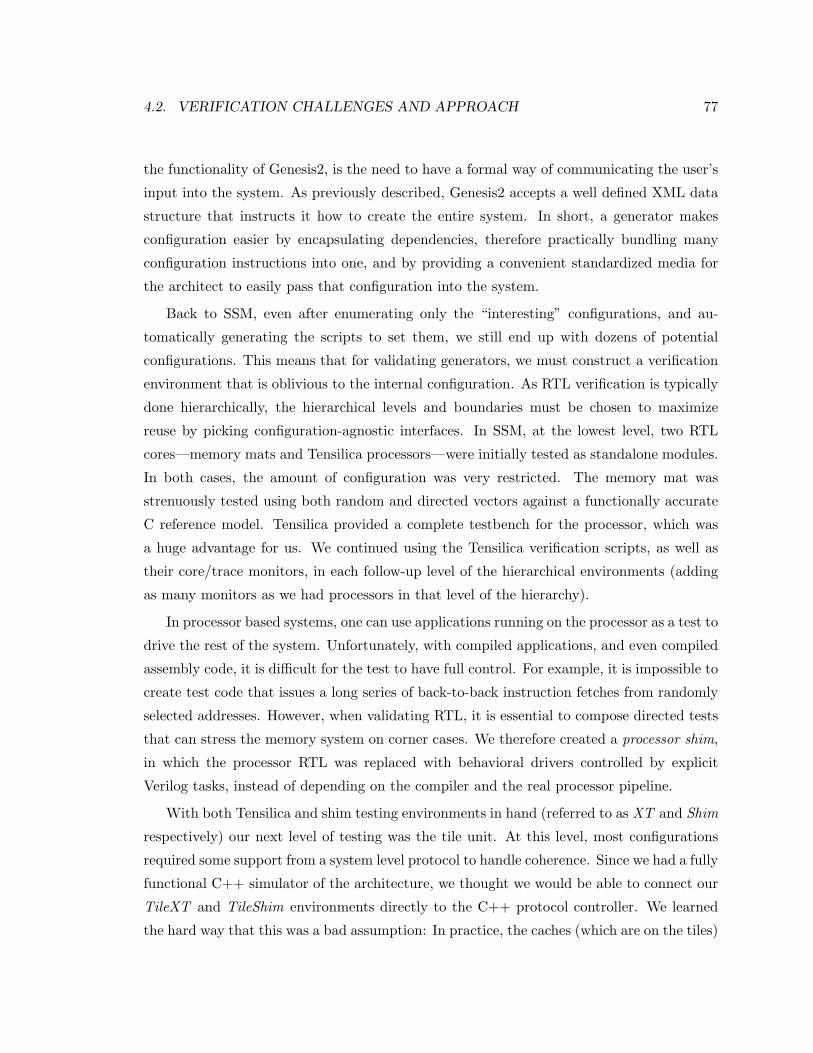
4.2. VERIFICATION CHALLENGES AND APPROACH 77
the functionality of Genesis2, is the need to have a formal way of communicating the user’s
input into the system. As previously described, Genesis2 accepts a well defined XML data
structure that instructs it how to create the entire system. In short, a generator makes
configuration easier by encapsulating dependencies, therefore practically bundling many
configuration instructions into one, and by providing a convenient standardized media for
the architect to easily pass that configuration into the system.
Back to SSM, even after enumerating only the “interesting” configurations, and au-
tomatically generating the scripts to set them, we still end up with dozens of potential
configurations. This means that for validating generators, we must construct a verification
environment that is oblivious to the internal configuration. As RTL verification is typically
done hierarchically, the hierarchical levels and boundaries must be chosen to maximize
reuse by picking configuration-agnostic interfaces. In SSM, at the lowest level, two RTL
cores—memory mats and Tensilica processors—were initially tested as standalone modules.
In both cases, the amount of configuration was very restricted. The memory mat was
strenuously tested using both random and directed vectors against a functionally accurate
C reference model. Tensilica provided a complete testbench for the processor, which was
a huge advantage for us. We continued using the Tensilica verification scripts, as well as
their core/trace monitors, in each follow-up level of the hierarchical environments (adding
as many monitors as we had processors in that level of the hierarchy).
In processor based systems, one can use applications running on the processor as a test to
drive the rest of the system. Unfortunately, with compiled applications, and even compiled
assembly code, it is difficult for the test to have full control. For example, it is impossible to
create test code that issues a long series of back-to-back instruction fetches from randomly
selected addresses. However, when validating RTL, it is essential to compose directed tests
that can stress the memory system on corner cases. We therefore created a processor shim,
in which the processor RTL was replaced with behavioral drivers controlled by explicit
Verilog tasks, instead of depending on the compiler and the real processor pipeline.
With both Tensilica and shim testing environments in hand (referred to as XT and Shim
respectively) our next level of testing was the tile unit. At this level, most configurations
required some support from a system level protocol to handle coherence. Since we had a fully
functional C++ simulator of the architecture, we thought we would be able to connect our
TileXT and TileShim environments directly to the C++ protocol controller. We learned
the hard way that this was a bad assumption: In practice, the caches (which are on the tiles)
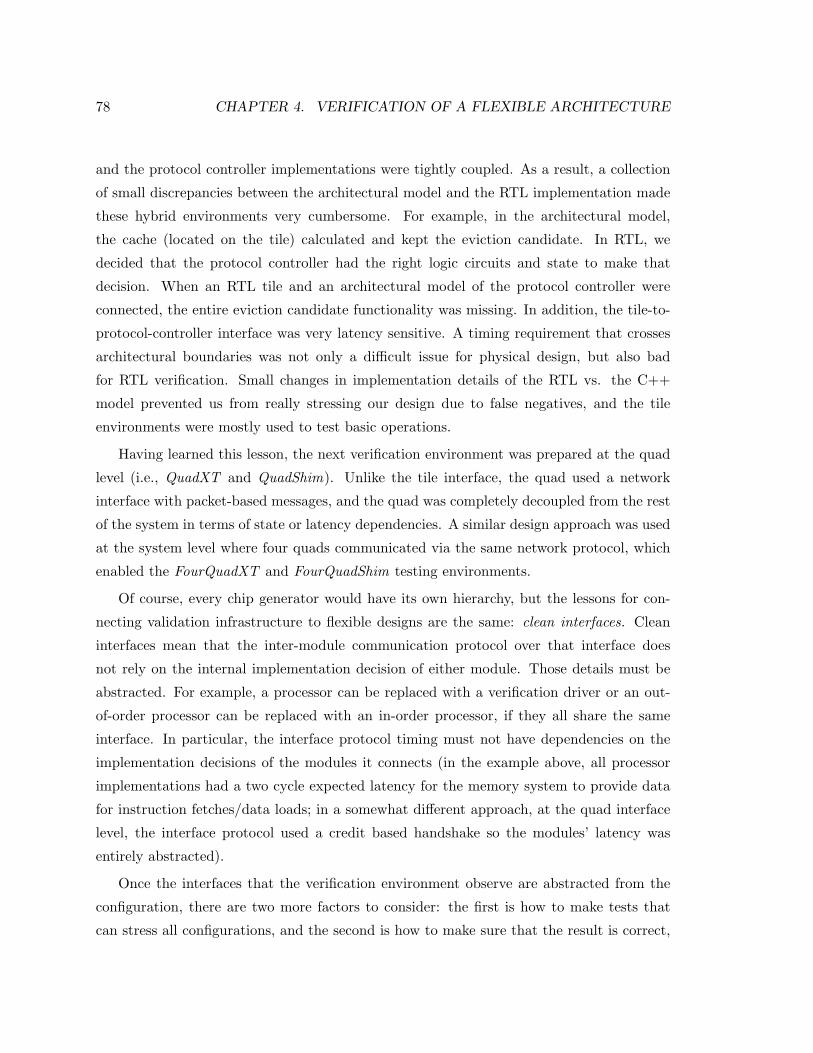
78 CHAPTER 4. VERIFICATION OF A FLEXIBLE ARCHITECTURE
and the protocol controller implementations were tightly coupled. As a result, a collection
of small discrepancies between the architectural model and the RTL implementation made
these hybrid environments very cumbersome. For example, in the architectural model,
the cache (located on the tile) calculated and kept the eviction candidate. In RTL, we
decided that the protocol controller had the right logic circuits and state to make that
decision. When an RTL tile and an architectural model of the protocol controller were
connected, the entire eviction candidate functionality was missing. In addition, the tile-to-
protocol-controller interface was very latency sensitive. A timing requirement that crosses
architectural boundaries was not only a difficult issue for physical design, but also bad
for RTL verification. Small changes in implementation details of the RTL vs. the C++
model prevented us from really stressing our design due to false negatives, and the tile
environments were mostly used to test basic operations.
Having learned this lesson, the next verification environment was prepared at the quad
level (i.e., QuadXT and QuadShim). Unlike the tile interface, the quad used a network
interface with packet-based messages, and the quad was completely decoupled from the rest
of the system in terms of state or latency dependencies. A similar design approach was used
at the system level where four quads communicated via the same network protocol, which
enabled the FourQuadXT and FourQuadShim testing environments.
Of course, every chip generator would have its own hierarchy, but the lessons for con-
necting validation infrastructure to flexible designs are the same: clean interfaces. Clean
interfaces mean that the inter-module communication protocol over that interface does
not rely on the internal implementation decision of either module. Those details must be
abstracted. For example, a processor can be replaced with a verification driver or an out-
of-order processor can be replaced with an in-order processor, if they all share the same
interface. In particular, the interface protocol timing must not have dependencies on the
implementation decisions of the modules it connects (in the example above, all processor
implementations had a two cycle expected latency for the memory system to provide data
for instruction fetches/data loads; in a somewhat different approach, at the quad interface
level, the interface protocol used a credit based handshake so the modules’ latency was
entirely abstracted).
Once the interfaces that the verification environment observe are abstracted from the
configuration, there are two more factors to consider: the first is how to make tests that
can stress all configurations, and the second is how to make sure that the result is correct,
4.2. VERIFICATION CHALLENGES AND APPROACH 79
since making a reference model for each separate configuration is out of the question. To
make configuration-agnostic tests it is best if the tests’ details are “hidden” behind the
software-hardware abstraction. In SSM, that meant that all the tests we created, whether
as a compiled application or as tasks driving the shim interface, did not depend on cache
size, associativity, etc. This is a benefit of placing the driver on a clear-cut interface such
as the processor interface. Having multiple memory models in SSM, on the other hand,
did impact the system at the software layers, so we did have to create three sets of tests
and runtime environments; one each for streams, transactional and cache coherent memory
models.
The second and bigger challenge is to create a reference model that tolerates many
configurations, to check that the results of tests conform to the desired memory protocol.
Even in a fixed design, building a reference model is difficult, since the precise output will
vary depending on the cycle-by-cycle behavior of the underlying machine. In some designs,
this hurdle can be skipped over by having the verification environment “cheat,” by using
the details of the actual RTL implementation. A chip generator however, requires a stricter
approach, since different configurations of the chip are likely to result in drastically different,
yet correct, outcomes.
To avoid dependencies on the exact configuration, when we verified SSM our test suite
performed end-to-end checking, rather than cycle accurate checking, even though we knew
that performance bugs may sometimes evade end-to-end checkers. In doing so, we rejected
the single-correct-output reference required by conventional models, relaxing this constraint
to allow a set of multiple possible outcomes. We still had to create slightly different sets of
scoreboard check/update rules to account for differences in SSM’s memory models; however,
this relaxed scoreboard enabled us to run strenuous random vectors on dozens of design
configurations within each model.
The relaxed scoreboard ideas and implementation were developed in collaboration with
Megan Wachs. A detailed report of the technique, as well as code examples and measured
results, can be found in [90]. Section 4.3 quickly summarizes the essence of that study and
extends the discussion to chip generators.
Once the configuration space is constrained and verification components capable of han-
dling (or agnostic to) these configurations are created, actual testing and coverage closure
can start. Typically in design houses, the most seasoned verification team members analyze
the architecture, to come up with the coverage list—a list of scenarios that must be seen
80 CHAPTER 4. VERIFICATION OF A FLEXIBLE ARCHITECTURE
in simulation to “prove” that the DUT handles them gracefully, and is ready for tapeout.
More often than not, this would also be the bottleneck of the design/validation process since
it takes a long time to simulate/emulate the design to reach high coverage, and since bugs
that are found and fixed late require a “reset-and-rerun” of the coverage counters. While
thus far, we have seen that there is overhead in making validation infrastructure for chip
generators (although the entire validation effort is then amortized across multiple chips),
for coverage purposes, chip generators may present an advantage. Since the goal is to stress
many corner cases faster, what better way is there to induce corner cases in some module
X than, say, to introduce different loads to its interfaces? We already do this on the bound-
aries of the design by using bus-functional-models (BFM) so why not do the same inside
the design? For example, we can test a cache controller better if we test it with various
sizes and associativities of caches. A producer-consumer design can be better tested if we
set the FIFO between the producer and consumer to be very big (to avoid back pressure)
or very small (to always have back pressure). This observation implies that chip generators
may even be useful for verification, even for the first chip instance. This is not to say that
initial development of the template and the verification environment would not be done on
some “canonic” configuration. For example, in SSM we did manual development of tests
and design features on configuration number 200 for cache coherence, 10200 for transactions
and 1000 for streams. But once stable, in order to generate more “interesting” events, on
each regression run our suite randomly picked numerical configurations for each test. In
Section 4.5 we perform a postmortem analysis that quantifies the usefulness of using many
configurations for bug discovery in SSM, but first, in Section 4.3 we deepen the discussion
of reference models, and in Section 4.4 we show results and statistics from making the SSM
configuration-agnostic verification environment.
4.3 Creating A Reference Model1
Verification of complex systems is challenging. One of the greatest challenges is trans-
forming a system “spec” (the document that contains the specification) into an automatic
all-knowing checker—a piece of software that can run alongside the system simulation, and
for every input, assert whether the observed output is “correct”. This all-knowing checker
is often referred to as a reference model, a gold model or a scoreboard. It greatly aids
1The work presented in Section 4.3 was done in collaboration with Megan Wachs
4.3. CREATING A REFERENCE MODEL 81
simulation based validation since it enables testing with random input vectors, rather than
self-checking diagnostics only. Unfortunately, accurate scoreboards are complex and hard
to create since often the “correct” output value (or time of appearance) depends on specific
implementation details.
Moreover, protocols are often defined mathematically using non-deterministic automata.
This is especially common for high level protocols like chip multiprocessor memory systems
or network routing. The inherent non-determinism implies that when implemented in RTL,
multiple correct designs may exist, each of which may produce different traces of execution.
When considering a chip generator, the problem may be even more severe: a chip generator
framework can generate many different implementations/configurations of the high level
architecture! Consequently, a traditional golden model for one implementation cannot be
used for a different implementation.
Therefore, a more robust solution is needed, one that encapsulates the non-determinism
of the protocol, and hence can be used to verify different implementations of the proto-
col. One good example is the TSOtool [52], a suite of post-mortem algorithms for trace
analysis, which checks that a CMP implementation complies with the Total Store Order-
ing consistency model. Similar work has been done to verify Transactional Coherence and
Consistency (TCC [50]) implementations [73]. Instead of dealing with the complexity of the
implementation, TSOtool’s post-mortem analysis checks that the observed trace values are
logically correct with respect to the consistency model. Since it does not specify what the
output should be at each cycle, or even what the ordering must be, it reduces the coupling
between the verification model and the design details. The key insight is that this undesir-
able verification-design coupling can be broken by creating a checker that allows multiple
output traces to be correct. Therefore any TSO implementation, whether manually coded,
runtime configured or automatically generated, can be verified using TSOtool.
Because of the nature of the work presented in this thesis, which revolves mostly around
generating CMP systems, for the rest of the discussion here we will focus on creating
reference models for CMP memory systems2. Verification of a shared memory system is in
essence the attempt to prove that the hardware complies with the mathematical definition of
the coherence and consistency model from a programmer standpoint. For example, deciding
whether a set of processor execution traces complies with sequential consistency is known as
Verifying Sequential Consistency (VSC) [45]. Similar definitions apply for other consistency
2Having said that, we strongly believe that the same concepts apply to other complex systems as well
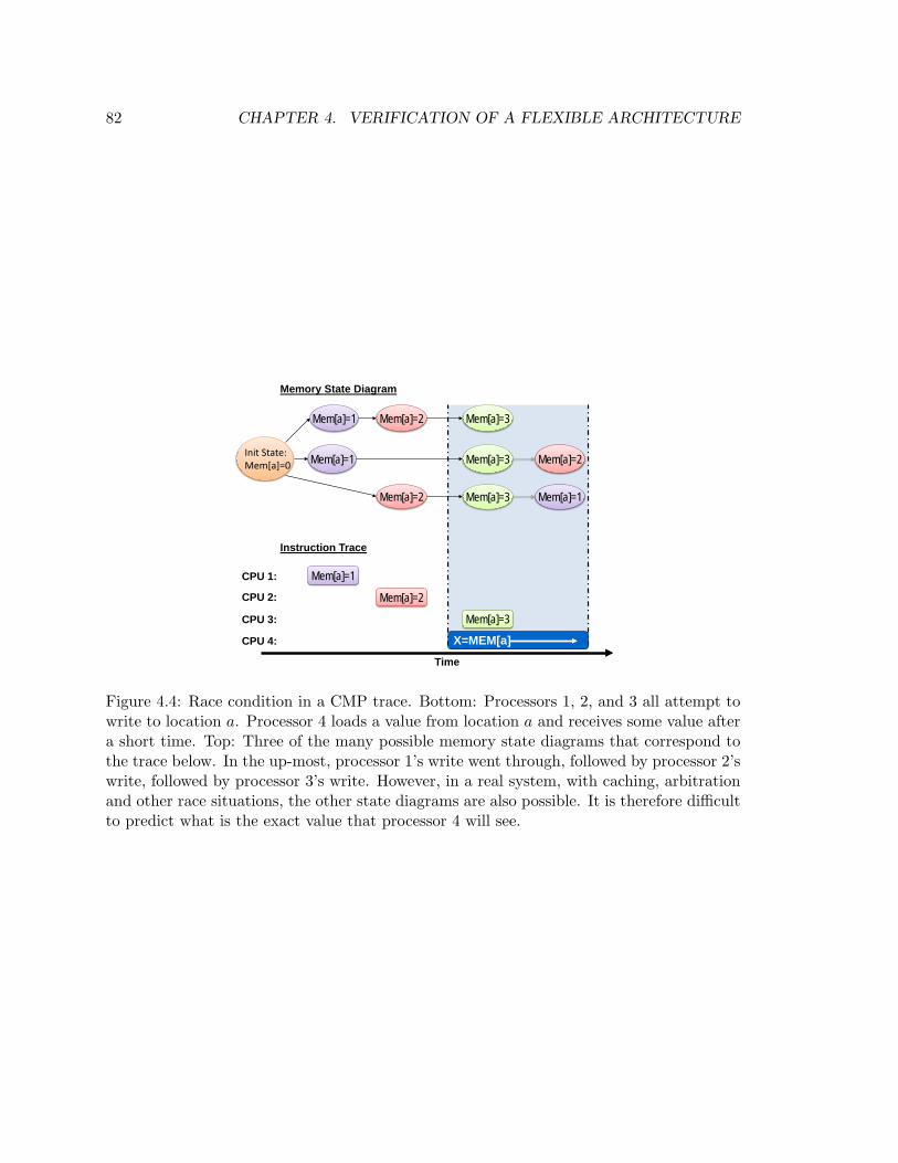
82 CHAPTER 4. VERIFICATION OF A FLEXIBLE ARCHITECTURE
Init State:Mem[a]=0
Mem[a]=1
Mem[a]=2
Mem[a]=2
Mem[a]=3
Mem[a]=3
Mem[a]=1 Mem[a]=3 Mem[a]=2
Mem[a]=1
Memory State Diagram
X=MEM[a]
Mem[a]=3
Mem[a]=2
Time
Mem[a]=1CPU 1:
CPU 2:
CPU 3:
CPU 4:
Instruction Trace
Figure 4.4: Race condition in a CMP trace. Bottom: Processors 1, 2, and 3 all attempt towrite to location a. Processor 4 loads a value from location a and receives some value aftera short time. Top: Three of the many possible memory state diagrams that correspond tothe trace below. In the up-most, processor 1’s write went through, followed by processor 2’swrite, followed by processor 3’s write. However, in a real system, with caching, arbitrationand other race situations, the other state diagrams are also possible. It is therefore difficultto predict what is the exact value that processor 4 will see.
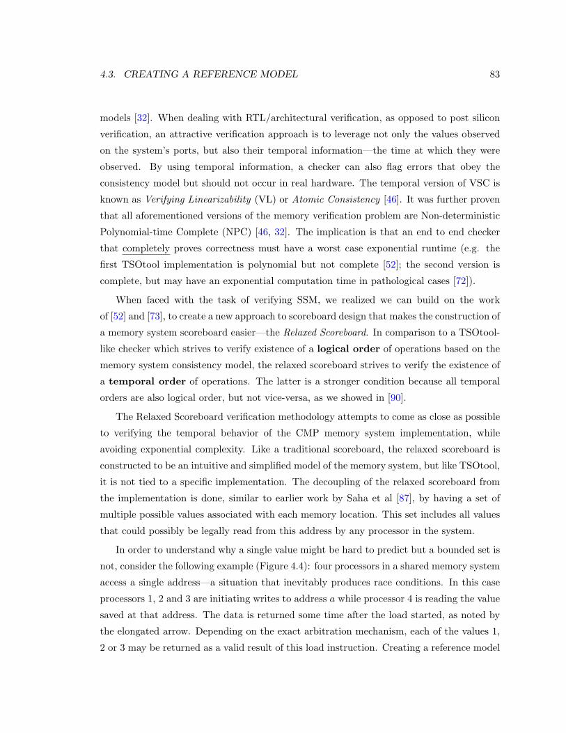
4.3. CREATING A REFERENCE MODEL 83
models [32]. When dealing with RTL/architectural verification, as opposed to post silicon
verification, an attractive verification approach is to leverage not only the values observed
on the system’s ports, but also their temporal information—the time at which they were
observed. By using temporal information, a checker can also flag errors that obey the
consistency model but should not occur in real hardware. The temporal version of VSC is
known as Verifying Linearizability (VL) or Atomic Consistency [46]. It was further proven
that all aforementioned versions of the memory verification problem are Non-deterministic
Polynomial-time Complete (NPC) [46, 32]. The implication is that an end to end checker
that completely proves correctness must have a worst case exponential runtime (e.g. the
first TSOtool implementation is polynomial but not complete [52]; the second version is
complete, but may have an exponential computation time in pathological cases [72]).
When faced with the task of verifying SSM, we realized we can build on the work
of [52] and [73], to create a new approach to scoreboard design that makes the construction of
a memory system scoreboard easier—the Relaxed Scoreboard. In comparison to a TSOtool-
like checker which strives to verify existence of a logical order of operations based on the
memory system consistency model, the relaxed scoreboard strives to verify the existence of
a temporal order of operations. The latter is a stronger condition because all temporal
orders are also logical order, but not vice-versa, as we showed in [90].
The Relaxed Scoreboard verification methodology attempts to come as close as possible
to verifying the temporal behavior of the CMP memory system implementation, while
avoiding exponential complexity. Like a traditional scoreboard, the relaxed scoreboard is
constructed to be an intuitive and simplified model of the memory system, but like TSOtool,
it is not tied to a specific implementation. The decoupling of the relaxed scoreboard from
the implementation is done, similar to earlier work by Saha et al [87], by having a set of
multiple possible values associated with each memory location. This set includes all values
that could possibly be legally read from this address by any processor in the system.
In order to understand why a single value might be hard to predict but a bounded set is
not, consider the following example (Figure 4.4): four processors in a shared memory system
access a single address—a situation that inevitably produces race conditions. In this case
processors 1, 2 and 3 are initiating writes to address a while processor 4 is reading the value
saved at that address. The data is returned some time after the load started, as noted by
the elongated arrow. Depending on the exact arbitration mechanism, each of the values 1,
2 or 3 may be returned as a valid result of this load instruction. Creating a reference model
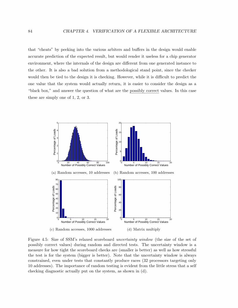
84 CHAPTER 4. VERIFICATION OF A FLEXIBLE ARCHITECTURE
that “cheats” by peeking into the various arbiters and buffers in the design would enable
accurate prediction of the expected result, but would render it useless for a chip generator
environment, where the internals of the design are different from one generated instance to
the other. It is also a bad solution from a methodological stand point, since the checker
would then be tied to the design it is checking. However, while it is difficult to predict the
one value that the system would actually return, it is easier to consider the design as a
“black box,” and answer the question of what are the possibly correct values. In this case
these are simply one of 1, 2, or 3.
0 20 40 60 80 1000
1
2
3
4
5
Number of Possibly Correct Values
Per
cent
age
of L
oads
Random Accesses to 10 Addresses
(a) Random accesses, 10 addresses
0 5 10 15 200
5
10
15
20
Number of Possibly Correct Values
Per
cent
age
of L
oads
Random Accesses to 100 Addresses
(b) Random accesses, 100 addresses
0 5 10 15 200
10
20
30
40
50
60
70
80
Number of Possibly Correct Values
Per
cent
age
of L
oads
Random Accesses to 1000 Addresses
(c) Random accesses, 1000 addresses
0 5 10 15 200
20
40
60
80
100
Number of Possibly Correct Values
Per
cent
age
of L
oads
Matrix Multiply
(d) Matrix multiply
Figure 4.5: Size of SSM’s relaxed scoreboard uncertainty window (the size of the set ofpossibly correct values) during random and directed tests. The uncertainty window is ameasure for how tight the scoreboard checks are (smaller is better) as well as how stressfulthe test is for the system (bigger is better). Note that the uncertainty window is alwaysconstrained, even under tests that constantly produce races (32 processors targeting only10 addresses). The importance of random testing is evident from the little stress that a selfchecking diagnostic actually put on the system, as shown in (d).
4.3. CREATING A REFERENCE MODEL 85
Maintaining a set of values is a simple task that can easily be done using any search-
able data structure. The entries are sorted by address and chronological time, and each
entry is associated with a sender ID, value, and start and end time stamps, as observed
during runtime on the relevant processor interface. In addition, each entry contains a set of
expiration times, one for each possible interface on which this transaction may be observed.
Upon arrival of a new transaction from a monitor, the scoreboard performs a series of checks
followed by a series of updates. The checks produce the scoreboard’s answer—transaction
is valid or transaction is erroneous—based on the previously stored values in the data
structure. Updates are a completing and crucial part of the scoreboard. Updates use the
outputs of the design under test, and according to the rules of the implemented protocol,
reduce the set of possible values, keeping it up to date so that it contains all possibly correct
values but no stale values.
Overall, a relaxed scoreboard is essentially a set of global protocol-level assertions. The
assertions are constructed to verify that certain rules of the protocol are followed at a
high level, without actually relying on, or examining the implementation details. Adding
more assertions (i.e., checks and updates) as the design matures, has the positive impact of
decreasing the set of possibly correct values. Therefore, the size of that set, which we call
the uncertainty window, is a measure for how tight the scoreboard’s checks are. Since the
size of the set is tied to the number of transactions racing at a given time, it is also a rough
measure for how stressful a test is for the system.
For SSM, a relaxed scoreboard was implemented as an object oriented programming class
using OpenVera. Vera’s Aspect Oriented Programming (AOP) capability was leveraged to
connect the scoreboard into the existing verification environment, which already included
code to monitor key interfaces. To verify SSM’s cache coherency mode, the scoreboard’s
data structure contained an associative array of queues, one queue per writable address in
the system. For TCC, the scoreboard also maintained a queue for each processor, containing
pointers to the transaction’s read and write sets, and flags to indicate the state of the current
transaction. Checks and updates were written based on the protocol rules of earlier work by
others [19][50]. Examples for how protocol properties are translated to checks and updates
are shown in our previous paper [90]. Complete source code of the relaxed scoreboard
implementation for Smart Memories can be found at http://www-vlsi.stanford.edu/
smart memories/RSB/index.html.
Due to the scoreboard’s black-box approach, it was usable without modification across
86 CHAPTER 4. VERIFICATION OF A FLEXIBLE ARCHITECTURE
dozens of different cache-coherent configurations and dozens of different TCC configurations
(of course, a different set of checks/updates was required for the cache-coherence vs. TCC
protocol properties). Moreover, it was applied to both single-quad (8 processors) and four-
quad (32 processors) testing environments, with the only difference being the number of
monitor instances that fed the scoreboard with information.
Figure 4.5 shows the size of the uncertainty window for several SSM test-runs with 32
processors. Each sub-figure shows a histogram of the number of possibly allowed values for
every simulated load in the test. Figure 4.5(a) shows that for a random test, limited to 10
addresses for all 32 processors, the average uncertainty is 35 values and never exceeds 81.
Figures 4.5(b) and 4.5(c) show that as there is less contention for the addresses there is also
less uncertainty. Figure 4.5(d) shows the results for a real application, in which there is
very little uncertainty, and the scoreboard only occasionally needs to maintain more than
one value. In all cases, the size of the set of possibly correct values is bounded, even when
the test focuses on a very small address range.
Figure 4.5(d) further shows that for a self-checking diagnostic such as matrix multipli-
cation, a relaxed scoreboard behaves almost identically to a golden reference model. In
addition, it is important to note how much more stressful a random test with true sharing
is (Figure 4.5(a)) in comparison to a deterministic self-checking diagnostic (Figure 4.5(d)).
The latter rarely induced any races. This emphasizes the initial motivation for creating
an end-to-end reference model that can be used with random tests, for a more efficient
verification environment.
A relaxed scoreboard methodology introduces a number of traits that are important for
chip generator verification. Most important, is the complete decoupling from the low level
implementation details, which makes it a good fit for chip generators. The construction of
the scoreboard is derived directly from the relevant consistency model properties. Each of
those properties can be considered separately, thereby enabling the verification environment
to be developed incrementally along with the design. In contrast to static trace analysis
algorithms, the relaxed scoreboard is designed to be a dynamic on-the-fly checker, meaning
that any error will be reported immediately. Table 4.1 compares and contrasts the relaxed
scoreboard with other memory system verification schemes across a number of dimensions
(bold text indicates the most desired value). With a reference model that can be used across
all configurations in place, next we look at real bug and configuration statistics from the
SSM environment.
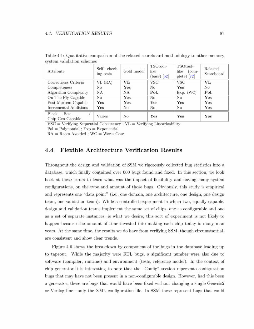
4.4. VERIFICATION RESULTS 87
Table 4.1: Qualitative comparison of the relaxed scoreboard methodology to other memorysystem validation schemes
Attribute Self check-ing tests Gold model
TSOtool-like(base) [52]
TSOtool-like (com-plete) [72]
RelaxedScoreboard
Correctness Criteria VL (RA) VL VSC VSC VLCompleteness No Yes No Yes NoAlgorithm Complexity NA NA Pol. Exp. (WC) Pol.On-The-Fly Capable No Yes No No YesPost-Mortem Capable Yes Yes Yes Yes YesIncremental Additions Yes No No No YesBlack Box /Chip Gen Capable Varies No Yes Yes Yes
VSC = Verifying Sequential Consistency ; VL = Verifying LinearizabilityPol = Polynomial ; Exp = ExponentialRA = Races Avoided ; WC = Worst Case
4.4 Flexible Architecture Verification Results
Throughout the design and validation of SSM we rigorously collected bug statistics into a
database, which finally contained over 600 bugs found and fixed. In this section, we look
back at these errors to learn what was the impact of flexibility and having many system
configurations, on the type and amount of those bugs. Obviously, this study is empirical
and represents one “data point” (i.e., one domain, one architecture, one design, one design
team, one validation team). While a controlled experiment in which two, equally capable,
design and validation teams implement the same set of chips, one as configurable and one
as a set of separate instances, is what we desire, this sort of experiment is not likely to
happen because the amount of time invested into making each chip today is many man
years. At the same time, the results we do have from verifying SSM, though circumstantial,
are consistent and show clear trends.
Figure 4.6 shows the breakdown by component of the bugs in the database leading up
to tapeout. While the majority were RTL bugs, a significant number were also due to
software (compiler, runtime) and environment (tests, reference model). In the context of
chip generator it is interesting to note that the “Config” section represents configuration
bugs that may have not been present in a non-configurable design. However, had this been
a generator, these are bugs that would have been fixed without changing a single Genesis2
or Verilog line—only the XML configuration file. In SSM these represent bugs that could
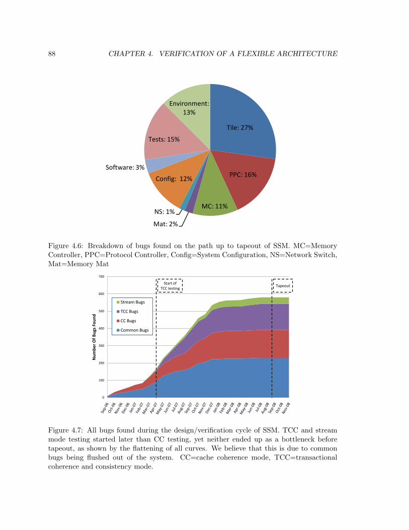
88 CHAPTER 4. VERIFICATION OF A FLEXIBLE ARCHITECTURE
Tile: 27%
T t 15%
Environment: 13%
PPC: 16%
MC: 11%
Mat: 2%
NS: 1%
Config: 12%
Software: 3%
Tests: 15%
Figure 4.6: Breakdown of bugs found on the path up to tapeout of SSM. MC=MemoryController, PPC=Protocol Controller, Config=System Configuration, NS=Network Switch,Mat=Memory Mat
0
100
200
300
400
500
600
700
Num
ber
Of B
ugs
Foun
d
Stream Bugs
TCC Bugs
CC Bugs
Common Bugs
Start of TCC testing
Tapeout
Figure 4.7: All bugs found during the design/verification cycle of SSM. TCC and streammode testing started later than CC testing, yet neither ended up as a bottleneck beforetapeout, as shown by the flattening of all curves. We believe that this is due to commonbugs being flushed out of the system. CC=cache coherence mode, TCC=transactionalcoherence and consistency mode.
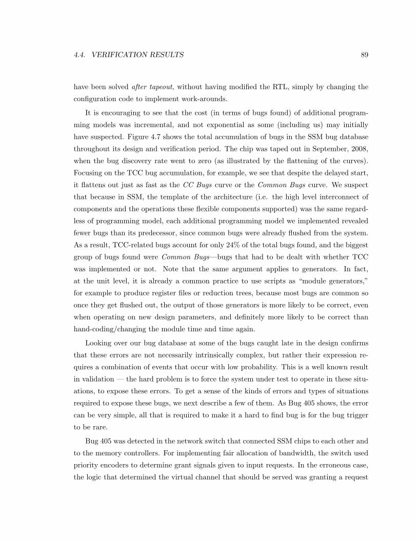
4.4. VERIFICATION RESULTS 89
have been solved after tapeout, without having modified the RTL, simply by changing the
configuration code to implement work-arounds.
It is encouraging to see that the cost (in terms of bugs found) of additional program-
ming models was incremental, and not exponential as some (including us) may initially
have suspected. Figure 4.7 shows the total accumulation of bugs in the SSM bug database
throughout its design and verification period. The chip was taped out in September, 2008,
when the bug discovery rate went to zero (as illustrated by the flattening of the curves).
Focusing on the TCC bug accumulation, for example, we see that despite the delayed start,
it flattens out just as fast as the CC Bugs curve or the Common Bugs curve. We suspect
that because in SSM, the template of the architecture (i.e. the high level interconnect of
components and the operations these flexible components supported) was the same regard-
less of programming model, each additional programming model we implemented revealed
fewer bugs than its predecessor, since common bugs were already flushed from the system.
As a result, TCC-related bugs account for only 24% of the total bugs found, and the biggest
group of bugs found were Common Bugs—bugs that had to be dealt with whether TCC
was implemented or not. Note that the same argument applies to generators. In fact,
at the unit level, it is already a common practice to use scripts as “module generators,”
for example to produce register files or reduction trees, because most bugs are common so
once they get flushed out, the output of those generators is more likely to be correct, even
when operating on new design parameters, and definitely more likely to be correct than
hand-coding/changing the module time and time again.
Looking over our bug database at some of the bugs caught late in the design confirms
that these errors are not necessarily intrinsically complex, but rather their expression re-
quires a combination of events that occur with low probability. This is a well known result
in validation — the hard problem is to force the system under test to operate in these situ-
ations, to expose these errors. To get a sense of the kinds of errors and types of situations
required to expose these bugs, we next describe a few of them. As Bug 405 shows, the error
can be very simple, all that is required to make it a hard to find bug is for the bug trigger
to be rare.
Bug 405 was detected in the network switch that connected SSM chips to each other and
to the memory controllers. For implementing fair allocation of bandwidth, the switch used
priority encoders to determine grant signals given to input requests. In the erroneous case,
the logic that determined the virtual channel that should be served was granting a request
90 CHAPTER 4. VERIFICATION OF A FLEXIBLE ARCHITECTURE
to a high priority virtual channel in the middle of switching a low priority packet. This was
causing flits from different packets to be interleaved and wrong data to be sent in the packet.
While this was a simple logical problem that existed even when only one physical port was
used (e.g. one quad connected to one MC) it only appeared under high-load situations,
which were very rare for a single quad. Thus, this error was not discovered until much later
in the verification process, when we were testing a configuration in which all physical ports
(eight) were stressed by four quads and four memory controllers (a 32-processor system).
In fact, sometimes it is not even clear why the trigger is a low probability event: this is
what makes debugging so interesting. For example, Bug 386 was discovered during a TCC
test run, and indicated an error in the request-merging logic in the MSHR (Miss Status
Holding Register). To increase performance, the protocol controller was allowed to merge
cache misses from different processors in the quad and serve all of them after the cache
line was acquired. Cache miss requests were assigned an MSHR and all merging requests
shared the same entry. Requests were rejected when there was no MSHR entry to allocate
to the cache miss. However, when there was no available MSHR entry, an exception would
be made for requests that could be merged with an existing MSHR entry. In this particular
bug the indication for merging was incorrect, and was causing a request that should have
not been accepted to get accepted after the MSHR was already full, hence overwriting a
previous request’s entry. While this problem was discovered when running a TCC test case,
it clearly applied to the CC programming model as well.
Not all bugs were simple errors. Some arose from situations that were not considered dur-
ing the logical design process, and required a change to the implemented micro-architecture
to correct them. Bug 272 was an example of this type of error. In TCC, we chose to
merge data from commits from previous transactions if they overlapped with a currently
outstanding store miss. To accomplish this merge, commit data was placed in the line
buffer associated with the cache miss request inside the protocol controller, and was then
merged with the rest of the cache line. This bug occurred when two different transactions
completed their commit phases while a third transaction had an outstanding cache miss. In
this particular case, both committing transactions were trying to update the same word in
the missing cache line. The error was that after the first transaction’s commit, the valid bit
for that particular word in the line buffer was set. Since this state was also associated with
data that the processor may have written, when the second transaction’s commit came, it
did not override the word with an updated value. As a result, the transaction with the
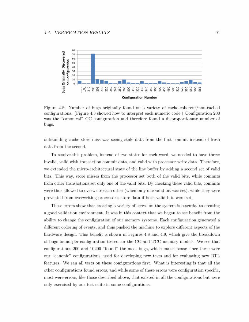
4.4. VERIFICATION RESULTS 91
60
70
80
overed
n
10
20
30
40
50gina
lly D
isco
Configuration
0
10_ _ _
_0_
2_0
200
201
210
220
240
245
250
260
300
310
320
330
340
350
360
400
450
460
500
510
520
530
550
560
561
Bugs Orig
on C
Configuration Numberg
Figure 4.8: Number of bugs originally found on a variety of cache-coherent/non-cachedconfigurations. (Figure 4.3 showed how to interpret each numeric code.) Configuration 200was the “canonical” CC configuration and therefore found a disproportionate number ofbugs.
outstanding cache store miss was seeing stale data from the first commit instead of fresh
data from the second.
To resolve this problem, instead of two states for each word, we needed to have three:
invalid, valid with transaction commit data, and valid with processor write data. Therefore,
we extended the micro-architectural state of the line buffer by adding a second set of valid
bits. This way, store misses from the processor set both of the valid bits, while commits
from other transactions set only one of the valid bits. By checking these valid bits, commits
were thus allowed to overwrite each other (when only one valid bit was set), while they were
prevented from overwriting processor’s store data if both valid bits were set.
These errors show that creating a variety of stress on the system is essential to creating
a good validation environment. It was in this context that we began to see benefit from the
ability to change the configuration of our memory systems. Each configuration generated a
different ordering of events, and thus pushed the machine to explore different aspects of the
hardware design. This benefit is shown in Figures 4.8 and 4.9, which give the breakdown
of bugs found per configuration tested for the CC and TCC memory models. We see that
configurations 200 and 10200 “found” the most bugs, which makes sense since these were
our “canonic” configurations, used for developing new tests and for evaluating new RTL
features. We ran all tests on these configurations first. What is interesting is that all the
other configurations found errors, and while some of these errors were configuration specific,
most were errors, like those described above, that existed in all the configurations but were
only exercised by our test suite in some configurations.
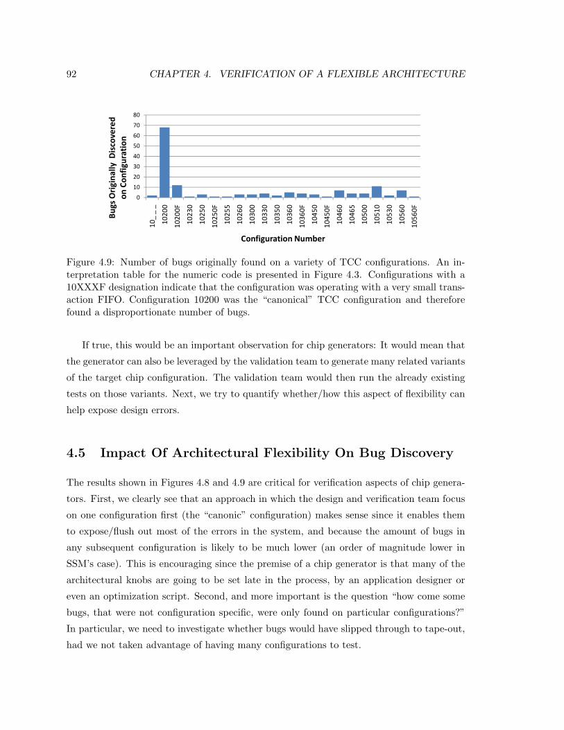
92 CHAPTER 4. VERIFICATION OF A FLEXIBLE ARCHITECTURE
40
50
60
70
80y Discovered
uration
0
10
20
30
10_ _ _
10200
10200F
10230
10250
10250F
10255
10260
10300
10330
10350
10360
10360F
10450
10450F
10460
10465
10500
10510
10530
10560
10560F
Bugs Originally
on Config
Configuration Number
Figure 4.9: Number of bugs originally found on a variety of TCC configurations. An in-terpretation table for the numeric code is presented in Figure 4.3. Configurations with a10XXXF designation indicate that the configuration was operating with a very small trans-action FIFO. Configuration 10200 was the “canonical” TCC configuration and thereforefound a disproportionate number of bugs.
If true, this would be an important observation for chip generators: It would mean that
the generator can also be leveraged by the validation team to generate many related variants
of the target chip configuration. The validation team would then run the already existing
tests on those variants. Next, we try to quantify whether/how this aspect of flexibility can
help expose design errors.
4.5 Impact Of Architectural Flexibility On Bug Discovery
The results shown in Figures 4.8 and 4.9 are critical for verification aspects of chip genera-
tors. First, we clearly see that an approach in which the design and verification team focus
on one configuration first (the “canonic” configuration) makes sense since it enables them
to expose/flush out most of the errors in the system, and because the amount of bugs in
any subsequent configuration is likely to be much lower (an order of magnitude lower in
SSM’s case). This is encouraging since the premise of a chip generator is that many of the
architectural knobs are going to be set late in the process, by an application designer or
even an optimization script. Second, and more important is the question “how come some
bugs, that were not configuration specific, were only found on particular configurations?”
In particular, we need to investigate whether bugs would have slipped through to tape-out,
had we not taken advantage of having many configurations to test.
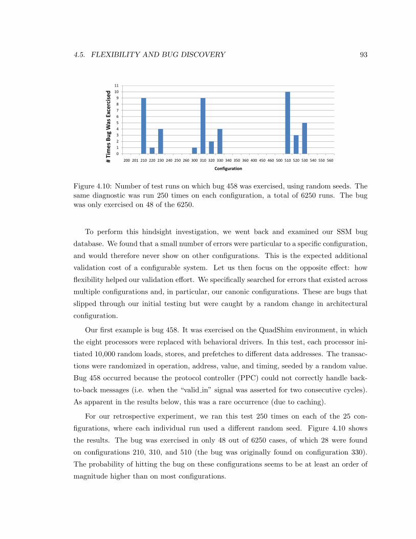
4.5. FLEXIBILITY AND BUG DISCOVERY 93
11
78910
Excercised
23456
Bug Was E
012
200 201 210 220 230 240 250 260 300 310 320 330 340 350 360 400 450 460 500 510 520 530 540 550 560# Times
ConfigurationConfiguration
Figure 4.10: Number of test runs on which bug 458 was exercised, using random seeds. Thesame diagnostic was run 250 times on each configuration, a total of 6250 runs. The bugwas only exercised on 48 of the 6250.
To perform this hindsight investigation, we went back and examined our SSM bug
database. We found that a small number of errors were particular to a specific configuration,
and would therefore never show on other configurations. This is the expected additional
validation cost of a configurable system. Let us then focus on the opposite effect: how
flexibility helped our validation effort. We specifically searched for errors that existed across
multiple configurations and, in particular, our canonic configurations. These are bugs that
slipped through our initial testing but were caught by a random change in architectural
configuration.
Our first example is bug 458. It was exercised on the QuadShim environment, in which
the eight processors were replaced with behavioral drivers. In this test, each processor ini-
tiated 10,000 random loads, stores, and prefetches to different data addresses. The transac-
tions were randomized in operation, address, value, and timing, seeded by a random value.
Bug 458 occurred because the protocol controller (PPC) could not correctly handle back-
to-back messages (i.e. when the “valid in” signal was asserted for two consecutive cycles).
As apparent in the results below, this was a rare occurrence (due to caching).
For our retrospective experiment, we ran this test 250 times on each of the 25 con-
figurations, where each individual run used a different random seed. Figure 4.10 shows
the results. The bug was exercised in only 48 out of 6250 cases, of which 28 were found
on configurations 210, 310, and 510 (the bug was originally found on configuration 330).
The probability of hitting the bug on these configurations seems to be at least an order of
magnitude higher than on most configurations.
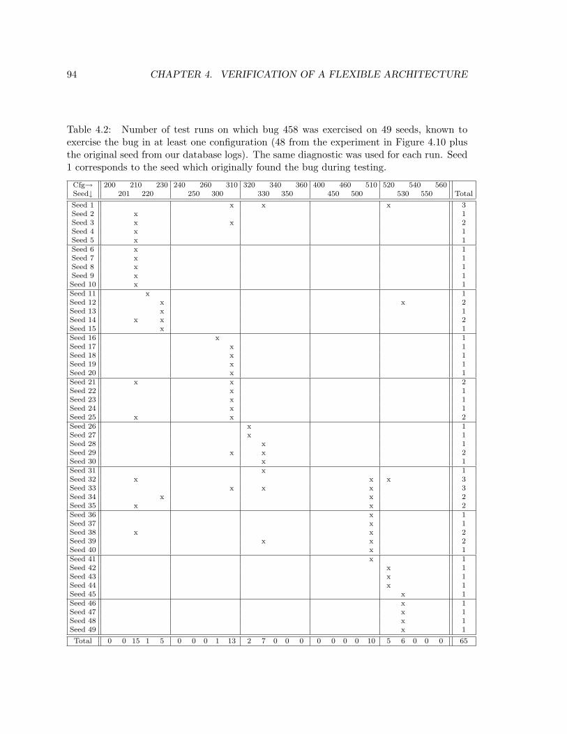
94 CHAPTER 4. VERIFICATION OF A FLEXIBLE ARCHITECTURE
Table 4.2: Number of test runs on which bug 458 was exercised on 49 seeds, known toexercise the bug in at least one configuration (48 from the experiment in Figure 4.10 plusthe original seed from our database logs). The same diagnostic was used for each run. Seed1 corresponds to the seed which originally found the bug during testing.
Cfg→ 200 210 230 240 260 310 320 340 360 400 460 510 520 540 560Seed↓ 201 220 250 300 330 350 450 500 530 550 Total
Seed 1 x x x 3Seed 2 x 1Seed 3 x x 2Seed 4 x 1Seed 5 x 1Seed 6 x 1Seed 7 x 1Seed 8 x 1Seed 9 x 1Seed 10 x 1Seed 11 x 1Seed 12 x x 2Seed 13 x 1Seed 14 x x 2Seed 15 x 1Seed 16 x 1Seed 17 x 1Seed 18 x 1Seed 19 x 1Seed 20 x 1Seed 21 x x 2Seed 22 x 1Seed 23 x 1Seed 24 x 1Seed 25 x x 2Seed 26 x 1Seed 27 x 1Seed 28 x 1Seed 29 x x 2Seed 30 x 1Seed 31 x 1Seed 32 x x x 3Seed 33 x x x 3Seed 34 x x 2Seed 35 x x 2Seed 36 x 1Seed 37 x 1Seed 38 x x 2Seed 39 x x 2Seed 40 x 1Seed 41 x 1Seed 42 x 1Seed 43 x 1Seed 44 x 1Seed 45 x 1Seed 46 x 1Seed 47 x 1Seed 48 x 1Seed 49 x 1
Total 0 0 15 1 5 0 0 0 1 13 2 7 0 0 0 0 0 0 0 10 5 6 0 0 0 65
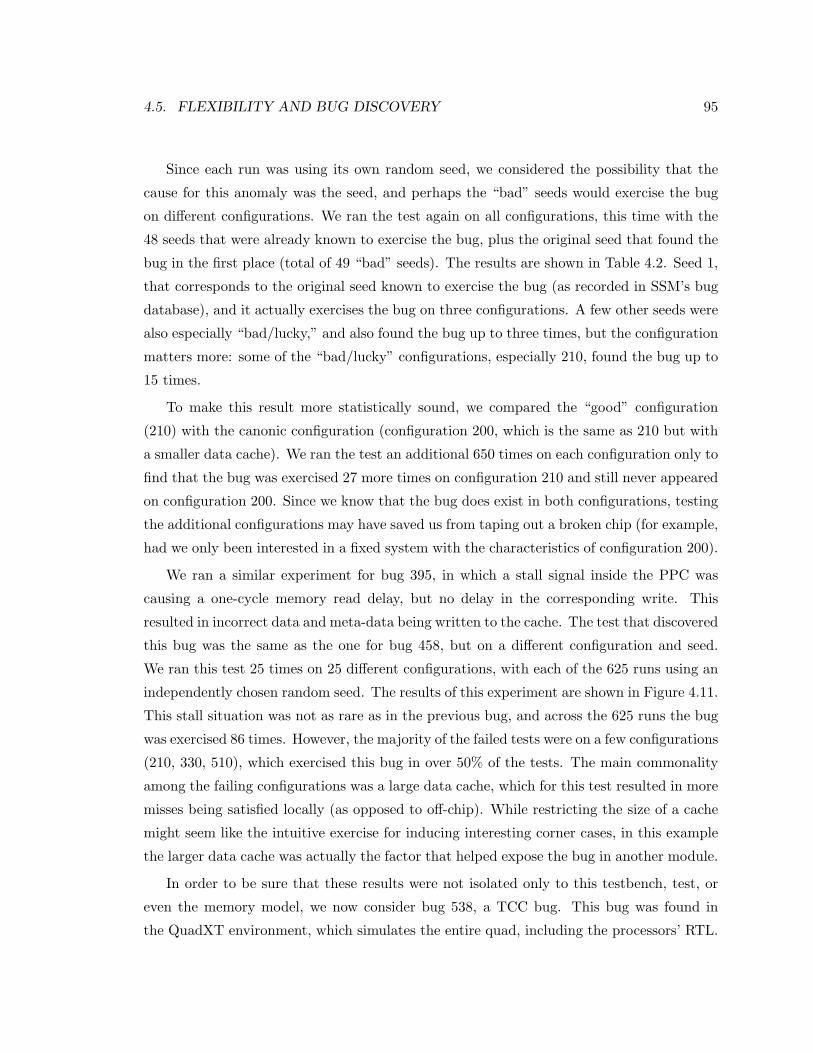
4.5. FLEXIBILITY AND BUG DISCOVERY 95
Since each run was using its own random seed, we considered the possibility that the
cause for this anomaly was the seed, and perhaps the “bad” seeds would exercise the bug
on different configurations. We ran the test again on all configurations, this time with the
48 seeds that were already known to exercise the bug, plus the original seed that found the
bug in the first place (total of 49 “bad” seeds). The results are shown in Table 4.2. Seed 1,
that corresponds to the original seed known to exercise the bug (as recorded in SSM’s bug
database), and it actually exercises the bug on three configurations. A few other seeds were
also especially “bad/lucky,” and also found the bug up to three times, but the configuration
matters more: some of the “bad/lucky” configurations, especially 210, found the bug up to
15 times.
To make this result more statistically sound, we compared the “good” configuration
(210) with the canonic configuration (configuration 200, which is the same as 210 but with
a smaller data cache). We ran the test an additional 650 times on each configuration only to
find that the bug was exercised 27 more times on configuration 210 and still never appeared
on configuration 200. Since we know that the bug does exist in both configurations, testing
the additional configurations may have saved us from taping out a broken chip (for example,
had we only been interested in a fixed system with the characteristics of configuration 200).
We ran a similar experiment for bug 395, in which a stall signal inside the PPC was
causing a one-cycle memory read delay, but no delay in the corresponding write. This
resulted in incorrect data and meta-data being written to the cache. The test that discovered
this bug was the same as the one for bug 458, but on a different configuration and seed.
We ran this test 25 times on 25 different configurations, with each of the 625 runs using an
independently chosen random seed. The results of this experiment are shown in Figure 4.11.
This stall situation was not as rare as in the previous bug, and across the 625 runs the bug
was exercised 86 times. However, the majority of the failed tests were on a few configurations
(210, 330, 510), which exercised this bug in over 50% of the tests. The main commonality
among the failing configurations was a large data cache, which for this test resulted in more
misses being satisfied locally (as opposed to off-chip). While restricting the size of a cache
might seem like the intuitive exercise for inducing interesting corner cases, in this example
the larger data cache was actually the factor that helped expose the bug in another module.
In order to be sure that these results were not isolated only to this testbench, test, or
even the memory model, we now consider bug 538, a TCC bug. This bug was found in
the QuadXT environment, which simulates the entire quad, including the processors’ RTL.
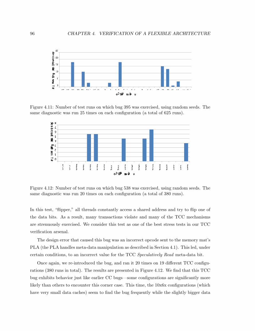
96 CHAPTER 4. VERIFICATION OF A FLEXIBLE ARCHITECTURE
��� �� �� �� �
� � � � � � � � � � � � �� � �� � � � � �� � � � � � � � � � � � � � � � � � � � � � � � � � � � � � � � � � � � � � � � � � � � � � � � � � � � ��� �� � �� ���� ��� � ���
�� � ��� � �� � � �Figure 4.11: Number of test runs on which bug 395 was exercised, using random seeds. Thesame diagnostic was run 25 times on each configuration (a total of 625 runs).
���� �� ���
� � � � � � �� � � � � �� �� � � � � �� � � � � � �� �� � ���� ��� � �� ���� ��� �� ���
! " #$% & '( ) $ ! "Figure 4.12: Number of test runs on which bug 538 was exercised, using random seeds. Thesame diagnostic was run 20 times on each configuration (a total of 380 runs).
In this test, “flipper,” all threads constantly access a shared address and try to flip one of
the data bits. As a result, many transactions violate and many of the TCC mechanisms
are strenuously exercised. We consider this test as one of the best stress tests in our TCC
verification arsenal.
The design error that caused this bug was an incorrect opcode sent to the memory mat’s
PLA (the PLA handles meta-data manipulation as described in Section 4.1). This led, under
certain conditions, to an incorrect value for the TCC Speculatively Read meta-data bit.
Once again, we re-introduced the bug, and ran it 20 times on 19 different TCC configu-
rations (380 runs in total). The results are presented in Figure 4.12. We find that this TCC
bug exhibits behavior just like earlier CC bugs—some configurations are significantly more
likely than others to encounter this corner case. This time, the 10x6x configurations (which
have very small data caches) seem to find the bug frequently while the slightly bigger data
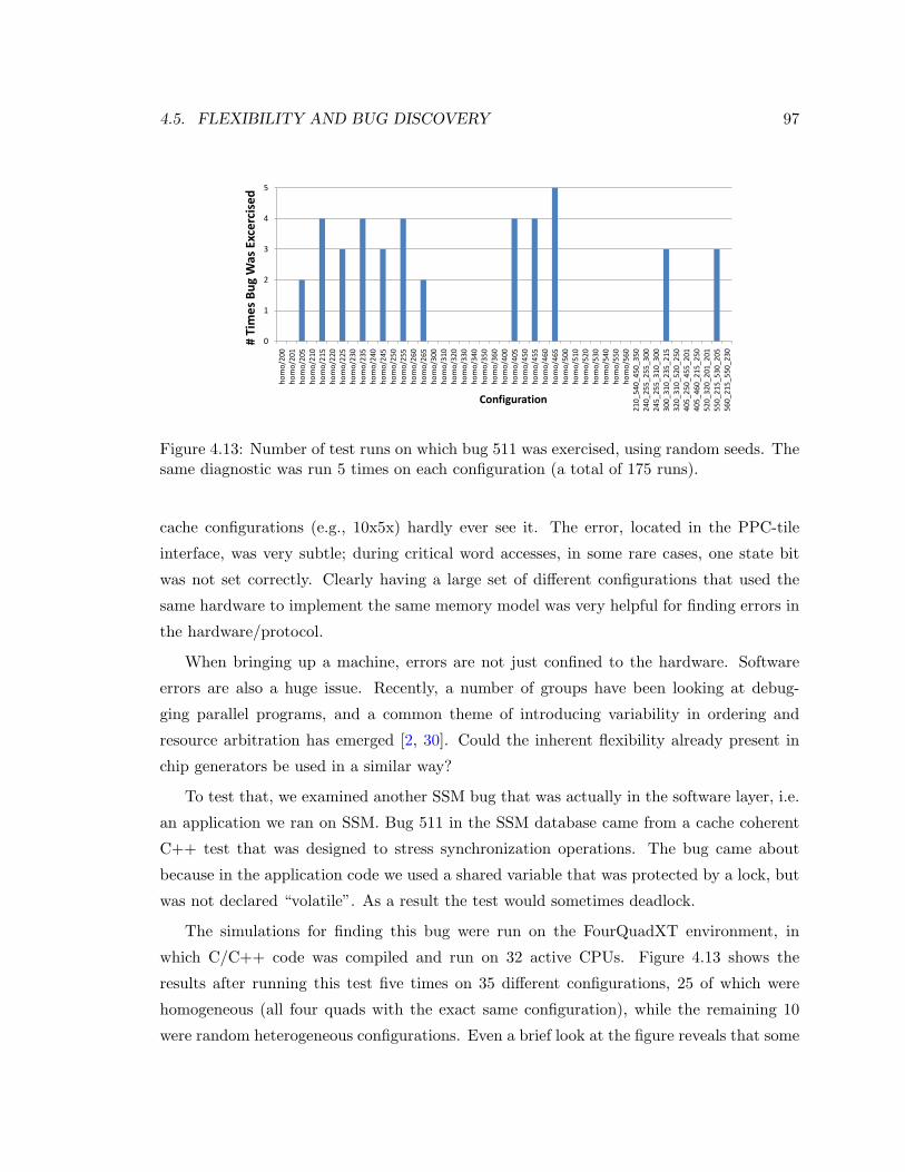
4.5. FLEXIBILITY AND BUG DISCOVERY 97
0
1
2
3
4
5
hom
o/20
0ho
mo/
201
hom
o/20
5ho
mo/
210
hom
o/21
5ho
mo/
220
hom
o/22
5ho
mo/
230
hom
o/23
5ho
mo/
240
hom
o/24
5ho
mo/
250
hom
o/25
5ho
mo/
260
hom
o/26
5ho
mo/
300
hom
o/31
0ho
mo/
320
hom
o/33
0ho
mo/
340
hom
o/35
0ho
mo/
360
hom
o/40
0ho
mo/
405
hom
o/45
0ho
mo/
455
hom
o/46
0ho
mo/
465
hom
o/50
0ho
mo/
510
hom
o/52
0ho
mo/
530
hom
o/54
0ho
mo/
550
hom
o/56
021
0_54
0_45
0_35
024
0_25
5_25
5_30
024
5_25
5_31
0_30
030
0_31
0_23
5_21
532
0_31
0_52
0_25
040
5_25
0_45
5_20
140
5_46
0_21
5_25
052
0_32
0_20
1_20
155
0_21
5_53
0_20
556
0_21
5_55
0_23
0
# Ti
mes
Bug
Was
Exc
erci
sed
Configuration
Figure 4.13: Number of test runs on which bug 511 was exercised, using random seeds. Thesame diagnostic was run 5 times on each configuration (a total of 175 runs).
cache configurations (e.g., 10x5x) hardly ever see it. The error, located in the PPC-tile
interface, was very subtle; during critical word accesses, in some rare cases, one state bit
was not set correctly. Clearly having a large set of different configurations that used the
same hardware to implement the same memory model was very helpful for finding errors in
the hardware/protocol.
When bringing up a machine, errors are not just confined to the hardware. Software
errors are also a huge issue. Recently, a number of groups have been looking at debug-
ging parallel programs, and a common theme of introducing variability in ordering and
resource arbitration has emerged [2, 30]. Could the inherent flexibility already present in
chip generators be used in a similar way?
To test that, we examined another SSM bug that was actually in the software layer, i.e.
an application we ran on SSM. Bug 511 in the SSM database came from a cache coherent
C++ test that was designed to stress synchronization operations. The bug came about
because in the application code we used a shared variable that was protected by a lock, but
was not declared “volatile”. As a result the test would sometimes deadlock.
The simulations for finding this bug were run on the FourQuadXT environment, in
which C/C++ code was compiled and run on 32 active CPUs. Figure 4.13 shows the
results after running this test five times on 35 different configurations, 25 of which were
homogeneous (all four quads with the exact same configuration), while the remaining 10
were random heterogeneous configurations. Even a brief look at the figure reveals that some
98 CHAPTER 4. VERIFICATION OF A FLEXIBLE ARCHITECTURE
configurations were more efficient in exposing this software bug (e.g. homo/235, homo/255)
and others were not (homo/240, homo/250 etc.). Interestingly, the configurations that failed
frequently were all xx5—random sizes and associativities of D and I caches, with a common
property of separate I-caches. While we can try to reason why the separate I-cache is
important, few would have predicted this would turn out to be critical.
We did not expect this synergistic behavior among the configurations, helping to find
errors in each other, when we designed SSM and even while we were busy verifying its
functionality. Of course, now that the data has forced us to notice it, these results are
really not surprising. Validation engineers often make small changes in a design to help
“randomize” the tests—changing the sizes of queues is a common example. They do it
because writing more and more diagnostic tests takes much more time and effort than
(randomly) changing a few internal parameters. Configurable machines just do this at a
larger, system-level scale. As we have seen, these changes are helpful, since each induces
different (unexpected) corner cases, which is the goal of validation.
Changing a particular cache configuration in SSM did not test that cache better, but
slightly changed the ordering of events seen by the cache controller. Similarly, replacing one
processor with another changes the access patterns to the cache, and trading one program-
ming model for another changes the access patterns for the network switch. The recurring
theme is that when each component is just a little flexible, we can tweak it to better test
the rest of the machine. Intuitively speaking, in a chip generator template whose internal
components can be configured in many ways, verifying each of the first (N − 1) system
configurations increases our confidence in the correctness of the N th one. Taken one step
further, even if one is not interested in all N systems, running tests on all may turn out to
be a useful exercise.
4.6 Putting It All Together
Our experience and results from validating a highly reconfigurable chip multiprocessor con-
firmed some of the expected costs related to creating a flexible design, but at the same
time showed that, when done thoughtfully, flexibility can be leveraged to improve the ef-
fectiveness of the validation suite. The added costs were obvious in the overheads needed
to construct SSM’s verification environment, because test vectors and reference model im-
plementations had to be extended to cover all cases. However, with careful design and
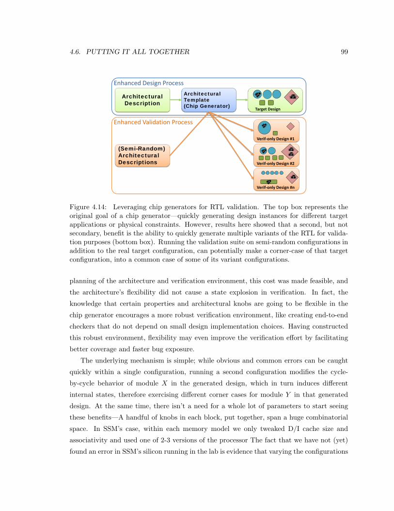
4.6. PUTTING IT ALL TOGETHER 99
Enhanced Validation Process
Verif-only Design #2
Verif-only Design #n
Target Design
Verif-only Design #1
Architectural Description
Architectural Template(Chip Generator)
(Semi-Random) Architectural Descriptions
Enhanced Design Process
Figure 4.14: Leveraging chip generators for RTL validation. The top box represents theoriginal goal of a chip generator—quickly generating design instances for different targetapplications or physical constraints. However, results here showed that a second, but notsecondary, benefit is the ability to quickly generate multiple variants of the RTL for valida-tion purposes (bottom box). Running the validation suite on semi-random configurations inaddition to the real target configuration, can potentially make a corner-case of that targetconfiguration, into a common case of some of its variant configurations.
planning of the architecture and verification environment, this cost was made feasible, and
the architecture’s flexibility did not cause a state explosion in verification. In fact, the
knowledge that certain properties and architectural knobs are going to be flexible in the
chip generator encourages a more robust verification environment, like creating end-to-end
checkers that do not depend on small design implementation choices. Having constructed
this robust environment, flexibility may even improve the verification effort by facilitating
better coverage and faster bug exposure.
The underlying mechanism is simple; while obvious and common errors can be caught
quickly within a single configuration, running a second configuration modifies the cycle-
by-cycle behavior of module X in the generated design, which in turn induces different
internal states, therefore exercising different corner cases for module Y in that generated
design. At the same time, there isn’t a need for a whole lot of parameters to start seeing
these benefits—A handful of knobs in each block, put together, span a huge combinatorial
space. In SSM’s case, within each memory model we only tweaked D/I cache size and
associativity and used one of 2-3 versions of the processor The fact that we have not (yet)
found an error in SSM’s silicon running in the lab is evidence that varying the configurations

100 CHAPTER 4. VERIFICATION OF A FLEXIBLE ARCHITECTURE
before tape-out helped our validation efforts.
These results are encouraging, since they mean a generator may even lead to better,
faster verification. To this extent, it calls for a new validation methodology (Figure 4.14):
when possible, run simulation/emulation tests on many variants of the target design to
shorten the long tail of hitting all corner cases and finding more bugs.
Chapter 5
Conclusion
The early years of the new millennium has been an inflection point in the life cycle of the
Integrated Circuit (IC) industry. For almost three decades, Dennard’s constant-field-scaling
rules enabled us to maintain the electric properties of the IC’s basic unit, the transistor,
while at the same time decreasing its physical area, decreasing the required energy per
switch and speeding that transistor up. Due to physical limitations, this paradigm broke
around the 90nm node (∼2005), and to this day (32nm, 2011), while transistors still get
smaller and faster, their energy efficiency is only scaling slowly. As if to make things even
worse, the biggest growing market, and the driver of the IC industry during this decade,
are battery operated mobile and hand held devices. Power has became the main design
constraint.
In a power constrained world, the only way to achieve more performance, that is, achieve
more operations per second, is to reduce the energy required per operation. To do that we
must tailor the systems we build to the application they are being built for. However,
here lies another problem: As the systems we build get bigger and more complex, the non-
recurring engineering costs of making those systems grow rapidly. In 2005 (90nm), the cost
of design validation and software were $10M. In 2010 (45nm) they are already more than
three times that, and these costs are expected to grow to over $100M by the time we reach
the 22nm technology node [63]. The result is that unless a solution is found, only a few
applications will have big enough markets to justify these high design costs for hardware
solutions.
In this dissertation, we argue for a new approach to system design, called “chip gener-
ators,” that fills the void between power-inefficient general-purpose designs and expensive
101
102 CHAPTER 5. CONCLUSION
application-specific ones. A chip generator uses a fixed system architecture to simplify ver-
ification and software development, but it is built of highly flexible components that are
configured to optimally match the target application in terms of allocated resources, re-
quired performance and power constraints. Once the configuration is chosen, it is compiled
and the required design and validation collateral are generated. Since making new and
different systems becomes a matter of configuration, rather than a re-design, the bulk of
the costs are amortized.
The key insight of the chip generator approach is that the most valuable resource for
making new chips is the human knowledge of how the system works, how the specialized
units perform, and what are the implications of any change in the specification. Therefore
our first and main goal should always be to encompass domain-specific designer knowledge
regarding trade-offs and the design process, in the system itself. We must code that knowl-
edge, instead of just the result of applying that knowledge to a particular problem. When
we code knowledge, we open the system to a world of automation: it is easy(er) to change
the system if you don’t need to worry about the low level details time and time again. It
becomes possible to accept external input to how the system should be constructed, and
even build a stack of customization tools that take even higher level input.
Unfortunately, existing design tools do not enable an easy, standardized way of embed-
ding the engineers’ knowledge into the system, or into the modules they create. Hardware
descriptive languages (HDL) focus, for the most part, on describing just the functionality.
Adding the ability to describe how a system needs to be constructed is much like the ad-
dition of constructors in C++ to C. To overcome these limitations of HDLs, we proposed
Genesis2—a tool that adds an explicit “constructor” layer on top of a regular HDL. By
doing that we enjoy the full capabilities of a software language (Perl) for describing how
the system is to be constructed while getting all the benefits of a synthesizable language
(System Verilog) for the hardware description. Both the concept and the implementation of
Genesis2 are simple, and mostly leverage known techniques such as constructors, templates
and pre-processors. However, the benefit is great: on the one hand, designers can now
make templates (or constructor-programs or “recipes”) for modules, which explicitly incor-
porate their thought process and trade-off analysis. On the other hand, the input to those
constructors comes from an external, standardized XML based architectural description, to
enable the creation of that customization stack.
Hand in hand with chip design comes RTL validation. The key to handling validation of
103
a chip generator is the understanding that we must verify the generated design instances, not
the generator. To make this process efficient we need to create a validation infrastructure
that is, for the most part, configuration agnostic. Some parts of the validation collateral
can/should also be generated along side the design. We have shown here that while one
should expect a small upfront cost in making the validation infrastructure configuration
agnostic, it can be done. In fact, making configuration-agnostic validation environments is
already something designers do anyway when they make runtime reconfigurable chips (as
we showed for the Stanford Smart Memories). The important part is that by investing in a
configuration-agnostic validation environment, we enable the amortization of the validation
costs across many chips. This is, of course, a worthwhile trade-off.
However, the best part of validation, when it comes to generators, is not that one
infrastructure can be used for all configurations. While we were working hard to prove
that we can reuse that infrastructure we observed what we initially thought was a strange
phenomena: there was synergy between configurations. That is, some bugs were found
orders of magnitude faster on certain configurations than on others. Furthermore, we did
not find one configuration that was always best at finding bugs. In hindsight, the mechanism
of this phenomena is clear and is already being exploited to various degrees in verification
teams today. A change in configuration changes the cycle by cycle behavior of the system
and introduces different scenarios and loads to the various modules. A chip generator just
does this at a larger, system-level scale. For example, a cache controller is better tested
when the system uses many different sizes and associativities of caches because the ordering,
the timing, and the number of requests it needs to handle varies from one configuration to
the other. The implication is most interesting: using a chip generator, we can quickly and
easily generate many (semi-random) variants of a target chip, and run our test suite on all
these variants to achieve better coverage at a shorter time.
This thesis focused on the definition of a chip generator and the enabling mechanisms:
Genesis2, a configuration-agnostic validation environment, and the relaxed scoreboard ref-
erence model. However, this is just the tip of the iceberg, and it opens up new questions in
many directions.
The first direction involves further integration of chip generator tools. For example,
the integration of a system level optimization engine that could assign optimal values to
all lower level design parameters (referred to as free parameters in Section 3.3) would be
very powerful. As mentioned in Section 2.4, Azizi showed one such framework that samples
104 CHAPTER 5. CONCLUSION
the design space and does joint circuit and micro-architecture optimization [25, 24]. With
Genesis2 in place, these two tools can be combined such that given a high level configura-
tion, the optimal design is immediately generated. This would complete the automation of
optimal design generation—the functionality depicted as the HW Optimization and Gen-
eration block shown in Figures 2.7(a) and 2.7(b). As a second step down that same road,
a higher level, domain specific co-optimizer for hardware and software can assist in the
automation of the per-application software and hardware customization (noted by the red
curved arrows in Figure 2.7(a)). Mohiyuddin et al demonstrate that co-tuning significantly
improves hardware area and energy efficiency for a number of applications that are heavily
used in supercomputing [76].
Until complete automation of the customization process can be achieved, lower hanging
fruit might be the creation of a user-friendly customization interface. Exemplifying the
benefit from embedding the designer knowledge in the design on one hand, and the clear
XML-based interfacing that separates the architectural decisions from their low level im-
plementation, we have already created a prototype of a client-server based customization
portal. This portal, when completed, will enable a user to log in, choose a Genesis2-based
template, and through a GUI, iteratively modify any of the architectural decisions through-
out the hierarchy on a per-instance basis to create a complete heterogeneous system. The
user, an architect or application expert, need never touch a single line of Verilog.
Nevertheless, we believe that even after exposing these architectural knobs to the user,
further levels of abstraction should be, and will be built. Genesis2 provides an opportunity
for easily converting higher level abstractions into low-level code, by providing a way to con-
figure flexible primitives like interfaces, microcode tables, message buffers, and so on. This
makes it easier to move beyond simple numeric parameters, into complex state machines
and protocols. Where an architecture written in Genesis provides a known abstraction,
domain specific languages can be compiled into these flexible structures. For example, one
future research direction involves taking a language designed to specify cache coherence
protocols for simulation [74], and providing an interface which makes it easy to compile into
the XML format used by Genesis2, so as to implement the memory protocols in hardware.
Thus, the protocol designer can operate at a high level, and different back-ends can produce
the XML configuration for different “protocol controller generators” written with Genesis2.
An important direction, and a great challenge on its own, is the software stack that
105
runs on the generated hardware. Once again we are optimistic as others have shown prac-
tical ways to build a software stack for customized and heterogeneous systems: Tensilica
automatically produces a compiler and linker for each of its generated cores [9, 47], and
GRAMPS is a programming model that permits arbitrary processing elements and con-
nectivity graphs [96]. In fact, work is already under way for the development of a chip
multiprocessor generator using Genesis2. When completed, this CMP generator will be
paired with the GRAMPS heterogeneous runtime to give researchers a powerful tool for
hardware/software co-design, providing a comprehensive generator for imaging and graph-
ics applications.
Thus far our results have demonstrated the feasibility of our chip generator approach,
as well as the potential energy savings it could foster. Now, with Genesis2 as the framework
to create generators, and with better understanding and confidence in the ability to verify
chip generators, work is already under way to construct one. If success continues, we hope
that people will someday look back at RTL coding the way they now look back at assembly
coding and custom IC design: although working at these lower levels is still possible, working
at higher levels is more productive and yields better solutions in most cases.

106 CHAPTER 5. CONCLUSION
Appendix A
Genesis2 User Guide
The following is meant to serve as a user guide for Genesis2 users. The ideas, methodology
and programming concepts of Genesis2 were described in Chapter 3. This Appendix is
meant to augment that text with the “dirty” implementation dependent details required for
using Genesis2 to build a generator. We start by instruction for installation and environment
setting in Section A.1. We then move to describe all the required input files and the
generated files in Section A.2, followed by instructions for activating the Genesis2 program
in Section A.3. Section A.4 provide information regarding syntax and built-in methods,
followed by debugging hints and suggestions in Section A.5. Finally, Section A.6 provide a
design example for a generator of a register file, written using Genesis2.
A.1 Setting Your Environment For Genesis2
Adding Genesis2 To Your Execution Path
In order to invoke the Genesis2 scripts, it is best to add them to the default execution
path. For example, install the Genesis2 files under USER/bin/PerlLibs/Genesis2. You
should now be able to see (at least) the following files:
neva-2:~/bin/PerlLibs/Genesis2>ls -R
.:
Auxiliary/ Genesis2.pl Manager.pm UniqueModule.pm
./Auxiliary:
TypeConv.pm
Then, to add Genesis2 to your execution path, simply type (or place at the end of your.cshrc file):
107
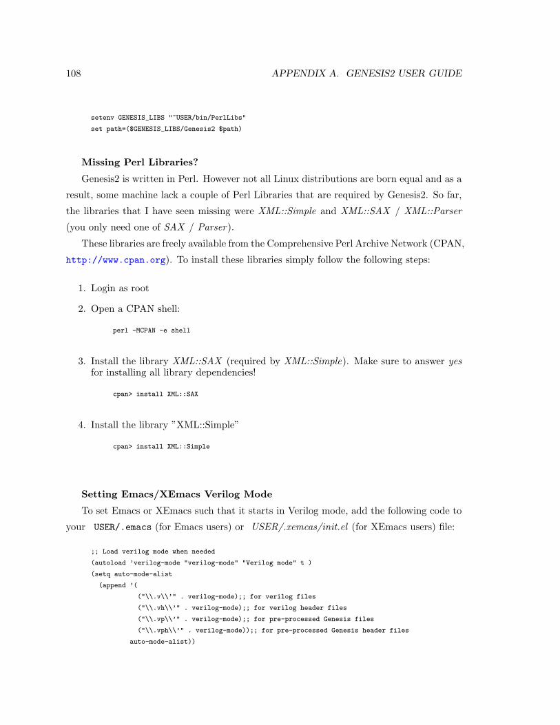
108 APPENDIX A. GENESIS2 USER GUIDE
setenv GENESIS_LIBS "~USER/bin/PerlLibs"
set path=($GENESIS_LIBS/Genesis2 $path)
Missing Perl Libraries?
Genesis2 is written in Perl. However not all Linux distributions are born equal and as a
result, some machine lack a couple of Perl Libraries that are required by Genesis2. So far,
the libraries that I have seen missing were XML::Simple and XML::SAX / XML::Parser
(you only need one of SAX / Parser).
These libraries are freely available from the Comprehensive Perl Archive Network (CPAN,
http://www.cpan.org). To install these libraries simply follow the following steps:
1. Login as root
2. Open a CPAN shell:
perl -MCPAN -e shell
3. Install the library XML::SAX (required by XML::Simple). Make sure to answer yesfor installing all library dependencies!
cpan> install XML::SAX
4. Install the library ”XML::Simple”
cpan> install XML::Simple
Setting Emacs/XEmacs Verilog Mode
To set Emacs or XEmacs such that it starts in Verilog mode, add the following code to
your USER/.emacs (for Emacs users) or USER/.xemcas/init.el (for XEmacs users) file:
;; Load verilog mode when needed
(autoload ’verilog-mode "verilog-mode" "Verilog mode" t )
(setq auto-mode-alist
(append ’(
("\\.v\\’" . verilog-mode);; for verilog files
("\\.vh\\’" . verilog-mode);; for verilog header files
("\\.vp\\’" . verilog-mode);; for pre-processed Genesis files
("\\.vph\\’" . verilog-mode));; for pre-processed Genesis header files
auto-mode-alist))
A.2. GENESIS2 FILE TYPES 109
Note that a loader for Verilog mode may have already been defined. In that case either
modify it to identify .vp and .vph files, or replace with the above code. Of course, you
would have to make sure that you have the file /elisp/verilog-mode.el which is freely
available on the web.
A.2 Genesis2 File Types
There are a number of input and output files that are associated with each Genesis2’s run.
In Section A.2.1 we describe the main file types and their role in the process of generation.
Section A.2.2 describes a few more output files that Genesis2 can generate, which are useful
for downstream tools such as simulator and synthesis compilers.
A.2.1 Main File Types
SomeModule.vp And SomeIncluded.vph Files
These are the user’s files. That is, when a hardware designer writes a hardware template
that (for Genesis2 generation), he/she should write it in a file named base template name.vp.
For example, if the template name is onehotmux, it should be placed in a file named one-
hotmux.vp.
Included files should be named whatever.vph. In fact, this requirement is not real and
whatever.anything or even whatever would work. However, for nice coding style, and for
XEmacs/Emacs Verilog mode to work nicely, the whatever.vph style is recommended.
SomeModule.pm Files
Genesis2 generates intermediate Perl module files. Given the file filename1.vp, Genesis2
would generate filename1.pm. Typically there is no reason to look at these files, except for
debugging of parsing errors and their like.
* Note: Genesis2 works in two stages as described in Section 3.4: First all the .pm files
are generated. This is, in fact, a complete object oriented program in Perl, where each
Perl package is in fact a Verilog module generator. Then, after all the Perl packages were
created, Genesis2 execute the newly created Perl program that in turn generates Verilog.
SomeModule.v Files

110 APPENDIX A. GENESIS2 USER GUIDE
The final type of file of interest is the generated Verilog file. This code should consist
of only Verilog, and will eventually be fed to VCS/dc shell/other tools.
* Note: For every somemodule.vp input file, there may be more than one Verilog files
generated. If somemodule is instantiated in different places using different parameters,
each different instance would be uniquified. The resulting Verilog files would be named
somemodule unq0.v, somemodule unq1.v, etc.
Program.xml File
The XML input program has a very simple structure. An example follows. Note that
the structure-wise:
1. There are just a few reserved element names. Those are: BaseModuleName, Instance-
Name, Parameters, ImmutableParameters, SubInstances, UniqueModuleName, Clo-
neOf, HashType, ArrayType, ArrayItem, InstancePath. Avoid using these key words
in any context other than the one explained here or in Section A.2.2.
2. There is a single root element which is the name of the top module of the design (since
the top module is not instantiated, it is referred to by its module name and not by
its instance name).
3. Each element in the hierarchy has the following sub-elements:
(a) Parameters: a list of parameter definitions, where the definition def of a pa-
rameter param name would be coded as <param name>def</param name>.
More complicated data structures are also supported: Use the <HashType> to
show that a parameter is a hash rather than a string/scalar. Use <ArrayType>
to show that a parameter is an array rather than a string/scalar, and the
<ArrayItem> notation to express items in that array. Use <InstancePath> to
express that a parameter represent a reference to a particular instance in the
design hierarchy. See examples below.
(b) SubInstances: (Optional) A list of XML elements that represent the names of
sub-instances in the current hierarchy level. The same rules apply recursively for
each of these elements.
If an instance is encountered during elaboration, but is missing from the XML
tree, it will be assumed that it uses the default parameters or the instantiation
line parameters, as coded by the hardware designer in the .vp files.
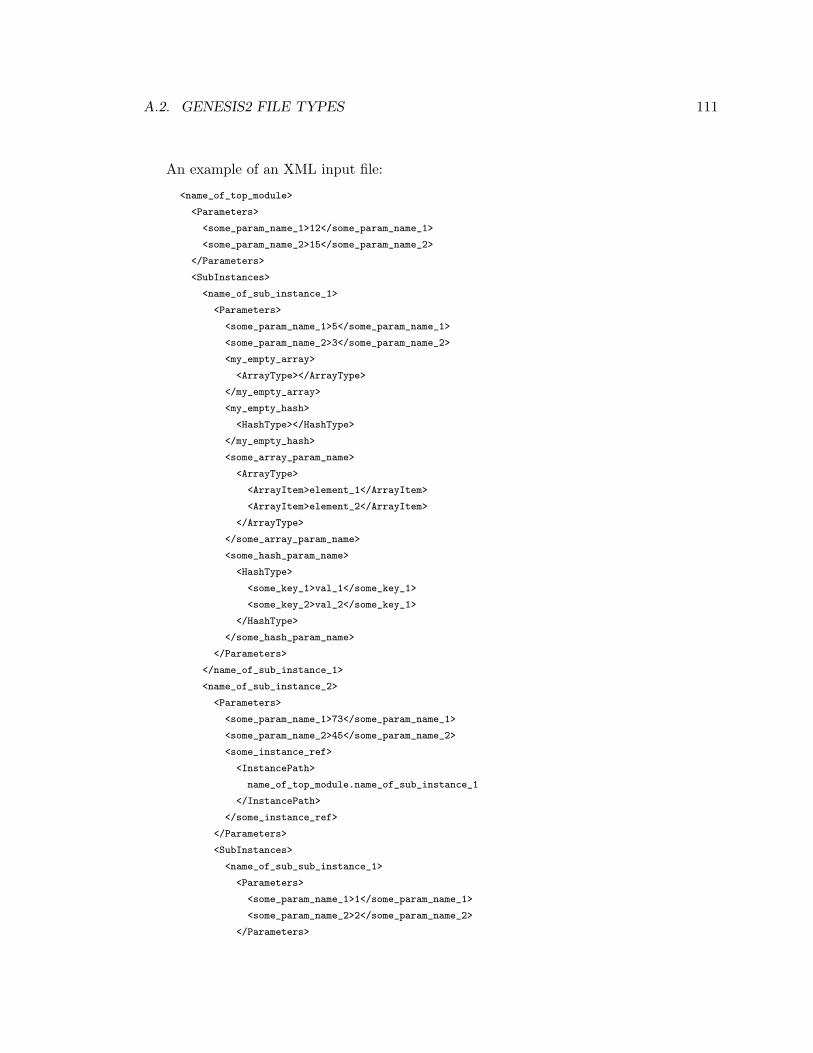
A.2. GENESIS2 FILE TYPES 111
An example of an XML input file:
<name_of_top_module>
<Parameters>
<some_param_name_1>12</some_param_name_1>
<some_param_name_2>15</some_param_name_2>
</Parameters>
<SubInstances>
<name_of_sub_instance_1>
<Parameters>
<some_param_name_1>5</some_param_name_1>
<some_param_name_2>3</some_param_name_2>
<my_empty_array>
<ArrayType></ArrayType>
</my_empty_array>
<my_empty_hash>
<HashType></HashType>
</my_empty_hash>
<some_array_param_name>
<ArrayType>
<ArrayItem>element_1</ArrayItem>
<ArrayItem>element_2</ArrayItem>
</ArrayType>
</some_array_param_name>
<some_hash_param_name>
<HashType>
<some_key_1>val_1</some_key_1>
<some_key_2>val_2</some_key_1>
</HashType>
</some_hash_param_name>
</Parameters>
</name_of_sub_instance_1>
<name_of_sub_instance_2>
<Parameters>
<some_param_name_1>73</some_param_name_1>
<some_param_name_2>45</some_param_name_2>
<some_instance_ref>
<InstancePath>
name_of_top_module.name_of_sub_instance_1
</InstancePath>
</some_instance_ref>
</Parameters>
<SubInstances>
<name_of_sub_sub_instance_1>
<Parameters>
<some_param_name_1>1</some_param_name_1>
<some_param_name_2>2</some_param_name_2>
</Parameters>
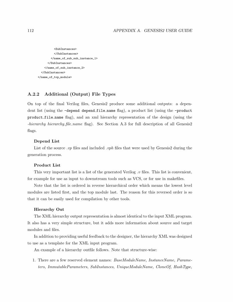
112 APPENDIX A. GENESIS2 USER GUIDE
<SubInstances>
</SubInstances>
</name_of_sub_sub_instance_1>
</SubInstances>
</name_of_sub_instance_2>
</SubInstances>
</name_of_top_module>
A.2.2 Additional (Output) File Types
On top of the final Verilog files, Genesis2 produce some additional outputs: a depen-
dent list (using the -depend depend file name flag), a product list (using the -product
product file name flag), and an xml hierarchy representation of the design (using the
-hierarchy hierarchy file name flag). See Section A.3 for full description of all Genesis2
flags.
Depend List
List of the source .vp files and included .vph files that were used by Genesis2 during the
generation process.
Product List
This very important list is a list of the generated Verilog .v files. This list is convenient,
for example for use as input to downstream tools such as VCS, or for use in makefiles.
Note that the list is ordered in reverse hierarchical order which means the lowest level
modules are listed first, and the top module last. The reason for this reversed order is so
that it can be easily used for compilation by other tools.
Hierarchy Out
The XML hierarchy output representation is almost identical to the input XML program.
It also has a very simple structure, but it adds more information about source and target
modules and files.
In addition to providing useful feedback to the designer, the hierarchy XML was designed
to use as a template for the XML input program.
An example of a hierarchy outfile follows. Note that structure-wise:
1. There are a few reserved element names: BaseModuleName, InstanceName, Parame-
ters, ImmutableParameters, SubInstances, UniqueModuleName, CloneOf, HashType,

A.2. GENESIS2 FILE TYPES 113
ArrayType, ArrayItem, InstancePath. Avoid using these key words in any context
other than the one explained here or in Section A.2.1.
2. There is a single root element which is the name of the top module of the design (since
the top module is not instantiated, it is referred to by it’s module name and not by
it’s instance name).
3. Each element in the hierarchy may have the following sub elements:
(a) BaseModuleName: name of the template before module generation and uniquifi-
cation
(b) InstanceName: name of the instance that was instantiated
(c) Parameters: a list of parameter definitions, where the definition def of a pa-
rameter param name would be written as <param name>def</param name>.
More complicated data structures are also supported: Use the <HashType> to
show that a parameter is a hash rather than a string/scalar. Use <ArrayType>
to show that a parameter is an array rather than a string/scalar, and the
<ArrayItem> notation to express items in that array. Use <InstancePath> to
express that a parameter represent a reference to a particular instance in the
design hierarchy. See examples below.
(d) ImmutableParameters: a list of parameter definitions with the exact same
structure of the previously mentioned Parameters element. However, while
Parameters can be altered and re-fed into Genesis2 to create new RTL, Im-
mutableParameters are parameters that where already assigned a value, either us-
ing the $self->force param(...) call or at instantiation using the $self->unique inst(...)
call. More about the different possible ways to assign values to parameters in
Section A.4.2.
(e) SubInstances: A list of XML elements that represent the names of sub-instances
in the current hierarchy level. The same rules apply recursively for each of these
elements.
(f) UniqueModuleName: name of the generated module after uniquification
(g) CloneOf: if the instance is a clone of another instance, the field CloneOf appears
instead of the fields Parameters and SubInstances. CloneOf would then have a
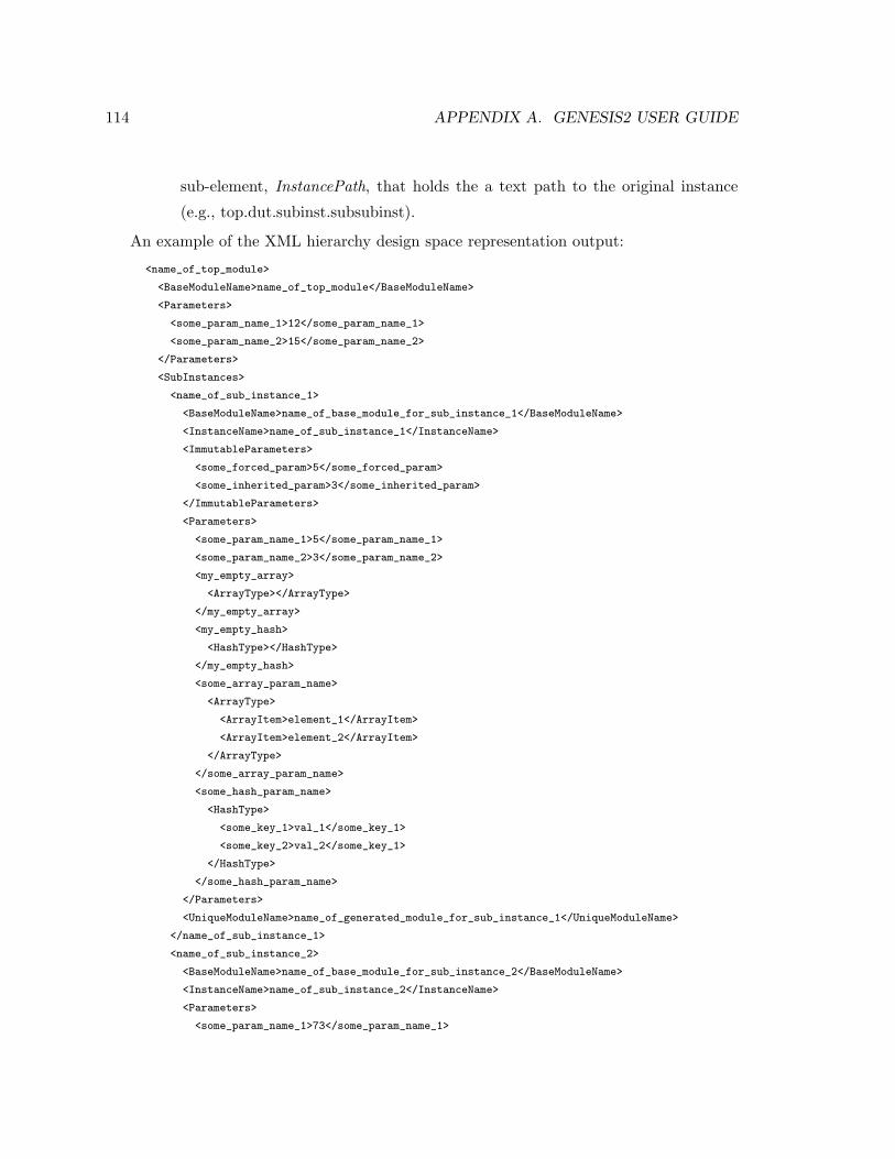
114 APPENDIX A. GENESIS2 USER GUIDE
sub-element, InstancePath, that holds the a text path to the original instance
(e.g., top.dut.subinst.subsubinst).
An example of the XML hierarchy design space representation output:
<name_of_top_module>
<BaseModuleName>name_of_top_module</BaseModuleName>
<Parameters>
<some_param_name_1>12</some_param_name_1>
<some_param_name_2>15</some_param_name_2>
</Parameters>
<SubInstances>
<name_of_sub_instance_1>
<BaseModuleName>name_of_base_module_for_sub_instance_1</BaseModuleName>
<InstanceName>name_of_sub_instance_1</InstanceName>
<ImmutableParameters>
<some_forced_param>5</some_forced_param>
<some_inherited_param>3</some_inherited_param>
</ImmutableParameters>
<Parameters>
<some_param_name_1>5</some_param_name_1>
<some_param_name_2>3</some_param_name_2>
<my_empty_array>
<ArrayType></ArrayType>
</my_empty_array>
<my_empty_hash>
<HashType></HashType>
</my_empty_hash>
<some_array_param_name>
<ArrayType>
<ArrayItem>element_1</ArrayItem>
<ArrayItem>element_2</ArrayItem>
</ArrayType>
</some_array_param_name>
<some_hash_param_name>
<HashType>
<some_key_1>val_1</some_key_1>
<some_key_2>val_2</some_key_1>
</HashType>
</some_hash_param_name>
</Parameters>
<UniqueModuleName>name_of_generated_module_for_sub_instance_1</UniqueModuleName>
</name_of_sub_instance_1>
<name_of_sub_instance_2>
<BaseModuleName>name_of_base_module_for_sub_instance_2</BaseModuleName>
<InstanceName>name_of_sub_instance_2</InstanceName>
<Parameters>
<some_param_name_1>73</some_param_name_1>
A.2. GENESIS2 FILE TYPES 115
<some_param_name_2>45</some_param_name_2>
</Parameters>
<SubInstances>
<name_of_sub_sub_instance_1>
<BaseModuleName>neta</BaseModuleName>
<InstanceName>netisnt</InstanceName>
<Parameters>
<some_param_name_1>1</some_param_name_1>
<some_param_name_2>2</some_param_name_2>
</Parameters>
<SubInstances>
</SubInstances>
<UniqueModuleName>
name_of_generated_module_for_sub_sub_instance_1
</UniqueModuleName>
</name_of_sub_sub_instance_1>
<name_of_sub_sub_instance_2>
<BaseModuleName>neta</BaseModuleName>
<CloneOf>
<InstancePath>
name_of_top_module.name_of_sub_instance_2.name_of_sub_sub_instance_1
</InstancePath>
</CloneOf>
<InstanceName>netisnt2</InstanceName>
<UniqueModuleName>
name_of_generated_module_for_sub_sub_instance_2
</UniqueModuleName>
</name_of_sub_sub_instance_1>
</SubInstances>
<UniqueModuleName>name_of_generated_module_for_sub_instance_2</UniqueModule_Name>
</name_of_sub_instance_2>
</SubInstances>
<UniqueModuleName>name_of_top_module</UniqueModuleName>
</name_of_top_module>
A.2.3 Extending Genesis2 With Home-made Perl Libraries
One of the best things about using Perl as the language on top of Verilog, is that it is very
easily extended. This means that one can use any Perl library in the world as part of the
knowledge base that create a template’s micro-architecture.
1. Adding Perl Built-in Library:
To add one of the thousands of Perl libraries that were written in Perl Simply put a
116 APPENDIX A. GENESIS2 USER GUIDE
”//; use LibraryName;” in your text, just as you would do for any Perl script.
The following is an example of using the POSIX library. In this code snippet, which is
taken from a flip-flop based register file template, we make use of the the mathematical
ceiling function to calculate the number of bits required for the address bus. The
complete code can be found in Section A.6.3. Here, pieces of code which were not
relevant were replaced by “...” (three dots):
// Parameters declaration
//; my $reg_list = \$self->define_param(REG_LIST => [...]);
//; # Import Perl Libraries to Scope
//; use POSIX;
//; my $num_regs = scalar(@{$reg_list});
//; my $num_addr_bits = POSIX::ceil(log($num_regs)/log(2));
// Verilog code for the module
module ‘mname‘ (
input Clk,
input Reset,
input [‘$num_addr_bits-1‘:0] Addr,
...
);
endmodule // ‘mname‘
2. Adding Your Own Perl Library:
Assuming your homemade Perl package is called MyLib.pm, place it in the folder
$GENESIS LIBS/Genesis2/Auxiliary/. There are two ways for your Genesis2 mod-
ules to get the functions of a home-made library into their name space:
(a) Typical Perl ”use” system (preferred way for not polluting the name space): In
your module (e.g., your file flop.vp) add a line that reads use MyLib;. Now
you can call MyLib::funcName(args). If you want some (or all) of the func-
tions to be embedded in the name space, you can also add their names to
the Perl package EXPORT or EXPORT OK lists. In the following example, the file
$GENESIS LIBS/Genesis2/Auxiliary/TypeConv.pm has these lists marked with
”METHOD 1 FOR INHERITING ALL METHODS”
(b) Inheritance: You can tell all Genesis2 templates to inherit Perl methods from

A.2. GENESIS2 FILE TYPES 117
your package. In order to do that, we force the UniqueModule (which is the
base class of all Genesis2 templates) to inherit from this package. Then, given
a method with name methodName, each and every template in Genesis2 would
be able to call it by invoking $self->methodName. To activate this inheritance
follow these two steps:
i. Push the current package into the ISA of the base module UniqueModule.
In the following example, the file $GENESIS LIBS/Genesis2/Auxiliary/-
TypeConv.pm, the Perl lines that are annotated as ”METHOD 2 FOR IN-
HERITING ALL METHODS”).
ii. Add the Genesis2 flag -perl modules MyLib (for the example below this
would be -perl modules TypeConv) to your command line. Alternatively,
for advanced users only, add the Perl command use MyLib; (or use TypeConv;
for the example below) to your Genesis2.pl script at the appropriate location,
which would force this library to always be used.
The following is a stub of a library file. In this example, the new Perl package defines
one new function for scalar-array type conversion.
package TypeConv;
use strict;
use vars qw($VERSION @ISA @EXPORT @EXPORT_OK);
use Exporter;
@ISA = qw(Exporter);
$VERSION = ’1.00’;
# *********** METHOD 1 FOR INHERITING ALL METHODS *************
# To make a function available in the name space of the
# including package, simply place it in the EXPORT or EXPORT_OK
# lists.
# Example: ‘‘@EXPORT = qw(funcName);’’
@EXPORT = qw();
@EXPORT_OK = qw();
# **************************************************************
# ************ METHOD 2 FOR INHERITING ALL METHODS *************
# Uncomment the following line to activate inheritance
#push (@Genesis2::UniqueModule::ISA, qw(TypeConv));
# ***************************************************************
118 APPENDIX A. GENESIS2 USER GUIDE
#################################################################
################ ACTUAL TypeConv CODE STARTS HERE ###############
#################################################################
sub make_array{
my $item = shift;
if (ref ($item) eq ’ARRAY’){
return $item;
}
else {
return [$item];
}
}
1;
A.3 Genesis2 Command Line Arguments
In this section, we describe the command line argument that Genesis2 accept. The maininvocation script for Genesis2 is located at $GENESIS LIBS/Genesis2/Genesis2.pl, andthe format of the command is:
Genesis2.pl [-option value, ...]
Genesis2.pl -help
Note that there are two distinct stages in Genesis2—Parsing and Generation—as explained
in Section 3.4. However, one can also call the script once with both the -parse and the
-generate flags on. Genesis2 would perform parsing and then move immediately to gener-
ating. The following is a description of the parse-time and generation-time options.
A.3.1 Parsing Mode
Parsing mode performs the first transformation: From the designer’s source code (.vp files)
to an object oriented set of packages in Perl. Each Perl module (.pm files) is a code generator
for its corresponding Verilog module (.v file), but verilog generation is not yet done at this
stage, and therefore there is no significance to the order of parsing the template (.vp) files.
Parsing options are:
• -parse: Activates Genesis2 in parse mode
A.3. GENESIS2 COMMAND LINE ARGUMENTS 119
• -sources—srcpath dir: Where to find source files
• -includes—incpath dir: Where to find included files
• -input file#1 .. file#n: List of files to parse
• -depend filename: Should Genesis2 generate a dependency file list? (list of input
files)
• -perl modules modulename: Additional perl modules to load
A.3.2 Generation Mode
Generation mode is the stage where Genesis2 is asked to start doing the target Verilog code
generation, starting from some specified top level (does not need to be the absolute top
level of your design). This is when the previously created .pm files generate the final .v
files. Generation options are:
• -generate: Activates Genesis2 in generate design hierarchy mode (Final Verilog code
generation)
• -top topmodule: Name of top module to start generation from
• -product filename: Should Genesis2 generate a product file list? (list of output
files)
• -hierarchy filename: Should Genesis2 generate a hierarchy representation tree?
• -xml filename: Input XML representation of definitions
• -perl modules modulename: Additional perl modules to load
A.3.3 Help and Debugging
• -debug level: Set debug level
• -help: prints the script’s usage message
120 APPENDIX A. GENESIS2 USER GUIDE
A.4 Genesis2 Source File Structure and Built-in Methods
This section describes the “dirty” details of how template designers should write their
code when using Genesis2. To make the adoption of Genesis2 easy, the code structure for
using Genesis2, is the same as the target language that Genesis2 is expected to generate,
annotated with meta-language code and using a minimal amount of pre-defined methods,
that Genesis2 compiles into the target language. In our case, the target language is Verilog
or System Verilog. The meta language that is used on top is simply Perl. As a result, you
now have the strength of Perl in your hands when you write Verilog. Use it wisely.
A.4.1 Genesis2 Source Code Structure
Genesis2 enables user to code in two languages simultaneously and interleaved. One is
Verilog that describes the hardware functionality. The other is Perl that describes the
construction of the Verilog. By default, any code written is considered as Verilog, and
special escape characters mark snippets of code or even complete lines that should be
handled using the Perl interpreter. There are two types of Perl escapes that can be used:
• Full Line Escape: This escape sequence tells Genesis2 that the entire line is Perl.
To use it, simply type “//;” (i.e. Verilog line comment followed by a semi-colon) at
the beginning of the line (white space before is also allowed).
Note that this would look like a comment to the XEmacs’s (or any other editor’s)
Verilog mode. Hence, coloring and indentations would not be influenced.Descriptive example:
This is regular (though not legal Verilog) text that
would go directly to output.
// This is regular text that would go directly to the
// output as Verilog comment.
//; This is text that would be evaluated as a part of
//; the meta-language constructor (but since the meta-
//; language is Perl, this code generates a syntax error ;-))
Compile-able (though not meaningful) example:
assign verilog_wire = some_other_verilog_wire;
// I am a verilog comment line
//; my $to_be_perl_var = "This is Perl";
A.4. GENESIS2 SOURCE CODE & BUILT-IN METHODS 121
• Part-Of-Line Escape: This escape sequence tells Genesis2 that a part of the line,
which is delimited in-between two “ ‘ “ (i.e. grave accent) signs, is to be evaluated
using the Perl interpreter. The result of the Perl evaluation of the block is to be
printed to screen.
Note that this would look like a ”tick-define” to the XEmacs’s (or any other editor’s)
Verilog mode. Hence, coloring and indentations would not be influenced.
Example:
//; my $width = 5;
assign some_wire[‘$width-1‘:0] = some_other_wire[‘$width+9‘:10];
//; foreach my $idx (0,1,2,3){
assign wire_‘$idx‘ = wire_‘($idx+1)%4‘;
//; }
Which will produce:
assign some_wire[4:0] = some_other_wire[14:10];
assign wire_0 = wire_1;
assign wire_1 = wire_2;
assign wire_2 = wire_3;
assign wire_3 = wire_0;
Note About The Perl print Function: Though not recommended as a methodology, itis some times convenient to use the built-in Perl print function. Therefore for the usersconvenience, printing is done by default to the output file (i.e. the Verilog modulename.vfile). However, if you wish to print progress or debug statements that need to go to thescreen use:
//; print STDOUT "your text here\n"
or
//; print STDERR "your text here\n"
A.4.2 Genesis2 Special Built-in Methods
As mentioned before, the entire effort of creating such tool is to enable scopes, enhance
parametrization and most importantly uniquification of modules. For this reason, there are
a handful of pre-built Perl methods that were defined.
Data Structure Related Methods
122 APPENDIX A. GENESIS2 USER GUIDE
• sub get parent: Returns a pointer to the parent instance
//; my $parent = $self->get_parent();
• sub get subinst: Returns a pointer to the object of a sub instance (by name)
//; my $subInst_of_someInst = $someInst->get_subinst("addr_flop");
or
//; my $subInst_name = "data_fifo";
//; my $subInst_of_someInst = $someInst->get_subinst($subinst_name);
• sub get subinst array: Returns a handle to an array of sub instance objects thatmatch a pattern
//; my $subinsts_of_someinst = $someinst->get_subinst_array($pattern);
• sub get instance path: API method that returns a complete path to the giveninstance object. An instance path has the strict format of “topModule.subInst.-subSubInst.subSubSubInst....”. For example: top.dut.regfile.addr flop.
//; my $instPath = $inst_obj->get_instance_path();
• sub get instance obj: API method that accepts an instance path (or an instanceobject) and returns the corresponding instance object. An instance path has the strictformat of “topModule.subInst.subSubInst.subSubSubInst....”. For example: top.dut.-regfile.addr flop.
//; my $instObj = $self->get_instance_obj($instPath);
Parametrization Methods
• sub define param: API method for defining a new parameter (just like defining
a parameter in Verilog). Note that using the define param, parameters can only
be defined inside the template to which they belong (i.e., a call to another object’s
define param will be flaged by Genesis2 as generation error).
However, parameters can also be defined at instantiation using the unique inst method
as shown below. Definition at instantiation time overwrite definitions done within the
module (just like in Verilog). As a middle ground, parameter definitions that are not
A.4. GENESIS2 SOURCE CODE & BUILT-IN METHODS 123
bounded by instantiation can be set using the input XML configuration file. For more
details on parameter’s strengths and priorities, turn to Section 3.3.2.
In the following example, the parameter is registered with name prmName and receivethe value prmVal. The value is also returned to the Perl variable $val.
//; my $val = $self->define_param(prmName => $prmVal);
• sub force param: API method for defining an IMMUTABLE parameter. Thisis pretty much the equivalent of the localparam keyword in Verilog. It defines aparameter and other modules (up or down the hierarchy) can query its value usingthe get param method (see next definition). However, this parameter definition isimmutable—it cannot be altered neither at module instantiation nor through theXML configuration file (See more at Section 3.3.2).
//; my $val = $self->force_param(prmName => $prmVal);
• sub get param: API method for extracting a parameter’s value from the parameter’sregistry. This method is useful when a module needs to read a parameter from adifferent module:
//; my $val = $other_module->get_param(’prmName’);
The get param method is also useful as a mean for forcing instantiators or the externalXML input to always provide the definition of a particular parameter. If neither ofthem defines the parameter prior to the get param call, an error is thrown.
//; my $val = $self->get_param(’prmName’);
• sub get top param: API method for extracting a parameter’s value from the toplevel parameter’s registry. Conceptually, the top level testbench is where globaldefinitions may reside. These definition may include for example SVA MODE orSYNTHESIS MODE.
//; my $val = $self->get_top_param(’prmName’);
Note that get top param is merely syntactic sugar for:
//; $tmp = $self;
//; while (defined $tmp1){
//; $tmp2=$tmp1;
//; $tmp1=$tmp1->get_parent();
//; }
//; my $val = $tmp2->get_param(’prmName’);
Module Generation / Template Instantiation Methods
124 APPENDIX A. GENESIS2 USER GUIDE
• sub unique inst: The main function call for generating (and later instantiating) anew module. Note that this call on it’s own does not print anything to the outputmodule. Rather, it will return a pointer to the instance module ($newObj in thecode example below). Use the get module name (syntactic sugared as mname) andget instance name (syntactic sugared as iname), as well as other methods as describedabove to query for the generated module’s name and properties.
//; my $newObj = $self->unique_inst(’templateName’, ’instName’,
//; prm1 => val1, prm2 => val2, ...);
• sub generate: This is syntactic sugar for $self->uniqu inst(...)—the main functioncall for generating (and later instantiating) a new module. No need for the $selfreference.
//; my $newObj = generate(’templateName’, ’instName’,
//; prm1 => val1, prm2 => val2, ...);
• sub clone inst: An API method for replicating a module based on an existing in-stance
//; my $clonedObj = $self->clone_inst($srcInst, ’clonedInstName’);
Note that srcInst can either be a path (e.g., “top.subInst.subSubInst”) or it can be
just an instance object (like the ones returned by unique inst or clone inst).
• sub clone: This is syntactic sugar for $self->clone inst(...)—A method for replicatinga module based on an existing instance. No need for the $self reference.
//; my $clonedObj = clone($src_inst, ’new_inst_name’);
Auxiliary Methods
• sub include: includes a (header) file to your text
//; include("some_header_file.vph");
• sub get instance name: Returns the name of the instance that this object is gen-erating / already generated (can only be called on $self or on previously generatedinstances)
//; my $inst_name = $someObj->get_instance_name();
• sub iname: Syntactic sugar for get instance name().
//; my $inst_name = iname();
OR
//; my $someObj_inst_name = $someObj->iname();

A.4. GENESIS2 SOURCE CODE & BUILT-IN METHODS 125
• sub get module name: Returns the uniquified module name. This task is especiallyimportant since whenever we declare a new module or System Verilog interface wedon’t really know whether or not it is going to be uniquified, and how many uniquifa-tions of this module already happened. This enables us to leave the dirty work forGenesis.
//; my $module_name = $self->get_module_name();
module ‘$module_name‘ (input logic Clk, ... );
// parameterized module code comes here
endmodule
• sub mname: Syntactic sugar for get module name(). No need for the $self reference.
module ‘mname‘ (input logic Clk, ... );
// parameterized module code comes here
endmodul
• sub instantiate: Syntactic sugar for $obj->mname() $obj->iname()—I.e., the mod-ule and instance names of $obj for the purpose of instantiating that module.
module ‘mname‘(input clk, ...);
// some parameterized module code comes here
// Let’s generate and instantiate an ALU module:
//; my $ALU = generate(’ALU’, ’ALU_U’, param1=>val1, param2=>val2,...);
‘$ALU->instantiate‘ (.clk(clk),
.arg1(vector1),
.arg2(vector2),
.cmd(operation),
.result(result));
// more parameterized module code comes here
endmodule: ‘mname‘
• sub error: Prints an error message and exits with a printout of the current file andline
//; $self->error("some error message");
• sub warning: Prints a warning message and a printout of the current file and line.Does NOT exit.
126 APPENDIX A. GENESIS2 USER GUIDE
//; $self->warning("some message");
No other directives you need to remember. It is all
Verilog annotated with Perl from here on.
A.5 Useful Debugging Hints
The following are a few generic tips for debugging templates code with Genesis2.
Debug level
In order to see a more verbose messages from Genesis2 during parsing and generation
use the flag “-debug n” where n is a bit-wise verbosity level. The 0x0 level means “no
information required”; The 0x1 level will print progress messages as the different files are
parsed and different instances instantiated. In addition, it prints a synchronization message
to the target Verilog file every ten lines; The 0x2 level only provide information regarding
template files location during parsing phase; The 0x4 level provide information about the
hierarchy construction during generation, and regarding parameter definitions and value
assignments;
Error and warning messages
It is always a good habit to check the input (that can many times come from a user
filling an XML form), and printing errors or warnings accordingly. See the Section A.4.2
for the use of the error and warning predefined methods.
Debug messages to the Verilog fileTo print debug messages during elaboration, such that they go to the output Verilog
file, one can either use simple text with inline Perl escapes, since simple text is printed tothe Verilog file by default. It is better however to make these statements look as Verilogcomments so they don’t disturb compilation. A few examples:
1. This text goes as is to the verilog file... but would cause
a verilog compile error since it’s not legal verilog
// 2. This text also goes to the verilog file... but no
// compile errors this time since for verilog it’s a comment.
// You can even use an inline escape such as x=‘$x‘ and the
// value of $x will be printed in the comment.
A.6. GENESIS2 DESIGN EXAMPLE 127
//;# 3. This text does NOT go to the verilog file! It can
//;# serve as a way to write comments to self or to others
//;# reading the code. Essencially these lines are passed to
//;# the constructor for evaluation, but the # sign makes
//;# them look as a comment for the software (Perl) interpreter.
//; print "4. This is a Perl print command that prints this".
//; " line to the verilog file... expect verilog compile".
//; " errors...\n";
//; print "// 5. This is also a Perl print command. This text".
//; " also goes to the verilog file... no compile error".
//; " this time\n";
Debug messages to the screenIt is also possible to print a debug messages to the screen (printed during generation
phase):
//; print STDOUT "your text here\n"
or
//; print STDERR "your text here\n"
A.6 Flip-Flop Based Register File Design Example Using
Genesis2
In this section we provide a simple template design example, one that most designers had
to deal with in most their chips—A flip-flop based register file. Traditionally, these register
files are used as a (relatively) small configuration and debug memory.
Typically, every register output in that configuration space would be wired directly to
the logic that it controls and would be assigned with some default value for the Power-
on/Reset (PoR) stage. Similarly debug registers’ inputs will be connected to and driven by
the design logic, and in some cases debug registers would also have an enable input signal,
indicating when the debug value should be sampled.
Often times, such config and debug register files are automatically compiled from an
Excel spreadsheet or its like, using simple scripts. However using Genesis2, the engineer
essentially writes Verilog code and the construction script is interleaved, making it easier to
write. This example illustrates how Genesis2 compounds the notion of module “generator”
128 APPENDIX A. GENESIS2 USER GUIDE
scripts as a way to build a system generator. This is greatly beneficial to the design process
for various reasons:
1. There is no need to call the register-file script for every module of register file that
needs to be created in the design. More importantly, there is no need for the design
team to keep track of how many different register files were previously created and
what their module names were.
2. Once the register file is embedded as a generator in Genesis2, it is easy to change
all architectural properties of the generated hardware without ever needing to change
a single word of Verilog. For a register file these parameters will include the base
address of each instance and the default value of each register. (Note that whether
the register is used for configuration or debug or how many registers the register file
contains is an inherited parameter that must comply with the instantiating module)
3. Since we can use the same Genesis2 template to generate not only the modules but
also software and/or verification header files, any change to the register file (such as
the ones mentioned above) would automatically propagate to the verication testbench
and the software stack.
In order to create this register-file template, we first create a simple register template
(Section A.6.1) and a configuration bus interface (Section A.6.2). Then we move to the
main deal at Section A.6.3.
A.6.1 Basic Flip-Flop Template
The low level of this unit is a simple register. Note that here, we parametrize the register
by its type, its width and its default value. Also note that the type and width parameters
must inherited from/constrained by the instantiating module, since otherwise the interface
will break. The default value however, is an architectural parameter and can be set by the
application designer at a later stage.
Of course, there is nothing special in this parametrization that can not be done in Verilog,
however, by performing the parametrization through Genesis2, we enable any other instance
to query those parameters. More importantly, we enable an external user to change the
default value of each and every register instance, without worrying about the uniquification
implications on the rest of the design hierarchy.
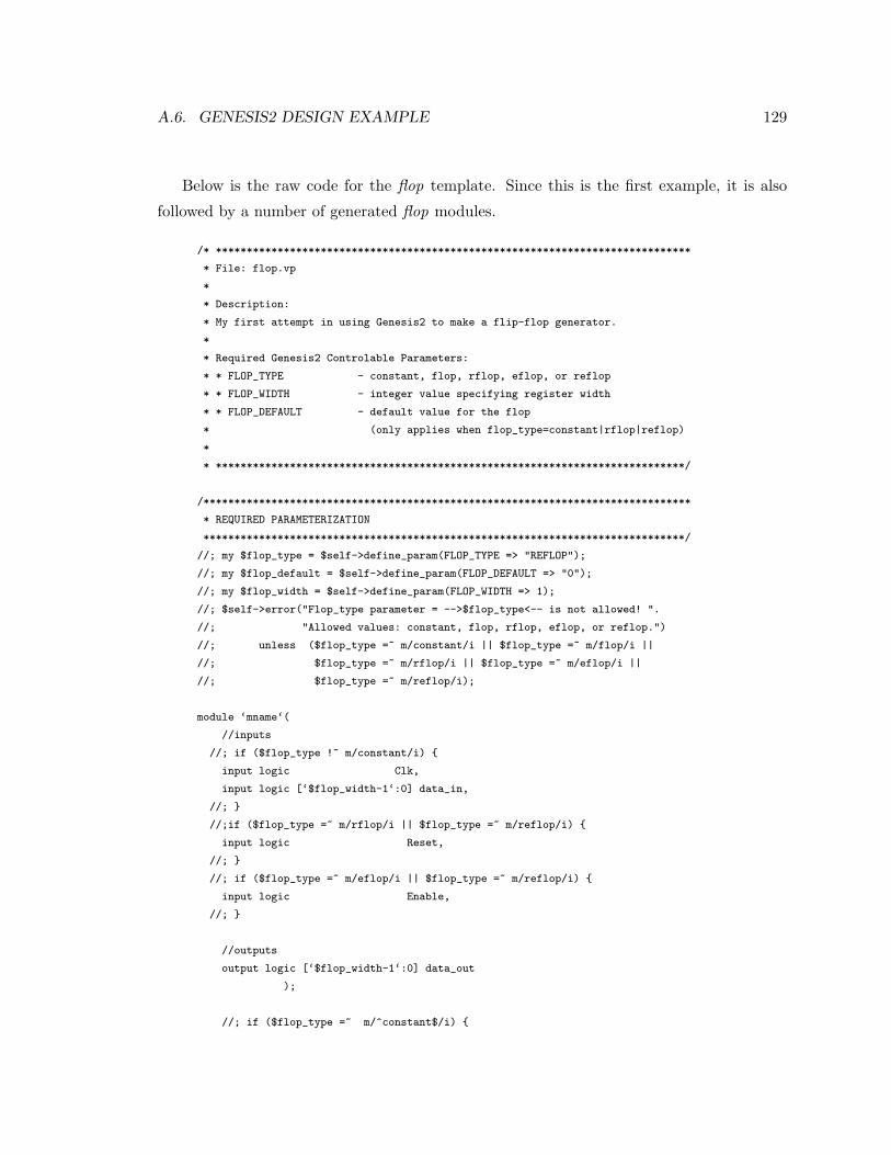
A.6. GENESIS2 DESIGN EXAMPLE 129
Below is the raw code for the flop template. Since this is the first example, it is also
followed by a number of generated flop modules.
/* *****************************************************************************
* File: flop.vp
*
* Description:
* My first attempt in using Genesis2 to make a flip-flop generator.
*
* Required Genesis2 Controlable Parameters:
* * FLOP_TYPE - constant, flop, rflop, eflop, or reflop
* * FLOP_WIDTH - integer value specifying register width
* * FLOP_DEFAULT - default value for the flop
* (only applies when flop_type=constant|rflop|reflop)
*
* ****************************************************************************/
/*******************************************************************************
* REQUIRED PARAMETERIZATION
******************************************************************************/
//; my $flop_type = $self->define_param(FLOP_TYPE => "REFLOP");
//; my $flop_default = $self->define_param(FLOP_DEFAULT => "0");
//; my $flop_width = $self->define_param(FLOP_WIDTH => 1);
//; $self->error("Flop_type parameter = -->$flop_type<-- is not allowed! ".
//; "Allowed values: constant, flop, rflop, eflop, or reflop.")
//; unless ($flop_type =~ m/constant/i || $flop_type =~ m/flop/i ||
//; $flop_type =~ m/rflop/i || $flop_type =~ m/eflop/i ||
//; $flop_type =~ m/reflop/i);
module ‘mname‘(
//inputs
//; if ($flop_type !~ m/constant/i) {
input logic Clk,
input logic [‘$flop_width-1‘:0] data_in,
//; }
//;if ($flop_type =~ m/rflop/i || $flop_type =~ m/reflop/i) {
input logic Reset,
//; }
//; if ($flop_type =~ m/eflop/i || $flop_type =~ m/reflop/i) {
input logic Enable,
//; }
//outputs
output logic [‘$flop_width-1‘:0] data_out
);
//; if ($flop_type =~ m/^constant$/i) {
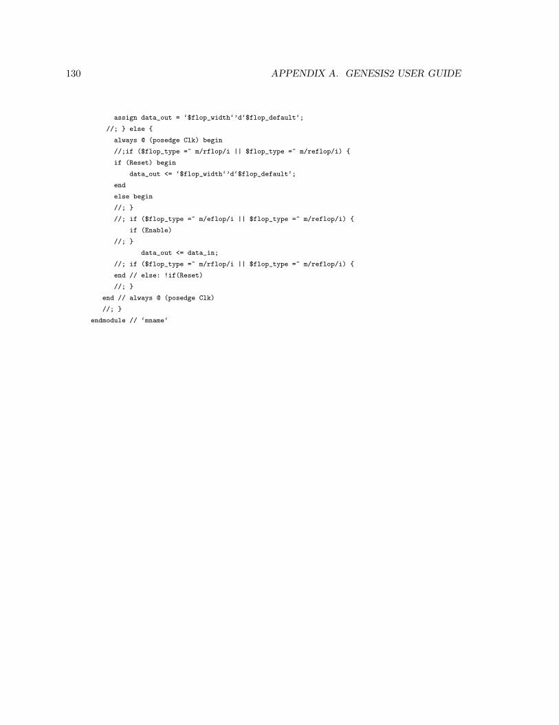
130 APPENDIX A. GENESIS2 USER GUIDE
assign data_out = ‘$flop_width‘’d‘$flop_default‘;
//; } else {
always @ (posedge Clk) begin
//;if ($flop_type =~ m/rflop/i || $flop_type =~ m/reflop/i) {
if (Reset) begin
data_out <= ‘$flop_width‘’d‘$flop_default‘;
end
else begin
//; }
//; if ($flop_type =~ m/eflop/i || $flop_type =~ m/reflop/i) {
if (Enable)
//; }
data_out <= data_in;
//; if ($flop_type =~ m/rflop/i || $flop_type =~ m/reflop/i) {
end // else: !if(Reset)
//; }
end // always @ (posedge Clk)
//; }
endmodule // ‘mname‘
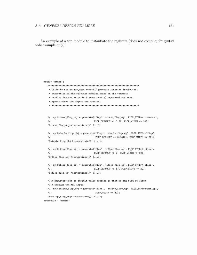
A.6. GENESIS2 DESIGN EXAMPLE 131
An example of a top module to instantiate the registers (does not compile; for syntaxcode example only):
module ‘mname‘;
/******************************************************************
* Calls to the unique_inst method / generate function invoke the
* generation of the relevant modules based on the template.
* Verilog instantiation is (intentionally) separated and must
* appear after the object was created.
* ***************************************************************/
//; my $const_flop_obj = generate(’flop’, ’const_flop_eg’, FLOP_TYPE=>’constant’,
//; FLOP_DEFAULT => 0xFF, FLOP_WIDTH => 32);
‘$const_flop_obj->instantiate()‘ (...);
//; my $simple_flop_obj = generate(’flop’, ’simple_flop_eg’, FLOP_TYPE=>’flop’,
//; FLOP_DEFAULT => 0b10101, FLOP_WIDTH => 32);
‘$simple_flop_obj->instantiate()‘ (...);
//; my $rflop_flop_obj = generate(’flop’, ’rflop_flop_eg’, FLOP_TYPE=>’rflop’,
//; FLOP_DEFAULT => 7, FLOP_WIDTH => 32);
‘$rflop_flop_obj->instantiate()‘ (...);
//; my $eflop_flop_obj = generate(’flop’, ’eflop_flop_eg’, FLOP_TYPE=>’eflop’,
//; FLOP_DEFAULT => 17, FLOP_WIDTH => 32);
‘$eflop_flop_obj->instantiate()‘ (...);
//;# Register with no default value binding so that we can bind it later
//;# through the XML input.
//; my $reflop_flop_obj = generate(’flop’, ’reflop_flop_eg’, FLOP_TYPE=>’reflop’,
//; FLOP_WIDTH => 32);
‘$reflop_flop_obj->instantiate()‘ (...);
endmodule : ‘mname‘
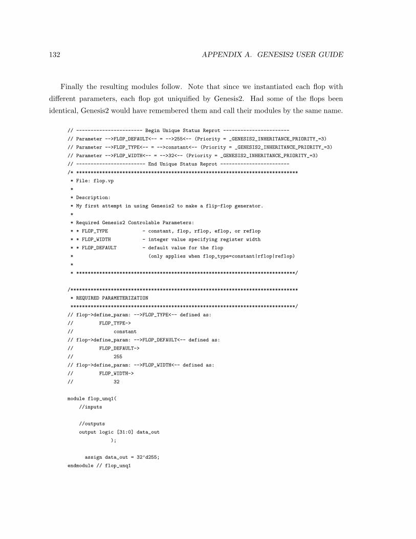
132 APPENDIX A. GENESIS2 USER GUIDE
Finally the resulting modules follow. Note that since we instantiated each flop with
different parameters, each flop got uniquified by Genesis2. Had some of the flops been
identical, Genesis2 would have remembered them and call their modules by the same name.
// ----------------------- Begin Unique Status Reprot -----------------------
// Parameter -->FLOP_DEFAULT<-- = -->255<-- (Priority = _GENESIS2_INHERITANCE_PRIORITY_=3)
// Parameter -->FLOP_TYPE<-- = -->constant<-- (Priority = _GENESIS2_INHERITANCE_PRIORITY_=3)
// Parameter -->FLOP_WIDTH<-- = -->32<-- (Priority = _GENESIS2_INHERITANCE_PRIORITY_=3)
// ------------------------ End Unique Status Reprot ------------------------
/* *****************************************************************************
* File: flop.vp
*
* Description:
* My first attempt in using Genesis2 to make a flip-flop generator.
*
* Required Genesis2 Controlable Parameters:
* * FLOP_TYPE - constant, flop, rflop, eflop, or reflop
* * FLOP_WIDTH - integer value specifying register width
* * FLOP_DEFAULT - default value for the flop
* (only applies when flop_type=constant|rflop|reflop)
*
* ****************************************************************************/
/*******************************************************************************
* REQUIRED PARAMETERIZATION
******************************************************************************/
// flop->define_param: -->FLOP_TYPE<-- defined as:
// FLOP_TYPE->
// constant
// flop->define_param: -->FLOP_DEFAULT<-- defined as:
// FLOP_DEFAULT->
// 255
// flop->define_param: -->FLOP_WIDTH<-- defined as:
// FLOP_WIDTH->
// 32
module flop_unq1(
//inputs
//outputs
output logic [31:0] data_out
);
assign data_out = 32’d255;
endmodule // flop_unq1
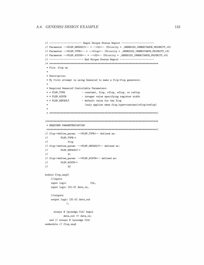
A.6. GENESIS2 DESIGN EXAMPLE 133
// ----------------------- Begin Unique Status Reprot -----------------------
// Parameter -->FLOP_DEFAULT<-- = -->21<-- (Priority = _GENESIS2_INHERITANCE_PRIORITY_=3)
// Parameter -->FLOP_TYPE<-- = -->flop<-- (Priority = _GENESIS2_INHERITANCE_PRIORITY_=3)
// Parameter -->FLOP_WIDTH<-- = -->32<-- (Priority = _GENESIS2_INHERITANCE_PRIORITY_=3)
// ------------------------ End Unique Status Reprot ------------------------
/* *****************************************************************************
* File: flop.vp
*
* Description:
* My first attempt in using Genesis2 to make a flip-flop generator.
*
* Required Genesis2 Controlable Parameters:
* * FLOP_TYPE - constant, flop, rflop, eflop, or reflop
* * FLOP_WIDTH - integer value specifying register width
* * FLOP_DEFAULT - default value for the flop
* (only applies when flop_type=constant|rflop|reflop)
*
* ****************************************************************************/
/*******************************************************************************
* REQUIRED PARAMETERIZATION
******************************************************************************/
// flop->define_param: -->FLOP_TYPE<-- defined as:
// FLOP_TYPE->
// flop
// flop->define_param: -->FLOP_DEFAULT<-- defined as:
// FLOP_DEFAULT->
// 21
// flop->define_param: -->FLOP_WIDTH<-- defined as:
// FLOP_WIDTH->
// 32
module flop_unq2(
//inputs
input logic Clk,
input logic [31:0] data_in,
//outputs
output logic [31:0] data_out
);
always @ (posedge Clk) begin
data_out <= data_in;
end // always @ (posedge Clk)
endmodule // flop_unq2
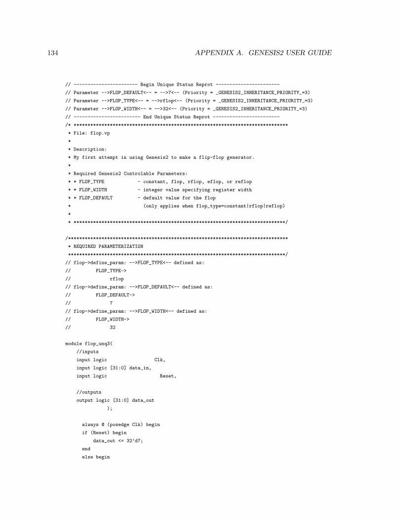
134 APPENDIX A. GENESIS2 USER GUIDE
// ----------------------- Begin Unique Status Reprot -----------------------
// Parameter -->FLOP_DEFAULT<-- = -->7<-- (Priority = _GENESIS2_INHERITANCE_PRIORITY_=3)
// Parameter -->FLOP_TYPE<-- = -->rflop<-- (Priority = _GENESIS2_INHERITANCE_PRIORITY_=3)
// Parameter -->FLOP_WIDTH<-- = -->32<-- (Priority = _GENESIS2_INHERITANCE_PRIORITY_=3)
// ------------------------ End Unique Status Reprot ------------------------
/* *****************************************************************************
* File: flop.vp
*
* Description:
* My first attempt in using Genesis2 to make a flip-flop generator.
*
* Required Genesis2 Controlable Parameters:
* * FLOP_TYPE - constant, flop, rflop, eflop, or reflop
* * FLOP_WIDTH - integer value specifying register width
* * FLOP_DEFAULT - default value for the flop
* (only applies when flop_type=constant|rflop|reflop)
*
* ****************************************************************************/
/*******************************************************************************
* REQUIRED PARAMETERIZATION
******************************************************************************/
// flop->define_param: -->FLOP_TYPE<-- defined as:
// FLOP_TYPE->
// rflop
// flop->define_param: -->FLOP_DEFAULT<-- defined as:
// FLOP_DEFAULT->
// 7
// flop->define_param: -->FLOP_WIDTH<-- defined as:
// FLOP_WIDTH->
// 32
module flop_unq3(
//inputs
input logic Clk,
input logic [31:0] data_in,
input logic Reset,
//outputs
output logic [31:0] data_out
);
always @ (posedge Clk) begin
if (Reset) begin
data_out <= 32’d7;
end
else begin

A.6. GENESIS2 DESIGN EXAMPLE 135
data_out <= data_in;
end // else: !if(Reset)
end // always @ (posedge Clk)
endmodule // flop_unq3
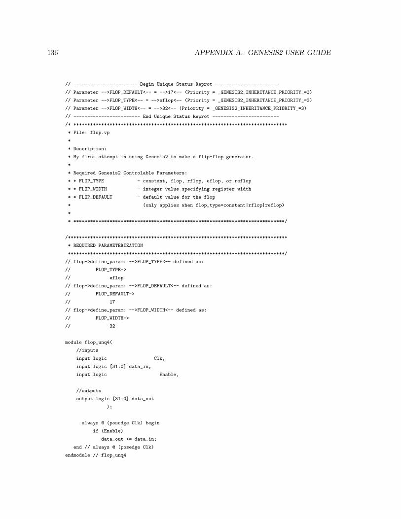
136 APPENDIX A. GENESIS2 USER GUIDE
// ----------------------- Begin Unique Status Reprot -----------------------
// Parameter -->FLOP_DEFAULT<-- = -->17<-- (Priority = _GENESIS2_INHERITANCE_PRIORITY_=3)
// Parameter -->FLOP_TYPE<-- = -->eflop<-- (Priority = _GENESIS2_INHERITANCE_PRIORITY_=3)
// Parameter -->FLOP_WIDTH<-- = -->32<-- (Priority = _GENESIS2_INHERITANCE_PRIORITY_=3)
// ------------------------ End Unique Status Reprot ------------------------
/* *****************************************************************************
* File: flop.vp
*
* Description:
* My first attempt in using Genesis2 to make a flip-flop generator.
*
* Required Genesis2 Controlable Parameters:
* * FLOP_TYPE - constant, flop, rflop, eflop, or reflop
* * FLOP_WIDTH - integer value specifying register width
* * FLOP_DEFAULT - default value for the flop
* (only applies when flop_type=constant|rflop|reflop)
*
* ****************************************************************************/
/*******************************************************************************
* REQUIRED PARAMETERIZATION
******************************************************************************/
// flop->define_param: -->FLOP_TYPE<-- defined as:
// FLOP_TYPE->
// eflop
// flop->define_param: -->FLOP_DEFAULT<-- defined as:
// FLOP_DEFAULT->
// 17
// flop->define_param: -->FLOP_WIDTH<-- defined as:
// FLOP_WIDTH->
// 32
module flop_unq4(
//inputs
input logic Clk,
input logic [31:0] data_in,
input logic Enable,
//outputs
output logic [31:0] data_out
);
always @ (posedge Clk) begin
if (Enable)
data_out <= data_in;
end // always @ (posedge Clk)
endmodule // flop_unq4
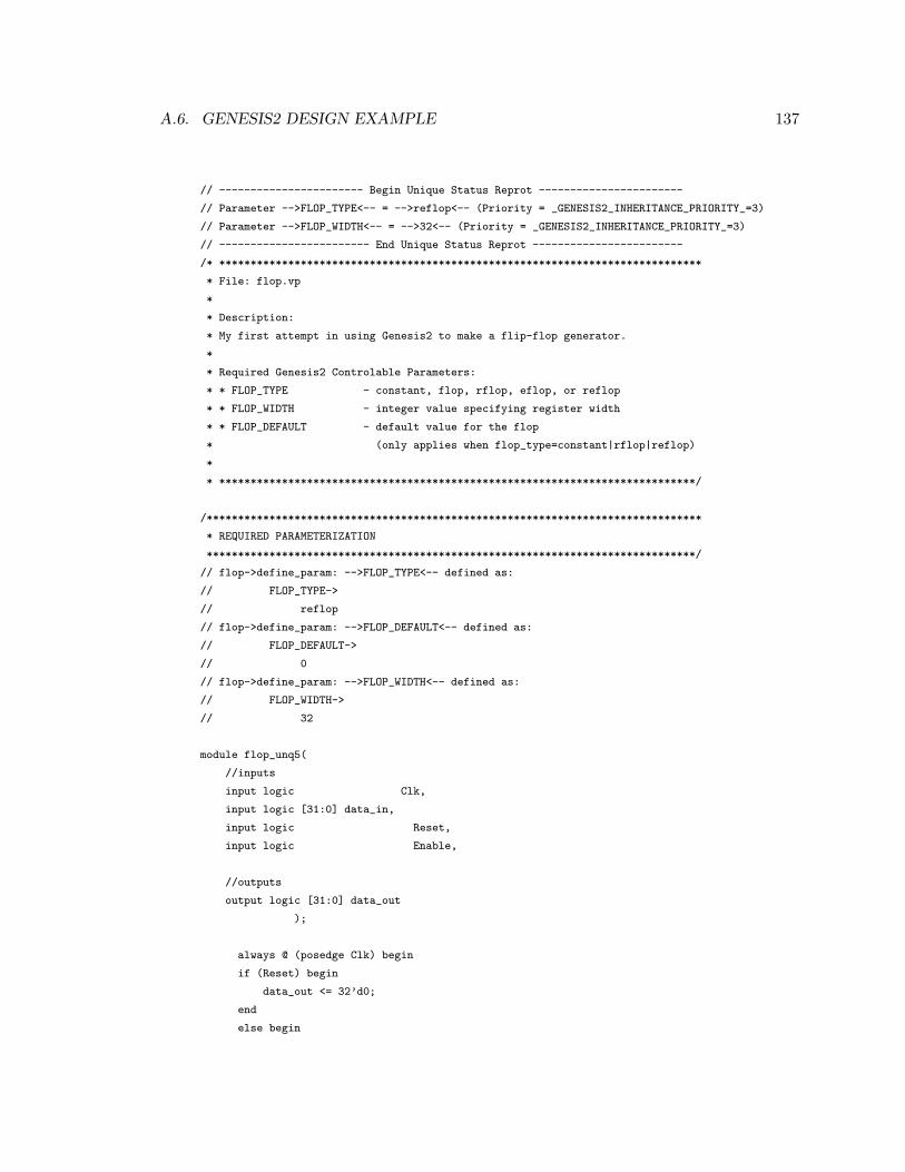
A.6. GENESIS2 DESIGN EXAMPLE 137
// ----------------------- Begin Unique Status Reprot -----------------------
// Parameter -->FLOP_TYPE<-- = -->reflop<-- (Priority = _GENESIS2_INHERITANCE_PRIORITY_=3)
// Parameter -->FLOP_WIDTH<-- = -->32<-- (Priority = _GENESIS2_INHERITANCE_PRIORITY_=3)
// ------------------------ End Unique Status Reprot ------------------------
/* *****************************************************************************
* File: flop.vp
*
* Description:
* My first attempt in using Genesis2 to make a flip-flop generator.
*
* Required Genesis2 Controlable Parameters:
* * FLOP_TYPE - constant, flop, rflop, eflop, or reflop
* * FLOP_WIDTH - integer value specifying register width
* * FLOP_DEFAULT - default value for the flop
* (only applies when flop_type=constant|rflop|reflop)
*
* ****************************************************************************/
/*******************************************************************************
* REQUIRED PARAMETERIZATION
******************************************************************************/
// flop->define_param: -->FLOP_TYPE<-- defined as:
// FLOP_TYPE->
// reflop
// flop->define_param: -->FLOP_DEFAULT<-- defined as:
// FLOP_DEFAULT->
// 0
// flop->define_param: -->FLOP_WIDTH<-- defined as:
// FLOP_WIDTH->
// 32
module flop_unq5(
//inputs
input logic Clk,
input logic [31:0] data_in,
input logic Reset,
input logic Enable,
//outputs
output logic [31:0] data_out
);
always @ (posedge Clk) begin
if (Reset) begin
data_out <= 32’d0;
end
else begin

138 APPENDIX A. GENESIS2 USER GUIDE
if (Enable)
data_out <= data_in;
end // else: !if(Reset)
end // always @ (posedge Clk)
endmodule // flop_unq5
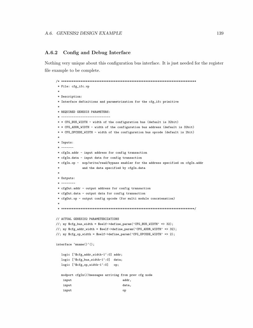
A.6. GENESIS2 DESIGN EXAMPLE 139
A.6.2 Config and Debug Interface
Nothing very unique about this configuration bus interface. It is just needed for the register
file example to be complete.
/* *****************************************************************************
* File: cfg_ifc.vp
*
* Description:
* Interface definitions and parametrization for the cfg_ifc primitive
*
* REQUIRED GENESIS PARAMETERS:
* ----------------------------
* * CFG_BUS_WIDTH - width of the configuration bus (default is 32bit)
* * CFG_ADDR_WIDTH - width of the configuration bus address (default is 32bit)
* * CFG_OPCODE_WIDTH - width of the configuration bus opcode (default is 2bit)
*
* Inputs:
* -------
* cfgIn.addr - input address for config transaction
* cfgIn.data - input data for config transaction
* cfgIn.op - nop/write/read/bypass enabler for the address specified on cfgIn.addr
* and the data specified by cfgIn.data
*
* Outputs:
* --------
* cfgOut.addr - output address for config transaction
* cfgOut.data - output data for config transaction
* cfgOut.op - output config opcode (for multi module concatenation)
*
* ****************************************************************************/
// ACTUAL GENESIS2 PARAMETERIZATIONS
//; my $cfg_bus_width = $self->define_param(’CFG_BUS_WIDTH’ => 32);
//; my $cfg_addr_width = $self->define_param(’CFG_ADDR_WIDTH’ => 32);
//; my $cfg_op_width = $self->define_param(’CFG_OPCODE_WIDTH’ => 2);
interface ‘mname()‘();
logic [‘$cfg_addr_width-1‘:0] addr;
logic [‘$cfg_bus_width-1‘:0] data;
logic [‘$cfg_op_width-1‘:0] op;
modport cfgIn(//messages arriving from prev cfg node
input addr,
input data,
input op
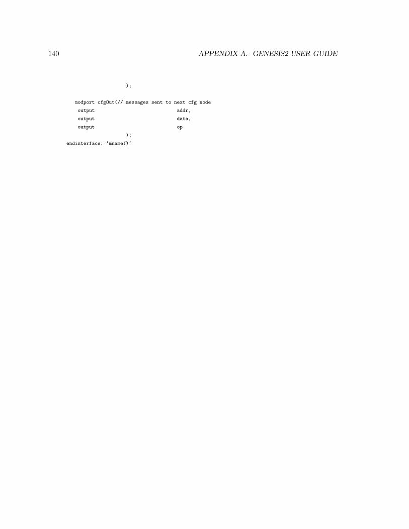
140 APPENDIX A. GENESIS2 USER GUIDE
);
modport cfgOut(// messages sent to next cfg node
output addr,
output data,
output op
);
endinterface: ‘mname()‘
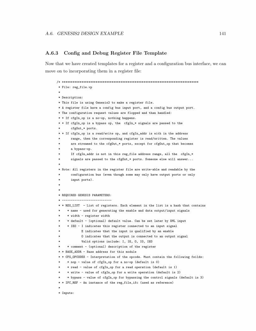
A.6. GENESIS2 DESIGN EXAMPLE 141
A.6.3 Config and Debug Register File Template
Now that we have created templates for a register and a configuration bus interface, we can
move on to incorporating them in a register file:
/* *****************************************************************************
* File: reg_file.vp
*
* Description:
* This file is using Genesis2 to make a register file.
* A register file have a config bus input port, and a config bus output port.
* The configuration request values are flopped and than handled:
* * If cfgIn_op is a no-op, nothing happens.
* * If cfgIn_op is a bypass op, the cfgIn_* signals are passed to the
* cfgOut_* ports.
* * If cfgIn_op is a read/write op, and cfgIn_addr is with in the address
* range, then the corresponding register is read/written. The values
* are streamed to the cfgOut_* ports, except for cfgOut_op that becomes
* a bypass-op.
* If cfgIn_addr is not in this reg_file address range, all the cfgIn_*
* signals are passed to the cfgOut_* ports. Someone else will answer...
*
* Note: All registers in the register file are write-able and readable by the
* configuration bus (even though some may only have output ports or only
* input ports).
*
*
* REQUIRED GENESIS PARAMETERS:
* ----------------------------
* * REG_LIST - List of registers. Each element in the list is a hash that contains
* * name - used for generating the enable and data output/input signals
* * width - register width
* * default - (optional) default value. Can be set later by XML input
* * IEO - I indicates this register connected to an input signal
* E indicates that the input is qualified by an enable
* O indicates that the output is connected to an output signal
* Valid options include: I, IE, O, IO, IEO
* * comment - (optional) description of the register
* * BASE_ADDR - Base address for this module
* * CFG_OPCODES - Interpretation of the opcode. Must contain the following feilds:
* * nop - value of cfgIn_op for a no-op (default is 0)
* * read - value of cfgIn_op for a read operation (default is 1)
* * write - value of cfgIn_op for a write operation (default is 2)
* * bypass - value of cfgIn_op for bypassing the control signals (default is 3)
* * IFC_REF - An instance of the reg_file_ifc (used as reference)
*
* Inputs:

142 APPENDIX A. GENESIS2 USER GUIDE
* -------
* Clk
* Reset
* cfgIn - Incomming config request
* foreach REG in REG_LIST (but depending on the IEO flag):
* * <REG.name>_en - enable signal for the register
* * <REG.name>_d - data input for the register
*
* Outputs:
* --------
* cfgOut - Outgoing reply for config request cfgIn
* foreach REG in REG_LIST (but depending on the IEO flag):
* * <REG.name>_q - data output for the register
*
*
* NOTE: registers with input from the design may become resource contention
* if both their private enable and their by-address enable signals are raised.
* Priority is always given to data from the cfg bus!
*
* ****************************************************************************/
//; # Perl Libraries
//; use POSIX;
//;
//;
// ACTUAL GENESIS2 PARAMETERIZATIONS
//; my $reg_list = $self->define_param(REG_LIST => [
//; {name => ’regA’, width => 5, default => 17, IEO => ’ie’, comment => ’this is a reg’},
//; {name => ’regB’, width => 10, default => 27, IEO => ’o’},
//; {name => ’regC’, width => 15, IEO => ’ieo’},
//; {name => ’regD’, width => 13, default => 4, IEO => ’i’},
//; ]);
//; my $num_regs = scalar(@{$reg_list});
//; my $base_addr = $self->define_param(’BASE_ADDR’ => 0);
//; my $cfg_ops = $self->define_param(’CFG_OPCODES’ => {nop=>0, read=>1, write=>2, bypass=>3});
//; my $ifc_ref = $self->define_param(IFC_REF => ’’);
//; $self->error("Missing parameter: IFC_REF") if ($ifc_ref eq ’’);
//;
//; # Extract paramteres from the interdace
//; my $cfgIn_ifc_obj = clone($ifc_ref, ’cfgIn’);
//; my $cfgOut_ifc_obj = clone($ifc_ref, ’cfgOut’);
//; my $cfg_bus_width = $cfgIn_ifc_obj->get_param(’CFG_BUS_WIDTH’);
//; my $cfg_addr_width = $cfgIn_ifc_obj->get_param(’CFG_ADDR_WIDTH’);
//; my $cfg_op_width = $cfgIn_ifc_obj->get_param(’CFG_OPCODE_WIDTH’);
//;
//;
//;# Verify correctness of register parameters:
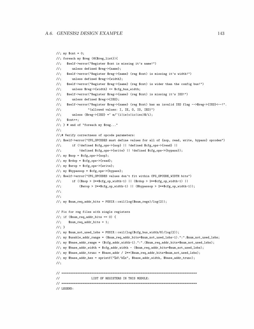
A.6. GENESIS2 DESIGN EXAMPLE 143
//; my $cnt = 0;
//; foreach my $reg (@{$reg_list}){
//; $self->error("Register $cnt is missing it’s name!")
//; unless defined $reg->{name};
//; $self->error("Register $reg->{name} (reg $cnt) is missing it’s width!")
//; unless defined $reg->{width};
//; $self->error("Register $reg->{name} (reg $cnt) is wider than the config bus!")
//; unless $reg->{width} <= $cfg_bus_width;
//; $self->error("Register $reg->{name} (reg $cnt) is missing it’s IEO!")
//; unless defined $reg->{IEO};
//; $self->error("Register $reg->{name} (reg $cnt) has an invalid IEO flag -->$reg->{IEO}<--!".
//; "(allowed values: I, IE, O, IO, IEO)")
//; unless ($reg->{IEO} =~ m/^(i|ie|o|io|ieo)$/i);
//; $cnt++;
//; } # end of "foreach my $reg..."
//;
//;# Verify correctness of opcode parameters:
//; $self->error("CFG_OPCODES must define values for all of {nop, read, write, bypass} opcodes")
//; if (!defined $cfg_ops->{nop} || !defined $cfg_ops->{read} ||
//; !defined $cfg_ops->{write} || !defined $cfg_ops->{bypass});
//; my $nop = $cfg_ops->{nop};
//; my $rdop = $cfg_ops->{read};
//; my $wrop = $cfg_ops->{write};
//; my $bypassop = $cfg_ops->{bypass};
//; $self->error("CFG_OPCODES values don’t fit within CFG_OPCODE_WIDTH bits")
//; if (($nop > 2**$cfg_op_width-1) || ($rdop > 2**$cfg_op_width-1) ||
//; ($wrop > 2**$cfg_op_width-1) || ($bypassop > 2**$cfg_op_width-1));
//;
//;
//; my $num_req_addr_bits = POSIX::ceil(log($num_regs)/log(2));
// Fix for reg files with single registers
//; if ($num_req_addr_bits == 0) {
//; $num_req_addr_bits = 1;
//; }
//; my $num_not_used_lsbs = POSIX::ceil(log($cfg_bus_width/8)/log(2));
//; my $usable_addr_range = ($num_req_addr_bits+$num_not_used_lsbs-1).":".$num_not_used_lsbs;
//; my $base_addr_range = ($cfg_addr_width-1).":".($num_req_addr_bits+$num_not_used_lsbs);
//; my $base_addr_width = $cfg_addr_width - ($num_req_addr_bits+$num_not_used_lsbs);
//; my $base_addr_trunc = $base_addr / 2**($num_req_addr_bits+$num_not_used_lsbs);
//; my $base_addr_hex = sprintf("%d\’h%x", $base_addr_width, $base_addr_trunc);
//;
// =============================================================================
// LIST OF REGISTERS IN THIS MODULE:
// =============================================================================
// LEGEND:
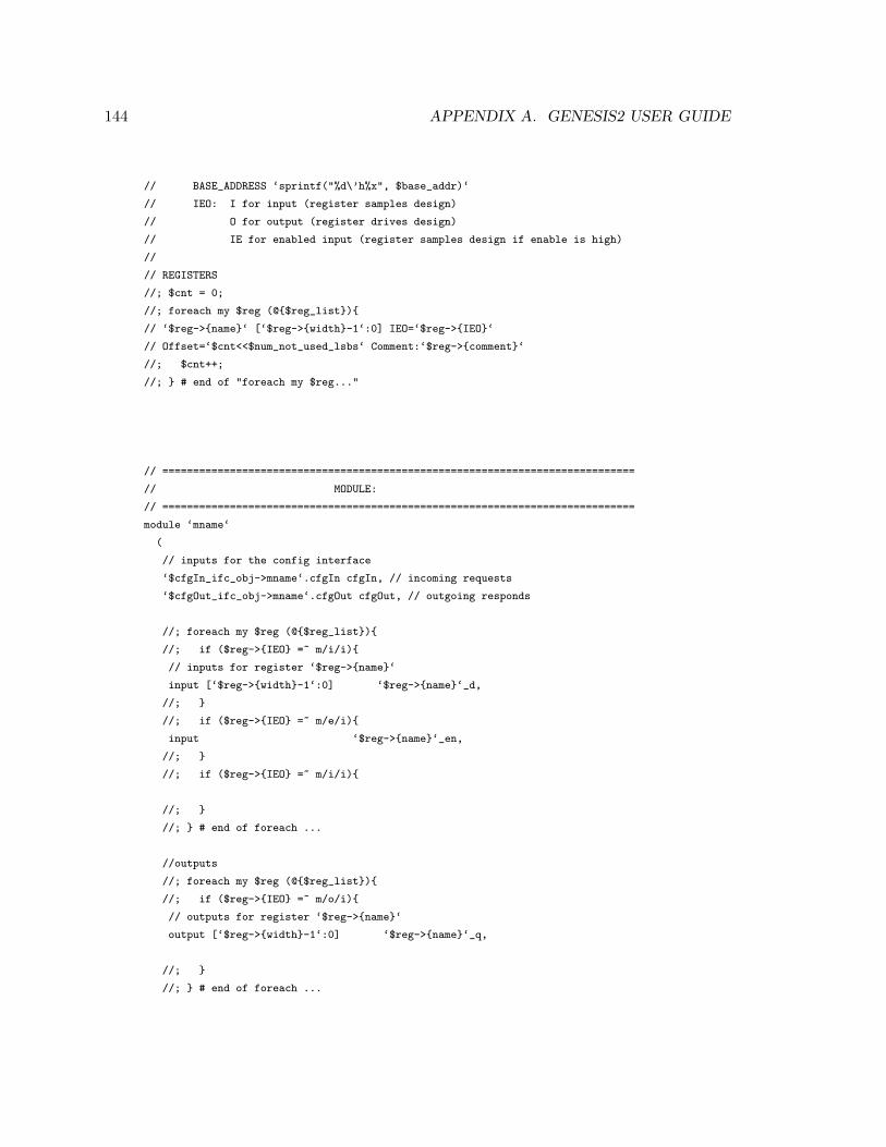
144 APPENDIX A. GENESIS2 USER GUIDE
// BASE_ADDRESS ‘sprintf("%d\’h%x", $base_addr)‘
// IEO: I for input (register samples design)
// O for output (register drives design)
// IE for enabled input (register samples design if enable is high)
//
// REGISTERS
//; $cnt = 0;
//; foreach my $reg (@{$reg_list}){
// ‘$reg->{name}‘ [‘$reg->{width}-1‘:0] IEO=‘$reg->{IEO}‘
// Offset=‘$cnt<<$num_not_used_lsbs‘ Comment:‘$reg->{comment}‘
//; $cnt++;
//; } # end of "foreach my $reg..."
// =============================================================================
// MODULE:
// =============================================================================
module ‘mname‘
(
// inputs for the config interface
‘$cfgIn_ifc_obj->mname‘.cfgIn cfgIn, // incoming requests
‘$cfgOut_ifc_obj->mname‘.cfgOut cfgOut, // outgoing responds
//; foreach my $reg (@{$reg_list}){
//; if ($reg->{IEO} =~ m/i/i){
// inputs for register ‘$reg->{name}‘
input [‘$reg->{width}-1‘:0] ‘$reg->{name}‘_d,
//; }
//; if ($reg->{IEO} =~ m/e/i){
input ‘$reg->{name}‘_en,
//; }
//; if ($reg->{IEO} =~ m/i/i){
//; }
//; } # end of foreach ...
//outputs
//; foreach my $reg (@{$reg_list}){
//; if ($reg->{IEO} =~ m/o/i){
// outputs for register ‘$reg->{name}‘
output [‘$reg->{width}-1‘:0] ‘$reg->{name}‘_q,
//; }
//; } # end of foreach ...
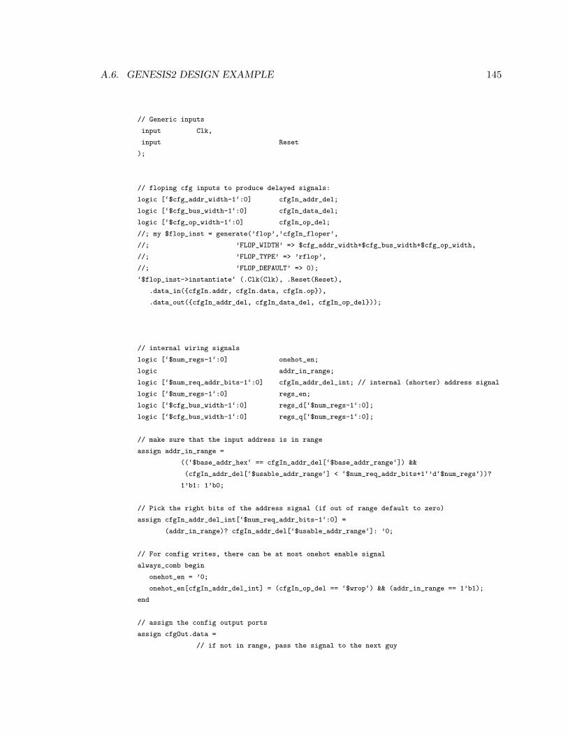
A.6. GENESIS2 DESIGN EXAMPLE 145
// Generic inputs
input Clk,
input Reset
);
// floping cfg inputs to produce delayed signals:
logic [‘$cfg_addr_width-1‘:0] cfgIn_addr_del;
logic [‘$cfg_bus_width-1‘:0] cfgIn_data_del;
logic [‘$cfg_op_width-1‘:0] cfgIn_op_del;
//; my $flop_inst = generate(’flop’,’cfgIn_floper’,
//; ’FLOP_WIDTH’ => $cfg_addr_width+$cfg_bus_width+$cfg_op_width,
//; ’FLOP_TYPE’ => ’rflop’,
//; ’FLOP_DEFAULT’ => 0);
‘$flop_inst->instantiate‘ (.Clk(Clk), .Reset(Reset),
.data_in({cfgIn.addr, cfgIn.data, cfgIn.op}),
.data_out({cfgIn_addr_del, cfgIn_data_del, cfgIn_op_del}));
// internal wiring signals
logic [‘$num_regs-1‘:0] onehot_en;
logic addr_in_range;
logic [‘$num_req_addr_bits-1‘:0] cfgIn_addr_del_int; // internal (shorter) address signal
logic [‘$num_regs-1‘:0] regs_en;
logic [‘$cfg_bus_width-1‘:0] regs_d[‘$num_regs-1‘:0];
logic [‘$cfg_bus_width-1‘:0] regs_q[‘$num_regs-1‘:0];
// make sure that the input address is in range
assign addr_in_range =
((‘$base_addr_hex‘ == cfgIn_addr_del[‘$base_addr_range‘]) &&
(cfgIn_addr_del[‘$usable_addr_range‘] < ‘$num_req_addr_bits+1‘’d‘$num_regs‘))?
1’b1: 1’b0;
// Pick the right bits of the address signal (if out of range default to zero)
assign cfgIn_addr_del_int[‘$num_req_addr_bits-1‘:0] =
(addr_in_range)? cfgIn_addr_del[‘$usable_addr_range‘]: ’0;
// For config writes, there can be at most onehot enable signal
always_comb begin
onehot_en = ’0;
onehot_en[cfgIn_addr_del_int] = (cfgIn_op_del == ‘$wrop‘) && (addr_in_range == 1’b1);
end
// assign the config output ports
assign cfgOut.data =
// if not in range, pass the signal to the next guy
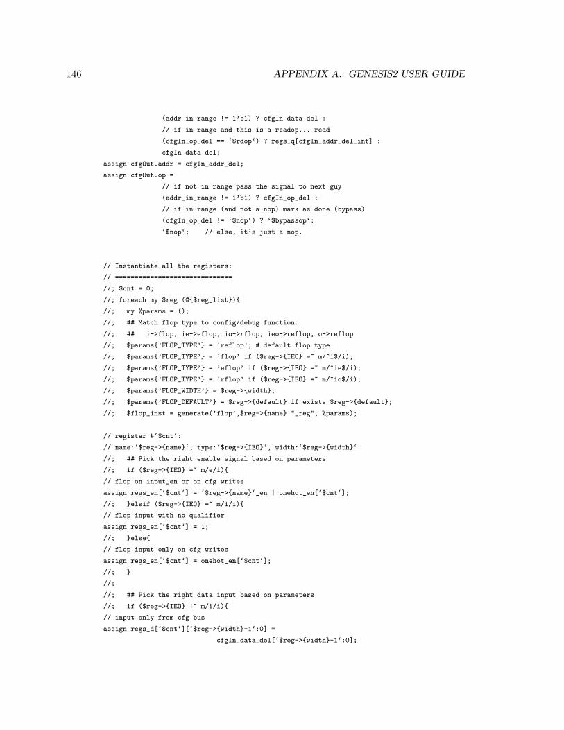
146 APPENDIX A. GENESIS2 USER GUIDE
(addr_in_range != 1’b1) ? cfgIn_data_del :
// if in range and this is a readop... read
(cfgIn_op_del == ‘$rdop‘) ? regs_q[cfgIn_addr_del_int] :
cfgIn_data_del;
assign cfgOut.addr = cfgIn_addr_del;
assign cfgOut.op =
// if not in range pass the signal to next guy
(addr_in_range != 1’b1) ? cfgIn_op_del :
// if in range (and not a nop) mark as done (bypass)
(cfgIn_op_del != ‘$nop‘) ? ‘$bypassop‘:
‘$nop‘; // else, it’s just a nop.
// Instantiate all the registers:
// ==============================
//; $cnt = 0;
//; foreach my $reg (@{$reg_list}){
//; my %params = ();
//; ## Match flop type to config/debug function:
//; ## i->flop, ie->eflop, io->rflop, ieo->reflop, o->reflop
//; $params{’FLOP_TYPE’} = ’reflop’; # default flop type
//; $params{’FLOP_TYPE’} = ’flop’ if ($reg->{IEO} =~ m/^i$/i);
//; $params{’FLOP_TYPE’} = ’eflop’ if ($reg->{IEO} =~ m/^ie$/i);
//; $params{’FLOP_TYPE’} = ’rflop’ if ($reg->{IEO} =~ m/^io$/i);
//; $params{’FLOP_WIDTH’} = $reg->{width};
//; $params{’FLOP_DEFAULT’} = $reg->{default} if exists $reg->{default};
//; $flop_inst = generate(’flop’,$reg->{name}."_reg", %params);
// register #‘$cnt‘:
// name:‘$reg->{name}‘, type:‘$reg->{IEO}‘, width:‘$reg->{width}‘
//; ## Pick the right enable signal based on parameters
//; if ($reg->{IEO} =~ m/e/i){
// flop on input_en or on cfg writes
assign regs_en[‘$cnt‘] = ‘$reg->{name}‘_en | onehot_en[‘$cnt‘];
//; }elsif ($reg->{IEO} =~ m/i/i){
// flop input with no qualifier
assign regs_en[‘$cnt‘] = 1;
//; }else{
// flop input only on cfg writes
assign regs_en[‘$cnt‘] = onehot_en[‘$cnt‘];
//; }
//;
//; ## Pick the right data input based on parameters
//; if ($reg->{IEO} !~ m/i/i){
// input only from cfg bus
assign regs_d[‘$cnt‘][‘$reg->{width}-1‘:0] =
cfgIn_data_del[‘$reg->{width}-1‘:0];
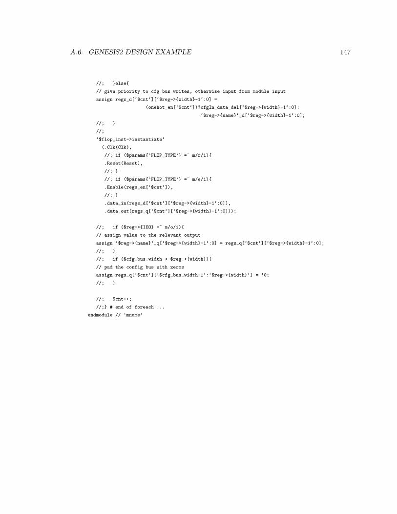
A.6. GENESIS2 DESIGN EXAMPLE 147
//; }else{
// give priority to cfg bus writes, otherwise input from module input
assign regs_d[‘$cnt‘][‘$reg->{width}-1‘:0] =
(onehot_en[‘$cnt‘])?cfgIn_data_del[‘$reg->{width}-1‘:0]:
‘$reg->{name}‘_d[‘$reg->{width}-1‘:0];
//; }
//;
‘$flop_inst->instantiate‘
(.Clk(Clk),
//; if ($params{’FLOP_TYPE’} =~ m/r/i){
.Reset(Reset),
//; }
//; if ($params{’FLOP_TYPE’} =~ m/e/i){
.Enable(regs_en[‘$cnt‘]),
//; }
.data_in(regs_d[‘$cnt‘][‘$reg->{width}-1‘:0]),
.data_out(regs_q[‘$cnt‘][‘$reg->{width}-1‘:0]));
//; if ($reg->{IEO} =~ m/o/i){
// assign value to the relevant output
assign ‘$reg->{name}‘_q[‘$reg->{width}-1‘:0] = regs_q[‘$cnt‘][‘$reg->{width}-1‘:0];
//; }
//; if ($cfg_bus_width > $reg->{width}){
// pad the config bus with zeros
assign regs_q[‘$cnt‘][‘$cfg_bus_width-1‘:‘$reg->{width}‘] = ’0;
//; }
//; $cnt++;
//;} # end of foreach ...
endmodule // ‘mname‘

148 APPENDIX A. GENESIS2 USER GUIDE
Now let’s consider the following top module that instantiate two seemingly identical
register files. Note that this module does not really do anything useful and is used for the
purpuse of demonstration only. Having said that, this Genesis2’s template does compile
and does generate legal Verilog code:
/******************************************************************
* File: top.vp
* Simple top level that instantiates two register files
*****************************************************************/
module ‘mname‘();
/******************************************************************
* Calls to the unique_inst method generate function invoke the
* generation of the relevant modules based on the template.
* Verilog instantiation is (intentionally) separated and must
* appear after the object was created.
* ***************************************************************/
// First, for the sake of this example,
// let’s assume that these are the signals we care about:
logic [31:0] DataOut1;
logic [7:0] Status1;
logic [31:0] DataIn1;
logic DataRdy1; // qualifier for DataIn
logic SoftReset1;
logic [31:0] DataOut2;
logic [7:0] Status2;
logic [31:0] DataIn2;
logic DataRdy2; // qualifier for DataIn
logic SoftReset2;
// And also some generic wires
logic Clk;
logic Reset;
// Config interfaces to connect to/from the register files:
// For this example, we generate one and then clone it multiple times.
// We could have also easily just generate it with the same parameters
// which would have yielded the same results.
//
//; # Create the cfg interface object
//; my $tst_rf1_cfg_ifc_obj = generate(’cfg_ifc’, ’tst_rf1_cfg_ifc’,
//; CFG_BUS_WIDTH => 32,
//; CFG_ADDR_WIDTH => 32,
//; CFG_OPCODE_WIDTH => 2 );
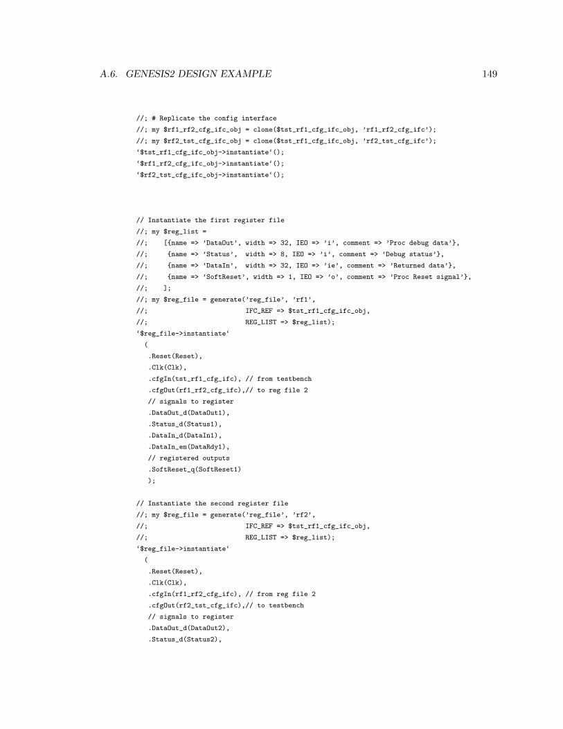
A.6. GENESIS2 DESIGN EXAMPLE 149
//; # Replicate the config interface
//; my $rf1_rf2_cfg_ifc_obj = clone($tst_rf1_cfg_ifc_obj, ’rf1_rf2_cfg_ifc’);
//; my $rf2_tst_cfg_ifc_obj = clone($tst_rf1_cfg_ifc_obj, ’rf2_tst_cfg_ifc’);
‘$tst_rf1_cfg_ifc_obj->instantiate‘();
‘$rf1_rf2_cfg_ifc_obj->instantiate‘();
‘$rf2_tst_cfg_ifc_obj->instantiate‘();
// Instantiate the first register file
//; my $reg_list =
//; [{name => ’DataOut’, width => 32, IEO => ’i’, comment => ’Proc debug data’},
//; {name => ’Status’, width => 8, IEO => ’i’, comment => ’Debug status’},
//; {name => ’DataIn’, width => 32, IEO => ’ie’, comment => ’Returned data’},
//; {name => ’SoftReset’, width => 1, IEO => ’o’, comment => ’Proc Reset signal’},
//; ];
//; my $reg_file = generate(’reg_file’, ’rf1’,
//; IFC_REF => $tst_rf1_cfg_ifc_obj,
//; REG_LIST => $reg_list);
‘$reg_file->instantiate‘
(
.Reset(Reset),
.Clk(Clk),
.cfgIn(tst_rf1_cfg_ifc), // from testbench
.cfgOut(rf1_rf2_cfg_ifc),// to reg file 2
// signals to register
.DataOut_d(DataOut1),
.Status_d(Status1),
.DataIn_d(DataIn1),
.DataIn_en(DataRdy1),
// registered outputs
.SoftReset_q(SoftReset1)
);
// Instantiate the second register file
//; my $reg_file = generate(’reg_file’, ’rf2’,
//; IFC_REF => $tst_rf1_cfg_ifc_obj,
//; REG_LIST => $reg_list);
‘$reg_file->instantiate‘
(
.Reset(Reset),
.Clk(Clk),
.cfgIn(rf1_rf2_cfg_ifc), // from reg file 2
.cfgOut(rf2_tst_cfg_ifc),// to testbench
// signals to register
.DataOut_d(DataOut2),
.Status_d(Status2),

150 APPENDIX A. GENESIS2 USER GUIDE
.DataIn_d(DataIn2),
.DataIn_en(DataRdy2),
// registered outputs
.SoftReset_q(SoftReset2)
);
endmodule // ‘mname‘
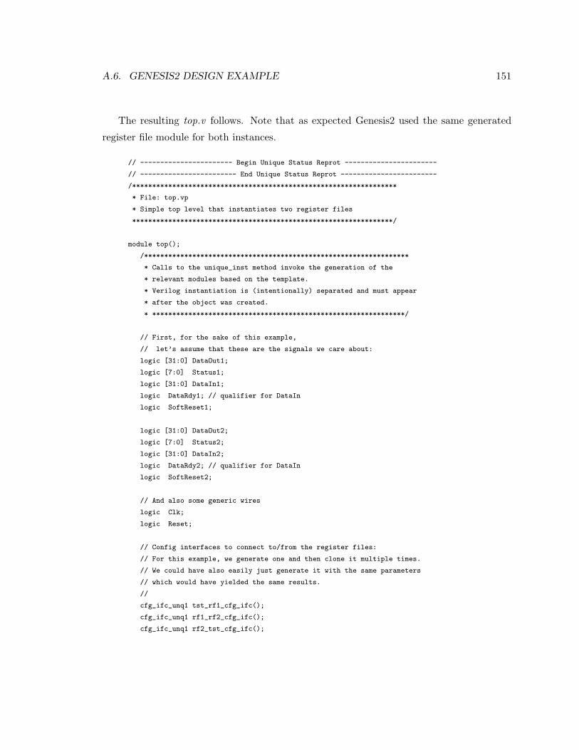
A.6. GENESIS2 DESIGN EXAMPLE 151
The resulting top.v follows. Note that as expected Genesis2 used the same generated
register file module for both instances.
// ----------------------- Begin Unique Status Reprot -----------------------
// ------------------------ End Unique Status Reprot ------------------------
/******************************************************************
* File: top.vp
* Simple top level that instantiates two register files
*****************************************************************/
module top();
/******************************************************************
* Calls to the unique_inst method invoke the generation of the
* relevant modules based on the template.
* Verilog instantiation is (intentionally) separated and must appear
* after the object was created.
* ***************************************************************/
// First, for the sake of this example,
// let’s assume that these are the signals we care about:
logic [31:0] DataOut1;
logic [7:0] Status1;
logic [31:0] DataIn1;
logic DataRdy1; // qualifier for DataIn
logic SoftReset1;
logic [31:0] DataOut2;
logic [7:0] Status2;
logic [31:0] DataIn2;
logic DataRdy2; // qualifier for DataIn
logic SoftReset2;
// And also some generic wires
logic Clk;
logic Reset;
// Config interfaces to connect to/from the register files:
// For this example, we generate one and then clone it multiple times.
// We could have also easily just generate it with the same parameters
// which would have yielded the same results.
//
cfg_ifc_unq1 tst_rf1_cfg_ifc();
cfg_ifc_unq1 rf1_rf2_cfg_ifc();
cfg_ifc_unq1 rf2_tst_cfg_ifc();
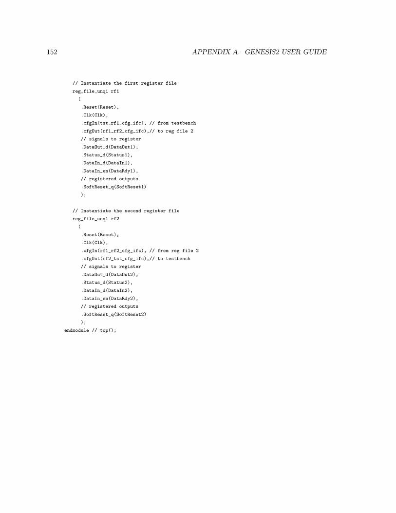
152 APPENDIX A. GENESIS2 USER GUIDE
// Instantiate the first register file
reg_file_unq1 rf1
(
.Reset(Reset),
.Clk(Clk),
.cfgIn(tst_rf1_cfg_ifc), // from testbench
.cfgOut(rf1_rf2_cfg_ifc),// to reg file 2
// signals to register
.DataOut_d(DataOut1),
.Status_d(Status1),
.DataIn_d(DataIn1),
.DataIn_en(DataRdy1),
// registered outputs
.SoftReset_q(SoftReset1)
);
// Instantiate the second register file
reg_file_unq1 rf2
(
.Reset(Reset),
.Clk(Clk),
.cfgIn(rf1_rf2_cfg_ifc), // from reg file 2
.cfgOut(rf2_tst_cfg_ifc),// to testbench
// signals to register
.DataOut_d(DataOut2),
.Status_d(Status2),
.DataIn_d(DataIn2),
.DataIn_en(DataRdy2),
// registered outputs
.SoftReset_q(SoftReset2)
);
endmodule // top();
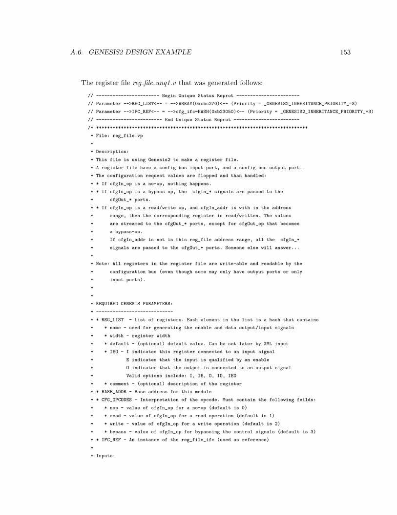
A.6. GENESIS2 DESIGN EXAMPLE 153
The register file reg file unq1.v that was generated follows:
// ----------------------- Begin Unique Status Reprot -----------------------
// Parameter -->REG_LIST<-- = -->ARRAY(0xcbc270)<-- (Priority = _GENESIS2_INHERITANCE_PRIORITY_=3)
// Parameter -->IFC_REF<-- = -->cfg_ifc=HASH(0xb23050)<-- (Priority = _GENESIS2_INHERITANCE_PRIORITY_=3)
// ------------------------ End Unique Status Reprot ------------------------
/* *****************************************************************************
* File: reg_file.vp
*
* Description:
* This file is using Genesis2 to make a register file.
* A register file have a config bus input port, and a config bus output port.
* The configuration request values are flopped and than handled:
* * If cfgIn_op is a no-op, nothing happens.
* * If cfgIn_op is a bypass op, the cfgIn_* signals are passed to the
* cfgOut_* ports.
* * If cfgIn_op is a read/write op, and cfgIn_addr is with in the address
* range, then the corresponding register is read/written. The values
* are streamed to the cfgOut_* ports, except for cfgOut_op that becomes
* a bypass-op.
* If cfgIn_addr is not in this reg_file address range, all the cfgIn_*
* signals are passed to the cfgOut_* ports. Someone else will answer...
*
* Note: All registers in the register file are write-able and readable by the
* configuration bus (even though some may only have output ports or only
* input ports).
*
*
* REQUIRED GENESIS PARAMETERS:
* ----------------------------
* * REG_LIST - List of registers. Each element in the list is a hash that contains
* * name - used for generating the enable and data output/input signals
* * width - register width
* * default - (optional) default value. Can be set later by XML input
* * IEO - I indicates this register connected to an input signal
* E indicates that the input is qualified by an enable
* O indicates that the output is connected to an output signal
* Valid options include: I, IE, O, IO, IEO
* * comment - (optional) description of the register
* * BASE_ADDR - Base address for this module
* * CFG_OPCODES - Interpretation of the opcode. Must contain the following feilds:
* * nop - value of cfgIn_op for a no-op (default is 0)
* * read - value of cfgIn_op for a read operation (default is 1)
* * write - value of cfgIn_op for a write operation (default is 2)
* * bypass - value of cfgIn_op for bypassing the control signals (default is 3)
* * IFC_REF - An instance of the reg_file_ifc (used as reference)
*
* Inputs:
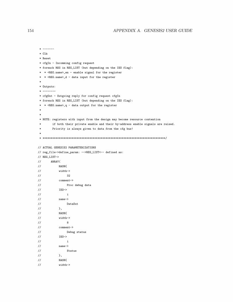
154 APPENDIX A. GENESIS2 USER GUIDE
* -------
* Clk
* Reset
* cfgIn - Incomming config request
* foreach REG in REG_LIST (but depending on the IEO flag):
* * <REG.name>_en - enable signal for the register
* * <REG.name>_d - data input for the register
*
* Outputs:
* --------
* cfgOut - Outgoing reply for config request cfgIn
* foreach REG in REG_LIST (but depending on the IEO flag):
* * <REG.name>_q - data output for the register
*
*
* NOTE: registers with input from the design may become resource contention
* if both their private enable and their by-address enable signals are raised.
* Priority is always given to data from the cfg bus!
*
* ****************************************************************************/
// ACTUAL GENESIS2 PARAMETERIZATIONS
// reg_file->define_param: -->REG_LIST<-- defined as:
// REG_LIST->
// ARRAY(
// HASH{
// width->
// 32
// comment->
// Proc debug data
// IEO->
// i
// name->
// DataOut
// },
// HASH{
// width->
// 8
// comment->
// Debug status
// IEO->
// i
// name->
// Status
// },
// HASH{
// width->
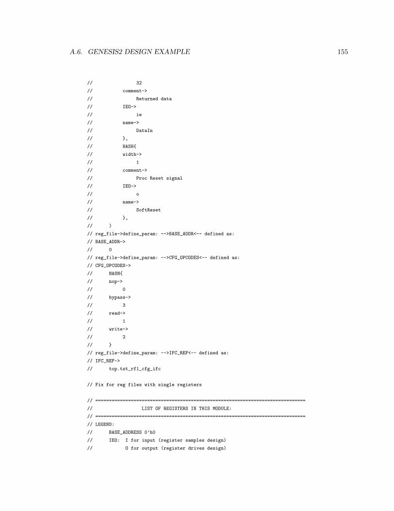
A.6. GENESIS2 DESIGN EXAMPLE 155
// 32
// comment->
// Returned data
// IEO->
// ie
// name->
// DataIn
// },
// HASH{
// width->
// 1
// comment->
// Proc Reset signal
// IEO->
// o
// name->
// SoftReset
// },
// )
// reg_file->define_param: -->BASE_ADDR<-- defined as:
// BASE_ADDR->
// 0
// reg_file->define_param: -->CFG_OPCODES<-- defined as:
// CFG_OPCODES->
// HASH{
// nop->
// 0
// bypass->
// 3
// read->
// 1
// write->
// 2
// }
// reg_file->define_param: -->IFC_REF<-- defined as:
// IFC_REF->
// top.tst_rf1_cfg_ifc
// Fix for reg files with single registers
// =============================================================================
// LIST OF REGISTERS IN THIS MODULE:
// =============================================================================
// LEGEND:
// BASE_ADDRESS 0’h0
// IEO: I for input (register samples design)
// O for output (register drives design)
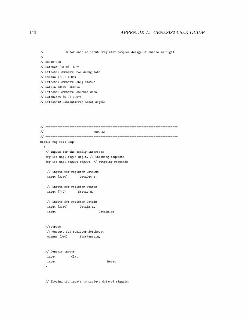
156 APPENDIX A. GENESIS2 USER GUIDE
// IE for enabled input (register samples design if enable is high)
//
// REGISTERS
// DataOut [31:0] IEO=i
// Offset=0 Comment:Proc debug data
// Status [7:0] IEO=i
// Offset=4 Comment:Debug status
// DataIn [31:0] IEO=ie
// Offset=8 Comment:Returned data
// SoftReset [0:0] IEO=o
// Offset=12 Comment:Proc Reset signal
// =============================================================================
// MODULE:
// =============================================================================
module reg_file_unq1
(
// inputs for the config interface
cfg_ifc_unq1.cfgIn cfgIn, // incoming requests
cfg_ifc_unq1.cfgOut cfgOut, // outgoing responds
// inputs for register DataOut
input [31:0] DataOut_d,
// inputs for register Status
input [7:0] Status_d,
// inputs for register DataIn
input [31:0] DataIn_d,
input DataIn_en,
//outputs
// outputs for register SoftReset
output [0:0] SoftReset_q,
// Generic inputs
input Clk,
input Reset
);
// floping cfg inputs to produce delayed signals:
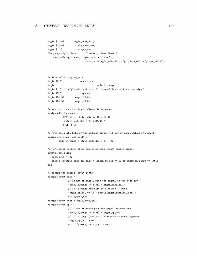
A.6. GENESIS2 DESIGN EXAMPLE 157
logic [31:0] cfgIn_addr_del;
logic [31:0] cfgIn_data_del;
logic [1:0] cfgIn_op_del;
flop_unq1 cfgIn_floper (.Clk(Clk), .Reset(Reset),
.data_in({cfgIn.addr, cfgIn.data, cfgIn.op}),
.data_out({cfgIn_addr_del, cfgIn_data_del, cfgIn_op_del}));
// internal wiring signals
logic [3:0] onehot_en;
logic addr_in_range;
logic [1:0] cfgIn_addr_del_int; // internal (shorter) address signal
logic [3:0] regs_en;
logic [31:0] regs_d[3:0];
logic [31:0] regs_q[3:0];
// make sure that the input address is in range
assign addr_in_range =
((28’h0 == cfgIn_addr_del[31:4]) &&
(cfgIn_addr_del[3:2] < 3’d4))?
1’b1: 1’b0;
// Pick the right bits of the address signal (if out of range default to zero)
assign cfgIn_addr_del_int[1:0] =
(addr_in_range)? cfgIn_addr_del[3:2]: ’0;
// For config writes, there can be at most onehot enable signal
always_comb begin
onehot_en = ’0;
onehot_en[cfgIn_addr_del_int] = (cfgIn_op_del == 2) && (addr_in_range == 1’b1);
end
// assign the config output ports
assign cfgOut.data =
// if not in range, pass the signal to the next guy
(addr_in_range != 1’b1) ? cfgIn_data_del :
// if in range and this is a readop... read
(cfgIn_op_del == 1) ? regs_q[cfgIn_addr_del_int] :
cfgIn_data_del;
assign cfgOut.addr = cfgIn_addr_del;
assign cfgOut.op =
// if not in range pass the signal to next guy
(addr_in_range != 1’b1) ? cfgIn_op_del :
// if in range (and not a nop) mark as done (bypass)
(cfgIn_op_del != 0) ? 3:
0; // else, it’s just a nop.
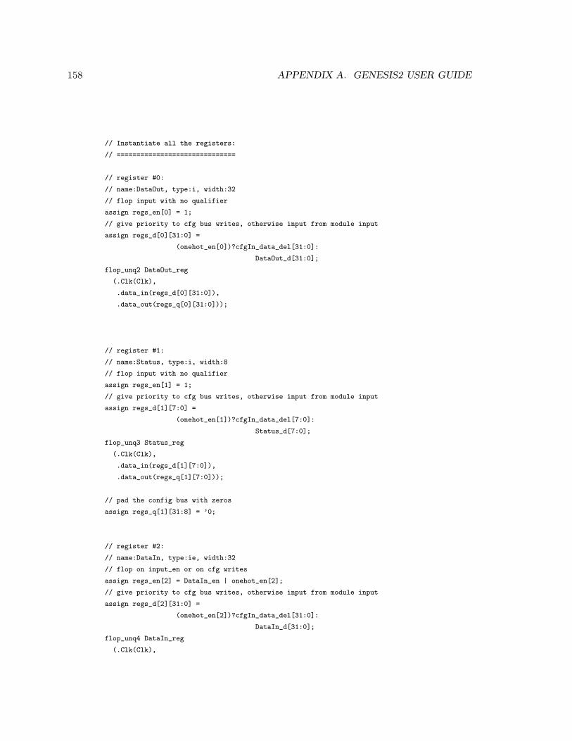
158 APPENDIX A. GENESIS2 USER GUIDE
// Instantiate all the registers:
// ==============================
// register #0:
// name:DataOut, type:i, width:32
// flop input with no qualifier
assign regs_en[0] = 1;
// give priority to cfg bus writes, otherwise input from module input
assign regs_d[0][31:0] =
(onehot_en[0])?cfgIn_data_del[31:0]:
DataOut_d[31:0];
flop_unq2 DataOut_reg
(.Clk(Clk),
.data_in(regs_d[0][31:0]),
.data_out(regs_q[0][31:0]));
// register #1:
// name:Status, type:i, width:8
// flop input with no qualifier
assign regs_en[1] = 1;
// give priority to cfg bus writes, otherwise input from module input
assign regs_d[1][7:0] =
(onehot_en[1])?cfgIn_data_del[7:0]:
Status_d[7:0];
flop_unq3 Status_reg
(.Clk(Clk),
.data_in(regs_d[1][7:0]),
.data_out(regs_q[1][7:0]));
// pad the config bus with zeros
assign regs_q[1][31:8] = ’0;
// register #2:
// name:DataIn, type:ie, width:32
// flop on input_en or on cfg writes
assign regs_en[2] = DataIn_en | onehot_en[2];
// give priority to cfg bus writes, otherwise input from module input
assign regs_d[2][31:0] =
(onehot_en[2])?cfgIn_data_del[31:0]:
DataIn_d[31:0];
flop_unq4 DataIn_reg
(.Clk(Clk),
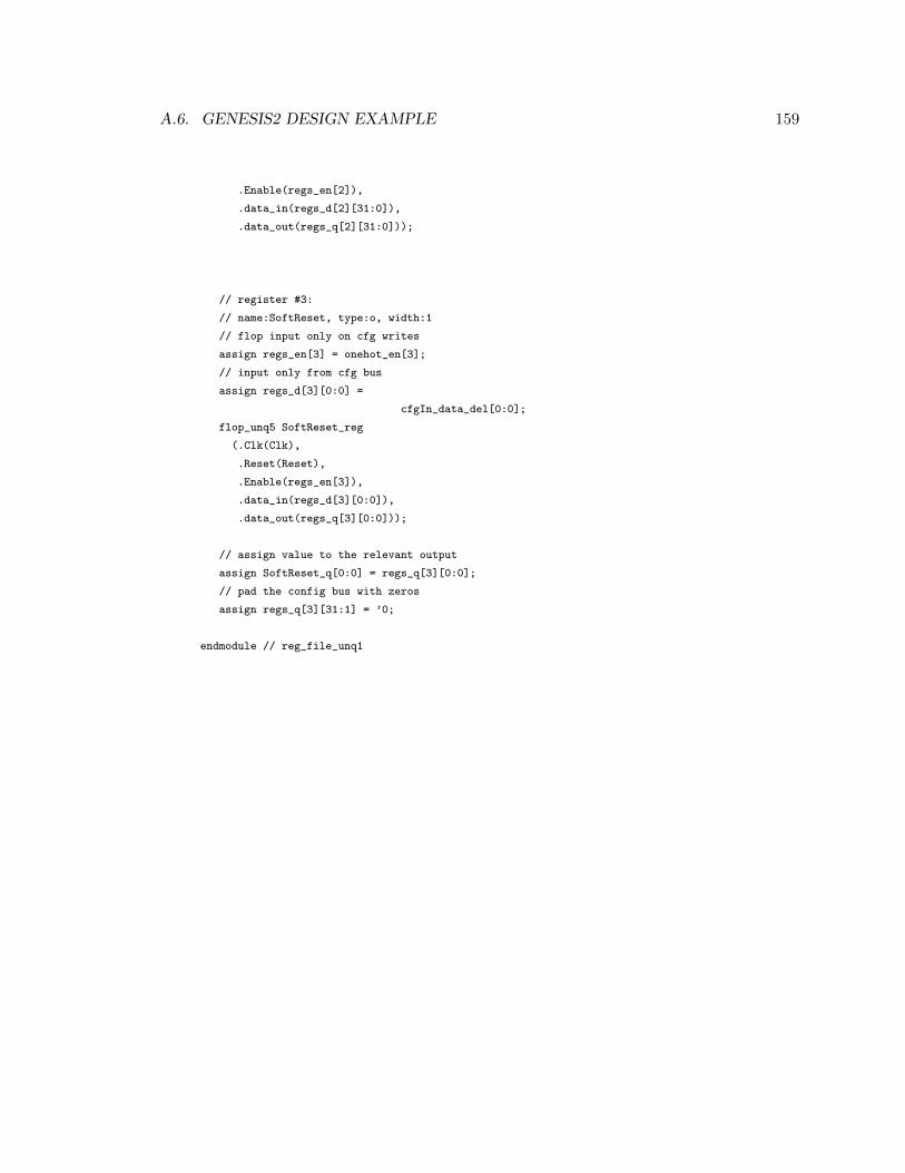
A.6. GENESIS2 DESIGN EXAMPLE 159
.Enable(regs_en[2]),
.data_in(regs_d[2][31:0]),
.data_out(regs_q[2][31:0]));
// register #3:
// name:SoftReset, type:o, width:1
// flop input only on cfg writes
assign regs_en[3] = onehot_en[3];
// input only from cfg bus
assign regs_d[3][0:0] =
cfgIn_data_del[0:0];
flop_unq5 SoftReset_reg
(.Clk(Clk),
.Reset(Reset),
.Enable(regs_en[3]),
.data_in(regs_d[3][0:0]),
.data_out(regs_q[3][0:0]));
// assign value to the relevant output
assign SoftReset_q[0:0] = regs_q[3][0:0];
// pad the config bus with zeros
assign regs_q[3][31:1] = ’0;
endmodule // reg_file_unq1
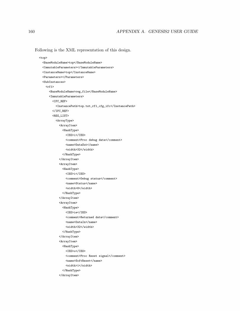
160 APPENDIX A. GENESIS2 USER GUIDE
Following is the XML representation of this design.
<top>
<BaseModuleName>top</BaseModuleName>
<ImmutableParameters></ImmutableParameters>
<InstanceName>top</InstanceName>
<Parameters></Parameters>
<SubInstances>
<rf1>
<BaseModuleName>reg_file</BaseModuleName>
<ImmutableParameters>
<IFC_REF>
<InstancePath>top.tst_rf1_cfg_ifc</InstancePath>
</IFC_REF>
<REG_LIST>
<ArrayType>
<ArrayItem>
<HashType>
<IEO>i</IEO>
<comment>Proc debug data</comment>
<name>DataOut</name>
<width>32</width>
</HashType>
</ArrayItem>
<ArrayItem>
<HashType>
<IEO>i</IEO>
<comment>Debug status</comment>
<name>Status</name>
<width>8</width>
</HashType>
</ArrayItem>
<ArrayItem>
<HashType>
<IEO>ie</IEO>
<comment>Returned data</comment>
<name>DataIn</name>
<width>32</width>
</HashType>
</ArrayItem>
<ArrayItem>
<HashType>
<IEO>o</IEO>
<comment>Proc Reset signal</comment>
<name>SoftReset</name>
<width>1</width>
</HashType>
</ArrayItem>
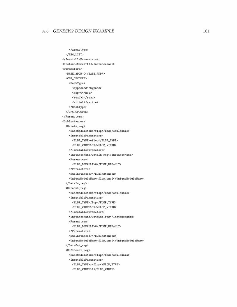
A.6. GENESIS2 DESIGN EXAMPLE 161
</ArrayType>
</REG_LIST>
</ImmutableParameters>
<InstanceName>rf1</InstanceName>
<Parameters>
<BASE_ADDR>0</BASE_ADDR>
<CFG_OPCODES>
<HashType>
<bypass>3</bypass>
<nop>0</nop>
<read>1</read>
<write>2</write>
</HashType>
</CFG_OPCODES>
</Parameters>
<SubInstances>
<DataIn_reg>
<BaseModuleName>flop</BaseModuleName>
<ImmutableParameters>
<FLOP_TYPE>eflop</FLOP_TYPE>
<FLOP_WIDTH>32</FLOP_WIDTH>
</ImmutableParameters>
<InstanceName>DataIn_reg</InstanceName>
<Parameters>
<FLOP_DEFAULT>0</FLOP_DEFAULT>
</Parameters>
<SubInstances></SubInstances>
<UniqueModuleName>flop_unq4</UniqueModuleName>
</DataIn_reg>
<DataOut_reg>
<BaseModuleName>flop</BaseModuleName>
<ImmutableParameters>
<FLOP_TYPE>flop</FLOP_TYPE>
<FLOP_WIDTH>32</FLOP_WIDTH>
</ImmutableParameters>
<InstanceName>DataOut_reg</InstanceName>
<Parameters>
<FLOP_DEFAULT>0</FLOP_DEFAULT>
</Parameters>
<SubInstances></SubInstances>
<UniqueModuleName>flop_unq2</UniqueModuleName>
</DataOut_reg>
<SoftReset_reg>
<BaseModuleName>flop</BaseModuleName>
<ImmutableParameters>
<FLOP_TYPE>reflop</FLOP_TYPE>
<FLOP_WIDTH>1</FLOP_WIDTH>
162 APPENDIX A. GENESIS2 USER GUIDE
</ImmutableParameters>
<InstanceName>SoftReset_reg</InstanceName>
<Parameters>
<FLOP_DEFAULT>0</FLOP_DEFAULT>
</Parameters>
<SubInstances></SubInstances>
<UniqueModuleName>flop_unq5</UniqueModuleName>
</SoftReset_reg>
<Status_reg>
<BaseModuleName>flop</BaseModuleName>
<ImmutableParameters>
<FLOP_TYPE>flop</FLOP_TYPE>
<FLOP_WIDTH>8</FLOP_WIDTH>
</ImmutableParameters>
<InstanceName>Status_reg</InstanceName>
<Parameters>
<FLOP_DEFAULT>0</FLOP_DEFAULT>
</Parameters>
<SubInstances></SubInstances>
<UniqueModuleName>flop_unq3</UniqueModuleName>
</Status_reg>
<cfgIn>
<BaseModuleName>cfg_ifc</BaseModuleName>
<CloneOf>
<InstancePath>top.tst_rf1_cfg_ifc</InstancePath>
</CloneOf>
<InstanceName>cfgIn</InstanceName>
<UniqueModuleName>cfg_ifc_unq1</UniqueModuleName>
</cfgIn>
<cfgIn_floper>
<BaseModuleName>flop</BaseModuleName>
<ImmutableParameters>
<FLOP_DEFAULT>0</FLOP_DEFAULT>
<FLOP_TYPE>rflop</FLOP_TYPE>
<FLOP_WIDTH>66</FLOP_WIDTH>
</ImmutableParameters>
<InstanceName>cfgIn_floper</InstanceName>
<Parameters></Parameters>
<SubInstances></SubInstances>
<UniqueModuleName>flop_unq1</UniqueModuleName>
</cfgIn_floper>
<cfgOut>
<BaseModuleName>cfg_ifc</BaseModuleName>
<CloneOf>
<InstancePath>top.tst_rf1_cfg_ifc</InstancePath>
</CloneOf>
<InstanceName>cfgOut</InstanceName>
A.6. GENESIS2 DESIGN EXAMPLE 163
<UniqueModuleName>cfg_ifc_unq1</UniqueModuleName>
</cfgOut>
</SubInstances>
<UniqueModuleName>reg_file_unq1</UniqueModuleName>
</rf1>
<rf1_rf2_cfg_ifc>
<BaseModuleName>cfg_ifc</BaseModuleName>
<CloneOf>
<InstancePath>top.tst_rf1_cfg_ifc</InstancePath>
</CloneOf>
<InstanceName>rf1_rf2_cfg_ifc</InstanceName>
<UniqueModuleName>cfg_ifc_unq1</UniqueModuleName>
</rf1_rf2_cfg_ifc>
<rf2>
<BaseModuleName>reg_file</BaseModuleName>
<ImmutableParameters>
<IFC_REF>
<InstancePath>top.tst_rf1_cfg_ifc</InstancePath>
</IFC_REF>
<REG_LIST>
<ArrayType>
<ArrayItem>
<HashType>
<IEO>i</IEO>
<comment>Proc debug data</comment>
<name>DataOut</name>
<width>32</width>
</HashType>
</ArrayItem>
<ArrayItem>
<HashType>
<IEO>i</IEO>
<comment>Debug status</comment>
<name>Status</name>
<width>8</width>
</HashType>
</ArrayItem>
<ArrayItem>
<HashType>
<IEO>ie</IEO>
<comment>Returned data</comment>
<name>DataIn</name>
<width>32</width>
</HashType>
</ArrayItem>
<ArrayItem>
<HashType>
164 APPENDIX A. GENESIS2 USER GUIDE
<IEO>o</IEO>
<comment>Proc Reset signal</comment>
<name>SoftReset</name>
<width>1</width>
</HashType>
</ArrayItem>
</ArrayType>
</REG_LIST>
</ImmutableParameters>
<InstanceName>rf2</InstanceName>
<Parameters>
<BASE_ADDR>0</BASE_ADDR>
<CFG_OPCODES>
<HashType>
<bypass>3</bypass>
<nop>0</nop>
<read>1</read>
<write>2</write>
</HashType>
</CFG_OPCODES>
</Parameters>
<SubInstances>
<DataIn_reg>
<BaseModuleName>flop</BaseModuleName>
<ImmutableParameters>
<FLOP_TYPE>eflop</FLOP_TYPE>
<FLOP_WIDTH>32</FLOP_WIDTH>
</ImmutableParameters>
<InstanceName>DataIn_reg</InstanceName>
<Parameters>
<FLOP_DEFAULT>0</FLOP_DEFAULT>
</Parameters>
<SubInstances></SubInstances>
<UniqueModuleName>flop_unq4</UniqueModuleName>
</DataIn_reg>
<DataOut_reg>
<BaseModuleName>flop</BaseModuleName>
<ImmutableParameters>
<FLOP_TYPE>flop</FLOP_TYPE>
<FLOP_WIDTH>32</FLOP_WIDTH>
</ImmutableParameters>
<InstanceName>DataOut_reg</InstanceName>
<Parameters>
<FLOP_DEFAULT>0</FLOP_DEFAULT>
</Parameters>
<SubInstances></SubInstances>
<UniqueModuleName>flop_unq2</UniqueModuleName>
A.6. GENESIS2 DESIGN EXAMPLE 165
</DataOut_reg>
<SoftReset_reg>
<BaseModuleName>flop</BaseModuleName>
<ImmutableParameters>
<FLOP_TYPE>reflop</FLOP_TYPE>
<FLOP_WIDTH>1</FLOP_WIDTH>
</ImmutableParameters>
<InstanceName>SoftReset_reg</InstanceName>
<Parameters>
<FLOP_DEFAULT>0</FLOP_DEFAULT>
</Parameters>
<SubInstances></SubInstances>
<UniqueModuleName>flop_unq5</UniqueModuleName>
</SoftReset_reg>
<Status_reg>
<BaseModuleName>flop</BaseModuleName>
<ImmutableParameters>
<FLOP_TYPE>flop</FLOP_TYPE>
<FLOP_WIDTH>8</FLOP_WIDTH>
</ImmutableParameters>
<InstanceName>Status_reg</InstanceName>
<Parameters>
<FLOP_DEFAULT>0</FLOP_DEFAULT>
</Parameters>
<SubInstances></SubInstances>
<UniqueModuleName>flop_unq3</UniqueModuleName>
</Status_reg>
<cfgIn>
<BaseModuleName>cfg_ifc</BaseModuleName>
<CloneOf>
<InstancePath>top.tst_rf1_cfg_ifc</InstancePath>
</CloneOf>
<InstanceName>cfgIn</InstanceName>
<UniqueModuleName>cfg_ifc_unq1</UniqueModuleName>
</cfgIn>
<cfgIn_floper>
<BaseModuleName>flop</BaseModuleName>
<ImmutableParameters>
<FLOP_DEFAULT>0</FLOP_DEFAULT>
<FLOP_TYPE>rflop</FLOP_TYPE>
<FLOP_WIDTH>66</FLOP_WIDTH>
</ImmutableParameters>
<InstanceName>cfgIn_floper</InstanceName>
<Parameters></Parameters>
<SubInstances></SubInstances>
<UniqueModuleName>flop_unq1</UniqueModuleName>
</cfgIn_floper>
166 APPENDIX A. GENESIS2 USER GUIDE
<cfgOut>
<BaseModuleName>cfg_ifc</BaseModuleName>
<CloneOf>
<InstancePath>top.tst_rf1_cfg_ifc</InstancePath>
</CloneOf>
<InstanceName>cfgOut</InstanceName>
<UniqueModuleName>cfg_ifc_unq1</UniqueModuleName>
</cfgOut>
</SubInstances>
<UniqueModuleName>reg_file_unq1</UniqueModuleName>
</rf2>
<rf2_tst_cfg_ifc>
<BaseModuleName>cfg_ifc</BaseModuleName>
<CloneOf>
<InstancePath>top.tst_rf1_cfg_ifc</InstancePath>
</CloneOf>
<InstanceName>rf2_tst_cfg_ifc</InstanceName>
<UniqueModuleName>cfg_ifc_unq1</UniqueModuleName>
</rf2_tst_cfg_ifc>
<tst_rf1_cfg_ifc>
<BaseModuleName>cfg_ifc</BaseModuleName>
<ImmutableParameters>
<CFG_ADDR_WIDTH>32</CFG_ADDR_WIDTH>
<CFG_BUS_WIDTH>32</CFG_BUS_WIDTH>
<CFG_OPCODE_WIDTH>2</CFG_OPCODE_WIDTH>
</ImmutableParameters>
<InstanceName>tst_rf1_cfg_ifc</InstanceName>
<Parameters></Parameters>
<SubInstances></SubInstances>
<UniqueModuleName>cfg_ifc_unq1</UniqueModuleName>
</tst_rf1_cfg_ifc>
</SubInstances>
<UniqueModuleName>top</UniqueModuleName>
</top>
Note that by simply modifying the parameters’ values in this XML document, for in-
stance changing the base address or the default value for any of the registers, we force
Genesis2 to create a differnt, uniquified module (which will be named reg file unq2 ). This
is done using the -xml program.xml command line flag as described in Section A.3. Gen-
esis2 will also update the module name at the top.

Bibliography
[1] Bluespec, the Synthesizable Modeling Company(tm). http://www.bluespec.com/.
[2] Corensic Concurrency Debugger and Thread Debugger for Parallel Applications and
Multicore Software. Corensic Jinx.
[3] MyHDL - From Python to Silicon.
[4] Open SystemC Initiative (OSCI). IEEE Std. 1666-2005.
[5] RHDL - Ruby Hardware Description Language.
[6] Sonics, On-Chip Communication Network for Advanced SoCs.
http://www.sonicsinc.com/.
[7] STMicroelectronics. http://www.st.com/index.htm.
[8] Synfora, Productivity = Abstraction x QoR. http://www.synfora.com/.
[9] Tensilica: Customizable Processor Cores. http://www.tensilica.com/.
[10] Tensilica Instruction Extension (TIE) Language Reference Manual. Chapter 31, pg
229-233.
[11] Texas Instruments, Microcontrollers Units (MCU).
http://focus.ti.com/mcu/docs/mcuhome.tsp.
[12] The Standard Performance Evaluation Corporation (SPEC).
http://www.spec.org/cpu2006/results/. SPEC CPU2006 Results.
[13] Ieee standard hardware description language based on the verilog(r) hardware de-
scription language. IEEE Std 1364-1995, page i, 1996.
167
168 BIBLIOGRAPHY
[14] Ieee standard for system verilog-unified hardware design, specification, and verifica-
tion language. IEEE STD 1800-2009, pages C1 –1285, 2009.
[15] Ieee standard vhdl language reference manual. IEEE Std 1076-2008 (Revision of IEEE
Std 1076-2002), pages c1 –626, jan. 2009.
[16] International Technology Roadmap for Semiconductors.
http://www.itrs.net/Links/2009ITRS/Home2009.htm, 2009. Design Technology
Working Group.
[17] David Abrahams and Aleksey Gurtovoy. C++ Template Metaprogramming:
Concepts, Tools, and Techniques from Boost and Beyond (C++ in Depth Series).
Addison-Wesley Professional, 2004.
[18] Robert Adams. Take command: The m4 macro package. Linux J., 2002:6–, April
2002.
[19] Sarita V. Adve and Kourosh Gharachorloo. Shared memory consistency models: A
tutorial. Computer, 29(12):66–76, 1996.
[20] S.V. Adve and K. Gharachorloo. Shared memory consistency models: a tutorial.
Computer, 29(12):66–76, Dec 1996.
[21] Gene M. Amdahl. Validity of the single processor approach to achieving large scale
computing capabilities. In AFIPS ’67: Proc. of the April 18-20, 1967, Spring Joint
Computer Conference, pages 483–485, New York, NY, 1967. ACM.
[22] T. Austin, E. Larson, and D. Ernst. SimpleScalar: An infrastructure for computer
system modeling. Computer, 35(2):59–67, 2002.
[23] Omid Azizi. Design and Optimization of Processors For Energy Efficiency: A Joint
Architecture-Circuit Approach. PhD thesis, Stanford University, 2010.
[24] Omid Azizi, Aqeel Mahesri, Benjamin C. Lee, Sanjay Patel, and Mark Horowitz.
Energy-Performance Tradeoffs in Processor Architecture and Circuit Design: A
Marginal Cost Analysis. In ISCA ’10: Proc. 37th Annual International Symposium
on Computer Architecture. ACM, 2010.
BIBLIOGRAPHY 169
[25] Omid Azizi, Aqeel Mahesri, John P. Stevenson, Sanjay Patel, and Mark Horowitz.
An Integrated Framework for Joint Design Space Exploration of Microarchitecture
and Circuits. In DATE ’10: Proc. Conf. on Design, Automation and Test in Europe,
pages 250–255, March 2010.
[26] J. Balfour, W.J. Dally, D. Black-Schaffer, V. Parikh, and JongSoo Park. An Energy-
Efficient Processor Architecture for Embedded Systems. Computer Architecture
Letters, 7(1):29 –32, Jan-Jun 2008.
[27] N.L. Binkert, R.G. Dreslinski, L.R. Hsu, K.T. Lim, A.G. Saidi, and S.K. Reinhardt.
The M5 simulator: Modeling networked systems. IEEE Micro, 26(4):52–60, 2006.
[28] Bruno Bougard, Bjorn De Sutter, Sebastien Rabou, David Novo, Osman Allam,
Steven Dupont, and Liesbet Van der Perre. A coarse-grained array based baseband
processor for 100mbps+ software defined radio. Design, Automation and Test in
Europe Conference and Exhibition, 0:716–721, 2008.
[29] T. Bray, J. Paoli, C.M. Sperberg-McQueen, E. Maler, and F. Yergeau. Extensible
markup language (XML) 1.0. W3C recommendation, 6, 2000.
[30] Sebastian Burckhardt, Pravesh Kothari, Madanlal Musuvathi, and Santosh Na-
garakatte. A randomized scheduler with probabilistic guarantees of finding bugs.
In Proceedings of the fifteenth edition of ASPLOS on Architectural support for
programming languages and operating systems, ASPLOS ’10, pages 167–178, New
York, NY, USA, 2010. ACM.
[31] Cadence. Incisive Enterprise Specman Elite Testbench.
http://www.cadence.com/products/fv/enterprise specman elite/pages/default.aspx.
[32] JF Cantin, MH Lipasti, and JE Smith. The complexity of verifying memory coherence
and consistency. Parallel and Distributed Systems, IEEE Transactions on, 16(7):663–
671, 2005.
[33] G. Castagna. Object-oriented programming: a unified foundation. Birkhauser, 1997.
[34] L. Chang, D.J. Frank, R.K. Montoye, S.J. Koester, B.L. Ji, P.W. Coteus, R.H. Den-
nard, and W. Haensch. Practical strategies for power-efficient computing technologies.
Proceedings of the IEEE, 98(2):215 –236, 2010.

170 BIBLIOGRAPHY
[35] M. Chu, N. Weaver, K. Sulimma, A. Dehon, and J. Wawrzynek. Object ori-
ented circuit-generators in java. In FPGAs for Custom Computing Machines, 1998.
Proceedings. IEEE Symposium on, pages 158 –166, April 1998.
[36] Ronald E. Collett. Executive session: How to address today’s growing system com-
plexity. DATE ’10: Conference on Design, Automation and Test in Europe, March
2010.
[37] R.H. Dennard, F.H. Gaensslen, H.N. Yu, V.L. Rideout, E. Bassous, and A.R. LeBlanc.
Design of ion-implanted MOSFET’s with very small physical dimensions. Proceedings
of the IEEE (reprinted from IEEE Journal Of Solid-State Circuits, 1974), 87(4):668–
678, 1999.
[38] Christophe Dubach, Timothy Jones, and Michael O’Boyle. Microarchitectural design
space exploration using an architecture-centric approach. In MICRO ’07: Proceedings
of the 40th Annual IEEE/ACM International Symposium on Microarchitecture, pages
262–271, Washington, DC, 2007. IEEE Computer Society.
[39] Stijn Eyerman and Lieven Eeckhout. Modeling Critical Sections in Amdahl’s Law and
its Implications for Multicore Design. In ISCA ’10: Proc. 37th Annual International
Symposium on Computer Architecture. ACM, 2010.
[40] David Fick. DePerlify. University of Michigan’s VLSI Design Automation Laboratory.
[41] A. Firoozshahian, A. Solomatnikov, O. Shacham, Z. Asgar, S. Richardson,
C. Kozyrakis, and M. Horowitz. A Memory System Design Framework: Creating
Smart Memories. In ISCA ’09: Proc. 36th Annual International Symposium on
Computer Architecture, pages 406–417. ACM, 2009.
[42] Amin Firoozshahian. Smart Memories: A Reconfigurable Memory System
Architecture. PhD thesis, Stanford University, 2008.
[43] Erik Max Francis. EmPy. European Python and Zope Conference, 2003.
[44] Gary Smith EDA. Private communication with Mr. Gary Smith.
http://www.garysmitheda.com/.
[45] E. Gibbons, P.B.; Korach. The complexity of sequential consistency. Symposium on
Parallel and Distributed Processing, pages 317–325, 1992.
BIBLIOGRAPHY 171
[46] P.B. Gibbons and E. Korach. Testing Shared Memories. SIAM Journal on Computing,
26(4):1208–1244, 1997.
[47] R.E. Gonzalez. Xtensa: a configurable and extensible processor. Micro, IEEE,
20(2):60–70, Mar/Apr 2000.
[48] Douglas Grose. Keynote: From Contract to Collaboration Delivering a New Approach
to Foundry. DAC ’10: Design Automation Conference, June 2010.
[49] Michael Gschwind. Chip multiprocessing and the cell broadband engine. In CF ’06:
Proceedings of the 3rd conference on Computing frontiers, pages 1–8. ACM, 2006.
[50] Lance Hammond, Vicky Wong, Mike Chen, Brian D. Carlstrom, John D. Davis, Ben
Hertzberg, and K. P Manohar. Transactional memory coherence and consistency. In
International Symposium on Computer Architecture (ISCA ’04), page 102, 2004.
[51] Wei Han, Ying Yi, Mark Muir, Ioannis Nousias, Tughrul Arslan, and Ahmet T.
Erdogan. Multicore architectures with dynamically reconfigurable array processors
for wireless broadband technologies. Trans. Comp.-Aided Des. Integ. Cir. Sys.,
28(12):1830–1843, 2009.
[52] Sudheendra Hangal, Durgam Vahia, Chaiyasit Manovit, and Juin-Yeu Joseph Lu.
TSOtool: A Program for Verifying Memory Systems Using the Memory Consistency
Model. In ISCA ’04: Proc. 31st Annual International Symposium on Computer
Architecture, page 114. ACM, 2004.
[53] Pat Hanrahan. Keynote: Why are graphics systems so fast? In Parallel Architectures
and Compilation Techniques, 2009. PACT ’09. 18th International Conference on, Sep
2009.
[54] M. Herlihy and J. E. B. Moss. Transactional Memory: Architectural Support for Lock-
Free Data Structures. In ISCA ’93: Proceedings of the 20th Annual International
Symposium on Computer Architecture, pages 289–300, New York, NY, USA, 1993.
ACM.
[55] M.D. Hill. Multiprocessors should support simple memory consistency models.
Computer, 31(8):28–34, Aug 1998.

172 BIBLIOGRAPHY
[56] R. Hofmann and B. Drerup. Next generation coreconnect trade; processor local bus
architecture. pages 221 – 225, sep. 2002.
[57] Paul Hudak, Simon Peyton Jones, Philip Wadler, Brian Boutel, Jon Fairbairn, Joseph
Fasel, Marıa M. Guzman, Kevin Hammond, John Hughes, Thomas Johnsson, Dick
Kieburtz, Rishiyur Nikhil, Will Partain, and John Peterson. Report on the program-
ming language haskell: a non-strict, purely functional language version 1.2. SIGPLAN
Not., 27(5):1–164, 1992.
[58] B. Hutchings and B. Nelson. Developing and debugging fpga applications in hardware
with jhdl. In Signals, Systems, and Computers, 1999. Conference Record of the
Thirty-Third Asilomar Conference on, pages 554 –558 vol.1, 1999.
[59] Engin Ipek, Sally A. McKee, Rich Caruana, Bronis R. de Supinski, and Martin Schulz.
Efficiently exploring architectural design spaces via predictive modeling. SIGARCH
Comput. Archit. News, 34(5):195–206, 2006.
[60] Ujval J. Kapasi, William J. Dally, Scott Rixner, John D. Owens, and Brucek Khailany.
The imagine stream processor. Computer Design, International Conference on, 0:282,
2002.
[61] H. Kaul, M.A. Anders, S.K. Mathew, S.K. Hsu, A. Agarwal, R.K. Krishnamurthy,
and S. Borkar. A 300mV 494GOPS/W reconfigurable dual-supply 4-way SIMD vector
processing accelerator in 45nm CMOS. In IEEE International Solid-State Circuits
Conference(ISSCC) - Digest of Technical Papers, pages 260–261, 2009.
[62] M. Keating, D. Flynn, R. Aitken, A. Gibbons, and K. Shi.
Low power methodology manual: for system-on-chip design. Springer Verlag,
2008.
[63] Mike Keating. Third Revolution: The Search for Scalable Code-Based Design. Syn-
opsys Presentations, 2010.
[64] Martha Mercaldi Kim, John D. Davis, Mark Oskin, and Todd Austin. Polymorphic
on-chip networks. In ISCA ’08: Proceedings of the 35th International Symposium on
Computer Architecture, pages 101–112, 2008.
BIBLIOGRAPHY 173
[65] J. W. Klop, Marc Bezem, and R. C. De Vrijer, editors. Term Rewriting Systems.
Cambridge University Press, New York, NY, USA, 2001.
[66] James R. Larus and Ravi Rajwar. Transactional memory. Synthesis Lectures on
Computer Architecture, 1(1):1–226, 2006.
[67] Benjamin C. Lee and David M. Brooks. Accurate and efficient regression modeling
for microarchitectural performance and power prediction. SIGARCH Comput. Archit.
News, 34(5):185–194, 2006.
[68] Mark Lutz. Programming Python. O’Reilly Media, Inc., 2006.
[69] A. Madorsky and D.E. Acosta. VPP-a Verilog HDL simulation and generation library
for C++. In Nuclear Science Symposium Conference Record, 2007. NSS’07. IEEE,
volume 3, pages 1927–1933. IEEE, 2007.
[70] K. Mai, R. Ho, E. Alon, D. Liu, Younggon Kim, D. Patil, and M.A. Horowitz. Ar-
chitecture and circuit techniques for a 1.1-GHz 16-kb reconfigurable memory in 0.18u
CMOS. Solid-State Circuits, IEEE Journal of, 40(1):261–275, 2005.
[71] K. Mai, T. Paaske, N. Jayasena, R. Ho, W.J. Dally, and M. Horowitz. Smart memories:
a modular reconfigurable architecture. Computer Architecture, 2000. Proceedings of
the 27th International Symposium on, pages 161–171, 2000.
[72] C. Manovit and S. Hangal. Completely verifying memory consistency of test pro-
gram executions. High-Performance Computer Architecture, 2006. The Twelfth
International Symposium on, pages 166–175, 2006.
[73] Chaiyasit Manovit, Sudheendra Hangal, Hassan Chafi, Austen McDonald, Christos
Kozyrakis, and Kunle Olukotun. Testing implementations of transactional memory. In
PACT ’06: Proceedings of the 15th international conference on Parallel architectures
and compilation techniques, pages 134–143, New York, NY, USA, 2006. ACM.
[74] Milo M. K. Martin, Daniel J. Sorin, Bradford M. Beckmann, Michael R. Marty, Min
Xu, Alaa R. Alameldeen, Kevin E. Moore, Mark D. Hill, and David A. Wood. Multi-
facet’s general execution-driven multiprocessor simulator (gems) toolset. SIGARCH
Comput. Archit. News, 33:92–99, November 2005.

174 BIBLIOGRAPHY
[75] Paul E. McKenney. Memory ordering in modern microprocessors, part I and II. Linux
J., 2005(136/7), 2005.
[76] Marghoob Mohiyuddin, Mark Murphy, Leonid Oliker, John Shalf, John Wawrzynek,
and Samuel Williams. A design methodology for domain-optimized power-efficient
supercomputing. In Proceedings of the Conference on High Performance Computing
Networking, Storage and Analysis, SC ’09, pages 12:1–12:12, New York, NY, USA,
2009. ACM.
[77] Clyde Montevirgen. Industry Survey: Semiconductors. Standard & Poor’s Industry
Surveys, November 2010.
[78] Gordon Moore. Cramming More Components onto Integrated Circuits. Electronics
Magazine, 38(8), April 1965.
[79] Yehuda Naveh, Michal Rimon, Itai Jaeger, Yoav Katz, Michael Vinov, Eitan Marcus,
and Gil Shurek. Constraint-based random stimuli generation for hardware verifica-
tion. In IAAI’06: Proceedings of the 18th Conference on Innovative Applications of
Artificial Intelligence, pages 1720–1727. AAAI Press, 2006.
[80] R. Nikhil. Bluespec system verilog: efficient, correct rtl from high level specifications.
pages 69 – 70, jun. 2004.
[81] J.K. Ousterhout, K. Jones, and MyiLibrary. Tcl and the Tk toolkit. Citeseer, 1994.
[82] John Owens. Streaming architectures and technology trends. In SIGGRAPH ’05:
ACM SIGGRAPH 2005 Courses, page 9, New York, NY, USA, 2005. ACM.
[83] D. Patterson. The trouble with multi-core. IEEE Spectrum, 47(7):28–32, 2010.
[84] Marines Puig-Medina, Gulbin Ezer, and Pavlos Konas. Verification of Configurable
Processor Cores. DAC ’00: Design Automation Conference., pages 426–431, 2000.
[85] Walden C. Rhines. Keynote: World Semiconductor Dynamics: Myth vs. Reality.
Semicon West ’09, July 2009.
[86] Robert Colwell. Private communication with Mr. Robert Colwell.

BIBLIOGRAPHY 175
[87] A. Saha, N. Malik, B. O’Krafka, J. Lin, R. Raghavan, and U. Shamsi. A simulation-
based approach to architectural verification of multiprocessor systems. Computers
and Communications, 1995. Conference Proceedings of the 1995 IEEE Fourteenth
Annual International Phoenix Conference on, pages 34–37, Mar 1995.
[88] K. Sankaralingam, R. Nagarajan, Haiming Liu, Changkyu Kim, Jaehyuk Huh,
D. Burger, S.W. Keckler, and C.R. Moore. Exploiting ILP, TLP, and DLP with the
polymorphous TRIPS architecture. In ISCA ’03: Proc. 30th Annual International
Symposium on Computer Architecture, pages 422–433, June 2003.
[89] Ofer Shacham, Zain Asgar, Han Chen, Amin Firoozshahian, Rehan Hameed,
Christos Kozyrakis, Wajahat Qadeer, Stephen Richardson, Alexandre Solomat-
nikov, Don Stark, Megan Wachs, and Mark Horowitz. Smart memories
polymorphic chip multiprocessor, 2009. DAC/ISSCC Student Design Contest:
http://www.dac.com/46th/studcon.html.
[90] Ofer Shacham, Megan Wachs, Alex Solomatnikov, Amin Firoozshahian, Stephen
Richardson, and Mark Horowitz. Verification of Chip Multiprocessor Memory Systems
Using A Relaxed Scoreboard. In MICRO ’08: Proceedings of the 41st IEEE/ACM
International Symposium on Microarchitecture, pages 294–305, 2008.
[91] Alex Solomatnikov. Polymorphic Chip Multiprocessor Architecture. PhD thesis,
Stanford University, 2008.
[92] Alex Solomatnikov, Amin Firoozshahian, Ofer Shacham, Zain Asgar, Megan Wachs,
Wajahat Qadeer, Stephen Richardson, and Mark Horowitz. Using a configurable
processor generator for computer architecture prototyping. In Proceedings of the
42nd Annual IEEE/ACM International Symposium on Microarchitecture, pages 358–
369, 2009.
[93] Chris Spear. SystemVerilog for verification: a guide to learning the testbench language features.
Springer Publishing Company, Incorporated, 2008.
[94] G. Spivey. Ep3: An extensible perl preprocessor. pages 106 –113, mar. 1998.
[95] R.M. Stallman and Z. Weinberg. The C preprocessor. GNU Project, Free software
foundation, 2010.

176 BIBLIOGRAPHY
[96] Jeremy Sugerman, Kayvon Fatahalian, Solomon Boulos, Kurt Akeley, and Pat Han-
rahan. Gramps: A programming model for graphics pipelines. ACM Trans. Graph.,
28(1):1–11, 2009.
[97] Synopsys. OpenVera (TM). http://www.open-vera.com/.
[98] Michael Bedford Taylor, Jason Kim, Jason Miller, David Wentzlaff, Fae Ghodrat, Ben
Greenwald, Henry Hoffman, Paul Johnson, Jae-Wook Lee, Walter Lee, Albert Ma,
Arvind Saraf, Mark Seneski, Nathan Shnidman, Volker Strumpen, Matt Frank, Saman
Amarasinghe, and Anant Agarwal. The Raw Microprocessor: A Computational Fabric
for Software Circuits and General-Purpose Programs. IEEE Micro, 22(2), 2002.
[99] A.S. Vincentelli and J. Cohn. Platform-based design. IEEE Design & Test, 18(6):23–
33, 2001.
[100] M. Woh, Yuan Lin, Sangwon Seo, S. Mahlke, T. Mudge, C. Chakrabarti, R. Bruce,
D. Kershaw, A. Reid, M. Wilder, and K. Flautner. From soda to scotch: The evolution
of a wireless baseband processor. In Microarchitecture, 2008. MICRO-41. 2008 41st
IEEE/ACM International Symposium on, pages 152 –163, 2008.
[101] S.C. Woo, M. Ohara, E. Torrie, J.P. Singh, and A. Gupta. The SPLASH-2 programs:
Characterization and methodological considerations. In ISCA ’95: Proc. 22nd Annual
International Symposium on Computer Architecture, pages 24–36, Jun 1995.