Embed Size (px)
Citation preview
at SciVerse ScienceDirect
Journal of Cleaner Production 26 (2012) 1e8
Contents lists available
Journal of Cleaner Production
journal homepage: www.elsevier .com/locate/ jc lepro
Chlorine use reduction in nuclear or conventional power plants: a combinedcooling-and-stripping tower for coastal power plants
María J. Fernández Torres*, Francisco Ruiz BeviáDepartamento de Ingeniería Química, Universidad de Alicante, Apartado 99, E-03080, Spain
a r t i c l e i n f o
Article history:Received 14 September 2011Received in revised form11 December 2011Accepted 14 December 2011Available online 22 December 2011
Keywords:Chlorine use reductionChemical pollution reductionThermal pollution reductionNuclear cooling systemEnvironmental designCleaner process
* Corresponding author. Tel.: þ34 965903400x3012E-mail addresses: [email protected] (M.J. Fernánd
(F. Ruiz Beviá).
0959-6526/$ e see front matter � 2011 Elsevier Ltd.doi:10.1016/j.jclepro.2011.12.016
a b s t r a c t
Conventional seaside nuclear or coal-fired power stations draw water directly from the sea, chlorinate itand send it into a “once-through” cooling circuit that discharges it directly back into the sea. This practiceleads to a constant input of thermal and chemical pollution (residual chlorine and chlorinationby-products) into ecosystems in the immediate vicinity of the power plant. To reduce chlorine usage andachieve a cleaner process, a new design for the cooling system of power plants is proposed. This can beaccomplished by means of a cooling-stripping tower that operates in a closed circuit. With that purposein mind, the design of such a cooling system configuration was undertaken. Results show that the warmstream leaving the condensers at 38 �C cools down to 27.1 �C after exiting the cooling-stripping tower.This decrease in the seawater coolant temperature before it is rejected to the sea therefore preventsthermal pollution. Furthermore, the small amount of seawater returned to the sea at 27.1 �C contains nochlorination by-products. In addition, a dramatic reduction in the seawater intake by the cooling systemis obtained, and represents only 5.2% of that needed by conventional systems. This, in turn, impliesa reduction in the chlorine dosage and the filter sizes required for the seawater input stream. It is rec-ommended that all power plants consider implementing the proposed design in order to preventseawater pollution and damage to coastal ecosystems.
� 2011 Elsevier Ltd. All rights reserved.
1. Introduction
Nuclear power plants, as with all conventional power plants,require a cooling circuit (with water as the cooling agent) whosesole purpose is to transfer excess heat created by power generationto a heat sink. Fresh water has become such a treasured resourcethat a significant body of recent literature is devoted to researchingimproved management techniques, for instance: Sotelo-Pichardoet al. (2011), de Faria et al. (2009), Kumaraprasad andMuthukumar (2009), Chew et al. (2009), to name a few. For thissame reason, large industries are increasingly being located nearseacoasts, primarily due to the availability of plenty of coolingwater. In general, the most distinguishing feature of seaside steampower plants (nuclear or conventional), as opposed to their river-side counterparts, is the presence or absence of cooling towers.Seaside power plants in theory do not require cooling towers asthey are built next to a large body of water, which makesa continuous supply of cooling water readily available. There are
; fax: þ34 965903826.ez Torres), [email protected]
All rights reserved.
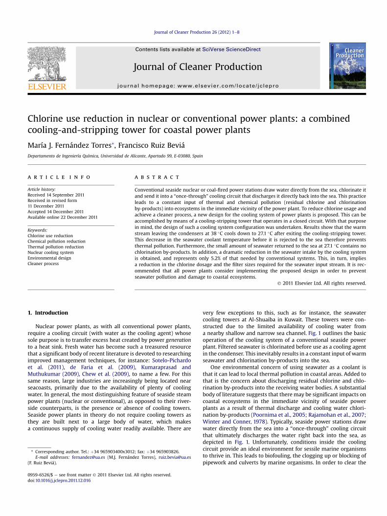
very few exceptions to this, such as for instance, the seawatercooling towers at Al-Shuaiba in Kuwait. These towers were con-structed due to the limited availability of cooling water froma nearby shallow and narrow sea channel. Fig. 1 outlines the basicoperation of the cooling system of a conventional seaside powerplant. Filtered seawater is chlorinated before use as a cooling agentin the condenser. This inevitably results in a constant input of warmseawater and chlorination by-products into the sea.
One environmental concern of using seawater as a coolant isthat it can lead to local thermal pollution in coastal areas. Added tothat is the concern about discharging residual chlorine and chlo-rination by-products into the receiving water bodies. A substantialbody of literature suggests that there may be significant impacts oncoastal ecosystems in the immediate vicinity of seaside powerplants as a result of thermal discharge and cooling water chlori-nation by-products (Poornima et al., 2005; Rajamohan et al., 2007;Winter and Conner, 1978). Typically, seaside power stations drawwater directly from the sea into a “once-through” cooling circuitthat ultimately discharges the water right back into the sea, asdepicted in Fig. 1. Unfortunately, conditions inside the coolingcircuit provide an ideal environment for sessile marine organismsto thrive in. This leads to biofouling, the clogging up or blocking ofpipework and culverts by marine organisms. In order to clear the
Turbine
Power Plant
Condenser
Vapor
ENTRY EXIT
SEA WATER
Liquid
WAR
MW
ATERC
OLD
WAT
ER
Filter
Chlorine
Fig. 1. Schematic representation of the basic operation of a coastal power plant coolingsystem.
Turbine
PowerPlant
Condenser
Vapor
Mak
e-up
Purge
SEAWATER
Liquid
COOLING/STRIPPINGTOWER
WARM WATER
COLDWATER
Chlorine
FilterAIR
WATERVAPOUR
+ AIR + THMs
A
B
C
V
E
D
P
F
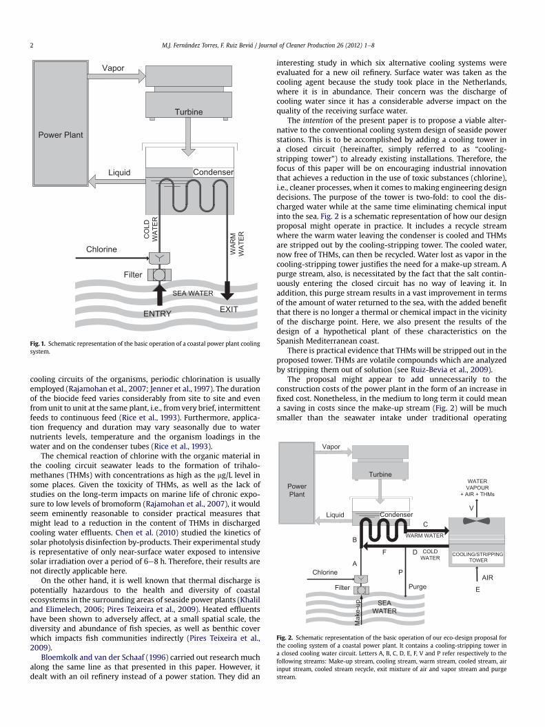
Fig. 2. Schematic representation of the basic operation of our eco-design proposal forthe cooling system of a coastal power plant. It contains a cooling-stripping tower ina closed cooling water circuit. Letters A, B, C, D, E, F, V and P refer respectively to thefollowing streams: Make-up stream, cooling stream, warm stream, cooled stream, airinput stream, cooled stream recycle, exit mixture of air and vapor stream and purgestream.
M.J. Fernández Torres, F. Ruiz Beviá / Journal of Cleaner Production 26 (2012) 1e82
cooling circuits of the organisms, periodic chlorination is usuallyemployed (Rajamohan et al., 2007; Jenner et al., 1997). The durationof the biocide feed varies considerably from site to site and evenfrom unit to unit at the same plant, i.e., fromvery brief, intermittentfeeds to continuous feed (Rice et al., 1993). Furthermore, applica-tion frequency and duration may vary seasonally due to waternutrients levels, temperature and the organism loadings in thewater and on the condenser tubes (Rice et al., 1993).
The chemical reaction of chlorine with the organic material inthe cooling circuit seawater leads to the formation of trihalo-methanes (THMs) with concentrations as high as the mg/L level insome places. Given the toxicity of THMs, as well as the lack ofstudies on the long-term impacts on marine life of chronic expo-sure to low levels of bromoform (Rajamohan et al., 2007), it wouldseem eminently reasonable to consider practical measures thatmight lead to a reduction in the content of THMs in dischargedcooling water effluents. Chen et al. (2010) studied the kinetics ofsolar photolysis disinfection by-products. Their experimental studyis representative of only near-surface water exposed to intensivesolar irradiation over a period of 6e8 h. Therefore, their results arenot directly applicable here.
On the other hand, it is well known that thermal discharge ispotentially hazardous to the health and diversity of coastalecosystems in the surrounding areas of seaside power plants (Khaliland Elimelech, 2006; Pires Teixeira et al., 2009). Heated effluentshave been shown to adversely affect, at a small spatial scale, thediversity and abundance of fish species, as well as benthic coverwhich impacts fish communities indirectly (Pires Teixeira et al.,2009).
Bloemkolk and van der Schaaf (1996) carried out research muchalong the same line as that presented in this paper. However, itdealt with an oil refinery instead of a power station. They did an
interesting study in which six alternative cooling systems wereevaluated for a new oil refinery. Surface water was taken as thecooling agent because the study took place in the Netherlands,where it is in abundance. Their concern was the discharge ofcooling water since it has a considerable adverse impact on thequality of the receiving surface water.
The intention of the present paper is to propose a viable alter-native to the conventional cooling system design of seaside powerstations. This is to be accomplished by adding a cooling tower ina closed circuit (hereinafter, simply referred to as “cooling-stripping tower”) to already existing installations. Therefore, thefocus of this paper will be on encouraging industrial innovationthat achieves a reduction in the use of toxic substances (chlorine),i.e., cleaner processes, when it comes to making engineering designdecisions. The purpose of the tower is two-fold: to cool the dis-charged water while at the same time eliminating chemical inputinto the sea. Fig. 2 is a schematic representation of how our designproposal might operate in practice. It includes a recycle streamwhere the warm water leaving the condenser is cooled and THMsare stripped out by the cooling-stripping tower. The cooled water,now free of THMs, can then be recycled. Water lost as vapor in thecooling-stripping tower justifies the need for a make-up stream. Apurge stream, also, is necessitated by the fact that the salt contin-uously entering the closed circuit has no way of leaving it. Inaddition, this purge stream results in a vast improvement in termsof the amount of water returned to the sea, with the added benefitthat there is no longer a thermal or chemical impact in the vicinityof the discharge point. Here, we also present the results of thedesign of a hypothetical plant of these characteristics on theSpanish Mediterranean coast.
There is practical evidence that THMs will be stripped out in theproposed tower. THMs are volatile compounds which are analyzedby stripping them out of solution (see Ruiz-Bevia et al., 2009).
The proposal might appear to add unnecessarily to theconstruction costs of the power plant in the form of an increase infixed cost. Nonetheless, in the medium to long term it could meana saving in costs since the make-up stream (Fig. 2) will be muchsmaller than the seawater intake under traditional operating
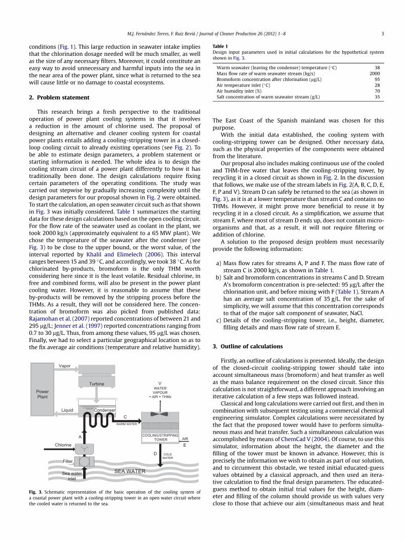
Table 1Design input parameters used in initial calculations for the hypothetical systemshown in Fig. 3.
Warm seawater (leaving the condenser) temperature (�C) 38Mass flow rate of warm seawater stream (kg/s) 2000Bromoform concentration after chlorination (mg/L) 95Air temperature inlet (�C) 28Air humidity inlet (%) 70Salt concentration of warm seawater stream (g/L) 35
M.J. Fernández Torres, F. Ruiz Beviá / Journal of Cleaner Production 26 (2012) 1e8 3
conditions (Fig. 1). This large reduction in seawater intake impliesthat the chlorination dosage needed will be much smaller, as wellas the size of any necessary filters. Moreover, it could constitute aneasy way to avoid unnecessary and harmful inputs into the sea inthe near area of the power plant, since what is returned to the seawill cause little or no damage to coastal ecosystems.
2. Problem statement
This research brings a fresh perspective to the traditionaloperation of power plant cooling systems in that it involvesa reduction in the amount of chlorine used. The proposal ofdesigning an alternative and cleaner cooling system for coastalpower plants entails adding a cooling-stripping tower in a closed-loop cooling circuit to already existing operations (see Fig. 2). Tobe able to estimate design parameters, a problem statement orstarting information is needed. The whole idea is to design thecooling stream circuit of a power plant differently to how it hastraditionally been done. The design calculations require fixingcertain parameters of the operating conditions. The study wascarried out stepwise by gradually increasing complexity until thedesign parameters for our proposal shown in Fig. 2 were obtained.To start the calculation, an open seawater circuit such as that shownin Fig. 3 was initially considered. Table 1 summarizes the startingdata for these design calculations based on the open cooling circuit.For the flow rate of the seawater used as coolant in the plant, wetook 2000 kg/s (approximately equivalent to a 65 MW plant). Wechose the temperature of the seawater after the condenser (seeFig. 3) to be close to the upper bound, or the worst value, of theinterval reported by Khalil and Elimelech (2006). This intervalranges between 15 and 39 �C, and accordingly, we took 38 �C. As forchlorinated by-products, bromoform is the only THM worthconsidering here since it is the least volatile. Residual chlorine, infree and combined forms, will also be present in the power plantcooling water. However, it is reasonable to assume that theseby-products will be removed by the stripping process before theTHMs. As a result, they will not be considered here. The concen-tration of bromoform was also picked from published data:Rajamohan et al. (2007) reported concentrations of between 21 and295 mg/L; Jenner et al. (1997) reported concentrations ranging from0.7 to 30 mg/L. Thus, from among these values, 95 mg/L was chosen.Finally, we had to select a particular geographical location so as tothe fix average air conditions (temperature and relative humidity).
Turbine
PowerPlant
Condenser
Vapor
Sea waterinlet
Liquid
COOLING/STRIPPINGTOWER
WARM WATER
COLDWATER
Chlorine
Filter
AIR
WATERVAPOUR
+ AIR + THMs
SEA WATER
A
C
V
E
D
Fig. 3. Schematic representation of the basic operation of the cooling system ofa coastal power plant with a cooling-stripping tower in an open water circuit wherethe cooled water is returned to the sea.
The East Coast of the Spanish mainland was chosen for thispurpose.
With the initial data established, the cooling system withcooling-stripping tower can be designed. Other necessary data,such as the physical properties of the components were obtainedfrom the literature.
Our proposal also includes making continuous use of the cooledand THM-free water that leaves the cooling-stripping tower, byrecycling it in a closed circuit as shown in Fig. 2. In the discussionthat follows, we make use of the stream labels in Fig. 2(A, B, C, D, E,F, P and V). Stream D can safely be returned to the sea (as shown inFig. 3), as it is at a lower temperature than stream C and contains noTHMs. However, it might prove more beneficial to reuse it byrecycling it in a closed circuit. As a simplification, we assume thatstream F, where most of stream D ends up, does not contain micro-organisms and that, as a result, it will not require filtering oraddition of chlorine.
A solution to the proposed design problem must necessarilyprovide the following information:
a) Mass flow rates for streams A, P and F. The mass flow rate ofstream C is 2000 kg/s, as shown in Table 1.
b) Salt and bromoform concentrations in streams C and D. StreamA’s bromoform concentration is pre-selected: 95 mg/L after thechlorination unit, and before mixing with F (Table 1). Stream Ahas an average salt concentration of 35 g/L. For the sake ofsimplicity, we will assume that this concentration correspondsto that of the major salt component of seawater, NaCl.
c) Details of the cooling-stripping tower, i.e., height, diameter,filling details and mass flow rate of stream E.
3. Outline of calculations
Firstly, an outline of calculations is presented. Ideally, the designof the closed-circuit cooling-stripping tower should take intoaccount simultaneous mass (bromoform) and heat transfer as wellas the mass balance requirement on the closed circuit. Since thiscalculation is not straightforward, a different approach involving aniterative calculation of a few steps was followed instead.
Classical and long calculations were carried out first, and then incombination with subsequent testing using a commercial chemicalengineering simulator. Complex calculations were necessitated bythe fact that the proposed tower would have to perform simulta-neous mass and heat transfer. Such a simultaneous calculation wasaccomplished bymeans of ChemCad V (2004). Of course, to use thissimulator, information about the height, the diameter and thefilling of the tower must be known in advance. However, this isprecisely the information we wish to obtain as part of our solution,and to circumvent this obstacle, we tested initial educated-guessvalues obtained by a classical approach, and then used an itera-tive calculation to find the final design parameters. The educated-guess method to obtain initial trial values for the height, diam-eter and filling of the column should provide us with values veryclose to those that achieve our aim (simultaneous mass and heat
M.J. Fernández Torres, F. Ruiz Beviá / Journal of Cleaner Production 26 (2012) 1e84
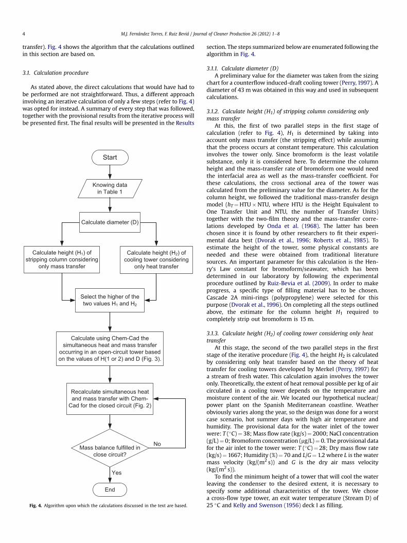
transfer). Fig. 4 shows the algorithm that the calculations outlinedin this section are based on.
3.1. Calculation procedure
As stated above, the direct calculations that would have had tobe performed are not straightforward. Thus, a different approachinvolving an iterative calculation of only a few steps (refer to Fig. 4)was opted for instead. A summary of every step that was followed,together with the provisional results from the iterative process willbe presented first. The final results will be presented in the Results
Start
Knowing datain Table 1
Calculate height (H1) ofstripping column considering
only mass transfer
Calculate height (H2) ofcooling tower considering
only heat transfer
Select the higher of thetwo values H1 and H2
End
Calculate using Chem-Cad thesimultaneous heat and mass transfer
occurring in an open-circuit tower basedon the values of H(1 or 2) and D (Fig. 3).
Recalculate simultaneous heatand mass transfer with Chem-
Cad for the closed circuit (Fig. 2)
Mass balance fulfilled inclose circuit?
Yes
No
Calculate diameter (D)
Fig. 4. Algorithm upon which the calculations discussed in the text are based.
section. The steps summarized beloware enumerated following thealgorithm in Fig. 4.
3.1.1. Calculate diameter (D)A preliminary value for the diameter was taken from the sizing
chart for a counterflow induced-draft cooling tower (Perry, 1997). Adiameter of 43 mwas obtained in this way and used in subsequentcalculations.
3.1.2. Calculate height (H1) of stripping column considering onlymass transfer
At this, the first of two parallel steps in the first stage ofcalculation (refer to Fig. 4), H1 is determined by taking intoaccount only mass transfer (the stripping effect) while assumingthat the process occurs at constant temperature. This calculationinvolves the tower only. Since bromoform is the least volatilesubstance, only it is considered here. To determine the columnheight and the mass-transfer rate of bromoform one would needthe interfacial area as well as the mass-transfer coefficient. Forthese calculations, the cross sectional area of the tower wascalculated from the preliminary value for the diameter. As for thecolumn height, we followed the traditional mass-transfer designmodel (hT¼HTU�NTU, where HTU is the Height Equivalent toOne Transfer Unit and NTU, the number of Transfer Units)together with the two-film theory and the mass-transfer corre-lations developed by Onda et al. (1968). The latter has beenchosen since it is found by other researchers to fit their experi-mental data best (Dvorak et al., 1996; Roberts et al., 1985). Toestimate the height of the tower, some physical constants areneeded and these were obtained from traditional literaturesources. An important parameter for this calculation is the Hen-ry’s Law constant for bromoform/seawater, which has beendetermined in our laboratory by following the experimentalprocedure outlined by Ruiz-Bevia et al. (2009). In order to makeprogress, a specific type of filling material has to be chosen.Cascade 2A mini-rings (polypropylene) were selected for thispurpose (Dvorak et al., 1996). On completing all the steps outlinedabove, the estimate for the column height H1 required tocompletely strip out bromoform is 15 m.
3.1.3. Calculate height (H2) of cooling tower considering only heattransfer
At this stage, the second of the two parallel steps in the firststage of the iterative procedure (Fig. 4), the height H2 is calculatedby considering only heat transfer based on the theory of heattransfer for cooling towers developed by Merkel (Perry, 1997) fora stream of fresh water. This calculation again involves the toweronly. Theoretically, the extent of heat removal possible per kg of aircirculated in a cooling tower depends on the temperature andmoisture content of the air. We located our hypothetical nuclear/power plant on the Spanish Mediterranean coastline. Weatherobviously varies along the year, so the design was done for a worstcase scenario, hot summer days with high air temperature andhumidity. The provisional data for the water inlet of the towerwere: T (�C)¼ 38; Mass flow rate (kg/s)¼ 2000; NaCl concentration(g/L)¼ 0; Bromoform concentration (mg/L)¼ 0. The provisional datafor the air inlet to the tower were: T (�C)¼ 28; Dry mass flow rate(kg/s)¼ 1667; Humidity (%)¼ 70 and L/G¼ 1.2 where L is the watermass velocity (kg/(m2 s)) and G is the dry air mass velocity(kg/(m2 s)).
To find the minimum height of a tower that will cool the waterleaving the condenser to the desired extent, it is necessary tospecify some additional characteristics of the tower. We chosea cross-flow type tower, an exit water temperature (Stream D) of25 �C and Kelly and Swenson (1956) deck I as filling.
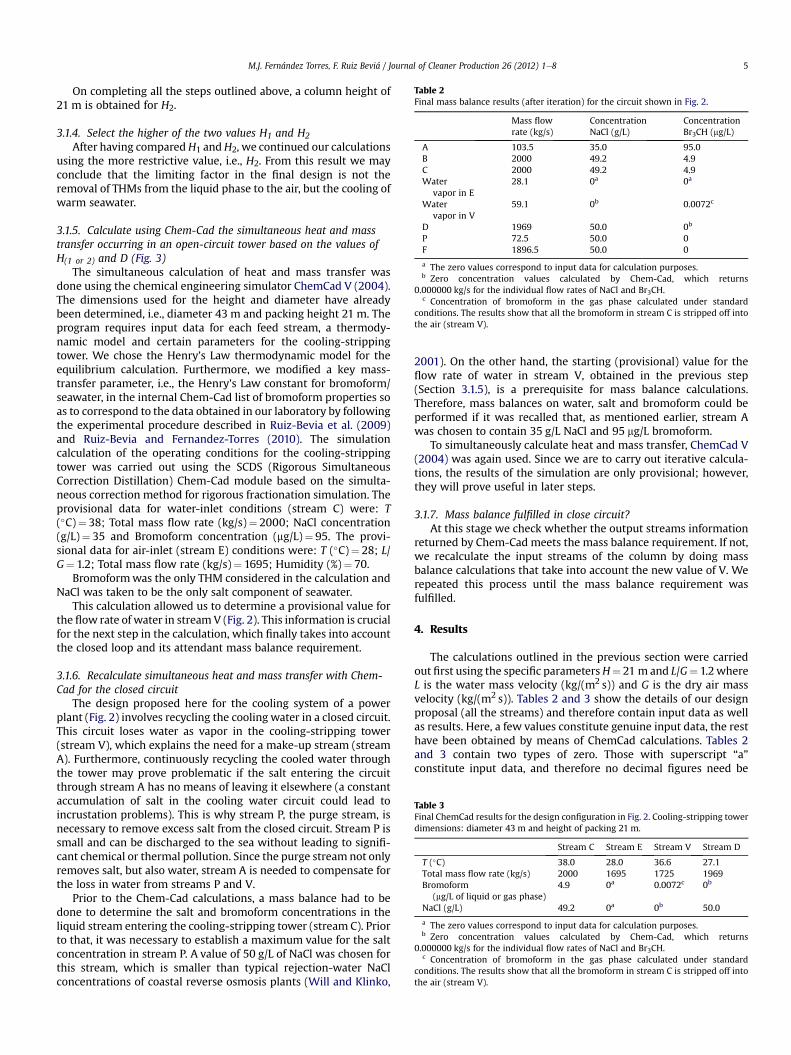
Table 2Final mass balance results (after iteration) for the circuit shown in Fig. 2.
Mass flowrate (kg/s)
ConcentrationNaCl (g/L)
ConcentrationBr3CH (mg/L)
A 103.5 35.0 95.0B 2000 49.2 4.9C 2000 49.2 4.9Water
vapor in E28.1 0a 0a
Watervapor in V
59.1 0b 0.0072c
D 1969 50.0 0b
P 72.5 50.0 0F 1896.5 50.0 0
a The zero values correspond to input data for calculation purposes.b Zero concentration values calculated by Chem-Cad, which returns
0.000000 kg/s for the individual flow rates of NaCl and Br3CH.c Concentration of bromoform in the gas phase calculated under standard
conditions. The results show that all the bromoform in stream C is stripped off intothe air (stream V).
Table 3Final ChemCad results for the design configuration in Fig. 2. Cooling-stripping towerdimensions: diameter 43 m and height of packing 21 m.
Stream C Stream E Stream V Stream D
T (�C) 38.0 28.0 36.6 27.1Total mass flow rate (kg/s) 2000 1695 1725 1969Bromoform
(mg/L of liquid or gas phase)4.9 0a 0.0072c 0b
NaCl (g/L) 49.2 0a 0b 50.0
a The zero values correspond to input data for calculation purposes.b Zero concentration values calculated by Chem-Cad, which returns
0.000000 kg/s for the individual flow rates of NaCl and Br3CH.c Concentration of bromoform in the gas phase calculated under standard
conditions. The results show that all the bromoform in stream C is stripped off intothe air (stream V).
M.J. Fernández Torres, F. Ruiz Beviá / Journal of Cleaner Production 26 (2012) 1e8 5
On completing all the steps outlined above, a column height of21 m is obtained for H2.
3.1.4. Select the higher of the two values H1 and H2
After having comparedH1 andH2, we continued our calculationsusing the more restrictive value, i.e., H2. From this result we mayconclude that the limiting factor in the final design is not theremoval of THMs from the liquid phase to the air, but the cooling ofwarm seawater.
3.1.5. Calculate using Chem-Cad the simultaneous heat and masstransfer occurring in an open-circuit tower based on the values ofH(1 or 2) and D (Fig. 3)
The simultaneous calculation of heat and mass transfer wasdone using the chemical engineering simulator ChemCad V (2004).The dimensions used for the height and diameter have alreadybeen determined, i.e., diameter 43 m and packing height 21 m. Theprogram requires input data for each feed stream, a thermody-namic model and certain parameters for the cooling-strippingtower. We chose the Henry’s Law thermodynamic model for theequilibrium calculation. Furthermore, we modified a key mass-transfer parameter, i.e., the Henry’s Law constant for bromoform/seawater, in the internal Chem-Cad list of bromoform properties soas to correspond to the data obtained in our laboratory by followingthe experimental procedure described in Ruiz-Bevia et al. (2009)and Ruiz-Bevia and Fernandez-Torres (2010). The simulationcalculation of the operating conditions for the cooling-strippingtower was carried out using the SCDS (Rigorous SimultaneousCorrection Distillation) Chem-Cad module based on the simulta-neous correction method for rigorous fractionation simulation. Theprovisional data for water-inlet conditions (stream C) were: T(�C)¼ 38; Total mass flow rate (kg/s)¼ 2000; NaCl concentration(g/L)¼ 35 and Bromoform concentration (mg/L)¼ 95. The provi-sional data for air-inlet (stream E) conditions were: T (�C)¼ 28; L/G¼ 1.2; Total mass flow rate (kg/s)¼ 1695; Humidity (%)¼ 70.
Bromoformwas the only THM considered in the calculation andNaCl was taken to be the only salt component of seawater.
This calculation allowed us to determine a provisional value forthe flow rate of water in stream V (Fig. 2). This information is crucialfor the next step in the calculation, which finally takes into accountthe closed loop and its attendant mass balance requirement.
3.1.6. Recalculate simultaneous heat and mass transfer with Chem-Cad for the closed circuit
The design proposed here for the cooling system of a powerplant (Fig. 2) involves recycling the cooling water in a closed circuit.This circuit loses water as vapor in the cooling-stripping tower(stream V), which explains the need for a make-up stream (streamA). Furthermore, continuously recycling the cooled water throughthe tower may prove problematic if the salt entering the circuitthrough stream A has no means of leaving it elsewhere (a constantaccumulation of salt in the cooling water circuit could lead toincrustation problems). This is why stream P, the purge stream, isnecessary to remove excess salt from the closed circuit. Stream P issmall and can be discharged to the sea without leading to signifi-cant chemical or thermal pollution. Since the purge stream not onlyremoves salt, but also water, stream A is needed to compensate forthe loss in water from streams P and V.
Prior to the Chem-Cad calculations, a mass balance had to bedone to determine the salt and bromoform concentrations in theliquid stream entering the cooling-stripping tower (stream C). Priorto that, it was necessary to establish a maximum value for the saltconcentration in stream P. A value of 50 g/L of NaCl was chosen forthis stream, which is smaller than typical rejection-water NaClconcentrations of coastal reverse osmosis plants (Will and Klinko,
2001). On the other hand, the starting (provisional) value for theflow rate of water in stream V, obtained in the previous step(Section 3.1.5), is a prerequisite for mass balance calculations.Therefore, mass balances on water, salt and bromoform could beperformed if it was recalled that, as mentioned earlier, stream Awas chosen to contain 35 g/L NaCl and 95 mg/L bromoform.
To simultaneously calculate heat and mass transfer, ChemCad V(2004) was again used. Since we are to carry out iterative calcula-tions, the results of the simulation are only provisional; however,they will prove useful in later steps.
3.1.7. Mass balance fulfilled in close circuit?At this stage we check whether the output streams information
returned by Chem-Cad meets the mass balance requirement. If not,we recalculate the input streams of the column by doing massbalance calculations that take into account the new value of V. Werepeated this process until the mass balance requirement wasfulfilled.
4. Results
The calculations outlined in the previous section were carriedout first using the specific parametersH¼ 21 m and L/G¼ 1.2whereL is the water mass velocity (kg/(m2 s)) and G is the dry air massvelocity (kg/(m2 s)). Tables 2 and 3 show the details of our designproposal (all the streams) and therefore contain input data as wellas results. Here, a few values constitute genuine input data, the resthave been obtained by means of ChemCad calculations. Tables 2and 3 contain two types of zero. Those with superscript “a”constitute input data, and therefore no decimal figures need be
23
24
25
26
27
28
29
30
31
32
33
0 10 20 30 40 50 60
Packing height (m)
T (
ºC
)
0,000000
0,000002
0,000004
0,000006
0,000008
0,000010
0,000012
ma
ss
flo
w r
ate
of B
r3C
H (
kg
/s) in
air
T of stream E
T of stream D
mass flow rate of Br3CH in air
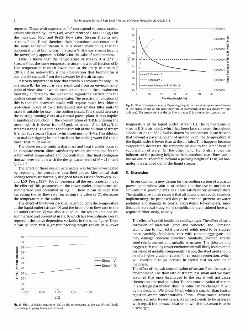
Fig. 6. Effect of design parameter H (packing height) on the exit temperature of streamD (left ordinate) and on the mass flow rate of bromoform in the gas stream V (rightordinate). The temperature at the air inlet (stream E) is included for comparison.
M.J. Fernández Torres, F. Ruiz Beviá / Journal of Cleaner Production 26 (2012) 1e86
reported. Those with superscript “b” correspond to concentrationvalues calculated by Chem-Cad, which returned 0.000000 kg/s forthe individual NaCl and Br3CH flow rates. Stream D splits intostreams P and F, and therefore their bromoform concentration isthe same as that of stream D. It is worth mentioning that theconcentration of bromoform in stream V (the gas stream leavingthe tower) only appears in Table 3 for the sake of completeness.
Table 3 shows that the temperature of stream D is 27.1 �C.Stream P has the same temperature since it is a small fraction of D.This temperature is much lower than at the entry, in stream C(38 �C). Also noteworthy is the observation that bromoform iscompletely stripped from the seawater by the air stream.
It is very important to note that stream A accounts for only 5.2%of stream B. This result is very significant from an environmentalpoint of view, since it would mean a reduction in the entrainmentmortality suffered by the planktonic organisms carried into thecooling circuit with the cooling water. The practical implication ofthis is that the seawater intake will require much less chlorine(reduction in use of toxic substances) and smaller filter units tomake it suitable for use in the cooling circuit. This should decreasethe existing running costs of a coastal power plant. It also impliesa significant reduction in the concentration of THMs entering thetower, which is down from 95 mg/L in stream A to 4.9 mg/L instreams B and C. This comes about as result of the dilution of streamA (small) by stream F (large), which contains noTHMs. This dilutionalso makes stripping bromoform from the cooling water fed to thetower that much easier.
The above results confirm that mass and heat transfer occur toan adequate extent. Since satisfactory results are obtained for thewater outlet temperature and concentration, this final configura-tion achieves our aim with the design parameters of H¼ 21 m andL/G¼ 1.2.
The effect of these design parameters was further investigatedby repeating the procedure described above. Mechanical draftcooling towers are normally designed for L/G ratios of between 0.75and 1.50 (Perry, 1997). For convenience, all the results pertaining tothe effect of this parameter on the tower outlet temperature aresummarized and presented in Fig. 5. There it can be seen thatincreasing the air flow rate (increasing the value of G), decreasesthe temperature at the outlet.
The effect of the tower packing height on both the temperatureat the liquid outlet (stream D) and the bromoform flow rate in theair outlet (stream V) was also studied. All the results obtained aresummarized and presented in Fig. 6, which has two ordinate axes torepresent the above dependent variables in the same figure. Thereit can be seen that a greater packing height results in a lower
20
22
24
26
28
30
32
34
36
38
40
0,75 0,95 1,15 1,35 1,55
L/G
T (
ºC
) o
f e
xit
stream
s
Stream VStream D
Fig. 5. Effect of design parameter L/G on the temperature at the gas (V) and liquid(D) cooling-stripping tower exit streams.
temperature at the liquid outlet (stream D). The temperature ofstream E (the air inlet), which has been kept constant throughoutall calculations at 28 �C, is also shown for comparison. It can be seenthat beyond a packing height of around 37 m, the temperature atthe liquid outlet is lower than at the air inlet. This happens becauseevaporation decreases the temperature due to the latent heat ofvaporization of water. On the other hand, Fig. 6 also shows theinfluence of the packing height on the bromoformmass flow rate inthe air outlet. Therefore, beyond a packing height of 13 m, all bro-moform is stripped out of the liquid stream.
5. Discussion
In our opinion, a new design for the cooling system of a coastalpower plant whose aim is to reduce chlorine use in nuclear orconventional power plants has been satisfactorily accomplished.The significance of this result is that all power plants could considerimplementing the proposed design in order to prevent seawaterpollution and damage to coastal ecosystems. Nevertheless, sincethis is a theoretical study, some simplifications considered herewillrequire further study, namely:
- The effect of sea salt inside the cooling tower. The effect of extracorrosion of materials (steel and concrete) and increasedscaling due to high total dissolved solids need to be studiedmore carefully. Sulphates react with cement aggregate andmay damage concrete structure. Similarly, chloride attackssteel reinforcement and metallic structures. The chloride andoxygen-rich cooling tower environmentwill likely lead to rapidcorrosion of metallic components. Hence, the steel used shouldbe of a higher grade or coated for corrosion protection, whichwill contribute to an increase in capital cost on account ofmaterials.
- The effect of the salt concentration of stream P on the coastalenvironment. The flow rate of stream P is small and we haveassumed that once discharged to the sea, it will not causechemical or thermal pollution. The salt concentration of streamP is a design parameter; thus, its value can be changed at willby the designer. We chose 50 g/L which is smaller than typicalrejection-water concentrations of NaCl from coastal reverseosmosis plants. Nevertheless, its impact needs to be assessedwith regard to the exact location in which this stream is to bedischarged.
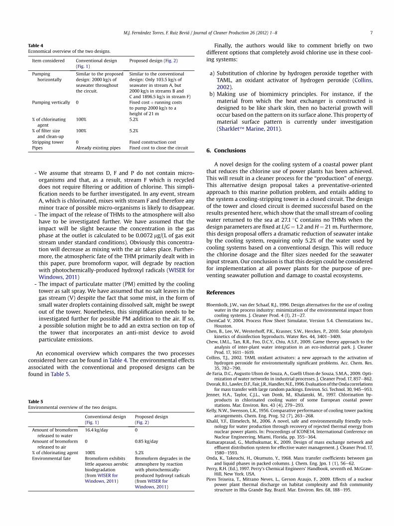
Table 4Economical overview of the two designs.
Item considered Conventional design(Fig. 1)
Proposed design (Fig. 2)
Pumpinghorizontally
Similar to the proposeddesign: 2000 kg/s ofseawater throughoutthe circuit.
Similar to the conventionaldesign: Only 103.5 kg/s ofseawater in stream A, but2000 kg/s in streams B andC and 1896.5 kg/s in stream F)
Pumping vertically 0 Fixed costþ running coststo pump 2000 kg/s to aheight of 21 m
% of chlorinatingagent
100% 5.2%
% of filter sizeand clean-up
100% 5.2%
Stripping tower 0 Fixed construction costPipes Already existing pipes Fixed cost to close the circuit
M.J. Fernández Torres, F. Ruiz Beviá / Journal of Cleaner Production 26 (2012) 1e8 7
- We assume that streams D, F and P do not contain micro-organisms and that, as a result, stream F which is recycleddoes not require filtering or addition of chlorine. This simpli-fication needs to be further investigated. In any event, streamA, which is chlorinated, mixes with stream F and therefore anyminor trace of possible micro-organisms is likely to disappear.
- The impact of the release of THMs to the atmosphere will alsohave to be investigated further. We have assumed that theimpact will be slight because the concentration in the gasphase at the outlet is calculated to be 0.0072 mg/(L of gas exitstream under standard conditions). Obviously this concentra-tion will decrease as mixing with the air takes place. Further-more, the atmospheric fate of the THM primarily dealt with inthis paper, pure bromoform vapor, will degrade by reactionwith photochemically-produced hydroxyl radicals (WISER forWindows, 2011)
- The impact of particulate matter (PM) emitted by the coolingtower as salt spray. We have assumed that no salt leaves in thegas stream (V) despite the fact that some mist, in the form ofsmall water droplets containing dissolved salt, might be sweptout of the tower. Nonetheless, this simplification needs to beinvestigated further for possible PM addition to the air. If so,a possible solution might be to add an extra section on top ofthe tower that incorporates an anti-mist device to avoidparticulate emissions.
An economical overview which compares the two processesconsidered here can be found in Table 4. The environmental effectsassociated with the conventional and proposed designs can befound in Table 5.
Table 5Environmental overview of the two designs.
Conventional design(Fig. 1)
Proposed design(Fig. 2)
Amount of bromoformreleased to water
16.4 kg/day 0
Amount of bromoformreleased to air
0 0.85 kg/day
% of chlorinating agent 100% 5.2%Environmental fate Bromoform exhibits
little aqueous aerobicbiodegradation(from WISER forWindows, 2011)
Bromoform degrades in theatmosphere by reactionwith photochemically-produced hydroxyl radicals(from WISER forWindows, 2011)
Finally, the authors would like to comment briefly on twodifferent options that completely avoid chlorine use in these cool-ing systems:
a) Substitution of chlorine by hydrogen peroxide together withTAML, an oxidant activator of hydrogen peroxide (Collins,2002).
b) Making use of biomimicry principles. For instance, if thematerial from which the heat exchanger is constructed isdesigned to be like shark skin, then no bacterial growth willoccur based on the pattern on its surface alone. This property ofmaterial surface pattern is currently under investigation(Sharklet� Marine, 2011).
6. Conclusions
A novel design for the cooling system of a coastal power plantthat reduces the chlorine use of power plants has been achieved.This will result in a cleaner process for the “production” of energy.This alternative design proposal takes a preventative-orientedapproach to this marine pollution problem, and entails adding tothe system a cooling-stripping tower in a closed circuit. The designof the tower and closed circuit is deemed successful based on theresults presented here, which show that the small stream of coolingwater returned to the sea at 27.1 �C contains no THMs when thedesign parameters are fixed at L/G¼ 1.2 andH¼ 21 m. Furthermore,this design proposal offers a dramatic reduction of seawater intakeby the cooling system, requiring only 5.2% of the water used bycooling systems based on a conventional design. This will reducethe chlorine dosage and the filter sizes needed for the seawaterinput stream. Our conclusion is that this design could be consideredfor implementation at all power plants for the purpose of pre-venting seawater pollution and damage to coastal ecosystems.
References
Bloemkolk, J.W., van der Schaaf, R.J., 1996. Design alternatives for the use of coolingwater in the process industry: minimization of the environmental impact fromcooling systems. J. Cleaner Prod. 4 (I), 21e27.
ChemCad V, 2004. Process Flow Sheet Simulator, Version 5.4. Chemstations Inc.,Houston.
Chen, B., Lee, W., Westerhoff, P.K., Krasner, S.W., Herckes, P., 2010. Solar photolysiskinetics of disinfection byproducts. Water Res. 44, 3401e3409.
Chew, I.M.L., Tan, R.R., Foo, D.C.Y., Chiu, A.S.F., 2009. Game theory approach to theanalysis of inter-plant water integration in an eco-industrial park. J. CleanerProd. 17, 1611e1619.
Collins, T.J., 2002. TAML oxidant activators: a new approach to the activation ofhydrogen peroxide for environmentally significant problems. Acc. Chem. Res.35, 782e790.
de Faria, D.C., Augusto Ulson de Souza, A., Guelli Ulson de Souza, S.M.A., 2009. Opti-mization of water networks in industrial processes. J. Cleaner Prod. 17, 857e862.
Dvorak,B.I., Lawler,D.F., Fair, J.R.,Handler,N.E.,1996.Evaluationof theOndacorrelationsfor mass transfer with large random packings. Environ. Sci. Technol. 30, 945e953.
Jenner, H.A., Taylor, C.J.L., van Donk, M., Khalanski, M., 1997. Chlorination by-products in chlorinated cooling water of some European coastal powerstations. Mar. Environ. Res. 43 (4), 279e293.
Kelly, N.W., Swenson, L.K., 1956. Comparative performance of cooling tower packingarrangements. Chem. Eng. Prog. 52 (7), 263e268.
Khalil, Y.F., Elimelech, M., 2006. A novel, safe and environmentally friendly tech-nology for water production through recovery of rejected thermal energy fromnuclear power plants. In: Proceedings of ICONE14, International Conference onNuclear Engineering, Miami, Florida, pp. 355e364.
Kumaraprasad, G., Muthukumar, K., 2009. Design of mass exchange network andeffluent distribution system for effective water management. J. Cleaner Prod. 17,1580e1593.
Onda, K., Takeuchi, H., Okumuto, Y., 1968. Mass transfer coefficients between gasand liquid phases in packed columns. J. Chem. Eng. Jpn. 1 (1), 56e62.
Perry, R.H. (Ed.), 1997. Perry’s Chemical Engineers’ Handbook, seventh ed. McGraw-Hill, New York. USA.
Pires Teixeira, T., Mitrano Neves, L., Gerson Araujo, F., 2009. Effects of a nuclearpower plant thermal discharge on habitat complexity and fish communitystructure in Ilha Grande Bay, Brazil. Mar. Environ. Res. 68, 188e195.

M.J. Fernández Torres, F. Ruiz Beviá / Journal of Cleaner Production 26 (2012) 1e88
Poornima, E.H., Rajadurai, M., Rao, T.S., Anupkumar, B., Rajamohan, R.,Narasimhan, S.V., Rao, V.N.R.,Venugopalan,V.P., 2005. Impactof thermaldischargefrom a tropical coastal power plant on phytoplankton. J. Therm. Biol. 30, 307e316.
Rajamohan, R., Viñita, E., Venugopalan, V.P., Narasimhan, S.V., 2007. Chlorinationby-products and their discharge from the cooling water system of a coastalelectric plant. Curr. Sci. 93 (10), 1608e1612.
Rice, J.K., Garey, J., Mussalli, Y.G., Puckorius, P., 1993. Condenser MicrobiofoulingControl Handbook. EPRI RP 2300-16, Final Report TR-102507. Electric PowerResearch Institute, California, USA.
Roberts, P.V., Hopkins, G.D., Munz, C., Riojas, A.H., 1985. Evaluating two-resistancemodels for air stripping of volatile organic contaminants in a countercurrent,packed column. Environ. Sci. Technol. 19, 164e173.
Ruiz-Bevia, F., Fernandez-Torres, M.J., 2010. Determining the Henry’s Law Constantsof THMs in seawater by means of purge-and-trap gas chromatography (PT-GC):the influence of seawater as simple matrix. Anal. Sci. 26, 723e726.
Ruiz-Bevia, F., Fernandez-Torres, M.J., Blasco-Alemany, M.P., 2009. Purge efficiencyin the determination of trihalomethanes in water by purge-and-trap gaschromatography. Anal. Chim. Acta 632, 304e314.
Sharklet� Marine, 2011. Sharklet Technology Inc. www.sharklet.com/sharklet-products/sharklet%E2%84%A2-marine/ (accessed August 2011).
Sotelo-Pichardo, C., Ponce-Ortega, J.M., El-Halwagi, M.M., Frausto-Hernández, S.,2011. Optimal retrofit of water conservation networks. J. Cleaner Prod. 19,1560e1581.
Will, M., Klinko, K., 2001. Optimization of seawater RO systems design. Desalination138, 299e306.
Winter, J.V., Conner, D.A., 1978. Power Plant Sitting. In: Van Nostrand ReinholdEnvironmental Engineering Series. Litton Educational Publishing, Inc., NewYork. USA.
WISER for Windows (Wireless Information System for Emergency Responders)User’s Guide Version 2.2, 2011. National Library of Medicine, USA.